introduction notes for heavy duty snowplows · •index •main menu inall + out •2500/3500 ram...
TRANSCRIPT

2014 Ram Snowplow Installation
10/17/2013
•Main Menu •Index IN
+
OUT
-
ALL •2500/3500 Ram Home
INTRODUCTION The factory-installed Snowplow Preparation Groups (or their equivalent components) are recommended and listed for each vehicle. The normal warranty applies to Dodge Ram trucks that have after market snowplows installed in accordance with these guidelines. Maximum Vehicle Loading Requirements: Installation of snowplows and their mounting hardware may result in a vehicle weight distribution or a front axle loading which is detrimental to brake performance or which exceeds the front GAWR. The following load requirements are applicable: 1. The loaded vehicle, including all after market
accessories, the snowplow system, passengers, and cargo, must not exceed the gross vehicle weight (GVW), front or rear gross axle weight (GAW) ratings specified on the Safety Compliance Certification label located in the driver’s side door opening.
2. The empty truck with all permanently attached accessories and snowplow components must not exceed 62 percent of its total weight on the front axle to comply with FMVSS/CMVSR 105 Brake Certification. Permanently attached snowplow parts are those parts not easily removed when the blade is removed. The permanently attached parts are: sub-frame, hydraulic pump, hydraulic lift cylinder, lamps, wiring, snowplow controls, etc.
If the front axle loading exceeds either 62 percent of the empty truck total weight, or the front GAWR, ballast-compensating weight must be securely attached at the rear of the truck to bring front axle weight within weight specifications as defined above.
Notes for Heavy Duty Snowplows:
At any time, the maximum number of occupants in the truck must not exceed two
Under Any Circumstances, vehicles should NOT exceed GVWR (Gross Vehicle Weight Rating), Front or Rear GAWRs (Gross Axle Weight Ratings)
Snowplow prep packages are NOT available with Sport (AAG) package
Cargo capacity will be reduced by the addition of options.
Ballast should be securely attached inside the box at 9 inches from the rear tailgate for pickups.
The total weight of permanently attached hardware should not exceed 125 lbs.
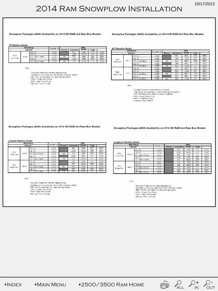
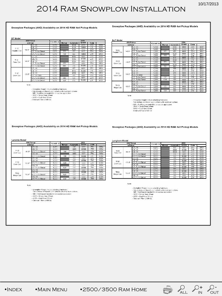
Max snowplow weight should not exceed values for models shown in this section.
The snowplow weights shown in the charts on the next page are the manufacturer recommendations based on maximum vehicle option content. Other plow weight values may be possible, based on the specific capability of the vehicle being modified (actual weight, GVWR, front and rear GAWR). The maximum allowable plow weight can be determined by the dealer /supplier / manufacturer. In all cases, the loaded vehicle weight, including the snowplow system, all aftermarket accessories, driver, passengers, options, and cargo, must not exceed either the Gross Vehicle Weight (GVWR) or Gross Axle Weight (GAWR) ratings. The GVWR and GAWR weights are specified on the Safety Compliance Certification Label on the driver’s side door opening.
Safety Compliance Certification Label
CHRYSLER GROUP LLC
•Main Menu •Index IN
+
OUT
-
ALL •2500/3500 Ram Home
2014 Ram Snowplow Installation
10/17/2013
•Main Menu •Index IN
+
OUT
-
ALL •2500/3500 Ram Home
2014 Ram Snowplow Installation
10/17/2013

•Main Menu •Index IN
+
OUT
-
ALL •2500/3500 Ram Home
2014 Ram Snowplow Installation
10/17/2013

•Main Menu •Index IN
+
OUT
-
ALL •2500/3500 Ram Home
2014 Ram Snowplow Installation
10/17/2013
•Main Menu •Index IN
+
OUT
-
ALL •2500/3500 Ram Home
2014 Ram Snowplow Installation
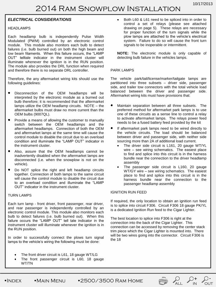
ELECTRICAL CONSIDERATIONS HEADLAMPS Each headlamp bulb is independently Pulse Width Modulated (PWM) controlled by an electronic control module. This module also monitors each bulb to detect failures (i.e. bulb burned out) on both the high beam and low beam filaments. When this failure occurs, the “LAMP OUT” telltale indicator in the instrument cluster will illuminate whenever the ignition is in the RUN position. The module also provides the DRL function when required and therefore there is no separate DRL controller. Therefore, the any aftermarket wiring kits should use the following guidelines:
Disconnection of the OEM headlamps will be interpreted by the electronic module as a burned out bulb therefore; it is recommended that the aftermarket lamps utilize the OEM headlamp circuits. NOTE – the aftermarket bulbs must draw no more current than the OEM bulbs (9007QL).
Provide a means of allowing the customer to manually switch between the OEM headlamps and the aftermarket headlamps. Connection of both the OEM and aftermarket lamps at the same time will cause the control module to disable the circuit due to an overload condition and illuminate the “LAMP OUT” indicator in the instrument cluster.
Also, assure that the OEM headlamps cannot be inadvertently disabled when the aftermarket lamps are disconnected (i.e. when the snowplow is not on the vehicle).
Do NOT splice the right and left headlamp circuits together. Connection of both lamps to the same circuit will cause the control module to disable the circuit due to an overload condition and illuminate the “LAMP OUT” indicator in the instrument cluster.
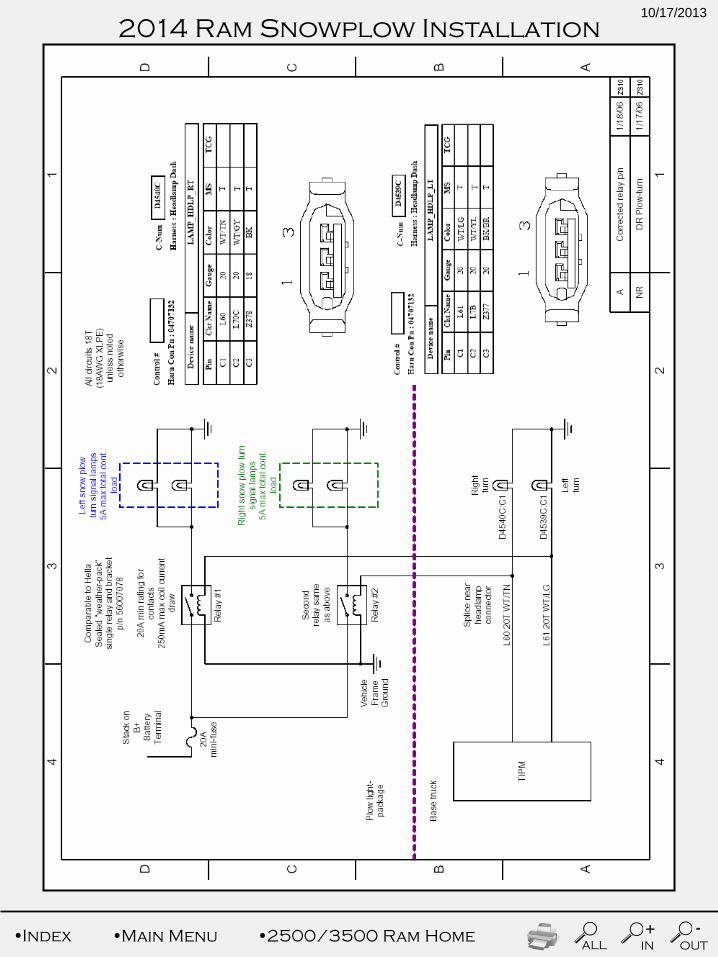
TURN LAMPS Each turn lamp - front driver, front passenger, rear driver, and rear passenger is independently controlled by an electronic control module. This module also monitors each bulb to detect failures (i.e. bulb burned out). When this failure occurs the “LAMP OUT” tell tale indicator in the instrument cluster will illuminate whenever the ignition is in the RUN position. In order to successfully connect the plows turn signal lamps to the vehicle’s wiring the following must be done:
The front driver circuit is L61, 18 gauge WT/LG
The front passenger circuit is L60, 18 gauge WT/TN
Both L60 & L61 need to be spliced into in order to control a set of relays (please see attached drawing on page 5). These relays are necessary for proper function of the turn signals while the plow lamps are attached to the vehicle’s electrical system. Failure to do so will cause the front turn signals to be inoperable or intermittent.
NOTE: The electronic module is only capable of detecting bulb failure in the vehicles lamps.
PARK LAMPS The vehicle park/tail/license/marker/tailgate lamps are partitioned into three subsets – driver side, passenger side, and trailer tow connectors with the total vehicle load balanced between the driver and passenger side. Aftermarket wiring kits must have provisions that:
Maintain separation between all three subsets. The preferred method for aftermarket park lamps is to use one of these circuits as a sense line to control a relay to activate aftermarket lamps. The relays power feed needs to be a fused battery feed provided by the kit
If aftermarket park lamps need to be wired directly to the vehicle circuits. The load should be balanced between driver and passenger side, with neither side sourcing more than 2A of additional load current.
The driver side circuit is L161, 20 gauge WT/YL wire – see wiring schematics. The easiest place to find and splice into this circuit is in the harness bundle near the connection to the driver headlamp assembly
The passenger side circuit is L160, 20 gauge WT/GY wire – see wiring schematics. The easiest place to find and splice into this circuit is in the harness bundle near the connection to the passenger headlamp assembly
IGNITION RUN FEED
If required, the only location to obtain an ignition run feed
is to splice into circuit F306. Circuit F306 18 gauge PK/YL
is a dedicated Ignition Run feed to the Cigar Lighter.
The best location to splice into F306 is right at the connection into the back of the Cigar Lighter. This connection can be accessed by removing the center stack trim piece which the Cigar Lighter is mounted into. There will be two wires going into the connector. Circuit F306 is the 18
10/17/2013
•Main Menu •Index IN
+
OUT
-
ALL •2500/3500 Ram Home
2014 Ram Snowplow Installation
gauge PK/YL wire. The other wire will be (Z736) BK/YL
tracer.
The spliced in aftermarket wire should be a minimum 18
gauge high temperature rated wire due to the 20A fuse for
the Cigar lighter.
The load placed on the aftermarket circuit should not
exceed 2A. Exceeding 2A will potentially blow the Cigar
Lighter fuse when activating the Cigar lighter and the
aftermarket load simultaneously.
Note: Circuit F306 is an Ignition Run and
ACCESSORY feed, meaning it will be hot with the
ignition key in the Run position and also the
Accessory position.
Note: If more than a 2A ignition feed is required, then
the aftermarket application will have to add an external
relay, with appropriate battery fusing and use the
recommended F306 circuit to turn the relay on and off.
Note: There is no other acceptable place to find a
vehicle Ignition Run source, in cab or underhood.
10/17/2013
•Main Menu •Index IN
+
OUT
-
ALL •2500/3500 Ram Home
2014 Ram Snowplow Installation
10/17/2013