introduction - thecatweb.cecs.pdx.edu/~mperkows/class_479/quanta/13.… · web viewthese servos...
TRANSCRIPT

Countess Quanta RobotDeveloper’s Guide
Brad Pitney
June 25, 2014

Table of Contents
Introduction......................................................................................................................................4
Overview of the Countess Quanta Robot........................................................................................4
Hardware Components................................................................................................................6
Upper Body..............................................................................................................................6
Lower Body.............................................................................................................................6
Sensors.....................................................................................................................................6
Software Control..........................................................................................................................8
Controlling the Robot Hardware Components................................................................................8
Required Cables...........................................................................................................................8
Powering on the Robot..............................................................................................................11
Controlling the Servo Hardware................................................................................................11
Controlling the Wheel Hardware...............................................................................................13
Controlling the Kinect Hardware...............................................................................................15
Controlling the Robot with the CountessQuantaControl Software...............................................16
Building and Running the Software..........................................................................................16
Using the Graphical User Interface...........................................................................................16
Hardware Connection Status.................................................................................................17
Connecting to the Wheel Hardware.......................................................................................17
Reinitializing Hardware.........................................................................................................17
Log Messages........................................................................................................................17
Disabling and Enabling Motion.............................................................................................18
Testing Text-to-Speech..........................................................................................................18
Running a Motion Sequence..................................................................................................18
2

Displaying the Skeleton Viewer............................................................................................19
Using Speech Recognition.....................................................................................................19
Using Gesture Recognition....................................................................................................19
Using Person Tracking..........................................................................................................20
Creating and Modifying Motion Sequences..............................................................................20
Sequence Structure................................................................................................................20
Sequence Examples...............................................................................................................22
Understanding and Modifying the CountessQuantaControl Software..........................................24
CountessQuantaControl C# Files and Classes...........................................................................25
Other Files Used by CountessQuantaControl............................................................................26
Adding New XML Elements and Attributes.............................................................................26
Servo Management....................................................................................................................27
Wheel Management...................................................................................................................29
Speech Recognition...................................................................................................................30
Adding New Speech Recognition Vocabulary..........................................................................31
Gesture Recognition..................................................................................................................32
Adding New Gesture Recognition Vocabulary.........................................................................32
Person Tracking.........................................................................................................................33
RobotEyes..................................................................................................................................34
Error Logging............................................................................................................................34
Ideas for Further Development......................................................................................................35
Hardware Development.............................................................................................................35
Software Development..............................................................................................................38
Motion Sequence Development.................................................................................................44
Appendix........................................................................................................................................45
3
Servo Range Data......................................................................................................................45
Right Arm Length Measurements.............................................................................................48
Servo Replacement and Hardware Documentation...................................................................49
Introduction
The purpose of this document is to describe the functionality of the Countess Quanta robot and to
help new developers in becoming familiar with the robot’s hardware and software systems. This
document starts by describing the robot hardware components and the key software features. It
then provides instructions on how to connect to the main hardware components individually,
using their own development tools. Next, it describes how to build the CountessQuantaControl
software and use this to control the robot. The CountessQuantaControl software structure is then
discussed, along with how to add new features to the code. Finally, a list of future development
tasks is presented, to provide some ideas for future hardware and software work. As the robot is
modified and as new features are developed, this document should be updated to include these
changes.
Included with this document are several directories:
CountessQuantaControl – Source code of the main control software.
ARIA_CSharpWrapper – Modified ARIA source code for the wheel control.
Documentation – Useful hardware component documentation.
Installs – Programs and development SDKs for the hardware components.
PastDevelopment – Docs, code, videos, etc. from past development work.
Overview of the Countess Quanta Robot
Countess Quanta is a wheeled, humanoid robot planned to fulfill several roles:
To interact with humans and provide information about the Portland State University
robotics program.
To act as a guide robot, and show people around the PSU building.
4

To participate in the PSU Robot Theater.
5

6

Hardware Components
Upper Body
The upper half of Countess Quanta includes two arms and a head animated by a set of 16 servos.
These servos are controlled through a Pololu Mini Maestro 18 USB servo controller, which is
mounted in the left shoulder of the robot. This device connects through USB to a laptop PC,
which sends the servo commands to animate the upper body of the robot. The servo power is
supplied from batteries in the robot base, allowing the servos to operate while disconnected from
external power.
The right arm is controlled by a series of six servos, which allow the robot to point at objects,
wave, and strum the lap harp instrument mounted on the front of the body. The left arm is
mounted upright, and uses one servo for waving and five servos for controlling the five fingers.
These fingers can curl and extend independently, which allow for more complex hand motions,
such as displaying numbers or playing rock-paper-scissors. For the head, one servo turns the
head left and right, while another lets the head look up and down. A third servo lets the eyes look
left and right, and a fourth servo opens and closes the mouth.
Lower Body
The lower part of Countess Quanta serves as a wheeled platform on which everything else is
mounted. This wheeled base is actually a Pioneer 2 Mobile Robot developed by ActivMedia
Robotics. This robot contains three batteries which allow the wheels and upper body servos to
operate for several hours when disconnected from external power. A Belkin USB-to-serial
adapter is used to connect the Pioneer 2 robot to the laptop PC, which sends motion commands
to the wheels. This allows for animations that move and rotate the whole Countess Quanta body,
and for turning to face people during interactions. Only a small subset of the full Pioneer 2
capabilities is currently utilized by the control software. The Pioneer 2 provides advanced
navigation and sonar sensing capabilities that still need to be integrated into the control system.
Sensors
The main sensor for Countess Quanta is the Microsoft Xbox 360 Kinect sensor mounted on at
the robot’s base:
7

This Kinect communicates with a laptop PC through a USB adapter cable. This adapter cable
also provides power to the Kinect through an attached AC power plug, although this currently
prevents Countess Quanta from operating on battery power alone. The Kinect device includes a
color camera and infrared laser depth sensor for locating objects in 3D space. It also provides a
multi-array microphone, which allows for detecting which direction a sound is coming from.
Countess Quanta currently uses the Kinect to track the location of people, to detect specific
gestures people are making, and to detect spoken commands.
The Pioneer 2 robot provides other sensor systems that are not currently integrated into the
control software. The Pioneer 2 provides three sonar arrays which each consist of eight
individual sensors (gold-colored circles). Two of these arrays are installed in the front and rear of
the Pioneer 2 base, just above the wheels. The third array is located on the front of Countess
Quanta’s upper body. This third sonar array is not currently hooked up. The sonars can be used
to detect distances between the robot and surrounding obstacles. The Pioneer 2 also provides a
8

set of collision sensors around the edge of the robot, near the ground. These are used to detect
physical collisions with objects while moving.
Software Control
These hardware components are integrated through control software called
CountessQuantaControl, which was developed starting in Winter of 2014.
CountessQuantaControl is a C# application that uses Windows Presentation Foundation (WPF).
It was developed mainly with Visual Studio 2010, and runs under Windows 7 and Windows 8.
Here are the main features of this software:
Configures and manages the servo controller and Pioneer 2.
Coordinates robot motions as sequences of animation frames.
Stores move sequences and servo configurations in human-readable xml files.
Provides speech and gesture recognition through the Kinect.
Provides person tracking capabilities through the Kinect.
Provides speech synthesis with animated mouth motion.
Provides a simple graphical user interface (GUI) for testing and control.
Provides a versatile error logging system.
Controlling the Robot Hardware Components
This section provides instructions for how to connect to each of the main hardware components
using a Windows laptop PC, and control these devices using their own development software.
Required Cables
Four cables are required to connect the Countess Quanta hardware components.
1) Power cable for the Pioneer 2 robot. The cable in the lab is labeled with a
PeopleBot/GuideBot sticker. Here are the details and a picture:
AU48 - 120 - 120T
Input 120VAC 60Hz
Output 12VDC 1200mA
9

2) A standard ‘USB A Male to Mini-B cable’ is used for connecting the laptop to the servo
controller.
3) An RS-232 serial cable and Belkin F5U409 USB-to-serial adapter is used to connect the
Pioneer 2 robot to a laptop USB port:
10

4) An Xbox 360 Kinect adapter cable is used for connecting the Kinect hardware to a laptop
USB port. The Xbox Kinect uses a proprietary connector to provide both power and data
transfer. This adapter converts this Kinect plug into a separate AC power plug which
must be connected to a power outlet, and a standard USB plug which is connected to the
laptop PC:
11

Powering on the Robot
1) The power switch for the Pioneer 2 is located near Countess Quanta’s right wheel. Switch
this on to power up the Pioneer 2 and the servo system. Make sure to switch this off after
using the robot, to avoid draining the battery.
2) Just below the power switch is a port for plugging in the power cable. Connect the power
cable when possible to avoid draining the battery:
Controlling the Servo Hardware
1) Power on the robot and use a USB A Male to Mini-B cable to connect the laptop PC to
the Pololu Mini Maestro servo controller located at the left shoulder of Countess Quanta,
as shown:
12

2) In the included Installs\Servos directory, unzip maestro-windows-130422.zip and run
the setup.exe program to install the Maestro Control Center application.
3) Run the Maestro Control Center application. If the Connected To: box shows Not
Connected, then use the dropdown to select the servo controller.
4) The Maestro Control Center should show a list of 18 servos (numbered 0 to 17).
Currently, 16 of these servos are used in the robot (servos 4 and 7 are not used). To move
a servo, click its Enabled checkbox to power up the servo, then move the slider to
change the servo’s position. To power down a servo, uncheck the Enabled checkbox.
Below is a list of which servo controls which body part:
Servo 0 - Wrist left/right
Servo 1 - Wrist rotation
Servo 2 - Wrist Up/down
13

Servo 3 - Arm Up/down
Servo 4 - not used
Servo 5 - Arm rotation
Servo 6 - Shoulder left/right
Servo 7 - not used
Servo 8 - Eyes left/right
Servo 9 - Head up/down
Servo 10 - Head left/right
Servo 11 - Mouth open/close
Servo 12 - Ring finger
Servo 13 - Middle finger
Servo 14 - Pinky finger
Servo 15 - Left arm
Servo 16 - Thumb
Servo 17 - Index finger
Controlling the Wheel Hardware
1) No official Windows 7 driver exists for the Belkin F5U409 USB-to-serial adapter, but a
functional 3rd party driver is included in the Installs\Pioneer2 directory. To get the
Belkin device to work in Windows 7, open this directory and run the U232-
13.2.98.130315.exe program to install the driver.
2) Power on the robot and connect the serial cable / Belkin adapter from the Pioneer 2 to the
laptop. The device should appear in Windows as Staples Serial On USB Port (COM8).
3) In the Windows Start menu, navigate to Control Panel -> Hardware and Sound ->
Devices and Printers.
4) Right-click on the Staples Serial On USB Port (COM8) device and select Properties.
Select the Hardware tab and click the Properties button.
14

5) On the Port Settings tab, change the Bits per second field to 38400. The other settings
should show 8 data bits, 1 stop bit, no parity, no hardware handshaking. Click OK to
close these dialogs.
6) In the Installs\Pioneer2 directory, run the ARIA-2.7.6.exe program to install the
“ActivMedia Robotics Interface for Applications” software and example code.
7) In C:\Program Files\MobileRobots\ARIA\examples, run the All_Examples solution
for your version of Visual Studio.
8) In this solution, build the simpleConnect project. This will build also build the AriaDLL
project.
9) Open a command prompt and navigate to C:\Program Files\MobileRobots\ARIA\bin.
Run the simpleConnect application with the following command (if the Belkin adapter
was assigned to a different COM port, you will need to substitute COM8 for the correct
COM port number):
simpleConnect.DebugVC10.exe -rp COM8
10) If the simpleConnect application was able to communicate with the Pioneer 2 robot, it
should return something like the following:
Could not connect to simulator, connecting to robot through serial port COM8.
Syncing 0
Syncing 1
Syncing 2
Connected to robot.
Name: AM_PeopleBot
Type: Pioneer
Subtype: p2pb
15

Loaded robot parameters from p2pb.p
simpleConnect: Connected.
simpleConnect: Pose=(0.00,0.00,0.00), Trans. Vel=0.00, Battery=13.40V
simpleConnect: Sleeping for 3 seconds...
simpleConnect: Ending robot thread...
Disconnecting from robot.
simpleConnect: Exiting.
If simpleConnect is able to communicate with the Pioneer 2, then
CountessQuantaControl should be able to as well.
Controlling the Kinect Hardware
1) Connect the Xbox 360 Kinect adapter cable to the Kinect and the laptop USB port. On
the adapter cable, connect the AC power plug into an outlet to power up the Kinect.
2) In Installs\Kinect, run KinectSDK-v1.8-Setup.exe to install the Kinect SDK.
3) In Installs\Kinect, run KinectDeveloperToolkit-v1.8.0-Setup.exe to install the Kinect
Developer Toolkit.
4) In the Windows Start menu, click Kinect for Windows SDK v1.8 -> Developer Toolkit
Browser v1.8.0 (Kinect for Windows) to run the Toolkit Browser.
5) The Toolkit Browser contains many example programs that demonstrate the features of
the Kinect. Scroll down to Skeleton Basics-WPF and click Run to start this program.
6) This should connect to the Kinect hardware and display a black window. Stand in front of
the Kinect to appear on the display as a skeleton visualization. This skeleton functionality
is used in the CountessQuantaControl software for person tracking and gesture
recognition.
16

Controlling the Robot with the CountessQuantaControl Software
This section describes how to control the entire robot, using the CountessQuantaControl
software. It covers how to use the GUI, how to test the different robot features, and how to
understand and create motion sequences.
Building and Running the Software
In the CountessQuantaControl directory, run the CountessQuantaControl solution. You may
need to create a new solution to use this project with a different version of Visual Studio (e.g.
CountessQuantaControl-vs2012.sln). Build the CountessQuantaControl project and run this
application.
Using the Graphical User Interface
This program will display the CountessQuantaControl GUI, which is used to display the
hardware connection status and test various aspects of the system:
17

Hardware Connection Status
The left side of the form shows the connection status of the Countess Quanta servos, wheels, and
Kinect hardware. When the software is started, the Servo Status and Kinect Status fields should
show Connected, while the Wheel Status will show Not Connected.
Connecting to the Wheel Hardware
Due to an issue with how the CountessQuantaControl program currently connects to the ARIA
software, the application will freeze if it tries to connect while the Pioneer 2 hardware is not
connected to the laptop. The Connect Wheel Hardware button was added to work around this
issue. After the Pioneer 2 hardware has been connected, click this button to connect; the Wheel
Status field should then show Connected.
Note that if the Belkin adapter is using a different COM port than COM8, then this will need to
be changed in the modified AriaDebugVC10.dll that the CountessQuantaControl project uses to
communicate with the Pioneer 2. To do this, open the AriaDLL project included with
CountessQuantaControl and modify the InitializeRobot_dll() function so that the
builder.add("-rp COM8") call uses the correct COM port. Then rebuild the
AriaDebugVC10.dll, copy this dll into the CountessQuantaControl\bin\Debug directory
(replacing the existing dll), and restart the CountessQuantaControl. The Connect Wheel
Hardware button should then work correctly.
Reinitializing Hardware
The Reinitialize Hardware button attempts to reconnect to the hardware devices if they are
unplugged from the laptop and then plugged back in, or powered off and back on, while the
CountessQuantaControl software is running.
Log Messages
The bottom half of the CountessQuantaControl consists of a logging window that displays errors
and other messages. The Logging Level dropdown allows you to select what kind of log
messages will be displayed, depending on the messages’ severity:
Error – This displays only messages that indicate a problem in the system.
18

Warning – This displays warnings messages that indicate unusual behavior. Error
messages are also displayed.
Info – This displays extra information regarding what the system is doing. Warning and
Error messages are also displayed.
Debug – This displays all messages, including detailed information used in software
debugging. This is the most detailed logging, but will also fill up the screen with many
messages.
Disabling and Enabling Motion
The Disable Motion button can be clicked to stop all servo and wheel motion, and disallow new
motions. Clicking the button again (now displaying Enable Motion) will allow the robot to
move again. The Motion State field will show whether the motion state is currently Enabled or
Disabled. This feature can be used to terminate motion during a motion sequence and put the
system in a relatively safe state. Note that the robot should be powered down using the power
switch to put it in a truly safe state, before making adjustments that would be harmful if the robot
were to move (e.g. putting your fingers between gears, etc.).
Testing Text-to-Speech
The Test Text-to-Speech button can be clicked to test the speech synthesizer. The system will
speak whatever phrase is entered in the Speak field. This feature can be useful in testing the
sound and duration of spoken phrases, before these are added to a motion sequence.
Running a Motion Sequence
Robot motion sequences are stored in XML format under CountessQuantaControl\bin\Debug,
in the SequenceFile.xml file. To run a motion sequence from this file, the name of the sequence
is selected from the Sequence dropdown box. The Run Motion Sequence button can then be
clicked to perform the motion sequence. This can be useful for testing the actual robot motion
when developing a new motion sequence. Note that this file contains many test sequences from
various phases of development, and some motions may not be very functional at this point. Some
simple sequences to try are the Speech Demo 1, 2, and 3 sequences, which show robot mouth
motion during speech synthesis. The Wheel Motion Demo shows some simple forward/back
19

and rotation moves using the wheels. Creation of new motion sequences is discussed later in this
section.
Displaying the Skeleton Viewer
Clicking Show Skeleton Viewer button opens a black display screen similar to the Skeleton
Basics-WPF program from the Kinect Developer Toolkit. Standing in front of the Kinect should
show a skeleton visualization on the display.
Using Speech Recognition
Checking the Speech Recognition Enabled checkbox activates the speech recognition feature,
which uses the Kinect microphone to detect spoken commands. When a phrase is recognized, the
system runs a corresponding motion sequence in response. The phrases that can be recognized
are stored in SpeechGrammer.xml, which is discussed in a later section. Here are some simple
examples:
Say “Hello” – Countess will say hello and wave her left hand.
Say “How are you doing?” – Countess will respond.
Say “Can you introduce yourself?” – Countess will introduce herself.
Using Gesture Recognition
Checking the Gesture Recognition Enabled checkbox activates the gesture recognition feature,
which uses the Kinect skeleton visualization to detect specific gestures performed by the user.
The gestures that can be recognized are stored in KinectManager.cs, which is discussed in a later
section. To use this feature, you must stand in front of the Kinect and try to stand far enough
away that your whole skeleton is visible in the Skeleton Viewer. Here are some example
gestures:
Raise your right hand above your head – Countess will say hello and wave her left hand.
Place your right hand on your stomach – Countess will play her instrument.
Walk towards Countess (within 1.5 meters) – Countess will react accordingly.
20

Using Person Tracking
Checking the Person Tracking Enabled checkbox activates the person tracking feature, which
uses the Kinect skeleton visualization to detect the position of the user and turns the robot to face
the user. To use this feature, you must stand in front of the Kinect and try to stand far enough
away that your whole skeleton is visible in the Skeleton Viewer. Move back and forth in front of
Countess and she should turn to face you.
Creating and Modifying Motion Sequences
Robot motion sequences are stored in XML format, which allows for creating and modifying
sequences without needing to change any source code. All motion sequences are stored in the
SequenceFile.xml file, which is in the CountessQuantaControl\bin\Debug directory. Motion
sequences can be added to this file and then easily tested using the Run Motion Sequence
button on the GUI.
Sequence Structure
Sequences are represented by a structure of XML elements, which may each contain XML
attributes. Here is a description of the XML elements and their attributes, which are used to
define Sequences:
ServoPosition – This element represents the movement of a single servo to a specified
target position.
o Index – This attribute identifies which servo should move. This matches the servo
number used in the Maestro Control Center application.
o Position – This is the position that the servo should move to. This is equivalent to
the positions used in the Maestro Control Center application.
WheelMove – This element represents the movement of the Pioneer 2 wheels.
o Translation – This attribute sets how far forwards or backwards the robot should
move (in millimeters).
o Rotation – This sets how much the robot should turn left or right (in degrees).
o LeftWheel – This sets how far forwards or backwards the robot’s left wheel
should move (in millimeters).
21

o RightWheel – This sets how far forwards or backwards the robot’s right wheel
should move (in millimeters).
Note that a Translation move and a Rotation move can be used together, for example,
to have the robot move forward while also turning to the right. Similarly, a LeftWheel
move and RightWheel move can be used together, to move both wheels
simultaneously. However, Translation/Rotation moves cannot be used together with
LeftWheel/RightWheel moves, in the same WheelMove element.
Frame – This element represents a single ‘animation frame’ of the robot. A Frame may
contain a set of ServoPosition elements; one for each servo that should be moved to a
new position. It may also contain a WheelPosition element to move the Pioneer 2 wheels.
Several attributes are available as well:
o TimeToDestination – This specifies how long it should take for the wheels and
servos to move to their new positions. The wheels and each servo automatically
scales their speed based on how far they needs to move, so that the wheels and all
servos in a Frame reach their new positions at the same time.
o Speech – This is used to set a phrase that the robot will speak with the speech
synthesizer, when the Frame runs. This speech is asynchronous, so the sequence
will continue running while the robot speaks.
o Delay – If a delay is set, then the sequence will stop and wait for the specified
amount of time (in seconds), before continuing on to the next Frame.
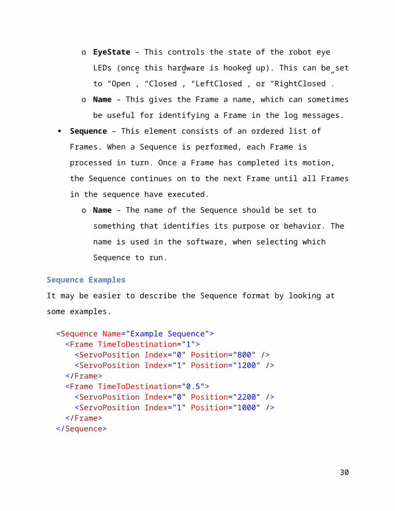
o EyeState – This controls the state of the robot eye LEDs (once this hardware is
hooked up). This can be set to “Open”, “Closed”, “LeftClosed”, or
“RightClosed”.
o Name – This gives the Frame a name, which can sometimes be useful for
identifying a Frame in the log messages.
Sequence – This element consists of an ordered list of Frames. When a Sequence is
performed, each Frame is processed in turn. Once a Frame has completed its motion, the
Sequence continues on to the next Frame until all Frames in the sequence have executed.
o Name – The name of the Sequence should be set to something that identifies its
purpose or behavior. The name is used in the software, when selecting which
Sequence to run.
22

Sequence Examples
It may be easier to describe the Sequence format by looking at some examples.
<Sequence Name="Example Sequence"> <Frame TimeToDestination="1"> <ServoPosition Index="0" Position="800" /> <ServoPosition Index="1" Position="1200" /> </Frame> <Frame TimeToDestination="0.5"> <ServoPosition Index="0" Position="2200" /> <ServoPosition Index="1" Position="1000" /> </Frame> </Sequence>
All Sequences have a ‘Name’ attribute, which is set to “Example Sequence”, in this instance.
When running a Sequence, the Sequence ‘Name’ is used to specify which Sequence in the
SequenceList.xml file should be performed. In this example, the Sequence contains two Frames,
which in turn each contain two ServoPositions. When this Sequence is executed, the first Frame
will be processed and will move Servo 0 to position 800 and Servo 1 to position 1200. The servo
speeds will be set automatically so that both servos arrive at their respective positions after 1
second, as specified by the Frame’s ‘TimeToDestination’ parameter. Once these servos arrive at
their destinations, the second Frame will be processed and will move Servo 0 to position 2200
and Servo 1 to position 1000. The servo speeds will be set to reach these positions in 0.5
seconds, as specified by the second Frame’s ‘TimeToDestination’ parameter. Once the servos
reach these positions, the Sequence will be complete.
The Frame object also has several additional attributes that can be used to provide some extra
functionality. One is the ‘Delay’ attribute, which causes the Sequence to wait for some amount
of time before proceeding to the next Frame. Another is the ‘Speech’ attribute, which causes the
speech synthesizer to begin speaking the specified text. The speech synthesizer runs
asynchronously, so the Sequence can continue on to processing the next Frame while the
synthesizer is speaking. This allows for servo/wheel motions, while the robot is speaking. Both
the ‘Delay’ and ‘Speech’ attributes can be used with Frames that contain no ServoPosition or
WheelMove elements, to allow for delay or speech behavior without motion. Here is a modified
version of the first example, with some extra ‘Delay’ and ‘Speech’ Frames:
23

<Sequence Name="Example Sequence 2"> <Frame TimeToDestination="1"> <ServoPosition Index="0" Position="800" /> <ServoPosition Index="1" Position="1200" /> </Frame> <Frame Delay="2"/> <Frame Speech="Testing one two three."/> <Frame TimeToDestination="0.5"> <ServoPosition Index="0" Position="2200" /> <ServoPosition Index="1" Position="1000" /> </Frame> </Sequence>
This example Sequence contains four frames, but the first and fourth frames are identical to be
previous example. When running this Sequence, the first Frame will be processed as before, with
Servos 0 and 1 moving to their respective positions. Once this movement completes, the second
Frame will be processed and the Delay=“2” attribute will cause the Sequence to pause for 2
seconds. After these 2 seconds, the third Frame will be processed, and the ‘Speech’ attribute will
cause the speech synthesizer to start speaking the selected phrase “Testing one two three.” The
speech synthesizer runs asynchronously, so as soon as the synthesizer starts speaking, the fourth
Frame will be processed. This Frame performs the second servo move, with Servos 0 and 1
moving to their final position. The speech synthesizer will keep talking during this motion and
after the Sequence has completed.
A Frame can also contain multiple attributes, as in the following example:
<Sequence Name="Example Sequence 3"> <Frame TimeToDestination="1" Delay="2" Speech="Hello!"> <ServoPosition Index="0" Position="800" /> <ServoPosition Index="1" Position="1200" /> </Frame> </Sequence>
In this example, the Frame has ServoPositions and both a ‘Delay’ and ‘Speech’ attribute. In this
case, the Speech will be processed first, causing the robot to begin saying “Hello!” Right after
this speech starts, the Delay will be processed and the Sequence will pause for 2 seconds (while
24

the speech continues). After this 2 second delay, the robot motion will be processed, and Servos
0 and 1 will move to their respective positions, which will take 1 second.
Here is an example that shows the different ways that the WheelMove element can be used:
<Sequence Name="Example Sequence 4"> <Frame TimeToDestination="1"> <WheelMove Translation="100" /> </Frame> <Frame TimeToDestination="1"> <WheelMove Rotation="45" /> </Frame> <Frame TimeToDestination="1"> <WheelMove Translation="-200" Rotation="-90" /> </Frame> <Frame TimeToDestination="1"> <WheelMove LeftWheel="100" /> </Frame> <Frame TimeToDestination="1"> <WheelMove RightWheel="100" /> </Frame> <Frame TimeToDestination="1"> <WheelMove LeftWheel="-50" RightWheel="-20" /> </Frame> </Sequence>
The robot will first move forward 100 mm over a period of 1 second. It will then spend the next
second rotating 45 degrees to the left (counterclockwise). During the third frame, it will combine
two moves by moving backwards 200 mm while simultaneously turning 90 degrees to the right
(clockwise). In the fourth frame, the robot will move only its left wheel 100 mm forward. In the
following frame, it will move the right wheel 100 mm forward. During the last frame, the robot
will move both wheels simultaneously, by moving the left wheel backwards 50 mm and the right
wheel backwards 20 mm.
Understanding and Modifying the CountessQuantaControl Software
This section describes the source code files and class structure of the CountessQuantaControl
project, how the main software features work, and how to add new speech and gesture
recognition vocabulary.
25

CountessQuantaControl C# Files and Classes
ControlWindow.xaml – This file contains the XAML code that defines the main
CountessQuantaControl GUI window.
ControlWindow.xaml.cs – Creates and initializes all of the main object used in the project, in
the ControlWindow() method. Also contains logic for the GUI.
SkeletonViewer.xaml – Contains the XAML code that defines the SkeletonViewer window.
This code is based on the ‘Skeleton Basics-WPF’ application from the Kinect Toolkit.
SkeletonViewer.xaml.cs – Contains the implementation for the SkeletonViewer window. This
code is based on the ‘Skeleton Basics-WPF’ application from the Kinect Toolkit.
ServoManager.cs – Contains the ServoManager class, which connects to the Pololu servo
controller through Usc.dll. Defines the Servo class to track the status of each servo, loads the
servo configuration from the ServoConfig.xml file, and handles the process of servo motion.
AriaManager.cs – Contains the AriaManager class, which connects to the modified ARIA dll
and handles the wheel motion of the Pioneer 2.
RobotSpeech.cs – Contains the RobotSpeech class, which handles speech synthesis commands
and moves the robot’s mouth (using ServoManager) while speech is being performed.
RobotEyes.cs – Contains the RobotEyes class, which handles control of the LED eyes (once this
hardware is connected). Provides methods for opening and closing one or both eyes (turning the
LEDs on and off), and provides automated blinking.
PersonTracking.cs – Contains the PersonTracking class, which takes skeleton position updates
from the Kinect and turns the robot to face the user. It can have the robot turn its head, eyes, or
whole body by sending commands to the servos/wheels through the ServoManager and
AriaManager.
SequenceProcessor.cs – Contains the SequenceProcessor class, which handles the process of
running robot motion sequences. It loads the SequenceList.xml file and executes the selected
sequence using the ServoManager, AriaManager, and RobotEyes classes.
26

SequenceClasses.cs – Contains classes used primarily by the SequenceProcessor. These are the
ServoPosition, WheelMove, Frame, Sequence, and SequenceList classes. These classes mainly
store data that is read from the SequenceList.xml file.
KinectManager.cs – Contains the KinectManager class, which handles connection to the Kinect
hardware. It implements the speech and gesture recognition functionality by detecting the
speech/gesture and running the corresponding response sequence using SequenceProcessor. It
also updates PersonTracking with skeleton position data. Most of this code is adapted from the
‘Skeleton Basics-WPF’ and ‘Speech Basics-WPF’ code from the Kinect Toolkit.
ErrorLogging.cs – Contains the ErrorLogging class, which is used to log various messages from
the software and display these as text on the main GUI. ErrorLogging is a public static class, so
every class in the project can add log messages without needing to explicitly include this class.
Other Files Used by CountessQuantaControl
SequenceFile.xml – This file contains all of the robot motion sequences.
ServoConfig.xml – Contains configuration data for each servo, such as position limits.
SpeechGrammar.xml – Contains speech recognition vocabulary data.
AriaDebugVC10.dll – This dll is used to send motion commands to the Pioneer 2 wheels.
Usc.dll – Used to send motion commands to the Pololu servo controller.
UsbWrapper.dll – Required for Usc.dll.
Adding New XML Elements and Attributes
As new kinds of hardware are added to Countess Quanta, it may be useful to integrate these into
the sequence-based control system. To do this, modify the SequenceClasses.cs file to add the
new control to the Frame class, using the existing items as examples. The existing
implementation uses .NET Attribute syntax to automatically handle how these parameters are
loaded from an XML file. Simple controls that require a single parameter, such as ‘Delay’ and
‘Speech’, can be added to the Frame as an XmlAttribute. Controls that require multiple
27

parameters, such as ‘WheelMove’, can be added as a new class containing each parameter as a
separate XmlAttribute. This class can then be added to Frame as an XmlElement. The new
parameters can then be used in a sequence in SequenceList.xml, and the software should
automatically populate the new Frame items when this sequence is loaded.
In SequenceProcessor.cs, the RunSequenceThread() method will need to be modified to use
these new parameters. This method contains a loop that steps through each frame in the sequence
and makes the appropriate calls to the hardware components. For new hardware, support would
need to be added either be added to an existing class, or added within a new type of class. The
communication methods could then be called within this RunSequenceThread method to use
them during sequence execution.
Servo Management
Commands to control the Pololu Mini Maestro servo controller hardware are handled by the
ServoManager class, which is implemented in the ServoManager.cs file. Initialization and
control of the hardware is performed using the Pololu C# library, which is part of the Pololu
USB SDK. This SDK is available in pololu-usb-sdk-120712.zip, which is in the included
Installs\Servos directory. The CountessQuantaControl\bin\Debug directory contains the
Usc.dll and UsbWrapper.dll files, which were built from the unmodified Usc C# project
included in this Pololu SDK (in pololu-usb-sdk\Maestro).
To better manage each of the 16 servos that are currently used in the robot, ServoManager stores
settings and polled hardware data for each of these servos by using the ‘Servo’ class. On
software startup, ServoManager reads in the settings for each servo from an xml file called
‘ServoConfig.xml’, which is stored in the CountessQuantaControl\bin\Debug directory. Here
is an example entry for one of the servos:
<Servo> <index>0</index> <name>Wrist left/right</name> <positionLimitMin>700</positionLimitMin> <positionLimitMax>2300</positionLimitMax> <speedLimitMin>10</speedLimitMin> <speedLimitMax>1000</speedLimitMax> <defaultPosition>1400</defaultPosition>
28

<defaultSpeed>20</defaultSpeed> <defaultAcceleration>0</defaultAcceleration> </Servo>
Here is an overview of what each of these parameters represents:
index – The index number that identifies this particular servo in the Maestro servo controller.
name – A human readable name that describes which servo this is in the robot.
positionLimitMin – The minimum move position allowed for this servo.
positionLimitMax – The maximum move position allowed for this servo.
speedLimitMin – The minimum speed allowed for this servo.
speedLimitMax – The maximum speed allowed for this servo.
defaultPosition – The default move position for this servo.
defaultSpeed – The default speed for this servo.
defaultAcceleration – The default acceleration for this servo.
Note that the units used for these parameters match those used by the Pololu’s Maestro Control
Center application. The position of a servo is set by sending it a pulse-width modulation (PWM)
signal, where the servo position is determined by the width of the pulse, in time units. The
Maestro Control Center and ‘ServoConfig.xml’ represent the servo position parameters in units
of ‘µs’. This value is later multiplied by four, to convert it to the 0.25 µs increments used by the
servo controller hardware. Servo speed is always represented in units of (0.25 µs) / (10 ms), and
acceleration is represented in units of (0.25 µs) / (10 ms) / (80 ms).
The ServoManager provides methods for setting the position, speed, and acceleration of each
servo. The position and speed limits for each servo that are defined in ‘ServoConfig.xml’ are
enforced in these methods. Commands to set a servo’s position or speed outside of its limit cause
the software to instead set the value to the minimum or maximum limit. A warning message is
then logged, indicating what value was specified, and what limit value was actually sent to the
29
hardware controller. This process allows the system to restrict unsafe commands and make these
issues visible to the user, without halting the system every time an issue arises.
The ServoManager also provides support for servo moves that are specified in terms of move
time, rather than servo speed. The reasoning behind this feature is that it may be easier for a user
to think in terms of the robot spending two seconds raising its arm, rather than specifying the
servo’s velocity in the (0.25 μs) / (10 ms) units used by the hardware controller. This becomes
more important when a motion involves multiple servos; especially when the servos need to be
synchronized to arrive at the target location at the same time. This feature works by using the
servo’s current and target position and calculating the required speed to reach the new position in
the specified amount of time.
In many cases, the desired functionality isn’t to simply start a servo moving, but to monitor the
move progress and wait for this move to complete before performing some subsequent action.
The ServoManager provides a method that achieves this by automatically polling the servo
hardware controller, and returning once the servo has reached its target position. If the target
position isn’t reached within the expected time, then a warning is logged to inform the user. The
ServoManager also provides a method for moving multiple servos, and then waiting until all
servos in this list have completed their moves.
Wheel Management
Commands to control the Pioneer 2 wheels are handled by the AriaManager class, which is
implemented in the AriaManager.cs file. Initialization and control of the hardware is performed
through a modified version of the “ActivMedia Robotics Interface for Applications” (ARIA)
software, provided by ActivMedia. The CountessQuantaControl\bin\Debug directory contains
this modified AriaDebugVC10.dll file. The source code for the original dll can be installed from
ARIA-2.7.6.exe, which is included in the Installs\Pioneer2 directory. The source code for the
modified version is in the ARIA_CSharpWrapper directory.
The ARIA software is written in C++ and provides wrappers for Python and Java, but not for C#.
To work around this, the code was modified to include two new files: CSharpWrapper.h and
CSharpWrapper.cpp. These files include some code adapted from ARIA’s
30

directMotionExample, in order to expose some basic initialization and wheel control that can be
used from a C# application. The CSharpWrapperTest project was created to test this
functionality before the modified dll was integrated into the CountessQuantaControl software.
Here are the dll methods that are currently exposed:
TestMethod_dll – Provides a simple test that communication with the dll is working (multiplies
the input number by two, and returns this value).
InitializeRobot_dll – Initializes the Pioneer 2 robot in the same way as directMotionExample.
DisconnectRobot_dll – Disconnects from the Pioneer 2 robot.
IsConnected_dll – Returns whether the Pioneer 2 is currently connected.
setVel_dll – Sets the translational velocity of the robot, in mm/s (i.e. sets how fast the robot is
moving forwards or backwards).
setVel2_dll – Sets separate velocities of the left and right wheels, in mm/s.
setRotVel_dll – Sets the rotational velocity of the robot, in degrees/s (i.e. sets how fast the robot
is turning).
To keep the control scheme consistent with servo motion, AriaManager provides methods that
take wheel moves in terms of a position change and a time-to-destination. AriaManager then
converts a position/time request into an ARIA velocity command, and sends a stop command
after the time-to-destination has elapsed. Also note that the Countess Quanta torso is mounted
backwards on the Pioneer 2, so the low level motion commands are reversed from what might be
expected. AriaManager handles this conversion, so forward/backwards and right/left wheels are
oriented in terms of the torso facing direction, when moving the wheels from a motion sequence.
Speech Recognition
The speech recognition feature allows the user to interact with the robot by speaking words and
phrases from a specified vocabulary. The system detects this speech and the robot responds by
performing an assigned motion sequence.
31

Speech recognition is handled within the KinectManager class. Much of this code was adapted
from the ‘Speech Basics-WPF’ example project in the Kinect Developer Toolkit, which uses
a .NET speech recognition library. In this example project, the speech vocabulary is stored in a
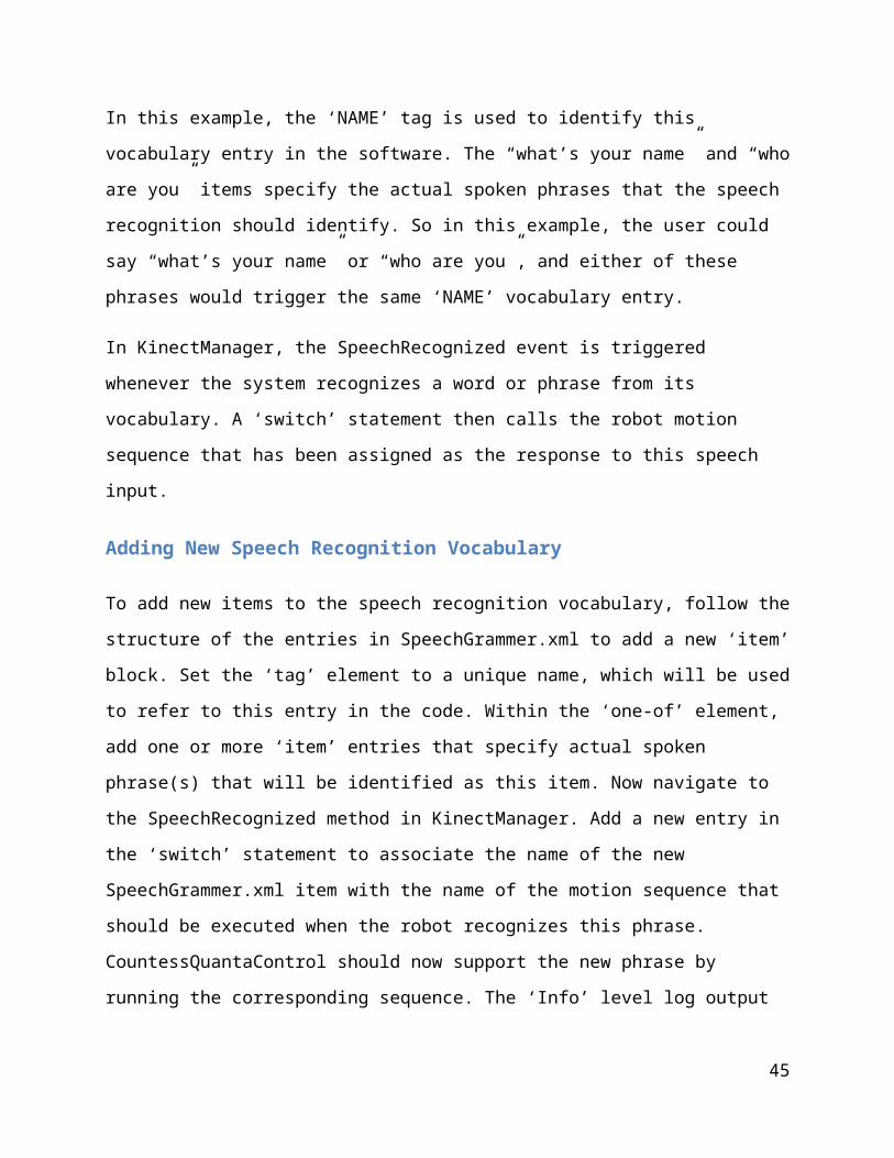
file called ‘SpeechGrammar.xml’. This file contains a list of items, each in the following form:
<item> <tag>NAME</tag> <one-of> <item> what's your name </item> <item> who are you </item> </one-of> </item>
In this example, the ‘NAME’ tag is used to identify this vocabulary entry in the software. The
“what’s your name” and “who are you” items specify the actual spoken phrases that the speech
recognition should identify. So in this example, the user could say “what’s your name” or “who
are you”, and either of these phrases would trigger the same ‘NAME’ vocabulary entry.
In KinectManager, the SpeechRecognized event is triggered whenever the system recognizes a
word or phrase from its vocabulary. A ‘switch’ statement then calls the robot motion sequence
that has been assigned as the response to this speech input.
Adding New Speech Recognition Vocabulary
To add new items to the speech recognition vocabulary, follow the structure of the entries in
SpeechGrammer.xml to add a new ‘item’ block. Set the ‘tag’ element to a unique name, which
will be used to refer to this entry in the code. Within the ‘one-of’ element, add one or more
‘item’ entries that specify actual spoken phrase(s) that will be identified as this item. Now
navigate to the SpeechRecognized method in KinectManager. Add a new entry in the ‘switch’
statement to associate the name of the new SpeechGrammer.xml item with the name of the
motion sequence that should be executed when the robot recognizes this phrase.
CountessQuantaControl should now support the new phrase by running the corresponding
sequence. The ‘Info’ level log output can be used to show the detected phrase, and help debug
any issues.
32

Gesture Recognition
The gesture recognition feature allows the user to interact with the robot by making physical
gestures. These gestures are very general and can include relationships between parts of the
person’s body (e.g. right hand raised above the head) or positions within space (e.g. person
approaches within 2 meters of the robot). When the system detects a gesture, the robot responds
by performing an assigned motion sequence.
Gesture recognition is handled within the KinectManager class. Much of this code was adapted
from the ‘Skeleton Basics-WPF’ example project in the Kinect Developer Toolkit. When new
skeleton data is available from the Kinect sensor, the SensorSkeletonFrameReady event is
triggered. Code in this event then looks at the tracked skeleton, and evaluates a set of gesture
trigger conditions. Here is an example of one of these conditions:
skel.Joints[JointType.HandRight].Position.Y > skel.Joints[JointType.Head].Position.Y
This condition checks the relationship between two joints in the target skeleton: the right hand
joint and the head joint. It looks at the Y axis of each joint, which represents the vertical axis in
the Kinect coordinate system. If the person’s right hand is above the person’s head, then this
condition triggers, and performs the robot’s response behavior by running the specified motion
sequence.
Additional logic in KinectManager only allows a particular condition to trigger the response
once before requiring that the condition be reverted. For instance, when the person first raises
their hand above their head, then the robot would detect this condition and would perform its
response once. If the person keeps their hand above their head, the robot would ignore this, but
could respond to other gestures, speech commands, etc. When the person lowers their hand, then
the condition would be reset. If the person raises their hand a second time, then the robot would
detect this condition and would perform its response a second time.
33

Adding New Gesture Recognition Vocabulary
To add new items to the gesture recognition vocabulary, open KinectManager.cs and add a new
GestureTrigger item just above the “[Add new GestureTriggers here]” comment. GestureTrigger
is a simple class that manages the gesture reset condition, which prevents a gesture from
triggering continuously when its conditions are met. Now add a new Evaluate call just above the
“[Add new Evaluate calls here]” comment, using the same form as the existing items. You will
need to specify the gesture trigger condition as a Boolean value describing the position of one or
more joints in the Kinect coordinate space. You will also need to include the name of the motion
sequence that should be executed when the robot recognizes the gesture. CountessQuantaControl
should now support the new gesture by running the corresponding sequence.
Person Tracking
The objective of the person tracking feature is to allow the robot to turn its head, eyes, and body
to face a person, and to follow the person as they move about. The code is in place to provide
tracking using the robot’s head, eyes, and wheeled base, and to allow the robot’s head to track
the target both horizontally and vertically. However, some work needs to be done to integrate all
of these motions together. Person tracking motion can be performed while the robot is executing
motion sequences, although the sequence will take priority if it happens to use the same
servos/wheels as the person tracking.
The actual person tracking feature is implemented in the PersonTracking class, through the
UpdatePosition method. This method is called from KinectManager whenever new skeleton data
arrives from the Kinect sensor. The Kinect skeleton data consists of a set of points at specific
‘joint’ locations on the target’s body. For person tracking, it makes the most sense for the robot
to look at the target’s face, so the coordinates of the ‘Head’ joint was initially used. However,
due to the position of the Kinect, the target’s head doesn’t always appear within the viewing
area. Instead, the ‘ShoulderCenter’ position is passed to the UpdatePosition method, since this
joint is more often in view, and approximates the position of the target’s head.
Determining the robot’s new head or eye position from this skeleton joint coordinate is mostly a
matter of trigonometry. The Kinect SDK provides three-dimensional Cartesian positioning data
34

(in meters) for each skeleton joint. Each SkeletonJoint object contains an X coordinate reflecting
the horizontal position of the joint, with the very center of the Kinect image being zero, the right
side of the image being positive values, and the left side being negative. Similarly, the Y
coordinate represents placement on the vertical axis. The Z coordinate represents the joint’s
distance in the direction away from the front of the sensor, with the Kinect sensor being the zero
point.
The UpdatePosition method contains all of the actual equations that are used to update the
head/eye servos and wheel positions, based on the Kinect data. Each device is handled
differently due to relations between these components. For instance, the motion of the wheels
changes the direction of the Kinect sensor, so it is handled differently from the servos. Also, the
eyes are mounted on the head, so the position of the eyes servo needs to take into account the
position of the head servo, in order to correctly face the target.
RobotEyes
The robot’s eyes contain LEDs that will make it easier to see where the robot is looking, as well
as providing extra effects for human interaction. At the time of writing, this hardware has not yet
been connected, but the RobotEyes class has been created to support this feature once the
hardware is hooked up. RobotEyes supports opening and closing each eyes separately (i.e.
turning the LEDs on or off), through the use of the SetEyeState method. This state can be set
from a motion sequence, by creating a Frame with the EyeState attribute. This can be used to
implement animations such as winking and sleeping. RobotEyes also includes automated
blinking behavior, which runs in the background and randomly blinks the eyes every few
seconds. This is currently set for 100 ms blinks every 2-7 seconds, but can be adjusted if needed.
Error Logging
A logging system is important during development, for providing detailed and ordered tracking
of servo commands and other system states. During normal robot operation, the logs can be
monitored to catch errors that occur, and to record system information at the time of the error to
help in debugging these issues. The ErrorLogging class was developed to provide a framework
35

for recording log messages from the other classes used in the project, and for displaying these
messages in the GUI.
Here are some features that the ErrorLogging class provides:
Logging from anywhere – Any class in the project can write messages into the log at
any time. The logging methods are thread-safe, so messages can be written from multiple
threads without issue.
Time-stamping – The date and time of every message is automatically stored and
displayed, to track the exact time that an error or event occurred.
Severity filtering – Each log message has a specified severity: Error, Warning, Info, or
Debug. The system logging level can be configured to only display messages of a certain
severity. For instance, the ‘Warning’ level might be used during normal robot operation,
to only display ‘Error’ and ‘Warning’ level messages. During development, the ‘Debug’
level might be selected, since this would display all types of log messages.
Log message limit – To prevent the log from running out of memory, a maximum
number of log messages is allowed. Exceeding this limit results in the oldest log
messages being removed. This limit is configurable in the source code.
Ideas for Further Development
This section describes ideas for new features that still need to be implemented. Time estimates
are included, and try to take into account the time needed for investigation and testing the
feature. These estimates are based on current information, and may need to be adjusted as the
tasks are researched. Teams can use this list as a reference, and work with Dr. Perkowski to plan
out specific tasks.
Hardware Development
Repair broken arm servo
Work Estimate: 4 hrs.
36

Servo 2 is damaged and needs to be replaced. This is the servo that handles the ‘wrist
up/down’ motion on the right arm, and is easily identified by the joint swinging freely
and not moving when controlled from Maestro Control Center (although the motor makes
noise and sounds like it should be moving). The servo type is Hitec HS-82MG, and
would cost around $20 if a spare is not available in the Robotics Lab.
Add safety bracket to left arm
Work Estimate: 8 hrs.
The robot’s left arm is controlled by Servo 15, and has a functional range between servo
positions 1250 and 1600. If the arm is moved past 1600, then the arm will soon cross its
balance point and fall over, uncontrolled. The CountessQuantaControl application limits
this motion during Sequences, but this limit can still be exceeded through the Maestro
Control Center. Since the left arm is heavy, this is potentially dangerous to the robot and
others. A bracket or other restraint needs to be added to this arm, to prevent it from
falling over. This bracket could be bolted on near the joint, so that the arm collides with
this before falling.
Integrate LED eye hardware
Work Estimate: 16 hrs.
The current robot eyes have built-in LEDs, which need to be connected to control
hardware. Each eye has two wires coming out of the back, which would appear to
connect to the DC voltage outputs of a control board. There doesn’t seem to be any
documentation on the power requirements of these LEDs, so this would need to be
researched. There may be compatible outputs on either the Pololu Mini Maestro board or
the Pioneer 2. Once the hardware is connected, this control can be added to the existing
RobotEyes class.
Install speakers and amplifier
Work Estimate: 24 hrs.
37

Built-in laptop speakers are too small to be able to clearly hear the robot’s synthesized
voice. An external amplifier and speakers will need to be mounted on the robot, and
connected to the laptop audio output. These will need to be powered either directly
through the laptop or from the Pioneer 2 batteries (like the Pololu board). The
speakers/amplifier may need to be purchased if compatible hardware is not available in
the Robotics Lab.
Replace photo frame with iPad
Work Estimate: 4+ hrs.
Currently, an HP digital photo frame is mounted on the front of the robot, but this device
is not easily controllable from the laptop. This should be replaced by an iPad, which Dr.
Perkowski can provide. If the iPad is similar in size to the photo frame, then the existing
mounting bracket can probably be used. Otherwise, a new mounting bracket will need to
be developed. If the existing bracket is used, the screws that attach it to the robot body
need to be replaced by bolts, and nuts should be added to ensure that the brackets/iPad
cannot be removed and stolen from the robot. The iPad USB connection and power
should be accessible, so that the device can be connected to the laptop and power charger
without removing the bracket.
Power Kinect with robot batteries
Work Estimate: 16 hrs.
The Kinect adapter cable is currently set up to plug into an external power outlet, which
limits the mobility of the robot. The adapter will need to be modified and connected to a
12V DC output on the Pioneer 2, to power the Kinect through the Pioneer 2 batteries.
Here is a website that describes this process:
http://robots.mobilerobots.com/wiki/
Kinect_on_a_Pioneer_Mobile_Robot_with_Onboard_SBC
Attach laptop firmly to the back frame of the robot
Work Estimate: 8 hrs.
38

Dr. Perkowski has a laptop available for controlling the robot, but this needs to be
attached securely to the metal frame on the back of the robot. The laptop should be
attached in such a way that it is very hard to remove and steal from the robot. Maybe
there is a way to actually lock this device to the robot frame.
Attach laser pointer to the right hand
Work Estimate: 16 hrs.
A laser pointer should be attached to the right hand of the robot, to allow the robot to
gesture at distant objects. It might be easiest to mount this device to the wrist bracket
under the cardboard hand. If possible, the laser pointer should be a type that can be
powered and controlled from an external device, so that this can be connected to a DC
output on the Pololu controller or Pioneer 2. This would allow for turning the laser
pointer on and off from the CountessQuantaControl software.
Add eyebrows to robot
Work Estimate: 40+ hrs.
Servo-controlled eyebrows should be added to the robot’s face, to allow for more facial
expressions. This will require some mechanical work in attaching new servos and
eyebrow hardware to the face. This will also take some software work, to add these
servos to the ServoConfig.xml file, with the correct range limits and other parameters.
Two servo outputs are still available on the Pololu controller, but a second servo
controller might be required if the eyebrows require more than this (e.g. each eyebrow
might use 2 servos: one to move the eyebrow up/down and another to change the angle of
the eyebrow).
Software Development
Motion Sequence Editing GUI
Work Estimate: 40 hrs.
39

A graphical user interface should be developed for creating and testing robot motion
sequences. With the current system, creating and editing sequences requires manually
changing entries in the SequenceList.xml file. To implement servo motion, the user poses
the robot using the Maestro Control Center application, and then types these servo
positions into the xml file. A GUI interface would make this process much faster and less
error-prone. Here are some items that the Sequence Editing GUI could include:
A list of all Sequences in SequenceList.xml, with buttons for adding new
sequences and removing existing sequences.
A list of all Frames in the selected sequence, with buttons for adding/removing a
frame and for reordering the frames.
A ‘Properties’ display for the selected Frame. This would include all of the items
that can be associated with a single Frame: servo positions (0-17), wheel move
distance, time-to-destination, time delay, speech synthesizer, etc.
A list of servo controls for servos 0-17 with Enable checkboxes, position slider,
target position, current position, and speed setting (as in the Maestro Control
Center application).
A button for saving the current servo positions to a Frame.
A button for executing the selected Sequence.
A button for executing the selected Frame within a Sequence.
Buttons for stepping forwards and backwards through the Frame list, executing
each Frame individually (to test how parts of an animation will look).
Incorporate the Sequence Editing GUI into the main CountessQuantaControl
program, by adding this as a new form and adding a button to display this form.
Add software support for iPad display
Work Estimate: 40+ hrs.
The iPad mounted on the robot’s chest is meant to support several features:
Display slides and videos of the lab, PSU building, etc.
Display lists of robot functions, speech commands, etc.
Display images or animation of gesture recognition poses.
40

Provide touch screen controls for robot features.
To support these items, software will need to be developed on both the iPad and in
CountessQuantaControl to support USB communication between the iPad and the laptop
PC. Sequence functionality will need to be added to allow a Frame to display a specific
slide/image/video on the iPad, while the robot is interacting. The iPad software will need
to be able to display touch screen button options and send the user’s selection to
CountessQuantaControl to trigger a Sequence or other behavior.
Improve integration of eye/head/body tracking motion
Work Estimate: 16 hrs.
Currently, the robot is able to track people using the Kinect by moving its eyes, head, or
body individually. Support should be added to somehow integrate all of these motions, so
that the robot actively tracks with all of these parts in some realistic way. For instance,
maybe the robot initially follows the target by turning its head, but begins to turn its body
after some delay, or if the target is at risk of moving out of the Kinect field-of-view.
Person tracking for multiple targets
Work Estimate: 8+ hrs.
Currently, the robot always tracks the first person it sees, and attempts to ignore other
people unless the current target leaves the Kinect field-of-view. The Kinect supports
tracking of multiple targets, which could be used in interesting ways:
Randomly look at different people in view.
Watch for gestures from multiple people and look at the last person who
performed a gesture.
Use a specific gesture to get the robot’s attention (i.e. the robot only pays
attention to one person, unless another person uses a specific gesture to take
control).
If the robot is bored, maybe it looks around the room instead of staring at the
target person.
41

Use the Kinect positional audio feature to detect which person said a command
word, and focus on them (see ‘Audio Basics-WPF’ in the Kinect Toolbox).
Add motions to follow and avoid human
Work Estimate: 16 hrs.
This involves adding a mode where the robot would use the Kinect to follow a person and
stay within some distance. Similarly, a mode could be added where the robot moves away
from a person, and tries to maintain some distance. These features would probably be
added as an extension to the current person tracking functionality.
State machine for conversation logic
Work Estimate: 24 hrs.
To support realistic conversations and other more complex interactions, some kind of
state machine structure needs to be added to the software to allow the robot to behave
differently depending on past interactions. For instance, this would allow the robot to
answer multi-stage questions:
User: “Tell me about a room”
Countess: “What room would you like to know about?” [enter RoomAsking state]
User: “The robotics lab”
Countess: “The robotics lab is…” [enter TalkingAboutRoboticsLab state]
User: “Could you take me there?”
Countess: “Ok, heading to the robotics lab…”
Probability-based gesture and speech responses
Work Estimate: 4 hrs.
To make the robot behavior more interesting and less predictable, support should be
added to the speech and gesture recognition to allow the robot to reply somewhat
42

randomly to a particular input. For instance, a given phrase might cause to robot to reply
with Sequence A 70% of the time, but run Sequence B 30% of the time.
Recognition of combined speech and gesture
Work Estimate: 16 hrs.
Currently, the robot recognizes a set of speech elements and a set of gesture elements, but
does not have any logic to combine the two inputs. With this feature, the robot would be
able to recognize inputs that have a gesture component combined with a spoken
component. For instance, the robot could be configured to ignore a user if they say “Hi”,
and ignore a user if they wave their hand, but recognize if the user both says “Hi” and
waves their hand at the same time. This would require some rework of the speech/gesture
recognition code to have the robot remember recently viewed gesture/speech input, and
trigger an event if a second component is detected after the first. This should work
regardless of the input order (e.g. either “Hi” followed by wave, or wave followed by
“Hi”), and should have some short timeout for each input (e.g. so that “Hi” followed by a
5 minute delay, followed by a wave does not trigger the response).
Recognition of gestures with motion
Work Estimate: 40 hrs.
Currently, the gesture recognition code only recognizes single poses, and does not have
any support for detecting motion in a gesture. For instance, the robot can detect “right
hand above right elbow”, but the robot can’t tell the difference between a hand that is
holding still in one position and a hand that is waving back and forth. To support this
feature, some kind of state machine or other memory needs to be added, to detect
different parts of the motion. For instance, the robot might be able to detect a waving
hand as “hand above and to the right of elbow” followed by “hand above and to the left
of elbow”.
Expose remaining ARIA methods
Work Estimate: 24+ hrs.
43

The current implementation of the modified ARIA dll (Aria_CSharpWrapper) is very
limited and only exposes a handful of low-level Pioneer 2 wheel controls. It also doesn’t
work very well if the hardware is not present, causing it to freeze the
CountessQuantaControl application (hence the need for a ‘Connect Wheel Hardware’
button instead of auto-connecting on startup). To resolve these issues and expose all of
the functionality of the ARIA C++ dll, a new implementation is needed. Here are some
ideas for this:
The ARIA install includes wrappers for Java and Python that were created using
an application called SWIG, which can be downloaded at:
http://www.swig.org/
SWIG can be used to automatically create C# wrappers for C++ dlls, so the
existing ARIA Python or Java SWIG configuration might be modified to create a
C# dll instead. A partial tutorial on how this might be done is available here:
http://robolabwiki.sdu.dk/mediawiki/index.php/Anders_B%C3%B8gild
This C# wrapper could then be used by CountessQuantaControl to access all of
the ARIA dll’s functionality.
It might be easier to use Python or Java to create a C# wrapper on top of the
existing Python/Java wrapper that ARIA provides. So CountessQuantaControl
would talk to C# code which wraps Python code which wraps the ARIA C++ dll.
Rather than using the dll directly, it might be easier to expose the ARIA
functionality by creating a local C++ server (or using Python/Java) which would
allow clients to connect and use the ARIA system through some general
communication framework. CountessQuantaControl could then send text
commands to the server, which would translate these to the actuall dll calls.
Integrate Pioneer 2 navigation
Work Estimate: 40+ hrs.
44
The Pioneer 2 provides sophisticated navigation functionality that is net yet being used
by Countess Quanta. This will eventually be needed to allow the robot to navigate and
guide people around the PSU building. The pdf files and Wisam Project 579.docx
document included Documentation\Pioneer2 directory contains a lot of information on
this functionality and the available software.
Add support for robot standby/resume
Work Estimate: 4 hrs.
The software should support putting the hardware into a low-power standby mode where
the servos/wheels are relaxed, displays are turned off, and the robot does not respond to
inputs. A timer should then be added to allow the robot to automatically activate for some
period of time, and then go into standby mode again. This would allow for the robot to
turn on for some limited amount of time (e.g. from noon-1pm each day) and interact with
people, but would also reduce wear on the hardware components, which would occur if
the robot was operational 24 hours a day.
Add support for logging to a file
Work Estimate: 2 hrs.
For long-term operation, it will be useful to log messages to a log file, rather than just
displaying the messages in the terminal window. This log file can then be reviewed
periodically to see if any Errors/Warning messages have occurred.
Motion Sequence Development
Add robot hardware test Sequence
Work Estimate: 4 hrs.
It would be useful to develop a Sequence that steps through each piece of hardware, and
tests it to see if it is functional. For instance, the robot could move each servo
individually while saying e.g. “Now testing wrist rotation servo”, and a human could
watch for any problems.
45

Robot gestures should be more relevant to the situation
Work Estimate: 8 hrs.
For some of the existing motion sequences, the robot’s gestures are not very relevant to
the situation. Dr. Perkowski has a video that shows some of these issues. Here are some
items that came up while reviewing this:
The robot should point to display screen when displaying slides.
Should point to the other hand when holding up fingers.
Could demonstrate what gestures the user should perform.
Gestures should be more exaggerated and theatrical.
Music playing improvements
Work Estimate: 8 hrs.
While watching this video, some similar suggestions came up regarding the use of the
harp instrument:
Music playing motions should be more interesting.
Could have more exaggerated playing motion.
Could play music as part of a transition.
Add new recognizable speech/gesture vocabulary
Work Estimate: variable
The robot’s gesture recognition and speech recognition vocabulary could be improved by
adding more elements. Similarly, more Sequences could be added to allow for more
kinds of responses.
46

Appendix
Servo Range Data
This section list the effective movement range of each servo on the Countess Quanta robot, along
with descriptions of what each movement represents. The Min and Max values indicate the point
just prior to the mechanism reaching the physical limit. Commanding the servo to a position past
this point results in high stress on the servo without additional motion. The Mid values represent
some meaningful neutral position, for particular servos. Note that all directions are stated with
respect to the robot itself (i.e. from the robot's perspective, or someone standing behind the
robot). Also note that references to a 'human thumb' or 'human pinky' specify the direction of the
right hand, if this hand was oriented as a human hand. The current right hand is actually
implemented with cardboard 'left hand', which can make things confusing.
Servo 0:Part: Right Arm Wrist left/rightMin: 700 (toward human thumb)Mid: 1400 (hand straight)Max: 2300 (toward human pinky)
Servo 1:Part: Right Arm Wrist rotationMin: 800 (toward human pinky)Mid: 1350 (wrist aligned with shoulder)Max: 2400 (toward human thumb)
Servo 2:Part: Right Arm Wrist up/downMin: 700 (wrist straight along arm)Mid: 750 (wrist straight along arm)Max: 2400 (wrist folds towards body)
Servo 3:Part: Right Arm up/downMin: 700 (arm swings in front)Mid: 1400 (arm hangs straight down)Max: 2650 (arm swings behind)
Servo 4: not used
47

Servo 5:Part: Right Arm rotationMin: 550 (toward human pinky)Mid: 1500 (wrist aligned with shoulder)Max: 2400 (toward human thumb)
Servo 6:Part: Right Arm Shoulder left/rightMin: 1600 (into body, forward)Max: 2350 (away from body, towards the right)
Servo 7: not used
Servo 8:Part: Eyes left/rightMin: 1000 (eyes look right)Mid: 1600 (eyes look center)Max: 2000 (eyes look left)
Servo 9:Part: Head up/down Min: 1600 (head up)Mid: 2000 (head center)Max: 2350 (head down)
Servo 10:Part: Head left/rightMin: 1350 (head turns left)Mid: 1550 (head in center)Max: 1750 (head turns right)
Servo 11:Part: Mouth open/closeMin: 600 (mouth close)Max: (mouth open) position is variable, due to collision with neck: 1050 with Servo 9 at 2350 (head down), 1450 with Servo 9 at 1600 (head up)
Servo 12:Part: Left Arm Ring FingerMin: 1350 (extended)Max: 2000 (retracted)
Servo 13:Part: Left Arm Middle FingerMin: 1250 (extended)
48

Max: 1900 (retracted)
Servo 14:Part: Left Arm Pinky FingerMin: 1200 (extended)Max: 1750 (retracted)
Servo 15:Part: Left ArmMin: 1250 (towards body)Max: 1600 (away from body; falls at ~1700)
Servo 16:Part: Left Arm ThumbMin: 1500 (extended)Max: 1700 (retracted)
Servo 17:Part: Left Arm Index FingerMin: 1000 (retracted, opposite of other fingers)Max: 1500 (extended, opposite of other fingers)
Right Arm Length Measurements
Wrist (servo 0) to tip of middle finger: 6.5 inchesWrist rotating axis (servo 1) to wrist (servo 0): 3.75Wrist bending axis (servo 2) to wrist rotating axis (servo 1): 2.25Arm rotating axis (servo 5) to wrist bending axis (servo 2): 3.75Arm raising axis (servo 3) to arm rotating axis (servo 5): 4.25Shoulder (servo 6) to arm axis: 11
The figures below display the right arm and are annotated showing the motion of each of the six
servos and min/max directions used by the servo controller.
49

The figure below shows the length measurements of the arm segments between each servo joint.
Servo Replacement and Hardware Documentation
Sixteen servos are used to control the upper body of the Countess Quanta robot. The types of
some of these servos are known, while others are not documented and would require disassembly
50

of some portion of the robot to determine their type. Here are the known servos and their type, in
case these servos need to be replaced:
Servo 0 (Wrist left/right) – Hitec HS-82MG
Servo 1 (Wrist rotation) – Hitec HS-82MG
Servo 2 (Wrist Up/down) – Hitec HS-82MG
Servo 3 (Arm Up/down) – Hitec HS-705MG
Servo 5 (Arm rotation) – Hitec HS-645MG
Servo 6 (Shoulder left/right) – Futaba S3003
Servo 9 (Head up/down) – Hitec HS-700BB
Servo 10 (Head left/right) – Hitec HS-700BB
Here are some hardware items that remain to be documented:
Servo types for the remaining eight servos.
How is power supplied through the robot base into the Maestro servo controller?
Is the power supply sufficient to move all sixteen servos simultaneously?
51