introduction - mitsubishi electric global website
TRANSCRIPT

Introduction
This manual describes how to carry out MITSUBISHI CNC programming.Supported models are as follows:
This manual describes programming, therefore, read this manual thoroughly before using this NC system. To ensure safe use of this NC system, thoroughly study the "Precautions for Safety" on the following page before using this NCsystem. Be sure to always keep this manual on hand so that users can refer to it at any time.
Details described in this manualThe description concerning "Signals" in the main text refers to information transmission between a machine and PLC or betweenNC and PLC. The method for controlling the signals (ON/OFF) differs depending on the machine. Refer to the manual issued by the machinetool builder (MTB). Some parameters can be used by end-users and some parameters are set by the MTB according to the specifications. End-users may not be able to set or change some of the parameters described as "... can be set with the parameter #XXXX" inthe main text. Confirm the specifications for your machine with the manual issued by the MTB.
CAUTION
For items described as "Restrictions" or "Usable State" in this manual, the instruction manual issued by themachine tool builder (MTB) takes precedence over this manual.
Items not described in this manual must be interpreted as "not possible".
This manual is written on the assumption that all the applicable functions are included. Some of them, however,may not be available for your NC system. Refer to the specifications issued by the machine tool builder beforeuse.
Refer to the Instruction Manual issued by the MTB for details regarding each machine tool.
Some screens and functions may differ depending on the NC system (or its version), and some functions maynot be available. Please confirm the specifications before use.
In this manual, the following abbreviations might be used.L system: Lathe systemM system: Machining center system MTB: Machine tool builder
Also refer to the manuals on "Manual List" as necessary.
Supported models Abbreviations in this manual
M800W seriesM800 series, M800, M8
M800S series
M80W seriesM80 series, M80, M8
M80 series

Manual List
Manuals related to M800/M80/C80 Series are listed as follows.
These manuals are written on the assumption that all optional functions are added to the targeted model.
Some functions or screens may not be available depending on the machine or specifications set by MTB. (Confirm the
specifications before use.)
The manuals issued by MTB take precedence over these manuals.
Manual IB No. Purpose and Contents
M800/M80 SeriesInstruction Manual
IB-1501274- Operation guide for NC- Explanation for screen operation, etc.
C80 SeriesInstruction Manual
IB-1501453- Operation guide for NC- Explanation for screen operation, etc.
M800/M80/C80 SeriesProgramming Manual(Lathe System) (1/2)
IB-1501275- G code programming for lathe system- Basic functions, etc.
M800/M80/C80 SeriesProgramming Manual(Lathe System) (2/2)
IB-1501276- G code programming for lathe system- Functions for multi-part system, high-accuracy function, etc.
M800/M80/C80 SeriesProgramming Manual(Machining Center System) (1/2)
IB-1501277- G code programming for machining center system- Basic functions, etc.
M800/M80/C80 SeriesProgramming Manual(Machining Center System) (2/2)
IB-1501278- G code programming for machining center system- Functions for multi-part system, high-accuracy function, etc.
M800/M80/C80 SeriesAlarm/Parameter Manual
IB-1501279- Alarms- Parameters

Manuals for MTBs (NC)
Manuals for MTBs (drive section)
Manual IB No. Purpose and Contents
M800/M80/C80 SeriesSpecifications Manual
IB-1501267- Model selection- Specifications of hardware unit- Outline of various functions
M800W/M80W SeriesConnection and Setup Manual
IB-1501268- Detailed specifications of hardware unit- Installation, connection, wiring, setup (startup/adjustment)
M800S/M80 SeriesConnection and Setup Manual
IB-1501269- Detailed specifications of hardware unit- Installation, connection, wiring, setup (startup/adjustment)
C80 SeriesConnection and Setup Manual
IB-1501452- Detailed specifications of hardware unit- Installation, connection, wiring, setup (startup/adjustment)
M800/M80 SeriesPLC Development Manual
IB-1501270
- Electrical design- I/O relation (assignment, setting, connection), field network- Development environment (PLC on-board, peripheral development environment), etc.
M800/M80 SeriesPLC Programming Manual
IB-1501271- Electrical design- Sequence programming- PLC support functions, etc.
M800/M80/C80 SeriesPLC Interface Manual
IB-1501272- Electrical design- Interface signals between NC and PLC
M800/M80 SeriesMaintenance Manual
IB-1501273- Cleaning and replacement for each unit- Other items related to maintenance
C80 SeriesMaintenance Manual
IB-1501454- Cleaning and replacement for each unit- Other items related to maintenance
Manual IB No. Contents
MDS-E/EH SeriesSpecifications Manual
IB-1501226 - Specifications for power supply regeneration type
MDS-E/EH SeriesInstruction Manual
IB-1501229 - Instruction for power supply regeneration type
MDS-EJ/EJH SeriesSpecifications Manual
IB-1501232 - Specifications for regenerative resistor type
MDS-EJ/EJH SeriesInstruction Manual
IB-1501235 - Instruction for regenerative resistor type
MDS-EM/EMH SeriesSpecifications Manual
IB-1501238 - Specifications for multi-hybrid, power supply regeneration type
MDS-EM/EMH SeriesInstruction Manual
IB-1501241 - Instruction for multi-hybrid, power supply regeneration type
DATA BOOK IB-1501252 - Specifications of servo drive unit, spindle drive unit, motor, etc.

Manuals for MTBs (Others)
■ For M800/M80 Series
■ For C80 Series
Reference Manual for MTBs
Manual No. Purpose and Contents
GX Developer Version 8 Operating Manual (Startup)
SH-080372E- Explanation for system configuration, installation, etc. of PLC development tool GX Developer
GX Developer Version 8 Operating Manual
SH-080373E- Explanation for operations using PLC development tool GX Developer
GX Converter Version 1 Operating Manual
IB-0800004E- Explanation for operations using data conversion tool GX Converter
MELSEC-Q CC-Link System Master/Local Module User’s Manual
SH-080394E- Explanation for system configuration, installation, wiring, etc. of master/local modules for CC-Link system
Manual No. Purpose and Contents
MELSEC iQ-R Module Configuration Manual
SH-081262- Outline of system configuration, specifications, installation, wiring, maintenance, etc.
MELSEC iQ-R CPU Module User’s Manual (Startup)
SH-081263- Outline of specifications, procedures before operation, troubleshooting, etc. for CPU module
MELSEC iQ-R CPU Module User’s Manual (Application)
SH-081264- Outline of memory, functions, devices, parameters, etc. for CPU module
QCPU User’s Manual (Hardware Design, Maintenance and Inspection)
SH-080483- Outline of specifications, necessary knowledge to configure the system and maintenance-related descriptions for Q series CPU module, etc.
GX Works3 Operating Manual SH-081215 - Outline of functions, programming, etc.
GOT2000 Series User’s Manual (Hardware)
SH-081194- Outline of hardware such as part names, external dimensions, installation, wiring, maintenance, etc. of GOTs
GOT2000 Series User’s Manual (Utility)
SH-081195- Outline of utilities such as screen display setting, operation method, etc. of GOTs
GOT2000 Series User’s Manual (Monitor)
SH-081196 - Outline of each monitor function of GOTs
GOT2000 Series Connection Manual (Mitsubishi Electric Products)
SH-081197- Outline of connection types and connection method between GOT and Mitsubishi Electric connection devices
GT Designer3 (GOT2000) Screen Design Manual
SH-081220- Outline of screen design method using screen creation software GT Designer3
Manual No. Purpose and Contents
M800/M80 Series Smart safety observation Specification manual
BNP-C3072-022 - Explanation for smart safety observation function

Precautions for Safety
Always read the specifications issued by the machine tool builder, this manual, related manuals and attached documents be-fore installation, operation, programming, maintenance or inspection to ensure correct use. Understand this numerical controller, safety items and cautions before using the unit. This manual ranks the safety precautions into "DANGER", "WARNING" and "CAUTION".
Note that even items ranked as " CAUTION", may lead to major results depending on the situation. In any case, important in-formation that must always be observed is described.The following sings indicate prohibition and compulsory.
The meaning of each pictorial sing is as follows.
Mitsubishi CNC is designed and manufactured solely for applications to machine tools to be used for industrial purposes.Do not use this product in any applications other than those specified above, especially those which are substantially influentialon the public interest or which are expected to have significant influence on human lives or properties.
Not applicable in this manual.
DANGERWhen the user may be subject to imminent fatalities or major injuries if handling is mistaken.
WARNINGWhen the user may be subject to fatalities or major injuries if handling is mistaken.
CAUTIONWhen the user may be subject to injuries or when physical damage may occur if handling is mistaken.
This sign indicates prohibited behavior (must not do).
For example, indicates "Keep fire away".
This sign indicated a thing that is pompously (must do).
For example, indicates "it must be grounded".
CAUTION
CAUTION
rotated objectCAUTION HOT
Danger
Electric shock risk
Danger
explosive
Prohibited
Disassembly is
prohibited
KEEP FIRE AWAY
General instruction
Earth ground
For Safe Use
DANGER

1. Items related to operation
If the operation start position is set in a block which is in the middle of the program and the program is started, the programbefore the set block is not executed. Please confirm that G and F modal and coordinate values are appropriate. If there arecoordinate system shift commands or M, S, T and B commands before the block set as the start position, carry out therequired commands using the MDI, etc. If the program is run from the set block without carrying out these operations, thereis a danger of interference with the machine or of machine operation at an unexpected speed, which may result in breakageof tools or machine tool or may cause damage to the operators.
Under the constant surface speed control (during G96 modal), if the axis targeted for the constant surface speed control(normally X axis for a lathe) moves toward the spindle center, the spindle rotation speed will increase and may exceed theallowable speed of the workpiece or chuck, etc. In this case, the workpiece, etc. may jump out during machining, whichmay result in breakage of tools or machine tool or may cause damage to the operators.
1. Items related to product and manual
For items described as "Restrictions" or "Usable State" in this manual, the instruction manual issued by the machine toolbuilder takes precedence over this manual.
Items not described in this manual must be interpreted as "not possible".
This manual is written on the assumption that all the applicable functions are included. Some of them, however, may notbe available for your NC system.Refer to the specifications issued by the machine tool builder before use.
Refer to the Instruction Manual issued by each machine tool builder for details on each machine tool.
Some screens and functions may differ depending on the NC system (or its version), and some functions may not be pos-sible. Please confirm the specifications before use.
2. Items related to operation
Before starting actual machining, always carry out graphic check, dry run operation and single block operation to check themachining program, tool offset amount, workpiece compensation amount and etc.
If the workpiece coordinate system offset amount is changed during single block stop, the new setting will be valid from thenext block.
Turn the mirror image ON and OFF at the mirror image center.
If the tool offset amount is changed during automatic operation (including during single block stop), it will be validated fromthe next block or blocks onwards.
Do not make the synchronized spindle rotation command OFF with one workpiece chucked by the reference spindle andsynchronized spindle during the spindle synchronization.Failure to observe this may cause the synchronized spindle stop, and hazardous situation.
3. Items related to programming
The commands with "no value after G" will be handled as "G00".
";" "EOB" and "%" "EOR" are expressions used for explanation. The actual codes are: For ISO: "CR, LF", or "LF" and "%".Programs created on the Edit screen are stored in the NC memory in a "CR, LF" format, but programs created with externaldevices such as the FLD or RS-232C may be stored in an "LF" format. The actual codes for EIA are: "EOB (End of Block)" and "EOR (End of Record)".
When creating the machining program, select the appropriate machining conditions, and make sure that the performance,capacity and limits of the machine and NC are not exceeded. The examples do not consider the machining conditions.
Do not change fixed cycle programs without the prior approval of the machine tool builder.
When programming the multi-part system, take special care to the movements of the programs for other part systems.
WARNING
CAUTION

Disposal
(Note) This symbol mark is for EU countries only.
This symbol mark is according to the directive 2006/66/EC Article 20 Information for end-
users and Annex II.
Your MITSUBISHI ELECTRIC product is designed and manufactured with high quality materials and
components which can be recycled and/or reused.
This symbol means that batteries and accumulators, at their end-of-life, should be disposed of
separately from your household waste.
If a chemical symbol is printed beneath the symbol shown above, this chemical symbol means that the
battery or accumulator contains a heavy metal at a certain concentration. This will be indicated as
follows:
Hg: mercury (0,0005%), Cd: cadmium (0,002%), Pb: lead (0,004%)
In the European Union there are separate collection systems for used batteries and accumulators.
Please, dispose of batteries and accumulators correctly at your local community waste collection/
recycling centre.
Please, help us to conserve the environment we live in!

Trademarks
MELDAS, MELSEC, EZSocket, EZMotion, iQ Platform, MELSEC iQ-R, MELSOFT, GOT, CC-Link, CC-Link/LT and
CC-Link IE are either trademarks or registered trademarks of Mitsubishi Electric Corporation in Japan and/or other
countries.
Ethernet is a registered trademark of Xerox Corporation in the United States and/or other countries.
Microsoft®, Windows®, SQL Server® and Access® are either trademarks or registered trademarks of Microsoft
Corporation in the United States and/or other countries.
SD logo and SDHC logo are either registered trademarks or trademarks of LLC.
UNIX is a registered trademark of The Open Group in the United States and/or other countries.
Intel® and Pentium® are either trademarks or registered trademarks of Intel Corporation in the United States and/or
other countries.
MODBUS® is either a trademark or a registered trademark of Schneider Electric USA, Inc. or the affiliated
companies in Japan and/or other countries.
EtherNet/IP is a trademark of Open DeviceNet Vendor Association,Inc.
PROFIBUS-DP is a trademark of Profibus International.
Oracle® is a registered trademark of Oracle Corporation, the subsidiaries, or the affiliated companies in the United
States and /or other countries.
Other company and product names that appear in this manual are trademarks or registered trademarks of the
respective companies.

本製品の取扱いについて
( 日本語 /Japanese)
本製品は工業用 ( クラス A) 電磁環境適合機器です。販売者あるいは使用者はこの点に注意し、住商業環境以外で
の使用をお願いいたします。
Handling of our product
(English)
This is a class A product. In a domestic environment this product may cause radio interference in which case the
user may be required to take adequate measures.
본 제품의 취급에 대해서
( 한국어 /Korean)
이 기기는 업무용 (A 급 ) 전자파적합기기로서 판매자 또는 사용자는 이 점을 주의하시기 바라며 가정외의 지역에
서 사용하는 것을 목적으로 합니다 .

Contents
Chapter 1 - 14 : Refer to M800/M80 Series Programming Manual (M2/M0 Format) (1/2)
Chapter 15 and later : M800/M80 Series Programming Manual (M2/M0 Format) (2/2)
1 Control Axes................................................................................................................................................. 11.1 Coordinate Words and Control Axes ........................................................................................................................ 21.2 Coordinate Systems and Coordinate Zero Point Symbols ....................................................................................... 3
2 Minimum command unit.............................................................................................................................. 52.1 Input Setting unit....................................................................................................................................................... 62.2 Input Command Increment Tenfold .......................................................................................................................... 72.3 Indexing Increment ................................................................................................................................................... 8
3 Program Formats ......................................................................................................................................... 93.1 Program Format...................................................................................................................................................... 103.2 File Format.............................................................................................................................................................. 143.3 Optional Block Skip................................................................................................................................................. 16
3.3.1 Optional Block Skip; / ..................................................................................................................................... 163.3.2 Optional Block Skip Addition ; /n .................................................................................................................... 18
3.4 G Codes.................................................................................................................................................................. 203.4.1 Modal, Unmodal ............................................................................................................................................. 203.4.2 G Code Lists .................................................................................................................................................. 20
3.5 Precautions Before Starting Machining .................................................................................................................. 25
4 Pre-read buffer ........................................................................................................................................... 274.1 Pre-read Buffer ....................................................................................................................................................... 28
5 Position Commands .................................................................................................................................. 295.1 Position Command Methods ; G90,G91 ................................................................................................................. 305.2 Inch/Metric Conversion; G20, G21 ......................................................................................................................... 325.3 Decimal Point Input................................................................................................................................................. 34
6 Interpolation Functions ............................................................................................................................. 416.1 Positioning (Rapid Traverse); G00 ......................................................................................................................... 426.2 Linear Interpolation; G01 ........................................................................................................................................ 456.3 Circular Interpolation; G02, G03 ............................................................................................................................. 476.4 R Specification Circular Interpolation; G02, G03 .................................................................................................... 536.5 Plane Selection; G17, G18, G19 ............................................................................................................................ 566.6 Thread Cutting ........................................................................................................................................................ 58
6.6.1 Constant Lead Thread Cutting; G33 .............................................................................................................. 586.6.2 Inch Thread Cutting; G33............................................................................................................................... 62
6.7 Helical Interpolation ; G17, G18, G19 and G02, G03 ............................................................................................. 646.8 Unidirectional Positioning ....................................................................................................................................... 70
6.8.1 Unidirectional Positioning; G60 ...................................................................................................................... 706.8.2 Axis-based Unidirectional Positioning ............................................................................................................ 72
6.9 Cylindrical Interpolation; G07.1............................................................................................................................... 736.10 Circular Cutting; G12,G13 .................................................................................................................................... 806.11 Polar Coordinate Interpolation; G12.1, G13.1/G112, G113.................................................................................. 826.12 Exponential Interpolation; G02.3, G03.3............................................................................................................... 896.13 Polar Coordinate Command; G16 ........................................................................................................................ 966.14 Spiral/Conical Interpolation; G02.1/G03.1 (Type 1), G02/G03 (Type 2)............................................................. 1036.15 3-dimensional Circular Interpolation; G02.4, G03.4............................................................................................ 1086.16 NURBS Interpolation; G06.2............................................................................................................................... 1136.17 Hypothetical Axis Interpolation; G07................................................................................................................... 119
7 Feed Functions......................................................................................................................................... 1217.1 Rapid traverse rate ............................................................................................................................................... 122
7.1.1 Rapid traverse rate....................................................................................................................................... 1227.1.2 G00 Feedrate Command (,F Command) ..................................................................................................... 123
7.2 Cutting feed rate ................................................................................................................................................... 1277.3 F1-digit Feed......................................................................................................................................................... 1287.4 Feed Per Minute/Feed Per Revolution (Asynchronous Feed/Synchronous Feed); G94,G95 .............................. 130
7.5 Inverse Time Feed; G93 ....................................................................................................................................... 1337.6 Feedrate Designation and Effects on Control Axes.............................................................................................. 1387.7 Rapid Traverse Constant Inclination Acceleration/Deceleration........................................................................... 1427.8 Rapid traverse constant inclination multi-step acceleration/deceleration ............................................................. 1477.9 Cutting Feed Constant Inclination Acceleration/Deceleration............................................................................... 1557.10 Exact Stop Check; G09 ...................................................................................................................................... 1617.11 Exact Stop Check Mode; G61 ............................................................................................................................ 1657.12 Deceleration Check ............................................................................................................................................ 166
7.12.1 Deceleration Check.................................................................................................................................... 1667.12.2 Deceleration Check when Movement in The Opposite Direction Is Reversed........................................... 174
7.13 Rapid Traverse Block Overlap; G0.5 P1............................................................................................................. 1767.13.1 Rapid Traverse Block Overlap for G00; G0.5 ............................................................................................ 1787.13.2 Rapid Traverse Block Overlap for G28 ...................................................................................................... 186
7.14 Automatic Corner Override ................................................................................................................................. 1887.14.1 Inner Arc Override...................................................................................................................................... 194
7.15 Tapping Mode; G63 ............................................................................................................................................ 1957.16 Cutting Mode; G64.............................................................................................................................................. 196
8 Dwell.......................................................................................................................................................... 1978.1 Dwell (Time Designation); G04............................................................................................................................. 198
9 Miscellaneous Functions ........................................................................................................................ 2019.1 Miscellaneous Functions (M8-digits) .................................................................................................................... 2029.2 Secondary Miscellaneous Functions (A8-digits, B8-digits or C8-digits) ............................................................... 2049.3 Index Table Indexing ............................................................................................................................................ 205
10 Spindle Functions .................................................................................................................................. 21110.1 Spindle Functions ............................................................................................................................................... 21210.2 Constant Surface Speed Control; G96, G97 ...................................................................................................... 21310.3 Spindle Clamp Speed Setting; G92 .................................................................................................................... 21910.4 Spindle Position Control (Spindle/C axis Control) .............................................................................................. 221
11 Tool Functions (T command)................................................................................................................ 22911.1 Tool Functions (T8-digit BCD) ............................................................................................................................ 230
12 Tool Compensation Functions ............................................................................................................. 23112.1 Tool compensation ............................................................................................................................................. 232
12.1.1 Tool compensation..................................................................................................................................... 23212.1.2 Number of Tool Offset Sets Allocation to Part Systems............................................................................. 236
12.2 Tool Length Compensation/Cancel; G43, G44................................................................................................... 23812.3 Tool Radius Compensation ; G38,G39/G40/G41,G42 ....................................................................................... 243
12.3.1 Tool Radius Compensation Operation ....................................................................................................... 24412.3.2 Other Commands and Operations during Tool Radius Compensation...................................................... 25312.3.3 G41/G42 Commands and I, J, K Designation ............................................................................................ 26312.3.4 Interrupts during Tool Radius Compensation............................................................................................. 26912.3.5 General Precautions for Tool Radius Compensation................................................................................. 27112.3.6 Changing of Compensation No. during Compensation Mode.................................................................... 27212.3.7 Start of Tool Radius Compensation and Z Axis Cut in Operation .............................................................. 27512.3.8 Interference Check..................................................................................................................................... 27712.3.9 Diameter Designation of Compensation Amount ....................................................................................... 28712.3.10 Workpiece Coordinate Changing during Radius Compensation.............................................................. 289
12.4 Tool Nose Radius Compensation (for Machining Center System) ..................................................................... 29112.5 3-dimensional Tool Radius Compensation; G40/G41, G42................................................................................ 29412.6 Tool Position Offset; G45 to G48........................................................................................................................ 306
13 Fixed Cycle ............................................................................................................................................. 31513.1 Fixed Cycles ....................................................................................................................................................... 316
13.1.1 Drilling, Spot Drilling; G81 .......................................................................................................................... 32013.1.2 Drilling, Counter Boring; G82 ..................................................................................................................... 32113.1.3 Deep Hole Drilling Cycle; G83 ................................................................................................................... 322
13.1.3.1 Deep Hole Drilling Cycle ................................................................................................................... 32213.1.3.2 Small Diameter Deep Hole Drilling Cycle.......................................................................................... 324
13.1.4 Tapping Cycle; G84 ................................................................................................................................... 32713.1.5 Boring; G85................................................................................................................................................ 33913.1.6 Boring; G86................................................................................................................................................ 340

13.1.7 Back Boring; G87....................................................................................................................................... 34113.1.8 Boring; G88................................................................................................................................................ 34413.1.9 Boring; G89................................................................................................................................................ 34513.1.10 Stepping Cycle; G73 ................................................................................................................................ 34613.1.11 Reverse Tapping Cycle; G74................................................................................................................... 34813.1.12 Circular Cutting; G75................................................................................................................................ 35013.1.13 Fine Boring; G76...................................................................................................................................... 35213.1.14 Precautions for Using a Fixed Cycle ........................................................................................................ 35513.1.15 Initial Point and R Point Level Return; G98, G99..................................................................................... 35813.1.16 Setting of Workpiece Coordinates in Fixed Cycle Mode.......................................................................... 35913.1.17 Drilling Cycle High-Speed Retract............................................................................................................ 36013.1.18 Acceleration/Deceleration Mode Change in Hole Drilling Cycle .............................................................. 364
13.2 Special Fixed Cycle ............................................................................................................................................ 36613.2.1 Bolt Hole Cycle; G34.................................................................................................................................. 36713.2.2 Line at Angle; G35 ..................................................................................................................................... 36813.2.3 Arc; G36..................................................................................................................................................... 36913.2.4 Grid; G37.................................................................................................................................................... 370
14 Macro Functions .................................................................................................................................... 37314.1 Subprogram Control; G22, G23.......................................................................................................................... 374
14.1.1 Subprogram Call; G22, G23....................................................................................................................... 37414.1.2 Figure Rotation; G22 I_J_K_...................................................................................................................... 380
14.2 Variable Commands ........................................................................................................................................... 38314.3 User Macro ......................................................................................................................................................... 38814.4 Macro Call Instructions ....................................................................................................................................... 389
14.4.1 Simple Macro Calls; G65 ........................................................................................................................... 38914.4.2 Modal Call A (Movement Command Call) ; G66 ....................................................................................... 39414.4.3 Modal Call B (for Each Block); G66.1 ........................................................................................................ 39614.4.4 G code macro call ...................................................................................................................................... 39814.4.5 Miscellaneous Command Macro Call (for M, S, T, B Code Macro Call) .................................................... 39914.4.6 Detailed Description for Macro Call Instruction .......................................................................................... 40114.4.7 ASCII Code Macro ..................................................................................................................................... 403
14.5 Variables Used in User Macros .......................................................................................................................... 40714.5.1 Common Variables..................................................................................................................................... 40914.5.2 Local Variables (#1 to #33) ........................................................................................................................ 41014.5.3 System Variables ....................................................................................................................................... 413
14.6 User Macro Commands...................................................................................................................................... 41414.6.1 Operation Commands ................................................................................................................................ 41414.6.2 Control Commands .................................................................................................................................... 41814.6.3 External Output Commands; POPEN, PCLOS, DPRNT............................................................................ 42114.6.4 Precautions ................................................................................................................................................ 42514.6.5 Actual Examples of Using User Macros..................................................................................................... 427
14.7 Macro Interruption; ION, IOF .............................................................................................................................. 431
15 Program Support Functions ................................................................................................................. 44115.1 Corner Chamfering I /Corner Rounding I ............................................................................................................ 442
15.1.1 Corner Chamfering I ; G01 X_ Y_ ,C ......................................................................................................... 44215.1.2 Corner Rounding I ; G01 X_ Y_ ,R_........................................................................................................... 44415.1.3 Corner Chamfering Expansion/Corner Rounding Expansion..................................................................... 44615.1.4 Interrupt during Corner Chamfering/Interrupt during Corner Rounding ..................................................... 448
15.2 Corner Chamfering II /Corner Rounding II .......................................................................................................... 44915.2.1 Corner Chamfering II ; G01/G02/G03 X_ Y_ ,C_....................................................................................... 44915.2.2 Corner Rounding II ; G01/G02/G03 X_ Y_ ,R_ .......................................................................................... 45115.2.3 Corner Chamfering Expansion/Corner Rounding Expansion..................................................................... 45215.2.4 Interrupt during Corner Chamfering/Interrupt during Corner Rounding ..................................................... 452
15.3 Linear Angle Command; G01 X_/Y_ A_/,A_....................................................................................................... 45315.4 Geometric; G01 A_ ............................................................................................................................................. 45415.5 Geometric IB....................................................................................................................................................... 456
15.5.1 Geometric IB (Automatic Calculation of Two-arc Contact) ; G02/G03 P_Q_ /R_ ..................................... 45715.5.2 Geometric IB (Automatic Calculation of Linear - Arc Intersection) ; G01 A_ , G02/G03 P_Q_H_ ............. 45915.5.3 Geometric IB (Automatic Calculation of Linear - Arc Intersection) ; G01 A_ , G02/G03 R_H_.................. 462
15.6 G Command Mirror Image; G50.1, G51.1, G62.................................................................................................. 46415.7 Normal Line Control; G40.1/G41.1/G42.1 (G150/G151/G152)........................................................................... 46915.8 Manual Arbitrary Reverse Run Prohibition; G127............................................................................................... 48915.9 Data input by program ........................................................................................................................................ 495
15.9.1 Parameter Input by Program; G10 L70/L100, G11.1 ................................................................................. 495
15.9.2 Compensation Data Input by Program; G10 L2/L10/L11/L12/L13/L20, G11.1 .......................................... 49815.9.3 Compensation Data Input by Program (Turning Tool); G10 L12/L13, G11.1............................................. 50415.9.4 Tool Shape Input by Program; G10 L100, G11.1....................................................................................... 50615.9.5 R-Navi Data Input by Program; G10 L110/L111, G11.1, G68.2, G69.1..................................................... 50915.9.6 Compensation Data Input to Variable by Program; G11............................................................................ 513
15.10 Inputting The Tool Life Management Data; G10, G11.1................................................................................... 51415.10.1 Inputting The Tool Life Management Data by G10 L3 Command; G10 L3, G11.1 .................................. 51415.10.2 Inputting The Tool Life Management Data by G10 L30 Command; G10 L30, G11.1 .............................. 51715.10.3 Precautions for Inputting The Tool Life Management Data...................................................................... 52015.10.4 Allocation of The Number of Tool Life Management Sets to Part Systems ............................................. 521
15.11 End Point Error Check Cancellation; G69 ........................................................................................................ 52315.12 Coordinate Read Function; G14 ....................................................................................................................... 525
16 Multi-part System Control ..................................................................................................................... 52916.1 Timing Synchronization Operation...................................................................................................................... 530
16.1.1 Timing Synchronization Operation (! code) !n (!m ...) L ............................................................................. 53016.1.2 Timing Synchronization Operation with Start Point Designated (Type 1); G115 ....................................... 53316.1.3 Timing Synchronization Operation with Start Point Designated (Type 2); G116 ....................................... 53616.1.4 Timing Synchronization Operation Function Using M codes ; M*** ........................................................... 53916.1.5 Time Synchronization when Timing Synchronization Ignore is Set ........................................................... 543
16.2 Mixed Control...................................................................................................................................................... 54616.2.1 Arbitrary Axis Exchange; G140, G141, G142 ............................................................................................ 546
16.3 Sub Part System Control .................................................................................................................................... 54916.3.1 Sub Part System Control I; G122.............................................................................................................. 549
17 High-speed High-accuracy Control ...................................................................................................... 56517.1 High-speed Machining Mode .............................................................................................................................. 566
17.1.1 High-speed Machining Mode I, II; G05 P1, G05 P2................................................................................... 56617.2 High-accuracy control ......................................................................................................................................... 575
17.2.1 High-accuracy Control; G61.1, G08 ........................................................................................................... 57517.2.2 SSS Control ............................................................................................................................................... 59217.2.3 Tolerance control ....................................................................................................................................... 59617.2.4 Variable-acceleration pre-interpolation acceleration/deceleration ............................................................. 60017.2.5 Initial High-accuracy Control ...................................................................................................................... 60317.2.6 Multi-part System Simultaneous High-accuracy ........................................................................................ 604
17.3 High-speed High-accuracy Control ..................................................................................................................... 60617.3.1 High-speed High-accuracy Control I, II, III; G05.1 Q1/Q0, G05 P10000/P0, G05 P20000/P0................... 60617.3.2 Fairing ........................................................................................................................................................ 62217.3.3 Smooth Fairing........................................................................................................................................... 62317.3.4 Acceleration Clamp Speed......................................................................................................................... 63217.3.5 Corner Deceleration in High-speed Mode.................................................................................................. 63317.3.6 Precautions on High-speed High-accuracy Control ................................................................................... 634
17.4 Spline Interpolation; G05.1 Q2/Q0...................................................................................................................... 63717.5 Spline Interpolation 2; G61.4 .............................................................................................................................. 64517.6 High-accuracy Spline Interpolation; G61.2 ......................................................................................................... 65217.7 Machining Condition Selection I; G120.1, G121................................................................................................. 654
18 Advanced Machining Control ............................................................................................................... 65918.1 Tool Length Compensation in the Tool Axis Direction; G43.1/G44 .................................................................... 66018.2 Tool Center Point Control; G43.4, G43.5/G44.................................................................................................... 66718.3 Inclined Surface Machining; G68.2, G68.3/G69.1 .............................................................................................. 695
18.3.1 How to Define Feature Coordinate System Using Euler Angles ................................................................ 69618.3.2 How to Define Feature Coordinate System Using Roll-Pitch-Yaw Angles................................................. 69818.3.3 How to Define Feature Coordinate System Using Three Points in a Plane ............................................... 70018.3.4 How to Define Feature Coordinate System Using Two Vectors ................................................................ 70218.3.5 How to Define Feature Coordinate System Using Projection Angles ........................................................ 70418.3.6 Define by selecting the registered machining surface................................................................................ 70618.3.7 How to Define Feature Coordinate System Using Tool Axis Direction ...................................................... 70718.3.8 Tool Axis Direction Control; G53.1/G53.6 .................................................................................................. 70918.3.9 Details of Inclined Surface Machining Operation ....................................................................................... 71718.3.10 Rotary Axis Basic Position Selection ....................................................................................................... 72118.3.11 Relationship between inclined surface machining and other functions.................................................... 72718.3.12 Precautions for Inclined Surface Machining............................................................................................. 731
18.4 3-dimensional Tool Radius Compensation (Tool's vertical-direction compensation); G40/G41.2, G42.2 .......... 735
19 Coordinate System Setting Functions ................................................................................................. 74719.1 Coordinate Words and Control Axes .................................................................................................................. 74819.2 Types of Coordinate Systems............................................................................................................................. 749
19.2.1 Basic Machine, Workpiece and Local Coordinate Systems....................................................................... 74919.2.2 Machine Zero Point and 2nd, 3rd, 4th Reference Position (Zero Point) .................................................... 75019.2.3 Automatic Coordinate System Setting ....................................................................................................... 75119.2.4 Coordinate System for Rotary Axis ............................................................................................................ 752
19.3 Basic Machine Coordinate System Selection; G53 ............................................................................................ 75519.4 Coordinate System Setting; G92 ........................................................................................................................ 75819.5 Local Coordinate System Setting; G52............................................................................................................... 76019.6 Workpiece Coordinate System Setting and Offset; G54 to G59 (G54.1)............................................................ 76419.7 Workpiece Coordinate System Preset; G92.1 .................................................................................................... 77419.8 3-dimensional Coordinate Conversion; G68.1/G69.1 ......................................................................................... 77919.9 Coordinate Rotation by Program; G68.1/G69.1.................................................................................................. 79719.10 Coordinate Rotation Input by Parameter; G10 I_ J_/K_ ................................................................................... 80419.11 Scaling; G50/G51 ............................................................................................................................................. 82119.12 Reference Position (Zero Point) Return; G28, G29 .......................................................................................... 82519.13 2nd, 3rd, and 4th Reference Position (Zero Point) Return; G30....................................................................... 82919.14 Tool Change Position Return; G30.1 - G30.6................................................................................................... 83219.15 Reference Position Check; G27 ....................................................................................................................... 835
20 Protection Function ............................................................................................................................... 83720.1 Stroke Check before Travel; G22.1/G23.1 ......................................................................................................... 83820.2 Enable Interfering Object Selection Data; G186................................................................................................. 840
21 Measurement Support Functions ......................................................................................................... 84321.1 Automatic Tool Length Measurement; G37.1 ..................................................................................................... 84421.2 Skip Function; G31 ............................................................................................................................................. 84821.3 Multi-step Skip Function 1; G31.n, G04.............................................................................................................. 85421.4 Multi-step Skip Function 2; G31 P ...................................................................................................................... 85621.5 Speed Change Skip; G31 Fn.............................................................................................................................. 85821.6 Torque Limitation Skip; G160 ............................................................................................................................. 86221.7 Programmable Current Limitation; G10 L14 ; ..................................................................................................... 866
22 System Variables ................................................................................................................................... 86722.1 System Variables List ......................................................................................................................................... 86822.2 System Variables (G Command Modal) ............................................................................................................. 87022.3 System Variables (Non-G Command Modal) ..................................................................................................... 87122.4 System Variables (Modal Information at Macro Interruption) ............................................................................. 87222.5 System Variables (Tool Information) .................................................................................................................. 87422.6 System Variables (Tool Compensation) ............................................................................................................. 88222.7 System Variables (Tool Life Management)......................................................................................................... 88322.8 System Variables (Workpiece Coordinate Offset) .............................................................................................. 88822.9 System Variables (Extended Workpiece Coordinate Offset) .............................................................................. 88922.10 System Variables (External Workpiece Coordinate Offset) .............................................................................. 89022.11 System Variables (Position Information)........................................................................................................... 89122.12 System Variables (Alarm) ................................................................................................................................. 89522.13 System Variables (Message Display and Stop)................................................................................................ 89622.14 System Variables (Cumulative Time) ............................................................................................................... 89622.15 System Variables (Time Read Variables)......................................................................................................... 89722.16 System Variables (Machining Information) ....................................................................................................... 89922.17 System Variables (Reverse Run Information) .................................................................................................. 90022.18 System Variables (Number of Workpiece Machining Times) ........................................................................... 90022.19 System Variables (Mirror Image) ...................................................................................................................... 90022.20 System Variables (Coordinate Rotation Parameter)......................................................................................... 90122.21 System Variables (Rotary Axis Configuration Parameter)................................................................................ 90222.22 System Variables (Normal Line Control Parameter)......................................................................................... 90322.23 System Variables (Parameter Reading) ........................................................................................................... 90422.24 System Variables (Workpiece Installation Error Compensation Amount)......................................................... 90822.25 System Variables (Macro Interface Input (PLC -> NC)).................................................................................... 90922.26 System Variables (Macro Interface Output (NC -> PLC))................................................................................. 91522.27 System Variables (R Device Access Variables) ............................................................................................... 92122.28 System Variables (PLC Data Reading) ............................................................................................................ 92722.29 System Variables (Interfering Object Selection) ............................................................................................... 930
23 Appx.1: Fixed Cycles ............................................................................................................................. 933


1
1 IB-1501480-A
Control Axes
M800/M80 Series Programming Manual (M2/M0 Format) (1/2)
1 Control Axes
2IB-1501480-A
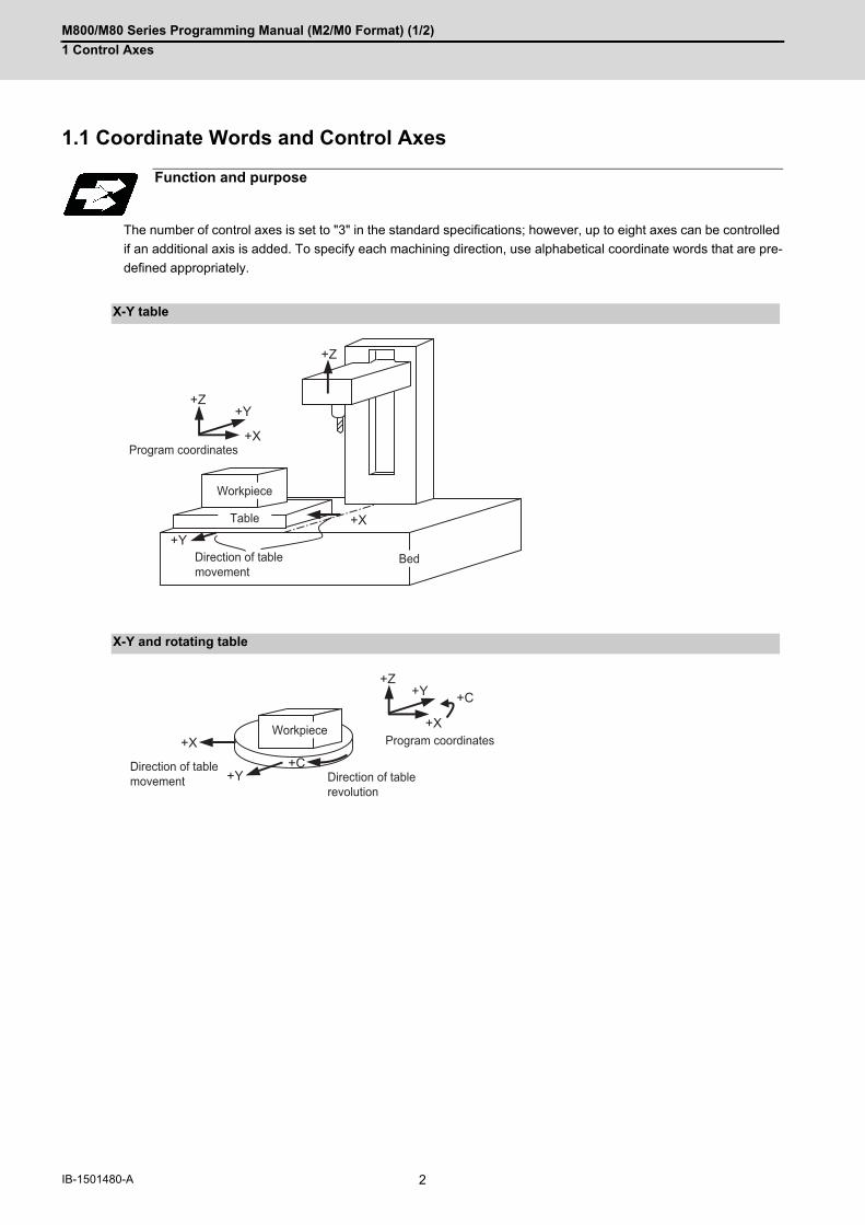
1Control Axes1.1 Coordinate Words and Control Axes
The number of control axes is set to "3" in the standard specifications; however, up to eight axes can be controlled
if an additional axis is added. To specify each machining direction, use alphabetical coordinate words that are pre-
defined appropriately.
Function and purpose
X-Y table
X-Y and rotating table
+Z
+Z
+Y
+Y
+X
+X
Program coordinates
Direction of table movement
Workpiece
Table
Bed
+Z+Y
+Y
+C
+C
+X+X Program coordinates
Direction of table movement Direction of table
revolution
Workpiece

M800/M80 Series Programming Manual (M2/M0 Format) (1/2)
1 Control Axes
3 IB-1501480-A
1.2 Coordinate Systems and Coordinate Zero Point Symbols
The basic machine coordinate system is the coordinate system that expresses the position (tool change position,
stroke end position, etc.) that is specific to the machine.
Workpiece coordinate systems are used for workpiece machining.
Upon completion of the dog-type reference position return, the parameters are referred and the basic machine co-
ordinate system and workpiece coordinate systems (G54 to G59) are automatically set.
The offset of the basic machine coordinate zero point and reference position is set by a parameter. (Normally, set
by MTB)
Workpiece coordinate systems can be set with coordinate systems setting functions, workpiece coordinate offset
measurement (additional specification), and etc.
Reference position: A specific position to establish coordinate systems and change tools
Basic machine coordinate zero point: A position specific to machine
Workpiece coordinate zero points (G54 to G59) A coordinate zero point used for workpiece machining
M800/M80 Series Programming Manual (M2/M0 Format) (1/2)
1 Control Axes
4IB-1501480-A
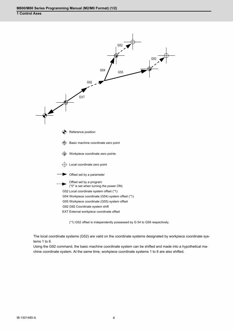
The local coordinate systems (G52) are valid on the coordinate systems designated by workpiece coordinate sys-
tems 1 to 6.
Using the G92 command, the basic machine coordinate system can be shifted and made into a hypothetical ma-
chine coordinate system. At the same time, workpiece coordinate systems 1 to 6 are also shifted.
Reference position
Basic machine coordinate zero point
Workpiece coordinate zero points
Local coordinate zero point
Offset set by a parameter
Offset set by a program ("0" is set when turning the power ON)
G52 Local coordinate system offset (*1)
G54 Workpiece coordinate (G54) system offset (*1)
G55 Workpiece coordinate (G55) system offset
G92 G92 Coordinate system shift
EXT External workpiece coordinate offset
(*1) G52 offset is independently possessed by G 54 to G59 respectively.
G52
G92
G55G54
EXT
G52

2
5 IB-1501480-A
Minimum command unit
M800/M80 Series Programming Manual (M2/M0 Format) (1/2)
2 Minimum command unit
6IB-1501480-A
2Minimum command unit2.1 Input Setting unit
The input setting units are the units of setting data including tool compensation amounts and workpiece coordinates
compensation.
The program command units are the units of movement amounts in programs.
These are expressed with mm, inch or degree (°).
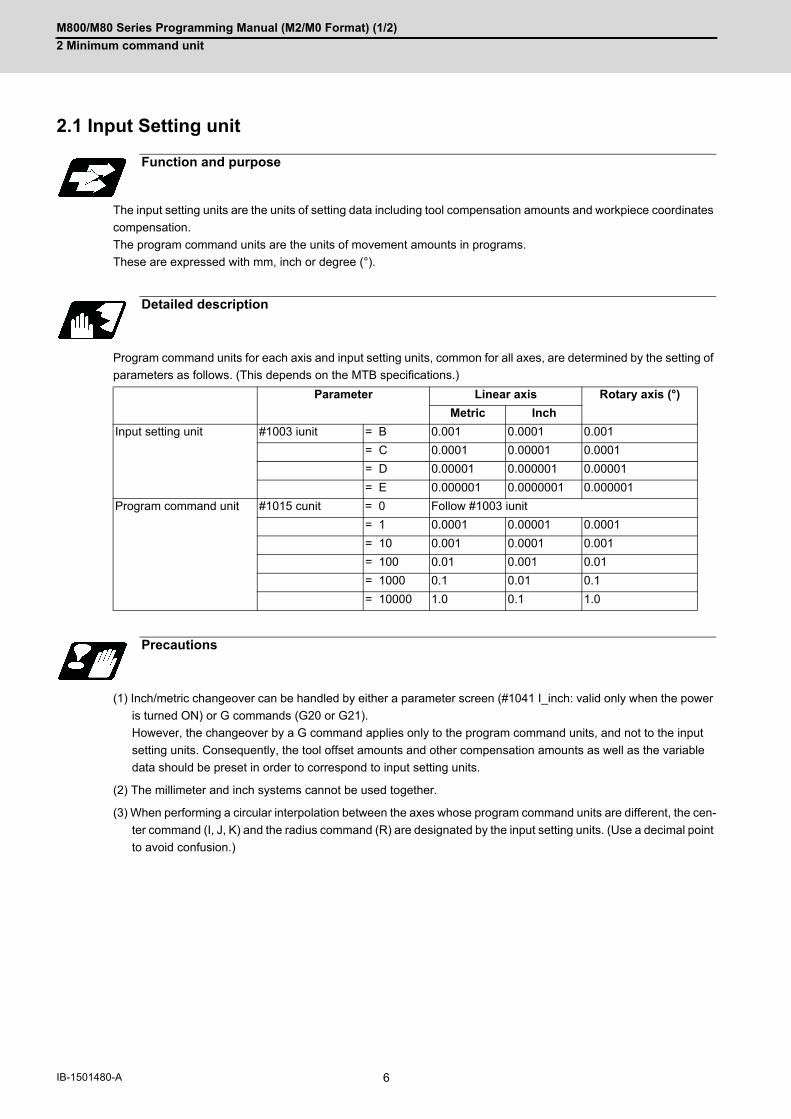
Program command units for each axis and input setting units, common for all axes, are determined by the setting of
parameters as follows. (This depends on the MTB specifications.)
(1) Inch/metric changeover can be handled by either a parameter screen (#1041 I_inch: valid only when the power
is turned ON) or G commands (G20 or G21).
However, the changeover by a G command applies only to the program command units, and not to the input
setting units. Consequently, the tool offset amounts and other compensation amounts as well as the variable
data should be preset in order to correspond to input setting units.
(2) The millimeter and inch systems cannot be used together.
(3) When performing a circular interpolation between the axes whose program command units are different, the cen-
ter command (I, J, K) and the radius command (R) are designated by the input setting units. (Use a decimal point
to avoid confusion.)
Function and purpose
Detailed description
Parameter Linear axis Rotary axis (°)
Metric Inch
Input setting unit #1003 iunit = B 0.001 0.0001 0.001
= C 0.0001 0.00001 0.0001
= D 0.00001 0.000001 0.00001
= E 0.000001 0.0000001 0.000001
Program command unit #1015 cunit = 0 Follow #1003 iunit
= 1 0.0001 0.00001 0.0001
= 10 0.001 0.0001 0.001
= 100 0.01 0.001 0.01
= 1000 0.1 0.01 0.1
= 10000 1.0 0.1 1.0
Precautions

M800/M80 Series Programming Manual (M2/M0 Format) (1/2)
2 Minimum command unit
7 IB-1501480-A
2.2 Input Command Increment Tenfold
The program's command increment can be multiplied by an arbitrary scale with the parameter designation.
This function is valid when a decimal point is not used for the command increment.
The scale is set with the parameter "#8044 UNIT*10".
(1) When running a machining program already created with a 10μm input command increment with a CNC unit for
which the command increment is set to 1μm and this function's parameter value is set to "10", this function en-
ables the same machining as the original program.
(2) When running a machining program already created with a 1μm input command increment with a CNC unit for
which the command increment is set to 0.1μm and this function's parameter value is set to "10", this function
enables the same machining as the original program.
(3) This function cannot be used for the dwell function G04_X_(P_);.
(4) This function cannot be used for the compensation amount of the tool compensation input.
(5) This function can be used when decimal point type I is valid, but cannot be used when decimal point type II is
valid.
(6) This function cannot be used for a tool shape setting command (in G10L100 format).
Function and purpose
Detailed description
Program example(Machining program : programmed with 1=10μm)
(CNC unit is 1=1μm system)
"UNIT*10" parameter
10 1
X Y X Y
N1 G90 G00 X0 Y0; 0 0 0 0
N2 G91 X-10000 Y-15000; -100.000 -150.000 -10.000 -15.000
N3 G01 X-10000 Y-5000 F500; -200.000 -200.000 -20.000 -20.000
N4 G03 X-10000 Y-10000 J-10000; -300.000 -300.000 -30.000 -30.000
N5 X10000 Y-10000 R10000; -200.000 -400.000 -20.000 -40.000
N6 G01 X20.000 Y20.000 -180.000 -380.000 0.000 -20.000
UNIT*10 ON UNIT*10 OFF
N1
N2
N3
N4
N5
R
-400
-300
-200
-100
W
-100-200-300
N6
N1
N2
N3
N4
N5
R
-40
-30
-20
-10
W
-10-20-30
N6

M800/M80 Series Programming Manual (M2/M0 Format) (1/2)
2 Minimum command unit
8IB-1501480-A
2.3 Indexing Increment
This function limits the command value for the rotary axis.
This can be used for indexing the rotary table, etc. It is possible to cause a program error with a program command
other than an indexing increment (parameter setting value).
When the indexing increment (parameter) which limits the command value is set, the rotary axis can only be posi-
tioned with that indexing increment. If a program other than the indexing increment setting value is commanded, a
program error (P20) will occur.
The indexing position will not be checked when the parameter is set to 0.
(Example) When the indexing increment setting value is 2 degrees, the machine coordinate position at the end point
can only be commanded with the 2-degree increment.
G90 G01 C102.000 ; ... Moves to the 102 degree angle.
G90 G01 C101.000; Program error
G90 G01 C102 ; ... Moves to the 102 degree angle. (Decimal point type II)
The following axis specification parameter is used. (This depends on the MTB specifications.)
(1) When the indexing increment is set, positioning will be conducted in degree unit.
(2) The indexing position is checked with the rotary axis, and is not checked with other axes.
(3) When the indexing increment is set to 2 degrees, the rotary axis is set to the B axis, and the B axis is moved with
JOG to the 1.234 position, an indexing error will occur if "G90B5." or "G91B2." is commanded.
Function and purpose
Detailed description
# Item Details Setting range (unit)
2106 Index unit Indexing incre-ment
Set the indexing increment with which the rotary axis can be positioned.
0 to 360(°)
Precautions

3
9 IB-1501480-A
Program Formats

M800/M80 Series Programming Manual (M2/M0 Format) (1/2)
3 Program Formats
10IB-1501480-A
3Program Formats3.1 Program Format
A collection of commands assigned to an NC to move a machine is called "program".
A program is a collection of units called "block" which specifies a sequence of machine tool operations.
Blocks are written in the order of the actual movement of a tool.
A block is a collection of units called "word" which constitutes a command to an operation.
A word is a collection of characters (alphabets, numerals, signs) arranged in a specific sequence.
%BlockBlockBlockBlockBlockBlockBlockBlockBlock
%

M800/M80 Series Programming Manual (M2/M0 Format) (1/2)
3 Program Formats
11 IB-1501480-A
A program format looks as follows.
(1) Program startInput an End Of Record (EOR, %) at the head of a program. It is automatically added when writing a program on an NC. When using an external device, do not forget to inputit at the head of a program. For details, refer to the description of the file format.
(2) Program No.Program Nos. are used to classify programs by main program unit or subprogram unit. They are designated bythe address "L" followed by numbers of up to 8 digits. Program Nos. must be written at the head of programs. Asetting is available to prohibit L8000s and L9000s from editing (edit lock). Refer to the instruction manual for theedit lock.
(3) CommentData between control out "(" and control in ")" is ignored. With label L, all information contained from "O" to ";" is ignored. Information including program names and comments can be written in.(*) Make sure to add "O" at the head of the block.When "O" is added in the middle of the block, the program error(P32) occurs.
(4) Program sectionA program is a collection of several blocks.
(5) Program endInput an end of record (EOR, %) at the end of a program. It is automatically added when writing a program on an NC.
Detailed description
Program
%L(COMMENT)BlockBlockBlockBlockBlockBlockBlockBlock
%
(1)
(5)
(2)
(4)
(3)

M800/M80 Series Programming Manual (M2/M0 Format) (1/2)
3 Program Formats
12IB-1501480-A
[Block]
A block is a least command increment, consisting of words.
It contains the information which is required for a machine tool to execute a specific operation. One block unit con-
stitutes a complete command.
The end of each block is marked with an End of Block (EOB, expressed as ";" for the sake of convenience).
[Word]
A word consists of a set of an alphabet, which is called an address, and numerals (numerical information).
Meanings of the numerical information and the number of significant digits of words differ according to an address.
(1) Leading zeros can be omitted from numerals.
The major contents of a word are described below.
(1) Sequence No.A "sequence No." consists of the address "N" followed by numbers of up to 8 digits (Normally 3 or 4 digits). It isused as an index when searching a necessary block in a program (as branch destination and etc.). It does not affect the operation of a tool machine.
(2) Preparatory function (G code, G function)"Preparatory function (G code, G function)" consists of the address G followed by numbers of 2 or 3 digits (it mayinclude 1 digit after the decimal point). G codes are mainly used to designate functions, such as axis movementsand setting of coordinate systems. For example, G00 executes a positioning and G01 executes a linear interpo-lation.
(3) Coordinate words"Coordinate words" specify the coordinate positions and movement amounts of machine tool axes. They consistof an address which indicates each axis of a tool machine followed by numerical information (+ or - signs andnumerals). X, Y, Z, U, V, W, A, B and C are used as address. Coordinate positions and movement amounts are specifiedby either "incremental value commands" or "absolute value commands".
(4) Feed Functions (F functions)"Feed Functions (F functions)" designate the speed of a tool relative to a workpiece. They consist of the addressF followed by numbers.
Block and word
(a) Alphabet (address)(n) Numerals
EOB
Word Word Word... ;Word
(a) (n)
Note
N___ G__ X__ Z__ F__ ;
( 1) ( 2) ( 3) ( 4) EOB

M800/M80 Series Programming Manual (M2/M0 Format) (1/2)
3 Program Formats
13 IB-1501480-A
Fixed sequences or repeatedly used parameters can be stored in the memory as subprograms which can then be
called from the main program when required.
If a command is issued to call a subprogram while a main program is being executed, the subprogram will be exe-
cuted. And when the subprogram is completed, the main program will be resumed.
Refer to the description of "14.1 Subprogram Control; G22, G23" for details of subprogram execution.
Main program and subprograms
L0010;
G22L1000;
G22L2000;
M02;
L1000;
G23;
L2000;
G23;
Main program Subprogram 1
Subprogram 2

M800/M80 Series Programming Manual (M2/M0 Format) (1/2)
3 Program Formats
14IB-1501480-A
3.2 File Format
Program file can be created using NC edit screen and PC.
It can be input/output between NC memory and an external I/O device. Hard discs stored in NC unit are regarded
as an external I/O device. For the details of input/output method, refer to the instruction manual.
Program file format differs depending on the device which creates the program.
Devices which can input/output program files are as follows.
The file format for each external I/O device is as follows:
(1) NC memory (Creates program on NC)
Function and purpose
Detailed description
Devices available for input/output
External data input/output interface M800W M800S M80
NC memory ○ ○ ○
Serial ○ ○ ○
SD card in control unit ○ - -
Front-side SD card ○ ○ ○
Ethernet ○ ○ ○
Display unit-side data server ○ ○ ○
Front-side USB memory ○ ○ ○
Program file format
End of record (EOR, %) The end of record (EOR, %) is automatically added. It does not need to be input purposely.
Program No. (L No.) Not necessary.
File transfer When multiple programs within the NC memory are transferred to an external device as serial, they will be integrated into one file in the external device. When a file containing multiple programs in an external device is transferred to NC memory as serial, it will be divided into one file per one program.
(COMMENT) ;G28XYZ ;
M02 ;%

M800/M80 Series Programming Manual (M2/M0 Format) (1/2)
3 Program Formats
15 IB-1501480-A
(2) External device (except for serials such as SD card and USB memory)
(3) External device (serial)
[Single program] [Multiple programs]
End of record (EOR, %) The first line (from % to LF, or CR LF) will be skipped. Also, the content after the second % will not be transferred. "%" must be included in the first line because if not, the necessary information when transferring a file to an NC memory cannot be transferred.
Program No. (L No.) L No. before (COMMENT) will be ignored and the file name will be given the priority.
File transfer Transfer and check of multiple programs between external devices, except for serial <-> serial, are not available. When a file containing multiple programs in an external device is transferred to NC memory as serial, it will be divided into one file per one program. When transferring divided programs one by one from an external device, which is not serial, (multiple programs) to an NC memory, the head program name can be omitted like "(COMMENT)" only when the transferring destina-tion file name is designated to the file name field of device B.
Program name Program name should be designated with up to 32 alphanumeric characters (29 characters for a multi-part system program).
End of block (EOB, ;) When the I/O parameter "CR output" is set to "1", EOB becomes CRLF.
End of record (EOR, %) The first line (from % to LF, or CR LF) will be skipped. Also, the content after the second % will not be transferred. "%" must be included in the first line because if not, the necessary information when transferring a file to an NC memory cannot be transferred.
File transfer Transfer and check of multiple programs between external devices, except for serial <-> serial, are not available. When transferring a file as serial, the head program name can be omitted like "(COMMENT)" only when the transferring destination file name is designated to the file name field of device B.
Program name Program name should be designated with up to 32 alphanumeric characters (29 characters for a multi-part system program).
End of block (EOB, ;) When the I/O parameter "CR output" is set to "1", EOB becomes CRLF.
CRLF
(COMMENT) CRLF
G28 XYZ CRLF
: :M02 CRLF
% ^Z
CRLF
CRLF
G28 XYZ CRLF
: :M02 CRLF
L101(COMMENT1) CRLF
:M02 CRLF
% ^Z
L100(COMMENT)
LF
L100(COMMENT) LF
G28 XYZ LF
: :M02 LF
%
%

M800/M80 Series Programming Manual (M2/M0 Format) (1/2)
3 Program Formats
16IB-1501480-A
3.3 Optional Block Skip
3.3.1 Optional Block Skip; /
This function selectively ignores a section of a machining program from a "/" (slash code) to the end of the block.
Provided that the optional block skip switch is ON, a section of a machining program from a "/" to the end of the block
are ignored. They are executed if the switch is OFF.
Parity check is valid regardless of whether the optional block skip switch is ON or OFF.
When, for instance, all blocks are to be executed for one workpiece but specific blocks are not to be executed for
another workpiece, one machining program can be used to machine different parts by inserting the "/" into those
specific blocks.
(1) When the parameter "#1274 ext10/bit4" is set to "0" and the parameter "#1226 aux10/bit1" is set to "0":A "/" placed in the middle of a block is always interpreted as a division instruction regardless of whether or notthe optional block skip signal state is ON or OFF.
(2) When the parameter "#1274 ext10/bit4" is set to "0" and the parameter "#1226 aux10/bit1" is set to "1":A "/" placed in a bracketed ("[ ]") expression is interpreted as a division instruction.As for a "/" that appears in any other contexts, the section of the block following the "/" will be skipped if the op-tional skip signal is ON, and the "/" itself will be ignored if the optional skip signal is OFF.
- Operation example of a case when optional block skip signal is ON:
- Operation example of a case when optional block skip signal is OFF:
Function and purpose
Detailed description
Program example
G00 X0. Z0.;
#101 = [ 100. / 4 ] ; Sets "25." to #101. (As the result of execution of a division instruction)
G00 Z[ 100. / 4 ] ; Moves Z axis to "25.". (As the result of execution of a division instruction)
#102 = 100. / #101 ; Sets "4." to #102. (As the result of execution of a division instruction)
M30 ;
G00 X0. Z0.;
#101 = [ 100. / 4 ] ; Sets "25." to #101. (As the result of execution of a division instruction)
G00 X100. / Z200. ; Moves X axis to "100. No Z axis movements made. (As the result of skipping the section of the block after "/")
G00 Z[ 100. / 4 ] ; Moves Z axis to "25.". (As the result of execution of a division instruction)
#102 = 100. / #101 ; Sets "100." to #102. (As the result of skipping the section of the block after "/")
M30 ;
G00 X0. Z0.;
#101 = [ 100. / 4 ] ; Sets "25." to #101. (As the result of execution of a division instruction)
G00 X100. / Z200. ; Moves X axis to "100." and Z axis to "200.". (As the result of ignoring "/")
G00 Z[ 100. / 4 ] ; Moves Z axis to "25.". (As the result of execution of a division instruction)
#102 = 100. / #101 ; Program error "P242 = not defined at vrble set" occurs. (As the result of ignoring "/")
M30 ;

M800/M80 Series Programming Manual (M2/M0 Format) (1/2)
3 Program Formats
17 IB-1501480-A
(3) When the parameter "#1274 ext10/bit4" is set to "1": When a "/" is placed in a bracketed expression or when anexpression that includes a "/" is on the right side of an equation, the "/" is interpreted as a division instruction.As for a "/" that appears in any other contexts, the section of the block following the "/" will be skipped if the op-tional skip signal is ON, and the "/" itself will be ignored if the optional skip signal is OFF.
- Operation example of a case when optional block skip signal is ON:
- Operation example of a case when optional block skip signal is OFF:
(1) When the parameter "#1274 ext10/bit4" is set to "0" and parameter "#1226 aux10/bit1" is set to "0", put the "/"code for optional block skip at the beginning of a block. If it is placed inside the block, it is assumed as a usermacro, a division instruction.(Example)N20 G01 X25. /Z25. ; NG (User macro, a division instruction; a program error results.)/N20 G01 X25. Z25. ; OKWhen parameter "#1274 ext10/bit4" = "0" and parameter "#1226 aux10/bit1" = "1", a "/" placed in the middle ofa block functions as a starting point of the optional skip.To use a "/" as a division instruction, bracket (enclose in square brackets) the formula containing a slash code.
(2) A space immediately followed by a "/" at the very beginning of a block is always regarded as equal to a "/" at thehead of a block regardless of the value set in parameter "#1226 aux10/bit1".
(3) The optional block skip is processed immediately before the pre-read buffer.Consequently, it is not possible to skip up to the block which has been read into the pre-read buffer.
(4) This function is valid even during a sequence number search.
(5) All blocks with the "/" code are also input and output during tape storage and tape output, regardless of the po-sition of the optional block skip switch.
G00 X0. Z0.;
#101 = [ 100. / 4 ] ; Sets "25." to #101. (As the result of execution of a division instruction)
G00 X100. / Z200. ; Moves X axis to "100. No Z axis movements made. (As the result of skipping the section of the block after "/")
G00 Z[ 100. / 4 ] ; Moves Z axis to "25.". (As the result of execution of a division instruction)
#102 = 100. / #101 ; Sets "4." to #102. (As the result of execution of a division instruction)
M30 ;
G00 X0. Z0.;
#101 = [ 100. / 4 ] ; Sets "25." to #101. (As the result of execution of a division instruction)
G00 X100. / Z200. ; Moves X axis to "100." and Z axis to "200.". (As the result of ignoring "/")
G00 Z[ 100. / 4 ] ; Moves Z axis to "25.". (As the result of execution of a division instruction)
#102 = 100. / #101 ; Sets "4." to #102. (As the result of execution of a division instruction)
M30 ;
Precautions
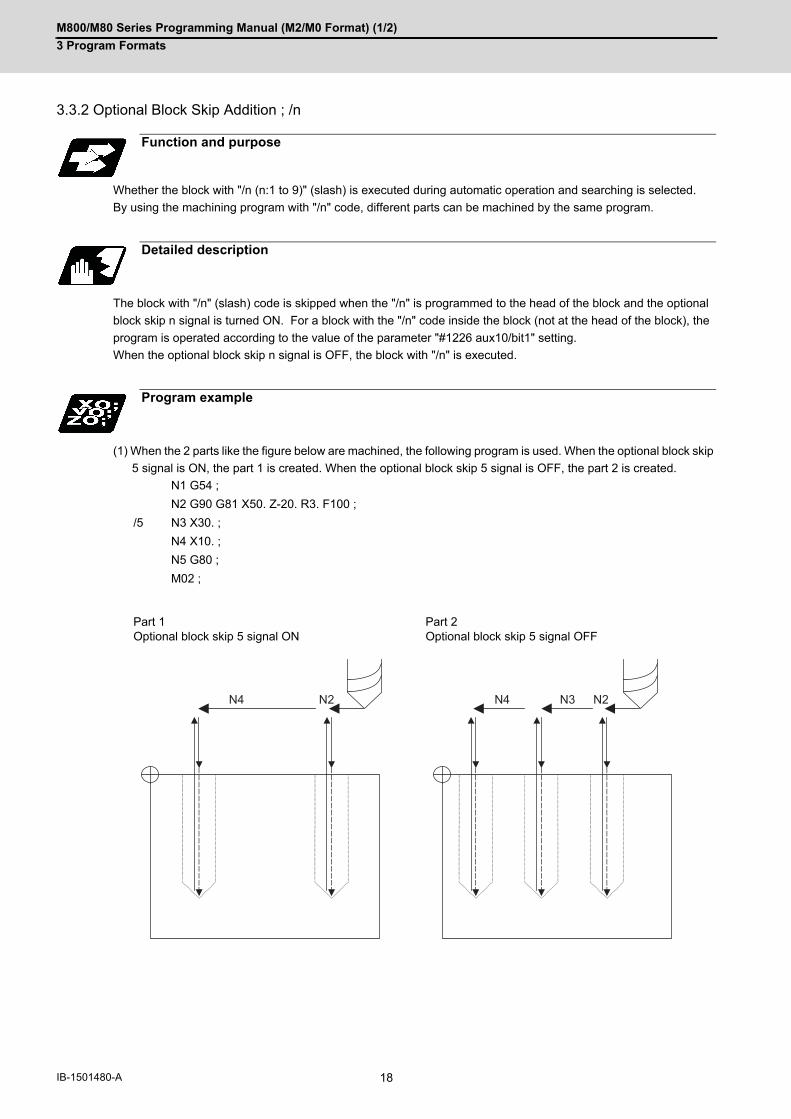
M800/M80 Series Programming Manual (M2/M0 Format) (1/2)
3 Program Formats
18IB-1501480-A
3.3.2 Optional Block Skip Addition ; /n
Whether the block with "/n (n:1 to 9)" (slash) is executed during automatic operation and searching is selected.
By using the machining program with "/n" code, different parts can be machined by the same program.
The block with "/n" (slash) code is skipped when the "/n" is programmed to the head of the block and the optional
block skip n signal is turned ON. For a block with the "/n" code inside the block (not at the head of the block), the
program is operated according to the value of the parameter "#1226 aux10/bit1" setting.
When the optional block skip n signal is OFF, the block with "/n" is executed.
(1) When the 2 parts like the figure below are machined, the following program is used. When the optional block skip
5 signal is ON, the part 1 is created. When the optional block skip 5 signal is OFF, the part 2 is created.
Function and purpose
Detailed description
Program example
N1 G54 ;
N2 G90 G81 X50. Z-20. R3. F100 ;
/5 N3 X30. ;
N4 X10. ;
N5 G80 ;
M02 ;
Part 1 Optional block skip 5 signal ON
Part 2 Optional block skip 5 signal OFF
N4 N2 N2N3N4
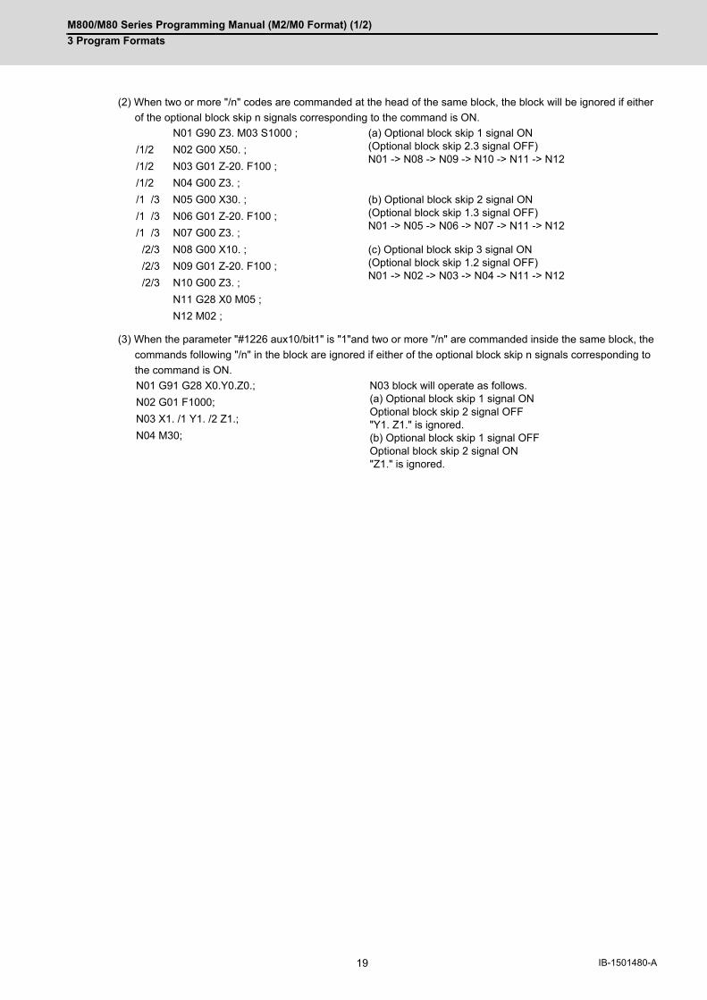
M800/M80 Series Programming Manual (M2/M0 Format) (1/2)
3 Program Formats
19 IB-1501480-A
(2) When two or more "/n" codes are commanded at the head of the same block, the block will be ignored if either
of the optional block skip n signals corresponding to the command is ON.
(3) When the parameter "#1226 aux10/bit1" is "1"and two or more "/n" are commanded inside the same block, the
commands following "/n" in the block are ignored if either of the optional block skip n signals corresponding to
the command is ON.
N01 G90 Z3. M03 S1000 ; (a) Optional block skip 1 signal ON (Optional block skip 2.3 signal OFF) N01 -> N08 -> N09 -> N10 -> N11 -> N12
/1/2 N02 G00 X50. ;
/1/2 N03 G01 Z-20. F100 ;
/1/2 N04 G00 Z3. ;
/1 /3 N05 G00 X30. ; (b) Optional block skip 2 signal ON (Optional block skip 1.3 signal OFF) N01 -> N05 -> N06 -> N07 -> N11 -> N12
/1 /3 N06 G01 Z-20. F100 ;
/1 /3 N07 G00 Z3. ;
/2/3 N08 G00 X10. ; (c) Optional block skip 3 signal ON (Optional block skip 1.2 signal OFF) N01 -> N02 -> N03 -> N04 -> N11 -> N12
/2/3 N09 G01 Z-20. F100 ;
/2/3 N10 G00 Z3. ;
N11 G28 X0 M05 ;
N12 M02 ;
N01 G91 G28 X0.Y0.Z0.; N03 block will operate as follows. (a) Optional block skip 1 signal ON Optional block skip 2 signal OFF "Y1. Z1." is ignored. (b) Optional block skip 1 signal OFF Optional block skip 2 signal ON "Z1." is ignored.
N02 G01 F1000;
N03 X1. /1 Y1. /2 Z1.;
N04 M30;

M800/M80 Series Programming Manual (M2/M0 Format) (1/2)
3 Program Formats
20IB-1501480-A
3.4 G Codes3.4.1 Modal, Unmodal
G codes define the operation modes of each block in programs.
G codes can be modal or unmodal command.
Modal commands always designate one of the G codes in the group as the NC operation mode. The operation mode
is maintained until a cancel command is issued or other G code among the same group is commanded.
An unmodal command designates the NC operation mode only when it is issued. It is invalid for the next block.
3.4.2 G Code Lists
G code Group Function Section
∆ 00 01 Positioning 6.1
0.5 28 Rapid traverse block overlap 7.13.1
∆ 01 01 Linear interpolation 6.2
02 01 Circular interpolation CW 6.3
R-specified circular interpolation CW 6.4
Helical interpolation CW 6.7
Spiral/Conical interpolation CW (type2) 6.14
03 01 Circular interpolation CCW 6.3
R-specified circular interpolation CCW 6.4
Helical interpolation CCW 6.7
Spiral/Conical interpolation CCW (type2) 6.14
02.1 01 Spiral/Conical interpolation CW (type1) 6.14
03.1 01 Spiral/Conical interpolation CCW (type1) 6.14
02.3 01 Exponential function interpolation positive rotation 6.12
03.3 01 Exponential function interpolation negative rotation 6.12
02.4 01 3-dimensional circular interpolation CW 6.15
03.4 01 3-dimensional circular interpolation CCW 6.15
04 00 Dwell (Time-based designation) 8.1
05 00 High-speed machining mode 17.1
High-speed high-accuracy control II/III 17.3
05.1 00 High-speed high-accuracy control I 17.3
Spline interpolation 17.4
06.2 01 NURBS interpolation 6.16
07 00 Hypothetical axis interpolation 6.17
07.1107
21 Cylindrical interpolation 6.9
08 00 High-accuracy control 17.2
09 00 Exact stop check 7.10
10 00 Data input by program(Parameter input, Compensation input, Tool shape input, R-Navi data in-put)
15.9
Tool life management data input 15.10
Coordinate rotation input by parameter 19.10
11.1 00 Data input by program cancel(Parameter input, Compensation input, Tool shape input, R-Navi data in-put)
15.9
Tool life management data input 15.10
11 00 Compensation data input to variable by program 15.9.6
12 00 Circular cutting CW 6.10
13 00 Circular cutting CCW 6.10
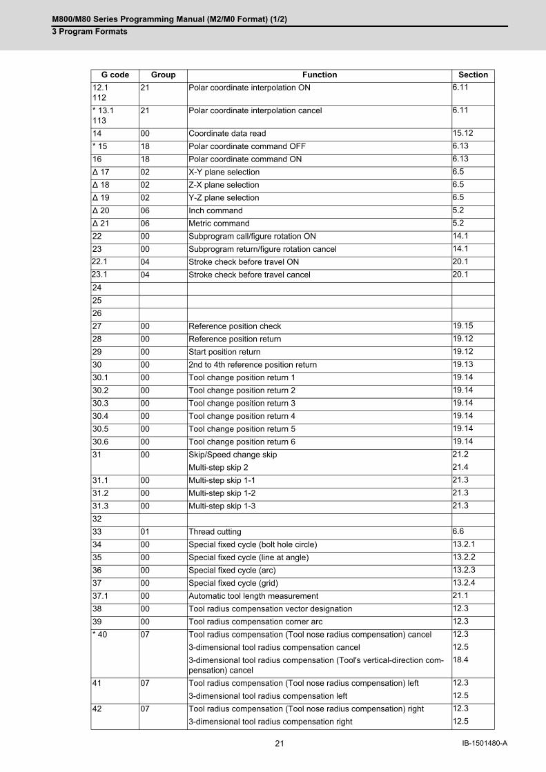
M800/M80 Series Programming Manual (M2/M0 Format) (1/2)
3 Program Formats
21 IB-1501480-A
12.1112
21 Polar coordinate interpolation ON 6.11
* 13.1113
21 Polar coordinate interpolation cancel 6.11
14 00 Coordinate data read 15.12
* 15 18 Polar coordinate command OFF 6.13
16 18 Polar coordinate command ON 6.13
∆ 17 02 X-Y plane selection 6.5
∆ 18 02 Z-X plane selection 6.5
∆ 19 02 Y-Z plane selection 6.5
∆ 20 06 Inch command 5.2
∆ 21 06 Metric command 5.2
22 00 Subprogram call/figure rotation ON 14.1
23 00 Subprogram return/figure rotation cancel 14.1
22.1 04 Stroke check before travel ON 20.1
23.1 04 Stroke check before travel cancel 20.1
24
25
26
27 00 Reference position check 19.15
28 00 Reference position return 19.12
29 00 Start position return 19.12
30 00 2nd to 4th reference position return 19.13
30.1 00 Tool change position return 1 19.14
30.2 00 Tool change position return 2 19.14
30.3 00 Tool change position return 3 19.14
30.4 00 Tool change position return 4 19.14
30.5 00 Tool change position return 5 19.14
30.6 00 Tool change position return 6 19.14
31 00 Skip/Speed change skip 21.2
Multi-step skip 2 21.4
31.1 00 Multi-step skip 1-1 21.3
31.2 00 Multi-step skip 1-2 21.3
31.3 00 Multi-step skip 1-3 21.3
32
33 01 Thread cutting 6.6
34 00 Special fixed cycle (bolt hole circle) 13.2.1
35 00 Special fixed cycle (line at angle) 13.2.2
36 00 Special fixed cycle (arc) 13.2.3
37 00 Special fixed cycle (grid) 13.2.4
37.1 00 Automatic tool length measurement 21.1
38 00 Tool radius compensation vector designation 12.3
39 00 Tool radius compensation corner arc 12.3
* 40 07 Tool radius compensation (Tool nose radius compensation) cancel 12.3
3-dimensional tool radius compensation cancel 12.5
3-dimensional tool radius compensation (Tool's vertical-direction com-pensation) cancel
18.4
41 07 Tool radius compensation (Tool nose radius compensation) left 12.3
3-dimensional tool radius compensation left 12.5
42 07 Tool radius compensation (Tool nose radius compensation) right 12.3
3-dimensional tool radius compensation right 12.5
G code Group Function Section

M800/M80 Series Programming Manual (M2/M0 Format) (1/2)
3 Program Formats
22IB-1501480-A
* 40.1150
15 Normal line control cancel 15.7
41.1151
15 Normal line control left ON 15.7
42.1152
15 Normal line control right ON 15.7
41.2 07 3-dimensional tool radius compensation (Tool's vertical-direction com-pensation) (left)
18.4
42.2 07 3-dimensional tool radius compensation (Tool's vertical-direction com-pensation) (right)
18.4
43 08 Tool length compensation 12.2
*44 08 Tool length compensation cancel 12.2
Tool length compensation along the tool axis 18.1
Tool center point control cancel 18.2
43.1 08 Tool length compensation along the tool axis ON 18.1
43.4 08 Tool center point control type1 ON 18.2
43.5 08 Tool center point control type2 ON 18.2
45 00 Tool position offset (extension) 12.6
46 00 Tool position offset (reduction) 12.6
47 00 Tool position offset (double elongation) 12.6
48 00 Tool position offset (double contraction) 12.6
* 50 11 Scaling cancel 19.11
51 11 Scaling ON 19.11
* 50.1 19 Mirror image by G code cancel 15.6
51.1 19 Mirror image by G code ON 15.6
52 00 Local coordinate system setting 19.5
53 00 Basic machine coordinate system selection 19.3
53.1 00 Tool axis direction control (type 1) 18.3.8
53.6 00 Tool axis direction control (type 2) 18.3.8
* 54 12 Workpiece coordinate system 1 selection 19.6
55 12 Workpiece coordinate system 2 selection 19.6
56 12 Workpiece coordinate system 3 selection 19.6
57 12 Workpiece coordinate system 4 selection 19.6
58 12 Workpiece coordinate system 5 selection 19.6
59 12 Workpiece coordinate system 6 selection 19.6
54.1 12 Extended workpiece coordinate system selection 19.6
54.4 27 Workpiece installation error compensation -
60 00 Unidirectional positioning 6.8.1
61 13 Exact stop check mode 7.11
61.1 13 High-accuracy control ON 17.2
61.2 13 High-accuracy spline 17.6
61.4 13 Spline interpolation 2 17.5
62 19 G command mirror image 15.6
63 13 Tapping mode 7.15
* 64 13 Cutting mode 7.16
65 00 User macro simple call 14.4.1
66 14 User macro modal call A 14.4.2
66.1 14 User macro modal call B 14.4.3
* 67 14 User macro modal call cancel 14.3
68 04 Subprogram return 14.3
69 00 End point error check cancellation 15.11
G code Group Function Section
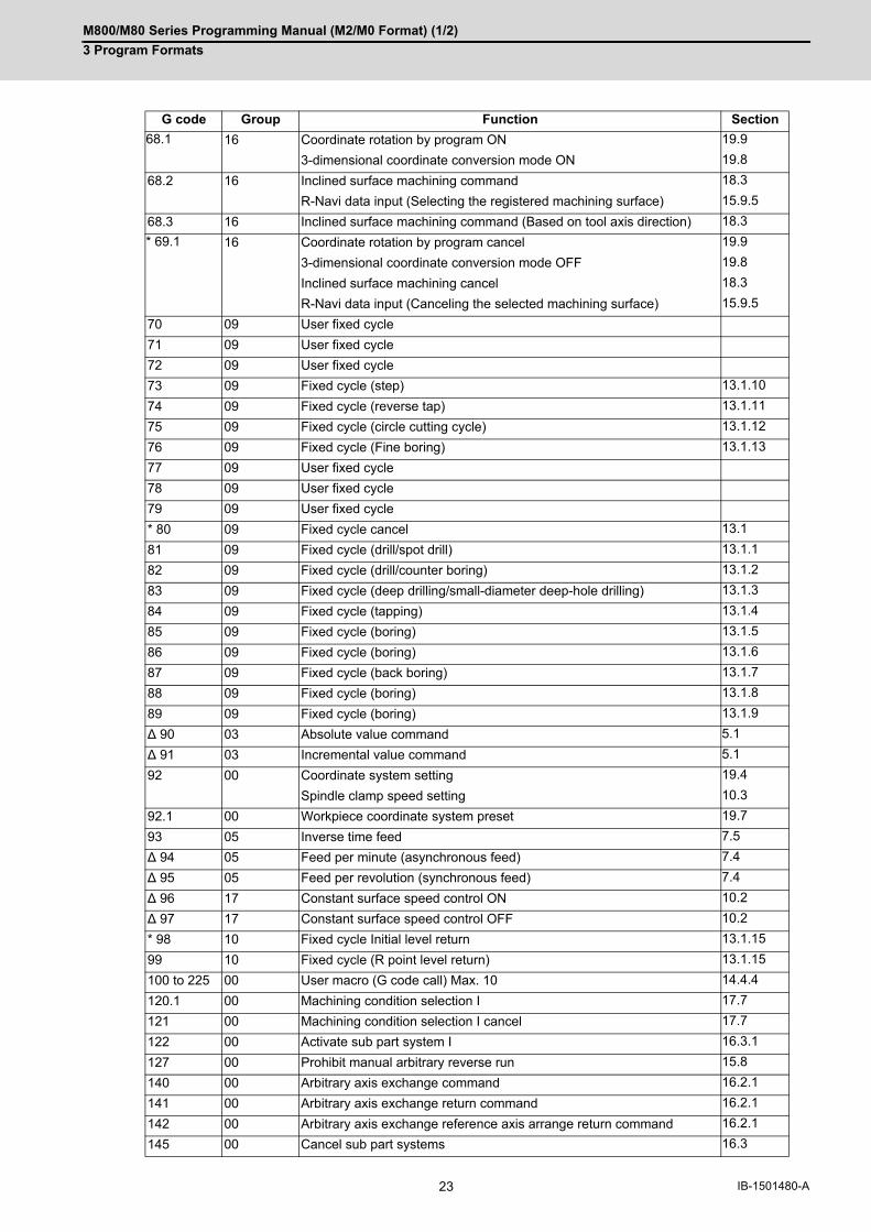
M800/M80 Series Programming Manual (M2/M0 Format) (1/2)
3 Program Formats
23 IB-1501480-A
68.1 16 Coordinate rotation by program ON 19.9
3-dimensional coordinate conversion mode ON 19.8
68.2 16 Inclined surface machining command 18.3
R-Navi data input (Selecting the registered machining surface) 15.9.5
68.3 16 Inclined surface machining command (Based on tool axis direction) 18.3
* 69.1 16 Coordinate rotation by program cancel 19.9
3-dimensional coordinate conversion mode OFF 19.8
Inclined surface machining cancel 18.3
R-Navi data input (Canceling the selected machining surface) 15.9.5
70 09 User fixed cycle
71 09 User fixed cycle
72 09 User fixed cycle
73 09 Fixed cycle (step) 13.1.10
74 09 Fixed cycle (reverse tap) 13.1.11
75 09 Fixed cycle (circle cutting cycle) 13.1.12
76 09 Fixed cycle (Fine boring) 13.1.13
77 09 User fixed cycle
78 09 User fixed cycle
79 09 User fixed cycle
* 80 09 Fixed cycle cancel 13.1
81 09 Fixed cycle (drill/spot drill) 13.1.1
82 09 Fixed cycle (drill/counter boring) 13.1.2
83 09 Fixed cycle (deep drilling/small-diameter deep-hole drilling) 13.1.3
84 09 Fixed cycle (tapping) 13.1.4
85 09 Fixed cycle (boring) 13.1.5
86 09 Fixed cycle (boring) 13.1.6
87 09 Fixed cycle (back boring) 13.1.7
88 09 Fixed cycle (boring) 13.1.8
89 09 Fixed cycle (boring) 13.1.9
∆ 90 03 Absolute value command 5.1
∆ 91 03 Incremental value command 5.1
92 00 Coordinate system setting 19.4
Spindle clamp speed setting 10.3
92.1 00 Workpiece coordinate system preset 19.7
93 05 Inverse time feed 7.5
∆ 94 05 Feed per minute (asynchronous feed) 7.4
∆ 95 05 Feed per revolution (synchronous feed) 7.4
∆ 96 17 Constant surface speed control ON 10.2
∆ 97 17 Constant surface speed control OFF 10.2
* 98 10 Fixed cycle Initial level return 13.1.15
99 10 Fixed cycle (R point level return) 13.1.15
100 to 225 00 User macro (G code call) Max. 10 14.4.4
120.1 00 Machining condition selection I 17.7
121 00 Machining condition selection I cancel 17.7
122 00 Activate sub part system I 16.3.1
127 00 Prohibit manual arbitrary reverse run 15.8
140 00 Arbitrary axis exchange command 16.2.1
141 00 Arbitrary axis exchange return command 16.2.1
142 00 Arbitrary axis exchange reference axis arrange return command 16.2.1
145 00 Cancel sub part systems 16.3
G code Group Function Section

M800/M80 Series Programming Manual (M2/M0 Format) (1/2)
3 Program Formats
24IB-1501480-A
(1) Codes marked with * are codes that must be or are selected in the initial state. The codes marked with ∆ are codes that should be or are selected in the initial state by the parameters.
(2) If two or more G codes from the same code are commanded, the latter G code will be valid.
(3) This G code list is a list of conventional G codes. Depending on the machine, movements that differ from theconventional G commands may be included when called by the G code macro. Refer to the Instruction Manualissued by the MTB.
(4) Whether the modal is initialized or not depends on each reset input.
(a) "Reset 1"
The modal is initialized when the reset initialization parameter (#1151 rstinit) is ON. (This depends on the
MTB specifications.)
(b) "Reset 2" and "Reset & rewind"
The modal is initialized when the signal is input.
(c) Reset at emergency stop release
Conforms to "Reset 1".
(d) When modal is automatically reset at the start of individual functions such as reference position return
Follows "Reset & rewind".
160 00 Torque limitation skip 21.6
186 00 Interference check III interfering object data enable command 20.2
Precautions
CAUTION
The commands with "no value after G" will be handled as "G00".
G code Group Function Section

M800/M80 Series Programming Manual (M2/M0 Format) (1/2)
3 Program Formats
25 IB-1501480-A
3.5 Precautions Before Starting Machining
CAUTION
When creating the machining program, select the appropriate machining conditions, and make sure that the
performance, capacity and limits of the machine and NC are not exceeded. The examples do not take into ac-
count the machining conditions.
Before starting actual machining, always carry out a graphic check, a dry run operation, and a single block op-
eration to check the machining program, tool offset amount, workpiece offset amount, etc.

M800/M80 Series Programming Manual (M2/M0 Format) (1/2)
3 Program Formats
26IB-1501480-A

4
27 IB-1501480-A
Pre-read buffer

M800/M80 Series Programming Manual (M2/M0 Format) (1/2)
4 Pre-read buffer
28IB-1501480-A
4Pre-read buffer4.1 Pre-read Buffer
During automatic operation, the contents of one block ahead are normally pre-read so that program analysis pro-
cessing is conducted smoothly. However, during tool radius compensation, a maximum of 5 blocks are pre-read for
the intersection point calculation including interference check.
The specifications of pre-read buffers in 1 block are as follows:
(1) The data of 1 block is stored in this buffer.
(2) When comments and the optional block skip function is ON, the data extending from the "/" (slash) code up to
the EOB code are not read into the pre-read buffer.
(3) The pre-read buffer contents are cleared with resetting.
(4) When the single block function is ON during continuous operation, the pre-read buffer stores the next block's
data and then stops operation.
(5) The way to prohibit the M command which operates the external controls from pre-reading, and to make it to
recalculate, is as follows:
Identify the M command which operates the external controls by a PLC, and turn on the "recalculation request"
on PLC output signal. (When the "recalculation request" is turned ON, the block that has been pre-read is recal-
culated.)
These operations depend on the MTB specifications.
(1) Depending on whether the program is executed continuously or by single blocks, the timing of the validation/
invalidation of the PLC signals, including optional block skip, will differ.
(2) If the PLC signal such as optional block skip is turned ON/OFF with the M command, the PLC signal operation
will not be effective for the program pre-read with the buffer register.
Function and purpose
Detailed description
Precautions

5
29 IB-1501480-A
Position Commands
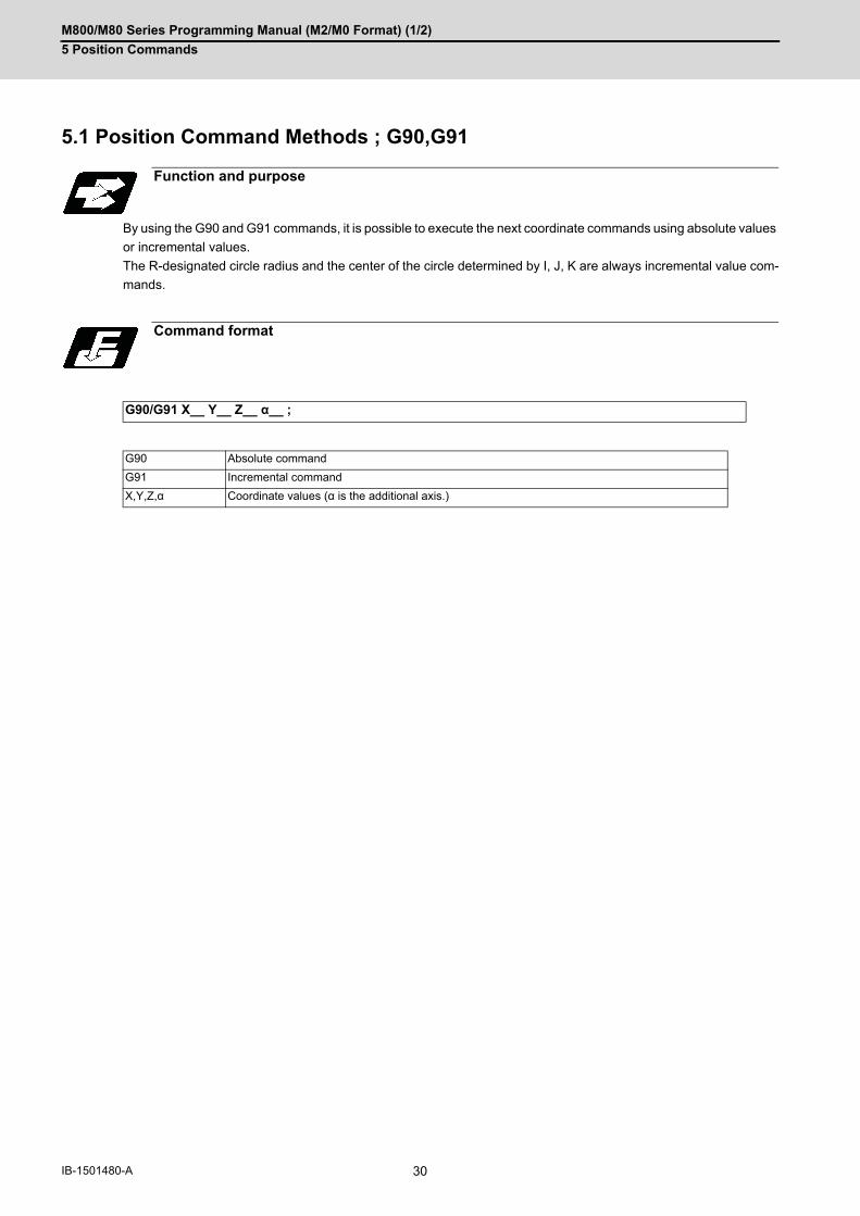
M800/M80 Series Programming Manual (M2/M0 Format) (1/2)
5 Position Commands
30IB-1501480-A
5Position Commands5.1 Position Command Methods ; G90,G91
By using the G90 and G91 commands, it is possible to execute the next coordinate commands using absolute values
or incremental values.
The R-designated circle radius and the center of the circle determined by I, J, K are always incremental value com-
mands.
Function and purpose
Command format
G90/G91 X__ Y__ Z__ α__ ;
G90 Absolute command
G91 Incremental command
X,Y,Z,α Coordinate values (α is the additional axis.)

M800/M80 Series Programming Manual (M2/M0 Format) (1/2)
5 Position Commands
31 IB-1501480-A
(1) Regardless of the current position, in the absolute value mode, it is possible to move to the position of the work-
piece coordinate system that was designated in the program.
(2) For the next block, the last G90/G91 command that was given becomes the modal.
(3) Since multiple commands can be issued in the same block, it is possible to command specific addresses as ei-
ther absolute values or incremental values.
(4) When the power is turned ON, it is possible to select whether you want absolute value commands or incremental
value commands with the #1073 I_Absm parameter.
(5) Even when commanding with the manual data input (MDI), it will be treated as a modal from that block.
Detailed description
N1 G90 G00 X0 Y0 ; In the incremental value mode, the current position is the start point (0), and the movement is made only the value determined by the program, and is expressed as an incremental value. N2 G90 G01 X200. Y50. F100 ;N2 G91 G01 X200. Y50. F100 ; Using the command from the 0 point in the workpiece coordinate sys-tem, it becomes the same coordinate command value in either the ab-solute value mode or the incremental value mode.
Tool
(G90) N3 X100. Y100. ;
The axis moves to the workpiece coordinate system X = 100.mm and Y = 100.mm position.
(G91) N3 X-100. Y50. ;
The X axis moves to -100.mm and the Y axis to +50.0mm as an incremental value, and as a result X moves to 100.mm and Y to 100.mm.
N4 G90 X300. G91 Y100. ; The X axis is treated in the absolute value mode, and with G90 is moved to the workpiece coordinate system 300.mm position. The Y axis is moved +100.mm with G91. As a result, Y moves to the 200.mm position. In terms of the next block, G91 remains as the modal and be-comes the incremental value mode.
300.200.
200.
100 N1
100.N2
WX
Y
300.200.
200.
100.
N3
W
X
Y
100.
300.200.100.
N4
W
X
Y
100.
200.
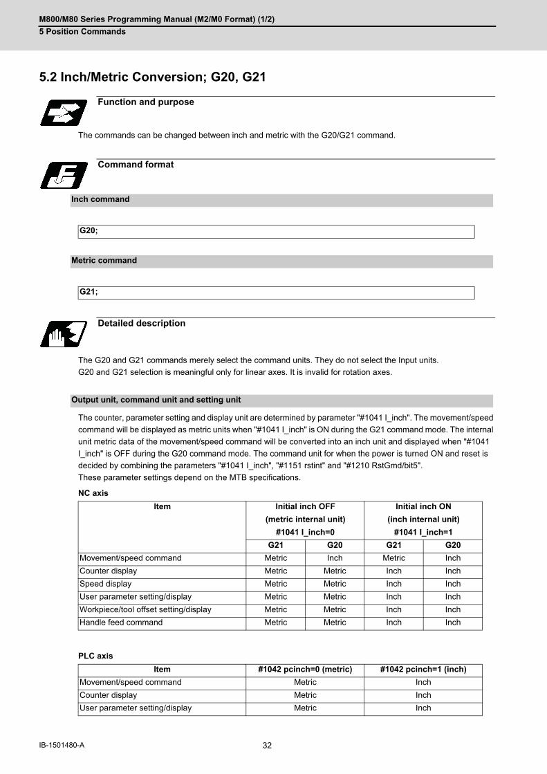
M800/M80 Series Programming Manual (M2/M0 Format) (1/2)
5 Position Commands
32IB-1501480-A
5.2 Inch/Metric Conversion; G20, G21
The commands can be changed between inch and metric with the G20/G21 command.
The G20 and G21 commands merely select the command units. They do not select the Input units.
G20 and G21 selection is meaningful only for linear axes. It is invalid for rotation axes.
The counter, parameter setting and display unit are determined by parameter "#1041 I_inch". The movement/speed
command will be displayed as metric units when "#1041 I_inch" is ON during the G21 command mode. The internal
unit metric data of the movement/speed command will be converted into an inch unit and displayed when "#1041
I_inch" is OFF during the G20 command mode. The command unit for when the power is turned ON and reset is
decided by combining the parameters "#1041 I_inch", "#1151 rstint" and "#1210 RstGmd/bit5".
These parameter settings depend on the MTB specifications.
NC axis
PLC axis
Function and purpose
Command format
Inch command
G20;
Metric command
G21;
Detailed description
Output unit, command unit and setting unit
Item Initial inch OFF Initial inch ON
(metric internal unit) (inch internal unit)
#1041 I_inch=0 #1041 I_inch=1
G21 G20 G21 G20
Movement/speed command Metric Inch Metric Inch
Counter display Metric Metric Inch Inch
Speed display Metric Metric Inch Inch
User parameter setting/display Metric Metric Inch Inch
Workpiece/tool offset setting/display Metric Metric Inch Inch
Handle feed command Metric Metric Inch Inch
Item #1042 pcinch=0 (metric) #1042 pcinch=1 (inch)
Movement/speed command Metric Inch
Counter display Metric Inch
User parameter setting/display Metric Inch

M800/M80 Series Programming Manual (M2/M0 Format) (1/2)
5 Position Commands
33 IB-1501480-A
(1) The parameter and tool data will be input/output with the unit set by "#1041 I_inch". If "#1041 I_inch" is not found in the parameter input data, the unit will follow the unit currently set to NC.
(2) The unit of read/write used in PLC window is fixed to metric unit regardless of a parameter and G20/G21 com-mand modal.
(3) A program error (P33) will occur if G20/G21 command is issued in the same block as following G codes. Com-mand in a separate block.G05 (High-speed machining mode)G7.1 (Cylindrical Interpolation)G12.1 (Polar coordinate interpolation)
Precautions

M800/M80 Series Programming Manual (M2/M0 Format) (1/2)
5 Position Commands
34IB-1501480-A
5.3 Decimal Point Input
This function enables to input decimal points. It assigns the decimal point in millimeter or inch units for the machining
program input information that defines the tool paths, distances and speeds.
Whether to apply minimum input command increment (type I) or zero point (type II) to the least significant digit of
data without a decimal point depends on the MTB specifications (parameter "#1078 Decpt2").
(1) The decimal point command is valid for the distances, angles, times, speeds and scaling rate, in machining pro-grams. (Note, only after G51)
(2) In decimal point input type I and type II, the values of the data commands without the decimal points are shownin the table below.
(3) The valid addresses for the decimal points are X, Y, Z, U, V, W, A, B, C, I, J, K, E, F, P, Q, and R. However, Pis valid only during scaling. For details, refer to the list.
(4) In decimal point command, the valid range of command value is as shown below. (for input command incrementcunit=10)
(5) The decimal point command is valid even for commands defining the variable data used in subprograms.
(6) While the smallest decimal point command is validated, the smallest unit for a command without a decimal pointdesignation is the smallest command input unit set in the specifications (1μm, 10μm, etc.) or mm can be select-ed. This selection can be made with parameter "#1078 Decpt2".
(7) Decimal point commands for decimal point invalid addresses are processed as integer data only and everythingafter the decimal point is ignored. Decimal point invalid addresses include the followings; D,H,L,M,N,O,P,S,T. All variable commands, however, are treated as data with decimal points.
(8) "Input command increment tenfold" is applied in the decimal point type I mode, but not in the decimal point typeII mode.
Function and purpose
Detailed description
Command Command unit Type I Type II
X1; cunit=10000 1000
(μm, 10-4inch, 10-3°)
1(mm, inch, °)
cunit= 1000 100 1
cunit= 100 10 1
cunit= 10 1 1
Movement com-mand (linear)
Movement com-mand (rotary)
Feedrate Dwell
Input unit [mm] -99999.999 to 99999.999
-99999.999 to 99999.999
0.001 to 10000000.000
0 to 99999.999
Input unit [inch] -9999.9999 to 9999.9999
0.0001 to 1000000.0000

M800/M80 Series Programming Manual (M2/M0 Format) (1/2)
5 Position Commands
35 IB-1501480-A
Decimal point input I and II will result as follows when decimal points are not used in an address which a decimal
point command is valid.
Both decimal point input I and II will produce the same result when a command uses a decimal point.
(1) Decimal point input IThe least significant digit of command data matches the command unit. (Example) When "X1" is commanded in 1 μm system, the same result occurs as for an "X0.001" command.
(2) Decimal point input IIThe least significant digit of command data matches the command unit. (Example) When "X1" is commanded in 1μm system, the same result occurs as for an "X1." command.
-Addresses used, validity of decimal point commands-
Decimal point input I, II and decimal point command validity
Address Decimal point com-
mand
Usage Remarks
A Valid Coordinate position data
Invalid Revolving table
Invalid Miscellaneous function codes
Valid Angle data
Invalid Data settings, axis numbers (G10)
Invalid Subprogram call: program No. (label O)
Invalid Program No.
Invalid R-Navi data input by program: Coordinate axis selection
B Valid Coordinate position data
Invalid Revolving table
Invalid Miscellaneous function codes
Invalid Sub part system I: Identification No.
Invalid R-Navi data input by program: Coordinate axis direction setting
C Valid Coordinate position data
Invalid Revolving table
Invalid Miscellaneous function codes
Valid Corner chamfering amount ,C
Invalid Tool shape input by program: Tool color
Invalid R-Navi data input by program: Basic coordinate system
Invalid R-Navi data input by program: Coordinate axis direction setting
D Invalid Compensation numbers (tool position, tool radius)
Valid Automatic tool length measurement: Deceleration distance d
Invalid Data setting: Byte type data
Invalid Subprogram storing device number ,D
Invalid Sub part system I: Synchronous control designation
Valid Droop skip value
Valid Tool shape input by program: Shape data 1
Invalid R-Navi data input by program: Machining registration No.
E Valid Inch thread: number of ridges, precision thread: lead
Invalid R-Navi data input by program: Coordinate axis direction setting
Valid Synchronous tap: Cutting feedrate (Number of screw threads)
Valid Dwell time at hole bottom of fixed cycle (label L, O)

M800/M80 Series Programming Manual (M2/M0 Format) (1/2)
5 Position Commands
36IB-1501480-A
F Valid Cutting feedrate, automatic tool length measurement speed
Valid Thread lead
Valid Number of Z axis pitch in synchronous tap
Valid Rapid traverse rate ,F
Invalid R-Navi data input by program: Workpiece shape
Invalid R-Navi data input by program: Coordinate axis direction setting
G Valid Preparatory function code
H Invalid Tool length compensation No.
Invalid Sequence Nos. in subprograms (label L, O)
Invalid Subprogram return destination sequence No. (label L, O)
Invalid Parameter input by program: Bit type data
Invalid Reference spindle selection
Invalid Sub part system I: Reset type
Valid Tool shape input by program: Shape data 2
Invalid R-Navi data input by program: Coordinate axis direction setting
Invalid Tool position compensation: Compensation No.
I Valid Coordinates for arc center and center of figure rotation (incremental)
Valid Tool radius compensation vector components
Valid Hole pitch in the special fixed cycle
Valid Circle radius of cut circle (increase amount)
Valid G0/G1 in-position width, Hole drilling cycle: G0 in-position width ,I
Valid Stroke check before travel: Lower limit coordinates
Valid Tool shape input by program: Shape data 3
Valid R-Navi data input by program: Workpiece shift
Invalid R-Navi data input by program: Coordinate axis direction setting
J Invalid Coordinates for arc center and center of figure rotation (incremental)
Valid Tool radius compensation vector components
Valid Special fixed cycle's hole pitch or angle
Valid G0/G1 in-position width, Hole drilling cycle: G1 in-position width ,J
Valid Stroke check before travel: Lower limit coordinates
Valid Tool shape input by program: Shape data 4
Valid R-Navi data input by program: Workpiece shift
K Valid Coordinates for arc center and center of figure rotation (incremental)
Valid Tool radius compensation vector components
Invalid Number of holes of the special fixed cycle
Invalid Hole drilling cycle, sub part system I: Number of repetitions
Valid Stroke check before travel: Lower limit coordinates
Valid Spline interpolation 2: Tolerance
Invalid Tool shape input by program: Tool type
Valid R-Navi data input by program: Workpiece shift
Address Decimal point com-
mand
Usage Remarks

M800/M80 Series Programming Manual (M2/M0 Format) (1/2)
5 Position Commands
37 IB-1501480-A
L Invalid Subprogram call program No. (label L)
Invalid Tool compensation data input by program/workpiece offset input: type selection
L2,L20,L10,L11,L12,L1
3
Invalid Parameter input by program: data setting selection L70
Invalid Parameter input by program: 2-word type data 4 bytes
Invalid R-Navi data input by program: Start setting workpiece data L110
Invalid R-Navi data input by program: Start setting machining surface data L111
Invalid Timing synchronization number
Invalid Program No. (label L)
Invalid Tool life data
M Invalid Miscellaneous function codes
Invalid R-Navi data input by program: Coordinate axis direction designation method
N Invalid Sequence No.
Invalid Parameter input by program: data numbers
O Invalid Program No. (label O)
P Invalid/Valid Dwell time Parameter
Invalid Number of subprogram repetitions. (label L, O)
Invalid/Valid Dwell at tap cycle hole base (label L) Parameter
Invalid Number of holes of the special fixed cycle
Invalid Amount of helical pitch
Invalid Offset number (G10)
Invalid Constant surface speed control axis number
Invalid Parameter input by program: Broad classification number
Invalid Tool compensation data input by program/workpiece offset input: Com-pensation No.
Invalid Tool shape input by program: Data numbers
Invalid Multi-step skip function 2 signal command
Invalid Subprogram return destination sequence No.
Invalid 2nd, 3rd, 4th reference position return number
Valid Scaling factor
Invalid High-speed mode type
Invalid Type of the coordinates to be read
Invalid Transmission source compensation No. of program compensation data input to variable
Invalid High-accuracy control mode: Start/End
Invalid Extended workpiece coordinate system No, external workpiece coordi-nate system offset compensation No.
Invalid Tool life data: Group No.
Invalid Machining purpose
Invalid Sub part system I: Start sequence No.
Invalid R-Navi data input by program: Machining surface registration
Invalid R-Navi data input by program: Coordinate axis direction axis designation
Address Decimal point com-
mand
Usage Remarks
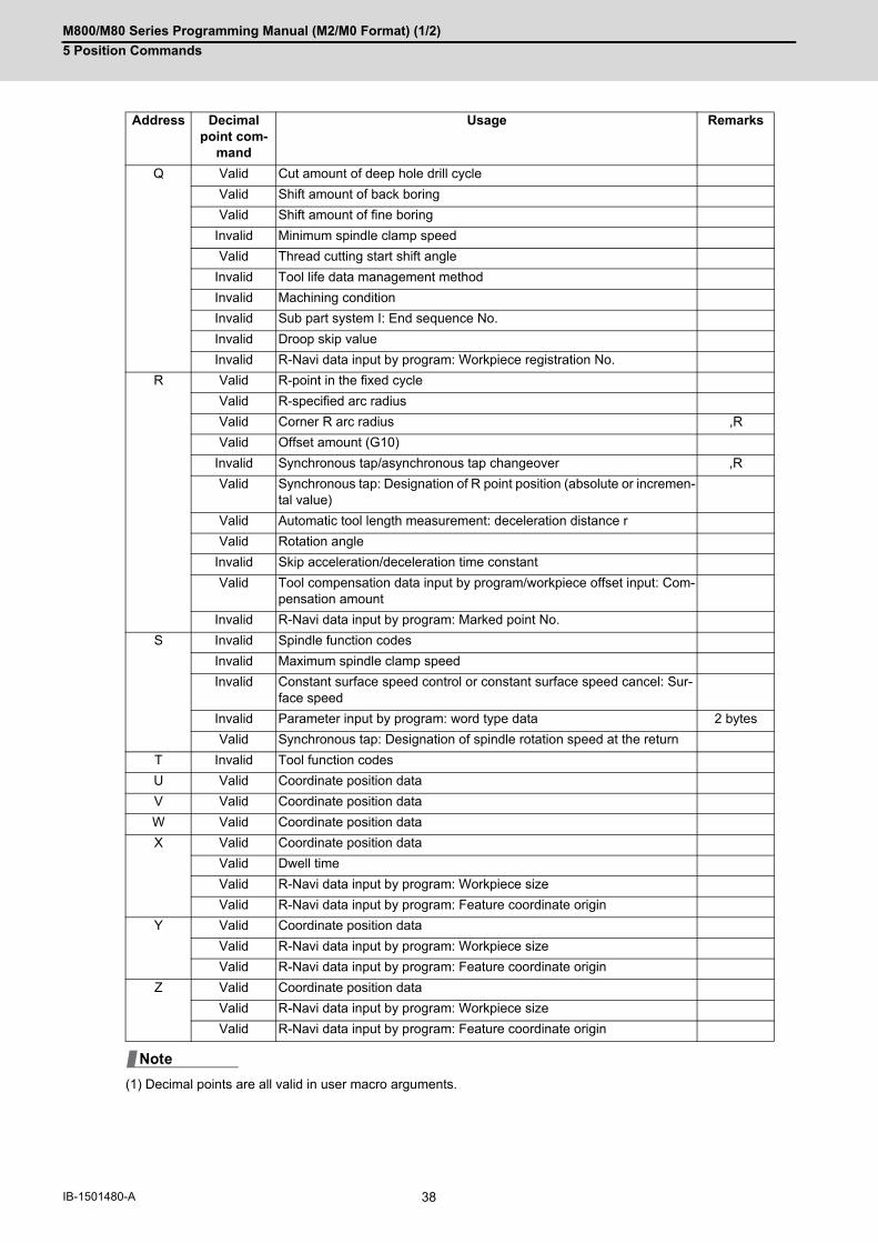
M800/M80 Series Programming Manual (M2/M0 Format) (1/2)
5 Position Commands
38IB-1501480-A
(1) Decimal points are all valid in user macro arguments.
Q Valid Cut amount of deep hole drill cycle
Valid Shift amount of back boring
Valid Shift amount of fine boring
Invalid Minimum spindle clamp speed
Valid Thread cutting start shift angle
Invalid Tool life data management method
Invalid Machining condition
Invalid Sub part system I: End sequence No.
Invalid Droop skip value
Invalid R-Navi data input by program: Workpiece registration No.
R Valid R-point in the fixed cycle
Valid R-specified arc radius
Valid Corner R arc radius ,R
Valid Offset amount (G10)
Invalid Synchronous tap/asynchronous tap changeover ,R
Valid Synchronous tap: Designation of R point position (absolute or incremen-tal value)
Valid Automatic tool length measurement: deceleration distance r
Valid Rotation angle
Invalid Skip acceleration/deceleration time constant
Valid Tool compensation data input by program/workpiece offset input: Com-pensation amount
Invalid R-Navi data input by program: Marked point No.
S Invalid Spindle function codes
Invalid Maximum spindle clamp speed
Invalid Constant surface speed control or constant surface speed cancel: Sur-face speed
Invalid Parameter input by program: word type data 2 bytes
Valid Synchronous tap: Designation of spindle rotation speed at the return
T Invalid Tool function codes
U Valid Coordinate position data
V Valid Coordinate position data
W Valid Coordinate position data
X Valid Coordinate position data
Valid Dwell time
Valid R-Navi data input by program: Workpiece size
Valid R-Navi data input by program: Feature coordinate origin
Y Valid Coordinate position data
Valid R-Navi data input by program: Workpiece size
Valid R-Navi data input by program: Feature coordinate origin
Z Valid Coordinate position data
Valid R-Navi data input by program: Workpiece size
Valid R-Navi data input by program: Feature coordinate origin
Address Decimal point com-
mand
Usage Remarks
Note

M800/M80 Series Programming Manual (M2/M0 Format) (1/2)
5 Position Commands
39 IB-1501480-A
(1) Program example of decimal point valid address
(1) If an arithmetic operator is inserted, the data will be handled as data with a decimal point. (Example 1) G00 X123+0 ;This is the X axis 123mm command. It will not be 123 μm.
Program example
Program example Decimal point command 1 Decimal point command 2
When 1 = 1 μm When 1 = 10 μm 1 = 1 mm
G00 X123.45(decimal points are all mm points)
X123.450 mm X123.450 mm X123.450 mm
G00 X12345 X12.345 mm(last digit is 1μm unit)
X123.450 mm X12345.000 mm
#111=123 #112=5.55X#111 Y#112
X123.000 mmY5.550 mm
X123.000 mmY5.550 mm
X123.000 mmY5.550 mm
#113=#111+#112(addition)
#113=128.550 #113=128.550 #113=128.550
#114=#111-#112(subtraction)
#114=117.450 #114=117.450 #114=117.450
#115=#111*#112(multiplication)
#115=682.650 #115=682.650 #115=682.650
#116=#111/#112#117=#112/#111(division)
#116=22.162#117=0.045
#116=22.162#117=0.045
#116=22.162#117=0.045
Precautions

M800/M80 Series Programming Manual (M2/M0 Format) (1/2)
5 Position Commands
40IB-1501480-A

6
41 IB-1501480-A
Interpolation Functions
M800/M80 Series Programming Manual (M2/M0 Format) (1/2)
6 Interpolation Functions
42IB-1501480-A
6Interpolation Functions6.1 Positioning (Rapid Traverse); G00
This command is accompanied by coordinate words and performs high-speed positioning of a tool, from the present
point (start point) to the end point specified by the coordinate words.
The command addresses are valid for all additional axes.
(1) The rapid traverse speed varies depending on the MTB specifications (parameter "#2001 rapid"). When the "G00 feedrate designation (,F command)" function is enabled and an ",F" command is included in thesame block as for the G00 command, positioning is carried out at the feedrate specified by the ",F" command. Ifthis function is invalid or an ",F" command is not designated, positioning is carried out at the feedrate specifiedin parameter "#2001 rapid".
(2) G00 command belongs to the 01 group and is modal. When G00 command is successively issued, the followingblocks can be specified only by the coordinate words.
(3) In the G00 mode, acceleration and deceleration are always carried out at the start point and end point of theblock. Before advancing to the next block, a commanded deceleration or an in-position check is conducted atthe end point to confirm that the movement is completed for all the moving axes in each part system.
(4) G functions (G72 to G89) in the 09 group are canceled (G80) by the G00 command.
Function and purpose
Command format
Positioning (Rapid Traverse)
G00 X__ Y__ Z__α__ ,I__ ,F__;
X, Y, Z, α Coordinate values (α is the additional axis.)An absolute position or incremental position is indicated based on the state of G90/G91 at that time.
,I In-position width. (1 to 999999 )This address is valid only in the commanded block. A block that does not contain this address will follow the parameter "#1193 inpos" settings. For details, refer to "7.12 Deceleration Check".
,F Specifies the rapid traverse rate of the movement initiated by a G00 command, the movement in the G00 mode, and the movement during the fixed cycle for drilling. The range is equal to the range of the feed per minute F command (mm/min, inch/min) in the G01 mode. Switching inch/mm is invalid for rotary axes. For details, refer to "7.1.2 G00 Feedrate Command (,F Command)".
Detailed description
CAUTION
The commands with "no value after G" will be handled as "G00".
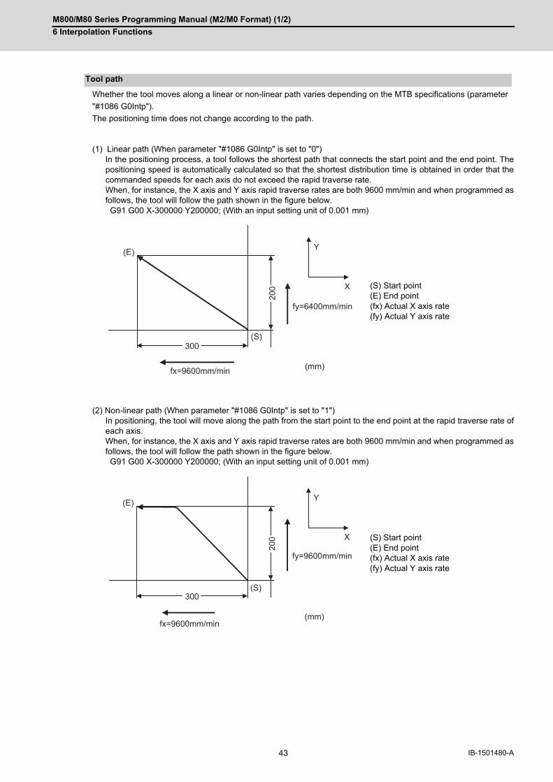
M800/M80 Series Programming Manual (M2/M0 Format) (1/2)
6 Interpolation Functions
43 IB-1501480-A
Whether the tool moves along a linear or non-linear path varies depending on the MTB specifications (parameter
"#1086 G0Intp").
The positioning time does not change according to the path.
(1) Linear path (When parameter "#1086 G0Intp" is set to "0")In the positioning process, a tool follows the shortest path that connects the start point and the end point. Thepositioning speed is automatically calculated so that the shortest distribution time is obtained in order that thecommanded speeds for each axis do not exceed the rapid traverse rate. When, for instance, the X axis and Y axis rapid traverse rates are both 9600 mm/min and when programmed asfollows, the tool will follow the path shown in the figure below. G91 G00 X-300000 Y200000; (With an input setting unit of 0.001 mm)
(2) Non-linear path (When parameter "#1086 G0Intp" is set to "1")In positioning, the tool will move along the path from the start point to the end point at the rapid traverse rate ofeach axis. When, for instance, the X axis and Y axis rapid traverse rates are both 9600 mm/min and when programmed asfollows, the tool will follow the path shown in the figure below. G91 G00 X-300000 Y200000; (With an input setting unit of 0.001 mm)
Tool path
(S) Start point(E) End point(fx) Actual X axis rate(fy) Actual Y axis rate
(S) Start point(E) End point(fx) Actual X axis rate(fy) Actual Y axis rate
300
(mm)
(E)
(S)
fy=6400mm/min
Y
X
200
fx=9600mm/min
300
(mm)
(E)
(S)
fy=9600mm/min
Y
X
200
fx=9600mm/min
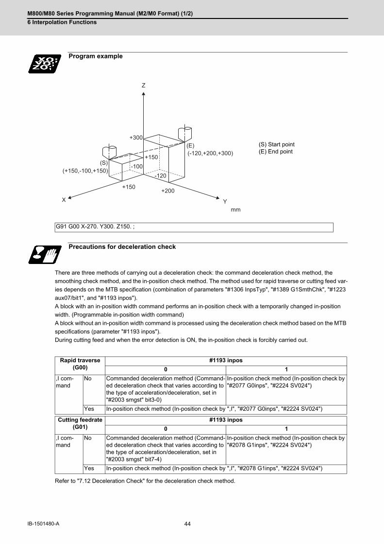
M800/M80 Series Programming Manual (M2/M0 Format) (1/2)
6 Interpolation Functions
44IB-1501480-A
There are three methods of carrying out a deceleration check: the command deceleration check method, the
smoothing check method, and the in-position check method. The method used for rapid traverse or cutting feed var-
ies depends on the MTB specification (combination of parameters "#1306 InpsTyp", "#1389 G1SmthChk", "#1223
aux07/bit1", and "#1193 inpos").
A block with an in-position width command performs an in-position check with a temporarily changed in-position
width. (Programmable in-position width command)
A block without an in-position width command is processed using the deceleration check method based on the MTB
specifications (parameter "#1193 inpos").
During cutting feed and when the error detection is ON, the in-position check is forcibly carried out.
Refer to "7.12 Deceleration Check" for the deceleration check method.
Program example
(S) Start point(E) End point
G91 G00 X-270. Y300. Z150. ;
Precautions for deceleration check
Rapid traverse (G00)
#1193 inpos
0 1
,I com-mand
No Commanded deceleration method (Command-ed deceleration check that varies according to the type of acceleration/deceleration, set in "#2003 smgst" bit3-0)
In-position check method (In-position check by "#2077 G0inps", "#2224 SV024")
Yes In-position check method (In-position check by ",I", "#2077 G0inps", "#2224 SV024")
Cutting feedrate (G01)
#1193 inpos
0 1
,I com-mand
No Commanded deceleration method (Command-ed deceleration check that varies according to the type of acceleration/deceleration, set in "#2003 smgst" bit7-4)
In-position check method (In-position check by "#2078 G1inps", "#2224 SV024")
Yes In-position check method (In-position check by ",I", "#2078 G1inps", "#2224 SV024")
(-120,+200,+300)(E)
(S)(+150,-100,+150)
Y
Z
X
+150
+300
-100
+150
-120
+200
mm

M800/M80 Series Programming Manual (M2/M0 Format) (1/2)
6 Interpolation Functions
45 IB-1501480-A
6.2 Linear Interpolation; G01
This command is accompanied by coordinate words and a feedrate command. It makes the tool move (interpolate)
linearly from its current position to the end point specified by the coordinate words at the speed specified by address
F. In this case, the feedrate specified by address F always acts as a linear speed in the tool nose center advance
direction.
(1) G01 command is a modal command in the 01 group. When G01 command is successively issued, the followingblocks can be specified only by the coordinate words. If there is no command, a program error (P62) will occur.
(2) The feedrate for a rotary axis is commanded by °/min (decimal point position unit). (F300=300°/min)
(3) The G functions (G72 to G89) in the 09 group are cancelled (G80) by the G01 command.
This command commands the in-position width for the linear interpolation command from the machining program.
The commanded in-position width is valid in the linear interpolation command only when carrying out deceleration
check.
When the error detection switch is ON.When G09 (exact stop check) is commanded in the same block.When G61 (exact stop check mode) is selected.
(1) Refer to section "6.1 Positioning (Rapid Traverse); G00" for details on the in-position check operation.
Function and purpose
Command format
Linear interpolation
G01 X__ Y__ Z__ α__ F__ ,I__ ;
X,Y,Z,α Coordinate values (α is the additional axis.)An absolute position or incremental position is indicated based on the state of G90/G91 at that time.
F Feedrate (mm/min or °/min)
,I In-position width. (1 to 999999)This address is valid only in the commanded block. A block that does not contain this address will follow the parameter "#1193 inpos" settings.
Detailed description
Programmable in-position width command for linear interpolation
G01 X_ Y_ Z_ F_ ,I_ ;
X,Y,Z Linear interpolation coordinate value of each axis
F Feedrate
,I In-position width
Note
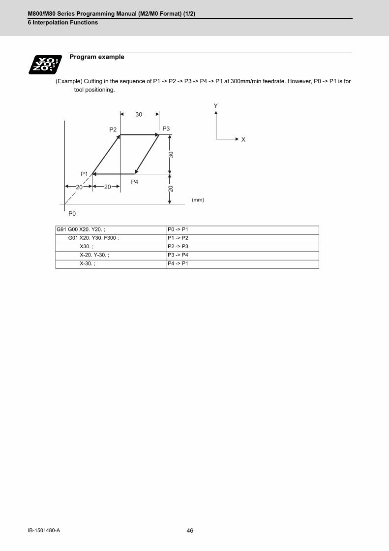
M800/M80 Series Programming Manual (M2/M0 Format) (1/2)
6 Interpolation Functions
46IB-1501480-A
(Example) Cutting in the sequence of P1 -> P2 -> P3 -> P4 -> P1 at 300mm/min feedrate. However, P0 -> P1 is for
tool positioning.
Program example
G91 G00 X20. Y20. ; P0 -> P1
G01 X20. Y30. F300 ; P1 -> P2
X30. ; P2 -> P3
X-20. Y-30. ; P3 -> P4
X-30. ; P4 -> P1
P4P1
P0
P3P2
20
30
20 2030
Y
X
(mm)

M800/M80 Series Programming Manual (M2/M0 Format) (1/2)
6 Interpolation Functions
47 IB-1501480-A
6.3 Circular Interpolation; G02, G03
These commands serve to move the tool along a circular.
Function and purpose
Command format
Circular interpolation : Clockwise (CW)
G02 X__ Y__ I__ J__ F__ ;
Circular interpolation : Counterclockwise (CCW)
G03 X__ Y__ I__ J__ F__ ;
X,Y Arc end point coordinates
I,J Arc center coordinates
F Feedrate

M800/M80 Series Programming Manual (M2/M0 Format) (1/2)
6 Interpolation Functions
48IB-1501480-A
(1) For the arc command, the arc end point coordinates are assigned with addresses X, Y (or Z, or parallel axis X,Y, Z), and the arc center coordinate value is assigned with addresses I, J (or K). Either an absolute value or incremental value can be used for the arc end point coordinate value command, butthe arc center coordinate value must always be commanded with an incremental value from the start point. The arc center coordinate must be commanded in the input setting unit. Caution is required for the arc commandof an axis for which the input command unit differs. Command with a decimal point to avoid confusion.
(2) G02 (G03) is a modal command of the 01 group. When G02 (G03) command is issued continuously, the nextblock and after can be commanded with only coordinate words. The circular rotation direction is distinguished by G02 and G03. G02 CW (Clockwise)G03 CCW (Counterclockwise)
(3) Select the XY plane, ZX plane or YZ plane to draw an arc on it, using the plane selection G code.
(4) An arc which extends for more than one quadrant can be executed with a single block command.
(5) The following information is needed for circular interpolation.
(6) If an R specification and I, K specification are given at the same time in the same block, the circular commandwith the R specification takes precedence.
Detailed description
G17(X-Y) plane G18(Z-X) plane G19(Y-Z) plane
(a) Plane selection Is there an arc parallel to one of the XY, ZX or YZ planes?
(b) Rotation direction Clockwise (G02) or counterclockwise (G03)
(c) Arc end point coordi-nates
Set by addresses X, Y, Z.
(d) Arc center coordinates Set by addresses I, J, K. (incremental value commands)
(e) Feedrate Set by address F
X
Z
YG03
G03
G03
G02G02
G02
Y
X
G02
G03
G02
G03
X
Z
G02
G03
Y
Z

M800/M80 Series Programming Manual (M2/M0 Format) (1/2)
6 Interpolation Functions
49 IB-1501480-A
Program error (P33) will occur in general use when the center and radius are not designated at circular command.
Depending on the MTB specifications, the linear interpolation can be carried out up to the end point coordinates only
in a block with no center coordinates or radius specified (parameter "#11029 Arc to G1 no Cent"). However, a modal
is the circular modal.
This function is not applied to a circular command by a geometric function.
(Example) #11029 = "1"
Change into linear interpolation command
G90 X0 Y0 ;N1 G02 X20. I10. F500 ; ... (a)N2 G00 X0 ;N3 G02 X20. F500 ; ... (b)M02 ;
(a) The circular interpolation (G02) is executed because there is a center command.
(b) The linear interpolation (G01) is executed because there is no center and radius command.
Y
X
N1
N3
200
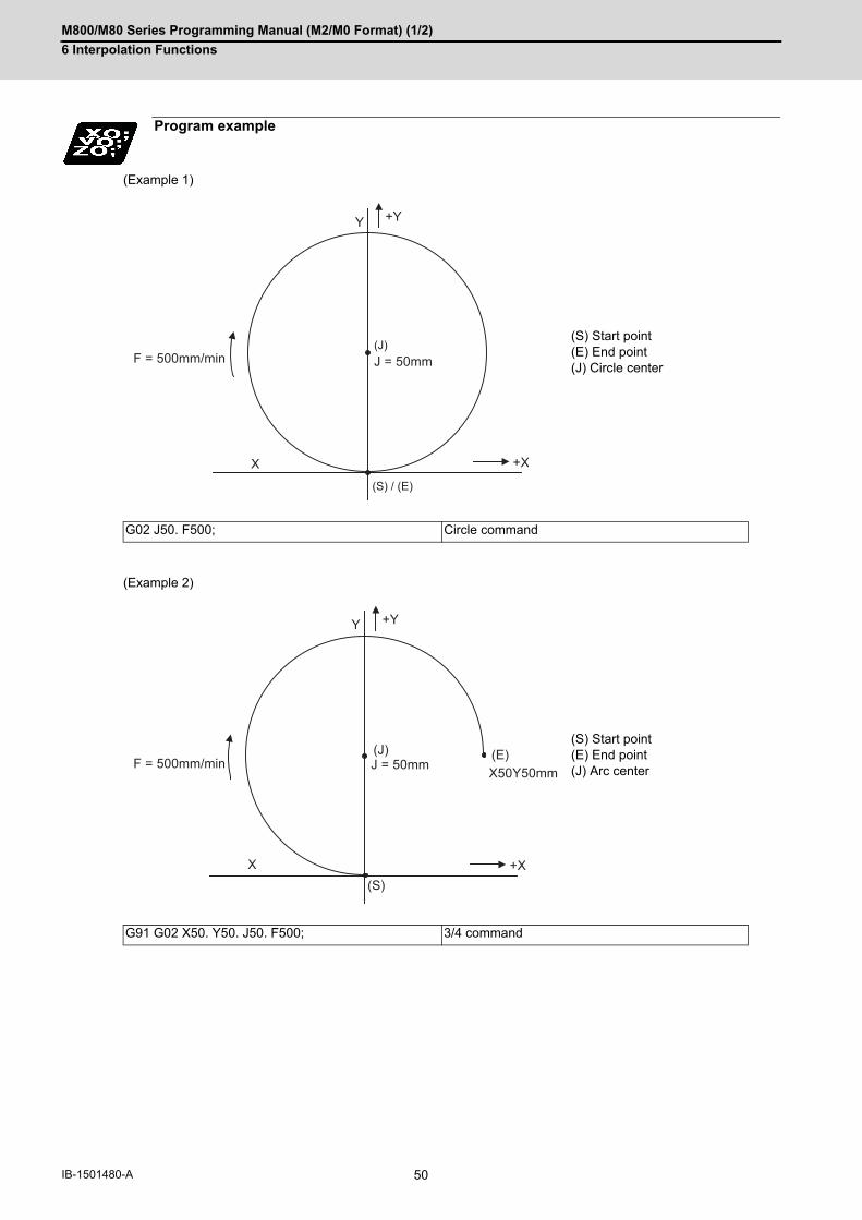
M800/M80 Series Programming Manual (M2/M0 Format) (1/2)
6 Interpolation Functions
50IB-1501480-A
(Example 1)
(Example 2)
Program example
(S) Start point(E) End point(J) Circle center
G02 J50. F500; Circle command
(S) Start point(E) End point(J) Arc center
G91 G02 X50. Y50. J50. F500; 3/4 command
F = 500mm/min
+Y
+X
J = 50mm
Y
X
(S) / (E)
(J)
F = 500mm/min
+Y
+X
J = 50mm X50Y50mm
(J)
Y
X
(E)
(S)

M800/M80 Series Programming Manual (M2/M0 Format) (1/2)
6 Interpolation Functions
51 IB-1501480-A
(1) The terms "clockwise" (G02) and "counterclockwise" (G03) used for circular operations are defined as a casewhere, in a right-hand coordinate system, the negative direction is viewed from the positive direction of the co-ordinate axis which is at right angles to the plane in question.
(2) If all the end point coordinates are omitted or the end point is at the same position as the start point, commandingthe center using I, J and K is the same as commanding a 360°arc (perfect circle).
(3) The following occurs when the start and end point radius do not match in a circular command :
Also, if "#1084 RadErr" is set to "0", "0.1" is assumed to set.
Precautions
(a) Program error (P70) results at the circular start point when error ∆R is greater than parameter "#1084 RadErr".
#1084 RadErr parameter value 0.100 Start point radius=5.000 End point radius=4.899 Error ∆R =0.101 (S) Start point(CP) Center point(E) End point(SR) Start point radius(ER) End point radius(AL) Alarm stop
(b) Spiral interpolation in the direction of the commanded end point will be conducted when error ∆R is less than the parameter value.
#1084 RadErr parameter value 0.100 Start point radius=5.000 End point radius=4.900 Error ∆R =0.100 (S) Start point(CP) Center point(E) End point(SR) Start point radius(ER) End point radius(SI) Spiral interpolation
(G91) G02 X9.899 I5. ;
∆R(S)
(AL)
(SR) (ER)
(CP) (E)
(G91) G02 X9.9 I5. ;
∆R
(SI)
(E)(CP)(S)
(SR) (ER)
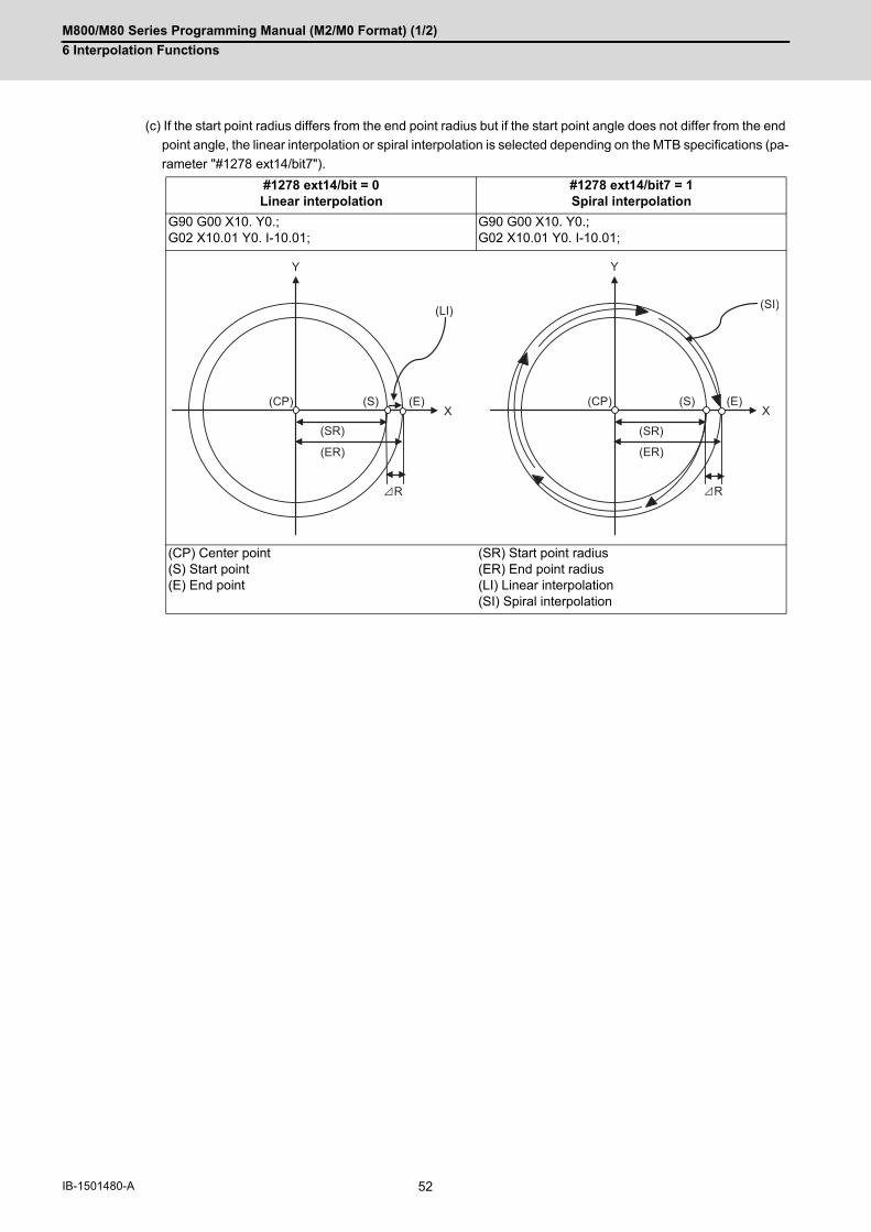
M800/M80 Series Programming Manual (M2/M0 Format) (1/2)
6 Interpolation Functions
52IB-1501480-A
(c) If the start point radius differs from the end point radius but if the start point angle does not differ from the end
point angle, the linear interpolation or spiral interpolation is selected depending on the MTB specifications (pa-
rameter "#1278 ext14/bit7").
#1278 ext14/bit = 0Linear interpolation
#1278 ext14/bit7 = 1Spiral interpolation
G90 G00 X10. Y0.;G02 X10.01 Y0. I-10.01;
G90 G00 X10. Y0.;G02 X10.01 Y0. I-10.01;
(CP) Center point(S) Start point(E) End point
(SR) Start point radius(ER) End point radius (LI) Linear interpolation(SI) Spiral interpolation
(CP) (E)(S)
(SR)
(ER)
(LI)
R
X
Y
(CP) (E)(S)
(SR)
(ER)
R
(SI)
X
Y

M800/M80 Series Programming Manual (M2/M0 Format) (1/2)
6 Interpolation Functions
53 IB-1501480-A
6.4 R Specification Circular Interpolation; G02, G03
Along with the conventional circular interpolation commands based on the circular center coordinate (I, J, K) desig-
nation, these commands can also be issued by directly designating the circular radius R.
The arc radius must be commanded in the input setting unit. Caution is required for the arc command of an axis for
which the input command unit (#1015 cunit) differs. Command with a decimal point to avoid confusion.
A maximum of 6 digits before decimal point can be specified for the radius.
The circular center is on the bisector line which is perpendicular to the line connecting the start and end points of
the circular. The point, where the circular with the specified radius whose start point is the center intersects the per-
pendicular bisector line, serves as the center coordinates of the circular command.
If the R sign of the commanded program is plus, the circular is smaller than a semicircular; if it is minus, the circular
is larger than a semicircular.
Function and purpose
Command format
R specification circular interpolation Clockwise (CW)
G02 X__ Y__ R__ F__ ;
R specification circular interpolation Counterclockwise (CCW)
G03 X__ Y__ R__ F__ ;
X X axis end point coordinate
Y Y axis end point coordinate
R Circular radius
F Feedrate
Detailed description
(S) Start point(E) End point(C1): Arc center if R<0(C2): Arc center if R>0
R < 0
R > 0
(E)
(S)
L
r
(C1)
(C2)

M800/M80 Series Programming Manual (M2/M0 Format) (1/2)
6 Interpolation Functions
54IB-1501480-A
The following condition must be met with an R-specified arc interpolation command:
Where L is the line from the start point to the end point. If an R specification and I, J, (K) specification are given at
the same time in the same block, the circular command with the R specification takes precedence. In the case of a
full-circle command (where the start and end points coincide), an R specification circular command will be completed
immediately even if it is issued and no operation will be executed. An I, J, (K) specification circular command should
therefore be used in such a case.
The plane selection command is the same as the I, J, or K specification circular command.
When "the error margin between the segment connecting the start and end points" and "the commanded radius ×
2" is less than the setting value because the required semicircle is not obtained by calculation error in R specification
circular interpolation, "the midpoint of the segment connecting the start and end points" is compensated for as the
circular center.
The setting value depends on the MTB specifications (parameter "#11028 Tolerance Arc Cent" (Tolerable correction
value of arc center error)).
(Example) #11028 = "0.000 (mm)"
Calculation error margin compensation allowance value: 0.002 mm
Segment connecting the start and end points: 10.000
N3: Radius × 2 = 10.002 "Error 0.002 -> Compensate"
N5: Radius × 2 = 10.004 "Error 0.004 -> Do not compensate"
When (L/2 - r) > (parameter : #1084 RadErr), an alarm will occur.
Circular center coordinate compensation
Setting value Tolerance value
Setting value < 0 0 (Center error will not be interpolated)
Setting value = 0 2×minimum setting increment
Setting value > 0 Setting value
G90 X0 Y0 ;N1 G02 X10. R5.000;N2 G00 X0; N3 G02 X10. R5.001; ...(a)N4 G00 X0;N5 G02 X10. R5.002; ...(b)N6 G00 X0;M02 ;
(a) Compensate the center coordinate: Same as N1 path
(b) Do not compensate the center coordinate: Inside path a little than N1
L12 r
N1, N3
N5
100X
Y

M800/M80 Series Programming Manual (M2/M0 Format) (1/2)
6 Interpolation Functions
55 IB-1501480-A
(Example 1)
(Example 2)
(Example 3)
(Example 4)
(1) In the case of a full-circle command (where the start and end points coincide), an R specification circular com-mand will be completed immediately even if it is issued and no operation will be executed. An I, J, K specificationcircular command should therefore be used in such a case.
(2) If an R specification and I, K specification are given at the same time in the same block, the circular commandwith the R specification takes precedence.
Program example
G02 Xx1 Yy1 Rr1 Ff1 ; XY plane R-specified arc
G03 Zz1 Xx1 Rr1 Ff1 ; R specification circular on Z-X plane
G02 Xx1 Yy1 Ii1 Jj1 Rr1 Ff1 ; XY plane R-specified arc(When the R specification and I, J, (K) specification are contained in the same block, the circular command with the R specification takes precedence.)
G17 G02 Ii1 Jj1 Rr1 Ff1 ; XY plane This is an R-specified arc, but as this is a circle command, it will be completed immediately.
Precautions

M800/M80 Series Programming Manual (M2/M0 Format) (1/2)
6 Interpolation Functions
56IB-1501480-A
6.5 Plane Selection; G17, G18, G19
The plane to which the movement of the tool during the circle interpolation (including helical cutting) and tool radius
compensation command belongs is selected.
If the 3 basic axes and the parallel axes corresponding to these basic axes are entered as parameters, the com-
mands can select the plane composed of any 2 axes which are not parallel axes. If a rotary axis is entered as a
parallel axis, the commands can select the plane containing the rotary axis.
These commands are used to select:
Plane that executes circular interpolation (including helical cutting)Plane that executes tool radius compensationUsed to select a plane that executes fixed cycle positioning.
X, Y and Z indicate each coordinate axis or the parallel axis.
Table 1 Examples of plane selection parameter entry
As shown in the above example, the basic axis and its parallel axis can be registered.
The basic axis can be an axis other than X, Y and Z.
Axes that are not registered are irrelevant to the plane selection.
Function and purpose
Command format
G17; (J-K plane selection)
G18; (Z-X plane selection)
G19; (Y-Z plane selection)
Detailed description
Parameter entry
#1026-1028 #1029-1031
Basic axis I, J, K Flat axis I, J, K
I X U
J Y
K Z V
M800/M80 Series Programming Manual (M2/M0 Format) (1/2)
6 Interpolation Functions
57 IB-1501480-A
In Table 1, characters I, J, K represent the following axes.
I: Horizontal axis for the G17 plane or the vertical axis for the G18 plane
J: Vertical axis for the G17 plane or horizontal axis for the G19 plane
K: Horizontal axis for the G18 plane or vertical axis for the G19 plane
Therefore, the G17, G18 and G19 commands select the following planes.
G17: I-J plane
G18: K-I plane
G19: J-K plane
(1) Axis addresses assigned in the same block as the plane selection (G17, G18, G19) command determine whichof the basic axes or parallel axes are to be in the actual plane selected. For the parameter entry example in Table 1G17 X__ Y__ ; X-Y planeG18 X__ V__ ; V-X planeG18 U__ V__ ; V-U planeG19 Y__ Z__ ; Y-Z planeG19 Y__ V__ ; Y-V plane
(2) Plane selection is not performed with blocks in which the plane selection G code (G17, G18, G19) is not as-signed. G17 X__ Y__ ; X-Y plane Y__ Z__ ; X-Y plane (No plane change)
(3) If the axis address is omitted in the block where the plane selection G code (G17, G18, G19) is commanded, itis assumed that the axis addresses of the 3 basic axes have been omitted. For the parameter entry example in Table 1G17 ; X-Y planeG17 U__ ; U-Y planeG18 U__ ; Z-U planeG18 V__ ; V-X planeG19 Y__ ; Y-Z planeG19 V__ ; Y-V plane
(4) When the axis addresses are commanded to the same block as the plane selection G code (G17, G18, G19),the commanded axes will travel.
(5) The axis command that does not exist in the plane determined by the plane selection G code (G17, G18, G19)is irrelevant to the plane selection. For the parameter entry example in Table 1G17 U__Z__ ;If the above is commanded, the U-Y plane will be selected, and Z will move regardless of the plane.
(6) When the basic axes or their parallel axes are duplicated and assigned in the same block as the plane selectionG code (G17, G18, G19), the plane is determined in the order of basic axes, and then parallel axes. For the parameter entry example in Table 1.G17 U__Y__W__ ;If the above is commanded, the UY plane will be selected, and W will move regardless of the plane.
When the power is turned ON or when the system is reset, the plane set by the parameter "#1025 Initial planeselection" is selected.
Plane selection system
Note

M800/M80 Series Programming Manual (M2/M0 Format) (1/2)
6 Interpolation Functions
58IB-1501480-A
6.6 Thread Cutting
6.6.1 Constant Lead Thread Cutting; G33
The G33 command exercises feed control over the tool which is synchronized with the spindle rotation and so this
makes it possible to conduct constant-lead straight thread-cutting, and tapered thread-cutting. Multiple thread
screws, etc., can also be machined by designating the thread cutting angle.
(1) The E command is also used for the number of ridges in inch thread cutting, and whether the number of ridgesor precision lead is to be designated can be selected by parameter setting. (Parameter "#8156 Fine thread cutE" is set to "1" for precision lead designation.)
(2) The lead in the long axis direction is commanded for the taper thread lead.
Function and purpose
Command format
Normal lead thread cutting
G33 Z__(X__ Y__ α__) F__ Q__ ;
Z (X Y α) End point of thread cutting
F Lead of long axis (axis which moves most) direction
Q Thread cutting start shift angle (0.001 - 360.000°)
Precision lead thread cutting
G33 Z__(X__ Y__ α__) E__ Q__ ;
Z (X Y α) End point of thread cutting
E Lead of long axis (axis which moves most) direction
Q Thread cutting start shift angle (0.001 - 360.000°)
Detailed description
(t) Tapered thread sectionWhen a < 45°, lead is in LZ direction.When a > 45°, lead is in LX direction.When a = 45°, lead can be in either LZ or LX direc-tion.
LZ
Z
XLX
a
(t)
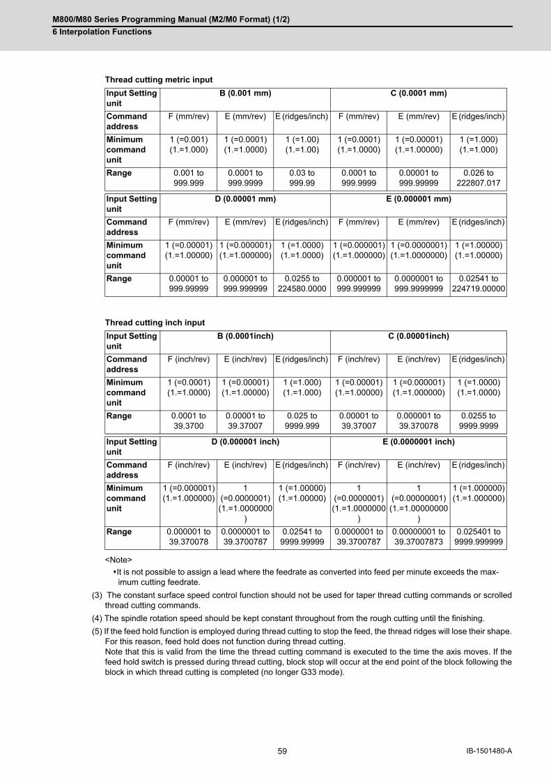
M800/M80 Series Programming Manual (M2/M0 Format) (1/2)
6 Interpolation Functions
59 IB-1501480-A
Thread cutting metric input
Thread cutting inch input
<Note>
It is not possible to assign a lead where the feedrate as converted into feed per minute exceeds the max-imum cutting feedrate.
(3) The constant surface speed control function should not be used for taper thread cutting commands or scrolledthread cutting commands.
(4) The spindle rotation speed should be kept constant throughout from the rough cutting until the finishing.
(5) If the feed hold function is employed during thread cutting to stop the feed, the thread ridges will lose their shape.For this reason, feed hold does not function during thread cutting. Note that this is valid from the time the thread cutting command is executed to the time the axis moves. If thefeed hold switch is pressed during thread cutting, block stop will occur at the end point of the block following theblock in which thread cutting is completed (no longer G33 mode).
Input Setting unit
B (0.001 mm) C (0.0001 mm)
Command address
F (mm/rev) E (mm/rev) E (ridges/inch) F (mm/rev) E (mm/rev) E (ridges/inch)
Minimum command unit
1 (=0.001)(1.=1.000)
1 (=0.0001)(1.=1.0000)
1 (=1.00)(1.=1.00)
1 (=0.0001)(1.=1.0000)
1 (=0.00001)(1.=1.00000)
1 (=1.000)(1.=1.000)
Range 0.001 to 999.999
0.0001 to 999.9999
0.03 to 999.99
0.0001 to 999.9999
0.00001 to 999.99999
0.026 to 222807.017
Input Setting unit
D (0.00001 mm) E (0.000001 mm)
Command address
F (mm/rev) E (mm/rev) E (ridges/inch) F (mm/rev) E (mm/rev) E (ridges/inch)
Minimum command unit
1 (=0.00001)(1.=1.00000)
1 (=0.000001)(1.=1.000000)
1 (=1.0000)(1.=1.0000)
1 (=0.000001)(1.=1.000000)
1 (=0.0000001)(1.=1.0000000)
1 (=1.00000)(1.=1.00000)
Range 0.00001 to 999.99999
0.000001 to 999.999999
0.0255 to 224580.0000
0.000001 to 999.999999
0.0000001 to 999.9999999
0.02541 to 224719.00000
Input Setting unit
B (0.0001inch) C (0.00001inch)
Command address
F (inch/rev) E (inch/rev) E (ridges/inch) F (inch/rev) E (inch/rev) E (ridges/inch)
Minimum command unit
1 (=0.0001)(1.=1.0000)
1 (=0.00001)(1.=1.00000)
1 (=1.000)(1.=1.000)
1 (=0.00001)(1.=1.00000)
1 (=0.000001)(1.=1.000000)
1 (=1.0000)(1.=1.0000)
Range 0.0001 to 39.3700
0.00001 to 39.37007
0.025 to 9999.999
0.00001 to 39.37007
0.000001 to 39.370078
0.0255 to 9999.9999
Input Setting unit
D (0.000001 inch) E (0.0000001 inch)
Command address
F (inch/rev) E (inch/rev) E (ridges/inch) F (inch/rev) E (inch/rev) E (ridges/inch)
Minimum command unit
1 (=0.000001)(1.=1.000000)
1 (=0.0000001)(1.=1.0000000
)
1 (=1.00000)(1.=1.00000)
1 (=0.0000001)(1.=1.0000000
)
1 (=0.00000001)(1.=1.00000000
)
1 (=1.000000)(1.=1.000000)
Range 0.000001 to 39.370078
0.0000001 to 39.3700787
0.02541 to 9999.99999
0.0000001 to 39.3700787
0.00000001 to 39.37007873
0.025401 to 9999.999999

M800/M80 Series Programming Manual (M2/M0 Format) (1/2)
6 Interpolation Functions
60IB-1501480-A
(6) The converted cutting feedrate is compared with the cutting feed clamp rate when thread cutting starts, and if itis found to exceed the clamp rate, an operation error will occur.
(7) In order to protect the lead during thread cutting, a cutting feedrate which has been converted may sometimesexceed the cutting feed clamp rate.
(8) An illegal lead is normally produced at the start of the thread and at the end of the cutting because of servo sys-tem delay and other such factors. Therefore, it is necessary to command a thread length which is determined by adding the illegal lead lengths tothe required thread length.
(9) The spindle rotation speed is subject to the following restriction: 1 <= R <= Maximum feedrate/Thread leadWhere R <= Tolerable speed of encoder (r/min)R: Spindle rotation speed (r/min)Thread lead = mm or inchesMaximum feedrate= mm/min or inch/mim (this is subject to the restrictions imposed by the machine specifica-tions.)
(10) A program error (P93) may occur when the result of the expression (9) is R<1 because the thread lead is verylarge to the highest cutting feedrate.
(11) Dry run is valid for thread cutting but the feedrate based on dry run is not synchronized with the spindle rotation. The dry run signal is checked at the start of thread cutting and any switching during thread cutting is ignored.
(12) Synchronous feed applies for the thread cutting commands even with an asynchronous feed command (G94).
(13) Spindle override and cutting feed override are invalid and the speeds are fixed to 100% during thread cutting.
(14) When a thread cutting is commanded during tool radius compensation, the compensation is temporarily can-celed and the thread cutting is executed.
(15) When the mode is switched to another automatic mode while G33 is executed, the following block which doesnot contain a thread cutting command is first executed and then the automatic operation stops.
(16) When the mode is switched to the manual mode while G33 is executed, the following block which does not con-tain a thread cutting command is first executed and then the automatic operation stops. In the case of a singleblock, the following block which does not contain a thread cutting command (G33 mode is canceled) is first ex-ecuted and then the automatic operation stops. Note that automatic operation is stopped until the G33 commandaxis starts moving.
(17) The thread cutting command waits for the single rotation synchronization signal of the rotary encoder and startsmovement. Make sure to carry out timing synchronization operation between part systems before issuing a thread cuttingcommand with multiple part systems. For example, when using the 1-spindle specifications with two part sys-tems, if one part system issues a thread cutting command during ongoing thread cutting by another part system,the movement will start without waiting for the rotary encoder single rotation synchronization signal causing anillegal operation.
(18) The thread cutting start shift angle is not modal. If there is no Q command with G33, this will be handled as "Q0".
(19) The automatic handle interrupt/interruption is valid during thread cutting.
(20) If a value exceeding 360.000 is command in G33 Q, a program error (P35) will occur.
(21) G33 cuts one row with one cycle. To cut two rows, change the Q value, and issue the same command.

M800/M80 Series Programming Manual (M2/M0 Format) (1/2)
6 Interpolation Functions
61 IB-1501480-A
Program example
N110 G90 G00 X-200. Y-200. S50 M3 ; The spindle center is positioned to the workpiece center, and the spin-dle rotates in the forward direction.N111 Z110 ;
N112 G33; Z40 F6.0; The first thread cutting is executed. Thread lead = 6.0mm
N113 M19 ; Spindle orientation is executed with the M19 command.
N114 G00 X-210.; The tool is evaded in the X axis direction.
N115 Z110. M0 ; The tool rises to the top of the workpiece, and the program stops with M00.Adjust the tool if required.
N116 X-200. ; M3 ;
Preparation for second thread cutting is done.
N117 G04 X5.0 ; Command dwell to stabilize the spindle rotation if necessary.
N118 G33 Z40.; The second thread cutting is executed.
Z
XY
X
10
50
10

M800/M80 Series Programming Manual (M2/M0 Format) (1/2)
6 Interpolation Functions
62IB-1501480-A
6.6.2 Inch Thread Cutting; G33
If the number of ridges per inch in the long axis direction is assigned in the G33 command, the feed of the tool syn-
chronized with the spindle rotation will be controlled, which means that constant-lead straight thread-cutting and ta-
pered thread-cutting can be performed.
(1)The number of ridges in the long axis direction is assigned as the number of ridges per inch.
(2)The E code is also used to assign the precision lead length, and whether the number of ridges or precision lead
length is to be designated can be selected by parameter setting. (The number of ridges is designated by setting
the parameter "#8156 Fine thread cut E" to "0".)
(3)The E command value should be set within the lead value range when converted to lead.
(4)See Section "Constant lead thread cutting" for other details.
Function and purpose
Command format
G33 Z__ (X_ Y_ α_) E__ Q__ ; ... Inch thread cutting
Z (X Y α) End point of thread cutting
E Number of ridges per inch in direction of long axis (axis which moves most) (decimal point command can also be assigned)
Q Thread cutting start shift angle, 0 to 360°
Detailed description

M800/M80 Series Programming Manual (M2/M0 Format) (1/2)
6 Interpolation Functions
63 IB-1501480-A
Thread lead ..... 3 threads/inch (= 8.46666 ...)
When programmed with δ1= 10 mm, δ2=10 mm using metric input
Program example
N210 G90 G00 X-200. Y-200. S50 M3 ;
N211 Z110. ;
N212 G91 G33 Z-70. E3.0 ; (First thread cutting)
N213 M19;
N214 G90 G00 X-210. ;
N215 Z110. M0 ;
N216 X-200. ; M3 ;
N217 G04 X2.0 ;
N218 G91 G33 Z-70. ; (Second thread cutting)
Z
XY
X
150.0mm
2

M800/M80 Series Programming Manual (M2/M0 Format) (1/2)
6 Interpolation Functions
64IB-1501480-A
6.7 Helical Interpolation ; G17, G18, G19 and G02, G03
When this interpolation is performed with 3 orthogonal axes, the tool will travel helically when circular interpolation
is executed for any 2 axes and, at the same time, when another 1 axis is synchronized with the rotation of the circular
and linear interpolation is executed synchronously with the rotation of the circular arc.
Large diameter threads and 3-dimensional cams can be machined.
Either an absolute value or incremental value can be used for the arc end point coordinate value command and the linear axis end point coordinate value command, but the arc center coordinate value must always be commanded with an incremental value from the start point. The arc center coordinate value and arc radius value must be commanded in the input setting unit. Caution is re-quired for the helical interpolation command of an axis for which the input command unit differs. Command with a decimal point to avoid confusion.
Function and purpose
3-dimensional path XY plane path (projection path)
(S) Start point (E) End point
Program command path XY plane projection path in command program
Command format
Helical interpolation command (Specify arc center)
G17/G18/G19 G02/G03 X__ Y__ Z__ I__ J__ P__ F__ ;
Helical interpolation command (Specify radius (R))
G17/G18/G19 G02/G03 X__ Y__ Z__ R__ F__ ;
G17/G18/G19 Arc plane (G17: XY plane, G18: ZX plane, G19: YZ plane)
G02/G03 Arc rotation direction (G02: clockwise, G03: counterclockwise)
X, Y Arc end point coordinates
Z Linear axis end point coordinates
I, J Arc center coordinates
P Number of pitches
R Circular radius
F Feedrate
Z
Y(S)
(E)
X
j
Y
X
i
(E)
(S)

M800/M80 Series Programming Manual (M2/M0 Format) (1/2)
6 Interpolation Functions
65 IB-1501480-A
Normally, the helical interpolation speed is designated with the tangent speed F' including the 3rd axis interpolation
element as shown in the lower drawing. However, when designating the arc plane element speed, the tangent speed
F on the arc plane is commanded as shown in the upper drawing.
The NC automatically calculates the helical interpolation tangent speed F' so that the tangent speed on the arc plane
is F.
Whether the arc plane element speed designation or the normal speed designation is valid depends on the MTB
specifications.
Command the feedrate F as the composite speed for each axis.
Detailed description
Speed designation during the helical interpolation
(S) Start point (E) End point
#1235 set07/bit0 Meaning
1 Arc plane element speed designation is selected.
0 Normal speed designation is selected.
F
Y
X (S)
(E)
Y
Z
X
F'
(S)
(E)

M800/M80 Series Programming Manual (M2/M0 Format) (1/2)
6 Interpolation Functions
66IB-1501480-A
(1) This command should be issued with a linear axis (multiple axes can be commanded) that does not contain acircular axis in the circular interpolation command combined.
(2) For feedrate F, command the X, Y and Z axis composite element directions speed.
(3) Pitch L is obtained with the following expression.
xs, ys: Start point coordinates from the arc center xe, ye: End point coordinates from the arc center
(4) If pitch No. is 0, address P can be omitted.
<Note>
The pitch No. P command range is 0 to 9999. The pitch No. designation (P command) cannot be made with the R-specified arc.
(5) Plane selectionThe helical interpolation arc plane selection is determined with the plane selection mode and axis address as forthe circular interpolation. For the helical interpolation command, the plane where circular interpolation is execut-ed is commanded with the plane selection G code (G17, G18, G19), and the 2 circular interpolation axes andlinear interpolation axis (axis that intersects with circular plane) 3 axis addresses are commanded. XY plane circular, Z axis linearCommand the X, Y and Z axis addresses in the G02 (G03) and G17 (plane selection G code) mode. ZX plane circular, Y axis linearCommand the X, Y and Z axis addresses in the G02 (G03) and G18 (plane selection G code) mode. YZ plane circular, X axis linear Command the X, Y and Z axis addresses in the G02 (G03) and G19 (plane selection G code) mode. The plane for an additional axis can be selected as with circular interpolation. UY plane circular, Z axis linearCommand the U, Y and Z axis addresses in the G02 (G03) and G17 (plane selection G code) mode. In addition to the basic command methods above, the command methods described in the following programexample can be used. Refer to the section "6.5 Plane Selection; G17, G18, G19" for the arc planes selected withthese command methods.
Normal speed designation
(S) Start point (E) End point
Z
Y
X
L
P
Z
Y
X
(E)
(S)
e
s2
1
L =
= e - s = tan - 1 - tan - 1 ( )0 < 2ysye
xsxe
(2 P + )/2Z

M800/M80 Series Programming Manual (M2/M0 Format) (1/2)
6 Interpolation Functions
67 IB-1501480-A
If arc plane element speed designation is selected, the F command will be handled as modal data in the same man-
ner as the normal F command. This will also apply to the following G01, G02 and G03 commands.
(Example)
When the arc plane element speed designation is selected, only the helical interpolation speed command is con-
verted to the speed commanded with the arc plane element and operates. The other linear and arc commands op-
erate as normal speed commands.
(1) The actual feedrate display (Fc) indicates the tangent element of the helical interpolation.
(2) The modal value speed display (FA) indicates the command speed.
(3) The speed data acquired with API functions follows the Fc and FA display.
(4) This function is valid only when feed per minute (asynchronous feed: G94) is selected. If feed per revolution (syn-chronous feed: G95) is selected, the arc plane element speed will not be designated.
Arc plane element speed designation selection
G17 G91 G02 X10. Y10. Z-4. I10. F100 ; Helical interpolation at speed at which arc plane element is F100
G01 X20 ; Linear interpolation at F100
G02 X10. Y-10. Z4. J-10. ; Helical interpolation at speed at which arc plane element is F100
G01 Y-40. F120; Linear interpolation at F120
G02 X-10. Y-10. Z-4. I-10. ; Helical interpolation at speed at which arc plane element is F120
G01 X-20 ; Linear interpolation at F120
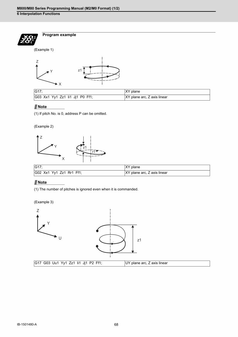
M800/M80 Series Programming Manual (M2/M0 Format) (1/2)
6 Interpolation Functions
68IB-1501480-A
(Example 1)
(1) If pitch No. is 0, address P can be omitted.
(Example 2)
(1) The number of pitches is ignored even when it is commanded.
(Example 3)
Program example
G17; XY plane
G03 Xx1 Yy1 Zz1 Ii1 Jj1 P0 Ff1; XY plane arc, Z axis linear
G17; XY plane
G02 Xx1 Yy1 Zz1 Rr1 Ff1; XY plane arc, Z axis linear
G17 G03 Uu1 Yy1 Zz1 Ii1 Jj1 P2 Ff1; UY plane arc, Z axis linear
z1
Z
Y
X
Note
Z
Y
X
z1r1
Note
Z
Y
U z1

M800/M80 Series Programming Manual (M2/M0 Format) (1/2)
6 Interpolation Functions
69 IB-1501480-A
(Example 4)
(1) If the same system is used, the standard axis will perform circular interpolation and the additional axis will performlinear interpolation.
(Example 5)
(1) Two or more axes can be designated for the linear interpolation axis.
G18 G03 Xx1 Uu1 Zz1 Ii1 Kk1 Ff1; ZX plane arc, U axis linear
G18 G02 Xx1 Uu1 Yy1 Zz1 Ii1 Jj1 Kk1 Ff1; ZX plane arc, U axis, Y axis linear (The J command is ignored.)
U X
Z
u1
x1
z1
Note
Note
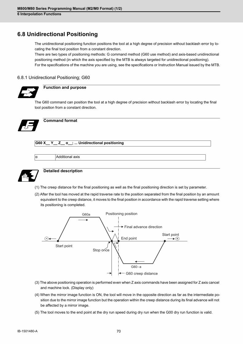
M800/M80 Series Programming Manual (M2/M0 Format) (1/2)
6 Interpolation Functions
70IB-1501480-A
6.8 Unidirectional Positioning
The unidirectional positioning function positions the tool at a high degree of precision without backlash error by lo-
cating the final tool position from a constant direction.
There are two types of positioning methods: G command method (G60 use method) and axis-based unidirectional
positioning method (in which the axis specified by the MTB is always targeted for unidirectional positioning).
For the specifications of the machine you are using, see the specifications or Instruction Manual issued by the MTB.
6.8.1 Unidirectional Positioning; G60
The G60 command can position the tool at a high degree of precision without backlash error by locating the final
tool position from a constant direction.
(1) The creep distance for the final positioning as well as the final positioning direction is set by parameter.
(2) After the tool has moved at the rapid traverse rate to the position separated from the final position by an amount
equivalent to the creep distance, it moves to the final position in accordance with the rapid traverse setting where
its positioning is completed.
(3) The above positioning operation is performed even when Z axis commands have been assigned for Z axis cancel
and machine lock. (Display only)
(4) When the mirror image function is ON, the tool will move in the opposite direction as far as the intermediate po-
sition due to the mirror image function but the operation within the creep distance during its final advance will not
be affected by a mirror image.
(5) The tool moves to the end point at the dry run speed during dry run when the G00 dry run function is valid.
Function and purpose
Command format
G60 X__ Y__ Z__ α__; ... Unidirectional positioning
α Additional axis
Detailed description
- +
G60a
G60 - a
End pointStart point
Start point
Final advance direction
G60 creep distance
Positioning position
Stop once
M800/M80 Series Programming Manual (M2/M0 Format) (1/2)
6 Interpolation Functions
71 IB-1501480-A
(6) Feed during creep distance movement with final positioning can be stopped by resetting, emergency stop, inter-
lock, feed hold and rapid traverse override zero.
The tool moves over the creep distance at the rapid traverse setting. Rapid traverse override is valid.
(7) Unidirectional positioning is not performed for the drilling axis during drilling fixed cycles.
(8) Unidirectional positioning is not performed for shift amount movements during the fine boring or back boring fixed
cycle.
(9) Normal positioning is performed for axes whose creep distance has not been set by parameter.
(10) Unidirectional positioning is always a non-interpolation type of positioning.
(11) When the same position (movement amount of zero) has been commanded, the tool moves back and forth over
the creep distance and is positioned at its original position from the final advance direction.
(12) Program error (P61) will occur when the G60 command is assigned with an NC system which has not been
provided with this particular specification.

M800/M80 Series Programming Manual (M2/M0 Format) (1/2)
6 Interpolation Functions
72IB-1501480-A
6.8.2 Axis-based Unidirectional Positioning
This function carries out unidirectional positioning for each axis for G00 positioning.
The target axis is determined in the MTB specifications (parameter "#2084 G60_ax").
When the unidirectional positioning is commanded, set the last positioning direction and distance to parameter
"#8209 G60 shift amount" for each axis.
The example below shows a case in which axis B is set as the unidirectional positioning axis.
The axis-based unidirectional positioning is the same as for the G60 command. Refer to "Unidirectional Position-
ing:G60".
Function and purpose
G00 X100.; ... Normal positioning
G00 B100.; ... Unidirectional positioning
G00X200.B200.; ... Axis X: Normal positioning, Axis B: Unidirectional positioning
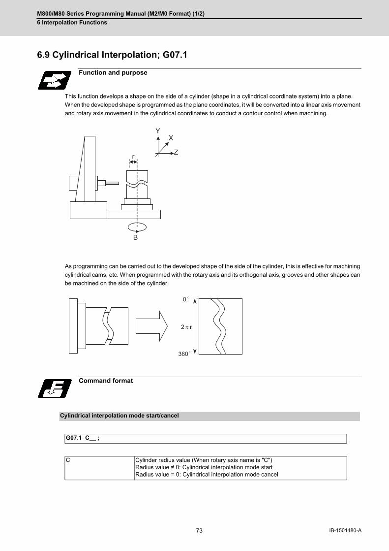
M800/M80 Series Programming Manual (M2/M0 Format) (1/2)
6 Interpolation Functions
73 IB-1501480-A
6.9 Cylindrical Interpolation; G07.1
This function develops a shape on the side of a cylinder (shape in a cylindrical coordinate system) into a plane.
When the developed shape is programmed as the plane coordinates, it will be converted into a linear axis movement
and rotary axis movement in the cylindrical coordinates to conduct a contour control when machining.
As programming can be carried out to the developed shape of the side of the cylinder, this is effective for machining
cylindrical cams, etc. When programmed with the rotary axis and its orthogonal axis, grooves and other shapes can
be machined on the side of the cylinder.
Function and purpose
Command format
Cylindrical interpolation mode start/cancel
G07.1 C__ ;
C Cylinder radius value (When rotary axis name is "C")Radius value ≠ 0: Cylindrical interpolation mode startRadius value = 0: Cylindrical interpolation mode cancel
r
B
Z
X
Y
0
360
2 r

M800/M80 Series Programming Manual (M2/M0 Format) (1/2)
6 Interpolation Functions
74IB-1501480-A
(1) The coordinate commands in the interval from the start to cancellation of the cylindrical interpolation mode willbe the cylindrical coordinate system.
(2) G107 can be used instead of G07.1.
(3) Command G07.1 is an independent block. If it is commanded in the same block with other G code, a programerror (P33) will occur.
(4) Program the rotary axis with an angle degree.
(5) Linear interpolation or circular interpolation can be commanded during the cylindrical interpolation mode. Notethat the plane selection command must be issued just before the G07.1 block.
(6) The coordinate commands can be both an absolute command or incremental command.
(7) Tool radius compensation can be applied on the program command. Cylindrical interpolation will be executed tothe path after it has gone through a tool radius compensation.
(8) Command the tangent speed on the developed cylinder by F. F is in mm/min or inch/min unit.
In the cylindrical interpolation mode, the movement amount of the rotary axis commanded with an angle is converted
into distance on a circle periphery, and after calculating the linear and circular interpolation between the other axes,
the amount is converted into an angle again.
Thus, the actual movement amount may differ from the commanded value such as when the cylinder radius is small.
Note that the gap generated by this will not be cumulated.
#1516 mill_ax (Milling axis name)#8111 Milling Radius#1267 ext03/bit0 (G code type)#1270 ext06/bit7 (Handling of C axis coordinate during cylindrical interpolation)
Detailed description
G07.1 C20.; Cylindrical interpolation mode start (Cylindrical interpolation will start.)
: (The coordinate commands in this interval will be the cylindrical coordinate system)
G07.1 C0 ; Cylindrical interpolation mode cancel (Cylindrical interpolation will be canceled.)
Cylindrical interpolation accuracy
Related parameter
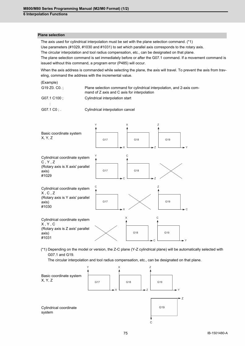
M800/M80 Series Programming Manual (M2/M0 Format) (1/2)
6 Interpolation Functions
75 IB-1501480-A
The axis used for cylindrical interpolation must be set with the plane selection command. (*1)
Use parameters (#1029, #1030 and #1031) to set which parallel axis corresponds to the rotary axis.
The circular interpolation and tool radius compensation, etc., can be designated on that plane.
The plane selection command is set immediately before or after the G07.1 command. If a movement command is
issued without this command, a program error (P485) will occur.
When the axis address is commanded while selecting the plane, the axis will travel. To prevent the axis from trav-
eling, command the address with the incremental value.
(Example)
(*1) Depending on the model or version, the Z-C plane (Y-Z cylindrical plane) will be automatically selected with
G07.1 and G19.
The circular interpolation and tool radius compensation, etc., can be designated on that plane.
Plane selection
G19 Z0. C0. ; Plane selection command for cylindrical interpolation, and 2-axis com-mand of Z axis and C axis for interpolation
G07.1 C100 ; Cylindrical interpolation start
:
G07.1 C0 ; . Cylindrical interpolation cancel
Basic coordinate systemX, Y, Z
Cylindrical coordinate systemC , Y , Z(Rotary axis is X axis' parallel axis)#1029
Cylindrical coordinate systemX , C , Z(Rotary axis is Y axis' parallel axis)#1030
Cylindrical coordinate systemX , Y , C(Rotary axis is Z axis' parallel axis)#1031
Basic coordinate systemX, Y, Z
Cylindrical coordinate system
G17
Y
X
G18
Z
X
G19
Y
Z
G18
Z
C
G17
C
Y
G19
C
Z
G17
X
C
G18
C
X
G19
Y
C
G17
Y
X
G18
Z
X
G19
Y
Z
Z
C
G19
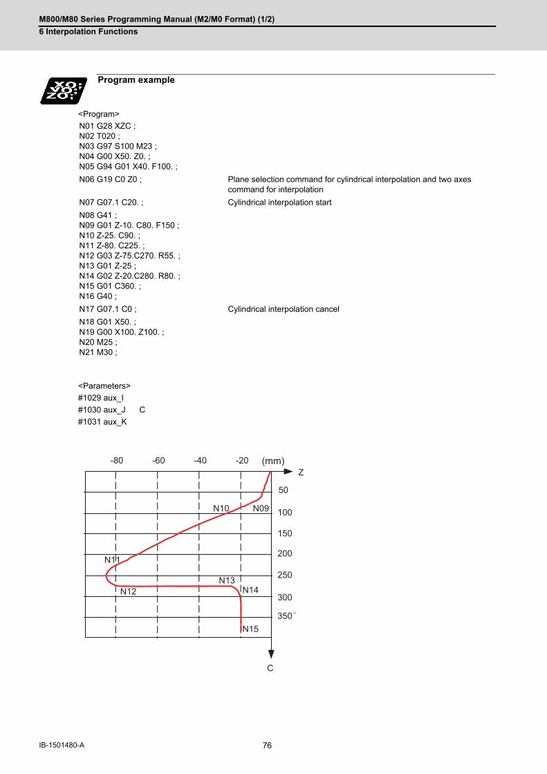
M800/M80 Series Programming Manual (M2/M0 Format) (1/2)
6 Interpolation Functions
76IB-1501480-A
<Program>
<Parameters>
#1029 aux_I
#1030 aux_J C
#1031 aux_K
Program example
N01 G28 XZC ;N02 T020 ;N03 G97 S100 M23 ;N04 G00 X50. Z0. ;N05 G94 G01 X40. F100. ;
N06 G19 C0 Z0 ; Plane selection command for cylindrical interpolation and two axes command for interpolation
N07 G07.1 C20. ; Cylindrical interpolation start
N08 G41 ;N09 G01 Z-10. C80. F150 ;N10 Z-25. C90. ;N11 Z-80. C225. ;N12 G03 Z-75.C270. R55. ;N13 G01 Z-25 ; N14 G02 Z-20.C280. R80. ;N15 G01 C360. ;N16 G40 ;
N17 G07.1 C0 ; Cylindrical interpolation cancel
N18 G01 X50. ;N19 G00 X100. Z100. ;N20 M25 ;N21 M30 ;
50
100
150
200
250
300
350
-20-40-60-80
C
Z
N09N10
N11
N12N13
N14
N15
(mm)

M800/M80 Series Programming Manual (M2/M0 Format) (1/2)
6 Interpolation Functions
77 IB-1501480-A
(1) Circular interpolation between the rotary axis and linear axis is possible during the cylindrical interpolation mode.
(2) An R specification command can be issued with circular interpolation. (I, J and K cannot be designated.)
The tool radius can be compensated during the cylindrical interpolation mode.
(1) Command the plane selection in the same manner as circular interpolation. When using tool radius compensation, start up/cancel the compensation in the cylindrical interpolation mode.
(2) A program error (P485) will occur if G07.1 is commanded during tool radius compensation.
(3) If the G07.1 command is issued with no movement command after the tool radius compensation is canceled, theposition of the axis in the G07.1 command block is interpreted as the position applied after the tool radius com-pensation is canceled and the following operations are performed.
(1) The feed per minute (asynchronous) mode is forcibly set when the cylindrical interpolation mode is started.
(2) When the cylindrical interpolation mode is canceled, the feed per revolution (synchronous) will return to the statebefore the cylindrical interpolation mode was started.
(1) A program error (P485) will occur if G07.1 is commanded in the constant surface speed control mode (G96).
(1) The miscellaneous function (M) and 2nd miscellaneous function can be issued in the cylindrical interpolationmode.
(2) The S command in the cylindrical interpolation mode specifies the rotary tool's rotation speed instead of the spin-dle rotation speed.
(1) Program error (P481) will occur if tool length compensation is performed in the cylindrical interpolation mode.
(2) Complete the tool compensation operation (movement of tool length and wear compensation amount) beforeexecuting the cylindrical interpolation. If the tool compensation operation is not completed when the cylindrical interpolation start command is issued,the followings will occur:
The machine coordinate will not change even if G07.1 is executed.The workpiece coordinate will change to that of the post tool length compensation when G07.1 is executed.
(Even if the cylindrical interpolation is canceled, this workpiece coordinate will not be canceled.)
Relationship with Other Functions
Circular interpolation
Tool radius compensation
Cutting feed per minute (asynchronous feed)
Constant surface speed control
Miscellaneous function
Tool length compensation
:
G43 H12 ; G00 X100. Z0. ; G19 Z C ; G07.1 C100. ;
Tool length compensation before cylindrical interpolation -> Valid
:
G43 H11 ; Tool length compensation in cylindrical interpolation mode -> Program error
:
G07.1 C0 ;

M800/M80 Series Programming Manual (M2/M0 Format) (1/2)
6 Interpolation Functions
78IB-1501480-A
As for the F command during cylindrical interpolation mode, whether to use the previous F command depends on
the previous mode of the feed per minute command (G94/G98) or feed per rotation command (G95/G99).
(1) When G94 (G98) is commanded just before G07.1If there is no F command in the cylindrical interpolation, the previous F command feedrate will be used. After the cylindrical interpolation mode is canceled, the F command feedrate set at the start of the cylindricalinterpolation mode or the last F command feedrate set during cylindrical interpolation will continue to be the fee-drate.
(2) When G95 (G99) is commanded just before G07.1The previous F command feedrate cannot be used during cylindrical interpolation, thus a new F command mustbe issued. After the cylindrical interpolation mode is canceled, the feedrate will return to the state before the cylindrical in-terpolation mode was started.
When there is no F command in G07.1
When F is commanded in G07.1
F command during cylindrical interpolation
Previous mode No F command After G07.1 is canceled
G94 (G98) Previous F is used ←
G95 (G99) Program error (P62) F just before G07.1 is used
Previous mode With F command After G07.1 is canceled
G94 (G98) Commanded F is used ←
G95 (G99) Commanded F is used (*1) F just before G07.1 is used
(*1) Moves with the feed per minute command during G07.1.

M800/M80 Series Programming Manual (M2/M0 Format) (1/2)
6 Interpolation Functions
79 IB-1501480-A
(1) The following G code commands can be used during the cylindrical interpolation mode.
A program error will occur if a G code other than those listed above is commanded during cylindrical interpola-
tion.
(2) The cylindrical interpolation mode is canceled when the power is turned ON or reset.
(3) A program error (P484) will occur if any axis commanded during cylindrical interpolation has not completed thereference position return.
(4) Tool radius compensation must be canceled before canceling the cylindrical interpolation mode.
(5) When the cylindrical interpolation mode is canceled and switched to the cutting mode, the plane selected beforethe cylindrical interpolation will be restored.
(6) Program cannot be restarted (program restart) when the block is in the cylindrical interpolation.
(7) A program error (P486) will occur if the cylindrical interpolation command is issued during the mirror image.
(8) When the cylindrical interpolation mode is started or canceled, the deceleration check is performed.
(9) A program error (P481) will occur if the cylindrical interpolation or the polar coordinate interpolation is command-ed during the cylindrical interpolation mode.
Restrictions and precautions
G code Details
G00 Positioning
G01 Linear interpolation
G02 Circular interpolation (CW)
G03 Circular interpolation (CCW)
G04 Dwell
G09 Exact stop check
G40-42 Tool radius compensation
G61 Exact stop mode
G64 Cutting mode
G65 Macro call (simple call)
G66 Macro modal call (modal call)
G66.1 Macro modal call (block call per macro)
G67 Macro modal call cancel (modal call cancel)
G80-89 Fixed cycle for drilling
G90/91 Absolute/incremental value command
G94 Asynchronous feed
G98 Hole drilling cycle initial return
G99 Hole drilling cycle R point return

M800/M80 Series Programming Manual (M2/M0 Format) (1/2)
6 Interpolation Functions
80IB-1501480-A
6.10 Circular Cutting; G12,G13
Circular cutting starts the tool from the center of the circle, and cuts the inner circumference of the circle. The tool
continues cutting while drawing a circle and returns to the center position.
(1) The sign + for the offset amount indicates reduction, and - indicates enlargement.
(2) The circle cutting is executed on the plane G17, G18 or G19 currently selected.
For G12 (tool center path) 0->1->2->3->4->5->6->7->0
For G13 (tool center path) 0->7->6->5->4->3->2->1->0
Function and purpose
Command format
G12 I__ D__ F__ ; ... Circular cutting Clockwise (CW)
G13 I__ D__ F__ ; ... Circular cutting Counterclockwise (CCW)
I Radius of circle (incremental value), the sign is ignored
D Offset No. (The offset No. and offset data are not displayed on the setting and display unit.)
F Feedrate
Detailed description
Compensation amount sign + Compensation amount sign -
(a) Circle radius (b) d1 offset amount +
(c) d1 offset amount -
0
12
3
4
5
67
(a)
i 1
(b)
(c) X
Y

M800/M80 Series Programming Manual (M2/M0 Format) (1/2)
6 Interpolation Functions
81 IB-1501480-A
(Example 1) G12 I50.000 D01 F100 ; When compensation amount is +10.000mm
(1) If the offset No. "D" is not issued or if the offset No. is illegal, the program error (P170) will occur.
(2) If [Radius (I) - offset amount] is 0 or negative, the program error (P223) will occur.
(3) If G12 or G13 is commanded during radius compensation (G41, G42), the radius compensation will be validated
on the path after compensated with the D, commanded with G12 or G13.
(4) If an address not included in the format is commanded in the same block as G12 and G13, the program error
(P32) will occur.
But when the parameter "#11034 Circular cutting command address check type" is set to "1", it operates as fol-
lows;
(a) Program error will not occur except for an "H" command.
(b) Only "D","F","I" and "M","S","T","B" will be valid.
Program example
Tool
Compensation amount
Radius
Precautions
50.000
10.000
X
Y

M800/M80 Series Programming Manual (M2/M0 Format) (1/2)
6 Interpolation Functions
82IB-1501480-A
6.11 Polar Coordinate Interpolation; G12.1, G13.1/G112, G113
This function converts the commands programmed with the orthogonal coordinate axis into linear axis movement
(tool movement) and rotary axis movement (workpiece rotation), and controls the contour.
The plane that uses the linear axis as the plane's 1st orthogonal axis, and the intersecting hypothetical axis as the
plane's 2nd axis (hereafter "polar coordinate interpolation plane") is selected. Polar coordinate interpolation is car-
ried out on this plane. The workpiece coordinate system zero point is used as the coordinate system zero point
during polar coordinate interpolation.
This is effective for cutting a notch in a linear line to the external diameter of the workpiece, for cutting cam shafts,
etc.
Function and purpose
Linear axis
Rotary axis (Hypothetical axis)
Polar coordinate interpo-lation plane (G17 plane)
Command format
Polar coordinate interpolation mode start
G12.1 ;
Polar coordinate interpolation mode cancel
G13.1 ;
X
Z
C
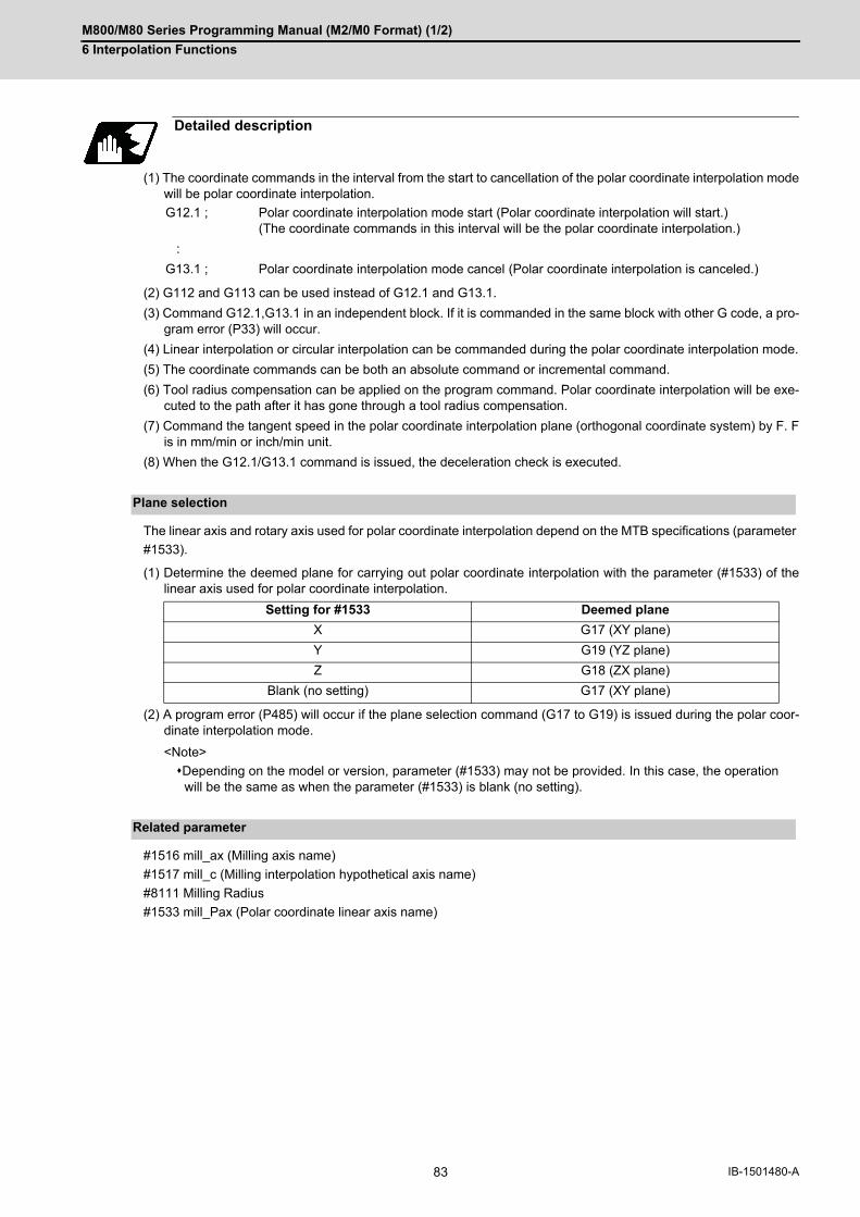
M800/M80 Series Programming Manual (M2/M0 Format) (1/2)
6 Interpolation Functions
83 IB-1501480-A
(1) The coordinate commands in the interval from the start to cancellation of the polar coordinate interpolation modewill be polar coordinate interpolation.
(2) G112 and G113 can be used instead of G12.1 and G13.1.
(3) Command G12.1,G13.1 in an independent block. If it is commanded in the same block with other G code, a pro-gram error (P33) will occur.
(4) Linear interpolation or circular interpolation can be commanded during the polar coordinate interpolation mode.
(5) The coordinate commands can be both an absolute command or incremental command.
(6) Tool radius compensation can be applied on the program command. Polar coordinate interpolation will be exe-cuted to the path after it has gone through a tool radius compensation.
(7) Command the tangent speed in the polar coordinate interpolation plane (orthogonal coordinate system) by F. Fis in mm/min or inch/min unit.
(8) When the G12.1/G13.1 command is issued, the deceleration check is executed.
The linear axis and rotary axis used for polar coordinate interpolation depend on the MTB specifications (parameter
#1533).
(1) Determine the deemed plane for carrying out polar coordinate interpolation with the parameter (#1533) of thelinear axis used for polar coordinate interpolation.
(2) A program error (P485) will occur if the plane selection command (G17 to G19) is issued during the polar coor-dinate interpolation mode.
<Note>
Depending on the model or version, parameter (#1533) may not be provided. In this case, the operationwill be the same as when the parameter (#1533) is blank (no setting).
#1516 mill_ax (Milling axis name)
#1517 mill_c (Milling interpolation hypothetical axis name)
#8111 Milling Radius
#1533 mill_Pax (Polar coordinate linear axis name)
Detailed description
G12.1 ; Polar coordinate interpolation mode start (Polar coordinate interpolation will start.)(The coordinate commands in this interval will be the polar coordinate interpolation.)
:
G13.1 ; Polar coordinate interpolation mode cancel (Polar coordinate interpolation is canceled.)
Plane selection
Setting for #1533 Deemed plane
X G17 (XY plane)
Y G19 (YZ plane)
Z G18 (ZX plane)
Blank (no setting) G17 (XY plane)
Related parameter

M800/M80 Series Programming Manual (M2/M0 Format) (1/2)
6 Interpolation Functions
84IB-1501480-A
<Program>
Program example
Hypothetical C axis
Hypothetical C axis
Tool
Path after tool radius compensation
Programmed path
:
N01 G17 G90 G00 X40.0 C0 Z0; Setting of start position
N02 G12.1 ; Polar coordinate interpolation mode: Start
N03 G01 G42 X20.0 F2000; Actual machining start
N04 C10.0;N05 G03 X10.0 C20.0 R10.0;
N06 G01 X-20.0; Shape program
N07 C-10.0;
N08 G03 X-10.0 C-20.0 I10.0 J0; (Follows orthogonal coordinate positions on X-C hypothetical axis plane.)
N09 G01 X20.0;N10 C00;N11 G40 X40.0;
N12 G13.1 ; Polar coordinate interpolation mode: Cancel
:M30 ;
XC
Z
C
X
N06 N05
N04N03
N10
N09N08
N07N11
N01N02

M800/M80 Series Programming Manual (M2/M0 Format) (1/2)
6 Interpolation Functions
85 IB-1501480-A
(1) The program commands in the polar coordinate interpolation mode are issued by the orthogonal coordinate val-ue of the linear axis and rotary axis (hypothetical axis) on the polar coordinate interpolation plane. The axis address of the rotary axis (C) is specified as the axis address for the plane's 2nd axis (hypothetical axis)command. The command unit is not deg (degree). The same unit (mm or inch) as used for the command by the axis addressof the plane's 1st axis (linear axis) will be used.
(2) The hypothetical axis coordinate value will be set to "0" when G12.1 is commanded. In other words, the positionwhere G12.1 is commanded will be interpreted as angle = 0, and the polar coordinate interpolation will start.
The arc radius address for carrying out circular interpolation during the polar coordinate interpolation mode is deter-
mined with the linear axis parameter (#1533).
The arc radius can also be designated with the R command.
(1) Depending on the model or version, parameter (#1533) may not be provided. In this case, the operation will bethe same as when the parameter (#1533) is blank (no setting).
The tool radius can be compensated during the cylindrical interpolation mode.
(1) Command the plane selection in the same manner as polar coordinate interpolation. When conducting tool radius compensation, it must be started up and canceled during the polar coordinate in-terpolation mode.
(2) A program error (P485) will occur if polar coordinate interpolation is executed during tool radius compensation.
(3) If the G12.1 and G13.1 commands are issued with no movement command after the tool radius compensationis canceled, the position of the axis in the G12.1 and G13.1 commands block is interpreted as the position ap-plied after the tool radius compensation is canceled and the following operations are performed.
(1) The asynchronous mode is forcibly set when the polar coordinate interpolation mode is started.
(2) When the polar coordinate interpolation mode is canceled, the synchronous mode will return to the state beforethe polar coordinate interpolation mode was started.
(3) A program error (P485) will occur if G12.1 is commanded in the constant surface speed control mode (G96).
(1) The miscellaneous function (M) and 2nd miscellaneous function can be issued in the polar coordinate interpola-tion mode.
(2) The S command in the polar coordinate interpolation mode specifies the rotary tool's rotation speed instead ofthe spindle rotation speed.
Relationship with Other Functions
Program commands during polar coordinate interpolation
Circular interpolation on polar coordinate plane
Setting for #1533 Center designation command
X I, J (polar coordinate plane is interpreted as XY plane)
Y J, K (polar coordinate plane is interpreted as YZ plane)
Z K, I (polar coordinate plane is interpreted as ZX plane)
Blank (no setting) I, J (polar coordinate plane is interpreted as XY plane)
Tool radius compensation
Cutting asynchronous feed
Miscellaneous function
Note

M800/M80 Series Programming Manual (M2/M0 Format) (1/2)
6 Interpolation Functions
86IB-1501480-A
(1) Program error (P481) will occur if tool length compensation is performed in the polar coordinate interpolationmode.
(2) Complete the tool compensation operation (movement of tool length and wear compensation amount) beforeexecuting the polar coordinate interpolation. If the tool compensation operation is not completed when the polar coordinate interpolation start command hasbeen issued, the followings will occur:
Machine coordinate will not change even if G12.1 is executed.When G12.1 is executed, the workpiece coordinate will change to that of the post tool length compensation.
(Even if polar coordinate interpolation is canceled, this workpiece coordinate will not be canceled.)
As for the F command during polar coordinate interpolation mode, whether to use the previous F command depends
on the previous mode of the feed per minute command (G94/G98) or feed per rotation command (G95/G99).
(1) When G94 (G98) is commanded just before G12.1If there is no F command in the polar coordinate interpolation, the previous F command feedrate will be used. After the polar coordinate interpolation mode is canceled, the F command feedrate set at the start of the polarcoordinate interpolation mode or the last F command feedrate set during polar coordinate interpolation will con-tinue to be the feedrate.
(2) When G95 (G99) is commanded just before G12.1The previous F command feedrate cannot be used during polar coordinate interpolation. A new F command mustbe issued. The feedrate after the polar coordinate interpolation mode is canceled will return to the state before the polarcoordinate interpolation mode was started.
[When there is no F command in G12.1]
[When F is commanded in G12.1]
Tool length compensation
:
G43 H12 ; Tool length compensation before polar coordinate interpolation -> Valid
G00 X100. Z0. ;G12.1 ; :
G43 H11 ; Tool length compensation in polar coordinate interpolation mode -> Pro-gram error
:G13.1 ;
F command during polar coordinate interpolation
Previous mode No F command After G13.1
G94 (G98) Previous F is used (Same as on the left)
G95 (G99) Program error (P62) F just before G12.1 is used
Previous mode With F command After G13.1
G94 (G98) Commanded F is used (Same as on the left)
G95 (G99) Commanded F is used (*1) F just before G12.1 is used
(*1) Moves with the feed per minute command during G12.1.
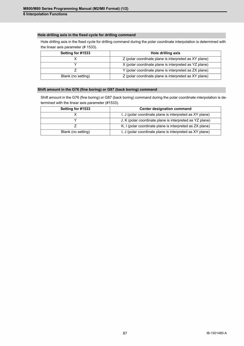
M800/M80 Series Programming Manual (M2/M0 Format) (1/2)
6 Interpolation Functions
87 IB-1501480-A
Hole drilling axis in the fixed cycle for drilling command during the polar coordinate interpolation is determined with
the linear axis parameter (# 1533).
Shift amount in the G76 (fine boring) or G87 (back boring) command during the polar coordinate interpolation is de-
termined with the linear axis parameter (#1533).
Hole drilling axis in the fixed cycle for drilling command
Setting for #1533 Hole drilling axis
X Z (polar coordinate plane is interpreted as XY plane)
Y X (polar coordinate plane is interpreted as YZ plane)
Z Y (polar coordinate plane is interpreted as ZX plane)
Blank (no setting) Z (polar coordinate plane is interpreted as XY plane)
Shift amount in the G76 (fine boring) or G87 (back boring) command
Setting for #1533 Center designation command
X I, J (polar coordinate plane is interpreted as XY plane)
Y J, K (polar coordinate plane is interpreted as YZ plane)
Z K, I (polar coordinate plane is interpreted as ZX plane)
Blank (no setting) I, J (polar coordinate plane is interpreted as XY plane)
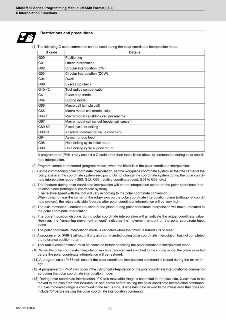
M800/M80 Series Programming Manual (M2/M0 Format) (1/2)
6 Interpolation Functions
88IB-1501480-A
(1) The following G code commands can be used during the polar coordinate interpolation mode.
A program error (P481) may occur if a G code other than those listed above is commanded during polar coordi-
nate interpolation.
(2) Program cannot be restarted (program restart) when the block is in the polar coordinate interpolation.
(3) Before commanding polar coordinate interpolation, set the workpiece coordinate system so that the center of therotary axis is at the coordinate system zero point. Do not change the coordinate system during the polar coordi-nate interpolation mode. (G50, G52, G53, relative coordinate reset, G54 to G59, etc.)
(4) The feedrate during polar coordinate interpolation will be the interpolation speed on the polar coordinate inter-polation plane (orthogonal coordinate system). (The relative speed with the tool will vary according to the polar coordinate conversion.) When passing near the center of the rotary axis on the polar coordinate interpolation plane (orthogonal coordi-nate system), the rotary axis side feedrate after polar coordinate interpolation will be very high.
(5) The axis movement command outside of the plane during polar coordinate interpolation will move unrelated tothe polar coordinate interpolation.
(6) The current position displays during polar coordinate interpolation will all indicate the actual coordinate value.However, the "remaining movement amount" indicates the movement amount on the polar coordinate inputplane.
(7) The polar coordinate interpolation mode is canceled when the power is turned ON or reset.
(8) A program error (P484) will occur if any axis commanded during polar coordinate interpolation has not completedthe reference position return.
(9) Tool radius compensation must be canceled before canceling the polar coordinate interpolation mode.
(10) When the polar coordinate interpolation mode is canceled and switched to the cutting mode, the plane selectedbefore the polar coordinate interpolation will be restored.
(11) A program error (P486) will occur if the polar coordinate interpolation command is issued during the mirror im-age.
(12) A program error (P481) will occur if the cylindrical interpolation or the polar coordinate interpolation is command-ed during the polar coordinate interpolation mode.
(13) During polar coordinate interpolation, if X axis moveable range is controlled in the plus side, X axis has to bemoved to the plus area that includes "0" and above before issuing the polar coordinate interpolation command.If X axis moveable range is controlled in the minus side, X axis has to be moved to the minus area that does notinclude "0" before issuing the polar coordinate interpolation command.
Restrictions and precautions
G code Details
G00 Positioning
G01 Linear interpolation
G02 Circular interpolation (CW)
G03 Circular interpolation (CCW)
G04 Dwell
G09 Exact stop check
G40-42 Tool radius compensation
G61 Exact stop mode
G64 Cutting mode
G65 Macro call (simple call)
G66 Macro modal call (modal call)
G66.1 Macro modal call (block call per macro)
G67 Macro modal call cancel (modal call cancel)
G80-89 Fixed cycle for drilling
G90/91 Absolute/incremental value command
G94 Asynchronous feed
G98 Hole drilling cycle initial return
G99 Hole drilling cycle R point return

M800/M80 Series Programming Manual (M2/M0 Format) (1/2)
6 Interpolation Functions
89 IB-1501480-A
6.12 Exponential Interpolation; G02.3, G03.3
Exponential function interpolation changes the rotary axis into an exponential function shape in respect to the linear
axis movement.
At this time, the other axes carry out linear interpolation between the linear axis.
This allows a machining of a taper groove with constant torsion angle (helix angle) (uniform helix machining of taper
shape).
This function can be used for slotting or grinding a tool for use in an end mill, etc.
Uniform helix machining of taper shape
Relation of linear axis and rotary axis
Function and purpose
A: A axis (rotation ax-is)X: X axis (linear axis)
Torsion angle: J1 = J2 = J3
A: A axis (rotation axis)X: X axis (linear axis)* : {B, C... constant}
(G02.3/G03.3)(G01)
Z
AJ1 J2 J3
X
(G01)
(G00)
X=B(eCA-1)
A
X *

M800/M80 Series Programming Manual (M2/M0 Format) (1/2)
6 Interpolation Functions
90IB-1501480-A
(*1) Designate the end point of the linear axis specified by parameter "#1514 expLinax" and the axis that carries out
linear interpolation between that axis.
If the end point on of the rotary axis designated with parameter "#1515 expRotax" is specified, linear interpola-
tion without exponential function interpolation will take place. These parameter settings depend on the MTB
specifications.
(*2) The command unit is as follows.
The command range is -89 to +89°.
A program error (P33) will occur if there is no address I or J command.
A program error (P35) will occur if the address I or J command value is 0.
(*3) The command unit is as follows.
The command range is a positive value that does not include 0.
A program error (P33) will occur if there is no address R command.
A program error (P35) will occur if the address R command value is 0.
(*4) The command unit and command range is the same as the normal F code. (Command as per minute feed.)
Command the composite feedrate that includes the rotary axis.
The normal F modal value will not change by the address F command.
A program error (P33) will occur if there is no address F command.
A program error (P35) will occur if the address F command value is 0.
Command format
Forward rotation interpolation (Modal)
G02.3 Xx1 Yy1 Zz1 Ii1 Jj1 Rr1 Ff1 Qq1 Kk1 ;
Backward rotation interpolation (Modal)
G03.3 Xx1 Yy1 Zz1 Ii1 Jj1 Rr1 Ff1 Qq1 Kk1 ;
X X axis end point (*1)
Y Y axis end point (*1)
Z Z axis end point (*1)
I Angle i1 (*2)
J Angle j1 (*2)
R Constant value r1 (*3)
F Initial feedrate (*4)
Q Feedrate at end point (*5)
K Command will be ignored.
Setting unit #1003=B #1003=C #1003=D #1003=E
(Unit = °) 0.001 0.0001 0.00001 0.000001
Setting unit #1003=B #1003=C #1003=D #1003=E Unit
Millimeter system 0.001 0.0001 0.00001 0.000001 mm
Inch system 0.0001 0.00001 0.000001 0.0000001 inch

M800/M80 Series Programming Manual (M2/M0 Format) (1/2)
6 Interpolation Functions
91 IB-1501480-A
(*5) The command unit is as follows.
The command unit and command range is the same as the normal F code.
Command the composite feedrate that includes the rotary axis.
The normal F modal value will not change by the address Q command.
The axis will interpolate between the initial speed (F) and end speed (Q) in the CNC according to the linear axis.
If there is no address Q command, interpolation will take place with the same value as the initial feedrate (ad-
dress F command). (The start point and end point feedrates will be the same.)
A program error (P35) will occur if the address Q command value is 0.
[Example of uniform helix machining of taper shape]
The exponential function relational expression of the linear axis (X) and rotary axis (A) in the G02.3/G03.3 command
is defined in the following manner.
where, "D" is as follows.
D = tan(j1) / tan(i1)
During forward rotation (G02.3): ω = 0
During backward rotation (G03.3): ω = 1
θ is the rotation angle (radian) from the rotary axis' start point. The rotary axis' rotation angle (θ) is as follows ac-
cording to expression (1).
θ = D * 1n{(X * tan(i1) / r1) + 1}
Setting unit #1003 = B #1003=C #1003=D #1003=E Unit
Millimeter system 0.001 0.0001 0.00001 0.000001 mm
Inch system 0.0001 0.00001 0.000001 0.0000001 inch
X : X axis (linear axis) A : A axis (rotation axis) x0 : linear axis (X axis) start point
Detailed description
Relational expression of exponential function
X(θ) = r1 * (eθ/D - 1) / tan(i1) Linear axis (X) movement (1)
A(θ) = (-1)ω * 360 * θ / (2π) Rotary axis (A) movement
i1
j1 x1x0
r1
ZZ
AX

M800/M80 Series Programming Manual (M2/M0 Format) (1/2)
6 Interpolation Functions
92IB-1501480-A
[Uniform helix machining of taper shape]
<Relational expression of exponential function in machining example>
where, "D" is as follows.
D = tan(j1) / tan(i1)
Machining example
Z(θ) = r1 *(eθ/D-1)* tan(p1) / tan(i1) + z0 (1)
X(θ) = r1 *(eθ/D-1)/ tan(i1) (2)
A(θ) = (-1)ω * 360 * θ / (2π)
Z(θ) Absolute value from zero point of Z axis (axis that linearly interpolates with linear axis (X axis))
X(θ) Absolute value from X axis (linear axis) start point
A(θ) Absolute value from A axis (rotary axis) start point
r1 Exponential function interpolation constant value (address R command)
r2 Workpiece left edge radius
x2 X axis (linear axis) position at the left edge of the workpiece
x1 X axis (linear axis) end point (address X command)
x0 X axis (linear axis) start point (Set as "x0 ≤ x1" so that workpiece does not interfere with the tool)
z1 End point of Z axis (axis that linearly interpolates between interval with linear axis (X axis)) (ad-dress Z command)
z0 Start point of Z axis (axis that linearly interpolates between interval with linear axis (X axis))
i1 Taper gradient angle (address I command)
p1 Slot base gradient angle
j1 Torsion angle (helix angle) (address J command)
ω Torsion direction (0: Forward rotation, 1: reverse direction)
θ Workpiece rotation angle (radian)
f1 Initial feedrate (address F command)
q1 Feedrate at end point (address Q command)
k1 Insignificant data (address K command)
i1
j1 x1x0 x2
p1
r1r2
z1
z2 z0 A
X
Z
M800/M80 Series Programming Manual (M2/M0 Format) (1/2)
6 Interpolation Functions
93 IB-1501480-A
According to expressions (1) and (2), expression (3) is obtained.
Z(θ) = X(θ) * tan(p1) + z0 ...(3)
According to expression (3), the slot base gradient angle (p1) is set from the X axis and Z axis end point positions
(x1, z1).
The Z axis movement amount is determined by the slot base gradient angle (p1) and X axis position.
In the above diagram, the exponential function interpolation's constant value (r1) is determined with the following
expression using the workpiece left edge radius (r2), X axis start point (x0), X axis position at workpiece left edge
(x2) and taper gradient angle (i1).
r1 = r2 -{(x2 - x0) * tan(i1)}
The taper gradient angle (i1) and torsion angle (j1) are set by the command address I and J, respectively.
Note that if the shape is a reverse taper shape, the taper gradient angle (i1) is issued as a negative value.
The torsion direction (ω) is changed by the G code. (Forward rotation when G02.3 is commanded, negative rotation
when G03.3 is commanded)
The above settings allow uniform helix machining of a taper shape (or reverse taper shape).

M800/M80 Series Programming Manual (M2/M0 Format) (1/2)
6 Interpolation Functions
94IB-1501480-A
(1) G2.3 (equivalent to G3.3 if j1 < 0)In the conditional figure below, the upper side shows a command, and the lower side shows an operation.
(S) Start point, (E) End point
(2) G3.3 (equivalent to G2.3 if j1 < 0)In the conditional figure below, the upper side shows a command, and the lower side shows an operation.
(S) Start point, (E) End point
Command and operation
X movement direction > 0 X movement direction < 0
i1 > 0 i1 < 0 i1 > 0 i1 < 0
N10 G28XYZC;N20 G91G0 X100. Z100.;N30 G2.3 X100. Z100. I50. J80. R105. F500.;N40 M30;
N10 G28XYZC;N20 G91G0 X100. Z200.;N30 G2.3 X100. Z-100. I-50. J80. R105. F500.;N40 M30;
N10 G28XYZC;N20 G91G0 X-100. Z100.;N30 G2.3 X-100. Z100. I50. J80. R105. F500.;N40 M30;
N10 G28XYZC;N20 G91G0 X-100. Z200.;N30 G2.3 X-100. Z-100. I-50. J80. R105. F500.;N40 M30;
X movement direction > 0 X movement direction < 0
i1 > 0 i1 < 0 i1 > 0 i1 < 0
N10 G28XYZC;N20 G91G0 X100. Z100.;N30 G3.3 X100. Z100. I50. J80. R105. F500.;N40 M30;
N10 G28XYZC;N20 G91G0 X100. Z200.;N30 G3.3 X100. Z-100. I-50. J80. R105. F500.;N40 M30;
N10 G28XYZC;N20 G91G0 X-100. Z100.;N30 G3.3 X-100. Z100. I50. J80. R105. F500.;N40 M30;
N10 G28XYZC;N20 G91G0 X-100. Z200.;N30 G3.3 X-100. Z-100. I-50. J80. R105. F500.;N40 M30;
(S)
r1
Z
j1
i1 (E)
X
Z
(S)
j1
i1
(E)
Xr1
Z
(S)
Xr1
j1
i1(E)(S)
X
Zi1
j1(E)
r1
A
X
A
X
A
X
A
X
Z
(S)
r1 X
j1
(E)i1Z
(S)
j1
i1
(E)
Xr1
Z
(S)
Xr1
j1
i1(E)(S)
X
Zi1
j1(E)
r1
A
X
A
X
A
X
A
X

M800/M80 Series Programming Manual (M2/M0 Format) (1/2)
6 Interpolation Functions
95 IB-1501480-A
(1) When G02.3/G03.3 is commanded, interpolation takes place with the exponential function relational expressionusing the start position of the linear axis and rotary axis as 0.
(2) Linear interpolation will take place in the following cases, even if in the G02.3/G03.3 mode. The feedrate for linear interpolation will be the F command in that block. (Note that the normal F modal is notupdated.)The linear axis designated with the parameter (#1514 expLinax) is not commanded,
or the movement amount for that axis is 0.The rotary axis designated with the parameter (#1515 expRotax) is commanded.
(3) A program error will occur if the following commands are issued during the G02.3/G03.3 mode. A program error will also occur if G02.3 or G03.3 command is issued in the following modes.Tool length compensation (A program error will occur only when the compensation starts at the same time
as the movement by exponential function interpolation.The tool length compensation will operate normally if it has started before the G02.3/G03.3 mode starts.)Tool radius compensationHigh-speed High-accuracy ControlHigh-speed machiningScalingTool length compensation along the tool axisFigure rotationCoordinate rotation by programCoordinate rotation by parameter3-dimensional coordinate conversion
(4) A program error (P481) will occur if commands are issued during the pole coordinate interpolation, cylindricalinterpolation or milling interpolation modes.
(5) Program error (P612) will occur if commands are issued during the scaling or mirror image.
(6) Program error (P34) will occur if commands are issued during the high-speed high-accuracy control II.
(7) G02.3/G03.3 will function with asynchronous feed even during the synchronous feed mode, and the synchronousfeed mode will be canceled.
(8) If the parameter "#1515 expRota" setting is the same axis name as the initial C axis, the axis selected with theC axis selection signal will interpolate as the rotary axis.
Precautions

M800/M80 Series Programming Manual (M2/M0 Format) (1/2)
6 Interpolation Functions
96IB-1501480-A
6.13 Polar Coordinate Command; G16
With this function, the end point coordinate value is commanded with the polar coordinate of the radius and angle.
Function and purpose
Command format
G16 ; ... Polar coordinate command mode ON
G15 ; ... Polar coordinate command mode OFF

M800/M80 Series Programming Manual (M2/M0 Format) (1/2)
6 Interpolation Functions
97 IB-1501480-A
(1) The polar coordinate command is applied in the interval from turning ON to OFF of the polar coordinate commandmode
(2) The plane selection during the polar coordinate command mode is carried out with G17, G18 and G19.
(3) The polar coordinate command is a modal. The polar coordinate command mode when the power is turned ONis off (G15). Whether to initialize the modal at reset or not can be selected with the parameter (#1210 RstGmd/bit 11) setting.
(4) During polar coordinate command mode, command the radius with the 1st axis for the selected plane, and theangle with the 2nd axis. For example, when the X-Y plane is selected, command the radius with the address "X",and the angle with the address "Y".
(5) For the angle, the counterclockwise direction of the selected plane is positive and the clockwise direction is neg-ative.
(6) The radius and angle can be commanded with both the absolute value (G90) and incremental value (G91).
(7) When the radius is commanded with the absolute value, command the distance from the zero point in the work-piece coordinate system (note that when the local coordinate system is set, command the distance in the localcoordinate system).
(8) When the radius is commanded with the incremental value command, considering the end point of the previousblock as the polar coordinate center, command the incremental value from that end point. The angle is com-manded with the incremental value of the angle from the previous block.
(9) When the radius is commanded with the negative value, the same operation as the command that the radiuscommand value is changed to the absolute value and 180° is added to the angle command value.
Detailed description
G1x ; Plane selection for polar coordinate command (G17/G18/G19)
G16 ; Polar coordinate command mode ON
G9x G01 Xx1 Yy1 F2000 ;:
Polar coordinate commandG9x: Center selection for polar coordinate command (G90/G91)G90: The workpiece coordinate system zero point is the polar coordinate center.G91: The current position is the polar coordinate center.x1: 1st axis for the plane: The radius of the polar coordinate commandedy1: 2nd axis for the plane: The angle of the polar coordinate commanded
G15 ; Polar coordinate command mode OFF
(CP) Current position(IP) Commanded position
For G90/G17 (X-Y plane)
y1
x1
X
Y
(IP)
(CP)
+
-

M800/M80 Series Programming Manual (M2/M0 Format) (1/2)
6 Interpolation Functions
98IB-1501480-A
(1) When the zero point in the workpiece coordinate system is applied to the polar coordinate center
The zero point in the workpiece coordinate system is applied to the polar coordinate center by commanding the
radius value with the absolute value.
Note that the zero point in the local coordinate system is applied to the polar coordinate center if the local coor-
dinate system (G52) is used.
(2) When the present position is applied to the polar coordinate center
The present position is applied to the polar coordinate center by commanding the radius value with the incre-
mental value.
Commanded position
When the angle is the absolute value command When the angle is the incremental value command
When the angle is the absolute value command When the angle is the incremental value command
(CP) Current position (IP) Command position (a) Angle (r) Radius
(IP)
(CP)
(r)
(a)
(IP)
(CP)
(r)
(a)
(IP)
(CP)
(r)
(a)
(IP)
(CP)
(r) (a)

M800/M80 Series Programming Manual (M2/M0 Format) (1/2)
6 Interpolation Functions
99 IB-1501480-A
(3) When the radius value command is omitted
When the radius value command is omitted, the zero point in the workpiece coordinate system is applied to the
polar coordinate center, and the distance between the polar coordinate center and current position is regarded
as the radius. Note that the zero point in the local coordinate system is applied to the polar coordinate center if
the local coordinate system (G52) is used.
(4) When the angle command is omitted
When the angle command is omitted, the angle of the present position in the workpiece coordinate system is
applied to the angle command.
The zero point in the workpiece coordinate system is applied to the polar coordinate center by commanding the
radius value with the absolute value. Note that the zero point in the local coordinate system is applied to the polar
coordinate center if the local coordinate system (G52) is used.
If the radius value is commanded with the incremental value, the current position is applied to the polar coordi-
nate center.
When the angle is the absolute value command When the angle is the incremental value command
When the angle is the absolute value command When the angle is the incremental value command
(CP) Current position (IP) Command position (a) Angle (r) Radius
(IP)
(CP)
(r)
(a)
(IP)
(CP)
(r)(a)
(IP)
(CP)
(r)
(a)
(IP)
(CP)
(r)
(a)

M800/M80 Series Programming Manual (M2/M0 Format) (1/2)
6 Interpolation Functions
100IB-1501480-A
The axis command with the following command is not interpreted as the polar coordinate command during the polar
coordinate command mode. The movement command that has no axes commands for the 1st axis and 2nd axis in
the selected plane mode is also not interpreted as polar coordinate command during the polar coordinate command
mode.
Axis command not interpreted as polar coordinate command
Function G code
Dwell G04
Parameter input by program/Compensation data input G10
Local coordinate system setting G52
Machine coordinate system setting G92
Machine coordinate system selection G53
Coordinate rotation by program G68.1
Scaling G51
G command mirror image G51.1, G62
Reference position check G27
Reference position return G28
Start position return G29
2nd, 3rd, 4th reference position return G30
Tool change position return 1 G30.1
Tool change position return 2 G30.2
Tool change position return 3 G30.3
Tool change position return 4 G30.4
Tool change position return 5 G30.5
Tool change position return 6 G30.6
Automatic tool length measurement G37.1
Skip G31
Multi-step skip 1-1 G31.1
Multi-step skip 1-2 G31.2
Multi-step skip 1-3 G31.3
Linear angle command G01 Aa1

M800/M80 Series Programming Manual (M2/M0 Format) (1/2)
6 Interpolation Functions
101 IB-1501480-A
When the zero point in the workpiece coordinate system is the polar coordinate zero point
- The polar coordinate zero point is the zero point in the workpiece coordinate system.
- The plane is the X-Y plane.
(1) When the radius and angle are the absolute value command
(2) When the radius is the absolute value command and the angle is the incremental value command
Program example
N1 G17 G90 G16 ; Polar coordinate command, X-Y plane selectionThe polar coordinate zero point is the zero point in the work-piece coordinate system.
N2 G85 X200. Y30. Z-20. F200. Radius 200mm, angle 30°
N3 Y120. Radius 200mm, angle 120°
N4 Y270. Radius 200mm, angle 270°
N5 G15 G80 ; Polar coordinate command cancel
N1 G17 G90 G16 ; Polar coordinate command, X-Y plane selectionThe polar coordinate zero point is the zero point in the work-piece coordinate system.
N2 G85 X200. Y30. Z-20. F200. Radius 200mm, angle 30°
N3 G91 Y90. Radius 200mm, angle +90°
N4 Y150. Radius 200mm, angle +150°
N5 G15 G80 ; Polar coordinate command cancel
200mm
X
Y
30
120
270
N4
N2
N3
M800/M80 Series Programming Manual (M2/M0 Format) (1/2)
6 Interpolation Functions
102IB-1501480-A
(1) If the high-accuracy commands are carried out during the polar coordinate command mode, or if the polar coor-
dinate commands are carried out during the high-accuracy command mode, operations are performed depend-
ing on your machine's specifications.
Refer to "High-accuracy Control" and "High-speed High-accuracy Control" for details.
(2) When the mirror image (G code/parameter/PLC signal) is canceled anywhere except at the mirror image center
during the polar coordinate command mode, the absolute value and machine position will deviate. The mirror
center is set with an absolute value, so if the mirror center is commanded again in this state, the center may be
set to an unpredictable position. Cancel the mirror image above the mirror center or, after cancellation, assign a
positioning command using absolute value command that the radius and angle of the polar coordinate command
are designated.
Precautions

M800/M80 Series Programming Manual (M2/M0 Format) (1/2)
6 Interpolation Functions
103 IB-1501480-A
6.14 Spiral/Conical Interpolation; G02.1/G03.1 (Type 1), G02/G03 (Type 2)
This function carries out interpolation that smoothly joins the start and end points in a spiral. This interpolation is
carried out for arc commands in which the start point and end point are not on the same circumference.
There are two types of command formats, and they can be switched with the parameters.
Circular interpolation operations are carried out at the f1 speed by the commands above.
The path is toward the end point, following a spiral arc path centered at the position designated by distance i (X axis
direction) and distance j (Y axis direction) in respect to the start point.
(1) The arc plane is designated by G17, G18 and G19. (Common for type 1 and 2)
(2) The arc rotation direction is designated by G02.1 (G02) or G03.1 (G03). (Common for type 1 and 2)
(3) The end point coordinates are designated with XYZ. (Common for type 1 and 2)(Decimal point command is possible. Use mm (or inch) as the unit.) When designation of arc plane axes is omitted, the coordinates of the start point are inherited. If the axis other than arc plane axes is designated, conical interpolation is applied.
Function and purpose
Command format
Spiral/conical interpolation (Type 1: #1272 ext08/bit2=0)
G17 G02.1/G03.1 X__ Y__ I__ J__ P__ F__;
Spiral/conical interpolation (Type 2: #1272 ext08/bit2=1)
G17 G02/G03 X__ Y__ I__ J__ Q__/L__/K__ F__;
G17 Arc plane
G02.1/G03.1 (Type 1) Arc rotation direction (Type 1)
G02/G03 (Type 2) Arc rotation direction (Type 2)
X Y End point coordinates (Conical Interpolation when the axis other than arc plane axes is included.)
I J Arc center
P (Type 1) Number of pitches (number of spirals) (Type 1)
Q/L/K (Type 2) Incremental-decremental amount of radius /Number of pitches (Number of spirals)/Increment-decrement amount of height (Type 2)
F Feedrate (tool path direction speed)
G17 XY plane
G18 ZX plane
G19 YZ plane
G02.1/G02 Clockwise (CW)
G03.1/G03 Counterclockwise (CCW)

M800/M80 Series Programming Manual (M2/M0 Format) (1/2)
6 Interpolation Functions
104IB-1501480-A
(4) The arc center is designated with IJK. (Common for type 1 and 2)(Decimal point command is possible. Use mm (or inch) as the unit.) I: Incremental designation in the X axis direction from the start pointJ: Incremental designation in the Y axis direction from the start pointK: Incremental designation in the Z axis direction from the start pointWhen either 1 axis of arc plane is omitted, the coordinates of the start point are inherited.
(5) P designates the number of pitches (number of spirals). (Type 1)The number of pitches and rotations are as shown below.
(6) Q designates the increment/decrement amount of radius per spiral rotation. (Type 2)The number of spiral rotations when the radius increment/decrement amount is specified can be calculated withthe following expression. Number of rotations= | (arc end point radius - arc start point radius) | / | increment or decrement amount of radius |
(7) L designates the number of pitches (number of spirals). (Type 2) (range: 0 to 99)When omitted, L1 is designated. The number of pitches and rotations are as shown below.
Q takes precedence over L if both Q and L have been designated at the same time.
(8) K designates the increment or decrement amount of height per spiral rotation in conical interpolation. (Type 2)The increment or decrement amount of height is designated with I/J/K for the axis other than arc plane. The relation between increment or decrement amount of height and the rotation plane is as shown below.
The number of rotations when the designation of increment or decrement amount of height is specified can be
calculated with the following expression.
Number of rotations = Height / | Increment/decrement amount of height |
If Q, K and L have been designated at the same time, the order of precedence is Q>K>L.
Decimal point command is possible in the range of the increment or decrement amount of radius and height. Use
mm (or inch) as the unit.
Number of pitches (0 to 99) Number of rotations
P0 Less than 1 rotation (Can be omitted.)
P1 1 or more rotation and less than 2 rotations
Pn n or more rotation and less than (n+1) rotations
Number of pitches (0 to 99) Number of rotations
L1 Less than 1 rotation
L2 1 or more rotation and less than 2 rotations
Ln (n-1) or more rotations and less than n rotations
Rotation plane Increment or decrement amount of height
G18 J command
G19 I command
Other than G18/G19 K command

M800/M80 Series Programming Manual (M2/M0 Format) (1/2)
6 Interpolation Functions
105 IB-1501480-A
(1) The arc rotation direction G02.1 is the same as G02, and G03.1 is the same as G03.
(2) There are no R-designated arcs in spiral interpolation.
(3) Conical cutting, tapered thread-cutting and other such machining operations can be conducted by changing thestart point and end point radius and commanding the linear axis simultaneously.
(4) Normally the spiral interpolation is automatically enabled with the arc commands (G02, G03) when the differencebetween the start point radius and the end point radius is less than the parameter setting value.
(5) The axis combination that can be simultaneously commanded depends on the specifications. The combinationwithin that range is arbitrary.
(6) The feedrate is the constant tangent speed.
(7) Simultaneous control by combining with tool radius compensation (G41, G42) is not possible.
(8) The arc plane always follows G17, G18 and G19. The plane arc control is carried out by G17, G18 and G19,even if designated by two addresses that do not match the plane.
(9) Conical interpolationWhen an axis designation other than the spiral interpolation plane is simultaneously designated, other axes arealso interpolated in synchronization with the spiral interpolation.
(10) The command such as "G69 G02" or "G69 G03" can be also used for the spiral interpolation. For details, referto "15.11 End Point Error Check Cancellation; G69".
(11) In the following cases, a program error will occur.
(a) Items common for type 1 and 2
Detailed description
Setting Items Command range (unit)
Error
End point coor-dinates
Range of coordinate command(mm/inch)(Decimal point com-mand is possible.)
If a value exceeding the command range is issued, a program er-ror (P35) will occur.If an axis other than one which can be controlled with the com-
mand system is commanded, a program error (P33) will occur.
Arc center Range of coordinate command(mm/inch)(Decimal point com-mand is possible.)
If a value exceeding the command range is issued, a program er-ror (P35) will occur.If an axis other than one which can be controlled with the com-
mand system is commanded, a program error (P33) will occur.If rotation plane axis is not designated completely, a program er-
ror (P33) will occur.
Number of pitches
0 to 99 If a value exceeding the command range is issued, a program er-ror (P35) will occur.
Feedrate Range of speed com-mand(mm/min, inch/min)(Decimal point com-mand is possible.)
If a value exceeding the command range is issued, a program er-ror (P35) will occur.
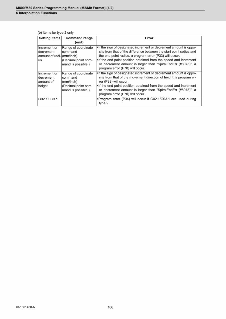
M800/M80 Series Programming Manual (M2/M0 Format) (1/2)
6 Interpolation Functions
106IB-1501480-A
(b) Items for type 2 only
Setting Items Command range (unit)
Error
Increment or decrement amount of radi-us
Range of coordinate command(mm/inch)(Decimal point com-mand is possible.)
If the sign of designated increment or decrement amount is oppo-site from that of the difference between the start point radius andthe end point radius, a program error (P33) will occur.If the end point position obtained from the speed and increment
or decrement amount is larger than "SpiralEndErr (#8075)", aprogram error (P70) will occur.
Increment or decrement amount of height
Range of coordinate command(mm/inch)(Decimal point com-mand is possible.)
If the sign of designated increment or decrement amount is oppo-site from that of the movement direction of height, a program er-ror (P33) will occur.If the end point position obtained from the speed and increment
or decrement amount is larger than "SpiralEndErr (#8075)", aprogram error (P70) will occur.
G02.1/0G3.1 Program error (P34) will occur if G02.1/G03.1 are used duringtype 2.
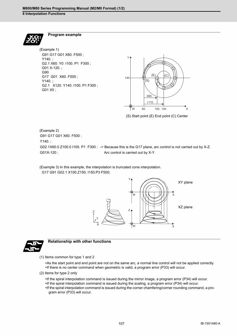
M800/M80 Series Programming Manual (M2/M0 Format) (1/2)
6 Interpolation Functions
107 IB-1501480-A
(Example 1)
(Example 2)
(Example 3) In this example, the interpolation is truncated cone interpolation.
(1) Items common for type 1 and 2
As the start point and end point are not on the same arc, a normal line control will not be applied correctly.If there is no center command when geometric is valid, a program error (P33) will occur.
(2) Items for type 2 only
If the spiral interpolation command is issued during the mirror image, a program error (P34) will occur.If the spiral interpolation command is issued during the scaling, a program error (P34) will occur.If the spiral interpolation command is issued during the corner chamfering/corner rounding command, a pro-
gram error (P33) will occur.
Program example
G91 G17 G01 X60. F500 ;Y140. ;G2.1 X60. Y0 I100. P1 F300 ;G01 X-120. ;G90 G17 G01 X60. F500 ;Y140. ;G2.1 X120. Y140. I100. P1 F300 ;G01 X0 ;
(S) Start point (E) End point (C) Center
G91 G17 G01 X60. F500 ;
Y140. ;
G02.1X60.0 Z100.0 I100. P1 F300 ; -> Because this is the G17 plane, arc control is not carried out by X-Z.
G01X-120 ; Arc control is carried out by X-Y.
G17 G91 G02.1 X100.Z150. I150.P3 F500;
XY plane
XZ plane
Relationship with other functions
140.(S)
(E) (C)
Y
W X60.
X60.
120. 140.
110.
Y
ZZ
W
W
X
XX
Y
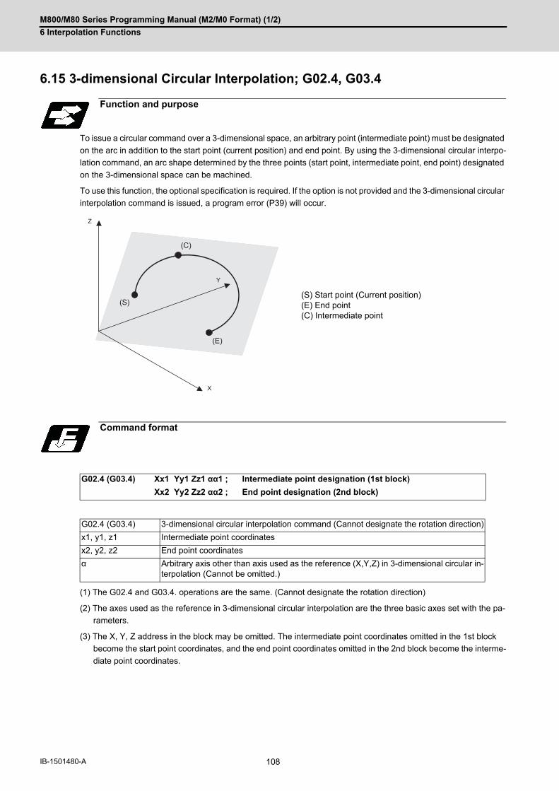
M800/M80 Series Programming Manual (M2/M0 Format) (1/2)
6 Interpolation Functions
108IB-1501480-A
6.15 3-dimensional Circular Interpolation; G02.4, G03.4
To issue a circular command over a 3-dimensional space, an arbitrary point (intermediate point) must be designated
on the arc in addition to the start point (current position) and end point. By using the 3-dimensional circular interpo-
lation command, an arc shape determined by the three points (start point, intermediate point, end point) designated
on the 3-dimensional space can be machined.
To use this function, the optional specification is required. If the option is not provided and the 3-dimensional circular
interpolation command is issued, a program error (P39) will occur.
(1) The G02.4 and G03.4. operations are the same. (Cannot designate the rotation direction)
(2) The axes used as the reference in 3-dimensional circular interpolation are the three basic axes set with the pa-
rameters.
(3) The X, Y, Z address in the block may be omitted. The intermediate point coordinates omitted in the 1st block
become the start point coordinates, and the end point coordinates omitted in the 2nd block become the interme-
diate point coordinates.
Function and purpose
(S) Start point (Current position)(E) End point(C) Intermediate point
Command format
G02.4 (G03.4) Xx1 Yy1 Zz1 αα1 ; Intermediate point designation (1st block)
Xx2 Yy2 Zz2 αα2 ; End point designation (2nd block)
G02.4 (G03.4) 3-dimensional circular interpolation command (Cannot designate the rotation direction)
x1, y1, z1 Intermediate point coordinates
x2, y2, z2 End point coordinates
α Arbitrary axis other than axis used as the reference (X,Y,Z) in 3-dimensional circular in-terpolation (Cannot be omitted.)
Z
X
Y
(S)
(C)
(E)

M800/M80 Series Programming Manual (M2/M0 Format) (1/2)
6 Interpolation Functions
109 IB-1501480-A
(4) When using the 3-dimensional circular interpolation command, an arbitrary axis can be commanded in addition
to the orthogonal coordinate system (X, Y, Z) used as the reference. The arbitrary axis designated in the inter-
mediate point designating block (1st block) will interpolate to the command point when moving from the start
point to intermediate point. The arbitrary axis designated in the end point command block (2nd block) will inter-
polate to the command point when moving from the intermediate point to the end point. The number of arbitrary
axes that can be commanded differs according to the number of simultaneous contour control axes. The total of
the basic three axes used as the reference of the 3-dimensional circular interpolation and the arbitrary axes com-
manded simultaneously must be less than the number of simultaneous contour control axes.
When using the 3-dimensional circular interpolation command, an arc that exists over the 3-dimensional space can
be determined by designating the intermediate point and end point in addition to the start point (current position)
(Refer to following figure). So according to the command format, it is necessary to designate an intermediate point
in the 1st block and an end point in the 2nd block. If only one block is designated, a program error (P74) will occur.
Liner interpolation is applied when the end point match the start point in the 3-dimensional circular interpolation com-
mand (Refer to "When liner interpolation is applied"). Thus, a true circle (360-degree rotation) cannot be designated
in the 3-dimensional circular interpolation.
In addition, designate the intermediate point in the middle of a start point and an end point. If the intermediate point
is near the start point or the end point, arc accuracy may fall.
- Designation of arc in 3-dimensional space
As shown in the above figure, when three points (start point, intermediate point, end point) are specified on 3-dimen-
sional space, arc center coordinates can be obtained. An arc center cannot be obtained if only two points are spec-
ified, and a liner interpolation is applied.
If the intermediate point is near the start point or the end point, an error may occur when calculating arc center.
Detailed description
Designating intermediate point and end point
(P) Plane including start point, intermedi-ate point and end point(S) Start point (Current position)(E) End point(CP) Intermediate point(C) Center
(E)
(CP)
(S) (C)
(P)
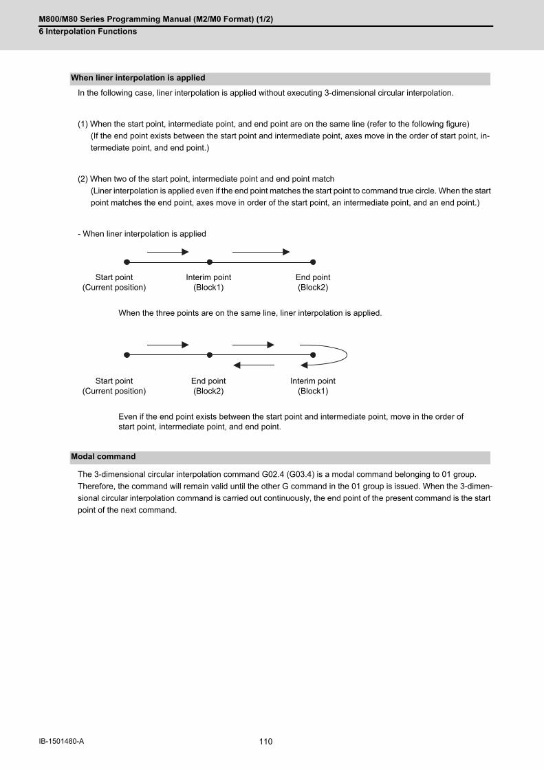
M800/M80 Series Programming Manual (M2/M0 Format) (1/2)
6 Interpolation Functions
110IB-1501480-A
In the following case, liner interpolation is applied without executing 3-dimensional circular interpolation.
(1) When the start point, intermediate point, and end point are on the same line (refer to the following figure)
(If the end point exists between the start point and intermediate point, axes move in the order of start point, in-
termediate point, and end point.)
(2) When two of the start point, intermediate point and end point match
(Liner interpolation is applied even if the end point matches the start point to command true circle. When the start
point matches the end point, axes move in order of the start point, an intermediate point, and an end point.)
- When liner interpolation is applied
The 3-dimensional circular interpolation command G02.4 (G03.4) is a modal command belonging to 01 group.
Therefore, the command will remain valid until the other G command in the 01 group is issued. When the 3-dimen-
sional circular interpolation command is carried out continuously, the end point of the present command is the start
point of the next command.
When liner interpolation is applied
Start point(Current position)
Interim point(Block1)
End point(Block2)
When the three points are on the same line, liner interpolation is applied.
Start point(Current position)
End point(Block2)
Interim point(Block1)
Even if the end point exists between the start point and intermediate point, move in the order of start point, intermediate point, and end point.
Modal command

M800/M80 Series Programming Manual (M2/M0 Format) (1/2)
6 Interpolation Functions
111 IB-1501480-A
G code command which leads to a program error during 3-dimensional circular interpolation modal
G code command which leads to a program error when 3-dimensional circular interpolation is commanded
Relationship with other functions
Commands that cannot be used
G code Function name Program error
G05 Pn High-speed machining mode P34
G05 P10000 High-speed high-accuracy control II P34
G05.1 Q0/G05.1 Q1 High-speed high-accuracy control I P34
G07.1 Cylindrical interpolation P485
G12/G13 Circular cutting CW/CCW P75
G12.1 Polar coordinate interpolation P485
G16 Polar coordinate command P75
G41/G42 Tool radius compensation P75
G41/G42 3-dimensional tool radius compensation P75
G41.1/G42.1 Normal line control P75
G43 Tool length compensation P75
G51 Scaling P75
G51.1, G62 Mirror image P75
G66/G66.1 User macro P75
G67 User macro P276
G68.1 Coordinate rotation by program P75
G68.1 3-dimensional coordinate conversion P921
G73/G74/G76/G81/G82G83/G84/G85/G86/G87G88/G89
Fixed cycle P75
G code modal Function name Program error
G05 Pn High-speed machining mode P34
G05 P10000 High-speed high-accuracy control II P34
G05.1 Q1 High-speed high-accuracy control I P34
G07.1 Cylindrical interpolation P481
G12.1 Polar coordinate interpolation P481
G16 Polar coordinate command P75
G41/G42 Tool radius compensation P75
G41/G42 3-dimensional tool radius compensation P75
G41.1/G42.1 Normal line control P75
G43 Tool length compensation P75
G51 Scaling P75
G51.1, G62 Mirror image P75
G66/G66.1 User macro P75
G68.1 Coordinate rotation by program P75
G68.1 3-dimensional coordinate conversion P922

M800/M80 Series Programming Manual (M2/M0 Format) (1/2)
6 Interpolation Functions
112IB-1501480-A
If following functions are used in 3-dimensional circular interpolation, alarm will occur.
- Chopping
- Macro interruption
- Mirror image by parameter setting
- Mirror image by external input
- Corner chamfering / corner R
Restrictions may be added for other functions. Refer to explanation of each function.
(1) If single block is valid and this command is operated, a block stop is carried out at an intermediate point and the
end point.
(2) The speed command during 3-dimensional circular interpolation is the tangent speed on arc.
(3) When 3-dimensional circular interpolation is commanded while incremental command is valid, the relative posi-
tion of the intermediate point in respect to the start point is designated in the intermediate point designation block,
and the relative position of the end point in respect to the intermediate point is designated in the intermediate
point designation block.
(4) The path of 3-dimensional circular interpolation during graphic check is drawn as linear at each range from start
point to intermediate point and from intermediate point to end point.
Functions that cannot be used
Precautions

M800/M80 Series Programming Manual (M2/M0 Format) (1/2)
6 Interpolation Functions
113 IB-1501480-A
6.16 NURBS Interpolation; G06.2
This function realizes NURBS (Non-Uniform Rational B-Spline) curve machining by simply commanding NURBS
curve parameters (stage, weight, knot, control point), which is used for the curved surface/line machining, without
replacing the path with minute fine segments.
This function operates only in the high-speed high-accuracy control II mode, therefore, the high-speed high-accura-
cy control II function is also required as the specification.
However, if the curvature is large, the speed is clamped so that the machine's tolerable acceleration rate is not ex-
ceeded.
Function and purpose
Command format
NURBS interpolation start
G06.2 Pp Kk1 X1 Yy1 Zz1 Rr1 Ff;
Kk2 Xx2 Yy2 Zz2 Rr2;
Kk3 Xx3 Yy3 Zz3 Rr3;
Kk4 Xx4 Yy4 Zz4 Rr4;
:
Kkn Xxn Yyn Zzn Rrn;
Kkn+1;
Kkn+2;
Kkn+3;
Kkn+4;
Pp Set the stage of the NURBS curve. Designate in the same block as G06.2 command. The NURBS curve of the stage p will be (p-1)th curve. When omitted, Pp means the same as P4. (Example) P2: Primary curve (liner)
Kkn KnotSet the knot for each NURBS interpolation block. Set the same value for the knot in the 1st block to the stage p block. NURBS interpo-lation is terminated if there is a block exclusively with knot.
Xxn Yyn Zzn Control point coordinate value. Designate the same coordinate value for the 1st block control point as that designated right before NURBS interpolation.
Rrn Control point weight. Set the weight of each NURBS interpolation control point.
Ff Interpolation speed (Can be omitted)

M800/M80 Series Programming Manual (M2/M0 Format) (1/2)
6 Interpolation Functions
114IB-1501480-A
(1) Designate the stage P for the 1st block of NURBS interpolation.
(2) Designate the same coordinate value for the 1st block control point of NURBS interpolation as that designatedright before NURBS interpolation.
(3) Designate all axes to be used in the subsequent NURBS interpolation blocks for 1st block of NURBS interpola-tion.
(4) Set the same value for knot K from the 1st block of NURBS interpolation to setting value block of the stage P.
(5) Command knot K exclusive block of the same number as the setting value of the stage P for terminating NURBSinterpolation. At this time, set the same value for knot K setting.
(1) If an exclusive knot is commanded immediately after NURBS interpolation, NURBS interpolation mode is activeagain. An exclusive knot that is commanded immediately after NURBS interpolation is the same meaning as followingcommand. G06.2 Pp Km Xxn Yyn Zzn R1.0
Detailed description
Passes through control point
NURBS interpolation curve
(xn,yn,zn)
(x4,y4,z4)(x3,y3,z3)
(x2,y2,z2)
(x1,y1,z1)
Note
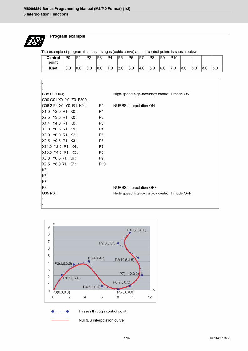
M800/M80 Series Programming Manual (M2/M0 Format) (1/2)
6 Interpolation Functions
115 IB-1501480-A
The example of program that has 4 stages (cubic curve) and 11 control points is shown below.
Program example
Control point
P0 P1 P2 P3 P4 P5 P6 P7 P8 P9 P10
Knot 0.0 0.0 0.0 0.0 1.0 2.0 3.0 4.0 5.0 6.0 7.0 8.0 8.0 8.0 8.0
:
:
G05 P10000; High-speed high-accuracy control II mode ON
G90 G01 X0. Y0. Z0. F300 ;
G06.2 P4 X0. Y0. R1. K0 ; P0 NURBS interpolation ON
X1.0 Y2.0 R1. K0 ; P1
X2.5 Y3.5 R1. K0 ; P2
X4.4 Y4.0 R1. K0 ; P3
X6.0 Y0.5 R1. K1 ; P4
X8.0 Y0.0 R1. K2 ; P5
X9.5 Y0.5 R1. K3 ; P6
X11.0 Y2.0 R1. K4 ; P7
X10.5 Y4.5 R1. K5 ; P8
X8.0 Y6.5 R1. K6 ; P9
X9.5 Y8.0 R1. K7 ; P10
K8;
K8;
K8;
K8; NURBS interpolation OFF
G05 P0; High-speed high-accuracy control II mode OFF
:
:
Passes through control point
NURBS interpolation curve
P10(9.5,8.0)
P8(10.5,4.5)
P9(8.0,6.5)
P3(4.4,4.0)
P7(11.0,2.0)
P6(9.5,0.5)
P2(2.5,3.5)
P1(1.0,2.0)
P4(6.0,0.5)P0(0.0,0.0) P5(8.0,0.0)
10 1286420
0
1
2
3
4
5
6
7
8
9Y
X

M800/M80 Series Programming Manual (M2/M0 Format) (1/2)
6 Interpolation Functions
116IB-1501480-A
All the G code, feedrate and MSTB code cannot be set during NURBS interpolation.
However, when the fixed cycle G code is commanded in the same block where G06.2 is commanded, the fixed cycle
G code is ignored.
If a command other than the axis address designated in the 1st block of NURBS interpolation, R and K is command-
ed, a program error will occur.
(1) Optional block skip "/"Cannot be set in the NURBS interpolation 2nd block or after.
(2) Control IN "("and Control OUT ")"Cannot be set in the NURBS interpolation 2nd block or after.
(3) Local variables and common variablesCan be referred but cannot be set in the NURBS interpolation. Setting the variables causes a program error(P29).
(4) System variablesCannot be referred nor set in the NURBS interpolation; a program error (P29) will occur.
The validity of program interruption/restart is shown below.
(*1) A single block stop is carried out at the last control points only.
The single block stop is not applied during NURBS interpolation.
(*2) NURBS interpolation mode is canceled with Reset (Reset1/Reset2/Reset&Rewind).
(*3) The operation differs according to the manual absolute signal status.
When the manual absolute signal OFFNURBS interpolation is carried out in the state where axis-coordinate system is shifted by the manual ab-solute movement amount.When the manual absolute signal ON
Upon automatic start after manual interruption, a program error (P554) will occur after moving by the re-maining distance. Note that the operation can run continually by returning the axis to the original position after manual inter-ruption.
(*4) "Macro interrupt" signal (UIT) is ignored.
(*5) "PLC interrupt" signal (PIT) is ignored.
Relationship with other functions
G code/Feed/Miscellaneous functions
Data format
Interruption/restart
Type During NURBS interpolation
Single block Valid (*1)
Feed hold Valid
Resetting Valid (*2)
Program stop Invalid
Optional stop Invalid
Manual interruption Invalid (*3)
MDI interruption Invalid
Restart search Invalid
Macro interruption Invalid (*4)
PLC interruption Invalid (*5)

M800/M80 Series Programming Manual (M2/M0 Format) (1/2)
6 Interpolation Functions
117 IB-1501480-A
NURBS interpolation cannot be applied during graphic check (continuous/step check).
Linear interpolation that connects the control points is applied during graphic check.
With the high-accuracy control in 2 part systems specification, NURBS interpolation can be commanded by 1st and
2nd part systems.
(1) Target axes for NURBS interpolation are 3 basic axes.
(2) Command the control point for all the axes for which NURBS interpolation is carried out in the 1st block (G06.2block). A program error (P32) will occur if an axis which was not commanded in the 1st block is commanded inthe 2nd block or after.
(3) The first control point (G06.2 block coordinate value) should be commanded as the start point of the NURBScurve. Thus, the start point of the NURBS curve should be commanded to match the end point of the previousblock. A program error will occur if the points do not match. (P552)
(4) The command range of the weight is 0.0001 to 99.9999. If "1" is commanded, the resulting command will beequal to "1.0". If more than 5 digits are commanded after the decimal point, a program error (P33) will occur.
(5) The knot command cannot be omitted, and must be commanded in each block. A program error (P33) will occurif omitted.
(6) As with knot, in the same manner as weight, up to 4 digits can be commanded after the decimal point. Even ifthe decimal point is omitted, the value will be handled as the one with a decimal point. If "1" is commanded, theresult will be the same as "1.0". If more than 5 digits are commanded after the decimal point, a program error (P33) will occur.
(7) As with knot, command the same or greater value than the previous block. If a smaller value than previous blockis set, a program error (P551) will occur.
(8) NURBS interpolation cannot be applied during graphic check (continuous/step check). Linear interpolation that connects the control points is applied during graphic check.
(9) NURBS interpolation mode is canceled with Reset (Reset1/Reset2/Reset&Rewind).
Graphic check
High-accuracy Control in 2 part Systems
Precautions

M800/M80 Series Programming Manual (M2/M0 Format) (1/2)
6 Interpolation Functions
118IB-1501480-A
(10) NURBS interpolation can be commanded in only the following modes. If NURBS interpolation is commandedin other than the following modes, the program error (P29) will occur.
Type Mode in which NURBS interpolation can be commanded
G group 5 Asynchronous feed (G94)
G group 7 Tool radius compensation cancel (G40)
G group 8 Tool length compensation (G43)Tool length compensation cancel (G44)
G group 9 Fixed cycle cancel (G80)
G group 11 Scaling cancel (G50)
G group 13 High-accuracy control ON (G61.1)Cutting mode (G64)
G group 14 User macro modal call cancel (G67)
G group 15 Normal line control cancel (G40.1)
G group 16 Programmable coordinate rotation mode OFF /3-dimensional coordinate conversion mode OFF (G69.1)
G group 17 Constant surface speed control OFF (G97)
G group 18 Polar coordinate command OFF (G15)
G group 19 G command mirror image cancel (G50.1)
G group 21 Polar coordinate interpolation cancel (G13.1)
- Not during the coordinate rotation by parameter
- Not during the mirror image by parameter setting
- Not during the mirror image by external input

M800/M80 Series Programming Manual (M2/M0 Format) (1/2)
6 Interpolation Functions
119 IB-1501480-A
6.17 Hypothetical Axis Interpolation; G07
Take one of the axes of the helical interpolation or spiral interpolation, including a linear axis, as a hypothetical axis
(axis with no actual movement) and perform pulse distribution. With this procedure, an interpolation equivalent to
the helical interpolation or spiral interpolation looked from the side (hypothetical axis), or SIN or COS interpolation,
will be possible.
Normal helical interpolation
Helical interpolation in the hypothetical axis interpolation mode
To perform the SIN interpolation on Z-X plane, execute the helical interpolation (Y-X plane: G17 G02) with Y axis,
which is designated as the hypothetical axis. The hypothetical axis does not make any actual movement.
Function and purpose
Command format
G07 α0 ; ... Hypothetical axis interpolation mode ON
G07 α1 ; ... Hypothetical axis interpolation mode cancel
α Axis name for which hypothetical axis interpolation is performed.
0.
5.
10.
-5.
-10.
20. 40. -10.0.
X X
YZ
0.
5.
10.
-5.
-10.
20. 40. -10.0.
X X
YZ
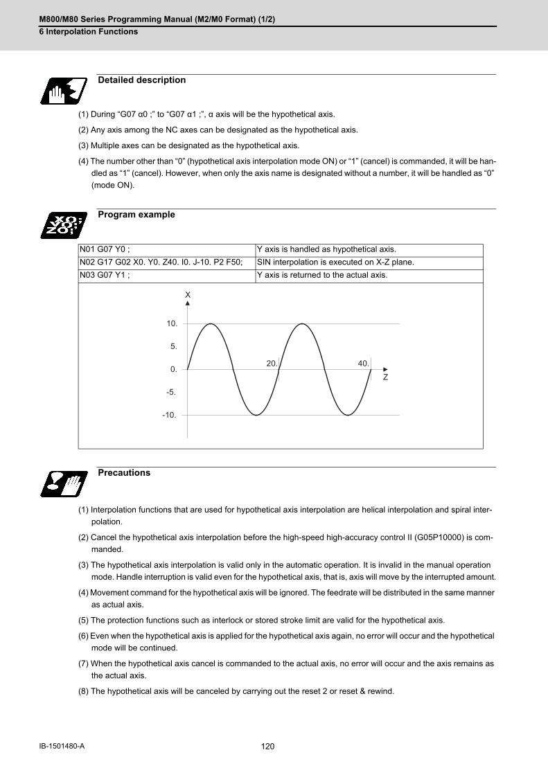
M800/M80 Series Programming Manual (M2/M0 Format) (1/2)
6 Interpolation Functions
120IB-1501480-A
(1) During “G07 α0 ;” to “G07 α1 ;”, α axis will be the hypothetical axis.
(2) Any axis among the NC axes can be designated as the hypothetical axis.
(3) Multiple axes can be designated as the hypothetical axis.
(4) The number other than “0” (hypothetical axis interpolation mode ON) or “1” (cancel) is commanded, it will be han-
dled as “1” (cancel). However, when only the axis name is designated without a number, it will be handled as “0”
(mode ON).
(1) Interpolation functions that are used for hypothetical axis interpolation are helical interpolation and spiral inter-
polation.
(2) Cancel the hypothetical axis interpolation before the high-speed high-accuracy control II (G05P10000) is com-
manded.
(3) The hypothetical axis interpolation is valid only in the automatic operation. It is invalid in the manual operation
mode. Handle interruption is valid even for the hypothetical axis, that is, axis will move by the interrupted amount.
(4) Movement command for the hypothetical axis will be ignored. The feedrate will be distributed in the same manner
as actual axis.
(5) The protection functions such as interlock or stored stroke limit are valid for the hypothetical axis.
(6) Even when the hypothetical axis is applied for the hypothetical axis again, no error will occur and the hypothetical
mode will be continued.
(7) When the hypothetical axis cancel is commanded to the actual axis, no error will occur and the axis remains as
the actual axis.
(8) The hypothetical axis will be canceled by carrying out the reset 2 or reset & rewind.
Detailed description
Program example
N01 G07 Y0 ; Y axis is handled as hypothetical axis.
N02 G17 G02 X0. Y0. Z40. I0. J-10. P2 F50; SIN interpolation is executed on X-Z plane.
N03 G07 Y1 ; Y axis is returned to the actual axis.
Precautions
0.
5.
10.
-5.
-10.
20. 40.
X
Z

7
121 IB-1501480-A
Feed Functions
M800/M80 Series Programming Manual (M2/M0 Format) (1/2)
7 Feed Functions
122IB-1501480-A
7Feed Functions7.1 Rapid traverse rate7.1.1 Rapid traverse rate
The rapid traverse rate can be set with parameters independently for each axis. The available speed ranges are
from 1 mm/min to 10000000 mm/min. The upper limit is subject to the restrictions limited by the machine specifica-
tions.
Refer to the specifications manual of the machine for the rapid traverse rate settings.
The feedrate is valid for the G00, G27, G28, G29, G30 and G60 commands.
Two paths are available for positioning: the interpolation type where the area from the start point to the end point is
linearly interpolated or the non-interpolation type where movement proceeds at the maximum speed of each axis.
The type is selected with parameter "#1086 G0Intp". The positioning time is the same for each type.
If the high-accuracy control mode's rapid traverse rate is set, the axis will move at that feedrate during high-accuracy
control, high-speed high-accuracy control I/II/III, high-accuracy spline control or SSS control.
If the value set for the high-accuracy control mode rapid traverse rate is 0, the axis will move at the rapid tra-verse rate.The high-accuracy control mode rapid traverse rate can be set independently for each axis.The high-accuracy control mode rapid traverse rate is effective for the following G commands: G00, G27, G28,
G29, G30 and G60.Override can be applied on the high-accuracy control mode rapid traverse rate using the PLC signal supplied.
(The operation of the PLC signal depends on the MTB specifications.)
(1) Rapid traverse overrideOverride can be applied by a PLC input signal for both manual and automatic rapid traverse. There are 2 typeswhich are determined by the PLC specifications. Type1 : Override in 4 steps (1%, 25%, 50% and 100%). Type2 : Override in 1% steps from 0% to 100%.
Function and purpose
Note

M800/M80 Series Programming Manual (M2/M0 Format) (1/2)
7 Feed Functions
123 IB-1501480-A
7.1.2 G00 Feedrate Command (,F Command)
Use this function to specify G00 (positioning command) and an axis feedrate in G00 mode.
The speed of tool exchange, axis movement of gantry, etc. can be specified with the machining program so that the
mechanical vibration can be suppressed.
Operations other than the feedrate follows the G00 specification.
(1) ",F" command is in effect only in the block in which it is commanded.
(2) If ",F" is commanded in G00, G27 to G30, G60, G00 mode, a block other than the one that specifies the move-ment to the initial point of the hole position for the drilling cycle or a block that does not contain a movementcommand (axis address command), ",F" is ignored.
(3) ",F" command in the feed per revolution (G95) mode will also be considered a feed per minute feedrate.
(4) The motion of the ",F" command varies depending on the status of parameter "#1086 G0Intp".
Feedrates when commanding G00 X200. Z300. ,F1000
fx: Actual X axis rate
fz: Actual Z axis rate
Function and purpose
Command format
Rapid traverse at a feedrate specified with the ",F" command
G00 X_ Z_ (Y_) ,F1000;
,F Specifies the rapid traverse rates for G00, movement in G00 mode and the move-ment during the fixed cycle for drilling. The range is equal to the range of the feed per minute F command (mm/min, inch/min) in the G01 mode. Switching inch/mm is invalid for rotary axes.
Detailed description
"#1086 G0Intp" Handling of ",F"command
OFF (see figure shown at below left) Handled as an interpolation speed.
ON (see figure shown at below right) Handled as a commanded speed for each axis.
When "G0 non-interpolation" is OFF When "G0 non-interpolation" is ON
E
Z
X X
ZS S
E
300fz = 832.05(mm/min) fz = 1000(mm/min)
1000(mm/min)
fz =
100
0(m
m/m
in)
fx =
554
.70(
mm
/min
)
300
200
200

M800/M80 Series Programming Manual (M2/M0 Format) (1/2)
7 Feed Functions
124IB-1501480-A
(5) When the ",F" command has not been issued, the rapid traverse rate set by the axis specification parameter willbe valid. (*1)
(6) The ",F" command is clamped by the rapid traverse rate set by the axis specification parameter. (*1)Feedrate clamping depends on the setting of parameter "#1086 G0Intp".
(*1) The rapid traverse rate parameter depends on the MTB specifications.
Typically, parameter "#2001 rapid" is selected.
(1) Feedrate command in G00 block and G00 mode (for G00 interpolation)
(2) Speed command for the movement to the initial point of the hole position for the drilling cycle (for a longitudinaltapping cycle)
"#1086 G0Intp" Speed clamp
OFF If it is found that, after converting ",F" command value (interpolation speed) into a speed for each axis, there is an axis for which the programmed feedrate exceeds the rapid traverse rate parameter, the interpolation speed is calculated so that it does not exceed the rapid traverse rate. (*1)
ON An axis whose ",F" command value (per axis speed) exceeds the rapid traverse rate parameter is clamped to a speed specified by the parameter. (*1)For an axis that does not exceed the rapid traverse rate parameter, the command-ed speed is applied.
Program example
:
G00 X100. Z100. ,F1000 ; The tool moves at the combined feedrate, 1000 (mm/min), of XZ.
X200. Z200. ; The X and Z axes interpolate at the fastest feedrate that does not exceed the rapid traverse rate parameter for each of these axes.
X300.Z300. ,F2500 ; The tool moves at the combined feedrate, 2500 (mm/min), of XZ.
:
:
G88 X-20. Z30 R5. F1.D3 S500 ,R1 ,F2000 ;
The tool moves to the initial point (Z30.) of the hole position at 2000 (mm/min). Positioning (G00) during the drilling cycle moves at 2000 (mm/min).
X-20. Z35. R5. ; The tool moves to the initial point (Z35.) of the hole position at the Z axis rapid traverse rate (parameter setting value).
X-20. Z40. R5.,F3000 ; The tool moves to the initial point (Z40.) of the hole position at 3000 (mm/min). Positioning (G00) during the drilling cycle moves at 2000 (mm/min).
G80 ;
:

M800/M80 Series Programming Manual (M2/M0 Format) (1/2)
7 Feed Functions
125 IB-1501480-A
When ",F" is specified, constant inclination acceleration/deceleration control is applied to the feedrate specified by
",F".
The feedrate (vertical axis in the figure below) varies depending on whether or not the ",F" command has been is-
sued.
The feedrate specified by ",F" is applied according to acceleration pattern calculated from acceleration rate to "rapid
traverse rate", "rated speed", "G00 time constant to rated speed" and "maximum acceleration".
An override for ",F" command
The override cancel for the rapid traverse override is also invalid when ",F" is specified.
Dry run is valid when the parameter "#1085 G00Drn" is ON and the rapid traverse is OFF. The axis will move at the
manual feedrate that is set. If the manual override valid is turned ON, the cutting feed override also becomes valid.
Relationship with Other Functions
Rapid Traverse Constant Inclination Acceleration/Deceleration
(1) When the ",F" command has not been issued (2) When the ",F" command has been issued
Rapid traverse rate set by the parameter Feedrate specified by the ",F" command
Movement when rapid traverse constant inclination is enabled
Movement when rapid traverse constant inclination is disabled
Rapid Traverse Constant Inclination Multi-step Acceleration/Deceleration
Rated speed
Rapid Traverse Rate
Feedrate specified by ",F"
Time
Rapid traverse override
Override cancel
Dry run
TsTs

M800/M80 Series Programming Manual (M2/M0 Format) (1/2)
7 Feed Functions
126IB-1501480-A
It is also valid when ",F"is specified.
It is also valid when ",F"is specified.
",F" command is ineffective in tool center point control.
When an ",F" command is specified in the fixed cycle for drilling, the movement between hole positions is carried
out at the speed commanded with ",F".
",F" commands in the same block as for the special fixed cycle are ignored.
When an ",F" command is specified in the same block as G60 (unidirectional positioning), the feedrate specified by
",F" is assumed.
When an ",F" command is specified in the same block as G27 (reference position check), G29 (start point return),
and/or G30.n (tool change position return), the feedrate specified by ",F" is assumed.
When an ",F" command is specified in the same block as G28 (reference position return) and G30 (2nd to 4th ref-
erence position return), the feedrate specified by ",F" is assumed.
Axes not subject to high-speed reference position return are returned by the dog-type of in the same way as with
the manual type. The feedrate depends on the MTB specifications (parameter "#2025 G28rap").
(1) If an ",F" command is specified when there is no specifications for the feedrate specified for G00, a program error(P39) will occur.
(2) ",F" and "F" commands may be specified in the same block. The "F" command is assumed to the feedrate forcutting feed.
(3) Depending on the MTB specifications (parameter "#1100 Tmove"), compensation may be performed on a blockthat does not contain a move command. If an ",F" is specified in a tool compensation command (T command) block in which no move command is spec-ified, compensation move is made at the feedrate specified by ",F" only in G00 mode.
(4) If an ",F" is specified in a tool radius compensation cancel command (G40) block in which no move command isspecified, tool radius compensation is canceled at the specified feedrate only in G00 mode. This is the same as when using the tool nose radius compensation instead of tool radius compensation.
External deceleration
Programmable in-position check
Tool center point control
Special Fixed Cycle
Unidirectional positioning
Reference position check, Start point return, Tool change position return
Reference position return, 2nd to 4th reference position return
Precautions

M800/M80 Series Programming Manual (M2/M0 Format) (1/2)
7 Feed Functions
127 IB-1501480-A
7.2 Cutting feed rate
The cutting feedrate is assigned with address F and numerals.
The cutting feedrate is valid for the G01, G02, G03, G02.1 and G03.1 commands.
If the cutting clamp feedrate for the high-accuracy control mode is set, the axis will move at that feedrate during high-
accuracy control, high-speed high-accuracy control I/II/III, high-accuracy spline control or SSS control.
If the value set for the high-accuracy control mode cutting clamp speed is "0", the axis will be clamped at thecutting feed clamp speed.
The cutting feedrate is clamped with high-accuracy control mode cutting clamp speed in the parameter.
Examples Feed per minute (asynchronous feed)
Speed range that can be commanded (when input setting unit is 1μm)
(1) A program error (P62) will occur when there is no F command in the first cutting command (G01, G02, G03) afterthe power has been turned ON.
Function and purpose
Feedrate
G01 X100. Y100. F200 ; 200.0mm/min F200 or F200.000 gives the same rate.
G01 X100. Y100. F123.4 ; 123.4mm/min
G01 X100. Y100. F56.789 ; 56.789mm/min
Command Mode Feedrate command range
Remarks
mm/min 0.001 to 10000000
inch/min 0.0001 to 1000000
°/min 0.001 to 10000000
Note

M800/M80 Series Programming Manual (M2/M0 Format) (1/2)
7 Feed Functions
128IB-1501480-A
7.3 F1-digit Feed
By setting the F1-digit feed parameter, the feedrate which has been set to correspond to the 1-digit number following
the F address serves as the command value.
When F0 is assigned, the rapid traverse rate is established and the speed is the same as for G00. (G modal does
not change, but the acceleration/deceleration method follows the rapid traverse setting.)
When F1 to F5 is assigned, the feedrate set to correspond to the command serves as the command value.
If F1-digit feedrate changing valid signal is turned ON when F1-digit feed is commanded, the feedrate specified by
the parameter can be increased or decreased by operation of manual handle. For the changing of F1-digit feedrate
with the handle feed, refer to the instruction manual.
(1) To validate the F1-digit feed, the parameter "#8145 Validate F1 digit" or "#1079 f1digt" must be ON.
(2) The feedrates that correspond to F1 to F5 depend on the MTB specifications (parameters "#1185 spd_F1" to"#1189 spd_F5"). The increase/reduction range is from "0" to the set value of the parameter "#1506 F1_FM". An operation error (M01 0104) will occur when the feedrate is "0". When F0 is commanded, the acceleration or deceleration method follows the rapid traverse setting. Note thatthe G modal is not changed.
(3) Use of both the F1-digit command and normal cutting feedrate command is possible when the F1-digit is valid. (Example 1) F0 Rapid traverse rate F1 to F5 F1 digit F6 or more Normal cutting feedrate command
(4) The F1-digit command is valid in a G01, G02, G03, G02.1 or G03.1 modal.
(5) The F1-digit command can also be used for fixed cycle.
(6) The F1-digit feedrate command can also be used during high-speed high-accuracy control II. However, a program error (P62) will occur when F0 command is issued.
(7) The F1-digit command is modal.
(8) The number of manual handle pulses is 1 pulse per scale unit regardless of the scaling factor.
(9) During a F1-digit command, the F1-digit number and F1-digit command signal are output as the PLC signals.(Based on the MTB specifications.)
Function and purpose
Detailed description

M800/M80 Series Programming Manual (M2/M0 Format) (1/2)
7 Feed Functions
129 IB-1501480-A
(1) F1 to F5 are invalid in the G00 mode and the rapid traverse rate is established instead.
(2) If F0 is used in the G02, G03, G02.1 or G03.1 mode, the program error (P121) will occur. The error will be elim-inated if the F0 command is rewritten.
(3) When F1. to F5. (with decimal point) are assigned, the 1mm/min to 5mm/min (direct numerical value command)are established instead of the F1-digit feed command.
(4) When the commands are used with inch units, one-tenth of the feedrate set correspond to F1 to F5 serves at theassigned speed inch/min.
(5) When the commands are used with the millimeter or degree units, the feedrate set to correspond to F1 to F5serves as the assigned speed mm (°)/min.
(6) Even if the F1-digit feed is commanded during feed per revolution (G95), it is executed as a normal F command(direct numerical value command).
(7) When both the F1-digit feed command and inverse time feed command are present, the inverse time feed com-mand will have priority. (The inverse time feed function is available only for a machining center system.)
(8) When both the F1-digit feedrate changing and the manual speed command are present, the manual speed com-mand will have the priority.
(9) In the synchronous tapping command, the speed cannot be changed with the handle.
Precautions
M800/M80 Series Programming Manual (M2/M0 Format) (1/2)
7 Feed Functions
130IB-1501480-A
7.4 Feed Per Minute/Feed Per Revolution (Asynchronous Feed/
Synchronous Feed); G94,G95
By issuing the G94 command, the commands from that block are issued directly by the numerical value following F
as the feedrate per minute (mm/min, inch/min).
By issuing the G95 command, the commands from that block are issued directly by the numerical value following F
as the feedrate per spindle revolution (mm/rev, inch/rev).
When this command is used, the rotary encoder must be attached to the spindle.
G94/G95 commands are modal commands.
(Ex.) After the G95 command is assigned, the G95 command is valid until the G94 command or G93 command (in-
verse time feed) is next assigned.
(1) The F code command range is as follows.
Metric input
Function and purpose
Feed per minute (asynchronous feed)
Feed per revolution (synchronous feed)
Command format
G94; ... Feed per minute (mm/min) (asynchronous feed)
G95; ... Feed per revolution (mm/rev) (synchronous feed)
Detailed description
Input Setting unit B(0.001mm)
Command Mode Feed per minute Feed per revolution
Command Address F(mm/min) F(mm/rev)
Minimum command unit 1 (=1.000)(1.=1.000)
1 (=0.001)(1.=1.000)
Command range 0.001 -1000000.000
0.001 -999.999
Input Setting unit C(0.0001mm)
Command Mode Feed per minute Feed per revolution
Command Address F(mm/min) F(mm/rev)
Minimum command unit 1 (=1.0000)(1.=1.0000)
1 (=0.0001)(1.=1.0000)
Command range 0.0001 -1000000.0000
0.0001 -999.9999
Input Setting unit D(0.00001mm)
Command Mode Feed per minute Feed per revolution
Command Address F(mm/min) F(mm/rev)
Minimum command unit 1 (=1.00000)(1.=1.00000)
1 (=0.00001)(1.=1.00000)
Command range 0.00001 -1000000.00000
0.00001 -999.99999
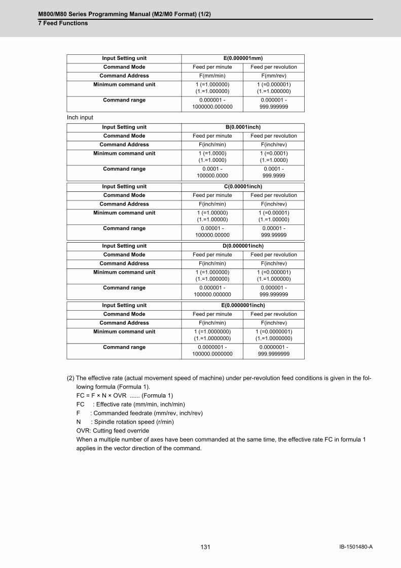
M800/M80 Series Programming Manual (M2/M0 Format) (1/2)
7 Feed Functions
131 IB-1501480-A
Inch input
(2) The effective rate (actual movement speed of machine) under per-revolution feed conditions is given in the fol-
lowing formula (Formula 1).
FC = F × N × OVR ...... (Formula 1)
FC : Effective rate (mm/min, inch/min)
F : Commanded feedrate (mm/rev, inch/rev)
N : Spindle rotation speed (r/min)
OVR: Cutting feed override
When a multiple number of axes have been commanded at the same time, the effective rate FC in formula 1
applies in the vector direction of the command.
Input Setting unit E(0.000001mm)
Command Mode Feed per minute Feed per revolution
Command Address F(mm/min) F(mm/rev)
Minimum command unit 1 (=1.000000)(1.=1.000000)
1 (=0.000001)(1.=1.000000)
Command range 0.000001 -1000000.000000
0.000001 -999.999999
Input Setting unit B(0.0001inch)
Command Mode Feed per minute Feed per revolution
Command Address F(inch/min) F(inch/rev)
Minimum command unit 1 (=1.0000)(1.=1.0000)
1 (=0.0001)(1.=1.0000)
Command range 0.0001 -100000.0000
0.0001 -999.9999
Input Setting unit C(0.00001inch)
Command Mode Feed per minute Feed per revolution
Command Address F(inch/min) F(inch/rev)
Minimum command unit 1 (=1.00000)(1.=1.00000)
1 (=0.00001)(1.=1.00000)
Command range 0.00001 -100000.00000
0.00001 -999.99999
Input Setting unit D(0.000001inch)
Command Mode Feed per minute Feed per revolution
Command Address F(inch/min) F(inch/rev)
Minimum command unit 1 (=1.000000)(1.=1.000000)
1 (=0.000001)(1.=1.000000)
Command range 0.000001 -100000.000000
0.000001 -999.999999
Input Setting unit E(0.0000001inch)
Command Mode Feed per minute Feed per revolution
Command Address F(inch/min) F(inch/rev)
Minimum command unit 1 (=1.0000000)(1.=1.0000000)
1 (=0.0000001)(1.=1.0000000)
Command range 0.0000001 -100000.0000000
0.0000001 -999.9999999

M800/M80 Series Programming Manual (M2/M0 Format) (1/2)
7 Feed Functions
132IB-1501480-A
(1) The effective rate (mm/min or inch/min), which is produced by converting the commanded speed, the spindle
rotation speed and the cutting feed override into the per-minute speed, appears as the FC on the monitor 1.
Screen of the setting and display unit.
(2) When the above effective rate exceeds the cutting feed clamp rate, it is clamped at that clamp rate.
(3) If the spindle rotation speed is zero when feed per revolution is executed, the error "M01 operation erro 0105"
occurs.
(4) Feedrate in the machine lock status is the command speed.
(5) Under dry run conditions, feed per minute applies and movement results at the manual feedrate (mm/min or inch/
min).
(6) The fixed cycle G84 (tapping cycle) and G74 (reverse tapping cycle) are executed according to the feed mode
that is already designated.
(7) Whether feed per minute (G94) or feed per revolution (G95) is to be established when the power is turned ON
or when M02 or M30 is executed can be selected by setting parameter "#1074 I_Sync".
Precautions

M800/M80 Series Programming Manual (M2/M0 Format) (1/2)
7 Feed Functions
133 IB-1501480-A
7.5 Inverse Time Feed; G93
During inside cutting when machining curved shapes with radius compensation applied, the machining speed on the
cutting surface becomes faster than the tool center feedrate. Therefore, problems such as reduced accuracy may
occur.
This reduced accuracy can be prevented with inverse time feed. This function can, in place of normal feed com-
mands, issue one block of machining time (inverse) in F commands. The machining speed on the cutting surface is
constantly controlled, even if radius compensation is applied to the machining program that expresses the free curve
surface with fine segment lines.
Note that when the calculated machining time exceeds the cutting feed clamp speed, the F command value in the
inverse time feed follows the cutting feed clamp speed.
Function and purpose
Regular F command
Actual machining speed: High Actual machining speed: Low
The speed of tool center is commanded, thus the ac-tual speed at the cutting surface may become larger or smaller.
F command
Inverse time feed
The actual machining speed is constant.
The actual speed at the cutting surface is command-ed, thus, the speed will be constant and machining speed can be maintained as commanded regard-less of the tool radius.
F command

M800/M80 Series Programming Manual (M2/M0 Format) (1/2)
7 Feed Functions
134IB-1501480-A
Inverse time feed (G93) is a modal command. Once commanded, it will be valid until feed per minute or feed per
revolution is commanded.
In movement blocks, since processing time is commanded to a line segment, command the feedrate "F" each time.
(1) Inverse time feed (G93) is a modal command. Once commanded, it is valid until feed per minute (G94) or feedper revolution (G95) is commanded, or until a reset (M02, M30, etc.) is executed.
(2) Command method of F command values in inverse time feed
(3) The initial modal after a restart is G94 (feed per minute) or G95 (feed per revolution).
(4) The feedrate of the block inserted in tool radius compensation and corner R/C is the same speed as the feedrateof the block immediately before it.
(5) The feedrate of the block inserted in C axis normal line control (normal line control type II) is the same speed asthe feedrate of the movement block after turning.
Command format
Inverse time feed
G93;
G00 Xx1 Yy1;
G93; -> Inverse time feed mode ON
G01 Xx2 Yy2 Ff2; -> In inverse time feed mode
G02 Xx3 Yy3 Ii3 Jj3 Ff3; :
G94 (G95); -> Inverse time feed mode OFF
Detailed description
Metric command (G21) Inch command (G20)
In linear mode(G01)
Cutting point feedrate (mm/min)
Line segment length (mm)
Cutting point feedrate (inch/min)
Line segment length (inch)
In arc mode(G02, G03)
(G02.1, G03.1)
Cutting point feedrate (mm/min)
Start point arc radius (mm)
Cutting point feedrate (inch/min)
Start point arc radius (inch)
Command range
B 0.001 to 999999.999 (1/min)
C 0.0001 to 999999.9999 (1/min)
D 0.00001 to 999999.99999 (1/min)
E 0.000001 to 999999.999999 (1/min)

M800/M80 Series Programming Manual (M2/M0 Format) (1/2)
7 Feed Functions
135 IB-1501480-A
When using inverse time feed during tool radius compensation
Comparison between feed per minute and inverse time feed (Assuming that tool radius is 10. [mm]) (Unit: mm/min)
Program example
Feed per minute
N01 G90 G00 X80. Y-80. ;
N02 G01 G41 X80. Y-80. D11 F500 ;
N03 X180. ;
N04 G02 Y-280. R100. ;
N05 G03 Y-480. R100. ;
N06 G02 Y-680. R100. ;
N07 G01 X80. F500 ;
N08 Y-80. ;
N09 G04 X80. Y-80. ;
N10 M02 ;
Inverse time feed
N01 G90 G00 X80. Y-80. ;
N02 G01 G41 X80. Y-80. D11 F500 ;
N03 X180. ;
N04 G93 G02 Y-280. R100. F5 ;
N05 G03 Y-480. R100. F5 ;
N06 G02 Y-680. R100. F5 ;
N07 G94 G01 X80. F500 ;
N08 Y-80. ;
N09 G04 X80. Y-80. ;
N10 M02 ;
Sequence No. Feed per minute Inverse time feed
Feedrate of tool cen-ter
Feedrate of cutting point
Feedrate of tool cen-ter
Feedrate of cutting point
N04 F500 F450 F550 F500
N05 F500 F550 F450 F500
N06 F500 F450 F550 F500
↓ ↓
The block seam pro-trudes due to the cut-ting speed change at the block seam.
The feedrate follows the command regard-less of the tool radius.
N4
N5
N6

M800/M80 Series Programming Manual (M2/M0 Format) (1/2)
7 Feed Functions
136IB-1501480-A
(1) Scaling (G51)
When using a scaling function, issue a F command for the shape after scaling. For example, if a doublesize scal-
ing is carried out, the machining distance will be twice.
Thus, if executing a cutting at the same speed as that of before scaling, command the value (F') calculated by
dividing F value by the multiples of scaling.
(2) High-speed machining mode II (G05P2)
With the inverse time feed (G93) modal, high-speed machining mode II (G05P2) is operated in the inverse time
feed mode, instead of high-speed machining mode. High-speed machining mode will be valid when the inverse
time feed mode is canceled.
(3) If the speed calculated in the G93 mode exceeds the speed range at the feed per minute, clamping is performedat the clamp speed set with parameters.
(4) The program error (P125) will occur when the commands below are issued in the inverse time feed (G93) mode.
(5) The program error (P125) will occur if inverse time feed (G93) is commanded in the following modes.
Relationship with other functions
F = Feedrate (mm/min) / Distance (mm)
Shape after scaling (Double size)
G code Function
G02.3, G03.3 Exponential interpolation
G06.2 NURBS interpolation
G12 Circular cutting CW
G13 Circular cutting CCW
G31 to G31.3 Skip
G33 Thread cutting
G34 to G37 Special fixed cycle
G37.1 Automatic tool length measurement
G73 to G89 Fixed cycle
G96 Constant surface speed control ON
G code Function
G02.3, G03.3 Exponential interpolation
G33 Thread cutting
G73 to G89 Fixed cycle
G96 Constant surface speed control ON
FF' =
2
F
M800/M80 Series Programming Manual (M2/M0 Format) (1/2)
7 Feed Functions
137 IB-1501480-A
(1) The initial modal after a restart is G94 (feed per minute) or G95 (feed per revolution).
(2) The F command in G93 modal is unmodal. Issue an F command for each block. The program error (P62) willoccur in blocks with no F command.
(3) The program error (P62) will occur when F0 is commanded.
(4) An F command is necessary when changing from G93 to G94 or G95. The program error (P62) will occur if thereis no F command.
(5) The feed function is clamped at the maximum cutting speed. Consequently, the feed may be slower than thecommanded speed.
(6) If an extremely slow speed such as F0.001 is designated, an error will occur in the machining time.
Precautions

M800/M80 Series Programming Manual (M2/M0 Format) (1/2)
7 Feed Functions
138IB-1501480-A
7.6 Feedrate Designation and Effects on Control Axes
It has already been mentioned that a machine has a number of control axes. These control axes can be divided into
linear axes which control linear movement and rotary axes which control rotary movement. The feedrate is designed
to assign the displacement speed of these axes, and the effect exerted on the tool movement speed which poses
problems during cutting differs according to when control is exercised over the linear axes or when it is exercised
over the rotary axes.
The displacement amount for each axis is assigned separately for each axis by a value corresponding to the respec-
tive axis. The feedrate is not assigned for each axis but assigned as a single value. Therefore, when two or more
axes are to be controlled simultaneously, it is necessary to understand how this will work for each of the axes in-
volved.
The assignment of the feedrate is described with the following related items.
Even when only one machine axis is to be controlled or there are two or more axes to be controlled simultaneously,
the feedrate which is assigned by the F code functions as a linear speed in the tool advance direction.
(Example) When the feedrate is designated as "f" and linear axes (X and Y) are to be controlled:
When only linear axes are to be controlled, it is sufficient to designate the cutting feed in the program.
The feedrate for each axis is such that the designated rate is broken down into the components corresponding to
the movement amounts.
Function and purpose
Detailed description
When controlling linear axes
... Feedrate for X axis
... Feedrate for Y axis
(S) Tool start point (E) Tool end point
(F) Speed in this direction is "f".
Y
Xx
y = f
x
= fy
x2 + y2
x2 + y2(E)
(F)
(S)
fx
fy

M800/M80 Series Programming Manual (M2/M0 Format) (1/2)
7 Feed Functions
139 IB-1501480-A
(Example) When the feedrate is designated as "f" and the linear axes (X and Y) are to be controlled using the circular
interpolation function:
The rate in the tool advance direction, or in other words the tangential direction, will be the feedrate des-
ignated in the program.
In this case, the feedrate of the X and Y axes will change along with the tool movement. However, the combined
speed will always be maintained at the constant value "f".
When rotary axes are to be controlled, the designated feedrate functions as the rotary speed of the rotary axes or,
in other words, as an angular speed.
Consequently, the cutting feed in the tool advance direction, or in other words the linear speed, varies according to
the distance between the center of rotation and the tool.
This distance must be borne in mind when designating the feedrate in the program.
(Example) When the feedrate is designated as "f" and the rotary axis (C axis) is to be controlled:
("f" units = °/min)
In this case, in order to make the cutting feed (linear feed) in the tool advance direction "fc" :
Therefore, the feedrate to be designated in the program must be :
(S) Tool start point(E) Tool end point(F) Speed in this direction is "f".
When controlling rotary axes
(S) Tool start point(E) Tool end point(CP) Center of rotation(F) Angular speed is "f".
y
x
Y
Xi
(E)
(F)
(S)
(S)c
(E)
r(CP)
(F)
fc
fc = f × π・ r 180
f = fc × 180 π・ r
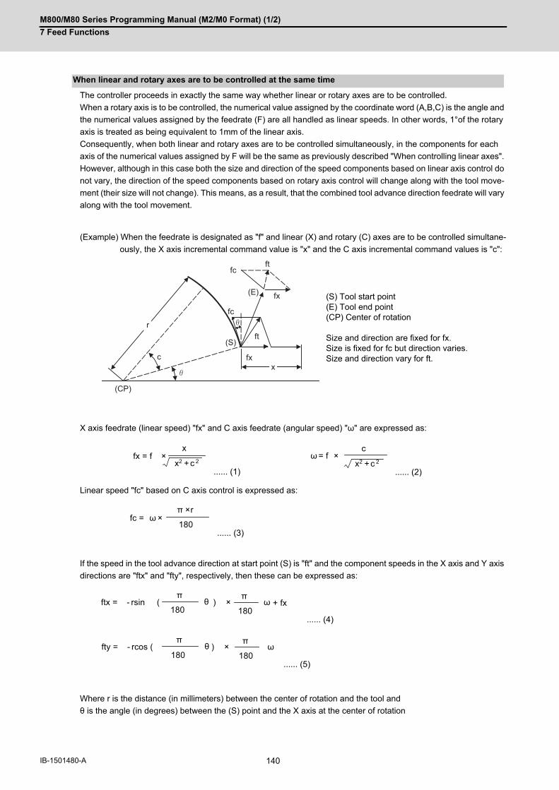
M800/M80 Series Programming Manual (M2/M0 Format) (1/2)
7 Feed Functions
140IB-1501480-A
The controller proceeds in exactly the same way whether linear or rotary axes are to be controlled.
When a rotary axis is to be controlled, the numerical value assigned by the coordinate word (A,B,C) is the angle and
the numerical values assigned by the feedrate (F) are all handled as linear speeds. In other words, 1°of the rotary
axis is treated as being equivalent to 1mm of the linear axis.
Consequently, when both linear and rotary axes are to be controlled simultaneously, in the components for each
axis of the numerical values assigned by F will be the same as previously described "When controlling linear axes".
However, although in this case both the size and direction of the speed components based on linear axis control do
not vary, the direction of the speed components based on rotary axis control will change along with the tool move-
ment (their size will not change). This means, as a result, that the combined tool advance direction feedrate will vary
along with the tool movement.
(Example) When the feedrate is designated as "f" and linear (X) and rotary (C) axes are to be controlled simultane-
ously, the X axis incremental command value is "x" and the C axis incremental command values is "c":
X axis feedrate (linear speed) "fx" and C axis feedrate (angular speed) "ω" are expressed as:
Linear speed "fc" based on C axis control is expressed as:
If the speed in the tool advance direction at start point (S) is "ft" and the component speeds in the X axis and Y axis
directions are "ftx" and "fty", respectively, then these can be expressed as:
Where r is the distance (in millimeters) between the center of rotation and the tool and
θ is the angle (in degrees) between the (S) point and the X axis at the center of rotation
When linear and rotary axes are to be controlled at the same time
(S) Tool start point(E) Tool end point(CP) Center of rotation Size and direction are fixed for fx.Size is fixed for fc but direction varies.Size and direction vary for ft.
...... (1) ...... (2)
...... (3)
...... (4)
...... (5)
(S)
x
fc
c
fcft
fx
fx
ftr
(E)
(CP)
fx = f × x2 + c 2
x ω = f × x2 + c 2
c
fc = ω × 180
π × r
ftx = - rsin ( θ ) × ω + fx 180
π
180
π
fty = - rcos ( θ ) × ω π
180 180
π
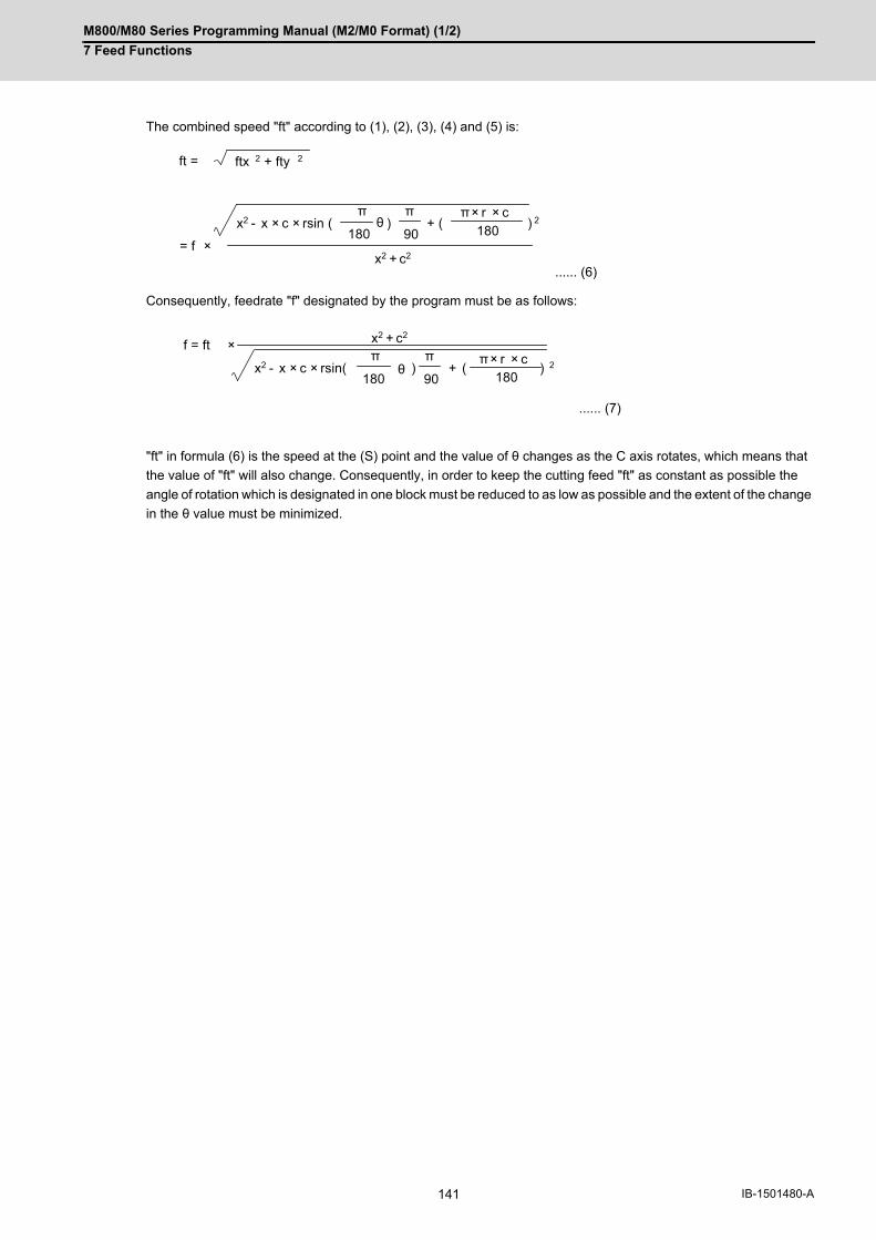
M800/M80 Series Programming Manual (M2/M0 Format) (1/2)
7 Feed Functions
141 IB-1501480-A
The combined speed "ft" according to (1), (2), (3), (4) and (5) is:
Consequently, feedrate "f" designated by the program must be as follows:
"ft" in formula (6) is the speed at the (S) point and the value of θ changes as the C axis rotates, which means that
the value of "ft" will also change. Consequently, in order to keep the cutting feed "ft" as constant as possible the
angle of rotation which is designated in one block must be reduced to as low as possible and the extent of the change
in the θ value must be minimized.
...... (6)
...... (7)
ftx 2 + fty 2 ft =
x2 - x × c × rsin ( θ ) + ( ) 2
x2 + c2 = f ×
π
90 π × r × c
180 π
180
x2 - x × c × rsin( θ ) + ( ) 2
x2 + c2 f = ft ×
π
90 π × r × c
180 π
180
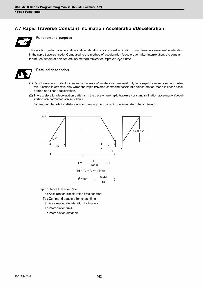
M800/M80 Series Programming Manual (M2/M0 Format) (1/2)
7 Feed Functions
142IB-1501480-A
7.7 Rapid Traverse Constant Inclination Acceleration/Deceleration
This function performs acceleration and deceleration at a constant inclination during linear acceleration/deceleration
in the rapid traverse mode. Compared to the method of acceleration /deceleration after interpolation, the constant
inclination acceleration/deceleration method makes for improved cycle time.
(1) Rapid traverse constant inclination acceleration/deceleration are valid only for a rapid traverse command. Also,this function is effective only when the rapid traverse command acceleration/deceleration mode is linear accel-eration and linear deceleration.
(2) The acceleration/deceleration patterns in the case where rapid traverse constant inclination acceleration/decel-eration are performed are as follows.
[When the interpolation distance is long enough for the rapid traverse rate to be achieved]
Function and purpose
Detailed description
rapid : Rapid Traverse Rate
Ts : Acceleration/deceleration time constant
Td : Command deceleration check time
θ : Acceleration/deceleration inclination
T : Interpolation time
L : Interpolation distance
rapid
G00 Xx1 ;L
Ts TsTd
T
T =L
rapid+Ts
Td = Ts + (0 14ms)
= tan-1 rapid
Ts( )

M800/M80 Series Programming Manual (M2/M0 Format) (1/2)
7 Feed Functions
143 IB-1501480-A
[When the interpolation distance is smaller than the acceleration/deceleration distance]
rapid : Rapid traverse speed (Axis specification parameter #2001 rapid)
Ts1 : Acceleration/deceleration time (Axis specification parameter #2004 G0tL)
Ts2 : Acceleration/deceleration time to reach the maximum speed
Td : Command deceleration check time
θ : Acceleration/deceleration inclination
T1 : Interpolation time (Time-constant acceleration/deceleration)
T2 : Interpolation time (Inclination-constant acceleration/deceleration)
L : Interpolation distance
θ L
Ts1 Ts2
Td
T1
θL
Ts1
Ts2Td
T2
rapid
rapid T1 = Ts1 + Ts2
T2 = 2× Ts1 × Lrapid
Td =
θ =
T22 + (0 ~ 14 ms)
tan−1
Ts1(rapid)
In case of time-constant acceleration/deceleration:
In case of inclination-constant acceleration/deceleration:
Speed
Speed
Next block
Time
Next block
Time

M800/M80 Series Programming Manual (M2/M0 Format) (1/2)
7 Feed Functions
144IB-1501480-A
(3) When 2-axis simultaneous interpolation (linear interpolations) is performed during rapid traverse constant incli-nation acceleration and deceleration, the acceleration (deceleration) time is the longest value of the acceleration(deceleration) times determined for each axis by the rapid traverse rate of commands executed simultaneously,the rapid traverse acceleration and deceleration time constant, and the interpolation distance, respectively. Con-sequently, linear interpolation is performed even when the axes have different acceleration and deceleration timeconstants.
[2-axis simultaneous interpolation (When linear interpolation is used, Tsx < Tsz, Lx ≠ Lz)]
Tsx : X axis acceleration/deceleration time
Tsz : Z axis acceleration/deceleration time
Tdx : X axis commanded deceleration check time
Tdz : Z axis commanded deceleration check time
Lx : X axis interpolation distance
Lz : Z axis interpolation distance
Tsx
Tsz TszTdz
TsxTdx
Lx
Lz
rapid X
rapid Z
Speed
Next block
Time
Next block
Time
X axis
Z axis
When Tsz is greater than Tsx,
Tdz is also greater than Tdx, and
Td = Tdz in this block.
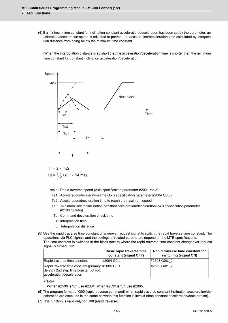
M800/M80 Series Programming Manual (M2/M0 Format) (1/2)
7 Feed Functions
145 IB-1501480-A
(4) If a minimum time constant for inclination-constant acceleration/deceleration has been set by the parameter, ac-celeration/deceleration speed is adjusted to prevent the acceleration/deceleration time calculated by interpola-tion distance from going below the minimum time constant.
[When the interpolation distance is so short that the acceleration/deceleration time is shorter than the minimum
time constant for constant inclination acceleration/deceleration]
(5) Use the rapid traverse time constant changeover request signal to switch the rapid traverse time constant. Theoperations via PLC signals and the settings of related parameters depend on the MTB specifications. The time constant is switched in the block next to where the rapid traverse time constant changeover requestsignal is turned ON/OFF.
<Note>
When #2598 is "0", use #2004. When #2599 is "0", use #2005.
(6) The program format of G00 (rapid traverse command) when rapid traverse constant inclination acceleration/de-celeration are executed is the same as when this function is invalid (time constant acceleration/deceleration).
(7) This function is valid only for G00 (rapid traverse).
rapid : Rapid traverse speed (Axis specification parameter #2001 rapid)
Ts1 : Acceleration/deceleration time (Axis specification parameter #2004 G0tL)
Ts2 : Acceleration/deceleration time to reach the maximum speed
Ts3 : Minimum time for inclination-constant acceleration/deceleration (Axis specification parameter #2198 G0tMin)
Td : Command deceleration check time
T : Interpolation time
L : Interpolation distance
Basic rapid traverse time constant (signal OFF)
Rapid traverse time constant for switching (signal ON)
Rapid traverse time constant #2004 G0tL #2598 G0tL_2
Rapid traverse time constant (primary delay) / 2nd step time constant of soft acceleration/deceleration
#2005 G0t1 #2599 G0t1_2
L
Ts2
Ts3
Ts1Td
T
T = 2 × Ts2
rapid
Speed
Next block
Time
Td = + (0 14 ms)~ T2

M800/M80 Series Programming Manual (M2/M0 Format) (1/2)
7 Feed Functions
146IB-1501480-A
(1) When "#2003 smgst" (acceleration/deceleration mode) is set to the soft acceleration/deceleration, and "#1219aux03 bit7" (time constant setting changeover for soft acceleration/deceleration) is set to "1", the acceleration/deceleration speed is adjusted to prevent the sum of the 1st step and 2nd step acceleration/deceleration timesfrom going below the minimum time constant for inclination-constant acceleration/deceleration. In this case, theacceleration time will be "G0tL+G0t1" or "G1tL+G1t1".
(2) When "#2003 smgst" (acceleration/deceleration mode) is set to the soft acceleration/deceleration, if the acceler-ation/deceleration is shorter than G0tL (or G1tL), the 2nd step time constant will be reduced by the same rate asthe 1st step time constant.
(3) If a commanded travel distance in a block is small, acceleration/deceleration time becomes quite short when theconstant-inclination acceleration/deceleration method is enabled. Although this does contribute to reduce the cy-cle time, this can also be a cause of machine vibrations. In these cases, if the minimum time constant for incli-nation-constant acceleration/deceleration is set in parameter "#2198 G0tMin", it is possible to performacceleration/deceleration to prevent the acceleration/deceleration time from being below this setting value. Thisparameter depends on the MTB specifications.
Precautions

M800/M80 Series Programming Manual (M2/M0 Format) (1/2)
7 Feed Functions
147 IB-1501480-A
7.8 Rapid traverse constant inclination multi-step acceleration/deceleration
This function carries out the acceleration/deceleration according to the torque characteristic of the motor in the rapid
traverse mode during automatic operation. (This function is not available in manual operation.) The rapid traverse
constant inclination multi-step acceleration/deceleration method makes for improved cycle time because the posi-
tioning time is shortened by using the motor ability to its maximum.
In general, the servomotor has the characteristic that the torque falls in the high-speed rotation range.
In the rapid traverse constant inclination acceleration/deceleration method, the acceleration is treated as constant
because this torque characteristic is not considered. So, It is necessary to use a minimum acceleration within the
used speed range. Therefore, the margin of acceleration must be had in a low-speed range. Or if the acceleration
is used to its maximum, the upper limit of the rotation speed must be slowed.
Then, to use the servomotor ability to its maximum, acceleration/deceleration to which the torque characteristic is
considered is carried out by the rapid traverse constant inclination multi-step acceleration/deceleration method.
The acceleration/deceleration patterns in the case where rapid traverse constant inclination multi-step acceleration/
deceleration are performed are as follows.
Function and purpose
[Rapid traverse constant inclination multi-step acceleration/deceleration]
[Rapid traverse constant inclination acceleration/deceleration]
Number of steps is automatically adjusted by parameter setting.
It was necessary to slow down the acceleration for high speed rotation.
(f) Speed (t) Time (a) Acceleration
t bt a
(f)
(t)
(f)
(t)
(t)
(t)
(a) (a)

M800/M80 Series Programming Manual (M2/M0 Format) (1/2)
7 Feed Functions
148IB-1501480-A
(1) The validity of this function depends on the MTB specifications. (Parameter "#1205 G0bdcc")
However, note the following conditions.
(2)To use this function, the following parameters must be set for each axis.
Acceleration rate in proportion to the maximum acceleration rate = Acceleration at rapid traverse rate / Max. ac-
celeration
(3) When either of the following conditions applies, this function is invalid and operates as "rapid traverse constant
inclination acceleration/deceleration". For the axis for which the rapid traverse constant inclination multi-step ac-
celeration/deceleration is not necessary, set "0" to "#2151 rated_spd", "#2152 acc_rate" and "#2153 G0t_rated".
However, these parameters depend on the MTB specifications.
Detailed description
Use conditions
(a) "2" cannot be set to parameter "#1205 G0bdcc" except the 1st part system. When "2" is set to other than 1st part system, an MCP alarm (Y51 0017) will occur.
(b) When there is no specification for the rapid traverse constant inclination acceleration/deceleration, "2" cannot be set to parameter "#1205 G0bdcc". Even if the parameter is set to "2", this function is invalid. A normal time constant acceleration/deceleration (acceleration/deceleration after interpolation) is ap-plied.
(c) Even if "2" is set to "#1205 G0bdcc" when G00 non-interpolation type ("#1086 G00Intp" = "1"), this func-tion is invalid. In this case, a normal time constant acceleration/deceleration (acceleration/deceleration after interpolation) is applied.
#2001 rapid Rapid traverse [mm/min]
#2151 rated_spd Rated speed [mm/min]
#2153 G0t_rated Acceleration time to rated speed [ms]
#2152 acc_rate Acceleration at rapid traverse in ratio to the maximum accel-eration [%]
Speed
rapid
rated_spd
Time
Acceleration
Max. acceleration
Acceleration at rapid traverse rate
Time
(a) When "#2151 rated_spd" (rated speed) is "0" or larger than "#2001 rapid" (rapid traverse)
(b) When "#2152 acc_rate" (Acceleration rate in proportion to the maximum acceleration rate) is "0" or "100"
(c) Even if "2" is set to "#1205 G0bdcc" when G00 non-interpolation type ("#1086 G00Intp" = "1"), this function is invalid. In this case, a normal time constant acceleration/deceleration (acceleration/deceleration after interpolation) is applied.
(G0t_rated)

M800/M80 Series Programming Manual (M2/M0 Format) (1/2)
7 Feed Functions
149 IB-1501480-A
(4) The comparison of the acceleration/deceleration patterns by the parameter setting is in the table below.
Mode Rapid traverse constant inclination multi-step ac-celeration/deceleration
#1086 G00Intp
#1205 G0bdcc
Operation
G00 command ON 0 0 Time constant acceleration/decelera-tion (interpolation type)
1 Constant inclination acceleration/de-celeration (acceleration/deceleration before interpolation)
2 Constant inclination multi-step acceler-ation/deceleration
1 Arbitrary Time constant acceleration/decelera-tion (non-interpolation type)
OFF 0 0 Time constant acceleration/decelera-tion (interpolation type)
1 Constant inclination acceleration/de-celeration (acceleration/deceleration before interpolation)
2 Time constant acceleration/decelera-tion (interpolation type)
1 Arbitrary Time constant acceleration/decelera-tion (non-interpolation type)
Manual rapid traverse
Arbitrary Arbitrary Arbitrary Time constant acceleration/decelera-tion (non-interpolation type)
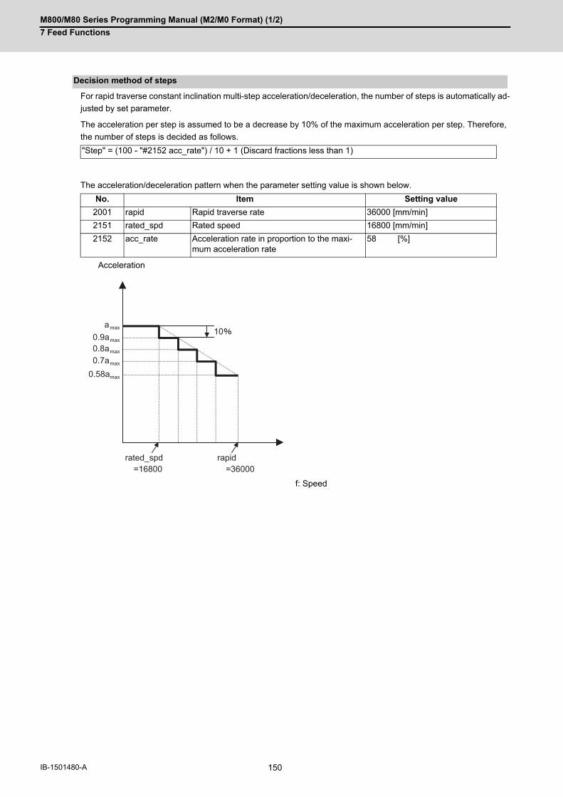
M800/M80 Series Programming Manual (M2/M0 Format) (1/2)
7 Feed Functions
150IB-1501480-A
For rapid traverse constant inclination multi-step acceleration/deceleration, the number of steps is automatically ad-
justed by set parameter.
The acceleration per step is assumed to be a decrease by 10% of the maximum acceleration per step. Therefore,
the number of steps is decided as follows.
The acceleration/deceleration pattern when the parameter setting value is shown below.
Decision method of steps
"Step" = (100 - "#2152 acc_rate") / 10 + 1 (Discard fractions less than 1)
No. Item Setting value
2001 rapid Rapid traverse rate 36000 [mm/min]
2151 rated_spd Rated speed 16800 [mm/min]
2152 acc_rate Acceleration rate in proportion to the maxi-mum acceleration rate
58 [%]
Acceleration
f: Speed
rapid=36000
rated_spd=16800
amax
0.58amax
0.9amax
0.8amax
0.7amax
10

M800/M80 Series Programming Manual (M2/M0 Format) (1/2)
7 Feed Functions
151 IB-1501480-A
When there are two or more rapid traverse axes with a different acceleration pattern, there are the following two
operation methods.
- Interpolation type (#1086 G0Intp = 0) : Moves from the start point to the end point by straight line
- Non-interpolation type (#1086 G0Intp = 1) : Each axis moves separately at the speed of the parameter
Rapid traverse constant inclination multi-step acceleration/deceleration are valid only for an interpolation type. For
the interpolation type, the acceleration pattern operates to the maximum acceleration within the range where toler-
able acceleration of each axis is not exceeded.
Acceleration pattern at two or more axis interpolation
[Acceleration pattern of Y axis inde-pendently]
[Acceleration pattern of X axis inde-pendently]
[Acceleration pattern of synthesis direction]
(a) Acceleration (f) Speed
(S) Start point (E) End point
(ac1) Acceleration pattern when the axis moved to synthesis direction at Y axis rapid traverse rate
(ac2) Acceleration pattern when the axis moved to synthesis direction at X axis rapid traverse rate
(ac3) Acceleration pattern of synthesis direction
Y
a y
v y (f)
(a)
4
35
(S)
(E)
X
a x
v x (f)
(a)
a x / 0.8
a y / 0.6
vy / 0.6 vx / 0.8
(ac2)
(a)
(f)
(ac3)
(ac1)

M800/M80 Series Programming Manual (M2/M0 Format) (1/2)
7 Feed Functions
152IB-1501480-A
With S-pattern filter control, this enables the rapid traverse inclination multi-step acceleration/deceleration fluctua-
tion to further smoothen.
This can be set in the range of 0 to 200 (ms) with the base specification parameter "#1569 SfiltG0" (G00 soft accel-
eration/deceleration filter). With "#1570 Sfilt2" (Soft acceleration/deceleration filter 2), this also enables the acceler-
ation/deceleration fluctuation to further smoothen.
S-pattern filter control
(f) Speed (t) Time
No S-pattern filter control S-pattern filter control
SfiltG0 + Sfilt2
(f)
(t)
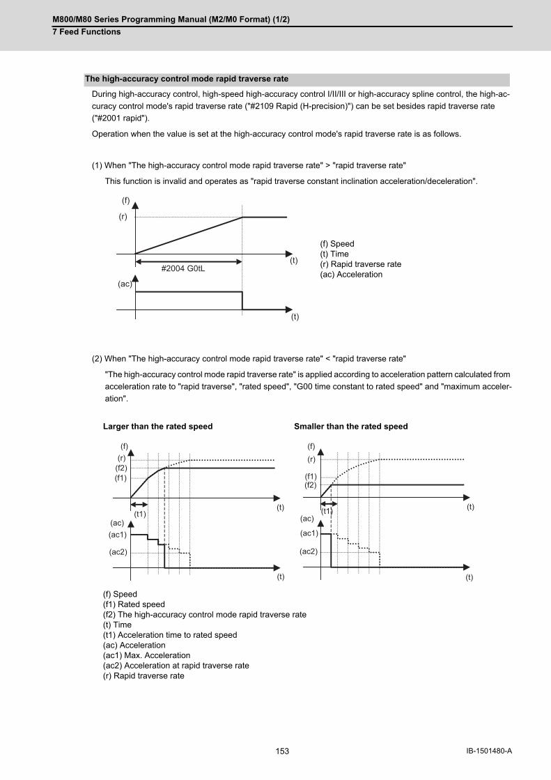
M800/M80 Series Programming Manual (M2/M0 Format) (1/2)
7 Feed Functions
153 IB-1501480-A
During high-accuracy control, high-speed high-accuracy control I/II/III or high-accuracy spline control, the high-ac-
curacy control mode's rapid traverse rate ("#2109 Rapid (H-precision)") can be set besides rapid traverse rate
("#2001 rapid").
Operation when the value is set at the high-accuracy control mode's rapid traverse rate is as follows.
(1) When "The high-accuracy control mode rapid traverse rate" > "rapid traverse rate"
This function is invalid and operates as "rapid traverse constant inclination acceleration/deceleration".
(2) When "The high-accuracy control mode rapid traverse rate" < "rapid traverse rate"
"The high-accuracy control mode rapid traverse rate" is applied according to acceleration pattern calculated from
acceleration rate to "rapid traverse", "rated speed", "G00 time constant to rated speed" and "maximum acceler-
ation".
The high-accuracy control mode rapid traverse rate
(f) Speed(t) Time(r) Rapid traverse rate(ac) Acceleration
Larger than the rated speed Smaller than the rated speed
(f) Speed(f1) Rated speed(f2) The high-accuracy control mode rapid traverse rate(t) Time(t1) Acceleration time to rated speed(ac) Acceleration(ac1) Max. Acceleration(ac2) Acceleration at rapid traverse rate(r) Rapid traverse rate
#2004 G0tL
(f)
(ac)
(r)
(t)
(t)
(f)(r)
(t)
(f2)(f1)
(t)
(ac)(ac1)
(ac2)
(t1)
(f)
(ac)
(f2)(f1)
(r)
(t)
(t)
(ac1)
(ac2)
(t1)

M800/M80 Series Programming Manual (M2/M0 Format) (1/2)
7 Feed Functions
154IB-1501480-A
(1) Rapid traverse constant inclination multi-step acceleration/deceleration are valid only for a rapid traverse com-
mand. Note that when the manual rapid traverse, rapid traverse constant inclination multi-step acceleration/de-
celeration cannot be used.
In this case, a time constant acceleration/deceleration (acceleration/deceleration after interpolation) is applied.
So, acceleration/deceleration is decided by the following parameters.
- #2001 rapid : Rapid traverse rate
- #2003 smgst : Acceleration/deceleration mode
- #2004 G0tL: G00 time constant (linear)
- #2005 G0t1: G00 time constant (primary delay)
The acceleration time (time constant) is different between the rapid traverse constant inclination multi-step ac-
celeration/deceleration and the manual rapid traverse as shown in figure.
(2) Rapid traverse constant inclination multi-step acceleration/deceleration cannot be used in part system excluding
1st part system. However, even if two or more part systems are used, it is possible to use this function in case
of the 1st part system.
(3) When there is no specification for the rapid traverse constant inclination acceleration/deceleration, this function
is invalid even if "2" is set to the parameter "#1205 G0bdcc". In this case, a normal time constant acceleration/
deceleration (acceleration/deceleration after interpolation) is applied.
(4) When G00 non-interpolation type ("#1086 G0Intp" = "1"), rapid traverse constant inclination multi-step acceler-
ation/deceleration cannot be used. It is valid in interpolation mode only.
(5) When the rapid traverse constant inclination multi-step acceleration/deceleration is applied, rapid traverse accel-
eration/deceleration types ("#2003 smgst" bit0 to bit3) are ignored.
(6) When the rapid traverse constant inclination multi-step acceleration/deceleration is valid, G0 constant inclination
("#1200 G0_acc") cannot be used. Even if G0 constant inclination is valid ("#1200 G0_acc" = "1"), the setting is
ignored.
(7) When the rapid traverse constant inclination multi-step acceleration/deceleration is valid, programmable in-po-
sition check cannot be used. The in-position width will be ignored even if commanded.
(8) This function cannot be used during the tool center point control.
Precautions
Rapid traverse constant inclination multi-step acceleration/deceleration
(f) Speed (t) Time (ac) Acceleration
Rapid traverse constant inclination multi-step acceleration/deceleration
Manual rapid traverse (linear)
S-pattern filter control
Soft acceleration/deceleration
(t)(f)
(f)(ac)

M800/M80 Series Programming Manual (M2/M0 Format) (1/2)
7 Feed Functions
155 IB-1501480-A
7.9 Cutting Feed Constant Inclination Acceleration/Deceleration
This function performs linear acceleration/deceleration at a constant inclination in the cutting feed mode. The incli-
nation-constant acceleration/deceleration method can be more beneficial in reducing cycle time in comparison to
the time-constant acceleration/deceleration method.
(1) Cutting feed constant inclination acceleration/deceleration function is effective only when the commanded cutting
feed acceleration/deceleration mode is linear method or soft method in linear interpolation (G01) command.
(2) The program format of linear interpolation when cutting feed constant inclination acceleration/deceleration is ex-
ecuted is the same as when this function is invalid (time constant acceleration/deceleration).
Function and purpose
Detailed description
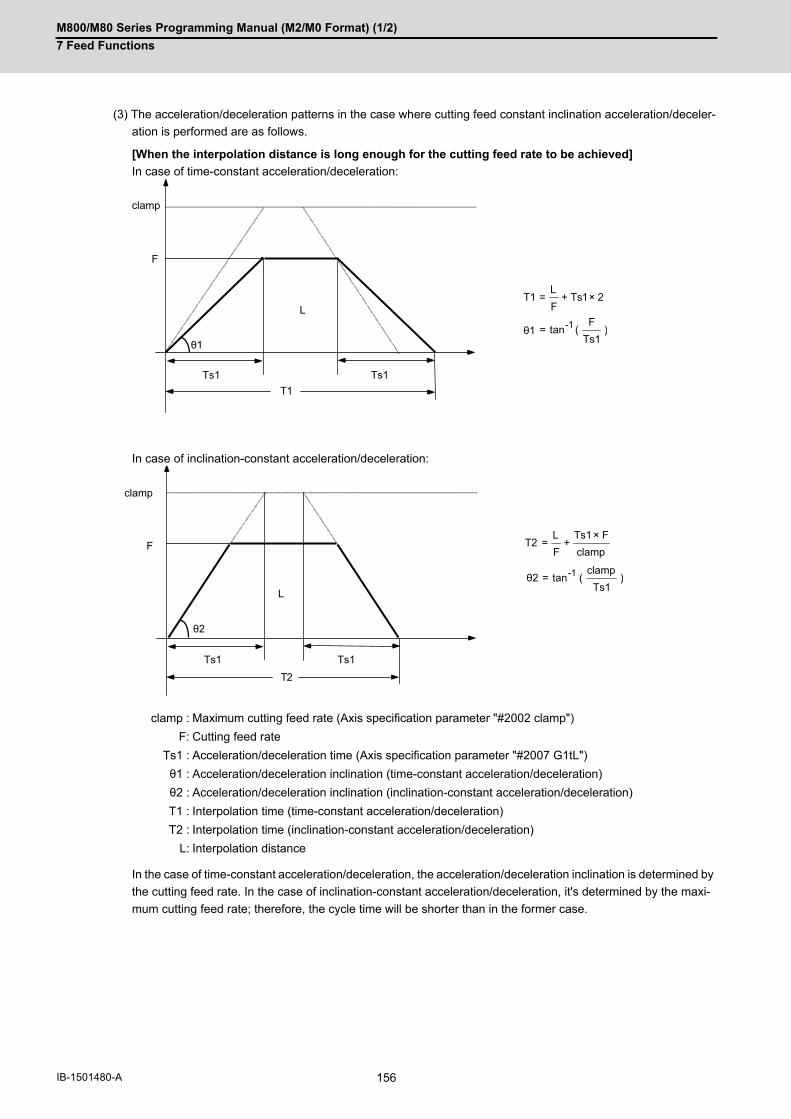
M800/M80 Series Programming Manual (M2/M0 Format) (1/2)
7 Feed Functions
156IB-1501480-A
(3) The acceleration/deceleration patterns in the case where cutting feed constant inclination acceleration/deceler-
ation is performed are as follows.
[When the interpolation distance is long enough for the cutting feed rate to be achieved]
In case of time-constant acceleration/deceleration:
In case of inclination-constant acceleration/deceleration:
In the case of time-constant acceleration/deceleration, the acceleration/deceleration inclination is determined by
the cutting feed rate. In the case of inclination-constant acceleration/deceleration, it's determined by the maxi-
mum cutting feed rate; therefore, the cycle time will be shorter than in the former case.
clamp : Maximum cutting feed rate (Axis specification parameter "#2002 clamp")
F: Cutting feed rate
Ts1 : Acceleration/deceleration time (Axis specification parameter "#2007 G1tL")
θ1 : Acceleration/deceleration inclination (time-constant acceleration/deceleration)
θ2 : Acceleration/deceleration inclination (inclination-constant acceleration/deceleration)
T1 : Interpolation time (time-constant acceleration/deceleration)
T2 : Interpolation time (inclination-constant acceleration/deceleration)
L: Interpolation distance
Ts1
L
Ts1
clamp
T1
F
θ1
21TsFL
T1 ×+=
)Ts1F
(tan-1=θ1
Ts1
L
Ts1
θ2
clamp
T2
F clampFTs1
FL
T2×
+=
)Ts1
clamp(tanθ2 -1=
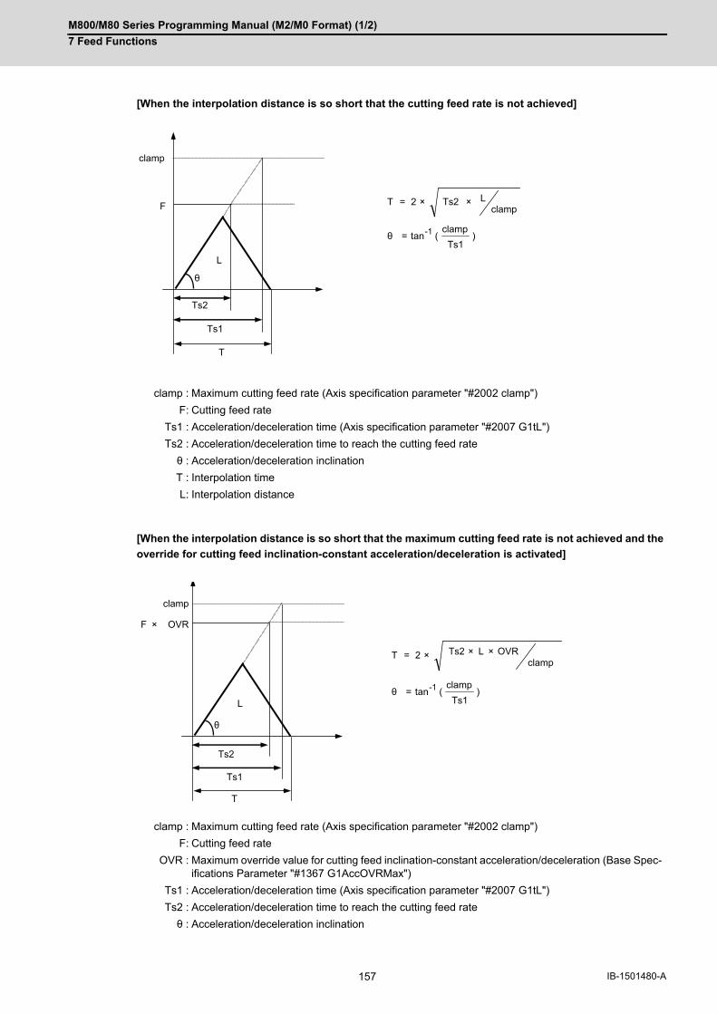
M800/M80 Series Programming Manual (M2/M0 Format) (1/2)
7 Feed Functions
157 IB-1501480-A
[When the interpolation distance is so short that the cutting feed rate is not achieved]
[When the interpolation distance is so short that the maximum cutting feed rate is not achieved and the
override for cutting feed inclination-constant acceleration/deceleration is activated]
clamp : Maximum cutting feed rate (Axis specification parameter "#2002 clamp")
F: Cutting feed rate
Ts1 : Acceleration/deceleration time (Axis specification parameter "#2007 G1tL")
Ts2 : Acceleration/deceleration time to reach the cutting feed rate
θ : Acceleration/deceleration inclination
T : Interpolation time
L: Interpolation distance
clamp : Maximum cutting feed rate (Axis specification parameter "#2002 clamp")
F: Cutting feed rate
OVR : Maximum override value for cutting feed inclination-constant acceleration/deceleration (Base Spec-ifications Parameter "#1367 G1AccOVRMax")
Ts1 : Acceleration/deceleration time (Axis specification parameter "#2007 G1tL")
Ts2 : Acceleration/deceleration time to reach the cutting feed rate
θ : Acceleration/deceleration inclination
)Ts1
clamp(tanθ -1=
L
Ts1
θ
clamp
T
F
Ts2
clampLTs22T ××=
L
Ts1
θ
clamp
T
F × OVR
Ts2
)Ts1
clamp(tanθ -1=
2T ×=clamp
×× OVRLTs2

M800/M80 Series Programming Manual (M2/M0 Format) (1/2)
7 Feed Functions
158IB-1501480-A
[2-axis simultaneous interpolation (When Tsx < Tsz, Lx ≠ Lz)]
When 2-axis simultaneous interpolation is performed during linear interpolation inclination-constant acceleration/
deceleration, the acceleration/deceleration time of each axis will be set to the longest one among the accelera-
tion/decoration times determined by maximum cutting feed rates (axis specification parameter "#2002 clamp"),
cutting feed acceleration/deceleration time constant (axis specification parameter "#2007 G1tL"), cutting feed
rates (F) and interpolation distances (L) of the simultaneously commanded axes.
Should the acceleration/deceleration time constant of an axis be greater than the cutting feed acceleration/de-
celeration time constant (axis specification parameter "#2007 G1tL"), that axis accelerates/decelerates in accor-
dance with the cutting feed acceleration/deceleration time constant (axis specification parameter "#2007 G1tL").
When Tsx < Tsz, the acceleration/deceleration time of the block (Ts) will be equal to the acceleration/decelera-
tion time Tsz (Z axis acceleration/deceleration time).
Tsx : X axis acceleration/deceleration time
Tsz : Z axis acceleration/deceleration time
Lx : X axis interpolation distance
Lz : Z axis interpolation distance
Fx : X axis feed rate
Fz : Z axis feed rate
clampX
clampZ
Tsx
Tsz Tsz
Tsx
Lx
Fx
Fz
X
Lz
Z

M800/M80 Series Programming Manual (M2/M0 Format) (1/2)
7 Feed Functions
159 IB-1501480-A
[When the feed rate is so low that the acceleration/deceleration time is shorter than the minimum time
constant for inclination-constant acceleration/deceleration]
Acceleration/deceleration speed is adjusted to prevent the acceleration/deceleration time calculated by the cut-
ting feed rate from going below the minimum time constant.
[When the interpolation distance is so short that the acceleration/deceleration time is shorter than the
minimum time constant for inclination-constant acceleration/deceleration]
Acceleration/deceleration speed is adjusted to prevent the acceleration/deceleration time calculated by interpo-
lation distance from going below the minimum time constant.
clamp : Maximum cutting feed rate (Axis specification parameter "#2002 clamp")
F: Cutting feed rate
Ts1 : Acceleration/deceleration time (Axis specification parameter "#2007 G1tL")
Ts2 : Acceleration/deceleration time to reach the cutting feed rate
Ts3 : Minimum time for inclination-constant acceleration/deceleration (Axis specification parameter "#2199 G1tMin")
T : Interpolation time
L: Interpolation distance
clamp : Maximum cutting feed rate (Axis specification pa-rameter "#2002 clamp")
F: Cutting feed rate
Ts1 : Acceleration/deceleration time (Axis specifica-tion parameter "#2007 G1tL")
Ts2 : Acceleration/deceleration time to reach the cut-ting feed rate
Ts3 : Minimum time for inclination-constant accelera-tion/deceleration (Axis specification parameter "#2199 G1tMin")
T : Interpolation time
L: Interpolation distance
L
Ts1
clamp
T
Ts3
F
Ts2
Ts32F
LT ×+=
L
Ts1
clamp
T
Ts3
F
Ts2
Ts32T ×=
M800/M80 Series Programming Manual (M2/M0 Format) (1/2)
7 Feed Functions
160IB-1501480-A
(1) If a value greater than 100 (%) is designated for cutting feed override under cutting feed inclinationconstant ac-
celeration/deceleration control, the acceleration/deceleration inclination becomes steeper as the feedrate in-
creases.
To use the cutting feed override function at a rate higher than 100%, set the parameter "#1367 G1AccOVRMax"
accordingly. (This parameter depends on the MTB specifications.) When the setting of this parameter is between
0 and 99 for "#1367 G1AccOVRMax", the override value is handled as 100% even if the specified cutting feed
override is greater than 100%.
(2) If there are one or more NC control axes that are set to soft acceleration/deceleration for G1, the parameter
"#1367 G1AccOVRMax" setting will be ignored and the cutting feed override value is handled as 100%.
(3) When "#2003 smgst"(acceleration/deceleration mode) is set to the soft acceleration/deceleration, and "#1219
aux03 bit7: Time constant setting changeover for soft acceleration/deceleration" is set to "1": Acceleration time
is obtained by G0tL+G0t1 (G1tL+G1t1)", acceleration/deceleration speed is adjusted to prevent the sum of the
1st step and 2nd step acceleration/deceleration times from going below the minimum time constant for inclina-
tion-constant acceleration/deceleration.
(4) When "#2003 smgst" (acceleration/deceleration mode) is set to the soft acceleration/deceleration, if the acceler-
ation/deceleration is shorter than G0tL (or G1tL), the 2nd step time constant will be reduced by the same rate as
the 1st step time constant.
(5) If the commanded travel distance in the block is small or the commanded linear interpolation (G01) feed rate is
low, acceleration/deceleration time becomes quite short when the inclination-constant acceleration/deceleration
method is enabled. Although this does contribute to reduce the cycle time, this can also be a cause of machine
vibrations. In these cases, if the minimum time constant for inclination-constant acceleration/deceleration is set
in parameter "#2199 G1tMin", it is possible to perform acceleration/deceleration to prevent the acceleration/de-
celeration time from being below this setting value.
This parameter depends on the MTB specifications.
Precautions
M800/M80 Series Programming Manual (M2/M0 Format) (1/2)
7 Feed Functions
161 IB-1501480-A
7.10 Exact Stop Check; G09
In order to prevent roundness during corner cutting and machine shock when the tool feedrate changes suddenly,
there are times when it is desirable to start the commands in the following block once the in-position state after the
machine has decelerated and stopped or the elapsing of the deceleration check time has been checked. The exact
stop check function is designed to accomplish this purpose.
A deceleration check is performed when the G09 (exact stop check) command has been designated in the same
block. The G09 command is unmodal.
Either the deceleration check time or in-position state is based on the parameter settings specified by the MTB. (Re-
fer to section "7.12 Deceleration Check".)
The in-position width is set in servo parameter "#2224 sv024", "#2077 G0inps" or "#2078 G1inps". This parameter
also depends on the MTB specifications.
The exact stop check command G09 has an effect only with the cutting command (G01 - G03) in its particular block.
Function and purpose
Command format
Exact stop check
G09 G01 (G02, G03);
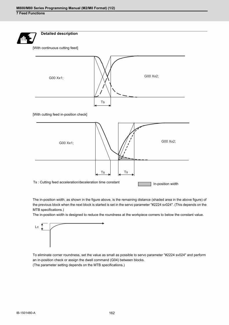
M800/M80 Series Programming Manual (M2/M0 Format) (1/2)
7 Feed Functions
162IB-1501480-A
[With continuous cutting feed]
[With cutting feed in-position check]
The in-position width, as shown in the figure above, is the remaining distance (shaded area in the above figure) of
the previous block when the next block is started is set in the servo parameter "#2224 sv024". (This depends on the
MTB specifications.)
The in-position width is designed to reduce the roundness at the workpiece corners to below the constant value.
To eliminate corner roundness, set the value as small as possible to servo parameter "#2224 sv024" and perform
an in-position check or assign the dwell command (G04) between blocks.
(The parameter setting depends on the MTB specifications.)
Detailed description
Ts : Cutting feed acceleration/deceleration time constant In-position width
Ts
G00 Xx2;G00 Xx1;
G00 Xx1; G00 Xx2;
Ts Ts
Lc

M800/M80 Series Programming Manual (M2/M0 Format) (1/2)
7 Feed Functions
163 IB-1501480-A
(1) With linear acceleration/deceleration
(2) With exponential acceleration/deceleration
(3) With exponential acceleration/linear deceleration
The time required for the deceleration check during cutting feed is the longest among the cutting feed decelera-
tion check times of each axis determined by the cutting feed acceleration/deceleration time constants and by the
cutting feed acceleration/ deceleration mode of the axes commanded simultaneously.
(1) To execute exact stop check in a fixed cycle cutting block, insert command G09 into the fixed cycle subprogram.
With deceleration check
Ts: Acceleration/deceleration time constant Td: Deceleration check time Td = Ts + α (0 to 10ms)
Ts: Acceleration/deceleration time constant Td: Deceleration check time Td = 2 x Ts + α (0 to 10ms)
Ts: Acceleration/deceleration time constant Td: Deceleration check time Td = 2 x Ts + α (0 to 10ms)
Ts
Td
G00 Xx1; G00 Xx2;
Ts
Td
G00 Xx1; G00 Xx2;
Td Ts
G00 Xx1; G00 Xx2;
2×Ts
Note

M800/M80 Series Programming Manual (M2/M0 Format) (1/2)
7 Feed Functions
164IB-1501480-A
[Exact stop check result]
Program example
N001 G09 G01 X100.000 F150 ; The commands in the following block are started once the deceleration check time or in-position state has been checked after the machine has de-celerated and stopped.
N002 Y100.000 ;
f: Commanded speed Tool
t: Time
Solid line indicates speed pattern with G09 command
Broken line indicates speed pattern without G09 command
N001X
Y
N001
N002
N002

M800/M80 Series Programming Manual (M2/M0 Format) (1/2)
7 Feed Functions
165 IB-1501480-A
7.11 Exact Stop Check Mode; G61
Whereas the G09 exact stop check command checks the in-position status only for the block in which the command
has been assigned, the G61 command functions as a modal. This means that deceleration will apply at the end
points of each block to all the cutting commands (G01 to G03) subsequent to G61 and that the in-position status will
be checked.
The modal command is released by the following commands.
G61.1........ High-accuracy control mode
G63 .......... Tapping mode
G64 .......... Cutting mode
In-position check is executed when the G61 command has been selected, and thereafter, the in-position check is
executed at the end of the cutting command block until the check mode is canceled.
Function and purpose
Command format
G61 ; ... Exact stop check mode

M800/M80 Series Programming Manual (M2/M0 Format) (1/2)
7 Feed Functions
166IB-1501480-A
7.12 Deceleration Check7.12.1 Deceleration Check
The deceleration check reduces the machine shock that occurs when the control axis feedrate is suddenly changed
and prevents corners from becoming rounded. This is accomplished by decelerating the motor to a stop at axis
movement block joints before the next block is executed.
The conditions for executing a deceleration check are described below.
(1) Deceleration check in the rapid traverse modeIn the rapid traverse mode, the deceleration check is always performed when block movement is completed be-fore executing the next block.
(2) Deceleration check in the cutting feed modeIn the cutting feed mode, the deceleration check is performed and the program starts moving the next block whenone of the following conditions is satisfied. (a) When G61 (Exact stop check mode) is selected(b) When the G09 (Exact stop check) command has been designated in the same block(c) When the error detect switch (PLC signal) is ON
There are three methods for deceleration check: command deceleration check method, smoothing check method,
and in-position check method.
The method that is selected for rapid traverse or cutting feed depends on the MTB specifications (combination of
parameters "#1306 InpsTyp", "#1389 G1SmthChk", "#1223 aux07/bit1", and "#1193 inpos").
Depending on the MTB specifications, different deceleration check methods may be used for each feed command
during rapid traverse command and cutting feed command (parameter "#1306 InpsTyp").
Function and purpose
Without deceleration check With deceleration check
N010 G01 X100 ; N011 G01 Y-50 ;
Corner rounding occurs becausethe N011 block is started beforethe N010 command is completelyfinished.
N010 G09 G01 X100 ; N011 G01 Y-50 ;
A sharp edge is formed becausethe N011 block is started after the N010 command is decelerated and stopped.

M800/M80 Series Programming Manual (M2/M0 Format) (1/2)
7 Feed Functions
167 IB-1501480-A
(*1) Deceleration check time is automatically calculated from the acceleration/deceleration mode and time constant.
Detailed description
Behavior for each combination of movement commands
Next block Current block
G00 G01 G00/G01 without move-ment
G00 ○ (○) (*1)(*2) ×
G01 ○ (○) (*1)(*3) ×
Others ○ (○) (*1) ×
○ : Deceleration check is performed.
(○): (*1) A deceleration check is performed when the error detection signal is ON or when G09 or G61 is en-abled. (*2) A command deceleration check is performed when G01 => G00 block is specified, "#1502 G0Ipfg" is ON or the movement reverses to the opposite direction. (*3) A command deceleration check is performed when G01 => G01 block is specified, "#1503 G1Ipfg" is ON or the movement reverses to the opposite direction. For the deceleration check when movement in the opposite direction is reversed, refer to "7.12.2 Decel-eration Check when Movement in The Opposite Direction Is Reversed". A deceleration check is not performed if the above conditions are not satisfied.
× : Deceleration check is not performed.
Types of deceleration check
(1) Command deceleration check methodDeceleration is completed after the deceleration check time (*1) has passed after the interpola-tion.
(2) Smoothing check methodDeceleration is completed after the deceleration check time (*1) has passed after the interpola-tion and all axis smoothing has become zero.
(3) In-position check methodThe deceleration is completed after the deceleration check time (*1) had passed after the interpolation, all axis smoothing has become zero, and all axes have become in-position.
NC command speed Deceleration check time
Block is completedInterpolation is completed
Speed
Block is completed
NC command speed Deceleration check time
Interpolation is completed
Speed
NC command speed
Actual motor rotation speed
Deceleration check time
Interpolation is completed
Speed
Block is completed
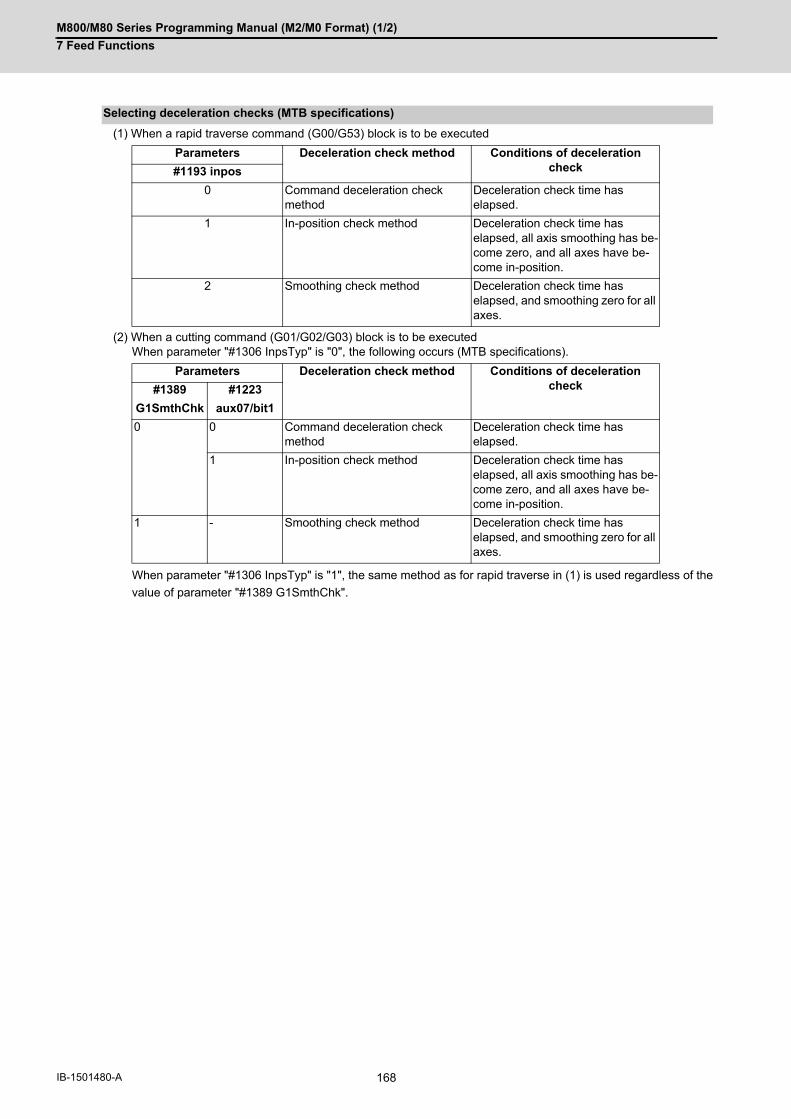
M800/M80 Series Programming Manual (M2/M0 Format) (1/2)
7 Feed Functions
168IB-1501480-A
(1) When a rapid traverse command (G00/G53) block is to be executed
(2) When a cutting command (G01/G02/G03) block is to be executedWhen parameter "#1306 InpsTyp" is "0", the following occurs (MTB specifications).
When parameter "#1306 InpsTyp" is "1", the same method as for rapid traverse in (1) is used regardless of the
value of parameter "#1389 G1SmthChk".
Selecting deceleration checks (MTB specifications)
Parameters Deceleration check method Conditions of deceleration check#1193 inpos
0 Command deceleration check method
Deceleration check time has elapsed.
1 In-position check method Deceleration check time has elapsed, all axis smoothing has be-come zero, and all axes have be-come in-position.
2 Smoothing check method Deceleration check time has elapsed, and smoothing zero for all axes.
Parameters Deceleration check method Conditions of deceleration check#1389 #1223
G1SmthChk aux07/bit1
0 0 Command deceleration check method
Deceleration check time has elapsed.
1 In-position check method Deceleration check time has elapsed, all axis smoothing has be-come zero, and all axes have be-come in-position.
1 - Smoothing check method Deceleration check time has elapsed, and smoothing zero for all axes.

M800/M80 Series Programming Manual (M2/M0 Format) (1/2)
7 Feed Functions
169 IB-1501480-A
Execution of the next block starts after confirming that the deceleration of the command system is completed upon
completion of interpolation for one block.
The following explains an example of transition from the current block (rapid traverse) to the next block.
The time required for the deceleration check is the longest among the deceleration check times of each axis deter-
mined by the acceleration/deceleration mode and time constants of the axes commanded simultaneously.
(a) For linear acceleration/deceleration
(b) For exponential acceleration/deceleration
(c) For soft acceleration/deceleration
Command deceleration check method
(Ts) Linear acceleration/deceleration time constant
(Td) Deceleration check time: Td = Ts + α (0 to 10 ms)
(Ts) Exponential acceleration/deceleration time constant
(Td) Deceleration check time: Td = 2 x Ts + α (0 to 10 ms)
(Ts) Soft acceleration/deceleration time constant
(Td) Deceleration check time: Td = 2 x Ts + α (0 to 10 ms)
Td
Ts
Execution block Next block
Td
Ts
Execution block Next block
command
Td
Ts
Execution block Next block

M800/M80 Series Programming Manual (M2/M0 Format) (1/2)
7 Feed Functions
170IB-1501480-A
Execution of the next block starts after the command deceleration check is performed and after confirming that the
smoothing for all axes in the part system has reached zero.
For exponential acceleration/deceleration
Execution of the next block starts after the command deceleration check is performed and after confirming that the
remaining distances for all axes in the part system are below certain values.
The confirmation of the remaining distance should be done with the imposition width.
The bigger one of the servo parameter "#2224 SV024" or G0 in-position width "#2077 G0inps" (For G01, in-position
width "#2078 G1inps"), will be adapted as the in-position width.
(For a rotary axis, the setting value of spindle parameter "#13024 SP024" is assumed to be the in-position width.)
With linear acceleration/deceleration
As shown in the figure above, the in-position width is the remaining distance from the previous block at the start of
the next block. (Shaded area of the figure above).
Smoothing check method
(Ts) Exponential acceleration/deceleration time constant
(Td) Deceleration check time
(Tp) Waiting time for a block to complete
In-position check method
(Ts) Linear acceleration/deceleration time constant
(Td) Deceleration check time
(Tp) Waiting time for a block to complete
Td
Tp
TsSmoothing zero for all axes
Execution block Next block
Command
Td
Tp
Ts
Execution block Next block
In-position width
Servo
Command

M800/M80 Series Programming Manual (M2/M0 Format) (1/2)
7 Feed Functions
171 IB-1501480-A
The purpose of the deceleration check is to minimize the positioning time. The bigger the setting value for the in-
position width, the shorter the time is, but the remaining distance of the previous block at the start of the next block
also becomes larger, and this could become an obstacle in the actual processing work.
The check for the remaining distance is done at set intervals. Accordingly, it may not be possible to get the effect of
time reduction for positioning as in-position width setting value.
(1) In-position check by the G0inps: When SV024 < G0inps (Stop is judged at A in the figure.)
(2) In-position check by the SV024: When G0inps < SV024 (Stop is judged at A in the figure.)
Command to motor
Outline of motor movement
: G0inps
: SV024
Command to motor
Outline of motor movement
: G0inps
: SV024
G0inps
SV024
A
SV024
G0inps
A

M800/M80 Series Programming Manual (M2/M0 Format) (1/2)
7 Feed Functions
172IB-1501480-A
This command commands the in-position width for the positioning command from the machining program.
Execution of the next block starts after confirming that the position error amount in the block in which the decelera-
tion check is to be performed is less than the in-position width.
The in-position width specified by parameter (SV024, G0inps (G1inps for G01)) or the one specified in the program,
whichever is greater, will be adapted as the in-position width.
When there are several movement axes, the system confirms that the position error amount of each movement axis
in each part system is less than the in-position width issued in this command before executing the next block.
For ",I" command, also refer to "6.1 Positioning (Rapid Traverse); G00".
The differences between the in-position check with parameter and with programmable command are as follows:
(1) In-position check with parameterAfter completing deceleration of the command system ("A" in the figure), the servo system's position erroramount and the parameter setting value (in-position width) are compared.
(2) In-position check with programmable command (",I" address command)After starting deceleration of the command system ("A" in the figure), the position error amount and commandedin-position width are compared.
Programmable in-position width command
G00 X_ Z_(Y_) ,I_ ;
X,Z(,Y_) Positioning coordinate value of each axis
,I In-position width (setting range: 1 to 999999)
The differences of In-position check
(Ts) Acceleration/deceleration time constant
(Td) Deceleration check time: Td = Ts + α (0 to 10 ms)
Servo machine positionCommandIn-position width (Servo system position error amount)
(Ts) Acceleration/deceleration time constant
(Td) Deceleration check time: Td = Ts + α (0 to 10 ms)
Servo machine positionCommandIn-position width (Servo system position error amount)
G00 Xx1;
Ts
Td
A
G00 Xx1;
Ts
Td
A

M800/M80 Series Programming Manual (M2/M0 Format) (1/2)
7 Feed Functions
173 IB-1501480-A
The deceleration check acts on the compensated block when tool compensation is performed.
The automatic error detection is disabled in a block in which deceleration check is enabled.
When the axis movement reverses to the opposite direction in a G01 → G01 successive block during the high-speed
machining mode other than high-speed machining mode I (G05 P1) the commanded deceleration will not take place
even if parameter "#1503 G1Ipfg" is set to 1.
Note that the G0Ipfg setting will be followed if the axis direction reverses to the opposite direction in a G01 → G00
successive block.
A deceleration check is performed even when high-speed simple program check is running. During high-speed sim-
ple program checking, the deceleration check time is reduced according to the time reduce coefficient.
(1) When the in-position check is valid, the parameter for the in-position width "#2224 SV024" must be set. (Basedon the MTB specifications.)
(2) This function is disabled for an axis to which automatic machine lock is applied.
(3) If MSTB is commanded in the block that follows a cutting command, the MSTB code is output before decelerationis completed in the cutting command. If an MSTB command must be executed after the completion of axis move-ment, check the PLC signals (DEN) before executing it. (The behavior depends on the MTB specifications.)
(4) If there is an axis in control axis synchronization/superimposition in the part system for which the in-positioncheck method is specified, deceleration is considered to be completed when all axis smoothing has become ze-ro. (Equivalent to smoothing check method)
(5) If thread cutting commands are specified in succession, a deceleration check is not carried out at block joints.
(6) If the parameter "#1205 G0bdcc" is set to "1", the value set with the parameter "#2224 SV024" (in-position de-tection width) will be used as the in-position width. The setting of the parameter "#2077 G0inps" (G0 in-position width) and the programmable in-position check with",I" address are disabled. These parameters depend on the MTB specifications.
Relationship with Other Functions
Tool compensation
Automatic error detection
High-speed machining mode
High-speed simple program check
Precautions

M800/M80 Series Programming Manual (M2/M0 Format) (1/2)
7 Feed Functions
174IB-1501480-A
7.12.2 Deceleration Check when Movement in The Opposite Direction Is Reversed
A deceleration check cannot be designated for G01 -> G00 or G01 -> G01, but it can be designated in the following
manner only when the movement reverses to the opposite direction in successive blocks.
A deceleration check can also be executed if even one axis is moving in the opposite direction while several axes
are interpolating.
For the relation with other functions and precautions, refer to "Deceleration Check".
If the axis movement reverses to the opposite direction in a G01 to G00 successive block, the deceleration check
for the movement in the opposite direction can be changed with the MTB specifications (parameter "#1502 G0Ipfg").
Example of program: When there is a deceleration check in the movement of several axes
(1)
(2)
(3)
(4)
Function and purpose
Detailed description
Designating deceleration check for G01 -> G00 opposite direction movement reversal
Same direction Opposite direction
G0Ipfg:0
The acceleration is excessive due to the G01 and G00 composite speed.
G0Ipfg:1
Command deceleration
G91 G01 X100. Y100. F4000 ;G00 X-100. Y120. ;
A deceleration check is carried out, because the X axis moves in the reverse direction in the program.
G91 G01 X100. Y-100. F4000 ;G00 X80. Y100. ;
A deceleration check is carried out, because the Y axis moves in the reverse direction in the program.
G90 G01 X100. Y100. F4000 ;G00 X80. Y120. ;
A deceleration check is carried out, because the X axis moves in the reverse direction in the program.(When the program start position is X0 Y0)
G91 G01 X100. Y100. F4000 ;G00 X100. Y100. ;
A deceleration check is not carried out, because both the X axis and the Y axis move in the same direction in the program.
G01 G00
G01 G00
G01 G00
G01 G00

M800/M80 Series Programming Manual (M2/M0 Format) (1/2)
7 Feed Functions
175 IB-1501480-A
(5)
If the axis movement reverses to the opposite direction in a G01 to G01 successive block, the deceleration check
for the movement in the opposite direction can be changed with the MTB specifications (parameter "#1503 G1Ipfg").
Example of program: When there is a deceleration check in the movement of several axes
(1)
(2)
(3)
(4)
(5)
G91 G01 X100. Y80. F4000 ;G00 X80. ;
A deceleration check is not carried out, because the X axis moves in the same direction, and there is no Y axis movement command in the program.
Designating deceleration check for G01 -> G01 opposite direction movement reversal
Same direction Opposite direction
G1Ipfg:0
The acceleration is excessive due to the G01 and G01 composite speed.
G1Ipfg:1
Command deceleration
G91 G01 X100. Y100. F4000 ;G01 X-100. Y120. ;
A deceleration check is carried out, because the X axis moves in the reverse direction in the program.
G91 G01 X100. Y-100. F4000 ;G01 X80. Y100. ;
A deceleration check is carried out, because the Y axis moves in the reverse direction in the program.
G90 G01 X100. Y100. F4000 ;G01 X80. Y120. ;
A deceleration check is carried out, because the X axis moves in the reverse direction in the program.(When the program start position is X0 Y0)
G91 G01 X100. Y100. F4000 ;G01 X100. Y100. ;
A deceleration check is not carried out, because both the X axis and the Y axis move in the same direction in the program.
G91 G01 X100. Y80. F4000 ;G01 X80. ;
A deceleration check is not carried out, because the X axis moves in the same direction, and there is no Y axis movement command in the program.
G01 G01
G01 G01
G01 G01G01 G01
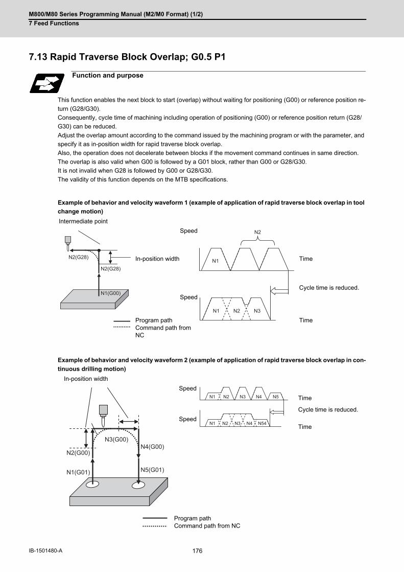
M800/M80 Series Programming Manual (M2/M0 Format) (1/2)
7 Feed Functions
176IB-1501480-A
7.13 Rapid Traverse Block Overlap; G0.5 P1
This function enables the next block to start (overlap) without waiting for positioning (G00) or reference position re-
turn (G28/G30).
Consequently, cycle time of machining including operation of positioning (G00) or reference position return (G28/
G30) can be reduced.
Adjust the overlap amount according to the command issued by the machining program or with the parameter, and
specify it as in-position width for rapid traverse block overlap.
Also, the operation does not decelerate between blocks if the movement command continues in same direction.
The overlap is also valid when G00 is followed by a G01 block, rather than G00 or G28/G30.
It is not invalid when G28 is followed by G00 or G28/G30.
The validity of this function depends on the MTB specifications.
Example of behavior and velocity waveform 1 (example of application of rapid traverse block overlap in tool
change motion)
Example of behavior and velocity waveform 2 (example of application of rapid traverse block overlap in con-
tinuous drilling motion)
Function and purpose
Intermediate point
Speed
In-position width Time
Cycle time is reduced.
Speed
Program pathCommand path from NC
Time
In-position width
Speed
Time
Cycle time is reduced.
SpeedTime
Program pathCommand path from NC
N2(G28)
N2(G28)
N1(G00)
N1
N1 N2 N3
N2
N3(G00)N4(G00)
N5(G01)
N2(G00)
N1(G01)
N1
N1 N2 N3 N4 N54
N2 N3 N4 N5

M800/M80 Series Programming Manual (M2/M0 Format) (1/2)
7 Feed Functions
177 IB-1501480-A
For a deceleration check method that uses the in-position width for rapid traverse (G00) or reference position return
(G28/G30), a function with a higher priority that is enabled will be applied.
If none of the functions is enabled, the command deceleration is carried out.
For G00 overlap, refer to "7.13.1 Rapid Traverse Block Overlap for G00; G0.5". For G28/G30 overlap, refer to
"7.13.2 Rapid Traverse Block Overlap for G28".
Deceleration check method using in-position width
Function
Enabling conditions
Deceleration Check
Priority(Deceleration check
method)Enabled behav-
ior
Programmable in-posi-tion
Valid when the in-position width is designated with address ",I" in the same block as G00. (It is valid only for a block in which address ",I" is specified.)(For details, refer to "6.1 Positioning (Rapid Tra-verse); G00" and "7.12 Deceleration Check".)
G00 1
Rapid traverse block overlap (this function)
(1) For G00Parameter "#1442 G0ol" must be "1" and G00 rapid traverse block overlap must be valid modal code (G0.5P1).
G00/G28/G30 2
(2) For G28/G30Parameter "#1443 G28ol" must be "1".
In-position check by pa-rameter settings
Parameter "#1193 inpos" must be "1". (For details, refer to "7.12 Deceleration Check".)
G00 3

M800/M80 Series Programming Manual (M2/M0 Format) (1/2)
7 Feed Functions
178IB-1501480-A
7.13.1 Rapid Traverse Block Overlap for G00; G0.5
This function enables the next block to start (overlap) without waiting for positioning (G00) or reference position re-
turn (G28/G30).
For the rapid block overlap function, also refer to "7.13 Rapid Traverse Block Overlap; G0.5 P1".
G28/G30 can be overlapped when the rapid traverse block overlap for G28 is enabled. For details, refer to "7.13.2
Rapid Traverse Block Overlap for G28".
(1) A program error (P35) will occur unless this block is independently specified.
(2) This block can be specified simultaneously with an N code (sequence number).
(3) The in-position width at joints between two blocks containing G28/G30 cannot be changed with G0.5P1 com-mand.
(4) G0.5P1 and G0.5P0 are modal.
(5) Address J in G20 must be programmed in inches.
(6) If an address is omitted, the width determined by the MTB specifications becomes valid. (Parameters "#2224SV024" and "#13024 SP024")If a value less than the width determined by the MTB is specified, that width becomes valid.
(7) If address J or K is set to "0", the conventional deceleration check is performed.
Function and purpose
Command format
Starting rapid traverse block overlap for G00
G0.5 P1 J_ K_;
P Starting or canceling the rapid traverse block overlap function (0: Cancel, 1: Start)
J Liner axis in-position width (0.000 to 1000.000 (mm))
K Rotary axis in-position width (0.000 to 1000.000 (°))
Canceling rapid traverse block overlap for G00
G0.5 P0;
Note
M800/M80 Series Programming Manual (M2/M0 Format) (1/2)
7 Feed Functions
179 IB-1501480-A
The rapid traverse block overlap function for G00 becomes effective when all of the following conditions are satisfied.
(1) The rapid traverse block overlap for G00 must be enabled. Refer to the MTB specifications (parameter "#1442 G0ol").
(2) G0.5P1 modal must be active. To make G0.5P1 modal active:
Specify a G code (G0.5P1) in which rapid traverse block overlap is enabled in the machining program.Set parameter "#12056 I_G0oL G00" to "1" (valid).
(1) When the rapid traverse block overlap for G00 is enabled, a G code (positioning (G00) or linear interpolation(G01)) following positioning (G00) may not be subject to rapid traverse block overlap depending on the currentcontrol mode or parameter settings that are specified by the MTB. (Parameters "#1086 G0intp" and "#1205G0bdcc")For details, refer to the table below.
○ : Motion subject to rapid traverse block overlap for G00
× : Motion not subject to rapid traverse block overlap for G00
Detailed description
Enabling conditions
N1 G0.5 P1; Rapid traverse block overlap function: Enabled
N2 G91 G00 X10.;
N3 G00 X20.;
N4 G0.5 P0; Rapid traverse block overlap function: Disabled
:
Motion subject to rapid traverse block overlap
Control mode Parameters G code following positioning (G00)
High-accuracy mode
#1086 #1205 G00 G01
OFF 0 0 ○ ○
1 ○ ×
2 ○ ×
1 0/1/2 ○ ○
ON 0 0 ○ ×
1 ○ ×
2 ○ ×
1 0/1/2 ○ ×

M800/M80 Series Programming Manual (M2/M0 Format) (1/2)
7 Feed Functions
180IB-1501480-A
(2) When executing a rapid traverse block overlap in G00 multi-step acceleration/deceleration, the next block (N2 inthe following program) will be started after the deceleration at the last step in the execution bock (N1) has started. The hatched area in the figure below is an area in which the in-position width can be specified.
(3) When the rapid traverse block overlap for G00 is enabled, this function is valid if positioning (G00) is followed bya fixed cycle, subprogram or macro call command block. In addition, this function is valid if a fixed cycle, subprogram or macro program contains consecutive move com-mands to which this function is applied. (If the in-position width is specified in a fixed cycle command, that value is given priority.)
The start position of overlap when a rapid traverse block overlap for G00 is executed can be adjusted with the in-
position width. The next block is started when the remaining distances of all movement axes in the current move-
ment block are smaller than the in-position width. (Refer to following figure.)
When setting the in-position width with J and K commands, set a value for each linear and rotary axis. Setting the
in-position width for axes with parameter settings depend on the MTB specifications (parameter "#2631 G0olinps").
The start position of the next block based on the remaining distance and in-position width for each movement axis
is shown below.
This shows an example of when the X axis in-position width is set to 0.5 mm and the Y axis in-position width to 1 mm.
N1 G91 G00 X10.;N2 X10.;
Speed Command to motor Start of deceleration at the last step
Time
Motor movement Deceleration stop
Adjustment of start position of overlap
(a) For X axis (b) For Y axis
Program example Program example
N1 G91 G00 X50.;N2 Y50.;
N1 G91 G00 Y50.;N2 X-50.;
Operation Operation
Start position of N2 block Y axis in-position width = 1mm
X axis in-position width = 0.5mm Start position of N2 block
N1 N2
N1
N2
N1
N2
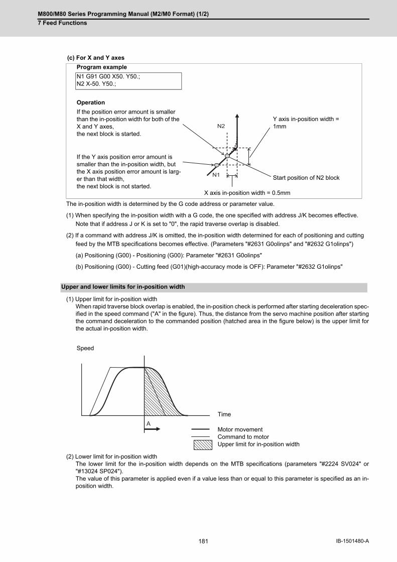
M800/M80 Series Programming Manual (M2/M0 Format) (1/2)
7 Feed Functions
181 IB-1501480-A
The in-position width is determined by the G code address or parameter value.
(1) When specifying the in-position width with a G code, the one specified with address J/K becomes effective.
Note that if address J or K is set to "0", the rapid traverse overlap is disabled.
(2) If a command with address J/K is omitted, the in-position width determined for each of positioning and cutting
feed by the MTB specifications becomes effective. (Parameters "#2631 G0olinps" and "#2632 G1olinps")
(a) Positioning (G00) - Positioning (G00): Parameter "#2631 G0olinps"
(b) Positioning (G00) - Cutting feed (G01)(high-accuracy mode is OFF): Parameter "#2632 G1olinps"
(1) Upper limit for in-position widthWhen rapid traverse block overlap is enabled, the in-position check is performed after starting deceleration spec-ified in the speed command ("A" in the figure). Thus, the distance from the servo machine position after startingthe command deceleration to the commanded position (hatched area in the figure below) is the upper limit forthe actual in-position width.
(2) Lower limit for in-position widthThe lower limit for the in-position width depends on the MTB specifications (parameters "#2224 SV024" or"#13024 SP024"). The value of this parameter is applied even if a value less than or equal to this parameter is specified as an in-position width.
(c) For X and Y axes
Program example
N1 G91 G00 X50. Y50.;N2 X-50. Y50.;
Operation
If the position error amount is smaller than the in-position width for both of the X and Y axes, the next block is started.
Y axis in-position width = 1mm
If the Y axis position error amount is smaller than the in-position width, but the X axis position error amount is larg-er than that width, the next block is not started.
Start position of N2 block
X axis in-position width = 0.5mm
Upper and lower limits for in-position width
Speed
Time
Motor movementCommand to motorUpper limit for in-position width
N1
N2
A

M800/M80 Series Programming Manual (M2/M0 Format) (1/2)
7 Feed Functions
182IB-1501480-A
The conventional deceleration check (in-position check method) applies the same in-position width regardless of the path (corner angle). Therefore, an extra speed change occurs and cycle time is increased even though path direction stays almost the same. The rapid traverse block overlap automatically compensates for the in-position width based on the path (corner angle). However, the in-position width is not compensated for based on the path if a block without a movement command is inserted between the movement commands to be overlapped.
(1) If the angle is greater than 90°, the rapid traverse overlap function is temporarily canceled.
(2) If the angle is less than 90°, the in-position width is compensated for so that it matches the amount of droop ata corner when the corner angle is 90°.
The following are examples of using G00 rapid traverse block overlap in combination with G00 (rapid traverse) and G01 (cutting feed). (When the high-accuracy control mode is OFF)
Compensation for in-position width based on the path
Program example
When the in-position width is specified with address J (G0.5P1 J_)
Parameter setting X axis Z axis
#2631(G0olinps) 2mm 1.5mm
#2632(G1olinps) 1 mm 0.5 mm
N1 G0.5P1 J1.0;N2 G91 G01 Z25.;N3 G00 Z25.;N4 G00 Z50.;N5 G00 X125.;N6 G00 Z-75.;N7 G01 Z-25. F1000.;
Z axis in-position width is set to 1 mm with the J address command.
X axis in-position width is set to 1 mm with the J address command.
Program path
Command path from NC
Speed
Time
Speed
Time
Cycle time is re-duced.
N5N6
N7N2N2N2
N4
Z
X
N3
N2 N3 N4 N5 N6 N7
N3 N4 N5 N6 N7N2

M800/M80 Series Programming Manual (M2/M0 Format) (1/2)
7 Feed Functions
183 IB-1501480-A
When specifying G00 (positioning) -> G81 (drilling)
Example behavior in fixed cycle
(Main program) (G81 program)
N10 G0.5 P1 J0.5; N31 G00 X50. Y0.;
N20 G91 G98 G64 G00 X50.; N32 G00 Z-25.;
N30 G81 X50. Y0. Z-25. R-25. F1000. L1. ,I2.0 ,J1.0; N33 G01 Z-25. F1000.;
N40 G00 X50. ; N34 G00 Z50.;
Rapid traverse block overlap function: Enabled(Start G81 command before positioning is com-pleted.)
Rapid traverse block overlap: Invalid (Valid when address ,I is omitted)
Rapid traverse block overlap: Invalid (Valid when address ,J is omitted)
R point position: Rapid traverse block overlap function: Enabled
Hole bottom position: Rapid traverse block overlap function: Enabled
Program path
Command path from NC
N33
N32
N31
N40
N20
N34
(R)
Z
X
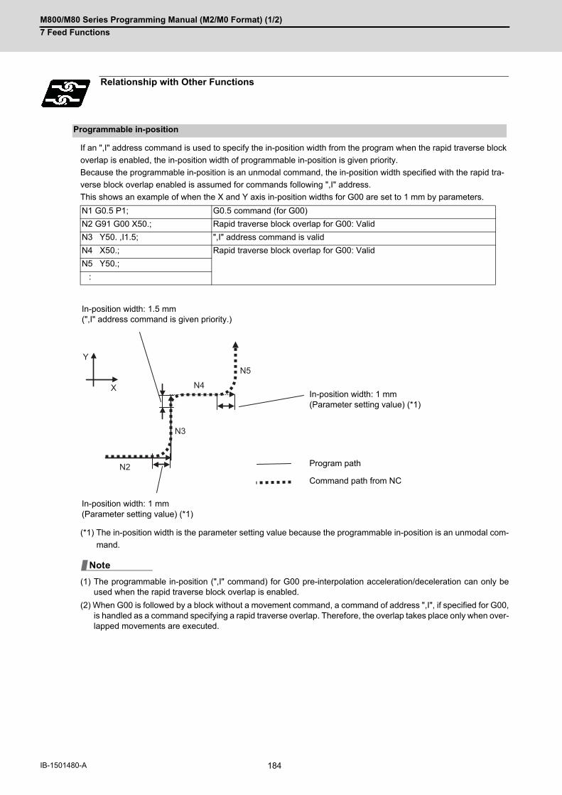
M800/M80 Series Programming Manual (M2/M0 Format) (1/2)
7 Feed Functions
184IB-1501480-A
If an ",I" address command is used to specify the in-position width from the program when the rapid traverse block
overlap is enabled, the in-position width of programmable in-position is given priority.
Because the programmable in-position is an unmodal command, the in-position width specified with the rapid tra-
verse block overlap enabled is assumed for commands following ",I" address.
This shows an example of when the X and Y axis in-position widths for G00 are set to 1 mm by parameters.
(*1) The in-position width is the parameter setting value because the programmable in-position is an unmodal com-
mand.
(1) The programmable in-position (",I" command) for G00 pre-interpolation acceleration/deceleration can only beused when the rapid traverse block overlap is enabled.
(2) When G00 is followed by a block without a movement command, a command of address ",I", if specified for G00,is handled as a command specifying a rapid traverse overlap. Therefore, the overlap takes place only when over-lapped movements are executed.
Relationship with Other Functions
Programmable in-position
N1 G0.5 P1; G0.5 command (for G00)
N2 G91 G00 X50.; Rapid traverse block overlap for G00: Valid
N3 Y50. ,I1.5; ",I" address command is valid
N4 X50.; Rapid traverse block overlap for G00: Valid
N5 Y50.;
:
In-position width: 1.5 mm(",I" address command is given priority.)
In-position width: 1 mm(Parameter setting value) (*1)
Program path
Command path from NC
In-position width: 1 mm(Parameter setting value) (*1)
N2
Y
X
N3
N4
N5
Note
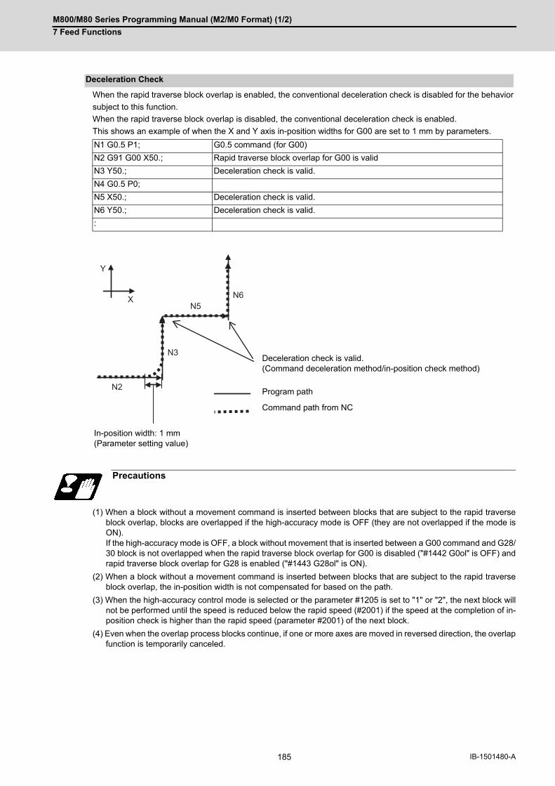
M800/M80 Series Programming Manual (M2/M0 Format) (1/2)
7 Feed Functions
185 IB-1501480-A
When the rapid traverse block overlap is enabled, the conventional deceleration check is disabled for the behavior
subject to this function.
When the rapid traverse block overlap is disabled, the conventional deceleration check is enabled.
This shows an example of when the X and Y axis in-position widths for G00 are set to 1 mm by parameters.
(1) When a block without a movement command is inserted between blocks that are subject to the rapid traverseblock overlap, blocks are overlapped if the high-accuracy mode is OFF (they are not overlapped if the mode isON). If the high-accuracy mode is OFF, a block without movement that is inserted between a G00 command and G28/30 block is not overlapped when the rapid traverse block overlap for G00 is disabled ("#1442 G0ol" is OFF) andrapid traverse block overlap for G28 is enabled ("#1443 G28ol" is ON).
(2) When a block without a movement command is inserted between blocks that are subject to the rapid traverseblock overlap, the in-position width is not compensated for based on the path.
(3) When the high-accuracy control mode is selected or the parameter #1205 is set to "1" or "2", the next block willnot be performed until the speed is reduced below the rapid speed (#2001) if the speed at the completion of in-position check is higher than the rapid speed (parameter #2001) of the next block.
(4) Even when the overlap process blocks continue, if one or more axes are moved in reversed direction, the overlapfunction is temporarily canceled.
Deceleration Check
N1 G0.5 P1; G0.5 command (for G00)
N2 G91 G00 X50.; Rapid traverse block overlap for G00 is valid
N3 Y50.; Deceleration check is valid.
N4 G0.5 P0;
N5 X50.; Deceleration check is valid.
N6 Y50.; Deceleration check is valid.
:
Deceleration check is valid.(Command deceleration method/in-position check method)
Program path
Command path from NC
In-position width: 1 mm(Parameter setting value)
Precautions
N2
Y
X
N3
N6N5
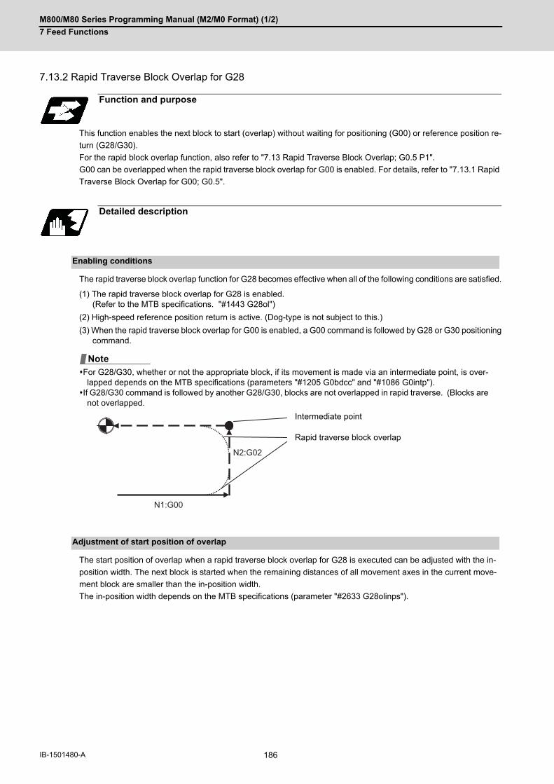
M800/M80 Series Programming Manual (M2/M0 Format) (1/2)
7 Feed Functions
186IB-1501480-A
7.13.2 Rapid Traverse Block Overlap for G28
This function enables the next block to start (overlap) without waiting for positioning (G00) or reference position re-
turn (G28/G30).
For the rapid block overlap function, also refer to "7.13 Rapid Traverse Block Overlap; G0.5 P1".
G00 can be overlapped when the rapid traverse block overlap for G00 is enabled. For details, refer to "7.13.1 Rapid
Traverse Block Overlap for G00; G0.5".
The rapid traverse block overlap function for G28 becomes effective when all of the following conditions are satisfied.
(1) The rapid traverse block overlap for G28 is enabled. (Refer to the MTB specifications. "#1443 G28ol")
(2) High-speed reference position return is active. (Dog-type is not subject to this.)
(3) When the rapid traverse block overlap for G00 is enabled, a G00 command is followed by G28 or G30 positioningcommand.
For G28/G30, whether or not the appropriate block, if its movement is made via an intermediate point, is over-lapped depends on the MTB specifications (parameters "#1205 G0bdcc" and "#1086 G0intp").
If G28/G30 command is followed by another G28/G30, blocks are not overlapped in rapid traverse. (Blocks arenot overlapped.
The start position of overlap when a rapid traverse block overlap for G28 is executed can be adjusted with the in-
position width. The next block is started when the remaining distances of all movement axes in the current move-
ment block are smaller than the in-position width.
The in-position width depends on the MTB specifications (parameter "#2633 G28olinps").
Function and purpose
Detailed description
Enabling conditions
Intermediate point
Rapid traverse block overlap
Adjustment of start position of overlap
Note
N1:G00
N2:G02

M800/M80 Series Programming Manual (M2/M0 Format) (1/2)
7 Feed Functions
187 IB-1501480-A
The following are examples of using rapid traverse block overlap for G28 in combination with G28/G30 (reference
position return) and G00 (rapid traverse).
Initial position of axes: X axis = -50 mm; Z axis = -100 mm
Refer to "7.13 Rapid Traverse Block Overlap; G0.5 P1".
Refer to "7.13 Rapid Traverse Block Overlap; G0.5 P1".
Program example
Parameter setting X axis Z axis
#2633 G28olinps 0.5 mm 1 mm
Intermediate point
In-position width: 1 mm
N1 G91 G00 Z50.;N2 G91 G28 X0.Z50.;
Program pathCommand path from NC
Relationship with Other Functions
Precautions
N2(G28)
N2(G28)
N1(G00)

M800/M80 Series Programming Manual (M2/M0 Format) (1/2)
7 Feed Functions
188IB-1501480-A
7.14 Automatic Corner Override
With tool radius compensation, this function reduces the load during inside cutting of automatic corner R, or during
inside corner cutting, by automatically applying override to the feedrate.
This function is always valid in the tool radius compensation (G41/G42).
There are two types of automatic corner override: Automatic corner override and inner arc override.
When cutting an inside corner, as shown in the figure below, the machining allowance amount increases and a
greater load is applied to the tool. To remedy this, override is applied automatically within the corner set range, the
feedrate is reduced, the increase in the load is reduced and cutting is performed effectively.
However, this function is valid only when finished shapes are programmed.
[Operation]
(1) When automatic corner override is not to be applied:When the tool moves in the order of P1 -> P2 -> P3 in the above figure, the machining allowance at P3 increaseby an amount equivalent to the area of shaded section S and so that tool load increases.
(2) When automatic corner override is to be applied:When the inside corner angle θ in the above figure is less than the angle set in the parameter, the override setinto the parameter is automatically applied in the deceleration range Ci.
Function and purpose
Detailed description
Machining inside corners
Workpiece
Programmed path(Finished shape)Machining allowance
Workpiece surface shape
Tool center path
Deceleration range Ci (IN)
Tool
θ: Max. angle at inside corner
Ci
P1
P3P2
S

M800/M80 Series Programming Manual (M2/M0 Format) (1/2)
7 Feed Functions
189 IB-1501480-A
[Parameter setting]
The following parameters are set into the machining parameters. Refer to the Instruction Manual for details on the
setting method.
(1) The override set in the parameter is automatically applied at the deceleration range Ci and corner R section forinside offset with automatic corner R. (There is no angle check.)
# Parameter Setting range
#8007 Override 0 to 100 [%]
#8008 MAX ANGLE 0 to 180 [°]
#8009 DSC.ZONE 0 to 99999.999 [mm] or0 to 3937.000 [inches]
Automatic corner R
Program path Tool center path
Corner R centerCorner R section
Deceleration range (Ci)
Workpiece surface shape
Machining allowance
Workpiece
Ci

M800/M80 Series Programming Manual (M2/M0 Format) (1/2)
7 Feed Functions
190IB-1501480-A
The lines in the figure denote:
(1) Linear - linear corner
The override set in the parameter (#8007) is applied in the deceleration range Ci.
(2) Linear - arc (outside offset) corner
The override set in the parameter (#8007) is applied in the deceleration range Ci.
(3) Arc (outside offset) - linear corner
<Note>
The deceleration range Ci where the override is applied is the length of the arc with an arc command.
(4) Linear - arc (inside offset) corner
During cutting of arc (inside offset), an inner arc override is applied.
Application example
Program pathTool centerArc (inside offset)
(a) When automatic corner override is to be applied: (b) When automatic corner override is not to be applied:
For straight lines, the override set in the parameter (#8007) is applied in the deceleration range Ci.
Ci
Ci
Ci
Ci

M800/M80 Series Programming Manual (M2/M0 Format) (1/2)
7 Feed Functions
191 IB-1501480-A
(5) Arc (inside offset) - linear corner
(*1) The deceleration range Ci where the override is applied is the length of the arc with an arc command.
During cutting of arc (inside offset), an inner arc override is applied.
Automatic corner override will not be applied to straight lines.
(6) Arc (inside offset) - arc (outside offset) corner
(*1) The deceleration range Ci where the override is applied is the length of the arc with an arc command.
During cutting of arc (inside offset), an inner arc override is applied.
Automatic corner override will not be applied to straight lines.
(a) When automatic corner override is to be applied: (b) When automatic corner override is not to be applied:
In addition to the inner arc override, the override set in the parameter (#8007) is applied in the deceleration range Ci. (*1)F (speed command value) x (inner arc override) x (set-ting for #8007)
Ci
Ci
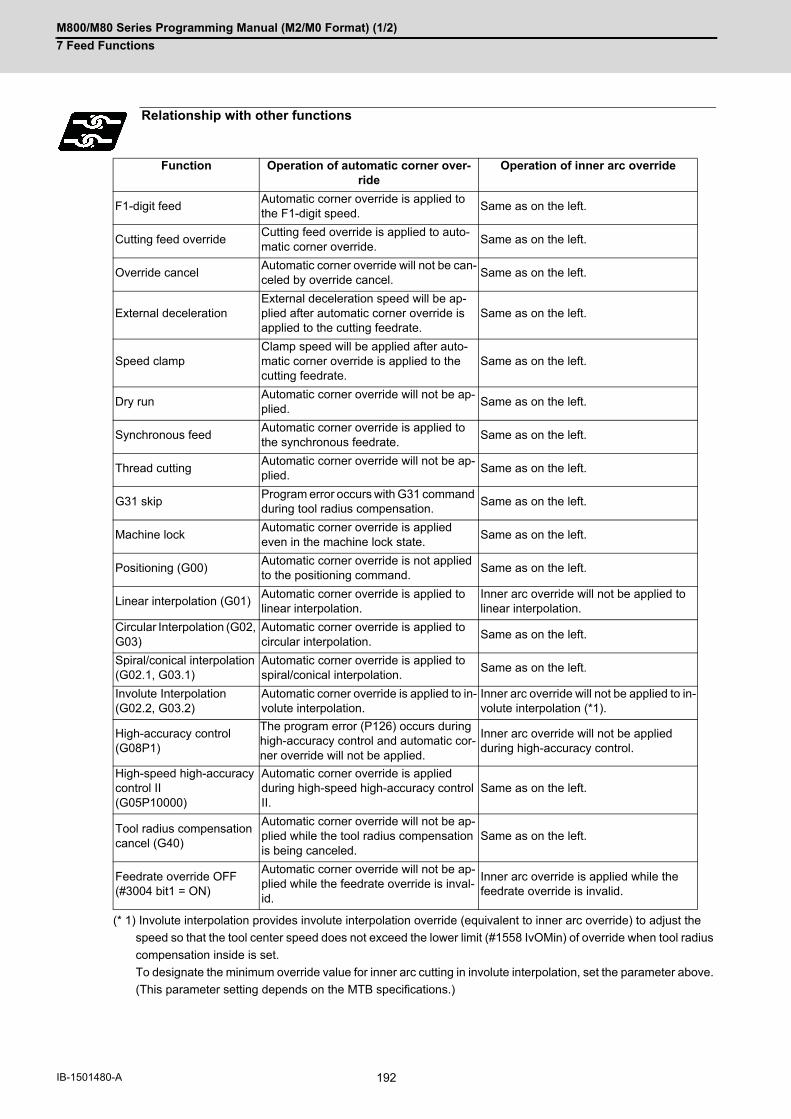
M800/M80 Series Programming Manual (M2/M0 Format) (1/2)
7 Feed Functions
192IB-1501480-A
(* 1) Involute interpolation provides involute interpolation override (equivalent to inner arc override) to adjust the
speed so that the tool center speed does not exceed the lower limit (#1558 IvOMin) of override when tool radius
compensation inside is set.
To designate the minimum override value for inner arc cutting in involute interpolation, set the parameter above.
(This parameter setting depends on the MTB specifications.)
Relationship with other functions
Function Operation of automatic corner over-ride
Operation of inner arc override
F1-digit feedAutomatic corner override is applied to the F1-digit speed.
Same as on the left.
Cutting feed overrideCutting feed override is applied to auto-matic corner override.
Same as on the left.
Override cancelAutomatic corner override will not be can-celed by override cancel.
Same as on the left.
External decelerationExternal deceleration speed will be ap-plied after automatic corner override is applied to the cutting feedrate.
Same as on the left.
Speed clampClamp speed will be applied after auto-matic corner override is applied to the cutting feedrate.
Same as on the left.
Dry runAutomatic corner override will not be ap-plied.
Same as on the left.
Synchronous feedAutomatic corner override is applied to the synchronous feedrate.
Same as on the left.
Thread cuttingAutomatic corner override will not be ap-plied.
Same as on the left.
G31 skipProgram error occurs with G31 command during tool radius compensation.
Same as on the left.
Machine lockAutomatic corner override is applied even in the machine lock state.
Same as on the left.
Positioning (G00)Automatic corner override is not applied to the positioning command.
Same as on the left.
Linear interpolation (G01)Automatic corner override is applied to linear interpolation.
Inner arc override will not be applied to linear interpolation.
Circular Interpolation (G02, G03)
Automatic corner override is applied to circular interpolation.
Same as on the left.
Spiral/conical interpolation(G02.1, G03.1)
Automatic corner override is applied to spiral/conical interpolation.
Same as on the left.
Involute Interpolation (G02.2, G03.2)
Automatic corner override is applied to in-volute interpolation.
Inner arc override will not be applied to in-volute interpolation (*1).
High-accuracy control (G08P1)
The program error (P126) occurs during high-accuracy control and automatic cor-ner override will not be applied.
Inner arc override will not be applied during high-accuracy control.
High-speed high-accuracy control II(G05P10000)
Automatic corner override is applied during high-speed high-accuracy control II.
Same as on the left.
Tool radius compensation cancel (G40)
Automatic corner override will not be ap-plied while the tool radius compensation is being canceled.
Same as on the left.
Feedrate override OFF(#3004 bit1 = ON)
Automatic corner override will not be ap-plied while the feedrate override is inval-id.
Inner arc override is applied while the feedrate override is invalid.

M800/M80 Series Programming Manual (M2/M0 Format) (1/2)
7 Feed Functions
193 IB-1501480-A
(1) Automatic corner override is valid only in the G01, G02, and G03 modes; it is not effective in the G00 mode.When switching from the G00 mode to the G01 (or G02 or G03) mode at a corner (or vice versa), automaticcorner override will not be applied at that corner in the G00 block.
(2) The automatic corner override will not be applied until the tool radius compensation mode is entered.
(3) Automatic corner override will not be applied on a corner where the tool radius compensation is started or can-celed.
(4) Automatic corner override will not be applied on a corner where the tool radius compensation I, K vector com-mand is issued.
(5) Automatic corner override will not be applied when intersection calculation cannot be executed. Intersection calculation cannot be executed in the following case. - When the movement command block does not continue for four or more times.
(6) The deceleration range with an arc command is the length of the arc.
(7) The inside corner angle, as set by parameter, is the angle on the programmed path.
(8) When the parameters are set as shown below, the automatic corner override or inner arc override is disabled.
(a) Conditions that disable the automatic corner override
#8007 (override) is set to 0 or 100#8008 (max. angle) is set to 0 or 180#8009 (DSC.ZONE) is set to 0
(b) Condition that disables the inner arc override
#19418 (minimum OVR for inner arc) is set to 0 or 100
(9) The inclined surface machining command is not available during automatic corner override modal. To perform inclined surface machining, command G64 (cutting mode) in advance, then cancel the modal mode.
Precautions

M800/M80 Series Programming Manual (M2/M0 Format) (1/2)
7 Feed Functions
194IB-1501480-A
7.14.1 Inner Arc Override
When cutting an arc (inside offset), applying the override given by the following expression to the commanded fee-
drate (F) causes that feedrate to become the F value for which the feedrate of the programmed path is commanded.
The inner arc override is valid whenever the machine is in the tool radius compensation mode (G41/G42).
Inner arc override will not be applied when the machine is in automatic corner R.
(C) Arc center
R1: Radius of tool center path
R2: Radius of program path
If the radius (R1) of tool center path is very small compared to the radius (R2) of program path, R1/R2 is nearly equal
to 0, causing the tool feed to stop.
To prevent the tool feed from being stopped, set the parameter "#19418" (minimum OVR for inner arc) and set the
tool feedrate to F x (setting for #19418) when the value of R1/R2 is equal to or less than (setting for #19418).
The inner arc override is invalid when the #19418 (minimum OVR for inner arc) is set to 0 or 100.
For detailed description, execution example, the relationship with other functions and precautions, refer to "7.14 Au-
tomatic Corner Override".
Detailed description
R1: Radius of tool center pathR2: Radius of program path
Programmed path
Tool center path
F R1R2
R1
R2
(C)

M800/M80 Series Programming Manual (M2/M0 Format) (1/2)
7 Feed Functions
195 IB-1501480-A
7.15 Tapping Mode; G63
The G63 command allows the control mode best suited for tapping to be entered, as indicated below:
(1) Cutting override is fixed at 100%.
(2) Deceleration commands at joints between blocks are invalid.
(3) Feed hold is invalid.
(4) Single block is invalid.
(5) In-tapping mode signal is output.
G63 is released by the exact stop check mode (G61), high-accuracy control mode (G61.1) or cutting mode (G64)
command.
The machine is in the cutting mode status when its power is turned ON.
Function and purpose
Command format
G63; ... Tapping mode
M800/M80 Series Programming Manual (M2/M0 Format) (1/2)
7 Feed Functions
196IB-1501480-A
7.16 Cutting Mode; G64
The G64 command allows the cutting mode in which smooth cutting surfaces are obtained to be established. Unlike
the exact stop check mode (G61), the next block is executed continuously with the machine not decelerating and
stopping between cutting feed blocks in this mode.
G64 is released by the exact stop check mode (G61), high-accuracy control mode (G61.1) or tapping mode (G63).
The machine is in the cutting mode status when its power is turned ON.
Function and purpose
Command format
G64; ... Cutting mode

8
197 IB-1501480-A
Dwell
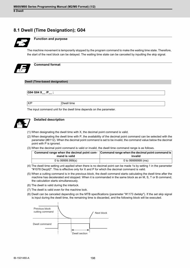
M800/M80 Series Programming Manual (M2/M0 Format) (1/2)
8 Dwell
198IB-1501480-A
8Dwell8.1 Dwell (Time Designation); G04
The machine movement is temporarily stopped by the program command to make the waiting time state. Therefore,
the start of the next block can be delayed. The waiting time state can be canceled by inputting the skip signal.
The input command unit for the dwell time depends on the parameter.
(1) When designating the dwell time with X, the decimal point command is valid.
(2) When designating the dwell time with P, the availability of the decimal point command can be selected with theparameter (#8112). When the decimal point command is set to be invalid, the command value below the decimalpoint with P is ignored.
(3) When the decimal point command is valid or invalid, the dwell time command range is as follows.
(4) The dwell time setting unit applied when there is no decimal point can be made 1s by setting 1 in the parameter"#1078 Decpt2". This is effective only for X and P for which the decimal command is valid.
(5) When a cutting command is in the previous block, the dwell command starts calculating the dwell time after themachine has decelerated and stopped. When it is commanded in the same block as an M, S, T or B command,the calculation starts simultaneously.
(6) The dwell is valid during the interlock.
(7) The dwell is valid even for the machine lock.
(8) Dwell can be canceled depending on the MTB specifications (parameter "#1173 dwlskp"). If the set skip signalis input during the dwell time, the remaining time is discarded, and the following block will be executed.
Function and purpose
Command format
Dwell (Time-based designation)
G94 G04 X__ /P__ ;
X/P Dwell time
Detailed description
Command range when the decimal point com-mand is valid
Command range when the decimal point command is invalid
0 to 99999.999(s) 0 to 99999999 (ms)
Previous block cutting command
Dwell command
Dwell section
Next block
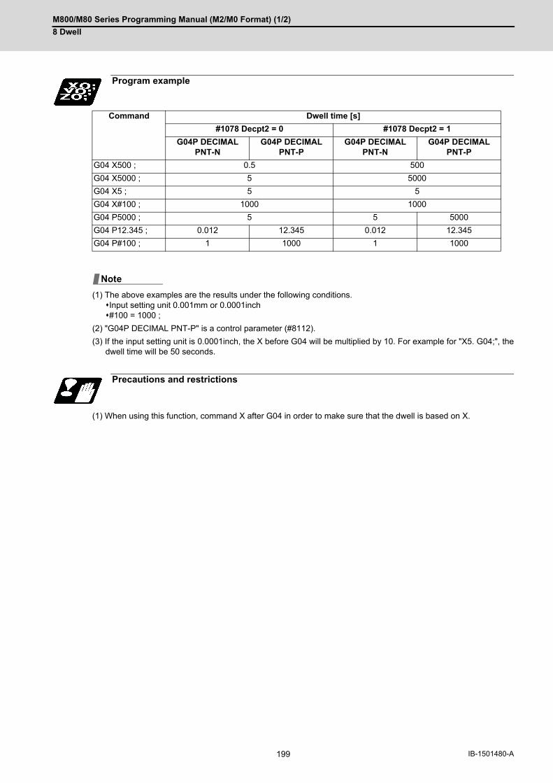
M800/M80 Series Programming Manual (M2/M0 Format) (1/2)
8 Dwell
199 IB-1501480-A
(1) The above examples are the results under the following conditions.Input setting unit 0.001mm or 0.0001inch#100 = 1000 ;
(2) "G04P DECIMAL PNT-P" is a control parameter (#8112).
(3) If the input setting unit is 0.0001inch, the X before G04 will be multiplied by 10. For example for "X5. G04;", thedwell time will be 50 seconds.
(1) When using this function, command X after G04 in order to make sure that the dwell is based on X.
Program example
Command Dwell time [s]
#1078 Decpt2 = 0 #1078 Decpt2 = 1
G04P DECIMAL PNT-N
G04P DECIMAL PNT-P
G04P DECIMAL PNT-N
G04P DECIMAL PNT-P
G04 X500 ; 0.5 500
G04 X5000 ; 5 5000
G04 X5 ; 5 5
G04 X#100 ; 1000 1000
G04 P5000 ; 5 5 5000
G04 P12.345 ; 0.012 12.345 0.012 12.345
G04 P#100 ; 1 1000 1 1000
Precautions and restrictions
Note

M800/M80 Series Programming Manual (M2/M0 Format) (1/2)
8 Dwell
200IB-1501480-A

9
201 IB-1501480-A
Miscellaneous Functions

M800/M80 Series Programming Manual (M2/M0 Format) (1/2)
9 Miscellaneous Functions
202IB-1501480-A
9Miscellaneous Functions9.1 Miscellaneous Functions (M8-digits)
The miscellaneous functions are also known as M functions, and they command auxiliary functions, such as spindle
forward and reverse rotation, operation stop and coolant ON/OFF.
These functions are designated by an 8-digit number (0 to 99999999) following the address M, and up to 4 groups
can be commanded in a single block. The number of M commands that can be issued within the same block de-
pends on the MTB specifications (parameter "#12005 Mfig").
(Example) G00 Xx Mm1 Mm2 Mm3 Mm4;
When five or more commands are issued in a block, only the last four will be valid.
Whether to BCD output or binary output the 2nd miscellaneous function can be selected by a parameter.
The four commands of M00, M01, M02, and M30 are used as auxiliary commands for specific objectives and so they
cannot be used as general auxiliary commands. Therefore, 96 miscellaneous functions are available.
Reference should be made to the instructions issued by the MTB for the actual correspondence between the func-
tions and numerical values.
When the M00, M01, M02, and M30 functions are used, the next block is not read into the pre-read buffer due to
pre-read inhibiting.
If the M function is designated in the same block as a movement command, the commands may be executed in
either of the following two orders. The machine specifications determine which sequence applies.
(1) The M function is executed after the movement command.
(2) The M function is executed at the same time as the movement command.
Processing and completion sequences are required in each case for all M commands.
When the NC has read this function, it stops reading the next block. As far as the NC system's functions are con-
cerned, it only stops reading the next block. Whether machine functions such as the spindle rotation and coolant
supply are stopped or not differs according to the machine in question.
Re-start is enabled by pressing the automatic start button on the machine operation board.
Whether resetting can be initiated by M00 depends on the machine specifications.
If the M01 command is read when the optional stop switch on the machine operation board is ON, it will stop reading
the next block and perform the same operation as the M00.
If the optional stop switch is OFF, the M01 command is ignored.
Function and purpose
Detailed description
Program stop: M00
Optional stop: M01
(Example)
N10 G00 X1000 ; The state and operation of optional stop switch
N11 M01 ; Stops at N11 when the switch is ON
N12 G01 X2000 Z3000 F600 ; Next command (N12) is executed without stopping at N11 when the switch is OFF
:

M800/M80 Series Programming Manual (M2/M0 Format) (1/2)
9 Miscellaneous Functions
203 IB-1501480-A
This command is normally used in the final block for completing the machining, and so it is primarily used for cueing
up the machining program. Whether the program is actually cued up or not depends on the machine specifications.
Depending on the machine specifications, the system is reset by the M02 or M30 command upon completion of cue-
ing up the program and any other commands issued in the same block.
(Although the contents of the command position display counter are not cleared by this reset action, the modal com-
mands and compensation amounts are canceled.)
The next operation stops when the cueing up operation is completed (the in-automatic operation lamp goes off).
To restart the unit, the automatic start button must be pressed or similar steps must be taken. When the program is
restarted after M02 and M30 are completed, if the first movement command is designated only with a coordinate
word, the interpolation mode will function when the program ends. It is recommended that a G function always be
designated for the movement command designated first.
(1) Independent signals are also output respectively for the M00, M01, M02 and M30 commands and these outputsare each reset by pressing the reset key.
(2) M02 or M30 can be assigned by manual data input (MDI). At this time, commands can be issued simultaneously with other commands.
Internal processing suspends pre-reading when the M00, M01, M02 or M30 command has been read. Other tape
rewinding operations and the initialization of modals by resetting differ according the machine specifications.
Program end: M02 or M30
Internal processing with M00/M01/M02/M30 commands
Note

M800/M80 Series Programming Manual (M2/M0 Format) (1/2)
9 Miscellaneous Functions
204IB-1501480-A
9.2 Secondary Miscellaneous Functions (A8-digits, B8-digits or C8-digits)
These serve to assign the indexing table positioning and etc. In this controller, they are assigned by an 8-digit num-
ber from 0 to 99999999 following address A, B or C. The MTB determines which codes correspond to which posi-
tions.
The address that is used for the 2nd miscellaneous function (A, B, or C) depends on the MTB specifications (param-
eter "#1170 M2name"). (Except the address that is used for the axis name.) The 2nd miscellaneous function can be
issued up to 4 sets in a block.
The number of M commands to be issued within a same block is determined by the parameter setting (#12011 Bfig).
Whether to BCD output or binary output the 2nd miscellaneous function can be selected by a parameter.
If the A, B or C function is designated in the same block as a movement command, the commands may be executed
in either of the following two orders. The machine specifications determine which sequence applies.
(1) The A, B or C function is executed after the movement command.
(2) The A, B or C function is executed simultaneously with the movement command.
Processing and completion sequences are required for all 2nd miscellaneous functions.
The table below gives address combinations. It is not possible to use an address that is the same for the axis name
of an additional axis and 2nd miscellaneous function.
(1) When A has been assigned as the 2nd miscellaneous function address, the following commands cannot be used. - Linear angle commands (,A can be used.) - Geometric command
(2) When the sub part system control I function is valid, the independent command of address B is ignored.
Function and purpose
Detailed description
Additional axis name
A B C
2nd miscellaneous function A - ○ ○
B ○ - ○
C ○ ○ -
Precautions
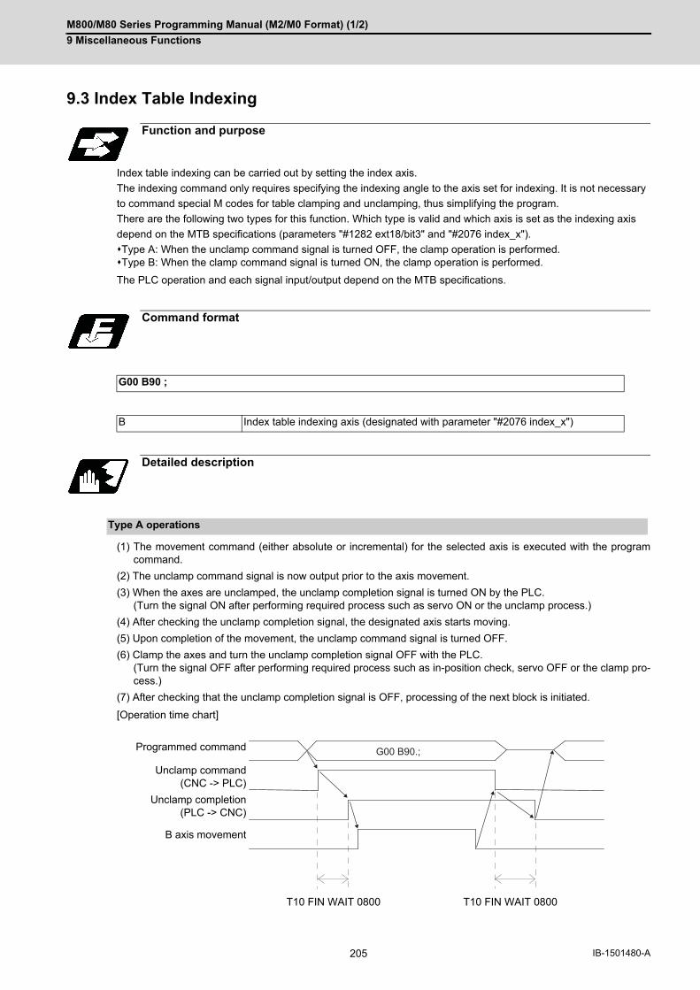
M800/M80 Series Programming Manual (M2/M0 Format) (1/2)
9 Miscellaneous Functions
205 IB-1501480-A
9.3 Index Table Indexing
Index table indexing can be carried out by setting the index axis.
The indexing command only requires specifying the indexing angle to the axis set for indexing. It is not necessary
to command special M codes for table clamping and unclamping, thus simplifying the program.
There are the following two types for this function. Which type is valid and which axis is set as the indexing axis
depend on the MTB specifications (parameters "#1282 ext18/bit3" and "#2076 index_x").
Type A: When the unclamp command signal is turned OFF, the clamp operation is performed.Type B: When the clamp command signal is turned ON, the clamp operation is performed.
The PLC operation and each signal input/output depend on the MTB specifications.
(1) The movement command (either absolute or incremental) for the selected axis is executed with the programcommand.
(2) The unclamp command signal is now output prior to the axis movement.
(3) When the axes are unclamped, the unclamp completion signal is turned ON by the PLC. (Turn the signal ON after performing required process such as servo ON or the unclamp process.)
(4) After checking the unclamp completion signal, the designated axis starts moving.
(5) Upon completion of the movement, the unclamp command signal is turned OFF.
(6) Clamp the axes and turn the unclamp completion signal OFF with the PLC. (Turn the signal OFF after performing required process such as in-position check, servo OFF or the clamp pro-cess.)
(7) After checking that the unclamp completion signal is OFF, processing of the next block is initiated.
[Operation time chart]
Function and purpose
Command format
G00 B90 ;
B Index table indexing axis (designated with parameter "#2076 index_x")
Detailed description
Type A operations
Programmed command
Unclamp command(CNC -> PLC)
Unclamp completion(PLC -> CNC)
B axis movement
T10 FIN WAIT 0800 T10 FIN WAIT 0800
G00 B90.;

M800/M80 Series Programming Manual (M2/M0 Format) (1/2)
9 Miscellaneous Functions
206IB-1501480-A
(1) The movement command (either absolute or incremental) for the selected axis is executed with the programcommand.
(2) The unclamp command signal is now output prior to the axis movement.
(3) When the axes are unclamped, the unclamp completion signal is turned ON by the PLC. (Turn the signal ON after performing required process such as servo ON or the unclamp process.)
(4) After checking the unclamp completion signal, turn the unclamp command signal OFF and the designated axisstarts moving.
(5) Turn the unclamp completion signal OFF with the PLC.
(6) Upon completion of the movement, the clamp command signal is turned ON.
(7) Clamp the axes and turn the clamp completion signal ON with the PLC. (Turn the signal OFF after performing required process such as in-position check, servo OFF or the clamp pro-cess.)
(8) After checking that the clamp completion signal is ON, turn the clamp command signal OFF and processing ofthe next block is initiated.
(9) Turn the clamp completion signal OFF with the PLC.
When the cutting feed of index table indexing axes is prohibited, the cutting feed can be prohibited by issuing a pro-
gram error (P20) if all of the following conditions are satisfied during automatic operation.
The indexing axis movement command is issued. (*1)The modal of G code group 1 is other than "G00" or "G60".
(*1) If a cutting feed command without axis movement (such as "G01 B0;" during incremental command) is issued,
the program error does not occur. Also, the unclamp command is not output.
The cutting feed prohibit function is valid for both type A and type B, and the parameter settings depend on the MTB
specifications (Parameter "#2580 index_Gcmd").
Type B operations
Programmed command
Unclamp command(CNC -> PLC)
Unclamp command(PLC -> CNC )
Clamp command(CNC -> PLC)
Clamp completion(PLC -> CNC)
Axis movement
T10 FIN WAIT 0800 T10 FIN WAIT 0800
Cutting feed prohibit of index table indexing axes
G00 B90.;
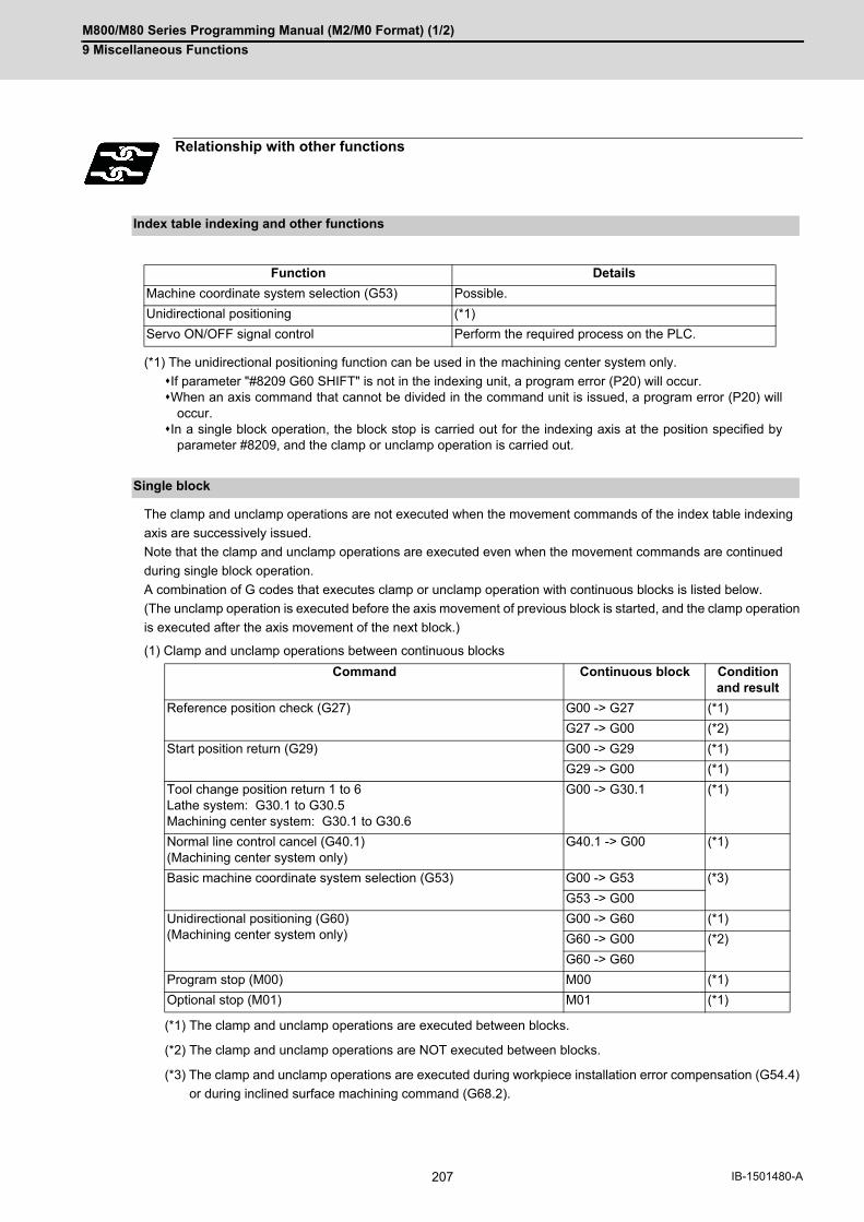
M800/M80 Series Programming Manual (M2/M0 Format) (1/2)
9 Miscellaneous Functions
207 IB-1501480-A
(*1) The unidirectional positioning function can be used in the machining center system only.
If parameter "#8209 G60 SHIFT" is not in the indexing unit, a program error (P20) will occur.When an axis command that cannot be divided in the command unit is issued, a program error (P20) will
occur.In a single block operation, the block stop is carried out for the indexing axis at the position specified by
parameter #8209, and the clamp or unclamp operation is carried out.
The clamp and unclamp operations are not executed when the movement commands of the index table indexing
axis are successively issued.
Note that the clamp and unclamp operations are executed even when the movement commands are continued
during single block operation.
A combination of G codes that executes clamp or unclamp operation with continuous blocks is listed below.
(The unclamp operation is executed before the axis movement of previous block is started, and the clamp operation
is executed after the axis movement of the next block.)
(1) Clamp and unclamp operations between continuous blocks
(*1) The clamp and unclamp operations are executed between blocks.
(*2) The clamp and unclamp operations are NOT executed between blocks.
(*3) The clamp and unclamp operations are executed during workpiece installation error compensation (G54.4)
or during inclined surface machining command (G68.2).
Relationship with other functions
Index table indexing and other functions
Function Details
Machine coordinate system selection (G53) Possible.
Unidirectional positioning (*1)
Servo ON/OFF signal control Perform the required process on the PLC.
Single block
Command Continuous block Condition and result
Reference position check (G27) G00 -> G27 (*1)
G27 -> G00 (*2)
Start position return (G29) G00 -> G29 (*1)
G29 -> G00 (*1)
Tool change position return 1 to 6Lathe system: G30.1 to G30.5Machining center system: G30.1 to G30.6
G00 -> G30.1 (*1)
Normal line control cancel (G40.1)(Machining center system only)
G40.1 -> G00 (*1)
Basic machine coordinate system selection (G53) G00 -> G53 (*3)
G53 -> G00
Unidirectional positioning (G60)(Machining center system only)
G00 -> G60 (*1)
G60 -> G00 (*2)
G60 -> G60
Program stop (M00) M00 (*1)
Optional stop (M01) M01 (*1)

M800/M80 Series Programming Manual (M2/M0 Format) (1/2)
9 Miscellaneous Functions
208IB-1501480-A
(2) Clamp and unclamp operations between continuous blocks (Reference position return)The operation during reference position return depends on the ignoring of intermediate points during return, andit depends on the MTB specifications (Parameter "#1091 Mpoint").
(*1) Performs the clamp operation at the end of G00 movement, and performs the unclamp operation before ref-erence position return.
(*2) The clamp/unclamp operation will not be performed until the reference position return is completed.
(*3) Performs the clamp operation after the reference position return, and performs the unclamp operation before G00 movement.
(*4) The clamp/unclamp operation will not be performed when movement to the intermediate point is completed. The clamp operation will be performed after the reference position return, and the unclamp operation will be performed before G00 movement.
Clamp/unclamp operations during macro interrupt are as follows.
(1) When the macro interrupt program, executed during indexing axis movement, contains a movement commandThe commands in the interrupted block are lost, and the interrupt program is executed. After completion of inter-rupt program, when executing from the block next to the interrupt block, the clamp/unclamp operation is execut-ed even if the interrupt program and main program specify the continuous movement.
(Example)
(a) Performs unclamp operation at the beginning of main program N130 block.
(b) Executes macro interrupt during main program N130 execution.
(c) Performs clamp operation after end of interrupt program L621 N100 block B1.
(d) Performs unclamp operation at the beginning of main program N132 block, and performs clamp operation after axis movement.
Command Continuous block Condition and result
#1091 = 1 #1091 = 0
1st reference position return (G28) G00 -> G28 (*1) (*2)
G28 -> G00 (*3) (*4)
2nd to 4th reference position return (G30) G00 -> G30 (*1) (*2)
G30 -> G00 (*3) (*4)
Macro interruption
Parameter Settings
#1112 S_TRG 0 Edge trigger mode
#1113 INT_2 0 Immediately start the interrupt program without waiting for the completion of currently executing block.
#8101 MACRO SINGLE 1
[Main program] [Interrupt program]
L620(MINT MAIN)
N100 G90G94;
N110 G28B0.X0.;
N120 ION621;
N130 G01X10.B10.F150.;
N132 G01B15.;
N140 G04X3.;
N150 IOF;
M02;
L621(MINT SUB)
N100 G01B1.F500.;
G23;

M800/M80 Series Programming Manual (M2/M0 Format) (1/2)
9 Miscellaneous Functions
209 IB-1501480-A
(2) When the macro interrupt program, executed during indexing axis movement, does not contain a movementcommand
When executing the remaining blocks after completion of interrupt program, perform the unclamp operation at the restart of main program. Also, perform the clamp/unclamp operation even when the next block continues. (Example)
(a) Performs unclamp operation at the beginning of main program N130 block.
(b) Executes macro interrupt during main program N130 execution.
(c) Interrupt program L623 execution is completed.
(d) Performs unclamp operation at the restart of main program N130 block, and performs clamp operation after completion of axis movement.
(e) Performs unclamp operation at the beginning of main program N132 block, and performs clamp operation after completion of axis movement.
(1) Several axes can be set as index table indexing axes.
(2) The movement speed of index table indexing axes follows the feedrate of the modal (G00/G01) at that time.
(3) The unclamp command for the indexing axes is also issued when the index table indexing axes are commandedin the same block as other axes. Thus, the movement of other axes commanded in the same block is not carriedout until the unclamp operation completes. Note that the movement of other axes commanded in the same block is carried out during a non-interpolationcommands.
(4) Index table indexing axes are used as normal rotation axes, but this function performs an unclamp operationeven for linear axes.
(5) If some error that makes unclamp command OFF occurs during indexing axis movement in automatic operation,the unclamp state will remain, and the indexing axis will execute a deceleration stop. Other axes commanded in the same block will also execute a deceleration stop, except during non-interpolationcommands.
(6) If the axis movement is interrupted by an interlock, etc., during indexing axis movement, the unclamp state willremain.
(7) The clamp and unclamp operations are not executed when the movement commands of the index table indexingaxis are successively issued. Note that the clamp and unclamp operations are executed even when the movement commands are continuedduring single block operation. Refer to "Single block" of the "Relationship with other functions".
(8) Make sure that the command position is at a position where clamping is possible.
(9) Set the unidirectional positioning (G60) parameter "#8209 G60 SHIFT" in indexing increment. A program error(P20) will occur if it is not set in indexing increment. In a single block operation, the block stop is carried out at the "G60 SHIFT" position, and the clamp or unclampoperation is carried out.
[Main program] [Interrupt program]
Precautions
L622(MINT MAIN)
N100 G90G94;
N110 G28B0.X0.;
N120 ION623;
N130 G01X10.B10.F150.;
N132 G01B15.;
N140 G04X3.;
N150 IOF;
M02;
L623(MINT SUB)
N100 #100=#100+1;
G23;

M800/M80 Series Programming Manual (M2/M0 Format) (1/2)
9 Miscellaneous Functions
210IB-1501480-A

10
211 IB-1501480-A
Spindle Functions
M800/M80 Series Programming Manual (M2/M0 Format) (1/2)
10 Spindle Functions
212IB-1501480-A
10Spindle Functions10.1 Spindle Functions
These functions are assigned with an 8-digit (0 to 99999999) number following the address S, and one group can
be assigned in one block.
The output signal is a 32-bit binary data with sign and start signal.
Processing and completion sequences are required for all S commands.
Function and purpose

M800/M80 Series Programming Manual (M2/M0 Format) (1/2)
10 Spindle Functions
213 IB-1501480-A
10.2 Constant Surface Speed Control; G96, G97
This function adjusts the spindle rotation speed (constant surface speed control) in accordance with the movement
of the tool nose point so that the cutting point always remains at the constant speed (constant surface speed).
Using this function for processes such as a cutting-off process is effective in terms of machining time, tool life, etc.
Note that when the tool nose point is moving to the workpiece zero point, the rotation may be at the maximum rota-
tion speed defined in the machine specifications; this is dangerous. Be sure to specify the maximum clamp rotation
speed with the spindle clamp speed setting command (G92/G50).
Constant surface speed control at constant surface speed command G96 S314 m/min
To keep the surface speed constant, this function obtains and automatically adjusts the spindle rotation speed in
accordance with the movement of the tool nose point.
In the example above, to keep the surface speed (314 (m/min)) constant, the rotation speed is changed from 999
(r/min) to 1999 (r/min) with changes of the workpiece radius (50mm → 25mm).
(1) The S command is handled as the absolute value (the sign is ignored).
(2) If the value of the S command exceeds the allowable range, a program error will occur (P35).
(3) If the value of the P command exceeds the allowable range, a program error will occur (P133).
Function and purpose
Workpiece diameter: 50 mm(Radius value)
Workpiece diameter: 25mm(Radius value)
Spindle rotation speed (r/min)
=Surface speed
(m/min)/
Workpiece surface (m/r)
G96 command value
Automatically calculated from the workpiece zero point and tool nose position
Command format
Constant surface speed ON
G96 S__ P__ ;
S Surface speed (-99999999 to 99999999 (m/min)), -99999999 to 99999999 (feet/min))
P Constant surface speed control axis 0 to n (n: Number of axes that can be controlled in the part system with G96 commanded)
Constant surface speed cancel
G97 S__ ;
S Spindle rotation speed (-99999999 to 99999999 (r/min))
314(m/min)
999(r/min) 1999(r/min)
50.25.314(m/min)
XX
Note

M800/M80 Series Programming Manual (M2/M0 Format) (1/2)
10 Spindle Functions
214IB-1501480-A
(1) The S command is handled as the absolute value (the sign is ignored).
(1) When the P0 or P command is not specified, the operation depends on the MTB specifications (parameter"#1181 G96_ax"). However, if this parameter is set to "0", the first axis is used as the surface speed axis regardless of whetheraddress P is specified or not. 0: Fixed at 1st axis (P command invalid)1: 1st axis2: 2nd axis :
(2) To change the constant surface speed control axis in the constant surface speed control mode, specify the com-mand in the G96 P_ format. (However, when the parameter above is set to "0", no change can be made.) If the S command is issued simultaneously, the surface speed can also be changed.
<Example 1>
<Example 2>
(3) The spindle to be controlled is determined in the MTB specifications (parameter "#1300 ext36/bit0"). For multiple-spindle control II (*1), the spindle is determined by the spindle selection signal from the PLC.
(*1) Multiple-spindle control with the PLC signal used. Whether the specification is provided and the details de-
pend on models and MTB specifications.
(4) Specify the spindle surface speed with the S command when constant surface speed control ON is commanded. In constant surface speed control mode, the surface speed can only be changed with the S command.
(5) The spindle clamp speed setting (G92 S__ Q__) is to be commanded when the spindle speed needs to be limiteddepending on the workpiece to be machined, the chuck to be mounted on the spindle and the tool specifications,etc. Whether the spindle clamp speed setting is made valid only in the constant surface speed control mode or alsomade valid for normal spindle rotation commands depends on the MTB specifications (parameter "#1227 aux11/bit5"). Once the maximum clamp rotation speed and the minimum clamp rotation speed are set using the spindle clampspeed setting (G92 S__ Q __), the maximum speed clamp will not be canceled even if the command "G92 S0"is issued. Whether the commanded spindle clamp speed setting is kept when NC is reset during constant surface speedcontrol depends on the MTB specifications (parameter "#1210 RstGmd/bit19").
Detailed description
Machining program
Control axis sequence in constant surface speed command part sys-
tem Details of Operation
1st axis 2nd axis 3rd axis
:G96 S200 P1; : :
X1↓↓↓
Z1↓↓↓
C1↓↓↓
The X1 axis is used as the constant surface speed control axis. (Controls the spindle rotation so that the surface speed is set to 200 (m/min) for the X1 axis.)
G96 P2; :
↓↓
↓↓
↓↓
The Z1 axis is used as the constant surface speed control axis.
Machining program
Control axis sequence in constant surface speed command part sys-
tem Details of Operation
1st axis 2nd axis 3rd axis
:G96 S200 P1; : : :
Z1↓↓↓↓
C1↓↓↓↓
-----
The Z1 axis is used as the constant surface speed control axis. (Controls the spindle rotation so that the surface speed is set to 200 (m/min) for the Z1 axis.)
Note

M800/M80 Series Programming Manual (M2/M0 Format) (1/2)
10 Spindle Functions
215 IB-1501480-A
(6) Whether the surface speed is always calculated or at the end of a block when the rapid traverse command isissued depends on the MTB specifications (parameter "#1087 G96_G0").
(7) The constant surface speed cancel command (G97) cancels constant surface speed control in the part systemthat has executed the constant surface speed ON command (G96). The constant surface speed control cannot be canceled from another part system. The spindle rotation speed is maintained at the speed specified when the constant surface speed cancel com-mand (G97) has been executed.
(8) If NC is reset during constant surface speed control, the spindle rotation speed is changed to "0" (r/min) afterreset.
When the constant surface speed control is commanded, check whether the spindle speed clamp is valid.
If the constant surface speed control axis is near the zero point, it causes the spindle to rotate at the maximum ro-
tation speed.
Check the spindle speed clamp command to prevent the spindle from rotating at high speed.
(1) In multiple-spindle control II, if the speed clamp command is not valid for the selected spindle, it causes an op-eration error (M01 1043). When such an error occurs, reset to finish the program, and issue the spindle speedclamp command after selecting a spindle. When the operation error above occurs, execute the commands in the same block.
(2) When spindle speed clamp command check is valid, the spindle speed clamp command value is set to "0" if theG92/G50 S0 command is issued.
(3) In multiple-spindle control II, spindle speed clamp check is conducted for the spindle selected in the G96S com-mand. Specify the spindle speed clamp command for all the currently selected spindles.
(4) Whether to conduct spindle speed clamp command check depends on the MTB specifications (parameters"#1146 Sclamp" and "#1284 ext20/bit0".) If parameter "#1146 Sclamp" is set to "0", the spindle speed clamp command cannot be executed when constantsurface speed control is turned off; therefore, the spindle speed clamp command cannot be issued before con-stant surface speed control.
Parameter "#1284 ext20/bit0" has the following setting:
0: Checks the spindle speed clamp.
1: Does not check the spindle speed clamp.
(5) The spindle speed clamp may be performed only in the constant surface speed mode depending on the MTBspecifications (parameter "#1227 aux11/bit5"). If the program is then reset, the clamp may be rendered ineffec-tive. For information on whether the setting is configured to keep the clamp status, refer to the MTB specifications.(Parameter "#1210 RstGmd/bit10, bit19")
BIT10: Group 17, constant surface speed control command modal
BIT19: Spindle rotation clamp speed
(6) When operating the system in the initial constant surface speed mode or with the constant surface speed modalby holding the constant surface speed control command modal, the constant surface speed control mode is setby the S command (surface speed). When spindle speed clamp command check is valid, issue the spindle speedclamp command before the S command.
Relationship with Other Functions
Checking the maximum clamp rotation speed
(a) G96 S100 M03 com-mand:
When the spindle forward rotation signal is input from the user PLC by the M03 command, the spindle runs forward. (The spindle speed is set to the previously commanded rotation speed.)
(b) G96 S100 X30. com-mand:
If an error occurs, axis movement is performed until the program is reset.

M800/M80 Series Programming Manual (M2/M0 Format) (1/2)
10 Spindle Functions
216IB-1501480-A
(1) If constant surface speed control axes are rearranged by the arbitrary axis exchange command, the spindle ro-tation speed is maintained at the value specified before rearrangement.
(2) If a new surface speed is specified by the S command while the spindle rotation speed is maintained, it becomesvalid when the rearranged constant surface speed axes are returned to the original status.
(3) If the constant surface speed command is re-executed when constant surface speed axes are rearranged andthe spindle rotation speed is maintained at the constant rotation speed, the kept spindle rotation speed is can-celed, and the reissued constant surface speed control command is executed.
(4) If constant surface speed axes are returned to the original status by rearrangement while constant surface speedcontrol is temporarily canceled, the spindle rotation speed will be maintained. After this, the surface speed be-comes constant when it is specified with the S command.
(5) If the surface speed is specified by the S command with the rearrangement of the constant surface speed axeswhile the constant surface speed control is in the temporary cancel state, the spindle rotation speed kept at tem-porary cancellation is applied, and the surface speed becomes constant when the constant surface speed axesare returned to the original arrangement.
Arbitrary axis exchange control
Other functions
Function name Operation
Spindle Clamp Speed Setting (G92/G50) The spindle clamp speed setting is valid in the constant surface speed control mode. Whether the commanded spindle clamp speed setting is kept when NC is reset during constant surface speed control depends on the MTB specifications. (parameter "#1210 RstGmd BIT19")
Cylindrical Interpolation (G07.1) The constant surface speed control cannot be commanded during the cylindrical interpolation mode. Program error (P481) will occur. The cylindrical interpolation cannot be commanded during the con-stant surface speed control mode. Program error (P485) will occur.
Thread Cutting (Designation of lead or number of ridges) (G32)
When the constant surface speed command is issued in the same part system during execution of the thread cutting or thread cutting cycle command or when the thread cutting or thread cutting cycle command is issued in the same part system in the constant surface speed control mode, the spindle rotation speed for constant surface speed control remains unchanged. (The constant surface speed control is not performed.) This function keeps the spindle rotation speed specified at execution of the thread cutting or thread cutting cycle command. When the thread cutting or thread cutting cycle command is terminat-ed, the spindle rotation speed is changed to the value obtained from the position of the constant surface speed control axis and the sur-face speed. The constant surface speed command cannot be issued from other part systems to the spindle for which the thread cutting command is currently executed. Also, the thread cutting command cannot be is-sued from other part systems to the spindle in the constant surface speed control mode. An operation error (M01 1113) will occur.

M800/M80 Series Programming Manual (M2/M0 Format) (1/2)
10 Spindle Functions
217 IB-1501480-A
Tapping cycle (G84/G88)Synchronous tapping cycle (G84/G88)
If the constant surface speed command is issued in the same part system during execution of the tapping cycle or synchronous tapping cycle command or the tapping cycle command is issued in the same part system in the constant surface speed control mode, the spindle rotation speed for constant surface speed control remains un-changed. (The constant surface speed control is not performed.) This function keeps the spindle rotation speed specified at execution of the tapping cycle command. When the tapping cycle or synchronous tapping cycle command is terminated, the spindle rotation speed is changed to the value ob-tained from the position of the constant surface speed control axis and the surface speed. The constant surface speed command cannot be issued from other part systems to the spindle for which the tapping cycle or synchro-nous tapping cycle command is currently executed. Also, the tapping cycle or synchronous tapping cycle command cannot be issued from other part systems to the spindle in the constant surface speed con-trol mode. An operation error (M01 1113) will occur. The synchronous tapping cycle command cannot be executed in the constant surface speed control mode. Program error (P182) will oc-cur. Also, the constant surface speed command cannot be executed during execution of the synchronous taping cycle command. Program error (P186) will occur.
Spindle-Mode Servo Motor Control The system also runs when a spindle-mode servo is specified for con-stant surface speed control
External Spindle Deceleration If the external spindle deceleration signal is set to OFF for the spindle under constant surface speed control, the spindle is clamped at the external spindle deceleration speed. The S analog maximum/mini-mum over signal (SOVE) is set on.
High-Speed Simple Program Check The surface speed is calculated, but the actual rotation speed of the spindle remains set to the value specified before the part system syn-chronization machine lock high-speed operation is selected.
NC reset (Reset 1/2, reset & rewind) When NC is reset during constant surface speed control, the spindle rotation speed is set to "0" (r/min).
Function name Operation
M800/M80 Series Programming Manual (M2/M0 Format) (1/2)
10 Spindle Functions
218IB-1501480-A
(1) Under the constant surface speed control (during G96 modal), if the axis targeted for the constant surface speedcontrol (normally X axis for a lathe) moves toward the spindle center, the spindle rotation speed will increase andmay exceed the allowable speed of the workpiece or chuck, etc. In this case, the workpiece, etc. may jump outduring machining, which may break tools or the machine or injure the operators. Therefore, make sure to usethis control while the "spindle speed clamp" is enabled. When the constant surface speed control is commanded,keep enough distance from the program zero point.
Program example
(Example 1) When the parameter "#1146 Sclamp" is set to "0"
(Example 2) When the parameter "#1146 Sclamp" is set to "1"
<Note>
For safety, issue the rotation command to the spindle after G92.
(2) When the G96 command is issued, do not omit the "S_" surface speed command. If omitted, the system will fol-low the previous "S_" command. The S command ("S_" command) for the spindle in the constant surface speed control mode specifies the sur-face speed.
(3) If the spindle speed clamp is not commanded when the constant surface speed control axis is near the zero point,it causes the spindle to rotate at the maximum rotation speed. We recommend that you command the spindlespeed clamp before the constant surface speed command. In this case, the parameter "#1146 Sclamp" must be made valid, but this function depends on the MTB specifi-cations.
(4) If an axis number not registered in the command part system is commanded when the constant surface speedcommand is specified, it causes a program error (P133).
Precautions
G96 S200 ; The spindle rotation speed is controlled so that the surface speed is 200 m/min.
G92 S4000 Q200 ; The spindle rotation speed is clamped up to 4000 r/min and down to 200 r/min.
M3 ; The rotation command to the spindle
G92 S4000 Q200 ; The spindle rotation speed is clamped up to 4000 r/min and down to 200 r/min.
G96 S200 ; The spindle rotation speed is controlled so that the surface speed is 200 m/min.
M3 ; The rotation command to the spindle
WARNING
Under the constant surface speed control (during G96 modal), if the axis targeted for the constant surface speed
control (normally X axis for a lathe) moves toward the spindle center, the spindle rotation speed will increase
and may exceed the allowable speed of the workpiece or chuck, etc. In this case, the workpiece, etc. may jump
out during machining, which may break tools or the machine or injure the operators.

M800/M80 Series Programming Manual (M2/M0 Format) (1/2)
10 Spindle Functions
219 IB-1501480-A
10.3 Spindle Clamp Speed Setting; G92
The maximum clamp rotation speed of the spindle can be assigned by address S following G92 and the minimum
clamp rotation speed by address Q.
Use this command when the spindle speed needs to be limited depending on the workpiece to be machined, the
chuck to be mounted on the spindle and the tool specifications, etc.
(1) Besides this command, parameters can be used to set the rotation speed range up to 4 stages in 1 r/min unitsto accommodate gear selection between the spindle and spindle motor. The lowest upper limit and highest lowerlimit are valid among the rotation speed ranges based on the parameters and based on "G92 S_ Q_;".
(2) Whether to carry out rotation speed clamp only in the constant surface speed mode or even when the constantsurface speed is canceled depends on the MTB specifications (parameters "#1146 Sclamp" and "#1227 aux11/bit5").
<Note>
G92S command and rotation speed clamp operation
The address Q following the G92 command is handled as the spindle speed clamp command regardlessof the constant surface mode.
(3) The command value of the spindle clamp rotation speed will be cleared by modal reset (reset 2 or reset & rewind). Note that the modal is retained if the parameter "#1210 RstGmd / bit19" is ON. It is set to "0" during power ON.
Function and purpose
Command format
Spindle clamp speed setting
G92 S__ Q__ ;
S Maximum clamp rotation speed
Q Minimum clamp rotation speed
Detailed description
Sclamp=0 Sclamp=1
aux11/bit5=0 aux11/bit5=1 aux11/bit5=0 aux11/bit5=1
Command In G96 Rotation speed clamp command Rotation speed clamp command
In G97 Spindle rotation speed command Rotation speed clamp command
Operation In G96 Rotation speed clamp execution Rotation speed clamp execution
In G97 No rotation speed clamp Rotation speed clamp command
No rotation speed clamp

M800/M80 Series Programming Manual (M2/M0 Format) (1/2)
10 Spindle Functions
220IB-1501480-A
(1) Once the maximum clamp speed and the minimum clamp speed are set using the spindle clamp speed setting(G92 S__ Q __), the maximum speed clamp will not be cancelled even if the command "G92 S0" is issued.During this time, the Q__ value is still valid and S0 < Q__ is established. The Q__ value is treated as the maxi-mum speed clamp, and S0 is treated as the minimum speed clamp.
(2) Note that if the spindle clamp speed setting (G92 S__ Q__) is not commanded, the speed may increase to themachine's maximum specified speed that is set by the parameter. Especially when the constant surface speedcontrol (G96 S__) is commanded, command the spindle clamp speed setting as well as the spindle maximumrotation speed. As the tool moves closer to the spindle center, the spindle rotation speed will increase and mayexceed the allowable speed of the workpiece or chuck, etc.
Precautions
WARNING
The spindle clamp speed setting command is a modal command, but make sure to confirm that the G and F
modal and coordinate values are appropriate if the operation is started from a block in the middle of the pro-
gram. If there are coordinate system shift commands or M, S, T and B commands before the block set as the
start position, carry out the required commands using the MDI, etc. If the program is run from the set block with-
out carrying out these operations, the machine interference may occur or the machine may operate at an unex-
pected speed.

M800/M80 Series Programming Manual (M2/M0 Format) (1/2)
10 Spindle Functions
221 IB-1501480-A
10.4 Spindle Position Control (Spindle/C axis Control)
This function controls a spindle as the rotary axis. After switching the spindle to the rotary axis, the positioning and
the interpolation between the spindle and other servo axes can be operated in the same way as the servo axis by
executing the position command (the movement command). Using this function, the servo axis for controlling the
spindle stock as the rotary axis or the machinery for switching the spindle and servo axis (such as a gear switching
machinery) had been necessary for controlling a spindle stock readily as the rotary axis, but they are not necessary
with this function.
For information on how to validate or invalidate this function, each setting to use this function, and the mechanism
of your machine, refer to the specifications or the instruction manual issued by the MTB.
There are two methods to switch the spindle and rotary axis: PLC signal method and program command method.
The available method depends on the MTB specifications (parameter "#3129 cax_spec/bit0"). For details, refer to
the specifications issued by the MTB.
This section describes the program command method.
In this manual, the state of controlling an axis as a spindle is referred to as "spindle mode", and the state of con-
trolling an axis as a rotary axis is referred to as “C axis mode”.
The PLC signal processing and operation depends on the MTB specifications. Refer to the instruction manual issued
by the MTB for details.
For the encoder-based spindle position control (PLG and external encoder), set the Z phase position of the encoder
as the first reference point of the C axis. This first reference point is used as the coordinate zero point; however, the
spindle zero point position can be adjusted with the spindle/C axis reference position return shift amount parameter,
which is determined in the MTB specifications. This parameter is determined in the MTB specifications (parameter
"#3113 cax_sft").
In the machining program, the program switches to the C axis mode with G00 command, and to the spindle mode
with S command. The C axis servo OFF signal (*SVFn) must be always kept ON while the program command meth-
od is selected. This depends on the MTB specifications.
When the servo OFF signal is set to OFF, operations are performed as follows.
The mode cannot be switched from the spindle mode to the C axis mode or from the C axis mode to the spindlemode.
In the spindle mode, the axis does not run as a spindle even if the forward run command (SRN) or reverse runcommand (SRI) is executed.
In the C axis mode, an operation error (M01 0005) occurs if the movement command is executed. In the servoOFF mode, operations follow the setting of the parameter "#1064 svof" (error correction) MTB specifications).
Which mode (the spindle mode or the C axis mode) is set at power-ON or reset depends on the MTB specifi-cations (parameter "#3129 cax_spec/bit2, bit3"). If the power is turned on in the C axis mode setting, the mode shifts to the C axis mode after the Z phase de-tection and reference position return operations have been performed. For Z phase detection, the spindle rotates in the C axis zero point return direction at the C axis zero point returnspeed.
Function and purpose
Coordinate zero point and zero point adjustment in C axis mode
Program command method

M800/M80 Series Programming Manual (M2/M0 Format) (1/2)
10 Spindle Functions
222IB-1501480-A
Command "G00 C_ " in the NC program during the spindle mode. The axis is positioned directly to the specifiedposition. The non-interpolation positioning for each axis is performed by specifying "G00 X__ Z__ C__ " regardless ofthe G00 interp OFF parameter ("#1086 G0Intp" in the MTB specifications) setting, and C axis is switched to theC axis mode.Only the G00 command is valid to switch the mode. If the mode is commanded with another G code, it causes
a program error (P430).Designate the axis for spindle position control with the absolute value address or absolute value command
(G90). If the axis is designated with the incremental value address or incremental value command (G91), itcauses a program error (P32).The reference position return type (*1) is set at switching, and the direction to return from the rotation mode to
the zero point follows the rotation direction (*2). The direction for returning from the stop mode to the referenceposition and the interpolation mode depend on the MTB specifications (parameters "#3106 zrn_typ/bit9,bitA","#3106 zrn_typ/bitD,bitE" and "#1256 set28/bit1").
(*1) Type to necessarily return to the reference position when switching from the spindle mode to the C axis mode.
This depends on the MTB specifications (parameter "#3106 zrn_typ/bit8").
(*2) Depends on the MTB specifications (parameter "#3106 zrn_typ/bitB").
If the Z phase is not detected and if switching is commanded, the spindle is rotated in the zero point return di-rection (*4) at the spindle zero return speed (*3). Then, the zero point return operation is executed after the Zphase detection.
(*3) Depends on the MTB specifications (parameter "#3112 cax_spd").
(*4) Depends on the MTB specifications (parameter "#3106 zrn_typ/bitA-9").
[C axis mode switching conditions]
When switching is commanded, the following condition must be satisfied.
"The C axis servo OFF signal (*SVFn) is turned ON."
The switching is performed with the spindle forward run signal (SRN) ON or the spindle reverse run signal (SRI)ON and the S command.The switching is performed with the startup of the spindle forward run signal (SRN) or the spindle reverse run
signal (SRI).
[Spindle mode switching condition]
When switching is commanded, the following condition must be satisfied.
"The C axis servo OFF signal (*SVFn) is turned ON and the C axis selection signal (CMD) is turned OFF."
Command format
Switching from spindle mode to C axis mode (C axis)
G00 C__ ;
C Target C axis in C axis mode
Switching C axis mode to spindle mode

M800/M80 Series Programming Manual (M2/M0 Format) (1/2)
10 Spindle Functions
223 IB-1501480-A
(1) Example in which the mode is switched to the spindle mode with the forward run command and the rotation com-mand (S command)M03 command -> Forward run command (SRN) ON and reverse run command (SRI) OFFM04 command -> Reverse run command (SRI) ON and forward run command (SRN) OFF
Detailed description
Mode switching
Program example Mode Description
M03 S1000 Spindle mode The spindle rotates at forward run speed 1000 (r/min).
:
:
G00 C90. C axis mode The axis is positioned at 90 degrees directly based on the rotation mode.
After positioning, the mode is switched from the spindle mode to the C axis mode.
G01 X10. C20. F100 In the C axis mode, the spindle can be commanded as the rotary axis.
: In the C axis mode, interpolation with another servo axis is possi-ble.
M03 S1500 Spindle mode The mode is switched from the C axis mode to the spindle mode with the forward run command and rotation command (S com-mand).
:
: After being switched to the spindle mode, the spindle rotates at for-ward run speed 1500 (r/min).
G00 X20.C270. C axis mode The axis is positioned at 270 degrees directly based on the rotation mode, and stops at the position. Simultaneously, the X axis is po-sitioned at 20mm with interpolation.
After positioning, the mode is switched from the spindle mode to the C axis mode.
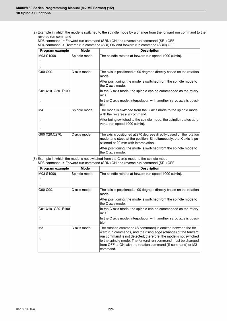
M800/M80 Series Programming Manual (M2/M0 Format) (1/2)
10 Spindle Functions
224IB-1501480-A
(2) Example in which the mode is switched to the spindle mode by a change from the forward run command to thereverse run commandM03 command -> Forward run command (SRN) ON and reverse run command (SRI) OFFM04 command -> Reverse run command (SRI) ON and forward run command (SRN) OFF
(3) Example in which the mode is not switched from the C axis mode to the spindle modeM03 command -> Forward run command (SRN) ON and reverse run command (SRI) OFF
Program example Mode Description
M03 S1000 Spindle mode The spindle rotates at forward run speed 1000 (r/min).
:
:
G00 C90. C axis mode The axis is positioned at 90 degrees directly based on the rotation mode.
After positioning, the mode is switched from the spindle mode to the C axis mode.
G01 X10. C20. F100 In the C axis mode, the spindle can be commanded as the rotary axis.
: In the C axis mode, interpolation with another servo axis is possi-ble.
M4 Spindle mode The mode is switched from the C axis mode to the spindle mode with the reverse run command.
: After being switched to the spindle mode, the spindle rotates at re-verse run speed 1000 (r/min).
:
G00 X20.C270. C axis mode The axis is positioned at 270 degrees directly based on the rotation mode, and stops at the position. Simultaneously, the X axis is po-sitioned at 20 mm with interpolation.
After positioning, the mode is switched from the spindle mode to the C axis mode.
Program example Mode Description
M03 S1000 Spindle mode The spindle rotates at forward run speed 1000 (r/min).
:
:
G00 C90. C axis mode The axis is positioned at 90 degrees directly based on the rotation mode.
After positioning, the mode is switched from the spindle mode to the C axis mode.
G01 X10. C20. F100 In the C axis mode, the spindle can be commanded as the rotary axis.
: In the C axis mode, interpolation with another servo axis is possi-ble.
M3 C axis mode The rotation command (S command) is omitted between the for-ward run commands, and the rising edge (change) of the forward run command is not detected; therefore, the mode is not switched to the spindle mode. The forward run command must be changed from OFF to ON with the rotation command (S command) or M3 command.
:
:

M800/M80 Series Programming Manual (M2/M0 Format) (1/2)
10 Spindle Functions
225 IB-1501480-A
When the program command method is selected, switching operation is performed with the reference position return
type.
Switching operation
Machining program
Spindle rotation speed(C axis speed)
Spindle
X axis speed
PLC→NC
Servo OFF signal*SVFn
Forward run commandSRN
NC→PLC
Servo readyRDYn
C axis modeSVMD
M03 S1000 G00 X10.C45. M03 S1000G01 C180. F90
45.0(deg)
180.0(deg)
X axis positioning (non-interpolation)
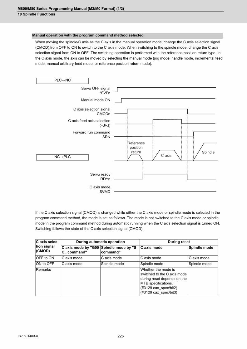
M800/M80 Series Programming Manual (M2/M0 Format) (1/2)
10 Spindle Functions
226IB-1501480-A
When moving the spindle/C axis as the C axis in the manual operation mode, change the C axis selection signal
(CMOD) from OFF to ON to switch to the C axis mode. When switching to the spindle mode, change the C axis
selection signal from ON to OFF. The switching operation is performed with the reference position return type. In
the C axis mode, the axis can be moved by selecting the manual mode (jog mode, handle mode, incremental feed
mode, manual arbitrary-feed mode, or reference position return mode).
If the C axis selection signal (CMOD) is changed while either the C axis mode or spindle mode is selected in the
program command method, the mode is set as follows. The mode is not switched to the C axis mode or spindle
mode in the program command method during automatic running when the C axis selection signal is turned ON.
Switching follows the state of the C axis selection signal (CMOD).
Manual operation with the program command method selected
PLC→NC
Servo OFF signal*SVFn
Manual mode ON
C axis selection signalCMODn
C axis feed axis selection(+J/-J)
Forward run commandSRN
NC→PLC
Servo readyRDYn
C axis modeSVMD
C axis selec-tion signal (CMOD)
During automatic operation During reset
C axis mode by "G00 C_ command"
Spindle mode by "S command"
C axis mode Spindle mode
OFF to ON C axis mode C axis mode C axis mode C axis mode
ON to OFF C axis mode Spindle mode Spindle mode Spindle mode
Remarks Whether the mode is switched to the C axis mode during reset depends on the MTB specifications. (#3129 cax_spec/bit2)(#3129 cax_spec/bit3)
Reference position return
C axisSpindle

M800/M80 Series Programming Manual (M2/M0 Format) (1/2)
10 Spindle Functions
227 IB-1501480-A
The mode is switched to the C axis mode regardless of the state of the spindle forward-run start (SRN) or spindle
reverse-run start (SRI) signal. In the C axis mode, spindle forward-run start and spindle reverse-run start are invalid.
When [PLC signal method] is selected, the spindle rotates by carrying out the spindle forward-run start or spindle
reverse-run start again (OFF to ON operation) after the C axis mode has been canceled.
When [Program command method] is selected, the spindle rotates by carrying out the spindle forward-run start or
spindle reverse-run start again (OFF to ON operation) in the C axis mode or by issuing the S command with the
spindle forward-run start or spindle reverse-run start set ON.
In the C axis mode, the spindle orientation command (ORC) is invalid. Also, the spindle position control command
(spindle/C axis control) is invalid if issued during spindle orientation.
Gear switching cannot be performed in the C axis mode. After the mode has been changed from the C axis mode
to the spindle mode, gear switching is performed. Also, the mode cannot be switched to the C axis mode during gear
switching. After gear switching has been completed, the mode is switched to the C axis mode.
Coil switching is invalid in the C axis mode. Conduct coil switching before switching to the C axis mode. If switching
to the C axis mode is commanded during coil switching, switching to the C axis mode is executed after coil switching
has been completed.
The spindle override is valid for the reference position return operation at switching to the C axis mode. In the C axis
mode, the spindle override is invalid. The cutting feed override or rapid traverse override is valid in the C axis mode.
The spindle position control is valid, excluding the following differences.
Relationship with Other Functions
Spindle forward-run start (SRN) and spindle reverse-run start (SRI)
Spindle orientation signal (ORC)
Spindle gear switching
Coil switching
Spindle override
Spindle-Mode Servo Motor Control

M800/M80 Series Programming Manual (M2/M0 Format) (1/2)
10 Spindle Functions
228IB-1501480-A
(1) Speed pattern of the reference position return operationThe reference position return from the stop mode is performed by the same operation as for the normal spindle.However, when the spindle returns from the rotation mode to the zero point, the rotation speed decelerates upto the C axis zero point return speed with the multi-step acceleration/deceleration pattern. After the C axis zeropoint return speed has been reached, the spindle inclines to the zero point, and stops while decelerating at theconstant speed The multi-step acceleration/deceleration pattern and C axis reference position return speed de-pend on the MTB specifications (parameters "#3054 sptc1" to "#3061 spdiv1" and "#3112 cax_spd").
The spindle position control is invalid.
The absolute position detection is invalid in the C axis mode.
When [Program command method] is selected, the mode is switched from the C axis mode to the spindle mode if
the surface speed command S (m/min) and the spindle forward-run start (SRN) or spindle reverse-run start (SRI)
signal is set ON.
When the program command method is selected, "block switched from spindle mode to C axis mode (example: G00
C_) and "block switched from C axis mode to spindle mode (example: M03 S1000)" is handled as a reverse run
prohibited block. The reverse run cannot be carried out back through blocks with the mode switched.
(1) If the movement is commanded while the servo OFF signal (*SVFn) is set to OFF, it causes an operation error(M01 0005). Reset NC to cancel the error, and set the servo OFF signal on to restart machining. If the spindlecommand is issued, the spindle does not rotate.
(2) If the servo OFF signal (*SVFn) is set to OFF during C axis movement, it causes an operation error (M01 0005).Reset NC to cancel the error.
(3) To switch from the spindle mode to the C axis mode, issue the G00 command. If a command other than the G00command is issued, it causes a program error (P430).
(4) The spindle position control axis must be commanded with the absolute value address or absolute value com-mand (G90). If the incremental value address or incremental value command (G91) is used, it causes a programerror (P32).
Stop mode Rotation mode
Multi-speed acceleration/deceleration
Spindle zero point
Spindle zero point
Analog spindle
Absolute position detection
Constant surface speed control
Manual arbitrary reverse run
Precautions and restrictions
#3115 sp2_t1
#3112cax_spd
#3001slimt1
#3115 sp2_t1
#3112cax_spd
#3001slimt1

11
229 IB-1501480-A
Tool Functions (T command)

M800/M80 Series Programming Manual (M2/M0 Format) (1/2)
11 Tool Functions (T command)
230IB-1501480-A
11Tool Functions (T command)11.1 Tool Functions (T8-digit BCD)
The tool functions are also known as T functions and they assign the tool numbers. This control unit specifies a tool
number with an 8-digit (0 to 99999999) number following the address T, and up to four sets can be commanded into
one block. However, the number of sets that can be commanded within the same block depends on the MTB spec-
ifications (parameter "#12009 Tfig").
One of the following output signals is issued depending on the parameter setting (depends on the machine specifi-
cations).
- 8-digit BCD code and start signal
- Signed 32-bit binary data and start signal
- Unsigned 32-bit binary data and start signal
If the T function is designated in the same block as a movement command, the commands may be executed in either
of the following two orders. The machine specifications determine which sequence applies.
(1) The T function is executed after completion of the movement.
(2) The T function is executed simultaneously with the movement command.
Processing and completion sequences are required for all T commands.
Function and purpose
12
231 IB-1501480-A
Tool Compensation Functions

M800/M80 Series Programming Manual (M2/M0 Format) (1/2)
12 Tool Compensation Functions
232IB-1501480-A
12Tool Compensation Functions12.1 Tool compensation12.1.1 Tool compensation
The basic tool compensation function includes the tool length compensation and tool radius compensation. Each
compensation amount is designated with the tool compensation No. Each compensation amount is input from the
setting and display unit or the program.
Function and purpose
Tool length compensation
Basic point
Tool length
(Side view)
Tool radius compensation
(Plane view)
Right compensation
Left compensation

M800/M80 Series Programming Manual (M2/M0 Format) (1/2)
12 Tool Compensation Functions
233 IB-1501480-A
There are two types of tool compensation memories, types I and II, used to set and select the tool compensation
amount. (The type used is determined by the MTB specifications.)
Each of types I and II can be changed to type III depending on the MTB settings (parameter "#1046 T-ofs disp type").
If the tool compensation memory is changed to type III, you can register the tool compensation amount of the base
axes I, J, and K and the tool tip point, enabling tool compensation for a turning tool.
The details of type III are also displayed on the screen.
If the tool compensation memory is reset to the original type, the turning tool compensation items are not displayed.
However, when it is changed to type III, the previously registered data is displayed.
The compensation amount settings are preset with the setting and display unit.
Type I is selected when parameter "#1037 cmdtyp" is set to "1", and type II is selected when set to "2".
(*1) Distinguished between tool length compensation and tool nose radius compensation.
Tool compensation memory
Type of tool compensation memo-ry
Classification of length compen-sation, radius compensation
Classification of shape compen-sation, wear compensation
Type I No No
Type II Yes Yes
Type III (*1) Yes
Basic point
Basic tool
Tool length com-pensation
Shape
Wear amount
Tool radius compensation Shape Wear amount

M800/M80 Series Programming Manual (M2/M0 Format) (1/2)
12 Tool Compensation Functions
234IB-1501480-A
Type I
One compensation amount corresponds to one compensation No. as shown below. Thus, these can be used
commonly regardless of the tool length compensation amount, tool radius compensation amount, shape com-
pensation amount and wear compensation amount.
(D1) = a1 , (H1) = a1
(D2) = a2 , (H2) = a2
: :
(Dn) = an , (Hn) = an
If the tool compensation type is changed from type I to type III, the tool compensation amount of type I is handled
as tool length Z of type III.
Type II
The shape compensation amount related to the tool length, wear compensation amount, shape compensation
related to the tool radius and the wear compensation amount can be set independently for one compensation
No. as shown below.
The tool length compensation amount is set with H, and the tool radius compensation amount with D.
(H1) = b1 + c1 , (D1) = d1 + e1
(H2) = b2 + c2 , (D2) = d2 + e2
: :
(Hn) = bn + cn , (Dn) = dn + en
If the tool compensation type is changed from type II to type III, data registered for type II is handled as the fol-
lowing data.
Compensation No. Compensation amount
1 a1
2 a2
3 a3
: :
: :
n an
Compensation No.Tool length (H) Tool radius (D)/(Position compensation)
Shape compensa-tion amount
Wear compensa-tion amount
Shape compensa-tion amount
Wear compensation amount
1 b1 c1 d1 e1
2 b2 c2 d2 e2
3 b3 c3 d3 e3
: : : : :
: : : : :
n bn cn dn en
Type II Type III
Length dimension Tool length Z
Length wear Z wear
Radius dimension Tool nose R
Radius wear R wear
CAUTION
If the tool compensation amount is changed during automatic operation (including during single block stop), it
will be validated from the next block or multiple blocks onwards.

M800/M80 Series Programming Manual (M2/M0 Format) (1/2)
12 Tool Compensation Functions
235 IB-1501480-A
This address designates the tool compensation No.
(1) H is used for the tool length compensation, and D is used for the tool position compensation and tool radius com-pensation.
(2) The tool compensation No. that is designated once does not change until a new H or D is designated.
(3) The compensation No. can be commanded once in each block. (If two or more Nos. are commanded, the latterone will be valid.)
(4) For 40 sets:Designate with the H01 to H40 (D01 to D40) numbers.
(5) If a value larger than this is set, the program error (P170) will occur.
(6) The setting value ranges are as follows for each No. The compensation amount for each compensation No. is preset with the setting and display unit.
Tool compensation No. (H/D)
Setting Shape compensation amount Wear compensation amount
Metric system Inch system Metric system Inch system
#1003=B ± 999.999 (mm) ± 99.9999 (inch) ± 999.999 (mm) ± 99.9999 (inch)
#1003=C ± 999.9999 (mm) ± 99.99999 (inch) ± 999.9999 (mm) ± 99.99999 (inch)
#1003=D ± 999.99999 (mm) ± 99.999999 (inch) ± 999.99999 (mm) ± 99.999999 (inch)
#1003=E ± 999.999999 (mm) ± 99.9999999 (inch) ± 999.999999 (mm) ± 99.9999999 (inch)

M800/M80 Series Programming Manual (M2/M0 Format) (1/2)
12 Tool Compensation Functions
236IB-1501480-A
12.1.2 Number of Tool Offset Sets Allocation to Part Systems
The number of tool offset sets can be set per part system.
This function is divided into the following methods and which one is used depends on the MTB specifications (pa-
rameters "#1438 Ofs-SysAssign", "#12054 Tol-Ofsnum").
Arbitrary allocation: Arbitrarily allocates to each part system.
Fixed allocation: Automatically and evenly allocates to each part system.
The arbitrary allocation enables the efficient allocation because when a certain part system needs only a small num-
ber of offset sets, the rest can be allocated to another part system. If an auxiliary-axis part system does not need
the tool offset set at all, the number of tool offset sets can be set to "0" for the auxiliary-axis part system.
While this function is available if the specification allows allocation by tool compensation memory part system, this
parameter depends on the MTB specification parameter "#1051 MemTol"). Subsequent description is an example
in the case where the number of tool offset sets in the system is 999. Number of tool offset sets in system is the total
number of tool offset sets of all part systems.
(1) Arbitrary allocation (with #1438=1)The number of tool offset sets allocated to each part system depends on the MTB specifications (parameter"#12054 Tol-ofsnum").The following example shows the number of tool offset sets allocated when the lathe system is a 4-part system.
(a) When the number of tool offset sets is increased for the 1st part system of 4-part system
(b) When the number of offset sets is set to "0 sets" for the 3rd part system to use the 3rd part system as auxiliary-
axis part system
(2) Fixed allocation (with #1438=0)
(*1) The maximum number of tool offset sets per part system is 999.
(*2) If there is any remainder, the remainder sets are allocated to the 1st part system.
Function and purpose
(Lathe system only) (Lathe system only)
250
250
250
250
200
200
200
400$1
$2
$3
$4
$1
$2
$3
$4
334
333
333 500
0
500$1
$2
$3
$1
$2
$3
500
333
333500
334
999
250
250
250
250
$1
$2
$3
$1
$2
$1
$1
$2
$3
$4
(*2)
(*1)

M800/M80 Series Programming Manual (M2/M0 Format) (1/2)
12 Tool Compensation Functions
237 IB-1501480-A
(1) The maximum number of tool offset sets for 1-part system is 999.
(2) For 1-part system, up to the number of tool offset sets in the system is available regardless of the parametersetting.
(3) When the value of the parameter "#12054 Tol-Ofsnum" (the number of tool offset sets by arbitrary allocation) isequal to or below the number of tool offset sets in the system, the remainder is not allocated to any part systemeven if the specification allows arbitrary allocation.
(4) When the tool compensation memory is provided commonly for the part systems ("#1051 MemTol"=1), the num-ber of tool offset sets in the system are commonly used by all part systems regardless of the parameter setting.The setting of parameter #1051 depends on the MTB specifications, so check it in your machine specifications.
(5) Even if the specification allows arbitrary allocation, fixed allocation is applied if the parameter is "#12054 Tol-Ofsnum"= 0.
(6) When entering offset data, if the number of offset data exceeds that of current tool offset sets, the excess offsetdata cannot be entered.
Precautions

M800/M80 Series Programming Manual (M2/M0 Format) (1/2)
12 Tool Compensation Functions
238IB-1501480-A
12.2 Tool Length Compensation/Cancel; G43, G44
The end position of the movement command for each axis can be compensated for by the preset amount when this
command is issued. A continuity can be applied to the program by setting the actual deviation from the tool length
value decided during programming as the compensation amount using this function.
Function and purpose
Command format
Tool length compensation start
G43 Zz Hh ;
Tool length compensation cancel
G44 Zz ;

M800/M80 Series Programming Manual (M2/M0 Format) (1/2)
12 Tool Compensation Functions
239 IB-1501480-A
The movement amount is calculated with the following expressions when the G43 tool length compensation com-
mand or G44 tool length compensation cancel command is issued.
lh1; Compensation amount for compensation No. h1 (Positive value)
lh2; Compensation amount for compensation No. h2 (Negative value)
Regardless of the absolute value command or incremental value command, the actual end point will be the point
compensated for by the compensation amount designated for the programmed movement command end point co-
ordinate value.
The G44 (tool length compensation cancel) mode is entered when the power is turned ON or when M02 has been
executed.
Detailed description
Tool length compensation movement amount
Z axis movement amount Operation
G43 Zz Hh1; z +(lh1) Compensation in + direction by tool compensation amount
G43 Zz Hh2; z -(lh2) Compensation in - direction by tool compensation amount
G44 Zz; z -(lh1) or +(lh2) Compensation amount cancel
(Example 1) For absolute value command H01=-100000
N1 G28 Z0 T01 M06 ;N2 G90 G92 Z0 ;N3 G43 Z5000 H01 ;N4 G01 Z-50000 F500 ;
(Example 2) For incremental value command H01=-100000
N1 G28 Z0 T01 M06 ;N2 G91 G92 Z0 ;N3 G43 Z5000 H01 ;N4 G01 Z-55000 F500 ;
Tool length com-pensation
H01=-100.
R
5.000
0W
50.000
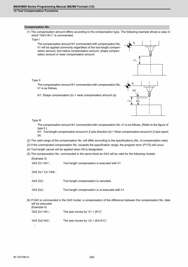
M800/M80 Series Programming Manual (M2/M0 Format) (1/2)
12 Tool Compensation Functions
240IB-1501480-A
(1) The compensation amount differs according to the compensation type. The following example shows a case inwhich "G43 Hh1;" is commanded.
(2) The valid range of the compensation No. will differ according to the specifications (No. of compensation sets).
(3) If the commanded compensation No. exceeds the specification range, the program error (P170) will occur.
(4) Tool length cancel will be applied when H0 is designated.
(5) The compensation No. commanded in the same block as G43 will be valid for the following modals.
(Example 3)
(6) If G43 is commanded in the G43 modal, a compensation of the difference between the compensation No. datawill be executed. (Example 4)
Compensation No.
Type I
The compensation amount lh1 commanded with compensation No. h1 will be applied commonly regardless of the tool length compen-sation amount, tool radius compensation amount, shape compen-sation amount or wear compensation amount.
Type II
The compensation amount lh1 commanded with compensation No. h1 is as follows. lh1: Shape compensation (b) + wear compensation amount (a)
Type III
The compensation amount lh1 commanded with compensation No. h1 is as follows. (Refer to the figure of type II.) lh1: Tool length compensation amount in Z axis direction (b) + Wear compensation amount in Z axis report (a)
G43 Zz1 Hh1 ; Tool length compensation is executed with h1.
:
G45 Xx1 Yy1 Hh6 ;
:
G44 Zz2 ; Tool length compensation is canceled.
:
G43 Zz2 ; Tool length compensation is re-executed with h1.
:
G43 Zz1 Hh1 ; The axis moves by "z1 + (lh1)".
:
G43 Zz2 Hh2 ; The axis moves by "z2 + (lh2-lh1)".
:
l h1
R
l h1
R
(a)
(b)

M800/M80 Series Programming Manual (M2/M0 Format) (1/2)
12 Tool Compensation Functions
241 IB-1501480-A
(1) When parameter "#1080 Dril_Z" is set to "1", the tool length compensation is always applied to the Z axis.
(2) When parameter "#1080 Dril_Z" is set to "0", the axis will depend on the axis address commanded in the sameblock as G43. The order of priority is shown below. Zp > Yp > Xp(Example 5)
The handling of the additional axis will follow the parameters "#1029 to 1031 aux_I, J and K" settings.
If the tool length compensation is commanded for the rotary axis, set the rotary axis name for one of the parallel
axes.
(3) If H (compensation No.) is not designated in the same block as G43, the Z axis will be valid. (Example 6)
(1) If reference position return is executed with G28 and manual operation, the tool length compensation will be can-celed when the reference position return is completed. (Example 7)
(2) The movement is commanded to the G53 machine coordinate system, the axis will move to the machine positionwhen the tool compensation amount is canceled. When the G54 to G59 workpiece coordinate system is returned to, the position returned to will be the coordinatesshifted by the tool compensation amount.
Axis valid for tool length compensation
G43 Xx1 Hh1; + compensation to X axis
:
G44 Xx2 ;
:
G43 Yy1 H-h2 ; - compensation to Y axis
:
G44 Yy2 ;
:
G43 αα1 Hh3; + compensation to additional axis
:
G44 αα1 ;
:
G43 Xx3Yy3Zz3 ; Compensation is applied on Z axis.
:
G44 ;
G43 Hh1 ; Compensation and cancel to Z axis
:
G44 ;
:
Movement during other commands in tool length compensation modal
G43 Zz1 Hh1 ;
:
G28 Zz2 ; Canceled when reference position is reached. (Same as G44)
:
G43 Zz2Hh2 ;
:
G44 G28Zz2 ; The tool length compensation will be included when positioning the intermediate point. Canceled when reference position is reached.

M800/M80 Series Programming Manual (M2/M0 Format) (1/2)
12 Tool Compensation Functions
242IB-1501480-A
When the independent tool length compensation command (G43) or independent tool length compensation cancel
command (G44) is issued, the movement by the compensation amount may not be carried out depending on the
MTB specifications (parameter "#1247/bit0" (movement by tool length compensation command)).
Movement by tool length compensation command
Without movement (#1247/bit0 = 1) With movement (#1247/bit0 = 0)
Indepen-dent tool length com-pensation command
:G54 A0. C0.G68.2G53.1G00XxYyZzG43H1:
G44
:G54 A0. C0.G68.2G53.1G00XxYyZzG43H1:
G44
The axis does not move when Tool length compen-sation is commanded independently, but the tool compensation amount is applied to the program po-sition counter.
The axis moves by the compensation amount when Tool length compensation is commanded independent-ly.
Tool length compensa-tion com-mand with movement
:G54 A0. C0.G68.2G53.1G00XxYyZzG43H1Z0:
G44Z10.
:G54 A0. C0.G68.2G53.1G00XxYyZzG43H1Z0:
G44Z10.
The axis moves by the compensation amount when the tool length compensation with travel is command-ed.
The axis moves by the compensation amount when the tool length compensation with travel is commanded.
Mx
MyMz
G43 G44
Positioning
Cutting
Machine coordinate system
Mx
My Mz
G43 G44
Positioning
Cutting
Machine coordinate system
Mx
My Mz
G43 G44
Positioning
Cutting
Machine coordinate system
Mx
My Mz
G43 G44
Positioning
Cutting
Machine coordinate system
M800/M80 Series Programming Manual (M2/M0 Format) (1/2)
12 Tool Compensation Functions
243 IB-1501480-A
12.3 Tool Radius Compensation ; G38,G39/G40/G41,G42
This function compensates the radius of the tool. The compensation can be done in the random vector direction by
the radius amount of the tool selected with the G command (G38 to G42) and the D command.
When using tool nose radius compensation, refer to "12.4 Tool Nose Radius Compensation (for Machining Center
System)".
The number of sets for the compensation differ according to machine specification. (The No. of sets is the total of
the tool length offset, tool position offset and tool radius compensation sets.)
The H command is ignored during the tool radius compensation, and only the D command is valid.
The compensation will be executed within the plane designated with the plane selection G code or axis address 2
axis, and axes other than those included in the designated plane and the axes parallel to the designated plane will
not be affected. Refer to the section on plane selection for details on selecting the plane with the G code.
Function and purpose
Command format
G40 X__Y__; Tool radius compensation cancel
G41 X__Y__ D__; Tool radius compensation (Left)
G42 X__Y__ D__; Tool radius compensation (Right)
G38 I__J__; Change or hold of compensation vector (Can be commanded only during the radius compensation mode.)
G39 X__Y__; Corner changeover (Can be commanded only during the radius compensa-tion mode.)
Detailed description

M800/M80 Series Programming Manual (M2/M0 Format) (1/2)
12 Tool Compensation Functions
244IB-1501480-A
12.3.1 Tool Radius Compensation Operation
The tool radius compensation cancel mode is established by any of the following conditions.
(1) After the power has been switched on
(2) After the reset button on the setting and display unit has been pressed
(3) After the M02 or M30 command with reset function has been executed
(4) After the compensation cancel command (G40) is issued
The compensation vectors are zero in the compensation cancel mode, and the tool nose point path coincides with
the programmed path.
Programs including tool radius compensation must be terminated in the compensation cancel mode.
Tool radius compensation starts when all the following conditions are met in the compensation cancel mode.
(1) The movement command is issued after G41 or G42.
(2) The tool radius compensation offset No. is 0 < D <= max. offset No.
(3) The movement command of positioning (G00) or linear interpolation (G01) is issued.
Whether in continuous or single block operation, compensation always starts after reading three blocks, or if the
three blocks do not contain any movement command, up to five continuous blocks will be pre-read.
In compensation mode, too, up to 5 blocks are pre-read and the compensation is arithmetically processed.
There are two ways of starting the compensation operation: type A and type B.
The type depends on the setting of the parameter "#8157 Radius comp type B".
This type is used in common with the compensation cancel type.
Detailed description
Tool radius compensation cancel mode
Tool radius compensation start (startup)
[Control state diagram]
After pre-reading G41, start pre-reading Max. 5 blocks
Execution block Pre-read Buffer
N16 G02_;N15 G01_;N14 G41_;N13 G00_;N12 S_;N11 T_;
N16 G02_;N15 G01_;N14 G41_;N13 G00_;N12 S_;N11 T_;
N16 G02_;N15 G01_;
N16 G02_;N15 G01_;N14 G41_;N13 G00_;N12 S_;N11 T_;
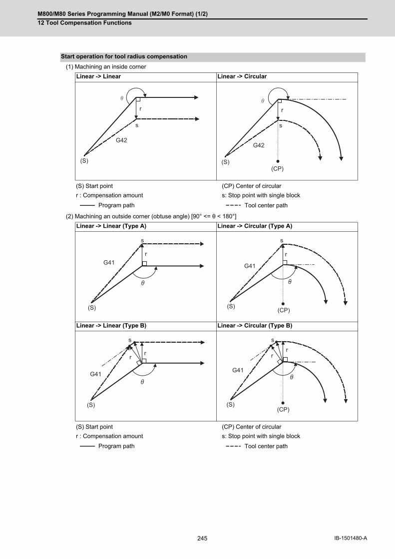
M800/M80 Series Programming Manual (M2/M0 Format) (1/2)
12 Tool Compensation Functions
245 IB-1501480-A
(1) Machining an inside corner
(2) Machining an outside corner (obtuse angle) [90° <= θ < 180°]
Start operation for tool radius compensation
Linear -> Linear Linear -> Circular
(S) Start point (CP) Center of circular
r : Compensation amount s: Stop point with single block
Program path Tool center path
Linear -> Linear (Type A) Linear -> Circular (Type A)
Linear -> Linear (Type B) Linear -> Circular (Type B)
(S) Start point (CP) Center of circular
r : Compensation amount s: Stop point with single block
Program path Tool center path
G42
s
(S)
r
s
G42
r
(S)(CP)
G41r
s
(S)
G41
r
s
(S) (CP)
G41
rr
s
(S)
G41
rr
s
(S)(CP)
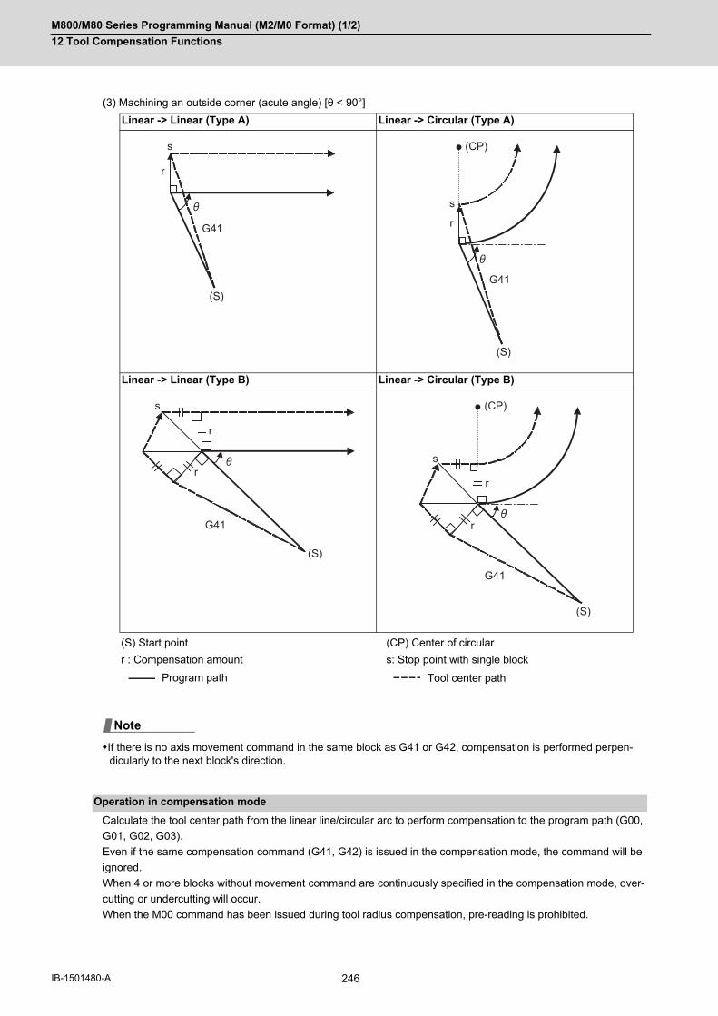
M800/M80 Series Programming Manual (M2/M0 Format) (1/2)
12 Tool Compensation Functions
246IB-1501480-A
(3) Machining an outside corner (acute angle) [θ < 90°]
If there is no axis movement command in the same block as G41 or G42, compensation is performed perpen-dicularly to the next block's direction.
Calculate the tool center path from the linear line/circular arc to perform compensation to the program path (G00,
G01, G02, G03).
Even if the same compensation command (G41, G42) is issued in the compensation mode, the command will be
ignored.
When 4 or more blocks without movement command are continuously specified in the compensation mode, over-
cutting or undercutting will occur.
When the M00 command has been issued during tool radius compensation, pre-reading is prohibited.
Linear -> Linear (Type A) Linear -> Circular (Type A)
Linear -> Linear (Type B) Linear -> Circular (Type B)
(S) Start point (CP) Center of circular
r : Compensation amount s: Stop point with single block
Program path Tool center path
Operation in compensation mode
G41
r
s
(S)G41
r
s
(S)
(CP)
G41
r
r
s
(S)
G41
r
r
s
(S)
(CP)
Note

M800/M80 Series Programming Manual (M2/M0 Format) (1/2)
12 Tool Compensation Functions
247 IB-1501480-A
(1) Machining an outside corner
Linear -> Linear (90°<= θ < 180°) Linear -> Linear (0° < θ < 90°)
Linear -> Circular (90° <= θ < 180°) Linear -> Circular (0° < θ < 90°)
Circular -> Linear (90° <= θ < 180°) Circular -> Linear (0° < θ < 90°)
Circular -> Circular (90° <= θ < 180°) Circular -> Circular (0° < θ < 90°)
(CP) Center of circular
r : Compensation amount s : Single block stop point
Program path Tool center path
s
r
r
s
s
r r
(CP)
r
r
s
(CP)
rr
s
(CP)
r
r
s
(CP)
rr
s
(CP)
(CP)
r r
s(CP) (CP)

M800/M80 Series Programming Manual (M2/M0 Format) (1/2)
12 Tool Compensation Functions
248IB-1501480-A
(2) Machining an inside corner
Linear -> Linear (Obtuse angle) Linear -> Linear (Acute angle)
Linear -> Circular (Obtuse angle) Linear -> Circular (Acute angle)
Circular -> Linear (Obtuse angle) Circular -> Linear (Acute angle)
Circular -> Circular (Obtuse angle) Circular -> Circular (Acute angle)
(CP) Center of circular
r : Compensation amount s : Single block stop point
Program path Tool center path
r
s
r
rs
r
s
(CP)
r
r
s
(CP)
rs
(CP)
r
s
(CP)
r
s
(CP)(CP)
r
s
(CP)
(CP)
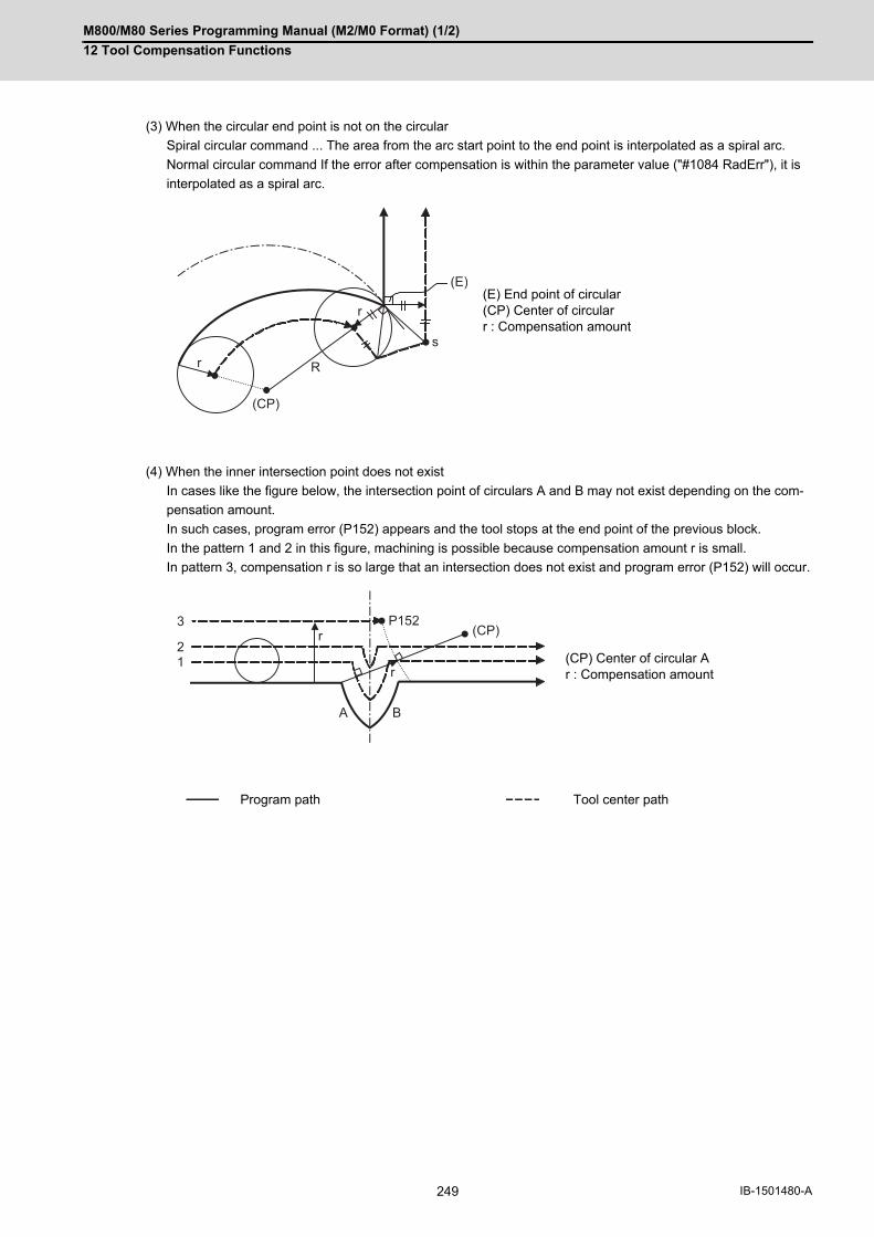
M800/M80 Series Programming Manual (M2/M0 Format) (1/2)
12 Tool Compensation Functions
249 IB-1501480-A
(3) When the circular end point is not on the circular
Spiral circular command ... The area from the arc start point to the end point is interpolated as a spiral arc.
Normal circular command If the error after compensation is within the parameter value ("#1084 RadErr"), it is
interpolated as a spiral arc.
(4) When the inner intersection point does not exist
In cases like the figure below, the intersection point of circulars A and B may not exist depending on the com-
pensation amount.
In such cases, program error (P152) appears and the tool stops at the end point of the previous block.
In the pattern 1 and 2 in this figure, machining is possible because compensation amount r is small.
In pattern 3, compensation r is so large that an intersection does not exist and program error (P152) will occur.
(E) End point of circular(CP) Center of circularr : Compensation amount
(CP) Center of circular Ar : Compensation amount
Program path Tool center path
r
rs
R
(E)
(CP)
r
r
A B
P152(CP)
3
21

M800/M80 Series Programming Manual (M2/M0 Format) (1/2)
12 Tool Compensation Functions
250IB-1501480-A
Tool radius compensation cancel If either of the following conditions is met in the tool radius compensation mode,
the compensation will be canceled.
However, there must be any movement command except a circular command.
If the compensation is canceled by a circular command, program error (P151) will occur.
(1)The G40 command has been executed.
(2)Executed the compensation No.D00.
The cancel mode is established once the compensation cancel command has been read, 5-block pre-reading is sus-
pended and 1-block pre-reading will be operated.
(1) Machining an inside corner
Tool radius compensation cancel
Tool radius compensation cancel operation
Linear -> Linear Circular -> Linear
(E) End point (CP) Center of circular
r : Compensation amount s : Single block stop point
Program path Tool center path
r
s
G40
(E)
G40
r
s
(CP)(E)
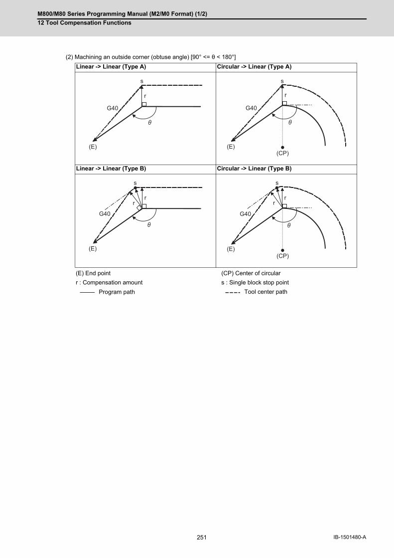
M800/M80 Series Programming Manual (M2/M0 Format) (1/2)
12 Tool Compensation Functions
251 IB-1501480-A
(2) Machining an outside corner (obtuse angle) [90° <= θ < 180°]
Linear -> Linear (Type A) Circular -> Linear (Type A)
Linear -> Linear (Type B) Circular -> Linear (Type B)
(E) End point (CP) Center of circular
r : Compensation amount s : Single block stop point
Program path Tool center path
r
s
G40
(E)
G40
r
s
(CP)(E)
r
s
G40
r
(E)
G40
r
s
r
(CP)(E)
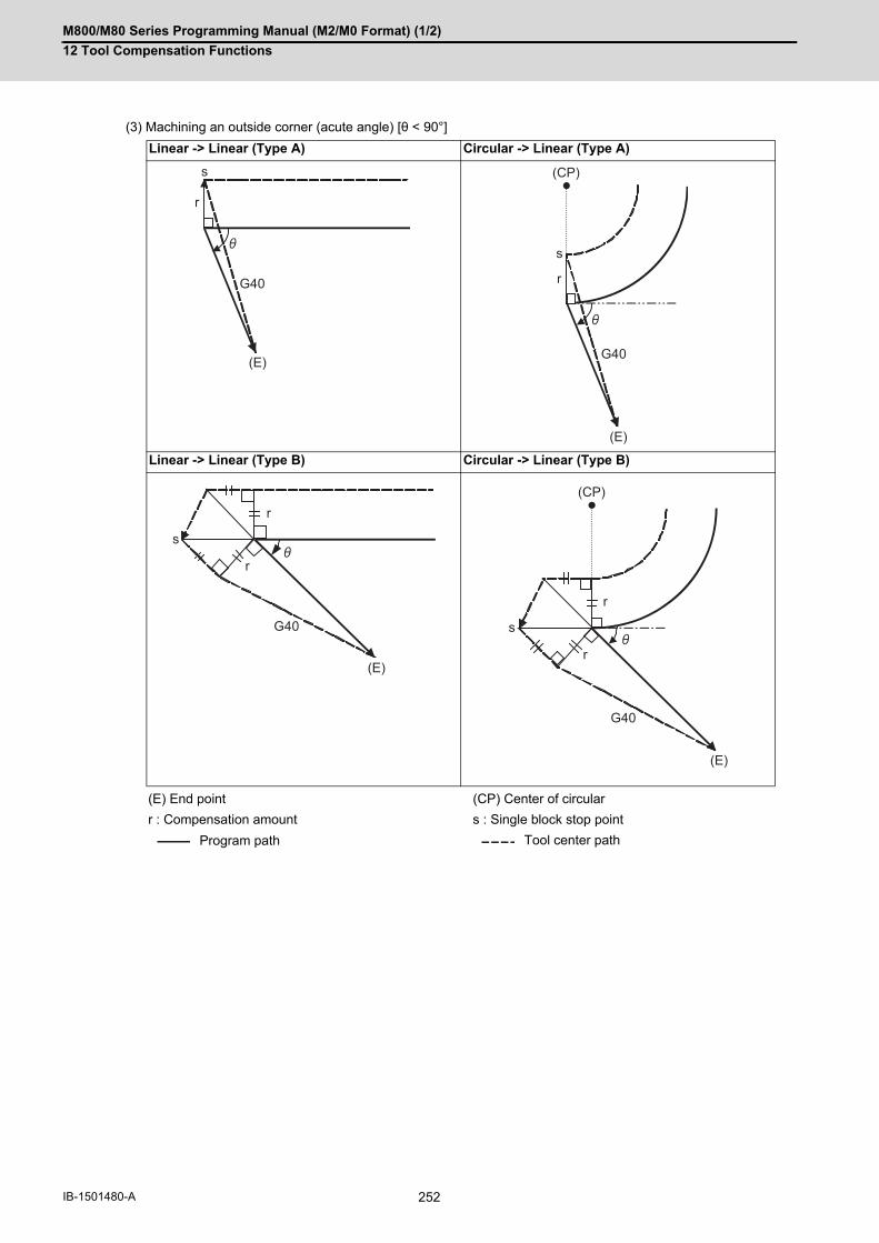
M800/M80 Series Programming Manual (M2/M0 Format) (1/2)
12 Tool Compensation Functions
252IB-1501480-A
(3) Machining an outside corner (acute angle) [θ < 90°]
Linear -> Linear (Type A) Circular -> Linear (Type A)
Linear -> Linear (Type B) Circular -> Linear (Type B)
(E) End point (CP) Center of circular
r : Compensation amount s : Single block stop point
Program path Tool center path
r
s
G40
(E)
s
G40
r
(CP)
(E)
r
s
G40
r
(E)
r
s
G40
r
(E)
(CP)

M800/M80 Series Programming Manual (M2/M0 Format) (1/2)
12 Tool Compensation Functions
253 IB-1501480-A
12.3.2 Other Commands and Operations during Tool Radius Compensation
An arc that uses the compensation amount as the radius is inserted without calculating the point of intersection at
the workpiece corner when G39 (corner arc) is commanded.
Detailed description
Insertion of corner arc
(With G39 com-mand)
(No G39 com-mand)
(With G39 com-mand)
(No G39 com-mand)
[For outer side compensation] [For inner side compensation]
(a) Inserted circular (b) Point of intersection r : Compensation amount
s: Stop point with single block
N1 G28 X0 Y0 ;N2 G91 G01 G42 X20. Y20. D1 F100 ;N3 G39 X40. ;N4 G39 Y40. ;N5 G39 X-40. ;N6 Y-40. ;N7 G40 X-20. Y-20. ;N8 M02 ;
Programmed path
Tool center path
s(a) (b)
rs
(a)
(b)
r
N2
N1
D1=5.000
N3
N4
N5
N6
N7
Y
X

M800/M80 Series Programming Manual (M2/M0 Format) (1/2)
12 Tool Compensation Functions
254IB-1501480-A
The compensation vector can be changed or held during tool radius compensation by using the G38 command.
(1) Holding of vector
When G38 is commanded in a block having a movement command, the point of intersection will not be calculated
at the program end point, and instead the vector of the previous block will be held.
G38 Xx Yy;
This can be used for pick feed, etc.
Changing and holding of compensation vector
[Holding the inside compensation vector]
N11 G01 Xx11 ;N12 G38 Xx12 Yy12 ;N13 G40 Xx13 ; r1: Vector at N11-N12 block intersection calculation
[Holding the outside compensation acute an-gle]
N11 G01 Xx11 Yy11 ;N12 G38 Xx12 Yy12 ;N13 G40 Xx13 ; r1: Vector at N11-N12 block intersection calculation
[Holding the outside compensation obtuse an-gle]
N11 G01 Xx11 Yy11 ;N12 G38 Xx12 Yy12 ;N13 G40 Xx13 ; r1: Vector at N11-N12 block intersection calculation
Programmed path
Tool center path
N11
N12
N13
r1
r1
N11N12
N13
r1
r1
N11N12
N13
r1
r1

M800/M80 Series Programming Manual (M2/M0 Format) (1/2)
12 Tool Compensation Functions
255 IB-1501480-A
(2) Changing of vector
A new compensation vector direction can be commanded with I, J and K, and a new compensation amount with
D.
(These can be commanded in the same block as the movement command.)
G38 Ii Jj Dd ; (I, J and K will differ according to the selected plane.)
The compensation amount “d” vector is created in the commanded i and j vector direction.
If G38 is commanded in the same block as the circular block (G02/G03) I and J commands, I and J will be han-dled as the G38 vector, and an error will occur.
N11 G01 Xx11 ;N12 Yy12 ;N13 G38 Xx13 Ii Jj Dd ;N14 G40 Xx14 Yy14 ;
Programmed path
Tool center path
N13
N12
N11
i
j
N14
d d
Note

M800/M80 Series Programming Manual (M2/M0 Format) (1/2)
12 Tool Compensation Functions
256IB-1501480-A
The compensation direction is determined by the tool radius compensation commands (G41, G42) and compensa-
tion amount sign.
The compensation direction can be changed by changing the compensation command during the compensation
mode without canceling the mode.
However, it is impossible to change the direction in the compensation start block and the next block.
(1) Linear -> Linear
(a) When there is an intersection (A) at the change of compensation direction
(b) When there is no intersection at the change of compensation direction
(2) Linear <-> Circular
(a) When there is a point of intersection (A) when the compensation direction is changed.
(b) When there is no point of intersection when the compensation direction is changed.
Changing the compensation direction during tool radius compensation
G Code Compensation amount sign + Compensation amount sign -
G41 Left-side compensation Right-side compensation
G42 Right-side compensation Left-side compensation
Program path Tool center path
r
G41
r
G41 G42
r
r
(a)
(b)
A
r
G41
r
G41 G42G41G42
r
r
r
r
A
(b)
(a)

M800/M80 Series Programming Manual (M2/M0 Format) (1/2)
12 Tool Compensation Functions
257 IB-1501480-A
(3) Circular -> Circular
(a) When there is an intersection at the change of compensation direction
(b) When there is no intersection at the change of compensation direction
(4) Linear return
(5) Arc exceeding 360° due to compensation method.In the cases below, it is possible that the arc may exceed 360°. With compensation direction selection based on G41/G42 If the arc exceeds 360°, compensation will be performed as shown in the figure and uncut section will be left.
(CP) Center of circular
:G42 G01 X_ Y_;G41 G02 X_ Y_ I_ J_;G42 G01 X_ Y_;:
Program path Tool center path
Section left uncut
G42G41G41
G41
G41
G42
(CP)
(CP)
(a)
(b) r
r
r
G41
G42r
G41
G42
G42

M800/M80 Series Programming Manual (M2/M0 Format) (1/2)
12 Tool Compensation Functions
258IB-1501480-A
When the following command is issued in the compensation mode, the compensation vectors are temporarily elim-
inated and then, compensation mode will automatically return.
In this case, the compensation is not canceled, and the tool goes directly from the intersection point vector to the
point without vectors, in other words, to the programmed command point. When returning to the compensation
mode, it goes directly to the intersection point.
(1) Reference position return commandTemporarily no compensation vectors at intermediate point. (Reference position when there is no intermediatepoint).
(2) The compensation vector will be eliminated temporarily with the G53 command (Basic machine coordinate sys-tem selection).
<Note>
The compensation vectors do not change with the coordinate system setting (G92) command.
(3) G33 thread cutting commandTool radius compensation does not apply to the G33 block.
Command for eliminating compensation vectors temporarily
(G41) :N5 G91 G01 X60. Y30. ;N6 G28 X50. Y-40. ; ← Temporarily no compensation vectors at intermediate point. N7 X30. Y-60. ; (Reference position when there is no intermediate point)N8 X70. Y40. ; :
(CP) Intermediate point
(CP)
N6N5
S
S
S
N8 N7
r
G33

M800/M80 Series Programming Manual (M2/M0 Format) (1/2)
12 Tool Compensation Functions
259 IB-1501480-A
The following blocks are known as blocks without movement.
M00, M01, M02 and M30 are handled as pre-read inhibit M codes.
(1) When command is assigned at start of the compensationCompensation vector cannot be created when there are four or more successive blocks without movement, orwhen pre-reading prohibiting M command is issued.
Blocks without movement
M03 ; M command
S12 ; S command
T45 ; T command
G04X500 ; Dwell
G22.1 X200. Y150. Z100 ; Machining prohibited region setting
G10 L10; P01 R50; Compensation amount setting
G92 X600. Y400. Z500. Coordinate system setting
(G17) Z40. Movement outside the compensation plane
G90 ; G code only
G91 X0; Movement amount 0
N1 X30.Y60 ;
N2 G41 D10 ;
Block without movement
N3 G04 X1000 ;
N4 F100 ;
N5 S500 ;
N6 M3 ;
N7 X20.Y-50. ;
N8 X50.Y-20. ;
N1
N2, 3, 4, 5, 6
N7
N8
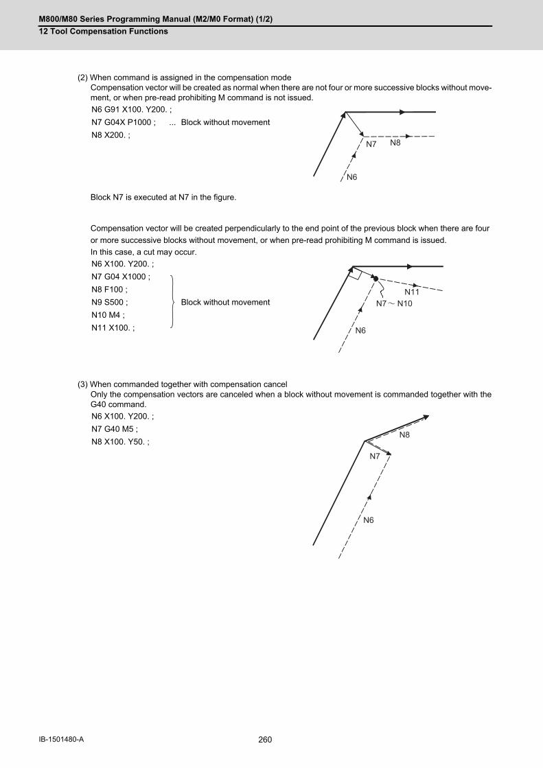
M800/M80 Series Programming Manual (M2/M0 Format) (1/2)
12 Tool Compensation Functions
260IB-1501480-A
(2) When command is assigned in the compensation modeCompensation vector will be created as normal when there are not four or more successive blocks without move-ment, or when pre-read prohibiting M command is not issued.
Block N7 is executed at N7 in the figure.
Compensation vector will be created perpendicularly to the end point of the previous block when there are four
or more successive blocks without movement, or when pre-read prohibiting M command is issued.
In this case, a cut may occur.
(3) When commanded together with compensation cancelOnly the compensation vectors are canceled when a block without movement is commanded together with theG40 command.
N6 G91 X100. Y200. ;
N7 G04X P1000 ; ... Block without movement
N8 X200. ;
N6 X100. Y200. ;
N7 G04 X1000 ;
Block without movement
N8 F100 ;
N9 S500 ;
N10 M4 ;
N11 X100. ;
N6 X100. Y200. ;
N7 G40 M5 ;
N8 X100. Y50. ;
N8N7
N6
N7 N10
N6
N11
N6
N7
N8
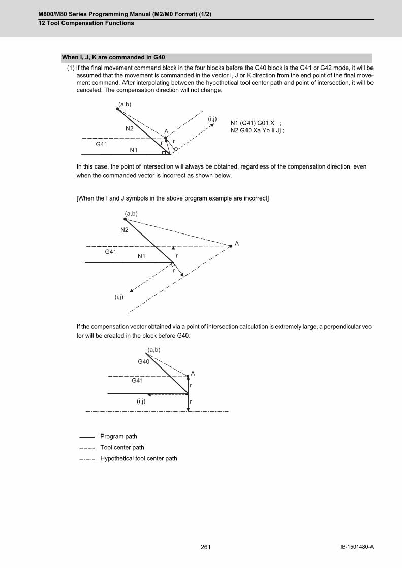
M800/M80 Series Programming Manual (M2/M0 Format) (1/2)
12 Tool Compensation Functions
261 IB-1501480-A
(1) If the final movement command block in the four blocks before the G40 block is the G41 or G42 mode, it will beassumed that the movement is commanded in the vector I, J or K direction from the end point of the final move-ment command. After interpolating between the hypothetical tool center path and point of intersection, it will becanceled. The compensation direction will not change.
In this case, the point of intersection will always be obtained, regardless of the compensation direction, even
when the commanded vector is incorrect as shown below.
[When the I and J symbols in the above program example are incorrect]
If the compensation vector obtained via a point of intersection calculation is extremely large, a perpendicular vec-
tor will be created in the block before G40.
When I, J, K are commanded in G40
N1 (G41) G01 X_ ;N2 G40 Xa Yb Ii Jj ;
Program path
Tool center path
Hypothetical tool center path
rN1
(i,j)N2 A
(a,b)
rG41
rN1
(i,j)
N2
A
(a,b)
r
G41
r
G40
(i,j)
A
(a,b)
r
G41

M800/M80 Series Programming Manual (M2/M0 Format) (1/2)
12 Tool Compensation Functions
262IB-1501480-A
(2) If the arc is 360° or more due to the details of I, J and K at G40 after the arc command, an uncut section will occur.
When a multiple number of compensation vectors are created at the joints between movement command blocks,
the tool will move in a straight line between these vectors. This action is called corner movement.
When the vectors do not coincide, the tool moves in order to machine the corner although this movement is part and
parcel of the joint block.
Consequently, operation in the single block mode will execute the previous block + corner movement as a single
block and the remaining joining movement + following block will be executed as a single block in the following op-
eration.
N1 (G42,G91) G01 X200. ;N2 G03 J150.;N3 G40 G01 X150. Y-150. I-100. J100. ;
Programmed path
Tool center path
Section left uncut
Corner movement
(CP) Center of circularr: Compensation amounts: Single block stop point
Programmed path Tool center path
r
N1
(i,j)
N2
r
G42
r
G40N3
r
N1
N2
r
s
(CP)

M800/M80 Series Programming Manual (M2/M0 Format) (1/2)
12 Tool Compensation Functions
263 IB-1501480-A
12.3.3 G41/G42 Commands and I, J, K Designation
The compensation direction can be intentionally changed by issuing the G41/G42 command and I, J, K in the same
block.
Assign a linear command (G00, G01) in a movement mode.
This section describes the new I,J type vectors (G17 plane) created by this command. (Similar descriptions apply to
vector K, I for the G18 plane and to J, K for the G19 plane.)
As shown in the following figures, I, J type vectors create compensation vectors which are perpendicular to the di-
rection designated by I, J and equivalent to the compensation amount, without the intersection point calculation of
the programmed path. The I, J vectors can be commanded even in the mode (G41/G42 mode in the block before)
and even at the compensation start (G40 mode in the block before).
(1) When I, J is commanded at compensation start
Function and purpose
Command format
G17 (X-Y plane) G41/G42 X__ Y__ I__ J__ ;
G18 (Z-X plane) G41/G42 X__ Z__ I__ K__ ;
G19 (Y-Z plane) G41/G42 Y__ Z__ J__ K__ ;
Detailed description
I, J type vectors (G17 X-Y plane selection)
Program path
Tool center path
(G40)
N100 G91 G41 X100. Y100. I150. D1 ;
N110 G04 X1000 ;
N120 G01 F1000 ;
N130 S500 ;
N140 M03 ;
N150 X150. ;
N150
N100
Y
X
N110N120N130N140
D1
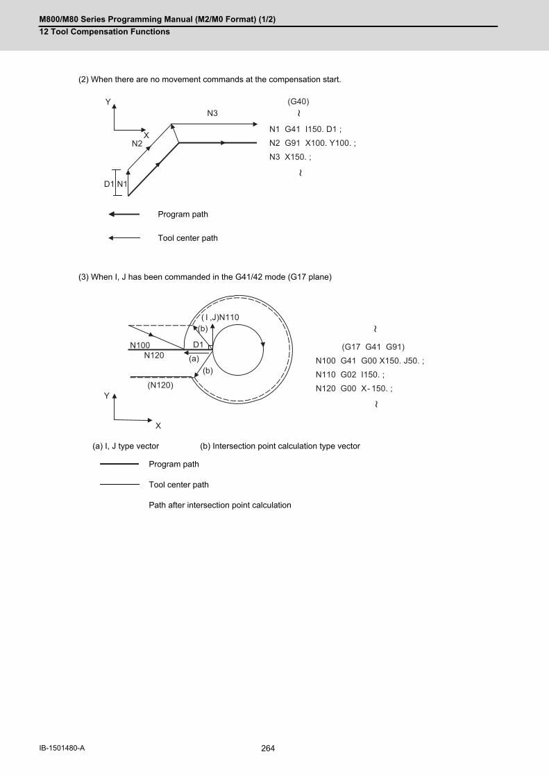
M800/M80 Series Programming Manual (M2/M0 Format) (1/2)
12 Tool Compensation Functions
264IB-1501480-A
(2) When there are no movement commands at the compensation start.
(3) When I, J has been commanded in the G41/42 mode (G17 plane)
Program path
Tool center path
(a) I, J type vector (b) Intersection point calculation type vector
Program path
Tool center path
Path after intersection point calculation
(G40)
N1 G41 I150. D1 ;
N2 G91 X100. Y100. ;
N3 X150. ;
N3
N2
Y
X
D1 N1
(G17 G41 G91)
N100 G41 G00 X150. J50. ;
N110 G02 I150. ;
N120 G00 X- 150. ;(N120)
N100
Y
X
N120
( I ,J)N110
D1
(a)(b)
(b)
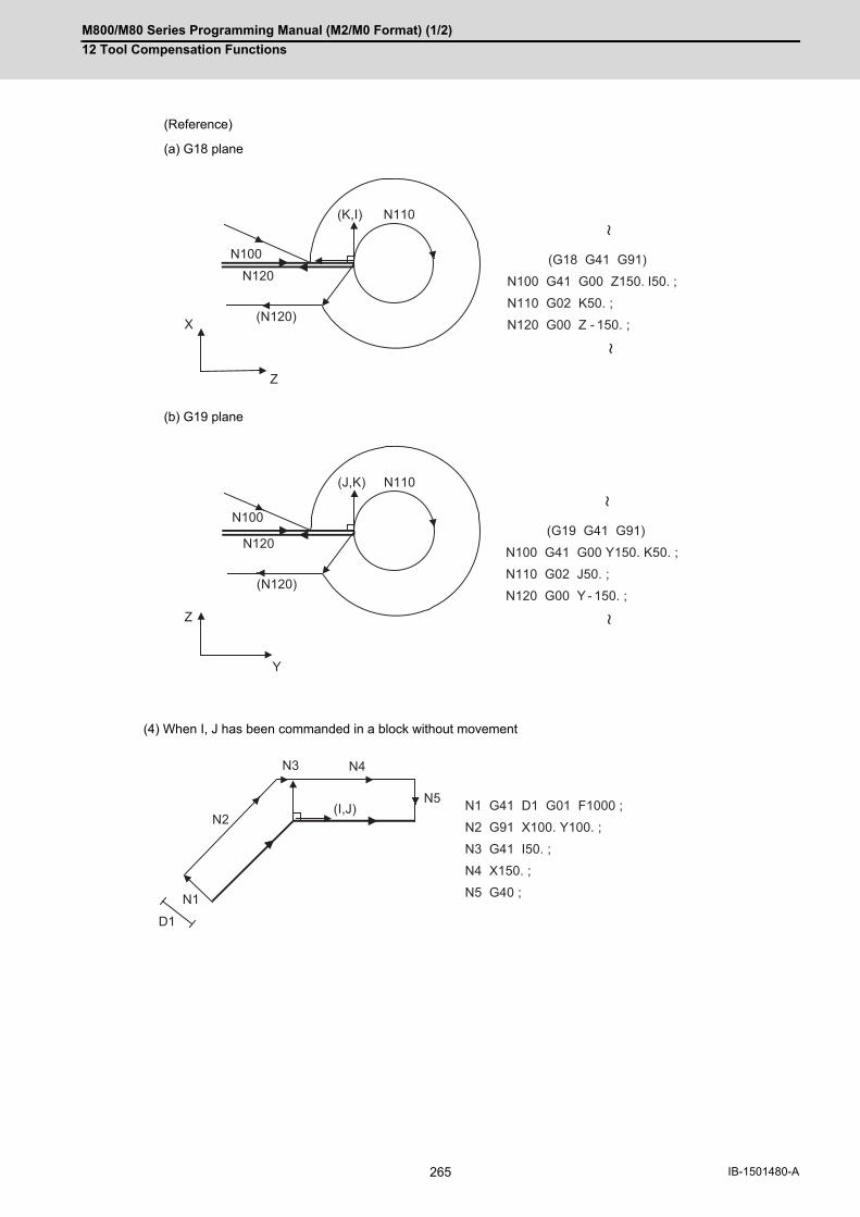
M800/M80 Series Programming Manual (M2/M0 Format) (1/2)
12 Tool Compensation Functions
265 IB-1501480-A
(Reference)
(a) G18 plane
(b) G19 plane
(4) When I, J has been commanded in a block without movement
(G18 G41 G91)
N100 G41 G00 Z150. I50. ;
N110 G02 K50. ;
N120 G00 Z - 150. ;(N120)
N100
Z
X
N120
(K,I) N110
(G19 G41 G91)
N100 G41 G00 Y150. K50. ;
N110 G02 J50. ;
N120 G00 Y - 150. ;(N120)
N100
Z
Y
N120
(J,K) N110
N1 G41 D1 G01 F1000 ;
N2 G91 X100. Y100. ;
N3 G41 I50. ;
N4 X150. ;
N5 G40 ;
N3
N2
D1
N1
N4
(I,J)N5

M800/M80 Series Programming Manual (M2/M0 Format) (1/2)
12 Tool Compensation Functions
266IB-1501480-A
(1) In G41 mode
Direction produced by rotating the direction commanded by I,J by 90° to the left when looking at the zero point
from the forward direction of the Z axis (3rd axis).
(2) In G42 mode
Direction produced by rotating the direction commanded by I, J by 90° to the right when looking at the zero point
from the forward direction of the Z axis (3rd axis).
G41 and G42 modals can be switched over at any time.
Compensation vector direction
(Example 1) With I100. (Example 2) With I-100.
(100, 0) IJ direction (-100, 0) IJ direction
Compensation vector direction Compensation vector direction
(Example 1) With I100. (Example 2) With I-100.
(100, 0) IJ direction (-100, 0) IJ direction
Compensation vector direction Compensation vector direction
Selection of compensation modal
N1 G28 X0 Y0 ;
N2 G41 D1 F1000 ;
N3 G01 G91 X100. Y100. ;
N4 G42 X100. I100. J - 100.
D2 ;
N5 X100. Y- 100. ;
N6 G40 ;
N7 M02 ;
%
N3
x
D1 N2
N6
(I,J)
N5
y
N4D2
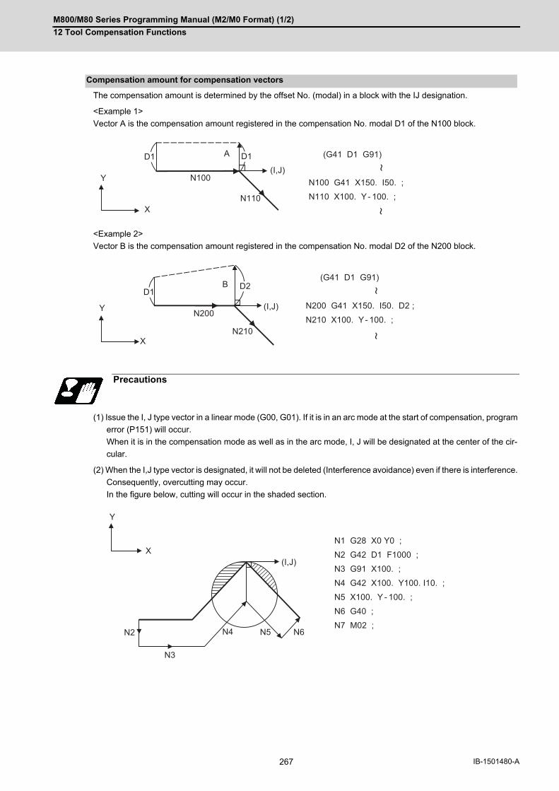
M800/M80 Series Programming Manual (M2/M0 Format) (1/2)
12 Tool Compensation Functions
267 IB-1501480-A
The compensation amount is determined by the offset No. (modal) in a block with the IJ designation.
<Example 1>
Vector A is the compensation amount registered in the compensation No. modal D1 of the N100 block.
<Example 2>
Vector B is the compensation amount registered in the compensation No. modal D2 of the N200 block.
(1) Issue the I, J type vector in a linear mode (G00, G01). If it is in an arc mode at the start of compensation, program
error (P151) will occur.
When it is in the compensation mode as well as in the arc mode, I, J will be designated at the center of the cir-
cular.
(2) When the I,J type vector is designated, it will not be deleted (Interference avoidance) even if there is interference.
Consequently, overcutting may occur.
In the figure below, cutting will occur in the shaded section.
Compensation amount for compensation vectors
Precautions
(G41 D1 G91)
N100 G41 X150. I50. ;
N110 X100. Y- 100. ;X
N110
(I,J)
A
Y N100
D1 D1
(G41 D1 G91)
N200 G41 X150. I50. D2 ;
N210 X100. Y- 100. ;
XN210
(I,J)
B
Y N200
D2
D1
N1 G28 X0 Y0 ;
N2 G42 D1 F1000 ;
N3 G91 X100. ;
N4 G42 X100. Y100. I10. ;
N5 X100. Y - 100. ;
N6 G40 ;
N7 M02 ;
Y
X
N5
(I,J)
N4
N3
N2 N6

M800/M80 Series Programming Manual (M2/M0 Format) (1/2)
12 Tool Compensation Functions
268IB-1501480-A
(3) The vectors differ for the G38 I _J_ (K_) command and the G41/G42 I_J_(K_) command.
(4) Refer to the following table for the compensation methods depend on the presence or absence of G41/G42 com-
mand and I, K, (J) command.
During the I, J type vector compensation, the A insertion block will not exist.
G38 G41/G42
Example :(G41)
:G38 G91 X100. I50. J50. ;
:
:(G41)
:G41 G91 X100. I50. J50. ;
:
Vector in IJ direction having a compensation amount (a) size
Vector perpendicular in IJ direction and having a compensation amount (b) size
G41/42 I, J (K) Compensation methods
No No Intersection point calculation type vector
No Yes Intersection point calculation type vector
Yes No Intersection point calculation type vector
Yes Yes I, J, type vectorNo insertion block
(I J)
(a)(I J)
(b)
Y
XN5
(I,J)
N4
N3
N2
N1
N1 G91 G01 G41 X200. D1 F1000 ;N2 X-150. Y150. ;N3 G41 X300. I50. ;N4 X-150. Y-150. ;N5 G40 X-200. ;
(A)
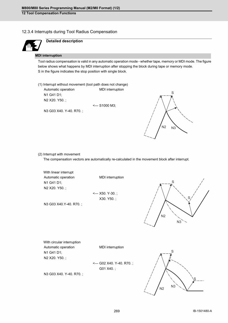
M800/M80 Series Programming Manual (M2/M0 Format) (1/2)
12 Tool Compensation Functions
269 IB-1501480-A
12.3.4 Interrupts during Tool Radius Compensation
Tool radius compensation is valid in any automatic operation mode - whether tape, memory or MDI mode. The figure
below shows what happens by MDI interruption after stopping the block during tape or memory mode.
S in the figure indicates the stop position with single block.
(1) Interrupt without movement (tool path does not change)
(2) Interrupt with movement
The compensation vectors are automatically re-calculated in the movement block after interrupt.
With linear interrupt
With circular interruption
Detailed description
MDI interruption
Automatic operation MDI interruption
N1 G41 D1;
N2 X20. Y50. ;
<--- S1000 M3;
N3 G03 X40. Y-40. R70. ;
Automatic operation MDI interruption
N1 G41 D1;
N2 X20. Y50. ;
<--- X50. Y-30. ;
X30. Y50. ;
N3 G03 X40.Y-40. R70. ;
Automatic operation MDI interruption
N1 G41 D1;
N2 X20. Y50. ;
<--- G02 X40. Y-40. R70. ;
G01 X40. ;
N3 G03 X40. Y-40. R70. ;
N2
S
N3
S
S
N2
N3
S
S
N2N3
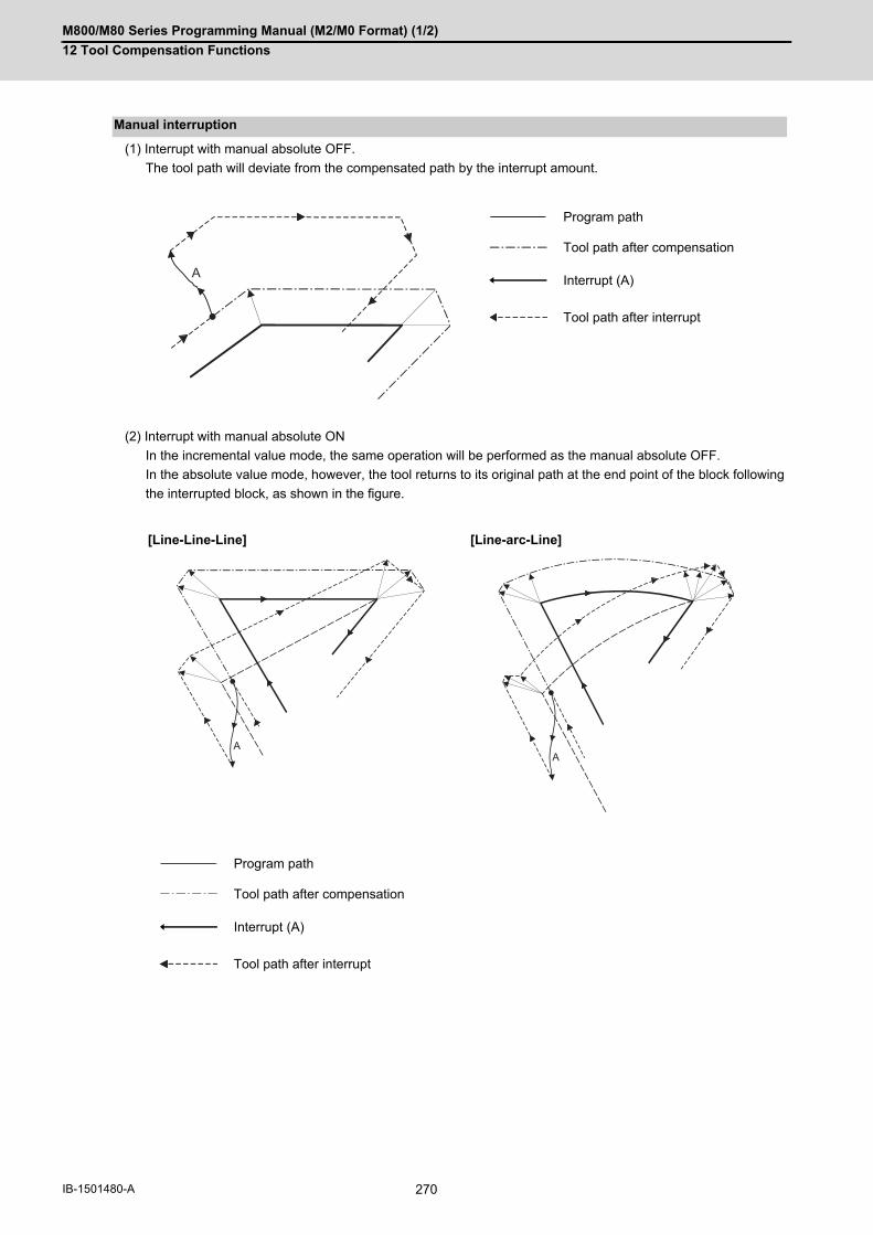
M800/M80 Series Programming Manual (M2/M0 Format) (1/2)
12 Tool Compensation Functions
270IB-1501480-A
(1) Interrupt with manual absolute OFF.
The tool path will deviate from the compensated path by the interrupt amount.
(2) Interrupt with manual absolute ON
In the incremental value mode, the same operation will be performed as the manual absolute OFF.
In the absolute value mode, however, the tool returns to its original path at the end point of the block following
the interrupted block, as shown in the figure.
Manual interruption
Program path
Tool path after compensation
Interrupt (A)
Tool path after interrupt
[Line-Line-Line] [Line-arc-Line]
Program path
Tool path after compensation
Interrupt (A)
Tool path after interrupt
A
AA
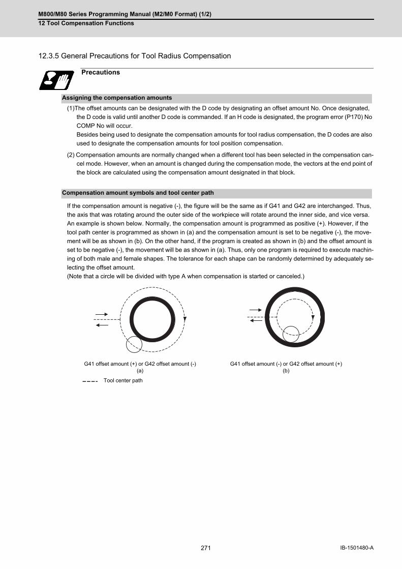
M800/M80 Series Programming Manual (M2/M0 Format) (1/2)
12 Tool Compensation Functions
271 IB-1501480-A
12.3.5 General Precautions for Tool Radius Compensation
(1)The offset amounts can be designated with the D code by designating an offset amount No. Once designated,
the D code is valid until another D code is commanded. If an H code is designated, the program error (P170) No
COMP No will occur.
Besides being used to designate the compensation amounts for tool radius compensation, the D codes are also
used to designate the compensation amounts for tool position compensation.
(2) Compensation amounts are normally changed when a different tool has been selected in the compensation can-
cel mode. However, when an amount is changed during the compensation mode, the vectors at the end point of
the block are calculated using the compensation amount designated in that block.
If the compensation amount is negative (-), the figure will be the same as if G41 and G42 are interchanged. Thus,
the axis that was rotating around the outer side of the workpiece will rotate around the inner side, and vice versa.
An example is shown below. Normally, the compensation amount is programmed as positive (+). However, if the
tool path center is programmed as shown in (a) and the compensation amount is set to be negative (-), the move-
ment will be as shown in (b). On the other hand, if the program is created as shown in (b) and the offset amount is
set to be negative (-), the movement will be as shown in (a). Thus, only one program is required to execute machin-
ing of both male and female shapes. The tolerance for each shape can be randomly determined by adequately se-
lecting the offset amount.
(Note that a circle will be divided with type A when compensation is started or canceled.)
Precautions
Assigning the compensation amounts
Compensation amount symbols and tool center path
G41 offset amount (+) or G42 offset amount (-)(a)
G41 offset amount (-) or G42 offset amount (+)(b)
Tool center path

M800/M80 Series Programming Manual (M2/M0 Format) (1/2)
12 Tool Compensation Functions
272IB-1501480-A
12.3.6 Changing of Compensation No. during Compensation Mode
As a principle, the compensation No. must not be changed during the compensation mode. If changed, the move-
ment will be as shown below.
When compensation No. (compensation amount) is changed:
G41 G01 ........ Dr1 ;
(α = 0,1,2,3)
N101 G0α Xx1 Yy1 ;
N102 G0α Xx2 Yy2 Dr2 ; ................................... Compensation No. changed
N103 Xx3 Yy3 ;
Function and purpose
During linear -> linear
The compensation amount designated with N101 will be applied.
The compensation amount designated with N102 will be applied.
Program path
Tool center path
N101 r2
r2r1
r1N102
N103
r1
r1
r1r1
r2
r2

M800/M80 Series Programming Manual (M2/M0 Format) (1/2)
12 Tool Compensation Functions
273 IB-1501480-A
Linear ->circular
(CP) Arc center
Program path
Tool center path
N101
N102r1
r2
G02r1
N102
N101
G03
r1
r1
r1r1
r2
(CP)
(CP)

M800/M80 Series Programming Manual (M2/M0 Format) (1/2)
12 Tool Compensation Functions
274IB-1501480-A
Circular -> circular
(CP) Arc center
Program path
Tool center path
r1N101
r1 r2
N102
r1r1
r1r1
r2
(CP)
(CP)
(CP)
(CP)

M800/M80 Series Programming Manual (M2/M0 Format) (1/2)
12 Tool Compensation Functions
275 IB-1501480-A
12.3.7 Start of Tool Radius Compensation and Z Axis Cut in Operation
Often when starting cutting, a method of applying a radius compensation (normally the XY plane) beforehand at a
position separated for the workpiece, and then cutting in with the Z axis is often used. When using this method, cre-
ate the program so that the Z axis movement is divided into the two steps of rapid traverse and cutting feed after
nearing the workpiece.
When the following type of program is created:
With this program, at the start of the N1 compensation the program will be read to the N6 block. The relation of N1
and N6 can be judged, and correct compensation can be executed as shown above.
If the above program's N4 block is divided into two
In this case, the four blocks N2 to N5 do not have a command in the XY plane, so when the N1 compensation is
started, the program cannot be read to the N6 block.
As a result, the compensation is done based only on the information in the N1 block, and the compensation vector
is not created at the start of compensation. Thus, an excessive cut in occurs as shown above.
Function and purpose
Program example
N1 G91 G00 G41 X500. Y500. D1 ;N2 S1000 ;N3 M3 ;N4 G01 Z-300. F1 ;N6 Y100. F2 ; : :
N4 Z axis lowers (1 block)
Tool center path
N1 G91 G00 G41 X500. Y500. D1 ;N2 S1000 ;N3 M3 ;N4 Z-250. ;N5 G01 Z-50. F1 ;N6 Y100. F2 ;
(c) Cut in
N1Y
X
N1 Y
Z
N4N6 N6
N4
N1
N1
N4
N5N6
XX
Y Z
N6
(c)

M800/M80 Series Programming Manual (M2/M0 Format) (1/2)
12 Tool Compensation Functions
276IB-1501480-A
In this case, consider the calculation of the inner side, and before the Z axis cutting, issue a command in the same
direction as the direction that the Z axis advances in after lowering, to prevent excessive cutting.
The movement is correctly compensated as the same direction as the N6 advance direction is commanded in N2.
N1 G91 G00 G41 X500. Y400. D1 ;N2 Y100. S1000 ;N3 M3 ;N4 Z-250. ;N5 G01 Z-50. F1 ;N6 Y100. F2 ;
N1 Y
Z
N5
N6
N2
N1
N2
Y
X
N6 N6
N4

M800/M80 Series Programming Manual (M2/M0 Format) (1/2)
12 Tool Compensation Functions
277 IB-1501480-A
12.3.8 Interference Check
When tool radius is larger than the program path, a tool, compensated for by the tool radius compensation function,
may sometimes cut into the workpiece. This is known as interference, and interference check is the function which
prevents this from occurring.
The table below shows the three functions of interference check and each can be selected for use by parameter.
When there is a movement command in three of the five pre-read blocks, and if the compensation calculation vectors
which are created at the contacts of movement commands intersect each other, it will be viewed as interference.
Function and purpose
Function Parameters Operation
#8102 #8103
COLL. ALM OFF COLL. CHK OFF
(1) Interference check alarm function
0 0 Operation stops with a program error (P153) before executing a block which will cause cutting.
(2) Interference check avoidance function
1 0 The tool path is changed to prevent cutting from occurring. If the path cannot be changed, a program error (P153) occurs and the program will be stopped.
(3) Interference check in-valid function
0/1 1 Cutting continues as is, even if the work-piece is cut into. Use in the fine segment program.
Detailed description
Conditions viewed as interference
r : Compensation amount (a) Vectors intersect
Program path
Tool center path
N1 N3
N2
r
(a)
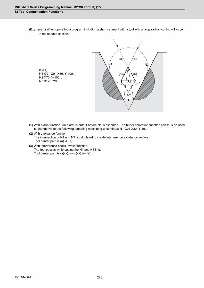
M800/M80 Series Programming Manual (M2/M0 Format) (1/2)
12 Tool Compensation Functions
278IB-1501480-A
(Example 1) When operating a program including a short segment with a tool with a large radius, cutting will occur
in the shaded section.
(1) With alarm function. An alarm is output before N1 is executed. The buffer correction function can thus be usedto change N1 to the following, enabling machining to continue: N1 G01 X20. Y-40.;
(2) With avoidance functionThe intersection of N1 and N3 is calculated to create interference avoidance vectors. Tool center path is (a) -> (e).
(3) With interference check invalid function.The tool passes while cutting the N1 and N3 line. Tool center path is (a)->(b)->(c)->(d)->(e) .
(G41)N1 G91 G01 X50. Y-100. ;N2 X70. Y-100. ;N3 X120. Y0 ;
N1 N3
N2
(a)
(b)
(c)
(d)
(e)

M800/M80 Series Programming Manual (M2/M0 Format) (1/2)
12 Tool Compensation Functions
279 IB-1501480-A
(Example 2) When operating a program including a small circular with a tool with a large radius, cutting occurs near
the start point/end point of the circular in the following figure.
Interference check processing
(1) With alarm functionThe alarm occurs before N1 is executed.
(2) With avoidance functionWith the above process, the vectors (1), (2), (3)' and (4)' will remain as the valid vectors. The tool center pathwill follow the path that connects vectors (1), (2), (3)' and (4)', as the interference avoidance path.
(3) With interference check invalid functionThe tool center path will follow the path that connects (1), (2), (3), (4), (1)', (2)', (3)', (4)', as the interference avoid-ance path while cutting.
Vectors (1) (4)' check -> No interference
↓
Vectors (2) (3)' check -> No interference
↓
Vectors (3) (2)' check -> Interference -> Erase vectors (3) (2)'
↓
Erase vectors (4) (1)'
(Thick broken line path)
(Thin broken line path)
(4)’(2)
(1)
N1
N3
N2
(2)’
(4)(1)’
(3)
(3)’
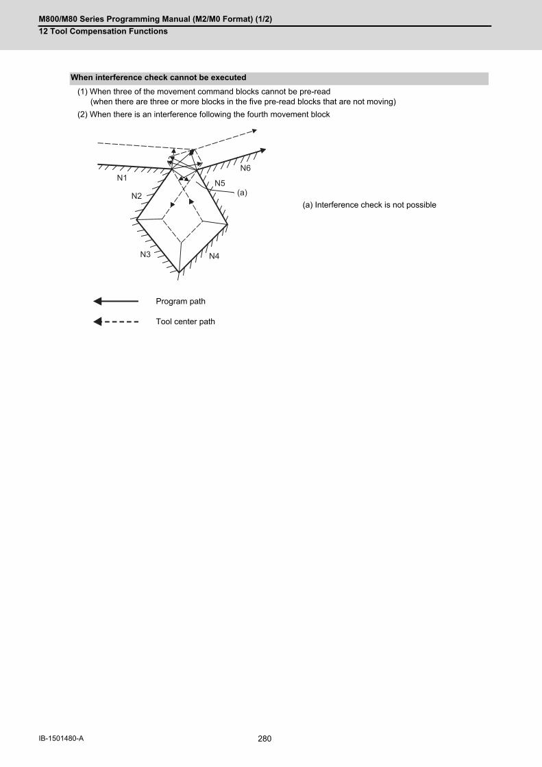
M800/M80 Series Programming Manual (M2/M0 Format) (1/2)
12 Tool Compensation Functions
280IB-1501480-A
(1) When three of the movement command blocks cannot be pre-read(when there are three or more blocks in the five pre-read blocks that are not moving)
(2) When there is an interference following the fourth movement block
When interference check cannot be executed
(a) Interference check is not possible
Program path
Tool center path
N1
N3
N2
N4
N5
N6
(a)

M800/M80 Series Programming Manual (M2/M0 Format) (1/2)
12 Tool Compensation Functions
281 IB-1501480-A
The movement will be as shown below when the interference avoidance check is valid.
Operation when interference avoidance function is valid
(a) Program path (b) Tool center path
Program path
Tool center path without interference check
Tool center path when interference is avoided (*: Linear movement)
Valid vector
Invalid vector
N1 N3
N2
(b)(a)
N1
N3N2
N1
N3N2
r
r (CP)
*

M800/M80 Series Programming Manual (M2/M0 Format) (1/2)
12 Tool Compensation Functions
282IB-1501480-A
If all of the line vectors for the interference avoidance are deleted, create a new avoidance vector as shown in below
to avoid the interference.
In the case of the figure below, the groove will be left uncut.
Tool center path (*1)
Program path
Tool center path 2 (*1)
Tool center path 1 (*1)
Program path
(a) Avoidance vector
(*1) Tool center path when interference is avoided
Program path
Tool center path without interference check
Tool center path when interference is avoided
N1
N3
N2
N1
N3
N2
r1
N4
r2
r1r2
(a)2
(a)1
(a)
(a)
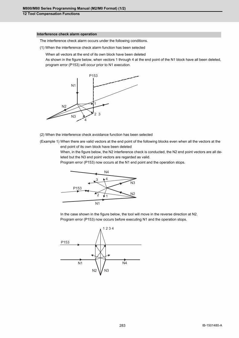
M800/M80 Series Programming Manual (M2/M0 Format) (1/2)
12 Tool Compensation Functions
283 IB-1501480-A
The interference check alarm occurs under the following conditions.
(1) When the interference check alarm function has been selected
When all vectors at the end of its own block have been deleted
As shown in the figure below, when vectors 1 through 4 at the end point of the N1 block have all been deleted,
program error (P153) will occur prior to N1 execution.
(2) When the interference check avoidance function has been selected
(Example 1) When there are valid vectors at the end point of the following blocks even when all the vectors at the
end point of its own block have been deleted
When, in the figure below, the N2 interference check is conducted, the N2 end point vectors are all de-
leted but the N3 end point vectors are regarded as valid.
Program error (P153) now occurs at the N1 end point and the operation stops.
In the case shown in the figure below, the tool will move in the reverse direction at N2.
Program error (P153) now occurs before executing N1 and the operation stops.
Interference check alarm operation
N1
P153
2 3
N21
N34
N1
2 N21
N343
N4
P153
N1
P153
N2 N3
N4
1 2 3 4

M800/M80 Series Programming Manual (M2/M0 Format) (1/2)
12 Tool Compensation Functions
284IB-1501480-A
(Example 2) When avoidance vectors cannot be created
Even when, as in the figure below, the conditions for creating the avoidance vectors are satisfied, it may
still be impossible to create avoidance vectors, or the interference vectors may interfere with N3.
Program error (P153) will occur at the N1 end point when the vector intersecting angle is more than 90°
and the operation will stop.
(Example 3) When the program advance direction and the advance direction after compensation are reversed
When grooves that are narrower than the tool diameter with parallel or widening bottom are pro-
grammed, it will still be regarded as interference even if there is actually no interference.
N1
N2
N3
N4
P153
N1
N2
N3
N4
P153
P153

M800/M80 Series Programming Manual (M2/M0 Format) (1/2)
12 Tool Compensation Functions
285 IB-1501480-A
(Example 4) When vectors at the end point of the block immediately before the command to eliminate compensation
vectors temporarily cause an interference
Interference check will be executed also at the end point of the block immediately before the command
to eliminate compensation vectors temporarily, similarly with the case compensation vectors are not
eliminated. It may be regarded as an interference even if there is actually no interference. If regarded
as an interference, program error (P153) will occur.
In the figure below, only vector 1 is left as an end point vector in N2 because of the N3 G53 command
to temporarily eliminate compensation vectors. However, the interference check will still be conducted
to vector 1 to 4 and an interference will be detected.
Program error (P153) now occurs at the end point of the previous block and the operation stops.
Program path
Tool center path
Tool center path when the interference check is invalid
Tool center path when the interference check is invalid in N3 due to a command (G01 etc.) not to eliminate compensation vectors.
Valid vector
Invalid vector (Invalid, however, subject to interference check)
N1(G01)
N2(G03)
N3(G53)
1
2
3 4
P153

M800/M80 Series Programming Manual (M2/M0 Format) (1/2)
12 Tool Compensation Functions
286IB-1501480-A
When starting compensation operation, the tool center path is determined with the movement command of the same
block as G41/G42 and the next movement command. The interference check is not executed at that time. To check
interference, set the parameter "#1241 set13/bit1" (MTB specifications). Note that an alarm is output and the oper-
ation is stopped even when the collision avoidance setting "#8102 COLL. ALM OFF" is set to "1" and that the inter-
ference avoidance is not applied.
Interference check for start-up block
(a) Interference check for start-up block invalid (b) Interference check for start-up block valid
"#1241 set13/bit1" = "0" or "#8103 COLL. CHK OFF" = "1"
"#1241 set13/bit1" = "1" and "#8103 COLL. CHK OFF" = "0"
Tool center path Alarm stop
The interference with the compensation calculation vec-tor of the contact between the N2 block and N3 block is not checked. Doing so will cause a cut in the N3 block.
The interference with the compensation calculation vec-tor of the contact between the N2 block and N3 block is checked, and this is judged to be an alarm.
N1(G41 G01)
N2(G01)
N3(G01)
N1(G41 G01)
N2(G01)
N3(G01)

M800/M80 Series Programming Manual (M2/M0 Format) (1/2)
12 Tool Compensation Functions
287 IB-1501480-A
12.3.9 Diameter Designation of Compensation Amount
With this function, the tool radius compensation amount can be designated by tool diameter. When the control pa-
rameter "#8117 OFS Diam DESIGN" is ON, the compensation amount specified to the commanded tool No. will be
recognized as the diameter compensation amount, and the amount will be converted to the radius compensation
amount when executing the compensation.
When the tool radius compensation amount D=10.0 is commanded, tool radius compensation amount "d" is 5.0 if
the parameter "#8117" is ON (set to "1").
(Tool radius compensation amount "r" is 10.0 if the parameter "#8117" is OFF (set to "0").)
(1) Linear -> linear corner (acute angle)
Function and purpose
Operation example
Operations when designating the compensation amount with diameter
Outside of the corner Inside of the corner
Program path
Tool center path (When #8117 is ON)
Tool center path (When #8117 is OFF)
rd
2020
ds
r
d
r
d r
d
r
s

M800/M80 Series Programming Manual (M2/M0 Format) (1/2)
12 Tool Compensation Functions
288IB-1501480-A
(2) Linear -> arc (obtuse angle)
(3) Arc -> linear (obtuse angle)
(1) If tool radius compensation amount has already been set, the compensation amount is not be changed even if
the parameter "8117" is changed.
(2) Make sure not to change the parameter #8117 during the compensation. When the parameter is changed using
parameter input by program function, the program error (P421) will occur.
(3) If the parameter #8117 is set to ON with the parameter "#1037 cmdtyp" set to “2”, the tool radius wear data is
also regarded as the diameter compensation amount, thus, it will be converted to the radius value and compen-
sation will be performed.
(4) Diameter designation of tool radius compensation amount can be used for the tool life management data.
(5) There is no effect by #8117 on the tool radius measurement function.
Outside of the corner Inside of the corner
Outside of the corner Inside of the corner
Program path
Tool center path (When #8117 is ON)
Tool center path (When #8117 is OFF)
(CP) Arc center
Restrictions
s
d
r
(CP)
r
s
d
(CP)
d
sr
(CP)
d s
r
d
r
(CP)

M800/M80 Series Programming Manual (M2/M0 Format) (1/2)
12 Tool Compensation Functions
289 IB-1501480-A
12.3.10 Workpiece Coordinate Changing during Radius Compensation
When the tool radius compensation is executed, the tool center path is calculated based on the position on the co-
ordinate system. The based coordinate system is different depending on setting of the parameter "#1246/bit2 Switch
coordinate systems for radius compensation". (This depends on the MTB specifications.)
When the parameter is "0", the tool radius compensation is calculated based on the position on the workpiece co-
ordinate system.
When the parameter is "1", the tool radius compensation is calculated based on the position on the program coor-
dinate system.
The program coordinate systems are defined as shown in the figure below.
Function and purpose
Detailed description
(R1) 1st reference position
(a) 1st reference position offset
(b) Interrupt amount offset
(c) Extended workpiece coordinate system offset
(d) G92 offset
(e) Workpiece coordinate system offset
(f) Local coordinate system offset
(g) G53 Basic machine coordinate system
(h) Program coordinate system
(i) G54 to G59/G54.1Pn Workpiece coordinate system/Extended workpiece coordinate system
(j) G52Local coordinate system
(b)
(c)
(e)
(f)
(a)
(h)
(R1)
(i)
(j)
(g)
(d)

M800/M80 Series Programming Manual (M2/M0 Format) (1/2)
12 Tool Compensation Functions
290IB-1501480-A
The coordinate system changed by parameter is as follows.
D3 =5.000
G54 offset
X15.000
Y15.000
G90 G54 G00 X15. Y20.;
N1 G41 D3 X5. Y10. ;
N2 G01; Y-20 F1000;
N3 G40 X20. ;
M30 ;
(1) Parameter = 0
(2) Parameter = 1
Program path (a) Compensation vector
Tool center path (b) Program coordinate system
G54
10.0
5.0
- 20.0
20.0
G53
N2
N3
N1
(a)
(b)
G54
N2
N3
N1
25.0
- 5.0
20.0 35.0
G53
(a)
(b)
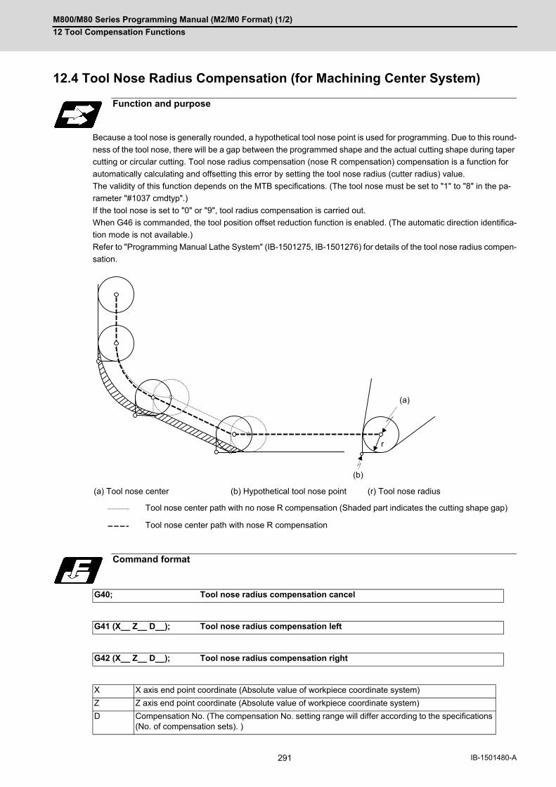
M800/M80 Series Programming Manual (M2/M0 Format) (1/2)
12 Tool Compensation Functions
291 IB-1501480-A
12.4 Tool Nose Radius Compensation (for Machining Center System)
Because a tool nose is generally rounded, a hypothetical tool nose point is used for programming. Due to this round-
ness of the tool nose, there will be a gap between the programmed shape and the actual cutting shape during taper
cutting or circular cutting. Tool nose radius compensation (nose R compensation) compensation is a function for
automatically calculating and offsetting this error by setting the tool nose radius (cutter radius) value.
The validity of this function depends on the MTB specifications. (The tool nose must be set to "1" to "8" in the pa-
rameter "#1037 cmdtyp".)
If the tool nose is set to "0" or "9", tool radius compensation is carried out.
When G46 is commanded, the tool position offset reduction function is enabled. (The automatic direction identifica-
tion mode is not available.)
Refer to "Programming Manual Lathe System" (IB-1501275, IB-1501276) for details of the tool nose radius compen-
sation.
Function and purpose
(a) Tool nose center (b) Hypothetical tool nose point (r) Tool nose radius
Tool nose center path with no nose R compensation (Shaded part indicates the cutting shape gap)
Tool nose center path with nose R compensation
Command format
G40; Tool nose radius compensation cancel
G41 (X__ Z__ D__); Tool nose radius compensation left
G42 (X__ Z__ D__); Tool nose radius compensation right
X X axis end point coordinate (Absolute value of workpiece coordinate system)
Z Z axis end point coordinate (Absolute value of workpiece coordinate system)
D Compensation No. (The compensation No. setting range will differ according to the specifications (No. of compensation sets). )
(a)
(b)
r
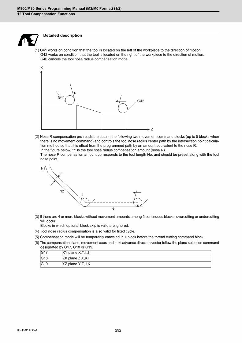
M800/M80 Series Programming Manual (M2/M0 Format) (1/2)
12 Tool Compensation Functions
292IB-1501480-A
(1) G41 works on condition that the tool is located on the left of the workpiece to the direction of motion. G42 works on condition that the tool is located on the right of the workpiece to the direction of motion. G40 cancels the tool nose radius compensation mode.
(2) Nose R compensation pre-reads the data in the following two movement command blocks (up to 5 blocks whenthere is no movement command) and controls the tool nose radius center path by the intersection point calcula-tion method so that it is offset from the programmed path by an amount equivalent to the nose R. In the figure below, "r" is the tool nose radius compensation amount (nose R). The nose R compensation amount corresponds to the tool length No. and should be preset along with the toolnose point.
(3) If there are 4 or more blocks without movement amounts among 5 continuous blocks, overcutting or undercuttingwill occur. Blocks in which optional block skip is valid are ignored.
(4) Tool nose radius compensation is also valid for fixed cycle.
(5) Compensation mode will be temporarily canceled in 1 block before the thread cutting command block.
(6) The compensation plane, movement axes and next advance direction vector follow the plane selection commanddesignated by G17, G18 or G19.
Detailed description
G17 XY plane X,Y,I,J
G18 ZX plane Z,X,K,I
G19 YZ plane Y,Z,J,K
G42
X
Z
G41
N1
N2
N3
r

M800/M80 Series Programming Manual (M2/M0 Format) (1/2)
12 Tool Compensation Functions
293 IB-1501480-A
(1) For nose radius compensation for machining center system, the compensation amount should always be spec-ified with radius value.
(2) Compensation amounts are normally changed when a different tool has been selected in the compensation can-cel mode. However, when an amount is changed during the compensation mode, the vectors at the end point ofthe block are calculated using the compensation amount designated in that block.
(1) The criterion to execute the outer rounding at the small corner in tool radius compensation depends on the MTBspecifications (parameter "#1289 ext25/bit0").
(1) There two methods to set the tool nose point for machining center system. (This depends on the MTB specifica-tions.)Set a value in the system variable #23000+n ("n" corresponds to the compensation number) using the ma-
chining program.Set the parameter "#1046 T-ofs disp type" to change the compensation type to III, then, set a value in the
tool compensation amount screen.
(1) An error will occur when any of the following commands is programmed during tool nose radius compensation. G17, G18, G19 (when a plane different from the one used during the compensation is commanded (P112))G31 (P608)G74,G75,G76 (P155)G81 to G89(P155)
(2) A program error will occur when a circular command is issued in the first or last block of the tool nose radiuscompensation. (P151)
(3) A program error will occur during tool nose radius compensation when the intersection point of single block skipin the interference block processing cannot be calculated. (P152)
(4) A program error will occur when there is an error in one of the pre-read blocks during tool nose radius compen-sation.
(5) A program error will occur when an interference occurs under no interference avoidance conditions during toolnose radius compensation. (P153)
(6) A program error will occur when a tool nose radius compensation command is issued even though the tool noseradius compensation specification is not provided. (P150)
(7) If a tool nose radius compensation command is issued in mirror image, a program error will occur. (P803)
Precautions
Assigning the compensation amounts
Corner judgment method
Designating the tool nose point
Errors during tool nose radius compensation

M800/M80 Series Programming Manual (M2/M0 Format) (1/2)
12 Tool Compensation Functions
294IB-1501480-A
12.5 3-dimensional Tool Radius Compensation; G40/G41, G42
The 3-dimentional tool radius compensation compensates for the tool in a 3-dimensional space following the com-
manded three-dimensional vectors.
As shown above, the tool is moved in the tool center coordinate position (x', y', z') (d) which is compensated for by
the tool radius "r" (c) in respect to the program coordinate position (x, y, z) (b) following the plane normal line vector
(I, J, K) (a).
Though two-dimensional tool radius compensation creates the vectors at a right angle to the (I, J, K) direction, three-
dimensional tool radius compensation creates the vector in the (I, J, K) direction. (The vector is created at the end
point of the block.)
The three-dimensional compensation vector (compensation) (e) axis elements are as below.
Thus, the tool center coordinate position (x', y', z') (d) is each expressed as below. Note that (x, y, z) are the
program coordinate position.
(1) Three-dimensional compensation vector (Hx, Hy, Hz) refers to the plane normal line vector whose direction issame as the plane normal line vector (I, J, K ) and the size equals to the tool radius "r".
(2) When the machining parameter "#8071 3-D CMP" is set to a value other than "0", the value of
"#8071 3-D CMP" will be used as the value. (Refer to the s Setup Manual for details.)
Function and purpose
(x', y', z')
Y (J)X (I)
Z (K)
(x, y, z)
(I, J, K)
(b)
(c)
(a)(d)
(e)
IHx = r
( I2 + J
2 + K
2)
JH Y = r
( I2 + J
2 + K
2)
KHZ = r
( I2 + J
2 + K
2)
x’ = x + Hx
y’ = y + Hy
z’ = z + Hz
Note
( I2 + J 2 + K 2 )

M800/M80 Series Programming Manual (M2/M0 Format) (1/2)
12 Tool Compensation Functions
295 IB-1501480-A
Command, for all three axes, the compensation No. D and plane normal line vector (I, J, K) in the same block as the
three-dimensional tool radius compensation command G41 (G42).
If only one or two axes are commanded, the normal tool radius compensation mode will be applied. (When the com-
mand value for I, J, K is set to "0", this command is valid.)
Command format
3-dimensional tool radius compensation start
G41(G42) X__ Y__ Z__ I__ J__ K__ D__ ;
New plane normal line vector is commanded in the compensation mode.
X__ Y__ Z__ I__ J__ K__;
3-dimentional tool radius compensation cancel
G40; (or D00;)
G40 X__ Y__ Z__; (or X__ Y__ Z__ D00;)
G41 Three-dimensional tool radius compensation command (+ direction)
G42 Three-dimensional tool radius compensation command (- direction)
G40 Three-dimensional tool radius compensation cancel command
X, Y, Z Movement axis command compensation space
I, J, K Plane normal line vector
D Compensation No.(Note that when "D00" is issued, three dimensional tool radius compensation will be canceled even if G40 is not commanded.)
G Code Compensation amount: D00
+ -
G40 Cancel Cancel Cancel
G41 I, J, K direction Reverse direction of I, J, K Cancel
G42 Reverse direction of I, J, K I, J, K direction Cancel
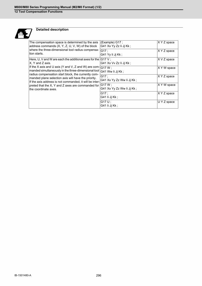
M800/M80 Series Programming Manual (M2/M0 Format) (1/2)
12 Tool Compensation Functions
296IB-1501480-A
Detailed description
The compensation space is determined by the axis address commands (X, Y, Z, U, V, W) of the block where the three-dimensional tool radius compensa-tion starts.
(Example) G17 ;G41 Xx Yy Zz Ii Jj Kk ;
X Y Z space
G17 ;G41 Yy Ii Jj Kk ;
X Y Z space
Here, U, V and W are each the additional axes for the X, Y and Z axis. If the X axis and U axis (Y and V, Z and W) are com-manded simultaneously in the three-dimensional tool radius compensation start block, the currently com-manded plane selection axis will have the priority. If the axis address is not commanded, it will be inter-preted that the X, Y and Z axes are commanded for the coordinate axes.
G17 V ;G41 Xx Vv Zz Ii Jj Kk ;
X V Z space
G17 W ;G41 Ww Ii Jj Kk ;
X Y W space
G17 ;G41 Xx Yy Zz Ww Ii Jj Kk ;
X Y Z space
G17 W ;G41 Xx Yy Zz Ww Ii Jj Kk ;
X Y W space
G17 ;G41 Ii Jj Kk ;
X Y Z space
G17 U ;G41 Ii Jj Kk ;
U Y Z space

M800/M80 Series Programming Manual (M2/M0 Format) (1/2)
12 Tool Compensation Functions
297 IB-1501480-A
Operation example
Compensation start (1) When there is a movement command
(S) Start point
Tool center path
Programmed path
Three-dimensional compensation vec-tor
Compensation start : When there is no movement command
(S) Start point
Tool center path
Three-dimensional compensation vec-tor
Movement during the compensation (3) When there is a movement command and a plane normal line vector command
(S) Start point
(a) Old vector
(b) New vector
Tool center path
Programmed path
Movement during the compensation (4) When there is no plane normal line vector command
(S) Start point
(a) Old vector
(b) New vector
Tool center path
Programmed path
G41 Xx Yy Zz Ii Jj Kk Dd ;
(S)
G41 Ii Jj Kk Dd ;
(S)
Xx Yy Zz Ii Jj Kk ;
(a)
(b)
(S)
Xx Yy Zz Ii Jj Kk ;
(a)
(S)
(b)

M800/M80 Series Programming Manual (M2/M0 Format) (1/2)
12 Tool Compensation Functions
298IB-1501480-A
The I, J, K commands for a circular or helical cutting are regarded as the circular center commands, thus, the new
vector is equivalent to the old vector.
Even for the R-designation method, commanded I, J, K addresses will be ignored, then the new vector will be equiv-
alent to the old vector.
G02 Xx Yy (Zz) Ii Jj ; I, J(K) means the circular center
Or
G02 Xx Yy (Zz) Rr ; R-designated arc
(1) The center coordinate will not shift during the circular or helical cutting. Thus, when I, J, K are commanded withthe vector as below, the program error (P70) will occur.
G02 Xx Yy (Zz) Ii Jj ; I, J(K) means the circular center
Or
G02 Xx Yy (Zz) Rr ; R-designated arc
(1) If I, J, K are not commanded in a block where the compensation amount is to be changed, the vector will beequivalent to the old vector. In this case, the modal will change, however, the compensation amount will changewhen I, J, K are commanded.
Movement during the compensation (5) For arc or helical cutting
(S) Start point
(a) Old vector
(b) New vector
Tool center path
Programmed path
(S) Start point
(a) Old vector
(b) New vector
(CP) Arc center
Tool center path
Programmed path
Movement during the tool radius compensation (6) When compensation amount is to be changed
(S) Start point
(a) Old vector
(b) New vector
Tool center path
Programmed path
(a) (b)
(S)
Note
(b)(a)
r
(CP)
r
(S)
G41 Xx Yy Zz Ii Jj Kk Dd1 ;
G41 Xx Yy Zz Ii Jj Kk Dd2 ;
(b)
(S)
(a)
Note

M800/M80 Series Programming Manual (M2/M0 Format) (1/2)
12 Tool Compensation Functions
299 IB-1501480-A
(1) If I, J and K are not commanded in a block where the compensation direction is to be changed, the vector will beequivalent to the old vector and the compensation direction will not be changed. In this case, the modal willchange, however, the compensation direction will change when I, J and K are commanded.
(2) If the compensation direction is changed in an arc (G02/G03) block, I, J will be the center of the arc, thus, thecompensation direction will not change. Even for the R-designation method, commanded I, J and K will be ignored, and the compensation direction can-not be changed.
G40 Xx Yy Zz ; (or Xx Yy Zz D00 ;)
G40; (or D00;)
Movement during the tool radius compensation (7) When compensation direction is to be changed
(S) Start point
(a) Old vector
(b) New vector
Tool center path
Programmed path
Movement during the tool radius compensation : When there is a movement command
(S) Start point
(E) End point
(a) Old vector
Tool center path
Programmed path
Tool radius compensation cancel: When there is no movement command
(a) Old vector
Tool center path
Programmed path
G41 Xx Yy Zz Ii Jj Kk Dd1 ;
G42 Xx Yy Zz Ii Jj Kk ; (b)
(a)
(S)
Note
(S)
(a)
(E)
(a)
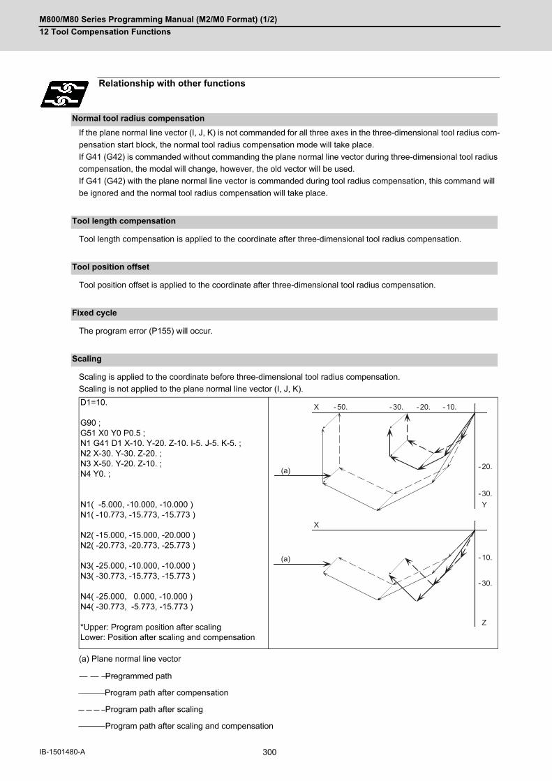
M800/M80 Series Programming Manual (M2/M0 Format) (1/2)
12 Tool Compensation Functions
300IB-1501480-A
If the plane normal line vector (I, J, K) is not commanded for all three axes in the three-dimensional tool radius com-
pensation start block, the normal tool radius compensation mode will take place.
If G41 (G42) is commanded without commanding the plane normal line vector during three-dimensional tool radius
compensation, the modal will change, however, the old vector will be used.
If G41 (G42) with the plane normal line vector is commanded during tool radius compensation, this command will
be ignored and the normal tool radius compensation will take place.
Tool length compensation is applied to the coordinate after three-dimensional tool radius compensation.
Tool position offset is applied to the coordinate after three-dimensional tool radius compensation.
The program error (P155) will occur.
Scaling is applied to the coordinate before three-dimensional tool radius compensation.
Scaling is not applied to the plane normal line vector (I, J, K).
(a) Plane normal line vector
Programmed path
Program path after compensation
Program path after scaling
Program path after scaling and compensation
Relationship with other functions
Normal tool radius compensation
Tool length compensation
Tool position offset
Fixed cycle
Scaling
D1=10. G90 ;G51 X0 Y0 P0.5 ;N1 G41 D1 X-10. Y-20. Z-10. I-5. J-5. K-5. ;N2 X-30. Y-30. Z-20. ;N3 X-50. Y-20. Z-10. ;N4 Y0. ; N1( -5.000, -10.000, -10.000 )N1( -10.773, -15.773, -15.773 ) N2( -15.000, -15.000, -20.000 )N2( -20.773, -20.773, -25.773 ) N3( -25.000, -10.000, -10.000 )N3( -30.773, -15.773, -15.773 ) N4( -25.000, 0.000, -10.000 )N4( -30.773, -5.773, -15.773 ) *Upper: Program position after scalingLower: Position after scaling and compensation
X
X - 50.
(a)
(a)
- 30. - 20.
- 20.
- 30.
- 10.
- 30.
Y
Z
- 10.
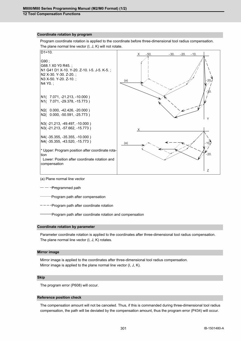
M800/M80 Series Programming Manual (M2/M0 Format) (1/2)
12 Tool Compensation Functions
301 IB-1501480-A
Program coordinate rotation is applied to the coordinate before three-dimensional tool radius compensation.
The plane normal line vector (I, J, K) will not rotate.
(a) Plane normal line vector
Programmed path
Program path after compensation
Program path after coordinate rotation
Program path after coordinate rotation and compensation
Parameter coordinate rotation is applied to the coordinates after three-dimensional tool radius compensation.
The plane normal line vector (I, J, K) rotates.
Mirror image is applied to the coordinates after three-dimensional tool radius compensation.
Mirror image is applied to the plane normal line vector (I, J, K).
The program error (P608) will occur.
The compensation amount will not be canceled. Thus, if this is commanded during three-dimensional tool radius
compensation, the path will be deviated by the compensation amount, thus the program error (P434) will occur.
Coordinate rotation by program
D1=10. G90 ;G68.1 X0 Y0 R45. ;N1 G41 D1 X-10. Y-20. Z-10. I-5. J-5. K-5. ;N2 X-30. Y-30. Z-20. ;N3 X-50. Y-20. Z-10. ;N4 Y0. ; N1( 7.071, -21.213, -10.000 )N1( 7.071, -29.378, -15.773 ) N2( 0.000, -42.426, -20.000 )N2( 0.000, -50.591, -25.773 ) N3( -21.213, -49.497, -10.000 )N3( -21.213, -57.662, -15.773 ) N4( -35.355, -35.355, -10.000 )N4( -35.355, -43.520, -15.773 ) * Upper: Program position after coordinate rota-tion Lower: Position after coordinate rotation and compensation
Coordinate rotation by parameter
Mirror image
Skip
Reference position check
- 20.
- 30.
- 10.
- 20.
X
Y
Z
X
- 50.
(a)
(a)
- 30. - 20. - 10.

M800/M80 Series Programming Manual (M2/M0 Format) (1/2)
12 Tool Compensation Functions
302IB-1501480-A
Automatic corner override is invalid during three-dimensional tool radius compensation.
(1) For the absolute command, all axes will be temporarily canceled at the commanded coordinate position.
Programmed path
Program path after compensation
(2) For the incremental command, the axis will move by the amount obtained by subtracting each axis vector fromthe incremental movement amount. (The compensation amount is temporarily canceled.)
Programmed path
Program path after compensation
Automatic corner override
Machine coordinate system selection
D1=10. G90 ;N1 G41 D1 X-10. Y-20. Z-10. I-5. J-5. K-5. ;N2 X-30. Y-30. Z-20. ;N3 X-50. Y-20. Z-10. ;N4 G53 Y0 ; N1( -10.000, -20.000, -10.000 )N1( -15.773, -25.773, -15.773 ) N2( -30.000, -30.000, -20.000 )N2( -35.773, -35.773, -25.773 ) N3( -50.000, -20.000, -10.000 )N3( -55.773, -25.773, -15.773 ) N4( -50.000, 0.000, -10.000 )N4( -50.000, 0.000, -10.000 ) * Upper: Program position Lower: Program position after compensation
D1=10. G91 ;N1 G41 D1 X-10. Y-20. Z-10. I-5. J-5. K-5. ;N2 X-20. Y-10. Z-10. ;N3 X-20. Y10. Z10. ;N4 G90 G53 Y0.; N1( -10.000, -20.000, -10.000 )N1( -15.773, -25.773, -15.773 ) N2( -30.000, -30.000, -20.000 )N2( -35.773, -35.773, -25.773 ) N3( -50.000, -20.000, -10.000 )N3( -55.773, -25.773, -15.773 ) N4( -50.000, 0.000, -10.000 )N4( -50.000, 0.000, -10.000 ) * Upper: Program position Lower: Program position after compensation
X - 50. - 30. - 20. - 10.
X
- 20.
- 30.
Y
- 10.
- 20.
Z
X
X
Y
Z
- 50. - 30. - 20. - 10.
- 30.
- 20.
- 10.
- 20.

M800/M80 Series Programming Manual (M2/M0 Format) (1/2)
12 Tool Compensation Functions
303 IB-1501480-A
When commanded in the same block as the coordinate system setting, the coordinate system will be set, and op-
eration will start up independently with the plane normal line vector (I, J, K).
Programmed path
Program path after compensation
Coordinate system setting
D1=10. G91 ;N1 G92 G41 D1 X-10. Y-20. Z-10. I-5. J-5. K-5. ;N2 X-20. Y-10. Z-10. ;N3 X-30. Y-10. Z10. ;N4 Y20. ; N1( -10.000, -20.000, -10.000 )N1( -10.000, -20.000, -10.000 ) N2( -30.000, -30.000, -20.000 )N2( -35.773, -35.773, -25.773 ) N3( -50.000, -20.000, -10.000 )N3( -55.773, -25.773, -15.773 ) N4( -50.000, 0.000, -10.000 )N4( -55.773, -5.773, -15.773 ) * Upper: Program position Lower: Program position after compensation
- 20.G92
- 30.
Y
- 10.
- 20.
Z
X
X
- 50. - 30. - 20. - 10. W(0,0)
W(0,0)
G92
G92G92
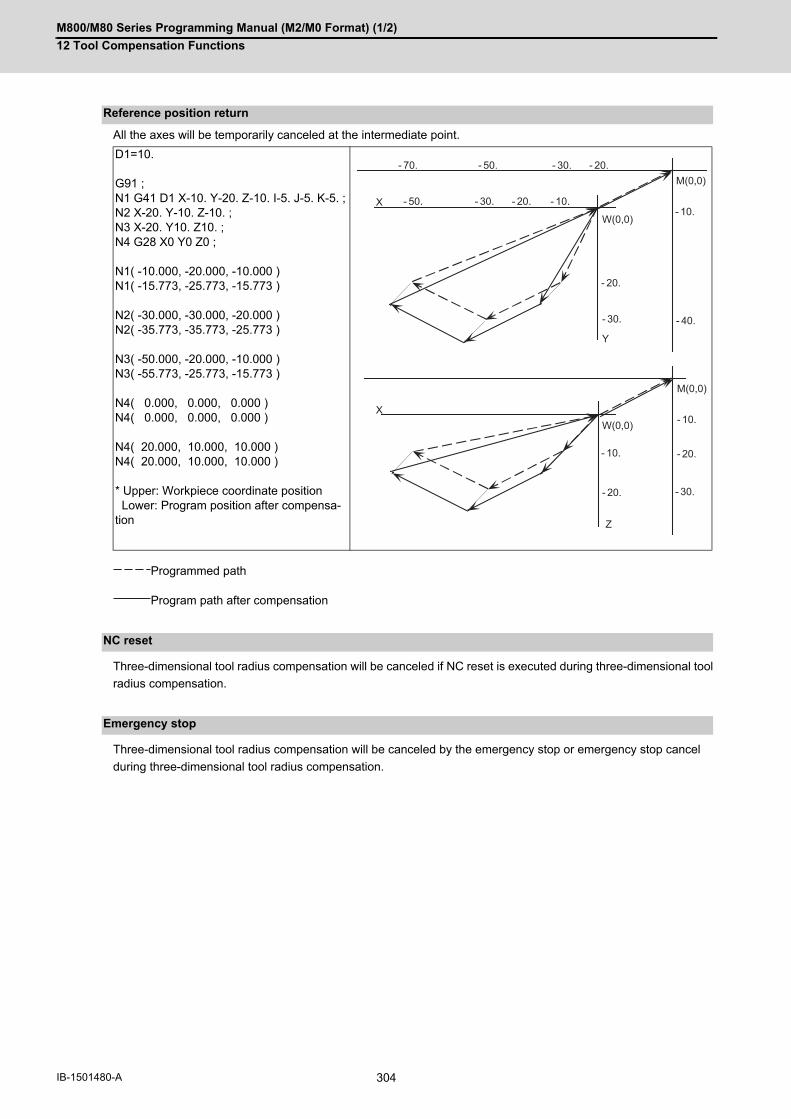
M800/M80 Series Programming Manual (M2/M0 Format) (1/2)
12 Tool Compensation Functions
304IB-1501480-A
All the axes will be temporarily canceled at the intermediate point.
Programmed path
Program path after compensation
Three-dimensional tool radius compensation will be canceled if NC reset is executed during three-dimensional tool
radius compensation.
Three-dimensional tool radius compensation will be canceled by the emergency stop or emergency stop cancel
during three-dimensional tool radius compensation.
Reference position return
D1=10. G91 ;N1 G41 D1 X-10. Y-20. Z-10. I-5. J-5. K-5. ;N2 X-20. Y-10. Z-10. ;N3 X-20. Y10. Z10. ;N4 G28 X0 Y0 Z0 ; N1( -10.000, -20.000, -10.000 )N1( -15.773, -25.773, -15.773 ) N2( -30.000, -30.000, -20.000 )N2( -35.773, -35.773, -25.773 ) N3( -50.000, -20.000, -10.000 )N3( -55.773, -25.773, -15.773 ) N4( 0.000, 0.000, 0.000 )N4( 0.000, 0.000, 0.000 ) N4( 20.000, 10.000, 10.000 )N4( 20.000, 10.000, 10.000 ) * Upper: Workpiece coordinate position Lower: Program position after compensa-tion
NC reset
Emergency stop
X
X
Z
- 30. - 20. - 10.
- 40.
- 20.
- 10.
- 30.
W(0,0)
M(0,0)
- 10.
Y
- 30.
- 20.
M(0,0)
W(0,0)
- 20.
- 10.
- 50.
- 30. - 20.- 70. - 50.
M800/M80 Series Programming Manual (M2/M0 Format) (1/2)
12 Tool Compensation Functions
305 IB-1501480-A
(1) The compensation No. is selected with the D address, however, the D address is valid only when G41 or G42 iscommanded. If D is not commanded, the number of the previous D address will be valid.
(2) Switch the mode to the compensation mode in the G00 or G01 mode. When changed during the arc mode, theprogram error (P150) will occur. The compensation direction and compensation amount after the mode change will become valid from the blockwhere I, J and K are commanded in the G00 or G01 mode. If three-dimensional tool radius compensation is com-manded in a block not containing the plane normal line vector (I, J, K) during the arc mode, only the modal infor-mation will be changed. The plane normal line vector will be validated from the block where I, J and K are commanded next.
(3) During the 3-dimensional tool radius compensation mode in a certain space, it is not possible to switch the spaceto another one and to execute three-dimensional tool radius compensation. To switch the compensation space,always cancel the compensation mode with G40 or D00 first. (Example)
(4) If the compensation No. D is other than the range of 1 to 40 with the standard specifications or 1 to 800 (max.)with the additional specifications, the program error (P170) will occur.
(5) Only the G40 and D00 commands can be used to cancel 3-dimensional tool radius compensation.
(6) If the size (I2+J2+K2) of the vector commanded with I, J and K overflows, the program error (P35) will occur.
Restrictions
G41 Xx Yy Zz Ii Jj Kk ; Compensation starts in X, Y, Z space.
: :
: :
G41 Uu Yy Zz Ii Jj Kk ; Compensation is carried out in X, Y, Z space, and U axis moves by commanded value.

M800/M80 Series Programming Manual (M2/M0 Format) (1/2)
12 Tool Compensation Functions
306IB-1501480-A
12.6 Tool Position Offset; G45 to G48
Using the G45 to G46 commands, the movement distance of the axes specified in the same block can be extended
or reduced by a preset compensation length.
Furthermore, the compensation amount can be similarly doubled (x 2 expansion) or halved (x 2 reduction) with com-
mands G47 and G48.
The number of sets for the compensation differ according to machine specification. Refer to Specifications Manual.
D01 to Dn
(The numbers given are the total number of sets for tool length compensation, tool position compensation and
tool radius compensation.)
Function and purpose
Start point End point
G45 command
Expansion by compensa-tion amount only
Internal arithmetic processing
Movement amount
G46 command
Reduction by compensa-tion amount only
Internal arithmetic processing
Movement amount
G47 command
2 expansion by compen-sation amount
Internal arithmetic processing
Movement amount
G48 command
2 reduction by compensa-tion amount
Internal arithmetic processing
Movement amount
(Program command value) (compensation amount) (Movement amount after compen-sation)
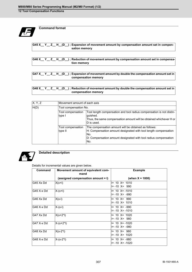
M800/M80 Series Programming Manual (M2/M0 Format) (1/2)
12 Tool Compensation Functions
307 IB-1501480-A
Details for incremental values are given below.
Command format
G45 X__ Y__ Z__ H__(D__) ; Expansion of movement amount by compensation amount set in compen-sation memory
G46 X__ Y__ Z__ H__(D__) ; Reduction of movement amount by compensation amount set in compensa-tion memory
G47 X__ Y__ Z__ H__(D__) ; Expansion of movement amount by double the compensation amount set in compensation memory
G48 X__ Y__ Z__ H__(D__) ; Reduction of movement amount by double the compensation amount set in compensation memory
X, Y, Z Movement amount of each axis
H(D) Tool compensation No.
Tool compensation type I
Tool length compensation and tool radius compensation is not distin-guished. Thus, the same compensation amount will be obtained whichever H or D is used.
Tool compensation type II
The compensation amount will be obtained as follows: H: Compensation amount designated with tool length compensation No.D: Compensation amount designated with tool radius compensation No.
Detailed description
Command Movement amount of equivalent com-mand
Example
(assigned compensation amount = l) (when X = 1000)
G45 Xx Dd X(x+l) l= 10 X= 1010l= -10 X= 990
G45 X-x Dd X-(x+l) l= 10 X= -1010l= -10 X= -990
G46 Xx Dd X(x-l) l= 10 X= 990l= -10 X= 1010
G46 X-x Dd X-(x-l) l= 10 X= -990l= -10 X= -1010
G47 Xx Dd X(x+2*l) l= 10 X= 1020l= -10 X= 980
G47 X-x Dd X-(x+2*l) l= 10 X= -1020l= -10 X= -980
G48 Xx Dd X(x-2*l) l= 10 X= 980l= -10 X= 1020
G48 X-x Dd X-(x-2*l) l= 10 X= -980l= -10 X= -1020

M800/M80 Series Programming Manual (M2/M0 Format) (1/2)
12 Tool Compensation Functions
308IB-1501480-A
Tool position compensation with 1/4 arc command
It is assumed that compensation has already been provided in the + X direction by D01 = 200.
Even if the compensation numbers are not assigned in the same block as the G45 to G48 commands, compensation
is provided with the tool position compensation number previously stored in the memory.
If the commanded compensation No. exceeds the specification range, the program error (P170) will occur.
These G codes are unmodal and are effective only in the command block.
Even with an absolute value command, the amount of the movement is extended or reduced for each axis with re-
spect to the direction of movement from the end point of the preceding block to the position assigned by the G45 to
G48 block.
In other words, even for an absolute value command, compensation can be applied to movement amounts (incre-
mental values) in the same block.
When a command for "n" number of simultaneous axes is given, the same compensation will be applied to all axes.
It is valid even for the additional axes. (but it must be within the range of the number of axes that can be controlled
simultaneously.)
Program example
(Example 1)
(S) Start point
(E) End point
(CP) Programmed arc center
Tool
Programmed pathTool center path
G91 G45 G03 X -1000 Y1000 I -1000 F1000 D01 ;
G01 G45 X220. Y60. D20 ;(D20) = +50. 000
End point after compensation
Programmed end point
(S) Start point
Y
X
(E)
(S)
1000
1000
200
(CP)
X(S)
Y
60.50.
50.
110.
220. 270.

M800/M80 Series Programming Manual (M2/M0 Format) (1/2)
12 Tool Compensation Functions
309 IB-1501480-A
(1) If compensation is applied to two axes, over-cutting or under-cutting will result, as shown in the figures below. Incases like this, use the cutter compensation commands (G40 to G42).
G01 G45 Xx 1 Dd1 ; Xx2 Yy 2 ;G45 Yy3 ;
G01 Xx1 ;G45 Xx2 Yy2 Dd 2 ;Yy3 ;
Programmed path Tool center path
Workpiece
Undercutting (figure above) or overcutting (figure below)
l = Compensation amount setting
Note
l
Y
X
lY
X
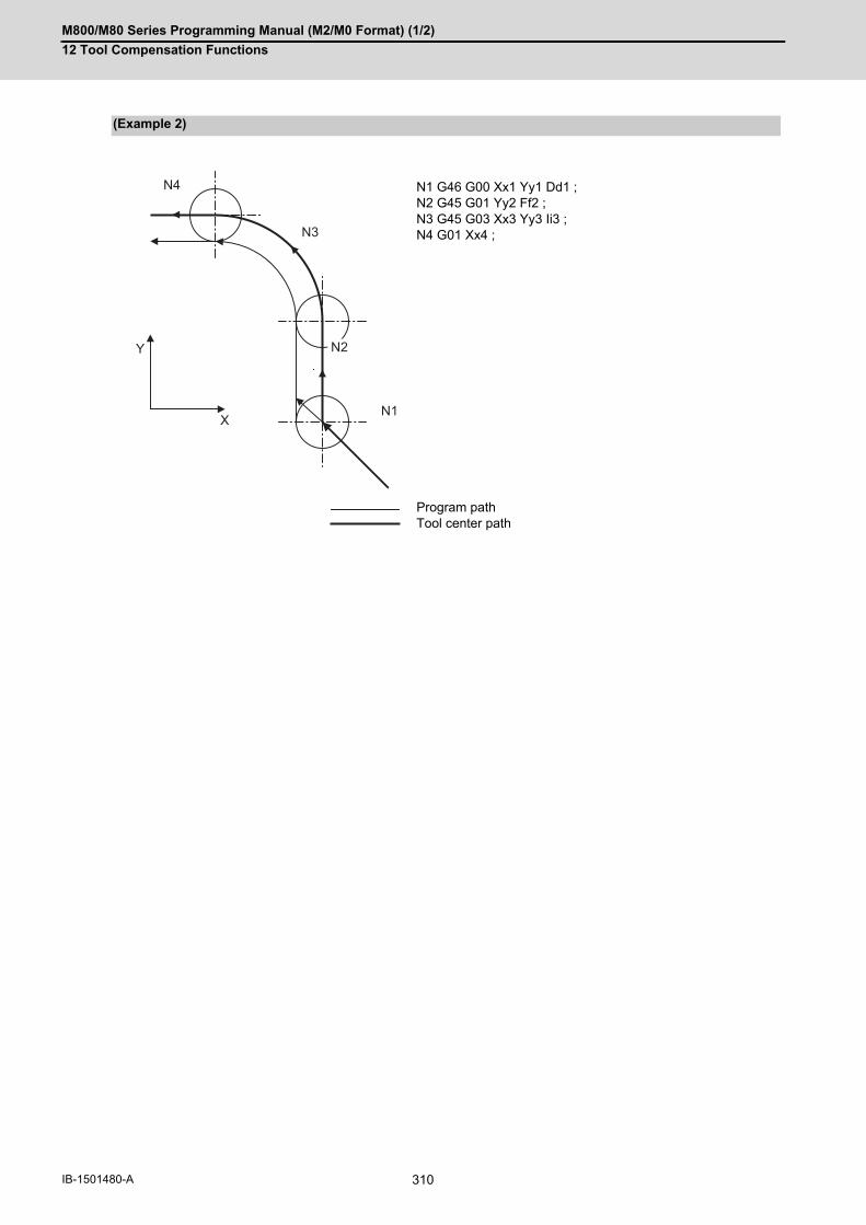
M800/M80 Series Programming Manual (M2/M0 Format) (1/2)
12 Tool Compensation Functions
310IB-1501480-A
(Example 2)
N1 G46 G00 Xx1 Yy1 Dd1 ;N2 G45 G01 Yy2 Ff2 ;N3 G45 G03 Xx3 Yy3 Ii3 ;N4 G01 Xx4 ;
Program pathTool center path
N4
N3
Y
XN1
N2

M800/M80 Series Programming Manual (M2/M0 Format) (1/2)
12 Tool Compensation Functions
311 IB-1501480-A
When the G45 to G48 command is assigned, the compensation amount for each pass is the amount assigned by
the compensation number, and the tool does not move for the difference from the previous compensation as it would
do with the tool length compensation command (G43).
Compensation amount D01 = 10.000mm (Compensation amount of tool radius)
(Example 3)
(S) Start point
(a) Programmed path (b) Tool center path
N100 G91 G46 G00 X40.0 Y40.0 D01 ;
N101 G45 G01 X100.0 F200 ;
N102 G45 G03 X10.0 Y10.0 J10.0 ;
N103 G45 G01 Y40.0 ;
N104 G46 X0 ;
N105 G46 G02 X-20.0 Y20.0 J20.0 ;
N106 G45 G01 Y0 ;
N107 G47 X-30.0 ;
N108 Y-30.0 ;
N109 G48 X-30.0 ;
N110 Y30.0 ;
N111 G45 X-30.0 ;
N112 G45 G03 X-10.0 Y-10.0 J-10.0 ;
N113 G45 G01 Y-20.0 ;
N114 X10.0 ;
N115 Y-40.0 ;
N116 G46 X-40.0 Y-40.0 ;
N117 M02 ;
%
4030
N101
10
N102
30
30
30
40
40
10
N100
N105N108N110
N103
N115
N114
N116
N113N109
N112
N104
N106
N107
20R
10R
10R
N111
(b)(a)
(S)

M800/M80 Series Programming Manual (M2/M0 Format) (1/2)
12 Tool Compensation Functions
312IB-1501480-A
(1) These commands should be used when operation is not in a fixed cycle mode. (They are ignored even if they are assigned during a fixed cycle.)
(2) As a result of the internal arithmetic processing based on the expansion or reduction, the tool will proceed tomove in the opposite direction when the command direction is reversed.
(3) When a zero movement amount has been specified in the incremental value command (G91) mode, the resultis as follows.
When a zero movement amount has been specified with an absolute value command, the operation is completed
immediately and the tool does not move for the compensation amount.
Precautions
Program command G48 X20.000 D01 ;
Compensation Compensation amount = +15.000
Tool movement Actual movement = X - 10.000
(S) Start point
(E) End point
Compensation No. : D01
Compensation amount corresponding to D01 : 1234
NC command G45 X0 D01 ; G45 X-0 D01 ; G46 X0 D01 ; G46 X-0 D01;
Equivalent command X1234; X -1234 ; X -1234 ; X1234;
(S)
(E)

M800/M80 Series Programming Manual (M2/M0 Format) (1/2)
12 Tool Compensation Functions
313 IB-1501480-A
(4) In the case of circular interpolation, tool radius compensation is possible by the G45 to G48 commands only forone quadrant, two quadrants (semi sphere) or three quadrants when the start and end points are on the axis.
The commands are assigned as follows depending on whether the compensation is applied for outside or inside
the arc programmed path.
However, in this case, compensation must already be provided in the desired direction at the arc start point. (If
a compensation command is assigned for the arc independently, the arc start point and end point radius will shift
by an amount equivalent to the compensation amount.)
The program path is indicated by the heavy line in the figure.
1/4 circle
G45 for compensation outside the circleG46 for compensation inside the circle
Program pathCompensated path
1/2 circle
G47 for compensation outside the circleG48 for compensation inside the circle
Program pathCompensated path
3/4 circle
G45 for compensation outside the circleG46 for compensation inside the circle
Program pathCompensated path
G46
G45
G48
G47
G46
G45

M800/M80 Series Programming Manual (M2/M0 Format) (1/2)
12 Tool Compensation Functions
314IB-1501480-A

13
315 IB-1501480-A
Fixed Cycle

M800/M80 Series Programming Manual (M2/M0 Format) (1/2)
13 Fixed Cycle
316IB-1501480-A
13Fixed Cycle13.1 Fixed Cycles
These fixed cycles are used to perform prepared sequences of machining programs, such as positioning, hole drill-
ing, boring and tapping in one block. The available machining sequences are listed in the table below.
By editing the standard fixed cycle subprograms, the fixed cycle sequences can be changed by the user. The user
can also register and edit an original fixed cycle program. For the standard fixed cycle subprograms, refer to the list
of the fixed cycle subprograms in the appendix of the operation manual. The list of fixed cycle functions for this con-
trol unit is shown below.
A fixed cycle mode can be canceled by G80 command and other hole machining modes or G command in the 01
group. At the same time, various other data will also be cleared to zero.
Function and purpose
G code Hole drilling start Operation at hole bottom
Return opera-tion
Retract at high
speed
Application
(-Z direction) Dwell Spindle (+Z direction)
G80 - - - - - Cancel
G81 Cutting feed - - Rapid traverse Possible Drill, spot drilling cycle
G82 Cutting feed Yes - Rapid traverse - Drill, counter boring cycle
G83 Intermittent feed - - Rapid traverse Possible Deep Hole Drilling Cycle
G84 Cutting feed Yes Reverse rotation
Cutting feed - Tapping cycle
G85 Cutting feed - - Cutting feed - Boring cycle
G86 Cutting feed Yes Stop Rapid traverse - Boring cycle
G87 Rapid traverse - Forward rotation
Cutting feed - Back boring cycle
G88 Cutting feed Yes Stop Rapid traverse - Boring cycle
G89 Cutting feed Yes - Cutting feed - Boring cycle
G73 Intermittent feed Yes - Rapid traverse Possible Stepping cycle
G74 Cutting feed Yes Forward rotation
Cutting feed - Reverse tapping cycle
G75 Cutting feed - - Rapid traverse - Circular cutting cycle
G76 Cutting feed - Oriented spindle
stop
Rapid traverse - Fine boring cycle
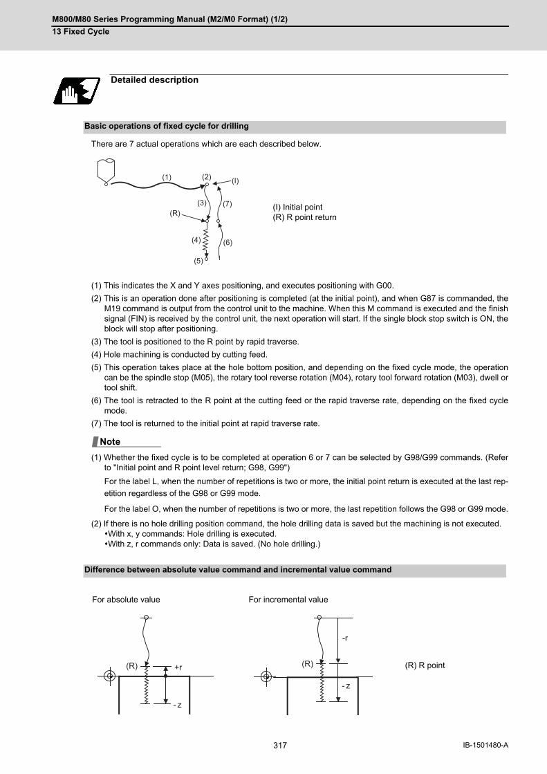
M800/M80 Series Programming Manual (M2/M0 Format) (1/2)
13 Fixed Cycle
317 IB-1501480-A
There are 7 actual operations which are each described below.
(1) This indicates the X and Y axes positioning, and executes positioning with G00.
(2) This is an operation done after positioning is completed (at the initial point), and when G87 is commanded, theM19 command is output from the control unit to the machine. When this M command is executed and the finishsignal (FIN) is received by the control unit, the next operation will start. If the single block stop switch is ON, theblock will stop after positioning.
(3) The tool is positioned to the R point by rapid traverse.
(4) Hole machining is conducted by cutting feed.
(5) This operation takes place at the hole bottom position, and depending on the fixed cycle mode, the operationcan be the spindle stop (M05), the rotary tool reverse rotation (M04), rotary tool forward rotation (M03), dwell ortool shift.
(6) The tool is retracted to the R point at the cutting feed or the rapid traverse rate, depending on the fixed cyclemode.
(7) The tool is returned to the initial point at rapid traverse rate.
(1) Whether the fixed cycle is to be completed at operation 6 or 7 can be selected by G98/G99 commands. (Referto "Initial point and R point level return; G98, G99")
For the label L, when the number of repetitions is two or more, the initial point return is executed at the last rep-
etition regardless of the G98 or G99 mode.
For the label O, when the number of repetitions is two or more, the last repetition follows the G98 or G99 mode.
(2) If there is no hole drilling position command, the hole drilling data is saved but the machining is not executed.With x, y commands: Hole drilling is executed.With z, r commands only: Data is saved. (No hole drilling.)
Detailed description
Basic operations of fixed cycle for drilling
(I) Initial point(R) R point return
Difference between absolute value command and incremental value command
For absolute value For incremental value
(R) R point
(2)
(4)
(3)
(5)
(6)
(7)(R)
(I)(1)
Note
+r
- z
(R)
-r
- z
(R)

M800/M80 Series Programming Manual (M2/M0 Format) (1/2)
13 Fixed Cycle
318IB-1501480-A
The fixed cycle has basic control elements for the positioning plane and hole drilling axis. The positioning plane is
determined by the G17, G18 and G19 plane selection commands, and the hole drilling axis is the axis perpendicular
(X, Y, Z or their parallel axis) to the above plane.
Xp, Yp and Zp indicate the basic axes X, Y and Z or an axis parallel to the basic axis.
An arbitrary axis other than the hole drilling axis can be commanded for positioning.
The hole drilling axis is determined by the axis address of the hole drilling axis commanded in the same block as
G81 to G89, G73, G74 or G76. The basic axis will be the hole drilling axis if there is no designation.
(Example 1) When G17 (X-Y plane) is selected, and the axis parallel to the Z axis is set as the W axis.
(1) The hole drilling axis can be fixed to the Z axis with parameter #1080 Dril_Z.
(2) Changeover of the hole drilling axis must be done with the fixed cycle canceled.
In the following explanations on the movement in each fixed cycle mode, the XY plane is used for the positioning
plane and the Z axis for the hole drilling axis. Note that all command values will be incremental values, the position-
ing plane will be the XY plane and the hole drilling axis will be the Z axis.
This commands the in-position width for commanding the fixed cycle from the machining program. The commanded
in-position width is valid only in the eight fixed cycles; G81 (drill, spot drill), G82 (drill, counter boring), G83 (deep
drill cycle), G84 (tap cycle), G85 (boring), G89 (boring), G73 (step cycle) and G74 (reverse tap cycle). The ", I" ad-
dress is commanded in respect to the positioning axis, and the ",J" address is commanded in respect to the drilling
axis.
Positioning plane and hole drilling axis
Plane selection Positioning plane Hole drilling axis
G17 (X-Y) Xp-Yp Zp
G18 (Z-X) Zp-Xp Yp
G19 (Y-Z) Yp-Zp Xp
G81 .... Z_ ; The Z axis is used as the hole drilling axis.
G81 .... W_ ; The W axis is used as the hole drilling axis.
G81 .... ; (No Z or W) The Z axis is used as the hole drilling axis.
Programmable in-position width command in fixed cycle
Address Meaning of address Command range (unit) Remarks
,I Positioning axis in-position width(position error amount)
0.001 to 999.999 (mm) If a value exceeding the command range is commanded, a program er-ror (P35) will occur.
,J Drilling axis in-position width(position error amount)
Note

M800/M80 Series Programming Manual (M2/M0 Format) (1/2)
13 Fixed Cycle
319 IB-1501480-A
When L (number of repetitions) is designated twice or more times in the fixed cycle, the commanded in-position
width will be valid in the repetition block (5) to (8) below.
:
G91 G81 X-50. Z-50. R-50. L2 F2000 ,I0.2 ,J0.3;
:
In the following machining program, the commanded in-position width is valid for the Fig. 2 block. In the (B) block,
the in-position width (, I) commanded regarding to positioning in the previous block (A) is invalid (5). However, when
returning from the hole bottom, the in-position width (, J) commanded in the previous block (A) is valid (8).
To validate the in-position width for positioning, command again as shown in block (C) (9).
In-position check in fixed cycle
Operation pattern ,I ,J
(1) Valid -
(2) - Invalid
(3) - Invalid
(4) - Valid
(5) Valid -
(6) - Invalid
(7) - Invalid
Fig. 1 Operation when number of repetitions L is designated (8) - Valid
:
G91 G81 X-50. Z-50. R-50. F2000 ,I0.2 ,J0.3 ; (A)
X-10. ; . (B)
X-10.,I0.2 ; (C)
Operation pattern ,I ,J
(1) Valid -
(2) - Invalid
(3) - Invalid
(4) - Valid
(5) Invalid -
(6) - Invalid
(7) - Invalid
(8) - Valid
(9) Valid -
(10) - Invalid
(11) - Invalid
Fig. 2 Operation in fixed cycle modal (12) - Valid
(6)
(5)(1)
(8)(7)
(4)
(3)
(2)
- 10.
- 10. - 50.
(6)
(5)(1)
(8)
(7)
(4)
(3)
(2)
(9)
(11)
(10)
(12)

M800/M80 Series Programming Manual (M2/M0 Format) (1/2)
13 Fixed Cycle
320IB-1501480-A
13.1.1 Drilling, Spot Drilling; G81
[Label L]
[Label O]
The operation stops at after the (1), (2) and (4) commands during single block operation.
Command format
G81 Xx1 Yy1 Zz1 Rr1 Ff1 Ll1(Hh1),Ii1,Jj1;
G81 Xx1 Yy1 Zz1 Rr1 Ff1 Pp1,Ii1,Jj1;
Xx1 Designation of hole drilling position (absolute value or incremental value)
Yy1 Designation of hole drilling position (absolute value or incremental value)
Zz1 Designation of hole bottom position (absolute value or incremental value) (modal)
Rr1 Designation of R point position (absolute value or incremental value) (modal)
Ff1 Designation of feedrate for cutting feed (modal)
Ll1(Hh1)(Label L)Pp1(Label O)
Designation of number of repetitions. (0 to 9999)
When ″0″ is set, no execution
,Ii1 Positioning axis in-position width
,Jj1 Drilling axis in-position width
Detailed description
Operation pattern i1 j1 Program
(1) Valid - G00 Xx1 Yy1
(2) - Invalid G00 Zr1
(3) - Invalid G01 Zz1 Ff1
(4) - Valid G98 mode G00 Z-(z1+r1)G99 mode G00 Z-z1
G98 G99
(1)
(2)
(3) (4)
x1 , y1
z1 (4)
r 1

M800/M80 Series Programming Manual (M2/M0 Format) (1/2)
13 Fixed Cycle
321 IB-1501480-A
13.1.2 Drilling, Counter Boring; G82
[Label L]
[Label O]
The operation stops at after the (1), (2) and (5) commands during single block operation.
Command format
G82 Xx1 Yy1 Zz1 Rr1 Ff1 Ee1(Pp1) Ll1(Hh1) ,Ii1 ,Jj1;
G82 Xx1 Yy1 Zz1 Rr1 Ff1 Ee1 Pp1 ,Ii1 ,Jj1;
Xx1 Designation of hole drilling position (absolute value or incremental value)
Yy1 Designation of hole drilling position (absolute value or incremental value)
Zz1 Designation of hole bottom position (absolute value or incremental value) (modal)
Rr1 Designation of R point position (absolute value or incremental value) (modal)
Ff1 Designation of feedrate for cutting feed (modal)
Ee1(Pp1)(Label L)Ee1(Label O)
Designation of dwell time at hole bottom position (modal)
Ll1(Hh1)(Label L)Pp1(Label O)
Designation of number of repetitions (0 to 9999)
When ″0″ is set, processing is not executed.
,Ii1 Positioning axis in-position width
,Jj1 Drilling axis in-position width
Detailed description
Operation pattern i1 j1 Program
(1) Valid - G00 Xx1 Yy1
(2) - Invalid G00 Zr1
(3) - Invalid G01 Zz1 Ff1
(4) - - G04 Ee1 (Dwell)
(5) - Valid G98 mode G00 Z-(z1+r1)G99 mode G00 Z-z1
G98 G99
(1)
(2)
(3)
(4)
x1 , y1
z1 (5)
r 1
(5)
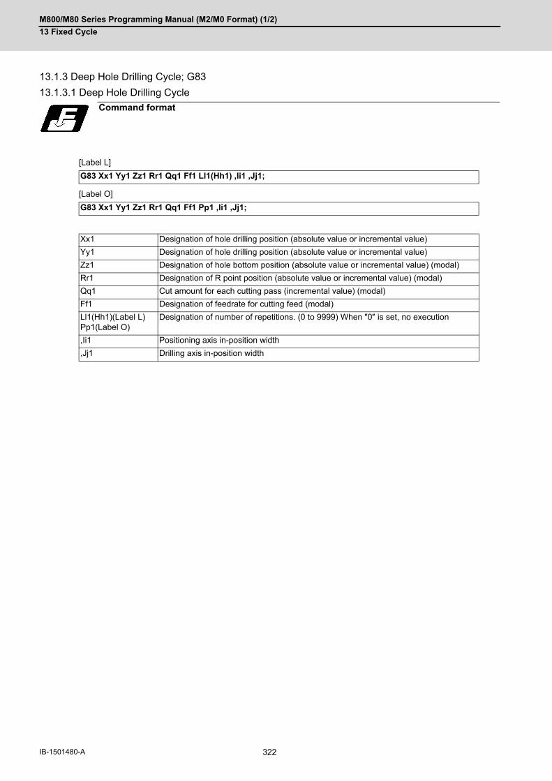
M800/M80 Series Programming Manual (M2/M0 Format) (1/2)
13 Fixed Cycle
322IB-1501480-A
13.1.3 Deep Hole Drilling Cycle; G83
13.1.3.1 Deep Hole Drilling Cycle
[Label L]
[Label O]
Command format
G83 Xx1 Yy1 Zz1 Rr1 Qq1 Ff1 Ll1(Hh1) ,Ii1 ,Jj1;
G83 Xx1 Yy1 Zz1 Rr1 Qq1 Ff1 Pp1 ,Ii1 ,Jj1;
Xx1 Designation of hole drilling position (absolute value or incremental value)
Yy1 Designation of hole drilling position (absolute value or incremental value)
Zz1 Designation of hole bottom position (absolute value or incremental value) (modal)
Rr1 Designation of R point position (absolute value or incremental value) (modal)
Qq1 Cut amount for each cutting pass (incremental value) (modal)
Ff1 Designation of feedrate for cutting feed (modal)
Ll1(Hh1)(Label L)Pp1(Label O)
Designation of number of repetitions. (0 to 9999) When ″0″ is set, no execution
,Ii1 Positioning axis in-position width
,Jj1 Drilling axis in-position width

M800/M80 Series Programming Manual (M2/M0 Format) (1/2)
13 Fixed Cycle
323 IB-1501480-A
When executing a second and following cuttings in the G83 as shown above, the movement will change from rapid
traverse to cutting feed "m" mm before the position machined last. After reaching the hole bottom, the axis will return
according to the G98 or G99 mode.
"m" will differ according to the parameter "#8013 G83 return". Program so that q1 > m.
The operation stops at after the (1), (2) and (n) commands during single block operation.
Detailed description
Operation pat-tern
i1 j1 Program
(1) Valid - G00 Xx1 Yy1
(2) - Invalid G00 Zr1
(3) - Invalid G01 Zq1 Ff1
(4) - Invalid G00 Z-q1
(5) - Invalid G00 Z(q1-m)
(6) - Invalid G01 Z(q1+m) Ff1
(7) - Invalid G00 Z-2*q1
(8) - Invalid G00 Z(2*q1-m)
(9) - Invalid G01 Z(q1+m) Ff1
(10) - Invalid G00 Z-3*q1
:
(n)-1 - Invalid
(n) - Valid G98 mode G00 Z-(z1+r1)G99 mode G00 Z-z1
(1)
(2)
(3) (4) (5)
(6)
(7) (8)
(9)
(10)
(n) (n)
G98 G99
(n) -1
x1,y1
q1
q1
q1
r 1
z1
m
m
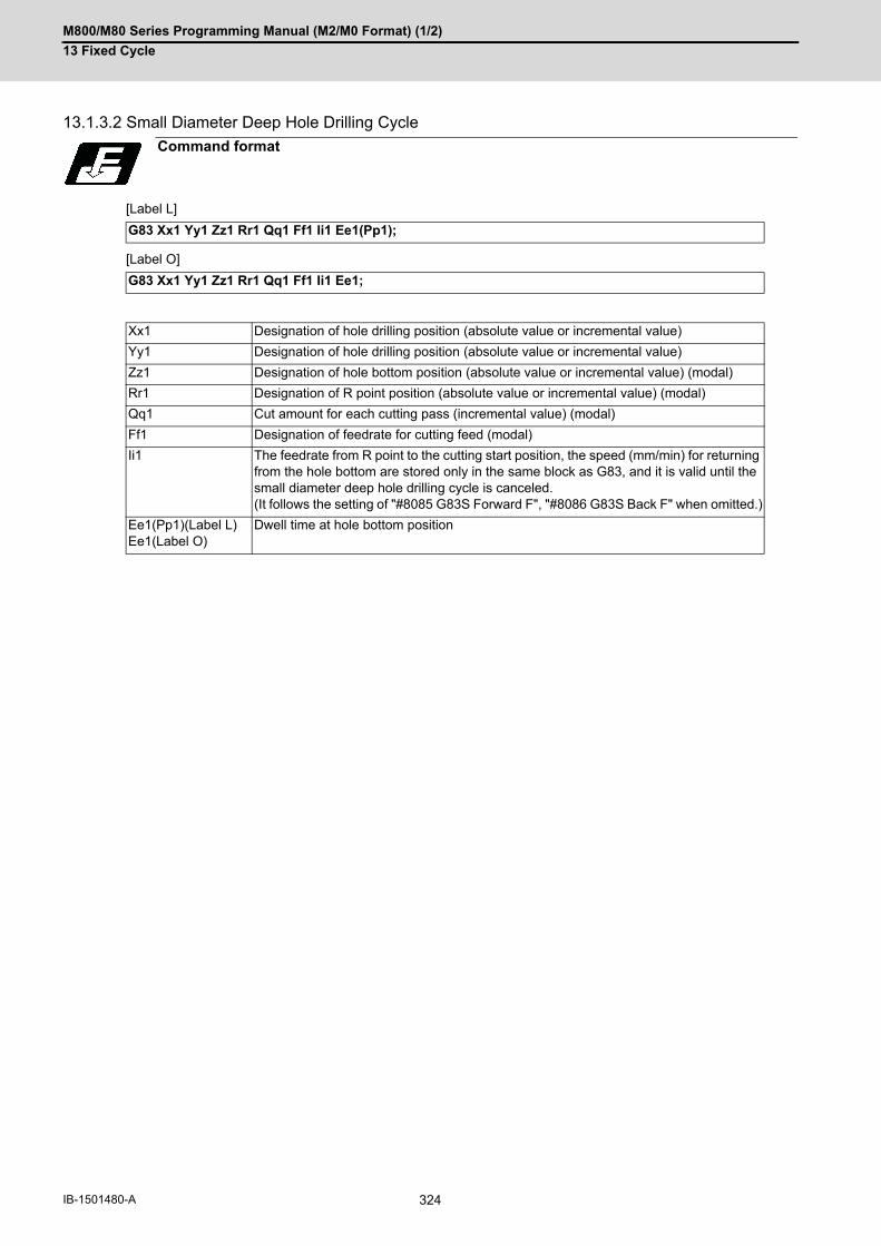
M800/M80 Series Programming Manual (M2/M0 Format) (1/2)
13 Fixed Cycle
324IB-1501480-A
13.1.3.2 Small Diameter Deep Hole Drilling Cycle
[Label L]
[Label O]
Command format
G83 Xx1 Yy1 Zz1 Rr1 Qq1 Ff1 Ii1 Ee1(Pp1);
G83 Xx1 Yy1 Zz1 Rr1 Qq1 Ff1 Ii1 Ee1;
Xx1 Designation of hole drilling position (absolute value or incremental value)
Yy1 Designation of hole drilling position (absolute value or incremental value)
Zz1 Designation of hole bottom position (absolute value or incremental value) (modal)
Rr1 Designation of R point position (absolute value or incremental value) (modal)
Qq1 Cut amount for each cutting pass (incremental value) (modal)
Ff1 Designation of feedrate for cutting feed (modal)
Ii1 The feedrate from R point to the cutting start position, the speed (mm/min) for returning from the hole bottom are stored only in the same block as G83, and it is valid until the small diameter deep hole drilling cycle is canceled. (It follows the setting of "#8085 G83S Forward F", "#8086 G83S Back F" when omitted.)
Ee1(Pp1)(Label L)Ee1(Label O)
Dwell time at hole bottom position

M800/M80 Series Programming Manual (M2/M0 Format) (1/2)
13 Fixed Cycle
325 IB-1501480-A
"i1" follows the parameter "#8085 G83S Forward F" when there is no I command.
"i2" follows the parameter "#8086 G83S Back F" when there is no I command.
Detailed description
c: Parameter "#8084 G83S Clearance"
qs: Small diameter deep hole drilling cycle signal (YCCA) cut amount when inputting
skip: Small diameter deep hole drilling cycle signal (YCCA) input
Operation pat-tern
Program
(1) G00 Xx1 Yy1,Ii1
(2) G00 Zr1
(3) G01 Zq1 Ff1
(4) G01 Z-q1 Fi2
(5) G01 Z(q1-c) Fi1
(6) G01 Z(q1+c) Ff1
(7) G01 Z-2•q1 Fi2
(8) G01 Z(2•q1-c) Fi1
(9) G01 Z(q1+c) Ff1
(10) G01 Z-(2•q1+qs) Fi2
(11) G01 Z(2•q1+qs-c) Fi1
(12) G01 Z(z1-q1*n-qs) Ff1
(13) G98 mode G01 Z-(z1+r1) Fi2G99 mode G01 Z-z1 Fi2
q1
c
x1,y1
r 1
z1
G98
(1)
(2)
(3) (4)(5)
(6)(7)
(8)
(9)
skip
(10)
(11)
q1qS
G99
q1c
c
(12)
(13) (13)

M800/M80 Series Programming Manual (M2/M0 Format) (1/2)
13 Fixed Cycle
326IB-1501480-A
In deep hole drilling, cutting and retract are repeated and the workpiece is machined multiple times. In addition, when
PLC signals are input during cutting, the cutting for the time concerned is skipped. In this way, this cycle reduces
the load applied to the tool.
The small-diameter deep-hole drilling cycle mode is established by designating the M code command that was set
in the parameter "#8083 G83S mode M".
If the G83 command is designated in this mode, the small-diameter deep-hole drilling cycle is executed.
The mode is canceled by the following conditions.
- Designation of a fixed cycle cancel command (G80, G commands in Group 1)
- Resetting
It is not immediately switched to the small diameter deep hole drilling cycle mode even the small diameter deep hole
drilling cycle switch M command is issued during G83 deep hole drilling cycle modal. Then, when G83 is command-
ed, the small diameter deep hole drilling cycle mode is applied.
When the small diameter deep hole drilling cycle signal (YCCA) is input during the cutting operation (9), the remain-
ing cutting command is skipped and the axis returns to the R point at the cutting speed i2.
"In small diameter deep hole cycle signal (XCC1)" is output between the positioning to the R point of drilling axis (2)
and the R point/initial point return after finishing the drilling (13).
"c" depends on the parameter "#8084 G83S Clearance".
Program the small diameter deep hole drilling cycle to make it "q1 > c".
The operation stops at after the (1), (2) and (13) commands during single block operation.
If there is no "I" command, or either the parameter "#8085 G83S Forward F" or "#8086 G83S Back F" is set to "0",
a program error (P62) will occur.
Confirm the following related parameters before using the small hole diameter drilling cycle.
- #8083 G83S Mode M
- #8084 G83S Clearance
- #8085 G83S Forward F
- #8086S Back F

M800/M80 Series Programming Manual (M2/M0 Format) (1/2)
13 Fixed Cycle
327 IB-1501480-A
13.1.4 Tapping Cycle; G84
[Label L]
[Label O]
(1) ",S" command is held as a modal information. When the value of the ",S" command is lower than the spindle rotation speed (S command), operations dependon the MTB specifications. (Whether it operates on the spindle rotation speed at the return or on the spindle rotation speed of S commandis determined according to the parameter "#1241 set13"/bit7 setting.) When the spindle speed at the return is not "0", the value of tap return override (#1172 tapovr) is invalid.
Command format
G84 Xx1 Yy1 Zz1 Rr1 Qq1 Ff1(Ee1) Ee1(Pp1), Rr2 Ss1 ,Ss2 ,Ii1 ,Jj1 Ll1(Hh1) (Kk1);
G84 Xx1 Yy1 Zz1 Rr1 Qq1 Ff1(Ee1) Ee1, Rr2 Ss1 ,Ss2 ,Ii1 ,Jj1 Pp1 (Kk1);
Xx1 Designation of hole drilling position (absolute value or incremental value)
Yy1 Designation of hole drilling position (absolute value or incremental value)
Zz1 Designation of hole bottom position (absolute value or incremental value) (modal)
Rr1 Designation of R point position (absolute value or incremental value) (modal)
Qq1 Cut amount for each cutting pass (incremental value) (modal)
Ff1 During synchronous tapping: Designation of drilling axis feed amount (tapping pitch) per spindle revolution (modal)During asynchronous tapping: Designation of feedrate for cutting feed (modal)
Ee Cutting feedrate at synchronous tapping (Number of screw threads per inch)If this command is issued simultaneously with the F command, the F command is valid.
Ee1 (Pp1) (Label L)Ee1 (Label O)
Designation of dwell time at hole bottom position (modal)
<Note>
E command at a synchronous tapping mode operates as threads per inch com-mand, but does not operate as dwell.
,Rr2 Synchronization method selection (r2=1 synchronous, r2=0 asynchronous)(When omitted, the mode will follow the setting of parameter "#8159 Synchronous tap")
Ss1 Spindle rotation speed command
<Note>At a synchronous tapping mode, "Sn = *****" type S command will be ignored.
(n:spindle number, *****: rotation speed)If an S command is issued during synchronous tapping modal, a program error
(P186) will occur.
,Ss2 Spindle rotation speed during return
,Ii1 Positioning axis in-position width
,Jj1 Drilling axis in-position width
Ll1(Hh1)(Label L)Pp1(Label O)
Designation of number of repetitions. (0 to 9999)When ″0″ is set, no execution
Kk1 Number of repetitions (It can be commanded when the parameter "#1271 ext07/bit1" is "1" )
Note

M800/M80 Series Programming Manual (M2/M0 Format) (1/2)
13 Fixed Cycle
328IB-1501480-A
When r2 = 1, the synchronous tapping mode will be applied, and when r2 = 0, the asynchronous tapping mode will
be applied. If there is no r2 command, mode will follow the parameter setting.
When G84 is executed, the override will be canceled and automatically be set to 100%.
Dry run is valid for the positioning command when the control parameter "G00 DRY RUN" is on. If the feed hold
button is pressed during G84 execution, and the sequence is at (3) to (6), the movement will not stop immediately,
and instead will stop after (6). During the rapid traverse in sequence (1), (2) and (9), the movement will stop imme-
diately.
The operation stops at after the (1), (2) and (9) commands during single block operation.
(f) During the G84 mode, the NC signal "Tapping" will be output.
During the G84 synchronous tapping modal, the M3, M4, M5 and S code will not be output.
When it is interrupted by such as the emergency stop during the tapping cycle, enable the "Tap retract" signal (TRV);
a tool can be taken out from the workpiece by tap retract operation.
Detailed description
Normal tapping cycle (When Q is not designated)
Operation pattern i1 j1 Program
(1) Valid - G00 Xx1 Yy1
(2) - Invalid G00 Zr1
(3) - Invalid G01 Zz1 Ff1
(4) - - G04 Ee1
(5) - - M4 (Spindle reverse rotation)
(6) - Invalid G01 Z-z1 Ff1
(7) - - G04 Ee1
(8) - - M3 (Spindle forward rotation)
(9) - Valid G98 mode G00 Z - r1G99 mode No movement
(4)(5)
r 1
z1
G98 G99
(1)
(2)
(3) (6) (6)
(9)
x1 , y1
(8) (7)(8) (7)

M800/M80 Series Programming Manual (M2/M0 Format) (1/2)
13 Fixed Cycle
329 IB-1501480-A
m: parameter (#8018 G84/G74 n)
This program is for the G84 command.
The spindle forward rotation (M3) and reverse rotation (M4) are reversed with the G74 command.
Pecking Tapping Cycle (When the Q command is designated #1272 ext08/bit4=0)
Operation pattern Program
(1) G00 Xx1 Yy1 ,Ii1
(2) G00 Zr1
(3) G01 Zq1 Ff1
(4) M4 (Spindle reverse rotation)
(5) G01 Z-m Ff1
(6) M3 (Spindle forward rotation)
(7) G01 Z(q1+m) Ff1
(8) M4 (Spindle reverse rotation)
(9) G01 Z-m Ff1
(10) M3 (Spindle forward rotation)
(11) G01 Z(q1+m) Ff1
: :
(n1) G01 Z(z1-q1*n) Ff1
(n2) G04 Ee1
(n3) M4 (Spindle reverse rotation)
(n4) G01 Z-z1 Ff1 Ss2
(n5) G04 Ee1
(n6) M3 (Spindle forward rotation)
(n7) G98 mode G00 Z - r1 ,Jj1G99 mode No movement
(1)
(2)
(3)
(4)(5)
(6)
(7)
(8)
(9)
(10)
(11)
(n1)
(n2)(n3)
(n4) (n4)
(n5)(n6) (n5)(n6)
(n7)r 1
z1
G98 G99
q1
q1
q1
x1,y 1
m
m
Note
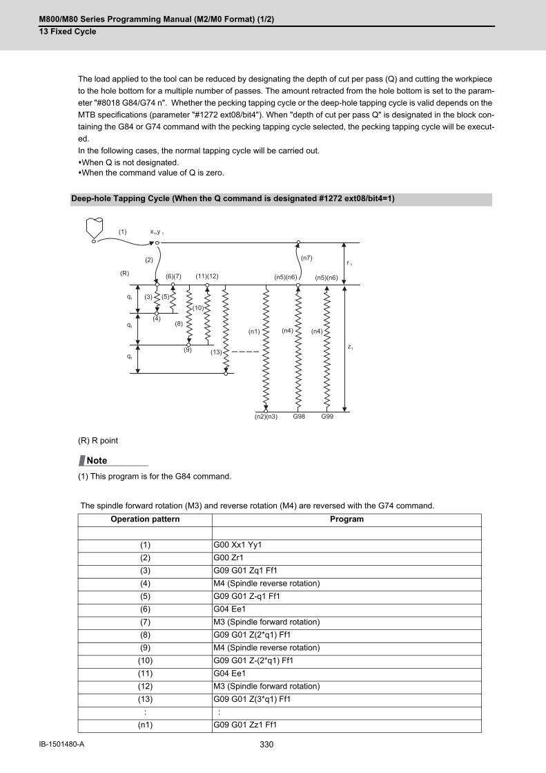
M800/M80 Series Programming Manual (M2/M0 Format) (1/2)
13 Fixed Cycle
330IB-1501480-A
The load applied to the tool can be reduced by designating the depth of cut per pass (Q) and cutting the workpiece
to the hole bottom for a multiple number of passes. The amount retracted from the hole bottom is set to the param-
eter "#8018 G84/G74 n". Whether the pecking tapping cycle or the deep-hole tapping cycle is valid depends on the
MTB specifications (parameter "#1272 ext08/bit4"). When "depth of cut per pass Q" is designated in the block con-
taining the G84 or G74 command with the pecking tapping cycle selected, the pecking tapping cycle will be execut-
ed.
In the following cases, the normal tapping cycle will be carried out.
When Q is not designated. When the command value of Q is zero.
(R) R point
(1) This program is for the G84 command.
The spindle forward rotation (M3) and reverse rotation (M4) are reversed with the G74 command.
Deep-hole Tapping Cycle (When the Q command is designated #1272 ext08/bit4=1)
Operation pattern Program
(1) G00 Xx1 Yy1
(2) G00 Zr1
(3) G09 G01 Zq1 Ff1
(4) M4 (Spindle reverse rotation)
(5) G09 G01 Z-q1 Ff1
(6) G04 Ee1
(7) M3 (Spindle forward rotation)
(8) G09 G01 Z(2*q1) Ff1
(9) M4 (Spindle reverse rotation)
(10) G09 G01 Z-(2*q1) Ff1
(11) G04 Ee1
(12) M3 (Spindle forward rotation)
(13) G09 G01 Z(3*q1) Ff1
: :
(n1) G09 G01 Zz1 Ff1
(1)
r 1
z1
G98 G99
q1
x1,y 1
(R)
q1
q1
(2)
(3)
(4)
(5)
(6)(7)
(8)
(10)
(13)
(11)(12)
(9)
(n7)
(n5)(n6)
(n1) (n4) (n4)
(n2)(n3)
(n5)(n6)
Note
M800/M80 Series Programming Manual (M2/M0 Format) (1/2)
13 Fixed Cycle
331 IB-1501480-A
(a) In the deep-hole tapping, the load applied to the tool can be reduced by designating the depth of cut per pass
and cutting the workpiece to the hole bottom for a multiple number of passes.
Under the deep-hole tapping cycle, the tool is retracted to the R-point every time.
(b) Whether the pecking tapping cycle or the deep-hole tapping cycle is valid depends on the MTB specifications
(parameter "#1272 ext08/bit4").
When "depth of cut per pass Q" is designated in the block containing the G84 or G74 command in the state
where the deep-hole tapping cycle is selected by parameter, the deep-hole tapping cycle is executed.
In the following cases, the normal tapping cycle will be carried out.
When Q is not designated. When the command value of Q is zero.
(c) When G84 is executed, the override will be canceled and the override will automatically be set to 100% in the
cutting operation. And the override set in the parameter "#1172 tapovr" will also be disabled.
(When "#1272 ext08/bit5" = 1, the setting of "#1172 tapovr" will be enabled only during a pulling operation)
(d) Dry run is valid for a positioning command when the parameter "#1085 G00 DRY RUN" is "1" and is valid for the
positioning command. If the feed hold button is pressed during G84 execution, the tool does not stop immediately
during cutting or returning, and it stops after completing an R point return.
(e) During single block operation, the tool does not stop during cutting or returning, but stops after completing an R
point/initial point return.
(f) During the G84 mode, the NC signal "Tapping" will be output.
(g) During the G84 synchronous tapping mode, the M3, M4, M5 or S code will not be output.
(h) If the command value of F becomes extremely small such as around "F < 0.01mm/rev" during synchronous tap-
ping, the spindle does not rotate smoothly. So make sure to command a value larger than "0.01mm/rev". The
unit of F can be selected between mm/rev and mm/min.
(i) If the external deceleration signal is turned ON during synchronous or asynchronous tapping, the feed rate does
not change even when deceleration conditions are satisfied.
(j) If the operation is interrupted by a cause such as an emergency stop or reset during the deep-hole tapping cycle,
a tap retract is executed when the tap retract signal is input.
(k) When the reference position return signal is input during the deep-hole tapping cycle, a tap retract is carried out,
and a reference position return will be executed from the end point of the tap retract.
(n2) G04 Ee1
(n3) M4 (Spindle reverse rotation)
(n4) G09 G01 Z-z1 Ff1
(n5) G04 Ee1
(n6) M3 (Spindle forward rotation)
(n7) G98 mode G00 Z - r1G99 mode No movement
Operation pattern Program

M800/M80 Series Programming Manual (M2/M0 Format) (1/2)
13 Fixed Cycle
332IB-1501480-A
This function enables to make spindle acceleration/deceleration pattern closer to that of the speed loop by dividing
the spindle and drilling axis acceleration/deceleration pattern into up to three stages during synchronous tapping.
The acceleration/deceleration pattern can be set up to three stages for each gear. (This depends on the MTB spec-
ifications.)
When returning from the hole bottom, rapid return is possible at the spindle rotation speed during return. The spindle
rotation speed during return is held as modal information.
(1) When tapping rotation speed < spindle rotation speed during return ≤ synchronous tapping changeover spindlerotation speed 2
Spindle acceleration/deceleration pattern during synchronous tapping
S Command spindle rotation speed
S' Spindle rotation speed during return
S1 Tapping rotation speed (spindle specification parameters #3013 to #3016)
S2 Synchronous tapping changeover spindle rotation speed 2 (spindle specification parameters #3037 to #3040)
S3 Maximum spindle rotation speed for synchronous tapping (spindle specification parameters #43046 to #43049)However, when those parameters are set to "0", processing is performed based on "#3005" to "#3008".
T1 Tapping time constant (spindle specification parameters #3017 to #3020)
T2 Synchronous tapping changeover time constant 2 (spindle specification parameters #3041 to #3044)
S2S3
S(S1)
S1S'S2S3
T1
T1T1
T1
T2
T2

M800/M80 Series Programming Manual (M2/M0 Format) (1/2)
13 Fixed Cycle
333 IB-1501480-A
(2) When synchronous tapping changeover spindle rotation speed 2 < spindle rotation speed during return
S Command spindle rotation speed
S' Spindle rotation speed during return
S1 Tapping rotation speed (spindle specification parameters #3013 to #3016)
S2 Synchronous tapping changeover spindle rotation speed 2 (spindle specification parameters #3037 to #3040)
S3 Maximum spindle rotation speed for synchronous tapping (spindle specification parameters #43046 to #43049)However, when those parameters are set to "0", processing is performed based on "#3005" to "#3008".
T1 Tapping time constant (spindle specification parameters #3017 to #3020)
T2 Synchronous tapping changeover time constant 2 (spindle specification parameters #3041 to #3044)
T3 Synchronous tapping changeover time constant 3 (spindle specification parameters #3045 to #3048)
S3S2
S(S1)
S1S2
S'(S3)
T1
T2T1T1
T1
T2
T3
T3

M800/M80 Series Programming Manual (M2/M0 Format) (1/2)
13 Fixed Cycle
334IB-1501480-A
The feedrates for the tapping cycle and tapping return are as shown below.
(1) Selection of synchronous tapping cycle/asynchronous tapping cycle
- is irrelevant to the setting
(2) Selection of asynchronous tapping cycle feedrate
- is irrelevant to the setting
(3) Spindle rotation speed during return of synchronous tapping cycle
The M code set with the parameter "#3028 sprcmm" is output as the M code for spindle forward/reverse rotation that
is output at "hole bottom" or at "R point" during asynchronous tapping cycle.
Note that the M code for forward rotation is output as "M3" and that for reverse rotation is as "M4" if the parameter
"#3028 sprcmm" is set to "0".
Feedrate for tapping cycle and tapping return
ProgramG84…, Rxx
Control parameterSynchronous tap-
ping
Synchronous/asynchronous
,R00 - Asynchronous
,RxxNo designation
OFF
ON Synchronous
,R01 -
G94/G95 Control parameterF1-digit valid
F command value Feed designation
G94 OFF F designation Feed per minute
ON Other than F0 to F8
F0 to F8(no decimal point)
F1-digit Feed
G95 - F designation Feed per revolution
Address Meaning of ad-dress
Command range (unit)
Remarks
,S Spindle rotation speed during return
0 to 99999 (r/min) The data is held as modal information. If the value is smaller than the spindle ro-tation speed, the spindle rotation speed value will be valid even during return. If the spindle rotation speed is not 0 during return, the taping retract override value will be invalid.
M code for forward/reverse rotation command in asynchronous tapping cycle
M800/M80 Series Programming Manual (M2/M0 Format) (1/2)
13 Fixed Cycle
335 IB-1501480-A
Enable the feed per minute command of the synchronous tapping by the setting of parameter "#1268 ext04/bit2".
When this parameter is valid, G94 and G95 modal will be applied.
(*1) The F command is set to feed per minute (mm/min, inch/min).
Pitch = F command value / S command value
(*2) The F command is set to feed per revolution (mm/rev, inch/rev).
(1) The G94 command, which is a modal command, is valid until the G95 (feed per revolution) command is issuednext.
(2) If the E address (number of screw threads per inch) is issued while feed per minute is valid, the program error(P32) will occur.
(3) The F address of the synchronous tapping command does not affect the F modal for cutting feed.
You can restrict the maximum value (minimum value of the E address for the number of screw threads) of the pitch
F address for synchronous tapping (parameter "#19004 tap feedrate limit"). The program error (P184) will occur if
the machining program is executed when the value of "F" address (pitch) exceeds the maximum value or when the
value of "E" address (number of the screw threads per inch) is below the minimum value.
When the parameter "#19004" is set to "0", the pitch command by the F address is set as follows.
(*1) When feed per minute is commanded, the pitch calculation result for the spindle rotation speed is range-restrict-
ed in this parameter setting.
Feed per minute command of the synchronous tapping
During G94 modal (feed per minute) During G95 modal (feed per revolution)
#1268/bit2 = 1 Feed per minute (*1) Feed per revolution (*2)
#1268/bit2 = 0 Feed per revolution (*2) Feed per revolution (*2)
Range restriction of maximum cutting feedrate command for synchronous tapping
Command unit Pitch F E setting (number of screw threads) (*1)
B (0.001 mm) 0.001 to 999.999 mm/rev 0.0255 to 999.99 screw threads/inch
C (0.0001 mm) 0.0001 to 999.9999 mm/rev 0.026 to 999.999 screw threads/inch
D (0.00001 mm) 0.00001 to 999.99999 mm/rev 0.0255 to 999.9999 screw threads/inch
E (0.000001 mm) 0.000001 to 999.999999 mm/rev 0.02541 to 999.99999 screw threads/inch
B (0.0001 inch) 0.000001 to 39.370078 inch/rev 0.03 to 9999.9999 screw threads/inch
C (0.00001 inch) 0.0000001 to 39.3700787 inch/rev 0.026 to 9999.99999 screw threads/inch
D (0.000001 inch) 0.00000001 to 39.37007874 inch/rev 0.0255 to 9999.999999 screw threads/inch
E (0.0000001 inch) 0.000000001 to 39.370078740 inch/rev 0.02541 to 9999.9999999 screw threads/inch
Note

M800/M80 Series Programming Manual (M2/M0 Format) (1/2)
13 Fixed Cycle
336IB-1501480-A
(*1) Carry out in-position check by tapping in-position width.
(1) The I point refers to the initial point.
Synchronous tapping in-position check (Parameter setting values and tapping axis movement)
#1223 aux07 "P" designation of G84/G74 command
In-position check during synchronous tap-pingbit3 bit4 bit5 bit2
In-position check during synchronous
tapping
Hole bottom
R point I point -> R
point
Hole bottom R point I point -> R point
0 - - - - yes yes yes
1 - - - No "P" designationExample: G84 F1. Z-5. S1000
R-5.
no no no
1 1 1 1 "P" designationExample: G84 F1. Z-5. S1000
P0 R-5.
(*1) yes yes
1 1 0 1 "P" designationExample: G84 F1. Z-5. S1000
P0 R-5.
(*1) no yes
1 0 1 1 "P" designationExample: G84 F1. Z-5. S1000
P0 R-5.
yes yes yes
1 0 0 1 "P" designationExample: G84 F1. Z-5. S1000
P0 R-5.
no no yes
1 1 1 0 "P" designationExample: G84 F1. Z-5. S1000
P0 R-5.
(*1) yes no
1 1 0 0 "P" designationExample: G84 F1. Z-5. S1000
P0 R-5.
(*1) no no
1 0 1 0 "P" designationExample: G84 F1. Z-5. S1000
P0 R-5.
no yes no
1 0 0 0 "P" designationExample: G84 F1. Z-5. S1000
P0 R-5.
no no no
Note

M800/M80 Series Programming Manual (M2/M0 Format) (1/2)
13 Fixed Cycle
337 IB-1501480-A
In-position width and tapping axis movement for a synchronous tapping in-position check
(a) In-position completion of the G00 feed from the R point
(b) G01 deceleration start at tapping cut-in
(c) G01 deceleration start at tapping return
(d) Start of G00 feed to the R point
(1) Section in which the in-position check is carried out by G0inps.
(2) Section in which the in-position check is carried out by TapInp.
(3) Section in which the in-position check is carried out by G1inps.
(4) Section in which the in-position check is carried out by sv024.
R point: In-position check by the G1inps
I point: In-position check by the G0inps
Hole bottom: In-position check by the TapInp
(Z) Hole bottom (R) R point
FIN
(1) (2) (3) (4)
(Z) (R) (d)(c)(b)(a)(F)
(T)
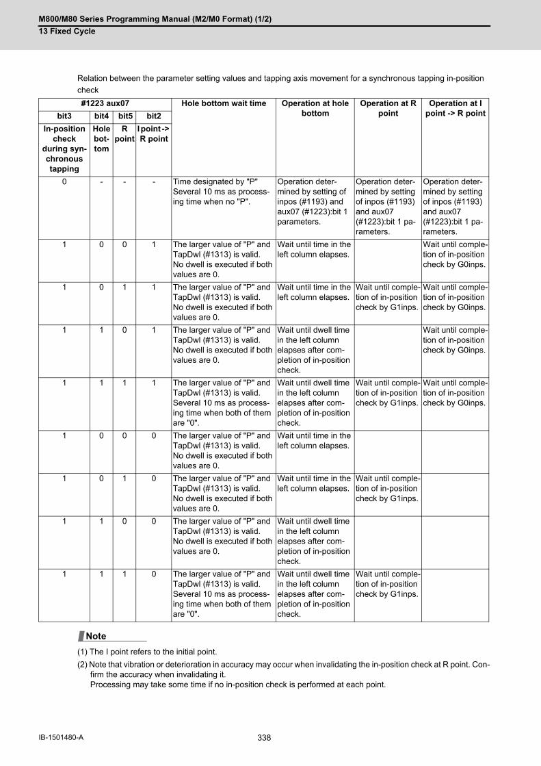
M800/M80 Series Programming Manual (M2/M0 Format) (1/2)
13 Fixed Cycle
338IB-1501480-A
Relation between the parameter setting values and tapping axis movement for a synchronous tapping in-position
check
(1) The I point refers to the initial point.
(2) Note that vibration or deterioration in accuracy may occur when invalidating the in-position check at R point. Con-firm the accuracy when invalidating it. Processing may take some time if no in-position check is performed at each point.
#1223 aux07 Hole bottom wait time Operation at hole bottom
Operation at R point
Operation at I point -> R pointbit3 bit4 bit5 bit2
In-position check
during syn-chronous tapping
Hole bot-tom
R point
I point -> R point
0 - - - Time designated by "P"Several 10 ms as process-ing time when no "P".
Operation deter-mined by setting of inpos (#1193) and aux07 (#1223):bit 1 parameters.
Operation deter-mined by setting of inpos (#1193) and aux07 (#1223):bit 1 pa-rameters.
Operation deter-mined by setting of inpos (#1193) and aux07 (#1223):bit 1 pa-rameters.
1 0 0 1 The larger value of "P" and TapDwl (#1313) is valid.No dwell is executed if both values are 0.
Wait until time in the left column elapses.
Wait until comple-tion of in-position check by G0inps.
1 0 1 1 The larger value of "P" and TapDwl (#1313) is valid.No dwell is executed if both values are 0.
Wait until time in the left column elapses.
Wait until comple-tion of in-position check by G1inps.
Wait until comple-tion of in-position check by G0inps.
1 1 0 1 The larger value of "P" and TapDwl (#1313) is valid.No dwell is executed if both values are 0.
Wait until dwell time in the left column elapses after com-pletion of in-position check.
Wait until comple-tion of in-position check by G0inps.
1 1 1 1 The larger value of "P" and TapDwl (#1313) is valid.Several 10 ms as process-ing time when both of them are "0".
Wait until dwell time in the left column elapses after com-pletion of in-position check.
Wait until comple-tion of in-position check by G1inps.
Wait until comple-tion of in-position check by G0inps.
1 0 0 0 The larger value of "P" and TapDwl (#1313) is valid.No dwell is executed if both values are 0.
Wait until time in the left column elapses.
1 0 1 0 The larger value of "P" and TapDwl (#1313) is valid.No dwell is executed if both values are 0.
Wait until time in the left column elapses.
Wait until comple-tion of in-position check by G1inps.
1 1 0 0 The larger value of "P" and TapDwl (#1313) is valid.No dwell is executed if both values are 0.
Wait until dwell time in the left column elapses after com-pletion of in-position check.
1 1 1 0 The larger value of "P" and TapDwl (#1313) is valid.Several 10 ms as process-ing time when both of them are "0".
Wait until dwell time in the left column elapses after com-pletion of in-position check.
Wait until comple-tion of in-position check by G1inps.
Note
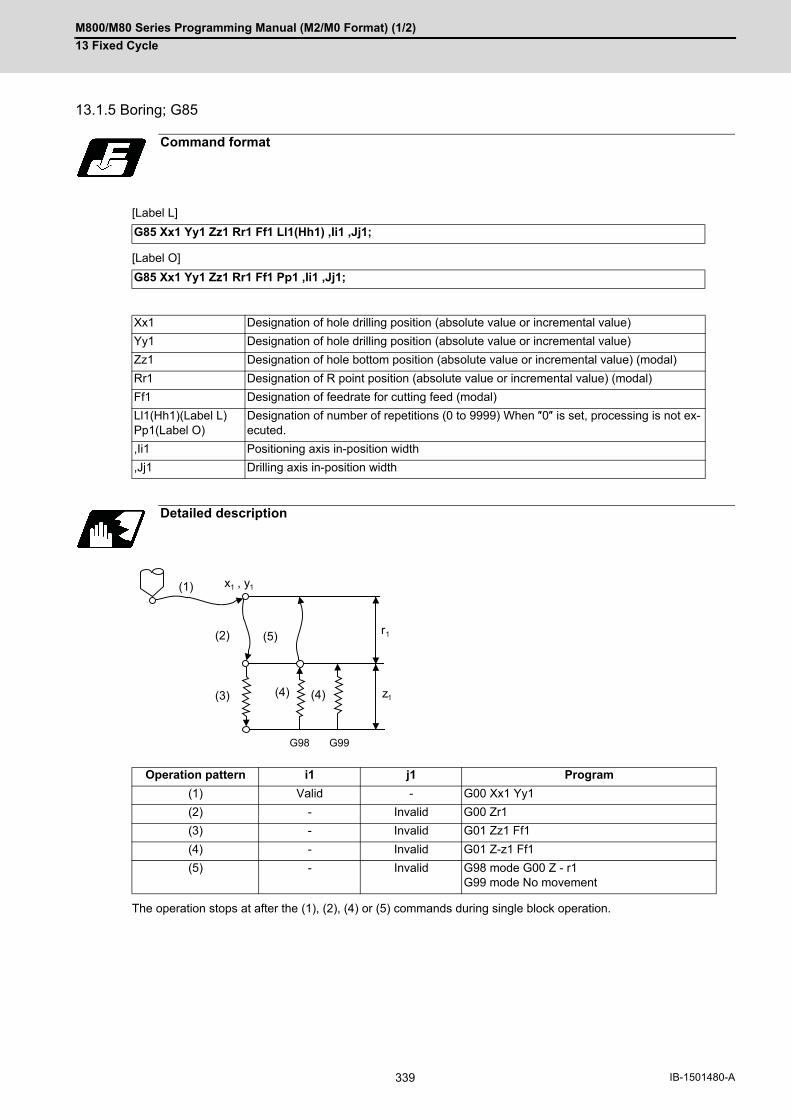
M800/M80 Series Programming Manual (M2/M0 Format) (1/2)
13 Fixed Cycle
339 IB-1501480-A
13.1.5 Boring; G85
[Label L]
[Label O]
The operation stops at after the (1), (2), (4) or (5) commands during single block operation.
Command format
G85 Xx1 Yy1 Zz1 Rr1 Ff1 Ll1(Hh1) ,Ii1 ,Jj1;
G85 Xx1 Yy1 Zz1 Rr1 Ff1 Pp1 ,Ii1 ,Jj1;
Xx1 Designation of hole drilling position (absolute value or incremental value)
Yy1 Designation of hole drilling position (absolute value or incremental value)
Zz1 Designation of hole bottom position (absolute value or incremental value) (modal)
Rr1 Designation of R point position (absolute value or incremental value) (modal)
Ff1 Designation of feedrate for cutting feed (modal)
Ll1(Hh1)(Label L)Pp1(Label O)
Designation of number of repetitions (0 to 9999) When ″0″ is set, processing is not ex-ecuted.
,Ii1 Positioning axis in-position width
,Jj1 Drilling axis in-position width
Detailed description
Operation pattern i1 j1 Program
(1) Valid - G00 Xx1 Yy1
(2) - Invalid G00 Zr1
(3) - Invalid G01 Zz1 Ff1
(4) - Invalid G01 Z-z1 Ff1
(5) - Invalid G98 mode G00 Z - r1G99 mode No movement
r1
z1
G98 G99
(1)
(2)
(3) (4) (4)
(5)
x1 , y1
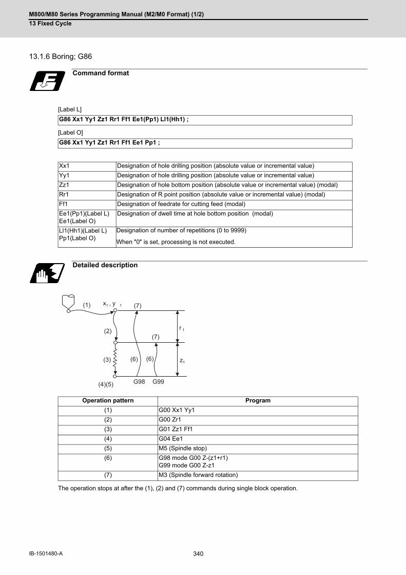
M800/M80 Series Programming Manual (M2/M0 Format) (1/2)
13 Fixed Cycle
340IB-1501480-A
13.1.6 Boring; G86
[Label L]
[Label O]
The operation stops at after the (1), (2) and (7) commands during single block operation.
Command format
G86 Xx1 Yy1 Zz1 Rr1 Ff1 Ee1(Pp1) Ll1(Hh1) ;
G86 Xx1 Yy1 Zz1 Rr1 Ff1 Ee1 Pp1 ;
Xx1 Designation of hole drilling position (absolute value or incremental value)
Yy1 Designation of hole drilling position (absolute value or incremental value)
Zz1 Designation of hole bottom position (absolute value or incremental value) (modal)
Rr1 Designation of R point position (absolute value or incremental value) (modal)
Ff1 Designation of feedrate for cutting feed (modal)
Ee1(Pp1)(Label L)Ee1(Label O)
Designation of dwell time at hole bottom position (modal)
Ll1(Hh1)(Label L)Pp1(Label O)
Designation of number of repetitions (0 to 9999)
When ″0″ is set, processing is not executed.
Detailed description
Operation pattern Program
(1) G00 Xx1 Yy1
(2) G00 Zr1
(3) G01 Zz1 Ff1
(4) G04 Ee1
(5) M5 (Spindle stop)
(6) G98 mode G00 Z-(z1+r1)G99 mode G00 Z-z1
(7) M3 (Spindle forward rotation)
(4)(5) G98 G99
(1)
(2)
(3) (6)
(7)
x1 , y 1
z1(6)
r 1
(7)

M800/M80 Series Programming Manual (M2/M0 Format) (1/2)
13 Fixed Cycle
341 IB-1501480-A
13.1.7 Back Boring; G87
[Label L]
[Label O]
Command format
G87 Xx1 Yy1 Zz1 Rr1 Iq1 Jq2 Kq3 Ff1 Ll1(Hh1);
G87 Xx1 Yy1 Zz1 Rr1 Iq1 Jq2 Kq3 Ff1 Pp1;
Xx1 Designation of hole drilling position (absolute value or incremental value)
Yy1 Designation of hole drilling position (absolute value or incremental value)
Zz1 Designation of hole bottom position (absolute value or incremental value) (modal)
Rr1 Designation of R point position (absolute value or incremental value) (modal)
Iq1Jq2Kq3
Designation of shift amount (incremental value) (modal)The command address for each plane selection is as follows: G17 plane: IJG18 plane: KIG19 plane: JKDepending on the parameter setting, the shift amount can be designated by Q address. Refer to "Designation of shift amount (I,J,K)".
Ff1 Designation of feedrate for cutting feed (modal)
Ll1(Hh1)(Label L)Pp1(Label O)
Designation of number of repetitions (0 to 9999) When ″0″ is set, processing is not ex-ecuted.

M800/M80 Series Programming Manual (M2/M0 Format) (1/2)
13 Fixed Cycle
342IB-1501480-A
The operation stops at after the (1), (4), (6) and (11) commands during single block operation.
Detailed description
Operation pattern Program
(1) G00 Xx1 Yy1
(2) M19 (Spindle orientation)
(3) G00 Xq1 (Yq2) (shift)
(4) G00 Zr1
(5) G01 X-q1(Y-q2)Ff1 (shift)
(6) M3 (Spindle forward rotation)
(7) G01 Zz1 Ff1
(8) M19 (Spindle orientation)
(9) G00 Xq1 (Yq2) (shift)
(10) G98 mode G00 Z - (z1+r1)G99 mode G00 Z - (r1+z1)
(11) G00 X-q1 (Y-q2) (shift)
(12) M3 (Spindle forward rotation)
(1)
r 1
Xq1(Yq2)(3)
(2) (12)(11)
(8) (9)(10)
(4)
(7)
(6) (5)
z1
x1 , y1

M800/M80 Series Programming Manual (M2/M0 Format) (1/2)
13 Fixed Cycle
343 IB-1501480-A
When this command is issued, high precision drilling machining that does not scratch the machining surface can be
done. Positioning to the hole bottom and escaping (return) after cutting are carried out in the state shifted to the
direction opposite of the cutter.
The command addresses to designate the shift amount for each plane selection are as follow;
G17 plane: IJ
G18 plane: KI
G19 plane: JK
The shift amount is executed with linear interpolation, and the feedrate follows the F command.
Command I, J, and K with incremental values in the same block as the hole position data.
I, J and K will be handled as modal during the fixed cycle.
(1) If the parameter "#1080 Dril_Z" which fixes the hole drilling axis to the Z axis is set, the shift amount can be des-ignated with address Q instead of I, J. In this case, whether to shift or not and the shift direction are set withparameter "#8207 G76/87 No shift" and "#8208 G76/87 Shift (-)". The sign for the Q value is ignored and thevalue is handled as a positive value. The Q value is a modal during the fixed cycle, and will also be used as theG83, G73 and G76 cutting amount.
Designation of shift amount (I,J,K)
A: Tool position during cutting
B: Tool position when positioning to the hole bottom and, also, when escaping after cutting
A B
Note

M800/M80 Series Programming Manual (M2/M0 Format) (1/2)
13 Fixed Cycle
344IB-1501480-A
13.1.8 Boring; G88
[Label L]
[Label O]
The operation stops at after the (1), (2), (6) and (9) commands during single block operation.
Command format
G88 Xx1 Yy1 Zz1 Rr1 Ff1 Ee1(Pp1) Ll1(Hh1);
G88 Xx1 Yy1 Zz1 Rr1 Ff1 Ee1 Pp1;
Xx1 Designation of hole drilling position (absolute value or incremental value)
Yy1 Designation of hole drilling position (absolute value or incremental value)
Zz1 Designation of hole bottom position (absolute value or incremental value) (modal)
Rr1 Designation of R point position (absolute value or incremental value) (modal)
Ff1 Designation of feedrate for cutting feed (modal)
Ee1(Pp1)(Label L)Ee1(Label O)
Designation of dwell time at hole bottom position (modal)
Ll1(Hh1)(Label L)Pp1(Label O)
Designation of number of repetitions (0 to 9999)
When ″0″ is set, processing is not executed.
Detailed description
Operation pattern Program
(1) G00 Xx1 Yy1
(2) G00 Zr1
(3) G01 Zz1 Ff1
(4) G04 Ee1
(5) M5 (Spindle stop)
(6) Stop when single block stop switch is ON
(7) Automatic start switch ON
(8) G98 mode G00 Z-(z1+r1)G99 mode G00 Z-z1
(9) M3 (Spindle forward rotation)
(4)(5)(6)(7) G98 G99
(1)
(2)
(3) (8)
(9)
x1 , y1
z1(8)
r 1
(9)

M800/M80 Series Programming Manual (M2/M0 Format) (1/2)
13 Fixed Cycle
345 IB-1501480-A
13.1.9 Boring; G89
[Label L]
[Label O]
The operation stops at after the (1), (2), (5) or (6) commands during single block operation.
Command format
G89 Xx1 Yy1 Zz1 Rr1 Ff1 Ee1(Pp1) Ll1(Hh1) ,Ii1,Jj1;
G89 Xx1 Yy1 Zz1 Rr1 Ff1 Ee1 Pp1 ,Ii1,Jj1;
Xx1 Designation of hole drilling position (absolute value or incremental value)
Yy1 Designation of hole drilling position (absolute value or incremental value)
Zz1 Designation of hole bottom position (absolute value or incremental value) (modal)
Rr1 Designation of R point position (absolute value or incremental value) (modal)
Ff1 Designation of feedrate for cutting feed (modal)
Ee1(Pp1)(Label L)Ee1(Label O)
Designation of dwell time at hole bottom position (modal)
Ll1(Hh1)(Label L)Pp1(Label O)
Designation of number of repetitions (0 to 9999)
When ″0″ is set, processing is not executed.
,Ii1 Positioning axis in-position width
,Jj1 Drilling axis in-position width
Detailed description
Operation pattern i1 j1 Program
(1) Valid - G00 Xx1 Yy1
(2) - Invalid G00 Zr1
(3) - Invalid G01 Zz1 Ff1
(4) - - G04 Ee1
(5) - Invalid G01 Z-z1 Ff1
(6) - Valid G98 mode G00 Z-r1G99 mode No movement
(4)
r 1
z1
G98 G99
(1)
(2)
(3) (5) (5)
(6)
x1 , y1

M800/M80 Series Programming Manual (M2/M0 Format) (1/2)
13 Fixed Cycle
346IB-1501480-A
13.1.10 Stepping Cycle; G73
[Label L]
[Label O]
Command format
G73 Xx1 Yy1 Zz1 Qq1 Rr1 Ff1 Ee1(Pp1) Ll1(Hh1) ,Ii1 ,Jj1;
G73 Xx1 Yy1 Zz1 Qq1 Rr1 Ff1 Ee1 Pp1 ,Ii1 ,Jj1;
Xx1 Designation of hole drilling position (absolute value or incremental value)
Yy1 Designation of hole drilling position (absolute value or incremental value)
Zz1 Designation of hole bottom position (absolute value or incremental value) (modal)
Qq1 Cut amount for each cutting pass (incremental value) (modal)
Rr1 Designation of R point position (absolute value or incremental value) (modal)
Ff1 Designation of feedrate for cutting feed (modal)
Ee1(Pp1)(Label L)Ee1(Label O)
Designation of dwell time at hole bottom position (modal)
Ll1(Hh1)(Label L)Pp1(Label O)
Designation of number of repetitions (0 to 9999)
When ″0″ is set, processing is not executed.
,Ii1 Positioning axis in-position width
,Jj1 Drilling axis in-position width

M800/M80 Series Programming Manual (M2/M0 Format) (1/2)
13 Fixed Cycle
347 IB-1501480-A
When executing a second and following cutting in the G73 as shown above, the movement will return several "m"
mm with rapid traverse and then will change to cutting feed. The return amount "m" will differ according to the pa-
rameter "#8012 G73 return".
The operation stops at after the (1), (2) and (n) commands during single block operation.
Detailed description
Operation pattern i1 j1 Program
(1) Valid - G00 Xx1 Yy1
(2) - Invalid G00 Zr1
(3) - Invalid G01 Zq1 Ff1
(4) - - G04 Ee1
(5) - Invalid G00 Z-m
(6) - Invalid G01 Z(q1+m) Ff1
:
(n)-1 - Invalid
(n) - Valid G98 mode G00 Z-(z1+r1)G99 mode G00 Z-z1
(1)
(2)
(3)
(4)
x1 , y1
z1
r 1
(5) (6)
q1
q1
q1
(n)
m
(n) - 1
(n)
G98 G99
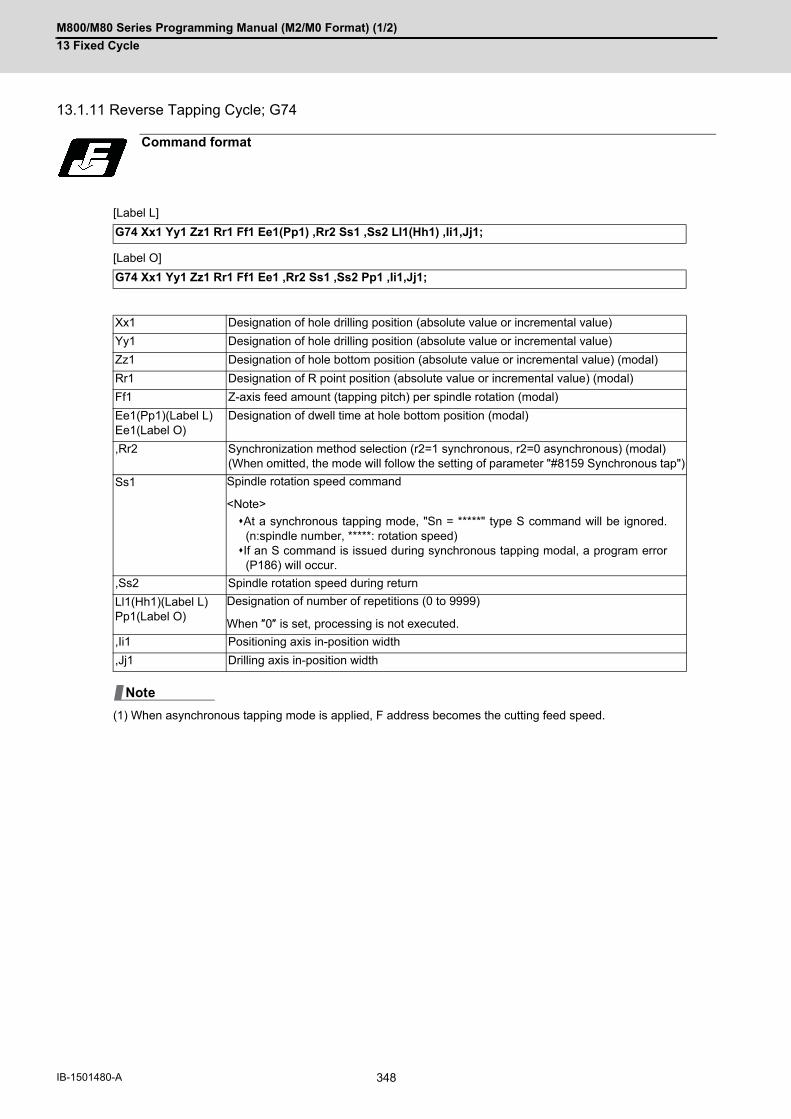
M800/M80 Series Programming Manual (M2/M0 Format) (1/2)
13 Fixed Cycle
348IB-1501480-A
13.1.11 Reverse Tapping Cycle; G74
[Label L]
[Label O]
(1) When asynchronous tapping mode is applied, F address becomes the cutting feed speed.
Command format
G74 Xx1 Yy1 Zz1 Rr1 Ff1 Ee1(Pp1) ,Rr2 Ss1 ,Ss2 Ll1(Hh1) ,Ii1,Jj1;
G74 Xx1 Yy1 Zz1 Rr1 Ff1 Ee1 ,Rr2 Ss1 ,Ss2 Pp1 ,Ii1,Jj1;
Xx1 Designation of hole drilling position (absolute value or incremental value)
Yy1 Designation of hole drilling position (absolute value or incremental value)
Zz1 Designation of hole bottom position (absolute value or incremental value) (modal)
Rr1 Designation of R point position (absolute value or incremental value) (modal)
Ff1 Z-axis feed amount (tapping pitch) per spindle rotation (modal)
Ee1(Pp1)(Label L)Ee1(Label O)
Designation of dwell time at hole bottom position (modal)
,Rr2 Synchronization method selection (r2=1 synchronous, r2=0 asynchronous) (modal)(When omitted, the mode will follow the setting of parameter "#8159 Synchronous tap")
Ss1 Spindle rotation speed command
<Note>
At a synchronous tapping mode, "Sn = *****" type S command will be ignored.(n:spindle number, *****: rotation speed)If an S command is issued during synchronous tapping modal, a program error
(P186) will occur.
,Ss2 Spindle rotation speed during return
Ll1(Hh1)(Label L)Pp1(Label O)
Designation of number of repetitions (0 to 9999)
When ″0″ is set, processing is not executed.
,Ii1 Positioning axis in-position width
,Jj1 Drilling axis in-position width
Note

M800/M80 Series Programming Manual (M2/M0 Format) (1/2)
13 Fixed Cycle
349 IB-1501480-A
When r2 = 1, the synchronous tapping mode will be applied, and when r2 = 0, the asynchronous tapping mode will
be applied. If there is no r2 command, mode will follow the parameter setting.
When G74 is executed, the override will be canceled and the override will automatically be set to 100%.
Dry run is valid for the positioning command when the parameter "#1085 G00 Drn" is set to "1".
If the feed hold button is pressed during G74 execution, and the sequence is at (3) to (6), the movement will not stop
immediately, and instead will stop after (6). During the rapid traverse in sequence (1), (2) and (9), the movement will
stop immediately.
The operation stops at after the (1), (2) and (9) commands during single block operation.
During the G74 and G84 modal, the "Tapping" NC output signal will be output.
During the G74 synchronous tapping modal, the M3, M4, M5 and S code will not be output.
Refer to "13.1.4 Tapping Cycle; G84".
Refer to "13.1.4 Tapping Cycle; G84".
Refer to "13.1.4 Tapping Cycle; G84".
Refer to "13.1.4 Tapping Cycle; G84".
Detailed description
Operation pattern i1 j1 Program
(1) Valid - G00 Xx1 Yy1
(2) - Invalid G00 Zr1
(3) - Invalid G01 Zz1 Ff1
(4) - - G04 Ee1
(5) - - M3 (Spindle forward rotation)
(6) - Invalid G01 Z-z1 Ff1
(7) - - G04 Ee1
(8) - - M4 (Spindle reverse rotation)
(9) - Valid G98 mode G00 Z - r1G99 mode No movement
Spindle acceleration/deceleration pattern during synchronous tapping
Feedrate for tapping cycle and tapping return
M code for forward/reverse rotation command in asynchronous tapping cycle
Parameter setting values and tapping axis
(4)(5)
r 1
z1
G98 G99
(1)
(2)
(3) (6) (6)
(9)
x1 ,y1
(8)(7)(8)
(7)

M800/M80 Series Programming Manual (M2/M0 Format) (1/2)
13 Fixed Cycle
350IB-1501480-A
13.1.12 Circular Cutting; G75
Circular cutting starts with the X and Y axes positioned at the center of the circle, and the Z axis cuts into the com-
manded position. Then, the tool cuts the inner circumference of the circle drawing a true circle and returns to the
center position.
[Label L]
[Label O]
Function and purpose
Command format
G75 Xx1 Yy1 Zz1 Rr1 Qq1 Ee1(Pp1) Ff1 Ll1(Hh1);
G75 Xx1 Yy1 Zz1 Rr1 Qq1 Ee1 Ff1 Pp1;
Xx1 Designation of hole drilling position (absolute value or incremental value)
Yy1 Designation of hole drilling position (absolute value or incremental value)
Zz1 Designation of hole bottom position (absolute value or incremental value) (modal)
Rr1 Designation of R point position (absolute value or incremental value) (modal)
Qq1 Radius of outer circumference (modal)
Ee1(Pp1)(Label L)Ee1(Label O)
Tool radius compensation No. (modal)
Ff1 Designation of feedrate for cutting feed (modal)
Ll1(Hh1)(Label L)Pp1(Label O)
Designation of number of repetitions (0 to 9999) When ″0″ is set, processing is not executed.
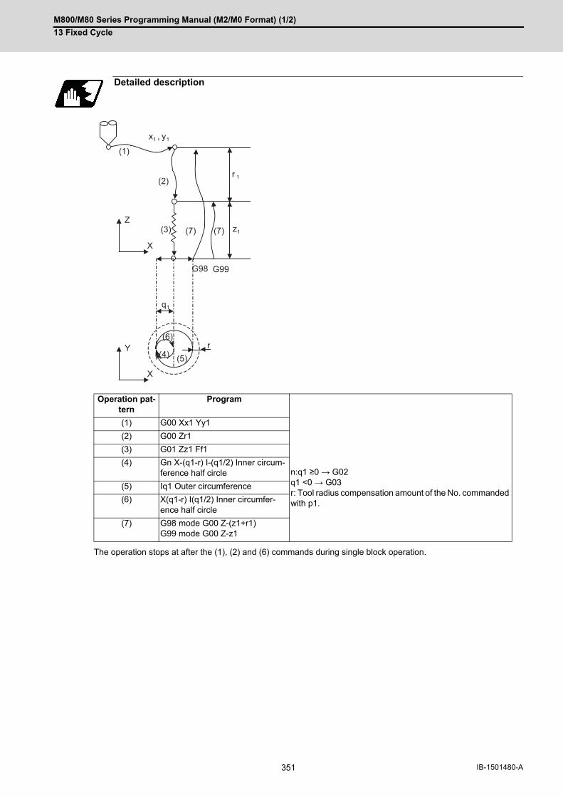
M800/M80 Series Programming Manual (M2/M0 Format) (1/2)
13 Fixed Cycle
351 IB-1501480-A
The operation stops at after the (1), (2) and (6) commands during single block operation.
Detailed description
Operation pat-tern
Program n:q1 ≥0 → G02q1 <0 → G03r: Tool radius compensation amount of the No. commanded with p1.
(1) G00 Xx1 Yy1
(2) G00 Zr1
(3) G01 Zz1 Ff1
(4) Gn X-(q1-r) I-(q1/2) Inner circum-ference half circle
(5) Iq1 Outer circumference
(6) X(q1-r) I(q1/2) Inner circumfer-ence half circle
(7) G98 mode G00 Z-(z1+r1)G99 mode G00 Z-z1
(4)
G98 G99
(1)
(2)
(3)
(6)
(7)
x1 , y1
z1
r 1
(5)
(7)
r
q1
Y
X
Z
X

M800/M80 Series Programming Manual (M2/M0 Format) (1/2)
13 Fixed Cycle
352IB-1501480-A
13.1.13 Fine Boring; G76
[Label L]
[Label O]
Command format
G76 Xx1 Yy1 Zz1 Rr1 Iq1 Jq2 Kq3 Ff1 Ll1(Hh1);
G76 Xx1 Yy1 Zz1 Rr1 Iq1 Jq2 Kq3 Ff1 Pp1;
Xx1 Designation of hole drilling position (absolute value or incremental value)
Yy1 Designation of hole drilling position (absolute value or incremental value)
Zz1 Designation of hole bottom position (absolute value or incremental value) (modal)
Rr1 Designation of R point position (absolute value or incremental value) (modal)
Iq1Jq2Kq3
Designation of shift amount (incremental value) (modal)The command address for each plane selection is as follows: G17 plane: IJG18 plane: KIG19 plane: JKDepending on the parameter setting, the shift amount can be designated by Q address. Refer to "Designation of shift amount (I,J,K)".
Ff1 Designation of feedrate for cutting feed (modal)
Ll1(Hh1)(Label L)Pp1(Label O)
Designation of number of repetitions (0 to 9999) When ″0″ is set, processing is not ex-ecuted.

M800/M80 Series Programming Manual (M2/M0 Format) (1/2)
13 Fixed Cycle
353 IB-1501480-A
The operation stops at after the (1), (2) and (7) commands during single block operation.
Detailed description
Operation pattern Program
(1) G00 Xx1 Yy1
(2) G00 Zr1
(3) G01 Zz1 Ff1
(4) M19 (Spindle orientation)
(5) G01 Xq1 (Yq2)Ff1 (shift)
(6) G98 mode G00 Z-(z1+r1)G99 mode G00 Z-z1
(7) G00 X-q1 (Y-q2) (shift)
(8) M3 (Spindle forward rotation)
(4)(5) G98 G99
(1)
(2)
(3) (6)
(7)
x1 , y1
z1(6)
r 1
(7)
(8)
(8)

M800/M80 Series Programming Manual (M2/M0 Format) (1/2)
13 Fixed Cycle
354IB-1501480-A
When this command is issued, high precision drilling machining that does not scratch the machining surface can be
done.
Positioning to the hole bottom and the escape (return) after cutting is executed in the state shifted to the direction
opposite of the cutter.
The command addresses to designate the shift amount for each plane selection are as follow;
G17 plane: IJ
G18 plane: KI
G19 plane: JK
The shift amount is executed with linear interpolation, and the feedrate follows the F command.
Command I, J, and K with incremental values in the same block as the hole position data.
I, J and K will be handled as modal during the fixed cycle.
(1) If the parameter "#1080 Dril_Z" which fixes the hole drilling axis to the Z axis is set, the shift amount can be des-ignated with address Q instead of I and J. In this case, whether to shift or not and the shift direction are set withparameter "#8207 G76/87 IGNR" and "#8208 G76/87 (-)". The sign for the Q value is ignored and the value ishandled as a positive value. The Q value is a modal during the fixed cycle, and will also be used as the G83, G87 and G73 cutting amount.
Designation of shift amount (I,J,K)
A: Tool position during cutting
B: Tool position when escaping after cutting
A B
Note

M800/M80 Series Programming Manual (M2/M0 Format) (1/2)
13 Fixed Cycle
355 IB-1501480-A
13.1.14 Precautions for Using a Fixed Cycle
(1) Before the fixed cycle is commanded, the spindle must be rotating in a specific direction with a miscellaneousfunction command (M3; or M4;). Note that for the G87 (back boring) command, the spindle rotation command is included in the fixed cycle so onlythe rotation speed command needs to be commanded beforehand.
(2) If there is data for the basic axis, additional axis or R in the block during the fixed cycle mode, the hole drillingoperation will be executed. If there is no data, the hole drilling operation will not be executed. Note that even when the X axis data exists, the hole will not be drilled if the data is a dwell (G04) time command.
(3) Command the hole machining data (Q, P, I, J, K) in a block where hole drilling is executed (Block containing abasic axis, additional axis or R data).
(4) The fixed cycle can be canceled by the G00 to G03 or G33 command besides the G80 command. If these aredesignated in the same block as the fixed cycle, the following will occur.
Note that for the G02 and G03 commands, R will be handled as the arc radius.
(5) If M00 or M01 is commanded in a same block with a fixed cycle or during a fixed cycle mode, the fixed cycle willbe ignored. Instead, M00 and M01 will be output after positioning. The fixed cycle is executed if X, Y, Z or R iscommanded.
(6) If an M function is commanded in the same block as the fixed cycle command, the M code and MF will be outputduring the initial positioning. The axis will move to the next operation with FIN (finish signal). If there is a designation of No. of times, the above control will be executed only for the first drilling.
(7) If another control axis (ex. rotary axis, additional axis) is commanded in the same block as the fixed cycle controlaxis, the fixed cycle will be executed after the other control axes start to move.
(8) If the No. of repetitions L is not designated, L1 will be set. If L0 is designated in the same block as the fixed cycleG code command, the hole machining data will be memorized, but the hole machining will not be executed.
(Example) G73 X_Y_Z_R_Q_P_F_L0_;
Memorize only the codes with an execution address
(9) When the fixed cycle is executed, only the modal command issued in the fixed cycle program will be valid in thefixed cycle subprogram. The modal of the program which called the fixed cycle will not be affected.
(10) Other subprograms cannot be called from the fixed cycle subprogram.
(11) Decimal points in the movement command of the fixed cycle subprogram will be ignored.
(12) If the No. of repetitions L is 2 or more during the incremental value mode, the positioning will also be increment-ed each time.
(Example) G91 G81 X10. Z-50. R-20. F100. L3;
Precautions
m = 00 to 03, 33 n = Fixed cycles
Gm Gn X_Y_Z_R_Q_P_L_F_;
Gm : Execution Gn : Ignore
X_Y_Z : Execution R_Q_P_L : Ignore F : Record
X Y 10. 10. 10.

M800/M80 Series Programming Manual (M2/M0 Format) (1/2)
13 Fixed Cycle
356IB-1501480-A
(13) If the spindle rotation speed value during return is smaller than the spindle speed value, the spindle rotationspeed value is valid even during return.
(14) If inclinations of the 2nd and 3rd acceleration/deceleration stages according to the spindle rotation speed andtime constants set in the parameters are each steeper than the previous stage's inclinations, the previous stage'sinclination will be valid.
(15) If the values set in the spindle specification parameter "tap rotation speed" and "the synchronous tap change-over spindle rotation speed 2" exceed the maximum rotation speed, the spindle rotation speed will be clampedat the maximum rotation speed.
(16) If the spindle rotation speed is not 0 during return, the taping retract override value will be invalid.
(17) As shown below, in a block where the movement direction of either axis reverses, the servo system load willgreatly increase, so do not command the in-position width in the machining program.
G01 X100. ,I10.0;
X-200.;
(18) If the in-position width commanded by the programmable in-position width command is increased, the position-ing time and linear interpolation time can be reduced. However, the position error amount of the previous blockwill also increase before the next block starts, and the actual machining could be obstructed.
(19) The in-position width and the position error amount are constantly compared, so the position error amount atthe point to be judged as in-position will be smaller than the commanded in-position width.
(20) If the in-position width commanded with the programmable in-position command is small, the commanded de-celeration check or in-position check by the parameters may be carried out first.
(21) Synchronous or asynchronous tapping can be selected with the M function.
Base specification parameters
Synchronous tapping cannot be selected with the M function when this parameter is OFF.
Base specification parameters
The synchronous tapping mode is selected with the miscellaneous function code set with this parameter.
The M function can be commanded just before or in the same block as the tapping command.
To use this parameter, validate "#1272 ext08/bit1" (M function synchronous tapping cycle).
The selection of synchronous or asynchronous tappinf will follow the combination shown below.
<Note>
Do not use M00, 01, 02, 30, 98 and 99.
(22) Even when the parameter "#1151 rstinit" is OFF, the fixed cycle will be canceled if NC reset 1 is carried outwhile executing the fixed cycle.
(23) If a tapping axis is under machine lock, normal synchronous tapping is applied even though high-speed syn-chronous tapping function is enabled.
(24) For the label L, when the number of repetitions is two or more, the initial point return is executed at the lastrepetition regardless of the G98 or G99 mode.
(25) For the label O, when the number of repetitions is two or more, the last repetition follows the G98 or G99 mode.
(26) For the label O, the number of repetitions can be designated with the address L because this function is uppercompatible; however, we recommend using the address P because it is not original function.
# Item Details Setting range
1272(PR)
ext08 bit1 M-function synchronous tapping cycle valid.
0: Invalid1: Valid
# Item Details Setting range
1513 stapM M code for synchronous tapping selection 0 to 99999999
Combination
Program command (,R0/1) 0 0 0 0 1 1 1 1 No command
#8159 Synchronous tap 0 0 1 1 0 0 1 1 0 0 1 1
M function code (M**) × ○ × ○ × ○ × ○ × ○ × ○
Synchronous/asynchronous selection
A A A A B B B B A B B B
× Not commanded. A Asynchronous tapping
○ Commanded. B Synchronous tapping

M800/M80 Series Programming Manual (M2/M0 Format) (1/2)
13 Fixed Cycle
357 IB-1501480-A
(27) If there is no hole drilling position command, the hole drilling data is saved but the machining is not executed.With x, y commands: Hole drilling is executed.With z, r commands only: Data is saved. (No hole drilling.)
(28) When the dwell time at hole bottom position is designated with the address E, the decimal point is always valid.If you use the address P with the decimal point (label L), it follows the parameter "#8112 DECIMAL PNT-P".
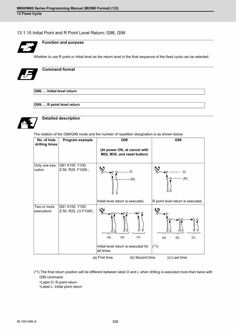
M800/M80 Series Programming Manual (M2/M0 Format) (1/2)
13 Fixed Cycle
358IB-1501480-A
13.1.15 Initial Point and R Point Level Return; G98, G99
Whether to use R point or initial level as the return level in the final sequence of the fixed cycle can be selected.
The relation of the G98/G99 mode and the number of repetition designation is as shown below.
(*1) The final return position will be different between label O and L when drilling is executed more than twice with
G99 command.
Label O: R point returnLabel L: Initial point return
Function and purpose
Command format
G98; ... Initial level return
G99; ... R point level return
Detailed description
No. of hole drilling times
Program example G98 G99
(At power ON, at cancel with M02, M30, and reset button)
Only one exe-cution
G81 X100. Y100.Z-50. R25. F1000 ;
Initial level return is executed. R point level return is executed.
Two or more executions
G81 X100. Y100.Z-50. R25. L5 F1000 ;
Initial level return is executed for all times.
(*1)
(a) First time (b) Second time (c) Last time
(I)
(R)
(I)
(R)
(a) (b) (c) (a) (b) (c)
M800/M80 Series Programming Manual (M2/M0 Format) (1/2)
13 Fixed Cycle
359 IB-1501480-A
13.1.16 Setting of Workpiece Coordinates in Fixed Cycle Mode
The designated axis moves in the workpiece coordinate system set for the axis.
The Z axis becomes valid from the R point positioning after positioning is completed or from Z axis movement.
(1) When the workpiece coordinates change, re-program the addresses Z and R, even if the values are the same.
<Example> G54 Xx1 Yy1 Zz1;
Function and purpose
G81 Xx1 Yy2 Zz2 Rr2;
G55 Xx3 Yy3 Zz2 Rr2 Re-command even if Z and R are the same as the previous value.
Xx4 Yy4 ;
Xx5 Yy5 ;
Note

M800/M80 Series Programming Manual (M2/M0 Format) (1/2)
13 Fixed Cycle
360IB-1501480-A
13.1.17 Drilling Cycle High-Speed Retract
This function retracts the drill from the hole bottom at high speed in drilling machining. This helps extending the drill
life by reducing the time of drilling in vain at hole bottom.
The drill moves up at high-speed (1) and returns to the initial point or R point in rapid traverse (2).
The command format is the same as fixed cycle.
Function and purpose
Command format
(1) (2)
M800/M80 Series Programming Manual (M2/M0 Format) (1/2)
13 Fixed Cycle
361 IB-1501480-A
(1) This function is available only when “#8123 H-spd retract ON” is enabled in the following fixed cycles.G81 (Drill spot drilling cycle)G83 (Deep whole drilling cycle) G73 (Step cycle)
(2) When "#8123 H-spd retract ON" is ON, the tool is retracted from the hole bottom at high speed using the lostmotion compensation function.
(a) Set the lost motion compensation type 2 or 3 to the servo parameter. Then set the following parameters to
adjust the retract amount.
#2170 Lmc1QR (Lost motion compensation gain 1 for high-speed retract)(correspond to "#2216 SV016(LMC1)" (Lost motion compensation 1))
#2171 Lmc2QR (Lost motion compensation gain 2 for high-speed retract)(correspond to "#2241 SV041(LMC2)" (Lost motion compensation 2))
(b) When the lost motion compensation timing, lost motion compensation 3 spring constant, or lost motion com-
pensation 3 viscous coefficient is set in addition to the ordinary lost motion compensations, its setting value
depends on the MTB specifications (parameter shown below).
#2172 LmcdQR (Lost motion compensation timing for high-speed retract)(correspond to "#2239 SV039(LMCD)" (Lost motion compensation timing))
#2173 LmckQR (Lost motion compensation 3 spring constant for high-speed retract)(correspond to "#2285 SV085(LMCk)" (Lost motion compensation 3 spring constant))
#2174 LmccQR (Lost motion compensation 3 viscous coefficient for high-speed retract)(correspond to "#2286 SV086(LMCc)" (Lost motion compensation 3 viscous coefficient))
(c) If the drilling axis is synchronously controlled, set the same value in both parameters for master axis and slave
axis.
(3) While G80 (Fixed cycle cancel) command is issued, this function will be canceled by issuing any other fixed cycleof the same group (Group 9) or any Group 1 command.
(4) This function is invalid during the following command modal: In this case, the drill moves in the ordinary rapid traverse even if "#8123" is enabled.G43.1 (Tool length compensation in the tool axis direction)G43.4, G43.5 (Tool center point control)G68.1(3-dimensional coordinate conversion)
Detailed description
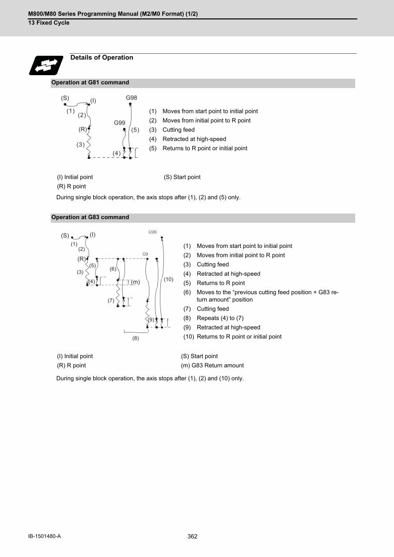
M800/M80 Series Programming Manual (M2/M0 Format) (1/2)
13 Fixed Cycle
362IB-1501480-A
During single block operation, the axis stops after (1), (2) and (5) only.
During single block operation, the axis stops after (1), (2) and (10) only.
Details of Operation
Operation at G81 command
(1) Moves from start point to initial point
(2) Moves from initial point to R point
(3) Cutting feed
(4) Retracted at high-speed
(5) Returns to R point or initial point
(I) Initial point (S) Start point
(R) R point
Operation at G83 command
(1) Moves from start point to initial point
(2) Moves from initial point to R point
(3) Cutting feed
(4) Retracted at high-speed
(5) Returns to R point
(6) Moves to the “previous cutting feed position + G83 re-turn amount” position
(7) Cutting feed
(8) Repeats (4) to (7)
(9) Retracted at high-speed
(10) Returns to R point or initial point
(I) Initial point (S) Start point
(R) R point (m) G83 Return amount
(1)(2)
(3)(4)
(5)
G98
G99
(S)
(R)
(I)
(10)
(1)(2)
(3)
(4)
(7)
(5) (6)
(9)
(8)
(I)
(R)
(S)
(m)

M800/M80 Series Programming Manual (M2/M0 Format) (1/2)
13 Fixed Cycle
363 IB-1501480-A
During single block operation, the axis stops after (1), (2) and (8) only.
If a dwell command is issued, the high-speed retract will be executed after the command.
Operation at G73 command
(1) Moves from start point to initial point
(2) Moves from initial point to R point
(3) Cutting feed
(4) Retracted at high-speed
(5) Moves to the position set with “G73 return amount“
(6) Repeats (3) to (5)
(7) Retracted at high-speed
(8) Returns to R point or initial point
(I) Initial point (S) Start point
(R) R point (n) G73 Return amount
(8)
(7)
(6)
(5)(4)
(3)
(1)
(2)
G98
G99
(I)
(R)
(S)
(n)
M800/M80 Series Programming Manual (M2/M0 Format) (1/2)
13 Fixed Cycle
364IB-1501480-A
13.1.18 Acceleration/Deceleration Mode Change in Hole Drilling Cycle
This function switches the acceleration/deceleration mode for the hole drilling cycle between the inclination constant
method and the acceleration/deceleration after interpolation.
The command formats are the same as those of the fixed cycles G83, G87, and G83.2.
With parameter "#1253 set25/bit2 Acceleration/deceleration mode change in hole drilling cycle" enabled, operation
will be as follows.
(1) Acceleration/deceleration mode will be either linear or soft method. (Unless soft acceleration/deceleration is ap-
plied, the linear method will always be applied.)
(2) The operation follows the parameter settings that determine whether the inclination-constant or postinterpolation
acceleration/deceleration is applied.
"#2001 rapid (rapid traverse rate)" and "#2004 G0tL (G0 time constant (linear))" provide G0 (rapid traverse) ac-
celeration/deceleration inclination, and "#2002 clamp (cutting feedrate for clamp)" and "#2007 G1tL (G1 time
constant (linear))" provide G1 (cutting feed) acceleration/deceleration inclination.
Refer to "Rapid Traverse Constant Inclination Acceleration/Deceleration" for details of constant inclination ac-
celeration/deceleration.
Function and purpose
Command format
Detailed description
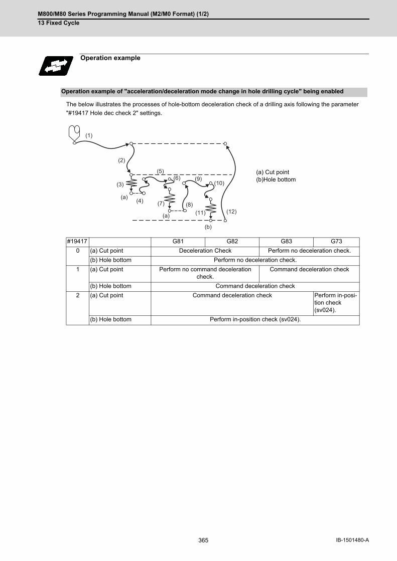
M800/M80 Series Programming Manual (M2/M0 Format) (1/2)
13 Fixed Cycle
365 IB-1501480-A
The below illustrates the processes of hole-bottom deceleration check of a drilling axis following the parameter
"#19417 Hole dec check 2" settings.
Operation example
Operation example of "acceleration/deceleration mode change in hole drilling cycle" being enabled
(a) Cut point(b)Hole bottom
#19417 G81 G82 G83 G73
0 (a) Cut point Deceleration Check Perform no deceleration check.
(b) Hole bottom Perform no deceleration check.
1 (a) Cut point Perform no command deceleration check.
Command deceleration check
(b) Hole bottom Command deceleration check
2 (a) Cut point Command deceleration check Perform in-posi-tion check (sv024).
(b) Hole bottom Perform in-position check (sv024).
(1)
(2)
(3)
(a)
(a)
(4) (7)
(9)(6)(5)
(8)
(b)
(11)
(10)
(12)

M800/M80 Series Programming Manual (M2/M0 Format) (1/2)
13 Fixed Cycle
366IB-1501480-A
13.2 Special Fixed Cycle
The special fixed cycle is used with the standard fixed cycle.
Before using the special fixed cycle, record the hole machining data except for the positioning data (except for X, Y
plane) by the standard fixed cycle.
The tool is positioned to the hole drilling position when the special fixed cycle is executed. The drilling operation is
executed with the fixed cycle for drilling.
Even after the special fixed cycle is executed, the recorded standard fixed cycle will be kept until canceled.
If the special fixed cycle is designated when not in the fixed cycle mode, only positioning will be executed, and the
hole drilling operation will not be carried out.
If the special fixed cycle is commanded without commanding the fixed cycle for drilling, positioning will be executed
following the current 01 group modal G code.
Function and purpose

M800/M80 Series Programming Manual (M2/M0 Format) (1/2)
13 Fixed Cycle
367 IB-1501480-A
13.2.1 Bolt Hole Cycle; G34
This function is used to drill "n" holes, dividing the circumference by "n", on the circumference with radius R centering
the coordinates designated with X and Y. The drilling starts at the point which makes the angle θ with X axis. The
hole drilling operation at each hole will follow the standard fixed cycle.
The movement between hole positions will all be done in the G00 mode. G34 will not hold the data after the com-
mand is completed.
As shown in the example, the tool position after the G34 command is completed is above the final hole. When mov-
ing to the next position, the coordinate value must be calculated to issue the command with an incremental value.
Thus, use of the absolute value mode is handy.
(1) If an address other than the selected plane's vertical axis, horizontal axis, G, N, I, J, K, H, O, P, F, M, S or 2ndmiscellaneous function is issued in the same block as the G34 command, a program error (P32) will occur.
Function and purpose
Command format
G34 Xx1 Yy1 Ir Jθ Kn ;
Xx1,Yy1 Positioning of bolt hole cycle center. This will be affected by G90/G91.
Ir Radius r of the circle. The unit follows the input setting unit, and is given with a positive No.
Jθ Angle θ of the point to be drilled first. The CCW direction is positive. (The decimal point position will be the degree class. If there is no decimal point, the unit will be 0.001°.)
Kn No. of holes to be drilled: n 1 to 9999 can be designated, but 0 cannot be designated. When the value is positive, positioning will take place in the CCW direction, and when negative, will take place in the CW direction. If "0" is designated, a program error (P221) occurs.
Program example
N001 G91;
N002 G81 Z-10.000 R5.000 L0 F200 ;
N003 G90 G34 X200.000 Y100.000 I100.000 J20.000 K6;
N004 G80 ; --------------- (G81 cancel)
N005 G90 G00 X500.000 Y100.000. ;
(a) Position before G34 execution
(500mm, 100mm)
20
x1=200mmn=6
I=100mmy1=100mm
(a) N005 G00
Note
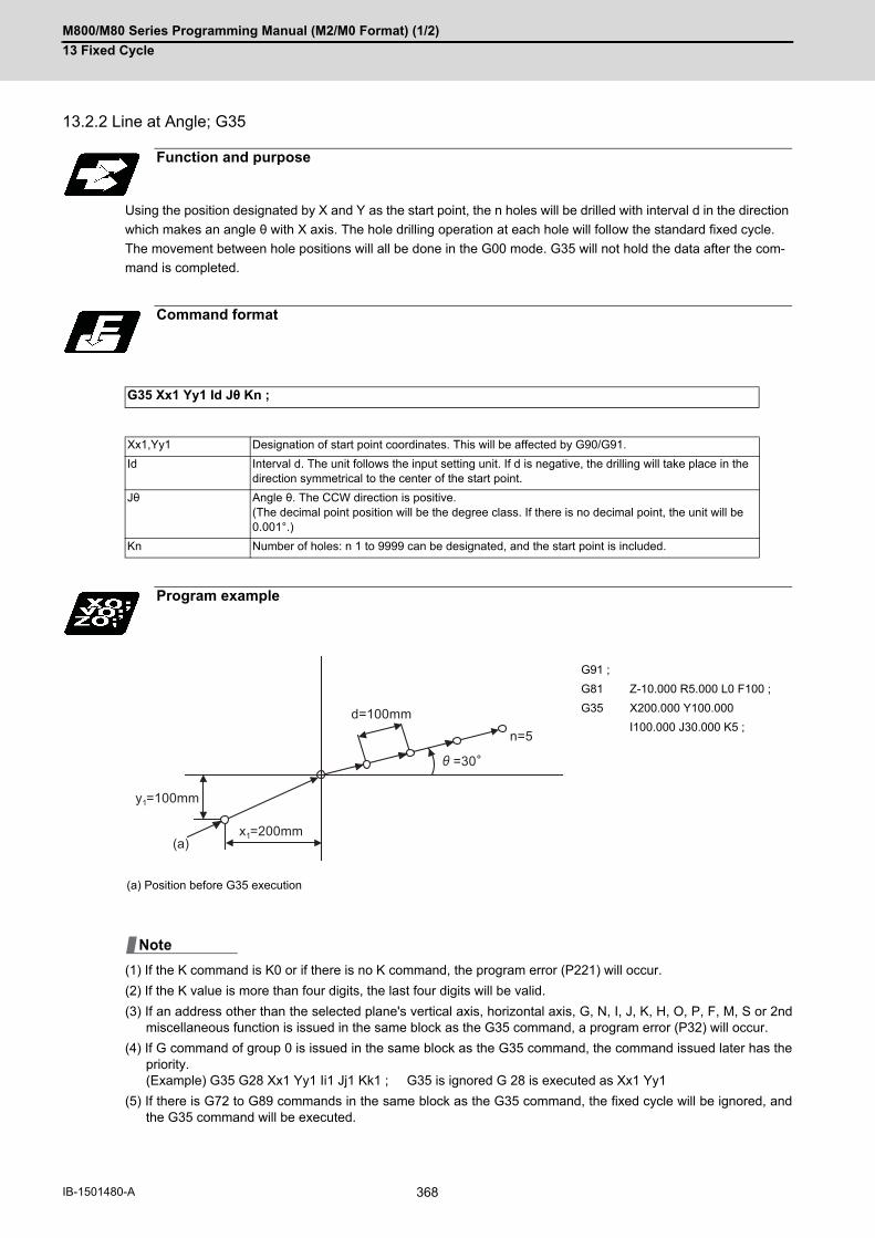
M800/M80 Series Programming Manual (M2/M0 Format) (1/2)
13 Fixed Cycle
368IB-1501480-A
13.2.2 Line at Angle; G35
Using the position designated by X and Y as the start point, the n holes will be drilled with interval d in the direction
which makes an angle θ with X axis. The hole drilling operation at each hole will follow the standard fixed cycle.
The movement between hole positions will all be done in the G00 mode. G35 will not hold the data after the com-
mand is completed.
(1) If the K command is K0 or if there is no K command, the program error (P221) will occur.
(2) If the K value is more than four digits, the last four digits will be valid.
(3) If an address other than the selected plane's vertical axis, horizontal axis, G, N, I, J, K, H, O, P, F, M, S or 2ndmiscellaneous function is issued in the same block as the G35 command, a program error (P32) will occur.
(4) If G command of group 0 is issued in the same block as the G35 command, the command issued later has thepriority. (Example) G35 G28 Xx1 Yy1 Ii1 Jj1 Kk1 ; G35 is ignored G 28 is executed as Xx1 Yy1
(5) If there is G72 to G89 commands in the same block as the G35 command, the fixed cycle will be ignored, andthe G35 command will be executed.
Function and purpose
Command format
G35 Xx1 Yy1 Id Jθ Kn ;
Xx1,Yy1 Designation of start point coordinates. This will be affected by G90/G91.
Id Interval d. The unit follows the input setting unit. If d is negative, the drilling will take place in the direction symmetrical to the center of the start point.
Jθ Angle θ. The CCW direction is positive. (The decimal point position will be the degree class. If there is no decimal point, the unit will be 0.001°.)
Kn Number of holes: n 1 to 9999 can be designated, and the start point is included.
Program example
G91 ;
G81 Z-10.000 R5.000 L0 F100 ;
G35 X200.000 Y100.000
I100.000 J30.000 K5 ;
(a) Position before G35 execution
y1=100mm
=30
n=5
d=100mm
x1=200mm(a)
Note
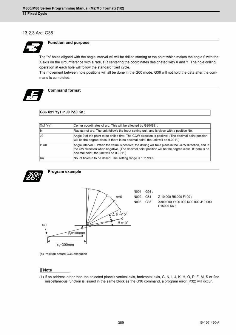
M800/M80 Series Programming Manual (M2/M0 Format) (1/2)
13 Fixed Cycle
369 IB-1501480-A
13.2.3 Arc; G36
The "n" holes aligned with the angle interval ∆θ will be drilled starting at the point which makes the angle θ with the
X axis on the circumference with a radius R centering the coordinates designated with X and Y. The hole drilling
operation at each hole will follow the standard fixed cycle.
The movement between hole positions will all be done in the G00 mode. G36 will not hold the data after the com-
mand is completed.
(1) If an address other than the selected plane's vertical axis, horizontal axis, G, N, I, J, K, H, O, P, F, M, S or 2ndmiscellaneous function is issued in the same block as the G36 command, a program error (P32) will occur.
Function and purpose
Command format
G36 Xx1 Yy1 Ir Jθ P∆θ Kn ;
Xx1,Yy1 Center coordinates of arc. This will be affected by G90/G91.
Ir Radius r of arc. The unit follows the input setting unit, and is given with a positive No.
Jθ Angle θ of the point to be drilled first. The CCW direction is positive. (The decimal point position will be the degree class. If there is no decimal point, the unit will be 0.001°.)
P ∆θ Angle interval θ. When the value is positive, the drilling will take place in the CCW direction, and in the CW direction when negative. (The decimal point position will be the degree class. If there is no decimal point, the unit will be 0.001°.)
Kn No. of holes n to be drilled. The setting range is 1 to 9999.
Program example
N001 G91 ;
N002 G81 Z-10.000 R5.000 F100 ;
N003 G36 X300.000 Y100.000 I300.000 J10.000 P15000 K6 ;
(a) Position before G36 execution
n=6
x1=300mm
=10
= 15
y1=100mm
(a)
Note

M800/M80 Series Programming Manual (M2/M0 Format) (1/2)
13 Fixed Cycle
370IB-1501480-A
13.2.4 Grid; G37
The nx points on a grid are drilled with an interval ∆x parallel to the X axis, starting at the position designated with
X, Y. The hole drilling operation at each hole will follow the standard fixed cycle.
The movement between hole positions will all be done in the G00 mode. G37 will not hold the data after the com-
mand is completed.
Function and purpose
Command format
G37 Xx1 Yy1 I∆x Pnx J∆y Kny ;
Xx1,Yy1 Designate the coordinates at the start point. This will be affected by G90/G91.
I ∆x Interval ∆x of the X axis. The unit will follow the input setting unit. If ∆x is positive, the interval will be in the forward direction looking from the start point, and when negative, will be in the reverse direction looking from the start point.
Pnx No. of holes nx in the X axis direction. The setting range is 1 to 9999.
J ∆y Interval ∆y of the Y axis. The unit will follow the input setting unit. If ∆y is positive, the interval will be in the forward direction looking from the start point, and when negative, will be in the reverse direction looking from the start point.
Kny No. of holes ny in the Y axis direction. The setting range is 1 to 9999.
Program example
G91 ;
G81 Z-10.000 R5.000 F20 ;
G37 X300.000 Y-100.000 I50.000 P10
J100.000 K8 ;
(a) Position before G37 is executed
ny=8
nx=10x1=300mm
y= 100mmy1=100mm
x=50mm
(a)
M800/M80 Series Programming Manual (M2/M0 Format) (1/2)
13 Fixed Cycle
371 IB-1501480-A
(1) If the P and K commands are P0 or K0, or if there is no P or K command, the program error (P221) will occur. Ifthe P or K value is more than four digits, the last four digits will be valid.
(2) If an address other than the selected plane's vertical axis, horizontal axis, G, N, I, J, K, H, O(Label L), L(LabelO), P, F, M, S or 2nd miscellaneous function is issued in the same block as the G37 command, a program error(P32) will occur.
(3) If G command of group 0 is issued in the same block as the G37 command, the command issued later has thepriority.
(4) If there is G72 to G89 command in the same block as the G37 command, the fixed cycle will be ignored, and theG37 command will be executed.
(5) If the G22.1/G23.1 command is programmed in the same block as the G37 command, the G22.1/G23.1 com-mand will be ignored, and the G37 command will be executed.
Note

M800/M80 Series Programming Manual (M2/M0 Format) (1/2)
13 Fixed Cycle
372IB-1501480-A

14
373 IB-1501480-A
Macro Functions

M800/M80 Series Programming Manual (M2/M0 Format) (1/2)
14 Macro Functions
374IB-1501480-A
14Macro Functions14.1 Subprogram Control; G22, G23
14.1.1 Subprogram Call; G22, G23
Fixed sequences or repeatedly used parameters can be stored in the memory as subprograms that can then be
called from the main program when required. G22 serves to call subprograms and G23 serves to return operation
from the subprogram to the main program. Furthermore, it is possible to call other subprograms from particular sub-
programs and the nesting depth can include as many as 10 levels.
The table below shows the functions that can be executed by adding and combining the tape memory/editing func-
tions, subprogram control functions and fixed cycle functions.
(*1) Symbol "○" denotes available functions and symbol "×" denotes unavailable functions.
(*2) Variables cannot be transferred with the G22 command, but variable commands in subprograms are available
if the variable command specifications are provided.
(*3) A maximum of 10 nesting levels form the nesting depth.
Function and purpose
Case 1 Case 2 Case 3 Case 4
1. Tape memory and editing Yes Yes Yes Yes
2. Subprogram control No Yes Yes No
3. Fixed cycles No No Yes Yes
Function
1. Memory mode ○ ○ ○ ○
2. Tape editing (main memory) ○ ○ ○ ○
3. Subprogram call × ○ ○ ×
4. Subprogram variable designation (*2) × ○ ○ ×
5. Subprogram nesting level call (*3) × ○ ○ ×
6. Fixed cycles × × ○ ○
7. Editing subprogram for fixed cycle × × ○ ○
G22 L1 ;
L1000 L1 L2 L10
G23 ;
G23 ;G23 ;
M02/M30 ;
G22 L2 ;
G22 L3 ;
Main program:Level 0 (L1000)
Subprogram:Level 1 (L1)
Subprogram:Level 2 (L2)
Subprogram:Level 10 (L10)
10-le
vel n
estin
g
M800/M80 Series Programming Manual (M2/M0 Format) (1/2)
14 Macro Functions
375 IB-1501480-A
Command format
Subprogram call
G22 L(A)__ H__ P__ ,D__ ;
G22 <file name> H__ P__ ,D__ ;
L (label L)A (label O)
Program number in subprogram to be called (own program if omitted)Note that L(A) can be omitted only for memory mode, MDI operation, high-speed pro-gram server operation, SD card operation, hard disk operation, or USB operation. (Numeric value of up to 8 digits)Use a parameter to specify a 4- or 8-digit subprogram No. starting with L/O. However, if the commanded value is bigger than the digit number set with parameter, a subprogram call is carried out as commanded.
<File name> File nameA file name can be specified instead of a program No. In this case, enclose the file name inside brackets < >. (The file name can have up to 32 characters including the extension.) (Example) G22 <BUHIN-12. RAF> ;
H Program sequence number in subprogram to be called (head block if omitted)
P Number of subprogram repetitions
(If omitted, it is assumed to be "P1", and processing is not carried out when "P0" is set.)
(1 to 9999 times depending on the 4-digit value)
For instance, “G22 L1 P3;” is equivalent to the following:
G22 L1 ;
G22 L1 ;
G22 L1 ;
,D Subprogram device No. (0 to 4). The subprogram is searched according to the setting of parameter "#8890 Subpro srch odr D0" to "#8894 Subpro srch odr D4" when ",D" is omitted. The device No. is set to the parameter, such as "#8880 Subpro stor D0: dev".
Return to main program from subprogram
G23 H__ ;
H Sequence No. of return destination (returned to block that follows the calling block)

M800/M80 Series Programming Manual (M2/M0 Format) (1/2)
14 Macro Functions
376IB-1501480-A
Subprograms have the same format as machining programs for normal memory mode, except that the subprogram
completion instruction G23(H_); must be registered as an independent block in the last block.
(1) The above program is registered by editing operations at the setting and display unit. For further details, refer tothe section on "program editing" in the Instruction Manual.
(2) Only those subprogram Nos. ranging from 1 to 99999999 designated by the optional specifications can be used.When there are no program Nos. on the tape, they are registered as the setting No. for "program input."
(3) If a program is called from a subprogram over the nesting depth determined in the specifications, the programerror (P230) will occur.
(4) Main programs and subprograms are registered in the order they were read without distinction. Therefore, mainprograms and subprograms should not be given the same Nos. (If they are, error "E11" will be displayed at reg-istration.)
(5) Main programs can be executed during memory, tape, MDI, or BTR mode, but subprograms must be in the mem-ory mode.
(6) Besides the G22 command, subprogram nesting is subject to the following commands:G65: Macro callG66: Modal callG66.1: Modal callG Code call Miscellaneous function callMDI interruptionAutomatic tool length measurementMacro interruptionMultiple-step skip function
(7) Subprogram nesting is not subject to the following commands that can be called even beyond the 10th nestinglevel.Fixed cyclesPattern cycles
(8) To repeatedly use the subprogram, it can be repeated p1 times by programming G22 Ll1 Pp1;.
(9) When using the multi-part system, if the subprogram attributed to the part system with the call command is emp-ty, the subprogram call operation will change according to the parameters. (These parameters depend on theMTB specifications.)
Detailed description
Creating and registering subprograms
L******** ; Program No. as subprogram No.
....... ; :....... ;
Main body of subprogram
G23; Subprogram return command
%(EOR) Registration completion code
#1285 ext21/bit1
Description
OFF The subprogram registered in the memory for the selected part system is called out.
ON The subprogram registered in the memory for the selected part system is called out. If the sub-program in the selected part system is empty, the subprogram with the same No. in the 1st part system is called out.

M800/M80 Series Programming Manual (M2/M0 Format) (1/2)
14 Macro Functions
377 IB-1501480-A
When there are 3 subprogram calls (known as 3 nesting levels)
Sequence of execution: (a)-(b)-(c)-(c')-(b')-(a')
(1) For nesting, the G22 and G23 commands should always be paired off on a 1:1 basis; (a)' for (a), (b)' for (b), etc.
(2) Modal information is rewritten in the order of execution sequence without distinction between main programs andsubprograms. Therefore, after calling a subprogram, attention must be paid to the modal data status when pro-gramming.
The G22 H__ ; G23 H__ ; commands designate the sequence Nos. in a program with a call instruction.
Program example
Program example 1
Program example 2
G22L10; G22L20;
G23; G23; G23;
L1;
G22L1;
M02;
L10; L20;
(a')
(a) (b) (c)
(b') (c')
Main program Subprogram 1 Subprogram 2 Subprogram 3
G22H3;
N3___;
G23;
G22H__ ;
N100___;G22 L123;N200_;N300___;N400___;
L123;
G23 H200;
G23 H__ ;
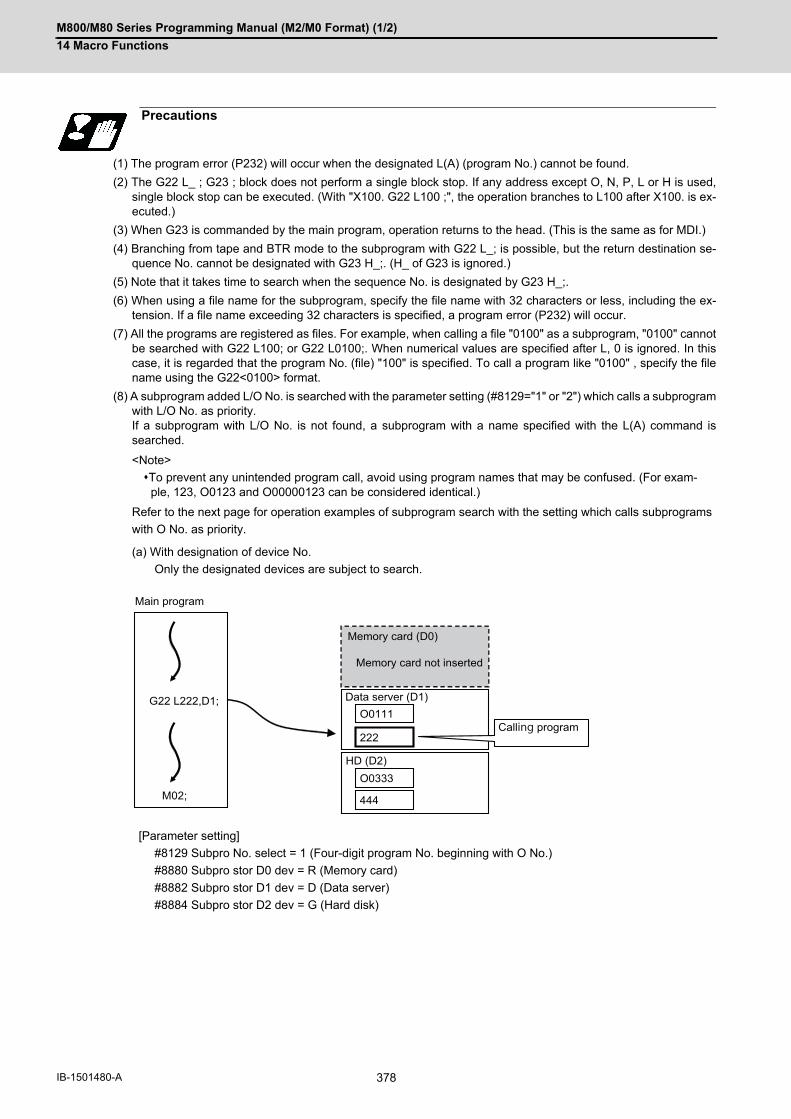
M800/M80 Series Programming Manual (M2/M0 Format) (1/2)
14 Macro Functions
378IB-1501480-A
(1) The program error (P232) will occur when the designated L(A) (program No.) cannot be found.
(2) The G22 L_ ; G23 ; block does not perform a single block stop. If any address except O, N, P, L or H is used,single block stop can be executed. (With "X100. G22 L100 ;", the operation branches to L100 after X100. is ex-ecuted.)
(3) When G23 is commanded by the main program, operation returns to the head. (This is the same as for MDI.)
(4) Branching from tape and BTR mode to the subprogram with G22 L_; is possible, but the return destination se-quence No. cannot be designated with G23 H_;. (H_ of G23 is ignored.)
(5) Note that it takes time to search when the sequence No. is designated by G23 H_;.
(6) When using a file name for the subprogram, specify the file name with 32 characters or less, including the ex-tension. If a file name exceeding 32 characters is specified, a program error (P232) will occur.
(7) All the programs are registered as files. For example, when calling a file "0100" as a subprogram, "0100" cannotbe searched with G22 L100; or G22 L0100;. When numerical values are specified after L, 0 is ignored. In thiscase, it is regarded that the program No. (file) "100" is specified. To call a program like "0100" , specify the filename using the G22<0100> format.
(8) A subprogram added L/O No. is searched with the parameter setting (#8129="1" or "2") which calls a subprogramwith L/O No. as priority.If a subprogram with L/O No. is not found, a subprogram with a name specified with the L(A) command issearched.
<Note>
To prevent any unintended program call, avoid using program names that may be confused. (For exam-ple, 123, O0123 and O00000123 can be considered identical.)
Refer to the next page for operation examples of subprogram search with the setting which calls subprograms
with O No. as priority.
(a) With designation of device No.
Only the designated devices are subject to search.
[Parameter setting]
#8129 Subpro No. select = 1 (Four-digit program No. beginning with O No.)
#8880 Subpro stor D0 dev = R (Memory card)
#8882 Subpro stor D1 dev = D (Data server)
#8884 Subpro stor D2 dev = G (Hard disk)
Precautions
444
O0333
222
O0111
M02;
G22 L222,D1;
HD (D2)
Memory card (D0)
Memory card not inserted
Data server (D1)
Calling program
Main program

M800/M80 Series Programming Manual (M2/M0 Format) (1/2)
14 Macro Functions
379 IB-1501480-A
(b) Without designation of device No.
A subprogram with O No. is searched according to the settings of #8890 (D0 in order of subprogram search)
to #8894 (D4 in order of subprogram search). (Refer to the solid line arrows "a" and "b" in the figure.)
If a subprogram with O No. is not found, subprograms with a name designated with the L(A) command are
searched in order of the parameter setting. (Refer to the broken lines "c" and "d" in the figure.)
If none of the designated subprogram storage locations are subject to search, memories are searched.
If any device or directory designated as the subprogram storage location is not found due to a reasonsuch as absence, poor contact and contact failure of a memory card, the said device or directory willbe excluded from the search target.
[Parameter setting]
#8129 Subpro No. select = 1 (Four-digit program No. beginning with O No.)
#8880 Subpro stor D0 dev = R (Memory card)
#8882 Subpro stor D1 dev = D (Data server)
#8884 Subpro stor D2 dev = G (Hard disk)
#8890 Subpro srch odr D0 = 1
#8891 Subpro srch odr D1 = 2
#8892 Subpro srch odr D2 = 3
(9) When a program in an external device such as a USB memory device is executed, a period of processing timeis required in the subprogram call or in the instruction to change the flow of the program such as GOTO or DO-END; therefore, interpolation may be decelerated or stopped.
Note
d
b
c
a
(3)
(2)
(1)
444
O0333
222
O0111
M02;
G22 L444;
Main program
Calling program
Subprogram search order
HD (D2)
Data server (D1)
Memory card not inserted
Memory card (D0)
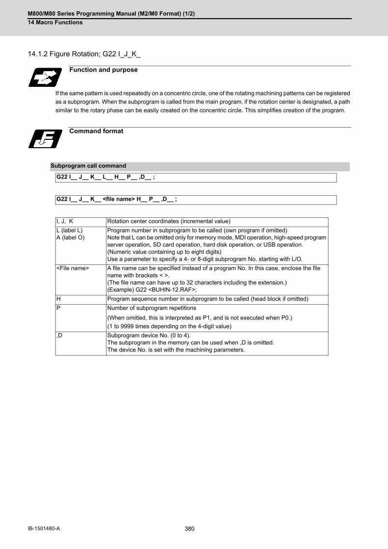
M800/M80 Series Programming Manual (M2/M0 Format) (1/2)
14 Macro Functions
380IB-1501480-A
14.1.2 Figure Rotation; G22 I_J_K_
If the same pattern is used repeatedly on a concentric circle, one of the rotating machining patterns can be registered
as a subprogram. When the subprogram is called from the main program, if the rotation center is designated, a path
similar to the rotary phase can be easily created on the concentric circle. This simplifies creation of the program.
Function and purpose
Command format
Subprogram call command
G22 I__ J__ K__ L__ H__ P__ ,D__ ;
G22 I__ J__ K__ <file name> H__ P__ ,D__ ;
I, J, K Rotation center coordinates (incremental value)
L (label L)A (label O)
Program number in subprogram to be called (own program if omitted)Note that L can be omitted only for memory mode, MDI operation, high-speed program server operation, SD card operation, hard disk operation, or USB operation.(Numeric value containing up to eight digits)Use a parameter to specify a 4- or 8-digit subprogram No. starting with L/O.
<File name> A file name can be specified instead of a program No. In this case, enclose the file name with brackets < >. (The file name can have up to 32 characters including the extension.) (Example) G22 <BUHIN-12.RAF>;
H Program sequence number in subprogram to be called (head block if omitted)
P Number of subprogram repetitions
(When omitted, this is interpreted as P1, and is not executed when P0.)
(1 to 9999 times depending on the 4-digit value)
,D Subprogram device No. (0 to 4). The subprogram in the memory can be used when ,D is omitted. The device No. is set with the machining parameters.

M800/M80 Series Programming Manual (M2/M0 Format) (1/2)
14 Macro Functions
381 IB-1501480-A
(1) The first subprogram called out with subprogram call is executed at 0° rotation angle. The path is created as
commanded.
(2) If the number of repetitions is set to twice or more, the rotation angle is obtained from the called subprogram's
start point, end point and rotation center coordinate. The path of the first subprogram is used as the basic figure
and is rotated and arranged for the designated number of call repetitions, using the rotation center coordinates
as a reference.
(3) All blocks in the subprogram are rotated.
(4) If the subprogram start point and end point are not on the same circle having the commanded figure rotation
center coordinates as the center, the axis will interpolate using the subprogram's end point as the start point, and
the end point in the first movement command block in the rotated subprogram as the end point.
(5) Both absolute values and incremental values can be used in the figure rotation subprogram. Even if commanded
with an absolute value command, the rotation will be the same as when commanded with an incremental value.
(6) I, J and K are commanded with the incremental amount from the start point.
(7) A subprogram of which figure is rotating cannot be branched to the other subprogram.
(8) The figure is rotated on the workpiece coordinate system, and can be shifted with the G92, G52, G54 to G59
(workpiece coordinate system shift) command.
(9) Functions (reference position return, uni-direction positioning, etc.) on the machine coordinate system for the ro-
tary plane axis cannot be used while the figure is rotated. However, the machine coordinate system functions
can be used for axes other than the rotation plane.
(10) Refer to "14.1.1 Subprogram Call; G22, G23" for <File name> and calling the subprogram with L/O No.
Detailed description
(a) Basic figure(b) Center of rotation
J
I
(a)
(b)
L

M800/M80 Series Programming Manual (M2/M0 Format) (1/2)
14 Macro Functions
382IB-1501480-A
(1) A program error will occur if figure rotation is commanded during figure rotation.
(2) Figure rotation and program coordinate rotation cannot be commanded simultaneously. The program error will
occur.
Program example
Main program (L1000)
N01 G90 G54 G00 X0 Y0 ;N02 G01 G41 X200. Y150. D01 F500 ;N03 G01 Z-50. F300 ;
N04 G22 L2200 P5 J-100. ;
N05 G90 G01 Z50. F500 ;N06 G40 ;N07 G00 X0 Y0 ;
Subprogram (L2200)
N01 G91 G01 X29.389 Y-59.549 ;N02 X65.717 Y-9.549 ;N03 G23 ;
(a) Basic figure
Precautions
200.
100. 300.
Y
X
(a)

M800/M80 Series Programming Manual (M2/M0 Format) (1/2)
14 Macro Functions
383 IB-1501480-A
14.2 Variable Commands
Programming can be endowed with flexibility and general-purpose capabilities by designating variables, instead of
giving direct numerical values to particular addresses in a program, and by assigning the variable values depending
on the conditions that exist when executing the program.
All common variables are retained even when the power is turned OFF.
When the power is turned OFF or reset, the common variables can be set to <null> by setting the parameter ("#1128
RstVCl", "#1129 PwrVCl").
(1) The 4 standard operators are +, -, * and /.
(2) Functions cannot be used unless the user macro specifications are available.
(3) Error (P241) will occur when a variable No. is negative.
(4) Examples of incorrect variable expressions are given below.
Function and purpose
Command format
#∆∆∆=○○○○○○○○ ;
#*** = [formula] ;
Detailed description
Variable expressions
Example
#m m = value consisting of 0 to 9 #100
# [f] f = one of the followings in the formula #[-#120]
Numerical value m 123
Variable #543
Formula Operator Formula #110+#119
- (minus) formula -#120
[Formula] [#119]
Function [formula] SIN[#110]
Incorrect Correct
#6/2 # [6/2] (#6/2 is regarded as [#6] /2.)
#--5 #[-[-5]]
#-[#1] #[-#1]
Note

M800/M80 Series Programming Manual (M2/M0 Format) (1/2)
14 Macro Functions
384IB-1501480-A
The following table gives the types of variables.
The common variables are divided into the following two types.
Common variables 1: Used in common through all part systems
Common variables 2: Used in common in the programs of the part system
(*1) Common variable address #400s can only be used when there are 700 or more sets of common variables and
the MTB specifications are valid (parameter "#1336 #400_Valtyp").
When common variable address #400s can be used, these can be displayed and set on the common variable
screen.
It also becomes possible to input/output data of common variable address #400s.
(*2) When the parameter "#1052 MemVal" is set to "1" in multi-part system (MTB specifications), some or all of com-
mon variables "#100 to #199" and "#500 to #999" can be shared and used between part systems. The number
of variables sharable in part systems depends on the MTB specifications (parameters "#1303 V1comN" and
"#1304 V0comN").
Depending on the MTB specifications, the common variables #100 to #199 are used for each part system, and
variables #500 to #999 are common for the part systems (parameter "#1052 MemVal"). Address #400s, that
can be used as common variable with 700 or more sets of variable, is common for the part systems regardless
of the setting of parameter "#1052 MemVal".
(*3) When "#1052 MemVal" is set to "1", #900000 to #907399 available for 8,000 sets of variable are not available.
Types of Variables
Type No. Function
Common variable Common variables 1 Common variables 2
Can be used in common throughoutmain, sub and macro programs.When using common variables in the
multi-part system, the number ofcommon variables shared betweenthe part systems can be specified de-pending on the MTB specifications(parameter "#1052 MemVal").
(*2)
1 part sys-tem
600 sets 500 to 999100100 to 800199 (*4)
100 to 199
700 sets 400 to 999 (*1)100100 to 800199 (*4)
100 to 199
8000 sets 400 to 999 (*1)100100 to 800199 (*4)900000 to 907399 (*3)
100 to 199
Multi-part systems(n = number of part sys-tems)
600 + 100 * n sets
400 to 999 (*1)100100 to 800199 (*4)
100 to 199 *n
7900 + 100 * n sets
400 to 999 (*1)100100 to 800199 (*4)900000 to 907399 (*3)
100 to 199 *n
Local variables 1 to 33 Can be used as local variables in macro programs.
System variable 1000 to Application is fixed by system.
Fixed cycle variables 1 to 32 Local variables in fixed cycle programs.
(Example) When "#1304 V0comN" is set to "5":
#500 to #504: Common for the part systems
#505 to #999: Each part system

M800/M80 Series Programming Manual (M2/M0 Format) (1/2)
14 Macro Functions
385 IB-1501480-A
(*4) When the parameter "#1316 CrossCom" is set to "1", the common variables #100100 to #800199 can be shared
between the part systems. (This depends on the MTB specifications.) The part system common variable which
can be used is shown in the table below.
(Example)
<1-part system>
<Multi-part system>
Common variables for each part system #100 to #199" in other part system can be used.
The PLC data reading function cannot be used, which uses system variables #100100 to #100110, andvariables #100100 to #100110 are used as common variables.
The setting of number of common variables shared between the part systems (The parameter #1052MemVal" is set to "1") becomes invalid, thus the movement is the same as "0" is set.
When the parameters "#1128 RstVCl", "#1129 PwrVCl" are set to "1", the operation is as follows. "#1128 RstVCl"The common variables shared between the part systems equivalent to #100 to #199 of the reset partsystem are cleared. (Example) If the 1st part system is reset, #100100 to #100199 are cleared.If the 2nd part system is reset, #200100 to #200199 are cleared."#1129 PwrVCl"The common variables shared between the part systems equivalent to #100 to #199 in the valid partsystem are cleared. (Example) In 1st part system, #100100 to #100199 are cleared.In 2nd part system, #100100 to #100199 and #200100 to #200199 are cleared.
Common variables shared between the part systems #100100 to #800199 can be displayed and set onthe common variable screen.
If common variables #100100 to #800199 are used when the number of sets of common variables isless than 600 sets or the parameter "#1316 CrossCom" is "0", a program error (P241) will occur.
Variable sets Common variables 1 (When "#1316 CrossCom" = "1")
Variable sets specification
600 sets (500 + 100 sets)
#100100 to #100199 (Equivalent to # 100 to #199 in 1st part system)#200100 to #200199 (Equivalent to # 100 to #199 in 2nd part system)#300100 to #300199 (Equivalent to # 100 to #199 in 3rd part system)#400100 to #400199 (Equivalent to # 100 to #199 in 4th part system)#500100 to #500199 (Equivalent to # 100 to #199 in 5th part system)#600100 to #600199 (Equivalent to # 100 to #199 in 6th part system)#700100 to #700199 (Equivalent to # 100 to #199 in 7th part system)#800100 to #800199 (Equivalent to # 100 to #199 in 8th part system)
700 sets (600 + 100 sets)
8000 sets (7900 + 100 sets)
#100100=200 ; Equivalent to #100 = 200 ;
#200105=#100 ; "200" is set to #200105.
#300110=#100100 ; "200" is set to #300110.
#800199=#500120 ; The variable value of "#500120" is set to #800199.
$1
#200100=-100 ; "-100" is set to #100 of 2nd part system.
#101=#200102 ; "#101" is set to #102 of 2nd part system.
#300105=#200103 ; "#103" of 2nd part system is set to #105 of 3rd part system.
#110=#500107 ; The variable value of "#500107" is set to #110.

M800/M80 Series Programming Manual (M2/M0 Format) (1/2)
14 Macro Functions
386IB-1501480-A
(1) When inputting the common variable data, if the following illegal variable No. data exist in the input file, the illegalvariable No. data is ignored and only the correct common variable data will be input. Variable data that is not common variables such as local variables (#1 to #33) or system variables (#1000
and after)Variable data of which the number of common variable sets does not match the pre-specified value
(Example)
If variables of # numbers undefined in the specifications exist in the input file when there are 700 sets of common
variables (#100 to #199, #500 to #999, and #100100 to #800199), they are ignored, and only the variables de-
fined in the specifications are input.
Variables can be used for all addresses except L(O), N and / (slash).
(1) When the variable value is used directly:
(2) When the complement of the variable value is used:
(3) When defining variables:
(4) When defining the variable arithmetic formula:
(1) A variable cannot be defined in the same block as an address. It must be defined in a separate block.
(2) Up to five sets of square parentheses [ ] may be used. #543 = -[[[[[#120]/2+15.]*3-#100]/#520+#125+#128]*#130+#132]
(3) There are no restrictions on the number of characters and number of variables for variable definition.
(4) The variable values should be within the range of 0 to ±99999999. If this range is exceeded, the arithmetic operations may not be conducted properly.
(5) The variable definitions become valid when definitions are made. #1 = 100 ; ............................. #1 = 100#1 = 200 #2 = #1 + 200 ; ..... #1 = 200, #2 = 400#3 = #1 + 300 ; ..................... #3 = 500
(6) Variable quotations are always regarded as having a decimal point at the end. When #100 is set to “10”“X#100;” is set to “X10.”.
Variable quotations
X#1 Value of #1 is used as the X value.
X-#2 Value with the #2 sign changed is used as the X value.
#3 = #5 Variable #3 uses the equivalent value of variable #5.
#1 = 1000 Variable #1 uses the equivalent value 1000. ("1000" is assumed to be "1000.".)
#1 = #3 + #2 - 100 Value of the operation result of "#3 + #2 - 100." is used as the #1 value.
X[#1 + #3 + 1000] Value of the operation result of "#1 + #3 + 1000" is used as the X value.
Incorrect Correct
X#1 = #3 + 100 ; → #1 = #3 + 100 ;X#1 ;
Note
Note

M800/M80 Series Programming Manual (M2/M0 Format) (1/2)
14 Macro Functions
387 IB-1501480-A
(1) If the common variable protection function is valid, the common variables in the range specified in the parameters(#12111 to #12114) cannot be changed from machining program or screen operation, or user operation such asfile input. This function depends on the MTB specifications (parameter "#1391 User level protect").
(2) If an attempt is made to change the value or name of the protected variable on the machining program, the pro-gram error (P243) will occur, causing the operation to be stop. Such a variable value or name can be changedusing the machine tool builder macro program, but cannot be done by the user. Multiple variable names can be changed in one block with the SETVNn command. However, if at least one ofthem is protected, the program error (P243) will occur.
(3) If "#1128 RstVCl" is set to "1", the variables (#100 to #199) are cleared after reset even if common variables(#100 to #199) are protected.
(4) If "#1129 PwrVCl" is set to "1", the variables (#100 to #199) are cleared at the power-ON even if common vari-ables (#100 to #199) are protected.
(5) For common variables used common to the part systems, the variable values and variable names can bechanged by the displayed part system.
Protection of common variable

M800/M80 Series Programming Manual (M2/M0 Format) (1/2)
14 Macro Functions
388IB-1501480-A
14.3 User Macro
A group of control and arithmetic instructions can be registered and used as a macro program to make it one inte-
grated function.
Macro programs use variables, control and arithmetic instructions to create subprograms which function to provide
special-purpose controls.
By combining the user macros with variable commands, it is possible to use the macro program call, arithmetic op-
erations, data input/output with PLC, control, decision, branch and many other instructions for measurement and
other such applications.
These special-purpose control functions (macro programs) are called by the macro call instructions from the main
program when needed.
(1) When the G66 or G66.1 command is entered, the specified user macro program will be called every time a block
is executed or after a movement command in blocks with a movement command is executed, until the G67 (can-
cel) command is entered.
(2) The G66 (G66.1) and G67 commands must be paired in a same program.
Function and purpose
G68 or G23 is used to terminate the user macro subprogram.
G code Function
G65 User macro Simple call
G66 User macro Modal call A (Movement command call)
G66.1 User macro Modal call B (Per-block call)
G67 User macro Modal call (G66, G66.1) cancel
G68 User macro program termination (same as G23)
Detailed description
;;
G65/G66/G66.1
M30; G68(G23);
Main program Subprogram

M800/M80 Series Programming Manual (M2/M0 Format) (1/2)
14 Macro Functions
389 IB-1501480-A
14.4 Macro Call Instructions
Macro call commands include the simple calls which call only the instructed block and the modal calls (types A and
B) which call a block in the call modal.
When the macro argument L/P valid function is enabled, the addresses L (calling program No.) and P (number of
subprogram repetitions) used as commands in user macro can be used as arguments.
The validity of this parameter depends on the MTB specifications. (Parameter "#1241 set13"/bit5 (Macro argument
L/P valid))
When a program in an external device such as a USB memory device is executed, a machining program stored in
USB memory cannot be called with a macro call such as G65, G66, or G66.1. Using such a macro calls a macro
program in memory.
14.4.1 Simple Macro Calls; G65
Function and purpose
Function and purpose
G68 or G23 is used to terminate the user macro subprogram.
Command format
Simple macro calls
G65 L__(A__) P__ argument ;
Simple macro calls
G65 <File name> P__ argument ;
L (label L)A (label O)
Program No.
<File name> File nameA file name can be specified instead of a program No. In this case, enclose the file name inside brackets < >. (The file name can have up to 32 characters including the extension.)
P Number of repetitions If omitted, this value is set to "1". (0 to 9999)
Argument Specify variable data
Subprogram(L__)
G65 L__ P__ ;
L__
G23 ;
Main program
to Subprogram
to Main program
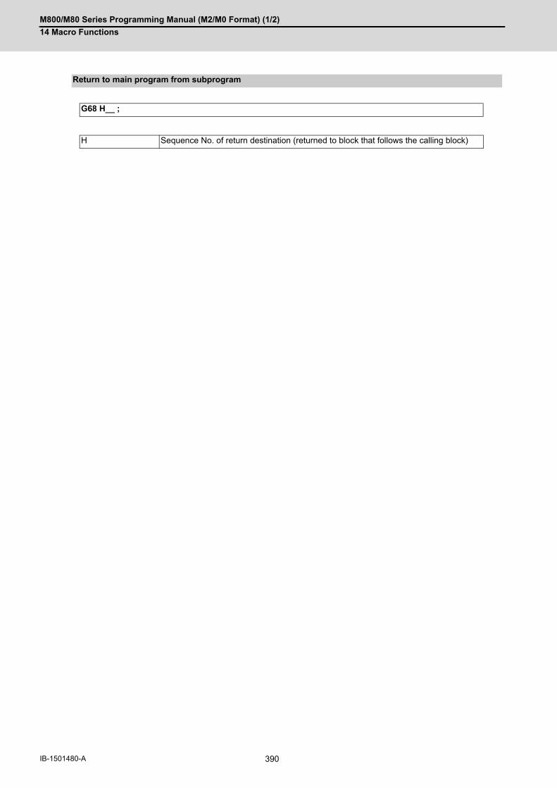
M800/M80 Series Programming Manual (M2/M0 Format) (1/2)
14 Macro Functions
390IB-1501480-A
Return to main program from subprogram
G68 H__ ;
H Sequence No. of return destination (returned to block that follows the calling block)

M800/M80 Series Programming Manual (M2/M0 Format) (1/2)
14 Macro Functions
391 IB-1501480-A
(1) When the argument must be transferred as a local variable to a user macro subprogram, the actual value shouldbe designated after the address. In this case, regardless of the address, a sign and decimal point can be used in the argument. There are 2 waysin which arguments are designated.
Format : A_ B_ C_ ......X_ Y_ Z_
(a) Arguments can be designated using any address except G, L(A), N, O and P.
(b) I, J and K must be designated in alphabetical order.
I_ J_ K_...Correct
J_ I_ K_...Incorrect
(c) Except for I, J and K, there is no need for designation in alphabetical order.
(d) Addresses which do not need to be designated can be omitted.
(e) The following table shows the correspondence between the addresses which can be designated by argument
designation I and the variable numbers in the user macro main body.
○: Available
×: Unavailable
*: Can be used while G66.1 command is modal
Detailed description
Argument designation I
Address and variable No. correspondence Addresses available for call instructions
Argument designation I address
Variable in macro G65, G66 G66.1
A #1 × ×
B #2 ○ ○
C #3 ○ ○
D #7 ○ ○
E #8 ○ ○
F #9 ○ ○
G #10 × × *
H #11 ○ ○
I #4 ○ ○
J #5 ○ ○
K #6 ○ ○
L #12 × × *
M #13 ○ ○
N #14 × × *
O #15 × ×
P #16 × × *
Q #17 ○ ○
R #18 ○ ○
S #19 ○ ○
T #20 ○ ○
U #21 ○ ○
V #22 ○ ○
W #23 ○ ○
X #24 ○ ○
Y #25 ○ ○
Z #26 ○ ○

M800/M80 Series Programming Manual (M2/M0 Format) (1/2)
14 Macro Functions
392IB-1501480-A
(1) With the label O type, the address "A" is used as the address for subprogram No., thus, "A" can not be used asthe local variable No.
Format: A__B__C__I__J__K__I__J__K__...
(a) In addition to address A, B and C, up to 10 groups of arguments with I, J, K serving as 1 group can be designated.
(b) When the same address is duplicated, designate the addresses in the specified order.
(c) Addresses which do not need to be designated can be omitted.
(d) The following table shows the correspondence between the addresses which can be designated by argument
designation II and the variable numbers in the user macro main body.
(1) The numbers 1 to 10 accompanying I, J and K indicate the sequence of the commanded sets, and are notrequired in the actual command.
(2) With the label O type, the address "A" is used as the address for subprogram No., thus, "A" can not be usedas the local variable No.
Argument designation II
Argument designa-tion II address
Variable in macro Argument designa-tion II address
Variable in macro
A #1 J5 #17
B #2 K5 #18
C #3 I6 #19
I1 #4 J6 #20
J1 #5 K6 #21
K1 #6 I7 #22
I2 #7 J7 #23
J2 #8 K7 #24
K2 #9 I8 #25
I3 #10 J8 #26
J3 #11 K8 #27
K3 #12 I9 #28
I4 #13 J9 #29
J4 #14 K9 #30
K4 #15 I10 #31
I5 #16 J10 #32
K10 #33
Note
Note
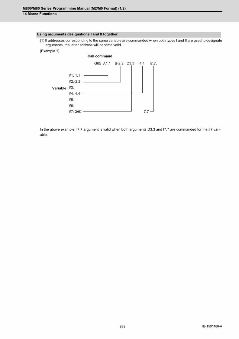
M800/M80 Series Programming Manual (M2/M0 Format) (1/2)
14 Macro Functions
393 IB-1501480-A
(1) If addresses corresponding to the same variable are commanded when both types I and II are used to designatearguments, the latter address will become valid.
(Example 1)
In the above example, I7.7 argument is valid when both arguments D3.3 and I7.7 are commanded for the #7 vari-
able.
Using arguments designations I and II together
Call command
Variable
G65 A1.1 B-2.2 D3.3 I4.4 I7.7;
#1: 1.1
#2:-2.2
#3:
#4: 4.4
#5:
#6: #7: 3.3 7.7

M800/M80 Series Programming Manual (M2/M0 Format) (1/2)
14 Macro Functions
394IB-1501480-A
14.4.2 Modal Call A (Movement Command Call) ; G66
When the block with a movement command is commanded between G66 and G67, the movement command is first
executed and then the designated user macro subprogram is executed. A number of user macro subprograms are
designated with "P".
The argument is the same as for a simple call.
Function and purpose
Command format
Modal call A
G66 L__(A__) P__ argument ;
G66 <File name> P__ argument ;
L (label L)A (label O)
Program No.
<File name> File nameA file name can be specified instead of a program No. In this case, enclose the file name inside brackets < >. (The file name can have up to 32 characters including the extension.)
P Number of repetitions
Argument Specify variable data
Modal call end
G67;
Return to main program from subprogram
G68 H__ ;
H Sequence No. of return destination (returned to block that follows the calling block)
G66 L__ P__ ;
G67 ;
L__
G68(G23) ;
Main program Subprogram
to Subprogram
to Subprogram
to Main program

M800/M80 Series Programming Manual (M2/M0 Format) (1/2)
14 Macro Functions
395 IB-1501480-A
(1) When the G66 command is entered, the specified user macro program will be called after the movement com-mand in a block with the movement commands has been executed, until the G67 (cancel) command is entered.
(2) The G66 and G67 commands must be paired in a same program. A program error will occur when G67 is issued without G66.
(Example) Drill cycle
<Note>
After the axis command is executed in the main program, the subprogram is executed.The subprogram is not executed in the blocks following G67.
Detailed description
N1 G90 G54 G0 X0 Y0 Z0;
N2 G91 G00 X-50.Y-50.Z-200.;
N3 G66 L9010 R-10.Z-30.F100;
N4 X-50.Y-50.;
N5 X-50.;
N6 G67;
L 9010
N10 G00 Z #18 M0;
N20 G09 G01 Z #26 F#9;
N30 G00 Z- #18+#26 ;
G68(G23) ;
WN1
N10
N20 N30
N2
N3
N4N5
X
-50.
-50.
-100.
-100.-150.
YArgument F
Argument R
Argument Z
Main program
To subprogram after axis command execution
To subprogram after axis command execution
Subprogram
To main program
to subprogramto subprogram

M800/M80 Series Programming Manual (M2/M0 Format) (1/2)
14 Macro Functions
396IB-1501480-A
14.4.3 Modal Call B (for Each Block); G66.1
The specified user macro subprogram is called unconditionally for each command block that is assigned between
G66.1 and G67 and the subprogram will be repeated for the number of times specified in P.
The argument is the same as for a simple call.
Function and purpose
Command format
Modal call B
G66.1 L__(A__) P__ argument ;
G66.1 <File name> P__ argument ;
L (label L)A (label O)
Program No.
<File name> File nameA file name can be specified instead of a program No. In this case, enclose the file name inside brackets < >. (The file name can have up to 32 characters including the extension.)
P Number of repetitions
Argument Specify variable data
Modal call end
G67;
Return to main program from subprogram
G68 H__ ;
H Sequence No. of return destination (returned to block that follows the calling block)
M800/M80 Series Programming Manual (M2/M0 Format) (1/2)
14 Macro Functions
397 IB-1501480-A
(1) In the G66.1 mode, everything except the L(O), N and G codes in the various command blocks which are readare handled as the argument without being executed. Any G code designated last or any N code commandedafter anything except L(O) and N will function as the argument.
(2) All significant blocks in the G66.1 mode are handled as when G65 L_ is assigned at the head of a block. (Example 1)In "G66.1 L1000;" mode,"N100 G01 G90 X100. Y200. F400 R1000 ;" is same as "N100 G65 L1000 G01 G90 X100. Y200. F400 R1000 ;".
<Note>
The call is performed even in the G66.1 command block in the G66.1 mode and the correspondence be-tween the argument address and the variable number is the same as for G65 (simple call).
(3) The range of the G and N command values that can be used anew as variables in the G66.1 mode is subject tothe restrictions as normal NC command values.
(4) Program number L(O), sequence numbers N and modal G codes are updated as modal information.
Detailed description

M800/M80 Series Programming Manual (M2/M0 Format) (1/2)
14 Macro Functions
398IB-1501480-A
14.4.4 G code macro call
User macro subprogram with prescribed program numbers can be called merely by issuing the G code command.
(*1) Functions as an argument when the macro argument L/P valid function is enabled.
It cannot be used when the macro argument L/P valid function is disabled.
(1) The above instruction functions in the same way as the instructions below, however, the correspondence be-tween G codes and instructions can be set by parameters.
a : G22 L****;
b : G65 L**** <Argument>;
c : G66 L**** <Argument>;
d : G66.1 L**** <Argument>;
When the parameters corresponding to "c" and "d" above are set, issue the cancel command (G67) either in the
user macro or after the call code has been commanded so as to cancel the modal call.
(2) The correspondence between the "**" which conducts the macro call and the macro program number L**** to becalled is set by parameters.
(3) Up to 10 G codes from G100 to G999 can be used with this instruction. (G codes from G01 to G99 used in thesystem can also be used with parameter "#1081 Gmac_P". This parameter setting depends on the MTB speci-fications.)
<Note>
G101 to G110 and G200 to G202 are user macro I codes, but if the parameters are set as the G code callcodes, the G code call will be the priority, and these codes cannot be used for user macro I.
(4) These commands cannot be issued in a program which has been called by a G code macro. If issued in such aprogram, they will be handled as ordinary G commands.
(5) When ",D" or "<(Character string)>"is commanded in a block that is calling a G code macro, a miscellaneouscommand macro, or an ASCII macro while the macro argument L/P valid function is enabled, a program error(P33) will occur. This parameter setting depends on the MTB specifications. (Parameter "#1241 set13"/bit5)
Function and purpose
Command format
G code macro call
G** P__ L__ argument ;
G** G code for macro call
P (*1)
L (*1)
Detailed description

M800/M80 Series Programming Manual (M2/M0 Format) (1/2)
14 Macro Functions
399 IB-1501480-A
14.4.5 Miscellaneous Command Macro Call (for M, S, T, B Code Macro Call)
The user macro subprogram of the specified program number can be called merely by issuing an M (or S, T, B)
code. (Registered M code and all S, T and B codes.)
(*1) Functions as an argument when the macro argument L/P valid function is enabled.
It cannot be used when the macro argument L/P valid function is disabled.
(1) The above instruction functions in the same way as the instructions below, however, the correspondence be-tween M codes and instructions can be set by parameters. (Same for S, T and B codes)
When the parameters corresponding to "c" and "d" above are set, issue the cancel command (G67) either in the
user macro or after the call code has been commanded so as to cancel the modal call.
(2) The correspondence between the "M**" which conducts the macro call and the macro program number L**** tobe called is set by parameters. Up to 10 M codes from M00 to M9999 can be registered. Note that the codes to be registered should exclude those basically required for the machine and the followingM codes.
M0, M1, M2, M30, M198, and M codes for G83 specified in the parameter "#8083"
(3) As with G22, it is displayed on the screen display of the setting and display unit but the M codes and MF are notoutput.
(4) Even if the registered miscellaneous commands above are issued in a user macro subprogram which are calledby an M code, it will not be regarded as a macro call and will be handled as a normal miscellaneous command.(Same for S, T and B codes)
(5) All S, T and B codes call the subprograms in the prescribed program numbers of the corresponding S, T and Bfunctions.
Function and purpose
Command format
Miscellaneous command macro call
M** P__ L__ ; (or S** ; , T** ; , B** ;)
M** M code for macro call (or S, T, B code)
P (*1)
L (*1)
Detailed description
a: G22 L**** ; M** is not output.
b: G65 L***** M** ;
c: G66 L***** M** ;
d: G66.1 L***** M** ;
M800/M80 Series Programming Manual (M2/M0 Format) (1/2)
14 Macro Functions
400IB-1501480-A
(6) Up to 10 M codes can be set.
<Note>
When "1 to 3" is set to "#7002 M[01] type", the macro call will be equivalent call to G65/G66/G66.1. In thiscase, the alphabet before the M,S,T,B code macro is not handled as an argument. For example, commanding the M code and T code in the same block changes the operation dependingon the order of the address.
(Example) To register M06 in M code macro
(7) When ",D" or "<(Character string)>"is commanded in a block that is calling a G code macro, a miscellaneouscommand macro, or an ASCII macro while the macro argument L/P valid function is enabled, a program error(P33) will occur. This parameter setting depends on the MTB specifications. (Parameter "#1241 set13"/bit5)
M06 T02 The value of T is treated as variable #20 in macro. The value is entered in the T code at the same time.
T02 M06 The value is not entered in the variable #20 in macro. The value is entered in the T code.
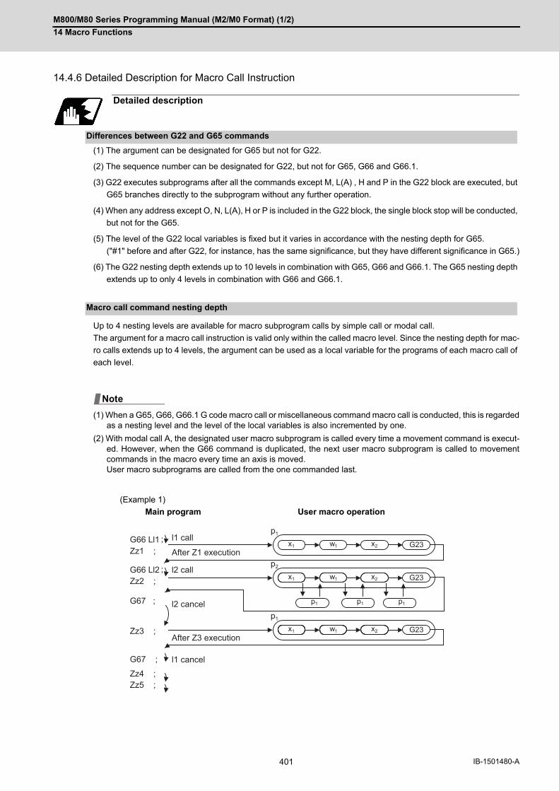
M800/M80 Series Programming Manual (M2/M0 Format) (1/2)
14 Macro Functions
401 IB-1501480-A
14.4.6 Detailed Description for Macro Call Instruction
(1) The argument can be designated for G65 but not for G22.
(2) The sequence number can be designated for G22, but not for G65, G66 and G66.1.
(3) G22 executes subprograms after all the commands except M, L(A) , H and P in the G22 block are executed, but
G65 branches directly to the subprogram without any further operation.
(4) When any address except O, N, L(A), H or P is included in the G22 block, the single block stop will be conducted,
but not for the G65.
(5) The level of the G22 local variables is fixed but it varies in accordance with the nesting depth for G65.
("#1" before and after G22, for instance, has the same significance, but they have different significance in G65.)
(6) The G22 nesting depth extends up to 10 levels in combination with G65, G66 and G66.1. The G65 nesting depth
extends up to only 4 levels in combination with G66 and G66.1.
Up to 4 nesting levels are available for macro subprogram calls by simple call or modal call.
The argument for a macro call instruction is valid only within the called macro level. Since the nesting depth for mac-
ro calls extends up to 4 levels, the argument can be used as a local variable for the programs of each macro call of
each level.
(1) When a G65, G66, G66.1 G code macro call or miscellaneous command macro call is conducted, this is regardedas a nesting level and the level of the local variables is also incremented by one.
(2) With modal call A, the designated user macro subprogram is called every time a movement command is execut-ed. However, when the G66 command is duplicated, the next user macro subprogram is called to movementcommands in the macro every time an axis is moved. User macro subprograms are called from the one commanded last.
(Example 1)
Detailed description
Differences between G22 and G65 commands
Macro call command nesting depth
Main program User macro operation
Note
G66 Ll1 ;p1
x1
p1 p1 p1
x2 G23w1
x1 x2 G23w1
x1 x2 G23w1
p2
p1
G66 Ll2 ;
Zz1 ;
Zz2 ;
Zz3 ;
Zz4 ;Zz5 ;
G67 ;
G67 ;
l1 call
After Z1 execution
l2 call
l2 cancel
After Z3 execution
l1 cancel

M800/M80 Series Programming Manual (M2/M0 Format) (1/2)
14 Macro Functions
402IB-1501480-A
(3) When G22 command is executed in G66 (G66.1) modal, the program designated by G66 (G66.1) will be execut-ed after completing the movement command in the subprogram called by G22 (in case of G66.1, after complet-ing each block).
(Example 2)
When the program numbers of l1 and l2 are same, the program numbers of subprograms 1 and 2 will be
same.
G66 Ll1;
G01 Xx1;
G22 Ll2;
G67;
G00 Xx2;
G23;
G00 Xx3;
G23;
G00 Xx2;
G23;
Main program
Subprogram 1
Subprogram 2 Subprogram 1

M800/M80 Series Programming Manual (M2/M0 Format) (1/2)
14 Macro Functions
403 IB-1501480-A
14.4.7 ASCII Code Macro
A macro program can be called out by setting the correspondence of a subprogram (macro program) preregistered
with the parameters to codes, and then commanding the ASCII code in the machining program.
This function can be used in addition to the G, M, S, T and B miscellaneous command macro call function.
These parameters depend on the MTB specifications.
(Execution example 1) G22 type
After outputting 2000 to common variable #146, the program No. 200 subprogram is called with the G22 subprogram
call type.
Parameters
(Execution example 2) G65 type
After outputting 500 to local variable #1, the program No. 3000 subprogram is called out with the G65 macro call
type.
Parameters
Function and purpose
#7401 (ASCII call Valid/Invalid) 1 (Valid)
#7402 (ASCII code) D
#7403 (Call type) 0 (G22 type)
#7404 (ASCII [01] Program No.) 200
#7405 (ASCII [01] Variable) 146
#7411 (ASCII call Valid/Invalid) 1 (Valid)
#7412 (ASCII code) A
#7413 (Call type) 1 (G65 type)
#7414 (ASCII [01] Program No.) 3000
#7415 (ASCII [01] Variable) 100 (Not used)
L0002; :D2000; :M30;
L200 : : :G23;
Main program Subprogram
L0003; :A500; :M30;
L3000 : : :G23;
Main program Subprogram

M800/M80 Series Programming Manual (M2/M0 Format) (1/2)
14 Macro Functions
404IB-1501480-A
(*1) Functions as an argument when the macro argument L/P valid function is enabled. It cannot be used when the macro argument L/P valid function is disabled.
(1) The above command performs the same operations as the commands listed below. The correspondence of com-mands is set for each ASCII code with the parameters.
0: G22 L**** ;
1: G65 L**** <Argument>;
2: G66 L**** <Argument>;
3: G66.1 L**** <Argument>;
When parameters corresponding to items "2" and "3" above are set, the modal call will be canceled. Thus, com-mand the cancel command (G67) after commanding the call code or during the user macro.
(2) The ASCII code for calling the macro and the program No. L**** to be called are set with the parameters. Up to two ASCII codes can be registered.
(3) The code section is output to the variables, but the output destination differs according to the call type and ad-dress.
(a) For G22 type
The code section is output to a common variable and the variable No. is set with a parameter. When corresponding to the first address (parameter #7401), the section is output to the common variable which is indicated by the first variable No. (parameter #7404). (These parameters depend on the MTB spec-ifications.)
(b) For G65/G66/G66.1 type
The code section is output to a local variable. The variable No. differs according to the address, and corre-sponds to the following table.
(1) The following addresses can be used. A, B, D, F, H, I, J, K, M, Q, R, S, T
Command format
□**** P__ L__ ; ... Designates the address and code
□ ASCII code for calling out a macro (one character)
**** Value or expression output to variable(Setting range: ±999999.9999)
P (*1)
L (*1)
Detailed description
Address # Address # Address #
A 1 K 6 U 21
B 2 L 12 V 22
C 3 M 13 W 23
D 7 N 14 X 24
E 8 O 15 Y 25
F 9 P 16 Z 26
G 10 Q 17
H 11 R 18
I 4 S 19
J 5 T 20
Note

M800/M80 Series Programming Manual (M2/M0 Format) (1/2)
14 Macro Functions
405 IB-1501480-A
A macro cannot be called with an ASCII code from a macro-called program with an ASCII code.
The other patterns are shown below.
If it is judged that a macro cannot be called, the command will be handled as a normal command.
Up to 4 nesting levels are available for macro subprogram calls using simple call (G65) and modal call (G66/G66.1).
The macro call command's argument is valid only in the called macro level.
Since the macro call nest level is four, the argument can be used in the program as a local variable for each macro
call.
Counting the main program as 0, up to ten levels of subprograms can be called (G22) from a subprogram.
The following commands are used for subprogram nesting.
(1) G22
(2) G65 G66 G66.1
(3) G code call Miscellaneous function call (M/S/T/B)
(4) MDI interruption
(5) Automatic tool length measurement
(6) Multiple-step skip function
The following commands can be issued regardless of nesting.
(7) Fixed cycles
(8) Macro interruption
Precautions
Calling a macro with an ASCII code from a macro-called program
Called side
ASCII GMSTB macro G65/66/66.1 G22
Calling side ASCII × × ○ ○
GMSTB macro × × ○ ○
G65/66/66.1 ○ ○ ○ ○
G22 ○ ○ ○ ○
Nest level of macro call commands
Nest level of subprogram call command
M800/M80 Series Programming Manual (M2/M0 Format) (1/2)
14 Macro Functions
406IB-1501480-A
If "M" is designated for the ASCII code address, it may overlap with the codes basically necessary for that machine.
In this case, commands will be identified with the following priority using code values.
(1) M00 (program stop command),M01 (optional stop command)M02, M30, M198, M199 (end command)
(2) When corresponding to ASCII code macro command
(3) Used as normal command
If "S", "T" and "B" are designated for the ASCII code address, commands will be identified with the following pri-
ority using code values.
(a) When corresponding to miscellaneous code (S, T, B) call macro command
(b) When corresponding to ASCII code macro command
(c) When used as normal command.
If the other addresses do not correspond to the ASCII code macro command, they will be identified as normal
commands. If the command to be used, overlaps with an ASCII code macro command, it must be commanded
in the macro-called program with the ASCII code.
Note that there are cases where the command will be unconditionally handled as a normal command, as ex-
plained in below.
(1) When there is a data setting command (G10) in the same block.
(2) When ASCII code macro call is executed after the G code macro call command in the same block (also appliesfor M, S, T, B and ASCII)(Example) When address "D" (G65 type) is set in the ASCII code macro, and M50 is set in the macro call (G65type).
(3) When inputting parameters
(4) When there is a comma (,) before the address. Example) ,D ,R, etc.
(5) When commanded in fixed cycle
(6) When commanded in macro subprogram called with G code macro call(Also applies when macro is called with M, S, T, B or ASCII)
(7) When ",D" or "<(Character string)>"is commanded in a block that is calling a G code macro, a miscellaneouscommand macro, or an ASCII macro while the macro argument L/P valid function is enabled, a program error(P33) will occur. This parameter setting depends on the MTB specifications. (Parameter "#1241 set13"/bit5)
Order of command priority
Conditions where the address set is handled as a normal command
M50 D200 ; Execute M code macro with argument (200 set in #7)

M800/M80 Series Programming Manual (M2/M0 Format) (1/2)
14 Macro Functions
407 IB-1501480-A
14.5 Variables Used in User Macros
Both the variable specifications and user macro specifications are required for the variables that are used with the
user macros.
The compensation amounts of the local, common and system variables among the variables for this NC system ex-
cept #33 are retained even when the unit's power is switched off. (Common variables can also be cleared by param-
eter "#1129 PwrVCl".)
When the user macro specifications are applied, variable Nos. can be turned into variables (multiple uses of vari-
ables) or replaced by <formula>.
Only one of the four basic arithmetic rule (+, -, * , / ) operations can be conducted with <formula>.
(Example 1) Multiple uses of variables
(Example 2) Example of multiple designations of variables
(Example 3) Replacing variable Nos. with <formula>
Function and purpose
Detailed description
Use of multiple variable
#1=10 #10=20 #20=30 ;
#5=# [#[#1]] ;
# [# [#1]] = # [#10] from #1 = 10. # [#10] = #20 from #10 = 20. Therefore, #5 = #20 or #5 = 30.
#1=10 #10 =20 #20=30 #5=1000;
#[#[#1]]=#5;
# [# [#1]] = # [#10] from #1 = 10. # [#10] = #20 from #10 = 20. Therefore, #20 = #5 or #20 = 1000.
#10=5; <Formula>##10 = 100; is handled in the same manner as # [#10] = 100.
##10=100 ; In which case, #5 = 100.
#10=5 ;
#[#10 + 1] = 1000 ; In which case, #6 = 1000.
#[#10 - 1] = -1000 ; In which case, #4 = -1000.
#[#10 * 3] = 100 ; In which case, #15 = 100.
#[#10/2] = -100 ; In which case, #2 = -100.

M800/M80 Series Programming Manual (M2/M0 Format) (1/2)
14 Macro Functions
408IB-1501480-A
When applying the user macro specifications, variables which have not been used even once after the power was
switched on or local variables which were not specified by the G65, G66 or G66.1 commands, can be used as
<Blank>. Also, variables can forcibly be set to <Blank>.
Variable #0 is always used as the <Blank> and cannot be defined in the left-side member.
(1) Arithmetic expressions
Note that <Blank> in an arithmetic expression is handled in the same way as 0.
<Blank> + <Blank> = 0
<Blank> + <Constant> = Constant
<Constant> + <Blank> = Constant
(2) Variable quotationsWhen only the undefined variables are quoted, they are ignored including the address itself. When #1 = <Blank>
(3) Conditional expressions<Blank> differs from "0", only for EQ and NE. (#0 is <Blank>.)
(1) EQ and NE should be compared only for integers. For comparison of numeric values with decimals, GE, GT, LE,and LT should be used.
Undefined variables
#1 = #0; #1 = <Blank>
#2 = #0 + 1; #2 = 1
#3 = 1 + #0; #3 = 1
#4 = #0 * 10; #4 = 0
#5 = #0 + #0; #5 = 0
G00 X#1 Z1000 ; Equivalent to G00 Z1000 ;
G00 X#1+10 Z1000 ; Equivalent to G00 X10 Z1000 ;
When #101 = <Blank> When #101 = 0
#101EQ#0<Blank> = <Blank> Established
#101EQ#00 = <Blank> Not established
#101NE0<Blank> ≠ 0 Established
#101NE00 ≠ 0 Not established
#101GE#0<Blank> >= <Blank> Established
#101GE#00 >= <Blank> Established
#101GT0<Blank> > 0 Not established
#101GT00 > 0 Not established
#101LE#0<Blank> <= <Blank> Established
#101LE#00 <= <Blank> Established
#101LT0<Blank> < 0 Not established
#101LT00 < 0 Not established
Note

M800/M80 Series Programming Manual (M2/M0 Format) (1/2)
14 Macro Functions
409 IB-1501480-A
14.5.1 Common Variables
Common variables can be used commonly from any position. Number of the common variables sets depends on
the specifications.
Refer to the explanation about Variable Commands for details.
Any name (variable name) can be given to common variables #100 to #199 and #500 to #599. It must be composed
of not more than 7 alphanumerics and it must begin with a letter. Do not use "#" in variable names. It causes an
alarm when the program is executed.
Variable names are separated by a comma (,).
(1) Once variable names have been set, they will not be cleared even when the power is turned off.
(2) Variables in programs can be quoted by their variable names. In this case, the variables should be enclosed insquare parentheses [ ]. (Example 1) G01X [#POINT1] ;
(3) The variable Nos., data and variable names are displayed on the screen of the setting and display unit. (Example 2)Program... SETVN500[A234567, DIST, TOOL25] ;
(1) Do not use characters (SIN, COS, etc.) predetermined by the NC and used for operation commands at the headof a variable name.
Detailed description
Variable name setting and quotation
SETVNn [ NAME1,NAME2, .....] ;
n Head No. of variable to be named
NAME1 #n name (variable name)
NAME2 #n + 1 name (variable name)
Note

M800/M80 Series Programming Manual (M2/M0 Format) (1/2)
14 Macro Functions
410IB-1501480-A
14.5.2 Local Variables (#1 to #33)
Local variables can be defined as an <argument> when a macro subprogram is called, and also used locally within
main programs and subprograms. They can be duplicated because there is no relationship between macros. (up to
4 levels)
The <argument> is assumed to be Aa1 Bb1 Cc1...... Zz1.
The following table shows correspondences points between the addresses designated by <argument> and the local
variable numbers used in the user macro main bodies.
[Argument designation I]
"×" in the above table denotes argument addresses which cannot be used. However, provided that the G66.1 mode
has been established, an argument address denoted by the asterisk can be added for use.
The hyphen (-) mark indicates that there is no corresponding address.
A "∆" mark denotes an argument address which may be used depending on the MTB specifications. (Parameter
"#1241 set13"/bit5)
(1) With the label O type, the address "A" is used as the address for subprogram No., thus, "A" can not be used asthe local variable No.
Detailed description
G65 L__(A__) P__ <argument>;
L Program No.
P Number of repetitions
Call command Argument ad-dress
Local vari-able No.
Call command Argument ad-dress
Local vari-able No.G65 G66 G66.1 G65 G66 G66.1
× × A #1 ○ ○ Q #17
○ ○ B #2 ○ ○ R #18
○ ○ C #3 ○ ○ S #19
○ ○ D #7 ○ ○ T #20
○ ○ E #8 ○ ○ U #21
○ ○ F #9 ○ ○ V #22
× × * G #10 ○ ○ W #23
○ ○ H #11 ○ ○ X #24
○ ○ I #4 ○ ○ Y #25
○ ○ J #5 ○ ○ Z #26
○ ○ K #6 - #27
∆ ∆ * L #12 - #28
○ ○ M #13 - #29
× × * N #14 - #30
× × O #15 - #31
∆ ∆ * P #16 - #32
- #33
Note
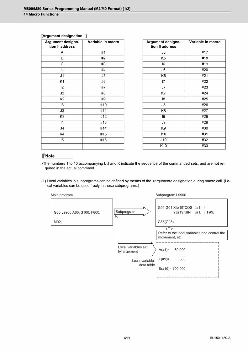
M800/M80 Series Programming Manual (M2/M0 Format) (1/2)
14 Macro Functions
411 IB-1501480-A
[Argument designation II]
The numbers 1 to 10 accompanying I, J and K indicate the sequence of the commanded sets, and are not re-quired in the actual command.
(1) Local variables in subprograms can be defined by means of the <argument> designation during macro call. (Lo-cal variables can be used freely in those subprograms.)
Argument designa-tion II address
Variable in macro Argument designa-tion II address
Variable in macro
A #1 J5 #17
B #2 K5 #18
C #3 I6 #19
I1 #4 J6 #20
J1 #5 K6 #21
K1 #6 I7 #22
I2 #7 J7 #23
J2 #8 K7 #24
K2 #9 I8 #25
I3 #10 J8 #26
J3 #11 K8 #27
K3 #12 I9 #28
I4 #13 J9 #29
J4 #14 K9 #30
K4 #15 I10 #31
I5 #16 J10 #32
K10 #33
Note
G65 L9900 A60. S100. F800;
M02; G68(G23);
A(#1)= 60.000
F(#9)= 800
S(#19)= 100.000
G91 G01 X #19*COS #1Y #19*SIN #1 F#9;
Main program
Subprogram
Local variables set by argument
Local variable data table
Refer to the local variables and control the movement, etc.
Subprogram L9900
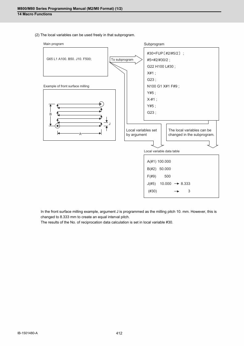
M800/M80 Series Programming Manual (M2/M0 Format) (1/2)
14 Macro Functions
412IB-1501480-A
(2) The local variables can be used freely in that subprogram.
In the front surface milling example, argument J is programmed as the milling pitch 10. mm. However, this is
changed to 8.333 mm to create an equal interval pitch.
The results of the No. of reciprocation data calculation is set in local variable #30.
G65 L1 A100. B50. J10. F500;#30=FUP #2/#5/2 ;
#5=#2/#30/2 ;
G22 H100 L#30 ;
X#1 ;
G23 ;
N100 G1 X#1 F#9 ;
Y#5 ;
X-#1 ;
Y#5 ;
G23 ;
A(#1) 100.000
B(#2) 50.000
F(#9) 500
J(#5) 10.000 8.333
(#30) 3
B
A
J
Local variables set by argument
The local variables can be changed in the subprogram.
Main program
Example of front surface milling
Local variable data table
Subprogram
To subprogram
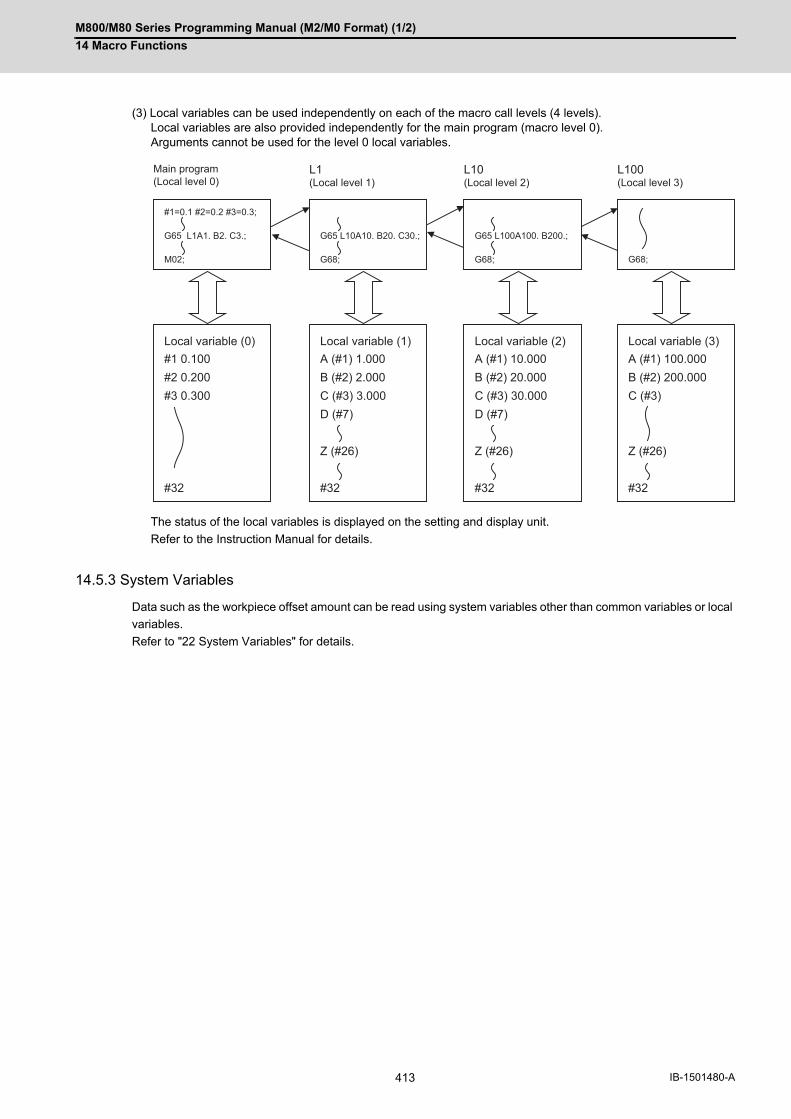
M800/M80 Series Programming Manual (M2/M0 Format) (1/2)
14 Macro Functions
413 IB-1501480-A
(3) Local variables can be used independently on each of the macro call levels (4 levels). Local variables are also provided independently for the main program (macro level 0). Arguments cannot be used for the level 0 local variables.
The status of the local variables is displayed on the setting and display unit.
Refer to the Instruction Manual for details.
14.5.3 System Variables
Data such as the workpiece offset amount can be read using system variables other than common variables or local
variables.
Refer to "22 System Variables" for details.
#1 0.100#2 0.200#3 0.300
#1=0.1 #2=0.2 #3=0.3;
G65 L1A1. B2. C3.;
M02;
#32
A (#1) 10.000B (#2) 20.000C (#3) 30.000D (#7)
Z (#26)
G65 L100A100. B200.;
G68;
#32
A (#1) 1.000B (#2) 2.000C (#3) 3.000D (#7)
Z (#26)
G65 L10A10. B20. C30.;
G68;
#32
A (#1) 100.000B (#2) 200.000C (#3)
Z (#26)
G68;
#32
Main program(Local level 0)
L1(Local level 1)
L10(Local level 2)
L100(Local level 3)
Local variable (0) Local variable (3)Local variable (2)Local variable (1)
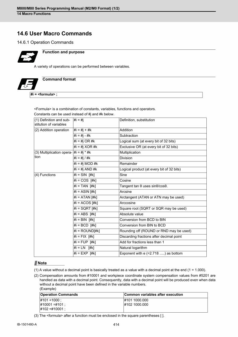
M800/M80 Series Programming Manual (M2/M0 Format) (1/2)
14 Macro Functions
414IB-1501480-A
14.6 User Macro Commands
14.6.1 Operation Commands
A variety of operations can be performed between variables.
<Formula> is a combination of constants, variables, functions and operators.
Constants can be used instead of #j and #k below.
(1) A value without a decimal point is basically treated as a value with a decimal point at the end (1 = 1.000).
(2) Compensation amounts from #10001 and workpiece coordinate system compensation values from #5201 arehandled as data with a decimal point. Consequently, data with a decimal point will be produced even when datawithout a decimal point have been defined in the variable numbers. (Example)
(3) The <formula> after a function must be enclosed in the square parentheses [ ].
Function and purpose
Command format
#i = <formula> ;
(1) Definition and sub-stitution of variables
#i = #j Definition, substitution
(2) Addition operation #i = #j + #k Addition
#i = #j - #k Subtraction
#i = #j OR #k Logical sum (at every bit of 32 bits)
#i = #j XOR #k Exclusive OR (at every bit of 32 bits)
(3) Multiplication opera-tion
#i = #j * #k Multiplication
#i = #j / #k Division
#i = #j MOD #k Remainder
#i = #j AND #k Logical product (at every bit of 32 bits)
(4) Functions #i = SIN [#k] Sine
#i = COS [#k] Cosine
#i = TAN [#k] Tangent tan θ uses sinθ/cosθ.
#i = ASIN [#k] Arcsine
#i = ATAN [#k] Arctangent (ATAN or ATN may be used)
#i = ACOS [#k] Arccosine
#i = SQRT [#k] Square root (SQRT or SQR may be used)
#i = ABS [#k] Absolute value
#i = BIN [#k] Conversion from BCD to BIN
#i = BCD [#k] Conversion from BIN to BCD
#i = ROUND[#k] Rounding off (ROUND or RND may be used)
#i = FIX [#k] Discarding fractions after decimal point
#i = FUP [#k] Add for fractions less than 1
#i = LN [#k] Natural logarithm
#i = EXP [#k] Exponent with e (=2.718 .....) as bottom
Operation Commands Common variables after execution
#101 =1000 ;#10001 =#101 ;#102 =#10001 ;
#101 1000.000#102 1000.000
Note

M800/M80 Series Programming Manual (M2/M0 Format) (1/2)
14 Macro Functions
415 IB-1501480-A
(1) The sequence of the operations (a) to (c) is performed in the following order; the function, the multiplication op-eration and the addition operation.
(2) The part to be given priority in the operation sequence should be enclosed in square parentheses [ ]. Up to 5pairs of such parentheses, including those for the functions, may be used.
Detailed description
Sequence of operations
(a) Function
(b) Multiplication operation
(c) Addition operation
Examples of operation commands
(1) Main program and argument designation
G65 L100 A10 B20. ;
#101 = 100.000 #102 = 200.000;#1 10.000#2 20.000#101 100.000#102 200.000
(2) Definition and substitution=
#1 = 1000#2 = 1000.
#1 1000.000#2 1000.000
#3 = #101#4 = #102
#3 100.000#4 200.000
From common vari-ables
#5 = #10001 (#10001 = -10.) #5 -10.000 From tool compensa-tion
(3) Addition and sub-traction+ -
#11 = #1 + 1000#12 = #2 - 50.#13 = #101 + #1#14 = #10001 - 3. (#10001 = -10.)#15 = #10001 + #102
#11 2000.000#12 950.000#13 1100.000#14 -13.000#15 190.000
(4) Multiplication and division* /
#21 = 100 * 100#22 = 100. * 100#23 = 100 * 100.#24 = 100. * 100.#25 = 100 / 100#26 = 100. / 100#27 = 100 / 100.#28 = 100. / 100.#29 = #10001 * #101 (#10001 = -10.)#30 = #10001 / #102
#21 10000.000#22 10000.000#23 10000.000#24 10000.000#25 1.000#26 1.000#27 1.000#28 1.000#29 -1000.000#30 -0.050
(5) RemainderMOD
#19 = 48#20 = 9#31 = #19 MOD #20
#19/#20 = 48/9 = 5 Remainder 3#31 = 3
(6) Logical sumOR
#3 = 100#4 = #3 OR 14
#3 = 01100100 (binary)14 = 00001110 (binary)
#4 = 01101110 = 110
#101=#111+#112*SIN #113
#101=SQRT #111-#112 *SIN #113 +#114 *#115 ;First pair ofbrackets
Second pair of bracketsThird pair of brackets

M800/M80 Series Programming Manual (M2/M0 Format) (1/2)
14 Macro Functions
416IB-1501480-A
(7) Exclusive ORXOR
#3 = 100#4 = #3 XOR 14
#3 = 01100100 (binary)14 = 00001110 (binary)
#4 = 01101010 = 106
(8) Logical productAND
#9 = 100#10 = #9 AND 15
#9 = 01100100 (binary)15 = 00001111 (binary)
#10 = 00000100 = 4
(9) SineSIN
#501 = SIN [60]#502 = SIN [60.]#503 = 1000 * SIN [60]#504 = 1000 * SIN [60.]#505 = 1000. * SIN [60]#506 = 1000. * SIN [60.]
<Note>
SIN [60] is equivalent to SIN [60.]
#501#502#503#504#505#506
0.8660.866866.025866.025866.025866.025
(10) CosineCOS
#541 = COS [45]#542 = COS [45.]#543 = 1000 * COS [45]#544 = 1000 * COS [45.]#545 = 1000. * COS [45]#546 = 1000. * COS [45.]
<Note>
COS [45] is equivalent to COS [45.]
#541#542#543#544#545#546
0.7070.707707.107707.107707.107707.107
(11) TangentTAN
#551 = TAN [60]#552 = TAN [60.]#553 = 1000 * TAN [60]#554 = 1000 * TAN [60.]#555 = 1000. * TAN [60]#556 = 1000. * TAN [60.]
<Note>
TAN [60] is equivalent to TAN [60.]
#551#552#553#554#555#556
1.7321.7321732.0511732.0511732.0511732.051
(12) ArcsineASIN
#531 = ASIN[100.500 / 201.]#532 = ASIN[100.500 / 201]#533 = ASIN[0.500]#534 = ASIN[-0.500]
#531#532#533#534
30.00030.00030.000-30.000
<Note>When #1273/bit 0 is set to 1,
#534 will be 330°.
(13) ArctangentATN or ATAN
#561 = ATAN [173205 / 100000]#562 = ATAN [173205 / 100000.]#563 = ATAN [173.205 / 100]#564 = ATAN [173.205 / 100.]#565 = ATAN [1.73205]
#561#562#563#564#565
60.00060.00060.00060.00060.000
(14) ArccosineACOS
#521 = ACOS [100 / 141.421]#522 = ACOS [100. / 141.421]
#521#522
45.00045.000
(15) Square rootSQR or SQRT
#571 = SQRT [1000]#572 = SQRT [1000.]#573 = SQRT [10. * 10. + 20. * 20]
<Note>
In order to increase the accuracy, proceedwith the operation inside parentheses asmuch as possible.
#571#572#573
31.62331.62322.360
(16) Absolute valueABS
#576 = -1000#577 = ABS [#576]#3 = 70. #4 = -50.#580 = ABS [#4 - #3]
#576#577 #580
-1000.0001000.000 120.000
(17) BIN, BCD #1 = 100#11 = BIN [#1]#12 = BCD [#1]
#11#12
64256

M800/M80 Series Programming Manual (M2/M0 Format) (1/2)
14 Macro Functions
417 IB-1501480-A
(1) Notes on logical relationEQ, NE, GT, LT, GE and LE conduct the same calculation as addition and subtraction. Pay careful attention toerrors. For example, to determine whether or not #10 and #20 are equal in the following example, it is not alwayspossible to judge correctly because of the error. IF [#10 EQ #20]Therefore when the difference between #10 and #20 falls within the designated error range, both values shouldbe considered equal. IF [ABS [#10 - #20] LT 200000]
(18) Rounding offRND or ROUND
#21 = ROUND [14 / 3]#22 = ROUND [14. / 3]#23 = ROUND [14 / 3.]#24 = ROUND [14. / 3.]#25 = ROUND [-14 / 3]#26 = ROUND [-14. / 3]#27 = ROUND [-14 / 3.]#28 = ROUND [-14. / 3.]
#21#22#23#24#25#26#27#28
5555-5-5-5-5
(19) Discarding frac-tions below decimal pointFIX
#21 = FIX [14 / 3]#22 = FIX [14. / 3]#23 = FIX [14 / 3.]#24 = FIX [14. / 3.]#25 = FIX [-14 / 3]#26 = FIX [-14. / 3]#27 = FIX [-14 / 3.]#28 = FIX [-14. / 3.]
#21#22#23#24#25#26#27#28
4.0004.0004.0004.000-4.000-4.000-4.000-4.000
(20) Adding fractions less than 1FUP
#21 = FUP [14 / 3]#22 = FUP [14. / 3]#23 = FUP [14 / 3.]#24 = FUP [14. / 3.]#25 = FUP [-14 / 3]#26 = FUP [-14. / 3]#27 = FUP [-14 / 3.]#28 = FUP [-14. / 3.]
#21#22#23#24#25#26#27#28
5.0005.0005.0005.000-5.000-5.000-5.000-5.000
(21) Natural loga-rithmsLN
#10 = LN [5]#102 = LN [0.5]#103 = LN [-5]
#101#102Error
1.609-0.693"P282"
(22) ExponentsEXP
#104 = EXP [2]#105 = EXP [1]#106 = EXP [-2]
#104#105#106
7.3892.7180.135
Precautions

M800/M80 Series Programming Manual (M2/M0 Format) (1/2)
14 Macro Functions
418IB-1501480-A
14.6.2 Control Commands
The flow of programs can be controlled by IF-GOTO- and WHILE-DO-END.
When a program in an external device such as a USB memory device is executed, a period of processing time is
required in the subprogram call or in the instruction to change the flow of the program such as GOTO or DO-END;
therefore, interpolation may be decelerated or stopped.
When the condition is satisfied, control branches to "n" and when it is not satisfied, the next block is executed.
IF [conditional expression] can be omitted and, when it is, control branches to "n" unconditionally.
The following types of [conditional expressions] are available.
"n" of "GOTO n" must always be in the same program. If not, program error (P231) will occur. A formula or variable
can be used instead of i, #j and n.
In the block with sequence number "n" which will be executed after a "GOTO n" command, the sequence number
"Nn" must always be at the head of the block. Otherwise, program error (P231) will occur.
If "/" is at the head of the block and "Nn" follows, control can be branched to the sequence number.
(1) When searching the sequence number of the branch destination, the search is conducted up to the end of theprogram (% code) from the block following IF............; and if it is not found, it is then conducted from the top ofthe program to the block before IF............;. Therefore, branch searches in the opposite direction to the programflow will take longer time compared with branch searches in the forward direction.
(2) EQ and NE should be compared only for integers. For comparison of numeric values with decimals, GE, GT, LE,and LT should be used.
Function and purpose
Detailed description
Branching
IF [conditional expression] GOTO n; (n = sequence number in the program)
#i EQ #j = When #i and #j are equal
#i NE #j ≠ When #i and #j are not equal
#i GT #j > When #i is greater than #j
#i LT #j < When #i is less than #j
#i GE #j >= When #i is #j or more
#i LE #j <= When #i is #j or less
N100 X#22 ;#1=#1+1 ;
N100
N10 #22=#20 ;IF #2 EQ1 GOTO100 ;#22=#20 -#3 ;
Branching to N100when content of #2 is 1 Branch
search Branchsearch
WithN10Tohead
Note

M800/M80 Series Programming Manual (M2/M0 Format) (1/2)
14 Macro Functions
419 IB-1501480-A
While the conditional expression is established, the blocks from the following block to ENDm are repeatedly execut-
ed; when it is not established, execution moves to the block following ENDm. DOm may come before WHILE.
"WHILE [conditional expression] DOm" and "ENDm" must be used as a pair. If "WHILE [conditional expression]" is
omitted, these blocks will be repeatedly ad infinitum. The repeating identification Nos. range from 1 to 127. (DO1,
DO2, DO3, .....DO127) Up to 27 nesting levels can be used.
Repetitions
WHILE [conditional expression] DOm ; (m =1, 2, 3 ..... 127) :
:
END m ;
(1) Same identification No. can be used any number of times.
(2) Any number may be used as the WHILE-DOm identification No.
(3) Up to 27 nesting levels can be used for WHILE-DOm. "m" is any number from 1 to 127 for the nesting depth.
<Note>
For nesting, "m" which has been used once cannotbe used.
(4) The number of WHILE-DOm nesting levels can-not exceed 27.
(5) WHILE - DOm must be designated first and ENDm last.
(6) WHILE - DOm and ENDm must correspond on a 1:1 (pairing) basis in a same program.
END1;
WHILE DO1;
END1;
WHILE DO1;
END1;
WHILE DO1;
END3;
WHILE DO3;
END2;
WHILE DO2;
END1;
WHILE DO1;
END1;
WHILE DO1;
END2;
WHILE DO2;
END27;
WHILE DO27;
DO1
DO2
DO27
END28;
END3;
END2;
END1;
WHILE DO1;
WHILE DO2;
WHILE DO3;
WHILE DO28;
Notpossible
WHILE DO1;
END 1;
Notpossible
WHILE DO1;
END1;
WHILE DO1;
Notpossible

M800/M80 Series Programming Manual (M2/M0 Format) (1/2)
14 Macro Functions
420IB-1501480-A
Even if a fixed cycle containing WHILE is called, the nesting level will be counted up.
(7) Two WHILE - DOm's must not overlap.
(8) Branching externally out of the WHILE - DOm range, is possible.
(9) No branching into WHILE - DOm, is possible.
(10) Subprograms can be called by G22, G65 or G66 between WHILE - DOm's.
(11) Calls can be initiated by G65 or G66 between WHILE - DOm's and commands can be issued again from 1. Up to 27 nesting levels are possible for the main program and subprograms.
(12) A program error will occur in G23 if WHILE and END are not paired in the subprogram (including macro subprogram).
(MP) Main program (SP) Subprogram
END2;
END1;
WHILE DO2;
WHILE DO1;
Notpossible
WHILE DO1;
END1;
IF GOTOn;
Nn;
IF GOTOn;
WHILE DO1;
END1;
WHILE DO1;
Nn;Nn;
END1;END1;
IF GOTOn;
WHILE DO1; Notpossible
Notpossible
G65 L100;
END1;
WHILE DO1; WHILE DO02;
END2;
G23;M02;
(MP) (SP)
G65L100;
END1;
WHILE DO1; WHILE DO1;
END1;
G23;M02;
(MP) (SP)(100)
DO1;WHILE
(SP)(MP)
G23;
G22L100;
M02;DOn ENDnillegal usage.
Note

M800/M80 Series Programming Manual (M2/M0 Format) (1/2)
14 Macro Functions
421 IB-1501480-A
14.6.3 External Output Commands; POPEN, PCLOS, DPRNT
Besides the standard user macro commands, the following macro instructions are also available as external output
commands. They are designed to output the variable values or characters to external devices. The data output port
can be chosen from RS-232C or memory card.
Command sequence
Function and purpose
Command format
Open command
POPEN
Closed command
PCLOS
Data output command
DPRNT
POPEN For preparing the data outputs
PCLOS For terminating the data outputs
DPRNT For character output and digit-by-digit variable numerical output
...Open command
... Data output command
... Closed command
POPEN
PCLOS
DPRNT

M800/M80 Series Programming Manual (M2/M0 Format) (1/2)
14 Macro Functions
422IB-1501480-A
(1) The command is issued before the series of data output commands.
(2) The DC2 control code and % code are output from the NC system to the external output device.
(3) Once POPEN; is issued, it will remain valid until PCLOS; is issued.
(1) This command is issued when all the data outputs are completed.
(2) The DC4 control code and % code are output from the NC system to the external output device.
(3) This command is used together with the open command and it should not be issued unless the open mode hasbeen established.
(4) Issue the close command at the end of the program even when the operation is suspended by resetting or someother operation during data output.
(1) The character output and decimal output of the variable values are done with ISO codes.
(2) The commanded character string is output as it is by the ISO code. Alphanumerics (A to Z, 0 to 9) and special characters (+, -, *, /) can be used. Note that asterisk (*) is output as a space code.
(3) The required significant digits above and below the decimal point of the variable values are each commandedwithin square parentheses. As a result, the commanded number of digits of variable values are output in ISOcode in decimal notation from the high-order digits including the decimal point. In this case, trailing zeroes arenot omitted.
(4) Leading zeroes are omitted. The omitted leading zero can be replaced by a space by the setting of a parameter. This can justify the last digit of the data output to the printer.
(5) Linefeed (LF) code will be output to the end of the output data. And by setting the parameter "#9112 to #9512 DEV0 - 4 CR OUTPUT" to "1", (CR) code will be written in justbefore EOB (LF) code.
A data output command can be issued even in two-part system mode. In this case, however, note that the out-put channel is shared by both part systems. So, be careful not to execute data output by both part systemssimultaneously.
(1) The output port can be selected by the parameter "#9007 MACRO PRINT PORT".
(2) When the port is a memory card, the file name of the port can be designated by the parameter "#9054 MACROPRINT FILE".
(3) When the port is a memory card, the port directory is fixed to root directory.
Detailed description
Open command : POPEN
Close command : PCLOS
Data output command : DPRNT
DPRNT [l1#v1 [d1 c1] l2#v2 [d2 c2] ...... ] ;
l1 Character string
v1 Variable No.
d1 Significant digits above dec-imal point
c + d <= 8
c1 Significant digits after deci-mal point
Data output port
Note

M800/M80 Series Programming Manual (M2/M0 Format) (1/2)
14 Macro Functions
423 IB-1501480-A
<Parameter setting>
<Machining program>
(*1) Designate a blank line when opening an output file on an edit screen. If not, it will be regarded that no information
is provided in the head line of the file on the NC edit screen.
<Output file (file name = DPRNT_OUT)>
Use example:
#1127 DPRINT (DPRINT alignment) = 1 (Align the minimum digit and output)
#9007 MACRO PRINT PORT = 9 (Output to a memory card by an external output command)
#9008 MACRO PRINT DEV. = 0 (Device 0 is selected for an external output command)
#9054 MACRO PRINT FILE = DPRNT_OUT (File name to store output data of an external output command)
#9112 DEV0 CR OUTPUT = 1 (Insert the CR code just before the LF code)
#1=12.34;
#2=#0
#100=-123456789.;
#500=-0.123456789;
POPEN;
DPRNT[]; (*1)
DPRNT[VAL-CHECK];
DPRNT[1234567890];
DPRNT[#1[44]];
DPRNT[#2[44]];
DPRNT[#100[80]];
DPRNT[#500[80]];
DPRNT[#100[08]];
DPRNT[#500[08]];
PCLOS;
M30;
%
Blank Linefeed code
Values above the number of significant figures are rounded down
Values below the number of significant figures are rounded off
(CR) (LF)
V A L - C H E C K (CR) (LF)
1 2 3 4 5 6 7 8 9 0 (CR) (LF)
1 2 . 3 4 0 0 (CR) (LF)
0 . 0 0 0 0 (CR) (LF)
- 2 3 4 5 6 7 8 9 (CR) (LF)
- 0 (CR) (LF)
- . 0 0 0 0 0 0 0 0 (CR) (LF)
- . 1 2 3 4 5 6 7 9 (CR) (LF)

M800/M80 Series Programming Manual (M2/M0 Format) (1/2)
14 Macro Functions
424IB-1501480-A
(1) An external output command during restart-searching is ignored. After using the restart-search type 2 to restart-search between a POPEN command and a PCLOS command,execute a POPEN command by such as an MDI interruption before restarting the program.
(2) An external output command during graphic check is ignored.
(3) A program error (P460) will occur if an external output command is issued when the output device is unable tooutput due to a lack of connection, a low free space etc.
(4) The NC automatically conducts a closing processing when it is reset between a POPEN command and a PCLOScommand. So, execute a POPEN command by such as an MDI interruption before executing the rest of the ma-chining program.
(5) If a program error occurs between a POPEN command and a PCLOS command, NC will not automatically con-duct a closing processing. So, there is no need to execute a POPEN command by such as an MDI interruptionbefore executing the rest of the machining program.
(6) If a program error occurs to the output port due to the setting of the memory card, execute an NC reset and closethe output file before demounting the card.
(7) When the output port is a memory card, the output file may be destroyed if the card is dismounted or the poweris turned off without issuing a PCLOS command or NC reset after a POPEN command is issued.
(8) As for M800 series, output data of an external output command can be output to a memory card only when thedrive name of the card is "E:" or "F:". Drive name "E" is given the priority. A program error (P460) will occur if theoutput port executes the external output command of the memory card when the drive name is neither "E:" nor"F:".
(9) When the data is output to a memory card, the maximum number of files that can be created is determined bythe FAT16 format.
Precautions

M800/M80 Series Programming Manual (M2/M0 Format) (1/2)
14 Macro Functions
425 IB-1501480-A
14.6.4 Precautions
When the user macro commands are employed, it is possible to use the M, S, T and other NC control commands
together with the arithmetic, decision, branching and other macro commands for preparing the machining programs.
When the former commands are made into executable statements and the latter commands into macro statements,
the macro statement processing should be accomplished as quickly as possible in order to minimize the machining
time, because such processing is not directly related to machine control.
By setting the parameter "#8101 MACRO SINGLE", the macro statements can be processed concurrently with the
execution of the executable statement.
(During normal machining, set the parameter OFF to process all the macro statements together, and during a pro-
gram check, set it ON to execute the macro statements block by block. Setting can be chosen depending on the
purpose.)
Program example
Macro statements are:
(a) Arithmetic commands (block including =)
(b) Control commands (block including GOTO, DO-END, etc.)
(c) Macro call commands (including macro calls based on G codes and cancel commands (G65, G66, G66.1, G67))
Execution statements refer to statements other than macro statements.
Precautions
N1 G91 G28 X0 Y0 ; ......(1)
N2 G92 X0 Y0 ; ......(2)
N3 G00 X-100. Y-100. ; ......(3)
N4 #101 = 100. * COS[210.] ; ......(4) (4),(5) Macro statements
N5 #103 = 100. * SIN[210.] ; ......(5)
N6 G01 X#101 Y#103 F800 ; ......(6)
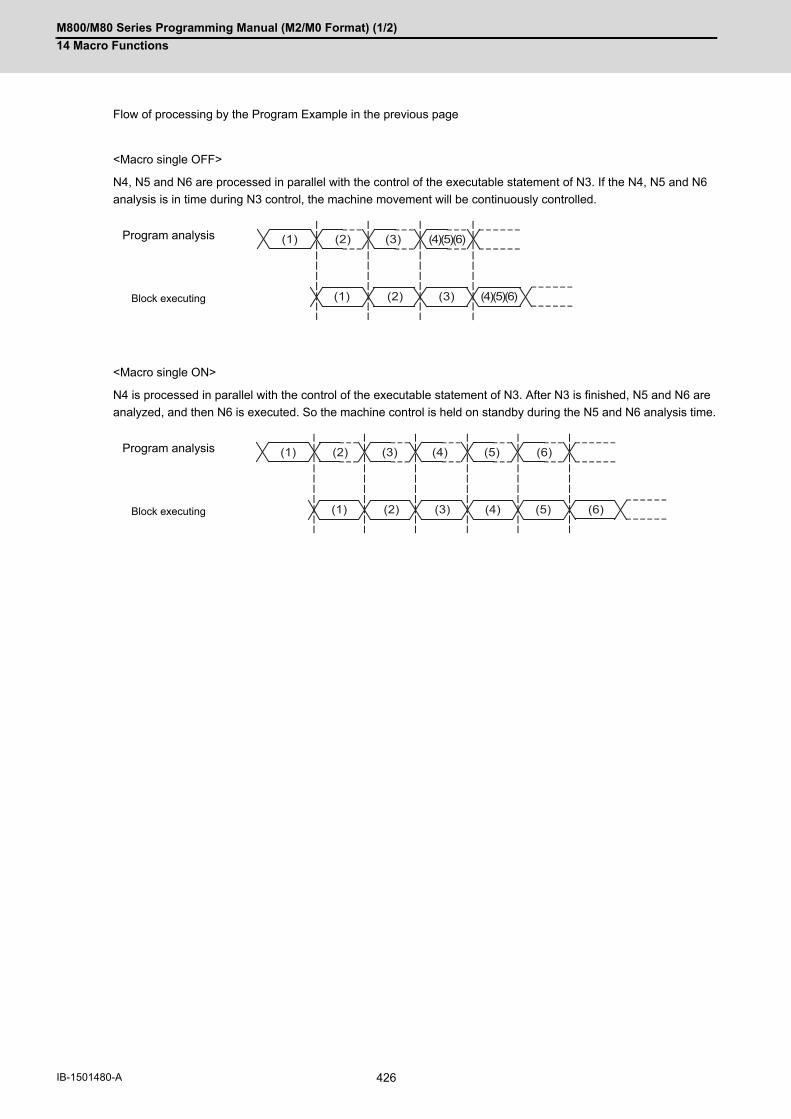
M800/M80 Series Programming Manual (M2/M0 Format) (1/2)
14 Macro Functions
426IB-1501480-A
Flow of processing by the Program Example in the previous page
<Macro single OFF>
N4, N5 and N6 are processed in parallel with the control of the executable statement of N3. If the N4, N5 and N6
analysis is in time during N3 control, the machine movement will be continuously controlled.
<Macro single ON>
N4 is processed in parallel with the control of the executable statement of N3. After N3 is finished, N5 and N6 are
analyzed, and then N6 is executed. So the machine control is held on standby during the N5 and N6 analysis time.
Program analysis
Block executing
Program analysis
Block executing
(1) (2) (4)(5)(6)(3)
(1) (2) (4)(5)(6)(3)
(1) (2) (3)
(1) (2) (3)
(4) (5) (6)
(4) (5) (6)
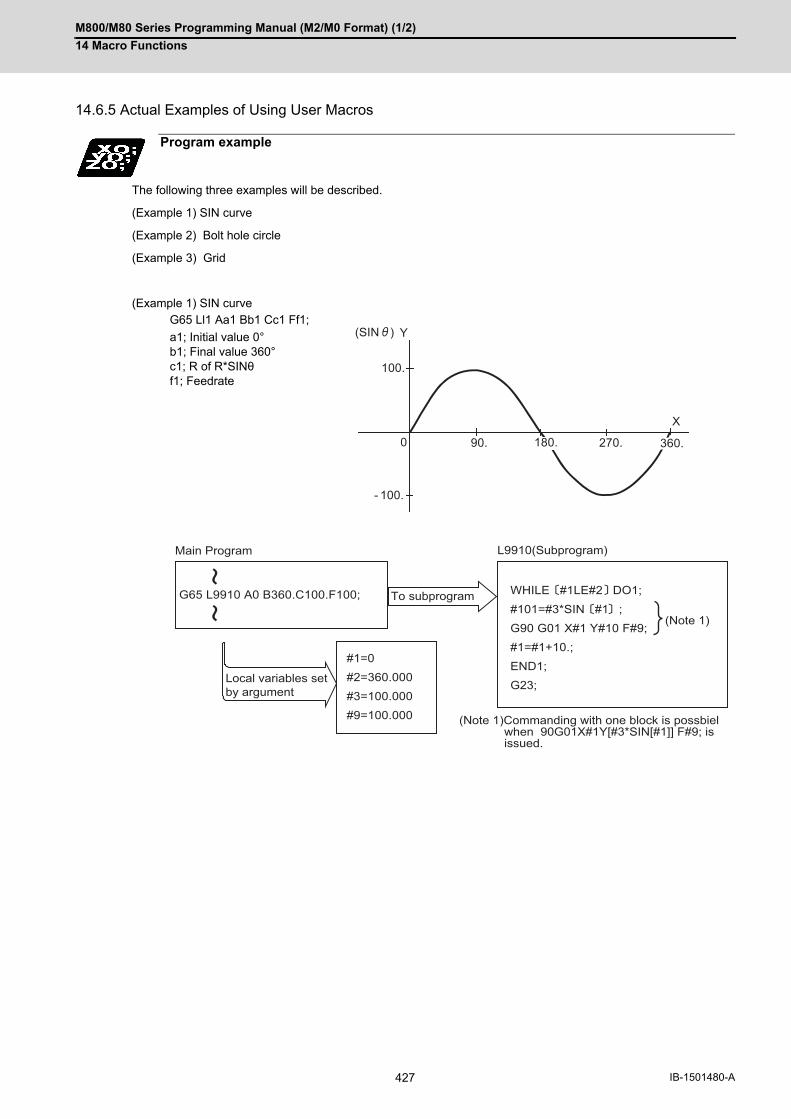
M800/M80 Series Programming Manual (M2/M0 Format) (1/2)
14 Macro Functions
427 IB-1501480-A
14.6.5 Actual Examples of Using User Macros
The following three examples will be described.
(Example 1) SIN curve
(Example 2) Bolt hole circle
(Example 3) Grid
(Example 1) SIN curve
Program example
G65 Ll1 Aa1 Bb1 Cc1 Ff1;
a1; Initial value 0°b1; Final value 360°c1; R of R*SINθf1; Feedrate
(SIN ) Y
X
100.
- 100.
0 90. 270. 360.180.
G65 L9910 A0 B360.C100.F100;
#1=0#2=360.000#3=100.000#9=100.000
WHILE #1LE#2 DO1;#101=#3*SIN #1 ;G90 G01 X#1 Y#10 F#9;#1=#1+10.;END1;G23;
Main Program
Local variables set by argument
L9910(Subprogram)
To subprogram
(Note 1)Commanding with one block is possbiel when 90G01X#1Y[#3*SIN[#1]] F#9; is issued.
(Note 1)

M800/M80 Series Programming Manual (M2/M0 Format) (1/2)
14 Macro Functions
428IB-1501480-A
(Example 2) Bolt hole circle
After defining the hole data with fixed cycle (G72 to G89), the macro command is issued as the hole position com-
mand.
G81 Z-100.R50.F300L0G65 L9920 Aa1 Bb1 Rr1 Xx1 Yy1;
#101=0;#102=#4003;#103=#5001;#104=#5002;#111=#1;
WHILE #101LT#2 DO1;
#120=#24+#18*COS #111 ;#121=#25+#18*SIN #111 ;
#122=#120 #123=#121;IF #102EQ90 GOTO100;
#122=#120-#103;#123=#121-#104;
#103=#120;#104=#121;
N100 X#122 Y#123;#101=#101+1;#111=#1+360.*#101/#2;
END1;G23;
-X x1
W
y1
-Y
a1
Radius*COS[#111]+Center coordinates X #120Radius*SIN [#111]+Center coordinates Y #121#120 #122 #121 #123
L9920
#102=90
N100 X#122 Y#123
Y
Y
N
N
END
#120-#103 #122 #121-#104 #123 #120 #103 #121 #104
Main program
L9920(Subprogram)
(Note 1)
(Note 1)
(Note 1)
(Note 1)
(Note 1)
a1;Start angleb1;No. of holesr1;Radiusx1;X axis centerpositiony1;Y axis centerposition
#101=No. of hole count
#102=G90 or G91
#103=X axis current position#104=Y axis current position#111=Start angle
#120=Hole position X coordinates#121=Hole position Y coordinates#122=X axis absolute value#123=Y axis absolute value
Judgment of G90, G91mode#122=X axis incremental value#123=Y axis incremental valueX axis current position updateY axis current position update
#101≤ No. of holes
Drilling command
No.of holes counter up
#111=Hole position angle
#101+1 #101360 *#101/No. of holes +#1 #111
(Note 1) The processing time can be shortened by programming in one block.
To subprogram
0 #101G90,G91 modeRead in #102Read previous coordinates X #103 Y #104 Start angle #111
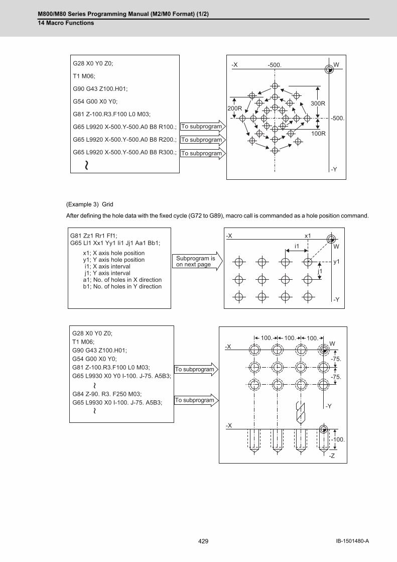
M800/M80 Series Programming Manual (M2/M0 Format) (1/2)
14 Macro Functions
429 IB-1501480-A
(Example 3) Grid
After defining the hole data with the fixed cycle (G72 to G89), macro call is commanded as a hole position command.
G28 X0 Y0 Z0;
T1 M06;
G90 G43 Z100.H01;
G54 G00 X0 Y0;
G81 Z-100.R3.F100 L0 M03;
G65 L9920 X-500.Y-500.A0 B8 R100.;
G65 L9920 X-500.Y-500.A0 B8 R200.;
G65 L9920 X-500.Y-500.A0 B8 R300.;
-X
200R300R
100R
-500.
-500. W
-Y
To subprogram
To subprogram
To subprogram
G81 Zz1 Rr1 Ff1;G65 Ll1 Xx1 Yy1 Ii1 Jj1 Aa1 Bb1;
-X
i1
x1
W
j1y1
-Y
x1; X axis hole positiony1; Y axis hole position i1; X axis interval j1; Y axis intervala1; No. of holes in X directionb1; No. of holes in Y direction
Subprogram ison next page
G28 X0 Y0 Z0;T1 M06;G90 G43 Z100.H01;G54 G00 X0 Y0;G81 Z-100.R3.F100 L0 M03;G65 L9930 X0 Y0 I-100. J-75. A5B3;
G84 Z-90. R3. F250 M03;G65 L9930 X0 I-100. J-75. A5B3;
-X
-X
100.100.
-75.
-75.
100.
-100.
W
-Y
-Z
To subprogram
To subprogram
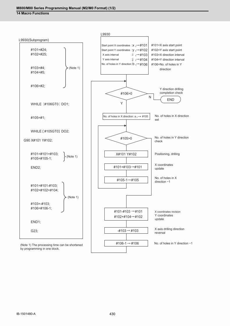
M800/M80 Series Programming Manual (M2/M0 Format) (1/2)
14 Macro Functions
430IB-1501480-A
END
#106>0
#105>0
X#101 Y#102
#101+#103 #101
#105-1 #105
#101-#103 #101#102+#104 #102
-#103 #103
#106-1 #106
N
Y
#101=#24;#102=#25;
#103=#4;#104=#5;
#106=#2;
WHILE #106GT0 DO1;
#105=#1;
WHILE #105GT0 DO2;
G90 X#101 Y#102;
#101=#101+#103;#105=#105-1;
END2;
#101=#101-#103;#102=#102+#104;
#103=-#103;#106=#106-1;
END1;
G23;
L9930
#101#102#103#104#106
:x 1:y 1:i 1:j 1:b 1
#105No. of holes in X direction: a 1
L9930(Subprogram)
(Note 1)
(Note 1)
(Note 1)
#101=X axis start point#102=Y axis start point#103=X direction interval#104=Y direction interval#106=No. of holes in Y direction
Y direction drilling completion check
No. of holes in X directionset
No. of holes in Y directioncheck
Positioning, drilling
X coordinates update
No. of holes in X direction −1
X axis drilling directionreversal
No. of holes in Y direction −1
X coordinates revisionY coordinates update
(Note 1) The processing time can be shortenedby programming in one block.
Start point X coordinates
Start point Y coordinates
X axis interval
Y axis interval
No. of holes in Y direction

M800/M80 Series Programming Manual (M2/M0 Format) (1/2)
14 Macro Functions
431 IB-1501480-A
14.7 Macro Interruption; ION, IOF
A user macro interrupt signal (UIT) is input from the machine to interrupt the program currently being executed, and
instead calls and executes another program. This is called the user macro interrupt function.
Use of this function allows the program to operate flexibly enough to meet varying conditions.
Function and purpose
Command format
User macro interruption enable
ION__ H__ ;
ION Interrupt program No.
H Interrupt sequence No.
User macro interruption disable
IOF ;

M800/M80 Series Programming Manual (M2/M0 Format) (1/2)
14 Macro Functions
432IB-1501480-A
(1) The user macro interrupt function is enabled and disabled by the ION and IOF commands programmed to makethe user macro interrupt signal (UIT) valid or invalid. That is, if an interrupt signal (UIT) is input from the machineside in a user macro interruption enable period from when ION is issued to when IOF is issued or the NC is reset,a user macro interruption is caused to execute the program specified by ION instead of the one being executedcurrently.
(2) Another interrupt signal (UIT) is ignored until ION is commanded while one user macro interrupt is in service. Itis also ignored in a user macro interrupt disable state such as after an IOF command is issued or the system isreset.
A user macro interruption is enabled only during execution of a program.
The enabling conditions are as follows:
(1) An automatic operation mode or MDI has been selected.
(2) The system is running in automatic mode.
(3) No user macro interruption is being processed.
(Note 1) A macro interruption is disabled in manual operation mode (JOG, STEP, HANDLE, etc.)
Detailed description
Enabling conditions

M800/M80 Series Programming Manual (M2/M0 Format) (1/2)
14 Macro Functions
433 IB-1501480-A
(1) When a user macro interrupt signal (UIT) is input after an IONa1; command is issued by the current program,
interrupt program La1 is executed. When a G23; command is issued by the interrupt program, control returns to
the main program.
(2) If G23 Hh1; is specified, the blocks from the one next to the interrupted block to the last one are searched. If none
is found, blocks between the first block of the program and the one before the interrupted block are searched.
Control then returns to the block with sequence number Nh1; that is found first in the above search.
Outline of operation
G23(Hh1);
IONa1 ;
Nh1 ;
Nh1 ;
IOF ;
M30 ;
La1 ;
User macrointerrupt signal(UIT)
"User macrointerruption"signal isacceptable.
"User macrointerruption"signal is not acceptable.
Interrupt signal(UIT) notacceptable withina user macroprogram
(If Hh1 is specified)
Interrupt program
Current program
M800/M80 Series Programming Manual (M2/M0 Format) (1/2)
14 Macro Functions
434IB-1501480-A
Interrupt types 1 and 2 can be selected by the parameter "#1113 INT_2".
[Type 1]
(1) When an interrupt signal (UIT) is input, the system immediately stops moving the tool and interrupts dwell, then
permits the interrupt program to run.
(2) If the interrupt program contains a move or miscellaneous function (MSTB) command, the commands in the in-
terrupted block are lost. After the interrupt program completes, the main program resumes operation from the
block next to the interrupted one.
(3) If the interrupted program contains no move and miscellaneous (MSTB) commands, it resumes operation, after
completion of the interrupt program, from the point in the block where the interrupt was caused.
If an interrupt signal (UIT) is input during execution of a miscellaneous function (MSTB) command, the NC system
waits for a completion signal (FIN). The system thus executes a move or miscellaneous function command (MSTB)
in the interrupt program only after input of FIN.
[Type 2]
(1) When an interrupt signal (UIT) is input, the interrupt program will be executed without interrupting execution of
the current block in parallel with the executing block.
(2) If the interrupt program contains a move or miscellaneous function (MSTB) command, the commands in the in-
terrupted block are completed, then, these commands will be executed.
(3) If the interrupt program contains no move and miscellaneous function (MSTB) commands, the interrupt program
is executed without interrupting execution of the current block.
However, if the interrupt program has not ended even after the execution of the original block is completed, the sys-
tem may stop machining temporarily.
Interrupt type

M800/M80 Series Programming Manual (M2/M0 Format) (1/2)
14 Macro Functions
435 IB-1501480-A
block 1
block 1
block 1
block 3
block 3
block 3
block 2
block 1 block 3block 2
block 1 block 3block 2
block 1 block 3block 2
block 2
block 2 block 2
User macro interruption signal
If the interrupt program contains a move or miscellaneous function command, the reset of block (2) is lost.
User macro interruption signal
User macro interruption signal
User macro interruption signal
Interrupt program
Interrupt program
Interrupt program
Main program[Type 1]
[Type 2]Main program
Executing
Interrupt program
If the interrupted program contains nomove and miscellaneous commands,it resumes operation from where it left in block (2), that is, all the reset commands.
If the interrupted program contains no move and miscellaneous commands, the interrupted program is kept executed in parallel to execution of the current program.
The move or miscellaneouscommand in the interrupt program is executed after completion of the current block.

M800/M80 Series Programming Manual (M2/M0 Format) (1/2)
14 Macro Functions
436IB-1501480-A
User macro interruption is classified into the following two types depending on the way an interrupt program is called.
These two types of interrupt are selected by parameter "#8155 Sub-pro interrupt".
Both types of interrupt are added to the calculation of the nest level. The subprograms and user macros called in
the interrupt program are also added to the calculation of the nest level.
A user macro interruption signal (UIT) is accepted in the following two modes: These two modes are selected by a
parameter "#1112 S_TRG".
G23 (H_); (G68 is also acceptable.)
A G23 command is issued in the interrupt program to return to the main program.
Address H is used to specify the sequence number of the return destination in the main program.
The blocks from the one next to the interrupted block to the last one in the main program are first searched for the
block with designated sequence No. If it is not found, all the blocks before the interrupted one are then searched.
Control thus returns to the block with sequence No. that is found first in the above search. (This is equivalent to
G23H__ used after G22 calling.)
Calling method
Subprogram type inter-rupt
The user macro interruption program is called as a subprogram. As with calling by G22, the local variable level remains unchanged before and after an interrupt.
Macro type interruption The user macro interpretation program is called as a user macro. As with calling by G65, the local variable level changes before and after an interrupt. No arguments in the main program can be passed to the interrupt program.
Acceptance of user macro interruption signal (UIT)
Status trigger mode The user macro interruption signal (UIT) is accepted as valid when it is ON.
If the interrupt signal (UIT) is ON when the user macro interrupt function is enabled
by ION, the interrupt program is activated.
By keeping the interrupt signal (UIT) ON, the interrupt program can be executed re-
peatedly.
Edge trigger mode The user macro interrupt signal (UIT) is accepted as valid at its rising edge, that is, at
the instance it turns ON.
This mode is useful to execute an interrupt program once.
Returning from user macro interruption
ON
OFF
User macro interruption signal (UIT)
User macro interruption signal (UIT)
User macro interruption
(Status trigger method)
(Edge trigger method)

M800/M80 Series Programming Manual (M2/M0 Format) (1/2)
14 Macro Functions
437 IB-1501480-A
If modal information is changed by the interrupt program, it is handled as follows after control returns from the inter-
rupt program to the main program.
Modal information affected by user macro interruption
Returning with G23; The change of modal information by the interrupt program is invalidated and the original modal information is restored. With interrupt type 1, however, if the interrupt program contains a move or mis-cellaneous function (MSTB) command, the original modal information is not re-stored.
Returning with G23 H_; The original modal information is updated by the change in the interrupt program even after returning to the main program.
This is the same as in returning with G23H__; from a program called by G22, etc.
La1 ;
Nh1 ;
G23(Hh1) ;
ION a1 ;
User macrointerruptionsignal (UIT)
Modal beforeinterrupt is restored.
Main programbeing executed
Modal modifiedby interruptprogram remainseffective.
Interrupt program
(Modal change)
(With Hh1 specified)
Modal information affected by user macro interruption

M800/M80 Series Programming Manual (M2/M0 Format) (1/2)
14 Macro Functions
438IB-1501480-A
Modal information when control passes to the user macro interruption program can be known by reading system
variables #4401 to #4520.
The unit specified with a command applies.
The above system variables are available only in the user macro interrupt program.
If they are used in other programs, program error (P241) will occur.
(Note 1) The programs are registered as files. When the program No. (file name) is read with #4515, the character
string will be converted to a value.
(Example 1)
The file name "123" is the character string 0x31, 0x32, 0x33, so the value will be (0x31-0x30)*100 + (0x32-
0x30)*10 + (0x33-0x30) = 123.0.
Note that if the file name contains characters other than numbers, it will be "blank".
(Example 2)
If the file name is "123ABC", it contains characters other than numbers, so the result will be "blank".
(1) Subprogram call validity "#8155 Sub-pro interrupt"1: Subprogram type user macro interruption0: Macro type user macro interruption
(2) Status trigger mode validity "#1112 S_TRG"1: Status trigger mode0: Edge trigger mode
(3) Interrupt type 2 validity "#1113 INT_2"1: The executable statements in the interrupt program are executed after completion of execution of the currentblock. (Type 2)0: The executable statements in the interrupt program are executed before completion of execution of the currentblock. (Type 1)
Modal information variables (#4401 to #4520)
System variable Modal information
#4401 :
#4421
G code (group 01):G code (group 21)
Some groups are not used.
#4507 D code
#4509 F code
#4511 H code
#4513 M code
#4514 Sequence No.
#4515 Program No. (Note 1)
#4519 S code
#4520 T code
Parameters

M800/M80 Series Programming Manual (M2/M0 Format) (1/2)
14 Macro Functions
439 IB-1501480-A
(1) If the user macro interruption program uses system variables #5001 and after (position information) to read co-ordinates, the coordinates pre-read in the buffer are used.
(2) If an interrupt is caused during execution of the tool radius compensation, a sequence No. (G23H_;) must bespecified with a command to return from the user macro interrupt program. If no sequence No. is specified, con-trol cannot return to the main program normally.
(3) With interrupt type 1, when the interrupt program contains a move or MSTB command, do not command the mac-ro interruption to the waiting part system among multiple part systems. Doing so stops machining while the partsystem that does not perform an interruption remains set in the waiting standby state. If an interruption is carried out, machining can be started by the "ignore the timing synchronization between partsystems" signal; however, the operation of this signal depends on the MTB specifications.
Precautions

M800/M80 Series Programming Manual (M2/M0 Format) (1/2)
14 Macro Functions
440IB-1501480-A

15
441 IB-1501481-A
Program Support Functions
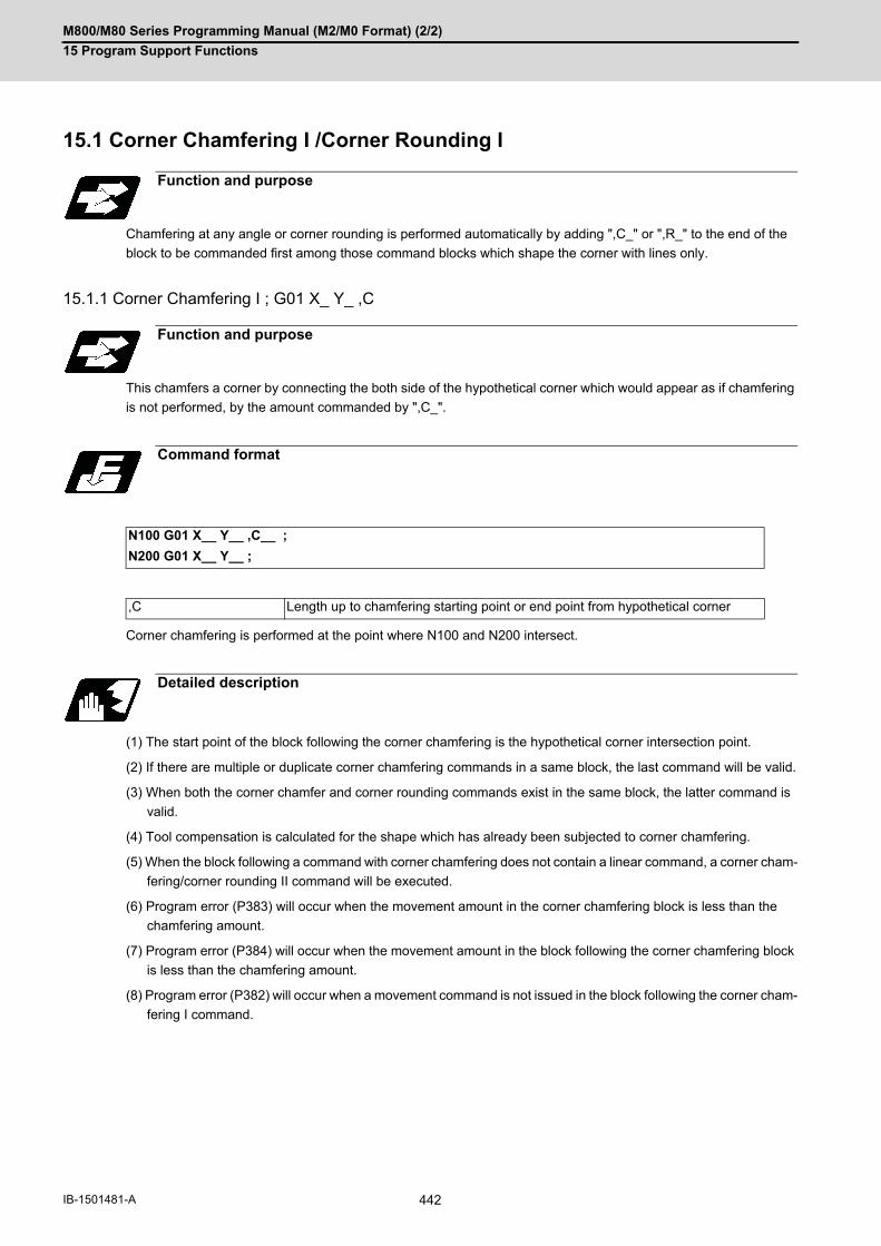
M800/M80 Series Programming Manual (M2/M0 Format) (2/2)
15 Program Support Functions
442IB-1501481-A
15Program Support Functions15.1 Corner Chamfering I /Corner Rounding I
Chamfering at any angle or corner rounding is performed automatically by adding ",C_" or ",R_" to the end of the
block to be commanded first among those command blocks which shape the corner with lines only.
15.1.1 Corner Chamfering I ; G01 X_ Y_ ,C
This chamfers a corner by connecting the both side of the hypothetical corner which would appear as if chamfering
is not performed, by the amount commanded by ",C_".
Corner chamfering is performed at the point where N100 and N200 intersect.
(1) The start point of the block following the corner chamfering is the hypothetical corner intersection point.
(2) If there are multiple or duplicate corner chamfering commands in a same block, the last command will be valid.
(3) When both the corner chamfer and corner rounding commands exist in the same block, the latter command is
valid.
(4) Tool compensation is calculated for the shape which has already been subjected to corner chamfering.
(5) When the block following a command with corner chamfering does not contain a linear command, a corner cham-
fering/corner rounding II command will be executed.
(6) Program error (P383) will occur when the movement amount in the corner chamfering block is less than the
chamfering amount.
(7) Program error (P384) will occur when the movement amount in the block following the corner chamfering block
is less than the chamfering amount.
(8) Program error (P382) will occur when a movement command is not issued in the block following the corner cham-
fering I command.
Function and purpose
Function and purpose
Command format
N100 G01 X__ Y__ ,C__ ;
N200 G01 X__ Y__ ;
,C Length up to chamfering starting point or end point from hypothetical corner
Detailed description
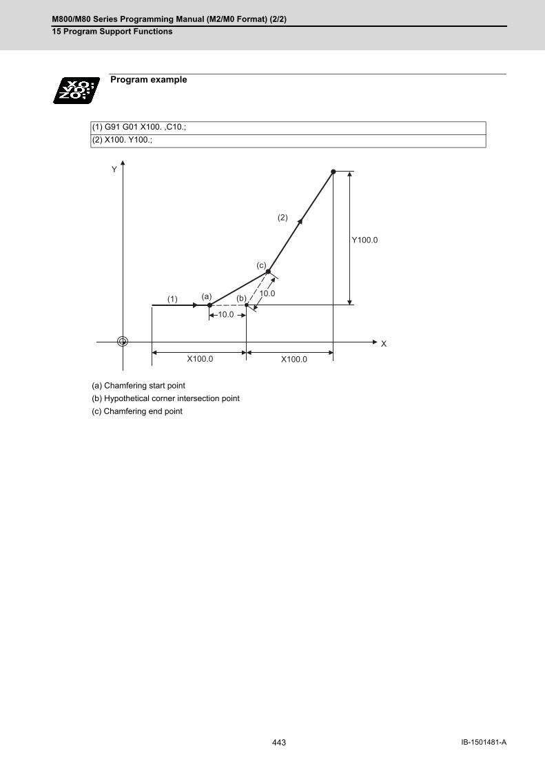
M800/M80 Series Programming Manual (M2/M0 Format) (2/2)
15 Program Support Functions
443 IB-1501481-A
Program example
(1) G91 G01 X100. ,C10.;
(2) X100. Y100.;
(a) Chamfering start point
(b) Hypothetical corner intersection point
(c) Chamfering end point
X100.0 X100.0
10.0
10.0
X
Y
Y100.0
(1)
(2)
(a) (b)
(c)
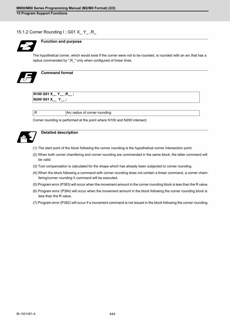
M800/M80 Series Programming Manual (M2/M0 Format) (2/2)
15 Program Support Functions
444IB-1501481-A
15.1.2 Corner Rounding I ; G01 X_ Y_ ,R_
The hypothetical corner, which would exist if the corner were not to be rounded, is rounded with an arc that has a
radius commanded by ",R_" only when configured of linear lines.
Corner rounding is performed at the point where N100 and N200 intersect.
(1) The start point of the block following the corner rounding is the hypothetical corner intersection point.
(2) When both corner chamfering and corner rounding are commanded in the same block, the latter command will
be valid.
(3) Tool compensation is calculated for the shape which has already been subjected to corner rounding.
(4) When the block following a command with corner rounding does not contain a linear command, a corner cham-
fering/corner rounding II command will be executed.
(5) Program error (P383) will occur when the movement amount in the corner rounding block is less than the R value.
(6) Program error (P384) will occur when the movement amount in the block following the corner rounding block is
less than the R value.
(7) Program error (P382) will occur if a movement command is not issued in the block following the corner rounding.
Function and purpose
Command format
N100 G01 X__ Y__ ,R__ ;
N200 G01 X__ Y__ ;
,R Arc radius of corner rounding
Detailed description
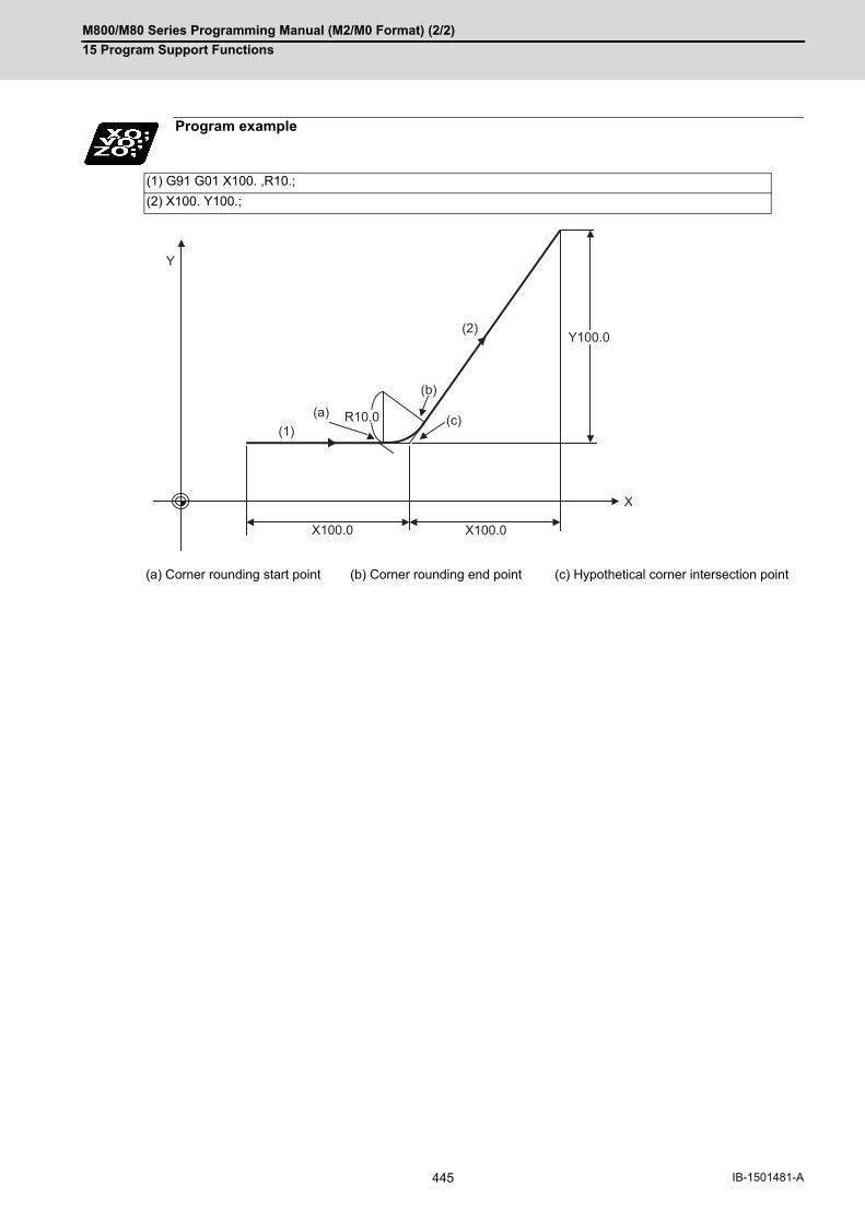
M800/M80 Series Programming Manual (M2/M0 Format) (2/2)
15 Program Support Functions
445 IB-1501481-A
Program example
(1) G91 G01 X100. ,R10.;
(2) X100. Y100.;
(a) Corner rounding start point (b) Corner rounding end point (c) Hypothetical corner intersection point
X100.0 X100.0
X
Y
Y100.0
(1)
(2)
R10.0(a)
(b)
(c)

M800/M80 Series Programming Manual (M2/M0 Format) (2/2)
15 Program Support Functions
446IB-1501481-A
15.1.3 Corner Chamfering Expansion/Corner Rounding Expansion
Using an E command, the feedrate can be designated for the corner chamfering and corner rounding section.
In this way, the corner section can be cut into a correct shape.
Example
Function and purpose
F200.
E100.
F200.
F200.
YF200.
(G94) G01Y70.,C30. F200.E100.; X-110.;
(G94) G01Y70.,R30. F200.E100.; X-110.;
X
E100.
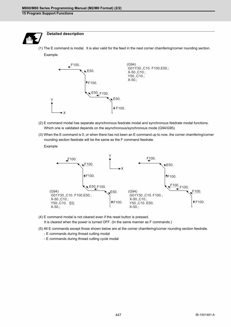
M800/M80 Series Programming Manual (M2/M0 Format) (2/2)
15 Program Support Functions
447 IB-1501481-A
(1) The E command is modal. It is also valid for the feed in the next corner chamfering/corner rounding section.
Example
(2) E command modal has separate asynchronous feedrate modal and synchronous feedrate modal functions.
Which one is validated depends on the asynchronous/synchronous mode (G94/G95).
(3) When the E command is 0, or when there has not been an E command up to now, the corner chamfering/corner
rounding section feedrate will be the same as the F command feedrate.
Example
(4) E command modal is not cleared even if the reset button is pressed.
It is cleared when the power is turned OFF. (In the same manner as F commands.)
(5) All E commands except those shown below are at the corner chamfering/corner rounding section feedrate.
- E commands during thread cutting modal
- E commands during thread cutting cycle modal
Detailed description
(G94) G01Y30.,C10. F100.E50.; X-50.,C10.; Y50.,C10.; X-50.;
F100.
F100.
F100.
E50.
E50.
E50.
F100.
Y
X
F100.F100.
F100.
F100.
F100.
F100.
F100.
F100. F100.F100.
F100.
E50.
E50. E50.
Y
X
(G94) G01Y30.,C10. F100.E50.; X-50.,C10.; Y50.,C10. E0; X-50.;
(G94) G01Y30.,C10. F100.; X-50.,C10.; Y50.,C10. E50; X-50.;
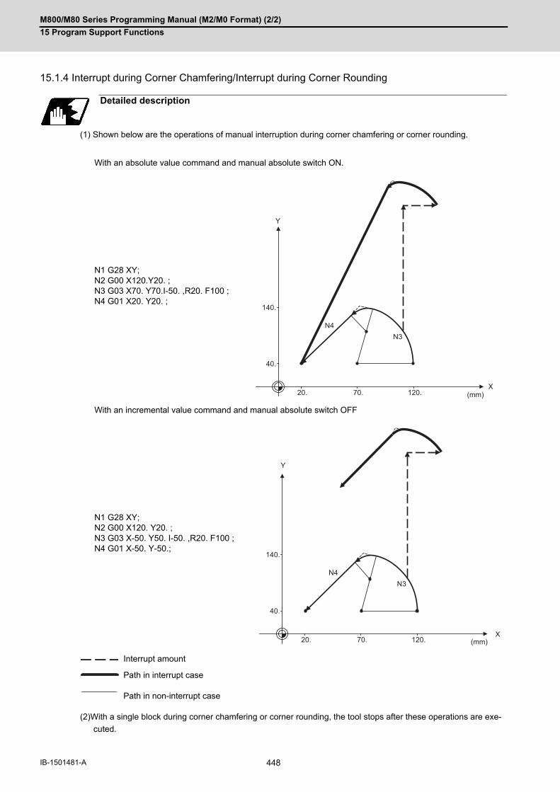
M800/M80 Series Programming Manual (M2/M0 Format) (2/2)
15 Program Support Functions
448IB-1501481-A
15.1.4 Interrupt during Corner Chamfering/Interrupt during Corner Rounding
(1) Shown below are the operations of manual interruption during corner chamfering or corner rounding.
(2)With a single block during corner chamfering or corner rounding, the tool stops after these operations are exe-
cuted.
Detailed description
With an absolute value command and manual absolute switch ON.
N1 G28 XY;N2 G00 X120.Y20. ;N3 G03 X70. Y70.I-50. ,R20. F100 ;N4 G01 X20. Y20. ;
With an incremental value command and manual absolute switch OFF
N1 G28 XY;N2 G00 X120. Y20. ;N3 G03 X-50. Y50. I-50. ,R20. F100 ;N4 G01 X-50. Y-50.;
Interrupt amount
Path in interrupt case
Path in non-interrupt case
X
140.
40.
20. 70.
N4N3
120.
Y
(mm)
X
140.
40.
20. 70.
N4N3
120.
Y
(mm)
M800/M80 Series Programming Manual (M2/M0 Format) (2/2)
15 Program Support Functions
449 IB-1501481-A
15.2 Corner Chamfering II /Corner Rounding II
Corner chamfering and corner rounding can be performed by adding ",C" or ",R" to the end of the block which is
commanded first among the block that forms a corner with continuous arbitrary angle lines or arcs.
15.2.1 Corner Chamfering II ; G01/G02/G03 X_ Y_ ,C_
The corner is chamfered by commanding ",C" in the 1st block of the two continuous blocks containing an arc. For
an arc, this will be the chord length.
Corner chamfering is performed at the point where N100 and N200 intersect.
(1) If this function is commanded while the corner chamfer or corner rounding command is not defined in the spec-
ifications, it causes a program error (P381).
(2) The start point of the block following the corner chamfering is the hypothetical corner intersection point.
(3) If there are multiple or duplicate corner chamfering commands in a same block, the last command will be valid.
(4) When both corner chamfering and corner rounding are commanded in the same block, the latter command will
be valid.
(5) Tool compensation is calculated for the shape which has already been subjected to corner chamfering.
(6) Program error (P385) will occur when positioning or thread cutting is commanded in the corner chamfering com-
mand block or in the next block.
(7) Program error (P382) will occur when the block following corner chamfering contains a G command other than
group 01 or another command.
(8) Program error (P383) will occur when the movement amount in the block, commanding corner chamfering, is
less than the chamfering amount.
(9) Program error (P384) will occur when the movement amount is less than the chamfering amount in the block
following the block commanding corner chamfering.
(10) Even if a diameter is commanded, it will be handled as a radial command value during corner chamfering.
(11) Program error (P382) will occur when a movement command is not issued in the block following the corner
chamfering II command.
Function and purpose
Function and purpose
Command format
N100 G03 X__ Y__ I__ J__ ,C__ ;
N200 G01 X__ Y__ ;
,C Length up to chamfering starting point or end point from hypothetical corner
Detailed description

M800/M80 Series Programming Manual (M2/M0 Format) (2/2)
15 Program Support Functions
450IB-1501481-A
(1) Linear - arc
(2) Arc - arc
Program example
Absolute value command N1 G28 XY; N2 G90 G00 X100. Y100.; N3 G01 X50.Y150.,C20. F100; N4 G02 X0 Y100. I-50. J0; :Relative value command N1 G28 XY; N2 G91 G00 X100. Y100.; N3 G01 X-50.Y50.,C20. F100; N4 G02 X-50. Y-50. I-50. J0; :
(a) Hypothetical corner intersection point
Absolute value command N1 G28 XY; N2 G91 G00 X140. Y10.; N3 G02 X60.Y50.I0 J100. ,C20. F100; N4 X0 Y30.I-60.J80.; : Relative value command N1 G28 XY; N2 G91 G00 X140. Y10.; N3 G02 X-80.Y40. R100. ,C20. F100; N4 X-60. Y-20. I-60. J80.; :
(a) Hypothetical corner intersection point
Y
150.
100.
X100.50.
N4
C20.C20.
N3
(a)
(mm)
Y
130.
110.
50.
30.
10.X
140.60.
N4C20.
C20.
N3
(a)
(mm)

M800/M80 Series Programming Manual (M2/M0 Format) (2/2)
15 Program Support Functions
451 IB-1501481-A
15.2.2 Corner Rounding II ; G01/G02/G03 X_ Y_ ,R_
The corner is rounded by commanding ",R_" in the 1st block of the two continuous blocks containing an arc.
Corner rounding is performed at the point where N100 and N200 intersect.
(1) If this function is commanded while the corner chamfer or corner rounding command is not defined in the spec-
ifications, it causes a program error (P381).
(2) The start point of the block following the corner rounding is the hypothetical corner intersection point.
(3) When both corner chamfering and corner rounding are commanded in a same block, the latter command will be
valid.
(4) Tool compensation is calculated for the shape which has already been subjected to corner rounding.
(5) Program error (P385) will occur when positioning or thread cutting is commanded in the corner rounding com-
mand block or in the next block.
(6) Program error (P382) will occur when the block following corner rounding contains a G command other than
group 01 or another command.
(7) Program error (P383) will occur when the movement amount in the corner rounding block is less than the R value.
(8) Program error (P384) will occur when the movement amount is less than the R value in the block following the
corner rounding.
(9) Even if a diameter is commanded, it will be handled as a radial command value during corner rounding.
(10) A program error (P382) will occur if a movement command is not issued in the block following corner rounding.
Function and purpose
Command format
N100 G03 X__ Y__ I__ J__ ,R__ ;
N200 G01 X__ Y__ ;
,R Arc radius of corner rounding
Detailed description

M800/M80 Series Programming Manual (M2/M0 Format) (2/2)
15 Program Support Functions
452IB-1501481-A
(1) Linear - arc
(2) Arc - arc
15.2.3 Corner Chamfering Expansion/Corner Rounding Expansion
For details, refer to "Corner Chamfering I / Corner Rounding" and "Corner Chamfering Expansion / Corner Rounding
Expansion".
15.2.4 Interrupt during Corner Chamfering/Interrupt during Corner Rounding
For details, refer to "Corner Chamfering I / Corner Rounding" and "Interrupt during Corner Chamfering Interrupt
during / Corner Rounding".
Program example
Absolute value command N1 G28 XY; N2 G90 G00 X100. Y30.; N3 G01 X50.Y80.,R10. F100; N4 G02 X0 Y30. I-50.J0; :Relative value command N1 G28 XY; N2 G91 G00 X100. Y30.; N3 G01 X-50.Y50.,R10. F100; N4 G02 X-50. Y-50. I-50.J0; :
(a) Hypothetical corner intersection point
Absolute value command N1 G28 XY; N2 G90 G00 X100. Y30.; N3 G02 X50.Y80. R50.,R10.F100; N4 X0 Y30. R50.; :Relative value command N1 G28 XY; N2 G91 G00 X100. Y30.; N3 G02 X-50.Y50. I0 J50.,R10.F100; N4 X-50. Y-50. I-50. J0; :
(a) Hypothetical corner intersection point
Y
80.
30.
X100.50.
N4N3
(a)
(mm)
R10.
Y
80.
30.
X100.50.
N4 N3
(a)
(mm)
R10.

M800/M80 Series Programming Manual (M2/M0 Format) (2/2)
15 Program Support Functions
453 IB-1501481-A
15.3 Linear Angle Command; G01 X_/Y_ A_/,A_
The end point coordinates are automatically calculated by commanding the linear angle and one of the end point
coordinate axes.
This designates the angle and the X or Y axis coordinates.
Select the command plane with G17 to G19.
(1) The angle is set based on the positive (+) direction of the horizontal axis for the selected plane. The counter-clockwise (CCW) direction is indicated by a positive sign (+), and the clockwise (CW) direction by a negative sign(-).
(2) Either of the axes on the selected plane is commanded for the end point.
(3) The angle is ignored when the angle and the coordinates of both axes are commanded.
(4) When only the angle has been commanded, this is treated as a geometric command.
(5) The angle of either the start point (a1) or end point (a2) may be used.
(6) This function is valid only for the G01 command; it is not valid for other interpolation or positioning commands.
(7) The range of slope "a" is between -360.000 and 360.000. When a value outside this range is commanded, it will be divided by 360 (degrees) and the remainder will becommanded. (Example) If 400 is commanded, 40° (remainder of 400/360) will become the command angle.
(8) If an address A is used for the axis name or the 2nd miscellaneous function, use ",A" as the angle.
(9) If "A" and ",A" are commanded in a same block, ",A" will be interpreted as the angle.
A program error (P33) will occur if this function is commanded during the high-speed machining mode or high-speed high-accuracy mode.
Function and purpose
Command format
N1 G01 Xx1(Yy1) Aa1;
N2 G01 Xx2(Yy2) A-a2; (A-a2 can also be set as Aa 3. )
N1 G01 Xx1(Yy1) ,Aa1;
N2 G01 Xx2(Yy2) ,A-a2;
Detailed description
Y
y2
y1( x1,y1)
N1
X
N2
a1
a2
a3
( x2,y2)
Note
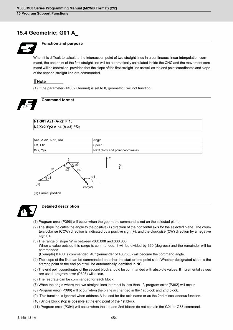
M800/M80 Series Programming Manual (M2/M0 Format) (2/2)
15 Program Support Functions
454IB-1501481-A
15.4 Geometric; G01 A_
When it is difficult to calculate the intersection point of two straight lines in a continuous linear interpolation com-
mand, the end point of the first straight line will be automatically calculated inside the CNC and the movement com-
mand will be controlled, provided that the slope of the first straight line as well as the end point coordinates and slope
of the second straight line are commanded.
(1) If the parameter (#1082 Geomet) is set to 0, geometric I will not function.
(1) Program error (P396) will occur when the geometric command is not on the selected plane.
(2) The slope indicates the angle to the positive (+) direction of the horizontal axis for the selected plane. The coun-terclockwise (CCW) direction is indicated by a positive sign (+), and the clockwise (CW) direction by a negativesign (-).
(3) The range of slope "a" is between -360.000 and 360.000. When a value outside this range is commanded, it will be divided by 360 (degrees) and the remainder will becommanded. (Example) If 400 is commanded, 40° (remainder of 400/360) will become the command angle.
(4) The slope of the line can be commanded on either the start or end point side. Whether designated slope is thestarting point or the end point will be automatically identified in NC.
(5) The end point coordinates of the second block should be commanded with absolute values. If incremental valuesare used, program error (P393) will occur.
(6) The feedrate can be commanded for each block.
(7) When the angle where the two straight lines intersect is less than 1°, program error (P392) will occur.
(8) Program error (P396) will occur when the plane is changed in the 1st block and 2nd block.
(9) This function is ignored when address A is used for the axis name or as the 2nd miscellaneous function.
(10) Single block stop is possible at the end point of the 1st block.
(11) Program error (P394) will occur when the 1st and 2nd blocks do not contain the G01 or G33 command.
Function and purpose
Command format
N1 G01 Aa1 (A-a2) Ff1;
N2 Xx2 Yy2 A-a4 (A-a3) Ff2;
Aa1, A-a2, A-a3, Aa4 Angle
Ff1, Ff2 Speed
Xx2, Yy2 Next block end point coordinates
(C) Current position
Detailed description
Note
a1
Y
XN1 N2a2
a3
a4
(x2,y2)
?
(C)

M800/M80 Series Programming Manual (M2/M0 Format) (2/2)
15 Program Support Functions
455 IB-1501481-A
(1) Corner chamfering and corner rounding can be commanded after the angle command in the 1st block.
(2) The geometric command I can be issued after the corner chamfering or corner rounding command.
(3) The geometric command I can be issued after the linear angle command.
Relationship with Other Functions
(Example 1)N1 Aa1 ,Cc1 ;N2 Xx2 Yy2 Aa2 ;
(Example 2)N1 Aa1 ,Rr1 ;N2 Xx2 Yy2 Aa2 ;
(Example 3)N1 Xx2 Yy2 ,Cc1 ;N2 Aa1 ;N3 Xx3 Yy3 Aa2 ;
(Example 4)N1 Xx2 Aa1 ;N2 Aa2 ;N3 Xx3 Yy3 Aa3 ;
?
N2
N1
(x2,y2)
a2
a1
c1
c1
(x1,y1)
N2
N1
(x2,y2)
a1
a2
r1
?
(x1,y1)
N2
N1(x2,y2)
(x3,y3) a2
a1
c1
c1
(x1,y1)
N3
?
N2
N1(x2,y2)
(x3,y3) a3
a2
(x1,y1)
N3
a1
?

M800/M80 Series Programming Manual (M2/M0 Format) (2/2)
15 Program Support Functions
456IB-1501481-A
15.5 Geometric IB
With the geometric IB function, the contact and intersection are calculated by commanding an arc center point or
linear angle in the movement commands of two continuous blocks (only blocks with arc commands), instead of com-
manding the first block end point.
(1) If the parameter (#1082 Geomet) is not set to 2, geometric IB will not function.
Function and purpose
Two-arc contact
Linear - arc (arc - linear) intersection
Linear - arc (arc - linear) contact
Note
N2
N1
r2
r1(??)
Y
X
N2
N2 N1
N1
(??)
(??)Y
X
r1
r1
N2
N2
N1N1
r1r1
(??)
Y
X
(??)

M800/M80 Series Programming Manual (M2/M0 Format) (2/2)
15 Program Support Functions
457 IB-1501481-A
15.5.1 Geometric IB (Automatic Calculation of Two-arc Contact) ; G02/G03 P_Q_ /R_
When the contact of two continuous contacting arcs is not indicated in the drawing, it can be automatically calculated
by commanding the 1st circular center coordinate value or radius, and the 2nd arc end point absolute value and
center coordinate value or radius.
* I and J (X and Y axes arc center coordinate incremental value) commands can be issued instead of P and Q.
1st block arc : Incremental amount from the start point to the center
2nd block arc : Incremental amount from the end point to the center
Function and purpose
Command format
N1 G02(G03) Pp1 Qq1 Ff1;
N2 G03(G02) Xx2 Yy2 Pp2 Qq2 Ff2;
N1 G02(G03) Pp1 Qq1 Ff1;
N2 G03(G02) Xx2 Yy2 Rr2 Ff2;
N1 G02(G03) Rr1 Ff1;
N2 G03(G02) Xx2 Yy2 Pp2 Qq2 Ff2;
P,Q X and Y axes circular center coordinate absolute value (diameter/radius value com-mand)The center address for the 3rd axis is commanded with A.
R Arc radius (when a (-) sign is attached, the arc is judged to be 180° or more)
r2
r1
(x2,y2)
Y
X
(p2,q2)
(p1,q1)
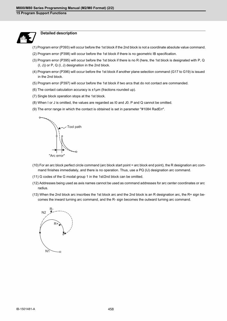
M800/M80 Series Programming Manual (M2/M0 Format) (2/2)
15 Program Support Functions
458IB-1501481-A
(1) Program error (P393) will occur before the 1st block if the 2nd block is not a coordinate absolute value command.
(2) Program error (P398) will occur before the 1st block if there is no geometric IB specification.
(3) Program error (P395) will occur before the 1st block if there is no R (here, the 1st block is designated with P, Q
(I, J)) or P, Q (I, J) designation in the 2nd block.
(4) Program error (P396) will occur before the 1st block if another plane selection command (G17 to G19) is issued
in the 2nd block.
(5) Program error (P397) will occur before the 1st block if two arcs that do not contact are commanded.
(6) The contact calculation accuracy is ±1μm (fractions rounded up).
(7) Single block operation stops at the 1st block.
(8) When I or J is omitted, the values are regarded as I0 and J0. P and Q cannot be omitted.
(9) The error range in which the contact is obtained is set in parameter "#1084 RadErr".
(10) For an arc block perfect circle command (arc block start point = arc block end point), the R designation arc com-
mand finishes immediately, and there is no operation. Thus, use a PQ (IJ) designation arc command.
(11) G codes of the G modal group 1 in the 1st/2nd block can be omitted.
(12) Addresses being used as axis names cannot be used as command addresses for arc center coordinates or arc
radius.
(13) When the 2nd block arc inscribes the 1st block arc and the 2nd block is an R designation arc, the R+ sign be-
comes the inward turning arc command, and the R- sign becomes the outward turning arc command.
Detailed description
Tool path
"Arc error"
R-
R+
N2
N1

M800/M80 Series Programming Manual (M2/M0 Format) (2/2)
15 Program Support Functions
459 IB-1501481-A
15.5.2 Geometric IB (Automatic Calculation of Linear - Arc Intersection) ; G01 A_ , G02/G03 P_Q_H_
When the contact point of a shape in which contact between a line and an arc is not indicated in the drawing, it can
be automatically calculated by commanding the following program.
* I and J (X and Y axes arc center coordinate incremental value) commands can be issued instead of P and Q.
1st block arc : Incremental amount from the start point to the center
2nd block arc : Incremental amount from the end point to the center
Function and purpose
Command format (For G18 plane)
N1 G01 Aa1 (A-a2) Ff1;
N2 G02(G03) Xx2 Yy2 Pp2 Qq2 Hh2 Ff2 ;
N1 G02(G03) Pp1 Qq1 Hh1 (,Hh1) Ff1 ;
N2 G1 Xx2 Yy2 Aa3 (A-a4) Ff2 ;
A Linear angle (-360.000° to 360.000°)
P,Q X and Y axes circular center coordinate absolute value (diameter/radius value com-mand)The center address for the 3rd axis is commanded with A.
H (,H) Selection of linear - arc intersection 0: Intersection of the shorter line 1: Intersection of the longer line
H=1 H=1
H=0
N2 N1
H=0
N1a1
N2a3
- a4- a2
(??)
(??)
(??)(??) (p2,q2)
(x2,y2)(p1,q1)
(x2,y2)Y
X

M800/M80 Series Programming Manual (M2/M0 Format) (2/2)
15 Program Support Functions
460IB-1501481-A
(1) When the 2nd miscellaneous function address is A, the 2nd miscellaneous function is validated and this function
is invalidated.
(2) Program error (P393) will occur before the 1st block if the 2nd block is not a coordinate absolute value command.
(3) Program error (P398) will occur before the 1st block if there is no geometric IB specification.
(4) In case of the 2nd block arc, a program error (P395) will occur before the 1st block if there is no P, Q (I, J) des-
ignation. A program error (P395) will also occur if there is no A designation for the line.
(5) Program error (P396) will occur before the 1st block if another plane selection command (G17 to G19) is issued
in the 2nd block.
(6) Program error (P397) will occur before the 1st block if a straight line and arc that do not contact or intersect are
commanded.
(7) Single block operation stops at the 1st block.
(8) When I or J is omitted, the values are regarded as I0 and J0. P and Q cannot be omitted.
(9) When H is omitted, the value is regarded as H0.
(10) The linear - arc contact is automatically calculated by designating R instead of P, Q (I, J).
(11) The error range in which the intersect is obtained is set in parameter "#1084 RadErr".
(12) As seen from the + direction of the horizontal axis of the selected plane, the counterclockwise (CCW) direction
is considered to be + and the clockwise direction (CW) -.
(13) The slope of the line can be commanded on either the start or end point side. Whether designated slope is the
starting point or the end point will be automatically identified.
(14) When the distance to the intersection from the line and arc is same (as in the figure below), the control by ad-
dress H (short/long distance selection) is invalidated. In this case, the judgment is carried out based on the angle
of the line.
(15) The intersect calculation accuracy is ±1μm (fractions rounded up).
(16) In linear - arc intersections, the arc command can only be PQ (IJ) command. When the arc block start point and
arc block end point are the same point, the arc is a perfect circle.
Detailed description
Tool path
Arc error
N2 G2 Xx2 Yy2 Pp2 Qq2 Ff2 ;N1 G1 A a1 Ff1;
N1 G1 A –a2 Ff1;N2 G2 Xx2 Yy2 Pp2 Qq2 Ff2 ;
(p2,q2)
-a2
a1

M800/M80 Series Programming Manual (M2/M0 Format) (2/2)
15 Program Support Functions
461 IB-1501481-A
(17) G codes of the G modal group in the 1st block can be omitted.
(18) Addresses being used as axis names cannot be used as command addresses for angles, arc center coordi-
nates or intersection selections.
(19) When geometric IB is commanded, two blocks are pre-read.
Relationship with other functions
Command Tool path
Geometric IB + corner chamfering N1 G02 P_ Q_ H_ ;N2 G01 X_ Y_ A_ ,C_ ;G01 X_ Y_ ;
N2
N1X
Y

M800/M80 Series Programming Manual (M2/M0 Format) (2/2)
15 Program Support Functions
462IB-1501481-A
15.5.3 Geometric IB (Automatic Calculation of Linear - Arc Intersection) ; G01 A_ , G02/G03 R_H_
When the intersection of a shape in which a line and an arc intersect is not indicated in the drawing, it can be auto-
matically calculated by commanding the following program.
(1) When the 2nd miscellaneous function address is A, the 2nd miscellaneous function is validated and this function
is invalidated.
(2) Program error (P393) will occur before the 1st block if the 2nd block is not a coordinate absolute value command.
(3) Program error (P398) will occur before the 1st block if there is no geometric IB specification.
(4) Program error (P396) will occur before the 1st block if another plane selection command (G17 to G19) is issued
in the 2nd block.
(5) A program error (P397) will occur before the 1st block if a straight line and arc that do not contact are command-
ed.
(6) In case of the 2nd block arc, a program error (P395) will occur before the 1st block if there is no R designation.
A program error (P395) will also occur if there is no A designation for the line.
(7) Single block operation stops at the 1st block.
(8) The linear - arc contact is automatically calculated by designating R instead of P, Q (I, J).
Function and purpose
Command format (For G18 plane)
N1 G01 Aa1 (A-a2) Ff1;
N2 G03(G02) Xx2 Yy2 Rr2 Ff2;
N1 G03(G02) Rr1 Ff1;
N2 G01 Xx2 Yy2 Aa3 (A-a4) Ff2 ;
A Linear angle (-360.000° to 360.000°)
R Circular radius
Detailed description
Y
X
N1
(x2,y2)
(??) N1N2
N2
(x2,y2)
(??)
a3
- a4
- a2 r2r1
a1
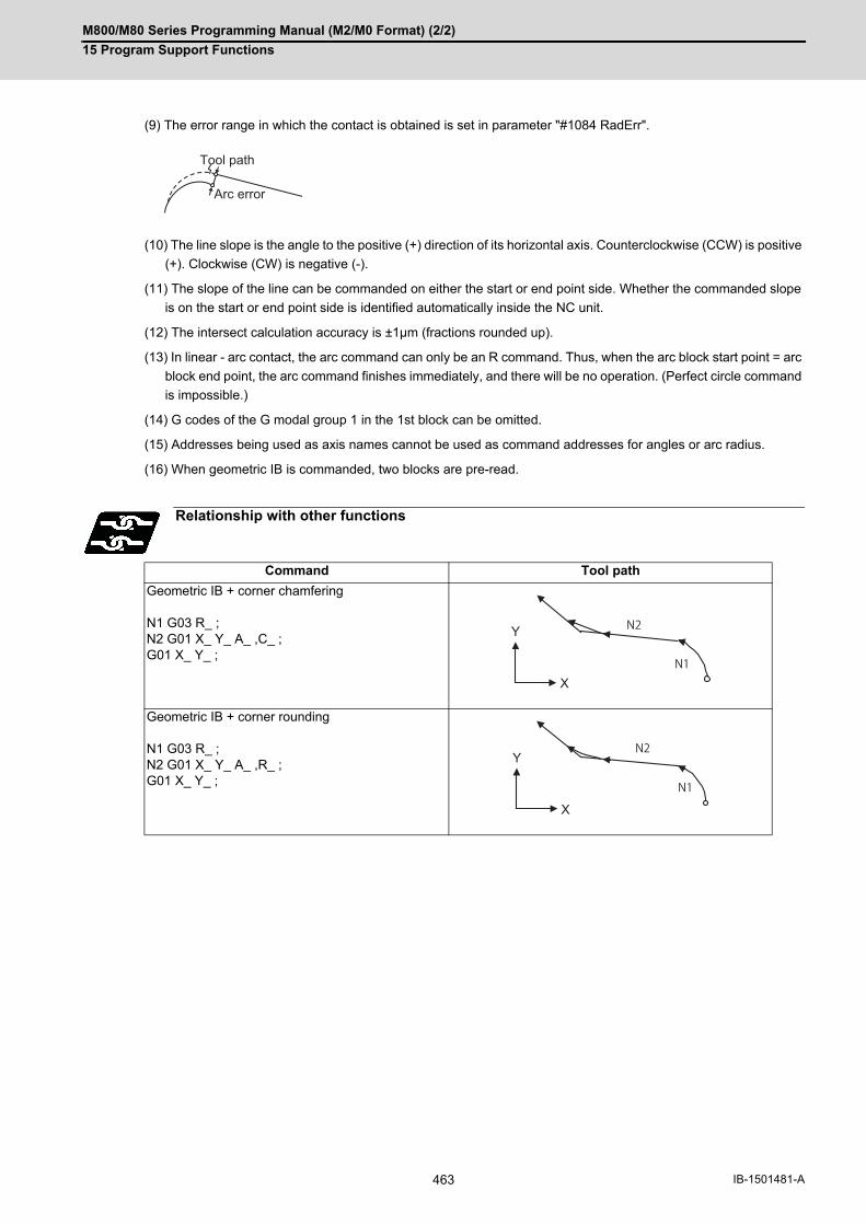
M800/M80 Series Programming Manual (M2/M0 Format) (2/2)
15 Program Support Functions
463 IB-1501481-A
(9) The error range in which the contact is obtained is set in parameter "#1084 RadErr".
(10) The line slope is the angle to the positive (+) direction of its horizontal axis. Counterclockwise (CCW) is positive
(+). Clockwise (CW) is negative (-).
(11) The slope of the line can be commanded on either the start or end point side. Whether the commanded slope
is on the start or end point side is identified automatically inside the NC unit.
(12) The intersect calculation accuracy is ±1μm (fractions rounded up).
(13) In linear - arc contact, the arc command can only be an R command. Thus, when the arc block start point = arc
block end point, the arc command finishes immediately, and there will be no operation. (Perfect circle command
is impossible.)
(14) G codes of the G modal group 1 in the 1st block can be omitted.
(15) Addresses being used as axis names cannot be used as command addresses for angles or arc radius.
(16) When geometric IB is commanded, two blocks are pre-read.
Relationship with other functions
Command Tool path
Geometric IB + corner chamfering N1 G03 R_ ;N2 G01 X_ Y_ A_ ,C_ ;G01 X_ Y_ ;
Geometric IB + corner rounding N1 G03 R_ ;N2 G01 X_ Y_ A_ ,R_ ;G01 X_ Y_ ;
Tool path
Arc error
X
Y
N1
N2
X
Y
N1
N2

M800/M80 Series Programming Manual (M2/M0 Format) (2/2)
15 Program Support Functions
464IB-1501481-A
15.6 G Command Mirror Image; G50.1, G51.1, G62
When cutting a shape that is symmetrical on the left and right, programming time can be shortened by machining
one side and then using the same program to machine the other side. The mirror image function is effective for this.
For example, when using a program as shown below to machine the shape on the left side (A), a symmetrical shape
(B) can be machined on the right side by applying mirror image and executing the program.
Function and purpose
Mirror axis
Command format
Mirror image ON
G51.1 Xx1 Yy1 Zz1;
x1, y1, z1 Mirror image center coordinates(Mirror image will be applied regarding this position as a center)
Mirror image OFF
G50.1 Xx2 Yy2 Zz2;
x2, y2, z2 Mirror image cancel axis(The values of x2, y2, z2 will be ignored.)
Y
X
(A) (B)
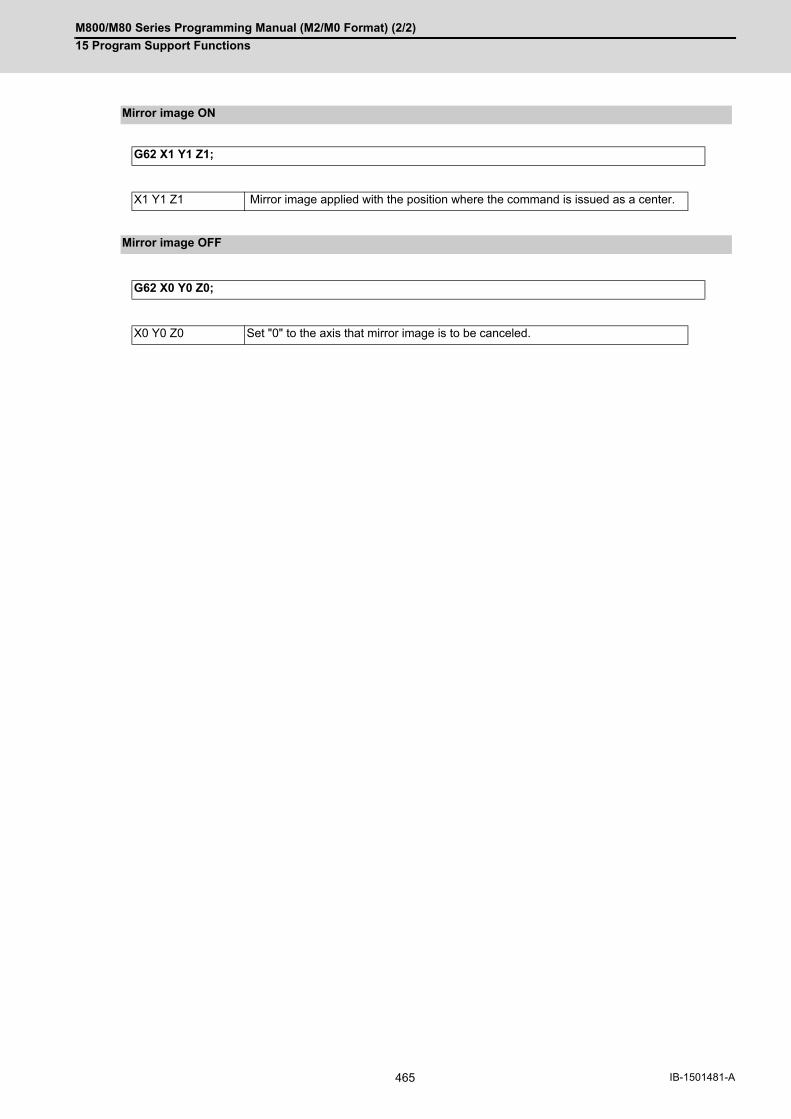
M800/M80 Series Programming Manual (M2/M0 Format) (2/2)
15 Program Support Functions
465 IB-1501481-A
Mirror image ON
G62 X1 Y1 Z1;
X1 Y1 Z1 Mirror image applied with the position where the command is issued as a center.
Mirror image OFF
G62 X0 Y0 Z0;
X0 Y0 Z0 Set "0" to the axis that mirror image is to be canceled.

M800/M80 Series Programming Manual (M2/M0 Format) (2/2)
15 Program Support Functions
466IB-1501481-A
(1) At G51.1, command the mirror image axis and the coordinate to be a center of mirror image with the absolute
command or incremental command.
(2) At G50.1, command the axis for which mirror image is to be turned OFF. The values of x2, y2, and z2 will be
ignored.
(3) If mirror image is applied on only one axis of the designated plane, the rotation direction and compensation di-
rection will be reversed for the arc or tool radius compensation and coordinate rotation, etc.
(4) This function is processed on the local coordinate system, so the center of the mirror image will change when
the counter is preset or when the workpiece coordinates are changed.
(5) Reference position return during mirror image
If the reference position return command (G28, G30) is executed during the mirror image, the mirror image will
be valid during the movement to the intermediate point, but will not be applied to the movement to the reference
position after the intermediate point.
(6) Return from zero point during mirror image
If the return command (G29) from the zero point is commanded during the mirror image, the mirror will be applied
to the intermediate point.
(7) The mirror image will not be applied to the G53 command.
(8) For G62, mirror image ON/OFF will be applied on all the axes commanded in the same block. The position where
G62 is executed is regarded as the center of the mirror image.
(9) For G62, command "0" or "1" following to the axis name basically. The value other than "0" will be regarded as
"1".
In addition, mirror image axis ON/OFF can be commanded together.
Detailed description
Path on which mirror is applied Mirror center Programmed path
Intermediate point when mirror is applied
Intermediate point

M800/M80 Series Programming Manual (M2/M0 Format) (2/2)
15 Program Support Functions
467 IB-1501481-A
(1) Combination with radius compensation
The mirror image (G51.1) will be processed after the radius compensation (G41, G42) is applied, so the following
type of cutting will take place.
Relationship with other functions
Programmed path Path with mirror image applied
Programmed path
Path with only radius compensation applied
Path with only mirror image applied
Path with mirror image and radius compen-sation applied
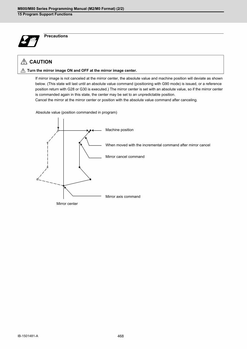
M800/M80 Series Programming Manual (M2/M0 Format) (2/2)
15 Program Support Functions
468IB-1501481-A
If mirror image is not canceled at the mirror center, the absolute value and machine position will deviate as shown
below. (This state will last until an absolute value command (positioning with G90 mode) is issued, or a reference
position return with G28 or G30 is executed.) The mirror center is set with an absolute value, so if the mirror center
is commanded again in this state, the center may be set to an unpredictable position.
Cancel the mirror at the mirror center or position with the absolute value command after canceling.
Precautions
CAUTION
Turn the mirror image ON and OFF at the mirror image center.
Absolute value (position commanded in program)
Machine position
When moved with the incremental command after mirror cancel
Mirror cancel command
Mirror axis command
Mirror center

M800/M80 Series Programming Manual (M2/M0 Format) (2/2)
15 Program Support Functions
469 IB-1501481-A
15.7 Normal Line Control; G40.1/G41.1/G42.1 (G150/G151/G152)
The C axis (rotary axis) turning will be controlled so that the tool constantly faces the normal line direction in respect
to the movement of the axes in the selected plane during program operation.
At the block seams, the C axis turning is controlled so that the tool faces the normal line direction at the next block's
start point.
During arc interpolation, the rotary axis turning is controlled in synchronization with the operation of the arc interpo-
lation.
The normal line control I and II can be used according to the C axis turning direction during normal line control. Which
method is to be used depends on the MTB specifications (parameter "#1524 C_type").
Function and purpose
C axis center (rotary axis)
Tool end position
C axis turning
Rotation axis center (C axis)
Tool end position
Normal line con-trol type
Turning direction Turning speed Turning speed in arc in-terpolation
Type I Direction that is 180° or less(shortcut direction)
Parameter speed(#1523 C_feed)
Speed when the program path follows the F com-mand
(#1524 C_type = 0)
Type II As a principle, the com-manded direction
Feedrate Speed when the tool nose follows the F command (#1524 C_type = 1)
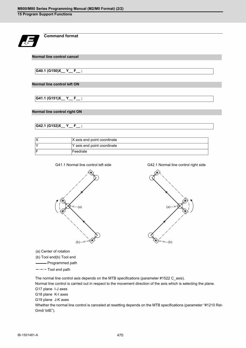
M800/M80 Series Programming Manual (M2/M0 Format) (2/2)
15 Program Support Functions
470IB-1501481-A
The normal line control axis depends on the MTB specifications (parameter #1522 C_axis).
Normal line control is carried out in respect to the movement direction of the axis which is selecting the plane.
G17 plane I-J axes
G18 plane K-I axes
G19 plane J-K axes
Whether the normal line control is canceled at resetting depends on the MTB specifications (parameter “#1210 Rst-
Gmd/ bitE”).
Command format
Normal line control cancel
G40.1 (G150)X__ Y__ F__ ;
Normal line control left ON
G41.1 (G151)X__ Y__ F__ ;
Normal line control right ON
G42.1 (G152)X__ Y__ F__ ;
X X axis end point coordinate
Y Y axis end point coordinate
F Feedrate
G41.1 Normal line control left side G42.1 Normal line control right side
(a) Center of rotation
(b) Tool end(b) Tool end
Programmed path
Tool end path
(a)
(b)
(a)
(b)

M800/M80 Series Programming Manual (M2/M0 Format) (2/2)
15 Program Support Functions
471 IB-1501481-A
The normal line control angle is 0° (degree) when the tool is facing the horizontal axis (+ direction) direction.
The counterclockwise direction turning is + (plus), and the clockwise direction turning is - (minus).
Detailed description
Definition of the normal line control angle
G17 plane (I - J axes) ... The axis angle is 0°(degree) when the tool is facing the +I direction.
G18 plane (K - I axes) ...The axis angle is 0°(degree) when the tool is facing the +K direction.
G19 plane (J - K axes) ... The axis angle is 0°(degree) when the tool is facing the +J direction.
0I+
J+
90
180
270
0K+
I+
90
180
270
0J+
K+
90
180
270

M800/M80 Series Programming Manual (M2/M0 Format) (2/2)
15 Program Support Functions
472IB-1501481-A
(1) Start-upAfter the normal line control axis turns to the right angle of the advance direction at the start point of the normalline control command block, the axis which is selecting the plane is moves. Note that the normal line control axisat the start up turns in the direction that is 180° or less (shortcut direction) in both the normal line control type Iand II.
(2) During normal line control mode
(a) Operation in block
During interpolation of the linear command, the angle of the normal line control axis is fixed, and the normal
line control axis does not turn.
During the arc command, the normal line control axis turns in synchronization with the operation of the arc
interpolation.
Normal line control turning operation in respect to movement command
:
N1 G01 Xx1 Yy1 Ff1 ;
N2 G41.1 ; ... Independent block
N3 Xx2 Yy2 ;
:
N2 is fixed
:
N1 G01 Xx1 Yy1 Ff1 ;
N2 G41.1 Xx2 Yy2 ; ... Same block
:
:G41.1 ;N1 G02 Xx1 Yy1 Ii1 Jj1 ; :
Programmed path
Tool end path
(x2,y2)
(x1,y1)N3
N3
N1
G41.1
(x2,y2)
(x1,y1)N2
N2
N1
G41.1
(i1,j1)
(x1,y1)
N1

M800/M80 Series Programming Manual (M2/M0 Format) (2/2)
15 Program Support Functions
473 IB-1501481-A
(b) Block seam
(3) CancelThe normal line control axis will not turn, and the plane selecting axis will be moved by the program command.
No tool radi-us compen-sation
After the normal line control axis is turned to be at the right angle of the plane selecting movement in the next block, the operation moves to the next block.
Liner - Liner Liner - Arc Arc - Arc
Programmed path
Tool end path
With tool ra-dius com-pensation
If tool radius compensation is applied, normal line control is carried out along the path to which the tool radius compensation is applied.
Liner - Liner Liner - Arc Arc - Arc
Programmed path
Tool radius compensation path
Tool end path
:
N1 G01 Xx1 Yy1 Ff1 ;
N2 G40.1 ; ... Independent block
N3 Xx2 Yy2 ;
:
N2 is fixed
:
N1 G01 Xx1 Yy1 Ff1 ;
N2 G40.1 Xx2 Yy2 ; ... Same block
:
(x2,y2)
(x1,y1)N3
N1
G40.1
(x2,y2)
(x1,y1)N2
N1
G40.1

M800/M80 Series Programming Manual (M2/M0 Format) (2/2)
15 Program Support Functions
474IB-1501481-A
During normal line control, the turning operation for the normal line control axis is not carried out at the seam be-
tween a block and the next block, in which the movement amount is smaller than that set with the parameter (#1535
C_leng).
(1) For liner block;When the movement amount of the N2 block is smaller than the parameter(#1535 C_leng), the normal line con-trol axis is not turned at the seam between the N1 block and N2 block. It stays the same direction as the N1 block.
(2) For arc block;When the diameter value of the N2 block is smaller than the parameter(#1535 C_leng), the normal line controlaxis is not turned at the seam between the N1 block and N2 block. It stays the same direction as the N1 block.During arc interpolation of the N2 block, the normal line control axis does not turn in synchronization with theoperation of arc interpolation.
Since operation fractions are created by calculating the intersection point of two segments, the turning operationmay or may not be carried out when the parameter (#1535 C_leng) and the segment length are equal.
Normal line control temporary cancel
N2 block movement amount < Parameter(#1535 C_leng)
N2 block diameter value < Parameter (#1535 C_leng)
(a) Diameter value
N3N1N2
N3N1
N2
(a)
Note

M800/M80 Series Programming Manual (M2/M0 Format) (2/2)
15 Program Support Functions
475 IB-1501481-A
The normal line control axis turning direction at block seam differs according to the normal line control type I or II
(parameter “#1524 C_type”). The turning angle is limited by the angle ε set with the parameter (#1521 C_min).
These parameter settings depend on the MTB specifications.
Normal line control axis turning direction at block seam
Item Normal line control type I Normal line control type II
Normal line control axis turning direction at block seam
Direction that is 180° or less.(shortcut direction)
G41.1: - direction (CW)G42.1: + direction (CCW)
Normal line control axis turning angle at block seam
When | θ | < ε, turning is not performed. θ: Turning angle ε: Parameter (#1521 C_min)When the turning angle is 180 degrees,
the turning direction is undefined re-gardless of the command mode.
[G41.1/G42.1 When the normal line control
axis is at 0°]
(a) The normal line control axis turns coun-
terclockwise.
(b) The normal line control axis turns clock-
wise.
(c) The axis does not turn.
When | θ | < ε, turning is not per-formed. θ: Turning angle ε: Parameter (#1521 C_min)
The operation error (0118) will occur in the following cases: [For G41.1]ε <= θ < 180° - ε[For G42.1]180° + ε < θ <= 360° - ε
[G41.1 When the normal line control axis
is at 0°]
[G42.1 When the normal line control axis is at 0°]
(c) The axis does not turn.(d) The normal line control axis turns.(e) Operation error (0118)
-
0180
270
90 (a)
(b) (c)
-
0180
270
90
180 -
(c)(d)
(e)
-
0180
270
90
180 +
(c)
(d)
(e)

M800/M80 Series Programming Manual (M2/M0 Format) (2/2)
15 Program Support Functions
476IB-1501481-A
(1) Normal line control type I
Normal line control axis turning angle at block seam: θ
G41.1 G42.1
1. -ε < θ < ε
No turning No turning
2. ε <= θ < 180°
3. 180° <= θ <= 360°- ε
Shortcut direction Shortcut direction
-
0180
270 (-90 )
90
0180
270 (-90 )
90
360 -
0180
270 (-90 )
90
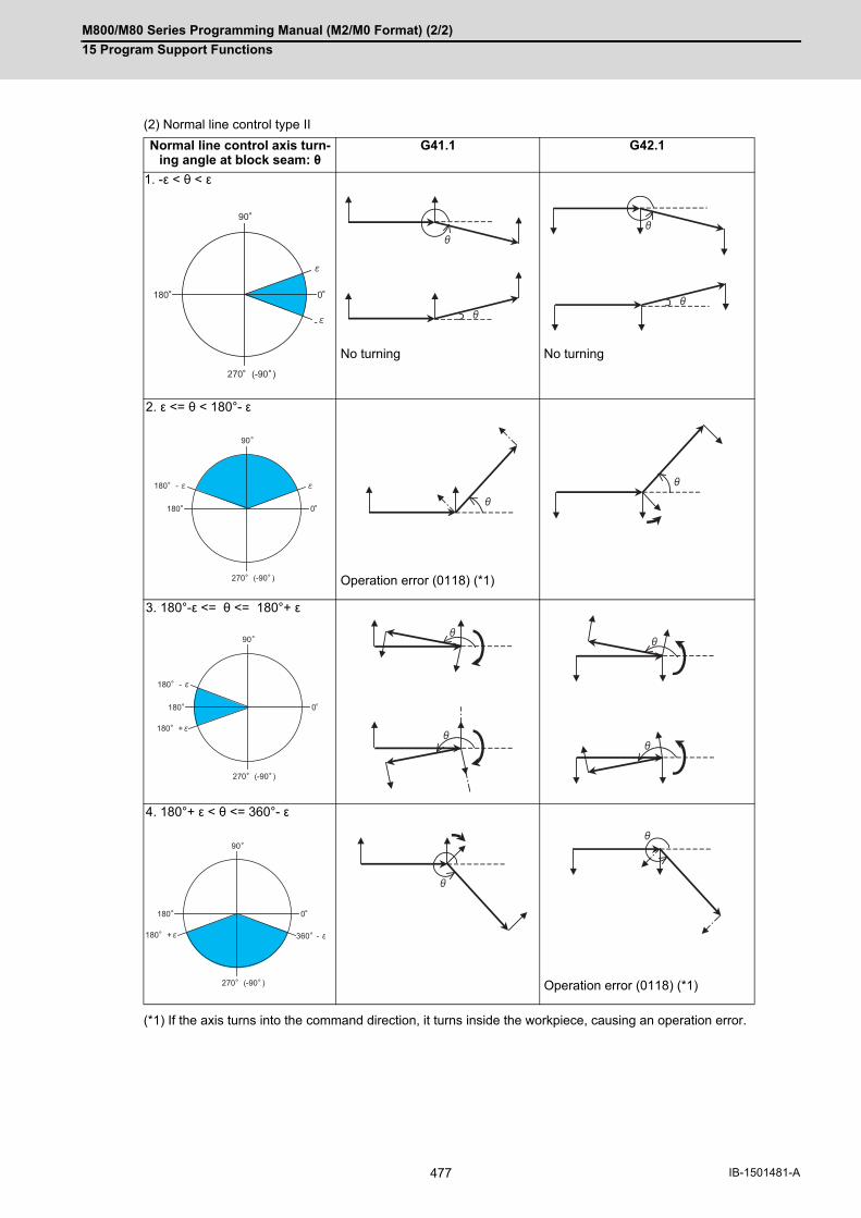
M800/M80 Series Programming Manual (M2/M0 Format) (2/2)
15 Program Support Functions
477 IB-1501481-A
(2) Normal line control type II
(*1) If the axis turns into the command direction, it turns inside the workpiece, causing an operation error.
Normal line control axis turn-ing angle at block seam: θ
G41.1 G42.1
1. -ε < θ < ε
No turning No turning
2. ε <= θ < 180°- ε
Operation error (0118) (*1)
3. 180°-ε <= θ <= 180°+ ε
4. 180°+ ε < θ <= 360°- ε
Operation error (0118) (*1)
-
0180
270 (-90 )
90
0180
270 (-90 )
90
180 -
180 -
0180
270 (-90 )
90
180 +
360 -
0180
270 (-90 )
90
180 +
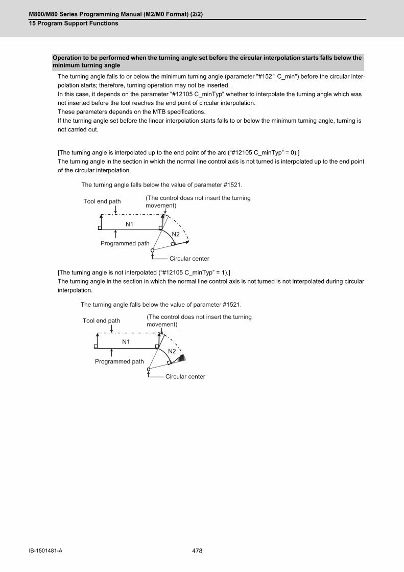
M800/M80 Series Programming Manual (M2/M0 Format) (2/2)
15 Program Support Functions
478IB-1501481-A
The turning angle falls to or below the minimum turning angle (parameter "#1521 C_min") before the circular inter-
polation starts; therefore, turning operation may not be inserted.
In this case, it depends on the parameter "#12105 C_minTyp" whether to interpolate the turning angle which was
not inserted before the tool reaches the end point of circular interpolation.
These parameters depends on the MTB specifications.
If the turning angle set before the linear interpolation starts falls to or below the minimum turning angle, turning is
not carried out.
[The turning angle is interpolated up to the end point of the arc (“#12105 C_minTyp” = 0).]
The turning angle in the section in which the normal line control axis is not turned is interpolated up to the end point
of the circular interpolation.
[The turning angle is not interpolated (“#12105 C_minTyp” = 1).]
The turning angle in the section in which the normal line control axis is not turned is not interpolated during circular
interpolation.
Operation to be performed when the turning angle set before the circular interpolation starts falls below the minimum turning angle
N1N2
The turning angle falls below the value of parameter #1521.
Programmed path
Tool end path
Circular center
(The control does not insert the turning movement)
N1N2
The turning angle falls below the value of parameter #1521.
Circular center
Programmed path
Tool end path (The control does not insert the turning movement)

M800/M80 Series Programming Manual (M2/M0 Format) (2/2)
15 Program Support Functions
479 IB-1501481-A
Normal line control axis turning speed Turning speed at block seam (select from type I or type II)
(1) Normal line control axis turning speed at block seam
(a) Rapid traverse
Therefore, an operation error will occur.
Normal line control type I Normal line control type II
Dry run OFF
The rapid traverse rate (#2001 rapid) is applied.
Normal line control axis turning speed f
= Rapid traverse rate * (Rapid traverse override) (° /
min)
Dry run OFF
Normal line control axis turning speed f
= F * 180 / (π * R) * (Rapid traverse override) (°/min)
When R = 0, follow the formula below.
Normal line control axis turning speed f
= F * (Rapid traverse override) (° /min)
F: Rapid traverse rate (#2001 rapid) (mm/min)
R: Parameter (#8041 C-rot.R) (mm)
(Length from normal line control axis center to tool
nose)
<Note>
(1) If the normal line control axis turning speed ex-ceeds the rapid traverse rate (#2001 rapid), therapid traverse rate will be applied.
Dry run ON
The manual feedrate is applied.
Normal line control axis turning speed f
= Manual feedrate * (Cutting feed override) (° /min)
<Note>
(1) When the manual override valid is ON, the cuttingfeed override is valid.
(2) If the normal line control axis turning speed ex-ceeds the cutting feed clamp speed (#2002clamp), the cutting feed clamp speed will be ap-plied.
(3) When the rapid traverse is ON, the dry run is in-valid.
Dry run ONNormal line control axis turning speed f= F * 180 / (π * R) * (Rapid traverse override) (°/min) When R = 0, follow the formula below. Normal line control axis turning speed f= F * (Rapid traverse override) (° /min)F: Rapid traverse rate (#2001 rapid) (mm/min)R: Parameter (#8041 C-rot.R) (mm)(Length from normal line control axis center to tool nose)
<Note>
(1) If the normal line control axis turning speed ex-ceeds the cutting feed clamp speed (#2002clamp), the cutting feed clamp speed will be ap-plied.
(2) If the normal line control axis turning speed ex-ceeds the rapid traverse rate (#2001 rapid), therapid traverse rate will be applied.
(3) When the rapid traverse is ON, the dry run is in-valid.

M800/M80 Series Programming Manual (M2/M0 Format) (2/2)
15 Program Support Functions
480IB-1501481-A
(b) Cutting feed
Normal line control type I Normal line control type II
Dry run OFF
The normal line control axis turning speed set with the parameter (#1523 C_feed) is applied. Normal line control axis turning speed f= Parameter (#1523 C_feed) * (Cutting feed override) (° /min)
The feedrate at the tool nose is the F command. The normal line control axis turning speed is the normal line control axis speed that follows this F command. Normal line control axis turning speed f= F * 180 / (π * R) * (Cutting feed override) (°/min) When R = 0, follow the formula below. Normal line control axis turning speed f = F (° /min)F: Feedrate command (mm/min)R: Parameter (#8041 C-rot.R) (mm)(Length from normal line control axis center to tool nose)
Dry run ON (Rapid traverse ON)
The cutting feed clamp speed (#2002 clamp) is ap-plied. Normal line control axis turning speed f= Cutting feed clamp speed (°/min)
Dry run ON (Rapid traverse OFF)
The manual feedrate is applied.
Normal line control axis turning speed f
= Manual feedrate * (Cutting feed override) (° /min)
<Note>
(1) When the manual override valid is ON, the cuttingfeed override is valid.
(2) If the normal line control axis turning speed ex-ceeds the cutting feed clamp speed (#2002clamp), the cutting feed clamp speed will be ap-plied.
F: Feedrate command
f: Normal line control axis turning speed
<Note>
(1) If the normal line control axis turning speed ex-ceeds the cutting feed clamp speed (#2002clamp), the cutting feed clamp speed will be ap-plied.
(2) When the dry run is ON, the normal line controlaxis turning speed is obtained by the same ex-pression as the rapid traverse.
F: Feedrate command
f: Normal line control axis turning speed
R: Parameter (#8041 C-rot.R)
(F)
(f)=F*180/( *R)
(F)
(f)
(R)

M800/M80 Series Programming Manual (M2/M0 Format) (2/2)
15 Program Support Functions
481 IB-1501481-A
(2) Normal line control axis turning speed during circular interpolation
(1) If the normal line control axis turning speed exceeds the cutting feed clamp speed (#2002 clamp), the speed willbe as follows; - Normal line control axis turning speed = Cutting feed clamp speed.Normal line control axis turning speed = Cutting feed clamp speedMoving speed during arc interpolation = The speed according to the normal line control axis turning speed
Normal line control type I Normal line control type II
The normal line control axis turning speed is the rota-tion speed obtained by feedrate F. Normal line control axis turning speed f= F * 180 / (π * r) (° /min)F : Feed command speed (mm/min)r : Arc radius (mm)
The feedrate at the tool nose is the F command. The normal line control axis turning speed is the rotation speed that follows this F command. Normal line control axis turning speed f= F * 180 / (π * (R + r)) (° /min)F : Feed command speed (mm/min)R : Parameter (#8041 C-rot. R) (mm)(Length from normal line control axis center to tool nose)r : Arc radius (mm)
=F*180/( *r)
(F)
(r)
(f)
=F*180/( *(R+r))
(F)
(R) (r)
(f)
Note

M800/M80 Series Programming Manual (M2/M0 Format) (2/2)
15 Program Support Functions
482IB-1501481-A
During normal line control, an arc is automatically inserted at the corner in the axis movement of the plane selection.
This function is for the normal line control type I.
The radius of the arc to be inserted is set with the parameter (#8042 C-ins.R).
This parameter can be read and written using the macro variable #1901.
Normal line control is performed also during the interpolation for the arc to be inserted.
<Supplements>
The corner arc is not inserted in the following cases: linear and arc, arc and arc, linear and moveless or move-less and linear blocks or when a line is shorter than the radius of the arc to insert.
During the radius compensation, the radius compensation is applied to the path that the corner arc is inserted.
Automatic corner arc insertion function
Parameter (#8042 C-rot. R)
Corner R is not inserted.
Radius compensation path
Parameter (#8042 C-rot. R)

M800/M80 Series Programming Manual (M2/M0 Format) (2/2)
15 Program Support Functions
483 IB-1501481-A
The stop point of the single block and block start interlock is as follows.
The stop point of the cutting start interlock is as follows.
Stop point
Stop point
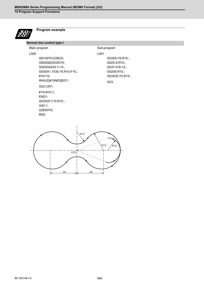
M800/M80 Series Programming Manual (M2/M0 Format) (2/2)
15 Program Support Functions
484IB-1501481-A
Program example
Normal line control type I
Main program
L500
Sub-program
L501
G91X0Y0;G28C0;
G90G92G53X0Y0;
G00G54X25.Y-10.;
G03G41.1X35.Y0.R10.F10.;
#10=10;
WHILE[#10NE0]DO1;
G22 L501;
#10=#10-1;
END1;
G03X25.Y10.R10.;
G40.1;
G28X0Y0;
M02;
G03X8.Y9.R15.;
G02X-8.R10.;
G03Y-9.R-15.;
G02X8.R10.;
G03X35.Y0.R15.;
G23;
(0,0)
R10
R10R15
20.20.

M800/M80 Series Programming Manual (M2/M0 Format) (2/2)
15 Program Support Functions
485 IB-1501481-A
(Example 1)
(a) C-axis
(b) Tool
Normal line control type II
Main program
L500
Sub-program
L1001
G91X0Y0;
G28Z0;
G28C0;
G90G92G53X0Y0Z0;
G00G54G43X35.Y0.Z100.H1;
G00Z3.;
G01Z0.1F6000;
G42.1;
G22L1001P510;
G22L1002P2;
G91G01Y10.Z0.05;
G40.1;
G90G00Z100.;
G28X0Y0Z0;
M02;
G17G91G01Y20.,R10.Z-0.01;
X-70.,R10.;
Y-40.,R10.;
X70.,R10.;
Y20.;
G23;
(Corner chamfering/Corner R specifications are required)
L1002
G17G91G01Y20.,R10.;
X-70.,R10.;
Y-40.,R10.;
X70.,R10.;
Y20.;
G23;
(Corner chamfering/Corner R specifications are required)
5.
(b)
0.1
10.
(a)
20.
(0,0)
R10
20.
35. 35.

M800/M80 Series Programming Manual (M2/M0 Format) (2/2)
15 Program Support Functions
486IB-1501481-A
(Example 2)Main program
L2000
Sub-program
L2001
G91G28Z0;
G28X0Y0;
G28C0;
G90G92G53X0Y0Z0;
G00G54X30.Y0.;
G00Z3.;
G41.1G01Z0.1F5000;
G22L2001P510;
G22L2002P2;
G91G01X-30.Z0.05;
G40.1;
G90G00Z100.;
G28X0Y0Z0;
M02;
G17G91G01X-60.Z-0.01;
X60.;
G23;
L2002
G17G91G01X-60.;
X60.;
G23;
(a) C-axis(b) Tool
5.
(b)
0.1
(a)
(0,0)
30. 30.
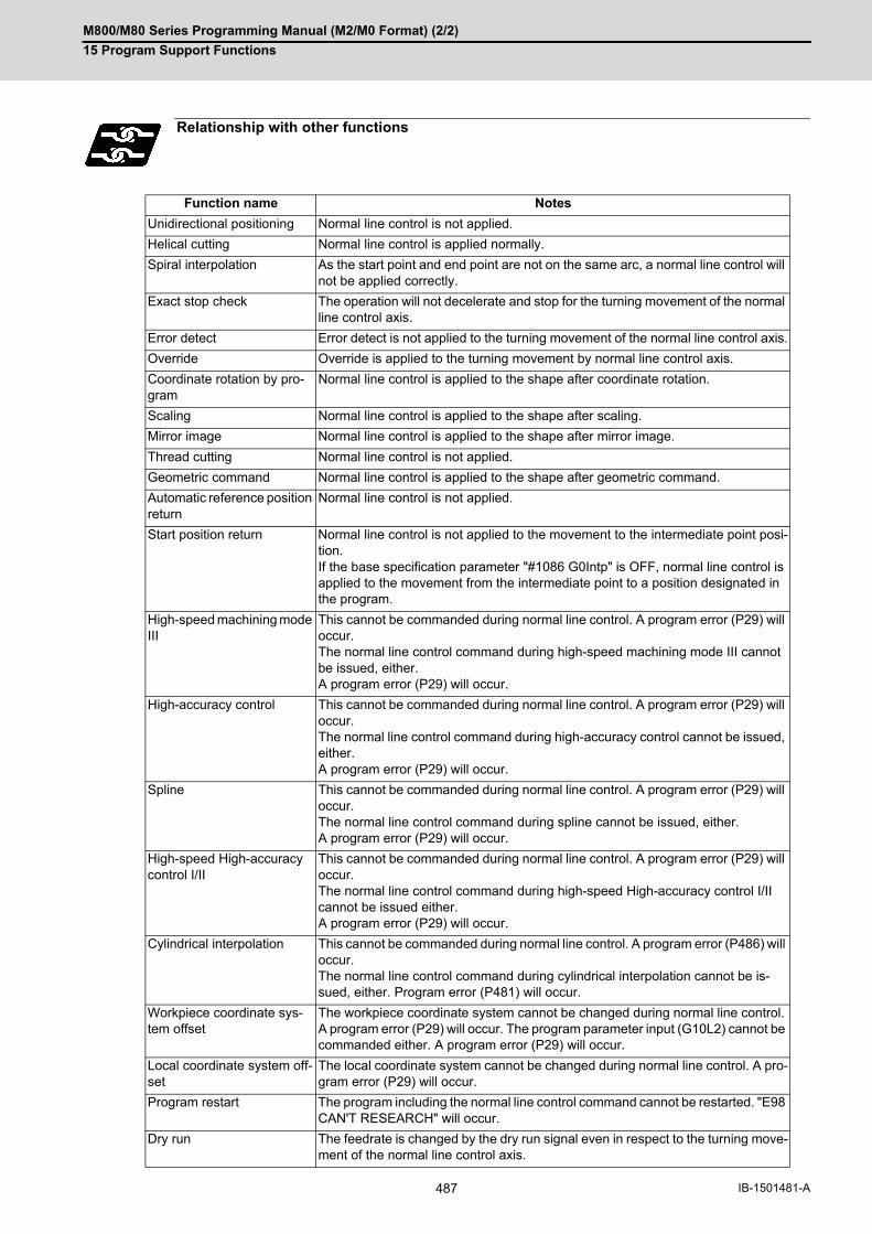
M800/M80 Series Programming Manual (M2/M0 Format) (2/2)
15 Program Support Functions
487 IB-1501481-A
Relationship with other functions
Function name Notes
Unidirectional positioning Normal line control is not applied.
Helical cutting Normal line control is applied normally.
Spiral interpolation As the start point and end point are not on the same arc, a normal line control will not be applied correctly.
Exact stop check The operation will not decelerate and stop for the turning movement of the normal line control axis.
Error detect Error detect is not applied to the turning movement of the normal line control axis.
Override Override is applied to the turning movement by normal line control axis.
Coordinate rotation by pro-gram
Normal line control is applied to the shape after coordinate rotation.
Scaling Normal line control is applied to the shape after scaling.
Mirror image Normal line control is applied to the shape after mirror image.
Thread cutting Normal line control is not applied.
Geometric command Normal line control is applied to the shape after geometric command.
Automatic reference position return
Normal line control is not applied.
Start position return Normal line control is not applied to the movement to the intermediate point posi-tion. If the base specification parameter "#1086 G0Intp" is OFF, normal line control is applied to the movement from the intermediate point to a position designated in the program.
High-speed machining mode III
This cannot be commanded during normal line control. A program error (P29) will occur. The normal line control command during high-speed machining mode III cannot be issued, either. A program error (P29) will occur.
High-accuracy control This cannot be commanded during normal line control. A program error (P29) will occur. The normal line control command during high-accuracy control cannot be issued, either. A program error (P29) will occur.
Spline This cannot be commanded during normal line control. A program error (P29) will occur. The normal line control command during spline cannot be issued, either. A program error (P29) will occur.
High-speed High-accuracy control I/II
This cannot be commanded during normal line control. A program error (P29) will occur. The normal line control command during high-speed High-accuracy control I/II cannot be issued either. A program error (P29) will occur.
Cylindrical interpolation This cannot be commanded during normal line control. A program error (P486) will occur. The normal line control command during cylindrical interpolation cannot be is-sued, either. Program error (P481) will occur.
Workpiece coordinate sys-tem offset
The workpiece coordinate system cannot be changed during normal line control. A program error (P29) will occur. The program parameter input (G10L2) cannot be commanded either. A program error (P29) will occur.
Local coordinate system off-set
The local coordinate system cannot be changed during normal line control. A pro-gram error (P29) will occur.
Program restart The program including the normal line control command cannot be restarted. "E98 CAN'T RESEARCH" will occur.
Dry run The feedrate is changed by the dry run signal even in respect to the turning move-ment of the normal line control axis.

M800/M80 Series Programming Manual (M2/M0 Format) (2/2)
15 Program Support Functions
488IB-1501481-A
(1) During normal line control, the program coordinates are updated following the normal line control axis movement.Thus, program the normal line control on the program coordinate system.
(2) The normal line control axis will stop at the turning start position for the single block, cutting block start interlockand block start interlock.
(3) If the movement command is issued to the normal line control axis (C axis) during normal line control, it is ig-nored.
(4) The coordinate system preset command (G92 C_;) cannot be issued to the normal line control axis during C axisnormal line control (during G41.1 or G42.1 modal). The program error (P901) will occur if commanded.
(5) When a mirror image is applied to the axis in plane selection mode, normal line control is carried out for the shapeprocessed with the mirror image.
(6) The rotary axis must be designated as the normal line control axis (parameter "#1522 C_axis"). Designate sothat the axis is not duplicated with the axis on the plane where normal line control is to be carried out. If an illegalaxis is designated, the program error (P902) will occur when the program (G40.1, G41.1, G42.1) is commanded. The program error (P902) will also occur if the parameter "#1522 C_axis" is "0" when commanding a program. This parameter setting depends on the MTB specifications.
(7) The movement of the normal line control axis is counted as one axis of number of simultaneous contouring con-trol axes. If the number of simultaneous contouring control axes exceeds the specification range by movement of the nor-mal line control axis, the program error (P10) will occur.
Graphic check The section turned by normal line control is not drawn. The axes subject to graphic check are drawn.
G00 non-interpolation Normal line control is not applied.
Polar coordinate interpola-tion
This cannot be commanded during normal line control. A program error (P486) will occur. The normal line control command during polar coordinate interpolation cannot be issued either. Program error (P481) will occur.
Exponential interpolation If the normal line control axis is the same as the rotary axis of exponential interpo-lation, a program error (P612) will occur. If they are different, an error will not occur, but normal line control is not applied.
Plane selection This cannot be commanded during normal line control. A program error (P903) will occur.
Mixed control This cannot be commanded during normal line control. An operation error (M01 1035) will occur.
System variable The block end coordinate (#5001 - ) for the normal line control axis during normal line control cannot obtain a correct axis position.
Precautions
Function name Notes

M800/M80 Series Programming Manual (M2/M0 Format) (2/2)
15 Program Support Functions
489 IB-1501481-A
15.8 Manual Arbitrary Reverse Run Prohibition; G127
The manual arbitrary reverse run function controls the feedrate, which is under automatic operation in memory or
MDI mode, in proportion to the manual feedrate by the jog or the rotation speed by the manual handle, and manually
carries out the reverse run.
After the automatic operation has been stopped in a block, the reverse run can be carried out back through the
blocks (up to 20 blocks) that were executed before the block. If necessary, it is possible to correct the program buffer
and execute the fixed program after carrying out the reverse run up to the return position.
This function (G127) is available to prevent the program from backing to blocks before the commanded block when
carrying out the manual arbitrary reverse run.
The detailed setting and operation vary depending on the machine specifications. Refer to the Instruction Manual
issued by the MTB.
"Forward run" means to execute blocks in the same order as for the automatic operation.
"Reverse run" means to process the executed blocks backward.
Whether the reverse run is prohibited for each part system depends on the MTB specifications (system variable
#3004). Refer to "List of System Variables" for details.
This command disables the program from running reverse to blocks before G127. In part systems that do not have
this command executed, the program cannot run reverse before the timing with G127 commanded in any part sys-
tem even if a block is in process.
No commands in the machining program can be backed in the reverse run mode. For some G codes, the operation
differs from the above. Refer to "Relationship with Other Functions".
Function and purpose
Command format
All part system reverse run prohibit command
G127 ;
The reverse run is disabled before the G127 block in the 2nd part system. The reverse run is canceled in the middle of a block in part sys-tems other than the 2nd part system.
G127
$1
$2
$3
$4

M800/M80 Series Programming Manual (M2/M0 Format) (2/2)
15 Program Support Functions
490IB-1501481-A
The following shows the relationship between the manual arbitrary reverse run command and G code.
Relationship with other functions
Symbol in "Reverse run"
column
Operation
○ *1 Block with reverse run enabled
○ *2 Block with restricted-reverse run enabled Refer to the Remarks for restrictions.
∆ Block with reverse run ignored. This block is ignored in both the forward and reverse run modes.
× *3 Block with reverse run prohibited. This is intended only for the command blocks.
× *4 Block with reverse run prohibited. The reverse run is also prohibited for all blocks after the mode has been switched by this block.
× *5 Prohibits the reverse run in all part systems.
G code Function name Reverse run
Remarks
G00 Positioning ○ *1 -
G01 Linear interpolation ○ *1 -
G02 Circular interpolation CW and spiral/conical interpolation CW (type2)
× *3 -
G03 Circular interpolation CCW and spiral/coni-cal interpolation CCW (type2)
× *3 -
G02.3 Exponential interpolation CW × *3 -
G03.3 Exponential interpolation CCW × *3 -
G02.4 3-dimensional circular interpolation × *3 -
G03.4 3-dimensional circular interpolation × *3 -
G04 Dwell ○ *1 Dwell skip is invalid.
G05 High-speed high-accuracy control II/III / High-speed machining mode
× *4 -
G05.1 High-speed high-accuracy control I / Spline × *4 -
G06.2 NURBS interpolation × *4 -
G07 Hypothetical axis interpolation × *3 -
G07.1G107
Cylindrical interpolation × *4 -
G08 High-accuracy control × *4 -
G09 Exact stop check ○ *1 -
G10 Program data input (Parameter / Compen-sation amount / Coordinate rotation by pa-rameter data) / Life management data registration
∆ The reverse run is enabled, but data is not re-covered.
G10.6 Tool retract command × *3 -
G11.1 Program parameter input / cancel ∆ The reverse run is enabled, but data is not re-covered.
G12 Circular cutting CW × *3 -
G13 Circular cutting CCW × *3 -
G12.1G112
Polar coordinate interpolation ON × *4 -
G13.1G113
Polar coordinate interpolation cancel × *4 -
G15 Polar coordinate command OFF × *4 -
G16 Polar coordinate command ON × *4 -
G17 X-Y plane selection ○ *2 Data is recovered using the modal informa-tion storage block.

M800/M80 Series Programming Manual (M2/M0 Format) (2/2)
15 Program Support Functions
491 IB-1501481-A
G18 Z-X plane selection ○ *2 Data is recovered using the modal informa-tion storage block.
G19 Y-Z plane selection ○ *2 Data is recovered using the modal informa-tion storage block.
G20 Inch command ○ *1 Switched with the movement command just after commanded.
G21 Metric command ○ *1 Switched with the movement command just after commanded.
G22.1 Stroke check before travel ON × *3 -
G23.1 Stroke check before travel OFF × *3 -
G27 Reference position check × *3 -
G28 Automatic reference position return × *3 -
G29 Start position return × *3 -
G30 2nd, 3rd and 4th reference position return × *3 -
G30.1 Tool change position return 1 × *3 -
G30.2 Tool change position return 2 × *3 -
G30.3 Tool change position return 3 × *3 -
G30.4 Tool change position return 4 × *3 -
G30.5 Tool change position return 5 × *3 -
G30.6 Tool change position return 6 × *3 -
G31 Skip/Multi-step skip function 2 × *3 -
G31.1 Multi-step skip function 1-1 × *3 -
G31.2 Multi-step skip function 1-2 × *3 -
G31.3 Multi-step skip function 1-3 × *3 -
G33 Thread cutting ○ *2 The reverse run is enabled, but the synchro-nous feed is invalid. Actual cutting mode available.
G34 Special fixed cycle (bolt hole circle) × *4 -
G35 Special fixed cycle (write at angle) × *4 -
G36 Special fixed cycle (arc) × *4 -
G37 Special fixed cycle (grid) × *4 -
G37.1 Automatic tool length measurement × *3 -
G38 Tool radius compensation vector designa-tion
× *3 -
G39 Tool radius compensation corner arc × *3 -
G40 Tool radius compensation cancel / 3-dimen-sional tool radius compensation cancel
○ *2 Data is recovered using the modal informa-tion storage block.
G41 Tool radius compensation left / 3-dimen-sional tool radius compensation left
○ *2 Data is recovered using the modal informa-tion storage block.
G42 Tool radius compensation right / 3-dimen-sional tool radius compensation right
○ *2 Data is recovered using the modal informa-tion storage block.
G40.1G150
Normal line control cancel × *4 -
G41.1G151
Normal line control left ON × *4 -
G42.1G152
Normal line control right ON × *4 -
G43 Tool length compensation ○ *2 Data is recovered using the modal informa-tion storage block.
G43.1 Tool length compensation along the tool axis
× *3 -
G43.4 Tool center point control type1 ON × *4 -
G43.5 Tool center point control type2 ON × *4 -
G code Function name Reverse run
Remarks
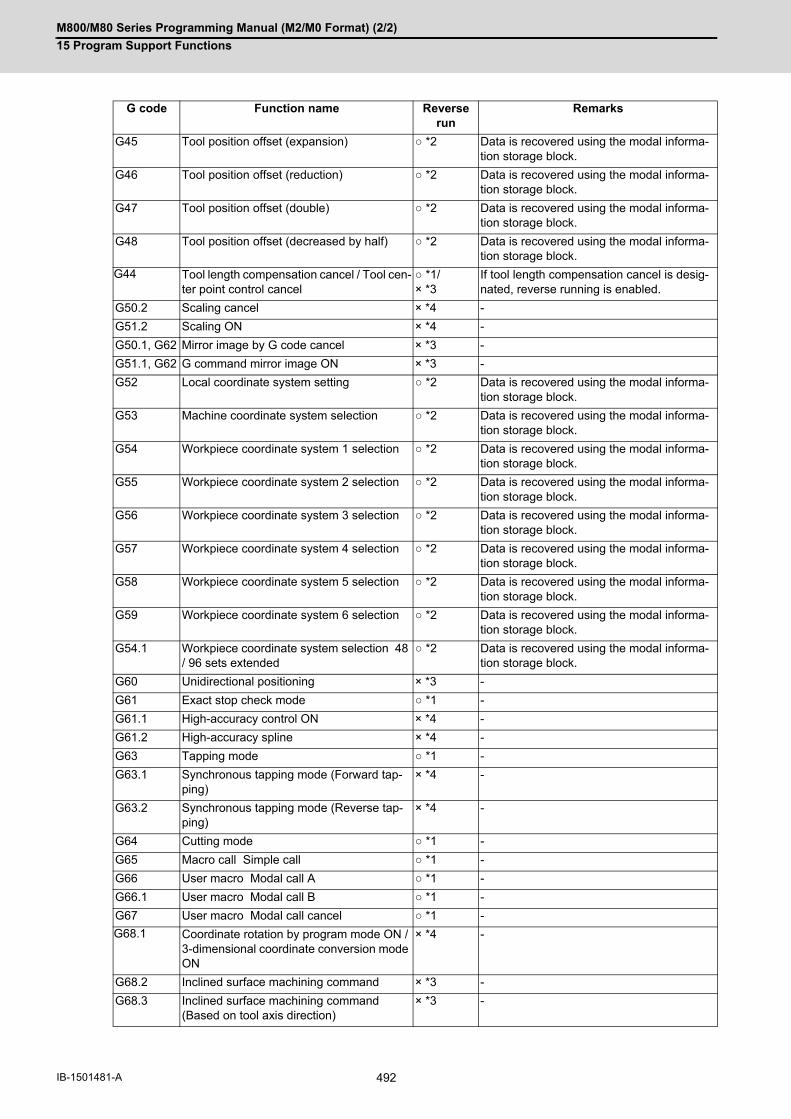
M800/M80 Series Programming Manual (M2/M0 Format) (2/2)
15 Program Support Functions
492IB-1501481-A
G45 Tool position offset (expansion) ○ *2 Data is recovered using the modal informa-tion storage block.
G46 Tool position offset (reduction) ○ *2 Data is recovered using the modal informa-tion storage block.
G47 Tool position offset (double) ○ *2 Data is recovered using the modal informa-tion storage block.
G48 Tool position offset (decreased by half) ○ *2 Data is recovered using the modal informa-tion storage block.
G44 Tool length compensation cancel / Tool cen-ter point control cancel
○ *1/× *3
If tool length compensation cancel is desig-nated, reverse running is enabled.
G50.2 Scaling cancel × *4 -
G51.2 Scaling ON × *4 -
G50.1, G62 Mirror image by G code cancel × *3 -
G51.1, G62 G command mirror image ON × *3 -
G52 Local coordinate system setting ○ *2 Data is recovered using the modal informa-tion storage block.
G53 Machine coordinate system selection ○ *2 Data is recovered using the modal informa-tion storage block.
G54 Workpiece coordinate system 1 selection ○ *2 Data is recovered using the modal informa-tion storage block.
G55 Workpiece coordinate system 2 selection ○ *2 Data is recovered using the modal informa-tion storage block.
G56 Workpiece coordinate system 3 selection ○ *2 Data is recovered using the modal informa-tion storage block.
G57 Workpiece coordinate system 4 selection ○ *2 Data is recovered using the modal informa-tion storage block.
G58 Workpiece coordinate system 5 selection ○ *2 Data is recovered using the modal informa-tion storage block.
G59 Workpiece coordinate system 6 selection ○ *2 Data is recovered using the modal informa-tion storage block.
G54.1 Workpiece coordinate system selection 48 / 96 sets extended
○ *2 Data is recovered using the modal informa-tion storage block.
G60 Unidirectional positioning × *3 -
G61 Exact stop check mode ○ *1 -
G61.1 High-accuracy control ON × *4 -
G61.2 High-accuracy spline × *4 -
G63 Tapping mode ○ *1 -
G63.1 Synchronous tapping mode (Forward tap-ping)
× *4 -
G63.2 Synchronous tapping mode (Reverse tap-ping)
× *4 -
G64 Cutting mode ○ *1 -
G65 Macro call Simple call ○ *1 -
G66 User macro Modal call A ○ *1 -
G66.1 User macro Modal call B ○ *1 -
G67 User macro Modal call cancel ○ *1 -
G68.1 Coordinate rotation by program mode ON / 3-dimensional coordinate conversion mode ON
× *4 -
G68.2 Inclined surface machining command × *3 -
G68.3 Inclined surface machining command (Based on tool axis direction)
× *3 -
G code Function name Reverse run
Remarks

M800/M80 Series Programming Manual (M2/M0 Format) (2/2)
15 Program Support Functions
493 IB-1501481-A
G69.1 Coordinate rotation by program mode can-cel / 3-dimensional coordinate conversion mode cancel / Inclined surface machining command cancel
× *4 -
G70 User fixed cycle × *3 -
G71 User fixed cycle × *3 -
G72 User fixed cycle × *3 -
G73 Fixed cycle (step) ○ *1 Data is created for each movement block in the fixed cycle.
G74 Fixed cycle (reverse tap) ○ *2 The reverse run is enabled, but the synchro-nous feed is invalid. Actual cutting mode available.
G75 Fixed cycle (circular cutting cycle) ○ *1 Data is created for each movement block in the fixed cycle.
G76 Fixed cycle (Fine boring) ○ *1 Data is created for each movement block in the fixed cycle.
G77 User fixed cycle × *3 -
G78 User fixed cycle × *3 -
G79 User fixed cycle × *3 -
G80 Fixed cycle for drilling cancel ○ *1 -
G81 Fixed cycle (drill/spot drill) ○ *1 Data is created for each movement block in the fixed cycle.
G82 Fixed cycle (drill/counter boring) ○ *1 Data is created for each movement block in the fixed cycle.
G83 Fixed cycle (deep drilling) ○ *1 Data is created for each movement block in the fixed cycle.
G84 Fixed cycle (tapping) ○ *2 The reverse run is enabled, but the synchro-nous feed is invalid. Actual cutting mode available.
G85 Fixed cycle (boring) ○ *1 Data is created for each movement block in the fixed cycle.
G86 Fixed cycle (boring) ○ *1 Data is created for each movement block in the fixed cycle.
G87 Fixed cycle (back boring) ○ *1 Data is created for each movement block in the fixed cycle.
G88 Fixed cycle (boring) ○ *1 Data is created for each movement block in the fixed cycle.
G89 Fixed cycle (boring) ○ *1 Data is created for each movement block in the fixed cycle.
G90 Absolute value command ○ *2 Switched with the movement command just after commanded.
G91 Incremental value command ○ *2 Switched with the movement command just after commanded.
G92 Coordinate system setting ○ *1 -
G92.1 Workpiece coordinate system preset ○ *1 -
G93 Inverse time feed ○ *1 -
G94 Asynchronous feed (feed per minute) ○ *1 -
G95 Synchronous feed (feed per revolution) ○ *1 -
G96 Constant surface speed control ON ○ *2 Switched with the movement command just after commanded.
G97 Constant surface speed control OFF ○ *2 Switched with the movement command just after commanded.
(G94) Asynchronous feed (feed per minute) ○ *1 -
(G95) Synchronous feed (feed per revolution) ○ *1 -
G code Function name Reverse run
Remarks

M800/M80 Series Programming Manual (M2/M0 Format) (2/2)
15 Program Support Functions
494IB-1501481-A
G98 Fixed cycle(Initial level return)
○ *1 -
G99 Fixed cycle R point level return ○ *1 -
G115 Start point designation timing synchroniza-tion Type 1
○ *1 -
G116 Start point designation timing synchroniza-tion Type 2
○ *1 -
G118.2 Parameter switching (Spindle) × *3 -
G119.2 Inertia Estimation (Spindle) × *3 -
G100 to G225
User macro (G code call) Max. 10 ○ *1 -
G22 Subprogram call ○ *1 -
G code Function name Reverse run
Remarks

M800/M80 Series Programming Manual (M2/M0 Format) (2/2)
15 Program Support Functions
495 IB-1501481-A
15.9 Data input by program15.9.1 Parameter Input by Program; G10 L70/L100, G11.1
The parameters set from the setting and display unit can be changed in the machining programs.
(1) The sequence of addresses in a block must be as shown above. When an address is commanded two or more times, the last command will be valid.
(2) The part system No. is set in the following manner. "1" for the 1st part system, "2" for 2nd part system, and soforth. If the address S is omitted, the part system of the executing program will be applied. As for the parameters common to part systems, the command of part system No. will be ignored.
(3) The axis No. is set in the following manner. "1" for 1st axis, "2" for 2nd axis, and so forth. If the address A is omitted, the 1st axis will be applied. As for the parameters common to axes, the command of axis No. will be ignored.
(4) Address H is commanded with the combination of setting data (0 or 1) and the bit designation □ (0 to 7). Hd0: Sets the dth bit OFF. (d: 0 to 7)Hd1: Sets the dth bit ON. (d: 0 to 7)
(5) Only the decimal number can be commanded with the address D. The value that is smaller than the input setting increment (#1003 iunit) will be round off to the nearest increment.
(6) The character string must be put in angled brackets "<" and ">". If these brackets are not provided, the program error (P33) will occur. Up to 63 characters can be set.
Function and purpose
G10 L70 For commanding data with decimal point, and character string data. The data's command range conforms to the parameter setting range described in Setup Manual.
G10 L100 For setting/changing the tool shape for 3D solid program check.
Command format
Data setting start command
G10 L70;
P__ S__ A__ H□__ ; Bit parameter
P__ S__ A__ D__ ; Numerical value parameter
P__ S__ A__ <character string> ; Character string parameter
P Parameter No.
S Part system No.
A Axis No.
H Bit type data
D Numeric type data
character string Character string data
Data setting end command
G11.1;
Note

M800/M80 Series Programming Manual (M2/M0 Format) (2/2)
15 Program Support Functions
496IB-1501481-A
(7) Issue "G10 L70" and "G11.1" commands in independent blocks. A program error (P33, P421) will occur if notcommanded in independent blocks.
(8) The parameter "#1078 Decimal pnt type 2" is disabled.
(9) The following data cannot be changed with the G10 L70 command: Tool compensation data, workpiece coordinate data, PLC switch, and PLC axis parameter.
(10) The settings of the parameters with (PR) in the parameter list will be enabled after the power is turned OFF andON. Refer to the parameter list in your manual.
(*1) Line No. corresponds with a line No. in the tool shape set area (tool shape set screen).
(*2) The setting of "#8117 OFS Diam DESIGN" determines tool diameter or tool radius.
(*3) For details of the data, refer to the explanation of Instruction Manual "Program Check (3D)".
(*4) Omitted addresses cannot be set or changed.
(*5) When address T is set to 0, the designated line is deleted.
(*6) In the following cases, the program error (P421) occurs and the parameter in the block is not changed.
When a block contains an address whose data are out of rangeWhen there is an illegal addressWhen P or T is omitted
(*7) Issue G10 L70/L100 and G11.1 commands in independent blocks. A program error (P421) will occur if not com-
manded in independent blocks.
(*8) The parameter "#1078 Decimal pnt type 2" is enabled.
(*9) The parameter "#8044 Unit*10" is disabled.
(*10) The display or operation at graphic check varies depending on the model or display unit.
Data setting start command
G10 L100;
P__ T__ K__ D__ H__ I__ J__ C__ ;
Data setting end command
G11.1;
P Line No. of the tool set area 1 to 80 (Required to command) (*1)
T Tool No. 0 to 99999999 (Required to command)
K Command the tool type using a numerical value. 0: Default tool (3: Drill is set.)
1: Ball end mill 2: Flat end mill
3: Drill 4: Bull nose end mill
5: Chamfer 6: Tap
7: Face mill
D Tool diameter/radius (Decimal point input available) (*2)
H Tool length (Decimal point input available)
I Tool shape data 1 (Decimal point input available)
J Tool shape data 2 (Decimal point input available)
C Command the tool color using a numerical value. 0: Default color (2: Red is set)
1: Gray 2: Red 3: Yellow 4: Blue
5: Green 6: Light blue 7: Purple 8: Pink

M800/M80 Series Programming Manual (M2/M0 Format) (2/2)
15 Program Support Functions
497 IB-1501481-A
The timing for updating the spindle parameter and the NC axis parameter settings depends on the MTB specifica-
tions (parameter "#1254 set26/bit3").
(*1) The parameters of the target spindle are not updated while the functions below are active. The parameters are
updated after the functions have been completed.
Synchronous tapping cycleThe spindle for spindle position control is in C axis mode and the C axis is in motion.
(*2) The program updates the exchange axis under the arbitrary axis exchange control, waiting for "all axes smooth-
ing zero" in all part systems.
(1) For G10 L70
(2) For G10 L100
Precautions
Parameter update timing
#1254 set26/bit3 Spindle parameter NC axis parameter
Invalid The program updates the parameter settings, waiting for "all axes smoothing zero" in all part systems.
Valid The program updates the parameter set-tings without waiting for "smoothing zero". (*1)
The program updates the parameter set-tings, waiting for "all axes smoothing zero" in control part systems. (*2)
Program example
G10 L70;
P6401 H71 ; Sets "1" to "#6401 bit7".
P8204 S1 A2 D1.234 ; Sets "1.234" to "#8204 of the 1st part system 2nd axis".
P8621 <X> ; Sets "X" to "#8621".
G11.1;
G10 L100;
P1 T1 K3 D5. H20. I0 J0 C2 ; Set the data of Line 1
P2 T10 D10. ; Set "10." for the tool diameter/radius of Line 2
P8 T0 ; Clear the data of Line 8
G11.1;

M800/M80 Series Programming Manual (M2/M0 Format) (2/2)
15 Program Support Functions
498IB-1501481-A
15.9.2 Compensation Data Input by Program; G10 L2/L10/L11/L12/L13/L20, G11.1
The tool compensation and workpiece offset can be set or changed by the program using the G10 command.
The commanded values will be set regardless of the absolute value (G90) or incremental value (G91) mode.
Function and purpose
Command format
Workpiece coordinate system offset input (L2)
G90 (G91) G10 L2 P_ X_ Y_ Z_ ;
P 0: External workpiece1: G542: G553: G564: G575: G586: G59
X, Y, Z Offset amount of each axis
Extended workpiece coordinate system offset input (L20)
G10 L20 P_ X_ Y_ Z_ ;
P n No. of G54.n (1 to 300)
X, Y, Z Offset amount of each axis
Offset input to the currently selected workpiece coordinate system (When the L command is omitted)
G10 P_ X_ Y_ Z_ ;
P (1) During G54 to G59 modal
0 : External workpiece offset (EXT)
1 to 6 : Workpiece offset input (G54 to G59)
Other than 0 to 6 : Program error (P35)
(2) During G54.n modal
1 to 300 : Extended workpiece coordinate offset amount set-ting (G54.n)
Other than 1 to 300 : Program error (P35)
X, Y, Z Offset amount of each axis
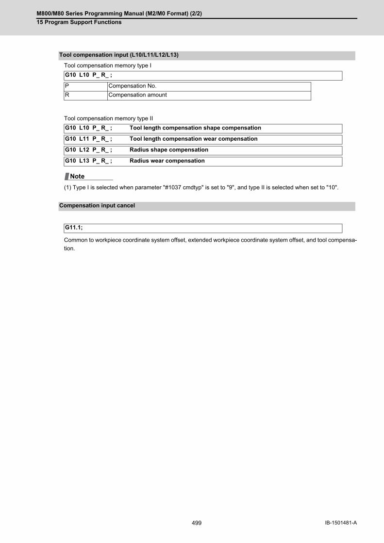
M800/M80 Series Programming Manual (M2/M0 Format) (2/2)
15 Program Support Functions
499 IB-1501481-A
Tool compensation memory type I
Tool compensation memory type II
(1) Type I is selected when parameter "#1037 cmdtyp" is set to "9", and type II is selected when set to "10".
Common to workpiece coordinate system offset, extended workpiece coordinate system offset, and tool compensa-
tion.
Tool compensation input (L10/L11/L12/L13)
G10 L10 P_ R_ ;
P Compensation No.
R Compensation amount
G10 L10 P_ R_ ; Tool length compensation shape compensation
G10 L11 P_ R_ ; Tool length compensation wear compensation
G10 L12 P_ R_ ; Radius shape compensation
G10 L13 P_ R_ ; Radius wear compensation
Compensation input cancel
G11.1;
Note

M800/M80 Series Programming Manual (M2/M0 Format) (2/2)
15 Program Support Functions
500IB-1501481-A
(1) Even if this command is displayed on the screen, the offset No. and variable details will not be updated until ac-tually executed.
(2) G10 is an unmodal command and is valid only in the commanded block.
(3) The G10 command does not contain movement, but must not be used with G commands other than G54 to G59,G90 or G91.
(4) Do not command G10 in the same block as the fixed cycle and sub-program call command. This will cause mal-functioning and program errors.
(5) The workpiece offset input command (L2 or L20) should not be issued in the same block as the tool compensa-tion input command (L10).
(6) If an illegal L No. or compensation No. is commanded, the program errors (P172 and P170) will occur respec-tively. If the offset amount exceeds the maximum command value, the program error (P35) will occur.
(7) Decimal point inputs can be used for the offset amount.
(8) The offset amounts for the external workpiece coordinate system and the workpiece coordinate system are com-manded as distances from the basic machine coordinate system zero point.
(9) The workpiece coordinate system updated by inputting the workpiece coordinate system will follow the previousmodal (G54 to G59) or the modal (G54 to G59) in the same block.
(10) L2/L20 can be omitted when the workpiece offset is input.
(11) When the P command is omitted for workpiece offset input, it will be handled as the currently selected work-piece compensation input.
(12) If the G command that cannot be combined with G10 is issued in the same block, a program error (P45) willoccur.
(13) When the "P" to designate the compensation No. is commanded in the same block as G22 or G23, the toolcompensation data will not be input. "P" will be regarded as the number of repetition of subprogram call, that willcause an illegal operation.
(14) The setting range for the compensation amount is given below. Program error (P35) occurs for any value not listed in the table after command unit conversion. With an incremental value command, the setting range for the compensation amount is the sum of the presentsetting value and command value.
(1) Input the compensation amount.
H10=-12.345 H05=9.8765 H30=2.468
Detailed description
Setting Compensation amount
Metric system Inch system
#1003=B ± 9999.999 (mm) ± 999.9999 (inch)
#1003=C ± 9999.9999 (mm) ± 999.99999 (inch)
#1003=D ± 9999.99999 (mm) ± 999.999999 (inch)
#1003=E ± 9999.999999 (mm) ± 999.9999999 (inch)
Program example
; G10 L10 P10 R-12.345 ; G10 L10 P05 R9.8765 ; G10 L10 P30 R2.468 ;
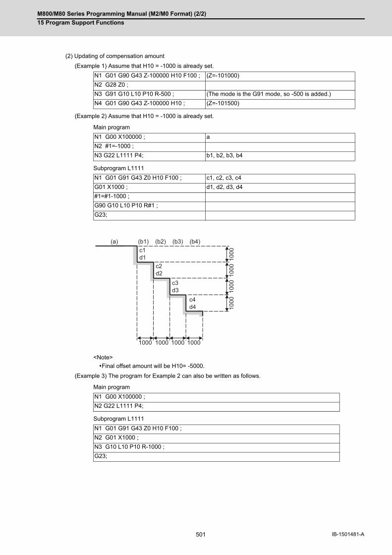
M800/M80 Series Programming Manual (M2/M0 Format) (2/2)
15 Program Support Functions
501 IB-1501481-A
(2) Updating of compensation amount
(Example 1) Assume that H10 = -1000 is already set.
(Example 2) Assume that H10 = -1000 is already set.
Main program
Subprogram L1111
<Note>
Final offset amount will be H10= -5000.
(Example 3) The program for Example 2 can also be written as follows.
Main program
Subprogram L1111
N1 G01 G90 G43 Z-100000 H10 F100 ; (Z=-101000)
N2 G28 Z0 ;
N3 G91 G10 L10 P10 R-500 ; (The mode is the G91 mode, so -500 is added.)
N4 G01 G90 G43 Z-100000 H10 ; (Z=-101500)
N1 G00 X100000 ; a
N2 #1=-1000 ;
N3 G22 L1111 P4; b1, b2, b3, b4
N1 G01 G91 G43 Z0 H10 F100 ; c1, c2, c3, c4
G01 X1000 ; d1, d2, d3, d4
#1=#1-1000 ;
G90 G10 L10 P10 R#1 ;
G23;
N1 G00 X100000 ;
N2 G22 L1111 P4;
N1 G01 G91 G43 Z0 H10 F100 ;
N2 G01 X1000 ;
N3 G10 L10 P10 R-1000 ;
G23;
(a) (b1) (b2) (b3) (b4)
1000 1000 1000 1000
1000
1000
1000
1000c1
d1
c3d3
c2d2
c4d4

M800/M80 Series Programming Manual (M2/M0 Format) (2/2)
15 Program Support Functions
502IB-1501481-A
(3) When updating the workpiece coordinate system offset amount
Assume that the previous workpiece coordinate system offset amount is as follows.
X=-10.000 Y=-10.000
<Note>
Changes of workpiece current position display in N101The G54 workpiece position display data will change before and after the workpiece coordinate systemis changed with G10 in N101.
When workpiece coordinate system offset amount is set in G54 to G59
N100 G00 G90 G54 X0 Y0 ;
N101 G90 G10 L2 P1 X-15.000 Y-15.000 ;
N102 X0 Y0 ;
M02 ;
Basic machine coordinate system zero point
G54 coordinate before change
G54 coordinate after change
X = 0
Y = 0
→ X = +5.000
Y = +5.000
G90 G10 L2 P1 X-10.000 Y-10.000 ;
G90 G10 L2 P2 X-20.000 Y-20.000 ;
G90 G10 L2 P3 X-30.000 Y-30.000 ;
G90 G10 L2 P4 X-40.000 Y-40.000 ;
G90 G10 L2 P5 X-50.000 Y-50.000 ;
G90 G10 L2 P6 X-60.000 Y-60.000 ;
- X - 20. - 10.
- 10.
- 20.
- Y
- Y
- Y
- X
- X
N100
N101
N102
M
(W1)
W1

M800/M80 Series Programming Manual (M2/M0 Format) (2/2)
15 Program Support Functions
503 IB-1501481-A
(4) When using one workpiece coordinate system as multiple workpiece coordinate systems
(1) Even if this command is displayed on the screen, the offset No. and variable details will not be updated until ac-tually executed.
Main program :
#1=-50. #2=10. ;
G22 L200 P5;
M02 ;
%
Subprogram
L200
N1 G90 G54 G10 L2 P1 X#1 Y#1 ;
N2 G00 X0 Y0 ;
N3 X-5. F100 ;
N4 X0 Y-5. ;
N5 Y0 ;
N6 #1=#1+#2 ;
N7 G23;
%
Basic machine coordinate system zero point
Precautions
N1 G90 G10 L10 P10 R-100 ;
N2 G43 Z-10000 H10 ;
N3 G00 X-10000 Y-10000 ;
N4 G90 G10 L10 P10 R-200 ; The H10 offset amount is updated when the N4 block is executed.
- X - 10.
- 10.
M
- 20.
- Y- 50.
- 30.
- 60.
- 40.
G54'' ''
W
W
W
W
W
G54'' '
G54''
G54'
G54
- 50. - 40. - 30. - 20.
1
2
3
5
4

M800/M80 Series Programming Manual (M2/M0 Format) (2/2)
15 Program Support Functions
504IB-1501481-A
15.9.3 Compensation Data Input by Program (Turning Tool); G10 L12/L13, G11.1
If the tool compensation type is changed to type III by the compensation type selection function, it is possible to write
the offset amount for three base axes, nose R compensation amount, and tool nose point (parameter "#1046 T-ofs
disp type"). During the absolute value (G90) mode, the commanded tool compensation amount serves as a new
one. During the incremental value (G91) mode, the currently set compensation amount plus the commanded com-
pensation amount serves as the new compensation amount.
Function and purpose
Command format
Turning tool compensation input (L12/L13)
G10 L12 P__ X__ Y__ Z__ R__ Q__ ; (Shape compensation)
P Tool shape compensation No. (1 to number of tool compensation sets)
X, Y, Z Compensation amount for each axis
R Nose R compensation amount
Q Hypothetical tool nose point
G10 L13 P__ X__ Y__ Z__ R__ Q__ ; (Wear compensation)
P Wear compensation No. (1 to number of tool compensation sets)
X, Y, Z Compensation amount for each axis
R Nose R compensation amount
Q Hypothetical tool nose point
Compensation input cancel
G11.1;

M800/M80 Series Programming Manual (M2/M0 Format) (2/2)
15 Program Support Functions
505 IB-1501481-A
The commanded range and unit of the compensation amount are as follows.
Program error (P35) occurs for any value not listed in the table after command unit conversion. With an incremental
value command, the commanded range for the compensation amount is the sum of the present setting value and
command value.
(1) The X, Y, and Z addresses are set to the axis names specified in the parameters for three base axes (parameters"#1026 base_I", "#1027 base_J", and "#1028 base_K"). The compensation data input by program of the tool offset is not available for an axis address that is not specifiedin the parameters for three base axes. Therefore, be sure to carry out compensation data input by program afterspecifying the parameters for three base axes.
(2) The compensation data input by program is available using a command (G10 L10, L11, L12, or L13) in a normalmachining center system, but only the compensation amount of the Z axis and nose R can be input as data.
Detailed description
Setting Compensation amount
Metric system Inch system
#1003=B ± 9999.999 (mm) ± 999.9999 (inch)
#1003=C ± 9999.9999 (mm) ± 999.99999 (inch)
#1003=D ± 9999.99999 (mm) ± 999.999999 (inch)
#1003=E ± 9999.999999 (mm) ± 999.9999999 (inch)
Precautions
G10 L10 P__ R__; Z axis shape compensation
G10 L11 P__ R__; Z axis wear compensation
G10 L12 P__ R__; Nose R shape compensation
G10 L13 P__ R__; Nose R wear compensation

M800/M80 Series Programming Manual (M2/M0 Format) (2/2)
15 Program Support Functions
506IB-1501481-A
15.9.4 Tool Shape Input by Program; G10 L100, G11.1
This function sets tool shape data of the tool management screen by the machining program. Using this function
saves having to execute the many steps required to input the tool shape from the screen when executing 3D checks.
Function and purpose
Command format
Tool shape settings from the program
G10 L100; Data setting start command
P_ T_ K_ D_ H_ I_ J_ C_ ; Data setting command
P Data No. Specify the data No. on the tool management screen. (Cannot be omitted.)The maximum value of data No. varies depending on the number of tool manage-ment data sets.
T Tool No. Specify the tool No. (Cannot be omitted.)0 to 99999999When "0" is specified, all the tool shape data of data No. specified by address P will be "0". In this case, only the tool shape data is changed.
K Type Designate the tool type using a numerical value. [Mill tool]
1: Ball end mill 2: Flat end mill
3: Drill 4: Radius end mill
5: Chamfer 6: Tap
7: Face mill
[Turning tool]
51: Turning 52: Slotting
53: Thread cutting 54: Turning drill
55: Turning tap
D Shape data 1 Designate shape data of the tool. (Decimal point input enabled)The setting details of shape data differ depending on the tool type.H Shape data 2
I Shape data 3 Refer to the following "Correspondence between tool types and shape data" for the settings for each tool type.J Shape data 4
C Tool color Specify the tool color.
1: Gray 2: Red 3: Yellow
4: Blue 5: Green 6: Light blue
7: Purple 8: Pink
G11.1; Data setting end command
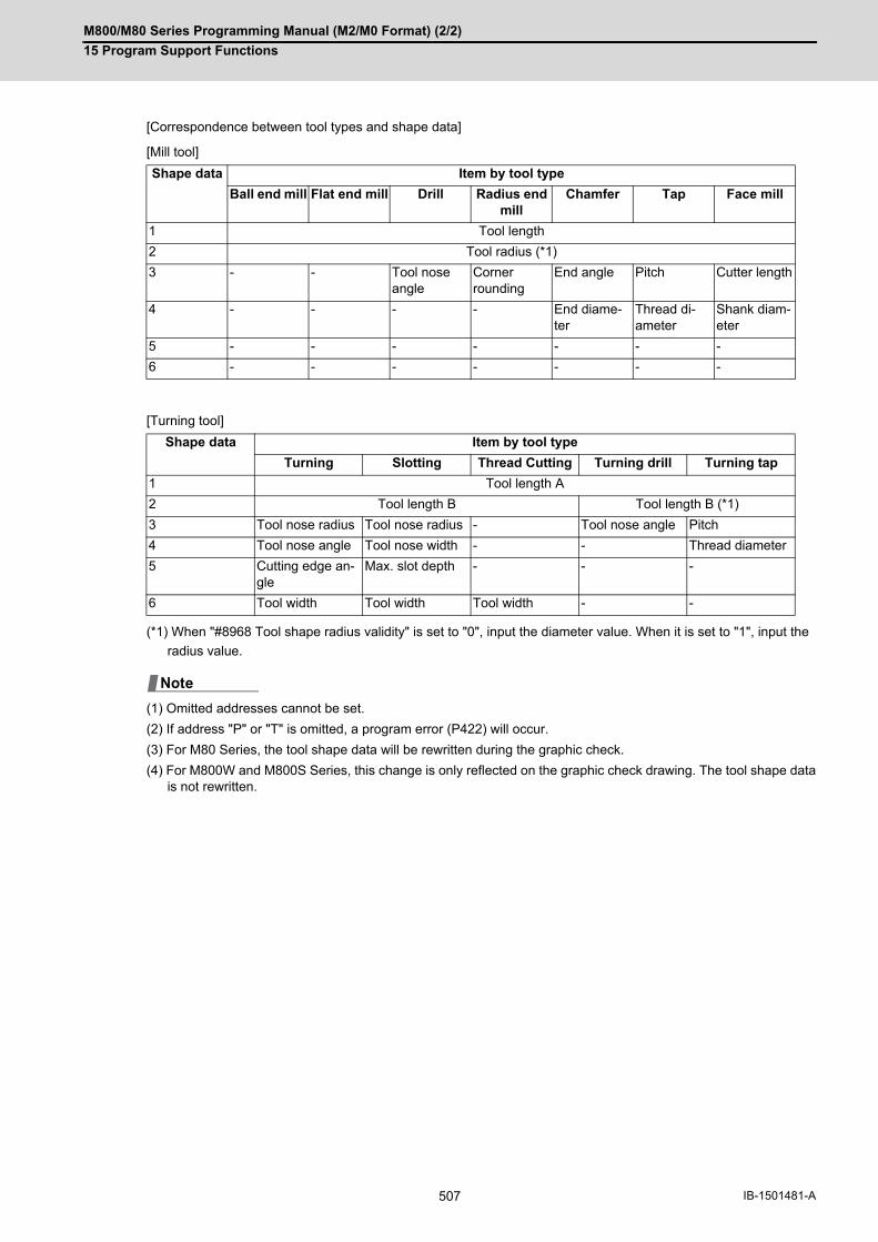
M800/M80 Series Programming Manual (M2/M0 Format) (2/2)
15 Program Support Functions
507 IB-1501481-A
[Correspondence between tool types and shape data]
[Mill tool]
[Turning tool]
(*1) When "#8968 Tool shape radius validity" is set to "0", input the diameter value. When it is set to "1", input the
radius value.
(1) Omitted addresses cannot be set.
(2) If address "P" or "T" is omitted, a program error (P422) will occur.
(3) For M80 Series, the tool shape data will be rewritten during the graphic check.
(4) For M800W and M800S Series, this change is only reflected on the graphic check drawing. The tool shape datais not rewritten.
Shape data Item by tool type
Ball end mill Flat end mill Drill Radius end mill
Chamfer Tap Face mill
1 Tool length
2 Tool radius (*1)
3 - - Tool nose angle
Corner rounding
End angle Pitch Cutter length
4 - - - - End diame-ter
Thread di-ameter
Shank diam-eter
5 - - - - - - -
6 - - - - - - -
Shape data Item by tool type
Turning Slotting Thread Cutting Turning drill Turning tap
1 Tool length A
2 Tool length B Tool length B (*1)
3 Tool nose radius Tool nose radius - Tool nose angle Pitch
4 Tool nose angle Tool nose width - - Thread diameter
5 Cutting edge an-gle
Max. slot depth - - -
6 Tool width Tool width Tool width - -
Note
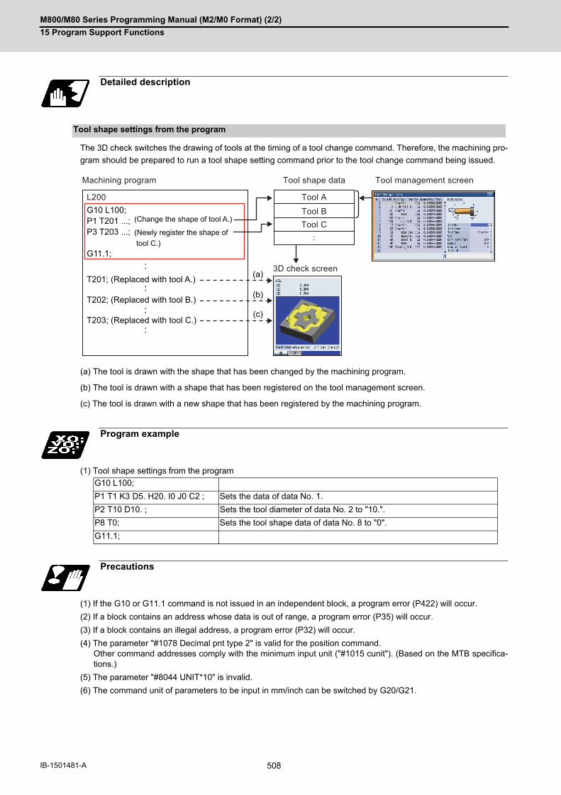
M800/M80 Series Programming Manual (M2/M0 Format) (2/2)
15 Program Support Functions
508IB-1501481-A
The 3D check switches the drawing of tools at the timing of a tool change command. Therefore, the machining pro-
gram should be prepared to run a tool shape setting command prior to the tool change command being issued.
(a) The tool is drawn with the shape that has been changed by the machining program.
(b) The tool is drawn with a shape that has been registered on the tool management screen.
(c) The tool is drawn with a new shape that has been registered by the machining program.
(1) Tool shape settings from the program
(1) If the G10 or G11.1 command is not issued in an independent block, a program error (P422) will occur.
(2) If a block contains an address whose data is out of range, a program error (P35) will occur.
(3) If a block contains an illegal address, a program error (P32) will occur.
(4) The parameter "#1078 Decimal pnt type 2" is valid for the position command. Other command addresses comply with the minimum input unit ("#1015 cunit"). (Based on the MTB specifica-tions.)
(5) The parameter "#8044 UNIT*10" is invalid.
(6) The command unit of parameters to be input in mm/inch can be switched by G20/G21.
Detailed description
Tool shape settings from the program
Program example
G10 L100;
P1 T1 K3 D5. H20. I0 J0 C2 ; Sets the data of data No. 1.
P2 T10 D10. ; Sets the tool diameter of data No. 2 to "10.".
P8 T0; Sets the tool shape data of data No. 8 to "0".
G11.1;
Precautions
G10 L100;P1 T201 ...; P3 T203 ...;
G11.1;
L200
(a)
(b)
(c)
T201; (Replaced with tool A.)
T202; (Replaced with tool B.)
T203; (Replaced with tool C.)
Machining program Tool shape data
Tool A
Tool BTool C
3D check screen
Tool management screen
(Change the shape of tool A.)
(Newly register the shape of tool C.)

M800/M80 Series Programming Manual (M2/M0 Format) (2/2)
15 Program Support Functions
509 IB-1501481-A
15.9.5 R-Navi Data Input by Program; G10 L110/L111, G11.1, G68.2, G69.1
The R-Navi setup parameters can be configured from a machining program.
Command setting values with absolute values.
The input unit conforms to the input setting unit of the 1st part system and the initial inch.
In either case, the input unit depends on the MTB specifications (parameters "#1003 iunit" and "#1041 I_inch").
The parameter "#8044 UNIT*10" is invalid.
Command G10 and G11.1 in independent blocks. A program error (P423) will occur if not commanded in independent blocks.
Address Q cannot be omitted. If omitted, a program error (P423) will occur.For the omitted addresses, data remains unchanged.Cancel the selected machining surface before data setting.
If data is set to a machining workpiece including the selected machining surface, a program error (P423) willoccur.
Function and purpose
Command format
Workpiece registration and setting
G69.1 Canceling the selected machining surface
G10 L110; Start setting workpiece data
Q_ <_> F_ C_ R_ X_ Y_ Z_ I_ J_ K_; Data setting
G11.1; End data setting
Q Workpiece registration No. (1 to 10)
< > Workpiece nameDesignate the name using up to 20 one-byte alphanumeric characters, including symbols. (If "0" is entered, the setting value is cleared.)
F Workpiece shape0: Rectangular parallelepiped1: Circular cylinder
C Basic coordinate system of machining workpiece0 to 5: G54 to G596 to 305: G54.1P1 to G54.1P300
R Marked point No.When the workpiece shape is set to rectangular parallelepiped, designate the marked point to set the basic coordinate system zero point. (0 to 8)
X, Y, Z, Workpiece sizeWhen the shape is set to circular cylinder, designate the diameter with X and the height with Y. (0.000 to 99999.999)
I, J, K Workpiece shiftSet the shift amount from the marked point to the basic coordinate system zero point. (-99999.999 to 99999.999)

M800/M80 Series Programming Manual (M2/M0 Format) (2/2)
15 Program Support Functions
510IB-1501481-A
Symbols "\", "/", ",", "*", "?", """, "<", ">", "|", " " (space), "@", and "~" cannot be used as one-byte symbols. If an available symbol is set, a program error (P35) or (P32) will occur.
For details on each of input data, refer to the instruction manual.
Command G10 and G11.1 in independent blocks. A program error (P423) will occur if not commanded in independent blocks.
Addresses P, Q, and D cannot be omitted. If omitted, a program error (P423) will occur.For the omitted addresses, data remains unchanged. For the machining surface designated with P0, set the coordinate axis direction with P1 and P2. Be sure to first
command P0. If P1 or P2 is commanded before P0, a program error (P423) will occur.
The machining surface cannot be registered for an undefined workpiece. If the registration command is issued, a program error (P423) will occur.
Cancel the selected machining surface before data setting. If data is set to the selected machining surface, a program error (P423) will occur.
(1) Command address to register the machining surface
Symbols "\", "/", ",", "*", "?", """, "<", ">", "|", " " (space), "@", and "~" cannot be used as one-byte symbols. If an available symbol is set, a program error (P35) or (P32) will occur.
For details on each of input data, refer to the instruction manual.
Machining surface registration and setting
G69.1; Canceling the selected machining surface
G10 L111; Start setting machining surface data
P0 Q_ D_ <_> X_ Y_ Z_ A_;
P1 M_ B_ C_ E_ F_ H_ I_;
P2 M_ B_ C_ E_ F_ H_ I_;
Machining surface setting (Refer to (1).)
Designate the coordinate axis direction (1st axis). (Refer to (2).)
Designate the coordinate axis direction (2nd axis). (Refer to (2).)
G11.1; End data setting
G68.2 P10 Q_ D_; Selecting the registered machining surface
P Machining surface registration(0)
Q Workpiece registration No. (1 to 10)
D Machining surface registration No.(2 to 17)
< > Designate the name of the machining surface using up to 15 one-byte alphanu-meric characters, including symbols. (If "0" is entered, the setting value is cleared.)
X, Y, Z Designate the coordinate system zero point (feature coordinate system zero point) of the machining surface with the offset from the basic coordinate zero point. In this case, designate the coordinate axis direction of the basic coordinate sys-tem. (-99999.999 to 99999.999)
A From three orthogonal axes (X, Y, and Z axes), select two coordinate axes to des-ignate the coordinate axis direction along the machining surface. 0: Z/X axis1: Y/Z axis2: X/Y axis

M800/M80 Series Programming Manual (M2/M0 Format) (2/2)
15 Program Support Functions
511 IB-1501481-A
(2) Command address to designate the coordinate axis direction
(*1) The setting details vary depending on the coordinate axis direction designation method (M address).
[M address: 0 (On-axis point (+))]
B, C, E: Coordinate value on X, Y, or Z axis
F to I: Vacuous
[M address: 1 (Latitude/Longitude)]
B: Latitude (θ1)
C: Longitude (θ2)
E to I: Vacuous
[M address: 2 (Latitude/Projection angle)]
B: Latitude (θ1)
C: Projection angle (θ2)
E to I: Vacuous
[M address: 3 (Start point/End point)]
B: Start point coordinate value (X)
C: Start point coordinate value (Y)
E: Start point coordinate value (Z)
F: End point coordinate value (X)
H: End point coordinate value (Y)
I: End point coordinate value (Z)
[M address: 4 (Indexing angle)]
B: 1st rotation angle (θ1)
C: 2nd rotation angle (θ2)
E to I: Vacuous
Method 5 (indexing angle) in the coordinate axis direction designation method is only available in the Z axisdirection. If a command is issued to an axis other than the Z axis designated by the coordinate axis selection command(P0Ax), a program error (P423) will occur.
For details on each of input data, refer to the instruction manual.
P Coordinate axis direction designation axis1: 1st axis2: 2nd axis
M Coordinate axis direction designation methodDesignate the method to set the coordinate axis direction along the machining sur-face. 0: [Method 1] On-axis point (+)1: [Method 2] Latitude/Longitude2: [Method 3] Latitude/Projection angle3: [Method 4] Start point/End point4: [Method 5] Indexing angle (Z axis direction only)
B, C, E, F, H, I Coordinate axis direction setting (*1)(-99999.999 to 99999.999)
P0 A0 (Z/X axis) P2 M4 setting causes an error. (Method 5 is not able to be selected on the 2nd axis.)P0 A1 (Y/Z axis)
P0 A2 (X/Y axis) P1M4 or P2M4 setting causes an error. (Method 5 is not able to be select-ed.)

M800/M80 Series Programming Manual (M2/M0 Format) (2/2)
15 Program Support Functions
512IB-1501481-A
This function enables the R-Navi setup parameters to be configured from a machining program.
After the parameters have been configured from the program, you can check the values or select the machining
surface from the setup
screen.
(1) If the machining surface is selected or canceled while the block start interlock signal (*BSL) is turned OFF, anoperation error (M01 0109) will occur. After this, if the block start interlock signal (*BSL) is turned ON, the ma-chining surface is selected or canceled. The operation of the PLC signal depends on the MTB specifications.
Operation example
Restrictions
WORK1
WORK2
BASE-SURFACE
SURFACE1-2
L200
Canceling the selected machining surfaceG69.1; (Setting of workpiece)G10 L110;Q1 <WORK1> F0 C0 R1 X50.0 Y30.0 Z20.0 I0.0 J0.0 K0.0 ;Q2 <WORK2> F0 C0 R5 X50.0 Y30.0 Z20.0 I-10.0 J-5.0 K-40.0 ;...G11.1;
(Setting the machining surface)G10 L111;(Workpiece : 1, surface : 2)P0 Q1 D2 <SURFACE1_2> X50.0 Y-30.0 Z-20.0 A0;P1 M0 B1.0 C0.0 E1.732 F0.0 H0.0 I0.0;P2 M1 B90.0 C0.0 E0.0 F0.0 H0.0 I0.0;(Workpiece : 1, surface : 17)P0 Q1 D17 <SURFACE1_17> X20.0 Y20.0 Z10.0 A0;P1 M1 B0.0 C30.0 E0.0 F0.0 H0.0 I0.0;P2 M0 B0.0 C30.0 E0.0 F0.0 H0.0 I0.0;...(Workpiece : 2, surface : 2)P0 Q2 D2 <SURFACE2_2> X20.0 Y20.0 Z10.0 A0;P1 M0 B1.0 C0.0 E1.732 F0.0 H0.0 I0.0;P2 M1 B90.0 C0.0 E0.0 F0.0 H0.0 I0.0;...G11.1;
Machining program
Setup parameters
Setup screen

M800/M80 Series Programming Manual (M2/M0 Format) (2/2)
15 Program Support Functions
513 IB-1501481-A
15.9.6 Compensation Data Input to Variable by Program; G11
Using G11, the compensation amount of the No. commanded as the transmission source can be set into the arbi-
trary variable.
(1) Type I is selected when parameter "#1037 cmdtyp" is set to "9", and type II is selected when set to "10".
(1) G11 command is unmodal, thus, it is valid only in the block where it is commanded.
(2) G11 must not be used with G codes other than G54 to G59, G90 or G91. If G11 is used with unsuitable G codes,an illegal operation will result.
(3) When G11 is commanded in the same block as G22 or G23, the tool compensation data will not be input. ("P"will be regarded as the number of repetition of subprogram call.)
Function and purpose
Command format
G11 P__ Q__ ; Compensation data input to variable by program
P Compensation No. of transmission source
Q Variable No. of transmission destination
Tool compensation memo-ry type
Function
Type I Tool compensation amount substituted
Type II Tool length shape compensation amount Substituted
Tool length wear compensation amount -
Tool radius shape compensation amount -
Tool radius wear compensation amount -
Detailed description
Note
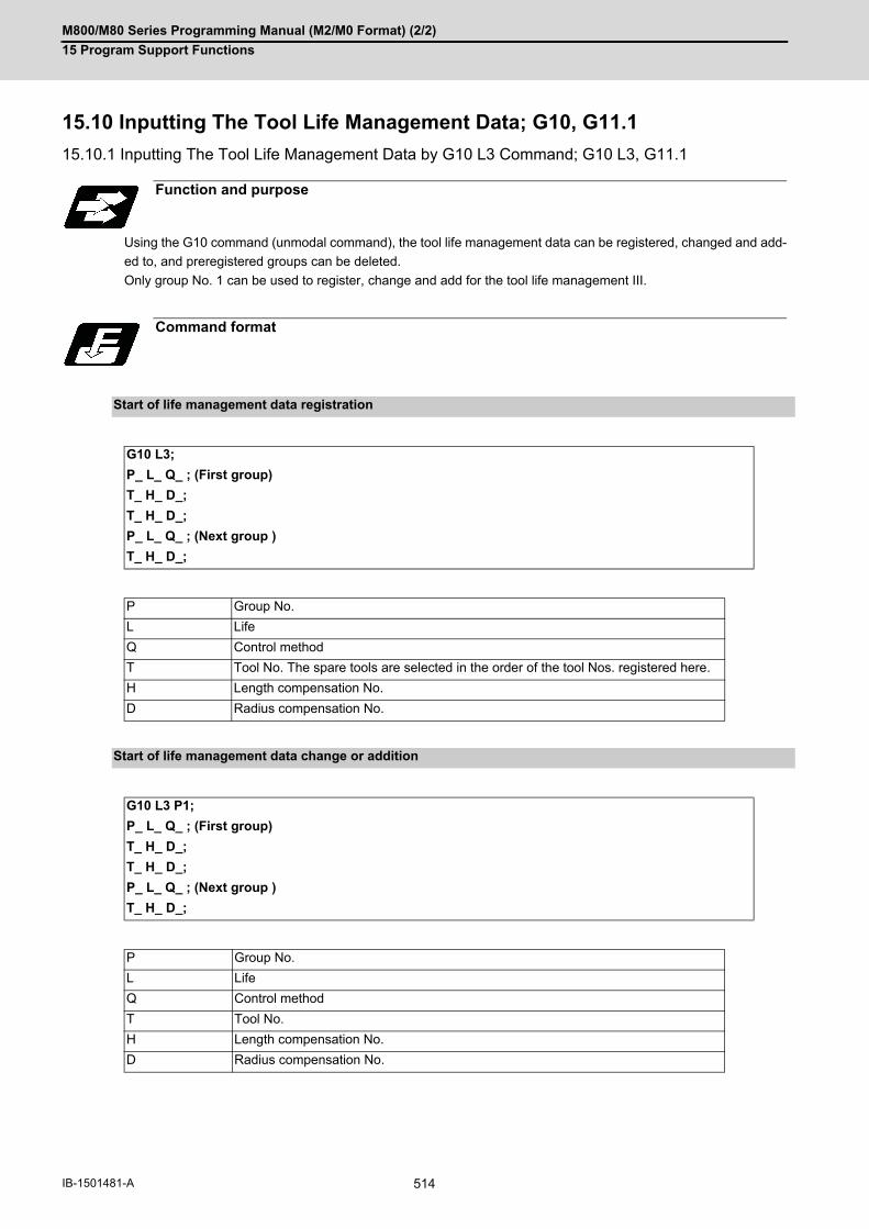
M800/M80 Series Programming Manual (M2/M0 Format) (2/2)
15 Program Support Functions
514IB-1501481-A
15.10 Inputting The Tool Life Management Data; G10, G11.1
15.10.1 Inputting The Tool Life Management Data by G10 L3 Command; G10 L3, G11.1
Using the G10 command (unmodal command), the tool life management data can be registered, changed and add-
ed to, and preregistered groups can be deleted.
Only group No. 1 can be used to register, change and add for the tool life management III.
Function and purpose
Command format
Start of life management data registration
G10 L3;
P_ L_ Q_ ; (First group)
T_ H_ D_;
T_ H_ D_;
P_ L_ Q_ ; (Next group )
T_ H_ D_;
P Group No.
L Life
Q Control method
T Tool No. The spare tools are selected in the order of the tool Nos. registered here.
H Length compensation No.
D Radius compensation No.
Start of life management data change or addition
G10 L3 P1;
P_ L_ Q_ ; (First group)
T_ H_ D_;
T_ H_ D_;
P_ L_ Q_ ; (Next group )
T_ H_ D_;
P Group No.
L Life
Q Control method
T Tool No.
H Length compensation No.
D Radius compensation No.

M800/M80 Series Programming Manual (M2/M0 Format) (2/2)
15 Program Support Functions
515 IB-1501481-A
(*) The setting range of the tool compensation No. differs according to the specification of the "number of tool offset
sets".
If a value exceeding each command range is issued, a program error (P35) will occur.
Start of life management data deletion
G10 L3 P2;
P_ ; (First group)
P_ ; (Second group)
P Group No.
End of life management data registration, change, addition or deletion
G11.1;
Detailed description
Command range
Item Command range
Group No. (Pn) 1 to 99999999 (Only group No. 1 can be used for the tool life management III)
Life (Ln) 0 to 65000 times (No. of times control method)0 to 4000 minutes (time control method)
Control method (Qn) 1 to 31: Number of mounts control2: Time control3: Number of cutting times control
Tool No. (Tn) 1 to 99999999
Length compensation No. (Hn) 0 to 999 (*)
Radius compensation No. (Dn) 0 to 999 (*)

M800/M80 Series Programming Manual (M2/M0 Format) (2/2)
15 Program Support Functions
516IB-1501481-A
Operation example
Program example Operation
Data registration G10 L3 ;
P10 L10 Q1 ;
T10 H10 D10 ;
G11.1 ;
M02 ;
1. After deleting all group data, the registration starts. 2. Group No. 10 is registered. 3. Tool No. 10 is registered in group No. 10. 4. The registration ends. 5. The program ends.
Group change, addi-tion
G10 L3 P1 ;
P10 L10 Q1 ;
T10 H10 D10 ;
G11.1;
M02 ;
1. Changing and addition of the group and tool starts. 2. The change and addition operation takes place in the following manner. (1) When group No. 10 has not been registered. - Group No. 10 is additionally registered. - Tool No. 10 is registered in group No. 10. (2) When group No. 10 has been registered, but tool No. 10 has not been registered. - Tool No. 10 is additionally registered in group No. 10 (3) When group No. 10 and tool No. 10 have been both regis-tered. - The tool No. 10 data is changed. 3. The group and tool change and addition ends. 4. The program ends.
Group deletion G10 L3 P2 ;
P10 ;
G11.1 ;
M02 ;
1. The group deletion starts. 2. The group No. 10 data is deleted. 3. The group deletion ends. 4. The program ends.
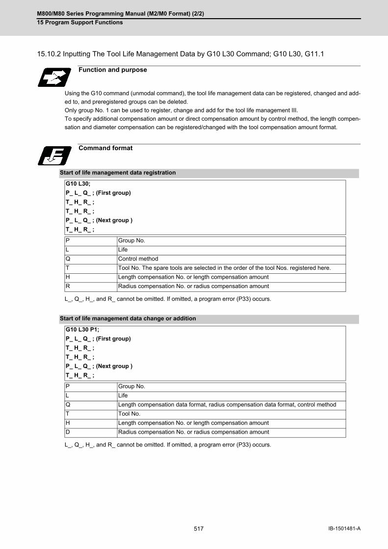
M800/M80 Series Programming Manual (M2/M0 Format) (2/2)
15 Program Support Functions
517 IB-1501481-A
15.10.2 Inputting The Tool Life Management Data by G10 L30 Command; G10 L30, G11.1
Using the G10 command (unmodal command), the tool life management data can be registered, changed and add-
ed to, and preregistered groups can be deleted.
Only group No. 1 can be used to register, change and add for the tool life management III.
To specify additional compensation amount or direct compensation amount by control method, the length compen-
sation and diameter compensation can be registered/changed with the tool compensation amount format.
L_, Q_, H_, and R_ cannot be omitted. If omitted, a program error (P33) occurs.
L_, Q_, H_, and R_ cannot be omitted. If omitted, a program error (P33) occurs.
Function and purpose
Command format
Start of life management data registration
G10 L30;
P_ L_ Q_ ; (First group)
T_ H_ R_ ;
T_ H_ R_ ;
P_ L_ Q_ ; (Next group )
T_ H_ R_ ;
P Group No.
L Life
Q Control method
T Tool No. The spare tools are selected in the order of the tool Nos. registered here.
H Length compensation No. or length compensation amount
R Radius compensation No. or radius compensation amount
Start of life management data change or addition
G10 L30 P1;
P_ L_ Q_ ; (First group)
T_ H_ R_ ;
T_ H_ R_ ;
P_ L_ Q_ ; (Next group )
T_ H_ R_ ;
P Group No.
L Life
Q Length compensation data format, radius compensation data format, control method
T Tool No.
H Length compensation No. or length compensation amount
D Radius compensation No. or radius compensation amount

M800/M80 Series Programming Manual (M2/M0 Format) (2/2)
15 Program Support Functions
518IB-1501481-A
(*1) The setting range of the tool compensation No. differs according to the specification of the "number of tool offset
sets".
Start of life management data deletion
G10 L30 P2;
P_ ; (First group)
P_ ; (Second group)
P Group No.
End of life management data registration, change, addition or deletion
G11.1;
Detailed description
Command range
Item Command range
Group No. (Pn) 1 to 99999999 (Only group No. 1 can be used for the tool life management III)
Tool No. (Tn) 1 to 99999999
Control method (Qabc) abc: Three integer digitsa. Tool length compensation data format0: Compensation No.1: Incremental value compensation amount2: Absolute value compensation amountb. Tool radius compensation data format0: Compensation No.1: Incremental value compensation amount2: Absolute value compensation amountc. Tool management method0: Usage time1: Number of mounts2: Number of usages
Life (Ln) 0 to 4000 minutes (usage time)0 to 65000 times (number of mounts)0 to 65000 times (number of usages)
Length compensation (No./amount)
(Hn) 0 to 999 (compensation No.) (*1)±999.999 (incremental value compensation amount)±999.999 (absolute value compensation amount)
Radius compensation (No./amount)
(Rn) 0 to 999 (compensation No.) (*1)±999.999 (incremental value compensation amount)±999.999 (absolute value compensation amount)
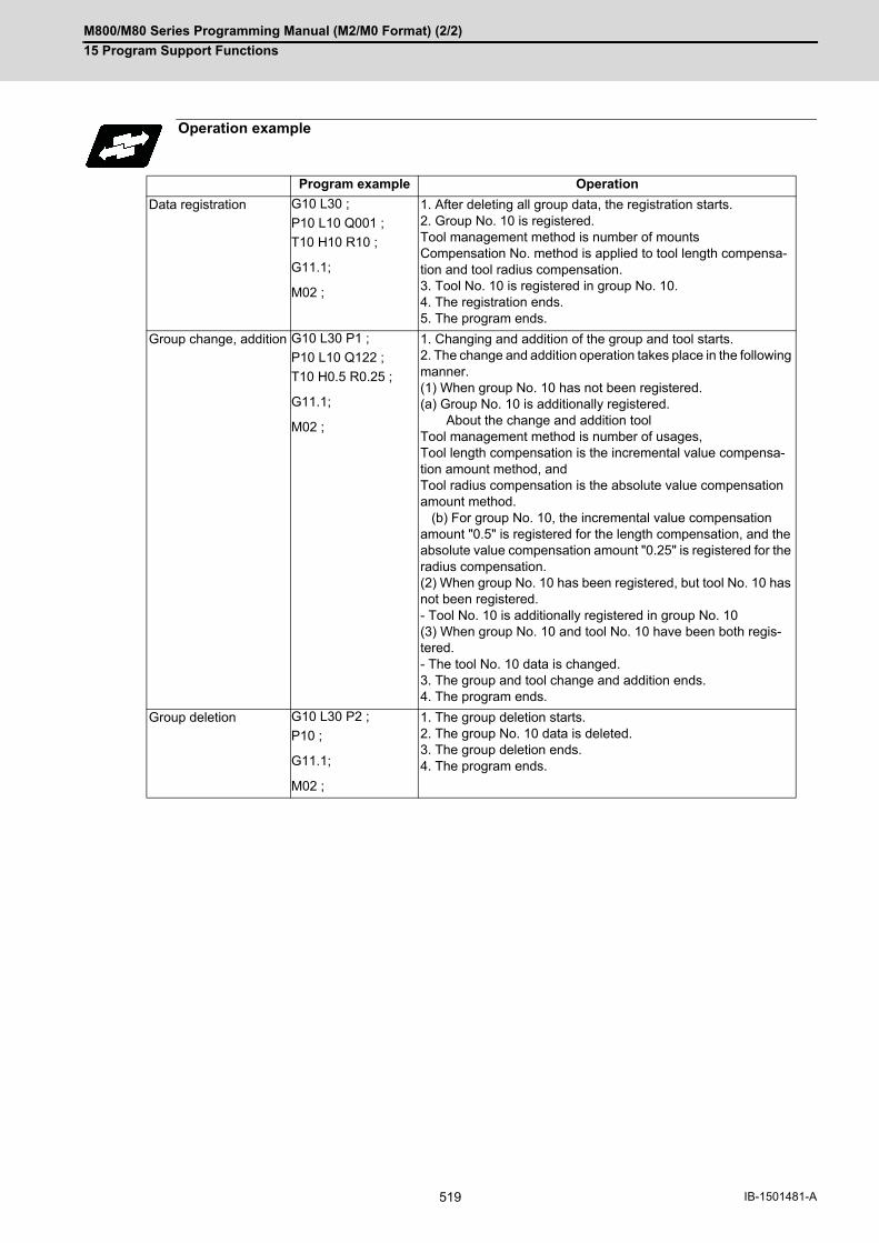
M800/M80 Series Programming Manual (M2/M0 Format) (2/2)
15 Program Support Functions
519 IB-1501481-A
Operation example
Program example Operation
Data registration G10 L30 ;
P10 L10 Q001 ;
T10 H10 R10 ;
G11.1;
M02 ;
1. After deleting all group data, the registration starts. 2. Group No. 10 is registered. Tool management method is number of mounts Compensation No. method is applied to tool length compensa-tion and tool radius compensation. 3. Tool No. 10 is registered in group No. 10. 4. The registration ends. 5. The program ends.
Group change, addition G10 L30 P1 ;
P10 L10 Q122 ;
T10 H0.5 R0.25 ;
G11.1;
M02 ;
1. Changing and addition of the group and tool starts. 2. The change and addition operation takes place in the following manner. (1) When group No. 10 has not been registered.(a) Group No. 10 is additionally registered. About the change and addition toolTool management method is number of usages,Tool length compensation is the incremental value compensa-tion amount method, andTool radius compensation is the absolute value compensation amount method. (b) For group No. 10, the incremental value compensation amount "0.5" is registered for the length compensation, and the absolute value compensation amount "0.25" is registered for the radius compensation. (2) When group No. 10 has been registered, but tool No. 10 has not been registered.- Tool No. 10 is additionally registered in group No. 10 (3) When group No. 10 and tool No. 10 have been both regis-tered.- The tool No. 10 data is changed. 3. The group and tool change and addition ends. 4. The program ends.
Group deletion G10 L30 P2 ;
P10 ;
G11.1;
M02 ;
1. The group deletion starts. 2. The group No. 10 data is deleted. 3. The group deletion ends. 4. The program ends.

M800/M80 Series Programming Manual (M2/M0 Format) (2/2)
15 Program Support Functions
520IB-1501481-A
15.10.3 Precautions for Inputting The Tool Life Management Data
(1) During the following operations, the tool usage data will not be counted.
- Machine lock
- Auxiliary axis function lock
- Dry run
- Single block
- Skip
(1) The tool life data is registered, changed, added to or deleted by executing the program in the memory or MDI
mode.
(2) The group No. and tool No. cannot be commanded in duplicate. The program error (P179) will occur.
(3) When two or more addresses are commanded in one block, the latter address will be valid.
(4) If the life data (L_) is omitted in the G10L3 command, the life data for that group will be "0".
(5) If the control method (Q_) is omitted in the G10L3 command, the control method for that group will follow the
base specification parameter "#1106 Tcount".
Note that when carrying out the No. of cutting times control method, command the method from the program.
(6) If the control method (Q_) is not designated with 3-digit by G10 L30 command, the omitted high-order are equiv-
alent to "0".
Therefore, "Q1" is equivalent to "Q001", and "Q12" is equivalent to "Q012".
(7) If the length compensation No. (H_) is omitted in the G10L3 command, the length compensation No. for that
group will be "0".
(8) If the radius compensation No. (D_) is omitted in the G10L3 command, the radius compensation No. for that
group will be "0".
(9) Programming with a sequence No. is not possible between G10 L3 or G10 L30 and G11.1. The program error
(P33) will occur.
(10) If the usage data count valid signal (YC8A) is ON, G10 L3 or G10 L30 cannot be commanded. The program
error (P177) will occur.
(11) The registered data is held even if the power is turned OFF.
(12) When G10 L3 or G10 L30 is commanded, the commanded group and tool will be registered after all of the reg-
istered data is erased.
(13) The change and addition conditions in the G10 L3 P1 or G10 L30 P1 command are as follows:
(a) Change conditions
- Both the commanded group No. and tool No. are registered.
-> Change the commanded tool No. data.
(b) Additional conditions
- Neither the commanded group No. nor tool No. is registered.
-> Additionally register the commanded group No. and tool No. data.
- The commanded group No. is registered, but the commanded tool No. is not registered.
-> Additionally register the commanded tool No. data to the commanded group No.
(14) The setting range of the tool compensation No. depends on the MTB specifications.
(15) Only group No. 1 can be used to register, change and add for the tool life management III.
Relationship with other functions
Precautions

M800/M80 Series Programming Manual (M2/M0 Format) (2/2)
15 Program Support Functions
521 IB-1501481-A
15.10.4 Allocation of The Number of Tool Life Management Sets to Part Systems
The number of tool life management sets can be set per part system.
This function is divided into following methods and which one is used depends on the MTB specifications (parame-
ters "#1439 Tlife-SysAssign", "#12055 Tol-lifenum").
Arbitrary allocation: Arbitrarily allocates the number of tool life management sets to each part system.
Fixed allocation: Automatically and evenly allocates the number of tool life management sets to each part system.
The arbitrary allocation enables the efficient allocation because when a certain part system needs only a small num-
ber of tool life management sets, the rest can be allocated to another part system. If an auxiliary-axis part system
does not need the tool life management sets at all, the number of tool life management sets can be set to "0" for the
auxiliary-axis part system.
Subsequent description is an example in the case where the number of tool life management sets in the system is
999 sets.
(1) Arbitrary allocation (with #1439=1)
The number of sets allocated to each part system depends on the MTB specifications (parameter "#12055 Tol-
lifenum").
The following example shows the number of tool offset sets allocated when the lathe system is a 4-part system.
(a) When the number of tool life management sets is increased for the 1st part system ($1) of 4-part system
(b) When the number of tool life management sets is set to "0 sets" for the 3rd part system ($3) of 3-part system
to use that part system as an auxiliary-axis part system
Function and purpose
250
250
250
250
200
200
200
400$1
$2
$3
$4
$1
$2
$3
$4
334
333
333 500
0
500$1
$2
$3
$1
$2
$3

M800/M80 Series Programming Manual (M2/M0 Format) (2/2)
15 Program Support Functions
522IB-1501481-A
(2) Automatic and even allocation (with #1439=0)
(*1)The maximum number of tool life management sets per part system is 999.
(*2) If there is any remainder, the remainder is allocated to the 1st part system.
(1) The maximum number of tool life management sets for 1-part system is 999.
(2) For 1-part system, up to the number of tool life management sets in the system is available regardless of the
parameter setting.
(3) When the value of the parameter "#12055 Tol-lifenum" is equal to or lower than the number of tool life manage-
ment sets in the system, the remainder is not allocated to any part system even if the specification allows arbi-
trary allocation.
(4) When the value of the parameter "#12055 Tol-lifenum" is equal to or lower than the number of tool life manage-
ment sets in the system, system alarm (Y05) is generated even if the specification allows arbitrary allocation.
(5) Even if the specification allows arbitrary allocation, fixed allocation is applied if the parameter is "#12055 Tol-
lifenum"= "0" for all part systems.
(6) When entering data into the tool life management file, if the number of tool life management data exceeds that
of current tool life management sets, the excess tool life management data cannot be entered.
1-part system 2-part system 3-part system(Lathe system only)
4-part system(Lathe system only)
Precautions
500
333
333500
334
999
250
250
250
250
$1
$2
$3
$1
$2
$1
$1
$2
$3
$4
(*2)
(*1)

M800/M80 Series Programming Manual (M2/M0 Format) (2/2)
15 Program Support Functions
523 IB-1501481-A
15.11 End Point Error Check Cancellation; G69
If an illegal program is given to NC, a program error will occur. However, the error point check cancellation command
G69 can be used to escape a program error only in the following conditions:
(1) The end point does not exist on the circumference of a circle in circular interpolation (containing helical cutting).
(2) With tool radius compensation, the compensation amount is changed during circular interpolation modal.
(1) Circular cutting (including helical interpolation)If the end point does not exist on the circumference of a circle and G69 command is given in circular interpolation,the circular radius changes linearly together with the angle after movement as shown below:
Although the speed of the outer circumference is slightly faster than the commanded speed, the angular speed
is constant.
Function and purpose
Command format
G69(G03) X__ Y__ Z__ ; ... End point error check cancellation
G69 End point error check cancellation (G69 command is unmodal.)
G03 Commands such as circular command
X,Y,Z End point of the circular commands(Though this point is illegal at usual, it will not be regarded as the error point by us-ing G69.)
Detailed description
θs θe
Rs
Re
θ
θe
Rs
Re
θs 0
R
R
θ
End point
Outercircumference
Radius
Start point
Start point
Angle
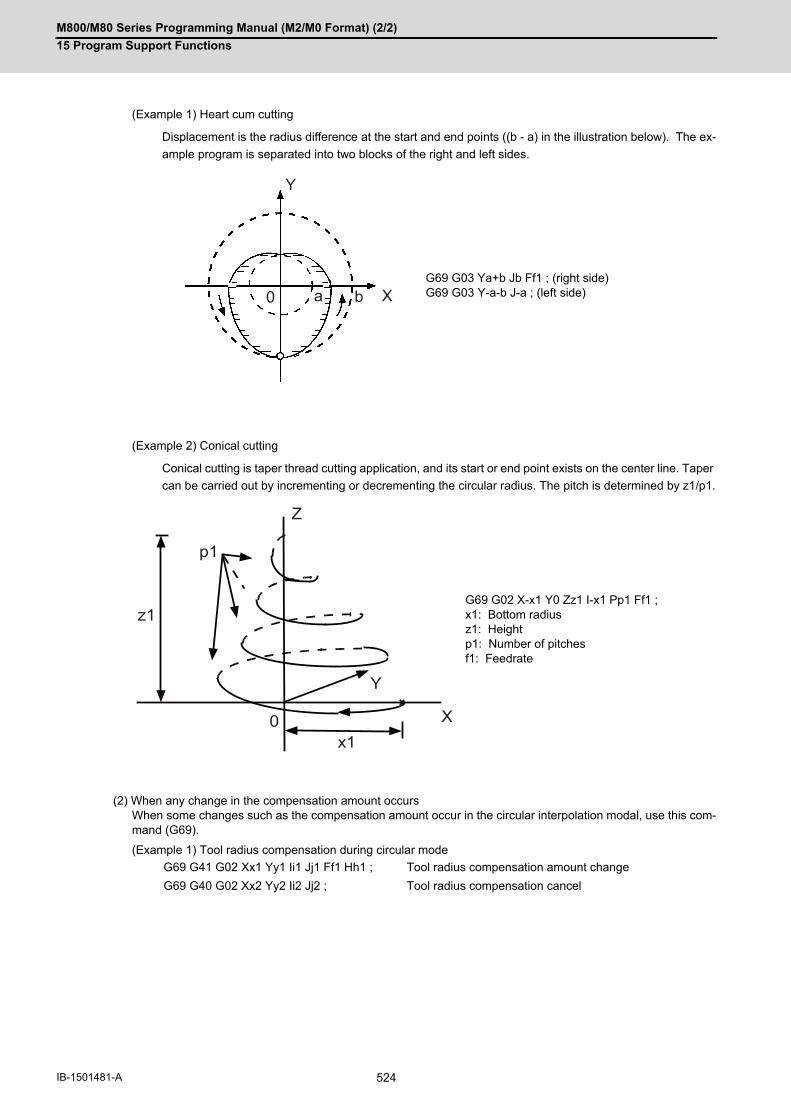
M800/M80 Series Programming Manual (M2/M0 Format) (2/2)
15 Program Support Functions
524IB-1501481-A
(Example 1) Heart cum cutting
Displacement is the radius difference at the start and end points ((b - a) in the illustration below). The ex-
ample program is separated into two blocks of the right and left sides.
(Example 2) Conical cutting
Conical cutting is taper thread cutting application, and its start or end point exists on the center line. Taper
can be carried out by incrementing or decrementing the circular radius. The pitch is determined by z1/p1.
(2) When any change in the compensation amount occursWhen some changes such as the compensation amount occur in the circular interpolation modal, use this com-mand (G69).
(Example 1) Tool radius compensation during circular mode
G69 G03 Ya+b Jb Ff1 ; (right side)G69 G03 Y-a-b J-a ; (left side)
G69 G02 X-x1 Y0 Zz1 I-x1 Pp1 Ff1 ;x1: Bottom radiusz1: Heightp1: Number of pitchesf1: Feedrate
G69 G41 G02 Xx1 Yy1 Ii1 Jj1 Ff1 Hh1 ; Tool radius compensation amount change
G69 G40 G02 Xx2 Yy2 Ii2 Jj2 ; Tool radius compensation cancel
Y
X0 a b
Y
X0
Z
x1
p1
z1

M800/M80 Series Programming Manual (M2/M0 Format) (2/2)
15 Program Support Functions
525 IB-1501481-A
15.12 Coordinate Read Function; G14
The G14 command is used to read the end point coordinates of the immediately preceding block, the machine co-
ordinates, the workpiece coordinates, the TLM coordinates, or the skip coordinates.
(1) The type of coordinates to be read is specified in "p". The coordinates that can be read are listed below:
Type of the coordinates to be read
(2) The end point position will be read instead of the skip coordinates when the skip signal is not turned ON in a G31block.
(3) G14 command is unmodal, thus, it is valid only in the block where it is commanded.
(4) The end point and skip coordinates can be read even while moving. Always confirm that the movement hasstopped before reading the machine, workpiece, and TLM coordinates. To stop the movement, stop the axis movement with the dwell command and so forth.
(5) The program error (P241) will occur if an illegal variable No. is commanded.
Function and purpose
Command format
G14 X__ Y__ Z__ A__ P__ ; Coordinate read command
X,Y,Z,A Each axis and the variable No. where the axis’s coordinates data will be stored. (A "A" means the additional axis.)
P Type of the coordinates to be read
Detailed description
"P" command val-ue
Contents Compensation amount
Read during mov-ing
No "p" command is given or a value oth-er than 1 to 4 is specified
End point position of the immediately preceding block(The absolute coordinate system set by G92)
Not contained Enabled
1 Machine coordinates(Basic machine coordinate system)
Contained Disabled
2 Zero point of the current workpiece coordinate sys-tem(Workpiece coordinate system)
Contained Disabled
3 TLM coordinates(The point where TLM switch is turned OFF to ON at machine stop is used as the zero point of the TLM coordinate system.)
Contained Disabled
4 Skip signal input coordinates (Workpiece coordi-nate system)
Contained Disabled

M800/M80 Series Programming Manual (M2/M0 Format) (2/2)
15 Program Support Functions
526IB-1501481-A
(1) An example of P command value and reading coordinates are given.
When the above is set
Program example
G54: X-50.
Y-75.
H10:50.
N1 G28 X0 Y0 Z0 ;
N2 G90 G00 X-200. Y-100. G53 ;
N3 M60 ; TLM switch is turned from OFF to ON.
N4 G00 G54 X-100. Y-100. ;
N5 G92 X0 Y0 Y-50. ;
N6 G00 G43 X-100. H10 ;
N7 G14 X100 Y101 Pp1 ;
"P" command value Read coordinates Compensation amount
End point position of the im-mediately preceding block
No “p” command is given or a value other than 1 to 4 is specified
#100 = -100.#101 = -50.
Not contained
Machine coordinate 1 #100 = -200.#101 = -175.
Contained
Workpiece coordinate 2 #100 = -50.#101 = -50.
Contained
TLM coordinates 3 #100 = -0#101 = -75.
Contained
-50-150
-50
-100G92
N2
N4
N3
Y
X
-150
-200
N5H10
-100-200-250
Basic machine coordinate system
N4 workpiece coordinate system
Workpiece coordinate systemafter execution of N5.
TLM coordinate system(TLM switch ON)
Position after execution of N6.

M800/M80 Series Programming Manual (M2/M0 Format) (2/2)
15 Program Support Functions
527 IB-1501481-A
(2) An example of reading skip coordinates are given.
The coordinates read by the above program is as follows.
<Note>
"ε" is an error caused by response delay. (For details, see the section of skip function.)The skip signal input coordinates of N4 block will be read to #111 because there is no Y command in theN7 block
(1) The program error (P241) will occur if an illegal variable No. is commanded.
N1 G91 G28 X0 Y0 Z0 ;N2 G90 G00 X0 Y0 ;N3 X0 Y-100. ;N4 G31 X-150. Y-50. F80 ;N5 G14 X100 Y101 P4 ;N6 G00 Y0 ;N7 G31 X0 ;N8 G14 X110 Y111 P4 ;N9 M02 ;
#100 = -75. + ε #101 = -75. + ε
#110 = -25. + ε #111 = -75. + ε
Precautions
Y
X-X
-75 -25-150
-50
-75
-100N3
N7
N4
N6
Skip signal input

M800/M80 Series Programming Manual (M2/M0 Format) (2/2)
15 Program Support Functions
528IB-1501481-A

16
529 IB-1501481-A
Multi-part System Control

M800/M80 Series Programming Manual (M2/M0 Format) (2/2)
16 Multi-part System Control
530IB-1501481-A
16Multi-part System Control16.1 Timing Synchronization Operation
16.1.1 Timing Synchronization Operation (! code) !n (!m ...) L
The multi-axis, multi-part system complex control CNC system can simultaneously run multiple machining programs
independently. The synchronization-between-part systems function is used in cases when, at some particular point
during operation, the operations of 1st and 2nd part systems are to be synchronized or in cases when the operation
of only one part system is required.
When timing synchronization is executed in the 1st part system ($1) and the 2nd part system ($2), operations will
be as follows.
CAUTION
When programming a multi-part system, carefully observe the movements caused by other part systems' pro-
grams.
Function and purpose
Simultaneous and independent operation
Timing synchronization operation
Simultaneous and independent operation
Timing synchronization operation
2nd part system operation only1st part system waiting
Timing synchronization operation
Simultaneous and independent operation
Command format
!n (!m ...) L_ ; ... timing synchronization operation
!n, !m, ... Timing synchronization operation (!) and part system No. (n:1 - number of part system that can be used)Follows the settings of the parameter "#19419 Timing sync system" if part system num-ber is omitted.
L Timing Synchronization Operation No. 0 to 9999
% %
$1 $2

M800/M80 Series Programming Manual (M2/M0 Format) (2/2)
16 Multi-part System Control
531 IB-1501481-A
(1) Timing synchronization between part systems during automatic operation
If !n L__ is commanded from a part system (i), operation of the part system i program will wait until !i L_ is com-
manded from the part system n program.
When !i L_ is commanded, the programs for the two part systems will start simultaneously.
Timing synchronization between 2 part systems
(2) The timing synchronization operation is normally issued in a single block. However, if a movement command or
M, S or T command is issued in the same block, whether to synchronize after the movement command or M, S
or T command or to execute the movement command or M, S or T command after synchronization will depend
on the MTB specifications (#1093 Wnvfin).
#1093 Wmvfin
0 : Wait before executing movement command.
1 : Wait after executing movement command.
(3) If there is no movement command in the same block as the timing synchronization operation, when the next block
movement starts, synchronization may not be secured between the part systems. To synchronize the part sys-
tems when movement starts after waiting, issue the movement command in the same block as the timing syn-
chronization operation.
(4)The L command is the timing synchronization identification No. The same Nos. are waited but when they are omit-
ted, the Nos. are handled as L0.
(5) "SYN" will appear in the operation status section during timing synchronization operation. The timing synchroni-
zation operation signal will be output to the PLC I/F.
(6) In a timing synchronization operation, other part system to be waited for is specified but the own part system can
be specified with the other part system.
(7) The timing synchronization operation of a specific part system can be ignored depending on the MTB specifica-
tions.
Operation will be determined by the combination of the timing synchronization operation ignore signal and pa-
rameter "#1279 ext15/bit0".
For setting combination, refer to "Time synchronization when timing synchronization ignore is set".
For the specifications of the machine you are using, see the instructions issued by the MTB.
Detailed description
!nL1 ;
!iL1;
Pi1 Pn1
Pi2 Pn2
Pi1 Pi2
Pn1 Pn2
$i
$n
$i $n
waiting...
Simultaneously start
Timing synchronization

M800/M80 Series Programming Manual (M2/M0 Format) (2/2)
16 Multi-part System Control
532IB-1501481-A
(1) When the M code can be used, both the M code and ! code can be used.
(2) While the timing synchronization operation M code is valid, if one part system is standing by with an M code, an
alarm will occur if there is a ! code timing synchronization operation command in the other part system.
(3) While the timing synchronization operation M code is valid, if one part system is standing by with a ! code, an
alarm will occur if there is an M code timing synchronization operation command in the other part system.
(4) When macro interruption is carried out in a part system waiting, the part system can stop while waiting even if
the conditions for time synchronization are met. In this case, you will be able to continue the program, ignoring
the timing synchronization with timing synchronization operation ignore signal.
For details, contact the MTB.
Precautions

M800/M80 Series Programming Manual (M2/M0 Format) (2/2)
16 Multi-part System Control
533 IB-1501481-A
16.1.2 Timing Synchronization Operation with Start Point Designated (Type 1); G115
The part system can wait for the other part system to reach the start point before starting itself. The start point can
be set in the middle of a block.
Function and purpose
Command format
!n L__ G115 X__ Y__ Z__ ;
!n Timing synchronization operation (!) and part system No. (n:1 - number of part sys-tem that can be used)Part systems follow the settings of the parameter "#19419 Timing sync system" if the number is omitted.
L Timing Synchronization Operation No. 0 to 9999(It will be regarded as "L0" when omitted.)
G115 G command
X Y Z Start point(Command by axis and workpiece coordinate value)

M800/M80 Series Programming Manual (M2/M0 Format) (2/2)
16 Multi-part System Control
534IB-1501481-A
(1)Designate the start point using the workpiece coordinates of the other part system (ex. $2).
(2)The start point check is executed only for the axis designated by G115.
(Example) !L2 G115 X100. ;
Once the other part system reaches X100, the own part system (ex. $1) will start. The other axes are not
checked.
(3)The other part system starts first when timing synchronization operation is executed.
(4)The own part system waits for the other part system to move and reach the designated start point, and then starts.
(5) When the start point designated by G115 is not on the next block movement path of the other part system, the
own part system starts once all the designated axis of the other part system has reach the designated start point.
(6) After waiting, if the start point cannot be obtained with movement command of the other timing synchronization
block, the operations depend on the MTB specifications (parameter "#1229 set01/bit5").
(a) When the parameter is ON
Wait till the own part system reaches the start point by moving after the next block.
(b) When the parameter is OFF
When the next block finishes moving, the own part system will start.
Detailed description
Timing synchronization Designated start point
Movement Designated start point Actual start point
$1
$2 !1
!1
$1
$2
!2 G115
!2 G115
G00 X...
G00 X...

M800/M80 Series Programming Manual (M2/M0 Format) (2/2)
16 Multi-part System Control
535 IB-1501481-A
(7)The timing synchronization status continues when the G115 command has been duplicated between part sys-
tems. (Operations will not restart.)
(8) The single block stop function does not apply for the G115 block.
(9) A program error (P32) will occur if an address other than an axis is designated in G115 command block.
(10) In the timing synchronization operation, other part system to be waited for is specified but the own part system
can be specified with the other part system.
(11) The timing synchronization operation of a specific part system can be ignored depending on the MTB specifi-
cations. Operation will be determined by the combination of the timing synchronization operation ignore signal
(PLC signal) and parameter "#1279 ext15/bit0".
For setting combination, refer to "Time synchronization when timing synchronization ignore is set".
For the specifications of the machine you are using, see the instructions issued by the MTB.
(1) Parameter "#1093 Wmvfin" that selects the timing of the timing synchronization operation and commands on the
same block does not work for the start point command block (G115/G116). After synchronization. the start point
check will be executed by G115/G116.
(2) Be careful about the timing when interrupting during the time synchronization of G115/G116. For example, as-
sume interruption with the macro interrupt type 1 while a part system is waiting for time synchronization with
G116. In this case, if there is a movement command or MSTB command in the interrupt program, the program
will continue after the interrupt program completes without waiting for the start point.
(3)The L command is the timing synchronization identification No. The same Nos. are waited but when they are omit-
ted, the Nos. are handled as L0.
Timing synchronizing
Precautions
$1 !2 G115
!1 G115$2

M800/M80 Series Programming Manual (M2/M0 Format) (2/2)
16 Multi-part System Control
536IB-1501481-A
16.1.3 Timing Synchronization Operation with Start Point Designated (Type 2); G116
The own part system can make the other part system to wait until it reaches the start point. The start point can be
set in the middle of a block.
Function and purpose
Command format
!n L__ G116 X__ Y__ Z__ ;
!n Timing synchronization operation (!) and part system No. (n:1 - number of part sys-tem that can be used)Part systems follow the settings of the parameter "#19419 Timing sync system" if the number is omitted.
L Timing Synchronization Operation No. 0 to 9999(It will be regarded as "L0" when omitted.)
G116 G command
X Y Z Start point(Command by axis and workpiece coordinate value)

M800/M80 Series Programming Manual (M2/M0 Format) (2/2)
16 Multi-part System Control
537 IB-1501481-A
(1)Designate the start point using the workpiece coordinates of the own part system (ex. $1).
(2)The start point check is executed only for the axis designated by G116.
(Example) !L1 G116 X100. ;
Once the own part system reaches X100, the other part system (ex. $2) will start. The other axes are not
checked.
(3)The own part system starts first when timing synchronization operation is executed.
(4)The other part system waits for the own part system to move and reach the designated start point, and then starts.
(5) When the start point designated by G116 is not on the next block movement path of own part system, the other
part system starts once all the designated axes of the own part system has reach the designated start point.
(6) If the start point cannot be obtained with the movement of the own part system to the next block, the operations
depend on the MTB specifications (parameter "#1229 set01/bit5").
(a) When the parameter is ON
The own part system will have a program error (P511) before moving.
(b) When the parameter is OFF
When the next block finishes moving, the other part system will start.
(7)The timing synchronization status continues when the G116 command has been duplicated between part sys-
tems. (Operations will not restart.)
Detailed description
Timing synchronization Designated start point
Movement Designated start point Actual start point
Timing synchronizing
$1
$2
$1
$2
!2 G116G00 X...
G00 X...
!1
!1
!2 G116
$1 !2 G116
!1 G116$2

M800/M80 Series Programming Manual (M2/M0 Format) (2/2)
16 Multi-part System Control
538IB-1501481-A
(8) The single block stop function does not apply for the G116 block.
(9) A program error (P32) will occur if an address other than an axis is designated in G116 command block.
(10) In the timing synchronization operation, other part system to be waited for is specified but the own part system
can be specified with the other part system.
(11) The timing synchronization operation of a specific part system can be ignored depending on the MTB specifi-
cations. Operation will be determined by the combination of the timing synchronization operation ignore signal
(PLC signal) and parameter "#1279 ext15/bit0".
For setting combination, refer to "Time synchronization when timing synchronization ignore is set".
For the specifications of the machine you are using, see the instructions issued by the MTB.
Refer to "Start point designation timing synchronization (Type 1) ; G115".
Precautions

M800/M80 Series Programming Manual (M2/M0 Format) (2/2)
16 Multi-part System Control
539 IB-1501481-A
16.1.4 Timing Synchronization Operation Function Using M codes ; M***
The timing synchronization operation function between part systems is conventionally commanded with the "!" code,
but by using this function, the part systems can be waited with the M code commanded in the machining program.
If the timing synchronization operation M code is commanded in either part system during automatic operation, the
system will wait for the same M code to be commanded in the other part system before executing the next block.
The timing synchronization operation M code is used to control the timing synchronization operation between the
1st part system and 2nd part system. Whether the timing synchronization operation M code can be used depends
on the MTB specifications.
M code used for timing synchronization depends on the MTB specifications (parameter "#1310 WtMmin)", "#1311
WtMmax").
Function and purpose
Command format
M*** ;
*** Timing synchronization operation M code

M800/M80 Series Programming Manual (M2/M0 Format) (2/2)
16 Multi-part System Control
540IB-1501481-A
(1) When the timing synchronization operation M code is commanded in the machining program, the two part sys-
tems will be waited and operation will start in the commanded block. If the timing synchronization operation M
code is commanded in either part system during automatic operation, the system will wait for the same M code
to be commanded in the other part system before executing the next block.
(2) When the timing synchronization operation M code has been commanded in one part system, and the part sys-
tem is standing by for waiting, an alarm will occur if a different M code is commanded in the other part system.
Detailed description
Simultaneous and independent operation on part system 1 and 2
Timing synchronization
In simultaneous and independent operation
M101 Waiting
As M101 is commanded in part system 1, part sys-tem 2 starts operation.
M102 Waiting
As M102 is commanded in part system 2, part sys-tem 1 and 2 start operation.independently.Simultaneous and independent operation
M102 Waiting
M101 Waiting
Simultaneous and independent op-eration
M100 Waiting
Alarm (Operation stops)
P11
$1
P12
P14
M100 ;
M101 ;M102 ;
M30 ;
P21
$2
P22
P23
P24
M100 ;
M101 ;
M102 ;
M30 ;
P11 P12 P14
P21 P22 P24P23
$1
$2
$1
M100 ;
M101 ;
P11 P21
P22P12
$2

M800/M80 Series Programming Manual (M2/M0 Format) (2/2)
16 Multi-part System Control
541 IB-1501481-A
(3)The part systems are waited with the M code following the parameters below.
These settings depend on the MTB specifications. Refer to these settings. For details, refer to the specifications
of your machine.
(a) M code range designation parameter (M code minimum value <= M code <= M code maximum value)
This function is invalid if either parameter is set to "0".
The timing synchronization operation M code cannot be used if the M code maximum value is smaller than
the minimum value.
When the timing synchronization operation M code is valid, both the M code and ! code can be used for timing
synchronization operation.
(b) Timing synchronization operation method parameters
Depending on the timing synchronization operation method selection parameter and timing synchronization
operation ignore signal combination, the timing synchronization operation will be determined by the param-
eters, regardless of the command format ("!" code and M code).
This parameter requires the CNC to be turned OFF after the settings. Turn the power OFF and ON to enable
the parameter settings.
Refer to "Timing Synchronization Operation (! code);!n (!m ...) L"
# Item Details Setting range
1310 WtMmin Timing syn-chronizationM codeABS. MIN.
The minimum value of the M code. If the setting value is "0", the timing synchronization operation M code will be ignored.
0,100 ~ 99999999
1311 WtMmax Timing syn-chronizationM codeABS. MAX.
The maximum value of the M code. If the setting value is "0", the timing synchronization operation M code will be ignored.
0,100 ~ 99999999
# Item Details Setting range
1279(PR)
ext15(bit0)
Method for timing syn-chronization operation be-tween part systems
Select an operation for timing synchronization opera-tion between part systems.0: If one of the part systems is not in automatic opera-tion, ignore the timing synchronization operation and execute the next block.1: Operate according to the timing synchronization op-eration ignore signal.If the timing synchronization operation ignore signal is "1", the timing synchronization operation will be ig-nored. If "0", the part systems will be waited.
0 / 1
# Item Details Setting range
1093 Wmvfin Method for timing syn-chronization operation be-tween part systems
Parameter to designate the timing synchronization op-eration between part systems method when using multi-part systems.When there is a movement command in the timing synchronization operation (!, M) block:0 : Wait before executing movement command.1 : Wait after executing movement command.
0 / 1
Relation with other functions
M800/M80 Series Programming Manual (M2/M0 Format) (2/2)
16 Multi-part System Control
542IB-1501481-A
For precautions for time synchronization, also refer to "Timing Synchronization (!code);!n (!m ...) L"
(1) When timing synchronization operation with the M code, always command the M code in an independent block.
(2) When standing by after commanding the timing synchronization operation M code in one part system, an alarm
will occur if a different M code is commanded in the other part system. Operation will stop in both part systems.
(3) The timing synchronization operation (! code, M code) in the machining program can be ignored with the timing
synchronization operation ignore signal. (This depends on the MTB specifications. ) Operation with a single part
system is possible without deleting the timing synchronization operation (! code, M code) in the machining pro-
gram.
(4) Unlike other M codes, the timing synchronization operation M code does not output code signals and strobe sig-
nals.
(5) When the M code can be used, both the M code and ! code can be used.
(6) While the timing synchronization operation M code is valid, if one part system is standing by with an M code, an
alarm will occur if there is a ! code timing synchronization operation command in the other part system.
(7) While the timing synchronization operation M code is valid, if one part system is standing by with a ! code, an
alarm will occur if there is an M code timing synchronization operation command in the other part system.
(8) If there is a timing synchronization operation with M code after the 3rd part system, an alarm will occur.
(9) The G115 and G116 commands cannot be used when waiting with the M code.
(10) If the M code command Nos. are overlapped, the order of priority will be M code macro, M command synchro-
nous tapping, timing synchronization operation M code and normal M code.
(11) When macro interruption is carried out in a part system waiting, the part system can stop while waiting even if
the conditions for time synchronization are met. In this case, you will be able to continue the program, ignoring
the timing synchronization with timing synchronization operation ignore signal. For details, contact the MTB.
(12) "SYN" will appear in the operation status section during timing synchronization operation.
Precautions

M800/M80 Series Programming Manual (M2/M0 Format) (2/2)
16 Multi-part System Control
543 IB-1501481-A
16.1.5 Time Synchronization when Timing Synchronization Ignore is Set
Turning on the timing synchronization operation ignore signal makes it possible to ignore the timing synchronization
operation of that part system.
With a 2-part system, if the timing synchronization operation ignore signal of the other part system is ON, timing
synchronization is not executed. In the following section, a 3-part system is used as an example to make it easier
to understand the functions.
This signal is also used in the following functions.
Timing synchronization (! code, M code)Start point timing synchronization (G115, G116)Balance cut (G15) Lathe system only
(1) For sub part system control function, refer to "16.3 Sub Part System Control".
The following operation diagram gives an example of ! code.
(1) A case that "Ignores the timing synchronization with a part system not in automatic operation"
Function and purpose
Timing synchronization operation ignore signal (PLC signal)
OFF ON
Parameter(#1279 ext15/bit0)
0 (1) Ignores the timing synchronization with a part system not in automatic operation
1 (2) Does not ignore the timing synchroniza-tion regardless of whether or not a part sys-tem is in automatic operation (the timing synchronization is executed until the condi-tions for timing synchronization are estab-lished.)
(3) Ignores the timing synchronization re-gardless of whether or not a part system is in automatic operation (ignores the timing synchronization command for the part sys-tem with the timing synchronization ignore signal ON and the timing synchronization operation for that part system)
Note
!n !m L _ ;
$i
$n
Pi1
Pi2
Pi1 Pi2
Pm1
Pm2
!i !n L _ ;
$mPm1 Pm2
$i $n $m
waiting...
Start simultaneously
Ignore timing synchronization
Simultaneously start after timing synchronization block
(Not in automatic operation)
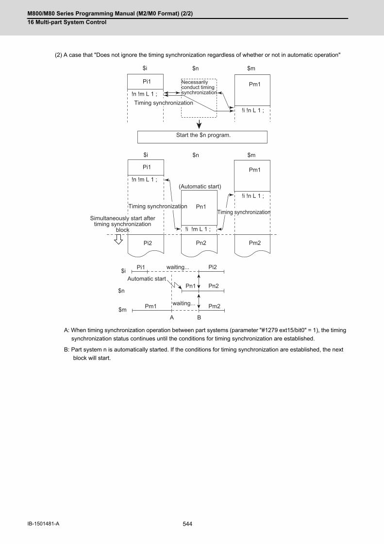
M800/M80 Series Programming Manual (M2/M0 Format) (2/2)
16 Multi-part System Control
544IB-1501481-A
(2) A case that "Does not ignore the timing synchronization regardless of whether or not in automatic operation"
A: When timing synchronization operation between part systems (parameter "#1279 ext15/bit0" = 1), the timing
synchronization status continues until the conditions for timing synchronization are established.
B: Part system n is automatically started. If the conditions for timing synchronization are established, the next
block will start.
!n !m L 1 ;
Pi1
Pn1
Pi2 Pn2
Pi1 Pi2
Pn1 Pn2
Pm1
Pm2
!i !m L 1 ;
!i !n L 1 ;
!n !m L 1 ;
Pi1 Pm1
!i !n L 1 ;
Pm1
A B
Pm2
$i $n $m
$i $n $m
$i
$n
$m
waiting...
waiting...
Start the $n program.
Timing synchronizationTiming synchronization
Timing synchronization
Necessarily conduct timing synchronization
(Automatic start)
Automatic start
Simultaneously start after timing synchronization
block

M800/M80 Series Programming Manual (M2/M0 Format) (2/2)
16 Multi-part System Control
545 IB-1501481-A
(3) A case that "Ignores the timing synchronization regardless of whether or not in automatic operation"
!n !m L 1 ;
!i !n L 1 ;
!i !m L1 ;
!n !m
!i !m
!i !n
Pi1
Pi2 Pn2
Pn1
Pi1 Pi2
Pm1
Pm2
Pm1
Pn1 Pn2
$i $n $m
$i
$n
$m
waiting...
Timing synchronization
Ignore timing synchronization
Timing synchronization operation ignore signal ON
$i and $n start simultaneously in the next block after timing synchronization.
$m timing synchronization
ignore signalPart system m is in the timing synchronization ignore state, so timing synchronization is not conducted.
Part system m does not conduct timing synchronization.
Ignore timing synchronization with part system m.
Timing synchronization
Ignore timing synchronization

M800/M80 Series Programming Manual (M2/M0 Format) (2/2)
16 Multi-part System Control
546IB-1501481-A
16.2 Mixed Control16.2.1 Arbitrary Axis Exchange; G140, G141, G142
With this function, an arbitrary axis can be exchanged freely across part systems.
The machining can be freer in the multiple part systems by exchanging an axis that can be commanded for machin-
ing programs in each part system.
This makes it possible to perform operations which are not possible with regular axis configurations: for instance,
tools which are provided only on the 1st part system can be used for machining on the 2nd part system.
This chapter illustrates an example based on the placements of the basis axes below.
Refer to "Programming Manual Lathe System" (IB-1501275, IB-1501276) for details of the arbitrary axis exchange.
Returns the control right of the axis, exchanged by the previous arbitrary axis exchange command (G140) in the
commanded part system, to the state before the axis exchange.
Returns the control right of the axis, exchanged by the arbitrary axis exchange command (G140) in the commanded
part system, to the power-on state.
Function and purpose
X axis Y axis Z axis C axis
1st part system ($1) X1 Y1 Z1 -
2nd part system ($2) X2 Y2 - C2
Command format
When commanding the arbitrary axis exchange
G140 command address = axis address ... ;
Command Address It is a command address used in a movement or other command after arbitrary axis exchange command (G140). Designate the command address with one alphabetical character set to parame-ters ("#12071 adr_abs[1]"to "#12078 adr_abs[8]") .
Axis address Set the axis name for arbitrary axis exchange. Designate the command with two alphanumeric characters set to the parameter "#1022 axname2".
When returning the exchanged axis
G141; Arbitrary axis exchange return
G142; Reference axis arrange return

M800/M80 Series Programming Manual (M2/M0 Format) (2/2)
16 Multi-part System Control
547 IB-1501481-A
There are two methods for axis exchange operations with arbitrary axis exchange command (G140). The methods
for your machine depends on the MTB specifications (parameter "#1434 G140Type2").
(1) Operation example of the method for exchanging all axes ("#1434 G140Type2"=0)
Below is the control axis of each part system when running the following machining programs (1st part system,
2nd part system)
Detailed description
Arbitrary axis exchange command (G140)
Method Operation
Method for exchanging all axes("#1434 G140Type2" = 0)
Designates axes to be used in the part system with a command address. The command addresses axes that are not designated will be released as uncon-trol axes.
Method for exchanging com-mand axes("#1434 G140Type2" = 1)
Designates axes to be used in the part system with a command address. The command addresses axes that are not designated will maintain the current state.
$1 $2 Control axesUncontrol
axesMachining program Machining program $1 $2
X Y Z X Y C
G140 X=X1 Y=Y1 Z=Z1; G00 X10.;G01 X5. F1; :
(a) G140 X=X2 Y=Y2 C=C2; G00 X20.;G01 X15. F2; :
(d)
X1 Y1 Z1 X2 Y2 C2 -
G140 X=X1 Y=Y2;G00 Y25.;G01 X8. F2; :
(b)
X1 Y2 -
X2 - C2 Y1,Z1
G140 Y=Z1; G00 Y10.;G01 Y8. F0.05; :
(e)
- Z1 - Y1,X2,C2
G140 X=X1 Y=Y1 Z=Z1; G00 X20. Y15.;G01 X15. F5; :
(c)
X1 Y1 Z1
- - - X2,Y2,C2
G140 X=X2 Y=Y2 C=C2; G00 X0; :
(f)X2 Y2 C2 -
1st part system ($1) (a),(c) Declares the use of X1 axis, Y1 axis and Z1 axis.
(b) Declares the use of X1 axis and Y2 axis. The control right of Y2 axis shifts to the 2nd part system from the 1st part sys-tem. Y1 axis, exchanged for Z1 axis and Y2 axis which were not designated, will be an uncontrol axis.
2nd part system ($2) (d),(f) Declares the use of X2 axis, Y2 axis and C2 axis.
(e) Declares the use of Z1 axis. X2 axis and C2 axis which were not designated will be uncontrol axes.
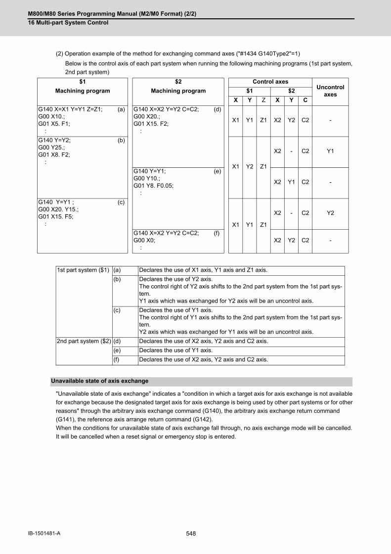
M800/M80 Series Programming Manual (M2/M0 Format) (2/2)
16 Multi-part System Control
548IB-1501481-A
(2) Operation example of the method for exchanging command axes ("#1434 G140Type2"=1)
Below is the control axis of each part system when running the following machining programs (1st part system,
2nd part system)
"Unavailable state of axis exchange" indicates a "condition in which a target axis for axis exchange is not available
for exchange because the designated target axis for axis exchange is being used by other part systems or for other
reasons" through the arbitrary axis exchange command (G140), the arbitrary axis exchange return command
(G141), the reference axis arrange return command (G142).
When the conditions for unavailable state of axis exchange fall through, no axis exchange mode will be cancelled.
It will be cancelled when a reset signal or emergency stop is entered.
$1 $2 Control axesUncontrol
axesMachining program Machining program $1 $2
X Y Z X Y C
G140 X=X1 Y=Y1 Z=Z1; G00 X10.;G01 X5. F1; :
(a) G140 X=X2 Y=Y2 C=C2; G00 X20.;G01 X15. F2; :
(d)
X1 Y1 Z1 X2 Y2 C2 -
G140 Y=Y2;G00 Y25.;G01 X8. F2; :
(b)
X1 Y2 Z1
X2 - C2 Y1
G140 Y=Y1;G00 Y10.;G01 Y8. F0.05; :
(e)
X2 Y1 C2 -
G140 Y=Y1 ;G00 X20. Y15.;G01 X15. F5; :
(c)
X1 Y1 Z1
X2 - C2 Y2
G140 X=X2 Y=Y2 C=C2; G00 X0; :
(f)X2 Y2 C2 -
1st part system ($1) (a) Declares the use of X1 axis, Y1 axis and Z1 axis.
(b) Declares the use of Y2 axis. The control right of Y2 axis shifts to the 2nd part system from the 1st part sys-tem. Y1 axis which was exchanged for Y2 axis will be an uncontrol axis.
(c) Declares the use of Y1 axis. The control right of Y1 axis shifts to the 2nd part system from the 1st part sys-tem. Y2 axis which was exchanged for Y1 axis will be an uncontrol axis.
2nd part system ($2) (d) Declares the use of X2 axis, Y2 axis and C2 axis.
(e) Declares the use of Y1 axis.
(f) Declares the use of X2 axis, Y2 axis and C2 axis.
Unavailable state of axis exchange

M800/M80 Series Programming Manual (M2/M0 Format) (2/2)
16 Multi-part System Control
549 IB-1501481-A
16.3 Sub Part System Control16.3.1 Sub Part System Control I; G122
This function activates and operates any non-operating part system (sub part system) in the multi-part system. Sub
part system control I can be used in the same manner as calling subprogram in a non-operating part system. An
auxiliary axis machining program can be controlled in the sub part system by commanding Sub part system control
I (G122) from the main part system.
In the usage example below, the tool positioning starts to the machining start point at the same time (time T1) as
the start of gantry retract by using Sub part system control I (G145) in the flow from feeding the workpiece to moving
to cut start position in order to reduce the cycle time.
Select whether main part system or sub part system for each part system in Sub part system control I. When using
a part system as a sub part system, by setting the operation mode to "Sub part system I operation mode" with the
PLC signal and commanding sub part system control I (G122) from an operating part system, it is possible to activate
the part system in the sub part system I operation mode as a sub part system.
The following describes the meanings of the terms used in this chapter.
The examples below shows many part systems to provide an easy-to-understand explanation. The actually avail-
able number of part systems depends on your machine's specifications.
Function and purpose
Term Meaning
Main part system Indicates a part system located on the uppermost stream side of a sub part system call flow.
Sub part system Indicates a part system activated by the sub part system activation command.
Calling part system Indicates a part system that issued the sub part system activation command.
($1)
T1 T2
T1 T2
T2:
T1:
($2)
($1)
(1) Feed the workpiece
(1)Feed the workpiece
Wait for completion of sub part system
(4)Move to cut start position
(2)Clamp the workpiece
(2) Clamp the workpiece
(3) Retract gantry
(3)Retract gantry
(4) Move to cut start position
Machining process when Sub part system control is OFF
Machining process when Sub part system control is ON
Main part system
Time when gantry retract is star
Time when gantry retract is comSub part system
Main part system
Sub part system startsTime
Time

M800/M80 Series Programming Manual (M2/M0 Format) (2/2)
16 Multi-part System Control
550IB-1501481-A
(1) This function can be used in multi-part systems of two or more part systems.
(2) In order to activate a sub part system using the sub part system control I command, the following conditions mustbe satisfied. There are conditions to enable functions that are only applicable to the M80 series.
[Condition 1]
This condition must only be satisfied for the M80 series.
The number of sub part systems has been set in the base common parameter "#1483 SBS1_sys num" (the num-
ber of part systems in sub part system I).
(a) Part systems as many as the number specified in #1483, counted from the end of the valid part system (the
part system for which "#1001 SYS_ON" is set to "1"), will be reserved as sub part systems.
(b) If the number of sub part systems or main part systems exceeds the maximum number defined in the system
specifications, an MCP alarm (Y05 1483) will occur.
(c) If the values set for "#1483 SBS1_sys num" and "#1474 SBS2_sys num" are both "1" or more, an MCP alarm
(Y05 1483) will occur.
[Condition 2]
The identification No. (B command value) used to activate a sub part system has been set in the base common
parameter "#12049 SBS_no" (sub part system I identification No.) for sub part systems.
(a) If an identification No. that is not set in the parameter "#12049 SBS_no" is specified when the sub part system
control I command is issued, a program error (P650) (sub part system identification No. illegal) will occur.
[Condition 3]
The PLC signal SBSM (Sub part system I operation mode) of the sub part system is set to "1".
(a) In a part system operating the sub part system I operation mode, the operation mode appears as "SUB" in
the part system display of the operation screen.
(b) If the sub part system control I command is issued to a part system that is not operating the sub part system
I operation mode, an operation error (M01 1111) will occur. However, while the operation error (M01 1111)
is occurring, the operation can be started by setting SBSM to "1".
Enabling conditions
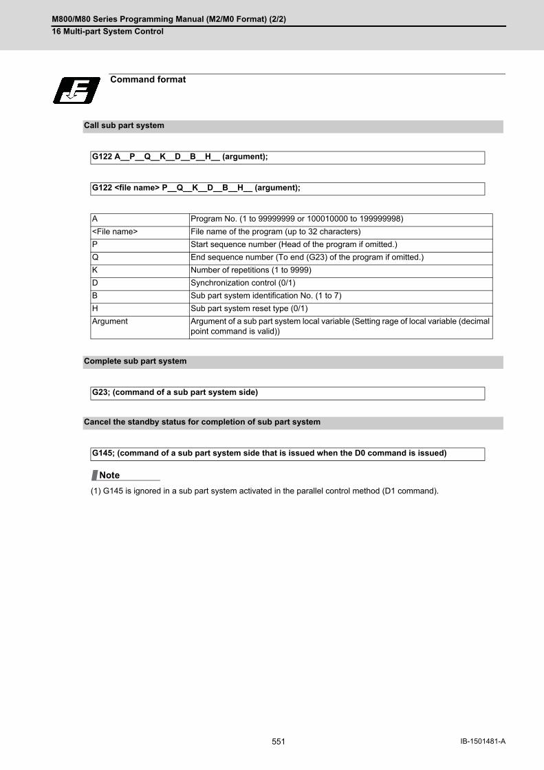
M800/M80 Series Programming Manual (M2/M0 Format) (2/2)
16 Multi-part System Control
551 IB-1501481-A
(1) G145 is ignored in a sub part system activated in the parallel control method (D1 command).
Command format
Call sub part system
G122 A__P__Q__K__D__B__H__ (argument);
G122 <file name> P__Q__K__D__B__H__ (argument);
A Program No. (1 to 99999999 or 100010000 to 199999998)
<File name> File name of the program (up to 32 characters)
P Start sequence number (Head of the program if omitted.)
Q End sequence number (To end (G23) of the program if omitted.)
K Number of repetitions (1 to 9999)
D Synchronization control (0/1)
B Sub part system identification No. (1 to 7)
H Sub part system reset type (0/1)
Argument Argument of a sub part system local variable (Setting rage of local variable (decimal point command is valid))
Complete sub part system
G23; (command of a sub part system side)
Cancel the standby status for completion of sub part system
G145; (command of a sub part system side that is issued when the D0 command is issued)
Note

M800/M80 Series Programming Manual (M2/M0 Format) (2/2)
16 Multi-part System Control
552IB-1501481-A
This function can be used in multi-part systems of two or more part systems.
Main part system and sub part system are switched according to the MTB specifications.
Detailed description
Description of each address
Address Meaning of ad-dress
Command range (unit)
Remarks
A Program No. 1 to 99999999or100010000 to 199999998 (*1)
Program No. or file name of the machining program op-erating in the sub part system.
Programs in external device cannot be designated.If address A and <file name> are designated at the
same time, precedence is given to address A.If designation of the program is omitted, the ma-
chining program defined by the MTB will be used(parameter "#12050 SBS_pro").
<File name> File name of the pro-gram
Up to 32 characters.
P Start sequence No. 1 to 99999999 Sequence No. to start the machining program operating in the sub part system.
If there is no command, the operation will start fromthe head of the machining program.
Q End sequence No. 1 to 99999999 Sequence No. to end the machining program operating in the sub part system.
If there is no command, the program will run up toG23.
K Number of repeti-tions
1 to 9999 The number of times to repeat the machining program for continuous operation in the sub part system.
If there is no command, the program will run onlyonce. (No repetition)
D Synchronization control
0 / 1 Validity of synchronous control0: The next block is processed after the sub part system operation completes. 1: The next block is processed at the same time as the start of a sub part system operation. If there is no command, it is handled in the same man-ner as 0 is designated.
B Sub part system identification No.
1 to 7 Identification No. used for timing synchronization with sub part system, etc.
The sub part system to be activated is designatedby an identification No. The correspondence be-tween identification No. and part system No. de-pends on the MTB specifications (parameter"#12049 SBS_no").
If there is no command, it is handled in the samemanner as 1 is designated.
H Sub part system re-set type (*2)
0 / 1 0: The G command modal is maintained by the reset when a sub part system is complete. 1: The G command modal is initialized by the reset when a sub part system is complete.
If there is no command, it is handled in the samemanner as 0 is designated.
(Argument) Argument of a sub part system local variable
Setting range of lo-cal variable(Decimal point com-mand is possible.)
Argument is passed to the sub part system as a lo-cal variable (level 0). However, addresses A, B, D, G, H, K, O, P, and Qcannot be used as an argument.
For the correspondence between address and vari-able number, refer to the following table.

M800/M80 Series Programming Manual (M2/M0 Format) (2/2)
16 Multi-part System Control
553 IB-1501481-A
(*1) When the parameter "#1253 set25/bit0" is set to "1", the command range is "100010000 to 199999989".
(*2) If a sub part system ends by G23 or the end sequence No., resetting processing is performed automatically in
the sub part system.
(1) Addresses can be designated in an arbitrary order.
(2) Addresses which do not need to be designated can be omitted.
(3) Local variables in a sub part system are initialized every time the sub part system is activated. Default value is<empty>.
(4) To use local variables in a sub part system, user macros must be available. For the available functions of eachmodel, refer to the list.
(1) The operation mode of sub part systems is used as "sub part system I operation mode". If the memory mode/MDI mode and the sub part system I operation mode are entered at the same time, the stop code (T01 0108)will be generated.
(2) In a part system operating the sub part system I operation mode, the operation mode appears as "SUB" in thepart system display of the operation screen. If an alarm or warning occurs in a sub part system, the part system No. appears as "SUB" in the alarm/warningmessage of the operation screen.
(3) If the sub part system control I command is issued to a part system that is not operating the sub part system Ioperation mode, an operation error (M01 1111) will occur.
When issuing the sub part system control I command, designate the sub part system identification No. with com-
mand address B. (When there is no B command, it will be handled as the B1 command.) The sub part system iden-
tification No. and the sub part system No. to be called depend on the MTB specifications. (Parameter "#12049
SBS_no")
(Example 1) and (Example 2) show the operations when parameters are set as shown below.
The available number of part systems depends on your machine's specifications.
Correspondence of argument designation address and variable number in sub part system
Argument designa-tion address
Variable number in sub part system
Argument designa-tion address
Variable number in sub part system
A - N #14
B - O -
C #3 P -
D - Q -
E #8 R #18
F #9 S #19
G - T #20
H - U #21
I #4 V #22
J #5 W #23
K - X #24
L #12 Y #25
M #13 Z #26
Operation mode of a sub part system
Activation part system of a sub part system
#12049 SBS_no Sub part system I identification No.
$1 $2 $3 $4 $5 $6 $7 $8
0 0 0 0 1 2 3 4
Note

M800/M80 Series Programming Manual (M2/M0 Format) (2/2)
16 Multi-part System Control
554IB-1501481-A
(Example 1) If the B command is omitted, $5 corresponding to B1 will be activated.
(Example 2) Sub part system identification No. (the part system No. to be activated and correspondence) can
be specified with the B command.
When issuing the sub part system control I command, designate the program No. or program name to be operated
in the sub part system with command address A or <file name>. If designation of the program is omitted, the ma-
chining program set in parameter "#12050 SBS_pro" will be started.
If a machining program is managed for each part system, the program of the part system designated as a sub part
system will be operated (*1). If a machining program is commonly managed between part systems, the designated
program will be operated.
(*1) If the program of the part system No. for the sub part system is empty, the program of the 1st part system ($1)
will be operated. If the program of the 1st part system is also empty, a program error (P461) will occur.
(1) If program is managed for each part system
Calling part system ($1) Sub part system ($5)
Calling part system ($1) Sub part system ($7)
Operation program of a sub part system
: :G122 A100 D0; : :
: : :G23;
: :G122 A100 D0 B3; : :
: : :G23;
:
:
G23;
:
: G122 A100 D0 B3 :
$1
$2
$3
$4
$5
$6
$7
$8
L100 - $7
L1 - $1
L100Caller part system ($1)
$7 is assumed to be started by B3 command.
Sub part system ($7)
When $7 is blank, $1 data will be called.
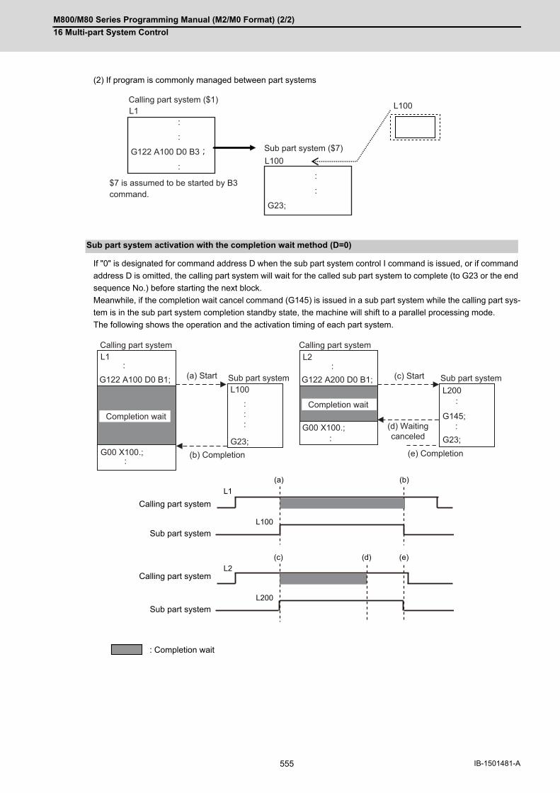
M800/M80 Series Programming Manual (M2/M0 Format) (2/2)
16 Multi-part System Control
555 IB-1501481-A
(2) If program is commonly managed between part systems
If "0" is designated for command address D when the sub part system control I command is issued, or if command
address D is omitted, the calling part system will wait for the called sub part system to complete (to G23 or the end
sequence No.) before starting the next block.
Meanwhile, if the completion wait cancel command (G145) is issued in a sub part system while the calling part sys-
tem is in the sub part system completion standby state, the machine will shift to a parallel processing mode.
The following shows the operation and the activation timing of each part system.
Sub part system activation with the completion wait method (D=0)
Calling part system
Sub part system
Calling part system
Sub part system
: Completion wait
:
:
G23;
:
:
G122 A100 D0 B3;
:L100
L1 L100Calling part system ($1)
Sub part system ($7)
$7 is assumed to be started by B3 command.
L1 L2
G00 X100.;
L100 L200
G23;
G145;
G23;G00 X100.;
G122 A100 D0 B1; G122 A200 D0 B1;:
:::
:
::
:
:
Calling part system Calling part system
Sub part system Sub part system(a) Start (c) Start
(d) Waitingcanceled
(e) Completion(b) Completion
Completion waitCompletion wait
(a) (b)
L100
L1
L200
L2(c) (e)(d)
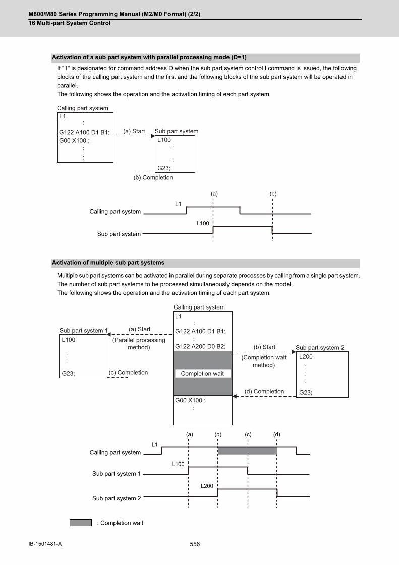
M800/M80 Series Programming Manual (M2/M0 Format) (2/2)
16 Multi-part System Control
556IB-1501481-A
If "1" is designated for command address D when the sub part system control I command is issued, the following
blocks of the calling part system and the first and the following blocks of the sub part system will be operated in
parallel.
The following shows the operation and the activation timing of each part system.
Multiple sub part systems can be activated in parallel during separate processes by calling from a single part system.
The number of sub part systems to be processed simultaneously depends on the model.
The following shows the operation and the activation timing of each part system.
Activation of a sub part system with parallel processing mode (D=1)
Calling part system
Sub part system
Activation of multiple sub part systems
Calling part system
Sub part system 1
Sub part system 2
: Completion wait
G122 A100 D1 B1;:
:
:::
G00 X100.;
L1
L100
G23;
Calling part system
Sub part system(a) Start
(b) Completion
(a) (b)
L100
L1
L1
L200
G00 X100.;
G23;
L100
G23;
G122 A100 D1 B1;
G122 A200 D0 B2;:
::
:::
:
:
Sub part system 1
Calling part system
(Parallel processing method)
(Completion wait method)
(a) Start
Completion wait
(b) Start
(d) Completion
(c) Completion
Sub part system 2
(a) (c)
L100
L1
L200
(b) (d)

M800/M80 Series Programming Manual (M2/M0 Format) (2/2)
16 Multi-part System Control
557 IB-1501481-A
A sub part system can be activated from another sub part system.
The number of sub part systems to be processed simultaneously depends on the model.
The following shows the operation and the activation timing of each part system.
Activate a sub part system from another sub part system
Calling part system
Sub part system 1
Sub part system 2
: Completion wait
L1
L100
L200
G23;
G23;
G00 X100.;
G122 A100 D0 B1;
G122 A200 D0 B2;
:
::
::
::
:
Calling part system
Completion wait Completion wait
(a) Start
(d) Completion
(c) Completion
(b) Start
Sub part system 1
Sub part system 2
(a) (c)
L100
L1
L200
(b) (d)

M800/M80 Series Programming Manual (M2/M0 Format) (2/2)
16 Multi-part System Control
558IB-1501481-A
If G122 is commanded while a sub part system is being activated, using the same identification No. (B command),
the machine will wait for the earlier sub part system to complete activation, before activating the next sub part sys-
tem.
Sub part system activation command to a sub part system being activated
Calling part system 1
Calling part system 2
Sub part system
: Completion wait : Standby
L1 L2
G00 X-20.;
L100
G23;
G23;
L200G00 X100.;
(b)
:
::
:
:::
G122 A100 D0 B1;
G122 A200 D1 B1;
:::
:::
Calling part system 1
(a) Start
(c) Completion
(e) Completion
(d) StartWait for vacancy of
sub part system
Completion wait
Sub part system
Calling part system 2
(Identification No. 1)
(a)
L1
L100 L200
L2
(b) (c) (d) (e)

M800/M80 Series Programming Manual (M2/M0 Format) (2/2)
16 Multi-part System Control
559 IB-1501481-A
In the following example, the machining start timing is accelerated by controlling auxiliary axis with a sub part system
and operating the main part system and the sub part system in parallel. The tool positioning starts to the machining
start point at the same time (time T1) as the start of gantry retract by using sub part system completion wait cancel
command (G145) in the flow from mounting the workpiece to moving to cut start position, after feeding and mounting
the workpiece with the gantry, in order to reduce the cycle time. (The machine configuration below is a sample only.)
(1) Machining process when sub part system control is OFF
After the gantry is retracted, cut start position is determined.
Operation example
[Axis configuration]
Main part system ($1) : X1 axis, Z1 axis => ToolSub part system ($2) : X2 axis, Z2 axis => Workpiece feed gantry
[Machining process]
(a) Feed workpiece(b) Clamp workpiece(c) Retract gantry(d) Move to cut start position
Main part system ($1)
L1
:
G140 X=X2 Z=Z2; ... (a)
G00 X50.;
G00 Z20.;
M20; ... (b)
G00 X0. Z0. ; ... (c) G140: Arbitrary axis exchange command
G141; G141: Arbitrary axis exchange return command
G00 X30. Z-15.; ... (d) M20 : M code of workpiece mounting
G01 Z-20. F10.;
:
Main part system ($1)
Time
Time when gantry retract is started Time when gantry retract is completed
(a) (b) (c) (d)
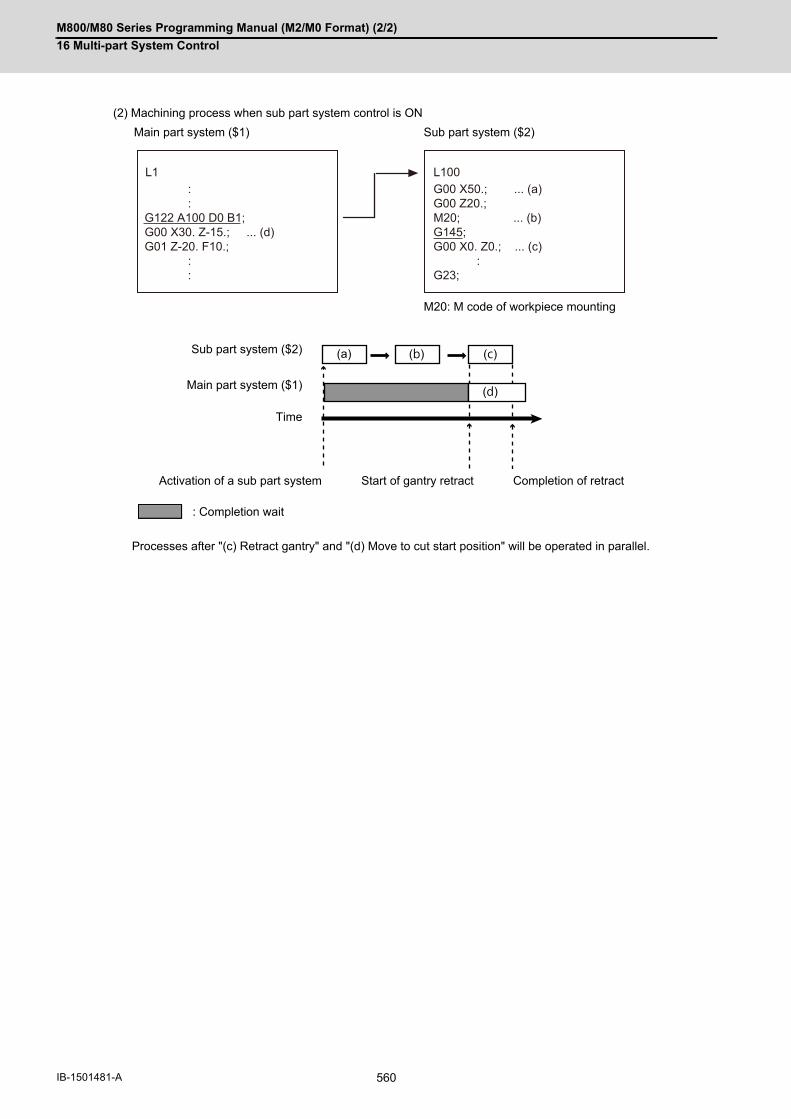
M800/M80 Series Programming Manual (M2/M0 Format) (2/2)
16 Multi-part System Control
560IB-1501481-A
(2) Machining process when sub part system control is ON
Processes after "(c) Retract gantry" and "(d) Move to cut start position" will be operated in parallel.
Main part system ($1) Sub part system ($2)
M20: M code of workpiece mounting
Sub part system ($2)
Main part system ($1)
Time
Activation of a sub part system Start of gantry retract Completion of retract
: Completion wait
L1 L100 : :G122 A100 D0 B1;G00 X30. Z-15.; ... (d)G01 Z-20. F10.; : :
G00 X50.; ... (a)G00 Z20.;M20; ... (b)G145;G00 X0. Z0.; ... (c) :G23;
(a) (b) (c)
(d)

M800/M80 Series Programming Manual (M2/M0 Format) (2/2)
16 Multi-part System Control
561 IB-1501481-A
While a sub part system is under control, timing synchronization between part systems can be issued with the "![Part
system No.]" command. To synchronize timing between a main part system and a sub part system, or between sub
part systems, it is also possible to designate a sub part system identification No. (B command) as shown below.
However, the number of part systems that can be used is limited by the specifications.
For example, to synchronize timing with the calling part system, command "![0]". Note that, designate the calling part
system with "![0]", not the main part system.
(Example 1) and (Example 2) shown below are examples of the timing synchronization operation between the main
part system ($3), sub part system 1 ($5, identification No. 1), and sub part system 2 ($6, identification No. 2).
(Example 1) Timing synchronization by designating a part system No.
(Example 2) Timing synchronization by designating a sub part system identification No.
Relationship with other functions
Timing synchronization with sub part system
![Sub part system identification No.]
Main part system ($3) Sub part system 1 ($5) Sub part system 2 ($6)
Timing synchronization with 5th and 6th part systems
Timing synchronization with 3rd and 6th part systems
Timing synchronization with 3rd and 5th part systems
Main part system ($3) Sub part system 1 ($5, identi-fication No. 1)
Sub part system 2 ($6, identifi-cation No. 2)
Timing synchronization with the following part system
Sub part system of iden-tification No. 1
Sub part system of iden-tification No. 2
Timing synchronization with the following part system
Calling part system ($3)Sub part system of iden-
tification No. 2
Timing synchronization with the following part system
Calling part system ($3)Sub part system of identi-
fication No. 1
:G122 A100 D1 B1;G122 A200 D1 B2; :!5!6;G00 X100.; : :
: : : :!3!6; : : :
: : : :!3!5; : : :
:G122 A100 D1 B1;G122 A200 D1 B2; :![1]![2];G00 X100.; :
: : : :![0]![2]; : :
: : : :![0]![1]; : :
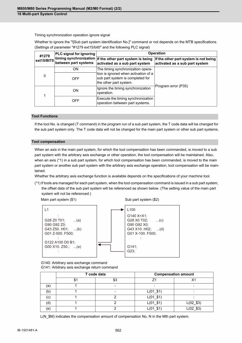
M800/M80 Series Programming Manual (M2/M0 Format) (2/2)
16 Multi-part System Control
562IB-1501481-A
Timing synchronization operation ignore signal
Whether to ignore the "![Sub part system identification No.]" command or not depends on the MTB specifications.
(Settings of parameter "#1279 ext15/bit0" and the following PLC signal)
If the tool No. is changed (T command) in the program run of a sub part system, the T code data will be changed for
the sub part system only. The T code data will not be changed for the main part system or other sub part systems.
When an axis in the main part system, for which the tool compensation has been commanded, is moved to a sub
part system with the arbitrary axis exchange or other operation, the tool compensation will be maintained. Also,
when an axis (*1) in a sub part system, for which tool compensation has been commanded, is moved to the main
part system or another sub part system with the arbitrary axis exchange operation, tool compensation will be main-
tained.
Whether the arbitrary axis exchange function is available depends on the specifications of your machine tool.
(*1) If tools are managed for each part system, when the tool compensation command is issued in a sub part system,
the offset data of the sub part system will be referenced as shown below. (The setting value of the main part
system will not be referenced.)
L(N_$M) indicates the compensation amount of compensation No. N in the Mth part system.
#1279 ext15/BIT0
PLC signal for ignoring timing synchronization between part systems
Operation
If the other part system is being activated as a sub part system
If the other part system is not being activated as a sub part system
0
ON The timing synchronization opera-tion is ignored when activation of a sub part system is completed for the other part system.
Program error (P35)
OFF
1ON
Ignore the timing synchronization operation.
OFFExecute the timing synchronization operation between part systems.
Tool Functions
Tool compensation
Main part system ($1) Sub part system ($2)
G140: Arbitrary axis exchange commandG141: Arbitrary axis exchange return command
T code data Compensation amount
$1 $3 Z1 X1
(a) 1 - : :
(b) 1 - L(01_$1) :
(c) 1 2 L(01_$1) :
(d) 1 2 L(01_$1) L(02_$3)
(e) 1 2 L(01_$1) L(02_$3)
L1
:G28 Z0 T01; ...(a)G90 G92 Z0;G43 Z50. H01; ...(b)G01 Z-500. F500; :G122 A100 D0 B1;G00 X10. Z50.; ...(e) :
L100
G140 X=X1;G28 X0 T02; ...(c)G90 G92 X0;G43 X10. H02; ...(d)G01 X-100. F500; :
G141;G23;

M800/M80 Series Programming Manual (M2/M0 Format) (2/2)
16 Multi-part System Control
563 IB-1501481-A
The sub part system control I command does not affect nesting in user macros and subprograms. It can be com-
manded from a subprogram nested at the deepest level.
(1) If the NC reset signal is input to the main part system, the operation of the main part system will be reset andend immediately. However, the operation of sub part systems will continue. The reset operation of the sub partsystem follows the NC reset signal of the sub part system.
(2) If the NC reset signal is input to an operating sub part system, the operation of the sub part system will end im-mediately. Therefore, if the calling part system is in the sub part system completion standby state, the sub partsystem is reset, and at the same time, the calling part system cancels the standby state, and the following blockwill be executed.
If both of the following conditions (1) and (2) are satisfied, the buffer correction is disabled. (The buffer correction
window will not open even if the program correction key is pressed.)
(1) The next block is G122 command (including "macro statement + G122 command").
(2) The program designated by G122 is the same as that of the calling part system.
The completion wait time of the sub part system control I command (G122) will not be added to the machining time
computation for the main part system.
If the restart search from the block of the G122 command is attempted, a program error (P49) will occur.
If the sub part system control I (G122) is commanded during the following G command modal, a program error
(P652) will occur.
User macro modal call (G66, G66.1)Fixed cycle modalHigh-speed machining mode (G05P1, G05P2)High-speed high-accuracy mode (G05.1Q1, G05P10000, G05P20000)
The sub part system control I (G122) is ignored at the reverse run or the forward run after the reverse run.
Because the sub part systems are in a mode in which reverse run is prohibited, reverse run cannot be carried out
in sub part systems.
User macro
Resetting
Buffer correction
L100
:
G00 Z50.; Buffer correction possible
G00 X100.; Buffer correction impossible
G122 A100 P77 D0 B1; Designated program is the program of its own part system (L100)
G00 Y30.; Buffer correction possible
:
N77
: Program operated in sub part system
G23;
Machining time computation
Program restart
Illegal modal of a sub part system control I command
Manual arbitrary reverse run

M800/M80 Series Programming Manual (M2/M0 Format) (2/2)
16 Multi-part System Control
564IB-1501481-A
(1) The sub part system control I command (G122) is a G code that must be issued alone. If it is commanded in thesame block together with another G code, a program error (P651) or (P32) will occur.If another G code is commanded prior to G122 (for example, G00 G122), a program error (P651) will occur.If another G code is commanded following G122 (for example, G122 G00), a program error (P32) will occur.
(2) While the sub part system I operation mode is in operation, even if the sub part system is not being activated,automatic operation cannot be started with the automatic operation start signal (ST). The stop code (0146) willbe generated. However, when a sub part system is being activated, automatic operation is started with the au-tomatic operation start signal (ST).
(3) If a sub part system identification No. of its own part system is designated for the B command with the sub partsystem control I command (G122), a program error (P650) will occur.
(4) The PLC signal of the sub part system references the state of the sub part system. (The signal state of the mainpart system will not be taken over.)
(5) Parameters per part system of the sub part system follow the setting in the sub part system. Therefore, param-eters must also be set in the sub part system.
(6) If the sub part system completion wait cancel command (G145) is issued in the main part system, the programerror (P34) will occur.
(7) Operation executed by M80 is as follows. These parameter settings depend on the MTB specifications.Activation of a sub part system is only possible in sub part systems that are reserved using the parameter
"#1483 SBS1_sys num". If the sub part system activation command is issued to a main part system (*1),an operation error (M01 1111) will occur. (*1) This refers to a case in which the Sub part system I operation mode is established (SBSM: ON) usingthe PLC signal before G122 is commanded.Operation searches cannot be carried out in sub part systems that are reserved using the parameter "#1483
SBS1_sys num".If the values set for the parameters "#1483 SBS1_sys num" and "#1474 SBS2_sys num" are both "1" or
more, an MCP alarm (Y05 1483) will occur.
Precautions

17
565 IB-1501481-A
High-speed High-accuracy Control

M800/M80 Series Programming Manual (M2/M0 Format) (2/2)
17 High-speed High-accuracy Control
566IB-1501481-A
17High-speed High-accuracy Control17.1 High-speed Machining Mode
17.1.1 High-speed Machining Mode I, II; G05 P1, G05 P2
This function runs a machining program for which a freely curved surface has been approximated by fine segments
at high speed.
A higher fine segment processing capability leads to a faster cutting speed, resulting in a shorter cycle time and a
better machining surface quality.
The high-speed high-accuracy control I/II/III enable not only the high-speed machining mode but also the high-ac-
curacy control mode. Use the high-speed high-accuracy control I/II/III for machining which needs to make an edge
at a corner or reduce an error from an inner route of curved shape.
This function can be used simultaneously for up to two part systems depending on the MTB specifications.
kBPM, the unit for the fine segment processing capability, is an abbreviation of "kilo blocks per minute" and refers
to the number of machining program blocks that can be processed per minute.
In the main text, the axis address refers to the address of an axis that exits on the machine.
It corresponds to the address designated in the parameters "#1013 axname" and "#1014 incax".
These parameter settings depend on the MTB specifications.
G01 block fine segment capacity for 1mm segment (unit: kBPM)
(1) The above performance applies under the following conditions.
6-axis system (including spindle) or less1-part system3 axes or less commanded simultaneously in G01The block containing only the axis name and movement amount (Macro and variable command are not in-
cluded.)In the "G61.1" high-accuracy control mode or cutting mode (G64)During tool radius compensation cancel (G40) (only in the high-speed machining mode II)The parameter "#1259 set31/bit1" is set to "1". (The number of machining blocks per unit time is set to "low-
speed mode".)
When the above conditions are not satisfied, the given feedrate may not be secured.
(2) The performance in the table may vary depending on the combination with other function.
Function and purpose
For one part system
Mode Command Maximum feedrate when 1mm segment G01 block is executed (kBPM)
M850/M830 M80
Type A Type B
High-speed machining mode I
G05 P1 33.7 33.7 16.8
High-speed machining mode II
G05 P2 168 67.5 -
Note

M800/M80 Series Programming Manual (M2/M0 Format) (2/2)
17 High-speed High-accuracy Control
567 IB-1501481-A
G01 block fine segment capacity for 1mm segment (unit: kBPM)
(*1) This system cannot be used for this model.
(*2) There are no high-speed machining mode II specifications.
(1) The above performance applies under the following conditions.
3 axes commanded simultaneously in G01The block containing only the axis name and movement amount (Macro and variable command are not in-
cluded.)Tool radius compensation cancel (G40) modeThe parameter "#1259 set31/bit1" is set to "1". (The number of machining blocks per unit time is set to "low-
speed mode".)
When the above conditions are not satisfied, the given feedrate may not be secured.
(2) The performance in the table may vary depending on the combination with other function.
(3) The number of part systems and axes that can be used depends on the specifications of your machine tool.
Multi-part system (high-speed machining mode II)
Maximum feedrate when 1mm segment G01 block is exe-cuted (kBPM)
M850/M830 M80
Type A Type B
1-part system 1 part system 168 67.5 - (*2)
2-part system 1 part system only 100 67.5 - (*2)
Two part systems si-multaneously
67.5 33.7 - (*2)
4-part systemUp to 16 axes
1 part system only - (*1) - (*1) - (*2)
Two part systems si-multaneously
- (*1) - (*1) - (*2)
5 part systems or moreor 17 axes or more
1 part system only - (*1) - (*1) - (*2)
Two part systems si-multaneously
- (*1) - (*1) - (*2)
Note

M800/M80 Series Programming Manual (M2/M0 Format) (2/2)
17 High-speed High-accuracy Control
568IB-1501481-A
In addition to the G05 P0 command, the high-speed machining mode I is canceled when the high-speed machining
mode II (G05 P2) is commanded.
In reverse, the high-speed machining mode II is canceled when the high-speed machining mode I (G05 P1) is com-
manded.
Command G05 in an independent block. A program error (P33) will occur if a movement or other command is addi-
tionally issued in a G05 command block. A program error (P33) will also occur if there is no P command in a G05
command.
In addition to cancel the high-speed machining mode II, a G05 P0 command is also used to cancel the high-speed
high-accuracy control II/III.
Refer to "17.3 High-speed High-accuracy Control" for details.
Command format
High-speed machining mode I ON
G05 P1 ;
High-speed machining mode II ON
G05 P2 ;
High-speed machining mode I/II OFF
G05 P0 ;

M800/M80 Series Programming Manual (M2/M0 Format) (2/2)
17 High-speed High-accuracy Control
569 IB-1501481-A
(1) The override, maximum cutting speed clamp, single block operation, dry run, manual interruption and graphictrace and high-accuracy control mode are valid even during the high-speed machining mode I/II. For a part system that uses the high-speed machining mode II, "1" must be set for the parameter "#8040 High-SpeedAcc". By default, the high-speed machining mode II can only be used in the first part system.
(2) When using the high-speed machining mode II, setting to eliminate the speed fluctuation at the seams betweenthe arc and the straight line, or between arcs depends on the MTB specifications (parameter "#1572 Cirorp/bit1").
(3) Combination with high-accuracy controlThe high-speed machining mode and high-accuracy control can be used simultaneously by taking the followingsteps: (a) Set "1" for the parameter "#8040 High-SpeedAcc". (b) Command "G05 P2" and "G08 P1" or "G61.1" from the machining program. The parameter "#8040 High-SpeedAcc" can be set to "1" for up to two part systems. If "0" is set for all part sys-tems, the first and second part systems can use the high-speed machining mode and high-accuracy control si-multaneously. Also refer to the following for the description of each function:
High-accuracy control: "17.2 High-accuracy control"Simultaneous usage of the high-speed machining mode and high-accuracy control: "17.3 High-speed High-
accuracy Control"
(4) While high-speed machining mode II is valid, the following variable commands or operation commands can bedesignated following the axis address. When other variable commands or operation commands are issued, high-speed machining mode II is canceled temporarily. (a) Referencing common variables or local variablesCommon variables or local variables can be referenced (example: X#500, Y#1, Z##100, A#[#101], etc.). (b) Four basic arithmetic ruleFour basic arithmetic rule (+, -, *, /) operations are available, and also the operation priority can be designatedusing parentheses ( ) ([#500+1.0]*#501, etc.).
Detailed description
Program example
High-speed machining mode I
G28 X0. Y0. Z0. ;
G91 G00 X-100. Y-100. ;
G01 F10000 ;
G05 P1 ; High-speed machining mode I ON
:
X0.1 Y0.01 ;
X0.1 Y0.02 ;
X0.1 Y0.03 ;
:
G05 P0 ; High-speed machining mode I OFF
M30 ;

M800/M80 Series Programming Manual (M2/M0 Format) (2/2)
17 High-speed High-accuracy Control
570IB-1501481-A
Column A: Operation when the additional function is commanded while the high-speed machining mode II is en-
abled
Column B: Operation when the high-speed machining mode II (G05P2) is commanded while the additional function
is enabled
○: The high-speed machining mode II and the additional function are both enabled
∆: The high-speed machining mode II is temporarily canceled, while the additional function is enabled
x: Alarm generation (the text in parentheses refers to the number of the program error to be generated.)
-: No combination
□: Others
Relationship with other functions
Relationship between the high-speed machining mode II and G code functions
Group G code Function name A B
0 G04 Dwell ∆ -
G05P0 High-speed machining mode II OFFHigh-speed high-accuracy control II OFFHigh-speed high-accuracy control III OFF
□ (*1) □ (*2)
G05P2 High-speed machining mode II ON □ (*3) □ (*3)
G05P10000 High-speed high-accuracy control II ON □ (*2) □ (*2)
G05P20000 High-speed high-accuracy control III ON □ (*2) □ (*3)
G05.1Q0 High-speed high-accuracy control I OFFSpline interpolation OFF
□ (*3) □ (*2)
G05.1Q1 High-speed high-accuracy control I ON □ (*2) □ (*2)
G05.1Q2 Spline interpolation ON ○ ○
G07 Hypothetical axis interpolation ∆ ∆
G08P0 High-accuracy control OFF □ (*3) □ (*2)
G08P1 High-accuracy control ON □ (*4) □ (*4)
G09 Exact stop check ∆ -
G10 I_J_G10 K_
Parameter coordinate rotation input ∆ -
G10 L2 Compensation data input by program ∆ -
G10 L70G10 L50
Parameter input by program ∆ -
G27 Reference position check ∆ -
G28 Reference position return ∆ -
G29 Start position return ∆ -
G30 2nd to 4th reference position return ∆ -
G30.1-G30.6
Tool change position return ∆ -
G31 SkipMultiple-step skip 2
∆ -
G31.1-G31.3
Multi-step skip ∆ -
G34-G37 Special Fixed Cycle ∆ -
G37.1 Automatic tool length measurement ∆ -
G38 Tool radius compensation vector designation ∆ -
G39 Tool radius compensation corner circular command
∆ -

M800/M80 Series Programming Manual (M2/M0 Format) (2/2)
17 High-speed High-accuracy Control
571 IB-1501481-A
Group G code Function name A B
0 G52 Local coordinate system setting ∆ -
G53 Machine coordinate system selection ∆ -
G60 Unidirectional positioning ∆ -
G65 User macro simple call □ (*5) □ (*6)
G92 Coordinate system setting ∆ -
G92.1 Workpiece coordinate system preset ∆ -
G122 Sub part system control I ×(P652) □ (*7)
1 G00 Positioning ∆ ∆
G01 Linear interpolation ○ ○
G02G03
Circular interpolation ○ ○
G02.1G03.1
Spiral interpolation ∆ ∆
G02.3G03.3
Exponential interpolation ∆ ∆
G02.4G03.4
3-dimensional circular interpolation ∆ ∆
G06.2 NURBS interpolation ○ ○
G33 Thread cutting ∆ ∆
2 G17 to G19 Plane selection ○ ○
3 G90 Absolute value command ○ ○
G91 Incremental value command ○ ○
4 G22.1 Stroke check before travel ON ∆ ∆
G23.1 Stroke check before travel OFF ○ ○
5 G93 Inverse time feed ∆ ∆
G94 Asynchronous feed (feed per minute) ○ ○
G95 Synchronous feed (feed per revolution) ∆ ∆
6 G20 Inch command ○ ○
G21 Metric command ○ ○
7 G40 Tool radius compensation cancel ○ ○
G41G42
Tool radius compensation ○ ○
8 G43 Tool length offset ○ ○
G43.1 Tool length compensation along the tool axis
○ ○
G43.4G43.5
Tool center point control ○ ○
G44 Tool length offset cancel ○ ○
9 G80 Fixed cycle cancel ○ ○
Group 9Other than G80
Fixed cycle ∆ ∆

M800/M80 Series Programming Manual (M2/M0 Format) (2/2)
17 High-speed High-accuracy Control
572IB-1501481-A
(*1) Disables the high-speed machining mode II.
(*2) Enables the high-speed machining mode II.
(*3) High-speed machining mode II continues.
(*4) Enables the high-speed machining mode II and high-accuracy control.
(*5) Enables the high-speed machining mode II in a macro program.
(*6) Enables the high-speed machining mode II if G05P2 is commanded in a macro program.
(*7) Enables the high-speed machining mode II if G05P2 is commanded in a sub part system.
Group G code Function name A B
10 G98 Fixed cycle initial level return ○ ○
G99 Fixed cycle R point return ○ ○
11 G50 Scaling cancel ○ ○
G51 Scaling ON ∆ ∆
12 G54 to G59G54.1
Workpiece coordinate system selection ○ ○
13 G61 Exact stop check mode ∆ ∆
G61.1 High-accuracy control ○ ○
G61.2 High-accuracy spline ○ ○
G63 Tapping mode ∆ ∆
G64 Cutting mode ○ ○
14 G66G66.1
User macro modal call ∆ ∆
G67 User macro modal call ○ ○
Cancel
15 G40.1 Normal line control cancel ○ ○
G41.1G41.2
Normal line control ×(P29) ×(P29)
16 G68.1 Coordinate rotation by program ON ∆ ∆
G68.2G68.3
Inclined surface machining command ○ ○
G69.1 Coordinate rotation cancel ○ ○
17 G96 Constant surface speed control ON ○ ○
G97 Constant surface speed control OFF ○ ○
18 G15 Polar coordinate command OFF ○ ○
G16 Polar coordinate command ON ∆ ∆
19 G50.1,G62 Mirror image OFF ○ ○
G51.1, G62 Mirror image ON ○ ○
21 G07.1 Cylindrical interpolation ×(P34) ×(P481)
G12.1 Polar coordinate interpolation ON ×(P34) ×(P481)
G13.1 Polar coordinate interpolation OFF ○ ○
24 G188 Dynamic M/L program changeover ○ ○
G189 Dynamic M/L program changeovercancel
○ ○
27 G54.4P0 Workpiece installation error compensation cancel
○ ○
G54.4P1 to P7
Workpiece installation error compensation ○ ○

M800/M80 Series Programming Manual (M2/M0 Format) (2/2)
17 High-speed High-accuracy Control
573 IB-1501481-A
Column A: Operation when the additional function is commanded while the high-speed machining mode II is en-
abled
Column B: Operation when the high-speed machining mode II (G05P2) is commanded while the additional function
is enabled
○: The high-speed machining mode II and the additional function are both enabled
∆: The high-speed machining mode II is temporarily canceled, while the additional function is enabled
x: Alarm generation (the text in parentheses refers to the number of the program error to be generated.)
-: No combination
□: Others
(*8) Enables the high-speed machining mode II in a subprogram.
(*9) Enables the high-speed machining mode II if G05P2 is commanded in a subprogram.
(*10) Enables timing synchronization.
(*11) Enables the high-speed machining mode II in a MTB program.
(*12) Enables the high-speed machining mode II if G05P2 is commanded in a MTB program.
(*13) Enables the high-speed machining mode II in an interrupt program.
(*14) Enables the high-speed machining mode II if G05P2 is commanded in an interrupt program.
(*15) Disables the high-speed machining mode II in a figure rotation subprogram.
(*16) The high-speed machining mode II is disabled even if G05P2 is commanded in a figure rotation subprogram.
Relationship between the high-speed machining mode II and functions other than G codes
Function name A B
SSS ON - ○
Mirror image by parameter setting ON - ∆
PLC mirror image ON - ∆
Coordinate rotation by parameter - ∆
Subprogram call □ (*8) □ (*9)
Figure rotation □ (*15) □ (*16)
Timing synchronization between part sys-tems
□ (*10) -
MTB macro □ (*11) □ (*12)
Macro interruption □ (*13) □ (*14)
Corner chamfering/Corner R ∆ -
Linear angle command ∆ -
Geometric command ∆ -
Chopping ○ ○
Fairing/smooth fairing ON ○ ○
Optional block skip ○ -
M800/M80 Series Programming Manual (M2/M0 Format) (2/2)
17 High-speed High-accuracy Control
574IB-1501481-A
(1) If "G05 P1(P2)" is commanded when the high-speed machining mode I/(II) specifications are not provided, a pro-gram error (P39) will occur.
(2) The automatic operation process has priority in high-speed machining mode I/II, and as a result, the screen dis-play may slow down.
(3) The speed will decelerate once at the G05 command block, so turn ON and OFF when the tool separates fromthe workpiece.
(4) When carrying out operations in high-speed machining mode I/II by communication or tape mode, the machiningspeed may be suppressed depending on the program transmission speed limit.
(5) Command G05 in an independent block.
(6) A decimal point is invalid for the P address in the G05 command block.
(7) The P addresses, which are valid in the G05 command block, are P0, P1 and P2 only. If other P addresses are commanded, a program error (P35) will occur. If there is no P command, a program error (P33) will occur.
(8) The machining speed may be suppressed depending on the number of characters in one block.
Precautions

M800/M80 Series Programming Manual (M2/M0 Format) (2/2)
17 High-speed High-accuracy Control
575 IB-1501481-A
17.2 High-accuracy control17.2.1 High-accuracy Control; G61.1, G08
Machining errors caused by delays in control systems can be inhibited. This function is useful for machining which
needs to make an edge at a corner or reduce an error from an inner route of curved shape. In high-accuracy control,
acceleration/deceleration is performed not to cause machining error by pre-reading blocks and acceleration/decel-
eration is automatically performed according to a machining shape so that the machining error is inhibited with min-
imizing an extension of machining time.
Commands to enable high-accuracy control are as follows:
High-accuracy control command (G08P1/G61.1)High-speed high-accuracy control I command (G05.1Q1)High-speed high-accuracy control II/III command (G05P10000/G05P20000)High-accuracy spline interpolation command (G61.2)
This function uses the following functions to minimize the increase in machining time while reducing the shape error.
(1) Acceleration/deceleration before interpolation
(2) Optimum speed control
(3) Vector accuracy interpolation
(4) Feed forward
(5) S-pattern filter control
In the main text, the axis address refers to the address of an axis that exits on the machine.
It corresponds to the address designated in the parameters "#1013 axname" and "#1014 incax".
These parameter settings depend on the MTB specifications.
Function and purpose
High-accuracy control OFF
NC command NC command
Machining program commanded shape
Machining program commanded shapeMachining program commanded shape
Machining program commanded shape
Corner shape
Curve shape
High-accuracy control ON
NC command
NC command

M800/M80 Series Programming Manual (M2/M0 Format) (2/2)
17 High-speed High-accuracy Control
576IB-1501481-A
High-accuracy control can be canceled with either command regardless of the command that has enabled the con-
trol.
(1) After "G08 P1" is commanded, G code group 13 is automatically switched to the G61.1 modal. If the high-accuracy control mode is canceled by the "G08 P0" command, G code group 0 is switched to the"G08P0" modal and G code group 13 becomes the "commanded mode".
Command format
High-accuracy control valid
G61.1 ;
or, G08 P1;
High-accuracy control invalid
G08 P0 ;
or, G command in G code group 13 except G61.1
Note

M800/M80 Series Programming Manual (M2/M0 Format) (2/2)
17 High-speed High-accuracy Control
577 IB-1501481-A
(1) Feedrate command F is clamped with the "#2110 Clamp (H-precision)" (Cutting feed clamp speed for high-ac-curacy control mode) set with parameter.
(2) Rapid traverse rate enables "#2109 Rapid(H-precision)" (Rapid traverse rate during high-accuracy control mode)set by the parameter.
(3) When the "#2109 Rapid(H-precision)" is set to "0", the movement follows "#2001 rapid" (rapid traverse rate) setby the parameter. Also, when "#2110 Clamp (H-precision)" is set to "0", the speed will be clamped with "#2002clamp" (Cutting clamp speed) set with parameter.
(4) The modal holding state of the high-accuracy control mode depends on the MTB specifications (combination ofthe parameters "#1151 rstint" (reset initial) and "#1148 I_G611" (initial high-accuracy)).
Hold: Modal hold
ON: Switches to the high-accuracy control mode
As for G61.1, the mode is switched to the high-accuracy mode, even if the other modes (G61 to G64) are valid.
OFF: The status of the high-accuracy control mode is OFF.
Detailed description
Parameter Default state Resetting
Reset initial(#1151)
Initial high-accuracy(#1148)
Power ON Reset 1 Reset 2 Reset & rewind
OFF OFF OFF Hold OFF
ON OFF
OFF ON ON Hold ON
ON ON
Parameter Emergency stop Emergency stop cancel
Reset initial (#1151)
Initial high-accuracy (#1148)
Emergency stop switchor
external emergency stop
Emergency stop switchor
external emergency stop
OFF OFF Hold Hold
ON OFF
OFF ON Hold Hold
ON ON
Parameter Block interruption Block stop NC alarm OT
Reset initial(#1151)
Initial high-accuracy(#1148)
Mode changeover (au-tomatic/manual)
orfeed hold
Single block Servo alarm H/W OT
OFF OFF Hold
ON
OFF ON
ON

M800/M80 Series Programming Manual (M2/M0 Format) (2/2)
17 High-speed High-accuracy Control
578IB-1501481-A
Acceleration/deceleration control is carried out for the movement commands to suppress the impact and to smooth
out the velocity waveform when the machine starts or stops moving. However, if high-accuracy control is disabled,
the corners at the block seams are rounded, and path errors occur regarding the command shape because accel-
eration/deceleration is performed after interpolation.
In the high-accuracy control function mode, acceleration/deceleration is carried out before interpolation to solve the
above problems. This acceleration/deceleration before interpolation enables machining with a faithful path to the
commanded shape of the machining program.
Furthermore, the acceleration/deceleration time can be reduced because the constant inclination acceleration/de-
celeration is performed for the acceleration/deceleration before interpolation.
(1) Basic patterns of acceleration/deceleration control in linear interpolation commands
Acceleration/deceleration before interpolation
Acceleration/deceleration waveform pattern
Normal mode (a) Because of the acceleration/deceleration that controls the acceleration/deceleration time to achieve the commanded speed at a constant level (constant time constant accel-eration/deceleration), the acceleration/decel-eration becomes more gentle as the command speed becomes slower (the accel-eration/deceleration time does not change). (b) The time to achieve the commanded speed (G1tL) can be set independently for each axis. Note, however, that an arc shape will be distorted if the time constant differs among the base axes. G1tL: G1 time constant (linear) (MTB-specified parameter #2007)
High-accuracy con-trol mode
(F) Combined speed (T) Time
(a) Because of the acceleration/deceleration that controls the acceleration/deceleration time to achieve the maximum speed (G1bF) set by a parameter at a constant level (con-stant inclination type linear acceleration/de-celeration), the acceleration/deceleration time is reduced as the command speed be-comes slower. (b) Only one acceleration/deceleration time constant (common for each axis) exists in a system. G1bF: Maximum speed(MTB-specified parameter #1206)G1btL: Time constant(MTB-specified parameter #1207)
<Note>
G1bF and G1btL are values for speci-fying the inclination of the accelera-tion/deceleration time. The actualcutting feed maximum speed isclamped by the "#2002 clamp" value.
clamp
G1tL
(T)
(F)
clamp
G1btL/2
G1bF
G1bF/2
G1btL
(T)
(F)

M800/M80 Series Programming Manual (M2/M0 Format) (2/2)
17 High-speed High-accuracy Control
579 IB-1501481-A
(2) Path control in circular interpolation commands
When commanding circular interpolation with the conventional post-interpolation acceleration/deceleration con-
trol method, the path itself that is output from the NC to the servo runs further inside the commanded path, and
the circle radius becomes smaller than that of the commanded circle. This is due to the influence of the smooth-
ing course droop amount for NC internal acceleration/deceleration.
With the pre-interpolation acceleration/deceleration control method, the path error is eliminated and a circular
path faithful to the command results, because interpolation is carried out after the acceleration/deceleration con-
trol. Note that the tracking lag due to the position loop control in the servo system is not the target here.
The following shows a comparison of the circle radius reduction error amounts for the conventional post-inter-
polation acceleration/deceleration control and pre-interpolation acceleration/deceleration control in the high-ac-
curacy control mode.
If an arc is commanded by a machining program as shown above, the error ∆R occurs for the commanded shape
on the actual tool path. In the normal mode (acceleration/deceleration after interpolation), ∆R is caused by ac-
celeration/deceleration of NC and lag of servo system. High-accuracy control (acceleration/deceleration before
interpolation), however, can eliminate errors caused by acceleration/deceleration of NC. By additionally using
the feed forward control, it is also possible to reduce errors caused by lag of servo system.
The compensation amount of the circle radius reduction error (∆R) is theoretically calculated as shown in the
following table.
Ts: Acceleration/deceleration time constant in the NC (s)
Tp: Servo system position loop time constant (s) (inverse number to "#2203 PGN1")
Kf: Feed forward coefficient
Kf = fwd_g / 1000 (fwd_g: #2010 Feed forward gain)
Machining program commanded shape
Actual tool path
R : Commanded radius (mm)∆R: Circle radius reduction error amount (mm)F: Cutting feedrate (mm/min)
Post-interpolation acceleration/deceleration con-trol (normal mode)
Pre-interpolation acceleration/deceleration con-trol (high-accuracy control mode)
Linear acceleration/deceleration
Exponential function acceleration/deceleration
Linear acceleration/deceleration
(a) Because the item Ts can be ignored by using the pre-interpolation acceleration/deceleration control method, the radius reduction error amount can be re-duced. (b) Item Tp can be negated by making Kf = 1.
R
R
F
∆R = Ts 2 + Tp2 1 12
1 2R
F 60
2
∆R = Ts2 + Tp2 1 2R
F 60
2
∆R = Tp2 1 - Kf 2 1 2R
F 60
2

M800/M80 Series Programming Manual (M2/M0 Format) (2/2)
17 High-speed High-accuracy Control
580IB-1501481-A
When the moving direction is changed on the corner, arc, etc., acceleration corresponding to the amount of change
and the feedrate is generated. When the acceleration is large, there is a possibility of machine vibration and it may
leave stripes on the machining surface.
In the high-accuracy control mode, the deceleration control (optimum speed control) is performed to keep the gen-
erated acceleration under the allowance that has been designed with the parameter so that the problem mentioned
above can be solved. The optimum speed control suppresses the machine vibration and enables highly accurate
machining while minimizing the extension of cycle time.
Corner deceleration
Consists of optimum corner deceleration and tolerable acceleration control for each axis.
Arc speed clamp
Controls deceleration so that the combined acceleration on an arc is kept below the tolerable ac-
celeration common to all axes. This can suppress path errors (circle radius reduction error
amount) on an arc to a certain level.
(1) Optimum corner deceleration
Highly accurate edge machining can be achieved by controlling deceleration so that the combined acceleration
at the seam between blocks is kept under the tolerable acceleration common to all axes, which is determined by
"#1206 G1bF (maximum speed)", "#1207 G1btL (time constant)", and accuracy coefficient. When entering in a
corner, optimum speed for the corner (optimum corner speed) is calculated from the angle with the next block
(corner angle) and the tolerable acceleration common to all axes. The machine decelerates to the speed in ad-
vance, and then accelerates back to the command speed after passing the corner.
Optimum speed control
When a corner with the corner angle θ is passed at speed F, the acceleration ∆F occurs according to θ and F.
The corner speed F is controlled so that ∆F gen-erated above does not exceed the tolerable accel-eration common to all axes. The speed pattern is as shown on the left.
Y axis F : Speed before entering the corner
F : Speed after passingcorner
F : Acceleration at the corner
X axis
F0 =
F0x2
F0y2
F0x2 + F0y2
Time
Synthesis rate
X-axis speed
Time
Time
Y-axis speed

M800/M80 Series Programming Manual (M2/M0 Format) (2/2)
17 High-speed High-accuracy Control
581 IB-1501481-A
Optimum corner deceleration is not carried out when blocks are smoothly connected, because deceleration is
not necessary. The criteria for whether the connection is smooth or not can be designated by the machining pa-
rameter "#8020 DCC ANGLE". If the corner angle is equal to or less than the corner deceleration angle, the con-
nection is judged to be smooth and optimum corner deceleration is not carried out.
The edge accuracy can be further improved by setting a greater accuracy coefficient. A greater accuracy coef-
ficient, however, reduces the optimum corner speed, which may increase the cycle time. Setting a negative ac-
curacy coefficient can increase the optimum corner speed and reduce the cycle time.
As shown below, different accuracy coefficients can be used depending on the parameter "#8021 COM-
P_CHANGE", and the tolerable acceleration common to all axes can be obtained with the following formula:
The corner speed V0 can be maintained at more than a certain speed so that the corner speed does not drop
too far.
Set "#2096 crncsp (corner deceleration minimum speed)" for each axis, and make a combined speed so that the
moving axis does not exceed this setting.
Note that the speed is controlled with the optimum corner deceleration speed in the following cases.
When the combined corner deceleration speed is equal to or less than the optimum corner decelerationspeed
When the corner deceleration minimum speed parameter setting for the moving axes is set to "0" for evenone axis.
#8021 COMP CHANGE Accuracy coefficient used
0 #8019 R COMP
1 #8022 CORNER COMP
Speed is not clamped Speed is clamped
(a) Corner deceleration speed (b) Clamp value according to X axis
(c) Y axis setting value (d) X axis setting value
* 60 * 1000 *G1bF(mm/min)
100G1btL(ms)=Tolerable acceleration
for all axes (mm/s2)
100 - R COMP
V
(a)
(b)
(c)
(a)
(d)

M800/M80 Series Programming Manual (M2/M0 Format) (2/2)
17 High-speed High-accuracy Control
582IB-1501481-A
(2) Tolerable acceleration control for each axis (optimum acceleration control)
The acceleration to be generated at a seem between blocks is evaluated for each axis to control deceleration so
that the seam is passed at the optimum speed. This enables highly accurate edge machining.
The optimum deceleration speed is calculated so that the acceleration of each axis to be generated at the seam
is equal to or less than the tolerable acceleration for each axis, which is determined by "#2157 G1bFx" (maximum
speed for each axis), "#2158 G1btLx" (time constant for each axis), and the accuracy coefficient. The machine
decelerates to the speed in advance, and then accelerates back to the command speed after passing the corner.
This control enables deceleration at an appropriate speed for the characteristics of each axis even when ma-
chine vibrations may easily occur due to a low tolerable acceleration for a specific axis (rotary axis). This means
that the deceleration speed can be raised at a corner where acceleration is generated only for an axis with a high
tolerable acceleration, leading to a reduced cycle time.
If acceleration is generated for the X axis (linear axis) as shown in Figure (a) below or for the C axis (rotary axis)
as shown in Figure (b), the corner speed F is controlled so that the acceleration to be generated at the X or C
axis does not exceed the tolerable acceleration for the X or C axis, respectively. If the tolerable acceleration for
the X axis is higher than that for the C axis, a higher deceleration speed can be used for a path where acceler-
ation is generated only for the X axis than where acceleration is generated only for the C axis. In this case, the
speed patterns are as shown in Figures (c) and (d) below:
F0 =
F0x2
F0x2
F0c2
F0x2 + F0c2F0 = F0x2 + F0y2
F0c2
F : Speed before entering the corner
(a) Corner shape which generates the acceleration on X axis (linear axis)
Controls the acceleration generated on X axis to be the X-axis tolerable acceleration or less.
Controls the acceleration generated on C axis to be the C-axis tolerable acceleration or less.
(b) Corner shape which generates the acceleration on C axis (rotary axis)
(c) Speed pattern which generates the acceleration on X axis (linear axis)
(d) Speed pattern which generates the acceleration on C axis (rotary axis)
F : Speed after passing the corner F : Speed before entering the corner
F : Speed after passing the cornerF :
Acceleration at the corner
X axis X axisF : Acceleration at the corner
Time Time
Time
Time
Time
Time
Synthesis rate
X-axis speed
Synthesis rate
X-axis speed
C-axis speed C-axis speed
C axis C axis
M800/M80 Series Programming Manual (M2/M0 Format) (2/2)
17 High-speed High-accuracy Control
583 IB-1501481-A
Deceleration is not carried out when blocks are smoothly connected (when the acceleration to be generated for each
axis is equal to or lower than the tolerable acceleration for each axis).
The edge accuracy can be further improved by setting a greater accuracy coefficient. A greater accuracy coefficient,
however, reduces the optimum corner speed, which may increase the cycle time. Setting a negative accuracy coef-
ficient can increase the optimum corner speed and reduce the cycle time.
As shown below, different accuracy coefficients can be used depending on the parameter "#8021 COM-
P_CHANGE". Also, the tolerable acceleration can be adjusted for each axis using "#2159 compx" (accuracy coeffi-
cient for each axis), and the tolerable acceleration for each axis can be obtained with the following formula. It is
necessary, however, to set the same tolerable acceleration for all base axes because an arc shape is distorted if it
differs among them. If G1bFx is 0 (not set), the tolerable acceleration is calculated using "#2001 rapid" (rapid tra-
verse rate). And if G1btLx is 0 (not set), the tolerable acceleration is calculated using "#2004 G0tL" (G0 time constant
(linear)).
If G1bFx and G1btLx are 0 for all base axes, the tolerable accelerations for the base axes are unified to the lowest
one.
#8021 COMP CHANGE Accuracy coefficient used
0 #8019 R COMP
1 #8022 CORNER COMP
* 60 * 1000 * *G1bFx(mm/min)
100 100G1btLx(ms)
100 - compx=
100 - R COMPTolerable acceleration for each axes (mm/s2)

M800/M80 Series Programming Manual (M2/M0 Format) (2/2)
17 High-speed High-accuracy Control
584IB-1501481-A
(3) Arc speed clamp
During circular interpolation, even when moving at a constant speed, acceleration is generated as the advance
direction constantly changes. When the arc radius is large enough in relation to the commanded speed, control
is carried out at the commanded speed. However, when the arc radius is relatively small, the speed is clamped
so that the generated acceleration does not exceed the tolerable acceleration/deceleration speed before inter-
polation, calculated with the parameters.
This allows arc cutting to be carried out at an optimum speed for the arc radius.
The figure below shows the acceleration ∆F (mm/s²) for movement at the constant speed F (mm/min) on an arc
shape with the radius R (mm). Here, the arc clamp speed F' (mm/min) that makes the acceleration ∆F lower than
the tolerable acceleration common to all axes Ac (mm/s²) can be obtained with the following formula:
When the above F' expression is substituted with F in the expression for the maximum logical arc radius reduc-
tion error amount ∆R, explained in the section "Pre-interpolation acceleration/deceleration", the commanded ra-
dius R is eliminated, and ∆R does not rely on R.
Here, Tp is the servo system position loop time constant (s) and Kf is the feed forward coefficient.
Tp is the inverse number to "#2203 PGN1" (position loop gain) (Tp = 1 / PGN1) and Kf is a ratio of "#2010 fws_g"
(feed forward gain) (Kf = fwd_g / 100), both of which depend on the MTB specifications.
In other words, with an arc command to be clamped at the arc clamp speed, in logical terms regardless of the
commanded radius R, machining can be carried out with a radius reduction error amount within a constant value.
The roundness can be further improved by setting a greater accuracy coefficient. A greater accuracy coefficient,
however, reduces the arc clamp speed, which may increase the cycle time. Setting a negative accuracy coeffi-
cient can increase the arc clamp speed and reduce the cycle time.
As shown below, different accuracy coefficients can be used depending on the parameter "#8021 COM-
P_CHANGE", and the tolerable acceleration common to all axes can be obtained with the following formula:
F : Commanded speed (mm/min)R : Commanded arc radius (mm)∆θ : Angle change per interpolation unit∆F : Speed change per interpolation unit
The tool is fed with the arc clamp speed F' so that ∆F does not exceed the tolerable acceleration common to all axes Ac (mm/s²).
∆R : Arc radius reduction error amountTp : Position loop gain time constant of servo systemKf : Feed forward coefficientF : Cutting feedrate
#8021 COMP CHANGE Accuracy coefficient used
0 #8019 R COMP
1 #8023 CURVE COMP
F
R
F
F
F
F
F'
F' =G1bF( mm/min)
G1btL(ms)
R*Ac*60
R Tp2 1 - Kf 2 1 2R
F 60
2
Tp2 1 - Kf 2 2
AC
* 60 * 1000 *G1bF(mm/min)
100G1btL(ms)=Tolerable acceleration
for all axes (mm/s2)
100 - R COMP

M800/M80 Series Programming Manual (M2/M0 Format) (2/2)
17 High-speed High-accuracy Control
585 IB-1501481-A
When a fine segment is commanded and the angle between the blocks is extremely small (when not using optimum
corner deceleration), interpolation can be carried out more smoothly using the vector accuracy interpolation.
This function reduces path errors caused by delay of servo systems. Path errors caused by acceleration/decelera-
tion of NC can be eliminated by acceleration/deceleration before interpolation, however errors caused by delay of
servo systems cannot be eliminated by acceleration/deceleration before interpolation. Therefore, when the arc
shape of radius R (mm) is machined at speed F (mm/min) as the figure (a)below, for instance, the lag time occurs
between the NC commanded speed and the actual tool speed in amount of the servo system time constant and the
path error ∆R (mm) occurs. Feed forward control generates the command value taking the delay of servo systems
as shown in figure (b)below so that the path error caused by delay of servo systems can be inhibited.
(a) NC command and actual tool movement during Feed forward control OFF
Vector accuracy interpolation
Vector accuracy interpolationCommanded path
Feed forward control
R ΔR
F
NC commanded speed
NC commanded shape
Actual tool path
Actual tool speed
Delay of servo
Time
Speed
NC commanded shape
Actual tool speed(corresponding to original NC commanded speed)
Actual tool path
NC commanded speed is set forward according to a expected delay.(Feed forward control)
Time
Speed

M800/M80 Series Programming Manual (M2/M0 Format) (2/2)
17 High-speed High-accuracy Control
586IB-1501481-A
(b) NC command and actual tool movement during Feed forward control ON
Here, Tp is the servo system position loop time constant (s) and Kf is the feed forward coefficient. Tp is the in-
verse number to "#2203 PGN1" (position loop gain) (Tp = 1 / PGN1) and Kf is a ratio of "#2010 fws_g" (feed
forward gain) (Kf = fwd_g / 100), both of which depend on the MTB specifications.
Combination with the smooth high gain (SHG) control function
Feed forward control can inhibit path errors more effectively by increasing the feed forward coefficient. In some
cases, however, the coefficient cannot be increased because a greater coefficient may cause machine vibra-
tions. In this case, use this function together with the smooth high gain (SHG) control function to stably compen-
sate path errors caused by lag of servo system.
To enable the SHG control, it is also necessary to set "#2204 PGN2" (position loop gain 2) and "#2257 SHGC
SHG" (control gain) in addition to "#2203 PGN1" (position loop gain 1), all of which depend on the MTB specifi-
cations. By enabling the SHG control, it is possible to inhibit path errors, for example, for an arc shape equiva-
lently as with conventional control (SHG control OFF) using the equivalent feed forward gain fwd_g as shown in
the following formula. This means that setting fwd_g = 50 (%) for the SHG control is as effective as setting fwd_g
= 100 (%) for conventional control in inhibiting path errors.
=R F2R 601
Tp 1 - Kf
fwd _ g' = 100100 2
fwd _ g 11 - 1 -
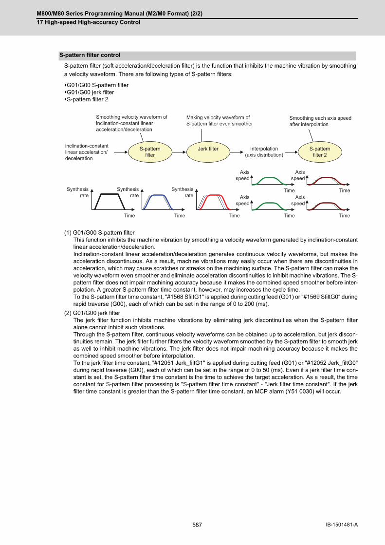
M800/M80 Series Programming Manual (M2/M0 Format) (2/2)
17 High-speed High-accuracy Control
587 IB-1501481-A
S-pattern filter (soft acceleration/deceleration filter) is the function that inhibits the machine vibration by smoothing
a velocity waveform. There are following types of S-pattern filters:
G01/G00 S-pattern filterG01/G00 jerk filterS-pattern filter 2
(1) G01/G00 S-pattern filterThis function inhibits the machine vibration by smoothing a velocity waveform generated by inclination-constantlinear acceleration/deceleration. Inclination-constant linear acceleration/deceleration generates continuous velocity waveforms, but makes theacceleration discontinuous. As a result, machine vibrations may easily occur when there are discontinuities inacceleration, which may cause scratches or streaks on the machining surface. The S-pattern filter can make thevelocity waveform even smoother and eliminate acceleration discontinuities to inhibit machine vibrations. The S-pattern filter does not impair machining accuracy because it makes the combined speed smoother before inter-polation. A greater S-pattern filter time constant, however, may increases the cycle time. To the S-pattern filter time constant, "#1568 SfiltG1" is applied during cutting feed (G01) or "#1569 SfiltG0" duringrapid traverse (G00), each of which can be set in the range of 0 to 200 (ms).
(2) G01/G00 jerk filterThe jerk filter function inhibits machine vibrations by eliminating jerk discontinuities when the S-pattern filteralone cannot inhibit such vibrations. Through the S-pattern filter, continuous velocity waveforms can be obtained up to acceleration, but jerk discon-tinuities remain. The jerk filter further filters the velocity waveform smoothed by the S-pattern filter to smooth jerkas well to inhibit machine vibrations. The jerk filter does not impair machining accuracy because it makes thecombined speed smoother before interpolation. To the jerk filter time constant, "#12051 Jerk_filtG1" is applied during cutting feed (G01) or "#12052 Jerk_filtG0"during rapid traverse (G00), each of which can be set in the range of 0 to 50 (ms). Even if a jerk filter time con-stant is set, the S-pattern filter time constant is the time to achieve the target acceleration. As a result, the timeconstant for S-pattern filter processing is "S-pattern filter time constant" - "Jerk filter time constant". If the jerkfilter time constant is greater than the S-pattern filter time constant, an MCP alarm (Y51 0030) will occur.
S-pattern filter control
Time
S-pattern filter 2
Interpolation(axis distribution)
inclination-constant linear acceleration/deceleration
Synthesis rate
Synthesis rate
Synthesis rate
Time Time Time
Axis speed
Time
Time
Axis speed
Time
Axis speed
Axis speed
Jerk filter
Smoothing velocity waveform of inclination-constant linear acceleration/deceleration
Making velocity waveform of S-pattern filter even smoother
Smoothing each axis speed after interpolation
S-pattern filter
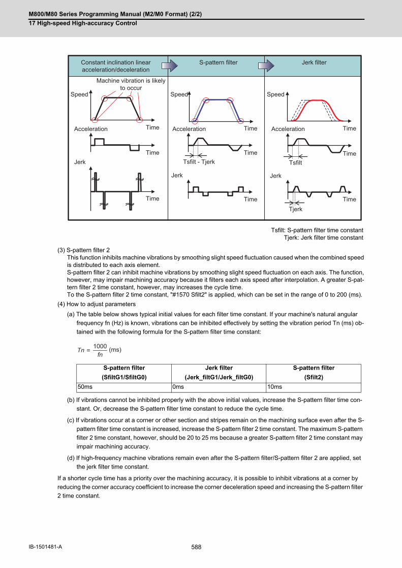
M800/M80 Series Programming Manual (M2/M0 Format) (2/2)
17 High-speed High-accuracy Control
588IB-1501481-A
(3) S-pattern filter 2This function inhibits machine vibrations by smoothing slight speed fluctuation caused when the combined speedis distributed to each axis element. S-pattern filter 2 can inhibit machine vibrations by smoothing slight speed fluctuation on each axis. The function,however, may impair machining accuracy because it filters each axis speed after interpolation. A greater S-pat-tern filter 2 time constant, however, may increases the cycle time. To the S-pattern filter 2 time constant, "#1570 Sfilt2" is applied, which can be set in the range of 0 to 200 (ms).
(4) How to adjust parameters
(a) The table below shows typical initial values for each filter time constant. If your machine's natural angular
frequency fn (Hz) is known, vibrations can be inhibited effectively by setting the vibration period Tn (ms) ob-
tained with the following formula for the S-pattern filter time constant:
(b) If vibrations cannot be inhibited properly with the above initial values, increase the S-pattern filter time con-
stant. Or, decrease the S-pattern filter time constant to reduce the cycle time.
(c) If vibrations occur at a corner or other section and stripes remain on the machining surface even after the S-
pattern filter time constant is increased, increase the S-pattern filter 2 time constant. The maximum S-pattern
filter 2 time constant, however, should be 20 to 25 ms because a greater S-pattern filter 2 time constant may
impair machining accuracy.
(d) If high-frequency machine vibrations remain even after the S-pattern filter/S-pattern filter 2 are applied, set
the jerk filter time constant.
If a shorter cycle time has a priority over the machining accuracy, it is possible to inhibit vibrations at a corner by
reducing the corner accuracy coefficient to increase the corner deceleration speed and increasing the S-pattern filter
2 time constant.
Tsfilt: S-pattern filter time constantTjerk: Jerk filter time constant
S-pattern filter Jerk filter S-pattern filter
(SfiltG1/SfiltG0) (Jerk_filtG1/Jerk_filtG0) (Sfilt2)
50ms 0ms 10ms
Tsfilt - Tjerk Tsfilt
Tjerk
Constant inclination linear acceleration/deceleration
Machine vibration is likely to occur
S-pattern filter Jerk filter
Time
Speed
Acceleration
Jerk
Jerk Jerk
Acceleration AccelerationTime Time
Time
Time
Time
Time
Time
Time
Speed Speed
=Tnfn
1000 (ms)

M800/M80 Series Programming Manual (M2/M0 Format) (2/2)
17 High-speed High-accuracy Control
589 IB-1501481-A
(1) The modal must be set as shown below when commanding G08 P1/G61.1.
(*1) These functions can be commanded if the tolerable acceleration control for each axis (optimum acceleration
control) or variable-acceleration pre-interpolation acceleration/deceleration specifications are valid.
(2) A program error will occur if high-accuracy control is commanded in the following modes.During milling -> Program error (P481)During cylindrical interpolation -> Program error (P481) (*2)During polar coordinate interpolation -> Program error (P481) (*2)During normal line control -> Program error (P29)
(3) A program error (P29) will occur if the following commands are issued during the high-accuracy control mode.MillingCylindrical interpolation (*2)Polar coordinate interpolation (*2)Normal line control
(*2) An error will not occur if the tolerable acceleration control for each axis (optimum acceleration control) or
variable-acceleration pre-interpolation acceleration/deceleration specifications are valid.
Relationship with other functions
Function G code
Cylindrical interpolation cancel (*1) G07.1
Polar coordinate interpolation cancel (*1) G15
Tool radius compensation mode cancel G40
Tool length compensation cancel G44
Normal line control cancel G40.1
Programmable mirror image OFF G50.1
Mirror image with settings Cancel
Mirror image with signals Cancel
No macro modal call G67
Feed per revolution cancel G94
Constant surface speed control mode cancel G97
Interruption type macro mode cancel IOF

M800/M80 Series Programming Manual (M2/M0 Format) (2/2)
17 High-speed High-accuracy Control
590IB-1501481-A
The table below shows operations when following high-accuracy control-related commands are combined:
Operation when high-accuracy control-related G commands are combined
G61.1, G8P1 : High-accuracy control
G64 : Cutting mode
G61 : Exact stop check mode
G63 : Tapping mode
G61.2 : High-accuracy spline interpolation
G08P0 : High-accuracy control cancel (cutting mode)
G05.1Q1 : High-speed high-accuracy control I
G05.1Q2 : Spline interpolation
G05P2 : High-speed machining mode II
G05P10000 : High-speed high-accuracy control II
G05P20000 : High-speed high-accuracy control III
A B Operation when B is commanded during A command
G61.1/G08P1 G61.1 Continues high-accuracy control.
G61, G63, G64 Cancels high-accuracy control and operates in the commanded mode.
G61.2 Operates in the high-accuracy spline interpolation mode.
G8P1 Continues high-accuracy control.
G8P0 Cancels high-accuracy control. (Changes G code group 13 to G64.)
G05.1Q1 Operates in the high-speed high-accuracy control I mode.
G05.1Q2 A program error (P34) will occur.
G05P2 Operates in high-accuracy control + high-speed machining mode II.
G05P10000 Operates in the high-speed high-accuracy control II mode.
G06.2 A program error (P34) will occur.
G61.2 G61.1 Operates in the high-accuracy control mode.
G61, G63, G64 Operates in the commanded mode.
G61.2 Continues high-accuracy spline interpolation.
G08P1 Operates in the high-accuracy control mode.
G08P0 A program error (P29) will occur.
G05.1Q1 A program error (P29) will occur.
G05.1Q2 A program error (P34) will occur.
G05P2 Operates in high-accuracy spline interpolation + high-speed ma-chining mode II.
G05P10000 A program error (P29) will occur.
G06.2 A program error (P34) will occur.
G05.1Q1 G61.1 Continues the high-speed high-accuracy control I mode.
G64 Continues the high-speed high-accuracy control I mode.
G61, G63 Operates in the high-speed high-accuracy control I + commanded mode.
G61.2 A program error (P29) will occur.
G08P1 Continues the high-speed high-accuracy control I mode.
G08P0 Continues the high-speed high-accuracy control I mode.
G05.1Q1 Continues the high-speed high-accuracy control I mode.
G05.1Q2 A program error (P34) will occur.
G05P2 Operates in the high-speed machining mode II.
G05P10000 A program error (P34) will occur.
G06.2 A program error (P34) will occur.

M800/M80 Series Programming Manual (M2/M0 Format) (2/2)
17 High-speed High-accuracy Control
591 IB-1501481-A
(1) The "high-accuracy control" specifications are required to use this function If G61.1 is commanded when there are no specifications, a program error (P123) will occur.
(2) The high-accuracy control function is internally enabled by the high-speed high-accuracy I/II/III (G5.1Q1/G5P10000) command. If the high-speed high-accuracy I/II/III is commanded in the high-accuracy control mode,the high-speed high-accuracy I/II/III mode is enabled. Then, if the high-speed high-accuracy I/II/III mode is can-celed, the high-accuracy control mode is restored.
(3) In the high-accuracy control mode, feedrate command F is clamped with the "#2110 Clamp (H-precision)" (Cut-ting feed clamp speed for high-accuracy control mode) set with parameter. When the cutting feed clamp speedfor the high-accuracy control mode is 0, however, it is clamped with the "#2002 clamp" cutting clamp speed setby the parameter.
(4) In the high-accuracy control mode, rapid traverse rate conforms to "#2109 Rapid(H-precision)" (Rapid traverserate during high-accuracy control mode) set by the parameter. When the rapid traverse rate during the high-ac-curacy control mode is set to "0", however, the movement follows "#2001 rapid" set by the parameter.
(5) If the specifications for the multi-part system simultaneous high-accuracy control are not provided, the "#1205G0bdcc" (G0 pre-interpolation) can be used with only one part system. If the 2nd or later part system is set to the G0 pre-interpolation acceleration/deceleration, an MCP alarm (Y510017) will occur.
(6) "#1568 SfiltG1", "#1569 SfiltG0" and "#1570 Sfilt2" cannot be changed from the screen during program mode. If these parameters is changed by "parameter input by program", these parameters become valid from the nextblock.
(7) If Reset or Emergency signal is input during axis travel, it takes a time equal to the time constant to recover fromthe reset or emergency stop state.
(8) When there are high-accuracy acceleration/deceleration time constant expansion specifications, the samplingbuffer area may be smaller.
(9) The high-accuracy control time constant expansion specifications can only be used for a 1-part system. In amulti-part system, the high-accuracy acceleration/deceleration time constant expansion specifications are dis-abled even when they are set to ON.
(10) For a part system where high-accuracy control is to be commanded, set the number of axes in the part systemto 8 or less. If high-accuracy control is commanded for a part system that has 9 or more axes, an operation error(M01 0135) will occur. The error will not occur, however, if the number of axes in the part system excluding themaster axis/slave axis is 8 or less during the synchronous control/control axis synchronization between part sys-tems.
(11) Even if the parameter "#1210 RstGmd" (modal G code reset setting) is set to "not to initialize group 13 at reset",group 13 is initialized according to the setting of "#1148 I_G611" (Initial hi-precis) if it is enabled. To retain group13 at reset, set "#1148 I_G611" to "0". These parameters depend on the MTB specifications.
(12) If the parameter "#1205 G0bdcc" (G0 acceleration/deceleration before interpolation) is set to "1", the value setwith the parameter "#2224 SV024" (in-position detection width) will be used as the in-position width. The settingof the parameter "#2077 G0inps" (G0 in-position width) and the programmable in-position check with ",I" addressare disabled.
G05P10000 G61.1 Continues the high-speed high-accuracy control II mode.
G64 Continues the high-speed high-accuracy control II mode.
G61, G63 Operates in the high-speed high-accuracy control II + command-ed mode.
G61.2 A program error (P29) will occur.
G08P1 Continues the high-speed high-accuracy control II mode.
G08P0 Continues the high-speed high-accuracy control II mode.
G05.1Q1 A program error (P34) will occur.
G05.1Q2 Operates in the high-speed high-accuracy control II mode + spline interpolation
G05P2 Operates in the high-speed machining mode II.
G05P10000 Continues the high-speed high-accuracy control II mode.
G06.2 Operates in the NURBS interpolation mode.
Precautions
A B Operation when B is commanded during A command
M800/M80 Series Programming Manual (M2/M0 Format) (2/2)
17 High-speed High-accuracy Control
592IB-1501481-A
17.2.2 SSS Control
This function runs a machining program that approximates a freely curved surface with fine segment lines at high
speed and with high-level accuracy. This function enables machining with less scratches and streaks on the cutting
surface compared to the conventional high-accuracy control function.
With conventional high-accuracy control, the angle between two blocks is compared with the corner deceleration
angle to determine whether to execute corner deceleration between the blocks. This can cause the speed to sud-
denly change between the blocks with an angle close to the corner deceleration angle, resulting in scratches or
streaks.
The SSS (Super Smooth Surface) control uses information on not only the angle but also global paths between two
blocks to provide optimum speed control that is not significantly affected by minute stepping or waviness. The favor-
able effects of this control include a reduction in the number of scratches or streaks on cutting surfaces.
The SSS control has the following features:
(1) This function is effective at machining smooth-shaped dies using a fine segment program.
(2) This function provides speed control that is not susceptible to errors in paths.
(3) Even if corner deceleration is not required, the speed is clamped if the predicted acceleration is high. (The clamp speed can be adjusted using the parameter "#8092 ClampCoeff".)
The length of the path direction recognized with SSS control can be adjusted with the machining parameter "#8091
reference length". The range is increased as the setting value increases, and the effect of the error is reduced.
If the multi-part system simultaneous high-accuracy specification is provided, up to two part systems can be used
at the same time.
(1) The use of this function requires the following functions, in addition to the SSS control specifications. Make surethat these specifications are enabled before using this function. High-accuracy control (G61.1/G08P1)High-speed high-accuracy control I (G05.1 Q1)High-speed high-accuracy control II (G05 P10000)High-speed high-accuracy control III (G05 P20000)
Function and purpose
Note
M800/M80 Series Programming Manual (M2/M0 Format) (2/2)
17 High-speed High-accuracy Control
593 IB-1501481-A
When the parameters are set as below, each of the following high-accuracy control commands is activated under
SSS control.
<Parameter>
"#8090 SSS ON" ON
<Command format of the modes activated under SSS control>"
"SSS" is displayed on the modal display screen under SSS control.
However "SSS" is not displayed when a command being executed is out of the scope of SSS control.
The clamp speed at a corner and arc can be adjusted using "#8022 CORNER COMP" and "#8023 CURVE COMP"
(If "#8021 COMP_CHANGE" is set to "0", use "#8019 R COMP" to adjust the clamp speed at a corner and arc).
When "#8096 Deceler. coeff. ON" is set to "1", "#8097 Corner decel coeff" and "#8098 Arc clamp spd coef" become
valid during SSS control. Using these parameters, you can use different corner deceleration speeds and clamp
speeds at arcs according to whether or not the SSS control is enabled.
For parameters #8097 and #8098, respectively, set a percentage ratio to the level of the relevant speed that is ap-
plied when the SSS control is disabled.
(Example) When "#8097 Corner decel coeff" is set to 200 (%), the corner deceleration speed that is applied when
the SSS control is enabled becomes twice the corner deceleration speed that is applied when the SSS control
is disabled.
When setting the parameters, adjust the values within the range in which the machine does not vibrate.
Detailed description
[High-accuracy control]
G61.1 ; or G08P1; High-accuracy control ON
G08P0; or, G command in group 13 except G61.1 High-accuracy control OFF
[High-speed high-accuracy control I]
G05.1 Q1 ; High-speed high-accuracy control I ON
G05.1 Q0 ; High-speed high-accuracy control I OFF
[High-speed high-accuracy control II]
G05 P10000 ; High-speed high-accuracy control II ON
G05 P0 ; High-speed high-accuracy control II OFF
[High-speed high-accuracy control III]
G05 P20000 ; High-speed high-accuracy control III ON
G05 P0 ; High-speed high-accuracy control III OFF
Adjustment of accuracy coefficient
Parameter Item to be adjusted
#8097 Corner decel coeff Corner deceleration speed to be applied when the SSS control is enabled
#8098 Arc clamp spd coef Arc clamp speed to be applied when the SSS control is en-abled
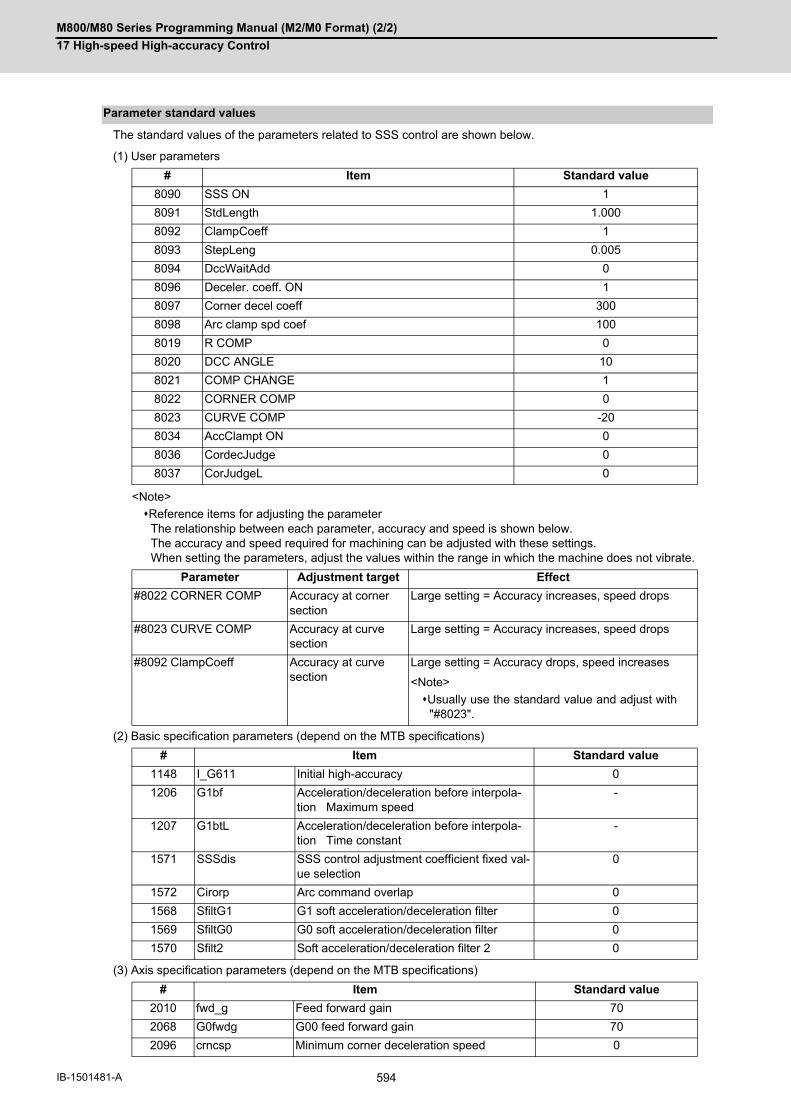
M800/M80 Series Programming Manual (M2/M0 Format) (2/2)
17 High-speed High-accuracy Control
594IB-1501481-A
The standard values of the parameters related to SSS control are shown below.
(1) User parameters
<Note>
Reference items for adjusting the parameterThe relationship between each parameter, accuracy and speed is shown below. The accuracy and speed required for machining can be adjusted with these settings. When setting the parameters, adjust the values within the range in which the machine does not vibrate.
(2) Basic specification parameters (depend on the MTB specifications)
(3) Axis specification parameters (depend on the MTB specifications)
Parameter standard values
# Item Standard value
8090 SSS ON 1
8091 StdLength 1.000
8092 ClampCoeff 1
8093 StepLeng 0.005
8094 DccWaitAdd 0
8096 Deceler. coeff. ON 1
8097 Corner decel coeff 300
8098 Arc clamp spd coef 100
8019 R COMP 0
8020 DCC ANGLE 10
8021 COMP CHANGE 1
8022 CORNER COMP 0
8023 CURVE COMP -20
8034 AccClampt ON 0
8036 CordecJudge 0
8037 CorJudgeL 0
Parameter Adjustment target Effect
#8022 CORNER COMP Accuracy at corner section
Large setting = Accuracy increases, speed drops
#8023 CURVE COMP Accuracy at curve section
Large setting = Accuracy increases, speed drops
#8092 ClampCoeff Accuracy at curve section
Large setting = Accuracy drops, speed increases
<Note>
Usually use the standard value and adjust with"#8023".
# Item Standard value
1148 I_G611 Initial high-accuracy 0
1206 G1bf Acceleration/deceleration before interpola-tion Maximum speed
-
1207 G1btL Acceleration/deceleration before interpola-tion Time constant
-
1571 SSSdis SSS control adjustment coefficient fixed val-ue selection
0
1572 Cirorp Arc command overlap 0
1568 SfiltG1 G1 soft acceleration/deceleration filter 0
1569 SfiltG0 G0 soft acceleration/deceleration filter 0
1570 Sfilt2 Soft acceleration/deceleration filter 2 0
# Item Standard value
2010 fwd_g Feed forward gain 70
2068 G0fwdg G00 feed forward gain 70
2096 crncsp Minimum corner deceleration speed 0

M800/M80 Series Programming Manual (M2/M0 Format) (2/2)
17 High-speed High-accuracy Control
595 IB-1501481-A
(1) Pre-reading is executed during SSS control, so a program error could occur before the block containing the erroris executed.
(2) Buffer correction is not guaranteed during SSS control.
(3) If automatic/manual simultaneous or automatic handle feed interrupt are used during SSS control, the machiningaccuracy will not be guaranteed.
(4) If a fine arc command is issued during SSS control, it may take longer to machine.
(5) The same path as single block operation will be used during graphic check.
(6) The line under the cutting feedrate and arc command block are subjected to the speed control in the SSS control.The command blocks that are not subjected to speed control, decelerate first and automatically switch the SSScontrol ON and OFF.
(7) SSS control is temporally disabled in the following modal: NURBS interpolationPolar coordinate interpolationCylindrical interpolationUser macro interruption enable (ION)Feed per revolution (synchronous feed)Inverse time feedConstant surface speed controlFixed cycle3-dimensional coordinate conversionHypothetical axis interpolationAutomatic tool length measurementTool length compensation along the tool axis
(8) There are some restrictions for each high-accuracy control. Refer to each section for restrictions."17.2 High-accuracy control""17.3 High-speed High-accuracy Control"
(9) Fairing is disabled during the SSS control.
SSS control parameter
Precautions
[Range for recognizing the shape]#1571 SSSdis#8091 StdLength
[Acceleration/deceleration process]Feedrate
Seam between blocksClamp speed = theory deceleration speed (after adding accuracy coefficient)×√#8092 ClampCoeff
Time
#8094 DccWaitAddAble to wait for deceleration by setting the extra time when the speed feedback does not drop to the clamp speed.
Movement command
[Measure for step]#8093 StepLengSet the value approximately the same as the CAM path difference (tolerance) for the parameter.
#8093 StepLeng
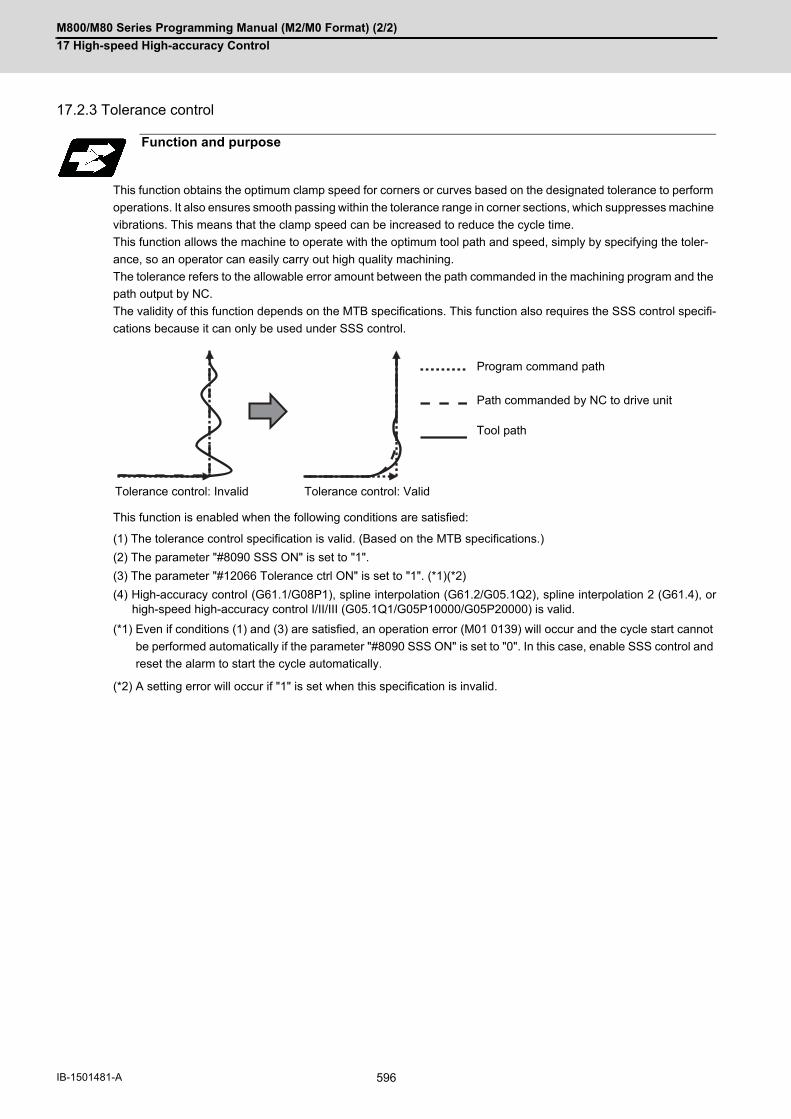
M800/M80 Series Programming Manual (M2/M0 Format) (2/2)
17 High-speed High-accuracy Control
596IB-1501481-A
17.2.3 Tolerance control
This function obtains the optimum clamp speed for corners or curves based on the designated tolerance to perform
operations. It also ensures smooth passing within the tolerance range in corner sections, which suppresses machine
vibrations. This means that the clamp speed can be increased to reduce the cycle time.
This function allows the machine to operate with the optimum tool path and speed, simply by specifying the toler-
ance, so an operator can easily carry out high quality machining.
The tolerance refers to the allowable error amount between the path commanded in the machining program and the
path output by NC.
The validity of this function depends on the MTB specifications. This function also requires the SSS control specifi-
cations because it can only be used under SSS control.
This function is enabled when the following conditions are satisfied:
(1) The tolerance control specification is valid. (Based on the MTB specifications.)
(2) The parameter "#8090 SSS ON" is set to "1".
(3) The parameter "#12066 Tolerance ctrl ON" is set to "1". (*1)(*2)
(4) High-accuracy control (G61.1/G08P1), spline interpolation (G61.2/G05.1Q2), spline interpolation 2 (G61.4), orhigh-speed high-accuracy control I/II/III (G05.1Q1/G05P10000/G05P20000) is valid.
(*1) Even if conditions (1) and (3) are satisfied, an operation error (M01 0139) will occur and the cycle start cannot
be performed automatically if the parameter "#8090 SSS ON" is set to "0". In this case, enable SSS control and
reset the alarm to start the cycle automatically.
(*2) A setting error will occur if "1" is set when this specification is invalid.
Function and purpose
Program command path
Path commanded by NC to drive unit
Tool path
Tolerance control: Invalid Tolerance control: Valid

M800/M80 Series Programming Manual (M2/M0 Format) (2/2)
17 High-speed High-accuracy Control
597 IB-1501481-A
Set the tolerance with the parameter "#2659 tolerance" or the ",K" address following the G code (G61.1 or G61.4
command). When the setting value is "0", this function runs with "0.01(mm)".
The range of the command value is 0.000 to 100.000. If a value exceeding the range is commanded, a programerror (P35) will occur.
The tolerance designated by ",K" is applied to all axes in the part system.When "0" is designated or ",K" is omitted, the program runs based on the value of the parameter "#2659 toler-
ance".The tolerance designated by ",K" is not held after reset. Therefore, if ",K" is not designated in the G61.1 or G61.4
command after reset, the axis runs based on the value of the parameter "#2659 tolerance".
(1) The G61.4 command requires the specifications of spline interpolation 2.
The clamp speed is obtained from the tolerance in the corner or curve section during tolerance control.
As the designated tolerance is lower, the axis speed decelerates.
Command format
Tolerance specification
G61.1 or G61.4 ,K__ ;
,K Tolerance (mm)
Detailed description
The axis moves in the designated tolerance range during tolerance con-trol. The tolerance on the corner shape is as shown on the right.
Speed control
Tolerance: High Tolerance: LowCommand path
Synthesis rate
Time Time
Note
M800/M80 Series Programming Manual (M2/M0 Format) (2/2)
17 High-speed High-accuracy Control
598IB-1501481-A
The parameters valid and invalid during tolerance control are as follows. Some parameters depend on the MTB
specifications.
(1) Valid parameters
(2) Invalid parameters (Parameters with no setting required)
Parameters valid during tolerance control
No. Parameter name Supplements
1206 G1bF When combining with the variable-acceleration pre-inter-polation acceleration/deceleration or tolerable accelera-tion control for each axis, specify parameters "#2157 G1bFx" and "#2158 G1btLx".
1207 G1btL
1568 SfiltG1
12051 Jerk_filtG1
2659 tolerance
No. Parameter name Supplements
1570 Sfilt2 Ignored even if the value is entered.
2159 compx Ignored even if the value is entered. The clamp speed is obtained from the tolerance during tolerance control; therefore, parameters for adjusting the clamp speed are not required.
8019 R COMP
8020 DCC ANGLE
8021 COMP CHANGE
8022 CORNER COMP
8023 CURVE COMP
8096 Deceler. coeff. ON
8097 Corner decel coeff
8098 Arc clamp spd coef
Program example
:G91 ;
G61.1 ,K0.02; Designate tolerance 0.02 (mm).
G01 X0.1 Z0.1 F1000 ;X0.1 Z-0.2 ;Y0.1 ;
Tolerance: 0.02 (mm)
G61.1 ,K0; Designate tolerance 0 (mm).
X-0.1 Z-0.05 ;X-0.1 Z-0.3 ;
Tolerance: Follows parameter "#2659 tolerance".
G64 ;:
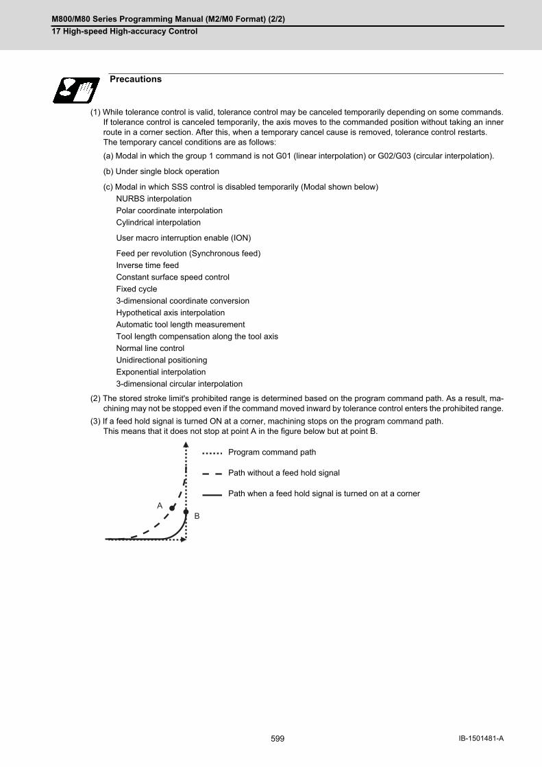
M800/M80 Series Programming Manual (M2/M0 Format) (2/2)
17 High-speed High-accuracy Control
599 IB-1501481-A
(1) While tolerance control is valid, tolerance control may be canceled temporarily depending on some commands.If tolerance control is canceled temporarily, the axis moves to the commanded position without taking an innerroute in a corner section. After this, when a temporary cancel cause is removed, tolerance control restarts.The temporary cancel conditions are as follows:
(a) Modal in which the group 1 command is not G01 (linear interpolation) or G02/G03 (circular interpolation).
(b) Under single block operation
(c) Modal in which SSS control is disabled temporarily (Modal shown below)
NURBS interpolation
Polar coordinate interpolation
Cylindrical interpolation
User macro interruption enable (ION)
Feed per revolution (Synchronous feed)
Inverse time feed
Constant surface speed control
Fixed cycle
3-dimensional coordinate conversion
Hypothetical axis interpolation
Automatic tool length measurement
Tool length compensation along the tool axis
Normal line control
Unidirectional positioning
Exponential interpolation
3-dimensional circular interpolation
(2) The stored stroke limit's prohibited range is determined based on the program command path. As a result, ma-chining may not be stopped even if the command moved inward by tolerance control enters the prohibited range.
(3) If a feed hold signal is turned ON at a corner, machining stops on the program command path. This means that it does not stop at point A in the figure below but at point B.
Precautions
Program command path
Path without a feed hold signal
Path when a feed hold signal is turned on at a corner
AB

M800/M80 Series Programming Manual (M2/M0 Format) (2/2)
17 High-speed High-accuracy Control
600IB-1501481-A
17.2.4 Variable-acceleration pre-interpolation acceleration/deceleration
This function is useful when each axis differs in the characteristics (responsiveness) (4-axis/5-axis machine, etc.).
The normal acceleration/deceleration before interpolation performs the acceleration/deceleration by setting accel-
eration common to all axes. Therefore, if the high responsiveness and low responsiveness coexist in axes, the ac-
celeration needs to be set to suit the axis with low responsiveness.
On the other hand, the variable-acceleration pre-interpolation acceleration/deceleration can perform the accelera-
tion/deceleration by setting diverse acceleration to each axis. This means that it is possible to set a higher acceler-
ation for axes with high responsiveness than before. Therefore, the acceleration for the axis with high
responsiveness can be larger than before so that cycle time can be reduced especially in the indexing machining.
(Refer to following figure.)
The validity of this function depends on the MTB specifications. This function also requires the SSS control specifi-
cations because it can only be used under SSS control.
This function is enabled when the following conditions are satisfied:
(1) The variable-acceleration pre-interpolation acceleration/deceleration specification is valid. (Based on the MTBspecifications.)
(2) The MTB-specific parameter has been set (#12060 VblAccPreInt). (*1)
(3) Under SSS control (*2)
(*1) A setting error will occur if "1" is set when this specification is invalid.
(*2) The validity of the SSS control function depends on the MTB specifications.
To enable SSS control, it is necessary to set the parameter "#8090 SSS ON" to "1" to command high-accu-
racy control.
(*3) Even if conditions (1) and (2) are satisfied, an operation error (M01 0136) will occur and the cycle start can-
not be performed automatically if the parameter "#8090 SSS ON" is set to "0". In this case, enable SSS con-
trol and reset the alarm to start the cycle automatically.
"VAC" is displayed on the operation screen and modal display under variable-acceleration pre-interpolation accel-
eration/deceleration.
Function and purpose
Synthesis rate
Variable-acceleration pre-interpolation acceleration/deceleration
Acceleration/deceleration before inter-polation
Time
Rotary axis Linear axis Shortened
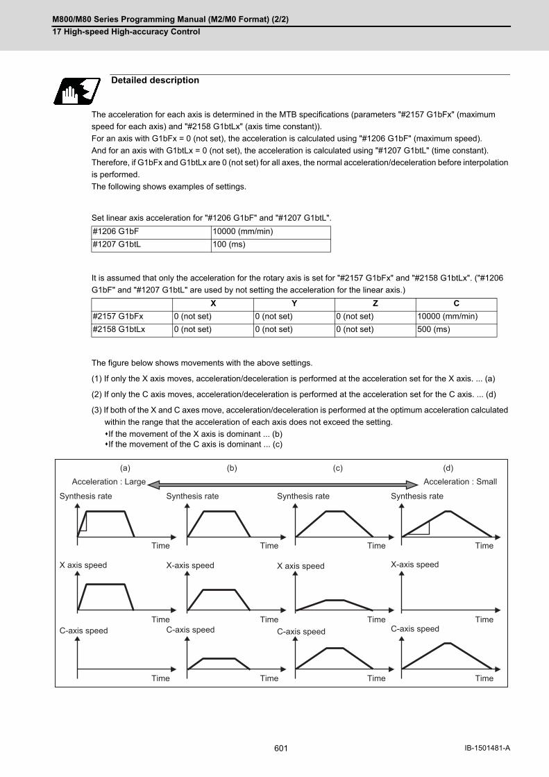
M800/M80 Series Programming Manual (M2/M0 Format) (2/2)
17 High-speed High-accuracy Control
601 IB-1501481-A
The acceleration for each axis is determined in the MTB specifications (parameters "#2157 G1bFx" (maximum
speed for each axis) and "#2158 G1btLx" (axis time constant)).
For an axis with G1bFx = 0 (not set), the acceleration is calculated using "#1206 G1bF" (maximum speed).
And for an axis with G1btLx = 0 (not set), the acceleration is calculated using "#1207 G1btL" (time constant).
Therefore, if G1bFx and G1btLx are 0 (not set) for all axes, the normal acceleration/deceleration before interpolation
is performed.
The following shows examples of settings.
Set linear axis acceleration for "#1206 G1bF" and "#1207 G1btL".
It is assumed that only the acceleration for the rotary axis is set for "#2157 G1bFx" and "#2158 G1btLx". ("#1206
G1bF" and "#1207 G1btL" are used by not setting the acceleration for the linear axis.)
The figure below shows movements with the above settings.
(1) If only the X axis moves, acceleration/deceleration is performed at the acceleration set for the X axis. ... (a)
(2) If only the C axis moves, acceleration/deceleration is performed at the acceleration set for the C axis. ... (d)
(3) If both of the X and C axes move, acceleration/deceleration is performed at the optimum acceleration calculated
within the range that the acceleration of each axis does not exceed the setting.
If the movement of the X axis is dominant ... (b)If the movement of the C axis is dominant ... (c)
Detailed description
#1206 G1bF 10000 (mm/min)
#1207 G1btL 100 (ms)
X Y Z C
#2157 G1bFx 0 (not set) 0 (not set) 0 (not set) 10000 (mm/min)
#2158 G1btLx 0 (not set) 0 (not set) 0 (not set) 500 (ms)
(b) (c) (d)(a)
Time
Time
Time
Time
Time
Time
Time
Time
Time
Time
Time
Time
Acceleration : Large Acceleration : Small
Synthesis rate Synthesis rate Synthesis rate Synthesis rate
X axis speed X-axis speed X-axis speed
C-axis speed C-axis speedC-axis speed
X axis speed
C-axis speed

M800/M80 Series Programming Manual (M2/M0 Format) (2/2)
17 High-speed High-accuracy Control
602IB-1501481-A
(1) Under variable-acceleration pre-interpolation acceleration/deceleration, corner deceleration is realized with tol-erable acceleration control for each axis. Corner deceleration patterns and acceleration/deceleration patterns are as follows with each parameter setting:
(2) This function can only be used under SSS control. This means that variable-acceleration pre-interpolation accel-eration/deceleration is also disabled during a modal that temporarily disables SSS control. As a result, the toolis under tolerable acceleration control for each axis. In this mode, the acceleration is determined by "#1206G1bF" and "#1207 G1btL". Out of #2157 and #2158, set the longer one for #1206 and #1207. (Make a note ofthe original values and restore them as necessary.) Refer to "17.2.2 SSS Control" for modals that temporarily disable SSS control.
(3) Basically, set the same acceleration for base axes I, J, and K. A different acceleration causes a distorted shapeagainst an arc command. The figure below shows an example where the acceleration in the Y direction is greater than that in the X direc-tion.
Precautions
#12060 VblAccPreInt 0 0 1 1
Variable-acceleration Pre-interpo-lation Acceleration/Deceleration ON
#12053 EachAxAccCntrl 0 1 0 1
Tolerable acceleration control for each axis ON
Corner deceleration pattern Optimum corner deceleration
Tolerable acceleration control for each axis
Acceleration/deceleration pattern Acceleration/deceleration before interpolation
Variable-acceleration pre-interpo-lation acceleration/deceleration
Actual tool pathMachining program commanded shape
X
Y
M800/M80 Series Programming Manual (M2/M0 Format) (2/2)
17 High-speed High-accuracy Control
603 IB-1501481-A
17.2.5 Initial High-accuracy Control
If "#1148 I_G611" (Initial high-accuracy) is set by the MTB specifications, high-accuracy control-related functions
can be enabled when the power is turned ON. At power ON, the modes set by this parameter are enabled, but each
mode can be changed to a different one by commanding as follows in the machining program.
It is impossible, however, to shift to the high-speed high-accuracy control II/high-speed high-accuracy control III
mode during the high-speed high-accuracy control I. Likewise, it is also impossible to shift to the high-speed high-
accuracy control I mode during the high-speed high-accuracy control II/high-speed high-accuracy control III mode.
To shift to either mode, cancel the current high-speed high-accuracy control mode using "G05.1 Q0" or "G05 P0"
first and then command the target mode.
If any function set by this parameter is not included in your machine's specifications, an available high-accuracy
function with a number smaller than the parameter setting is enabled.
#1148 setting value Modes enabled at power ON
0 G08P0/G64 (cutting mode) command
1 G08P1/G61.1 (high-accuracy control mode) command
2 G05.1Q1 (high-speed high-accuracy control I mode) command
3 G05P10000 (high-speed high-accuracy control II mode) command
4 G05P20000 (high-speed high-accuracy control III mode) command
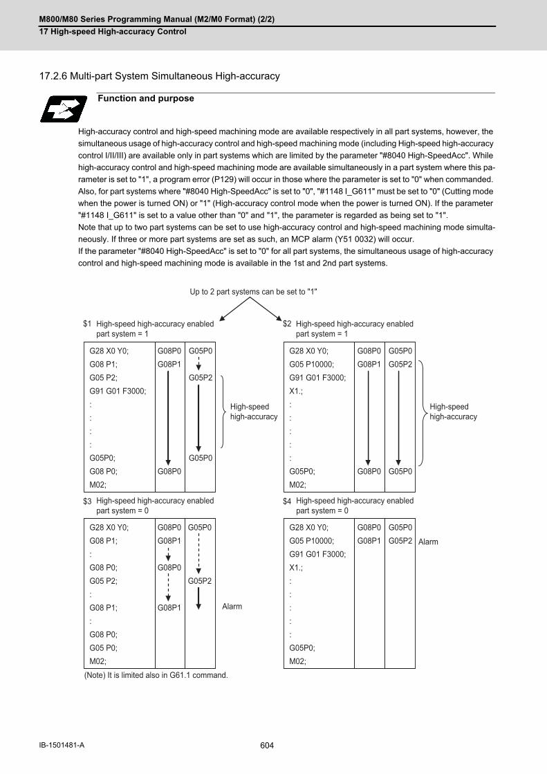
M800/M80 Series Programming Manual (M2/M0 Format) (2/2)
17 High-speed High-accuracy Control
604IB-1501481-A
17.2.6 Multi-part System Simultaneous High-accuracy
High-accuracy control and high-speed machining mode are available respectively in all part systems, however, the
simultaneous usage of high-accuracy control and high-speed machining mode (including High-speed high-accuracy
control I/II/III) are available only in part systems which are limited by the parameter "#8040 High-SpeedAcc". While
high-accuracy control and high-speed machining mode are available simultaneously in a part system where this pa-
rameter is set to "1", a program error (P129) will occur in those where the parameter is set to "0" when commanded.
Also, for part systems where "#8040 High-SpeedAcc" is set to "0", "#1148 I_G611" must be set to "0" (Cutting mode
when the power is turned ON) or "1" (High-accuracy control mode when the power is turned ON). If the parameter
"#1148 I_G611" is set to a value other than "0" and "1", the parameter is regarded as being set to "1".
Note that up to two part systems can be set to use high-accuracy control and high-speed machining mode simulta-
neously. If three or more part systems are set as such, an MCP alarm (Y51 0032) will occur.
If the parameter "#8040 High-SpeedAcc" is set to "0" for all part systems, the simultaneous usage of high-accuracy
control and high-speed machining mode is available in the 1st and 2nd part systems.
Function and purpose
G28 X0 Y0;G08 P1;G05 P2;G91 G01 F3000;::::G05P0;G08 P0;M02;
G08P0G08P1
G08P0
$1 $2
$3 $4
G05P0
G05P2
G05P0
G28 X0 Y0;G08 P1;:G08 P0;G05 P2;:G08 P1;:G08 P0;G05 P0;M02;
G08P0G08P1
G08P0
G08P1
G05P0
G05P2
G28 X0 Y0;G05 P10000;G91 G01 F3000;X1.;:::::G05P0;M02;
G08P0G08P1
G08P0
G05P0G05P2
G05P0
G28 X0 Y0;G05 P10000;G91 G01 F3000;X1.;:::::G05P0;M02;
G08P0G08P1
G05P0G05P2
Up to 2 part systems can be set to "1"
High-speed high-accuracy enabled part system = 1
High-speed high-accuracy enabled part system = 1
High-speed high-accuracy enabled part system = 0
High-speed high-accuracy
High-speed high-accuracy
High-speed high-accuracy enabled part system = 0
(Note) It is limited also in G61.1 command.
Alarm
Alarm
M800/M80 Series Programming Manual (M2/M0 Format) (2/2)
17 High-speed High-accuracy Control
605 IB-1501481-A
Although some MTB specifications support the high-accuracy acceleration/deceleration time constant expansion
specifications, only one part system can be used. Multi-part systems cannot be used even if the high-accuracy ac-
celeration/deceleration time constant expansion specifications are valid. For multi-part systems, "#1207 G1btL"
must be set to a value within the setting range that is applicable when there are no high-accuracy acceleration/de-
celeration time constant expansion specifications.
Refer to the following chapters for details of each high-accuracy control.
"17.2 High-accuracy control"
"17.3 High-speed High-accuracy Control"
(1) When "#1148 I_G611" (Initial hi-precis) is enabled, the initial modal state after power ON will be the high-accu-racy control mode. Refer to "17.2.5 Initial High-accuracy Control" for details. In this case, the high-accuracy control mode is enabled if the multi-part system simultaneous high-accuracyspecification is provided. Otherwise, the 1st part system enters the high-accuracy control mode, but the 2nd partsystem enters the cutting mode.
(2) If you use the high-accuracy acceleration/deceleration time constant expansion function together with the multi-part system simultaneous high-accuracy function, an MCP alarm (Y51 0020) will occur. Make sure to disable the high-accuracy acceleration/deceleration time constant extension function when youuse the multi-part system simultaneous high-accuracy function.
Detailed description
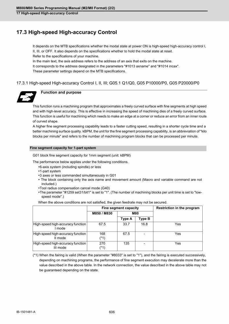
M800/M80 Series Programming Manual (M2/M0 Format) (2/2)
17 High-speed High-accuracy Control
606IB-1501481-A
17.3 High-speed High-accuracy Control
It depends on the MTB specifications whether the modal state at power ON is high-speed high-accuracy control I,
II, III, or OFF. It also depends on the specifications whether to hold the modal state at reset.
Refer to the specifications of your machine.
In the main text, the axis address refers to the address of an axis that exits on the machine.
It corresponds to the address designated in the parameters "#1013 axname" and "#1014 incax".
These parameter settings depend on the MTB specifications.
17.3.1 High-speed High-accuracy Control I, II, III; G05.1 Q1/Q0, G05 P10000/P0, G05 P20000/P0
This function runs a machining program that approximates a freely curved surface with fine segments at high speed
and with high-level accuracy. This is effective in increasing the speed of machining dies of a freely curved surface.
This function is useful for machining which needs to make an edge at a corner or reduce an error from an inner route
of curved shape.
A higher fine segment processing capability leads to a faster cutting speed, resulting in a shorter cycle time and a
better machining surface quality. kBPM, the unit for the fine segment processing capability, is an abbreviation of "kilo
blocks per minute" and refers to the number of machining program blocks that can be processed per minute.
G01 block fine segment capacity for 1mm segment (unit: kBPM)
The performance below applies under the following conditions.
6-axis system (including spindle) or less1-part system3 axes or less commanded simultaneously in G01 The block containing only the axis name and movement amount (Macro and variable command are not
included.)Tool radius compensation cancel mode (G40)The parameter "#1259 set31/bit1" is set to "1". (The number of machining blocks per unit time is set to "low-
speed mode".)
When the above conditions are not satisfied, the given feedrate may not be secured.
(*1) When the fairing is valid (When the parameter "#8033" is set to "1"), and the fairing is executed successively,
depending on machining programs, the performance of fine segment execution may decelerate more than the
value described in the above table. In the network connection, the value described in the above table may not
be guaranteed depending on the state.
Function and purpose
Fine segment capacity for 1-part system
Fine segment capacity Restriction in the program
M850 / M830 M80
Type A Type B
High-speed high-accuracy function I mode
67.5 33.7 16.8 Yes
High-speed high-accuracy function II mode
168(*1)
67.5 - Yes
High-speed high-accuracy function III mode
270(*1)
135 - Yes

M800/M80 Series Programming Manual (M2/M0 Format) (2/2)
17 High-speed High-accuracy Control
607 IB-1501481-A
G01 block fine segment capacity for 1mm segment (unit: kBPM)
The fine segment processing capability below applies under the following conditions.
3 axes or less commanded simultaneously in G01The block containing only the axis name and axis movement amount (Macro and variable command are not
included.)Tool radius compensation OFF (G40)The parameter "#1259 set31/bit1" is set to "1". (The number of machining blocks per unit time is set to "low-
speed mode".)
When the above conditions are not satisfied, the given feedrate may not be secured.
(1) High-speed high-accuracy control I
(2) High-speed high-accuracy control II
(3) High-speed high-accuracy control III
(*1) This system cannot be used for this model.
(*2) There are no corresponding high-speed high-accuracy control specifications.
(*3) 100 kBPM for a time constant expansion system.
(The time constant expansion system is available when its specifications are enabled and it is a 1-part system.)
Fine segment capacity for multi-part system
Number of part systems/num-ber of axes
Number of part systems M850 / M830 M80
(#8040=1) Type A Type B
1-part system 1 part system 67.5 33.7 16.8
2-part system 1 part system 67.5 33.7 16.8
2 part systems 33.7 33.7 16.8
4-part system 1 part system - (*1) - (*1) - (*1)
Up to 16 axes 2 part systems - (*1) - (*1) - (*1)
5 part systems or moreor 17 axes or more
1 part system - (*1) - (*1) - (*1)
2 part systems - (*1) - (*1) - (*1)
Number of part systems/num-ber of axes
Number of part systems M850 / M830 M80
(#8040=1) Type A Type B
1-part system 1 part system 168 (*3) 67.5 - (*2)
2-part system 1 part system 100 67.5 - (*2)
2 part systems 67.5 67.5 - (*2)
4-part system 1 part system - (*1) - (*1) - (*2)
Up to 16 axes 2 part systems - (*1) - (*1) - (*2)
5 part systems or moreor 17 axes or more
1 part system - (*1) - (*1) - (*2)
2 part systems - (*1) - (*1) - (*2)
Number of part systems/num-ber of axes
Number of part systems M850 / M830 M80
(#8040=1) Type A Type B
1-part system 1 part system 270 135 - (*2)
2-part system 1 part system 168 135 - (*2)
2 part systems 100 67.5 - (*2)
4-part system 1 part system - (*1) - (*2) - (*2)
Up to 16 axes 2 part systems - (*1) - (*2) - (*2)
5 part systems or moreor 17 axes or more
1 part system - (*1) - (*2) - (*2)
2 part systems - (*1) - (*2) - (*2)

M800/M80 Series Programming Manual (M2/M0 Format) (2/2)
17 High-speed High-accuracy Control
608IB-1501481-A
High-speed high-accuracy control I, II, III can be used simultaneously in up to two part systems.
High-speed high-accuracy control I, II, III can be used in a part system where "1" is set for the parameter "#8040
High-SpeedAcc". A program error occurs (P129) if this is commanded for a part system where "0" is set for the pa-
rameter.
If the parameter "#8040 High-SpeedAcc" is set to "0" for all part systems, only the first part system is handled as the
one with the parameter set to "1". Also, a part system where the parameter "#1148 Initial hi-precis" is set to "2" to
"4" is handled as the one with the parameter "#8040 High-SpeedAcc" set to "1".
The parameter "#8040 High-SpeedAcc" can be set to "1" for up to two part systems. If 3 or more part systems are
set to "1", an MCP alarm (Y51 0032) occurs. When "1" is set for two part systems, the fine segment processing ca-
pability decreases compared to when "1" is set only for one part system.
(1) The high-speed high-accuracy mode II and III cannot be used at the same time.
(2) These commands are valid regardless of the parameter "#1267 ext03/bit0" setting if the specifications are avail-able.
(3) High-speed high-accuracy control III can also be used by setting a parameter instead of a G code. If the parameter "#8131 High-speed high-accuracy control 3" is set to "1", the high-speed high-accuracy controlII command can be handled as the III command. This also enables the high-speed high-accuracy control III modein the machining program using "G05P10000". Likewise, the G05P2 command issued during a high-accuracycontrol mode can be handled as the high-speed high-accuracy control III command. Furthermore, by setting "#1148 Initial hi-precis" to "4", the high-speed high-accuracy control III mode can be setas the initial modal state after power ON.
High-speed high-accuracy control simultaneously for two part systems
Command format
G05.1 Q1 ; High-speed high-accuracy control I ON
G05.1 Q0 ; High-speed high-accuracy control I OFF
G05 P10000 ; High-speed high-accuracy control II ON
G05 P20000 ; High-speed high-accuracy control III ON
G05 P0 ; High-speed high-accuracy control II/III OFF
Note

M800/M80 Series Programming Manual (M2/M0 Format) (2/2)
17 High-speed High-accuracy Control
609 IB-1501481-A
(1) The high-speed high-accuracy control I / II / III can be used during tape, MDI, SD card or memory modes.
(2) The override, maximum cutting speed clamp, single block operation, dry run, handle interrupt and graphic traceare valid even during the high-speed high-accuracy control I / II / III modal.
(3) The machining speed may drop depending on the number of characters in one block.
(4) The high-speed high-accuracy control I / II / III function automatically turns the high-accuracy control mode ON. For high-accuracy control function, refer to "17.3 High-speed High-accuracy Control".
(5) Turn the tool radius compensation command ON and OFF during the high-speed high-accuracy control I/II/IIImode. If the high-speed high-accuracy control I/II/III mode is turned OFF without turning the tool radius compensationOFF, a program error (P34) will occur.
(6) Turn the high-speed high-accuracy control I / II / III mode OFF before commanding data other than those thatcan be commanded.
(7) When using the high-speed high-accuracy control II / III mode, it is necessary to set the parameter "#1572 Cirorp"to eliminate the speed fluctuation at the seams between arc and straight line or arc and arc. This parameter,however, depends on the MTB specifications.
(8) Feedrate command F is clamped with the "#2110 Clamp (H-precision)" (Cutting feed clamp speed for high-ac-curacy control mode) set with parameter.
(9) Rapid traverse rate enables "#2109 Rapid(H-precision)" (Rapid traverse rate during high-accuracy control mode)set by the parameter.
(10) When the "#2109 Rapid(H-precision)" is set to "0", the movement follows "#2001 rapid" (rapid traverse rate) setby the parameter. Also, when "#2110 Clamp (H-precision)" is set to "0", the speed will be clamped with "#2002clamp" (Cutting clamp speed) set with parameter.
To enable each high-speed high-accuracy control function, it is necessary to satisfy the following conditions respec-
tively:
(1) The specification of each function is valid. (*1)
(2) Each function is in a valid modal state. (Refer to "Relationship with other functions".)
(3) Each function is enabled by one of the following procedures:
Command each in the machining program. (*2)Set each for the parameter "#1148 Initial hi-precis". (The modal at power ON corresponds to each high-
speed high-accuracy control function.)
(*1) The following conditions are additionally required to enable high-speed high-accuracy control III.
The time constant expansion system is invalid.The SSS control specifications are valid, and the parameter "#8090 SSS ON" is set to "1".
If high-speed high-accuracy control III is commanded when the SSS control mode is set to OFF, high-speed
high-accuracy control II is enabled.
(*2) High-speed high-accuracy control III is also enabled by the following commands.
While the parameter "#8131 High-speed high-accuracy control III" is set to "1", command "G05 P10000" (high-
speed high-accuracy control II) from the machining program.
Detailed description
Enabling conditions
#1148 setting
High-speed high-accuracy control I 2
High-speed high-accuracy control II 3
High-speed high-accuracy control III 4

M800/M80 Series Programming Manual (M2/M0 Format) (2/2)
17 High-speed High-accuracy Control
610IB-1501481-A
(1) Relationship between the high-speed high-accuracy control I and G code functionsColumn A: Operation when the additional function is commanded while the high-speed high-accuracy control Iis enabledColumn B: Operation when the high-speed high-accuracy control I (G05.1Q1) is commanded while the additionalfunction is enabled○: The high-speed high-accuracy control I and the additional function are both enabled∆: The high-speed high-accuracy control I is temporarily canceled, while the additional function is enabledX: Alarm generation (the text in parentheses refers to the number of the program error to be generated.) -: No combination□: Others
Relationship with other functions
Relationship between the high-speed high-accuracy control I and other functions
Group G code Function name A B
0 G04 Dwell ∆ -
G05P0 High-speed machining mode II OFFHigh-speed high-accuracy control II OFFHigh-speed high-accuracy control III OFF
× (P34) □ (*2)
G05P2 High-speed machining mode II ON □ (*4) □ (*2)
G05P10000 High-speed high-accuracy control II ON × (P34) × (P34)
G05P20000 High-speed high-accuracy control III ON × (P34) × (P34)
G05.1Q0 High-speed high-accuracy control I OFFSpline interpolation OFF
□ (*1) □ (*2)
G05.1Q1 High-speed high-accuracy control I ON □ (*3) □ (*3)
G05.1Q2 Spline interpolation ON × (P34) × (P34)
G07 Hypothetical axis interpolation ∆ ∆
G08P0 High-accuracy control OFF □ (*3) □ (*2)
G08P1 High-accuracy control ON □ (*3) □ (*2)
G09 Exact stop check ∆ -
G10 I_J_G10 K_
Parameter coordinate rotation input ∆ -
G10 L2 Compensation data input by program ∆ -
G10 L70G10 L50
Parameter input by program ∆ -
G27 Reference position check ∆ -
G28 Reference position return ∆ -
G29 Start position return ∆ -
G30 2nd to 4th reference position return ∆ -
G30.1 - G30.6 Tool change position return ∆ -
G31 SkipMultiple-step skip 2
∆ -
G31.1 - G31.3 Multi-step skip ∆ -
G34 - G37 Special Fixed Cycle ∆ -
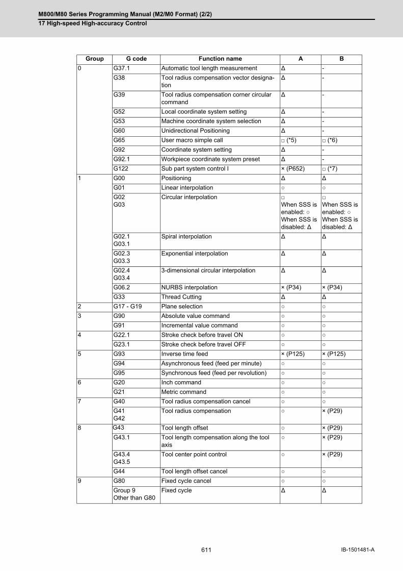
M800/M80 Series Programming Manual (M2/M0 Format) (2/2)
17 High-speed High-accuracy Control
611 IB-1501481-A
Group G code Function name A B
0 G37.1 Automatic tool length measurement ∆ -
G38 Tool radius compensation vector designa-tion
∆ -
G39 Tool radius compensation corner circular command
∆ -
G52 Local coordinate system setting ∆ -
G53 Machine coordinate system selection ∆ -
G60 Unidirectional Positioning ∆ -
G65 User macro simple call □ (*5) □ (*6)
G92 Coordinate system setting ∆ -
G92.1 Workpiece coordinate system preset ∆ -
G122 Sub part system control I × (P652) □ (*7)
1 G00 Positioning ∆ ∆
G01 Linear interpolation ○ ○
G02G03
Circular interpolation □When SSS is enabled: ○When SSS is disabled: ∆
□When SSS is enabled: ○When SSS is disabled: ∆
G02.1G03.1
Spiral interpolation ∆ ∆
G02.3G03.3
Exponential interpolation ∆ ∆
G02.4G03.4
3-dimensional circular interpolation ∆ ∆
G06.2 NURBS interpolation × (P34) × (P34)
G33 Thread Cutting ∆ ∆
2 G17 - G19 Plane selection ○ ○
3 G90 Absolute value command ○ ○
G91 Incremental value command ○ ○
4 G22.1 Stroke check before travel ON ○ ○
G23.1 Stroke check before travel OFF ○ ○
5 G93 Inverse time feed × (P125) × (P125)
G94 Asynchronous feed (feed per minute) ○ ○
G95 Synchronous feed (feed per revolution) ○ ○
6 G20 Inch command ○ ○
G21 Metric command ○ ○
7 G40 Tool radius compensation cancel ○ ○
G41G42
Tool radius compensation ○ × (P29)
8 G43 Tool length offset ○ × (P29)
G43.1 Tool length compensation along the tool axis
○ × (P29)
G43.4G43.5
Tool center point control ○ × (P29)
G44 Tool length offset cancel ○ ○
9 G80 Fixed cycle cancel ○ ○
Group 9Other than G80
Fixed cycle ∆ ∆

M800/M80 Series Programming Manual (M2/M0 Format) (2/2)
17 High-speed High-accuracy Control
612IB-1501481-A
(*1) Disables the high-speed high-accuracy control I.
(*2) Enables the high-speed high-accuracy control I.
(*3) High-speed high-accuracy control I continues.
(*4) Enables the high-speed machining mode II.
(*5) Enables the high-speed high-accuracy control I in a macro program.
(*6) Enables the high-speed high-accuracy control I if G05.1Q1 is commanded in a macro program.
(*7) Enables the high-speed high-accuracy control I if G05.1Q1 is commanded in a sub part system.
(*8) Enables the exact stop check mode.
(*9) Exact stop check mode continues.
Group G code Function name A B
10 G98 Fixed cycle initial level return ○ ○
G99 Fixed cycle R point return ○ ○
11 G50 Scaling cancel ○ ○
G51 Scaling ON ○ × (P34)
12 G54 - G59G54.1
Workpiece coordinate system selection ○ ○
13 G61 Exact stop check mode □ (*8) □ (*9)
G61.1 High-accuracy control □ (*3) □ (*2)
G61.2 High-accuracy spline × (P29) × (P29)
G63 Tapping mode □ (*3) □ (*2)
G64 Cutting mode □ (*3) □ (*2)
14 G66G66.1
User macro modal call □ (*5) □ (*6)
G67 User macro modal call cancel ○ ○
15 G40.1 Normal line control cancel ○ ○
G41.1G41.2
Normal line control × (P29) × (P29)
16 G68.1 Coordinate rotation by program ON ○ × (P34)
G68.2G68.3
Inclined surface machining command ○ ○
G69.1 Coordinate rotation cancel ○ ○
17 G96 Constant surface speed control ON ○ ○
G97 Constant surface speed control OFF ○ ○
18 G15 Polar coordinate command OFF ○ ○
G16 Polar coordinate command ON × (P34) × (P34)
19 G50.1, G62 Mirror image OFF ○ ○
G51.1, G62 Mirror image ON ○ × (P34)
21 G07.1 Cylindrical interpolation × (P485) ∆
G12.1 Polar coordinate interpolation ON × (P485) ∆
G13.1 Polar coordinate interpolation OFF ○ ○
24 G188 Dynamic M/L program changeover ○ ○
G189 Dynamic M/L program changeovercancel
○ ○
27 G54.4P0 Workpiece installation error compensation cancel
○ ○
G54.4P1 - P7
Workpiece installation error compensation ○ ○
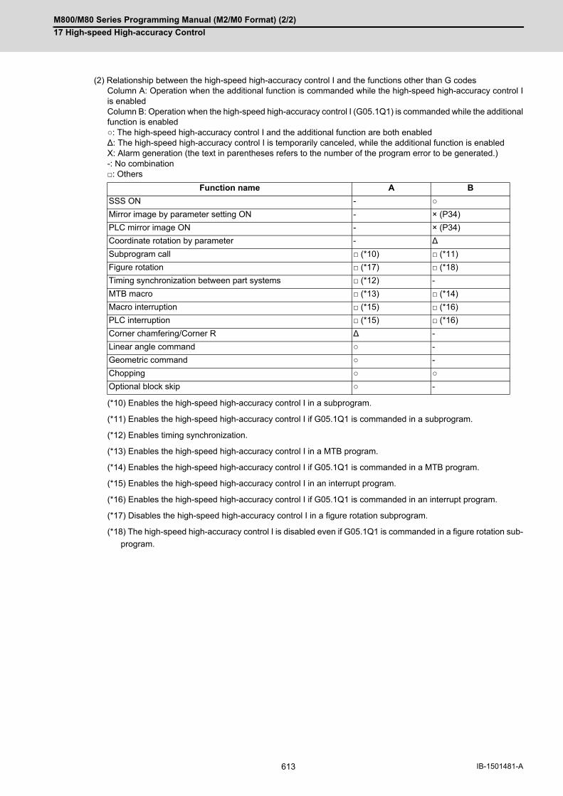
M800/M80 Series Programming Manual (M2/M0 Format) (2/2)
17 High-speed High-accuracy Control
613 IB-1501481-A
(2) Relationship between the high-speed high-accuracy control I and the functions other than G codesColumn A: Operation when the additional function is commanded while the high-speed high-accuracy control Iis enabledColumn B: Operation when the high-speed high-accuracy control I (G05.1Q1) is commanded while the additionalfunction is enabled○: The high-speed high-accuracy control I and the additional function are both enabled∆: The high-speed high-accuracy control I is temporarily canceled, while the additional function is enabledX: Alarm generation (the text in parentheses refers to the number of the program error to be generated.) -: No combination□: Others
(*10) Enables the high-speed high-accuracy control I in a subprogram.
(*11) Enables the high-speed high-accuracy control I if G05.1Q1 is commanded in a subprogram.
(*12) Enables timing synchronization.
(*13) Enables the high-speed high-accuracy control I in a MTB program.
(*14) Enables the high-speed high-accuracy control I if G05.1Q1 is commanded in a MTB program.
(*15) Enables the high-speed high-accuracy control I in an interrupt program.
(*16) Enables the high-speed high-accuracy control I if G05.1Q1 is commanded in an interrupt program.
(*17) Disables the high-speed high-accuracy control I in a figure rotation subprogram.
(*18) The high-speed high-accuracy control I is disabled even if G05.1Q1 is commanded in a figure rotation sub-
program.
Function name A B
SSS ON - ○
Mirror image by parameter setting ON - × (P34)
PLC mirror image ON - × (P34)
Coordinate rotation by parameter - ∆
Subprogram call □ (*10) □ (*11)
Figure rotation □ (*17) □ (*18)
Timing synchronization between part systems □ (*12) -
MTB macro □ (*13) □ (*14)
Macro interruption □ (*15) □ (*16)
PLC interruption □ (*15) □ (*16)
Corner chamfering/Corner R ∆ -
Linear angle command ○ -
Geometric command ○ -
Chopping ○ ○
Optional block skip ○ -

M800/M80 Series Programming Manual (M2/M0 Format) (2/2)
17 High-speed High-accuracy Control
614IB-1501481-A
(1) Relationship between the high-speed high-accuracy control II and G code functionsColumn A: Operation when the additional function is commanded while the high-speed high-accuracy control IIis enabledColumn B: Operation when the high-speed high-accuracy control II (G05P10000) is commanded while the ad-ditional function is enabled○: The high-speed high-accuracy control II and the additional function are both enabled∆: The high-speed high-accuracy control II is temporarily canceled, while the additional function is enabledX: Alarm generation (the text in parentheses refers to the number of the program error to be generated.) -: No combination□: Others
Relationship between the high-speed high-accuracy control II and other functions
Group G code Function name A B
0 G04 Dwell ∆ -
G05P0 High-speed machining mode II OFFHigh-speed high-accuracy control II OFFHigh-speed high-accuracy control III OFF
□ (*1) □ (*2)
G05P2 High-speed machining mode II ON □ (*4) □ (*2)
G05P10000 High-speed high-accuracy control II ON □ (*3) □ (*3)
G05P20000 High-speed high-accuracy control III ON □ (*2) □ (*2)
G05.1Q0 High-speed high-accuracy control I OFFSpline interpolation OFF
□ (*3) □ (*2)
G05.1Q1 High-speed high-accuracy control I ON × (P34) × (P34)
G05.1Q2 Spline interpolation ON ○ ○
G07 Hypothetical axis interpolation ∆ ∆
G08P0 High-accuracy control OFF □ (*3) □ (*2)
G08P1 High-accuracy control ON □ (*3) □ (*2)
G09 Exact stop check ∆ -
G10 I_J_G10 K_
Parameter coordinate rotation input ∆ -
G10 L2 Compensation data input by program ∆ -
G10 L70G10 L50
Parameter input by program ∆ -
G27 Reference position check ∆ -
G28 Reference position return ∆ -
G29 Start position return ∆ -
G30 2nd to 4th reference position return ∆ -
G30.1 - G30.6 Tool change position return ∆ -
G31 SkipMultiple-step skip 2
∆ -
G31.1 - G31.3 Multi-step skip ∆ -
G34 - G37 Special Fixed Cycle ∆ -
G37.1 Automatic tool length measurement ∆ -
G38 Tool radius compensation vector designa-tion
∆ -
G39 Tool radius compensation corner circular command
∆ -
G52 Local coordinate system setting ∆ -
G53 Machine coordinate system selection ∆ -
G60 Unidirectional positioning ∆ -

M800/M80 Series Programming Manual (M2/M0 Format) (2/2)
17 High-speed High-accuracy Control
615 IB-1501481-A
Group G code Function name A B
0 G65 User macro simple call □ (*5) □ (*6)
G92 Coordinate system setting ∆ -
G92.1 Workpiece coordinate system preset
∆ -
G122 Sub part system control I × (P652) □ (*7)
1 G00 Positioning ∆ ∆
G01 Linear interpolation ○ ○
G02G03
Circular interpolation ○ ○
G02.1G03.1
Spiral interpolation ∆ ∆
G02.3G03.3
Exponential interpolation ∆ ∆
G02.4G03.4
3-dimensional circular inter-polation
∆ ∆
G06.2 NURBS interpolation ○ ○
G33 Thread cutting ∆ ∆
2 G17 - G19 Plane selection ○ ○
3 G90 Absolute value command ○ ○
G91 Incremental value command ○ ○
4 G22.1 Stroke check before travel ON
∆ ∆
G23.1 Stroke check before travel OFF
○ ○
5 G93 Inverse time feed ∆ ∆
G94 Asynchronous feed (feed per minute)
○ ○
G95 Synchronous feed (feed per revolution)
∆ ∆
6 G20 Inch command ○ ○
G21 Metric command ○ ○
7 G40 Tool radius compensation cancel
○ ○
G41G42
Tool radius compensation ○ ○
8 G43 Tool length offset ○ ○
G43.1 Tool length compensation along the tool axis
○ ○
G43.4G43.5
Tool center point control ○ ○
G44 Tool length offset cancel ○ ○
9 G80 Fixed cycle cancel ○ ○
Group 9Other than G80
Fixed cycle ∆ ∆
10 G98 Fixed cycle initial level return ○ ○
G99 Fixed cycle R point return ○ ○
11 G50 Scaling cancel ○ ○
G51 Scaling ON ∆ ∆
12 G54 - G59 Workpiece coordinate system selection
○ ○
G54.1

M800/M80 Series Programming Manual (M2/M0 Format) (2/2)
17 High-speed High-accuracy Control
616IB-1501481-A
(*1) Disables the high-speed high-accuracy control II.
(*2) Enables the high-speed high-accuracy control II.
(*3) High-speed high-accuracy control II continues.
(*4) Enables the high-speed machining mode II.
(*5) Enables the high-speed high-accuracy control II in a macro program.
(*6) Enables the high-speed high-accuracy control II if G05P10000 is commanded in a macro program.
(*7) Enables the high-speed high-accuracy control II if G05P10000 is commanded in a sub part system.
(*8) Enables the exact stop check mode.
(*9) Exact stop check mode continues.
Group G code Function name A B
13 G61 Exact stop check mode ∆ ∆
G61.1 High-accuracy control □ (*3) □ (*2)
G61.2 High-accuracy spline × (P29) × (P29)
G63 Tapping mode ∆ ∆
G64 Cutting mode □ (*3) □ (*2)
14 G66G66.1
User macro modal call ∆ ∆
G67 User macro modal call cancel ○ ○
15 G40.1 Normal line control cancel ○ ○
G41.1G41.2
Normal line control × (P29) × (P29)
16 G68.1 Coordinate rotation by pro-gram ON
∆ ∆
G68.2G68.3
Inclined surface machining command
○ ○
G69.1 Coordinate rotation cancel ○ ○
17 G96 Constant surface speed con-trol ON
○ ○
G97 Constant surface speed con-trol OFF
○ ○
18 G15 Polar coordinate command OFF
○ ○
G16 Polar coordinate command ON
∆ ∆
19 G50.1, G62 Mirror image OFF ○ ○
G51.1, G62 Mirror image ON ○ ○
21 G07.1 Cylindrical interpolation × (P34) × (P481)
G12.1 Polar coordinate interpolation ON
× (P34) × (P481)
G13.1 Polar coordinate interpolation OFF
○ ○
24 G188 Dynamic M/L program changeover
○ ○
G189 Dynamic M/L program changeovercancel
○ ○
27 G54.4P0 Workpiece installation error compensation cancel
○ ○
G54.4P1 to P7
Workpiece installation error compensation
○ ○

M800/M80 Series Programming Manual (M2/M0 Format) (2/2)
17 High-speed High-accuracy Control
617 IB-1501481-A
(2) Relationship between the high-speed high-accuracy control II and the functions other than G codesColumn A: Operation when the additional function is commanded while the high-speed high-accuracy control IIis enabledColumn B: Operation when the high-speed high-accuracy control II (G05P10000) is commanded while the ad-ditional function is enabled○: The high-speed high-accuracy control II and the additional function are both enabled∆: The high-speed high-accuracy control II is temporarily canceled, while the additional function is enabledX: Alarm generation (the text in parentheses refers to the number of the program error to be generated.) -: No combination□: Others
(*10) Enables the high-speed high-accuracy control II in a subprogram.
(*11) Enables the high-speed high-accuracy control II if G05P10000 is commanded in a subprogram.
(*12) Enables timing synchronization.
(*13) Enables the high-speed high-accuracy control II in a MTB program.
(*14) Enables the high-speed high-accuracy control II if G05P10000 is commanded in a MTB program.
(*15) Enables the high-speed high-accuracy control II in an interrupt program.
(*16) Enables the high-speed high-accuracy control II if G05P10000 is commanded in an interrupt program.
(*17) Disables the high-speed high-accuracy control II in a figure rotation subprogram.
(*18) The high-speed high-accuracy control II is disabled even if G05P10000 is commanded in a figure rotation
subprogram.
(*19) Enables the normal mode (G05P0).
Function name A B
SSS ON - ○
Mirror image by parameter setting ON - ∆
PLC mirror image ON - ∆
Coordinate rotation by parameter - ∆
Subprogram call □ (*10) □ (*11)
Figure rotation □ (*17) □ (*18)
Timing synchronization between part systems □ (*12) -
MTB macro □ (*13) □ (*14)
Macro interruption □ (*15) □ (*16)
PLC interruption □ (*15) □ (*16)
Corner chamfering/Corner R ∆ -
Linear angle command ∆ -
Geometric command ∆ -
Chopping ○ ○
Fairing/smooth fairing ON ○ ○
Optional block skip ○ -

M800/M80 Series Programming Manual (M2/M0 Format) (2/2)
17 High-speed High-accuracy Control
618IB-1501481-A
(1) Relationship between the high-speed high-accuracy control III and G code functions
Column A: Operation when the additional function is commanded while the high-speed high-accuracy control III
is enabled
Column B: Operation when the high-speed high-accuracy control III (G05P20000) is commanded while the ad-
ditional function is enabled
○: The high-speed high-accuracy control III and the additional function are both enabled
∆: The high-speed high-accuracy control III is temporarily canceled, while the additional function is enabled
X: Alarm generation (the text in parentheses refers to the number of the program error to be generated.)
-: No combination
□: Others
Relationship between the high-speed high-accuracy control III and other functions
Group G code Function name A B
0 G04 Dwell ∆ -
G05P0 High-speed machining mode II OFFHigh-speed high-accuracy control II OFFHigh-speed high-accuracy control III OFF
□ (*1) □ (*2)
G05P2 High-speed machining mode II ON □ (*3) □ (*2)
G05P10000 High-speed high-accuracy control II ON □ (*4) □ (*2)
G05P20000 High-speed high-accuracy control III ON □ (*3) □ (*3)
G05.1Q0 High-speed high-accuracy control I OFFSpline interpolation OFF
□ (*3) □ (*2)
G05.1Q1 High-speed high-accuracy control I ON × (P34) × (P34)
G05.1Q2 Spline interpolation ON □ (*2) □ (*2)
G07 Hypothetical axis interpolation ∆ ∆
G08P0 High-accuracy control OFF □ (*3) □ (*2)
G08P1 High-accuracy control ON □ (*3) □ (*2)
G09 Exact stop check ∆ -
G10 I_J_G10 K_
Parameter coordinate rotation input ∆ -
G10 L2 Compensation data input by program ∆ -
G10 L70G10 L50
Parameter input by program ∆ -
G27 Reference position check ∆ -
G28 Reference position return ∆ -
G29 Start position return ∆ -
G30 2nd to 4th reference position return ∆ -
G30.1 - G30.6 Tool change position return ∆ -
G31 SkipMultiple-step skip 2
∆ -
G31.1 - G31.3 Multi-step skip ∆ -
G34 - G37 Special Fixed Cycle ∆ -
G37.1 Automatic tool length measurement ∆ -
G38 Tool radius compensation vector designation ∆ -
G39 Tool radius compensation corner circular com-mand
∆ -
G52 Local coordinate system setting ∆ -

M800/M80 Series Programming Manual (M2/M0 Format) (2/2)
17 High-speed High-accuracy Control
619 IB-1501481-A
Group G code Function name A B
0 G53 Machine coordinate system selection ∆ -
G60 Unidirectional positioning ∆ -
G65 User macro simple call □ (*5) □ (*6)
G92 Coordinate system setting ∆ -
G92.1 Workpiece coordinate system preset ∆ -
G122 Sub part system control I × (P652) □ (*7)
1 G00 Positioning □ (*2) □ (*2)
G01 Linear interpolation ○ ○
G02G03
Circular interpolation □ (*2) □ (*2)
G02.1G03.1
Spiral interpolation ∆ □ (*19)
G02.3G03.3
Exponential interpolation ∆ □ (*19)
G02.4G03.4
3-dimensional circular interpolation ∆ □ (*19)
G06.2 NURBS interpolation □ (*2) □ (*2)
G33 Thread cutting ∆ □ (*19)
2 G17 - G19 Plane selection ○ ○
3 G90 Absolute value command ○ ○
G91 Incremental value command ○ ○
4 G22.1 Stroke check before travel ON ∆ □ (*19)
G23.1 Stroke check before travel OFF ○ ○
5 G93 Inverse time feed ∆ □ (*19)
G94 Asynchronous feed (feed per minute) ○ ○
G95 Synchronous feed (feed per revolution) ∆ □ (*19)
6 G20 Inch command ○ ○
G21 Metric command ○ ○
7 G40 Tool radius compensation cancel ○ ○
G41G42
Tool radius compensation □ (*2) □ (*2)
8 G43 Tool length offset ○ ○
G43.1 Tool length compensation along the tool axis □ (*2) □ (*2)
G43.4G43.5
Tool center point control □ (*2) □ (*2)
G44 Tool length offset cancel ○ ○
9 G80 Fixed cycle cancel ○ ○
Group 9Other than G80
Fixed cycle ∆ □ (*19)
10 G98 Fixed cycle initial level return ○ ○
G99 Fixed cycle R point return ○ ○
11 G50 Scaling cancel ○ ○
G51 Scaling ON ∆ □ (*19)
12 G54 - G59 Workpiece coordinate system selection ○ ○
G54.1

M800/M80 Series Programming Manual (M2/M0 Format) (2/2)
17 High-speed High-accuracy Control
620IB-1501481-A
(*1) Disables the high-speed high-accuracy control III.
(*2) Enables the high-speed high-accuracy control III.
(*3) High-speed high-accuracy control III continues.
(*4) Enables the high-speed high-accuracy control II.
(*5) Enables the high-speed high-accuracy control III in a macro program.
(*6) Enables the high-speed high-accuracy control III if G05P20000 is commanded in a macro program.
(*7) Enables the high-speed high-accuracy control III if G05P20000 is commanded in a sub part system.
(*8) Enables the exact stop check mode.
(*9) Exact stop check mode continues.
Group G code Function name A B
13 G61 Exact stop check mode ∆ □ (*19)
G61.1 High-accuracy control □ (*3) □ (*2)
G61.2 High-accuracy spline × (P29) × (P29)
G63 Tapping mode ∆ □ (*19)
G64 Cutting mode □ (*3) □ (*2)
14 G66G66.1
User macro modal call ∆ □ (*19)
G67 User macro modal call cancel ○ ○
15 G40.1 Normal line control cancel ○ ○
G41.1G41.2
Normal line control × (P29) × (P29)
16 G68.1 Coordinate rotation by program ON ∆ □ (*19)
G68.2G68.3
Inclined surface machining command □ (*2) □ (*2)
G69.1 Coordinate rotation cancel ○ ○
17 G96 Constant surface speed control ON ○ ○
G97 Constant surface speed control OFF ○ ○
18 G15 Polar coordinate command OFF ○ ○
G16 Polar coordinate command ON ∆ □ (*19)
19 G50.1, G62 Mirror image OFF ○ ○
G51.1, G62 Mirror image ON □ (*2) □ (*2)
21 G07.1 Cylindrical interpolation × (P34) × (P481)
G12.1 Polar coordinate interpolation ON × (P34) × (P481)
G13.1 Polar coordinate interpolation OFF ○ ○
24 G188 Dynamic M/L program changeover ○ ○
G189 Dynamic M/L program changeovercancel
○ ○
27 G54.4P0 Workpiece installation error compensation can-cel
○ ○
G54.4P1 - P7 Workpiece installation error compensation □ (*2) □ (*2)

M800/M80 Series Programming Manual (M2/M0 Format) (2/2)
17 High-speed High-accuracy Control
621 IB-1501481-A
(2) Relationship between the high-speed high-accuracy control III and the functions other than G codes
Column A: Operation when the additional function is commanded while the high-speed high-accuracy control III
is enabled
Column B: Operation when the high-speed high-accuracy control III (G05P20000) is commanded while the ad-
ditional function is enabled
○: The high-speed high-accuracy control III and the additional function are both enabled
∆: The high-speed high-accuracy control III is temporarily canceled, while the additional function is enabled
X: Alarm generation (the text in parentheses refers to the number of the program error to be generated.)
-: No combination
□: Others
(*10) Enables the high-speed high-accuracy control III in a subprogram.
(*11) Enables the high-speed high-accuracy control III if G05P20000 is commanded in a subprogram.
(*12) Enables timing synchronization.
(*13) Enables the high-speed high-accuracy control III in a MTB program.
(*14) Enables the high-speed high-accuracy control III if G05P20000 is commanded in a MTB program.
(*15) Enables the high-speed high-accuracy control III in an interrupt program.
(*16) Enables the high-speed high-accuracy control III if G05P20000 is commanded in an interrupt program.
(*17) Disables the high-speed high-accuracy control III in a figure rotation subprogram.
(*18) The high-speed high-accuracy control III is disabled even if G05P20000 is commanded in a figure rotation
subprogram.
(*19) Enables the normal mode (G05P0).
Function name A B
SSS ON - ○
SSS OFF - □ (*4)
Mirror image by parameter setting ON - ∆
PLC mirror image ON - ∆
Coordinate rotation by parameter - ∆
Subprogram call □ (*10) □ (*11)
Figure rotation □ (*17) □ (*18)
Timing synchronization between part systems □ (*12) -
MTB macro □ (*13) □ (*14)
Macro interruption □ (*15) □ (*16)
PLC interruption □ (*15) □ (*16)
Corner chamfering/Corner R ∆ -
Linear angle command ∆ -
Geometric command ∆ -
Chopping ○ ○
Fairing/smooth fairing ON □ (*4) □ (*4)
Optional block skip □ (*4) -

M800/M80 Series Programming Manual (M2/M0 Format) (2/2)
17 High-speed High-accuracy Control
622IB-1501481-A
17.3.2 Fairing
This function is an additional function when the high-speed high-accuracy control II mode is ON If there is a protru-
sion in a path (zigzagging path) in a machining program generated with a CAM, etc., this function can be used to
eliminate the protruding path smaller than the setting value so that the protruding path is smoothly connected with
the previous and the next paths.
This function is valid only for continuous linear commands (G01).
If there is any protruding path after fairing, fairing is repeated.
Function and purpose
Related parameter Details
#8033 Fairing ON 0 : Fairing invalid1 : Execute fairing for the protruding block2 : Smooth fairing valid
#8029 Fairing L Execute fairing for the shorter block than this setting value
Before fairing After fairing
Path before/after fairing execution
Before fairing After first fairing After final fairing
Path in repetitive fairing executions

M800/M80 Series Programming Manual (M2/M0 Format) (2/2)
17 High-speed High-accuracy Control
623 IB-1501481-A
17.3.3 Smooth Fairing
This function is an additional function when the high-speed high-accuracy control II mode is ON
A path can be smoothen by compensating commanded positions of a machining program.
This function is useful when executing a fine segment program to machine smoothly at low speed or a rough ma-
chining program with long segment to machine smoothly.
This function is enabled while high-speed high-accuracy control II is ON or while high-accuracy control is ON in high-
speed machining mode II, and performs compensation on consecutive G01 command during this time.
The validity of this function depends on the MTB specifications. To use this function, the high-speed high-accuracy
control II specification, or the high-speed machining mode II and high-accuracy control specifications are required.
Faring and smooth faring differ as follows:
Function and purpose
Fairing Smooth fairing
Operation - Eliminating blocks shorter than designated length
- Compensating commanded positions across multiple blocks
Usage - Eliminating minute steps to occur at fillet and other sections- Eliminating noises on commanded paths
- Smooth machining at low speed for a fine segment program- Smooth machining for a rough machining program
G90 G00 X0.271 Y0.161;G01;N01 X0.319 Y0.249;N02 X0.415 Y0.220;N03 X0.475 Y0.299;N04 X0.566 Y0.256;N05 X0.638 Y0.325;N06 X0.720 Y0.268;N07 X0.803 Y0.325;N08 X0.875 Y0.256;N09 X0.965 Y0.299;N10 X1.026 Y0.220;N11 X1.122 Y0.249;N12 X1.169 Y0.161;
N01N03
N11
N05 N09N07
N02N04 N06 N08
N10N12
Commanded position
Commanded position
Tool path Tool pathCommanded position
Compensated position
Commanded path
Smooth fairing OFF Smooth fairing ON

M800/M80 Series Programming Manual (M2/M0 Format) (2/2)
17 High-speed High-accuracy Control
624IB-1501481-A
When a minute step exists on a commanded path, for instance, the path after compensation differs between fairing
and smooth fairing as follows:
Refer to "Relationship with Other Functions" for the relationship between smooth fairing and other functions.
To enable smooth fairing, it is necessary for the following conditions to be satisfied respectively:
(a) The smooth fairing option is set to ON.
(b) One of the following modes is set to ON.
- G05 P20000 (*1)
- G05 P10000
- G05 P2 and the high-accuracy function (G61.1/G08P1 or G61.2) are used simultaneously.
(c) At least one of the following conditions is satisfied.
- The parameter "#8033 Fairing ON" is set to "2".
- The G05 P20000, R1 / G05 P10000, R1 / G05 P2, or R1 command is issued.
(*1) This command functions as G05 P10000 while smooth fairing is ON.
Detailed description
Enabling conditions
G90 G00 X0 Y0;
G01;
N01 X0.100 Y0.000;
N02 X0.200 Y0.000;
N03 X0.300 Y0.000;
N04 X0.400 Y0.000;
N05 X0.500 Y0.000;
N06 X0.500 Y0.010;
N07 X0.600 Y0.010;
N08 X0.700 Y0.010;
N09 X0.800 Y0.010;
N10 X0.900 Y0.010;
N01 N02 N03 N04 N05N06
N07 N08 N09 N10
Commanded position
Path after compensation
Eliminates blocks shorter than designated length.
Compensates commanded positions in blocks around a step.
Commanded path
Path after compensation by fairing
Path after compensation by smooth fairing
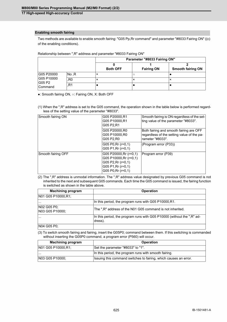
M800/M80 Series Programming Manual (M2/M0 Format) (2/2)
17 High-speed High-accuracy Control
625 IB-1501481-A
Two methods are available to enable smooth fairing: "G05 Pp,Rr command" and parameter "#8033 Fairing ON" ((c)
of the enabling conditions).
Relationship between ",R" address and parameter "#8033 Fairing ON"
●: Smooth fairing ON, ○: Fairing ON, X: Both OFF
(1) When the ",R" address is set to the G05 command, the operation shown in the table below is performed regard-less of the setting value of the parameter "#8033".
(2) The ",R" address is unmodal information. The ",R" address value designated by previous G05 command is notinherited to the next and subsequent G05 commands. Each time the G05 command is issued, the fairing functionis switched as shown in the table above.
(3) To switch smooth fairing and fairing, insert the G05P0; command between them. If this switching is commandedwithout inserting the G05P0 command, a program error (P560) will occur.
Enabling smooth fairing
Parameter "#8033 Fairing ON"
0Both OFF
1Fairing ON
2Smooth fairing ON
G05 P20000G05 P10000G05 P2Command
No ,R × ○ ●
,R0 × × ×
,R1 ● ● ●
Smooth fairing ON G05 P20000,R1G05 P10000,R1G05 P2,R1
Smooth fairing is ON regardless of the set-ting value of the parameter "#8033".
G05 P20000,R0G05 P10000,R0G05 P2,R0
Both fairing and smooth fairing are OFF regardless of the setting value of the pa-rameter "#8033".
G05 P0,Rr (r=0,1)G05 P1,Rr (r=0,1)
(Program error (P33))
Smooth fairing OFF G05 P20000,Rr (r=0,1)G05 P10000,Rr (r=0,1)G05 P2,Rr (r=0,1)G05 P1,Rr (r=0,1)G05 P0,Rr (r=0,1)
Program error (P39)
Machining program Operation
N01 G05 P10000,R1;
... In this period, the program runs with G05 P10000,R1.
N02 G05 P0;N03 G05 P10000;
The ",R" address of the N01 G05 command is not inherited.
... In this period, the program runs with G05 P10000 (without the ",R" ad-dress).
N04 G05 P0;
Machining program Operation
N01 G05 P10000,R1; Set the parameter "#8033" to "1".
... In this period, the program runs with smooth fairing.
N03 G05 P10000; Issuing this command switches to fairing, which causes an error.

M800/M80 Series Programming Manual (M2/M0 Format) (2/2)
17 High-speed High-accuracy Control
626IB-1501481-A
(4) To enable smooth fairing without setting the ",R" address to the G05 command, set the parameter "#8033 FairingON" to "2". The following operation is performed.
An operation example is as follows.
(In this figure, symbol ○ indicates the compensated position, and symbol ● indicates the commanded position.)
(1) Smooth fairing smoothens the path by compensating the positions designated by successive G01 commands.This function recognizes the paths before and after each commanded position, and compensates commandedpositions that cause a path to become unsmooth.
: Compensated position
: Commanded position
G05 P20000G05 P10000G05 P2
Smooth fairing ON
G05 P1G05 P0
Both fairing and smooth fairing are OFF
Details of Operation
[Commanded path] (indicated by dashed lines) G90 G00 X0.322 Y0.234;G01;N01 X0.413 Y0.276;N02 X0.507 Y0.311;N03 X0.603 Y0.338;N04 X0.701 Y0.357;N05 X0.798 Y0.399;N06 X0.900 Y0.343;N07 X1.003 Y0.399;N08 X1.095 Y0.328;N09 X1.205 Y0.367;N10 X1.284 Y0.282;N11 X1.399 Y0.304;N12 X1.465 Y0.207;
[Path after compensation] (indicated by solid lines)
The smooth parts are not targeted for compensation.
Only the unsmooth parts are compensated.
NO1
NO2NO3
NO5 NO6NO8NO7
NO9 NO10
NO11 NO12

M800/M80 Series Programming Manual (M2/M0 Format) (2/2)
17 High-speed High-accuracy Control
627 IB-1501481-A
(2) The path recognition range is determined by the parameter "#8038 Path recog. range". Determine the settingvalue to include multiple G01 commands in the path recognition range. When the setting value is "0", the rangeis set to "1.0 (1 mm)". When the path recognition range is set to 0.5 mm:
(3) The upper limit of the compensation distance can be determined so that the compensated position does not de-viate from the commanded position significantly. Designate this upper limit in the parameter "#8039 Comp. rangelimit". Ordinarily, designate the tolerance that is designated when generating the machining program with CAM.When the setting value is "0", the range is set to "0.005 (5 microns)". (a) When the compensation distance tolerance is high:
(b) When the compensation distance tolerance is low:
G90 G00 X0.322 Y0.234;G01;N01 X0.413 Y0.276;N02 X0.507 Y0.311;N03 X0.603 Y0.338;N04 X0.701 Y0.357;N05 X0.800 Y0.369;N06 X0.900 Y0.423;N07 X1.000 Y0.369;N08 X1.099 Y0.357;N09 X1.198 Y0.338;N10 X1.294 Y0.311;N11 X1.388 Y0.276;N12 X1.478 Y0.234;
The path is recognized in the range of 0.5 mm forward and 0.5 mm backward of the commanded position.
G90 G00 X0.322 Y0.234;G01;N01 X0.413 Y0.276;N02 X0.507 Y0.311;N03 X0.603 Y0.338;N04 X0.701 Y0.357;N05 X0.800 Y0.369;N06 X0.900 Y0.423;N07 X1.000 Y0.369;N08 X1.099 Y0.357;N09 X1.198 Y0.338;N10 X1.294 Y0.311;N11 X1.388 Y0.276;N12 X1.478 Y0.234;
G90 G00 X0.322 Y0.234;G01;N01 X0.413 Y0.276;N02 X0.507 Y0.311;N03 X0.603 Y0.338;N04 X0.701 Y0.357;N05 X0.800 Y0.369;N06 X0.900 Y0.423;N07 X1.000 Y0.369;N08 X1.099 Y0.357;N09 X1.198 Y0.338;N10 X1.294 Y0.311;N11 X1.388 Y0.276;N12 X1.478 Y0.234;
0.1mm0.1mm 0.1mm
0.1mm0.1mm
0.1mm0.1mm
0.1mm 0.1mm0.1mm
0.11mm 0.11mm
NO6 NO7
Compensation range tolerance
Desirable compen-sation position
Actual compensa-tion position
Compensation range tolerance
Desirable compen-sation position
Actual compensa-tion position

M800/M80 Series Programming Manual (M2/M0 Format) (2/2)
17 High-speed High-accuracy Control
628IB-1501481-A
(4) While smooth fairing is ON, the modal or mode status is changed, and smooth fairing may be set to OFF. Whilesmooth fairing is OFF, the commanded position is not compensated, and the axis moves as commanded. Fordetails on the modal or mode status that causes smooth fairing to be set to OFF, refer to "Relationship with otherfunctions".
(5) While smooth fairing is ON, it may be canceled temporarily depending on commands when: - there is a block that contains only a sequence number;- the modal status of the absolute value/incremental value command is changed by the G90 or G91 command;and- the movement command is issued to an axis other than the three basic axes.If a command that triggers a temporary cancel is inserted, the axis moves to the commanded position once. Forthe list of commands that trigger a temporary cancel, refer to "Relationship with other functions".
While smooth fairing is OFF, the axis moves to the commanded posi-tion.
G90 G00 X0.0 Y0.0;G01;N01 G01 X0.039 Y0.077;N02 G01 X0.139 Y0.080;N03 G01 X0.172 Y0.174;N04 G01 X0.271 Y0.161;N05 G01 X0.319 Y0.249;N06 G02 X1.122 Y0.249 R0.5;N07 G01 X1.169 Y0.161;N08 G01 X1.268 Y0.174;N09 G01 X1.301 Y0.080;N10 G01 X1.401 Y0.077;N11 G01 X1.441 Y0.000;
Compensation restarts from the block in which the enabling conditions are satisfied again.
G90 G00 X0.322 Y0.234;G90 G01;N01 X0.413 Y0.276;N02 X0.507 Y0.311;N03 X0.603 Y0.338;N04 X0.701 Y0.357;N05 X0.798 Y0.399;N06 X0.900 Y0.343;N07;N08 X1.003 Y0.399;N09 X1.095 Y0.328;N10 X1.205 Y0.367;N11 X1.284 Y0.282;N12 X1.399 Y0.304;N13 X1.465 Y0.207;
If a block that triggers a temporary cancel is in-serted, the axis moves to the commanded posi-tion once.
NO6
Valid Invalid Valid
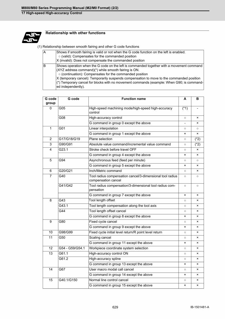
M800/M80 Series Programming Manual (M2/M0 Format) (2/2)
17 High-speed High-accuracy Control
629 IB-1501481-A
(1) Relationship between smooth fairing and other G code functions
Relationship with other functions
A Shows if smooth fairing is valid or not when the G code function on the left is enabled. ○ (valid): Compensates for the commanded positionX (invalid): Does not compensate the commanded position
B Shows operation when the G code on the left is commanded together with a movement command (XYZ address command)(*) while smooth fairing is ON. ○ (continuation): Compensates for the commanded positionX (temporary cancel): Temporarily suspends compensation to move to the commanded position(*) Temporary cancel for blocks with no movement commands (example: When G90; is command-ed independently).
G code group
G code Function name A B
0 G05 High-speed machining mode/high-speed high-accuracy control
(*1) -
G08 High-accuracy control ○ ×
G command in group 0 except the above - ×
1 G01 Linear interpolation ○ ○
G command in group 1 except the above × ×
2 G17/G18/G19 Plane selection ○ (*2)
3 G90/G91 Absolute value command/incremental value command ○ (*2)
4 G23.1 Stroke check before travel OFF ○ ×
G command in group 4 except the above × ×
5 G94 Asynchronous feed (feed per minute) ○ ○
G command in group 5 except the above × ×
6 G20/G21 Inch/Metric command ○ ×
7 G40 Tool radius compensation cancel/3-dimensional tool radius compensation cancel
○ ○
G41/G42 Tool radius compensation/3-dimensional tool radius com-pensation
○ ○
G command in group 7 except the above × ×
8 G43 Tool length offset ○ ×
G43.1 Tool length compensation along the tool axis ○ ×
G44 Tool length offset cancel ○ ×
G command in group 8 except the above × ×
9 G80 Fixed cycle cancel ○ ×
G command in group 9 except the above × ×
10 G98/G99 Fixed cycle initial level return/R point level return ○ ×
11 G50 Scaling cancel ○ ×
G command in group 11 except the above × ×
12 G54 - G59/G54.1 Workpiece coordinate system selection ○ ×
13 G61.1 High-accuracy control ON ○ ×
G61.2 High-accuracy spline ○ ×
G command in group 13 except the above × ×
14 G67 User macro modal call cancel ○ ×
G command in group 14 except the above × ×
15 G40.1/G150 Normal line control cancel ○ ×
G command in group 15 except the above × ×

M800/M80 Series Programming Manual (M2/M0 Format) (2/2)
17 High-speed High-accuracy Control
630IB-1501481-A
(*1) ○ (valid) for G05P2/G05P10000/G05P20000 and X (invalid) for the others.
(*2) ○ (continuation) if the modal state does not change before and after the command and X (temporary cancel)
otherwise.
(*3) ○ (Valid) for G54.4P0 and X (invalid) for the others.
(2) Relationship between smooth fairing and functions other than G codes
(*1) When there is a block containing only EOB, compensation is not temporarily canceled. However, in such a
case, the path slightly changes compared to when there are no blocks containing only EOB.
(*2) PLC interruption is not allowed during high-speed high-accuracy control II/III.
16 G69.1 Coordinate rotation cancel/3-dimensional coordinate con-version cancel
○ ×
G command in group 16 except the above × ×
17 G96/G97 Constant surface speed control ON/OFF ○ ×
18 G15 Polar coordinate command OFF ○ ×
G command in group 18 except the above × ×
19 G50.1 Mirror image by G code OFF ○ ○
G command in group 19 except the above × ×
21 G13.1/G113 Cylindrical interpolation/polar coordinate interpolation OFF ○ ○
G command in group 21 except the above × ×
24 G188/G189 Dynamic M/L program changeover/cancel ○ ×
27 G54.4 Workpiece installation error compensation (*3) ×
A Shows if smooth fairing is valid or not when the function on the left is enabled. ○ (valid): Compensates for the commanded positionX (invalid): Does not compensate the commanded position
B Shows operation when the function on the left is commanded while smooth fairing is ON. ○ (continuation): Compensates for the commanded positionX (temporary cancel): Temporarily suspends compensation to move to the commanded position
Function other than G code A B
Block containing only EOB(;) - (*1)
Block containing only comment - ○
Block containing only sequence number - ×
Block containing only MSTB command - ×
Block containing only F command - ×
If there is an axis movement command for other than three base axes - ×
Block without movement command - ×
During single block operation × ×
Subprogram call (G22 L_) ○ ×
Figure rotation subprogram call (G22 L_I_J_K_) × ×
Macro interruption (ION, UIT) ○ ×
User macro simple call ○ ×
User macro modal call × ×
MTB macro × ×
PLC interruption (PIT) (*2)
Coordinate rotation by parameter (G10 I_J_/K_) × ×
Mirror image by parameter setting (#8211 Mirror image) × ×
Mirror image with PLC signals ON × ×
G code group
G code Function name A B
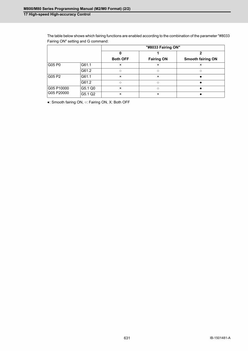
M800/M80 Series Programming Manual (M2/M0 Format) (2/2)
17 High-speed High-accuracy Control
631 IB-1501481-A
The table below shows which fairing functions are enabled according to the combination of the parameter "#8033
Fairing ON" setting and G command:
●: Smooth fairing ON, ○: Fairing ON, X: Both OFF
"#8033 Fairing ON"
0 1 2
Both OFF Fairing ON Smooth fairing ON
G05 P0 G61.1 × × ×
G61.2 ○ ○ ○
G05 P2 G61.1 × × ●
G61.2 ○ ○ ●
G05 P10000G05 P20000
G5.1 Q0 × ○ ●
G5.1 Q2 × × ●

M800/M80 Series Programming Manual (M2/M0 Format) (2/2)
17 High-speed High-accuracy Control
632IB-1501481-A
17.3.4 Acceleration Clamp Speed
This function is an additional function when the high-speed high-accuracy control II mode is ON
The cutting feed clamp speed during the high-speed high-accuracy control II / III mode, when the following param-
eter is set to "1", is clamped so that the acceleration generated by each block movement does not exceed the toler-
able value. This function clamps the speed optimally even at a section where "angle change at each block is small
but entire curvature is large" such as shown below.
The tolerable acceleration value is calculated from the parameter "#1206 G1bF" and "#1207 G1btL" setting values.
(Tolerable acceleration = #1206/#1207)
(*1) When a speed is set in "#2109 Clamp(H-precision)", clamp is executed at that speed. When the setting value
is "0", clamp is executed with "#2002 clamp".
Function and purpose
Related parameter Details
#8034 AccClampt ON 0 : Clamp the cutting speed with parameter "#2002 clamp" (*1) or the corner deceleration function.1: Cutting speed clamp determined by acceleration reference is also executed.
Speed control by curvature
If the tool moves along the large curvature section without deceler-ation, a large acceleration is generated resulting in a path error by curving inward.
R

M800/M80 Series Programming Manual (M2/M0 Format) (2/2)
17 High-speed High-accuracy Control
633 IB-1501481-A
17.3.5 Corner Deceleration in High-speed Mode
This function is an additional function when high-speed high-accuracy control II mode is ON.
During high-accuracy control, if the angle between the adjacent blocks in the machining program is large, this func-
tion, conventionally, automatically decelerates the machining so that the acceleration generated when passing
through the corner is maintained within the tolerable value.
If a fine block is inserted at the corner section in the machining program generated with the CAM, etc., the corner
passing speed will not match the periphery. This can affect the machining surface.
In the corner deceleration in the high-speed mode, even when this type of fine block is inserted, the corner will be
judged from a vantage point by setting the below parameter.
The fine block is excluded at the judgment of an angle, but is not excluded from the actual movement command.
(a) When"#8036 CordecJudge" is set to "1", corner deceleration is realized without an influence of fine blocks.
Function and purpose
Related parameter Details
#8036 CordecJudge 0 : Judge the corner from the angle of the neighboring block.1 : Judge the corner from the angle of the neighboring block, excluding the minute blocks.
#8027 CorJudgeL Exclude shorter block than this setting value.
High-speed mode corner deceleration
(a)

M800/M80 Series Programming Manual (M2/M0 Format) (2/2)
17 High-speed High-accuracy Control
634IB-1501481-A
17.3.6 Precautions on High-speed High-accuracy Control
(1) The validity of each high-speed high-accuracy control function depends on the MTB specifications. If any of theabove is commanded when the corresponding specification is not available on the machine, a program error(P39) will occur.
(2) The machining speed may drop depending on the number of characters in one block.
(3) Feedrate command F is clamped with the "#2110 Clamp (H-precision)" (Cutting feed clamp speed for high-ac-curacy control mode) set with parameter.
(4) The rapid traverse rate conforms to "#2109 Rapid(H-precision)" (Rapid traverse rate during high-accuracy con-trol mode) set by the parameter.
(5) When "#2109 Rapid(H-precision)" (high-accuracy control mode rapid traverse rate) is set to "0", however, themovement follows "#2001 rapid" (Rapid traverse rate) set with the parameter. Also, when "#2110 Clamp (H-pre-cision)" (Cutting feed clamp speed for high-accuracy control mode) is set to "0", the speed will be clamped with"#2002 clamp" (Cutting clamp speed) set with parameter.
(6) The automatic operation processing has priority in the high-speed high-accuracy control I/II/III modal, so thescreen display, etc., may be delayed.
(7) The speed will decelerate once at the high-speed high-accuracy control I command (G05.1 Q1), high-speedhigh-accuracy control I OFF command (G05.1 Q0), high-speed high-accuracy control II command (G05P10000),high-speed high-accuracy control III command (G05P20000), and high-speed high-accuracy control II/III OFFcommand (G05P0), so turn ON and OFF when the tool separates from the workpiece.
(8) When carrying out high-speed high-accuracy control I/II operation during tape mode, the machining speed maybe suppressed depending on the program transmission speed and the number of characters in one block.
(9) If the parameter "#1205 G0bdcc" (G0 acceleration/deceleration before interpolation) is set to "1", the value setwith the parameter "#2224 SV024" (in-position detection width) will be used as the in-position width. "#2077G0inps" (G0 in-position width) and the ",I" command (programmable in-position check) are disabled.
(1) While high-speed high-accuracy control II/III is enabled, the following variable commands or operation com-mands can be designated following the axis address. When other variable commands or operation commandsare issued, high-speed high-accuracy control II/III is canceled temporarily.
(a) Referencing common variables or local variables
Common variables or local variables can be referenced (example: X#500, Y#1, Z##100, A#[#101], etc.).
(b) Four basic arithmetic rule
Four basic arithmetic rule (+, -, *, /) operations are available, and also the operation priority can be designated
using parentheses ( ) ([#500 + #501] * #502, etc.).
(1) Command G05.1Q0 after turning the tool radius compensation OFF. If G05.1Q0 is commanded without turningthe tool radius compensation OFF, a program error (P29) will occur.
(2) G05.1Q1; and G05.1Q0; are independent commands. If a sequence number other than "N" is commanded, theprogram error (P33) will occur.
(3) The program error (P33) will occur if the G05.1 command block does not contain a Q command.
(4) If the high-speed high-accuracy control I command is issued in the high-speed high-accuracy control II modal, aprogram error (P34) will occur.
Precautions
Common precautions on high-speed high-accuracy control I/II/III
Common precautions on high-speed high-accuracy control II/III
Precautions on high-speed high-accuracy control I
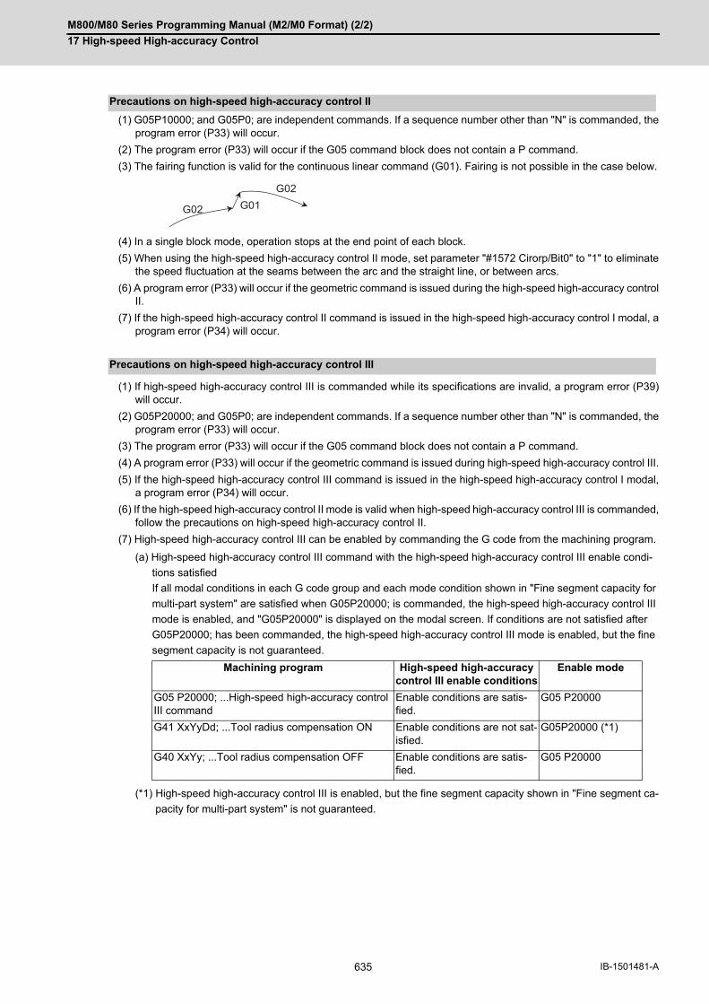
M800/M80 Series Programming Manual (M2/M0 Format) (2/2)
17 High-speed High-accuracy Control
635 IB-1501481-A
(1) G05P10000; and G05P0; are independent commands. If a sequence number other than "N" is commanded, theprogram error (P33) will occur.
(2) The program error (P33) will occur if the G05 command block does not contain a P command.
(3) The fairing function is valid for the continuous linear command (G01). Fairing is not possible in the case below.
(4) In a single block mode, operation stops at the end point of each block.
(5) When using the high-speed high-accuracy control II mode, set parameter "#1572 Cirorp/Bit0" to "1" to eliminatethe speed fluctuation at the seams between the arc and the straight line, or between arcs.
(6) A program error (P33) will occur if the geometric command is issued during the high-speed high-accuracy controlII.
(7) If the high-speed high-accuracy control II command is issued in the high-speed high-accuracy control I modal, aprogram error (P34) will occur.
(1) If high-speed high-accuracy control III is commanded while its specifications are invalid, a program error (P39)will occur.
(2) G05P20000; and G05P0; are independent commands. If a sequence number other than "N" is commanded, theprogram error (P33) will occur.
(3) The program error (P33) will occur if the G05 command block does not contain a P command.
(4) A program error (P33) will occur if the geometric command is issued during high-speed high-accuracy control III.
(5) If the high-speed high-accuracy control III command is issued in the high-speed high-accuracy control I modal,a program error (P34) will occur.
(6) If the high-speed high-accuracy control II mode is valid when high-speed high-accuracy control III is commanded,follow the precautions on high-speed high-accuracy control II.
(7) High-speed high-accuracy control III can be enabled by commanding the G code from the machining program.
(a) High-speed high-accuracy control III command with the high-speed high-accuracy control III enable condi-
tions satisfied
If all modal conditions in each G code group and each mode condition shown in "Fine segment capacity for
multi-part system" are satisfied when G05P20000; is commanded, the high-speed high-accuracy control III
mode is enabled, and "G05P20000" is displayed on the modal screen. If conditions are not satisfied after
G05P20000; has been commanded, the high-speed high-accuracy control III mode is enabled, but the fine
segment capacity is not guaranteed.
(*1) High-speed high-accuracy control III is enabled, but the fine segment capacity shown in "Fine segment ca-
pacity for multi-part system" is not guaranteed.
Precautions on high-speed high-accuracy control II
Precautions on high-speed high-accuracy control III
Machining program High-speed high-accuracy control III enable conditions
Enable mode
G05 P20000; ...High-speed high-accuracy control III command
Enable conditions are satis-fied.
G05 P20000
G41 XxYyDd; ...Tool radius compensation ON Enable conditions are not sat-isfied.
G05P20000 (*1)
G40 XxYy; ...Tool radius compensation OFF Enable conditions are satis-fied.
G05 P20000
G02
G01G02

M800/M80 Series Programming Manual (M2/M0 Format) (2/2)
17 High-speed High-accuracy Control
636IB-1501481-A
(b) High-speed high-accuracy control III command with no high-speed high-accuracy control III enable condi-
tions satisfied
If the conditions shown in "Fine segment capacity for multi-part system" are not satisfied when G05P20000;
is commanded, the high-speed high-accuracy control II mode is enabled, and "G05P10000" is displayed on
the modal screen. In this case, even if all the conditions shown in "Fine segment capacity for multi-part sys-
tem" are satisfied after G05P20000; has been commanded, the high-speed high-accuracy control III mode
is not enabled. To enable the high-speed high-accuracy control III mode, command G05P20000; again.
Machining program High-speed high-accuracy control III enable conditions
Enable mode
G41 XxYyDd; ...Tool radius compensation ONEnable conditions are not sat-isfied.
G05 P10000G05 P20000; ...High-speed high-accuracy control III command
G40 XxYy; ...Tool radius compensation OFF Enable conditions are satis-fied.
G05 P10000

M800/M80 Series Programming Manual (M2/M0 Format) (2/2)
17 High-speed High-accuracy Control
637 IB-1501481-A
17.4 Spline Interpolation; G05.1 Q2/Q0
This function automatically generates a spline curve that passes through a sequence of points commanded by the
fine segment machining program, and interpolates the path along this curve. This enables high-speed and high-ac-
curacy machining to be achieved.
There are two types of spline interpolation command format: G61.2 and G05.1Q2. Both formats can be used regard-
less of the parameter "#1267 ext03/bit0" setting if the spline interpolation specifications are available to the machine.
This section describes the G05.1Q2 command. For G61.2, refer to "17.6 High-accuracy Spline Interpolation; G61.2".
The G05.1Q2 command can be issued when the machining parameter "#8025 SPLINE ON" is set to "1" in the high-
speed high-accuracy control function II or III mode. The following explanation is limited to the spline function in the
high-speed high-accuracy control function II or III mode.
(1) High-speed high-accuracy control III functions as high-speed high-accuracy control II while spline interpolationis ON.
Conditions under which the command can be issued and functions that are valid during a specific modal differ be-
tween G61.2 and G05.1Q2.
(*1) The validity of the high-speed high-accuracy control II or III function depends on the MTB specifications.
A program error (P34) will occur if the conditions under which the command can be issued are not satisfied.
(*2) The spline interpolation smoothly connects a sequence of points commanded by program. As a result, the
glossy machining surface can be obtained, and the machining time can be reduced because the frequency of
the corner deceleration decreases compared with conventional linear interpolation.
Function and purpose
Difference between G61.2 and G05.1Q2
Command formatConditions under
which the command can be issued
Functions that become valid
Spline interpolation Fairing High-accuracy con-trol
(*2) (*3) (*4)
G61.2 None Valid Valid Valid
G05.1 Q2 When the system is in the high-speed high-accuracy control II or III mode and "#8025 SPLINE ON" is set to "1" (*1)
Valid Can be turned ON and OFF using "#8033 Fairing ON"
Valid (Because the system is in the high-speed high-accuracy control II or III mode)
G61.2/G05.1Q2
G64/G61.1
Note

M800/M80 Series Programming Manual (M2/M0 Format) (2/2)
17 High-speed High-accuracy Control
638IB-1501481-A
(*3) Super-fine blocks often included in the data generated with CAM are deleted. Such a super-fine block may
scratch the machining surface, and increase machining time because of acceleration/deceleration. This function
prevents these problems.
(*4) The following shows the functions and their operations included in the high-accuracy control described in this
section.
The validity of the SSS control function depends on the MTB specifications.
Functions of high-accuracy control
Contents
Acceleration/deceleration before interpolation (Constant inclination acceleration/deceleration, S-pat-tern filter)
The process is the same as that performed in the high-accuracy control mode (G61.1/G08P1).
Optimum corner deceleration As is done in the high-accuracy control mode (G61.1/G08P1), op-timum corner deceleration is performed at points where the angle between blocks exceeds the spline cancel angle or points at the boundary between G01 and G00, because spline interpolation is temporarily canceled to make corners.
Arc speed clamp (For spline in-terpolation, curvature speed clamp)
Clamp speed is calculated based on the spline curvature radius. The process for arc blocks is the same as that performed in the high-accuracy control mode (G61.1/G08P1).
Curvature radius speed clamp Clamp speed is calculated based on the spline curvature radius.
Arc entrance/exit deceleration control
The process for arc blocks is the same as that performed in the high-accuracy control mode (G61.1/G08P1).
SSS Control Optimum speed control is performed so that the process is not af-fected by steps or reverse runs.
Feed forward control The process is the same as that performed in the high-accuracy control mode (G61.1/G08P1).
Command format
Spline interpolation mode ON
G05.1 Q2 X0 Y0 Z0 ;
Spline interpolation mode OFF
G05.1 Q0;

M800/M80 Series Programming Manual (M2/M0 Format) (2/2)
17 High-speed High-accuracy Control
639 IB-1501481-A
Normally, once the spline function is activated, one curve is generated by smoothly connecting all points until it is
canceled. However, if a corner edge should be created, or if the segment length is long and spline interpolation
should not to be carried out, the function can be canceled temporarily with the parameters.
(1) Cancel angle
If the angle θ of two consecutive blocks exceeds the value set in parameter "#8026 CANCEL ANG.", the spline
function will be temporarily canceled, and optimum corner deceleration will be applied. When this parameter is
not set (=0), the spline interpolation will be constantly applied. The corner deceleration angle of the high-accu-
racy control function is valid during the temporary cancellation, and the optimum corner deceleration will be ap-
plied.
(Example 1) Cancel angle = 60°
(Example 2) Cancel angle = 0°
<Note>
If the section to be a corner is smooth when actual machining is carried out, lower the "CANCEL ANG.".If a smooth section becomes a corner, increase the "CANCEL ANG.".If "CANCEL ANG." >= "DCC ANGLE", the axis will decelerate at all corners where the angle is larger than
the "CANCEL ANG." .If the "CANCEL ANG." < "DCC ANGLE", corner deceleration will not be applied if the corner angle is equal
to or less than "DCC ANGLE" even if the spline interpolation is canceled.
Detailed description
Temporary cancellation of spline interpolation
Programmed command Spline interpolation path
Programmed command Spline interpolation path

M800/M80 Series Programming Manual (M2/M0 Format) (2/2)
17 High-speed High-accuracy Control
640IB-1501481-A
(2) Fine segment length
If the movement amount in a block is longer than the parameter "#8030 MINUTE LENGS", the spline function
will be temporarily canceled, and the linear interpolation will be executed. When this parameter is not set (= 0),
the fine segment length will be 1mm.
When the segment length in a block > fine segment length (#8030 MINUTE LENGS), the linear interpolation will
be executed.
If the fine segment length is set to "-1", the spline interpolation will not be canceled according to the block length.
(3) When a block without movement exists
If a block without movement exists during the spline function is operating, the spline interpolation will be canceled
temporarily. Note that blocks containing only ";" will not be viewed as a block without movement.
(4) When a block markedly longer than other blocks exists in spline function
Given that the i-th block length is Li in the spline interpolation mode and if the following condition is met, the block
will be interpreted as a linear section, and the spline interpolation mode will be temporarily canceled:
Li > Li-1 x 8 or Li > Li+1 x 8
However, if the parameter "#8030 MINUTE LENGS" is set to "-1", the mode will not be canceled.
Linear interpolation
Block without movement
Li > Li-1 × 8 or Li > Li + 1 × 8
Li+1Li - 1

M800/M80 Series Programming Manual (M2/M0 Format) (2/2)
17 High-speed High-accuracy Control
641 IB-1501481-A
Normally, once the spline function is enabled, one curve is generated by connecting all points smoothly until the
function is canceled. But if the spline curve shape should be corrected, the spline curve shape can be corrected with
the parameters.
(1) Chord error of block containing inflection point
When changing the CAD curve data into fine segments with the CAM, normally, the tolerance (chord error) of
the curve is approximated in segments that are approx. 10μm. If there is an inflection point in the curve, the
length of the block containing the inflection point may lengthen. (Because the tolerance is applied at both ends
near the inflection point.) If the block lengths with this block and the previous and subsequent blocks are unbal-
anced, the spline curve in this block may have a large error in respect to the original curve.
At sections where the tolerance (chord error) of the fine segment block and spline curve in a block containing
this type of inflection point, if the chord error in the corresponding section is larger than the value set in parameter
(#8027 Toler-1), the spline curve shape is automatically corrected so that the error is within the designated value.
However, if the maximum chord error of the corresponding section is more than five times larger than the param-
eter "#8027" setting value, the spline function will be temporarily canceled.
The curve is corrected only in the corresponding block.
The corrections are carried out under the following conditions for each block in the spline interpolation mode.
When the above conditions are satisfied, the spline curve will be corrected so that the error between P3-P4 in
Fig. 2 is within the designated value.
Spline interpolation curve shape correction
There is an inflection point in the spline curve, and the maximum error of the spline curve and linear block is larger than parameter "#8027". (Distance between P3-P4 in Fig. 1)
Tolerance (chord error) Spline curve
Inflection point
Fine segment
Fig. 1 Spline curve before error correction
P6P5
P4
P7
P0
P1
P2P3

M800/M80 Series Programming Manual (M2/M0 Format) (2/2)
17 High-speed High-accuracy Control
642IB-1501481-A
In parameter "#8027 Toler-1", set the tolerance when developed into fine segments with the CAM. Set a smaller
value if the expansion (indentation) is apparent due to the relationship with the adjacent cutting paths.
(2) Chord error of block not containing inflection point
Even in blocks that do not contain an inflection point, if the block lengths are not matched, the tolerance of the
spline curve may increase. The curve may also expand due to the effect of relatively short blocks.
At sections where the tolerance (chord error) between the fine segment block and spline curve in a block without
an inflection point becomes large, if the chord error in the corresponding section is larger than the value set in
parameter (#8028 Toler-2), the spline curve shape is automatically corrected so that the error is within the des-
ignated value. However, if the maximum chord error of the corresponding section is more than five times larger
than the parameter "#8028" setting value, the spline function will be temporarily canceled.
The curve is corrected only in the corresponding block.
The corrections are carried out under the following conditions for each block in the spline interpolation mode.
When the above conditions are satisfied, the spline curve will be corrected so that the error between P2-P3 in
Fig. 4 is within the designated value.
Chord error designated in the parameter "Toler"
Spline curve before correction
Spline curve after correction
Fig. 2 Spline curve after error correction
There is no inflection point in the spline curve, and the maximum error of the spline curve and linear block is larger than parameter "#8028". (Distance between P2-P3 in Fig. 3)
Spline curve
Fine segment
Tolerance (chord error)
Fig. 3 Spline curve before error correction
P3
P4
P1
P2 P3
P4
P5
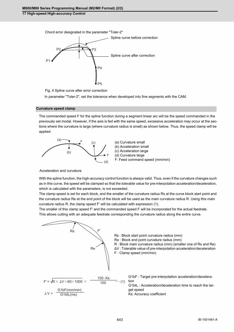
M800/M80 Series Programming Manual (M2/M0 Format) (2/2)
17 High-speed High-accuracy Control
643 IB-1501481-A
In parameter "Toler-2", set the tolerance when developed into fine segments with the CAM.
The commanded speed F for the spline function during a segment linear arc will be the speed commanded in the
previously set modal. However, if the axis is fed with the same speed, excessive acceleration may occur at the sec-
tions where the curvature is large (where curvature radius is small) as shown below. Thus, the speed clamp will be
applied.
With the spline function, the high-accuracy control function is always valid. Thus, even if the curvature changes such
as in this curve, the speed will be clamped so that the tolerable value for pre-interpolation acceleration/deceleration,
which is calculated with the parameters, is not exceeded.
The clamp speed is set for each block, and the smaller of the curvature radius Rs at the curve block start point and
the curvature radius Re at the end point of the block will be used as the main curvature radius R. Using this main
curvature radius R, the clamp speed F' will be calculated with expression (1).
The smaller of this clamp speed F' and the commanded speed F will be incorporated for the actual feedrate.
This allows cutting with an adequate feedrate corresponding the curvature radius along the entire curve.
Chord error designated in the parameter "Toler-2"
Spline curve before correction
Spline curve after correction
Fig. 4 Spline curve after error correction
Curvature speed clamp
(a) Curvature small (b) Acceleration small (c) Acceleration large (d) Curvature large F: Feed command speed (mm/min)
Acceleration and curvature
Rs : Block start point curvature radius (mm) Re : Block end point curvature radius (mm) R : Block main curvature radius (mm) (smaller one of Rs and Re) ∆V : Tolerable value of pre-interpolation acceleration/deceleration F : Clamp speed (mm/min)
G1bF : Target pre-interpolation acceleration/decelera-tion G1btL : Acceleration/deceleration time to reach the tar-get speed Ks: Accuracy coefficient
P1
P2 P3
P4
P5
(c)F
F
(a)
(b)
(d)
Rs
Re
F'
V = G1bF(mm/min)
G1btL(ms)
F' = R V 60 1000 (1)100- Ks
100

M800/M80 Series Programming Manual (M2/M0 Format) (2/2)
17 High-speed High-accuracy Control
644IB-1501481-A
(1) The spline function carries out spline interpolation when the following conditions are all satisfied. If the followingconditions are not satisfied, the spline function will be canceled once, and the judgment whether to carry out newspline from the next block will be made.
It is the movement only of three axes set to the basic axes I, J and K.When the block length is smaller than the value of the machining parameter "#8030 MINUTE LENGS".When the movement amount is not 0.When one of the following modes is entered.
G01: Linear interpolation, G40: Tool compensation cancel, G64: Cutting mode, G80: Fixed cycle cancel, G94: Feed per minute
When only an axis commanded with G05.1Q2 is commanded.A single block is not being executed.
(2) Graphic check will draw the shape of when the spline interpolation OFF.
(3) During the spline function mode, the command to the axis must be issued after G05.1 Q2 in the same block. Forexample, if the X axis and Y axis are to be commanded in the spline function mode, command "G05.1 Q2 X0Y0;". The command block containing an axis not designated with this command (G05.1 Q2 X0 Y0) in the splinefunction mode will carry out linear interpolation instead of spline interpolation.
(4) If G05.1 Q2 is commanded when not in the high-speed high-accuracy control function II or III mode, the programerror (P34) will occur.
(5) If the machining parameter "#8025 SPLINE ON" is "0" in the high-speed high-accuracy control function II or IIImode and G05.1 Q2 is commanded, the program error (P34) will occur.
(6) Up to three axes set as the basic axes I, J and K can be commanded for the spline function.
Refer to "Relationship with other functions" in "17.2 High-accuracy control".
(1) If this function are not provided and "G05.1 Q2" is commanded, the program error (P39) will occur.
(2) Even if "-1" is set for parameter "#8030 MINUTE LENGS", the spline function will be temporarily canceled by thecancel conditions (cancel angle, non-movement block, excessive chord error, etc.) other than the block length.
(3) Command "G05.1 Q2" and "G05.1 Q0" commands in independent blocks. A program error (P33) will occur if not commanded in independent blocks.
(4) The program error (P33) will occur if the G05.1 command block does not contain a Q command.
(5) A program error (P34) will occur if the number of axis in the part system does not exceed 3.
Program example
:
G91;
G05 P10000; High-speed high-accuracy control function II mode ON
:
G05.1 Q2 X0 Y0 Z0; Spline interpolation mode ON
G01 X1000 Z-300 F1000;
X1000 Z-200;
Y1000;
X-1000 Z-50;
X-1000 Z-300;
G05.1 Q0; Spline interpolation mode OFF
:
G05 P0 ; High-speed high-accuracy control function II mode OFF
:
Relationship with other functions
Precautions
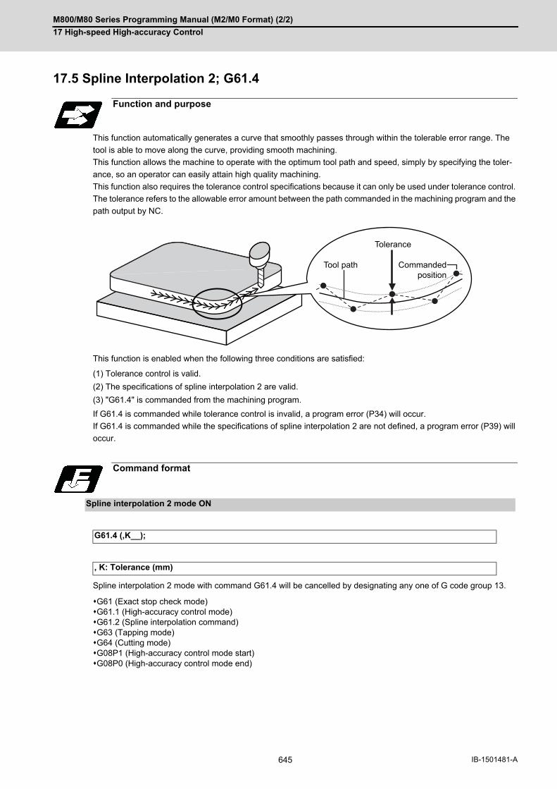
M800/M80 Series Programming Manual (M2/M0 Format) (2/2)
17 High-speed High-accuracy Control
645 IB-1501481-A
17.5 Spline Interpolation 2; G61.4
This function automatically generates a curve that smoothly passes through within the tolerable error range. The
tool is able to move along the curve, providing smooth machining.
This function allows the machine to operate with the optimum tool path and speed, simply by specifying the toler-
ance, so an operator can easily attain high quality machining.
This function also requires the tolerance control specifications because it can only be used under tolerance control.
The tolerance refers to the allowable error amount between the path commanded in the machining program and the
path output by NC.
This function is enabled when the following three conditions are satisfied:
(1) Tolerance control is valid.
(2) The specifications of spline interpolation 2 are valid.
(3) "G61.4" is commanded from the machining program.
If G61.4 is commanded while tolerance control is invalid, a program error (P34) will occur.
If G61.4 is commanded while the specifications of spline interpolation 2 are not defined, a program error (P39) will
occur.
Spline interpolation 2 mode with command G61.4 will be cancelled by designating any one of G code group 13.
G61 (Exact stop check mode)G61.1 (High-accuracy control mode)G61.2 (Spline interpolation command)G63 (Tapping mode)G64 (Cutting mode)G08P1 (High-accuracy control mode start)G08P0 (High-accuracy control mode end)
Function and purpose
Command format
Spline interpolation 2 mode ON
G61.4 (,K__);
, K: Tolerance (mm)
Tolerance
Commanded position
Tool path

M800/M80 Series Programming Manual (M2/M0 Format) (2/2)
17 High-speed High-accuracy Control
646IB-1501481-A
Designate the tolerance using one of the following methods.
Designate the tolerance using the parameter "#2659 tolerance". When the setting value is "0", this function runswith "0.01 (mm)".
Designate the numeric value following the ",K" address in the G61.4 command.
(a) The range of the command value is 0.000 to 100.000 (mm). If a value exceeding the range is commanded,
a program error (P35) will occur.
(b) The tolerance designated by ",K" is applied to all axes in the part system.
(c) When "0" is set to ",K" or ",K" is omitted, the program runs using the setting value of the parameter "#2659
tolerance" as the tolerance.
(d) The tolerance designated by ",K" is not held after reset. Therefore, if ",K" is not designated in the G61.4 com-
mand after reset, the setting value of the parameter "#2659 tolerance" is enabled.
[Program example]
Spline interpolation 2 interpolates a command point row of the machining program with a smooth curve. The follow-
ing figures show the command points and paths.
Detailed description
Tolerance specification method
:G91 ;
G61.4 ,K0.02; Designate tolerance 0.02 (mm).
G01 X0.1 Z0.1 F1000 ;X0.1 Z-0.2 ;Y0.1 ;
Tolerance: 0.02 (mm)
G61.4 ,K0; Designate the tolerance 0 [mm].
X-0.1 Z-0.05 ;X-0.1 Z-0.3 ;
Tolerance: Follows parameter "#2659 tolerance".
G64 ;:
Details of Operation
Basic operations
Program command point Program command path
Interpolated path

M800/M80 Series Programming Manual (M2/M0 Format) (2/2)
17 High-speed High-accuracy Control
647 IB-1501481-A
Since the path is interpolated with a smooth curve, the interpolated path is different from that of the commanded
path of the machining program. Set the tolerance between the interpolated path and commanded path in the param-
eter "#2659 tolerance".
The interpolated path varies depending on the tolerance as shown below.
[For curve] [For corner]
For curve For corner
Tolerance: High
Tolerance: Low
Tolerance amount
Tolerance amount
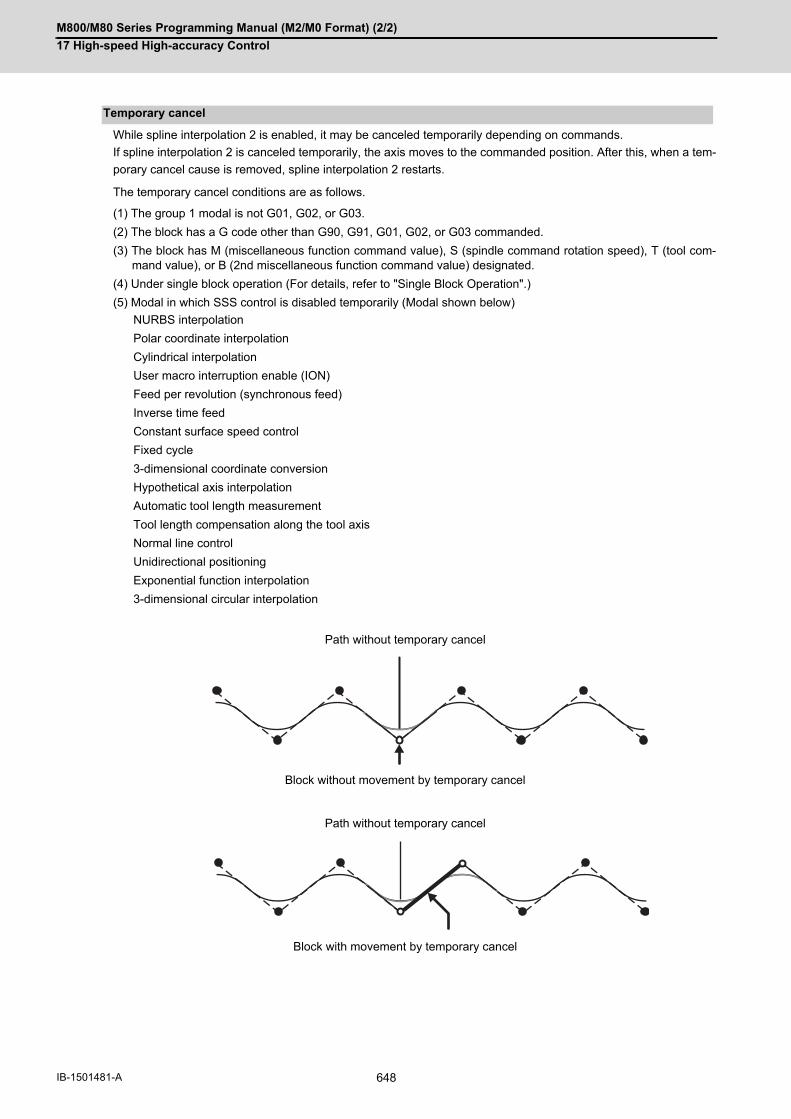
M800/M80 Series Programming Manual (M2/M0 Format) (2/2)
17 High-speed High-accuracy Control
648IB-1501481-A
While spline interpolation 2 is enabled, it may be canceled temporarily depending on commands.
If spline interpolation 2 is canceled temporarily, the axis moves to the commanded position. After this, when a tem-
porary cancel cause is removed, spline interpolation 2 restarts.
The temporary cancel conditions are as follows.
(1) The group 1 modal is not G01, G02, or G03.
(2) The block has a G code other than G90, G91, G01, G02, or G03 commanded.
(3) The block has M (miscellaneous function command value), S (spindle command rotation speed), T (tool com-mand value), or B (2nd miscellaneous function command value) designated.
(4) Under single block operation (For details, refer to "Single Block Operation".)
(5) Modal in which SSS control is disabled temporarily (Modal shown below)
Temporary cancel
NURBS interpolation
Polar coordinate interpolation
Cylindrical interpolation
User macro interruption enable (ION)
Feed per revolution (synchronous feed)
Inverse time feed
Constant surface speed control
Fixed cycle
3-dimensional coordinate conversion
Hypothetical axis interpolation
Automatic tool length measurement
Tool length compensation along the tool axis
Normal line control
Unidirectional positioning
Exponential function interpolation
3-dimensional circular interpolation
Path without temporary cancel
Block without movement by temporary cancel
Path without temporary cancel
Block with movement by temporary cancel

M800/M80 Series Programming Manual (M2/M0 Format) (2/2)
17 High-speed High-accuracy Control
649 IB-1501481-A
Feed hold allows a deceleration stop in the middle of a curve. However, no interrupt operation can be performed. If
the mode is switched to the manual mode or MDI mode during the feed hold, an operation error (M01 0180) will
occur and the interrupt operation will be prohibited.
After the program has been stopped by the feed hold, the movement on the curve can be restarted by the cycle start.
The tool path specified just after the program has restarted is different from that specified when the program is not
stopped by the feed hold, and the tool passes an area near the program-commanded shape.
During single block operation, spline interpolation 2 is canceled temporarily. In this period, linear interpolation is car-
ried out at the commanded position. If single block is set to ON during continuous operation, the currently processed
block stops on a curve, and the next and subsequent blocks stop on the commanded points.
Feed hold
Program commanded shape
NC commanded shape(Not stopped by the feed hold)
NC commanded shape(Stopped by the feed hold)
Single block operation
(a) Sets the single block signal ON.
(b) Block stop on curve (e) Restarts spline interpolation 2.
(d) Sets the single block signal OFF.
(c) Block stop at commanded position

M800/M80 Series Programming Manual (M2/M0 Format) (2/2)
17 High-speed High-accuracy Control
650IB-1501481-A
Spline interpolation 2 and smooth fairing can be used together.
A spline interpolation 2 curve is generated along the points that are compensated by smooth fairing.
Spline interpolation 2 and tool radius compensation can be combined. A spline curve is generated along the path
for which the radius is compensated.
Spline interpolation 2 and high-speed high-accuracy control III can be combined. However, the fine segment pro-
cessing capacity is limited.
Spline interpolation 2 (G61.4) and spline interpolation (G61.2/G05.1Q2) cannot be combined.
The following differences are between spline interpolation 2 (G61.4) and spline interpolation (G61.2/G05.1Q2).
(*1) The axis passes through the commanded points at the start and end points.
The following shows differences between the spline interpolation 2 path and spline interpolation path.
Relationship with other functions
Smooth fairing
Compensation by smooth fairing
Smooth fairing OFF
Smooth fairing ON
Tool radius compensation
High-speed high-accuracy control III
Spline interpolation
Feature of spline curve Parameter for adjusting the curve shape
Spline interpolation 2(G61.4)
Passes near the commanded points. (*1)
#2659 tolerance
Spline interpolation(G61.2/G05.1Q2)
Passes on the commanded points. #8026 CANCEL ANG.#8027 Toler-1#8028 Toler-2#8029 FairingL#8030 MINUTE LENGS#8033 Fairing ON
Spline interpolation 2 Spline interpolation

M800/M80 Series Programming Manual (M2/M0 Format) (2/2)
17 High-speed High-accuracy Control
651 IB-1501481-A
(1) The graphic check drawing is not carried out during spline interpolation 2 (the period from G61.4 to the cancelcommand).
(2) PLC interrupt is not available during spline interpolation 2. If an PLC interrupt is performed during spline interpo-lation 2, the operation error (M01 0180) will occur.
Others
G code Function name When the G codes shown on the left are commanded while spline interpolation 2 is en-
abled
When spline interpolation 2 is en-abled while the functions shown on
the left are enabled
G43.4G43.5
Tool center point control Program error (P941) Program error (P942)
G68.2G68.3
Inclined surface machin-ing command
Program error (P953) Program error (P951)
G54.4P1 to P7
Workpiece installation error compensation
Program error (P546) Program error (P545)
Precautions

M800/M80 Series Programming Manual (M2/M0 Format) (2/2)
17 High-speed High-accuracy Control
652IB-1501481-A
17.6 High-accuracy Spline Interpolation; G61.2
This function automatically generates a spline curve that passes through a sequence of points commanded by the
fine segment machining program, and interpolates the path along this curve. This enables high-speed and high-ac-
curacy machining to be achieved.
This function has two functions; fairing function to delete unnecessary fine blocks, and spline interpolation function
to connect smoothly a sequence of points commanded by the program.
The high-accuracy control function G61.1 is also valid.
The high-accuracy spline Interpolation is valid only for the first part system.
G61.2 cannot be commanded in the 2nd part system even when the multi-part system simultaneous high-accuracy
specifications are available.
There are two types of spline interpolation command format: G61.2 and G05.1Q2. Both formats can be used regard-
less of the parameter "#1267 ext03/bit0" setting if the spline interpolation specifications are available to the machine.
This section describes the G61.2 command. For information about differences between G05.1Q2 and G61.2 or fea-
tures of spline interpolation, refer to "Spline Interpolation ; G05.1Q2".
The "G61.2" high-accuracy spline interpolation mode is canceled when any of the functions of G code group 13 is
commanded.
(1) Fairing
Refer to "Additional functions when high-speed high-accuracy control II mode is ON" in "High-speed high-accu-
racy control".
(2) Spline interpolation
Refer to "Detailed description" of "Spline Interpolation".
Function and purpose
Command format
G61.2 X__ Y__ Z__ F__ ; or G61.2 ; ... Spline mode ON
X X axis end point coordinate
Y Y axis end point coordinate
Z Z axis end point coordinate
F Feedrate
Detailed description

M800/M80 Series Programming Manual (M2/M0 Format) (2/2)
17 High-speed High-accuracy Control
653 IB-1501481-A
(1) The spline interpolation is available when the following conditions are all satisfied. If the following conditions are
not satisfied, the spline function will be canceled once, and the judgment whether to carry out new spline from
the next block will be made.
- It is the movement only of three axes set to the basic axes I, J and K.
- When the block length is smaller than the value of the machining parameter "#8030 MINUTE LENGS".
- When the movement amount is not 0.
- The group 1 command is G01 (linear interpolation).
- Operation in fixed cycle modal
- It is not during hypothetical axis interpolation mode.
- It is not during 3-dimensional coordinate conversion modal.
- It is not in a single block mode.
(2) The spline function is a modal command of group 13. This function is valid from G61.2 command block.
(3) The spline function is canceled by group 13 commands (G61 to G64).
(4) The spline function is canceled by NC reset 2, reset & rewind, NC reset 1 (the setting which does not hold modal
when NC is reset) or power ON/OFF.
(1) If this function are not provided and G61.2 is commanded, the program error (P39) will occur.
(2) Even if "-1" is set for parameter "#8030 MINUTE LENGS", the spline function will be temporarily canceled by the
cancel conditions (cancel angle, non-movement block, excessive chord error, etc.) other than the block length.
(3) Graphic check will draw the shape of when the spline interpolation OFF.
(4) A program error (P34) will occur if the number of axis in the part system does not exceed 3.
Program example
:G91 ;G61.2 ; ...... Spline interpolation mode ONG01 X0.1 Z0.1 F1000 ;X0.1 Z-0.2 ;Y0.1 ;X-0.1 Z-0.05;X-0.1 Z-0.3;G64 ; ...... Spline interpolation mode OFF:
Precautions

M800/M80 Series Programming Manual (M2/M0 Format) (2/2)
17 High-speed High-accuracy Control
654IB-1501481-A
17.7 Machining Condition Selection I; G120.1, G121
After initializing the machining condition parameter groups with the machining condition selection I function, the ma-
chining condition parameter groups can be switched by G code command.
Switching is also possible on the machining condition selection screen. In that case, however, the machining con-
ditions selected on the screen are applied to all part systems.
(1) G120.1 and G121 commands are unmodal commands of G code group 0.
(2) Switching of the machining condition parameter group using the G120.1 or G121 command is only applied to thecommanded part system.
(3) Command G120.1 and G121 in an independent block. If not, a program error (P33) will occur.
(4) Address P in G120.1 command cannot be omitted. If omitted, a program error (P33) will occur.
(5) Address Q in G120.1 command can be omitted. If omitted, it will be handled as "Q1 (condition 1)" is commanded.
(6) When address P and Q in G120.1 command is commanded with a decimal point, the digit after the decimal pointis ignored.
(7) If other than "0 to 3" is set to address P in G120.1 command or other than "1 to 3" is set to address Q, a programerror (P35) will occur.
(8) When address P is set to "0" and address Q is omitted or set between "1" and "3" in G120.1 command, it will beswitched to the reference parameter.
(9) It will be switched to the machining condition parameter group selected in "Machining cond" screen by the G121command.
(10) When the emergency stop and reset (reset 1, reset 2, and reset & rewind) are performed while running the ma-chining program whose machining condition parameter group is switched by G120.1 command, it will beswitched to the selected condition parameter group machining in "Machining cond" screen.
(11) Because the parameters are switched after being decelerated by G120.1 and G121 commands, the workpiecemay be damaged. Make sure to keep the tool away from the workpiece when commanding G120.1 and G121.
(12) When the machining condition parameter group is switched by G120.1 command more than once, the param-eter group commanded last becomes valid.
Function and purpose
Command format
G120.1 P_ Q_ ; ... Machining condition selection I
P Machining purpose0: Reference parameter1: Usage 12: Usage 23: Usage 3
Q Condition1: Condition 12: Condition 23: Condition 3When omitted, Q1 will be applied
G121 ; ... Machining condition selection I cancel
Detailed description
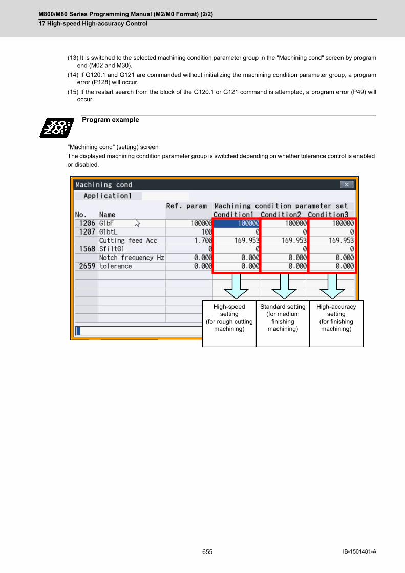
M800/M80 Series Programming Manual (M2/M0 Format) (2/2)
17 High-speed High-accuracy Control
655 IB-1501481-A
(13) It is switched to the selected machining condition parameter group in the "Machining cond" screen by programend (M02 and M30).
(14) If G120.1 and G121 are commanded without initializing the machining condition parameter group, a programerror (P128) will occur.
(15) If the restart search from the block of the G120.1 or G121 command is attempted, a program error (P49) willoccur.
"Machining cond" (setting) screen
The displayed machining condition parameter group is switched depending on whether tolerance control is enabled
or disabled.
Program example
High-accuracysetting
(for finishingmachining)
Standard setting(for medium
finishingmachining)
High-speed setting
(for rough cuttingmachining)
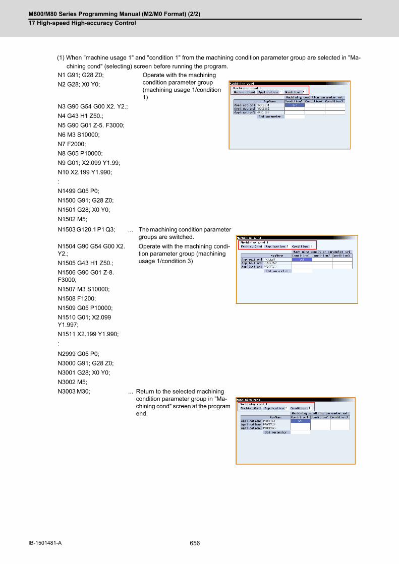
M800/M80 Series Programming Manual (M2/M0 Format) (2/2)
17 High-speed High-accuracy Control
656IB-1501481-A
(1) When "machine usage 1" and "condition 1" from the machining condition parameter group are selected in "Ma-
chining cond" (selecting) screen before running the program.
N1 G91; G28 Z0; Operate with the machining condition parameter group (machining usage 1/condition 1)
N2 G28; X0 Y0;
N3 G90 G54 G00 X2. Y2.;
N4 G43 H1 Z50.;
N5 G90 G01 Z-5. F3000;
N6 M3 S10000;
N7 F2000;
N8 G05 P10000;
N9 G01; X2.099 Y1.99;
N10 X2.199 Y1.990;
:
N1499 G05 P0;
N1500 G91; G28 Z0;
N1501 G28; X0 Y0;
N1502 M5;
N1503 G120.1 P1 Q3; ... The machining condition parameter groups are switched.
N1504 G90 G54 G00 X2. Y2.;
Operate with the machining condi-tion parameter group (machining usage 1/condition 3)N1505 G43 H1 Z50.;
N1506 G90 G01 Z-8. F3000;
N1507 M3 S10000;
N1508 F1200;
N1509 G05 P10000;
N1510 G01; X2.099 Y1.997;
N1511 X2.199 Y1.990;
:
N2999 G05 P0;
N3000 G91; G28 Z0;
N3001 G28; X0 Y0;
N3002 M5;
N3003 M30; ... Return to the selected machining condition parameter group in "Ma-chining cond" screen at the program end.

M800/M80 Series Programming Manual (M2/M0 Format) (2/2)
17 High-speed High-accuracy Control
657 IB-1501481-A
(1) G code modal that cause a program error when commanding G120.1 and G121 are listed below.
(1) Because the parameters are switched after being decelerated once G120.1 or G121 is commanded, the work-piece may be damaged. Make sure to keep the tool away from the workpiece when commanding G120.1 andG121.
(2) For the parameters "#8033 Fairing ON" and "#8090 SSS ON", the switched machining condition parameter groupis effective only after it has been switched on the machining condition selection screen.
(3) It is switched to the reference parameter by turning the power ON again.
(4) The machining condition parameter cannot be switched on the "Machining cond" screen and cannot be set onthe "Machining cond" screen during automatic operation.
(5) When the machining condition parameter group is switched by the G120.1 command in the machining programduring displaying the "Machining cond" screen, the selected machining condition parameter being displayed willnot be switched unless the display screen is transited to the other screen once.
(6) When G120.1 and G121 are commanded, parameters are switched when smoothing for NC axes in all part sys-tems become "0".
(7) The machining condition parameter group neither set the parameter setting from the program by G10 commandnor read the parameters by system variables (from #100000).
(8) When the machining condition parameter group is switched, the same values are used for all NC axes whichbelong to the switched part system to the parameter "#2010 Feed forward gain" and "#2659 Tolerance".
Relationship with other functions
G code Function Program error when G120.1 and G121 are commanded
G02.3, G03.3 Exponential interpolation P128
G06.2 NURBS interpolation P32
G07.1 Cylindrical interpolation P128
G12.1 Polar coordinate interpolation P128
G10 Parameter input by program P421
Tool compensation input by pro-gram
G33 Thread Cutting P128
G38 Tool radius compensation (vector designation)
P128
G39 Tool radius compensation (corner arc)
P128
G41, G42 Tool radius compensation P128
3-dimensional tool radius compen-sation
G41.1/G151 Normal line control Left P128
G42.1/G152 Normal line control Right P128
G43 Tool length compensation P128
G43.1 Tool length compensation along the tool axis
P128
G43.4, G43.5 Tool center point control P942
G66, G66.1 User macro (modal call A, B) P128
G68.2, G68.3 Inclined surface machining P951
G73/G74/G76/G81/G82/G83/G84/G85/G86/G87/G88/G89
Fixed cycle P33 (When G120.1 command is is-sued)
P128 (When G121 command is is-sued)
Precautions

M800/M80 Series Programming Manual (M2/M0 Format) (2/2)
17 High-speed High-accuracy Control
658IB-1501481-A

18
659 IB-1501481-A
Advanced Machining Control

M800/M80 Series Programming Manual (M2/M0 Format) (2/2)
18 Advanced Machining Control
660IB-1501481-A
18Advanced Machining Control18.1 Tool Length Compensation in the Tool Axis Direction; G43.1/G44
(1) Changes in the tool length compensation in the tool axis direction and compensation amount
The tool length can be compensated for in the tool axis direction even when the rotary axis rotates and the tool
axis direction becomes other than the Z axis direction. By using this function, and setting the deviation between
the tool length amount set in the program and the actual tool length as the compensation amount, a more flexible
program can be created. This is especially valid for programs in which many axis movement commands are
present.
The tool length compensation amount in the tool axis direction can be changed by rotating the manual pulse gen-
erator when the tool length compensation amount in the tool axis direction is being changed during the tool length
compensation in the tool axis direction mode.
(2) Machine configuration
The compensation using the tool length compensation in the tool axis direction function is applied to the direction
of the tool tip axis (rotary axis).
As for the axes that determine the compensation direction, a combination of the C axis (spindle) for Z axis rota-
tion and the A axis for X axis rotation or B axis for Y axis rotation is designated using a parameter.
Function and purpose
Axis A or B Axis B or C Axis A or B
(d) Rotation center (e) Tool
(f) Axis direction (compensation direction) (g) Workpiece
Y
Z
X
AB
C
A
B
C(d)
(e)
(f)
A/B
(g)
(d)
(e)
(f)
(g)

M800/M80 Series Programming Manual (M2/M0 Format) (2/2)
18 Advanced Machining Control
661 IB-1501481-A
(1) G43 and G43.1 are in the same G code group. Therefore, it is not possible to designate more than one of thesecommands simultaneously for compensation. G44 is used to cancel the G43 and G43.1 commands.
(2) If the G43.1 command is designated when the specification for the tool length compensation in the tool axis di-rection is not provided, the program error (P930) will occur.
(3) If reference position has not been completed for any of the X, Y, Z, A or B and C axes in the G43.1 block, theprogram error (P430) will occur. However, the error does not apply to the following cases.When mechanical axes have been selected
The error does not apply to the A, B and C axes.When "1" has been set for the "#2031 noref" zero point return parameter
The error does not apply to the axis for which "noref" is set to "1" because it is considered that the referenceposition return of the axis has already completed.
Command format
Tool length compensation along the tool axis ON
G43.1 X__ Y__ Z__ H__ ;
Tool length compensation cancel
G44 X__ Y__ Z__ ;
X, Y, Z Movement data
H Tool length compensation No.(If the compensation No. exceeds the specification range, a program error (P170) will occur.)
Detailed description

M800/M80 Series Programming Manual (M2/M0 Format) (2/2)
18 Advanced Machining Control
662IB-1501481-A
(1) When the following conditions have been met, the handle movement amount is added to the tool length com-pensation amount in the tool axis direction by rotating the manual pulse generator.When the operation mode is MDI, memory or tape operation mode and the state is "during single block
stop", "during feed hold" or "during cutting feed movement". Note that compensation amount cannot bechanged during error or warning.
During tool length compensation in the tool axis direction (G43.1).In the tool length compensation amount in the tool axis direction changing mode (YC92/1).In the tool handle feed & interruption mode (YC5E/1).The 3rd axis (tool axis) is selected for the handle selection axis.
(2) The change amount is canceled when the compensation No. is changed.
The coordinate value in the tool length compensation amount in the tool axis direction change mode operatesin the same manner as that when the manual ABS is ON, regardless of manual ABS switch (YC28) or baseaxis specification parameter "#1061 intabs".If compensation amount is changed during continuous operation, single block stop, or feed hold, the compen-
sation amount will be effective immediately in the next block.
When changing compensation amount, the compensation amount corresponding to the actual compensationNo. will be changed. However, when executing the NC reset or tool length compensation in the direction of toolaxis cancel (G44), the compensation amount will be returned to the original.
Changing the amount of tool length compensation in the tool axis direction
(Example) When changing compensation amount during continuous operation.
(Example) When changing compensation amount during single block stop.
(a) Compensation amount before change (b) Changed compensation amount
(c) Path after compensation (d) Program path
(e) Single block stop
Note
(a)
(b)
(c)
(d)
(a)
(b) (c)
(d)
(b)
(e)

M800/M80 Series Programming Manual (M2/M0 Format) (2/2)
18 Advanced Machining Control
663 IB-1501481-A
The vectors representing the tool length compensation in the tool axis direction are as follows.
(1) When the A and C axes are set as the rotary axes:Vx = L * sin(A) * sin(C)Vy = -L * sin(A) * cos(C)Vz = L * cos(A)
(2) When the B and C axes are set as the rotary axes:Vx = L * sin(B) * cos(C)Vy = L * sin(B) * sin(C)Vz = L * cos(B)
Vx, Vy, Vz: Tool length compensation along the tool axis vectors for X, Y and Z axes
L: Tool length compensation amount (1h)
A, B, C: Rotation angle (machine coordinate position) of A, B and C axes
(3) Rotary axis angle commandThe value used for the angle of the rotary axis (tool tip axis) differs according to the type of rotary axis involved.
When servo axes are used:
The machine coordinate position is used for the rotation angles of the A, B and C axes.
When mechanical axes are used:
Instead of the machine coordinate position of the axes, the values read out from the R registers (R2628 to
R2631) are used for the rotation angles of the A, B and C axes.
Tool length compensation in the tool axis direction is cleared in the following cases.
(1) When manual reference position return is completed.
(2) When reset 1, reset 2 or reset & rewind has been executed.
(3) When the G44 command has been designated.
(4) When the offset No. 0 command has been executed.
(5) When NC reset has been executed with "1" set for the basic system parameter "#1151 rstint".
(6) When the G53 command is designated while the compensation status is still established, the compensation istemporarily canceled, and the tool moves to the machine position designated by G53.
Tool length compensation in the tool axis direction vector
(a) Path after tool length compensation in the tool axis direction (b) G43.1 command
(c) Program path (d) G44 command
Compensation amount resetting
(c)
(d)
(a)
(b)
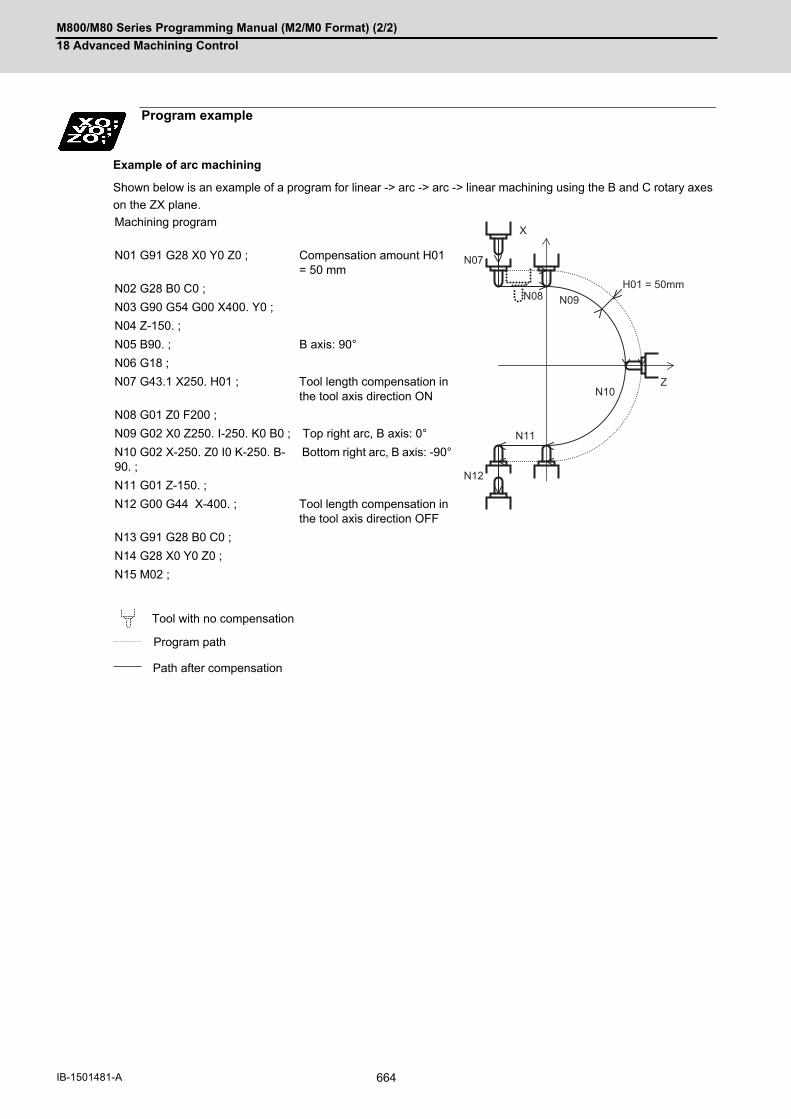
M800/M80 Series Programming Manual (M2/M0 Format) (2/2)
18 Advanced Machining Control
664IB-1501481-A
Example of arc machining
Shown below is an example of a program for linear -> arc -> arc -> linear machining using the B and C rotary axes
on the ZX plane.
Program example
Machining program
N01 G91 G28 X0 Y0 Z0 ; Compensation amount H01 = 50 mm
N02 G28 B0 C0 ;
N03 G90 G54 G00 X400. Y0 ;
N04 Z-150. ;
N05 B90. ; B axis: 90°
N06 G18 ;
N07 G43.1 X250. H01 ; Tool length compensation in the tool axis direction ON
N08 G01 Z0 F200 ;
N09 G02 X0 Z250. I-250. K0 B0 ; Top right arc, B axis: 0°
N10 G02 X-250. Z0 I0 K-250. B-90. ;
Bottom right arc, B axis: -90°
N11 G01 Z-150. ;
N12 G00 G44 X-400. ; Tool length compensation in the tool axis direction OFF
N13 G91 G28 B0 C0 ;
N14 G28 X0 Y0 Z0 ;
N15 M02 ;
Tool with no compensation
Program path
Path after compensation
N07
N08 N09H01 = 50mm
N10
N11
N12
X
Z

M800/M80 Series Programming Manual (M2/M0 Format) (2/2)
18 Advanced Machining Control
665 IB-1501481-A
(1) A program error (P931) will occur if 3-dimensional coordinate conversion is carried out during tool length com-pensation in the tool axis direction.
(2) A program error (P921) will occur if the tool length is compensated for in the tool axis direction during 3-dimen-sional coordinate conversion.
(3) A program error (P923) will occur if the tool length compensation in the tool axis direction is commanded in thesame block as the 3-dimensional coordinate conversion.
(1) A program error (P931) will occur if a command from G27 to G30 is issued during tool length compensation inthe tool axis direction.
(1) Reference position return of orthogonal axisTool length compensation along the tool axis will be canceled, as well as the dog-type reference position returnand the high-speed reference position return.
<Y axis Manual reference position return>
<Movement after Y axis Manual reference position return>
Relationship with other functions
Relationship with 3-dimensional coordinate conversion
Relationship with automatic reference position return
Relationship with manual reference position return
N1 G90 G00 G54 X0 Y0 Z0 ;
Positioning to the workpiece origin
N2 G00 A45. ;
Rotating the rotary axis by 45°
N3 G43.1 H1 ;
Tool length compensation along the tool axis ON
N4 G19 G03 Y-5.858 Z-14.142 J14.142 K-14.142 A90. ;
Circular cutting
Manual dog-type reference position return (a)
N5 G00 Y0. ;
N6 Z0. ;
: :
N5 G00 Y0. ;-> Positioning to the position where tool length compen-sation along the tool axis was canceled.
N6 Z0. ;-> Positioning to the position where tool length compen-sation along the tool axis was canceled.
: :
N2
N3
N4
(a)
N145◦
Z
YM
W
Z
YM
W
N6
N5
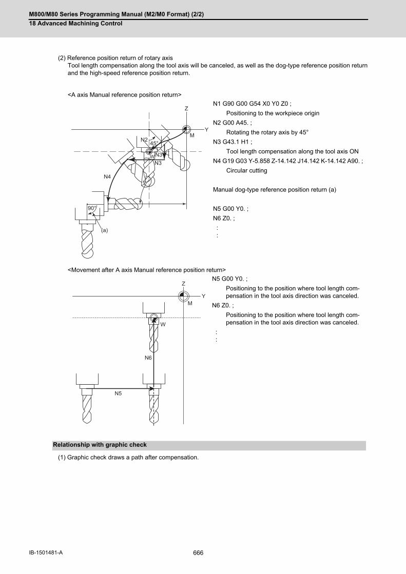
M800/M80 Series Programming Manual (M2/M0 Format) (2/2)
18 Advanced Machining Control
666IB-1501481-A
(2) Reference position return of rotary axisTool length compensation along the tool axis will be canceled, as well as the dog-type reference position returnand the high-speed reference position return.
<A axis Manual reference position return>
<Movement after A axis Manual reference position return>
(1) Graphic check draws a path after compensation.
N1 G90 G00 G54 X0 Y0 Z0 ;
Positioning to the workpiece origin
N2 G00 A45. ;
Rotating the rotary axis by 45°
N3 G43.1 H1 ;
Tool length compensation along the tool axis ON
N4 G19 G03 Y-5.858 Z-14.142 J14.142 K-14.142 A90. ;
Circular cutting
Manual dog-type reference position return (a)
N5 G00 Y0. ;
N6 Z0. ;
: :
N5 G00 Y0. ;
Positioning to the position where tool length com-pensation in the tool axis direction was canceled.
N6 Z0. ;
Positioning to the position where tool length com-pensation in the tool axis direction was canceled.
: :
Relationship with graphic check
45°
90°
(a)
N2
N3N3
N4
M
W
Z
Y
Z
YM
W
N6
N5

M800/M80 Series Programming Manual (M2/M0 Format) (2/2)
18 Advanced Machining Control
667 IB-1501481-A
18.2 Tool Center Point Control; G43.4, G43.5/G44
The tool center point control function controls a commanded position described in the machining program to be the
tool center point in the coordinate system that rotates together with a workpiece (table coordinate system). This func-
tion can be applied for the three types of machine as below.
(1) A tool tilt type: A machine with two rotary axes set on the head.
(2) A table tilt type: A machine with two rotary axes set on the table.
(3) A combined type: A machine with one rotary axis set on the tool and another on the table.
With this function, in the case of using tool tilt type, the tool center point is controlled so that it moves on the pro-
grammed path specified on the workpiece coordinate system. In the case of using the table tilt type, the tool center
point is controlled so that it moves on the programmed path specified on the table coordinate system (a coordinate
system which rotates together with a workpiece).
(1) Tool tilt type
(2) Table tilt type
Function and purpose
Tool center point control OFF and tool length com-pensation along the tool axis ON
Tool Center Point Control ON
Rotation center Program path Rotation center
Path of the tool center point
Controls so that the path of the tool holder center point draws a straight line.
Controls so that the tool center point draws a straight line.
Tool center point control OFF and tool length com-pensation along the tool axis ON
Tool center point control ON
Path of the tool center point
Rotation center Rotation center
Controls so that the tool holder center point positions on the workpiece coordinate system.
Controls so that the tool center point positions on the ta-ble coordinate system.
Z(+)
X(+)
B(- )B(- )
Z(+)
X(+)
X'(+)Z''(+)
X''(+)

M800/M80 Series Programming Manual (M2/M0 Format) (2/2)
18 Advanced Machining Control
668IB-1501481-A
(3) Combined type
If the tool center point control is commanded without the specifications of this function, a program error (P940)
will occur.
In addition, 3 orthogonal axes must be commanded first and 2 rotary axes alter.
When the number of simultaneous contouring control axes is 4, the tool center point control is only available for the
simultaneous movement of 4 axes or less.
Using this function allows you to designate the tool center point position on the table coordinate system (which ro-
tates as the workpiece rotates); therefore, you can easily create a machining program without calculating the work-
piece rotation or spindle end point position.
[Restrictions]
(*1) If G43.5 is commanded, a program error (P34) will occur.
(*2) If two rotary axes are commanded, a program error (P10) occurs. However, if a single rotary axis only moves
even when two rotary axes are commanded, it is not judged to be erroneous.
(*3) Selected by a parameter.
(*4) Only the joint interpolation is available in G43.4; therefore, the singular point type is invalid.
Tool center point control OFF and tool length com-pensation along the tool axis ON
Tool Center Point Control ON
Path of the tool center point
Rotation center Rotation center
Controls so that the tool holder center point positions on the workpiece coordinate system.
Controls so that the tool center point positions on the ta-ble coordinate system.
When the number of simultaneous contouring control axes is 4
5 or more simultaneous contour control axes
When the number of simultaneous con-touring control axes is 4
Command type G43.4/G43.5 G43.4 only (*1)
Limitations when com-manded
None (Format error, etc. only) A single rotary axis can be commanded in the same block. (*2)
Interpolation method Joint interpolation / Single axis rotation in-terpolation (*3)
Joint interpolation only
Type of passing singu-lar point
Type 1/type 2 (*3) Invalid (*4)
Program coordinate system selection
Table coordinate system / workpiece coordinate system (selected by parameter) (*3)
Rotary axis reference position selection
Zero degree position basis / start position standard (*3)
Rotary axis prefiltering Select whether this function is valid or invalid with a parameter.Designate the time constant with a parameter.
Z(+)
X(+)
B(- )B(- )
Z(+)
X(+)
X'(+)Z''(+)
X''(+)
Z'(+)
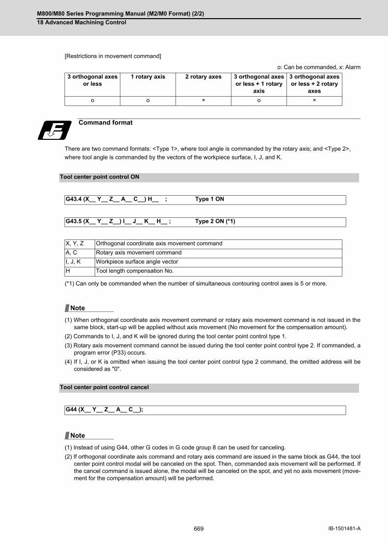
M800/M80 Series Programming Manual (M2/M0 Format) (2/2)
18 Advanced Machining Control
669 IB-1501481-A
[Restrictions in movement command]
o: Can be commanded, x: Alarm
There are two command formats: <Type 1>, where tool angle is commanded by the rotary axis; and <Type 2>,
where tool angle is commanded by the vectors of the workpiece surface, I, J, and K.
(*1) Can only be commanded when the number of simultaneous contouring control axes is 5 or more.
(1) When orthogonal coordinate axis movement command or rotary axis movement command is not issued in thesame block, start-up will be applied without axis movement (No movement for the compensation amount).
(2) Commands to I, J, and K will be ignored during the tool center point control type 1.
(3) Rotary axis movement command cannot be issued during the tool center point control type 2. If commanded, aprogram error (P33) occurs.
(4) If I, J, or K is omitted when issuing the tool center point control type 2 command, the omitted address will beconsidered as "0".
(1) Instead of using G44, other G codes in G code group 8 can be used for canceling.
(2) If orthogonal coordinate axis command and rotary axis command are issued in the same block as G44, the toolcenter point control modal will be canceled on the spot. Then, commanded axis movement will be performed. Ifthe cancel command is issued alone, the modal will be canceled on the spot, and yet no axis movement (move-ment for the compensation amount) will be performed.
3 orthogonal axes or less
1 rotary axis 2 rotary axes 3 orthogonal axes or less + 1 rotary
axis
3 orthogonal axes or less + 2 rotary
axes
o o × o ×
Command format
Tool center point control ON
G43.4 (X__ Y__ Z__ A__ C__) H__ ; Type 1 ON
G43.5 (X__ Y__ Z__) I__ J__ K__ H__ ; Type 2 ON (*1)
X, Y, Z Orthogonal coordinate axis movement command
A, C Rotary axis movement command
I, J, K Workpiece surface angle vector
H Tool length compensation No.
Tool center point control cancel
G44 (X__ Y__ Z__ A__ C__);
Note
Note

M800/M80 Series Programming Manual (M2/M0 Format) (2/2)
18 Advanced Machining Control
670IB-1501481-A
Specify the end position of each block looking from the programming coordinate system in the tool center point con-
trol mode. In the program, specify the position of the tool center point.
The programming coordinate system is a coordinate system used for the tool center point control, and whether to
use the table coordinate system or the workpiece coordinate system depends on the MTB specifications (parameter
"#7908 SLCT_PRG_COORD").
(1) Table coordinate systemWhen "0" is set to the programming coordinate system selection parameter, the table coordinate system, whichis the valid workpiece coordinate system at that time fixed to the table, is specified as the programming coordi-nate system. Table coordinate system rotates along the table rotation. And it does not rotate along the tool axisrotation. The X,Y,Z addresses are considered to have been issued on the table coordinate system. When a rotary axis movement is commanded in a block prior to G43.4/G43.5 command, the angle generated byrotary axis movement is regarded as an initial setting at G43.4/G43.5 command.
(2) Workpiece coordinate systemWhen "1" is set to the programming coordinate system selection parameter, the valid workpiece coordinate sys-tem at that time is specified as the programming coordinate system. The coordinate system in this case doesnot rotate along the table rotation. A linear movement is carried out for the table (workpiece) when the X,Y,Zaddresses are issued. The end position looking from the workpiece coordinate system after table rotation isspecified to the X, Y and Z.
Detailed description
Programming coordinate system

M800/M80 Series Programming Manual (M2/M0 Format) (2/2)
18 Advanced Machining Control
671 IB-1501481-A
When the table coordinate system, the workpiece coordinate system fixed to the table, is to be defined as a pro-
gramming coordinate system, the appropriate rotary axis angle for fixing the workpiece coordinate system to the ta-
ble depends on the MTB specifications (parameter "#7911 SLCT_STANDARD_POS").
Rotary axis reference position selection
Rotary axis stan-dard selection
Start position standard (#7911=1) Zero degree position standard (#7911=0)
The timing to be fixed to the table
The position of rotary axis holding the work-piece at the start of tool center point control
When the position of rotary axis holding the workpiece is at 0 degree on the workpiece coordinate system
Operation example 1
(Workpiece coordi-nate offset 0°)
Machine coordinate system
:G90G54G0C0 C-15. ; G43.4 Hh ; : C90. ; :
Workpiece coordi-nate 0°
:G90G54C0C-15. ;G43.4 Hh ; : C90. ; :
Workpiece coordi-nate 0°
Machine coordinate position fixed at -15°
Machine coordinate position 90° by C90. command
Machine coordinate position -15° by C-15. command
Machine coordinate position 90° by C90. command
Operation example 2
(Workpiece coordi-nate offset 45°)
Machine coordinate system
: G90G54G0C0 C-15. ; G43.4 Hh ; : C90. ; :
Workpiece coordi-nate 0°
: G90G54C0 C-15. ; G43.4 Hh ; : C90. ; :
Workpiece coordi-nate 0°
Machine coordinate position fixed at 30°
Machine coordinate position 135° by C90. command
Machine coordinate position 30° by C-15. command
Machine coordinate position 135° by C90. command
Y
X
0°
Y
X
Y
X
0°
Y
X
-15°Y
X -90°
X
Y
-15°
X 90°
Y
Y
X
X
Y
45°
X
Y
45°
X
Y
30°X
135°
Y X
Y
30° X 135°
Y

M800/M80 Series Programming Manual (M2/M0 Format) (2/2)
18 Advanced Machining Control
672IB-1501481-A
(1) Independent start-up command
(a) Tool center point control type 1, type 2
When the tool center point control is ON, no axis movement is performed (including movement for the com-
pensation amount).
(b) Tool center point control type 2
"G43.5 Ii Jj Kk Hh ; " performs the same movement as the tool center point control type 1 in (2).
(2) Start-up with movement command (When orthogonal coordinate axis command is issued in the same block)
(a) Tool center point control type 1, type 2
When the tool center point control is ON, the tool center point moves only as much as it is ordered under the
incremental value command.
Under the absolute value command, the tool center point moves to y1, z1.
Start-up
<Tool tilt type> <Table tilt type>
:G43.4 Hh ;
:or:
G43.5 Hh ;
:G43.4 Hh ;
:or:
G43.5 Hh ;
<Tool tilt type> <Table tilt type>
:G91 ; (Incre-mental value)G43.4 Yy Zz
Hh;:
or:
G43.5 Yy Zz Hh ;
:
:G91 ; (Incre-mental value)G43.4 Yy Zz
Hh;:
or:
G43.5 Yy Zz Hh ;
:
<Tool tilt type> <Table tilt type>
:G90 ; (Abso-lute value)
G00 Yy0 Zz0;G43.4 Yy Zz
Hh;:
or:
G43.5 Yy Zz Hh ;
:
:G90 ; (Abso-lute value)
G00 Yy0 Zz0;G43.4 Yy Zz
Hh;:
or:
G43.5 Yy Zz Hh ;
:
Y
Z
A (+)
Y
Z
A (+)
Y
Z
A (+)
Y
Z
Y
Z
A (+)
Y
Z
Y
Z
A (+)
y1- y0
(y1,z1)h
(y0,z0)
z1- z0
Y
Z
A (+)
(y1,z1)h
y1- y0z1- z0
(y0,z0)

M800/M80 Series Programming Manual (M2/M0 Format) (2/2)
18 Advanced Machining Control
673 IB-1501481-A
(b) Tool center point control type 2
The rotary axis moves toward the commanded workpiece surface vector (I,J,K) direction along the movement
command issued.
(3) Start-up with movement command (When rotary axis command is issued in the same block)
(a) Tool center point control type 1
In the case of using the tool tilt type, the orthogonal axis moves according to the rotary axis angle while fixing
the tool center point to the center. In the case of using the table tilt type, the orthogonal axis moves so that
the tool center point locates on the rotated table workpiece coordinate system.
(b) Tool center point control type 2
A program error (P33) will occur.
<Tool tilt type> <Table tilt type>
:G91 ; (Incre-mental value)G43.5 Yy ZzIi Jj Kk Hh;
:
:G91 ; (Incre-mental value)G43.5 Yy ZzIi Jj Kk Hh;
:
<Tool tilt type> <Table tilt type>
:G43.4 Aa Hh;
:
:G43.4 Aa Hh;
:
zy
(i,j,k)
Y
Z
A (+)
z
y
Y
Z
A (+)
(i,j,k)
z
a
Y
Z
A (+)
aY
Z A (+)

M800/M80 Series Programming Manual (M2/M0 Format) (2/2)
18 Advanced Machining Control
674IB-1501481-A
(1) Independent cancel command
(a) Tool center point control type 1, type 2
Canceling the movement for the compensation amount is not performed regardless of absolute/incremental
value command.
On the other hand, the tool center point control modal will be canceled.
The tool will not move.
(2) Cancellation with movement command (When orthogonal coordinate axis command is issued in the same block)
(a) Tool center point control type 1, type 2
Canceling the movement for the compensation amount is not performed regardless of absolute/incremental
value command.
Orthogonal coordinate axis movement command is executed upon cancellation of the tool center point con-
trol modal.
(3) Cancellation with movement command (When rotary axis command is issued in the same block)
(a) Tool center point control type 1, type 2
Canceling the movement for the compensation amount is not performed regardless of absolute/incremental
value command.
Rotary axis movement command is executed upon cancellation of the tool center point control modal.
Cancel
<Tool tilt type> <Table tilt type>
:
G44;
:
:
G44;
:
<Tool tilt type> <Table tilt type>
:
G91; (Incre-mental val-ue)
G44 Yy Zz ;
:
:
G91; (Incre-mental val-ue)
G44 Yy Zz ;
:
<Tool tilt type> <Table tilt type>
:
G44 Aa Hh;
:
:
G44 Aa Hh;
:
Y
Z
A (+)
Y
ZA (+)
z
y
Y
Z
A (+)
zy
Y
Z
A (+)
aY
Z
A (+)
a
Y
Z
A (+)

M800/M80 Series Programming Manual (M2/M0 Format) (2/2)
18 Advanced Machining Control
675 IB-1501481-A
(1) Tool center point control type 1
(a) When executing the movement command to the orthogonal coordinate axis and rotary axis.
(b) When executing the movement command to the rotary axis only.
(2) Tool center point control type 2
(a) When executing the movement command to the orthogonal coordinate axis and the workpiece surface angle
vector command.
(b) When executing workpiece surface angle vector command only.
During tool center point control
:G90 ;G43.4 Yy1 Zz1 Aa1 Hh ;Yy2 Aa2 ;Yy3 Aa3 ; :
The tool center point moves along the programmed path.
:G90 ;G43.4 Yy1 Zz1 Aa1 Hh ;Yy2 ;Aa2 ;Yy3 Aa3 ; :
When executing the move-ment command to the rotary axis only, the orthogonal axis moves without moving the tool center point.
:G43.5 Yy1 Zz1Ii1 Jj1 Kk1 Hh ;Yy2 Ii2 Jj2 Kk2 ;Yy3 Ii3 Jj3 Kk3 ; :
Tool center point moves along the program path.
:G43.5 Yy1 Zz1Ii1 Jj1 Kk1 Hh ;Yy2 ;Ii2 Jj2 Kk2 ;Yy3 Ii3 Jj3 Kk3 ; :
When executing the work-piece surface angle vector command only, the orthogo-nal axis moves without mov-ing the tool center point.
Z A (+)
a1
z1
y1 y2 y3
a2=0 a3
Y
z1
a1
A (+)
a2 a3
y1 y3y2
Z A (+)
z1
y1 y2 y3
(i1,j1,k1)
Y
(i2,j2,k2)
(i3,j3,k3)
z1
(i1, j1, k1)
A (+)
a3
y1 y3y2
(i3, j3, k3)

M800/M80 Series Programming Manual (M2/M0 Format) (2/2)
18 Advanced Machining Control
676IB-1501481-A
Feedrate during the tool center point control is controlled so that the tool center point moves according to the com-
manded speed.
There are two methods of interpolation: single axis rotation interpolation and joint interpolation, which are selected
by parameter.
(1) Single axis rotation interpolationWhen transforming from a start-point angle vector "r1" into an end-point angle vector "r2", interpolate so that theangular rate of the rotary "φ" around the vector "k" axis, which is vertical to "r1"-"r2" plane, will be constant.
(a) Features
Tool angle vector always exists on the plane consisting of "O", "r1" and "r2".The angular rates of each rotary axis will not be constant.
(b) Operations
(Example) Current position: Aa° , C0°
When commanding "G90 Yy A-a. C45. ;" or "G90 Yy Ii Jj Kk ;"
Feedrate during tool center point control
Interpolation method
(r1) Start-point command vector "r1"(r2) End-point command vector "r2"(k) Unit vector vertical to r1-r2 plane
<Tool tilt type> <Table tilt type>
<Combined type>
Z( - )Z’( - )
Y(- )
Y’( - ) O(r1)
(k)
(r2)
Y(- )
Z(- )
Y(+)
Z(+)
Z(+)
Z’’(+)
Z’(+)
Y’’(+)
Y(+)
Y’(+)
Y(+)
Z(+)
Y(+)
Z(+) Z(+)
Z(+)
Y (+)

M800/M80 Series Programming Manual (M2/M0 Format) (2/2)
18 Advanced Machining Control
677 IB-1501481-A
(2) Joint interpolationA movement from a start-point angle vector "r1" to an end-point angle vector "r2" is interpolated to keep the an-gular rates of each axis constant.
(a) Features
The angular rates of each rotary axis become constant.As this control aims to keep the angular rates of each rotary axis constant, a tool angle vector may not
exist on the plane consisting of "O", "r1" and "r2".
When passing the singular point (singular position (*1)), there are two kinds of movements to be followed from the
singular point.
When using an A-C axis tilt type machinery, there are two different movements (Fig. b, c) to be followed. In those
movements, the rotation angles of the A axis are the same absolute value but different in signs (+/-). The rotation
angles of the C axis corresponding the two movements are differed by 180 degrees one another.
Determine which one of the two movements are to be selected with parameter.
The figures below are the example of movements seen during tool center point control type 2. When the tool-center-
point-side rotary axis moves in the sign (+) direction from the starting position (Fig. a), (Fig. b) is representing "pass-
ing singular point type 1". When the tool-center-point-side rotary axis moves in the sign (-) direction from the starting
position (Fig. a), (Fig. c) is representing "passing singular point type 2".
(*1) The position in which the tool-center-point-side rotary axis or the table-base-side rotary axis is 0.
(r1) Start-point command vector "r1"(r2) End-point command vector "r2"
Passing singular point
<Starting position>
Movement in sign (+)
Movement in sign (-
)
Y(- )C(+)
A(+)
Z(- )
O
(r1)
(r2)
Y(- )
Z(- )
C0
(a)
Y(- )
Z(- )
C0
(b)
Y(- )
Z(- )-
C0
(c)

M800/M80 Series Programming Manual (M2/M0 Format) (2/2)
18 Advanced Machining Control
678IB-1501481-A
(1) Passing singular point type 1Select the same direction as the start point of the tool-base-side rotary axis or table-workpiece-side rotary axisin the block where a singular point passing is carried out. When the rotation angle of the start point is 0°, selectthe wider stroke limit. When the stroke limits are the same, select the one with a minus-coded rotation angle.
<Tool tilt type>
<Table tilt type>
<Combined type>
(a) Singular point
(b) When passing near the singular point, C axis rotates 180° within the parameter "#7907 CHK_ANG" (Near the singular judgment angle).
(c) C axis rotates 180°
X(- )Y(- )
Z(- )
(a)
(b)
(c)
Z(+)Z'(+)
Y(+) Y'( - )
Z"(+)
Y"( - )
(a)
(b)
(c)
Z(+)
Y(- )Y(+)
Z(+) Z(+)
Y(- )
(a)
(b)
(c)
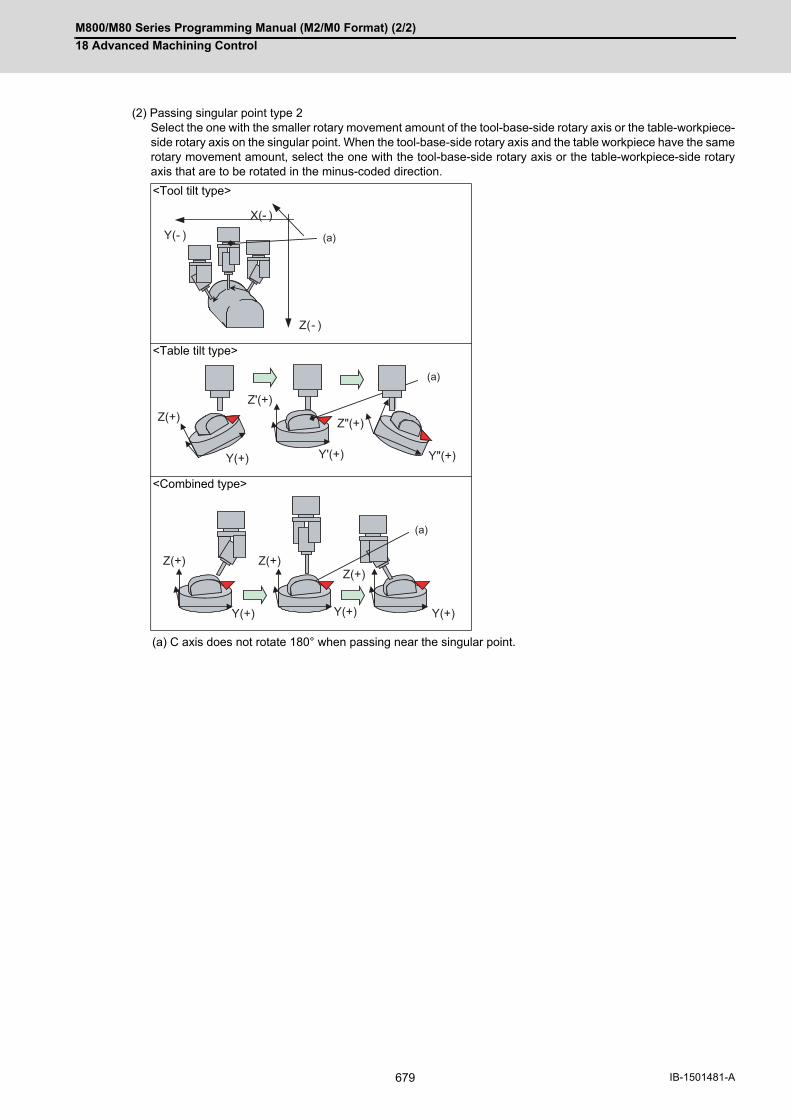
M800/M80 Series Programming Manual (M2/M0 Format) (2/2)
18 Advanced Machining Control
679 IB-1501481-A
(2) Passing singular point type 2Select the one with the smaller rotary movement amount of the tool-base-side rotary axis or the table-workpiece-side rotary axis on the singular point. When the tool-base-side rotary axis and the table workpiece have the samerotary movement amount, select the one with the tool-base-side rotary axis or the table-workpiece-side rotaryaxis that are to be rotated in the minus-coded direction.
<Tool tilt type>
<Table tilt type>
<Combined type>
(a) C axis does not rotate 180° when passing near the singular point.
X(- )Y(- )
Z(- )
(a)
Z(+)Z'(+)
Y(+) Y'(+) Y"(+)
Z"(+)
(a)
Z(+)
Y(+)Y(+)
Z(+)
Y(+)
Z(+)
(a)
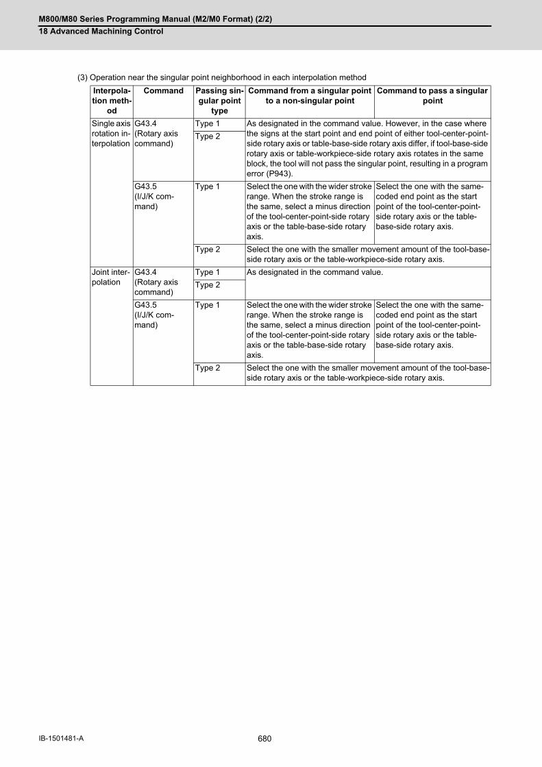
M800/M80 Series Programming Manual (M2/M0 Format) (2/2)
18 Advanced Machining Control
680IB-1501481-A
(3) Operation near the singular point neighborhood in each interpolation method
Interpola-tion meth-
od
Command Passing sin-gular point
type
Command from a singular point to a non-singular point
Command to pass a singular point
Single axis rotation in-terpolation
G43.4(Rotary axis command)
Type 1 As designated in the command value. However, in the case where the signs at the start point and end point of either tool-center-point-side rotary axis or table-base-side rotary axis differ, if tool-base-side rotary axis or table-workpiece-side rotary axis rotates in the same block, the tool will not pass the singular point, resulting in a program error (P943).
Type 2
G43.5(I/J/K com-mand)
Type 1 Select the one with the wider stroke range. When the stroke range is the same, select a minus direction of the tool-center-point-side rotary axis or the table-base-side rotary axis.
Select the one with the same-coded end point as the start point of the tool-center-point-side rotary axis or the table-base-side rotary axis.
Type 2 Select the one with the smaller movement amount of the tool-base-side rotary axis or the table-workpiece-side rotary axis.
Joint inter-polation
G43.4(Rotary axis command)
Type 1 As designated in the command value.
Type 2
G43.5(I/J/K com-mand)
Type 1 Select the one with the wider stroke range. When the stroke range is the same, select a minus direction of the tool-center-point-side rotary axis or the table-base-side rotary axis.
Select the one with the same-coded end point as the start point of the tool-center-point-side rotary axis or the table-base-side rotary axis.
Type 2 Select the one with the smaller movement amount of the tool-base-side rotary axis or the table-workpiece-side rotary axis.
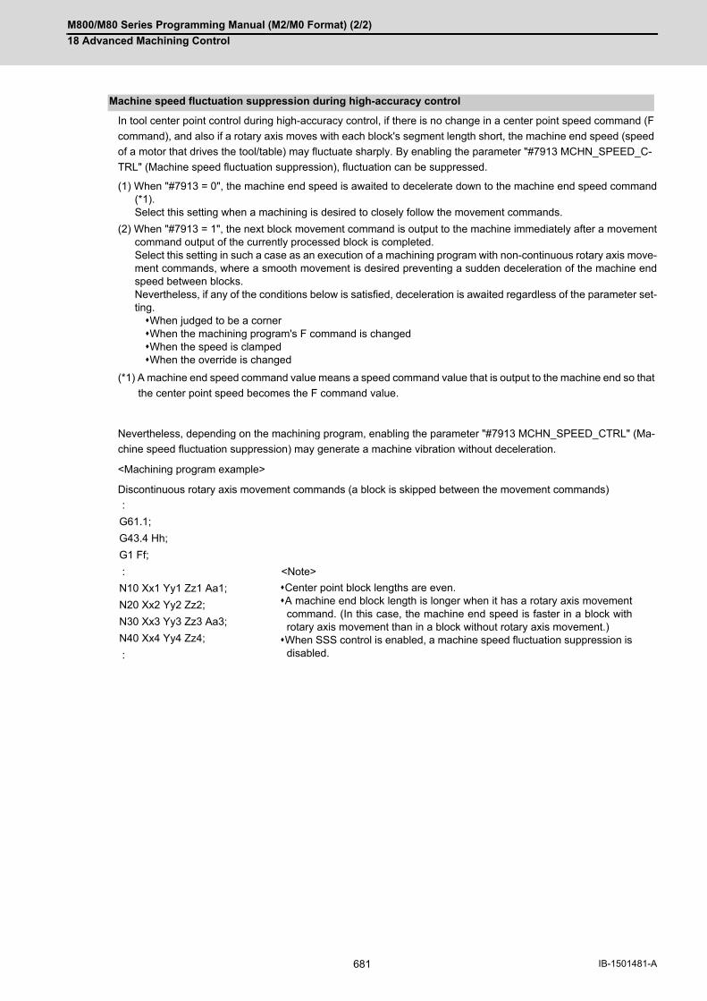
M800/M80 Series Programming Manual (M2/M0 Format) (2/2)
18 Advanced Machining Control
681 IB-1501481-A
In tool center point control during high-accuracy control, if there is no change in a center point speed command (F
command), and also if a rotary axis moves with each block's segment length short, the machine end speed (speed
of a motor that drives the tool/table) may fluctuate sharply. By enabling the parameter "#7913 MCHN_SPEED_C-
TRL" (Machine speed fluctuation suppression), fluctuation can be suppressed.
(1) When "#7913 = 0", the machine end speed is awaited to decelerate down to the machine end speed command(*1). Select this setting when a machining is desired to closely follow the movement commands.
(2) When "#7913 = 1", the next block movement command is output to the machine immediately after a movementcommand output of the currently processed block is completed. Select this setting in such a case as an execution of a machining program with non-continuous rotary axis move-ment commands, where a smooth movement is desired preventing a sudden deceleration of the machine endspeed between blocks. Nevertheless, if any of the conditions below is satisfied, deceleration is awaited regardless of the parameter set-ting.When judged to be a cornerWhen the machining program's F command is changedWhen the speed is clampedWhen the override is changed
(*1) A machine end speed command value means a speed command value that is output to the machine end so that
the center point speed becomes the F command value.
Nevertheless, depending on the machining program, enabling the parameter "#7913 MCHN_SPEED_CTRL" (Ma-
chine speed fluctuation suppression) may generate a machine vibration without deceleration.
<Machining program example>
Discontinuous rotary axis movement commands (a block is skipped between the movement commands)
Machine speed fluctuation suppression during high-accuracy control
:
G61.1;
G43.4 Hh;
G1 Ff;
: <Note>
N10 Xx1 Yy1 Zz1 Aa1; Center point block lengths are even.A machine end block length is longer when it has a rotary axis movement
command. (In this case, the machine end speed is faster in a block withrotary axis movement than in a block without rotary axis movement.)When SSS control is enabled, a machine speed fluctuation suppression is
disabled.
N20 Xx2 Yy2 Zz2;
N30 Xx3 Yy3 Zz3 Aa3;
N40 Xx4 Yy4 Zz4;
:
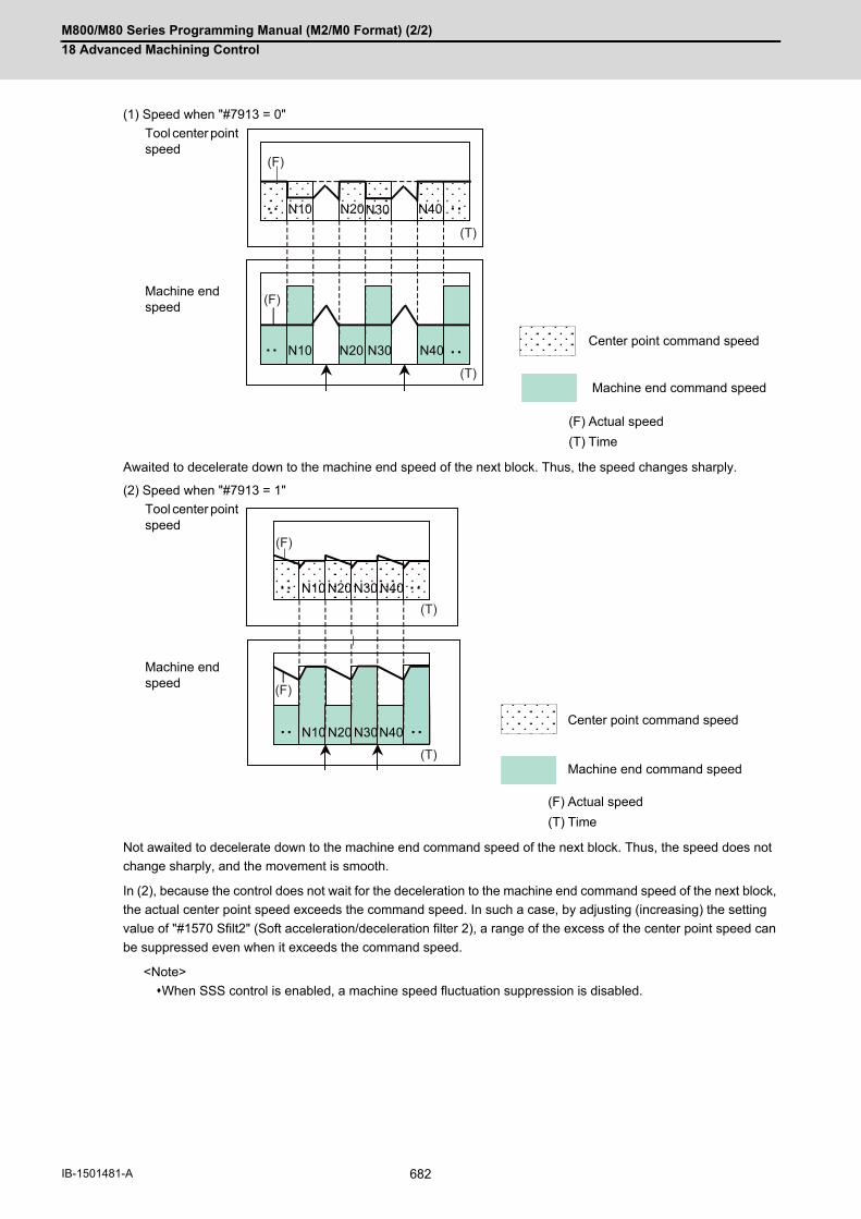
M800/M80 Series Programming Manual (M2/M0 Format) (2/2)
18 Advanced Machining Control
682IB-1501481-A
(1) Speed when "#7913 = 0"
Awaited to decelerate down to the machine end speed of the next block. Thus, the speed changes sharply.
(2) Speed when "#7913 = 1"
Not awaited to decelerate down to the machine end command speed of the next block. Thus, the speed does not
change sharply, and the movement is smooth.
In (2), because the control does not wait for the deceleration to the machine end command speed of the next block,
the actual center point speed exceeds the command speed. In such a case, by adjusting (increasing) the setting
value of "#1570 Sfilt2" (Soft acceleration/deceleration filter 2), a range of the excess of the center point speed can
be suppressed even when it exceeds the command speed.
<Note>
When SSS control is enabled, a machine speed fluctuation suppression is disabled.
Tool center point speed
Machine end speed
Center point command speed
Machine end command speed
(F) Actual speed
(T) Time
Tool center point speed
Machine end speed
Center point command speed
Machine end command speed
(F) Actual speed
(T) Time
N10
N10 N20 N30 N40
N20 N30 N40
(F)
(T)
(T)
(F)
N10
N10 N20 N30 N40
N20 N30 N40
(F)
(T)
(T)
(F)
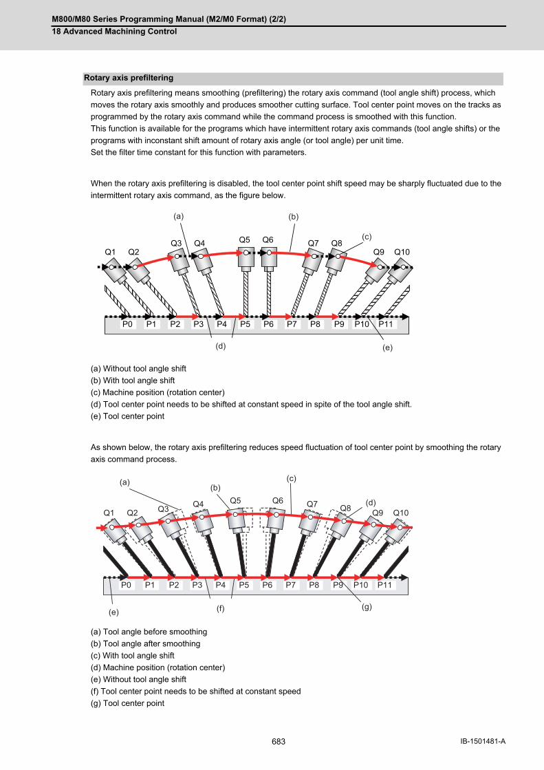
M800/M80 Series Programming Manual (M2/M0 Format) (2/2)
18 Advanced Machining Control
683 IB-1501481-A
Rotary axis prefiltering means smoothing (prefiltering) the rotary axis command (tool angle shift) process, which
moves the rotary axis smoothly and produces smoother cutting surface. Tool center point moves on the tracks as
programmed by the rotary axis command while the command process is smoothed with this function.
This function is available for the programs which have intermittent rotary axis commands (tool angle shifts) or the
programs with inconstant shift amount of rotary axis angle (or tool angle) per unit time.
Set the filter time constant for this function with parameters.
When the rotary axis prefiltering is disabled, the tool center point shift speed may be sharply fluctuated due to the
intermittent rotary axis command, as the figure below.
(a) Without tool angle shift
(b) With tool angle shift
(c) Machine position (rotation center)
(d) Tool center point needs to be shifted at constant speed in spite of the tool angle shift.
(e) Tool center point
As shown below, the rotary axis prefiltering reduces speed fluctuation of tool center point by smoothing the rotary
axis command process.
(a) Tool angle before smoothing
(b) Tool angle after smoothing
(c) With tool angle shift
(d) Machine position (rotation center)
(e) Without tool angle shift
(f) Tool center point needs to be shifted at constant speed
(g) Tool center point
Rotary axis prefiltering
P0 P1 P2 P3 P4 P5 P6 P7 P8 P9 P10 P11
Q1 Q2 Q3 Q4 Q5 Q6 Q7 Q8
Q9 Q10
(a)
(c)
(b)
(e)(d)
P0 P1 P2 P3 P4 P5 P6 P7 P8 P9 P10 P11
Q1 Q2 Q3 Q4 Q5 Q6 Q7 Q8 Q9 Q10
(a) (c)(b)
(e)
(d)
(f) (g)

M800/M80 Series Programming Manual (M2/M0 Format) (2/2)
18 Advanced Machining Control
684IB-1501481-A
(1) This function is available only when SSS control is enabled. (Not available together with a machine speed fluc-tuation suppression.)
(2) This function is disabled at G00 command.
(3) The actual angle of the tool may be deviated from the commanded one in the program.
(4) Even if a rotary axis prefiltering is enabled for a program without an angle shift, it does not affect the machiningquality. However, it may extend cycle time, so when executing such a machining, it is recommended that therotary axis prefiltering is disabled.
When tool center point control is used on the machine in which the rotary axis is mounted on the left-hand orthogonal
coordinate system, all the following three conditions must be satisfied.
(1) Use tool center point control type 1 (G43.4). (Normal operation is not assured in tool center point control type 2 (G43.5).)
(2) Set the parameter "#7910 SLCT_INT_MODE" (interpolation mode selection) to the joint interpolation method. (Normal operation is not assured in single axis interpolation mode.)
(3) Set the rotary axis configuration parameter "rotation direction" of the rotary axis mounted on the left-hand orthog-onal coordinate system to CCW. The target "rotation direction" parameters are as follows. "#7923 DIR_T1" (Rotation direction of the tool rotating type base-side rotary axis)"#7933 DIR_T2" (Rotation direction of the tool rotating type / composite type tool axis)"#7943 DIR_W1" (Rotation direction of the table rotating type base-side rotary axis)"#7953 DIR_W2" (Rotation direction of the table rotating type / composite type workpiece axis)
Mounting the rotary axis on the left-hand orthogonal coordinate system
Note

M800/M80 Series Programming Manual (M2/M0 Format) (2/2)
18 Advanced Machining Control
685 IB-1501481-A
When the following conditions are met, circular command will be executed on the selected plane in tool center point
control.
<Tool tilt type>
<Table tilt type>
<Combined type>
<Note>
(a) A program error (P942) will occur in the following cases.
During tool center point control type 2 (G43.5)Rotary axis command is issued in the same blockDuring the inclined surface machining and the workpiece installation error compensation
(b) If the circular command is issued without positioning three orthogonal axes after tool center point control has
been started independently, a program error (P70) or (P71) may occur.
Circular command in tool center point control (G43.4/G43.5)
Programming coordinate system
Rotary axis reference position selection
Start position standard (#7911=1) 0° position standard (#7911=0)
Table coordinate system(#7908=0)
Rotary axis machine coordinate position in circular command is at 0°. (1) (2)
Workpiece coordinate sys-tem
(#7908=1)
Programming coordinate system
Rotary axis reference position selection
Start position standard (#7911=1) 0° position standard (#7911=0)
Table coordinate system(#7908=0)
Rotary axis workpiece coordinate posi-tion at the start of tool center point con-trol coincides with that of the circular command. (4)
Rotary axis workpiece coordinate po-sition in circular command is at 0°. (3)
Workpiece coordinate sys-tem
(#7908=1)
Rotary axis about the I/J/K axis workpiece coordinate position in circular com-mand is at 0°. (5)
Programming coordinate system
Rotary axis reference position selection
Start position standard (#7911=1) 0° position standard (#7911=0)
Table coordinate system(#7908=0)
Table-side rotary axis workpiece coor-dinate position at the start of tool center point control coincides with that of the circular command, and also, tool-side rotary axis machine coordinate position in circular command is at 0°.
Table-side rotary axis workpiece coor-dinate position in circular command is at 0° and tool-side rotary axis machine coordinate position is at 0°.
Workpiece coordinate sys-tem
(#7908=1)
Tool-side rotary axis machine coordinate position in circular command is at 0° and table-side rotary axis workpiece coordinate position is at 0°.

M800/M80 Series Programming Manual (M2/M0 Format) (2/2)
18 Advanced Machining Control
686IB-1501481-A
(1) Tool tilt type (Rotary axis machine coordinate 0°)
(2) Tool tilt type (Rotary axis machine coordinate - 30°)
(3) Table tilt type (0° position standard)
<Machining program>
:G18G43.4 H1 :G02 Xx Zz Ii Kk :
<Machining program>
:G18G43.4 H1A-30. :G02 Xx Zz Ii Kk :
<Machining program>
:G18G43.4 H1 :G02 Xx Zz Ii Kk :
(a) Arc operations (P) Program error
X(+)
Y(+)
Z(+)
X(+)
Y(+)
Z(+) (a)
X(+)
Y(+) X(+)
Y(+)
Z(+)
A(-)
A0°
Z(+)
A-30
(P)
X(+)
Y(+)
Z(+)
X(+)
Y(+)
Z(+)
A(+)
(a)

M800/M80 Series Programming Manual (M2/M0 Format) (2/2)
18 Advanced Machining Control
687 IB-1501481-A
(4) Table tilt type (Start position standard)
(5) Table tilt type (Programming coordinate system = workpiece coordinate system)
<Machining program>
:G19 A-45.G43.4 H1 :G02 Xx Yy Ii Jj :
<Machining program>
:G18G43.4 H1 :G02 Xx Zz Ii Kk :
(a) Arc operations (s) Start position (I) About I axis
X(+)
Y(+)
Z(+)
Z(+)
Y(+)
X(+) A(+)
A0°
(a)A-45°:(s)
Y(+)
Z(+)
X(+)
Y(+)
Z(+)
:(s)A0°
(I)
X(+)
(a)

M800/M80 Series Programming Manual (M2/M0 Format) (2/2)
18 Advanced Machining Control
688IB-1501481-A
(1) F1-digit FeedControls so that the tool center point moves at the commanded speed. Note that speed cannot be changed withthe manual handle.
(2) Buffer correctionBuffer correction cannot be performed during tool center point control.
(3) Miscellaneous function (MSTB)Miscellaneous function (MSTB) command can be executed during tool center point control. (When passing the singular point, strobe signal is output at the block start and the completion wait at the blockend.)
(4) Spindle/C Axis ControlAxes unrelated to the tool tilt or table tilt can be controlled.
(5) Manual reference position returnDo not perform manual reference position return during tool center point control. If performed, the tool moves offthe programmed track.
(6) Machining time computationMachining time calculation is not performed accurately on the machining program in which the tool center pointcontrol mode is commanded.
(7) Graphic traceGraphic trace during the tool center point control is always traced with the tool center point.
(8) Graphic checkGraphic check during the tool center point control is always check the graphic with the tool center point.
(9) Program restartRestart search cannot be performed during the tool center point control. If attempted, a program error (P49) oc-curs.
(10) Reset modal retentionCanceled during the tool center point control.
(11) Collation stopPosition in the tool center point control can be collated and stopped.
(12) Automatic operation handle interruptionDo not perform the automatic operation handle interruption during the tool center point control. If performed, thetool moves off the programmed track.
(13) Manual/Automatic simultaneousManual/Automatic simultaneous cannot be executed to the axes related to the tool center point control duringthe tool center point control.
(14) Tool handle feed & interruptionDo not perform the tool handle feed & interruption during the tool center point control. If performed, the toolmoves off the programmed track.
(15) Corner chamfering/Corner RWhen the corner chamfering/corner R is performed during the tool center point control, the tool center point con-trol becomes valid to the track after the corner chamfering/corner R.
Relationship with other functions
(Example):G90 Aa1 ;G43.4 Yy1 Aa2 Mm Hh ;:
(a) M strobe output (b) Passing singular point
(c) M completion wait
Y
Z (+)
a
y1
(+)
a2
A
C
(a) (c)(b)

M800/M80 Series Programming Manual (M2/M0 Format) (2/2)
18 Advanced Machining Control
689 IB-1501481-A
(16) Mirror image by parameter setting / external mirror image inputWhen the tool center point control command is issued during the mirror image by parameter/external Input, aprogram error (P941) occurs. Also, do not turn the mirror image by parameter/external input ON during the toolcenter point control.
(17) Linear angle commandWhen A axis is used as a rotary axis, the linear angle command cannot be executed. When A axis is not usedas a rotary axis, tool center point control becomes valid to the shape after the linear angle command.
(18) Geometric commandWhen A axis is used as a rotary axis, the geometric command cannot be executed. When A axis is not used asa rotary axis, tool center point control becomes valid to the shape after the geometric command.
(19) Figure rotationThe tool center point control becomes valid to the shape after the figure rotation.
(20) Coordinate rotation by parameterWhen the tool center point control command is issued during the coordinate rotation by parameter, a programerror (P941) occurs. Also, do not turn the coordinate rotation by parameter ON during the tool center point con-trol.
(21) ChoppingChopping operation for the 3 orthogonal axes and 2 rotary axes cannot be performed during the tool center pointcontrol.
(22) Macro interruptionIf the macro interruption command is executed during the tool center point control, a program error (P942) oc-curs.
(23) Tool life managementThe compensation amount of the tool center point control during the tool life management is equal to the com-pensation amount of the tool subjected to the tool life management.
(24) G00 non-interpolationFunctions as "G00 interpolation".
(25) Actual feedrate displayThe final combined feedrate is displayed here.
(26) Manual interruptionWhen the manual interruption is executed during the feed hold or single block stop, the movement will be theone to be observed when the manual ABS is OFF when rebooting regardless of whether an absolute/incrementalvalue command is selected.
(27) Machine lockThe each axis machine lock becomes valid to the motor axis.
(28) Remaining distance counterRemaining distance at the tool center point on the programming coordinate system is displayed.
(29) InterlockInterlock is applied for the motor axis.
(30) Cutting feed / Rapid traverse overrideOverride is applied to the feedrate at the tool center point. When the feedrate is clamped, the override is appliedto the clamp speed.
(31) Manual reference position returnIf the manual reference position return is performed during the tool center point control, the tool moves off theprogrammed track after that.
(32) Dry runDry run is applied to the speed at the tool center point.
(33) NC resetImmediately decelerates to stop when the NC reset is executed during the tool center point control. The tool cen-ter point control will be canceled even if NC reset 1 and the modal retention.
(34) Emergency stopImmediately stops if the emergency stop is applied during the tool center point control.
(35) Stored stroke limitlimit Stored stroke limit will be valid at the motor axis for all IB, IIB and IC.
M800/M80 Series Programming Manual (M2/M0 Format) (2/2)
18 Advanced Machining Control
690IB-1501481-A
(36) MDI interruptionWhen the MDI interruption is performed during the tool center point control, an operation error (M01 0170) oc-curs.
(37) High-accuracy control functionThe acceleration at rapid traverse (G00) during the high-accuracy control is same as that at cutting feedrate(G01).
When performing tool center point control in combination with an arbitrary axis exchange (G140) command, you
need to set the rotary axis configuration parameters using the 2nd axis name. Set the parameter "#1450 5ax-
is_Spec/bit0" to "1" (setting by the 2nd axis name), and assign the axis configuration for executing tool center point
control to the rotary axis configuration parameter (#7900 or later) using the 2nd axis name (example: A1, B2).
If the G43.4/G43.5 command is issued after the arbitrary tool exchange has been completed while the parameter
"#1450 5axis_Spec/bit0" is not designated, a program error (P941) will occur.
You can set the configurations up to the number of valid part systems (up to four part systems) in the rotary axis
configuration parameter. With multiple configurations set, you can perform tool center point control in different axis
configurations.
Tool center point control can be performed using the axis configuration in the part system with axis exchange com-
pleted by applying the rotary axis configuration parameter in the configuration in which all axes included in the part
system are set.
Combination with arbitrary axis exchange

M800/M80 Series Programming Manual (M2/M0 Format) (2/2)
18 Advanced Machining Control
691 IB-1501481-A
Pxxx in the list indicates the program error Nos.
Column A: Operation to be carried out when the G command in the list is issued while this function is modal
Column B: Operation to be carried out when this function is commanded while the G command in the list is modal
Column C: Operation to be carried out when the G command in the list and this function are commanded for the
same block
All the G codes not listed above cannot be used.
Relation with other G codes
Format Function A B C
G00 Positioning Switched to a rapid tra-verse feedrate, and then perform tool center point control.
Perform tool center point control at a rapid tra-verse feedrate.
Perform tool center point control at a rapid tra-verse feedrate.
G01 Linear interpola-tion
Switched to a cutting feedrate, and then per-form tool center point control.
Perform tool center point control with cutting feed.
Perform tool center point control with cutting feed.
G02/G03 Circular interpo-lation
Available when some conditions are met. Re-fer to "Tool Center Point Control; G43.4/G43.5".
P941 P941
Helical interpola-tion
P942 P941 P941
G02.1/G03.1 Spiral Interpola-tion
P942 P941 P941
G02.3/G03.3 Exponential function interpo-lation
P942 P941 P941
G04 Dwell Dwelling is performed. - Tool center point control is ignored as dwell func-tion takes precedence over the tool center point control function.
G05 P1(*1)
High-speed ma-chining mode
Max. feedrate is 16.8 m/min when 1 mm seg-ment G1 block is com-manded with 5 axes simultaneously
Max. feedrate is 16.8 m/min when 1 mm seg-ment G1 block is com-manded with 5 axes simultaneously
P33
P2(*1)
Max. feedrate is 100m/min when 1 mm seg-ment G1 block is com-manded with 5 axes simultaneously
Max. feedrate is 100m/min when 1 mm seg-ment G1 block is com-manded with 5 axes simultaneously
P33
P10000(*2)
High-speed high-accuracy control II
Max. feedrate is 100m/min when 1 mm seg-ment G1 block is com-manded with 5 axes simultaneously
Max. feedrate is 100m/min when 1mm segment G1 block is commanded with 5 axes simultane-ously
P33
G05.1(*2)
High-speed high-accuracy control I
Max. feedrate is 33.7m/min when 1 mm seg-ment G1 block is com-manded with 5 axes simultaneously
Max. feedrate is 33.7m/min when 1 mm seg-ment G1 block is com-manded with 5 axes simultaneously
P33
G06.2 NURBS interpo-lation
P942 P*** NURBS general er-ror
P941
G07.1G107
Cylindrical inter-polation
P942 P941 P941

M800/M80 Series Programming Manual (M2/M0 Format) (2/2)
18 Advanced Machining Control
692IB-1501481-A
G08(*2)
P0 High-accuracy control
Perform tool center point control in cutting mode.
Perform tool center point control in cutting mode.
P33
P1 Tool center point control is performed in the high-accuracy control mode.
Tool center point control is performed in the high-accuracy control mode.
P33
G09 Exact stop check Deceleration check is performed at the block end.
- Deceleration check is performed at the block end.
G10/G11.1 Parameter input by program
P942 - P941
G10 Compensation data input by pro-gram
P942 - P941
G12/G13 Circular cut P942 - Tool center point control is ignored as the circular cutting takes prece-dence over the tool cen-ter point control function.
G12.1/G13.1G112/G113
Polar coordinate interpolation
P942 P941 P941
G15/G16 Polar coordinate command
P942 P941 P941
G17 to G19 Plane selection The modal is switched to the specified plane.
- The modal is switched to the specified plane.
G20/G21 Inch/metric P942 Tool center point control is performed according to the inch / metric mod-al.
P941
G22.1/G23.1 Stroke check be-fore travel
P942 P941 P941
G27 Reference posi-tion check
P942 - The tool center point control is ignored as the reference position check becomes valid.
G28 Reference posi-tion return
P942 - The tool center point control is ignored as the reference position return becomes valid.
G29 Start position re-turn
P942 - The tool center point control is ignored as the start position return be-comes valid.
G30 2nd to 4th refer-ence position re-turn
P942 - The tool center point control is ignored as the 2nd, 3rd, 4th reference position return becomes valid.
G30.1 to G30.6 Tool change po-sition return 1 to 6
P942 - P941
G31 Skip P942 - P941
G31.1 to G31.3 Multi-step skip P942 - P941
G33 Thread cutting P942 P941 P941
G34 to G37 Special Fixed Cycle
P942 - P941
G37.1 Automatic tool length measure-ment
P942 - P941
Format Function A B C
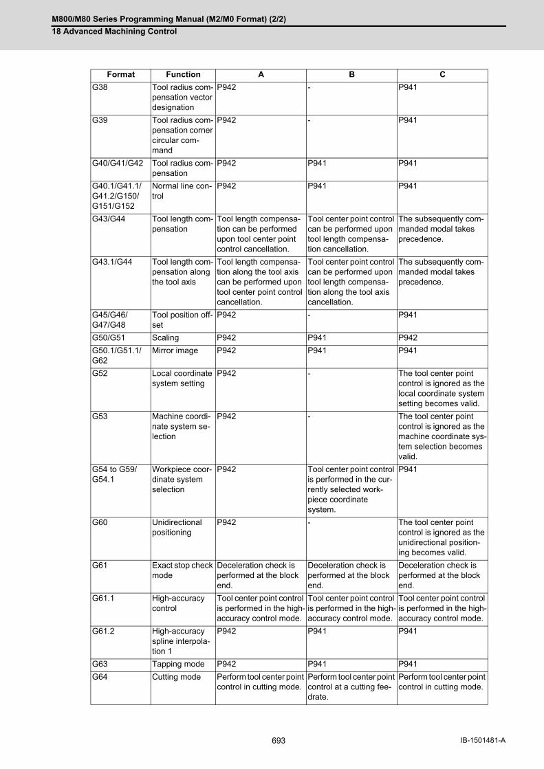
M800/M80 Series Programming Manual (M2/M0 Format) (2/2)
18 Advanced Machining Control
693 IB-1501481-A
G38 Tool radius com-pensation vector designation
P942 - P941
G39 Tool radius com-pensation corner circular com-mand
P942 - P941
G40/G41/G42 Tool radius com-pensation
P942 P941 P941
G40.1/G41.1/G41.2/G150/G151/G152
Normal line con-trol
P942 P941 P941
G43/G44 Tool length com-pensation
Tool length compensa-tion can be performed upon tool center point control cancellation.
Tool center point control can be performed upon tool length compensa-tion cancellation.
The subsequently com-manded modal takes precedence.
G43.1/G44 Tool length com-pensation along the tool axis
Tool length compensa-tion along the tool axis can be performed upon tool center point control cancellation.
Tool center point control can be performed upon tool length compensa-tion along the tool axis cancellation.
The subsequently com-manded modal takes precedence.
G45/G46/G47/G48
Tool position off-set
P942 - P941
G50/G51 Scaling P942 P941 P942
G50.1/G51.1/G62
Mirror image P942 P941 P941
G52 Local coordinate system setting
P942 - The tool center point control is ignored as the local coordinate system setting becomes valid.
G53 Machine coordi-nate system se-lection
P942 - The tool center point control is ignored as the machine coordinate sys-tem selection becomes valid.
G54 to G59/G54.1
Workpiece coor-dinate system selection
P942 Tool center point control is performed in the cur-rently selected work-piece coordinate system.
P941
G60 Unidirectional positioning
P942 - The tool center point control is ignored as the unidirectional position-ing becomes valid.
G61 Exact stop check mode
Deceleration check is performed at the block end.
Deceleration check is performed at the block end.
Deceleration check is performed at the block end.
G61.1 High-accuracy control
Tool center point control is performed in the high-accuracy control mode.
Tool center point control is performed in the high-accuracy control mode.
Tool center point control is performed in the high-accuracy control mode.
G61.2 High-accuracy spline interpola-tion 1
P942 P941 P941
G63 Tapping mode P942 P941 P941
G64 Cutting mode Perform tool center point control in cutting mode.
Perform tool center point control at a cutting fee-drate.
Perform tool center point control in cutting mode.
Format Function A B C

M800/M80 Series Programming Manual (M2/M0 Format) (2/2)
18 Advanced Machining Control
694IB-1501481-A
(*1) It is valid when the parameter "#1267 ext03/bit0" is OFF. If it is commanded when this parameter is ON, the
program error (P34) will occur.
(*2) It is valid when the parameter "#1267 ext03/bit0" is ON. If it is commanded when the parameter is OFF, the
program error (P34) will occur.
G65 to G67/G66.1
User macro Tool center point control becomes valid even in the user macro program.
Tool center point control becomes valid even in the user macro program.
Tool center point control is ignored as the user macro takes prece-dence over the tool cen-ter point control function.
G68 User macro sub-program termi-nation
User macro subprogram is terminated.
- Tool center point control will be ignored.
G69 End point error check cancella-tion
The end position error check cancellation be-comes valid.
- The end position error check cancellation, too, becomes valid.
G68.1/G69.1 Coordinate rota-tion
P942 P941 P941
G68.1IiJjKk/
G69.13-dimensional coordinate con-version
P922 P941 P923
G70 to G89 Fixed cycle P942 The tool center point control is ignored as the start fixed cycle be-comes valid.
The tool center point control is ignored as the start fixed cycle be-comes valid.
G90/G91 Absolute/Incre-mental value command
The modal is switched to the specified absolute / incremental value com-mand, and then tool center point control is performed.
Tool center point control is performed following the absolute / incremen-tal modal.
Tool center point control is performed under the specified absolute / in-cremental value com-mand.
G92 Machine coordi-nate system set-ting
P942 - P941
G94 Feed per minute Tool center point control is performed in the feed-perminute mode.
Tool center point control is performed in the feed-perminute mode.
Tool center point control is performed in the feed-perminute mode.
G95 Feed per revolu-tion
P942 P941 P941
G96/G97 Constant surface speed control
P942 P941 P941
G98 Fixed cycle Initial level return
The modal is switched to G98 and tool center point control becomes valid.
The modal is switched to G98 and tool center point control becomes valid.
The modal is switched to G98 and tool center point control becomes valid.
G99 Fixed cycle (R point level return)
The modal is switched to G99 and tool center point control becomes valid.
The modal is switched to G99 and tool center point control becomes valid.
The modal is switched to G99 and tool center point control becomes valid.
G114.1 Spindle synchro-nization
P942 P941 P941
Format Function A B C

M800/M80 Series Programming Manual (M2/M0 Format) (2/2)
18 Advanced Machining Control
695 IB-1501481-A
18.3 Inclined Surface Machining; G68.2, G68.3/G69.1
Inclined surface machining function enables defining a new coordinate system (feature coordinate system) which is obtained by rotating and parallel translating the origin of the present coordinate system (X, Y, Z) (a coordinate sys-tem that existed before the inclined surface machining command was issued). With this function, you can define an arbitrary plane in a space and issue normal program commands to this plane in machining.
It's possible to automatically control the tool axis to be in the + Z direction of the newly defined feature coordinate system. The feature coordinate system is redefined in accordance with the tool axis direction, thus there is no need to mind the feature coordinate system's direction and tool axis' rotation direction in making machining programs. If the inclined surface machining is commanded while this function is not defined in the specifications, it causes a program error (P950).
When workpiece installation error compensation is valid, the workpiece coordinate system is set to the workpiece installation coordinate system.
In M830/M80, if the linear axis and two rotary axes are commanded to the same block, a program error (P10) will occur. (Example) When the following machining program is executed with machine configuration X-Y-Z-A-C
The feature coordinate system is defined using the following method.
If address P is omitted when G68.2 is commanded, it is assumed that G68.2 P0 is designated (define usingEuler angles).
If address P is not set to "0" to "4" or "10" when G68.2 is commanded, a program error (P954) will occur.If address P or Q of the G68.2 command includes a decimal point, it is rounded to an integer.Make sure to command G68.2, G68.3, and G69.1 in an independent block. If they are commanded in the same
block as for other G codes or a motion command, etc., a program error (P954) will occur.The G69.1 command cannot be issued during circular interpolation or fixed cycle mode. If issued, a program
error (P952) will occur.
Function and purpose
Original coordinate system
Feature coordinate system
:
G68.2 X10. Y20, I0. J-45. K0.;
:
X20. A10 C20; Program error (P10)
:
G69.1;
G code Command method
G68.2 P0 Define using Euler angles
G68.2 P1 Define using roll-pitch-yaw angles
G68.2 P2 Define using three points in a plane
G68.2 P3 Define using two vectors
G68.2 P4 Define using projection angles
G68.2 P10 Define by selecting the registered machining surface
G68.3 Define using tool axis direction
G69.1 Cancel inclined surface machining command
Z
Y
X
Z’Y’
X’

M800/M80 Series Programming Manual (M2/M0 Format) (2/2)
18 Advanced Machining Control
696IB-1501481-A
18.3.1 How to Define Feature Coordinate System Using Euler Angles
(1) If the address X, Y or Z is omitted, the address will be regarded as zero. When all of addresses X, Y, and Z are set to "0", the feature coordinate system's origin will be the same as thatof the coordinate system before the inclined surface machining command is issued.
(2) If the address I, J or K is omitted, the address will be regarded as zero.
(3) If any address other than P, X, Y, Z, I, J and K is included, a program error (P954) will occur.
By commanding G68.2 P0 (define using Euler angles), the feature coordinate system (a coordinate system made
by rotating and shifting the origin of the coordinate system before inclined surface machining) is defined.
Coordinate system rotation is commanded using the Euler angles.
(Example) When "G68.2 Xx Yy Zz Ia Jb Kc;" is commanded, the feature coordinate system is established as below.
(a) Define a point (x, y, z) in the coordinate system before issuing the inclined surface machining command, as the
feature coordinate system's origin.
(b) Rotate the coordinate system, which was defined by shifting the origin in (a), by angle a about its Z axis.
(c) Rotate the coordinate system, which was defined by rotation in (b), by angle b about its X axis.
(d) Rotate the coordinate system, which was defined by rotation in (c), by angle c about its Z axis.
(e) The coordinate system created in the above steps is the feature coordinate system.
Command format
Inclined surface machining mode ON (define using Euler angles) (P0 can be omitted.)
G68.2 P0 X__ Y__ Z__ I__ J__ K__ ;
X, Y, Z Feature coordinate system's originCommand by the absolute values with respect to the coordinate system before is-suing the inclined surface machining command.
I, J, K Euler angles (-360.0° to 360.0°)
Detailed description
Note

M800/M80 Series Programming Manual (M2/M0 Format) (2/2)
18 Advanced Machining Control
697 IB-1501481-A
If coordinate system's rotation is counter clockwise when viewing from the positive ends of the rotation center axis,
this rotation will be considered as forward rotation. The relationship between the coordinate system before issuing
the inclined surface machining command and the feature coordinate system is as shown below.
WZ
WX
WY
WZ
WX
WY
FZ
FX
FYa
c
b
(b)
x
y
z
(a) (c)
Z
X
Y Z
X
Y
(d)
ZX
Y
xy
z
(e)
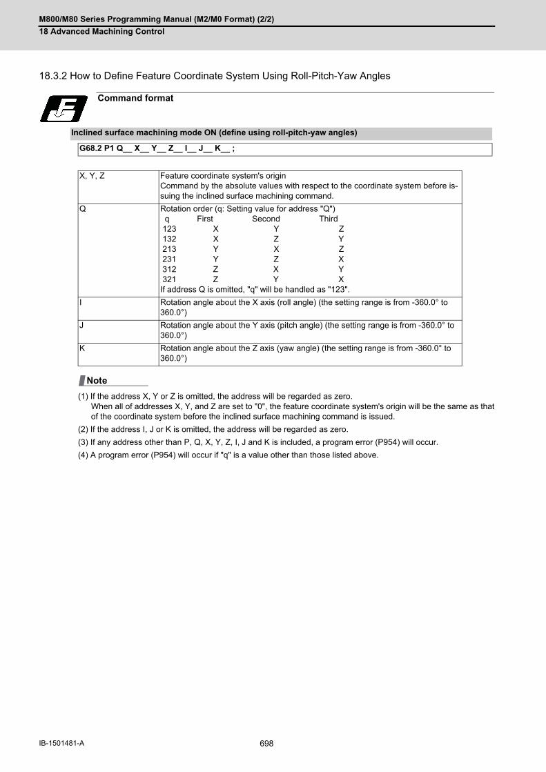
M800/M80 Series Programming Manual (M2/M0 Format) (2/2)
18 Advanced Machining Control
698IB-1501481-A
18.3.2 How to Define Feature Coordinate System Using Roll-Pitch-Yaw Angles
(1) If the address X, Y or Z is omitted, the address will be regarded as zero. When all of addresses X, Y, and Z are set to "0", the feature coordinate system's origin will be the same as thatof the coordinate system before the inclined surface machining command is issued.
(2) If the address I, J or K is omitted, the address will be regarded as zero.
(3) If any address other than P, Q, X, Y, Z, I, J and K is included, a program error (P954) will occur.
(4) A program error (P954) will occur if "q" is a value other than those listed above.
Command format
Inclined surface machining mode ON (define using roll-pitch-yaw angles)
G68.2 P1 Q__ X__ Y__ Z__ I__ J__ K__ ;
X, Y, Z Feature coordinate system's originCommand by the absolute values with respect to the coordinate system before is-suing the inclined surface machining command.
Q Rotation order (q: Setting value for address "Q") q First Second Third 123 X Y Z 132 X Z Y 213 Y X Z 231 Y Z X 312 Z X Y 321 Z Y XIf address Q is omitted, "q" will be handled as "123".
I Rotation angle about the X axis (roll angle) (the setting range is from -360.0° to 360.0°)
J Rotation angle about the Y axis (pitch angle) (the setting range is from -360.0° to 360.0°)
K Rotation angle about the Z axis (yaw angle) (the setting range is from -360.0° to 360.0°)
Note

M800/M80 Series Programming Manual (M2/M0 Format) (2/2)
18 Advanced Machining Control
699 IB-1501481-A
(Example) The feature coordinate system is established by the machining program as shown below.
G68.2 P1 Q123 Xx Yy Zz Ia Jb Kc;
(When q=123 [rotations in the order of WX, WY and WZ])
(a) Designate the feature coordinate system's origin by x, y and z (coordinates that existed before the inclined sur-
face machining command was issued).
(b) Rotate the shifted coordinate system by angle "a" about the X axis of the coordinate system before issuing the
inclined surface machining command. (Roll angle)
(c) Rotate the coordinate system, which was defined after rotation in (b), by angle "b" about the Y axis of the coor-
dinate system before issuing the inclined surface machining command. (Pitch angle)
(d) Rotate the coordinate system, which was defined after rotation in (c), by angle "c" about the Z axis of the coor-
dinate system before issuing the inclined surface machining command. (Yaw angle)
(e) The coordinate system created in the above steps is the feature coordinate system.
Detailed description
(a) (b)
FX
FZ
FY
WX
WZ
WY
aFY FX
FZ
(c)
FXb
FY
FZ (d)
cFY FX
FZ
(x, y, z)
(e)
FY
FX
FZ

M800/M80 Series Programming Manual (M2/M0 Format) (2/2)
18 Advanced Machining Control
700IB-1501481-A
18.3.3 How to Define Feature Coordinate System Using Three Points in a Plane
(*1) Command by the absolute values with respect to the coordinate system before issuing the inclined surface ma-
chining command.
(1) If the address Q is omitted, the address will be regarded as zero.
(2) If the address X, Y or Z in Q0 to Q3 is omitted, the address will be handled as zero.
(3) If the address R is omitted, the address will be regarded as zero.
(4) If any address other than P, Q, X, Y, Z and R is included, a program error (P954) will occur.
(5) A program error (P954) will occur in the following cases.When any other command is included among G68.2 P2 Q0 to Q3.When any of G68.2 P2 Q1 to Q3 is lacked.When G68.2 P2 Q0 to Q3 are overlapped.When a value other than 0 to 3 is commanded in the address Q.When R is commanded in more than one block.
(6) A program error (P955) will occur in the following cases.When the same point was designated for two or more points among the 1st to the 3rd points.When the three points exist on a straight line.The distance between one of the three points and the straight line connecting the other two points is less
than 0.1 (mm).
Command format
Inclined surface machining mode ON (define using three points in a plane)
G68.2 P2 Q0 X__ Y__ Z__ R__ ; Shift amount setting
G68.2 P2 Q1 X__ Y__ Z__ ; 1st point coordinate setting
G68.2 P2 Q2 X__ Y__ Z__ ; 2nd point coordinate setting
G68.2 P2 Q3 X__ Y__ Z__ ; 3rd point coordinate setting
Q Designate the pointsDesignate from the 1st to the 3rd points, or specify by the shift distance. 0: Shift distance1: The 1st point2: The 2nd point3: The 3rd point
X, Y, Z(Shift amount setting)
Shift amount between the 1st point and the feature coordinate system's originCommand by the incremental value with respect to the feature coordinate system before parallel shift.
R The angle to rotate the feature coordinate system about the Z axis (the setting range is from -360.0° to 360.0°)
X, Y, Z(The 1st point)
Designate the feature coordinate system's origin using with the workpiece coordi-nate system's position. (*1)
X, Y, Z(The 2nd point)
Designate a point on the feature coordinate system's X axis (+ direction) using with the workpiece coordinate system's position. (*1)
X, Y, Z(The 3rd point)
Designate a point on the feature coordinate system's Y axis using with the work-piece coordinate system's position. (*1)
Note

M800/M80 Series Programming Manual (M2/M0 Format) (2/2)
18 Advanced Machining Control
701 IB-1501481-A
(1) Designate the points Q1, Q2 and Q3 with respect to the coordinate system before issuing the inclined surfacemachining command. The point Q1 will be the origin of the feature coordinate system.
(2) Define the X, Y and Z axes' directions of the feature coordinate system in the following procedure.
Feature coordinate system's X axis is in the direction from the 1st point (Q1) to the 2nd point (Q2). Normally,designate a point on Y axis (+ direction) as Q3. (If the commanded X axis and Y axis are not at perfect rightangles, the Y axis will be automatically compensated to be at right angles to the X axis.)Feature coordinate system's Z axis is in the direction of the cross product of (Q2-Q1)×(Q3-Q1).Feature coordinate system's Y axis is determined with respect to the right-handed system.
(3) When shift distance (x0, y0, z0) of the feature coordinate system's origin is commanded, the feature coordinatesystem's origin is further parallel translated by (x0, y0, z0). Command the parallel translation distance with re-spect to the feature coordinate system before parallel translation. Always specify x0, y0 and z0 by incrementalvalue.
(4) When the rotation angle a is commanded in the address R, the feature coordinate system is rotated by the angle"a" about the Z axis of the feature coordinate system.
(Example) The feature coordinate system is established by the machining program as shown below.
G68.2 P2 Q0 Xx0 Yy0 Zz0 Ra ;
G68.2 P2 Q1 Xx1 Yy1 Zz1 ;
G68.2 P2 Q2 Xx2 Yy2 Zz2 ;
G68.2 P2 Q3 Xx3 Yy3 Zz3 ;
Detailed description
Coordinate system before issuing the inclined surface machining command(Workpiece coordinate system)
(x0,y0,z0)Q1
Q3
Q2
a
WZ
FZ (=FZ1)
WY
WX
FX
FYFZ1
FX1
FY1
a
(x1,y1,z1)(1) (2)
(3)
(4)
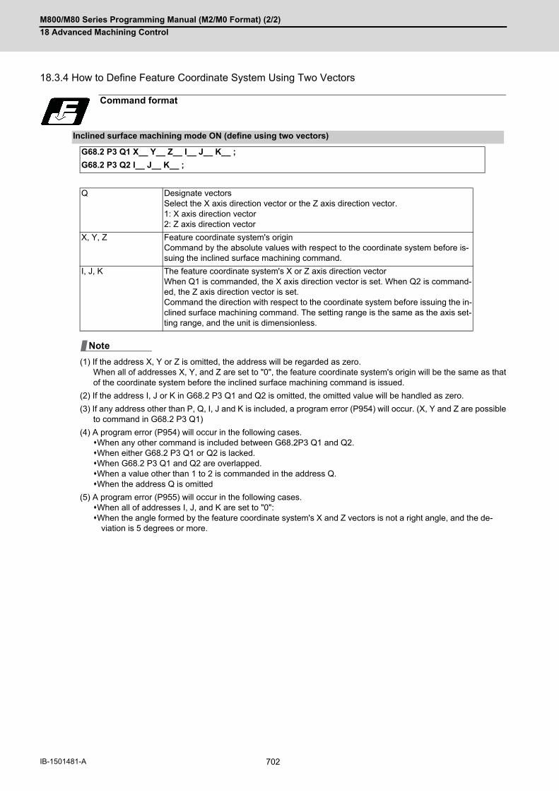
M800/M80 Series Programming Manual (M2/M0 Format) (2/2)
18 Advanced Machining Control
702IB-1501481-A
18.3.4 How to Define Feature Coordinate System Using Two Vectors
(1) If the address X, Y or Z is omitted, the address will be regarded as zero. When all of addresses X, Y, and Z are set to "0", the feature coordinate system's origin will be the same as thatof the coordinate system before the inclined surface machining command is issued.
(2) If the address I, J or K in G68.2 P3 Q1 and Q2 is omitted, the omitted value will be handled as zero.
(3) If any address other than P, Q, I, J and K is included, a program error (P954) will occur. (X, Y and Z are possibleto command in G68.2 P3 Q1)
(4) A program error (P954) will occur in the following cases.When any other command is included between G68.2P3 Q1 and Q2.When either G68.2 P3 Q1 or Q2 is lacked.When G68.2 P3 Q1 and Q2 are overlapped.When a value other than 1 to 2 is commanded in the address Q.When the address Q is omitted
(5) A program error (P955) will occur in the following cases.When all of addresses I, J, and K are set to "0":When the angle formed by the feature coordinate system's X and Z vectors is not a right angle, and the de-
viation is 5 degrees or more.
Command format
Inclined surface machining mode ON (define using two vectors)
G68.2 P3 Q1 X__ Y__ Z__ I__ J__ K__ ;
G68.2 P3 Q2 I__ J__ K__ ;
Q Designate vectorsSelect the X axis direction vector or the Z axis direction vector. 1: X axis direction vector2: Z axis direction vector
X, Y, Z Feature coordinate system's originCommand by the absolute values with respect to the coordinate system before is-suing the inclined surface machining command.
I, J, K The feature coordinate system's X or Z axis direction vectorWhen Q1 is commanded, the X axis direction vector is set. When Q2 is command-ed, the Z axis direction vector is set. Command the direction with respect to the coordinate system before issuing the in-clined surface machining command. The setting range is the same as the axis set-ting range, and the unit is dimensionless.
Note

M800/M80 Series Programming Manual (M2/M0 Format) (2/2)
18 Advanced Machining Control
703 IB-1501481-A
(1) Designate the feature coordinate system's origin by x, y and z (coordinates that existed before the inclined sur-face machining command was issued).
(2) Define the X, Y and Z axes' directions of the feature coordinate system in the following procedure.Feature coordinate system's X axis positive direction is rx = (ix, jx, kx).Feature coordinate system's Y axis positive direction is that of the cross product of (iz, jz, kz)×(ix, jx, kx).The feature coordinate system's Z axis is determined with respect to the right-handed system.
The direction of rx=(ix, jx, kx) is the X axis of the feature coordinate system.
Normally, the direction of rz=(iz, jz, kz) is the Z axis (positive direction) of the feature coordinate system.
(If rx and rz are not at perfect right angle to each other, they will be automatically compensated so that they are
at right angle to the X axis.)
(Example) The feature coordinate system is established by the machining program as shown below.
G68.2 P3 Q1 Xx Yy Zz Iix Jjx Kkx ;
G68.2 P3 Q2 Iiz Jjz Kkz ;
Detailed description
Coordinate system before issuing the inclined surface machining command(Workpiece coordinate system)
FZ
FY FX
rz=(iz,jz,kz)rx=(ix,jx,kx)
(x,y,z)XY
ZWX
WZ
WY

M800/M80 Series Programming Manual (M2/M0 Format) (2/2)
18 Advanced Machining Control
704IB-1501481-A
18.3.5 How to Define Feature Coordinate System Using Projection Angles
(1) If the address X, Y or Z is omitted, the address will be regarded as zero. When all of addresses X, Y, and Z are set to "0", the feature coordinate system's origin will be the same as thatof the coordinate system before the inclined surface machining command is issued.
(2) If the address I, J or K is omitted, the omitted value will be handled as zero.
(3) If any address other than P, X, Y, Z, I, J and K is included, a program error (P954) will occur.
(4) A program error (P955) will occur when the angle formed by the X axis after rotating by the angle designatedwith address I about the Y axis, and the Y axis after rotating by the angle designated with address J about theX axis is 1 degree or less.
(1) Designate the feature coordinate system's origin by x, y and z (coordinates that existed before the inclined sur-face machining command was issued).
(2) Define the X, Y and Z axes' directions of the feature coordinate system in the following procedure.The direction in which the X axis of the coordinate system before issuing the inclined surface machining
command is rotated by angle a about the Y axis is defined as "ra".The direction in which the Y axis of the coordinate system before issuing the inclined surface machining
command is rotated by angle b about the X axis is defined as "rb".Feature coordinate system's Z axis is in the direction of the cross product of (ra × rb).Feature coordinate system's X axis is in the direction determined by rotating "ra" by the angle "c" about the
feature coordinate system's Z axis.Feature coordinate system's Y axis is determined with respect to the right-handed system.
If "ra" and "rb" are considered to be parallel (or if the angle formed by the two vectors is 1 degree or less), aprogram error (P955) will occur.Except XZ and YZ plane, it is not possible to designate a plane that is in parallel with Z axis.
Command format
Inclined surface machining mode ON (define using projection angles)
G68.2 P4 X__ Y__ Z__ I__ J__ K__ ;
X, Y, Z Feature coordinate system's originCommand by the absolute values with respect to the coordinate system before issuing the inclined surface machining command.
I The angle to rotate the X axis about the Y axis of the coordinate system before issuing the inclined surface machining command (the setting range is from -360.0° to 360.0°)
J The angle to rotate the Y axis about the X axis of the coordinate system before issuing the inclined surface machining command (the setting range is from -360.0° to 360.0°)
K The rotation angle about the Z axis of the feature coordinate system (the setting range is from -360.0° to 360.0°)
Detailed description
Note
Note

M800/M80 Series Programming Manual (M2/M0 Format) (2/2)
18 Advanced Machining Control
705 IB-1501481-A
(Example) The feature coordinate system is established by the machining program as shown below.
G68.2 P4 Xx Yy Zy Ia Jb Kc ;
Coordinate system before issuing the inclined surface machining command(Workpiece coordinate system)
FZ
FY FXa
b
XY
Z
ra
rb
WXWZ
WY
FYFX
c
FZFZFZ
(x, y, z)
M800/M80 Series Programming Manual (M2/M0 Format) (2/2)
18 Advanced Machining Control
706IB-1501481-A
18.3.6 Define by selecting the registered machining surface
(1) When address Q is omitted, select workpiece No. 1 if Q0,Q1 is commanded.
(2) When address D is omitted, select machining surface No. 1 (BASE-SURFACE) if D0,D1 is commanded.
(3) If any address other than P, Q, and D is designated when G68.2 P10 is commanded, a program error (P954)will occur.
(4) A program error (P954) will occur when:a value other than 0 to 10 is commanded in address Q or an undefined workpiece name is designated;a value other than 0 to 17 is commanded in address D or an undefined machining surface name is desig-
nated;the workpiece name does not include a character string (command represented by "Q<>"); andthe machining surface name does not include a character string (command represented by "D<>").
(5) If no feature coordinate system can be defined for the selected machining surface, a program error (P956) willoccur.
(6) If there are multiple workpieces or machining surfaces of the same name when the workpiece name or machiningsurface name is designated, a lower number is selected.
(7) When the machining surface is called from the program, [SEL] or [*] is not displayed on the screen. Various PLCsignals are not set to ON. (R-Navi machining surface selecting signal (XD28), R-Navi selecting workpiece No.signal (R660), R-Navi selecting machining surface No. signal (R661))
(8) When the machining surface is called from the program, the basic coordinate system designated by R-Navi foreach workpiece is not selected. Before "G68.2 P10" is commanded, select a workpiece coordinate system fromthe program.
(9) If you have defined a workpiece No. in address Q, define a machining surface No. in address D. If you have defined a workpiece name in address Q, define a machining surface name in address D.
Command format
Inclined surface machining mode ON (define R-Navi machining surface)
G68.2 P10 Q__ D__ ;
Q Workpiece No. designated by R-Navi or workpiece name designated by R-Navi
D Machining surface No. designated by R-Navi or machining surface name designat-ed by R-Navi
Note

M800/M80 Series Programming Manual (M2/M0 Format) (2/2)
18 Advanced Machining Control
707 IB-1501481-A
18.3.7 How to Define Feature Coordinate System Using Tool Axis Direction
(1) If the address X, Y or Z is omitted, the address will be regarded as zero. When all of addresses X, Y, and Z are set to "0", the feature coordinate system's origin will be the same as thatof the coordinate system before the inclined surface machining command is issued.
(2) If the address R is omitted, the omitted value will be handled as zero.
(3) If any address other than X, Y, Z and R is included, a program error (P954) will occur.
(1) Designate the feature coordinate system's origin by x, y and z (coordinates that existed before the inclined sur-face machining command was issued).
(2) Define the X, Y and Z axes' directions of the feature coordinate system in the following procedure.Feature coordinate system's Z axis is in the tool axis direction.Feature coordinate system's X axis is in the direction of the X axis of the coordinate system before issuing
the inclined surface machining command after rotating with the tool. (When all the tool-side rotary axes areat 0 degrees (machine value), the feature coordinate system's X axis will be in the same direction as theX axis of the coordinate system before issuing the inclined surface machining command.)
Feature coordinate system's Y axis is in the direction of the Y axis of the coordinate system before issuingthe inclined surface machining command after rotating with the tool. (When all the tool-side rotary axes areat 0 degrees (machine value), the feature coordinate system's Y axis will be in the same direction as theY axis in the coordinate system before issuing the inclined surface machining command.)
Feature coordinate system is finally established by rotating the commanded angle with address R about theZ axis.
Command format
Inclined surface machining mode ON (define using tool axis direction)
G68.3 X__ Y__ Z__ R__;
X, Y, Z Feature coordinate system's originCommand by the absolute values with respect to the coordinate system before is-suing the inclined surface machining command.
R The angle to rotate the feature coordinate system about Z axis (the setting range is from -360.0° to 360.0°)
Detailed description
Note
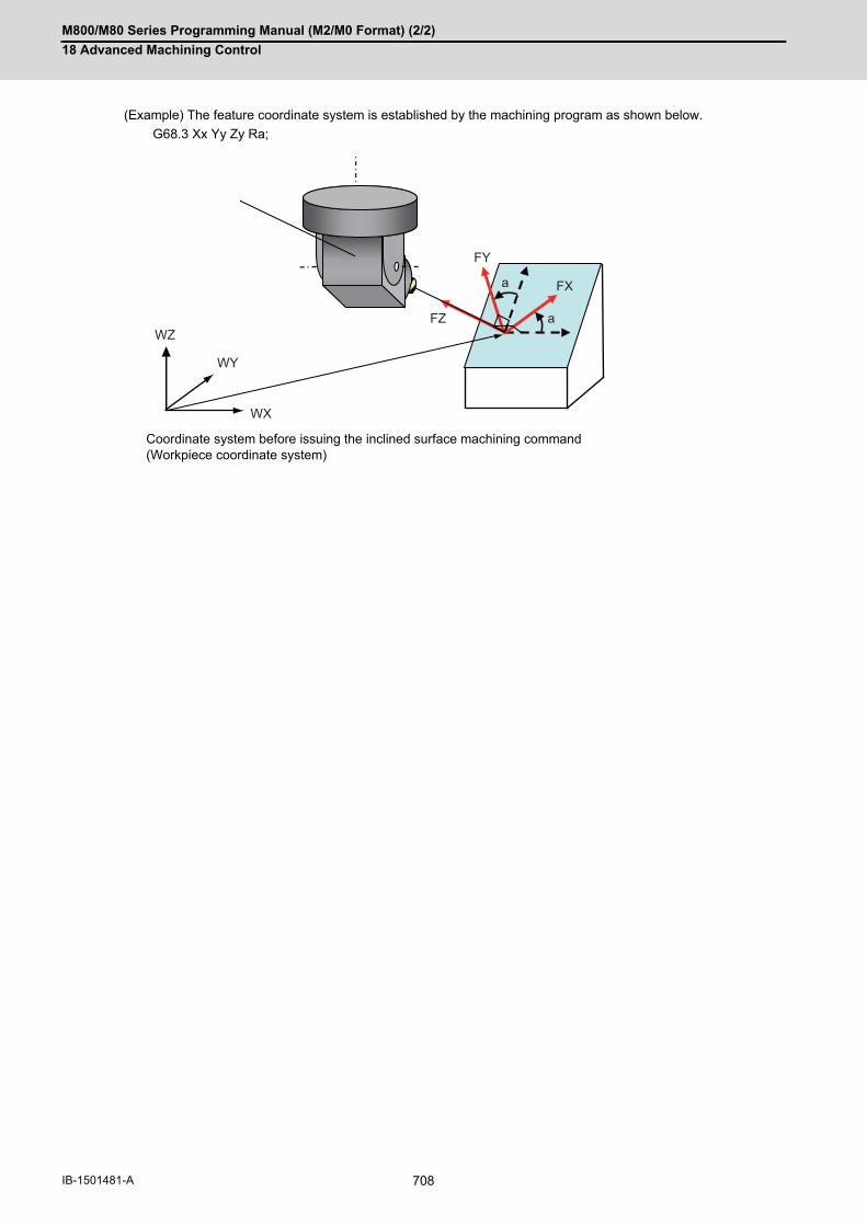
M800/M80 Series Programming Manual (M2/M0 Format) (2/2)
18 Advanced Machining Control
708IB-1501481-A
(Example) The feature coordinate system is established by the machining program as shown below.
G68.3 Xx Yy Zy Ra;
Coordinate system before issuing the inclined surface machining command(Workpiece coordinate system)
WY
WZ
WX
FY
FXa
aFZ

M800/M80 Series Programming Manual (M2/M0 Format) (2/2)
18 Advanced Machining Control
709 IB-1501481-A
18.3.8 Tool Axis Direction Control; G53.1/G53.6
A rotary axis is automatically moved so that the tool axis direction (direction from the tool's tip to the bottom) will be
the feature coordinate system's +Z axis direction. For table tilt type and compound type machines, feature coordi-
nate system may change in accordance with the rotation of the table rotary axis.
The following two types of tool axis direction control can be utilized:
G53.1/G53.6 are group 00.
(1) Command G53.1/G53.6 during inclined surface machining mode. If commanded in any other mode, a programerror (P953) will occur.
(2) Make sure to command G53.1/G53.6 surely in a block. If this command is issued in the same block as of otherG codes or travel command etc., a program error (P953) will occur.
(3) The travel speed when G53.1 is commanded follows the G group 1 modal (such as G00/G01) during the toolaxis direction control command.
(4) The travel speed on the feature coordinate system when G53.6 is commanded follows G group 1 modal (suchas G00/G01). The travel speed of each axis may exceed the command speed as the tool tip position is fixed inthe view from workpiece. However, rapid traverse (G00) is clamped by the parameter "#2001 rapid", and thecutting feed (G01) is clamped by the parameter "#2002 clamp". (These parameters depend on the MTB specifi-cations.)
Function and purpose
Type 1 (G53.1 command) Only the rotary axis is moved.
Type 2 (G53.6 command) The rotary axis and the orthogonal axis are moved by fixing the tool center point position in the view from the workpiece.
Command format
Tool axis direction control (type 1): Only the rotary axis is moved.
G53.1 P__ ;
Tool axis direction control (type 2): The rotary axis and the orthogonal axis are moved by fixing the tool cen-ter point position in the view from the workpiece.
G53.6 P__ Q__ H__ ;
P Select a solution for the rotary axis0: Select a default solution for each machine type 1: Select a solution so that the primary rotary axis rotation is positive. 2: Select a solution so that the primary rotary axis rotation is negative.
Q Select the rotation order of the rotary axes when the number of simultaneous con-touring control axes is 4 axes or less and the operation at the time of G53.6 com-mand is limited to simultaneous 4 axes (3 orthogonal axes + 1 rotary axis) or less. (In the following example, there are 2 rotary axes.) 0: The axes operate in the order set in the "#7917 SLCT_G53_6_ROTAX" param-eter. 1: The axes operate in the order of primary rotary axis and secondary rotary axis. 2: The axes operate in the order of secondary rotary axis and primary rotary axis. Even if the number of simultaneous contouring control axes is 5 axes or more, the number can be limited to the simultaneous 4 axes (3 orthogonal axes + 1 rotary ax-is) or fewer by address Q command. However, when address Q command is "0", 5 axes operate simultaneously regardless of the parameter settings.
H Tool length offset No.
Note

M800/M80 Series Programming Manual (M2/M0 Format) (2/2)
18 Advanced Machining Control
710IB-1501481-A
(5) If the address P is omitted, the omitted value will be handled as zero. If any other value than 0, 1, and 2 is com-mand, a program error (P35) will occur.
(6) If any address other than P/N is commanded while commanding G53.1, a program error (P953) will occur.
(7) When address Q is omitted at the time of G53.6 command, it is regarded that 0 is commanded. If any other valuethan 0, 1, and 2 is command, a program error (P35) will occur.
(8) If any address other than P/H/N is commanded while commanding G53.6, a program error (P953) will occur.
(9) When the address H is omitted, H modal commanded before G53.6 command will be applied. If H modal is notcommanded, a program error (P953) will occur.
(10) If the tool length offset No. is changed by address H command, a program error (P953) will occur.
(11) If the offset amount for the tool No. that the address H is commanded is "0", a program error (P957) will occur.
(Example 1) (Example 2)
:G43 H1 :G53.6 ← Use H1 :
:G53.6 ← Error (P953) :
(Example 1)
:G43 H1 ← Command the tool offset No.1 :G53.6 H2 ← If tool length offset No.2 is commanded, a program error (P953) will occur. :
(Example 1) When "H1 = 0" (Example 2) When "H1 ≠ 0" (Example 3) When "0" is com-maned to address H
:G43 H1 :G53.6 ← Error (P957) :
:G43 H1 :H0 ← Tool length offset is "0" : while it remains G43 modal.G53.6 ← Error (P957) :
:G53.6 ← Error (P957) :

M800/M80 Series Programming Manual (M2/M0 Format) (2/2)
18 Advanced Machining Control
711 IB-1501481-A
For the G53.1 command, the 3 orthogonal axes (X, Y, and Z axes) do not move, however, only the 2 rotary axes
rotate simultaneously so that the tool axis direction is in line with the +Z direction of the feature coordinate system.
(1) For compound type B-C axesWhen the G53.1 command is issued for a compound type (B-C axes) machine, the B axis of the tool and the Caxis of the table rotate simultaneously.
(2) For table tilt type A-C axesWhen the G53.1 command is issued for a table tilt type (A-C axes) machine, the A and C axes of the table rotatesimultaneously.
(3) For tool tilt type B-C axesWhen the G53.1 command is issued for a tool tilt type (B-C axes) machine, the B and C axes of the tool rotatesimultaneously.
Detailed description
The operation of type 1 (G53.1)
G53.1
WZ
WYWX FZ
B B
CC
FY
FX
G53.1WZ WYWX
FZ
A A
CC
FYFX
G53.1
WZ
WYWX
B B
CC
FZ
FY
FX

M800/M80 Series Programming Manual (M2/M0 Format) (2/2)
18 Advanced Machining Control
712IB-1501481-A
For G53.6 command, the tool axis end position of the tool axis direction seen from workpiece is fixed to be in +Z
direction in the feature coordinate system, and up to 3 orthogonal axes (x axis, Y axis, and Z axis) and 2 rotary axes
moves simultaneously.
The number of axes to be moved simultaneously is limited by the number of simultaneous contouring control axes.
If the number of simultaneous contouring control axes is 4 axes or fewer, the rotary axes move separately.
The order of rotary axes moving separately can be specified with address Q command. When the number of simul-
taneous contouring control axes is 5 axes or more, the rotary axes can also be moved separately by issuing the
address Q command.
[When the number of simultaneous contouring control axes is 5 axes or more]
For G53.6 command, up to 3 orthogonal axes(X axis, Y axis, and Z axis) and 2 rotary axes can be moved simulta-
neously.
(1) For compound type B-C axesWhen the G53.6 command is issued for a compound type (B-C axes) machine, the X, Y, Z, and B axes of thetool and the C axis of the table move simultaneously.
(2) For table tilt type A-C axesWhen the G53.6 command is issued for a table tilt type (A-C axes) machine, the X, Y, and Z axes of the tool andthe A and C axes of the table move simultaneously.
Type 2 (G53.6) command
G53.6
WZ
WYWX
B B
CC
FZFY
FX
G53.6WZ WYWX
A A
CC
FZ
FYFX

M800/M80 Series Programming Manual (M2/M0 Format) (2/2)
18 Advanced Machining Control
713 IB-1501481-A
(3) For tool tilt type B-C axesWhen the G53.6 command is issued for a tool tilt type (B-C axes) machine, the X, Y, Z, B, and C axes of the toolrotate simultaneously.
[When the number of simultaneous contouring control axes is 4 axes or fewer]
Up to 3 orthogonal axes (X, Y, Z axes) and a rotary axis move simultaneously with G53.6 command. When 2 rotary
axes move, the order of rotary axes to move is specified with the parameter “#7917 SLCT_G53_6_ROTAX” or ad-
dress Q. When specifying "1" to the address Q, the axis moves in the order of primary rotary axis and secondary
rotary axis. When setting "2" to the address Q, the axis moves in the order of the secondary axis and the primary
axis. When executing the single block operation, either performing the block stop or not at the movement completion
for each rotary axis can also be specified with parameter “#8132 G53.6 block stop”.
(1) Compound type B-C axis
(a) When moving in the order of primary rotary axis and secondary rotary axis
First, the B axis ("B" in the figure below) of the tool rotates, and then the X, Y, and Z axes of the tool also
move to fix the tool center position.
Next, the C axis ("C" in the figure below) of the table rotates, and then the X, Y, and Z axes of the tool also
move as if the tool follows the workpiece movement.
G53.1
WZ
WYWX
B
B
CC
FZ
FY
FX
B B
C C
G53.6FZ
WZ
WYWX
FY
FX
FZ
WY
WX
FY
FX
FY
FXFY
FX

M800/M80 Series Programming Manual (M2/M0 Format) (2/2)
18 Advanced Machining Control
714IB-1501481-A
(b) When moving in the order of secondary rotary axis and primary rotary axis
First, the C axis ("C" in the figure below) of the table rotates, and then the X, Y, and Z axes of the tool also
move as if the tool follows the workpiece movement.
Next, the B axis ("B" in the figure below) of the tool rotates, and then the X, Y, and Z axes of the tool also
move to fix the tool center position.
(2) For table tilt type A-C axes (When moving in the order of secondary rotary axis and primary rotary axis)First, the C axis ("C" in the figure below) of the table rotates, and then the X, Y, and Z axes of the tool also moveas if the tool follows the workpiece movement. Next, the A axis ("A" in the figure below) of the table rotates, and then the X, Y, and Z axes of the tool also moveas if the tool follows the workpiece movement.
FY
FX
BB
C C
G53.6FZ
WZ
WYWX
FY
FX
FZ FY
FX
WY
WX
FY
FX
FY
FX
A A
C C
G53.6
FZ
FY
FX
WZWY
WX
FY
FX
WY
WX
FY
FX

M800/M80 Series Programming Manual (M2/M0 Format) (2/2)
18 Advanced Machining Control
715 IB-1501481-A
(3) For tool tilt type B-C axis (When moving in the order of primary rotary axis and secondary rotary axis)First, the B axis ("B" in the figure below) of the tool rotates, and then the X, Y, and Z axes of the tool also moveto fix the tool center position. Next, the C axis ("C" in the figure below) of the tool rotates, and then the X, Y, and Z axes of the tool also moveto fix the tool center position.
When G53.1 is commanded, there are normally two types of solutions for the rotary axis' calculated angle; one is to
rotate the primary rotary axis positively, and the other negatively. Use the address P (P=0, 1 or 2) in G53.1 command
to select either one of the solutions.
These are the default solutions for each machine type.
When P is "0": Selects a default solution for each machine type
When P is "1": Selects a solution so that the primary rotary axis rotation is positive
When P is "2": Selects a solution so that the primary rotary axis rotation is negative
When the address P is omitted, P will be regarded as zero, so the default solution for each machine type is selected.
If any other value than 0,1, and 2 is command, a program error (P35) will occur.
These are the default solutions for each machine type.
Select rotary axis' solution
Machine type Primary rotary axis Solution selected by default
Tool tilt type Tool-side 2nd rotary axis Selects a solution so that the primary rotary axis rotation is positive (same as when P is "1")
Table tilt type Table-side 2nd rotary axis Selects a solution so that the primary rotary axis rotation is negative (same as when P is "2")
Compound type Tool-side rotary axis Selects a solution so that the primary rotary axis rotation is positive (same as when P is "1")
B B
C
C
FX FX
G53.6 FZ
WZ
WYWX
FY
FX
FZ
WY
WX
FY
FX
FY
FX
FY
FX
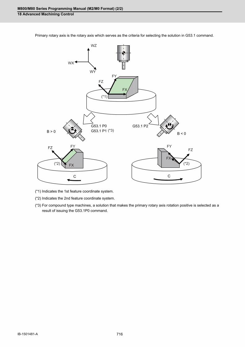
M800/M80 Series Programming Manual (M2/M0 Format) (2/2)
18 Advanced Machining Control
716IB-1501481-A
Primary rotary axis is the rotary axis which serves as the criteria for selecting the solution in G53.1 command.
(*1) Indicates the 1st feature coordinate system.
(*2) Indicates the 2nd feature coordinate system.
(*3) For compound type machines, a solution that makes the primary rotary axis rotation positive is selected as a
result of issuing the G53.1P0 command.
B > 0
C
G53.1 P2
C
B < 0
G53.1 P0 G53.1 P1
WY
WZ
WX
FYFZ
FX
FYFZ
FX
FYFZ
FX
(*1)
(*3)
(*2) (*2)

M800/M80 Series Programming Manual (M2/M0 Format) (2/2)
18 Advanced Machining Control
717 IB-1501481-A
18.3.9 Details of Inclined Surface Machining Operation
When inclined surface machining is commanded, the above-mentioned feature coordinate system is defined. By set-
ting the parameters #8901 to #8906 to "23", you can display the coordinates of the feature coordinate system on the
counter (no machine motion). The travel commands during inclined surface machining mode are handled with re-
spect to the feature coordinate system.
In the counter display of the feature coordinate system, whether the machining position on the program command
that does not include the tool length compensation/tool radius compensation can be selected depends on the MTB
specifications (parameter "#1287 ext23/bit1, bit2 (inclined surface coordinate display)".
When G53.1 is commanded, the rotary axis moves so that the tool axis direction will be + Z direction of the feature
coordinate system. At this time, the rotary axis moves, but X, Y and Z axes won't move. The rotary axis' travel speed
is determined based on the modal when G53.1 is commanded.
The command G69.1 cancels the inclined surface machining. When this mode is canceled, the feature coordinate
system setting will be canceled, the coordinate system will change back to the workpiece coordinate system when
inclined surface machining was commanded, and workpiece coordinate position counter will change back to the pre-
vious workpiece coordinate system's coordinates (no machine motion). By inputting Reset, the inclined surface ma-
chining is also canceled.
(If the parameter "#1151 rstint" is set to "0", however, the inclined surface machining mode is kept even when Reset
1 is input.)
Detailed description
Operation during inclined surface machining mode
Tool Axis Direction Control
CAUTION
Depending on the feature coordinate system setting, rotary axis may move greatly in response to G53.1 com-
mand. Thus, before commanding G53.1, move the tool far enough away from the table.
Cancel inclined surface machining mode

M800/M80 Series Programming Manual (M2/M0 Format) (2/2)
18 Advanced Machining Control
718IB-1501481-A
The machining program #10 is for machining an identical shape on each face of the hexagonal column using a com-pound type machine. Feature coordinate systems on each face are defined in the blocks N1 to N6, and then same machining is performed using the subprogram (Machining program #100). The workpiece origin is deemed to be at the center of the hexagonal column's end-face.
Machining program #10
Machining program #100G53.1;G90 G00 X0. Y0. Z5.;G01 Z-5. F500;G01 Y20. F1000;G02 X20. Y0. R20. F1000;G01 X0. F1000;
G23;
G: Feature coordinate system's origin
Program example
Program example 1
N1 G68.2 X86.6025 Y50. Z0. I-90. J-45. K0.;
G22 L100;
G69.1;
G00 Z200.;
Machining on the face (1)
N2 G68.2 X86.6025 Y-50. Z0. I-150. J-45. K0.;
G22 L100;
G69.1;
G00 Z200.;
Machining on the face (2)
N3 G68.2 X0. Y-100. Z0. I-210. J-45. K0.;
G22 L100;
G69.1;
G00 Z200.;
Machining on the face (3)
N4 G68.2 X-86.6025 Y-50. I-270. J-45. K0.;
G22 L100;
G69.1;
G00 Z200. ;
Machining on the face (4)
N5 G68.2 X-86.6025 Y50. I-330. J-45. K0;
G22 L100;
G69.1;
G00 Z200. ;
Machining on the face (5)
N6 G68.2 X0. Y100. I-30. J-45. K0.;
G22 L100;
G69.1;
G00 Z200. ;
Machining on the face (6)
M30
(1)
(2)
(3)
(4)
(6)
(5)
50. 86.6025
G WY
FY
WX
FY FZ FX

M800/M80 Series Programming Manual (M2/M0 Format) (2/2)
18 Advanced Machining Control
719 IB-1501481-A
The machining program #10 to #15 are for machining a shape on an inclined surface of the cube as shown in the
figure next page. The feature coordinate system is defined by designating the inclined surface in each main program,
and then same machining is done using the subprogram (Machining program #100).
Program example 2
Machining program #10 Euler angles
N1 G28XYZBC ;
G54X0Y0Z0 ;
M200 ;
G68.2 X33.3333 Y 33.3333 Z66.6666 I-45 J54.7356 K0;
G22 L100;
G69.1;
Machining program #11 Roll-pitch-yaw angles
N2 G28XYZBC ;
M200 ;
G68.2 P1 Q321 X33.3333 Y 33.3333 Z66.6666 I45 J-35.2644 K-30;
G22 L100;
G69.1;
M30 ;
Machining program #12 Three points in a plane
N3 G28XYZBC ;
G54X0Y0Z ;
M200 ;
G68.2 P2 Q0 X0 Y-18.7503 Z0 R0;
G68.2 P2 Q1 X50 Y50 Z100;
G68.2 P2 Q2 X50 Y0 Z50;
G68.2 P2 Q3 X50 Y50 Z100;
G22 L100;
G69.1;
M30 ;
Machining program #13 Two vectors
N4 G28XYZBC ;
G54X0Y0Z0 ;
M200 ;
G68.2 P3 Q1 X33.3333 Y 33.3333 Z66.6666 J-100 K0;
G68.2 P3 Q2 I-100 J-100 K100;
G22 L100;
G69.1;
M30 ;
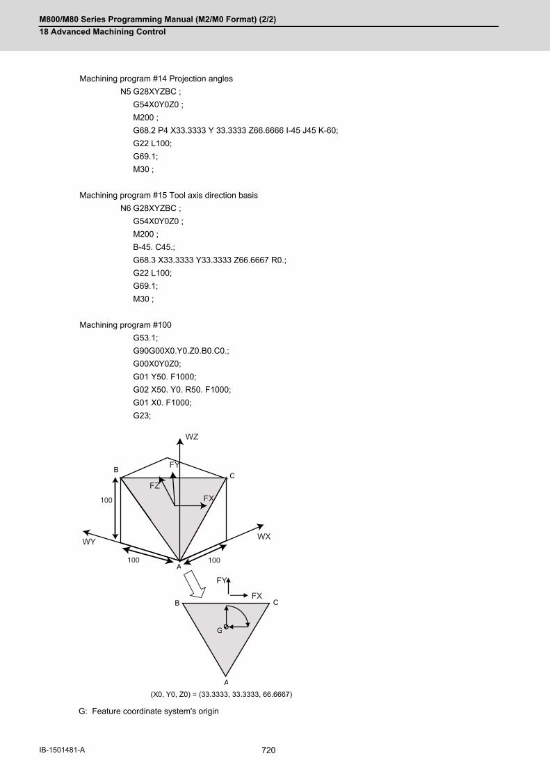
M800/M80 Series Programming Manual (M2/M0 Format) (2/2)
18 Advanced Machining Control
720IB-1501481-A
G: Feature coordinate system's origin
Machining program #14 Projection angles
N5 G28XYZBC ;
G54X0Y0Z0 ;
M200 ;
G68.2 P4 X33.3333 Y 33.3333 Z66.6666 I-45 J45 K-60;
G22 L100;
G69.1;
M30 ;
Machining program #15 Tool axis direction basis
N6 G28XYZBC ;
G54X0Y0Z0 ;
M200 ;
B-45. C45.;
G68.3 X33.3333 Y33.3333 Z66.6667 R0.;
G22 L100;
G69.1;
M30 ;
Machining program #100
G53.1;
G90G00X0.Y0.Z0.B0.C0.;
G00X0Y0Z0;
G01 Y50. F1000;
G02 X50. Y0. R50. F1000;
G01 X0. F1000;
G23;
A
B C
A
B C
(X0, Y0, Z0) = (33.3333, 33.3333, 66.6667)
G
100 100
100
WY
WZ
WX
FY
FZ
FX
FY
FX

M800/M80 Series Programming Manual (M2/M0 Format) (2/2)
18 Advanced Machining Control
721 IB-1501481-A
18.3.10 Rotary Axis Basic Position Selection
When inclined surface machining is commanded, the basic position for establishing the feature coordinate system's
origin can be set with the parameter (#7915 Rotary axis basic position in inclined surface machining).
There are two types of basic position selection. One is to set the feature coordinate system in view from the work-
piece coordinate system independently of the rotary axis' position when inclined surface machining is commanded
(Start position basis), and the other is to set the feature coordinate system in view from a workpiece coordinate sys-
tem which is determined regardless of the rotary axis position when inclined surface machining is commanded (Zero
degree position basis).
Detailed description
Rotary axis basic position in inclined surface machining
Start position basis (#7915=1)
Rotary axis basic position in inclined surface machining
Zero degree position basis (#7915=0)
When workpiece is placed in the workpiece coordinate sys-tem direction:Workpiece coordinate offset A0. C0.
When G68.2 is commanded: When G68.2 is commanded:
Feature coordinate system is defined at a position in view from a workpiece co-ordinate system.
Feature coordinate system is defined at a position in view from a workpiece co-ordinate system regardless of rotary axis position.
When G53.1 is commanded: When G53.1 is commanded:
The tool axis direction matches the Z axis direction of the feature coordinate system, which has been defined with G68.2.
The tool axis direction matches the Z axis direction of the feature coordinate system, which has been defined with G68.2.
WZ
WY
WX C0°
:G90 G54 A0. C0. G68.2XxYyZz G53.1 :
FX
FY
FZ
WZ
WY
WXC0°
:G90 G54 A0. C0. G68.2XxYyZz G53.1 :
FX
FY
FZ
WZ
WY
WX C0°
FX
FY
FZWZ
WY
WX
C0°
FX
FY
FZWZ
WY
WX
C0°

M800/M80 Series Programming Manual (M2/M0 Format) (2/2)
18 Advanced Machining Control
722IB-1501481-A
Rotary axis basic position in inclined surface machining
Start position basis (#7915=1)
Rotary axis basic position in inclined surface machining Zero degree posi-
tion basis (#7915=0)
When workpiece is placed de-viated from the workpiece co-ordinate system:Workpiece coordinate offset A0. C30.
When G68.2 is commanded: When G68.2 is commanded:
Feature coordinate system is defined at a position in view from a workpiece co-ordinate system.
Feature coordinate system is defined at a position in view from a workpiece co-ordinate system regardless of rotary axis position.
When G53.1 is commanded: When G53.1 is commanded:
The tool axis direction does not match the Z axis direction of the feature coor-dinate system, which has been defined with G68.2 command.
The tool axis direction matches the Z axis direction of the feature coordinate system, which has been defined with G68.2.
Example) Polygon machining: Machining an identical shape on each of the six surfaces.
(Subprogram)
:
G68.2 Xx Yy Zz Ii Jj Kk
G53.1
G01 Xx Ff
:
G69.1
G23
Create a machining shape in the sub-
program using inclined surface machin-
ing and tool axis direction control. Need
to consider the rotary axis' angle before
calling the subprogram.
(Main program)
:
G68.2 Xx Yy Zz Ii Jj Kk
G53.1
G22 Ll
G69.1
:
(Subprogram)
G01 Xx Ff
:
G23
Carry out inclined surface machining
and tool axis direction control in the
main program and create a machining
shape in the subprogram. No need to
consider the rotary axis' angle before
calling the subprogram.
WZ
30°
WY
WX C0°
:G90 G54 A0. C30. G68.2XxYyZz G53.1 :
30°
FX
FY
FZ
WZ
WY
WX C0°
:G90 G54 A0. C30. G68.2XxYyZz G53.1 :
30°FX
FYFZ
WZ
WY
WX C0°
FX
FZ
FYWZ
WY
WX
C0°
FX
FZ
FYWZ
WY
WX
C0°
WZ
WY
WX(1)
(2)
(3) (4)
(5)
(6)
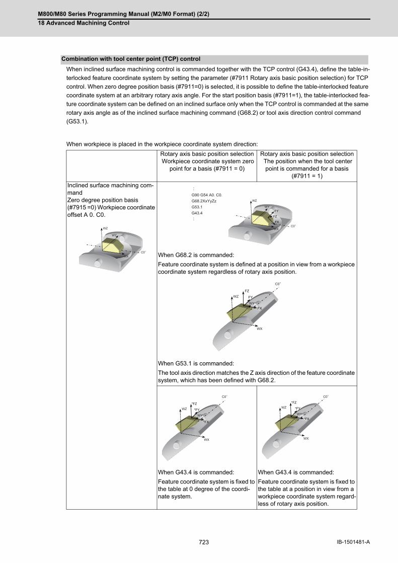
M800/M80 Series Programming Manual (M2/M0 Format) (2/2)
18 Advanced Machining Control
723 IB-1501481-A
When inclined surface machining control is commanded together with the TCP control (G43.4), define the table-in-
terlocked feature coordinate system by setting the parameter (#7911 Rotary axis basic position selection) for TCP
control. When zero degree position basis (#7911=0) is selected, it is possible to define the table-interlocked feature
coordinate system at an arbitrary rotary axis angle. For the start position basis (#7911=1), the table-interlocked fea-
ture coordinate system can be defined on an inclined surface only when the TCP control is commanded at the same
rotary axis angle as of the inclined surface machining command (G68.2) or tool axis direction control command
(G53.1).
When workpiece is placed in the workpiece coordinate system direction:
Combination with tool center point (TCP) control
Rotary axis basic position selection Workpiece coordinate system zero
point for a basis (#7911 = 0)
Rotary axis basic position selection The position when the tool center
point is commanded for a basis (#7911 = 1)
Inclined surface machining com-mandZero degree position basis (#7915 =0) Workpiece coordinate offset A 0. C0.
When G68.2 is commanded:
Feature coordinate system is defined at a position in view from a workpiece coordinate system regardless of rotary axis position.
When G53.1 is commanded:
The tool axis direction matches the Z axis direction of the feature coordinate system, which has been defined with G68.2.
When G43.4 is commanded: When G43.4 is commanded:
Feature coordinate system is fixed to the table at 0 degree of the coordi-nate system.
Feature coordinate system is fixed to the table at a position in view from a workpiece coordinate system regard-less of rotary axis position.
WZ
WY
WX C0°
:G90 G54 A0. C0. G68.2XxYyZz G53.1 G43.4 :
FX
FY
FZ
WZ
WY
WXC0°
FX
FY
FZWZ
WY
WX
C0°
*FX
*FY
*FZWZ
WY
WX
C0°
*FX
*FY
*FZWZ
WY
WX
C0°

M800/M80 Series Programming Manual (M2/M0 Format) (2/2)
18 Advanced Machining Control
724IB-1501481-A
When workpiece is placed deviated from workpiece coordinate system
(1) When TCP control (G43.4) is commanded at the same angle as of tool axis direction control (G53.1)
Rotary axis basic position selection Workpiece coordinate system zero
point for a basis (#7911 = 0)
Rotary axis basic position selection The position when the tool center
point is commanded for a basis (#7911 = 1)
Inclined surface machining com-mandZero degree position basis (#7915 =0) Workpiece coordinate offset A 0. C30.
When G68.2 is commanded:
Feature coordinate system is defined at a position in view from a workpiece coordinate system regardless of rotary axis position.
When G53.1 is commanded:
The tool axis direction matches the Z axis direction of the feature coordinate system, which has been defined with G68.2.
When G43.4 is commanded: When G43.4 is commanded:
Feature coordinate system is fixed to the table at a position in view from a workpiece coordinate system regard-less of rotary axis angle.
Feature coordinate system is fixed to the table at the position of the present feature coordinate system.
WZ
30°
WY
WX C0°
:G90 G54 A0. C0. G68.2XxYyZz G53.1 G43.4 :
FX
FY
FZ
WZ
WY
WX C-30°
FX
FY
FZWZ
WY
WX
C-30°
*FX
*FY
*FZWZ
WY
WX
C-30°
*FX
*FY
*FZWZ
WY
WX
C-30°

M800/M80 Series Programming Manual (M2/M0 Format) (2/2)
18 Advanced Machining Control
725 IB-1501481-A
(2) When TCP control (G43.4) is commanded at a different angle from tool axis direction control (G53.1).
Rotary axis basic position selection Workpiece coordinate system zero
point for a basis (#7911 = 0)
Rotary axis basic position selection The position when the tool center
point is commanded for a basis (#7911 = 1)
Inclined surface machining com-mandZero degree position basis (#7915 =0) Workpiece coordinate offset A 0. C30.Rotary axis is rotated before tool center point control command
When G68.2 is commanded:
Feature coordinate system is defined at a position in view from a workpiece coordinate system regardless of rotary axis position.
When G53.1 is commanded:
The tool axis direction matches the Z axis direction of the feature coordinate system, which has been defined with G68.2.
When G00 A30 is commanded:
The tool axis direction does not match the Z axis direction of the feature co-ordinate system, which has been defined with G68.2 command.
When G43.4 is commanded: When G43.4 is commanded:
Feature coordinate system is fixed to the table at a degree determined based on the rotary axis position.
Feature coordinate system is fixed to the table at the position of the present feature coordinate system.
WZ
30°
WY
WX C0°
:G90 G54 A0. C0. G68.2XxYyZz G53.1 G00 A30. G43.4 :
FX
FY
FZ
WZ
WY
WXC-30°
FX
FY
FZWZ
WY
WX
C-30°
FX
WZ
WY
WX
FY
FZ
C-30°
*FX
WZ
WY
WX
*FY
*FZ C-30° FX
WZ
WY
WX
FY
FZ
C-30°
M800/M80 Series Programming Manual (M2/M0 Format) (2/2)
18 Advanced Machining Control
726IB-1501481-A
If the Z axis of the feature coordinate system defined on an inclined surface matches the tool axis direction, the table-
interlocked feature coordinate system can be defined by commanding the tool center point (TCP) control.
However, if the TCP control start position basis is selected (#7911=1), the table-interlocked feature coordinate sys-
tem can be defined on an inclined surface only when TCP control is commanded at the same angle as of the inclined
surface machining command (G68.2) or tool axis direction control command (G53.1).
Start position based inclined surface machining command (#7915=1)

M800/M80 Series Programming Manual (M2/M0 Format) (2/2)
18 Advanced Machining Control
727 IB-1501481-A
18.3.11 Relationship between inclined surface machining and other functions
If commanded in any other mode, a program error (P951) will occur.
Relationship with other functions
Commands Available in Inclined Surface Machining Mode
Command Function
G00, G01G02, G03G02.1, G03.1
Positioning, Linear interpolationCircular interpolation, Helical interpolationSpiral interpolation
G04 Dwell
G05 P0, P1, P2, P10000 High-speed machining mode, high-speed high-accuracy control II
G05.1 Q0, Q1 High-speed high-accuracy control I
G08 P1 High-accuracy control
G09 Exact stop check
G10, G11.1 Parameter input by program / cancel, Compensation data input by pro-gram
G12, G13 Circular cut
G17, G18, G19 Plane selection
G22.1/23.1 Stroke check before travel ON / cancel
G28 Automatic 1st reference position return
G29 Start position return
G30 2nd to 4th reference position return
G30.1 to G30.6 Tool exchange position return
G31 Skip (*1)
G31.1 to G31.3 Multi-step skip (*1)
G34, G35, G36, G37 Special Fixed Cycle
G40, G41, G42 Tool radius compensation cancel/left/right
G43, G44
G43.1G43.4, G43.5
Tool length compensation/cancel
Tool length compensation along the tool axisTool center point control types I/II
G45, G46, G47, G48 Tool position offset
G50, G51 Scaling cancel/ON
G50.1, G51.1, G62 G command mirror image cancel/ON
G53 Machine coordinate system selection
G53.1 Tool Axis Direction Control
G61G61.1
G64
Exact stop check modeHigh-accuracy control
Cutting mode
G65 User macro simple call
G66, G66.1, G67 User macro modal call A/B/cancel
G69.1 Coordinate rotation cancel, Inclined surface machining cancel
G70 to G76, G80 to G89 Fixed cycle for drilling(Including synchronous tapping)
G90, G91 Absolute value command, Incremental value command
G93G94G95
Inverse time feedFeed per minuteFeed per revolution
G98, G99 Fixed cycle initial level return, R point level return
G22, G23 Subprogram call, main program return
F Feedrate command
M,S,T,B M, S, T, B command

M800/M80 Series Programming Manual (M2/M0 Format) (2/2)
18 Advanced Machining Control
728IB-1501481-A
(*1) Only the three orthogonal axes designated by the rotary axis configuration parameter can be commanded. If
two rotary axes are commanded, a program error (P951) will occur
If inclined surface machining (G68.2 or G68.3) is commanded in a mode other than those listed below, a program
error (P952) will occur.
Macro command Local variable, Common variable, Arithmetic Commands (such as four basic arithmetic rule, trigonometric functions, square root) Control Com-mands (IF-GOTO- and WHILE-DO-)
Modes where inclined surface machining (including cancel command) is available
Mode Function
G00, G01 Positioning, Linear Interpolation
G05 P0, P1, P2 High-speed machining mode
G05.1 Q0, Q1 High-speed high-accuracy control I
G08 P1 High-accuracy control
G13.1 Polar coordinate interpolation cancel
G15 Polar coordinate command cancel
G17, G18, G19 Plane selection
G20, G21 Inch command, Metric command
G22.1/G23.1 Stroke check before travel ON/cancel
G40 Tool radius compensation cancel
G40.1 Normal line control cancel
G43
G44Tool length compensationTool length compensation cancel
G50 Scaling cancel
G50.1 Mirror image by G code OFF
G54 to G59, G54.1 Workpiece coordinate system selection, Extended workpiece coordinate system selection
G54.4 Pp Workpiece installation error compensation
G61G61.1G64
Exact stop check modeHigh-accuracy controlCutting mode
G67 User macro modal call OFF
G69.1 Coordinate rotation cancel, 3-dimensional coordinate conversion cancel
G80 Fixed cycle cancel
G90, G91 Absolute value command, Incremental value command
G93G94G95
Inverse time feedFeed per minuteFeed per revolution
G97 Constant surface speed control OFF
G98, G99 Fixed cycle initial level return, R point level return
Command Function

M800/M80 Series Programming Manual (M2/M0 Format) (2/2)
18 Advanced Machining Control
729 IB-1501481-A
If tool axis direction control is commanded in a mode other than those listed below, a program error (P953) will occur.
Modes where tool axis direction control (G53.1/G53.6) is available
Mode Function
G00, G01 Positioning, Linear interpolation
G05 P0, P1, P2 High-speed machining mode
G05.1 Q0, Q1 High-speed high-accuracy control I
G08 High-accuracy control
G13.1 Polar coordinate interpolation cancel
G15 Polar coordinate command cancel
G17, G18, G19 Plane selection
G20, G21 Inch command, Metric command
G23.1 Stroke check before travel OFF
G40 Tool radius compensation cancel
G40.1 Normal line control cancel
G43 Tool length compensation
G44 Tool length compensation cancel
G50 Scaling cancel
G50.1 Mirror image by G code OFF
G54 to G59, G54.1 Workpiece coordinate system selection, Extended workpiece coordinate system selection
G54.4 P Workpiece installation error compensation
G61 Exact stop check mode
G61.1/G08P1 High-accuracy control
G64 Cutting mode
G67 User macro modal call OFF
G68.2 to G68.9 Inclined surface machining
G80 Fixed cycle cancel
G90, G91 Absolute value command, Incremental value command
G93 Inverse time feed
G94 Feed per minute
G95 Feed per revolution
G97 Constant surface speed control OFF
G98, G99 Fixed cycle initial level return, R point level return
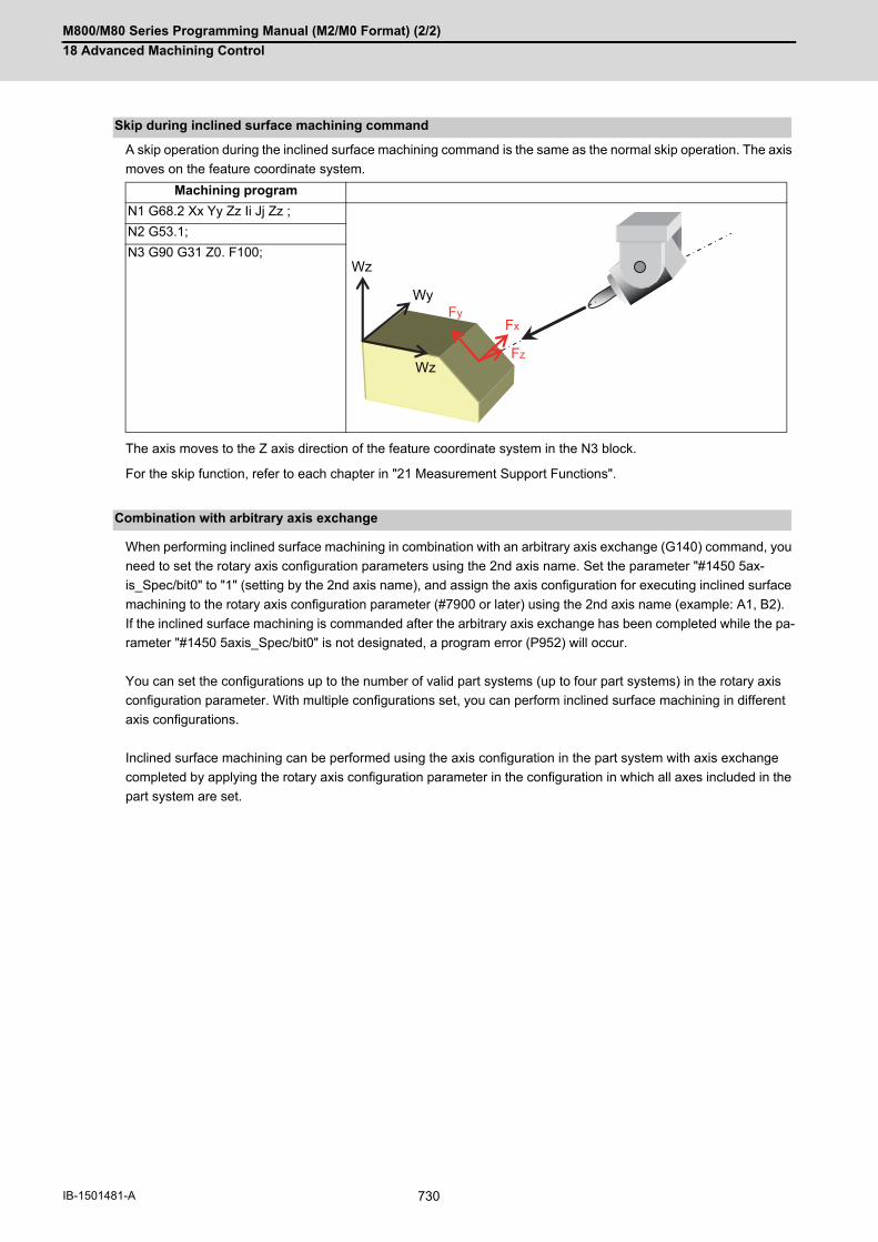
M800/M80 Series Programming Manual (M2/M0 Format) (2/2)
18 Advanced Machining Control
730IB-1501481-A
A skip operation during the inclined surface machining command is the same as the normal skip operation. The axis
moves on the feature coordinate system.
The axis moves to the Z axis direction of the feature coordinate system in the N3 block.
For the skip function, refer to each chapter in "21 Measurement Support Functions".
When performing inclined surface machining in combination with an arbitrary axis exchange (G140) command, you
need to set the rotary axis configuration parameters using the 2nd axis name. Set the parameter "#1450 5ax-
is_Spec/bit0" to "1" (setting by the 2nd axis name), and assign the axis configuration for executing inclined surface
machining to the rotary axis configuration parameter (#7900 or later) using the 2nd axis name (example: A1, B2).
If the inclined surface machining is commanded after the arbitrary axis exchange has been completed while the pa-
rameter "#1450 5axis_Spec/bit0" is not designated, a program error (P952) will occur.
You can set the configurations up to the number of valid part systems (up to four part systems) in the rotary axis
configuration parameter. With multiple configurations set, you can perform inclined surface machining in different
axis configurations.
Inclined surface machining can be performed using the axis configuration in the part system with axis exchange
completed by applying the rotary axis configuration parameter in the configuration in which all axes included in the
part system are set.
Skip during inclined surface machining command
Machining program
N1 G68.2 Xx Yy Zz Ii Jj Zz ;
N2 G53.1;
N3 G90 G31 Z0. F100;
Combination with arbitrary axis exchange
Fz
FxFy
Wz
Wy
Wz

M800/M80 Series Programming Manual (M2/M0 Format) (2/2)
18 Advanced Machining Control
731 IB-1501481-A
18.3.12 Precautions for Inclined Surface Machining
(1) A rotary axis moves at G53.1 command. Thus, move the tool far enough away from the table before commandingG53.1.
(2) When inclined surface machining is commanded, the coordinates of the feature coordinate system are set in thesystem variables #5001 to #5100+n (excluding #5021 to #5021+n), which are used to read the position informa-tion. But, the coordinates of the machine coordinate system are set in the variables #5021 to #5021+n (machinecoordinate values) even when inclined surface machining is commanded. n: varies depending on the number of control axes.
(3) When Reset signal is input during inclined surface machining command, the inclined surface machining modewill be canceled, and the modal G code will be G69.1. (However, when the parameter "#1151 rsint" is set to "0",the inclined surface machining mode will be kept even if Reset 1 is input.)
(4) When the external deceleration signal is input, the signal is not input to the axes of the feature coordinate system,but to the axes of the machine coordinate system that is actually operating.
(5) If G28 or G30 is commanded after the inclined surface machining command has been issued, the control is car-ried out with respect to the inclined surface coordinate system up to the intermediate point, and then carried outwith respect to the machine coordinate system from the intermediate point.
(6) Tool radius compensation, mirror image by G code, fixed cycle command, tool center point control, scaling, andtool length compensation along the tool axis should be nested in the inclined surface machining command. Thus,these commands need to be commanded between the inclined surface machining command (G68.2, etc) andG69.1.
Precautions
Inclined surface machining In tool radius compensation
G68.2 X_Y_Z_I_J_K_
G41 D1
:
:
G40 :G69.1

M800/M80 Series Programming Manual (M2/M0 Format) (2/2)
18 Advanced Machining Control
732IB-1501481-A
(7) If inclined surface machining (G68.2) is commanded while tool length compensation is active, the actual tool tipposition does not match the current position. In such case, command G53.1 to align the tool axis direction withthe Z axis of the feature coordinate system, which will make the tool tip position the same as the current position.
(8) Coordinate conversion is not carried out upon manual interruption, so travel, by a distance equivalent to the man-ual interruption amount, is carried out with respect to the machine coordinate system. When manual interruptionwith ABS ON, or tool center point control has been performed during inclined surface machining, return to theposition before interruption, and then restart automatic operation. If you restart automatic operation in a differentposition from the one prior to the interruption, operation error (M01 0185) will occur. An interruption to a rotaryaxis during inclined surface machining will also cause an operation error (M01 0185). If automatic handle inter-ruption is attempted during inclined surface machining, an operation error (M01 0185) will occur.
(9) MDI interruption, PLC interruption and macro interruption are disabled during inclined surface machining. If MDIinterruption or PLC interruption is attempted during inclined surface machining, an operation error (M01 0185)will occur. If macro interruption is enabled during inclined surface machining, a program error (P951) will occur.Also when inclined surface machining is commanded while macro interruption is active, a program error (P952)will occur.
(10) When inclined surface machining is commanded during MDI interruption, PLC interruption, or macro interrup-tion, a program error (P952) will occur.
(11) When a circular command is graphically traced under the inclined surface machining command, circular tracingis performed if the feature coordinate system matches the machine coordinate system. If the systems are un-matched, a linear tracing is performed instead.
(12) Tracing is carried out using the machine coordinate values.
(13) When this function is used together with tool center point control or the workpiece installation error compensa-tion function, inclined surface machining is subject to the restraints of each function. For details, refer to eachchapter.
Before commanding G68.2, the current position and actual tool tip are the same.
When feature coordinate system is defined in G68.2, a point ob-tained by compensating the tool length direction to be in the fea-ture coordinate axis' Z direction is deemed as the current position. Thus, the current position doesn't match with the actual tool tip po-sition.
The actual tool tip point becomes the same as the current position by commanding G53.1 to align the tool axis direction with the fea-ture coordinate system's Z direction.
X
Z
X
Z
Z
X

M800/M80 Series Programming Manual (M2/M0 Format) (2/2)
18 Advanced Machining Control
733 IB-1501481-A
(14) Program restart from the block after the inclined surface machining command is issued cannot be implemented.If commanded, a program error (P49) occurs.
(15) If you want to display the coordinates on the position screen during inclined surface machining, enter "23" inthe parameters #8901 to #8906. Then, the corresponding counter is shown with respect to the feature coordinatesystem. In the inclined surface coordinate counter display, whether the machining position on the program command thatdoes not include the tool length compensation/tool radius compensation can be selected depends on the MTBspecifications (parameter "#1287 ext23/bit1, bit2 (inclined surface coordinate display)". When tool tip coordinate display is enabled, inclined surface coordinates' counter can be displayed on the win-dow by selecting the inclined surface for the counter selections 1, 2 and 3.
(16) The movement that occurs in response to the G00 command is always the interpolation type. (Non-interpolationtype is not available.)
(17) In the case of table rotation type machines, the tool axis direction is not changed in G68.3. Thus, a feature co-ordinate system is defined with respect to the Z axis of the coordinate system before the inclined surface ma-chining command is issued. But, designation of feature coordinate system's origin, and the rotation R about Zaxis are enabled.
(18) When inclined surface machining is commanded during inclined surface machining, a program error (P951) willoccur.
(19) In the parameters #7900 to #7902, #7922, #7932, #7942, and #7952, designate the axes of the first part system.If you command inclined surface machining in a part system where any of the designated axes is not ready, aprogram error (P932) will occur.
(20) The feature coordinate system is defined with respect to the coordinate system (workpiece coordinate system),which is independent of the table rotary axis' rotation angle, so it is dependent on the table rotary axis' anglebefore the inclined surface machining command is issued.
(21) A linear axis command during inclined surface machining is carried out using the coordinates of the feature co-ordinate system. And a rotary axis command is done using the coordinates (machine values) of the workpiececoordinate system.
(22) If the address R, I, J or K has exceeded the setting range, a program error (P35) will occur.
(23) Buffer correction cannot be implemented during inclined surface machining command.
(24) If the operation mode is switched to "reference position return" during inclined surface machining command, anoperation error (M01 0185) will occur.
(25) If a linear angle command, geometric command, or figure rotation command is issued during inclined surfacemachining command, a program error (P951) will occur.
(26) If arbitrary axis exchange (G140) is issued during inclined surface machining modal, the program error (P951)will occur.
(27) When the axis during inclined surface machining control is the target for axis exchange, the operation error(M01 1101) will occur. The alarm will be canceled by reset.
(28) The part system in which inclined surface machining is being carried out does not cancel mixed control regard-less of the setting for the "#1280 ext16/bit1" parameter (Cancellation of mixed control by resetting) even if a resetoperation that does not reset the modal ("#1151 rstint" = "0" and NC reset 1) is carried out. If an axis in a partsystem in which inclined surface machining is being carried out is specified as the axis to be exchanged in thepart system, the axis exchange will not be possible and an operation error (M01 1101) will occur regardless ofwhether the automatic operation mode has been established.
Program example
N10 G00 X_Y_Z_; Restart from the block N10 or N11 is possible.
N11 G00 X_Y_Z_B_C;
:
N20 G68.2 X_Y_Z_I_J_K; Restart from the block N20 or later is not possible.
N21 G01 X_Y_Z_F_; Attempting to do so will cause an alarm.
N22 G01 X_Y_Z_F_;
N23 G69.1
N30 G90 G00 X_Y_;
N31 G90 G00 Z_;

M800/M80 Series Programming Manual (M2/M0 Format) (2/2)
18 Advanced Machining Control
734IB-1501481-A
(29) When the number of simultaneous contouring control axes is four or less and the indexing is performed withthe indexing type 2 of R-navi on the selected machining surface, the block stop due to the completion of eachaxis travel will not be performed regardless of whether the parameter "#8132 G53.6 block stop" has been set.
(30) The axis configuration of applicable machines is as follows: The function is effective for the machine configuration with the right-hand orthogonal coordinate system definedin ISO standard.
(a) This function applies to three types of machine configuration as below:
In this manual, the following axes are called as primary rotary axis: the tool-side 2nd rotary axis (tool tilt type),
the table-side 1st rotary axis (table tilt type), and the tool side rotary axis (compound type).
(b) This function is not applicable to machines as below:
(31) If any of the orthogonal axes of all the active part systems is under machine lock during inclined surface ma-chining, normal synchronous tapping is applied even though the high-speed tapping specification is provided.
Type Tool tilt type Table tilt type Compound type
Description Two rotary axes on tool head side
Two rotary axes on table side One rotary axis each on tool head side and table side
Example of ma-chines
Primary rotary axis (A)
Tool-side 2nd rotary axis Table-side 2nd rotary axis Tool-side rotary axis
(B) Tool-side 1st rotary axis Table-side 1st rotary axis Table-side rotary axis
Description Example of machines
A machine whose rotary axis's rotation center axis is not parallel to any orthogonal coordinate axis.
A machine whose direction from the tool tip to the tool base is not parallel to Z axis (Z axis positive direction) when machine positions of the rotary axes are all 0°.
Tool axis direction
A machine in which three linear axes do not form a right-handed orthogonal coordinate system.
(B)
(A)
(B)
(A)
(A)
(B)
0°
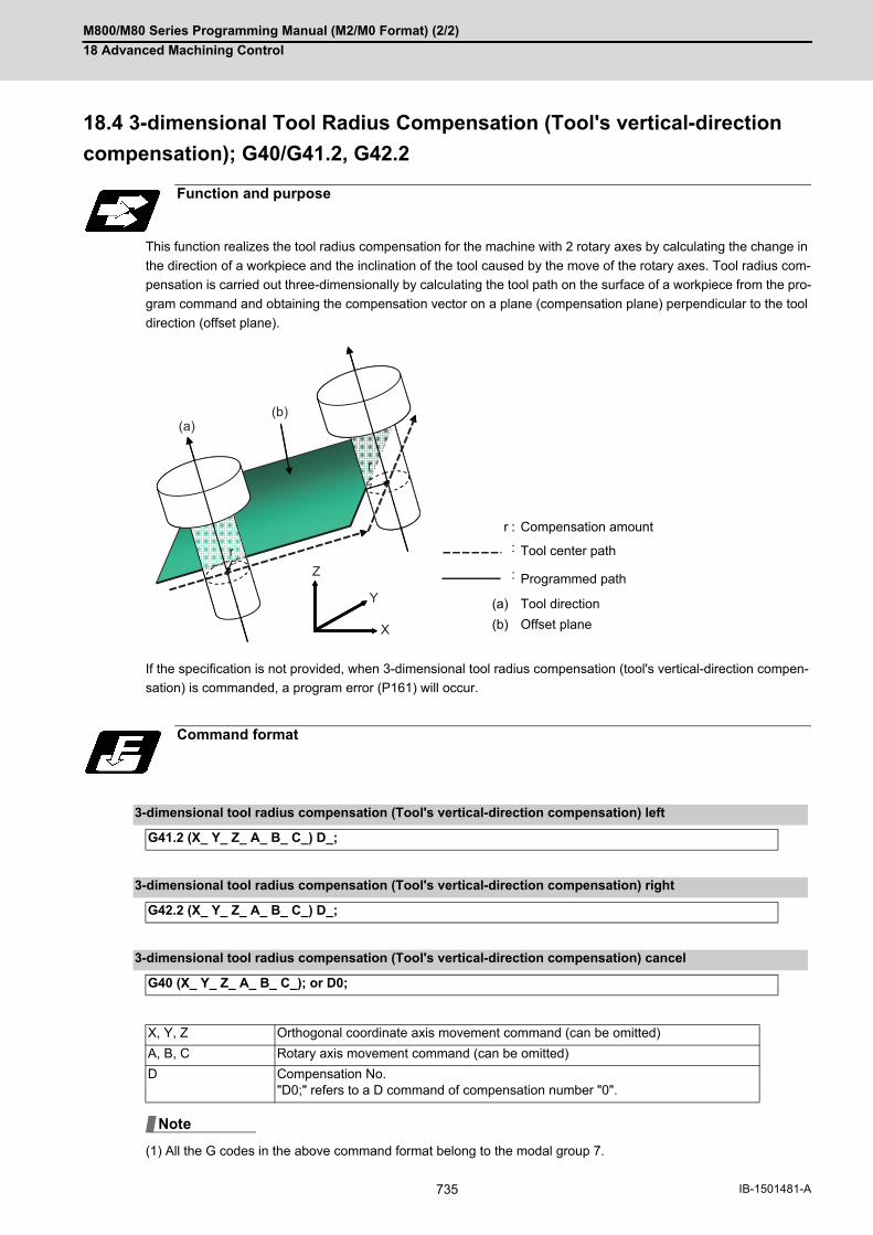
M800/M80 Series Programming Manual (M2/M0 Format) (2/2)
18 Advanced Machining Control
735 IB-1501481-A
18.4 3-dimensional Tool Radius Compensation (Tool's vertical-direction
compensation); G40/G41.2, G42.2
This function realizes the tool radius compensation for the machine with 2 rotary axes by calculating the change in
the direction of a workpiece and the inclination of the tool caused by the move of the rotary axes. Tool radius com-
pensation is carried out three-dimensionally by calculating the tool path on the surface of a workpiece from the pro-
gram command and obtaining the compensation vector on a plane (compensation plane) perpendicular to the tool
direction (offset plane).
If the specification is not provided, when 3-dimensional tool radius compensation (tool's vertical-direction compen-
sation) is commanded, a program error (P161) will occur.
(1) All the G codes in the above command format belong to the modal group 7.
Function and purpose
r : Compensation amount
: Tool center path
: Programmed path
(a) Tool direction
(b) Offset plane
Command format
3-dimensional tool radius compensation (Tool's vertical-direction compensation) left
G41.2 (X_ Y_ Z_ A_ B_ C_) D_;
3-dimensional tool radius compensation (Tool's vertical-direction compensation) right
G42.2 (X_ Y_ Z_ A_ B_ C_) D_;
3-dimensional tool radius compensation (Tool's vertical-direction compensation) cancel
G40 (X_ Y_ Z_ A_ B_ C_); or D0;
X, Y, Z Orthogonal coordinate axis movement command (can be omitted)
A, B, C Rotary axis movement command (can be omitted)
D Compensation No."D0;" refers to a D command of compensation number "0".
r
r
(a)(b)
X
Y
Z
Note

M800/M80 Series Programming Manual (M2/M0 Format) (2/2)
18 Advanced Machining Control
736IB-1501481-A
This function calculates the change in the direction of a workpiece and the inclination of the tool caused by the move
of the rotary axes, and converts the programmed tool path onto the offset plane (perpendicular to the tool direction
at the compensation point) to conduct the tool radius compensation for 5-axis machining. (Refer to "How to calculate
the compensation vector" for the details of offset plane.)
The operations at the start/cancel and in compensation mode on the offset plane conform to the normal tool radius
compensation. Refer to Chapter "12.3 Tool Radius Compensation ; G38,G39/G40/G41,G42" for the operations
which are not explained in this section.
The type of compensation start can be selected from type A and type B by the parameter "#8157 Radius comp type
B", like the conventional tool radius compensation. Refer to "12.3 Tool Radius Compensation ; G38,G39/G40/
G41,G42" for the descriptions of type A/type B.
The startup must be carried out in the G code modal listed in "Modes in which G41.2/G42.2 command is issued" in
"Relation with other functions". If commanded in an unlisted modal, a program error (P163) will occur.
For usable functions during the compensation, refer to "Commands which can be issued while G41.2/G42.2 is ex-
ecuted" in "Relation with other functions". If an unavailable function is commanded, a program error (P162) will oc-
cur. Interference check is not available for this function.
When any of the following condition is met, the tool radius compensation for 5-axis machining will be canceled.
(1) After the compensation cancel command (G40) is executed
(2) A command of offset number D00 is issued
(3) NC reset 1 (*1)
(4) NC reset 2 or Reset &Rewind is commanded
The type of compensation cancel can be selected from type A and type B by the parameter "#8157 Radius comp
type B", as well as the startup.
(*1) The compensation is canceled when "#1151 rstint" is ON.
Detailed description
Tool radius compensation start (startup)
Tool radius compensation operation
Tool radius compensation cancel

M800/M80 Series Programming Manual (M2/M0 Format) (2/2)
18 Advanced Machining Control
737 IB-1501481-A
The compensation vectors for tool radius compensation are obtained as shown below.
(1) Table coordinate systemConvert the program command into the path on the surface of the table coordinate system. Table coordinatesystem rotates with the workpiece (the figure below) as the table rotates. The command path on this coordinatesystem is the relative command path of the tool against the workpiece.
(2) Conversion into the points on the offset planeReflect the obtained path on the table coordinate system onto the offset plane (vertical to the tool axis directionat the compensation point) and calculate the points (A' and C' in the figure below) on the offset plane.
How to calculate the compensation vector
<Default state> <When the table rotates>
(a) Tool direction at point A
(b) Tool direction at point B
Offset plane at point A
Offset plane at point B
Path on the table coordinate system
XX
YZ Z
Y
X
A
BB(a)
(b)
C
C’
B
A’
A
X
ZY
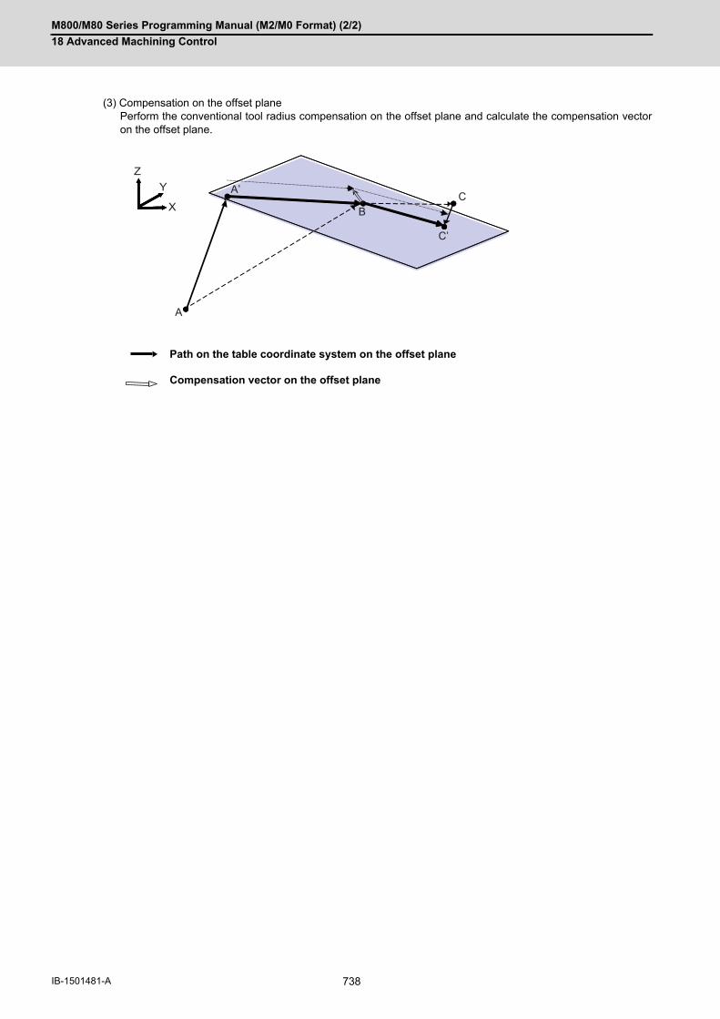
M800/M80 Series Programming Manual (M2/M0 Format) (2/2)
18 Advanced Machining Control
738IB-1501481-A
(3) Compensation on the offset planePerform the conventional tool radius compensation on the offset plane and calculate the compensation vectoron the offset plane.
Path on the table coordinate system on the offset plane
Compensation vector on the offset plane
A
CX
C’
B
A’YZ

M800/M80 Series Programming Manual (M2/M0 Format) (2/2)
18 Advanced Machining Control
739 IB-1501481-A
When a block is inserted while cutting a corner, the direction of the tool at the single block stop is equal to that of
the previous block. (Like a feedrate and other modal data, the rotation angle of the previous block is kept.)
If the program moves from A, B to C as shown in the figure above, the offset plane at point B is as the figure below.
The block between the points B2 and B3 is inserted, the tool direction between B2-B3 is the same as that at point
B2 and the tool moves on the offset plane which is created at point B.
When a block is inserted
(b) Tool direction at point B
Path on the table coordinate system
Offset plane at point B
Path on the table coordinate system on the offset plane
(S) Single block stop point
B
X
YZ
A
A’
C’
C
B
(b)
C’
B
B1
B3 B2
B4
(S)
A’

M800/M80 Series Programming Manual (M2/M0 Format) (2/2)
18 Advanced Machining Control
740IB-1501481-A
(D1 =5.0, H1=50.0)
Program example
N1 G28 Z
N2 G28 BC
N3 G28 XY
N4 G90 G54 G00 X-60. Y0.
N5 G00 B30.
N6 G43.4 H1 Z-50.
N7 G42.2 G01 X-50. D1
N8 G01 X-49.990 Y-1.000 C 1.15
N9 G01 X-49.960 Y-1.999 C 2.29
N10 G01 X-49.910 Y-2.998 C 3.44
:
:
N200 G01 X50. Y0. C180.
N201 G01 Z0.
N202 G40
N203 G44
N204 G28 Z
N205 G28 BC
N206 G28 X
M30
Compensation amount
Programmed path
Tool center path
X
Y
-50.0
50.0
G54
Z
-50.0

M800/M80 Series Programming Manual (M2/M0 Format) (2/2)
18 Advanced Machining Control
741 IB-1501481-A
If unlisted commands are issued in a same block with 3-dimensional tool radius compensation (tool's vertical-direc-
tion compensation) (G41.2/G42.2), a program error (P163) will occur.
(*1) If the inch/metric command switches during 3-dimensional tool radius compensation (tool's vertical-direction
compensation), a program error (P162) will occur.
Relationship with other functions
Commands which can be issued in a same block as G41.2/G42.2
Function
G00 Positioning
G01 Linear interpolation
G90 Absolute value command
G91 Incremental value command
F Feedrate command
N Sequence No.
Commands which can be issued while G41.2/G42.2 is executed
Function
G00 Positioning
G01 Linear interpolation
G04 Dwell
G05 P0, G05 P1, G05 P2 High-speed Machining Mode
G05 P0, G05 P10000 High-speed high-accuracy control II
G08 P0, G08 P1 High-accuracy control
G09 Exact stop
G20, G21 Inch/metric command (*1)
G22.1, G23.1 Stroke check before travel ON/OFF
G40 Tool radius compensation cancel
G41.2, G42.2 3-dimensional tool radius compensation (tool's vertical-direction compensa-tion) right/left
G61 Exact stop check mode
G61.1 High-accuracy control ON
G64 Cutting mode
G65 User macro simple call
G66 User macro modal call A
G66.1 User macro modal call B
G67 User macro modal call cancel
G90, G91 Absolute value command, Incremental value command
G93 Inverse time feed
G94 Feed per minute
G95 Feed per revolution
G96, G97 Constant surface speed control ON/OFF
G22, G23 Subprogram call, main program return
F Feedrate command
M, S, T, B M, S, T, B command
Macro command Local variables and common variablesOperation commands (four basic arithmetic rule, trigonometric functions, square root)Control commands (IF - GOTO -, WHILE - DO -)
N Sequence No.

M800/M80 Series Programming Manual (M2/M0 Format) (2/2)
18 Advanced Machining Control
742IB-1501481-A
When performing 3-dimensional tool radius compensation (tool's vertical-direction compensation) in combination
with an arbitrary axis exchange (G140) command, you need to set the rotary axis configuration parameters using
the 2nd axis name. Set the parameter "#1450 5axis_Spec/bit0" to "1" (setting by the 2nd axis name), and assign the
axis configuration for executing 3-dimensional tool radius compensation (tool's vertical-direction compensation) to
the rotary axis configuration parameter (#7900 or later) using the 2nd axis name (example: A1, B2).
If the G41.2/G42.2 command is issued after arbitrary tool exchange has been completed while the parameter "#1450
5axis_Spec/bit0" is not designated, a program error (P163) will occur.
You can set the configurations up to the number of valid part systems (up to four part systems) in the rotary axis
configuration parameter. With multiple configurations set, you can perform 3-dimensional tool radius compensation
(tool's vertical-direction compensation) in different axis configurations.
3-dimensional tool radius compensation (tool's vertical-direction compensation) can be performed using the axis
configuration in the part system with axis exchange completed by applying the rotary axis configuration parameter
in the configuration in which all axes included in the part system are set.
Modes in which G41.2/G42.2 command can be issued
Function
G00, G01 Positioning, Linear interpolation
G17, G18, G19 Plane selection
G20, G21 Inch/Metric command
G22.1, G23.1 Stroke check before travel ON/OFF
G40 Tool radius compensation cancel
G40.1, G150 Normal line control cancel
G41.2, G42.2 3-dimensional tool radius compensation (tool's vertical-direction compensation) left/right
G43 Tool length compensation
G43.1 Tool length compensation along the tool axis
G43.4, G43.5 Tool center point control type I/II
G44 Tool length compensation cancel
G50 Scaling cancel
G50.1 G command mirror image cancel
G54, G55, G56, G57,G58, G59, G54.1
Workpiece coordinate system selection, extended workpiece coordinate system selection
G54.4Pn Workpiece installation error compensation
G61 Exact stop check mode
G61.1 High-accuracy control ON
G64 Cutting mode
G67 User macro modal call cancel
G68.2 Inclined surface machining
G68.3 Inclined surface machining command (Define using tool axis direction)
G69.1 3-dimensional coordinate conversion cancel
G80 Fixed cycle cancel
G90, G91 Absolute value command, Incremental value command
G93 Inverse time feed
G94 Feed per minute
G95 Feed per revolution
G96, G97 Constant surface speed control ON/OFF
G98, G99 Fixed cycle initial level return, R point level return
G15, G13.1, G113 Polar coordinate command cancel
Combination with arbitrary axis exchange control
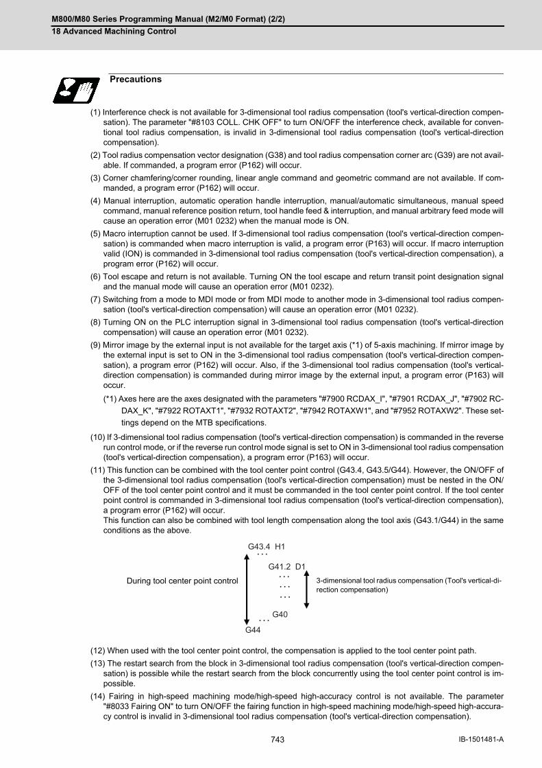
M800/M80 Series Programming Manual (M2/M0 Format) (2/2)
18 Advanced Machining Control
743 IB-1501481-A
(1) Interference check is not available for 3-dimensional tool radius compensation (tool's vertical-direction compen-sation). The parameter "#8103 COLL. CHK OFF" to turn ON/OFF the interference check, available for conven-tional tool radius compensation, is invalid in 3-dimensional tool radius compensation (tool's vertical-directioncompensation).
(2) Tool radius compensation vector designation (G38) and tool radius compensation corner arc (G39) are not avail-able. If commanded, a program error (P162) will occur.
(3) Corner chamfering/corner rounding, linear angle command and geometric command are not available. If com-manded, a program error (P162) will occur.
(4) Manual interruption, automatic operation handle interruption, manual/automatic simultaneous, manual speedcommand, manual reference position return, tool handle feed & interruption, and manual arbitrary feed mode willcause an operation error (M01 0232) when the manual mode is ON.
(5) Macro interruption cannot be used. If 3-dimensional tool radius compensation (tool's vertical-direction compen-sation) is commanded when macro interruption is valid, a program error (P163) will occur. If macro interruptionvalid (ION) is commanded in 3-dimensional tool radius compensation (tool's vertical-direction compensation), aprogram error (P162) will occur.
(6) Tool escape and return is not available. Turning ON the tool escape and return transit point designation signaland the manual mode will cause an operation error (M01 0232).
(7) Switching from a mode to MDI mode or from MDI mode to another mode in 3-dimensional tool radius compen-sation (tool's vertical-direction compensation) will cause an operation error (M01 0232).
(8) Turning ON on the PLC interruption signal in 3-dimensional tool radius compensation (tool's vertical-directioncompensation) will cause an operation error (M01 0232).
(9) Mirror image by the external input is not available for the target axis (*1) of 5-axis machining. If mirror image bythe external input is set to ON in the 3-dimensional tool radius compensation (tool's vertical-direction compen-sation), a program error (P162) will occur. Also, if the 3-dimensional tool radius compensation (tool's vertical-direction compensation) is commanded during mirror image by the external input, a program error (P163) willoccur.
(*1) Axes here are the axes designated with the parameters "#7900 RCDAX_I", "#7901 RCDAX_J", "#7902 RC-
DAX_K", "#7922 ROTAXT1", "#7932 ROTAXT2", "#7942 ROTAXW1", and "#7952 ROTAXW2". These set-
tings depend on the MTB specifications.
(10) If 3-dimensional tool radius compensation (tool's vertical-direction compensation) is commanded in the reverserun control mode, or if the reverse run control mode signal is set to ON in 3-dimensional tool radius compensation(tool's vertical-direction compensation), a program error (P163) will occur.
(11) This function can be combined with the tool center point control (G43.4, G43.5/G44). However, the ON/OFF ofthe 3-dimensional tool radius compensation (tool's vertical-direction compensation) must be nested in the ON/OFF of the tool center point control and it must be commanded in the tool center point control. If the tool centerpoint control is commanded in 3-dimensional tool radius compensation (tool's vertical-direction compensation),a program error (P162) will occur. This function can also be combined with tool length compensation along the tool axis (G43.1/G44) in the sameconditions as the above.
(12) When used with the tool center point control, the compensation is applied to the tool center point path.
(13) The restart search from the block in 3-dimensional tool radius compensation (tool's vertical-direction compen-sation) is possible while the restart search from the block concurrently using the tool center point control is im-possible.
(14) Fairing in high-speed machining mode/high-speed high-accuracy control is not available. The parameter"#8033 Fairing ON" to turn ON/OFF the fairing function in high-speed machining mode/high-speed high-accura-cy control is invalid in 3-dimensional tool radius compensation (tool's vertical-direction compensation).
Precautions
During tool center point control 3-dimensional tool radius compensation (Tool's vertical-di-rection compensation)
G44
G40
G41.2 D1
G43.4 H1
・・・
・・・
・・・・・・
・・・
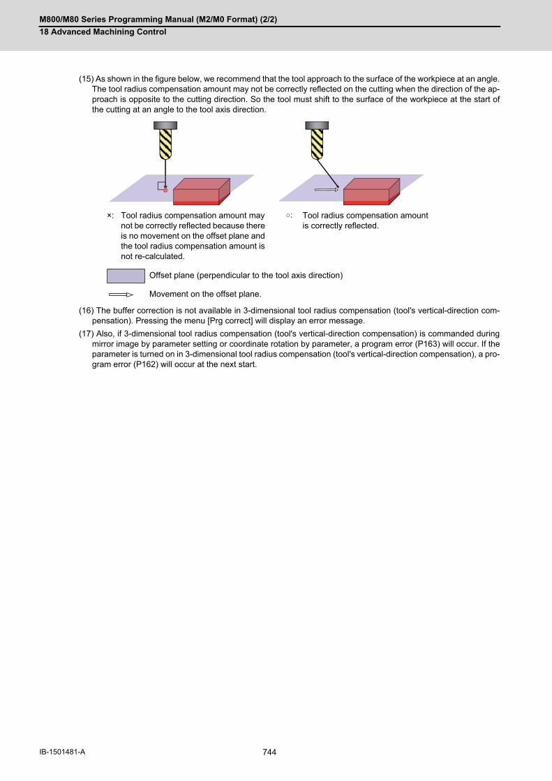
M800/M80 Series Programming Manual (M2/M0 Format) (2/2)
18 Advanced Machining Control
744IB-1501481-A
(15) As shown in the figure below, we recommend that the tool approach to the surface of the workpiece at an angle.The tool radius compensation amount may not be correctly reflected on the cutting when the direction of the ap-proach is opposite to the cutting direction. So the tool must shift to the surface of the workpiece at the start ofthe cutting at an angle to the tool axis direction.
(16) The buffer correction is not available in 3-dimensional tool radius compensation (tool's vertical-direction com-pensation). Pressing the menu [Prg correct] will display an error message.
(17) Also, if 3-dimensional tool radius compensation (tool's vertical-direction compensation) is commanded duringmirror image by parameter setting or coordinate rotation by parameter, a program error (P163) will occur. If theparameter is turned on in 3-dimensional tool radius compensation (tool's vertical-direction compensation), a pro-gram error (P162) will occur at the next start.
×: Tool radius compensation amount may not be correctly reflected because there is no movement on the offset plane and the tool radius compensation amount is not re-calculated.
○: Tool radius compensation amount is correctly reflected.
Offset plane (perpendicular to the tool axis direction)
Movement on the offset plane.

M800/M80 Series Programming Manual (M2/M0 Format) (2/2)
18 Advanced Machining Control
745 IB-1501481-A
(18) The axis configuration of applicable machines is as follows: The function is effective for the machine configuration with the right-hand orthogonal coordinate system definedin ISO standard.
(a) This function applies to three types of machine configurations as below:
In this manual, the following axes are called as primary rotary axis: the tool-side 2nd rotary axis (tool tilt type),
the table-side 1st rotary axis (table tilt type), and the tool side rotary axis (compound type).
(b) This function is not applicable to machines as below:
<Note>
This cannot be applied to a machine on which the rotary axis's rotation center axis is not parallel to anyorthogonal coordinate axis.This cannot be applied to a machine of which the direction from the tool tip to the tool base is not parallel
to Z axis (Z axis positive direction) when machine positions of the rotary axes are all 0°.
Type Tool tilt type Table tilt type Compound type
Description Two rotary axes on tool head side
Two rotary axes on table side One rotary axis each on tool head side and table side
Example of machines
Primary rota-ry axis (A)
Tool-side 2nd rotary axis Table-side 2nd rotary axis Tool-side rotary axis
(B) Tool-side 1st rotary axis Table-side 1st rotary axis Table-side rotary axis
Description Example of machines
A machine whose rotary axis's rotation center axis is not par-allel to any orthogonal coordinate axis.
A machine whose direction from the tool tip to the tool base is not parallel to Z axis (Z axis positive direction) when ma-chine positions of the rotary axes are all 0°.
Tool axis direction
A machine in which three linear axes do not form a right-handed orthogonal coordinate system.
(B)
(A)
(B)
(A)
(A)
(B)
0°

M800/M80 Series Programming Manual (M2/M0 Format) (2/2)
18 Advanced Machining Control
746IB-1501481-A

19
747 IB-1501481-A
Coordinate System Setting Functions
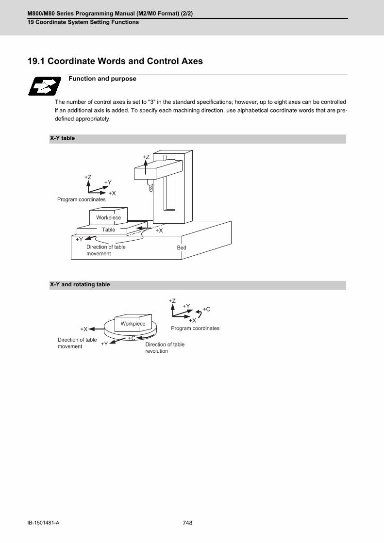
M800/M80 Series Programming Manual (M2/M0 Format) (2/2)
19 Coordinate System Setting Functions
748IB-1501481-A
19Coordinate System Setting Functions19.1 Coordinate Words and Control Axes
The number of control axes is set to "3" in the standard specifications; however, up to eight axes can be controlled
if an additional axis is added. To specify each machining direction, use alphabetical coordinate words that are pre-
defined appropriately.
Function and purpose
X-Y table
X-Y and rotating table
+Z
+Z
+Y
+Y
+X
+X
Program coordinates
Direction of table movement
Workpiece
Table
Bed
+Z+Y
+Y
+C
+C
+X+X Program coordinates
Direction of table movement Direction of table
revolution
Workpiece

M800/M80 Series Programming Manual (M2/M0 Format) (2/2)
19 Coordinate System Setting Functions
749 IB-1501481-A
19.2 Types of Coordinate Systems19.2.1 Basic Machine, Workpiece and Local Coordinate Systems
The basic machine coordinate system is fixed in the machine and it denotes that position which is determined inher-
ently by the machine.
The workpiece coordinate systems are used for programming and in these systems the basic point on the workpiece
is set as the coordinate zero point.
The local coordinate systems are created on the workpiece coordinate systems and they are designed to facilitate
the programs for parts machining.
Upon completion of the reference position return, the basic machine coordinate system and workpiece coordinate
systems (G54 to G59) are automatically set with reference to the parameters.
The basic machine coordinate system is set so that the first reference position is brought to the position specified
by the parameter from the basic machine coordinate zero point (machine zero point).
The local coordinate systems (G52) are valid on the coordinate systems designated by workpiece coordinate sys-
tems 1 to 6.
The hypothetical machine coordinate system can be set on the basic machine coordinate system using a G92 com-
mand. At this time, the workpiece coordinate system 1 to 6 is also simultaneously shifted.
Also refer to "Coordinate Systems and Coordinate Zero Point symbols".
Function and purpose
M: Basic machine coordinate system
W: Workpiece coordinate system
L: Local coordinate system
W1 W2
W4
R#1
Y
X
Y1
X1
W3
W2 W1 L
Z
X
M
R#1
Z1
X1 M
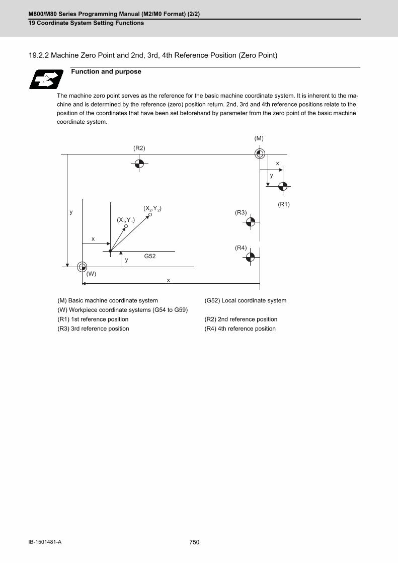
M800/M80 Series Programming Manual (M2/M0 Format) (2/2)
19 Coordinate System Setting Functions
750IB-1501481-A
19.2.2 Machine Zero Point and 2nd, 3rd, 4th Reference Position (Zero Point)
The machine zero point serves as the reference for the basic machine coordinate system. It is inherent to the ma-
chine and is determined by the reference (zero) position return. 2nd, 3rd and 4th reference positions relate to the
position of the coordinates that have been set beforehand by parameter from the zero point of the basic machine
coordinate system.
Function and purpose
(M) Basic machine coordinate system (G52) Local coordinate system
(W) Workpiece coordinate systems (G54 to G59)
(R1) 1st reference position (R2) 2nd reference position
(R3) 3rd reference position (R4) 4th reference position
(W)
(X1,Y1)
G52
x
y
x
y
x
y (X2,Y2)
(M)
(R1)
(R4)
(R3)
(R2)

M800/M80 Series Programming Manual (M2/M0 Format) (2/2)
19 Coordinate System Setting Functions
751 IB-1501481-A
19.2.3 Automatic Coordinate System Setting
This function creates each coordinate system according to the parameter values input beforehand from the setting
and display unit when the first manual reference position return or the reference position is reached with the dog-
type reference position return when the NC power is turned ON. The actual machining program is programmed over
the coordinate systems that have been set above.
(1) The coordinate systems created by this function are as follow:
- Basic machine coordinate system
- Workpiece coordinate systems (G54 to G59)
(2) The parameters related to the coordinate system all provide the distance from the zero point of the basic machine
coordinate system. Therefore, after deciding at which position the first reference position should be set in the
basic machine coordinate system and then set the zero point positions of the workpiece coordinate systems.
(3) When the automatic coordinate system setting function is executed, shifting of the workpiece coordinate system
with G92, setting of the local coordinate system with G52, shifting of the workpiece coordinate system with origin
set, and shifting of the workpiece coordinate system with manual interrupt will be canceled.
(4) The dog-type reference position return will be executed when the first time manual reference position return or
the first time automatic reference position return is executed after the power has been turned ON. It will be also
executed when the dog-type is selected by the parameter for the manual reference position return or the auto-
matic reference position return for the second time onwards.
Function and purpose
(M) Basic machine coordinate system (R1) 1st reference position
(G54) Workpiece coordinate system 1 (G55) Workpiece coordinate system 2
(G56) Workpiece coordinate system 3 (G57) Workpiece coordinate system 4
(G58) Workpiece coordinate system 5 (G59) Workpiece coordinate system 6
Detailed description
CAUTION
If the workpiece coordinate offset amount is changed during automatic operation (including during single block
operation), it will be validated from the next block or after multiple blocks of the command.
(G54)
y1
x1
(G55)(G56)
(G57)(G58)(G59)
y2
x2
y3
x3
y4
x4
(R1)
(M)
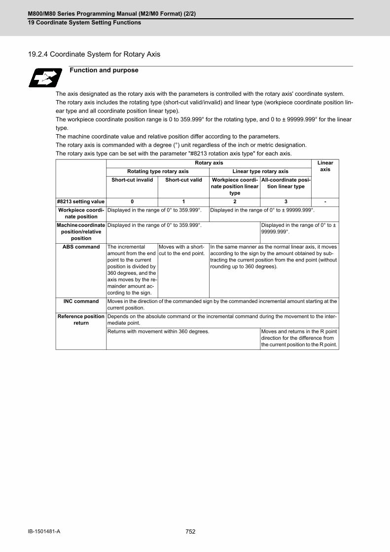
M800/M80 Series Programming Manual (M2/M0 Format) (2/2)
19 Coordinate System Setting Functions
752IB-1501481-A
19.2.4 Coordinate System for Rotary Axis
The axis designated as the rotary axis with the parameters is controlled with the rotary axis' coordinate system.
The rotary axis includes the rotating type (short-cut valid/invalid) and linear type (workpiece coordinate position lin-
ear type and all coordinate position linear type).
The workpiece coordinate position range is 0 to 359.999° for the rotating type, and 0 to ± 99999.999° for the linear
type.
The machine coordinate value and relative position differ according to the parameters.
The rotary axis is commanded with a degree (°) unit regardless of the inch or metric designation.
The rotary axis type can be set with the parameter "#8213 rotation axis type" for each axis.
Function and purpose
Rotary axis Linear axisRotating type rotary axis Linear type rotary axis
Short-cut invalid Short-cut valid Workpiece coordi-nate position linear
type
All-coordinate posi-tion linear type
#8213 setting value 0 1 2 3 -
Workpiece coordi-nate position
Displayed in the range of 0° to 359.999°. Displayed in the range of 0° to ± 99999.999°.
Machine coordinate position/relative
position
Displayed in the range of 0° to 359.999°. Displayed in the range of 0° to ± 99999.999°.
ABS command The incremental amount from the end point to the current position is divided by 360 degrees, and the axis moves by the re-mainder amount ac-cording to the sign.
Moves with a short-cut to the end point.
In the same manner as the normal linear axis, it moves according to the sign by the amount obtained by sub-tracting the current position from the end point (without rounding up to 360 degrees).
INC command Moves in the direction of the commanded sign by the commanded incremental amount starting at the current position.
Reference position return
Depends on the absolute command or the incremental command during the movement to the inter-mediate point.
Returns with movement within 360 degrees. Moves and returns in the R point direction for the difference from the current position to the R point.
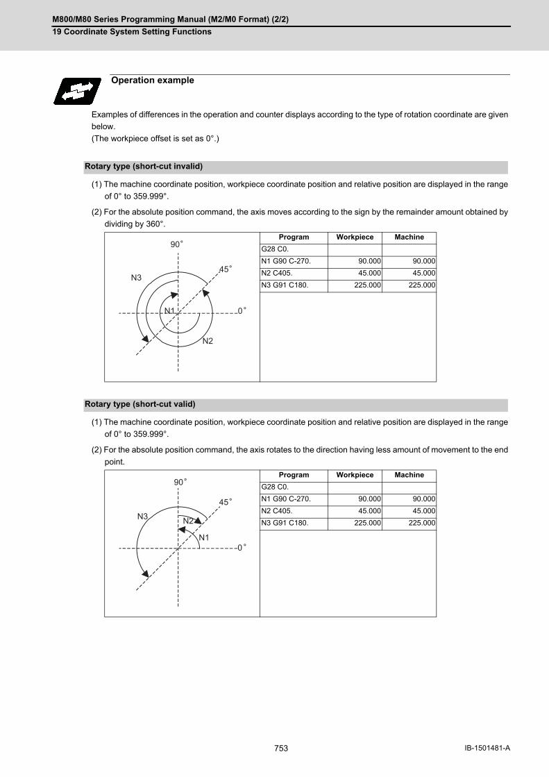
M800/M80 Series Programming Manual (M2/M0 Format) (2/2)
19 Coordinate System Setting Functions
753 IB-1501481-A
Examples of differences in the operation and counter displays according to the type of rotation coordinate are given
below.
(The workpiece offset is set as 0°.)
(1) The machine coordinate position, workpiece coordinate position and relative position are displayed in the range
of 0° to 359.999°.
(2) For the absolute position command, the axis moves according to the sign by the remainder amount obtained by
dividing by 360°.
(1) The machine coordinate position, workpiece coordinate position and relative position are displayed in the range
of 0° to 359.999°.
(2) For the absolute position command, the axis rotates to the direction having less amount of movement to the end
point.
Operation example
Rotary type (short-cut invalid)
Program Workpiece Machine
G28 C0.
N1 G90 C-270. 90.000 90.000
N2 C405. 45.000 45.000
N3 G91 C180. 225.000 225.000
Rotary type (short-cut valid)
Program Workpiece Machine
G28 C0.
N1 G90 C-270. 90.000 90.000
N2 C405. 45.000 45.000
N3 G91 C180. 225.000 225.000
90
45
0
N3
N2
N1
90
45
0
N3 N2
N1
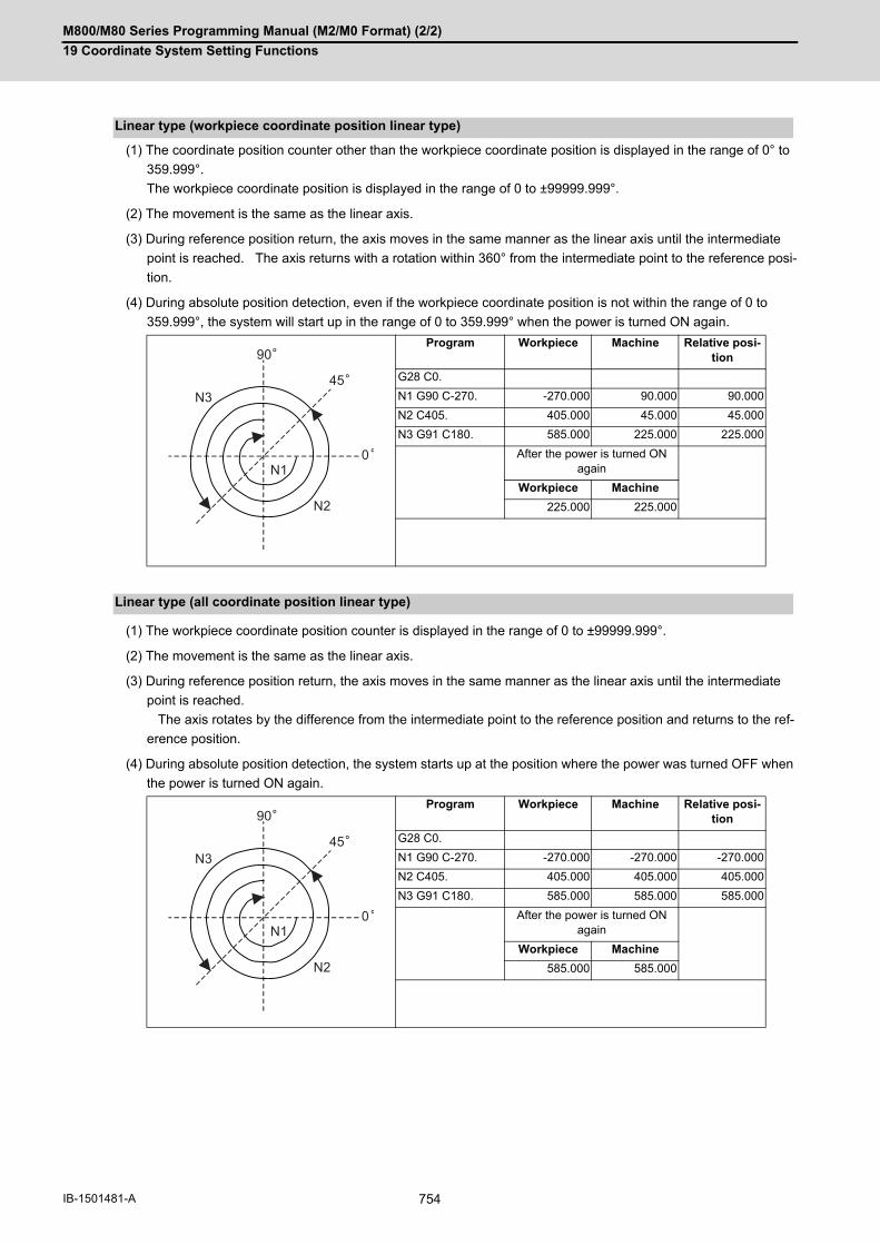
M800/M80 Series Programming Manual (M2/M0 Format) (2/2)
19 Coordinate System Setting Functions
754IB-1501481-A
(1) The coordinate position counter other than the workpiece coordinate position is displayed in the range of 0° to
359.999°.
The workpiece coordinate position is displayed in the range of 0 to ±99999.999°.
(2) The movement is the same as the linear axis.
(3) During reference position return, the axis moves in the same manner as the linear axis until the intermediate
point is reached. The axis returns with a rotation within 360° from the intermediate point to the reference posi-
tion.
(4) During absolute position detection, even if the workpiece coordinate position is not within the range of 0 to
359.999°, the system will start up in the range of 0 to 359.999° when the power is turned ON again.
(1) The workpiece coordinate position counter is displayed in the range of 0 to ±99999.999°.
(2) The movement is the same as the linear axis.
(3) During reference position return, the axis moves in the same manner as the linear axis until the intermediate
point is reached.
The axis rotates by the difference from the intermediate point to the reference position and returns to the ref-
erence position.
(4) During absolute position detection, the system starts up at the position where the power was turned OFF when
the power is turned ON again.
Linear type (workpiece coordinate position linear type)
Program Workpiece Machine Relative posi-tion
G28 C0.
N1 G90 C-270. -270.000 90.000 90.000
N2 C405. 405.000 45.000 45.000
N3 G91 C180. 585.000 225.000 225.000
After the power is turned ON again
Workpiece Machine
225.000 225.000
Linear type (all coordinate position linear type)
Program Workpiece Machine Relative posi-tion
G28 C0.
N1 G90 C-270. -270.000 -270.000 -270.000
N2 C405. 405.000 405.000 405.000
N3 G91 C180. 585.000 585.000 585.000
After the power is turned ON again
Workpiece Machine
585.000 585.000
90
45
0
N3
N2
N1
90
45
0
N3
N2
N1

M800/M80 Series Programming Manual (M2/M0 Format) (2/2)
19 Coordinate System Setting Functions
755 IB-1501481-A
19.3 Basic Machine Coordinate System Selection; G53
The basic machine coordinate system is the coordinate system that expresses the position (tool change position,
stroke end position, etc.) that is characteristic to the machine. The tool is moved to the position commanded on the
basic machine coordinate system with the G53 command and the coordinate command that follows.
(1) When the power is switched on, the basic machine coordinate system is automatically set as referenced to thereference (zero) position return position, which is determined by the automatic or manual reference (zero) posi-tion return.
(2) The basic machine coordinate system is not changed by the G92 command.
(3) The G53 command is valid only in the designated block.
(4) In the incremental value command mode (G91), the G53 command provides movement with the incremental val-ue in the coordinate system being selected.
(5) Even if G53 is commanded, the tool radius compensation amount for the commanded axis will not be canceled.
(6) The 1st reference coordinate position indicates the distance from the basic machine coordinate system zeropoint to the reference position (zero point) return position.
(7) The G53 command will move with cutting feedrate or rapid traverse following command modal.
(8) If the G53 command and G28 command (reference position return) are issued in the same block, the commandissued last will be valid.
1st reference position coordinate value: X=+500 and Y=+500
(9) If the G53 command and G28 command (reference position return) are issued in the same block, the commandissued last will be valid.
(10) Even if G53 is commanded, the tool radius compensation amount for the commanded axis will not be canceled.
Function and purpose
Command format
(G90)G53 X__ Y__ Z__ α__ ;
α Additional axis
Detailed description
(M) Basic machine coordinate system(R1) 1st reference position
(500,500)
-Y
- X R1(M)

M800/M80 Series Programming Manual (M2/M0 Format) (2/2)
19 Coordinate System Setting Functions
756IB-1501481-A
(11) Depending on the MTB specifications, all movement commands in the G53 command block may run in rapidtraverse mode (parameter "#1253 set/bit5").
(a) When the movement method of the G53 command block follows the command modal [Example in which the
G53 block is executed during G01 modal)
[Example in which the G53 block is executed during G00 modal]
(b) When all the movement methods of the G53 command block are set to rapid traverse [Example in which the
G53 block is executed during G01 modal)
The G group 01 modal does not change in the G53 command block; only the operation is set to rapid tra-
verse.
(1) Tool Compensation FunctionsWhen the G53 command is issued, the tool compensation amount of the axis with the movement command des-ignated is canceled temporarily.
(2) Machine coordinate system selection, Feedrate designationIf an ",F" command is specified when there are no specifications for the feedrate command for G53, a programerror (P39) will occur.
(3) Inclined surface machiningWhen the G53 command is issued during inclined surface machining, a program error (P951) occurs.
(4) Polar coordinate interpolationDo not issue the G53 command during the polar coordinate interpolation mode.
(5) Polar coordinate commandThe axis command with the G53 command is not interpreted as the polar coordinate command during the polarcoordinate command mode.
(6) Tool length compensation along the tool axisWhen the G53 command is designated while the compensation status is still established, the compensation istemporarily canceled, and the tool moves to the machine position designated by G53.
(7) G command mirror imageThe mirror image will not be applied to the G53 command.
(8) High-speed High-accuracy ControlA program error will occur if the G53 command is issued during the high-speed high-accuracy control II mode.
(9) 3-dimensional coordinate conversionCoordinate conversion will not be carried out for the machine coordinate system even if G53 command is issuedin the 3-dimensional coordinate conversion modal.
(10) Tool center point controlA program error (P942) will occur if the G53 command is issued during the tool center point modal.
(11) Workpiece installation error compensationA program error (P545) will occur if the G53 command is issued during workpiece installation error compensa-tion.
Program G group 01 modal Cutting or Rapid traverse
N01 G01 X100. Z100. F1000; G01 Cutting
N02 G53 X200. Z200.; G01 Cutting
N03 X300. Z300.; G01 Cutting
Program G group 01 modal Cutting or Rapid traverse
N01 G00 X100. Z100.; G00 Rapid traverse
N02 G53 X200. Z200.; G00 Rapid traverse
N03 X300. Z300.; G00 Rapid traverse
Program G group 01 modal Cutting or Rapid traverse
N01 G01 X100. Z100. F1000; G01 Cutting
N02 G53 X200. Z200.; G01 Rapid traverse
N03 X300. Z300.; G01 Cutting
Relationship with other functions
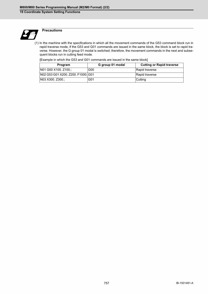
M800/M80 Series Programming Manual (M2/M0 Format) (2/2)
19 Coordinate System Setting Functions
757 IB-1501481-A
(1) In the machine with the specifications in which all the movement commands of the G53 command block run inrapid traverse mode, if the G53 and G01 commands are issued in the same block, the block is set to rapid tra-verse. However, the G group 01 modal is switched; therefore, the movement commands in the next and subse-quent blocks run in cutting feed mode.
[Example in which the G53 and G01 commands are issued in the same block]
Precautions
Program G group 01 modal Cutting or Rapid traverse
N01 G00 X100. Z100.; G00 Rapid traverse
N02 G53 G01 X200. Z200. F1000; G01 Rapid traverse
N03 X300. Z300.; G01 Cutting

M800/M80 Series Programming Manual (M2/M0 Format) (2/2)
19 Coordinate System Setting Functions
758IB-1501481-A
19.4 Coordinate System Setting; G92
By commanding G92, the absolute value coordinate system and current position display value can be newly preset
according to the command value without moving the machine.
After the power is turned on, the first reference position return will be done with dog-type, and when completed, the
coordinate system will be set automatically.
(Automatic coordinate system setting)
By commanding G92, the absolute value (workpiece) coordinate system and current position display value can be
preset in the command value without moving the machine.
Function and purpose
Command format
G92 X__ Y__ Z__ α__ ;
α Additional axis
Detailed description
Reference position return completed
The basic machine co-ordinate system and workpiece coordinate system are created at the preset position. (a) Power ON position(b) Basic machine co-ordinate system(c) Workpiece coordi-nate system
[Relative position]X 0.000Y 0.000
[Workpiece]X 300.000Y 200.000
Coordinate system setting
For example,if G92 X0 Y0;is commanded, the workpiece coordinate system will be newly created. (d) Tool position
[Relative position]X -200.000Y -150.000
[Workpiece]X 100.000Y 50.000
[Relative position]X 0.000Y 0.000
[Workpiece]X 0.000Y 0.000
R
(a)
WG54 100. 200.
100.
R,M
(a)
(b)
(c)
WG54 100. 200. 300.
200.
100.
50.
R,M
(d)
WG54' 100. 200.
100.
-100.
- 50.WG54
R,M
(d)

M800/M80 Series Programming Manual (M2/M0 Format) (2/2)
19 Coordinate System Setting Functions
759 IB-1501481-A
(1) If the workpiece coordinate system deviated because the axis is moved manually when the manual absolute po-sition switch is OFF, etc., the workpiece coordinate system can be corrected with the following steps.Execute reference position return while the coordinate system is deviated.After that, command G92G53X0Y0Z0;. With this command, the workpiece coordinate position and cur-
rent position will be displayed, and the workpiece coordinate system will be preset to the offset value.
(1) If the parameter "#1279 ext15/bit5" is set to "1", the coordinate systems setting (G92) shift amount is clearedwhen the axis reaches to the manual reference position.
Precautions
Note
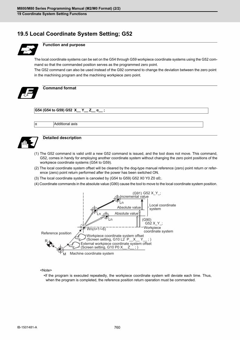
M800/M80 Series Programming Manual (M2/M0 Format) (2/2)
19 Coordinate System Setting Functions
760IB-1501481-A
19.5 Local Coordinate System Setting; G52
The local coordinate systems can be set on the G54 through G59 workpiece coordinate systems using the G52 com-
mand so that the commanded position serves as the programmed zero point.
The G52 command can also be used instead of the G92 command to change the deviation between the zero point
in the machining program and the machining workpiece zero point.
(1) The G52 command is valid until a new G52 command is issued, and the tool does not move. This command,G52, comes in handy for employing another coordinate system without changing the zero point positions of theworkpiece coordinate systems (G54 to G59).
(2) The local coordinate system offset will be cleared by the dog-type manual reference (zero) point return or refer-ence (zero) point return performed after the power has been switched ON.
(3) The local coordinate system is canceled by (G54 to G59) G52 X0 Y0 Z0 α0;.
(4) Coordinate commands in the absolute value (G90) cause the tool to move to the local coordinate system position.
<Note>
If the program is executed repeatedly, the workpiece coordinate system will deviate each time. Thus,when the program is completed, the reference position return operation must be commanded.
Function and purpose
Command format
G54 (G54 to G59) G52 X__ Y__ Z__ α__ ;
α Additional axis
Detailed description
R
M
Ln
Ln
Ln
Wn(n=1 6)
(G90) G52 X_Y_;
G52 X_Y_;(G91)
Machine coordinate system
Workpiece coordinate system
Local coordinate systemAbsolute value
Absolute value
Incremental value
Reference positionWorkpiece coordinate system offset(Screen setting, G10 L2 P__X__ Y__ ; )
External workpiece coordinate system offset (Screen setting, G10 P0 X__ Z__ ; )

M800/M80 Series Programming Manual (M2/M0 Format) (2/2)
19 Coordinate System Setting Functions
761 IB-1501481-A
(Example 1) Local coordinates for absolute value mode (The local coordinate system offset is not cumulated)
The local coordinate system is created by (5), canceled by (9) and matched with the coordinate system for (3).
<Note>
If the program is executed repeatedly, the workpiece coordinate system will deviate each time. Thus,when the program is completed, the reference position return operation must be commanded.
(Example 2) Local coordinates for incremental value mode (The local coordinate system offset is cumulated.)
The local coordinate system X'Y' is created at the XY coordinate system (500,500) position by (3).
The local coordinate system X"Y" is created at the X'Y' coordinate system (1000,1000) position by (5).
The local coordinate system is created at the X"Y" coordinate system (-1500, -1500) position by (7). In other
words, the same occurs as when the local coordinate system and XY coordinate system are matched and the
local coordinate system is canceled.
(1) G28 X0 Y0 ;
(2) G00 G90 X1. Y1. ;
(3) G92 X0 Y0 ;
(4) G00 X500 Y500 ;
(5) G52 X1. Y1. ;
(6) G00 X0 Y0 ;
(7) G01 X500 F100 ;
(8) Y500 ;
(9) G52 X0 Y0 ;
(10) G00 X0 Y0 ;
<Main program>
(1) G28 X0 Y0 ;
(2) G92 X0 Y0 ;
(3) G91 G52 X500 Y500 ;
(4) G22 L100;
(5) G52 X1. Y1. ;
(6) G22 L100;
(7) G52 X-1.5 Y-1.5 ;
(8) G00 G90 X0 Y0 ;
M02 ;
<Subprogram>
(A) L100;
(B) G90 G00 X0 Y0 ;
(C) G01 X500 ;
(D) Y500 ;
(E) G91 ;
(F) G23;
2500
2500 3000
2000
2000
1500
1500
1000
1000
500
500R#1W1
W1
W1 L1
Y
X
(2)(3)
(6)(7)
(4)(5)
(9)(8)
(10)
(1)
Local coordinatesystem created by (5).
New coordinate system created by (3)Matched with local coordinate system by (9).
Current position
2500
2500 3000
2000
2000
1500
1500
1000
1000
500
500R#1
W1 L1
W1 L2
W1
YY' Y"
X
X"
X'
(2)(3)
(6)
(4)
(C)
(C)
(D)
(D)
(B)
(B)
(8)(1)
Local coordinate systemcreated by (5).
Local coordinate system created by (3).
(Matched with local coordinate system by (7).
Current position
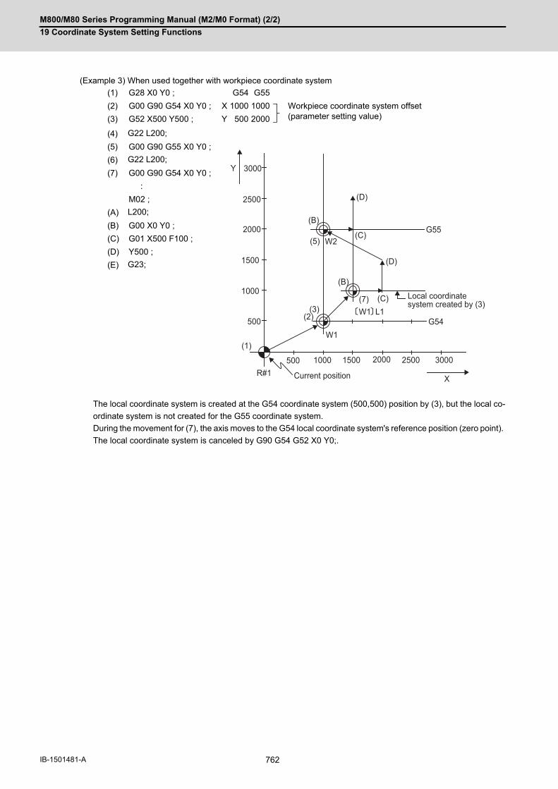
M800/M80 Series Programming Manual (M2/M0 Format) (2/2)
19 Coordinate System Setting Functions
762IB-1501481-A
(Example 3) When used together with workpiece coordinate system
The local coordinate system is created at the G54 coordinate system (500,500) position by (3), but the local co-
ordinate system is not created for the G55 coordinate system.
During the movement for (7), the axis moves to the G54 local coordinate system's reference position (zero point).
The local coordinate system is canceled by G90 G54 G52 X0 Y0;.
(1) G28 X0 Y0 ; G54 G55
(2) G00 G90 G54 X0 Y0 ; X 1000 1000 Workpiece coordinate system offset(parameter setting value)(3) G52 X500 Y500 ; Y 500 2000
(4) G22 L200;
(5) G00 G90 G55 X0 Y0 ;
(6) G22 L200;
(7) G00 G90 G54 X0 Y0 ;
:
M02 ;
(A) L200;
(B) G00 X0 Y0 ;
(C) G01 X500 F100 ;
(D) Y500 ;
(E) G23;
2500
2500
3000
3000
2000
2000
W1 L1
1500
1500
1000
1000
500
500R#1
G54
G55
W1
W2
Y
X
(B)
(B)
(C)
(C)
(D)
(D)
(2)
(1)
(3)
(5)
(7) Local coordinate system created by (3)
Current position

M800/M80 Series Programming Manual (M2/M0 Format) (2/2)
19 Coordinate System Setting Functions
763 IB-1501481-A
(Example 4) Combination of workpiece coordinate system G54 and multiple local coordinate systems
The local coordinate system is created at the G54 coordinate system (1000,1000) by (4).
The local coordinate system is created at the G54 coordinate system (2000,2000) by (6).
The G54 coordinate system and local coordinate system are matched by (8).
(1) G28 X 0 Y0 ; G54
(2) G00 G90 G54 X0 Y0 ; X 500 Workpiece coordinate system offset(parameter setting value)(3) G22 L300; Y 500
(4) G52 X1. Y1. ;
(5) G22 L300;
(6) G52 X2. Y2. ;
(7) G22 L300;
(8) G52 X0 Y0 ;
:
M02 ;
(A) L300;
(B) G00 X0 Y0 ;
(C) G01 X500 F100 ;
(D) Y500 ;
(E) X0 Y0 ;
(F) G23;
%
2500
2000
1500
1000
500
R#1500 1000 1500 2000 2500 3000
G54
W1
W1 L1
W1 L2
(B)
(C)
(D)
(E)(2)
(8)(3)
(5)
(7)
3000
Local coordinate system created by (6)
Local coordinate systemcreated by (4)
Current position
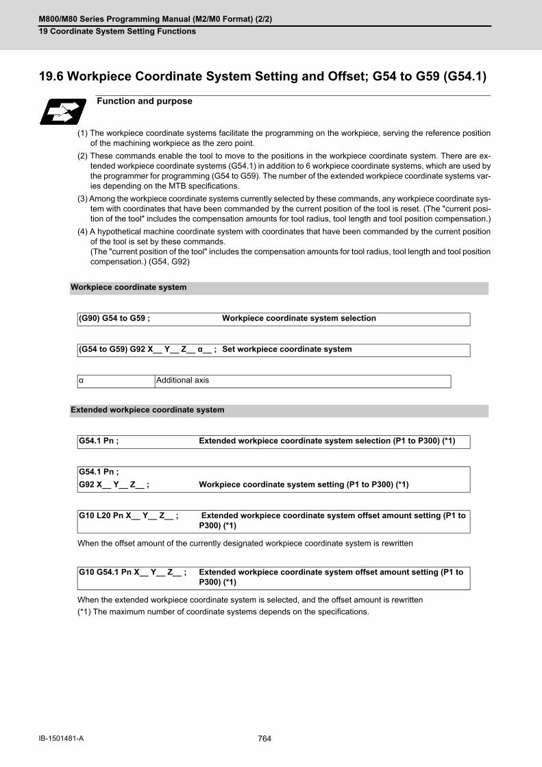
M800/M80 Series Programming Manual (M2/M0 Format) (2/2)
19 Coordinate System Setting Functions
764IB-1501481-A
19.6 Workpiece Coordinate System Setting and Offset; G54 to G59 (G54.1)
(1) The workpiece coordinate systems facilitate the programming on the workpiece, serving the reference positionof the machining workpiece as the zero point.
(2) These commands enable the tool to move to the positions in the workpiece coordinate system. There are ex-tended workpiece coordinate systems (G54.1) in addition to 6 workpiece coordinate systems, which are used bythe programmer for programming (G54 to G59). The number of the extended workpiece coordinate systems var-ies depending on the MTB specifications.
(3) Among the workpiece coordinate systems currently selected by these commands, any workpiece coordinate sys-tem with coordinates that have been commanded by the current position of the tool is reset. (The "current posi-tion of the tool" includes the compensation amounts for tool radius, tool length and tool position compensation.)
(4) A hypothetical machine coordinate system with coordinates that have been commanded by the current positionof the tool is set by these commands. (The "current position of the tool" includes the compensation amounts for tool radius, tool length and tool positioncompensation.) (G54, G92)
When the offset amount of the currently designated workpiece coordinate system is rewritten
When the extended workpiece coordinate system is selected, and the offset amount is rewritten
(*1) The maximum number of coordinate systems depends on the specifications.
Function and purpose
Workpiece coordinate system
(G90) G54 to G59 ; Workpiece coordinate system selection
(G54 to G59) G92 X__ Y__ Z__ α__ ; Set workpiece coordinate system
α Additional axis
Extended workpiece coordinate system
G54.1 Pn ; Extended workpiece coordinate system selection (P1 to P300) (*1)
G54.1 Pn ;
G92 X__ Y__ Z__ ; Workpiece coordinate system setting (P1 to P300) (*1)
G10 L20 Pn X__ Y__ Z__ ; Extended workpiece coordinate system offset amount setting (P1 to P300) (*1)
G10 G54.1 Pn X__ Y__ Z__ ; Extended workpiece coordinate system offset amount setting (P1 to P300) (*1)

M800/M80 Series Programming Manual (M2/M0 Format) (2/2)
19 Coordinate System Setting Functions
765 IB-1501481-A
(1) With any of the G54 through G59 commands or G54.1P1 through G54.1P300 commands, the tool radius com-pensation amounts for the commanded axes will not be canceled even if workpiece coordinate system selectionis commanded.
(2) The G54 workpiece coordinate system is selected when the power is turned ON.
(3) Commands G54 through G59 and G54.1P1 through G54.1P300 are modal commands (group 12).
(4) The coordinate system will move with G92 in a workpiece coordinate system.
(5) The offset setting amount in a workpiece coordinate system denotes the distance from the basic machine coor-dinate system zero point.
(6) The offset settings of workpiece coordinate systems can be changed any number of times. (They can also bechanged by G10 L2 Pp1 Xx1 Yy1 Zz1.)
[Handling when L or P is omitted]
(7) A new workpiece coordinate system 1 is set by issuing the G92 command in the G54 (workpiece coordinate sys-tem 1) mode. At the same time, the other workpiece coordinate systems 2 to 6 (G55 to G59) will move in paralleland new workpiece coordinate systems 2 to 6 will be set.
Detailed description
(#1)Reference position (zero point) return position
Basic machine coordinate system zero point
G54 reference position (zero point)
G55 reference position (zero point)
G54 X = -500 Y = -500 G55 X = -2000 Y = -1000
G10 L2 Pn Xx Yy Zz ; n=0 : Set the offset amount in the external workpiece coordinate system. n=1 to 6 : Set the offset amount in the designated workpiece coordinate system. Others: The program error (P35) will occur.
G10 L2 Xx Yy Zz ; Set the offset amount in the currently selected workpiece coordinate system. When in G54.1 modal, the program error (P33) will occur.
G10 L20 Pn Xx Yy Zz ;
n=1 to maximum number of coordinate systems : Set the offset amount in the desig-nated workpiece coordinate system. (The number of extended workpiece coordinate systems under the specifications)Others: Program error (P35) will occur.
G10 L20 Xx Yy Zz ; Set the offset amount in the currently selected workpiece coordinate system. When in G54 to G59 modal, the program error (P33) will occur.
G10 Pn Xx Yy Zz ; Set the offset amount in the designated coordinate system No. by P code. When the currently selected coordinate system is G54 to G59, P1 to P6 corresponds to G54 to G59 respectively. When the external coordinate system is selected, P No. corresponds to G54.1 P1 to P300. If other values are set, the program error (P35) will occur.
G10 Xx Yy Zz ; Set the offset amount in the currently selected coordinate system.
G10 G54.1 Xx Yy Zz ; When there is no P code in the same block as G54.1, the program error (P33) will oc-cur.
R#1
- X
- Y
- X(G54)(- 500,- 500)
- X(G55)(- 2000,- 1000)
W2
- Y(G55)
W1- Y(G54)
M

M800/M80 Series Programming Manual (M2/M0 Format) (2/2)
19 Coordinate System Setting Functions
766IB-1501481-A
(8) A hypothetical machine coordinate system is formed at the position that deviates from the new workpiece refer-ence position (zero point) by an amount equivalent to the workpiece coordinate system offset amount.
After the power has been switched on, the hypothetical machine coordinate system is matched with the basic
machine coordinate system by the first automatic (G28) or manual reference position (zero point) return.
(9) By setting the hypothetical machine coordinate system, the new workpiece coordinate system will be set at aposition that deviates from that hypothetical machine coordinate system by an amount equivalent to the work-piece coordinate system offset amount.
(10) When the first automatic (G28) or manual reference position (zero point) return is completed after the powerhas been turned ON, the basic machine coordinate system and workpiece coordinate systems are set automat-ically in accordance with the parameter settings.
(11) If G54 X- Y-; is commanded after the reference position return (both automatic or manual) executed after thepower is turned ON, the program error (P62) will occur. (A speed command is required as the movement will becontrolled with the G01 speed.)
(12) Do not command a G code for which a P code is used in the same block as G54.1 or G10L20. If a G code iscommanded, a P code is used for a prior G command or the program error occurs (P33).
(13) If there are no specifications for the extended workpiece coordinate system selection, a program error (P35)will occur when the G54.1 command is executed. This error will also occur when one of P49 to P300 is com-manded although the specifications allow up to the 48 sets.
(14) If there are no specifications for the extended workpiece coordinate system selection, the program error (P172)will occur when the G10 L20 command is executed.
(15) A new workpiece coordinate system P1 can be set by commanding G92 in the G54.1 P1 mode. However, theworkpiece coordinate system of the other workpiece coordinate systems G54 to G59, G54.1, and P2 to P96 willmove in parallel with it, and a new workpiece coordinate system will be set.
(R1) Reference position 1 (a) Hypothetical machine coordinate system based on G92
(b) Old workpiece 1 (G54) coordinate system (c) Old workpiece 2 (G55) coordinate system
(d) New workpiece 1 (G54) coordinate system (e) New workpiece 2 (G55) coordinate system
Command 6 sets Standard 48 sets 96 sets 300 sets
○: Movable×: P35 Setting value range over
6 sets ○ ○ ○ ○
48 sets × ○ ○ ○
96 sets × × ○ ○
300 sets × × × ○
(R1)
- X
- X(G54)
- X
- X(G54' )
- X(G55)
- X(G55' ) - Y(G54)
- Y
- Y(G55)
- Y
- Y(G54 ' )
- Y(G55 ' )
W2
W1
W2
W1
M
M(a)
(b)
(c)
(d)
(e)

M800/M80 Series Programming Manual (M2/M0 Format) (2/2)
19 Coordinate System Setting Functions
767 IB-1501481-A
(16) The offset amount of the extended workpiece coordinate system is assigned to system variables #7001 on-wards. The system variables #7001 to #890n are available up to the valid number of sets. (You can use them for the300-set specification also, but there are system variables corresponding to up to 96 sets only.) The system variables #101001 to #11595n are available when the 300-set specification is enabled. If you use the system variables #101001 to #11595n when the 300-set specification is disabled, the programerror (P241) will occur.
(17) When the "#1151 Reset ini" parameter is OFF, the modal of G54.1 command will be retained even if the reset1 is carried out.
(18) The P address of the G54.1 command cannot be commanded alone even in G54.1 modal. Even if commanded,the designated extended workpiece coordinate system cannot be selected. (Example)P54.1 P5 ; Changed to P5 workpiece coordinate system. P3 ; Ignored. G92 X0 Y0 Z0 ; The current position becomes the zero point of P5 workpiece coordinate system.
(19) When G92 is commanded in the extended workpiece coordinate system, the coordinate system will be sifted.
(Example 1)
When the coordinate value of the 1st reference position (R1) is zero, the basic machine coordinate system
zero point (M) and reference position (zero point) return position (#1) will coincide.
(Example 2)
CAUTION
If the workpiece coordinate system offset amount is changed during single block stop, the new setting will be
valid from the next block.
Program example
(1) G28 X0 Y0 ;
(2) G53 X-1000 Y-500 ;
(3) G53 X0 Y0 ;
(1) G28 X0 Y0 ;
(2) G90 G00 G53 X0 Y0 ;
(3) G54 X-500 Y-500 ;
(4) G01 G91 X-500 F100 ;
(5) Y-500 ;
(6) X+500 ;
(7) Y+500 ;
(8) G90 G00 G55 X0 Y0 ;
(9) G01 X-500 F200 ;
(10) X0 Y-500 ;
(11) G90 G28 X0 Y0 ;
(R1)
(1)
M(2)(3)
M
(G55)
(G54) - 1000 - 500
(G54)(G55)
W2 W1-500
(11)(6)
(5) (4)
(3)
(2)
(1)
(10) (7)
(8)(9)
(R1)
-1000
-500
-1000
-1500
-X
-X
-Y -Y

M800/M80 Series Programming Manual (M2/M0 Format) (2/2)
19 Coordinate System Setting Functions
768IB-1501481-A
(Example 3) When workpiece coordinate system G54 (-500, -500) has deviated in Example 2. (It is assumed that
(3) to (10) in Example 2 have been entered in subprogram 1111.)
(1) The workpiece coordinate system will deviate each time steps (3) to (5) shown in the above figure are repeated.The reference position return (G28) command should therefore be issued upon completion of the program.
(1) G28 X0 Y0 ;
(2) G90 G00 G53 X0 Y0 ; (This is not required when there is no G53 offset.)
(3) G54 X-500 Y-500 ; Amount by which workpiece coordinate system deviates
(4) G92 X0 Y0 ; New workpiece coordinate system is set.
(5) G22 L1111;
(R1) Reference position return position
(a) Old G54 coordinate system
(b) New G54 coordinate system
(c) Old G55 coordinate system
(d) New G55 coordinate system
M
- X(G55)- X(G54')
- Y(G54)
- Y(G55)
- X(G55')
- Y(G54')
- Y(G55')
- Y
- X
- X(G54)
W2
W1(4)
(3)
(2)(1)
(R1)
(a)
(b)
(c)
(d)
Note

M800/M80 Series Programming Manual (M2/M0 Format) (2/2)
19 Coordinate System Setting Functions
769 IB-1501481-A
(Example 4) When six workpieces are placed on the same coordinate system of G54 to G59, and each is to be ma-
chined with the same machining.
(1) Setting of workpiece offset data
(2) Machining program (subprogram)
(3) Positioning program (main)
Workpiece 1 X = -100.000 Y = -100.000.....G54Workpiece 2 X = -100.000 Y = -500.000.....G55Workpiece 3 X = -500.000 Y = -100.000.....G56Workpiece 4 X = -500.000 Y = -500.000.....G57Workpiece 5 X = -900.000 Y = -100.000.....G58Workpiece 6 X = -900.000 Y = -500.000.....G59
L100;
N1 G90 G00 G43 X-50. Y-50. Z-100. H10 ; Positioning
N2 G01 X-200. F50 ; Surface cutting
Y-200. ; Surface cutting
X-50. ; Surface cutting
Y-50. ; Surface cutting
N3 G28 X0 Y0 Z0 ;
:
N4 G98 G81 X-125. Y-75. Z-150. R-100. F40 ; Drilling 1
X-175. Y-125. ; Drilling 2
X-125. Y-175. ; Drilling 3
X- 75. Y-125. ; Drilling 4
G80 ;
N5 G28 X0 Y0 Z0 ;
:
N6 G98 G84 X-125. Y-75. Z-150. R-100. F40 ; Tapping 1
X-175. Y-125. ; Tapping 2
X-125. Y-175. ; Tapping 3
X- 75. Y-125. ; Tapping 4
G80 ;
G23;
G28 X0 Y0 Z0 ; At power ON
N1 G90 G54 G22 L100 ;
N2 G55 G22 L100 ;
N3 G57 G22 L100 ;
N4 G56 G22 L100 ;
N5 G58 G22 L100 ;
N6 G59 G22 L100 ;
N7 G28 X0 Y0 Z0 ;
N8 M02 ;
%
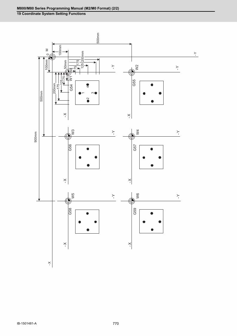
M800/M80 Series Programming Manual (M2/M0 Format) (2/2)
19 Coordinate System Setting Functions
770IB-1501481-A
75
W2
-X
-Y
G55
W4
-X
-Y
G57
W6
-X
-Y
G59
W3
-X
-Y
G56
W5
-X
-Y
G58
W1
-X
-Y
G54
125
200m
m
175
50m
m12
517
5
500m
m
100m
m
100m
m50
0mm
900m
m
-X
-Y0M
43
21
200m
m
5075

M800/M80 Series Programming Manual (M2/M0 Format) (2/2)
19 Coordinate System Setting Functions
771 IB-1501481-A
(Example 5) Program example when continuously using 48 sets of added workpiece coordinate system offsets.
In this example, the offsets for each workpiece are set beforehand in P1 to P48 when 48 workpieces are fixed
on a table, as shown in the drawing below.
L1000 L1001
G28 XYZ ; Reference position return G43 X-10.Y-10.Z-100.H10.; Contour
#100=1 ; Initialize added workpiece coordinate system P No.
G01 X-30.;
G90 ; Absolute value mode Y-30.;
WHILE [#100LE48]D01 ;
Repeat P No. to 48 X-10.;
G54.1 P#100 ; Set workpiece coordinate system
Y-10.;
G22 L1001; Call sub-program G00 G40 Z10.;
#100=#100+1 ; P No. +1 G98 G81 X-20.Y-15.Z-150.R5.F40;
Drilling
END1 ; X-25.Y-20.;
G28 Z ; Return to reference position X-20.Y-25.;
G28 XY ; X-15.Y-20.;
M02 ; G80 ;
G23;
P8P7 P1
P2P3
P4P5
P6
P9P10 P16
P15P14
P13P12
P11
P24P23 P17
P18P19
P20P21
P22
P25P26 P32
P31P30
P29P28
P27
P40P39 P33
P34P35
P36P37
P38
P41P42 P48
P47P46
P45P44
P43
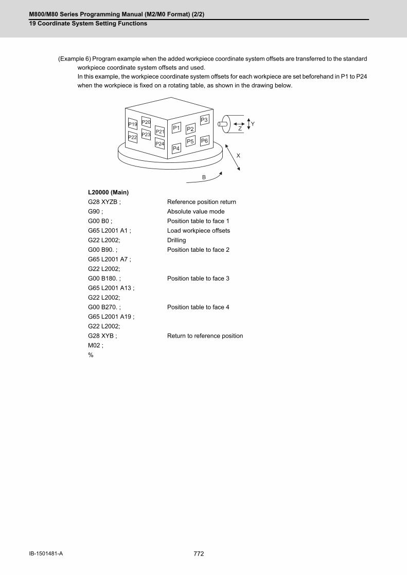
M800/M80 Series Programming Manual (M2/M0 Format) (2/2)
19 Coordinate System Setting Functions
772IB-1501481-A
(Example 6) Program example when the added workpiece coordinate system offsets are transferred to the standard
workpiece coordinate system offsets and used.
In this example, the workpiece coordinate system offsets for each workpiece are set beforehand in P1 to P24
when the workpiece is fixed on a rotating table, as shown in the drawing below.
L20000 (Main)
G28 XYZB ; Reference position return
G90 ; Absolute value mode
G00 B0 ; Position table to face 1
G65 L2001 A1 ; Load workpiece offsets
G22 L2002; Drilling
G00 B90. ; Position table to face 2
G65 L2001 A7 ;
G22 L2002;
G00 B180. ; Position table to face 3
G65 L2001 A13 ;
G22 L2002;
G00 B270. ; Position table to face 4
G65 L2001 A19 ;
G22 L2002;
G28 XYB ; Return to reference position
M02 ;
%
B
X
P19Z
YP20
P21P22 P23
P24
P1 P2
P3
P4P5 P6

M800/M80 Series Programming Manual (M2/M0 Format) (2/2)
19 Coordinate System Setting Functions
773 IB-1501481-A
L2001 (Transmission of workpiece offsets)
#2=5221 ; Leading No. of workpiece coordinate system variables
#3=[#1-1]*20+7001 ; Leading No. of added workpiece coordinate system variables
#5=0 ; No. of sets counter clear
WHILE [#5 LT 6] DO1 ; Check No. of sets
#6=#6+1 ; Set transmission source 1st axis variable No.
#7=#7+1 ; Set transmission destination 1st axis variable No.
#4=#4+1 ; Clear No. of axes counter
WHILE [#4 LT 6] DO2 ; Check No. of axes
#[#6]=#[#7] ; Transmit variable data
#6=#6+1 ; Set transmission source next axis
#7=#7+1 ; Set transmission destination next axis
#4=#4+1 ; No. of axes counter +1
END2 ;
#2=#2+20 ; Transmission source Set lead of next variable set.
#3=#3+20 ; Transmission destination Set lead of next variable set.
#5=#5+1 ; No. of sets counter +1
END1 ;
G23;
%
L2002 (Drilling)
G54 G22 H100 ; Drilling in G54 coordinate system
G55 G22 H100 ; G55
G56 G22 H100 ; G56
G57 G22 H100 ; G57
G58 G22 H100 ; G58
G59 G22 H100 ; G59
G28 Z0 ;
G23;
N100 G98 G81 X-20. Y-15. Z-150. R5. F40 ; Fixed cycle for drilling
X-25. Y-20. ;
X-20. Y-25. ;
X-15. Y-20. ;
G80 ;
G28 Z ;
G23;
%
M800/M80 Series Programming Manual (M2/M0 Format) (2/2)
19 Coordinate System Setting Functions
774IB-1501481-A
19.7 Workpiece Coordinate System Preset; G92.1
This function presets the workpiece coordinate system shifted with the program command during manual operation
to the workpiece coordinate system offset from the machine zero point by the workpiece coordinate offset amount
by the program command (G92.1).
The workpiece coordinate system, which is set when the following type of operation or program command is exe-
cuted, will be shifted from the machine coordinate system.
When manual interrupt is executed while manual absolute is OFFWhen movement command is issued in machine lock stateWhen axis is moved with handle interruptWhen operation is carried out with mirror imageWhen local coordinate system is set with G52Shifting the workpiece coordinate system with G92
This function presets the shifted workpiece coordinate system to the workpiece coordinate system offset from the
machine zero point by the workpiece coordinate offset amount. This takes place in the same manner as manual
reference position return. Whether to preset the relative coordinate depends on the MTB specifications (parameter
"#1228 aux12/bit6").
(1) Command the address of the axis to be preset. The axis will not be preset unless commanded.
(2) A program error (P35) will occur if a value other than "0" is commanded.
(3) Command G92.1 in an independent block.
(4) Whether to conduct an error check when the coordinate system preset command (G92.1) is independently is-sued depends on the MTB specifications (parameter "#1242 set14/bit1").
Function and purpose
Command format
G92.1 X0. Y0. Z0. α0 ;
α0 Additional axis
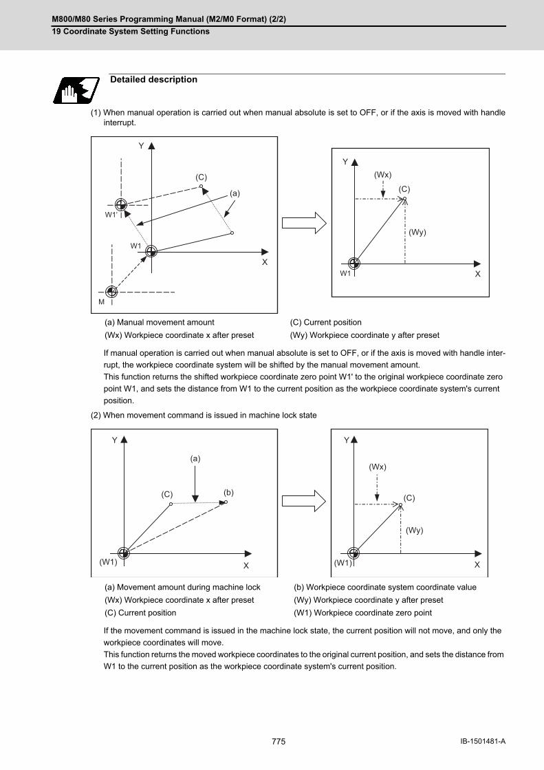
M800/M80 Series Programming Manual (M2/M0 Format) (2/2)
19 Coordinate System Setting Functions
775 IB-1501481-A
(1) When manual operation is carried out when manual absolute is set to OFF, or if the axis is moved with handleinterrupt.
If manual operation is carried out when manual absolute is set to OFF, or if the axis is moved with handle inter-
rupt, the workpiece coordinate system will be shifted by the manual movement amount.
This function returns the shifted workpiece coordinate zero point W1' to the original workpiece coordinate zero
point W1, and sets the distance from W1 to the current position as the workpiece coordinate system's current
position.
(2) When movement command is issued in machine lock state
If the movement command is issued in the machine lock state, the current position will not move, and only the
workpiece coordinates will move.
This function returns the moved workpiece coordinates to the original current position, and sets the distance from
W1 to the current position as the workpiece coordinate system's current position.
Detailed description
(a) Manual movement amount (C) Current position
(Wx) Workpiece coordinate x after preset (Wy) Workpiece coordinate y after preset
(a) Movement amount during machine lock (b) Workpiece coordinate system coordinate value
(Wx) Workpiece coordinate x after preset (Wy) Workpiece coordinate y after preset
(C) Current position (W1) Workpiece coordinate zero point
X
Y
X
Y
W1
W1’
W1
M
(a)
(C) (Wx)
(C)
(Wy)
X
Y
X
Y
(W1) (W1)
(a)
(C)
(Wx)
(C)
(Wy)
(b)

M800/M80 Series Programming Manual (M2/M0 Format) (2/2)
19 Coordinate System Setting Functions
776IB-1501481-A
(3) When operation is carried out with mirror image
If operation is carried out with mirror image, only the NC internal coordinates are used as the program command
coordinates. The other coordinates are the current position coordinates.
This function sets the NC internal coordinates as the current position coordinates.
(4) Setting local coordinate system with G52
The local coordinate system is set with the G52 command, and the program commands, etc., are issued with
the local coordinate system.
With this function, the set local coordinate system is canceled, and the program commands, etc., use the work-
piece coordinate system which has W1 as the zero point. The canceled local coordinate system is only the se-
lected workpiece coordinate system.
(a) Actual operation (b) Program command
(C) Current position (d) Mirror image center
(Wx) Workpiece coordinate x after preset (Wy) Workpiece coordinate y after preset
(W1) Workpiece coordinate zero point
(a) Local coordinates x (b) Local coordinates y
(Wx) Workpiece coordinate x after preset (Wy) Workpiece coordinate y after preset
(C) Current position (L1) Local coordinate zero point
(W1) Workpiece coordinate zero point
X
Y
X
Y
(W1) (W1)
(Wx)
(b)(Wy)
(d)
(a)
(C)(C)
X
Y
X
Y
(W1)
(L1)
(W1)
(C) (Wx) (C)
(Wy)
(a)
(b)

M800/M80 Series Programming Manual (M2/M0 Format) (2/2)
19 Coordinate System Setting Functions
777 IB-1501481-A
(5) Shifting the workpiece coordinate system with G92
The workpiece coordinate system shifts with the G92 command, and the distance between W1' and the current
position is set as the current position of the workpiece coordinate system.
This function returns the shifted workpiece coordinate zero point to W1, and sets the distance from W1 to the
current position as the workpiece coordinate system's present position. This is valid for all workpiece coordinate
systems.
The workpiece coordinate system shifted with G92 is preset with G92.1.
(W1) Workpiece coordinate zero point
(W1') Workpiece zero point after G92 command
(Example)
G28 X0 Y0 ; ... (1)
G00 G90 X1. Y1. ; ... (2)
G92 X0 Y0 ... (3)
G00 X500 Y500 ; ... (4)
G92.1 X0 Y0 ; ... (5)
(a) Local coordinates x (b) Local coordinates y
(Wx) Workpiece coordinate x after preset (Wy) Workpiece coordinate y after preset
(C) Current position
(W1) Workpiece coordinate zero point (W1') Workpiece zero point after G92 command
Program example
X
Y
X
Y
(W1)
(W1')
(W1)
(C) (Wx) (C)
(Wy)
(a)
(b)
X
Y
X
Y
(W1)
(1)
(W1)
(2)(3)
(4) (5)
500
1000
1500
500 1000 1500
500
1000
1500
500 1000 1500(mm) (mm)
(W1')

M800/M80 Series Programming Manual (M2/M0 Format) (2/2)
19 Coordinate System Setting Functions
778IB-1501481-A
If the error check is enabled when the workpiece coordinate system preset is independently commanded (*1), com-
mand all the tool compensation axes when commanding "G92.1" during the tool compensation. When commanding
"G92.1" during the tool length compensation, designate the tool length compensation axis.
If those axes are not commanded, a program error (P29) will occur.
(*1) The setting depends on the MTB specifications (parameter "#1242 set14/bit1").
Cancel the tool nose radius compensation or the tool radius compensation, and command the workpiece coordinate
system preset (G92.1). When the workpiece coordinate system preset (G92.1) is commanded during the tool nose
radius compensation or the tool radius compensation, a program error (P29) will occur if none of the tool compen-
sation axes are commanded.
If the workpiece coordinate system preset (G92.1) is commanded in 3-dimensional coordinate conversion, a pro-
gram error (P921) will occur.
If the workpiece coordinate system preset (G92.1) is commanded during the modal shown below, a program error
(P34) will occur.
(1) Scaling
(2) Coordinate rotation by program
(3) G command mirror image
(4) Tool length compensation along the tool axis
(1) Cancel tool length compensation, tool nose radius compensation, tool radius compensation, and tool positionoffset when using this function. If this function is executed without canceling them, the workpiece coordinateswill be at a position obtained by subtracting the workpiece coordinate offset amount from the machine value.Thus, the compensation vector will be temporarily canceled.
(2) This function cannot be executed while the program is being resumed.
Relationship with other functions
Tool No./Tool Compensation No. (T Code)/tool length compensation
Tool nose radius compensation / Tool radius compensation
3-dimensional coordinate conversion
Other G code commands
Precautions

M800/M80 Series Programming Manual (M2/M0 Format) (2/2)
19 Coordinate System Setting Functions
779 IB-1501481-A
19.8 3-dimensional Coordinate Conversion; G68.1/G69.1
With the 3-dimensional coordinate conversion function, a new coordinate system can be defined by shifting the zero point and rotating in respect to the X, Y and Z axes of the currently set workpiece coordinate system. By using this function, an arbitrary spatial plane can be defined, and machining on that plane can be carried out with normal pro-gram commands. The validity of this function depends on the MTB specifications. Refer to the specifications of your machine tool.
When the G68.1 command is issued, the zero point is shifted by the command value (x, y, z) in respect to the current local coordinate system. A new G68.1 program coordinate system rotated by the designated rotation angle "r" in respect to the commanded rotation center direction (i, j, k) is created.
The local coordinate system is the same as the workpiece coordinate system when the local coordinate system off-set is not ON.
Function and purpose
(M) Machine coordinate system (P) G68.1 Program coordinate system (W) Workpiece coordinate system
Command format
3-dimensional coordinate conversion mode command
G68.1 X__ Y__ Z__ I__ J__ K__ R__ ;
X, Y, Z Rotation center coordinatesDesignate with the absolute position of the local coordinate system.
I, J, K Rotation center axis direction (1: Designated 0: Not designated)Note that "1" is designated for only one of the three axes. "0" is designated for the other two axes.
R Rotation angleThe counterclockwise direction looking at the rotation center from the rotation center axis di-rection is positive (+). The setting range is -360 to 360°, and the unit follows the minimum command unit.
3-dimensional coordinate conversion mode cancel command
G69.1
Y'
X'
X
Y
Z'
Z(M)
(P)
(W)

M800/M80 Series Programming Manual (M2/M0 Format) (2/2)
19 Coordinate System Setting Functions
780IB-1501481-A
(1) Command the rotation center coordinates with absolute values.
(2) If the rotation center coordinates are omitted, the zero point of the currently set coordinate system will be therotation center coordinates.
(3) Designate values for all of I, J and K. If any of the I, J, K is not designated, program coordinate rotation command will be valid.
(4) Set "1" in only one of I, J and K, and set "0" for the other two. The program error (P33) will occur if "1" is set in two or more.
(5) The program error (P33) will also occur if "0" is set for all I, J and K.
(6) When addresses I, J and K are not designated, this will be handled as the program coordinate rotation.
(7) If a number other than "0" (including numbers of two or more digits) is designated for addresses I, J and K, thiswill be handled as "1". If a blank is designated, this will be handled as "0".
(8) If a G code that cannot be commanded in the 3-dimensional coordinate conversion modal is issued, the programerror (P921) will occur. When 3-dimensional coordinate conversion is commanded during the modal where 3-dimensional coordinateconversion cannot be carried out, the program error (P922) or program error (P923) will also occur. For details,refer to "Relationship with Other Functions".
(9) Command G68.1 in an independent block. If another G code command is issued to the same block as for theG68.1 command, a program error (P923) will occur.
(10) The 3-dimensional coordinate conversion command for the rotary axis will result in the program error (P32).
(11) If a 3-dimensional coordinate conversion command is issued when there are no specifications for 3-dimensionalcoordinate conversion, the program error (P920) will occur.
(1) By issuing the 3-dimensional coordinate conversion command, a new coordinate system (G68.1 program coor-dinate system) will be created on the local coordinate system.
(2) The coordinate system for the 3-dimensional coordinate conversion rotation center coordinates is the local co-ordinate system. Thus, these coordinate systems are affected by the following coordinate system offset and coordinate systemshift amount.
When local coordinate system is set with G52 G92 shift amount by G92 commandCoordinate system offset corresponding to the workpiece coordinate system selected with the commandExternal workpiece coordinate offsetManual interruption amount or manual feed amount when manual ABS is OFF
(3) If 3-dimensional coordinate conversion is commanded again during the 3-dimensional coordinate conversionmodal, a G68.1 program coordinate system is created on the current G68.1 program coordinate system, and isused as a new G68.1 program coordinate system.
(4) The local coordinate system cannot be created (G52) on the G68.1 program coordinate system. (If G52 is issued,the program error (P921) will occur.)
(5) G68.1 program coordinate system can be reset either by G69.1 command or reset inputting. (Exclude reset 1when "0" is set to the parameter "#1151 rsint")
(6) Whether to run the manual operation during the 3-dimensional coordinate conversion modal in the G68.1 pro-gram coordinate system can be designated by switching the manual feed coordinate for 3-dimensional coordi-nate conversion.
(7) Even if the 3-dimensional coordinate conversion modal state is canceled by reset, etc., the manual operation ispossible in the G68.1 program coordinate system before the 3-dimensional coordinate conversion modal is can-celed, until the G69.1 command is issued. In the same way as during the 3-dimensional coordinate conversion modal, the target coordinate can be desig-nated by switching the manual feed coordinate for 3-dimensional coordinate conversion.
Detailed description
Coordinate system

M800/M80 Series Programming Manual (M2/M0 Format) (2/2)
19 Coordinate System Setting Functions
781 IB-1501481-A
(1) For the rotation angle, the counterclockwise direction looking at the rotation center from the plus direction of therotation center axis is the plus (+) direction.
(2) The rotation angle command unit with no decimal point depends on the parameter "#1078 Decpt2" (Decimal pnttype 2).
(3) If the rotation angle is omitted, the rotation angle will be handled as 0°.
(1) The G68.1 rotation center coordinate system is commanded with the local coordinate system (G68.1 programcoordinate system during the 3-dimensional coordinate conversion modal).
(2) The rotation center coordinate designation is handled as an absolute value command whether or not an absolute/incremental modal (G90/G91) is currently being executed.
(3) If the rotation center coordinate is omitted, it will be handled as if the zero point of the current local coordinate(G68.1 program coordinate system during the 3-dimensional coordinate conversion modal) is designated for theomitted address's axis. (The same as when "0" is just set.)
By commanding 3-dimensional coordinate conversion during the 3-dimensional coordinate conversion modal, two
or more multiple commands can be issued.
(1) The 3-dimensional coordinate conversion command in the 3-dimensional coordinate conversion modal is com-bined with the conversion in the modal.
(2) If 3-dimensional coordinate conversion is overlapped during the 3-dimensional coordinate conversion modal, theoverlapped 3-dimensional coordinate conversion will be created on the coordinate system (G68.1 program co-ordinate system) created with 3-dimensional coordinate conversion in the modal. Thus, the rotary axis and coordinates must be designated with this G68.1 program coordinate system. If creating a 90° rotated coordinate system for X axis and Y axis each, commands must be issued as in Example2, not Example 1.
Rotation angle
Rotation center coordinates
G68.1 multiple commands
<Example 1>
G68.1 X0. Y0. Z0. I1 J0 K0 R90.; X axis rotation 90°
G68.1 X0. Y0. Z0. I0 J1 K0 R90.; Y axis rotation 90°(The Y axis designated here is the same as the Z axis in the original coordinate system.)
<Example 2>
G68.1 X0. Y0. Z0. I1 J0 K0 R90.; X axis rotation 90°
G68.1 X0. Y0. Z0. I0 J0 K1 R-90.; Z axis rotation 90°(The Z axis -90 rotation designated here is the same as the Y axis +90 rotation in the original coordinate system.)

M800/M80 Series Programming Manual (M2/M0 Format) (2/2)
19 Coordinate System Setting Functions
782IB-1501481-A
The coordinate values (Xp, Yp, Zp) in the newly set G68.1 program coordinate system and the coordinate values
(Xm, Ym, Zm) in the reference workpiece coordinate system are converted as shown below.
R1, R2 : Rotation row calculated from first and second G68.1 parameter
T1, T2 : Movement row calculated from first and second G68.1 parameter
The conversion rows Rn and Tn (n = 1, 2) are as follow.
Rn conversion row
Tn conversion row
Whether to run manual operations (jog feed, incremental feed, and manual handle feed) during the 3-dimensional
coordinate conversion modal in the coordinate system (G68.1 program coordinate system) after the 3-dimensional
coordinate conversion command was issued can be designated by switching the manual feed coordinate for 3-di-
mensional coordinate conversion.
When the axis stops during machining, operations such as a pulling operation by manual feed can be performed in
the G68.1 program coordinate system.
(1) Coordinate switching enable conditionsA manual operation coordinate change by switching the manual feed coordinate for 3-dimensional coordinateconversion is available only when the output signal that enables the manual feed for 3-dimensional coordinateconversion is set to ON. (The operation of the PLC signal depends on the MTB specifications.) The manual operation coordinate change by switching the manual feed coordinate for 3-dimensional coordinateconversion becomes valid after three basic axes have stopped. When the manual feed coordinate for 3-dimen-sional coordinate conversion is switched while even one of three basic axes is moving, a coordinate change isperformed after three basic axes have stopped. The output signal that enables the manual feed for 3-dimensional coordinate conversion is set to ON when all ofthe following conditions are satisfied.
(a) One of the jog, incremental, or handle feed modes is selected.
(b) G68.1 (3-dimensional coordinate conversion command) is commanded once. However, if the signal is can-
celed by the G69.1 command, it is not turned ON until G68.1 is commanded again.
Conversion method for 3-dimensional coordinate conversion
First G68.1 command
[Xm, Ym, Zm, 1]=[Xp, Yp, Zp, 1]R1 T1 (Forward row)
[Xp, Yp, Zp, 1]=[Xm, Ym, Zm, 1](T1-1)(R1-1) (Reverse row)
Second G68.1 command
[Xm, Ym, Zm, 1]=[Xp, Yp, Zp, 1]R2 T2 R1 T1
[Xp, Yp, Zp, 1]=[Xm, Ym, Zm, 1](T1-1)(R1-1)(T2-1)(R2-1)
I designation (rotation around X axis)
J designation (rotation around Y axis)
K designation (rotation around Z axis)
x, y, z: Rotation center coordinates (parallel movement amount)I, J, K: Rotation axis selectionR: Rotation angle
Manual operation in G68.1 program coordinate system
1 0 0 0
0 cosR sinR 0
0 - sinR cosR 0
0 0 0 1
cosR 0 - sinR 0
0 1 0 0
sinR 0 cosR 0
0 0 0 1
cosR sinR 0 0
- sinR cosR 0 0
0 0 1 0
0 0 0 1
1 0 0 0
0 1 0 0
0 0 1 0
x y z 1

M800/M80 Series Programming Manual (M2/M0 Format) (2/2)
19 Coordinate System Setting Functions
783 IB-1501481-A
(2) Operation exampleThe absolute coordinate positions are displayed in the G68.1 program coordinate system with a parameter. Thisdepends on the MTB specifications (parameter "#1561 3Dcdc"). The machine zero point is used as the workpiece coordinate zero point. Also, the manual ABS is set to ON toreturn to the position commanded by the machining program with the absolute command after a manual inter-ruption. <Operation procedure>
(1) Set mode selection to automatic operation (memory, MDI, tape, etc.) mode.
(2) Execute the following machining program, then perform single block stop after the N03 block has been com-pleted... (a)
(3) Set the handle mode, then select the Z axis with the 1st handle. Then, check that the output signal that en-ables the manual feed for 3-dimensional coordinate conversion is set to ON.
(4) Set to ON the signal that switches the manual feed coordinate for 3-dimensional coordinate conversion.
(5) Move the axis by -5. with the handle in the Z' direction of the G68.1 program coordinate, then check the holeposition... (b)
(6) Move the axis by +7. with the handle in the Z' direction to retract the tool... (c)
(7) After executing an automatic start, execute the N04 block... (d)
N01 G68.1 X0. Z0. Y0. I0 J1 K0 R45. ; Set the G68.1 program coordinate system (X'Y'Z') which has been rotated +45°in the Y axis direction around the (X0, Z0).
N02 G00 X1.;N03 G00 Z-10.;
Position the axis near the hole position in the G68.1 program co-ordinate system.
N04 G01 Z-20.; Cutting in G68.1 program coordinate system.
Absolute coordinate Machine coordinate
(a) Positioning X 1.000 -6.364
Z -10.000 -7.778
(b) Hole position check X 1.000 -9.900
Z -15.000 -11.314
(c) Retract X 1.000 -4.950
Z -8.000 -6.364
(d) Cutting X 1.000 -13.435
Z -20.000 -14.849
(a)
(b)
(c)
(d)
X’ Z’
Z
X

M800/M80 Series Programming Manual (M2/M0 Format) (2/2)
19 Coordinate System Setting Functions
784IB-1501481-A
(3) Precautions
(a) When the automatic and manual operation modes are selected simultaneously, the manual feed for 3-dimen-
sional coordinate conversion cannot be commanded. However, manual operation is available only for the
axis for which the manual automatic simultaneous valid axis signal is set to ON.
(b) The speed limit is applied so that the speed distributed to the movement amount in the machine axis direction
does not exceed the clamp speed of each axis.
(c) If even one axis satisfies the external deceleration conditions, the speed limit is applied so that the movement
speed in each axis direction does not exceed the external deceleration speed.
(d) The movement amount by handle feed conforms to that on the G68.1 program coordinate system. If clamp
("#1281 ext17/bit4=1") is commanded with the number of handle input pulses, the movement amount on the
G68.1 program coordinate system becomes the integral multiple of the handle magnification.
(e) When clamp ("#1281 ext17/bit4=1") is commanded with the number of handle input pulses, if the one-scale
movement amount by manual feed for 3-dimensional coordinate conversion exceeds the movement amount
for the specified time at clamp speed, the operation error (M01 0060) occurs at the time of pulse occurrence,
not at the time of handle axis selection, and movement will fail. To move, reduce the handle magnification.
(f) The manual feed operation for 3-dimensional coordinate conversion is not available in manual reference po-
sition return mode. If it is started, an operation error (M01 0060) will occur. To use the manual reference po-
sition return mode, set to OFF the signal that switches the manual feed coordinate for 3-dimensional
coordinate conversion.
(g) The manual feed operation for 3-dimensional coordinate conversion is not available in tool retract and return
mode. If it is started, an operation error (M01 0060) will occur. To use the tool escape mode, set to OFF the
signal that switches the manual feed coordinate for 3-dimensional coordinate conversion.
(h) This function is not compatible with the manual tool length measurement function, workpiece position mea-
surement function, and manual skip based on the manual feed for 3-dimensional coordinate conversion. If it
is started, an operation error (M01 014) will occur. While the manual tool length measurement function or
workpiece position measurement function is active or when manual skip is valid, set to OFF the signal that
switches the manual feed coordinate for 3-dimensional coordinate conversion.
(i) When the manual automatic simultaneous valid axis signal is set to ON for any of three basic axes, operation
is performed in the same way as when the manual automatic simultaneous valid axis signal for three basic
axes is set to ON.
(j) When the manual machine lock signal is set to ON for any of three basic axes, operation is performed in the
same way as when the manual machine lock signal for three basic axes is set to ON.
(k) When a factor such as manual interlock that triggers the stop of the axis under manual movement occurs at
any of three basic axes, execute deceleration stop on the three basic axes.
(l) When the 3-dimensional coordinate conversion modal state is canceled by reset, etc., the manual feed for 3-
dimensional coordinate conversion is possible; however, the absolute coordinate position display function
and other functions conform to the 3-dimensional coordinate conversion modal state and parameter setting.
The coordinate cannot be changed by switching the manual feed coordinate for 3-dimensional coordinate
conversion.
(m) If the G69.1 command exists up to the block to be restart-searched at program restart, it also cancels the
state that enables the manual feed in 3-dimensional coordinate conversion as the G69.1 command does.
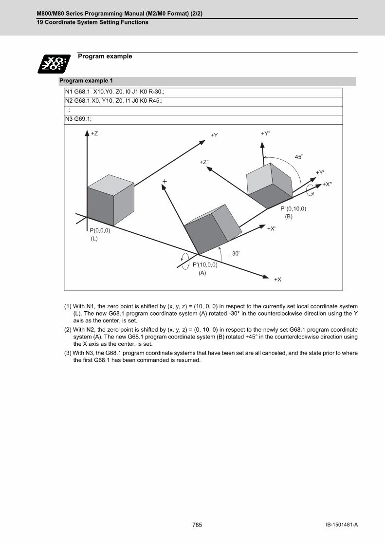
M800/M80 Series Programming Manual (M2/M0 Format) (2/2)
19 Coordinate System Setting Functions
785 IB-1501481-A
(1) With N1, the zero point is shifted by (x, y, z) = (10, 0, 0) in respect to the currently set local coordinate system(L). The new G68.1 program coordinate system (A) rotated -30° in the counterclockwise direction using the Yaxis as the center, is set.
(2) With N2, the zero point is shifted by (x, y, z) = (0, 10, 0) in respect to the newly set G68.1 program coordinatesystem (A). The new G68.1 program coordinate system (B) rotated +45° in the counterclockwise direction usingthe X axis as the center, is set.
(3) With N3, the G68.1 program coordinate systems that have been set are all canceled, and the state prior to wherethe first G68.1 has been commanded is resumed.
Program example
Program example 1
N1 G68.1 X10.Y0. Z0. I0 J1 K0 R-30.;
N2 G68.1 X0. Y10. Z0. I1 J0 K0 R45.;
:
N3 G69.1;
P'(10,0,0)
+Z +Y
+X
+X'
+Z"
+Y"
+Y'
+X"
45
P(0,0,0)
- 30
P"(0,10,0)
(L)
(A)
(B)
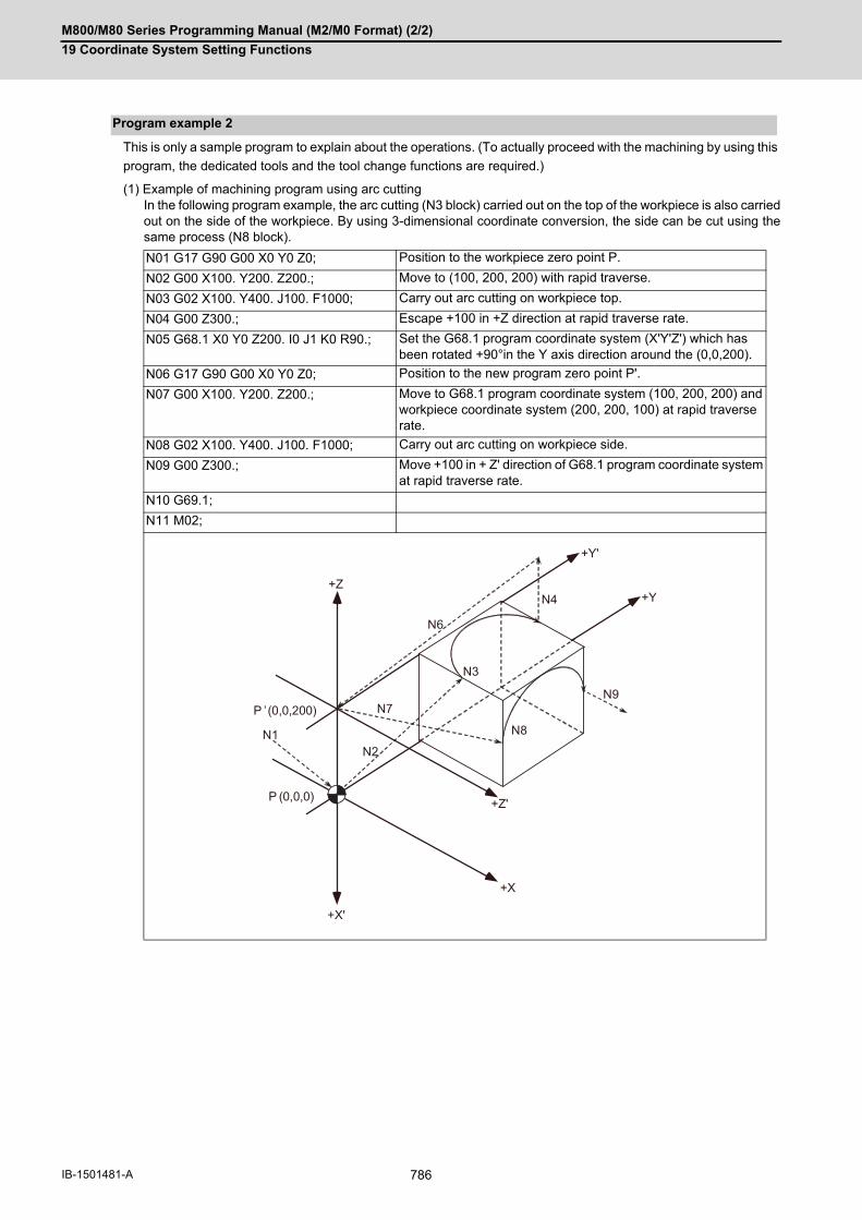
M800/M80 Series Programming Manual (M2/M0 Format) (2/2)
19 Coordinate System Setting Functions
786IB-1501481-A
This is only a sample program to explain about the operations. (To actually proceed with the machining by using this
program, the dedicated tools and the tool change functions are required.)
(1) Example of machining program using arc cuttingIn the following program example, the arc cutting (N3 block) carried out on the top of the workpiece is also carriedout on the side of the workpiece. By using 3-dimensional coordinate conversion, the side can be cut using thesame process (N8 block).
Program example 2
N01 G17 G90 G00 X0 Y0 Z0; Position to the workpiece zero point P.
N02 G00 X100. Y200. Z200.; Move to (100, 200, 200) with rapid traverse.
N03 G02 X100. Y400. J100. F1000; Carry out arc cutting on workpiece top.
N04 G00 Z300.; Escape +100 in +Z direction at rapid traverse rate.
N05 G68.1 X0 Y0 Z200. I0 J1 K0 R90.; Set the G68.1 program coordinate system (X'Y'Z') which has been rotated +90°in the Y axis direction around the (0,0,200).
N06 G17 G90 G00 X0 Y0 Z0; Position to the new program zero point P'.
N07 G00 X100. Y200. Z200.; Move to G68.1 program coordinate system (100, 200, 200) and workpiece coordinate system (200, 200, 100) at rapid traverse rate.
N08 G02 X100. Y400. J100. F1000; Carry out arc cutting on workpiece side.
N09 G00 Z300.; Move +100 in + Z' direction of G68.1 program coordinate system at rapid traverse rate.
N10 G69.1;
N11 M02;
+X'
+X
N1
P (0,0,0)
N2
N3
N4
N6
P ’(0,0,200)
+Z
+Z'
N7
N9
+Y'
+Y
N8

M800/M80 Series Programming Manual (M2/M0 Format) (2/2)
19 Coordinate System Setting Functions
787 IB-1501481-A
(2) Example of machining program using fixed cycleIn the following program, the bolt hole circle (N08 block) executed on the top of the workpiece is also carried outon the side of the workpiece. By using 3-dimensional coordinate conversion, the side can be cut using the sameprocess (N18 block).
N01 G90 G00 X0 Y0 Z0; Position to the workpiece coordinate system's 1st workpiece zero point.
N02 F2000;
N03 G00 X100. Y100. Z-600.; Move to (100, 100, -600) with rapid traverse.
N04 G52 X100. Y100. Z-600.; Set the local coordinate system (X'Y'Z') to the (100, 100, -600).
N05 G00 X100. Y10. Z 200.; Move to (100, 10, 200) position in the local coordinate system at a rapid traverse.
N06 G91; Incremental value command
N07 G81 Z-10. R5. L0 F2000; Drilling cancel
N08 G34 X100. Y200. I90. J270. K10.; Bolt hole circle
N09 G80; Drilling cancel
N10 G91 G00 X-200.; Move -200 from machining end point in X axis direction at rapid traverse rate.
N11 G90 G52 X0 Y0 Z0; Cancel local coordinate system.
N12 G90 G00 X0 Y0 Z0; Position to workpiece zero point.
N13 G00 X100. Y100. Z-400.; Move to (100, 100, -400) with rapid traverse.
N14 G68.1 X100. Y100. Z-400. I0 J1 K0 R90.;
Set G68.1 program coordinate system (X",Y",Z") rotated +90° in Y axis direction using (100, 100, -400) position as center.
N15 G00 X100.Y10. Z200.; Move to (100, 10, 200) position in the G68.1 program coordinate system at a rapid traverse rate.
N16 G91; Incremental value command
N17 G81 Z-10. R5. L0 F200; Drilling cancel
N18 G34 X100.Y200. I90. J270. K10.; Bolt hole circle
N19 G80; Drilling cancel
N20 G91 G00 X-200.; Move -200 from machining end point in X axis direction at rapid traverse rate.
N21 G69.1; Cancel 3-dimensional coordinate conversion modal.
N22 M02; End program.
-Z
(0,0,0)
N1
+Y
+X
N3
+Z’
’(100,100, - 600)
+X’’
N5
N10
N12
N13
’’ (100,100, - 400)
N15
N20
N7 N9
N17 N19
+Y’’
+X’
+Z’’
+Y’

M800/M80 Series Programming Manual (M2/M0 Format) (2/2)
19 Coordinate System Setting Functions
788IB-1501481-A
(1) Circular interpolationCircular interpolation in the 3-dimensional coordinate conversion modal operates according to the coordinatevalue resulting from 3-dimensional coordinate conversion. With G17, G18 and G19 commands, circular interpo-lation functions normally for all the planes in which 3-dimensional coordinate conversion has been executed.
(2) Fine splineDesignation of a spline axis should be done to the movement axis after the 3-dimensional coordinate conversion.When a movement occurs to the axis in which spline cannot be designated, spline will be in the pause status.
(3) Reference position checkThe 3-dimensional coordinate conversion is applied for the positioning commanded by G27 in the 3-dimensionalcoordinate conversion modal.
(4) Reference point returnThe 3-dimensional coordinate conversion is applied for the mid-point commanded by G28 and G30 in the 3-di-mensional coordinate conversion modal. However, reference position return will be carried out without the 3-di-mensional coordinate conversion.
(5) Tool change position return3-dimensional coordinate conversion is not carried out for the tool change position even if a command fromG30.1 to G30.6 is issued in the 3-dimensional coordinate conversion modal. The returning order and positionwill be on the machine coordinate system.
(6) Tool compensationWhen executing the tool length/radius/position compensation in the 3-dimensional coordinate conversion modal,the 3-dimensional coordinate conversion is carried out after the compensation value has been applied.
(7) Machine coordinate system selectionCoordinate conversion will not be carried out for the machine coordinate system even if G53 command is issuedin the 3-dimensional coordinate conversion modal.
(8) Mirror imageWhen issuing the mirror image command in the 3-dimensional coordinate conversion modal, as well as whenexecuting the 3-dimensional coordinate conversion in the mirror image modal, 3-dimensional coordinate conver-sion will be executed for the coordinate value, which is calculated by the mirror image.
(9) User macroWhen a user macro call command is issued in the 3-dimensional coordinate conversion modal, the 3-dimension-al coordinate conversion will be valid after the macro execution.
(10) Fixed cycle for drillingThe fixed cycle in the 3-dimensional coordinate conversion can be executed in an oblique direction for the or-thogonal coordinate system. In the same manner, synchronous tapping cycle can also be executed. However, the fixed cycle hole drilling rapid traverse speed during the 3-dimensional coordinate conversion modalis switched as shown below by the settings of the parameters "#15663 DselctDrillaxMode" and "#1564 3Dspd".(This depends on the MTB specifications.) Fixed cycle rapid traverse speed during 3-dimensional coordinate conversion
<Note>
The speed of operation 1 in the table above conforms to the "#2001 rapid" value regardless of the param-eter setting above.When a macro interruption, MDI interruption, or PLC interruption is carried out in the fixed cycle during 3-
dimensional coordinate conversion, the rapid traverse speed in the interrupt machining program con-forms to the "#2001 rapid" value regardless of the parameter setting above.
Relationship with other functions
#1566 0 (Rapid traverse mode) 1 (Cutting mode)
#1564 - 0 1 to 1000000
Rapid traverse speed The "#2001 rapid" value for each machine axis is con-verted to the speed in the composite movement direc-tion, and the slowest speed is applied.
The "#2002 clamp" value for each machine axis is converted to the speed in the composite movement direction, and the slowest speed is applied.
The value (mm/min) set to "#1564 3Dspd" is applied.

M800/M80 Series Programming Manual (M2/M0 Format) (2/2)
19 Coordinate System Setting Functions
789 IB-1501481-A
Parameter "#1566" becomes valid when each fixed cycle is set to rapid traverse mode. The operation numbers
in the table below correspond to those in the figure above.
Relationships between fixed cycles and parameter "#1566"
o: "#1566" is valid (rapid traverse).
x: "#1566" is irrelevant (cutting feed).
For G87, the movement completion position in operation 3 is set to R point.
Parameter "#1566" is also valid for rapid traverse operation at G76 or G87 shift.
Parameter "#1566" is also valid for G73 or G83 return operation.
(11) Synchronous tapping cycleThe synchronous tapping cycle in the 3D coordinate conversion can be executed in an oblique direction for theorthogonal coordinate system. The Synchronous tapping cycle in the 3-dimensional coordinate conversion modal will not function even if"#1223 aux07/bit3" (synchronous tapping in-position check expansion valid)" is valid. Set the synchronous tap-ping cycle to invalid. (This parameter setting depends on the MTB specifications.) The rapid traverse rate in synchronous tapping cycle always follows the value of #2001(rapid traverse rate)during the 3D coordinate conversion mode, regardless of the values of #1566(switch drill axis's mode from rapidtraverse during 3D) and #1564(hole drilling cycle during 3D coordinate conversion). If any of the orthogonal axes of all the active part systems is under machine lock during 3-dimensional coordinateconversion, normal synchronous tapping is applied even though the high-speed synchronous tapping specifica-tion is enabled.
[Operation]
(1) Position to the initial position at the rapid traverse rate.
(2) Position to the R point at the rapid traverse rate.
(3) Hole machining is conducted by cutting feed.
(4) Escape to the R point. Cutting feed or rapid traverse depending on the fixed cycle mode.
(5) The tool is returned to the initial point at the rapid traverse rate.
(I) Initial point
(R) R point
G code [Operation] (2) [Operation] (3) [Operation] (4) [Operation] (5)
G73 ○ × ○ ○
G74 ○ × × ○
G75 ○ × ○ ○
G76 ○ × ○ ○
G81 ○ × ○ ○
G82 ○ × ○ ○
G83 ○ × ○ ○
G84 ○ × × ○
G85 ○ × × ○
G86 ○ × ○ ○
G87 ○ ○ × ○
G88 ○ × ○ ○
G89 ○ × × ○
(R)
(I)(1)
(2)
(3) (4)
(5)

M800/M80 Series Programming Manual (M2/M0 Format) (2/2)
19 Coordinate System Setting Functions
790IB-1501481-A
(12) Geometric commandGeometric command can be issued in the 3-dimensional coordinate conversion modal. However, if the geomet-ric command is issued in the same block as in the 3-dimensional coordinate conversion command (G68.1,G69.1), "the program error (P32) will occur.
(13) Init const sur spdWhen the 3-dimensional coordinate conversion command is issued while the parameter initial constant surfacespeed is valid, the program error (P922) will occur. This is the same consequence as in the case where the 3-dimensional coordinate conversion command is issued in the constant surface speed (G96) modal.
(14) Machine lockThe machine lock in the 3-dimensional coordinate conversion modal will be valid for the movement axis for thecoordinate value after executing the 3-dimensional coordinate conversion.
(15) InterlockThe interlock in the 3-dimensional coordinate conversion modal will be valid for the movement axis for the coor-dinate value after executing the 3-dimensional coordinate conversion.
(16) Coordinate read variableWhen reading the workpiece coordinate system/skip coordinate system during the 3-dimensional coordinateconversion modal, local coordinate system and G68.1 program coordinate system can be switched with the pa-rameter "#1563 3Dcdrc".
(17) Workpiece coordinate displayWhether to display the workpiece coordinate system position in the 3-dimensional coordinate conversion modal,in the workpiece coordinate system or in the G68.1 program coordinate system can be switched with the param-eter "#1561 3Dcdc". In the same manner, absolute value can be displayed on the special display.
<Note>
1um of display deviation may occur during the 3-dimensional coordinate conversion; however, this is nor-mal.
(18) Remaining command displayWhether to display the remaining commands in the 3-dimensional coordinate conversion modal, in the workpiececoordinate system or in the G68.1 program coordinate system can be switched with the parameter "#15623Dremc".
<Note>
1um of display deviation may occur during the 3-dimensional coordinate conversion; however, this is nor-mal.
(19) Graphic checkLinear tracing is applied to circular interpolation (including corner R) during 3-dimensional coordinate conversionin graphic check mode.
(20) Manual operation in G68.1 program coordinate systemRefer to "Manual Operation in G68.1 Program Coordinate System" in Detailed description.
(21) OthersG41, G42, and the fixed cycle commands G73 to G89 have to be nested inside the G68.1/G69.1 commands.
For the block next to G68.1, a movement command in the G90 (Absolute value command) mode has to be is-
sued.
G00 command during 3-dimensional coordinate conversion modal is the interpolation type regardless of set-tings of the basic parameter "#1086 G0Intp (G00 non-interpolation)"
Origin zero cannot be executed during the 3-dimensional coordinate conversion modal.When in a G68.1/G69.1 block during tool compensation, the program position counter indicates a position
shifted by the tool length offset.
(Example)
G68.1 X50. Y100. Z150. I1 J0 K0 R60. ;G90 G00 X0 Y0 Z0 ;G41 D01 ;
G40 ;G69.1 ;

M800/M80 Series Programming Manual (M2/M0 Format) (2/2)
19 Coordinate System Setting Functions
791 IB-1501481-A
Pxxx in the list indicates the program error Nos.
Column A: Operation to be carried out when the G command in the list is issued during 3-dimensional coordinate
conversion
Column B: Operation to be carried out when 3-dimensional coordinate conversion is commanded while the G com-
mand modal in the list is established
Column C: Operation to be carried out when the G command in the list and 3-dimensional coordinate conversion
are commanded for the same block
Relation with other G codes
G com-mand
Function A B C
G00 Positioning ○ ○ P923
G01 Linear interpolation ○ ○ P923
G02 Circular interpolation CW ○ ○ P923
Helical interpolation CW P921 P922 P923
G03 Circular interpolation CCW
○ ○ P923
Helical interpolation CCW
P921 P922 P923
G02.3 Exponential interpola-tion CW
P921 P922 P923
G02.4 3-dimensional circular in-terpolation CW
P921 P922 P923
G03.3 Exponential interpola-tion CCW
P921 P922 P923
G03.4 3-dimensional circular in-terpolation CCW
P921 P922 P923
G04 Dwell ○ - G04 valid, G68.1 ig-nored
G05 P0 High-speed machining mode cancel
○ - P923
G05 P1, 2 High-speed machining mode I, II
P34 P34 P923
G05 P10000
High-speed high-accura-cy control II
P34 P34 P923
G05.1 Q0 High-speed machining mode/High-speed high- accuracy control cancel
○ ○ P923
G05.1 Q1 High-speed high-accura-cy control I
○ ○ P923
G05.1 Q2 Fine spline P34 P34 P923
G07.1/G107
Cylindrical interpolation P921 P481 P923
G09 Exact stop check ○ - P923
G10 Parameter input by pro-gram
○ P421 P923
Program tool compensa-tion input
○ - G10 valid, G68.1 ig-nored
G11.1 Parameter input by pro-gram cancel
○ - P923
G12 Circular cutting CW ○ - P923
G12.1 Polar coordinate interpo-lation
P921 P481 P923
G13 Circular cutting CCW ○ - P923
G13.1 Polar coordinate interpo-lation cancel
○ - P923
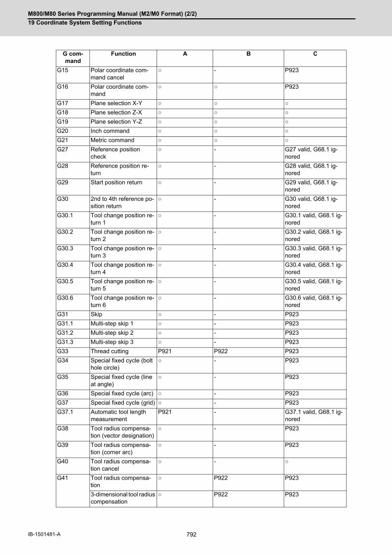
M800/M80 Series Programming Manual (M2/M0 Format) (2/2)
19 Coordinate System Setting Functions
792IB-1501481-A
G15 Polar coordinate com-mand cancel
○ - P923
G16 Polar coordinate com-mand
○ ○ P923
G17 Plane selection X-Y ○ ○ ○
G18 Plane selection Z-X ○ ○ ○
G19 Plane selection Y-Z ○ ○ ○
G20 Inch command ○ ○ ○
G21 Metric command ○ ○ ○
G27 Reference position check
○ - G27 valid, G68.1 ig-nored
G28 Reference position re-turn
○ - G28 valid, G68.1 ig-nored
G29 Start position return ○ - G29 valid, G68.1 ig-nored
G30 2nd to 4th reference po-sition return
○ - G30 valid, G68.1 ig-nored
G30.1 Tool change position re-turn 1
○ - G30.1 valid, G68.1 ig-nored
G30.2 Tool change position re-turn 2
○ - G30.2 valid, G68.1 ig-nored
G30.3 Tool change position re-turn 3
○ - G30.3 valid, G68.1 ig-nored
G30.4 Tool change position re-turn 4
○ - G30.4 valid, G68.1 ig-nored
G30.5 Tool change position re-turn 5
○ - G30.5 valid, G68.1 ig-nored
G30.6 Tool change position re-turn 6
○ - G30.6 valid, G68.1 ig-nored
G31 Skip ○ - P923
G31.1 Multi-step skip 1 ○ - P923
G31.2 Multi-step skip 2 ○ - P923
G31.3 Multi-step skip 3 ○ - P923
G33 Thread cutting P921 P922 P923
G34 Special fixed cycle (bolt hole circle)
○ - P923
G35 Special fixed cycle (line at angle)
○ - P923
G36 Special fixed cycle (arc) ○ - P923
G37 Special fixed cycle (grid) ○ - P923
G37.1 Automatic tool length measurement
P921 - G37.1 valid, G68.1 ig-nored
G38 Tool radius compensa-tion (vector designation)
○ - P923
G39 Tool radius compensa-tion (corner arc)
○ - P923
G40 Tool radius compensa-tion cancel
○ - ○
G41 Tool radius compensa-tion
○ P922 P923
3-dimensional tool radius compensation
○ P922 P923
G com-mand
Function A B C

M800/M80 Series Programming Manual (M2/M0 Format) (2/2)
19 Coordinate System Setting Functions
793 IB-1501481-A
G42 Tool radius compensa-tion
○ P922 P923
3-dimensional tool radius compensation
○ P922 P923
G40.1/G150
Normal line control can-cel
P921 - P923
G41.1/G151
Normal line control Left P921 P922 P923
G42.1/G152
Normal line control Right P921 P922 P923
G43 Tool length compensa-tion
○ ○ P923
G45 Tool position compensa-tion increase
○ - P923
G46 Tool position compensa-tion decrease
○ - P923
G47 Tool position compensa-tion 2-fold increase
○ - P923
G48 Tool position compensa-tion 2-fold decrease
○ - P923
G44 Tool length compensa-tion cancel
○ - P923
G43.1 Tool length compensa-tion along the tool axis
P927 P931 P923
G43.4 Tool center point control type1 ON
P941 P922 P923
G43.5 Tool center point control type2 ON
P941 P922 P923
G50 Scaling cancel P921 - P923
G51 Scaling ON P921 ○ P923
G50.1, G62 Mirror image cancel ○ - P923
G51.1, G62 Mirror image ON ○ ○ P923
G52 Local coordinate system setting
P921 - G52 valid, G68.1 ig-nored
G53 Machine coordinate sys-tem setting
○ - G53 valid, G68.1 ig-nored
G54 Workpiece coordinate system 1 selection
P921 ○ P923
G55 Workpiece coordinate system 2 selection
P921 ○ P923
G56 Workpiece coordinate system 3 selection
P921 ○ P923
G57 Workpiece coordinate system 4 selection
P921 ○ P923
G58 Workpiece coordinate system 5 selection
P921 ○ P923
G59 Workpiece coordinate system 6 selection
P921 ○ P923
G54.1 Extended workpiece co-ordinate system selec-tion
P921 ○ P923
G60 Unidirectional positioning P921 - G60 valid, G68.1 ig-nored
G61 Exact stop check mode ○ ○ P923
G61.1 High-accuracy control ○ ○ P923
G com-mand
Function A B C

M800/M80 Series Programming Manual (M2/M0 Format) (2/2)
19 Coordinate System Setting Functions
794IB-1501481-A
G63 Tapping mode P921 P922 P923
G64 Cutting mode ○ ○ ○
G65 User macro simple call ○ - Update modal only(Coordinate rotation by program)
G66 User macro Modal call A ○ ○ Update modal only(Coordinate rotation by program)
G66.1 User macro modal call B ○ Update modal only(Coordinate rotation by program)
Update modal only(Coordinate rotation by program)
G67 User macro modal call cancel
○ ○ Update modal only af-ter macro (Coordinate rotation by program)
G68.1 Coordinate rotation by program ON
P921 P922 -
3-dimensional coordi-nate conversion ON
○ ○ -
G69.1 Coordinate rotation by programcancel
○ (3-dimensional co-ordinate conversion cancel)
- -
3-dimensional coordi-nate conversion cancel
○ - -
G73 Fixed cycle (step) ○ P922 P923
G74 Fixed cycle (reverse tap-ping)(including synchronous tapping)
○ P922 P923
G76 Fixed cycle (fine boring) ○ P922 P923
G80 Fixed cycle cancel ○ - P923
G81 Fixed cycle (drill/spot drill)
○ P922 P923
G82 Fixed cycle (drill/counter boring)
○ P922 P923
G83 Fixed cycle (deep drill-ing)
○ P922 P923
G84 Fixed cycle (tapping)(including synchronous tapping)
○ P922 P923
G85 Fixed cycle (boring) ○ P922 P923
G86 Fixed cycle (boring) ○ P922 P923
G87 Fixed cycle (back boring) ○ P922 P923
G88 Fixed cycle (boring) ○ P922 P923
G89 Fixed cycle (boring) ○ P922 P923
G90 Absolute value com-mand
○ ○ ○
G91 Incremental value com-mand
○ ○ ○
G92 Coordinate system set-ting
P921 - P923
G94 Asynchronous feed (feed per minute)
○ ○ ○
G95 Synchronous feed (feed per revolution)
○ ○ ○
G com-mand
Function A B C
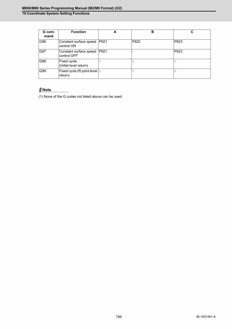
M800/M80 Series Programming Manual (M2/M0 Format) (2/2)
19 Coordinate System Setting Functions
795 IB-1501481-A
(1) None of the G codes not listed above can be used.
G96 Constant surface speed control ON
P921 P922 P923
G97 Constant surface speed control OFF
P921 - P923
G98 Fixed cycle(Initial level return)
○ ○ ○
G99 Fixed cycle (R point level return)
○ ○ ○
G com-mand
Function A B C
Note

M800/M80 Series Programming Manual (M2/M0 Format) (2/2)
19 Coordinate System Setting Functions
796IB-1501481-A
If the first command after the 3-dimensional coordinate conversion command is an arc shape, and the center of the
arc did not change before and after the 3-dimensional coordinate conversion, an arc is drawn. However, an error
will occur in the following cases:
(1) For the arc in which the arc center is specified with I and J, if the center coordinate has deviated by 3-dimensionalcoordinate conversion, a program error (P70 Major arc end position deviation) will occur.
G90 G28 X0 Y0 Z0 ;
F3000 G17 ;
G68.1 X100. Y0. Z0. I0 J0 K1 R0. ;
G02 X100. I50. ;
(2) For the arc in which the arc radius is specified with R, if the center coordinate has deviated by 3-dimensionalcoordinate conversion, a program error (P71 Arc center calculation disabled) will occur.
G90 G28 X0 Y0 Z0 ;
F3000 G17 ;
G68.1 X100. Y0. Z0. I0 J0 K1 R0. ;
G02 X100. R50. ;
Precautions
Precautions related to arc command
No 3-dimensional coordinate con-version
In 3-dimensional coordinate conversion
(a) Arc center (C) Current position (E) End point (Err.) Program error
No 3-dimensional coordinate con-version
In 3-dimensional coordinate conversion
(a) Arc center (C) Current position (E) End point (r) Radius (Err.) Program error
Y
X
(X100, Y0) (X50, Y0)
(a)
(C) (E)
Y Y'
(X100, Y0)
(X'50, Y'0)
(X'100, Y'0)X'X
(C)
(Err.)
(E)
(a)
Y
X(X100, Y0)
= 50(r)
(C) (E)
Y Y'
(X100, Y0)(X'100, Y'0)
X
50
X'(C)
(Err.)
(E)
(r)

M800/M80 Series Programming Manual (M2/M0 Format) (2/2)
19 Coordinate System Setting Functions
797 IB-1501481-A
19.9 Coordinate Rotation by Program; G68.1/G69.1
When machining a complicated shape located in a rotated position in respect to the coordinate system, this function
enables to machine the rotated shape with the program for the shape before rotation on the local coordinate system
and with the rotation angle designated by the program coordinate rotation command.
Select the command plane with G17 to G19.
Function and purpose
Command format
Coordinate rotation ON
G68.1 X__ Y__ R__;
X,Y Rotation center coordinatesTwo axes (X, Y or Z) corresponding to the selected plane are designated with absolute po-sitions.
R Rotation angleThe counterclockwise direction is +.
Coordinate rotation cancel
G69.1;
W: Original local coordinate W': Rotated local coordinate system
r1: Rotation angle (x1, y1) Rotation center
r1(x1,y1)
W
W'
x1
X'
X
Y'
Y
y1
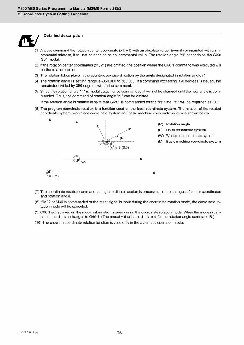
M800/M80 Series Programming Manual (M2/M0 Format) (2/2)
19 Coordinate System Setting Functions
798IB-1501481-A
(1) Always command the rotation center coordinate (x1, y1) with an absolute value. Even if commanded with an in-cremental address, it will not be handled as an incremental value. The rotation angle "r1" depends on the G90/G91 modal.
(2) If the rotation center coordinates (x1, y1) are omitted, the position where the G68.1 command was executed willbe the rotation center.
(3) The rotation takes place in the counterclockwise direction by the angle designated in rotation angle r1.
(4) The rotation angle r1 setting range is -360.000 to 360.000. If a command exceeding 360 degrees is issued, theremainder divided by 360 degrees will be the command.
(5) Since the rotation angle "r1" is modal data, if once commanded, it will not be changed until the new angle is com-manded. Thus, the command of rotation angle "r1" can be omitted.
If the rotation angle is omitted in spite that G68.1 is commanded for the first time, "r1" will be regarded as "0".
(6) The program coordinate rotation is a function used on the local coordinate system. The relation of the rotatedcoordinate system, workpiece coordinate system and basic machine coordinate system is shown below.
(7) The coordinate rotation command during coordinate rotation is processed as the changes of center coordinatesand rotation angle.
(8) If M02 or M30 is commanded or the reset signal is input during the coordinate rotation mode, the coordinate ro-tation mode will be canceled.
(9) G68.1 is displayed on the modal information screen during the coordinate rotation mode. When the mode is can-celed, the display changes to G69.1. (The modal value is not displayed for the rotation angle command R.)
(10) The program coordinate rotation function is valid only in the automatic operation mode.
Detailed description
(R) Rotation angle
(L) Local coordinate system
(W) Workpiece coordinate system
(M) Basic machine coordinate system
(x1,y1)=(0,0)
(R)
(L)
(W)
(M)

M800/M80 Series Programming Manual (M2/M0 Format) (2/2)
19 Coordinate System Setting Functions
799 IB-1501481-A
Program example
Program coordinate rotation by absolute command
N01 G28 X0. Y0.;
N02 G54 G52 X200. Y100. ; Local coordinate designa-tion
N03 T10 ;
N04 G68.1 X-100. Y0. R60. ; Coordinate rotation ON
N05 G22 H101 ; Subprogram execution
N06 G69.1 ; Coordinate rotation cancel
N07 G54 G52 X0 Y0 ; Local coordinate system cancel
N08 M02; End
Subprogram(Shape programmed with original coordinate system) N101 G00 X-100. Y-40.;N102 G83 X-150. R-20. Q-10.F100 ;N103 G00 Y40. ;N104 G83 X-150. R-20. Q-10.F100 ;N105 G23;
(a) Actual machining shape (b) Program coordinate
(W) Local coordinates (before rotation)
- 100.
- 100.
100.
Y
X
100. 200.- 100.N101
N102
N103
N104
Y'X'
60(a)
(b)
(W)

M800/M80 Series Programming Manual (M2/M0 Format) (2/2)
19 Coordinate System Setting Functions
800IB-1501481-A
Command basically two axes in the rotation plane by an absolute value immediately after the coordinate rotation
command.
When commanding one axis only, the following two kinds of operations can be selected by the parameter "#19003
PRG coord rot type".
(1) When "#19003 PRG coord rot type" is "1", the operation is the same as when "N04" is "X50.Y0.". The end pointis calculated on the assumption that the start point rotates along with the coordinates' rotation.
(2) When "#19003 PRG coord rot type" is "0", only axis commanded in N04 (X' Axis) is moved. The start point doesnot rotate along with the coordinate rotation; therefore the end position is calculated based on the current posi-tion on the local coordinate system before rotation.
Operation when only one axis was commanded by the first movement command
N01 G17 G28 X0. Y0.;
N02 G90 G92 G53 X0. Y0.;
N03 G68.1 X40. Y0. R90.; Coordinate rotation ON
N04 X50.;
N05 Y50.;
N06 G69.1; Coordinate rotation can-cel
N07 M02; End
Machine movement path (S) Start point
(a) Center of rotation (b) The start point is rotated virtually
(W) Local coordinate system before rotation (W1) Local coordinate system after rotation
N01 G17 G28 X0. Y0.;
N02 G90 G92 G53 X0. Y0.;
N03 G68.1 X40. Y0. R90.; Coordinate rotation ON
N04 X50.;
N05 Y50.;
N06 G69.1 ; Coordinate rotation can-cel
N07 M02; End
Machine movement path (S) Start point
(a) Center of rotation (b) The start point is rotated virtually
(W) Local coordinate system before rotation (W1) Local coordinate system after rotation
N04
Y
X
X’
Y’
N05
X=-10
Y=10(X’,Y’)=(50,50)
(X’ ,Y’)=(0,0)
X’=50
Y’=50
(X’,Y’)=(40,40)
(a)
(S)
(b)
(W)
(W1)
N04
Y
X
X'
Y'
N05
X=-10
Y=10 X' =50
Y'=50
(X ,Y )=(40,40)
(X',Y')=(0,0)
(X’,Y’)=(50,50)(a)
(S)
(W)
(W1)
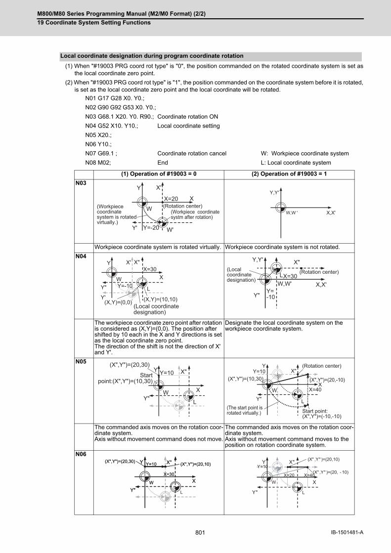
M800/M80 Series Programming Manual (M2/M0 Format) (2/2)
19 Coordinate System Setting Functions
801 IB-1501481-A
(1) When "#19003 PRG coord rot type" is "0", the position commanded on the rotated coordinate system is set asthe local coordinate zero point.
(2) When "#19003 PRG coord rot type" is "1", the position commanded on the coordinate system before it is rotated,is set as the local coordinate zero point and the local coordinate will be rotated.
Local coordinate designation during program coordinate rotation
N01 G17 G28 X0. Y0.;
N02 G90 G92 G53 X0. Y0.;
N03 G68.1 X20. Y0. R90.; Coordinate rotation ON
N04 G52 X10. Y10.; Local coordinate setting
N05 X20.;
N06 Y10.;
N07 G69.1 ; Coordinate rotation cancel W: Workpiece coordinate system
N08 M02; End L: Local coordinate system
(1) Operation of #19003 = 0 (2) Operation of #19003 = 1
N03
Workpiece coordinate system is rotated virtually. Workpiece coordinate system is not rotated.
N04
The workpiece coordinate zero point after rotation is considered as (X,Y)=(0,0). The position after shifted by 10 each in the X and Y directions is set as the local coordinate zero point. The direction of the shift is not the direction of X' and Y'.
Designate the local coordinate system on the workpiece coordinate system.
N05
The commanded axis moves on the rotation coor-dinate system. Axis without movement command does not move.
The commanded axis moves on the rotation coor-dinate system. Axis without movement command moves to the position on rotation coordinate system.
N06
X'
Y'
Y
W
W'
XX=20
Y=-20
(Rotation center)(Workpiece coordinate system is rotatedvirtually.)
(Workpiece coordinatesystm after rotation)
Y,Y'
X,X'W,W '
Y"
X'
Y'
Y
W X
X"
L
(X,Y)=(0,0) (X,Y)=(10,10)
X=30
Y=-10
(Local coordinatedesignation)
Y"
L
X"
X,X'
Y,Y'
Y=-10
X=30W,W'
(Local coordinatedesignation)
(Rotation center)
(X",Y")=(20,30)
Y"
Y=10
X
X"
WL
YStart
point:(X",Y")=(10,30)
Y"
Y
WX
X"
(X",Y")=(20,-10)(X",Y")=(10,30)
L
Y=10
X=40
(Rotation center)
Start point:(X",Y")=(-10,-10)
(The start point is rotated virtually.)
Y"
(X",Y")=(20,30) (X",Y")=(20,10)Y
W X
Y=10
X=30
X"
Y"
(X",Y")=(20,30) (X",Y")=(20,10)Y
W X
Y=10
X=30
X"
L
Y
X
X"
Y"
(X" ,Y" )=(20, - 10)
(X" ,Y" )=(20,10)Y=10
X=40X=20
L
W

M800/M80 Series Programming Manual (M2/M0 Format) (2/2)
19 Coordinate System Setting Functions
802IB-1501481-A
When the coordinate system setting (G92) is executed during program coordinate rotation (G68.1), this program op-
erates same as "Local coordinate designation during program coordinate rotation".
(1) When "#19003 PRG coord rot type" is "0", the position is preset to the current position commanded on the rotatedcoordinate system. (Example) Designation on the coordinate system (X'-Y') after rotation
(2) When "#19003 PRG coord rot type" is "1", the position is preset to the current position commanded on the coor-dinate system before rotation. The coordinate system is rotated after the position is commanded. (Example) Setting on the coordinate system (X-Y) after rotation
<Note>
When "#19003 PRG coord rot type" is "1"and the coordinate system setting (G92) is executed during co-ordinate rotation mode, the rotation center of the program coordinate rotation is not shifted. (It stays atthe same position in respect to the basic machine coordinate system.)
Coordinate system designation during program coordinate rotation
(a) Position after rotation (b) Commanded position (c) G92 shift amount
(a) Position after rotation (b) Commanded position (c) G92 shift amount
G54(0, 0)X
Y
X'
Y'
10.
10.
G68.1 X0 Y0 R30.G00 X10. Y10.G92 X0. Y0.
G54(0, 0) X
Y
X'
Y'
10.10.
(a)
(b)
(c)
G54(0, 0) X
Y
X'
Y'
10.
10.
G68.1 X0 Y0 R30.G00 X10. Y10.G92 X0. Y0.
G54(0, 0) X
Y
X'
Y'
10.
10.
(a)
(b)
(c)
M800/M80 Series Programming Manual (M2/M0 Format) (2/2)
19 Coordinate System Setting Functions
803 IB-1501481-A
(1) Program error (P111) will occur if the plane selection code is commanded during the coordinate rotation mode.
(2) Program error (P485) will occur if polar coordinate interpolation is commanded during the coordinate rotationmode.
(3) Program error (P481) will occur if coordinate rotation is commanded during the polar coordinate interpolationmode.
(4) Program error (P485) will occur if cylindrical interpolation is commanded during the coordinate rotation mode.
(5) Program error (P481) will occur if coordinate rotation is commanded during the cylindrical interpolation mode.
(6) Program error (P34) will occur if the workpiece coordinate system preset (G92.1) is commanded during the co-ordinate rotation mode.
(7) Program error (P34) will occur if high-accuracy control mode, high-speed machining mode, high-speed high-ac-curacy I or II is commanded during the coordinate rotation mode.
(8) Program coordinate rotation and figure rotation cannot be carried out simultaneously. If the coordinate rotationis commanded during the figure rotation and vice versa, a program error (P252) will occur.
(9) If the tool position offset is commanded during the coordinate rotation mode, a program error (P141) will occur.
(1) Always command an absolute value for the movement command immediately after G68.1 and G69.1.
(2) If the manual absolute is ON and interrupted the coordinate rotary axis, then, do not use automatic operation forthe following absolute value command.
(3) The intermediate point during reference position return is the position after the coordinates are rotated.
(4) If the workpiece coordinate system offset amount is changed during the coordinate rotation mode, the rotationcenter for the program coordinate rotation will be shifted. (The center will follow the coordinate system.)
(5) If the workpiece coordinates are changed during the coordinate rotation mode (ex. from G54 to G55), the rotationcenter of the program coordinate rotation will be the position on the coordinate system which the command wasissued. (It stays at the same position in respect to the basic machine coordinate system.)
(6) If coordinate rotation is executed to the G00 command for only one axis, two axes will move. If G00 non-interpo-lation (parameter "#1086 G0Intp" = 1) is set, each axis will move independently at the respective rapid traverserates. If the axis must be moved linearly (interpolated) from the start point to the end point (such as during thehole machining cycle), always turn G00 non-interpolation OFF (parameter "#1086 G0Intp" = 0). The feedrate inthis case is the composite speed of each axis' rapid traverse rate, so the movement speed will be faster thanwhen moving only one axis (before coordinate rotation).
(7) If the coordinate rotation specifications are not provided, a program error (P260) will occur when coordinate ro-tation is commanded.
(8) The compensation during the coordinate rotation mode is carried out to the local coordinate system after coor-dinate rotation. The compensation direction is the coordinate system before rotation.
(9) Mirror image during the coordinate rotation mode is applied to the local coordinate system after coordinate rota-tion.
(10) On the display, the positions after rotation is always displayed on the local coordinate system before rotation.
(11) When the coordinate value variables are read, the positions are all on the coordinate system before rotation.
(12) The coordinates can also be rotated for the parallel axis. Select the plane that contains the parallel axis beforeissuing the G68.1 command. The plane cannot be selected in the same block as the G68.1 command.
(13) The coordinates can be rotated for the rotary axis. The angle will be interpreted as the length when rotating.
Relationship with other functions
Precautions

M800/M80 Series Programming Manual (M2/M0 Format) (2/2)
19 Coordinate System Setting Functions
804IB-1501481-A
19.10 Coordinate Rotation Input by Parameter; G10 I_ J_/K_
If a deviation occurs between the workpiece alignment line and machine coordinate system's coordinate axis when
the workpiece is mounted, the machine can be controlled by rotating the machining program coordinates according
to the workpiece alignment line deviation. The coordinate rotation amount is set with the parameters. The parame-
ters can also be set with the G10 command.
To enable this function, the following conditions must be satisfied:
(1) The parameter "#8116 CoordRotPara invd" is set to "0".
(2) The parameter "#8627 Coord rot angle" is set. Alternatively, "#8625 Coord rot vctr(H)" and "#8626 Coord rot vc-tr(V)" are set.
Function and purpose
(a) Center of rotation (b) Rotation angle
Ym
Xm
G56
G54
G55
G57
W1'
W2'
W3'
W4'
M
W1
W2
(a)(b)

M800/M80 Series Programming Manual (M2/M0 Format) (2/2)
19 Coordinate System Setting Functions
805 IB-1501481-A
Parameters specified in the parameter setting screen can be changed from the machining program.
Refer to the Instruction Manual for settings and contents of the parameters.
Command format
G10 I__ J__ ;
G10 K__ ;
I Horizontal vector. Command a value corresponding to the parameter "#8625 Coord rot vc-tr(H)". Command range: -99999.999 to 99999.999The value of "#8627 Coord rot angle" is automatically calculated when commanding vector contents.
J Vertical vector. Command a value corresponding to the parameter "#8626 Coord rot vctr(V)". Command range: -99999.999 to 99999.999The value of "#8627 Coord rot angle" is automatically calculated when commanding vector contents.
K Rotation angle Command a value corresponding to the parameter "#8627 Coord rot angle". Command range: -360.000 to 360.000"#8625 Coord rot vctr(H)" and "#8626 Coord rot vctr(V)" are set to "0" when commanding the coordinate rotation angle.

M800/M80 Series Programming Manual (M2/M0 Format) (2/2)
19 Coordinate System Setting Functions
806IB-1501481-A
(1) As for the coordinate rotation center position, designate the position on the machine coordinate system.
(2) All workpiece coordinate systems from G54 to G59, G54.1 rotate with the rotation command. While the machine coordinate system does not rotate, it can be understood that there is a hypothetical machinecoordinate system in the coordinate system after rotation.
(3) When parameter settings are configured, their setting values become valid at the following timings.Automatic operation: The setting values become valid from the next block after parameter settings have
been configured.Manual operation: The setting values become valid if the PLC signal (manual feed coordinate switching
for coordinate rotation by parameter) is set to ON after parameter settings have been configured.
(1) Set the parameters "#8623 Coord rot centr(H)" and "#8624 Coord rot centr(V)" at the position of the machinecoordinate system.
(2) The workpiece coordinate system set on the orthogonal coordinate system rotates around the rotation center.
(3) The machine coordinate system does not rotate.
The coordinate rotation starts when the following parameters are changed. (When the same value is reset to the
parameter, it is not considered as change.)
When the parameter "#8116 CoordRotPara invd" is "1" or the parameter "#8627 coordinate rotation angle" is "0",
coordinate rotation will not start.
#8621 Coord rot plane (H)
#8622 Coord rot plane (V)
#8623 Coord rot centr (H)
#8624 Coord rot centr (V)
#8625 Coord rot vctr (H)
#8626 Coord rot vctr (V)
#8627 Coord rot angle
#8116 CoordRotPara invd (*1)
(*1) The parameter "#8116 CoordRotPara invd" is common to all part systems. Therefore, before designating this
parameter, set "0" to the parameter "#8627 Coord rot angle" in part systems in which "coordinate rotation by
parameter" is not used.
Detailed description
Concept of coordinate system
Workpiece coordinate system setting Workpiece coordinate system after coordinate rotation by parameter
Coordinate rotation start
#8623
G55G54
#8624
EXT (External workpiece coordinate offset)
G92 (Coordinate system shift)
Workpiece coordinate zero point
Basic machine coordinate zero point
Rotation center

M800/M80 Series Programming Manual (M2/M0 Format) (2/2)
19 Coordinate System Setting Functions
807 IB-1501481-A
When coordinate rotation is enabled, setting the parameter "#8116 CoordRotPara invd" to "1" or "#8627 Coord rot
angle" to "0", and then issuing the following movement command cancels the parameter coordinate rotation.
The coordinate rotation by parameter is temporarily canceled when in (1) or (2) as follows.
(1) Reference position return command (G28, G30)If reference position return is performed on any of the axes in the rotated coordinate system (horizontal axis orvertical axis), both of the two axes will temporarily cancel the coordinate rotation. However moving to the intermediate point will not be temporarily canceled, but it will keep operating.
(2) Basic machine coordinate system selection (G53)Only the commanded axis of basic machine coordinate system selection (G53) will be temporarily cancel thecoordinate rotation.
In items (1) and (2) above, when the coordinate rotation by parameter is canceled temporarily, the counter display
follows the setting of the parameter "#11086 PRM coordinate rotation counter".
Coordinate rotation stop (cancel)
Coordinate rotation temporary cancel

M800/M80 Series Programming Manual (M2/M0 Format) (2/2)
19 Coordinate System Setting Functions
808IB-1501481-A
When issuing a movement command for the first time after coordinate rotation has been started, ended, reset, or
returned from temporary cancel, issue the command in G00 or G01 mode by designating the two axes configuring
the rotation plane using absolute values.
Note that, if the command that is issued for the first time after coordinate rotation has been started, ended, or re-
turned from temporary cancel is any of the following, the operation differs depending on the setting of the parameter
"#19008 PRM coord rot type".
(1) Command to an axis configuring the rotation plane by the absolute value
(2) Command by incremental value
(3) Circular interpolation command
Operation example
First movement command after coordinate rotation start/end/temporary cancel
[Parameters]#8621 Coord rot plane (H) = X#8622 Coord rot plane (V) = Y#8623 Coord rot centr (H) = 30.0#8624 Coord rot centr (V) = 60.0#8627 Coord rot angle = 0.0[G54 workpiece coordinate system offset]X = 10.0Y = 10.0
[Machining program]N01 G17 G28 X0. Y0.;N02 G54 G90 X0. Y0.;N03 G10 K90.; (Coordinate rotation start)N04 G54 G90 G00 X20. Y10.; (Absolute value com-mand to two axes):
(W): Workpiece coordinate system before rotation(W1): Workpiece coordinate system after rotation(a): Rotation center(b): Actual axis position(c): Workpiece coordinate system zero point after co-ordinate rotation(d): N04 Commanded path(e): N04 Actual movement path(f): N04 End point
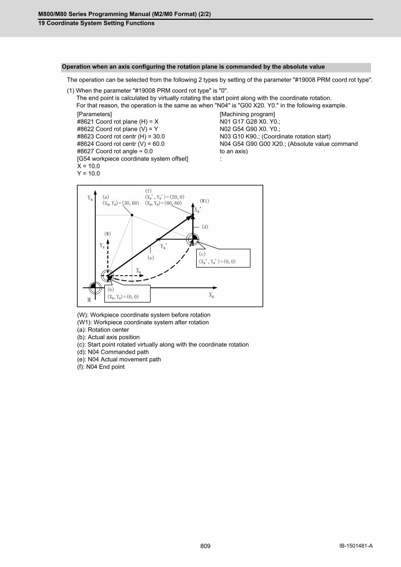
M800/M80 Series Programming Manual (M2/M0 Format) (2/2)
19 Coordinate System Setting Functions
809 IB-1501481-A
The operation can be selected from the following 2 types by setting of the parameter "#19008 PRM coord rot type".
(1) When the parameter "#19008 PRM coord rot type" is "0".The end point is calculated by virtually rotating the start point along with the coordinate rotation. For that reason, the operation is the same as when "N04" is "G00 X20. Y0." in the following example.
Operation when an axis configuring the rotation plane is commanded by the absolute value
[Parameters]#8621 Coord rot plane (H) = X#8622 Coord rot plane (V) = Y#8623 Coord rot centr (H) = 30.0#8624 Coord rot centr (V) = 60.0#8627 Coord rot angle = 0.0[G54 workpiece coordinate system offset]X = 10.0Y = 10.0
[Machining program]N01 G17 G28 X0. Y0.;N02 G54 G90 X0. Y0.;N03 G10 K90.; (Coordinate rotation start)N04 G54 G90 G00 X20.; (Absolute value command to an axis):
(W): Workpiece coordinate system before rotation(W1): Workpiece coordinate system after rotation(a): Rotation center(b): Actual axis position(c): Start point rotated virtually along with the coordinate rotation(d): N04 Commanded path(e): N04 Actual movement path(f): N04 End point

M800/M80 Series Programming Manual (M2/M0 Format) (2/2)
19 Coordinate System Setting Functions
810IB-1501481-A
(2) When the parameter "#19008 PRM coord rot type" is "1".The start point does not rotate along with the coordinate rotation; therefore the end point position is calculatedbased on the current position on the local coordinate system before rotation. For that reason, only the axis commanded in N04 (X' axis) is moved.
[Parameters]#8621 Coord rot plane (H) = X#8622 Coord rot plane (V) = Y#8623 Coord rot centr (H) = 30.0#8624 Coord rot centr (V) = 60.0#8627 Coord rot angle = 0.0[G54 workpiece coordinate system offset]X = 10.0Y = 10.0
[Machining program]N01 G17 G28 X0. Y0.;N02 G54 G90 X0. Y0.;N03 G10 K90.; (Coordinate rotation start)N04 G54 G90 G00 X20.; (Absolute value command to an axis):
(W): Workpiece coordinate system before rotation(W1): Workpiece coordinate system after rotation(a): Rotation center(b): The actual axis position and start point position are the same(d): N04 Commanded path(e): N04 Actual movement path(f): N04 End point
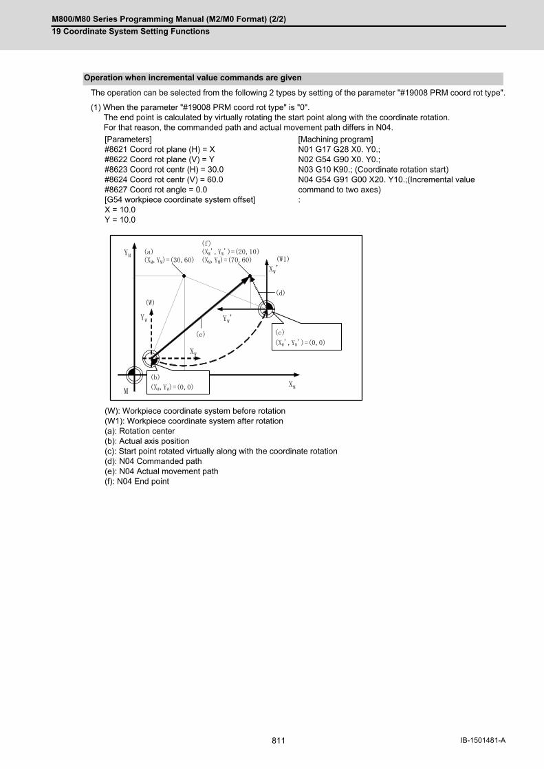
M800/M80 Series Programming Manual (M2/M0 Format) (2/2)
19 Coordinate System Setting Functions
811 IB-1501481-A
The operation can be selected from the following 2 types by setting of the parameter "#19008 PRM coord rot type".
(1) When the parameter "#19008 PRM coord rot type" is "0".The end point is calculated by virtually rotating the start point along with the coordinate rotation. For that reason, the commanded path and actual movement path differs in N04.
Operation when incremental value commands are given
[Parameters]#8621 Coord rot plane (H) = X#8622 Coord rot plane (V) = Y#8623 Coord rot centr (H) = 30.0#8624 Coord rot centr (V) = 60.0#8627 Coord rot angle = 0.0[G54 workpiece coordinate system offset]X = 10.0Y = 10.0
[Machining program]N01 G17 G28 X0. Y0.;N02 G54 G90 X0. Y0.;N03 G10 K90.; (Coordinate rotation start)N04 G54 G91 G00 X20. Y10.;(Incremental value command to two axes):
(W): Workpiece coordinate system before rotation(W1): Workpiece coordinate system after rotation(a): Rotation center(b): Actual axis position(c): Start point rotated virtually along with the coordinate rotation(d): N04 Commanded path(e): N04 Actual movement path(f): N04 End point

M800/M80 Series Programming Manual (M2/M0 Format) (2/2)
19 Coordinate System Setting Functions
812IB-1501481-A
(2) When the parameter "#19008 PRM coord rot type" is "1".The start point does not rotate along with the coordinate rotation; therefore the end point position is calculatedbased on the current position on the local coordinate system before rotation. For that reason, the commanded path and actual movement path are the same in N04.
[Parameters]#8621 Coord rot plane (H) = X#8622 Coord rot plane (V) = Y#8623 Coord rot centr (H) = 30.0#8624 Coord rot centr (V) = 60.0#8627 Coord rot angle = 0.0[G54 workpiece coordinate system offset]X = 10.0Y = 10.0
[Machining program]N01 G17 G28 X0. Y0.;N02 G54 G90 X0. Y0.;N03 G10 K90.; (Coordinate rotation start)N04 G54 G91 G00 X20. Y10.;(Incremental value command to two axes):
(W): Workpiece coordinate system before rotation(W1): Workpiece coordinate system after rotation(a): Rotation center(b): The actual axis position and start point position are the same(d): N04 Commanded path(e): N04 Actual movement path(f): N04 End point

M800/M80 Series Programming Manual (M2/M0 Format) (2/2)
19 Coordinate System Setting Functions
813 IB-1501481-A
The operation can be selected from the following 2 types by setting of the parameter "#19008 PRM coord rot type".
(1) When the parameter "#19008 PRM coord rot type" is "0".The end point of an arc is calculated from the position to which the start point is virtually rotated along with thecoordinate rotation. In this case, the start point of an arc is not rotating but the end point of an arc is rotating, so it may cause "P70:Arc end point deviation large" due to the difference in radius between the start and end points.
Operation when circular interpolation is commanded
[Parameters]#1084 Arc error = 0.1#8621 Coord rot plane (H) = X#8622 Coord rot plane (V) = Y#8623 Coord rot centr (H) = 30.0#8624 Coord rot centr (V) = 60.0#8627 Coord rot angle = 0.0[G54 workpiece coordinate system offset]X = 10.0Y = 10.0
[Machining program]N01 G17 G28 X0. Y0.;N02 G54 G90 X0. Y0.;N03 G10 K90.; (Coordinate rotation start)N04 G54 G91 G03 X20. R10. F500; (Circular interpo-lation command):
(W): Workpiece coordinate system before rotation(W1): Workpiece coordinate system after rotation(a): Rotation center(b): Actual axis position(c): Start point rotated virtually along with the coordinate rotation(d): N04 Commanded path(f): End point calculated from the virtually rotated start point(g): Start point radius(h): End point radiusAs the difference in radius between the start and end points is bigger than "#1084 RadErr", it causes pro-gram error (P70).

M800/M80 Series Programming Manual (M2/M0 Format) (2/2)
19 Coordinate System Setting Functions
814IB-1501481-A
(2) When the parameter "#19008 PRM coord rot type" is "1".The start point and end point of an arc are calculated from the current position on the workpiece coordinate sys-tem before the coordinate rotation and the circular interpolation is performed from the current position to the endpoint.
[Parameters]#1084 Arc error = 0.1#8621 Coord rot plane (H) = X#8622 Coord rot plane (V) = Y#8623 Coord rot centr (H) = 30.0#8624 Coord rot centr (V) = 60.0#8627 Coord rot angle = 0.0[G54 workpiece coordinate system offset]X = 10.0Y = 10.0
[Machining program]N01 G17 G28 X0. Y0.;N02 G54 G90 X0. Y0.;N03 G10 K90.; (Coordinate rotation start)N04 G54 G91 G03 X20. R10. F500; (Circular interpo-lation command):
(W): Workpiece coordinate system before rotation(W1): Workpiece coordinate system after rotation(a): Rotation center(b): The actual axis position and start point position are the same(d): N04 Commanded path(e): N04 Actual movement path(f): N04 End point

M800/M80 Series Programming Manual (M2/M0 Format) (2/2)
19 Coordinate System Setting Functions
815 IB-1501481-A
When rotation angle "0" is commanded during coordinate rotation, it will be canceled by next movement command
regardless of G90 and G91.
The calculation of the end point will be different by setting of the parameter "#19008 PRM coord rot type".
(1) When the parameter "#19008 PRM coord rot type" is "0".The end point is calculated on the assumption that the start point rotates along with the coordinate rotation can-cel. Program the first movement command after coordinate rotation cancel either G00 or G01 mode.
First movement command after coordinate rotation cancel
[Parameters]#8621 Coord rot plane (H) = X#8622 Coord rot plane (V) = Y#8623 Coord rot centr (H) = 30.0#8624 Coord rot centr (V) = 60.0#8627 Coord rot angle = 90.0[G54 workpiece coordinate system offset]X = 10.0Y = 10.0
[Machining program]N01 G54 G90 X50.Y50.;N02 G54 G90 X0. Y0.;N03 G10 K0.; (Coordinate rotation cancel)N04 G91 G00 X20. Y10.; (Incremental value com-mand to two axes):
(W): Workpiece coordinate system before rotation(W1): Workpiece coordinate system after rotation(a): Rotation center(b): Actual axis position(c): Start point rotated virtually along with the coordinate rotation cancel(d): N04 Commanded path(e): N04 Actual movement path(f): N04 End point
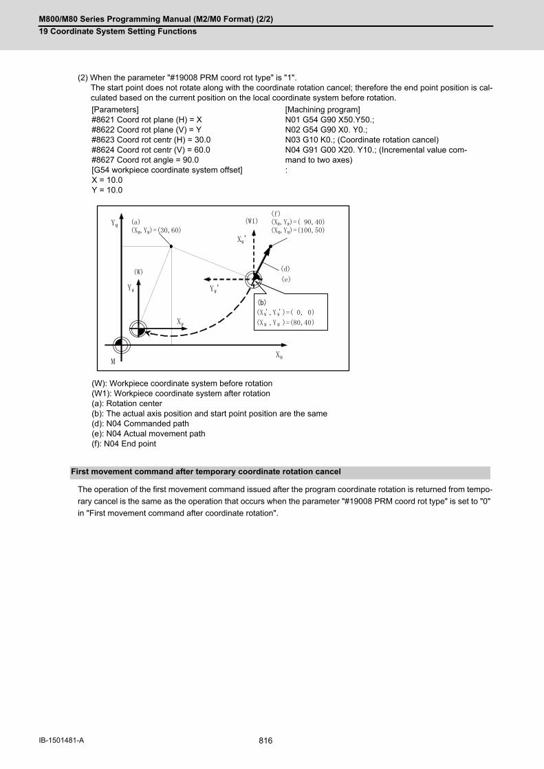
M800/M80 Series Programming Manual (M2/M0 Format) (2/2)
19 Coordinate System Setting Functions
816IB-1501481-A
(2) When the parameter "#19008 PRM coord rot type" is "1".The start point does not rotate along with the coordinate rotation cancel; therefore the end point position is cal-culated based on the current position on the local coordinate system before rotation.
The operation of the first movement command issued after the program coordinate rotation is returned from tempo-
rary cancel is the same as the operation that occurs when the parameter "#19008 PRM coord rot type" is set to "0"
in "First movement command after coordinate rotation".
[Parameters]#8621 Coord rot plane (H) = X#8622 Coord rot plane (V) = Y#8623 Coord rot centr (H) = 30.0#8624 Coord rot centr (V) = 60.0#8627 Coord rot angle = 90.0[G54 workpiece coordinate system offset]X = 10.0Y = 10.0
[Machining program]N01 G54 G90 X50.Y50.;N02 G54 G90 X0. Y0.;N03 G10 K0.; (Coordinate rotation cancel)N04 G91 G00 X20. Y10.; (Incremental value com-mand to two axes):
(W): Workpiece coordinate system before rotation(W1): Workpiece coordinate system after rotation(a): Rotation center(b): The actual axis position and start point position are the same(d): N04 Commanded path(e): N04 Actual movement path(f): N04 End point
First movement command after temporary coordinate rotation cancel
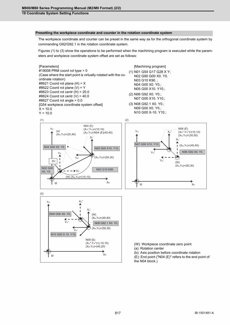
M800/M80 Series Programming Manual (M2/M0 Format) (2/2)
19 Coordinate System Setting Functions
817 IB-1501481-A
The workpiece coordinate and counter can be preset in the same way as for the orthogonal coordinate system by
commanding G92/G92.1 in the rotation coordinate system.
Figures (1) to (3) show the operations to be performed when the machining program is executed while the param-
eters and workpiece coordinate system offset are set as follows:
Presetting the workpiece coordinate and counter in the rotation coordinate system
[Parameters]#19008 PRM coord rot type = 0(Case where the start point is virtually rotated with the co-ordinate rotation)#8621 Coord rot plane (H) = X#8622 Coord rot plane (V) = Y#8623 Coord rot centr (H) = 20.0#8624 Coord rot centr (V) = 40.0#8627 Coord rot angle = 0.0[G54 workpiece coordinate system offset]X = 10.0Y = 10.0
[Machining program]
(1) N01 G54 G17 G28 X Y;N02 G90 G00 X0. Y0.N03 G10 K90. ;N04 G00 X0. Y0.;N05 G00 X10. Y10.;
(2) N06 G92 X0. Y0.;N07 G00 X10. Y10.;
(3) N08 G92.1 X0. Y0.;N09 G00 X0. Y0.;N10 G00 X-10. Y10.;
(W): Workpiece coordinate zero point(a): Rotation center(b): Axis position before coordinate rotation(E): End point ("N04 (E)" refers to the end point of the N04 block.)
(1) (2)
(b)
YM
Xw’
N04 (E)(XW',YW')=(10,10)(XM,YM)=N04 (E)(40,40)(a)
(XM,YM)=(20,40)
N05 G00 X10. Y10.
YW’
YW
XM
XWN03 G10 K90.
N04 G00 X0. Y0.
N02 G00 X0. Y0.
(XM,YM)=(50,30)
(W) (XM,YM)=(10,10)
M
YM Xw’’
Xw’
XM
YW’’
YW’
N06 G92 X0. Y0.
N07 G00 X10. Y10.
M
N06 (E)(XW'',YW'')=(10,10)(XM,YM)=(30,50)
(XM,YM)=(40,40)
(W)(XM,YM)=(50,30)
YM Xw’’
Xw’
(3)
XM
YW’’
YW’
N08 G92.1 X0. Y0.
N10 G00 X-10. Y10.
N09 G00 X0. Y0.
M
(W)(XM,YM)=(40,40)
(XM,YM)=(50,30)
N09 (E)(XW'',YW'')=(-10,10)(XM,YM)=(40,20)
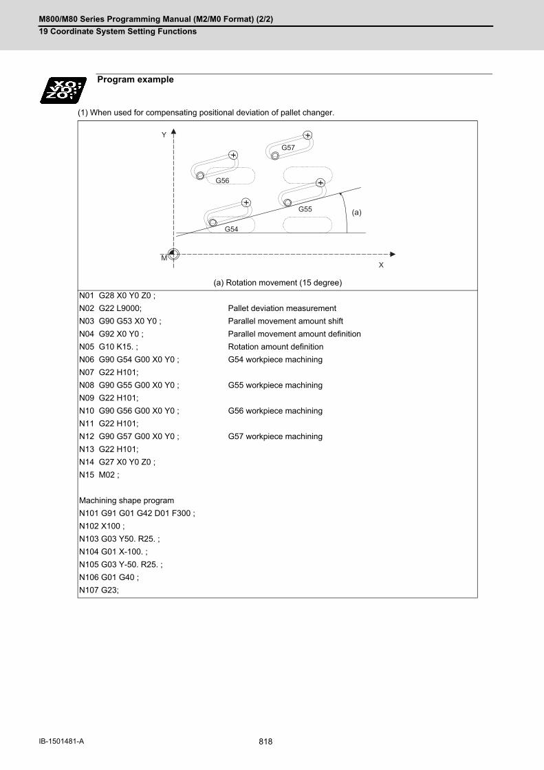
M800/M80 Series Programming Manual (M2/M0 Format) (2/2)
19 Coordinate System Setting Functions
818IB-1501481-A
(1) When used for compensating positional deviation of pallet changer.
Program example
(a) Rotation movement (15 degree)
N01 G28 X0 Y0 Z0 ;
N02 G22 L9000; Pallet deviation measurement
N03 G90 G53 X0 Y0 ; Parallel movement amount shift
N04 G92 X0 Y0 ; Parallel movement amount definition
N05 G10 K15. ; Rotation amount definition
N06 G90 G54 G00 X0 Y0 ; G54 workpiece machining
N07 G22 H101;
N08 G90 G55 G00 X0 Y0 ; G55 workpiece machining
N09 G22 H101;
N10 G90 G56 G00 X0 Y0 ; G56 workpiece machining
N11 G22 H101;
N12 G90 G57 G00 X0 Y0 ; G57 workpiece machining
N13 G22 H101;
N14 G27 X0 Y0 Z0 ;
N15 M02 ;
Machining shape program
N101 G91 G01 G42 D01 F300 ;
N102 X100 ;
N103 G03 Y50. R25. ;
N104 G01 X-100. ;
N105 G03 Y-50. R25. ;
N106 G01 G40 ;
N107 G23;
Y
XM
+
+
+
+
G56
G57
G54
G55 (a)
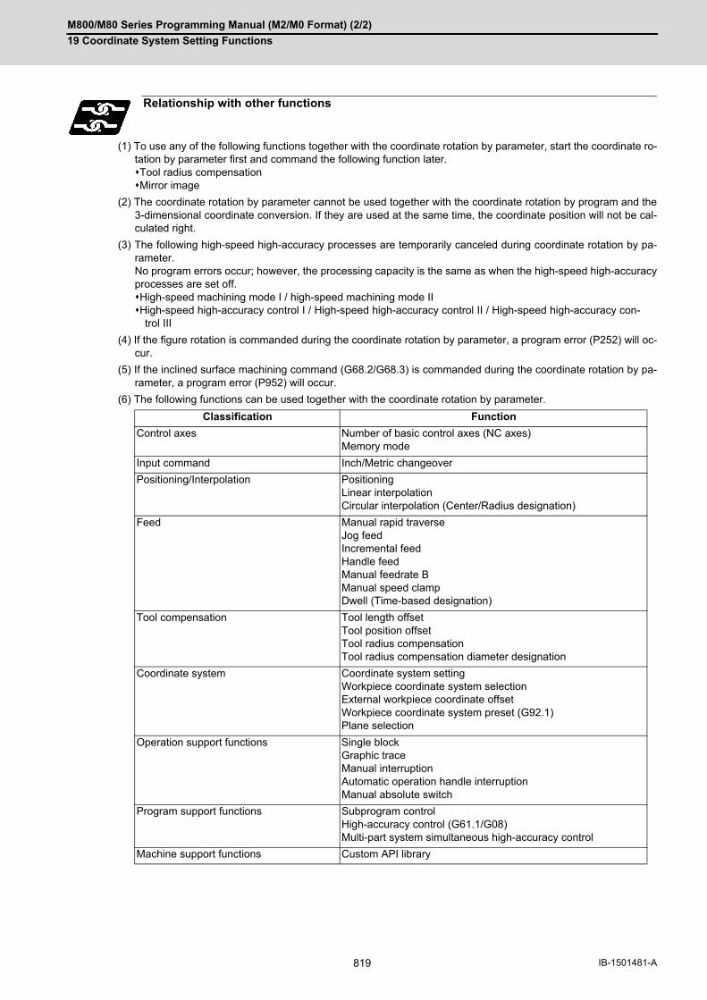
M800/M80 Series Programming Manual (M2/M0 Format) (2/2)
19 Coordinate System Setting Functions
819 IB-1501481-A
(1) To use any of the following functions together with the coordinate rotation by parameter, start the coordinate ro-tation by parameter first and command the following function later.Tool radius compensationMirror image
(2) The coordinate rotation by parameter cannot be used together with the coordinate rotation by program and the3-dimensional coordinate conversion. If they are used at the same time, the coordinate position will not be cal-culated right.
(3) The following high-speed high-accuracy processes are temporarily canceled during coordinate rotation by pa-rameter. No program errors occur; however, the processing capacity is the same as when the high-speed high-accuracyprocesses are set off.High-speed machining mode I / high-speed machining mode IIHigh-speed high-accuracy control I / High-speed high-accuracy control II / High-speed high-accuracy con-
trol III
(4) If the figure rotation is commanded during the coordinate rotation by parameter, a program error (P252) will oc-cur.
(5) If the inclined surface machining command (G68.2/G68.3) is commanded during the coordinate rotation by pa-rameter, a program error (P952) will occur.
(6) The following functions can be used together with the coordinate rotation by parameter.
Relationship with other functions
Classification Function
Control axes Number of basic control axes (NC axes)Memory mode
Input command Inch/Metric changeover
Positioning/Interpolation PositioningLinear interpolationCircular interpolation (Center/Radius designation)
Feed Manual rapid traverseJog feedIncremental feedHandle feedManual feedrate BManual speed clampDwell (Time-based designation)
Tool compensation Tool length offsetTool position offsetTool radius compensationTool radius compensation diameter designation
Coordinate system Coordinate system settingWorkpiece coordinate system selectionExternal workpiece coordinate offsetWorkpiece coordinate system preset (G92.1)Plane selection
Operation support functions Single blockGraphic traceManual interruptionAutomatic operation handle interruptionManual absolute switch
Program support functions Subprogram controlHigh-accuracy control (G61.1/G08)Multi-part system simultaneous high-accuracy control
Machine support functions Custom API library

M800/M80 Series Programming Manual (M2/M0 Format) (2/2)
19 Coordinate System Setting Functions
820IB-1501481-A
(1) If rotation angle zero is commanded while carrying out coordinate rotation, it will be canceled at the next move-ment command regardless of the G90 or G91.
(2) Command the first movement after this command with the G00 or G01 mode. If an arc command is issued, thearc start point will not be rotated. However, only the arc end point will rotate. This will cause the start point radiusand end point radius to differ, and the program error (P70) will occur.
(3) When data has been input using the data input/output function, it is recognized that the parameter "#8627 Coordrot angle" has been input, and automatic calculation from the values of "#8625 Coord rot vctr(H)" and "#8626Coord rot vctr(V)" is not carried out.
(4) Do not use this command with G54 to G59 and G90, G91. If used, the command will not be reflected correctly.
(5) If both vertical / horizontal vectors (I,J) and rotation angle are commanded, the rotation angle will be given thepriority.
Precautions

M800/M80 Series Programming Manual (M2/M0 Format) (2/2)
19 Coordinate System Setting Functions
821 IB-1501481-A
19.11 Scaling; G50/G51
By multiplying the moving axis command values within the range specified under this command by the factor, the
shape commanded by the program can be enlarged or reduced to the desired size.
Function and purpose
Command format
Scaling ON (set the common scaling factor to the three basic axes)
G51 X__ Y__ Z__ P__ ;
X,Y,Z Scaling center coordinates
P Scaling factor
sc : Scaling center
p1,p2,p3: Program shape s1,s2,s3: Shape after scaling
Scaling ON (When setting the scaling factor to each of the three basic axes)
G51 X__ Y__ Z__ I__ J__ K__ ;
X,Y,Z Scaling center coordinates
I Scaling factor of basic 1st axis
J Scaling factor of basic 2nd axis
K Scaling factor of basic 3rd axis
Scaling cancel
G50 ;
sc s1
s3s2
p2
p1
p3
Y
Xx1
y1

M800/M80 Series Programming Manual (M2/M0 Format) (2/2)
19 Coordinate System Setting Functions
822IB-1501481-A
Commanding G51 selects the scaling mode. The G51 command only specifies the scaling axis, its center and factor,
and does not move the axis.
Though the scaling mode is selected by the G51 command, the axis actually valid for scaling is the axis where the
scaling center has been specified.
(1) Scaling center
- Specify the scaling center in accordance with the then absolute/incremental mode (G90/G91).
- The scaling center must be specified also when the current position is defined as a center.
- As described above, the axis valid for scaling is only the axis whose center has been specified.
(2) Scaling factor
- Use the address P or I, J, K to specify the scaling factor.
- Minimum command unit : 0.000001
- Command range: Both -99999999 to 99999999 (-99.999999 to 99.999999 times) and -99.999999 to 99.999999
is valid, but the decimal point command is valid only after the G51 command.
- When the factor is not specified in the same block as G51, the factor set with the parameter "#8072 SCALING
P" is used.
- When the address P and the address I, J, K are commanded in a same block, a factor specified by the address
I, J, K is applied for the basic three axes. And a factor specified by the address P is applied for other axes.
- If changed during the scaling mode, the value of this parameter will not become valid. Scaling is performed with
the setting value that was used when G51 was commanded.
- When the factor is not specified in either the program nor parameter, it is calculated as 1.
(3) A program error will occur in the following cases.
- Scaling was commanded though there was no scaling specification. (P350) - The upper limit of the factor com-
mand range was exceeded in the same block as G51. (P35) (When using the machining parameter scaling fac-
tor, the factor is calculated as 1, when -0.000001 < factor < 0.000001, or the factor is more than 99.999999 or
less than -99.999999.)
When G50 is commanded, scaling is canceled.
Detailed description
Specifying the scaling axis, scaling center and its factor
Scaling cancel

M800/M80 Series Programming Manual (M2/M0 Format) (2/2)
19 Coordinate System Setting Functions
823 IB-1501481-A
(Example 1)
<Program>
Program example
Scaling center
Program path after 1/2 scaling Tool path after 1/2 scaling
Program path when scaling is not applied Tool path when scaling is not applied
N01 G92 X0 Y0 Z0;
N02 G90 G51 X-100. Y-100. P0.5;
N03 G00 G43 Z-200. H02;
N04 G41 X-50. Y-50. D01;
N05 G01 Z-250. F1000;
N06 Y-150. F200;
N07 X-150.;
N08 G02 Y-50. J50.;
N09 G01 X-50.;
N10 G00 G44 Z0;
N11 G40 G50 X0 Y0;
N12 M02;
-200. -150. -100. -50.
Y
X
-50.
-100.
-150.
N03N11N09
N08
N07D01=25.000
N06

M800/M80 Series Programming Manual (M2/M0 Format) (2/2)
19 Coordinate System Setting Functions
824IB-1501481-A
(1) G27 reference position check command
When G27 is commanded during scaling, scaling is canceled at completion of the command.
(2) Reference position return command (G28, G29, G30)
When the G28, G30 or reference position return command is issued during scaling, scaling is canceled at the
intermediate point and the axis returns to the reference position. When the midpoint is to be ignored, the axis
returns to the reference point directly.
When G29 is commanded during scaling, scaling is applied to the movement after the midpoint.
(3) G60 (unidirectional positioning) command
If the G60 (unidirectional positioning) command is given during scaling, scaling is applied to the final positioning
point and is not applied to the creep amount. Namely, the creep amount is uniform regardless of scaling.
(4) Workpiece coordinate system switching
When the workpiece coordinate system is switched during scaling, the scaling center is shifted by the difference
between the offset amounts of the new and old workpiece coordinate systems.
(5) During figure rotation
When figure rotation is commanded during scaling, scaling is applied to the center of the figure rotation and the
rotation radius.
(6) Scaling command in figure rotation subprogram
By commanding the scaling in the subprogram of the figure rotation, scaling can be applied only to the shape
designated by the subprogram, not to the rotation radius of the figure rotation.
(7) During coordinate rotation
When scaling is commanded during coordinate rotation, the scaling center rotates. Scaling is executed at that
rotated scaling center.
(8) G51 command
When the G51 command is issued during the scaling mode, the axis whose center was newly specified is also
made valid for scaling. Also, the factor under the latest G51 command is made valid.
(1) Scaling is not applied to the compensation amounts of tool radius compensation, tool position compensation,
tool length compensation and the like. (Compensation is calculated for the shape after scaling.)
(2) Scaling is valid for only the movement command in automatic operation. It is invalid for manual movement.
(3) For X, Y and Z, scaling is valid for only the specified axes and is not applied to unspecified axes.
(4) When an arc is commanded and scaling is valid for one of the two axes configuring the arc plane, a program
error (P70) will occur.
(5) When M02 or M30 is commanded, or when NC reset is carried out during the scaling mode, the mode switches
to a cancel mode.
(6) When the coordinate system is shifted (G92, G52 command) during scaling, the scaling center is also shifted by
the difference amount.
(7) If manual interruption is made during scaling, manual ABS selection is ignored for the movement followed by an
incremental value command and operation performed is the same as in manual ABS OFF.
Relationship with other functions
Precautions

M800/M80 Series Programming Manual (M2/M0 Format) (2/2)
19 Coordinate System Setting Functions
825 IB-1501481-A
19.12 Reference Position (Zero Point) Return; G28, G29
After the commanded axes have been positioned by G00, they are returned respectively at rapid traverse to the first
reference position when G28 is commanded. By commanding G29, the axes are first positioned independently at
high speed to the G28 or G30 intermediate point and then positioned by G00 to the commanded position.
Function and purpose
(R1) 1st reference position (R2) 2nd reference position
(R3) 3rd reference position (R4) 4th reference position
(S) Start point (CP) Intermediate point
Command format
G28 Xx1 Yy1 Zz1 αα1; ... Automatic reference position return
X, Y, Z, α Coordinate value of the intermediate point (α is an additional axis)
G29 Xx2 Yy2 Zz2 αα2; ... Start point return
X, Y, Z, α Coordinate value of the end point (α is an additional axis)
(0,0,0,0)
G28G28
G29
G29
G30
G30P3G30P4
G30P2
(x1,y 1,z 1, 1)
(x2,y 2,z 2, 2)
(x3,y 3,z 3, 3)
(R1)
(R3)
(R2)
(S)
(R4)
(CP)
M800/M80 Series Programming Manual (M2/M0 Format) (2/2)
19 Coordinate System Setting Functions
826IB-1501481-A
(1)The G28 command is equivalent to the following:
G00 Xx1 Yy1 Zz1 α α1;
G00 Xx3 Yy3 Zz3 α α3;
where Xx3 Yy3 Zz3 α3 are the coordinate values of the reference position that are set in parameters "#2037
G53ofs" for the distance from the basic machine coordinate system zero point as specified by the MTB.
(2)After the power has been switched on, the axes that have not been subject to manual reference position return
are returned by the dog type of return just as with the manual type. In this case, the return direction is regarded
as the command sign direction. If the return type is straight-type return, the return direction will not be checked.
For the second and subsequence returns, the return is made at high speed to the reference (zero) position that
was stored at the first time and the direction is not checked.
(3)When reference position return is completed, the zero point arrival output signal is output and also #1 appears at
the axis name line on the setting and display unit screen.
(4)The G29 command is equivalent to the following:
G00 Xx1 Yy1 Zz1 α α1;
G00 Xx2 Yy2 Zz2 α α2;
Rapid traverse (non-interpolation type) applies independently to each axis for the positioning from the reference
position to the intermediate point.
In this case, x1 y1 z1 and α1 are the coordinate value of the G28 or G30 intermediate point.
(5)Program error (P430) occurs when G29 is executed without executing automatic reference position (zero point)
return (G28) after the power has been turned ON.
(6)When the Z axis is canceled, the movement of the Z axis to the intermediate point will be ignored, and only the
position display for the following positioning will be executed. (The machine itself will not move.)
(7)The intermediate point coordinates (x1, y1, z1, α1) of the positioning point are assigned by the position command
modal. (G90, G91).
(8)G29 is valid for either G28 or G30 but the commanded axes are positioned after a return has been made to the
latest intermediate point.
(9)The tool compensation will be canceled during reference position return unless it is already canceled, and the
compensation amount will be cleared.
(10)The intermediate point can be ignored by parameter "#1091 Ignore middle point" setting.
(11)Control from the intermediate point to the reference position is ignored for reference position return in the ma-
chine lock status. When the designated axis reaches as far as the intermediate point, the next block will be ex-
ecuted.
(12)Mirror image is valid from the start point to the intermediate point during reference position return in the mirror
image mode and the tool will move in the opposite direction to that of the command. However, mirror image is
ignored from the intermediate point to the reference position and the tool will move to the reference position.
(13)When G28/G29/G30 is commanded in single block mode, if "#1279 ext15/bit6 Enable single block stop at middle
point" is set to "1", single block stop at middle point will be performed; single block stop at middle point will not
be performed if set to "0".
(14)If the mode is switched to MDI mode or reference position return mode while in a single block stop at the inter-
mediate point, an operation error (M01 0013) occurs.
(15)If the NC is reset while in a single block stop at middle point, the intermediate point for G29 start position return
will not be updated.
(16) If a miscellaneous function is commanded in the same block, the miscellaneous function completion waiting
point will be the end of commanded movement, instead of the intermediate point.
(17) If the PLC interrupt operation is operated while in a single block stop at the intermediate point, an operation
error (M01 0129) occurs.
Detailed description

M800/M80 Series Programming Manual (M2/M0 Format) (2/2)
19 Coordinate System Setting Functions
827 IB-1501481-A
(Example 1) G28 Xx1 Zz1 ;
(Example 2) G29 Xx2, Zz2 ;
Program example
1st operation after power has been turned ON
2nd and subsequent operations
Near-point dog
(S) Return start position (CP) Intermediate point
(R1) Reference position (#1) (F) Rapid traverse rate
(C) Current position (CP) G28, G30 Intermediate point
(R1)
G0Xx3Zz3;
G0Xx1Zz1;
(S)
(CP) (x1,z1)
(F)
(R1)
R
(G00)Xx1 Zz1;
(x1,z1)
(G00)Xx2 Zz2;
(x2,z2)
(C)
(CP)

M800/M80 Series Programming Manual (M2/M0 Format) (2/2)
19 Coordinate System Setting Functions
828IB-1501481-A
(Example 3) G28 Xx1 Zz1 ;
: (From point A to 1st reference position)
:
G30 Xx2 Zz2 ;
: (From point B to 2nd reference position)
:
G29 Xx3 Zz3 ;
(From point C to point D)
(CP1) Old intermediate point (CP2) New intermediate point
(R1) Reference position (#1) (R2) 2nd reference position (#2)
(x1,z1)
C
G29B
G28
A
D
G30 (x2,z2)
(x3,z3)
(R1)
(R2)(CP1)
(CP2)

M800/M80 Series Programming Manual (M2/M0 Format) (2/2)
19 Coordinate System Setting Functions
829 IB-1501481-A
19.13 2nd, 3rd, and 4th Reference Position (Zero Point) Return; G30
The tool can return to the second, third, or fourth reference position by specifying G30 P2 (P3 or P4).
Function and purpose
(S) Start point (CP) Intermediate point
(R2) 2nd reference position (R3) 3rd reference position
(R4) 4th reference position
Command format
G30 P2(P3,P4)Xx1 Yy1 Zz1 αα1;
X, Y, Z, α Coordinate value of the intermediate point (α is an additional axis)
P Reference position No. P2: 2nd reference position return P3: 3rd reference position return P4: 4th reference position return
G28
G29
G29
G30
G30P3G30P4
G30P2
(x1,y1,z1, 1)
G28
(R2)
(R4)(R3)
(CP)(S)

M800/M80 Series Programming Manual (M2/M0 Format) (2/2)
19 Coordinate System Setting Functions
830IB-1501481-A
(1)The 2nd, 3rd, or 4th reference position return is specified by P2, P3, or P4.
A command without P or with other designation method will return the tool to the 2nd reference position.
(2) In the 2nd, 3rd, or 4th reference position return mode, as in the 1st reference position return mode, the tool re-
turns to the 2nd, 3rd, or 4th reference position via the intermediate point specified by G30.
(3) The 2nd, 3rd, and 4th reference position coordinates refer to the positions specific to the machine, and these can
be checked with the setting and display unit.
(4) If G29 is commanded after completion of returning to the 2nd, 3rd, and 4th reference position, the intermediate
position used last is used as the intermediate position for returning by G29.
(5) With reference position return on a plane during compensation, the tool moves without tool radius compensation
from the intermediate point as far as the reference position. With a subsequent G29 command, the tool move
without tool radius compensation from the reference position to the intermediate point and it moves with such
compensation until the G29 command from the intermediate point.
Detailed description
(CP) Intermediate point (R1) 1st reference position
(R2) 2nd reference position
(a) Tool nose center path (b) Program path
(CP) Intermediate point (R1) 1st reference position
(R2) 2nd reference position
(R2)(x2,y2)
G29 Xx2 Yy2;
(R1)
G30 Xx1 Yy1;
- X
-Y
(CP) (x1,y1)
(R2)
(x2,y2)
G29 Xx2Yy2;
(x1,y1)
-Y
- X
G30 Xx1Yy1;
(CP)
(b)
(a)

M800/M80 Series Programming Manual (M2/M0 Format) (2/2)
19 Coordinate System Setting Functions
831 IB-1501481-A
(6) The tool length compensation amount for the axis involved is canceled after the 2nd, 3rd and 4th reference po-
sition return.
(7) With second, third and fourth reference position returns in the machine lock status, control from the intermediate
point to the reference position will be ignored. When the designated axis reaches as far as the intermediate point,
the next block will be executed.
(8) With second, third and fourth reference position returns in the mirror image mode, mirror image will be valid from
the start point to the intermediate point and the tool will move in the opposite direction to that of the command.
However, mirror image is ignored from the intermediate point to the reference position and the tool moves to the
reference position.
(9) If the 2nd, 3rd or 4th reference position is changed while G30 zero point return operation is in pause due to an
interlock, "M01 Operation Error" occurs.
(10) When G28/G29/G30 is commanded in single block mode, if "#1279 ext15/bit6 Enable single block stop at mid-
dle point" is set to "1", single block stop at middle point will be performed; single block stop at middle point will
not be performed if set to "0".
(11) If the mode is switched to MDI mode or reference position return mode while in a single block stop at the inter-
mediate point, an operation error (M01 0013) occurs.
(12) If the NC is reset while in a single block stop at middle point, the intermediate point for G29 start position return
will not be updated.
(13) If a miscellaneous function is commanded in the same block, the miscellaneous function completion waiting
point will be the end of commanded movement, instead of the intermediate point.
(14) If the PLC interrupt operation is operated while in a single block stop at the intermediate point, an operation
error (M01 0129) occurs.
(a) X-axis mirror image (b) No mirror image
(R2) 2nd reference position
(R2)
-Y
- X
G30 P2 Xx1Yy1;(b)
(a)

M800/M80 Series Programming Manual (M2/M0 Format) (2/2)
19 Coordinate System Setting Functions
832IB-1501481-A
19.14 Tool Change Position Return; G30.1 - G30.6
By specifying the tool change position in a parameter "#8206 tool change" and also specifying a tool change position
return command in a machining program, the tool can be changed at the most appropriate position.
The axes that are going to return to the tool change position and the order in which the axes begin to return can be
changed by commands.
Commands and return order are given below.
<Note>
An arrow ( ->) indicates the order of axes that begin to return. A hyphen ( - ) indicates that the axes begin toreturn simultaneously. (Example: "Z axis -> X axis - Y axis" indicates that the Z axis returns to the tool changeposition, then the X axis and Y axis do at the same time.)
(1) Whether the tool exchange position return for the additional axis is enabled or disabled depends on the MTBspecifications (parameter "#1092 Tchg_A"). For the order for returning to the tool change position, the axes return after the standard axis completes the returnto the tool change position (refer to above table). The additional axis alone cannot return to the tool change po-sition.
(2) If the axis address is commanded in the same block as the tool change position return command, a programerror (P33) will occur.
(3) After all necessary tool change position return is completed by a G30.n command, tool change position returncomplete signal TCP (XC93) is turned ON. When an axis out of those having returned to the tool change positionby a G30.n command leaves the tool change position, the TCP signal is turned OFF. With a G30.1 command,for example, the TCP signal is turned on when the Z axis has reached the tool change position after the X andY axes have reached the tool change position (in addition, after the additional axis has reached the tool changeposition if additional axis tool change position return is valid). The TCP signal is then turned OFF when the X, Y,or Z axis leaves the position. If tool change position return for added axes is on with parameter "#1092 Tchg_A",the TCP signal is turned ON when the added axis or axes have reached the tool change position after the stan-dard axes did. It is then turned OFF when one of the X, Y, Z, and added axes leaves the position.
Function and purpose
Command format
Tool change position return
G30.n ;
n = 1 to 6 Specify the axes that return to the tool change position and the order in which they return.
Detailed description
Command Return order
G30.1 Z axis -> X axis - Y axis (-> additional axis)
G30.2 Z axis -> X axis -> Y axis (-> additional axis)
G30.3 Z axis -> Y axis -> X axis (-> additional axis)
G30.4 X axis -> Y axis - Z axis (-> additional axis)
G30.5 Y axis -> X axis - Z axis (-> additional axis)
G30.6 X axis - Y axis - Z axis (-> additional axis)

M800/M80 Series Programming Manual (M2/M0 Format) (2/2)
19 Coordinate System Setting Functions
833 IB-1501481-A
[TCP signal output timing chart] (G30.3 command with tool change position return for additional axes set ON)
(4) When a tool change position return command is issued, tool offset data such as for tool length offset and toolradius compensation for the axis that moved is canceled.
(5) This command is executed by dividing blocks for every axis. If this command is issued during single-block oper-ation, therefore, a block stop occurs each time one axis returns to the tool change position. To make the nextaxis tool change position return, therefore, a cycle start needs to be specified.
Machining program
Arrival of X axis to tool change position
Arrival of Z axis to tool change position
Arrival of additional axis to tool change position
Tool change position return complete signal (TCP)
G30.1; G00X - 100.T02;

M800/M80 Series Programming Manual (M2/M0 Format) (2/2)
19 Coordinate System Setting Functions
834IB-1501481-A
The figure below shows an example of how the tool operates during the tool change position return command. (Only
operations of X and Y axes in G30.1 to G30.3 are figured.)
(1) G30.1 command: The Z axis returns to the tool change position, then the X and Y axes simultaneously do thesame thing. (If tool change position return is on for an added axis, the added axis also returns to the tool changeposition after the X, Y and Z axes reach the tool change position.)
(2) G30.2 command: The Z axis returns to the tool change position, then the X axis does the same thing. After that,the Y axis returns to the tool change position. (If tool change position return is on for an added axis, the addedaxis also returns to the tool change position after the X, Y and Z axes reach the tool change position.)
(3) G30.3 command: The Z axis returns to the tool change position, then the Y axis does the same thing. After theY axis returns to the tool change position, the X axis returns to the tool change position. (If tool change positionreturn is on for an added axis, the added axis also returns to the tool change position after the X, Y and Z axesreach the tool change position.)
(4) G30.4 command : The X axis returns to the tool change position, then the Y axis and Z axis simultaneously dothe same thing. (If tool change position return is on for an added axis, the added axis also returns to the toolchange position after the X, Y and Z axes reach the tool change position.)
(5) G30.5 command : The Y axis returns to the tool change position, then the X and Z axes return to the tool changeposition simultaneously. (If tool change position return is on for an added axis, the added axis also returns to thetool change position after the X, Y and Z axes reach the tool change position.)
(6) G30.6 command :The X, Y and Z axes return to the tool change position simultaneously. (If tool change positionreturn is on for an added axis, the added axis also returns to the tool change position after the X, Y and Z axesreach the tool change position.)
Operation example
TCP : Tool change position
G30.3
G30.2
G30.1
Y
X
(TCP)
M800/M80 Series Programming Manual (M2/M0 Format) (2/2)
19 Coordinate System Setting Functions
835 IB-1501481-A
19.15 Reference Position Check; G27
This command first positions the tool at the position assigned by the program and then, if that positioning point is
the 1st reference position, it outputs the reference position arrival signal to the machine in the same way as with the
G28 command. Therefore, when a machining program is prepared so that the tool will depart from the 1st reference
position and return to the 1st reference position, it is possible to check whether the tool has returned to the reference
position after the program has been run.
(1) If the P command has been omitted, the 1st reference position will be checked.
(2) The number of axes whose reference positions can be checked simultaneously depends on the number of axes
which can be controlled simultaneously.
Note that the display shows one axis at a time from the final axis.
(3) An alarm will occur if the reference position is not reached after the command is completed.
Function and purpose
Command format
X__ Y__ Z__ P__ ; ... Check command
X Y Z Return control axis
P Check No.P1: 1st reference position checkP2: 2nd reference position checkP3: 3rd reference position checkP4: 4th reference position check
Detailed description

M800/M80 Series Programming Manual (M2/M0 Format) (2/2)
19 Coordinate System Setting Functions
836IB-1501481-A

20
837 IB-1501481-A
Protection Function
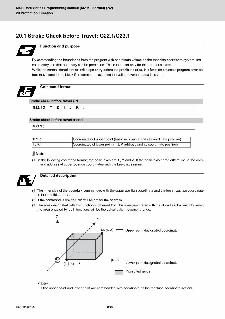
M800/M80 Series Programming Manual (M2/M0 Format) (2/2)
20 Protection Function
838IB-1501481-A
20Protection Function20.1 Stroke Check before Travel; G22.1/G23.1
By commanding the boundaries from the program with coordinate values on the machine coordinate system, ma-
chine entry into that boundary can be prohibited. This can be set only for the three basic axes.
While the normal stored stroke limit stops entry before the prohibited area, this function causes a program error be-
fore movement to the block if a command exceeding the valid movement area is issued.
(1) In the following command format, the basic axes are X, Y and Z. If the basic axis name differs, issue the com-mand address of upper position coordinates with the basic axis name.
(1) The inner side of the boundary commanded with the upper position coordinate and the lower position coordinateis the prohibited area.
(2) If the command is omitted, "0" will be set for the address.
(3) The area designated with this function is different from the area designated with the stored stroke limit. However,the area enabled by both functions will be the actual valid movement range.
<Note>
The upper point and lower point are commanded with coordinate on the machine coordinate system.
Function and purpose
Command format
Stroke check before travel ON
G22.1 X__ Y__ Z__ I__ J__ K__ ;
Stroke check before travel cancel
G23.1 ;
X Y Z Coordinates of upper point (basic axis name and its coordinate position)
I J K Coordinates of lower point (I, J, K address and its coordinate position)
Detailed description
Upper point designated coordinate
Lower point designated coordinate
Prohibited range
Note
Z Y
X(i, j, k)
(x, y, z)
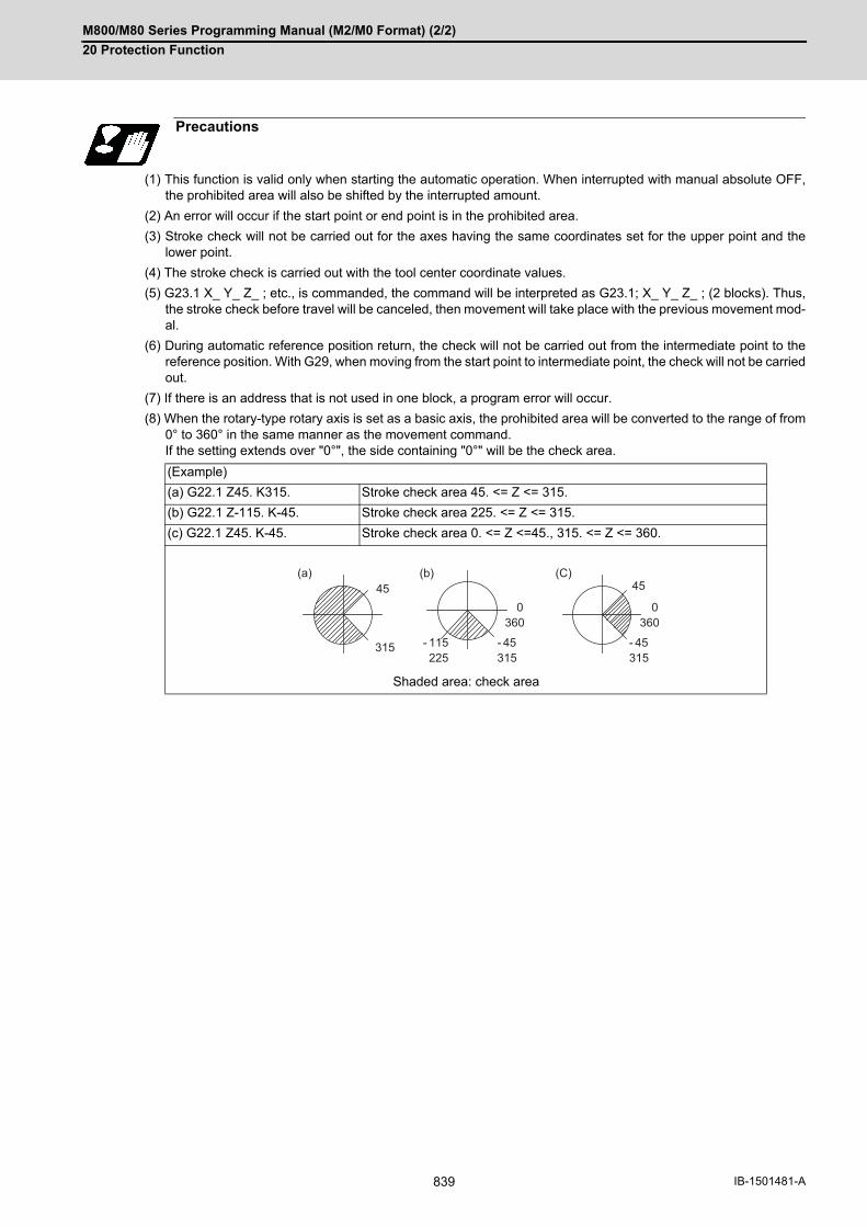
M800/M80 Series Programming Manual (M2/M0 Format) (2/2)
20 Protection Function
839 IB-1501481-A
(1) This function is valid only when starting the automatic operation. When interrupted with manual absolute OFF,the prohibited area will also be shifted by the interrupted amount.
(2) An error will occur if the start point or end point is in the prohibited area.
(3) Stroke check will not be carried out for the axes having the same coordinates set for the upper point and thelower point.
(4) The stroke check is carried out with the tool center coordinate values.
(5) G23.1 X_ Y_ Z_ ; etc., is commanded, the command will be interpreted as G23.1; X_ Y_ Z_ ; (2 blocks). Thus,the stroke check before travel will be canceled, then movement will take place with the previous movement mod-al.
(6) During automatic reference position return, the check will not be carried out from the intermediate point to thereference position. With G29, when moving from the start point to intermediate point, the check will not be carriedout.
(7) If there is an address that is not used in one block, a program error will occur.
(8) When the rotary-type rotary axis is set as a basic axis, the prohibited area will be converted to the range of from0° to 360° in the same manner as the movement command. If the setting extends over "0°", the side containing "0°" will be the check area.
Precautions
(Example)
(a) G22.1 Z45. K315. Stroke check area 45. <= Z <= 315.
(b) G22.1 Z-115. K-45. Stroke check area 225. <= Z <= 315.
(c) G22.1 Z45. K-45. Stroke check area 0. <= Z <=45., 315. <= Z <= 360.
Shaded area: check area
0360
- 45315
- 115225
0360
- 45315
315
4545(a) (b) (C)

M800/M80 Series Programming Manual (M2/M0 Format) (2/2)
20 Protection Function
840IB-1501481-A
20.2 Enable Interfering Object Selection Data; G186
Sixteen interfering objects to be checked in the interference check III are preset by the MTB (R register or system
variables).
The interfering object selection is enabled by the "Interference check III: Enable interfering object selection data"
signal (Y769) or the "Enable interfering object selection data" command (G186) after the target interfering object has
been selected.
When the "Interference check III mode" signal (Y76A) is set to ON after the interfering object selection has been
enabled, the interference check starts.
Refer to the PLC Interface Manual (IB-1501272) for the R register and commands issued by the PLC device.
For details on the system variables, refer to "22.29 System Variables (Interfering Object Selection)".
This section describes the "Enable interfering object selection data" command (G186).
(1) When the "Enable interfering object selection data" command (G186) or the "interference check III: Enable inter-fering object selection data" signal is set to ON, the consistency between the interfering object definition and in-terfering object selection is checked.
(2) If the consistency check causes an operation error, all axes in all part systems will stop. An operation error can be remedied by redefining the interfering object data (*1) or resetting all part systems(except for sub part system 2).
(*1) After correcting the interfering object data, issue the "Enable interfering object selection data" signal or "En-
able interfering object selection data" command (G186).
(3) The manual operation and automatic operation are not available until all the part systems (except for subpartsystem 2) are reset.
(4) In the case the alarm occurs due to the consistency check, the interfering data will not be updated. For the inter-ference check between interfering objects, the interfering data enabled last time is continuously used.
While the interference check III mode signal is set to ON after the "Enable interfering object selection data" signal
or the "Enable interfering object selection data" command (G186) has been executed, the interference between in-
terfering objects is checked. While the interference check III is being executed, the interference check III mode active
signal is turned ON.
After the NC power is turned ON, if the interference check III mode signal is turned ON without executing the "Enable
interfering object selection data" signal or the "Enable interfering object selection data" command (G186) even once,
an operation error (M03 1001) will occur.
Function and purpose
Command format
"Enable interfering object selection data" command
G186;
Detailed description
Consistency check between interfering object definition and interfering object selection
Interference check III mode enable command

M800/M80 Series Programming Manual (M2/M0 Format) (2/2)
20 Protection Function
841 IB-1501481-A
(*1) The first interfering data pattern is set by the G186 command.
The interference check III function executes check processing based on the first data pattern setting.
(*2) The second interfering data pattern is set by the G186 command.
The interference check III function executes check processing based on the second data pattern setting.
(*3) The interference check III function is not executed.
The program cannot be run backward prior to the "Enable interfering object selection data" command (G186).
If the "Enable interfering object selection data" command (G186) is run backward, the interference data at the re-
verse run is enabled, instead of returning to the interference data at forward run.
Timing chart at execution of G186
G186 command
Interference check III mode enable signal
Interference check III mode active signal
Status of interference check III
Relationship with other functions
Manual arbitrary reverse run
Arbitrary reverse run
G186 G186
(*1)
(*3) (*1) (*2) (*3)
(*2)

M800/M80 Series Programming Manual (M2/M0 Format) (2/2)
20 Protection Function
842IB-1501481-A
(1) The high-speed high-accuracy control function (high-speed machining mode, high-accuracy control, spline inter-polation, etc.) generates a path appropriate for the tolerance amount to execute a machining program command-ed with fine segments at high speed and smoothly. Thus, a difference arises between the path on which theinterference check III is performed and the path on which the tool actually passes. When using the interferencecheck III together with the high-speed high-accuracy control (high-speed machining mode, high-accuracy con-trol, spline interpolation, etc.), define an interfering object (solid) with the clearance amount to suit the path dif-ference that occurs depending on the tolerance amount.
(2) The axis that is stopped when an operation error (M03 0001) or (M03 0002) is detected depends on the MTBspecifications (parameter "#1444 otsys" (OT all-part-system stop enable/disable selection). When "0" is set, all the axes in the part system which controls the axes set to "interfering object I/J/K controlaxis" and "I/J/K rotary control axis" in the interfering object definition will stop. When "1" is set, all axes in all part systems will stop.
(3) If an operation error (M03 0002) is detected between the fixed interfering objects (*1), an alarm will be output topart system 1. (*1) These refer to the interfering objects for which "interfering object I/J/K control axis" and "I/J/K rotary controlaxis" are not set in the interfering object definition.
(4) If you perform the interference check III during the high-speed simple program check, an operation error (M030001) may occur at a position different from the actual operation.
(5) If multiple interfering objects including the rotary axis setting are set as one interfering object using the interferingcheck III: designation of disabled interference object, only the interfering object in which a rotary axis is set willbe in rotating operation, checking the interference between the interfering objects.
(6) If an operation error (M03 0001) occurs, cancel the alarm by moving the interfering object to the retracting direc-tion with the linear axis.
(7) The PLC axis is not available for the interference check III. However, it is available when NC axis/auxiliary axisswitching is enabled.
(8) In the interference check III, the interference is checked in 0.1μm units regardless of the control unit.
(9) At the occurrence of the operation error (M03 0001), all the axes in the part system in which the alarm has oc-curred will stop. If the entry to the interference alarm area is not detected by the subsequent axis travel command(manual operation/automatic operation), the operation error (M03 0001) will be cancelled and the axes will travel.Depending on the relative positional relation between the interfering objects or the feedrate of axes, the axis cantravel further to the interfering direction from the stopped position (a direction to which the interfering objects in-terfere). Even if the axis moves toward the interfering direction, it will stop before entering the interference alarm area.
Precautions

21
843 IB-1501481-A
Measurement Support Functions

M800/M80 Series Programming Manual (M2/M0 Format) (2/2)
21 Measurement Support Functions
844IB-1501481-A
21Measurement Support Functions21.1 Automatic Tool Length Measurement; G37.1
These functions issue the command values from the measuring start position as far as the measurement position,
move the tool in the direction of the measurement position, stop the machine once the tool has arrived at the sensor,
cause the NC system to calculate automatically the difference between the coordinate values at that time and the
coordinate values of the commanded measurement position and provide this difference as the tool offset amount.
When offset is already being applied to a tool, it moves the tool toward the measurement position with the offset still
applied, and if a further offset amount is generated as a result of the measurement and calculation, it provides further
compensation of the present compensation amount.
If there is one type of offset amount at this time, and the offset amount is distinguished between tool length offset
amount and wear offset amount, the wear amount will be automatically compensated.
Function and purpose
Command format
Automatic tool length measurement command
G37.1 Z__ R__ D__ F__ ;
Z Measuring axis address and coordinates of measurement position -------- X,Y,Z,α (α is the additional axis.)
R This commands the distance between the measurement position and point where the movement is to start at the measuring speed.
D This commands the range within which the tool is to stop.
F This commands the measuring feedrate. When R_, D_ or F_ is omitted, the value set in the parameter is used instead.<Parameter> ("Automatic tool length measurement" on the machining parameter screen) #8004 SPEED: 0 to 10000: 0 to 1000000 [mm/min] #8005 ZONE r: 0 to 99999.999 [mm] #8006 ZONE d: 0 to 99999.999 [mm]

M800/M80 Series Programming Manual (M2/M0 Format) (2/2)
21 Measurement Support Functions
845 IB-1501481-A
(1) Operation with G37.1 command
(2) The sensor signal (measuring position arrival signal) is used in common with the skip signal.
(3) The feedrate will be 1mm/min if the F command and parameter measurement speed are 0.
(4) An updated offset amount is valid unless it is assigned from the following Z axis (measurement axis) commandof the G37.1 command.
(5) Excluding the delay at the PLC side, the delay and fluctuations in the sensor signal processing range from 0 to0.2ms. As a result, the measuring error shown below is caused. Maximum measuring error [mm] = Measuring speed [mm/min] * 1/60 * 0.2 [ms]/1000
(6) The machine position coordinates at that point in time are read by sensor signal detection, and the machine willovertravel and stop at a position equivalent to the servo droop. Maximum overtravel [mm] = Measuring speed [mm/min] * 1/60 * 1/Position loop gain [1/s]The standard position loop gain is 33 (1/s).
Detailed description
Op1: Normal completion as it is measurement within the allowable range.
Op2: Alarm stop (P607) as it is outside of the measurement allowable range.
Op3: Alarm stop (P607) as the sensor is not detected.
Op4: Alarm stop (P607) as it is outside of the measurement allowable range. However if there is no (c) area, normal completion will occur.
(a) Measurement allowable range (b) Compensation amount
(d1) Distance (F1) Speed
(f2) Feedrate (d) Measurement range
(r) Deceleration range
Measuring position Stop point
Sensor output
(a)
(b)
(f2)(F1)
(d1)
D (d) D (d)
R (r)F (fp)
(c)
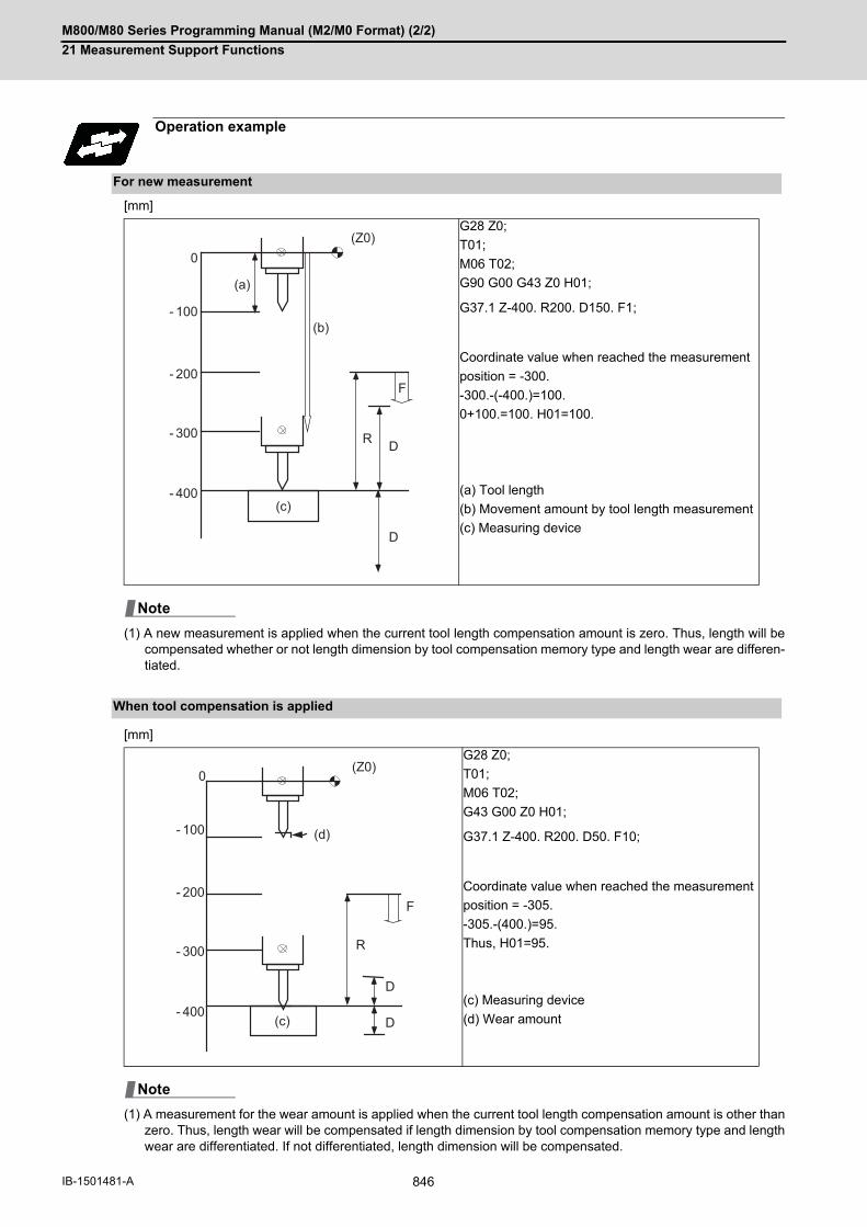
M800/M80 Series Programming Manual (M2/M0 Format) (2/2)
21 Measurement Support Functions
846IB-1501481-A
[mm]
(1) A new measurement is applied when the current tool length compensation amount is zero. Thus, length will becompensated whether or not length dimension by tool compensation memory type and length wear are differen-tiated.
[mm]
(1) A measurement for the wear amount is applied when the current tool length compensation amount is other thanzero. Thus, length wear will be compensated if length dimension by tool compensation memory type and lengthwear are differentiated. If not differentiated, length dimension will be compensated.
Operation example
For new measurement
G28 Z0;
T01;
M06 T02;
G90 G00 G43 Z0 H01;
G37.1 Z-400. R200. D150. F1;
Coordinate value when reached the measurement
position = -300.
-300.-(-400.)=100.
0+100.=100. H01=100.
(a) Tool length
(b) Movement amount by tool length measurement
(c) Measuring device
When tool compensation is applied
G28 Z0;
T01;
M06 T02;
G43 G00 Z0 H01;
G37.1 Z-400. R200. D50. F10;
Coordinate value when reached the measurement
position = -305.
-305.-(400.)=95.
Thus, H01=95.
(c) Measuring device
(d) Wear amount
0
- 100
- 200
- 300
- 400
F
R D
D
(a)
(b)
(c)
(Z0)
Note
0
- 100
- 200
- 300
- 400
F
R
D
D
(Z0)
(d)
(c)
Note

M800/M80 Series Programming Manual (M2/M0 Format) (2/2)
21 Measurement Support Functions
847 IB-1501481-A
(1) Program error (P600) occurs if G37.1 is commanded when the automatic tool length measurement function isnot provided.
(2) Program error (P604) will occur when no axis has been commanded in the G37.1 block or when two or moreaxes have been commanded.
(3) Program error (P605) will occur when the H code is commanded in the G37.1 block.
(4) Program error (P606) will occur when G43_H code is not commanded prior to the G37.1 block.
(5) Program error (P607) will occur when the sensor signal is input outside the allowable measuring range or whenthe sensor signal is not detected even upon arrival at the end point.
(6) When a manual interrupt is applied while the tool is moving at the measuring speed, a return must be made tothe position prior to the interrupt and then operation must be resumed.
(7) The data commanded in G37.1 or the parameter setting data must meet the following conditions:
| Measurement point start point | > R command or parameter r > D command or parameter d
(8) When the D address and parameter d in (7) above are zero, the operation will be completed normally only whenthe commanded measurement point and sensor signal detection point coincide. Otherwise, program error(P607) will occur.
(9) When the R and D addresses as well as parameters r and d in (7) above are all zero, program error (P607) willoccur regardless of whether the sensor signal is present or not after the tool has been positioned at the com-manded measurement point.
(10) When the measurement allowable range is larger than the measurement command distance, it becomes themeasurement allowable range for all axes.
(11) When the measurement speed movement distance is larger than the measurement command distance, all axesmove at the measurement speed.
(12) When the measurement allowable range is larger than the measurement speed movement distance, the axismoves in the measurement allowable range at the measurement speed.
(13) The automatic tool length measurement command (G37.1) must be commanded together with the G43H_ com-mand that designates the offset No.
G43 H_;
G37.1 Z_ R_ D_ F_;
(14) If an axis other than Z is specified for the measuring axis in G37.1 while the parameter "#1080 Dril_Z" is set to"1", the program error (P606) occurs.
Precautions

M800/M80 Series Programming Manual (M2/M0 Format) (2/2)
21 Measurement Support Functions
848IB-1501481-A
21.2 Skip Function; G31
When the skip signal is input externally during linear interpolation based on the G31 command, the machine feed is
stopped immediately, the coordinate value is read, the remaining distance is discarded and the command in the fol-
lowing block is executed.
Function and purpose
Command format
G31 X__ Y__ Z__ α__ R__ F__ ;
X,Y,Z,α Axis coordinate value; they are commanded as absolute or incremental values according to the G90/G91 modal when commanded. α is the additional axis.
R Acceleration/deceleration commandR0: Acceleration/deceleration time constant=0 (No automatic acceleration/deceleration after interpolation.)R1: Acceleration/deceleration time constant valid. Accelerate/decelerate with the time constant set with the parameters "#2102 skip_tL" and "#2103 skip_t1". R0 is applied when it is omitted.
F Feedrate (mm/min)
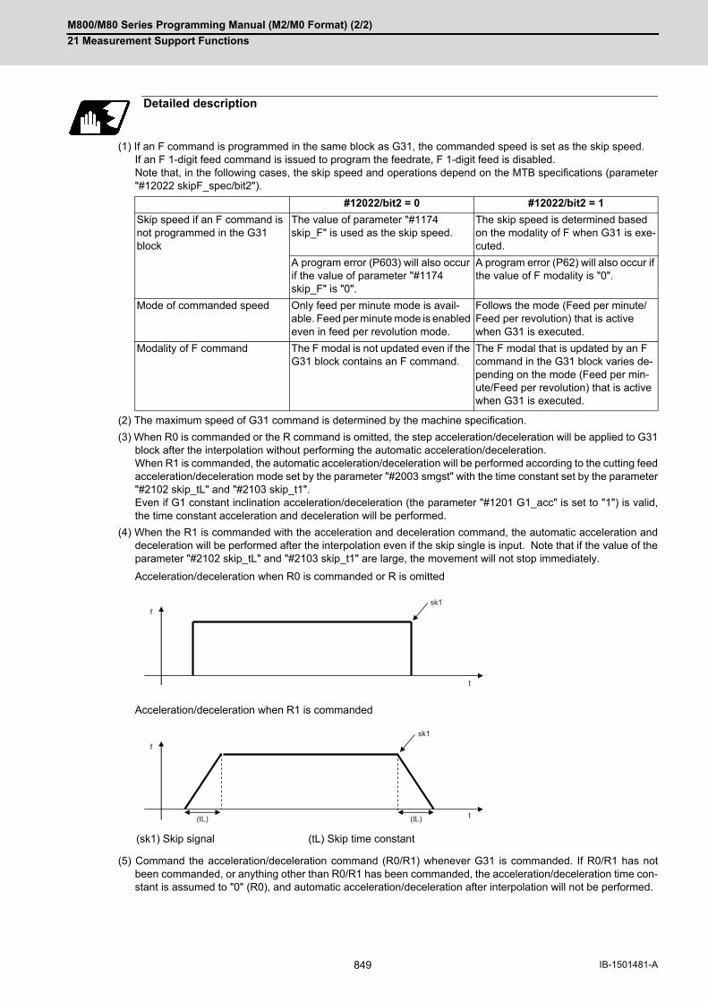
M800/M80 Series Programming Manual (M2/M0 Format) (2/2)
21 Measurement Support Functions
849 IB-1501481-A
(1) If an F command is programmed in the same block as G31, the commanded speed is set as the skip speed. If an F 1-digit feed command is issued to program the feedrate, F 1-digit feed is disabled. Note that, in the following cases, the skip speed and operations depend on the MTB specifications (parameter"#12022 skipF_spec/bit2").
(2) The maximum speed of G31 command is determined by the machine specification.
(3) When R0 is commanded or the R command is omitted, the step acceleration/deceleration will be applied to G31block after the interpolation without performing the automatic acceleration/deceleration. When R1 is commanded, the automatic acceleration/deceleration will be performed according to the cutting feedacceleration/deceleration mode set by the parameter "#2003 smgst" with the time constant set by the parameter"#2102 skip_tL" and "#2103 skip_t1". Even if G1 constant inclination acceleration/deceleration (the parameter "#1201 G1_acc" is set to "1") is valid,the time constant acceleration and deceleration will be performed.
(4) When the R1 is commanded with the acceleration and deceleration command, the automatic acceleration anddeceleration will be performed after the interpolation even if the skip single is input. Note that if the value of theparameter "#2102 skip_tL" and "#2103 skip_t1" are large, the movement will not stop immediately.
Acceleration/deceleration when R0 is commanded or R is omitted
Acceleration/deceleration when R1 is commanded
(5) Command the acceleration/deceleration command (R0/R1) whenever G31 is commanded. If R0/R1 has notbeen commanded, or anything other than R0/R1 has been commanded, the acceleration/deceleration time con-stant is assumed to "0" (R0), and automatic acceleration/deceleration after interpolation will not be performed.
Detailed description
#12022/bit2 = 0 #12022/bit2 = 1
Skip speed if an F command is not programmed in the G31 block
The value of parameter "#1174 skip_F" is used as the skip speed.
The skip speed is determined based on the modality of F when G31 is exe-cuted.
A program error (P603) will also occur if the value of parameter "#1174 skip_F" is "0".
A program error (P62) will also occur if the value of F modality is "0".
Mode of commanded speed Only feed per minute mode is avail-able. Feed per minute mode is enabled even in feed per revolution mode.
Follows the mode (Feed per minute/Feed per revolution) that is active when G31 is executed.
Modality of F command The F modal is not updated even if the G31 block contains an F command.
The F modal that is updated by an F command in the G31 block varies de-pending on the mode (Feed per min-ute/Feed per revolution) that is active when G31 is executed.
(sk1) Skip signal (tL) Skip time constant
t
sk1f
f
sk1
(tL)(tL) t
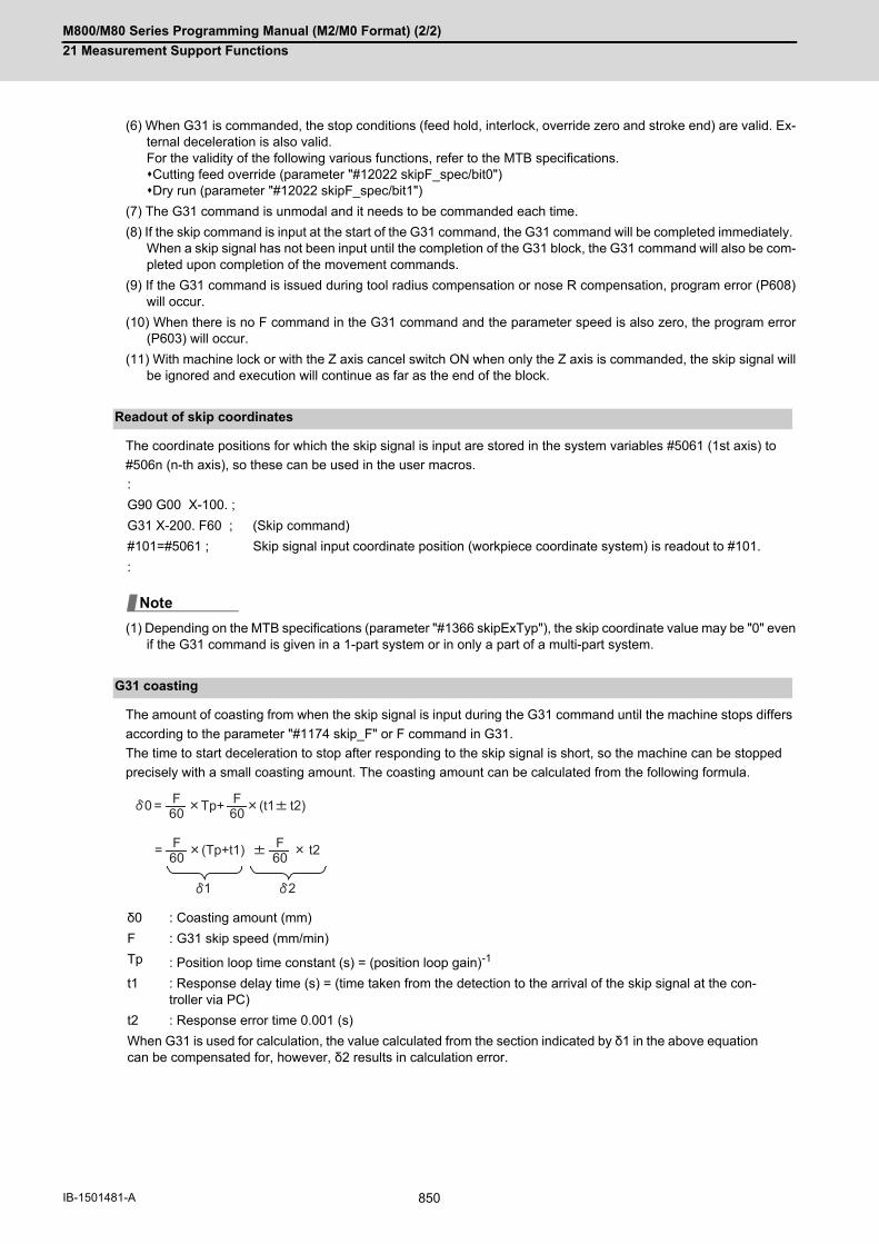
M800/M80 Series Programming Manual (M2/M0 Format) (2/2)
21 Measurement Support Functions
850IB-1501481-A
(6) When G31 is commanded, the stop conditions (feed hold, interlock, override zero and stroke end) are valid. Ex-ternal deceleration is also valid. For the validity of the following various functions, refer to the MTB specifications.Cutting feed override (parameter "#12022 skipF_spec/bit0")Dry run (parameter "#12022 skipF_spec/bit1")
(7) The G31 command is unmodal and it needs to be commanded each time.
(8) If the skip command is input at the start of the G31 command, the G31 command will be completed immediately. When a skip signal has not been input until the completion of the G31 block, the G31 command will also be com-pleted upon completion of the movement commands.
(9) If the G31 command is issued during tool radius compensation or nose R compensation, program error (P608)will occur.
(10) When there is no F command in the G31 command and the parameter speed is also zero, the program error(P603) will occur.
(11) With machine lock or with the Z axis cancel switch ON when only the Z axis is commanded, the skip signal willbe ignored and execution will continue as far as the end of the block.
The coordinate positions for which the skip signal is input are stored in the system variables #5061 (1st axis) to
#506n (n-th axis), so these can be used in the user macros.
(1) Depending on the MTB specifications (parameter "#1366 skipExTyp"), the skip coordinate value may be "0" evenif the G31 command is given in a 1-part system or in only a part of a multi-part system.
The amount of coasting from when the skip signal is input during the G31 command until the machine stops differs
according to the parameter "#1174 skip_F" or F command in G31.
The time to start deceleration to stop after responding to the skip signal is short, so the machine can be stopped
precisely with a small coasting amount. The coasting amount can be calculated from the following formula.
Readout of skip coordinates
:
G90 G00 X-100. ;
G31 X-200. F60 ; (Skip command)
#101=#5061 ; Skip signal input coordinate position (workpiece coordinate system) is readout to #101.
:
G31 coasting
δ0 : Coasting amount (mm)
F : G31 skip speed (mm/min)
Tp : Position loop time constant (s) = (position loop gain)-1
t1 : Response delay time (s) = (time taken from the detection to the arrival of the skip signal at the con-troller via PC)
t2 : Response error time 0.001 (s)
When G31 is used for calculation, the value calculated from the section indicated by δ1 in the above equation can be compensated for, however, δ2 results in calculation error.
Note
0 = Tp+ (t1 t2)60F
60F
60F
60F= (Tp+t1) t2
1 2

M800/M80 Series Programming Manual (M2/M0 Format) (2/2)
21 Measurement Support Functions
851 IB-1501481-A
Stop pattern with skip signal input is shown below.
The relationship between the coasting amount and speed when Tp is 30ms and t1 is 5ms is shown in the following
figure.
(1) Skip signal input coordinate readoutThe coasting amount based on the position loop time constant Tp and cutting feed time constant Ts is not in-cluded in the skip signal input coordinate values. Therefore, the workpiece coordinate values applying when the skip signal is input can be readout within the errorrange in the following formula as the skip signal input coordinate values. However, coasting based on responsedelay time t1 results in a measurement error and so compensation must be provided.
Readout error of skip signal input coordinates
Readout error with a 60mm/min feedrate is as shown below and the measurement value is within readout error
range of ±1μm:
ε= ± (60/60) x 0.001 = ± 0.001 (mm)
(2) Readout of other coordinatesThe readout coordinate values include the coasting amount. Therefore, when coordinate values at the time ofskip signal input is required, reference should be made to the section on the G31 coasting amount to compensatethe coordinate value. As in the case of (1), the coasting amount based on the delay error time t2 cannot be cal-culated, and this generates a measuring error.
F: Feedrate(a) Skip signal input(T) Time
Coasting amount
(a) Maximum value(b) Average value(c) Minimum value F: Feedrateδ: Coasting amount
Readout error of skip coordinates mm
ε : Readout errorε=±(F/60)×t 2F : Feedratet2 : Response error time 0.001 (s)
Measurement value
Tp t1 t2(T)
(a)
0
F
Tp=0.03t1=0.0050.050
F (mm/min)
0.040
0.030
0.020
0.010
(mm)
0 10 20 30 40 50 60 70
(a)(b)
(c)
F (mm/min)
+1
0
- 160
(µm)

M800/M80 Series Programming Manual (M2/M0 Format) (2/2)
21 Measurement Support Functions
852IB-1501481-A
(1) Compensating for skip signal input coordinates
#110 = Skip feedrate;
#111 = Response delay time t1;
(2) Compensating for workpiece coordinates
#110 = Skip feedrate;
#111 = Response delay time t1;
#112 = Position loop time constant Tp;
The operation resulting from the G31 command executed simultaneously on multiple part systems depends on the
MTB specifications (parameter "#1366 skipExTyp").
(*1) The skip coordinate position is also set to "0" when the G31 command is executed on a single part system.
Furthermore, it is set to "0" when the G31 command is executed on one part system in a multiple part system
configuration.
When the G31 command is used for measuring purposes, "#1366 skipExTyp" must be "0".
Examples of compensating for coasting
:
G31 X100.F100 ; Skip command
G04 ; Machine stop check
#101=#5061 ; Skip signal input coordinate readout
#102=#110*#111/60 ;
Coasting based on response delay time
#105=#101-#102 ; Skip signal input coordinates
:
:
G31 X100.F100 ; Skip command
G04 ; Machine stop check
#101=#5061 ; Skip signal input coordinate readout
#102=#110*#111/60 ;
Coasting based on response delay time
#103=#110*#112/60 ;
Coasting based on position loop time constant
#105=#101-#102-#103 ;
Skip signal input coordinates
:
Operation to be carried out when the skip command is executed on multiple part systems at the same time
#1366 Operation
0 When any part system is executing the G31 command, the G31 command issued for other part systems is subjected to a block interlock state, and such G31 command will be executed after the current G31 command execution is completed. (No error is displayed.) In a single-block operation, for example, where the G31 block is started in multiple part systems at the same time, it is executed in the smallest part system first.
1 The G31 command is executed on multiple part systems at the same time. However, the skip coordinate position is not read and is set to "0" in all part systems. (*1)

M800/M80 Series Programming Manual (M2/M0 Format) (2/2)
21 Measurement Support Functions
853 IB-1501481-A
Operation example
G90 G00 X-100000 Y0; G31 X-500000 F100; G01 Y-100000; G31 X-0 F100; Y-200000; G31 X-500000 F100; Y-300000; X0;
- 500000 0
- 100000
- 200000
- 300000
- 100000
G01
G31
G31
G31
G01G01
G01X
W
Y
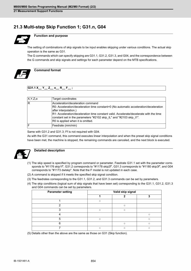
M800/M80 Series Programming Manual (M2/M0 Format) (2/2)
21 Measurement Support Functions
854IB-1501481-A
21.3 Multi-step Skip Function 1; G31.n, G04
The setting of combinations of skip signals to be input enables skipping under various conditions. The actual skip
operation is the same as G31.
The G commands which can specify skipping are G31.1, G31.2, G31.3, and G04, and the correspondence between
the G commands and skip signals and settings for each parameter depend on the MTB specifications.
Same with G31.2 and G31.3; Ff is not required with G04.
As with the G31 command, this command executes linear interpolation and when the preset skip signal conditions
have been met, the machine is stopped, the remaining commands are canceled, and the next block is executed.
(1) The skip speed is specified by program command or parameter. Feedrate G31.1 set with the parameter corre-sponds to "#1176 skip1f", G31.2 corresponds to "#1178 skip2f", G31.3 corresponds to "#1180 skip3f", and G04corresponds to "#1173 dwlskp". Note that the F modal is not updated in each case.
(2) A command is skipped if it meets the specified skip signal condition.
(3) The feedrates corresponding to the G31.1, G31.2, and G31.3 commands can be set by parameters.
(4) The skip conditions (logical sum of skip signals that have been set) corresponding to the G31.1, G31.2, G31.3and G04 commands can be set by parameters.
(5) Details other than the above are the same as those on G31 (Skip function).
Function and purpose
Command format
G31.1 X__ Y__ Z__ α__ R__ F__ ;
X,Y,Z,α Target coordinates
R Acceleration/deceleration commandR0: Acceleration/deceleration time constant=0 (No automatic acceleration/deceleration after interpolation.)R1: Acceleration/deceleration time constant valid. Accelerate/decelerate with the time constant set in the parameters "#2102 skip_tL" and "#2103 skip_t1". R0 is applied when it is omitted.
F Feedrate (mm/min)
Detailed description
Parameter setting Valid skip signal
1 2 3
1 ○
2 ○
3 ○ ○
4 ○
5 ○ ○
6 ○ ○
7 ○ ○ ○
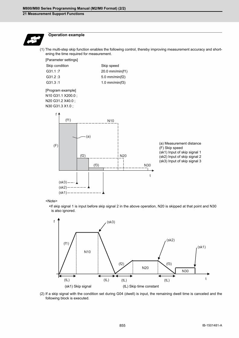
M800/M80 Series Programming Manual (M2/M0 Format) (2/2)
21 Measurement Support Functions
855 IB-1501481-A
(1) The multi-step skip function enables the following control, thereby improving measurement accuracy and short-ening the time required for measurement.
[Parameter settings]
[Program example]
N10 G31.1 X200.0 ;
N20 G31.2 X40.0 ;
N30 G31.3 X1.0 ;
<Note>
If skip signal 1 is input before skip signal 2 in the above operation, N20 is skipped at that point and N30is also ignored.
(2) If a skip signal with the condition set during G04 (dwell) is input, the remaining dwell time is canceled and thefollowing block is executed.
Operation example
Skip condition Skip speed
G31.1 :7 20.0 mm/min(f1)
G31.2 :3 5.0 mm/min(f2)
G31.3 :1 1.0 mm/min(f3)
(a) Measurement distance(F) Skip speed(sk1) Input of skip signal 1(sk2) Input of skip signal 2(sk3) Input of skip signal 3
(sk1) Skip signal (tL) Skip time constant
N10
f
N20
N30
(f1)
(f2)
(f3)
t
(a)
(F)
(sk3)(sk2)(sk1)
(tL) (tL) (tL) (tL) t
(f1)
(f2) (f3)
(sk3)
(sk2)
(sk1)N10
N20N30
f

M800/M80 Series Programming Manual (M2/M0 Format) (2/2)
21 Measurement Support Functions
856IB-1501481-A
21.4 Multi-step Skip Function 2; G31 P
During linear interpolation by the skip command (G31), operation can be skipped according to the conditions of the
skip signal parameter Pp.
If multi-step skip commands are issued simultaneously in different part systems as shown in the left figure, both part
systems perform skip operation simultaneously if the input skip signals are the same, or they perform skip operation
separately if the input skip signals are different as shown in the right figure. The skip operation is the same as a
normal skip command (G31 without P command).
If the skip condition specified by the parameter "#1173 dwlskp" (indicating external skip signals 1 to 4) is met during
execution of a dwell command (G04), the remaining dwell time is canceled and the following block is executed.
Function and purpose
[Same skip signals input in both 1st and 2nd part systems]
[Different skip signals input in 1st and 2nd part systems]
($1) 1st part system ($2) 2nd part system
(sk1) Skip signal 1 (sk2) Skip signal 2
Command format
G31 X__ Y__ Z__ α__ P__ R__ F__ ;
X Y Z α Target coordinates
P Skip signal command
R Acceleration/deceleration commandR0: Acceleration/deceleration time constant=0 (No automatic acceleration/decel-eration after interpolation.)R1: Acceleration/deceleration time constant valid. Accelerate/decelerate with the time constant set in the parameters "#2102 skip_tL" and "#2103 skip_t1".R0 is applied when it is omitted.
F Feedrate (mm/min)
Y1 (sk1)
($1)
Y1
X1 X1
(sk1)
($1)
Y2 (sk1)
($2)
Y2
X2 X2
(sk2)
($2)

M800/M80 Series Programming Manual (M2/M0 Format) (2/2)
21 Measurement Support Functions
857 IB-1501481-A
(1) The skip speed is specified by program command or parameter. The feedrate by the parameter is set by "#1174
skip_F". Note that the F modal is not updated in each case.
(2) The skip signal is specified by skip signal command p. The command range of "p" is from 1 to 255. If outside the
range is commanded, program error (P35) will occur.
(3) The specified skip signal command is a logical sum of the skip signals.
(Example) G31 X100. P5 F100 ;
Operation is skipped if skip signal 1 or 3 is input.
(4) If skip signal parameter Pp is not specified, it works as a skip function (G31), not as a multi-step skip function. If
speed parameter Ff is not specified, the skip speed set by the parameter "#1174 skip_F" will apply.
[Relations between skip and multi-step skip]
(5) If skip specification is effective and P is specified as an axis address, skip signal parameter P will be given a
priority. The axis address "P" will be ignored.
(Example) G31 X100. P500 F100 ;
This is regarded as a skip signal. (The program error (P35) will occur.)
(6) Other than above, the same detailed description as "Skip function; G31" applies.
Detailed description
Skip signal command P Valid skip signal
8 7 6 5 4 3 2 1
1 ○
2 ○
3 ○ ○
4 ○
5 ○ ○
6 ○ ○
7 ○ ○ ○
8 ○
:::
253 ○ ○ ○ ○ ○ ○ ○
254 ○ ○ ○ ○ ○ ○ ○
255 ○ ○ ○ ○ ○ ○ ○ ○
Skip specifications × ○
Condition Speed Condition Speed
G31 X100 ;(Without P and F) Program error(P601)
Skip 1 #1174 skip_F
G31 X100 P5 ;(Without F) Program error(P602)
Command val-ue
#1174 skip_F
G31 X100 F100 ;(Without P) Program error(P601)
Skip 1 Command value
G31 X100; P5 F100; Program error(P602)
Command val-ue
Command value

M800/M80 Series Programming Manual (M2/M0 Format) (2/2)
21 Measurement Support Functions
858IB-1501481-A
21.5 Speed Change Skip; G31 Fn
When the skip signal is detected during linear interpolation by the skip command (G31), the feedrate is changed.
Function and purpose
Command format
G31 X__ (Y__) Z__ α__ R__ F__ F1 = __ ... Fn = __ ; ("n" is the skip signal 1 to 8) ... Skip command
X, (Y,) Z, α Target coordinates
R Acceleration/deceleration command
R0: Acceleration/deceleration time constant=0
When the movement is stopped by the skip signal detection, the step stop will
occur.
R1: Acceleration/deceleration time constant valid.
When the movement is stopped by the skip signal detection, it will decelerate
with the time constant set in the parameter "#2102 skip_tL" and "#2103
skip_t1".
When omitted, R0 will be applied.
F Feedrate when starting the cutting feed (mm/min)
Fn= Feedrate after detecting the skip signal (mm/min) Fn = 0: Movement stop Fn ≠ 0 :Changing the feedrate to fn F1 = Feedrate after inputting the skip signal 1 : F8 = Feedrate after inputting the skip signal 8
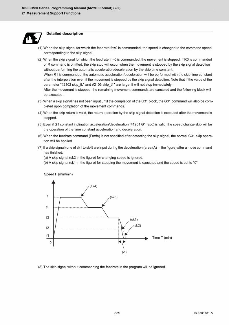
M800/M80 Series Programming Manual (M2/M0 Format) (2/2)
21 Measurement Support Functions
859 IB-1501481-A
(1) When the skip signal for which the feedrate fn≠0 is commanded, the speed is changed to the command speed
corresponding to the skip signal.
(2) When the skip signal for which the feedrate fn=0 is commanded, the movement is stopped. If R0 is commanded
or R command is omitted, the skip stop will occur when the movement is stopped by the skip signal detection
without performing the automatic acceleration/deceleration by the skip time constant.
When R1 is commanded, the automatic acceleration/deceleration will be performed with the skip time constant
after the interpolation even if the movement is stopped by the skip signal detection. Note that if the value of the
parameter "#2102 skip_tL" and #2103 skip_t1" are large, it will not stop immediately.
After the movement is stopped, the remaining movement commands are canceled and the following block will
be executed.
(3) When a skip signal has not been input until the completion of the G31 block, the G31 command will also be com-
pleted upon completion of the movement commands.
(4) When the skip return is valid, the return operation by the skip signal detection is executed after the movement is
stopped.
(5) Even if G1 constant inclination acceleration/deceleration (#1201 G1_acc) is valid, the speed change skip will be
the operation of the time constant acceleration and deceleration.
(6) When the feedrate command (Fn=fn) is not specified after detecting the skip signal, the normal G31 skip opera-
tion will be applied.
(7) If a skip signal (one of sk1 to sk4) are input during the deceleration (area (A) in the figure) after a move command
has finished:
(a) A skip signal (sk2 in the figure) for changing speed is ignored.
(b) A skip signal (sk1 in the figure) for stopping the movement is executed and the speed is set to "0".
(8) The skip signal without commanding the feedrate in the program will be ignored.
Detailed description
Speed F (mm/min)
Time T (min)
(sk4)
(sk3)
(sk1)
(sk2)
(A)
f
f4
f3
f2
f1
0

M800/M80 Series Programming Manual (M2/M0 Format) (2/2)
21 Measurement Support Functions
860IB-1501481-A
(9) The speed change or the movement stop is performed when detecting the rising edge of the skip signal. Note
that if several rising edges are input at 3.5ms intervals or less, they may be judged as the simultaneous input.
When they are judged as the simultaneous input, the smaller value will be valid.
Shown below are changes in time (T) and speed (F) when skip signals, 1 (sk1) to 4 (sk4), are input.
(10) If the G31 block is started with the skip signal input, that signal is considered to rise at the same time as the
block starts.
(11) If the skip signals for changing the speed and for stopping the movement are simultaneously input, the skip
signal for stopping the movement will be valid regardless of the size of the number.
(12) If the skip time constant "#2102 skip_tL" is illegal, an MCP alarm (Y51 15) will occur. If the "#2103 skip_t1" is
illegal, an MCP alarm (Y51 16) will occur.
(13) Other than above, the same detailed description as "Skip function; G31" applies.
Speed F (mm/min)
Time T (min)
Time T (min)
f4
f
f3
f2
0
f1
(sk3+sk4)
(sk1)
(sk2)
(sk4)
(sk3)
(sk2)
(sk1)

M800/M80 Series Programming Manual (M2/M0 Format) (2/2)
21 Measurement Support Functions
861 IB-1501481-A
The following shows the operations when a skip time constant and skip signals, 1 (sk1) to 4 (sk4), are input.
(1) Example of when R is not commanded
Skip time constant ((a) in the figure) and position loop time constant ((b) in the figure)
G31 X100. Ff F1=0 F2=f2 F3=f3 F4=f4 ;
(2) Example of when R1 is commanded
Skip time constant ((tL) in the figure)
G31 X100. R1 Ff F1=0 F2=f2 F3=f3 F4=f4;
Operation example
Speed F (mm/min)
Time T (min)
Speed F (mm/min)
Time T (min)
f4
f
f3
f2
0f1
(a) (a)
(sk4)
(sk3)
(sk2)
(sk1)
(b)
f4
f
f3
f2
0 (tL) (tL) (tL)
(sk4)
(sk3)
(sk2)
(sk1)
f1

M800/M80 Series Programming Manual (M2/M0 Format) (2/2)
21 Measurement Support Functions
862IB-1501481-A
21.6 Torque Limitation Skip; G160
Axis movement is performed in the torque limited status, and the axis movement command is suspended to proceed
to the next block when the current command value reaches the designated torque skip value and the torque skip
turns ON. In addition to the torque, the droop value can be add to the condition of the skip ON (Droop skip).
This function enables measurement without a sensor.
The G160 command is unmodal (group 00). When executing the G160 command continuously, it must always be
command for each block separately.
(1) Designate an axis that exits in the part system for the axis address. If an axis that does not exist in the part sys-tem, a program error (P32) will occur.
(2) Only one axis can be commanded with the axis address. If no axis is specified or if two or more axes are specifiedin the same block, a program error (P595) will occur.
(3) For spindle/C axis (C axis command), a Q command is specified with 121 to 500 %, the axis is clamped at 120%.
(4) If a Q command is omitted, torque skip function is performed as specified by the MTB (parameter shown below). NC axis (servo axis): SV014 lLMTsp (current limit value in special control)Spindle/C axis (C axis command):For the normal spindle, SP065 TLM1 (torque limit 1)For spindle-mode servo, SV014 ILMTsp (current limit value in special control)
(5) If D command is omitted, a skip operation is performed using the torque skip value only.
(6) D command must be programmed within the excessive error width shown below. NC axis (servo axis): SV023 OD1 (detected excessive error width when servo is on)Spindle/C axis: SP023 OD1 (detected excessive error width (interpolation mode))
(7) If an F command is omitted, the feedrate depends on the MTB specifications (parameter "#1174 skip_F").
(8) A program error (P603) will occur if the skip speed in F command is 0.
Function and purpose
Command format
Torque limitation skip
G160 X/Y/α__ Q__ D__ F__ ;
X/Y/α Axis address and coordinate value command (mm/inch) (Decimal point command is possible)
Q Torque skip value (0 to 500 (%))
D Droop skip value (0 to 99999.999 mm, 0 to 9999.9999 inch)
F Skip speedSet it in the range of feedrates. (mm/min, inch/min, mm/rev, inch/rev)
Note

M800/M80 Series Programming Manual (M2/M0 Format) (2/2)
21 Measurement Support Functions
863 IB-1501481-A
Follow the acceleration/deceleration pattern for linear interpolation (G01).Even if G01 constant inclination acceleration/deceleration is valid, the time constant acceleration and deceler-
ation will be performed.
If F command is programmed in the same block as G160, the commanded speed is set as the skip speed.
If an F 1-digit feed command is issued to program the feedrate, F 1-digit feed is disabled.
Note that, in the following cases, the skip speed and operations depend on the MTB specifications (parameter
"#12022 skipF_spec/bit2").
(1) For the validity of the following various functions, refer to the MTB specifications.Cutting feed override valid/invalid (parameter "#12022 skipF_spec/bit0")Dry run valid/invalid (parameter "#12022 skipF_spec/bit1")
(2) An operation error (M01 0102) occurs if 0% cutting feed override is performed when cutting feed override is in-valid.
(3) The stop conditions (feed hold, interlock, override zero and stroke end) and external deceleration are valid whentorque limitation skip is used.
(4) The machine lock signal is valid. (The counter is updated until the program reaches the end point of the block.)
(1) If the current value for the specified axis exceeds the torque skip value, the torque limit is reached and droopexceeds the droop skip value, the torque skip turns on. If there is no D command, the torque skip turns on whenthe torque limit is reached.
(2) The current position when the torque skip turns on is regarded as the block end point and the remaining distance(command value - actual movement distance) is discarded.
Detailed description
Acceleration/deceleration when G160 is commanded
Skip speed
#12022/bit2 = 0 #12022/bit2 = 1
Skip speed if F command is not programmed in the G160 block
The value of parameter "#1174 skip_F" is used as the skip speed.
The skip speed is determined based on the modality of F when G160 is ex-ecuted.
A program error (P603) will also occur if the value of parameter "#1174 skip_F" is "0".
A program error (P62) will also occur if the value of F modality is "0".
Mode of commanded speed Only feed per minute mode is avail-able. Feed per minute mode is enabled even in feed per revolution mode.
Follows the mode (Feed per minute/Feed per revolution) that is active when G160 is executed.
Modality of F command F modal is not updated even if the G160 block contains an F command.
The F modal that is updated by F com-mand in the G160 block varies de-pending on the mode (Feed per minute/Feed per revolution) that is ac-tive when G160 is executed.
Control signals regarding speed control and stop
Processing when the torque skip turns on

M800/M80 Series Programming Manual (M2/M0 Format) (2/2)
21 Measurement Support Functions
864IB-1501481-A
(1) If the torque skip turns on during G160 command, the program completes the current block before moving on tothe next block.
(2) If the torque skip does not turn on until G160 command reaches the end point, the skip command completes atthe end of the block and then the program moves on to the next block.
(3) Set the skip coordinate values (workpiece coordinate values) to system variables (#5061 and onwards). Whenthe tool has moved to the end point, set the end point position.
Completion of skip command
Program example
: : Workpiece radius measurement tool
G28 Z200.
T01; Tool selection for measurement
G00 X50. Y50. Z100. ;
G160 Z40. Q80 F20; Torque skip command
#100=#5061; Completion of skip command(Coordinate position (workpiece val-ue) read)
:
Droop
Torque skip on
Actual movement distance Remaining distance
Program command position
Axis movement target
Interference object
Time
Time
Block end point
Droop skip value
Current valueDroop skip value
Commanded speed
50.
40.
0.

M800/M80 Series Programming Manual (M2/M0 Format) (2/2)
21 Measurement Support Functions
865 IB-1501481-A
The skip speed is controlled with the manual arbitrary reverse run speed. Torque skip command block cannot be
executed in the reverse run.
When a manual interrupt is applied during execution of torque skip, calculate the position shifted by the amount of
the manual interruption as the skip position.
The torque skip position is common to skip variables (#5061 and onwards) for G31 skip function.
Geometric, Corner Rounding, and Corner Chamfering are not available for torque skip blocks. Program error (P595)
will occur.
Torque skip command, if executed on the axis to which torque limits are applied, is based on the torque skip value
in the G160 command.
Torque skip command (G160) cannot be commanded when any of the following functions is in use. (An error will
occur.)
(1) Decreasing the torque limit value may cause a torque limit to be applied during acceleration/deceleration.
(2) When the reset button is pressed while torque skip is active, an axis moving with G160 stops. After the axis hasstopped, the original torque is restored.
(3) Writing parameters via a PLC or other host controller during execution of torque skip causes the torque limit valueto be the setting value of servo parameter SV014, possibly causing it to be no longer correct torque skip value.(The PLC signal operations and setting values of the servo parameters are based on the MTB specifications.)
(4) When using D command (droop skip value), command a value that does not exceed the excessive error width.
(5) After a torque skip, the droop is canceled.
(6) The droop is displayed in interpolation increments on the drive monitor. They are different from the commandincrements of D command.
Relationship with Other Functions
Manual arbitrary reverse run
Manual interruption
Skip variables
Geometric, Corner Rounding, Corner Chamfering
Torque limit
Functions for which torque skip command is not available
Function name Error
Tool radius compensation (G40, G41, G42, G46) Program error (P608)
Synchronous control (G114.1) Program error (P595)
High-speed high-accuracy control (G05.1/G05) Program error (P34)
Precautions

M800/M80 Series Programming Manual (M2/M0 Format) (2/2)
21 Measurement Support Functions
866IB-1501481-A
21.7 Programmable Current Limitation; G10 L14 ;
This function allows the current limit value of the NC axis to be changed to a desired value in the program, and is
used for the workpiece stopper, etc. "#2214 SVO14(current limit value in special control)” can be changed.
The commanded current limit value is designated with a ratio of the limit current to the rated current.
(1) If the current limit value is reached when the current limit is valid, the current limit reached signal is output.
(2) The following two modes can be used with external signals as the operation after the current limit is reached.
The external signal determines which mode applies.
[Normal mode]
The movement command is executed in the current state.
During automatic operation, the movement command is executed until the end, and then move to the next block
with the droops still accumulated.
[Interlock mode]
During the occurrence of the droops, it enters to the internal interlock state and the next movement will not be
carried out.
During automatic operation, the operation stops at the corresponding block, and the next block is not moved to.
During manual operation, the following same direction commands are ignored.
(3) The position droop generated by the current limit can be canceled when the current limit changeover signal of
external signals is canceled. (Note that the axis must not be moving.)
(4) The setting range of the current limit value is 1% to 999%. Commands that exceed this range will cause a pro-
gram error (P35).
(5) If a decimal point is designated with the G10 command, only the integer will be valid.
Example) G10 L14 X10.123 ; The current limit value will be set to 10%.
(6) For the axis name "C", the current limit value cannot be set from the program (G10 command).
To set from the program, set the axis address with an incremental axis name, or set the axis name to one other
than "C".
Function and purpose
Command format
G10 L14 Xn ;
L14 Current limit value setting (+ side/- side)
X Axis address
n Current limit value (%) Setting range: 1 to 999
Precautions

22
867 IB-1501481-A
System Variables

M800/M80 Series Programming Manual (M2/M0 Format) (2/2)
22 System Variables
868IB-1501481-A
22System Variables22.1 System Variables List
The M800/M80 series provides the following system variables.
Note that the available types and numbers vary depending on the machine specifications and whether the machine
is intended for use by a user or MTB.
○: Available
- : Unavailable
No. Data type or use Reading Setting Section
#1000 - #1035,#1200 - #1295
Signal input from PLC to NC ○ (*1) - 22.25
#1100 - #1135#1300 - #1395
Signal output from NC to PLC ○ (*1) ○ (*1) 22.26
#1900, #1901 Used for normal line control. ○ ○ 22.22
#2001 - #2000+n#2201 - #2200+n#2401 - #2400+n#2601 - #2600+n
Tool offset dataAlso refer to the variables #10001, #135001 and #230001 or larg-er.
○ ○ 22.6
#2501, #2601 External workpiece coordinate offset ○ ○ 22.10
#3000 Used to forcibly set to the alarm mode. Designate the number and message.
- ○ 22.12
#3001, #3002 Cumulative time (integrating time) ○ - 22.14
#3001, #3002#3011, #3012
Time read variables ○ ○ 22.15
#3003 Inhibition of single block stopInhibition of miscellaneous function finish signal waitingProhibition of program check reverse run
○ ○ 22.16
#3004 Automatic operation pause OFFCutting override OFFG09 check OFFDry run invalid
○ ○
#3006 Used to display and stop a message. - ○ 22.13
#3007 Mirror image ○ - 22.19
#3901, #3902 Number of machining processes/Maximum number of machining processes
○ ○ 22.18
#4001 - #4021#4201 - #4221
G command modal information ○ - 22.2
#4101 - #4120#4301 - #4320
Non-G command modal information ○ - 22.3
#4401 - #4421#4507 - #4520
Modal information at macro interruption ○ - 22.4
#5001 - #5160+n Position information
End point coordinate position of the previous blockMachine coordinate positionWorkpiece coordinate positionSkip coordinate positionTool position compensation amountServo deviation amount Macro interruption stop block coordinate position
○ - 22.11
#5201 - #5320+n Workpiece coordinate offset data ○ ○ 22.8
#7001 - #8900+n Extended workpiece coordinate offset data (48- or 96-set specifi-cation)
○ ○ 22.9
#10001 - #10000+n#11001 - #11000+n#16001 - #16000+n#17001 - #17000+n
Tool offset dataAlso refer to the variables #2001, #135001 and #230001 or larger.
○ ○ 22.6
#26000 - #26077 Workpiece installation error compensation amount ○ ○ 22.24
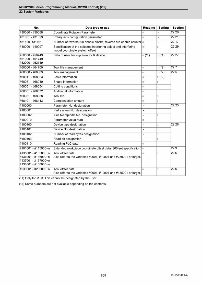
M800/M80 Series Programming Manual (M2/M0 Format) (2/2)
22 System Variables
869 IB-1501481-A
(*1) Only for MTB. This cannot be designated by the user.
(*2) Some numbers are not available depending on the contents.
#30060 - #30068 Coordinate Rotation Parameter ○ - 22.20
#31001 - #31023 Rotary axis configuration parameter ○ - 22.21
#31100, #31101 Number of reverse run enable blocks, reverse run enable counter ○ - 22.17
#40000 - #40097 Specification of the selected interfering object and interfering model coordinate system offset
○ ○ 22.29
#50000 - #50749#51000 - #51749#52000 - #52749
Data of user backup area for R device ○ (*1) ○ (*1) 22.27
#60000 - #64700 Tool life management ○ ○ (*2) 22.7
#68000 - #68003 Tool management ○ ○ (*2) 22.5
#68011 - #68023 Basic information ○ ○ (*2)
#68031 - #68040 Shape information ○ ○
#68051 - #68054 Cutting conditions ○ ○
#68061 - #68072 Additional information ○ ○
#68081 - #68088 Tool life ○ ○
#68101 - #68113 Compensation amount ○ ○
#100000 Parameter No. designation - ○ 22.23
#100001 Part system No. designation - ○
#100002 Axis No./spindle No. designation - ○
#100010 Parameter value read ○ -
#100100 Device type designation - ○ 22.28
#100101 Device No. designation - ○
#100102 Number of read bytes designation - ○
#100103 Read bit designation - ○
#100110 Reading PLC data ○ -
#101001 - #115950+n Extended workpiece coordinate offset data (300-set specification) ○ ○ 22.9
#135001 - #135000+n#136001 - #136000+n#137001 - #137000+n#138001 - #138000+n
Tool offset dataAlso refer to the variables #2001, #10001 and #230001 or larger.
○ ○ 22.6
#230001 - #230000+n Tool offset dataAlso refer to the variables #2001, #10001 and #135001 or larger.
○ ○ 22.6
No. Data type or use Reading Setting Section
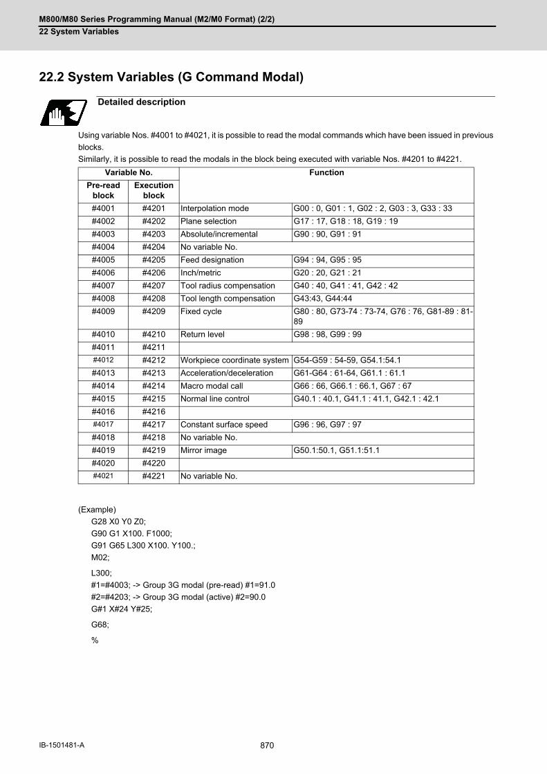
M800/M80 Series Programming Manual (M2/M0 Format) (2/2)
22 System Variables
870IB-1501481-A
22.2 System Variables (G Command Modal)
Using variable Nos. #4001 to #4021, it is possible to read the modal commands which have been issued in previous
blocks.
Similarly, it is possible to read the modals in the block being executed with variable Nos. #4201 to #4221.
(Example)
G28 X0 Y0 Z0;
G90 G1 X100. F1000;
G91 G65 L300 X100. Y100.;
M02;
L300;
#1=#4003; -> Group 3G modal (pre-read) #1=91.0
#2=#4203; -> Group 3G modal (active) #2=90.0
G#1 X#24 Y#25;
G68;
%
Detailed description
Variable No. Function
Pre-read block
Execution block
#4001 #4201 Interpolation mode G00 : 0, G01 : 1, G02 : 2, G03 : 3, G33 : 33
#4002 #4202 Plane selection G17 : 17, G18 : 18, G19 : 19
#4003 #4203 Absolute/incremental G90 : 90, G91 : 91
#4004 #4204 No variable No.
#4005 #4205 Feed designation G94 : 94, G95 : 95
#4006 #4206 Inch/metric G20 : 20, G21 : 21
#4007 #4207 Tool radius compensation G40 : 40, G41 : 41, G42 : 42
#4008 #4208 Tool length compensation G43:43, G44:44
#4009 #4209 Fixed cycle G80 : 80, G73-74 : 73-74, G76 : 76, G81-89 : 81-89
#4010 #4210 Return level G98 : 98, G99 : 99
#4011 #4211
#4012 #4212 Workpiece coordinate system G54-G59 : 54-59, G54.1:54.1
#4013 #4213 Acceleration/deceleration G61-G64 : 61-64, G61.1 : 61.1
#4014 #4214 Macro modal call G66 : 66, G66.1 : 66.1, G67 : 67
#4015 #4215 Normal line control G40.1 : 40.1, G41.1 : 41.1, G42.1 : 42.1
#4016 #4216
#4017 #4217 Constant surface speed G96 : 96, G97 : 97
#4018 #4218 No variable No.
#4019 #4219 Mirror image G50.1:50.1, G51.1:51.1
#4020 #4220
#4021 #4221 No variable No.

M800/M80 Series Programming Manual (M2/M0 Format) (2/2)
22 System Variables
871 IB-1501481-A
22.3 System Variables (Non-G Command Modal)
Using variable Nos. #4101 to #4120, it is possible to read the modal commands which have been issued in previous
blocks.
Similarly, it is possible to read the modals in the block being executed with variable Nos. #4301 to #4320.
(*1) Programs are registered as files. When the program No. (file name) is read with #4115, #4315, the character
string will be converted to a value.
(Example 1)
The file name "123" is the character string 0x31, 0x32, 0x33, so the value will be (0x31-0x30)*100 +
(0x32-0x30)*10 + (0x33-0x30) = 123.0.
Note that if the file name contains characters other than numbers, it will be "blank".
(Example 2)
If the file name is "123ABC", it contains characters other than numbers, so the result will be "blank".
Detailed description
Variable No. Modal information Variable No. Modal information
Pre-read block
Execution block
Pre-read Execution
#4101 #4301 #4111 #4311 Tool length compensation No. H
#4102 #4302 #4112 #4312
#4103 #4303 #4113 #4313 Miscellaneous function M
#4104 #4304 #4114 #4314 Sequence number N
#4105 #4305 #4115 #4315 Program number L(O) (*1)
#4106 #4306 #4116 #4316
#4107 #4307 Tool radius compensation No. D
#4117 #4317
#4108 #4308 #4118 #4318
#4109 #4309 Feedrate F #4119 #4319 Spindle function S
#4110 #4310 #4120 #4320 Tool function T
#4130 #4330 Extended workpiece coordi-nate system No. P

M800/M80 Series Programming Manual (M2/M0 Format) (2/2)
22 System Variables
872IB-1501481-A
22.4 System Variables (Modal Information at Macro Interruption)
Modal information when control passes to the user macro interruption program can be known by reading system
variables #4401 to #4520.
The unit specified with a command applies.
The above system variables are available only in the user macro interrupt program.
If they are used in other programs, program error (P241) will occur.
(*1) Programs are registered as files. When the program No. (file name) is read with #4515, the character string will
be converted to a value.
(Example 1)
The file name "123" is the character string 0x31, 0x32, 0x33, so the value will be (0x31-0x30)*100 + (0x32-
0x30)*10 + (0x33-0x30) = 123.0.
Note that if the file name contains characters other than numbers, it will be "blank".
(Example 2)
If the file name is "123ABC", it contains characters other than numbers, so the result will be "blank".
Detailed description
System variable Modal information
#4401 :
#4421
G code (group 01):G code (group 21)
Some groups are not used.
#4507 D code
#4509 F code
#4511 H code
#4513 M code
#4514 Sequence number N
#4515 Program number L(O) (*1)
#4519 S code
#4520 T code

M800/M80 Series Programming Manual (M2/M0 Format) (2/2)
22 System Variables
873 IB-1501481-A
If modal information is changed by the interrupt program, it is handled as follows after control returns from the inter-
rupt program to the main program.
Modal information affected by user macro interruption
Returning with G23; The change of modal information by the interrupt program is invalidated and the original modal information is restored. With interrupt type 1, however, if the interrupt program contains a move or mis-cellaneous function (MSTB) command, the original modal information is not re-stored.
Returning with G23H__; The original modal information is updated by the change in the interrupt pro-gram even after returning to the main program. This is the same as in returning with G23H__; from a program called by G22, etc.
La1 ;
Nh1 ;
G23(Hh1) ;
ION a1 ;
User macrointerruptionsignal (UIT)
Modal beforeinterrupt is restored.
Main programbeing executed
Modal modifiedby interruptprogram remainseffective.
Interrupt program
(Modal change)
(With Hh1 specified)
Modal information affected by user macro interruption
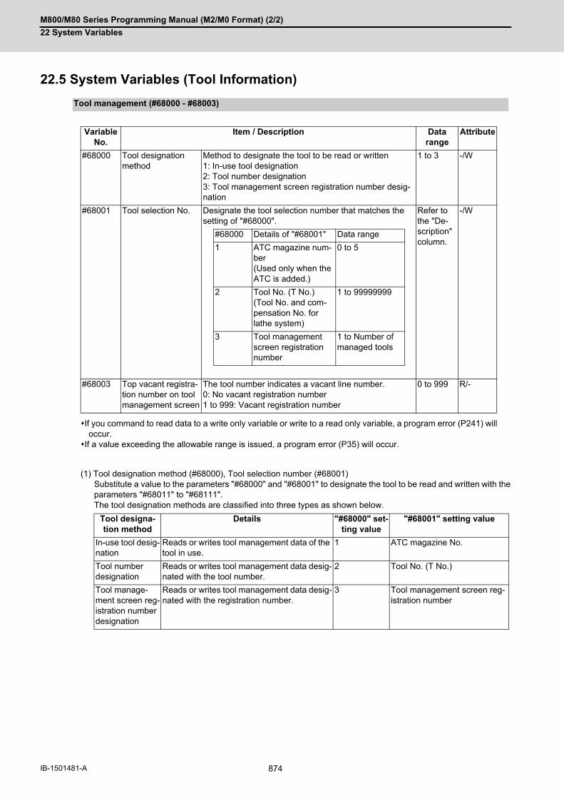
M800/M80 Series Programming Manual (M2/M0 Format) (2/2)
22 System Variables
874IB-1501481-A
22.5 System Variables (Tool Information)
If you command to read data to a write only variable or write to a read only variable, a program error (P241) willoccur.
If a value exceeding the allowable range is issued, a program error (P35) will occur.
(1) Tool designation method (#68000), Tool selection number (#68001)Substitute a value to the parameters "#68000" and "#68001" to designate the tool to be read and written with theparameters "#68011" to "#68111". The tool designation methods are classified into three types as shown below.
Tool management (#68000 - #68003)
Variable No.
Item / Description Data range
Attribute
#68000 Tool designation method
Method to designate the tool to be read or written1: In-use tool designation2: Tool number designation3: Tool management screen registration number desig-nation
1 to 3 -/W
#68001 Tool selection No. Designate the tool selection number that matches the setting of "#68000".
Refer to the "De-scription" column.
-/W
#68000 Details of "#68001" Data range
1 ATC magazine num-ber(Used only when the ATC is added.)
0 to 5
2 Tool No. (T No.)(Tool No. and com-pensation No. for lathe system)
1 to 99999999
3 Tool management screen registration number
1 to Number of managed tools
#68003 Top vacant registra-tion number on tool management screen
The tool number indicates a vacant line number. 0: No vacant registration number1 to 999: Vacant registration number
0 to 999 R/-
Tool designa-tion method
Details "#68000" set-ting value
"#68001" setting value
In-use tool desig-nation
Reads or writes tool management data of the tool in use.
1 ATC magazine No.
Tool number designation
Reads or writes tool management data desig-nated with the tool number.
2 Tool No. (T No.)
Tool manage-ment screen reg-istration number designation
Reads or writes tool management data desig-nated with the registration number.
3 Tool management screen reg-istration number

M800/M80 Series Programming Manual (M2/M0 Format) (2/2)
22 System Variables
875 IB-1501481-A
(a) In-use tool designation (#68000=1)
For the in-use tool, when the R register is checked in the order from "1" to "3" shown below, if the value des-
ignated in the R register is other than "0", it is judged to be the in-use tool number.
Tool life management spindle tool number in machining center system (R12200: 1st part system toR12270: 8th part system)
ATC spindle tool number (R10620: magazine 1 to R10660: magazine 5)T code data (R536)
"#68001" designates the ATC magazine number.
If ATC is not used, this item does not need to be designated.
The "#68001" setting value has the meanings shown below.
The in-use tool is determined when "#68000=1" or "#68001" is commanded. To designate the tool which is exchanged after the in-use tool has been determined as an in-use tool,command "#68000=1" or "#68001" again.
(b) Tool number designation (#68000=2)
"#68001" designates the tool number.
In the lathe system, designate the T code (tool number and tool compensation number).
(c) Tool management screen registration number designation (#68000=3)
"#68001" designates the tool management screen registration number (line number).
If "#68000" is commanded multiple times, the last designation method will be valid."#68000" and "#68001" are valid until they are reset. When the power is turned ON or when the system is
reset, "0" is set.When #68000 is 2, and when there are multiple tools which have the same tool number and the same tool
compensation number as the ones designated by "#68001", the tool that has been found first will be select-ed.A program error (P245) will occur when:
"#68001" setting value Meaning
"0" or no "#680001" command Magazine 1
1 to 5 Magazine 1 to magazine 5
"#68000" is not designated;
"#68000=1 ;" is commanded while the in-use tool number is set to "0";
"#68000=1 ;" is commanded while the in-use tool number is not registered on the tool management screen;
"#68000=2 ;" is commanded while a read/write command is issued using "#68011" to "#68111" without com-manding "#68001";
a tool not registered on the tool management screen with "#68011" is designated during the "#68000=2 ;" command;
a write command is issued with "#68011" during the "#68000=2 ;" command;
"#68000=3 ;" is commanded while a read/write command is issued using "#68011" to "#68111" without com-manding "#68001";
"#68001=0 ;" is commanded.
Note
Note

M800/M80 Series Programming Manual (M2/M0 Format) (2/2)
22 System Variables
876IB-1501481-A
(2) Top vacant registration number on tool management screen (#68003)
Designating this value reads the top vacant registration number on the tool management screen with "#68003".
Use example:
Follow the procedure below to measure the compensation amount with the measurement macro, etc. and search
for and register a vacant registration number when registering a new tool.
[Measurement macro program]
If no vacant registration number is found because all numbers are registered, "0" is set when "#68003" isread out. When "#68001=#68003;", "#68001" is set to "0", and a program error (P245) will occur.
:
#68000 = 3 ;
: Measurement
#68001=#68003 ; Searches for a vacant registration number (No.3 in the example above), and des-ignates registration number 3.
#68011=999 ; Sets "999" to the tool management data "tool number" of tool management screen registration number 3.
999
Note
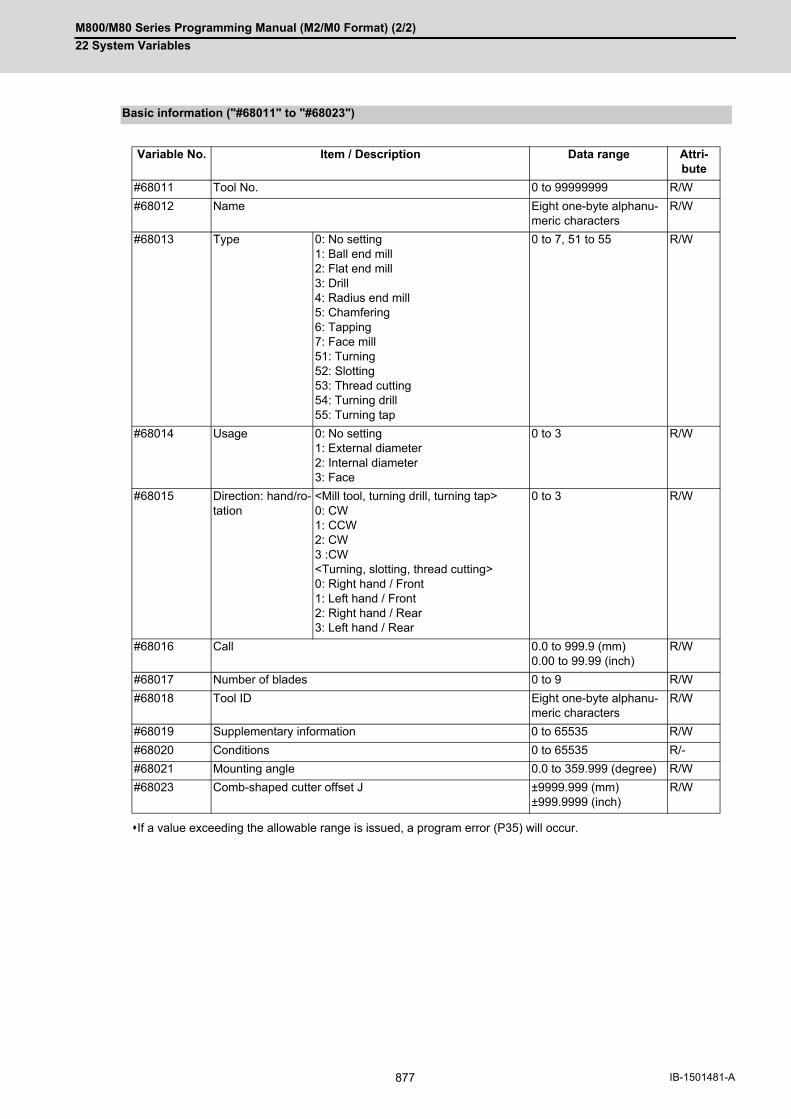
M800/M80 Series Programming Manual (M2/M0 Format) (2/2)
22 System Variables
877 IB-1501481-A
If a value exceeding the allowable range is issued, a program error (P35) will occur.
Basic information ("#68011" to "#68023")
Variable No. Item / Description Data range Attri-bute
#68011 Tool No. 0 to 99999999 R/W
#68012 Name Eight one-byte alphanu-meric characters
R/W
#68013 Type 0: No setting1: Ball end mill2: Flat end mill3: Drill4: Radius end mill5: Chamfering6: Tapping7: Face mill51: Turning52: Slotting53: Thread cutting54: Turning drill55: Turning tap
0 to 7, 51 to 55 R/W
#68014 Usage 0: No setting1: External diameter2: Internal diameter3: Face
0 to 3 R/W
#68015 Direction: hand/ro-tation
<Mill tool, turning drill, turning tap>0: CW1: CCW2: CW3 :CW<Turning, slotting, thread cutting>0: Right hand / Front1: Left hand / Front2: Right hand / Rear3: Left hand / Rear
0 to 3 R/W
#68016 Call 0.0 to 999.9 (mm)0.00 to 99.99 (inch)
R/W
#68017 Number of blades 0 to 9 R/W
#68018 Tool ID Eight one-byte alphanu-meric characters
R/W
#68019 Supplementary information 0 to 65535 R/W
#68020 Conditions 0 to 65535 R/-
#68021 Mounting angle 0.0 to 359.999 (degree) R/W
#68023 Comb-shaped cutter offset J ±9999.999 (mm) ±999.9999 (inch)
R/W

M800/M80 Series Programming Manual (M2/M0 Format) (2/2)
22 System Variables
878IB-1501481-A
(1) Tool No. ("#68011")The registered tool cannot be registered. If a tool is registered, the operation will be performed as shown below.
Example: When an attempt is made to change tool management data "tool number" of No.3 (3rd line) from "11"
to "1" in life management II of the machining center system, the setting is as follows.
(2) Tool name ("#68012"), Tool ID ("#68018"), Material ("#68053")
(a) Read
Reads data only with the variable No. designation of the DPRNT command.
(b) Write
A string can be designated by enclosing it in parentheses ( ).
(3) Type ("#68013") to tool nose point P ("#68111")A program error will occur in the following case.
(4) Compensation amount ("#68103" to "#68111")A program error will occur in the following case.
Type Operation performed when a reg-istered tool is designated
Machining center sys-tem
Life management I Program error (P245)
Life management II Program error (P245)
Life management III Program error (P245)
The life management specifications are invalid. Program error (P245)
Lathe system Life management I Program error (P245)
Life management II Can be registered.
The life management specifications are invalid. Can be registered.
#68000=3 Tool management screen registration number designation
#68001=3 Designates No. 3 (3rd line)
#68013=1 Tool No. 1 is already registered with No. 1 (1st line), causing a program error (P245).
Example 1: DPRNT [#68012] ; The tool name is read.
Example 2: #100=#68012 ; A program error (P243) will occur.
Example 1: #68012=(M-TOOL1) ;
Data is written up to the number of valid characters, and the rest is ig-nored.
Example 2: #68012=#0 ; A string is cleared by writing "null" characters.
Example 3: #68012= M-TOOL1 ;
If parentheses are omitted, a program error will occur.
Operation Operation result
Type ("#68013") to tool nose point P ("#68111") is read or written for the registration number with the tool num-ber unspecified.
Program error (P245)
Operation Operation result
The compensation amount ("#68103" to "#68111") is read or written for the tool with the compensation number unspecified.
Program error (P170)
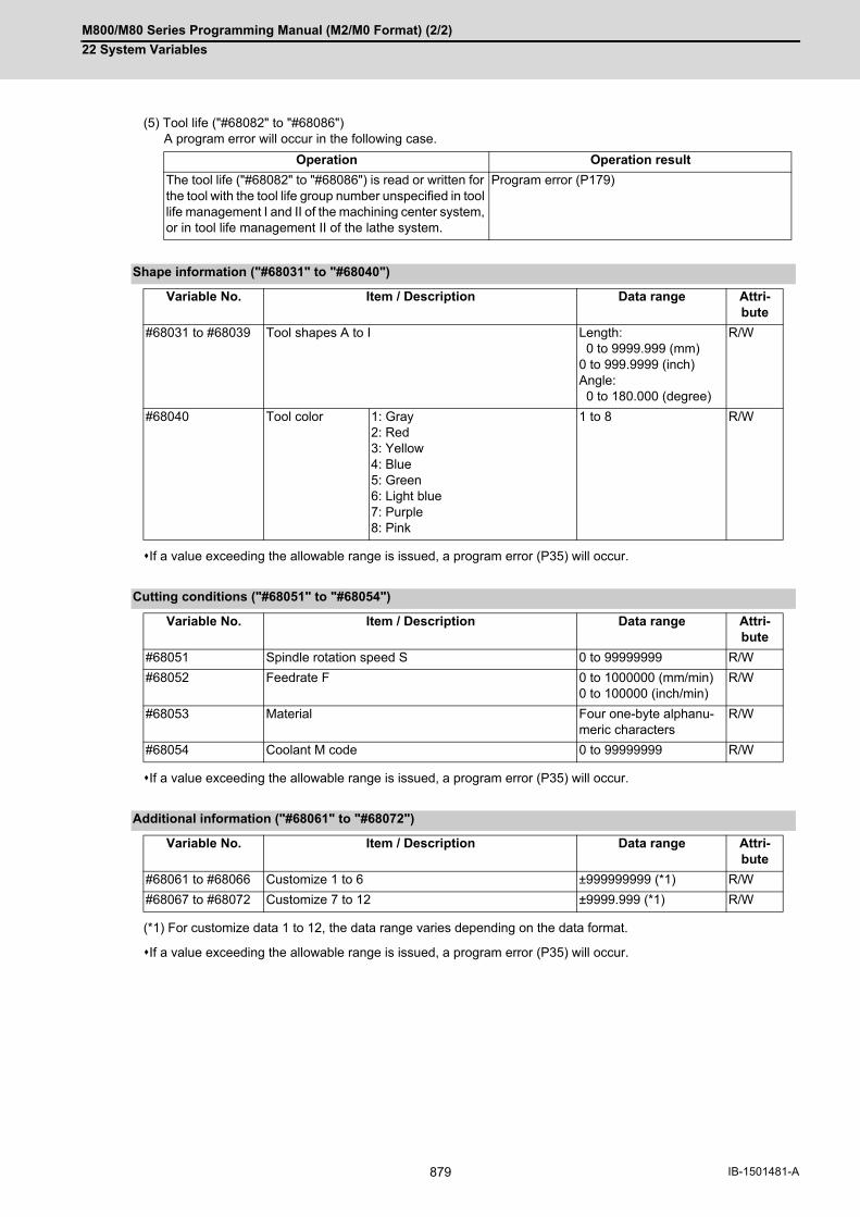
M800/M80 Series Programming Manual (M2/M0 Format) (2/2)
22 System Variables
879 IB-1501481-A
(5) Tool life ("#68082" to "#68086")A program error will occur in the following case.
If a value exceeding the allowable range is issued, a program error (P35) will occur.
If a value exceeding the allowable range is issued, a program error (P35) will occur.
(*1) For customize data 1 to 12, the data range varies depending on the data format.
If a value exceeding the allowable range is issued, a program error (P35) will occur.
Operation Operation result
The tool life ("#68082" to "#68086") is read or written for the tool with the tool life group number unspecified in tool life management I and II of the machining center system, or in tool life management II of the lathe system.
Program error (P179)
Shape information ("#68031" to "#68040")
Variable No. Item / Description Data range Attri-bute
#68031 to #68039 Tool shapes A to I Length: 0 to 9999.999 (mm)0 to 999.9999 (inch)Angle: 0 to 180.000 (degree)
R/W
#68040 Tool color 1: Gray2: Red3: Yellow4: Blue5: Green6: Light blue7: Purple8: Pink
1 to 8 R/W
Cutting conditions ("#68051" to "#68054")
Variable No. Item / Description Data range Attri-bute
#68051 Spindle rotation speed S 0 to 99999999 R/W
#68052 Feedrate F 0 to 1000000 (mm/min) 0 to 100000 (inch/min)
R/W
#68053 Material Four one-byte alphanu-meric characters
R/W
#68054 Coolant M code 0 to 99999999 R/W
Additional information ("#68061" to "#68072")
Variable No. Item / Description Data range Attri-bute
#68061 to #68066 Customize 1 to 6 ±999999999 (*1) R/W
#68067 to #68072 Customize 7 to 12 ±9999.999 (*1) R/W
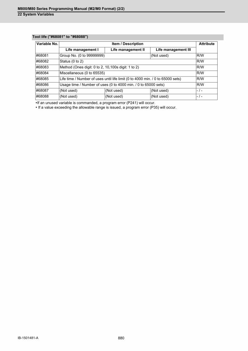
M800/M80 Series Programming Manual (M2/M0 Format) (2/2)
22 System Variables
880IB-1501481-A
If an unused variable is commanded, a program error (P241) will occur. If a value exceeding the allowable range is issued, a program error (P35) will occur.
Tool life ("#68081" to "#68088")
Variable No. Item / Description Attribute
Life management I Life management II Life management III
#68081 Group No. (0 to 99999999) (Not used) R/W
#68082 Status (0 to 2) R/W
#68083 Method (Ones digit: 0 to 2, 10,100s digit: 1 to 2) R/W
#68084 Miscellaneous (0 to 65535) R/W
#68085 Life time / Number of uses until life limit (0 to 4000 min. / 0 to 65000 sets) R/W
#68086 Usage time / Number of uses (0 to 4000 min. / 0 to 65000 sets) R/W
#68087 (Not used) (Not used) (Not used) - / -
#68088 (Not used) (Not used) (Not used) - / -

M800/M80 Series Programming Manual (M2/M0 Format) (2/2)
22 System Variables
881 IB-1501481-A
If an unused variable is commanded, a program error (P241) will occur.If a value exceeding the allowable range is issued, a program error (P35) will occur.
Compensation amount ("#68101" to "#68113")
Variable No. Item / Description Attri-buteCompensation type I Compensation type II Compensation type III
#68101 No. H (0 to number of tool offset sets)
No. H (0 to number of tool offset sets)
Tool length compensation No.(0 to number of tool offset sets)
R/W
#68102 (Not used) No. D (0 to number of tool offset sets)
Wear compensation No.(0 to number of tool offset sets)
R/W
#68103 Tool length(±9999.999999 (mm)±999.9999999 (inch))
Length dimension(±9999.999999 (mm)±999.9999999 (inch))
Tool length X(±9999.999999 (mm)±999.9999999 (inch))
R/W
#68104 (Not used) (Not used) Tool length Z(±9999.999999 (mm)±999.9999999 (inch))
R/W
#68105 (Not used) (Not used) Additional axis tool length(±9999.999999 (mm)±999.9999999 (inch))
R/W
#68106 (Not used) Length wear(±9999.999999 (mm)±999.9999999 (inch))
Wear X(±9999.999999 (mm)±999.9999999 (inch))
R/W
#68107 (Not used) (Not used) Wear Z(±9999.999999 (mm)±999.9999999 (inch))
R/W
#68108 (Not used) (Not used) Additional axis wear(±9999.999999 (mm)±999.9999999 (inch))
R/W
#68109 (Not used) Radius dimension(±9999.999999 (mm)±999.9999999 (inch))
Tool nose radius(±9999.999999 (mm)±999.9999999 (inch))
R/W
#68110 (Not used) Radius wear(±9999.999999 (mm)±999.9999999 (inch))
Radius wear(±9999.999999 (mm)±999.9999999 (inch))
R/W
#68111 (Not used) (Not used) Tool nose point P(0 to 9)
R/W
#68112 (Not used) (Not used) 2nd additional axis tool length(±9999.999999 (mm)±999.9999999 (inch))
R/W
#68113 (Not used) (Not used) 2nd additional axis wear(±9999.999999 (mm)±999.9999999 (inch))
R/W
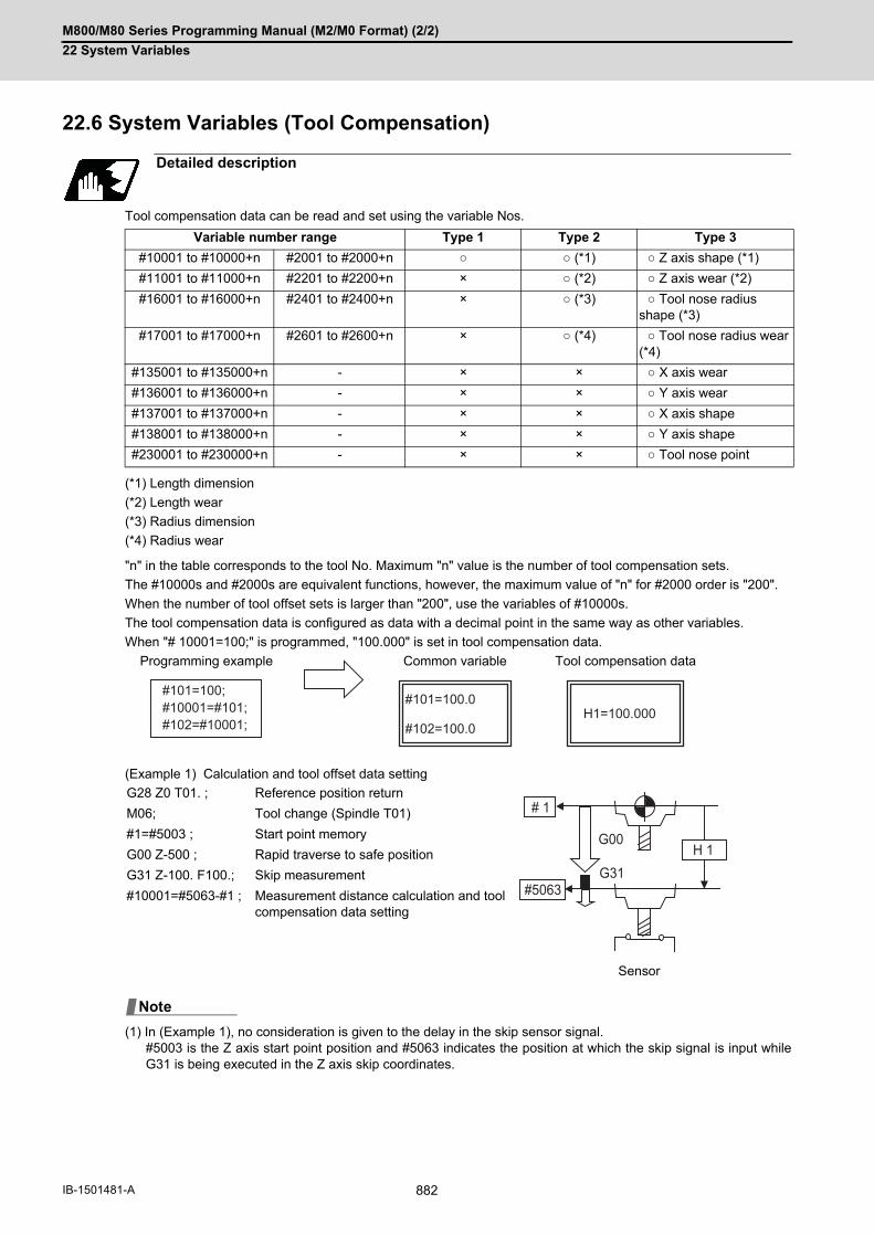
M800/M80 Series Programming Manual (M2/M0 Format) (2/2)
22 System Variables
882IB-1501481-A
22.6 System Variables (Tool Compensation)
Tool compensation data can be read and set using the variable Nos.
(*1) Length dimension
(*2) Length wear
(*3) Radius dimension
(*4) Radius wear
"n" in the table corresponds to the tool No. Maximum "n" value is the number of tool compensation sets.
The #10000s and #2000s are equivalent functions, however, the maximum value of "n" for #2000 order is "200".
When the number of tool offset sets is larger than "200", use the variables of #10000s.
The tool compensation data is configured as data with a decimal point in the same way as other variables.
When "# 10001=100;" is programmed, "100.000" is set in tool compensation data.
(Example 1) Calculation and tool offset data setting
(1) In (Example 1), no consideration is given to the delay in the skip sensor signal. #5003 is the Z axis start point position and #5063 indicates the position at which the skip signal is input whileG31 is being executed in the Z axis skip coordinates.
Detailed description
Variable number range Type 1 Type 2 Type 3
#10001 to #10000+n #2001 to #2000+n ○ ○ (*1) ○ Z axis shape (*1)
#11001 to #11000+n #2201 to #2200+n × ○ (*2) ○ Z axis wear (*2)
#16001 to #16000+n #2401 to #2400+n × ○ (*3) ○ Tool nose radius shape (*3)
#17001 to #17000+n #2601 to #2600+n × ○ (*4) ○ Tool nose radius wear (*4)
#135001 to #135000+n - × × ○ X axis wear
#136001 to #136000+n - × × ○ Y axis wear
#137001 to #137000+n - × × ○ X axis shape
#138001 to #138000+n - × × ○ Y axis shape
#230001 to #230000+n - × × ○ Tool nose point
Programming example Common variable Tool compensation data
G28 Z0 T01. ; Reference position return
M06; Tool change (Spindle T01)
#1=#5003 ; Start point memory
G00 Z-500 ; Rapid traverse to safe position
G31 Z-100. F100.; Skip measurement
#10001=#5063-#1 ; Measurement distance calculation and tool compensation data setting
Sensor
#101=100;#10001=#101;#102=#10001;
#101=100.0
#102=100.0H1=100.000
# 1
H 1
#5063G31
G00
Note

M800/M80 Series Programming Manual (M2/M0 Format) (2/2)
22 System Variables
883 IB-1501481-A
22.7 System Variables (Tool Life Management)
(1) Group number designation#60000Assign the value to this variable No. to designate the group number of the tool life management data to be readwith parameters "#60001" to "#64700". If a group No. is not designated, the data of the group registered first isread. This is valid until reset. When the tool life management III are provided, the group No. other than 1 cannotbe used.
(2) Tool life management system variable No. (Read)#60001 to #64700# | a | b | c | d | e |
| a | : "6" Fix (Tool life management)
| b | c | : Details of data classification
The group No. and life data are common for the group.
| d | e | : Registration No. or data type
Registration No.
Data type
Detailed description
Definition of variable Nos.
Data class Details Remarks
00 For control Refer by data types
05 Group No. Refer by registration No.
10 Tool No. Refer by registration No.
15 Tool data flag Refer by registration No.
20 Tool status Refer by registration No.
25 Life data Refer by registration No.
30 Usage data Refer by registration No.
35 Tool length compensation data Refer by registration No.
40 Tool radius compensation data Refer by registration No.
45 Auxiliary data Refer by registration No.
1 to 200
Type Details
1 Number of registered tools
2 Life current value
3 Tool selection No.
4 Number of remaining registered tools
5 Execution signal
6 Cutting time cumulative value (min)
7 Life end signal
8 Life prediction signal

M800/M80 Series Programming Manual (M2/M0 Format) (2/2)
22 System Variables
884IB-1501481-A
(*1) Designate group number "#60000".
List of variables
Variable No.
Item Type Details Data range
60001 Number of regis-tered tools
Common to sys-tem
Total number of tools registered in each group.
0 to 200
60002 Life current value For each group(*1)
In-use tool usage time / number of usesUsage data of the spindle tool or in-use tool (#60003)
0 to 4000min.0 to 65000 sets
60003 Tool selection No. In-use tool registration numberRegistration number of the spindle tool (the first tool of ST:1 when the spindle tool is not data of the designated group, the first tool of ST:0 when ST:1 is not defined, or the last tool when all tools have reached the end of their lives)
0 to 200
60004 Number of re-maining regis-tered tools
No. of first registered tool that has not reached its life.
0 to 200
60005 Execution signal "1" when this group is used in the pro-gram being executed."1" when the group number of spindle tool data matches that of the designated group.
0/1
60006 Cutting time cu-mulative value (min)
Indicates the time that this group is used in the program being executed.
(Not used)
60007 Life end signal "1" when lives of all tools in this group have expired."1" when all registered tools in the desig-nated group reach the end of their lives.
0/1
60008 Life prediction signal
"1" when a new tool is selected with the next command in this group."1" when there are no tools in use (ST: 1) while there is an unused tool (ST: 0) in the designated group.
0/1

M800/M80 Series Programming Manual (M2/M0 Format) (2/2)
22 System Variables
885 IB-1501481-A
(*2) Designate group number "#60000" / registration number***.
However, group number / method / life is data common to groups.
Variable No.
Item Type Details Data range
60500+***
Group No. For each group/registration num-ber (*2)
This group's No. 1 to 99999999
61000+***
Tool No. Tool No. of the designated tool 1 to 99999999
61500+***
Tool dataFlag
Parameters such as usage data count method, length compensation method, tool radius compensation methodbit0,1: Tool length compensation data for-matbit2,3: Tool radius compensation data for-mat0: Compensation number method1: Incremental value compensation amount method2: Absolute value compensation amount methodbit4,5: Tool life management method0: Usage time1: Number of mounts2: Number of uses
0 to FF (H)
62000+***
Tool status Tool usage state0: Unused tool1: In-use tool2: Normal life tool3: Tool error 14: Tool error 2
0 to 4
62500+***
Life data Life time or No. of lives for each tool 0 to 4000 min.0 to 65000 sets
63000+***
Usage data Usage time or No. of uses for each tool 0 to 4000 min.0 to 65000 sets
63500+***
Tool length com-pensation data
Length compensation data set as com-pensation No., absolute value compensa-tion amount or increment value compensation amount method.
Compensation No. 0 and afterNumber of tool com-pensation setsAbsolute value com-pensation amount±999.999 (*1)Incremental value compensation amount±999.999 (*1)
64000+***
Tool radius com-pensation data
Radius compensation data set as com-pensation No., absolute value compensa-tion amount or increment value compensation amount method.
Compensation No. 0 and afterNumber of tool com-pensation setsAbsolute value com-pensation amount±999.999 (*1)Incremental value compensation amount±999.999 (*1)
64500+***
Auxiliary data Spare data 0 to 65535
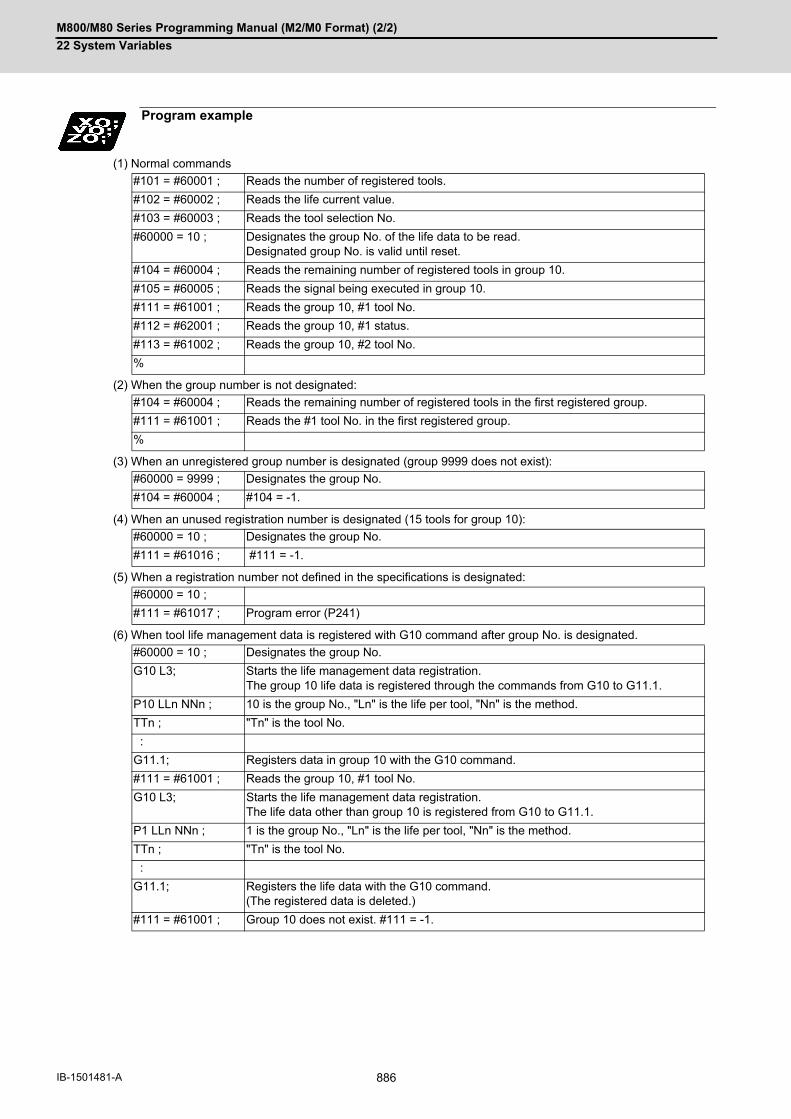
M800/M80 Series Programming Manual (M2/M0 Format) (2/2)
22 System Variables
886IB-1501481-A
(1) Normal commands
(2) When the group number is not designated:
(3) When an unregistered group number is designated (group 9999 does not exist):
(4) When an unused registration number is designated (15 tools for group 10):
(5) When a registration number not defined in the specifications is designated:
(6) When tool life management data is registered with G10 command after group No. is designated.
Program example
#101 = #60001 ; Reads the number of registered tools.
#102 = #60002 ; Reads the life current value.
#103 = #60003 ; Reads the tool selection No.
#60000 = 10 ; Designates the group No. of the life data to be read. Designated group No. is valid until reset.
#104 = #60004 ; Reads the remaining number of registered tools in group 10.
#105 = #60005 ; Reads the signal being executed in group 10.
#111 = #61001 ; Reads the group 10, #1 tool No.
#112 = #62001 ; Reads the group 10, #1 status.
#113 = #61002 ; Reads the group 10, #2 tool No.
%
#104 = #60004 ; Reads the remaining number of registered tools in the first registered group.
#111 = #61001 ; Reads the #1 tool No. in the first registered group.
%
#60000 = 9999 ; Designates the group No.
#104 = #60004 ; #104 = -1.
#60000 = 10 ; Designates the group No.
#111 = #61016 ; #111 = -1.
#60000 = 10 ;
#111 = #61017 ; Program error (P241)
#60000 = 10 ; Designates the group No.
G10 L3; Starts the life management data registration. The group 10 life data is registered through the commands from G10 to G11.1.
P10 LLn NNn ; 10 is the group No., "Ln" is the life per tool, "Nn" is the method.
TTn ; "Tn" is the tool No.
:
G11.1; Registers data in group 10 with the G10 command.
#111 = #61001 ; Reads the group 10, #1 tool No.
G10 L3; Starts the life management data registration. The life data other than group 10 is registered from G10 to G11.1.
P1 LLn NNn ; 1 is the group No., "Ln" is the life per tool, "Nn" is the method.
TTn ; "Tn" is the tool No.
:
G11.1; Registers the life data with the G10 command. (The registered data is deleted.)
#111 = #61001 ; Group 10 does not exist. #111 = -1.
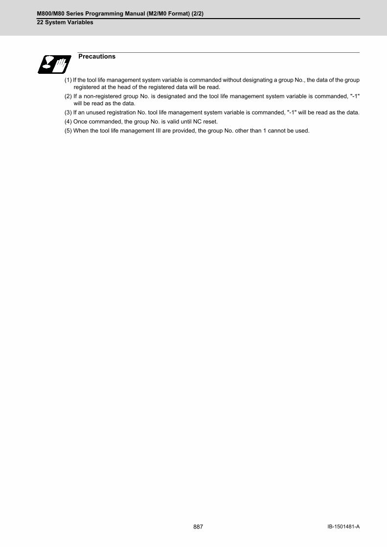
M800/M80 Series Programming Manual (M2/M0 Format) (2/2)
22 System Variables
887 IB-1501481-A
(1) If the tool life management system variable is commanded without designating a group No., the data of the groupregistered at the head of the registered data will be read.
(2) If a non-registered group No. is designated and the tool life management system variable is commanded, "-1"will be read as the data.
(3) If an unused registration No. tool life management system variable is commanded, "-1" will be read as the data.
(4) Once commanded, the group No. is valid until NC reset.
(5) When the tool life management III are provided, the group No. other than 1 cannot be used.
Precautions

M800/M80 Series Programming Manual (M2/M0 Format) (2/2)
22 System Variables
888IB-1501481-A
22.8 System Variables (Workpiece Coordinate Offset)
By using variable Nos #5201 to #532n, it is possible to read out the workpiece coordinate system compensation data
or to substitute values.
(1) The number of controllable axes varies depending on the specifications. The last digit of the variable No. corresponds to the control axis No.
This is an example where the external workpiece compensation values are added to the workpiece coordinate (G54,
G55) system compensation values without changing the position of the workpiece coordinate systems.
Detailed description
Coordinate name 1st axis 2nd axis
3rd axis 4th axis ..... nth axis Remarks
External workpiece offset
#5201 #5202 #5203 #5204 ..... #520n External workpiece offset specifica-tions are required.
G54 #5221 #5222 #5223 #5224 ..... #522n Workpiece coordinate system offset specifications are required.G55 #5241 #5242 #5243 #5244 ..... #524n
G56 #5261 #5262 #5263 #5264 ..... #526n
G57 #5281 #5282 #5283 #5284 ..... #528n
G58 #5301 #5302 #5303 #5304 ..... #530n
G59 #5321 #5322 #5323 #5324 ..... #532n
Note
N1 G28 X0 Y0 Z0 ;N2 #5221=-20. #5222=-20. ;N3 G90 G00 G54 X0 Y0 ;
N10 #5221=-90. #5222=-10. ;N11 G90 G00 G54 X0Y0 ;
M02 ;
N100 #5221=#5221+#5201 ; #5222=#5222+#5202 ; #5241=#5241+#5201 ;
#5242=#5242+#5202 ; #5201=0 #5202=0;
- 90. - 20.
- 20.
- 10.
N1
N3
W1W1 N11
W1 (G54)W2 (G55)
G55 G54
W2 (G55)W1 (G54)
M
G54G55
Y
X
G54 workpiece coordinatesystem defined by N10
Coordinatesystem afterchange
Coordinatesystem beforechange
(Example 1)
(Example 2)
G54 workpiece coordinatesystem defined by N2
Basic machine coordinateExternal workpiece offset
Basic machine coordinate system
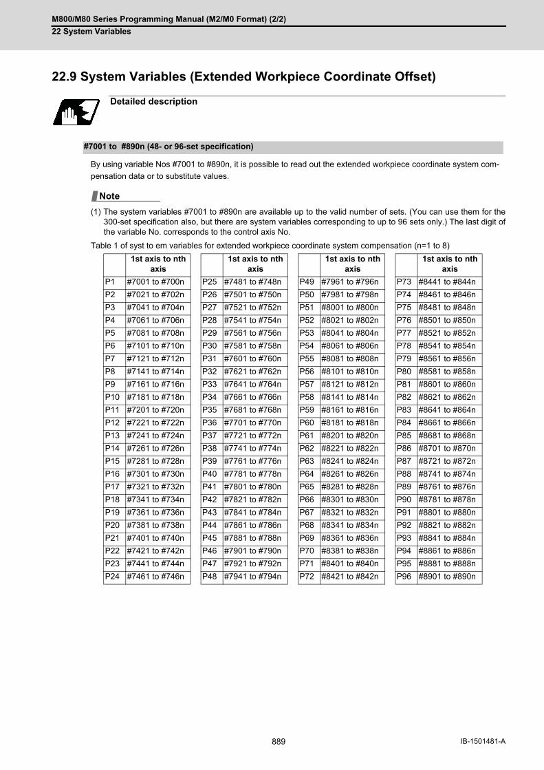
M800/M80 Series Programming Manual (M2/M0 Format) (2/2)
22 System Variables
889 IB-1501481-A
22.9 System Variables (Extended Workpiece Coordinate Offset)
By using variable Nos #7001 to #890n, it is possible to read out the extended workpiece coordinate system com-
pensation data or to substitute values.
(1) The system variables #7001 to #890n are available up to the valid number of sets. (You can use them for the300-set specification also, but there are system variables corresponding to up to 96 sets only.) The last digit ofthe variable No. corresponds to the control axis No.
Table 1 of syst to em variables for extended workpiece coordinate system compensation (n=1 to 8)
Detailed description
#7001 to #890n (48- or 96-set specification)
1st axis to nth axis
1st axis to nth axis
1st axis to nth axis
1st axis to nth axis
P1 #7001 to #700n P25 #7481 to #748n P49 #7961 to #796n P73 #8441 to #844n
P2 #7021 to #702n P26 #7501 to #750n P50 #7981 to #798n P74 #8461 to #846n
P3 #7041 to #704n P27 #7521 to #752n P51 #8001 to #800n P75 #8481 to #848n
P4 #7061 to #706n P28 #7541 to #754n P52 #8021 to #802n P76 #8501 to #850n
P5 #7081 to #708n P29 #7561 to #756n P53 #8041 to #804n P77 #8521 to #852n
P6 #7101 to #710n P30 #7581 to #758n P54 #8061 to #806n P78 #8541 to #854n
P7 #7121 to #712n P31 #7601 to #760n P55 #8081 to #808n P79 #8561 to #856n
P8 #7141 to #714n P32 #7621 to #762n P56 #8101 to #810n P80 #8581 to #858n
P9 #7161 to #716n P33 #7641 to #764n P57 #8121 to #812n P81 #8601 to #860n
P10 #7181 to #718n P34 #7661 to #766n P58 #8141 to #814n P82 #8621 to #862n
P11 #7201 to #720n P35 #7681 to #768n P59 #8161 to #816n P83 #8641 to #864n
P12 #7221 to #722n P36 #7701 to #770n P60 #8181 to #818n P84 #8661 to #866n
P13 #7241 to #724n P37 #7721 to #772n P61 #8201 to #820n P85 #8681 to #868n
P14 #7261 to #726n P38 #7741 to #774n P62 #8221 to #822n P86 #8701 to #870n
P15 #7281 to #728n P39 #7761 to #776n P63 #8241 to #824n P87 #8721 to #872n
P16 #7301 to #730n P40 #7781 to #778n P64 #8261 to #826n P88 #8741 to #874n
P17 #7321 to #732n P41 #7801 to #780n P65 #8281 to #828n P89 #8761 to #876n
P18 #7341 to #734n P42 #7821 to #782n P66 #8301 to #830n P90 #8781 to #878n
P19 #7361 to #736n P43 #7841 to #784n P67 #8321 to #832n P91 #8801 to #880n
P20 #7381 to #738n P44 #7861 to #786n P68 #8341 to #834n P92 #8821 to #882n
P21 #7401 to #740n P45 #7881 to #788n P69 #8361 to #836n P93 #8841 to #884n
P22 #7421 to #742n P46 #7901 to #790n P70 #8381 to #838n P94 #8861 to #886n
P23 #7441 to #744n P47 #7921 to #792n P71 #8401 to #840n P95 #8881 to #888n
P24 #7461 to #746n P48 #7941 to #794n P72 #8421 to #842n P96 #8901 to #890n
Note

M800/M80 Series Programming Manual (M2/M0 Format) (2/2)
22 System Variables
890IB-1501481-A
By using variable Nos #101001 to #11595n, it is possible to read out the extended workpiece coordinate system
compensation data or to substitute values.
(1) The system variables #101001 to #11595n are available when the 300-set specification is enabled. If you usethe system variables #101001 to #11595n when the 300-set specification is disabled, the program error (P241)will occur. The last digit of the variable No. corresponds to the control axis No.
Table 2 of syst to em variables for extended workpiece coordinate system compensation (n=1 to 8)
22.10 System Variables (External Workpiece Coordinate Offset)
The workpiece coordinate system compensation amount can be read using variables #2501 and #2601.
By substituting a value in these variable Nos., the workpiece coordinate system compensation amount can be
changed.
#101001 to #11595n (300-set specification)
1st axis to nth axis
P1 #101001 to #10100n
P2 #101051 to #10105n
P3 #101101 to #10110n
P4 #101151 to #10115n
P5 #101201 to #10120n
P6 #101251 to #10125n
P7 #101301 to #10130n
P8 #101351 to #10135n
: :
: :
P298 #115851 to #101585n
P299 #115901 to #101590n
P300 #118951 to #101595n
Detailed description
System variable No. External workpiece coordinate system offset amount
#2501 1st axis
#2601 2nd axis
Note

M800/M80 Series Programming Manual (M2/M0 Format) (2/2)
22 System Variables
891 IB-1501481-A
22.11 System Variables (Position Information)
Using variable Nos. #5001 to #5160+n, it is possible to read the end point coordinates, machine coordinates, work-
piece coordinates, skip coordinates, tool position compensation amount and servo deviation amounts in the last
block.
The number of axes which can be controlled differs according to the specifications. The last digit of the variable No. corresponds to the control axis No.
Detailed description
Position information Axis No. (in part system) Reading during move-
ment1 2 3 ... n
End point coordinate of the last block #5001 #5002 #5003 ... #5000+n Enabled
Machine coordinate #5021 #5022 #5023 ... #5020+n Disabled
Workpiece coordinate #5041 #5042 #5043 ... #5040+n Disabled
Skip coor-dinate
Parame-ters
#8713
0 Workpiece coordi-nate system
#5061 #5062 #5063 ... #5060+n Enabled
1 Feature coordinate /
Workpiece installa-tion coordinate
Feature coordinate/Workpiece in-stallation coordinate
#5161 #5162 #5163 ... #5160+n
Tool position compensation amount #5081 #5082 #5083 ... #5080+n Disabled
Servo deviation amount #5101 #5102 #5103 ... #5100+n Enabled
Macro interruption stop Start point coordi-nates
#5121 #5122 #5123 ... #5120+n Enabled
Macro interruption stop End point coordinates #5141 #5142 #5143 ... #5140+n Enabled
Note
W
M
M
W
G01
G00
Readcommand
Basic machine coordinate system
[Workpiececoordinates]
[End pointcoordinates]
Workpiece coordinate system
Workpiececoordinatesystem
Machinecoordinatesystem[Machine
coordinates]
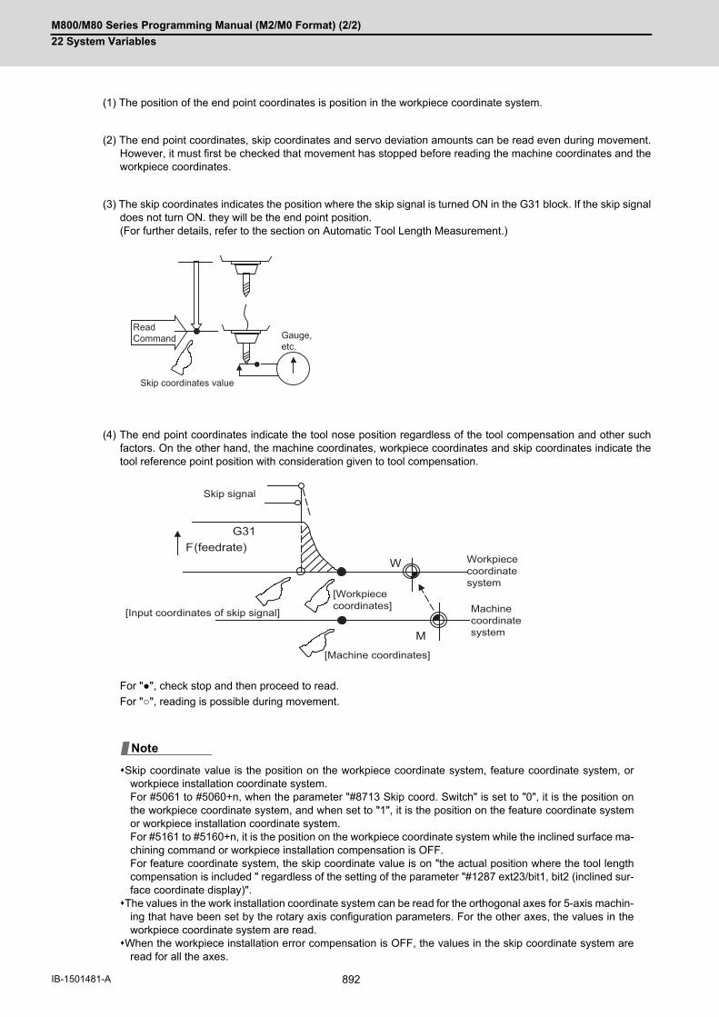
M800/M80 Series Programming Manual (M2/M0 Format) (2/2)
22 System Variables
892IB-1501481-A
(1) The position of the end point coordinates is position in the workpiece coordinate system.
(2) The end point coordinates, skip coordinates and servo deviation amounts can be read even during movement.However, it must first be checked that movement has stopped before reading the machine coordinates and theworkpiece coordinates.
(3) The skip coordinates indicates the position where the skip signal is turned ON in the G31 block. If the skip signaldoes not turn ON. they will be the end point position. (For further details, refer to the section on Automatic Tool Length Measurement.)
(4) The end point coordinates indicate the tool nose position regardless of the tool compensation and other suchfactors. On the other hand, the machine coordinates, workpiece coordinates and skip coordinates indicate thetool reference point position with consideration given to tool compensation.
For "●", check stop and then proceed to read.
For "○", reading is possible during movement.
Skip coordinate value is the position on the workpiece coordinate system, feature coordinate system, orworkpiece installation coordinate system. For #5061 to #5060+n, when the parameter "#8713 Skip coord. Switch" is set to "0", it is the position onthe workpiece coordinate system, and when set to "1", it is the position on the feature coordinate systemor workpiece installation coordinate system. For #5161 to #5160+n, it is the position on the workpiece coordinate system while the inclined surface ma-chining command or workpiece installation compensation is OFF. For feature coordinate system, the skip coordinate value is on "the actual position where the tool lengthcompensation is included " regardless of the setting of the parameter "#1287 ext23/bit1, bit2 (inclined sur-face coordinate display)".
The values in the work installation coordinate system can be read for the orthogonal axes for 5-axis machin-ing that have been set by the rotary axis configuration parameters. For the other axes, the values in theworkpiece coordinate system are read.
When the workpiece installation error compensation is OFF, the values in the skip coordinate system areread for all the axes.
ReadCommand
Skip coordinates value
Gauge,etc.
FG31
W
M
(feedrate)
Skip signal
Machine coordinatesystem
[Workpiececoordinates]
[Machine coordinates]
[Input coordinates of skip signal]
Workpiece coordinatesystem
Note

M800/M80 Series Programming Manual (M2/M0 Format) (2/2)
22 System Variables
893 IB-1501481-A
The coordinate value in variable Nos. #5061 to #5060+n or #5161 to #5160+n memorize the moments whenthe skip input signal during movement was input and so they can be read at any subsequent time. For details, refer to "21.2 Skip Function; G31".
When the parameter "#1366 skipExTyp" (Multi-part system simultaneous skip command) is set to "1", theskip coordinate value will be "0", even if G31 command is given in one-part system or G31 command isgiven in only one of the multiple part systems.

M800/M80 Series Programming Manual (M2/M0 Format) (2/2)
22 System Variables
894IB-1501481-A
(Example 1) Example of workpiece position measurement
An example to measure the distance from the measured reference position to the workpiece edge is shown be-
low.
(Example 2) Reading of skip input coordinates
ε is the error caused by response delay. Refer to "21.2 Skip Function; G31" for details.
#122 is the N4 skip signal input coordinates as there is no Y command at N7.
#101 X axis measurement amount N1 G90/G91 modal recording
#102 Y axis measurement amount N2 X, Y start point recording
#103 Measurement linear segment amount
N3 Z axis entry amount
N4 X, Y measurement (Stop at skip input)
#5001 X axis measurement start point N5 Return to X, Y start point
#5002 Y axis measurement start point N6 X, Y measurement incremental value calculation
N7 Measurement linear segment calculation
#5061 X axis skip input point N8 Z axis escape
#5062 Y axis skip input point N9,N10 G90/G91 modal return
N11 Main program return
(a) Skip signal
#111=-75.+ε #112=-75.+ε
#121=-25.+ε #122=-75.+ε
G65 L9031 X100. Y100. Z-10. F200;
F(#9) 200X(#24)100.000Y(#25)100.000Z(#26) - 10.000
#101 87.245#102 87.245#103 123.383
N1 #180=#4003;N2 #30=#5001 #31=#5002;N3 G91 G01 Z#26 F#9;N4 G31 X#24 Y#25 F#9;N5 G90 G00 X#30 Y#31;N6 #101=#30- #5061 #102=#31- #5062;N7 #103=SQR #101*#101+#102*#102 ;N8 G91 G01Z- #26;N9 IF #180 EQ 91 GOTO 11;N10 G90;N11 G23;
L9031
N3N4
N5N8 #103#102
#101X
Z
Y
To subprogram
Main program
Argument <Local variable>
<Common variable>
Start point
Skip input
N1 G91 G28 X0 Y0;N2 G90 G00 X0 Y0;N3 X0 Y- 100.;N4 G31 X- 150. Y- 50. F80;N5 #111=#5061#112=#5062;N6 G00 Y0;N7 G31 X0;N8 #121=#5061#122=#5062;N9 M02;
- Y
- 150
- 50
- 75
- 100
- 75 - 25 YX- X
(a)
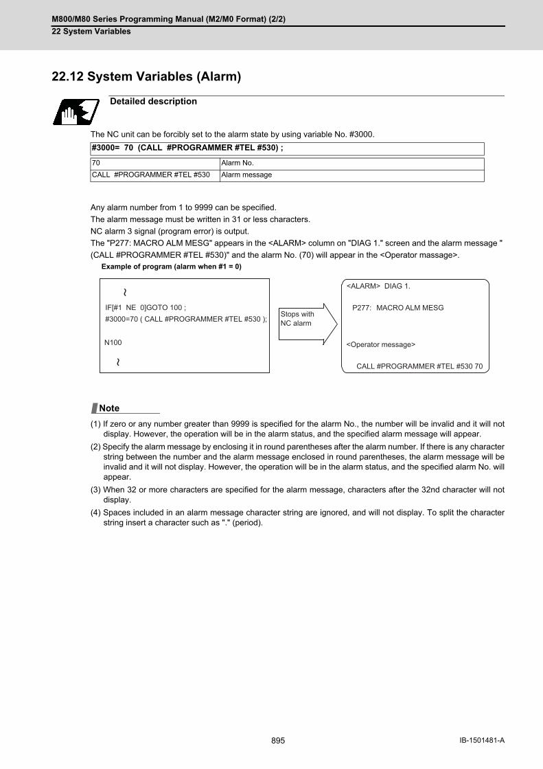
M800/M80 Series Programming Manual (M2/M0 Format) (2/2)
22 System Variables
895 IB-1501481-A
22.12 System Variables (Alarm)
The NC unit can be forcibly set to the alarm state by using variable No. #3000.
Any alarm number from 1 to 9999 can be specified.
The alarm message must be written in 31 or less characters.
NC alarm 3 signal (program error) is output.
The "P277: MACRO ALM MESG" appears in the <ALARM> column on "DIAG 1." screen and the alarm message "
(CALL #PROGRAMMER #TEL #530)" and the alarm No. (70) will appear in the <Operator massage>.
(1) If zero or any number greater than 9999 is specified for the alarm No., the number will be invalid and it will notdisplay. However, the operation will be in the alarm status, and the specified alarm message will appear.
(2) Specify the alarm message by enclosing it in round parentheses after the alarm number. If there is any characterstring between the number and the alarm message enclosed in round parentheses, the alarm message will beinvalid and it will not display. However, the operation will be in the alarm status, and the specified alarm No. willappear.
(3) When 32 or more characters are specified for the alarm message, characters after the 32nd character will notdisplay.
(4) Spaces included in an alarm message character string are ignored, and will not display. To split the characterstring insert a character such as "." (period).
Detailed description
#3000= 70 (CALL #PROGRAMMER #TEL #530) ;
70 Alarm No.
CALL #PROGRAMMER #TEL #530 Alarm message
Example of program (alarm when #1 = 0)
P277:
CALL #PROGRAMMER #TEL #530 70
IF[#1 NE 0]GOTO 100 ;#3000=70 ( CALL #PROGRAMMER #TEL #530 );
N100
Stops withNC alarm
<Operator message>
MACRO ALM MESG
<ALARM> DIAG 1.
Note

M800/M80 Series Programming Manual (M2/M0 Format) (2/2)
22 System Variables
896IB-1501481-A
22.13 System Variables (Message Display and Stop)
By using variable No. #3006, the operation stops after the previous block is executed and, if message display data
is commanded, the corresponding message and the stop No. will be indicated on the operator message area.
The message should be written in 31 or less characters and should be enclosed by round parentheses.
22.14 System Variables (Cumulative Time)
The integrating time during the power is turned ON or the automatic start is running, can be read or values can be
substituted by using variable Nos. #3001 and #3002.
The cumulative time is reset to "0" at approximately 2.44 × 10¹¹ms (approximately 7.7 years).
Detailed description
#3006 = 1( TAKE FIVE );
1 to 9999 Stop No. (When Nos. other than 1 - 9999 are set, the command will be invalidated.)
TAKE FIVE Message (Nothing will be displayed if no message is designated.)
Detailed description
Type Variable No. Unit Contents when power is switched on
Initialization of con-tents
Count condition
Power-on 3001 1ms Same as when power is switched off
Substitute values to variables
At all times while power is ON
Automatic start 3002 In-automatic start
G65L9010T
T#20
#3001=0 ;WHILE #3001LE#20 DO1 ;
END1 :
G23 ;
L9010
Entered in local variable #20
Local variable Allowable time portion: DO1 to END1 is repeated and when allowable time is reached, operations jumps to G23.
To sub-program(allowable time) ms ;
M800/M80 Series Programming Manual (M2/M0 Format) (2/2)
22 System Variables
897 IB-1501481-A
22.15 System Variables (Time Read Variables)
The following operations can be carried out using the system variable extension for the user macro time.
(1) By adding time information system variable #3011 and #3012, the current date (#3011) and current time (#3012)can be read and written.
(2) By adding parameter #1273/bit1, the unit (millisecond unit/hour unit) of the system variable "#3002" (cumulativetime during automatic start) can be changed.
(3) The cumulative time is reset to "0" at approximately 2.44 × 10¹¹ms (approximately 7.7 years).
(4) If a negative value or a value exceeding 244335917226 milliseconds (67871.08811851 hours for #3002 timedesignation) is set for the cumulative time, a program error (P35) will occur.
(5) If a value exceeding the command range is set for the date or time, a program error (P35) will occur.
(6) Always set the month/date/hour/minute/second as a two-digit value when setting the date and time. If the value only has one digit, always add 0. (February 14, 2001 => #3011= 20010214 ;, etc.)
Detailed description
Variable No.
Details
#3001 The cumulative time during power ON can be read and the value can be substituted. The unit is millisecond.
#3002 The cumulative time during automatic start can be read and the value can be substituted. The unit can be changed between millisecond and hour with parameter #1273/bit1.
#3011 The current date can be read and written. YYYY/MM/DD is read as a YYYYMMDD value. If a value "YYYYMMDD" is written, it is set to YY/MM/DD (the year is indicated by the last two digits).
Command range for year/month/day setting
Year (YYYY): 2000 to 2099
Month (MM): 1 to 12
Day (DD): 1 to maximum number of days in one month
#3012 The current time can be read and written. HH/MM/SS is read as a value "HHMMSS". When a value "HHMMSS" is written in, it will be set as HH/MM/SS.
Command range for time setting
Hour (HH): 0 to 23 (24-hour system)
Minute (MM): 0 to 59
Second (SS): 0 to 59

M800/M80 Series Programming Manual (M2/M0 Format) (2/2)
22 System Variables
898IB-1501481-A
(Example 1) To read the current date (February 14, 2001) in common variable #100
#100 = #3011 ; (20010214 is inserted in #100)
(Example 2) To write current time (18 hours, 13 minutes, 6 seconds) into system variable #3012
#3012 = 181306 ; (The command value cumulative time #2: time is set to 18:13:06.)
(Example 3) By setting the following program example, the machining start/end time (year/month/date/hour/minute/
second) can be viewed.
(1) #3011 reads the date as an eight-digit value, so the difference between the two dates read in will not be the dif-ference of days.
(2) #3012 reads the time as a six-digit value, so the difference between the two times read in will not be the differenceof hours.
Program example
Example of use (#3011, #3012)
#100=#3011 ; => Machining start year/month/date#101=#3012 ; => Machining start hour/minute/secondG28 X0 Y0 Z0 ; G92 ;G0 X50. ; : : :#102=#3011 ; => Machining end year/month/date#103=#3012 ; => Machining end hour/minute/secondM30 ;
Precautions
Limits and precautions for using time reading variable
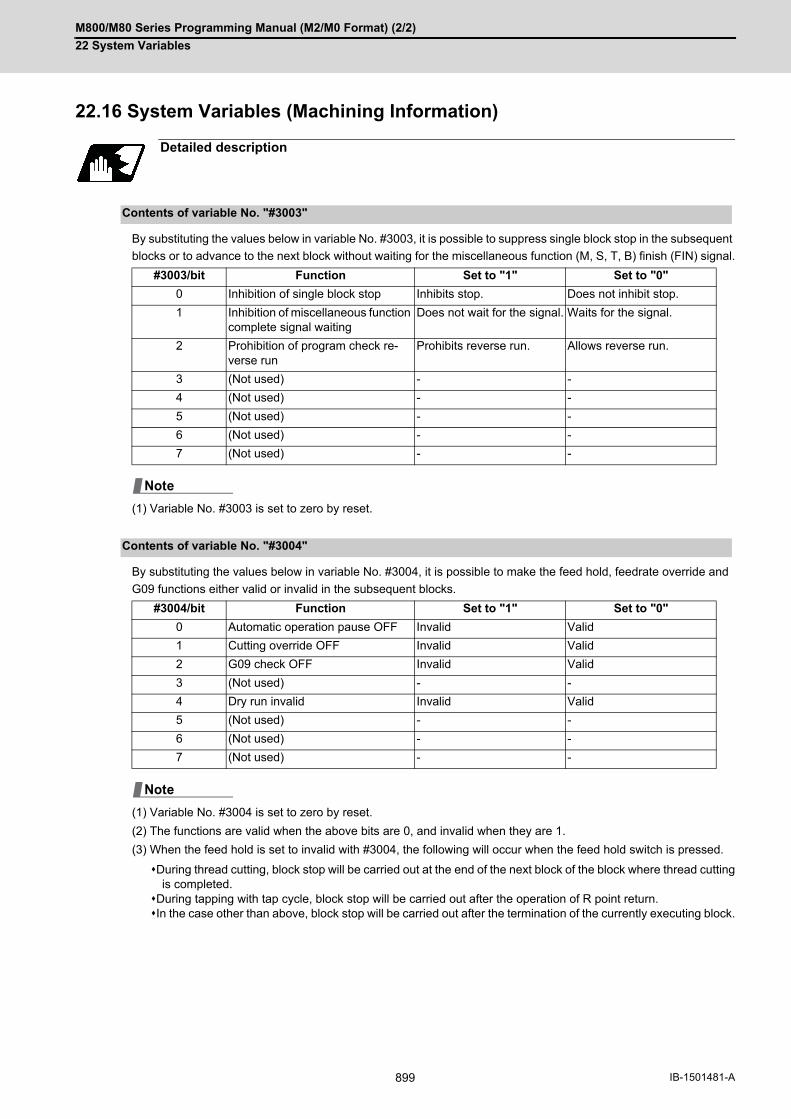
M800/M80 Series Programming Manual (M2/M0 Format) (2/2)
22 System Variables
899 IB-1501481-A
22.16 System Variables (Machining Information)
By substituting the values below in variable No. #3003, it is possible to suppress single block stop in the subsequent
blocks or to advance to the next block without waiting for the miscellaneous function (M, S, T, B) finish (FIN) signal.
(1) Variable No. #3003 is set to zero by reset.
By substituting the values below in variable No. #3004, it is possible to make the feed hold, feedrate override and
G09 functions either valid or invalid in the subsequent blocks.
(1) Variable No. #3004 is set to zero by reset.
(2) The functions are valid when the above bits are 0, and invalid when they are 1.
(3) When the feed hold is set to invalid with #3004, the following will occur when the feed hold switch is pressed.
During thread cutting, block stop will be carried out at the end of the next block of the block where thread cuttingis completed.
During tapping with tap cycle, block stop will be carried out after the operation of R point return.In the case other than above, block stop will be carried out after the termination of the currently executing block.
Detailed description
Contents of variable No. "#3003"
#3003/bit Function Set to "1" Set to "0"
0 Inhibition of single block stop Inhibits stop. Does not inhibit stop.
1 Inhibition of miscellaneous function complete signal waiting
Does not wait for the signal. Waits for the signal.
2 Prohibition of program check re-verse run
Prohibits reverse run. Allows reverse run.
3 (Not used) - -
4 (Not used) - -
5 (Not used) - -
6 (Not used) - -
7 (Not used) - -
Contents of variable No. "#3004"
#3004/bit Function Set to "1" Set to "0"
0 Automatic operation pause OFF Invalid Valid
1 Cutting override OFF Invalid Valid
2 G09 check OFF Invalid Valid
3 (Not used) - -
4 Dry run invalid Invalid Valid
5 (Not used) - -
6 (Not used) - -
7 (Not used) - -
Note
Note
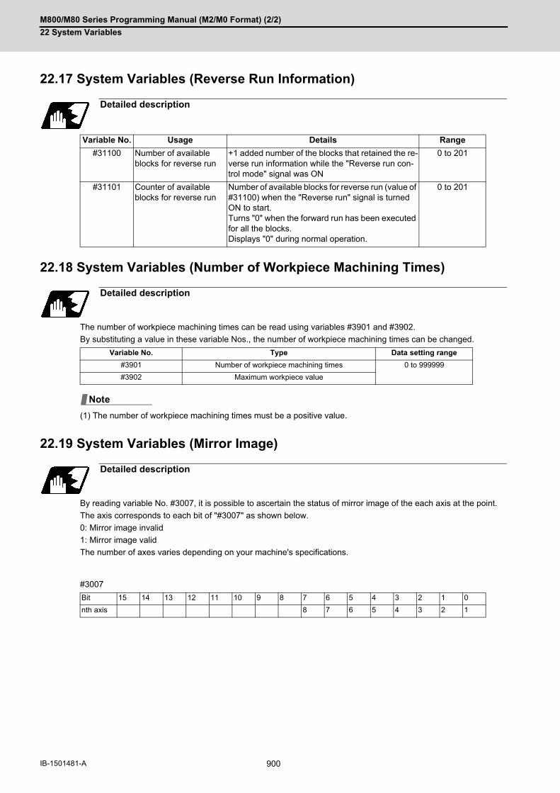
M800/M80 Series Programming Manual (M2/M0 Format) (2/2)
22 System Variables
900IB-1501481-A
22.17 System Variables (Reverse Run Information)
22.18 System Variables (Number of Workpiece Machining Times)
The number of workpiece machining times can be read using variables #3901 and #3902.
By substituting a value in these variable Nos., the number of workpiece machining times can be changed.
(1) The number of workpiece machining times must be a positive value.
22.19 System Variables (Mirror Image)
By reading variable No. #3007, it is possible to ascertain the status of mirror image of the each axis at the point.
The axis corresponds to each bit of "#3007" as shown below.
0: Mirror image invalid
1: Mirror image valid
The number of axes varies depending on your machine's specifications.
#3007
Detailed description
Variable No. Usage Details Range
#31100 Number of available blocks for reverse run
+1 added number of the blocks that retained the re-verse run information while the "Reverse run con-trol mode" signal was ON
0 to 201
#31101 Counter of available blocks for reverse run
Number of available blocks for reverse run (value of #31100) when the "Reverse run" signal is turned ON to start.Turns "0" when the forward run has been executed for all the blocks.Displays "0" during normal operation.
0 to 201
Detailed description
Variable No. Type Data setting range
#3901 Number of workpiece machining times 0 to 999999
#3902 Maximum workpiece value
Detailed description
Bit 15 14 13 12 11 10 9 8 7 6 5 4 3 2 1 0
nth axis 8 7 6 5 4 3 2 1
Note
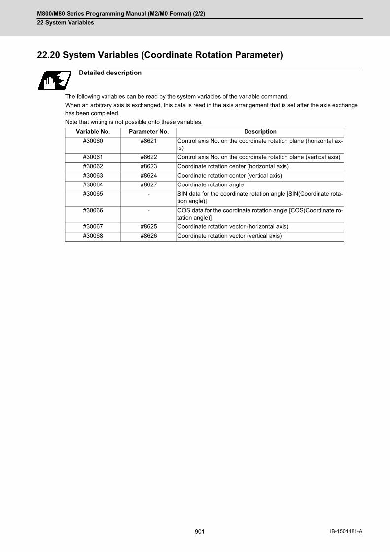
M800/M80 Series Programming Manual (M2/M0 Format) (2/2)
22 System Variables
901 IB-1501481-A
22.20 System Variables (Coordinate Rotation Parameter)
The following variables can be read by the system variables of the variable command.
When an arbitrary axis is exchanged, this data is read in the axis arrangement that is set after the axis exchange
has been completed.
Note that writing is not possible onto these variables.
Detailed description
Variable No. Parameter No. Description
#30060 #8621 Control axis No. on the coordinate rotation plane (horizontal ax-is)
#30061 #8622 Control axis No. on the coordinate rotation plane (vertical axis)
#30062 #8623 Coordinate rotation center (horizontal axis)
#30063 #8624 Coordinate rotation center (vertical axis)
#30064 #8627 Coordinate rotation angle
#30065 - SIN data for the coordinate rotation angle [SIN(Coordinate rota-tion angle)]
#30066 - COS data for the coordinate rotation angle [COS(Coordinate ro-tation angle)]
#30067 #8625 Coordinate rotation vector (horizontal axis)
#30068 #8626 Coordinate rotation vector (vertical axis)

M800/M80 Series Programming Manual (M2/M0 Format) (2/2)
22 System Variables
902IB-1501481-A
22.21 System Variables (Rotary Axis Configuration Parameter)
The following rotary axis configuration parameters can be read by the system variables of the variable command.
By substituting a value in these variables, the setting value of rotary axis configuration parameter can be changed.
Detailed description
Variable No. Parameter
#31001 #7903 G92_CRD Origin zero set coordinate selection
#31002 #7904 NO_TIP Tool handle feed function selection
#31003 #7920 SLCT_T1 Rotary axis selection (Base-side rotary axis of tool rotation type)
#31004 #7923 DIR_T1 Rotation direction (Base-side rotary axis of tool rotation type)
#31005 #7924 COFST1H Horizontal axis rotation center offset (Base-side rotary axis of tool rota-tion type)
#31006 #7925 COFST1V Vertical axis rotation center offset (Base-side rotary axis of tool rotation type)
#31007 #7926 COFST1T Height axis rotation center offset (Base-side rotary axis of tool rotation type)
#31008 #7930 SLCT_T2 Rotary axis selection (Tool-side rotary axis of tool rotation type)
#31009 #7933 DIR_T2 Rotation direction (Tool-side rotary axis of tool rotation type)
#31010 #7934 COFST2H Horizontal axis rotation center offset (Tool-side rotary axis of tool rota-tion type)
#31011 #7935 COFST2V Vertical axis rotation center offset (Tool-side rotary axis of tool rotation type)
#31012 #7936 COFST2T Height axis rotation center offset (Tool-side rotary axis of tool rotation type)
#31013 #7940 SLCT_W1 Rotary axis selection (Base-side rotary axis of table rotation type)
#31014 #7943 DIR_ W1 Rotation direction (Base-side rotary axis of table rotation type)
#31015 #7944 COFSW1H Horizontal axis rotation center offset (Base-side rotary axis of table ro-tation type)
#31016 #7945 COFSW1V Vertical axis rotation center offset (Base-side rotary axis of table rotation type)
#31017 #7946 COFSW1T Height axis rotation center offset (Base-side rotary axis of table rotation type)
#31018 #7950 SLCT_W2 Rotary axis selection (Workpiece-side rotary axis of table rotation type)
#31019 #7953 DIR_W2 Rotation direction (Workpiece-side rotary axis of table rotation type)
#31020 #7954 COFSW2H Horizontal axis rotation center offset (Workpiece-side rotary axis of ta-ble rotation type)
#31021 #7955 COFSW2V Vertical axis rotation center offset (Workpiece-side rotary axis of table rotation type)
#31022 #7956 COFSW2T Height axis rotation center offset (Workpiece-side rotary axis of table ro-tation type)
#31023 #7912 NO_MANUAL Selection of manual feed for 3-dimensional

M800/M80 Series Programming Manual (M2/M0 Format) (2/2)
22 System Variables
903 IB-1501481-A
22.22 System Variables (Normal Line Control Parameter)
The normal line control parameter can be read or written using variable Nos. "#1900" and "#1901".
Detailed description
Variable No. Details
#1900 #8041 C-rot.R (Data with decimal point)
#1901 #8042 C-ins.R (Data with decimal point)
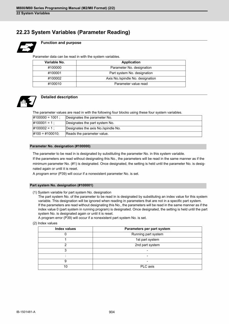
M800/M80 Series Programming Manual (M2/M0 Format) (2/2)
22 System Variables
904IB-1501481-A
22.23 System Variables (Parameter Reading)
Parameter data can be read in with the system variables.
The parameter values are read in with the following four blocks using these four system variables.
The parameter to be read in is designated by substituting the parameter No. in this system variable.
If the parameters are read without designating this No., the parameters will be read in the same manner as if the
minimum parameter No. (#1) is designated. Once designated, the setting is held until the parameter No. is desig-
nated again or until it is reset.
A program error (P39) will occur if a nonexistent parameter No. is set.
(1) System variable for part system No. designationThe part system No. of the parameter to be read in is designated by substituting an index value for this systemvariable. This designation will be ignored when reading in parameters that are not in a specific part system. If the parameters are read without designating this No., the parameters will be read in the same manner as if theindex value 0 (part system in running program) is designated. Once designated, the setting is held until the partsystem No. is designated again or until it is reset. A program error (P39) will occur if a nonexistent part system No. is set.
(2) Index values
Function and purpose
Variable No. Application
#100000 Parameter No. designation
#100001 Part system No. designation
#100002 Axis No./spindle No. designation
#100010 Parameter value read
Detailed description
#100000 = 1001 ; Designates the parameter No.
#100001 = 1 ; Designates the part system No.
#100002 = 1 ; Designates the axis No./spindle No.
#100 = #100010; Reads the parameter value.
Parameter No. designation (#100000)
Part system No. designation (#100001)
Index values Parameters per part system
0 Running part system
1 1st part system
2 2nd part system
3 -
: -
9 -
10 PLC axis

M800/M80 Series Programming Manual (M2/M0 Format) (2/2)
22 System Variables
905 IB-1501481-A
(1) System variable for axis or spindle No. designationThe axis or spindle No. of the parameter to be read in is designated by substituting an index value for this systemvariable. This designation will be ignored when reading in parameters that are neither for a specific axis nor spin-dle. The axis parameter index value is the value set in the part system designated with #100001. Thus, when reading parameters that are not in the designated part system, the part system No. must be desig-nated again. The spindle parameter's index value is not affected by the part system designation. If the parameters are read without designating this number, the parameters will be read in the same manner aswhen the index value 1 (1st axis/1st spindle in the designated part system) is designated. Once designated, thesetting is held until the index value is designated again or until it is reset. A program error (P39) will occur if a nonexistent axis/spindle No. is set.
(2) Index values
The designated parameter data is read with this system variable.
Data to be read as follows, depending on the parameter type.
Axis No. /spindle No. designation (#100002)
Index values Axis parameter Spindle parameter
1 1st axis 1st spindle
2 2nd axis 2nd spindle
3 3rd axis 3rd spindle
4 4th axis 4th spindle
5 5th axis -
6 6th axis -
Reading the parameters (#100010)
Type Read in data
Numeric value The values displayed on the Parameter screen are output.
Text ASCII codes are converted into decimal values.

M800/M80 Series Programming Manual (M2/M0 Format) (2/2)
22 System Variables
906IB-1501481-A
(1) To read the parameter "#1002 axisno (number of axes)" for each part system:
(2) To read the axis parameter "#2037 G53ofs (#1 reference position)":
[1st part system program]
[2nd part system program]
Program example
#100000 = 1002 ; Designates [#1002].
#100001 = 1 ; Designates [1st part system].
#101 = #100010; Reads the number of axes in 1st part system.
#100000 = 1002 ; Designates [#1002]. (can be omitted since parameter No. is same)
#100001 = 2 ; Designates [2nd part system].
#102 = #100010; Reads the number of axes in 2nd part system.
#100001 = 5 ; Designates [5th part system]. (The program error (P39) will occur.)
#100001 = 10 ; Designates [PLC axis].
#110 = #100010; Reads the number of PLC axes.
[Conditions] 1 part system 2 part systems
<1st axis> <2nd axis> <1st axis> <2nd axis>
#2037 G53ofs 100.000 200.000 300.000 400.000
#100002 = 1 ; Designates [1st axis].
#100000 = 2037 ; Designates [#2037].
#101 = #100010; Reads the [#1 reference point] for the 1st axis. (#101=100.000)
#100002 = 2 ; Designates [2nd axis].
#102 = #100010; Reads the [#2 reference point] for the 1st axis. (#102=200.000)
#100001 = 2 ; Designates [2nd part system].
#100002 = 1 ; Designates [1st axis].
#201 = #100010; Reads the [#2 reference position] for the 1st axis in the 1st part system. (#201=300.000)
#100002 = 1 ; Designates [1st axis].
#100000 = 2037 ; Designates [#2037].
#101 = #100010; Reads the [#1 reference point] for the 1st axis. (#101=300.000)
#100002 = 2 ; Designates [2nd axis].
#102 = #100010; Reads the [#2 reference point] for the 1st axis. (#102=400.000)
#100001 = 1 ; Designates [1st part system].
#100002 = 1 ; Designates [1st axis].
#201 = #100010; Reads the [#1 reference position] for the 1st axis in the 1st part system. (#201=100.000)

M800/M80 Series Programming Manual (M2/M0 Format) (2/2)
22 System Variables
907 IB-1501481-A
(3) To read the parameter for each part system, axis, or spindle:
(4) To read the text type parameter "#1169 system name" (part system name):
(1) The number of part systems, axes and spindles is set at the maximum number specified by the model.
(2) The inch/metric changeover function for the setting and display is valid for the readout data.
(3) The machining condition parameter group cannot set the parameters from the program using the G10 command,and cannot read the parameters using the system variables ("#100000" and later).
#100002 = 1 ; Designates [1st spindle].
#100000 = 3001 ; Designates [#3001].
#101 = #100010; Reads the [#3001 slimt1 (Number of limit rotation gears 00)] for 1st spindle.
#100000 = 3002 ; Designates [#3002].
#102 = #100010; Reads the [#3002 slimt2 (Number of limit rotation gears 01)] for 1st spindle.
#100002 = 2 ; Designates [2nd spindle].
#100000 = 3001 ; Designates [#3001].
#201 = #100010 ; Reads the [#3001 slimt1 (Number of limit rotation gears 00)] for 2nd spindle.
#100000 = 3002 ; Designates [#3002].
#202 = #100010; Reads the [#3002 slimt2 (Number of limit rotation gears 01)] for 2nd spindle.
[Conditions] <1st part system> <2nd part system>
#1169 system name SYS1 SYS2
#100000 = 1169 ; Designates #1169.
#100001 = 1 ; Designates 1st part system.
#101 = #100010; This will be #101 = 1398362929 (0x53595331).
Precautions

M800/M80 Series Programming Manual (M2/M0 Format) (2/2)
22 System Variables
908IB-1501481-A
22.24 System Variables (Workpiece Installation Error Compensation
Amount)
Using the system variables below, read/write of the workpiece installation error compensation amounts is enabled.
(Note 1) The primary rotary axis position corresponds with the axis set by the parameter #7942, and the secondary
rotary axis position corresponds with the axis set by the parameter #7952.
(Note 2) If the primary and secondary rotary axis positions are not of the table-side rotary axes, the set values are
ignored.
(Note 3) The setting ranges are the same as those set in the workpiece installation error setting screen.
(Note 4) If the system variables #26000 to #26077 are written during workpiece installation error compensation, the
program error (P545) will occur.
Detailed description
Common No.01 No.02 No.03 No.04 No.05 No.06 No.07
Workpiece installation error compensation amount ∆x
#26000 #26010 #26020 #26030 #26040 #26050 #26060 #26070
Workpiece installation error compensation amount ∆y
#26001 #26011 #26021 #26031 #26041 #26051 #26061 #26071
Workpiece installation error compensation amount ∆z
#26002 #26012 #26022 #26032 #26042 #26052 #26062 #26072
Workpiece installation error compensation amount ∆a
- #26013 #26023 #26033 #26043 #26053 #26063 #26073
Workpiece installation error compensation amount ∆b
- #26014 #26024 #26034 #26044 #26054 #26064 #26074
Workpiece installation error compensation amount ∆c
- #26015 #26025 #26035 #26045 #26055 #26065 #26075
Primary rotary axis position #26006 #26016 #26026 #26036 #26046 #26056 #26066 #26076
Secondary rotary axis posi-tion
#26007 #26017 #26027 #26037 #26047 #26057 #26067 #26077

M800/M80 Series Programming Manual (M2/M0 Format) (2/2)
22 System Variables
909 IB-1501481-A
22.25 System Variables (Macro Interface Input (PLC -> NC))
The status of the interface input signals can be ascertained by reading out the values of variable Nos. #1000 to
#1035, #1200 to #1295.
The interface output signals can be sent by substituting values in variable Nos. #1100 to #1135, #1300 to#1395. (For details of the system variables for the output signals, refer to "22.26 System Variables (Macro In-terface Output (NC -> PLC))".)
Example of 1st part system
Function and purpose
(a) Input signal (b) Output signal (c) Macro instructions
Note
#1000
#1031
#1032 (R6436, R6437)
#1200
#1231
#1033 (R6438, R6439)
#1232
#1263
#1034 (R6440, R6441)
#1264
#1295
#1035 (R6442, R6443)
#1132 (R6372, R6373)
#1133 (R6374, R6375)
#1134 (R6376, R6377)
#1135 (R6378, R6379)
#1300
#1331
#1332
#1363
#1364
#1395
#1100
#1131
(c)
(a) (b)
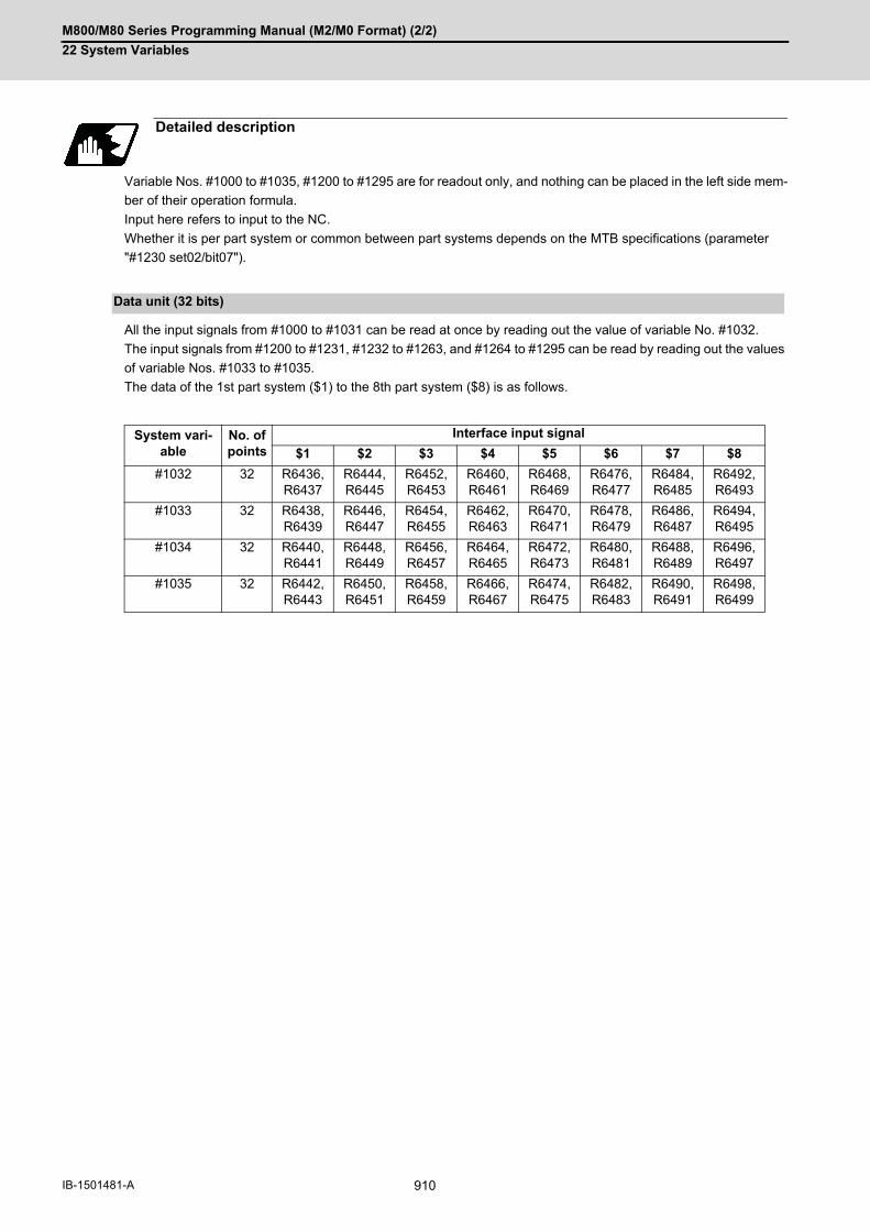
M800/M80 Series Programming Manual (M2/M0 Format) (2/2)
22 System Variables
910IB-1501481-A
Variable Nos. #1000 to #1035, #1200 to #1295 are for readout only, and nothing can be placed in the left side mem-
ber of their operation formula.
Input here refers to input to the NC.
Whether it is per part system or common between part systems depends on the MTB specifications (parameter
"#1230 set02/bit07").
All the input signals from #1000 to #1031 can be read at once by reading out the value of variable No. #1032.
The input signals from #1200 to #1231, #1232 to #1263, and #1264 to #1295 can be read by reading out the values
of variable Nos. #1033 to #1035.
The data of the 1st part system ($1) to the 8th part system ($8) is as follows.
Detailed description
Data unit (32 bits)
System vari-able
No. of points
Interface input signal
$1 $2 $3 $4 $5 $6 $7 $8
#1032 32 R6436, R6437
R6444, R6445
R6452, R6453
R6460, R6461
R6468, R6469
R6476, R6477
R6484, R6485
R6492, R6493
#1033 32 R6438, R6439
R6446, R6447
R6454, R6455
R6462, R6463
R6470, R6471
R6478, R6479
R6486, R6487
R6494, R6495
#1034 32 R6440, R6441
R6448, R6449
R6456, R6457
R6464, R6465
R6472, R6473
R6480, R6481
R6488, R6489
R6496, R6497
#1035 32 R6442, R6443
R6450, R6451
R6458, R6459
R6466, R6467
R6474, R6475
R6482, R6483
R6490, R6491
R6498, R6499

M800/M80 Series Programming Manual (M2/M0 Format) (2/2)
22 System Variables
911 IB-1501481-A
The input signal has only two values: "0" and "1".
If the value is common between part systems, refer to the column of the 1st part system ($1).
Bit unit
Part sys-tem
$1 $2 $3 $4 $5 $6 $7 $8
R device R6436-R6443
R6444-R6451
R6452-R6459
R6460-R6467
R6468-R6475
R6476-R6483
R6484-R6491
R6492-R6499
System variable
No. of points
Interface input signal register
$1 $2 $3 $4 $5 $6 $7 $8
#1000 1 R6436/bit0
R6444/bit0
R6452/bit0
R6460/bit0
R6468/bit0
R6476/bit0
R6484/bit0
R6492/bit0
#1001 1 bit1 bit1 bit1 bit1 bit1 bit1 bit1 bit1
#1002 1 bit2 bit2 bit2 bit2 bit2 bit2 bit2 bit2
#1003 1 bit3 bit3 bit3 bit3 bit3 bit3 bit3 bit3
#1004 1 bit4 bit4 bit4 bit4 bit4 bit4 bit4 bit4
#1005 1 bit5 bit5 bit5 bit5 bit5 bit5 bit5 bit5
#1006 1 bit6 bit6 bit6 bit6 bit6 bit6 bit6 bit6
#1007 1 bit7 bit7 bit7 bit7 bit7 bit7 bit7 bit7
#1008 1 bit8 bit8 bit8 bit8 bit8 bit8 bit8 bit8
#1009 1 bit9 bit9 bit9 bit9 bit9 bit9 bit9 bit9
#1010 1 bit10 bit10 bit10 bit10 bit10 bit10 bit10 bit10
#1011 1 bit11 bit11 bit11 bit11 bit11 bit11 bit11 bit11
#1012 1 bit12 bit12 bit12 bit12 bit12 bit12 bit12 bit12
#1013 1 bit13 bit13 bit13 bit13 bit13 bit13 bit13 bit13
#1014 1 bit14 bit14 bit14 bit14 bit14 bit14 bit14 bit14
#1015 1 bit15 bit15 bit15 bit15 bit15 bit15 bit15 bit15
#1016 1 R6437/bit0
R6445/bit0
R6453/bit0
R6461/bit0
R6469/bit0
R6477/bit0
R6485/bit0
R6493/bit0
#1017 1 bit1 bit1 bit1 bit1 bit1 bit1 bit1 bit1
#1018 1 bit2 bit2 bit2 bit2 bit2 bit2 bit2 bit2
#1019 1 bit3 bit3 bit3 bit3 bit3 bit3 bit3 bit3
#1020 1 bit4 bit4 bit4 bit4 bit4 bit4 bit4 bit4
#1021 1 bit5 bit5 bit5 bit5 bit5 bit5 bit5 bit5
#1022 1 bit6 bit6 bit6 bit6 bit6 bit6 bit6 bit6
#1023 1 bit7 bit7 bit7 bit7 bit7 bit7 bit7 bit7
#1024 1 bit8 bit8 bit8 bit8 bit8 bit8 bit8 bit8
#1025 1 bit9 bit9 bit9 bit9 bit9 bit9 bit9 bit9
#1026 1 bit10 bit10 bit10 bit10 bit10 bit10 bit10 bit10
#1027 1 bit11 bit11 bit11 bit11 bit11 bit11 bit11 bit11
#1028 1 bit12 bit12 bit12 bit12 bit12 bit12 bit12 bit12
#1029 1 bit13 bit13 bit13 bit13 bit13 bit13 bit13 bit13
#1030 1 bit14 bit14 bit14 bit14 bit14 bit14 bit14 bit14
#1031 1 bit15 bit15 bit15 bit15 bit15 bit15 bit15 bit15

M800/M80 Series Programming Manual (M2/M0 Format) (2/2)
22 System Variables
912IB-1501481-A
System variable
No. of points
Interface input signal register
$1 $2 $3 $4 $5 $6 $7 $8
#1200 1 R6438/bit0
R6446/bit0
R6454/bit0
R6462/bit0
R6470/bit0
R6478/bit0
R6486/bit0
R6494/bit0
#1201 1 bit1 bit1 bit1 bit1 bit1 bit1 bit1 bit1
#1202 1 bit2 bit2 bit2 bit2 bit2 bit2 bit2 bit2
#1203 1 bit3 bit3 bit3 bit3 bit3 bit3 bit3 bit3
#1204 1 bit4 bit4 bit4 bit4 bit4 bit4 bit4 bit4
#1205 1 bit5 bit5 bit5 bit5 bit5 bit5 bit5 bit5
#1206 1 bit6 bit6 bit6 bit6 bit6 bit6 bit6 bit6
#1207 1 bit7 bit7 bit7 bit7 bit7 bit7 bit7 bit7
#1208 1 bit8 bit8 bit8 bit8 bit8 bit8 bit8 bit8
#1209 1 bit9 bit9 bit9 bit9 bit9 bit9 bit9 bit9
#1210 1 bit10 bit10 bit10 bit10 bit10 bit10 bit10 bit10
#1211 1 bit11 bit11 bit11 bit11 bit11 bit11 bit11 bit11
#1212 1 bit12 bit12 bit12 bit12 bit12 bit12 bit12 bit12
#1213 1 bit13 bit13 bit13 bit13 bit13 bit13 bit13 bit13
#1214 1 bit14 bit14 bit14 bit14 bit14 bit14 bit14 bit14
#1215 1 bit15 bit15 bit15 bit15 bit15 bit15 bit15 bit15
#1216 1 R6439/bit0
R6447/bit0
R6455/bit0
R6463/bit0
R6471/bit0
R6479/bit0
R6487/bit0
R6495/bit0
#1217 1 bit1 bit1 bit1 bit1 bit1 bit1 bit1 bit1
#1218 1 bit2 bit2 bit2 bit2 bit2 bit2 bit2 bit2
#1219 1 bit3 bit3 bit3 bit3 bit3 bit3 bit3 bit3
#1220 1 bit4 bit4 bit4 bit4 bit4 bit4 bit4 bit4
#1221 1 bit5 bit5 bit5 bit5 bit5 bit5 bit5 bit5
#1222 1 bit6 bit6 bit6 bit6 bit6 bit6 bit6 bit6
#1223 1 bit7 bit7 bit7 bit7 bit7 bit7 bit7 bit7
#1224 1 bit8 bit8 bit8 bit8 bit8 bit8 bit8 bit8
#1225 1 bit9 bit9 bit9 bit9 bit9 bit9 bit9 bit9
#1226 1 bit10 bit10 bit10 bit10 bit10 bit10 bit10 bit10
#1227 1 bit11 bit11 bit11 bit11 bit11 bit11 bit11 bit11
#1228 1 bit12 bit12 bit12 bit12 bit12 bit12 bit12 bit12
#1229 1 bit13 bit13 bit13 bit13 bit13 bit13 bit13 bit13
#1230 1 bit14 bit14 bit14 bit14 bit14 bit14 bit14 bit14
#1231 1 bit15 bit15 bit15 bit15 bit15 bit15 bit15 bit15

M800/M80 Series Programming Manual (M2/M0 Format) (2/2)
22 System Variables
913 IB-1501481-A
System variable
No. of points
Interface input signal register
$1 $2 $3 $4 $5 $6 $7 $8
#1232 1 R6440/bit0
R6440/bit0
R6448/bit0
R6456/bit0
R6472/bit0
R6480/bit0
R6488/bit0
R6496/bit0
#1233 1 bit1 bit1 bit1 bit1 bit1 bit1 bit1 bit1
#1234 1 bit2 bit2 bit2 bit2 bit2 bit2 bit2 bit2
#1235 1 bit3 bit3 bit3 bit3 bit3 bit3 bit3 bit3
#1236 1 bit4 bit4 bit4 bit4 bit4 bit4 bit4 bit4
#1237 1 bit5 bit5 bit5 bit5 bit5 bit5 bit5 bit5
#1238 1 bit6 bit6 bit6 bit6 bit6 bit6 bit6 bit6
#1239 1 bit7 bit7 bit7 bit7 bit7 bit7 bit7 bit7
#1240 1 bit8 bit8 bit8 bit8 bit8 bit8 bit8 bit8
#1241 1 bit9 bit9 bit9 bit9 bit9 bit9 bit9 bit9
#1242 1 bit10 bit10 bit10 bit10 bit10 bit10 bit10 bit10
#1243 1 bit11 bit11 bit11 bit11 bit11 bit11 bit11 bit11
#1244 1 bit12 bit12 bit12 bit12 bit12 bit12 bit12 bit12
#1245 1 bit13 bit13 bit13 bit13 bit13 bit13 bit13 bit13
#1246 1 bit14 bit14 bit14 bit14 bit14 bit14 bit14 bit14
#1247 1 bit15 bit15 bit15 bit15 bit15 bit15 bit15 bit15
#1248 1 R6441/bit0
R6441/bit0
R6449/bit0
R6457/bit0
R6473/bit0
R6481/bit0
R6489/bit0
R6497/bit0
#1249 1 bit1 bit1 bit1 bit1 bit1 bit1 bit1 bit1
#1250 1 bit2 bit2 bit2 bit2 bit2 bit2 bit2 bit2
#1251 1 bit3 bit3 bit3 bit3 bit3 bit3 bit3 bit3
#1252 1 bit4 bit4 bit4 bit4 bit4 bit4 bit4 bit4
#1253 1 bit5 bit5 bit5 bit5 bit5 bit5 bit5 bit5
#1254 1 bit6 bit6 bit6 bit6 bit6 bit6 bit6 bit6
#1255 1 bit7 bit7 bit7 bit7 bit7 bit7 bit7 bit7
#1256 1 bit8 bit8 bit8 bit8 bit8 bit8 bit8 bit8
#1257 1 bit9 bit9 bit9 bit9 bit9 bit9 bit9 bit9
#1258 1 bit10 bit10 bit10 bit10 bit10 bit10 bit10 bit10
#1259 1 bit11 bit11 bit11 bit11 bit11 bit11 bit11 bit11
#1260 1 bit12 bit12 bit12 bit12 bit12 bit12 bit12 bit12
#1261 1 bit13 bit13 bit13 bit13 bit13 bit13 bit13 bit13
#1262 1 bit14 bit14 bit14 bit14 bit14 bit14 bit14 bit14
#1263 1 bit15 bit15 bit15 bit15 bit15 bit15 bit15 bit15

M800/M80 Series Programming Manual (M2/M0 Format) (2/2)
22 System Variables
914IB-1501481-A
System variable
No. of points
Interface input signal register
$1 $2 $3 $4 $5 $6 $7 $8
#1264 1 R6442/bit0
R6450/bit0
R6458/bit0
R6466/bit0
R6474/bit0
R6482/bit0
R6490/bit0
R6498/bit0
#1265 1 bit1 bit1 bit1 bit1 bit1 bit1 bit1 bit1
#1266 1 bit2 bit2 bit2 bit2 bit2 bit2 bit2 bit2
#1267 1 bit3 bit3 bit3 bit3 bit3 bit3 bit3 bit3
#1268 1 bit4 bit4 bit4 bit4 bit4 bit4 bit4 bit4
#1269 1 bit5 bit5 bit5 bit5 bit5 bit5 bit5 bit5
#1270 1 bit6 bit6 bit6 bit6 bit6 bit6 bit6 bit6
#1271 1 bit7 bit7 bit7 bit7 bit7 bit7 bit7 bit7
#1272 1 bit8 bit8 bit8 bit8 bit8 bit8 bit8 bit8
#1273 1 bit9 bit9 bit9 bit9 bit9 bit9 bit9 bit9
#1274 1 bit10 bit10 bit10 bit10 bit10 bit10 bit10 bit10
#1275 1 bit11 bit11 bit11 bit11 bit11 bit11 bit11 bit11
#1276 1 bit12 bit12 bit12 bit12 bit12 bit12 bit12 bit12
#1277 1 bit13 bit13 bit13 bit13 bit13 bit13 bit13 bit13
#1278 1 bit14 bit14 bit14 bit14 bit14 bit14 bit14 bit14
#1279 1 bit15 bit15 bit15 bit15 bit15 bit15 bit15 bit15
#1280 1 R6443/bit0
R6451/bit0
R6459/bit0
R6467/bit0
R6475/bit0
R6483/bit0
R6491/bit0
R6499/bit0
#1281 1 bit1 bit1 bit1 bit1 bit1 bit1 bit1 bit1
#1282 1 bit2 bit2 bit2 bit2 bit2 bit2 bit2 bit2
#1283 1 bit3 bit3 bit3 bit3 bit3 bit3 bit3 bit3
#1284 1 bit4 bit4 bit4 bit4 bit4 bit4 bit4 bit4
#1285 1 bit5 bit5 bit5 bit5 bit5 bit5 bit5 bit5
#1286 1 bit6 bit6 bit6 bit6 bit6 bit6 bit6 bit6
#1287 1 bit7 bit7 bit7 bit7 bit7 bit7 bit7 bit7
#1288 1 bit8 bit8 bit8 bit8 bit8 bit8 bit8 bit8
#1289 1 bit9 bit9 bit9 bit9 bit9 bit9 bit9 bit9
#1290 1 bit10 bit10 bit10 bit10 bit10 bit10 bit10 bit10
#1291 1 bit11 bit11 bit11 bit11 bit11 bit11 bit11 bit11
#1292 1 bit12 bit12 bit12 bit12 bit12 bit12 bit12 bit12
#1293 1 bit13 bit13 bit13 bit13 bit13 bit13 bit13 bit13
#1294 1 bit14 bit14 bit14 bit14 bit14 bit14 bit14 bit14
#1295 1 bit15 bit15 bit15 bit15 bit15 bit15 bit15 bit15
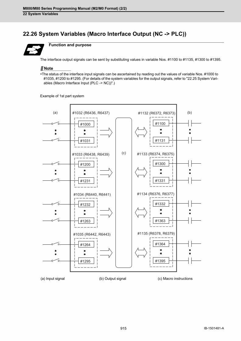
M800/M80 Series Programming Manual (M2/M0 Format) (2/2)
22 System Variables
915 IB-1501481-A
22.26 System Variables (Macro Interface Output (NC -> PLC))
The interface output signals can be sent by substituting values in variable Nos. #1100 to #1135, #1300 to #1395.
The status of the interface input signals can be ascertained by reading out the values of variable Nos. #1000 to#1035, #1200 to #1295. (For details of the system variables for the output signals, refer to "22.25 System Vari-ables (Macro Interface Input (PLC -> NC))".)
Example of 1st part system
Function and purpose
(a) Input signal (b) Output signal (c) Macro instructions
Note
#1000
#1031
#1032 (R6436, R6437)
#1200
#1231
#1033 (R6438, R6439)
#1232
#1263
#1034 (R6440, R6441)
#1264
#1295
#1035 (R6442, R6443)
#1132 (R6372, R6373)
#1133 (R6374, R6375)
#1134 (R6376, R6377)
#1135 (R6378, R6379)
#1300
#1331
#1332
#1363
#1364
#1395
#1100
#1131
(c)
(a) (b)

M800/M80 Series Programming Manual (M2/M0 Format) (2/2)
22 System Variables
916IB-1501481-A
The status of the writing and output signals can be read in order to compensate the #1100 to #1135, #1300 to #1395
output signals.
Output here refers to the output from the NC side.
Whether it is per part system or common between part systems depends on the MTB specifications (parameter
"#1230 set02/bit07").
(1) The last values of the system variables #1100 to #1135, #1300 to #1395 sent are retained as 1 or 0. (They arenot cleared even by resetting.)
(2) The following applies when any number except 1 or 0 is substituted into #1100 to #1131, #1300 to #1395. <Blank> is treated as 0. All values other than <blank> or "0" are treated as 1. Any value less than 0.00000001 is indefinite.
All the output Nos. from #1100 to #1131 can be sent at once by substituting a value in variable No. #1132.
The output signals from #1300 to #1331, #1332 to #1363, and #1364 to #1395 can be sent by substituting a value
in variable Nos. #1133 to #1135. (20 to 231)
The data of the 1st part system ($1) to the 8th part system ($8) is as follows.
Detailed description
Data unit (32 bits)
System vari-able
No. of points
Interface output signal
$1 $2 $3 $4 $5 $6 $7 $8
#1132 32 R6372, R6373
R6380, R6381
R6388, R6389
R6396, R6397
R6404, R6405
R6412, R6413
R6420, R6421
R6428, R6429
#1133 32 R6374, R6375
R6382, R6383
R6390, R6391
R6398, R6399
R6406, R6407
R6414, R6415
R6422, R6423
R6430, R6431
#1134 32 R6376, R6377
R6384, R6385
R6392, R6393
R6400, R6401
R6408, R6409
R6416, R6417
R6424, R6425
R6432, R6433
#1135 32 R6378, R6379
R6386, R6387
R6394, R6395
R6402, R6403
R6410, R6411
R6418, R6419
R6426, R6427
R6434, R6435
Note

M800/M80 Series Programming Manual (M2/M0 Format) (2/2)
22 System Variables
917 IB-1501481-A
The output signal has only two values: "0" and "1".
If the value is common between part systems, refer to the column of the 1st part system ($1).
Bit unit
Part sys-tem
$1 $2 $3 $4 $5 $6 $7 $8
R device R6372-R6379
R6380-R6387
R6388-R6395
R6396-R6403
R6404-R6411
R6412-R6419
R6420-R6427
R6428-R6435
System variable
No. of points
Interface output signal register
$1 $2 $3 $4 $5 $6 $7 $8
#1100 1 R6372/bit0
R6380/bit0
R6388/bit0
R6396/bit0
R6404/bit0
R6412/bit0
R6420/bit0
R6428/bit0
#1101 1 bit1 bit1 bit1 bit1 bit1 bit1 bit1 bit1
#1102 1 bit2 bit2 bit2 bit2 bit2 bit2 bit2 bit2
#1103 1 bit3 bit3 bit3 bit3 bit3 bit3 bit3 bit3
#1104 1 bit4 bit4 bit4 bit4 bit4 bit4 bit4 bit4
#1105 1 bit5 bit5 bit5 bit5 bit5 bit5 bit5 bit5
#1106 1 bit6 bit6 bit6 bit6 bit6 bit6 bit6 bit6
#1107 1 bit7 bit7 bit7 bit7 bit7 bit7 bit7 bit7
#1108 1 bit8 bit8 bit8 bit8 bit8 bit8 bit8 bit8
#1109 1 bit9 bit9 bit9 bit9 bit9 bit9 bit9 bit9
#1110 1 bit10 bit10 bit10 bit10 bit10 bit10 bit10 bit10
#1111 1 bit11 bit11 bit11 bit11 bit11 bit11 bit11 bit11
#1112 1 bit12 bit12 bit12 bit12 bit12 bit12 bit12 bit12
#1113 1 bit13 bit13 bit13 bit13 bit13 bit13 bit13 bit13
#1114 1 bit14 bit14 bit14 bit14 bit14 bit14 bit14 bit14
#1115 1 bit15 bit15 bit15 bit15 bit15 bit15 bit15 bit15
#1116 1 R6373/bit0
R6381/bit0
R6389/bit0
R6397/bit0
R6405/bit0
R6413/bit0
R6421/bit0
R6429/bit0
#1117 1 bit1 bit1 bit1 bit1 bit1 bit1 bit1 bit1
#1118 1 bit2 bit2 bit2 bit2 bit2 bit2 bit2 bit2
#1119 1 bit3 bit3 bit3 bit3 bit3 bit3 bit3 bit3
#1120 1 bit4 bit4 bit4 bit4 bit4 bit4 bit4 bit4
#1121 1 bit5 bit5 bit5 bit5 bit5 bit5 bit5 bit5
#1122 1 bit6 bit6 bit6 bit6 bit6 bit6 bit6 bit6
#1123 1 bit7 bit7 bit7 bit7 bit7 bit7 bit7 bit7
#1124 1 bit8 bit8 bit8 bit8 bit8 bit8 bit8 bit8
#1125 1 bit9 bit9 bit9 bit9 bit9 bit9 bit9 bit9
#1126 1 bit10 bit10 bit10 bit10 bit10 bit10 bit10 bit10
#1127 1 bit11 bit11 bit11 bit11 bit11 bit11 bit11 bit11
#1128 1 bit12 bit12 bit12 bit12 bit12 bit12 bit12 bit12
#1129 1 bit13 bit13 bit13 bit13 bit13 bit13 bit13 bit13
#1130 1 bit14 bit14 bit14 bit14 bit14 bit14 bit14 bit14
#1131 1 bit15 bit15 bit15 bit15 bit15 bit15 bit15 bit15
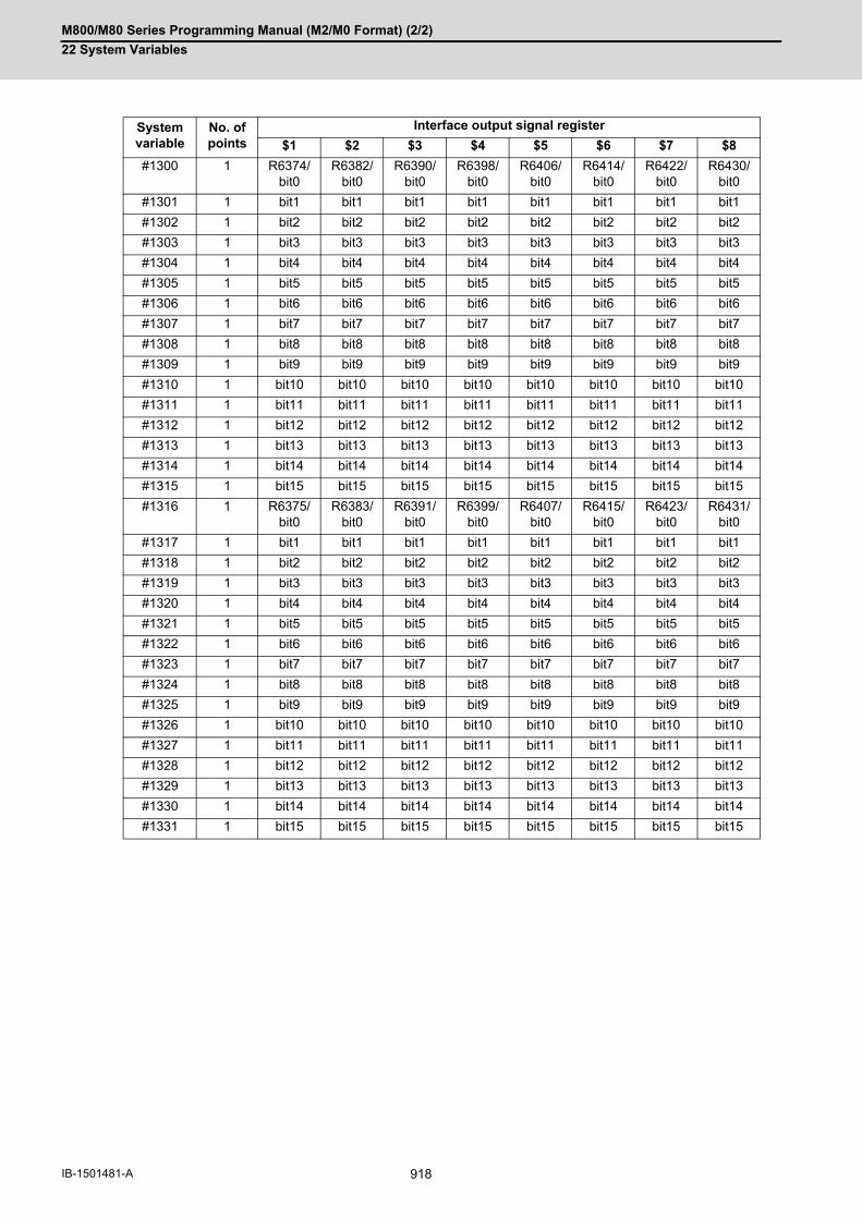
M800/M80 Series Programming Manual (M2/M0 Format) (2/2)
22 System Variables
918IB-1501481-A
System variable
No. of points
Interface output signal register
$1 $2 $3 $4 $5 $6 $7 $8
#1300 1 R6374/bit0
R6382/bit0
R6390/bit0
R6398/bit0
R6406/bit0
R6414/bit0
R6422/bit0
R6430/bit0
#1301 1 bit1 bit1 bit1 bit1 bit1 bit1 bit1 bit1
#1302 1 bit2 bit2 bit2 bit2 bit2 bit2 bit2 bit2
#1303 1 bit3 bit3 bit3 bit3 bit3 bit3 bit3 bit3
#1304 1 bit4 bit4 bit4 bit4 bit4 bit4 bit4 bit4
#1305 1 bit5 bit5 bit5 bit5 bit5 bit5 bit5 bit5
#1306 1 bit6 bit6 bit6 bit6 bit6 bit6 bit6 bit6
#1307 1 bit7 bit7 bit7 bit7 bit7 bit7 bit7 bit7
#1308 1 bit8 bit8 bit8 bit8 bit8 bit8 bit8 bit8
#1309 1 bit9 bit9 bit9 bit9 bit9 bit9 bit9 bit9
#1310 1 bit10 bit10 bit10 bit10 bit10 bit10 bit10 bit10
#1311 1 bit11 bit11 bit11 bit11 bit11 bit11 bit11 bit11
#1312 1 bit12 bit12 bit12 bit12 bit12 bit12 bit12 bit12
#1313 1 bit13 bit13 bit13 bit13 bit13 bit13 bit13 bit13
#1314 1 bit14 bit14 bit14 bit14 bit14 bit14 bit14 bit14
#1315 1 bit15 bit15 bit15 bit15 bit15 bit15 bit15 bit15
#1316 1 R6375/bit0
R6383/bit0
R6391/bit0
R6399/bit0
R6407/bit0
R6415/bit0
R6423/bit0
R6431/bit0
#1317 1 bit1 bit1 bit1 bit1 bit1 bit1 bit1 bit1
#1318 1 bit2 bit2 bit2 bit2 bit2 bit2 bit2 bit2
#1319 1 bit3 bit3 bit3 bit3 bit3 bit3 bit3 bit3
#1320 1 bit4 bit4 bit4 bit4 bit4 bit4 bit4 bit4
#1321 1 bit5 bit5 bit5 bit5 bit5 bit5 bit5 bit5
#1322 1 bit6 bit6 bit6 bit6 bit6 bit6 bit6 bit6
#1323 1 bit7 bit7 bit7 bit7 bit7 bit7 bit7 bit7
#1324 1 bit8 bit8 bit8 bit8 bit8 bit8 bit8 bit8
#1325 1 bit9 bit9 bit9 bit9 bit9 bit9 bit9 bit9
#1326 1 bit10 bit10 bit10 bit10 bit10 bit10 bit10 bit10
#1327 1 bit11 bit11 bit11 bit11 bit11 bit11 bit11 bit11
#1328 1 bit12 bit12 bit12 bit12 bit12 bit12 bit12 bit12
#1329 1 bit13 bit13 bit13 bit13 bit13 bit13 bit13 bit13
#1330 1 bit14 bit14 bit14 bit14 bit14 bit14 bit14 bit14
#1331 1 bit15 bit15 bit15 bit15 bit15 bit15 bit15 bit15

M800/M80 Series Programming Manual (M2/M0 Format) (2/2)
22 System Variables
919 IB-1501481-A
System variable
No. of points
Interface output signal register
$1 $2 $3 $4 $5 $6 $7 $8
#1332 1 R6376/bit0
R6384/bit0
R6392/bit0
R6400/bit0
R6408/bit0
R6416/bit0
R6424/bit0
R6432/bit0
#1333 1 bit1 bit1 bit1 bit1 bit1 bit1 bit1 bit1
#1334 1 bit2 bit2 bit2 bit2 bit2 bit2 bit2 bit2
#1335 1 bit3 bit3 bit3 bit3 bit3 bit3 bit3 bit3
#1336 1 bit4 bit4 bit4 bit4 bit4 bit4 bit4 bit4
#1337 1 bit5 bit5 bit5 bit5 bit5 bit5 bit5 bit5
#1338 1 bit6 bit6 bit6 bit6 bit6 bit6 bit6 bit6
#1339 1 bit7 bit7 bit7 bit7 bit7 bit7 bit7 bit7
#1340 1 bit8 bit8 bit8 bit8 bit8 bit8 bit8 bit8
#1341 1 bit9 bit9 bit9 bit9 bit9 bit9 bit9 bit9
#1342 1 bit10 bit10 bit10 bit10 bit10 bit10 bit10 bit10
#1343 1 bit11 bit11 bit11 bit11 bit11 bit11 bit11 bit11
#1344 1 bit12 bit12 bit12 bit12 bit12 bit12 bit12 bit12
#1345 1 bit13 bit13 bit13 bit13 bit13 bit13 bit13 bit13
#1346 1 bit14 bit14 bit14 bit14 bit14 bit14 bit14 bit14
#1347 1 bit15 bit15 bit15 bit15 bit15 bit15 bit15 bit15
#1348 1 R6377/bit0
R6385/bit0
R6393/bit0
R6401/bit0
R6409/bit0
R6417/bit0
R6425/bit0
R6433/bit0
#1349 1 bit1 bit1 bit1 bit1 bit1 bit1 bit1 bit1
#1350 1 bit2 bit2 bit2 bit2 bit2 bit2 bit2 bit2
#1351 1 bit3 bit3 bit3 bit3 bit3 bit3 bit3 bit3
#1352 1 bit4 bit4 bit4 bit4 bit4 bit4 bit4 bit4
#1353 1 bit5 bit5 bit5 bit5 bit5 bit5 bit5 bit5
#1354 1 bit6 bit6 bit6 bit6 bit6 bit6 bit6 bit6
#1355 1 bit7 bit7 bit7 bit7 bit7 bit7 bit7 bit7
#1356 1 bit8 bit8 bit8 bit8 bit8 bit8 bit8 bit8
#1357 1 bit9 bit9 bit9 bit9 bit9 bit9 bit9 bit9
#1358 1 bit10 bit10 bit10 bit10 bit10 bit10 bit10 bit10
#1359 1 bit11 bit11 bit11 bit11 bit11 bit11 bit11 bit11
#1360 1 bit12 bit12 bit12 bit12 bit12 bit12 bit12 bit12
#1361 1 bit13 bit13 bit13 bit13 bit13 bit13 bit13 bit13
#1362 1 bit14 bit14 bit14 bit14 bit14 bit14 bit14 bit14
#1363 1 bit15 bit15 bit15 bit15 bit15 bit15 bit15 bit15

M800/M80 Series Programming Manual (M2/M0 Format) (2/2)
22 System Variables
920IB-1501481-A
System variable
No. of points
Interface output signal register
$1 $2 $3 $4 $5 $6 $7 $8
#1364 1 R6378/bit0
R6386/bit0
R6394/bit0
R6402/bit0
R6410/bit0
R6418/bit0
R6426/bit0
R6434/bit0
#1365 1 bit1 bit1 bit1 bit1 bit1 bit1 bit1 bit1
#1366 1 bit2 bit2 bit2 bit2 bit2 bit2 bit2 bit2
#1367 1 bit3 bit3 bit3 bit3 bit3 bit3 bit3 bit3
#1368 1 bit4 bit4 bit4 bit4 bit4 bit4 bit4 bit4
#1369 1 bit5 bit5 bit5 bit5 bit5 bit5 bit5 bit5
#1370 1 bit6 bit6 bit6 bit6 bit6 bit6 bit6 bit6
#1371 1 bit7 bit7 bit7 bit7 bit7 bit7 bit7 bit7
#1372 1 bit8 bit8 bit8 bit8 bit8 bit8 bit8 bit8
#1373 1 bit9 bit9 bit9 bit9 bit9 bit9 bit9 bit9
#1374 1 bit10 bit10 bit10 bit10 bit10 bit10 bit10 bit10
#1375 1 bit11 bit11 bit11 bit11 bit11 bit11 bit11 bit11
#1376 1 bit12 bit12 bit12 bit12 bit12 bit12 bit12 bit12
#1377 1 bit13 bit13 bit13 bit13 bit13 bit13 bit13 bit13
#1378 1 bit14 bit14 bit14 bit14 bit14 bit14 bit14 bit14
#1379 1 bit15 bit15 bit15 bit15 bit15 bit15 bit15 bit15
#1380 1 R6379/bit0
R6387/bit0
R6395/bit0
R6403/bit0
R6411/bit0
R6419/bit0
R6427/bit0
R6435/bit0
#1381 1 bit1 bit1 bit1 bit1 bit1 bit1 bit1 bit1
#1382 1 bit2 bit2 bit2 bit2 bit2 bit2 bit2 bit2
#1383 1 bit3 bit3 bit3 bit3 bit3 bit3 bit3 bit3
#1384 1 bit4 bit4 bit4 bit4 bit4 bit4 bit4 bit4
#1385 1 bit5 bit5 bit5 bit5 bit5 bit5 bit5 bit5
#1386 1 bit6 bit6 bit6 bit6 bit6 bit6 bit6 bit6
#1387 1 bit7 bit7 bit7 bit7 bit7 bit7 bit7 bit7
#1388 1 bit8 bit8 bit8 bit8 bit8 bit8 bit8 bit8
#1389 1 bit9 bit9 bit9 bit9 bit9 bit9 bit9 bit9
#1390 1 bit10 bit10 bit10 bit10 bit10 bit10 bit10 bit10
#1391 1 bit11 bit11 bit11 bit11 bit11 bit11 bit11 bit11
#1392 1 bit12 bit12 bit12 bit12 bit12 bit12 bit12 bit12
#1393 1 bit13 bit13 bit13 bit13 bit13 bit13 bit13 bit13
#1394 1 bit14 bit14 bit14 bit14 bit14 bit14 bit14 bit14
#1395 1 bit15 bit15 bit15 bit15 bit15 bit15 bit15 bit15

M800/M80 Series Programming Manual (M2/M0 Format) (2/2)
22 System Variables
921 IB-1501481-A
22.27 System Variables (R Device Access Variables)
By using variable Nos. #50000 to #50749, #51000 to #51749, #52000 to #52749, it is possible to read data (R8300
to R9799, R18300 to R19799, R28300 to R29799) and substitute value in the R device user backup area.
These variables read and write the two words of R device.
Data range of these variables is -2147483648 to 2147483647.
Depending on the setting of the PLC bit selection parameter "#6455/ bit0 to 2", these variables can be changed be-
tween decimal point valid or invalid for each user backup area.
The position of the decimal point when decimal point valid is selected, varies according to the parameters "#1003
iunit" (inupt setting unit) and "#1041 I_inch" (initial inch). (This depends on the MTB specifications.)
These variables are retained even when the power is off.
These are common among part systems.
Function and purpose
Variable No. R device
#50000 R8300, R8301 User backup area (1500 points)
#50001 R8302, R8303
:
#50749 R9798, R9799
Variable No. R device
#51000 R18300, R18301 User backup area (1500 points)
#51001 R18302, R18303
:
#51749 R19798, R19799
Variable No. R device
#52000 R28300, R28301 User backup area (1500 points)
#52001 R28302, R28303
:
#52749 R29798, R29799
Detailed description
#1041 I_inch #1003 iunit
B C D E
0: Metric Three digits after the decimal point
Four digits after the dec-imal point
Five digits after the dec-imal point
Six digits after the deci-mal point
1: Inch Four digits after the dec-imal point
Five digits after the dec-imal point
Six digits after the deci-mal point
Seven digits after the decimal point
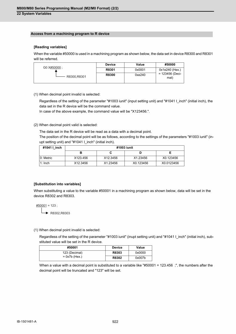
M800/M80 Series Programming Manual (M2/M0 Format) (2/2)
22 System Variables
922IB-1501481-A
[Reading variables]
When the variable #50000 is used in a machining program as shown below, the data set in device R8300 and R8301
will be referred.
(1) When decimal point invalid is selected:
Regardless of the setting of the parameter "#1003 iunit" (input setting unit) and "#1041 I_inch" (initial inch), the
data set in the R device will be the command value.
In case of the above example, the command value will be "X123456.".
(2) When decimal point valid is selected:
The data set in the R device will be read as a data with a decimal point.
The position of the decimal point will be as follows, according to the settings of the parameters "#1003 iunit" (in-
upt setting unit) and "#1041 I_inch" (initial inch).
[Substitution into variables]
When substituting a value to the variable #50001 in a machining program as shown below, data will be set in the
device R8302 and R8303.
(1) When decimal point invalid is selected:
Regardless of the setting of the parameter "#1003 iunit" (inupt setting unit) and "#1041 I_inch" (initial inch), sub-
stituted value will be set in the R device.
When a value with a decimal point is substituted to a variable like "#50001 = 123.456 ;", the numbers after the
decimal point will be truncated and "123" will be set.
Access from a machining program to R device
Device Value #50000
R8301 0x0001 0x1e240 (Hex.) = 123456 (Deci-
mal)R8300 0xe240
#1041 I_inch #1003 iunit
B C D E
0: Metric X123.456 X12.3456 X1.23456 X0.123456
1: Inch X12.3456 X1.23456 X0.123456 X0.0123456
#50001 Device Value
123 (Decimal)= 0x7b (Hex.)
R8303 0x0000
R8302 0x007b
G0 X#50000 ;
R8300,R8301
#50001 = 123 ;
R8302,R8303

M800/M80 Series Programming Manual (M2/M0 Format) (2/2)
22 System Variables
923 IB-1501481-A
(2) When decimal point valid is selected:
According to the settings of the parameter "#1003 iunit" (inupt setting unit) and "#1041 I_inch" (initial inch), val-
ues which are shifted for the number of decimals will be set in the R device, as shown below.
When a value with a decimal point is substituted to a variable like "#50001 = 123.456 ;", the value will directly
be set.
If the number of decimals of the substituted data exceeds the number of significant figures, the value will be
rounded off to the number of significant figures and will be set.
When "#50001 = 123.4567899 ;".
#1041 I_inch 0: Metric
#1003 iunit B C D E
#50001 123000 (Decimal)= 0x1e078 (Hex.)
1230000 (Decimal)= 0x12c4b0 (Hex.)
12300000 (Decimal)= 0xbbaee0 (Hex.)
123000000 (Decimal)= 0x754d4c0 (Hex.)
Device R8303 0x0001 0x0012 0x00bb 0x0754
R8302 0xe078 0xc4b0 0xaee0 0xd4c0
#1041 I_inch 1: Inch
#1003 iunit B C D E
#50001 1230000 (Decimal) = 0x12c4b0 (Hex.)
12300000 (Decimal) = 0xbbaee0 (Hex.)
123000000 (Decimal) = 0x754d4c0 (Hex.)
1230000000 (Decimal) = 0x49504f80 (Hex.)
Device R8303 0x0012 0x00bb 0x0754 0x4950
R8302 0xc4b0 0xaee0 0xd4c0 0x4f80
#1041 I_inch 0: Metric
#1003 iunit B C D E
#50001 123456 (Decimal)= 0x1e240 (Hex.)
1234560 (Decimal)= 0x12d680 (Hex.)
12345600 (Decimal)= 0xbc6100 (Hex.)
123456000 (Decimal)= 0x75bca00 (Hex.)
Device R8303 0x0001 0x0012 0x00bc 0x075b
R8302 0xe240 0xd680 0x6100 0xca00
#1041 I_inch 1: Inch
#1003 iunit B C D E
#50001 1234560 (Decimal)= 0x12d680 (Hex.)
12345600 (Decimal)= 0xbc6100 (Hex.)
123456000 (Decimal)= 0x75bca00 (Hex.)
1234560000 (Decimal)= 0x4995e400 (Hex.)
Device R8303 0x0012 0x00bc 0x075b 0x4998
R8302 0xd680 0x6100 0xca00 0xe400
#1041 I_inch 0: Metric
#1003 iunit B C D E
#50001 123457 (Decimal)= 0x1e241 (Hex.)
1234568 (Decimal)= 0x12d688 (Hex.)
12345679 (Decimal)= 0xbc614f (Hex.)
123456790 (Decimal)= 0x75bcd16 (Hex.)
Device R8303 0x0001 0x0012 0x00bc 0x075b
R8302 0xe241 0xd688 0x614f 0xcd16
#1041 I_inch 1: Inch
#1003 iunit B C D E
#50001 1234568 (Decimal)= 0x12d688 (Hex.)
12345679 (Decimal)= 0xbc614f (Hex.)
123456790 (Decimal)= 0x75bcd16 (Hex.)
1234567899 (Decimal)= 0x499602db (Hex.)
Device R8303 0x0012 0x00bc 0x075b 0x4996
R8302 0xd688 0x614f 0xcd16 0x02db

M800/M80 Series Programming Manual (M2/M0 Format) (2/2)
22 System Variables
924IB-1501481-A
These variables can be used in control command.
However, note that the variable value and the condition of true/false differ between decimal point valid variables and
invalid variables.
(1) When decimal point invalid is selected:
Regardless of the setting of the parameter "#1003 iunit" (input setting unit) and "#1041 I_inch" (initial inch), R
device value of #50003 whose condition is true, will be "1".
(2) When decimal point valid is selected:
The condition is true when #50003 is "1". So the R device value of #50003 will be as follows depending on the
setting of the parameter "#1003 iunit" (inupt setting unit) and "#1041 I_inch" (initial inch).
Use of R device access variables in control command
IF [#50003 EQ 1] GOTO 30 ;G00 X100 ;N30
#50003 Device Value
1 (Decimal)= 0x01 (Hex.)
R8307 0x0000
R8306 0x0001
#1041 I_inch 0: Metric
#1003 iunit B C D E
#50003 1000 (Decimal)= 0x3e8 (Hex.)
10000 (Decimal)= 0x2710 (Hex.)
100000 (Decimal)= 0x186a0 (Hex.)
1000000 (Decimal)= 0xf4240 (Hex.)
Device R8307 0x0000 0x0000 0x0001 0x000f
R8306 0x03e8 0x2710 0x86a0 0x4240
#1041 I_inch 1: Inch
#1003 iunit B C D E
#50003 10000 (Decimal)= 0x2710 (Hex.)
100000 (Decimal)= 0x186a0 (Hex.)
1000000 (Decimal)= 0xf4240 (Hex.)
10000000 (Decimal)= 0x989680 (Hex.)
Device R8307 0x0000 0x0001 0x000f 0x0098
R8306 0x2710 0x86a0 0x4240 0x9680
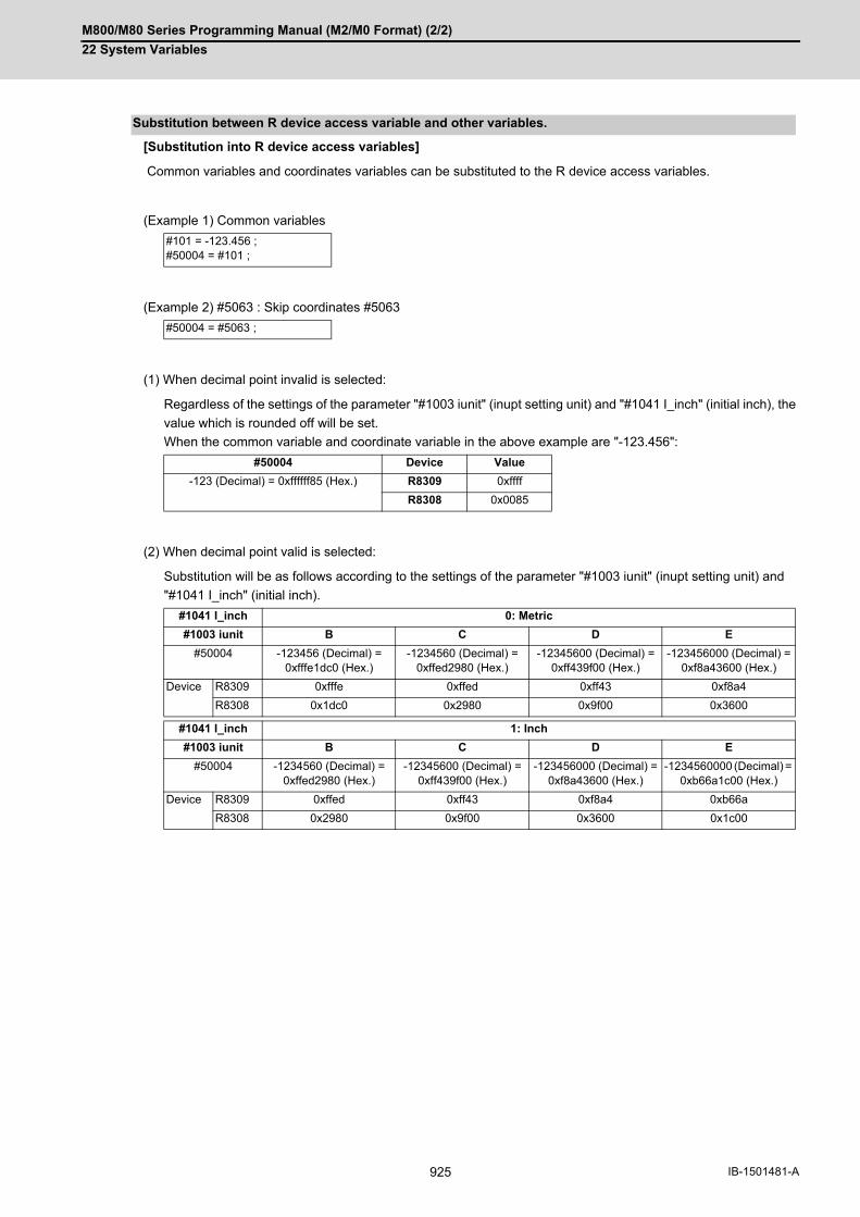
M800/M80 Series Programming Manual (M2/M0 Format) (2/2)
22 System Variables
925 IB-1501481-A
[Substitution into R device access variables]
Common variables and coordinates variables can be substituted to the R device access variables.
(Example 1) Common variables
(Example 2) #5063 : Skip coordinates #5063
(1) When decimal point invalid is selected:
Regardless of the settings of the parameter "#1003 iunit" (inupt setting unit) and "#1041 I_inch" (initial inch), the
value which is rounded off will be set.
When the common variable and coordinate variable in the above example are "-123.456":
(2) When decimal point valid is selected:
Substitution will be as follows according to the settings of the parameter "#1003 iunit" (inupt setting unit) and
"#1041 I_inch" (initial inch).
Substitution between R device access variable and other variables.
#101 = -123.456 ;#50004 = #101 ;
#50004 = #5063 ;
#50004 Device Value
-123 (Decimal) = 0xffffff85 (Hex.) R8309 0xffff
R8308 0x0085
#1041 I_inch 0: Metric
#1003 iunit B C D E
#50004 -123456 (Decimal) = 0xfffe1dc0 (Hex.)
-1234560 (Decimal) = 0xffed2980 (Hex.)
-12345600 (Decimal) = 0xff439f00 (Hex.)
-123456000 (Decimal) = 0xf8a43600 (Hex.)
Device R8309 0xfffe 0xffed 0xff43 0xf8a4
R8308 0x1dc0 0x2980 0x9f00 0x3600
#1041 I_inch 1: Inch
#1003 iunit B C D E
#50004 -1234560 (Decimal) = 0xffed2980 (Hex.)
-12345600 (Decimal) = 0xff439f00 (Hex.)
-123456000 (Decimal) = 0xf8a43600 (Hex.)
-1234560000 (Decimal) = 0xb66a1c00 (Hex.)
Device R8309 0xffed 0xff43 0xf8a4 0xb66a
R8308 0x2980 0x9f00 0x3600 0x1c00

M800/M80 Series Programming Manual (M2/M0 Format) (2/2)
22 System Variables
926IB-1501481-A
[Substitution of R device access variables]
(1) When decimal point invalid is selected:
Regardless of the settings of the parameter "#1003 iunit" (inupt setting unit) and "#1041 I_inch" (initial inch), #102
will be "123".
(2) When decimal point valid is selected:
Substitution will be as follows according to the settings of the parameter "#1003 iunit" (inupt setting unit) and
"#1041 I_inch" (initial inch).
(1) The position of a decimal point changes depending on the settings of the parameter "#1003 iunit" (input setting
unit) and "#1041 I_inch" (initial inch). Fix the decimal point position while considering these parameter settings
when setting a number to an R device.
(2) These variables do not handle <Blank>. If #0<Blank> is substituted, it will be converted into "0".
Therefore, when comparing this variable after substituting #0<Blank> and #0<Blank> with a conditional expres-
sion (EQ), it will not be formed.
(3) If a value exceeding the allowable range is substituted into this variable, a program error (P35) will occur.
(4) When these values are used as decimal point invalid, the settings of "#1078 Decpt2" (Decimal point type 2) and
"#8044 UNIT*10" will not be applied.
(5) When a graphic is being checked, writing into R device will not be executed even if a value is substituted into
these variables.
For reading of these variables (reference to the R device value) during a graphic check, "0" is always read.
#50005 = 123.456789 ;#102 = #50005 ;
#1041 I_inch 0: Metric
#1003 iunit B C D E
#102 123.4570 123.4568 123.4568 123.4568
#1041 I_inch 1: Inch
#1003 iunit B C D E
#102 123.4568 123.4568 123.4568 123.4568
Precautions

M800/M80 Series Programming Manual (M2/M0 Format) (2/2)
22 System Variables
927 IB-1501481-A
22.28 System Variables (PLC Data Reading)
PLC data can be read in with the system variables.
(1) These can be used only with some models.
(2) The readable devices are limited.
The PLC data is read in with the following five blocks using these five system variables.
(1) System variable for device designationThe type of device to be read in can be designated by substituting the device designation value in this systemvariable. If the data is read without designating this variable, the data will be read in the same manner as when the mini-mum value (0: M device) of the device designation value is designated. Once designated, the setting is held untilthe device is designated again or until it is reset. A program error (P39) will occur if a nonexistent device is set.
(2) Device designation value[M800/M80 series]
The unit indicates the amount of data per device No. "Word" is 16 bits, and "Bit" is one bit.
(*1) Device of which the device number is indicated in hexadecimal notation.
Function and purpose
Variable No. Application
#100100 Device type designation
#100101 Device No. designation
#100102 Number of read bytes designation
#100103 Read bit designation
#100110 Reading PLC data
Detailed description
#100100 = 1; Designates the device type.
#100101 = 0; Designates the device No.
#100102 = 1; Designates the number of bytes.
#100103 = 2; Designates the bit. (Valid only when reading word device bits.)
#100=#100110; Reads in the PLC data.
Device designation (#100100)
Device desig-nation value
Device Unit Device No. Device desig-nation value
Device Unit Device No.
0 M Bit M0 to M61439 10 F Bit F0 to F2047
1 D Word D0 to D4095 13 L Bit L0 to L1023
2 C Bit C0 to C511 18 V Bit V0 to V511
4 X (*1) Bit X0 to X1FFF 19 ST Bit ST0 to ST127
5 Y (*1) Bit Y0 to Y1FFF 20 SD Word SD0 to SD2047
6 R Word R0 to R32767 21 SB (*1) Bit SB0 to SB3FF
7 T Bit T0 to T2047 22 SW (*1) Word SW0 to SW3FF
9 SM Bit SM0 to SM2047
23 B (*1) Bit B0 to BDFFF
24 W (*1) Word W0 to W2FFF
Note

M800/M80 Series Programming Manual (M2/M0 Format) (2/2)
22 System Variables
928IB-1501481-A
The device to be read in is designated by substituting the device No. in this system variable.
Convert a device expressed as a hexadecimal into a decimal when designating.
If the data is read without designating this number, the data will be read in the same manner as when the minimum
device No. (0) is designated. Once designated, the setting is held until the device No. is designated again or until it
is reset.
A program error (P39) will occur if a nonexistent device No. is set.
(1) System variable for number of bytes designationThe reading size is designated by substituting the number of bytes designation value in this system variable. If the data is read without designating this number, the data will be read in the same manner as when the mini-mum device designation value (0: M device) is designated. Once designated, the setting is held until the numberof bytes is designated again or until it is reset. A program error (P39) will occur if a number of bytes that does not exist in the specifications is set.
(2) Number of bytes designation value
0 to 4 are designated without a sign, and 101 to 104 are designated with a sign.
(1) System variable for bit designationThe bit to be read in is designated by substituting the bit designation value in this system variable. This designation is valid only when reading the bits for a 16-bit device, and is invalid for the others. If the data is read without designating this number, the data will be read in the same manner as if the minimumbit designation value (0: bit 0) is designated. Once designated, the setting is held until the bit is designated againor until it is reset. A program error (P39) will occur if a nonexistent bit is set.
(2) Bit designation value
The data for the designated device is read in with this system variable.
Refer to the table for number of bytes designation for details on the range of data read in.
Device No. designation (#100101)
Number of bytes designation (#100102)
Number of bytes desig-nation value
Read in data Operation
Size Sign Range Word device Bit device
0 1 bit - 0 to 1 The number of bits des-ignated is read in.
The bits for the designated device No. are read in.
1 1 bytes No 0 to 255 The low-order byte is read in.
8 bits are read in from the designated device No.101 Yes -128 to 127
2 2 bytes No 0 to 65535 Two bytes are read in. 16 bits are read in from the designated device No.102 Yes -32768 to 32767
4 4 bytes No 0 to 4294967295 The designated device (L) and next device (H) are read in.
32 bits are read in from the designated device No.104 Yes -2147483648 to
2147483647
Bit designation (#100103)
Bit designation value Read in bit
0 Bit 0
1 Bit 1
: :
15 Bit 15
Reading PLC data (#100110)

M800/M80 Series Programming Manual (M2/M0 Format) (2/2)
22 System Variables
929 IB-1501481-A
(1) To read a bit device
(2) To read a word device
(1) As the PLC data is read asynchronously from the ladder execution, the data is not necessarily the one which wasgained when the program was executed. Be careful when reading devices which are changing.
(2) If reading of a nonexistent device is attempted by designating the device No. and number of bytes, the 0 valuewill be read in only for the nonexistent section.
(3) When "1" is set to the parameter "#1316 CrossCom", #100100 to #100110 cannot be used as system variablesto read PLC data.
Program example
#100100 = 0; Designates [M device].
#100101 = 0; Designates [Device No. 0].
#100102 = 0; Designates [Bit].
#100 = #100110; Reads M0 (one bit).
#100102 = 1; Designates [1 byte].
#101 = #100110; Reads M0 to M7 (8 bits). (If M7 to M0 is 0001 0010, this will be #102 = 18 (0x12).)
#100102 = 102; Designates [Signed two bytes].
#102 = #100110; Reads M0 to M15 (16 bits). (If M15 to M0 is 1111 1110 1101 1100, this will be #102 = -292 (0xFEDC).)
#100102 = 4; Designates [4 byte].
#104 = #100110; Reads M0 to M31 (32 bits). (If M31 to M0 is 0001 0010 0011 0100 0101 0110 0111 1000, #104 = 305419896 (0x12345678).)
#100100 = 1; Designates [D device].
#100101 = 0; Designates [Device No. 0].
#100102 = 0; Designates [Bit].
#100103 = 1; Designates [Bit 1].
#100 = #100110; Reads the D0 bit 1. (If D0 = 0x0102, #101 =1.)
#100102 = 1; Designates [1 byte].
#101 = #100110; Reads the low-order byte of D0. (If D0 = 0x0102, #101 =2.)
#100102 = 2; Designates [2 byte].
#102 = #100110; Reads D0. (If D0 = 0x0102, #102 =258.)
#100102 = 104; Designates [Signed four bytes].
#104 = #100110; Reads D0 and D1. (If D0 = 0xFFFE and D1 = 0xFFFF, #104 =-2.)
Precautions

M800/M80 Series Programming Manual (M2/M0 Format) (2/2)
22 System Variables
930IB-1501481-A
22.29 System Variables (Interfering Object Selection)
Select 16 interfering objects to use in the interference check III with system variables or R register.
Refer to the "PLC Interface Manual" (IB-1501272) for the R register.
When selecting an interfering object, specify the specification of the selected interfering object and interfering model
coordinate system offset 1.
The write command to the system variables (#40000 to #40097) is possible only in the machine tool builder macro
programs (L100010000 to L199999998).
Detailed description
System variable
R register Item Details Setting range (unit)
Upper: System variable
Lower: R register
#40000 R20304 Interfering object en-able/disable designation
Set enable/disable for each interfer-ing object.
0 to 65535 (decimal)
Bit designation (0: enable 1: dis-able)
bit0: Disable 1st interfering object 0x0000 to 0xFFFF (hexa-decimal):
bitF: Disable 16th interfering object
#40001 R20305 preliminary 0
0
#40002 R20306 1st interfering object se-lection
Select interfering object definition No. to use.
0 to 128 (0: not selected)
0 to 128 (0: not selected)
#40003 R20307 1st interfering object specification
In the configured solid specification of the interfering object definition, specify alarm area/warning area/solid setting invalid of the solid in which switching method is selected.
0 to 3
0, 1: Alarm area 0 to 3
2: Warning area
3: Solid setting invalid
#40004 R20308 (L) 1st interfering model co-ordinate systemI axis offset 1
Set the interfering model coordinate system offset with a radius value. (I axis direction) (*1)
-99999.999 to 99999.999 (mm) (radius value) R20309 (H)
#40005 R20310 (L) 1st interfering model co-ordinate systemJ axis offset 1
Set the interfering model coordinate system offset with a radius value. (J axis direction) (*1)
R20311 (H) -99999999 to 99999999 (μm) (radius value)
#40006 R20312 (L) 1st interfering model co-ordinate systemK axis offset 1
Set the interfering model coordinate system offset with a radius value. (K axis direction) (*1)
R20313 (H)
: :
#40077 R20426 16th interfering object selection
Same as above Same as above
#40078 R20427 16th interfering object specification selection
Same as above Same as above
#40079 R20428 (L) 16th interfering model coordinate systemI axis offset 1
Same as above Same as above
R20429 (H)
#40080 R20430 (L) 16th interfering model coordinate systemJ axis offset 1
Same as above Same as above
R20431 (H)

M800/M80 Series Programming Manual (M2/M0 Format) (2/2)
22 System Variables
931 IB-1501481-A
(*1) The interfering model coordinate system offset is the sum of the interfering model coordinate system offsets 1
and 2.
(Example) In the case that you do not check the interference between the 1st interfering object and the 2nd interfer-
ing object
"R20434 (#40082): 0x0002 (disable 2nd interfering object)" or "R20435 (#40083): 0x0001 (disable 1st interfering
object)"
Since each interfering object is designated to perform the interference check, the setting of the interference check
III specifying disabled interference object is repeated, but if either one is on disabled setting, the interference check
is not performed.
#40081 R20432 (L) 16th interfering model coordinate systemK axis offset 1
Same as above Same as above
R20433 (H)
#40082 R20434 1st interfering objectInterference check III: Specifying disabled in-terfering object
Select an interfering object that you do not check the interference with the 1st interfering object. bit0: Disable 1st interfering object (inaction data)bit1: Disable 2nd interfering object:bitF: Disable 16th interfering object
0 to 65535 (decimal)
0x0000 to 0xFFFF (hexa-decimal)
#40083 R204325 2nd interfering objectInterference check III: Specifying disabled in-terfering object
Select an interfering object that you do not check the interference with the 2nd interfering object. bit0: Disable 1st interfering objectbit1: Disable 2nd interfering object (inaction data):bitF: Disable 16th interfering object
0 to 65535 (decimal)
0x0000 to 0xFFFF (hexa-decimal)
: :
#40097 R20449 16th interfering objectInterference check III: Specifying disabled in-terfering object
Select an interfering object that you do not check the interference with the 16th interfering object. bit0: Disable 1st interfering objectbit1: Disable 2nd interfering object:bitF: Disable 16th interfering object (inaction data)
0 to 65535 (decimal)
0x0000 to 0xFFFF (hexa-decimal)
Interference check III: Specifying disabled interfering object
Back side of spindle part (without a workpiece)
Back side of spindle part (with a workpiece)
1st interfering object(back side of spindle part) 1st interfering object
(back side of spindle part)2nd interfering object (workpiece part)
By specifying the interference III disabled between the back side of spindle part (1st interfering object) and workpiece part (2nd interfering object), these 2 parts are treated as one interfering object.
System variable
R register Item Details Setting range (unit)
Upper: System variable
Lower: R register

M800/M80 Series Programming Manual (M2/M0 Format) (2/2)
22 System Variables
932IB-1501481-A
(1) When the interfering object selection is input with the system variables, the system variable in which the com-mand range integer is set in R register with the value after the decimal point being ignored. (a) When any value out of the setting range is input in #40000 to #40097, the low-order 16 bits of the input valueare set in R register. (b) When "#0" <empty> is input in #40000 to #40097, "0" is set in R register.
(2) If you have made a write command to the system variable (#40000 to #40097) in a program except for the ma-chine tool builder macro program, the program error (P241) occurs.
Precautions

23
933 IB-1501481-A
Appx.1: Fixed Cycles
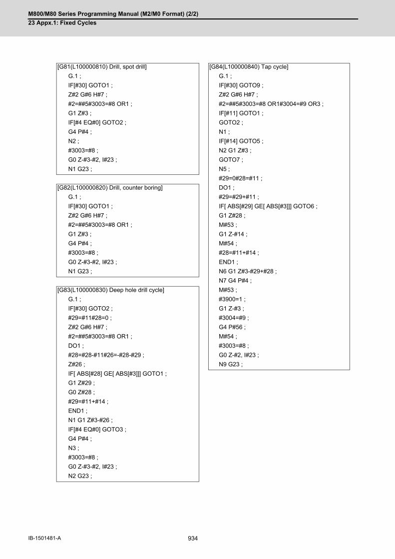
M800/M80 Series Programming Manual (M2/M0 Format) (2/2)
23 Appx.1: Fixed Cycles
934IB-1501481-A
23Appx.1: Fixed Cycles[G81(L100000810) Drill, spot drill] [G84(L100000840) Tap cycle]
G.1 ; G.1 ;
IF[#30] GOTO1 ; IF[#30] GOTO9 ;
Z#2 G#6 H#7 ; Z#2 G#6 H#7 ;
#2=##5#3003=#8 OR1 ; #2=##5#3003=#8 OR1#3004=#9 OR3 ;
G1 Z#3 ; IF[#11] GOTO1 ;
IF[#4 EQ#0] GOTO2 ; GOTO2 ;
G4 P#4 ; N1 ;
N2 ; IF[#14] GOTO5 ;
#3003=#8 ; N2 G1 Z#3 ;
G0 Z-#3-#2, I#23 ; GOTO7 ;
N1 G23 ; N5 ;
#29=0#28=#11 ;
[G82(L100000820) Drill, counter boring] DO1 ;
G.1 ; #29=#29+#11 ;
IF[#30] GOTO1 ; IF[ ABS[#29] GE[ ABS[#3]]] GOTO6 ;
Z#2 G#6 H#7 ; G1 Z#28 ;
#2=##5#3003=#8 OR1 ; M#53 ;
G1 Z#3 ; G1 Z-#14 ;
G4 P#4 ; M#54 ;
#3003=#8 ; #28=#11+#14 ;
G0 Z-#3-#2, I#23 ; END1 ;
N1 G23 ; N6 G1 Z#3-#29+#28 ;
N7 G4 P#4 ;
[G83(L100000830) Deep hole drill cycle] M#53 ;
G.1 ; #3900=1 ;
IF[#30] GOTO2 ; G1 Z-#3 ;
#29=#11#28=0 ; #3004=#9 ;
Z#2 G#6 H#7 ; G4 P#56 ;
#2=##5#3003=#8 OR1 ; M#54 ;
DO1 ; #3003=#8 ;
#28=#28-#11#26=-#28-#29 ; G0 Z-#2, I#23 ;
Z#26 ; N9 G23 ;
IF[ ABS[#28] GE[ ABS[#3]]] GOTO1 ;
G1 Z#29 ;
G0 Z#28 ;
#29=#11+#14 ;
END1 ;
N1 G1 Z#3-#26 ;
IF[#4 EQ#0] GOTO3 ;
G4 P#4 ;
N3 ;
#3003=#8 ;
G0 Z-#3-#2, I#23 ;
N2 G23 ;

M800/M80 Series Programming Manual (M2/M0 Format) (2/2)
23 Appx.1: Fixed Cycles
935 IB-1501481-A
[G85(L100000850) Boring 1] [G88(L100000880) Boring 3]
G.1 ; G.1 ;
IF[#30] GOTO1 ; IF[#30] GOTO1 ;
Z#2 G#6 H#7 ; Z#2 G#6 H#7 ;
#2=##5#3003=#8 OR1 ; #2=##5#3003=#8 OR1 ;
G1 Z#3 ; G1 Z#3 ;
IF[#4 EQ#0] GOTO2 ; G4 P#4 ;
G4 P#4 ; #3003=#8 ;
N2 ; M5 ;
#3003=#8 ; #3003=#8 OR1 ;
Z-#3 ; G0 Z-#3-#2 ;
G0 Z-#2, I#23 ; #3003=#8 ;
N1 G23 ; M3 ;
N1 G23 ;
[G86(L100000860) Boring 2]
G.1 ; [G89(L100000890) Boring 4]
IF[#30] GOTO1 ; G.1 ;
Z#2 G#6 H#7 ; IF[#30] GOTO1 ;
#2=##5#3003=#8 OR1 ; Z#2 G#6 H#7 ;
G1 Z#3 ; #2=##5#3003=#8 OR1 ;
G4 P#4 ; G1 Z#3 ;
M5 ; G4 P#4 ;
G0 Z-#3-#2 ; #3003=#8 ;
#3003=#8 ; Z-#3 ;
M3 ; G0 Z-#2, I#23 ;
N1 G23 ; N1 G23 ;
[G87(L100000870) Back boring] [G73(L100000831) Step cycle]
G.1 ; G.1 ;
IF[#30] GOTO1 ; IF[#30] GOTO2 ;
#3003=#8 OR1 ; #29=0#28=#11 ;
M19 ; Z#2 G#6 H#7 ;
X#12 Y#13 ; #2=##5#3003=#8 OR1 ;
#3003=#8 ; DO1 ;
Z#2 G#6 H#7 ; #29=#29+#11 ;
#3003=#8 OR1 ; IF[ ABS[#29] GE[ ABS[#3]]] GOTO1 ;
G1 X-#12 Y-#13 ; G1 Z#28 ;
#3003=#8 ; G4 P#4 ;
M3 ; G0 Z-#14 ;
#3003=#8 OR1 ; #28=#11+#14 ;
Z#3 ; END1 ;
M19 ; N1 G1 Z#3-#29+#28 ;
G0 X#12 Y#13 ; G4 P#4 ;
Z-#2-#3 ; #3003=#8 ;
#3003=#8 ; G0 Z-#3-#2, I#23 ;
X-#12 Y-#13 ; N2 G23 ;
M3 ;
N1 G23 ;

M800/M80 Series Programming Manual (M2/M0 Format) (2/2)
23 Appx.1: Fixed Cycles
936IB-1501481-A
[G74(L100000841) Reverse tap cycle] [G75(L100000851) Circle cutting cycle]
G.1 ; G.1 ;
IF[#30] GOTO9 ; IF[#30] GOTO1 ;
Z#2 G#6 H#7 ; #28=#18 ;
#2=##5#3003=#8 OR1#3004=#9 OR3 ; IF[#28 GE0] GOTO2 ;
IF[#11] GOTO1 ; #27=3#28=-#28 ;
GOTO2 ; GOTO3 ;
N1 ; N2#27=2 ;
IF[#14] GOTO5 ; N3#26=#4 ;
N2 G1 Z#3 ; IF[#26 GE#28] GOTO1 ;
GOTO7 ; Z#2 G#6 H#7 ;
N5 ; #2=##5#3003=#8 OR1 ;
#29=0#28=#11 ; G1 Z#3 ;
DO1 ; #28=#28-#26#29=#28/2 ;
#29=#29+#11 ; G#27 X-#28 I-#29 ;
IF[ ABS[#29] GE[ ABS[#3]]] GOTO6 ; I#28 P1 ;
G1 Z#28 ; X#28 I#29 ;
M#53 ; #3003=#8 ;
G1 Z-#14 ; G0 Z-#3-#2, I#23 ;
M#54 ; N1 G23 ;
#28=#11+#14 ;
END1 ; [G76(L100000861) Fine boring]
N6 G1 Z#3-#29+#28 ; G.1 ;
N7 G4 P#4 ; IF[#30] GOTO1 ;
M#53 ; Z#2 G#6 H#7 ;
#3900=1 ; #2=##5#3003=#8 OR1 ;
G1 Z-#3 ; G1 Z#3 ;
#3004=#9 ; M19 ;
G4 P#56 ; X#12 Y#13 ;
M#54 ; G0 Z-#3-#2 ;
#3003=#8 ; #3003=#8 ;
G0 Z-#2, I#23 ; X-#12 Y-#13 ;
N9 G23 ; M3 ;
N1 G23 ;

Index
Refer to Programming Manual (M2/M0 Format) (1/2) for Chapter 14 and previous chapters (page 440 and before).
Refer to Programming Manual (M2/M0 Format) (2/2) for Chapter 15 and succeeding chapters (page 441 and later).
Symbols!n (!m ...) L ..................................................................... 530/ ....................................................................................... 16/n ..................................................................................... 18
Numerics2nd Miscellaneous Functions (A8-digits, B8-digits or C8-digits) ....................................................................... 2042nd, 3rd, and 4th Reference Position (Zero Point) Return ... 8293-dimensional Circular Interpolation .............................. 1083-dimensional Coordinate Conversion .......................... 7793-dimensional Tool Radius Compensation ............ 294, 735
AAcceleration Clamp Speed ............................................ 632Acceleration/Deceleration Mode Change in Hole DrillingCycle ............................................................................. 364Actual Examples of Using User Macros ........................ 427Arbitrary Axis Exchange ................................................ 546Arc ................................................................................. 369ASCII Code Macro ........................................................ 403Automatic Coordinate System Setting ........................... 751Automatic Corner Override ............................................ 188Automatic Tool Length Measurement ............................ 844Axis-based Unidirectional Positioning ............................. 72
BBack Boring ................................................................... 341Basic Machine Coordinate System Selection ................ 755Basic Machine, Workpiece and Local Coordinate Systems ... 749Bolt Hole Cycle .............................................................. 367Boring .................................................... 339, 340, 344, 345
CChanging of Compensation No. during Compensation Mode ... 272Circular Cutting ........................................................ 80, 350Circular Interpolation ....................................................... 47Common Variables ........................................................ 409Compensation Data Input by Program .......................... 498Compensation Data Input by Program (Turning Tool) ... 504Compensation Data Input to Variable by Program ........ 513Constant Lead Thread Cutting ........................................ 58Constant Surface Speed Control ................................... 213Control Commands ....................................................... 418Coordinate Read Function ............................................ 525Coordinate Rotation by Program ................................... 797Coordinate Rotation Input by Parameter ....................... 804Coordinate System for Rotary Axis ............................... 752Coordinate System Setting ............................................ 758Coordinate Systems and Coordinate Zero Point Symbols ... 3Coordinate Words and Control Axes ......................... 2, 748Corner Chamfering Expansion/Corner Rounding Expansion .............................................................. 446, 452Corner Chamfering I ...................................................... 442Corner Chamfering I / Corner Rounding I ...................... 442Corner Chamfering II ..................................................... 449Corner Chamfering II / Corner Rounding II .................... 449Corner Rounding I ......................................................... 444Corner Rounding II ........................................................ 451Cutting Feed Constant Inclination Acceleration/Deceleration ... 155Cutting Feedrate ............................................................ 127Cutting Mode ................................................................. 196
Cylindrical Interpolation ................................................... 73
DDeceleration Check ....................................................... 166Deceleration Check when Movement in The Opposite Direction Is Reversed .................................................... 174Decimal Point Input .......................................................... 34Deep Hole Drilling Cycle ................................................ 322Define by Selecting the Registered Machining Surface ... 706Detailed Description for Macro Call Instruction .............. 401Details of Inclined Surface Machining Operation ........... 717Diameter Designation of Compensation Amount ........... 287Drilling Cycle High-Speed Retract ................................. 360Drilling, Counter Boring .................................................. 321Drilling, Spot Drilling ...................................................... 320Dwell (Time-based designation) .................................... 198
EEnable Interfering Object Selection Data ....................... 840End Point Error Check Cancellation .............................. 523Exact Stop Check .......................................................... 161Exact Stop Check Mode ................................................ 165Exponential Interpolation ................................................. 89External Output Commands .......................................... 421
FF1-Digit Feed ................................................................. 128Fairing ............................................................................ 622Feed Per Minute/Feed Per Revolution (Asynchronous Feed/ Synchronous Feed) .................... 130Feedrate Designation and Effects on Control Axes ....... 138Figure Rotation .............................................................. 380File Format ....................................................................... 14Fine Boring .................................................................... 352Fixed Cycles .......................................................... 316, 934
GG Code Lists .................................................................... 20G Cole Macro Call ......................................................... 398G Command Mirror Image ............................................. 464G0.5 ............................................................................... 178G0.5 P1 .......................................................................... 176G00 .................................................................................. 42G00 Feedrate Command (,F command) ........................ 123G01 .................................................................................. 45G01 A_ ........................................................................... 454G01 A_ , G02/G03 P_Q_H_ .......................................... 459G01 A_ , G02/G03 R_H_ ............................................... 462G01 X_ Y_ ,C ................................................................. 442G01 X_ Y_ ,R_ ............................................................... 444G01 X_/Y_ A_/,A_ ......................................................... 453G01/G02/G03 X_ Y_ ,C_ ............................................... 449G01/G02/G03 X_ Y_ ,R_ ............................................... 451G02, G03 ................................................................... 47, 53G02.1/G03.1 (Type 1), G02/G03 (Type 2) ..................... 103G02.3,G03.3 .................................................................... 89G02.4, G03.4 ................................................................. 108G02/G03 P_Q_ /R_ ....................................................... 457G04 ................................................................................ 198G05 P1, G05 P2 ............................................................ 566G05.1 Q1/Q0, G05 P10000/P0, G05 P20000/P0 .......... 606G05.1 Q2/Q0 ................................................................. 637

G06.2 ............................................................................. 113G07 ................................................................................ 119G07.1 ............................................................................... 73G09 ................................................................................ 161G10 I_ J_/K_ ................................................................. 804G10 L100, G11.1 ........................................................... 506G10 L110/L111, G11.1, G68.2, G69.1 .......................... 509G10 L12/L13, G11.1 ...................................................... 504G10 L14 ......................................................................... 866G10 L2/L10/L11/L12/L13/L20, G11.1 ............................ 498G10 L3, G11.1 ............................................................... 514G10 L30, G11.1 ............................................................. 517G10 L70/L100, G11.1 .................................................... 495G11 ................................................................................ 513G115 .............................................................................. 533G116 .............................................................................. 536G12,G13 .......................................................................... 80G12.1,G13.1/G112,G113 ................................................ 82G120.1, G121 ................................................................ 654G122 .............................................................................. 549G127 .............................................................................. 489G14 ................................................................................ 525G140, G141, G142 ........................................................ 546G16 .................................................................................. 96G160 .............................................................................. 862G17, G18, G19 ................................................................ 56G17, G18, G19 and G02, G03 ........................................ 64G186 .............................................................................. 840G20, G21 ......................................................................... 32G22 I_J_K_ ................................................................... 380G22, G23 ....................................................................... 374G22.1/G23.1 .................................................................. 838G27 ................................................................................ 835G28,G29 ........................................................................ 825G30 ................................................................................ 829G30.1 - G30.6 ................................................................ 832G31 ................................................................................ 848G31 Fn .......................................................................... 858G31 P ............................................................................ 856G31.n, G04 .................................................................... 854G33 ............................................................................ 58, 62G34 ................................................................................ 367G35 ................................................................................ 368G36 ................................................................................ 369G37 ................................................................................ 370G37.1 ............................................................................. 844G38, G39/G40/G41, G42 .............................................. 243G40.1/G41.1/G42.1(G150/G151/G152) ........................ 469G40/G41, G42 ............................................................... 294G40/G41.2, G42.2 ......................................................... 735G41/G42 Commands and I, J, K Designation ............... 263G43, G44 ....................................................................... 238G43.1/G44 ..................................................................... 660G43.4, G43.5/G44 ......................................................... 667G45 to G48 .................................................................... 306G50.1, G51.1, G62 ........................................................ 464G50/G51 ........................................................................ 821G52 ................................................................................ 760G53 ................................................................................ 755G53.1/G53.6 .................................................................. 709G54 to G59 (G54.1) ....................................................... 764G60 .................................................................................. 70G61 ................................................................................ 165G61.1, G08 .................................................................... 575G61.2 ............................................................................. 652G61.4 ............................................................................. 645G63 ................................................................................ 195
G64 ................................................................................ 196G65 ................................................................................ 389G66 ................................................................................ 394G66.1 ............................................................................. 396G68.1/G69.1 .......................................................... 779, 797G68.2, G68.3/G69.1 ...................................................... 695G69 ................................................................................ 523G73 ................................................................................ 346G74 ................................................................................ 348G75 ................................................................................ 350G76 ................................................................................ 352G81 ................................................................................ 320G82 ................................................................................ 321G83 ................................................................................ 322G84 ................................................................................ 327G85 ................................................................................ 339G86 ................................................................................ 340G87 ................................................................................ 341G88 ................................................................................ 344G89 ................................................................................ 345G90,G91 .......................................................................... 30G92 ........................................................................ 219, 758G92.1 ............................................................................. 774G93 ................................................................................ 133G94,G95 ........................................................................ 130G96,G97 ........................................................................ 213G98, G99 ....................................................................... 358General Precautions for Tool Radius Compensation .... 271Geometric ...................................................................... 454Geometric IB .................................................................. 456Geometric IB (Automatic Calculation of Linear - Arc Intersection) ........................................................... 459, 462Geometric IB (Automatic Calculation of Two-arc Contact) ... 457Grid ................................................................................ 370
HHelical Interpolation ......................................................... 64High-accuracy Control ................................................... 575High-accuracy Spline Interpolation ................................ 652High-speed High-accuracy Control ................................ 606High-speed High-accuracy Control I, II, III ..................... 606High-speed Machining Mode I, II ................................... 566High-speed Mode Corner Deceleration ......................... 633How to Define Feature Coordinate System Using Euler Angles ........................................................ 696How to Define Feature Coordinate System Using Projection Angles ................................................. 704How to Define Feature Coordinate System Using Roll-Pitch-Yaw Angles ......................................... 698How to Define Feature Coordinate System Using Three Points in a Plane ....................................... 700How to Define Feature Coordinate System Using Tool Axis Direction ............................................... 707How to Define Feature Coordinate System Using Two Vectors ......................................................... 702Hypothetical Axis Interpolation ...................................... 119
IInch Thread Cutting ......................................................... 62Inch/Metric Conversion .................................................... 32Inclined Surface Machining ............................................ 695Inclined Surface Machining and Relationship with Other Functions ....................................................................... 727Index Table Indexing ..................................................... 205Indexing Increment ............................................................ 8Initial High-accuracy Control .......................................... 603Initial Point and R Point Level Return ............................ 358
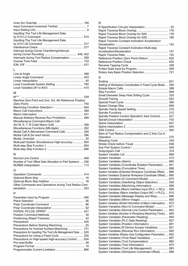
Inner Arc Override ......................................................... 194Input Command Increment Tenfold ................................... 7Input Setting Unit ............................................................... 6Inputting The Tool Life Management Data by G10 L3 Command .................................................... 514Inputting The Tool Life Management Data by G10 L30 Command .................................................. 517Interference Check ........................................................ 277Interrupt during Corner Chamfering/Interrupt during Corner Rounding ........................................ 448, 452Interrupts during Tool Radius Compensation ................ 269Inverse Time Feed ........................................................ 133ION, IOF ........................................................................ 431
LLine at Angle ................................................................. 368Linear Angle Command ................................................. 453Linear Interpolation .......................................................... 45Local Coordinate System Setting .................................. 760Local Variables (#1 to #33) ........................................... 410
MM*** ............................................................................... 539Machine Zero Point and 2nd, 3rd, 4th Reference Position(Zero Point) ................................................................... 750Machining Condition Selection I .................................... 654Macro Call Instructions .................................................. 389Macro Interruption ......................................................... 431Manual Arbitrary Reverse Run Prohibition .................... 489Miscellaneous Command Macro Call (for M, S, T, B Code Macro Call) ................................... 399Miscellaneous Functions (M8-digits) ............................. 202Modal Call A (Movement Command Call) ..................... 394Modal Call B (for each block) ........................................ 396Modal, Unmodal .............................................................. 20Multi-part System Simultaneous High-accuracy ............ 604Multi-step Skip Function 1 ............................................. 854Multi-step Skip Function 2 ............................................. 856
NNormal Line Control ...................................................... 469Number of Tool Offset Sets Allocation to Part Systems ... 236NURBS Interpolation ..................................................... 113
OOperation Commands ................................................... 414Optional Block Skip ......................................................... 16Optional Block Skip Addition ........................................... 18Other Commands and Operations during Tool Radius Com-pensation ....................................................................... 253
PParameter Input by Program ......................................... 495Plane Selection ............................................................... 56Polar Coordinate Command ............................................ 96Polar Coordinate Interpolation ......................................... 82POPEN, PCLOS, DPRNT ............................................. 421Position Command Methods ........................................... 30Positioning (Rapid Traverse) ........................................... 42Precautions ................................................................... 425Precautions Before Starting Machining ........................... 25Precautions for Inclined Surface Machining .................. 731Precautions for Inputting The Tool Life Management Data ... 520Precautions for Using a Fixed Cycle ............................. 355Precautions on High-speed High-accuracy Control ....... 634Pre-read Buffer ................................................................ 28Program Format .............................................................. 10Programmable Current Limitation .................................. 866
RR Specification Circular Interpolation ............................... 53Rapid Traverse Block Overlap ....................................... 176Rapid Traverse Block Overlap for G00 .......................... 178Rapid Traverse Block Overlap for G28 .......................... 186Rapid Traverse Constant Inclination Acceleration/Deceleration ................................................................... 142Rapid Traverse Constant Inclination Multi-step Acceleration/Deceleration .............................................. 147Rapid Traverse Rate ...................................................... 122Reference Position (Zero Point) Return ......................... 825Reference Position Check ............................................. 835Reverse Tapping Cycle ................................................. 348R-Navi Data Input by Program ....................................... 509Rotary Axis Basic Position Selection ............................. 721
SScaling ........................................................................... 821Setting of Workpiece Coordinates in Fixed Cycle Mode ... 359Simple Macro Calls ........................................................ 389Skip Function ................................................................. 848Small Diameter Deep Hole Drilling Cycle ...................... 324Smooth Fairing .............................................................. 623Special Fixed Cycle ....................................................... 366Speed Change Skip ....................................................... 858Spindle Clamp Speed Setting ........................................ 219Spindle Functions .......................................................... 212Spindle Position Control (Spindle/C Axis Control) ......... 221Spiral/Conical Interpolation ............................................ 103Spline Interpolation ........................................................ 637Spline Interpolation 2 ..................................................... 645SSS Control ................................................................... 592Start of Tool Radius Compensation and Z Axis Cut in Operation ....................................................................... 275Stepping Cycle ............................................................... 346Stroke Check before Travel ........................................... 838Sub Part System Control I ............................................. 549Subprogram Call ............................................................ 374System Variable List ...................................................... 868System Variables ........................................................... 413System Variables (Alarm) .............................................. 895System Variables (Coordinate Rotation Parameter) ...... 901System Variables (Cumulative Time) ............................ 896System Variables (Extended Workpiece Coordinate Offset) ... 889System Variables (External Workpiece Coordinate Offset) ... 890System Variables (G Command Modal) ........................ 870System Variables (Interfering Object Selection) ............ 930System Variables (Machining Information) .................... 899System Variables (Macro Interface Input (PLC -> NC)) ... 909System Variables (Macro Interface Output (NC -> PLC)) ... 915System Variables (Message Display and Stop) ............. 896System Variables (Mirror Image) ................................... 900System Variables (Modal Information at Macro Interruption) ... 872System Variables (Non-G Command Modal) ................ 871System Variables (Normal Line Control Parameter) ...... 903System Variables (Number of Workpiece Machining Times) ... 900System Variables (Parameter Reading) ........................ 904System Variables (PLC Data Reading) ......................... 927System Variables (Position Information) ........................ 891System Variables (R Device Access Variables) ............ 921System Variables (Reverse Run Information) ............... 900System Variables (Rotary Axis Configuration Parameter) ... 902System Variables (Time Read Variables) ...................... 897System Variables (Tool Compensation) ........................ 882System Variables (Tool Information) ............................. 874System Variables (Tool Life Management) .................... 883System Variables (Workpiece Coordinate Offset) ......... 888

System Variables (Workpiece Installation Error Compensation Amount) ................................................. 908
TTapping Cycle ............................................................... 327Tapping Mode ............................................................... 195Thread Cutting ................................................................. 58Time Synchronization When Timing Synchronization Ignore Is Set .................................................................. 543Timing Synchronization ................................................. 530Timing Synchronization Operation (! code) ................... 530Timing Synchronization Operation Function Using M codes ... 539Timing Synchronization Operation with Start Point Designated (Type 1) ...................................................... 533Timing Synchronization Operation with Start Point Designated (Type 2) ...................................................... 536Tolerance Control .......................................................... 596Tool Axis Direction Control ............................................ 709Tool Center Point Control .............................................. 667Tool Change Position Return ........................................ 832Tool Compensation ....................................................... 232Tool Functions (T8-digit BCD) ....................................... 230Tool Length Compensation / Cancel ............................. 238Tool Length Compensation in the Tool Axis Direction ... 660Tool Life Management Set Allocation to Part Systems ... 521Tool Nose Radius Compensation (for Machining Center System) ............................................................. 291Tool Position Offset ....................................................... 306Tool Radius Compensation ........................................... 243Tool Radius Compensation Operation .......................... 244Tool Shape Input by Program ....................................... 506Torque Limitation Skip ................................................... 862
UUnidirectional Positioning ................................................ 70User Macro .................................................................... 388User Macro Commands ................................................. 414
VVariable Commands ...................................................... 383Variable-acceleration Pre-interpolation Acceleration/Deceleration .................................................................. 600Variables Used in User Macros ..................................... 407
WWorkpiece Coordinate Changing during Radius Compensation ............................................................... 289Workpiece Coordinate System Preset ........................... 774Workpiece Coordinate System Setting and Offset ........ 764

Revision History
Date of revi-sion
Manual No. Revision details
Mar. 2017 IB(NA)-1501480-AIB(NA)-1501481-A
First edition created.

Global Service Network
AMERICA EUROPE
MITSUBISHI ELECTRIC AUTOMATION INC. (AMERICA FA CENTER) MITSUBISHI ELECTRIC EUROPE B.V. Central Region Service Center (Chicago) European Service Headquarter (Dusseldorf, GERMANY) 500 CORPORATE WOODS PARKWAY, VERNON HILLS, ILLINOIS 60061, U.S.A. Mitsubishi-Electric-Platz 1 40882 RATINGEN, GERMANY TEL: +1-847-478-2500 / FAX: +1-847-478-2650 TEL: +49-2102-486-1850 / FAX: +49-2102-486-5910 Minneapolis, MN Service Satellite Detroit, MI Service Satellite South Germany Service Center (Stuttgart) Grand Rapids, MI Service Satellite KURZE STRASSE. 40, 70794 FILDERSTADT-BONLANDEN, GERMANY Lima, OH Service Satellite TEL: + 49-711-770598-123 / FAX: +49-711-770598-141 Cleveland, OH Service Satellite Indianapolis, IN Service Satellite France Service Center (Paris) St. Louis, MO Service Satellite 25, BOULEVARD DES BOUVETS, 92741 NANTERRE CEDEX FRANCE
TEL: +33-1-41-02-83-13 / FAX: +33-1-49-01-07-25South/East Region Service Center (Georgia) 1845 SATTELITE BOULEVARD STE. 450, DULUTH, GEORGIA 30097, U.S.A. France Service Satellite (Lyon) TEL +1-678-258-4529 / FAX +1-678-258-4519 120, ALLEE JACQUES MONOD 69800 SAINT PRIEST FRANCE Charleston, SC Service Satellite TEL: +33-1-41-02-83-13 / FAX: +33-1-49-01-07-25 Charlotte, NC Service Satellite Raleigh, NC Service Satellite Italy Service Center (Milan) Dallas, TX Service Satellite VIALE COLLEONI, 7 - CENTRO DIREZIONALE COLLEONI PALAZZO SIRIO INGRESSO 1, Houston, TX Service Satellite 20864 AGRATE BRIANZA (MB), ITALY Hartford, CT Service Satellite TEL: +39-039-6053-342 / FAX: +39-039-6053-206 Knoxville, TN Service Satellite Nashville, TN Service Satellite Italy Service Satellite (Padova) Baltimore, MD Service Satellite VIA G. SAVELLI, 24 - 35129 PADOVA, ITALY Pittsburg, PA Service Satellite TEL: +39-039-6053-342 / FAX: +39-039-6053-206 Allentown, PA Service Satellite Syracuse, NY Service Satellite U.K. Service Center Tampa, FL Service Satellite TRAVELLERS LANE, HATFIELD, HERTFORDSHIRE, AL10 8XB, U.K. Lafayette, LA Service Satellite TEL: +49-2102-486-1850 / FAX: +49-2102-486-5910
Western Region Service Center (California) Spain Service Center 5900-B KATELLA AVE. - 5900-A KATELLA AVE. CYPRESS, CALIFORNIA 90630, U.S.A. CTRA. DE RUBI, 76-80-APDO. 420, 08173 SAINT CUGAT DEL VALLES, BARCELONA SPAIN TEL: +1-714-699-2625 / FAX: +1-847-478-2650 TEL: +34-935-65-2236 / FAX: +34-935-89-1579 San Francisco, CA Service Satellite Seattle, WA Service Satellite Poland Service Center
UL.KRAKOWSKA 50, 32-083 BALICE, POLANDCanada Region Service Center (Tronto) TEL: +48-12-347-6500 / FAX: +48-12-630-4701 4299 14TH AVENUE MARKHAM, ONTARIO L3R OJ2, CANADA TEL: +1-905-754-3805 / FAX: +1-905-475-7935 Hungary Service Center Edmonton, AB Service Satellite MADARASZ VIKTOR 47-49 , BUDAPEST XIII; HUNGARY Montreal, QC Service Satellite TEL: +48-12-347-6500 / FAX: +48-12-630-4701
Mexico Region Service Center (Queretaro) MITSUBISHI ELECTRIC TURKEY A.Ş Parque Tecnológico Innovación Querétaro, Lateral Carretera Estatal 431, Km 2+200, Lote 91 Modulos 1 y 2 Turkey Service Center Hacienda la Machorra, CP 76246, El Marqués, Querétaro, México SERIFALI MAHALLESI NUTUK SOKAK. NO.5 34775 TEL: +52-442-153 4250 UMRANIYE, ISTANBUL, TURKEY Monterrey, NL Service Satellite TEL: +90-216-526-3990 / FAX: +90-216-526-3995 Mexico City, DF Service Satellite
Czech Republic Service Center AutoCont Control Systems s.r.o (Service Partner) KAFKOVA 1853/3, 702 00 OSTRAVA 2, CZECH REPUBLIC
BRAZIL TEL: +420-59-5691-185 / FAX: +420-59-5691-199
Mitsubishi Electric do Brasil Comércio e Serviços Ltda. Russia Service CenterVotorantim Office NC-TECH (Service Partner) AV. GISELE CONSTANTINO,1578, PARQUE BELA VISTA, VOTORANTIM-SP, BRAZIL CEP:18.110-650 213, B.NOVODMITROVSKAYA STR., 14/2, 127015 MOSCOW, RUSSIA TEL: +55-15-3023-9000 TEL: +7-495-748-0191 / FAX: +7-495-748-0192 JOVIMAQ – Joinville, SC Service Satellite MAQSERVICE – Canoas, RS Service Satellite Sweden Service Center
HAMMARBACKEN 14, P.O.BOX 750 SE-19127, SOLLENTUNA, SWEDEN TEL: +46-8-6251000 / FAX: +46-8-966877
Bulgaria Service Center AKHNATON Ltd. (Service Partner) 4 ANDREJ LJAPCHEV BLVD. POB 21, BG-1756 SOFIA, BULGARIA TEL: +359-2-8176009 / FAX: +359-2-9744061
Ukraine Service Center (Kharkov) CSC Automation Ltd. (Service Partner) APTEKARSKIY PEREULOK 9-A, OFFICE 3, 61001 KHARKOV, UKRAINE TEL: +380-57-732-7774 / FAX: +380-57-731-8721
Belarus Service Center TECHNIKON Ltd. (Service Partner) NEZAVISIMOSTI PR.177, 220125 MINSK, BELARUS TEL: +375-17-393-1177 / FAX: +375-17-393-0081
South Africa Service Center MOTIONTRONIX (Service Partner) P.O. BOX 9234, EDLEEN, KEMPTON PARK GAUTENG, 1625, SOUTH AFRICA TEL: +27-11-394-8512 / FAX: +27-11-394-8513
ASEAN CHINA
MITSUBISHI ELECTRIC ASIA PTE. LTD. (ASEAN FA CENTER) MITSUBISHI ELECTRIC AUTOMATION (CHINA) LTD. (CHINA FA CENTER)Singapore Service Center China Shanghai Service Center 307 ALEXANDRA ROAD #05-01/02 MITSUBISHI ELECTRIC BUILDING SINGAPORE 159943 1-3,5-10,18-23/F, NO.1386 HONG QIAO ROAD, CHANG NING QU, TEL: +65-6473-2308 / FAX: +65-6476-7439 SHANGHAI 200336, CHINA
TEL: +86-21-2322-3030 / FAX: +86-21-2322-3000*8422Philippines Service Center China Ningbo Service Partner Flexible (Service Partner) China Wuxi Service Partner UNIT NO.411, ALABAMG CORPORATE CENTER KM 25. WEST SERVICE ROAD China Jinan Service Partner SOUTH SUPERHIGHWAY, ALABAMG MUNTINLUPA METRO MANILA, PHILIPPINES 1771 China Hangzhou Service Partner TEL: +63-2-807-2416 / FAX: +63-2-807-2417
China Beijing Service Center 9/F, OFFICE TOWER 1, HENDERSON CENTER, 18 JIANGUOMENNEI DAJIE,
VIETNAM DONGCHENG DISTRICT, BEIJING 100005, CHINA TEL: +86-10-6518-8830 / FAX: +86-10-6518-8030
MITSUBISHI ELECTRIC VIETNAM CO.,LTD China Beijing Service PartnerVietnam Ho Chi Minh Service Center UNIT 01-04, 10TH FLOOR, VINCOM CENTER 72 LE THANH TON STREET, DISTRICT 1, China Tianjin Service Center HO CHI MINH CITY, VIETNAM UNIT 2003, TIANJIN CITY TOWER, NO 35 YOUYI ROAD, HEXI DISTRICT, TEL: +84-8-3910 5945 / FAX: +84-8-3910 5946 TIANJIN 300061, CHINA
TEL: +86-22-2813-1015 / FAX: +86-22-2813-1017Vietnam Hanoi Service Center 6TH FLOOR, DETECH TOWER, 8 TON THAT THUYET STREET, MY DINH 2 WARD, China Chengdu Service Center NAM TU LIEM DISTRICT, HA NOI CITY, VIETNAM 1501-1503,15F,GUANG-HUA CENTRE BUILDING-C,NO.98 NORTH GUANG HUA 3th RD, TEL: +84-4-3937-8075 / FAX: +84-4-3937-8076 CHENGDU,610000,CHINA
TEL: +86-28-8446-8030 / FAX: +86-28-8446-8630
INDONESIA China Shenzhen Service Center ROOM 2512-2516, 25/F., GREAT CHINA INTERNATIONAL EXCHANGE SQUARE, JINTIAN RD.S.,
PT. MITSUBISHI ELECTRIC INDONESIA FUTIAN DISTRICT, SHENZHEN 518034, CHINAIndonesia Service Center (Cikarang) TEL: +86-755-2399-8272 / FAX: +86-755-8229-3686 JL. KENARI RAYA BLOK G2-07A, DELTA SILICON 5, LIPPO CIKARANG - BEKASI 17550, INDONESIA China Xiamen Service Partner TEL: +62-21-2961-7797 / FAX: +62-21-2961-7794 China DongGuang Service Partner
China Dalian Service Center MALAYSIA DONGBEI 3-5, DALIAN ECONOMIC & TECHNICAL DEVELOPMENTZONE, LIAONING PROVINCE,
116600, CHINAMITSUBISHI ELECTRIC SALES MALAYSIA SDN. BHD. TEL: +86-411-8765-5951 / FAX: +86-411-8765-5952Malaysia Service Center (Kuala Lumpur Service Center) LOT 11, JALAN 219, P.O BOX 1036, 46860 PETALING JAYA, SELANGOR DARUL EHSAN. MALAYSIA TEL: +60-3-7960-2628 / FAX: +60-3-7960-2629 KOREA Johor Bahru Service satellite
MITSUBISHI ELECTRIC AUTOMATION KOREA CO., LTD. (KOREA FA CENTER)Korea Service Center
THAILAND 8F GANGSEO HANGANG XI-TOWER A, 401 YANGCHEON-RO, GANGSEO-GU, SEOUL 07528 KOREA
MITSUBISHI ELECTRIC FACTORY AUTOMATION (THAILAND) CO.,LTD TEL: +82-2-3660-9609 / FAX: +82-2-3664-8668Thailand Service Center Korea Daegu Service Satellite 12TH FLOOR, SV.CITY BUILDING, OFFICE TOWER 1, NO. 896/19 AND 20 RAMA 3 ROAD, KWAENG BANGPONGPANG, KHET YANNAWA, BANGKOK 10120,THAILAND TEL: +66-2-682-6522 / FAX: +66-2-682-6020 TAIWAN
MITSUBISHI ELECTRIC TAIWAN CO., LTD. (TAIWAN FA CENTER) INDIA Taiwan Taichung Service Center
NO.8-1, INDUSTRIAL 16TH RD., TAICHUNG INDUSTRIAL PARK, SITUN DIST., MITSUBISHI ELECTRIC INDIA PVT., LTD. TAICHUNG CITY 40768, TAIWANCNC Technical Center (Bangalore) TEL: +886-4-2359-0688 / FAX: +886-4-2359-0689 PLOT NO. 56, 4TH MAIN ROAD, PEENYA PHASE 3, PEENYA INDUSTRIAL AREA, BANGALORE 560058, KARNATAKA, INDIA Taiwan Taipei Service Center TEL : +91-80-4655-2121 FAX : +91-80-4655-2147 10F, NO.88, SEC.6, CHUNG-SHAN N. RD., SHI LIN DIST., TAIPEI CITY 11155, TAIWAN Chennai Service Satellite TEL: +886-2-2833-5430 / FAX: +886-2-2833-5433 Coimbatore Service Satellite Hyderabad Service Satellite Taiwan Tainan Service Center
11F-1., NO.30, ZHONGZHENG S. ROAD, YONGKANG DISTRICT, TAINAN CITY 71067, TAIWANNorth India Service Center (Gurgaon) TEL: +886-6-252-5030 / FAX: +886-6-252-5031 2ND FLOOR, TOWER A&B, DLF CYBER GREENS, DLF CYBER CITY, DLF PHASE-III, GURGAON- 122 002, HARYANA, INDIA TEL : +91-124-4630 300 FAX : +91-124-4630 399 OCEANIA Ludhiana Satellite Panth Nagar Service Satellite MITSUBISHI ELECTRIC AUSTRALIA PTY. LTD. Delhi Service Satellite Oceania Service Center Jamshedpur Service Satellite 348 VICTORIA ROAD, RYDALMERE, N.S.W. 2116 AUSTRALIA
TEL: +61-2-9684-7269/ FAX: +61-2-9684-7245West India Service Center (Pune) EMERALD HOUSE, EL-3, J BLOCK, M.I.D.C., BHOSARI, PUNE - 411026, MAHARASHTRA, INDIA TEL : +91-20-2710 2000 FAX : +91-20-2710 2100 Kolhapur Service Satellite Aurangabad Service Satellite Mumbai Service Satellite
West India Service Center (Ahmedabad) UNIT NO: B/4, 3RD FLOOR, SAFAL PROFITAIRE, PRAHALADNAGAR CORPORATE ROAD, PRAHALADNAGAR SATELLITE, AHMEDABAD – 380015, GUJRAT, INDIA TEL : +91-265-2314699 Rajkot Service Satellite

Notice
Every effort has been made to keep up with software and hardware revisions in the contents describedin this manual. However, please understand that in some unavoidable cases simultaneous revision isnot possible. Please contact your Mitsubishi Electric dealer with any questions or comments regarding the use of thisproduct.
Duplication Prohibited
This manual may not be reproduced in any form, in part or in whole, without written permission fromMitsubishi Electric Corporation.
COPYRIGHT 2017 MITSUBISHI ELECTRIC CORPORATIONALL RIGHTS RESERVED