introduction: - ieee entity web hosting | a free service for...
TRANSCRIPT
APPENDIX A
FAULT CALCULATION METHOD USING SYMMETRICAL COMPONENT
Introduction:
This Appendix can be used to calculate the three phase and phase to ground faults at different points of the station service system as required. Using the calculated faults currents, the engineer can select the appropriate equipment ratings and the required protective device to insure a reliable and safe station service system. This Appendix consists of the following:
Review of per unit quantities. Review of symmetrical components Fault calculation process
1. Review of Per Unit Quantities:
Per unit system is used to help simplify the process of calculating the currents and voltages at different points of the power system when system analysis such as load flow or fault calculation is performed. Per unit quantity is defined by the following equation:
Perunit quantity ( pu)= Actual quantityBase quantity
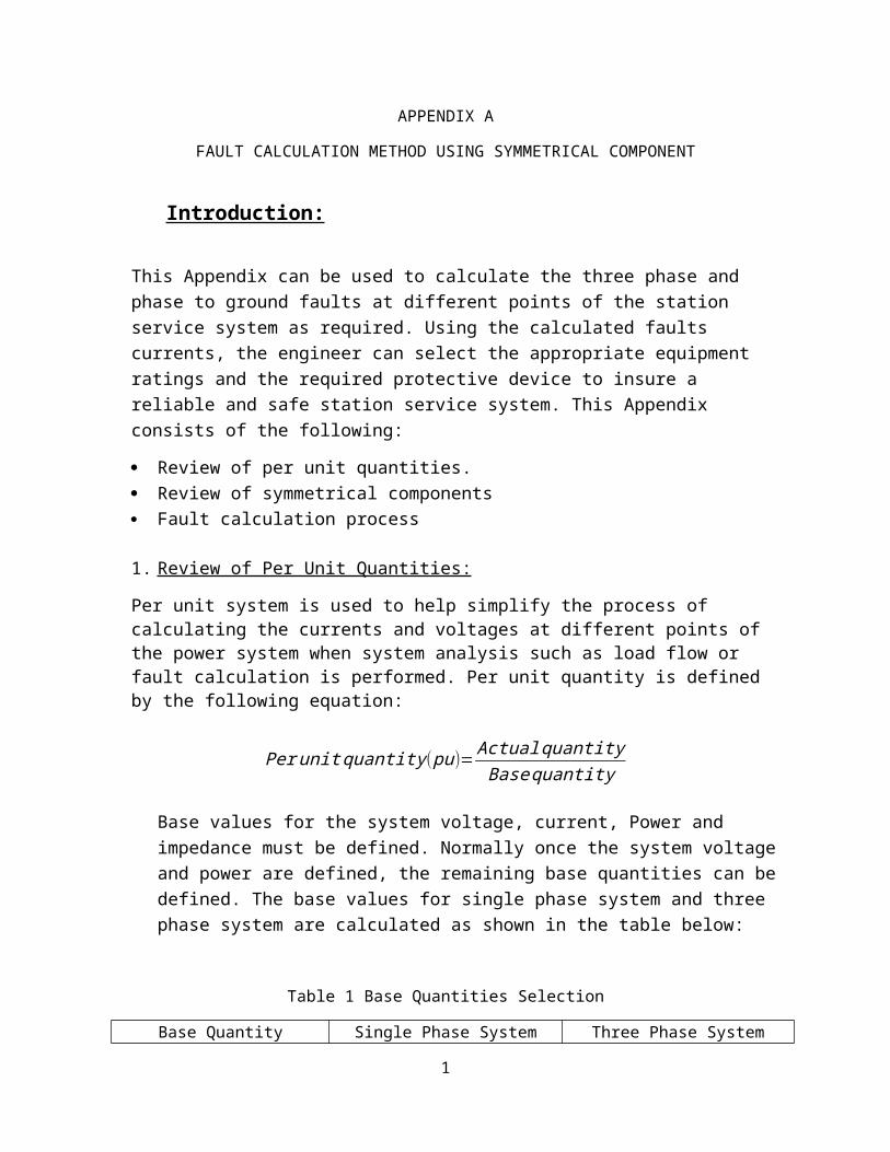
Base values for the system voltage, current, Power and impedance must be defined. Normally once the system voltage and power are defined, the remaining base quantities can be defined. The base values for single phase system and three phase system are calculated as shown in the table below:
Table 1 Base Quantities Selection
Base Quantity Single Phase System Three Phase SystemMVA☼☼ 33.33MVA 100 MVAVoltage☼ L-N System Nominal Voltage L-L System Nominal VoltageCurrent
I=base ,VA1φ
base voltageV lnI=
base ,VA 3φ
√3base voltageV ¿
ImpedanceZ=
(V BASE2 )
VA 1φBASEZ=
(V BASE2 )
VA 3φBASE
Impedance New BaseZnew=Zold
V BASEold2
V BASEnew2*
VAnew
VAoldZnew=Zold
V BASEold2
V BASEnew2*
VAnew
VAold
1
☼ for voltage base values use the system nominal voltage.☼☼ for power base a 100 MVA has been used for three phase. For single phase 33.33MVA can be used
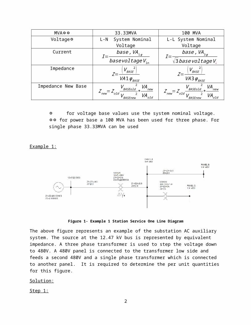
Example 1:
Figure 1- Example 1 Station Service One Line Diagram
The above figure represents an example of the substation AC auxiliary system. The source at the 12.47 kV bus is represented by equivalent impedance. A three phase transformer is used to step the voltage down to 480V. A 480V panel is connected to the transformer low side and feeds a second 480V and a single phase transformer which is connected to another panel. It is required to determine the per unit quantities for this figure.
Solution:
Step 1:
As a first step we need to determine the base values for current, voltage, MVA and impedance for the above system. This can be accomplished by dividing the system into areas. Each area includes one voltage level as shown in the figure below:
Figure 2 Example One Base Values Determinations
2
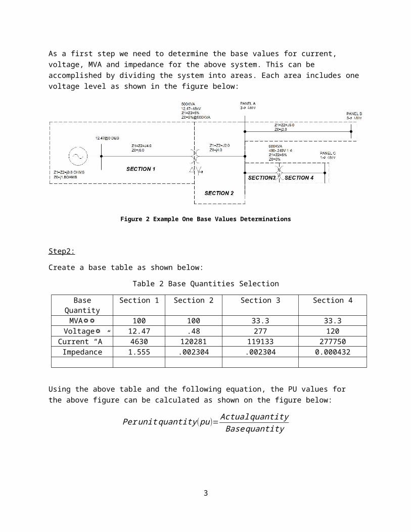
Step2:
Create a base table as shown below:
Table 2 Base Quantities Selection
Base Quantity Section 1 Section 2 Section 3 Section 4MVA☼☼ 100 100 33.3 33.3Voltage☼ 12.47 .48 277 120
Current “A” 4630 120281 119133 277750Impedance 1.555 .002304 .002304 0.000432
Using the above table and the following equation, the PU values for the above figure can be calculated as shown on the figure below:
Perunit quantity ( pu)= Actual quantityBase quantity
Figure 3 Example One - Per Unit Calculations
The above diagram can be represented by a single phase diagram as shown below. This diagram can be used to calculate the faults at different busses.
Figure- 4 Example 1 Impedance per Unit Representations
3

2. Symmetrical Component Review:
In 1918, Dr. C.L Fortescue an American scientist showed that any unbalanced system of 3- phase currents (or Voltages) may be regarded as being composed of three sets of balanced vectors which has come to be known as symmetrical component and is defined below:
Positive Phase Sequence Components: A balanced system of three phase currents having a positive or normal phase rotation.
Negative Phase Sequence Components: A balanced system of three phase currents having a negative or opposite to the positive sequence currents phase rotation.
Zero Phase Sequence Current: a system of three phase currents equal in magnitude and having zero phase displacements.
For a three phase unbalanced system shown in the figure below:
Figure 5- Three Phase Unbalance Phaser Representations
The positive, negative and zero sequence components of the above unbalanced three phase system can be represented as shown in the figure below:
Figure 6- Positive, Negative and Zero Sequence Representations of Unbalanced System
4

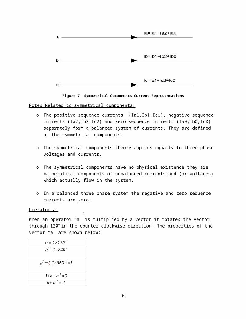
The current in any phase is equal to sum of the positive, negative and zero sequence current. As shown in the figure 7 below:
Figure 7- Symmetrical Components Current Representations
Notes Related to symmetrical components:
o The positive sequence currents (Ia1,Ib1,Ic1), negative sequence currents (Ia2,Ib2,Ic2) and zero sequence currents (Ia0,Ib0,Ic0) separately form a balanced system of currents. They are defined as the symmetrical components.
o The symmetrical components theory applies equally to three phase voltages and currents.
o The symmetrical components have no physical existence they are mathematical components of unbalanced currents and (or voltages) which actually flow in the system.
o In a balanced three phase system the negative and zero sequence currents are zero.
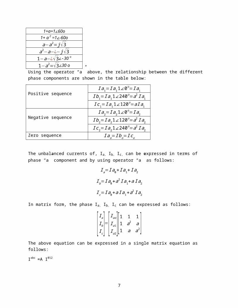
Operator a:
When an operator “a” is multiplied by a vector it rotates the vector through 1200 in the counter clockwise direction. The properties of the vector “a” are shown below:a = 1∠120 o
a2= 1∠240 o
a3=¿ 1∠360 o =11+a+ a 2 =0a+ a 2 =-11+a=1∠60o1+ a 2 =1∠-60oa−a2= j √3
a2−a−¿− j√31−a−¿√3∠-30 o
1−a2=√3∠30 o5
Using the operator “a” above, the relationship between the different phase components are shown in the table below:
Positive sequenceI a1=I a11∠0o=I a1
I b1=I a11∠240o=a2 I a1
I c1=I a1 1∠120o=aI a1
Negative sequenceI a2=I a21∠0o=I a2
I b2=I a21∠120o=a2 I a2
I c2=I a2 1∠240o=a2 I a2
Zero sequence I ao=I bo=I co
The unbalanced currents of, Ia, Ib, Ic, can be expressed in terms of phase “a” component and by using operator “a” as follows:
I a=I a0+ I a1+ I a2
I b=I a0+a2 I a1+a I a2
I c=I a0+a I a1+a2 I a2
In matrix form, the phase Ia, Ib, Ic can be expressed as follows:
[ Ia
Ib
I c]=[I ao
I a1
I a2] [1 1 1
1 a2 a1 a a2]
The above equation can be expressed in a single matrix equation as follows:
Iabc =A I012
Where A is known as the symmetrical component transformation matrix which transforms the currents Iabc to Ia
012 and is given by the following matrix:
A=[1 1 11 a2 a1 a a2]
Since a2=a* then
A−1=13
A ¿
The sequence quantities can be expressed in terms of the phase quantities by finding the inverse of the matrix as follows:
6
[ I0
a
I1a
I2a]=1
3 [1 1 11 a a2
1 a2 a ][ I a
I b
I c]
I 0a=
13 ( I a+ I b+ Ic )
I 1a=
13 (I a+aI b+a2 I c )
I 2a=
13 ( I a+a2 I b+aI c )
For a balanced three phase system,
I 0a=0 since I a+ I b+ IC=0
The above equations apply to voltages also.
Sequence representations of power system elements:
ELEMENT SYMBOL POSITIVE SEQ NEGATIVE SEQ
GENERATOR/SOURCE
LINE
TRANSFORMER
7

3. Fault Calculations:
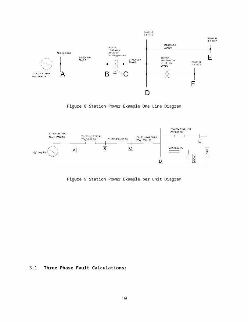
Using the station power one line diagram presented earlier as shown below, and the associated per unit diagram, calculate the three phase fault and the phase to ground fault at points A,B,C,D,E,F.
Figure 8 Station Power Example One Line Diagram
8
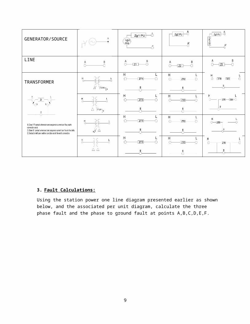
Figure 9 Station Power Example per unit Diagram
3.1 Three Phase Fault Calculations:
Since for three phase faults all currents are equal in magnitude and 1200 apart, the system is balanced and can be represented by the positive sequence impedance only.
Three Phase Fault at Point A:
I f =1@00
j .3871=− j2.583 PU
Three Phase Fault at Point B:
9
I f =1@00
j2.9594=− j .3379PU
Three Phase Fault at Point C:
I f =1@00
j12.9594=− j .0771 PU
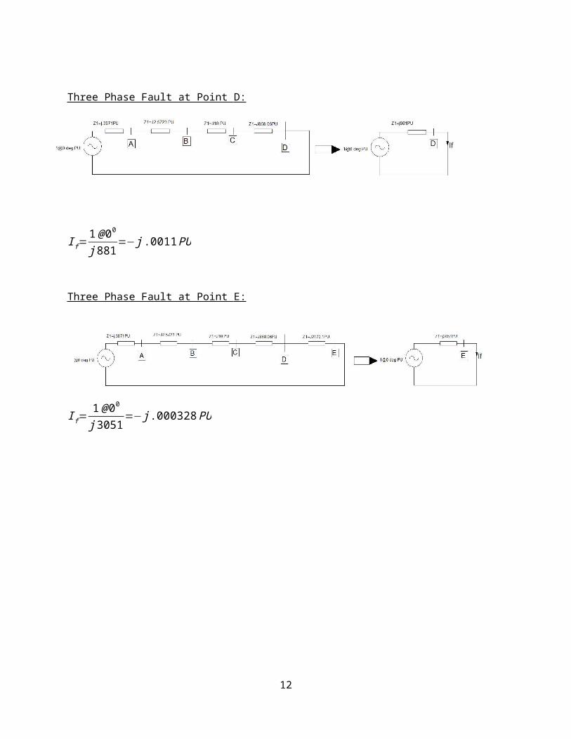
Three Phase Fault at Point D:
I f =1 @00
j881=− j .0011PU
Three Phase Fault at Point E:
I f =1@00
j3051=− j .000328 PU
10

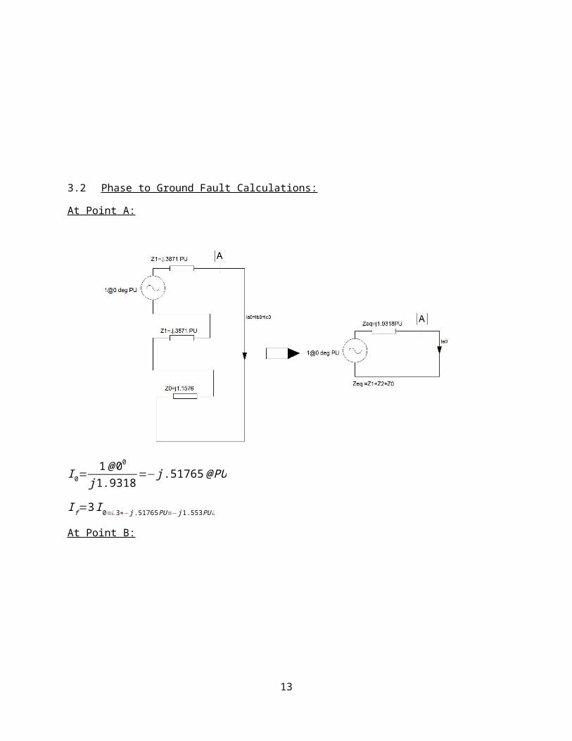
3.2 Phase to Ground Fault Calculations:
At Point A:
I 0=1@ 00
j 1.9318=− j .51765@ PU
11
I f =3 I 0=¿3∗− j .51765 PU=− j1.553 PU¿
At Point B:
I 0=1@ 00
j 10.9344=− j .09145 PU
I f =3 I 0=¿3∗− j .09145 PU=− j.2744 PU ¿
At Point C:
I 0=1@ 00
35.94 @89.80=− j .0278 PU
I f =3 I 0=¿3∗− j .0278 PU=− j .08347 PU¿
At Point D:
I 0=1@ 00
j 3508=− j .000285 PU
I f =3 I 0=¿3∗− j .000285 PU=− j .000855 PU ¿
12
At Point E:
I 0=1@ 00
j 8716=− j .0001147 PU
I f =3 I 0=¿3∗ j .0001147 PU=− j .000341PU ¿
Fault At Point F:
A single phase fault at point F is treated as a single phase fault at point D with the leakage impedance of the single phase transformer between F and D appearing as the fault impedance (therefore the fault impedance will be Zt x 3. See below.
Fault Summary:
13

I 0=1@ 00
j 3517=− j .000284333 PU
I f =3 I 0=¿3∗ j .000284333 PU=− j.000853 PU ¿
Calculation Summary:
Fault Location
3-Phase Fault “PU”
Phase-Ground Fault “PU”
Base Current Amp
3-Phase Fault “AMPS
Phase to Ground Fault
“Amps”A -j2.583 -j1.553 4630 11959 7190.4B -j.3379 -j.2744 4630 1564.5 1270C -j.0771 -j.08347 120281 9273 10039D -j.0011 -j.000855 120281 132.3 102.84E -j.000328 -j.000341 120281 39.45 41F .000853 277750 237☼
☼ Line to Neutral Fault
14