introduction customer service note - micron technology · customer service note micron ... cant...
TRANSCRIPT
CSN-16: Micron Component, Module and SSD PackagingIntroduction
Customer Service NoteMicron® Component, Module and SSD Packaging
IntroductionMicron follows specific packaging procedures to help ensure safe transport of our prod-ucts. This customer service note describes a wide range of topics concerning the pack-aging and shipping of Micron® semiconductors, modules and SSDs, including:• Packaging Procedures• Air Allowance in Moisture-Barrier and Static-Shielding Bags• Humidity Indicator Cards• Pin 1 Orientation for Tray and Tape-and-Reel Packaging• Carrier Tape Design Details• Component Packaging Materials Composition
Packaging ProceduresFor shipping, Micron packages its semiconductor, module, and SSD products inproduct-specific trays and tape-and-reel carriers.1 Each method may include a desic-cant pack, HIC, moisture-barrier or static-shielding bag, internal padding, boxes, andpacking labels. The following figures outline the packing sequence for each packagingmethod.
Notes: 1. For actual tray and box quantities, refer to CSN-04, “Shipping Quantities.”
PDF: 09005aef81179e18/Source: 09005aef81179e21 Micron Technology, Inc., reserves the right to change products or specifications without notice.CSN16.fm - Rev. V; Pub. 3/18 EN 1 ©2004 Micron Technology, Inc. All rights reserved.
Products and specifications discussed herein are for evaluation and reference purposes only and are subject to change byMicron without notice. Products are only warranted by Micron to meet Micron’s production data sheet specifications. All
information discussed herein is provided on an “as is” basis, without warranties of any kind.
CSN-16: Micron Component, Module and SSD PackagingPackaging Procedures
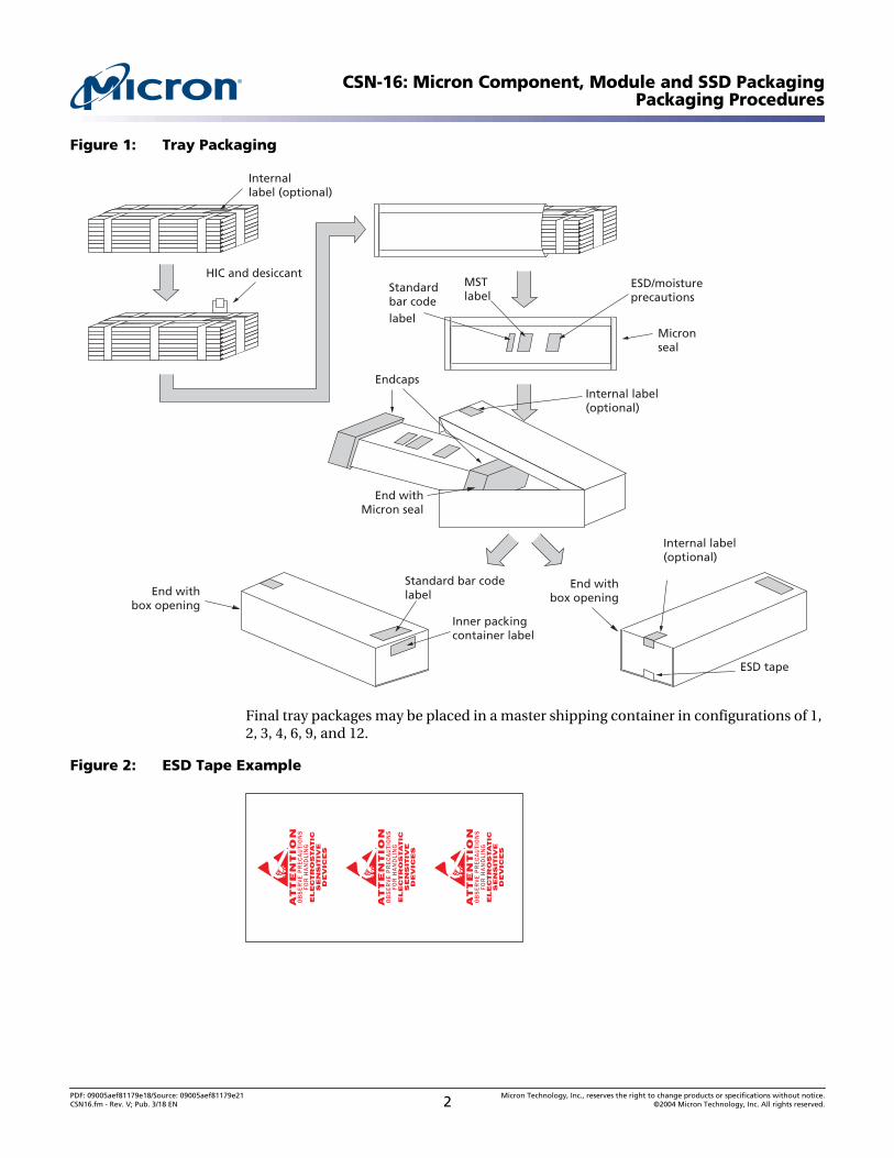
Figure 1: Tray Packaging
Final tray packages may be placed in a master shipping container in configurations of 1,2, 3, 4, 6, 9, and 12.
Figure 2: ESD Tape Example
HIC and desiccant
Micronseal
Standardbar code label
Internallabel (optional)
Internal label(optional)
MSTlabel
ESD/moistureprecautions
Standard bar codelabel
Inner packingcontainer label
End withMicron seal
End withbox opening
End withbox opening
ESD tape
Endcaps
Internal label(optional)
ATTENTION
OB
SE
RV
E P
RE
CA
UTI
ON
SFO
R H
AN
DLI
NG
ELECTROSTATIC
SENSITIVE
DEVICES
ATTENTION
OB
SE
RV
E P
RE
CA
UTI
ON
SFO
R H
AN
DLI
NG
ELECTROSTATIC
SENSITIVE
DEVICES
ATTENTION
OB
SE
RV
E P
RE
CA
UTI
ON
SFO
R H
AN
DLI
NG
ELECTROSTATIC
SENSITIVE
DEVICES
PDF: 09005aef81179e18/Source: 09005aef81179e21 Micron Technology, Inc., reserves the right to change products or specifications without notice.CSN16.fm - Rev. V; Pub. 3/18 EN 2 ©2004 Micron Technology, Inc. All rights reserved.
CSN-16: Micron Component, Module and SSD PackagingPackaging Procedures
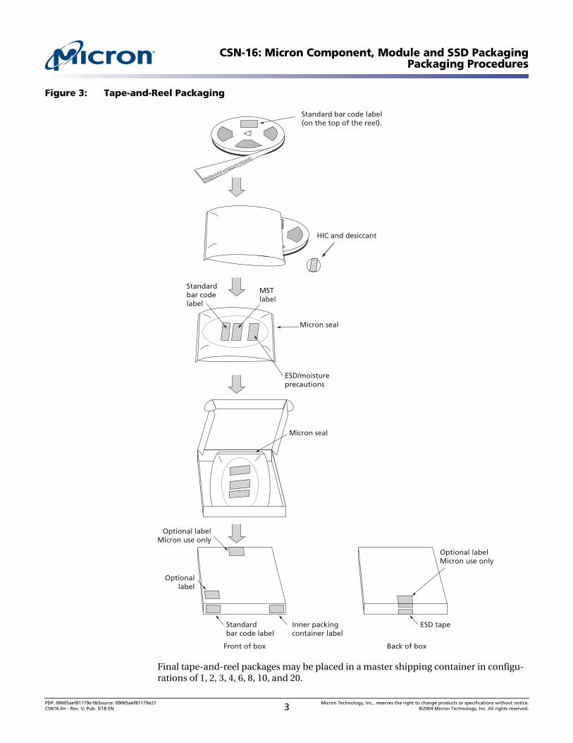
Figure 3: Tape-and-Reel Packaging
Final tape-and-reel packages may be placed in a master shipping container in configu-rations of 1, 2, 3, 4, 6, 8, 10, and 20.
HIC and desiccant
Micron seal
ESD/moistureprecautions
Inner packingcontainer label
Micron seal
Standardbar code label
Optionallabel
Optional labelMicron use only
Front of box
ESD tape
Back of box
Optional labelMicron use only
MSTlabel
Standardbar codelabel
Standard bar code label(on the top of the reel).
PDF: 09005aef81179e18/Source: 09005aef81179e21 Micron Technology, Inc., reserves the right to change products or specifications without notice.CSN16.fm - Rev. V; Pub. 3/18 EN 3 ©2004 Micron Technology, Inc. All rights reserved.
CSN-16: Micron Component, Module and SSD PackagingPackaging Procedures
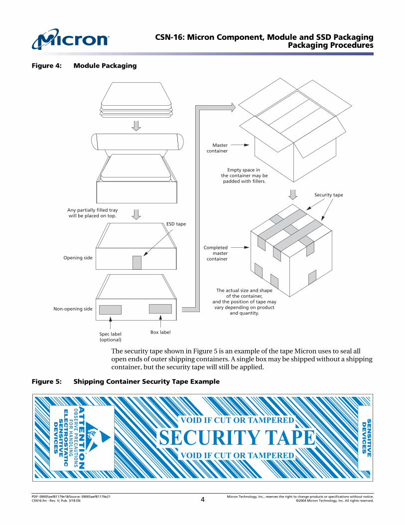
Figure 4: Module Packaging
The security tape shown in Figure 5 is an example of the tape Micron uses to seal allopen ends of outer shipping containers. A single box may be shipped without a shippingcontainer, but the security tape will still be applied.
Figure 5: Shipping Container Security Tape Example
Opening side
ESD tape
Security tape
Mastercontainer
Spec label(optional)
Any partially filled traywill be placed on top.
Empty space in the container may bepadded with fillers.
The actual size and shapeof the container,
and the position of tape mayvary depending on product
and quantity.
Completedmaster
container
Box label
Non-opening side
ATTENTION
OB
SE
RV
E P
RE
CA
UTIO
NS
FOR
HA
ND
LING
ELECTROSTATIC
SENSITIVE
DEVICES
SENSITIVE
DEVICES
VOID IF CUT OR TAMPERED
SECURITY TAPEVOID IF CUT OR TAMPERED
PDF: 09005aef81179e18/Source: 09005aef81179e21 Micron Technology, Inc., reserves the right to change products or specifications without notice.CSN16.fm - Rev. V; Pub. 3/18 EN 4 ©2004 Micron Technology, Inc. All rights reserved.
CSN-16: Micron Component, Module and SSD PackagingPackaging Procedures
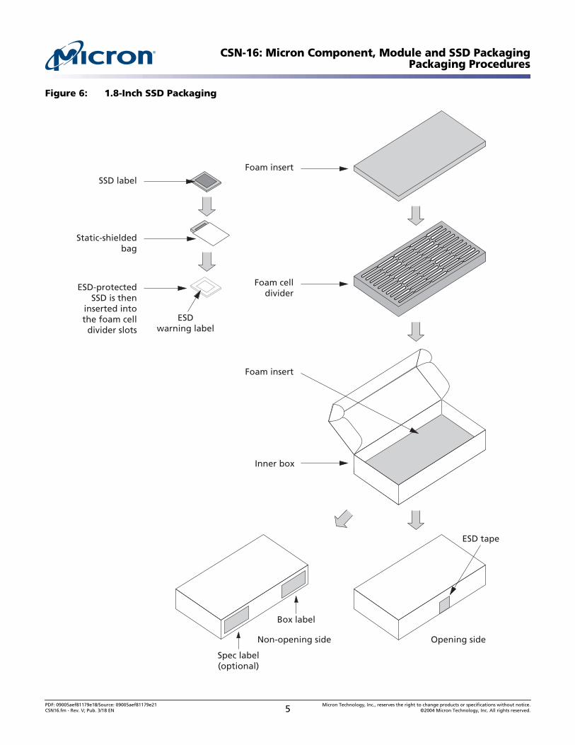
Figure 6: 1.8-Inch SSD Packaging
Inner box
Foam insert
Foam insert
Foam celldivider
SSD label
ESD-protectedSSD is then
inserted intothe foam celldivider slots
Static-shieldedbag
Opening sideNon-opening side
Spec label(optional)
Box label
ESDwarning label
ESD tape
PDF: 09005aef81179e18/Source: 09005aef81179e21 Micron Technology, Inc., reserves the right to change products or specifications without notice.CSN16.fm - Rev. V; Pub. 3/18 EN 5 ©2004 Micron Technology, Inc. All rights reserved.
CSN-16: Micron Component, Module and SSD PackagingPackaging Procedures
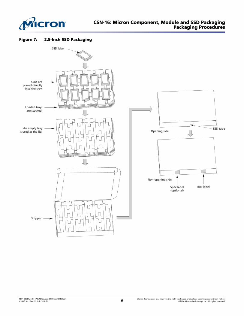
Figure 7: 2.5-Inch SSD Packaging
SSDs areplaced directly
into the tray.
Shipper
Loaded traysare stacked.
An empty trayis used as the lid.
SSD label
Box label
Opening side
Non-opening side
Spec label(optional)
ESD tape
PDF: 09005aef81179e18/Source: 09005aef81179e21 Micron Technology, Inc., reserves the right to change products or specifications without notice.CSN16.fm - Rev. V; Pub. 3/18 EN 6 ©2004 Micron Technology, Inc. All rights reserved.
CSN-16: Micron Component, Module and SSD PackagingPackaging Procedures
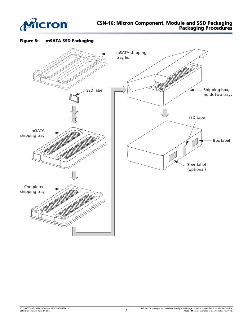
Figure 8: mSATA SSD Packaging
mSATA shippingtray lid
Shipping box,holds two trays
mSATAshipping tray
Completedshipping tray
SSD label
Spec label(optional)
ESD tape
Box label
PDF: 09005aef81179e18/Source: 09005aef81179e21 Micron Technology, Inc., reserves the right to change products or specifications without notice.CSN16.fm - Rev. V; Pub. 3/18 EN 7 ©2004 Micron Technology, Inc. All rights reserved.
CSN-16: Micron Component, Module and SSD PackagingPackaging Procedures
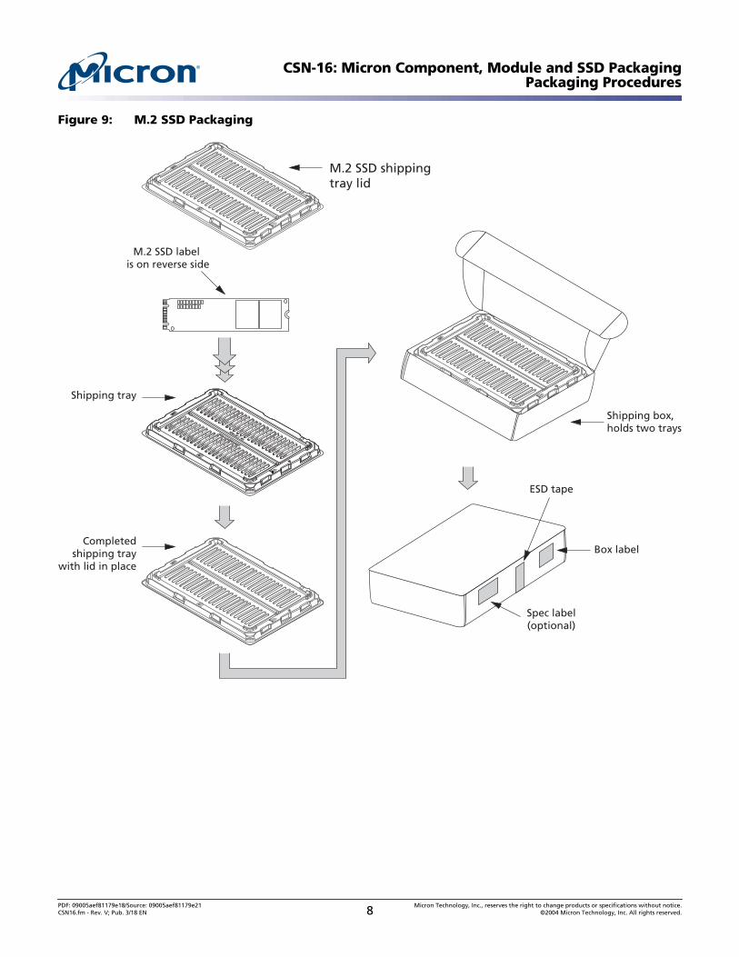
Figure 9: M.2 SSD Packaging
M.2 SSD shippingtray lid
M.2 SSD label is on reverse side
Completedshipping tray
with lid in place
Shipping tray
Shipping box,holds two trays
Spec label(optional)
ESD tape
Box label
PDF: 09005aef81179e18/Source: 09005aef81179e21 Micron Technology, Inc., reserves the right to change products or specifications without notice.CSN16.fm - Rev. V; Pub. 3/18 EN 8 ©2004 Micron Technology, Inc. All rights reserved.
CSN-16: Micron Component, Module and SSD PackagingAir Allowance in Moisture-Barrier and Static-Shielding Bags
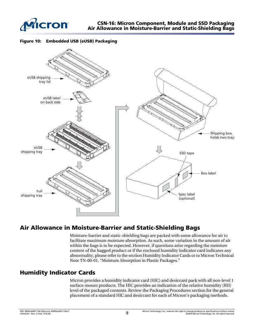
Figure 10: Embedded USB (eUSB) Packaging
Air Allowance in Moisture-Barrier and Static-Shielding BagsMoisture-barrier and static-shielding bags are packed with some allowance for air tofacilitate maximum moisture absorption. As such, some variation in the amount of airwithin the bags is to be expected. However, if questions arise regarding the moisturecontent of the bagged product or if the enclosed humidity indicator card indicates anyabnormality, please refer to the section Humidity Indicator Cards or to Micron TechnicalNote TN-00-01, “Moisture Absorption in Plastic Packages.”
Humidity Indicator CardsMicron provides a humidity indicator card (HIC) and desiccant pack with all non-level 1surface-mount products. The HIC provides an indication of the relative humidity (RH)level of the packaged contents. Review the Packaging Procedures section for the generalplacement of a standard HIC and desiccant for each of Micron’s packaging methods.
eUSB shippingtray lid
eUSB labelon back side
Shipping box,holds two trays
eUSBshipping tray
Fullshipping tray Spec label
(optional)
ESD tape
Box label
PDF: 09005aef81179e18/Source: 09005aef81179e21 Micron Technology, Inc., reserves the right to change products or specifications without notice.CSN16.fm - Rev. V; Pub. 3/18 EN 9 ©2004 Micron Technology, Inc. All rights reserved.
CSN-16: Micron Component, Module and SSD PackagingHumidity Indicator Cards
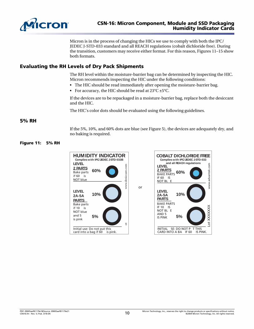
Micron is in the process of changing the HICs we use to comply with both the IPC/JEDEC J-STD-033 standard and all REACH regulations (cobalt dichloride free). Duringthe transition, customers may receive either format. For this reason, Figures 11–15 showboth formats.
Evaluating the RH Levels of Dry Pack Shipments
The RH level within the moisture-barrier bag can be determined by inspecting the HIC.Micron recommends inspecting the HIC under the following conditions:• The HIC should be read immediately after opening the moisture-barrier bag.• For accuracy, the HIC should be read at 23°C ±5°C.
If the devices are to be repackaged in a moisture-barrier bag, replace both the desiccantand the HIC.
The HIC’s color dots should be evaluated using the following guidelines.
5% RH
If the 5%, 10%, and 60% dots are blue (see Figure 5), the devices are adequately dry, andno baking is required.
Figure 11: 5% RH
Lot
XX
XX
XX
Xw
ww
.ad
van
tek.
com
COBALT DICHLORIDE FREEComplies with IPC/JEDEC J-STD-033
and all REACH regulationsLEVEL2 PARTSBAKE PARTSIF 60 ISNOT BL E
LEVEL2A-5APARTSBAKE PARTSIF 10 ISNOT BL EAND 5IS PINK
INITIAL SE: DO NOT P T THISCARD INTO A BA IF 60 IS PINK.
or
60%
10%
5%
ot
ww
w.d
esic
care
.co
m
HUMIDITY INDICATORComplies with IPC/JEDEC J-STD-033B
LEVEL2 PARTSBake partsif 60 isNOT blue
LEVEL2A-5APARTSBake partsif 10 isNOT blueand 5is pink
Initial use: Do not put thiscard into a bag if 60 is pink.
60%
10%
5%
PDF: 09005aef81179e18/Source: 09005aef81179e21 Micron Technology, Inc., reserves the right to change products or specifications without notice.CSN16.fm - Rev. V; Pub. 3/18 EN 10 ©2004 Micron Technology, Inc. All rights reserved.
CSN-16: Micron Component, Module and SSD PackagingHumidity Indicator Cards
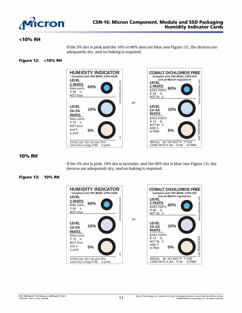
<10% RH
If the 5% dot is pink and the 10% or 60% dots are blue (see Figure 12), the devices areadequately dry, and no baking is required.
Figure 12: <10% RH
10% RH
If the 5% dot is pink, 10% dot is lavender, and the 60% dot is blue (see Figure 13), thedevices are adequately dry, and no baking is required.
Figure 13: 10% RH
Lot
XX
XX
XX
Xw
ww
.ad
van
tek.
com
COBALT DICHLORIDE FREEComplies with IPC/JEDEC J-STD-033
and all REACH regulationsLEVEL2 PARTSBAKE PARTSIF 60 ISNOT BL E
LEVEL2A-5APARTSBAKE PARTSIF 10 ISNOT BL EAND 5IS PINK
INITIAL SE: DO NOT P T THISCARD INTO A BA IF 60 IS PINK.
or
60%
10%
5%
ot
ww
w.d
esic
care
.co
m
HUMIDITY INDICATORComplies with IPC/JEDEC J-STD-033B
LEVEL2 PARTSBake partsif 60 isNOT blue
LEVEL2A-5APARTSBake partsif 10 isNOT blueand 5is pink
Initial use: Do not put thiscard into a bag if 60 is pink.
60%
10%
5%
PDF: 09005aef81179e18/Source: 09005aef81179e21 Micron Technology, Inc., reserves the right to change products or specifications without notice.CSN16.fm - Rev. V; Pub. 3/18 EN 11 ©2004 Micron Technology, Inc. All rights reserved.
CSN-16: Micron Component, Module and SSD PackagingHumidity Indicator Cards
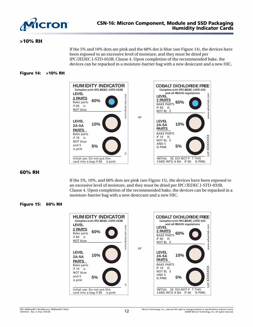
>10% RH
If the 5% and 10% dots are pink and the 60% dot is blue (see Figure 14), the devices havebeen exposed to an excessive level of moisture, and they must be dried perIPC/JEDEC J-STD-033B, Clause 4. Upon completion of the recommended bake, thedevices can be repacked in a moisture-barrier bag with a new desiccant and a new HIC.
Figure 14: >10% RH
60% RH
If the 5%, 10%, and 60% dots are pink (see Figure 15), the devices have been exposed toan excessive level of moisture, and they must be dried per IPC/JEDEC J-STD-033B,Clause 4. Upon completion of the recommended bake, the devices can be repacked in amoisture-barrier bag with a new desiccant and a new HIC.
Figure 15: 60% RHLo
tX
XX
XX
XX
ww
w.a
dva
nte
k.co
m
COBALT DICHLORIDE FREEComplies with IPC/JEDEC J-STD-033
and all REACH regulationsLEVEL2 PARTSBAKE PARTSIF 60 ISNOT BL E
LEVEL2A-5APARTSBAKE PARTSIF 10 ISNOT BL EAND 5IS PINK
INITIAL SE: DO NOT P T THISCARD INTO A BA IF 60 IS PINK.
or
60%
10%
5%
ot
ww
w.d
esic
care
.co
m
HUMIDITY INDICATORComplies with IPC/JEDEC J-STD-033B
LEVEL2 PARTSBake partsif 60 isNOT blue
LEVEL2A-5APARTSBake partsif 10 isNOT blueand 5is pink
Initial use: Do not put thiscard into a bag if 60 is pink.
60%
10%
5%
Lot
XX
XX
XX
Xw
ww
.ad
van
tek.
com
COBALT DICHLORIDE FREEComplies with IPC/JEDEC J-STD-033
and all REACH regulationsLEVEL2 PARTSBAKE PARTSIF 60 ISNOT BL E
LEVEL2A-5APARTSBAKE PARTSIF 10 ISNOT BL EAND 5IS PINK
INITIAL SE: DO NOT P T THISCARD INTO A BA IF 60 IS PINK.
or
60%
10%
5%
ot
ww
w.d
esic
care
.co
m
HUMIDITY INDICATORComplies with IPC/JEDEC J-STD-033B
LEVEL2 PARTSBake partsif 60 isNOT blue
LEVEL2A-5APARTSBake partsif 10 isNOT blueand 5is pink
Initial use: Do not put thiscard into a bag if 60 is pink.
60%
10%
5%
PDF: 09005aef81179e18/Source: 09005aef81179e21 Micron Technology, Inc., reserves the right to change products or specifications without notice.CSN16.fm - Rev. V; Pub. 3/18 EN 12 ©2004 Micron Technology, Inc. All rights reserved.
CSN-16: Micron Component, Module and SSD PackagingPin 1 Orientation for Tray and Tape-and-Reel Packaging
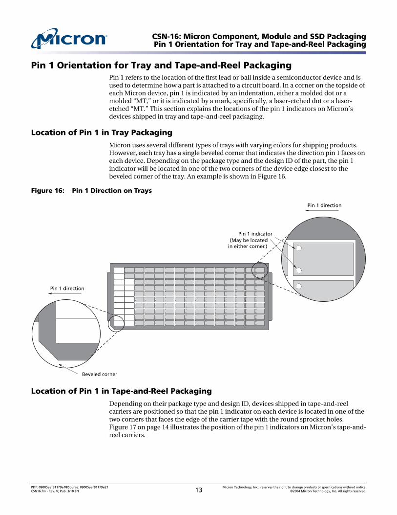
Pin 1 Orientation for Tray and Tape-and-Reel PackagingPin 1 refers to the location of the first lead or ball inside a semiconductor device and isused to determine how a part is attached to a circuit board. In a corner on the topside ofeach Micron device, pin 1 is indicated by an indentation, either a molded dot or amolded “MT,” or it is indicated by a mark, specifically, a laser-etched dot or a laser-etched “MT.” This section explains the locations of the pin 1 indicators on Micron’sdevices shipped in tray and tape-and-reel packaging.
Location of Pin 1 in Tray Packaging
Micron uses several different types of trays with varying colors for shipping products.However, each tray has a single beveled corner that indicates the direction pin 1 faces oneach device. Depending on the package type and the design ID of the part, the pin 1indicator will be located in one of the two corners of the device edge closest to thebeveled corner of the tray. An example is shown in Figure 16.
Figure 16: Pin 1 Direction on Trays
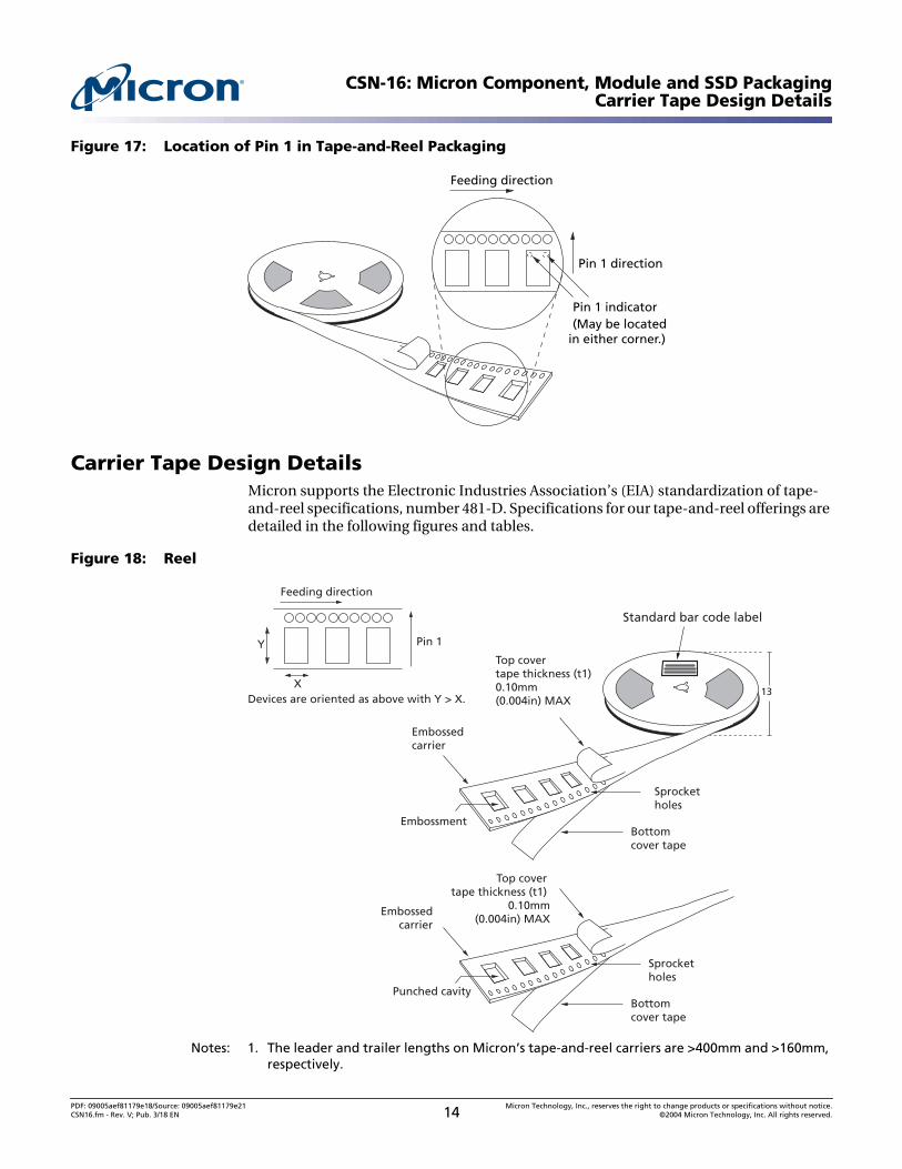
Location of Pin 1 in Tape-and-Reel Packaging
Depending on their package type and design ID, devices shipped in tape-and-reelcarriers are positioned so that the pin 1 indicator on each device is located in one of thetwo corners that faces the edge of the carrier tape with the round sprocket holes.Figure 17 on page 14 illustrates the position of the pin 1 indicators on Micron’s tape-and-reel carriers.
Pin 1 indicator(May be located
in either corner.)
Pin 1 direction
Pin 1 direction
Beveled corner
PDF: 09005aef81179e18/Source: 09005aef81179e21 Micron Technology, Inc., reserves the right to change products or specifications without notice.CSN16.fm - Rev. V; Pub. 3/18 EN 13 ©2004 Micron Technology, Inc. All rights reserved.
CSN-16: Micron Component, Module and SSD PackagingCarrier Tape Design Details
Figure 17: Location of Pin 1 in Tape-and-Reel Packaging
Carrier Tape Design DetailsMicron supports the Electronic Industries Association’s (EIA) standardization of tape-and-reel specifications, number 481-D. Specifications for our tape-and-reel offerings aredetailed in the following figures and tables.
Figure 18: Reel
Notes: 1. The leader and trailer lengths on Micron’s tape-and-reel carriers are >400mm and >160mm,respectively.
Feeding direction
Pin 1 direction
Pin 1 indicator(May be located
in either corner.)
Top covertape thickness (t1)0.10mm(0.004in) MAX
13
Feeding direction
Pin 1
Devices are oriented as above with Y > X.
Y
X
Embossedcarrier
Bottomcover tape
Sprocketholes
Bottomcover tape
Sprocketholes
Embossment
Top covertape thickness (t1)
0.10mm(0.004in) MAX
Embossedcarrier
Punched cavity
Standard bar code label
PDF: 09005aef81179e18/Source: 09005aef81179e21 Micron Technology, Inc., reserves the right to change products or specifications without notice.CSN16.fm - Rev. V; Pub. 3/18 EN 14 ©2004 Micron Technology, Inc. All rights reserved.
CSN-16: Micron Component, Module and SSD PackagingCarrier Tape Design Details
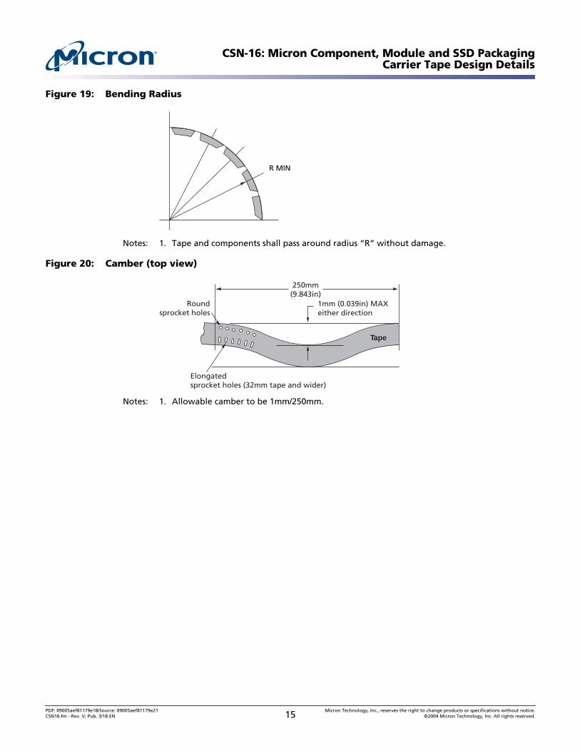
Figure 19: Bending Radius
Notes: 1. Tape and components shall pass around radius “R” without damage.
Figure 20: Camber (top view)
Notes: 1. Allowable camber to be 1mm/250mm.
R MIN
250mm(9.843in)
1mm (0.039in) MAXeither direction
Tape
Roundsprocket holes
Elongatedsprocket holes (32mm tape and wider)
PDF: 09005aef81179e18/Source: 09005aef81179e21 Micron Technology, Inc., reserves the right to change products or specifications without notice.CSN16.fm - Rev. V; Pub. 3/18 EN 15 ©2004 Micron Technology, Inc. All rights reserved.
CSN-16: Micron Component, Module and SSD PackagingCarrier Tape Design Details
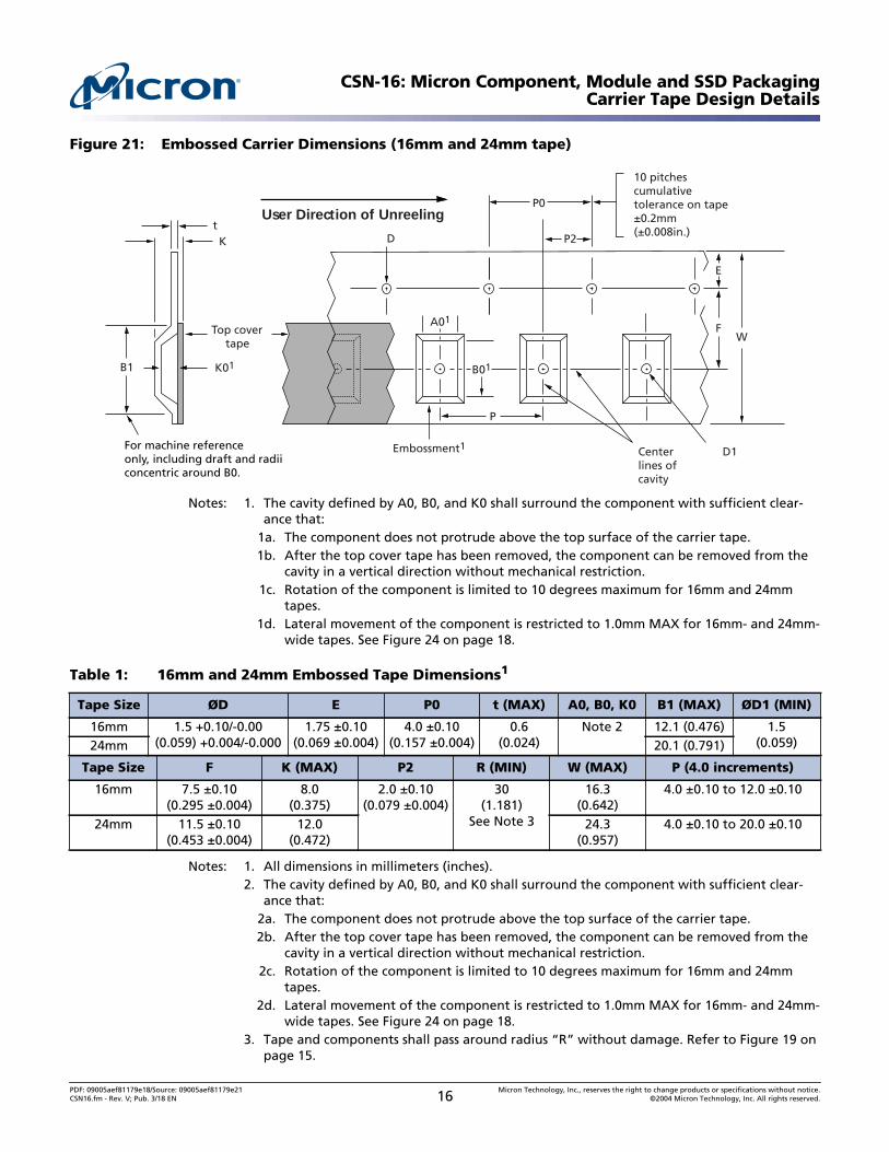
Figure 21: Embossed Carrier Dimensions (16mm and 24mm tape)
Notes: 1. The cavity defined by A0, B0, and K0 shall surround the component with sufficient clear-ance that:
1a. The component does not protrude above the top surface of the carrier tape.1b. After the top cover tape has been removed, the component can be removed from the
cavity in a vertical direction without mechanical restriction.1c. Rotation of the component is limited to 10 degrees maximum for 16mm and 24mm
tapes.1d. Lateral movement of the component is restricted to 1.0mm MAX for 16mm- and 24mm-
wide tapes. See Figure 24 on page 18.
Notes: 1. All dimensions in millimeters (inches).2. The cavity defined by A0, B0, and K0 shall surround the component with sufficient clear-
ance that:2a. The component does not protrude above the top surface of the carrier tape.2b. After the top cover tape has been removed, the component can be removed from the
cavity in a vertical direction without mechanical restriction.2c. Rotation of the component is limited to 10 degrees maximum for 16mm and 24mm
tapes.2d. Lateral movement of the component is restricted to 1.0mm MAX for 16mm- and 24mm-
wide tapes. See Figure 24 on page 18.3. Tape and components shall pass around radius “R” without damage. Refer to Figure 19 on
page 15.
Table 1: 16mm and 24mm Embossed Tape Dimensions1
Tape Size ØD E P0 t (MAX) A0, B0, K0 B1 (MAX) ØD1 (MIN)
16mm 1.5 +0.10/-0.00(0.059) +0.004/-0.000
1.75 ±0.10(0.069 ±0.004)
4.0 ±0.10(0.157 ±0.004)
0.6(0.024)
Note 2 12.1 (0.476) 1.5(0.059)24mm 20.1 (0.791)
Tape Size F K (MAX) P2 R (MIN) W (MAX) P (4.0 increments)
16mm 7.5 ±0.10(0.295 ±0.004)
8.0(0.375)
2.0 ±0.10(0.079 ±0.004)
30(1.181)
See Note 3
16.3(0.642)
4.0 ±0.10 to 12.0 ±0.10
24mm 11.5 ±0.10(0.453 ±0.004)
12.0(0.472)
24.3(0.957)
4.0 ±0.10 to 20.0 ±0.10
K01
t
For machine referenceonly, including draft and radiiconcentric around B0.
Top covertape
P
Embossment1 D1
FW
E
B1
User Direction of Unreeling
Centerlines ofcavity
B01
A01
P2D
P0
10 pitchescumulativetolerance on tape±0.2mm(±0.008in.)
K
PDF: 09005aef81179e18/Source: 09005aef81179e21 Micron Technology, Inc., reserves the right to change products or specifications without notice.CSN16.fm - Rev. V; Pub. 3/18 EN 16 ©2004 Micron Technology, Inc. All rights reserved.

CSN-16: Micron Component, Module and SSD PackagingCarrier Tape Design Details
Figure 22: Embossed Carrier Dimensions (32mm and 44mm tape only)
Notes: 1. The cavity defined by A0, B0, and K0 shall surround the component with sufficient clear-ance that:
1a. The component does not protrude above the top surface of the carrier tape.1b. After the top cover tape has been removed, the component can be removed from the
cavity in a vertical direction without mechanical restriction.1c. Rotation of the component is limited to 10 degrees maximum for 32mm and 44mm
tapes.1d. Lateral movement of the component is restricted to 1.0mm MAX for 32mm- and 44mm-
wide tapes. See Figure 24 on page 18.
Figure 23: Detail of Elongated Hole
K01 B01
tK
B1 is for machine referenceonly, including draft and radiiconcentric around B0.
Top covertape
P0 10 pitches cumulative toleranceon tape ±0.2mm (±0.008in.)
P
D1
A01
P2
F
S W
E
User Direction of Unreeling
B1
D Round sprocketholes this sideCenter
lines ofcavity
Embossment1
Elongatedsprocketholes
S
D/2
0.20mm ±0.05mm
Skew MAX0.05mm
PDF: 09005aef81179e18/Source: 09005aef81179e21 Micron Technology, Inc., reserves the right to change products or specifications without notice.CSN16.fm - Rev. V; Pub. 3/18 EN 17 ©2004 Micron Technology, Inc. All rights reserved.
CSN-16: Micron Component, Module and SSD PackagingCarrier Tape Design Details
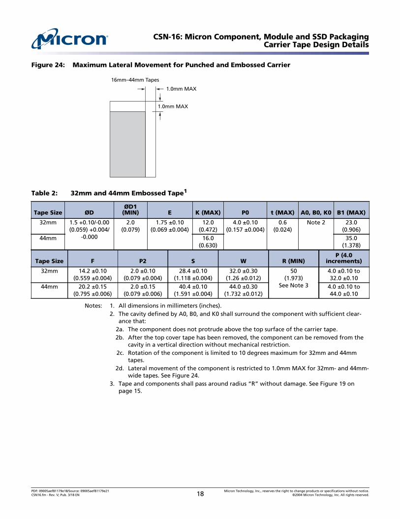
Figure 24: Maximum Lateral Movement for Punched and Embossed Carrier
Notes: 1. All dimensions in millimeters (inches).2. The cavity defined by A0, B0, and K0 shall surround the component with sufficient clear-
ance that:2a. The component does not protrude above the top surface of the carrier tape.2b. After the top cover tape has been removed, the component can be removed from the
cavity in a vertical direction without mechanical restriction.2c. Rotation of the component is limited to 10 degrees maximum for 32mm and 44mm
tapes.2d. Lateral movement of the component is restricted to 1.0mm MAX for 32mm- and 44mm-
wide tapes. See Figure 24.3. Tape and components shall pass around radius “R” without damage. See Figure 19 on
page 15.
Table 2: 32mm and 44mm Embossed Tape1
Tape Size ØDØD1
(MIN) E K (MAX) P0 t (MAX) A0, B0, K0 B1 (MAX)
32mm 1.5 +0.10/-0.00(0.059) +0.004/
-0.000
2.0(0.079)
1.75 ±0.10(0.069 ±0.004)
12.0(0.472)
4.0 ±0.10(0.157 ±0.004)
0.6(0.024)
Note 2 23.0(0.906)
44mm 16.0(0.630)
35.0(1.378)
Tape Size F P2 S W R (MIN)P (4.0
increments)
32mm 14.2 ±0.10(0.559 ±0.004)
2.0 ±0.10(0.079 ±0.004)
28.4 ±0.10(1.118 ±0.004)
32.0 ±0.30(1.26 ±0.012)
50(1.973)
See Note 3
4.0 ±0.10 to32.0 ±0.10
44mm 20.2 ±0.15(0.795 ±0.006)
2.0 ±0.15(0.079 ±0.006)
40.4 ±0.10(1.591 ±0.004)
44.0 ±0.30(1.732 ±0.012)
4.0 ±0.10 to44.0 ±0.10
16mm–44mm Tapes
1.0mm MAX
1.0mm MAX
PDF: 09005aef81179e18/Source: 09005aef81179e21 Micron Technology, Inc., reserves the right to change products or specifications without notice.CSN16.fm - Rev. V; Pub. 3/18 EN 18 ©2004 Micron Technology, Inc. All rights reserved.
CSN-16: Micron Component, Module and SSD PackagingComponent Packaging Materials Composition
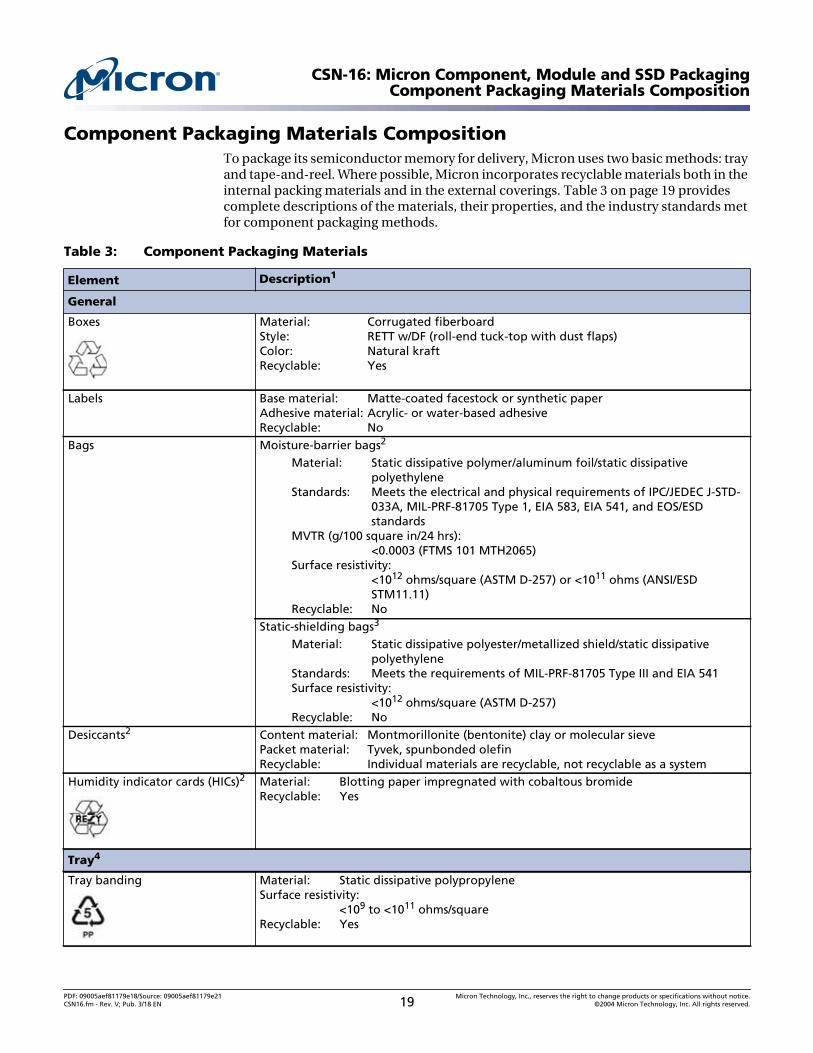
Component Packaging Materials CompositionTo package its semiconductor memory for delivery, Micron uses two basic methods: trayand tape-and-reel. Where possible, Micron incorporates recyclable materials both in theinternal packing materials and in the external coverings. Table 3 on page 19 providescomplete descriptions of the materials, their properties, and the industry standards metfor component packaging methods.
Table 3: Component Packaging Materials
Element Description1
General
Boxes Material: Corrugated fiberboardStyle: RETT w/DF (roll-end tuck-top with dust flaps)Color: Natural kraftRecyclable: Yes
Labels Base material: Matte-coated facestock or synthetic paperAdhesive material: Acrylic- or water-based adhesiveRecyclable: No
Bags Moisture-barrier bags2
Material: Static dissipative polymer/aluminum foil/static dissipativepolyethylene
Standards: Meets the electrical and physical requirements of IPC/JEDEC J-STD-033A, MIL-PRF-81705 Type 1, EIA 583, EIA 541, and EOS/ESDstandards
MVTR (g/100 square in/24 hrs):<0.0003 (FTMS 101 MTH2065)
Surface resistivity:<1012 ohms/square (ASTM D-257) or <1011 ohms (ANSI/ESDSTM11.11)
Recyclable: NoStatic-shielding bags3
Material: Static dissipative polyester/metallized shield/static dissipativepolyethylene
Standards: Meets the requirements of MIL-PRF-81705 Type III and EIA 541Surface resistivity:
<1012 ohms/square (ASTM D-257)Recyclable: No
Desiccants2 Content material: Montmorillonite (bentonite) clay or molecular sievePacket material: Tyvek, spunbonded olefinRecyclable: Individual materials are recyclable, not recyclable as a system
Humidity indicator cards (HICs)2 Material: Blotting paper impregnated with cobaltous bromideRecyclable: Yes
Tray4
Tray banding Material: Static dissipative polypropyleneSurface resistivity:
<109 to <1011 ohms/squareRecyclable: Yes
PDF: 09005aef81179e18/Source: 09005aef81179e21 Micron Technology, Inc., reserves the right to change products or specifications without notice.CSN16.fm - Rev. V; Pub. 3/18 EN 19 ©2004 Micron Technology, Inc. All rights reserved.
CSN-16: Micron Component, Module and SSD PackagingComponent Packaging Materials Composition
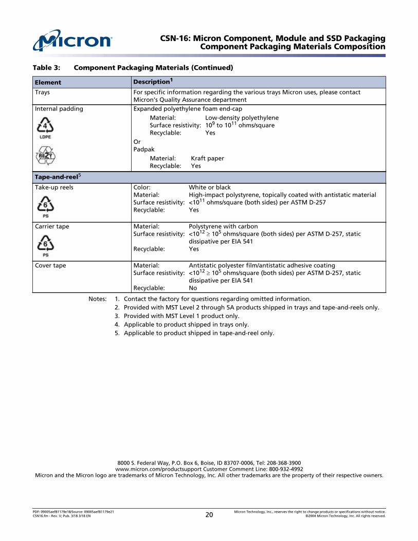
Notes: 1. Contact the factory for questions regarding omitted information.2. Provided with MST Level 2 through 5A products shipped in trays and tape-and-reels only.3. Provided with MST Level 1 product only.4. Applicable to product shipped in trays only.5. Applicable to product shipped in tape-and-reel only.
Trays For specific information regarding the various trays Micron uses, please contactMicron’s Quality Assurance department
Internal padding Expanded polyethylene foam end-capMaterial: Low-density polyethyleneSurface resistivity: 109 to 1011 ohms/squareRecyclable: Yes
OrPadpak
Material: Kraft paperRecyclable: Yes
Tape-and-reel5
Take-up reels Color: White or blackMaterial: High-impact polystyrene, topically coated with antistatic materialSurface resistivity: <1011 ohms/square (both sides) per ASTM D-257Recyclable: Yes
Carrier tape Material: Polystyrene with carbonSurface resistivity: <1012 105 ohms/square (both sides) per ASTM D-257, static
dissipative per EIA 541Recyclable: Yes
Cover tape Material: Antistatic polyester film/antistatic adhesive coatingSurface resistivity: <1012 105 ohms/square (both sides) per ASTM D-257, static
dissipative per EIA 541Recyclable: No
Table 3: Component Packaging Materials (Continued)
Element Description1
8000 S. Federal Way, P.O. Box 6, Boise, ID 83707-0006, Tel: 208-368-3900www.micron.com/productsupport Customer Comment Line: 800-932-4992
Micron and the Micron logo are trademarks of Micron Technology, Inc. All other trademarks are the property of their respective owners.
PDF: 09005aef81179e18/Source: 09005aef81179e21 Micron Technology, Inc., reserves the right to change products or specifications without notice.CSN16.fm - Rev. V; Pub. 3/18 3/18 EN 20 ©2004 Micron Technology, Inc. All rights reserved.
CSN-16: Micron Component, Module and SSD PackagingRevision History
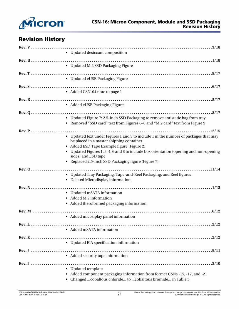
Revision HistoryRev. V . . . . . . . . . . . . . . . . . . . . . . . . . . . . . . . . . . . . . . . . . . . . . . . . . . . . . . . . . . . . . . . . . . . . . . . . . . . . . . . . . . . . . . . . . . . . . . .3/18
• Updated desiccant composition
Rev. U. . . . . . . . . . . . . . . . . . . . . . . . . . . . . . . . . . . . . . . . . . . . . . . . . . . . . . . . . . . . . . . . . . . . . . . . . . . . . . . . . . . . . . . . . . . . . . .1/18• Updated M.2 SSD Packaging Figure
Rev. T . . . . . . . . . . . . . . . . . . . . . . . . . . . . . . . . . . . . . . . . . . . . . . . . . . . . . . . . . . . . . . . . . . . . . . . . . . . . . . . . . . . . . . . . . . . . . . .9/17• Updated eUSB Packaging Figure
Rev. S . . . . . . . . . . . . . . . . . . . . . . . . . . . . . . . . . . . . . . . . . . . . . . . . . . . . . . . . . . . . . . . . . . . . . . . . . . . . . . . . . . . . . . . . . . . . . . .6/17• Added CSN-04 note to page 1
Rev. R . . . . . . . . . . . . . . . . . . . . . . . . . . . . . . . . . . . . . . . . . . . . . . . . . . . . . . . . . . . . . . . . . . . . . . . . . . . . . . . . . . . . . . . . . . . . . . .5/17• Added eUSB Packaging Figure
Rev. Q. . . . . . . . . . . . . . . . . . . . . . . . . . . . . . . . . . . . . . . . . . . . . . . . . . . . . . . . . . . . . . . . . . . . . . . . . . . . . . . . . . . . . . . . . . . . . . .3/17• Updated Figure 7: 2.5-Inch SSD Packaging to remove antistatic bag from tray• Removed “SSD card” text from Figures 6–8 and “M.2 card” text from Figure 9
Rev. P . . . . . . . . . . . . . . . . . . . . . . . . . . . . . . . . . . . . . . . . . . . . . . . . . . . . . . . . . . . . . . . . . . . . . . . . . . . . . . . . . . . . . . . . . . . . . .12/15• Updated text under Figures 1 and 3 to include 1 in the number of packages that may
be placed in a master shipping container• Added ESD Tape Example figure (Figure 2)• Updated Figures 1, 3, 4, 6 and 8 to include box orientation (opening and non-opening
sides) and ESD tape• Replaced 2.5-Inch SSD Packaging figure (Figure 7)
Rev. O. . . . . . . . . . . . . . . . . . . . . . . . . . . . . . . . . . . . . . . . . . . . . . . . . . . . . . . . . . . . . . . . . . . . . . . . . . . . . . . . . . . . . . . . . . . . . .11/14• Updated Tray Packaging, Tape-and-Reel Packaging, and Reel figures• Deleted Microdisplay information
Rev. N. . . . . . . . . . . . . . . . . . . . . . . . . . . . . . . . . . . . . . . . . . . . . . . . . . . . . . . . . . . . . . . . . . . . . . . . . . . . . . . . . . . . . . . . . . . . . . .1/13• Updated mSATA information• Added M.2 information• Added theroformed packaging information
Rev. M . . . . . . . . . . . . . . . . . . . . . . . . . . . . . . . . . . . . . . . . . . . . . . . . . . . . . . . . . . . . . . . . . . . . . . . . . . . . . . . . . . . . . . . . . . . . . .6/12• Added micosiplay panel information
Rev. L . . . . . . . . . . . . . . . . . . . . . . . . . . . . . . . . . . . . . . . . . . . . . . . . . . . . . . . . . . . . . . . . . . . . . . . . . . . . . . . . . . . . . . . . . . . . . . .2/12• Added mSATA information
Rev. K . . . . . . . . . . . . . . . . . . . . . . . . . . . . . . . . . . . . . . . . . . . . . . . . . . . . . . . . . . . . . . . . . . . . . . . . . . . . . . . . . . . . . . . . . . . . . . .2/12• Updated EIA specification information
Rev. J . . . . . . . . . . . . . . . . . . . . . . . . . . . . . . . . . . . . . . . . . . . . . . . . . . . . . . . . . . . . . . . . . . . . . . . . . . . . . . . . . . . . . . . . . . . . . . .8/11• Added security tape information
Rev. I . . . . . . . . . . . . . . . . . . . . . . . . . . . . . . . . . . . . . . . . . . . . . . . . . . . . . . . . . . . . . . . . . . . . . . . . . . . . . . . . . . . . . . . . . . . . . . .3/10• Updated template• Added component packaging information from former CSNs -15, -17, and -21• Changed ...cobaltous chloride... to ...cobaltous bromide... in Table 3
PDF: 09005aef81179e18/Source: 09005aef81179e21 Micron Technology, Inc., reserves the right to change products or specifications without notice.CSN16.fm - Rev. V; Pub. 3/18 EN 21 ©2004 Micron Technology, Inc. All rights reserved.
CSN-16: Micron Component, Module and SSD PackagingRevision History
Rev. H. . . . . . . . . . . . . . . . . . . . . . . . . . . . . . . . . . . . . . . . . . . . . . . . . . . . . . . . . . . . . . . . . . . . . . . . . . . . . . . . . . . . . . . . . . . . . . .8/07• Added customer revision to Figure 3 on page 3
Rev. G . . . . . . . . . . . . . . . . . . . . . . . . . . . . . . . . . . . . . . . . . . . . . . . . . . . . . . . . . . . . . . . . . . . . . . . . . . . . . . . . . . . . . . . . . . . . . . .3/07• Added new Humidity Indicator Card information to text and to Figures 5–9 on
pages 6–8
Rev. F . . . . . . . . . . . . . . . . . . . . . . . . . . . . . . . . . . . . . . . . . . . . . . . . . . . . . . . . . . . . . . . . . . . . . . . . . . . . . . . . . . . . . . . . . . . . . . .3/06• Added Figure 1 on page 2 and Figure 14 on page 11
Rev. E . . . . . . . . . . . . . . . . . . . . . . . . . . . . . . . . . . . . . . . . . . . . . . . . . . . . . . . . . . . . . . . . . . . . . . . . . . . . . . . . . . . . . . . . . . . . . . .6/05• Updated Figure 4 on page 4
Rev. D. . . . . . . . . . . . . . . . . . . . . . . . . . . . . . . . . . . . . . . . . . . . . . . . . . . . . . . . . . . . . . . . . . . . . . . . . . . . . . . . . . . . . . . . . . . . . . .5/05• Added Pb-free information
Rev. C . . . . . . . . . . . . . . . . . . . . . . . . . . . . . . . . . . . . . . . . . . . . . . . . . . . . . . . . . . . . . . . . . . . . . . . . . . . . . . . . . . . . . . . . . . . . . . .2/05
Rev. B . . . . . . . . . . . . . . . . . . . . . . . . . . . . . . . . . . . . . . . . . . . . . . . . . . . . . . . . . . . . . . . . . . . . . . . . . . . . . . . . . . . . . . . . . . . . . . .3/04
Rev. A . . . . . . . . . . . . . . . . . . . . . . . . . . . . . . . . . . . . . . . . . . . . . . . . . . . . . . . . . . . . . . . . . . . . . . . . . . . . . . . . . . . . . . . . . . . . . . .2/04• Initial release
PDF: 09005aef81179e18/Source: 09005aef81179e21 Micron Technology, Inc., reserves the right to change products or specifications without notice.CSN16.fm - Rev. V; Pub. 3/18 EN 22 ©2004 Micron Technology, Inc. All rights reserved.