introduction 1 2 ruggedcom i802 3 - siemens ag i802 installation guide 07/2017 rc1004-en-05 preface...
TRANSCRIPT
RUGGEDCOM i802
Installation Guide
07/2017RC1004-EN-05
Preface
Introduction 1
Installing the Device 2
Communication Ports 3
Technical Specifications 4
Dimension Drawings 5
Certification 6

RUGGEDCOM i802Installation Guide
ii
Copyright © 2017 Siemens Canada LtdAll rights reserved. Dissemination or reproduction of this document, or evaluation and communication of its contents, is not authorizedexcept where expressly permitted. Violations are liable for damages. All rights reserved, particularly for the purposes of patent application ortrademark registration.This document contains proprietary information, which is protected by copyright. All rights are reserved. No part of this document may bephotocopied, reproduced or translated to another language without the prior written consent of Siemens Canada Ltd.
Disclaimer Of LiabilitySiemens has verified the contents of this document against the hardware and/or software described. However, deviations between the productand the documentation may exist.Siemens shall not be liable for any errors or omissions contained herein or for consequential damages in connection with the furnishing,performance, or use of this material.The information given in this document is reviewed regularly and any necessary corrections will be included in subsequent editions. Weappreciate any suggested improvements. We reserve the right to make technical improvements without notice.
Registered TrademarksRUGGEDCOM™ and ROS™ are trademarks of Siemens Canada Ltd.Other designations in this manual might be trademarks whose use by third parties for their own purposes would infringe the rights of theowner.
Third Party CopyrightsSiemens recognizes the following third party copyrights:• Copyright © 2004 GoAhead Software, Inc. All Rights Reserved.
Security InformationSiemens provides products and solutions with industrial security functions that support the secure operation of plants, machines, equipmentand/or networks. They are important components in a holistic industrial security concept. With this in mind, Siemens' products and solutionsundergo continuous development. Siemens recommends strongly that you regularly check for product updates.For the secure operation of Siemens products and solutions, it is necessary to take suitable preventive action (e.g. cell protection concept) andintegrate each component into a holistic, state-of-the-art industrial security concept. Third-party products that may be in use should also beconsidered. For more information about industrial security, visit http://www.siemens.com/industrialsecurity.To stay informed about product updates as they occur, sign up for a product-specific newsletter. For more information, visit http://support.automation.siemens.com.
WarrantySiemens warrants this product for a period of five (5) years from the date of purchase, conditional upon the return to factory for maintenanceduring the warranty term. This product contains no user-serviceable parts. Attempted service by unauthorized personnel shall render allwarranties null and void. The warranties set forth in this article are exclusive and are in lieu of all other warranties, performance guaranteesand conditions whether written or oral, statutory, express or implied (including all warranties and conditions of merchantability and fitness fora particular purpose, and all warranties and conditions arising from course of dealing or usage or trade). Correction of nonconformities in themanner and for the period of time provided above shall constitute the Seller’s sole liability and the Customer’s exclusive remedy for defectiveor nonconforming goods or services whether claims of the Customer are based in contract (including fundamental breach), in tort (includingnegligence and strict liability) or otherwise.For warranty details, visit www.siemens.com/ruggedcom or contact a Siemens customer service representative.

RUGGEDCOM i802Installation Guide
iii
Contacting SiemensAddressSiemens Canada LtdIndustry Sector300 Applewood CrescentConcord, OntarioCanada, L4K 5C7
TelephoneToll-free: 1 888 264 0006Tel: +1 905 856 5288Fax: +1 905 856 1995
[email protected]/ruggedcom

RUGGEDCOM i802Installation Guide
iv

RUGGEDCOM i802Installation Guide
Table of Contents
v
Table of ContentsPreface ............................................................................................................ vii
Alerts ................................................................................................................................................. viiRelated Documents ............................................................................................................................ viiiAccessing Documentation .................................................................................................................. viiiTraining ............................................................................................................................................ viiiCustomer Support .............................................................................................................................. viii
Chapter 1Introduction ..................................................................................................... 1
1.1 Feature Highlights ........................................................................................................................ 11.2 Description ................................................................................................................................... 2
Chapter 2Installing the Device ......................................................................................... 5
2.1 General Procedure ........................................................................................................................ 62.2 Required Tools and Materials ......................................................................................................... 62.3 Mounting the Device .................................................................................................................... 62.4 Connecting the Failsafe Alarm Relay (If Equipped) ........................................................................... 72.5 Connecting Power ........................................................................................................................ 82.6 Connecting to the Device ............................................................................................................ 102.7 Configuring the Device ................................................................................................................ 112.8 Inserting/Removing the MicroSD/MicroSDHC Card .......................................................................... 11
Chapter 3Communication Ports ...................................................................................... 13
3.1 Copper Ethernet Ports ................................................................................................................. 143.2 Fiber Optic Ethernet Ports ........................................................................................................... 15
Chapter 4Technical Specifications .................................................................................. 17
4.1 Power Supply Specifications ........................................................................................................ 174.2 Environmental Specifications ....................................................................................................... 174.3 Failsafe Alarm Relay Specifications ............................................................................................... 184.4 Copper Ethernet Port Specifications .............................................................................................. 184.5 Fiber Optic Ethernet Port Specifications ........................................................................................ 184.6 Mechanical Specifications ............................................................................................................ 19

Table of Contents
RUGGEDCOM i802Installation Guide
vi
Chapter 5Dimension Drawings ....................................................................................... 21
Chapter 6Certification .................................................................................................... 23
6.1 Approvals ................................................................................................................................... 236.1.1 CSA ................................................................................................................................. 236.1.2 ATEX/IEC Ex ..................................................................................................................... 246.1.3 European Union (EU) ....................................................................................................... 246.1.4 FCC ................................................................................................................................. 256.1.5 FDA/CDRH ........................................................................................................................ 256.1.6 ISED ................................................................................................................................ 256.1.7 ACMA .............................................................................................................................. 266.1.8 RoHS ............................................................................................................................... 266.1.9 ISO .................................................................................................................................. 266.1.10 Other Approvals ............................................................................................................. 27
6.2 EMC and Environmental Type Tests .............................................................................................. 27
RUGGEDCOM i802Installation Guide
Preface
Alerts vii
PrefaceThis guide describes the RUGGEDCOM i802 (i-Series) product line. It describes the major features, installation,commissioning and important technical specifications.It is intended for use by network technical support personnel who are responsible for the installation,commissioning and maintenance of the device. It is also recommended for use by network and system planners,system programmers, and line technicians.
CONTENTS• “Alerts”• “Related Documents”• “Accessing Documentation”• “Training”• “Customer Support”
AlertsThe following types of alerts are used when necessary to highlight important information.
DANGER!DANGER alerts describe imminently hazardous situations that, if not avoided, will result in death orserious injury.
WARNING!WARNING alerts describe hazardous situations that, if not avoided, may result in serious injury and/orequipment damage.
CAUTION!CAUTION alerts describe hazardous situations that, if not avoided, may result in equipment damage.
IMPORTANT!IMPORTANT alerts provide important information that should be known before performing a procedureor step, or using a feature.
NOTENOTE alerts provide additional information, such as facts, tips and details.

Preface
RUGGEDCOM i802Installation Guide
viii Related Documents
Related DocumentsOther documents that may be of interest include:• RUGGEDCOM ROS User Guide for the RUGGEDCOM i802
Accessing DocumentationThe latest user documentation for RUGGEDCOM i802 is available online at www.siemens.com/ruggedcom. Torequest or inquire about a user document, contact Siemens Customer Support.
TrainingSiemens offers a wide range of educational services ranging from in-house training of standard courses onnetworking, Ethernet switches and routers, to on-site customized courses tailored to the customer's needs,experience and application.Siemens' Educational Services team thrives on providing our customers with the essential practical skills to makesure users have the right knowledge and expertise to understand the various technologies associated with criticalcommunications network infrastructure technologies.Siemens' unique mix of IT/Telecommunications expertise combined with domain knowledge in the utility,transportation and industrial markets, allows Siemens to provide training specific to the customer's application.For more information about training services and course availability, visit www.siemens.com/ruggedcom orcontact a Siemens Sales representative.
Customer SupportCustomer support is available 24 hours, 7 days a week for all Siemens customers. For technical support or generalinformation, contact Siemens Customer Support through any of the following methods:
OnlineVisit http://www.siemens.com/automation/support-request to submit a Support Request (SR) or check on the status of anexisting SR.
TelephoneCall a local hotline center to submit a Support Request (SR). To locate a local hotline center, visit http://www.automation.siemens.com/mcms/aspa-db/en/automation-technology/Pages/default.aspx.
Mobile AppInstall the Industry Online Support app by Siemens AG on any Android, Apple iOS or Windows mobile device and be able to:• Access Siemens' extensive library of support documentation, including FAQs and manuals• Submit SRs or check on the status of an existing SR• Contact a local Siemens representative from Sales, Technical Support, Training, etc.• Ask questions or share knowledge with fellow Siemens customers and the support community

RUGGEDCOM i802Installation Guide
Chapter 1Introduction
Feature Highlights 1
IntroductionThe RUGGEDCOM i802 is a compact, fully managed Ethernet switch designed to operate reliably in harshindustrial environments. The flexibility of the RUGGEDCOM i802 allows the user to choose from managed orunmanaged, regular or extended temperature, fiber optical or copper interfaces, and fast or Gigabit Ethernet. Withup to nine Ethernet ports, the RUGGEDCOM i802 is the perfect choice for a wide variety of demanding industrialenvironments such as those found in process control applications (oil and gas, petro-chemical, metals and mining,wind farms).The RUGGEDCOM i802 is packaged in a compact, die cast aluminum, DIN mountable enclosure for efficientuse of cabinet space. Dual 24 VDC power inputs increase reliability in case of primary power supply faults. Thei800 provides a high level of immunity to electromagnetic interference and heavy electrical surges typical ofenvironments found in industrial applications. An operating temperature range of -20 to 60 °C (-4 to 140 °F) oroptionally -40 to 85 °C (-40 to 185 °F), coupled with hazardous location certification (Class 1 Division 2) allows theRUGGEDCOM i802 to be placed in almost any location.The RUGGEDCOM i802 features a full array of intelligent functionality for high network availability andmanageability. The embedded Rugged Operating System (ROS) provides advanced Layer 2 and Layer 3 networkingfunctions, and advanced cyber security features. The Enhanced Rapid Spanning Tree Protocol (eRSTP) providesvery fast network recovery in case of failures, guaranteeing a high availability network, and allows any topologyfrom ring to mesh. Numerous other features like VLANs and QoS make the RUGGEDCOM i802 an enterprise classswitch in an industrial class package.
CONTENTS• Section 1.1, “Feature Highlights”• Section 1.2, “Description”
Section 1.1
Feature HighlightsEthernet Ports
• Up to 6 x 10/100Base-TX ports• Up to 2 x 100Base-FX or 1000Base-LX or 10/100/1000Base-TX ports• Industry standard LC fiber optical connectors• Multi-mode and single-mode optical transceivers
Cyber Security Features
• Multi-level user passwords• SSH/SSL (128-bit encryption)• Enable/disable ports, MAC based port security• Port based network access control (802.1x)

Chapter 1Introduction
RUGGEDCOM i802Installation Guide
2 Description
• VLAN (802.1Q) to segregate and secure network traffic• RADIUS centralized password management• SNMPv3 authentication and 56-bit encryption
Rated for Reliability in Harsh Environments
• Immunity to EMI and heavy electrical surges• Hazardous Location Certification: Class I, Division 2• -20 to +60 °C (-4 to 140 °F) operating temperature (optional -40 to +85°C or -40 to 185 °F)• Conformal coated printed circuit boards (optional)• Die cast aluminum enclosure
Memory Options
• Removable microSD/microSDHC card
Power Supply
• Dual low-voltage DC inputs: 24 VDC (9-32 VDC)• Compression fit connections• CSA/UL 60950 safety approved to 85 °C (185 °F)
Section 1.2
DescriptionThe RUGGEDCOM i802 features various ports, controls and indicator LEDs on the front panel for connecting,configuring and troubleshooting the device.
4 9 108
2
1
3
5 6
7
Figure 1: RUGGEDCOM i8021. Failsafe Alarm Relay 2. Power Supply Terminal Block 3. Chassis Ground Terminal 4. POWER LEDs 5. ALARM LED 6. Port StatusLED 7. Fiber Optic or Copper Gigabit Ethernet Ports 8. Copper Ethernet Ports 9. Access Plate 10. RS-232 Console Port (RJ-45)
Failsafe Alarm Relay Latches to default state when a power disruption or other alarm condition occurs. For moreinformation, refer to:• Section 2.4, “Connecting the Failsafe Alarm Relay (If Equipped)”• Section 4.3, “Failsafe Alarm Relay Specifications”

RUGGEDCOM i802Installation Guide
Chapter 1Introduction
Description 3
Power Supply Terminal Block A pluggable terminal block. For more information, refer to:• Section 2.5, “Connecting Power”• Section 4.1, “Power Supply Specifications”
POWER LEDs Illuminate when power is being supplied to the device by the respective power source.
Color Description
Green Device ready
Red Device booting up
Off No power
ALARM LED Illuminates when an alarm condition exists.
Port Status LED Indicates the status of the associated port.
State Description
Solid Link
Blinking Activity
Off No link/activity
Communication Ports Receive and transmit data, as well as provide access to the RUGGEDCOM ROS Web interface.For more information about the various ports available for the RUGGEDCOM i802, refer toChapter 3, Communication Ports.
Access Plate The removable access plate provides access to the microSD/microSDHC slot. Use a microSD/microSDHC card to load/store the firmware and configuration for the device. For informationabout using a microSD/microSDHC card, refer to Section 2.8, “Inserting/Removing theMicroSD/MicroSDHC Card”.
RS-232 Console Port The serial console port is for interfacing directly with the device and accessing initialmanagement functions. For information about connecting to the device via the serialconsole port, refer to Section 2.6, “Connecting to the Device”.

Chapter 1Introduction
RUGGEDCOM i802Installation Guide
4 Description
RUGGEDCOM i802Installation Guide
Chapter 2Installing the Device
5
Installing the DeviceThis section describes how to install the device, including mounting the device, installing/removing modules,connecting power, and connecting the device to the network.
DANGER!Electrocution hazard – risk of serious personal injury and/or damage to equipment. Before performingany maintenance tasks, make sure all power to the device has been disconnected and waitapproximately two minutes for any remaining energy to dissipate.
WARNING!Radiation hazard – risk of serious personal injury. This product contains a laser system and is classifiedas a CLASS 1 LASER PRODUCT. Use of controls or adjustments or performance of procedures otherthan those specified herein may result in hazardous radiation exposure.
IMPORTANT!This product contains no user-serviceable parts. Attempted service by unauthorized personnel shallrender all warranties null and void.Changes or modifications not expressly approved by Siemens Canada Ltd could invalidatespecifications, test results, and agency approvals, and void the user's authority to operate theequipment.
IMPORTANT!This product should be installed in a restricted access location where access can only be gained byauthorized personnel who have been informed of the restrictions and any precautions that must betaken. Access must only be possible through the use of a tool, lock and key, or other means of security,and controlled by the authority responsible for the location.
CONTENTS• Section 2.1, “General Procedure”• Section 2.2, “Required Tools and Materials”• Section 2.3, “Mounting the Device”• Section 2.4, “Connecting the Failsafe Alarm Relay (If Equipped)”• Section 2.5, “Connecting Power”• Section 2.6, “Connecting to the Device”• Section 2.7, “Configuring the Device”• Section 2.8, “Inserting/Removing the MicroSD/MicroSDHC Card”

Chapter 2Installing the Device
RUGGEDCOM i802Installation Guide
6 General Procedure
Section 2.1
General ProcedureThe general procedure for installing the device is as follows:1. Review the relevant certification information for any regulatory requirements. For more information, refer to
Section 6.1, “Approvals”.2. Mount the device.3. Connect the failsafe alarm relay.4. Connect power to the device and ground the device to safety Earth.5. Connect the device to the network.6. Configure the device.
Section 2.2
Required Tools and MaterialsThe following tools and materials are required to install the RUGGEDCOM i802:
Tools/Materials Purpose
AC or DC power cord (16 AWG) For connecting power to the device.
CAT-5 Ethernet cables For connecting the device to the network.
Flathead screwdriver For mounting the device to a DIN rail.
Phillips screwdriver For mounting the device to a panel.
4 x #8-32 screws For mounting the device to a panel.
Section 2.3
Mounting the DeviceThe RUGGEDCOM i802 can be equipped with a DIN rail bracket pre-installed on the back of the chassis. Thebracket allows the device to be slid onto a standard 35 mm (1.4 in) DIN rail.To mount the device to a DIN rail, do the following:1. Align the slot in the bracket with the DIN rail.

RUGGEDCOM i802Installation Guide
Chapter 2Installing the Device
Connecting the Failsafe Alarm Relay (If Equipped) 7
1
1
2
Figure 2: DIN Rail Mounting
1. DIN Rail 2. DIN Rail Bracket
2. Pull the release on the bracket down and slide the device onto the DIN rail. Let go of the release to lock thedevice in position.
Section 2.4
Connecting the Failsafe Alarm Relay (If Equipped)The failsafe relay can be configured to latch based on alarm conditions. The NO (Normally Open) contact is closedwhen the unit is powered and there are no active alarms. If the device is not powered or if an active alarm isconfigured, the relay opens the NO contact and closes the NC (Normally Closed) contact.
NOTEControl of the failsafe relay output is configurable through RUGGEDCOM ROS. One commonapplication for this relay is to signal an alarm if a power failure occurs. For more information, refer tothe RUGGEDCOM ROS User Guide for the RUGGEDCOM i802.
The following shows the proper relay connections.
Chapter 2Installing the Device
RUGGEDCOM i802Installation Guide
8 Connecting Power
1 32
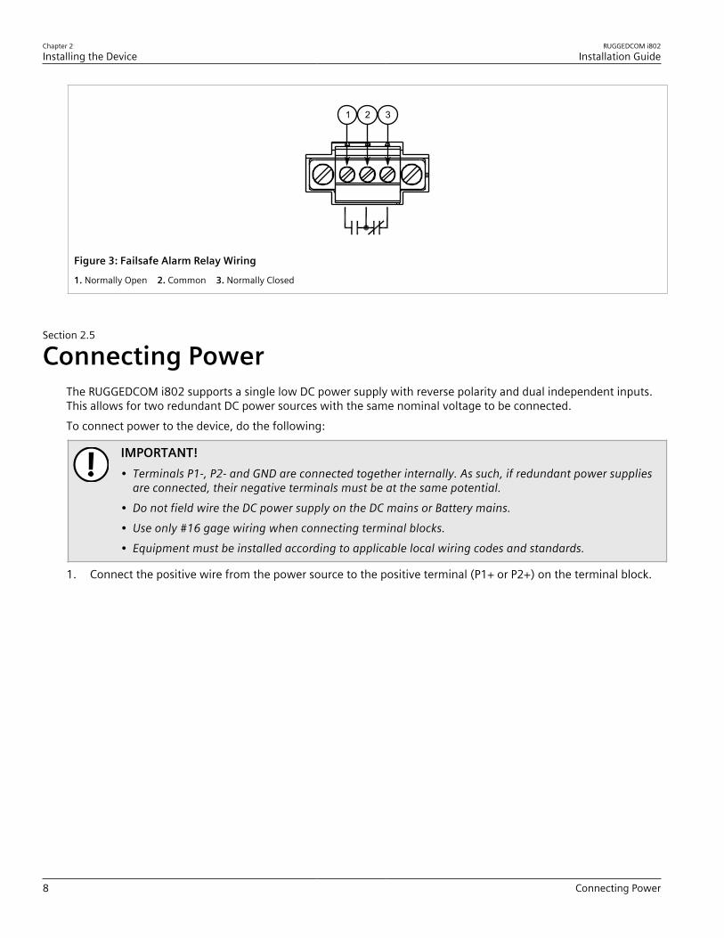
Figure 3: Failsafe Alarm Relay Wiring
1. Normally Open 2. Common 3. Normally Closed
Section 2.5
Connecting PowerThe RUGGEDCOM i802 supports a single low DC power supply with reverse polarity and dual independent inputs.This allows for two redundant DC power sources with the same nominal voltage to be connected.To connect power to the device, do the following:
IMPORTANT!• Terminals P1-, P2- and GND are connected together internally. As such, if redundant power supplies
are connected, their negative terminals must be at the same potential.• Do not field wire the DC power supply on the DC mains or Battery mains.• Use only #16 gage wiring when connecting terminal blocks.• Equipment must be installed according to applicable local wiring codes and standards.
1. Connect the positive wire from the power source to the positive terminal (P1+ or P2+) on the terminal block.

RUGGEDCOM i802Installation Guide
Chapter 2Installing the Device
Connecting Power 9
1
2
3
4
Figure 4: Terminal Block Wiring – Single DC Power Supply Input
1. Positive Terminal 2. Negative Terminal 3. GND Terminal 4. Chassis Ground Terminal
2. Connect the negative wire from the power source to the negative terminal (P1- or P2-) on the terminal block.3. [Optional] If connecting a second redundant power source, repeat Step 1 and Step 2, making sure to connect
the power supply to the P2 ports.
1
2
1
2
3
4
Figure 5: Terminal Block Wiring – Dual DC Power Supply Inputs
1. Positive Terminal 2. Negative Terminal 3. GND Terminal 4. Chassis Ground Terminal
4. Connect the chassis ground terminal to protective Earth.
Chapter 2Installing the Device
RUGGEDCOM i802Installation Guide
10 Connecting to the Device
Section 2.6
Connecting to the DeviceThe following describes the various methods for accessing the RUGGEDCOM ROS console and Web interfaces onthe device. For more detailed instructions, refer to the RUGGEDCOM ROS User Guide for the RUGGEDCOM i802.
RS232 Console PortConnect a PC or terminal directly to the RS232 console port to access the boot-time control and RUGGEDCOM ROSinterfaces. The console port provides access to RUGGEDCOM ROS's console and Web interfaces.
IMPORTANT!The console port is intended to be used only as a temporary connection during initial configuration ortroubleshooting.
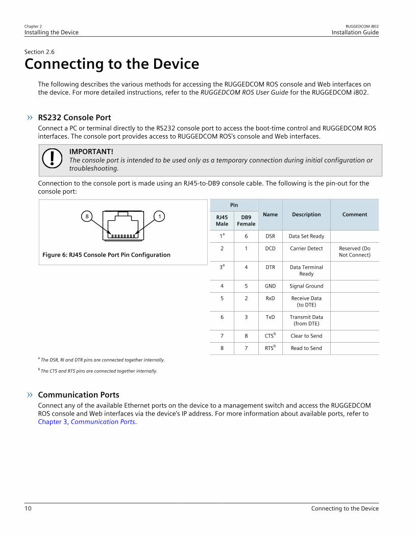
Connection to the console port is made using an RJ45-to-DB9 console cable. The following is the pin-out for theconsole port:
18
Figure 6: RJ45 Console Port Pin Configuration
Pin
RJ45Male
DB9Female
Name Description Comment
1a 6 DSR Data Set Ready
2 1 DCD Carrier Detect Reserved (DoNot Connect)
3a 4 DTR Data TerminalReady
4 5 GND Signal Ground
5 2 RxD Receive Data(to DTE)
6 3 TxD Transmit Data(from DTE)
7 8 CTSb Clear to Send
8 7 RTSb Read to Senda The DSR, RI and DTR pins are connected together internally.
b The CTS and RTS pins are connected together internally.
Communication PortsConnect any of the available Ethernet ports on the device to a management switch and access the RUGGEDCOMROS console and Web interfaces via the device's IP address. For more information about available ports, refer toChapter 3, Communication Ports.
RUGGEDCOM i802Installation Guide
Chapter 2Installing the Device
Configuring the Device 11
Section 2.7
Configuring the DeviceOnce the device is installed and connected to the network, it must be configured. All configuration managementis done via the RUGGEDCOM ROS interface. For more information about configuring the device, refer to theRUGGEDCOM ROS User Guide associated with the installed software release.
Section 2.8
Inserting/Removing the MicroSD/MicroSDHC CardThe RUGGEDCOM i802 accepts a microSD/microSDHC card to support the following features:• Configuration update and backup• Redundant firmware image• Greatly expanded logging capability• Fault-tolerant firmware update
CAUTION!Configuration hazard – risk of data loss. The microSD/microSDHC card must not be removed orreplaced during normal operation of the device. Make sure the device is powered down beforeremoving or inserting the card.
CAUTION!Mechanical/electrical hazard – risk of damage to the microSD/microSDHC card.• Do not expose the microSD/microSDHC car to extreme temperatures or humidity.• Do not expose the microSD/microSDHC card to large magnetic or static electric fields.• Do not bend or drop the microSD/microSDHC card.
CAUTION!Security hazard – risk of unauthorized access and/or exploitation. Make sure to remove the microSD/microSDHC card before decommissioning the device or sending the device to a third-party.
To insert or remove a microSD/microSDHC card, do the following:1. Power down the device.2. Unscrew the retention screw and remove the access plate.

Chapter 2Installing the Device
RUGGEDCOM i802Installation Guide
12 Inserting/Removing the MicroSD/MicroSDHC Card
1 2 3
Figure 7: Inserting/Removing a MicroSD/MicroSDHC Card1. Retention Screw 2. Access Plate 3. MicroSD/MicroSDHC Card
3. Without touching the contacts on the card, insert or remove the microSD/microSDHC card.4. Install the access plate and finger-tighten the retention screw.5. Power up the device.

RUGGEDCOM i802Installation Guide
Chapter 3Communication Ports
13
Communication PortsThe RUGGEDCOM i802 can be equipped with various types of communication ports to enhance its abilities andperformance. To determine which ports are equipped on the device, refer to the factory data file available throughRUGGEDCOM ROS. For more information on how to access the factory data file, refer to the RUGGEDCOM ROSUser Guide for the RUGGEDCOM i802.Each communication port type has a specific place in the RUGGEDCOM i802 chassis.
1
2
Figure 8: Port Assignment
1. Ports 1 to 6 2. Ports 7 to 8
Port Type
1 to 6 Copper Ethernet Ports (10/100Base-TX)
Ports 7 to 8 Copper or Fiber Ethernet Ports (10/100/1000Base-TX or 1000Base-SX or 1000Base-LX or100Base-FX)
CONTENTS• Section 3.1, “Copper Ethernet Ports”• Section 3.2, “Fiber Optic Ethernet Ports”

Chapter 3Communication Ports
RUGGEDCOM i802Installation Guide
14 Copper Ethernet Ports
Section 3.1
Copper Ethernet PortsThe RUGGEDCOM i802 supports several 10/100/1000Base-TX Ethernet ports that allow connection to standardCategory 5 (CAT-5) unshielded twisted-pair (UTP) cables with RJ45 male connectors. The RJ45 receptacles aredirectly connected to the chassis ground on the device and can accept CAT-5 shielded twisted-pair (STP) cables.
WARNING!Electric shock hazard – risk of serious personal injury and/or equipment interference. If shieldedcables are used, make sure the shielded cables do not form a ground loop via the shield wire and theRJ45 receptacles at either end. Ground loops can cause excessive noise and interference, but moreimportantly, create a potential shock hazard that can result in serious injury.
Each port features a Speed and Link LED that indicates the state of the port.
LED State Description
Yellow The port is operating at maximum speedSpeed
Off The port is not operating at maximum speed
Yellow (Solid) Link established
Yellow (Blinking) Link activity
Link
Off No link detected
The following is the pin-out for the RJ45 male connectors:
18
Figure 9: RJ45 Ethernet Port Pin Configuration
Name
Pin 10/100TX100FX
1000TX/SX/LXDescription
1 RX+ BI_DA+ Receive Data+or Bi-Directional
Pair A+
2 RX- BI_DA- ReceiveData- or Bi-
Directional Pair A-
3 TX+ BI_DB+ Transmit Data+or Bi-Directional
Pair B+
4 Reserved (DoNot Connect)
BI_DC+ Transmit Data+or Bi-Directional
Pair C+
5 Reserved (DoNot Connect)
BI_DC- ReceiveData- or Bi-
Directional Pair C-
6 TX- BI_DB- TransmitData- or Bi-
Directional Pair B-
7 Reserved (DoNot Connect)
BI_DD+ Receive Data-or Bi-Directional
Pair D+
RUGGEDCOM i802Installation Guide
Chapter 3Communication Ports
Fiber Optic Ethernet Ports 15
Name
Pin 10/100TX100FX
1000TX/SX/LXDescription
8 Reserved (DoNot Connect)
BI_DD- ReceiveData- or Bi-
Directional Pair D-
For specifications on the available copper Ethernet ports, refer to Section 4.4, “Copper Ethernet PortSpecifications”.
Section 3.2
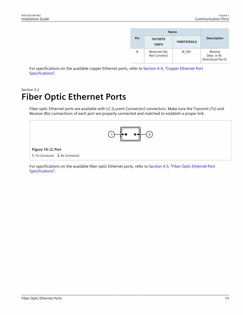
Fiber Optic Ethernet PortsFiber optic Ethernet ports are available with LC (Lucent Connector) connectors. Make sure the Transmit (Tx) andReceive (Rx) connections of each port are properly connected and matched to establish a proper link.
21
Figure 10: LC Port1. Tx Connector 2. Rx Connector
For specifications on the available fiber optic Ethernet ports, refer to Section 4.5, “Fiber Optic Ethernet PortSpecifications”.

Chapter 3Communication Ports
RUGGEDCOM i802Installation Guide
16 Fiber Optic Ethernet Ports
RUGGEDCOM i802Installation Guide
Chapter 4Technical Specifications
Power Supply Specifications 17
Technical SpecificationsThis section provides important technical specifications related to the device and available modules.
CONTENTS• Section 4.1, “Power Supply Specifications”• Section 4.2, “Environmental Specifications”• Section 4.3, “Failsafe Alarm Relay Specifications”• Section 4.4, “Copper Ethernet Port Specifications”• Section 4.5, “Fiber Optic Ethernet Port Specifications”• Section 4.6, “Mechanical Specifications”
Section 4.1
Power Supply SpecificationsPower Supply Type Minimum Input Maximum Input Internal Fuse Ratinga Maximum Power
Consumption
24 VDC 9 VDC 32 VDC 3A (T) 9 Wa (T) denotes a time-delay fuse.
Section 4.2
Environmental SpecificationsParameter Range Comments
Ambient Operating Temperature -20 to 60 °C (-4 to 140 °F)-40 to 85 °C (-40 to 185 °F) (Optional)
Ambient Temperature as measured from a30 cm radius surrounding the center of theenclosure.
Ambient Storage Temperature -40 to 85 °C (-40 to 185 °F)
Ambient Relative Humidity up to 95% Non-condensing, 55 °C (131 °F), 6 cycles
Vibration 1 g 10-500 Hz
Shock 30 g 11 ms
Chapter 4Technical Specifications
RUGGEDCOM i802Installation Guide
18 Failsafe Alarm Relay Specifications
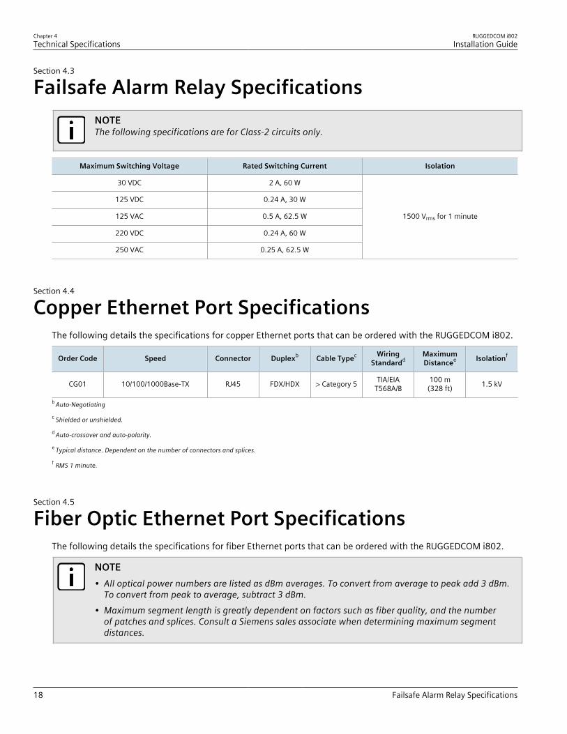
Section 4.3
Failsafe Alarm Relay SpecificationsNOTEThe following specifications are for Class-2 circuits only.
Maximum Switching Voltage Rated Switching Current Isolation
30 VDC 2 A, 60 W
125 VDC 0.24 A, 30 W
125 VAC 0.5 A, 62.5 W
220 VDC 0.24 A, 60 W
250 VAC 0.25 A, 62.5 W
1500 Vrms for 1 minute
Section 4.4
Copper Ethernet Port SpecificationsThe following details the specifications for copper Ethernet ports that can be ordered with the RUGGEDCOM i802.
Order Code Speed Connector Duplexb Cable Typec WiringStandardd
MaximumDistancee Isolationf
CG01 10/100/1000Base-TX RJ45 FDX/HDX > Category 5 TIA/EIAT568A/B
100 m(328 ft) 1.5 kV
b Auto-Negotiating
c Shielded or unshielded.
d Auto-crossover and auto-polarity.
e Typical distance. Dependent on the number of connectors and splices.
f RMS 1 minute.
Section 4.5
Fiber Optic Ethernet Port SpecificationsThe following details the specifications for fiber Ethernet ports that can be ordered with the RUGGEDCOM i802.
NOTE• All optical power numbers are listed as dBm averages. To convert from average to peak add 3 dBm.
To convert from peak to average, subtract 3 dBm.• Maximum segment length is greatly dependent on factors such as fiber quality, and the number
of patches and splices. Consult a Siemens sales associate when determining maximum segmentdistances.

RUGGEDCOM i802Installation Guide
Chapter 4Technical Specifications
Mechanical Specifications 19
Fixed Fast Ethernet Transceivers
Modeg ConnectorType
CableType (μm)
Tx λ(typ.)(nm)
Tx min.(dBm)
Tx max.(dBm)
Rx Sensitivity(dBm)
Rx Saturation(dBm)
Distance(typ.) (km)
PowerBudget
(dB)
SM LC 9/125 1300 -15 -8.0 -38 -3.0 20 23
MM LC 62.5/125 1310 -19 -14 -32 -14 2 13g MM = Multi-Mode, SM = Single-Mode
Fixed Gigabit Transceivers
Modeh ConnectorType
CableType (μm)
Tx λ(typ.)(nm)
Tx min.(dBm)
Tx max.(dBm)
Rx Sensitivity(dBm)
Rx Saturation(dBm)
Distance(typ.) (km)
PowerBudget
(dB)
MM LC 62.5/125 850 -9.5 -4.0 -20 0.0 0.4 10.5
SM LC 9/125 1310 -9.5 -3.0 -21 -3.0 10 11.5h MM = Multi-Mode, SM = Single-Mode
Section 4.6
Mechanical SpecificationsParameter Value
Dimensions Refer to Chapter 5, Dimension Drawings
Weight 1.0 kg (2.2 lbs)
Ingress Protection IP40 (1 mm or 0.04 in objects)
Enclosure Cast Aluminum Enclosure

Chapter 4Technical Specifications
RUGGEDCOM i802Installation Guide
20 Mechanical Specifications

RUGGEDCOM i802Installation Guide
Chapter 5Dimension Drawings
21
Dimension DrawingsNOTEAll dimensions are in millimeters, unless otherwise stated.
134.5
117.5
56.5
99.595.377.5
11.76.3
22.84
97.4 112.3
Figure 11: Overall Dimensions

Chapter 5Dimension Drawings
RUGGEDCOM i802Installation Guide
22

RUGGEDCOM i802Installation Guide
Chapter 6Certification
Approvals 23
CertificationThe RUGGEDCOM i802 device has been thoroughly tested to guarantee its conformance with recognizedstandards and has received approval from recognized regulatory agencies.
CONTENTS• Section 6.1, “Approvals”• Section 6.2, “EMC and Environmental Type Tests”
Section 6.1
ApprovalsThis section details the standards to which the RUGGEDCOM i802 complies.
CONTENTS• Section 6.1.1, “CSA”• Section 6.1.2, “ATEX/IEC Ex”• Section 6.1.3, “European Union (EU)”• Section 6.1.4, “FCC”• Section 6.1.5, “FDA/CDRH”• Section 6.1.6, “ISED”• Section 6.1.7, “ACMA”• Section 6.1.8, “RoHS”• Section 6.1.9, “ISO”• Section 6.1.10, “Other Approvals”
Section 6.1.1
CSAThis device meets the requirements of the following Canadian Standards Association (CSA) standards undercertificates 2058468 (general safety) and 2068170 (hazardous locations):• CAN/CSA-C22.2 No. 60950-1-03
Information Technology Equipment – Safety – Part 1: General Requirements• CAN/CSA-C22.2 No. 0-M91
General Requirements - Canadian Electrical Code, Part II
Chapter 6Certification
RUGGEDCOM i802Installation Guide
24 ATEX/IEC Ex
• CAN/CSA-C22.2 No. 14-05Industrial Control Equipment
• CAN/CSA-C22.2 No. 142-M1987Process Control Equipment Industrial Products
• CAN/CSA-C22.2 No. 213-M1987Non-Incendive Electrical Equipment for Use in Class I, Division 2 Hazardous Locations
• UL 60950-1Information Technology Equipment – Safety Part 1: General Requirements
• ANSI/UL 508Standard for Industrial Control Equipment
• UL 916 4th Edition 2007Standard for Energy Management Equipment
• ANSI/ISA-12.12.01-2007Non-incendive Electrical Equipment For Use In Class 1 And 2, Division 2 And Class 3, Divisions 1 And 2Hazardous (classified) Locations
The device is marked with a CSA symbol that indicates compliance with both Canadian and U.S. requirements.
C US
Copies of the CSA Declarations of Conformity are available via Siemens Industry Online Support:• https://support.industry.siemens.com/cs/ww/en/view/109476357 (General Safety)• https://support.industry.siemens.com/cs/ww/en/view/109476358 (Hazardous Locations)
Section 6.1.2
ATEX/IEC ExThis device meets the requirements of the following ATEX/IEC Ex standards:• IEC/EN 60079-15:2005
Electrical Apparatus for Explosive Gas Atmospheres - Part 15: Construction, Test and Marking of Type ofProtection "N" Electrical Apparatus
It is specifically approved for use in hazardous locations defined as:• EEx nC IIC T4• Ex II 3 G• 12-24 VDC, 2A, Class III
Section 6.1.3
European Union (EU)This device is declared by Siemens Canada Ltd to comply with essential requirements and other relevant provisionsof the following EU directives:
RUGGEDCOM i802Installation Guide
Chapter 6Certification
FCC 25
• EN 61000-6-2Electromagnetic Compatibility (EMC) – Part 6-2: Generic Standards – Immunity for Industrial Environments
• EN 60825-1Safety of Laser Products – Equipment Classification and Requirements
• EN 50581Technical Documentation for the Assessment of Electrical and Electronic Products with Respect to the Restrictionof Hazardous Substances
• EN 55022Information Technology Equipment – Radio Disturbance Characteristics – Limits and Methods of Measurement
The device is marked with a CE marking and can be used throughout the European community.
A copy of the EU Declaration of Conformity is available via Siemens Industry Online Support at https://support.industry.siemens.com/cs/ww/en/view/109475424.
Section 6.1.4
FCCThis device has been tested and found to comply with the limits for a Class A digital device, pursuant to Part 15 ofthe FCC Rules. These limits are designed to provide reasonable protection against harmful interference when theequipment is operated in a commercial environment.This device generates, uses and can radiate radio frequency energy and, if not installed and used in accordancewith the instruction manual, may cause harmful interference to radio communications. Operation of thisequipment in a residential area is likely to cause harmful interference in which case users will be required tocorrect the interference at their own expense.
IMPORTANT!Changes or modifications not expressly approved by the party responsible for compliance could voidthe user's authority to operate this device.
Section 6.1.5
FDA/CDRHThis device meets the requirements of the following U.S. Food and Drug Administration (FDA) standard:• Title 21 Code of Federal Regulations (CFR) – Chapter I – Sub-chapter J – Radiological Health
Section 6.1.6
ISEDThis device is declared by Siemens Canada Ltd to meet the requirements of the following ISED (Innovation Scienceand Economic Development Canada) standard:

Chapter 6Certification
RUGGEDCOM i802Installation Guide
26 ACMA
• CAN ICES-3 (A)/NMB-3 (A)
Section 6.1.7
ACMAThis device meets the requirements of the following Australian Communications and Media Authority (ACMA)standards under certificate ABN 98 004 347 880:• Radiocommunications (Compliance Labelling – Devices) Notice 2014 made under Section 182 of the
Radiocommunications Act 1992• Radiocommunications Labelling (Electromagnetic Compatibility) Notice 2008 made under Section 182 of the
Radiocommunications Act 1992• Radiocommunications (Compliance Labelling – Electromagnetic Radiation) Notice 2003 made under Section
182 of the Radiocommunications Act 1992• Telecommunications Labelling (Customer Equipment and Customer Cabling) Notice 2001 made under Section
407 of the Telecommunication Act 1997The device is marked with an RCM symbol to indicate compliance when sold in the Australian region.
A copy of the Declaration of Conformity is available via Siemens Industry Online Support at https://support.industry.siemens.com/cs/ww/en/view/89855782.
Section 6.1.8
RoHSThis device is declared by Siemens Canada Ltd to meet the requirements of the following RoHS (Restriction ofHazardous Substances) directives for the restricted use of certain hazardous substances in electrical and electronicequipment:• China RoHS 2
Administrative Measure on the Control of Pollution Caused by Electronic Information ProductsA copy of the Material Declaration is available online at https://support.industry.siemens.com/cs/ww/en/view/109738831.
Section 6.1.9
ISOThis device was designed and manufactured using a certified ISO (International Organization for Standardization)quality program that adheres to the following standard:• ISO 9001:2008
Quality management systems – Requirements
RUGGEDCOM i802Installation Guide
Chapter 6Certification
Other Approvals 27
Section 6.1.10
Other ApprovalsThis device meets the requirements of the following additional standards:• IEC 61000-6-2
Electromagnetic Compatibility (EMC) – Part 6-2: Generic Standards – Immunity for Industrial Environments
Section 6.2
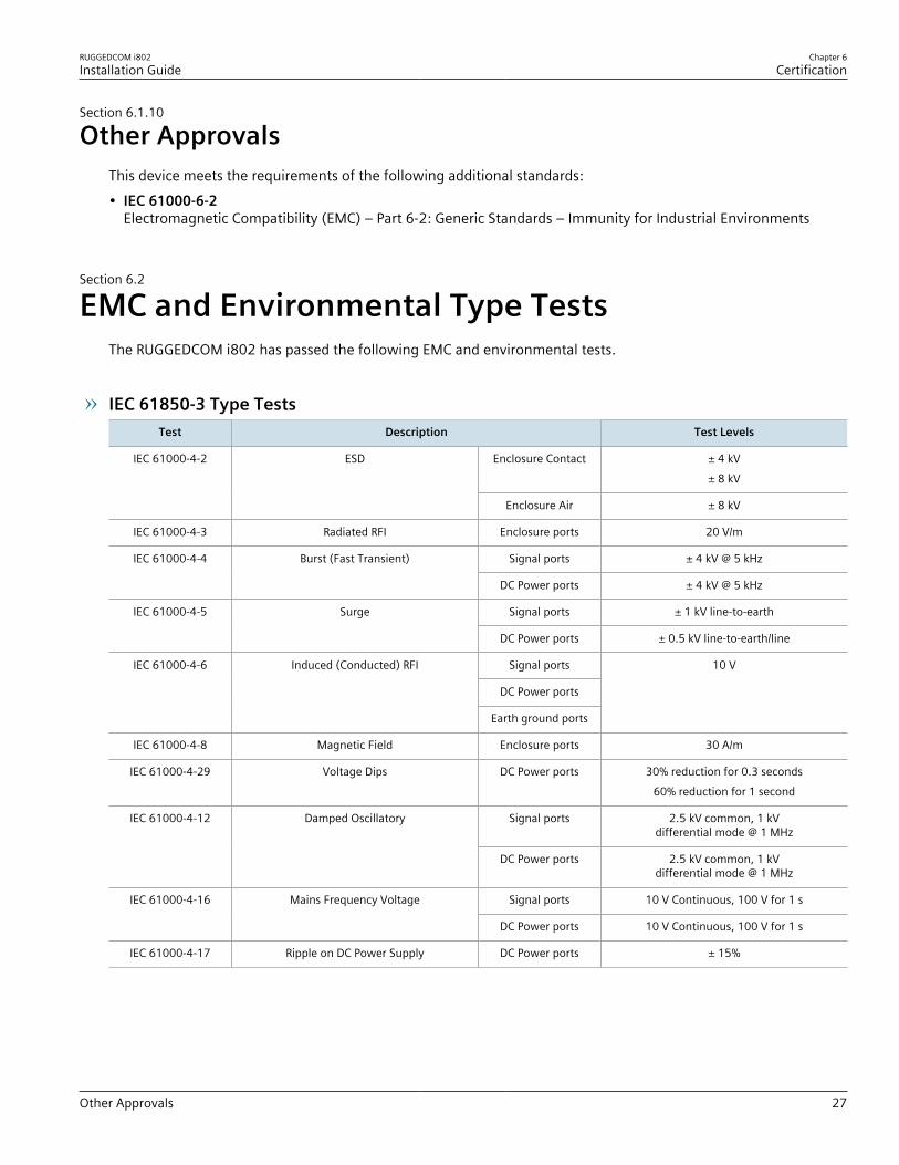
EMC and Environmental Type TestsThe RUGGEDCOM i802 has passed the following EMC and environmental tests.
IEC 61850-3 Type TestsTest Description Test Levels
Enclosure Contact ± 4 kV± 8 kV
IEC 61000-4-2 ESD
Enclosure Air ± 8 kV
IEC 61000-4-3 Radiated RFI Enclosure ports 20 V/m
Signal ports ± 4 kV @ 5 kHzIEC 61000-4-4 Burst (Fast Transient)
DC Power ports ± 4 kV @ 5 kHz
Signal ports ± 1 kV line-to-earthIEC 61000-4-5 Surge
DC Power ports ± 0.5 kV line-to-earth/line
Signal ports
DC Power ports
IEC 61000-4-6 Induced (Conducted) RFI
Earth ground ports
10 V
IEC 61000-4-8 Magnetic Field Enclosure ports 30 A/m
IEC 61000-4-29 Voltage Dips DC Power ports 30% reduction for 0.3 seconds60% reduction for 1 second
Signal ports 2.5 kV common, 1 kVdifferential mode @ 1 MHz
IEC 61000-4-12 Damped Oscillatory
DC Power ports 2.5 kV common, 1 kVdifferential mode @ 1 MHz
Signal ports 10 V Continuous, 100 V for 1 sIEC 61000-4-16 Mains Frequency Voltage
DC Power ports 10 V Continuous, 100 V for 1 s
IEC 61000-4-17 Ripple on DC Power Supply DC Power ports ± 15%

Chapter 6Certification
RUGGEDCOM i802Installation Guide
28 EMC and Environmental Type Tests
IEEE 1613 EMC Immunity Type TestsDescription Test Levels
Enclosure Contact ± 8 kVESD
Enclosure Air ± 8 kV
Radiated RFI Enclosure ports 35 V/m
Signal ports ± 4 kV @ 5 kHz
DC Power ports ± 4 kV @ 5 kHz
Fast Transient
Earth ground ports ± 4 kV @ 5 kHz
Signal ports 2.5 kV common mode @ 1MHzOscillatory
DC Power ports 2.5 kV common, 1 kV differential mode @ 1MHz
Environmental Type TestsTest Description Test Levels
IEC 60068-2-1 Cold Temperature Test Ad -40 °C (-40 °F), 16 Hours
IEC 60068-2-2 Dry Heat Test Bd 85 °C (185 °F), 16 Hours
IEC 60068-2-30 Humidity (Damp Heat, Cyclic) Test Db 95% (non-condensing),55 °C (131 °F), 6 cycles
IEC 60068-2-6 Vibration 1 g @ 10-500 Hz
IEC 60068-2-27 Shock 30 g @ 11 ms