intro to wlan analysis bardwel - wireshark to... · 3/13/2008 2 the secret science of wlan analysis...
TRANSCRIPT

3/13/2008
1
Introduction to WLAN AnalysisAnalysisTuesday, April 1, 2008
Joe BardwellChief Scientist | Connect802 Corporationwww.Connect802.com [email protected]
SHARKFEST '08
SHARKFEST '08 | Foothill College | March 31 - April 2, 2008
SHARKFEST '08Foothill CollegeMarch 31 - April 2, 2008
The 802.11 StandardsToday we’ll overview whatthe IEEE 802.11 standardstell us about how Wi-Fishould behaveYou need to understand theexpected behavior of theprotocols before you canidentify anomalies
• “If you don’t know where you’regoing then any road will takeyou there.”
Lewis CarrollLewis Carroll
http://standards.ieee.org/getieee802
“Begin at the beginning and go on till you come to the end; then stop.”

3/13/2008
2
The Secret Science of WLAN Analysis
There is no secret• The 802.11 standards explain what the expected
behavior is as Wi-Fi devices communicate
• Wireshark shows you what the actual behavior is in the network
• You isolate and describe how the actual behavior deviates from the expected behavior
• You determine why the deviation has occurred
Determining why a deviation has occurred is often the most difficult challenge
• There’s no substitute for experience when it comes to the “why”
• There’s no substitute for diligent study when it comes to isolating and describing anomolies
The Basis for Wireless Network SpecificationsFederal Communications Commission (FCC)
Develops regulatory and spectrumuse policies
– Sets radio equipment operating limits, and usage rules– Enforces violations under U.S. Federal law
International Electrical and Electronics Engineers Association (IEEE)Sets standards for equipment operation
– Does NOT specify how equipment should be designed or manufactured– Creates engineering standards that comply with regulatory limitations
The Wireless Fidelity Alliance (Wi-Fi)y ( )Establishes guidelines for interoperability based on the IEEE standards
– Does not set standards– Wi-Fi is an industry consortium

3/13/2008
3
THE IEEE 802.11 STANDARD
General description of the architecturePhysical layer bit representation
• Modulation Schemes: BPSK, QPSK, QAM• Spread Spectrum Bit Encoding: Barker, CCK• Orthogonal Frequency Division Multiplexing (OFDM)
Service sets and distribution systems• Basic Service Set, Extended Service Set
Authentication and AssociationFrame formats and fieldsWired Equivalent Privacy (WEP)Distributed Coordination Function (DCF)Distributed Coordination Function (DCF)Point Coordination Function (PCF)Fragmentation and defragmentationPower management
The Core 802.11 Architectural Standards
802.11– 1 and 2 Mb/sec DSSS, FHSS, and IrDA– BPSK and QPSK with Barker Coding
802 11b802.11b– Fall 1999– 2.4 GHz ISM band– 5.5 and 11 Mb/sec CCK+QPSK DSSS in 2.4 GHz band
802.11a– Fall 2001– 5.8 GHz U-NII band, 8 non-overlapping channels
6 54 Mb/sec OFDM+(BPSK QPSK or QAM) in the 5 8 GHz band– 6-54 Mb/sec, OFDM+(BPSK,QPSK or QAM) in the 5.8 GHz band

3/13/2008
4
The Core 802.11 Architectural Standards
802.11g– 11g is “11a in the ISM band”– The FCC (in response to a petition by Cisco) removed the
requirement mandating only Spread Spectrum in the ISM band
– Summer 2003– 6-54 Mb/sec, OFDM+(BPSK,QPSK or QAM)
in the 2.4 GHz band
802.11n– Finalization expected in 2009– MIMO using 40MHz channels
with STBC (Space-Time Block Code)
802 11y802.11y– Finalization expected in 2008– 11y is “high-power 11a in the licensed 3.7 GHz band”
The PHY Standards Differ Dramatically
802.11b, 802.11g, 802.11a, 802.11n…
The PHY Standards Have EvolvedThe PHY Standards Have Evolved to Provide Faster Data Rates
The Standards for Management and Control Have Remained the Same

3/13/2008
5
Radiotap Header Added by Wireshark
Possible Radiotap Header FieldsIEEE80211_RADIOTAP_TSFT
This field contains the unsigned 64-bit value, in microseconds,of the MAC's 802.11 Time Synchronization Function timer, when thefirst bit of the MPDU arrived at the MAC. This field should bepresent for received frames only.
IEEE80211_RADIOTAP_FLAGSThis field contains a single unsigned 8-bit value, containing abitmap of flags specifying properties of the frame being trans-mitted or received.
IEEE80211 RADIOTAP RATE
IEEE80211_RADIOTAP_TX_ATTENUATIONThis field contains a single unsigned 16-bit value, expressingtransmit power as unitless distance from maximum power set atfactory calibration. 0 indicates maximum transmit power. Mono-tonically nondecreasing with lower power levels.
IEEE80211_RADIOTAP_DB_TX_ATTENUATIONThis field contains a single unsigned 16-bit value, expressingtransmit power as decibel distance from maximum power set at fac-tory calibration. 0 indicates maximum transmit power. Monotoni-cally nondecreasing with lower power levels.
IEEE80211_RADIOTAP_DATA_RETRIESUnsigned 8-bit value indicating how many times the NIC
retransmitted a unicast data packet before receiving an 802.11 Acknowledgement.
IEEE80211_RADIOTAP_EXTThis bit is reserved for any future extensions to the radiotapstructure. A driver sets IEEE80211_RADIOTAP_EXT to
extend the it_present bitmap by another 64 bits. The bitmap can be extended by multiples of 32 bits to 96, 128, 160 bits or longer, by setting IEEE80211_RADIOTAP_EXT in the extensions. The bitmap ends at the first extension field IEEE80211_RADIOTAP_RATE
This field contains a single unsigned 8-bit value, which is thedata rate in use in units of 500Kbps.
IEEE80211_RADIOTAP_CHANNELThis field contains two unsigned 16-bit values. The first valueis the frequency upon which this PDU was transmitted or received.The second value is a bitmap containing flags which specify prop-erties of the channel in use. These are documented within theheader file, <net80211/ieee80211_radiotap.h>.
IEEE80211_RADIOTAP_FHSSThis field contains two 8-bit values. This field should bepresent for frequency-hopping radios only. The first byte is thehop set. The second byte is the pattern in use.
IEEE80211_RADIOTAP_DBM_ANTSIGNALThis field contains a single signed 8-bit value, which indicatesthe RF signal power at the antenna, in decibels difference from1mW.
IEEE80211 RADIOTAP DBM ANTNOISE
IEEE80211_RADIOTAP_DBM_TX_POWERTransmit power expressed as decibels from a 1mW reference. Thisfield is a single signed 8-bit value. This is the absolute powerlevel measured at the antenna port.
IEEE80211_RADIOTAP_ANTENNAFor radios which support antenna diversity, this field contains asingle unsigned 8-bit value specifying which antenna is beingused to transmit or receive this frame. The first antenna isantenna 0.
IEEE80211_RADIOTAP_DB_ANTSIGNALThis field contains a single unsigned 8-bit value, which indi-cates the RF signal power at the antenna, in decibels differencefrom an arbitrary, fixed reference.
IEEE80211_RADIOTAP_DB_ANTNOISEThis field contains a single unsigned 8-bit value, which indi-cates the RF noise power at the antenna, in decibels differencefrom an arbitrary, fixed reference.
where IEEE80211_RADIOTAP_EXT is not set.
IEEE80211_RADIOTAP_DBM_ANTNOISEThis field contains a single signed 8-bit value, which indicatesthe RF noise power at the antenna, in decibels difference from1mW.
IEEE80211_RADIOTAP_LOCK_QUALITYThis field contains a single unsigned 16-bit value, indicatingthe quality of the Barker Code lock. No unit is specified forthis field. There does not appear to be a standard way of mea-suring this at this time; this quantity is often referred to as``Signal Quality'' in some datasheets.
IEEE80211_RADIOTAP_RX_FLAGSAn unsigned 16-bit bitmap indicating properties of receivedframes.
IEEE80211_RADIOTAP_TX_FLAGSAn unsigned 16-bit bitmap indicating properties of transmittedframes.
IEEE80211_RADIOTAP_RTS_RETRIES u_int8_t dataUnsigned 8-bit value indicating how many times the NIC retrans-mitted the Request to Send (RTS) in an RTS/CTS handshake beforereceiving an 802.11 Clear to Send (CTS).

3/13/2008
6
802.11n MAC+PHY PPI Header
802.11n is as much anarchitecture as it is anengineering standardMIMO can be implementedMIMO can be implementedwith 2 or 3 radios
• Referred to as: 2 X 2, 2 X 3, 3 X 3
The “Per-Packet Information”(PPI) header is prependedinstead of the Radiotapheader to convey MIMOheader to convey MIMOinformation beyond what Radiotap can provide
Electromagnetic Signals at the Physical Layer
The 802.11 Physical Layer comprises the realm of electromagnetic signal propagationIn this realm it’s the skill set of the RF engineer that predominatesthat predominates
Agner Krarup ErlangOriginator of Queuing Theory
(Applied to 802.11 Oversubscription Calculations)
James Clerk MaxwellElectrical and Magnetic Field Equations
(Applied to 802.11 Signal Strength Considerations)

3/13/2008
7
If You Only Remember One Thing About RF…
This Is a BAD DesignA design based on circles will cause problemsNO CIRCLES !
Addressing the Complexities of RF DesignConnect802 Utilizes 3-Dimensional RF CAD Modelingto Consider RF Engineering Complexities in a System Design
• You provide a building (or outdoor area) plan• We create a 3-dimensional CAD model of the space
Wi Fi i l i d t i d t l• Wi-Fi signal coverage is determined accurately

3/13/2008
8
More of the 802.11 Alphabet Soup
802.11c – Bridge Operation Procedures• These standards form the basis for WDS
(Wireless Distribution System) implementation in the creation of a Microcell to be discussed
802.11d – PHY requirements to satisfy non-US regulatory requirements
• The 5 GHz band is used differently outside the U.S.
802.11e – QoS to optimize/prioritize traffic for voice and video• Anticipated firmware upgrades will provide backward compatibility
802 11f – Inter Access Point Protocol802.11f Inter Access Point Protocol• Communication between Access Points for multi-vendor interoperable
roaming support
More of the 802.11 Alphabet Soup
802.11h – Automatic configuration extensions to 802.11a
• Dynamic Channel/Frequency Selection (DCS/DFS)
Transmit Power Control (TPC)• Transmit Power Control (TPC)
802.11i – Strong security (foreshadowed by WPA)• Utilizes 802.1x Authentication with RADIUS (Remote Authentication Dial-
In User Service)– 802.1x has been in place for wired authentication for many years
• WPA and 802.11i correct the security flaws in WEP (Wired Equivalent Privacy)
• Wi-Fi networks can now be designed with strong security
• (802.11i and WPA will be discussed in more detail)
802.11j – 802.11a in the 4.9 GHz band for Japan

3/13/2008
9
More of the 802.11 Alphabet Soup802.11k – Radio Resource Management: measurement interrogation standards for Access Point and client self management to auto-provision large networks
Si l d N i i– Signal and Noise metrics– Channel use information– Hidden node discovery– Individual client statistics– Transmit Power Control (TPC)
802.11l – (Typographically unsound ☺)802.11m – Maintenance of existing standards802.11p – Wireless Access in the Vehicular Environment (WAVE) operating in the Intelligent Transportation Systems (ITS) licensed 5.9 GHz band.802.11r – Fast roaming between Access Points
Understanding 802.11 Network Architecture
Access Point (AP) – A “Station” (device) that provides access to the Distribution SystemDistribution System (DS) – The network that y ( )connects BSS-s together into an ESSStation (STA) – Any device with an 802.11 radio
– Includes laptops, VoIP phones, PDAs, etc…Basic Service Set (BSS) – Exactly one AP and all of its client stationsExtended Service Set (ESS) – One or more BSS s sharing the same ESSIDBSS-s sharing the same ESSID
Commonly referred to as the “SSID”This is the Network Name

3/13/2008
10
The Basic Service Set (BSS)
Contains exactly one APUniquely identified by the BSSID, which is ,essentially always the same as the MAC address of the AP’s wireless interfaceAll clients are associated with the APA client can only be a A client can only be a member of a single BSS at a time
Traffic Flow in a BSS
Traffic in a BSS alwaysflows from STA to AP or from AP to STAIf both the source and destination STA are in the same BSS, this results in packet duplicationAvailable throughput is cut in halfFortunately, wireless stations usually talk to wired stations
3/13/2008
11
Access Points are configured with an ESSIDTerm is often shortened to just SSID (or “Network Name”)This is what you see in your “Available Wireless Networks”
The Extended Service Set (ESS)
y yAll Access points with the same ESSID are part of an ESS
ESSID identifies the group of APs as a whole, not any specific APBSSID is what identifies the specific APs
Stations can roam within an ESS without losing connectionThe specifications for roaming are pragmatic and not optimal
802.11e and 802.11r cover fast roaming for multimedia applicationsAccess Point comprising a single ESS must be part of the same Layer 2Access Point comprising a single ESS must be part of the same Layer 2 Broadcast Domain
Connected to the same Layer 2 switched network or all configured on the same VLAN.
Mobile IP can mitigate these requirements
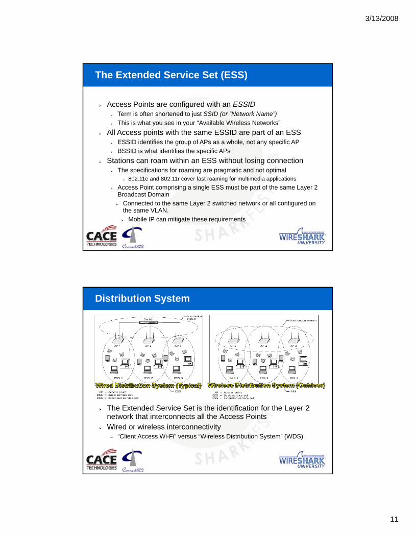
Distribution System
The Extended Service Set is the identification for the Layer 2 ynetwork that interconnects all the Access PointsWired or wireless interconnectivity
– “Client Access Wi-Fi” versus “Wireless Distribution System” (WDS)

3/13/2008
12
Frame Formats That You’ll See With Wireshark802.11 frames are structured differently from Ethernet framesAdditional addressing is used in Wi-Fi 802.11 data transferA comparison between the headers of 802.3 frames and the similarly named 802 11 headers will actually reveal that insimilarly named 802.11 headers will actually reveal that in reality, they are significantly different
Dest Address Src Address Length LLC Header
Ethernet
802.11
“Why are there four Data Link Layer addresses in 802.11?”
Frame Ctrl Duration / ID Addr. 1 LLC HeaderAddr. 2 Addr. 3 Addr. 4Seq.
802.11 and Ethernet Addressing
192.168.1.0
192.168.3.0Ethernet-attachedComputer
Consider this network map…
Server
WirelessDevice
802.11 Access PointLayer 2 SwitchLayer 3 RouterEthernet Endpoint 192.168.2.0
192.168.4.0 64.1.2.0
InternetConnection

3/13/2008
13
Wired to Wired Addressing
192.168.1.0
192.168.3.0Ethernet-attachedComputer
SD
ServerS
WirelessDevice
D
S
S
DS
D
192.168.2.0
192.168.4.064.1.2.0
Layer 2 Source and Destination
Layer 3 Source and Destination
InternetConnection
Wireless to Wired Addressing
192.168.1.0
192.168.3.0Ethernet-attachedComputer
D
Server
WirelessDevice
S
192.168.2.0
192.168.4.0 64.1.2.0
Layer 3 Source and Destination InternetConnection

3/13/2008
14
Wireless Addressing Requires More
192.168.1.0
192.168.3.0Ethernet-attachedComputer
To which access point is the client currently associated?
Server
WirelessDevice
S
D
192.168.2.0
192.168.4.0 64.1.2.0
Layer 2 Source and Destination
InternetConnection
802.11 Adds Address Fields To The Packet
192.168.1.0
192.168.3.0Ethernet-attachedComputer
R DBSSID
Server
WirelessDevice
T
S
D
S
S
DS
D
InternetConnection192.168.2.0
192.168.4.0 64.1.2.0
Layer 2 Source and Destination
802.11 “Transmitter” and “Receiver” (BSS Identifier)
Layer 3 Source and Destination

3/13/2008
15
Effects of 802.11 Addressing (1)802.11’s transmitter and receiver fields use the same MAC addresses as the source and destination fieldsThe “BSS Id” field is Address 3
• This is the MAC address of the Access PointThis is the MAC address of the Access Point
• Address 4 would only be present in a Wireless Distribution System frame
Effects of 802.11 Addressing (2)The transmitter and receiver address allow an 802.11 client to specify which access point a packet should go through, even when that client is within range of multiple access points
T
R
SWirelessDevice
S

3/13/2008
16
Effects of 802.11 Addressing (3)A client will “associate” with a single access point, then send all packets through that access point
• If necessary, a client may decide to roam to a new access point, but clients will not change APs on a packet-by-packet basis, even though 802.11’s addressing could support this802.11 s addressing could support this
802.11 transmitter and receiver addresses are only carried in 802.11 packets, not in Ethernet packets
• Although the same MAC addresses may be used for transmitter/receiver and source/destination, Ethernet frames don’t have fields for transmitter/receiver (nor do they need them)
802.11 source and destination addresses are identical to Ethernet source and destination packets
• Source and destination addresses don’t change when packets go through an AP
• In terms of source and destination addressing, the AP acts just like an Ethernet switch—packets pass through it transparently
Normally, Only the Access Point BSSID Will Be Present
This is not the case when packets are exchangedin a Wireless Distribution System
To DS and From DS
These flags within the 802.11 frame indicate where the packet is going
– From an AP to a client STA?
– From a client STA to an AP?
– From an AP to another AP within the DS?
Wireshark provides a plain-text explanation ofplain text explanation of the bits, as shown to the right

3/13/2008
17
The Wireless Distribution System (WDS)
One More Architecture: Wireless LAN Switching
The central switch controller performs some or all of the packet processing
– Authentication– EncryptionEncryption– Probe Response– Beacon Transmission
The “Access Point” can bethought of as a “radio head”The central switch controllercan automatically adjustchannel and power settingschannel and power settingsReal-Time Location Services (RTLS) can be implementedThe entire system could be a single BSS with the MAC of the controller used as the target for wireless packets (Address 3)

3/13/2008
18
“All together now….”
Class 1 FramesBeaconProbe• ACKProbe Response• ACK Class 2 Frames
Authenticate• ACKAuthenticate (Response)• ACKAssociation Request• ACKAssociated Response• ACK Class 3 Frames
• All Data• ACK
Setup for Milliseconds Since Previous Packet

3/13/2008
19
Beacon Frames Every 10 ms
Beacon Frames Tend to Clutter a Trace

3/13/2008
20
Get Rid of Those Beacon Frames
Where the Action Starts
ProbeAuthenticateAssociateAssociate

3/13/2008
21
The 802.11 State Machine
The “State Machine” and its “Classes” is just a complicated way of saying: “You can’t send data through the AP until you authenticate yourself”General flow is:1. Find a BSS2. Authenticate to the BSS3. Associate with the BSSMust be in that orderC l A i t ith O APCan only Associate with One AP at a time
Our Old Friend, the TCP 3-Way Handshake
Each TCP Data frame is followed by an 802.11 ACKIf the ACK is not received then the originating station retransmits the frameThi h hl 10 ti f t th TCP ld iThis happens roughly 10 times faster than TCP would recognize

3/13/2008
22
A TCP/IP Data Frame
The TCP/IP “stuff” is carried by the 802.11 header in exactly the same way it would have been carried by an 802.3 Ethernet header on a wired network
• The “Frame” and “Radiotap” headers are prepended by WiresharkThe Frame and Radiotap headers are prepended by Wireshark
IEEE 802.11 Layer 2 Header
Encrypted data is carried by the unencrypted 802.11 header• Addresses are always transmitted as unencrypted data over the air

3/13/2008
23
LLC Is Carried on 802.11 Instead of 802.3
Unencrypted frames look very much like their Ethernet counterparts
Same Frame – This Time It’s Encrypted
The Encrypted IP, TCP, and Data Portions of the Frame

3/13/2008
24
Dissecting the Key 802.11 Information
Radiotap Header• SSI Levels
• Channel
• Data Rate
802.11 Header• Addresses
• Sequence Number
• DS Status
• Retry
• Power Management
Fragmentation
802.11 has the ability to fragment frames into smaller chunks before transmissionFragments are reassembled by the receiving radio (AP or client)Fragmentation specifically addresses cases of intermittent interference, such as microwave ovens
Microwaves generate interference in pulses that cycle with the 60 Hz AC current that powers themFragmented 802.11 frames can slip between these pulses and not be corrupted
F t ti b bl d i th li t tiliti d iFragmentation can be enabled in the client utilities or driversEnabled on AP and/or client individuallyNo functionality to automatically enable/disable, so only enable it on stations that are consistently in the presence of interference

3/13/2008
25
Analyzing Fragmentation with WiresharkEach entire TCP/IP frame is assigned a Sequence NumberEach fragment is assigned a Fragment Number
802.11 LLC IP TCP DATA
0
1
2
The 802.11 Retransmission Mechanism
An ACK is needed to confirm receipt of a frameBeacon frames get no ACKYou don’t always see the ACK
• Or, sometimes all you see is the ACK !

3/13/2008
26
802.11 Power Management
Low-Power Portable Devices Are Fundamentalto the 802.11 Standards
• Significant thought was put into the standards to accommodatepower management
The Power Management Process• When a device is going to ‘sleep’ it sets the Power Management bit in the
last frame transmitted prior to entering Power Save Mode
• The Access Point queues all frames destined for the device
• The device ‘wakes up’ at the next Beacon interval
• If frames are queued then a bit is set in the Beacon frame’s Delivery Traffic Indication Message field (DTIM)
• The device indicates it’s now ready to receive the queued traffic
• The Access Point sends the queued frames
Distributed Coordination Function
A mechanism by which 802.11 stations (and that includes access points!) coordinate their transmissions
– If two stations transmit at the same time…– On the same channel…– Within range of each other…– Then corruption will result at the receiver– DCF is designed to prevent this from happening
In 802.11, the DCF implements an algorithm called CSMA/CA– Carrier Sense– Multiple Accessu t p e ccess– With Collision Avoidance
3/13/2008
27
CSMA/CAStep 1: Sense Carrier
Physical Carrier Sense (Clear Channel Assessment / CCA)Listen for signal energy coming in off of the radioAll stations in a BSS must be able to hear the APAll stations in a BSS are not required to be able to hear each other andAll stations in a BSS are not required to be able to hear each other… and usually they can’t!This is called the “Hidden Node Problem,” and it is addressed by…
Virtual Carrier Sense (Network Allocation Vector / NAV)A mechanism whereby stations can “reserve” the airtime for their transmissionsThink of it like a countdown timerTransmitting station “sets” the NAV on other stationsOther stations won’t transmit again until their NAV counts down to zero
NetworkAllocation
Vector
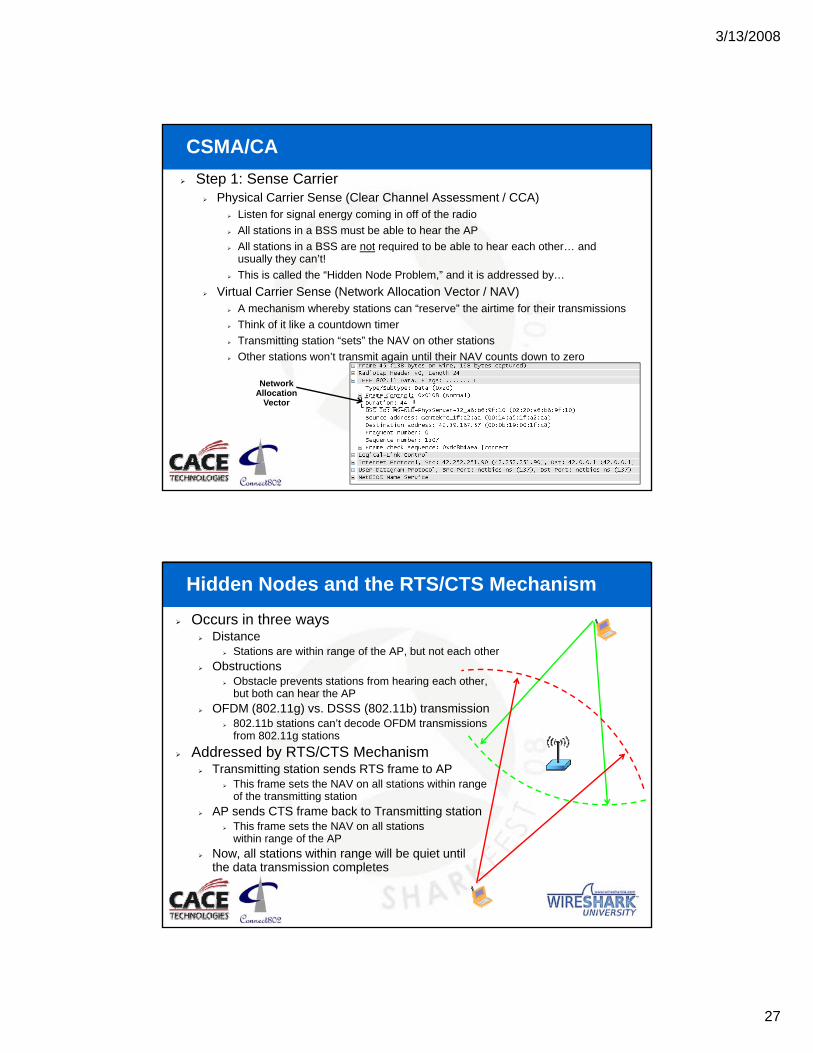
Occurs in three waysDistance
Stations are within range of the AP, but not each otherObstructions
Obstacle prevents stations from hearing each other,
Hidden Nodes and the RTS/CTS Mechanism
Obstacle prevents stations from hearing each other, but both can hear the AP
OFDM (802.11g) vs. DSSS (802.11b) transmission802.11b stations can’t decode OFDM transmissions from 802.11g stations
Addressed by RTS/CTS MechanismTransmitting station sends RTS frame to AP
This frame sets the NAV on all stations within range of the transmitting station
AP sends CTS frame back to Transmitting stationThis frame sets the NAV on all stations within range of the AP
Now, all stations within range will be quiet until the data transmission completes
3/13/2008
28
CSMA/CA
Step 2: Interframe Spacing (IFS)A certain minimum period of silence must be observed between each transmissionIFS length varies depending on the type of frame that a station is attempting to transmit
SIFS (“Short” IFS) – Used for frames that must immediately follow a previously-transmitted frame, such as 802.11 ACK in response to 802.11 DATA or CTS in response to RTS.DIFS (“DCF” IFS) – Longer than SIFS. Used for normal data frames when operating in DCF modeOth i t b t SIFS d DIFS th jOthers exist, but SIFS and DIFS are the major ones
Packets that use a shorter IFS will get priority access to the network when competing against packets that use a longer IFS
ACK packets are sent using the SIFS interval
CSMA/CA
Step 3: Random Backoff TimerStations’ NAV timers are may expire at the same timeMany stations are likely to use the same IFS valuey yThis means that many stations would transmit at the same time and have a ‘collision’ at the receiver
After the NAV expires, after the IFS expires, stations choose a random amount of additional time and waitThe station that chose the shortest time transmitsAll other stations pause their timer until the transmission completes, the NAV expires, and the IFS expires… again.completes, the NAV expires, and the IFS expires… again.

3/13/2008
29
And Now For Something Completely Different…
Point Coordination Function (PCF)A totally obscure supplement to DCFOptional in the 802.11 standard and no manufacturers implement it (that we know of—anybody know of one?)
The Access Point periodically orders all stations to be quiet!Reserves the airtime using the NAV
The Access Point then polls certain stations, one at a time, giving them permission to transmit data
This is the one case where a station can transmit when its NAV is nonzero
PCF has the advantage that a subset of stations can get guaranteed, priority access to the network…
This can be as fair or unfair as the administrator wants it to beBut since it is not typically implemented, that advantage is entirely hypothetical :-)
Isolating and Describing a Problem
Trouble Report: Poor Performance and Loss of ConnectivityWe see the Data and the Ack but evidently the Access Point doesn’t see the Ack
DATA
ACKWireless
Client
AccessPoint

3/13/2008
30
Practical WLAN Packet-Level Analysis
Determine the channel of interest and capture from it
Examine Beacon traffic then eliminate it with a filter
Examine Probe/Probe-Response traffic
F ll t ti th ti ti d i ti b h iFollow station authentication and association behavior
Look for atypical configurations (PCF, non-10ms Beacons, etc.)
Look for 802.11 retransmissions and isolate whether the data or the Ack is being lost
Track physical packet flow to and from the distribution system (focusing on the BSSID in the ESS as compared to the Ethernet addressing
Track and overlay the IP logical data flow on top of the physical packet flow assessment to ascertain validity (and to pay attention to TCP sequence and acknowledgment.)
Thank You !
For more information on Connect802’s services and products, please visit: www.Connect802.com/info
• Watch a video showing how 3-dimensional RF CAD modeling is performed
• Get sample system design reports
• Find out more about who we are and how we might be able to be a resource for you.
From our home page (www.Connect802.com) explore the Literature tab to find:
• “Wi-Fi: Just the Facts”Technical discussions that put 802 11 into perspective– Technical discussions that put 802.11 into perspective
• The Connect802 On-Line Encyclopedia– A compendium of 802.11 information
• “Wireless Connectivity Update”– Archives of our quarterly technical update newsletter
[email protected](925) 552-0802