intrinsically safe barrier
TRANSCRIPT
16102800A 07/01.00
Intrinsically Safe Barrier Technical Manual
©Mettler-Toledo, Inc. 2001
No part of this manual may be reproduced or transmitted in any form or by any means, electronic or mechanical, including photocopying and recording, for any purpose without the express written permission of Mettler-Toledo, Inc.
U.S. Government Restricted Rights: This documentation is furnished with Restricted Rights.

CUSTOMER FEEDBACK Your feedback is important to us! If you have a problem with this product or its documentation, or a suggestion on how we can serve you better, please fill out and send this form to us. Or, send your feedback via email to: [email protected]. If you are in the United States, you can mail this postpaid form to the address on the reverse side or fax it to (614) 438-4355. If you are outside the United States, please apply the appropriate amount of postage before mailing. Your Name: Date: Organization Name: METTLER TOLEDO Order Number: Address: Part / Product Name: Part / Model Number: Serial Number: Company Name for Installation: Phone Number: ( ) Fax Number: ( ) Contact Name: E-mail Address: Phone Number: Please check the appropriate box to indicate how well this product met your expectations in its intended use? Met and exceeded my needs Met all needs Met most needs Met some needs Did not meet my needs Comments/Questions:
DO NOT WRITE IN SPACE BELOW; FOR METTLER TOLEDO USE ONLY Retail Light Industrial Heavy Industrial Custom RESPONSE: Include Root Cause Analysis and Corrective Action Taken.
B12745800A
FOLD THIS FLAP FIRST
BUSINESS REPLY MAIL FIRST CLASS PERMIT NO. 414 COLUMBUS, OH
POSTAGE WILL BE PAID BY ADDRESSEE
Mettler-Toledo, Inc. Quality Manager - MTWT P.O. Box 1705 Columbus, OH 43216 USA
NO POSTAGE NECESSARY IF MAILED IN THE UNITED STATES
Please seal with tape.

INTRODUCTION This publication is provided solely as a guide for individuals who have received Technical Training in servicing the METTLER TOLEDO product.
Information regarding METTLER TOLEDO Technical Training may be obtained by contacting:
METTLER TOLEDO 1900 Polaris Parkway
Columbus, Ohio 43240 (US and Canada) 614- 438-4511
(All Others) 614-438-4888
FCC Notice This device complies with Part 15 of the FCC Rules and the Radio Interference Requirements of the Canadian Department of Communications. Operation is subject to the following conditions: (1) this device may not cause harmful interference, and (2) this device must accept any interference received, including interference that may cause undesired operation.
This equipment has been tested and found to comply with the limits for a Class A digital device, pursuant to Part 15 of FCC Rules. These limits are designed to provide reasonable protection against harmful interference when the equipment is operated in a commercial environment.
METTLER TOLEDO RESERVES THE RIGHT TO MAKE REFINEMENTS OR CHANGES WITHOUT NOTICE.

NOTES

PRECAUTIONS
WARNING DISCONNECT ALL POWER TO THIS UNIT BEFORE INSTALLING, SERVICING, CLEANING, OR REMOVING THE FUSE. FAILURE TO DO SO COULD RESULT IN BODILY HARM AND/OR PROPERTY DAMAGE.
CAUTION OBSERVE PRECAUTIONS FOR HANDLING ELECTROSTATIC SENSITIVE DEVICES.
WARNING ONLY PERMIT QUALIFIED PERSONNEL TO SERVICE THIS EQUIPMENT. EXERCISE CARE WHEN MAKING CHECKS, TESTS AND ADJUSTMENTS THAT MUST BE MADE WITH POWER ON. FAILING TO OBSERVE THESE PRECAUTIONS CAN RESULT IN PERSONAL INJURY AND/OR PROPERTY DAMAGE.
CAUTION BEFORE CONNECTING OR DISCONNECTING ANY INTERNAL ELECTRONIC COMPONENTS OR INTERCONNECTING WIRING BETWEEN ELECTRONIC EQUIPMENT, ALWAYS REMOVE POWER AND WAIT AT LEAST THIRTY (30) SECONDS. FAILURE TO OBSERVE THESE PRECAUTIONS COULD RESULT IN DAMAGE TO OR DESTRUCTION OF THE EQUIPMENT, OR BODILY HARM.
WARNING METTLER TOLEDO ASSUMES NO RESPONSIBILITY FOR CORRECT INSTALLATION OF THIS BARRIER IN A HAZARDOUS AREA APPLICATION. THE INSTALLER MUST BE FAMILIAR WITH ALL WIRING CODES AND ALL INSTALLATION REQUIREMENTS.
READ this manual BEFORE operating or servicing this equipment. FOLLOW these instructions carefully. SAVE this manual for future reference. DO NOT allow untrained personnel to operate, clean, inspect, maintain, service, or tamper with this equipment. ALWAYS DISCONNECT this equipment from the power source before cleaning or performing maintenance.

WARNING ALL METTLER TOLEDO ISB BARRIERS ARE DESIGNED TO WORK WITH TERMINALS THAT PROVIDE POSITIVE EXCITATION VOLTAGE REFERENCED TO LOGIC GROUND ONLY. THEY ARE NOT COMPATIBLE WITH TERMINALS WHICH PROVIDE NEGATIVE EXCITATION VOLTAGE. CONNECTING THIS BARRIER TO AN INCOMPATIBLE TERMINAL COULD RESULT IN DAMAGE TO THE BARRIER.
WARNING IN ORDER TO USE THIS BARRIER UTILIZING THE FM APPROVAL FOR AN AREA CLASSIFIED AS CLASS I, II OR III, DIVISION 1 OR 2, GROUPS A, B, C, D, E, F OR G, TEMPERATURE CODE T6, METTLER TOLEDO CONTROL DRAWING 159672R MUST BE FOLLOWED WITHOUT EXCEPTION. IN ORDER TO USE THE BARRIER UTILIZING THE KEMA APPROVAL AS [EEx ia] IIC, OR EEx d IIB+H2 [ia] IIC T6, THE APPROVAL CERTIFICATE EX-01.E.1055 AND EX-01.E.2071X AND ALL LOCAL REGULATIONS MUST BE FOLLOWED WITHOUT EXCEPTION. FAILURE TO DO SO COULD RESULT IN BODILY HARM AND/OR PROPERTY DAMAGE.
WARNING THE ISB05X AND ISB15X HAVE A TEMPERATURE RATING OF T6 (85°C / 185˚ F). THEY MUST NOT BE USED IN AREAS WHERE THE AUTO IGNITION TEMPERATURE OF THE HAZARDOUS ENVIRONMENT IS BELOW THIS RATING.
WARNING BEFORE SERVICING THE ISB05X OR ISB15X, BE SURE THE AREA HAS BEEN CLEARED OF ALL HAZARDS AND OFFICIAL NOTIFICATION OF SUCH HAS BEEN RECEIVED. DO NOT SERVICE THESE MODELS IF THE HAZARD IS STILL PRESENT IN THE AREA.
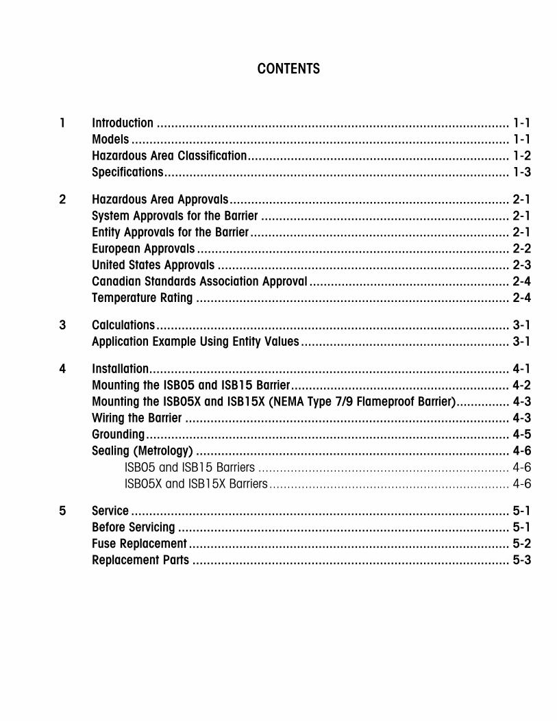
CONTENTS
1 Introduction .................................................................................................. 1-1 Models ......................................................................................................... 1-1 Hazardous Area Classification......................................................................... 1-2 Specifications................................................................................................ 1-3
2 Hazardous Area Approvals.............................................................................. 2-1 System Approvals for the Barrier ..................................................................... 2-1 Entity Approvals for the Barrier ........................................................................ 2-1 European Approvals ....................................................................................... 2-2 United States Approvals ................................................................................. 2-3 Canadian Standards Association Approval ........................................................ 2-4 Temperature Rating ....................................................................................... 2-4
3 Calculations.................................................................................................. 3-1 Application Example Using Entity Values .......................................................... 3-1
4 Installation.................................................................................................... 4-1 Mounting the ISB05 and ISB15 Barrier............................................................. 4-2 Mounting the ISB05X and ISB15X (NEMA Type 7/9 Flameproof Barrier)............... 4-3 Wiring the Barrier .......................................................................................... 4-3 Grounding..................................................................................................... 4-5 Sealing (Metrology) ....................................................................................... 4-6
ISB05 and ISB15 Barriers ...................................................................... 4-6 ISB05X and ISB15X Barriers................................................................... 4-6
5 Service ......................................................................................................... 5-1 Before Servicing ............................................................................................ 5-1 Fuse Replacement ......................................................................................... 5-2 Replacement Parts ........................................................................................ 5-3
6 Control Drawings and Approval Certificates ...................................................... 6-1
CE Declaration of Conformity (Europe) ..................................................................................6-1 KEMA Approval (Europe) ......................................................................................................6-3 FM Approval (USA) ..............................................................................................................6-9 OIML Approval (Europe) .....................................................................................................6-14 NTEP Approval (USA) .........................................................................................................6-15
Chapter 1: Introduction Models
(7/01)
1-1
1 Introduction
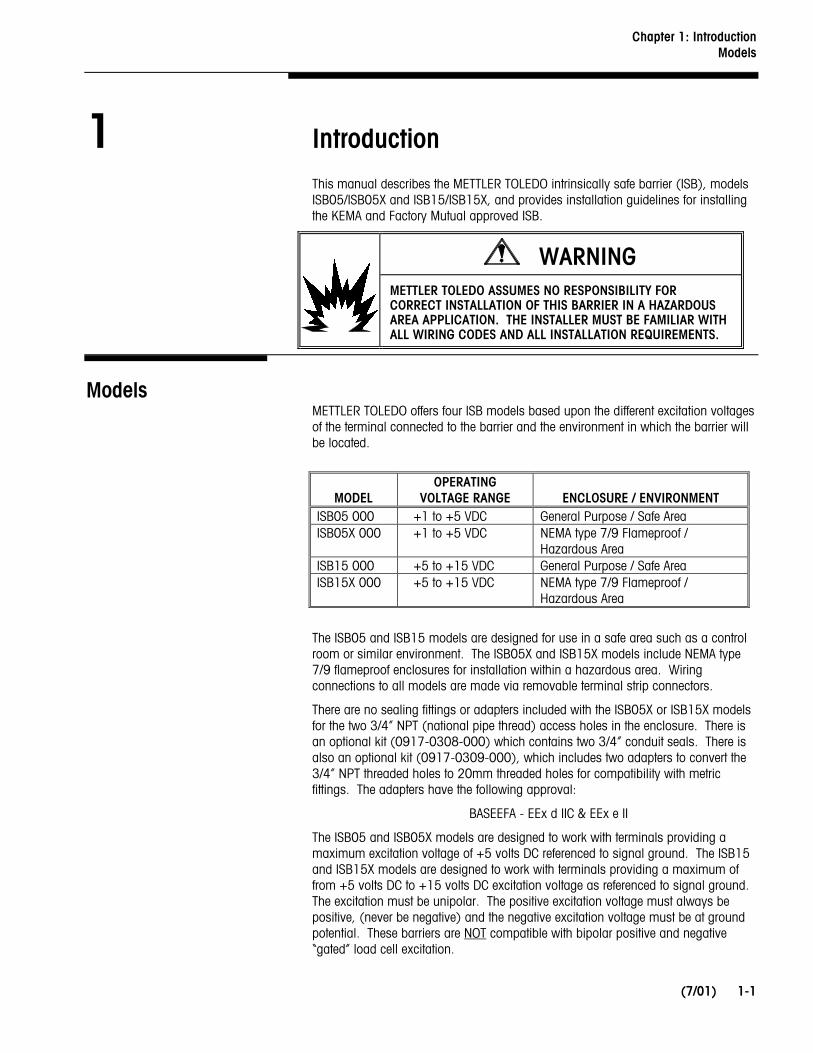
This manual describes the METTLER TOLEDO intrinsically safe barrier (ISB), models ISB05/ISB05X and ISB15/ISB15X, and provides installation guidelines for installing the KEMA and Factory Mutual approved ISB.
WARNING
METTLER TOLEDO ASSUMES NO RESPONSIBILITY FOR CORRECT INSTALLATION OF THIS BARRIER IN A HAZARDOUS AREA APPLICATION. THE INSTALLER MUST BE FAMILIAR WITH ALL WIRING CODES AND ALL INSTALLATION REQUIREMENTS.
Models METTLER TOLEDO offers four ISB models based upon the different excitation voltages of the terminal connected to the barrier and the environment in which the barrier will be located.
MODEL
OPERATING VOLTAGE RANGE
ENCLOSURE / ENVIRONMENT
ISB05 000 +1 to +5 VDC General Purpose / Safe Area ISB05X 000 +1 to +5 VDC NEMA type 7/9 Flameproof /
Hazardous Area ISB15 000 +5 to +15 VDC General Purpose / Safe Area ISB15X 000 +5 to +15 VDC NEMA type 7/9 Flameproof /
Hazardous Area
The ISB05 and ISB15 models are designed for use in a safe area such as a control room or similar environment. The ISB05X and ISB15X models include NEMA type 7/9 flameproof enclosures for installation within a hazardous area. Wiring connections to all models are made via removable terminal strip connectors.
There are no sealing fittings or adapters included with the ISB05X or ISB15X models for the two 3/4” NPT (national pipe thread) access holes in the enclosure. There is an optional kit (0917-0308-000) which contains two 3/4” conduit seals. There is also an optional kit (0917-0309-000), which includes two adapters to convert the 3/4” NPT threaded holes to 20mm threaded holes for compatibility with metric fittings. The adapters have the following approval:
BASEEFA - EEx d IIC & EEx e II
The ISB05 and ISB05X models are designed to work with terminals providing a maximum excitation voltage of +5 volts DC referenced to signal ground. The ISB15 and ISB15X models are designed to work with terminals providing a maximum of from +5 volts DC to +15 volts DC excitation voltage as referenced to signal ground. The excitation must be unipolar. The positive excitation voltage must always be positive, (never be negative) and the negative excitation voltage must be at ground potential. These barriers are NOT compatible with bipolar positive and negative “gated” load cell excitation.
METTLER TOLEDO ISB Technical Manual
(7/01) 1-2
WARNING
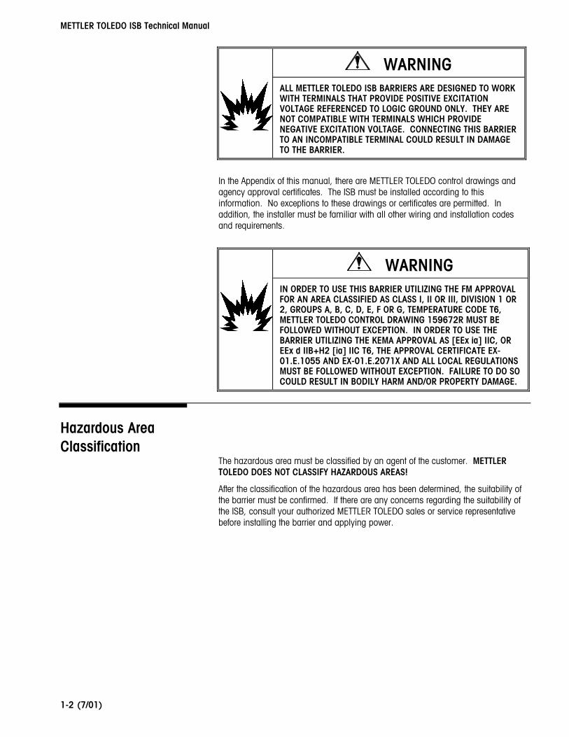
ALL METTLER TOLEDO ISB BARRIERS ARE DESIGNED TO WORK WITH TERMINALS THAT PROVIDE POSITIVE EXCITATION VOLTAGE REFERENCED TO LOGIC GROUND ONLY. THEY ARE NOT COMPATIBLE WITH TERMINALS WHICH PROVIDE NEGATIVE EXCITATION VOLTAGE. CONNECTING THIS BARRIER TO AN INCOMPATIBLE TERMINAL COULD RESULT IN DAMAGE TO THE BARRIER.
In the Appendix of this manual, there are METTLER TOLEDO control drawings and agency approval certificates. The ISB must be installed according to this information. No exceptions to these drawings or certificates are permitted. In addition, the installer must be familiar with all other wiring and installation codes and requirements.
WARNING
IN ORDER TO USE THIS BARRIER UTILIZING THE FM APPROVAL FOR AN AREA CLASSIFIED AS CLASS I, II OR III, DIVISION 1 OR 2, GROUPS A, B, C, D, E, F OR G, TEMPERATURE CODE T6, METTLER TOLEDO CONTROL DRAWING 159672R MUST BE FOLLOWED WITHOUT EXCEPTION. IN ORDER TO USE THE BARRIER UTILIZING THE KEMA APPROVAL AS [EEx ia] IIC, OR EEx d IIB+H2 [ia] IIC T6, THE APPROVAL CERTIFICATE EX-01.E.1055 AND EX-01.E.2071X AND ALL LOCAL REGULATIONS MUST BE FOLLOWED WITHOUT EXCEPTION. FAILURE TO DO SO COULD RESULT IN BODILY HARM AND/OR PROPERTY DAMAGE.
Hazardous Area Classification
The hazardous area must be classified by an agent of the customer. METTLER TOLEDO DOES NOT CLASSIFY HAZARDOUS AREAS!
After the classification of the hazardous area has been determined, the suitability of the barrier must be confirmed. If there are any concerns regarding the suitability of the ISB, consult your authorized METTLER TOLEDO sales or service representative before installing the barrier and applying power.

Chapter 1: Introduction Specifications
(7/01)
1-3
Specifications
ISB05 ISB15 ISB05X ISB15X Physical Dimensions (W x D x H)
4.3 x 4.4 X 1.4 in (110 x 115 x 35 mm)
5.8 x 7.6 x 5.6 in (150 x 195 x 140 mm)
Weight 0.8 lb (0.37 kg) 7.5 lb (3.4 kg) Construction Covers are ABS plastic Cast aluminum alloy containing not
more than 6% magnesium by weight Mounting Directly to NS35 DIN rail (including
locking lever) or surface mount using four #6 or M4
screws.
Surface mount using two 5/16” or M8 bolts
Hazardous Area Approvals FM - JI #3010967 KEMA No. Ex-01.E.1055
CSA - Application Submitted
FM - JI #3010967 KEMA No. Ex-01.E.2071X
CSA - Application Submitted Metrology Approvals NTEP – Approval Pending
NMi - As Instrument Peripheral Canada - Application Submitted
Environment Dry, non-hazardous areas only Washdown, within hazardous areas Operating Voltages +1 to +5 VDC +5 to +15 VDC +1 to +5 VDC +5 to +15 VDC Replaceable Fuses Yes - special 125 mA cartridge type
Qty. 6 on ISB05 and qty. 1 on ISB15 Operating Temperature 14˚ to 104˚ F (-10˚ to 40˚ C) Storage Temperature -4˚ to 140˚ F (-20˚ to 60˚ C) Non-IS Screw Terminal Wire Size #24 - 12 AWG (0.2 - 2.5mm2) IS Screw Terminal Wire Size #28 - 16 AWG (0.14 - 1.5mm2) Grounding Method and Terminal Wire Size
Nickel plated brass lug on PCB - #12 AWG (2.5 mm2) max
Nickel plated brass lug on PCB - #12 AWG (2.5 mm2) max and #10
grounding screw external to enclosure Shipping Weight 2.1 lb (0.95 kg) 9.6 lb (4.4 kg) Shipping Dimensions (W x D x H)
10.3 x 12.5 X 5.3 in (260 x 320 x 135 mm)
16.1 x 13.3 x 10 in (410 x 340 x 255 mm)
METTLER TOLEDO ISB Technical Manual
(7/01) 1-4
NOTES
Chapter 2: Hazardous Area Approvals System Approvals for the Barrier
(7/01)
2-1
2 Hazardous Area Approvals
The ISB05 and ISB15 models have been designed to be mounted in a safe area such as a control room or similar environment. If the ISB is to be installed within a hazardous area, the ISB05X or ISB15X models (NEMA type 7/9 flame-proof enclosure version) must be used.
WARNING
TO USE THIS BARRIER UTILIZING THE FM APPROVAL FOR AN AREA CLASSIFIED AS CLASS I, II OR III, DIVISION 1 OR 2, GROUPS A, B, C, D, E, F OR G, TEMPERATURE CODE T6, METTLER TOLEDO CONTROL DRAWING 159672R MUST BE FOLLOWED WITHOUT EXCEPTION. TO USE THE BARRIER UTILIZING THE KEMA APPROVAL AS [EEx ia] IIC, OR EEx d IIB+H2 [ia] IIC T6, THE APPROVAL CERTIFICATE EX-01.E.1055 AND EX-01.E.2071X AND ALL LOCAL REGULATIONS MUST BE FOLLOWED WITHOUT EXCEPTION. FAILURE TO DO SO COULD RESULT IN BODILY HARM AND/OR PROPERTY DAMAGE.
System Approvals for the Barrier
Depending upon the base or load cells used with the ISB and the geographic location, safety approvals may be based upon a “system” approval. A “system” approval evaluates the combination of certain load cells with the barrier as a complete system instead of evaluating each part individually. A control drawing listing the load cells that are approved for use with the barrier is then created. Any of the load cells on the control drawing may then be used with the barrier in an approved system. In order to properly apply the ISB using the system approval, certain guidelines must be followed. These guidelines will be listed on either the control drawing of the barrier or the control drawing listing the load cells. Specifics for any “system” approval for the ISB will be described in the following approval agency sections of this manual.
Entity Approvals for the Barrier
Depending upon the base or load cells used with the ISB and the geographic location, safety approvals may be based upon an entity parameter approval. This type of approval permits the application of individually approved components (even from various manufacturers) to be used together to build a solution which is approved. Applying the ISB using entity values requires comparison of the approval values from the different components.
METTLER TOLEDO ISB Technical Manual
(7/01) 2-2
In order to properly apply the barrier using entity parameters, a comparison must be made between the entity parameters of the barrier and the entity values of the load cells including all connecting cables. These entity parameters include voltage, current, power, capacitance and inductance. The barrier and load cells (including connecting cables) must compare as follows in order for the wiring to be considered intrinsically safe:
Vmax or UI (Maximum voltage permitted) ≥ Vt or Uo (Total voltage output)
Imax or II (Maximum current permitted) ≥ It or Io (Total current output)
Pmax or PI (Maximum power permitted) ≥ Pt or Po (Total power output)
Ci (Unprot. capacitance) + Ccable (Cable capacitance) ≤ Ca or Co (Allowable capacitance)
Li (Unprotected inductance) + Lcable (Cable inductance) ≤ La or Lo (Allowable inductance)
The descriptions for the entity parameters associated with the ISB are underlined in the above formulas. The other parameters are related to the base, load cells or the connecting cable.
If the above conditions are not true, then the circuit will not be intrinsically safe and must not be installed in a hazardous area. If the parameters compare favorably as shown above, then the circuit is intrinsically safe and can be installed in a hazardous area. Always refer to the electrical regulations for the country of installation for specific wiring requirements.
European Approvals
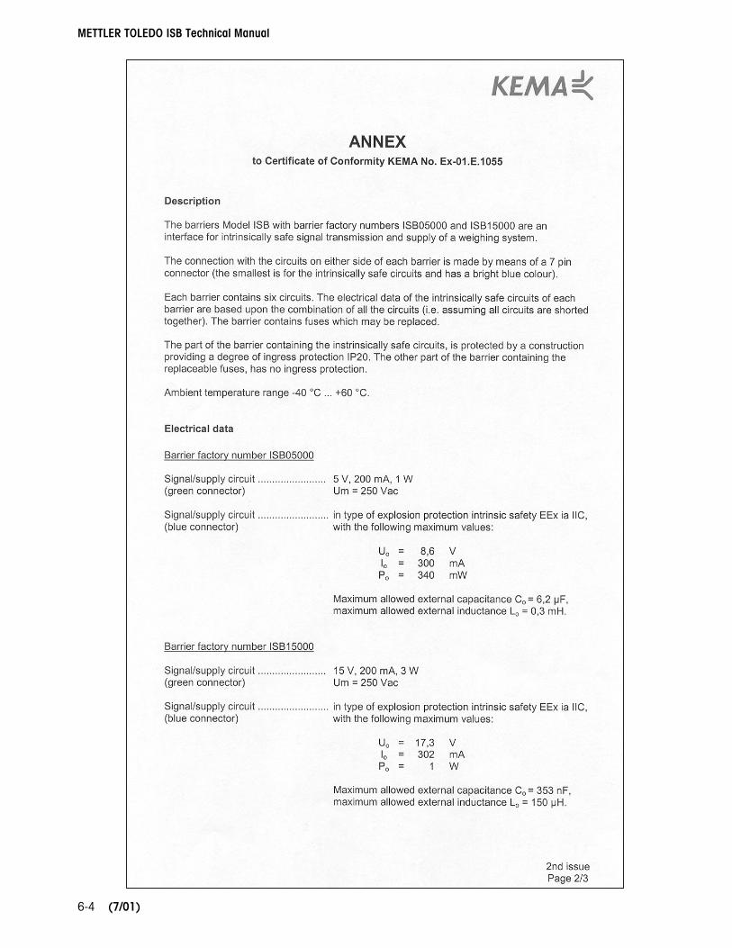
The European safety approvals for the ISB are based upon entity values. The system approval is not applicable for this product in European countries. The ISB05 and ISB15 barriers were submitted to KEMA for compliance to CENELEC standards EN 50014 and EN 50020. The ISB05X and ISB15X barriers were submitted for compliance to EN50014 and EN 50018. They were approved as intrinsically safe devices and issued the following certificates:
ISB05 & ISB15 - KEMA Ex-01.E.1055 as [EEx ia] IIC
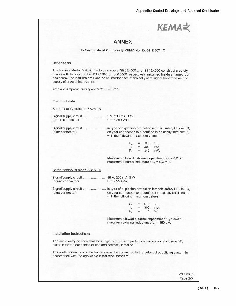
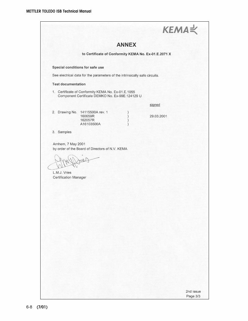
ISB05X & ISB15X - KEMA Ex-01.E.2071X as EEx d IIB+H2 [ia] IIC T6
A copy of the approval certificates may be found in the Appendix of this manual.
The following chart lists the entity values for all ISB models. Be sure to use the values for the correct barrier when making the calculations described above.
ISB Barrier Entity Values for KEMA Approval ISB05 & ISB05X ISB15 & ISB15X Uo (Total voltage output) 8.6 VDC 17.3 VDC Io (Total current output) 300 mA 302 mA Po (Total power output) 340 mW 1 W Co (Allowable capacitance) 6.2 uF 0.353 uF Lo (Allowable inductance) 0.3 mH 0.15 mH
Chapter 2: Hazardous Area Approvals United States Approvals
(7/01)
2-3
United States Approvals
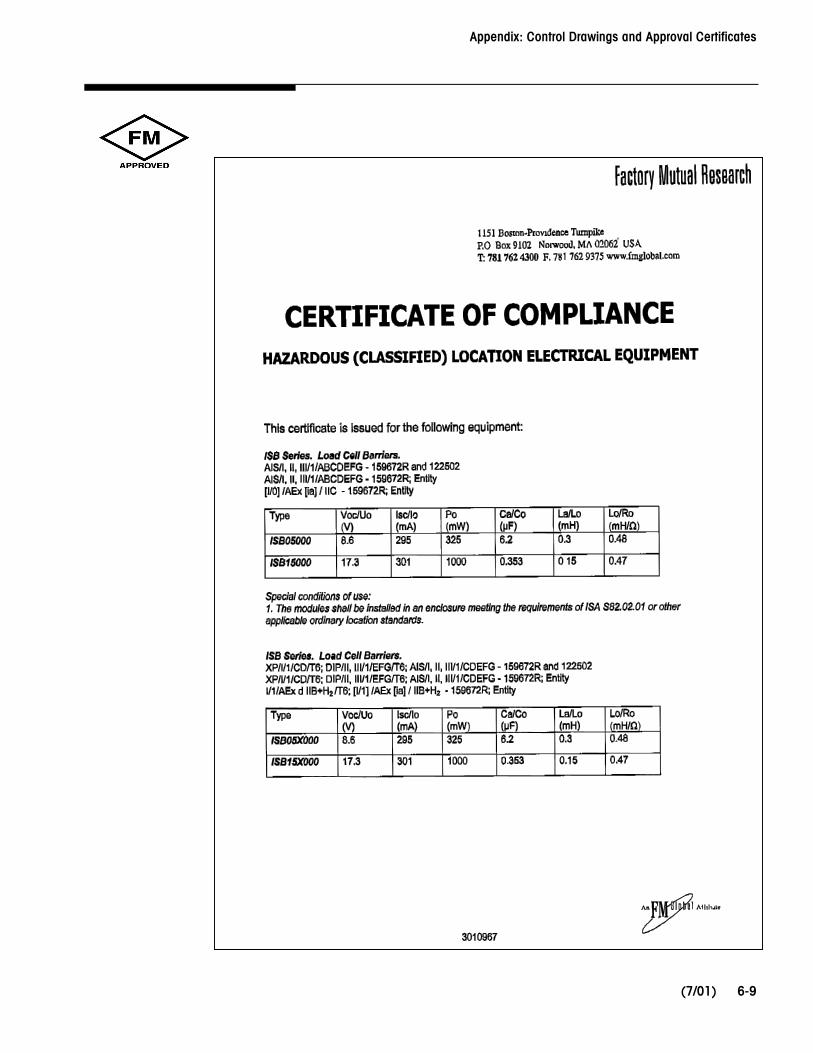
The U.S. safety approvals for the ISB are based on both entity values and a “system” approval. Newer products utilize entity approval. Older existing products use the system approval. Reports on the ISB were submitted to Factory Mutual for compliance to FM Approval Standards Class No. 3600, 3610, 3615 and 3810. They must be installed per ANSI/ISA standards S82.01-1994 and S82.03-1998. They were approved as intrinsically safe devices and issued a certificate of compliance using FM Original Approval Job Identification #3010967.
ISB05000 and ISB15000
AIS/I,II,III/1/ABCDEFG - 159672R and 122502
AIS/I,II,III/1/ABCDEFG - 159672R; Entity
[I/0] /AEx [ia] / IIC - 159672R: Entity
ISB05X000 and ISB15X000
XP/I/1/CD/T6; DIP/II,III/1/EFG/T6; AIS/I,II,III/1/CDEFG - 159672R and 122502
XP/I/1/CD/T6; DIP/II,III/1/EFG/T6; AIS/I,II,III/1/CDEFG - 159672R; Entity
I/1/AEx d IIB+H2 /T6; [I/1]/AEx [ia] / IIB+H2 - 159672R: Entity
When using the system approval of the ISB from Factory Mutual, the load cells used must be listed on METTLER TOLEDO control drawing 122502R. A copy of the control drawing and agency approval certificates are found in the Appendix of this manual.
The following chart lists the Factory Mutual entity values for the ISB barriers. Be sure to use the values for the correct barrier when making the calculations described in the section above “Entity Approvals for the Barrier”.
ISB Barrier Entity Values for Factory Mutual Approval ISB05 & ISB05X ISB15 & ISB15X Vt (Total voltage output) 8.6 VDC 17.3 VDC It (Total current output) 295 mA 301 mA Pt (Total power output) 325 mW 1 W Ca (Allowable capacitance) 6.2 uF 0.353 uF La (Allowable inductance) 0.3 mH 0.15 mH Lo/Ro (Inductance/ohm ratio) 0.48 (mH / ohm) 0.47 (mH / ohm)
METTLER TOLEDO ISB Technical Manual
(7/01) 2-4
Canadian Standards Association Approval
The Canadian safety approvals for the ISB will be based upon both entity values and “system” approval. Current METTLER TOLEDO products utilize the system approval while the entity approval permits use of the barrier with other manufacturers’ load cells. Reports on the ISB05 and ISB15 barriers were submitted to CSA for compliance to Canadian standards C22.2 No 157-92 and No. 213-M1987. In addition, reports on the ISB05X and ISB15X barriers were submitted for compliance to C22.2 No. 30M1986. At this time, CSA has not issued a Certificate of Compliance.
Temperature Rating It is very important that the temperature rating of the ISB.X models be appropriate for the environment in which they will be used. The ISB.X barriers have been approved by FM and KEMA with a temperature rating of T6. This indicates that the maximum surface temperature of the NEMA type 7/9 flame-proof enclosure for the barrier will not exceed 85°C (185°F). This value must be lower than the Auto Ignition Temperature (AIT) of the hazardous environment in order to be safe. If the AIT of the hazardous environment is lower than the T6 rating of the barrier, the barrier MUST NOT BE USED in that environment.
WARNING
THE ISB05X AND ISB15X BARRIERS HAVE A TEMPERATURE RATING OF T6 (85°C / 185˚ F). THEY MUST NOT BE USED IN AREAS WHERE THE AUTO IGNITION TEMPERATURE OF THE HAZARDOUS ENVIRONMENT IS BELOW THIS RATING.
Chapter 3: Calculations Application Example Using Entity Values
(7/01)
3-1
3 Calculations
To properly apply an ISB using its entity approval, five simple calculations must be completed. Some older approvals do not list the “power” entity value. In these cases, only four calculations are required. Examples of these calculations are given in this chapter. If you have any questions regarding these calculations, DO NOT complete the installation until the questions have been resolved. Please contact your METTLER TOLEDO representative for assistance.
Application Example Using Entity Values
The following is an example of applying a LYNX® terminal, an ISB15X, a model 2158 VERTEX® floor scale and 50 feet (15.2 meters) of load cell cable in a Division 1 application. For this example, the customer required a Factory Mutual approval so the FM entity values were used. The FM approved entity parameters for all devices and cables in the load cell line (including the load cells and junction box) must be known. They can be found by reviewing the control drawings of the specific equipment.
Terminal model: LYNX (Model LTHA 1000 000)
Barrier model: ISB15X 000
Base model: VERTEX (Model 2158 002024-A)
Load cell model: METTLER TOLEDO 0745A (Division 1 entity approved)
Quantity of load cells: 4
Load cell cable length: 50 feet (15.2 meters)
Junction box PCB p/n: 13640300A
Area Classification: U.S.A. - Division 1, Class I, Group D, AIT 255˚C
Since the LYNX terminal will be installed in the safe area, the only concern regarding it is matching the excitation voltage of the LYNX terminal to the proper barrier. By reviewing the LYNX technical manual and sales literature, it is determined that the standard LYNX terminal (LTHA 1000) uses 15 volts for excitation. The ISB15X is compatible with the 15-volt excitation level from the LYNX terminal so this combination is acceptable.
Next, the location of the barrier must be checked. This installation requires installation of the barrier inside the hazardous area so the barrier model number must be confirmed. The model ISB15X barrier is in a NEMA Type 7/9 enclosure which is rated for the Division 1, Class I, Group D area. The AIT of the hazard is 255˚C which is above the T6 rating of the ISB15X. These two checks indicate the ISB15x barrier is acceptable for installation inside the hazardous area with the LYNX terminal in the safe area.
METTLER TOLEDO ISB Technical Manual
(7/01) 3-2
Next, the barrier’s entity parameters must be listed and compared to the entity parameters of the load cells used in the VERTEX floor scale. The ISB15X FM entity parameters (from control drawing 159672R) are:
Vt = 17.3 VDC It = 301 mA Pt = 1 W Ca = 353 nF La = 150 uH
Load cell entity values from model 745A load cell control drawing 158574R:
Vmax = 25 VDC Imax = 600 mA Pi = 1.25 W Ci = 0 µF Li = 29 µH T-rating = T4
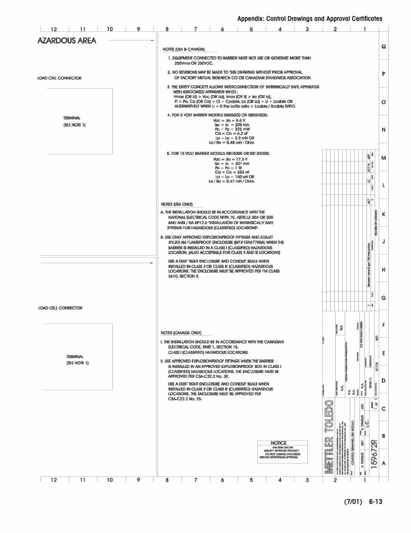
Load cell cable default values from the ISB control drawing 159672R:
Ccable = 60 pF / foot Lcable = 0.2 µH / foot
The 2158 floor scale junction box PCB was determined to not have significant capacitance or inductance impact. Values shown below should be used.
Ci = 0 pF Li = 0 µH
Chapter 3: Calculations Application Example Using Entity Values
(7/01)
3-3
Now, compare these values using the entity parameter formulas provided in the previous chapter and determine if all five criteria pass or fail. Note that the entity values for capacitance (but not the inductance) of the load cell must be multiplied by the quantity of load cells used. Also note that the entity values for the load cell cable must be multiplied by the total load cell cable length.
Formula Pass or Fail
Vmax must be ≥ Vt
25 VDC ≥ 17.3 VDC PASS
Imax must be ≥ It
600 mA ≥ 301 mA PASS
Pi must be ≥ Pt
1.25 W ≥ 1 W PASS
Ci + Ccable ≤ Ca
Ci = 0 µF * 4 cells = 0 µF (load cells)
Ci = 0 µF (junction box)
Ccable = 60 pF / foot * 50 feet = 3000 pF = 3 nF
(0 µF + 0 µF + 3 nF) ≤ 353 nF PASS
Li + Lcable ≤ La
Li = 29 µH (largest inductance value from one load cell used)
Li = 0 µH (junction box)
Lcable = 0.2 µH / foot * 50 feet = 10 µH
(29 µH + 0 µH + 10 µH) ≤ 150 uH PASS
Since all five entity values compare favorably and pass the formula evaluation, the products listed in this example may be safely connected in the application. They must be installed according to the Factory Mutual control drawing 159672R using all pertinent local and national standards.
Finally, the temperature rating of the load cells must be checked for suitability in the hazardous environment. The model 745A load cell is rated as T4 which has a temperature value of 135˚C (275˚F). The AIT of the hazard is 255˚C which is above the T4 rating of the cells. This check indicates the load cells are acceptable for installation inside the hazardous area as part of the solution.
METTLER TOLEDO ISB Technical Manual
(7/01) 3-4
NOTES
Chapter 4: Installation Installation Warnings
(7/01)
4-1
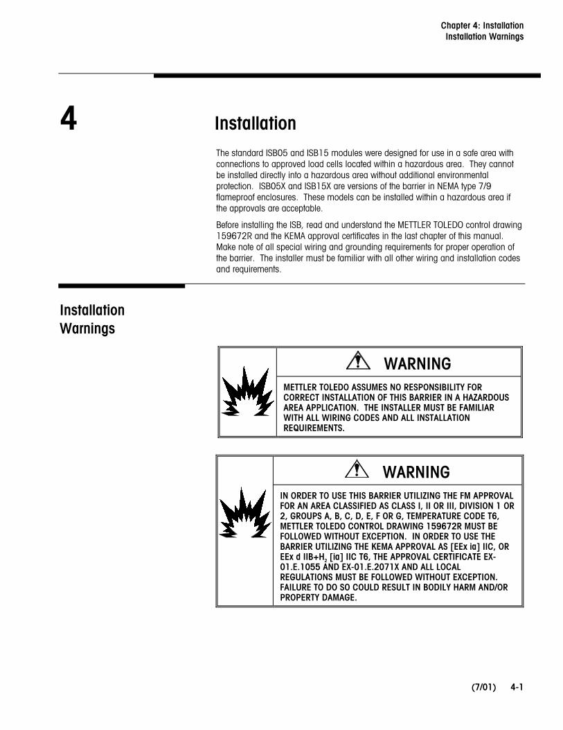
4 Installation
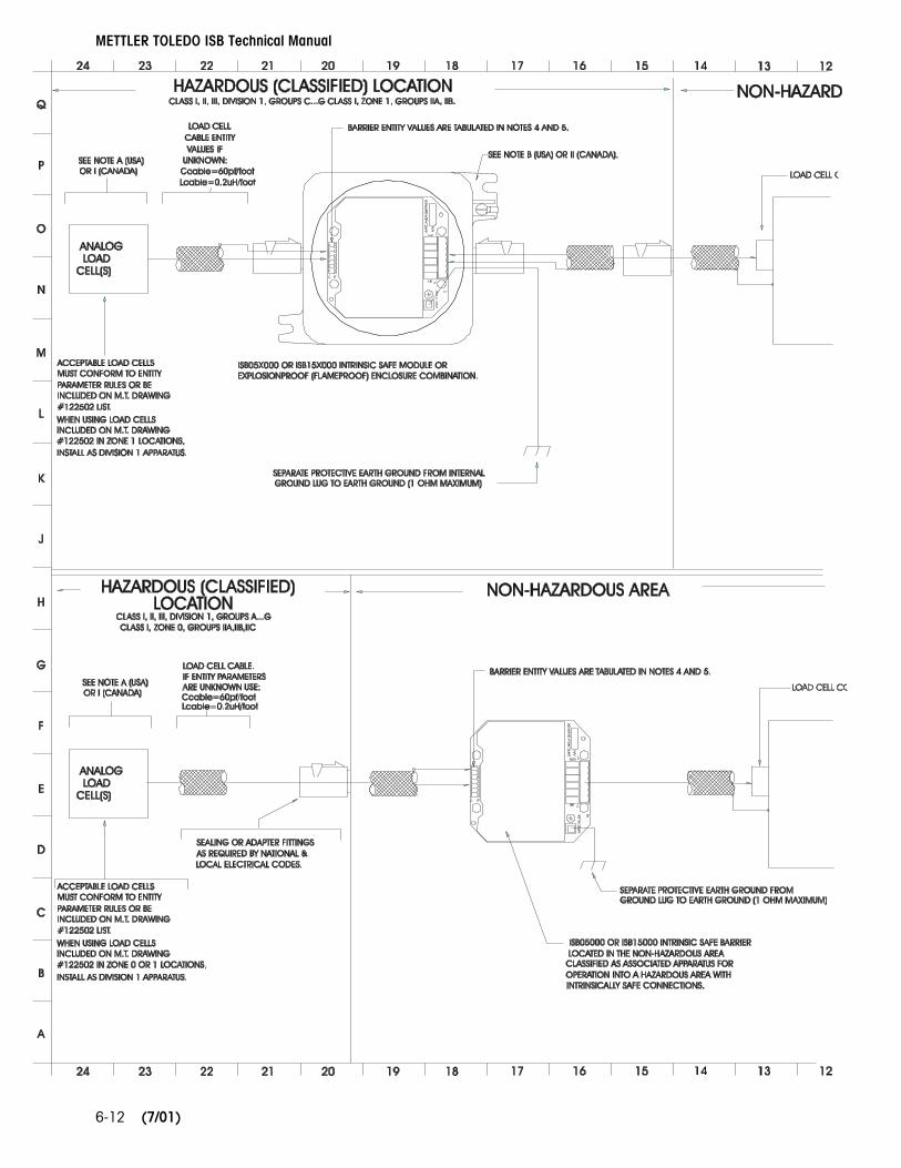
The standard ISB05 and ISB15 modules were designed for use in a safe area with connections to approved load cells located within a hazardous area. They cannot be installed directly into a hazardous area without additional environmental protection. ISB05X and ISB15X are versions of the barrier in NEMA type 7/9 flameproof enclosures. These models can be installed within a hazardous area if the approvals are acceptable.
Before installing the ISB, read and understand the METTLER TOLEDO control drawing 159672R and the KEMA approval certificates in the last chapter of this manual. Make note of all special wiring and grounding requirements for proper operation of the barrier. The installer must be familiar with all other wiring and installation codes and requirements.
Installation Warnings
WARNING METTLER TOLEDO ASSUMES NO RESPONSIBILITY FOR CORRECT INSTALLATION OF THIS BARRIER IN A HAZARDOUS AREA APPLICATION. THE INSTALLER MUST BE FAMILIAR WITH ALL WIRING CODES AND ALL INSTALLATION REQUIREMENTS.
WARNING
IN ORDER TO USE THIS BARRIER UTILIZING THE FM APPROVAL FOR AN AREA CLASSIFIED AS CLASS I, II OR III, DIVISION 1 OR 2, GROUPS A, B, C, D, E, F OR G, TEMPERATURE CODE T6, METTLER TOLEDO CONTROL DRAWING 159672R MUST BE FOLLOWED WITHOUT EXCEPTION. IN ORDER TO USE THE BARRIER UTILIZING THE KEMA APPROVAL AS [EEx ia] IIC, OR EEx d IIB+H2 [ia] IIC T6, THE APPROVAL CERTIFICATE EX-01.E.1055 AND EX-01.E.2071X AND ALL LOCAL REGULATIONS MUST BE FOLLOWED WITHOUT EXCEPTION. FAILURE TO DO SO COULD RESULT IN BODILY HARM AND/OR PROPERTY DAMAGE.
METTLER TOLEDO ISB Technical Manual
(7/01) 4-2
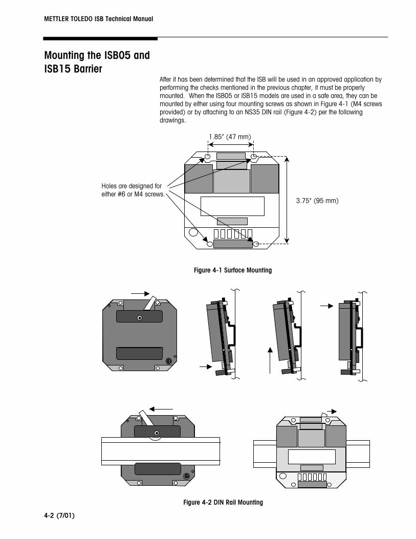
Mounting the ISB05 and ISB15 Barrier
After it has been determined that the ISB will be used in an approved application by performing the checks mentioned in the previous chapter, it must be properly mounted. When the ISB05 or ISB15 models are used in a safe area, they can be mounted by either using four mounting screws as shown in Figure 4-1 (M4 screws provided) or by attaching to an NS35 DIN rail (Figure 4-2) per the following drawings.
Holes are designed for either #6 or M4 screws.
1.85” (47 mm)
Figure 4-1 Surface Mounting
Figure 4-2 DIN Rail Mounting
3.75" (95 mm)
Chapter 4: Installation Mounting the ISB05X and ISB15X (NEMA Type 7/9 Flameproof Barrier)
(7/01)
4-3
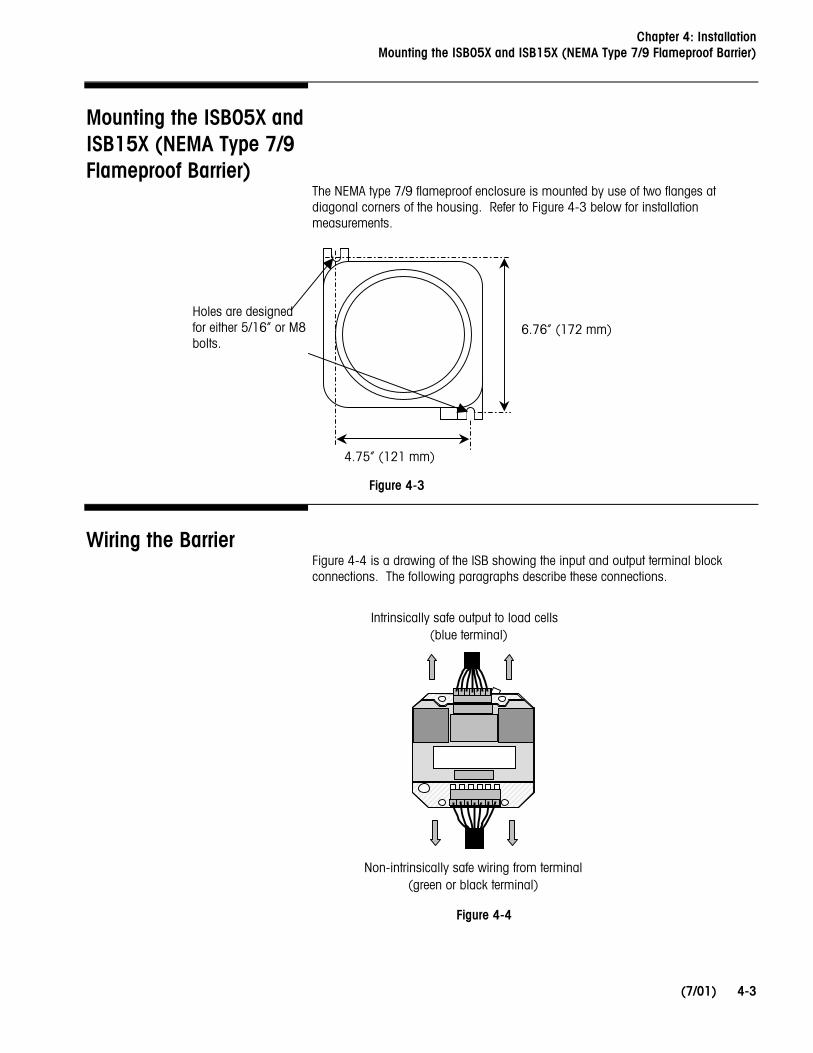
Mounting the ISB05X and ISB15X (NEMA Type 7/9 Flameproof Barrier)
The NEMA type 7/9 flameproof enclosure is mounted by use of two flanges at diagonal corners of the housing. Refer to Figure 4-3 below for installation measurements.
Wiring the Barrier Figure 4-4 is a drawing of the ISB showing the input and output terminal block connections. The following paragraphs describe these connections.
Intrinsically safe output to load cells (blue terminal)
Non-intrinsically safe wiring from terminal (green or black terminal)
Figure 4-3
Figure 4-4
Holes are designed for either 5/16” or M8 bolts.
6.76” (172 mm)
4.75” (121 mm)
METTLER TOLEDO ISB Technical Manual
(7/01) 4-4
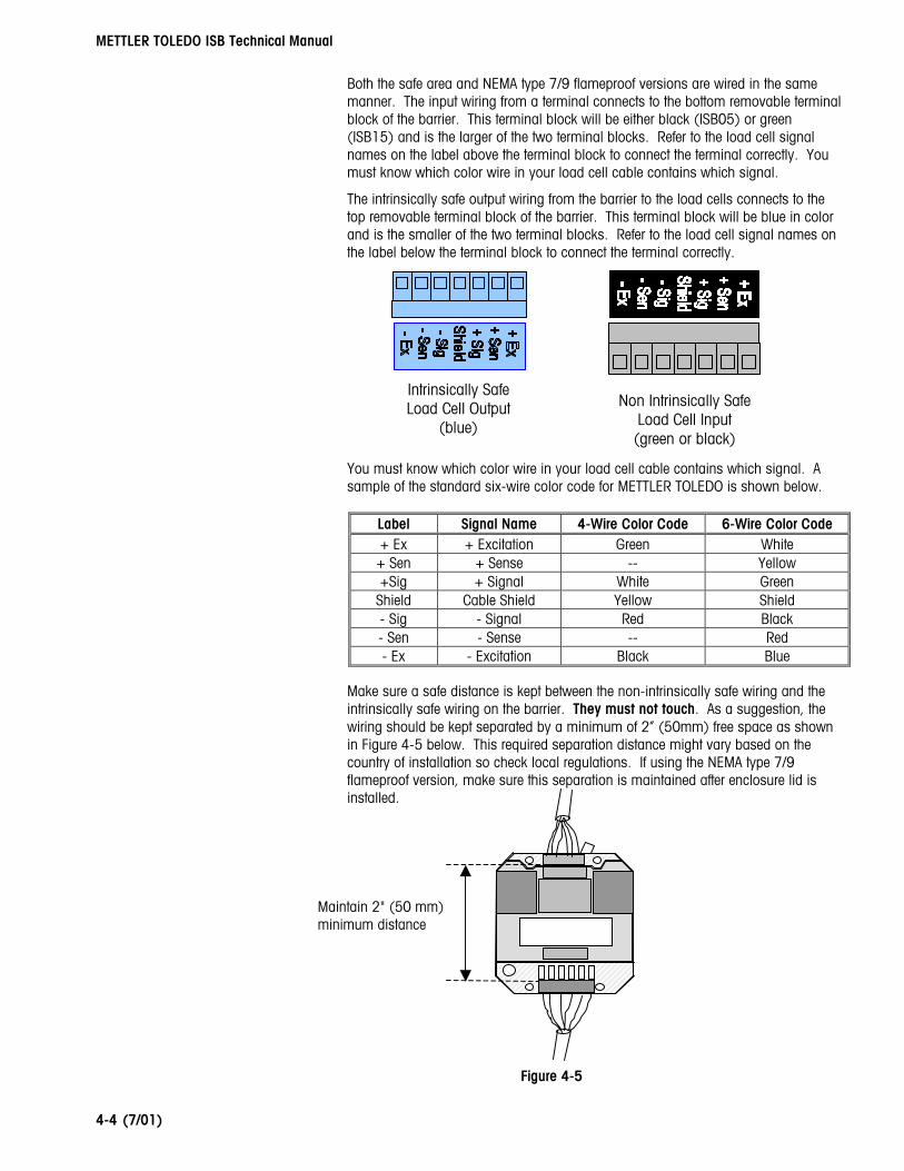
Both the safe area and NEMA type 7/9 flameproof versions are wired in the same manner. The input wiring from a terminal connects to the bottom removable terminal block of the barrier. This terminal block will be either black (ISB05) or green (ISB15) and is the larger of the two terminal blocks. Refer to the load cell signal names on the label above the terminal block to connect the terminal correctly. You must know which color wire in your load cell cable contains which signal.
The intrinsically safe output wiring from the barrier to the load cells connects to the top removable terminal block of the barrier. This terminal block will be blue in color and is the smaller of the two terminal blocks. Refer to the load cell signal names on the label below the terminal block to connect the terminal correctly.
You must know which color wire in your load cell cable contains which signal. A sample of the standard six-wire color code for METTLER TOLEDO is shown below.
Label Signal Name 4-Wire Color Code 6-Wire Color Code + Ex + Excitation Green White + Sen + Sense -- Yellow +Sig + Signal White Green
Shield Cable Shield Yellow Shield - Sig - Signal Red Black - Sen - Sense -- Red - Ex - Excitation Black Blue
Make sure a safe distance is kept between the non-intrinsically safe wiring and the intrinsically safe wiring on the barrier. They must not touch. As a suggestion, the wiring should be kept separated by a minimum of 2” (50mm) free space as shown in Figure 4-5 below. This required separation distance might vary based on the country of installation so check local regulations. If using the NEMA type 7/9 flameproof version, make sure this separation is maintained after enclosure lid is installed.
igure 4-5
Maintain 2" (50 mm) minimum distance
Intrinsically Safe Load Cell Output
(blue)
Non Intrinsically Safe Load Cell Input (green or black)
F
Chapter 4: Installation Grounding
(7/01)
4-5
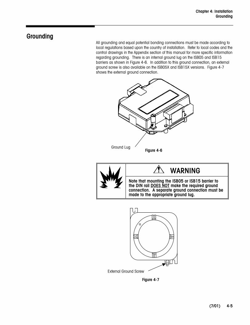
Grounding All grounding and equal potential bonding connections must be made according to local regulations based upon the country of installation. Refer to local codes and the control drawings in the Appendix section of this manual for more specific information regarding grounding. There is an internal ground lug on the ISB05 and ISB15 barriers as shown in Figure 4-6. In addition to this ground connection, an external ground screw is also available on the ISB05X and ISB15X versions. Figure 4-7 shows the external ground connection.
WARNING Note that mounting the ISB05 or ISB15 barrier to the DIN rail DOES NOT make the required ground connection. A separate ground connection must be made to the appropriate ground lug.
Figure 4-6
Figure 4-7
Ground Lug
External Ground Screw

METTLER TOLEDO ISB Technical Manual
(7/01) 4-6
Sealing (Metrology) In certain legal for trade or “approved” applications and geographic locations, there may be regulations which require that the ISB be sealed to prevent tampering. The next two sections describe how to seal both the safe area and NEMA type 7/9 flameproof enclosure versions.
ISB05 and ISB15 Barriers The ISB05 and ISB15 models are sealed using four tamper-proof sealing labels. The labels are METTLER TOLEDO part number B12363300A and they are available through service parts. The labels must be applied as shown in Figure 4-8. Note that there is also a sealing label on the bottom of the opposite side which cannot be seen in the figure below.
ISB05X and ISB15X Barriers The ISB05X and ISB15X models using a single tamper-proof sealiB12363300A) which is availableas shown in Figure 4-9 over the thousing. The set screw must be
Sealing Label Over Set Screw
Fig
Sealing Labels
Figure 4-8
(NEMA type 7/9 flameproof barriers) are sealed ng label (METTLER TOLEDO part number through service parts. The label must be applied op of the set screw that secures the lid to the tightened before applying the label.
Set Screw
ure 4-9
Chapter 5: Service Before Servicing
(7/01)
5-1
5 Service
When an ISB is used as part of an intrinsically safe system, some special service requirements must be understood. This chapter discusses these items. The METTLER TOLEDO control drawing for FM (159672R) and the KEMA approval certificates Ex-01.E.1055 and Ex-01.E.2071X must also be reviewed for any special requirements.
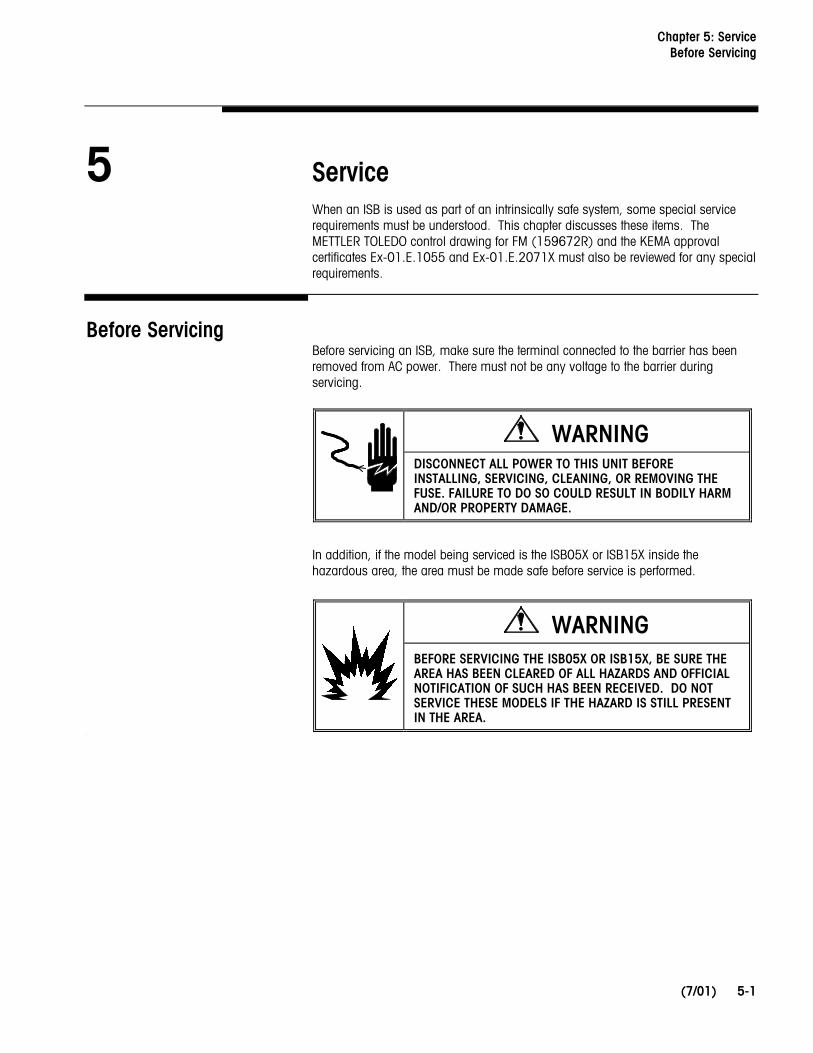
Before Servicing Before servicing an ISB, make sure the terminal connected to the barrier has been removed from AC power. There must not be any voltage to the barrier during servicing.
WARNING DISCONNECT ALL POWER TO THIS UNIT BEFORE INSTALLING, SERVICING, CLEANING, OR REMOVING THE FUSE. FAILURE TO DO SO COULD RESULT IN BODILY HARM AND/OR PROPERTY DAMAGE.
In addition, if the model being serviced is the ISB05X or ISB15X inside the hazardous area, the area must be made safe before service is performed.
WARNING
BEFORE SERVICING THE ISB05X OR ISB15X, BE SURE THE AREA HAS BEEN CLEARED OF ALL HAZARDS AND OFFICIAL NOTIFICATION OF SUCH HAS BEEN RECEIVED. DO NOT SERVICE THESE MODELS IF THE HAZARD IS STILL PRESENT IN THE AREA.
I
METTLER TOLEDO ISB Technical Manual
(7/01) 5-2
Fuse Replacement There are small ceramic fuses on the ISB which are designed to blow should there be an over voltage or over current through the barrier. If you suspect that one of these replaceable fuses has blown, the fuse can be checked with an ohm meter.
Remove the input terminal strip to the barrier (black or green depending upon model) and then measure the resistance from one end of the fuse to the other. Be cautious when checking these fuses as they are only rated for 125mA. If the fuse is open, it must be removed and replaced with a known good fuse.
When replacing a fuse, the correct size pliers or tweezers must be used. If the jaws of the tool are too large, the fuse holder might be damaged requiring replacement of the complete barrier. METTLER TOLEDO recommends using a special tool (part number 16231000A) to remove and replace the fuses.
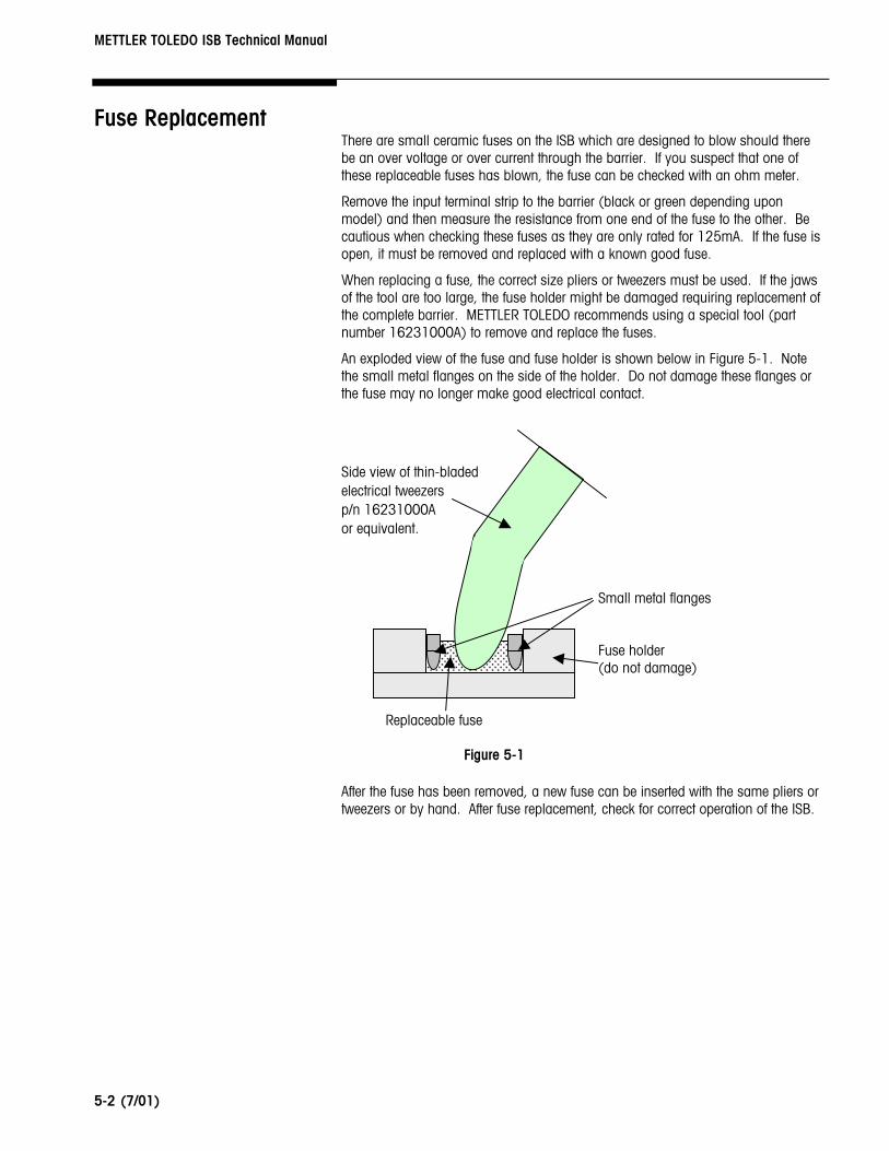
An exploded view of the fuse and fuse holder is shown below in Figure 5-1. Note the small metal flanges on the side of the holder. Do not damage these flanges or the fuse may no longer make good electrical contact.
Side view of thin-bladed electrical tweezers p/n 16231000A or equivalent.
After thetweezers
Small metal flanges Fuse holder (do not damage)
Replaceable fusefuse has been removed, a new fuse can be inserted with the same pliers or or by hand. After fuse replacement, check for correct operation of the ISB.
Figure 5-1
Chapter 5: Service Replacement Parts
(7/01)
5-3
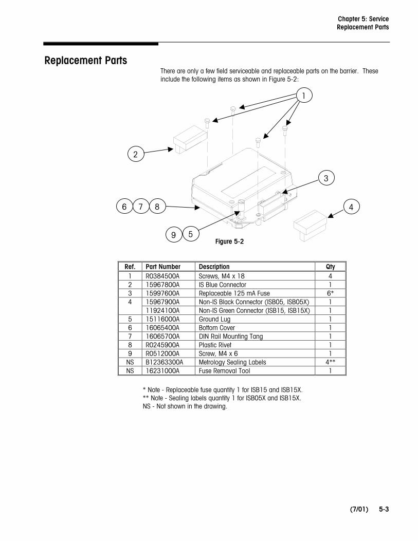
Replacement Parts There are only a few field serviceable and replaceable parts on the barrier. These include the following items as shown in Figure 5-2:
Ref. Part Number Description Qty 1 R0384500A Screws, M4 x 18 4 2 15967800A IS Blue Connector 1 3 15997600A Replaceable 125 mA Fuse 6*
15967900A Non-IS Black Connector (ISB05, ISB05X) 1 4 11924100A Non-IS Green Connector (ISB15, ISB15X) 1
5 15116000A Ground Lug 1 6 16065400A Bottom Cover 1 7 16065700A DIN Rail Mounting Tang 1 8 R0245900A Plastic Rivet 1 9 R0512000A Screw, M4 x 6 1
NS B12363300A Metrology Sealing Labels 4** NS 16231000A Fuse Removal Tool 1
* Note - Replaceable fuse quantity 1 for ISB15 and ISB15X. ** Note - Sealing labels quantity 1 for ISB05X and ISB15X. NS - Not shown in the drawing.
Figure 5-2
1
2
5
4
3
6 7 8
9

METTLER TOLEDO ISB Technical Manual
(7/01) 5-4
NOTES

Appendix: Control Drawings and Approval Certificates European CE Marking
(7/01) 6-1
6 Control Drawings and Approval Certificates
DECLARATION OF CONFORMITY Konformitätserklärung Déclaration de conformité Declaración de Conformidad Conformiteitsverklaring Dichiarazione di conformità
We/Wir/Nous/Wij/Noi: Mettler-Toledo, Inc. 1150 Dearborn Drive Worthington, Ohio 43085 USA declare under our sole responsibility that the product, erklären, in alleiniger Verantwortung, daß dieses Produkt, déclarons sous notre seule responsabilité que le produit, declaramos, bajo nuestra sola responsabilidad, que el producto, verklaren onder onze verantwoordelijkheid, dat het product, dichiariamo sotto nostra unica responsabilitá, che il prodotto, Model/Type: ISB05000 and ISB15000 (Intrinsic Safety Barrier) to which this declaration relates is in conformity with the following standard(s) or other normative document(s). auf das sich diese Erklärung bezieht, mitder/den folgenden Norm(en) oder Richtlinie(n) übereinstimmt. Auquel se réfère cette déclaration est conforme à la (aux) norme(s) ou au(x) document(s) normatif(s). Al que se refiere esta declaración es conforme a la(s) norma(s) u otro(s) documento(s) normativo(s). Waarnaar deze verklaring verwijst, aan de volende norm(en) of richtlijn(en) beantwoordt. A cui si riferisce questa dichiarazione è conforme alla/e sequente/i norma/e o documento/i normativo/i. in combination with an approved and compatible indicator and weighing platform produced by Mettler-Toledo is in conformity with the following directives and standards.
Council directive on the harmonization of the laws of the Member states: standards:
certificate number
(if applicable)
relating to non-automatic weighing instruments (90/384/EEC) Article 1.2.a. amended by directive (93/68/EEC)
EN 45501: 1992/1993
See approved and compatible indicator certificate
relating to electromagnetic compatibility (89/336/EEC) amended by directive (93/68/EEC; 92/31/EEC)
EN 55022-A
relating to electrical apparatus for potentially explosive atmospheres (84/47/EEC)
EN 50014: 1992, General requirements and EN 50020: 1994,
Intrinsic safety "i"
Ex-01.E.1055
(rating: [EEx ia] IIC)
Worthington, Ohio USA, May, 2001 Mettler-Toledo, Inc.
Darrell Flocken, Manager - Weights & Measures Office of Weights and Measures
METTLER TOLEDO ISB Technical Manual
6-2 (7/01)
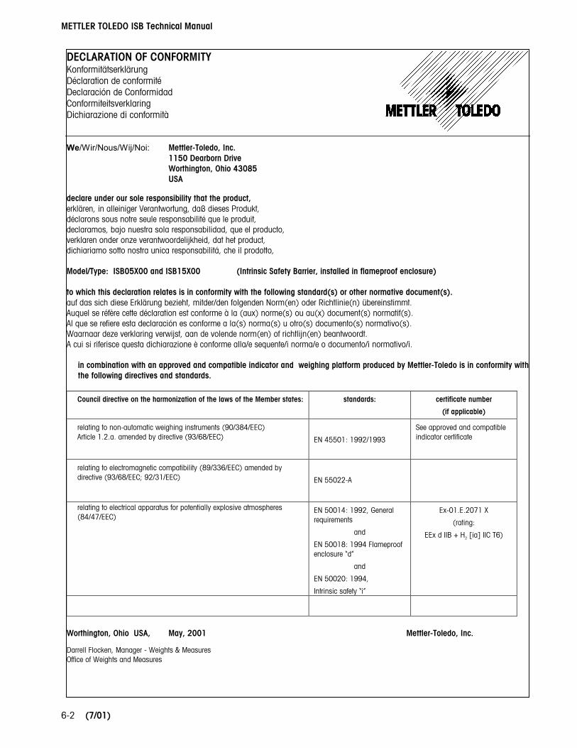
DECLARATION OF CONFORMITY Konformitätserklärung Déclaration de conformité Declaración de Conformidad Conformiteitsverklaring Dichiarazione di conformità
We/Wir/Nous/Wij/Noi: Mettler-Toledo, Inc. 1150 Dearborn Drive Worthington, Ohio 43085 USA declare under our sole responsibility that the product, erklären, in alleiniger Verantwortung, daß dieses Produkt, déclarons sous notre seule responsabilité que le produit, declaramos, bajo nuestra sola responsabilidad, que el producto, verklaren onder onze verantwoordelijkheid, dat het product, dichiariamo sotto nostra unica responsabilitá, che il prodotto, Model/Type: ISB05X00 and ISB15X00 (Intrinsic Safety Barrier, installed in flameproof enclosure) to which this declaration relates is in conformity with the following standard(s) or other normative document(s). auf das sich diese Erklärung bezieht, mitder/den folgenden Norm(en) oder Richtlinie(n) übereinstimmt. Auquel se réfère cette déclaration est conforme à la (aux) norme(s) ou au(x) document(s) normatif(s). Al que se refiere esta declaración es conforme a la(s) norma(s) u otro(s) documento(s) normativo(s). Waarnaar deze verklaring verwijst, aan de volende norm(en) of richtlijn(en) beantwoordt. A cui si riferisce questa dichiarazione è conforme alla/e sequente/i norma/e o documento/i normativo/i.
in combination with an approved and compatible indicator and weighing platform produced by Mettler-Toledo is in conformity with the following directives and standards.
Council directive on the harmonization of the laws of the Member states: standards:
certificate number
(if applicable)
relating to non-automatic weighing instruments (90/384/EEC) Article 1.2.a. amended by directive (93/68/EEC)
EN 45501: 1992/1993
See approved and compatible indicator certificate
relating to electromagnetic compatibility (89/336/EEC) amended by directive (93/68/EEC; 92/31/EEC)
EN 55022-A
relating to electrical apparatus for potentially explosive atmospheres (84/47/EEC)
EN 50014: 1992, General requirements
and
EN 50018: 1994 Flameproof enclosure “d”
and
EN 50020: 1994,
Intrinsic safety “i”
Ex-01.E.2071 X
(rating:
EEx d IIB + H2 [ia] IIC T6)
Worthington, Ohio USA, May, 2001 Mettler-Toledo, Inc.
Darrell Flocken, Manager - Weights & Measures Office of Weights and Measures

Appendix: Control Drawings and Approval Certificates
(7/01)
6-3
METTLER TOLEDO ISB Technical Manual
6-4 (7/01)

Appendix: Control Drawings and Approval Certificates
(7/01)
6-5

METTLER TOLEDO ISB Technical Manual
6-6 (7/01)
Appendix: Control Drawings and Approval Certificates
(7/01)
6-7
METTLER TOLEDO ISB Technical Manual
6-8 (7/01)
Appendix: Control Drawings and Approval Certificates
(7/01)
6-9

METTLER TOLEDO ISB Technical Manual
6-10 (7/01)

Appendix: Control Drawings and Approval Certificates
(7/01)
6-11
NOTES
METTLER TOLEDO ISB Technical Manual
6-12 (7/01)
Appendix: Control Drawings and Approval Certificates
(7/01)
6-13

METTLER TOLEDO ISB Technical Manual
6-14
Copy of manufacturer’s certification of meeting NMi testing and listing of approved terminal certificate numbers.
MANUFACTURERS DECLARATION OF
COMPLIANCE
We: Mettler-Toledo, Inc. 1150 Dearborn Drive Worthington, Ohio 43085 USA declare under our sole responsibility that the Intrinsic Safety Barrier (model ISB) conforms to applicable European Directives and associated standards when used in accordance with the technical requirements mentioned in the accompanying documentation. This documentation includes, but is not limited to, the technical manual and installation drawings of the model ISB and all other components combined to make up the complete instrument. The model ISB is approved for use with the Mettler Toledo terminals/indicators listed below. Reference to the model ISB may be found on the EC test-certificate of the terminal/indicator. Installation parameters are limited to the Characteristics mentioned in the certificate(s) of the associated components. The approved terminal’s/indicator’s along with a few of their key characteristics are mentioned below. Refer to the actual certificate for more details.
Maximum Number of Verification Scale
Intervals (n), by Class
Weighing Ranges
Terminal/Indicator
III IIII Multi-range Multi-interval
EC Test certificate
Number*
Jaguar ####10000 #### 1000 yes yes TC2618, Revision 6
JagXtreme ####10000 #### 1000 yes yes TC2618, Revision 6
Panther ####5000 #### 1000 no no TC2969, Revision 5
* The certificate revision number indicates the first revision that mentions the model ISB in the Essential parts and characteristics. No modifications were made to the terminals to permit proper operation with the model ISB.
Worthington, Ohio USA, May, 2001 Mettler-Toledo, Inc. Darrell Flocken, Manager - Weights & Measures
(7/01)
Appendix: Control Drawings and Approval Certificates
(7/01)
6-15
At the time of the printing of this manual, the ISB had been submitted for NTEP approval and the investigation was still in process.
METTLER TOLEDO ISB Technical Manual
6-16 (7/01)
NOTES


METTLER TOLEDO 1900 Polaris Parkway Columbus, Ohio 43240 Phone (US and Canada) (800) 786-0038 (614) 438-4511 (All Others) (614) 438-4888
Internet: www.mt.com
16102800A (7/01).00 METTLER TOLEDO® is a registered trademark of Mettler-Toledo, Inc. ©2001 Mettler-Toledo, Inc.
1 6 1 0 2 8 0 0 A