intrinsic redundancy to optimize the robotic cell behavior
TRANSCRIPT

21ème
Congrès Français de Mécanique Bordeaux, 26 au 30 août 2013
1
Intrinsic redundancy to optimize the robotic cell behavior:
application to robotic machining
K. SUBRINa, L. SABOURIN
a, G. GOGU
a, Y. MEZOUAR
a
a. Institut Pascal, UMR 6602 CNRS / UBP / IFMA, Campus des Cézeaux, 63171 AUBIERE Cedex FRANCE
Abstract :
Industries are currently seeking technical solutions less expensive and more flexible than machine tools.
Industrial robots seem to be a good alternative. However, their anisotropic behavior (kinematics, stiffness)
greatly reduces the volume of the operational workspace. The solution we propose is to extend this space by
adding intrinsic redundancy distributed between the effector and the part. The redundancy management for
the path planning requires a set of criteria associated with the expected capabilities (accuracy, kinematics,
dynamics, etc.). We use the well known gradient projected method (GPM) to realize the multi-criteria
optimization. This method is applied to two cells including two 6 DoFs hybrid robots with a parallelogram
closed loop (IRB6660), with parallel-serial structure (Tricept) and a turntable (2 DoFs) for which we
consider the relative positioning as variables. The optimization allows us to first define a global location of
the turntable and then to improve secondly the overall capacity of these cells for tasks machining in offline
programming.
Keywords: machining, kinematic redundancy, hybrid robot, multi-criteria optimization
1 Introduction
The increasing competitiveness between companies requires means of production which meet an expected
functionality at a reduced investment cost. This financial rationalization encourages industrial robotic to
compete with machine tools as regards tasks for which the volume of the workspace is large and does not
require a great accuracy (> 0.1mm). In the field of aluminum alloys, composites or steel machining, the
feasibility was demonstrated [1]. However, the behavior of robots must be improved to answer more
specifically to the needs of customers in terms of accuracy and quality. Manufacturers such as ABB, KUKA
and STAUBLI propose adapted manipulators architectures. These improvements are represented through the
integration of more rigid gearboxes, more powerful engines, mass compensator, parallelogram closed loop or
the integration of the spindle in the 5th link. The robotic machining represents less than 5% of robots sales
but should be a strong segment of application development within the next 5 years. A paper published by
"The Robotic Industries Association" shows that the barrier to robotic adoption in spite of a lower stiffness,
is the lack of knowledge about the potential that can provide these solutions [2]. It should also be noted that
robotic architectures have an anisotropic behavior in their workspace. The lack of accuracy and repeatability
applied to parallel and serial structures [3] shows that predominant factors are:
- Elastic deformations due to the forces generated by the process such as machining and the inertial
forces: robot stiffness is around 1N/μm [4][5].
- Gravitational deformations partially offset by the calibration procedures.
- Thermal deformation due to overheating of the link.
The work lead in the development of cells for large cast parts machining [6] and beef carcasses cutting [7],
show that working in a suitable space of the workspace [8], limiting accuracy errors, can be extended
through the exploitation of intrinsic redundancy. This allows to provide a consequent adaptability to the
capacity of the cell and an overall optimization of the behavior [4][9]. The studied robotic cells embed a 2
DoFs turntable and the objective of the paper is showing an optimization of the tool path with 11 DoFs to
find an optimized location of the turntable in the workspace of the robot.
21ème
Congrès Français de Mécanique Bordeaux, 26 au 30 août 2013
2
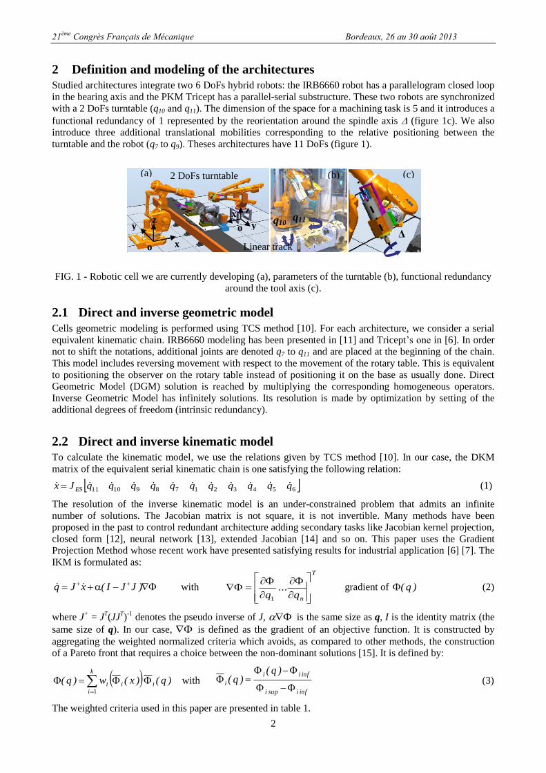
2 Definition and modeling of the architectures
Studied architectures integrate two 6 DoFs hybrid robots: the IRB6660 robot has a parallelogram closed loop
in the bearing axis and the PKM Tricept has a parallel-serial substructure. These two robots are synchronized
with a 2 DoFs turntable (q10 and q11). The dimension of the space for a machining task is 5 and it introduces a
functional redundancy of 1 represented by the reorientation around the spindle axis (figure 1c). We also
introduce three additional translational mobilities corresponding to the relative positioning between the
turntable and the robot (q7 to q9). Theses architectures have 11 DoFs (figure 1).
FIG. 1 - Robotic cell we are currently developing (a), parameters of the turntable (b), functional redundancy
around the tool axis (c).
2.1 Direct and inverse geometric model
Cells geometric modeling is performed using TCS method [10]. For each architecture, we consider a serial
equivalent kinematic chain. IRB6660 modeling has been presented in [11] and Tricept’s one in [6]. In order
not to shift the notations, additional joints are denoted q7 to q11 and are placed at the beginning of the chain.
This model includes reversing movement with respect to the movement of the rotary table. This is equivalent
to positioning the observer on the rotary table instead of positioning it on the base as usually done. Direct
Geometric Model (DGM) solution is reached by multiplying the corresponding homogeneous operators.
Inverse Geometric Model has infinitely solutions. Its resolution is made by optimization by setting of the
additional degrees of freedom (intrinsic redundancy).
2.2 Direct and inverse kinematic model
To calculate the kinematic model, we use the relations given by TCS method [10]. In our case, the DKM
matrix of the equivalent serial kinematic chain is one satisfying the following relation:
6543217891011 qqqqqqqqqqqJx ES (1)
The resolution of the inverse kinematic model is an under-constrained problem that admits an infinite
number of solutions. The Jacobian matrix is not square, it is not invertible. Many methods have been
proposed in the past to control redundant architecture adding secondary tasks like Jacobian kernel projection,
closed form [12], neural network [13], extended Jacobian [14] and so on. This paper uses the Gradient
Projection Method whose recent work have presented satisfying results for industrial application [6] [7]. The
IKM is formulated as:
)JJI(xJq with
T
nq...
q
1
gradient of )q( (2)
where J+ = J
T(JJ
T)
-1 denotes the pseudo inverse of J, is the same size as q, I is the identity matrix (the
same size of q). In our case, is defined as the gradient of an objective function. It is constructed by
aggregating the weighted normalized criteria which avoids, as compared to other methods, the construction
of a Pareto front that requires a choice between the non-dominant solutions [15]. It is defined by:
)q()x(w)q( i
k
i
ii 1
with infisupi
infii
i
)q()q(
(3)
The weighted criteria used in this paper are presented in table 1.
(a) (b) (c) 2 DoFs turntable
le
q10 q11
Δ
Linear track o x
y z
x
y
z
o

21ème
Congrès Français de Mécanique Bordeaux, 26 au 30 août 2013
3
FIG. 2 – Equivalent 11 DoFs architecture model including IRB6660 (a) and Tricept (b).
The direct implementation of this method brings up some limitations:
- In the choice of weightings for the different criteria to avoid the joint limits and singular
configuration [16].
- In the choice of the magnitude of the internal movement α which can disturb the convergence [17].
- This method allows the behavior to be improved but it does not guarantee to find an optimal solution
for the set of criteria [13].
In order to improve the behavior of the optimization, we propose the following ways:
- The implementation of variable weightings following a sinusoidal law of evolution [15].
- The magnitude adjustment from the Armijo Law [17].
- The dominance of the criteria weighting (joint limits and singularity) on process-related criteria
(stiffness, kinematics, etc...) (table 1).
- The search space of solutions satisfying all criteria that allows a second refinement by local
optimization based on the GPM.
3 Objective function
Robotic cell with Criteria type
Criteria IRB
6660 Tricept
Reference
Dexterity in a given direction vTvv
Tvv u)JJ(u)q( 1 X X [19]
Mechanical advantage in a given direction mTmm
Tmm u)JJ(u)q( X [19]
Stiffness (displacement on the stiffer axis) )q
k
kmax( i
n
in
j
rp
j
i
1
1
X [11]
Leg extension criteria (based on the cartesian
stiffness evaluation)
n
irt q)q(1
X [6]
Force cutting criteria 6uFc
X [6]
Joint limits criteria
n
i i
imoyi
Jq
qq2
X X [20]
TAB. 1 - Criteria used in the optimization.
We integer different criteria based on task analysis. HSM conditions imply to use a dexterity criterion in the
advance direction. The aim of the mechanical advantage is to take into account the direction and the
magnitude of the cutting force to insure a good mechanical ratio on the manipulator. The authors [8] use a
a)
q1q2
q3a6 b6
q8
q9
b7x
b7z
q7
q10
q11
q4q5
q6
Ot
xy
zo
q1
q2
q3
q4
q5
q6
O
a6
b6
q10
q11
q9
q8q7
a1
b7
Ot
xy
z

21ème
Congrès Français de Mécanique Bordeaux, 26 au 30 août 2013
4
stiffness criteria to limit the deviation of the manipulator taking into account the force orientation, magnitude
and articular stiffness. We propose our stiffness criteria to focus the displacement on the stiffest axis because
of the high degree of redundancy. We propose the use of weighted criteria which take into account : the
kinematic behavior Φv, the mechanical behavior following the direction and the force magnitude (Φm, Φα),
stiffness (Φrp, Φrt) according to the robot architecture (table 1) for the optimized path planning. The local
optimization integrates a modification of the configuration by adding a variation of the positioning of each
actuator at each trajectory point by:
iii dqqq with )q())x((w)JJI(dq ii'ii
(4)
))x((w i'i integers the dominance of criteria and the weighted variable. In our development to define the
best location, the criteria of joint limits and singularity are weighted to 5, the other criteria to 1.
4 Software development
The different models have been programming in Matlab®
(figure 3a, 3b). Some options have been integrated
like loading of machining programming and writing of Rapid Code to synchronize the optimization results
with the operating future cells. The option interface includes the different specificity of the robotic cells like
the use of the functional redundancy, the use of the Armijo law, the joint stops and limits, weightings,
process speed and so on. In the optimization, the criteria of joint limits is considered as a dominant criteria
that means that closed to the limits, the criteria is strong face to the other criteria.
FIG. 3 - Modeling of the two robotic cells in Matlab®
(a, b) in their reference configuration, tool path (c).
5 Results
The reference position Ot (figure 2) is defined as the distance with respect to O and located at the intersection
of q10 and q11 axis. The current optimization position is defined as the distance with respect to the reference
position Ot. We are first interested in finding a global location for the turntable in the robot workspace. The
tool path is a square composed of 12 points (4 at the corner, 4 at the midpoint and 4 at 1mm of the corner to
highlight the reorientation face to cutting forces) (figure 3c). These points are centered on q11 turntable axis
and located at 0.3m from the axis of q10. For each robotic cell, a reference configuration is taken into account.
It corresponds to a feasible trajectory outside the joint limits, apart from singularity configurations. The
global optimization evaluates in the workspace the best location to start the local optimization. To show the
relevance of the algorithm, we present for each architecture, the evaluation of the normalized criteria in the
reference configuration (figure 3) with dotted line and during optimized trajectories (figure 4c, 5c) with
continuous line.
5.1 Case of the hybrid robot with a parallelogram closed loop (IRB6660)
The turntable is located at the reference position Ot [1.8, 0, 0.8] (figure 3a). The first optimized trajectory
shows the improvement of the kinematic capacity Фv while working at a position around [0.1,-0.5, 0.3] from
Ot (figure 4a). This improvement has lead to an ill-oriented posture against the machining forces (see Фm in
figure 4a). In the second simulation, the robotic cell is better oriented against the forces but the kinematic
performances are reduced (figure 4b). These results highlight the importance of working at 1.4 m to have
q7
q8
q9
q10
q11
Tool path point distribution
(c) (a) (b)

21ème
Congrès Français de Mécanique Bordeaux, 26 au 30 août 2013
5
some good kinematic performances and to shift the turntable of 0.5m from xOz plane to have good global
performances.
5.2 Case of the hybrid robot with a parallel serial structure (Tricept)
The turntable is located at the reference position Ot [2, 0.3, 1.2]. The first optimized trajectory improves the
overall stiffness performances base on the extension criteria Фrt. We notice moreover an alternance between
the improvement of kinematic capacity and the orientation management faces to the forces (figure 5a). In the
second optimized trajectory, stiffness is improved but kinematic performances are reduced (figure 5b). We
notice that a good location of the turntable is [-0.2, q7opt, 0]. q7opt is variable and highlights for such a robot
the importance of adding a track along y axis to extend the workspace and to improve the capacities of such a
robot.
FIG. 4 - Trajectories evaluation for the robotic cell with hybrid robot with a parallelogram closed loop, first
optimized trajectory (a), second one (b) and some pictures while realizing the first optimized trajectory (c).
FIG. 5 - Trajectories evaluation for the robotic cell with the hybrid robot with parallel serial structure, first
optimized trajectory (a), second one (b) and some pictures while realizing the first optimized trajectory (c).
6 Conclusion
The main results of this work focus on the optimized location of the turntable. The results highlight that for a
given tool path, the influence of the location of the turntable on x and z-axis is less important than y-axis. It
0
0,5
1
1 3 5 7 9 11
-0,6
-0,4
-0,2
0
0,2
0,4
1 3 5 7 9 11
m
m
v
v
rp
rp
Weighted criteria Reference configuration
Optimized configuration
Trajectory points
0
0,5
1
1 3 5 7 9 11
-1
-0,5
0
0,5
1 3 5 7 9 11
Distance (m) Distance (m)
q7 on Yq8 on Xq9 on Z
Weighted criteria
Trajectory points
(for optimized
configuration)
0
0,5
1
1 3 5 7 9 11
-0,4
-0,2
0
0,2
0,4
1 3 5 7 9 11
-1
-0,8
-0,6
-0,4
-0,2
0
1 3 5 7 9 11
Weighted criteria
0
0,5
1
1 3 5 7 9 11
Weighted criteria
v
v
rt
rt
Reference configuration
Optimized configuration
Trajectory points
q7 on Yq8 on Xq9 on Z
Distance (m) Distance (m)
Trajectory points
(for optimized
configuration)
a) b) c)
a) b) c)
21ème
Congrès Français de Mécanique Bordeaux, 26 au 30 août 2013
6
indicates the usefulness of using a linear track to carrying out the turntable on direction y (figure 1a).
Moreover, this supplementary mobility is more important for the hybrid robot with parallel serial structure
(figure 5a, 5c) which uses it more because of its reduced workspace in comparison with the hybrid robot with
a parallelogram closed loop. These results allow us to well located the different elements of the cell and
validate the integration of the linear track.
7 Acknowledgements
This work has been sponsored by the French government research programm Investissements d'avenir
through the RobotEx Equipment of Excellence (ANR-10-EQPX-44), by the European Union through the
programm Regional competitiveness and employment 2007-2013 (ERDF – Auvergne région), by French
Institute for Advanced Mechanics and by the Auvergne region
References
[1] Kuka, Usinage avec un kuka avril 2008 - Ausbourg, 2008.
[2] Chen Y., Dong F., Robot machining: recent development and future research issues, The International
Journal of Advanced Manufacturing Technology, 2012.
[3] Pritschow G., Eppler C., Garber T., Influence of the dynamic stiffness on the accuracy of PKM, in 3rd
Chemnitz Parallel Kinematic Seminar, Chemnitz, 313‑333, 2002.
[4] Dumas C., Caro S., Garnier S., Furet B., Joint stiffness identification of six revolute industrial serial
robots, Robotics and Computer-Integrated Manufacturing, 2011.
[5] Pan Z., Zhang H., Zhu Z., Wang J., Chatter analysis of robotic machining process, Journal of Materials
Processing technology, 173, 301‑309, 2006.
[6] Robin V., Sabourin L., Gogu G., Optimization of a robotized cell with redundant architecture, Robotics
and Computer-Integrated Manufacturing, 27, 13‑21, 2011.
[7] Guire G., Sabourin L., Gogu G., Lemoine E., Robotic cell for beef carcass primal cutting and pork ham
boning in meat industry, Industrial Robot: An International Journal, 37(6), 532 - 541, 2010.
[8] Caro, S., Dumas, C., Garnier, S. and Furet, B., "Workpiece Placement Optimization for Machining
Operations with a KUKA KR270-2 Robot", The 2013 IEEE International Conference on Robotics and
Automation (ICRA 2013). Karlsruhe, Germany , May 6-10, 2013
[9] Olabi A., Béarée R., Gibaru O., Damak M., Feedrate planning for machining with industrial six-axis
robots, Control Engineering Practice, 18, 471‑482, 2010.
[10] Gogu G., Coiffet P., Barraco A., Représentations des déplacements des robots, Paris: Hermès, 1997.
[11] Subrin K., Sabourin L., Gogu G., Mezouar Y., Performance criteria to evaluate a kinematically
redundant robotic cell for machining tasks, Applied Mechanics and Materials, 162, 413‑422, 2012.
[12] Xiao W., Straub H., Loohb T., Closed-form inverse kinematics of 6R milling robot with singularity
avoidance, Prod. Eng. Res. Devel., 2010.
[13] Marcos, M. D. G., Tenreiro Machado, J. A., Azevedo-Perdicoúlis, T. P., A multi-objective approach for
the motion planning of redundant manipulators, Applied Soft Computing, 12(2), 589-599, 2012.
[14] Tchoń K., Janiak M., Repeatable approximation of the Jacobian pseudo-inverse, Systems & Control
Letters, 58, 12, 849‑856, 2009.
[15] Lee K., Buss M., Redundancy Resolution With Multiple Criteria, Intelligent Robots and Systems, 598‑603, 2006.
[16] Wang J., Li Y., Zhao X., Inverse kinematics and control of a 7dof redundant manipulator based on
closed loop algorithm , International Journal of Advanced Robotic Systems, 7(4),1, 2010.
[17] Chiaverini S., Oriolo G., Walker I., Kinematically redundant manipulators, Handbooks of Robotics O.
Khatib and B. Siciliano, Springer, 2009.
[18] Chiu S. L., Tack Compatibility of manipulator posture, Massachusetts Institute of Technology, 13‑21,
1988.
[19] Dubey R., Luh J. Y. S., Redundant robot control using task based performance measures, Journal of
robotic systems, 5(5), 409‑432, 1988.
[20] Liegeois A., Automatic Supervisory control of the configuration and behaviour of multibody, IEEE
transactions on systems, man, and cybernetics, 7(12), 868‑871, 1977.