intersystem operation and mobility managementdtipper/2700/2700_slides6.pdf · intersystem operation...
TRANSCRIPT
1
Intersystem Operation and Mobility Intersystem Operation and Mobility ManagementManagement
David TipperAssociate ProfessorAssociate Professor
Graduate Program in Telecommunications and Networking
University of PittsburghTelcom 2700
Slides 6http://http://www.tele.pitt.edu/tipper.htmlwww.tele.pitt.edu/tipper.html
Telcom 2700 2
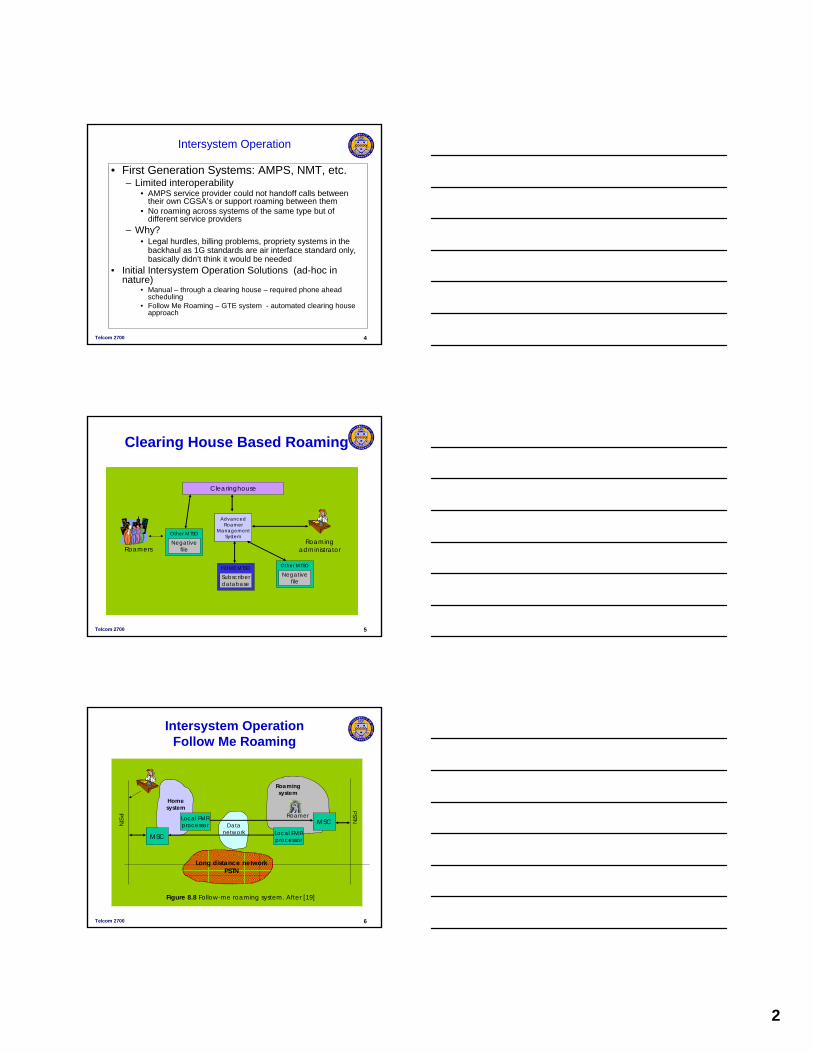
First Generation Systems• Basic Architecture AMPS, NMT, etc. similar• Mobile telephone switching office (MisTO) connects
base stations to PSTN, • Subscriber location and equipment databases were
local to each geographical service area (CGSA) (e.g., MSA or RSA)
• Could only move about locally!
Telcom 2700 3
System A
System B
System C
CGSA-1
CGSA-2
CGSA-N
Call deliveryand
handoff
Call delivery
Call delivery system and handoff between systems.
Intersystem Operation
Intersystem operation problem
• How to support handoffs and roaming between CGSA’swithin a operator’s network or between different operator’s networks if a roaming agreement in place and they support the same air interface
2
Telcom 2700 4
Intersystem Operation
• First Generation Systems: AMPS, NMT, etc.– Limited interoperability
• AMPS service provider could not handoff calls between their own CGSA’s or support roaming between them
• No roaming across systems of the same type but of different service providers
– Why?• Legal hurdles, billing problems, propriety systems in the
backhaul as 1G standards are air interface standard only, basically didn’t think it would be needed
• Initial Intersystem Operation Solutions (ad-hoc in nature)
• Manual – through a clearing house – required phone ahead scheduling
• Follow Me Roaming – GTE system - automated clearing house approach
Telcom 2700 5
Clearing House Based Roaming
AdvancedRoamer
ManagementSystem
HOME MTSO
Clearinghouse
Other MTSO
Negativefile
Other MTSO
Negativefile
RoamersRoaming
administrator
Subscriberdatabase
Telcom 2700 6
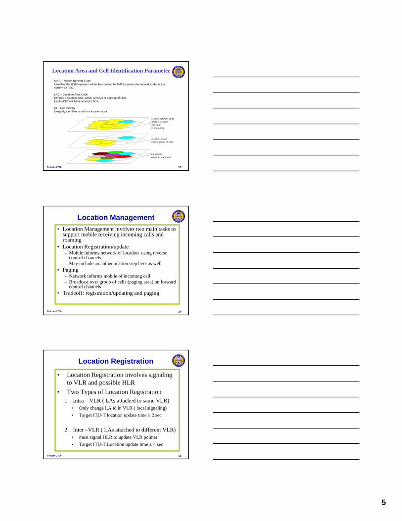
Intersystem Operation Follow Me Roaming
Figure 8.8 Follow-me roaming system. After [19]
MSC
Local FMRprocessor
Local FMRprocessor
MSCDatanetwork
Homesystem
Roamingsystem
Long distance networkPSTN
PSTN
PSTNRoamer

3
Telcom 2700 7
Mobility Management
• Mobility Management Problems1. Location Management
• Track location of users for incoming calls within a CGSA and allowing user to roam between CGSA service areas of a service provider while having the ability to place/receive calls, also support roaming among different service providers supporting the same air interface standard
• Location registration/authentication/paging
2. Handoff Management – Maintain in progress connection as user moves• (Handoff/rerouting) within systems, between systems
Telcom 2700 8
• Mobility Management StandardsIS-41 (several revs: IS-95, IS-54, AMPS)GSM-MAP (Mobile Application Part)ITU-T (E.750 series)
Location Management Handoff Management
Mobility Management
• GSM standard developed first, then IS-41, • ITU –T: specifies performance standards• All three are based on a system architecture
Telcom 2700 9
B S C
M S C
V L RB S C
B S C M S C
V L R
S S 7
P S T N
C O
C O
H L R A U C
E IR
Basic PCS Architecture
VLR – local database of subscriber information HLR – central database of subscriber info
4
Telcom 2700 10
IS-41 Architecture Reference
EIR
MSC
BS
PSTN
MSC AC
ISDN
HLRCSS
VLR VLR
UmA
E
F B DG
HCDiAi
AC: authentication center HLR: home location registerBS: base station ISDN: integrated services digital networkCSS: cellular subscriber station (terminal) MSC: mobile switching center (MTSO)EIR: equipment identity register PSTN: public switched telephone networkVLR: visitor location register
Telcom 2700 11
GSM System Architecture
VLR
HLR
AUC
EIR
VLR
B, C, D, E, FMobile ApplicationProtocol Interfaces
MobileSwitching
Center(MSC)
MobileSwitching
Center(MSC)
OMC - Radio
BaseStation
Controller(BSC)
BaseStation
Controller(BSC)
BTS
BTS
BTS
BTS
BTS
BTS
BTS
Traffic and Signaling
Signaling only
VLR = Visitor Location RegisterHLR = Home Location RegisterEIR = Equipment Identity RegisterAUC = Authentication Center
BTS = Base Transceiver StationADC = Admission Data CenterOMC = Operation Maintenance Center
D Interface
FInterface
CInterface
EInterface
PSTN
UMInterface
A-BisInterface
A Interface B Interface
Telcom 2700 12
Location Management• Location Area (LA)
– Divide coverage into non-overlapping groups of cells – Assign each LA a unique id– Location Area ID is periodically broadcast by each cell– As a mobile moves/turns phone on – it listens to location area
id – depending on the approach – it may perform a location update/authentication procedure to provide it’s location to VLR and possibly HLR
• Two level database hierarchy HLR/VLR– HLR points to VLR where mobile located– VLR entry points to LA where mobile last located
• In large networks may have HLR split among regions with aggregate info cross region
LocationArea 1
LocationArea 2
LocationArea 3
5
Telcom 2700 13
Location Area and Cell Identification Parameter
MNC – Mobile Network CodeIdentifies the GSM operator within the country. In AMPS system the network code is the system ID (SID)
LAC – Location Area CodeDefines a location area, which consists of a group of cells.Each MNC will have several LACs.
CI – Cell IdentityUniquely identifies a cell in a location area.
Mobile network codeunique to eachoperatorin a country
Location AreasDefine group of cells
Cell IdentityUnique to each cell
Telcom 2700 14
Location Management• Location Management involves two main tasks to
support mobile receiving incoming calls and roaming
• Location Registration/update– Mobile informs network of location using reverse
control channels– May include an authentication step here as well
• Paging – Network informs mobile of incoming call– Broadcast over group of cells (paging area) on forward
control channels• Tradeoff: registration/updating and paging
Telcom 2700 15
Location Registration
• Location Registration involves signaling to VLR and possible HLR
• Two Types of Location Registration1. Intra – VLR ( LAs attached to same VLR)
• Only change LA id in VLR ( local signaling)• Target ITU-T location update time ≤ 2 sec
2. Inter –VLR ( LAs attached to different VLR)• must signal HLR to update VLR pointer• Target ITU-T Location update time ≤ 4 sec

6
Telcom 2700 16
Inter-VLR Location Update
• Walkthrough Inter-VLR case1. Mobile powers up scans reverse control channels,
locks on to strongest signal. Listens to forward broadcast control channel until Location Area ID heard
2. Since Location Area ID - differs from last one mobile registered in mobile signals on reverse control channel to serving MSC, MSC signals HLR update VLR pointer
3. AUC verifies user- may issue challenge/response authentication procedure
4. HLR – gives VLR mobile service profile5. HLR – deregisters mobile from last VLR locationTarget ITU-T bound on location registration ≤ 4sec
Telcom 2700 17
Inter VLR Location Update Call Flow
Telcom 2700 18
VLR(New)
HLR
VLR(Old)
MSC(Old)
MSC(New)BSC
BSC
Location Area (New)
Location Area (Old)
1
1 1
1
2
34
44
5
1. The MS sends the Location Update request to the VLR (new) via the BSS and MSC.
2. The VLR sends a Location Update message to the HLR serving the MS which includes the address of the VLR (new) and the IMSI of the MS. This updating of the HLR is not required if the new LA is served by the same VLR as the old LA.
3. The service and security related data for the MS is downloaded to the new VLR.
4. The MS is sent an acknowledgement of successful location update.
5. The HRL requests the old VLR to delete data relating to the relocated MS.
Inter-VLR Location update in GSM
7
Telcom 2700 19
Location Management• Location Update Techniques in practice
– Timer based periodic registration (AMPS)– LA crossing based ( cell broadcast LA id)
• NA-TDMA, IS-95, GSM, 3G systems– Hybrid LA crossing + timer based (GSM)– Distance Based (IS-95)
• Paging Techniques– Paging Area (PA) usually same at LA but doesn’t have
to be – Blanket polling commonly deployed (page all cells
simultaneously)– If no response after a fixed number of attempts – give up
and roll over to voice mailbox– Target ITU-bound on paging delay time = 4 sec
Telcom 2700 20
Mobile Terminated Call Example
PSTNcallingstation GMSC
HLR VLR
BSSBSSBSS
MSC
MS
1 2
3
45
6
7
8 9
10
11 12
1316
10 10
11 11 11
14 15
17
• Assume a mobile has registered it’s location with VLR and HLR
• 1: calling a mobile subscriber• 2: forwarding call to GMSC• 3: signal call setup to HLR• 4, 5: request status from VLR• 6: forward responsible
MSC to GMSC• 7: forward call to • serving MSC• 8, 9: get current status and
LAI of MS• 10, 11: Paging of MS• 12, 13: MS answers• 14, 15: security checks• 16, 17: set up connection
Telcom 2700 21
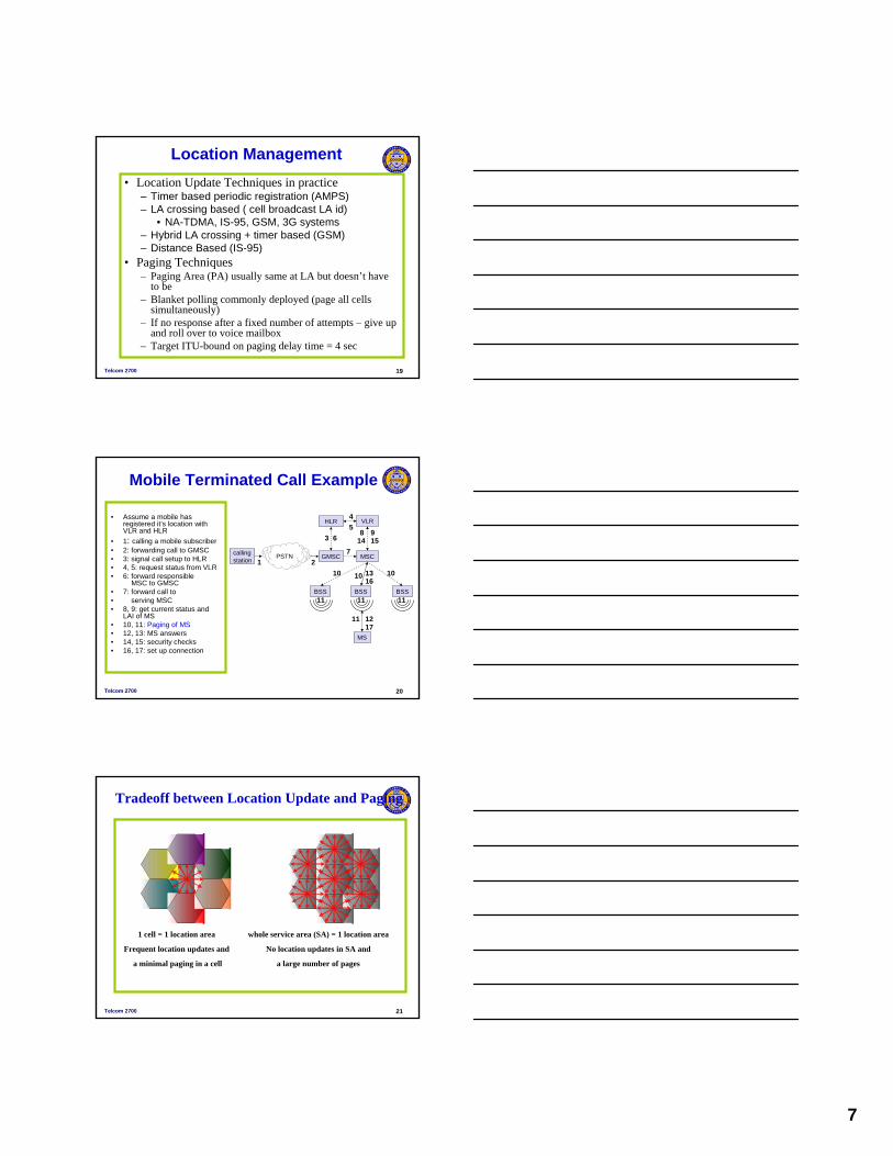
Tradeoff between Location Update and Paging
1 cell = 1 location area
Frequent location updates and
a minimal paging in a cell
whole service area (SA) = 1 location area
No location updates in SA and
a large number of pages
8
Telcom 2700 22
• Obviously must balance location update traffic load and paging load to minimize overhead to the network and battery drain on mobile
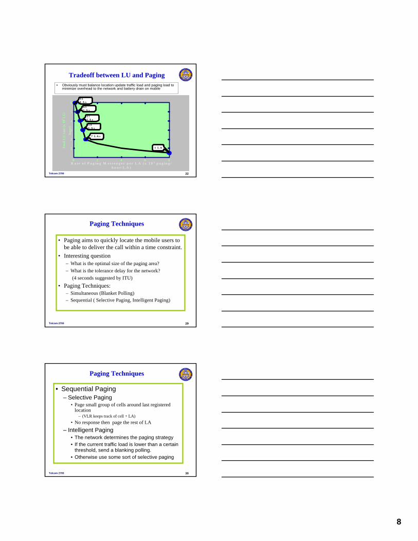
0 2 4 6 8
1
2
3
4
5
69 1L A s
6 1L A s
3 7L A s
1 9L A s
7 L A s
1 L A
R a t e o f P a g in g M e s s e n g e r p e r L A ( x 1 0 5 p a g in g /h o u r /L A )
Tot
al L
U r
ate
(x 1
05 L
U/
hour
)
Tradeoff between LU and Paging
Telcom 2700 29
• Paging aims to quickly locate the mobile users to be able to deliver the call within a time constraint.
• Interesting question– What is the optimal size of the paging area?– What is the tolerance delay for the network?
(4 seconds suggested by ITU)• Paging Techniques:
– Simultaneous (Blanket Polling)– Sequential ( Selective Paging, Intelligent Paging)
Paging Techniques
Telcom 2700 30
• Sequential Paging– Selective Paging
• Page small group of cells around last registered location
– (VLR keeps track of cell + LA)• No response then page the rest of LA
– Intelligent Paging • The network determines the paging strategy• If the current traffic load is lower than a certain
threshold, send a blanking polling.• Otherwise use some sort of selective paging
Paging Techniques

9
Telcom 2700 34
Handoff Management• Call in progress Mobility management• Radio Mobility ( Handoff or Handover) ( BSC or
MSC)– Based on air interface standard– Hard Handoff ( break before make)– Soft Handoff ( make before break)– Mobile Assisted Handoff (MAHO)
• Handoff measurement: major decision-making stages– Identify the need– Identify the candidate– Evaluate the candidates– Select a target cell
Telcom 2700 36
RSS (received signal strength) based
• RSS is the direct indication of actual received energy at the mobile
• Controlled parameters: threshold level, hysterisis margin H and averaging interval
B S 4 B S 1
RSSfromBS4
RSSfromBS1
Location of theMS betweenBS4 and BS1
TH
Telcom 2700 37
Handoff Management
• Two categories of handoff – Intrasystem handoff (3 cases)
• Intracell handoff ( different sector of same cell)• Standard Handoff (cells attached to same BSC)• Inter BSC handoff (same MSC)
– Intersystem handoff • Cells attached to two different MSCs• Require specialized signaling• IS-41, GSM -MAP protocol• Three cases
A. Handoff ForwardB. Handoff BackC. Handoff to a Third
10
Telcom 2700 38
Types of Handoff
MSC MSC
BSC BSCBSC
BTS BTS BTSBTS
MS MS MS MS
Intracell StandardInter-BSC Intersystem handoff
Telcom 2700 39
The situation after a handoff forward from System A (anchor system) toSystem B (serving system).
MSC-B MSC-A
PSTN
Intersystem Handoff – Handoff Forward
Telcom 2700 40
MSC-BMSC-AHandoff complete
MSC-BMSC-AMSC-AMSC-A decides to transfer call to MSC-B
MSC-BMSC-AMSC-ATerminal approaches service area of MSC-B
MSC-AMSC-ACall begins
TargetCandidateServingAnchor
Table 4.2 MSC Status Before, During, and After a Handoff Procedure
Handoff Forward
11
Telcom 2700 41
Detect weak signalHandoff request
MEASUREMENT REQUEST INVOKE
Measurement request
Measure signal strength
conversationRVC and FVC
New MSC Terminal Prior MSCPrior
Base stationNew
Base station
Measurement report
MEASUREMENT REQUEST RESULT
Goodman Figure 4.11 IS-41 Message sequence and system operations for handoff forward.
Handoff Forward
Telcom 2700 42
New MSC Terminal Prior MSCPrior
Base stationNew
Base station
Handoffphase FACILITY DIRECTIVE INVOKE
FACILITY DIRECTIVE RESULTSelect new voice ch.
Transmit new SAT Handoff command
Send ST for 50 ms
HANDOFF
Turn off transmitterTune to new voice ch.
Review new SATTurn on transmitter
Transmit new SAT
Detect SATConfirm voice ch. connection
MOBILE ON CHANNEL INVOKE
Handoff Forward
Telcom 2700 43
Handoff Back
After a Handoff ForwardFrom MSC1 to MSC2 User may move back to a cell attached to anchor MSC 1– use HANDOFF BACK command to prevent call going from MSC1 to MSC2 back to MSC1 in wired networkCalled the shoelace effect
12
Telcom 2700 44
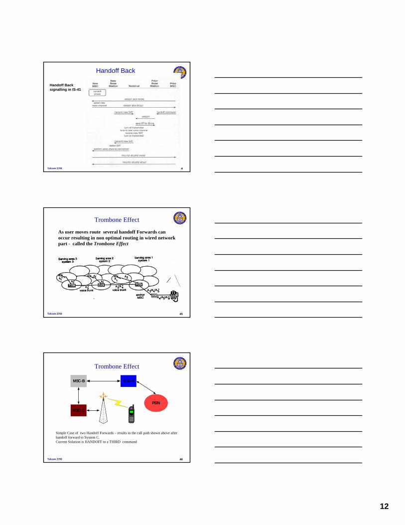
Handoff Back
Handoff Back signalling in IS-41
Telcom 2700 45
Trombone Effect
As user moves route several handoff Forwards can occur resulting in non optimal routing in wired network part - called the Trombone Effect
Telcom 2700 46
Simple Case of two Handoff Forwards – results in the call path shown above after handoff forward to System C.Current Solution is HANDOFF to a THIRD command
MSC-B MSC-A
PSTN
MSC-C
Trombone Effect

13
Telcom 2700 47
•If there are circuits connecting MSC-A and MSC-C, the system can perform handoff to third with this result. •Yields better routes in wired network
MSC-B MSC-A
PSTN
MSC-C
Handoff to a Third
Telcom 2700 48
Handoff to a Third
Handoff to a third signalling in IS-41