international journal of plasticity -...
TRANSCRIPT

International Journal of Plasticity xxx (2012) xxx–xxx
Contents lists available at SciVerse ScienceDirect
International Journal of Plasticity
journal homepage: www.elsevier .com/locate / i jp las
Transformation and slip behavior of Ni2FeGa
H. Sehitoglu a,⇑, J. Wang a, H.J. Maier b
a Department of Mechanical Science and Engineering, University of Illinois at Urbana-Champaign, 1206 W. Green St., Urbana, IL 61801, USAb University of Paderborn, Lehrstuhl für Werkstoffkunde, D-33095 Paderborn, Germany
a r t i c l e i n f o
Article history:Received 12 March 2012Received in final revised form 28 May 2012Available online xxxx
Keywords:Shape memoryDislocation slipPhase transformationEnergy barrierPseudoelasticity
0749-6419/$ - see front matter � 2012 Elsevier Ltdhttp://dx.doi.org/10.1016/j.ijplas.2012.05.011
⇑ Corresponding author.E-mail address: [email protected] (H. Sehitog
Please cite this article in press as: Sehitogludx.doi.org/10.1016/j.ijplas.2012.05.011
a b s t r a c t
Ni2FeGa is a relatively new shape memory alloy (SMA) and exhibits superior characteristicscompared to other SMAs. Its favorable properties include low transformation stress, highreversible strains and small hysteresis. The first stage of stress-induced martensitic trans-formation is from a cubic to a modulated monoclinic phase. The energy barriers associatedwith the transformation from L21 (cubic) to modulated martensite (10M-martensite)incorporating shear and shuffle are established via atomistic simulations. In addition, theslip resistance in the [111] direction and the dissociation of full dislocations into partialsas well as slip in the [001] direction are studied. The unstable stacking fault energy barriersfor slip by far exceeded the transformation transition state barrier permitting transforma-tion to occur with little irreversibility. Experiments at the meso-scale on single crystals andtransmission electron microscopy were conducted to provide further proof of the pseudo-elastic (reversible) behavior and the presence of anti-phase boundaries. The results haveimplications for design of new shape memory alloys that possess low energy barriers fortransformation coupled with high barriers for dislocation slip.
� 2012 Elsevier Ltd. All rights reserved.
1. Introduction
1.1. Challenges in Designing Shape Memory Alloys
Designing new shape memory materials that exhibit superior transformation characteristics remains a challenge. Thereneeds to be a better fundamental basis for describing how reversible transformation (shape memory) works in the first place.Specifically, two aspects remain uncertain. The first is that the phase changes involve complex transformation paths withshear and shuffle (Ahlers, 2002) and the energy barrier levels corresponding to the transition are not well established.The second issue is that the determination of dislocation slip resistance (Olson and Cohen, 1975), which decides the revers-ibility of transformation of shape memory alloys, is very important and requires further study. Thus, this paper is gearedtowards establishing both the energy barriers in the phase changing of Ni2FeGa and the fault energies associated with dis-location slip for the same material.
Thermo-elastic phase transformation refers to a change in lattice structure upon exposure to stress or temperature andreturn of the lattice to the original state upon removal of stress or temperature (Delaey et al., 1974). Modern understandingof shape memory transforming materials has relied on the phenomenological theory of the martensitic transformation(Wechsler et al., 1953), which does not deal with the presence of dislocation slip. The presence of slip has been observedin experimental work at micro- and meso-scales (Otsuka and Wayman, 1998; Duerig et al., 1990), and incorporated in someof the continuum modeling approaches (Boyd and Lagoudas, 1996). A low transformation stress (Sehitoglu et al., 2000) and
. All rights reserved.
lu).
, H., et al. Transformation and slip behavior of Ni2FeGa. Int. J. Plasticity (2012), http://

2 H. Sehitoglu et al. / International Journal of Plasticity xxx (2012) xxx–xxx
high slip resistance (Hamilton et al., 2004) are precursors to reversible martensitic transformation. Recently, theoreticaldevelopments at atomic length scales have been utilized (Hatcher et al., 2009; Kibey et al., 2009; Wagner and Windl,2008) bringing into light the magnitude of energies of different phases and defect fault energies in NiTi.
NiTi is the most well known shape memory alloy that meets the requirement of excellent slip resistance in both martens-ite (Ezaz et al., 2011) and in austenite (Manchiraju and Anderson, 2010; Moberly et al., 1991; Norfleet et al., 2009; Peltonet al., 2012; Simon et al., 2010). The recent interest in the austenite slip behavior of NiTi is well founded because it is akey factor that influences the shape memory response.
We note that some of the other shape memory alloys of the Cu-variety (Damiani et al., 2002b; Malarria et al., 2009;Roqueta et al., 1997; Sade et al., 1988; Sittner et al., 1998) and the Fe-based (Maki, 1998a,b; Morito et al., 2000; Jost,1999; Tsuzaki et al., 1992) alloys possess large transformation strains but are susceptible to plastic deformation by slip. Plas-tic deformation has been incorporated into continuum energy formulations where the interaction of plastic strains and thetransformation improves the prediction of overall mechanical response (Bartel et al., 2011; Idesman et al., 2000; Levitas,2002). All these previous works point to the importance of dislocation slip resistance in shape memory alloys.
The Ni2FeGa alloys have large recoverable strains (Chumlyakov et al., 2008; Hamilton et al., 2007a,b) and can potentiallyfind some important applications like NiTi. In the case of Ni2FeGa alloys, stress-induced transformation to modulated mar-tensite (Masdeu et al., 2005; Omori et al., 2004; Santamarta et al., 2006a,b; Sutou et al., 2004) and the slip deformation ofaustenite (Hamilton et al., 2007a,b) are two factors that dictate shape memory performance. The phase change in Ni2FeGaoccurs primarily upon shape strains (Bain strain) in combination with shuffles to create a ‘modulated’ martensitic structure.The ‘modulated’ monoclinic structure has a lower energy than the ‘non-modulated’ lattice, and hence is preferred. We focuson atomic movements and the energy landscapes for transformation of L21 austenite to a 10M modulated martensite struc-ture and establish the barrier for this change. We then investigate the dislocation slip barriers in [111] and [001] directions.
It is important to assess the transformation paths and energies associated with the austenite to martensite transformationsimultaneously with dislocation slip behavior because the external shear stress that can trigger transformation can also re-sult in dislocation slip. What we show is that the order strengthened Ni2FeGa alloy requires elevated stress levels for dislo-cation slip while undergoing transformation nucleation at much lower stress magnitudes (with lower energy barriers).
1.2. Energetics of Phase Transformation and Dislocation Slip
A schematic of pseudoelastic stress-strain response at constant temperature is given in Fig. 1. We note that the initialcrystal structure at zero strain is that of austenite. Upon deformation, the crystal undergoes a phase transformation to amodulated martensitic structure. In the case of Ni2FeGa, the structures of austenite and martensite are cubic and monoclinic,respectively. Over the plateau stress region, austenite and martensite phases can coexist. In the vicinity of austenite to mar-tensite interfaces, high internal stresses are generated to satisfy compatibility. Hence, slip deformation can occur in the aus-tenite domains as illustrated in the schematic. Once the transformation is complete, the deformation of the martensiticphase occurs with an upward curvature. Upon unloading, the martensite reverts back to austenite as shown in the schematic.The strain recovers at the macroscale, but at the micro-scale residual slip deformation could remain as shown with TEMstudies.
Fig. 1. Schematic of stress–strain curve displaying the modulated martensite and dislocation slip in austenite over the plateau region duringpseudoelasticity.
Please cite this article in press as: Sehitoglu, H., et al. Transformation and slip behavior of Ni2FeGa. Int. J. Plasticity (2012), http://dx.doi.org/10.1016/j.ijplas.2012.05.011

H. Sehitoglu et al. / International Journal of Plasticity xxx (2012) xxx–xxx 3
We capture the energetics of the transformation through ab initio density functional theory (DFT) calculations. In Fig. 2(a),the initial lattice constant is ao and the monoclinic lattice constants are a, b and c with a monoclinic angle. We incorporateshears and shuffles for the case of transformation from L21 to 10M. A typical transformation path is described in Fig. 2(a). Themartensite has lower energy than the austenite. To reach the martensitic state, there exists an energy barrier (correspondingto cA!M
u in Fig. 2(a)) that needs to be overcome. This barrier is dictated by the energy at the transition state (TS) as shown inFig. 2(a). A smaller barrier is desirable to allow transformation at stress levels well below dislocation mediated plasticity.Along the transformation path, we find a rather small energy barrier (8.5 mJ/m2 for the L21 to 10M transformation inNi2FeGa).
Fig. 2. (a) Schematic of transformation path showing the energy in the initial state, the final state and the transition state, (b) atomic arrangements ofNi2FeGa with long range order (first configuration). The viewing direction is [110]. The (001) planes are made of all Ni atoms, and alternating Fe and Gaatoms. The dashed line represents the slip plane. The displacement <111>/4 creates nearest neighbor APBs (middle configuration) and the displacement<111>/2 results in next nearest neighbor APBs (third configuration). (c) Generalized fault energy of austenite associated with full dislocation dissociationinto partials in an ordered alloy.
Please cite this article in press as: Sehitoglu, H., et al. Transformation and slip behavior of Ni2FeGa. Int. J. Plasticity (2012), http://dx.doi.org/10.1016/j.ijplas.2012.05.011

4 H. Sehitoglu et al. / International Journal of Plasticity xxx (2012) xxx–xxx
Dislocation slip resistance in the L21 austenite can be understood by consideration of energetics of slip displacements inthe [111] direction associated with the motion of the dissociated dislocations. Ribbons of anti-phase boundaries (APBs) formby dissociation of superdislocations in the L21 parent lattice. We compute the separation distance of the superpartials viaequilibrium considerations and show the presence of these APBs from TEM observations. The energy barriers are manifestedvia generalized stacking fault energy curves (GSFE) and decide the slip resistance of the material. We check the GSFE curvesin two possible dislocation slip systems and calculate theoretical resolved shear stress.
The fundamental descriptions of the APB formation in ordered cubic materials point to decomposition of full dislocations(Koehler and Seitz, 1947; Marcinkowski and Brown, 1961). For the Ni2FeGa, as atoms are sheared over other atoms in neigh-boring planes the energy landscape indicates the decomposition of the full dislocation to four partials resulting in APBs. Thepartial dislocations are not zig zag type as in face centered cubic systems but are in the same direction as the full dislocation.This is illustrated in Fig. 2(b). It is easiest to see the APB formation with a [110] projection (Fig. 2(b)). The x-axis is [001] andthe y-axis is ½1�10� in this case. In this view atoms on only two planes (in-plane and out-of-plane) are noted (a different viewwill be illustrated later). Because we have twice as many Ni atoms then Fe and Ga, in the ½1�10� direction every second columnhas all Ni atoms. When slip occurs with vector 1/4 ½1�11� the original ordering of the lattice no longer holds. The passage of thefirst partial 1/4 ½1�11� results in disordering of the atomic order at near neighbors. The passage of the second partial restoresthe original stacking of next to near neighbor atoms. Upon a slip displacement of 1/2 ½1�11� the columns with all Ni atoms arerestored but other columns do not have the original ordering (Fig. 2(b)). Upon displacement of ½1�11� the original lattice struc-ture with long range order of the matrix is recovered. The fault energy barriers corresponding to Fig. 2(b) have several min-ima (metastable equilibrium points) corresponding to the passages of the partial dislocations (Fig. 2(c)). More details will begiven later in the text. In Fig. 2(b) cUS refers to the unstable fault energy and cNN and cNNN describe the nearest-neighbor (NN)and next-nearest neighbor (NNN) APB energies respectively. The fault energy barriers are moderately high (>400 mJ/m2 inNi2FeGa) and point to the considerable slip resistance in Ni2FeGa. We provide TEM evidence of the presence of APBs in theaustenitic phase for samples that have undergone pseudoelastic cyclic deformation.
2. Fundamentals of Cubic to Modulated (10M) Transformation in Ni2FeGa
The martensitic structure is critical to the properties of ferro-magnetic shape memory alloys. Their tetragonality c/a,twinning stress and magnetocrystalline anisotropy constant determine the magnetic-field-induced strain (MFIS) (Luoet al., 2011b; Morito et al., 2005). However, large MFIS originates mainly from the contribution of the modulated martensites(Han et al., 2007). Experiments have shown that the cubic structure (L21) undergoes the phase transformation to martensiticphases, designated modulated structure (10M/14M) and tetragonal structure (L10). The transformation from a cubic struc-ture (L21) to a modulated 10M structure is an important one in shape memory alloys of the ferro-magnetic variety (Ef-stathiou et al., 2008; Hamilton et al., 2006, 2007a; Martynov, 1995; Segui et al., 2005). The Ni2FeGa alloys undergo such atransformation via a combination of shear (distortion) and shuffle. This is the first stage of multiple transformation stepsresulting in the L10 structure. It is a very important step because it decides the transformation stress and the plateau stressfor the shape memory alloy.
In Fig. 3(a), the L21 lattice of Ni-Fe-Ga is shown. We note that the distance ao represents repeating atom positions in the<001> directions. We refer to coordinates in the L21 structure with the larger cell noting that the small cell represents a B2structure. The L21 unit cell contains eight cells of the B2 type. Upon transformation to martensite, the lattice structure be-comes monoclinic (Fig. 3(b)) characterized by three constants a, b, c and a monoclinic angle of 91.49�. In Fig. 3(b), the sub-lattice of L21 is displayed. The distortion plane can be viewed with atom layers A and B superimposed. The change indimension is from length a0
ffiffiffi2p
=2 to length c for the modulation direction [110], and from a0
ffiffiffi2p
=2 to length a in the ½1�10�direction. The lattice dimension in [001] is changed from ao to b. The lattice constants are summarized in Table 1. The secondcolumn gives the experimental results, while the third and fourth columns provide the simulations. The agreement betweenexperimental and theoretical lattice constants including the monoclinic angle is remarkable. The ab-initio VASP code withGGA (Kresse and Furthmuller, 1996; Kresse and Hafner, 1993a,b; Kresse and Joubert, 1999) is used in the simulations(see Appendix).
Because the transformation occurs first via L21?10M, we investigated the energy landscape associated with this impor-tant step. We note that the lattice parameters of the 10M are designated as ai; bi; ci, while the L21 lattice is defined by a0.Relative to the parent body the 10M phase involves a volumetric distortion and local shuffle. The deformation gradientcan be written in the following form to represent the volumetric distortion, where e represents the extent of the Bain-typedeformation with e ¼ 0 corresponding to the L21 and e ¼ 1 to the 10M end states. The Cauchy-Born rule was used in estab-lishing the deformation gradient expression given below.
Pleasedx.doi
FðeÞ ¼biðeÞ=a0
ffiffiffi2p
biðeÞ=a0
ffiffiffi2p
0
ciðeÞ=a0
ffiffiffi2p
ciðeÞ=a0
ffiffiffi2p
0
0 0 aiðeÞ=a0
ffiffiffi2p
264
375 ð1Þ
To account for the internal displacements associated with the shuffles, the strain energy density is minimized with re-spect to the shuffle displacements while FðeÞ is held fixed. This is achieved with internal relaxations of the atoms to the localenergy minimum. The normalized shuffle parameter is defined as g ¼ s=a where s is the absolute shuffle. The energy
cite this article in press as: Sehitoglu, H., et al. Transformation and slip behavior of Ni2FeGa. Int. J. Plasticity (2012), http://.org/10.1016/j.ijplas.2012.05.011

Fig. 3. (a) Schematic of the L21 austenitic structure of Ni2FeGa, (b) the sublattice displaying the modulated and basal planes, (c) the 10M monoclinicmodulated structure of Ni–Fe–Ga.
H. Sehitoglu et al. / International Journal of Plasticity xxx (2012) xxx–xxx 5
landscape is completed for the multiple pathways that could achieve L21?10M by exploring all combinations of distortionand shuffle for Ni2FeGa. The transformation path to the 10M structure is rather complex as shown in Fig. 4(a) and (b) andinvolves both shear (Bain strain) and shuffle. The energy contours shown in Fig. 4(b) show that the non-modulated martens-ite (10NM) has a higher energy than the modulated 10M structure. The 10NM structure has the same lattice constants as
Please cite this article in press as: Sehitoglu, H., et al. Transformation and slip behavior of Ni2FeGa. Int. J. Plasticity (2012), http://dx.doi.org/10.1016/j.ijplas.2012.05.011

Table 1The L21 structure lattice constants for austenitic Ni–Fe–Ga (ao) and the lattice constants of the modulated monoclinic (10M) structure.
Experiment Theory (this study)
Austenite (L21) cubic structure Lattice parameter, ao (Å), 5.76 (Sutou et al., 2004),5.7405 (Liu et al., 2003)
Lattice parameter, ao (Å),5.755
Energy (eV/atom)�5.7185
Martensite (10M) monoclinicstructure
Lattice parameter (Å), a = 4.24, b = 5.38, c = 4.176,(Sutou et al., 2004)Monoclinic angle = 91.49�
Lattice parameter (Å), a = 4.203,b = 5.434, c = 4.1736Monoclinic angle = 91.456�
�5.7206Energy Barrier (TS)8.5 mJ/m2
Fig. 4. (a) The energy landscape associated with the L21 to 10M transformation. The transformation is comprised of a distortion and shuffle and the path israther complex. (b) 3D view of the transformation surface showing that the energy of 10NM (non-modulated martensite) structure is higher than 10M(modulated). See Fig. 3(b) for the lattices.
6 H. Sehitoglu et al. / International Journal of Plasticity xxx (2012) xxx–xxx
10M. The difference between the two is that 10M involves considerable shuffle that results in the modulation. The minimumenergy path is indicated in Fig. 4(a). We note that there is a rather small barrier (8.5 mJ/m2) at the early stages of combinedshear and shuffle. This is the principal reason why the transformation stress is rather low (<50 MPa) in this alloy.
Please cite this article in press as: Sehitoglu, H., et al. Transformation and slip behavior of Ni2FeGa. Int. J. Plasticity (2012), http://dx.doi.org/10.1016/j.ijplas.2012.05.011

H. Sehitoglu et al. / International Journal of Plasticity xxx (2012) xxx–xxx 7
To obtain the Potential Energy Surface (PES) within reasonable computational time, we divided the shear and shufflebased computational domain primarily into 7 � 7 nodes. Additional nodes are added near the energetically significant posi-tions such as the local minima and the saddle point. A symmetry-adapted ‘‘free energy’’ polynomial was fitted to our DEðg; eÞdata. For this fault energy functional DEðg; eÞ, we chose a fourth order cosine-sine polynomial (Liu and Johnson, 2009), whichcan appropriately represent the shear shuffle coupling, i.e.
Pleasedx.doi
DEðg; eÞ ¼Xmþn64
m;n¼0
amn½XðgÞ�m½XðeÞ�n½1� dm0dn0� þXmþn64
m;n¼0
bmn½XðgÞ�m½XðeÞ�n ð2Þ
where ½XðxÞ� ¼ ½1� CosðpxÞ�; ½YðxÞ� ¼ ½SinðpxÞ�; and dij represents Kronecker’s delta (dij is 1(0) if i is (not) equal to j). An addi-tional constraint of jdDEðg; eÞ=dxjx¼0;1 ¼ 0 was imposed to ensure local minima at (0,0) and (1,1) positions in the PES.
3. Dislocation slip (GSFE) in Ni2FeGa
3.1. The (011)<111> case
The generalized stacking fault energy (GSFE), first introduced by Vitek (1968), is a comprehensive definition of the faultenergy associated with dislocation motion. In fcc alloys, a single layer intrinsic stacking fault is formed by the passage ofpartial dislocations in the < 11�2 > direction on the {111} plane. The fault energy of different sheared lattice configurationscan be computed as a function of displacement ux. The generalized stacking fault energy (GSFE) is represented by a surface(c-surface) or a curve (c-curve). The peak in fault energy was termed as the unstable SFE by Rice (1992). In the case of Ni2-
FeGa, all fault energies are determined relative to the energy of the L21 structure.We investigated slip in the <111> direction consistent with experiments (Chumlyakov et al., 2008). In this case the slip
plane is {110}. Fig. 5(a) shows the L21 lattice with the slip plane (shaded) and the <111> direction, and Fig. 5(b) the stackingin the [111] direction as ABCDEFAB’CD’EF’..... This stacking is similar to the <111> direction in bcc metals, but the differencearises because of the presence of three elements in Ni2FeGa. Because the normal plane is {112}, a total of 6 layers must beshown in this projection. The largest atom represents in-plane and the atom size becomes smaller as the out-of-plane is de-picted. The smallest atom is in the fifth layer (out-of-plane) and the largest atom is in the zeroth layer (in-plane). Consider-able attention should be placed on establishing the correct atom positions when multiple planes and binary or ternary alloysare considered. We utilize visualization softwares (particularly VMD) to check for accuracy of the coordinates.
We note that in the case of dislocation moving through an ordered lattice (such as DO3 or L21) an antiphase boundaryforms on the glide plane. The GSFE associated with the APB formation is given in Fig. 5(c). We note that the stable fault struc-ture formed due to a shear displacement ux =|b| (see Fig. 5(c) corresponding to a local minimum, on the curve with faultenergy of intrinsic stacking fault (isf) (or APB)) where b=a0/4[111] (the intrinsic stacking fault energy has been also referredas the APB energy and both terms have been used interchangeably). The equilibrium fault structure corresponds to theintrinsic stacking fault on the {110} plane. Further shear beyond the first minima on the c-curve along <111> direction re-sults in another stable structure at ux =2|b| (Fig. 5(c)).
As stated earlier, the nearest neighbor (NN) and next nearest neighbor (NNN) bonds are altered in the glide plane viathe passage of first partial. When the second dislocation travels in succession, it reorders the NN sites but there is a furtherchange in the next nearest neighbor (NNN) sites. The passage of the third dislocation disorders the NN sites and results inanother change of the NNN sites. The fourth dislocation reorders both the NN and NNN sites across the slip plane. If fourdislocations travel in succession (as in the present case), the dislocations are bound by two types of anti-phase boundaries.Then, the distances between dislocations 1 and 2 and 2 and 3 are dictated by the APB energies (cNN and cNNN). We notethat mechanical relaxation was allowed for deviation from the perfect crystallographic displacements and these displace-ments were found to be less than 1% of the Burgers vector (Paidar, 1973; Yamagiuchi et al., 1981). Although these dis-placements are small, the relaxation in all three directions permits higher accuracy in terms of the APB energy values(Fig. 5(c)).
The position of the atoms corresponding to b=a0/4[111] is shown in Fig. 6(a). The ordering is incorrect across AD,BE,DC,DA ....... planes. We note that in Fig. 6(b) the correct ordering has been restored connecting the atoms across AA,CC, and EE.Thus, the NNNAPB plane is subdivided periodically with all Ni atoms arranged in the original ordered positions along ½1�10�direction, with the adjacent layers of Fe and Ga not conforming to the original order.
The superdislocation splitting into four superpartials with two NN APBs and one NNN APB can be described as,
½111� ¼ 1=4½111� þ NNAPBþ 1=4½111� þ NNNAPBþ 1=4½111� þ NNAPBþ 1=4½111�
where the lattice constant is omitted in the expression. The APBs pull the partials together while their elastic interactionresults in repulsion. There is equilibrium spacing for the APB boundaries. Ribbons of APB formed by dislocation glide are vis-ible as bands in transmission electron microscopy of deformed samples which we discuss below.
The separations of the partial dislocations d1 and d2 can be calculated using force balance (Crawford et al., 1973; Stroh,1958) for each partial leading to the following equations:
cite this article in press as: Sehitoglu, H., et al. Transformation and slip behavior of Ni2FeGa. Int. J. Plasticity (2012), http://.org/10.1016/j.ijplas.2012.05.011

Fig. 5. (a) The austenite (L21) lattice showing the slip plane and slip direction, (b) the {112} projection illustrating the atom positions on the {110} plane and<111> direction, note the stacking sequence in the [111] direction, (c) upon shearing in the <111> direction the dissociation of the superlattice dislocationao[111] to four partials, and the associated NNAPB and NNNAPB energies are noted.
8 H. Sehitoglu et al. / International Journal of Plasticity xxx (2012) xxx–xxx
Pleasedx.doi
cNN ¼ Kf 1d1þ 1
d1 þ d2þ 1
2d1 þ d2g
cNNN � cNN ¼ Kf 1d2þ 1
d1 þ d2� 1
d1g
These equations can be solved for the separation distances giving the energy levels and the other material constants as
input. The factor K is given as K ¼ lb2p
2p where l = 19 Gpa (obtained from our simulations), bp ¼ffiffi3p
a04 and a0 = 5.755 Å as noted
earlier. This results in d1 ¼ 1:73 nm, d2 ¼ 2:41 nm, hence the width of the entire fault is of the order of 10 a0: We note that ifthe shear modulus is not known from simulations one can determine the value of K above from the cubic constants using aformula provided by Head (1964).
cite this article in press as: Sehitoglu, H., et al. Transformation and slip behavior of Ni2FeGa. Int. J. Plasticity (2012), http://.org/10.1016/j.ijplas.2012.05.011

Fig. 6. (a) Atomic displacements for Ni2FeGa along the [111] direction. The atoms across the slip plane with a basic displacement of 1/4[111] are no longerin the correct position, (b) upon a displacement of 1/2[111] atoms AA, CC, EE across the slip plane (APB) are partially ordered.
H. Sehitoglu et al. / International Journal of Plasticity xxx (2012) xxx–xxx 9
3.2. The (011) <001> case
We conducted simulations to determine the energy barriers (GSFE) for the (011) <111> dislocation slip. The (011) <111>dislocation slip system has been observed experimentally for CuZnAl alloys as mentioned earlier. As the ionic character ofthe bonding changes there is a transition to <100> slip as noted for NiTi (Rachinger, 1956). Therefore, it is important to checkthe GSFE behavior and compare the results to the <111> case.
The atomic configuration for our simulations is shown in Fig. 7(a). The GSFE results are given in Fig. 7(b). We note thestacking fault energy is near 250 mJ/m2. Most importantly, the unstable energy barrier is very high near 1400 mJ/m2. Thefull dislocation dissociated to ½[001] in this case. The stress level required to overcome the unstable barrier is rather highin this case, hence this slip system would require very high stress magnitudes to be activated in Ni2FeGa.
4. Experimental results
Single crystal Ni54Fe19Ga27 with [0 01] orientation was utilized in this work. After single crystal growth, the samples wereheat treated at 900 �C for 3 h and subsequently water quenched. The details of the processing and heat treatment are de-scribed in our previous work (Hamilton et al., 2006). The Ni2FeGa is characterized by the forward and reverse transformationtemperatures obtained via differential scanning calorimetry. The reverse transformation temperature (martensite to austen-ite) for the Ni-Fe–Ga alloy is 16 �C. Our experiments were conducted at room temperature (25 �C). The material is in theaustenitic state at the beginning of the experiment and undergoes a stress-induced transformation. In the first step the trans-formation is from L21 to 10M with a transformation strain of 4%, then transformation to 14M results in additional 2% strain.
Please cite this article in press as: Sehitoglu, H., et al. Transformation and slip behavior of Ni2FeGa. Int. J. Plasticity (2012), http://dx.doi.org/10.1016/j.ijplas.2012.05.011
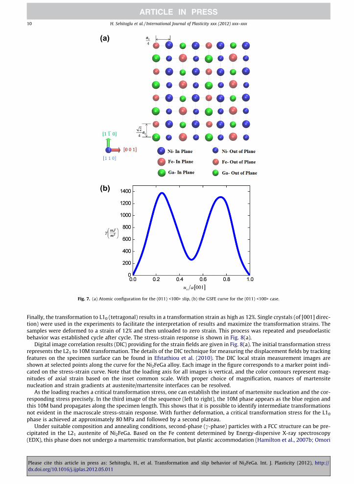
Fig. 7. (a) Atomic configuration for the (011) <100> slip, (b) the GSFE curve for the (011) <100> case.
10 H. Sehitoglu et al. / International Journal of Plasticity xxx (2012) xxx–xxx
Finally, the transformation to L10 (tetragonal) results in a transformation strain as high as 12%. Single crystals (of [001] direc-tion) were used in the experiments to facilitate the interpretation of results and maximize the transformation strains. Thesamples were deformed to a strain of 12% and then unloaded to zero strain. This process was repeated and pseudoelasticbehavior was established cycle after cycle. The stress-strain response is shown in Fig. 8(a).
Digital image correlation results (DIC) providing for the strain fields are given in Fig. 8(a). The initial transformation stressrepresents the L21 to 10M transformation. The details of the DIC technique for measuring the displacement fields by trackingfeatures on the specimen surface can be found in Efstathiou et al. (2010). The DIC local strain measurement images areshown at selected points along the curve for the Ni2FeGa alloy. Each image in the figure corresponds to a marker point indi-cated on the stress-strain curve. Note that the loading axis for all images is vertical, and the color contours represent mag-nitudes of axial strain based on the inset common scale. With proper choice of magnification, nuances of martensitenucleation and strain gradients at austenite/martensite interfaces can be resolved.
As the loading reaches a critical transformation stress, one can establish the instant of martensite nucleation and the cor-responding stress precisely. In the third image of the sequence (left to right), the 10M phase appears as the blue region andthis 10M band propagates along the specimen length. This shows that it is possible to identify intermediate transformationsnot evident in the macroscale stress-strain response. With further deformation, a critical transformation stress for the L10
phase is achieved at approximately 80 MPa and followed by a second plateau.Under suitable composition and annealing conditions, second-phase (c-phase) particles with a FCC structure can be pre-
cipitated in the L21 austenite of Ni2FeGa. Based on the Fe content determined by Energy-dispersive X-ray spectroscopy(EDX), this phase does not undergo a martensitic transformation, but plastic accommodation (Hamilton et al., 2007b; Omori
Please cite this article in press as: Sehitoglu, H., et al. Transformation and slip behavior of Ni2FeGa. Int. J. Plasticity (2012), http://dx.doi.org/10.1016/j.ijplas.2012.05.011

Fig. 8. (a) Pseudoelasticity experiments (at room temperature) (Efstathiou et al., 2008) and (b) TEM results displaying APBs in the austenite domains.
H. Sehitoglu et al. / International Journal of Plasticity xxx (2012) xxx–xxx 11
et al., 2004). In Fig. 8(b), the TEM results are shown clearly displaying the presence of APBs in this alloy. The TEM sampleswere extracted from samples that have undergone pseudoelastic cycling as described above. The dislocations were retainedafter the cycling sequence. The APBs appear as series of lines and are extended across the specimen width. Considering somedeviations because of magnetic rotation between diffraction patterns and the actual image, the trace of the image was foundto be close to the {110} type plane.
5. Implication of Results
Based on the GSFE results the ideal stress levels for dislocation slip were calculated for <111> and <001> directions and themagnitudes are shown in Table 2. We note that the stress magnitudes for slip nucleation, ðsshearÞnuc ¼
dcdux
���, are rather high pre-cluding significant slip within austenite. However, the stresses at the austenite -martensite interfaces can be sufficiently highto generate dislocation slip in the austenite domains. Furthermore, Fisher (1954) made a first order estimate of the additionalstress associated with the dislocation motion creating a change in order within the crystal. The increase in energy of the inter-face needs to be balanced by the extra applied shear stress to move the dislocations. Upon utilizing 200 mJ/m2 (correspondingto the lower value of cNN) we calculate the Fisher strengthening to be near 1 GPa for both cases as shown in Table 2.
We finally note that the calculated separation distances for partials within the APBs are consistent with the experimentsreported in this study. The precise width of the APBs can be further resolved by experiment utilizing high resolution meth-ods, which are outside the scope of the present work. Even though the experimental measurement of separation distances is
Please cite this article in press as: Sehitoglu, H., et al. Transformation and slip behavior of Ni2FeGa. Int. J. Plasticity (2012), http://dx.doi.org/10.1016/j.ijplas.2012.05.011

Table 2Calculated fault energies, Burgers vector, (ideal) critical stress for slip nucleation and Fisher stress for movement of APBs.
Slip plane Slip direction Theory (this study)
b (Å) c, Fault energy (mJ/m2) ðsshearÞnuc ¼dcdux
(GPa) ðsshearÞF ¼cb (GPa)
(1 �1 0) [111] 2.5 200 3.7 0.8
(1 �1 0) [001] 2.88 263 9.5 0.9
12 H. Sehitoglu et al. / International Journal of Plasticity xxx (2012) xxx–xxx
not available because they are only several nanometers, the experiments clearly show the presence of APBs. An example ofhigh density of APB formation in Ni–Fe–Ga has also been reported by Chumlyakov et al. (2008) and the images are in agree-ment to those presented in this study.
We make a comparison between the current results and the work on CuZnAl alloys where the fault energies were of theorder of 45 mJ/m2, which resulted in prediction of Fisher strengthening near 330 MPa (Romero et al., 1988). Similarly, if weare to consider dislocation glide in Ni2FeGa and use Fisher’s formula (ðsshearÞF ) we find the magnitude of extra shear stress todrag the APBs to be near 0.8–0.9 GPa. This magnitude is still significantly higher than the transformation stresses (less than0.2 GPa) observed experimentally for Ni2FeGa. Taking into account the temperature dependence in the phase transformationand plasticity behavior, we note that the critical stresses for the initial martensitic transformation and slip nucleation in Ni2-
FeGa will be modified with increasing temperatures. However, the present results are insightful because they represent theenergies associated with displacements to render the transformation or plasticity at a reference temperature (0K).Consequently, there is mounting evidence of the potential for Ni2FeGa as a shape memory alloy with favorable characteris-tics. To our knowledge, this is the first time the transformation path for L21 to 10M for Ni2FeGa has been determined and theGSFE in <111> and <001> directions are computed for the same alloy. Also, we present experimental evidence of APBs forsamples that have undergone pseudoelastic cycling.
There are a number of reasons why a transformation is reversible versus irreversible. Reversibility is favored when theenergy barriers for forward and reverse transformations are small compared to the energy barriers for dislocation slip.The absence of long range ordering results in rather large hysteresis levels in martensite transformations. For example,the Fe–C or Fe–Ni steels exhibit very large thermal hysteresis of the order of 400 �C, and the FeNiCoTi and FeMnSi fcc shapememory alloys (which do not have long-range ordering) also exhibit high hysteresis levels (200 �C). On the other hand, theFe–Pt shape memory alloys, which can be ordered (Foos et al., 1977), exhibit hysteresis levels as low as 10 �C. In Ni basedalloys (also of the shape memory variety) such as NiTi, NiTiX (X = Cu, Fe), where long-range ordered B2 to monoclinic mar-tensite transformation has been observed, the hysteresis levels are typically of the order of 10 �C to 20 �C. In Ni2FeGa, wherethe austenite phase is long-range ordered cubic L21 and the martensite is monoclinic 10M, the thermal hysteresis can be aslow as 1 �C (Hamilton et al., 2007a) generating new possibilities for applications (Pons et al., 2008). It is shown that the trans-formation barrier is rather low in Ni2FeGa (8.5 mJ/m2), hence the critical stress levels for forward and reverse transformationare much lower than for dislocation slip.
There has been previous discussion of the slip systems in L21 shape memory alloys of the CuZnAl type. The <111> glideplanes have been observed with APB formation for the L21 CuZnAl alloys as well (Damiani et al., 2002a; Romero et al., 1988).It is known that when the APB energies are low, <111> slip dominates. As APB energies become higher with increasing ioniccharacter, <100> slip is favored as noted by Rachinger and Cottrell (Rachinger, 1956). The present results show that theunstable energies for the <001> case are exceedingly high precluding its occurrence unless the stress magnitudes exceeda few GPa.
Finally, we summarize what primarily influences the transformation reversibility of Ni2FeGa alloys. The increase in elasticaccommodation of the transformation with an increase in plastic slip resistance leads to the reversible transformations. Weshow that the slip resistance in long-ranged ordered Ni2FeGa is high with total dislocations decomposing to partials con-nected with anti-phase boundaries.
Acknowledgements
The work was supported by the NSF grant CMMI-09-26813 and partly by DMR-08-03270.
Appendix A
The first-principles total-energy calculations were carried out using the Vienna ab initio Simulations Package (VASP) withthe projector augmented wave (PAW) method and the generalized gradient approximation (GGA). In our calculation, weused a 9 � 9 � 9 Monkhorst Pack k-point meshes for the Brillouin-zone integration to ensure the convergence of results.The energy cut-off of 500 eV was used for the plane-wave basis set. The total energy was converged to less than 10-5 eVper atom. Considering the effect of the number of layers on stacking fault energies (Hatcher et al., 2009), the present DFTcalculation of GSFE for slip system (011)<111> is conducted using a 8 layer supercell having 12-atom per layer; while forslip system (011)<001>, a 8 layer supercell having 4-atom per layer is used. For every shear displacement, the relaxation
Please cite this article in press as: Sehitoglu, H., et al. Transformation and slip behavior of Ni2FeGa. Int. J. Plasticity (2012), http://dx.doi.org/10.1016/j.ijplas.2012.05.011

H. Sehitoglu et al. / International Journal of Plasticity xxx (2012) xxx–xxx 13
perpendicular to the fault plane was allowed for minimizing the short-range repulsive energy between misfitted adjacentlayers (Fu and Yoo, 1992; Paidar, 1976). We construct a supercell consisting of 40 atoms to model the 10M structure in orderto incorporate the full period of modulation in the supercell (Luo et al., 2011a; Zayak et al., 2005). The relaxation by changingthe supercell shape, volume and atomic positions were carried out. The periodic boundary conditions are maintained acrossthe supercell to represent bulk Ni2FeGa material (no free surface). All supercells used in the study ensure the convergence ofthe calculation after careful testing.
The lattice parameters of L21 and L10 structures using DFT were calculated and compared with experimental measure-ments. They are in a good agreement. In order to obtain the 10M structure, the initial calculation parameters a = 4.272 Å,b = 5.245 Å, c = 4.25 Å and the monoclinic angle b = 91.49� (Sutou et al., 2004) are estimated by assuming the lattice corre-spondence with the L10 structure (Kainuma et al., 1996; Ryosuke et al., 2000). The relaxation by changing the supercellshape, volume and atomic positions were carried out. By using this optimization method, the atoms in the supercell movefrom their initial positions after each relaxation step by local forces, and after numerous such iteration processes, the con-figuration will be finally converged where the forces are zero in the stable 10M structure.
References
Ahlers, M., 2002. The martensitic transformation: Mechanisms and crystallography. Philosophical Magazine A 82, 1093–1114.Bartel, T., Menzel, A., Svendsen, B., 2011. Thermodynamic and relaxation-based modeling of the interaction between martensitic phase transformations and
plasticity. Journal of the Mechanics and Physics of Solids 59, 1004–1019.Boyd, J.G., Lagoudas, D.C., 1996. A thermodynamical constitutive model for shape memory materials. Part I. The monolithic shape memory alloy.
International Journal of Plasticity 12, 805–842.Chumlyakov, Y., Kireeva, I., Panchenko, E., Timofeeva, E., Pobedennaya, Z., Chusov, S., Karaman, I., Maier, H., Cesari, E., Kirillov, V., 2008. High-temperature
superelasticity in CoNiGa, CoNiAl, NiFeGa, and TiNi monocrystals. Russian Physics Journal 51, 1016–1036.Crawford, R.C., Ray, I.L.F., Cockayne, D.J.H., 1973. The weak-beam technique applied to superlattice dislocations in iron-aluminium alloys. Philosophical
Magazine 27, 1–7.Damiani, C., Lovey, F.C., Sade, M., 2002a. Plastic deformation under compression of Cu-Zn-Al martensitic single crystals. Materials Science and Engineering A
323, 436–444.Damiani, C., Lovey, F.C., Sade, M., 2002b. Plastic deformation under compression of Cu-Zn-Al martensitic single crystals. Materials Science & Engineering A
(Structural Materials: Properties, Microstructure and Processing) A323, 436–444.Delaey, L., Krishnan, R.V., Tas, H., Warlimont, H., 1974. Thermoelasticity, pseudoelasticity and the memory effects associated with martensitic
transformations. Journal of Materials Science 9, 1521–1535.T.W. Duerig, K.N.M., D. Stöckel, C.M. Wayman, Editors, 1990. Engineering Aspects of Shape Memory Alloys,. Butterworth-Heinemann, Boston.Efstathiou, C., Sehitoglu, H., Carroll, J., Lambros, J., Maier, H.J., 2008. Full-field strain evolution during intermartensitic transformations in single-crystal
NiFeGa. Acta Materialia 56, 3791–3799.Efstathiou, C., Sehitoglu, H., Lambros, J., 2010. Multiscale strain measurements of plastically deforming polycrystalline titanium: Role of deformation
heterogeneities. International Journal of Plasticity 26, 93.Ezaz, T., Sehitoglu, H., Maier, H.J., 2011. Energetics of twinning in martensitic NiTi. Acta Materialia 59, 5893–5904.Fisher, J.C., 1954. On the strength of solid solution alloys. Acta Metallurgica 2, 9–10.Foos, M., Frantz, C., Durupt, S., Gavoille, G., 1977. On reversible shape memory effect related to microstructural memory and residual stresses in Fe3Pt.
Scripta Metallurgica 11, 655–658.Fu, C.L., Yoo, M.H., 1992. Deformation behavior of B2 type aluminides: FeAl and NiAl. Acta Metallurgica et Materialia 40, 703–711.Hamilton, R.F., Sehitoglu, H., Chumlyakov, Y., Maier, H.J., 2004. Stress dependence of the hysteresis in single crystal NiTi alloys. Acta Materialia 52, 3383.Hamilton, R.F., Efstathiou, C., Sehitoglu, H., Chumlyakov, Y., 2006. Thermal and stress-induced martensitic transformations in NiFeGa single crystals under
tension and compression. Scripta Materialia 54, 465.Hamilton, R.F., Sehitoglu, H., Efstathiou, C., Maier, H.J., 2007a. Inter-martensitic transitions in Ni-Fe–Ga single crystals. Acta Materialia 55, 4867–4876.Hamilton, R.F., Sehitoglu, H., Efstathiou, C., Maier, H.J., 2007b. Mechanical response of NiFeGa alloys containing second-phase particles. Scripta Materialia
57, 497–499.Han, M., Bennett, J.C., Gharghouri, M.A., Chen, J., Hyatt, C.V., 2007. Understanding modulated twin transition at the atomic level. Acta Materialia 55, 1731–
1740.Hatcher, N., Kontsevoi, O.Y., Freeman, A.J., 2009. Role of elastic and shear stabilities in the martensitic transformation path of NiTi. Physical Review B
(Condensed Matter and Materials Physics) 80, 144203 (144218 pp.).Head, A.K., 1964. The [111] Dislocation in a Cubic Crystal. physica status solidi (b) 6, 461–465.Idesman, A.V., Levitas, V.I., Stein, E., 2000. Structural changes in elastoplastic material: a unified finite-element approach to phase transformation, twinning
and fracture. International Journal of Plasticity 16, 893–949.Kainuma, R., Nakano, H., Ishida, K., 1996. Martensitic transformations in NiMnAl β phase alloys. Metallurgical and Materials Transactions A: Physical
Metallurgy and Materials Science 27A, 4153–4162.Kibey, S., Sehitoglu, H., Johnson, D.D., 2009. Energy landscape for martensitic phase transformation in shape memory NiTi. Acta Materialia 57, 1624.Koehler, J.S., Seitz, F., 1947. Proposed experiments for further study of mechanism of plastic deformation. American Society of Mechanical Engineers –.
Journal of Applied Mechanics 14, 217–224.Kresse, G., Furthmuller, J., 1996. Efficient iterative schemes for ab initio total-energy calculations using a plane-wave basis set. Physical Review B
(Condensed Matter) 54, 11169.Kresse, G., Hafner, J., 1993a. Ab initio Hellmann-Feynman molecular dynamics for liquid metals, Netherlands, p. 956.Kresse, G., Hafner, J., 1993b. Ab initio molecular dynamics for open-shell transition metals. Physical Review B (Condensed Matter) 48, 13115.Kresse, G., Joubert, D., 1999. From ultrasoft pseudopotentials to the projector augmented-wave method. Physical Review B (Condensed Matter) 59, 1758.Levitas, V.I., 2002. Critical thought experiment to choose the driving force for interface propagation in inelastic materials. International Journal of Plasticity
18, 1499–1525.Liu, J.B., Johnson, D.D., 2009. Bcc-to-hcp transformation pathways for iron versus hydrostatic pressure: Coupled shuffle and shear modes. Physical Review B
79, 134113.Liu, Z.H., Zhang, M., Cui, Y.T., Zhou, Y.Q., Wang, W.H., Wu, G.H., Zhang, X.X., Xiao, G., 2003. Martensitic transformation and shape memory effect in
ferromagnetic Heusler alloy Ni[sub 2]FeGa. Applied Physics Letters 82, 424–426.Luo, H.B., Li, C.M., Hu, Q.M., Kulkova, S.E., Johansson, B., Vitos, L., Yang, R., 2011a. First-principles investigations of the five-layer modulated martensitic
structure in Ni2Mn(AlxGa1�x) alloys. Acta Materialia 59, 5938–5945.Luo, H.B., Li, C.M., Hu, Q.M., Kulkova, S.E., Johansson, B., Vitos, L., Yang, R., 2011b. First-principles investigations of the five-layer modulated martensitic
structure in Ni 2Mn(Al xGa 1-x) alloys. Acta Materialia 59, 5938–5945.
Please cite this article in press as: Sehitoglu, H., et al. Transformation and slip behavior of Ni2FeGa. Int. J. Plasticity (2012), http://dx.doi.org/10.1016/j.ijplas.2012.05.011

14 H. Sehitoglu et al. / International Journal of Plasticity xxx (2012) xxx–xxx
Maki, T., 1998a. Improvement of shape memory effect in Fe–Mn–Si alloys by strengthening of austenite matrix, International Conference on DisplacivePhase Transformations and their Applications in Materials Engineering. In: Honor of Professor CM Wayman on the Occasion of His Retirement, 8–9 May1996. TMS, Warrendale, PA, USA, pp. 111–117.
Maki, T., 1998b. Improvement of shape memory effect in Fe-Mn-Si alloys by strengthening of austenite matrix, Proceedings of the 1996 InternationalConference on Displacive Phase Transformations and their Applications in Materials Engineering, May 8, 1996 - May 9, 1996. Minerals, Metals &Materials Soc (TMS), Urban, IL, USA, pp. 111-117.
Malarria, J., Lovey, F.C., Sade, M., 2009. Two way shape memory effect in CuZnAl single crystals after pseudoelastic cycling at low temperatures. MaterialsScience & Engineering: A (Structural Materials: Properties, Microstructure and Processing) 517, 118–124.
Manchiraju, S., Anderson, P.M., 2010. Coupling between martensitic phase transformations and plasticity: A microstructure-based finite element model.International Journal of Plasticity 26, 1508–1526.
Marcinkowski, M.J., Brown, N., 1961. Theory and direct observation of dislocations in the Fe3Al superlattices. Acta Metallurgica 9, 764–786.Martynov, V.V., 1995. X-ray diffraction study of thermally and stress-induced phase transformations in single crystalline Ni–Mn–Ga alloys, C8 ed. Editions
de Physique, Lausanne, Switzerland, pp. 91–99.Masdeu, F., Pons, J., Segui, C., Cesari, E., Dutkiewicz, J., 2005. Some features of Ni–Fe–Ga shape memory alloys under compression. Journal of Magnetism and
Magnetic Materials 290–291, 816.Moberly, W.J., Proft, J.L., Duerig, T.W., Pelton, A.R., Sinclair, R., 1991. Thermomechanical strengthening of B2 intermetallics. Publ by Minerals, Metals &
Materials Soc (TMS), New Orleans, LA, USA, p. 387.Morito, S., Moritani, T., Furuhara, T., Maki, T., 2000. Martensitic transformation in thin foils of an Fe–Ni–Co–Ti shape memory alloy, International
Symposium and Exhibition on Shape Memory Materials (SMM ‘99), 19–21 May 1999. Trans Tech Publications, Switzerland, pp. 207–210.Morito, H., Oikawa, K., Fujita, A., Fukamichi, K., Kainuma, R., Ishida, K., 2005. Enhancement of magnetic-field-induced strain in Ni–Fe–Ga–Co Heusler alloy.
Scripta Materialia 53, 1237–1240.Jost, N., 1999. Thermal fatigue of Fe–Ni–Co–Ti shape-memory-alloys. Materials Science and Engineering A 273–275, 649–653.Norfleet, D.M., Sarosi, P.M., Manchiraju, S., Wagner, M.F.X., Uchic, M.D., Anderson, P.M., Mills, M.J., 2009. Transformation-induced plasticity during
pseudoelastic deformation in Ni-Ti microcrystals. Acta Materialia 57, 3549–3561.Olson, G.B., Cohen, M., 1975. Thermoelastic behavior in martensitic transformations. Scripta Metallurgica 9, 1247.Omori, T., Kamiya, N., Sutou, Y., Oikawa, K., Kainuma, R., Ishida, K., 2004. Phase transformations in Ni-Ga-Fe ferromagnetic shape memory alloys. Materials
Science and Engineering A 378, 403–408.Otsuka, K., Wayman, C.M., 1998. Shape Memory Materials. Cambridge University Press, Cambridge.Paidar, V., 1973. The equilibrium shape of the antiphase domains in the DO3 structure. Czechoslovak Journal of Physics, Section B B23, 1231–1236.Paidar, V., 1976. Generalized stacking faults in model lattice of ordered Fe-Si alloys. Czechoslovak Journal of Physics 26, 865–874.Pelton, A.R., Huang, G.H., Moine, P., Sinclair, R., 2012. Effects of thermal cycling on microstructure and properties in Nitinol. Materials Science and
Engineering: A 532, 130–138.Pons, J., Cesari, E., Segu
p–, C., Masdeu, F., Santamarta, R., 2008. Ferromagnetic shape memory alloys: Alternatives to Ni, ÄìMn, ÄìGa. Materials Science and
Engineering: A 481, Äì482, 57–65.Rachinger WA, C.A., 1956. Slip in crystals of caesium chloride type.. Acta Metallurgica 4:109.Rice, J.R., 1992. Dislocation nucleation from a crack tip: An analysis based on the Peierls concept. Journal of the Mechanics and Physics of Solids 40, 239.Romero, R., Lovey, F., Ahlers, M., 1988. Plasticity in Œ6 phase Cu-Zn-Al alloys. Philosophical Magazine A 58, 881–903.Roqueta, D.O., Lovey, F.C., Sade, M., 1997. Hysteresis evolution in the martensitic transformation cycling in -Cu-Zn-Al samples with -phase precipitates.
Scripta Materialia 36, 385–391.Ryosuke, K., Fumihiko, G., Yuji, S., Ikuo, O., Kiyohito, I., 2000. Ordering, Martensitic and Ferromagnetic Transformations in Ni-Al-Mn Heusler Shape Memory
Alloys. Materials Transactions, JIM 41, 943–949.Sade, M., Hazarabedian, A., Uribarri, A., Lovey, F.C., 1988. Effects of cycling through stress-induced martensitic transformation in Cu-Zn-Al alloys on
dislocation structures and two-way memory, Phase Transformations ‘87. Proceedings of the Conference, 6-10 July 1987. Inst. Met, London, UK, pp. 279-281.
Santamarta, R., Cesari, E., Font, J., Muntasell, J., Pons, J., Dutkiewicz, J., 2006a. Effect of atomic order on the martensitic transformation of Ni-Fe-Ga alloys.Scripta Materialia 54, 1985–1989.
Santamarta, R., Font, J., Muntasell, J., Masdeu, F., Pons, J., Cesari, E., Dutkiewicz, J., 2006b. Effect of ageing on the martensitic transformation of Ni-Fe-Gaalloys. Scripta Materialia 54, 1105–1109.
Segui, C., Chernenko, V.A., Pons, J., Cesari, E., Khovailo, V., Takagi, T., 2005. Low temperature-induced intermartensitic phase transformations in Ni-Mn-Gasingle crystal. Acta Materialia 53, 111–120.
Sehitoglu, H., Karaman, I., Anderson, R., Zhang, X., Gall, K., Maier, H.J., Chumlyakov, Y., 2000. Compressive response of NiTi single crystals. Acta Materialia 48,3311–3326.
Simon, T., Kroger, A., Somsen, C., Dlouhy, A., Eggeler, G., 2010. On the multiplication of dislocations during martensitic transformations in NiTi shapememory alloys. Acta Materialia 58, 1850–1860.
Sittner, P., Novak, V., Zarubova, N., 1998. Martensitic transformations in [001] CuAlZnMn single crystals. Acta Materialia 46, 1265–1281.Stroh, A.N., 1958. Dislocations and Cracks in Anisotropic Elasticity. Philosophical Magazine 3, 625–646.Sutou, Y., Kamiya, N., Omori, T., Kainuma, R., Ishida, K., Oikawa, K., 2004. Stress-strain characteristics in Ni-Ga-Fe ferromagnetic shape memory alloys.
Applied Physics Letters 84, 1275.Tsuzaki, K., Ikegami, M., Tomota, Y., Kurokawa, Y., Nakagawa, W., Maki, T., 1992. Effect of thermal cycling on the martensitic transformation in an Fe-24Mn-
6Si shape memory alloy. Materials Transactions, JIM 33, 263–270.Vitek, V., 1968. Intrinsic stacking faults in body-centred cubic crystals. Philosophical Magazine 18, 773–786.Wagner, M.F.X., Windl, W., 2008. Lattice stability, elastic constants and macroscopic moduli of NiTi martensites from first principles. Acta Materialia 56,
6232.Wechsler, M.S., Lieberman, D.S., Read, T.A., 1953. On theory of formation of martensite. Journal of Metals 5, 1503–1515.Yamagiuchi, M., Pope, D.P., Vitek, V., Umakoshi, Y., 1981. Planar faults and dislocation dissociations in body-centred-cubic-derivative ordered structures.
Philosophical Magazine A 43, 1265–1275.Zayak, A., Adeagbo, W.A., Entel, P., Buchelnikov, V.D., 2005. Crystal structures of Ni2MnGa from density functional calculations. Phase Transitions 78, 259–
266.
Please cite this article in press as: Sehitoglu, H., et al. Transformation and slip behavior of Ni2FeGa. Int. J. Plasticity (2012), http://dx.doi.org/10.1016/j.ijplas.2012.05.011