international journal of modern computer science … · international journal of modern computer...
TRANSCRIPT

International Journal of Modern Computer Science (IJMCS) ISSN: 2320-7868 (Online) Volume 4, Issue 6, December, 2016
RES Publication © 2012 Page | 13 http://ijmcs.info
An Efficient (EEMRP) Protocol for MANET
Sanjay Kumar Sahani 1
Computer science and Information Technology
SHIATS, Allahabad (UP)
Email [email protected]
Raghav Yadav 2
Associate Professor(CSIT)
SHIATS, Allahabad (UP)
Email [email protected]
Abstract-Saving energy and increasing network lifetime are significant challenges in the field of MANET. Energy-aware routing
protocols have been introduced for MANET to overcome limitations of MANET. The Ad hoc On-demand Distance Vector (AODV)
and the cluster-tree routing protocols. These protocols are implemented to establish the network, form clusters, and transfer data
between the nodes. The AODV and the a new protocol energy efficient mobile routing protocol(EEMRP) are two of the most
efficient routing protocols in terms of reducing the control message overhead, reducing the bandwidth usage in the network, and
reducing the power consumption of MANET compared to other routing protocols. All the aforementioned approaches contribute in
increasing the lifetime of the MANET, and distributing the power consumption among the MANET. We demonstrated proposed
techniques through simulations accomplished using NS-2 simulator. All the simulation results have verified the remarkable
improvement of performance in term of reducing the power consumption rate and increasing the lifetime of the MANET, Compared
with the original AODV and energy efficient mobile routing protocol (EEMRP).
Keywords: MANET, Energy-aware Routing Protocols, Network Lifetime, Energy Consumption Rate, AODV, EEMRP.
I. INTRODUCTION In MANET, each node acts as both host and router. That is it
is autonomous in behaviour. Multi-hop radio relaying- When a
source node and destination node for a message is out of the
radio range, the MANETs are capable of multi-hop routing.
Distributed nature of operation for security, routing and host
configuration; A centralized firewall is absent here. The nodes
can join or leave the network anytime, making the network
topology dynamic in nature. Mobile nodes are characterized
with less memory, power and light weight features. The
reliability, efficiency, stability and capacity of wireless links
are often inferior when compared with wired links. This shows
the fluctuating link bandwidth of wireless links. Mobile and
spontaneous behaviour which demands minimum human
intervention to configure the network. All nodes have identical
features with similar responsibilities and capabilities and
hence it forms a completely symmetric environment. High
user density and large level of user mobility. Nodal
connectivity is intermittent.
1.1 Wireless standards the wireless standards that we will
investigate in this paper is only a selection from all the
standards available. These explanations are not meant to be
exhaustive.
1.2 IEEE 802.11 - WLAN/Wi-Fi
Wireless LAN (WLAN, also known as Wi-Fi) is a set of low
tier, terrestrial, network technologies for data communication.
The WLAN standards operate on the 2.4 GHz and 5 GHz
Industrial, Science and Medical (ISM) frequency bands. It is
specified by the IEEE 802.11 standard.
1.3 IEEE 802.15.1 - Bluetooth
The IEEE 802.15.1 standard [3] is the basis for the Bluetooth
wireless communication technology. Bluetooth is a low tier,
ad hoc, terrestrial, wireless standard for short range
communication. It is designed for small and low cost devices
with low power consumption. The technology operates with
three different classes of devices: Class 1, class 2 and class 3
where the range is about 100 meters, 10 meters and 1 meter
respectively. Wireless LAN operates in the same 2.4 GHz
frequency band as Bluetooth.
1.4 IEEE 802.15.4 –Zig Bee
Zig Bee is a low tier, ad hoc, terrestrial, wireless standard in
some ways similar to Bluetooth. The IEEE 802.15.4 standard
[4] is commonly known as Zig Bee, but Zig Bee has some
features in addition to those of 802.15.4. It operates in the 868
MHz, 915 MHz and 2.4 GHz ISM bands. It explain some of
the differences and similarities between the IEEE 802.11,
802.15.1, 802.15.4 and 802.15.6 wireless standards with an
emphasis on the physical layer. Modes of operation Wireless
networks can have to distinct modes of operation: Ad hoc and
infrastructure. Infrastructure wireless networks usually have
some kind of base station1 which acts as a central node which
connects the wireless terminals. The base station is usually
provided in order to enable access to the Internet, an intranet
or other wireless networks. Most of the time the base stations
have a fixed location, but certain mobile base stations also
exist. The disadvantage over ad hoc networks is that the base
station is a central point of failure. If it stops working none of
the wireless terminals can communicate with each other.
1.5 Background on IEEE 802.15.4
An IEEE 802.15.4 network comprises one PAN coordinator
and a set of devices. These low-power devices are
characterized by a limited transmission range and a limited
quantity of energy. The IEEE has proposed the IEEE 802.15.4
to govern the medium access in this kind of networks,
presented in [3]. The protocol uses a PAN coordinator, inter-
connecting the WSN to e.g. the Internet. Although IEEE
802.15.4 was originally designed for single hop networks, the
working group has proposed topologies to cope with multi-
hop applications (Figure 1).

International Journal of Modern Computer Science (IJMCS) ISSN: 2320-7868 (Online) Volume 4, Issue 6, December, 2016
RES Publication © 2012 Page | 14 http://ijmcs.info
Star: The PAN coordinator is in the radio range of all other
nodes (i.e. each node forms a branch of the star). Single hop
transmissions are in this case sufficient. 15
Full function device
Reduced function device
Communications flow
Master/Slave
PANCoordinator
IEEE802.15.4 – Star Topology
Thomas Watteyne @ EDERC 2010
Peer-to-peer: A node may communicate with any neighbor,
the structure being decentralized. A routing protocol may
enable multihop communications, using P2P transmissions at
the MAC layer. 16
Full function device Communications flow
Point to point Cluster tree
IEEE802.15.4 – P2P Topology
Thomas Watteyne @ EDERC 2010
Cluster-tree: A tree is constructed, rooted at the PAN
coordinator. All the non-leaf-nodes are designated as
coordinators since they may forward the traffic to or from the
root. 17
Full function device
Reduced function device
Communications flow
Clustered stars - for example,cluster nodes exist between roomsof a hotel and each room has a star network for control.
IEEE802.15.4 – Combined Topology
Thomas Watteyne @ EDERC 2010
1.6 MAC mechanisms
In these topologies, IEEE 802.15.4 may work either in non-
beacon or in beacon-enabled mode. The MAC strategy
impacts the duty-cycle and thus the capacity and energy
consumption. In IEEE 802.15.4, one set of nodes (the
coordinators) regulates the transmissions. Any exchange is
initiated from the non-coordinator to the coordinator. In
particular, the coordinator buffers all the packets destined to
others.
II. RELATED WORKS
The optimized routing mechanism works at the network layer
and optimize the decision based on the physical parameters
translated as forwarding metrics. The physical parameters are
the PRR and remaining power. The forwarding metrics is used
to get an optimal decision. The forwarding metrics are
requested only during neighbor discovery and network
initialization phase. Some review to the optimized routing
mechanism
Joseph Polastre 2004: We propose B-MAC, a carrier sense
media access protocol for wireless sensor networks that
provides a flexible interface to obtain ultra-low power
operation, effective collision avoidance, and high channel
utilization. To achieve low power operation, B-MAC employs
an adaptive preamble sampling scheme to reduce duty cycle
and minimize idle listening.
Ilker Demirkol 2006: Various medium-access control (MAC)
protocols with different objectives have been proposed for
wireless sensor networks. In this article, we first outline the
sensor network properties that are crucial for the design of
MAC layer protocols. Then, we describe several MAC
protocols proposed for sensor networks, emphasizing their
strengths and weaknesses.
Meng-Shiuan Pan 2007:ZigBee is a communication standard
which is considered to be suitable for wireless sensor
networks. In ZigBee, a device (with a permanent 64-bit MAC
address) is said to join a network if it can successfully obtain a
16-bit network address from a parent device.
Jan Magne Tjensvold 2007: It explain some of the
differences and similarities between the IEEE 802.11,
802.15.1, 802.15.4and 802.15.6 wireless standards with an
emphasis on the physical layer.
Changsu Suh 2008: IEEE 802.15.4 MAC includes features
such as its dual operational modes (Non-Beacon-enabled
mode/Beacon- enabled mode), which make this standard more
attractive for providing multimedia services over the
networked sensors. Its Beacon-enabled mode can conserve
energy by using the RF sleep mechanism, but it is limited by
the lower data throughput.
Dr.S.S.Riaz Ahamed 2009: ZigBee is an IEEE 802.15.4
standard for data communications with business and consumer
devices. It is designed around low-power consumption
allowing batteries to essentially last forever. The ZigBee
standard provides network, security, and application support
services operating on top of the IEEE 802.15.4 Medium
MacAccess Control (MAC) and Physical Layer (PHY)
wireless standard.

International Journal of Modern Computer Science (IJMCS) ISSN: 2320-7868 (Online) Volume 4, Issue 6, December, 2016
RES Publication © 2012 Page | 15 http://ijmcs.info
Sukhvinder S 2010: This paper investigates the performance
of WPAN based on various topological scenarios like: cluster,
star and ring. The comparative results have been reported for
the performance metrics like: Throughput, Traffic sent, Traffic
received and Packets dropped.
Sukhvinder S Bamber 2010: The main objective of this
paper is to investigate the performance trade off with MSK,
BPSK and QAM_64 modulation techniques. Investigations
have been reported to compare the performance and tradeoffs
of MSK, BPSK and QAM_64 modulation schemes.
Yasser Gadallah 2010: The IEEE 802.15.4 standard was
developed for the purpose of media access control of low
power wireless personal area networks. Wireless sensor
network devices have the general characteristics of low power
capabilities and operation.
Sri Sai Krishna Pradeep 2011: we considered minimizing
energy consumption with and providing QoS in WSN which is
very important nowadays. In this work we developed a cross-
layer protocol that operated with MAC and network layer, it
introduces QoS and wake and sleep states.
M.E. Haque2012: paper presents a comprehensive review of
wireless sensor and fiber optic sensor for SHM and
challenging issue related to the structural health monitoring. It
also introduces research challenges and potential applications
of the WSN.\
M. M. Chandane 2012: Wireless Sensor Network (WSN)
consists of a large population of sensor nodes capable of
computation, communication and sensing. Limited storage,
processing, and transmission power are inherent limitations of
WSN. IEEE 802.15.4 is a new standard, uniquely designed for
low rate Wireless Personal Area Network (LR-WPAN),
developed for applications that demand low throughput.
Ms. Sonal J. Rane 2013: Wireless Sensor Networks (WSNs)
are an important class of services supported by the IEEE
802.15.4 standard. Time critical application of WSN can be
fulfilled by the IEEE 802.15.4 standard through Guaranteed
Time Slot (GTS) mechanism. The GTS is activated in the
beacon-enabled mode based on the super frame structure
Jianliang Zheng: IEEE 802.15.4 is a new standard uniquely
designed for low rate wireless personal area networks
(LRWPANs). It targets low data rate, low power consumption
and low cost wireless networking, and offers device level
wireless connectivity. We develop an NS2 simulator for IEEE
802.15.4 and conduct several sets of experiments.
III. PROTOCOL OPRATION
3.2 EEMRP (Energy Efficient Mobile Routing) protocol
3.2.1: Overview
We propose a proactive routing protocol for mobile ad hoc
networks, which we call as Energy Efficient Mobile Routing
(EEMRP). The protocol inherits the stability of the link state
algorithm. Due to its proactive nature ,it has an advantage of
having the routes immediately available when neighbor node
are declared and are flood in the entire networks. EEMRP
protocol is an optimization of a pure links state protocol for
mobile ad hoc Networks. First, it reduces the size of control
packets: instead of all links, it declares only a subset of. Links
with its neighbor who are its multipoint relay selection
.secondly it minimized flooding of this control traffic by using
only the selection node called multipoint relays, to different its
message in the network. Only the multipoint relays of a node
retransmit its broadcast messages. This technique significantly
reduces the number of retransmissions in a flooding or
broadcast procedure. A part from normal periodic control
messages, the protocol does not generate extra control traffic
in response to link failures and additions. The protocol keeps
the routes for all the destinations in the network; hence it is
beneficial for the traffic patterns where a large subset of nodes
is communicating with each other, and the [source,
destination] pairs are also changing with time. The protocol is
particularly suitable for large and dense network, as the
optimization done using the multipoint relays works well in
this context. More dense and large a network is, more
optimization is achieved as compared to the normal link state
algorithm. The protocol is designed to work in a completely
distributed manner and thus does not depend upon any central
entity. The protocol does not require a reliable transmission
for its control messages periodically, and can therefore sustain
a loss of some packets from time to time, which happens very
often in radio network due to collisions or other transmission
problems. The protocol also does not need an in-order delivery
of its messages: each control message contains a sequence
number of most recent information; therefore the re-ordering
at the receiving end cannot make the old information
interpreted as the recent one. EEMRP protocol performs hop
by hop routing, i.e. each node uses its most recent information
to route packet. Therefore, when a node is moving its packets
can be successfully delivered to it, if its speed is such that its
movement could be followed in its neighborhood, at least. The
protocol thus supports a nodal mobility that can be traced
through its local control messages, which depends upon the
frequency of these messages.
3.2.2 Multipoint relays.
The idea of multipoint relays is to minimize the flooding of
broadcast packets in the network by reducing duplicate
retransmissions in the same region. Each mode in the network
selects a set of nodes in its neighborhood, which retransmit its
packets. This set of selected neighbor nodes is called the
multipoint relays (MPRs) of that node. The neighbors of any
node N which are not in its MPR set, read and process the
packet but do not retransmit the broadcast packet received
from node N. For this purpose, each node maintains a set of its
neighbor which called the MPR selectors of the node. Every
broadcast message coming from these MPR selectors of a
node is assumed to be retransmitted by that node. This set can
change over time, which is indicated by the selector nodes in
their HELLO messages. Each node selects its multipoint relay
International Journal of Modern Computer Science (IJMCS) ISSN: 2320-7868 (Online) Volume 4, Issue 6, December, 2016
RES Publication © 2012 Page | 16 http://ijmcs.info
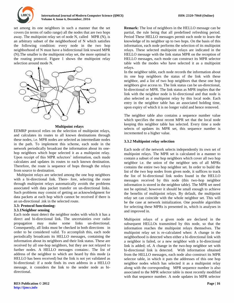
set among its one neighbors in such a manner that the set
covers (in terms of radio range) all the nodes that are two hops
away. The multipoint relay set of node N, called MPR (N), is
an arbitrary subset of the neighborhood of N which satisfies
the following condition: every node in the two hop
neighborhood of N must have a bidirectional link toward MPR
(N).The smaller is the multipoint relay set, the more optimal is
the routing protocol. Figure 1 shows the multipoint relay
selection around mode N.
Multipoint relays
EEMRP protocol relies on the selection of multipoint relays,
and calculates its routes to all known destinations through
these nodes, i.e. MPR nodes are selected as intermediate nodes
in the path. To implement this scheme, each node in the
network periodically broadcast the information about its one-
hop neighbors which hope selected it as a multipoint relay.
Upon receipt of this MPR selectors’ information, each made
calculates and updates its routes to each known destination.
Therefore, the route is sequence of hops through the relays
from source to destination.
Multipoint relays are selected among the one hop neighbors
with a bi-directional link. There- fore, selecting the route
through multipoint relays automatically avoids the problems
associated with data packet transfer on un-directional links.
Such problems may consist of getting an acknowledgment for
data packets at each hop which cannot be received if there is
an un-directional .ink in the selected route.
3.3: Protocol functioning:
3.3.1Neighbor sensing
Each node must detect the neighbor nodes with which it has a
direct and bi-directional link. The uncertainties over radio
propagation may make some links un-directional.
Consequently, all links must be checked in both directions in
order to be considered valid. To accomplish this, each node
periodically broadcasts its HELLO messages, containing the
information about its neighbors and their link status. These are
received by all one-hop neighbors, but they are not relayed to
further nodes. A HELLO messages contains:. The list of
address of the neighbor to which are heard by this mode (a
HELLO has been received) but the link is not yet validated as
bi-directional: if a node finds its own address in a HELLO
message, it considers the link to the sender node as bi-
directional.
Remark: The lost of neighbors in the HELLO message can be
partial, the rule being that all predefined refreshing period.
Period These HELLO messages permit each node to learn the
knowledge of its neighbor up to two hops. On the basis of this
information, each node performs the selection of its multipoint
relays. These selected multipoint relays are indicated in the
HELLO message with the link status MPR on the reception of
HELLO messages, each mode can construct its MPR selector
table with the modes who have selected it as a multipoint
relays.
In the neighbor table, each node records the information about
its one hop neighbors the status of the link with these
neighbor, and a list of two hop neighbors that these one hop
neighbors give access to. The link status can be un-directional,
bi-directional or MPR. The link status as MPR implies that the
link with the neighbor node is bi-directional and that node is
also selected as a multipoint relay by this local node. Each
entry in the neighbor table has an associated holding time,
upon expiry of which it is no longer valid and hence removed.
The neighbor table also contains a sequence number value
which specifies the most recent MPR set that the local node
keeping this neighbor table has selected. Every time a node
selects of updates its MPR set, this sequence number is
incremented to a higher value.
3.3.2 Multipoint relay selection
Each node of the network selects independently its own set of
multipoint relays. The MPR set is calculated in a manner to
contain a subset of one hop neighbors which cover all two hop
neighbor i.e. the union of the neighbor sets of all MPRs
contains the entire two hop neighbor set. In order to build the
list of the two hop nodes from given node, it suffices to track
the list of bi-directional link nodes found in the HELLO
messages received by this node (this two-hop neighbor
information is stored in the neighbor table). The MPR set need
not be optimal; however it should be small enough to achieve
the benefits of multipoint relays. By default, the multipoint
relay set can coincide with the whole neighbor set. This will
be the case at network initialization. One possible algorithm
for selecting these MPRs is presented in, which is analyses in
and improved in.
Multipoint relays of a given node are declared in the
subsequent HELLOs transmitted by this node, so that the
information reaches the multipoint relays themselves. The
multipoint relay set is re-calculated when: A change in the
neighborhood is detected when either a bi-directional link with
a neighbor is failed, or a new neighbor with a bi-directional
link is added; of. A change in the two-hop neighbor set with
bi-directional link is detected. With information obtained
from the HELLO messages, each node also construct its MPR
selector table, in which it puts the addresses of this one hop
neighbor nodes which has selected it as a multipoint relay
along with the corresponding MPR sequence number is also
associated to the MPR selector table is most recently modified
with that sequence number. A node updates its MPR selector

International Journal of Modern Computer Science (IJMCS) ISSN: 2320-7868 (Online) Volume 4, Issue 6, December, 2016
RES Publication © 2012 Page | 17 http://ijmcs.info
set according to the information it receives in the HELLO
messages, and increment this sequence number on each
modification.
3.3.3MPR information declaration
In order to build the intra-forwarding database needed for
routing packets, each node broadcasts specific control
messages called Topology Control (TC) messages. TC
messages are forwarded like usual broadcast messages in the
entire network. This technique is similar to the link state
technique used in ARPANET, but it takes advantage of MPRs
which enable a better scalability of intra- formation.
A TC message is sent periodically by each node in the
network to declare its MPR selector set, i.e. the message
contains the list of neighbors who have selected the sender
node as a multipoint relay. The sequence number associated to
this MPR selector set is also attached to the lost. The loss of
addresses cam be partial in each TC message, but parsing must
be complete within a certain refreshing period. (In the list of
addresses is mandatorily exhaustive). The information
diffused in the network by these TC messages will help each
node to build its topology table. A node which has an empty
MPR selector set, i.e. nobody has selected it as a multipoint
relay, may not generate any TC message. The interval between
the transmissions of two TC messages depends upon whether
the MPR selector set is changed or not, since the last TC
message transmitted. When a change occurs in the MPR
selector set, the next TC May be sent earlier that the scheduled
time, but after some pre-specified minimum interval, starting
from the time the last TC message was sent. If this much time
has already elapsed, the next TC message may be transmitted
immediately. All subsequent TC messages are sent with the
normal default interval for sending TC messages, until the
MPR selector set is changed again.
Each node of the network maintains a topology table, in which
it records the information about the topology of the network
obtained from the TC messages. A node records information
about the multipoint relays of other nodes in this table. Based
on this information, the routing table is calculated. An entry in
the topology table consists of an address of a (potential)
destination (an MPR selector in the received TC message),
address of last-hop node to that destination (originator of the
TF message) and the corresponding MPR selector set
sequence number (of the sender node). It implies that the
destination node can be reached in the last hop through this
last-hop node. Each topology entry has an associated holding
time, upon expiry of which it is no longer valid and hence
removed. Upon receipt of a TC message, the following
proposed procedure may be executed to record the information
in the topology table:
1. If there exist some entry in the topology table whose last-
hop address corresponds to the originator address of the TC
message and the MPR selector sequence number in the
received message, then no further processing of this TC
message is done and it is silently discarded (case: packet
received out of order).
2. If there exist some entry in the topology table whose last-
hop address of the TC message and the MPR selector
sequence number in that entry is smaller than the sequence
number in the received message, then that topology entry is
removed.
3. For each of the MPR selector address received in the TC
message .If there exist some entry in the topology table whose
destination address corresponds to the MPS selector address
and the last-hop address of that entry corresponds to the
originator address of the TC message, then the holding time of
that entry is refreshed. Otherwise, a new topology entry is
recorded in the topology table.
3.3.4 Routing table calculation
Each node maintains a routing table which allows it to route
the packets for other destinations in the network. The nodes
which receive a TC message parse and store some of the
connected pairs of form [last-hop, node] where “nodes” are
the addresses found in the TC message list. The routing table
is built from this database by tracking the connected pairs in a
descending order. To find a path from a given origin to a
remote node an R, one has to find a connected (Y, X) and so
forth until one finds a node Y in the neighbor set of the origin.
Figure 2 explains this procedure of searching the [last- hop
destination] pairs in the topology table to get a complete,
connected route from source to destination. In order to restrict
to optimal paths, the forwarding nodes will select only the
connected pairs on the minimal path this selection can be done
dynamically and with minimal storage facilities. The sequence
numbers are used to detect connected pairs which have been
invalidated by further topology changes The information
contained in the intra-forwarding database (topology table),
which has not been refreshed is discarded. See section 5for
more details.
The route entries in the routing table consist of destination
address, next-hop address and estimated distance to
destination. The entries are recorded in the table for each
destination in the network for which the route is known. All
the destinations for which the route is broken of partially
know are not entered in the table.
Building a route from topology table
The routing table is based on the information contained in the
neighbor table and the topology table. Therefore, if any of this
table is changed, the routing table is re-calculated to update
the route information about each known destination in the

International Journal of Modern Computer Science (IJMCS) ISSN: 2320-7868 (Online) Volume 4, Issue 6, December, 2016
RES Publication © 2012 Page | 18 http://ijmcs.info
network. The table is re-calculated when a change in the
neighborhood is detected concerning a bi-directional link or
when a route to any destination is expired (because the
corresponding topology entry is expired). The re-calculation
of this routing table dies not generate of trigger any packets to
be transmitted, neither in the entire network, nor in the one-
hop neighborhood
The following proposed procedure may be executed to
calculate (or re-calculate) the routing table:
1. All the entries of routing table are removed.
2. The new entries of routing table are recorded in the table
stating with one hop neighbours (h=1) as destination nodes.
For each neighbour’s entry in the neighbour table, whose link
status is not un-directional, a new route entry is recorded in
the routing table where set to 1.
3. Then the new route entries for destination nodes h+1 hop
away are recorded in the routing table. The following
procedure is executed for each value of h, starting with h=1
and incrementing it by 1 each time. The execution will stop if
no new entry is recorded in iteration.
4. For each topology entry in topology table if its destination
address does not corresponds to destination address of any
route entry in the routing table and its last-hop address of a
route entry with distance equal to h, then a new route entry is
recorded in the routing table where: destination is set to
destination address is topology table; next –hop is set of the
route entry whose destination is equal to above-mentioned
last-hop address; and _distance is set to h+1. After calculating
the routing table, the topology table, entries which are not
used in calculating the routes may be removed, if there is a
need to save memory space. Otherwise, these entries may
provide multiple routes.
3.4: Performance analysis
3.4.1Route optimality
The main problem is to show that the introduction of a
multipoint relay set as a subset of the neighbor set does not
destroy the connectivity properties of the network. Let us
take the following model: we consider a network made up of a
set of nodes and a set interconnection graph. We define the
usual distance which gives the minimal number of hops
between node and node .We also define as the minimal
number of hops, providing that the intermediate relay nodes
are forwarders. We can notice that does not define a distance
when some nodes are non-forwarders because triangle
inequality could be not satisfied every time. In the following,
we consider a safe network: By definition of link validity and
since the HELLO messages are periodically retransmitted, the
neighbor sensing and the election of multipoint relay nodes
can be performed without any particular problem, except if
mobile nodes move faster than HELLO interval. In the
following we suppose that every node has a multipoint relay
set that covers its two hop neighbor set we do not need to
assume optimality of the multipoint relay set. The last
operation is topology information broadcast. If for any node
its multipoint relay set coincides with its neighbor set, them
the TC message broadcast will reach any node in a straight-
forward way. In this case the minimal path to a remote node
received via TC message would be an optimal path and the
routing tables will contain the appropriate information. Our
point is that this property remains valid when multipoint relay
sets are strict subset of neighbor sets. We of multipoint relays
of rank 1 as the multipoint relays of rank k+1, for k integer, as
the union of multipoint relay set of all nodes element of the
multipoint relay set of rank k. In other words each element Mk
of the multipoint relay set of rank k of a node X can be
reached via a path XM1… Mk where M1 is multipoint relay
of X, and Mi+1 is multipoint relay of Mi
Theorem 1 If for two nodes X and Y, df (X, Y) = k+1 for k
integer, then Y is at distance 1 from the multipoint relay set of
rank k of X.
Proof: By recursion.
The proposition is valid for k = o and k = 1, by definition of
the multipoint relay set. We suppose the proposition valid for
k, and let us assume a node Y such that dF (X, Y) = k+ 2.
Therefore there exists an optimal valid path XF….FkFk+1Y
where the F is are all forwarder nodes. We have dF (X, Fk+1)
=k+1 therefore Fk+1 is at distance 1 from the multipoint relay
set of rank k of k. Let Mk be the element of the multipoint
relay set of rank k of X such that d F (Mk’Fk+1) +1; therefore
dF(Mk, Y ) =2 and Y belongs to the two hop neighbor set of
Mk. Let Mk+1 be multipoint relay of Mk+1 belongs to the
multipoint relay set of rank k+1 the theorem is proved.
3.4.2 Broadcast performance
Theorem 2 for all pair of nodes X and Y, X generating and
transmitting a broadcast packet P, Y receives a copy of P.
Proof: By reversed recursion.
We suppose that transmissions are error free but are
subject to arbitrary finite delays. Let k be the closest distance
to Y from which a copy of packet P has been eventually (re)
transmitted. We shall prove that k= 1 Let F be the first
forwarder at distance k (k> 2) from Y, which has retransmitted
P. There exists a multipoint relay F’ of F which is at distance
k-1 of Y. To be convinced: we imagine a path of length k from
F to Y: F, F1, F2 …..Fk-, Y and we take for F’ the multipoint
relay for F which covers F2 Since F’ received a copy of a P
the first time from F ( the prior transmitters are necessarily
two –hops away from F’ ) therefore F’ will automatically
forward P: packet P will be retransmitted at distance k- 1 from
Y. The theorem is proved.
Note that if the transmission is prone to errors, then there is no
guarantee of correct packets reception by the intended
destination. But this is a common problem to all unreliable
communications networks which need upper layer recovery
procedure.

International Journal of Modern Computer Science (IJMCS) ISSN: 2320-7868 (Online) Volume 4, Issue 6, December, 2016
RES Publication © 2012 Page | 19 http://ijmcs.info
IV. RESULTS
4.1AODV-802-11 MODULE
4, 1.1AODV-802-11-delay channel type Channel/WirelessChannel
radio-
propagation
model
Propagation/TwoRayGround
Antenna type Antenna/OmniAntenna
Link layer type LL
Interface queue
type
Queue/DropTail/PriQueue
max packet in
ifq
200
network
interface type
Phy/WirelessPhy
MAC type Mac/802_11
number of mobilenodes
50
routing protocol AODV
X 500
Y 500
Table 4.1
4.1.2 PACKET DELAY:
The delay of a packet in a network is the time it takes the
packet to reach the destination after it leaves the source.
time Frequency
0 0
2 3190.5
4 2740.3
6 1835.6
8 1391.2
10 1131.1
4.1.3: ENERGY SPENT
AODV-802-11-energy
time Frequency
0 0
2 16.33
4 16.59
6 16.81
8 17.01
10 17.21
4.1.4: PACKET DELIVERY RATIO
AODV-802-11-pdr
time Frequency
0 0
2 0.1250
4 0.4136
6 0.4380
8 0.4534
10 0.4675
4.1.5 THROUGHPUT
The vertical axis shows the throughput, measured in
kilobytes per second, which should be maximized.
Received bytes
Throughput=
Time of simulation

International Journal of Modern Computer Science (IJMCS) ISSN: 2320-7868 (Online) Volume 4, Issue 6, December, 2016
RES Publication © 2012 Page | 20 http://ijmcs.info
AODV-802-11-throughput
time Frequency
0 0
2 25.06
4 37.41
6 38.04
8 38.53
10 38.83
4.1.6: ROUTING OVERHEAD
AODV-802-11-routing-overhead
time Frequency
0 0
2 30.20
4 10.27
6 8.99
8 6.64
10 5.27
4.2: AODV-802-15-4 MODULE
AODV-MAC-802-15-4
channel type Channel/WirelessChannel
radio-propagation model Propagation/TwoRayGround
Antenna type Antenna/OmniAntenna
Link layer type LL
Interface queue type
Queue/DropTail/PriQueue
max packet in ifq
200
network interface type Phy/WirelessPhy
MAC type Mac/802_15_4
number of mobilenodes 50
routing protocol AODV
X 500
Y 500
4.2.1: DELAY
AODV-MAC-802-15-4-delay
time frequency
0 0
2 3066.5
4 2616.5
6 1711.5
8 1267.5
10 1007.5
4.2.2: ENERGY SPENT

International Journal of Modern Computer Science (IJMCS) ISSN: 2320-7868 (Online) Volume 4, Issue 6, December, 2016
RES Publication © 2012 Page | 21 http://ijmcs.info
AODV-MAC-802-15-4-energy
time frequency
0 0
2 14.16
4 14.42
6 14.64
8 14.84
10 15.04
4.2.3: PACKET DELIVERY RATIO
AODV-MAC-802-15-4-pdr
time frequency
0 0
2 0.36
4 0.6486
6 0.673
8 0.6884
10 0.7025
4.2.4: THROUGHPUT
AODV-MAC-802-15-4-throughput
time frequency
0 0
2 62.67
4 75.02
6 75.65
8 76.14
10 76.44
4.2.5: ROUTING OVERHEAD
AODV-MAC-802-15-4-routing-overhead
time frequency
0 0
2 26.04
4 6.11
6 4.82
8 2.48
10 1.11

International Journal of Modern Computer Science (IJMCS) ISSN: 2320-7868 (Online) Volume 4, Issue 6, December, 2016
RES Publication © 2012 Page | 22 http://ijmcs.info
4.3: NEW PROTOCOLE EEMRP (Energy Efficient
Mobile Routing Protocol) MODULE
Eemrp-802-15-4
channel type Channel/WirelessChannel
radio-propagation model Propagation/TwoRayGround
Antenna type Antenna/OmniAntenna
Link layer type LL
Interface queue type
Queue/DropTail/PriQueue
Max packet in ifq
200
Network interface type Phy/WirelessPhy
MAC type Mac/802_15_4
Number of mobilenodes 50
Routing protocol EEMRP
X 500
Y 500
4.3.1: DELAY
Eemrp-802-15-4-delay
time frequency
0 0
2 0
4 10.69
6 12.97
8 12.02
10 12.56
4.3.2: ENERGY
Eemrp-802-15-4-energy
time frequency
0 0
2 3.62
4 12.77
6 13.04
8 13.21
10 13.48
4.3.3: PACKET DELIVERY RATIO
Eemrp-802-15-4-pdr
time frequency
0 0
2 0
4 0.6778
6 0.8876
8 0.8907
10 0.9625
4.3.4: THROUGHPUT
Eemrp-802-15-4-throughput

International Journal of Modern Computer Science (IJMCS) ISSN: 2320-7868 (Online) Volume 4, Issue 6, December, 2016
RES Publication © 2012 Page | 23 http://ijmcs.info
time frequency
0 0
2 0
4 111.33
6 119.81
8 119.85
10 122.57
4.3.5: ROUTING OVERHEAD
Eemrp-802-15-4-routing-overhead
4.4: COMPRISTION WITH IN ALL MODULE
4.4.1: AVERAGE DELAY
module 0
Sec
2 Sec 4 Sec 6 Sec 8 Sec 10 Sec
aodv-
802-11
0 3190.5 2740.3 1835.6 1391.2 1131.1
aodv-
mac-802-
15-4
0 3066.5 2616.5 1711.5 1267.5 1007.5
eemrp-
802-15-4
0 0 10.69 12.97 12.02 12.56
4.4.2: COMPRISION WITH ENERGY SPENT IN ALL
MODULE
module 0
Sec
2 Sec 4 Sec 6 Sec 8 Sec 10 Sec
aodv-802-
11
0 16.33 16.59 16.81 17.01 17.21
aodv-mac-
802-15-4
0 14.16 14.42 14.64 14.84 15.04
eemrp-
802-15-4
0 3.62 12.77 13.04 13.21 13.48
4.4.3: COMPRITION WITH PACKET DELIVERY
RATIO IN ALL MODULE
time frequency
0 0.1
2 0.1
4 0.1
6 0.1
8 0.1
10 0.1

International Journal of Modern Computer Science (IJMCS) ISSN: 2320-7868 (Online) Volume 4, Issue 6, December, 2016
RES Publication © 2012 Page | 24 http://ijmcs.info
module 0
Sec
2 Sec 4 Sec 6 Sec 8 Sec 10 Sec
aodv-
802-11
0 0.1250 0.4136 0.4380 0.4534 0.4675
aodv-
mac-802-
15-4
0 0.36 0.6486 0.673 0.6884 0.7025
eemrp-
802-15-4
0 0 0.6778 0.8876 0.8907 0.9625
4.4.4: COMPRISION WITH THROUGHPUT IN ALL
MODULES
module 0
Sec
2 Sec 4 Sec 6 Sec 8 Sec 10 Sec
aodv-
802-11
0 25.06 37.41 38.04 38.53 38.83
aodv-
mac-802-
15-4
0 62.67 75.02 75.65 76.14 76.44
eemrp-
802-15-4
0 0 111.33 119.85 119.85 122.57
4.4.5: COMPRITION WITH PACKET OVERHEAD IN
ALL MODULES
module 0
Sec
2 Sec 4 Sec 6
Sec
8
Sec
10
Sec
aodv-
802-11
0 30.20 10.27 8.99 6.64 5.27
aodv-
mac-
802-15-4
0 26.04 6.11 4.82 2.48 1.11
eemrp-
802-15-4
0.1 0.1 0.1 0.1 0.1 0.1
Finally EEMRP (Energy Efficient Mobile Routing Protocol)
is best for energy, throuput packet delivery ratio.
V. CONCLUSION
In this work, we introduce proposed energy efficient protocol
enhanced; energy efficient mobile routing protocol (EEMRP)
routing mechanism for WSN. Furthermore, this algorithm is
enhanced with the multipath feature to reduce congestion
situations in WSN. Finally, this autonomic routing mechanism
will come up with better data throughput rate and maximum
lifetime while minimizing packet loss and packet delay.
REFERENCES
[1]. S. Kim, S. Pakzad, D. Culler, J. Demmel, G. Fenves, S.
Glaser, and M. Turon. Health monitoring of civil
infrastructures using wireless sensor networks. In
international conference on Information processing in
sensor networks (IPSN), Cambridge, USA, 2007. ACM.
[2]. T. Ulrich. Wireless network monitors h2o: System saves
resources, increases yield in cabernet vineyard. Wines and
Vines Magazine, July 2008.
[3]. IEEE 802.15.4-2006 standard.
http://www.ieee802.org/15/pub/TG4.html, 2006.
[4]. Joseph Polastre, Jason Hill, and David Culler. Versatile
low power media access for wireless sensor networks. In
International conference on Embedded networked sensor
systems (Sensys), pages 95–107. ACM, Baltimore,MD,
USA 2004.
[5]. A. Bachir, M. Heusse, A. Duda, and K.K. Leung.
Preamble sampling MAC protocols with persistent
receivers in wireless sensor networks. IEEE Transactions
on Wireless Communications, 8(3):1091 –1095, March
2009.
[6]. Wei Ye, J.Heidemann, and D. Estrin. An energy-
efficientmac protocol forwireless sensor networks. In
INFOCOM, volume 3, pages 1567 – 1576. IEEE, 2002.
[7]. W. Ye and J. Heidemann. Ultra-low duty cycle MAC with
scheduled channel polling. In Conference on Embedded
Networked Sensor Systems (SenSys), pages 321–334,
USA, 2006.
[8]. F. Cuomo, E. Cipollone, and A. Abbagnale. Performance
analysis of IEEE 802.15.4 wireless sensor networks: An
insight into the topology formation process. Computer
Networks, 53(18):3057–3075, December 2009.
[9]. Anna Abbagnale, Emanuele Cipollone, and Francesca
Cuomo. A case study for evaluating IEEE 802.15.4
wireless sensor network formation with mobile sinks. In
International Conference on Communications (ICC),
Dresden, Germany, June 2009. IEEE.
[10]. Zigbee. http://www.zigbee.org/, 2005.

International Journal of Modern Computer Science (IJMCS) ISSN: 2320-7868 (Online) Volume 4, Issue 6, December, 2016
RES Publication © 2012 Page | 25 http://ijmcs.info
[11]. Meng-Shiuan Pan, Chia-Hung Tsai, and Yu-Chee
Tseng. The orphan problem in zigbee wireless networks.
IEEE Transactions on Mobile Computing, 8(11):1573–
1584, November 2009.
[12]. N. Hadid, A. Guitton, and M. Misson. Exploiting a
meeting channel to interconnect 802.15.4-compliant
mobile entities: discovery and association phases. In
International Symposium on Computers and
Communications (ISCC), pages 94–99. IEEE, june 2010.
[13]. Andreas Willig, Niels Karowski, and Jan-Hinrich
Hauer. Passive discovery of IEEE 802.15.4-based body
sensor networks. Ad Hoc Networks, 8(7):742–754,
September 2010.
[14]. N. Karowski, A. C. Viana, and A. Wolisz.
Optimized asynchronous multi-channel neighbor
discovery. In INFOCOM, Shanghai, China, May 2011.
IEEE.
[15]. T.Winter, P. Thubert, A. Brandt, J.Hui, R.Kelsey, P.
Levis,K. Pister, R. Struik, JP.Vasseur, and R. Alexander.
RPL: IPv6 routing protocol for low-power and lossy
networks. Rfc 6550, 2012.
[16]. C. Chaudet, D. Dhoutaut, and I.G. Lassous.
Performance issues with IEEE 802.11 in ad hoc
networking. IEEE Communications Magazine, 43(7):110
– 116, july 2005.
[17]. IEEE 802.15WPANtask group 4b (tg4b).
http://www.ieee802.org/15/pub/TG4b.html, September
2004.
[18]. G. Anastasi, M. Conti, and M. Di Francesco. The
mac unreliability problem in IEEE 802.15.4 wireless
sensor networks. In International conference on
Modeling, analysis and simulation of wireless and mobile
systems (MSWiM), pages 196–203, Tenerife, Spain,
October 2009. ACM.
[19]. Jaejoon Cho and Sunshin An. An adaptive beacon
scheduling mechanism using power control in cluster-tree
wpans. Wireless Personal Communications, 50(2):143–
160, 2009.
[20]. R. Burda and C. Wietfeld. A distributed and
autonomous beacon scheduling algorithm for IEEE
802.15.4/ZigBee networks. In Internatonal Conference on
Mobile Adhoc and Sensor Systems (MASS), Pisa, Italy,
October 2007. IEEE.
[21]. P. Selvan Muthukumaran, R. de Paz, R. Špinar, and
D. Pesch. Meshmac: Enabling mesh networking over
IEEE802.15.4 through distributed beacon scheduling. In
International Conference on Ad Hoc Networks
(AdHocNets), Niagara Falls, Ontario, Canada, September
2009.
[22]. B.C. Villaverde, R. De Paz Alberola, S. Rea, and D.
Pesch. Experimental evaluation of beacon scheduling
mechanisms for multihop IEEE 802.15.4 wireless sensor
networks. In SENSORCOMM, pages 226–231. IARIA,
July 2010.
[23]. G. Chelius, A. Fraboulet, and E. Fleury. Worldsens:
development and prototyping tools for application
specific wireless sensors networks. In International
Conference on Information Processing in Sensor
Networks (IPSN), Cambridge, Massachusetts, USA,
2007. ACM.
[24]. Y. Chen and N. Nasser, "Energy-Balancing Multipath
Routing Protocol for Wireless Sensor Networks," in The
Third International Conference on Quality of Service in
Heterogeneous Wired/Wireless Networks (QShine’06)
Waterloo, Ontario, Canada: ACM, 2006.
[25]. S. Balasubramaniam, D. Botvich, W. Donnelly, M.
Foghluh, and J. Strassner, "Biologically Inspired Self-
Governance and Self-Organisation for Autonomic
Networks," in IEEE, 2006.
[26]. .
[27]. .
[28]. .
[29]. ..
[30]. .
[31]. .
[32]. .
[33]. .
[34]. .
.
.
.
.
.
.
.
.
.
.
.
.
.
.