international journal of innovative … issue.pdfijirae editorial board editor – chief dr.a.arul...
TRANSCRIPT

INTERNATIONAL JOURNAL OF INNOVATIVE
RESEARCH IN ADVANCED ENGINEERING
Volume 3, Issue 04 of April 2016 ISSN: 2349-2763
A Monthly Journal of Advanced Engineering
SPECIAL ISSUE
For the
National Level Conference
MEEMIC – 2016 (Medical Electronics Electrical Mechanical Information & Computer)
Organized by
SENGUNTHAR COLLEGE OF ENGINEERING TIRUCHENGODE – 637205


Thiru. Jansons T.S. NATARAJAN Chairman,
Sengunthar Group of Institutions, Tiruchengode.
CHAIRMAN MESSAGE I am delighted to know that Association of ECE, Medical Electronics Engineering & EEE, Association of CSE, IT and Association of Mechanical Engineering of Sengunthar College of Engineering are organizing a combined National Level Conference by the name MEEMIC-2016 on 23rd, April, 2016.I hope that this conference will provide a Technical forum for young minds from various colleges to exchange their ideas and to present results of research in current subject and plays a significant role for the development of creativity and innovation among the students. I wish “MEEMIC - 2016” – a grand success.
Prof. A. BALADHANDAPANI M.A., M.Phil., Secretary & Correspondent,
Sengunthar Group of Institutions, Tiruchengode.
SECRETARY & CORRESPONDENT MESSAGE To move along with fast changing scenario, the Department of CSE, ECE, EEE, IT, MECH and Medical Electronics Engineering Conduct MEEMIC - 2016, a National level Conference to exhibit the Talents of the Youth, Smart and Spirited students MEEMIC - 2016, is the platform for swapping you into bright and competitive world. On this auspicious occasion, I wish to congratulate the Principal, Head of the Departments, the Staff members and students for organizing MEEMIC – 2016 in a successful way. Let the Blessings of almighty shower on all of us to the efflorescence of MEEMIC – 2016 into a great success!. It is very happy to know that selected papers for the conference presentation will be published in “International Journal of Innovative Research in Advanced Engineering”.
Er. A.B. Madhan B.E., M.E (CAD/CAM).,
Chief Executive Officer, Sengunthar Group of Institutions,
Tiruchengode.
CEO MESSAGE In this 4G technology era, the National Level
Conference “MEEMIC - 2016” organized by the most demandable of CSE, ECE, EEE, Medical Electronics Engineering, IT & Mechanical Engineering made me feel exultant. The Conference MEEMIC – 2016 has become an annual event and is now attended by representatives from academia for Engineering disciplines and present with us each year.

Mr. Aravind Tirunavukarasu
Director - Corporate Relation & Training, Sengunthar Group of Institutions,
DIRECTOR – CRT MESSAGE
It is a wonderful opportunity to the students to prove their caliber in their field of study. My best wishes to staff and students of ECE, Medical Electronics Engineering, EEE, CSE, IT, & Mechanical Engineering department of our institution to conduct this National Level Conference in a successful manner.
Tiruchengode
Dr. R.Satishkumar, B.E., M.E., Ph.D.,
Principal, Sengunthar College of Engineering,
Tiruchengode
PRINCIPAL MESSAGE I am much elated by knowing that the Association of ECE, Medical Electronics Engineering & EEE, Association of CSE, IT and Association of Mechanical Engineering of Sengunthar College of Engineering is releasing proceedings as a special issue of “International Journal of Innovative Research in Advanced Engineering” on the occasion of the National Level conference MEEMIC – 2016 on 23rd April 2016. I wish all Faculty members and students of the Departments who have engaged in organizing the conference for its grand success. I hope this conference MEEMIC – 2016 will kindle the spirit in the students for developing their organizing skill, presentation skill and technical skill to address contemporary technological challengies for engineers. This is an opportunity for technocrats to keep abreast of Emerging Technologies.

IJIRAE Editorial Board Editor – Chief Dr.A.Arul L.S., (International Journal of Innovative Research in Advanced Engineering) Editorial Board Member Dr.Abdel-Badeh M Salem, Ph.D., Ain Shams University, Egypt Dr. Ali Ahmed, Ph.D., Monash University (Sunway Campus), Malaysia Dr. Dana Prochazkova, Ph.D., Czech Technical University, Czech Republic Dr.Hyo Jong Lee, Ph.D., Chonbuk National University, South Korea Dr. Jose Maria de Fuentes, Ph.D., Univ. Carlos III, Spain Dr.M. A. Siddiqui, Ph.D., Najran University, Saudi Arabia Dr. Mincheol Kim, Ph.D., Jeju National University, South Korea Dr. Mohamad Kamal Bin A. Rahim, Ph.D., Universiti Teknologi Malaysia, Malaysia Dr. Mohd Zaidi Abdul Rozan, Ph.D., Universiti Teknologi Malaysia, Malaysia Dr. Ramakrishnan Sundaram, Ph.D., Gannon University, USA Dr.Shyamala C. Doraisamy, Ph.D., University Putra Malaysia, Malaysia Dr. Steven Guan, Ph.D.,Xi’an Jiaotong-Liverpool University, China Dr. Afzaal H. Seyal, Ph.D., Institut Teknologi Brunei, Brunei Darussalam Dr. Chen Zhi Yuan, Ph.D., University of Nottingham, Malaysia Dr. Frans A. Henskens, Ph.D., University of Newcastle, Australia Dr. Inas Khayal, Ph.D., Masdar Institute of Science and Technology, UAE Dr.Lakshmi Prayaga, Ph.D., University of West Florida, USA Dr. Marenglen Biba, Ph.D., University of New York in Tirana, Albania Dr. Md Mahmud Hasan, Ph.D., Kazakh-British Technical University – Kazakhstan Dr. Mohammad Nazir Ahmad, Ph.D.,Universiti Teknologi Malaysia, Malaysia Dr. Peng Guan, Ph.D., Brown University, USA Dr. Rukshan I. Athauda, Ph.D., The University of Newcastle, Australia Dr. Steve Reames, Ph.D., A’Sharqiyah University, Oman Dr. Yunkai Liu, Ph.D., Gannon University, USA


IJIRAE Reviewer Board Prof. Ch. Sanjay, Director & Dean, GITAM University,INDIA Dr. Binod Kumar, Dean & Professor,Jayawant Technical Campus, Pune,INDIA Dr.Varsha Turkar, Professor,Thakur College of Science and Commerce,Mumbai, INDIA Prof. PremKumar.D, Assistant Professor,Dr.N.G.P. Institute of Technology, Coimbatore, INDIA Prof. Pankaj Bhambri, Assistant Professor, Guru Nanak Dev Engineering College, Ludhiana,INDIA Prof.Shivaji Sinha, Assistant Professor, JSS Academy of Technical Education, Noida, INDIA Prof. Veeramanickam M.R.M, Assistant Professor, Trinity College of Engineering & Research, Pune, INDIA Dr. V. Balaji, Principal,Sapthagiri College of Engineering, INDIA Dr. Pritam Gajkumar Shah, Associate Dean, DSEC, Bengaluru,INDIA Prof.Vadivel.M, Assistant Professor, Sethu Institute of Technology, Pullur,INDIA Prof.Abhishek Sengar, Assistant Professor, Eshan College of Engineering, Farah Mathura,INDIA Prof.Niranjanamurthy M.,Assistant Professor, MSRIT, Bangalore,INDIA Dr.G.Anusha, Associate Professor, Bannari Amman Institute of Technology,Sathyamangalam, INDIA Prof. Abhishek Shukla,Assistant Professor, R.D. Engineering College Technical Campus, Ghaziabad Prof.Anil Kumar Dubey, Assistant Professor, Govt. Engineering College- Ajmer,INDIA Prof.P.Boopathy,Assistant Professor, PRIST University, Thanjavur, INDIA Prof.Nagamadhu.M, Assistant Professor, Acharya Institute of Technology,Bangalore, INDIA Prof.Ramesh V, Assistant Professor, Kalasalingam Institute of Technology,Krishnankoil, INDIA Prof.Abhishek Sengar,Assistant Professor, Acropolis Technical Campus,Indore, INDIA Dr.Asoke Nath, Associate Professor, St. Xavier’s College (Autonomous), Kolkata,INDIA Dr.N.Krishnaraj, Associate Professor, Sree Sastha Institute of Engg & Tech, Chennai,INDIA Prof. Deepak D. Kapgate, Asst.Professor, G.H.Raisoni Academy of Engineering & Tech, Nagpur,INDIA. Prof. Gayatri Sakya, Professor/ECE, JSS Academy Of Technical Education,NOIDA,INDIA Dr. Ahmed Nabih Zaki Rashed, Faculty of Electronic Engineering, Menoufia University,Egypt Dr.T.V.Rajini Kanth, Professor in CSE, SNIST, Hyderabad,INDIA Prof. Anil T Gaikwad, Bharati Vidyapeeth Deemed University, Pune Institute of Management, Kolhapur Prof. Chandrashekhar Shinde, Dr. J. J. Magdum College of Engineering, Jaysingpur, Kolhapur,INDIA Dr.J.Senthil Kumar, Associate Professor,Dhanraj Baid Jain College, Chennai,INDIA Dr.S.Balaji, Associate Professor,Dhanraj Baid Jain College, Chennai,INDIA Prof. Dr. Avinash M. Badadhe, JSPM’s Rajarshi Shahu College of Engineering, Pune,INDIA Prof. ChandraKant Badgaiyan, Assistant Professor, CSVTU Bhilai / CSIT Durg,INDIA Prof.J.Naren, Assistant Professor, SASTRA University, Thanjavur,INDIA Dr. Rakesh Kumar Jha, Assistant Professor, SECE, SMVD University,INDIA Prof.Umesh Kumar Sahu, Assistant Professor CSIT, Durg - Chattisgarh,INDIA Dr. Sudheer.S.Marar, Assoc.Prof, Nehru College of Engineering and Research Centre, Pampady. Trissur. Dr. Vishnu Narayan Mishra, Professor, Sardar Vallabhbhai National Institute of Technology,Gujarat,INDIA Prof.Ashish Soni,Assistant Professor, Acropolis Technical Campus, Indore,INDIA Prof.S.Kannadhasan, Assistant Professor, Raja College of Engineering and Technology, Madurai,TN,INDIA Dr. S. Rajeshkumar, Assistant Professor,AdhiParasakthi College of Arts and Sciences,Vellore,TN,INDIA Prof. K.Prabhakara Rao, Professor, Padmasri Dr.B.V.Raju Institute of Technology, Narsapur-INDIA Dr.Rachayya. R. Arakerimath, Vice principal,G.H.Raisoni COE and Management (GHRCEM),Wagholi,Pune. Prof.M.R.M.Veeramanickam, Assistant Professor, Trinity College of Engineering & Research, Pune, INDIA Dr. Mohammad Israr, Principal, Dungarpur College of Engineering and Technology, Dungarpur, Rajasthan Dr. VikasJashvantlal Patel,Associate Professor, C.K.Pithawaala College of Engg. & Tech, Surat,INDIA Dr. Saber Mohamed Abd-Allah, Assistant Professor, Beni-Suef University, EGYPT Dr. Kiran Patil, Professor,Maharashtra Institute Of Technology, Paud Road,Pune,INDIA Prof.Mohite Tejashri Hindurao, Assistant Professor, Dr.J.J.M.C.O.E., Jaysingpur,INDIA Dr. Vaishali Vishwas Patil, Professor/EE, Dr.J.J.Magdum College of Engineering, Jaysingpur, INDIA Dr. Rakesh Kumar, Associate Professor, Madan Mohan Malviya University of Technology, Gorakhpur Prof. Praveen Naik, Assistant Professor, Acharya Institute of Technology, Bangalore,INDIA. Prof.V.Karthikeyan, Assistant Professor, SVS College of Engineering, Coimbatore, INDIA Prof.Sanjay Agal,Assistant Professor, Pacific college of Engineering, Udaipur, INDIA Prof. Vandana Reddy, Lecturer, Acharya Institute of Technology, Bangalore, INDIA Dr.H.Ravi Sankar,Senior Scientist,Central Tobacco Research Institute,Rajahmundry,INDIA Dr. Mohamed Saber Mohamed Gad Nemat Alla, Engineering Research Division,NRC, EGYPT Dr. Golam Kibria, Assistant Professor, Dept of Mechanical Engineering, Aliah University, Kolkata,INDIA

Dr. Jammi Ashok, Professor, Guru Nanak Institute of Technology,Hyderabad,INDIA Prof.Mohammad Jannati, Faculty of Electrical Engineering, Universiti Teknologi, MALAYSIA Prof. Anbu Kumar.S,Associate Professor, Dept. Of Civil Engg., Delhi Technological University, Delhi,INDIA Prof. Appasami.G., Associate Professor, Dr. Pauls Engineering College, Villupuram, Tamilnadu,INDIA Prof. Chandrashekhar Shankar Shinde, Dr. J. J. Magdum College of Engineering, Jaysingpur, INDIA Prof. Komarasamy G.,Assistant Professor, Bannari Amman Institute of Technology,Tamil Nadu,INDIA Prof.Kamal Kulshreshtha,Associate Prof, Modi Institute of Management & Technology, Kota,INDIA Prof.Vivek Kumar Srivastava, Assistant Professor,Faculty of Engg,R.B.S.College,Bichpuri,Agra,INDIA Prof.Anand Nayyar, AP, Dept of CA & IT,KCL Institute of Management and Technology, Jaland,,INDIA Prof. Chittaranjan Pradhan, AP, School of Computer Engineering, KIIT University, Odisha, ,INDIA Dr. Sohail Ayub, Assoc Professor, Dept of Civil, Z. H. College, Faculty of Engg. & Technology, Aligarh Prof. Zairi Ismael Rizman,Faculty of Electrical Engineering,Universiti Teknologi MARA,MALAYSIA Prof.Jaymin R. Desai, Professor,Government Polytechnic, Valsad, Gujarat,INDIA Prof.Naveen Kolla, Assistant Professor, Geetanjali Institute of Science and Technology, Nellore,INDIA Dr.K.R.Ananthapadmanaban, Assoc.Prof,Dept of CS, SRM Arts and Science College, Chennai,INDIA Dr.Ramalingam Shanmugam, Professor,Texas State University, San Marcos, TX 78666, USA Prof. Hemakumar Gopal, AP & Head,Dept of CS,Govt. College for Women, Mandya,INDIA Dr. Mohamed, UniversityConstantine,Faculty of Sciences,Constantine,ALGERIA Dr Sobhana N V, Professor, Department of Computer Science & Engineering, NIT Calicut,INDIA Dr. S.Kishore Reddy,Assoc. Prof, Adama science & Technology University, Adama, Ethiopia Dr. Abhinav Sharma,Assistant Professor in Govt. R.R. PG College, Alwar (Raj.),INDIA Dr.Mukesh Thakur, Reader, Rungta College of Engineering & Technology, Raipur, Chhattisgarh Dr.L.M.Karthikeyan,Asst Prof/ Dept of Aeronautical Engineering,Techno Global University,INDIA Dr. D. Prince Winston, Assoc.Prof / EEE, Kamaraj College of Engineering, Virudhunagar,INDIA Dr. Ramachandra C G,Professor& Head/Mech ,Srinivas Institute of Technology, Mangalore,INDIA Prof. Leila Bendifallah, Associate Professor, University of Boumerdes, ALGERIA Prof. Amod Shrotri, Assoc.Prof / Mech, PVP Institute of Technology, Budhgaon Prof. Anand Nayyar, Raman Enclave Extension, Ludhiana, INDIA Prof.Sharmila N. Rathod, Rajiv Gandhi Institute of Technology,Versova, Andheri,INDIA Prof. Anuradha Bhatia, Head, Dept of CS, VES Polytechnic, Chembur, Mumbai,INDIA Prof. R.Kavin,Asst Prof, Excel College Of Engineering & Technology, INDIA Prof. S.Balamurugan , Asst.Prof, Kalaignar Karunanidhi Institute of Technology, India. Prof.Patel DipalKumar,Assistant professor, Charotar University of Science & Technology, India Dr.B.Venkateswarlu, Senior Assistant Prof, School of Advanced Sciences, V.I.T University, Vellore,India Dr.RamaChandra C G, Head, Dept of Marine Engineering, Srinivas Institute of Technology, Mangalore Dr.P.Ezhilarasu, Associate Professor, Dept of CSE, Hindusthan College of Engg & Tech, Coimbatore,India Dr.D.M.Mate, Professor/Mechanical Engineering, Dr.D.Y. Patil Institute of Engg & Tech., Ambi, Pune, India Dr.V.N.Srinivasa Rao Repalle, Professor, Nalanda Institute of Engineering & Tech, Kantepudi, A.P, India Prof. Saurabh Sanjay Joshi, Assistant Prof, KIT‘s College of Engineering, Kolhapur Prof. Abhijith Augustine, Assistant Prof/ EEE, MET’S School of Engineering, Mala-680735, Thrissur, Kerala,

S.No. IJIRAE :: Vol3,Issue 4 of April 2016 (Special Issue) Title & Authors Details
Paper ID
01
AN ADAPTIVE DATAGATHERING TO IMPROVE THE NETWORK LIFETIME IN
WIRELESS SENSOR NETWORK Authors: N.VIGNESHKUMAR, A.PALANIVEL
APAE-SEC-
10080
02
AN EFFICIENT DATA TRANSMISSIONUSING RELAY NODE BASED OPPORTUNISTIC
ROUTING Authors: S.SRIJEEVITHA, R.ALWARSAMY
APAE-SEC-10081
03
MULTI PATH ROUTING ALGORITHM USED FOR WIRELESS SENSOR NETWORK
Authors: K.VEERAMUTHUPANDI, R.PRAVEENA
APAE-SEC-10082
04
DETECTION OF INTRUDER NODE IN AUTONOMOUS MOBILE MESH NETWORK
Authors: S.KANAGARAJ, Mr. N. KIRAN KUMAR SUBHASH
APAE-SEC-10083
05
HAND THERAPIST: A REHABILITATION APPROACH BASED ON WEARABLE
TECHNOLOGY AND VIDEO GAMING Authors: E.KEERTHIKA, MUHAMMADU SATHIK RAJA
APAE-SEC-10084
06
HUMAN TO COMPUTER INTERFACE CONTROLLED FOR USING TETRAPLEGIA BY THE
LIP Authors: M.POONKODI, Mr.M.S.Md SATHIKRAJA
APAE-SEC-10085
07
EFFICIENT STEGANOGRAPHY IN ENCRYPTED VIDEO STREAMS USING MOTION
VECTOR DIFFERENCE Authors S.GAYATHRI, Mr. K. SUDHAKAR,
APAE-SEC-10086
08
CONTROLLING TRAFFIC IN SMART GRID APPLICATION
Authors: J.OBURADHA, K.SUDHAKAR
APAE-SEC-10087
09
EARLY STAGE DIAGNOSIS OF LUNG CANCER USING CT-SCAN IMAGES BASED ON
CELLULAR LEARNING AUTOMATE Authors: SAKTHI NEELA.P.K, Mr.M.S.Muhammadu sathikraja
APAE-SEC-10088
10
REMOVING OF ARTIFACTS FROM BIOMEDICAL SIGNALS BY USING DWT AND ANC
ALGORITHM IN REAL TIME SENSOR APPLICATIONS Author: Pavithra.A
APAE-SEC-10089
11
A NON INVASIVE WIRELESS PRESSURE SENSOR FOR CONTINUOUS IOP MONITORING
Authors: S.Kalavathi, V.Madhura, M.S.Mohamed Sathik Raja
APAE-SEC-10090
12
AN ANDROID BASED PATIENT MONITORING SYSTEM
Authors: Gowthami.P, Dr.P.Sathishkumar
APAE-SEC-10091

13
SEGMENTATION AND CLASSIFICATION OF OPTICAL DISC IN RETINAL IMAGE
Author: T.Logaabirami
APAE-SEC-10092
14
ANALYSIS OF MULTI APPLICATION SERVICE PROVIDER SELECTION FRAMEWORK
USING SELCSP IN CLOUD ENVIRONMENT Authors: B.NANDHINI, Mr. O.K. GOWRISHANKAR
APAE-SEC-10093
15
ENGINE BATTERY SUPER CHARGING FROM EXHAUST GAS
Author: S.Pratheebha
APAE-SEC-10094
16
DETECTION AND QUANTIFICATION OF EXUDATES IN COLOR FUNDUS IMAGE
Authors: K.Ramya, S. Venkatesh
APAE-SEC-10095
17
AUTOMATED LICENSE MANAGEMENT SYSTEM USING RFID
Author: S. Arivoli
APAE-SEC-10096
18
AN EFFICIENT CLUSTERING SCHEME AND SCHEDULING FOR DATA AGGREGATION IN
RFID NETWORK Authors: R.M.DHIVYA, Mrs. K.SENTHIL VADIVU
APAE-SEC-10097

International Journal of Innovative Research in Advanced Engineering (IJIRAE) ISSN: 2349-2763 Issue 04, Volume 3 (April 2016) SPECIAL ISSUE www.ijirae.com
_______________________________________________________________________________________________________ IJIRAE: Impact Factor Value – SJIF: Innospace, Morocco (2015): 3.361 | PIF: 2.469 | Jour Info: 4.085 |
Index Copernicus 2014 = 6.57 © 2014- 16, IJIRAE- All Rights Reserved Page -1
AN ADAPTIVE DATAGATHERING TO IMPROVE THE NETWORK LIFETIME IN WIRELESS SENSOR NETWORK
N.VIGNESHKUMAR A.PALANIVEL Final Year – M.E (Communication and Networking), ASSISTANT PROFESSOR/ECE, Sengunthar College of Engineering, Sengunthar College of Engineering, Tiruchengode – 637 205. Tiruchengode – 637 205. Abstract - Nowadays, wireless sensor networks (WSNs) seen as an emerging technology due to its multi serviceable, low cost and low power sensor nodes that are deployed randomly and densely over a network to collect useful information from there. Since the nodes are deployed densely, makes it hard to recharge or replace their batteries. In this paper introduce the new protocol Energy Efficient Low Cost Clustering (EELCC) four-layer framework is proposed for mobile data collection in wireless sensor networks, which includes the sensor layer, cluster head layer, least cost routing layer, mobile collector layer, here cluster heads send a short range advertisement broadcast message. The sensor nodes receive the advertisements and choose their cluster heads based on the signal strength of the advertisement messages. Each sensor node sends an acknowledgment message to its cluster head. Moreover, in each iteration, the cluster heads choose a set of associate heads based on the signal strength of the acknowledgments. A head-set consists of a cluster head and the associates. The head-set member is responsible to send messages to the base station. Each data transfer phase consists of several epochs. Each member of head-set becomes a cluster head once during an epoch. A round consists of several iterations Results show that this protocol reduces energy consumption quite significantly and prolongs the life time of sensor network as compared to Low-Energy Adaptive Clustering Hierarchy (LEACH).
Keywords-WSNs, Data aggregations, Energy consumption, Network lifetime, Sensor node, Clustering.
1. INTRODUCTION 1.1 WIRELESS SENSOR NETWORKS
Wireless Sensor Network (WSN) is a collection of spatially deployed wireless sensors by which to monitor various changes of environmental conditions (e.g., forest fire, air pollutant concentration, and object moving) in a collaborative manner without relying on any underlying infrastructure support. Recently, a number of research efforts have been made to develop sensor hardware and network architectures in order to effectively deploy WSNs for a variety of applications.
Due to a wide diversity of WSN application requirements, however, a general-purpose WSN design cannot fulfill the needs of all applications. Many network parameters such as sensing range, transmission range, and node density have to be carefully considered at the network design stage, according to specific applications. To achieve this, it is critical to capture the impacts of network parameters on network performance with respect to application specifications.
Wireless sensor networks are deployed to monitor the sensing field and gather information from it. Traditionally, two approaches can be adopted to accomplish the data collection task: through direct communication, and through multi-hop forwarding. In the first case, sensor nodes upload data directly to the sink through one-hop wireless communication, which may result in long communication distances and degrade the energy efficiency of sensor nodes. On the other hand, with multi-hop forwarding, data are reported to the sink through multiple relays, and the communication distance is reduced. However, since nodes near the sink generally have a much heavier forwarding load, their energy may be depleted very fast, which degrades the network performance.
1.2 NATURES OF ROUTING Since a distributed network has multiple nodes and services many messages, and each node is a shared resource, many decisions must be made. There may be multiple paths from the source to the destination. Therefore, message routing is an important topic. The main performance measures affected by the routing scheme are throughput (quantity of service) and average packet delay (quality of service). Routing schemes should also avoid both deadlock and livelock (see below). Routing methods can be fixed (i.e. pre-planned), adaptive, centralized, distributed, broadcast, etc. Perhaps the simplest routing scheme is the token ring [Smythe 1999]. Here, a simple topology and a straightforward fixed protocol result in very good reliability and precomputable QoS. A token passes continuously around a ring topology. When a node desires to transmit, it captures the token and attaches the message. As the token passes, the destination reads the header, and captures the message. In some schemes, it attaches a ‘message received’ signal to the token, which is then received by the original source node.

International Journal of Innovative Research in Advanced Engineering (IJIRAE) ISSN: 2349-2763 Issue 04, Volume 3 (April 2016) SPECIAL ISSUE www.ijirae.com
_______________________________________________________________________________________________________ IJIRAE: Impact Factor Value – SJIF: Innospace, Morocco (2015): 3.361 | PIF: 2.469 | Jour Info: 4.085 |
Index Copernicus 2014 = 6.57 © 2014- 16, IJIRAE- All Rights Reserved Page -2
Then, the token is released and can accept further messages. The token ring is a completely decentralized scheme that effectively uses TDMA. Though this scheme is very reliable, one can see that it results in a waste of network capacity. The token must pass once around the ring for each message. Therefore, there are various modifications of this scheme, including using several tokens, etc.
Fixed routing schemes often use Routing Tables that dictate the next node to be routed to, given the current message location and the destination node. Routing tables can be very large for large networks, and cannot take into account real-time effects such as failed links, nodes with backed up queues, or congested links.
Adaptive routing schemes depend on the current network status and can take into account various performance measures, including cost of transmission over a given link, congestion of a given link, reliability of a path, and time of transmission. They can also account for link or node failures.
Routing Protocol Routing has two main functions: route discovery and packet forwarding. The former is concerned with discovering
routes between nodes, whereas the latter is about sending data packets through the previously discovered routes. There are different types of ad hoc routing protocols. One can distinguish proactive and reactive protocols. Protocols of the latter category are also called on-demand protocols. Another type of classification distinguishes routing table based protocols (e.g., DSDV) and source routing protocols (e.g., DSR).
The major requirements of a routing protocol : Minimum route acquisition delay Quick route reconfiguration in the case of path breaks. Loop-free routing Distributed routing protocol Low control over-head Scalability with network size QoS support as demanded by the application Support of time-sensitive traffic and Security and privacy
Proactive Routing Protocols (Table-driven) Nodes exchange routing information periodically in order to maintain consistent and accurate information. To transmit data to a destination, path can be computed rapidly based on the updated information available in the
routing table. The disadvantage of using a proactive protocol is high overhead needed to dynamic topology that might require a large
number of routing updates. Each node maintains a routing table, with an entry for each possible destination address, next hop on the shortest path
to that destination, shortest known distance to this destination, and a destination sequence number that is created by the destination itself.
Reactive Routing Protocols (On-demand) Route discovery mechanism is initiated only when a node does not know the path to a destination it wants to
communicate with. In case of mobile ad hoc network, reactive routing protocols have been demonstrated to perform better with
significantly lower changes that may occur in node connectivity, and yet are able to reduce/eliminate routing overhead in periods or areas of the network in which changes are less frequent.
A reactive routing has two main operations. Route discovery (usually broadcasting using a form of controlled flooding) and route maintenance. Various reactive protocols have been proposed in literature such as Ad Hoc On-demand vector (AODV), Dynamic source routing (DSR),
Temporary Ordered Routing Algorithm (TORA), etc 1.3 GENERAL PROJECT DETAILS In a large-scale sensor network, hundreds or thousands of tiny sensor nodes are randomly deployed into a monitoring field to gather data. The complexity of computation and communication increases with the number of active sensor nodes tracking the target. The amount of energy used in the network is proportional to the number of active sensor nodes. It is best for sensor nodes to be arranged into collaborative m groups.

International Journal of Innovative Research in Advanced Engineering (IJIRAE) ISSN: 2349-2763 Issue 04, Volume 3 (April 2016) SPECIAL ISSUE www.ijirae.com
_______________________________________________________________________________________________________ IJIRAE: Impact Factor Value – SJIF: Innospace, Morocco (2015): 3.361 | PIF: 2.469 | Jour Info: 4.085 |
Index Copernicus 2014 = 6.57 © 2014- 16, IJIRAE- All Rights Reserved Page -3
Group collaboration should be limited to a tracking area around the target so that the communication and computation will be independent of the size of the network. Multiple nodes surrounding the target may collaborate and gather information. The tracking accuracy and performance is limited to the information in those sensors. In a large-scale sensor network, it is important to locate the target with high accuracy while consuming the least amount of energy. Some of the existing studies have focused on energy efficient methods to track mobile targets. Our objective is to propose a simple routing metric that is composed of the energy expenditure and battery power of a node. Therefore, the cluster activation phase has a great importance not only in minimizing energy consumption but also improve the optimized tracking accuracy.
2. SYSTEM MODELS
2.1 SENSOR NETWORK FORMATION MODULE We contribute to a more systematic understanding and treatment of sensor deployment issues. For this purpose, we studied the existing literature on deployment experience and present a classification of common problems encountered during deployment of sensor networks. A wireless network that is temporarily installed alongside the actual sensor network during the deployment process. Parameters considered during sensor network formation.
Transmission range: nodes communication depends under transmission range which is placed nearly close to each other thus gets better link.
Local information system: Nodes must be grouped under specific feature like battery power, processing capability, bandwidth, memory etc. so according to those, nodes are partitioned using driver methods.
Mobility: Mobility refers the node movement procedure so need to consider the mobility options with limitation in maximum and minimum speed. According to the critical event monitoring process, sensor network formed under local information system with sleep wake scheduling mechanisms.
2.2 ROUTING PROTOCOL DESIGN MODULE A routing protocol is a protocol that specifies how routers communicate with each other, disseminating information that enables them to select routes between any two nodes on a computer network, the choice of the route being done by routing algorithms. Each router has a prior knowledge only of networks attached to it directly. A routing protocol shares this information first among immediate neighbors, and then throughout the network. This way, routers gain knowledge of the topology of the network. Design a Routing protocol named as PPOSS (Probability-based Prediction and Optimization-based Sleep Scheduling protocol), which is going to implement in OSI layer that need to get and deliver the messages from other layers for that make some more changes in supported layers. The routing protocol is implemented in the layered architecture of the GloMoSim simulator. 2.3 SLEEP WAKE SCHEDULING MODULE Measurements have shown that the energy that a sensor node spends while idly listening amounts to 50%-100% of the energy required for receiving. Furthermore, typically, a sensor node would spend a substantial fraction of the time in the idle state. Therefore, idle listening has been recognized as one of major sources of energy waste in sensor networks and sleep scheduling has been widely studied. The mainstream of research on sleep scheduling can be divided into two approaches. One approach, the “periodical packet-arrival based approach”, assumes periodical packet arrival, thus proposing a periodic active/sleep (i.e., ON/OFF) schedule. The second approach is “coverage-based approach”, which assumes large density of sensor nodes, thus maintaining the connectivity of the network by a subset of nodes which are ON all the time, while letting the other nodes sleep. There are also various strategies for adaptation of the sleeping schedule, that is ending the ON period according to different criteria, such as the overheard messages, the network topology, the residual energy of the nodes, the most recently updated neighbor sleeping schedule, the database of neighbor nodes’ sleeping schedule, the number of packets queued in the MAC layer, and the waiting time of packets and the length of waiting queue in the previous node. 2.4 TARGET TRACKING APPROACH MODULE
In this module, we quantify the benefits of our approach in terms of energy consumed and accuracy of tracking for different mobility patterns. The key issues in tracking a mobile target are accuracy of tracking and energy expenditure. The accuracy of tracking is strongly influenced by the number of active sensor nodes. The more sensor nodes that are active, the higher will be the accuracy in tracking. Too few will result in inaccurate tracking. On the other hand, energy expenditure is proportional to the number of active sensor nodes; the larger the size of the active tracking region, the higher the energy consumption. To accurately track the target and minimize energy, a minimum set of sensors nodes need to be active.

International Journal of Innovative Research in Advanced Engineering (IJIRAE) ISSN: 2349-2763 Issue 04, Volume 3 (April 2016) SPECIAL ISSUE www.ijirae.com
_______________________________________________________________________________________________________ IJIRAE: Impact Factor Value – SJIF: Innospace, Morocco (2015): 3.361 | PIF: 2.469 | Jour Info: 4.085 |
Index Copernicus 2014 = 6.57 © 2014- 16, IJIRAE- All Rights Reserved Page -4
2.5 CLUSTERING SCHEME A cluster-based scheme is proposed, where sensors are statically divided into clusters, and each cluster consists of a single Cluster Head (CH) and a bunch of slave sensors. At every sampling instant, only one cluster of sensors is triggered to track the target. When a target enters the wireless sensor network, the CH that detects the target becomes active while other nodes are in sleep mode. Then the active CH selects three sensor nodes of its members for tracking in which one node is selected as Leader node. The selected nodes sense the target and current target location is calculated.
2.6 INITIAL CONFIGURATION SETUP We need to configure some attributes which is supported to execute our routing protocol like Number of nodes,
Mobility, Mac protocol, Simulation time, Band width, Transmission range etc… by setting these kinds of attributes we execute out routing protocol with layers interaction. We setup the layer wise results in the configuration process.
2.7 PERFORMANCE EVALUATIONS First, we need to specify the necessary input parameters in the Config.in file as said above. For our simulation
procedure, we have been specific about certain parameters as mentioned below to enable hassle free simulation Terrain range – (500,500) Number of nodes – 20 (This is a scalable simulator. Hence number of nodes can be increased at will).
These parameters were adhered to for the whole process of experimentation with the new protocol. The performance of the proposed algorithm is evaluated via glomosim simulator. Performance metrics are utilized in
the simulations for performance comparison: Packet arrival rate. The ratio of the number of received data packets to the number of total data packets sent by the source. Average end-to-end delay. The average time elapsed for delivering a data packet within a successful transmission. Communication overhead. The average number of transmitted control bytes per second, including both the data packet header and the control packets. Energy consumption. The energy consumption for the entire network, including transmission energy consumption for both the data and control packets.
3. EXISTING SYSTEM
In spite of the diverse applications, WSNs face a number of unique technical challenges due to their inherent energy and bandwidth limitations, ad hoc deployment, and unattended operation, etc.,. Unfortunately, very little previous works on distributed systems can be applied to WSNs, since the underlying assumptions have changed dramatically. Therefore, innovative energy-aware, scalable, and robust algorithms for distributed signal processing in WSNs are highly required. A problem that is closely related is the localized topology control, which maintains energy-efficient network connectivity by controlling the transmission power at each node, or selecting a small subset of the local links of a node.
Since nodes often run on batteries that are generally difficult to be recharged once deployed, energy efficiency is a critical feature of WSNs for the purpose of extending the network lifetime. Target tracking in WSNs has been studied extensively. Due to the limited sensing capability and limited resources for communications and computation, collaborative resource management is required to trade-off between the tracking accuracy. Therefore, energy-efficient target tracking should improve the tradeoff between energy efficiency and tracking performance—e.g., by improving energy efficiency at the expense of a relatively small loss on tracking performance. For target tracking applications, idle listening is a major source of energy waste. To reduce the energy consumption during idle listening, duty cycling is one of the most commonly used approaches. The idea of duty cycling is to put nodes in the sleep state for most of the time, and only wake them up periodically. In certain cases, the sleep pattern of nodes may also be explicitly scheduled, i.e., forced to sleep or awakened on demand. This is usually called sleep scheduling. As a compensation for tracking performance loss caused by duty cycling and sleep scheduling, proactive wake up has been studied for awakening nodes proactively to prepare for the approaching target. However, most existing efforts about proactive wake up simply awaken all the neighbor nodes in the area, where the target is expected to arrive, without any differentiation. Based on target prediction, it is possible to sleep-schedule nodes precisely, so as to reduce the energy consumption for proactive wake up. For example, if nodes know the exact route of a target, it will be sufficient to awaken those nodes that cover the route during the time when the target is expected to traverse their sensing areas but not achieve that much target performance.

International Journal of Innovative Research in Advanced Engineering (IJIRAE) ISSN: 2349-2763 Issue 04, Volume 3 (April 2016) SPECIAL ISSUE www.ijirae.com
_______________________________________________________________________________________________________ IJIRAE: Impact Factor Value – SJIF: Innospace, Morocco (2015): 3.361 | PIF: 2.469 | Jour Info: 4.085 |
Index Copernicus 2014 = 6.57 © 2014- 16, IJIRAE- All Rights Reserved Page -5
3.2 DRAWBACKS As a compensation for tracking performance loss caused by duty cycling and sleep scheduling, proactive wake up has
been studied for awakening nodes proactively to prepare for the approaching target. However, if energy efficiency is enhanced, the quality of service (QoS) of target tracking is highly likely to be negatively
influenced. For example, forcing nodes to sleep may result in missing the passing target and lowering the tracking coverage.
Sleep scheduling inevitably increases the probability of losing track of the object when the sensor nodes that should be active are asleep.
4. PROPOSED SYSTEM
Our proposed work, present a probability-based target prediction and sleep scheduling protocol (PPSS) to improve the efficiency of proactive wake up and enhance the energy efficiency with limited loss on the tracking performance. With a target prediction scheme based on both kinematics rules and theory of probability, PPSS not only predicts a target’s next location, but also describes the probabilities with which it moves along all the directions. 4.1 PPSS ROUTING PROTOCOL PPSS is designed based on proactive wake up: when a node (i.e., alarm node) detects a target, it broadcasts an alarm message to proactively awaken its neighbor nodes (i.e., awakened node) to prepare for the approaching target. To enhance energy efficiency, we modify this basic proactive wake-up method to sleep schedule nodes precisely. Specifically, PPSS selects some of the neighbor nodes (i.e., candidate node) that are likely to detect the target to awaken. On receiving an alarm message, each candidate may individually make the decision on whether or not to be an awakened node, and if yes, when and how long to wake up. We utilize two approaches to reduce the energy consumption during this proactive wake-up process: 1. Reduce the number of awakened nodes. 2. Schedule their sleep pattern to shorten the active time. First, the number of awakened nodes can be reduced significantly, because: 1) Those nodes that the target may have already passed during the sleep delay do not need to be awakened; 2) Nodes that lie on a direction that the target has a low probability of passing by could be chosen to be awakened with a low probability. For this purpose, we introduce a concept of awake region and a mechanism for computing the scope of an awake region.
Second, the active time of chosen awakened nodes can be curtailed as much as possible, because they could wake up and keep active only when the target is expected to traverse their sensing area. For this purpose, we present a sleep scheduling protocol, which schedules the sleep patterns of awakened nodes individually according to their distance and direction away from the current motion state of the target.
ADVANATGES In a duty-cycled sensor network, proactive wake up and sleep scheduling can create a local active environment to
provide guarantee for the tracking performance. PPSS improves the energy efficiency with an acceptable loss on the tracking performance. Drawback Proactive awake, it is sometimes unnecessary to awaken all the neighbor nodes.
5. CONCLUSION
In this paper, a system is developed in such a way that target tracking in WSN is done in efficient way using an energy efficient prediction based sleep scheduling algorithm. In a duty-cycled sensor network, proactive wake up and sleep scheduling can create a local active environment to provide guarantee for the tracking performance. By effectively limiting the scope of this local active environment (i.e., reducing low value-added nodes that have a low probability of detecting the target), PPSS improves the energy efficiency with an acceptable loss on the tracking performance. Given some limitations in tracking accuracy, the potential future work includes optimization-based sleep scheduling and target prediction for abrupt direction changes. So as a future enhancement, the tracking algorithm can be extended by forming clustering as one of the optimization methods.
6. FUTURE ENHANCEMENT PPSS has limitations as well. First, it does not use optimization methods, i.e., PPSS imposes no performance constraints when reducing the energy consumption. Without performance constraints, it is difficult to configure the protocol toward the best energy performance tradeoff for a specific network environment.

International Journal of Innovative Research in Advanced Engineering (IJIRAE) ISSN: 2349-2763 Issue 04, Volume 3 (April 2016) SPECIAL ISSUE www.ijirae.com
_______________________________________________________________________________________________________ IJIRAE: Impact Factor Value – SJIF: Innospace, Morocco (2015): 3.361 | PIF: 2.469 | Jour Info: 4.085 |
Index Copernicus 2014 = 6.57 © 2014- 16, IJIRAE- All Rights Reserved Page -6
Second, the prediction method of PPSS cannot cover special cases such as the target movement with abrupt direction changes. This is the expense that PPSS pays for the energy efficiency enhancement. Given these limitations, the potential our work includes optimization-based sleep scheduling and target prediction. Probability-based Prediction and Optimization-based Sleep Scheduling protocol (PPOSS)
Besides, a cluster-based scheme is proposed, where sensors are statically divided into clusters, and each cluster consists of a single Cluster Head (CH) and a bunch of slave sensors. At every sampling instant, only one cluster of sensors is triggered to track the target. Resource consumption of the network is thus restricted to the activated cluster, where intra cluster communication is dramatically reduced so achieves optimization based sleep scheduling. Therefore, the cluster activation phase has a great importance not only in minimizing resource consumption but also in tracking accuracy. First, all the CHs need to measure the distances between the target and themselves at every sampling instant; then, a comparison among them is required to choose the nearest one. When a target enters the wireless sensor network, the CH that detects the target becomes active while other nodes are in sleep mode. Then the active CH selects three sensor nodes of its members for tracking in which one node is selected as Leader node. The selected nodes sense the target and current target location is calculated.
In this approach three sensor nodes are selected each time in which two nodes calculates its distance from the moving object and sends the data to the leader node. The localization of the moving object is done by leader node whereas in previous methods it’s done by CH. Using prediction based clustering method energy consumed in the network will be reduced since the transmission power of the nodes is directly proportional to the distances. The three nodes selected for tracking are close to each other, thus the energy consumed for sending a data between the nodes is lower than sending a data from one of the selected nodes to its CH.
In this work, a system is developed in such a way that target tracking in WSN is done in efficient way using an energy efficient prediction- based clustering algorithm. Energy efficient prediction based Clustering algorithm, reduces the average energy consumed by sensor nodes and thereby increase the lifetime of the network. The tracking of the moving object is accurately done.
7. REFERENCES
[1] Miao Zhao, Member, IEEE, Yuanyuan Yang, Fellow, IEEE, and Cong Wang, “Mobile Data Gathering with Load Balanced Clustering and Dual Data Uploading in Wireless Sensor Networks,” IEEE TRANSACTIONS ON MOBILE COMPUTING, VOL. 14, NO. 4, APRIL 2015.
[2] CrossBow, “TelosB Data Sheet,” http://www.willow.co.uk/ TelosB_Datasheet.pdf, 2012. [3] G. Wittenburg, N. Dziengel, C. Wartenburger, and J. Schiller, “A System for Distributed Event Detection in Wireless Sensor
Networks,” Proc. Ninth ACM/IEEE Int’l Conf. Information Processing in Sensor Networks (IPSN ’10), pp. 94-104, 2010. [4] J. Fuemmeler and V. Veeravalli, “Smart Sleeping Policies for Energy Efficient Tracking in Sensor Networks,” IEEE Trans.
Signal Processing, vol. 56, no. 5, pp. 2091-2101, May 2008. [5] X. Wang, J.-J. Ma, S. Wang, and D.-W. Bi, “Prediction-Based Dynamic Energy Management in Wireless Sensor Networks,”
Sensors, vol. 7, no. 3, pp. 251-266, 2007. [6] Y. Gu and T. He, “Data Forwarding in Extremely Low Duty-Cycle Sensor Networks with Unreliable Communication
Links,” Proc. Fifth Int’l Conf. Embedded Networked Sensor Systems (SenSys ’07), pp. 321-334, 2007. [7] Y. Wu, S. Fahmy, and N. Shroff, “Energy Efficient Sleep/Wake Scheduling for Multi-Hop Sensor Networks: Non-Convexity
and Approximation Algorithm,” Proc. IEEE INFOCOM, pp. 1568-1576, May 2007.
International Journal of Innovative Research in Advanced Engineering (IJIRAE) ISSN: 2349-2763 Issue 04, Volume 3 (April 2016) SPECIAL ISSUE www.ijirae.com
______________________________________________________________________________________________________ IJIRAE: Impact Factor Value – SJIF: Innospace, Morocco (2015): 3.361 | PIF: 2.469 | Jour Info: 4.085 |
Index Copernicus 2014 = 6.57 © 2014- 16, IJIRAE- All Rights Reserved Page -7
AN EFFICIENT DATA TRANSMISSIONUSING RELAY NODE BASED OPPORTUNISTIC ROUTING
S.SRIJEEVITHA R.ALWARSAMY Final Year – M.E (Communication and Networking), Assistant Professor/ECE, Sengunthar College of Engineering, Sengunthar College of Engineering, Tiruchengode – 637 205. Tiruchengode – 637 205. Abstract - The WSN network contains the combination of Infra Structure Network and Ad hoc Networks. WSN network have high reliability as the network failure will be easily managed as the network will be well equipped. In this work, we mainly focus on minimizing end to end latency, energy efficiency and congestion control as primary design objectives of routing. It is implemented by three hops routing protocol which considers three hopes to reach the destination. It uses at most two hop in the ad hoc transmission mode and one hop in the cellular transmission node. By implementing three hop routing the reliability of network will be more as the data failure will be highly addresses. So the node selection will be from both the network. In order to select the nodes we are considering the threshold value of each node. The threshold value is the unique code assigned to each node. The clustering of nodes will be based on the threshold value assigned to it. The threshold value is to maintain security in the network so that no unauthorized spoofing nodes may enter the network. This threshold distribution and data transmission will be performed using TAS protocol. This work also implements overhearing technique in which the sending node shares it content with one or more other nodes before transmission so that the failure of node may be addressed. The main objective of our work is to transfer to the information in a WSN network in a safe and secure manner.
INTRODUCTION A WSN network consists of spatially distributed autonomous sensors to monitor physical or environmental conditions, such as temperature, sound, vibration, pressure, motion or pollutants and to cooperatively pass their data through the network to a main location. Provide a bridge between the real physical and virtual worlds. Allow the ability to observe the previously unobservable at a fine resolution over large spatio-temporal scales. It has a wide range of potential applications to industry, science, transportation, civil infrastructure, and security. The more modern networks are bi-directional, also enabling control of sensor activity. The development of Hydrid Networks was motivated by military applications such as battlefield surveillance; today such networks are used in many industrial and consumer applications, such as industrial process monitoring and control, machine health monitoring, and so on.
The WSN network is built of "nodes" – from a few to several hundreds or even thousands, where each node is connected to one (or sometimes several) sensors. Each such sensor network node has typically several parts: a radio transceiver with an internal antenna or connection to an external antenna, a microcontroller, an electronic circuit for interfacing with the sensors and an energy source, usually a battery or an embedded form of energy. A sensor node might vary in size from that of a shoebox down to the size of a grain of dust, although functioning "motes" of genuine microscopic dimensions have yet to be created. The cost of sensor nodes is similarly variable, ranging from a few to hundreds of dollars, depending on the complexity of the individual sensor nodes. Size and cost constraints on sensor nodes result in corresponding constraints on resources such as energy, memory, computational speed and communications bandwidth.
The topology of the WSN networks can vary from a simple star network to an advanced multi-hop wireless mesh network. The propagation technique between the hops of the network can be routingor flooding. Hydrid Networks are more difficult to implement than PC or Web-based applications. There are three reasons for this that we found. First, the connection of computing to real world workflows makes such applications complex in the sense that current software development focuses on digital workflows. Second there is the lack of software support for distributed Hydrid Networksystems[6]. Third, programming and managing wireless sensor nodes are difficult and complex tasks. Some initial solution ideas have been published for these problems. Complex integration of multiple Hydrid Networks has been addressed by Wireless, which focuses on the networking aspect. Another proposal named FLOW focuses on the abstract software generation aspect. Both proposals have in common that they expect certain technical properties from their sensor nodes and thus show example implementations for one type of sensor network only. Also, both systems are complex in themselves, requiring a developer to learn a complex technical software system.

International Journal of Innovative Research in Advanced Engineering (IJIRAE) ISSN: 2349-2763 Issue 04, Volume 3 (April 2016) SPECIAL ISSUE www.ijirae.com
______________________________________________________________________________________________________ IJIRAE: Impact Factor Value – SJIF: Innospace, Morocco (2015): 3.361 | PIF: 2.469 | Jour Info: 4.085 |
Index Copernicus 2014 = 6.57 © 2014- 16, IJIRAE- All Rights Reserved Page -8
Attempts to lower complexity in sensor networks by providing more abstract approaches have been developed in the context of TinyOS.abstraction patterns and interfaces were developed for the design of sensor node software, but this approach only focuses on one sensor node.
In areas in which there is little or no communication infrastructure or the existing infrastructure is expensive or inconvenient to use, wireless mobile users may still be able to communicate through the formation of an ad hoc network. In such a network, each mobile node operates not only as a host but also as a router, forwarding packets for other mobile nodes in the network that may not be within direct wireless transmission range of each other. Each node participates in an ad hoc plus infrastructure routing protocol that allows it to discover “Three-hop” paths through the network to any other node is introduced in this work. The idea of ad hoc networking is sometimes also called infrastructure less networking, since the mobile nodes in the network dynamically establish routing among themselves to form their own network “on the fly”. Most Wi-Fi networks function in infrastructure mode. Devices on the network all communicate through a single access point, which is generally the wireless router. For example, let’s say you have two laptops sitting next to each other, each connected to the same wireless network. Even when sitting right next to each other, they’re not communicating directly. Some examples of the possible uses of this networking include students using laptop computers to participate in an interactive lecture ,business associates and sharing information during a meeting, soldiers relaying information for situation awareness on the emergency disaster relief and battlefield personnel coordinating efforts after a hurricane or earthquake[3].
Threshold based routing
Spread Code is commonly used for secured data transmission in wireless communication as a way to measure the quality of wireless connections. Typically the energy of a signal fade having distance. In wireless networks, this is commonly defined by path loss. But not like wired networks that where the existence of a wired path between the receiver and sender are determines the correct reception of a message, the wireless communication network has to take a lot of environmental parameters to account the examples are background noise and interfering strength of other simultaneous transmission. SINR attempts to create a representation of this aspect.
So we have implemented the TAS protocol by maintaining the details about the sender and receiver and the communication media in the network. We implement this through overhearing concept. This TAS implements grouping of nodes depending on the threshold value so that the communication will be easy. In overhearing, the data will be clustered relevancy to it is node and the data transferred according to it. The cluster will be formed in such a way that, cluster head and gateway will be appointed to each cluster. The message will be transmitted from sender top receiver. So the basic idea is to autonomously learn unknown and possibly random mobility parameters and to the group of mobile node with similar mobility pattern to the same cluster. The nodes in a cluster can then interchangeably share their resources for load balancing and overhead reduction , aiming to achieve scalable routing and efficient. In our protocol, a secured code called threshold for on-line updating nodal contact probability with it is mean proven to converge to the true contacts probability. Subsequently, a set of functions are devised to form clusters and select gateway nodes based on nodal contact probabilities. Finally gateway nodes exchange the network information and perform routing. The results show that it is achieve higher delivery ratio and significantly lower overhead and end-to-end delay, compared with its non-clustering counterpart.
Overview of Three Hop Routing
Since BSes are connected with a wired backbone, we assume that there are no power constraints and bandwidth on transmissions between BSes. We use intermediate nodes to denote relay nodes that function as gateways connecting an infrastructure wireless network and a mobile ad hoc network. We assume every mobile node is dual-mode; that is, it has ad-hoc network interface such as a WLAN radio interface and infrastructure network interface such as a 3G cellular interface[1]. DTR aims to shift the routing burden from the adhoc network to the infrastructure network by taking advantage of widespread base stations in a WSN wireless network[2]. Rather than using one multi-hop path to forward a message to one BS, DTR uses at most two hops to relay the segments of a message to different BSes in a distributed manner, and relies on BSes to combine the segments. Demonstrates the process of DTR in a WSN wireless network. We simplify the routings in the infrastructure network for clarity. when a source node wants to transmit a message stream to a destination node, it divides the message stream into a number of partial streams called segments and transmits each segment to a neighbor node. Upon receiving a segment from the source node, a neighbor node locally decides between direct transmission and relay transmission based on the QoS requirement of the application.

International Journal of Innovative Research in Advanced Engineering (IJIRAE) ISSN: 2349-2763 Issue 04, Volume 3 (April 2016) SPECIAL ISSUE www.ijirae.com
______________________________________________________________________________________________________ IJIRAE: Impact Factor Value – SJIF: Innospace, Morocco (2015): 3.361 | PIF: 2.469 | Jour Info: 4.085 |
Index Copernicus 2014 = 6.57 © 2014- 16, IJIRAE- All Rights Reserved Page -9
The neighbor nodes forward these segments in a distributed manner to nearby BSes. Relying on the infrastructure network routing, the BSes further transmit the segments to the BS where the destination node resides.
The final BS rearranges the segments into the original order and forwards the segments to the destination. It uses the cellular IP transmission method to send segments to the destination if the destination moves to another BS during segment transmission. Our DTR algorithm avoids the shortcomings of ad hoc transmission in the previous routing algorithms that directly combine an ad-hoc transmission mode and a cellular transmission mode[7]. Rather than using the multi hop ad-hoc transmission, DTR uses two hop forwarding by relying on node movement and widespread base stations. All other aspects remain the same as those in the previous routing algorithms (including the interaction with the TCP layer). DTR works on the Internet layer. It receives packets from the TCP layer and routes it to the destination node, where DTR forwards the packet to the TCP layer. The data routing process in DTR can be divided into two steps: uplink from a source node to the first BS and downlink from the final BS to the data’s destination. Critical problems that need to be solved include how a source node or relay node chooses nodes for efficient segment forwarding, and how to ensure that the final BS sends segments in the right order so that a destination node receives the correct data. Also, since traffic is not evenly distributed in the network, how to avoid overloading BSes is another problem. First section will present the details for forwarding node selection in uplink transmission and Second section will present the segment structure that helps ensure the correct final order of segments in a message, and DTR’s strategy for downlink transmission. The other will present the congestion control algorithm for balancing a load between BSes.
A long routing path will lead to high overhead, hot spots and low reliability. Thus, DTR tries to limit the path length. It uses one hop to forward the segments of a message in a distributed manner and uses another hop to find high-capacity forwarder for high performance routing. As a result, DTR limits the path length of uplink routing to two hops in order to avoid the problems of long-path multi-hop routing in the ad-hoc networks. Specifically, in the uplink routing, a source node initially divides its message stream into a number of segments, then transmits the segments to its neighbor nodes.
The neighbor nodes forward segments to BSes, which will forward the segments to the BS where the destination resides. Below, we first explain how to define capacity, then introduce the way for a node to collect the capacity information from its neighbors, and finally present the details of the DTR routing algorithm. Different applications may have different QoS requirements, such as efficiency, throughput, and routing speed. For example, delay-tolerant applications (e.g. voice mail, e-mail and text messaging) do not necessarily need fast real-time transmission and may make throughput the highest consideration to ensure successful data transmission.
Some applications may take high mobility as their priority to avoid hot spots and blank spots. Hot spots are areas where BS channels are congested, while blank spots are areas without signals or with very weak signals[4]. High-mobility nodes can quickly move out of a hot spot or blank spot and enter a cell with high bandwidth to a BS, thus providing efficient data transmission. Throughput can be measured by bandwidth, mobility can be measured by the speed of node movement, and routing speed can be measured by the speed of data forwarding. Bandwidth can be estimated using the nonintrusive technique proposed[10]. In this work, we take throughput and routing speed as examples for the QoS requirement. We use a bandwidth/queue metric to reflect node capacity in throughput and fast data forwarding. The metric is the ratio of a node’s channel bandwidth to its message queue size[5]. A larger bandwidth/queue value means higher throughput and message forwarding speed, and vice versa. When choosing neighbors for data forwarding, a node needs the capacity information (i.e., queue size and bandwidth) of its neighbors. Also, a selected neighbor should have enough storage space for a segment.
To keep track of the capacity and storage space of its neighbors, each node periodically exchanges its current capacity and storage information with its neighbors. In the ad hoc network component, every node needs to periodically send “hello” messages to identify its neighbors. Taking advantage of this policy, nodes piggyback the capacity and storage information onto the “hello” messages in order to reduce the overhead caused by the information Exchanges. If a node’s capacity and storage space are changed after its last “hello” message sending when it receives a segment, it sends its current capacity and storage information to the segment forwarder. Then, the segment forwarder will choose the highest capacity nodes in its neighbors based on the most updated information. When a source node sends out message segments, it chooses the neighbors that have enough space for store a segment to choose neighbors that have the highest capacity[8]. In order to find higher capacity forwarders in a larger neighborhood around the source, each segment receiver further forwards its received segment to its neighbor with the highest capacity. That is, after a neighbor node mi receives a segment from the source, it uses either direct transmission or relay transmission. If the capacity of each of its neighbors is no greater than itself, relay node mi uses direct transmission.

International Journal of Innovative Research in Advanced Engineering (IJIRAE) ISSN: 2349-2763 Issue 04, Volume 3 (April 2016) SPECIAL ISSUE www.ijirae.com
______________________________________________________________________________________________________ IJIRAE: Impact Factor Value – SJIF: Innospace, Morocco (2015): 3.361 | PIF: 2.469 | Jour Info: 4.085 |
Index Copernicus 2014 = 6.57 © 2014- 16, IJIRAE- All Rights Reserved Page -10
Otherwise, it uses relay transmission. In direct transmission, the relay node sends the segment to a BS if it is in a BS’s region. Otherwise, it stores the segment while moving until it enters a BS’s region. In relay transmission, relay node mi chooses its highest-capacity neighbor as the second relay node based on the QoS requirement.
The second relay node will use direct transmission to forward the segment directly to a BS. As a result, the number of
transmission hops in the ad-hoc network component is confined to no more than two. The small number of hops help to increase the capacity of the network and reduce channel contention in ad-hoc transmission. Algorithm 1 shows the pseudo-code for neighbor node selection and message forwarding in DTR. The purpose of the second hop selection is to find a higher capacity node as the message forwarder in order to improve the performance of the QoS requirement. As the neighborhood scope of a node for high capacity node searching grows, the probability of finding higher capacity nodes increases. Thus, a source node’s neighbors are more likely to find neighbors with higher capacities than the source node. Therefore, transmitting data segments to neighbors and enabling them to choose the second relays help to find higher capacity nodes to forward data.
If a source node has the highest capacity in its region, the segments will be forwarded back to the source node according to the DTR protocol. The source node then forwards the segments to the BSes directly due to the three-hop limit. Though sending data back and forth leads to latency and bandwidth wastage, this case occurs only when the source nodes is the highest capacity node within its two-hop neighborhood[9]. Also, this step is necessary for finding the highest capacity nodes within the source’s two-hop neighborhood, and ensures that the highest capacity nodes are always selected as the message forwarders. If the source node does not distribute segments to its neighbors, the higher capacity node searching cannot be conducted. Note that the data transmission rate of the ad hoc interface is more than 10 times faster than the cellular interface example 3G and GSM. Thus, the transmission delay for sending the data back and forth in the ad-hoc transmission is negligible in the total routing latency. By distributing a message’s segments to different nodes to be forwarded in different directions, our algorithm reduces the congestion in the previous routing algorithms in the WSN wireless networks.
When a node selects a relay to forward a segment, it checks the capacity of the node. Only when a node, say node mi, has enough capacity, the node will forward a segment to node mi. Therefore, even though the paths are not node-disjoint, there will be no congestion in the common sub-paths. In which the source node is in the transmission range of a BS. The value in the node represents its capacity. There exist nodes that have higher capacity than the source node within the source’s two-hop neighborhood. If a routing algorithm directly let a source node transmit a message to its BS, the high routing performance cannot be guaranteed since the source node may have very low capacity. In DTR, the source node sends segments to its neighbors, which further forward the segments to nodes with higher capacities. The source node has the highest capacity among the nodes in its two-hop neighborhood. After receiving segments from the source node, some neighbors forward the segments back to the source node, which sends the message to its BS. Thus, DTR always arranges data to be forwarded by nodes with high capacity to their BSes. DTR achieves higher throughput and faster data forwarding speed by taking into account node capacity in data forwarding.
SYSTEM MODEL
Network Establishment In the network establishment module, the network setup will be made such that the node will be divided among cells and each group of cells will form clusters. The clusters are the group of similar nodes formed in order to make the data transmission easier. So cluster will be formed such that each cluster will have Cluster Head, Gateway and other nodes. So by this way the nodes will transfer data among them. The first criterion in wireless medium was to discover the available routes and establish them before transmitting. The network consists of n nodes in which two being source and destination others will be used for data transmission. The selection of path for data transmission was done based on the availability of the nodes in the region using the ad-hoc on demand distance vector routing algorithm. Using the Ad-hoc in Demand Distance Vector routing protocol, the routes are created on demand that is only when a route was needed for which there is no “fresh” record in the routing table. To facilitate determination of the freshness of routing information. Threshold Distribution Threshold distribution is done using Teen, Apteen and Speed protocol.
a. Threshold-sensitive Energy Efficient sensor network protocol (TEEN) TEEN is a reactive protocol proposed for time-critical applications. In this node is arranged in hierarchical clustering
scheme in which some nodes acts as 1st level and 2nd level cluster heads. After forming the cluster head it is get the data. Once the data is received the cluster head broadcasts the data to this cluster members. The sensor nodes are started sensing and transmits the sensed data. The main objective of this technique is to generate this threshold value to each node in the network.

International Journal of Innovative Research in Advanced Engineering (IJIRAE) ISSN: 2349-2763 Issue 04, Volume 3 (April 2016) SPECIAL ISSUE www.ijirae.com
______________________________________________________________________________________________________ IJIRAE: Impact Factor Value – SJIF: Innospace, Morocco (2015): 3.361 | PIF: 2.469 | Jour Info: 4.085 |
Index Copernicus 2014 = 6.57 © 2014- 16, IJIRAE- All Rights Reserved Page -11
b. Adaptive Periodic Threshold-sensitive Energy Efficient sensor network protocol (APTEEN) APTEEN is a WSN protocol proposed for both time periodic data collection and critical events.In this, cluster is formed with 1st level and 2nd level cluster heads. In this APTEEN technique, the threshold value of each node in the cluster will be communicated with other cluster. Number of clusters will be there and number of APTEEN values will be there. So in order to communicate each node’s threshold value we are using APTEEN.
c. SPEED PROTOCOL SPEED is a stateless protocol proposed which provides real time communication by maintaining desired delivery
speed is across to the network. It provides unicast, area multicast and area anycast communication services. In this protocolwhenever source nodes are transmits a packet, the next hop neighbor is identified using Stateless Non deterministic Geographic Forwarding. The SNGF identifies a node as next hop neighbor, if it belongs to neighboring set of nodes, lies within the range of destination area and having speed larger than certain desired speed.
OVERHEARING IMPLEMENTATION
The path selection, maintenance and data transmission is consecutive process which happen in split seconds in real time transmission. Hence the path allocated priory is used for data transmission. The first path allocated previously is now used for data transmission. The data was transferred through the highlighted path. But the transmission path may fail some times. The second path selected now to used for data transmission. The data is transferred through the highlighted path. The third path selected to used for data transmission. The data was transferred through the highlighted path.
In order to the address overhearing was used. The overhearing is the concept in which the data should be maintained more securely. On order to maintain the security of the data will be sent more than one times to the nodes near to them. So that the failure of node can be easily rectified. Also the node which is failed will be substituted by other node which is being alive. By this way the overhearing was implemented.
THREE HOP ROUTING
Our main objective is to construct a minimum energy multi cast tree rooted at the source node using three hop routing. We explore the following two problems related to energy efficient multi casting in WANET using a source-based multicast tree wireless multicast and the concept of wireless multi cast advantage. Because the problem of constructing the optimal energy-efficient broadcast or multicast tree is hard and several heuristic algorithms for building a source based energy efficient broadcast/multicast tree have been developed recently. Among all other we have established a method which consists of two slots of nodes. Once is from infrastructure wireless network and another one is mobile ad hoc network. The usage of this combination is such that the reliability will be highly improved in this. So on the failure of one node we can easily use the other node.
In this technique, the network is silent until a connection is needed. At that point the network node that needs a connection broadcasts establish connection. The other nodes forwarded this message, and record the node that they heard it from, creating an explosion of temporary routes are back to the needed node. When a node receives such a message and already has a route to the desired node it will send the message backwards through a temporary route to the requesting node. The needy node then begins using the route that is the least number of hops through other nodes. Unused entries in the routing tables are recycled after a time.
CONCLUSION
WSN wireless networks have been receiving increasing attention in recent years.AWSN wireless network combining an infrastructure wireless network and a mobile ad-hoc network leverages their advantages to increase the throughput capacity of the system. However, current WSN wireless networks simply combine the routing protocols in the two types of networks for data transmission, which prevents them from achieving higher system capacity. In this paper, we propose a Distributed Three-hop Routing (DTR) data routing protocol that integrates the dual features of WSN wireless networks in the data transmission process.
In DTR, a source node divides a message stream into segments and transmits them to its mobile neighbors, which further forward the segments to their destination through an infrastructure network. DTR limits the routing path length to three, and always arranges for high-capacity nodes to forward data. It is not like most existing routing protocols, DTR produces significantly lower overhead by eliminating route discovery and maintenance. It has distinguishing characteristics of short path length, short-distance transmission, and balanced load distribution provides high routing reliability with high efficiency.

International Journal of Innovative Research in Advanced Engineering (IJIRAE) ISSN: 2349-2763 Issue 04, Volume 3 (April 2016) SPECIAL ISSUE www.ijirae.com
______________________________________________________________________________________________________ IJIRAE: Impact Factor Value – SJIF: Innospace, Morocco (2015): 3.361 | PIF: 2.469 | Jour Info: 4.085 |
Index Copernicus 2014 = 6.57 © 2014- 16, IJIRAE- All Rights Reserved Page -12
DTR also has a congestion control algorithm to avoid load congestion in BSes in the case of unbalanced traffic distributions in networks. Theoretical analysis and simulation results show that DTR can dramatically improve the throughput capacity and scalability of WSN wireless networks due to its high scalability, efficiency, and reliability and low overhead.
REFERENCE [1] G. N. Aggelou and R. Tafazolli. On the relaying capacity of next generation gsm cellular networks. IEEE Personal
Communications Magazine, 2001. [2] B. Bengfort, W. Zhang, and X. Du. Efficient resource allocation in WSN wireless networks. In Proc. of WCNC, 2011. [3] L. M. Feeney, B. Cetin, D. Hollos, M. Kubisch, S. Mengesha, and H. Karl. Multi-rate relaying for performance
improvement in ieee 802.11 wlans. In Proc. of WWIC, 2007. [4] J. Cho and Z. J. Haas. On the throughput enhancement of the downstream channel in cellular radio networks through
multihop relaying. IEEE JSAC, 2004. [5] C. Sarr, C. Chaudet, G. Chelius, and I. G. Lassous. A Node- Based Available Bandwidth Evaluation In IEEE 802.11 Ad
Hoc Networks. IJPEDS, 00(00):1–21, 2005. [6] P. Gupta and P. R. Kumar. The capacity of wireless networks. IEEE TIT, 2000. [7] H. Y. Hsieh and R. Sivakumar. On Using the Ad-hoc Network Model in Wireless Packet Data Networks. In Proc. of
MOBIHOC, 2002. [8] B. Liu, Z. Liu, and D. Towsley. On the capacity of WSN wireless networks. In Proc. of INFOCOM, 2003. [9] T. Liu, M. Rong, H. Shi, D. Yu, Y. Xue, and E. Schulz. Reuse partitioning in fixed two-hop cellular relaying network. In
Proc. of WCNC, 2006. [10] C. Sarr, C. Chaudet, G. Chelius, and I. G. Lassous. A Node- Based Available Bandwidth Evaluation In IEEE 802.11 Ad
Hoc Networks. IJPEDS, 00(00):1–21, 2005.
International Journal of Innovative Research in Advanced Engineering (IJIRAE) ISSN: 2349-2763 Issue 04, Volume 3 (April 2016) SPECIAL ISSUE www.ijirae.com
_________________________________________________________________________________________________________ IJIRAE: Impact Factor Value – SJIF: Innospace, Morocco (2015): 3.361 | PIF: 2.469 | Jour Info: 4.085 |
Index Copernicus 2014 = 6.57 © 2014- 16, IJIRAE- All Rights Reserved Page -13
MULTI PATH ROUTING ALGORITHM USED FOR WIRELESS SENSOR NETWORK
K.VEERAMUTHUPANDI R.PRAVEENA Final Year – M.E (Communication and Networking), ASSISTANT PROFESSOR/ECE, Sengunthar College of Engineering, Sengunthar College of Engineering, Tiruchengode – 637 205. Tiruchengode – 637 205. Abstract - Wireless sensor network WSNs consists of densely deployed sensor nodes, which have limited computational capabilities, power supply and computational bandwidth. These small, smart and inexpensive sensing and computing devices open new vista for scientists and engineers to observe and monitor physical phenomenon. Many works have been done through routing protocols that allow the sensor to distribute the data efficiently with limited energy supply. In this thesis, we propose a ovel routing algorithm to disseminate information via multiple path in static and energy constrained WSNs. The algorithm consists of distributed multipath search protocol and a load balancing algorithm. The multipath search protocol discovers multiple node disjoint path that connect a pair of sink and source node. The load balancing algorithm helps the sink node to allocate traffic over multiple paths found based on their cost which depends on the energy level and the hop distances of nodes along each path. We consider it as a key to improve the energy Efficiency in our protocol. The result is based on the use of ns2 simulator show that our algorithm can prolong the network life time by 9% to 18% and reduce the node energy consumption by a maximum of 34% over comparable schemes, including the energy aware routing, the directed diffusion, and the direct transmission. And these mechanism result in a significant improvement of Throughput, energy consumption and packet delivery ratio.
Keywords-WSNs, Load balancing algorithm, Energy efficiency, Network life time, Throughput
1. INTRODUCTION 1.1 Wireless Sensor Networks
Wireless sensor network WSNs consists of densely deployed sensor nodes, which have limited computational capabilities, power supply and computational bandwidth. These small, smart and inexpensive sensing and computing devices open new vista for scientists and engineers to observe and monitor physical phenomenon. The potential applications of sensor networks widely span both civilian and military domains. For military applications, wireless sensor networks can be used for surveillances in battle field. For civil applications, the sensor network can be used to monitor light, temperature, humidity, and other environmental factors that affect the habitat of endangered spices. Other applications of wireless sensor networks can be found. There are still many logical hurdles to overcome before wireless sensor networks can be widely deployed. The individual sensor nodes are resource constrained. They have limited battery resources processing capabilities and communication bandwidth. The ability to conserve power will determine their life time. An energy efficient and sensible routine protocol plays an essential role to facilitate data dissemination from the source node to the sink. The scalability assures that the size of sensor networks will not impact their functionality, as the number of nodes in the network varies from several hundreds to thousands. It also helps nodes to adapt various topological and geographical conditions, since nodes are deployed randomly. The energy efficiency on the other hand, alone sensor network stops long their life time, as sensor nodes can only carry limited energy supply. In summary, their characteristics of wireless sensor networks requirements and unique networking techniques to address these challenges. Depending on the networks structure adopted, the network routing protocols for wireless sensor networks can be classified in to flat network routing, hierarchal network routing, and location based routing.
1.2 Characteristics of Wireless Sensor Networks
a) Power consumption constraints for node using batteries or energy harvesting. b) Ability to cope with node failures. c) Scalability to large scale deployment. d) Mobility of nodes. e) Ability to withstand harsh environmental conditions.

International Journal of Innovative Research in Advanced Engineering (IJIRAE) ISSN: 2349-2763 Issue 04, Volume 3 (April 2016) SPECIAL ISSUE www.ijirae.com
_________________________________________________________________________________________________________ IJIRAE: Impact Factor Value – SJIF: Innospace, Morocco (2015): 3.361 | PIF: 2.469 | Jour Info: 4.085 |
Index Copernicus 2014 = 6.57 © 2014- 16, IJIRAE- All Rights Reserved Page -14
1.3 Operating System of Wireless Sensor networks Operating system of wireless sensor network nodes is typically less complex than general purpose operating system.
They more strongly resemble embedded system, for two reasons. First, Wireless sensor networks are typically deployed with a particular application in mind, rather than as general platform.Second,a need of low cost and low power leads most wireless sensor nodes to have low power microcontrollers ensuring the mechanism such as virtual memory are either unnecessary or too expensive to implement. Operating systems also may track energy consumption. For this, both hardware- and software-based approaches have been developed. Quanto uses a hardware-based energy meter coupled with a software-based power state and activity tracking system for TinyOS.The total time and energy measurements are dissected and attributed to hardware peripherals or logical activities. Based on the cumulative energy information in the energy capsules, a power profile can be determined. The operating system must make the underlying network protocols possible to implement efficiently. We call This communication architecture of the operating system and it performs memory allocation and management for message buffers, manages neighbor and address table, and provide an interface for application.
Operating systems for sensor networks share some characteristics with real-time operating systems for embedded systems. Like sensor network nodes, embedded systems also often have severe resource constraints. But unlike embedded systems, sensor network nodes must interact both with the physical world and with each other: sensor networks are highly communication intensive systems. This communication intensity adds additional challenges are in terms of resource management and operating system structure.
2. PROJECT DESCRIPTION 2.1 Definition & System Model Wireless sensor nodes are distributed randomly in a field. Each sensor nodes carries a radio transmitter which has a fixed transmission range of R.We assume that the network is connect and dense. That is given an arbitarary pair of nodes, data can be sent from one node to another in a multi-hop manner. There exist multiple paths between a pair of nodes. We further assume each sensor node is stationary and contain an internal battery to support its sensing and communication activities. This battery can neither be replaced nor recharged. Furthermore, the transmitted power of the node is fixed for both the data transmission and reception. At any time, a sensor node m,m_1,2 ,…. M is able to acquire the residual energy level em, residual of its battery.
We define a path, which consists of K<M as a group of nodes that relay the data generated from the source node x to the sink node y.since we assume that the network is dense, it is possible to have multiple route between the source node x to the sink node y.In this case,it is possible to use multiple path routing instead of single path routing. We assume that the multiple paths are used disjoint.That is, the path A, which consists of k nodes, and the path B which consists of L nodes are two groups mutually exclusive except for the source node x and the sink node y.We define a link as an abstract representation of a radio connection established between two neighboring sensor nodes. A path A with K nodes therefore contains (K-1) links. Let N denote the neighbor set of node a, the sensor node a will choose the next hop by following the criteria defined below:
Next hop = arg min {(1-eb, residual/eb, init) [ᵦ [1-(∆풅 + ퟏ)/풅ay])} Where day - distance in hop between node a and sink node y
dby - distance in hop between node b and sink node y d - distance between day and dby eb,init - initial energy level of node b eb,residual - residual energy level of node b β - weight factor, β > 1. 2.2 Protocol and Algorithm Used 2.2.1 Multi path search and Routing Protocol:
To discover alternative nodes disjoint path that connect the sink and the source node, we propose multipath search protocol which is distributed and scalable. In order to maintain the high energy efficiency and allow data transfer delay, the path selection is based on the evaluation of the node residual energy level and its neighbor distance to the destinations. The multipath\ routing protocol helps relaying data packet from source to sink over the newly discovered paths. It also allows a sink node to monitor the path condition in order to make the adjustment of traffic distribution in real time.

International Journal of Innovative Research in Advanced Engineering (IJIRAE) ISSN: 2349-2763 Issue 04, Volume 3 (April 2016) SPECIAL ISSUE www.ijirae.com
_________________________________________________________________________________________________________ IJIRAE: Impact Factor Value – SJIF: Innospace, Morocco (2015): 3.361 | PIF: 2.469 | Jour Info: 4.085 |
Index Copernicus 2014 = 6.57 © 2014- 16, IJIRAE- All Rights Reserved Page -15
2.2.2 Load Balancing Algorithm: We in introduce the term “Path cost” to reflect the cost of transmitting data with a unit rate through the path. It is obtained
from an empirical measurement of the path, such as the residual and initial energy level of nodes along the path and their hop distance to the destination. The load balanced algorithm is applied at the sink node to distribute the traffic over the multiple path based on their “Path cost”. The algorithm solves the optimize problem of traffic allocation to extend the network lifetime and main reasonable packet delay.
3. EXISTING SYSTEM
Most of the conventional routing schemes use a single path for data transmission between the sink and source nodes. A single node failure on the path will force the search of an alternate path, which is costly in terms of network resources. The existing multipath protocols still use only one primary path for data transmission and consider other alternative paths as backups. The energy saving is made by eliminating the route discovery when the primary path fails. The overall energy efficiency is not improved significantly compared with conventional single path routing protocols. We used different topologies and traffic patterns in our simulations and compared with other routing protocols, such as the energy-aware routing, the directed diffusion, and the directed transmission. EAR makes use of different paths and tends to balance the load by optimizing the residual energy. Hence, the system lifetime will be more than that obtained by using conventional routing protocols. The average node energy level in fixed intervals after the data transmission starts for three topology settings, with a data rate of 2 packets per second. We notice that the network size has an impact on the node energy level. The average node energy level decreases with larger network. .The shortest path algorithms are still used but with other carefully designed power-aware cost metrics instead of the simple hop count metric. We observe that in practical ad hoc network deployment there are some nodes that are powered by a source that is not critically limited in energy. DEAR that actively redirects the packets to the powered nodes for power-saving operations. MAC protocol is not optimal and better protocols will be investigated in the future. However, for low bit rate applications, the penalty of using this MAC protocol may not be severe. 3.1 Drawback of existing system
a) The single path routing is that it stresses a particular path and has a negative impact on the network lifetime. b) The overall energy efficiency is not improved significantly in single path routing protocol compared to other conventional protocol. c) Energy is wasted by collision, overhearing, control packet overhead, idle listening and reemitting. d) Energy aware routing provide saving but it does not guarantee the better performance. e) The most of single path and energy aware routing protocol does not increase or provide the better network life time.
4. PROPOSED SYSTEM
We proposed in this thesis a novel multipath routing scheme with objectives of increasing the energy efficiency and extending the network lifetime. Our scheme consists of a multipath search protocol and a load balancing algorithm. The multipath search protocol is distributed, which discovers node-disjoint paths that connect the sink and the source node. The major difference between our protocol and the conventional multipath routing protocols is that the data traffic is handled through multiple paths simultaneously, instead of using single optimal path. This allows us to take full advantage of the energy spent on the search of node-disjoint multipath. It also helps to avoid stressing one particular route and the premature partition of the network. The traffic rate at each route is allocated by the sink node via the load balancing algorithm, which performs the optimization based on the path conditions. In the following sections, we will conclude our work with our contributions and provide suggestions for future work. 4.1 Advantages a) The energy efficiency has improved by using multi path routing protocol compared to single path routing protocol.
b) Multipath search routing protocol and load balancing algorithm provide better performance and better network lifetime.
5. CONCLUSION
We begin our thesis with an investigation on previous work done for routing and data dissemination schemes in mobile ad-hoc and wireless sensor networks. We have demonstrated that:
Most of the conventional routing schemes use a single path for data transmission between the sink and source nodes. A single node failure on the path will force the search of an alternate path, which is costly in terms of network resources. Another drawback of the single path routing is that it stresses a particular path and has a negative impact on the network lifetime.

International Journal of Innovative Research in Advanced Engineering (IJIRAE) ISSN: 2349-2763 Issue 04, Volume 3 (April 2016) SPECIAL ISSUE www.ijirae.com
_________________________________________________________________________________________________________ IJIRAE: Impact Factor Value – SJIF: Innospace, Morocco (2015): 3.361 | PIF: 2.469 | Jour Info: 4.085 |
Index Copernicus 2014 = 6.57 © 2014- 16, IJIRAE- All Rights Reserved Page -16
The multipath routing is able to improve the reliability of the wireless sensor net-works, as alternate paths are made available in the initial phase. However, the majority of the existing multipath protocols still use only one primary path for data transmission and consider other alternative paths as backups. The energy saving is made by eliminating the route discovery when the primary path fails. The overall energy efficiency is not improved significantly compared with conventional single path routing protocols. We have proposed our multipath routing scheme to overcome the drawbacks found in the existing multipath protocols. The major achievements of our work are as follows:
We propose a distributed multipath routing protocol, which searches multiple node disjoint paths. We introduce the “path cost” to reflect the cost of transmitting data with a unit rate through a path. It is updated constantly to allow the sink node to monitor and adjust the traffic distribution accordingly.
The load balancing algorithm allocates the traffic rate to each path. It has the objective to extend the network lifetime and improve the energy efficiency by optimizing the load balance ratio. We have evaluated the performance of our multipath routing protocol with the ns-2 simulator. We used different topologies and traffic patterns in our simulations and compared with other routing protocols, such as the energy aware routing, the directed diffusion, and the directed transmission. We demonstrated that our proposed protocol had a higher network lifetime with an average increase of 9% to 18% than the energy-aware routing. We also noticed that the multipath routing had better node energy consumption when the network size increases.
6. FUTURE WORK
In this thesis, we proposed a multipath routing protocol for wireless sensor networks. Further research work is required to enhance the performance of the protocol. They include: Data Aggregation: Our multipath routing protocol does not include data aggregation. The future enhancement on data aggregation will make the protocol to be data centric and application aware. It will also allow further energy savings if the source nodes are close to each other and transmit the information collected for the same stimulus. The readings come from different source nodes will also be refined by data aggregation to make the data arrived at the sink node to be more accurate. Mobility Support: The multipath routing protocol we proposed applies for static sensor nodes. It will be useful to enhance the protocol to support nodes with limited mobility, as they are able to better adapt to the environment. A location update mechanism is required to allow each node to be aware of its own and its neighbors’ positions constantly. It is a challenge to balance between the node energy consumption and the additional Maintenance efforts that keep the node coordinate updated. Cross-Layer Optimization: The communication between wireless sensor nodes is influenced heavily by the physical medium, as the quality of radio channels varies over time. By interacting our multipath with the IEEE 802.11 MAC layer, which provides various information about the state of radio connections, the path selection and Maintenance will be more accurate. The protocol can select route with better channel quality and avoid using path with unstable conditions. The load balancing algorithm will also be able to take the channel conditions into consideration, in order to further increase energy efficiency and network lifetime.
7. REFERENCES
[1] Ioannis Glaropoulos, Member, IEEE, Marcello Laganà, Student Member, IEEE, Viktoria Fodor, Member, and Chiara Petrioli, Senior Member, IEEE“ Energy Efficient COGnitive-MAC for Sensor Networks Under WLAN Co-existence” IEEE TRANSACTIONS ON WIRELESS COMMUNICATIONS, VOL. 14, NO. 7, JULY 2015.
[2] A. Nasipuri and S.R. Das, “On-demand Multipath Routing for Mobile Ad Hoc Networks,” in Proc. of the 8th International Conference on Computer Communications and Networks (IC3N), Boston, MA, Oct. 1999.
[3] B. Deb, S. Bhatnagar, and B. Nath, “ReInForM: Reliable Information Forwarding Using the Multiple Paths Sensor Networks,” in Proc.of the 28th annual IEEE International Conference on Local Computer Networks, Bonn/Konigswinter,˙ Germany, pp. 406-415, Oct. 2003.
[4] P. H. Hsiao, A. Hwang, H. T. Kung, and D. Vlah, “Load-Balancing Routing for the Wireless Access Networks,” in Proc. of IEEE INFOCOM’01, Anchorage, AL, pp. 986-995, April at, 2001.
[5] Y. Xu, J. Heidemann, and D. Estrin, “Geography-informed Energy Conservation for Ad-hoc Routing,” in Proc of the 7th ACM/IEEE MobiCom’01, Rome, Italy, pp. 70-84, Jul. 2001.

International Journal of Innovative Research in Advanced Engineering (IJIRAE) ISSN: 2349-2763 Issue 04, Volume 3 (April 2016) SPECIAL ISSUE www.ijirae.com
______________________________________________________________________________________________________ IJIRAE: Impact Factor Value – SJIF: Innospace, Morocco (2015): 3.361 | PIF: 2.469 | Jour Info: 4.085 |
Index Copernicus 2014 = 6.57 © 2014- 16, IJIRAE- All Rights Reserved Page -17
DETECTION OF INTRUDER NODE IN AUTONOMOUS MOBILE MESH NETWORK
S.KANAGARAJ Mr. N. KIRAN KUMAR SUBHASH, M.E. II-ME (Communication & Networking) Assistant Professor
Department of Electronics and Communication Engineering,
Department of Electronics and Communication Engineering,
Sengunthar College of Engineering, Sengunthar College of Engineering, Tirunchengode – 637 205 Tirunchengode – 637 205.
ABSTRACT—In this paper Autonomous Mobile Mesh Network with security. In Mobile Adhoc Network nodes move from one place to another place in free directions. The movement of the nodes may split the network and form more than one group. In this case communication between two nodes will be disconnected. To maintain the communication between all nodes even they are in different groups Mesh Nodes are used. Mesh Nodes which have the capability of changing its nature into Inter-group router or Intra-group router. Even it can act as a bridge router. To make the communication effective One-hop neighbor information update is used to find the shortest path between any two nodes. Since nodes move from one place to another place intruder may join the group. To avoid this problem private key is assigned for all the nodes in the network and it is shared among the nodes. If any node want to communicate with the other node first private key must be exchanged. Only if private key matches nodes can communicate. If key does not matches then the node ID will be registered in the Blacklist. If any node registered in the blacklist says the private key wrongly, then the node will be removed from the network. In this way security can be provided to the network. Now a Days MANETs, however, may suffer from network partitioning. This limitation makes MANETs unsuitable for applications such as crisis management and battlefield communications, in which team members might need to work in groups scattered in the application terrain. A new cryptographic algorithm is developed to improve the time for encryption and decryption of data of end-to-end delay and provide higher level of security.
I. INTRODUCTION
WIRELESS technology has been one of the most transforming and empowering technologies in recent years. In particular, mobile ad hoc networks (MANETs) are among the most popularly studied network communication technologies. In such an environment, no communication infrastructure is required. The mobile nodes also play the role of the routers, helping to forward data packets to their destinations via multiple-hop relay. This type of network is suitable for situations where a fixed infrastructure is unavailable or infeasible. They are also a cost effective solution because the same ad hoc network can be relocated, and reused in different places at different times for different applications.
One great challenge in designing robust MANETs is to minimize network partitions. As autonomous mobile users move about in a MANET, the network topology may change rapidly and unpredictably over time; and portions of the network may intermittently become partitioned. This condition is undesirable, particularly for mission-critical applications such as crisis management and battlefield communications. We address this challenging problem in this paper by proposing a new class of robust mobile ad hoc network called Autonomous Mobile Mesh Networks (AMMNET).
In a standard wireless mesh network, stationary mesh nodes provide routing and relay capabilities. They form a mesh-like wireless network that allows mobile mesh clients to communicate with each other through multihop communications. Such a network is scalable, flexible, and low in maintenance cost.
II. LITERATURE REVIEW
Robust Positioning Algorithms for Distributed Ad-HocWireless Sensor Networks [1]. Ad-hoc wireless sensor networks are being developed for use in monitoring a host of environmental characteristics across the area of deployment, such as light, temperature, sound, and many others. Most of these data have the common characteristic that they are useful only when considered in the context of where the data was taken from, and so most sensor data will be stamped with position information. As these are ad-hoc networks, however, acquiring this position data can be quite challenging. In this paper we have presented a completely distributed algorithm for solving the problem of positioning nodes within an ad-hoc, wireless network of sensor nodes.
International Journal of Innovative Research in Advanced Engineering (IJIRAE) ISSN: 2349-2763 Issue 04, Volume 3 (April 2016) SPECIAL ISSUE www.ijirae.com
______________________________________________________________________________________________________ IJIRAE: Impact Factor Value – SJIF: Innospace, Morocco (2015): 3.361 | PIF: 2.469 | Jour Info: 4.085 |
Index Copernicus 2014 = 6.57 © 2014- 16, IJIRAE- All Rights Reserved Page -18
The procedure is partitioned into two algorithms: Hop- TERRAIN and Refinement.Each algorithm is described in detail. The simulation environment used to evaluate these algorithms is explained, including details about the specific implementation of each algorithm. Many experiments are documented for each algorithm, showing several aspects of the performance achieved under many different scenarios. Finally, guidelines for implementing and deploying a network that will use these algorithms are given and explained. An important aspect of wireless sensor networks is energy consumption. In the near future we therefore plan to study the amount of communication and computation induced by running Hop-TERRAIN and Refinement. A particularly interesting aspect is how the accuracy vs. energy consumption trade-off changes over subsequent iterations of Refinement.
Robust Positioning Algorithms for Distributed Ad-Hoc Wireless Sensor Networks [2]. Ad-hoc wireless sensor networks are being developed for use in monitoring a host of environmental characteristics across the area of deployment, such as light, temperature, sound, and many others. Most of these data have the common characteristic that they are useful only when considered in the context of where the data was taken from, and so most sensor data will be stamped with position information. As these are ad-hoc networks, however, acquiring this position data can be quite challenging. In this paper we have presented a completely distributed algorithm for solving the problem of positioning nodes within an ad-hoc, wireless network of sensor nodes. The procedure is partitioned into two algorithms: Hop- TERRAIN and Refinement. Each algorithm is described in detail. The simulation environment used to evaluate these algorithms is explained, including details about the specific implementation of each algorithm. Many experiments are documented for each algorithm, showing several aspects of the performance achieved under many different scenarios. Finally, guidelines for implementing and deploying a network that will use these algorithms are given and explained. An important aspect of wireless sensor networks is energy consumption. In the near future we therefore plan to study the amount of communication and computation induced by running Hop-TERRAIN and Refinement. A particularly interesting aspect is how the accuracy vs. energy consumption trade-off changes over subsequent iterations of Refinement.
Interference-Aware Channel Assignment in Multi-RadioWireless Mesh Networks [3]. This paper presents an interference-aware channel assignment algorithm and protocol for multi-radio wireless mesh networks that address this interference problem. The proposed solution intelligently assigns channels to radios to minimize interference within the mesh network and between the mesh network and co-located wireless networks. It utilizes a novel interference estimation technique implemented at each mesh router. An extension to the conflict graph model, the multi-radio conflict graph, is used to model the interference between the routers. We demonstrate our solution’s practicality through the evaluation of a prototype implementation in a IEEE 802.11 test bed. We also report on an extensive evaluation via simulations. In a sample multi-radio scenario, our solution yields performance gains Multi-radio routers can significantly improve the performance of wireless mesh networks.However, any static assignment of channels to the mesh radios can degrade network performance because of interference from co-located wireless networks. This paper presented BFS-CA, a dynamic, interference aware channel assignment algorithm and corresponding protocol for multi-radio wireless mesh networks. BFS-CA improves the performance of wireless mesh networks by minimizing interference between routers in the mesh network and between the mesh network and co-located wireless networks. The proposed solution is practical and easily implementable. We find that BFS-CA results in significant performance improvements in the presence of varying interference levels, which are validated through empirical measurements on a test bed. As future work, we plan to evaluate BFS-CA on the UCSB Mesh Net, a thirty node multi-radio wireless mesh test bed at UCSB.
Lifetime and Coverage Guarantees through Distributed Coordinate-Free Sensor Activation [4]. The contribution of this paper is two-fold. First, we present the rest coordinate-free distributed scheme that provides provable approximation guarantees on network lifetime, while providing strict coverage guarantees. This is a surprising result since the sensors are not aware of their coordinates in a global coordinate system, and are there- fore oblivious to their locations relative to each other and to the target end. To overcome this challenge we assume that the sensor distribution area is slightly larger than the area that needs to be monitored. The sensors are divided into periphery nodes that are located near the boundary of the distribution area and internal nodes that are internal to this area. The target end that our scheme is committed to monitor is taken as the closure of the area covered by the internal nodes. Our scheme at each time slot selects a subset of sensors for monitoring the target end that ensure K-coverage of the entire target end, for a given integer K ¸ 1, and different subsets may be selected in different slots. The selection process relies on two key steps: Each sensor is assigned a weight that is an exponentially increasing function of the energy it has consumed so far. The set of sensors that has the minimum total weight, or an approximation thereof, among all those that cover the entire target end is activated. This selection process balances the monitoring load on all the sensors, and preferentially selects in each slot the sensors with high residual energy.

International Journal of Innovative Research in Advanced Engineering (IJIRAE) ISSN: 2349-2763 Issue 04, Volume 3 (April 2016) SPECIAL ISSUE www.ijirae.com
______________________________________________________________________________________________________ IJIRAE: Impact Factor Value – SJIF: Innospace, Morocco (2015): 3.361 | PIF: 2.469 | Jour Info: 4.085 |
Index Copernicus 2014 = 6.57 © 2014- 16, IJIRAE- All Rights Reserved Page -19
We demonstrate that the algorithm can be executed using distributed computations that do not need to know the locations of the sensors.
Topology Control and Channel Assignment in Multi-RadioMulti-Channel Wireless Mesh Networks [5]. The aggregate capacity of wireless mesh networks can be improved significantly by equipping each node with multiple interfaces and by using multiple channels in order to reduce the effect of interference. Efficient channel assignment is required to ensure the optimal use of the limited channels in the radio spectrum. In this paper, a Cluster-based Multipath Topology control and Channel assignment scheme (CoMTaC), is proposed, which explicitly creates a separation between the channel assignment and topology control functions, thus minimizing flow disruptions. A cluster-based approach is employed to ensure basic network connectivity. Intrinsic support for broadcasting with minimal overheads is also provided. CoMTaC also takes advantage of the inherent multiple paths that exist in a typical WMN by constructing a spanner of the network graph and using the additional node interfaces.
The second phase of CoMTaC proposes a dynamic distributed channel assignment algorithm, which employs a novel interference estimation mechanism based on the average link-layer queue length within the interference domain. Partially overlapping channels are also included in the channel assignment process to enhance the network capacity. The cluster-based topology of CoMTaC ensured basic network connectivity with intrinsic support for broadcast. Multipath topology was constructed which took advantage of the inherent multiple paths that exist in a typical WMN by constructing a spanner of the network graph. The dynamic distributed channel assignment scheme of CoMTaC employed a novel interference estimation mechanism based on the average link-layer queue length within the interference domain. The simulation based experiments showed that CoMTaC outperformed the base case of single channel WMN by a factor of at least 5.
III. OVERVIEW OF THE STUDY
Similar to stationary wireless mesh networks, an AMMNET is a mesh-based infrastructure that forwards data for mobile clients. A client can connect to any nearby mesh node, which helps relay data to the destination mesh node via multihop forwarding. For ease of description, in this paper we use the terms “mesh node” and “router” interchangeably. Like stationary wireless mesh networks, where routers are deployed in fixed locations, routers in an AMMNET can forward data for mobile clients along the routing paths built by any existing ad hoc routing protocols, for example, AODV. Unlike stationary wireless mesh networks, where routers are deployed at fixed locations, routers in an AMMNET are mobile platforms with autonomous movement capability.. They are equipped with positioning devices such as GPS, to provide navigational aid while tracking mobile clients. Clients are not required to know their locations, and only need to periodically probe beacon messages. Once mesh nodes receive the beacon messages, they can detect the clients within its transmission range. With this capability, mesh nodes can continuously monitor the mobility pattern of the clients, and move with them to provide them seamless connectivity. Intragroup routers. A mesh node is an intragroup router if it detects at least one client within its radio range and is in charge of monitoring the movement of clients in its range. Intragroup routers that monitor the same group of clients can communicate with each other via multihop routing. For example, routers r1 and r2 in F are intragroup routers that monitor group G1. Intergroup routers. A mesh node is an intergroup router, i.e., square nodes , if it plays the role of a relay node helping to interconnect different groups. For each group, we designate at least one intergroup router that can communicate with any intragroup routers of that group via multihop forwarding as the bridge router, for example, router b1 for group G1.Free routers. A mesh node is a free router if it is neither an intragroup router nor an intergroup router.
IV. TECHNIQUES Adapting to Intragroup Movement[1].We recall that each client continuously broadcasts beacon message to notify its present within the ratio range of an intragroup router. When this router no longer hears the expected beacon messages, one of two possible scenarios might have happened. The first scenario is illustrated. It shows that client c moves out of the communication range of router r into the communication range of an adjacent router r0 in the same group. The second scenario is illustrated in Fig. 5b. It shows that the missing client c moves from the communication range of router r to a space not currently covered by any of the routers in the group. The router r can distinguish the above two scenarios by querying its neighboring routers for their lists of monitored clients. If c is in any of these lists, r determines that the first scenario has occurred. In this case, since some of the neighboring routers provide the coverage for c, no further action is required. On the other hand, if none of the client lists includes c, which indicates the second scenario, topology adaptation is required to extend the coverage to include c at its new location.

International Journal of Innovative Research in Advanced Engineering (IJIRAE) ISSN: 2349-2763 Issue 04, Volume 3 (April 2016) SPECIAL ISSUE www.ijirae.com
______________________________________________________________________________________________________ IJIRAE: Impact Factor Value – SJIF: Innospace, Morocco (2015): 3.361 | PIF: 2.469 | Jour Info: 4.085 |
Index Copernicus 2014 = 6.57 © 2014- 16, IJIRAE- All Rights Reserved Page -20
Fig. 1. AMMNET Framework. Routers are partitioned into two groups. Intragroup routers support intragroup communication; and intergroup routers prevent a network partition.
Topology adaption[2].The protocol discussed so far ensures that the mesh nodes maintain the connectivity for all clients. The resulting networks, however, might incur long end-to-end delay with potentially many unnecessary intergroup routers because the bridging networks are constructed independently. As the example shown in Fig. 6c, if a client in group G2 wants tocommunicate with another client in group G3, this must be done through a long path over the router b1 at group G1 although groups G2 and G3 are near each other. Another potential drawback is the excessive use of the intergroup routers. To improve this condition, we propose two topology adaptation schemes, namely local adaptation and global adaptation, each with a different resolution of location information to shorten the relay paths between groups. Local Adaption[3].Consider again the example in Fig. 6c. To save intergroup routers, we can replace three independent bridging net-works with a star network. A star topology generally provides shorter relay paths, and, as a result, requires fewer intergroup routers. To construct a star topology, we let the bridge routers exchange their location information opportunistically, and perform local adaptation as shown in Algorithm 2 when some bridge routers detect that they are close to each other. Algorithm 2. Topology Adaptation (initiated by router r). input: (Collected in Algorithm 1) Rb: set of bridge routers known by
r opportunistically; Lb: location of router b 2) Rb; Ri: set of intergroup routers connecting all known bridge routers b 2 Rb
1: if number of free routers in r’s group < _ then 2: Call Algorithm 3 to perform global adaptation; 3: else 4: Compute the single star topology S for Rb; 5: Build a bridge network B connecting to any bridge
router b0 62 Rb; 6: Ni
0 number of intergroup routers needed for S and B;
7: if Ni0 _ _jRij then
8: Trigger the assigned intergroup routers to adapt their topology to S [ B after a three-way handshaking;
9: Reclaim the rest of intergroup routers to the free-router poor; 10: end if 11: end if 12: return Specifically, when clients in different groups are communicating with each other, the corresponding bridge routers can exchange their location information by piggy-backing such information in the data packets. Global Adaptation[4]. Local topology adaptation provides local optimization. It is desirable to also perform global topology adaptation to achieve global optimality. The motivation is to achieve better overall end-to-end delay and free up intergroup routers for subsequent local adaptation.

International Journal of Innovative Research in Advanced Engineering (IJIRAE) ISSN: 2349-2763 Issue 04, Volume 3 (April 2016) SPECIAL ISSUE www.ijirae.com
______________________________________________________________________________________________________ IJIRAE: Impact Factor Value – SJIF: Innospace, Morocco (2015): 3.361 | PIF: 2.469 | Jour Info: 4.085 |
Index Copernicus 2014 = 6.57 © 2014- 16, IJIRAE- All Rights Reserved Page -21
A simple option for global optimization is to apply Algorithm 2 to construct a star network for all the bridge routers in the AMMNET. Such a star network, however, would be inefficient and require more intergroup routers than necessary, particu-larly when there are a significant number of groups in the network.
Ideally, an AMMNET should use as few intergroup routers as possible to minimize the number of mobile routers required and deliver good end-to-end delay for the application. This optimization problem can be formulated as the connected set cover problem, which has been proved to be NP-hard [14], [15]. In this paper, we propose a hierarchical star topology, which is a near-optimal techni-que based on R-tree [16] as shown in Algorithm 3. The R-tree is a multidimensional tree structure that aggregates at most M objects into a minimum-bounding rectangle. M of such rectangles are further aggregated into a larger bounding rectangle at the next higher level in the tree. This clustering process is repeated recursively at the higher levels until there is a single minimum-bounding rectangle left at the root of the R-tree. To determine a suitable value of M, we can apply k-means clustering or affinity propagation to cluster the bridge routers in the network. The latter does not require a specified number of clusters k. After clustering, each bridge router is associated with a distinct cluster based on its Euclidian distance with the centroid of the cluster. M is determined as the average. size of all the clusters, i.e., M ¼ Pk
i¼
1 jCij=k, where k is the number of clusters and jCij is the number of bridge routers in the ith cluster Ci. Algorithm 3. Hierarchical Star Topology Construction. Input: M: size of a bounding box
1: Broadcast a message to all the bridge routers to collect information and coordinate global adaptation; 2: Rb set of bridge routers; 3: Lb location of routerb 2 Rb; 4: Ri set of nonbridge intergroup routers; 5: Classify all r 2 Rb into cluster Ci; i ¼ 1; 2; . . . ; k; 6: M jC
kij ; 7: T R-Tree(Rb; Lb; M); 8: for all vertex v in T do 9: while v is a leave node and any ri; rj 2 v belong to the same group do
10: Remove rj from v; 11: end while 12: if not all elements r 2 v are interconnected then 13: Deploy a subset of intergroup routers in Ri as a star topology to connect all r 2 v and remove those routers from Ri; 14: end if 15: end for 16: Reclaim the remaining routers in Ri as free routers; 17: return
V. EVALUATION We conduct extensive simulations, implemented via NS2 , to study the ability of AMMNET in adapting to the dynamic movement of mobile clients and the data forwarding efficiency of such networks. Our performance evaluation compares the following network schemes: Grid-mesh. This simple scheme employs a grid based square topology for the mobile mesh nodes. This mobile mesh network follows the users by tracking and following one randomly selected client. The network maintains the same grid topology as it moves over the application terrain. AMMNET. This is our design of AMMNET, in which routers adapt their locations using only locally cached location information about some of the bridge routers. Global adaptation is also performed when the number of free routers at some user groups drops below a predefined threshold. Global-AMMNET. This is similar to the above AMMNET, except that global adaptation is per-formed by a randomly selected bridge router whenever any client moves out of the current network coverage area.
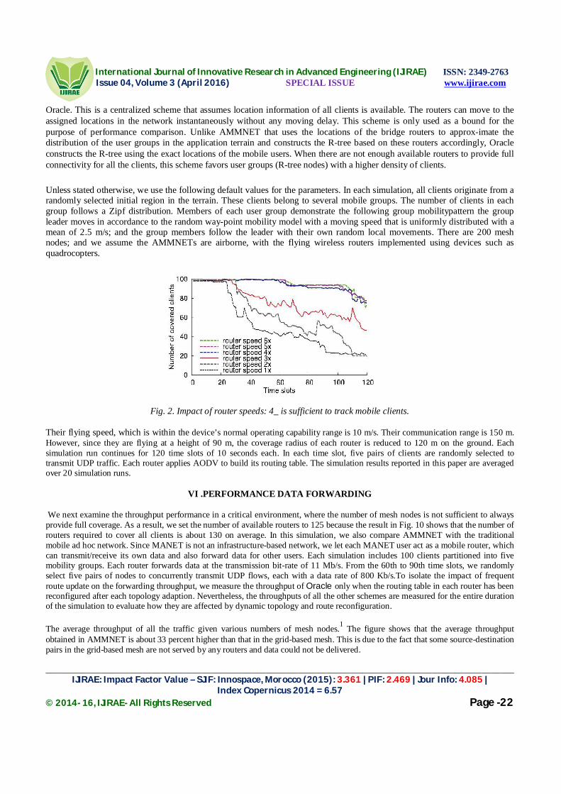
International Journal of Innovative Research in Advanced Engineering (IJIRAE) ISSN: 2349-2763 Issue 04, Volume 3 (April 2016) SPECIAL ISSUE www.ijirae.com
______________________________________________________________________________________________________ IJIRAE: Impact Factor Value – SJIF: Innospace, Morocco (2015): 3.361 | PIF: 2.469 | Jour Info: 4.085 |
Index Copernicus 2014 = 6.57 © 2014- 16, IJIRAE- All Rights Reserved Page -22
Oracle. This is a centralized scheme that assumes location information of all clients is available. The routers can move to the assigned locations in the network instantaneously without any moving delay. This scheme is only used as a bound for the purpose of performance comparison. Unlike AMMNET that uses the locations of the bridge routers to approx-imate the distribution of the user groups in the application terrain and constructs the R-tree based on these routers accordingly, Oracle constructs the R-tree using the exact locations of the mobile users. When there are not enough available routers to provide full connectivity for all the clients, this scheme favors user groups (R-tree nodes) with a higher density of clients. Unless stated otherwise, we use the following default values for the parameters. In each simulation, all clients originate from a randomly selected initial region in the terrain. These clients belong to several mobile groups. The number of clients in each group follows a Zipf distribution. Members of each user group demonstrate the following group mobilitypattern the group leader moves in accordance to the random way-point mobility model with a moving speed that is uniformly distributed with a mean of 2.5 m/s; and the group members follow the leader with their own random local movements. There are 200 mesh nodes; and we assume the AMMNETs are airborne, with the flying wireless routers implemented using devices such as quadrocopters.
Fig. 2. Impact of router speeds: 4_ is sufficient to track mobile clients. Their flying speed, which is within the device’s normal operating capability range is 10 m/s. Their communication range is 150 m. However, since they are flying at a height of 90 m, the coverage radius of each router is reduced to 120 m on the ground. Each simulation run continues for 120 time slots of 10 seconds each. In each time slot, five pairs of clients are randomly selected to transmit UDP traffic. Each router applies AODV to build its routing table. The simulation results reported in this paper are averaged over 20 simulation runs.
VI .PERFORMANCE DATA FORWARDING We next examine the throughput performance in a critical environment, where the number of mesh nodes is not sufficient to always provide full coverage. As a result, we set the number of available routers to 125 because the result in Fig. 10 shows that the number of routers required to cover all clients is about 130 on average. In this simulation, we also compare AMMNET with the traditional mobile ad hoc network. Since MANET is not an infrastructure-based network, we let each MANET user act as a mobile router, which can transmit/receive its own data and also forward data for other users. Each simulation includes 100 clients partitioned into five mobility groups. Each router forwards data at the transmission bit-rate of 11 Mb/s. From the 60th to 90th time slots, we randomly select five pairs of nodes to concurrently transmit UDP flows, each with a data rate of 800 Kb/s.To isolate the impact of frequent route update on the forwarding throughput, we measure the throughput of Oracle only when the routing table in each router has been reconfigured after each topology adaption. Nevertheless, the throughputs of all the other schemes are measured for the entire duration of the simulation to evaluate how they are affected by dynamic topology and route reconfiguration. The average throughput of all the traffic given various numbers of mesh nodes.1 The figure shows that the average throughput obtained in AMMNET is about 33 percent higher than that in the grid-based mesh. This is due to the fact that some source-destination pairs in the grid-based mesh are not served by any routers and data could not be delivered.

International Journal of Innovative Research in Advanced Engineering (IJIRAE) ISSN: 2349-2763 Issue 04, Volume 3 (April 2016) SPECIAL ISSUE www.ijirae.com
______________________________________________________________________________________________________ IJIRAE: Impact Factor Value – SJIF: Innospace, Morocco (2015): 3.361 | PIF: 2.469 | Jour Info: 4.085 |
Index Copernicus 2014 = 6.57 © 2014- 16, IJIRAE- All Rights Reserved Page -23
AMMNET can achieve a through-put about 70 percent of that of the Oracle scheme. The performance gap comes from the slightly longer relay paths, and, more deterministically, the packet loss due to route reconfiguration. More specifically, when mesh nodes adapt their locations to client movements, each router cannot relay data along the previous relay paths and needs to discover new routes. Some packets buffered in the original routing paths might be dropped, resulting in throughput degradation. Moreover, the throughput of MANET is far lower than that of AMMNET. This is to be expected because, when the network is partitioned into multiple groups, a MANET source destination pair might not be able to find a path to communicate with each other when they belong to two partitioned groups, as a result leading to a zero throughput. This situation is quite common in a dynamic environment.
VII. SYSTEM OVERHEAD
To perform network adaptations, a node needs to collect location information of the bridge routers, and multicast the assigned locations to the selected intergroup routers. In this study, we evaluate the number of exchanged messages required for such an adaptation process. Here, each message forwarding over a wireless link is counted as a message exchange. We consider a network with 100 users and 200 routers. The Grid-Mesh schemes are excluded in this study because each mesh node only needs to notify its updated location to it neighboring nodes. Namely, in Grid-Mesh, the message overhead is independent of the number of groups in a terrain.
The Autonomous Mobile mesh network with security. In MANET nodes move from one place to another place in free directions. The movement of the nodes may split the network and form more than one group. In this case communication between two nodes will be disconnected. To maintain the communication between all nodes even they are in different groups Mesh Nodes are used. Mesh Nodes which have the capability of changing its nature into Inter-group router or Intra-group router. Even it can act as a bridge router. To make the communication effective One-hop neighbour information update is used to find the shortest path between any two nodes. Since nodes move from one place to another place intruder may join the group. To avoid this problem private key is assigned for all the nodes in the network and it is shared among the nodes. If any node want to communicate with the other node first private key must be exchanged. Only if private key matches nodes can communicate. If key does not matches then the node ID will be registered in the Blacklist. If any node registered in the blacklist says the private key wrongly, then the node will be removed from the network. In this way security can be provided to the network.Advantages of Proposed System:One-hop neighbor information update is used for finding the shortest path and Secret key is maintained for providing security to the network. Free routers help to find the missing node.
VIII. CONCLUSION
For applications such as crisis management and battlefield communications, the mobile users need to work in dynamically formed groups that occupy different parts of a large and uncertain application terrain at different times.In this paper, we introduced a mobile infrastructure called AMMNET. Unlike conventional mobile ad hoc networks that suffer network partitions when the user groups move apart, the mobile mesh routers of an AMMNET track the users and dynamically adapt the network topology to seamlessly support both their intergroup and intergroup communications. Since this mobile Infrastructure follows the users; full connectivity can be achieved without the need and high cost of providing Network coverage for the entire application terrain at all time as in traditional stationary infrastructure. We conducted extensive simulation study to assess the effectiveness of AMMNET. The results confirm that the proposed distributed topology adaptation scheme based on autonomous mobile mesh routers is almost as Effective as a hypothetical centralized technique with complete knowledge of the locations of the mobile clients.The simulation results also indicate that AMMNET is scalable with the number of users. The required number of mobile mesh nodes does not increase with increases in the user population. Although an excessively large number of user groups may affect the performance of AMMNET, the number of user groups is typically very small relative to the number of users for most applications and AMMNET is effective for most practical scenarios.
IX. REFERENCES
[1]. Wei-Liang Shen, Chung-Shiuan Chen Kate Ching-Ju Lin, Member, IEEE, and Kien A. Hua, Fellow,’’Autonomous mobile mesh network’’,IEEE Transaction on mobile computing, 2014.
[2]. A. Petkova, K.A. Hua, and S. Koompairojn, “Processing Approximate Rank Queries in a Wireless Mobile Sensor Environment,” Proc. 11th Int’l Conf. Mobile Data Management (MDM), 2010.
[3]. “Quadrocopter LLC,” http://quadrocopter.us/, 2013.

International Journal of Innovative Research in Advanced Engineering (IJIRAE) ISSN: 2349-2763 Issue 04, Volume 3 (April 2016) SPECIAL ISSUE www.ijirae.com
______________________________________________________________________________________________________ IJIRAE: Impact Factor Value – SJIF: Innospace, Morocco (2015): 3.361 | PIF: 2.469 | Jour Info: 4.085 |
Index Copernicus 2014 = 6.57 © 2014- 16, IJIRAE- All Rights Reserved Page -24
[4]. R. Roy, Handbook of Mobility Models and Mobile Ad Hoc Networks. Springer, 2010. [5]. Y.-C. Chen, E. Rosensweig, J. Kurose, and D. Towsley, “Group Detection in Mobility Traces,” Proc. Sixth Int’l Wireless
Comm and Mobile Computing Conf. (IWCMC ’10), 2010. [6]. T. Camp, J. Boleng, and V. Davies, “A Survey of Mobility Models for Ad Hoc Network Research,” Wireless Comm. and
Mobile Computing, vol. 2, no. 5, pp. 483-502, 2002. [7]. X. Hong, M. Gerla, G. Pei, and C. Chiang, “A Group Mobility Model for Ad Hoc Wireless Networks,” Proc. Second
ACM Int’l Workshop Modelling, Analysis and Simulation of Wireless and Mobile Systems (MSWiM ’99), 1999. [8]. K. Blakely and B. Lowekamp, “A Structured Group Mobility Model for the Simulation of Mobile Ad Hoc Networks,”
Proc.Second Int’l Workshop Mobility Management & Wireless Access Protocols (MobiWac), 2004. [9]. Y. Zhang and Y. Fang, “ARSA: An Attack-Resilient Security Architecture for Multihop Wireless Mesh Networks,” IEEE
J. Selected Areas in Comm., vol.24, no. 10, pp. 1916-1928, Oct. 2006. [10]. J. Sun, C. Zhang, and Y. Fang, “A Security Architecture Achieving Anonymity and Traceability in Wireless Mesh
Networks,” Proc. IEEE INFOCOM, 2008 [11]. B. Salem and J. Hubaux, “Securing Wireless Mesh Networks,” IEEE Wireless Comm., vol. 13, no. 2, pp. 50-55, Apr.
2006. [12]. R. Gandhi, S. Khuller, and A. Srinivasan, “Approximation Algorithms for Partial Covering Problems,” Proc. 28th Int’l
Colloquium Automata, Languages and Programming, pp. 225-236,2001. [13]. “The Network Simulator - ns-2,” http://www.isi.edu/nsnam/ns, 2013. [14]. I.F. Akyildiz, X. Wang, and W. Wang, “Wireless Mesh Networks: A Survey,” Computer Networks, vol. 47, no. 4, pp.
445-487, 2005. [15]. R. Draves, J. Padhye, and B. Zill, “Comparison of Routing Metrics for Static Multi-Hop Wireless Networks,” Proc. ACM
SIGCOMM,2004. [16]. K.N. Ramachandran, E.M. Belding, K.C. Almeroth, and M.M. Buddhikot, “Interference-Aware Channel Assignment in
Multi- Radio Wireless Mesh Networks,” Proc. IEEE INFOCOM, 2006. [17]. J. Tang, G. Xue, and W. Zhang, “Interference-Aware Topology Control and QoS Routing in Multi-Channel Wireless
Mesh Networks,”Proc.ACM MobiHoc, 2005. [18]. A. Naveed, S. Kanhere, and S. Jha, “Topology Control and Channel Assignment in Multi-Radio Multi-Channel Wireless
Mesh Networks,” Proc. IEEE Int’l Conf. Mobile Adhoc and Sensor Systems (MASS), 2007. [19]. S. Meguerdichian, F. Koushanfar, M. Potkonjak, and M. Srivastava, “Coverage Problems in Wireless Ad-Hoc Sensor
Networks,”Proc. IEEE INFOCOM, 2001. [20]. C.-F. Huang and Y.-C. Tseng, “The Coverage Problem in a Wireless Sensor Network,” Mobile Networks and
Applications, vol. 10, pp. 519-528, Aug. 2005.

International Journal of Innovative Research in Advanced Engineering (IJIRAE) ISSN: 2349-2763 Issue 04, Volume 3 (April 2016) SPECIAL ISSUE www.ijirae.com
________________________________________________________________________________________________________ IJIRAE: Impact Factor Value – SJIF: Innospace, Morocco (2015): 3.361 | PIF: 2.469 | Jour Info: 4.085 |
Index Copernicus 2014 = 6.57 © 2014- 16, IJIRAE- All Rights Reserved Page -25
HAND THERAPIST: A REHABILITATION APPROACH BASED ON WEARABLE TECHNOLOGY AND VIDEO
GAMING
E.KEERTHIKA, MUHAMMADU SATHIK RAJA Department of Medical Electronics Sengunthar college of Engineering
Abstract— Hand impairment after stroke is quite debilitating. Present hand rehabilitation approaches, although useful, are still limited as they often require the constant help of a technician or caregiver and also because they are based on repetitive training which may be demotivating [1]. More advanced approaches are in development including the use of robotized systems [2]. Nonetheless, these systems are still expensive and require expert support. Here, we show the proof-of-concept of a hand rehabilitation system, dubbed “hand therapist”, inspired in video gaming devices and software which is comprised of the Myo armband, a home-built robotic glove and Unity3D, a video game development engine. With this approach we aim at a solution that combines performance, low-cost and engagement/motivation in hand therapy.
Keywords— Hand rehabilitation, Electromyography, Robotic glove
INTRODUCTION
The Myo armband is a ~200 euros wearable device comprised of a 9-axis inertial measurement unit (IMU) and 8 electromyography(EMG) sensors [3]. The device thus provides two kinds of data, spatial and gestural data, respectively. Spatial data informs about the orientation and movement of the user's arm whilst gestural data informs what the user is doing with his/her hand in the form of one of several pre-set poses. All data is communicated via Bluetooth with Unity3D. A ~100 euros robotic glove was built based on a sports glove, nylon wiring, two stepper motors for hand opening/closing, and an Arduino Uno board for control and communication with Unity3D. Touch buttons were also used to detect a fully opened/closed hand. A game was built in Unity 3D for hand training in which the user must grab, hold, transport and drop a cube in several increasingly difficult puzzle levels. In the game the user sees virtual hands/arms that replicates the user’s movements such that the user can feel more immersed in the game. Presently, the game works as follows: the user wears the Myo armband in the healthy forearm and executes the required movements, which are translated into the movement of the virtual hand/arm. Hand movements are then replicated into the movement of the robotic glove the user wears in the impaired hand. These movements are also simultaneous translated into the movement of a corresponding virtual hand/arm. So far the system was tested only with healthy subjects, but tests with stroke patients are planned. In the future, we also plan to combine the system with an additional Myo armband unit such that is possible to monitor both hand/arms simultaneously for an improved interaction of the user with the game. In this work we proposed a low-cost (<500 euros) and engaging solution for hand rehabilitation is possible based on gaming devices and software. Future studies with patients are still required.
I. PROPOSED METHOD
In this paper the wired process has been made with the interfacing module. So that data flow cannot lose due to the connectivity problem. Here two flexibility sensors are fixed in the two hand fingers to identify the force associated with it and accelerometer sensor is fixed in the hand to detect the movement of it. All the sensors are interfaced with the microcontroller through the amplifier and interfacing circuit.
Microcontroller is already programmed for the task needed for the proposed work. From where PC is interfaced with it through the RS232 serial communication. In PC we can easily monitor the whole hand movements and force associated with it. And also in PC video game is created in Unity 3D for hand training in which the user must grab, hold, transport and drops a cube in several increasingly difficult puzzle levels. In the game the user sees virtual hands/arms that replicate the user’s movements such that the user can feel more immersed in the game.
In the pre-processing stage bilateral filter is used, because it is an edge preserving nonlinear filter. The preprocessed image is decomposed to one level using 2D DWT and the detail subband coefficients are denoised using bivariate shrinkage. Finally the despeckled image is reconstructed from the modified wavelet coefficients using 2D IDWT.

International Journal of Innovative Research in Advanced Engineering (IJIRAE) ISSN: 2349-2763 Issue 04, Volume 3 (April 2016) SPECIAL ISSUE www.ijirae.com
________________________________________________________________________________________________________ IJIRAE: Impact Factor Value – SJIF: Innospace, Morocco (2015): 3.361 | PIF: 2.469 | Jour Info: 4.085 |
Index Copernicus 2014 = 6.57 © 2014- 16, IJIRAE- All Rights Reserved Page -26
II. PERFORMANCE METRICS FLEXI FORCE SENSOR:
This manual describes how to use Tekscan's Flexi Force Sensors. These sensors are ideal for designers, researchers, or anyone who needs to measure forces without disturbing the dynamics of their tests. The Flexi Force sensors can be used to measure both static and dynamic forces (up to 1000 lbf.), and are thin enough to enable non-intrusive measurement.
The Flexi Force sensors use a resistive-based technology. The application of a force to the active sensing area of the sensor results in a change in the resistance of the sensing element in inverse proportion to the force applied.
The Flexi Force sensor is an ultra-thin and flexible printed circuit, which can be easily integrated into most applications. With its paper-thin construction, flexibility and force measurement ability, the Flexi Force force sensor can measure force between almost any two surfaces and is durable enough to stand up to most environments. Flexi Force has better force sensing properties, linearity, hysteresis, drift, and temperature sensitivity than any other thin-film force sensors. The "active sensing area" is a 0.375” diameter circle at the end of the sensor.
Accelerometer sensor Accelerometer sensor have been developed to measure acceleration in a variety of application,a three dimensional
accelerometer sensor has been created for measuring involuntary human hand motion.the sensor uses three single axis accelerometer fabricated at MIT Microsystems technology laboratory. the size and mass of the sensor werelimited to avoid altering hand motion being measured. To measure the three dimensional acceleration of human hand motion with adequate accuracy and precision ,the necessary bandwidth for normal human motion, and the amplitude range required for the highest normal acceleration. At the same time ,the physical presence of the sensor should not alter the hand motion .the application of measuring something sensitive to external mass like human hand requires the accelerometer sensor to be extremely small and lightweight.
CALIBRATION: Calibration is the method by which the sensor’s electrical output is related to an actual engineering unit, such as pounds or Newtons. To calibrate, apply a known force to the sensor, and equate the sensor resistance output to this force. Repeat this step with a number of known forces that approximate the load range to be used in testing. Plot Force versus Conductance (1/R). A linear interpolation can then be done between zero load and the known calibration loads, to determine the actual force range that matches the sensor output range. Amplifier:
Generally, an amplifier is any device that will convert a signal with a small amount of energy into a similar signal with a larger amount of energy. In popular use, the term today usually refers to an electronic amplifier, often as in audio applications. The relationship of the input to the output of an amplifier — usually expressed as a function of the input frequency — is called the transfer function of the amplifier, and the magnitude of the transfer function is termed the gain
LCD DISPLAY Liquid crystal displays (LCDs) have materials which combine the properties of both liquids and crystals. Rather than having a melting point, they have a temperature range within which the molecules are almost as mobile as they would be in a liquid, but are grouped together in an ordered form similar to a crystal. An LCD consists of two glass panels, with the liquid crystal material sand witched in between them.
FLEXIBILITY SENSOR (2)
SCU (2)
AMPLIFIER (2)
LCD DISPLAY
MICRO CONTROLLER
16F877A RS232
ACCELEROMETER SENSOR (2)
PC (VB)

International Journal of Innovative Research in Advanced Engineering (IJIRAE) ISSN: 2349-2763 Issue 04, Volume 3 (April 2016) SPECIAL ISSUE www.ijirae.com
________________________________________________________________________________________________________ IJIRAE: Impact Factor Value – SJIF: Innospace, Morocco (2015): 3.361 | PIF: 2.469 | Jour Info: 4.085 |
Index Copernicus 2014 = 6.57 © 2014- 16, IJIRAE- All Rights Reserved Page -27
The inner surface of the glass plates are coated with transparent electrodes which define the character, symbols or patterns to be displayed polymeric layers are present in between the electrodes and the liquid crystal, which makes the liquid crystal molecules to maintain a defined orientation angle. One each polarizer’s are pasted outside the two glass panels. These polarizer’s would rotate the light rays passing through them to a definite angle, in a particular direction
When the LCD is in the off state, light rays are rotated by the two polarisers and the liquid crystal, such that the light rays come out of the LCD without any orientation, and hence the LCD appears transparent. When sufficient voltage is applied to the electrodes, the liquid crystal molecules would be aligned in a specific direction. The light rays passing through the LCD would be rotated by the polarisers, which would result in activating / highlighting the desired characters.The LCD’s are lightweight with only a few millimeters thickness. Since the LCD’s consume less power, they are compatible with low power electronic circuits, and can be powered for long durations. The LCD’s don’t generate light and so light is needed to read the display. By using backlighting, reading is possible in the dark. The LCD’s have long life and a wide operating temperature range.Changing the display size or the layout size is relatively simple which makes the LCD’s more customer friendly. The LCDs used exclusively in watches, calculators and measuring instruments are the simple seven-segment displays, having a limited amount of numeric data. The recent advances in technology have resulted in better legibility, more information displaying capability and a wider temperature range. These have resulted in the LCDs being extensively used in telecommunications and entertainment electronics. The LCDs have even started replacing the cathode ray tubes (CRTs) used for the display of text and graphics, and also in small TV applications
Signal conditioning unit:
The signal conditioning unit accepts input signals from the analog sensors and gives a conditioned output of 0-5V DC corresponding to the entire range of each parameter. This unit also accepts the digital sensor inputs and gives outputs in 10 bit binary with a positive logic level of +5V. The calibration voltages* (0, 2.5 and 5V) and the health bits are also generated in this unit. Microcontrollers are widely used for control in power electronics. They provide real time control by processing analog signals obtained from the system. A suitable isolation interface needs to be designed for interaction between the control circuit and high voltage hardware. A signal conditioning unit is which provides necessary interface between a high power grid inverter and a low voltage controller unit.
RS232 COMMUNICATION: In telecommunications, RS-232 is a standard for serial binary data interconnection between a DTE (Data terminal equipment) and a DCE (Data Circuit-terminating Equipment). It is commonly used in computer serial ports.
Scope of the Standard: The Electronic Industries Alliance (EIA) standard RS-232-C [3] as of 1969 defines:
Electrical signal characteristics such as voltage levels, signaling rate, timing and slew-rate of signals, voltage withstand level, short-circuit behavior, maximum stray capacitance and cable length
Interface mechanical characteristics, pluggable connectors and pin identification Functions of each circuit in the interface connector Standard subsets of interface circuits for selected telecom applications
The standard does not define such elements as character encoding (for example, ASCII, Baudot or EBCDIC), or the framing of characters in the data stream (bits per character, start/stop bits, parity). The standard does not define protocols for error detection or algorithms for data compression. The standard does not define bit rates for transmission, although the standard says it is intended for bit rates lower than 20,000 bits per second. Many modern devices can exceed this speed (38,400 and 57,600 bit/s being common, and 115,200 and 230,400 bit/s making occasional appearances) while still using RS-232 compatible signal levels.

International Journal of Innovative Research in Advanced Engineering (IJIRAE) ISSN: 2349-2763 Issue 04, Volume 3 (April 2016) SPECIAL ISSUE www.ijirae.com
________________________________________________________________________________________________________ IJIRAE: Impact Factor Value – SJIF: Innospace, Morocco (2015): 3.361 | PIF: 2.469 | Jour Info: 4.085 |
Index Copernicus 2014 = 6.57 © 2014- 16, IJIRAE- All Rights Reserved Page -28
III. EXPERIMENTAL RESULTS AND DISCUSSION
Visual basic:
Visual Basic is a third-generation event-driven programming language and integrated development environment(IDE) from Microsoft for its COM programming model first released in 1991. Microsoft intended Visual Basic to be relatively easy to learn and use. Visual Basic was derived from BASIC and enables the rapid application development (RAD) of graphical user interface (GUI) applications, access to databases using Data Access Objects, Remote Data Objects, or ActiveX Data Objects, and creation of ActiveX controls and objects. A programmer can create an application using the components provided by the Visual Basic program itself. Over time the community of programmers has developed new third party components, keeping this programming language to modern standards. Programs written in Visual Basic can also use the Windows API, which requires external function declarations .The final release was version 6 in 1998 (now known simply as Visual Basic). Though Visual Basic 6.0 IDE is unsupported as of April 8, 2008, the Visual Basic team is committed to “It Just Works” compatibility for Visual Basic 6.0 applications on Windows Vista, Windows Server 2008 including R2, Windows 7, and Windows 8. In 2014 there are tens of thousands of developers who still prefer Visual Basic 6.0 over Visual Basic .NET. Moreover, in recent years some developers lobbied aggressively for a new version of Visual Basic 6.0. A dialect of Visual Basic, Visual Basic for Applications (VBA), is used as a macro or scripting language within several Microsoft applications, including Microsoft Office
IV. CONCLUSION The progress in science & technology is a non-stop process. New things and new technology are being invented. As the technology grows day by day, we can imagine about the future in which thing we may occupy every place. The proposed system based on PIC microcontroller is found to be more compact, user friendly and less complex, which can readily be used in order to perform. Several tedious and repetitive tasks. Though it is designed keeping in mind about the need for industry, it can extended for other purposes such as commercial & research applications. due to the probability of high technology (pic microcontroller) used this” a rehabilitation approach based on wearable technology and video gaming” is fully software controlled with less hardware circuit. the feature makes this system is the base for future systems. The principle of the development of science is that “nothing is impossible”. So we shall look forward to a bright & sophisticated world
REFERENCES [1]. Skirven TM, Osterman AL, Fedorczyk J, Armadio PC. Rehabilitation of the Hand and Upper Extremity. 6th ed.
Philadelphia: Mosby Elsevier; 2011. [2]. Inmotion robot-assisted therapy [Internet]. Interactive Motion Technologies; 2013 [edited 2015 January 20]. Available from: [3]. Thalmic Labs Inc. [Internet]. Kitchener, Ontario: Thalmic Labs Inc.; 2013 [cited 2015] [4]. 4.Aisen, “A novel approach to stroke rehabilitation: robot aided sensorymotor stimulation,” Neurology, 54:1938-1944, 2014. [5]. B. T. Volpe, H. I. Krebs, and N. Hogan, "Is robot-aided sensorimotor training in stroke rehabilitation a realistic option?"
Current Opinion in Neurology, Lippincott Williams & Wilkins, 14:745-752, 2012. [6]. M. Ferraro, J. J. Palazzolo, J. Krol, H. I. Krebs, N. Hogan, and B. T. Volpe, “Robot aided sensorimotor arm training
improves outcome in patients with chronic stroke,” Neurology, 61:1604-1607, 2011. [7]. S. Fasoli, H. I. Krebs, J. Stein, W. R. Frontera, and N. Hogan, "Effects of robotic therapy on motor impairment and recovery
in chronic stroke," Archives of Physical Medicine and Rehabilitation, 84:477- 482, 2014.

International Journal of Innovative Research in Advanced Engineering (IJIRAE) ISSN: 2349-2763 Issue 04, Volume 3 (April 2016) SPECIAL ISSUE www.ijirae.com
_______________________________________________________________________________________________________ IJIRAE: Impact Factor Value – SJIF: Innospace, Morocco (2015): 3.361 | PIF: 2.469 | Jour Info: 4.085 |
Index Copernicus 2014 = 6.57 © 2014- 16, IJIRAE- All Rights Reserved Page -29
HUMAN TO COMPUTER INTERFACE CONTROLLED FOR USING TETRAPLEGIA BY THE LIP
M.POONKODI1
1PG Student, Department Of Medical Electronics, SCE, Tiruchengode-637205.
Mr.M.S.Md SATHIKRAJA2 2Assistant Professor Department Of ME,
SCE, Tiruchengode-637205.
Abstract: Lip control system is an innovative human–computer interface specially designed for people with tetraplegia. This paper presents an evaluation of the lower lip potential to control an input device, according to Fitts’ law (ISO/TS 9241-411:2012 standard). The results show that the lower lip throughput is comparable with the thumb throughput using the same input device under the same conditions. These results establish the baseline for future research studies about the lower lip capacity to operate a computer input device. Lip muscles are controlled by the facial nerve that is directly connected to the brain. This is an important characteristic for people with SCI in the neck region. An innovative human– computer interface using the lips, such as the one proposed in this paper, indicates an excellent potential. The major contributions of this paper are the analysis, under the rigor of Fitts’ law of using the lips to control a pointing device; and the comparison of the results with a common way to control the same
Index Terms—Assistive technologies (ATs), Fitts’ law, human–computer interaction, pointing devices, severe disabilitiesvice.
I. INTRODUCTION
Lip muscles are controlled by the facial nerve that is directly connected to the brain. This is an important characteristic for people with SCI in the neck region. An innovative human computer interface using the lips, such as the one proposed in this paper, indicates an excellent potential. This system is designed with the X, Y joystick device which is fixed in lower lip. When it is moved upwards, downwards or sideward’s the same movement will be controlled in the mouse input device. It totally meant that cursor movement will be based on our lower lip movement. Selecting the particulates files or folders will be based on the joystick centre clicks.
A. NEED OF JOYSTICK
This joystick device is interfaced with the PIC microcontroller through the interfacing circuit signal conditioning unit. Signal conditioning unit (SCU) is nothing but the communication device to pass the signal from inputs to the controller. Here PIC microcontroller is used to do the controlling actions where programming is done according to the project needs with the specific tasks. Status of the cursor as well as joy stick movements will be displayed in the LCD display which is interfaced with the microcontroller. Lots of robotic projects need a joystick.
Fig.1. Joy stick
B.TRANSMITTING PROCESS Transmitting the data’s from LIP movement with the joystick device to the PC will be done through the Bluetooth wireless modules. Whatever the lip is doing with the joystick, the movement of cursor will react according to tit in the PC.
II. RELATED WORK The components to be used are: � Microcontroller (any compatible arduino) � Joystick module � 1 Pin M-M connectors � Breadboard � USB cable

International Journal of Innovative Research in Advanced Engineering (IJIRAE) ISSN: 2349-2763 Issue 04, Volume 3 (April 2016) SPECIAL ISSUE www.ijirae.com
_______________________________________________________________________________________________________ IJIRAE: Impact Factor Value – SJIF: Innospace, Morocco (2015): 3.361 | PIF: 2.469 | Jour Info: 4.085 |
Index Copernicus 2014 = 6.57 © 2014- 16, IJIRAE- All Rights Reserved Page -30
1. Connect the components based on the figure shown in the wiring diagram using a M-M pin connector. +5V pin is
connected to the 5V power supply, GND pin is connected to the GND, the VRx and VRy pins are connected to the analog input pins and the SW pin is connected to the digital I/O pin. Pin number will be based on the actual program code.
2. After hardware connection, insert the sample sketch into the Arduino IDE. 3. Using a USB cable, connect the ports from the microcontroller to the computer. 4. Upload the program. 5. See the results in the serial monitor.
III. PROPOSED TECHNIQUE
The Concept of a Lip Controlled System are explained in following section
The lip control system (LCS) is a human–computer interface with a headset and a joystick positioned in front of the lower lip. The studies to develop the prototype showed that the lip control must be head mounted in order to capture the lower lip muscles movements. The joystick, as interaction method ,was chosen because it is easy to use, provides an intuitive control, is compatible with the lips movement and is widely known and adopted in assistive technologies (ATs). Some other important characteristics of the LCS are as follows: 1) It is controlled by the lower lip (dry area), an external body part, less hygienic issues; 2) It allows soft free movement in any direction as it is based on a joystick; 3) It is a personal system that can stay with the user in the wheelchair, chair, bed, etc; and 4) It avoids false commands deriving from wheelchair vibration or body spasms because it is head mounted.
An efficient human–computer interface is very important to improve the autonomy of people with tetraplegia allowing the control of power wheelchairs, computers, smart phones or other Computerized appliances. To evaluate LCS as a computer input device, it was configured as a Bluetooth standard mouse (compatible with computers and smart phones), but with the purpose of controlling power wheelchairs as well. Computer input devices have been deeply studied [30]–[32] and there are effective methods to evaluate their interface efficiency, such as Fitts’ law [28] (standards in ISO/TS 9241- 411:2012 [29] that revises ISO9241-9:2000) that is widely used. The main measure for comparing computer input devices is the throughput TP in bits/s [30] from a human to a computer, and it is calculated as: TP = (IDe/MT) ( where IDe is the task effective index of difficulty [23], [30], [32] and MT is the average movement time to execute it. IDe is based on Shannon formulation [33]: IDe = logz (De/We+1)) where De is the average of effective distance between the point where the participant selects one target and the point where he selects the next target. We is the effective width and is defined as: where De is the average of effective distance between the point where the participant selects one target and the point where he selects the next target. We is the effective width and is defined as: We = 4.133 � SD Where SD is the standard deviation of the distance between the target center and the point at which the participant selects the target, 4.133 is a constant. More detailed information can be found in . The LCS throughput, controlled by the lip, was measured to establish the lower lip capacity baseline to control a human– computer interface, but it is also important to understand if this throughput is limited by the device. The LCS throughput, controlled by the thumb (as a gamepad) was measured, because this can be considered one of the best use conditions, near the device limit throughput. This two- throughput comparison shows how good the lower lip could be considered if compared with the thumb to control the LCS. This is the reason why all the participants chosen to the tests are able-bodied.

International Journal of Innovative Research in Advanced Engineering (IJIRAE) ISSN: 2349-2763 Issue 04, Volume 3 (April 2016) SPECIAL ISSUE www.ijirae.com
_______________________________________________________________________________________________________ IJIRAE: Impact Factor Value – SJIF: Innospace, Morocco (2015): 3.361 | PIF: 2.469 | Jour Info: 4.085 |
Index Copernicus 2014 = 6.57 © 2014- 16, IJIRAE- All Rights Reserved Page -31
IV. LCS ARCHITECTURE AND IMPLEMENTATION
The LCS hardware consists of a development board Arduino Mega ADK, a Bluetooth module (Roving RN42-HID) and a thumb joystick, The system was configured as a standard Bluetooth mouse with a human interface device (HID) profile. All the communications occur as with a standard Bluetooth mouse. The LCS was designed specifically to be controlled by the lower lip; the current version is the ninth. The head support, evolved to provide the necessary stability during the operation; the joystick support, , evolved to be double and to provide calibration of length and angle in order to set the joystick in the correct operation position (just touching the skin). Fitts’ law multidirectional tests were done to choose the joystick response with better throughput response. The full headset prototype has 158.8 g of mass, including the joystick and the cable used to connect the joystick. A USB cable was connected to the computer just to provide power during the tests (this prototype does not have batteries).
V. RESULTS AND DISCUSSION
When the middle button was pressed
When the stick was moved downward The lip-controlled LCS achieved throughput comparable with other assistive technology research studies. The TDS presented in achieved for one-directional horizontal task results from 2.1 to 2.5 bits/s, vertical task from 2.2 to 2.7 bits/s and multidirectional task from 0.4 to 1.0 bits/s. An important objective of this work is to understand how the lower lip can be a good option to control an input device. That is the reason for controlling the LCS with the thumb and the lip under the same conditions. The lip-controlled LCS reaches 1.06 bits/s throughput for the multidirectional task, while the thumb-controlled LCS had 1.80 bits/s throughput (this can be considered near the device limit) also for the multidirectional task. We can conclude that the lower lip achieved 59.2% of the thumb-controlled LCS throughput for multidirectional task. Fig. 6 shows the percentages for each task. Fig. 6 shows a consistent percentage tendency for the three tasks, with mean 62.2% and standard deviation 3.2%. In short, the lower lip was able to control a human–computer interface reaching 62.2% of the thumb throughput.

International Journal of Innovative Research in Advanced Engineering (IJIRAE) ISSN: 2349-2763 Issue 04, Volume 3 (April 2016) SPECIAL ISSUE www.ijirae.com
_______________________________________________________________________________________________________ IJIRAE: Impact Factor Value – SJIF: Innospace, Morocco (2015): 3.361 | PIF: 2.469 | Jour Info: 4.085 |
Index Copernicus 2014 = 6.57 © 2014- 16, IJIRAE- All Rights Reserved Page -32
VI. CONCLUSIONS AND FUTURE WORK
This paper presented an evaluation of the LCS according to Fitts’ law (ISO/TS 9241-411:2012 standard). The tests showed the lower lip potential to control an input device, and the results showed viable throughputs (2.6 bits/s for one-direction tasks and 1.06 bits/s for multidirectional task) and the most important, the lower lip achieves 62.2% of the thumb throughput, showing its potential to control human–computer interfaces. These results encourage us to expand the use of LCS to other applications (for instance controlling a power wheelchair), researching the use of other input devices that has better throughput than the joystick (to be lip-controlled) or to develop a new input device specially designed to be controlled by the lower lip. We have two new ongoing works. 1) Development and test of a new version of LCS with a mini trackball instead of a thumb joystick. 2) Evaluating the LCS to control power wheelchairs
. VII. REFERENCES
[1]. Y. Guo, L. Ma, M. Cristofanilli, R. P. Hart, A. Hao, and M. Schachner, “Transcription factor Sox11b is involved in spinal
cord regeneration in adult zebrafish,” Neuroscience, vol. 172, pp. 329–341, Jan. 2011. [2]. S. Thuret, L. D. Moon, and F. H. Gage, “Therapeutic interventions after spinal cord injury,” Nat. Rev. Neurosci., vol. 7, no.
8, pp. 628–643, Aug. 2006. [3]. J. E. O’Doherty, M. A. Lebedev, P. J. Ifft, K. Z. Zhuang, S. Shokur, H. Bleuler, and M. A. L. Nicolelis, “Active tactile
exploration using a brain-machine-brain interface,” Nature, vol. 479, no. 7372, pp. 228–231, Nov. 2011. [4]. M. A. Nicolelis, “Actions from thoughts,” Nature, vol. 409, no. 6818, pp. 403–407, Jan. 2001. [5]. H. A. Caltenco, B. Breidegard, B. J¨onsson, and L. N. S. Andreasen Struijk, “Understanding computer users with
tetraplegia: Survey of assistive technology users,” Int. J. Human-Comput. Interaction, vol. 28, no. 4, pp. 258–268, Apr. 2012.
[6]. C. G. Pinheiro, E. L. M. Naves, P. Pino, E. Losson, A. O. Andrade, and G. Bourhis, “Alternative communication systems for people with severe motor disabilities: A survey,” Biomed. Eng. Online, vol. 10, no. 1, pp. 1– 28, Jan. 2011.
[7]. J. Abascal, “Users with disabilities: Maximum control with minimum effort,” in Articulated Motion and Deformable Objects – Lecture Notesin Computer Science Volume 5098. Berlin, Germany: Springer, 2008, pp. 449–456.
[8]. B. Rebsamen, C. Guan, H. Zhang, C. Wang, C. Teo, M. H. Ang, and E. Burdet, “A brain controlled wheelchair to navigate in familiar environments,” IEEE Trans. Neural Syst. Rehabil. Eng., vol. 18, no. 6, pp. 590– 598, Dec. 2010.
[9]. J. R. Wolpaw, N. Birbaumer, W. J. Heetderks, D. J. McFarland, P. H. Peckham, G. Schalk, E. Donchin, L. A. Quatrano, C. J. Robinson,and T. M. Vaughan, “Brain-computer interface technology: A review of the first international meeting,” IEEE Trans. Rehabil. Eng., vol. 8, no. 2,pp. 164–73, Jun. 2000.
[10]. B. Obermaier, C. Neuper, C. Guger, and G. Pfurtscheller, “Information transfer rate in a five-classes brain–computer interface,” IEEE Trans. Neural Syst. Rehabil. Eng., vol. 9, no. 3, pp. 283–288, Sep. 2001.
[11]. G. E. Fabiani, D. J. McFarland, J. R.Wolpaw, and G. Pfurtscheller, “Conversion of EEG activity into cursor movement by a brain–computer interface (BCI),” IEEE Trans. Neural Syst. Rehabil. Eng., vol. 12, no. 3, pp. 331–338, Sep. 2004.
[12]. D. J. McFarland, A. T. Lefkowicz, and J. R. Wolpaw, “Design and operation of an EEG-based brain-computer interface with digital signal processing technology,” Behavior Res. Methods, Instruments, Comput., vol. 29, no. 3, pp. 337–345, Sep. 1997.

International Journal of Innovative Research in Advanced Engineering (IJIRAE) ISSN: 2349-2763 Issue 04, Volume 3 (April 2016) SPECIAL ISSUE www.ijirae.com
_______________________________________________________________________________________________________ IJIRAE: Impact Factor Value – SJIF: Innospace, Morocco (2015): 3.361 | PIF: 2.469 | Jour Info: 4.085 |
Index Copernicus 2014 = 6.57 © 2014- 16, IJIRAE- All Rights Reserved Page -33
EFFICIENT STEGANOGRAPHY IN ENCRYPTED VIDEO STREAMS USING MOTION VECTOR DIFFERENCE
S.GAYATHRI Mr. K. SUDHAKAR, II-ME(CSE) Head of the Dept & Assistant Professor,
Department of Computer Science and Engineering, Department of Computer Science and Engineering, Sengunthar College of Engineering, Sengunthar College of Engineering,
Tirunchengode – 637 205 Tirunchengode – 637 205 ABSTRACT—Digital video sometimes are stored and processed in an encrypted format to maintain privacy and security. For the purpose of content notation, it is necessary to perform data hiding in these encrypted videos. In this way, data hiding in encrypted domain without decryption conserves the confidentiality of the content. In addition, it is more proficient without decryption followed by data trouncing and re-encryption. This study proposes a novel scheme of data hiding directly in the encrypted version of AVI video stream, which includes the following three parts, i.e., AVI video encryption, data embedding, and data extraction. By analyzing the property of AVI codec and the code words of motion vector differences are encrypted with stream ciphers. Then, a data hider may embed additional data in the encrypted domain by using codeword exchange technique, without knowing the original video content. Data taking out can be done either in the encrypted domain or in the decrypted domain. Furthermore, video file size is strictly conserved even after encryption and data embedding.
Keywords—Data hiding, encrypted domain, AVI, codeword substituting.
I. INTRODUCTION
Image Processing is a technique to enhance raw images received from cameras/sensors placed on satellites, space probes and aircrafts or pictures taken in normal day-to- day life for various applications. Various techniques have been developed in Image Processing during the last four to five decades. Most of the techniques are developed for enhancing images obtained from unmanned spacecrafts, space probes and military reconnaissance flights. Image Processing systems are becoming popular due to easy availability of powerful personnel computers, large size memory devices and graphics software. As an effective and popular means for privacy protection, encryption converts the ordinary signal into unintelligible data, so that the traditional signal processing usually takes place before encryption or after decryption. However, in some scenarios that a content owner does not trust the processing service provider, the ability to manipulate the encrypted data when keeping the plain content unrevealed is desired. For instance, when the secret data to be transmitted are encrypted, a channel provider without any knowledge of the cryptographic key may tend to compress the encrypted data due to the limited channel resource.
II. LITERATURE REVIEW
The most watermarking schemes for copyright protection, a seller usually embed a watermark in multimedia content to identify a buyer [1]. When an unauthorized copy is found by the seller, the traitor’s identity can be traced by the embedded watermark. However, it incurs both repudiation issue and framing issue. To solve these problems, some buyer seller watermarking protocols have been proposed based on watermarking scheme in the encrypted domain. The enhanced scheme increases effective watermarking capacity, avoids additional overhead and overcomes an inherent defect that watermarking capacity depends on the probability distribution of input watermark sequence. Based on the security requirements of buyer–seller watermarking protocols, a new watermarking scheme in the encrypted domain with flexible watermarking capacity is proposed. It improves the robustness of watermark sequence against image compressions and enables image tampering detection. Watermark extraction is blind, which employs the same threshold criterion and secret keys as watermark embedding. The secure and authenticated discrete reversible data hiding in cipher images deals with security and authentication [2]. In the first phase, a content owner encrypts the original uncompressed image using an encryption key. Then, a data hider may compress the least significant bits of the encrypted image using a data hiding key to create a sparse space to accommodate some additional data. With an encrypted image containing additional data, if a receiver has the data hiding key, receiver can extract the additional data though receiver does not know the image content. If the receiver has the encryption key, can decrypt the received data to obtain an image similar to the original one.
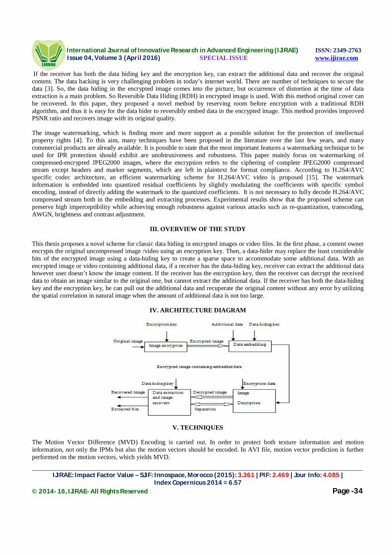
International Journal of Innovative Research in Advanced Engineering (IJIRAE) ISSN: 2349-2763 Issue 04, Volume 3 (April 2016) SPECIAL ISSUE www.ijirae.com
_______________________________________________________________________________________________________ IJIRAE: Impact Factor Value – SJIF: Innospace, Morocco (2015): 3.361 | PIF: 2.469 | Jour Info: 4.085 |
Index Copernicus 2014 = 6.57 © 2014- 16, IJIRAE- All Rights Reserved Page -34
If the receiver has both the data hiding key and the encryption key, can extract the additional data and recover the original content. The data hacking is very challenging problem in today’s internet world. There are number of techniques to secure the data [3]. So, the data hiding in the encrypted image comes into the picture, but occurrence of distortion at the time of data extraction is a main problem. So Reversible Data Hiding (RDH) in encrypted image is used. With this method original cover can be recovered. In this paper, they proposed a novel method by reserving room before encryption with a traditional RDH algorithm, and thus it is easy for the data hider to reversibly embed data in the encrypted image. This method provides improved PSNR ratio and recovers image with its original quality. The image watermarking, which is finding more and more support as a possible solution for the protection of intellectual property rights [4]. To this aim, many techniques have been proposed in the literature over the last few years, and many commercial products are already available. It is possible to state that the most important features a watermarking technique to be used for IPR protection should exhibit are unobtrusiveness and robustness. This paper mainly focus on watermarking of compressed-encrypted JPEG2000 images, where the encryption refers to the ciphering of complete JPEG2000 compressed stream except headers and marker segments, which are left in plaintext for format compliance. According to H.264/AVC specific codec architecture, an efficient watermarking scheme for H.264/AVC video is proposed [15]. The watermark information is embedded into quantized residual coefficients by slightly modulating the coefficients with specific symbol encoding, instead of directly adding the watermark to the quantized coefficients. It is not necessary to fully decode H.264/AVC compressed stream both in the embedding and extracting processes. Experimental results show that the proposed scheme can preserve high imperceptibility while achieving enough robustness against various attacks such as re-quantization, transcoding, AWGN, brightness and contrast adjustment.
III. OVERVIEW OF THE STUDY
This thesis proposes a novel scheme for classic data hiding in encrypted images or video files. In the first phase, a content owner encrypts the original uncompressed image /video using an encryption key. Then, a data-hider may replace the least considerable bits of the encrypted image using a data-hiding key to create a sparse space to accommodate some additional data. With an encrypted image or video containing additional data, if a receiver has the data-hiding key, receiver can extract the additional data however user doesn’t know the image content. If the receiver has the encryption key, then the receiver can decrypt the received data to obtain an image similar to the original one, but cannot extract the additional data. If the receiver has both the data-hiding key and the encryption key, he can pull out the additional data and recuperate the original content without any error by utilizing the spatial correlation in natural image when the amount of additional data is not too large.
IV. ARCHITECTURE DIAGRAM
V. TECHNIQUES
The Motion Vector Difference (MVD) Encoding is carried out. In order to protect both texture information and motion information, not only the IPMs but also the motion vectors should be encoded. In AVI file, motion vector prediction is further performed on the motion vectors, which yields MVD.

International Journal of Innovative Research in Advanced Engineering (IJIRAE) ISSN: 2349-2763 Issue 04, Volume 3 (April 2016) SPECIAL ISSUE www.ijirae.com
_______________________________________________________________________________________________________ IJIRAE: Impact Factor Value – SJIF: Innospace, Morocco (2015): 3.361 | PIF: 2.469 | Jour Info: 4.085 |
Index Copernicus 2014 = 6.57 © 2014- 16, IJIRAE- All Rights Reserved Page -35
The values of MVDs are taken. For Data Embedding, in the encrypted bit stream of AVI frames, the proposed data embedding is accomplished by substituting eligible code words of various Levels. Since the sign of Levels are encrypted, data hiding should not affect the sign of Levels. For Data Extraction scheme, the hidden data can be extracted either in encrypted or decrypted domain. Data extraction process is fast and simple. In addition, the given raw data is perturbed first, then encrypted with 3DES encryption and addition secure key is also embedded in the message. Then the data is embedded in video file. During decryption, the original video file as well as the decrypted data is retrieved. Then the data is decrypted and the perturbed data is found out. Then the original raw message is retrieved.
VI. EXPERIMENTS In the following way the proposed scheme is designed and experimented and the results will be analyzed.
Add Video File
In this phase, the video file selection is carried out open file dialog control and the path is displayed in text box and the video is displayed in media player control. Then the video file record is saved into ‘Videos’ table. Video File Selection for Enhanced Steganography
In this phase, the original video file selection is carried out and taken for Video Encryption. Then Encrypted Video is checked for playing in the player. Text Data Input and Perturbation
In this phase, the text message is given as input. Two random characters are inserted between each two consecutive characters in the text message and the message is perturbated (confused). Encrypted Data Embedding
In this phase, the text data is encrypted using TripleDES encryption and the bit sequences are taken for hiding. So, using the given data hiding key, the data embedding process is carried out with the given encrypted data. Finally, the encrypted data is made to hide inside the encrypted video.
Encrypted Data Extracting and Decryption
In this phase, the encrypted video with the hidden data is selected. For data extraction, Data-hiding key is given and the data is first extracted and then decrypted. Then with the video decryption key (same as encryption key), the video is decrypted and original video is obtained. The operation may be carried out in two types. A) First data extraction followed by Video decryption or B) Video decryption followed by data extraction.
VII. PROPOSED ALGORITHMS A) Video File Parsing
In this process, the video file’s number of frames is found out and extracted using AviFil32.dll methods. The frames are saved in a folder.
B) Text Data Input and Perturbation
i) Text message selection. ii) Two random characters are inserted between each two consecutive characters in the text message and the message is perturbated (confused).
C) Encrypted Data Embedding Text data is selected. Key for TripleDES encryption is given Bit sequences of the perturbated data is taken for hiding. Frame data of the video is encoded with different pixel values. Using the given data hiding key, the data embedding process is carried out with the given encrypted data. The encrypted data is made to hide inside the frames in the least significant bits.

International Journal of Innovative Research in Advanced Engineering (IJIRAE) ISSN: 2349-2763 Issue 04, Volume 3 (April 2016) SPECIAL ISSUE www.ijirae.com
_______________________________________________________________________________________________________ IJIRAE: Impact Factor Value – SJIF: Innospace, Morocco (2015): 3.361 | PIF: 2.469 | Jour Info: 4.085 |
Index Copernicus 2014 = 6.57 © 2014- 16, IJIRAE- All Rights Reserved Page -36
D) Encrypted Data Extracting and Decryption i) The encrypted video with the hidden data is selected. ii) For data extraction, Data-hiding key is given and the data is first extracted and then decrypted. iii) Then with the video decryption key (same as encryption key), the video is decrypted and original video is obtained. iv) The operation may be carried out in two types.
A) First data extraction followed by Video decryption or B) Video decryption followed by data extraction.
VIII. CONCLUSION
The reversible data hiding in encrypted image is examined. Most of the work on reversible data hiding focuses on the data embedding and extracting on the plain spatial domain. But, in some applications substandard subordinate or a channel administrator hopes to tag on some bonus message, such as the foundation information, image notation or validation data, within the encrypted image though user does not know the original image content. And it is also hopeful that the inventive content should be recovered without any blunder after image decryption and message pulling out at receiver side. A content owner encrypts the original image using an encryption key, and a data-hider can embed supplementary data into the encrypted image using a data-hiding key while the user does not know the actual content. With encrypted image containing additional data, the receiver may first decrypt it with the encryption key, and then extract the embedded data and recover the original image with the data-hiding key. In this scheme, the data extraction is not distinguishable from the content decryption. In other words, the supplementary data should be hauling out from the decrypted image, so that the crucial content of original image is uncovered before data pulling out, and if someone has the data-hiding key but not the encryption key, they can’t haul out any information from the encrypted image which containing additional data.
IX. FUTURE ENHANCEMENT
In this study, data hiding is completed entirely in the encrypted domain and the method can preserve the confidentiality of the content completely. With the encrypted video contains the hidden data, the data extraction can be carried out either in encrypted or decrypted domain. In this experimental study video taken in the avi file only. In future various kinds of file formats can be taken for the entire process. Also, the data hiding process with no degradation in video quality can be carried out.
X. REFERENCES
[1]. B. Zhao, W. D. Kou, and H. Li, “Effective watermarking scheme in the encrypted domain for buyer-seller watermarking
protocol,” Inf. Sci., vol. 180, no. 23, pp. 4672–4684, 2010 [2]. X. P. Zhang, “Separable reversible data hiding in encrypted image,” IEEE Trans. Inf. Forensics Security, vol. 7, no. 2, pp.
826–832, Apr. 2012. [3]. K. D. Ma, W. M. Zhang, X. F. Zhao, N. Yu, and F. Li, “Reversible data hiding in encrypted images by reserving room
before encryption,” IEEE Trans. Inf. Forensics Security, vol. 8, no. 3, pp. 553–562, Mar. 2013 [4]. A. V. Subramanyam, S. Emmanuel, and M. S. Kankanhalli, “Robust watermarking of compressed and encrypted
JPEG2000 images,” IEEE Trans. Multimedia, vol. 14, no. 3, pp. 703–716, Jun. 2012 [5]. M. N. Asghar and M. Ghanbari, “An efficient security system for CABAC bin-strings of H.264/SVC,” IEEE Trans.
Circuits Syst. Video Technol., vol. 23, no. 3, pp. 425–437, Mar. 2013. [6]. Yiqi Tew and Kok Sheik Wong, “An overview of Information Hiding in H.264/AVC Compressed Video”, IEEE
Transactions on Circuits and Systems for Video Technology, Vol. 24, No. 2, pp. 305-319, 2014. [7]. Dawen Xu, Rangding Wang and Jicheng Wang, “A novel watermarking scheme for H.264/AVC video authentication”,
Signal Processing: Image Communication, Vol. 26, No. 6, pp. 267-279, 2011 [8]. M. Noorkami and R. M. Mersereau, “A framework for robust watermarking of H.264-encoded video with controllable
detection performance”, IEEE Transactions on Information Forensics and Security, Vol. 2, No. 1, pp. 14-23, 2007. [9]. Jing Zhang, A. T. S. Ho, Gang Qiu and P. Marziliano, “Robust video watermarking of H.264/AVC”, IEEE Transactions on
Circuits and Systems II: Express Briefs, Vol. 54, No. 2, pp. 205-209, 2007. [10]. A. Mansouri, A. M. Aznaveh, Torkamani-Azar F and F. Kurugollu, “A Low Complexity Video Watermarking in H.264
Compressed Domain”, IEEE Transactions on Information Forensics and Security, Vol. 5, No. 4, pp. 649-657, 2010

International Journal of Innovative Research in Advanced Engineering (IJIRAE) ISSN: 2349-2763 Issue 04, Volume 3 (April 2016) SPECIAL ISSUE www.ijirae.com
_______________________________________________________________________________________________________ IJIRAE: Impact Factor Value – SJIF: Innospace, Morocco (2015): 3.361 | PIF: 2.469 | Jour Info: 4.085 |
Index Copernicus 2014 = 6.57 © 2014- 16, IJIRAE- All Rights Reserved Page -37
[11]. H. A. Aly, “Data hiding in motion vectors of compressed video based on their associated prediction error”, IEEE Transactions on Information Forensics and Security, Vol. 6, No. 1, pp. 14-18, 2011.
[12]. Jian Li, Hongmei Liu, Jiwu Huang and Yun Q. Shi, “Reference index-based H.264 video watermarking scheme”, ACM Transactions on Multimedia Computing, Communications, and Applications, Vol. 8, No. 2S, pp. 1-22, 2012.
[13]. Dawen Xu, Rangding Wang and Y. Q. Shi, “Data Hiding in Encrypted H.264/AVC Video Streams by Codeword Substitution”, IEEE Transactions on Information Forensics and Security, Vol. 9, No. 4, pp. 596-606, 2014.
[14]. Dawen Xu, Rangding Wang and Jicheng Wang, Prediction mode modulated data-hiding algorithm for H.264/AVC”, Journal of Real-Time Image Processing, Vol.7, No.4, pp 205-214, 2012.
[15]. Dawen Xu and Rangding Wang, “Watermarking in H.264/AVC Compressed Domain Using Exp-Golomb Code words Mapping”, Optical Engineering, Vol. 50, No. 9, pp. 1-11, 2011.
[16]. Yulin Wang and A. Pearmain, “Blind MPEG-2 video watermarking robust against geometric attacks: a set of approaches in DCT domain”, IEEE Transactions on Image Processing, Vol. 15, No. 6, pp. 1536-1543, 2006
[17]. 300 Million UMTS Subscribers. http://www.3gpp.org/300-million-UMTS-subscribers [18]. F. Qian, Z. Wang, A. Gerber, Z. M. Mao, S. Sen, and O. Spatscheck. Characterizing Radio Resource Allocation for 3G
Networks. In IMC, 2010 [19]. R. Friedman, A. Kogan, and K. Yevgeny, “On power and throughput tradeoffs of WiFi and bluetooth in smartphones,” in
Proc.INFOCOM, Shanghai, China, Apr. 2011 [20]. T. Pering, Y. Agarwal, R. Gupta, and C. Power, “Coolspots: Reducing the power consumption of wireless mobile devices
with multiple radio interfaces,” in Proc. ACM MobiSys, 2006, pp. 220–232


International Journal of Innovative Research in Advanced Engineering (IJIRAE) ISSN: 2349-2763 Issue 04, Volume 3 (April 2016) SPECIAL ISSUE www.ijirae.com
_____________________________________________________________________________________________________ IJIRAE: Impact Factor Value – SJIF: Innospace, Morocco (2015): 3.361 | PIF: 2.469 | Jour Info: 4.085 |
Index Copernicus 2014 = 6.57 © 2014- 16, IJIRAE- All Rights Reserved Page -38
CONTROLLING TRAFFIC IN SMART GRID APPLICATION
J.Oburadha K.Sudhakar PG Student Assistant Professor Department of CSE Department of CSE Sengunthar College of Engineering Sengunthar College of Engineering Abstract- Wireless sensor networks are network that consists of sensors which are distributed in an adhoc manner. These sensors work with each other to sense some physical phenomenon and then the information gathered is processed to get relevant results. Wireless sensor consists of protocols and algorithms. The basic components of sensor nodes are sensing unit, processing unit, transreceiver, and power unit. Smart grid is a digital physical framework that incorporates power foundations with data innovations. The jamming attack that constantly broadcasts radio interference is a primary security threat to prevent the deployment of wireless networks in the smart grid. In this paper, we are preventing the jamming attack by using RC4 algorithm. It prevents the data from message delay and jamming and it secures the encrypted data.
Keywords - Smart Grid, Message Delay, Jamming, RC4
1. INTRODUCTION
A sensor network is an infrastructure comprised of sensing, computing, and communication elements that gives an administrator the ability to instrument, observe, and react to events and phenomena in a specified environment. the components of a wireless sensor network enable wireless connectivity within the network, connecting an application platform at one end of the network with one or more sensor or actuator devices in any part of the network. The characteristics of wireless sensor nodes are power consumption constraints for nodes using batteries or energy harvesting. Ability to cope with node failures modes of mobility, heterogeneity of nodes.
2. RELATED WORK
An efficient cluster- tree based data collection scheme for large mobile wireless sensor networks, in this paper the main problem is time delay and not guaranteed reliable network. So by using the velocity energy- efficient and link aware cluster-tree form the cluster head for decrease the time delay. A secure scheme against power exhausting attacks in hierarchical wireless sensor network, in this paper the main problem is denial of sleep attack shorten the lifetime of wireless sensor network and MAC protocol are insufficient to protect the WSN from denial of sleep attack. To overcome this problem secure adaptive topology control algorithm is used.
3. JAMMING ATTACKS
Wireless technologies have become increasingly popular in our everyday business and personal lives. It enables one or more devices to communicate without physical connections without requiring network or peripheral cabling. As we know that wireless networks serve as the transport mechanism between devices and among devices. However, because of this wireless nature these are prone to multiple security threats in which one of the major serious security threat is jamming. Jamming can disrupt wireless transmission and can occur either unintentionally in the form of noise or interference at the receiver side. Jamming attacks may be viewed as a special case of Denial of service attack. In simplest form of jamming, the attacker interferes with the set of frequency bands used for communication by transmitting a continuous jamming signal or several short jamming pulses.
Normally Jamming attacks have been considered under an external threat model, but here we are considering
jamming attacks under an internal threat model. Under an external threat model, jamming strategies transmits high power interference signals continuously or randomly. This type of strategies has several disadvantages. First, the attacker has to spend huge amount of energy in order to jam certain frequency bands. Second, these types of attacks are easy to detect because of continuous presence of unusually high interference levels. A well-known countermeasure against this type of jamming attacks are spread spectrum techniques such jamming is referred as jamming gain.
4. EXISTING SYSTEMS Smart grid is an emerging cyber-physical system that incorporates networked control mechanisms into conventional power infrastructures. The use of wireless networks introduces potential security vulnerabilities due to the shared nature of wireless channels. The NIST has recently imposed a strong requirement for smart grid security: power system operations must be able to continue during any security attack or compromise.
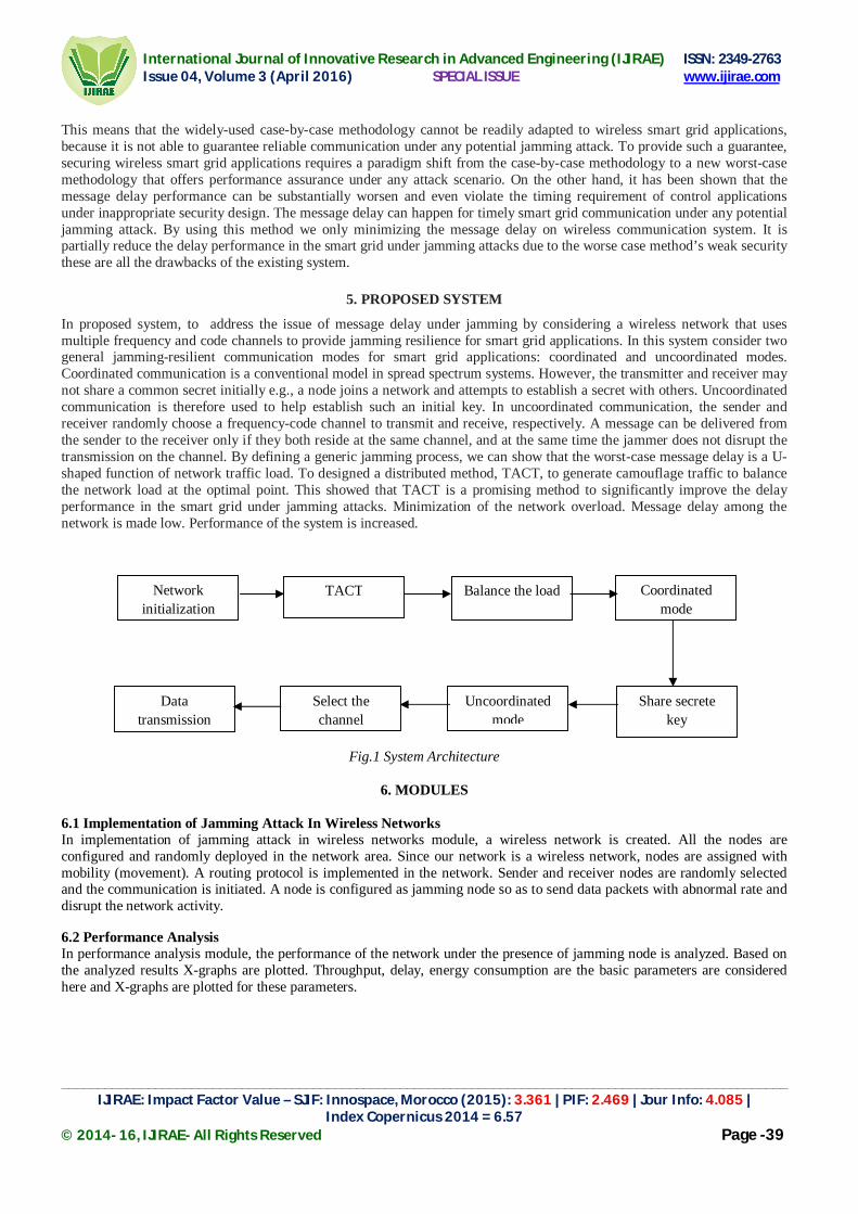
International Journal of Innovative Research in Advanced Engineering (IJIRAE) ISSN: 2349-2763 Issue 04, Volume 3 (April 2016) SPECIAL ISSUE www.ijirae.com
_____________________________________________________________________________________________________ IJIRAE: Impact Factor Value – SJIF: Innospace, Morocco (2015): 3.361 | PIF: 2.469 | Jour Info: 4.085 |
Index Copernicus 2014 = 6.57 © 2014- 16, IJIRAE- All Rights Reserved Page -39
This means that the widely-used case-by-case methodology cannot be readily adapted to wireless smart grid applications, because it is not able to guarantee reliable communication under any potential jamming attack. To provide such a guarantee, securing wireless smart grid applications requires a paradigm shift from the case-by-case methodology to a new worst-case methodology that offers performance assurance under any attack scenario. On the other hand, it has been shown that the message delay performance can be substantially worsen and even violate the timing requirement of control applications under inappropriate security design. The message delay can happen for timely smart grid communication under any potential jamming attack. By using this method we only minimizing the message delay on wireless communication system. It is partially reduce the delay performance in the smart grid under jamming attacks due to the worse case method’s weak security these are all the drawbacks of the existing system.
5. PROPOSED SYSTEM
In proposed system, to address the issue of message delay under jamming by considering a wireless network that uses multiple frequency and code channels to provide jamming resilience for smart grid applications. In this system consider two general jamming-resilient communication modes for smart grid applications: coordinated and uncoordinated modes. Coordinated communication is a conventional model in spread spectrum systems. However, the transmitter and receiver may not share a common secret initially e.g., a node joins a network and attempts to establish a secret with others. Uncoordinated communication is therefore used to help establish such an initial key. In uncoordinated communication, the sender and receiver randomly choose a frequency-code channel to transmit and receive, respectively. A message can be delivered from the sender to the receiver only if they both reside at the same channel, and at the same time the jammer does not disrupt the transmission on the channel. By defining a generic jamming process, we can show that the worst-case message delay is a U-shaped function of network traffic load. To designed a distributed method, TACT, to generate camouflage traffic to balance the network load at the optimal point. This showed that TACT is a promising method to significantly improve the delay performance in the smart grid under jamming attacks. Minimization of the network overload. Message delay among the network is made low. Performance of the system is increased.
Fig.1 System Architecture
6. MODULES
6.1 Implementation of Jamming Attack In Wireless Networks In implementation of jamming attack in wireless networks module, a wireless network is created. All the nodes are configured and randomly deployed in the network area. Since our network is a wireless network, nodes are assigned with mobility (movement). A routing protocol is implemented in the network. Sender and receiver nodes are randomly selected and the communication is initiated. A node is configured as jamming node so as to send data packets with abnormal rate and disrupt the network activity.
6.2 Performance Analysis In performance analysis module, the performance of the network under the presence of jamming node is analyzed. Based on the analyzed results X-graphs are plotted. Throughput, delay, energy consumption are the basic parameters are considered here and X-graphs are plotted for these parameters.
Network initialization
TACT
Data transmission
Balance the load
Select the channel
Uncoordinated mode
Share secrete key
Coordinated mode

International Journal of Innovative Research in Advanced Engineering (IJIRAE) ISSN: 2349-2763 Issue 04, Volume 3 (April 2016) SPECIAL ISSUE www.ijirae.com
_____________________________________________________________________________________________________ IJIRAE: Impact Factor Value – SJIF: Innospace, Morocco (2015): 3.361 | PIF: 2.469 | Jour Info: 4.085 |
Index Copernicus 2014 = 6.57 © 2014- 16, IJIRAE- All Rights Reserved Page -40
6.3 Detection Of Jamming Using TACT According to this method, TACT transmits camouflage traffic packets to balance the overall network traffic load. TACT considers two general jamming-resilient communication modes for smart grid applications: Coordinated mode and uncoordinated mode. In coordinated mode, the sender and receiver share a common secret or key (e.g., code-frequency channel assignment), which is unknown to attackers. In uncoordinated communication, the sender and receiver randomly choose a frequency-code channel to transmit and receive, respectively.
6.4 Performance Analysis In performance analysis module, the performance of the proposed TACT method is analyzed. Based on the analyzed results X-graphs are plotted. Throughput, delay, energy consumption are the basic parameters considered here and X-graphs are plotted for these parameters. Finally, the results obtained from this module is compared with previous results and comparison X-graphs are plotted. Form the comparison result, final RESULT is concluded.
7. CONCLUSION
To designed a distributed method, TACT, to generate camouflage traffic to balance the network load at the optimal point. This paper showed that TACT is a promising method to significantly improves the delay performance in the smart grid under jamming attacks. Although we have shown that uncoordinated w communication is not appropriate for time-critical applications, it is still essential to establish the secret key for coordinated communication. As a result, both communication modes are indispensable to fully secure communications for time-critical applications in the smart grid. Specifically, uncoordinated mode is used for key establishment and update. After the secret key is established or updated, the two communicators can use coordinated mode to exchange information based on the secret key. Hence, to substantially improve the performance of a wireless smart grid application with jamming resilience, TACT should be adapted to both coordinated and uncoordinated communications. This means that TACT must be enabled as long as a node is active, regardless of the mode on which it operates. Accordingly, we summarize the complete jamming-resilient communication scheme with TACT.
REFERENCES
[1] Zhuo Lu, Wenye Wang, Cliff Wang,” Camouflage Traffic: Minimizing Message Delay for Smart Grid Applications under Jamming ,”in proc. IEEE transactions on dependable and secure computing, vol. 12, no. 1, January/February 2015.
[2] Akyol .B, Kirkham .H, Clements .S, and Hadley .M, “A survey of wireless communications for the electric power system,” in Tech. Rep., Richland, WA, USA, Pacific Northwest Nat. Laboratory,PNNL-19084, Jan. 2010.
[3] Bayraktaroglu .E, King .C, Liu .X, Noubir .G, Rajaraman .R, and Thapa .B, “On the performance of IEEE 802.11 under jamming,” in Proc. IEEE IEEE Conf. Comput. Commun., pp. 1265–1273, Apr. 2008.
[4] Brinkmeier .M, Schafer .G, and Strufe .T, “Optimally DoS resistant P2P topologies for live multimedia streaming,” IEEE Trans. Parallel Distrib. Syst., vol. 20, no. 6, pp. 831–844, Jun. 2009.
[5] Cleveland .F, “Uses of wireless communications to enhance power system reliability,” in Proc. IEEE Power Eng. Soc. Gen. Meeting, p. 1, Jun. 2007.
[6] El-Khattam .W, Sidhu .T .S, and Seethapathy .R, “Evaluation of two anti-islanding schemes for a radial distribution system equipped with self-excited induction generator wind turbines,”
[7] Guidelines for Smart Grid Cyber Security, NIST IR-7628, NIST Smart Grid Cyber Security Working Group, vol. 1-3, Aug. 2010.
[8] Li .H, Lai .L, and Qiu .R .C, “A denial-of-service jamming game for remote state monitoring in smart grid,” in Proc. 45th Annu. Conf. Inf. Sci. Syst., pp. 1–6, Mar. 2011.


International Journal of Innovative Research in Advanced Engineering (IJIRAE) ISSN: 2349-2763 Issue 04, Volume 3 (April 2016) SPECIAL ISSUE www.ijirae.com
________________________________________________________________________________________________________ IJIRAE: Impact Factor Value – SJIF: Innospace, Morocco (2015): 3.361 | PIF: 2.469 | Jour Info: 4.085 |
Index Copernicus 2014 = 6.57 © 2014- 16, IJIRAE- All Rights Reserved Page -41
EARLY STAGE DIAGNOSIS OF LUNG CANCER USING CT-SCAN IMAGES BASED ON CELLULAR LEARNING
AUTOMATE
SAKTHI NEELA.P.K Department of M.E (Medical electronics)
Sengunthar College of engineering Namakkal, Tamilnadu, India
Mr.M.S.Muhammadu sathikraja,
HOD & Assistant professor Department of M.E (Medical electronics)
Sengunthar college of engineering Namakkal, Tamilnadu,India
Abstract—The early detection of lung cancer is a challenging problem due to the structure of the cancer cells, where most of the cells are overlapped with each other. This paper presents The project presents diagnosis of early stage lung cancer by making the image better and enhance it from noising, corruption or interference by using Gabor filtering and FIR filter to remove Gaussian noise. The noise removed image is given to two level histogram stage then given to Image Segmentation stage: to divide and segment the enhanced images by using canny edge detection algorithm. Then segmented image is Feature Extracted to obtain the general features of the enhanced segmented image using Binarization and Masking Approach. The proposed technique is efficient for segmentation principles to be a region of interest foundation for feature extraction obtaining. The proposed technique gives very promising results comparing with other used techniques. Relying on general features, a normality comparison is made. The main detected features for accurate images comparison are pixels percentage and mask-labelling with high accuracy and robust operation.
Keywords—Image preprocessing, Gabor filtering, Thresholding Technique, Cany edge detection, Image Segmentation, Feature extraction
. INTRODUCTION
Lung cancer is considered to be as the main cause of cancer death worldwide, and it is difficult to detect in its early stages because symptoms appear only at advanced stages causing the mortality rate to be the highest among all other types of cancer. More people die because of lung cancer than any other types of cancer such as: breast, colon, and prostate cancers. There is significant evidence indicating that the early detection of lung cancer will decrease the mortality rate. The most recent estimates according to the latest statistics provided by world health organization indicates that around 7.6 million deaths worldwide each year because of this type of cancer. Furthermore, mortality from cancer are expected to continue rising, to become around 17 million worldwide in 2030[1].
There are many techniques to diagnosis lung cancer, such as Chest Radiograph (x-ray), Computed Tomography (CT), Magnetic Resonance Imaging (MRI scan) and Sputum Cytology[2]. However, most of these techniques are expensive and time consuming. In other words, most of these techniques are detecting the lung cancer in its advanced stages, where the patient’s chance of survival is very low. Therefore, there is a great need for a new technology to diagnose the lung cancer in its early stages. Image processing techniques provide a good quality tool for improving the manual analysis.
For this reason we attempt to use automatic diagnostic system for detecting lung cancer in its early stages based on the analysis of the sputum color images. In order to formulate a rule we have developed a thresholding technique for unsupervised segmentation of the sputum color image to divide the images into several meaningful sub regions. Image segmentation has been used as the first step in image classification and clustering. There are many algorithms which have been proposed in other articles for medical image segmentation, such as histogram analysis, regional growth, edge detection and Adaptive Thresholding[2]. A review of such image segmentation techniques can be found in[5]. Other authors have considered the use of color information as the key discriminating factor for cell segmentation for lung cancer diagnosis[7].The analysis of sputum images have been used in[8] for detecting tuberculosis; it consists of analyzing sputum images for detecting bacilli. They used analysis techniques and feature extraction for the enhancement of the images, such as edge detection, heuristic knowledge, region labeling and removing.

International Journal of Innovative Research in Advanced Engineering (IJIRAE) ISSN: 2349-2763 Issue 04, Volume 3 (April 2016) SPECIAL ISSUE www.ijirae.com
________________________________________________________________________________________________________ IJIRAE: Impact Factor Value – SJIF: Innospace, Morocco (2015): 3.361 | PIF: 2.469 | Jour Info: 4.085 |
Index Copernicus 2014 = 6.57 © 2014- 16, IJIRAE- All Rights Reserved Page -42
Thresholding has some benefits such as: fast processing, easy influence, resulting images do not keep weight space and another method is region growing. This algorithm starts from a pixel of an image and checks other pixels that are around start point. The non assigned pixel that are neighbors with region checked are similar to the region then the region growing frequently but if differences between neighbor pix and region is more than the threshold the process is stopped. [5] The region growing segmentation based thresholding is used on enhanced image.
I. IMAGE PREPROCESSING GABOR FILTER
Image presentation based on Gabor function constitutes an excellent local and multi-scale decomposition in terms of logons that are simultaneously (and optimally) localization in space and frequency domains. A Gabor filter is a linear filter whose impulse response is defined by a harmonic function multiplied by a Gaussian function. Because of the multiplication-convolution property (Convolution theorem), the Fourier transform of a Gabor filter's impulse response is the convolution of the Fourier transform of the harmonic function and the Fourier transform of the Gaussian function. Its impulse response is defined by a sinusoidal wave (a plane wave for 2D Gabor filters) multiplied by a Gaussian filter . Because of the multiplication-convolution property (convolution), the of a Gabor filter's impulse response is the convolution of the Fourier transform of the harmonic function and the Fourier transform of the Gaussian function. The filter has a real and an imaginary component representing orthogonal directions. The two components may be formed into a complex number or used individually.
In this equation, represents the wavelength of the sinusoidal factor, represents the orientation of the normal to the parallel stripes of a Gabor function, is the phase offset, is the sigma/standard deviation of the Gaussian envelope and is the spatial aspect ratio, and specifies the ellipticity of the support of the Gabor function. Complex
Real
Imaginary
where
and
In this equation, represents the wavelength of the sinusoidal factor, represents the orientation of the normal to the parallel stripes of a Gabor function, is the phase offset, is the sigma/standard deviation of the Gaussian envelope and is the spatial aspect ratio, and specifies the elasticity of the support of the Gabor function.
FAST FOURIER TRANSFORM
Fast Fourier Transform technique operates on Fourier transform of a given image. The frequency domain is a space in which each image value at image position F represents the amount that the intensity values in image “I” vary over a specific distance related to F. Fast Fourier Transform is used here in image filtering (enhancement).
In particular, many of the existing techniques for image description and recognition depend highly on the segmentation
results. Segmentation divides the image into its constituent regions or objects. Segmentation of medical images in 2D, slice by slice has many useful applications for the medical professional such as: visualization and volume estimation of objects of interest, detection of abnormalities (e.g. tumors, polyps, etc.), tissue quantification and classification, and more . The goal of segmentation is to simplify and/or change the representation of the image into something that is more meaningful and easier to analyze. Image segmentation is typically used to locate objects and boundaries (lines, curves, etc.) in images. More precisely, image segmentation is the process of assigning a label to every pixel in an image such that pixels with the same label share certain visual characteristics.

International Journal of Innovative Research in Advanced Engineering (IJIRAE) ISSN: 2349-2763 Issue 04, Volume 3 (April 2016) SPECIAL ISSUE www.ijirae.com
________________________________________________________________________________________________________ IJIRAE: Impact Factor Value – SJIF: Innospace, Morocco (2015): 3.361 | PIF: 2.469 | Jour Info: 4.085 |
Index Copernicus 2014 = 6.57 © 2014- 16, IJIRAE- All Rights Reserved Page -43
The result of image segmentation is a set of segments that collectively cover the entire image, or a set of contours extracted from the image (edge detection). All pixels in a given region are similar with respect to some characteristic or computed property, such as color, intensity, or texture.
II. SEGMENTATION
HISTOGRAM THRESHOLDING Thresholding is one of the most powerful tools for image segmentation. The segmented image obtained from
thresholding has the advantages of smaller storage space, fast processing speed and ease in manipulation, compared with gray level image which usually contains 256 levels. Therefore, thresholding techniques have drawn a lot of attention during the past 20 years. Thresholding is a non-linear operation that converts a gray-scale image into a binary image where the two levels are assigned to pixels that are below or above the specified threshold value. In this research, Otsu’s method that uses (gray thresh) function to compute global image threshold is used. Otsu’s method is based on threshold selection by statistical criteria. Otsu suggested minimizing the weighted sum of within-class variances of the object and background pixels to establish an optimum threshold. Recalling that minimization of within-class variances is equivalent to maximization of between-class variance. This method gives satisfactory results for bimodal histogram images. Threshold values based on this method will be between 0 and 1, after achieving the threshold value; image will be segmented based on it
A. Segmentation Marker-driven watershed segmentation technique extracts seeds that indicate the presence of objects or background at
specific image locations. Marker locations are then set to be regional minima within the topological surface (typically, the gradient of the original input image), and the watershed algorithm is applied. Separating touching objects in an image is one of the most difficult image processing operations, where the watershed transform is often applied to such problem. Marker-controlled watershed approach has two types: External associated with the background and Internal associated with the objects of interest. Image Segmentation using the watershed transforms works well if we can identify or “mark” foreground objects and background locations, to find “catchment basins” and “watershed ridge lines” in an image by treating it as a surface where light pixels are high and dark pixels are low
B.Feature Extraction
Image features Extraction stage is an important stage that uses algorithms and techniques to detect and isolate various desired portions or shapes (features) of a given image. To predict the probability of lung cancer presence, the following two methods are used: binarization and masking, both methods are based on facts that strongly related to lung anatomy and information of lung CT imaging.
C.Binarization Approach Binarization approach depends on the fact that the number of black pixels is much greater than white pixels in normal
lung images, so we started to count the black pixels for normal and abnormal images to get an average that can be used later as a threshold, if the Leonardo Electronic Journal of Practices and Technologies number of the black pixels of a new image is greater that the threshold, then it indicates that the image is normal, otherwise, if the number of the black pixels is less than the threshold, it indicates that the image in abnormal.
D.Masking Approach
Masking approach depends on the fact that the masses are appeared as white connected areas inside ROI (lungs), as they increase the percent of cancer presence increase. The appearance of solid blue color indicates normal case while appearance of RGB masses indicates the presence of cancer
III. RESULTS AND DISCUSSION The experimental image is selected as the lung CT Image, whose size is 256×256 as shown in the figure (1). In this subsection, the proposed edge detection methods for detection of lung cancer are applied and results are shown in the figures 2-6
Figure(1) : Original image

International Journal of Innovative Research in Advanced Engineering (IJIRAE) ISSN: 2349-2763 Issue 04, Volume 3 (April 2016) SPECIAL ISSUE www.ijirae.com
________________________________________________________________________________________________________ IJIRAE: Impact Factor Value – SJIF: Innospace, Morocco (2015): 3.361 | PIF: 2.469 | Jour Info: 4.085 |
Index Copernicus 2014 = 6.57 © 2014- 16, IJIRAE- All Rights Reserved Page -44
(a) (b)
Figure (2): Results obtained after applying FFT(a) and one level thresholding(b)
Figure (3): Results obtained after applying 2nd level thresholding
Figure (4): Results obtained after applying Binerization
Figure (5): Results obtained after applying Masking
4. CONCLUSION
An image improvement technique is developing for earlier disease detection and treatment stages; the time factor was taken in account to discover the abnormality issues in target images. Image quality and accuracy is the core factors of this research, image quality assessment as well as enhancement stage where were adopted on low pre-processing techniques based on Gabor filter within Gaussian rules. The proposed technique is efficient for segmentation principles to be a region of interest foundation for feature extraction obtaining. The proposed technique gives very promising results comparing with other used techniques. Relying on general features, a normality comparison is made; features for accurate images comparison are pixels percentage and mask-labeling with high accuracy and robust operation.

International Journal of Innovative Research in Advanced Engineering (IJIRAE) ISSN: 2349-2763 Issue 04, Volume 3 (April 2016) SPECIAL ISSUE www.ijirae.com
________________________________________________________________________________________________________ IJIRAE: Impact Factor Value – SJIF: Innospace, Morocco (2015): 3.361 | PIF: 2.469 | Jour Info: 4.085 |
Index Copernicus 2014 = 6.57 © 2014- 16, IJIRAE- All Rights Reserved Page -45
5. FUTURE SCOPE
The two level thresholding, canny edge detection and features extraction technique shows promising result. The system diagnosis capability can be enhanced by archiving images and patient records. The archives should be available for free to the trained engineers and open source communities. The trained doctors and engineers working together need discover some new features for better classification and prognosis of cancer in early stages. The above techniques can be applied on images from X-ray or MRI for comparison of result. The images which give better result should be considered. The full automation of the system can be achieved by integrating diagnosis of cancer stage with best possible oncological treatment.
ACKNOWLEDGMENT
I wish to express my profound thanks to Medical Electronics engineering department, Sengunthar college of engineering, trichengode and faculty members for providing me all the facilities in making this project possible.. I also thank my parents for the encouragement, support and attention. I am also grateful to my friend who supported me throughout this venture with valuable feedback.
REFERENCES
[1].Sopore, J & K, 2014 “Efficient edge detection methods for diagnosis of lung cancer based on two-dimensional cellular automata” ” in presented at 22nd International Conference on Systems, Signals and Image Processing.
[2].Nunes É.D.O., Pérez M.G., 2013. “ Medical Image Segmentation by Multilevel Thresholding Based on Histogram Difference”, presented at 17th International Conference on Systems, Signals and Image Processing,
[3].Venkateshwarlu K., 2012 “Image Enhancement using Fuzzy Inference System” in presented at 19th International Conference on Systems, Signals and Image Processing,
[4].Mokhled S. AL-TARAWNEH,2012 “Lung Cancer Detection Using Image Processing Techniques” Leonardo Electronic Journal of Practices and Technologies
[5].Rama .M ,2010 “Application of Neural Networks in Diagnosing Cancer Disease Using Demographic Data” in International Journal of Computer Application.
[6].Sarika Tale,2015 “Lung Cancer Diagnosis using Computer Aided Diagnosis System “in International Journal of Computer Applications.


International Journal of Innovative Research in Advanced Engineering (IJIRAE) ISSN: 2349-2763 Issue 04, Volume 3 (April 2016) SPECIAL ISSUE www.ijirae.com
__________________________________________________________________________________________________ IJIRAE: Impact Factor Value – SJIF: Innospace, Morocco (2015): 3.361 | PIF: 2.469 | Jour Info: 4.085 |
Index Copernicus 2014 = 6.57 © 2014- 16, IJIRAE- All Rights Reserved Page -46
REMOVING OF ARTIFACTS FROM BIOMEDICAL SIGNALS BY USING DWT AND ANC ALGORITHM IN
REAL TIME SENSOR APPLICATIONS
Pavithra.A Department of Medical Electronics,
Sengunthar College of Engineering, Tiruchengode, India. Abstract: Embedded technology place an important role in biomedical application. Our method helps to filter the ocular artifacts in EEG signal using discrete wavelet transform (DWT) and adaptive noise cancellation (ANC) algorithms. Record the signals around the scalp using the electrodes. Here used surface electrodes that will attach on the skin.EEG signal is important in E-health care system especially in mental health care in the context of OPTIMI project light weight wearable sensor having designed here then apply the algorithm based on DWT and ANC to remove OA signal from original EEG signal.
Keyword: discrete wavelet transforms, adaptive noise cancellation, ocular artifact, EEG signal
I. INTRODUCTION
Adaptive noise cancellation and discrete wavelet transform algorithms are used to extract the artifacts from the signals. Hardware and software components are used to implement the system. The system consisting various hardware’s like Sensor, Electrodes, microcontroller, etc. Software’s like MP lab, MATLAB here we are going to extract the EEG and EMG signals.
Embedded technology place an important role in biomedical applications. Our method helps to filter the artifacts in biomedical signals using discrete wavelet transform (DWT) and adaptive noise cancellation algorithms. Record the signals around the scalp using the electrodes. Here I use surface electrodes that will attach on the skin. In this optimizations technique are going to analyse and remove the artifacts in the EEG and EMG signal using DWT and ANC. Thus has reduced side effects increase the contact between skin and electrodes so quality of signals is high it can give continuous monitoring and real time system. It can remove the ocular artifacts, power line interferences and so on.
II. PROPOSED TECHNIQUE
This proposed optimization technique thus has reduced side effects increase the contact between skin and electrodes so quality of signal is high it can give continuous monitoring and real time system. it can remove the ocular artifacts in EEG and EMG signals using DWT and ANC algorithm.
III. METHODOLOGY
EEG signals are taken from electrodes positioned on the forehead. The scalp electric potential amplitude is typically 20 to 100 µV. Signal data can be contaminated by non-cerebral potential interference such as electromyography (EMG) from muscle activity or baseline drift and power line interference (50/60Hz), etc. Also, since the electrode points of Fp1, Fpz and Fp2 are so close to eyes, the recorded data are likely to be distorted seriously by eye movements and blinks. An eye blink produces signal amplitudes of more than 10 times that of the ambient EEG signal. Eye movements can also be recorded during the EEG collection trial, even when the subjects keep their eyes closed. It is necessary to develop an efficient method for removing the noise caused by eye movements. Traditional approaches to attenuating ocular artifacts are based on time domain or frequency domain techniques. A number of investigations have applied Principal Component Analysis (PCA) or Independent Component Analysis (ICA). However, given that ICA needs a reference signal which requires tedious visual classification of the component. DWT is a method that neither relies upon the reference ocular artifacts nor requires visual inspection. We have developed a new model based on DWT and ANC cancellation to remove the ocular artifacts. This is conducted as follows. First step is to construct a reference signal with DWT. With this reference signal, a new model is established based on ANC, hence a combination of DWT and ANC. It is our contention that this is a novel and effective approach, particularly suitable for portable applications, even if the EEG signal has only one channel. OA are mainly concentrated in the low frequency band, so DWT is used to construct the OA in the frequency domain. DWT is a multi-resolution representation of signals and images. It can be used to decompose signals into multi-scale representations. It is widely used for analysing non-stationary signals.

International Journal of Innovative Research in Advanced Engineering (IJIRAE) ISSN: 2349-2763 Issue 04, Volume 3 (April 2016) SPECIAL ISSUE www.ijirae.com
__________________________________________________________________________________________________ IJIRAE: Impact Factor Value – SJIF: Innospace, Morocco (2015): 3.361 | PIF: 2.469 | Jour Info: 4.085 |
Index Copernicus 2014 = 6.57 © 2014- 16, IJIRAE- All Rights Reserved Page -47
The wavelets used in DWT are effective in constructing both time and frequency domain information from time-varying and non-stabile EEG signals. An alternative method of estimating signals, corrupted by additive noise interference, is to apply an ANC adaptive filter. In an ANC filter, the interference source is used as a reference when adjusting coefficients automatically to achieve optimal results. The combination of DWT and ANC is new model. Derived from the contaminated EEG, An ANC based on RLS algorithm is adopted to remove OA. This method works as follows. Wavelet decomposition is applied to expand the contaminated EEG signal so as to get the wavelet coefficients.
Daubechies 4 wavelet is selected as the mother wavelet function. According to the minimum risk value, the soft threshold is applied to the three lowest level coefficients to obtain the new coefficients for those three levels. Wavelet reconstruction is applied to the new wavelet coefficients for constructing the reference signal. ANC is applied to the contaminated EEG with the constructed reference signal as an input to remove the OA. In OPTIMI, a filter from 0.5 to 40Hz frequencies has been adopted to avoid the influence of power line interference. The new model proposed in this paper removes the OA from recorded EEG data. The results are sufficiently good t o facilitate feature extraction. According to the minimum risk value, the soft threshold is applied to the three lowest level coefficients to obtain the new coefficients for those three levels. EEG Raw EEG Signal
Wavelet
OAs Reference
Adaptive Filter
Decomposition Signal
Figure 1 OA removal model combining DWT and ANC
IV. BLOCK DIAGRAM AND DESCRIPTION
Block diagram:
Figure 2 Block Diagram of the Proposed System Description: Surface Electrodes are placed on the human body and it will connected with the sensor unit the sensor sense the biomedical signals. The biomedical signals are very low amplitude because the signals to be amplified and given to the PIC microcontroller. It will converts the analog values into digital and then interface with the mat lab in the PC using Serial port USB RS 232.the coming signals having the artifacts like power line Artifacts, ocular Artifacts etc.
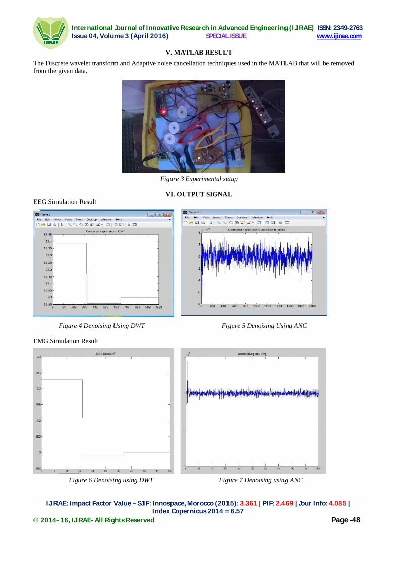
International Journal of Innovative Research in Advanced Engineering (IJIRAE) ISSN: 2349-2763 Issue 04, Volume 3 (April 2016) SPECIAL ISSUE www.ijirae.com
__________________________________________________________________________________________________ IJIRAE: Impact Factor Value – SJIF: Innospace, Morocco (2015): 3.361 | PIF: 2.469 | Jour Info: 4.085 |
Index Copernicus 2014 = 6.57 © 2014- 16, IJIRAE- All Rights Reserved Page -48
V. MATLAB RESULT
The Discrete wavelet transform and Adaptive noise cancellation techniques used in the MATLAB that will be removed from the given data.
Figure 3 Experimental setup
VI. OUTPUT SIGNAL EEG Simulation Result Figure 4 Denoising Using DWT Figure 5 Denoising Using ANC EMG Simulation Result Figure 6 Denoising using DWT Figure 7 Denoising using ANC

International Journal of Innovative Research in Advanced Engineering (IJIRAE) ISSN: 2349-2763 Issue 04, Volume 3 (April 2016) SPECIAL ISSUE www.ijirae.com
__________________________________________________________________________________________________ IJIRAE: Impact Factor Value – SJIF: Innospace, Morocco (2015): 3.361 | PIF: 2.469 | Jour Info: 4.085 |
Index Copernicus 2014 = 6.57 © 2014- 16, IJIRAE- All Rights Reserved Page -49
VII. SUMMARY
The required hardware can be connected and get the desired output. Here DWT is used for the reconstruction of signal for pre-processing and ANC is used to remove the noise. To obtain the denoising correctly DWT level should be low.
VIII. CONCLUSION AND FUTURE ENHANCEMENT Artifacts removal is one of the major features in biomedical signal. Considering the lack of suitable low cost sensors, designed and produced a sensor that can be easily used by ordinary public in an everyday setting. In order to validate the sensor when used in normal/real-world conditions by a non-professional person. I have presented an algorithm to calculate biomedical signal quality with which the users can adjust the connection of electrodes to correct any errors and to suit the prevailing environment. The reported results show that our proposed method functions well, meeting the design goals/requirements and helping to ensure the quality of the signal. In addition, the sensor can also be used as a low cost diagnostic tool to meet the needs of large e-health trials. Use the telemedicine system to transfer the data. In future I can remove artifact from more biomedical signals and quality of the signal is improved by using different effective algorithms.
REFERENCES [1].Christov. I and Dotsinsky(2005) ‘Removal of OA in eeg an approach combining DWT and ANC for portable
applications,’MedBiol Eng Comput. Vol.26,No.65,pp.431–434. [2].Rubana H. Chowdhury, Mohd Alauddin Bin Mohd Ali 1,Ashrif A. A. Bakar , Kalaivani Chellappan 1 and Tae G.
Chang 2 (2010) ‘Noise Removal from Surface Respiratory EMG Signal,’ International Journal of Electrical, Computer, ECE,Vol.2, No.2,pp.556-966
[3].Sanqing Hu, Matt Stead, and Gregory A.Worrell (2007) ‘Biomedical signals analysis by dwt signal denoisingwith neural networks’ IEEE Trans. Biomed. Eng., vol. 54, No.12, pp. 1560-1572.
[4].Yoon.U, Y. Nohand H. Yoon(2011) ‘Compression approach of emg signal transforms”, Biomedical Engineering Letters, Vol.2,No.65, pp.143-150, using 2d discrete wavelet and cosine

International Journal of Innovative Research in Advanced Engineering (IJIRAE) ISSN: 2349-2763 Issue 04, Volume 3 (April 2016) SPECIAL ISSUE www.ijirae.com
_______________________________________________________________________________________________________ IJIRAE: Impact Factor Value – SJIF: Innospace, Morocco (2015): 3.361 | PIF: 2.469 | Jour Info: 4.085 |
Index Copernicus 2014 = 6.57 © 2014- 16, IJIRAE- All Rights Reserved Page -50
A Non Invasive Wireless Pressure Sensor for Continuous IOP Monitoring
S.Kalavathi, M.E –II[Applied electronics],
Anna University Regional Campus ,Coimbatore
V.Madhura M.E –II[Applied electronics],
Sengunthar College of Engineering, Thiruchengode
M.S.Mohamed Sathik Raja HOD [Medical Electronics],
Sengunthar college of engineering, Thiruchengode
Abstract-This paper presents, the second leading cause of blindness, is most accurately defined as a collection of diseases that have in common, damage to the optic nerve and loss of visual field with increased intraocular pressure (IOP) being the primary risk factor. According to National Institutes of Health (NIH) approximately 120 000 Americans are blind from glaucoma which accounts for 9–12% of all cases of blindness in the U.S.Worldwide 79.6 million people are expected to suffer from glaucoma by 2020 increasing from 60.5 million in 2010. Although there are treatments available, there is a need to develop improved diagnostic and therapeutic techniques to fight this disease. Increased IOP is one of the primary factors used to diagnose glaucoma and is also a clinically significant risk factor for its progression. Goldmann tonometry performed during the office visit is considered to be the gold standard for the measurement of IOP. However, given that IOP fluctuates over time, a single office visit gives only a snapshot of what the true IOP is between measurements, which is often weeks or months depending on the patient.
Index Terms— intraocular pres-sure, sensor, wireless powering.
I. INTRODUCTION
G LAUCOMA, an eye disease that causes damage to the optic nerves due to high intraocular pressure, leads to progressive, irreversible vision loss. It is the second leading cause of blindness [1]. Regular eye pressure monitoring can identify the patients at risk and help start early preventive mea-sures to avoid further eye damage. Current clinical devices such as Goldman tonometry and Pulsair pneumo tonometry do not provide continuous monitoring [2]. Additionally, in-clinic mon-itoring through these devices is not sufficient for at-risk patients because the intraocular pressure varies significantly throughout the day and can be substantially greater at times such as during intense physical activity or sleeping [1]. As such, a device that enables on-demand intraocular pressure monitoring (IOPM) in day-to-day life at home without the necessity to go to a specialistin a clinic is highly desirable.
The size of the system is crucial to reduce invasive surgical procedures. Due to the heavy absorption of signals in the human body, generally longer wavelengths (frequencies below 1 GHz) are used. This results in large antenna sizes, which are required for wireless communication from the implant to the external world. One way for miniaturization is to use higher frequencies(smaller antenna sizes) at the cost of larger attenuation of the signal in the human body. Another way to achieve compactness is integrating the antennas with the RF circuits on the same chip, but this also enhances losses due to the low resistivity of the typical silicon substrates (10 .cm) [3]. The lossy environment of the eye makes the wireless communication and the subsequent antenna design even more challenging. The only relief is the short communication range required for this particular application (10 cm) [3].
Implantable IOPM is a new area of research, and not much work has been reported on this [4]. An implantable IOPM reported in [1] has a 27 -mm-long antenna that is unsuitable for the implant process. In [5], a wireless implantable IOPM is demonstrated, but relies on inductive coupling for data transfer. Recently, a passive IOPM system has been proposed that also utilizes inductive coupling [6]. The main drawback of passive systems is that they have very limited functionality and low accuracy level.

International Journal of Innovative Research in Advanced Engineering (IJIRAE) ISSN: 2349-2763 Issue 04, Volume 3 (April 2016) SPECIAL ISSUE www.ijirae.com
_______________________________________________________________________________________________________ IJIRAE: Impact Factor Value – SJIF: Innospace, Morocco (2015): 3.361 | PIF: 2.469 | Jour Info: 4.085 |
Index Copernicus 2014 = 6.57 © 2014- 16, IJIRAE- All Rights Reserved Page -51
The limitation with inductive coupling is that it requires perfect alignment with an external coil [1]. This letter reports two separate implantable antenna designs for transmit (Tx) and receive (Rx) functions in a 1.4- mm active IOPM system-on-chip (SoC). The antennas have been optimized in an eye environment, and a custom test setup has been created to emulate the eye for measurements.
II. DESIGN CONSIDERATIONS
In this system consisting the various hardware’s and softwares .the hardwares are PIC micro controller,Sensor,PC,and lcd.The software’s used in this systems are MP compiler. Here we used different Modules such as Power Supply Unit, Microcontroller Unit,Sensor Unit. Communication Unit,Display Unit,Software Unit.
Figure 1:Block Diagram
PC SECTION
POWER SUPPLY UNIT:
The supply of 5V DC is given to the system which is converted from 230V AC supply. Firstly, the step down transformer will be used here for converting the 230V AC into 12V AC. The microcontroller will support only the DC supply, so the AC supply will be converted into DC using the bridge rectifier. The output of the rectifier will have ripples so we are using the 2200uf capacitor for filtering those ripples. The output from the filter is given to the 7805 voltage regulator which will convert the 12V DC into 5V DC.The output from the regulator will be filtered using the 1000uf capacitor, so the pure 5V DC is getting as the output from the power supply unit. Here we are using the pic microcontroller which will be capable of getting the supply of 5V DC so we have to convert the 230V AC supply into 5V DC supply.
MICROCONTROLLER UNIT:
PIC16F877A
In this project we are using PIC16F877A microcontroller for controlling the devices which are connected in the controller. The eye pressure sensor is connected as the input of microcontroller. This controller has inbuilt ADC. So we can connect the sensor directly to the ADC channel. The Zigbee is connected to the controller. Thus the readed data is send to the PC using Zigbee.
Zigbee
PIC16F877A MICRO CONTROLLER
Pressure Sensor EYE
Power supply
LCD
Zigbee
Power supply

International Journal of Innovative Research in Advanced Engineering (IJIRAE) ISSN: 2349-2763 Issue 04, Volume 3 (April 2016) SPECIAL ISSUE www.ijirae.com
_______________________________________________________________________________________________________ IJIRAE: Impact Factor Value – SJIF: Innospace, Morocco (2015): 3.361 | PIF: 2.469 | Jour Info: 4.085 |
Index Copernicus 2014 = 6.57 © 2014- 16, IJIRAE- All Rights Reserved Page -52
The other Zigbee device is connected with the PC and the database is stored. Also the controller display the reading in LCD which is the output from the sensor.
SENSOR UNIT:
The sensor unit will sense the physical parameters and convert them into electrical signal and amplify the signal using the amplifiers.[6]This sensor is fixed in the eye lid. This sensor monitors the pressure of the eye. Then it sends the data to the microcontroller.
COMMUNICATION UNIT:
Communication unit will send or receive the datas from the microcontroller.The Zigbee device is connected in microcontroller as well as another Zigbee device is connected in the PC. This is used to communicate. [5] MAX232 is used to interface the PC with the microcontrollers to convert the voltage levels. It will convert the voltage level into TTL logic which is compatible to the microcontroller.
DISPLAY UNIT:
Liquid Crystal Display (LCD) is used as the displaying device. Here we are using the 2X16 LCD which is capable of accessing the datas in four bits as well as eight bits also. In this project we are going to display the pressure value of eye.PC is connected with the Zigbee and communicated to the microcontroller and the data is received through the microcontroller the data will be transmitted to the PC and the data will be monitored in PC using dotnet software.
SOFTWARE UNIT:
Software is used to compile the coding of the desired application for the corresponding embedded system,MPLAB Compiler This is the software used to compile the embedded C program. It generates the hex file which can be used to dump on the ic. Proteus 7.2 Proteus is software for microprocessor simulation, schematic capture, and printed circuit board (PCB) design. It is developed by Lab center Electronics. Proteus PCB design combines the ISIS schematic capture and ARES PCB layout programs to provide a powerful, integrated and easy to use suite of tools for professional PCB Design. All Proteus PCB design products include an integrated shape based auto router and a basic SPICE simulation capability as standard. We are using this software to simulate the hardware.[9]
III. MEASUREMENTS
In the Measurements Section we used the sensors ,there or two sensors one is ued for right eye side and another one is used for left side.here we used the pressure sensor the sensor can be kept on the eye lid or side of the eye,the pressure range of two eyes are different .the sensor will sense the pressure for each side and resuk=lt will be shown in the personal computer .the normal range of glaucoma pressure is 21.
IV. CONCLUSION
Thus this project shows how to monitor the pressure in the eye and then sends the data to the PC. The data can be send through zigbee. Also the data’s can be stored in PC. If we want to see the data immediately after checking means that can be displayed in lcd. This project has a wide application in future. Because it easily portable. It is used to monitor the pressure of the eye. This can be used in home also. Thus easy to check & monitor eye. This check up is less cost than others. So this project has a wide welcome in future and we can also add the alarm. when the pressure is higher than normal the alarm indicate the sign.
REFERENCES
[1].Y. H. Kwon, J. H. Fingert, M. H. Kuehn, and W. L. M. Alward, “Primary open-angle glaucoma,” N. Engl. J. Med., vol. 360, no. 11, pp. 1113–1124, Mar. 2009.
[2].H. A. Quigley and A. T. Broman, “The number of people with glaucoma worldwide in 2010 and 2020,” Br. J. Ophthalmol., vol. 90, no. 3, pp. 262– 267, Mar. 2006.
[3].H. Goldmann and T. Schmidt, “U¨ ber applanationstonometrie,” Ophthalmologica, vol. 134, no. 4, pp. 221–242, 1957.

International Journal of Innovative Research in Advanced Engineering (IJIRAE) ISSN: 2349-2763 Issue 04, Volume 3 (April 2016) SPECIAL ISSUE www.ijirae.com
_______________________________________________________________________________________________________ IJIRAE: Impact Factor Value – SJIF: Innospace, Morocco (2015): 3.361 | PIF: 2.469 | Jour Info: 4.085 |
Index Copernicus 2014 = 6.57 © 2014- 16, IJIRAE- All Rights Reserved Page -53
[4].S.Asrani, R. Zeimer, J.Wilensky, D. Gieser, S.Vitale, andK. Lindenmuth, “Large diurnal fluctuations in intraocular pressure are an independent risk factor in patients with glaucoma,” J. Glaucoma, vol. 9, no. 2, pp. 134–142, Apr. 2000.
[5].P. P. Lee, J. W. Walt, L. C. Rosenblatt, L. R. Siegartel, and L. S. Stern, “Association between intraocular pressure variation and glaucoma progression: data from a United States chart review,” Amer. J. Ophthalmol., vol. 144, no. 6, pp. 901–907, Dec. 2007.
[6].S. Hong, G. J. Seong, and Y. J. Hong, “Long-term intraocular pressure fluctuation and progressive visual field deterioration in patients with glaucoma and low intraocular pressures after a triple procedure,” Archives Ophthalmol., vol. 125, no. 8, pp. 1010–1013, Aug. 2007.
[7].J. Caprioli and A. L. Coleman, “Intraocular pressure fluctuation a risk factor for visual field progression at low intraocular pressures in the advanced glaucoma intervention study,” Ophthalmology, vol. 115, no. 7, pp. 1123–1129.e3, Jul. 2008.
[8].C. C. Collins, “Miniature passive pressure transensor for implanting in the eye,” IEEE Trans. Bio-Med. Eng., vol. 14, no. 2, pp. 74–83, Apr. 1967.
[9].L. Rosengren, P. Rangsten, Y. B¨acklund, B. H¨ok, B. Svedbergh, and G. Sel´en, “A system for passive implantable pressure sensors,” Sens. Actuators A: Phys., vol. 43, no. 1–3, pp. 55–58, May 1994.

International Journal of Innovative Research in Advanced Engineering (IJIRAE) ISSN: 2349-2763 Issue 04, Volume 3 (April 2016) SPECIAL ISSUE www.ijirae.com
_________________________________________________________________________________________________________ IJIRAE: Impact Factor Value – SJIF: Innospace, Morocco (2015): 3.361 | PIF: 2.469 | Jour Info: 4.085 |
Index Copernicus 2014 = 6.57 © 2014- 16, IJIRAE- All Rights Reserved Page -54
An Android Based Patient Monitoring System
Gowthami.P Department of Medical Electronics engineering
Sengunthar college of engineering Namakkal, Tamilnadu, India.
Dr.P.Sathishkumar
Principal, Sengunthar college of engineering Namakkal, Tamilnadu, India.
Abstract—This paper proposes an efficient online patient monitoring using android application. Telemedicine is a rapidly developing application of clinic medicine where medical information is transferred through the phone or internet or other networks for the purpose of consulting and performing remote medical procedures or examinations. Telemedicine can be applied to a greater extend in the field of patient monitoring serves as the major tool. This project elaborates the experience; a methodology adopted and highlights various design aspects to be considered for making telemedicine in patient monitoring system effective. In this method, the patient’s vital signs like heart rate, blood pressure, temperature, Angle Displacement Measurement, object reflection measurements are captured and the values are entered into the database. It is then uploaded into the web based server and sent to the doctor’s phone using ANDROID technology.
Keywords—Android, Patient monitoring, Telemedicine, Database
I. INTRODUCTION
A Patient Monitor (also known as Vital Signs Monitors) are a medical monitor or physiological monitor or display, is an electronic medical device that measures a patient's vital signs and displays the data so obtained, which may or may not be transmitted on a monitoring network. Physiological data are displayed continuously on a CRT or LCD screen as data channels along the time axis, They may be accompanied by numerical readouts of computed parameters on the original data, such as maximum, minimum and average values, pulse and respiratory frequencies, and so on. In critical care units of hospitals, bedside units allow continuous monitoring of a patient, with medical staff being continuously informed of the changes in general condition of a patient. Some monitors can even warn of pending fatal cardiac conditions before visible signs are noticeable to clinical staff, such as atrial fibrillation or premature ventricular contraction (PVC).
II. NEEDS AND SCOPE OF THIS PROJECT
Patient monitoring system is a process where a surgeon can continuously monitor more than one patient, for more than one parameter at a time in a remote place. With the development of Smart-phone, it has performed a Smartphone based body monitoring system with a combination of the advantages of network technology and multiple sensor fusion technology. Body monitoring system greatly improves the operational capability of health care, such as remote operations, wireless health care so on. There has been a growing concern with technology of medical care which has developed rapidly and plays an increasingly important role in our life.
The modern visionary of healthcare industry is to provide better healthcare to people anytime and anywhere in the world in a more economic and patient friendly manner. Therefore for increasing the patient care efficiency, there arises a need to improve the patient monitoring devices and make them more mobile. The medical world today faces two basic problems when it comes to patient monitoring. Firstly, the needs of health care’s provider’s presence near the bedside of the patient and secondly, the patient is restricted to bed and wired to large machines. In order to achieve better quality patient care, the above cited problems have to be solved.
As the bio instrumentation, computers and telecommunications technologies are advancing, it has become feasible to design more portal vital sign tele-monitoring systems to acquire, record, display and to transmit the physiological signal from the human body to any location. Recent works in communication technologies have inspired the development of telemedicine to a large extent. Telemedicine benefits not only the customers who are able to receive health care more efficiently; it also benefits the doctors who can streamline their efforts to assist more patients.

International Journal of Innovative Research in Advanced Engineering (IJIRAE) ISSN: 2349-2763 Issue 04, Volume 3 (April 2016) SPECIAL ISSUE www.ijirae.com
_________________________________________________________________________________________________________ IJIRAE: Impact Factor Value – SJIF: Innospace, Morocco (2015): 3.361 | PIF: 2.469 | Jour Info: 4.085 |
Index Copernicus 2014 = 6.57 © 2014- 16, IJIRAE- All Rights Reserved Page -55
The advances in information and communication technologies enable technically, the continuous monitoring of health related parameters with wireless sensor, wherever the user happens to be. They provide valuable real time information enabling the physicians to monitor and analyze a patient’s current and previous state of health. Now days there are several efforts towards the development of system that carry out remote monitoring of patients. Although many wireless standards can be used, there are important considerations such as range, throughput, security, ease of implementation and cost. The patient monitoring involves handling of sensitive data. These data should be transmitted securely without any intrusion. The web-database is a system where the web server will store the data in table format where the digital data are filled in column and then it is plotted against the time to get the parameters. For GUI, Android is used, since its open source and very cheaply available in market which fulfils the criteria of low cost system. Also now days, Android is available to each and every person, including Doctors, since they have started using the Smartphone. In present paper, we report on development of patient monitoring system an android platform which is an open source, to display five parameters such as Heart Beat, Temperature, Blood Pressure, Bone flexibility and Drowsiness. With this module, the doctors who are not present in hospital at time of emergency, they can also operate looking at the different parameters on his or her smart phone or laptop.
III. SYSTEM DESCRIPTION Our aim is to develop patient monitoring system which has telemetry included in that system. The system also includes the web server and web database system from where the data of patient is transmitted all over the world. The block diagram of proposed system is shown in figure.
Fig. 3.1 Block diagram of the project
Flex sensor
Eye blinking sensor
Power Supply
PIC Controller (Embedded C)
Heartbeat sensor
BP sensor
Temperature sensor
MAX 232 (Logic
Converter)
PC (Web server)

International Journal of Innovative Research in Advanced Engineering (IJIRAE) ISSN: 2349-2763 Issue 04, Volume 3 (April 2016) SPECIAL ISSUE www.ijirae.com
_________________________________________________________________________________________________________ IJIRAE: Impact Factor Value – SJIF: Innospace, Morocco (2015): 3.361 | PIF: 2.469 | Jour Info: 4.085 |
Index Copernicus 2014 = 6.57 © 2014- 16, IJIRAE- All Rights Reserved Page -56
Fig. 3.2 Functional diagram of the project
The block diagram consists of Hardware and Software. This system helps the doctor to work from outside of hospital premises. The hardware consists of 3 blocks sensors, microcontroller and display system. Since its patient monitoring system, multiple parameters are acquired and for proper signal acquisition, the placement of electrodes is utmost important factor. Thus placing the electrodes on the body for acquiring the different signal at a time is a main task. After acquiring the data from the sensor, it is amplified since the bio-signals have very low amplitude in micro-volts. So for proper diagnostic bio-amplifier is used which will amplify the signal and display it on display system.
IV. RESULTS
Fig. 4. GUI for Doctor-Login and Doctor-Informative Page

International Journal of Innovative Research in Advanced Engineering (IJIRAE) ISSN: 2349-2763 Issue 04, Volume 3 (April 2016) SPECIAL ISSUE www.ijirae.com
_________________________________________________________________________________________________________ IJIRAE: Impact Factor Value – SJIF: Innospace, Morocco (2015): 3.361 | PIF: 2.469 | Jour Info: 4.085 |
Index Copernicus 2014 = 6.57 © 2014- 16, IJIRAE- All Rights Reserved Page -57
V. ACKNOWLEDGMENT
I wish to express my profound thanks to Medical Electronics engineering department, Sengunthar college of engineering, trichengode and faculty members for providing me all the facilities in making this project possible.
REFERENCES
[1].P.Karthick , C.Sureshkumar , P.Arunprasad, S.Pusparaj , M.Jagadeeshraja , N.Suthanthira vanitha , ‘Embedded based real-time patient monitoring system, international journal of VLSI and Embedded systems’, ISSN:2249 – 6556, pp. 773 -777, 2014.
[2].A.J. Burns and M. Eric Johnson, ‘Securing health information’, Published by the IEEE Computer Society, pp. 23-29, 2015. [3].Paulj. F. White, Blake W. Podaima, and Marcia R. Friesen, ‘Algorithms for Smartphone and Tablet Image Analysis for
Healthcare Applications’, the journal for rapid open access publishing, vol 2, pp. 831-840, 2014. [4].Péter Várady, Zoltán Benyó, and Balázs Benyó, ‘An Open Architecture Patient Monitoring System Using Standard
Technologies’, IEEE Transactions on information technology in biomedicine, vol. 6, no. 1,, pp. 95 – 98, 2002. [5].Zaosheng Zhang, and TingLei Huang, ‘An Intelligent Patient Monitoring System for Home Application’, Genetic and
Evolutionary Computing, pp. 389 – 392, 2009.

International Journal of Innovative Research in Advanced Engineering (IJIRAE) ISSN: 2349-2763 Issue 04, Volume 3 (April 2016) SPECIAL ISSUE www.ijirae.com
______________________________________________________________________________________________________ IJIRAE: Impact Factor Value – SJIF: Innospace, Morocco (2015): 3.361 | PIF: 2.469 | Jour Info: 4.085 |
Index Copernicus 2014 = 6.57 © 2014- 16, IJIRAE- All Rights Reserved Page -58
SEGMENTATION AND CLASSIFICATION OF OPTICAL DISC IN RETINAL IMAGE
T.Logaabirami Department of Medical Electronics Engineering
Sengunthar college of engineering – Tiruchengode Abstract - Retinal image analysis is one of the crucial topics in medical image processing. Diabetes is a disorder of metabolism and is a major health care problem in India. The analysis of fundus images is a non-intrusive option for periodical retinal screening. A novel method to segment the blood vessels and optic disc in the fundus retinal images is proposed in this work.
INTRODUCTION
1.1 RETINAL IMAGE CAPTURE Fundus photography is a highly specialized form of medical imaging technique dedicated to capture the retinal for the study and treatment of disorders of the eye. A fundus camera is a low power microscope with an attached camera designed to photograph the interior surface of the eye, including the retina, optic disc, macula and posterior pole (i.e. the fundus). The optical design of fundus cameras is based on the principle of monocular indirect ophthalmoscopy. A fundus camera provides an upright, magnified view of the fundus of the retina. The observation light is focused via a series of lenses through a doughnut shaped aperture which then passes through a central aperture. The light reflected from the retina passes through the un-illuminated hole in the doughnut formed by the illumination system. The image forming rays continue towards the low powered telescopic eyepiece. When the button is pressed to take a picture, a mirror interrupts the path of the illumination system allow the light from the flash bulb to pass into the eye.
Figure 1.1 Different Views of Angles Captured
Simultaneously, a mirror falls in front of the observation telescope, which redirects the light onto the capturing medium, whether it is film or a digital CCD (charge-coupled device). Because of the eyes tendency to accommodate while looking through a telescope, it is imperative that the exiting convergence is parallel in order for an in focus image to be formed on the capturing angle of 30 creates a film image 2.5 times larger than life. Fundus cameras are described in terms of the angle of view Field Of View (FOV). FOV is the optical angle of acceptance of the lens as shown in Figure 1.2. A typical camera has FOV between 30 to 50 degrees of retinal area.
1.2 LANDMARKS OF RETINAL IMAGE The eye is unique because of the transparency of its optical media. Almost all eye structures can be examined with appropriate optical equipment and lenses. The rear view of eye is shown in Figure 1.2.
Figure 1.2 Rear View of Eye
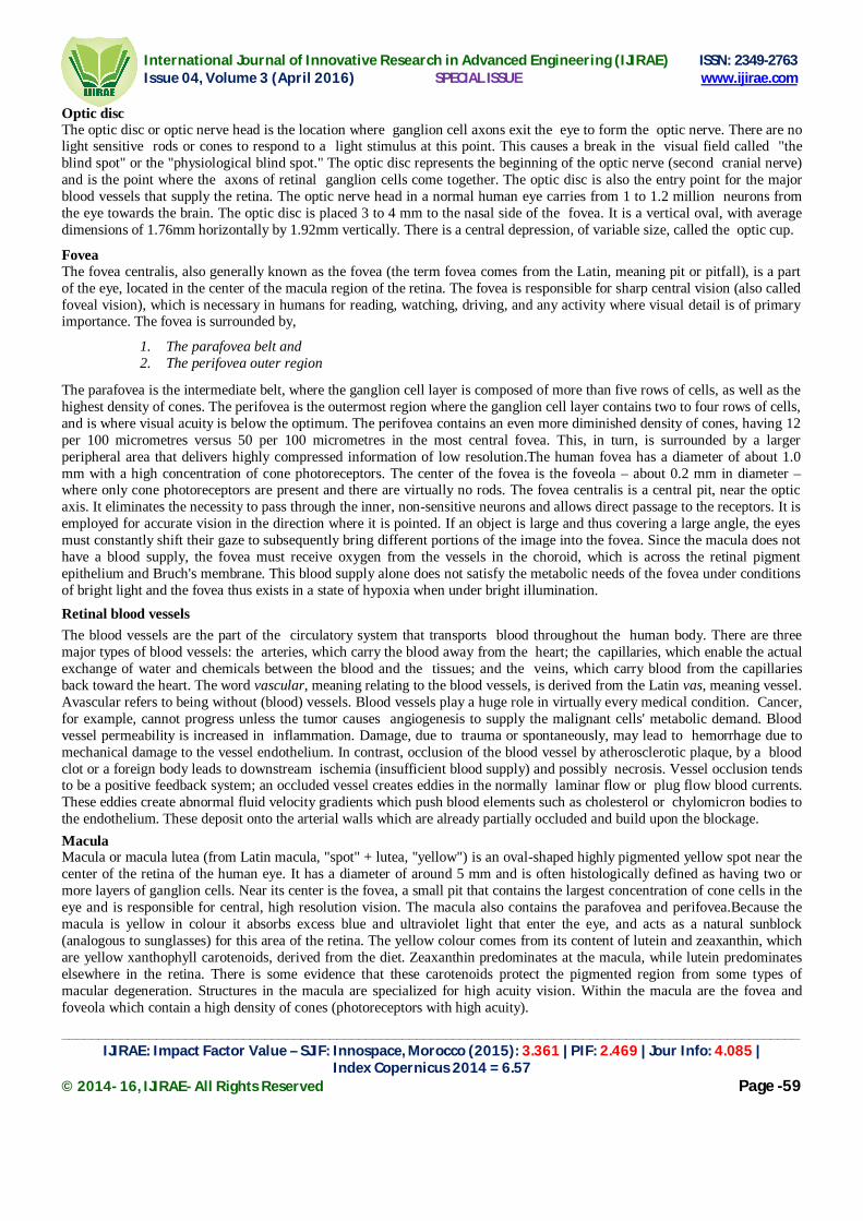
International Journal of Innovative Research in Advanced Engineering (IJIRAE) ISSN: 2349-2763 Issue 04, Volume 3 (April 2016) SPECIAL ISSUE www.ijirae.com
______________________________________________________________________________________________________ IJIRAE: Impact Factor Value – SJIF: Innospace, Morocco (2015): 3.361 | PIF: 2.469 | Jour Info: 4.085 |
Index Copernicus 2014 = 6.57 © 2014- 16, IJIRAE- All Rights Reserved Page -59
Optic disc The optic disc or optic nerve head is the location where ganglion cell axons exit the eye to form the optic nerve. There are no light sensitive rods or cones to respond to a light stimulus at this point. This causes a break in the visual field called "the blind spot" or the "physiological blind spot." The optic disc represents the beginning of the optic nerve (second cranial nerve) and is the point where the axons of retinal ganglion cells come together. The optic disc is also the entry point for the major blood vessels that supply the retina. The optic nerve head in a normal human eye carries from 1 to 1.2 million neurons from the eye towards the brain. The optic disc is placed 3 to 4 mm to the nasal side of the fovea. It is a vertical oval, with average dimensions of 1.76mm horizontally by 1.92mm vertically. There is a central depression, of variable size, called the optic cup.
Fovea The fovea centralis, also generally known as the fovea (the term fovea comes from the Latin, meaning pit or pitfall), is a part of the eye, located in the center of the macula region of the retina. The fovea is responsible for sharp central vision (also called foveal vision), which is necessary in humans for reading, watching, driving, and any activity where visual detail is of primary importance. The fovea is surrounded by,
1. The parafovea belt and 2. The perifovea outer region
The parafovea is the intermediate belt, where the ganglion cell layer is composed of more than five rows of cells, as well as the highest density of cones. The perifovea is the outermost region where the ganglion cell layer contains two to four rows of cells, and is where visual acuity is below the optimum. The perifovea contains an even more diminished density of cones, having 12 per 100 micrometres versus 50 per 100 micrometres in the most central fovea. This, in turn, is surrounded by a larger peripheral area that delivers highly compressed information of low resolution.The human fovea has a diameter of about 1.0 mm with a high concentration of cone photoreceptors. The center of the fovea is the foveola – about 0.2 mm in diameter – where only cone photoreceptors are present and there are virtually no rods. The fovea centralis is a central pit, near the optic axis. It eliminates the necessity to pass through the inner, non-sensitive neurons and allows direct passage to the receptors. It is employed for accurate vision in the direction where it is pointed. If an object is large and thus covering a large angle, the eyes must constantly shift their gaze to subsequently bring different portions of the image into the fovea. Since the macula does not have a blood supply, the fovea must receive oxygen from the vessels in the choroid, which is across the retinal pigment epithelium and Bruch's membrane. This blood supply alone does not satisfy the metabolic needs of the fovea under conditions of bright light and the fovea thus exists in a state of hypoxia when under bright illumination.
Retinal blood vessels
The blood vessels are the part of the circulatory system that transports blood throughout the human body. There are three major types of blood vessels: the arteries, which carry the blood away from the heart; the capillaries, which enable the actual exchange of water and chemicals between the blood and the tissues; and the veins, which carry blood from the capillaries back toward the heart. The word vascular, meaning relating to the blood vessels, is derived from the Latin vas, meaning vessel. Avascular refers to being without (blood) vessels. Blood vessels play a huge role in virtually every medical condition. Cancer, for example, cannot progress unless the tumor causes angiogenesis to supply the malignant cells' metabolic demand. Blood vessel permeability is increased in inflammation. Damage, due to trauma or spontaneously, may lead to hemorrhage due to mechanical damage to the vessel endothelium. In contrast, occlusion of the blood vessel by atherosclerotic plaque, by a blood clot or a foreign body leads to downstream ischemia (insufficient blood supply) and possibly necrosis. Vessel occlusion tends to be a positive feedback system; an occluded vessel creates eddies in the normally laminar flow or plug flow blood currents. These eddies create abnormal fluid velocity gradients which push blood elements such as cholesterol or chylomicron bodies to the endothelium. These deposit onto the arterial walls which are already partially occluded and build upon the blockage.
Macula Macula or macula lutea (from Latin macula, "spot" + lutea, "yellow") is an oval-shaped highly pigmented yellow spot near the center of the retina of the human eye. It has a diameter of around 5 mm and is often histologically defined as having two or more layers of ganglion cells. Near its center is the fovea, a small pit that contains the largest concentration of cone cells in the eye and is responsible for central, high resolution vision. The macula also contains the parafovea and perifovea.Because the macula is yellow in colour it absorbs excess blue and ultraviolet light that enter the eye, and acts as a natural sunblock (analogous to sunglasses) for this area of the retina. The yellow colour comes from its content of lutein and zeaxanthin, which are yellow xanthophyll carotenoids, derived from the diet. Zeaxanthin predominates at the macula, while lutein predominates elsewhere in the retina. There is some evidence that these carotenoids protect the pigmented region from some types of macular degeneration. Structures in the macula are specialized for high acuity vision. Within the macula are the fovea and foveola which contain a high density of cones (photoreceptors with high acuity).

International Journal of Innovative Research in Advanced Engineering (IJIRAE) ISSN: 2349-2763 Issue 04, Volume 3 (April 2016) SPECIAL ISSUE www.ijirae.com
______________________________________________________________________________________________________ IJIRAE: Impact Factor Value – SJIF: Innospace, Morocco (2015): 3.361 | PIF: 2.469 | Jour Info: 4.085 |
Index Copernicus 2014 = 6.57 © 2014- 16, IJIRAE- All Rights Reserved Page -60
The progressive destruction of the macula is a disease known as macular degeneration and can sometimes lead to the creation of a macular hole. Macular holes are rarely caused by trauma, but if a severe blow is delivered it can burst the blood vessels going to the macula, destroying it. Visual input to the macula occupies a substantial portion of the brain's visual capacity. As a result, some forms of visual field loss can occur without involving the macula; this is termed macular sparing.
1.3. MTHODOOGY
The analysis of retinal images is divided into three major procedures: blood vessel segmentation, optic disc segmentation and retinal lesions detection. In the first step, the retinal structures are segmented. The segmentation of the structures allows extracting features that can provide information about the health condition of the eye. The input retinal image is pre-processed. The morphological operation is applied to prune the image and then the outputs are segmented. The segmented outputs of the optic disc are used to extract the features like area, perimeter, eccentricity, Major axis length, minor axis length, etc. Using these features the classification is done. Various classifiers like K- Nearest Neighbour (K-NN) classifier and Support Vector Machine (SVM) are used to classify the optic disc in retinal images and their performance is analyzed. Later, the structures are masked out in order to create an adequate area to detect the lesions.
Figure 1.3. Overall flow diagram
1.4 RESULTS AND DISCUSSION 1.4.1 INPUT RETINAL IMAGE The input image is the retinal fundus image as shown in Figure 4.1. The width and height are 1500 and 1152 respectively. It is of the format 'png' whose resolutions are 72 along both X and Y directions.
Figure 1.4 Input Image

International Journal of Innovative Research in Advanced Engineering (IJIRAE) ISSN: 2349-2763 Issue 04, Volume 3 (April 2016) SPECIAL ISSUE www.ijirae.com
______________________________________________________________________________________________________ IJIRAE: Impact Factor Value – SJIF: Innospace, Morocco (2015): 3.361 | PIF: 2.469 | Jour Info: 4.085 |
Index Copernicus 2014 = 6.57 © 2014- 16, IJIRAE- All Rights Reserved Page -61
1.4.2 OUTPUT IMAGES
PRE-PROCESSING STAGE The images of three different channels - red, green and blue are taken as on Figure . The green channel of the image is chosen for further processing because it has high contrast and is easy to extract the features of the vessel. (a) (b) (c)
Figure 1.5 (a) Red Channel Image (b) Green Channel Image (c) Blue Channel Image
The inverted green channel image as in Figure 4.3 is taken because the clear vessel information is obtained.
Figure 1.6 Inverted Green Channel
The enhanced image after applying adaptive histogram equalization to the inverted image of the green plane as shown in Figure 4.4. GRADIENT EXTRACTION The gradients of the image is seen in Figure The gradient along X-direction in Figure (a) and Y-direction Figure (b) portrays the directional change in the intensity. This helps in finding the edges along the image.
DECOMPOSITION OF THE GRADIENT
(a) (b)
Figure 1.7 (a) Horizontal Decomposition (b) Vertical Decomposition

International Journal of Innovative Research in Advanced Engineering (IJIRAE) ISSN: 2349-2763 Issue 04, Volume 3 (April 2016) SPECIAL ISSUE www.ijirae.com
______________________________________________________________________________________________________ IJIRAE: Impact Factor Value – SJIF: Innospace, Morocco (2015): 3.361 | PIF: 2.469 | Jour Info: 4.085 |
Index Copernicus 2014 = 6.57 © 2014- 16, IJIRAE- All Rights Reserved Page -62
SEGMENTED BLOOD VESSEL The blood vessel is extracted by combining the decompositions along both horizontal and vertical directions as in Figure 1.7.
Figure 1.8 Extracted Blood Vessel SEED LOCALISATION The seeds are localised to locate the centre point of the optic disc as shown in Figure 4.8. The localisation of seed is done by selecting 1% of the brightest region with most number of pixels.
Figure1.9 Seed Localised Image SEGMENTED OPTIC DISC The optic disc shown in Figure 1.9 is segmented from the extracted vascular tree obtained using graph formulation. The optic disc obtained using Markov Random Field method is as shown in the Figure 4.10. This gives the boundary of the optic disc without any discontinuities.
Figure 1.10 OD Segmented Using MRF Method
REFERENCES
[1]. J. Bouguet (2000),”Pyramidal implementation of the lucas kanade feature tracker description of the algorithm,” Intel Corporation, Microprocessor Re-search Technology Rep.
[2]. A. Hoover, V. Kouznetsova and M. Goldbaum (2000), “Locating blood vessels in retinal images by piecewise threshold probing of a matched filter response, ” IEEE Transactions on Medical Imaging , Vol.19 , No.3, pp. 203–210.

International Journal of Innovative Research in Advanced Engineering (IJIRAE) ISSN: 2349-2763 Issue 04, Volume 3 (April 2016) SPECIAL ISSUE www.ijirae.com
______________________________________________________________________________________________________ IJIRAE: Impact Factor Value – SJIF: Innospace, Morocco (2015): 3.361 | PIF: 2.469 | Jour Info: 4.085 |
Index Copernicus 2014 = 6.57 © 2014- 16, IJIRAE- All Rights Reserved Page -63
[3]. A.M. Mendonca and A. Campilho (2006), “Segmentation of retinal blood vessels by combining the detection of center
lines and morphological reconstruction,” IEEE Transactions on Medical Imaging, Vol. 25, No.9, pp. 1200 – 1213. [4]. J. Soares, J. Leandro, R. Cesar, H. Jelinek and M. Cree (2006), “Retinal vessel segmentation using the 2-d gabor wavelet
and supervised classification,” IEEE Transactions on Medical Imaging, Vol.25, No.9, pp. 1214–1222. [5]. J. Staal, M.D. Abramoff , M. Niemeijer, M.A. Viergever and B. Van Ginneken (2004), “Ridge-based vessel segmentation
in color images of the retina, ” IEEE Transactions on Medical Imaging, Vol. 23, No.4, pp. 501– 509. [6]. S. Chaudhuri, S. Chatterjee, N. Katz, M. Nelson and M. Goldbaum (1989), “Detection of blood vessels in retinal images
using two-dimensional matched filters,” IEEE Transactions on medical imaging, Vol. 8, No.3, pp. 263–269. [7]. F. Zana and J.C. Klein (2001), “Segmentation of vessel – like patterns using mathematical morphology and curvature
evaluation”, IEEE Transactions on Image Processing, Vol. 10, No. 7, pp. 1010–1019. [8]. D. Wu, M. Zhang and J. Liu (2006) , “On the adaptive detection of blood vessels in retinal Images”, IEEE Transactions
on Biomedical Engineering, Vol. 53, No. 2, pp. 341 – 343. [9]. Y. Y. Boykov and M.P. Jolly (2001), “Interactive graph cuts for optimal boundary & region segmentation of objects
in and images , ” Proceedings on eighth IEEE International Conference on Computer Vision Conference on Computer Vision and Pattern Recognition, pp. 105–112.
[10]. S. Vicente, V. Kolmogorov and C. Rother (2008), “Graph cut based image segmentation with connectivity priors,” Proceedings of IEEE Conference on Computer Vision and Pattern Recognition, pp. 1 – 8.
[11]. V. Kolmogorov and Y. Boykov (2005), “What metrics can be approximated by geo-cuts or global optimization of length/ area and flux,” Proceedings of Tenth IEEE International Conference on Computer Vision, pp. 564 – 571.
[12]. A. Efros and T. Leung (1999), “Texture synthesis by non-parametric sampling,” Proceedings of the International conference on Computer Vision Pattern Recognition, pp. 1033 – 1038.
[13]. J. Lowell, A. Hunter , D. Steel, A. Basu, R. Ryder, E. Fletcher, and L. Kennedy (2004), “Optic nerve head segmentation, ” IEEE Transactions on Medical Imaging, Vol. 23, No. 2, pp. 256 – 264.

International Journal of Innovative Research in Advanced Engineering (IJIRAE) ISSN: 2349-2763 Issue 04, Volume 3 (April 2016) SPECIAL ISSUE www.ijirae.com
_______________________________________________________________________________________________________ IJIRAE: Impact Factor Value – SJIF: Innospace, Morocco (2015): 3.361 | PIF: 2.469 | Jour Info: 4.085 |
Index Copernicus 2014 = 6.57 © 2014- 16, IJIRAE- All Rights Reserved Page -64
ANALYSIS OF MULTI APPLICATION SERVICE PROVIDER SELECTION FRAMEWORK USING SELCSP IN
CLOUD ENVIRONMENT
B.NANDHINI Mr. O.K. GOWRISHANKAR, II-ME(CSE) Assistant Professor,
Department of Computer Science and Engineering, Department of Computer Science and Engineering, Sengunthar College of Engineering, Sengunthar College of Engineering,
Tirunchengode – 637 205 Tirunchengode – 637 205 ABSTRACT: Cloud computing facilitates better resource utilization by multiplexing the same physical resource among several tenants. Customer does not have to manage and maintain servers, and in turn, uses the resources of cloud provider as services, and is charged according to pay-as-you-use model. Therefore, the major challenge for a customer is to select an appropriate service provider to ensure guaranteed service quality. To support customers in reliably identifying ideal service provider, this work proposes a framework, SelCSP, which combines trustworthiness and competence to estimate risk of interaction. Trustworthiness is computed from personal experiences gained through direct interactions or from feedbacks related to reputations of vendors. Competence is assessed based on transparency in provider’s SLA guarantees. A case study has been presented to demonstrate the application of our approach. The result validates the practicability of the proposed estimating mechanisms.
Key word: Cloud Computing, Services Quality, CSP, SelCSP, ESELSP, SLAs
INTRODUCTION
Service level agreements (SLAs) are one of the major considerations for every buyer of cloud computing services. The question often asked is how many nines of availability a given provider guarantees. Cloud-based services are increasingly becoming commonplace. These services include infrastructure as-a-service (IaaS), platform-as-a-service (PaaS), and software-as-a-service (SaaS). Each service is typically accompanied by a service level agreement (SLA) which defines the minimal guarantees that a provider offers to its customers. The lack of standardization in cloud-based services implies a corresponding lack of clarity in the service level agreements offered by different providers.
Cloud Service Level Agreements (Cloud SLAs) form an important component of the contractual relationship between a cloud service customer and a cloud service provider of a cloud service. Given the global nature of the cloud, SLAs usually span many jurisdictions, with often varying applicable legal requirements, in particular with respect to the protection of the personal data hosted in the cloud service. Furthermore different cloud services and deployment models will require different approaches to SLAs, adding to the complexity of SLAs. Finally, SLA terminology today often differs from one cloud service provider to another, making it difficult for cloud service customers to compare cloud services. For the avoidance of doubt, this document does not address consumers as being cloud service customers. Standardizing aspects of SLAs improves the clarity and increases the understanding of SLAs for cloud services in the market, in particular by highlighting and providing information on the concepts usually covered by SLAs. The main objective of the paper following ways,
Support for customer-driven service management based on customer profiles and QoS requirements; Definition of computational risk management tactics to identify, assess, and manage risks involved in the execution of
applications with regards to service requirements and customer needs; Derivation of appropriate market-based resource management strategies that encompass both customer-driven service
management and computational risk management to sustain SLA-oriented resource allocation; Incorporation of autonomic resource management models that effectively self-manage changes in service requirements to
satisfy both new service demands and existing service obligations; Leverage of Virtual Machine (VM) technology to dynamically assign resource shares according to service requirements;
and Implementation of the developed resource management strategies and models into a real computing server in an
operational data center.

International Journal of Innovative Research in Advanced Engineering (IJIRAE) ISSN: 2349-2763 Issue 04, Volume 3 (April 2016) SPECIAL ISSUE www.ijirae.com
_______________________________________________________________________________________________________ IJIRAE: Impact Factor Value – SJIF: Innospace, Morocco (2015): 3.361 | PIF: 2.469 | Jour Info: 4.085 |
Index Copernicus 2014 = 6.57 © 2014- 16, IJIRAE- All Rights Reserved Page -65
RELATED WORKS In this paper [1], the authors stated that among the various human factors impinging upon making a decision in an
uncertain environment, risk and trust are surely crucial ones. Several models for trust have been proposed in the literature but few explicitly take risk into account. This paper analyses the relationship between the two concepts by first looking at how a decision is made to enter into a transaction based on the risk information. They then drew a model of the invested fraction of the capital function of a decision surface. The SECURE project [17] analyses a notion of trust that is “inherently linked to risk”. Risk is evaluated on every possible outcome of a particular action and is represented as a family of cost-PDFs (Probability Density Function) parameterized by the outcome’s intrinsic cost. The considered action is then analysed by a trust engine to compute multidimensional trust information which is then used by a risk engine to select one cost-PDF. The decision to take the action is then made by applying a user-defined policy to select one of the possible outcomes’ cost-PDFs. Trust and reputation systems represent a significant trend in decision support for Internet mediated service provision. The basic idea is to let parties rate each other, for example after the completion of a transaction, and use the aggregated ratings about a given party to derive a trust or reputation score, which can assist other parties in deciding whether or not to transact with that party in the future. A natural side effect is that it also provides an incentive for good behavior, and therefore tends to have a positive effect on market quality. Reputation systems can be called collaborative sanctioning systems to reflect their collaborative nature, and are related to collaborative filtering systems. Reputation systems are already being used in successful commercial online applications. Digital environments and infrastructures, such as distributed security services and distributed computing services, have generated new options of communication, information sharing, and resource utilization in past years. However, when distributed services are used, the question arises of to what extent we can trust service providers to not violate security requirements, whether in isolation or jointly. Answering this question is crucial for designing trustworthy distributed systems and selecting trustworthy service providers. Cloud computing paradigm is set to become the next explosive revolution on the Internet, but its adoption is still hindered by security problems. One of the fundamental issues is the need for better access control and identity management systems. In this context, Federated Identity Management (FIM) is identified by researchers and experts as an important security enabler, since it will play a vital role in allowing the global scalability that is required for the successful implantation of cloud technologies. However, current FIM frameworks are limited by the complexity of the underlying trust models that need to be put in place before inter-domain cooperation. Thus, the establishment of dynamic federations between the different cloud actors is still a major research challenge that remains unsolved
1. EXISTING SYSTEM
The existing system develops a framework, called SelCSP, to compute overall perceived interaction risk. It establishes a relationship among perceived interaction risk, trustworthiness and competence of service provider. It proposes a mechanism by which trustworthiness of a service provider may be estimated. It also proposes a mechanism by which transparency of any provider’s SLA may be computed. The model constitutes the
Risk estimate. It estimates perceived interaction risk relevant to a customer-CSP interaction by combining trustworthiness and competence.
Trust estimate. It computes trust between a customer-CSP pair provided direct interaction has occurred between them. Reputation estimate. It evaluates reputation of a CSP based on referrals/feedbacks from various sources and computes
the belief a customer has on former’s reputation. Trustworthiness computation. Function to evaluate a customer’s trust on a given CSP. SLA manager. This module manages SLAs from different CSPs. It takes into account different
recommendations/standards and controls which are supposed to be satisfied by the SLAs. Competence estimate. It estimates competence of a CSP based on the information available from its SLA. Competence computation. It computes transparency with respect to a given SLA and hence evaluates the competence of
the CSP. Risk computation. It computes perceived interaction risk relevant to a customer-CSP interaction. Interaction ratings. It is a data repository where customer provides feedback/ratings for CSP.
DRAWBACKS It does not aim at using this risk-based provider selection. It does not ensure secure multi-domain collaboration in cloud. It does not compare the new coming cloud service providers with existing cloud providers.

International Journal of Innovative Research in Advanced Engineering (IJIRAE) ISSN: 2349-2763 Issue 04, Volume 3 (April 2016) SPECIAL ISSUE www.ijirae.com
_______________________________________________________________________________________________________ IJIRAE: Impact Factor Value – SJIF: Innospace, Morocco (2015): 3.361 | PIF: 2.469 | Jour Info: 4.085 |
Index Copernicus 2014 = 6.57 © 2014- 16, IJIRAE- All Rights Reserved Page -66
2. PROPOSED SYSTEM
The proposed system includes all the existing system approach which covers multiple cloud service provider environments. In addition, the framework estimates trust-worthiness in terms of context-specific, dynamic trust and reputation feedbacks even from new coming cloud service providers. It also computes competence of a service provider in terms of transparency of SLAs. Both these entities are combined to model interaction risk, which gives an estimate of risk level involved in an interaction. ADVANTAGES
The proposed system has following advantages. Level of uptime: describes the time in a defined period th service was available, over the total possible available time,
expressed as a percentage. Percentage of successful requests: describes the number of requests processed by the service without an error over the total
number of submitted requests, expressed as a percentage. Percentage of timely service provisioning requests: describes the number of service provisioning requests completed within
a defined time period over the total number of service provisioning requests, expressed as a percentage. Average response time: refers to the statistical mean over a set of cloud service response time observations for a particular
form of request. Maximum response time: refers to the maximum response time target for a given particular form of request. Maximum resource capacity: refers to the maximum amount of a given resource available to an instance of the cloud
service for a particular cloud service customer. Example resources include data storage, memory, number of CPU cores. It compares the new coming cloud service providers with existing cloud providers. ESELCSP FRAME WORK
A framework, termed as SelCSP, has been proposed to facilitate customers in selecting an ideal cloud service provider for business outsourcing. Fig. 1 depicts different modules of the framework and how these modules are functionally related. As evident in Fig. 1a, the dotted boundary region denotes the SelCSP framework which acts as a third-party intermediator between customers and cloud service providers. SelCSP framework provides APIs through which both customers and providers can register themselves. After registering, customer can provide trust ratings based on interactions with provider. Cloud provider needs to submit its SLA to compute competence. At present, verifying the correctness of submitted ratings or sanitizing the erroneous data in the framework is beyond the scope. We assume that only registered customers can provide referrals/feedbacks and they do not have any malicious intents of submitting unfair ratings. Various modules constituting the framework are as follows;
Risk estimate. It estimates perceived interaction risk relevant to a customer-CSP interaction by combining trustworthiness and competence.
Trust estimate. It computes trust between a customerCSP pair provided direct interaction has occurred between them. Reputation estimate. It evaluates reputation of a CSP based on referrals/feedbacks from various sources and computes the
belief a customer has on former’s reputation. Trustworthiness computation. Function to evaluate a customer’s trust on a given CSP. SLA manager. This module manages SLAs from different CSPs. It takes into account different recommendations/standards
and controls which are supposed to be satisfied by the SLAs. Competence estimate. It estimates competence of a CSP based on the information available from its SLA. Competence computation. It computes transparency with respect to a given SLA and hence evaluates the competence of the
CSP. Risk computation. It computes perceived interaction risk relevant to a customer-CSP interaction. Interaction ratings. It is a data repository where customer provides feedback/ratings for CSP. SLA-oriented Resource Allocation Through Virtualization
Recently, virtualization [24][25] has enabled the abstraction of computing resources such that a single physical machine is able to function as multiple logical VMs (Virtual Machines).

International Journal of Innovative Research in Advanced Engineering (IJIRAE) ISSN: 2349-2763 Issue 04, Volume 3 (April 2016) SPECIAL ISSUE www.ijirae.com
_______________________________________________________________________________________________________ IJIRAE: Impact Factor Value – SJIF: Innospace, Morocco (2015): 3.361 | PIF: 2.469 | Jour Info: 4.085 |
Index Copernicus 2014 = 6.57 © 2014- 16, IJIRAE- All Rights Reserved Page -67
A key benefit of VMs is the ability to host multiple operating system environments which are completely isolated from one another on the same physical machine. Another benefit is the capability to configure VMs to utilize different partitions of resources on the same physical machine. Physical machine, one VM can be allocated 10% of the processing power, while another VM can be allocated 20% of the processing power. Hence, VMs can be started and stopped dynamically to meet the changing demand of resources by users as opposed to limited resources on a physical machine. In particular, VMs may be assigned various resource management policies catering to different user needs and demands to better support the implementation of SLA-oriented resource allocation
Good SLA sets boundaries and expectations of service provisioning and provides the following benefits: Enhanced customer satisfaction level: A clearly and concisely defined SLA increases the customer satisfaction
level, as it helps providers to focus on the customer requirements and ensures that the effort is put on the right direction.
Improved Service Quality: Each item in an SLA corresponds to a Key Performance Indicator (KPI) that specifies the customer service within an internal organisation.
Improved relationship between two parties: A clear SLA indicates the reward and penalty policies of a service provision. The consumer can monitor services according to Service Level Objectives (SLO) specified in the SLA. Moreover, the precise contract helps parties to resolve conflicts more easily.
CONCLUSION
Cloud computing is an evolving paradigm, where new service providers are frequently coming into existence, offering services of similar functionality. In this thesis work problem for a cloud customer is to select an appropriate service provider from the cloud marketplace to support its business needs. However, service guarantees provided by vendors through SLAs contain ambiguous clauses which make the job of selecting an ideal provider even more difficult. As customers use cloud services to process and store their individual client’s data, guarantees related to service quality level is of utmost importance. For this purpose, it is imperative from a customer’s perspective to establish trust relationship with a provider. In this proposed system is competence and assessed based on transparency in provider’s SLA guarantees. A case study has been presented to demonstrate the application of our approach. The result validates the practicability of the proposed estimating mechanisms using multi cloud services provider. In this study, proposed a novel framework-SelCSP, which facilitates selection of trustworthy and competent service provider. The framework estimates trust worthiness in terms of context-specific, dynamic trust and reputation feedbacks. It also computes competence of a service provider in terms of transparency of SLAs. Both these entities are combined to model interaction risk, which gives an estimate of risk level involved in an interaction. Such estimate enables a customer to make decisions regarding choosing a service provider for a given context of interaction. A case study has been described to demonstrate the application of the framework. Results establish validity and efficiency of the approach with respect to realistic scenarios.
SCOPE FOR FUTURE DEVELOPMENT
Several algorithms are proposed for select an appropriate service provider to ensure guaranteed service quality. To support customers in reliably identifying ideal service provider, the proposed searching SelCSP algorithm efficiency can be improved in future works. In future, for selecting the cloud service providers, data mining techniques and aggregation methodologies may apply for combines trustworthiness and competence to estimate risk of interaction and compute the Trustworthiness from personal experiences gained through direct interactions or from feedbacks related to reputations of vendors
If the experimental study is tested with real environment, then it can assist the further proceeding of the algorithm
implementation practically. The new system becomes useful if the above enhancements are made in future. The new system is designed such that those enhancements can be integrated with current modules easily with less integration work. The following enhancements are should be in future.
The application if developed as web services, then many applications can make use of the records. The data integrity in cloud environment is not considered. The error situation can be recovered if there is any mismatch. The web site and database can be hosted in real cloud place during the implementation.

International Journal of Innovative Research in Advanced Engineering (IJIRAE) ISSN: 2349-2763 Issue 04, Volume 3 (April 2016) SPECIAL ISSUE www.ijirae.com
_______________________________________________________________________________________________________ IJIRAE: Impact Factor Value – SJIF: Innospace, Morocco (2015): 3.361 | PIF: 2.469 | Jour Info: 4.085 |
Index Copernicus 2014 = 6.57 © 2014- 16, IJIRAE- All Rights Reserved Page -68
REFERENCES
[1]. A. Jøsang and S. L. Presti, “Analysing the relationship between risk and trust,” in Proc. 2nd Int. Conf. Trust Manage., Mar. 2004, pp. 135–145.
[2]. A. Jøsang, R. Ismail, and C. Boyd, “A survey of trust and reputation systems for online service provision,” Decision Support Sys., vol. 43, no. 2, pp. 618–644, Mar. 2007.
[3]. G. Schryen, M. Volkamer, S. Ries, and S. M. Habib, “A formal approach towards measuring trust in distributed systems,” in Proc. ACM Symp. Appl. Comput., 2011, pp. 1739–1745.
[4]. P. Arias-Cabarcos, F. Almenarez-Mendoza, A. Marın-Lopez, D. Dıaz-Sanchez, and R. S. anchez-Guerrero, “A metric-based approach to assess risk for “on cloud” federated identity management,” J. Netw. Syst.Manage., vol. 20, no. 4, pp. 1–21, 2012.Cybern., 2010, vol. 6, pp. 2843–2848.
[5]. M. Alhamad, T. Dillon, and E. Chang, “A trust-evaluation metric for cloud applications,” Int. J. Mach. Learn. Comput., vol. 1, no. 4, pp. 416–421, 2011.
[6]. T. Noor and Q. Sheng, “Trust as a service: A framework for trust management in cloud environments,” in Proc. 12th Int. Conf. Web Inf. Syst. Eng., 2011, pp. 314–321.
[7]. W. Li and L. Ping, “Trust model to enhance security and interoperability of cloud environment,” in Proc. 1st Int. Conf. Cloud Comput., 2009, vol. 5931, pp. 69–79.
[8]. S. K. Habib, S. Ries, and M. Muhlhauser, “Towards a trust management system for cloud computing,” in Proc. IEEE 10th Int. Conf. Trust, Secur. Privacy Comput. Commun., 2011, pp. 933–939.
[9]. K. M. Khan and Q. Malluhi, “Establishing trust in cloud computing,” IT Prof., vol. 12, no. 5, pp. 20–27, Oct. 2010. [10]. H. Takabi, J. B. D. Joshi, and G. J. Ahn, “Security and privacy challenges in cloud computing environments,” IEEE Secur.
Privacy, vol. 8, no. 6, pp. 24–31, Nov./Dec. 2010. [11]. D. H. McKnight and N. L. Chervany. The Meanings of Trust. Technical Report MISRC Working Paper Series 96-04,
University of Minnesota, Management Information Systems Reseach Center, 1996. http://www.misrc.umn.edu/wpaper/wp96-04.htm.


International Journal of Innovative Research in Advanced Engineering (IJIRAE) ISSN: 2349-2763 Issue 04, Volume 3 (April 2016) SPECIAL ISSUE www.ijirae.com
_________________________________________________________________________________________________ IJIRAE: Impact Factor Value – SJIF: Innospace, Morocco (2015): 3.361 | PIF: 2.469 | Jour Info: 4.085 |
Index Copernicus 2014 = 6.57 © 2014- 16, IJIRAE- All Rights Reserved Page -69
ENGINE BATTERY SUPER CHARGING FROM EXHAUST GAS
S.Pratheebha
II M.E – CAD/CAM Mechanical Department,
Sengunthar College of Engineering,Tiruchengode Abstract— This paper deals with usage of Exhaust gas from any engine there-by generating power using Thermo electric generators (TEG), turbocharger technology. Nowadays in automobile field many new innovating concepts are being developed. The electric power which is generated can be stored in battery for the later consumption. In this paper, I am demonstrating a concept of generating power in a moving vehicle by the usage of turbines, dynamo and TEG Elements.
Keywords— Exhaust gas recovery, waste heat recovery, I.C Engine fuel economy, TEG Elements (Thermo-electric Generator), harnessing waste heat
I. INTRODUCTION
We waste so much energy. As much as 60 percent of energy is wasted as heat. The nuclear power plants, chemical factories and automobiles all contribute to this waste heat. Thus Thermoelectric generators (TEGs) can be used to turn waste heat directly into electrical energy.
The material used is called skutterudite, which is a mix of minerals. Then other rare metals are added to it to make sure it’s a poor conductor. That way, the current is generated when the material is hot on one side and cold on the other. Ideally, it would reduce the amount of fuel used by five percent. It does this as it generates electricity to help power the car’s electrical system and charge its battery. The applications of the technology go beyond car exhaust. It could generate electricity in homes and power plants from waste streams.
II. EXHAUST GAS RECOVERY SYSTEM A. Exhaust heat recovery system
In an engine, an exhaust heat recovery system turns thermal losses in the exhaust pipe into energy. This technology seems to be more and more of interest by car and heavy-duty vehicle manufacturers as an efficient way to save fuel and reduce vehicles’ CO2 emissions. This technology can be used either on a hybrid vehicle or a conventional one: it produces either electric energy for batteries or mechanical energy reintroduced on the crankshaft. B. Thermal losses in the exhaust pipe Inside the exhaust pipe of an internal combustion engine, energy losses are various: thermal, kinetic, chemical and latent heat. Most important energy parts are located in the thermal and kinetic losses, the two others are negligible. Kinetic losses can be recovered through a turbocharger or a turbo-compound. C. Exhaust heat recovery technologies
TEG - Thermoelectric generator are another option to recover heat from the exhaust pipe to reduce vehicles fuel consumption.
D. Exhaust gas Kinetic energy recovery technologies Turbine is used to convert Kinetic Energy from the Exhaust Steam into electrical energy by using dynamo
III. METHODOLOGY
Heat Energy Recovery System.

International Journal of Innovative Research in Advanced Engineering (IJIRAE) ISSN: 2349-2763 Issue 04, Volume 3 (April 2016) SPECIAL ISSUE www.ijirae.com
_________________________________________________________________________________________________ IJIRAE: Impact Factor Value – SJIF: Innospace, Morocco (2015): 3.361 | PIF: 2.469 | Jour Info: 4.085 |
Index Copernicus 2014 = 6.57 © 2014- 16, IJIRAE- All Rights Reserved Page -70
Vehicle Battery Super charging from Exhaust Gas
IV. DESCRIPTION OF EQUIPMENTS A. Kinetic energy retrieval 1) Turbine: A steam turbine is a mechanical device that extracts kinetic energy from pressurized steam, and converts it into rotary motion. It has almost completely replaced the reciprocating piston steam engine primarily because of its greater thermal efficiency and higher power-to-weight ratio. Because the turbine generates rotary motion, it is particularly suited to be used to drive an electrical generator – about 90% of all electricity generation in the United States is by use of steam turbines. The steam turbine is a form of heat engine that derives much of its improvement in thermodynamic efficiency through the use of multiple stages in the expansion of the steam, which results in a closer approach to the ideal reversible process.
Energy provided for the turbine work is converted from the enthalpy and kinetic energy of the gas. The turbine housings direct the gas flow through the turbine as it spins at up to 250,000 rpm. The size and shape can dictate some performance characteristics of the overall turbocharger. Often the same basic turbocharger assembly is available from the manufacturer with multiple housing choices for the turbine, and sometimes the compressor cover as well. This lets the balance between performance, response, and efficiency be tailored to the application.
The turbine and impeller wheel sizes also dictate the amount of air or exhaust that can flow through the system, and the relative efficiency at which they operate. In general, the larger the turbine wheel and compressor wheel the larger the flow capacity. Measurements and shapes can vary, as well as curvature and number of A turbocharger’s performance is closely tied to its size.Large turbochargers take more heat and pressure to spin the turbine, creating lag at low speed. Small turbochargers spin quickly, but may not have the same performance at high acceleration.To efficiently combine the benefits of large and small wheels; advanced schemes are used such as twin-turbochargers, twin-scroll turbochargers, or variable-geometry turbochargers
Principle of operation and design An ideal steam turbine is considered to be an isentropic process, or constant entropy process, in which the
entropy of the steam entering the turbine is equal to the entropy of the steam leaving the turbine. No steam turbine is truly isentropic, however, with typical isentropic efficiencies ranging from 20–90% based on the application of the turbine. The interior of a turbine comprises several sets of blades, or buckets as they are more commonly referred to. One set of stationary blades is connected to the casing and one set of rotating blades is connected to the shaft. The sets inter mesh with certain minimum clearances, with the size and configuration of sets varying to efficiently exploit the expansion of steam at each stage. 2) Dynamo: Dynamo is an electrical generator. This dynamo produces direct current with the use of a commutator. Dynamo was the first generator capable of the power industries. The dynamo uses rotating coils of wire and magnetic fields to convert mechanical rotation into a pulsing direct electric current. A dynamo machine consists of a stationary structure, called the stator, which provides a constant magnetic field, and a set of rotating windings called the armature which turn within that field. On small machines the constant magnetic field may be provided by one or more permanent magnets; larger machines have the constant magnetic field provided by one or more electromagnets, which are usually called field coils.

International Journal of Innovative Research in Advanced Engineering (IJIRAE) ISSN: 2349-2763 Issue 04, Volume 3 (April 2016) SPECIAL ISSUE www.ijirae.com
_________________________________________________________________________________________________ IJIRAE: Impact Factor Value – SJIF: Innospace, Morocco (2015): 3.361 | PIF: 2.469 | Jour Info: 4.085 |
Index Copernicus 2014 = 6.57 © 2014- 16, IJIRAE- All Rights Reserved Page -71
The commutator was needed to produce direct current. When a loop of wire rotates in a magnetic field, the potential induced in it reverses with each half turn, generating an alternating current. However, in the early days of electric experimentation, alternating current generally had no known use. The few uses for electricity, such as electroplating, used direct current provided by messy liquid batteries. Dynamos were invented as a replacement for batteries. The commutator is a set of contacts mounted on the machine's shaft, which reverses the connection of the windings to the external circuit when the potential reverses, so instead of alternating current, a pulsing direct current is produced.
Dynamo
B. Thermal energy retrieval 1) Thermoelectric generator: Thermoelectric generator TEG (also called Seebeck generators) are solid state devices that convert heat (temperature differences) directly into electrical energy, using a phenomenon called the Seebeck effect (a form of thermoelectric effect). Thermoelectric generators function like heat engines, but are less bulky, have no moving parts. However, TEGs are typically more expensive and less efficient.
Thermoelectric Generator
Thermoelectric generators could be used in power plants in order to convert waste heat into additional electrical power and in automobiles as automotive thermoelectric generators (ATGs) to increase fuel efficiency.
Construction
Thermoelectric power generators consist of three major components: thermoelectric materials, thermoelectric
modules and thermoelectric systems that interface with the heat source. 2) Thermoelectric materials: Thermoelectric materials generate power directly from heat by converting temperature differences into electric voltage. These materials must have both high electrical conductivity and low thermal conductivity to be good thermoelectric materials. Having low thermal conductivity ensures that when one side is made hot, the other side stays cold, which helps to generate a large voltage while in a temperature gradient. The measure of the magnitude of electrons flow in response to a temperature difference across that material is given by the Seebeck coefficient. The efficiency of a given materials to produce a thermoelectic power is governed by their “figure of merit” z. For many years, the main three semiconductors known to have both low thermal conductivity and high power factor were bismuth telluride (Bi2Te3), lead telluride(PbTe), and silicon germanium (SiGe). These materials have very rare elements which make them very expensive compounds.

International Journal of Innovative Research in Advanced Engineering (IJIRAE) ISSN: 2349-2763 Issue 04, Volume 3 (April 2016) SPECIAL ISSUE www.ijirae.com
_________________________________________________________________________________________________ IJIRAE: Impact Factor Value – SJIF: Innospace, Morocco (2015): 3.361 | PIF: 2.469 | Jour Info: 4.085 |
Index Copernicus 2014 = 6.57 © 2014- 16, IJIRAE- All Rights Reserved Page -72
Today, the thermal conductivity of semiconductors can be lowered without affecting their high electrical
electrical properties using nanotechnology. This can be achieved by creating nanoscale features such as particles, wires or interfaces in bulk semiconductor materials. However, the manufacturing processes of nano-materials is still challenging.
Only a few known materials to date are identified as thermoelectric materials. Most thermoelectric materials today have a ZT value of around unity, such as in Bismuth Telluride (Bi2Te3) at room temperature and lead telluride (PbTe) at 500-700K. However, in order to be competitive with other power generation systems, TEG materials should have ZT of 2-3 range. Most research in thermoelectric materials has focused on increasing the Seebeck coefficient (S) and reducing the thermal conductivity, especially by manipulating the nanostructure of the thermoelectric materials. Because the thermal and electrical conductivity correlate with the charge carriers, new means must be introduced in order to conciliate the contradiction between high electrical conductivity and low thermal conductivity as indicated. When selecting materials for thermoelectric generation, a number of other factors need to be considered. During operation, ideally the thermoelectric generator has a large temperature gradient across it. Thermal expansion will then introduce stress in the device which may cause fracture of the thermoelectric legs, or separation from the coupling material. The mechanical properties of the materials must be considered and the coefficient of thermal expansion of the n and p-type material must be matched reasonably well. In segmented thermoelectric generators, the material's compatibility must also be considered. A material's compatibility factor is defined as s=((1-zT)1/2-1)/(ST). When the compatibility factor from one segment to the next differs by more than a factor of about two, the device will not operate efficiently. The material parameters determining s (as well as zT) are temperature dependent, so the compatibility factor may change from the hot side to the cold side of the device, even in one segment. This behavior is referred to as self-compatibility and may become important in devices design for low temperature operation. In general, thermoelectric materials can be categorized into conventional and new materials:
Thermoelectric Circuit
A thermoelectric circuit composed of materials of different Seebeck coefficient (p-doped and n-doped semiconductors), configured as a thermoelectric generator.
5.3.4 Thermoelectric module A thermoelectric module is a circuit containing thermoelectric materials that generate electricity from heat directly. A thermoelectric module consists of two dissimilar thermoelectric materials joining in their ends: an n-type (negatively charged); and a p-type (positively charged) semiconductors. A direct electric current will flow in the circuit when there is a temperature difference between the two materials. Generally, the current magnitude has a proportional relationship with the temperature difference. (.i.e., the more the temperature difference, the higher the current.)
In application, thermoelectric modules in power generation work in very tough mechanical and thermal conditions. Because they operate in very high temperature gradient, the modules are subject to large thermally induced stresses and strains for long periods of time. They also are subject to mechanical fatigue caused by large number of thermal cycles.
Thus, the junctions and materials must be selected so that they survive these tough mechanical and thermal conditions. Also, the module must be designed such that the two thermoelectric materials are thermally in parallel, but electrically in series. The efficiency of thermoelectric modules are greatly affected by its geometrical design.
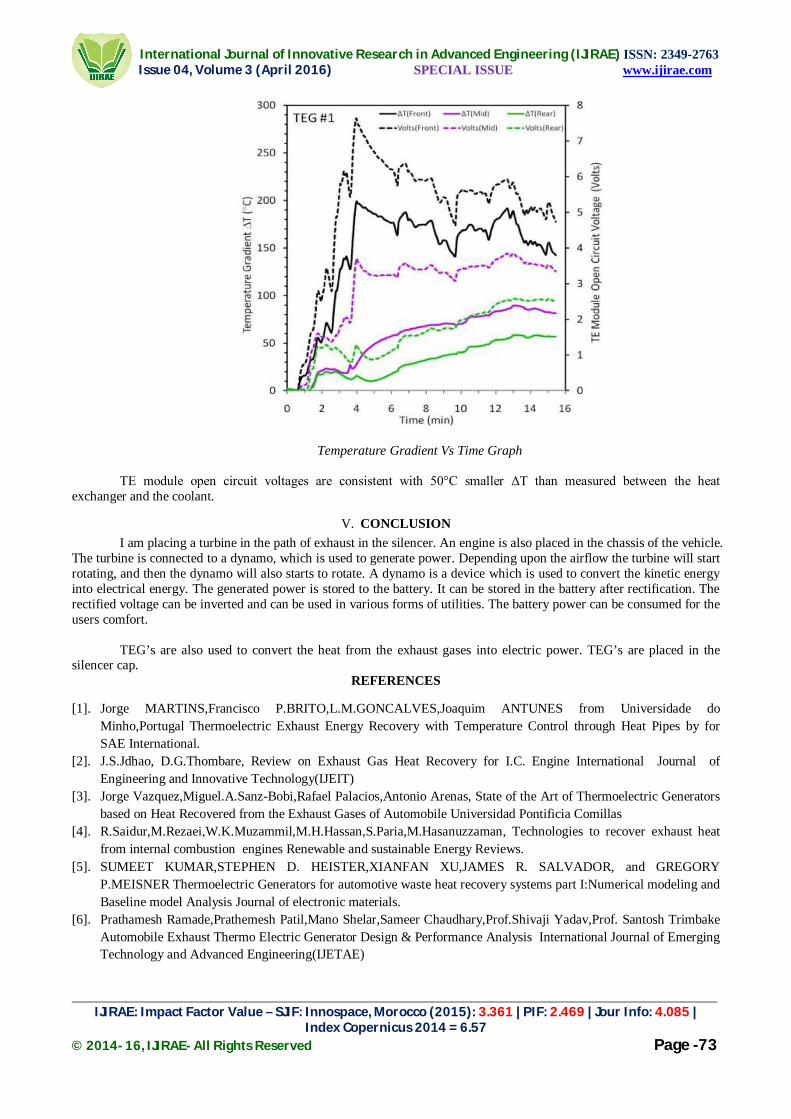
International Journal of Innovative Research in Advanced Engineering (IJIRAE) ISSN: 2349-2763 Issue 04, Volume 3 (April 2016) SPECIAL ISSUE www.ijirae.com
_________________________________________________________________________________________________ IJIRAE: Impact Factor Value – SJIF: Innospace, Morocco (2015): 3.361 | PIF: 2.469 | Jour Info: 4.085 |
Index Copernicus 2014 = 6.57 © 2014- 16, IJIRAE- All Rights Reserved Page -73
Temperature Gradient Vs Time Graph TE module open circuit voltages are consistent with 50°C smaller ΔT than measured between the heat
exchanger and the coolant. V. CONCLUSION
I am placing a turbine in the path of exhaust in the silencer. An engine is also placed in the chassis of the vehicle. The turbine is connected to a dynamo, which is used to generate power. Depending upon the airflow the turbine will start rotating, and then the dynamo will also starts to rotate. A dynamo is a device which is used to convert the kinetic energy into electrical energy. The generated power is stored to the battery. It can be stored in the battery after rectification. The rectified voltage can be inverted and can be used in various forms of utilities. The battery power can be consumed for the users comfort.
TEG’s are also used to convert the heat from the exhaust gases into electric power. TEG’s are placed in the
silencer cap. REFERENCES
[1]. Jorge MARTINS,Francisco P.BRITO,L.M.GONCALVES,Joaquim ANTUNES from Universidade do
Minho,Portugal Thermoelectric Exhaust Energy Recovery with Temperature Control through Heat Pipes by for SAE International.
[2]. J.S.Jdhao, D.G.Thombare, Review on Exhaust Gas Heat Recovery for I.C. Engine International Journal of Engineering and Innovative Technology(IJEIT)
[3]. Jorge Vazquez,Miguel.A.Sanz-Bobi,Rafael Palacios,Antonio Arenas, State of the Art of Thermoelectric Generators based on Heat Recovered from the Exhaust Gases of Automobile Universidad Pontificia Comillas
[4]. R.Saidur,M.Rezaei,W.K.Muzammil,M.H.Hassan,S.Paria,M.Hasanuzzaman, Technologies to recover exhaust heat from internal combustion engines Renewable and sustainable Energy Reviews.
[5]. SUMEET KUMAR,STEPHEN D. HEISTER,XIANFAN XU,JAMES R. SALVADOR, and GREGORY P.MEISNER Thermoelectric Generators for automotive waste heat recovery systems part I:Numerical modeling and Baseline model Analysis Journal of electronic materials.
[6]. Prathamesh Ramade,Prathemesh Patil,Mano Shelar,Sameer Chaudhary,Prof.Shivaji Yadav,Prof. Santosh Trimbake Automobile Exhaust Thermo Electric Generator Design & Performance Analysis International Journal of Emerging Technology and Advanced Engineering(IJETAE)


International Journal of Innovative Research in Advanced Engineering (IJIRAE) ISSN: 2349-2763 Issue 04, Volume 3 (April 2016) SPECIAL ISSUE www.ijirae.com
______________________________________________________________________________________________________ IJIRAE: Impact Factor Value – SJIF: Innospace, Morocco (2015): 3.361 | PIF: 2.469 | Jour Info: 4.085 |
Index Copernicus 2014 = 6.57 © 2014- 16, IJIRAE- All Rights Reserved Page -74
DETECTION AND QUANTIFICATION OF EXUDATES IN COLOR FUNDUS IMAGE
K.Ramya, II M.E Medical Electronics
Sengunthar college of engineering, Department of Medical Electronics Engineering,
S. Venkatesh II M.E Medical Electronics
Sengunthar college of engineering, Department of Medical Electronics Engineering
Abstract— A new method for the detection of blood vessels that improves the detection of exudates in fundus photographs. The method starts with pre-processing to enhance the input image. The initial estimation of exudates is obtained by segmenting the optic disc and blood vessels from the fundus image. In order to segment the optic disc and blood vessel separate algorithm were used. First, optic disc is segmented by using the circular Hough transform. Then vessel detection algorithm is used to detect the blood vessel in the image. The extracted blood vessel tree and optic disc could be subtracted from the over segmented image to get an initial estimate of exudates. The final estimation of exudates can then be obtained by morphological reconstruction based on the appearance of exudates. This blood vessel method improves the detection of exudates in the color fundus image.
Index Terms—Blood vessel, Exudates, Hough transform, optic disc
1 INTRODUCTION DIABETIC-related eye diseases are the commonest cause of vision defects and blindness in the world. Monitoring the health of the retina is important for those people with signs of Diabetic retinopathy (DR). Exudates are lipid leaks from blood vessels of abnormal retinas and are one of the most prevalent lesions at the early stages of DR [1]. Colour fundus images are used to detect exudates in retinal images. Fig.1 shows a fundus image of an unhealthy retina with its main features and exudates.
Several techniques for exudates detection have been proposed. Notable amongst these are those who utilised fuzzy C-means for segmentation in the different classification methods, such as Sopharak et al. [2]. They employed morphological techniques for fine-tuning after the segmentation step and reported results of 87.28% sensitivity, 99.2% specificity. However, this method sometimes detects artefacts wrongly as exudates especially those resembling exudates. Xiaohui et al. [3] applied a hierarchical support vector machine to classify bright non-lesion areas. Kande et al. [4] incorporated spatial neighbourhood information into the standard FCM clustering for exudates classification. Osareh et al. [5] used an artificial neural network to classify segmented regions in term of lesion based classification with 93% sensitivity and 94.1% specificity.
The modules that used are (1) retinal blood vessel detection in which plane separation, contrast enhancement, morphological process are done; (2) exudates detection in which segmentation technique is used. The segmentation technique is performed using clustering algorithm [7].
Fig. 1 – Retinal image with the main features and exudates.
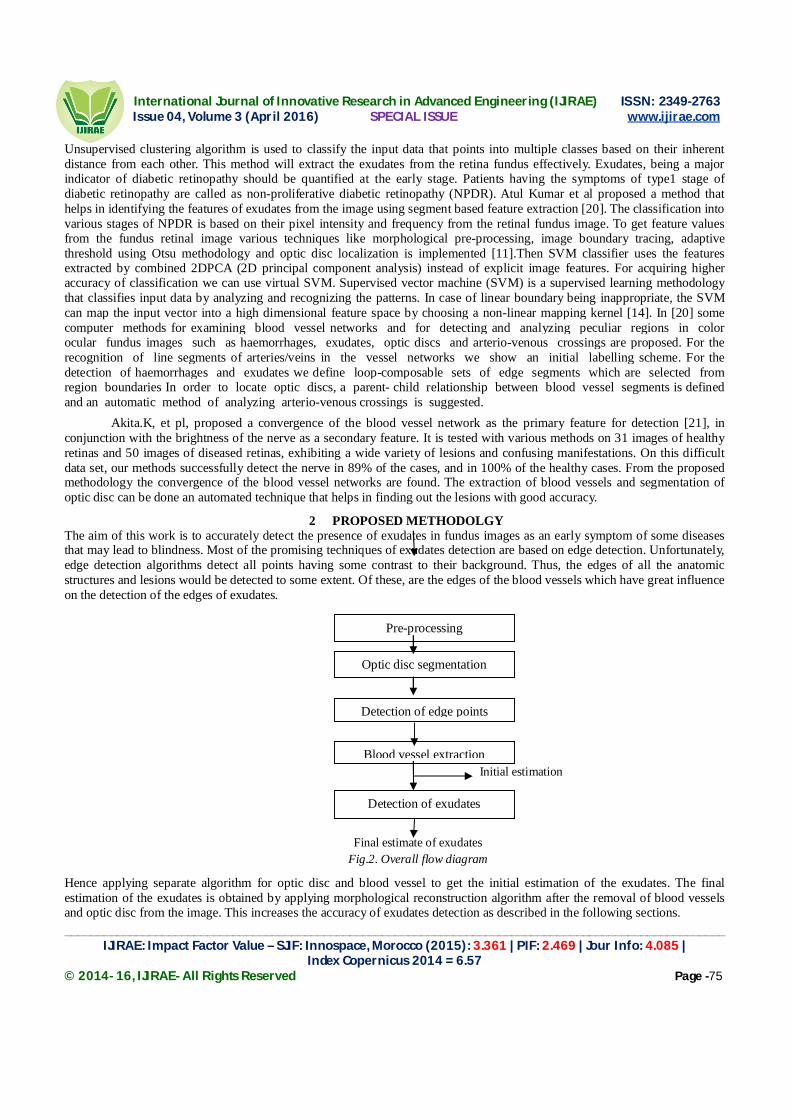
International Journal of Innovative Research in Advanced Engineering (IJIRAE) ISSN: 2349-2763 Issue 04, Volume 3 (April 2016) SPECIAL ISSUE www.ijirae.com
______________________________________________________________________________________________________ IJIRAE: Impact Factor Value – SJIF: Innospace, Morocco (2015): 3.361 | PIF: 2.469 | Jour Info: 4.085 |
Index Copernicus 2014 = 6.57 © 2014- 16, IJIRAE- All Rights Reserved Page -75
Unsupervised clustering algorithm is used to classify the input data that points into multiple classes based on their inherent distance from each other. This method will extract the exudates from the retina fundus effectively. Exudates, being a major indicator of diabetic retinopathy should be quantified at the early stage. Patients having the symptoms of type1 stage of diabetic retinopathy are called as non-proliferative diabetic retinopathy (NPDR). Atul Kumar et al proposed a method that helps in identifying the features of exudates from the image using segment based feature extraction [20]. The classification into various stages of NPDR is based on their pixel intensity and frequency from the retinal fundus image. To get feature values from the fundus retinal image various techniques like morphological pre-processing, image boundary tracing, adaptive threshold using Otsu methodology and optic disc localization is implemented [11].Then SVM classifier uses the features extracted by combined 2DPCA (2D principal component analysis) instead of explicit image features. For acquiring higher accuracy of classification we can use virtual SVM. Supervised vector machine (SVM) is a supervised learning methodology that classifies input data by analyzing and recognizing the patterns. In case of linear boundary being inappropriate, the SVM can map the input vector into a high dimensional feature space by choosing a non-linear mapping kernel [14]. In [20] some computer methods for examining blood vessel networks and for detecting and analyzing peculiar regions in color ocular fundus images such as haemorrhages, exudates, optic discs and arterio-venous crossings are proposed. For the recognition of line segments of arteries/veins in the vessel networks we show an initial labelling scheme. For the detection of haemorrhages and exudates we define loop-composable sets of edge segments which are selected from region boundaries In order to locate optic discs, a parent- child relationship between blood vessel segments is defined and an automatic method of analyzing arterio-venous crossings is suggested.
Akita.K, et pl, proposed a convergence of the blood vessel network as the primary feature for detection [21], in conjunction with the brightness of the nerve as a secondary feature. It is tested with various methods on 31 images of healthy retinas and 50 images of diseased retinas, exhibiting a wide variety of lesions and confusing manifestations. On this difficult data set, our methods successfully detect the nerve in 89% of the cases, and in 100% of the healthy cases. From the proposed methodology the convergence of the blood vessel networks are found. The extraction of blood vessels and segmentation of optic disc can be done an automated technique that helps in finding out the lesions with good accuracy.
2 PROPOSED METHODOLGY The aim of this work is to accurately detect the presence of exudates in fundus images as an early symptom of some diseases that may lead to blindness. Most of the promising techniques of exudates detection are based on edge detection. Unfortunately, edge detection algorithms detect all points having some contrast to their background. Thus, the edges of all the anatomic structures and lesions would be detected to some extent. Of these, are the edges of the blood vessels which have great influence on the detection of the edges of exudates.
Initial estimation
Final estimate of exudates
Fig.2. Overall flow diagram
Hence applying separate algorithm for optic disc and blood vessel to get the initial estimation of the exudates. The final estimation of the exudates is obtained by applying morphological reconstruction algorithm after the removal of blood vessels and optic disc from the image. This increases the accuracy of exudates detection as described in the following sections.
Pre-processing
Optic disc segmentation
Detection of edge points
Blood vessel extraction
Detection of exudates

International Journal of Innovative Research in Advanced Engineering (IJIRAE) ISSN: 2349-2763 Issue 04, Volume 3 (April 2016) SPECIAL ISSUE www.ijirae.com
______________________________________________________________________________________________________ IJIRAE: Impact Factor Value – SJIF: Innospace, Morocco (2015): 3.361 | PIF: 2.469 | Jour Info: 4.085 |
Index Copernicus 2014 = 6.57 © 2014- 16, IJIRAE- All Rights Reserved Page -76
2.1 PRE-PROCESSING Generally the retinal image is to be pre-processed to correct the problems arise from non uniform illumination. The low contrast of retinal images and the presence of noise are among these problems. The input retinal image is a three layer image containing red, green and blue layers. In the green layer, exudates appear brightest as compared to the other two layers thus the green layer is chosen for exudates detection. Median filter is used to remove the noise in the input image. Then morphological operations are applied to get the contrast enhanced image.
2.1.1Top-hat Morphological Operation The existing dilation and erosion operators have been extended to work with gray scale images [11 17]. New functions range from additional basic operators (morphological opening and closing) to advanced tools useful for segmentation (distance transforms, reconstruction-based operators, and the watershed transform). The operation has been described in the following steps:
Step1: Applied top-hat by opening results in an image of bright regions only. Step2: Top-hat by closing was applied and results in image of dark regions. Step3: By subtracting these results the contrast enhanced image was obtained which is shown in the figure 3.d
Fig.3. a) Input image
b) Green plane of image
c) Filtered image

International Journal of Innovative Research in Advanced Engineering (IJIRAE) ISSN: 2349-2763 Issue 04, Volume 3 (April 2016) SPECIAL ISSUE www.ijirae.com
______________________________________________________________________________________________________ IJIRAE: Impact Factor Value – SJIF: Innospace, Morocco (2015): 3.361 | PIF: 2.469 | Jour Info: 4.085 |
Index Copernicus 2014 = 6.57 © 2014- 16, IJIRAE- All Rights Reserved Page -77
d) Contrast enhanced image
2.2 OPTIC DISC SEGMENTATION The optic disc is a circular structure in retinal fundus images. So, Hough transform is used which is well known for its robustness in detecting circular objects in digital images[17]. The Canny edge detector is used to detect pixels to be candidates of the required circle. The optic disc appears brighter in the red component of the input image.. The values of the pixels composing the optic disc are set to zero in the colored image in order to differentiate the optic disc and exudates. The optic disc is segmented by way of setting the pixels composing of optic disc to one and others are set to zero which is shown in the figure 4c.
Fig.4 a) Red plane of the image
b) Optic disc removal
c) Segmented optic disc

International Journal of Innovative Research in Advanced Engineering (IJIRAE) ISSN: 2349-2763 Issue 04, Volume 3 (April 2016) SPECIAL ISSUE www.ijirae.com
______________________________________________________________________________________________________ IJIRAE: Impact Factor Value – SJIF: Innospace, Morocco (2015): 3.361 | PIF: 2.469 | Jour Info: 4.085 |
Index Copernicus 2014 = 6.57 © 2014- 16, IJIRAE- All Rights Reserved Page -78
2.3 DETECTION OF EDGE POINTS Edge detection is the name for a set of mathematical methods which aim at identifying points in a digital image. The Sobel operator [9] is based on convolving the image with a small, separable, and integer valued filter in horizontal and vertical direction which is shown in the figure 5a.. Here contour detection algorithm is applied to detect the edge points without discontinuities. In this algorithm, a contour represented by a discrete set of points {v1, v2,. . .,vn} with vi= (xi, yi) is to be initialized close to the contour of interest. Then, the algorithm checks the energies of a point on the initial contour and its 8-neighbors and replaces this point by the point of minimum energy among the nine points. The check and replacement process is done for all points on the contour. So, the shape of the contour will change accordingly.
An energy function is formulated to provide an estimate of the quality of the model in terms of its internal shape and external forces. The energy function E of is given by:
E=Eint +Eext Where Eint and Eext are the internal and external energies of a point on the contour. The internal energy determines the shape of the contour. The external energies are those not from the contour shape but from the image characteristics.
Fig.5. a) Sobel gradient
Fig.5 b) Edge detected image
2.4 BLOOD VESSEL DETECTION The green component of the RGB image is extracted to detect the blood vessels because the vessels have higher contrast in this component. Since the blood vessels appear as dark regions in brighter background, it is narrow them by morphological dilation. If the dilated image is then eroded using the same structuring element, the very small dark region should be eliminated from the image while the larger area returns to their initial size. Vessel detection algorithm is applied to extract the blood vessels from the input image. This algorithm is based on closing the image with two linear structuring elements of different sizes which is describe in the following steps Step i: Closing by the bigger element would make the vessels to disappear while closing by the smaller one leaves the cores of the vessels. Step ii: Subtracting the two closed images would result in brighter areas of blood vessels in a darker background with a contrast higher than that of the original image.

International Journal of Innovative Research in Advanced Engineering (IJIRAE) ISSN: 2349-2763 Issue 04, Volume 3 (April 2016) SPECIAL ISSUE www.ijirae.com
______________________________________________________________________________________________________ IJIRAE: Impact Factor Value – SJIF: Innospace, Morocco (2015): 3.361 | PIF: 2.469 | Jour Info: 4.085 |
Index Copernicus 2014 = 6.57 © 2014- 16, IJIRAE- All Rights Reserved Page -79
Fig.6. a) Closed Green Component
b) Image closed by a larger structuring element
c) Resulting image
d) Extracted Blood Vessel
2.5 DETECTION OF EXUDATES After eliminating the blood vessels and the optic disc from the result of edge detection, an initial estimate of exudates is obtained. Then the morphological reconstruction algorithm [20,21] is applied to get the final estimate of exudates. This is an iterative process that should be repeated until no changes occur in h. The result of final iteration is then subtracted from the input image to get the final estimate of exudates in Iout as given by, Iout = Iin− hfinal

International Journal of Innovative Research in Advanced Engineering (IJIRAE) ISSN: 2349-2763 Issue 04, Volume 3 (April 2016) SPECIAL ISSUE www.ijirae.com
______________________________________________________________________________________________________ IJIRAE: Impact Factor Value – SJIF: Innospace, Morocco (2015): 3.361 | PIF: 2.469 | Jour Info: 4.085 |
Index Copernicus 2014 = 6.57 © 2014- 16, IJIRAE- All Rights Reserved Page -80
Fig.7. a) Initial estimate of exudates
b) Detected exudates
3. CONCLUSION The development of automated Diabetic Retinopathy screening system becomes a highly effective way of reducing the burden of ophthalmologists. So, early detection of exudates are useful to reduce the occurrence of vision loss. A combination of both accurate and early diagnosis as well as correct application of treatment can prevent blindness caused by DR in more than 50% of all cases. Therefore, regular screenings for DR of patients with diabetes is important. The proposed algorithm not only detects the blood vessel tree accurately but also helps to enhance the detection of exudates. Automated DR detection can reduce the severity of diseases and prevents from the faults that are available in prevailing technologies.
REFERENCES [1] Fong D. S.( 2003) et al., “Diabetic Retinopathy”, Diabetes Care, vol. 26, no. 1, pp.226-229, [2] A. Sopharak, and B. Uyyanonvara, (2009) “Automatic Exudates Detection from Non- dilated Diabetic Retinopathy
Retinal Images Using Fuzzy C-means Clustering”, Sensor, vol. 9(3). pp. 2148-2161, [3] Z. Xiaohui and O. Chutatape, (2004) “Detection and Classification of Bright Lesions in Color Fundus Images”, IEEE
International Conference on Image Processing (ICIP), vol. 1, pp. 139-142, [4] G. Kande, P. Subbaiah and T. Savithri, (2008.)“Segmentation of Exudates and Optic Disk in Retinal Images”, IEEE Sixth
Indian Conference on Computer Vision, Graphic & Image Processing, [5] A. Osareh, M. Mirmehdi, B. Thomas and R. Markham (2003) “Automated identification of diabetic retinal exudates in
digital colour images”, Ophthalmol, vol. 87, pp. 1220-23, [6] Olson.J.A, Strachana.F.M, Hipwell.J.H, (2003) “A comparative evaluation of digital imaging, retinal photography and
optometrist examination in screening for diabetic retinopathy”, Diabetic Medicine, vol. 20, pp. 528–534. [7] Solouma.N.H,Youssef.A.B, Badr.Y.A, Kadah.Y.M,(2002) ”A new real-time retinal tracking system for image-guided laser
treatment”, IEEE Transaction on Biomedical vol. 49, pp. 1059–1067. [8] Hoover.A, GoldBaum.M, (2003)”Locating the optic nerve in a retinal image using the fuzzy convergence of the blood
vessels”, IEEE Transactions on Medical Imaging vol. 22 , pp. 951–958. [9] Gagnon. L, Lalonde.M, Beaulieu. M, Boucher. M.C, (2001) “Procedure to detect anatomical structures in optical fundus
images”, in Proceeding, SPIE Medical Imaging: Image Processing, vol.10, no.7, pp. 1218–1225. [10] Hsu.W, Pallawala .P.M.D.S, Lee. M.L,Eong. K.G.A, (2001) “The role of domain knowledge in the detection of retinal
hard exudates”, in: IEEE Conference on Computer Vision and Pattern Recognition (CVPR), Kauai Marriott, Hawaii.

International Journal of Innovative Research in Advanced Engineering (IJIRAE) ISSN: 2349-2763 Issue 04, Volume 3 (April 2016) SPECIAL ISSUE www.ijirae.com
______________________________________________________________________________________________________ IJIRAE: Impact Factor Value – SJIF: Innospace, Morocco (2015): 3.361 | PIF: 2.469 | Jour Info: 4.085 |
Index Copernicus 2014 = 6.57 © 2014- 16, IJIRAE- All Rights Reserved Page -81
[11] Wang. H, Hsu. W, Goh. K.G, Lee. M.L, (2000)” An effective approach to detect lesions in color retinal images”, in IEEE
Conference on Computer Vision and Pattern Recognition (CVPR), South Carolina, USA. [12] Mitra.S.K, Lee.T.W, Goldbaum.M, (2005) “Bayesian network based sequential inference for diagnosis of diseases from
retinal images”, Pattern Recognition Letters vol.26 , pp. 459–470. [13] Sopharak. A, Uyyanonvara.B, Barmanb.S, Williamson.T.H, (2007),”Automatic detection of diabetic retinopathy
exudates from non-dilated retinal images using mathematical morphology methods”, Computerized Medical Imaging and Graphics vol.32, no. 9, pp. 720–727.
[14] Welfer.D, Scharcanski.J, Marinho.D.R,(2007) “A coarse-to-fine for automatically detecting exudates in color eye fundus images”, Computerized Medical Imaging and Graphics vol.34 ,no. 3, pp. 228–235.
[15] Mabrouk.M.S, Solouma.N.H, Kadah.Y.M, (2006), “Survey of retinal image segmentation and registration”, GVIP Journal ,pp. 23-37
[16] Hussain F. Jaafar, Asoke K. Nandi and Waleed Al-Nuaimy, “Detection of exudates from digital fundus images using a region-based segmentation technique”(2011), 19th European Signal Processing Conference (EUSIPCO), pp. 137-154
[17] Radha.R and Bijee Lakshmanan, (2013), “Retinal image analysis using morphological process and clustering technique”, Signal & Image processing: An International Journal (SIPIJ) vol.4, No.6, pp. 564-571
[18] Atul Kumar, Abhishek Kumar Gaur, Manish Srivastava (2012), “A segment based technique for detecting exudates from retinal fundus image”, 2nd International Conference on Communication, Computing & Security.
[19] Akita.K, Kuga.H, (1982), “A computer method of understanding ocular fundus images, Pattern Recognition” vol 15, pp. 431–443.
[20] Hoover, Gold Baum.M, (2003), “Locating the optic nerve in a retinal image using the fuzzy convergence of the blood vessels”, IEEE Transactions on Medical Imaging vol. 22, pp. 951–958.

International Journal of Innovative Research in Advanced Engineering (IJIRAE) ISSN: 2349-2763 Issue 04, Volume 3 (April 2016) SPECIAL ISSUE www.ijirae.com
________________________________________________________________________________________________ IJIRAE: Impact Factor Value – SJIF: Innospace, Morocco (2015): 3.361 | PIF: 2.469 | Jour Info: 4.085 |
Index Copernicus 2014 = 6.57 © 2014- 16, IJIRAE- All Rights Reserved Page –82
Automated License Management System Using RFID S. Arivoli
Associate Professor Department of Electronics and Communication Engineering
Sengunthar Engineering College Tiruchengode, Namakkal District, TamilNadu, India.
Abstract— Normally, in license tests a candidate applied for license have to drive over a closed loop path like the number (8) in front of the authorities. The candidate has to drive over the path without any support over the land surface and if he fails to do he will be disqualified. For that, the authorities have to watch him/her manually. A system for watching the candidate whether he/she is eligible for getting license by using a load cell has been proposed here. The load cell changes its output when there is any pressure change over the surface. Thus the differential output from the load cell detects the candidate who fails to keep his/her foot in the vehicle while following the path. Then the differential output was processed by the micro-controller. The ultrasonic sensor is used for hand signal detection and finger print sensor is used for the number of attempts made by a person during license test and thereby automatically reject or pass status will be generated by the system.
Keywords— Finger print sensor, ultrasonic sensor, Load cell
I. INTRODUCTION Despite continued efforts made by the different state governments in India, various international and national organizations continue to highlight the fatalities on the roads caused by inconsistent process of issuing driving licenses across India. The study conducted by the International Finance Corporation (IFC) indicates that the process of obtaining driving license in India is a distorted bureaucratic one. The independent survey conducted shows that close to 60 percent of license holders did not even have to take the driving license test and 54 percent of them were untrained to drive .The study conducted by IFC also shows that the driving license is in that category of public services that involves corruption of a direct demand and supply of bribes between citizens and bureaucrats. The study also indicates that the corruption is focused on agents that work as intermediaries between the officials and citizens. This practice of agent-usage promotes corruption and subsequently results in higher payment for licenses, reduces driving test quality and this eventually results in unskilled drivers on road .Hence the only solution for this problem is to implement an efficient, transparent and cost effective driver testing system. In the present scenario, the candidates who have applied for driving license have to appear for a theoretical examination and a practical examination. The theoretical examination evaluates the candidate knowledge on different traffic signs, traffic regulation and also the basic understanding of simple safety check before using a vehicle. Different ways are adopted for the conduct of theoretical examination. These are oral examination, question paper or computer based examination. Theoretical examination is conducted before the practical examination. A pass in the theoretical examination is a prerequisite for the practical examination. The practical examination comprises of two tests namely off-road test and on-road test.The off road test is for examining the candidate’s ability in controlling the vehicle. The on-road test is conducted in light traffic on normal road . Normally, the on-road test is carried out after completing off-road test. The off-road test tracks are of three types – H, S and 8 shaped tracks. In India, the test track adopted for off-road test purpose varies from state to state.
1.1 Domain Detail An embedded system is a special-purpose computer system designed to perform one or a few dedicated functions, sometimes with real-time computing constraints. It is usually embedded as part of a complete device including hardware and mechanical parts. In contrast, a general-purpose computer, such as a personal computer, can do many different tasks depending on programming. Embedded systems have become very important today as they control many of the common devices we use. Since the embedded system is dedicated to specific tasks, design engineers can optimize it, reducing the size and cost of the product, or increasing the reliability and performance. Some embedded systems are mass-produced, benefiting from economies of scale. Physically, embedded systems range from portable devices such as digital watches and MP3 players, to large stationary installations like traffic lights, factory controllers, or the systems controlling nuclear power plants. Complexity varies from low, with a single microcontroller chip, to very high with multiple units, peripherals and networks mounted inside a large chassis or enclosure. In general, "embedded system" is not an exactly defined term, as many systems have some element of programmability. For example, Handheld computers share some elements with embedded systems — such as the operating systems and microprocessors which power them — but are not truly embedded systems, because they allow different applications to be loaded and peripherals to be connected.

International Journal of Innovative Research in Advanced Engineering (IJIRAE) ISSN: 2349-2763 Issue 04, Volume 3 (April 2016) SPECIAL ISSUE www.ijirae.com
________________________________________________________________________________________________ IJIRAE: Impact Factor Value – SJIF: Innospace, Morocco (2015): 3.361 | PIF: 2.469 | Jour Info: 4.085 |
Index Copernicus 2014 = 6.57 © 2014- 16, IJIRAE- All Rights Reserved Page –83
An embedded system is some combination of computer hardware and software, either fixed in capability or programmable, that is specifically designed for a particular kind of application device. Industrial machines, automobiles, medical equipment, cameras, household appliances, airplanes, vending machines, and toys (as well as the more obvious cellular phone and PDA) are among the myriad possible hosts of an embedded system. Embedded systems that are programmable are provided with a programming interface, and embedded systems programming is a specialized occupation. Certain operating systems or language platforms are tailored for the embedded market, such as Embedded Java and Windows XP Embedded. However, some low-end consumer products use very inexpensive microprocessors and limited storage, with the application and operating system both part of a single program. The program is written permanently into the system's memory in this case, rather than being loaded into RAM (random access memory), as programs on a personal computer are.
1.2 EXISTING SYSTEM In the present scenario, the candidates who have applied for driving license have to appear for a theoretical examination and a practical examination. The theoretical examination evaluates the candidate knowledge on different traffic signs, traffic regulation and also the basic understanding of simple safety check before using a vehicle. Different ways are adopted for the conduct of theoretical examination. These are oral examination, question paper or computer based examination. Theoretical examination is conducted before the practical examination. Pass in the theoretical examination is a prerequisite for the practical examination. The practical examination comprises of two tests namely off-road test and on-road test. The off road test is for examining the candidate’s ability in controlling the vehicle. The on-road test is conducted in light traffic on normal road. Normally, the on-road test is carried out after completing off-road test.The off-road test tracks are of three types – H, S and 8 shaped tracks. In India, the test track adopted for off-road test purpose varies from state to state.
1.3 PROPOSED SYSTEM
In this proposed track, in addition to detect interruption along the edges, we must also check if the vehicle moves correctly in the specified path. For detection of the correct path, we again use the same setup consisting of metal strips (pressure switch). Here we are using pairs of metal strips and they are placed in positions as shown in the diagram. The test taker must move to the following path. That is the test taker must start at start position and end the test at stop position. Here the metal strip is kept horizontally across each path. When the vehicle moves through the respective path, the metal strip is not conducting and this is done in a sequential manner that is from path start to stop end. On successful completion of the test, “pass” report will be generated or else a “fail” report.
II SYSTEM REQUIREMENT HARDWARE: ATmega8A microcontroller Load cell RFID IR Sensors 16*2 LCD display Power Supply Unit Buzzer SOFTWARE: Platform - AVR STUDIO In System Programmer - ProgISP 172 Compiler – Win AVR Visual basic .NET
III. SYSTEM DESIGN
Fig: Block Diagram of Proposed System

International Journal of Innovative Research in Advanced Engineering (IJIRAE) ISSN: 2349-2763 Issue 04, Volume 3 (April 2016) SPECIAL ISSUE www.ijirae.com
________________________________________________________________________________________________ IJIRAE: Impact Factor Value – SJIF: Innospace, Morocco (2015): 3.361 | PIF: 2.469 | Jour Info: 4.085 |
Index Copernicus 2014 = 6.57 © 2014- 16, IJIRAE- All Rights Reserved Page –84
A .Power Supply
Fig.2 Block diagram of power supply The given block diagram includes following: Transformer: A transformer is an electro-magnetic static device, which transfers electrical energy from one circuit to another, either at the same voltage or at different voltage but at the same frequency. Rectifier: The function of the rectifier is to convert AC to DC current or voltage. Usually in the rectifier circuit full wave bridge rectifier is used. Filter: The Filter is used to remove the pulsated AC. A filter circuit uses capacitor and inductor. The function of the capacitor is to block the DC voltage and bypass the AC voltage. The function of the inductor is to block the AC voltage and bypass the DC voltage. Voltage Regulator Voltage regulator constitutes an indispensable part of the power supply section of any electronic systems. The main advantage of the regulator ICs is that it regulates or maintains the output constant, in spite of the variation in the input supply. b.IR SENSOR The IR sensor is used for detecting the line tracking. c. Load Cells A load cell is a transducer that is used to convert a force into electrical signal. The most common type is a strain gauge load cell.A load cell is made by bonding strain gauges to a spring material. To efficiently detect the strain, strain gauges are bonded to the position on the spring material where the strain will be the largest. d.RFID The RFID Proximity OEM Reader Module has a built-in antenna in minimized form factor. It is designed to work on the industry standard carrier Frequency of 125 kHz. This LF reader module with an internal or an external antenna facilitates communication with Read-Only transponders—type UNIQUE or TK5530 via the air interface. The tag data is sent to the host systems via the wired communication interface with a protocol selected from the module Both TTL and wiegand protocol. The LF module is best suited for applications in Access Control, Time and Attendance, Asset Management, Handheld Readers, Immobilizers, and other RFID enabled applications. e. MICROCONTROLLER The AVR is a modified Harvard architecture8- bit RISC single chip microcontroller which was developed by Atmel in 1996.The AVR was one of the first microcontroller families to use on-chip flash memory for program storage, as opposed to one-time programmable ROM, EPROM, or EEPROM used by other microcontrollers at the time.

International Journal of Innovative Research in Advanced Engineering (IJIRAE) ISSN: 2349-2763 Issue 04, Volume 3 (April 2016) SPECIAL ISSUE www.ijirae.com
________________________________________________________________________________________________ IJIRAE: Impact Factor Value – SJIF: Innospace, Morocco (2015): 3.361 | PIF: 2.469 | Jour Info: 4.085 |
Index Copernicus 2014 = 6.57 © 2014- 16, IJIRAE- All Rights Reserved Page –85
ATmega8 Features: • High-performance, Low-power AVR® 8-bit Microcontroller • Advanced RISC Architecture
– 130 Powerful Instructions – Most Single-clock Cycle Execution – 32 x 8 General Purpose Working Registers – Fully Static Operation – Up to 16 MIPS Throughput at 16 MHz – On-chip 2-cycle Multiplier
• High Endurance Non-volatile Memory segments – 8K Bytes of In-System Self-programmable Flash program memory – 512 Bytes EEPROM – 1K Byte Internal SRAM – Write/Erase Cycles: 10,000 Flash/100,000 EEPROM – Data retention: 20 years at 85°C/100 years at 25°C(1) – Optional Boot Code Section with Independent Lock Bits
f. RS 232 Due to its relative simplicity and low hardware overhead (as compared to parallel interfacing), serial communications is used extensively within the electronics industry. Today, the most popular serial communications standard in use is certainly the EIA/TIA–232–E specification. In recent years, this suffix has been replaced with “EIA/TIA” to help identify the source of the standard. We use the common notation “RS–232”.
g.Switching Circuit The pressure switch (metal strip)are used as pairs where each pair consists of a transmitter and a receiver. The IR sensors can be also referred to as a long range IR start, stop pair. Sensors are mounted on to yardstick for embedding on the track. The IR sensor pairs, pressure switch used for detecting the trouncing of sensor mounted yardstick or the crossing of line intersection between the sensors. Two IR sensors are used at “START‟ and „STOP‟ position of the track. Speed sensor is used into the vehicle wheel to enable or disable of zero rpm measurement system. These sensors are interfaced to the microcontroller based central control unit. When either of these sensor pairs makes a high to low transition. The microcontroller based central control unit enables or disables the microcontroller based on-vehicle control unit for monitoring the vehicle motion. The on-vehicle control unit for zero rpm measurement is designed to perform the measurement only when the vehicle is inside the sensor embedded track.
IV. DATA ACQUISITION SYSTEM IN VB User personal details: The test taker enters his personal data in the specified field. Here the test taker has to fill his name, date of birth, e-mail, mobile number, address and gender. If any one of the data is not filled, then a pop up window displays for filling the data. Test Status: The test status of the candidate who is undertaking the test is displayed in this test status box. On successful completion of the test, „PASS‟ message will be displayed or else a „FAIL‟ message will be displayed. System Status: Here the system status will be displayed i.e. It displays the status of the test taken by the candidate. Here the system first gets ready, initializes, monitors, save the report and displays the report. Test Taking: Once the mandatory details are completed, then the test taker can get ready for his test by entering the vehicle. On his word the controller can press the „START‟ button on the software interface. This will mark the commencement of the test (for the controller at the PC interface, the LCD display will show processing). If all goes well and the driver returns his car safely without any deviations in the „H‟ (curved) track, press the „STOP‟ button on the software interface. This will point to the end of his test (for the controller at the PC interface, the LCD display will show some indication). The candidate can now get his result at the software interface.
V. CONCLUSION
A Driving License test automation system using RF Module based wireless acquisition is discussed. The usage of VB based technology for skill assessment in the automated driving test process eliminates human intervention leaving no scope for manipulation and negotiation. Hence we can say that the system increases the level of transparency in the driving skill test process and decreases the rate of corruption in the process of issuing the driving license.

International Journal of Innovative Research in Advanced Engineering (IJIRAE) ISSN: 2349-2763 Issue 04, Volume 3 (April 2016) SPECIAL ISSUE www.ijirae.com
________________________________________________________________________________________________ IJIRAE: Impact Factor Value – SJIF: Innospace, Morocco (2015): 3.361 | PIF: 2.469 | Jour Info: 4.085 |
Index Copernicus 2014 = 6.57 © 2014- 16, IJIRAE- All Rights Reserved Page –86
VI. RESULT
There are three conditions to get driving license (i)to cover the complete path.(ii)do not ouch or hit the edges(iii)speed of the vehicle must not to be zero. When all these condition are satisfy then the pass result will be displayed in the form of report, otherwise fail report will be generated.
Fig:3 Working Model
REFERENCES [1]. Marianne Bertrand, Simeon Djankov, Remma Hanna and SendhilMullainathan,“Obtaining a Driver‟s License in India:
An Experimental Approach to Studying Corruption”, The Quarterly Journal of Economics (2007) 122 (4): 1639-1676. [2]. Driver errors cause most road deaths in India”. The Times of India on the web.2010 – 07-04. [3]. Mondal, P, Abhishek Kumar, U. D. Bhangale, and Dinesh Tyagi. “A Silent Tsunami on Indian Road: A Comprehensive
Analysis of Epidemiological Aspects of Road Traffic Accidents”. British Journal of Medicine & Medical Research: 1(1):14-23, 2011. 2011-09-26.
[4]. ShizhuangLin; JingyuLiu; YanjunFang; Wuhan Univ., Wuhan" ZigBee Based Wireless Sensor Networks and Its Applications in Industrial”IEEE International Conference on Automation and Logistics, 200718-21Aug.2007page(s):1979-1983Location:Jinan
[5]. Xiuping Zhang; Guangjie Han; Changping Zhu; Yan Dou; Jianfeng Tao;” Research of WirelessSensor Networks based on ZigBee for Miner Position”, [J]International Symposium on Computer,Communication, Control and Automation, IEEE. 29 July 2010Pg1 – 5.
[6]. Dunfan Ye, Daoli Gong, Wei Wang,“Application of Wireless Sensor Networks in EnvironmentalMonitoring”2nd International Conference on Power Electronics and Intelligent TransportationSystemIEEE2009pp- 2563-2567.


International Journal of Innovative Research in Advanced Engineering (IJIRAE) ISSN: 2349-2763 Issue 04, Volume 3 (April 2016) SPECIAL ISSUE www.ijirae.com
____________________________________________________________________________________________________ IJIRAE: Impact Factor Value – SJIF: Innospace, Morocco (2015): 3.361 | PIF: 2.469 | Jour Info: 4.085 |
Index Copernicus 2014 = 6.57 © 2014- 16, IJIRAE- All Rights Reserved Page -87
An Efficient Clustering Scheme and Scheduling for Data Aggregation in RFID Network
R.M.DHIVYA II YEAR M.E
Department Of Computer Science And Engineering Sengunthar College Of Engineering
Trichengode 637205
Mrs. K.SENTHIL VADIVU Assistant Professor,
Department of Computer Science and Engineering, Sengunthar College of Engineering,
Tirunchengode– 637205
Abstract: RFID (Radio Frequency Identification) is an automatic identification method to identify and track objects using radio waves. It is a collection of readers with sensing, computation and communication capabilities. These networks are constraint with energy; memory and computing power .The problem in networks are more battery power consumption. Data aggregation is used to gather and aggregate data in an energy efficient manner. It also reduces the number of packets to be sent by aggregating the similar packets in an energy efficient manner. Due to the mobility of readers between the clusters the leaving rate is high. To overcome the mobility of readers, an efficient clustering scheme for data aggregation is used, which minimizes the power consumption of the readers. It consists of cluster head scheme and cluster formation scheme. Another problem in RFID is a reader collision problem. It causes multiple reads of the same tag. To overcome this, the data aggregation is done by scheduling to eliminate the redundant data. Using clustering scheme, efficient data aggregation will be provided and the mobility of the readers will are minimized.
Key Words: data aggregation; wireless sensors networks; clustering; scheduling.
I. INTRODUCTION
Radio frequency identification (RFID) is one member in the family of Automatic identification and data capture (AIDC) technologies and is a fast and reliable means of identifying any material object. The significant advantage of all types of RFID systems is the non-contact, non-line-of-sight nature of the technology. Identity tagging development is proceeding on multiple fronts. First, standards are evolving for the various components of an RFID system including the transmission technology (the “RF” part) and unique identifiers (the “ID” part). Second, outside the realm of dedicated RFID systems, short-range radio-based Communication networks like Wi-Fi and Bluetooth have emerged which are increasingly used in RFID applications. Third, optical tagging solutions may compete with certain RFID applications, particularly those aimed at consumers. Lastly, both RFID and other tagging technologies are making their way to the edges of the network and into the hands of end-users, significantly increasing the potential for disruptive rather than incremental innovation. Before examining these trends and their implications in more detail, we will review the basics of RFID technology. A. CLUSTERING IN WIRELESS SENSOR NETWORK
In the Wireless Sensor Networks, (WSNs) a key challenge is to schedule the activities of the mobile node for improvement in throughput, energy consumption and delay. The existing system proposes efficient schedule based data aggregation algorithm using node mobility (SDNM). It considers the cluster-based myopic and non-myopic scheduling scheme for conflict free schedule based on the current and next state. It uses TDMA as the MAC layer protocol and schedules the aggregated packets with consecutive slots. Simulation results show that, SDNM is energy efficient, has less delay as compared with state-of-the-art solutions. TDMA techniques used for scheduling and aggregation of data. It uses consecutive time slots (TDMA) for improving energy consumption in the homogeneous WSN. The proposed centralized and distributed wake-up scheduling algorithm is designed for low data rate WSN and lacks in the delay of collecting data, needs effective schedule for mobile nodes with data collection. Distributed Time Scheduling Protocol (DATP) uses the dummy packet for checking the collision free time slot. It considers the event triggered applications for scheduling the aggregated data.
In addition, it checks for the tolerable limits of interference from the neighbour nodes within the same time slot. This approach has a limitation of overhead caused by unknown interference of neighbour nodes and has the impact of synchronization error. It is proposes the multipath routing structures for the efficient scheduling and collection of data to reduce the complexity and running time. The distributed TDMA scheduling algorithms when used for data collection incurs overheads in terms of energy and delay.

International Journal of Innovative Research in Advanced Engineering (IJIRAE) ISSN: 2349-2763 Issue 04, Volume 3 (April 2016) SPECIAL ISSUE www.ijirae.com
____________________________________________________________________________________________________ IJIRAE: Impact Factor Value – SJIF: Innospace, Morocco (2015): 3.361 | PIF: 2.469 | Jour Info: 4.085 |
Index Copernicus 2014 = 6.57 © 2014- 16, IJIRAE- All Rights Reserved Page -88
Problem of scheduling the aggregated information in the cluster-based network with the mobile node is • Decision of scheduling is based on the current state for intra cluster communication called myopic scheduling. • Decision of scheduling which considers the current and future state of the mobile node for inter-cluster communication
i.e. for the CH and CH to BS is non-myopic. • Used to improve the Energy consumption, Throughput by a minimum number of conflicts. • Reduce delay in communication of aggregated message to BS.
II.RELATED WORK
In RFID network, the key challenge is to clustering head is selected using FIREFLY algorithm and data is aggregated by data aggregation algorithm. Firefly algorithm met heuristics work on the principle of the flashing lights of fireflies. The intensity of the light helps a firefly swarm move to brighter and attractive locations which can be mapped to an optimal solution in the search space.
The algorithm standardizes some of the firefly characteristics and can be listed as follows:
(i) Each firefly can be attracted to another irrespective of their sex. (ii) The brightness produced by the firefly is directly proportional to its attractiveness and between two fireflies; the firefly with higher brightness attracts the one which has lower brightness. A firefly moves randomly if it is not able to find a brighter neighbouring firefly. (iii) In the mathematical model, firefly’s brightness is based on the objective function. Firefly met heuristic is chosen for its capability of providing optimal solutions for multiobjective problems.
In the proposed synchronous firefly algorithm, the fireflies are ranked and the best fireflies elected using tournament selection. The selected fireflies reproduce among themselves by crossover and mutation. The solution for the best fireflies obtained using tournament selection. After crossover and mutation, the new solutions are added to firefly pool and the next iteration of the firefly is continued.
Cluster based network model
III. ARCHITECTURAL DIAGRAM .
A.POTENTIAL CORE NODES The Potential core nodes include the schedule, speed and collection of data for the nodes. Here each nodes have a different speed , time and may be different datum.
B. BASE STATION The information of the nodes from the potential core nodes are sent to this base station. It keeps the details of each node.
BASE STATION
CLUSTER HEAD SELECTION
JOIN THE HEAD
POTENTIAL CORE
NODES
DATA AGGREGATION

International Journal of Innovative Research in Advanced Engineering (IJIRAE) ISSN: 2349-2763 Issue 04, Volume 3 (April 2016) SPECIAL ISSUE www.ijirae.com
____________________________________________________________________________________________________ IJIRAE: Impact Factor Value – SJIF: Innospace, Morocco (2015): 3.361 | PIF: 2.469 | Jour Info: 4.085 |
Index Copernicus 2014 = 6.57 © 2014- 16, IJIRAE- All Rights Reserved Page -89
C.CLUSTER HEAD SELECTION Cluster Head is selected by base station depending upon the speed of the node. Here the speed of the nodes is analyzed. High speed node is declared as head node. Other nodes are slaver node
D.JOIN THE HEAD Other nodes are joined to the head node. They are grouping.
E.DATA AGGREGATION Similar nodes are aggregated by data aggregation method.
IV. TECHNIQUES USED
A.CLUSTERING In the clustering scheme reader and tags are grouped. The mobility, energy and direction of the nodes are analyzed.CH(cluster head) is selected based on the mobility, energy and direction. Firefly algorithm is used to select cluster head.
B.FIREFLY ALGORITHM In firefly algorithm, three techniques are used Separation Cohesion Alignment B1.SEPARATION Minimum distance nodes are analysed for choosing cluster head. For the condition minimum distance node is applicable for work as head.
B2.COHESION Number of nodes are counted. For the condition which reader has more number of nodes that is possible to work as head. B3.ALIGNMENT Directions are analysed. For the rule the number of slaver nodes of the header node must be travel the same direction of the header node. Above all the conditions are satisfied the head is selected and scheduling is allocated to the sub nodes which is send a data in order. And aggregation scheme is used to similar datum are eliminated. This process make as routine process.
V.ADVANTAGES
Advantage of Firefly is not only includes the self-improving process with the current space, but it also includes the improvement among its own space from the previous stages. Firefly algorithm has some disadvantages such as getting trapped into several local optima. It sometimes performs local search as well and sometimes is unable to completely get rid of them. Firefly algorithm parameters are fixed and they do not change with the time.
VI.CONCLUSION AND FUTURE WORK
This work proposed a Firefly based clustering protocol to select Cluster Head in RFID. LEACH protocol needs the user to specify probability for use with a threshold function to determine whether a node will become a CH or not leading to NP problem. In the proposed hybrid firefly algorithm, the best fireflies selected using tournament selection is allowed to reproduce among themselves by crossover and mutation. The proposed method achieves faster convergence and avoids multiple local optima. When compared to Efficient Schedule based clustering, the proposed hybrid firefly algorithm also increased the lifetime of the network. Future work can be carried out to investigate the impact on increasing specific quality of service parameter.
REFERENCES
[1]. Mohamedwatfa ,williamdaher and hisham al azar“A SENSOR NETWORK DATA AGGREGATION TECHNIQUE” in international journal of computer theory and engineering
[2]. N.V.S.N Sarma, Mahesh Gopi“ENERGYEFFICIENT CLUSTERING USING JUMPER FIREFLY ALGORITHM IN WIRELESS SENSOR NETWORKS “International Journal of Engineering Trends and Technology (IJETT)
[3]. Amin Rostami1and Mohammad HossinMottar“WIRELESS SENSOR NETWORK CLUSTERING USING PARTICLES SWARM OPTIMIZATION FOR REDUCING ENERGY CONSUMPTION” International Journal of Managing Information Technology (IJMIT).

International Journal of Innovative Research in Advanced Engineering (IJIRAE) ISSN: 2349-2763 Issue 04, Volume 3 (April 2016) SPECIAL ISSUE www.ijirae.com
____________________________________________________________________________________________________ IJIRAE: Impact Factor Value – SJIF: Innospace, Morocco (2015): 3.361 | PIF: 2.469 | Jour Info: 4.085 |
Index Copernicus 2014 = 6.57 © 2014- 16, IJIRAE- All Rights Reserved Page -90
[4]. HirenThakkar, Sushruta Mishra, AlokChakrabarty “A POWER EFFICIENT CLUSTER-BASED DATA AGGREGATION PROTOCOL FOR WSN (MHML)”in International Journal of Engineering and Innovative Technology (IJEIT).
[5]. DnyaneshwarMantri, Neeli R Prasad, and Ramjee Prasad, “TWO TIER CLUSTER BASED DATA AGGREGATION (TTCDA) IN WIRELESS SENSOR NETWORKS,” Springer journal Wireless Personal Communications, November 2013.
[6]. Rajiv Misra, and ChittaranjanMandal “ANT-AGGREGATION: ANT COLONY ALGORITHM FOR OPTIMAL DATA AGGREGATION IN WIRELESS SENSOR NETWORKS “
[7]. Jalil Jabber Lotf, Mehdi NozadBonab, SiavashKhorsandi “A NOVEL CLUSTER-BASED ROUTING PROTOCOL WITH EXTENDING LIFETIME FOR WIRELESS SENSOR NETWORKS”
[8]. Oh Seung Hyun, Lee Sang Hyuk Department of Computer Science, Dongguk University, South Korea “ANENERGY-EFFICIENT CLUSTER-HEAD SELECTION ALGORITHM FOR WIRELESS SENSOR NETWORKS”.
[9]. Kiran Maraiya Kamal Kant “EFFICIENT CLUSTER HEAD SELECTION SCHEME FOR DATA AGGREGATION IN WIRELESS SENSOR NETWORK”
[10]. A.Sumamaheshwari, Mrs. S. pushpalatha PG Scholar, Department of Computer Science & Engineering “CLUSTER HEAD SELECTION ALGORITHM USING AHYMN APPROACHES IN WSN”.