international journal of heat and fluid flo · steady drag of a sphere, produced by a shock mach...
TRANSCRIPT

International Journal of Heat and Fluid Flow 29 (2008) 1380–1392
Contents lists available at ScienceDirect
International Journal of Heat and Fluid Flow
journal homepage: www.elsevier .com/locate / i jhf f
Head-on collision of shock wave induced vortices with a cylinder and a sphere
K. Kontis *, R. An, D. Kounadis, H. Zare-BehtashUniversity of Manchester, School of Mechanical, Aerospace and Civil Engineering, George Begg, P.O. Box 88, M60 1QD Manchester, UK
a r t i c l e i n f o
Article history:Received 13 February 2007Received in revised form 22 April 2008Accepted 22 April 2008Available online 11 June 2008
Keywords:Shock-tube flowsCompressible vortex rings
0142-727X/$ - see front matter � 2008 Elsevier Inc. Adoi:10.1016/j.ijheatfluidflow.2008.04.010
* Corresponding author. Tel.: +44 161 3065751.E-mail address: [email protected] (K. Kon
a b s t r a c t
An experimental study has been conducted to examine the interaction of shock wave induced vorticeswith a cylinder and a sphere. The experiments were carried out using a 30 mm internal diametershock-tube, using air as both the driver and driven gas. High-speed schlieren photography was employedto study the development of the flow-field and the resulting interactions with the body configurations.Wall pressure measurements were also carried out to study the flow quantitatively along the leadingedge of the cylinder. Three different diaphragm pressures ratios of 3.95, 7.89, and 11.84 were examined;the experimental shock Mach numbers were 1.28, 1.51 and 1.63, respectively. The experimental resultsindicate that as the incident shock wave impinges on the frontal surface of the cylinder or sphere, itundergoes transition from regular to Mach reflection. The induced flow-field due to the interaction ofthe vortex ring with the two models is highly three-dimensional and time dependent. The vortex ringattempts to engulf the sphere, whereas, in the case of the cylinder, part of the ring accelerates rapidlyin the lateral direction along the leading edge of the body, whereas, the remaining flow moves aroundthe cylinder. In both cases, the ring maintains its structure throughout the interactions.
� 2008 Elsevier Inc. All rights reserved.
1. Introduction
The flow-field induced by a shock wave impinging on convexsurfaces has been studied both analytically and experimentally bya number of research groups (Heilig, 1969; Ben-Dor et al., 1980;Bryson and Gross, 1960). These studies have reported that as theshock wave propagates along the surface of the convex surface,the reflecting wedge angle at the reflection point decreases untilthe regular reflection goes through a transition to Mach reflection.Whitham (1957) has developed a two-dimensional theory for thediffraction and stability of shock waves, using the critical angleand the incident shock Mach number as initial values, to predictboth the triple point locus and the development of the Mach stem.Heilig (1969), and Bryson and Gross (1960), who employed Mach-Zehnder interferometry and schlieren photography, respectively,reported that the agreement between Whitham’s theory and exper-iment was satisfactory. Ben-Dor et al. (1980) reported that theanalytical solutions, based on steady or pseudo-steady flows,over-predict the experimental results of the actual transition fromregular to Mach reflection. More recently, Yang et al. (1987) em-ployed computational calculations in order to study the diffractionpattern of a non-stationary shock wave after its impingement on acylinder. The authors reported the subsequent development of thediffraction process, which was found to involve a regular reflection,transition to Mach reflection, Mach shock collision at the wake of
ll rights reserved.
tis).
the cylinder and complex shock–shock interactions. The numericalsimulations were also compared with both the experimental workby Bryson and Gross (1960) and the theoretical calculations byWhitham (1957). The results indicated a good agreement withthe previous researchers.
The interaction of a shock wave with a sphere has been investi-gated both experimentally and numerically by Tanno et al. (2003),and Sun et al. (2005). Tanno et al. (2003), who produced detailedpressure data along the apex of a sphere, reported a maximumpressure at the frontal stagnation point, which decreases withdecreasing wall inclination angles. The authors also reported highpressure levels at the rear of the sphere because of the Mach shockcollision at the wake of the sphere. Sun et al. (2005) studied the un-steady drag of a sphere, produced by a shock Mach number of 1.22.It was reported that the sphere experiences a steep drag increaseimmediately after shock impingement and reflection from thefrontal side. Then, the drag was found to drop as the shock wavemoves to the rear side of the sphere and finally converges to anearly constant value.
The flows and interactions associated with compressible vortexrings have received very little attention, and there are still manyunanswered questions related to most aspects of the vortex ringsthemselves, including their formation, propagation and decay, withmore challenging complexities in both their dynamics and energet-ics introduced by the effects of compressibility (Kontis et al., 2006).The present study examines the flow-field produced when a shockwave and the induced-vortex ring approach and impinge on a cylin-der and a sphere. It forms part of a larger research effort contributing

Fig. 2. Dimensions of the models: (a) cylinder and (b) sphere.
K. Kontis et al. / International Journal of Heat and Fluid Flow 29 (2008) 1380–1392 1381
directly into the future advances of non-lethal-weapon, fluiddynamics and high speed technology. The project will also benefitthose concerned with developing and validating DNS/LES and RANSsimulation tools. The effects of compressibility are identified withrespect to the strength of the generating shock wave at the exit ofthe shock-tube. The present investigation visualises the flow-fieldusing time-resolved schlieren photography, and it identifies thestrength of the various interactions using wall pressuremeasurements.
2. Apparatus and instrumentation
Experiments have been carried out using a cylindrical shock-tube (Fig. 1) made of seamless pipe. The internal (di) and external(do) diameters of the shock-tube were 30 mm and 38 mm, respec-tively. Experiments have been performed for diaphragm pressureratios of 3.95, 7.89 and 11.84, with air as both driver and drivengas, producing shock Mach numbers of 1.28, 1.51 and 1.63, respec-tively. The three Mach numbers were chosen because of the dis-tinct flow regimes that each one creates. From M = 1.0 to 1.43,conventional-looking vortex rings are produced characterised byvery thin cores. From M = 1.43 to 1.60, the axial flow velocity inthe recirculating region of the vortex ring becomes supersonic,producing rearward-facing shock wave embedded in this region.From M = 1.60 to 2.0, a secondary counter-rotating vortex ringforms ahead of the main vortex ring (Brouillette and Hebert,1997; Kontis et al., 2006).
The pressure in the driven section was atmospheric. The lengthof the driver and the driven sections were 100di and 43.68d i,respectively. An industrial film diaphragm has been used to dividethe two sections in the shock-tube. The thickness of the diaphragmwas chosen to be 23, 55 and 75 lm for the case of 3.95, 7.89 and11.84 pressure ratios, respectively. The bursting of the diaphragmwas initiated manually with a plunger.
A cylinder and a sphere were employed to study the interactioneffects of the incident shock wave and the induced-vortex ring.Both models were designed to be 30 mm in diameter and wereplaced 80 mm in front of the shock-tube exit plane. These geomet-ric parameters were determined from previous experimental workon the rate of growth and propagation of a compressible vortexring (Kontis et al., 2006). The central axis of both the cylinderand the sphere were aligned with the axis of symmetry of theshock-tube. In the case of the cylinder, measurements were carriedout with its axis both horizontal and vertical to the shock-tube. Thedimensions of the models are shown in Fig. 2.
High-speed schlieren photography (Settles, 2001; Merzkirch,1974) was employed to visualise the flow formed at the openend of the shock-tube and the induced interactions. Fig. 3 showsthe actual arrangement of the schlieren system. Side-view images
Fig. 1. Schematic diagram
were captured, utilising an Argon stabilised pulsed flash system(625 ns duration, 5 J) as a light source. The light generated by theflash passes through a plano-convex lens (75 mm in diameterand 75 mm focal length) and the converged light spot passesthrough a variable iris (3 mm–50 mm) and cut by a slit. Then, theresulting light beam reaches a parabolic mirror of 203.3 mm diam-eter and 1016 mm focal length. The collimated light beam passesthrough the test region and then is focused by another parabolicmirror. The focal point of the mirror is on a knife edge. The flashlamp was triggered by one of the transducers (Kulite XT-140)mounted on the shock-tube, and located 22.017di from the dia-phragm, see Fig. 1. Then, the flow features, in time sequence, werebuilt-up by delaying the emission of the flash using the signal syn-chronisation unit. The resolution of the combined system had alimit of 40 kHz. The experiments were carried out in dark condi-tions. The photographs were taken using a large format camerawith 4 � 5 in. ISO100 black and white Polaroid film.
Wall pressure measurements were conducted along the leadingedge of the cylinder at different locations away from its centre, 0,±16, ±32 and ±48 mm, see also Fig. 2. Pressure transducers (KuliteXT-140) connected to flexible tubes, were mounted inside the cyl-inder. The delay of the signal for each Mach number was calculatedand subtracted from the original signal, in order to match the flowfeatures visible from the schlieren images with the correspondingpressure values obtained from the pressure measurements.
The transducers were firstly calibrated, based on the existingcalibration facility, for a range of pressures between 0 and 5 bar.The signal from each transducer was transmitted to a PC equippedwith a high-speed Data Acquisition System (NI PCI-6251), via a sig-nal conditioner (NI SCXI-1520). The combined system had thecapability of collecting data in a frequency up to 40 kHz. The trans-ducer (Kulite XT-140) mounted onto the shock-tube and located22.017di from the diaphragm, was used to trigger the collectionof the data, see Fig. 1. The data were recorded and stored by meansof the existing software (LABVIEW). The stored data was then pro-cessed using a commercial software (Matlab). The repeatability er-
of the shock-tube.

Fig. 3. Schematic diagram of the set-up used for the schlieren measurements.
1382 K. Kontis et al. / International Journal of Heat and Fluid Flow 29 (2008) 1380–1392
ror was 2% and 1% for all pressure measurements and schlieren pic-tures, respectively.
3. Flow-field characteristics (without cylinder and sphere)
3.1. Shock wave calculations inside the shock-tube
The shock wave velocity for all the cases examined, was ob-tained using the signals from the pressure transducers, mountedon the wall in the driven section of the shock-tube. The shockvelocity (Us) in the tube was obtained from the distance betweenthe transducers (denoted as 1, 2, and 3 in Fig. 1) and the time be-tween the pressure peaks in the measured signal corresponding tothe passage of the shock wave. The incident shock Mach number(Ms) was then calculated for each of the driver pressures, undermaximum driver length of 100di. The theoretical Mach numberscorresponding to each diaphragm pressure ratio were calculatedfollowing the procedure described by Kontis et al. (2006). The tem-perature in the driver and driven sections was assumed ambient(300 K). The maximum driver length was selected in order to pro-duce shock waves with maximum strength (Kontis et al., 2006).
Table 1 gives the experimental conditions and the correspond-ing shock velocities and Mach numbers at various locations inside
Table 1Comparison between experimental and theoretical calculations
Experimental Theoretical
P4/P1 Us1 (m/s) Us2 (m/s) Ms1 Ms2 P2/P1 Us/(m/s) Ms
3.95 389.33 ± 6.1 448.73 ± 3.9 1.13 1.28 1.92 458.56 1.347.89 434.89 ± 5.8 511.00 ± 6.7 1.27 1.51 2.58 526.94 1.54
11.84 494.47 ± 3.6 552.42 ± 6.0 1.44 1.63 3.05 569.55 1.66
the shock-tube, where Us1 and Us2 represent the shock velocitiesbetween transducers 1 and 2, and transducers 2 and 3, respec-tively. It is clear that the shock wave velocity is higher near thetube exit, for all the diaphragm pressure ratios (P4/P1) examined.Subscripts 1 and 4 refer to the initial conditions behind and aheadof the diaphragm. The velocity increase is attributed to the factthat, immediately after the diaphragm rupture, a shock front isformed due to the coalescing of the compression waves, whichgains strength until it reaches a maximum velocity (Glass andSislian, 1994; White, 1958). It is believed (Emrich and Curtis,1953; Emrich and Wheeler, 1958; Bleakney et al., 1949) that ifthe diaphragm is not stressed to its limit before it is punctured,the shock velocity may increase before starting to decrease. Theshock wave is fully formed several tube diameters downstreamof the diaphragm. Shugaev and Shtemenko (1998) have reportedthat the maximum value of shock velocity depends on the rate ofthe diaphragm-opening at initial instants. The less the rate ofopening, the less the influence in the maximum value of theshock velocity and the greater the formation distance.
The theoretical values of the shock velocity (Us), shock Machnumber (Ms) and shock wave strength (n = P2/P1) are shown inTable 1, where P2 is the pressure behind the shock wave. It is evi-dent that the theoretical values are closer to the experimental val-ues corresponding to the pressure measurements taken near theexit of the shock-tube. However, their magnitude is slightly higherthan the experimental ones. The difference between experimentaland theoretical values is due to the fact that the one-dimensionaltheory assumes instantaneous diaphragm bursting reducing theproblem to the break-up of an arbitrary discontinuity. In addition,by assuming that the subsequent flow is one-dimensional, adia-batic and inviscid, interactions with the wall of the tube are ne-glected. The amount of the discrepancy mainly depends on thelocation of the measuring station.

Fig. 4. Shock wave and vortex ring at a shock Mach number of 1.63.
K. Kontis et al. / International Journal of Heat and Fluid Flow 29 (2008) 1380–1392 1383
3.2. Shock wave propagation outside shock-tube
The shock wave that is emitted from the open end of the shock-tube is diffracted at the nozzle exit and as it travels, becomesspherical (Fig. 4). In order to examine the axial development ofthe shock wave as it exits the tube, a number of schlieren photo-graphs were digitized and the intensity profiles were obtainedusing Matlab. Fig. 5 shows typical intensity profiles along the axisof symmetry of the flow-field at different specified times, for the
Fig. 5. Intensity profiles along the axis of symmetry of the flow
case of Ms = 1.51. By measuring the distance in pixels betweenpoints A, B, C and D, the position of the shock wave relative tothe shock-tube could be determined.
Fig. 6 shows the distance propagated by the shock wave as afunction of time, for Ms = 1.28, 1.51 and 1.63. The time is basedon the transducer located at 43.52di from the diaphragm. The errorin the values was calculated to be approximately 5%. The errortakes into consideration the resolution of the system, the imperfec-tions in the flow due to the diaphragm-opening process and the er-ror due to the image processing. As it is expected, with increasingshock Mach number, the shock wave covers a greater distance atthe same time. The relatively linear distribution of the data pointsin each case suggests that the shock wave is propagating with aconstant speed.
3.3. Vortex ring propagation
Immediately after the shock is emitted, the gas within theshock-tube starts to be discharged. Consequently, the shear layer,which is generated between the emerging and external fluids,starts to roll-up and then, develops a strong vortex ring near theopen end. Fig. 4 shows the vortex ring, which is described by thedark/bright region at the centre of its core.
As the vortex ring propagates downstream, an embedded shockwave (Fig. 4) appears to be formed in the vortex ring. This observa-tion is consistent with previous studies (Kontis et al., 2006; Brouil-lette and Hebert, 1997). The schlieren pictures indicate that thegenerated embedded shock wave travels with the main ring, as itaccelerates downstream. The presence of the embedded shockwave could be attributed to the fact that the induced flow velocityin the region of the ring becomes supersonic in the frame of refer-ence of the ring. Behind the vortex ring, a jet flow with a typical ob-lique shock pattern is generated. The generation of the obliqueshock pattern, which develops a diamond structure, was found(Kontis et al., 2006), to be the result of the acceleration of the
-field at different times at a shock Mach number of 1.51.

Fig. 6. Distance propagated by the shock wave as function of time at different shockMach numbers. Fig. 8. Variation of vortex ring diameter with time at different shock Mach
numbers.
1384 K. Kontis et al. / International Journal of Heat and Fluid Flow 29 (2008) 1380–1392
expansion waves inside the shock-tube. At some distance furtherdownstream of the tube exit, the vortex ring system leaves the ob-lique shock structure; an observation which is consistent with thatof Baird (1987).
Ring diameter, dr and core diameter, dc are two important geo-metric parameters, which characterise a vortex ring. In order todetermine these quantities, the schlieren photographs were digi-tized and the intensity distributions were processed using Matlab,in a similar way to that described in Section 3.2. The error in thevariation of the geometric parameters was calculated to be 5%.
Fig. 7 shows the variation of the dimensionless position of thevortex ring, L/di, with dimensionless time (t�to) � Us/di, for thethree Mach numbers. The dimensionless time (t�to) � Us/di is basedon the specified time t, the time required for the shock wave toreach 5 mm from the tube exit, to, the corresponding shock wavevelocity Us and the inner diameter di of the tube. The measurementof both t and to is using as reference the transducer located 43.52di
from the diaphragm (to is the time that takes for the shock wave toreach the third transducer, which is located 5mm from the tubeexit). The results indicate that initially, during the formation stage,the vortex ring propagates at a slow rate. As the vortex ring accel-erates the propagation distance increases significantly with time.The location of the maximum velocity value is found to occur at adistance equal to the tube diameter, an observation consistent withthat of Arakeri et al. (2004). Elder and De Haas (1952) have reported
Fig. 7. Variation of vortex ring position with time at different shock Mach numbers.
that the vortex ring retains its velocity until it is reached by theexpansion waves from inside the tube. Then, according to thoseauthors, the ring velocity starts to decay to a constant velocity.
The growth of the vortex ring diameter is shown in Fig. 8. It isfound that the vortex ring diameter increases with time and therate of growth of dr/di follows a linear trend. The variation of thevortex core diameter with time is shown in Fig. 9. It is evident thatthe diameter of the vortex core is a non-linear function of time. Inaddition, the vortex core is found to increase in diameter as itmoves downstream, due to the diffusion of vorticity. However,for the two lower shock Mach numbers, the core diameter seemsto asymptote at earlier times than that for the higher shock Machnumber. This could be an indication of the lower rate of dissipationof the vortex ring with decreasing diaphragm pressure ratio. Atlower shock Mach numbers, the vortex ring is more stable includ-ing its core and travels greater distances, making it easier to betraced in the schlieren images. However, at higher Mach numbersthe ring develops azimuthal instabilities much quicker and en-trains ambient fluid at a greater rate which increases the outer corefluid region and causes it to continue to grow (Kontis et al., 2006).In addition, schlieren studies by Kontis et al. (2006) have shownthat if the diaphragm pressure ratio is kept constant the dissipationrate of the vortex ring increases with increasing distance from thetube exit.
Fig. 9. Variation of vortex core diameter with time at different shock Machnumbers.

K. Kontis et al. / International Journal of Heat and Fluid Flow 29 (2008) 1380–1392 1385
4. Flow-field characteristics (with cylinder and sphere)
4.1. Shock wave interaction with cylinder and sphere
When the incident shock wave impinges on the cylinder, it firstexperiences a head-on collision and immediately develops a two-
Fig. 10. Shock wave interaction with the cylinder at (a) 1.2 ms, (b) 1.3 ms and (c)1.35 ms for a shock Mach number of 1.63. Notation: R.S., reflected shock, I.S., inc-ident shock, M.S., Mach shock, T.P.1., Mach shock triple point and F.S., focusingshock.
shock system referred to as a regular reflection (Fig. 10a). The coin-cidence point travels along the cylinder surface. As the shock wavepropagates along the surface of the cylinder, the ‘local equivalentwedge angle’ at the reflection point decreases until a critical value,where the regular reflection transits into irregular reflection in theform of a single Mach reflection. Similar observations have been
Fig. 11. Shock wave with the sphere at (a) 1.2 ms, (b) 1.3 ms and (c) 1.4 ms for ashock Mach number of 1.63. Notation: T.P., Mach shock triple point, F.S., focusingshock, R.R., regular reflection, D.S., diverging shock and V.N.R., von Neumannreflection.

1386 K. Kontis et al. / International Journal of Heat and Fluid Flow 29 (2008) 1380–1392
made from previous studies by Gonor et al. (2004), Yang et al.(1987), Bryson and Gross (1960), Heilig (1969), and Ben-Dor etal. (1980).
Fig. 10b and c show the subsequent development of the flow-field. The Mach reflection consists of a three-shock system, namelythe incident shock, the reflected shock and the Mach stem. Theincident and reflected shocks are no longer meeting at the wallbut rather at a triple point with a new shock front, the Mach stemand a slip stream, which is a contact discontinuity but it is not evi-dent in the present images. As the incident wave propagates fur-ther downstream, complex shock–shock interactions occur as theMach shocks collide behind the cylinder. Downstream of the cylin-der, a shock focus is formed due to the complicated flow interac-tions. Fig. 10b indicates the presence of a focusing shock (F.S.)resulting from the point of collision of the converging cylindricalMach shock at the rear stagnation point of the cylinder.
Fig. 12. Trajectories of the various interaction points along (a)
Fig. 13. Schlieren photographs showing the interaction of the vortex ring with the cylindat (d) 2.0 ms, (e) 2.2 ms and (f) 2.4 ms for a shock Mach number of 1.28.
From Fig. 6, it can be estimated that the shock wave velocityoutside the shock-tube, corresponding to a diaphragm pressure ra-tio of 11.84 (Ms = 1.63 inside the tube), leads to an incident Machnumber of 1.16 (assuming ambient temperature conditions). Thisestimation is consistent with the fact that shock wave does not in-duce a velocity just downstream the shock (in the shock wave ref-erence), and could explain the fact that no vortex shedding inobtained at the back of the cylinder (in contrast to previous stud-ies, for example by Yang et al. (1987)). The characteristic timescales required for the development of vortex shedding must be ta-ken into account. The lack of indication of vortex shedding may bedue to the fact that the flow is in transient process.
Similar to the cylinder case, when the incident shock wave im-pinges on the frontal side of the sphere, a regular reflection isformed. Then, the shock wave system transits from regular to Machreflection (Fig. 11a). Mach reflection is created at small ‘local
cylinder and (b) sphere for a shock Mach number of 1.63.
er; horizontal direction at (a) 2.0 ms, (b) 2.2 ms and (c) 2.4 ms, and vertical direction

K. Kontis et al. / International Journal of Heat and Fluid Flow 29 (2008) 1380–1392 1387
equivalent wedge angles’, when a reflected shock wave cannot de-flect the stream to become parallel to the wall. Behind the sphere,the flow-field behaviour is altered from the presence of the holder,which acts as a wedge. As the resulting shock impinges on theholder, a new regular reflection is generated. Then, further down-
Fig. 14. Schlieren photographs showing the interaction of the vortex ring with the cylindat (d) 1.6 ms, (e) 1.7 ms and (f) 1.8 ms for a shock Mach number of 1.51.
Fig. 15. Schlieren photographs showing the interaction of the vortex ring with the cylindat (d) 1.5 ms, (e) 1.6 ms and (f) 1.7 ms for a shock Mach number of 1.63.
stream, the regular reflection transits into an irregular reflectionin the form of a von Neumann reflection rather than a Mach reflec-tion (Fig. 11c). The difference between the single Mach reflectionand the von Neumann reflection is that the former has continuouscurvatures over the entire shock front including an incident shock
er; horizontal direction at (a) 1.6 ms, (b) 1.7 ms and (c) 1.8 ms and vertical direction
er; horizontal direction at (a) 1.5 ms, (b) 1.6 ms and (c) 1.7 ms and vertical direction

Fig. 16. Schlieren images showing the interaction of the vortex ring with the cylinder placed in the horizontal direction for (a) Ms = 1.28 and t = 2.6 ms, (b) Ms = 1.51 andt = 2.0 ms and (c) Ms = 1.63 and t = 1.8 ms.
Fig. 17. Pressure variations during the total running time of the shock-tube corr-esponding to tapings located at different locations along the apex of the cylinder atshock Mach number of (a) 1.28, (b) 1.51 and (c) 1.63.
1388 K. Kontis et al. / International Journal of Heat and Fluid Flow 29 (2008) 1380–1392
and a Mach stem, while the latter has a curvature discontinuity atthe triple point (Ben-Dor, 1992).
In the case of the impact of the shock wave with the cylinder,the resulting trajectories of the Mach shock triple point along withthe focused shock are presented in Fig. 12a. Due to the symmetryof the flow, half of the diffraction pattern is shown. There is an al-most linear variation of the triple point, relative to the location oftransition. According to Fig. 12a transition between regular andMach reflection occurs at an incident angle of 57.77�. It shouldbe noted that the existing analytical, experimental and computa-tional data are referred to plane incident shock waves. In the pres-ent study, the incident shock wave has a spherical shape, which is atruly unsteady case, and this could probably affect the location ofinitiation of the Mach reflection. As the converging shocks at thecylinder wake continue to pass one-another, the position of theirfocus remains stationary in the transverse direction while movingfurther downstream. Fig. 9b shows the propagation of the Mackshock reflection, and the locations of the regular reflection andthen von Neumann reflection in the region close to the holder,for the case of the shock wave impingement on the sphere.
4.2. Vortex ring interaction with cylinder and sphere
4.2.1. CylinderThe initial shock wave emitted from the shock-tube collides and
reflects from the front side of the cylinder (Fig. 10a). Then, the re-flected shock wave impinges on the vortex ring and its shape is de-formed. As the reflected shock wave travels through the vortexring, its central portion is captured by the vortex ring (Fig. 10b).The outer portion of the reflected shock wave is diffracted in thevortex core and bends as it passes around the core. The abovedescription agrees with the experimental work of Tokugawa etal. (1997). The interaction of the vortex ring with the reflectedshock is more pronounced for the higher shock Mach numberexamined. For Ms = 1.63, the generation of multiple layers of shockwaves between the embedded shock and the cylinder, can be ob-served (Fig. 10b and c). In addition, small vortex rings, with reversecirculation, are generated due to the roll-up of the shear layerahead of the main vortex.
Figs. 13–15 show the flow development with time as the vortexring approaches and interacts with the cylinder. The cylinder wasplaced both horizontally and vertically to the oncoming flow to al-low visualization of the interaction. The schlieren images indicatethat as the vortex ring approaches the cylinder, the flow betweenthe ring and the body starts to compress (Figs. 13, 14 and 15a).The compression continues to build up until it reaches a criticalpoint, and a compression wave is formed travelling back towardsthe shock-tube exit. The strength of this wave is found to increasewith increasing shock Mach number (Figs. 13c, 14c and 15c). The
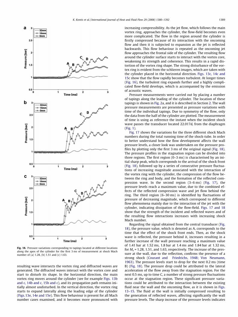
Fig. 18. Pressure variations corresponding to tapings located at different locationsalong the apex of the cylinder for the first 3 ms of measurement at shock Machnumber of (a) 1.28, (b) 1.51 and (c) 1.63.
K. Kontis et al. / International Journal of Heat and Fluid Flow 29 (2008) 1380–1392 1389
resulting wave intersects the vortex ring and diffracted waves aregenerated. The diffracted waves interact with the vortex core andstart to disturb its shape. In the horizontal direction, the mainvortex ring moves around the cylinder (see for example Figs. 13band c, 14b and c, 15b and c), and its propagation path remains ini-tially almost undisturbed. In the vertical direction, the vortex ringstarts to expand laterally along the leading edge of the cylinder(Figs.13e, 14e and 15e). This flow behaviour is present for all Machnumber cases examined, and it becomes more pronounced with
increasing compressibility. As the jet flow, which follows the mainvortex ring, approaches the cylinder, the flow-field becomes evenmore complicated. The flow in the region around the cylinder isfirstly compressed because of its interaction with the oncomingflow and then it is subjected to expansion as the jet is reflectedbackwards. This flow behaviour is repeated as the oncoming jetflow approaches the frontal side of the cylinder. The resulting flowaround the cylinder surface starts to interact with the vortex core,weakening its strength and coherence. This results in a rapid dis-tortion of the vortex ring shape. The strong disturbance of the vor-tex ring is evident from the schlieren images, which are taken withthe cylinder placed in the horizontal direction. Figs. 13c, 14c and15c show that the flow rapidly becomes turbulent. At longer times(Fig. 16), the turbulent ring expands further and a highly compli-cated flow-field develops, which is accompanied by the emissionof acoustic waves.
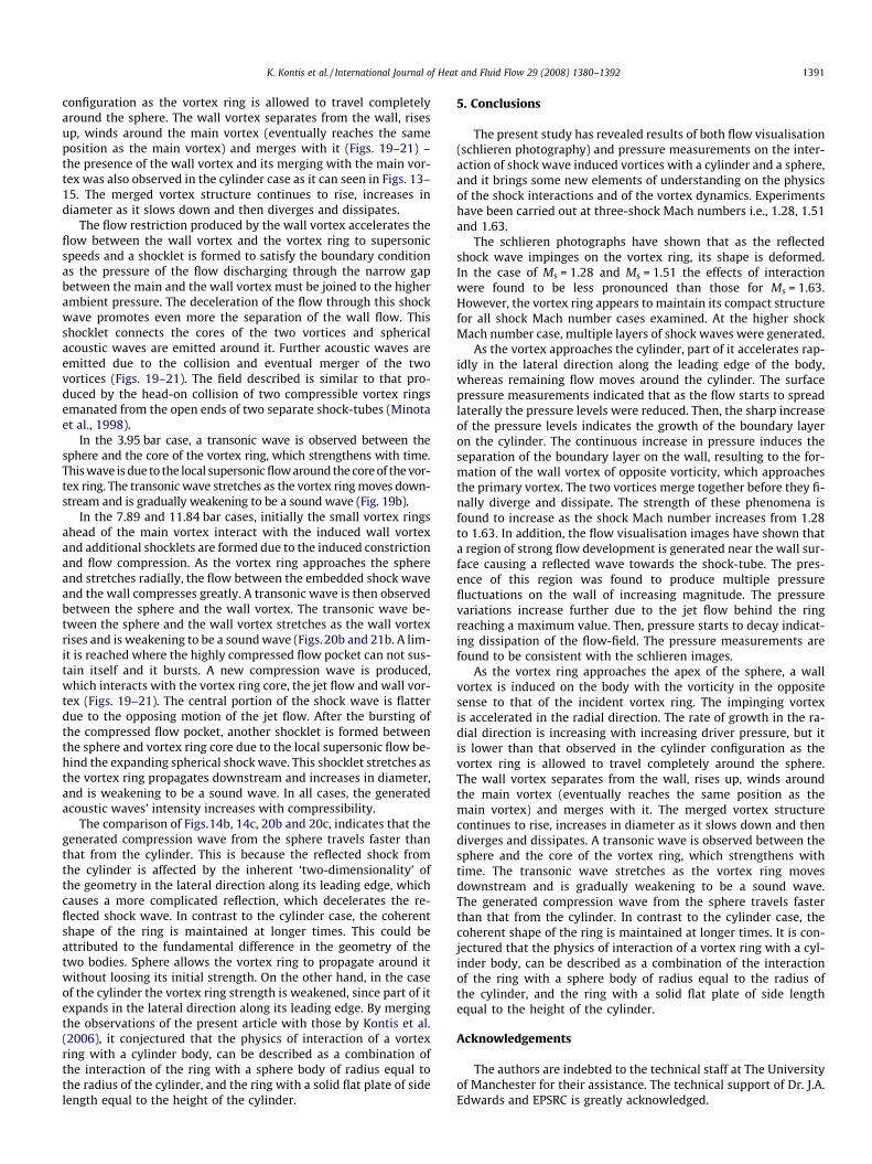
Pressure measurements were carried out by placing a numberof tapings along the leading of the cylinder. The location of thesetapings is shown in Fig. 2a, and it is described in Section 2. The wallpressure measurements are presented as pressure variations withtime of the individual tapings. Due to symmetry of the flow, onlythe data from the half of the cylinder are plotted. The measurementof time is using as reference the instant when the incident shockwave passes the transducer located 22.017di from the diaphragm(Fig. 1).
Fig. 17 shows the variations for the three different shock Machnumbers during the total running time of the shock-tube. In orderto better understand how the flow development affects the wallpressure levels, a closer look was undertaken on the pressure pro-files by plotting only the first 3 ms of the original signal (Fig. 18).The pressure profiles in the stagnation region can be divided intothree regions. The first region (0–3 ms) is characterised by an ini-tial sharp peak, which corresponds to the arrival of the shock front(Fig. 18), followed up by a series of consecutive pressure fluctua-tions of increasing magnitude associated with the interaction ofthe vortex ring with the cylinder, the compression of the flow be-tween the ring and body, and the formation of the reflected com-pression wave. In the second region (3–6 ms) (Fig. 17), thepressure levels reach a maximum value, due to the combined ef-fects of the reflected compression wave and jet flow behind thering. The third region (6–30 ms) is identified by fluctuations ofpressure of decreasing magnitude, which correspond to differentflow phenomena mainly due to the interaction of the jet with thecylinder, indicating dissipation of the flow-field. Figs. 17 and 18show that the strength of the incident and reflected waves and ofthe resulting flow interactions increases with increasing shockMach number.
Regarding the signal obtained from the central transducer (Fig.18), the pressure value, which is denoted as A, corresponds to thetime that the effect of the shock front ends. Then, as the shockwave is reflected, the pressure behind it, increases resulting in afurther increase of the wall pressure reaching a maximum valueof 1.41 bar at 1.52 ms, 1.8 bar at 1.4 ms and 1.84 bar at 1.32 ms,for Ms = 1.28, 1.51, and 1.63, respectively. The increase of the pres-sure at the wall, due to the reflection, confirms the presence of astrong shock (Courant and Friedrichs, 1948; Von Neumann,1963). The pressure levels start to drop for the next 0.2 ms (timeB) (Fig. 18). The pressure drop could be attributed to the lateralacceleration of the flow away from the stagnation region. For thenext 0.5 ms, up to time C, a number of strong pressure fluctuationsoccur at the stagnation region. These significant pressure varia-tions could be attributed to the interaction between the existingfluid near the wall and the oncoming flow, as it is shown in Figs.13–15. The fluid at the wall is initially compressed resulting tothe generation of reflected waves, affecting significantly the wallpressure levels. The sharp increase of the pressure levels indicates

Fig. 19. Schlieren images showing the interaction of the vortex ring with a sphere at (a) 2.0 ms, (b) 2.2 ms and (c) 2.4 ms for a shock Mach number of 1.28.
Fig. 20. Schlieren images showing the interaction of the vortex ring with a sphere at (a) 1.7 ms, (b) 1.8 ms and (c) 1.9 ms for a shock Mach number of 1.51.
Fig. 21. Schlieren images showing the interaction of the vortex ring with a sphere at (a) 1.5 ms, (b) 1.6 ms and (c) 1.7 ms for a shock Mach number of 1.63.
1390 K. Kontis et al. / International Journal of Heat and Fluid Flow 29 (2008) 1380–1392
the growth of the boundary layer on the cylinder. The continuousincrease in pressure induces the separation of the boundary layeron the wall, resulting to the formation of the wall vortex. The de-crease of pressure levels at time D is because of the presence ofthe wall vortex. The time of pressure variation (time D) is foundto be consistent with the presence of the wall vortex shown in Figs.13–15. Then, there is a number of further pressure fluctuations, asa result of the interactions that occur in the near-wall region. Thepressure fluctuations are found to increase further in strengthmainly due to the interaction of the cylinder with the jet (Fig.17) and their duration is in agreement with the schlieren imagesshown in Figs. 13–15.
The pressure variations on either side of the stagnation region(Figs. 17 and 18), indicate that initially, the effect of the shock waveis most significant at the locations (0, and ±16 mm) closer to thestagnation point. The outer locations, ±32 and ±48 mm, are sub-
jected to the least influence from the shock wave, with pressuresclose to the ambient pressure. This could be attributed to the factthat the shock wave propagates in a spherical shape, affectingmostly the wall pressure levels near the stagnation region. In addi-tion, by the time the outer portions of the shock wave make con-tact with the plate, the shock wave has increased in radius andhas become weaker so its effects are less pronounced in the outerregions.
4.2.2. SphereAs the vortex ring approaches the apex of the sphere, a wall vor-
tex is induced on the body with the vorticity in the opposite senseto that of the incident vortex ring (Figs. 19a, 20b and 21c. Theimpinging vortex is accelerated in the radial direction. The rateof growth in the radial direction is increasing with increasingdriver pressure, but it is lower than that observed in the cylinder
K. Kontis et al. / International Journal of Heat and Fluid Flow 29 (2008) 1380–1392 1391
configuration as the vortex ring is allowed to travel completelyaround the sphere. The wall vortex separates from the wall, risesup, winds around the main vortex (eventually reaches the sameposition as the main vortex) and merges with it (Figs. 19–21) –the presence of the wall vortex and its merging with the main vor-tex was also observed in the cylinder case as it can seen in Figs. 13–15. The merged vortex structure continues to rise, increases indiameter as it slows down and then diverges and dissipates.
The flow restriction produced by the wall vortex accelerates theflow between the wall vortex and the vortex ring to supersonicspeeds and a shocklet is formed to satisfy the boundary conditionas the pressure of the flow discharging through the narrow gapbetween the main and the wall vortex must be joined to the higherambient pressure. The deceleration of the flow through this shockwave promotes even more the separation of the wall flow. Thisshocklet connects the cores of the two vortices and sphericalacoustic waves are emitted around it. Further acoustic waves areemitted due to the collision and eventual merger of the twovortices (Figs. 19–21). The field described is similar to that pro-duced by the head-on collision of two compressible vortex ringsemanated from the open ends of two separate shock-tubes (Minotaet al., 1998).
In the 3.95 bar case, a transonic wave is observed between thesphere and the core of the vortex ring, which strengthens with time.This wave is due to the local supersonic flow around the core of the vor-tex ring. The transonic wave stretches as the vortex ring moves down-stream and is gradually weakening to be a sound wave (Fig. 19b).
In the 7.89 and 11.84 bar cases, initially the small vortex ringsahead of the main vortex interact with the induced wall vortexand additional shocklets are formed due to the induced constrictionand flow compression. As the vortex ring approaches the sphereand stretches radially, the flow between the embedded shock waveand the wall compresses greatly. A transonic wave is then observedbetween the sphere and the wall vortex. The transonic wave be-tween the sphere and the wall vortex stretches as the wall vortexrises and is weakening to be a sound wave (Figs.20b and 21b. A lim-it is reached where the highly compressed flow pocket can not sus-tain itself and it bursts. A new compression wave is produced,which interacts with the vortex ring core, the jet flow and wall vor-tex (Figs. 19–21). The central portion of the shock wave is flatterdue to the opposing motion of the jet flow. After the bursting ofthe compressed flow pocket, another shocklet is formed betweenthe sphere and vortex ring core due to the local supersonic flow be-hind the expanding spherical shock wave. This shocklet stretches asthe vortex ring propagates downstream and increases in diameter,and is weakening to be a sound wave. In all cases, the generatedacoustic waves’ intensity increases with compressibility.
The comparison of Figs.14b, 14c, 20b and 20c, indicates that thegenerated compression wave from the sphere travels faster thanthat from the cylinder. This is because the reflected shock fromthe cylinder is affected by the inherent ‘two-dimensionality’ ofthe geometry in the lateral direction along its leading edge, whichcauses a more complicated reflection, which decelerates the re-flected shock wave. In contrast to the cylinder case, the coherentshape of the ring is maintained at longer times. This could beattributed to the fundamental difference in the geometry of thetwo bodies. Sphere allows the vortex ring to propagate around itwithout loosing its initial strength. On the other hand, in the caseof the cylinder the vortex ring strength is weakened, since part of itexpands in the lateral direction along its leading edge. By mergingthe observations of the present article with those by Kontis et al.(2006), it conjectured that the physics of interaction of a vortexring with a cylinder body, can be described as a combination ofthe interaction of the ring with a sphere body of radius equal tothe radius of the cylinder, and the ring with a solid flat plate of sidelength equal to the height of the cylinder.
5. Conclusions
The present study has revealed results of both flow visualisation(schlieren photography) and pressure measurements on the inter-action of shock wave induced vortices with a cylinder and a sphere,and it brings some new elements of understanding on the physicsof the shock interactions and of the vortex dynamics. Experimentshave been carried out at three-shock Mach numbers i.e., 1.28, 1.51and 1.63.
The schlieren photographs have shown that as the reflectedshock wave impinges on the vortex ring, its shape is deformed.In the case of Ms = 1.28 and Ms = 1.51 the effects of interactionwere found to be less pronounced than those for Ms = 1.63.However, the vortex ring appears to maintain its compact structurefor all shock Mach number cases examined. At the higher shockMach number case, multiple layers of shock waves were generated.
As the vortex approaches the cylinder, part of it accelerates rap-idly in the lateral direction along the leading edge of the body,whereas remaining flow moves around the cylinder. The surfacepressure measurements indicated that as the flow starts to spreadlaterally the pressure levels were reduced. Then, the sharp increaseof the pressure levels indicates the growth of the boundary layeron the cylinder. The continuous increase in pressure induces theseparation of the boundary layer on the wall, resulting to the for-mation of the wall vortex of opposite vorticity, which approachesthe primary vortex. The two vortices merge together before they fi-nally diverge and dissipate. The strength of these phenomena isfound to increase as the shock Mach number increases from 1.28to 1.63. In addition, the flow visualisation images have shown thata region of strong flow development is generated near the wall sur-face causing a reflected wave towards the shock-tube. The pres-ence of this region was found to produce multiple pressurefluctuations on the wall of increasing magnitude. The pressurevariations increase further due to the jet flow behind the ringreaching a maximum value. Then, pressure starts to decay indicat-ing dissipation of the flow-field. The pressure measurements arefound to be consistent with the schlieren images.
As the vortex ring approaches the apex of the sphere, a wallvortex is induced on the body with the vorticity in the oppositesense to that of the incident vortex ring. The impinging vortexis accelerated in the radial direction. The rate of growth in the ra-dial direction is increasing with increasing driver pressure, but itis lower than that observed in the cylinder configuration as thevortex ring is allowed to travel completely around the sphere.The wall vortex separates from the wall, rises up, winds aroundthe main vortex (eventually reaches the same position as themain vortex) and merges with it. The merged vortex structurecontinues to rise, increases in diameter as it slows down and thendiverges and dissipates. A transonic wave is observed between thesphere and the core of the vortex ring, which strengthens withtime. The transonic wave stretches as the vortex ring movesdownstream and is gradually weakening to be a sound wave.The generated compression wave from the sphere travels fasterthan that from the cylinder. In contrast to the cylinder case, thecoherent shape of the ring is maintained at longer times. It is con-jectured that the physics of interaction of a vortex ring with a cyl-inder body, can be described as a combination of the interactionof the ring with a sphere body of radius equal to the radius ofthe cylinder, and the ring with a solid flat plate of side lengthequal to the height of the cylinder.
Acknowledgements
The authors are indebted to the technical staff at The Universityof Manchester for their assistance. The technical support of Dr. J.A.Edwards and EPSRC is greatly acknowledged.

1392 K. Kontis et al. / International Journal of Heat and Fluid Flow 29 (2008) 1380–1392
References
Arakeri, J.H., Das, D., Krothapalli, A., Lourenco, L., 2004. Vortex ring formation at theopen end of a shock tube: a particle image velocimetry study. Physics of Fluids16, 1008–1019.
Baird, J.P., 1987. Supersonic vortex rings. Proceedings of Royal Society of London,Series A 409, 59–65.
Ben-Dor, G., 1992. Shock Wave Reflection Phenomena. Springer-Verlag.Ben-Dor, G., Takayama, K., Kawauchi, T., 1980. The transition from regular to mach
reflexion and from mach to regular reflexion in truly non-stationary flows.Journal of Fluid Mechanics 100, 147–160.
Bleakney, W., Weimer, D.K., Fletcher, C.H., 1949. The shock tube: a facility forinvestigations in fluid dynamics. The Review of Scientific Instruments 20, 807–815.
Brouillette, M., Hebert, C., 1997. Propagation and interaction of shock-generatedvortices. Fluid Dynamics Research 21, 159–169.
Bryson, A.E., Gross, R.W.F., 1960. Diffraction of strong shocks by cones, cylinders andspheres. Journal of Fluid Mechanics 10, 1–16.
Courant, R., Friedrichs, K.O., 1948. Supersonic Flow and Shock Waves. Interscience,New York.
Elder, F.K., De Haas, N., 1952. Experimental study of the formation of a vortex ring atthe open end of a cylindrical shock tube. Journal of Applied Physics 23, 1065–1069.
Emrich, R.J., Curtis, C.W., 1953. Attenuation in the shock tube. Journal of AppliedPhysics 24, 360–363.
Emrich, R.J., Wheeler, D.B., 1958. Wall effects in shock tube flow. Physics of Fluids 1,14–23.
Glass, I.I., Sislian, J.P., 1994. Nonstationary Flows and Shock Waves. OxfordUniversity Press.
Gonor, A.L., Gottlieb, J.J., Hooton, I., 2004. Shock wave diffraction over wedges,cylinders and spheres in gases, liquids and condensed matter. Journal of AppliedPhysics 95, 1577–1585.
Heilig, W.H., 1969. Diffraction of a Shock Wave by a Cylinder. The Physics of FluidsSupplement I, 154–157.
Kontis, K., An, R., Edwards, J.A., 2006. Compressible vortex-ring interaction studieswith a number of generic body configurations. AIAA Journal 44 (12), 2962–2978.
Merzkirch, W., 1974. Flow Visualization. Academic Press Inc..Minota, T., Nishida, M., Lee, M.G., 1998. Head-on collision of two compressible
vortex rings. Fluid Dynamics Research 22, 43–60.Settles, G., 2001. Schlieren and Shadowgraph Techniques: Visualizing Phenomena
in Transparent Media. Springer-Verlag, Berlin and Heidelberg GmbH and Co.Shugaev, F.V., Shtemenko, L.S., 1998. Propagation and reflection of shock waves.
Series on Advances in Mathematics for Applied Sciences, vol. 49. WorldScientific.
Sun, M., Saito, T., Takayama, K., Tanno, H., 2005. Unsteady drag on a sphere by shockwave loading. Shock Waves 14, 3–9.
Tanno, H., Itoh, K., Saito, T., Abe, T., Takayama, K., 2003. Interaction of a shock with asphere suspended in a vertical shock tube. Shock Waves 13, 191–200.
Tokugawa, N., Ishii, Y., Sugano, K., Takayama, F., Kambe, T., 1997. Observation andanalysis of scattering interaction between a shock wave and a vortex ring. FluidDynamics Research 21, 185–199.
Von Neumann, J., 1963. Collected Works. Pergamon Press.White, D.R., 1958. Influence of diaphragm opening time on shock-tube flows.
Journal of Fluid Mechanics 4, 585–599.Whitham, G.B., 1957. A new approach to problems of shock dynamics part i two-
dimensional problems. Journal of Fluid Mechanics 2, 145–171.Yang, J.Y., Liu, Y., Lomax, H., 1987. Computation of shock wave reflection by circular
cylinders. AIAA Journal 25, 683–689.