international journal of engineering research-online … y.narasimha rao.pdf · 2018-01-28 ·...
TRANSCRIPT

International Journal of Engineering Research-Online
A Peer Reviewed International Journal Articles available online http://www.ijoer.in
Vol.3., Issue.6., 2015 (Nov.-Dec.,)
374 Y.NARASIMHA RAO,U.HARI BABU
1. OBJECTIVE
The objective of this paper is the basic idea is to
choose a compatible resin system with E-Glass
bidirectional fabric in such a way that the best
combination of mechanical properties are achieved.
The mechanical properties are determined by
carrying out tests on specimens in tension and
flexure in accordance with the test procedure laid
down in ASTM-D specifications D-3039 and D-790. +
450 specimens has prepared in accordance with D-
3518 to study the in-plane shear properties. Inter
laminar shear strength will be determined by
conducting short-beam shear test with span to
thickness ratio less than 4 in accordance with D-
2544. Finally after obtaining the testing results,
those will be evaluated using ANSYS software
package.
2. MATERIAL PREPARATION
A single layer of a laminated composite material is
generally referred to as a ply or laminate. It usually
contains a single layer of reinforcement,
unidirectional or multidirectional. A single lamina is
generally too thin to be directly used in any
engineering application. Several laminae are bonded
together to form a structure termed as laminate.
Properties and orientation of the laminae in a
laminate are chosen to meet the laminate design
requirements. Properties of a laminate may be
predicted by knowing the properties of its
constituent laminae.
RESEARCH ARTICLE ISSN: 2321-7758
FABRICATION AND ANALYSIS OF MECHANICAL PROPERTIES OF E-GLASS
BI-DIRECTIONAL FABRIC COMPOSITE MATERIAL
Y.NARASIMHA RAO 1,U.HARI BABU2 1M.Tech, student, Department of Mechanical Engineering, QIS College of Engineering &
Technology, Ongole 2 Professor, Department of Mechanical Engineering, QIS College of Engineering & Technology,
Ongole
ABSTRACT
Composites play a vital role in aerospace, land transportation and consumer goods
due to their high specific strengths and stiffness’s, leading to reduction in the mass
of moving objects. Glass epoxy composites are an unique materials for some of the
important hardware such as pressure vessels of commercial applications, Storage
of chemicals, sewage treatment plants, chemical industrial applications.
Initially to manufacture a laminate with appropriate finishing and maintaining
uniform thickness a Match-Die-Mold is designed and fabricated. In the present
investigation, I am going to use three different resin matrix systems in conjunction
with E-Glass bidirectional fabric. The epoxy LY556 (resin system - 1) the epoxy LY
556 with 5%reactive diluents (resin system - 2) and Epofine 1555(modified epoxy
resin with high elongation (resin system - 3)). Finally after obtaining the testing
results, those will be evaluated using ANSYS software package.
Key Words: E-birectional fabric 13mil, Ansys 16, Epoxy LY 556, Epofine 1555, Match
die mould
©KY Publications

International Journal of Engineering Research-Online
A Peer Reviewed International Journal Articles available online http://www.ijoer.in
Vol.3., Issue.6., 2015 (Nov.-Dec.,)
375 Y.NARASIMHA RAO,U.HARI BABU
In this experimental work the following types of
laminates were made with different orientations:
1. 0˚/0˚- (all plies are in 0˚ direction)
2. ±45˚
The fabric is laid on work bench covered with
polythene sheet. Marking is taken by using 0° and
±45° with mould dimensions 390mmx340mm
respectively. Resin is weighed as per specifications
of fabric that is 100 gms resin, pigmented (5%) for
colored surface typically white is chosen and
hardener is added in the ratio of 1/3rd
. Epoxy is
stirred well & bonding agent (epoxy resin) is applied
to create bonding between layers. This is usually
accomplished by rollers or brushes, with an
increasing use of roller type impregnators for forcing
resin into the fabrics by means of rotating rollers.
The surface of the mould is cleaned with 0-grade
Emery paper, the clearance holes are cleaned with
jewellery files, also cleaned with acetone and a
release agent (waxpol) is applied. If the surface is
not clean, then the release agent will not function
properly.
An optional sacrificial layer (Surface mat) is laid up
on the mould surface. This layer is usually a
fiberglass fabric made with the same resin system as
the composite laminate. The sacrificial layer protects
the laminate from surface abrasion and surface
irregularities during manufacturing.Impregnated
piles are cuted into the required size. The first
prepreg ply is oriented and placed upon the mould.
A roller or other small hand tool is used to compact
the plies and remove entrapped air that could later
lead to voids or layer separations. Now the
polythene sheet is peeled from the ply. It is
important that the pre impregnated material have
sufficient tack so that it sticks slightly to the peel ply
and to the adjacent plies. Thermocouple bead is
placed on middle ply just about 3mm from the
spacer clearance hole to get the exact temperature
reading of the laminate.
Subsequent plies are placed one upon another.
These plies are stacked layer by layer of about 12
layers to attain the thickness of 5mm as per the
ASTM Standard Specimen. Another surface mat is
placed on the top of laminate to protect the
laminate surface. Then the mould is closed with
punch. The mould is clamped by tightening the bolts
with specified torque.
Torque is applied to the clamping bolts on the tool
(Mould), causing the excess resin to flow of the
clearance holes. The resin flow is critical, since it
allows the removal of entrapped air and volatiles
from the prepreg and thus reduces the void content
in the cured laminate. The mould is now placed in
the oven for curing, The process of polymerization is
called "curing", and can be controlled through
temperature and choice of resin and hardener
compounds; the process can take minutes to hours.
Some formulations benefit from heating externally
supplied during the cure period, whereas others
simply require time, and cure on account of mild
increase in internal temperatures on account of
chemical reactions. IN the first stage in this cure
cycle consists of increasing the temperature up to 80
°C and dwelling at this temperature for nearly 60
minutes when the minimum resin viscosity is
reached. During this period of temperature dwell,
30KN/m Torque is applied on the tool (Mould),
causing some more resin to flow of the clearance
holes, indicating that the lay-up inside has further
International Journal of Engineering Research-Online
A Peer Reviewed International Journal Articles available online http://www.ijoer.in
Vol.3., Issue.6., 2015 (Nov.-Dec.,)
376 Y.NARASIMHA RAO,U.HARI BABU
become pliable, and takes compression. After that
the oven temperature is increased to 120oC and the
component is allowed to reach that temperature.
Once the component has reached 120oC, a dwell of
one hour is allowed. Finally the oven temperature is
raised to 180oC and the component is allowed to
reach it. Once the component has reached 180oC
then a dwell of 4 Hrs is followed and finally it is
allowed to cool for overnight. When the part is
sufficiently cured, the mold is opened and the part is
removed. Finished molding must usually be trimmed
with a handsaw to size outside edges.
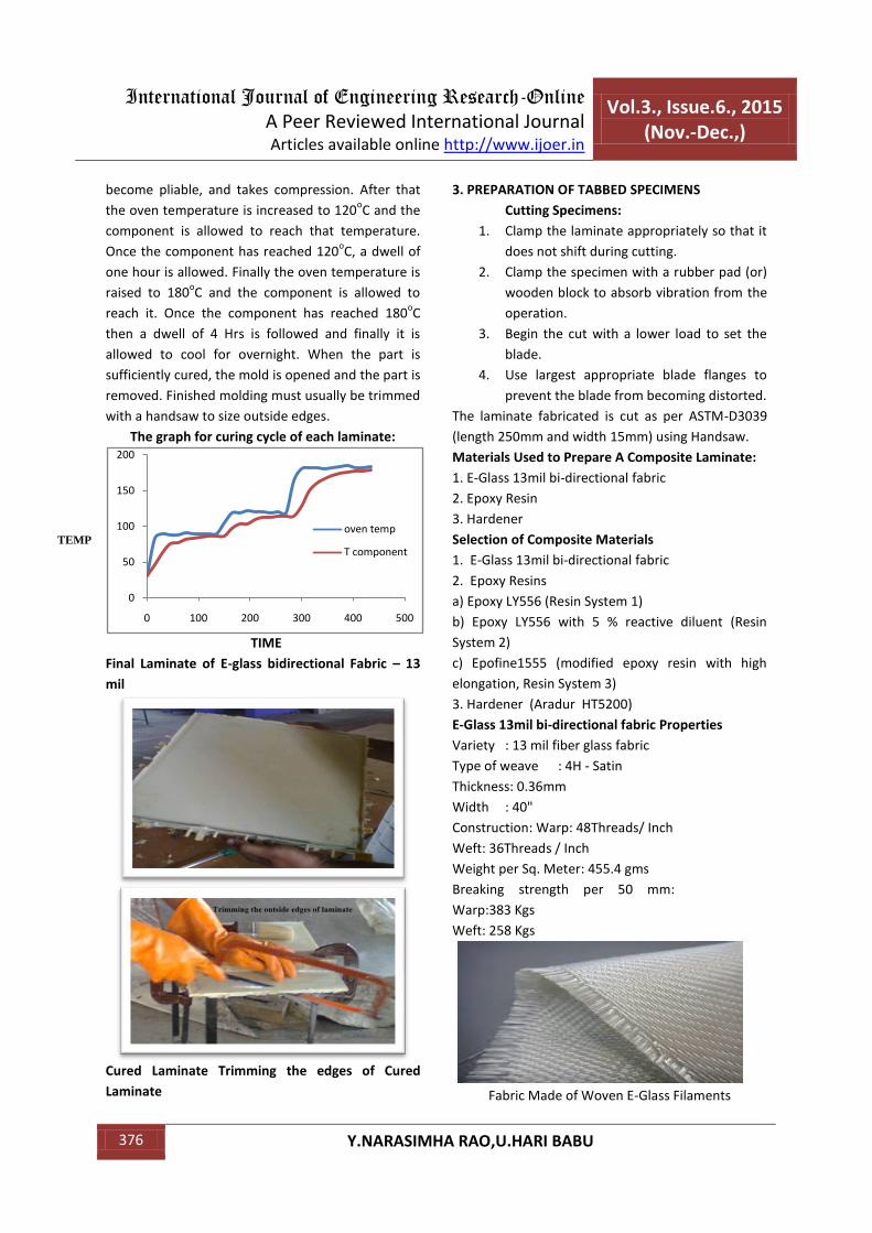
The graph for curing cycle of each laminate:
TIME
Final Laminate of E-glass bidirectional Fabric – 13
mil
Cured Laminate Trimming the edges of Cured
Laminate
3. PREPARATION OF TABBED SPECIMENS
Cutting Specimens:
1. Clamp the laminate appropriately so that it
does not shift during cutting.
2. Clamp the specimen with a rubber pad (or)
wooden block to absorb vibration from the
operation.
3. Begin the cut with a lower load to set the
blade.
4. Use largest appropriate blade flanges to
prevent the blade from becoming distorted.
The laminate fabricated is cut as per ASTM-D3039
(length 250mm and width 15mm) using Handsaw.
Materials Used to Prepare A Composite Laminate:
1. E-Glass 13mil bi-directional fabric
2. Epoxy Resin
3. Hardener
Selection of Composite Materials
1. E-Glass 13mil bi-directional fabric
2. Epoxy Resins
a) Epoxy LY556 (Resin System 1)
b) Epoxy LY556 with 5 % reactive diluent (Resin
System 2)
c) Epofine1555 (modified epoxy resin with high
elongation, Resin System 3)
3. Hardener (Aradur HT5200)
E-Glass 13mil bi-directional fabric Properties
Variety : 13 mil fiber glass fabric
Type of weave : 4H - Satin
Thickness: 0.36mm
Width : 40"
Construction: Warp: 48Threads/ Inch
Weft: 36Threads / Inch
Weight per Sq. Meter: 455.4 gms
Breaking strength per 50 mm:
Warp:383 Kgs
Weft: 258 Kgs
Fabric Made of Woven E-Glass Filaments
0
50
100
150
200
0 100 200 300 400 500
oven temp
T componentTEMP

International Journal of Engineering Research-Online
A Peer Reviewed International Journal Articles available online http://www.ijoer.in
Vol.3., Issue.6., 2015 (Nov.-Dec.,)
377 Y.NARASIMHA RAO,U.HARI BABU
Selected Specimen Specifications as per (ASTM):
S.NO Type of Test Relevant ASTM
Number of specimens
Specimen size(mm)
Selected Specimen size(mm)
1 UD-Tensile D-3039 5 250x15x1 250 X 15 X 3
2 Transverse Tensile
D-3039 5 175x25x2 250 X 15 X 3
3 Flexural D-790 5 50x25x1.6 60 X 25 X 3
4 ILSS D-2344 5 24x12x6 40 X 10 X 6
5 In-plane shear D-3518 5 300x25x3 300 X 25 X 3
Testing Condition:
1. The specimens were tested at a strain rate
(displacement) of 2mm/min
2. Co-axiality of the specimen axis and the
machine loading axis was ensuring.
3. Two layers of emery cloth were used on
either end of the specimen to hold
between the grips.
4. Cognizes was taken in respect of the results
in which explosive failure within the gauge
length was absorbed.
4. TESTING & ANALYSIS RESULTS
Observed results in respect of specimen derived
from Resin System -1(R1), Resin System -2(R2) and
Resin System -3(R3) composite plates are placed in
4.1 RESIN SYSTEM-1 PROPERTIES:
Tensile Properties:
S.
N
o
Geometry
(mm)
Breaking load(KN) 𝜎
(MPa)
1 250 X 15 X 3 12.82 284.8
2 250 X 15 X 3 12.76 283.5
3 250 X 15 X 3 12.54 278.6
4 250 X 15 X 3 12.70 282.2
5 250 X 15 X 3 12.68 281.7
Tensile Properties - Resin System-1
Average Tensile Strength =282 MPa
Transverse Tensile Properties:
S.No Geometry
(mm)
Breaking load
(KN)
𝜎
(MPa)
1 250 X 15 X 3 10.1 224.4
2 250 X 15 X 3 9.8 208.8
3 250 X 15 X 3 9.9 220.0
4 250 X 15 X 3 10.3 228.8
5 250 X 15 X 3 10.25 227.7
Transverse Tensile Properties - Resin System-1
Average Transverse Tensile Strength = 224
Flexural Properties (Span: 51mm):
S. No Geometry
(mm)
Breaking
load
𝜎f
(MPa)
1 60 X 25 X 3 2.35 80
2 60 X 25 X 3 2.41 82.1
3 60 X 25 X 3 2.29 78
4 60 X 25 X 3 2.32 79
5 60 X 25 X 3 2.39 81.5
Flexural Properties - Resin System-1
Average Flexural Strength = 80.12 MPa
Inter Laminar Shear Properties (Span: 18mm):
S.No Geometry
(mm)
Breaking load 𝜏12
(MPa)
1 40 X 10 X 6 4.54 56.8
2 40 X 10 X 6 4.6 57.5
3 40 X 10 X 6 4.47 55.9
4 40 X 10 X 6 4.42 55.3
5 40 X 10 X 6 4.56 57.1
Inter Laminar Shear Properties - Resin System-1
Average Inter Laminar Shear Strength (ILSS) = 56.52
MPa
In-Plane Shear Properties:
S.No Geometry (mm) Breaking
load
𝜏
(MPa)
1 300 X 25 X 3 27.1 180.66
2 300 X 25 X 3 25.8 172
3 300 X 25 X 3 27.3 182
4 300 X 25 X 3 25.9 172.6
5 300 X 25 X 3 26.4 176
In-Plane Shear Properties - Resin System-1
Average In- Plane Shear Strength =176.65 Mpa

International Journal of Engineering Research-Online
A Peer Reviewed International Journal Articles available online http://www.ijoer.in
Vol.3., Issue.6., 2015 (Nov.-Dec.,)
378 Y.NARASIMHA RAO,U.HARI BABU
4.2. Resin System-2 Properties:
Tensile Properties:
S.No. Geometry
(mm)
Breaking load
(KN)
𝜎
(MPa)
1 250 X 15 X 3 13.6 302.22
2 250 X 15 X 3 13.7 304.4
3 250 X 15 X 3 13.2 293.3
4 250 X 15 X 3 13.5 300
5 250 X 15 X 3 13.75 305.5
Tensile Properties - Resin System-2
Average Tensile Strength = 301.10 MPa
Transverse Tensile Properties:
S.No Geometry
(mm)
Breaking load
(KN)
𝜎
(MPa)
1 250 X 15 X 3 11.1 246.66
2 250 X 15 X 3 10.9 242.22
3 250 X 15 X 3 11.3 251.11
4 250 X 15 X 3 10.8 240.00
5 250 X 15 X 3 10.7 237.77
Transverse Tensile Properties - Resin System-2
Average Transverse Tensile Strength = 243.5 MPa
Flexural Properties (Span: 51mm):
S.No Geometry
(mm)
Breaking load
(KN)
𝜎f
(MPa)
1 60 X 25 X 3 2.53 86.3
2 60 X 25 X 3 2.49 84.7
3 60 X 25 X 3 2.60 88.5
4 60 X 25 X 3 2.45 83.4
5 60 X 25 X 3 2.5 85.2
Flexural Properties - Resin System-2
Average Flexural Strength = 85.62 MPa
Inter Laminar Shear Properties (Span: 18mm):
S.No Geometry
(mm)
Breaking load
(KN)
𝜏12
(MPa)
1 40 X 10 X 6 4.92 61.5
2 40 X 10 X 6 4.87 60.9
3 40 X 10 X 6 4.84 60.5
4 40 X 10 X 6 4.90 61.3
5 40 X 10 X 6 4.83 60.4
Inter laminar Shear Properties - Resin System-2

International Journal of Engineering Research-Online
A Peer Reviewed International Journal Articles available online http://www.ijoer.in
Vol.3., Issue.6., 2015 (Nov.-Dec.,)
379 Y.NARASIMHA RAO,U.HARI BABU
Average Inter Laminar Shear Strength (ILSS) =60.92 MPa
In -Plane Shear Properties:
S.
N
o
Geometry
(mm)
Breaking load
(KN)
𝜏
(MPa)
1 300 X 25 X 3 27.8 185.3
2 300 X 25 X 3 27.1 180.6
3 300 X 25 X 3 27.5 183.3
4 300 X 25 X 3 28.1 187.3
5 300 X 25 X 3 27.6 184
In-Plane Shear Properties - Resin System-2
Average In- Plane Shear Strength =184.10 Mpa
4.3.Resin System-3 Properties:
Tensile Properties:
S.No Geometry
(mm)
Breaking load
(KN)
𝜎
(MPa)
1 250 X 15 X 3 16.9 375.5
2 250 X 15 X 3 16.5 366.6
3 250 X 15 X 3 17.2 382.22
4 250 X 15 X 3 16.8 373.3
5 250 X 15 X 3 16.4 364.4
Tensile Properties - Resin System-3
Average Tensile Strength = 372.40 MPa
Transverse Tensile Properties:
S.No Geometry
(mm)
Breaking load
(KN)
𝜎
(MPa)
1 250 X 15 X 3 14.4 320
2 250 X 15 X 3 14.6 324.4
3 250 X 15 X 3 14.1 313.3
4 250 X 15 X 3 13.9 308.8
5 250 X 15 X 3 14.25 316.6
Transverse Tensile Properties - Resin System-3
Average Transverse Tensile Strength = 316.62 MPa
Flexural Properties (Span: 51mm):
S.No Geometry
(mm)
Breaking load
(KN)
𝜎f
(MPa)
1 60 X 25 X 3 3.33 113.5
2 60 X 25 X 3 3.26 110.9
3 60 X 25 X 3 3.30 112.5
4 60 X 25 X 3 3.35 114.2
5 60 X 25 X 3 3.28 111.6

International Journal of Engineering Research-Online
A Peer Reviewed International Journal Articles available online http://www.ijoer.in
Vol.3., Issue.6., 2015 (Nov.-Dec.,)
380 Y.NARASIMHA RAO,U.HARI BABU
Flexural Properties - Resin System-3
Average Flexural Strength = 112.54 MPa
Inter Laminar Shear Properties (span: 18mm):
S.No Geometry
(mm)
Breaking load
(KN)
𝜏12
(MPa)
1 40 X 10 X 6 6.07 75.9
2 40 X 10 X 6 6.12 76.5
3 40 X 10 X 6 6.02 75.3
4 40 X 10 X 6 6.13 76.6
5 40 X 10 X 6 6.08 76.1
Inter Laminar Shear Properties - Resin System-3
Average Inter Laminar Shear Strength (ILSS) = 76.08 MPa
In -Plane Shears Properties:
S.No Geometry
(mm)
Breaking load
(KN)
𝜏
(MPa)
1 300 X 25 X 3 32.1 214
2 300 X 25 X 3 31.9 212.6
3 300 X 25 X 3 32.3 215.3
4 300 X 25 X 3 31.6 210.66
5 300 X 25 X 3 31.75 211.66
In-Plane Shear Properties - Resin System-3
Average In- Plane Shear Strength =212.8 Mpa
5. ANALYTICAL RESULTS FOR RESIN SYSTEM 1: Tensile Strength
Maximum Stress = 382 MPa
Transverse Strength
Maximum Stress = 304 MPa
In-plane shear strength
1
MNMX
X
Y
Z
.108E+09
.196E+09.283E+09
.370E+09.457E+09
.544E+09.631E+09
.719E+09.806E+09
.893E+09
NOV 11 2015
12:06:24
NODAL SOLUTION
STEP=1
SUB =1
TIME=1
SEQV (AVG)
DMX =.038436
SMN =.108E+09
SMX =.893E+09
1
MNMX
X
Y
Z
.862E+08
.155E+09.225E+09
.294E+09.363E+09
.432E+09.502E+09
.571E+09.640E+09
.709E+09
NOV 11 2015
12:08:00
NODAL SOLUTION
STEP=1
SUB =1
TIME=1
SEQV (AVG)
DMX =.03053
SMN =.862E+08
SMX =.709E+09

International Journal of Engineering Research-Online
A Peer Reviewed International Journal Articles available online http://www.ijoer.in
Vol.3., Issue.6., 2015 (Nov.-Dec.,)
381 Y.NARASIMHA RAO,U.HARI BABU
Maximum Stress =369 MPa
Inter Laminar Shear Strength
Maximum Stress =57 MPa
Flexural Strength
Maximum Stress = 72 MPa (for ± 45
o)
Maximum Stress
6. ANALYTICAL RESULTS FOR RESIN SYSTEM 2
Tensile strength
Maximum Stress = 414 MPa
Transverse strength
Maximum Stress = 331 MPa
In-Plane Strength
1
MN MXX
Y
Z
.189E+09
.489E+09.789E+09
.109E+10.139E+10
.169E+10.199E+10
.229E+10.259E+10
.289E+10
NOV 11 2015
12:09:12
NODAL SOLUTION
STEP=1
SUB =1
TIME=1
SEQV (AVG)
DMX =.010327
SMN =.189E+09
SMX =.289E+10
1
MN
MX
X
Y
Z
0
.313E+08.626E+08
.939E+08.125E+09
.157E+09.188E+09
.219E+09.250E+09
.282E+09
NOV 11 2015
12:13:51
NODAL SOLUTION
STEP=1
SUB =1
TIME=1
SEQV (AVG)
DMX =.119E-03
SMX =.282E+09
1
MNMX
X
Y
Z
0
.154E+09.309E+09
.463E+09.617E+09
.771E+09.926E+09
.108E+10.123E+10
.139E+10
NOV 11 2015
12:10:54
NODAL SOLUTION
STEP=1
SUB =1
TIME=1
SEQV (AVG)
DMX =.002585
SMX =.139E+10
1
MNMX
X
Y
Z
0
.728E+08.146E+09
.218E+09.291E+09
.364E+09.437E+09
.509E+09.582E+09
.655E+09
NOV 11 2015
12:11:36
NODAL SOLUTION
STEP=1
SUB =1
TIME=1
SEQV (AVG)
DMX =.001492
SMX =.655E+09
1
MNMX
X
Y
Z
.109E+09
.204E+09.299E+09
.394E+09.489E+09
.584E+09.679E+09
.773E+09.868E+09
.963E+09
NOV 11 2015
12:16:12
NODAL SOLUTION
STEP=1
SUB =1
TIME=1
SEQV (AVG)
DMX =.044104
SMN =.109E+09
SMX =.963E+09
1
MNMX
X
Y
Z
.875E+08
.164E+09.240E+09
.316E+09.392E+09
.468E+09.544E+09
.620E+09.696E+09
.772E+09
NOV 11 2015
12:17:54
NODAL SOLUTION
STEP=1
SUB =1
TIME=1
SEQV (AVG)
DMX =.035342
SMN =.875E+08
SMX =.772E+09
International Journal of Engineering Research-Online
A Peer Reviewed International Journal Articles available online http://www.ijoer.in
Vol.3., Issue.6., 2015 (Nov.-Dec.,)
382 Y.NARASIMHA RAO,U.HARI BABU
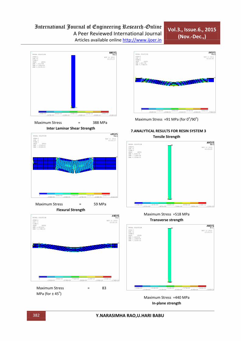
Maximum Stress = 388 MPa
Inter Laminar Shear Strength
Maximum Stress = 59 MPa
Flexural Strength
Maximum Stress = 83
MPa (for ± 45o)
Maximum Stress =91 MPa (for 0
o/90
o)
7.ANALYTICAL RESULTS FOR RESIN SYSTEM 3
Tensile Strength
Maximum Stress =518 MPa
Transverse strength
Maximum Stress =440 MPa
In-plane strength
1
MN MXX
Y
Z
.190E+09
.537E+09.883E+09
.123E+10.158E+10
.192E+10.227E+10
.262E+10.296E+10
.331E+10
NOV 11 2015
12:19:19
NODAL SOLUTION
STEP=1
SUB =1
TIME=1
SEQV (AVG)
DMX =.011758
SMN =.190E+09
SMX =.331E+10
1
MN
MX
X
Y
Z
0
.334E+08.669E+08
.100E+09.134E+09
.167E+09.201E+09
.234E+09.268E+09
.301E+09
NOV 11 2015
12:23:17
NODAL SOLUTION
STEP=1
SUB =1
TIME=1
SEQV (AVG)
DMX =.131E-03
SMX =.301E+09
1
MNMX
X
Y
Z
0
.193E+09.386E+09
.579E+09.772E+09
.965E+09.116E+10
.135E+10.154E+10
.174E+10
NOV 11 2015
12:20:31
NODAL SOLUTION
STEP=1
SUB =1
TIME=1
SEQV (AVG)
DMX =.003222
SMX =.174E+10
1
MNMX
X
Y
Z
0
.862E+08.172E+09
.259E+09.345E+09
.431E+09.517E+09
.604E+09.690E+09
.776E+09
NOV 11 2015
12:22:02
NODAL SOLUTION
STEP=1
SUB =1
TIME=1
SEQV (AVG)
DMX =.001798
SMX =.776E+09
1
MNMX
X
Y
Z
.128E+09
.247E+09.367E+09
.487E+09.606E+09
.726E+09.845E+09
.965E+09.108E+10
.120E+10
NOV 11 2015
12:24:20
NODAL SOLUTION
STEP=1
SUB =1
TIME=1
SEQV (AVG)
DMX =.058176
SMN =.128E+09
SMX =.120E+10
1
MNMX
X
Y
Z
.108E+09
.210E+09.311E+09
.413E+09.514E+09
.616E+09.717E+09
.818E+09.920E+09
.102E+10
NOV 11 2015
12:25:23
NODAL SOLUTION
STEP=1
SUB =1
TIME=1
SEQV (AVG)
DMX =.049334
SMN =.108E+09
SMX =.102E+10

International Journal of Engineering Research-Online
A Peer Reviewed International Journal Articles available online http://www.ijoer.in
Vol.3., Issue.6., 2015 (Nov.-Dec.,)
383 Y.NARASIMHA RAO,U.HARI BABU
Maximum Stress =449 MPa
Inter Laminar Shear Strength
Maximum Stress =84 MPa
Flexural Strength
Maximum Stress =103 MPa (for ±45
o)
Maximum Stress =125 MPa (for 0
o/90
o)
8.THE OVERALL TESTED RESULTS OF ALL FOUR RESIN SYSTEMS ARE TABULATED BELOW:
S.No. TEST
AVERAGE STRENGTH
(MPa)
RESIN SYSTEM
1
RESIN
SYSTEM 2
RESIN
SYSTEM 3
1 TENSILE TEST 282 302 372.4
2 TRANSVERSE TEST 224 242 318
3 FLEXURAL TEST 80 87 112
4 INTER LAMINAR SHEAR STRESS 56 61 76
5 IN-PLANE STRESS 177 185 213
Comparison of tested results of all resin systems
1
MN MXX
Y
Z
.210E+09
.649E+09.109E+10
.153E+10.197E+10
.240E+10.284E+10
.328E+10.372E+10
.416E+10
NOV 11 2015
12:27:00
NODAL SOLUTION
SUB =1
TIME=1
SEQV (AVG)
DMX =.014677
SMN =.210E+09
SMX =.416E+10
1
MN
MX
X
Y
Z
0
.500E+08.999E+08
.150E+09.200E+09
.250E+09.300E+09
.350E+09.400E+09
.450E+09
NOV 11 2015
12:30:34
NODAL SOLUTION
STEP=1
SUB =1
TIME=1
SEQV (AVG)
DMX =.200E-03
SMX =.450E+09
1
MNMX
X
Y
Z
0
.257E+09.514E+09
.771E+09.103E+10
.128E+10.154E+10
.180E+10.206E+10
.231E+10
NOV 11 2015
12:28:07
NODAL SOLUTION
STEP=1
SUB =1
TIME=1
SEQV (AVG)
DMX =.004266
SMX =.231E+10
1
MNMX
X
Y
Z
0
.109E+09.218E+09
.327E+09.435E+09
.544E+09.653E+09
.762E+09.871E+09
.980E+09
NOV 11 2015
12:29:29
NODAL SOLUTION
STEP=1
SUB =1
TIME=1
SEQV (AVG)
DMX =.002305
SMX =.980E+09

International Journal of Engineering Research-Online
A Peer Reviewed International Journal Articles available online http://www.ijoer.in
Vol.3., Issue.6., 2015 (Nov.-Dec.,)
384 Y.NARASIMHA RAO,U.HARI BABU
The analytical Results from ANSYS are tabulated below
S.No. TEST
AVERAGE STRENGTH
(MPa)
RESIN SYSTEM 1 RESIN SYSTEM 2 RESIN SYSTEM 3
1 TENSILE TEST 382 414 518
2 TRANSVERSE TEST 304 331 440
3 FLEXURAL TEST 72 83 103
4 INTER LAMINAR SHEAR STRESS 57 59 84
5 IN-PLANE STRESS 369 388 449
Comparison of FEM results of all resin systems
So, in this present investigation after introducing
the reactive diluents the strength has increased to
some extent (20MPa) resulting in higher strength.
But the toughened Epoxy resin resulted in best
bonding strength between fiber and matrix which
in turn resulted in higher tensile strength.
According to the tested results Resin system 3
resulted in high strength.
As the transverse strength is resin dominant
property, after introducing reactive diluents the
strength also increase slightly. For the resin
system 3 because of the good compatibility
between fiber and matrix it has resulted in high
transverse strength compared to other resin
systems. Whenever we discussed about flexural
strengths the Resin System 3 has resulted in
highest.
From the analytical point of view, the boundary
conditions given are the replication of the tested
results i.e. breaking loads, the resulted stresses at
the gauge length are compared. The obtained
tensile stresses are lesser compared to the FEM
stresses because in the FEM software there is no
provision of defining the fiber form i.e. if it is of
continuous fiber / woven fabric / chopped strand
mat.
When compared with the pure fiber form
laminate, the resulting in-plane shear for the
present case will be higher i.e. in the first case the
property is purely dominant by matrix and the
bonding strength between fiber and matrix. But in
the second case it is also affected by the interlock
between longitudinal and transverse fibers
because of weaving.
Comparison of Resin system 1 Properties
Comparison of Resin system 2 Properties
Comparison of Resin system 3 Properties
CONCLUSION
Full advantage of the enhanced mechanical
properties of the fibers like E-Glass can be fully
exploited if a judicious choice of matrix system is
0
200
400
600Resin System - 1
Tested (MPa)
FEM (Mpa)
0
200
400
600
Resin System - 2Tested (MPa)
FEM (Mpa)
0100200300400500600
Resin System - 3
Tested (MPa)
FEM (Mpa)

International Journal of Engineering Research-Online
A Peer Reviewed International Journal Articles available online http://www.ijoer.in
Vol.3., Issue.6., 2015 (Nov.-Dec.,)
385 Y.NARASIMHA RAO,U.HARI BABU
made. This investigation was aimed at zeroing on
an appropriate epoxy resin composition from
among a limited number of choices resulting the
following observations
Resin System appears to be compatible
with E-Glass fibers for the sizing given on
it.
Resin system 1 to resin system 3 the elastic
limit of resin is increasing then resulting in
higher strength.
In conclusion this experimental
investigation brings out the need for
compatible matrix material particularly
used in conjunction with high strength
fibers. The potential of high strength of the
fibers can be exploited fully only when a
compatible matrix is zeroed out.
Resin system besides having an elastomer
as its constituent, its functionality is 3.5 as
against 2 of the other resin systems. This is
a crucial factor in enhancing the
compatibility of matrix with fiber.
Among all the resin compositions tried out, Resin
System - 3 is most preferred one since it has given
consistent values of tensile strength at an average in
excess of 375 Mpa. This resin system is also given
reasonable good flexural, transverse tensile, in-
plane shear, inter laminar shear stress.
REFERENCES
[1]. Sivasaravanan.S ,V.K.Bupesh Raja ,Manikandan,
Impact Characterization of Epoxy LY556/E-Glass
Fibre/ Nano Clay Hybrid Nano Composite
Materials.
[2]. Rim Ben Toumi, Jacques Renard, Martine
Monin, Pongsak Nimdum, Fatigue damage
modeling of continuous E-glass fibre/epoxy
composite.
[3]. Amal A.M. Badawy, Impact behavior of glass
fibers reinforced composite laminates at
different temperatures.
[4]. Milan Žmindáka, Martin Dudinský,
Computational Modelling of Composite
Materials Reinforced by Glass Fibers.
[5]. A. Tasdemirci, A. Kara, A. K. Turan, G.
Tunusoglu, M. Guden, I. W. Hall, Experimental
and Numerical Investigation of High Strain
RateMechanical Behavior of a [0/45/90/- 45]
Quadriaxial EGlass/ Polyester Composite.
[6]. E. Graciania, J. Varna, V. Manti, A. Blázquez, F.
París, Evaluation of interfacial fracture
toughness and friction Coefficient in the single
fiber fragmentation test.
[7]. S. Giancane, F.W. Panella, R. Nobile, V.
Dattoma, Evaluation of interfacial fracture
toughness and friction coefficient in the single
fiber fragmentation test.
[8]. A. Ghorbel, N. Saintier, A. Dhiab, Investigation
of damage evolution in short glass fibers
reinforced polyamide 6,6 under tensile loading
using infrared thermography.
[9]. Mallick P.K., Composite Engineering Handbook,
1997, Marcel Dekker Inc., NY, USA.
[10]. Isaac M. Daniel, Emmanuel E. Gdoutos,
Deformation and Failure of Composite
Structures, Journal of Thermoplastic Composite
Materials 2003; 16; 345.
[11]. Jean-Marc Scanzi and Bruno Hilaire “All-
Thermoplastic Composite Sandwich Panels –
Part II: Modeling of Bending Behavior” Journal
of Sandwich Structures and Materials 2004; 6;
423.
[12]. Topdar, A. H. Sheikh and N. Dhang Finite
Element Analysis of Composite and Sandwich
Plates Using a Continuous Inter-laminar Shear
Stress Model P. Journal of Sandwich Structures
and Materials 2003; 5; 207.
[13]. Nirmal Saha, Amar Nath Banerjee, “Flexural
behavior of unidirectional polyethylene-carbon
fibers-PMMA hybrid composite laminates,” J.
App. Poly. Sci. vol.60, 1996, pp. 139-142.
[14]. Y.Li, K.J.Xian, C.L. Choy, Meili Guo,
Zuoguang Zhang; “Compressive and flexural
behavior of ultra-high-modulus polyethylene
fiber and carbon fiber hybrid composites,”
Comp. Sci. & Tech., vol.59, 1999, pp. 13-18.
[15]. Rohchoon Park, Jyongisk Jang; “Stacking
Sequence effect of aramid-UHMPE hybrid
composites by flexural test method,” Polymer
Testing, vol. 16, 1997, pp. 549-562.