international journal of civil engineering and technology...
TRANSCRIPT

International Journal of Civil Engineering and Technology (IJCIET), ISSN 0976 – 6308
(Print), ISSN 0976 – 6316(Online) Volume 4, Issue 6, November – December (2013), © IAEME
239
FEM MODELING FOR PILED RAFT FOUNDATION IN SAND
ANUJ CHANDIWALA
Civil Engineering Department, Chhotubhai Gopalbhai Patel Institute of Technology,
Bardoli- Mahuva Road, Dist- Surat, Gujarat, India
ABSTRACT
In recent years, there have been an increasing number of structures using piled rafts as the
foundation to reduce the overall and differential settlements. For cases where a piled raft is subjected
to a non-uniform loading, the use of piles with different sizes can improve the performance of the
foundation. Extensive research work has been performed in the past to examine the behavior of piled
rafts. However, most of the research was focused on piled rafts supported by identical piles, and
the use of non-identical piles has not received much attention. In this paper, the behavior of
piled raft is examined by the use of a computer program MIDAS GTS based on the finite layer and
finite element methods. The finite layer method is used for the analysis of the layered soil system.
The finite element method is used for the analysis of the raft and piles. Full interaction between raft,
piles and soil which is of major importance in the behavior of piled rafts is considered in the
analysis. Among the four different types of interaction present in the piled raft foundation. The
interaction between piles plays an important role. Two dimensional (2D) finite element analysis of
un-piled and piled raft foundations with sandy soil. For the un-piled raft, the normalized settlement
parameter (IR) for the raft sizes of 8mx8m and 15mx15m ranged as 1.03-1.17mm and 0.66-
0.83mm respectively. In the case of the piled raft with raft thickness of 0.25, 0.40, 0.80, 1.50,
3.0m, the corresponding maximum settlements are 66, 64, 63.7, 63mm. The results of these analyzes
are summarized into a series of design charts, which can be used in engineering practice.
Keywords: Sand, Settlement, Piled Raft, MIDAS GTS, FEM.
1. INTRODUCTION
Many tall buildings at surfer’s paradise along the coastal strip of gold coast involve piles as
well as raft and piled raft foundations. As such this paper is devoted to the analysis of rafts and piled
raft foundations for typical sub-surface soil profiles at surfers paradise using MIDAS GTS (software
INTERNATIONAL JOURNAL OF CIVIL ENGINEERING AND
TECHNOLOGY (IJCIET)
ISSN 0976 – 6308 (Print)
ISSN 0976 – 6316(Online)
Volume 4, Issue 6, November – December, pp. 239-251
© IAEME: www.iaeme.com/ijciet.asp
Journal Impact Factor (2013): 5.3277 (Calculated by GISI)
www.jifactor.com
IJCIET
©IAEME

International Journal of Civil Engineering and Technology (IJCIET), ISSN 0976 – 6308
(Print), ISSN 0976 – 6316(Online) Volume 4, Issue 6, November – December (2013), © IAEME
240
based on finite element method). The subsoil conditions at surfers paradise is an estuarine deposit
and typically consist of an upper layer of medium dense sand (layer 1), followed by very dense sand
(layer 2). Below this layer of very dense sand, there is a layer of peat (layer 3). At some locations
the layer 3 is missing. Below the peat layer is a very dense sand layer (layer 4) followed by sandy
clay (layer 5). This in turn is underlain by clayey sand (layer 6) which overlies a layer of gravely
sand (layer 7).
Outstanding contributions on piled foundations and piled raft foundations were also
made by pioneering workers such as berezantzev et al [1], vesic [2], burland [3], meyerhof [4],
semple and rigden [5], poulos [6], fleming et al. [7] among a very large number of researchers.
Further, various computer softwares are now available for the study of piles and piled raft
foundations and have been reported by many researchers. For example, pilegrp [8], unipile [9],
capwap [10], gasp [11], group [12], flac [13], napra [14], flac [15], plaxis [16], ansys [17], prab
[18], abaqus [19] and among others.
In this study, finite element (MIDAS GTS) software is used and a two dimensional plane
strain analysis is carried out. Ideally speaking, a 3D analysis is the best for rafts and piled raft
foundations, but as iterated before, this is the first attempt to study the foundation
conditions in sand at surfers paradise, and it is important that a step by step cautious approach is
followed. Additionally, the work of prakoso and Kulhawy [16] has demonstrated that a 2D plane
strain analysis can yield good results for piled raft analysis without excessive computing and
modeling time.
In this paper, the subsoil’s profiles at Surfers Paradise are analyzed using the data gathered
from the 26 boreholes extending to 40-50m and to establish the sub-soil profile models. Further,
analyses of un- piled raft foundation for typical cases are being conducted. These include three un-
piled rafts varying in size (from 8m×8m, 15m×15m and 30m×30m) and also in each case the raft
thickness is varied (as 0.25m, 0.4m, 0.8m 1.5m and 3m), and the applied vertical loading was 215
KN/m2. Then, 8m×8m piled rafts are considered with different raft thicknesses (0.25m, 0.4m, 0.8m
1.5m and 3m) and vertical loading of 645 KN/m2. A parametric study was made with piled raft 0.8m
thick and piles (16 in numbers) spaced at 3d, 4d, 5d, 6d and 7d. For each case three vertical loadings
of 215, 430 and 645 KN/m2 were considered. All piles were 16m long. This paper provides
information on the performance of piled raft foundation in sand.
2. METHOD OF ANALYSIS
This section summarizes the methodology adopted in this study and general condition of
Surfers Paradise subsoil is described in this section. On the surface, there is a thin layer of fill
material. The next layer of medium dense sand varied in thickness from 5 to 9.5m.The medium
dense sand is underlain by a layer of very dense sand with thickness varying from 14 to 22m.
Within the very dense sand layer, an organic peat strip is found. Although, the thickness of this
peat layer is not much (about 1 to 3m), it has adverse effects on the settlement of foundations
especially for raft foundations. Under the very dense sand layer, stiff clays are encountered with the
thickness of about 8 to 10m. The last layer above the high stiffness weathered rock is clayey sand or
a mixture of sand, gravels and clays. The clayey sand layer is about 3m thick. The weathered rock is
found at the level of 30m. The static water level is about 3.5m to 4m below the surface. Generally,
the soil has high bearing capacity at the surface so it is quite favorable for raft foundations.
However, the highly compressive peat can cause excessive settlements for buildings founded above
it. Thus, deep foundations such as piled foundation and piled raft foundation should be used. The
simplified soil profile at the Surfers Paradise and the summary of the soil properties used in the
numerical analysis are shown in Figure 1 and Table 1.

International Journal of Civil Engineering and Technology (IJCIET), ISSN 0976 – 6308
(Print), ISSN 0976 – 6316(Online) Volume 4, Issue 6, November – December (2013), © IAEME
241
Fig. 1: Summary of soil properties adopted in analysis
Table 1. Summary of soil properties adopted
Generally, the rock is assumed to be about 30m below the surface. It can be
considered as the rigid boundary for the piled raft modeling because the stiffness of the rock is
much higher than the upper soil layers.
Numerical analyses using finite element techniques are popular in recent years in
the field of foundation engineering. To date, a variety of finite element computer programs have
been developed with a number of useful facilities and to suit different needs. The behavior of soil is
also incorporated with appropriate stress-strain laws as applied to discrete elements. The finite
element method provides a valuable analytical tool for the analysis and design of foundations. The
analyses of piles and piled raft using finite element method are done in an excellent manner by many
authors [19, 20].
International Journal of Civil Engineering and Technology (IJCIET), ISSN 0976 – 6308
(Print), ISSN 0976 – 6316(Online) Volume 4, Issue 6, November – December (2013), © IAEME
242
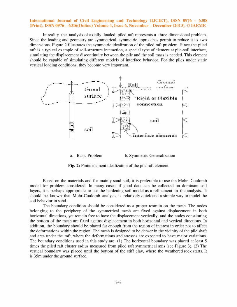
In reality the analysis of axially loaded piled raft represents a three dimensional problem.
Since the loading and geometry are symmetrical, symmetric approaches permit to reduce it to two
dimensions. Figure 2 illustrates the symmetric idealization of the piled raft problem. Since the piled
raft is a typical example of soil-structure interaction, a special type of element at pile-soil interface,
simulating the displacement discontinuity between the pile and the soil mass is needed. This element
should be capable of simulating different models of interface behavior. For the piles under static
vertical loading conditions, they become very important.
a. Basic Problem b. Symmetric Generalization
Fig. 2: Finite element idealization of the pile raft element
Based on the materials and for mainly sand soil, it is preferable to use the Mohr- Coulomb
model for problem considered. In many cases, if good data can be collected on dominant soil
layers, it is perhaps appropriate to use the hardening-soil model as a refinement in the analysis. It
should be known that Mohr-Coulomb analysis is relatively quick and a simple way to model the
soil behavior in sand.
The boundary condition should be considered as a proper restrain on the mesh. The nodes
belonging to the periphery of the symmetrical mesh are fixed against displacement in both
horizontal directions, yet remain free to have the displacement vertically, and the nodes constituting
the bottom of the mesh are fixed against displacement in both horizontal and vertical directions. In
addition, the boundary should be placed far enough from the region of interest in order not to affect
the deformations within the region. The mesh is designed to be denser in the vicinity of the pile shaft
and area under the raft, where the deformations and stresses are expected to have major variations.
The boundary conditions used in this study are: (1) The horizontal boundary was placed at least 5
times the piled raft cluster radius measured from piled raft symmetrical axis (see Figure 3). (2) The
vertical boundary was placed until the bottom of the stiff clay, where the weathered rock starts. It
is 35m under the ground surface.

International Journal of Civil Engineering and Technology (IJCIET), ISSN 0976 – 6308
(Print), ISSN 0976 – 6316(Online) Volume 4, Issue 6, November – December (2013), © IAEME
243
Fig. 3: Diagrammatic view of boundary condition using for modelling
3. PARAMETRIC STUDY
In the plane strain analysis using MIDAS GTS, the raft was modelled as a plate element,
while the piles are modelled as series of beam elements with the appropriate geometrical
parameters and geometrical boundaries as suggested by Prakoso and Kulhawy [16]. Different types
of case studies were carried out. The details are listed below:
Case-1: Un-piled raft 8m X 8m with thickness of 0.25m, 0.40m, 0.80m, 1.5m and 3m. Vertical
loading intensity 215 KN/m2.
Case-2: Un-piled raft 15m X 15m with thickness of 0.25m, 0.40m, 0.80m, 1.5m and 3m. Vertical
loading intensity 215 KN/m2.
Case-3: Piled raft, 8m X 8m raft thickness of 0.25m, 0.40m, 0.80m, 1.5m, and 3.0 m. The pile
spacing is 3d. The length of pile is 16m.
Case-4: Pile raft with raft thickness of 0.80m. Pile spacing varied as 3d, 4d and 5d and for each pile
spacing with vertical loading intensity of 215KN/m2, 430 KN/m2, and 645KN/m
2. The pile length is
16m.

International Journal of Civil Engineering and Technology (IJCIET), ISSN 0976 – 6308
(Print), ISSN 0976 – 6316(Online) Volume 4, Issue 6, November – December (2013), © IAEME
244
Case-5: Piled raft 8m X 8m and thickness 0.8m with 4,8,12 and 16 piles. The pile length is 16m. The
vertical loading intensity is 645 KN/m2.
Case-6: piled raft, 8m X 8m with raft thickness of 0.25m, 0.40m, 0.80m, 1.5m and 3.0m. Pile
spacing is 3d. The pile length is 16m. Vertical loading intensity 645KN/m2.
The serviceability load is 215 KN/m2, twice of serviceability load is 430 KN/m
2 and three
times of the serviceability load is 645 KN/m2. The thickness of the raft was varied to investigate the
effect of the relative stiffness of raft on settlements differential settlements, bending moments and
the proportion of the loads shared by the piles.
4. RESULTS AND DISCUSSIONS
4.1 settlement of un-piled raft
The Settlement of the un-piled raft was investigated for different sizes (8m and 15m) of raft and for
different raft thickness (0.25m, 0.4m, 0.8m, 1.5m and 3m), under a uniform intensity of vertical
loading. The settlement was normalized and can be described by the influence factor IR:
Where q is the uniform distribution loads acting on the raft, and Wi is the settlement of
raft, BR is the width of raft. Es and νs represent the young’s modulus and Poisson’s ratio of the soil
below the raft.
The distance from edge of the raft was normalized as X/BR to plot the results. The results
of the settlement analysis of the un-piled rafts of widths 8m and 15m are shown in Figures 4 and 5.
Fig. 4: Normalized vertical displacement of 8m X 8m square un-piled raft
International Journal of Civil Engineering and Technology (IJCIET), ISSN 0976 – 6308
(Print), ISSN 0976 – 6316(Online) Volume 4, Issue 6, November – December (2013), © IAEME
245
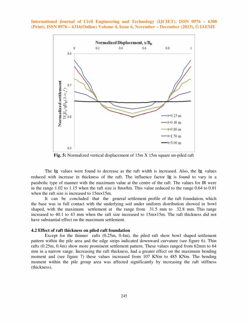
Fig. 5: Normalized vertical displacement of 15m X 15m square un-piled raft
The IR values were found to decrease as the raft width is increased. Also, the IR values
reduced with increase in thickness of the raft. The influence factor IR is found to vary in a
parabolic type of manner with the maximum value at the centre of the raft. The values for IR were
in the range 1.02 to 1.15 when the raft size is 8m×8m. This value reduced to the range 0.64 to 0.81
when the raft size is increased to 15m×15m.
It can be concluded that the general settlement profile of the raft foundation, which
the base was in full contact with the underlying soil under uniform distribution showed in bowl
shaped, with the maximum settlement at the range from 31.5 mm to 32.8 mm. This range
increased to 40.1 to 43 mm when the raft size increased to 15m×15m. The raft thickness did not
have substantial effect on the maximum settlement.
4.2 Effect of raft thickness on piled raft foundation Except for the thinner rafts (0.25m, 0.4m), the piled raft show bowl shaped settlement
pattern within the pile area and the edge strips indicated downward curvature (see figure 6). Thin
rafts (0.25m, 0.4m) show more prominent settlement pattern. These values ranged from 62mm to 64
mm in a narrow range. Increasing the raft thickness, had a greater effect on the maximum bending
moment and (see figure 7) these values increased from 107 KNm to 485 KNm. The bending
moment within the pile group area was affected significantly by increasing the raft stiffness
(thickness).

International Journal of Civil Engineering and Technology (IJCIET), ISSN 0976 – 6308
(Print), ISSN 0976 – 6316(Online) Volume 4, Issue 6, November – December (2013), © IAEME
246
Fig. 6: Effect of raft thickness on computed settlement of piled raft (q=645KN/m2
)
Fig. 7: Effect of raft thickness on bending moment of piled raft (q=645KN/m2
)

International Journal of Civil Engineering and Technology (IJCIET), ISSN 0976 – 6308
(Print), ISSN 0976 – 6316(Online) Volume 4, Issue 6, November – December (2013), © IAEME
247
For the case considered here, there is little effect on the maximum bending moment when the
raft thickness is increased beyond 1.5m.
It can be concluded that increasing the raft thickness of 0.25m do not influence the bending
moment in the pile. (as shown in figure 8) However it may be beneficial in resisting the punching
shear resulting from the piles and the column loadings.
Fig. 8: Summarized effect of raft thickness on piled raft performance (raft with 16 Piles, 16m long,
q = 645 KN/m2
)
4.3 Effects of pile spacing The effect of the pile spacing (3d to 5d) on the piled raft behavior is studied for the
bending moment and the settlement of the raft for three values of intensity of loading as 215 and 430
KN/m2. In this analysis, the raft thickness is 0.8m and the dimension of the raft will increase with
increased pile spacing. The piles are 0.7m diameter and 16m length. When the intensity of loading is
215 KN/m2, the reduction in pile spacing has the effect of reducing the raft settlement (see figure 9).
However the differential settlement is not affected much as the loading is very light.
International Journal of Civil Engineering and Technology (IJCIET), ISSN 0976 – 6308
(Print), ISSN 0976 – 6316(Online) Volume 4, Issue 6, November – December (2013), © IAEME
248
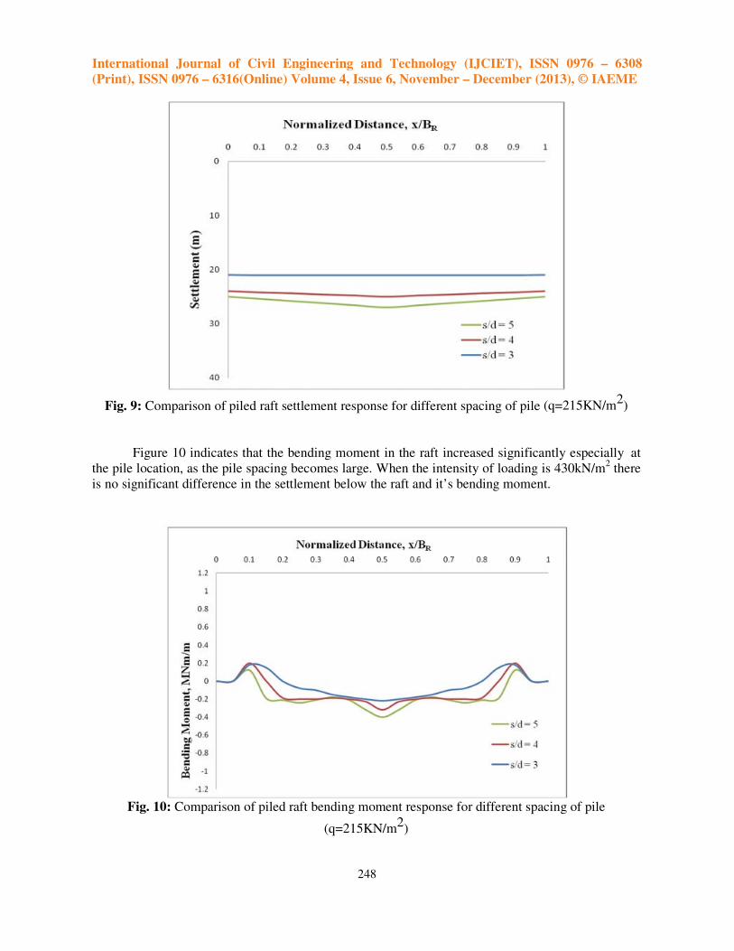
Fig. 9: Comparison of piled raft settlement response for different spacing of pile (q=215KN/m2
)
Figure 10 indicates that the bending moment in the raft increased significantly especially at
the pile location, as the pile spacing becomes large. When the intensity of loading is 430kN/m2 there
is no significant difference in the settlement below the raft and it’s bending moment.
Fig. 10: Comparison of piled raft bending moment response for different spacing of pile
(q=215KN/m2
)

International Journal of Civil Engineering and Technology (IJCIET), ISSN 0976 – 6308
(Print), ISSN 0976 – 6316(Online) Volume 4, Issue 6, November – December (2013), © IAEME
249
5. CONCLUDING REMARKS
A series of case studies were conducted on un-piled raft and piled raft foundation in
sandy subsoil condition. Although the examined piled raft conditions are limited, the following
conclusions can be drawn.
Under the working load intensity of 215 KN/m2 maximum settlements for 0.25m
thickness raft are 33mm and 44mm for the 8m×8m and 15m×15m rafts respectively. Increasing the
raft thickness to 3m reduced these maximum values to 31mm and 40mm respectively. The
corresponding bending moments are 0.026 and 0.017 MNm respectively. Increasing the raft
thickness to 3m increased these maximum values to 0.14 and 0.59 MNm respectively.
• When the raft thickness of the piled raft varied as 0.25, 0.4, 0.8, 1.5 and 3m, the corresponding
maximum settlements were 64, 63.3, 62.6, 62.3 and 62.2mm. The corresponding hogging
moments for the piled rafts with raft thicknesses of 0.25, 0.4, 0.8, 1.5 and 3m are 107, 160,
321, 446 and 485 KNm.
• Under an intensity of loading of 215 KN/m2, when the pile spacing is varied as 3d, 4d
and5d. The corresponding maximum settlements were 22, 26 and29mm. The hogging moment
in the raft centre developed as 0.197, 0.329, 0.369MNm, 0.42 and 0.44MNm. Similarly, the
pile loads increased from 0.265MN to 0.835MN in the edge pile and 0.475MN to 0.639MN
in the centre piles as the pile spacing increased. The pile head bending moment increased
greatly in both the edge piles and the centre piles and these ranges are 91.37KNm to
246.17KNm, and 28.91KNm to 69.44KNm respectively.
Further, it can be concluded that the foregoing simple example demonstrates the
following important points for practical design:
• The raft thickness affects differential settlement and bending moments, but has little effect on
load sharing or maximum settlement.
• Piles spacing plays an important role on the performance of piled raft foundation. It affects
greatly the maximum settlement, the differential settlement, the bending moment in the raft,
and the load shared by the piles.
• To reduce the maximum settlement of piled raft foundation, optimum performance is likely to
be achieved by increasing the length of the piles involved. While the differential
settlement, the maximum bending moment and the load sharing are not affected much by
increasing the pile lengths.
6. ACKNOWLEDGEMENTS
The authors wish to thank their colleagues Dr. S.A. Vasanwala in sardar Vallabhbhai
National Institute of Technology for many valuable discussions and assistance in the interpretation
of the data as presented in this paper. Special thanks would like to extend to Mr. Abid Ali for
providing the guidance of software.

International Journal of Civil Engineering and Technology (IJCIET), ISSN 0976 – 6308
(Print), ISSN 0976 – 6316(Online) Volume 4, Issue 6, November – December (2013), © IAEME
250
REFERENCES
[1]. Y.M. El-Mossallamy and B.Lutz(2009). “Special aspect related to the behavior of piled raft
foundation.” 17th
International Conference on Soil Mechanics & Geotechnical Engineering
ICSMGE, Alexandria/ Agypten.
[2]. Reza Ziaie_Moayed and Meysam Safavian. “Pile Raft Foundation Behavior with
Different Pile Diameters.” Assistant Professor, Department of Civil Engineering, Imam
Khomeini International University. Qazvin, Iran.
[3]. H.G.Poulos, J.C. Small and H. Chow(2011). “Piled Raft Foundations for Tall
Buildings”. Geotechnical Engineering Journal of the SEAGS & AGSSEA, Vol 42 No. 2 June
2011 ISSN 0046-5828.
[4]. Jinhyung Lee, Sangseom Jeong and Jae Young Kim. “Nonlinear 3D analysis of Piled Raft on
Soft Clay”. Graduate Student, School of Civil & Environmental Engineering, Yonsei Univ.,
Seoul, Korea.
[5]. Shoichi Nakai, Hideyuki Mano and Takashi Matsuda. “Analysis for Stress Distribution of
Piled Raft Foundations under Seismic Loading.” Department of Urban Environment
Systems, Faculty of Engineering, Chiba University Yayoicho 1-33, Inageku, Chiba 263-
8522, Japan.
[6]. Zhao Ming- Hua, Zhang Ling and Yang Ming-hui(2006). “Settlement Calculation for long-
short Composite Piled Raft Foundation”. College of Civil Engineering, Hunan University,
Changsha 410082, China.
[7]. Y.C. Tan and C.M. Chow. “Design of piled Raft Foundation on Soft Ground”.
Director, Gue & Partners sdn bhd, Kuala Lumpur, Malaysia.
[8]. Ningombam Thoiba Singh and Baleshwar Singh(2008). “Interaction Analysis for Piled Rafts
in Cohesive Soils”. The 12th
International conference of International Association for
Computer Methods and Advances in Geomechanics (IACMAG), 1-6 October, 2008, Goa,
India.
[9]. Zehai Cheng(2011). “Prediction and Measurement of Settlement of a Piled Raft Foundation
over Thick Soft Ground.” School of Civil Engineering and Architecture, Zhejiang University
of Science and Technology, China.
[10]. Meisam Rabiei(2011). “Parametric Study for Piled Raft Foundations”. Senior Geotechnical
Enginering Amirkabir University of Technology, Tehran, Iran.
[11]. Fa-Yun Liang(2003), Long-Zhu Chen and Xu-Guang Shi. “Numerical Analysis of
Composite Piled Raft with Cushion subjected to Vertical load. Computers and Geotechnics
30 (2003) 443-453.
[12]. L.Chen and H.G. Poulos(1993). “Analysis of Pile-Soil Interaction Under lateral Loading
Using Infinite and Finite Elements”. Computers and Geotechnics 15 (1993) 189-220.
[13]. Widjojo A. Prakoso and Fred H. Kulhawy(2001). “Contribution to Piled Raft Foundation
Design”. Journal of Geotechnical and Geoenvironmental Engineering, Vol. 127, No.1,
January, 2001.
[14]. Chow H.S.W and Small J.C. “Behaviour of Piled Rafts with Piles of Different Lengths
and Diameters under Vertical Loading”. Journal of Advances in Deep Foundations Vol. 132.
[15]. Chow Helen Sze Wai. “Analysis of Piled-Raft Foundation with Pile of Different length
and Diameters”. The University of Sydney School of Civil Engineering.
[16]. Gandhi S.R. and Maharaj D.K. (1996) “Settlement Behavior of Piled Raft Foundation”.
Indian Geotechnical Conference Madras.
[17]. Gandhi S.R. and Maharaj D.K. (1996), “Analysis of Piled Raft Foundation”. Indian
Geotechnical Conference Madras.

International Journal of Civil Engineering and Technology (IJCIET), ISSN 0976 – 6308
(Print), ISSN 0976 – 6316(Online) Volume 4, Issue 6, November – December (2013), © IAEME
251
[18]. Lin Der-Guey and Feng Zhrng-Yi (2006). “A Numerical study of Piled Raft Foundations”.
Journal of the Chinese Institute of Engineers, Vol. 29, No. 6, 1091- 1097.
[19]. Maharaj D.K.”3D Nonlinear Finite Element Analysis to study the Effect of Raft and Pile
Stiffness on the Load Settlement Behavior of Piled Raft Foundation”. Civil Engineering
Group Birla Institute of Technology and Science, Pilani, Rajasthan, India.
[20]. Poulos H.G. “Piled Raft Foundations: Design and Applications”. Journal of Geotechnique
Vol. 51, No.2, 95-113.
[21]. Poulos H.G. “Simplified Design Procedure for Piled Raft Foundations”. Coffey Geoscience
Pty.Ltd.& the university of Sydney, Australia.
[22]. Poulos H.G.(2001). ”Methods of Analysis of Piled Raft Foundations”, Journal of
International Society of Mechanics and Geotechnical Engineering.
[23]. Small J.C. and Poulos H.G.”Non-linear Analysis of Piled Raft Foundations”.
[24]. Clancy P. and Randolph M.F. (1993).”An Approximate Analysis procedure for Piled Raft
Foundations.” International Journal Numerical and Analytical Methods in Geomesh, London,
17(12), 849-869.
[25]. Hameedaswad Mohammed, “The Influence of Road Geometric Design Elements on
Highway Safety”, International Journal of Civil Engineering & Technology (IJCIET),
Volume 4, Issue 4, 2013, pp. 146 - 162, ISSN Print: 0976 – 6308, ISSN Online: 0976 – 6316.
[26]. M. S. Dixit and K. A. Patil, “Experimental Estimate of Ultimate Bearing Capacity and
Settlement for Rectangular Footings”, International Journal of Civil Engineering &
Technology (IJCIET), Volume 4, Issue 2, 2013, pp. 337 - 345, ISSN Print: 0976 – 6308,
ISSN Online: 0976 – 6316.
[27]. M. Alhassan and I. L. Boiko, “Effect of Vertical Cross-Sectional Shape of Foundation and
Soil Reinforcement on Settlement and Bearing Capacity of Soils”, International Journal of
Civil Engineering & Technology (IJCIET), Volume 4, Issue 2, 2013, pp. 80 - 88, ISSN Print:
0976 – 6308, ISSN Online: 0976 – 6316.