international journal of circuits, … from global system for mobile communication, ... the cellular...
TRANSCRIPT
Abstract— The paper presents the construction of a locator to
determine locations using GSM technology. The locator´s design will be tailored especially for the mobile security of more expensive items. The theoretical part will discuss different ways of positioning - using GSM technology in detail. In the conclusion, the benefits of GSM localisation for security applications are evaluated and compared to satellite locations
Keywords— locator, GSM, mobile security, satellite, mobile network, mobile station .
I. INTRODUCTION HE first mention of mobile networks, i.e. portable
communications, come from the Nordic countries - Finland, Norway, Sweden and Denmark, especially. Mobile communications were used above all for maritime transport; and had two basic differing features from the existing networks. The greatest drawback was the mutual incompatibility of individual networks; while the second distinct feature was (the use of) the analogue technologies that were used for the operation of these networks.
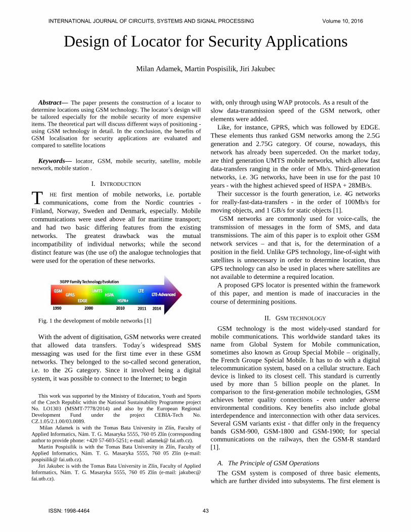
Fig. 1 the development of mobile networks [1] With the advent of digitisation, GSM networks were created
that allowed data transfers. Today´s widespread SMS messaging was used for the first time ever in these GSM networks. They belonged to the so-called second generation, i.e. to the 2G category. Since it involved being a digital system, it was possible to connect to the Internet; to begin
This work was supported by the Ministry of Education, Youth and Sports of the Czech Republic within the National Sustainability Programme project No. LO1303 (MSMT-7778/2014) and also by the European Regional Development Fund under the project CEBIA-Tech No. CZ.1.05/2.1.00/03.0089.
Milan Adamek is with the Tomas Bata University in Zlín, Faculty of Applied Informatics, Nám. T. G. Masaryka 5555, 760 05 Zlín (corresponding author to provide phone: +420 57-603-5251; e-mail: adamek@ fai.utb.cz).
Martin Pospisilik is with the Tomas Bata University in Zlín, Faculty of Applied Informatics, Nám. T. G. Masaryka 5555, 760 05 Zlín (e-mail: pospisilik@ fai.utb.cz).
Jiri Jakubec is with the Tomas Bata University in Zlín, Faculty of Applied Informatics, Nám. T. G. Masaryka 5555, 760 05 Zlín (e-mail: jakubec@ fai.utb.cz).
with, only through using WAP protocols. As a result of the slow data-transmission speed of the GSM network, other elements were added.
Like, for instance, GPRS, which was followed by EDGE. These elements thus ranked GSM networks among the 2.5G generation and 2.75G category. Of course, nowadays, this network has already been superceded. On the market today, are third generation UMTS mobile networks, which allow fast data-transfers ranging in the order of Mb/s. Third-generation networks, i.e. 3G networks, have been in use for the past 10 years - with the highest achieved speed of HSPA + 28MB/s.
Their successor is the fourth generation, i.e. 4G networks for really-fast-data-transfers - in the order of 100Mb/s for moving objects, and 1 GB/s for static objects [1].
GSM networks are commonly used for voice-calls, the transmission of messages in the form of SMS, and data transmissions. The aim of this paper is to exploit other GSM network services – and that is, for the determination of a position in the field. Unlike GPS technology, line-of-sight with satellites is unnecessary in order to determine location, thus GPS technology can also be used in places where satellites are not available to determine a required location.
A proposed GPS locator is presented within the framework of this paper, and mention is made of inaccuracies in the course of determining positions.
II. GSM TECHNOLOGY GSM technology is the most widely-used standard for
mobile communications. This worldwide standard takes its name from Global System for Mobile communication, sometimes also known as Group Special Mobile – originally, the French Groupe Spécial Mobile. It has to do with a digital telecommunication system, based on a cellular structure. Each device is linked to its closest cell. This standard is currently used by more than 5 billion people on the planet. In comparison to the first-generation mobile technologies, GSM achieves better quality connections - even under adverse environmental conditions. Key benefits also include global interdependence and interconnection with other data services. Several GSM variants exist - that differ only in the frequency bands GSM-900, GSM-1800 and GSM-1900; for special communications on the railways, then the GSM-R standard [1].
A. The Principle of GSM Operations The GSM system is composed of three basic elements,
which are further divided into subsystems. The first element is
Design of Locator for Security Applications Milan Adamek, Martin Pospisilik, Jiri Jakubec
T
INTERNATIONAL JOURNAL OF CIRCUITS, SYSTEMS AND SIGNAL PROCESSING Volume 10, 2016
ISSN: 1998-4464 43
external telecommunication networks. As has already been mentioned, GSM systems are open to other telecommunication networks; which include the PSTN publicly-switched network - also known as JTS, various ISDNs and many others [2].
The second element is the operators. These are organisations engaged in the telecommunications field and who manage GSM systems - especially however, in economic or financial terms. Above all, they take care of administrative activities and the distribution of mobile phones and relevant SIM cards. Another term for this element is Service Provider (SP) - a company providing operator services under its own account, but without its own network - leasing them rather, from an operator. It is not uncommon for these services to be associated with maintaining networks and expanding them into remote areas [2].
The third most important element of GSM networks is the cellular system. Thanks to this system, one can make calls all over the world. The cellular GSM system consists of three basic elements:
• The BSS Base Station Subsystem
• The NSS Network and Switching Subsystem
• The OSS Operation and Support Subsystem
These three internal constituents are known as fixed, or also – (as) stationary, and come into contact with the external mobile elements in the form of mobile stations´ users. Minimal cooperation is required between the internal and external components of GSM systems [2].
Fig. 2 GSM scheme [3]
B. Mobile Stations External GSM network users communicate with a network
via a mobile device. According to specification, the mobile device is understood to mean a mobile receiver/transmitter and a SIM module. The mobile device thus, is formed of a fully-duplex transceiver that communicates in a digital manner with base-stations. SIM cards are used as an identificator in GSM networks. By identificators, we mean the basic information about the rightful holder of a SIM card with the appropriate operator – also known as the International Mobile Subscriber
Identity (IMSI). The SIM card is protected by a four-digit PIN code, which can be easily edited. Its secondary additional function is memory for the phone-book and SMS messages. Without SIM cards, only the emergency number 112 is active, which is a manufacturers´ security measure [2].
Fig. 3 a SIM card [4]
C. The BSS Base Station Subsystem The GSM system is made up of cells, which cover an area
of one-to-three kilometers in diameter. In low population density areas, this can be up to 35 km; while in large cities, the microcell coverage dimensions is from 300 to 500 m. With such dense coverage, problems can occur with handovers – i.e. the transmission of a continuous call from one cell to another. Smooth call handovers should be ensured at speeds up to 200 km/h. A BSS itself consists of a Base Transceiver Station (BTS) and a Base Station Controller (BSC). For wide-range coverage, a 9x1 structure is most commonly used.
III. GSM SERVICES The GSM Standard provides many services that we take for
granted. Standard calls and SMS services also include data services that are used in the GSM locator´s design.
A. Phone Calls The most important function of the GSM network is making
a phone call itself. This seemingly basic function is not quite as simple as it seems. The basic requirement is a mobile device that is registered to the network and which has a sufficiently strong signal and is equipped with an activated provider/operator SIM card.
Due to increased network capacity, a call is a complex process. The user dials the appropriate number on their mobile device, this request is sent to the nearest available PBX switchboard to which the cell is linked. This then checks the user's authority to make a call and then determines the home PBX of the number being called according to the international MSISDN standard and forwards the call to the number. The called number´s PBX receives this request and checks its legitimacy to accept the call.
If the called number is active, it is located in the LA (Local Area) PBX data, which determines the approximate location of the dialed number. This is followed by the paging process, i.e.
INTERNATIONAL JOURNAL OF CIRCUITS, SYSTEMS AND SIGNAL PROCESSING Volume 10, 2016
ISSN: 1998-4464 44

tracing the dialed number. This process is done by polling the PBXs at each BTS station asking if the number dialed is reporting to one of them. After tracing the BTS station, the called number starts ringing and - after acceptance, the required call can take place.
B. SMS Short text messages - or the Short Message Service is the
most popular GSM network service. It uses a standardised communication protocol. 160 characters, i.e. 1120 bits, are allowed for one SMS message. The 7-bit ASCII table is used for character encoding. For characters that are not included in this table, 16-bit UCS-2s are used to encode, and the message is thus shortened to 70 characters. Short text messages are transmitted via signaling channels, which are normally used to signal incoming calls, outgoing calls requests, the allocation of communication bandwidth and other information of a technical nature. SMS messages are divided into two basic types:
1) Cell Broadcast (CB) messages are available for all mobile stations; it only depends on the settings of individual devices. These are for instance, informational messages about the weather, news, culture, sports, etc.
2) Point-to-Point (PP) messages are classic SMS messages - used by most users. This is the transmission of text messages from one telephone number to another.
C. WAP Wireles Application Protocol The WAP Wireless Application Protocol service is a set of
protocols that allow mobile devices to access the Internet. These protocols were developed in 1998 by the WAP Forum. The main aim was to make the Internet accessible to weaker, less powerful devices.
D. Data service Since GSM is a digital network, it enables data transfers.
Thus, we can exploit mobile networks as a means for connecting to the Internet or using it directly on one´s mobile device.
Fig. 4 the WAP architecture [5]
Data transmissions are enabled by using different protocols like CSD (Circuit Switched Data), HSCSD (High Speed Circuit Switched Data), GPRS (General Plan Packet Radio Service) and EDGE (Enhanced Data Rates for Evolution).
E. MMS Multimedia Messaging Service MMS is used to transfer media files between devices that
support this standard. The basic prerequisite for the functioning of this service are fast data transmission GPRS EDGE best. Sent MMS will be stored on a server with sufficient capacity, from which the beneficiary after connecting picked up. The service allows the transmission of different data, text, images or video. For this it is necessary to use the language SMIL Synchronized Multimedia Integration Language. This language is similar to the HTML language for creating Web pages. SMIL encapsulates the message and attached data into one package, which is then distributed according to the needs of one or more frames, which are gradually being sent to the target. Each frame is then transmitted individually area reserved for data and text. This principle is needed to make the data to be transmitted despite low network transfer rate. For MMS valid data limit up to 100 kB [6].
F. GPRS Generel Packet Radio Service GPRS system is used for data transfer packing. Transmitted
data are divided into packets, labeled and packaged. Recipient after receiving all the data again unpacks and assembles the data into its original consistency. Collapsed data to the recipient may even wander in different ways. The maximum transmission rate layers GPRS is 171.2 kB/s, in practice, this speed can not be achieved.
The transfer speed is also affected coding. GPRS uses CS scheme with various security against errors arising during transmission. Standards have been defined by the organization ETSI.
G. EDGE Enhanced Date Rates for Evolution Transferring data via EDGE technology increases the
transmission speed GSM network. Sometimes it is also known as EGPRS. This technology began to develop by Ericsson and gradually spread across the market. Advances generation GSM network to 2.75G. EDGE technology makes it possible to achieve similar speeds for 3G networks while using the 2G network resources. As with GPRS uses EDGE packet transmission occurs only to a change of modulation and channel coding Gaussian Minimum-Shift Keying. This technology is supplemented efficient eight-speed 8-PSK modulation Eight-Phase-Shift Keying. With these changes, the technology allows for higher transmission rates, at the expense of a smaller coverage. Incorporation of EDGE was very easy because it preserves both the width of the individual transmission channels of 200 kHz, and the division of time multiplex into eight parts - timeslots. Transmission speed can reach 384 kB/s.
Given that EDGE technology brings to the GPRS system with only a new and improved modulation coding schemes are
INTERNATIONAL JOURNAL OF CIRCUITS, SYSTEMS AND SIGNAL PROCESSING Volume 10, 2016
ISSN: 1998-4464 45

the same as the device class. Currently, most mobile phone supports data transfer via EDGE technology [5].
IV. GSM LOCALISATION The main assumption of GSM localisation is the
deployment of base stations across the whole structure of the GSM network. The area is divided into cells, whereby one cell is served by one BTS station or the BTS station is located at the interface and serves multiple cells – in such cases, we talk about sectors. The radius and the cell density are dependent on the estimated number of active mobile devices, or the population density in the given area. The number of BTS stations significantly affects the accuracy of the determination of a location [6].
Mobile stations communicate at any one instant with just one BTS station, but have information about other available BTS stations. BTS stations have a fixed location and are stationary, unlike mobile devices [6].
The following two identifiers important are for localisation:
1) The cell ID is the unique identifier of the BTS base station.
2) The Timing Advance (TA) is the parameter representing the signal propagation time between the mobile device and the network.
A. Cell ID Each cell in a network has its own unique identifier. Its
uniqueness is ensured within the framework of an operator in the given state. When logging into the network, the the mobile device can directly determine its location. Accuracy depends on the size of the area covered by the BTS station. Cell Sector is used for more accurate sectorisation - where the cell is divided into three sectors, which allows a two-thirds greater degree of precision [7].
Actual position
Designated position
Fig. 5 the Cell ID [5]
The estimated location of the mobile device is located in the centre of the field so created. TDMA specification requires that the chain manages to travel to the BTS station and back within half of the reserved 577 μs (microseconds). After deducting time caused by losses and signal quality, 233 microseconds remain. Within this time, the signal has to travel
to the BTS station and back. If we multiply this radio signal speed data, we find that the signal may cover a track of up to 70,000 meters. This also sets the maximum radius of the BTS to 35 km [2].
B. TA Timing advance The TA Identifier gives us the delay value between the
mobile device and the BTS station. The value can be determined directly during a telephone call, after activation of the service menu, with values from 0 to 63. The higher the value, the farther one is from the BTS station with which it is communicating. This parameter is stored in 4 bits, and if one multiplies this value by 547 m, we can ascertain the distance from the BTS station [7].
Fig. 6 TA identifier [5]
V. GSM LOCALISATION METHODS With this knowledge of the important parameters of the
GSM network and an adequate list of the greatest possible number of BTS stations, we can perform localisation itself by exploiting the GSM network.
A. Cell of Origin Cell of Origin (COO) is a method based on the cellular
structure of the GSM network. The top priority for this method is the Cell ID parameter, hence the accuracy of this method. In densely populated areas, the tolerance is about 200 meters; in less populated areas, the tolerance can theoretically reach up to 35 kilometers [6].
Fig. 7 the COO method [8]
INTERNATIONAL JOURNAL OF CIRCUITS, SYSTEMS AND SIGNAL PROCESSING Volume 10, 2016
ISSN: 1998-4464 46
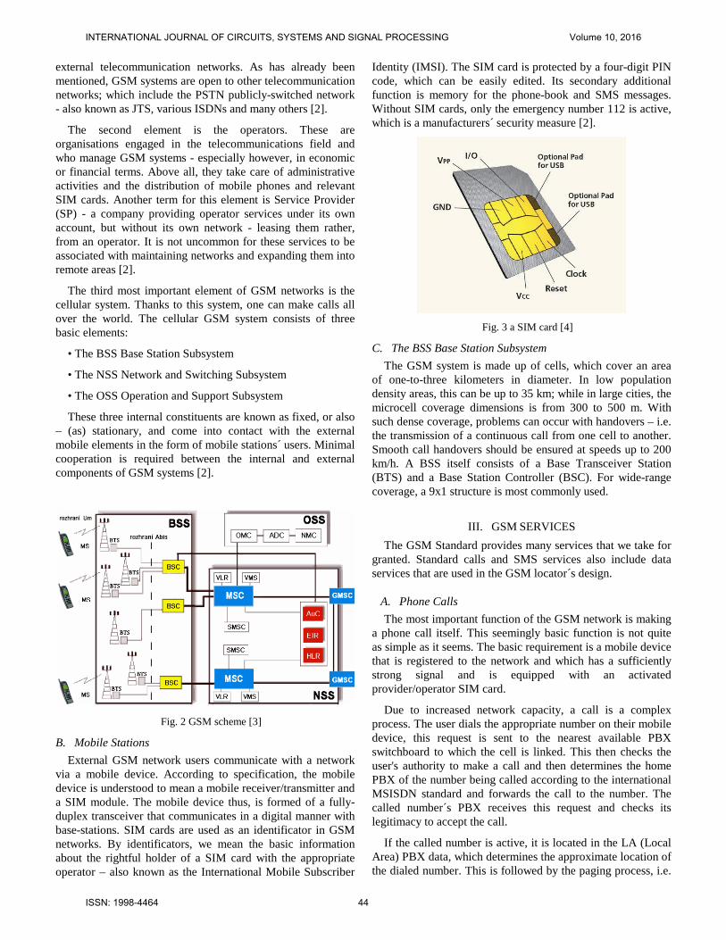
B. TA method TA is a method based on a knowledge of the distance to the
mobile station from at least three stations BTS. For the method it is necessary to adjust the mobile station so that we knew how to provide the requested information. After usually sufficient new firmware or applications called SIM Toolkit. When properly using this method, we can refine the tolerance of around 125 m [8].
Fig. 8 the TA method [8]
C. Time-Of-Arrival Time-Of-Arrival (TOA) is a method based on the TA
method. Its basis is the knowledge of the distances from three BTS stations. This information however, is obtained from the BTS base stations. For this, we need mutual synchronisation - which does not normally occur. The method requires additional investments; while in urban areas above all, it does not produce better results than the COO method [6].
D. Enhanced Cell Global Identity Enhanced Cell Global Identity (E-CGI) is a method that
complements and rounds out the Cell of Origin and Timing advance methods for measuring signal levels. The E-CGI method is used for calculating the distance of the mobile device from the BTS base-station. Areas with the most likely occurrence are identified according to the measured signal levels at the site/location of the mobile device and the knowledge of the transmission peformance of the BTS base stations.
Fig. 9 the E-OTD method [8]
The accuracy of this method is around 50-550 meters for densely populated areas, and 250 m to 8 km in rural areas with lower populations [7].
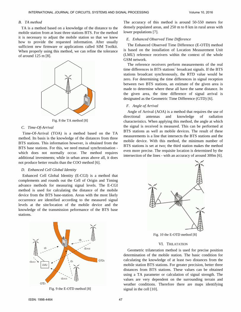
E. Enhanced Observed Time Difference The Enhanced Observed Time Difference (E-OTD) method
is based on the installation of Location Measurement Unit (LMU) reference receivers within the context of the whole GSM network.
The reference receivers perform measurements of the real time differences in BTS stations´ broadcast signals. If the BTS stations broadcast synchronously, the RTD value would be zero. For determining the time differences in signal reception between two BTS stations, an estimate of the given area is made to determine where these all have the same distance. In the given area, the time difference of signal arrival is designated as the Geometric Time Difference (GTD) [6].
F. Angle of Arrival Angle of Arrival (AOA) is a method that requires the use of
directional antennas and knowledge of radiation characteristics. When applying this method, the angle at which the signal is received is measured. This can be performed at BTS stations as well as mobile devices. The result of these measurements is a line that intersects the BTS stations and the mobile device. With this method, the minimum number of BTS stations is set at two; the third station makes the method even more precise. The requisite location is determined by the intersection of the lines - with an accuracy of around 300m [6].
Fig. 10 the E-OTD method [8]
VI. TRILATATION Geometric trilateration method is used for precise position
determination of the mobile station. The basic condition for calculating the knowledge of at least two distances from the mobile station BTS stations. For greater precision, better three distances from BTS stations. These values can be obtained using a TA parameter or calculation of signal strength. The values are very dependent on the surrounding terrain and weather conditions. Therefore there are maps identifying signal in the cell [10].
INTERNATIONAL JOURNAL OF CIRCUITS, SYSTEMS AND SIGNAL PROCESSING Volume 10, 2016
ISSN: 1998-4464 47

Fig. 11 the determining map [10]
The calculation is thus carried out from a knowledge of the position of BTS stations (x1, x2, y1, y2) and of the distances from each mobile station BTS station (d1, d2). The calculations are obtained eventual intersection of two circles, that is our position [10].
xa = xp – d2 * sin(a) = x2 – d1 * cos(a) – d2 * sin(a) (1) ya = yp – d2 * cos(a) = y2 – d1 * sin(a) + d2 * cos(a) (2) xb = xp – d2 * sin(a) = x2 – d1 * cos(a) – d2 * sin(a) (3)
yb = yp – d2 * cos(a) = y2 – d1 * sin(a) + d2 * cos(a) (4) For this case, the position of the mobile station is equal to
the coordinates (xa, xb), in other cases the position of a particular trilateration with another BTS station [10].
Fig. 12 the trilateration [10]
VII. GSM LOCATOR REALISATION In the GSM locator design process, priority was given to
two basic requirements – namely, the requirement for small dimensions of the locator, and the requirement for long battery life. The Cell of Origin (COO) method was used for localisation by the locator.
A. The Control module The basis of the whole system is the GSM module in which
the SIM card is placed. The locator uses the smallest GSM module on the market from Enfora - the Enabler IIIG, type: GSM0308.
The module is functional both in Europe and in the USA. It does not have a screen, microphone or keyboard – there is no need for these components [12].
The module can communicate across all GSM wave-bands, including GPRS data transmission. It includes a small antenna. Energy consumption, when demanded, is around 230 mA and only 10 mA in idle mode. These values are very low and contribute to extending the overall device battery life [12].
Fig. 13 the GSM module [12]
B. The battery charging circuit Charging module for lithium ion batteries has been chosen
with regard to the overall dimensions of the device. It allows continuous regulation of charging the battery with a nominal voltage of 3.7 V. Charging takes place via a standardized mini USB connector. The module is equipped with LEDs that indicate the individual states. When charging the battery LED lights up when the battery is fully charged, the LED turns off [12].
Fig. 14 the Diagram of the charging module [12]
Fig. 15 the Charging module [12]
C. The Control module The PCB for controlling the circuit includes an interface for
communicating with the quad-band GSM/GPRS module, microcontroller and microchip, as well as an on/off switch and an SOS button.
D. The operating principle of the GSM locator The control circuit is programmed in a loop that waits for a
certain event. This event initialises the entire programme and it
INTERNATIONAL JOURNAL OF CIRCUITS, SYSTEMS AND SIGNAL PROCESSING Volume 10, 2016
ISSN: 1998-4464 48
starts to search for the position. Such events may include the following:
• Incoming phone calls. In this case, the device hangs up the call and starts detecting its current position. After finding it, it sends the data to the caller's number. The caller's number must be displayed correctly - it cannot be hidden, and must be on the list in the GSM locator´s memory [13].
• Incoming SMS messages. The device, when receiving SMS messages, distinguishes whether it is a configuration SMS message or a request for it to send its current location [13].
• Pressing the SOS button. This feature is optional, and allows the sending of the current location after being pressed. Its practical use is only for tracking people. The SOS button cannot be used to secure a bicycle, only for testing purposes [13]. • The last way of determining the location is automatic initialisation. This can be set with a view to the time parameter, as well as to change the location of the device. The GSM module does not contain a gyroscope, but recognises changes in location according to changes in the actual BTS station [14].
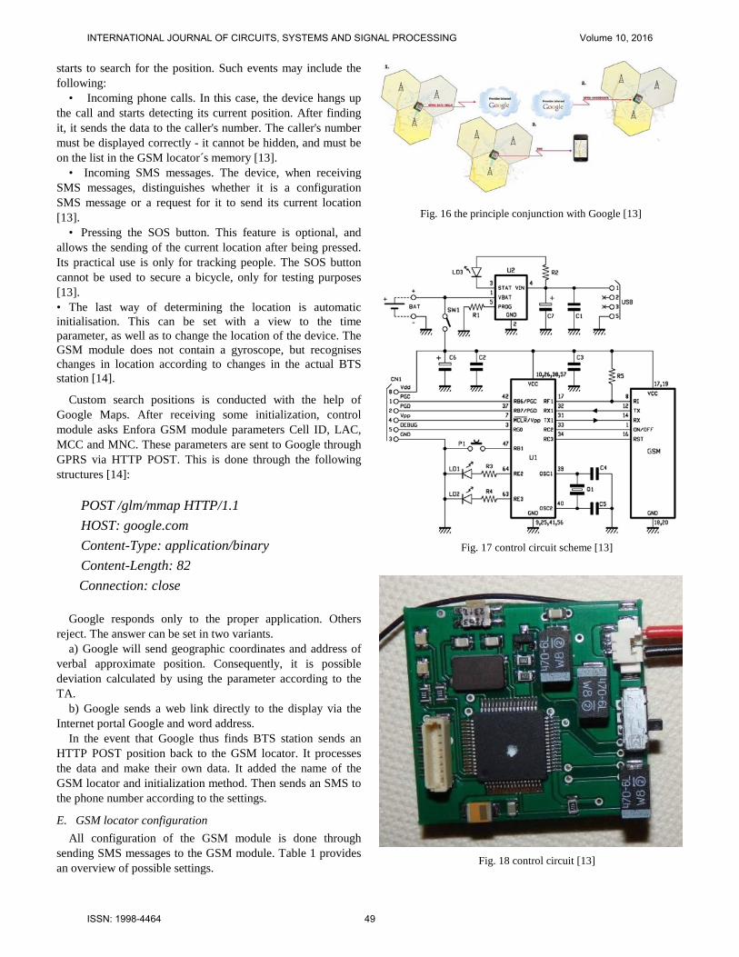
Custom search positions is conducted with the help of Google Maps. After receiving some initialization, control module asks Enfora GSM module parameters Cell ID, LAC, MCC and MNC. These parameters are sent to Google through GPRS via HTTP POST. This is done through the following structures [14]:
POST /glm/mmap HTTP/1.1 HOST: google.com Content-Type: application/binary Content-Length: 82
Connection: close Google responds only to the proper application. Others
reject. The answer can be set in two variants. a) Google will send geographic coordinates and address of
verbal approximate position. Consequently, it is possible deviation calculated by using the parameter according to the TA.
b) Google sends a web link directly to the display via the Internet portal Google and word address.
In the event that Google thus finds BTS station sends an HTTP POST position back to the GSM locator. It processes the data and make their own data. It added the name of the GSM locator and initialization method. Then sends an SMS to the phone number according to the settings.
E. GSM locator configuration All configuration of the GSM module is done through
sending SMS messages to the GSM module. Table 1 provides an overview of possible settings.
Fig. 16 the principle conjunction with Google [13]
Fig. 17 control circuit scheme [13]
Fig. 18 control circuit [13]
INTERNATIONAL JOURNAL OF CIRCUITS, SYSTEMS AND SIGNAL PROCESSING Volume 10, 2016
ISSN: 1998-4464 49
VIII. TESTING THE PROPOSED GSM LOCATOR The GSM locator was tested in two ways. In the first case,
the locator was sited on moving object (an automobile) and the reliability of the locator was determined. In the second, the test was performed on a randomly selected location, i.e. the GSM locator had a fixed location.
A. Testing the reliability of a moving GSM locator The proposed locator was fitted to a car which was moving
around in a densely-settled area and then in an area with low population density. Fig. 19 depicts the testing of the locator in a heavily-settled area.
Tab. 1 GSM locator configuration [13]
Fig. 19 map of a high-density settlement area
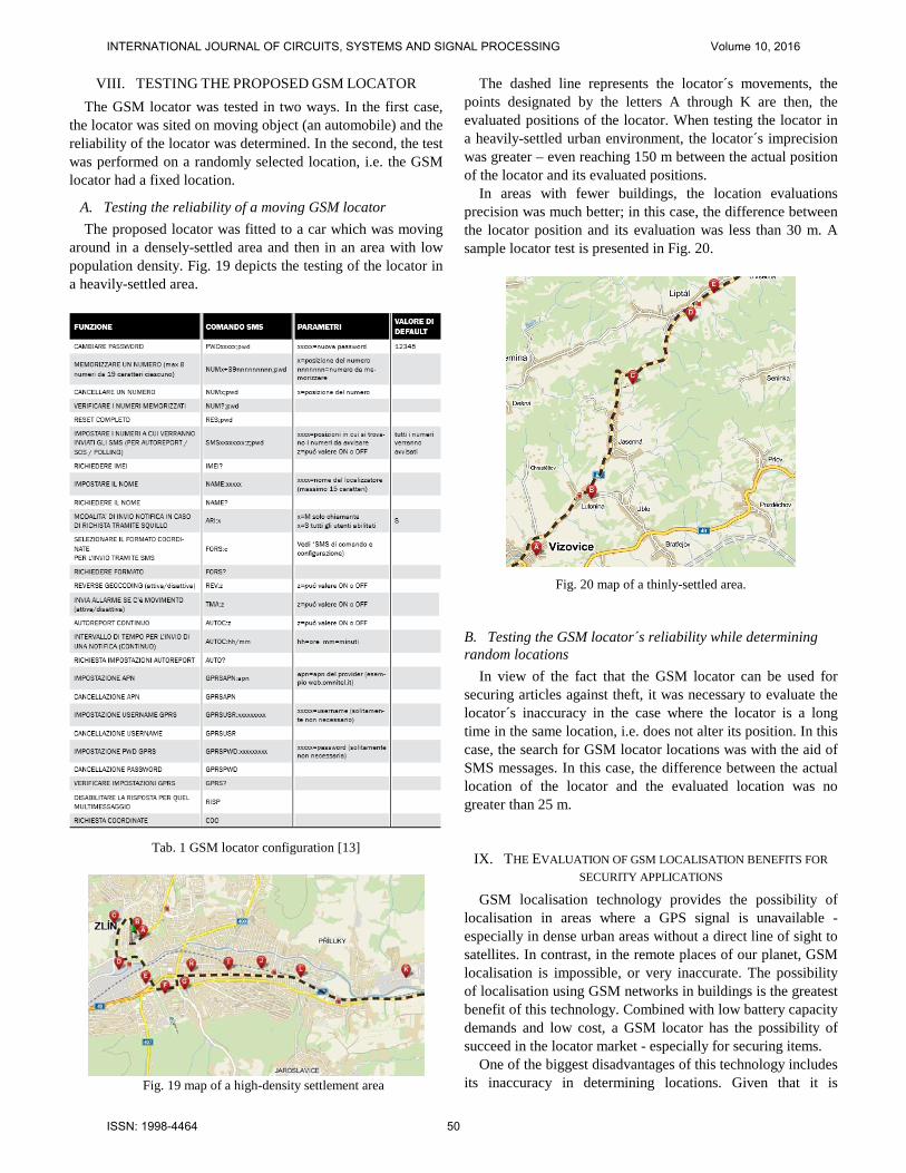
The dashed line represents the locator´s movements, the points designated by the letters A through K are then, the evaluated positions of the locator. When testing the locator in a heavily-settled urban environment, the locator´s imprecision was greater – even reaching 150 m between the actual position of the locator and its evaluated positions.
In areas with fewer buildings, the location evaluations precision was much better; in this case, the difference between the locator position and its evaluation was less than 30 m. A sample locator test is presented in Fig. 20.
Fig. 20 map of a thinly-settled area.
B. Testing the GSM locator´s reliability while determining random locations
In view of the fact that the GSM locator can be used for securing articles against theft, it was necessary to evaluate the locator´s inaccuracy in the case where the locator is a long time in the same location, i.e. does not alter its position. In this case, the search for GSM locator locations was with the aid of SMS messages. In this case, the difference between the actual location of the locator and the evaluated location was no greater than 25 m.
IX. THE EVALUATION OF GSM LOCALISATION BENEFITS FOR SECURITY APPLICATIONS
GSM localisation technology provides the possibility of localisation in areas where a GPS signal is unavailable - especially in dense urban areas without a direct line of sight to satellites. In contrast, in the remote places of our planet, GSM localisation is impossible, or very inaccurate. The possibility of localisation using GSM networks in buildings is the greatest benefit of this technology. Combined with low battery capacity demands and low cost, a GSM locator has the possibility of succeed in the locator market - especially for securing items.
One of the biggest disadvantages of this technology includes its inaccuracy in determining locations. Given that it is
INTERNATIONAL JOURNAL OF CIRCUITS, SYSTEMS AND SIGNAL PROCESSING Volume 10, 2016
ISSN: 1998-4464 50

impossible to predict where stolen articles fitted with a GSM locator can end up, we cannot rely on an acceptable level of tolerance which the device indicates in densely populated areas. Unfortunately, when using a GSM locator, it can happen that when the device sends us information about its location this is so distorted that localisation is virtually impossible.
The GSM locator presented in this paper was designed with the intent to protect bicycles against theft. The locator can be placed under the seat, where both types of GSM locator can be placed. The first type of locator has a built-in battery for its operations; with the second type, the battery is located in the saddle tube, which holds the seat.
Fig. 21 random location test
Fig. 22 installation of the GSM locator
REFERENCES [1] P. Moos, T. Zelinka, V. Malinovsky, Telecommunication Services.
Prague: CVUT, 2007, ch. 3. [2] P. Brabenec. (2013, Januar 28). Principles of operation of the GSM
network. [Online]. Available: http://www.brabenecz.wz.cz/principy_fungovani_gsm.htm
[3] O. Dudek. (2015, March 15). Structure of the GSM network. [Online]. Available: http://radio.feld.cvut.cz/personal/mikulak/MK/MK05_semestralky/ Struktura_GSM_Ondrej_Dudek.pdf
[4] S. Shafi. (2015, February 2). SIM card. [Online]. Available: http://uthmag.com/wp-content/uploads/2012/07/SIM-Cards.jpg
[5] K. Karanoka. (2014, December 20). WAP Push Process. [Online]. Available: http://upload.wikimedia.org/wikipedia/commons/f/f2/WAP_Push_Process.jpg
[6] M. Kopp. (2014, December 10). Methods for determining the location of mobile devices in the GSM network. [Online]. Available: http://radio.feld.cvut.cz/personal/mikulak/MK/MK06_semestralky/ UrceniPolohyvGSM_KoppM.pdf
[7] L. Szteffek. (2015, January 18). GSM localization. [Online]. Available: http://www.lukassztefek.cz/files/fit/projekt_sen.pdf
[8] M. Orlich. (2014, November 19). The localization method in GSM. [Online]. Available: http://access.feld.cvut.cz/view.php?cisloclanku=2006022801
[9] L. Enfora. (2014, October 24). Enfora Enabler IIIG. [Online]. Available: http://www.farnell.com/datasheets/876254.pdf.
[10] C. Srenk. (2015, January 12). Localizzatore tramite rete GSM. [Online]. Available: http://www.futuraelettronica.net/pdf_ita/7100-FT833M.pdf
[11] J. Novak. (2014, December 8). GSM localization. [Online]. Available: https://www.t-mobile.cz
[12] K. Rak. (2014. November 11). PHPBB Group. [Online]. Available: http://www.futurashop.it/forum_/
[13] M. Pospisilik, L. Kouril, I. Motyl, M. Adamek, “Single and Double Layer Spiral Planar Inductors Optimisation with the Aid of Self-Organising Migrating Algorithm”, in Proc. 11th WSEAS International Conference on Signal Processing, Computational Geometry and Artificial Vision. Venice, 2011, pp. 104 - 108.
[14] M. Pospisilik, L. Kouril, I. Motyl, M. Adamek, “Switching Power Supply for an Autonomous Monitoring System”, in Proc. WSEAS International Conference on Systems: Latest Trends on Systems. Greece, 2010. pp. 431-434.
INTERNATIONAL JOURNAL OF CIRCUITS, SYSTEMS AND SIGNAL PROCESSING Volume 10, 2016
ISSN: 1998-4464 51