international iso standard 9972 -...
TRANSCRIPT

Reference numberISO 9972:2006(E)
© ISO 2006
INTERNATIONAL STANDARD
ISO9972
Second edition2006-05-01
Thermal performance of buildings — Determination of air permeability of buildings — Fan pressurization method
Performance thermique des bâtiments — Détermination de la perméabilité à l'air des bâtiments — Méthode de pressurisation par ventilateur
Licensed to EURL FRANCHOIS / Mr. FRANCHOISISO Store order #: 10-1230851/Downloaded: 2011-10-12Single user licence only, copying and networking prohibited
ISO 9972:2006(E)
PDF disclaimer This PDF file may contain embedded typefaces. In accordance with Adobe's licensing policy, this file may be printed or viewed but shall not be edited unless the typefaces which are embedded are licensed to and installed on the computer performing the editing. In downloading this file, parties accept therein the responsibility of not infringing Adobe's licensing policy. The ISO Central Secretariat accepts no liability in this area.
Adobe is a trademark of Adobe Systems Incorporated.
Details of the software products used to create this PDF file can be found in the General Info relative to the file; the PDF-creation parameters were optimized for printing. Every care has been taken to ensure that the file is suitable for use by ISO member bodies. In the unlikely event that a problem relating to it is found, please inform the Central Secretariat at the address given below.
© ISO 2006 All rights reserved. Unless otherwise specified, no part of this publication may be reproduced or utilized in any form or by any means, electronic or mechanical, including photocopying and microfilm, without permission in writing from either ISO at the address below or ISO's member body in the country of the requester.
ISO copyright office Case postale 56 • CH-1211 Geneva 20 Tel. + 41 22 749 01 11 Fax + 41 22 749 09 47 E-mail [email protected] Web www.iso.org
Published in Switzerland
ii © ISO 2006 – All rights reserved
Licensed to EURL FRANCHOIS / Mr. FRANCHOISISO Store order #: 10-1230851/Downloaded: 2011-10-12Single user licence only, copying and networking prohibited
ISO 9972:2006(E)
© ISO 2006 – All rights reserved iii
Contents Page
Foreword............................................................................................................................................................ iv Introduction ........................................................................................................................................................ v 1 Scope ..................................................................................................................................................... 1 2 Normative references ........................................................................................................................... 1 3 Terms, definitions and symbols.......................................................................................................... 1 4 Apparatus .............................................................................................................................................. 3 5 Measurement procedure ...................................................................................................................... 4 6 Expression of results ........................................................................................................................... 8 7 Test report ........................................................................................................................................... 12 8 Uncertainty .......................................................................................................................................... 13 Annex A (informative) Description of equipment used to pressurize buildings........................................ 14 Annex B (informative) Dependence of air density on temperature, dew point and barometric
pressure............................................................................................................................................... 16 Annex C (informative) Recommended procedure for estimating uncertainty in derived quantities ....... 17 Annex D (informative) Beaufort scale for wind force (extract) .................................................................... 20
Licensed to EURL FRANCHOIS / Mr. FRANCHOISISO Store order #: 10-1230851/Downloaded: 2011-10-12Single user licence only, copying and networking prohibited

ISO 9972:2006(E)
iv © ISO 2006 – All rights reserved
Foreword
ISO (the International Organization for Standardization) is a worldwide federation of national standards bodies (ISO member bodies). The work of preparing International Standards is normally carried out through ISO technical committees. Each member body interested in a subject for which a technical committee has been established has the right to be represented on that committee. International organizations, governmental and non-governmental, in liaison with ISO, also take part in the work. ISO collaborates closely with the International Electrotechnical Commission (IEC) on all matters of electrotechnical standardization.
International Standards are drafted in accordance with the rules given in the ISO/IEC Directives, Part 2.
The main task of technical committees is to prepare International Standards. Draft International Standards adopted by the technical committees are circulated to the member bodies for voting. Publication as an International Standard requires approval by at least 75 % of the member bodies casting a vote.
Attention is drawn to the possibility that some of the elements of this document may be the subject of patent rights. ISO shall not be held responsible for identifying any or all such patent rights.
ISO 9972 was prepared by Technical Committee ISO/TC 163, Thermal performance and energy use in the built environment, Subcommittee SC 1, Test and measurement methods.
This second edition cancels and replaces the first edition (ISO 9972:1996), which has been technically revised.
Licensed to EURL FRANCHOIS / Mr. FRANCHOISISO Store order #: 10-1230851/Downloaded: 2011-10-12Single user licence only, copying and networking prohibited

ISO 9972:2006(E)
© ISO 2006 – All rights reserved v
Introduction
The fan-pressurization method is intended to characterize the air permeability of the building envelope or parts thereof. It can be used
a) to measure the air permeability of a building or part thereof for compliance with a design air-tightness specification;
b) to compare the relative air permeability of several similar buildings or parts of buildings;
c) to identify the leakage sources;
d) to determine the air-leakage reduction resulting from individual retrofit measures applied incrementally to an existing building or part of building.
The fan-pressurization method is suitable for the respective diagnostic purposes. Although the air infiltration and exfiltration cannot be measured directly, the results of this method can also be used to estimate with adequate precision by means of calculation both the mean infiltration through unintended leakages and the mean air flow through intended air flow devices from outside, in relation to the pressure conditions to be expected within the building.
This method does not measure the air-infiltration rate of a building. The results of the fan-pressurization test can be used to estimate the air infiltration by means of calculation. Other methods are applicable when it is desired to obtain a direct measurement of the air infiltration rate. It is better to use the fan-pressurization method for diagnostic purposes and measure the actual infiltration rate with tracer gas methods. A single tracer gas measurement gives limited information on the performance of ventilation and infiltration of buildings.
This method applies to measurements of air flow through the construction from outside to inside or vice versa. It does not apply to air flow measurements from outside through the construction and from other places within the construction back to outside.
The proper use of this International Standard requires a knowledge of the principles of air flow and pressure measurements. Ideal conditions for the test described in this standard are small temperature differences and low wind speeds. For tests conducted in the field, it needs to be recognized that field conditions can be less than ideal. Nevertheless, strong winds and large indoor-outdoor temperature differences should be avoided.
Licensed to EURL FRANCHOIS / Mr. FRANCHOISISO Store order #: 10-1230851/Downloaded: 2011-10-12Single user licence only, copying and networking prohibited

Licensed to EURL FRANCHOIS / Mr. FRANCHOISISO Store order #: 10-1230851/Downloaded: 2011-10-12Single user licence only, copying and networking prohibited

INTERNATIONAL STANDARD ISO 9972:2006(E)
© ISO 2006 – All rights reserved 1
Thermal performance of buildings — Determination of air permeability of buildings — Fan pressurization method
1 Scope
This International Standard is intended for the measurement of the air permeability of buildings or parts of buildings in the field. It specifies the use of mechanical pressurization or depressurization of a building or part of a building. It describes the measurement of the resulting air flow rates over a range of indoor-outdoor static pressure differences.
This International Standard is intended for the measurement of the air leakage of building envelopes of single-zone buildings. For the purpose of this International Standard, many multi-zone buildings can be treated as single-zone buildings by opening interior doors or by inducing equal pressures in adjacent zones.
It does not address evaluation of air permeability through individual components.
2 Normative references
The following referenced documents are indispensable for the application of this document. For dated references, only the edition cited applies. For undated references, the latest edition of the referenced document (including any amendments) applies.
ISO 6781, Thermal Insulation — Qualitative detection of thermal irregularities in building envelopes — Infrared method
ISO 7345, Thermal Insulation — Physical quantities and definitions
ISO 13790:2004, Thermal performance of buildings — Calculation of energy use for space heating and cooling
3 Terms, definitions and symbols
3.1 Terms and definitions
For the purposes of this document, the terms and definitions given in ISO 7345 and the following apply.
3.1.1 air leakage rate air flow rate across the building envelope
NOTE This movement includes flow through joints, cracks and porous surfaces, or a combination thereof, induced by the air-moving equipment used in this standard (see Clause 4).
3.1.2 internal volume deliberately heated, cooled or mechanically ventilated space within a building or part of a building subject to the measurement, generally not including the attic space, basement space and attached structures
Licensed to EURL FRANCHOIS / Mr. FRANCHOISISO Store order #: 10-1230851/Downloaded: 2011-10-12Single user licence only, copying and networking prohibited
ISO 9972:2006(E)
2 © ISO 2006 – All rights reserved
3.1.3 building envelope boundary or barrier separating the internal volume subject to the test from the outside environment or another part of the building
3.1.4 air change rate at reference pressure air leakage rate per internal volume at the reference pressure difference across the building envelope
NOTE The reference pressure is usually 50 Pa.
3.1.5 air permeability air leakage rate per envelope area at the reference pressure difference across the building envelope
NOTE The reference pressure is usually 50 Pa.
3.1.6 specific leakage rate air leakage rate per net floor area at the reference pressure difference across the building envelope
NOTE A pressure difference of 50 Pa is the most common.
3.1.7 leakage area area corresponding to air leakage rate at the reference pressure difference across the building envelope
NOTE A pressure difference of 10 Pa is the most common.
3.1.8 specific leakage area leakage area per net floor area or envelope area at the test reference pressure difference across the building envelope
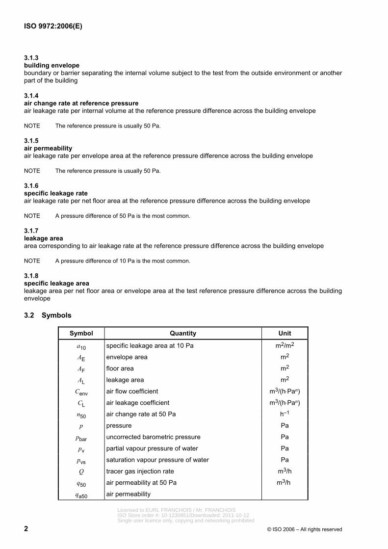
3.2 Symbols
Symbol Quantity Unit
a10 specific leakage area at 10 Pa m2/m2
AE envelope area m2
AF floor area m2
AL leakage area m2
Cenv air flow coefficient m3/(h⋅Pan)
CL air leakage coefficient m3/(h⋅Pan)
n50 air change rate at 50 Pa h–1
p pressure Pa
pbar uncorrected barometric pressure Pa
pv partial vapour pressure of water Pa
pvs saturation vapour pressure of water Pa
Q tracer gas injection rate m3/h
q50 air permeability at 50 Pa m3/h
qa50 air permeability
Licensed to EURL FRANCHOIS / Mr. FRANCHOISISO Store order #: 10-1230851/Downloaded: 2011-10-12Single user licence only, copying and networking prohibited

ISO 9972:2006(E)
© ISO 2006 – All rights reserved 3
Symbol Quantity Unit
qenv air flow rate through the building envelope m3/h
qenv,s air flow rate through the building envelope m3/s
qL50 air leakage rate at 50 Pa m3/h
qm measured air flow rate m3/h
qp50 air permeability at 50 Pa m3/(h⋅m2)
qpr air leakage rate at a specified reference pressure difference
m3/h
qr readings of air flow rate m3/h
V internal volume m3
w50 specific leakage rate at 50 Pa m3/(h⋅m2)
∆p induced pressure difference Pa
∆p0 zero flow pressure difference (average) Pa
∆p0,1; ∆p0,2 zero-flow pressure difference before and after the test (air moving equipment closed)
Pa
∆pm measured pressure difference Pa
∆pr reference pressure Pa
Φ relative humidity –
Τ absolute temperature K
Τe external air absolute temperature K
Τint internal air absolute temperature K
ρ air density kg/m3
ρe external air density kg/m3
ρint internal air density kg/m3
4 Apparatus
4.1 General
The following description of apparatus is general in nature. Any arrangement of equipment using the same principles and capable of performing the test procedure within the allowable tolerances is permitted. Examples of equipment configurations commonly used are indicated in Annex A.
Periodic calibration of the measurement system, used in this test method, according to manufacturer specifications or to standardized quality insurance systems is required.
4.2 Equipment
4.2.1 Air-moving equipment
This includes any device that is capable of inducing a specific range of positive and negative pressure differences across the building envelope or part thereof. The system shall provide a constant air flow at each pressure difference for the period required to obtain readings of air flow rate.
Licensed to EURL FRANCHOIS / Mr. FRANCHOISISO Store order #: 10-1230851/Downloaded: 2011-10-12Single user licence only, copying and networking prohibited
ISO 9972:2006(E)
4 © ISO 2006 – All rights reserved
4.2.2 Pressure-measuring device
This includes any instrument capable of measuring pressure differences with an accuracy of ± 2 Pa in the range of 0 Pa to 100 Pa.
4.2.3 Air flow rate measuring system
This includes any device capable of measuring air flow rate within ± 7 % of the reading.
Care shall be taken if the principle underlying the measurement of volumetric flow rate is an orifice. The reading of the air flow rate shall be corrected according to air density (see manufacturers' specifications).
4.2.4 Temperature-measuring device
This includes any instrument capable of measuring temperature to an accuracy of ± 1 K.
5 Measurement procedure
5.1 Measurement conditions
5.1.1 General
There are two methods for this measurement procedure: depressurization or pressurization of a building or part of a building. Regardless of which method is used, the air leakage of building envelope can be measured. The accuracy of this measurement procedure is largely dependent on the instrumentation and apparatus used and on the ambient conditions under which the data are taken.
NOTE In general, the measurement result of the depressurization method is larger than that for the pressurization method. However, when air-tightness in the building is high, the test results of both methods are almost equal.
5.1.2 Measured extent
The extent of the building or part of the building measured is defined as follows.
a) Normally, the part of the building measured includes all deliberately conditioned rooms.
b) In special cases, the extent of the part of the building actually to be tested can be defined in agreement with the client.
c) If the aim of the measurement is compliance with the air-tightness specification of a building code or standard and the measured extent is not defined in this code or by a standard, the measured extent is defined as in a).
Individual parts of a building can be measured separately; e.g. in apartment buildings, each apartment can be measured individually. However, interpretation of results shall consider that air leakage measured in this way can include flow through leaks to adjacent parts of the building.
NOTE 1 It is possible that an apartment building meets air-tightness requirements, but that one or more individual apartments do not.
NOTE 2 Good practice requires measuring pressures induced in adjoining spaces, such as the attic and basement or adjacent apartments, since air flow into or out of these spaces can be induced by the test method.
5.1.3 Time of measurement
The measurement can take place only after the completion of the envelope of the building or part of the building to be tested.
NOTE A preliminary air permeability measurement of the air barrier of the building under construction can allow leakages to be repaired more easily than after the building has been completed.
Licensed to EURL FRANCHOIS / Mr. FRANCHOISISO Store order #: 10-1230851/Downloaded: 2011-10-12Single user licence only, copying and networking prohibited
ISO 9972:2006(E)
© ISO 2006 – All rights reserved 5
5.1.4 Meteorological conditions
If the product of the indoor/outdoor air temperature difference, expressed in Kelvin, multiplied by the height, expressed in metres, of the building or measured part of the building gives a result greater than 250 m⋅K, it is unlikely that a satisfactory zero-flow pressure difference can be obtained (see 5.3.3).
If the wind speed near the ground exceeds 3 m/s or the meteorological wind speed exceeds 6 m/s or reaches 3 on the Beaufort scale, it is unlikely that a satisfactory zero-flow pressure difference can be obtained (see 5.3.3).
5.2 Preparation
5.2.1 General
This International Standard describes three types of test methods depending on the purpose. The preparation of the building depends on the test method selected:
⎯ Method A (test of a building in use):
The condition of the building envelope should represent its condition during the season in which heating or cooling systems are used.
⎯ Method B (test of the building envelope):
Any intentional opening in the building envelope shall be closed or sealed as specified in 5.2.2 and 5.2.3.
⎯ Method C (test of the building in use):
Automatically regulating, externally mounted air transfer devices are sealed, other openings are handled in the same way as for method A.
5.2.2 Building components
Close all intentional exterior openings of the building or part of the building to be tested (windows, doors, fireguard).
For the purpose of methods A and C (building in use), do not take any further measures to improve the air-tightness of the building components (however, see also 5.2.3). For the purpose of method C, all automatically regulating externally mounted air transfer devices are sealed. This is valid for natural supply and exhaust systems, as well as for natural supply and mechanical exhaust systems.
For the purpose of method B (building envelope), all adjustable openings shall be closed and remaining intentional openings shall be sealed.
The entire building or part of the building to be tested shall be configured to respond to pressurization as a single zone.
All interconnecting doors (except for cupboards and closets, which should be closed) in the part of the building to be tested shall be opened so that a uniform pressure is maintained within a range of less than 10 % of the measured inside/outside pressure difference.
NOTE When testing large or complex buildings, this condition becomes increasingly important and can be verified by selected differential pressure measurements between different rooms at the highest pressure contemplated.
Make general observations of the condition of the building. Take notes on the windows, doors, opaque walls, roof and floor, position of adjustable openings and any sealings applied to intentional openings.
Licensed to EURL FRANCHOIS / Mr. FRANCHOISISO Store order #: 10-1230851/Downloaded: 2011-10-12Single user licence only, copying and networking prohibited
ISO 9972:2006(E)
6 © ISO 2006 – All rights reserved
5.2.3 Heating, ventilation and air conditioning systems
Heating systems with indoor air intake shall be turned off. Open fireplaces shall be cleared of ashes. Mechanical ventilation and air conditioning systems shall be turned off.
Air terminal devices of mechanical ventilation or air conditioning systems shall be sealed. Other ventilation openings (for example, openings for natural ventilation) shall be closed for purposes of method A and sealed for method B.
Take measures to avoid exhaust hazards from heating systems. Take into account heating sources in adjacent apartments.
If there is an intention to estimate the infiltration/exfiltration air change rate in accordance with ISO 13790:2004, natural system openings are kept open for the purpose of the pressurization test or their contribution is calculated.
5.2.4 Air-moving equipment
Connect the air-moving equipment to the building envelope using a window, door, or vent opening. Ensure that the joints between the equipment and the building are sealed to eliminate any leakage.
If the building heating, ventilation and air conditioning system is used as the air-moving equipment, arrange the fans and dampers to allow the system to pressurize or to depressurize the building in a manner such that the total inward or outward air flow rate can be measured (see A.4).
NOTE In an airtight building, it is possible for the door, window or vent used to pass air during the test to produce the most leakage. It is important to be careful in such a case with regards to the selection of the position of the air-moving equipment and/or the interpretation of the test results.
5.2.5 Pressure measuring devices
The indoor/outdoor pressure difference is usually measured at the lowest floor level of the building envelope under consideration.
NOTE In tall buildings, it is good practice to measure the pressure difference at the top floor level of the building envelope under consideration as well.
Ensure that interior and exterior pressure drops are not influenced by the air moving equipment. The exterior pressure tap should be protected from the effects of dynamic pressure, e.g. by fitting a T-pipe or connecting it to a perforated box. Especially in windy conditions, it is good practice to place the exterior pressure tap some distance away from the building, but not close to other obstacles.
The pressure tubes should not be aligned vertically. The tubing shall not be exposed to large temperature differences (e.g. due to the sun).
5.3 Steps of the procedure
5.3.1 Preliminary check
Always check the complete building envelope at approximately the highest pressure difference used in the test for large leaks and failings of temporarily sealed openings. If such leaks are detected, take detailed notes.
Any temporary sealings found missing or deficient, e.g. of heating, ventilation and air conditioning components, shall be fixed at this time.
Check that water traps in plumbing systems are correctly filled or sealed.
Licensed to EURL FRANCHOIS / Mr. FRANCHOISISO Store order #: 10-1230851/Downloaded: 2011-10-12Single user licence only, copying and networking prohibited
ISO 9972:2006(E)
© ISO 2006 – All rights reserved 7
5.3.2 Temperature and wind conditions
To correct the air flow rate measurement for air density (see Annex B), read the temperature inside and outside the building before, during or after the test.
Record the wind speed or force. Determining wind force by visual assessment of trees, water, etc., in terms of the Beaufort scale (see Table D.1) is sufficient.
5.3.3 Zero-flow pressure difference
Short-circuit the pressure-measuring device and check or adjust the zero reading.
Connect the pressure measuring device to measure inside-outside pressure difference and temporarily cover the opening of the air moving equipment. Observe and record the average of the positive values of zero-flow pressure difference, ∆p01+, over a period of at least 30 s. Observe and record the average of the negative values of zero-flow pressure difference, ∆p01–, over a period of at least 30 s. If either of these average values of zero-flow pressure difference is greater than 5 Pa, do not perform the test.
Observe and record the average of all values of zero-flow pressure difference, ∆p01, over a period of at least 30 s.
Repeat this process at the end of the test (to obtain ∆p02+, ∆ p02– and ∆ p02). If either the positive or negative zero-flow pressure difference reading after the test is greater than 5 Pa, the test shall be declared not valid. If a test report is produced for such a test, this failure to meet required test conditions shall be stated in the test report.
5.3.4 Pressure difference sequence
Uncover and turn on the air-moving equipment.
The test is carried out by taking measurements of air flow rate and indoor-outdoor pressure difference over a range of applied pressure differences in increments of no more than approximately 10 Pa. The minimum pressure difference shall be approximately 10 Pa or five times the zero-flow pressure difference (positive or negative averages), whichever is greater. The highest pressure difference being tested can depend upon the size of the building according to a) and b).
a) Single dwellings and other small buildings:
The pressure difference shall be at least 50 Pa, but it is recommended that readings are taken at pressure differences up to 100 Pa for best accuracy of calculated results.
b) Large buildings:
Wherever possible, the pressure difference shall be the same as for single dwellings [see a)]. However, because of the large size of many non-domestic buildings and practical limitations on the capacity of portable air-moving equipment used to test them, it is often found that a pressure difference of 50 Pa is not achievable. In these cases, either additional air-moving equipment should be employed (to increase total capacity) and/or the test may be carried out up to the highest pressure difference that can be achieved with the available air-moving equipment. In such cases, the test shall not be valid unless a pressure difference of 25 Pa can be achieved. Where the pressure difference is between 25 Pa and 50 Pa, this shall be clearly recorded in the test report with a statement that the requirements of this International Standard have not been fully met and an account of the reasons why.
It is recommended that two sets of measurements be made: for pressurization and depressurization. However, it is permitted to make only one set of measurements for either pressurization or depressurization and still comply with the requirements of this International Standard. For each test, at least five approximately equally spaced data points between the highest and the lowest pressure differences shall be defined.
NOTE 1 It is more precise to take data at higher pressure differences than at lower differences. Therefore, it is important to exercise special care when measurements are taken at low pressure differences.
Licensed to EURL FRANCHOIS / Mr. FRANCHOISISO Store order #: 10-1230851/Downloaded: 2011-10-12Single user licence only, copying and networking prohibited

ISO 9972:2006(E)
8 © ISO 2006 – All rights reserved
NOTE 2 It is advisable to check that the condition of the building envelope have not changed during each test, for example, that sealed openings have not become unsealed or that doors, windows or dampers have not have been forced open by the induced pressure.
A large building shall be measured by dividing into some small parts.
6 Expression of results
6.1 Reference values
6.1.1 Internal volume
The internal volume, V, is the volume of air inside the measured building or part of building. The internal volume is calculated by multiplying the net floor area (see 6.1.3) by the mean net ceiling height. The volume of the furniture is not subtracted.
6.1.2 Envelope area
6.1.2.1 Total envelope area
The envelope area, AE, of the building or measured part of the building is the total area of all floors, walls and ceilings, bordering the internal volume subject to the test. This includes walls and floors below external ground level.
Overall internal dimensions shall be used to calculate this area. No subtractions shall be made for the area at junction of internal walls, floors and ceilings with exterior walls, floors and ceilings (see Figure 1).
6.1.2.2 Wall and roof envelope area
The wall and roof envelope area of the building or measured part of the building is the total area of walls and the underside of the roof bordering the internal volume subject to the test.
This excludes the areas of floors.
NOTE In the context of this International Standard, the envelope area of a row house includes the division wall(s). The envelope area of an apartment in a multiple story building includes the floors, walls and ceilings to adjacent apartments.
Key 1 outside 2 overall size 3 inside
Figure 1 — Envelope area
Licensed to EURL FRANCHOIS / Mr. FRANCHOISISO Store order #: 10-1230851/Downloaded: 2011-10-12Single user licence only, copying and networking prohibited
ISO 9972:2006(E)
© ISO 2006 – All rights reserved 9
6.1.3 Net floor area
The net floor area, AF, is the total floor area of all floors belonging to the internal volume subject to the test. It is calculated according to national regulations.
6.2 Calculation of the air leakage rate
Subtract the average zero-flow pressure difference (offset) from each of the measured pressure differences, ∆pm, to obtain the induced pressure differences, ∆p, using Equation (1). Attention shall be drawn to plus or minus signs.
0 1 0 2m 2
, ,p pp p
+∆ ∆∆ = −∆ (1)
First, convert the readings, qr, of the air flow rate measuring system into measured air flow rates, qm, at the temperature and pressure at the flow measuring device in accordance with manufacturer's specifications:
( )m rfq q= (2)
Then, convert the air flow rates, qm, to air flow rates, qenv, through the building envelope for depressurization using Equation (3).
= int eenv m m
inte
Tq q qT
ρρ
⎛ ⎞ ⎛ ⎞=⎜ ⎟ ⎜ ⎟⎜ ⎟ ⎝ ⎠⎝ ⎠
(3)
where
ρint is the internal air density, expressed in kilograms per cubic metre;
ρe is the external air density, expressed in kilograms per cubic metre;
intT is the internal air absolute temperature, expressed in kelvins;
eT is the external air absolute temperature, expressed in kelvins.
Convert the measured air flow rate, qm, to air flow rate through the building envelope, qenv, for pressurisation using Equation (4).
= e intenv m m
eint
Tq q qT
ρρ
⎛ ⎞ ⎛ ⎞=⎜ ⎟ ⎜ ⎟⎜ ⎟ ⎝ ⎠⎝ ⎠
(4)
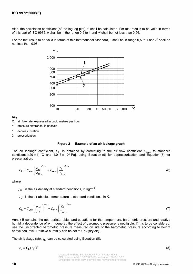
Plot the air flow rate through the building envelope against the corresponding pressure differences on a log-log plot to complete the air leakage graph for both pressurization and depressurization (see Figure 2).
The converted data shall be used to determine the air flow coefficient, Cenv, and air flow exponent, n, in accordance with Equation (5) using a least squares technique:
( ) = envenvnC pq ∆ (5)
where n is the air flow exponent.
In determining the fit of Equation (5), the confidence intervals of the derived air flow coefficient, Cenv, and air flow exponent, n, should be calculated. Cenv and n shall be calculated separately for pressurization and depressurization.
NOTE Cenv and n can be calculated using the procedure of Annex C.
Licensed to EURL FRANCHOIS / Mr. FRANCHOISISO Store order #: 10-1230851/Downloaded: 2011-10-12Single user licence only, copying and networking prohibited
ISO 9972:2006(E)
10 © ISO 2006 – All rights reserved
Also, the correlation coefficient (of the log-log plot) r2 shall be calculated. For test results to be valid in terms of this part of ISO 9972, n shall be in the range 0,5 to 1 and r2 shall be not less than 0,96.
For the test result to be valid in terms of this International Standard, n shall be in range 0,5 to 1 and r2 shall be not less than 0,96.
Key X air flow rate, expressed in cubic metres per hour Y pressure difference, in pascals
1 depressurisation 2 pressurisation
Figure 2 — Example of an air leakage graph
The air leakage coefficient, CL, is obtained by correcting to the air flow coefficient, Cenv, to standard conditions [(20 ± 1) °C and 1,013 × 105 Pa], using Equation (6) for depressurization and Equation (7) for pressurization:
1 1e 0
L env env0 e
n nT
C C CT
ρρ
− −⎛ ⎞ ⎛ ⎞
= ≈⎜ ⎟ ⎜ ⎟⎝ ⎠ ⎝ ⎠
(6)
where
ρ0 is the air density at standard conditions, in kg/m3.
0T is the air absolute temperature at standard conditions, in K.
1 1int 0
L env env0 int
n nT
C C CT
ρρ
− −⎛ ⎞ ⎛ ⎞
= ≈⎜ ⎟ ⎜ ⎟⎝ ⎠ ⎝ ⎠
(7)
Annex B contains the appropriate tables and equations for the temperature, barometric pressure and relative humidity dependence of ρ. In general, the effect of barometric pressure is negligible. If it is to be considered, use the uncorrected barometric pressure measured on site or the barometric pressure according to height above sea level. Relative humidity can be set to 0 % (dry air).
The air leakage rate, qL, can be calculated using Equation (8):
( )L Lnq C p= ∆ (8)
Licensed to EURL FRANCHOIS / Mr. FRANCHOISISO Store order #: 10-1230851/Downloaded: 2011-10-12Single user licence only, copying and networking prohibited
ISO 9972:2006(E)
© ISO 2006 – All rights reserved 11
6.3 Derived quantities
6.3.1 Air change rate at reference pressure difference
The air leakage rate, prq , at the reference pressure difference, ∆pr, usually equal to 50 Pa, is determined using Equation (9):
( )pr L rnq C p= ∆ (9)
e.g. ( )50 L 50 Pa nq C=
Derived values are calculated for the mean air leakage rate at 50 Pa for the pressurization and the depressurization test.
The air change rate, npr, at the pressure difference, e.g. 50 Pa, is calculated by dividing the mean air leakage rate at 50 Pa by the internal volume according to 6.1.1 using Equation (10):
prpr
qn
V= (10)
Example 5050
qn
V=
6.3.2 Air permeability
The air permeability, qa50, at 50 Pa, is calculated by dividing the mean air leakage rate at 50 Pa by the envelope area according to 6.1.2 using Equation (11):
5050
Ea
A= (11)
6.3.3 Specific leakage rate
The specific leakage rate, w50, is calculated by dividing of the mean air leakage rate at 50 Pa by the net floor area according to 6.1.3 using Equation (12):
5050
F
qw
A= (12)
6.3.4 Air leakage rate at reference pressure difference
The air leakage rate, qpr, expressed in cubic metres per hour, at a specified reference pressure difference is calculated using Equation (9).
6.3.5 Leakage area
The leakage area, AL, at the reference pressure difference, ∆pr, is calculated using Equation (13):
,,( )
0 50 50
L L r2nA C p
ρ −⎛ ⎞= ∆⎜ ⎟
⎝ ⎠ (13)
The reference pressure difference is 10 Pa, but other values may be used according to national regulation.
Licensed to EURL FRANCHOIS / Mr. FRANCHOISISO Store order #: 10-1230851/Downloaded: 2011-10-12Single user licence only, copying and networking prohibited

ISO 9972:2006(E)
12 © ISO 2006 – All rights reserved
6.3.6 Specific leakage area
The specific leakage area, a10, at 10 Pa is calculated by dividing the mean leakage area at 10 Pa by the net floor area according to 6.1.3 using Equation (14):
L10
F
Aa
A= (14)
Also, a10 at 10 Pa should be calculated by dividing the mean leakage area at 10 Pa by the envelope area according to 6.1.2 using Equation (15):
L10
E
Aa
A= (15)
7 Test report
The report shall contain at least the following information:
a) all details necessary to identify the object tested: purpose of test (method A or B); postal address and estimated date of construction of the building;
b) a reference to this International Standard, e.g. ISO 9972, and any deviation from it;
c) test object:
⎯ description of which parts of the building were subject to the test, apartment number,
⎯ net floor area and internal volume of space subject to the test and other required dimensions of the building,
⎯ documentation of calculations, such that the stated results can be verified,
⎯ the status of all openings on the building envelope, latched, sealed, open, etc.,
⎯ detailed description of temporarily sealed openings, if any,
⎯ the type of heating, ventilating and air conditioning system,
d) apparatus and procedure, i.e. equipment and technique employed;
e) test data:
⎯ zero-flow pressure differences ∆p0,1+, ∆p0,1–, ∆p0,2+, ∆p0,2–, ∆p0,1 and ∆p0,2 for pressurization and depressurization test,
⎯ inside and outside temperatures,
⎯ wind speed, barometric pressure, if it is part of the calculation,
⎯ table of induced pressure differences and corresponding air flow rates,
⎯ air leakage graph, see Figure 2, for example,
⎯ the air flow coefficient, Cenv, the air flow exponent, n, and the air leakage coefficient, CL, for both pressurization and depressurization tests determined by the method indicated in Clauses 4, 5 and 6 along with their confidence limits (see Clause 8),
Licensed to EURL FRANCHOIS / Mr. FRANCHOISISO Store order #: 10-1230851/Downloaded: 2011-10-12Single user licence only, copying and networking prohibited
ISO 9972:2006(E)
© ISO 2006 – All rights reserved 13
⎯ air change rate, n50 at 50 Pa, for pressurization and/or depressurization and mean value,
⎯ derived quantity according to national regulation,
⎯ report of both the total envelope area and the wall and roof envelope area,
f) date of test.
8 Uncertainty
8.1 General
The overall accuracy of a pressurization test depends on many factors. For any derived quantity, an estimate of the confidence interval shall be included in the data analysis.
NOTE Annex C describes a simplified procedure for estimating the uncertainty of the derived quantities of C and n. This uncertainty is not the uncertainty of the measurement.
8.2 Reference value
The accuracy of reference values can be estimated using error propagation calculation. Typically, the uncertainty is between 5 % and 10 %.
8.3 Overall uncertainty
The overall uncertainty in the derived quantities described in 6.3.1, 6.3.2, 6.3.3, 6.3.4, 6.3.5 and 6.3.6 of a pressurization test made in accordance with this International Standard can be estimated using error propagation calculation. This calculation should include uncertainties of all quantities used for the final result.
NOTE In calm conditions, the overall uncertainty is u 10 % in most cases. In windy conditions, the overall uncertainty can reach ± 20 %.
Licensed to EURL FRANCHOIS / Mr. FRANCHOISISO Store order #: 10-1230851/Downloaded: 2011-10-12Single user licence only, copying and networking prohibited

ISO 9972:2006(E)
14 © ISO 2006 – All rights reserved
Annex A (informative)
Description of equipment used to pressurize buildings
A.1 General
There are several ways to pressurize the building envelope. The most common are described in A.2 to A.4.
A.2 Fan and duct system
An assembly, including a fan, a duct and an air-flow meter, is connected to the building (see Figure A.1). The size of the air duct and the capacity of the fan are matched so that the linear flow velocity within the air duct falls within the range of measurement of the air flow meter.
Key 1 pressure-measuring device 2 temperature-measuring device 3 air-flow measuring system 4 air-moving equipment 5 fan
Figure A.1 — Schematic layout of equipment for whole building test
Licensed to EURL FRANCHOIS / Mr. FRANCHOISISO Store order #: 10-1230851/Downloaded: 2011-10-12Single user licence only, copying and networking prohibited
ISO 9972:2006(E)
© ISO 2006 – All rights reserved 15
A.3 Blower door
A blower door assembly is an accepted device in many countries for performing envelope permeability measurements. The assembly includes a door mount for a fan or blower that is adjustable to fit common door openings. The fan or blower should possess a variable-speed motor to accommodate the range of required air flow rates.
A.4 Fan for building heating or ventilation and air conditioning system fans
To determine the air permeability of large buildings, it can be possible to use the fan for building ventilation system for pressurization and depressurization of the building. An initial site inspection is advisable to establish the number of main supply (or exhaust) fans, likely air flow performance, the possibility of operating the fans with either 100 % outside air or 100 % exhaust air, and the available means of controlling the supply (or exhaust) air flow rates (e.g. adjusting damper openings or adjusting fan speeds). The duct system can also be examined and suitable locations for air flow rate measurements selected.
Since it is often difficult to satisfy accepted criteria for air flow rate measurements in ducts in an actual heating, ventilation and air conditioning system, the air flow rate, ,V can be determined by using a constant injection of tracer gas into the air stream entering the building. The air flow rate, qenv,s, expressed in cubic metres per second (see 3.2 and Figure 2), is determined using Equation (A.1).
env,sB
qqw
= (A.1)
where
q is the tracer gas injection rate, expressed in cubic metres per second;
wB is the tracer gas concentration, expressed in cubic metres per cubic metre.
NOTE Particular care is required where dampers and/or fan speeds are normally controlled automatically (e.g. by a building energy management system) to ensure that they can be operated independently as required for the test. Some heating, ventilation and air conditioning system interior grilles or openings might also have to be sealed in order to perform the test.
Licensed to EURL FRANCHOIS / Mr. FRANCHOISISO Store order #: 10-1230851/Downloaded: 2011-10-12Single user licence only, copying and networking prohibited
ISO 9972:2006(E)
16 © ISO 2006 – All rights reserved
Annex B (informative)
Dependence of air density on temperature, dew point
and barometric pressure
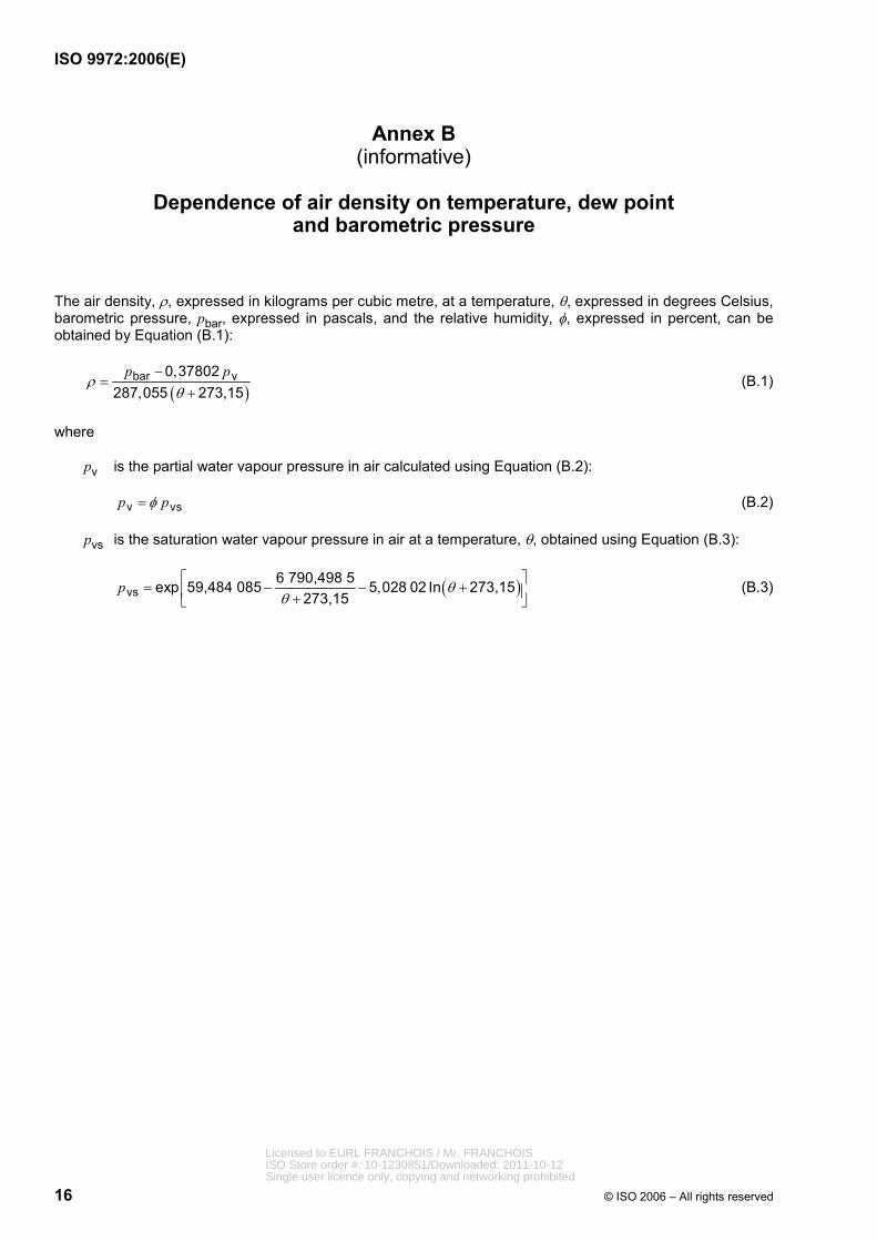
The air density, ρ, expressed in kilograms per cubic metre, at a temperature, θ, expressed in degrees Celsius, barometric pressure, pbar, expressed in pascals, and the relative humidity, φ, expressed in percent, can be obtained by Equation (B.1):
( ),
, ,bar v0 37802
287 055 273 15p p
ρθ
−=
+ (B.1)
where
pv is the partial water vapour pressure in air calculated using Equation (B.2):
v vsp pφ= (B.2)
pvs is the saturation water vapour pressure in air at a temperature, θ, obtained using Equation (B.3):
( ),vs6 790,498 5exp 59,484 085 5 028 02 In 273,15
273,15p θ
θ⎡ ⎤= − − +⎢ ⎥+⎣ ⎦
(B.3)
Licensed to EURL FRANCHOIS / Mr. FRANCHOISISO Store order #: 10-1230851/Downloaded: 2011-10-12Single user licence only, copying and networking prohibited
ISO 9972:2006(E)
© ISO 2006 – All rights reserved 17
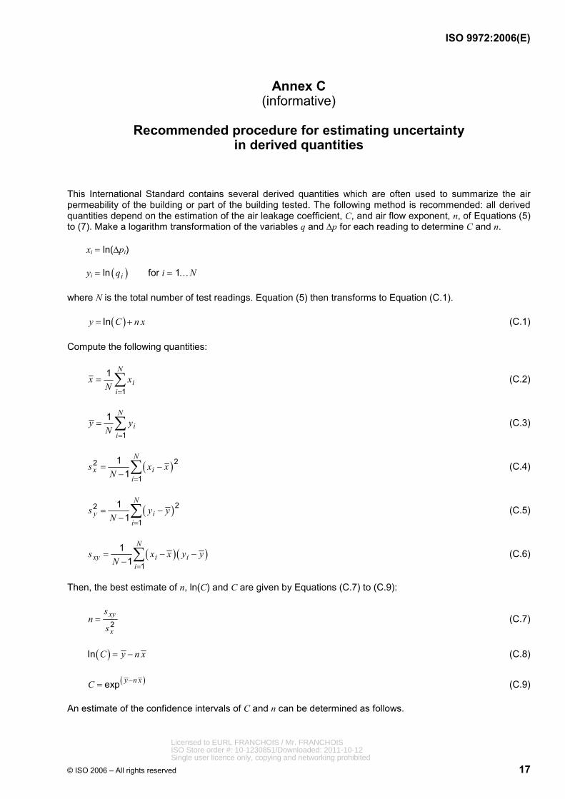
Annex C (informative)
Recommended procedure for estimating uncertainty
in derived quantities
This International Standard contains several derived quantities which are often used to summarize the air permeability of the building or part of the building tested. The following method is recommended: all derived quantities depend on the estimation of the air leakage coefficient, C, and air flow exponent, n, of Equations (5) to (7). Make a logarithm transformation of the variables q and ∆p for each reading to determine C and n.
xi = ln(∆pi)
yi = ln ( )iq for i = 1…N
where N is the total number of test readings. Equation (5) then transforms to Equation (C.1).
( )Iny C n x= + (C.1)
Compute the following quantities:
1
1 N
ii
x xN =
= ∑ (C.2)
1
1 N
ii
y yN =
= ∑ (C.3)
( )22
1
11
N
x ii
s x xN =
= −− ∑ (C.4)
( )22
1
11
N
y ii
s y yN =
= −− ∑ (C.5)
( ) ( )1
11
N
xy i ii
s x x y yN =
= − −− ∑ (C.6)
Then, the best estimate of n, ln(C) and C are given by Equations (C.7) to (C.9):
2xy
x
sn
s= (C.7)
( )In C y n x= − (C.8)
( )exp y n xC −= (C.9)
An estimate of the confidence intervals of C and n can be determined as follows.
Licensed to EURL FRANCHOIS / Mr. FRANCHOISISO Store order #: 10-1230851/Downloaded: 2011-10-12Single user licence only, copying and networking prohibited
ISO 9972:2006(E)
18 © ISO 2006 – All rights reserved
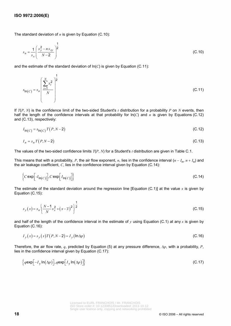
The standard deviation of n is given by Equation (C.10):
12 21
2y xy
nx
s n ss
s N
⎛ ⎞−⎜ ⎟=⎜ ⎟−⎝ ⎠
(C.10)
and the estimate of the standard deviation of ln(C) is given by Equation (C.11):
( )
122
1In
N
ii
nC
x
s sN
=
⎛ ⎞⎜ ⎟⎜ ⎟
= ⎜ ⎟⎜ ⎟⎜ ⎟⎝ ⎠
∑ (C.11)
If T(P, N) is the confidence limit of the two-sided Student's t distribution for a probability P on N events, then half the length of the confidence intervals at that probability for ln(C) and n is given by Equations (C.12) and (C.13), respectively:
( ) ( ) ( ),In In 2C CI s T P N= − (C.12)
( ), 2n nI s T P N= − (C.13)
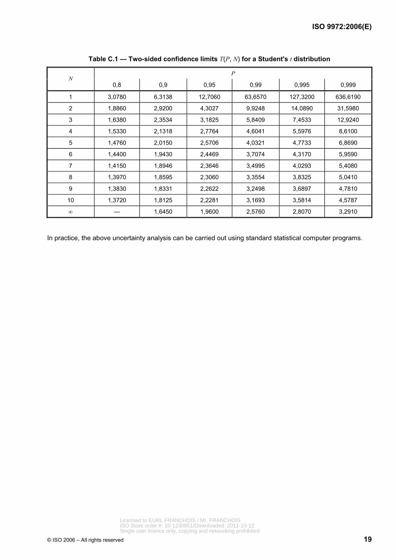
The values of the two-sided confidence limits T(P, N) for a Student's t distribution are given in Table C.1.
This means that with a probability, P, the air flow exponent, n, lies in the confidence interval (n − In, n + In) and the air leakage coefficient, C, lies in the confidence interval given by Equation (C.14):
( ) ( ){ }In Inexp , expC CC -I C I⎡ ⎤ ⎡ ⎤⎢ ⎥ ⎢ ⎥⎣ ⎦ ⎣ ⎦
(C.14)
The estimate of the standard deviation around the regression line [Equation (C.1)] at the value x is given by Equation (C.15):
( ) ( )12221
y n xNs x s s x x
N−⎧ ⎫= + −⎨ ⎬
⎩ ⎭ (C.15)
and half of the length of the confidence interval in the estimate of y using Equation (C.1) at any x is given by Equation (C.16):
( ) ( ) ( ) ( ), 2 Iny y yI x s x T P N I p= − = ∆ (C.16)
Therefore, the air flow rate, q, predicted by Equation (5) at any pressure difference, ∆p, with a probability, P, lies in the confidence interval given by Equation (C.17):
( ) ( ){ }y y,exp In exp Inq I p q I p⎡ ⎤ ⎡ ⎤− ∆ ∆⎣ ⎦ ⎣ ⎦ (C.17)
Licensed to EURL FRANCHOIS / Mr. FRANCHOISISO Store order #: 10-1230851/Downloaded: 2011-10-12Single user licence only, copying and networking prohibited
ISO 9972:2006(E)
© ISO 2006 – All rights reserved 19
Table C.1 — Two-sided confidence limits T(P, N) for a Student's t distribution
P N
0,8 0,9 0,95 0,99 0,995 0,999
1 3,0780 6,3138 12,7060 63,6570 127,3200 636,6190
2 1,8860 2,9200 4,3027 9,9248 14,0890 31,5980
3 1,6380 2,3534 3,1825 5,8409 7,4533 12,9240
4 1,5330 2,1318 2,7764 4,6041 5,5976 8,6100
5 1,4760 2,0150 2,5706 4,0321 4,7733 6,8690
6 1,4400 1,9430 2,4469 3,7074 4,3170 5,9590
7 1,4150 1,8946 2,3646 3,4995 4,0293 5,4080
8 1,3970 1,8595 2,3060 3,3554 3,8325 5,0410
9 1,3830 1,8331 2,2622 3,2498 3,6897 4,7810
10 1,3720 1,8125 2,2281 3,1693 3,5814 4,5787
∞ — 1,6450 1,9600 2,5760 2,8070 3,2910
In practice, the above uncertainty analysis can be carried out using standard statistical computer programs.
Licensed to EURL FRANCHOIS / Mr. FRANCHOISISO Store order #: 10-1230851/Downloaded: 2011-10-12Single user licence only, copying and networking prohibited

ISO 9972:2006(E)
20 © ISO 2006 – All rights reserved
Annex D (informative)
Beaufort scale for wind force (extract)
Table D.1 — Beaufort scale for wind force indication
Beaufort number Name Wind speed Description
m/s
0 calm less than 0,45 Calm; smoke rises vertically
1 light air 0,45 to 1,34 Direction of wind shown by smoke but not by wind vanes
2 light breeze 1,8 to 3,1 Wind felt on face; leaves rustle; ordinary vane moved by wind
3 gentle breeze 3,6 to 5,4 Leaves and small twigs in constant motion; wind extends light flag
4 moderate breeze 5,8 to 8 Raises dust and loose paper; small branches are moved
5 fresh breeze 8,5 to 10,7 Small trees in leaf begin to sway; crested wavelets form on inland waters
6 strong breeze 11,2 to 13,9 Large branches in motion; telegraph wires whistle; umbrellas used with difficulty
7 moderate gale 14,3 to 17 Whole trees in motion; inconvenience in walking against wind
8 fresh gale 17,4 to 20,6 Breaks twigs off trees; generally impedes progress
Licensed to EURL FRANCHOIS / Mr. FRANCHOISISO Store order #: 10-1230851/Downloaded: 2011-10-12Single user licence only, copying and networking prohibited

Licensed to EURL FRANCHOIS / Mr. FRANCHOISISO Store order #: 10-1230851/Downloaded: 2011-10-12Single user licence only, copying and networking prohibited

ISO 9972:2006(E)
ICS 91.120.10 Price based on 20 pages
© ISO 2006 – All rights reserved
Licensed to EURL FRANCHOIS / Mr. FRANCHOISISO Store order #: 10-1230851/Downloaded: 2011-10-12Single user licence only, copying and networking prohibited