international institute institut international of welding ... · de la soudure. 2 1. introduction....
TRANSCRIPT

IIW/IIS - DOCUMENT XIII - 1964 - 03
Comparison of the Improvement in Corrosion Fatigue Strength ofWeld Repaired Marine Cu 3-grade Bronze Propellers by Ultrasonic
Impact Treatment (UIT) or Heat Treatment
E.S. Statnikov, V.O. Muktepavel, V.N. Vityazev
Applied Ultrasonics, P.O. Box 100422, Birmingham, Alabama, 35210, USA
Northern Scientific & Technology Company, NSTC6 Voronin St., Severodvinsk, Archangelsk Region, 164500, Russia
V.I. Trufyakov, V.S. Kovalchuk
The E.O. Paton Electric Welding Institute11 Bozhenko St., Kiev, 252650, Ukraine
P.J. Haagensen
Norwegian University of Science and Technology, NTNUR. Birkelandsvei 1A, N-7491 Trondheim, Norway
ABSTRACT
Corrosion fatigue resistance is of great importance in the operation of marine propellers.Propeller castings, as a rule, are made using different casting methods characterized by theformation of various cast defects. Rectification of defective castings involves removal of thedefects followed by weld repair. Weld metal structure and residual welding stresses result in adecrease in the corrosion fatigue strength of the propeller.
In order to increase the corrosion fatigue strength in the weld repaired areas, qualificationsocieties, such as Det Norske Veritas, Bureau Veritas, Germanischer Lloyd, Lloyd’s Register ofShipping and Russian Maritime Register, require that weld-repaired propellers are heat treated.This technique is energy- and time-consuming as well as costly.
The paper presents the results of an investigation of the application UIT as an alternative toheat treatment based on comparative corrosion fatigue tests of plate specimens made from thesame material as that used for propellers, bronze Cu 3.
It is shown that with UIT application during weld repair the corrosion fatigue strength ishigher than that of heat treated propellers.
Key words: Propellers, corrosion fatigue strength, bronze, defects, deposition, welding, heattreatment, ultrasonic impact treatment.
International Instituteof Welding
RUSSIAN DELEGATION
Institut Internationalde la Soudure

2
1. INTRODUCTION. BACKGROUND
When a propeller is manufactured, the casting defects are revealed which are repaired bywelding. Weld metal structure and residual welding stresses result in a decrease in the corrosionfatigue strength of the weld repaired area as compared with the base metal. According to theregulations of classification societies, such as Veritas, Lloyds, National Registers of Shipping,heat treatment (HT) is performed to increase (restore) the corrosion fatigue strength by relief oftensile residual stress and to obtain a equilibrium metal structure.
Heat treatment of marine propellers is a costly and long-term operation. Creation of post-weld method for improving the corrosion fatigue strength of welds that would allow heattreatment to be omitted is a topical problem in the manufacture of propellers.
The objectives of this work were to develop such a method, to evaluate its effectiveness andsupport the application of the method to be appropriate and sound for repairing casting defects bywelding in propellers made from copper alloys (Cu 3).
Applied Ultrasonics (AU, USA) and Northern Scientific and Technology Company (NSTC,Russia) have developed a method of UIT of propellers and the following analyses have beenperformed:
– analysis of the properties and quality of the base metal and a welded joint before and afterUIT treatment;
– analysis of the corrosion fatigue characteristics of the large-scale base-metal specimens andspecimens with weld deposits treated by either heat treatment or UIT.
NSTC and AU have developed the ultrasonic impact treatment (UIT) technology, Esonix[1,2,3], that, along with inducing compressive stresses to the surface layer of the treated material,makes possible distributing and relaxation of residual stresses, such as welding residual stresses.A special feature of this work is the application of a multifrequency UIT technique with carrierfrequency of 27kHz. The power and the repetition rate of ultrasonic impacts are determined bythe treatment procedure.
On this basis, Federal State Unitary Enterprise “ME Zvyozdochka” (FSUE “MEZvyozdochka”) entered into a development agreement with NSTC.
Applied Ultrasonics provided the initial and current financing of these works between 1998and 2000.
Prof. Per J. Haagensen of Norwegian University of Science and Technology, expert of DetNorske Veritas, has directly participated in the development of the work program under theagreement and made a proposal regarding the method and a structure of full-scale specimens forcomparative testing [4, 5].
Zvyozdochka supplied the specimens and performed welding, weld deposition, mechanicaloperation, mechanical tests and metallographic testing of welded specimens.
NSTC have developed a work program, determined a test specimen fabrication technique,manufactured the UIT equipment and a tool, developed a UIT technique and performed UIT onspecimens. In collaboration with subcontractors NSTC carried out the scheduled and additionaltests.

3
The E.O. Paton Electric Welding Institute with regard to proposals of Prof. Per J. Haagensenhave developed a procedure for corrosion fatigue testing large-scale specimens and performedtesting [6].
The following metal-physical analyses were performed:
- mechanical and metallographic tests of welded specimens – Central Laboratory ofZvyozdochka, Severodvinsk;
- analysis of mechanical stresses in the surface layers of specimens – Material AnalysisLaboratory of Northern Engineering Enterprise SEVMASH, Severodvinsk;
- analysis of the UIT effect on etching of the specimen surface and analysis of the untreatedand UIT treated material characteristics in depth – Metallographic Laboratory of Sevmash,Severodvinsk;
- hardness measurement – Mechanical Test Laboratory of Sevmash, Severodvinsk.
It is shown that UIT, after weld repair, allows the casting defects on propellers in copperalloys (Cu-3) to be rectified, omitting heat treatment.
2. STATUS OF THE ISSUE
In compliance with Industrial Guideline “Propellers made from copper-based alloys.Rectification of defects and damages. Standard Manufacturing Process” and regulations specifiedby foreign classification societies (Det Norske Veritas, Lloyd’s Register of Shipping,Germanischer Lloyd), propellers are made from brasses and bronzes. Chemical composition andmechanical properties of Russian and foreign brasses and bronzes are almost the same.According to all above mentioned documents, the techniques of propeller production and defectrectification by welding, weld deposition and subsequent heat treatment are identical.
In compliance with western classification, Russian brass of LZn40Mn3Fe grade is similar tomanganese bronze Сu 1; BrAl9Fe4Ni4 grade bronze is similar to Ni-aluminum bronze Cu 3;BrAl7Mn14Fe3Ni2 grade bronze is similar to Mn-aluminum bronze Cu 4. The Ni-manganesebronze Cu 2 is also used in the West.
According to Russian and foreign classification, the surfaces of propeller blades and hub aredivided into three zones, A, B and C.
Propeller machining reveals casting defects that need to be repaired through grinding and arcwelding. In quite a large number of cases where welding is applied (especially in zone B and, inspecified cases, in zone A), subsequent general heat treatment of the entire propeller or local heattreatment of weld deposit areas is required.
Heat treatment of propellers is performed to relieve tensile residual stresses and to secure acomparatively equilibrium structure. Propellers made from Cu 3-grade bronze are heat treatedfollowing defect repair by welding on pressure side of blades at a distance of 0,7R, where R isthe radius of the propeller.
According to Det Norske Veritas, propellers made from brasses Сu 1, Cu 2 and bronze Cu 4are sensitive to stress corrosion cracking. In order to relieve stresses, it is essential to subject therepaired area coming in contact with sea water to heat treatment. Bronze Cu 3 is virtually

4
unsusceptible to stress corrosion cracking. Welding stress relief tempering is not performed onthis bronze.
According to Lloyd’s Register of Shipping, weld deposits on solid propeller surfaces andseparately cast blades should be subjected to stress-relieving heat treatment. In this case, heattreatment is optional in zone С of blades and for hub of fixed pitch propellers made of bronze Cu3.
According to Germanischer Lloyd, weld deposits on propellers of all types, excludingpropellers made of Cu 3 alloy, should be heat treated for stress relief and prevention of corrosioncracking. Heat treatment may as well be necessary for Cu 3 alloy provided that the major repairrequires weld deposition in zones В and А.
Thus, welding stress relief heat treatment is often an indispensable operation for propellers incopper alloys.
Actually, heat treatment done by heating the entire propeller or local heating of the repairedarea is a complex, expensive and difficult-to-perform operation. Creation of mobile andpractically feasible techniques for improvement of corrosion fatigue resistance of welded jointsand weld deposits as a means of omitting local heat treatment or furnace heat treatment is atopical issue in propeller fabrication. Germanischer Lloyd notes that in specific cases theclassification society is entitled to approve stress removal rather than tempering procedureprovided that the technique is approved by classification society for this particular purpose.
3. OBJECTIVE OF WORK
The intention was to estimate UIT effectiveness, justify and co-ordinate with classificationsocieties (Russian Maritime Register, Germanischer Lloyd, Lloyd’s Register of Shipping, DetNorske Veritas) its application on Cu 3 alloy propellers for defect repair by welding (welddeposition) as an alternative to post-weld heat treatment, as well as to develop and introduce thetechnology.
The work was carried out on the basis of Technical Assignment under the Agreement betweenNSTC and state enterprise Zvyozdochka, Russia, Severodvinsk.
4. DISTINGUISHING FEATURES, NOVELTY AND ADVANTAGES OF UIT
UIT was developed at NSTC as a process ensuring high quality and reliability of weldedstructures and constructions. It is used to improve the formation of the weld metal and heataffected zone structure and also to optimize the stressed condition of the welded joint andstructure as a whole.
The UIT method is based on conversion of harmonic oscillations of ultrasonic transducer intoimpact impulses of ultrasonic frequency. Manual or mechanized UIT results in increase ofreliability and endurance of metal structures in parallel with drastic reduction of costs forproduction of high durability structures, including maintenance and repair. The UIT methodreduces unfavorable residual tensile stresses, creates beneficial compressive stresses in the weldand at the weld toe region, reduces stress concentrations and improves the corrosion andcorrosion fatigue resistance of UIT treated areas.

5
Currently, NSTC is involved in development of the UIT technique, evaluation of itseffectiveness from the technical point of view, and manufacture of the prototype equipment forspecific applications.
Thus, NSTC have developed a procedure and in July of 1997 applied UIT for repair ofcracked details in the highway bridge over Allatoona Lake, Georgia, USA.
UIT method developed by NSTC is certified by expert and research laboratories ofInternational Institute of Welding of France, Sweden, Norway, Japan, USA and Ukraine.
UIT method allows for:
- increase in fatigue resistance and life of welded joints;- increase in corrosion fatigue strength;- reducing a level of residual welding stresses and deformations;- omitting traditional methods of stabilizing heat treatment;- achieving high processability of welded joint treatment using mechanical or manualequipment in actual conditions of production, installation, maintenance and repair ofvarious-purpose structures.
5. UIT EQUIPMENT
UIT equipment (Fig. 1) developed and manufactured at NSTC comprises the followingcomponents:
– power supply UPS MT-5 APS-2000,– ultrasonic generator UPS MT-5 UGenerator,– ultrasonic impact tool.
6. MATERIAL
Bronze Сu 3 has been the most commonly used material for production of propellers inRussia. Under contracts with international companies, Zvyozdochka Yard has been fabricatingand delivering propellers made from this bronze. For instance, Zvyozdochka has fabricated anddelivered bronze propellers of AZIPOD propulsion unit for cruise liners built in Finland.
Within the framework of this study, a comparison study was made of mechanical andcorrosion fatigue characteristics and properties of welded (deposited) joints on special testspecimens:
- in the initial condition,- after heat treatment,- after ultrasonic impact treatment.
A special programme of comparison tests based on the requirements of the classificationsocieties has been developed for this study.
Plates cast from Сu 3 bronze and manufactured at Baltiysky Zavod, St. Petersburg were usedas the base metal. Mechanical properties and chemical composition of the above bronze arepresented in Table 1 and Table 2.

6
Table 1 Mechanical properties of bronze
Material Grade Ultimate tensilestrength,kg/mm2
Yield strength,kg/mm2
Elongation,%
Brinellhardnessnumber
BrAl9Fe4Ni4bronze grade
66,0 – 67,0 29,0 17,0 - 19,0 163
Table 2 Chemical composition of bronze
Cu Al Fe Ni Mn Sn Pb P
The rest 9,50 4,12 4,13 0,82 0,011 0,005 0,004
7. WELDED JOINT QUALITY ANALYSIS
In compliance with the requirements of classification societies, special butt welded plates(Fig.2) were produced to determine the effect of heat treatment and ultrasonic impact treatmenton the mechanical properties and macrostructure of welded joints. The thickness of plates toweld was 40mm, so that after welding it would be possible to mill them down to a thickness of30mm, refer to Fig. 2.
One plate was a base metal without weld.Five plates were butt welded:
– one for as-welded joint analysis,– one for heat treated welded joint analysis,– three for analysis of welded joint subjected to UIT of each pass.
Each welded plate was cut into two tensile test specimens for strength determination andthree macrostructure test specimens (see Fig. 2).
Plates were welded by the TIG process using alternate welding current. BrAlFeNiMn 8,5-4-5-1,5 bronze was used as a filler material. Chemical composition of filler rods is presented nTable 3.
Table 3 Chemical composition of filler material
Cu Al Fe Ni Mn B V
The rest 8,2-9,0 3,7-4,3 4,7-5,3 1,0-1,8 0,005-0,01 0,005-0,01
Welding operation was performed by certified welders of Zvyozdochka Yard in compliancewith welding data sheet issued by Chief Welder Department.
Welding conditions:
– preliminary misalignment of plates to be welded for welding deformation compensation,– degreasing groove faces prior to welding,– heating the butt joint up to temperature of 50+5 degrees C prior to welding,– filler rod 4mm in diameter,

7
– welding current 300 – 320amp,– argon flow: 12 – 15 liter/min,– every consequent bead was deposited after thorough wire brushing of the previous bead,– every consequent bead was deposited after cooling of the previous bead down to a
temperature 1500C max,– weld root was removed with abrasive tools and welded.
Each weld pass of three joints was subjected to ultrasonic impact treatment (Fig. 3).
Ultrasonic impact treatment was performed in compliance with «Recommendations onultrasonic impact treatment of welded joints» developed at NSTC with the following conditions:
Manual UIT tool was fixed at right angles to the surface to be treated and pressed against itwith an axial force of 20-40N (2-4kg). This force, as a rule, is created by the weight of the toolitself.
UIT was performed through headway and shuttle movement of the tool over the weld surfaceand along the weld toe and inter-bead toes until uniformly treated surface, corresponding toreference specimens, was formed.
UIT parameters:
� frequency of the ultrasonic generator 27kHz,� current of polarization 10 – 14amp,� oscillation amplitude of the output end of the
waveguide 25 - 40 microns is automatically controlledby setting the output power in the range of 600 - 1200W,
� diameter of impact pins (indenters) 3mm, 3-4 pins in a row,� average travel speed 0,3 - 1,5 m/min.
Visual and X-ray examination was used to inspect welded joints. No unacceptable defectswere detected.
One welded joint (plate No. 2/4) was stress relieved by heat treatment in accordance withconditions specified by Det Norske Veritas.
Zvyozdochka Yard produced a heat treatment data sheet. Heat treatment conditions:
- heating speed - not more than 800C an hour- heating temperature - 675 0C,- soak time - 30 min.,- cooling speed - in furnace not more than 500C an hour
down to 2000C, then in air.
Dye penetrant inspection was performed after milling of the specimen down to the thicknessof 30mm. Defects like cavities, pores, cracks were not detected.
The results of the mechanical tests are presented in Table 4. All the specimens failed in thebase metal outside the weld zone (Fig. 4) and the properties satisfied DNV and GermanischerLloyd requirements.

8
Table 4 Mechanical test results
Specimen type Ultimate tensile strength, MPa
Value Average value
Base metal 579, 589 584
As welded joint 598, 598 598
Heat treated welded joint 629, 579 604
UIT treated welded joint 578, 589, 579, 569, 540, 579 572
The macrostructure was studied for the presence of defects. In compliance with Det NorskeVeritas and Germanischer Lloyd, pores more than 3mm in size and cracks are not acceptable.The present welds were free of any pores, cracks and discontinuities (Fig. 5).
Based on the results of works performed and analysis of weld quality, it can be concluded thatwelding followed by ultrasonic impact treatment ensures good weld quality with mechanicalproperties not inferior to those of as-welded joints and welded joints subjected to stress-relivingheat treatment.
8. SPECIMENS FOR CORROSION FATIGUE STUDIES
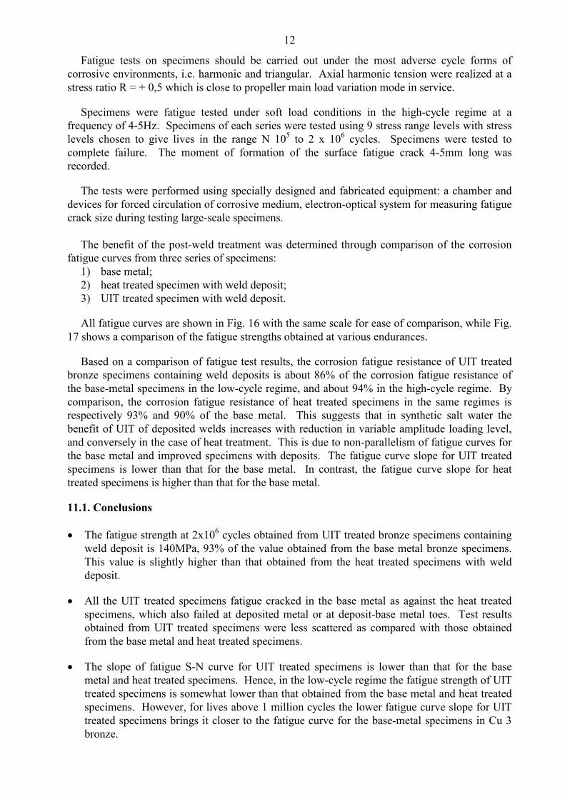
In order to determine the effect of ultrasonic impact treatment and heat treatment on thecorrosion fatigue properties of the base material and weld deposit areas of bronze propellers,special full-scale specimens were made for corrosion fatigue tests (Fig. 6).
The thickness of specimens prior to weld deposition was 22mm so that after depositing a zoneof 60x100mm (Fig. 6) it would be possible to mill them down to a thickness of 20mm, as shownin Fig. 2.
Specimens of one series were the base metal without weld deposit.
Specimens of three series incorporated a weld deposit:– one for testing specimens in the as-deposited condition,– one for testing heat treated specimens containing weld deposit,– one for testing UIT treated specimens containing weld deposit. Ultrasonic impact treatment
was applied after deposition of each bead. In addition, UIT of the entire surface of thespecimen was performed after removal of the excess metal (by grinding). In so doing, bothbase and deposited metal were treated by UIT.
Each series consisted of 10 specimens.
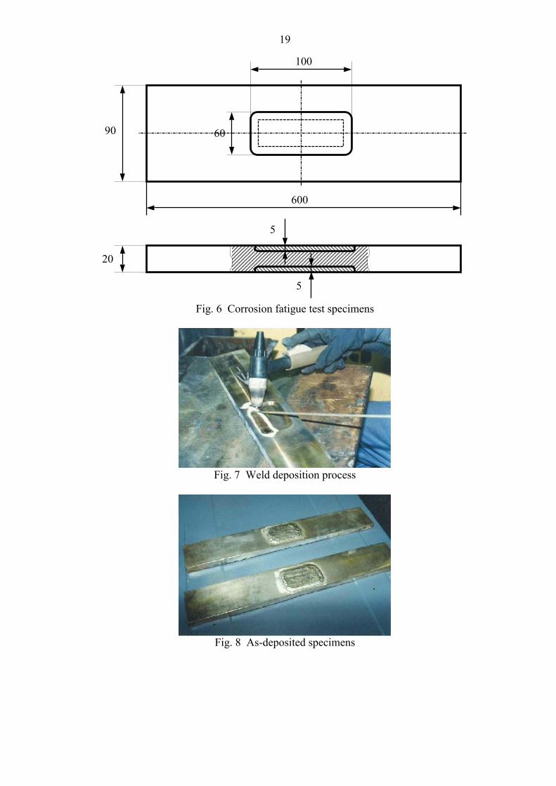
Specimens were weld deposited by the AC TIG process. BrAlFeNiMn 8,5-4-5-1,5 bronzewas used as a filler rod (Fig. 7.).
Deposition operation was performed by certified welders of Zvyozdochka in accordance witha data sheet for deposition.

9
Weld deposition conditions:
– prior to welding groove faces were degreased,– prior to welding specimens were heated up to 50+5 degrees C,– filler rod 4 mm in diameter,– welding current: 300 – 320amp,– argon flow: 12 – 15 liter/min,– every consequent bead was deposited after thorough brushing of the previous bead,– every consequent bead was deposited after cooling of the previous bead down to a
temperature 150 0C max,– weld metal was alternately deposited on each side of the specimen to avoid distortion.
One series of welded specimens was subjected to UIT of each weld pass. UIT conditionswere in compliance with those specified in Section 7.
The appearance of an as-welded specimen is shown in Fig. 8. Deposited metal on onespecimen underwent ultrasonic impact treatment.
Weld deposition, both before and after machining, was inspected by visual (dye penetrant)and X-ray examination. No unacceptable defects were detected.
One series of 10 specimens (No. 2/1 - 2/10) was subjected to stress relief heat treatment toconditions specified by Det Norske Veritas.
After final fabrication, all surfaces of specimens of series 3 were treated by mechanized UIT,including both deposited weld area and base metal to relieve residual welding stresses and hardenthe surface layer of the base metal and deposit (Fig. 9). This UIT technique would be intended toincrease the corrosion fatigue strength of the entire propeller blade.
UIT parameters:
- frequency of the ultrasonic generator 27kHz,- polarization current 10amp,- oscillation amplitude of output end of the waveguide 20 – 25 microns,- output power 600 - 800W,- pin one 5mm in diameter,- longitudinal feed of the machine-tool 400mm/min,- transverse feed 0,5mm/pass
9. HARDNESS TESTS
To check the effect of UIT on the surfaces of the weld and base metal, Brinell hardness testswere conducted.
A 10mm diameter ball with 1000kgf force was used. The results, which refer to themeasurement locations shown in Fig. 10, are presented in Table 5.
It will be noted that the hardness of specimens subjected to additional treatments has increasedsignificantly. The hardness of the deposited metal in the heat treated specimens is somewhathigher than that after UIT treatment. However, UIT produced the highest hardness in the basemetal.

10
Table 5 Bronze specimen Brinell hardness test results
Hardness in deposition area Hardness of UIT treated base metal Hardness of base metalSpecimenNo.
Measuringpoint
HB Average HB Measuringpoint
HB Average HB Measuringpoint
HB Average HB
2/1 (HT)
1
2
3
4
5
209
218
209
218
209
213 --- --- ---
6
7
8
9
10
148
148
153
148
153
150
3/1 (UIT)
1
2
3
4
5
200
200
200
200
200
200
6
7
8
9
10
193
185
193
185
193
190
11
12
13
14
15
148
143
143
148
143
145
4/1
1
2
3
4
5
159
159
159
159
159
159 --- --- ---
6
7
8
9
10
129
134
134
134
134
133
11
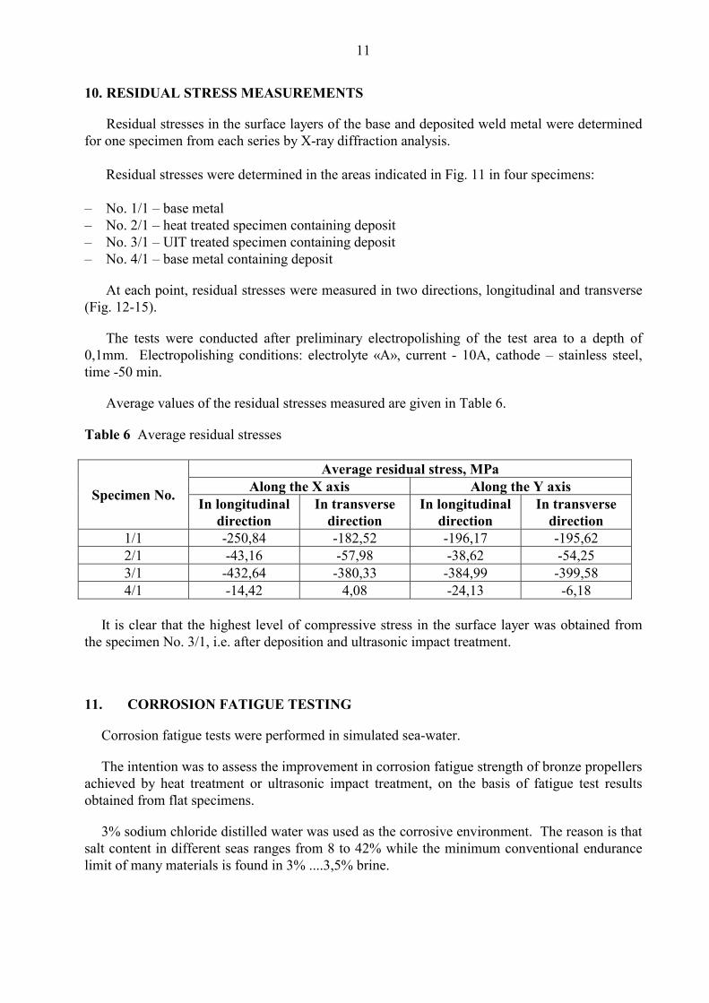
10. RESIDUAL STRESS MEASUREMENTS
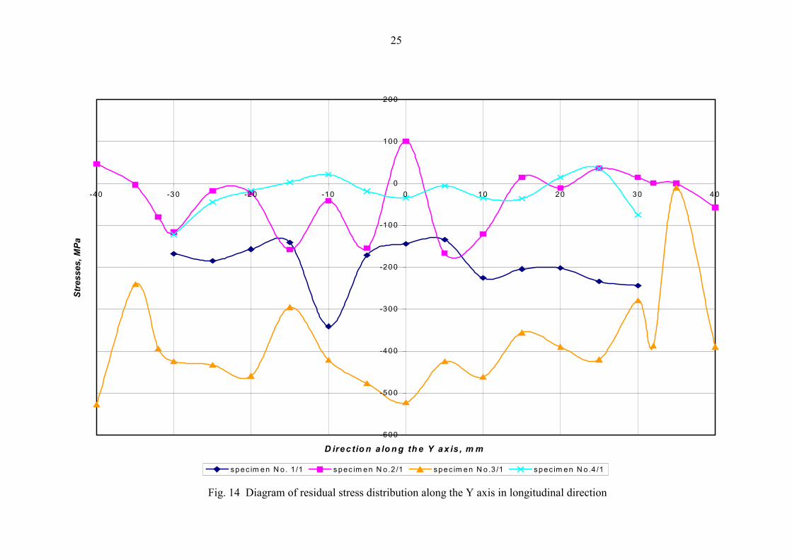
Residual stresses in the surface layers of the base and deposited weld metal were determinedfor one specimen from each series by X-ray diffraction analysis.
Residual stresses were determined in the areas indicated in Fig. 11 in four specimens:
– No. 1/1 – base metal– No. 2/1 – heat treated specimen containing deposit– No. 3/1 – UIT treated specimen containing deposit– No. 4/1 – base metal containing deposit
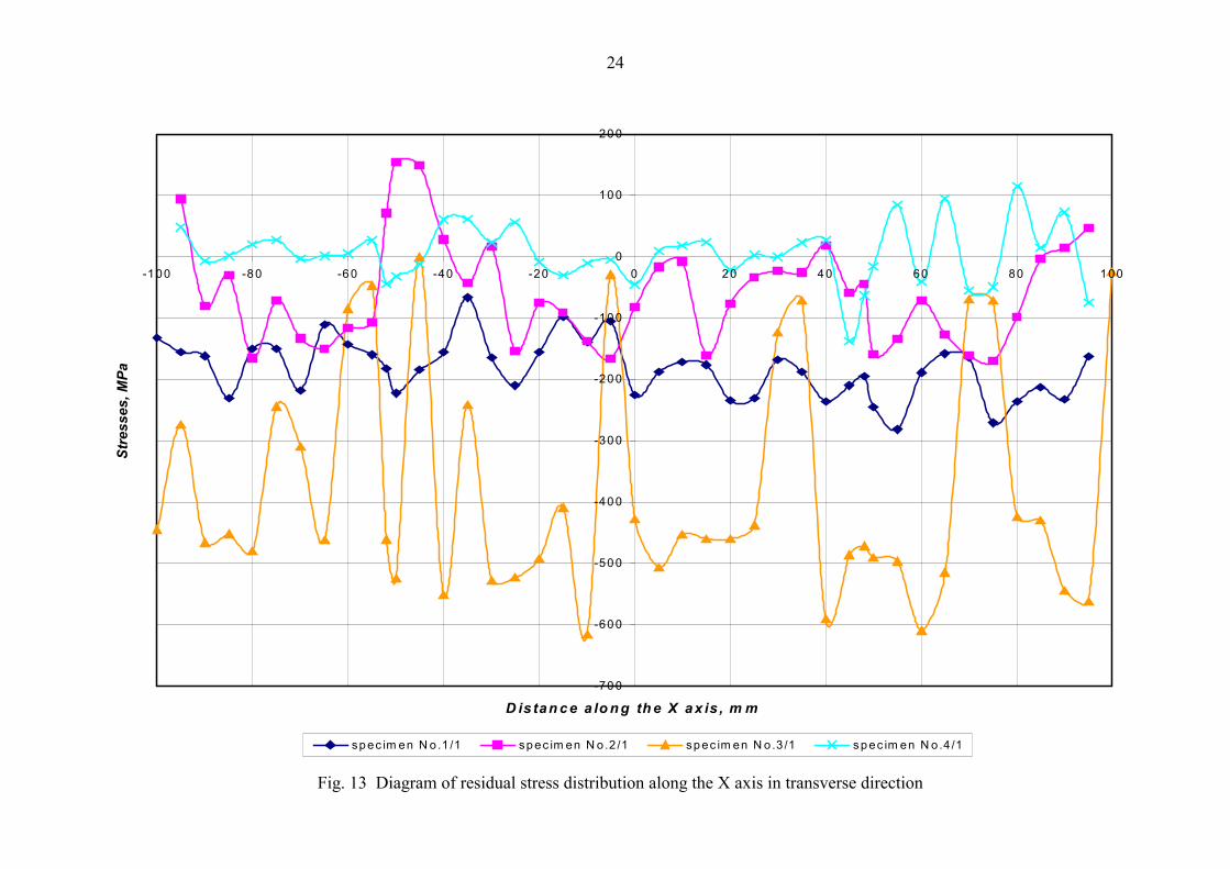
At each point, residual stresses were measured in two directions, longitudinal and transverse(Fig. 12-15).
The tests were conducted after preliminary electropolishing of the test area to a depth of0,1mm. Electropolishing conditions: electrolyte «A», current - 10A, cathode – stainless steel,time -50 min.
Average values of the residual stresses measured are given in Table 6.
Table 6 Average residual stresses
Average residual stress, MPaAlong the X axis Along the Y axisSpecimen No. In longitudinal
directionIn transverse
directionIn longitudinal
directionIn transverse
direction1/1 -250,84 -182,52 -196,17 -195,622/1 -43,16 -57,98 -38,62 -54,253/1 -432,64 -380,33 -384,99 -399,584/1 -14,42 4,08 -24,13 -6,18
It is clear that the highest level of compressive stress in the surface layer was obtained fromthe specimen No. 3/1, i.e. after deposition and ultrasonic impact treatment.
11. CORROSION FATIGUE TESTING
Corrosion fatigue tests were performed in simulated sea-water.
The intention was to assess the improvement in corrosion fatigue strength of bronze propellersachieved by heat treatment or ultrasonic impact treatment, on the basis of fatigue test resultsobtained from flat specimens.
3% sodium chloride distilled water was used as the corrosive environment. The reason is thatsalt content in different seas ranges from 8 to 42% while the minimum conventional endurancelimit of many materials is found in 3% ....3,5% brine.
12
Fatigue tests on specimens should be carried out under the most adverse cycle forms ofcorrosive environments, i.e. harmonic and triangular. Axial harmonic tension were realized at astress ratio R = + 0,5 which is close to propeller main load variation mode in service.
Specimens were fatigue tested under soft load conditions in the high-cycle regime at afrequency of 4-5Hz. Specimens of each series were tested using 9 stress range levels with stresslevels chosen to give lives in the range N 105 to 2 x 10⁶ cycles. Specimens were tested tocomplete failure. The moment of formation of the surface fatigue crack 4-5mm long wasrecorded.
The tests were performed using specially designed and fabricated equipment: a chamber anddevices for forced circulation of corrosive medium, electron-optical system for measuring fatiguecrack size during testing large-scale specimens.
The benefit of the post-weld treatment was determined through comparison of the corrosionfatigue curves from three series of specimens:
1) base metal;2) heat treated specimen with weld deposit;3) UIT treated specimen with weld deposit.
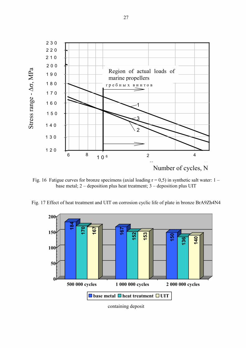
All fatigue curves are shown in Fig. 16 with the same scale for ease of comparison, while Fig.17 shows a comparison of the fatigue strengths obtained at various endurances.
Based on a comparison of fatigue test results, the corrosion fatigue resistance of UIT treatedbronze specimens containing weld deposits is about 86% of the corrosion fatigue resistance ofthe base-metal specimens in the low-cycle regime, and about 94% in the high-cycle regime. Bycomparison, the corrosion fatigue resistance of heat treated specimens in the same regimes isrespectively 93% and 90% of the base metal. This suggests that in synthetic salt water thebenefit of UIT of deposited welds increases with reduction in variable amplitude loading level,and conversely in the case of heat treatment. This is due to non-parallelism of fatigue curves forthe base metal and improved specimens with deposits. The fatigue curve slope for UIT treatedspecimens is lower than that for the base metal. In contrast, the fatigue curve slope for heattreated specimens is higher than that for the base metal.
11.1. Conclusions
� The fatigue strength at 2x10⁶ cycles obtained from UIT treated bronze specimens containingweld deposit is 140MPa, 93% of the value obtained from the base metal bronze specimens.This value is slightly higher than that obtained from the heat treated specimens with welddeposit.
� All the UIT treated specimens fatigue cracked in the base metal as against the heat treatedspecimens, which also failed at deposited metal or at deposit-base metal toes. Test resultsobtained from UIT treated specimens were less scattered as compared with those obtainedfrom the base metal and heat treated specimens.
� The slope of fatigue S-N curve for UIT treated specimens is lower than that for the basemetal and heat treated specimens. Hence, in the low-cycle regime the fatigue strength of UITtreated specimens is somewhat lower than that obtained from the base metal and heat treatedspecimens. However, for lives above 1 million cycles the lower fatigue curve slope for UITtreated specimens brings it closer to the fatigue curve for the base-metal specimens in Cu 3bronze.

13
12. ANALYSIS OF UIT EFFECT ON ETCHING
During residual stress analysis in the surface layers of bronze specimens UIT was found tohave the beneficial effect in terms of etching action.
The base and deposited metals both in the untreated and UIT treated conditions were subjectto electropolish etching to the depth 0,1mm. Electropolishing conditions were:– electrolyte “А”;– current 10А;– cathode – stainless steel;– etching time - 50 minutes– temperature 600С.
Electrolyte “А” is orthophosphoric acid (H3PO4)-base electrolyte with addition of sulfuricacid (H2SO4) and chromium anhydride (Cr2O3).
Two specimens No. 3/1 and 4/1 were studied. Specimen No. 3/1 were treated by ultrasonicimpact treatment, specimen No. 4/1 is in the as-deposited condition (untreated), see Fig. 18.
Specimen material is bronze grade Cu3, weld deposit material is bronze Br AlFeNiMn 8,5-4-5-1,5.
The etched areas on the base and deposited metal were photographed with magnification.
12.1 Comparative description
The etched surfaces were visually inspected using no magnifying devices and with the aid ofbinocular microscope MBS-9 of LOMO and metallurgical microscope MeF-4 of Reichert Jung.
The areas of the base and deposited metal were defined as a result of the etching process (Fig.19 and 20). By visual inspection it was found that, after etching, the base metal differs from thedeposited metal by higher surface roughness. Weld deposition was performed by TIG processusing an argon shielding gas and filler rods. The weld deposits have more pure chemicalcomposition, less segregation inclusions and more solid structure as compared to the as-castmetal. This is supported by the etch pattern on the surface, see Fig. 19 and 20 where the basemetal is seen to be corroded to a greater extent than the deposited metal.
On etching, the base metal areas not treated by UIT were found to differ significantly from theUIT treated base metal (Fig. 19 and 20).
By visual inspection it was found that the untreated metal (Fig. 20), after etching, has higherroughness than UIT treated metal (Fig. 19). In addition, the metal not treated by UIT has deeppitting randomly arranged on the etched surface.
Thus, the untreated base metal suffers higher corrosion damage as compared to the UITtreated base metal.
At the magnification (X20, 40, 50-1000), it is seen that:
– UIT treated base metal is covered with pitting 10-15 microns in depth and separate spot pitswith depth of not more than 30 microns (Fig. 21).

14
– Untreated base metal has the surface roughness governed by uneven etching of separateconstituents. The level difference between the constituents is about 10 microns.Considerable amount of spot pits is up to 80 microns in depth (Fig. 22).
After comparative analysis of specimens No. 3/1 and 4/1, the following was observed.
The etched surface of the untreated base metal differs from the etched base metal subjected toUIT by the presence of a great number of large pits visible with the naked eye.
In addition, the surface of the UIT treated material, after etching, remains smooth and notdamaged by corrosion.
The corrosion resistance in the surface layer of the cast bronze increases when UIT treatmentis applied.
13. ANALYSIS OF UIT TREATED MATERIAL IN DEPTH
UIT hardens the surface layers of the metal.
This study is intended to determine a depth of hardened layer on a bronze specimen. Platematerial is bronze of grade Cu 3, and weld deposit material is bronze of Br.AlFeNiMn 8,5-4-5-1,5 grade. Manual UIT treatment was applied both to the base and deposited metal.
The effect of the surface finish by soft Durex disk (flexible abrasive disk) to the depth ofremained hardened layer was also studied. For this purpose, the portion of the UIT treated platewas worked with Durex disks.
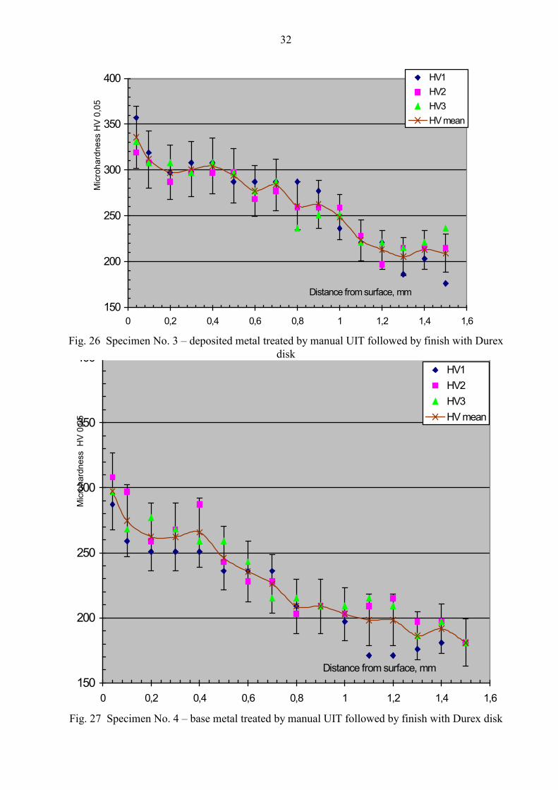
The depth of the hardened layer was determined by defining actual values and the mechanismof microhardness distribution obtained in the metal to a depth of up to 1.5mm.
The microhardness was measured using PMT-3 device under loading 0.490N (50 g-force) byindentation of tetrahedral diamond pyramid (HV 0,05).
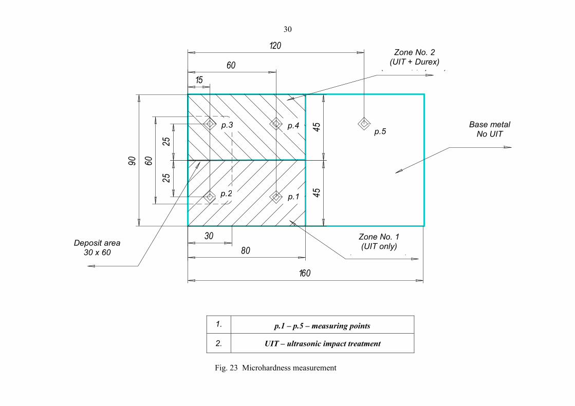
Microhardness was obtained in five points indicated in Fig. 23.
- zone No. 1 – the surface treated by manual UIT. Surface roughness in Rz = 29,1-52,9microns, and in Ra = 5,1-12,5 microns:
- point 1 – base metal,- point 2 – deposited metal;
- zone No. 2 – the surface treated by manual UIT followed by the surface finish with themanual abrasive tool (soft Durex disk). Surface roughness in Rz = 9,08–10,47 microns, andin Ra = 2,154–2,235 microns:
- point 3 – deposited metal;- point 4 – base metal,- point 5 – base metal. The surface was treated by the manual abrasive tool (soft Durex
disk) followed by manual polishing. Surface roughness in Rz = 1,36–4,50 microns, andin Ra = 0,55–1,08 microns.

15
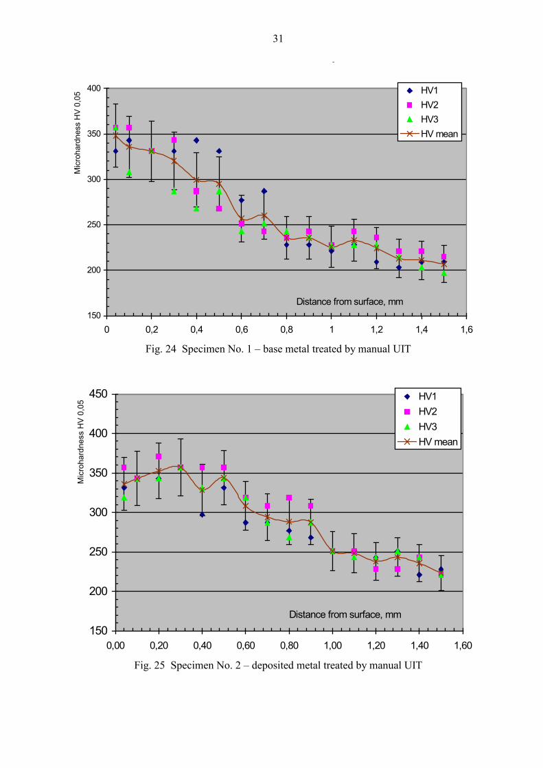
The microsections were then made through the above points to measure the microhardness at15 levels from the surface. First measurement point located at the minimal-allowable distancefrom the surface equal to 0.04mm. The rest measurement points were spaced at 0.1mm intervals.
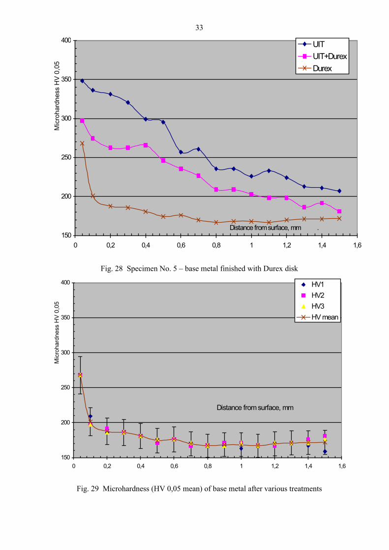
13.1 Microhardness measurement results
Microhardness measurement results are presented in Figs. 24-30.
UIT produced a hardened layer to a depth more than 1,5mm. Subsequent surface finish bysoft Durex disk reduces the depth of a hardened layer by 0,3-0,5mm, resulting in a hardened layerof a depth not less than 1mm.
UIT produces quite new surface layer in propellers in bronze Cu 3.
14. CONCLUSIONS
� A method has been developed for repairing casting defects with application of welding andconcurrent layer ultrasonic impact treatment during manufacture of propellers from bronzeCu3, allowing heat treatment to be omitted. Layer (during welding) and final ultrasonicimpact treatment produces high-quality welded joint that are not inferior to that subjected toheat treatment.
A method is based on the use of multifrequency UIT with carrier frequency of 27kHz. Thepower and repetition rate of ultrasonic impacts are determined by the treatment procedure.
� Analyses of corrosion fatigue characteristics of large-scale base-metal specimens, heat treatedspecimens with weld deposit and UIT treated specimens with deposit showed that in theregion of actual loads of marine propellers UIT gives much higher corrosion fatigue life forbronze blades with weld deposits compared to heat treatment.
� UIT increases the corrosion resistance of the as-cast bronze propeller surface in aggressiveenvironment.
� The surface treated by mechanized UIT is given a roughness Ra = 0,07 – 0,65 microns, that isnot lower than class 7. This is higher than the corresponding requirements to the quality ofthe propeller surface.
� UIT produces the hardened layer on the surface to a depth not less than 1,5mm. Surfacefinish, after manual UIT, using soft Durex disk reduces this layer only by 0,3-0,5mm. Thus,the depth of the UIT hardened layer after surface finishing with Durex disk is not less than1mm.
� Manual multifrequency UIT with carrier frequency of 27kHz increases the quality, enduranceand reliability of propellers in bronze Cu 3 as compared to heat treatment. Manual UITtreatment fits well with the actual propeller manufacturing conditions and being highlyeffective and inexpensive method.
� Manual multifrequency UIT with carrier frequency of 27kHz treatment does not eliminate thepossible application of conventional process steps for finishing a propeller surface (Durexdisks). These steps can be added to the manufacturing process after UIT application.

16
� Mechanized multifrequency UIT with carrier frequency of 27kHz allows the development ofthe propeller technology, giving propellers new high service performance and characteristicsin terms of customer demands.
15. REFERENCES
1. E.S. Statnikov. ‘Application of Operational Ultrasonic Impact Treatment (UIT)Technologies in Production of Welded Joints’. IIW Doc. XIII-1667-97.
2. E.S. Statnikov, V.I. Trufyakov, P.P. Mikheev and Yu.F. Kudryavtsev. ‘Specification forWeld Toe Improvement by Ultrasonic Impact Treatment’. IIW Doc. XIII-1617-96.
3. E.S. Statnikov. ‘Comparison of post-weld deformation methods for increase in fatiguestrength of welded joints’. IIW Doc. XIII-1668-97.
4. P.J. Haagensen. ‘IIW Collaborative Test Program on Improvement Methods’. IIW Doc.XIII-WG2-30-94.
5. P.J. Haagensen , P. d’Erasmo and B. Pettersen. ‘Fatigue performance in air and sea waterand fracture toughness of TIG-dressed steel weldments’. Proceedings European OffshoreSteel Research Seminar, The Welding Institute, Cambridge, UK, 1992. Paper 8.
6. V.T. Troshenko, L.A. Sosnovski. ‘Fatigue Resistance of Metals and Alloys’. Referencebook. Part 1 Kiev, “Naukova Dumka” 1987.

17
Fig. 1 UIT equipment
Fig. 2 Butt welded plate and tensile test specimen
Weld toes
Microstructure test specimens
Discard
Tensile test specimen
5�1
200
280
�=30Tensile test specimen
Discard
20
АА
Surfaces etchedА-А
30
280610 10
30
R50
�=30
6Weld toes

18
Fig. 3 UIT of each pass
Fig. 4 Failure mode of welded specimens
Fig. 5 Welded joints having no defects
19
Fig. 6 Corrosion fatigue test specimens
Fig. 7 Weld deposition process
Fig. 8 As-deposited specimens
100
90 60
600
5
20
5

20
Fig. 9 Mechanized UIT

21
Fig. 10 Diagram of hardness measurement on bronze specimens
Specimens No. 2/1; 3/1; 4/1
Specimen No. 3/1
Base metal
Base metal
Weld Deposition
Specimens No. 2/1; 3/1; 4/1

22
5,0
200
600
70 90
-X +X
-Y
+Y
0
Fig. 11 Layout of areas for measurement of specimen surface residual stresses
Deposition area100
60

23
-700
-600
-500
-400
-300
-200
-100
0
100
200
-100 -80 -60 -40 -20 0 20 40 60 80 100
Distance along the Х axis, m m
Stre
sses
, MPa
specim en No.1/1 specim en No.2/1 specim en No.3/1 specim en No.4/1
Fig. 12 Diagram of residual stress distribution along the X axis in longitudinal direction
24
-70 0
-60 0
-50 0
-40 0
-30 0
-20 0
-10 0
0
10 0
20 0
-1 00 -8 0 -6 0 -40 -20 0 20 4 0 60 80 1 00
D istan ce a lo n g th e X ax is , m m
Stre
sses
, MPa
sp ec im en N o.1 /1 sp ec im en N o.2 /1 sp ec im en N o.3 /1 sp ec im en N o.4 /1
Fig. 13 Diagram of residual stress distribution along the X axis in transverse direction
25
-600
-500
-400
-300
-200
-100
0
100
200
-40 -30 -20 -10 0 10 20 30 40
D irec tio n a lo n g th e Y ax is , m m
Stre
sses
, MPa
spec im en N o . 1 /1 s pec im en N o .2 /1 spec im en N o .3 /1 spec im en N o .4 /1
Fig. 14 Diagram of residual stress distribution along the Y axis in longitudinal direction

26
-700
-600
-500
-400
-300
-200
-100
0
100
200
-40 -30 -20 -10 0 10 20 30 40
D istan ce a long th e Y ax is , m m
Stre
sses
, MPa
spec im en N o.1/1 spec im en N o.2/1 spec im en N o.3/1 spec im en N o.4/1
Fig. 15 Diagram of residual stress distribution along the Y axis in transverse direction
27
Fig. 16 Fatigue curves for bronze specimens (axial loading r = 0,5) in synthetic salt water: 1 –base metal; 2 – deposition plus heat treatment; 3 – deposition plus UIT
Fig. 17 Effect of heat treatment and UIT on corrosion cyclic life of plate in bronze BrА9Zh4N4
containing deposit
Ч и с л о ц и к л о в , N1 0 66 8 2 4
1
2
3
О б л а с т ь р е а л ь н ы хн а г р у з о к к о р а б е л ь н ы хг р е б н ы х в и н т о в
Размах напряж
ений
- ��
, МПа
1 5 0
2 0 0 - -
- -
- -
- -
- -
- -
- -
- -
- -
- -
- -
- -
1 7 0
1 8 0
1 9 0
2 1 02 2 02 3 0
1 4 0
1 3 0
1 2 0
1 6 0
Region of actual loads ofmarine propellers
Stre
ss ra
nge
- ��
, MPa
Number of cycles, N
184
170
167
167
152
153
150
136
140
0
50
100
150
200
500 000 cycles 1 000 000 cycles 2 000 000 cycles
base metal heat treatment UIT

28
690
20
Ï ðî òðàâëåí í û é ó÷àñòî êî ñí î âí î ãî ì åòàëëà:ô î òî : ¹ 3/1-1;ô î òî ¹ 4/1-1
Ï ðî òðàâëåí í û é ó÷àñòî êí àï ëàâëåí í î ãî ì åòàëëà:ô î òî : ¹ 3/1-2;ô î òî ¹ 4/1-2.
Fig. 18 Specimens No. 3/1 and 4/1
х ~ 2,5
Fig. 19 UIT treated base metal after etching
x ~2,5
Fig. 20 Base metal after etching not treated by UIT
Etched region on basemetal:
Photo No. 3/1 – 1
Photo No. 4/1 – 1
Etched region ondeposited metal:
Photo No. 3/1 – 2
Photo No. 4/1 – 2

29
x 50Fig. 21 UIT treated base metal after etching
x 50Fig. 22 Base metal after etching not treated by UIT
30
1560
120
2525
6090
4545
3080
160
1. Т.1 - т .5 - точки замеров2. УУО - ультразвуковая ударная обработка
Район наплавки30 х 60
Зона № 1(только УУО)
Зона № 2(УУО + Дюрекс)
ò .4ò .3
ò .2 ò .1
ò .5 Основной металлбез УУО
p.2 p.1
Deposit area30 x 60
Zone No. 2(UIT + Durex)
p.3 p.4p.5
Base metalNo UIT
Zone No. 1(UIT only)
1. p.1 – p.5 – measuring points
2. UIT – ultrasonic impact treatment
Fig. 23 Microhardness measurement
31
y
150
200
250
300
350
400
0 0,2 0,4 0,6 0,8 1 1,2 1,4 1,6
Distance from surface, mm
Mic
roha
rdne
ss H
V 0,
05 HV1
HV2HV3HV mean
Fig. 24 Specimen No. 1 – base metal treated by manual UIT
150
200
250
300
350
400
450
0,00 0,20 0,40 0,60 0,80 1,00 1,20 1,40 1,60
Distance from surface, mm
Mic
roha
rdne
ss H
V 0,
05
HV1HV2HV3HV mean
Fig. 25 Specimen No. 2 – deposited metal treated by manual UIT
32
150
200
250
300
350
400
0 0,2 0,4 0,6 0,8 1 1,2 1,4 1,6
Distance from surface, mm
Mic
roha
rdne
ss H
V 0,
05
HV1HV2HV3HV mean
Fig. 26 Specimen No. 3 – deposited metal treated by manual UIT followed by finish with Durexdisk
150
200
250
300
350
400
0 0,2 0,4 0,6 0,8 1 1,2 1,4 1,6
Distance from surface, mm
Mic
roha
rdne
ss H
V 0,
05
HV1HV2HV3HV mean
Fig. 27 Specimen No. 4 – base metal treated by manual UIT followed by finish with Durex disk
33
150
200
250
300
350
400
0 0,2 0,4 0,6 0,8 1 1,2 1,4 1,6
Distance from surface, mm .
Mic
roha
rdne
ss H
V 0,
05
UIT UIT+DurexDurex
Fig. 28 Specimen No. 5 – base metal finished with Durex disk
150
200
250
300
350
400
0 0,2 0,4 0,6 0,8 1 1,2 1,4 1,6
Distance from surface, mm
Mic
roha
rdne
ss H
V 0,
05
HV1HV2HV3HV mean
Fig. 29 Microhardness (HV 0,05 mean) of base metal after various treatments

34
150
200
250
300
350
400
0 0,2 0,4 0,6 0,8 1 1,2 1,4 1,6
Distance from surface, mm
Mic
roha
rdne
ss H
V 0,
05UIT
UIT + Durex
Fig. 30 Microhardness (HV 0,05 mean) of deposited metal after various treatments