international and local experiences … chapter 5-6.pdf · of best practices in eco-houses both at...
TRANSCRIPT

192
CHAPTER 5
INTERNATIONAL AND LOCAL EXPERIENCES TOWARDS
ECO HOUSING
193
After reviewing the main principles of the Eco House, this chapter will present examples
of best practices in Eco-Houses both at the international and local levels in order to study
how these principles were applied and how were their outcomes. On the International
level, experiences from India, Israil and Tunisia were chosen because they applied lots of
eco design concepts from using low embodied materials, low cost construction techniques
and climatic design tools.
On the local level, experiences of pioneer architects such as Hassan Fathy and Ramses
Wissa Wassef , together with the house constructed in Toshka and the Ecolodge of Siwa,
were chosen for the local case studies. Along with these examples, efforts like: producing
Egypt's map of available raw building material and its industries, enhancing building
bricks to come with new types of bricks with insulation materials and bricks from
industrial wastes- construction and demolition wastes- agricultural wastes, producing
Egyptian residential energy code, had to be mentioned as a serious step towards
accomplishing the Eco-Eco house.

194
5.1. INTERNATIONAL EXPERIENCE TOWARDS ECO HOUSING
5.1.1 MONAMA
LOCATION : Hyderabad, India
CLIMATE : Inland composite
This house relies on energy efficient design to reduce loads and, where possible, reverts to
renewable energy to meet them. The house was completed in 2001.
5.1.1. A Low environmental impact:
The underlying ideology behind the building design was to generate as low an
environmental impact as possible, within the limits of site and budget. Environmental
impact resulting from both embodied (from materials) and operational (in use)
considerations were assessed.
5.1.1. B Construction materials:
Although the original idea was to use compressed earth blocks, on further investigation
the soil quality in the area was found to be unsuitable. It was realized that soil would have
to be transported from approximately 400 km away and country bricks that were made
within a couple of kilometers of the site would be a better alternative. Country bricks tend
to require plaster on the external side as they are not of a quality that can withstand the
extreme climate. The solution was to make cavity walls with country bricks on the inside
and first class, wire cut bricks on the external façade. As a result, the need to use plaster
was eliminated. This strategy also provides high thermal mass, which suits the prevailing
climatic conditions. The upper floor and roof structure is made with reinforced concrete,
which has low environmental impact. Natural materials have been chosen for most
internal finishes (Fig. 93).
5.1.1. C Wall orientation and form:
West oriented openings are associated with external conditions of high solar radiation and
ambient temperature during the summer. Thus the windows in this orientation were
minimized or replaced with other solutions. Depending on the time of the day, high or low
pressure zones form in either east or west directions. This induces air movement from the
zone of high pressure to that of low pressure. The windows of the house have been

195
specially oriented such that these pressure differences, in combination with the prevailing
wind direction, may be utilized for continuous ventilation. There is also a ventilation shaft
to exhaust hot air located in the central part of the house, which is based on the principles
of buoyancy and venturi's effect. The open plan design supports this process by
eliminating any internal resistance to the full movement of air (Fig. 95).
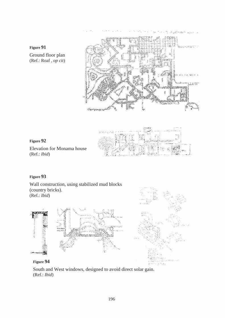
5.1.1. D Buried pipes and evaporative cooling:
The system used is a water pond along with an air fan. The system provides cooling by
consuming just the amount of electricity necessary for the operation of the fans. Since the
fans consume less energy than air conditioners this proves an energy efficient design for
maintaining human comfort. During the humid months evaporative coolers are rendered
inefficient owing to the high humidity levels. The system allows for the ponds to be
drained during these months (July through October) and window fans used to forcefully
ventilate the house (Fig. 96, Fig. 97).
5.1.1. E Renewable energy:
In Hyderabad there are four hours of power cut each day. The client specifications were to
design a system that works as a photovoltaic stand alone system during power cuts, and as
a regular grid connected system when the grid is working. The battery chosen for this
design allows for four days of autonomy, making unlikely that the client has to use the
utility power to charge the battery.
5.1.1. F Solar hot water collector:
The system chosen in this house was the free flow system known as a thermosiphon
system. The system has no pump or controls and is fully automatic in operation.
In the thermosiphon system the tank is positioned above the collector. As the water in the
collector is heated by the sun, it rises into the tank mounted above the collector. This
causes the cold water in the tank to flow into the collector, where it is heated. In this way,
flow is created and the tank is filled with hot water125 (Fig. 98).
125 Roaf , op cit, pp.304-309
196
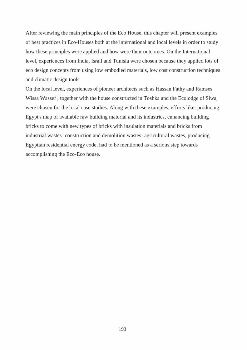
Figure 91 Ground floor plan (Ref.: Roaf , op cit)
Figure 92 Elevation for Monama house (Ref.: Ibid)
Figure 93 Wall construction, using stabilized mud blocks (country bricks). (Ref.: Ibid)
Figure 94 South and West windows, designed to avoid direct solar gain. (Ref.: Ibid)
197
Figure 95 Ventilation paths through the house (Ref.: Ibid)
Figure 97 Buried pipes. A: Inlet to circulate air 2m underground B: Outlet for living area, with adjustable "trunk" (Ref.: Ibid)
Figure 96 Evaporative cooling (Ref.: Ibid)
Figure 98
The solar water collector works by thermosiphon. (Ref.: Ibid)

198
5.1.2 REDEVELOPED PROPERTY AT CIVIL LINES
LOCATION : Civil lines, New Delhi, India.
CLIMATE : Composite
This project explores the challenges of designing and building a house in a dense urban
setting. This eco-project includes four courtyard houses built on a street. The houses on
the north face of the street are courtyard houses leading towards gardens on the south side;
whereas the houses on the south side of the street have their gardens on the north side and
are linear. These are all large single family houses, two to three storey high.
5.1.2. A Orientation:
The general orientation of the buildings is aligned east-west, with most window openings
in the north and south faces. The courtyard houses, because of their square proportions in
plan, also face towards the east and west. The windows on these faces look into narrow
protected alleys or the small courtyard between the houses. The alley space on the west
side is shaded by retaining the wall of the original double-storey building that had
previously lined the side street. For the linear houses on the north side, the width of the
driveway that separates the two row of houses is just sufficient to enable winter sunshine
to enter the first floor windows. Terraces on the second floor have skylights that again
admit winter sun into the first floor rooms on the north side of the house.
5.1.2. B Wind driven evaporative cooling:
The west house takes advantage of the prevailing north westerly hot winds that blow
during the hot dry seasons. A vertical screen tower is built on the west wall. This tower
houses Khus evaporative pads on its outer surface, fed by a water pump. The inner side
has adjustable windows opening into the adjacent rooms. The natural wind pressure will
drive air through the wet Khus pads and will then flow into the adjacent rooms. This
vertical arrangement would spread the Khus fragrance across the two storeys of the house
(Fig. 101).

199
5.1.2. C Courtyard roof:
The roof courtyard of the two courtyard houses is intended to be the main climate
response device. The hipped steel frame roof is cladded with a 20mm glass sandwich with
a reflective film and frosted underside for the most part, with a panel of transparent glass
on the south slope. This is under slung by a pair of razais (quilts), which can be pulled
across to cover the underside of the roof (for insulation) or allowed to hang down
vertically (to allow heat transfer). Above the roof is another frame in chicks (bamboo
severs), which can similarly be opened to shade the roof or rolled up to catch the sun.
The ridge of the roof is a water channel from which water overflows on to the thin roofing
membrane of stone and glass. Some water evaporates and excess water is collected at the
foot of the slope and re-circulated. This makes the roof a large evaporative cooler over the
central space of the house. All rooms communicate directly with this central space (Fig.
103, 104, 105).
The roof provides for:
1. Shading from outside / insulation from inside.
2. Roof evaporative cooling
3. Direct radiation
5.1.2. D Insulation / materials:
The roofs are finished with broken marble mosaic, which is reflective in nature.
The roof construction sandwich contains 30mm thick polyurethane board insulation above
the concrete slab. For the courtyard houses the western wall of the upper floor, the east
and west walls of the courtyard roof and the water tank walls are insulated using an
innovative construction sandwich of 115mm brick + 15mm plaster + 30mm polystyrene
foam + 50 mm terracotta jails, whose cavities are rendered with cement sand mortar.
Initially the courtyard roof was to be designed with 20mm thick stone slab. After
revisiting the idea, it was decided to replace the stone with glass sheets sandwiching a
reflective film to ensure a crack free, damp proof cover for water to stream over.

200
Figure 99 Façade of Courtyard House (Ref.: Ibid)
Figure 100 Ground floor plan (Ref.: Ibid)
Figure 102 Section (Ref.: Ibid)
Figure 101 Wind driven evaporative cooling (Ref.: Ibid)

201
Figure 103 Interactive courtyard roof (Ref.: Ibid)
Figure 104 West wall "Khus" cooling tower (Ref.: Ibid)
Figure 105 Looking up from the court (Ref.: Ibid)

202
5.1.3 MEIR HOUSE
LOCATION : Desert Highlands, Israel
CLIMATE : Arid, with hot and dry
summers, cold winters.
The Meir house was designed as a prototype
towards creating an energy conservating
urban building code. It combines external
insulation and internal thermal mass with
open plan.
5.1.3. A Thermal mass:
The wide diurnal temperature fluctuations characteristic of the Negev Desert climate
dictate the use of thermal mass, both for internal temperature damping and for energy
storage. The exterior walls are 250mm cellular concrete (YTONG) blocks, painted with a
high reflectivity ochre- coloured paint. The low conductivity of the YTONG blocks
eliminates the need for traditional sandwich wall sections or external insulation that
demands precise construction. Floors are reinforced concrete poured in place.
The roof is cast reinforced concrete, covered by extruded polystyrene, aerated sloped
cement and waterproofing. Aluminium frames encase double glazing for acoustical
considerations and are fitted with mosquito screens. To further reduce solar gains in the
summer, external aluminium rolling shutters filled with insulation (expanded
polyurethane) and interior Venetian horizontal and vertical blinds are fitted.
5.1.3.B Winter solar heating and solar water heating:
Approximately 24 m2 of the south façade and 8m2 of the east façade is glass, achieving a
passive approach to heating the house. The addition of a collapsible greenhouse on the
balcony, made of polycarbonate sheeting recovered from a dismantled agricultural
greenhouse, yielded winter temperatures of 35-36 deg C during the afternoon increasing
the room temperatures by 1-2 deg C with the help of a small fan that pushes the air into
the living spaces.
Figure 106
View of Meir house (Ref.: Ibid)

203
5.1.3. C Summer cooling and stack ventilation:
Although the higher windows provide solar access to the northern parts of the plan
(necessary in winter), the different height of spaces and operability enhance stack
ventilation and exhaust hot air from the upper strata (during the summer).
North and south facing windows enable cross ventilation during summer nights.
5.1.3. D Xeriscape
An intense post occupancy project was carried out to reduce by landscaping the amount of
wind driven dust. By laying stone paving, pebble ground covering, and planting drought
and salinity resistant plants, airborne dust is trapped and kept on the ground. Plants are
drip irrigated by a computer, providing a relative humidity sensor by-pass to the automatic
operation mode126.
126 Roaf , op cit, pp.330-343

204
5.1.4 TUNISIA SOLAR HOUSE\ PAVILION
LOCATION : Tunisia
CLIMATE : Pretty warm
The Tunisia Solar House, built by the
National School for Engineers, explores the
use of a passive heating element and a
trombe wall, among other features, in
identical and adjacent units that total 66m2
in area.
5.1.4. A Orientation / site
The aerodynamic shape decreases the wind pressure on the sides that are potentially
exposed to the prevailing winds. The shape forces windows to face 45 deg south of east
and west.
5.1.4. B Thermal mass
The construction materials of the west unit is made of an inner layer of 35cm stone, an
insulation of 6 cm cork and an outer layer of 6.5 cavity bricks resulting in a thermal
capacity of U= 0.51. The east unit has a double of cavity bricks separated by 6 cm of cork
insulation, which provides a higher insulator but lower thermal capacity (U=0.43). The
floor is a 10 cm concrete slab with 4 cm of cork insulation on 15 cm of stone. The cork is
placed under the stone in the floor of south area, which is subject to direct solar radiation.
The roof is a 20 cm thick concrete slab with 4 cm of cork on the outward side topped with
a reflective coating for summer radiation reflectance. The high level of insulation is not
customary in Tunisia dwellings. The trombe wall for each unit is made of 35 cm stone and
protected by a single glazing but without night insulation. The assembly (Fig. 109 A and
B ) is indicative of the very high thermal capacity and high insulative quality in each unit's
wall construction.
Figure 107
View of Tunisia house (Ref.: Ibid)

205
5.1.4. C Underground duct
A cooling chimney is integrated by way of an underground duct which pulls air from a
shaded area about 30m from the pavilion. The air crosses under the garden about 80 cm
below and is refreshed by the cold and humid soil above. The inlet into the pavilion on the
north side and an air flow was added later to blow air near the ceiling of the sitting room,
with the aid of a 30 W fan. However, operation of the underground duct when night
ventilation is active has shown to be disadvantageous. This is because room air in the case
of night ventilation is cooler than blown air from the underground duct.
The actual trombe wall with its thickness of 35 cm is a bit excessive. For this wall, double
glazing is of little help and is not cost effective. Thermal insulation is decisive for the
average level of room temperature but thermal capacity allows for the temperature to
remain stable127 (Fig. 110).
127 Roaf , op cit, pp.388-393
Figure 108
Ground Floor Plan (Ref.: Ibid)

206
Figure 109
A: East side B: West side (Ref.: Ibid)
Figure 110
a: Section showing underground duct and cooling chimney b and c : Ventilation is reactive to the seasons (Ref.: Ibid)

207
5.1.5 OSBORN CLAASSEN HOUSE, TUSCON,
LOCATION: ARIZONA, USA
CLIMATE: Hot arid
An overriding aim of the scheme was to be
as sit-sensitive as possible: the design was
developed after careful study of the
existing vegetation and the building was
almost surgically inserted into the native
desert so that no trees or cacti were
destroyed during construction. Rainwater
is diverted from the roof via a gutter that
runs the full depth of the house, but it is
not collected for domestic use so as not to
starve plants of water.
Construction materials
The rammed-earth construction of the house further emphasizes the site sensitivity and the
architect’s exposed intention to create a building that was rooted in the context and culture
of its surroundings. The soil used to construct the house was not drawn from the site, but
from three different sources in the immediate area-soils chosen for their color and
structural integrity. These were slightly moistened, mixed with a small amount of iron
oxide pigment and 3 percent Portland cement, and compacted into thick forms. The
unreinforced exposed rammed-earth walls sit on concrete stem walls and spread footings.
The north and south walls are 2 feet thick. The softly warping ‘butterfly’ roof is made of
weathered steel, extended out over the rammed-earth walls to serve as weather protection
and to shield the veranda from heat and sun. Interior walls, where they are not made of
exposed rammed earth, are of painted drywall on steel studs, and the floors are of polished
natural gray concrete and the windows are double-glazed128.
128 Wilhide, op cit, pp.52
Figure 111
View of Osborn house (Ref.: Wilhide, op cit)

208
.
Figure 113
The guest room is located on the north side of the house. (Ref.: Ibid)
Figure 114
The main living space of the house comprises an open eating, cooking, relaxing area. The rammed earth construction of the wall can clearly be seen (Ref.: Ibid)
Figure 112
View of the house with its background (Ref.: Ibid)

209
5.1.6 PALMETTO HOUSE, MIAMI
LOCATION: FLORIDA, USA
CLIMATE: Warm humid
The plan is in the form of a cross, with the longer sides of the building aligned north-
south, and the living space aligned east-west and raised up a level to catch the cooling
southeasterly breezes. On the south side, deep eaves keep the sun off exterior walls in the
summer; awnings shade the windows so they can be kept open, even during storms. At
either end, screened porches shield interior spaces from the sun; inside, there are few
partitions or walls so that air flows freely-the main living space is an open plan
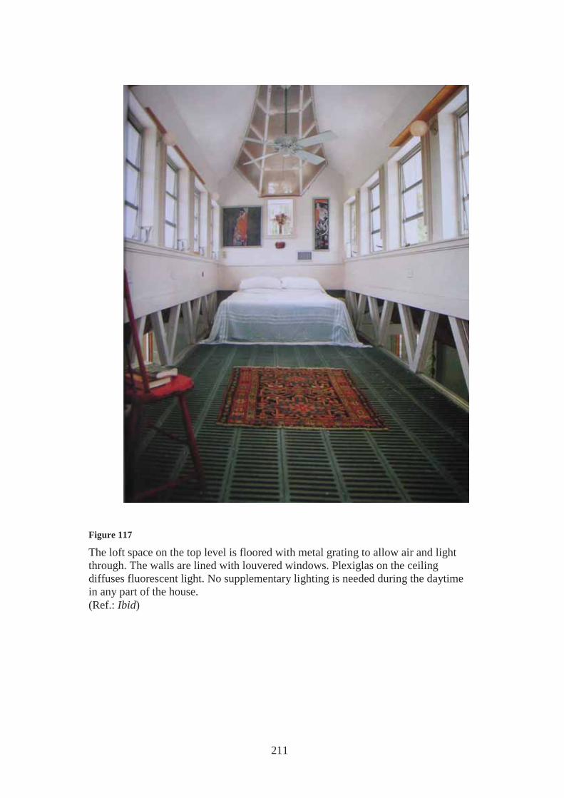
kitchen/living room/dinning room. The floor of the loft space is metal grating, which
allows air to circulate and permits light to filter through and the walls are lined in louvered
windows. Lush subtropical undergrowth shades the house at the lower level.
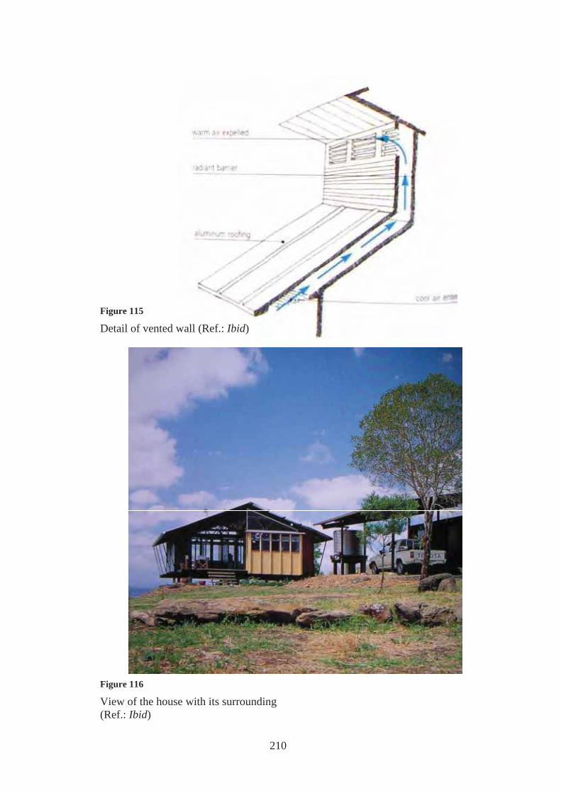
5.1.6. A Natural cooling
Material use also has a role to play in natural cooling. The exterior walls and roof are clad
with corrugated aluminum, which reflects the light and heat, high-mass concrete, used in
construction of the first floor keeps this part of the house cool.
The upper floors are lightweight timber-frame construction. To supplement these natural
cooling features, walls are also vented. Radiant barriers made of high-emissivity metal foil
inside the walls and roof trap heat before it has a chance to reach the interior and expel it
through high-level vents, drawing cooler air in from the shaded eaves (Fig. 115).
5.1.6. B Solar water heating
Almost all of the house’s hot water is heated by solar panels installed on the portion of the
roof that faces south, and the water is circulated by a pump powered by photovoltaic cells.
There is also a graywater system, with flow-control faucets to conserve water.
Unlike air conditioned homes, which must be hermetically sealed, this house is open to the
elements and to the sights, sounds, and smells of the natural landscape129.
129 Wilhide, op cit, pp.74
210
Figure 116
View of the house with its surrounding (Ref.: Ibid)
Figure 115
Detail of vented wall (Ref.: Ibid)
211
Figure 117
The loft space on the top level is floored with metal grating to allow air and light through. The walls are lined with louvered windows. Plexiglas on the ceiling diffuses fluorescent light. No supplementary lighting is needed during the daytime in any part of the house. (Ref.: Ibid)
212
5.2. LOCAL EXPERIENCE TOWARDS ECO HOUSING
5.2.1 NEW BARIZ BY HASSAN FATHY
The first Chairman's Award (which was established to honour special acheivments) was
given in 1980 to Hassan Fathy, an Egyptian architect, artist and poet in acknowledgment
of his lifelong commitment to architecture. Early in career he began to study the
preindustrial building systems of Egypt to understand their aesthetic qualities, to learn
what they had to teach about climate control and economical construction techniques and
to find ways to put them in contemporary use. In his lifetime he designed more than 30
projects including several villages for the poor and modest private residences shaped by
his profound understanding of vernacular design130.
LOCATION : Kharga Oasis, Egypt
CLIMATE : Arid, with hot and dry summers, cold winters.
5.2.1. A Courtyards
One of his most distinguished projects is the village of "New Bariz" in kharga oasis.
In this project, Fathy decided to employ a system of internal courtyards as a primary
means of climate control in his design, along with shading. In his initial presentation, he
stressed that thermal comfort in the housing design he proposed depended on the natural
control of air temperature, air movement, relative humidity and radiation. Air movement
was to be generated by creating a pressure differential and by convection, utilizing the
basic physical principle that hot air rises and is replaced by cooler air to best advantage.
5.2.1.B Wind driven evaporative cooling:
To bring air into the series of internal courtyards planned for each house, he proposed
wind towers, or "Badgirs" to catch the higher cooler breeze above the desert, and bring it
into each house. 130 FISA and Aga Khan, (1996), “Architecture for a Changing World”, Graficas Urania, Malaga
213
His refinement, also used in the market, where cool temperatures were essentials to
preserve agricultural perishables awaiting shipment to larger markets, consisted of two
shafts. One of these has an opening facing the windward side, and the other face the
leeward side with a metal-bladed funnel pointed downward, which ensures suction by
Venturi effect. This second stack and funnel have been painted black to draw air from
below as they are heated by the sun. To add to their cooling capacity the windward towers
had straw mats hanging inside them which were damped by a hand pump at regular
intervals during the day
5.2.1.C Building materials
A shortage of viable building materials indicated a repetition of the same vault and dome
system in mud brick, used at New Gourna, with paraffin and bitumen emulsions used as
stabilizers, since the soil at Kharga Oasis is of poorer quality than that near the Nile.
5.2.1.D Construction System
The housing, had it been built, would undoubtedly have functioned equally well, but we
only have his working drawings to show us what it would have looked like.
Rather than the domes that predominate in New Gourna, he relied mostly on a "Barasti"
truss system; a lighter reed and wire frame roof that was easily built and helped to
promote better convection. The repetitive, triangular forms of the Barasti roof, topping off
the linear, two-story housing blocks, would have been as visually distinctive as the
Badgirs of the market131.
131 Steel, op cit, pp.79-84

214
Ground Floor
First floor
Figure 118
Site plan of New Bariz (Ref.: Steel, op cit)
Figure 119
Plan of neighbourhood unit for non farmers (Ref.: Ibid)
215
Roof plan
Figure 120
Plan, sections and elevations of neighbourhood unit for non farmers (Ref.: Ibid)
Figure 121
Roofscape of market at New Bariz (Ref.: Ibid)

216
5.2.2 ART CENTER BY RAMSES WISSA WASSEF
Agakhan winning award
Near the pyramids of Giza, the centre was founded in the early 1950s by the late architect
Ramses Wissa Wassef as a weaving school. It has since evolved to comprise workshops
and showrooms, a pottery and sculpture museum, houses and farm buildings, constructed
entirely of mud brick. For Wissa Wassef, vaulted and domed brick structures represented
something quintessentially Egyptian as these forms had been adopted in turn by
Pharaonic, Coptic and Islamic civilizations. The choice of this traditional technology also
reflected his desire to transmit the values of handicraft to succeeding generations in a
rapidly industrializing country. The jury commended the centre for "the beauty of its
execution, the high value of its objectives, the social impact of its activities as well as the
power of its influence as an example"132
Scale 1:200
132 FISA, op cit
Figure 122
Section and plan for the art center in Haraneya (Ref.: FISA, op cit)

217
Figure 123
Different shots for the art center with its background (Ref.: Ibid)

218
5.2.3 TOSHKA HOUSE
LOCATION : Toshka region - Egypt
CLIMATE : Hot arid
A house in Toshka was built as a prototype through which several passive systems were
applied to reach an acceptable thermal performance in this region through out the whole
year using the most convenient construction method in this area and the available local
building materials. The house was built on an area of 200m2
5.2.3.A Building material:
Made of light weighted concrete blocks that are thermally insulated (Lyca aggregate -
cement-sand- thermal insulation). Its dimensions are 20x30x40 cm. This block is made by
a manual compressor. (Fig. 124-125)
The U-value of this block reached 0.365 watt/ m2 deg C which is a very low value
compared to traditional building materials that reached a U-value greater than 1.5 watt/m2
deg C
5.2.3.B Construction system:
The construction method used in this house is bearing walls using the previously
mentioned concrete block.
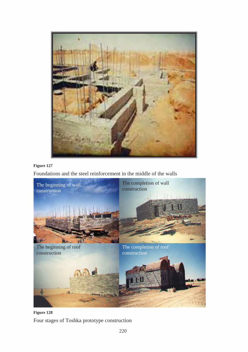
Reinforced walls are simply built by interlocking those blocks together thus saving
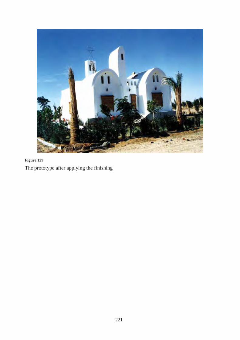
mortar, and therefore decreasing the costs. (Fig. 126-127-128)
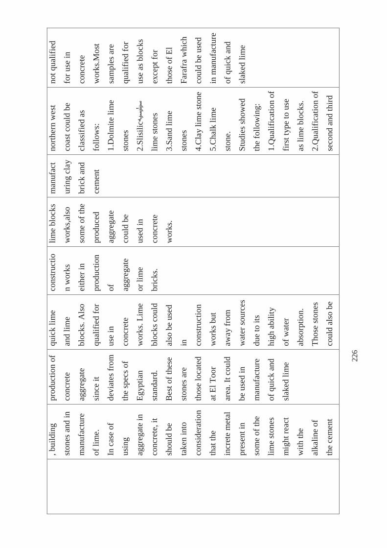
5.2.3.C Evaporative cooling:
Wind catchers were used to enhance natural ventilation, and further, water sprinklers were
used inside those ducts to cool the air before entering the house spaces.
The house is thermally comfortable through out the months October and November and
bearable in the period from July till September133. (Fig. 129)
133 :)(""
-

219
Figure 124
The manual compressor for concrete block production.
Figure 125
Light weighted concrete block with insulation material
Figure 126
The steel reinforcement in wall construction and the way of preventing it from conducting the heat
220
The beginning of roof construction
The completion of wall construction
The completion of roof construction
The beginning of wall construction
Figure 127
Foundations and the steel reinforcement in the middle of the walls
Figure 128
Four stages of Toshka prototype construction
221
Figure 129
The prototype after applying the finishing

222
5.2.4 ECOLODGE IN SIWA
LOCATION: SIWA-EGYPT
CLIMATE: HOT ARID
The ecolodge is a hotel located in Siwa, and it was chosen to be presented in our case
studies although it is not a residential case study and does not use electricity at all because
it has adopted a no. of eco design principles which we can learn from.
Built on the edge of the Sahara, at the foot of a mountain and next to a mirage-like lake
(that is as salty as the Dead Sea and great for the skin).134
The hotel was built using the traditional Berber techniques and architecture used in Siwa
for centuries. It is completely made out of mud, wood, straw, and salt.
The locals made everything in the hotel from the doors to the furniture by hand. There is
no electricity but night ventures are enjoyed by candlelight135. There is no telephone or air
conditioning136. The lodge even has its own organic garden where the food for all meals is
grown137.
134 http://greenthenewblack.blogspot.com 135 http://community.iexplore.com 136 http://greenthenewblack.blogspot.com 137 http://community.iexplore.com
Figure 130
Interior spaces are lit using natural day lighting in the morning and candle lights at night

223
Figure 131
Exterior views for the Ecolodge with its background

224
5.2.5 EGYPTS MAP OF AVAILABLE RAW BUILDING MATERIAL AND ITS
INDUSTRIES
The objective from this study made on Egypt was as follows:
Classifying and locating raw building materials all over Egypt.
Introducing the chemical and natural properties of raw materials in different locations.
Listing industries of building materials depending on those raw materials.
Offering a geo technical map of raw material locations that are qualified for use all
over the republic and industries depending upon it.
This study is important for architects because it identifies the available local materials
in order to use it and decrease the embodied energy.
Building materials were classified all over the Arab Republic of Egypt into:
• Clay
• Gypsum
• Aggregate (lime stones and its reciprocals such as dolmite – sand – gravel -
bazalt…etc)
• Decorative stones
The Republic was divided into eight areas:
1. North of Sinai
2. South of Sinai
3. Delta – East of Delta – East of
Tafreea
4. Suez Gulf and Red Sea
5. Nile valley
6. Toshka region – South of the valley
7. Western Northern Coast and West of Delta
8. Oasis and East of Oaynat
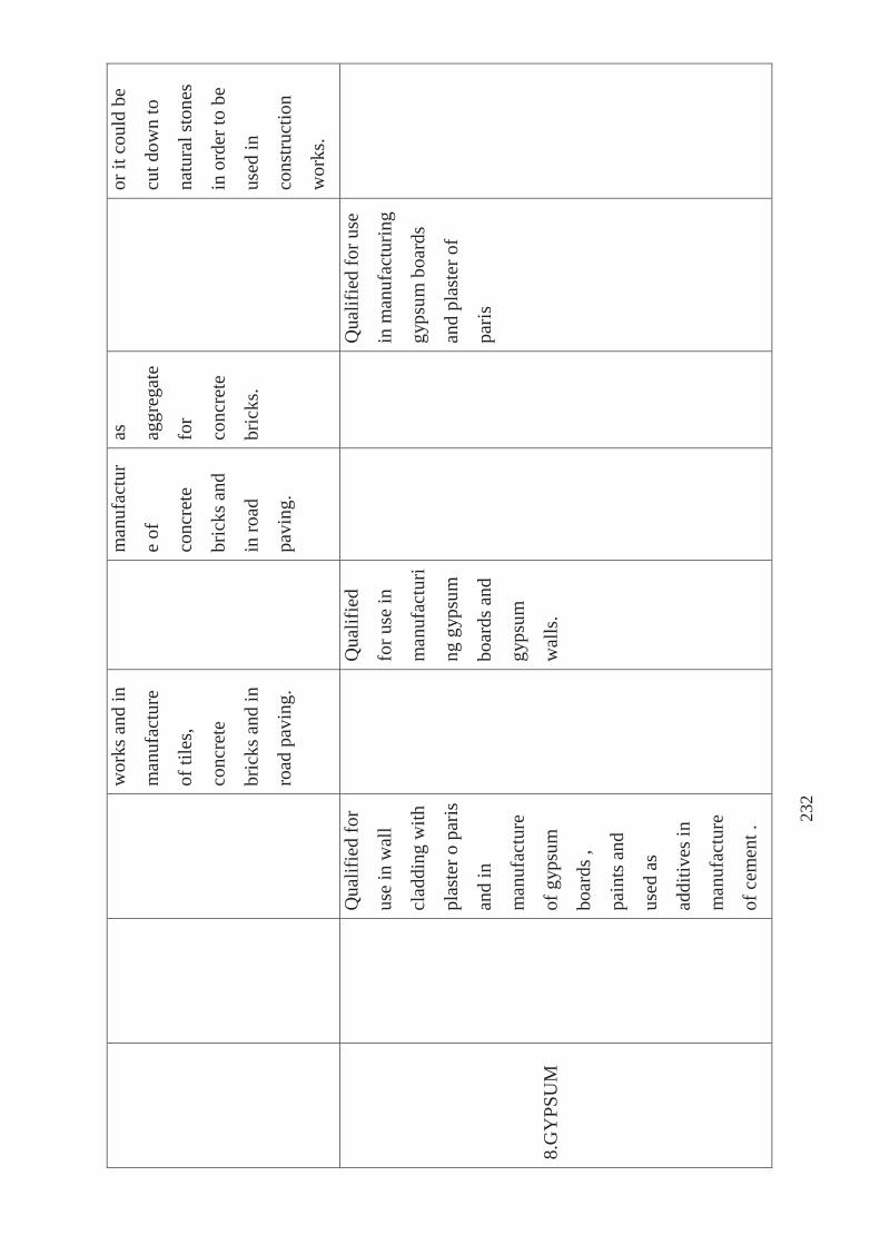
The following table (20) presents the eight
above mentioned areas of Egypt with its available raw materials138.
Table (20) Available raw building materials in the eight areas of Egypt and its industries. 138 :""
Figure 132
Egypt's map divided into eight areas "
"

225
RA
W
BU
ILD
ING
MA
TE
RIA
L
S
AR
EA
S
Nor
th o
f
Sina
i
Sout
h of
Sina
i
Eas
t of D
elta
– E
ast o
f
Taf
reea
Suez
Gul
f
and
Red
Sea
Nile
val
ley
Tos
hka
regi
on –
Sout
h of
the
valle
y
Wes
tern
Nor
ther
n C
oast
and
Wes
t of
Del
ta
Oas
is a
nd
Eas
t of
Oay
nat
1.C
LAY
Qua
lifie
d fo
r
use
in
man
ufac
turin
g cl
ay b
rick
Qua
lifie
d fo
r
use
in
man
ufac
turin
g cl
ay b
rick
and
cem
ent
Qua
lifie
d fo
r
use
in
man
ufac
turin
g cl
ay b
rick
Qua
lifie
d
for u
se in
man
ufac
turi
ng c
lay
bric
k
Qua
lifie
d
for u
se in
man
ufac
turi
ng c
lay
bric
k
Qua
lifie
d
for u
se in
man
ufac
t
urin
g cl
ay
bric
k an
d
cem
ent
Qua
lifie
d fo
r use
in m
anuf
actu
ring
clay
bric
k an
d in
gene
ral i
t nee
ds
addi
tion
of sa
nd
due
to it
s
sens
itivi
ty to
dryi
ng
Qua
lifie
d fo
r
use
in
man
ufac
turin
g
clay
bric
k ,it
coul
d al
so b
e
used
in
man
ufac
ture
of
light
wei
ghte
d
bric
k(Li
ca) o
r
cem
ent
2.LI
ME
STO
NE
Qua
lifie
d fo
r
use
as b
lock
s
Un
qual
ified
for
Qua
lifie
d fo
r
prod
uctio
n of
Qua
lifie
d
for u
se in
Qua
lifie
d
for u
se in
Qua
lifie
d
for u
se in
Type
s of l
ime
ston
es in
Agg
rega
te o
f
lime
ston
es is
226
, bui
ldin
g
ston
es a
nd in
man
ufac
ture
of li
me.
In c
ase
of
usin
g
aggr
egat
e in
conc
rete
, it
shou
ld b
e
take
n in
to
cons
ider
atio
n
that
the
incr
ete
met
al
pres
ent i
n
som
e of
the
lime
ston
es
mig
ht re
act
with
the
alka
line
of
the
cem
ent
prod
uctio
n of
conc
rete
aggr
egat
e
sinc
e it
devi
ates
from
the
spec
s of
Egyp
tian
stan
dard
.
Bes
t of t
hese
ston
es a
re
thos
e lo
cate
d
at E
l Too
r
area
. It c
ould
be u
sed
in
man
ufac
ture
of q
uick
and
slak
ed li
me
quic
k lim
e
and
lime
bloc
ks. A
lso
qual
ified
for
use
in
conc
rete
wor
ks. L
ime
bloc
ks c
ould
also
be
used
in
cons
truct
ion
wor
ks b
ut
away
from
wat
er so
urce
s
due
to it
s
high
abi
lity
of w
ater
abso
rptio
n.
Thos
e st
ones
coul
d al
so b
e
cons
truct
io
n w
orks
eith
er in
prod
uctio
n
of
aggr
egat
e
or li
me
bric
ks.
lime
bloc
ks
wor
ks,a
lso
som
e of
the
prod
uced
aggr
egat
e
coul
d be
used
in
conc
rete
wor
ks.
man
ufac
t
urin
g cl
ay
bric
k an
d
cem
ent
north
ern
wes
t
coas
t cou
ld b
e
clas
sifie
d as
follo
ws:
1.D
olm
ite li
me
ston
es
2.Sl
isili
c
lime
ston
es
3.Sa
nd li
me
ston
es
4.C
lay
lime
ston
e
5.C
halk
lim
e
ston
e.
Stud
ies s
how
ed
the
follo
win
g:
1.Q
ualif
icat
ion
of
first
type
to u
se
as li
me
bloc
ks.
2.Q
ualif
icat
ion
of
seco
nd a
nd th
ird
not q
ualif
ied
for u
se in
conc
rete
wor
ks.M
ost
sam
ples
are
qual
ified
for
use
as b
lock
s
exce
pt fo
r
thos
e of
El
Fara
fra
whi
ch
coul
d be
use
d
in m
anuf
actu
re
of q
uick
and
slak
ed li
me

227
whi
ch c
ould
caus
e cr
acks
in c
oncr
ete
stru
ctur
e.
used
in
man
ufac
ture
of q
uick
and
slak
ed li
me
type
to u
se a
s
aggr
egat
e in
conc
rete
wor
ks
and
cem
ent
bric
ks a
nd a
s raw
mat
eria
l in
man
ufac
ture
of
cem
ent a
nd a
s
ston
es fo
r
cons
truct
ion.
3.Fo
urth
type
coul
d be
use
d in
man
ufac
ture
of
clay
bric
ks
4.Fi
fth ty
pe
coul
d be
use
d in
prod
uctio
n of
quic
k an
d sl
aked
lime
3.M
AR
BLE
Th
ere
are
Ther
e ar
e tw
o
Qua
lifie
d O
f goo
d

228
diff
eren
t
type
s of
mar
ble
such
as :E
l Fel
eto-
El se
lsel
a –
El sh
abah
and
they
are
all
qual
ified
for
use
in
clad
ding
and
deco
rativ
e
wor
ks a
nd in
prod
uctio
n of
bloc
ks.
type
s of
mar
ble:
whi
te
with
bla
ck
vein
s and
blac
k w
ith
whi
te v
eins
.
They
are
of
good
qua
lity
for u
se in
wal
l cla
ddin
g
,ent
ranc
es,
stai
rs a
nd in
deco
rativ
e
wor
ks.
for u
se in
cons
truct
io
n w
orks
.
mec
hani
cal
and
natu
ral
qual
ities
.
4.G
RA
NIT
E
O
f goo
d
mec
hani
cal
and
natu
ral
qual
ities
.
Abu
ndan
tly
foun
d in
Asw
an a
nd
Qui
na ,i
t is
red
in c
olor
and
of v
ery
Qua
lifie
d
for
clad
ding
wor
ks a
nd
faca
des.
Q
ualif
ied
for
clad
ding
wor
ks
and
faca
des.
Agg
rega
te
prod
uced
from
natu
ral

229
high
resi
stiv
ity to
pres
sure
,it
is n
ot
easi
ly
affe
cted
by
chem
ical
fact
ors.
clim
atic
cto
rs
and
foun
d in
valle
ys ,
coul
d
be u
sed
in
man
ufac
ture
of
conc
rete
bric
ks
and
tiles
.
5.SA
ND
Stan
dard
spec
s
devi
ates
from
spec
s of
aggr
egat
e
used
in
conc
rete
wor
ks, b
ut it
is su
itabl
e fo
r
mor
tar a
nd
plas
ter w
orks
,
or a
s an
Unq
ualif
ied
for u
se in
cons
truct
ion
wor
ks a
nd
conc
rete
.
Qua
lifie
d fo
r
use
in
cons
truct
ion
wor
ks, t
akin
g
into
cons
ider
atio
n
parti
cle
grad
atio
n an
d
avoi
ding
mud
and
soft
subs
tanc
es.
But
in
Unq
ualif
ied
for u
se in
cons
truct
io
n w
orks
due
to th
e
devi
atio
n of
its p
artic
le
grad
atio
n
from
stan
dard
spec
s,
besi
des
Qua
lifie
d
for u
se in
cons
truct
ion
wor
ks.
Use
d in
man
ufac
t
ure
of
clay
,
conc
rete
and
sand
bric
ks.
Foun
d in
are
as
of w
est a
nd e
ast
bank
s of C
airo
–
Ale
xand
ria d
eser
t
road
and
it is
qual
ified
for u
se
in c
onst
ruct
ion
wor
ks su
ch a
s:
conc
rete
wor
ks-
mor
tar a
nd
plas
ter-
as a
n
addi
tive
in
Unq
ualif
ied
for u
se in
conc
rete
wor
ks, b
ut it
coul
d be
use
d
in p
last
er a
nd
mor
tar w
orks
or a
s add
itive
s
in m
anuf
actu
re
of o
ther
cons
truct
ion
mat
eria
ls su
ch

230
addi
tive
in
man
ufac
ture
of c
lay,
sand
and
conc
rete
bric
ks. W
hite
sand
is
abun
dant
ly
foun
d an
d it
is k
now
n fo
r
its h
igh
purit
y
whi
ch
qual
ifies
it
for u
se in
glas
s
man
ufac
ture
.
gene
ral i
t
coul
d be
use
d
in m
orta
r and
plas
ter w
orks
or a
s
addi
tives
in
man
ufac
ture
of c
oncr
ete
,sand
and
clay
bric
ks.
cont
aini
ng
high
perc
enta
ges
of m
ud a
nd
soft
subs
tanc
es
whi
ch m
ay
reac
h 11
%.
man
ufac
ture
of
clay
, con
cret
e
and
sand
bric
ks.
as c
lay
,
conc
rete
and
sand
bric
ks.
6.G
RA
VEL
AN
D
GR
AV
EL
SOIL
Qua
lifie
d fo
r
use
in
conc
rete
wor
ks, e
xcep
t
that
in
Un
qual
ified
for u
se in
conc
rete
wor
ks d
ue to
its d
evia
tion
Qua
lifie
d fo
r
use
in
conc
rete
wor
ks, e
xcep
t
that
in
Nee
ds to
redo
its
parti
cle
grad
atio
n
sinc
e it
Qua
lifie
d
for u
se in
conc
rete
wor
ks,
exce
pt th
at
Salis
ilic
grav
el
is q
ualif
ied
for
use
in c
oncr
ete
wor
ks,b
ut th
e
carb
onic

231
gene
ral i
t
need
s
impr
ovin
g its
parti
cle
grad
atio
n.
from
stan
dard
Egyp
tian
spec
s exc
ept
for t
hose
sam
ples
in E
l
Toor
of
gran
ite
orig
in, t
hose
sam
ples
are
qual
ified
for
use
in
conc
rete
aggr
egat
e.
gene
ral i
t
need
s
impr
ovin
g its
parti
cle
grad
atio
n.
devi
ates
from
stan
dard
Egyp
tian
spec
s of
conc
rete
aggr
egat
e.
Res
t of
prop
ertie
s
are
qual
ified
for u
se in
cons
truct
io
n w
orks
.
in g
ener
al it
need
s
impr
ovin
g
its p
artic
le
grad
atio
n.
grav
el is
not
,but
,it c
ould
be u
sed
in
pavi
ng w
orks
.
7.B
AZA
LT
A
ggre
gate
is
prod
uced
from
baz
alt
Baz
alt o
f Abu
zaba
l is
qual
ified
for
use
as
aggr
egat
e in
conc
rete
Q
ualif
ied
for u
se a
s
aggr
egat
e in
conc
rete
wor
ks a
nd
in
Qua
lifie
d
for u
se in
plan
e an
d
rein
forc
ed
conc
rete
wor
ks a
nd
Q
ualif
ied
for
use
as
aggr
egat
e in
conc
rete
wor
ks
and
in ro
ad
pavi
ng w
orks
232
wor
ks a
nd in
man
ufac
ture
of ti
les,
conc
rete
bric
ks a
nd in
road
pav
ing.
man
ufac
tur
e of
conc
rete
bric
ks a
nd
in ro
ad
pavi
ng.
as
aggr
egat
e
for
conc
rete
bric
ks.
or it
cou
ld b
e
cut d
own
to
natu
ral s
tone
s
in o
rder
to b
e
used
in
cons
truct
ion
wor
ks.
8.G
YPS
UM
Q
ualif
ied
for
use
in w
all
clad
ding
with
plas
ter o
par
is
and
in
man
ufac
ture
of g
ypsu
m
boar
ds ,
pain
ts a
nd
used
as
addi
tives
in
man
ufac
ture
of c
emen
t .
Q
ualif
ied
for u
se in
man
ufac
turi
ng g
ypsu
m
boar
ds a
nd
gyps
um
wal
ls.
Qua
lifie
d fo
r use
in m
anuf
actu
ring
gyps
um b
oard
s
and
plas
ter o
f
paris

233
9.ST
EEL
Perc
enta
ge
of ir
on
oxid
e in
raw
stee
l
exce
eds
80%
Perc
enta
ge o
f
iron
oxid
e in
raw
stee
l
reac
hes 7
4%
by w
eigh
t
10.S
AN
D
STO
NE
Con
tain
s an
acce
ptab
le
perc
enta
ge
of m
iner
als.
Its ro
cks a
re
of h
igh
resi
stiv
ity to
deca
ying
and
of g
ood
mec
hani
cal
and
natu
ral
prop
ertie
s.
Cou
ld b
e us
ed
in p
rodu
ctio
n
of st
one
bloc
ks
and
in
cons
truct
ion
wor
ks.

234
Figu
re 1
33
Raw
bui
ldin
g m
ater
ial s
ites i
n Eg
ypt

235
Figu
re 1
34
Bui
ldin
g m
ater
ial m
anuf
actu
re si
tes i
n Eg
ypt
236
5.2.6 ENHANCING BUILDING BRICKS
Efforts were made to enhance building bricks from different angles.
First: to decrease the U-value and thermal capacity in order to fit in arid conditions.
Second: to produce a recyclable building bricks with low environmental impact.
Both will be discussed respectively.
5.2.6.A Studies and experiments have been held in order to find a way to combine
building materials with thermal insulation material, and the results of those studies
confirmed the importance of using thermal insulation materials with building materials.
Those special bricks have passed through laboratory experiments using five different
walls with five different types of bricks and hot box to show the heat flow and U-value
of each type of brick and results came as follows (Fig. 135):
First wall:
Was built from hollow clay brick with thickness of 25 cm.
Results showed that heat flow reached 60 watt / m2 which confirm the ability of the
brick to prevent heat flow and creating thermal accumulation in outer crust of the brick
which causes reduction of heat flow and consequently reduces the U- value and increase
the thermal resistance of the brick. Also the thermal accumulation resulted in increasing
temperature difference between layer of brick facing the hot room and middle of the
brick which shows capability of this brick, with addition of thermal insulation material,
to reduce heat flow.
Second wall:
Was built from hollow concrete blocks with thickness of 25cm.
The brick contains two consecutive voids. Results showed that heat flow reached 120
watt / m2 which indicate that it is not suitable for use in hot climates due to the increase
of U-value and its low thermal resistance which makes it incapable of creating thermal
accumulation thermal accumulation on the outer crust of the brick.

237
Third wall:
Was built from concrete bricks insulated with extruded polystyrene with thickness of
7.5cm and at 4cm away from the outer surface of the brick, it is also has two separate
voids. Results showed that this brick is suitable for use in hot dry regions since it has
low U-value due to presence of insulating material.
Fourth wall:
Was built from hollow concrete blocks with thickness of 12.5cm.
The brick contains three consecutive voids, but it was taken into consideration, when
building a wall of 25cm thickness, to alternate the void locations in order to create two
separate alternating voids of 4cm apart. Results showed that heat flow reached 29
watt/m2, which clarifies the effect of the two voids in comparison to hollow concrete
blocks in second wall. And so therefore one can say that using two voids in a brick has
good effect on decreasing the U-value, it also decreases the thermal storage capacity of
the brick.
Fifth wall:
Was built from concrete bricks made from light weighted Lyca as a substitute of
aggregate with thickness of 30cm.
This brick has three defensive lines of thermal insulating material from extruded
polystyrene, it was taken into consideration in this brick to distribute the insulating
material in a way to prevent the heat transfer through thermal bridges in the brick.
This type of bricks is constructed b interlocking without using any mortar.
The wall was reinforced by steel horizontally and vertically through leaving voids
without thermal insulation every 80cm to place the steel bars. Results showed that heat
flow reached 18 watt/m2. This type of bricks is considered very suitable since its
manufacture depends on clay Lyca, also it does not contain high percentages of cement.
The outer layer of Lyca facing exterior climatic conditions store heat during day and
expel it during night, this is due to the role of the thermal insulating material in creating
thermal accumulation.
238
Conclusion
From previous study, the following findings can be concluded:
1. Usage of building materials available in the hot dry region alone is not enough and
does not fulfill the thermal needs of the building, and therefore thermal insulation
materials should be used with those building materials in order to increase its thermal
resistivity and decrease its thermal capacity. Thermal insulation layer must be placed in
the outer surface of the wall in order to create a layer capable of storing heat during day
and expelling it during night.
2. Usage of several consecutive air voids in walls give positive results in decreasing the
U- value, it also decreases the thermal capacity of the structure and therefore the
building structure becomes convenient during night. Reflective thermal insulation
materials could be placed on the outer layer139.
139 : "" -

239
Figure 135
Different types of bricks and its corresponding walls : ""

240
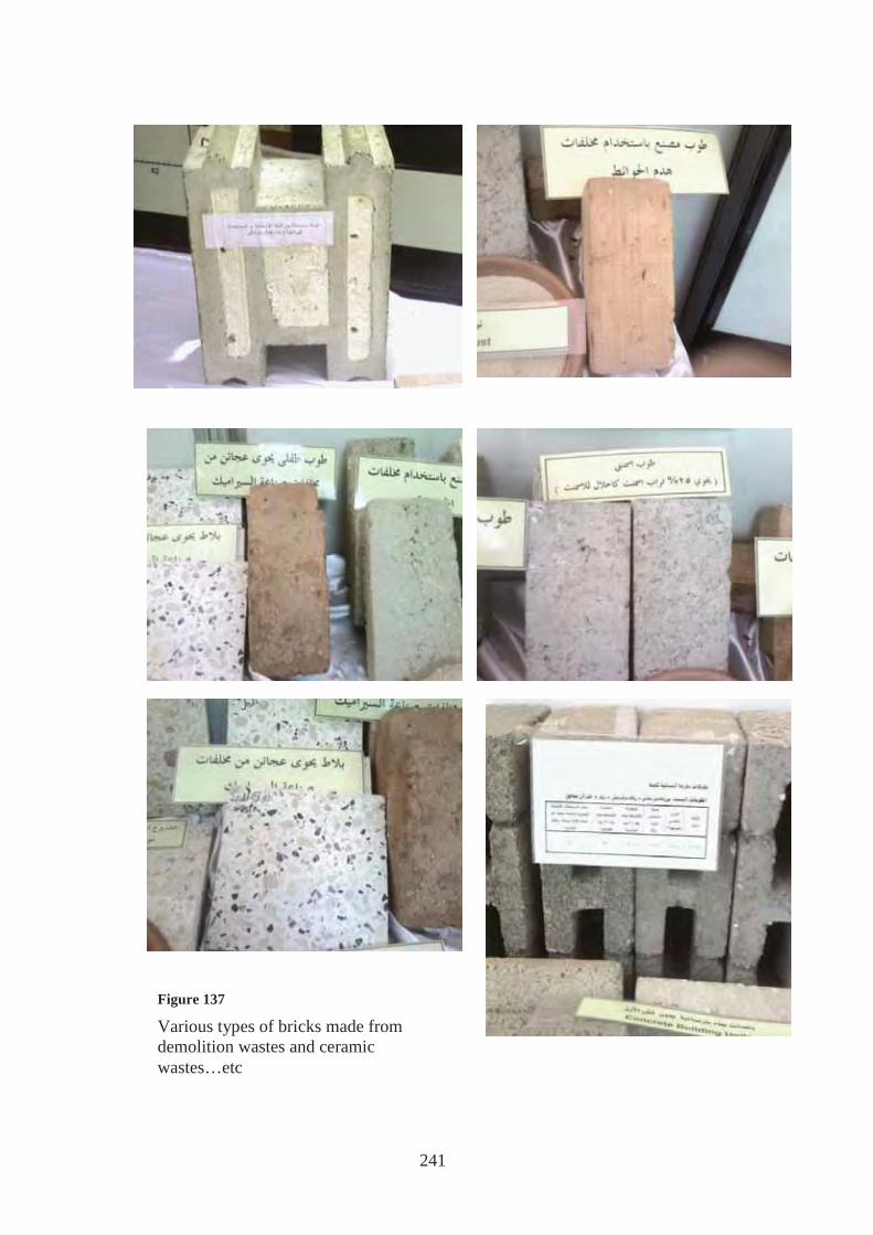
5.2.6.B Other bricks were created by HBRC in order to make good use of solid wastes
in its different forms because solid wastes are considered one of the most important
environmental problems and according to statistics of environmental ministry, the total
amount of solid wastes in Egypt reached 60 million tons annually and that included:
Industrial wastes- construction and demolition wastes- agricultural wastes…etc.
Examples of industrial wastes are:
• Wastes of ceramic tiles during manufacture.
• Wastes of clay brick industry
• Wastes of by-pass cement dust
Figure 136
Different types of bricks made from industrial and construction- demolition wastes: First one from left is cement block that contains 25% of cement dust Middle one is clay brick made of clay brick manufacture wastes Last one is clay brick that contains ceramic wastes
241
Figure 137
Various types of bricks made from demolition wastes and ceramic wastes…etc

242
One of the most important examples of agricultural waste in Egypt which caused a lot of
troubles is “rice straw”, where the amount of rice straw reaches 2 million tons per year.
The peasants have tried to get rid of it by burning it but this caused what is called “the
black cloud” which caused lots of illnesses besides, the burning process raises the soil
temperature and emits the ammonia present in the soil and so the soil loses a great
amount of one of its most important elements.
So studies were made and the results came out as follows:
• Production of low density construction units using rice straw
• Production of thermally insulated construction units which contain rice straw
• Production of gypsum boards that contain rice straw 140
140 :"
Figure 138
Thermally insulating clay bricks that contain different percentages of rice straw
Figure 139
Thermally insulating cement bricks that contain different percentages of rice straw

243
5.2.7 Egyptian Residential Energy Code
The Housing and Building National Research Center (HBRC) and the Organization for
Energy Planning (OEP) were engaged in an effort to produce an Egyptian Code for the
residential buildings. The project intended to improve the efficient use of electrical
energy. The Egyptian Residential building code gives minimum performance standards
for building envelope, windows and openings, natural ventilation and thermal comfort,
natural and artificial lighting. A great effort has been made to ensure its applicability in
our buildings here in Egypt specifically to the general climate conditions of the two
cities, Cairo and Alexandria. For example, the exterior building envelope must comply
with the following requirements141:
5.2.7.A Non air conditioned buildings in Cairo
Table (21) Requirements of building envelope for non air conditioned buildings in Cairo
and Delta region
(a) R Values for typical Roof construction are equivalent to: 141 " :"
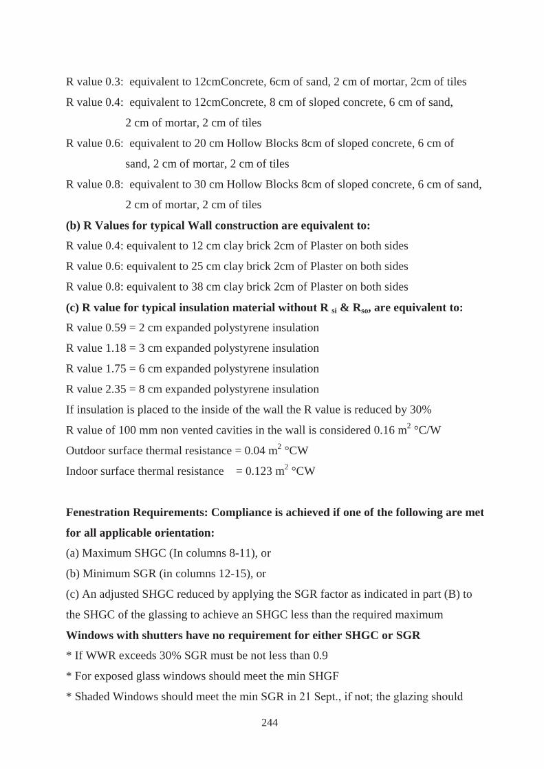
244
R value 0.3: equivalent to 12cmConcrete, 6cm of sand, 2 cm of mortar, 2cm of tiles
R value 0.4: equivalent to 12cmConcrete, 8 cm of sloped concrete, 6 cm of sand,
2 cm of mortar, 2 cm of tiles
R value 0.6: equivalent to 20 cm Hollow Blocks 8cm of sloped concrete, 6 cm of
sand, 2 cm of mortar, 2 cm of tiles
R value 0.8: equivalent to 30 cm Hollow Blocks 8cm of sloped concrete, 6 cm of sand,
2 cm of mortar, 2 cm of tiles
(b) R Values for typical Wall construction are equivalent to:
R value 0.4: equivalent to 12 cm clay brick 2cm of Plaster on both sides
R value 0.6: equivalent to 25 cm clay brick 2cm of Plaster on both sides
R value 0.8: equivalent to 38 cm clay brick 2cm of Plaster on both sides
(c) R value for typical insulation material without R si & Rso, are equivalent to:
R value 0.59 = 2 cm expanded polystyrene insulation
R value 1.18 = 3 cm expanded polystyrene insulation
R value 1.75 = 6 cm expanded polystyrene insulation
R value 2.35 = 8 cm expanded polystyrene insulation
If insulation is placed to the inside of the wall the R value is reduced by 30%
R value of 100 mm non vented cavities in the wall is considered 0.16 m2 °C/W
Outdoor surface thermal resistance = 0.04 m2 °CW
Indoor surface thermal resistance = 0.123 m2 °CW
Fenestration Requirements: Compliance is achieved if one of the following are met
for all applicable orientation:
(a) Maximum SHGC (In columns 8-11), or
(b) Minimum SGR (in columns 12-15), or
(c) An adjusted SHGC reduced by applying the SGR factor as indicated in part (B) to
the SHGC of the glassing to achieve an SHGC less than the required maximum
Windows with shutters have no requirement for either SHGC or SGR
* If WWR exceeds 30% SGR must be not less than 0.9
* For exposed glass windows should meet the min SHGF
* Shaded Windows should meet the min SGR i

245
meet the SHGC requirement.
These SHGC values are calculated including window frames
0.27 = reflective single glazing CLR 20%
0.75 = clear single glazing
SGR = percentage of glazing surface shaded from 9 am to 5 pm on 21 September.
5.2.7.B Non air conditioned buildings in North Coast
Table (22) Requirements of building envelope for non air conditioned buildings in
North Coast region
(a) R Values for typical Roof construction are equivalent to:
R value 0.3: equivalent to: 12 cm Concrete, 6cm of sand, 2 cm of mortar, 2 cm of tiles
R value 0.4: equivalent to: 12 cm Concrete, 8 cm of sloped concrete, 6cm of sand,
2 cm of mortar, 2 cm of tiles
R value 0.6: equivalent to: 20 cm Hollow Blocks 8 cm of sloped concrete, 6cm of sand,
2 cm of mortar, 2 cm of tiles
R value 0.8: equivalent to: 30 cm Hollow Blocks 8 cm of sloped concrete, 6cm of sand,
2 cm of mortar, 2 cm of tiles
(b) R Values for typical Wall construction are equivalent to:

246
R value 0.4: equivalent to: 12 cm clay brick 2cm of Plaster on both sides
R value 0.6: equivalent to: 25 cm clay brick 2cm of Plaster on both sides
R value 0.8: equivalent to: 38 cm clay brick 2cm of Plaster on both sides
(c) R value for typical insulation material without R si & Rso, are equivalent to:
R value 0.59 = 2 cm expanded polystyrene insulation with k= 0.032 W/m°C
R value 1.18 = 3 cm expanded polystyrene insulation with k= 0.032 W/m°C
R value 1.75 = 6 cm expanded polystyrene insulation with k= 0.032 W/m°C
R value 2.35 = 8 cm expanded polystyrene insulation with k= 0.032 W/m°C
If insulation is placed to the inside of the wall the R value is reduced by 30%
R value of 100 mm non vented cavities in the wall is considered 0.16 m2 °C/W
Outdoor surface thermal resistance = 0.04 m2 °CW
Indoor surface thermal resistance = 0.123 m2 °CW
Fenestration Requirements: Compliance is achieved if one of the following are met
for all applicable orientation:
(a) Maximum SHGC (In columns 8-11), or
(b) Minimum SGR (in columns 12-15), or
(c) An adjusted SHGC reduced by applying the SGR factor as indicated in part (B) to
the SHGC of the glassing to achieve an SHGC less than the required maximum.
Windows with shutters have no requirement for either SHGC or SGR.
* If WWR exceeds 30% SGR must be not less than 0 9
* For exposed glass windows should meet the min SHGF
* Shaded windows should meet the min SGR in 21 Sept.
If not, the glazing shall meet the SHGC requirement.
These SHGC values are calculated including window frames
0.27 = Reflective single glazing CLR 20%
0.75 = Clear single glazing
247
Conclusion
This chapter reviews international and local case studies of eco houses.
It is also concerned with the local efforts made as an approach for achieving an echo
house. Those efforts were as follows:
• Map of Egypt for available raw material and its industries.
This part divided the republic into eight areas and discussed the raw materials found in
each area and its industries and the conclusion is as follows:
1. Clay:
Present abundantly in all different eight areas that were previously mentioned, and it is
qualified for use in manufacture of clay bricks.
2. Lime stone:
Present in most of the eight areas, and is qualified for use in lime blocks and lime
bricks.
3. Marble:
Located abundantly and with various types in North of Sinai - South of Sinai - Suez
Gulf and Red Sea - Nile Valley, and it is qualified for use in cladding and decorative
works.
4. Granite:
Located in South of Sinai – Nile Valley – Toshka region and South of the valley –
Oasis and East of Oaynat , but it is abundantly found in Aswan and Quina where it is
red in color and of very high resistivity , it is qualified for use in cladding and
manufacture of concrete bricks and tiles.
5. Sand:
White sand is abundantly found in North of Sinai and it is known for its high purity
which qualifies it for use in glass manufacture.
Sand located in: South of Sinai - Suez gulf and Red sea – Oasis and East of Oaynat
areas is unqualified for use in construction works such as: concrete works, mortar and
plaster. Sand located in other areas is qualified for use in construction works and in
manufacture of clay, sand and concrete bricks.
248
6. Gravel and gravel soil:
Located in all areas except in Toshka region, South of the valley, Western Northern
coast and West of Delta.It is qualified for use in concrete works in all areas except in
South of Sinai.
7. Bazalt:
Located in all areas except in: North of Sinai, Delta - East of Delta - East of Tafreea,
Western Northern Coast and West of Delta.
It is qualified for use as aggregate in concrete works and in manufacture of concrete
bricks and in road paving.
8. Gypsum:
Located in South of Sinai – Suez Gulf and Red sea – Western Northern Coast and
West
of Delta. It is qualified for use in wall cladding with plaster of paris and in
manufacture of gypsum boards.
9. Steel:
Located in the Nile Valley, Oasis and East of Oaynat.
10. Sand Stone:
Located in the Nile Valley, Oasis and East of Oaynat. It is qualified for use in
construction works.
• Enhancing building bricks
A study has been held in HBRC on different types of construction bricks and
comparisons were made between them, conclusion of this study was as follows:
1. Usage of building materials available in the hot dry region alone is not enough and
does not fulfill the thermal needs of a building, and therefore thermal insulation
materials should be used with those building materials in order to increase its
thermal resistivity and decrease its thermal capacity. Thermal insulation layer must
be placed in the outer surface of the wall in order to create a layer capable of
storing heat during day and expelling it during night.

249
2. Usage of several consecutive air voids in walls give positive results in decreasing
the U- value , it also decreases the thermal capacity of the structure and therefore
the building structure becomes convenient during night. Reflective thermal
insulation materials could be placed on the outer layer.
New types of bricks were created in HBRC in order to make use of solid wastes, such
as:
• Wastes of ceramic tiles
• Wastes of clay brick
• Wastes of by pass cement dust
Also other bricks were made from agricultural waste such as rice straw.
• Egyptian residential Energy code
The Egyptian residential energy code gives minimum performance standards for
windows and openings, natural ventilation and thermal comfort, natural and artificial
lighting, where the exterior building envelope must comply with the requirements
mentioned in the code.
After reviewing all the principles concerning the Eco Eco house, a cost analysis system
is established to help designers through out the design process and decision making.

250
CHAPTER 6
ESTABLISHMENT OF COST ANALYSIS SYSTEM FOR ECO-HOUSE DESIGN

251
Studies have shown an urgent need for establishing a cost analysis system in order to
help designers reach a trade off between cost and ecological aspects during the different
phases of housing development. This earned a top priority because of all what has been
stated before in addition to the coming two factors:
1. In Egypt, buildings in general are responsible for 60.18% of the total electricity
consumption in all sectors. Energy demand has reached about 69.2 Billion kWh with an
annual increase of 7%, where the industry takes about 43%, Residential and commercial
buildings share is 42.6%, Governmental buildings and services consume about 16.7%
while Agriculture use only 4%. The two major consumers of electricity are households
and industry, followed by Government and public utilities. In order to reduce the energy
consumption in buildings, the Housing and Building Research Centre in collaboration
with UNDP&JEF. Has produced a building code to provide designers with know how
but we need to provide them also with cost effectiveness evaluation tool to help them
making decisions related to the market, the client affordability and the developments
plans drawn by the government.
2. Modernization trends in building designs in Egypt imported a new technology which
has led to an increase in energy consumption in buildings and at the urban scale for
many reasons:
- Exaggeration in use of metal and glass
- Not using thermal insulation in general practice
- Relying totally on mechanical air conditioning
- No effort done in design to adapt foreign technology to local conditions
Studies of the building industry in Egypt and technological innovations in the building
industry ( intelligent building elements and systems, component for renewable energy)
Show that the cost of these ecological components is still too high to encourage its use
on a large scale. Therefore, feasibility studies and methods to balance costs with benefits
are urgently needed142.
142 Prof. Dr. Suzette Michel and Eng. Hend Elsayed, (2006), “Examples of low energy design at Urban scale in Egypt”, PLEA2006
252
The thesis recommends a thorough cost analysis system for ecological houses helping
designers to decide according to checklists and choices available in each design phase.
The following is a proposal for a total approach followed by examples of detailed
modules supporting the total system that needs further development and completion in
future studies.
6.1 An integrated approach to achieve trade off between the ecological and
economical aspects of housing design
The designer is constantly making decisions as he goes through the design process.
Each decision has a cost impact that should be analysed and in order to achieve eco-
cities, eco-districts and eco-houses, additional costs might be required, therefore, a
comparison should be done between eco-design cost and the regular or traditional
design solutions in terms of costs taking into consideration all the advantages listed
previously from eco-design and the pay back that may not be instantly felt but on the
long run. The following chart proposes an approach of cost analysis following the
design phases to help defining the costs of eco-house. This system is composed of steps
following design process:
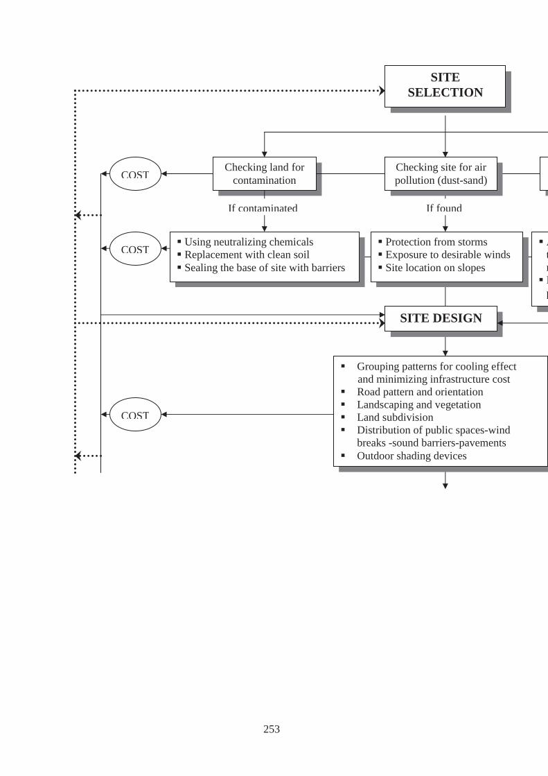
253
Checking land for contamination
Using neutralizing chemicals Replacement with clean soil Sealing the base of site with barriers
Protection from storms Exposure to desirable winds Site location on slopes
Grouping patterns for cooling effect and minimizing infrastructure cost Road pattern and orientation Landscaping and vegetation Land subdivision Distribution of public spaces-wind
breaks -sound barriers-pavements Outdoor shading devices
SITE DESIGN
If contaminated
SITE SELECTION
If found
COST
AtrNp
COST
COST
Checking site for air pollution (dust-sand)

254
Implementing ecological economical design factors: Outer shape Size, no. of rooms and their areas No. of storey Clear storey height Horizontal grouping Openings
BuCheFVCCInchevOshwN
SHELTER DESIGN
CONSTRUCTION
GARDENING AND LANDSCAPE Choice of species
Choice of irrigation system
COST
ADDITIONAL COSTS TO
ACHIEVE ECO DESIGN
Building materials Locality of materials Embodied energy of materials Recycling and renewability of materials
Building envelope Roof insulation (loose fill-semi rigid-rigid-foamed-reflective) Roof shape (horizontal-vertical- inclined) Wall insulation Opening design: Size and distribution of windows Type of glazing (single-double-triple) Shading devices GARDENING AND
LANDSCAPE
END OF DESIGN PROCESS
Choosing an ecologeconomical construcsystem from: Traditional systemDeveloping systemDeveloped system
COST
COST
Choice of species Choice of irrigation system Avoid using insecticides Compost organic waste matter

255
6.2 Cost Effectiveness Modules for ecological measures
As explained in the above mentioned system, cost analysis modules integrated with the
proposed system are needed to help designers decide about cost effectiveness of specific
design measures aiming at ecological and environmental improvement and preservation.
These modules varies from environmental impact assessment (EIA) to evaluation of
Energy performance in residential buildings, as well as evaluation of appropriateness of
different construction systems and different building materials used in residential
buildings regarding their availability and suitability to local natural conditions.
Following are some examples of cost effectiveness modules of ecological measures.
6.2.1. Evaluation of energy performance in residential buildings taking into
consideration life cycle cost
As part of developing the building energy code, the energy performance of new
prototypes of residential buildings and urban planning in Egypt was investigated
theoretically and experimentally taking into consideration the climatic conditions in
Cairo and Alexandria aiming to:
- reduce the energy consumption in buildings
- improve the comfort of the inhabitants in outdoor urban areas as well as in
indoor spaces.
- enhance the building energy efficiency leading to the quality of architectural and
urban environment.
The research used the following methodology in two stages:
First:
A field survey was conducted in both Cairo and Alexandria regions where construction
activities are very high. The survey aim was to evaluate design, construction, and energy
use in typical new residential buildings with a view to improving current building
practices and introducing new energy - efficient features through comprehensive
building code.

256
In order to have a sample representative of new construction, building selection was
carried out according to predefined sampling scheme based on primary and secondary
variables. The sample was designed to cover:
- Different zones in Cairo (Maadi, Nasr City, New Cairo …) and Alex (Agami, borg El
Arab City...).
Types of building heights (high rise: higher than 6 floors, middle: 5-6 floors, low rise:
villas of 2 floors).
- Income level (high income, middle income and low income level).
- A number of 140 buildings were surveyed, analyzed and classified into two main
patterns:
A) Introvert looking onto internal courts attached and semi detached as shown in table
23.
B) Extrovert with different shapes totally detached with low density arrangements in
sites as shown in table 24.
Table (23) Attached and semi detached introvert units143
143 Ibid
Patte
rn A
-Semi attached) attached from
one side)
- Square shape
- Rectangular
- Two units per floor
- One closed light-well
- Rectangular
- 4 units per floor
- 2 closed light-wells
- Buildings are attached from
the sides The Base Case Plan
257
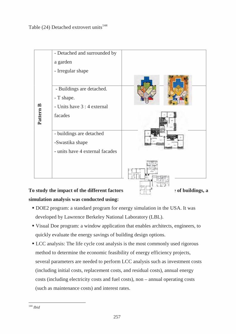
Table (24) Detached extrovert units144
To study the impact of the different factors on energy performance of buildings, a
simulation analysis was conducted using:
DOE2 program: a standard program for energy simulation in the USA. It was
developed by Lawrence Berkeley National Laboratory (LBL).
Visual Doe program: a window application that enables architects, engineers, to
quickly evaluate the energy savings of building design options.
LCC analysis: The life cycle cost analysis is the most commonly used rigorous
method to determine the economic feasibility of energy efficiency projects,
several parameters are needed to perform LCC analysis such as investment costs
(including initial costs, replacement costs, and residual costs), annual energy
costs (including electricity costs and fuel costs), non – annual operating costs
(such as maintenance costs) and interest rates.
144 Ibid
Patt
ern
B
- Detached and surrounded by
a garden
- Irregular shape
- Buildings are detached.
- T shape.
- Units have 3 : 4 external
facades
- buildings are detached
-Swastika shape
- units have 4 external facades

258
The base case is a housing unit in an apartment building at the top floor. The total area
of the unit is 125 m2 and the floor has 4 units (see Base Case in table 20, pattern A).
Each unit has two 0.25 m thick external walls on different orientation built in cement
bricks. Windows are of single glazing, transparent and 3mm thick.
The results of the simulation can be summarized in table (25) and are shown in figures
140 to 149.
Table (25): Results of the simulation145
Parameter Complied Improvement%
Cairo Alex.
Roo
f
Insulation 50 mm poly. 39.5 37.16
150 siliton 37.3 34.28
Absorbance Light color & solar
absorbance= 0.3 31.64 33.7
Insulation 25 mm Poly.+
Absorbance 0.3 48.9 42.47
Shading Optional 20.67 26.76
Insulation
+Shading 25 mm Poly.+ Shade 42.9 41.4
Wal
l
Construction Hclay_25 mm 8.8 7.81
Silt_brick_25mm 8.1 7.02
Insulation poly 25 mm _Mid 10.5 8.09
Absorbance Light color 0.3 13.3 17.09
Absorbance +
Insulation
Light color 0.3 + poly 25
mm _Mid 14.31 16.05
Win
dow
Window type SHGF_29 9.94 8.25
WWR WWR_15 3.16 3.58
PF+ WWR WWR_15+PF0.75 5.31 5.3
WWR +Wind.
Type WWR_15+SHGC0.29 6.75 9.95
Second:
145 Ibid
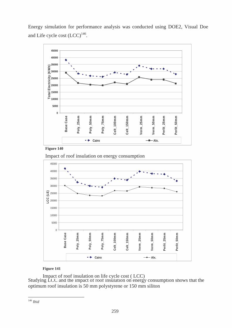
259
0
5000
10000
15000
20000
25000
30000
35000
40000
45000
Bas
e C
ase
Po
ly_2
5mm
Po
ly_5
0mm
Po
ly_7
5mm
Cel
t_10
0mm
Cel
t_15
0mm
Ve
rm_2
5mm
Ve
rm_5
0mm
Per
lit_2
5mm
Per
lit_5
0mm
Roof Insulation
LCC
(LE)
Cairo Alx.
0
5000
10000
15000
20000
25000
30000
35000
40000
45000
Bas
e C
ase
Po
ly_2
5mm
Po
ly_5
0mm
Po
ly_7
5mm
Cel
t_10
0mm
Cel
t_15
0mm
Ve
rm_2
5mm
Ve
rm_5
0mm
Per
lit_2
5mm
Per
lit_5
0mm
Roof insulation
Tota
l Ele
ctric
ity (K
Wh)
Cairo Alx.
Energy simulation for performance analysis was conducted using DOE2, Visual Doe
and Life cycle cost (LCC)146.
Studying LCC and the impact of roof insulation on energy consumption shows that the optimum roof insulation is 50 mm polystyrene or 150 mm siliton
146 Ibid
Figure 140
Impact of roof insulation on energy consumption
Figure 141
Impact of roof insulation on life cycle cost ( LCC)

260
25000
27000
29000
31000
33000
35000
37000
39000
41000
43000
Bas
e C
ase
Poly
_25m
m_O
ut
Poly
_25m
m_I
n
Poly
_25m
m_M
id
Poly
_50m
m_O
ut
Poly
_50m
m_I
n
Poly
_50m
m_M
id
Wall Insulation
LCC
(LE)
Cairo Alx.
34000
34500
35000
35500
36000
36500
37000
37500
38000
38500
0 0.25 0.5 0.75 1PF
Tota
l Ele
ctric
ity (K
Wh)
1P_Clear 1P_GreyTint 1P_Blue 1P_ReflD-Clr 1P_ReflB-ClrH 1P_ReflC-TintM
37000
37500
38000
38500
Wh)
1P_Clear 1P_GreyTint 1P_Blue 1P_ReflD-Clr 1P_ReflB-ClrH 1P_ReflC-TintM
Studying LCC and the impact of wall insulation on energy consumption shows that the optimum wall insulation is 25 mm polystyrene mid
Figure 142
Impact of wall insulation on energy consumption
Figure 143
Impact of wall insulation on life cycle

261
7600.00
7700.00
7800.00
7900.00
8000.00
8100.00
8200.00
8300.00
8400.00
0 0.25 0.5 0.75 1
PF
LCC
(LE)
1P-Clear 1P_GreyTint 1P_Blue 1P_ReflD-Clr 1P_ReflB-ClrH 1P_ReflC-TintM
Studying LCC and the impact of projection factor and SHGC on energy consumption in Cairo shows that the optimum PF is 0.5m with 1P_ref B-clr H or 1P_ref C-Tint M
31000
33000
35000
37000
39000
Elec
tric
ity (K
Wh)
Worest Oriantation for Alx.
Worest Oriantation for Cairo
Figure 144
Impact of projection factor and SHGC on energy consumption in Cairo
Figure 145
Impact of projection factor and SHGC on life cycle cost ( LCC) in Cairo
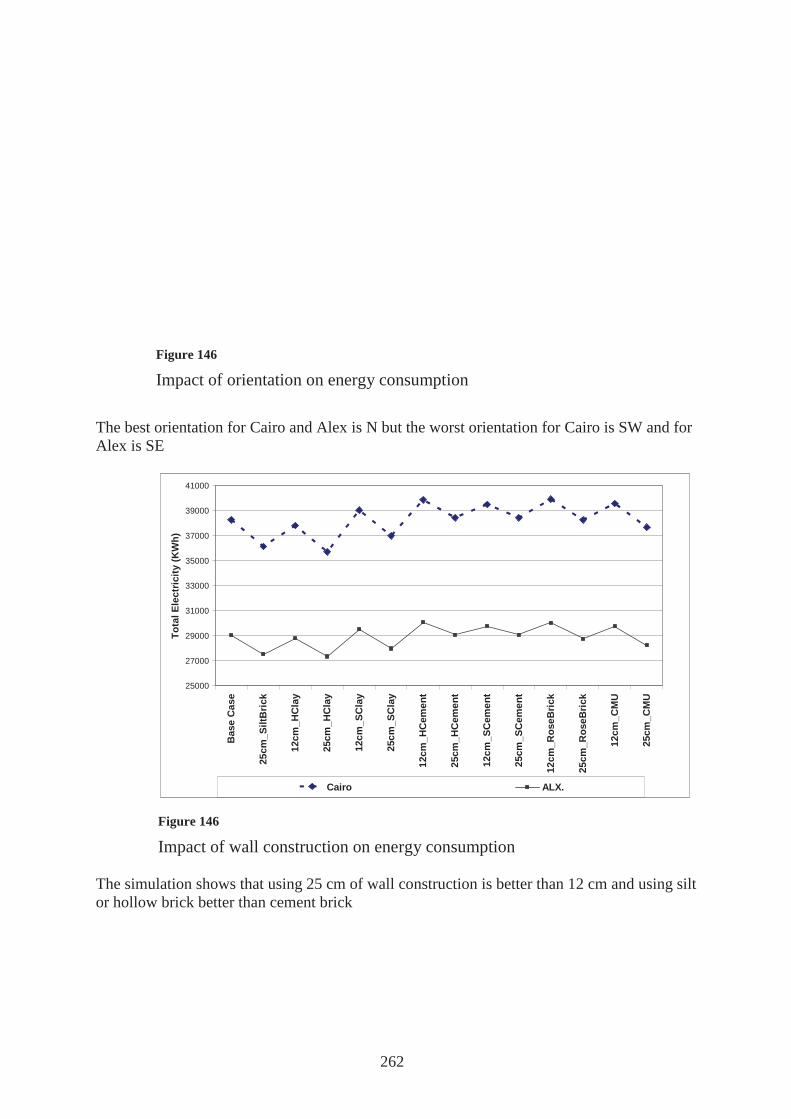
262
25000
27000
29000
31000
33000
35000
37000
39000
41000
Bas
e C
ase
25cm
_Silt
Bric
k
12c
m_H
Cla
y
25c
m_H
Cla
y
12c
m_S
Cla
y
25c
m_S
Cla
y
12cm
_HC
emen
t
25cm
_HC
emen
t
12cm
_SC
emen
t
25cm
_SC
emen
t
12cm
_Ros
eBric
k
25cm
_Ros
eBric
k
1
2cm
_CM
U
2
5cm
_CM
U
Wall Construction
Tota
l Ele
ctric
ity (K
Wh)
Cairo ALX.
The best orientation for Cairo and Alex is N but the worst orientation for Cairo is SW and for Alex is SE
The simulation shows that using 25 cm of wall construction is better than 12 cm and using silt or hollow brick better than cement brick
Figure 146
Impact of orientation on energy consumption
Figure 146
Impact of wall construction on energy consumption
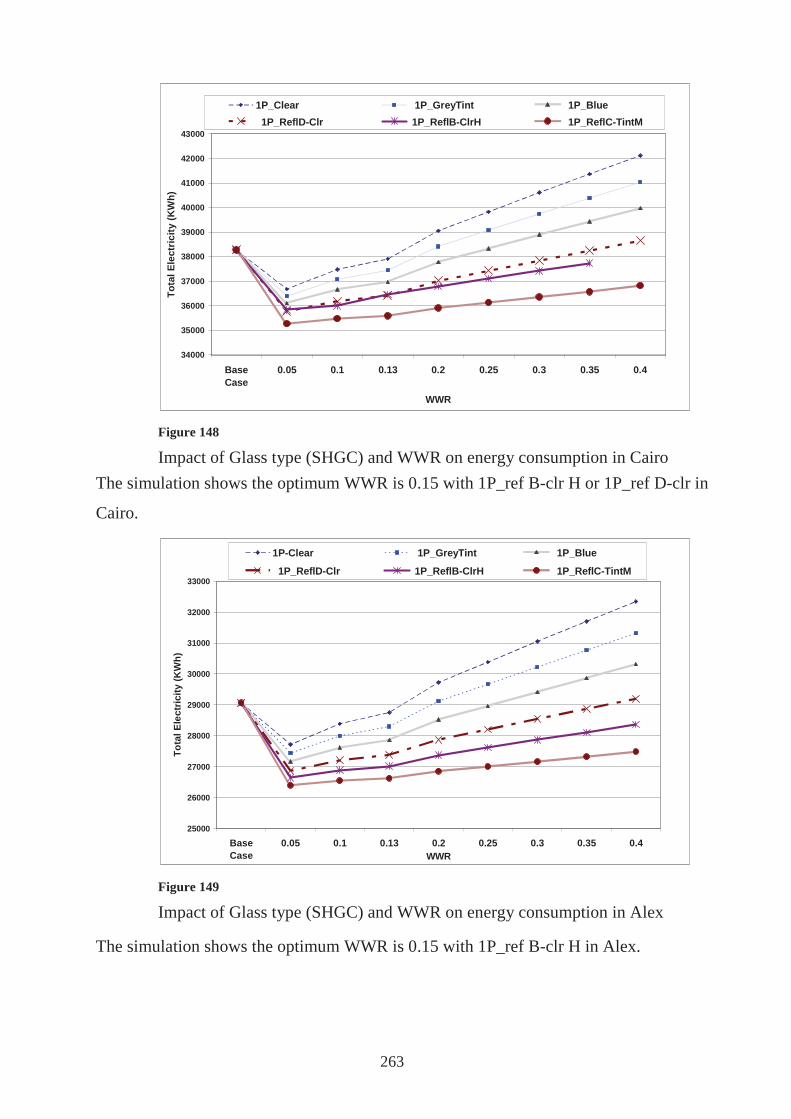
263
34000
35000
36000
37000
38000
39000
40000
41000
42000
43000
BaseCase
0.05 0.1 0.13 0.2 0.25 0.3 0.35 0.4
WWR
Tota
l Ele
ctric
ity (K
Wh)
1P_Clear 1P_GreyTint 1P_Blue 1P_ReflD-Clr 1P_ReflB-ClrH 1P_ReflC-TintM
25000
26000
27000
28000
29000
30000
31000
32000
33000
BaseCase
0.05 0.1 0.13 0.2 0.25 0.3 0.35 0.4WWR
Tota
l Ele
ctric
ity (K
Wh)
1P-Clear 1P_GreyTint 1P_Blue
1P_ReflD-Clr 1P_ReflB-ClrH 1P_ReflC-TintM
The simulation shows the optimum WWR is 0.15 with 1P_ref B-clr H or 1P_ref D-clr in
Cairo.
The simulation shows the optimum WWR is 0.15 with 1P_ref B-clr H in Alex.
Figure 148
Impact of Glass type (SHGC) and WWR on energy consumption in Cairo
Figure 149
Impact of Glass type (SHGC) and WWR on energy consumption in Alex
264
In conclusion, one can state that building energy performance is a trade off between
different design factors to achieve a target level of energy consumption that varies
according to the climatic conditions of the city. The impact of the different design
elements and measures evaluated for both Cairo and Alexandria climates show variation
giving relative importance to the different passive solutions.
6.2.2 Payback analysis for design improvements
Payback analysis help designers decide about accepting or rejecting improvement
measures since it relates initial costs needed to improve building performance to savings
achieved due to it in the following years by users. Examples of payback analysis are:
6.2.2.1 Payback analysis for adding thermal insulation layer to the roof
Assuming an exposed ceiling of 500m2 area composed of a layer of reinforced concrete
12 cm thick (U=3.45 watt/m2.C). Adding a layer of thermal insulation 7 cm thick will
decrease thermal transmittance (U= 0.45 watt/m2.C). Cooling loads will decrease
leading to electricity savings.
E = H*A*(Ub-Up)*CDD
Where
E energy savings in watts
H occupancy period where AC function in hours
A area of exposed roof in m2
Ub roof thermal transmittance before adding insulation
Up roof thermal transmittance after adding insulation
CDD cooling degree- day for a base of 25C = i j (Tao-25)
Tao outdoor air temperature
i month
j hours
E = 15 * 500 * (3.45-0.45) *2500= 56250 Kwh/year
265
Payback period = cost of insulation / energy savings
= (500*0>06*300)/ (56250*0.1) = 1.6 years
Previous studies have calculated payback back periods for adding a 7cm insulation layer
to a 500 m2 roof in different climatic regions to assess the impact of each climate. It was
found that payback period is 1.6 years in Alexandria, decreases to 1.2 years in Cairo and
0>9 year in Aswan147. According to theories, a payback is tolerable until a period of 7
years. It is obvious that the harsher the climate, the shorter the payback period.
6.2.2.2 Payback analysis for increasing glazing thermal resistance by using double
glazed panels
Calculation are made for a building envelope with 200 m2 glazing . Single glazing have
a U value of 5.6 watt/m2.C while double glazing U value decreases to 2 watt/m2.C.
Assuming the cost of 1 m2 in double glazing exceeds the cost of 1 m2 of single pane by
200 LE, and the cost of electricity is 0.1 LE/ Kwh.
For Alexandria:
E = 15 *200 * (5.6-2)*2500 = 27000 kwh/year
Payback = (200*150)/(27000*0.1)= 14.8 years
The payback is high and is rejected for Alexandria and Cairo (11.6 years). It is
acceptable in Aswan (8.8 years).
6.3 Specific technical conclusion and recommendations
The thesis has reached a set of technical and strategical conclusion and
recommendations based on the literature review and the analysis of the best local and
international practices. These are summarised as follows:
147

266
CONCLUSION:
An eco eco house should provide:
•Healthy living conditions through selecting eco materials and avoiding materials that
cause sick building syndrome and allergies and cancer, and selecting a site that is clear
of any contamination or radiation.
•Thermal comfort through following passive cooling strategies that are classified
according to Givoni chart.
• Energy efficiency through a set of design principles for shelter, house layout
and building envelope.
An eco house should select :
Low embodied energy materials with minimal environmental impact.
Recyclable and renewable materials to avoid harming the landscape resources of the
earth which may not be able to recover.
Eco gardening by adopting Xeriscaping that fits with our hot arid climate.
An eco house should be economical through:
Applying economical but ecological design factors and through selecting economical
ecological construction systems that uses local and natural building materials that
provide thermal insulation and could be recycled and consumes low energy during
construction.
In order to achieve an eco eco house, cost analysis chart should be applied through out
all the design phases.

267
RECOMMENDATIONS:
• Necessity of applying cost analysis for ecological design frame work through
out all the design phases.
• Directing future studies towards designing cost effectiveness modules for cost
analysis studies to help out the planners and designers evaluate the economic
feasibility and take the decisions needed.
• Establishment of labs for measuring the efficiency of different building
elements.
• Providing eco materials in the market to be available and in reach for
consumers, architects and contractors to use.
• Providing the eco tech needed such as the double and triple glazing with
reasonable and affordable prices.
• Enforcement of Egyptian energy residential code through the building permits
process and training designers on using and applying the code.

268
LIST OF REFRENCES
ENGLISH BOOKS
• Benjamin Stein-John S. Reynolds-William J. Mc Guinness, (1986), Mechanical and
Electrical Equipment for Buildings-7th Edition-Volume 1”, John Wiley and Sons,
New York
• Bill Holdsworth and Antony F Sealey, "Healthy Building " ,Longman, London
• Brenda, and, Vale, R., (1991), ”Green Architecture-Design for an Energy Conscious
Future”, pp.41 ,Thames and Hudson, London
• D.A.Mc INTYRE.,(1980), "INDOOR CLIMATE", Applied Science Publishers LTD,
London
• David Anink,etl, (1996), "HANDBOOK OF SUSTAINABLE BUILDING", James
and James, London
• David Pearson, (1991), "THE NATURAL HOUSE BOOK", Conran Octopus , London
• Donald Watson-FAIA-Kenneth Labs,(1983), “Climatic Design”, McGraw-Hill, New
York
• Elizabeth Wilhide, (2003), “ECO”, Rizzoli, New York
• FISA and Aga Khan, (1996), “Architecture for a Changing World”, Graficas Urania, Malaga
• Fuller Moore,(1993), "Environmental Control Systems-heating, cooling , lighting",
Mc Graw –Hill,Inc,New York
• G.Z.Brown, (1985), "Solar, Wind and Light", John Wiley and Sons, New Gersey
• Gideon S.Golany, (1983),"EARTH-SHELTERED HABITAT",VNR, New York
• James Steel, (1997), "SUSTAINABLE ARCHITECTURE", Mc Graw, New York
• Martin Evanes, (1980), "Housing Climate and Comfort", The architectural press,
London
• Peter Chapman, (1980), "Fuel's Paradise", Penguin Books, Middlesex
• Peter F. Smith, (2001), "Architecture in a climate of change", Architectural press,
Oxford
• Rick Schwolsky-James I. Williams, (1982), "The builder's guide to solar

269
construction", Mc Graw-Hill,Inc.,New York
• Sadat city planning study group,(1986), "The Planning of Sadat City"
• Sue Roaf ,etl (2003)."ECOHOUSE 2:A DESIGN GUIDE". Architectural
Press.Oxford
• Sydney and Loan Baggs, (1996), "The Healthy House", Thames and Hudson, London
• Timothy Cochrane Ali and Jane Brown,(1977), "Landscape Design for the Middle
East", RIBA, London
• Victor Olgay, (1963), "Design with climate, bioclimatic approach to architectural
regionalism",Princeton University, New Gersey
• Yuanhui Zhang,(2005),"INDOOR AIR QUALITY ENGINEERING", CRC PRESS,
FLORIDA
INTERNET RESOURCES
http://www.lhc.org.uk/members/pubs/books/sbs/sbs04.htm
http:// www.efficientwindows.org/gtypes.cfm
http://www.habitat.org/ap/news/2004/12_02_2004_forty_students.aspx
http://community.iexplore.com
http://greenthenewblack.blogspot.com
ENGLISH PAPERS
• ASHRAE TRANSACTIONS,(2004-Part 2),"Indoor Air Quality of an Energy –
Efficient, Healthy House with Mechanically Induced Fresh Air"
• Energy and Buildings 36, (2004), "Experimental work on a linked, dynamic and
ventilated, wall component", ELSEVIER
• HABITAT,(2000),"Report of the Regional Workshop on HOUSING and
ENVIRONMENT", Vienna
• Prof. Dr. Suzette Michel and Eng. Hend Elsayed, (2006), “Examples of low energy
design at Urban scale in Egypt”, PLEA2006

270
• :.) ""
• :""
•:)(" "
• : ""• :"
"•: ""
•.""- • :)("" • :)(""
• :"- ---
• :"" • : "" • :)(
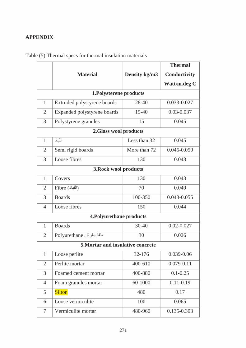
271
APPENDIX
Table (5) Thermal specs for thermal insulation materials
Material Density kg/m3
Thermal
Conductivity
Watt\m.deg C
1.Polysterene products
1 Extruded polystyrene boards 28-40 0.033-0.027
2 Expanded polystyrene boards 15-40 0.03-0.037
3 Polystyrene granules 15 0.045
2.Glass wool products
1 Less than 32 0.045
2 Semi rigid boards More than 72 0.045-0.050
3 Loose fibres 130 0.043
3.Rock wool products
1 Covers 130 0.043
2 Fibre ( ) 70 0.049
3 Boards 100-350 0.043-0.055
4 Loose fibres 150 0.044
4.Polyurethane products
1 Boards 30-40 0.02-0.027
2 Polyurethane 30 0.026
5.Mortar and insulative concrete
1 Loose perlite 32-176 0.039-0.06
2 Perlite mortar 400-610 0.079-0.11
3 Foamed cement mortar 400-880 0.1-0.25
4 Foam granules mortar 60-1000 0.11-0.19
5 Silton 480 0.17
6 Loose vermiculite 100 0.065
7 Vermiculite mortar 480-960 0.135-0.303

272
6.Cork products
1 Boards 110-130 0.033-0.039
2 Cork granules 100-115 0.039-0.052
7.Various materials
1 Rigid rubber 1190 0.016
2 Cotton 1500 0.042
3 Textile wool 110-330 0.036-0.063
4 Hand saw 145 0.08
Table (7) Thermal specs for construction and finishing materials
Material Density
kg/m3
Thermal
Conductivity
Watt\m.deg C
Specific Heat
Joule.kg deg C
First :Construction bricks
1 Hollow foam 530 0.20
2 Solid foam 800 0.25
3 Hollow gypsum 750 0.41
4 Solid gypsum 950 0.39
5 Hollow lyca 1200 0.39 1000
6 Hollow clay 1790 0.60 840
7 Solid clay 1950 1.00 829
8 Solid concrete 1800 1.25 880
9 Hollow concrete 1140 1.60 880
10 2000 1.40 840
11 985 0.33 850
12 1800 1.59 835
13 Hollow sand 1500 1.39 811
Second :Tiles
1 PVC tiles (Canaltex) 1350 0.16

273
2 Elastic tiles 1700 0.40
3 Ceramic tiles 2000 1.20
4 Concrete tiles 2100 1.10
5 Mosaic tiles 2450 1.60
Third :Wood
1. Natural wood
1 Beech 700 0.17
2 Spruce 415 0.105
3 Oak 770 0.16
4 Mahogany 700 0.155
5 Pitch pine 660 0.14
2. Artificial wood
1 Plywood 530 0.14
2 Chip board 400 0.17
3 Conter 0.212
Fourth :Metals
1 Lead 11300 34.8 129
2 Stainless steel 7830 45.3 500
3 Zinc 7130 110 390
4 Aluminium sheets 2740 221 896
5 Red copper 8780 150 400
6 Yellow copper 8310 120 400
Fifth : Gypsum and cement materials
1 Gypsum 320 0.15
2 Gypsum boards 950 0.39
3 Portland cement 1335 0.12
4 Thermal cement 1406 0.175
Sixth : Aggregate and stones
1 Sand 1520 0.33 800
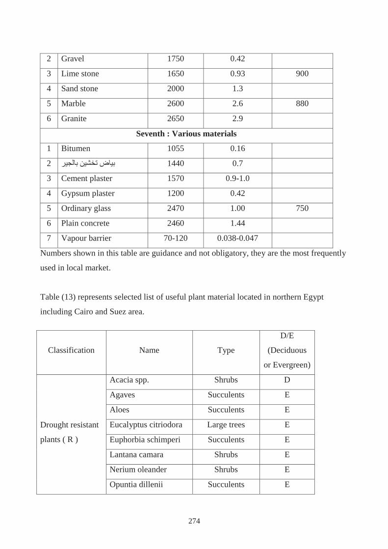
274
2 Gravel 1750 0.42
3 Lime stone 1650 0.93 900
4 Sand stone 2000 1.3
5 Marble 2600 2.6 880
6 Granite 2650 2.9
Seventh : Various materials
1 Bitumen 1055 0.16
2 1440 0.7
3 Cement plaster 1570 0.9-1.0
4 Gypsum plaster 1200 0.42
5 Ordinary glass 2470 1.00 750
6 Plain concrete 2460 1.44
7 Vapour barrier 70-120 0.038-0.047
Numbers shown in this table are guidance and not obligatory, they are the most frequently
used in local market.
Table (13) represents selected list of useful plant material located in northern Egypt
including Cairo and Suez area.
Classification Name Type
D/E
(Deciduous
or Evergreen)
Drought resistant
plants ( R )
Acacia spp. Shrubs D
Agaves Succulents E
Aloes Succulents E
Eucalyptus citriodora Large trees E
Euphorbia schimperi Succulents E
Lantana camara Shrubs E
Nerium oleander Shrubs E
Opuntia dillenii Succulents E
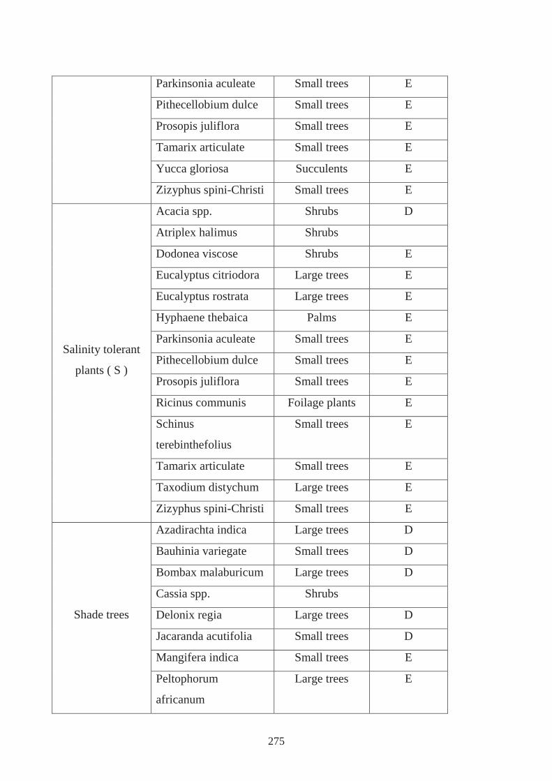
275
Parkinsonia aculeate Small trees E
Pithecellobium dulce Small trees E
Prosopis juliflora Small trees E
Tamarix articulate Small trees E
Yucca gloriosa Succulents E
Zizyphus spini-Christi Small trees E
Salinity tolerant
plants ( S )
Acacia spp. Shrubs D
Atriplex halimus Shrubs
Dodonea viscose Shrubs E
Eucalyptus citriodora Large trees E
Eucalyptus rostrata Large trees E
Hyphaene thebaica Palms E
Parkinsonia aculeate Small trees E
Pithecellobium dulce Small trees E
Prosopis juliflora Small trees E
Ricinus communis Foilage plants E
Schinus
terebinthefolius
Small trees E
Tamarix articulate Small trees E
Taxodium distychum Large trees E
Zizyphus spini-Christi Small trees E
Shade trees
Azadirachta indica Large trees D
Bauhinia variegate Small trees D
Bombax malaburicum Large trees D
Cassia spp. Shrubs
Delonix regia Large trees D
Jacaranda acutifolia Small trees D
Mangifera indica Small trees E
Peltophorum
africanum
Large trees E

276
Terminalia arjuna Large trees E
Screen trees
Acacia spp. Shrubs D
Cupressus
sempervirens
Large trees E
Ficus retusa Small trees E
Lawsonia inermis Small trees E
Pithecellobium dulce Small trees E
Hedging plants
Acacia spp. Shrubs D
Acalypha wilkesiana Shrubs E
Bougainvillea spp. Ground cover E
Casuarina equisetifolia Large trees E
Dodonea viscose Shrubs E
Duranta repens Shrubs E
Ficus retusa Small trees E
Hibiscus spp. Shrubs E/D
Lantana camara Shrubs E
Lawsonia inermis Small trees E
Nerium oleander Shrubs E
Pithecellobium dulce Small trees E

...
.
.
.
.
.
.
.

.
.
.

. -

Figure 54 Shows different examples