internal combustion engines and gas turbines lab c-engine-lab-manu… · · 2017-04-09internal...
TRANSCRIPT
Internal Combustion Engines and Gas turbines Lab
Experiment No. 1
Object:- To Study four strokes spark ignition (S.I) Engine and differences
between S.I. ad C.I engines.
Equipment: Four strokes S.I engine
Construction: - Four strokes SI engine consist of following main parts.
(i) Cylinder
(ii) Piston
(iii) Gudgeon pin or piston pin
(iv) Connecting rod
(v) Water jacket
(vi) Silencer
(vii) Small end of connecting rod
(viii) Big end of connecting rod
(ix) Crank pin
(x) Spark plug
(xi) Crank
(xii) Inlet valve
(xiii) Crank case
(xiv) Exhaust valve
(xv) Push rods
(xvi) Tappet
(xvii) Flywheel
Working Principle: - One working cycle of four strokes S.I engine is consisting
of four processes.
(i) Suction process
(ii) Compression process
(iii) Working or Expansion process
(iv) Exhaust process
Each process is completed in one stroke of the piston and one working cycle
completed in four strokes of piston that is suction, compression, expansion and
exhaust strokes
Suction stroke:- Inlet valve is open . Piston come down or travel towards bottom
dead centre position (BDC) and slight vacuum is created in the cylinder. Mixture
of air and petrol, which is prepared is carburettor, enters the engine cylinder
through inlet valve. In normal running of the engine, the ratio of air and petrol is
I5: 1 but at the time of starting and acceleration, mixture is rich in nature as per the
demand the engine. Suction process continues till the piston reaches at BDC.
Compression stroke:- Now piston travel towards top dead centre position
(TDC). Inlet valve and Exhaust valve are closed . Valves are operated by cams
mounted on cam shaft, crank shaft, tappet and push rods. Mixture is compressed
adiabatically (PV=k) in clearance space. Due to compression its temperature and
pressure increases. Now spark is produced in the compressed mixture by spark
plug. Combustion of mixture takes place.
Expansion or Working or power stroke:- Due to combustion of charge, its
pressure and temperature increases . Gases at high pressure push the piston
towards BDC. Both the valves are still closed. Power is obtained at the crank shaft.
Exhaust stroke: - Now piston turn towards TDC. Exhaust valve is open. Burnt
waste gases are thrown out side through Exhaust valve.
Again the inlet valve is open. Suction stroke started and processes are repeated.
Dead centre positions are over come due to the momentum of fly wheel.
In four stroke SI engine one working cycle is completed is two revolutions of the
crank shaft.
Differences between SI and CI Engines.
Sr.
No Spark Ignition Engines Compression ignition Engines
1 Petrol is used as fuel Diesel oil used as fuel
2 Works on Otto cycle Works on Diesel Cycle
3 Mixture of air and petrol is
taken during suction stroke
Pure air taken during suction stroke
4 Spark plug is used to ignite the
mixture
Fuel pump and fuel injector are used to
inject the diesel oil in the cylinder and its
combustion take place due to high
temperature of air.
5 Compression ratio 7:1 to 10:1
is used
Compression ratio 14:1 to 18:1 is used

6 Thermal efficiency is low due
to lower compression ratio
(about 30%)
Thermal efficiency is higher due to
higher compression ratio (35 to 40%)
7 For the same compression ratio
Otto cycle is more efficient
For the same compression ratio , Diesel
cycle is less efficient
8 Lighter and cheap Heavy and Costly
9 Low maintenance High maintenance
10 Quantitative governing is used Qualitative governing is used
Answer the following questions
(i) Define compression ratio and expansion ratio.
___________________________________________________________
___________________________________________________________
___________________________________________________________
(ii) State numerical value of compression ratio used is CI engines
___________________________________________________________
___________________________________________________________
___________________________________________________________
(iii) Thermal efficiency of CI engine is more than SI engine, why?
___________________________________________________________
___________________________________________________________
___________________________________________________________
(iv) For the same compression ratio, Otto cycle is more efficient than Diesel
cycle, Justify.
___________________________________________________________
___________________________________________________________
___________________________________________________________

(v) Why IC engines are cooled? Which type of cooling is used in two stroke
SI engines?
___________________________________________________________
___________________________________________________________
___________________________________________________________
(vi) What is function of fuel pump in CI engines?
___________________________________________________________
___________________________________________________________
___________________________________________________________
(vii) What is function of fuel injector in CI engines
___________________________________________________________
___________________________________________________________
___________________________________________________________
(viii) What is quantitative and qualitative governing used in IC engine? Which
type of governing is used in SI engines?
___________________________________________________________
___________________________________________________________
_________________________________________________________
(ix) How are the suction and exhaust valves operated in CI engines?
___________________________________________________________
___________________________________________________________
________________________________________________________
(x) What do you mean by MPFI system?
___________________________________________________________
___________________________________________________________
___________________________________________________________
Experiment No.2
Object: - To study two Strokes S.I. engine and differences between two
strokes and four strokes engines.
Equipment: - Two strokes spark ignition engine
Construction: - Two stroke spark ignition engines is consisting of following
main parts.
(i) Cylinder
(ii) Piston
(iii) Deflector
(iv) Piston pins or gudgeon pins
(v) Piston rings
(vi) Spark plug
(vii) Connecting rod
(viii) Small end of connecting rod
(ix) Big end of connecting rod
(x) Crank
(xi) Spark plug
(xii) Crank shaft
(xiii) Closed crankcase
(xiv) Inlet port
(xv) Transfer port
(xvi) Exhaust port
(xvii) Fins on cylinder and cylinder head
(xviii) Silencer
Working Principle: - Assume that piston going towards top dead centre
position (TDC) in case of vertical engine. As soon as piston covers the exhaust
port, Compression of mixture of air and petrol starts. Compression is
adiabatic (PV=K) process and temperature and pressure of mixture increases
At the same time inlet port is open and fresh mixture of petrol and air from
carburettor enters in the crank case. Mixture is compressed slightly in the

crank case due to clockwise movement of crank in the crank case. It helps the
mixture to go to engine cylinder through transfer port.
At the end of compression process, spark is induced by spark plug and
combustion of mixture takes place.
Due to combustion process the temperature and pressure of the gases
increases. These gases at high pressure and temperature push the piston
towards bottom dead Centre position. It is an expansion process.
Now first of all exhaust port uncovered by piston and waste gases start going
outside. After some time transfer port is also open by the piston. As soon as
transfer port is open, the fresh charge enters engine cylinder and deflected
upward due to deflector. Deflected charge helps in pushing the exhaust gases
outside but fresh charge remains in the engine cylinder. It is possible that part
of fresh charge may escape outside along with burnt gases.
Hence exhaust process and suction process take place is the same stroke.
Piston after reaching the BDC has reverse direction and go towards TDC and
process is repeated.
Applications: - Scooter and Bike engines
Differences between two strokes and four strokes engines
Sr.
No.
Two Strokes engines Four Strokes engines
1 Exhaust noise is more It is less
2 For the same RPM, power is almost
double
Power is less
3 Thermal efficiency is low Thermal efficiency high
4 Ports are used Valves are used
5 One working cycle completes in two
strokes of piston or in one revolution
of crank shaft
One working cycle completes in four
strokes of piston or two revolution of
crank shaft
6 Mechanical efficiency is more due to
low power lost in friction
Mechanical efficiency is less due to
higher power lost in friction
7 Crank case is closed Crank case is open

Answer the following questions
(i) Why the thermal efficiency of four strokes S.I. engines are more
than two strokes S.I. Engines?
___________________________________________________________
___________________________________________________________
(ii) Mechanical efficiency of two strokes S.I. engines is more than four
strokes S.I. engines why?
___________________________________________________________
___________________________________________________________
(iii) Exhaust noise from silencer in case of two stroke engines is more
than four stroke engines why?
___________________________________________________________
___________________________________________________________
(iv) For the same RPM two stroke engines produce almost double power
than four stroke engines why?
___________________________________________________________
___________________________________________________________
(v) What is the use of deflector used on the piston in case of two strokes
S.I. Engines?

___________________________________________________________
___________________________________________________________
(vi) What do you mean by scavenging process? It is positive in case of
four strokes engines and negative in two strokes engines, Explain.
___________________________________________________________
___________________________________________________________
(vii) In two stroke S.I. engines exhaust port is placed slightly at higher
level than transfer port. Why?
___________________________________________________________
___________________________________________________________
(viii) Piston rings are used on the piston why?
___________________________________________________________
___________________________________________________________
(ix) What is optimum percentage of lubricant oil used in petrol in case of
two strokes S.I. engines?
___________________________________________________________
___________________________________________________________
(x) What is compression ratio? State numerical value of compression
ratio in two strokes and four stroke S.I. engines.
___________________________________________________________
___________________________________________________________
Experiment no. 3
Object: To study battery ignition system for four cylinders S.I. engines and
requirements of ignition system.
Equipment: Battery ignition system
Construction:- Battery ignition system is consisting of following main parts.
I. 6 or 12 volt battery
II. Ignition switch
III. Ammeter
IV. Primary winding and secondary windings of induction coil
V. Contact breaker point
VI. Square edge cam
VII. Distributor
VIII. Rotor arm of distributor
IX. Spark plugs
X. Condenser
Working: - Current from battery pass through the ignition switch if it is closed
and it goes to primary winding of induction coil through ammeter. Now this
current passes through contact breaker point. If contact breaker point is closed, it
goes to earth, and earth to earth circuit is complete.
Since square edge cam , is mounted on the cam shaft which is rotating at a speed
half of that crank shafts (four stroke engine ) which open and close the contact
breaker point. In case the contact break point is open, in that case there is change
in lines of magnetic flux in the primary winding of inductinon coil and induced
EMF is induced in the secondary winding induction coil. Magnitude of voltage of
secondary current depends upon the number of turns in secondary winding of
induction coil.
Primary winding consist of 200-300 turns of thick wire (20 SWG) and secondary
winding is having……… number of turms of fine wire ( SWG). Hence the
secondary current has a voltage of 2000 to 30,000 volts.
Now high voltage current goes to distributor , where rotor arm, mounted on cam
shaft, distbrute the high voltage to spark plugs in a specific firing order (say
1,3,4,2 Or 1,3,2,4). This specific firing order is adopted to get uniform torque on
the crank shaft.
This high voltage current is sufficient to overcome the resistance of air gap
between the two electrodes of spark pug and current jumps from central electrode
to outer electrode and spark is produced. Combustion of charge takes place.
A condenser is also connected in parallel to contact breaker point to check the
sparking at contact breaker point.
Requirements of Ignition system
(i) To supply high voltage current of order of 20000 to 30000 voltages to
spark plug to induce spark at the spark plug gap.
(ii) Spark should take place at the correct time just before the compression
stroke is completed.
(iii) System should function efficiently at all speed of the engine.
(iv) System should be light , compact and easy to maintain.
(v) It should not cause any interference in working system of the engine.
Applications: - Battery ignition system is used in car engines using SI engines
Answer the following question questions
(1) What is the of Battery ignition system? Where it is used?
_____________________________________________________________
_____________________________________________________________
_____________________________________________________________
(2) What is the function of contact breaker point?
_____________________________________________________________
_____________________________________________________________
_____________________________________________________________
(3) What is the function of condenser or capacitor used in parallel with contact
breaker point?

_____________________________________________________________
_____________________________________________________________
_____________________________________________________________
(4) How the induced EMF is produced is the secondary winding of induction
coil?
_____________________________________________________________
_____________________________________________________________
_____________________________________________________________
(5) What is the magnitude of voltage of secondary current?
_____________________________________________________________
_____________________________________________________________
_____________________________________________________________
(6) What is the function of distributor?
_____________________________________________________________
_____________________________________________________________
_____________________________________________________________
(7) What do you mean by firing order? In which firing order spark is produced
in the four cylinders of the engine and why?
_____________________________________________________________
_____________________________________________________________
_____________________________________________________________
(8) Time to time spark plugs are cleaned, why?
_____________________________________________________________
_____________________________________________________________
_____________________________________________________________
(9) How much approximate air gap is required between two electrodes of spark
plug?
_____________________________________________________________
_____________________________________________________________
_____________________________________________________________

(10) Why high voltage of order of 20,000 to 30,000 Volt is required to produce
spark in spark plug?
_____________________________________________________________
_____________________________________________________________
_____________________________________________________________

Experiment No.4
Object: - To study magneto ignition system for SI engine having four cylinders
and differences between magneto and battery Ignition system.
Equpment: - Magneto Ignition system
Construction: - Magneto Ignition system has following mair parts.
(i) Permanent Magnet
(ii) Armature
(iii) Primary and secondary windings.
(iv) Contact breaker point
(v) Capacitor
(vi) Square edged cam
(vii) Distributor
(viii) Rotor arm
(ix) Spark plugs
Working principle: - In this system magnetic field in the core of primary and
secondary winding is produced by rotating permanent magnet. As the magnet is
rotated by crank shafts, the field is produced from positive maximum to negative
minimum and back again.
As the Magnetie field from positive maximum changes to the negative minimum,
the voltage and current are induced in the primary winding of induction coil.
Current in primary winding produces a magnetie field of its own, which keep the
total magnetie filed almost constant.
This current in the primary goes to contact breaker point. If it is closed, it goes to
earth and primary current circuit is completed.
In case , the contact breaker point is open by crank shaft, the magnetic field drop in
the primary and high voltage current is produced the secondary winding. This high
voltage current goes to distributor and distribute this current to spark plugs in a
specific firing order ( 1-3-4-2). This specific firing order is adopted to produce
uniform torque in the crank shaft.
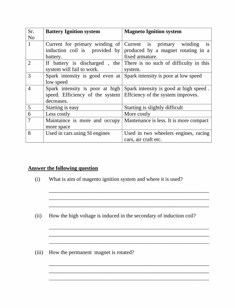
Differences between battery and magneto ignition system
Sr.
No Battery Ignition system Magneto Ignition system
1 Current for primary winding of
induction coil is provided by
battery.
Current is primary winding is
produced by a magnet rotating in a
fixed armature.
2 If battery is discharged , the
system will fail to work.
There is no such of difficulty in this
system.
3 Spark intensity is good even at
low speed
Spark intensity is poor at low speed
4 Spark intensity is poor at high
speed. Efficiency of the system
decreases.
Spark intensity is good at high speed .
Effciency of the system improves.
5 Starting is easy Starting is slightly difficult
6 Less costly More costly
7 Maintaince is more and occupy
more space
Mantenance is less. It is more compact
8 Used in cars using SI engines Used in two wheelers engines, racing
cars, air craft etc.
Answer the following question
(i) What is aim of magento ignition system and where it is used?
___________________________________________________________
___________________________________________________________
___________________________________________________________
(ii) How the high voltage is induced in the secondary of induction coil?
___________________________________________________________
___________________________________________________________
___________________________________________________________
(iii) How the permanent magnet is rotated?
___________________________________________________________
___________________________________________________________
___________________________________________________________

(iv) State the three major differences between battery and magneto ignition
systems.
___________________________________________________________
___________________________________________________________
___________________________________________________________
(v) On what factor, the shape of cam is used?
___________________________________________________________
___________________________________________________________
___________________________________________________________
(vi) Opening and closing of contact breaker point depends upon?
___________________________________________________________
___________________________________________________________
___________________________________________________________
(vii) Magneto ignition systems prefered for Aeroplanes, why?
___________________________________________________________
___________________________________________________________
___________________________________________________________
Experiment No. 5
Aim: - Study of carburettor with compensating and starting Jet devices.
Equipment: - Carburettor with compensating and starting Jet devices.
Construction: - Carburettor with compensating and starting Jet devices consist of
following main parts.
(i) Venturi
(ii) Venturi Throat
(iii) Throttle valve
(iv) Fuel nozzle
(v) Main Jet
(vi) Compensating Jet
(vii) Float Chamber
(viii) Float
(ix) Needle Valve
(x) Starting Jet
(xi) Air Control screw
Working Principle: - Air from air filter enters the venturi, converging in section.
Due to converging section, air velocity increases and its pressure decreases. At
throat of the venturi, area of cross sections is minimum, velocity is maximum and
pressure is minimum.
Pressure in float chamber over the petrol surface is atmospheric and pressure at the
tip of fuel nozzle at throat of venturi is lower than atmospheric pressure. Due to
this pressure difference, petrol from fuel nozzle comes out in the form of spray and
mixed with air and a homogenous mixture of air and petrol is formed.
This mixture of air and petrol enters the engine cylinder through throttle valve to
run the engine.
Petrol (Fuel) enters the float chamber from petrol tank through needle valve
attached with float. Float keep the level of petrol in float chamber constant.
In the carburettor having only main jet, during acceleration, velocity of air at throat
increases, pressure also decreases up to higher extent and quantity of petrol coming
that of fuel nozzle also increases. But amount of petrol coming out fuel nozzle is
about 2 ½ times than exact requirement.
This tendency of main jet is compensated by compensating jet. Compensating jet is
made around main jet and allows constant quantity of petrol at all speeds. The
combination of main jet and compensating jet provide right quantity of petrol in air
as per speed and load on the engine as per requirement.
In this carburetor discussed above at the time of starting, small volume of air
enters at throat of venturi and small quantity petrol comes out fuel nozzle. This
mixture strength is not enough to start the engine. At the time of starting, the
engine requires rich mixture (Air: Fuel ration of 9:1). This mixture is provided by
starting jet. Starting jet take air from venturi and petrol from float chamber and
provide a rich mixture just after the throttle valve and help to start the engine.
Answer the following questions
(i) What is the aim of carburettor? And where it is used?
___________________________________________________________
___________________________________________________________
___________________________________________________________
(ii) What is the draw back in simple carburettor?
___________________________________________________________
___________________________________________________________
___________________________________________________________
(iii) What is function of Compensating Jet?
___________________________________________________________
___________________________________________________________
___________________________________________________________
(iv) What is the function of staring Jet?
___________________________________________________________
___________________________________________________________
___________________________________________________________
(v) What is function of float in float chamber?

___________________________________________________________
___________________________________________________________
___________________________________________________________
(vi) What is the advantage of venturi portion?
___________________________________________________________
___________________________________________________________
___________________________________________________________
(vii) What is function of throttle valve?
___________________________________________________________
___________________________________________________________
___________________________________________________________
(viii) Why fuel nozzle is placed at the throat of the venturi.
___________________________________________________________
___________________________________________________________
___________________________________________________________
(ix) Mention the air fuel ratio required by the engine during...
(a) Starting time
(b) Normal running
(c) Acceleration
___________________________________________________________
___________________________________________________________
___________________________________________________________
(x) Carburetor has been replaced by MPFI system in S.I. engine, why?
___________________________________________________________
___________________________________________________________
___________________________________________________________

Experiment No.-6
Aim: - Determination of Brake power (BP), friction power (FP) and Indicated power (IP) of four stroke
four cylinder diesel engine with rope break dynamometer.
Equipment:
(i) Engine :- Four stroke, four cylinder, vertical, water cooled, self governed diesel engine
(ii) Rope brake dynamometer:- Rope brake dynamometer, spring balances and loading screw
(iii) Calibrated fuel burette for fuel consumption measurement
(iv) Orifice meter, fitted to air inlet tank with water manometer for air intake measurement
(v) Multi-channel digital temperature indicator for temperature measurement at various points
(vi) Exhaust gas calorimeter to measure heat carried away by exhaust gases.
Procedure:-
(i) Fill up sufficient diesel in diesel tank
(ii) Check the level of lubricant oil in the sump by oil dip stick. It should be up to top edge of the
flat
Portion provided over the dip stick
(iii) Fill up water in manometer up to half of manometer height
(iv) Start the water supply and see water is flowing through engine jacket, brake drum and
exhaust
Gas calorimeter
(v) Release the loading screws, so that there is no tension in the rope.
(vi) Start the engine with the help of auto ignition key
(vii) Load the engine with loading screw and set the balance difference to say 2 Kgs
(viii) Open the burette filling cock, take sufficient diesel in burette and close the cock
(ix) Now turn the selector cock to engine and note down the time required for 20 ml fuel
consumption
(x) Note down the brake drum speed with tachometer
(xi) Note down difference in two limbs of manometer
(xii) Note the following temperatures from digital thermometer
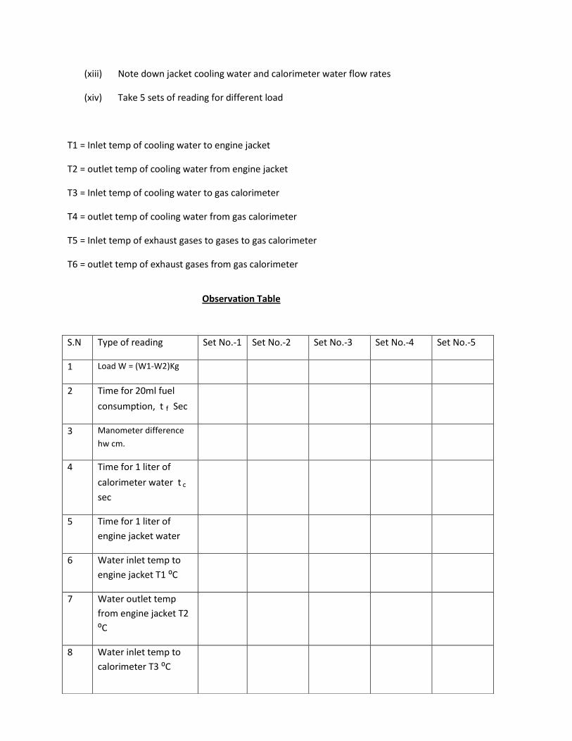
(xiii) Note down jacket cooling water and calorimeter water flow rates
(xiv) Take 5 sets of reading for different load
T1 = Inlet temp of cooling water to engine jacket
T2 = outlet temp of cooling water from engine jacket
T3 = Inlet temp of cooling water to gas calorimeter
T4 = outlet temp of cooling water from gas calorimeter
T5 = Inlet temp of exhaust gases to gases to gas calorimeter
T6 = outlet temp of exhaust gases from gas calorimeter
Observation Table
S.N Type of reading Set No.-1 Set No.-2 Set No.-3 Set No.-4 Set No.-5
1 Load W = (W1-W2)Kg
2 Time for 20ml fuel
consumption, t f Sec
3 Manometer difference
hw cm.
4 Time for 1 liter of
calorimeter water t c
sec
5 Time for 1 liter of
engine jacket water
6 Water inlet temp to
engine jacket T1 ⁰C
7 Water outlet temp
from engine jacket T2
⁰C
8 Water inlet temp to
calorimeter T3 ⁰C

Formula for calculations
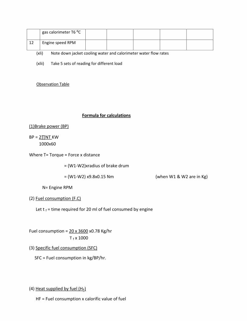
(1)Brake power (BP)
BP = 2∏NT KW
1000x60
Where T= Torque = Force x distance
= (W1-W2)xradius of brake drum
= (W1-W2) x9.8x0.15 Nm (when W1 & W2 are in Kg)
N= Engine RPM
(2) Fuel consumption (F.C)
Let t f = time required for 20 ml of fuel consumed by engine
Fuel consumption = 20 x 3600 x0.78 Kg/hr
T f x 1000
(3) Specific fuel consumption (SFC)
SFC = Fuel consumption in kg/BP/hr.
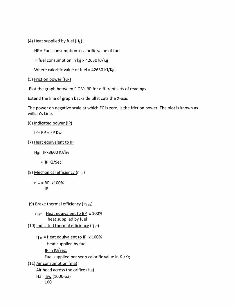
(4) Heat supplied by fuel (HF)
HF = Fuel consumption x calorific value of fuel
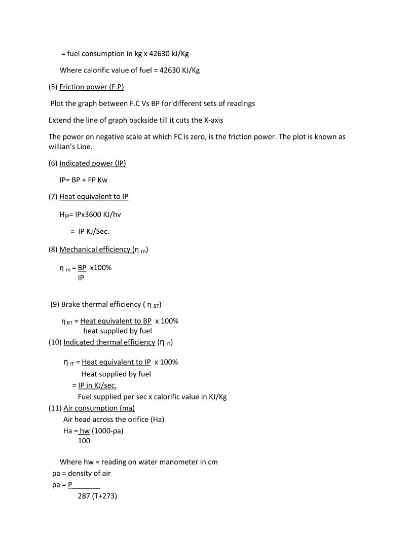
= fuel consumption in kg x 42630 kJ/Kg
9 Water outlet temp
from calorimeter T4
⁰C
10 Inlet temp of exhaust
gases to calorimeter
T5 ⁰C
11 Outlet temp of
exhaust gases from
gas calorimeter T6 ⁰C
12 Engine speed RPM
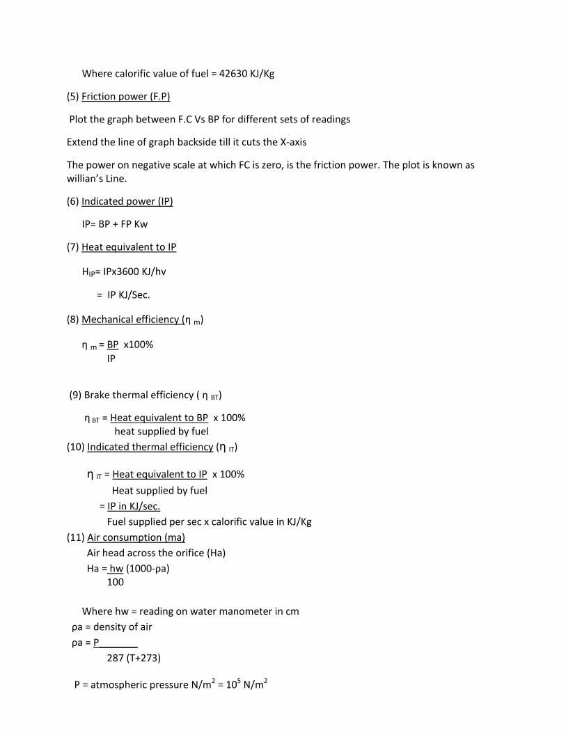
Where calorific value of fuel = 42630 KJ/Kg
(5) Friction power (F.P)
Plot the graph between F.C Vs BP for different sets of readings
Extend the line of graph backside till it cuts the X-axis
The power on negative scale at which FC is zero, is the friction power. The plot is known as willian’s Line.
(6) Indicated power (IP)
IP= BP + FP Kw
(7) Heat equivalent to IP
HIP= IPx3600 KJ/hv
= IP KJ/Sec.
(8) Mechanical efficiency (η m)
η m = BP x100%
IP
(9) Brake thermal efficiency ( η BT)
η BT = Heat equivalent to BP x 100% heat supplied by fuel
(10) Indicated thermal efficiency (η IT)
η IT = Heat equivalent to IP x 100%
Heat supplied by fuel
= IP in KJ/sec.
Fuel supplied per sec x calorific value in KJ/Kg
(11) Air consumption (ma)
Air head across the orifice (Ha)
Ha = hw (1000-ρa) 100
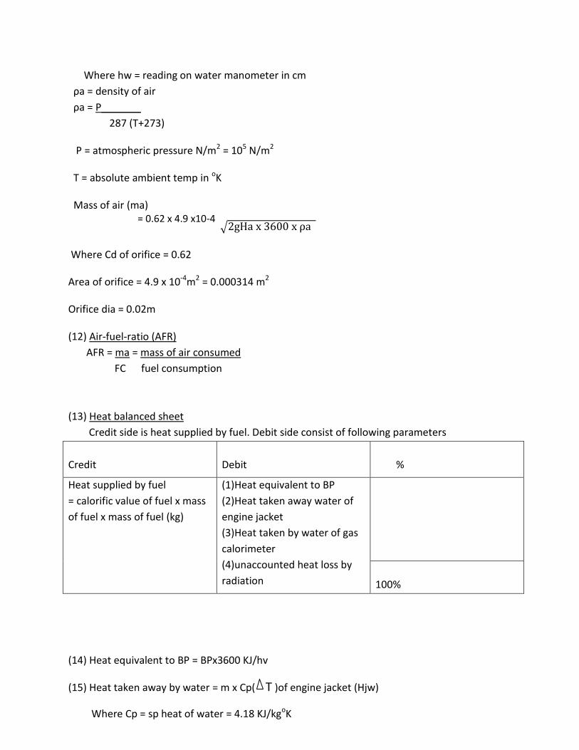
Where hw = reading on water manometer in cm
ρa = density of air
ρa = P_______
287 (T+273)
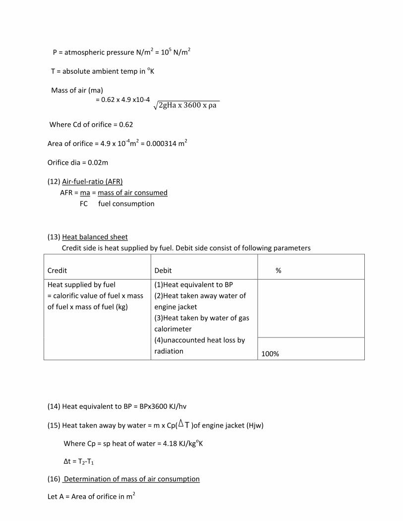
P = atmospheric pressure N/m2 = 105 N/m2
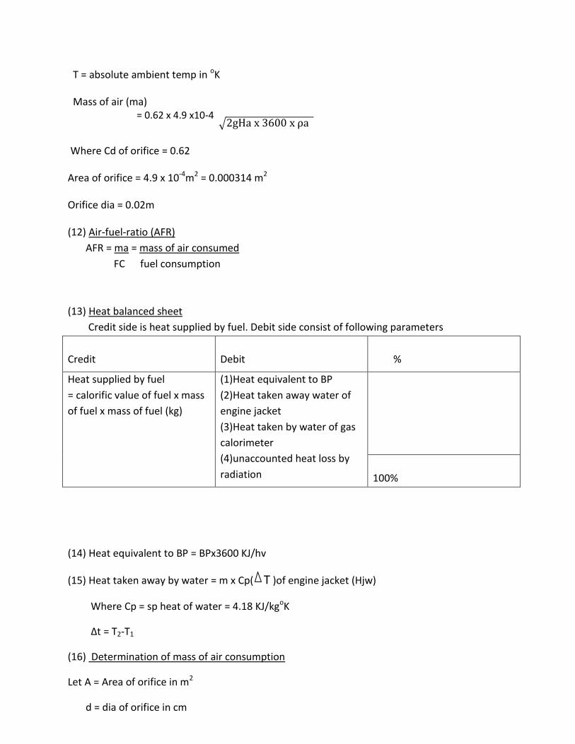
T = absolute ambient temp in oK
Mass of air (ma)
= 0.62 x 4.9 x10-4
Where Cd of orifice = 0.62
Area of orifice = 4.9 x 10⁻⁴m2 = 0.000314 m2
Orifice dia = 0.02m
(12) Air-fuel-ratio (AFR)
AFR = ma = mass of air consumed
FC fuel consumption
(13) Heat balanced sheet
Credit side is heat supplied by fuel. Debit side consist of following parameters
Credit
Debit
%
Heat supplied by fuel
= calorific value of fuel x mass
of fuel x mass of fuel (kg)
(1)Heat equivalent to BP
(2)Heat taken away water of
engine jacket
(3)Heat taken by water of gas
calorimeter
(4)unaccounted heat loss by
radiation
100%
(14) Heat equivalent to BP = BPx3600 KJ/hv
(15) Heat taken away by water = m x Cp( T )of engine jacket (Hjw)
Where Cp = sp heat of water = 4.18 KJ/kgoK
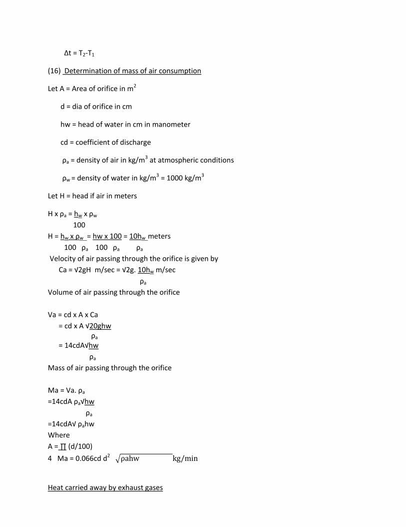
∆t = T2-T1
(16) Determination of mass of air consumption
Let A = Area of orifice in m2
d = dia of orifice in cm
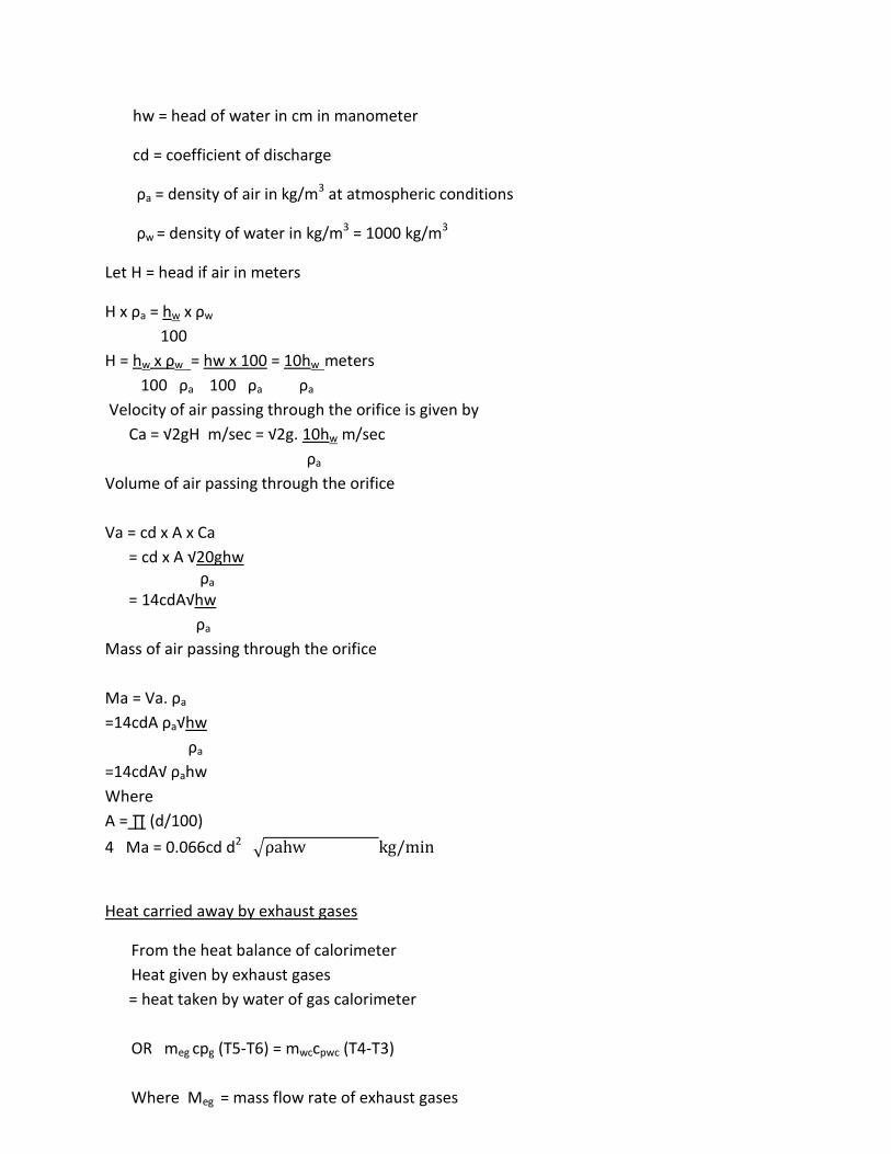
hw = head of water in cm in manometer
cd = coefficient of discharge
ρa = density of air in kg/m3 at atmospheric conditions
ρw = density of water in kg/m3 = 1000 kg/m3
Let H = head if air in meters
H x ρa = hw x ρw
100
H = hw x ρw = hw x 100 = 10hw meters
100 ρa 100 ρa ρa
Velocity of air passing through the orifice is given by
Ca = √2gH m/sec = √2g. 10hw m/sec
ρa
Volume of air passing through the orifice
Va = cd x A x Ca
= cd x A √20ghw ρa
= 14cdA√hw
ρa
Mass of air passing through the orifice
Ma = Va. ρa
=14cdA ρa√hw
ρa
=14cdA√ ρahw
Where
A = ∏ (d/100)
4 Ma = 0.066cd d2
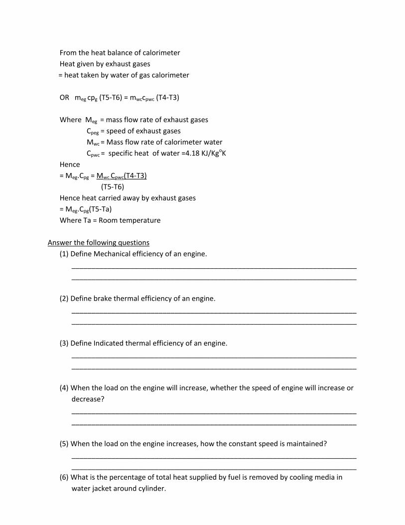
Heat carried away by exhaust gases
From the heat balance of calorimeter
Heat given by exhaust gases
= heat taken by water of gas calorimeter
OR meg cpg (T5-T6) = mwccpwc (T4-T3)
Where Meg = mass flow rate of exhaust gases

Cpeg = speed of exhaust gases
Mwc = Mass flow rate of calorimeter water
Cpwc = specific heat of water =4.18 KJ/KgoK
Hence
= Meg.Cpg = Mwc.Cpwc(T4-T3)
(T5-T6)
Hence heat carried away by exhaust gases
= Meg.Cpg(T5-Ta)
Where Ta = Room temperature

Experiment No.-7
Object: - To determine Mechanical efficiency, Brake thermal efficiency and indicated thermal efficiency
of four strokes, four cylinder diesel engine.
Equipment:
(vii) Engine :- Four stroke, four cylinder, vertical, water cooled, self governed diesel engine
(viii) Rope brake dynamometer:- Rope brake dynamometer, spring balances and loading screw
(ix) Calibrated fuel burette for fuel consumption measurement
(x) Orifice meter, fitted to air inlet tank with water manometer for air intake measurement
(xi) Multi-channel digital temperature indicator for temperature measurement at various points
(xii) Exhaust gas calorimeter to measure heat carried away by exhaust gases.
Procedure:-
(xv) Fill up sufficient diesel in diesel tank
(xvi) Check the level of lubricant oil in the sump by oil dip stick. It should be up to top edge of the
flat
Portion provided over the dip stick
(xvii) Fill up water in manometer up to half of manometer height
(xviii) Start the water supply and see water is flowing through engine jacket, brake drum and
exhaust
gas calorimeter
(xix) Release the loading screws, so that there is no tension in the rope.
(xx) Start the engine with the help of auto ignition key
(xxi) Load the engine with loading screw and set the balance difference to say 2 Kgs
(xxii) Open the burette filling cock, take sufficient diesel in burette and close the cock
(xxiii) Now turn the selector cock to engine and note down the time required for 20 ml fuel
consumption
(xxiv) Note down the brake drum speed with tachometer
(xxv) Note down difference in two limbs of manometer
(xxvi) Note the following temperatures from digital thermometer

T1 = Inlet temp of cooling water to engine jacket
T2 = outlet temp of cooling water from engine jacket
T3 = Inlet temp of cooling water to gas calorimeter
T4 = outlet temp of cooling water from gas calorimeter
T5 = Inlet temp of exhaust gases to gases to gas calorimeter
T6 = outlet temp of exhaust gases from gas calorimeter
S.N Type of reading Set No.-1 Set No.-2 Set No.-3 Set No.-4 Set No.-5
1 Load W = (W1-W2)Kg
2 Time for 20ml fuel
consumption, t f Sec
3 Manometer difference
hw cm.
4 Time for 1 liter of
calorimeter water t c
sec
5 Time for 1 liter of
engine jacket water
6 Water inlet temp to
engine jacket T1 ⁰C
7 Water outlet temp
from engine jacket T2
⁰C
8 Water inlet temp to
calorimeter T3 ⁰C
9 Water outlet temp
from calorimeter T4
⁰C

(xxvii) Note down jacket cooling water and calorimeter water flow rates
(xxviii) Take 5 sets of reading for different load
Observation Table
Formula for calculations
(1)Brake power (BP)
BP = 2∏NT KW
1000x60
Where T= Torque = Force x distance
= (W1-W2)xradius of brake drum
= (W1-W2) x9.8x0.15 Nm (when W1 & W2 are in Kg)
N= Engine RPM
(2) Fuel consumption (F.C)
Let t f = time required for 20 ml of fuel consumed by engine
Fuel consumption = 20 x 3600 x0.78 Kg/hr
T f x 1000
(3) Specific fuel consumption (SFC)
SFC = Fuel consumption in kg/BP/hr.
10 Inlet temp of exhaust
gases to calorimeter
T5 ⁰C
11 Outlet temp of
exhaust gases from
gas calorimeter T6 ⁰C
12 Engine speed RPM
(4) Heat supplied by fuel (HF)
HF = Fuel consumption x calorific value of fuel
= fuel consumption in kg x 42630 kJ/Kg
Where calorific value of fuel = 42630 KJ/Kg
(5) Friction power (F.P)
Plot the graph between F.C Vs BP for different sets of readings
Extend the line of graph backside till it cuts the X-axis
The power on negative scale at which FC is zero, is the friction power. The plot is known as willian’s Line.
(6) Indicated power (IP)
IP= BP + FP Kw
(7) Heat equivalent to IP
HIP= IPx3600 KJ/hv
= IP KJ/Sec.
(8) Mechanical efficiency (η m)
η m = BP x100%
IP
(9) Brake thermal efficiency ( η BT)
η BT = Heat equivalent to BP x 100% heat supplied by fuel
(10) Indicated thermal efficiency (η IT)
η IT = Heat equivalent to IP x 100%
Heat supplied by fuel
= IP in KJ/sec.
Fuel supplied per sec x calorific value in KJ/Kg
(11) Air consumption (ma)
Air head across the orifice (Ha)
Ha = hw (1000-ρa) 100
Where hw = reading on water manometer in cm
ρa = density of air
ρa = P_______
287 (T+273)
P = atmospheric pressure N/m2 = 105 N/m2
T = absolute ambient temp in oK
Mass of air (ma)
= 0.62 x 4.9 x10-4
Where Cd of orifice = 0.62
Area of orifice = 4.9 x 10⁻⁴m2 = 0.000314 m2
Orifice dia = 0.02m
(12) Air-fuel-ratio (AFR)
AFR = ma = mass of air consumed
FC fuel consumption
(13) Heat balanced sheet
Credit side is heat supplied by fuel. Debit side consist of following parameters
Credit
Debit
%
Heat supplied by fuel
= calorific value of fuel x mass
of fuel x mass of fuel (kg)
(1)Heat equivalent to BP
(2)Heat taken away water of
engine jacket
(3)Heat taken by water of gas
calorimeter
(4)unaccounted heat loss by
radiation
100%
(14) Heat equivalent to BP = BPx3600 KJ/hv
(15) Heat taken away by water = m x Cp( T )of engine jacket (Hjw)
Where Cp = sp heat of water = 4.18 KJ/kgoK
∆t = T2-T1
(16) Determination of mass of air consumption
Let A = Area of orifice in m2
d = dia of orifice in cm
hw = head of water in cm in manometer
cd = coefficient of discharge
ρa = density of air in kg/m3 at atmospheric conditions
ρw = density of water in kg/m3 = 1000 kg/m3
Let H = head if air in meters
H x ρa = hw x ρw
100
H = hw x ρw = hw x 100 = 10hw meters
100 ρa 100 ρa ρa
Velocity of air passing through the orifice is given by
Ca = √2gH m/sec = √2g. 10hw m/sec
ρa
Volume of air passing through the orifice
Va = cd x A x Ca
= cd x A √20ghw ρa
= 14cdA√hw
ρa
Mass of air passing through the orifice
Ma = Va. ρa
=14cdA ρa√hw
ρa
=14cdA√ ρahw
Where
A = ∏ (d/100)
4 Ma = 0.066cd d2
Heat carried away by exhaust gases
From the heat balance of calorimeter
Heat given by exhaust gases
= heat taken by water of gas calorimeter
OR meg cpg (T5-T6) = mwccpwc (T4-T3)
Where Meg = mass flow rate of exhaust gases
Cpeg = speed of exhaust gases
Mwc = Mass flow rate of calorimeter water
Cpwc = specific heat of water =4.18 KJ/KgoK
Hence
= Meg.Cpg = Mwc.Cpwc(T4-T3)
(T5-T6)
Hence heat carried away by exhaust gases
= Meg.Cpg(T5-Ta)
Where Ta = Room temperature
Answer the following questions
(1) Define Mechanical efficiency of an engine.
________________________________________________________________________
________________________________________________________________________
(2) Define brake thermal efficiency of an engine.
________________________________________________________________________
________________________________________________________________________
(3) Define Indicated thermal efficiency of an engine.
________________________________________________________________________
________________________________________________________________________
(4) When the load on the engine will increase, whether the speed of engine will increase or
decrease?
________________________________________________________________________
________________________________________________________________________
(5) When the load on the engine increases, how the constant speed is maintained?
________________________________________________________________________
________________________________________________________________________
(6) What is the percentage of total heat supplied by fuel is removed by cooling media in
water jacket around cylinder.
________________________________________________________________________
________________________________________________________________________
(7) What is the percentage of total heat supplied by fuel is taken away by lubricant oil and
heat lost by radiation.
________________________________________________________________________
________________________________________________________________________
(8)Volumetric efficiency of water cooled engine is higher than that of air cooled engine,
why?
___________________________________________________________________________
___________________________________________________________________________
(9)Torque developed by the engine is maximum at maximum volumetric efficiency and
maximum speed of the engine, why?
___________________________________________________________________________
___________________________________________________________________________
(10) Which type of governing is used in Diesel engines?
___________________________________________________________________________
___________________________________________________________________________

Experiment No.-8
Object: - To draw heat balance sheet for four stroke, four cylinder diesel engines.
Equipment:
(xiii) Engine :- Four stroke, four cylinder, vertical, water cooled, self governed diesel engine
(xiv) Rope brake dynamometer:- Rope brake dynamometer, spring balances and loading screw
(xv) Calibrated fuel burette for fuel consumption measurement
(xvi) Orifice meter, fitted to air inlet tank with water manometer for air intake measurement
(xvii) Multi-channel digital temperature indicator for temperature measurement at various points
(xviii) Exhaust gas calorimeter to measure heat carried away by exhaust gases.
Procedure:-
(xxix) Fill up sufficient diesel in diesel tank
(xxx) Check the level of lubricant oil in the sump by oil dip stick. It should be up to top edge of the
flat
Portion provided over the dip stick
(xxxi) Fill up water in manometer up to half of manometer height
(xxxii) Start the water supply and see water is flowing through engine jacket, brake drum and
exhaust
gas calorimeter
(xxxiii) Release the loading screws, so that there is no tension in the rope.
(xxxiv) Start the engine with the help of auto ignition key
(xxxv) Load the engine with loading screw and set the balance difference to say 2 Kgs
(xxxvi) Open the burette filling cock, take sufficient diesel in burette and close the cock
(xxxvii) Now turn the selector cock to engine and note down the time required for 20 ml fuel
consumption
(xxxviii) Note down the brake drum speed with tachometer
(xxxix) Note down difference in two limbs of manometer
(xl) Note the following temperatures from digital thermometer
T1 = Inlet temp of cooling water to engine jacket

T2 = outlet temp of cooling water from engine jacket
T3 = Inlet temp of cooling water to gas calorimeter
T4 = outlet temp of cooling water from gas calorimeter
T5 = Inlet temp of exhaust gases to gases to gas calorimeter
T6 = outlet temp of exhaust gases from gas calorimeter
S.N Type of reading Set No.-1 Set No.-2 Set No.-3 Set No.-4 Set No.-5
1 Load W = (W1-W2)Kg
2 Time for 20ml fuel
consumption, t f Sec
3 Manometer difference
hw cm.
4 Time for 1 liter of
calorimeter water t c
sec
5 Time for 1 liter of
engine jacket water
6 Water inlet temp to
engine jacket T1 ⁰C
7 Water outlet temp
from engine jacket T2
⁰C
8 Water inlet temp to
calorimeter T3 ⁰C
9 Water outlet temp
from calorimeter T4
⁰C
10 Inlet temp of exhaust
gases to calorimeter
T5 ⁰C
11 Outlet temp of
exhaust gases from
(xli) Note down jacket cooling water and calorimeter water flow rates
(xlii) Take 5 sets of reading for different load
Observation Table
Formula for calculations
(1)Brake power (BP)
BP = 2∏NT KW
1000x60
Where T= Torque = Force x distance
= (W1-W2)xradius of brake drum
= (W1-W2) x9.8x0.15 Nm (when W1 & W2 are in Kg)
N= Engine RPM
(2) Fuel consumption (F.C)
Let t f = time required for 20 ml of fuel consumed by engine
Fuel consumption = 20 x 3600 x0.78 Kg/hr
T f x 1000
(3) Specific fuel consumption (SFC)
SFC = Fuel consumption in kg/BP/hr.
(4) Heat supplied by fuel (HF)
HF = Fuel consumption x calorific value of fuel
gas calorimeter T6 ⁰C
12 Engine speed RPM
= fuel consumption in kg x 42630 kJ/Kg
Where calorific value of fuel = 42630 KJ/Kg
(5) Friction power (F.P)
Plot the graph between F.C Vs BP for different sets of readings
Extend the line of graph backside till it cuts the X-axis
The power on negative scale at which FC is zero, is the friction power. The plot is known as willian’s Line.
(6) Indicated power (IP)
IP= BP + FP Kw
(7) Heat equivalent to IP
HIP= IPx3600 KJ/hv
= IP KJ/Sec.
(8) Mechanical efficiency (η m)
η m = BP x100%
IP
(9) Brake thermal efficiency ( η BT)
η BT = Heat equivalent to BP x 100% heat supplied by fuel
(10) Indicated thermal efficiency (η IT)
η IT = Heat equivalent to IP x 100%
Heat supplied by fuel
= IP in KJ/sec.
Fuel supplied per sec x calorific value in KJ/Kg
(11) Air consumption (ma)
Air head across the orifice (Ha)
Ha = hw (1000-ρa) 100
Where hw = reading on water manometer in cm
ρa = density of air
ρa = P_______
287 (T+273)
P = atmospheric pressure N/m2 = 105 N/m2
T = absolute ambient temp in oK
Mass of air (ma)
= 0.62 x 4.9 x10-4
Where Cd of orifice = 0.62
Area of orifice = 4.9 x 10⁻⁴m2 = 0.000314 m2
Orifice dia = 0.02m
(12) Air-fuel-ratio (AFR)
AFR = ma = mass of air consumed
FC fuel consumption
(13) Heat balanced sheet
Credit side is heat supplied by fuel. Debit side consist of following parameters
Credit
Debit
%
Heat supplied by fuel
= calorific value of fuel x mass
of fuel x mass of fuel (kg)
(1)Heat equivalent to BP
(2)Heat taken away water of
engine jacket
(3)Heat taken by water of gas
calorimeter
(4)unaccounted heat loss by
radiation
100%
(14) Heat equivalent to BP = BPx3600 KJ/hv
(15) Heat taken away by water = m x Cp( T )of engine jacket (Hjw)
Where Cp = sp heat of water = 4.18 KJ/kgoK
∆t = T2-T1
(16) Determination of mass of air consumption
Let A = Area of orifice in m2

d = dia of orifice in cm
hw = head of water in cm in manometer
cd = coefficient of discharge
ρa = density of air in kg/m3 at atmospheric conditions
ρw = density of water in kg/m3 = 1000 kg/m3
Let H = head if air in meters
H x ρa = hw x ρw
100
H = hw x ρw = hw x 100 = 10hw meters
100 ρa 100 ρa ρa
Velocity of air passing through the orifice is given by
Ca = √2gH m/sec = √2g. 10hw m/sec
ρa
Volume of air passing through the orifice
Va = cd x A x Ca
= cd x A √20ghw ρa
= 14cdA√hw
ρa
Mass of air passing through the orifice
Ma = Va. ρa
=14cdA ρa√hw
ρa
=14cdA√ ρahw
Where
A = ∏ (d/100)
4 Ma = 0.066cd d2
Heat carried away by exhaust gases
From the heat balance of calorimeter
Heat given by exhaust gases
= heat taken by water of gas calorimeter
OR meg cpg (T5-T6) = mwccpwc (T4-T3)
Where Meg = mass flow rate of exhaust gases
Cpeg = speed of exhaust gases
Mwc = Mass flow rate of calorimeter water
Cpwc = specific heat of water =4.18 KJ/KgoK
Hence
= Meg.Cpg = Mwc.Cpwc(T4-T3)
(T5-T6)
Hence heat carried away by exhaust gases
= Meg.Cpg(T5-Ta)
Where Ta = Room temperature

Experiment No. 9
Object: - To study open cycle constant pressure combustion gas turbine with
inter cooler, regenerator and reheater
Equipment:-
(i) Compressor
(ii) Intercooler
(iii) Regenerator
(iv) Combustion chamber
(v) Gas Tribune
(vi) Reheater
(vii) Electric generator
Working Principle
(i) LP Compressor: - In open cycle gas turbine cycle air in taken from
atmosphere. It in compressed in low pressure compressor
adiabatically
(ii) Inter Cooler: - After LP sage of compressor, air in passed through
inter cooler, where air in cooled by means of water at constant
pressure. Air cooled in inter cooler to decrease the work done required
to compress the air in HP stage of compressor.
(iii) HP Compressor :- Air in finally compressed in HP stage of compressor
adiabatically
(iv) Regenerator: - Regenerator in used to reheat the compressed air by
means of exhaust gases from gas turbine.
(v) Combustion Chamber: - In combustion chamber heat in added to air
at constant pressure by combustion of fuel.
(vi) HP Gas Turbine: - Gases at high pressure and high temperature are
expanded in HP stage of gas turbine. Expansion take place
adiabatically.
(vii) Reheater: - Gases after high pressure stage of gas turbine are
reheated in reheater to increase their temperature and constant
pressure.
(viii) LP Gas turbine: - After reheater, gases are further expanded in low
pressure stage of gas turbine.
(ix) Generator: - Electric generator in coupled with gas turbine to
generate electric power.

T-S diagram for open cycle gas turbine with inter cooler,
regenerator and reheater in shown in Fig-II.
Process:-
1-2 - Adiabatic compression of air in LP stage of air compressor.
1-2 - Actual compression of air in LP stage of compressor
2-3 - Cooling of air in inter cooler at constant pressure.
3-4 - Adiabatic compression of air in HP stage of compressor.
3-4 - Actual compression of air in HP stage of compressor/
4-5 - Heating of air in regenerator by exhaust gases.
5-6 - Heat addition to air in combustion chamber at constant pressure.
6-7 - Adiabatic expansion of gases in HP stage of gas turbine.
6-7 - Actual expansion of gases in HP stage of gas turbine.
7-8 - Reheating of gases in reheater at constant pressure.
8-9 - Adiabatic expansion of gases in LP stage of gas turbine.
8-9 - Actual expansion of gases in LP gas turbine.

Experiment No. 10
Object: - To study centrifugal compressor and differences between centrifugal
and Axial compressors.
Equipment: - Centrifugal compressor and Axial compressors.
Construction: - Centrifugal compressor is consisting of following main part.
1. Vane or Blades
The vanes could be of three types
(a) Backward curved vanes.
(b) Radial curved vanes.
(c) Forward curved blades
Fig II – show the relative performance of these vanes. Centrifugal effects on the
curved blades create bending moment and produce increased stresses, when
reduce the maximum speed at which the impeller can run.
Normally backwards /vanes with 2 between 20-25◦ are employed except in
cases, where high head is major consideration
Sometimes compromise is made between the low energy transfer (Backward
curved vanes) and high outlet velocity (forward curved vanes) by using radial
vanes.
Advantage of radial vanes:-
(a) Can be manufactured easily
(b) Lower unit blade stress
(c) Free from complex bending stresses
(d) Equal energy conversion in impeller and diffuser, giving high pressure
ratio with good efficiency.
In view of the above reasons, the impeller with radial vanes has been the
logic choice of designers.
2. Impeller: - The impeller is a disc filled with radial vanes. The impeller is
generally forged or die cast of low silicon aluminum alloy. The impeller may
be single eyed or double sided (having eye on either side of compressor, so
that air is drawn in on both sides). The advantage of double sided impeller is
subjected to approximately equal forces in an axial direction.
3. Casing: - The casing surrounds the rotating impeller.
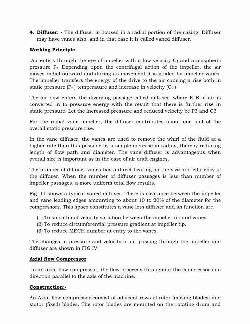
4. Diffuser: - The diffuser is housed in a radial portion of the casing. Diffuser
may have vanes also, and in that case it is called vaned diffuser.
Working Principle
Air enters through the eye of impeller with a low velocity C1 and atmospheric
pressure P1. Depending upon the centrifugal action of the impeller, the air
moves radial outward and during its movement it is guided by impeller vanes.
The impeller transfers the energy of the drive to the air causing a rise both in
static pressure (P2 ) temperature and increase in velocity (C2 )
The air now enters the diverging passage called diffuser, where K E of air is
converted in to pressure energy with the result that there is further rise in
static pressure. Let the increased pressure and reduced velocity be P3 and C3
For the radial vane impeller, the diffuser contributes about one half of the
overall static pressure rise.
In the vane diffuser, the vanes are used to remove the whirl of the fluid at a
higher rate than this possible by a simple increase in radius, thereby reducing
length of flow path and diameter. The vane diffuser is advantageous when
overall size is important as in the case of air craft engines.
The number of diffuser vanes has a direct bearing on the size and efficiency of
the diffuser. When the number of diffuser passages is less than number of
impeller passages, a more uniform total flow results.
Fig- III shows a typical vaned diffuser. There is clearance between the impeller
and vane leading edges amounting to about 10 to 20% of the diameter for the
compressors. This space constitutes a vane less diffuser and its function are.
(1) To smooth out velocity variation between the impeller tip and vanes.
(2) To reduce circumferential pressure gradient at impeller tip.
(3) To reduce MECH number at entry to the vanes.
The changes in pressure and velocity of air passing through the impeller and
diffuser are shown in FIG IV
Axial flow Compressor
In an axial flow compressor, the flow proceeds throughout the compressor in a
direction parallel to the axis of the machine.
Construction:-
An Axial flow compressor consist of adjacent rows of rotor (moving blades) and
stator (fixed) blades. The rotor blades are mounted on the rotating drum and
stator blades are fixed to the casing of stator. One stage of the machine
comprises a row of rotor blades and followed by a row of stator blades.
For efficient operation, the blades are of aerofoil section based on aerodynamic
theory. The blades are so designed that wasteful losses due to shock and
turbulence are prevented and blades are free from stalling troubles (the blades
are said to be stalled when air stream fails to follow the blade contour)
The annular area is reduced from inlet to outlet of the compressor. Due to this
pressure and absolute Velocity of air increases.
Fixed blades (i) convert part of the KE of air in to pressure energy. This
conversion is achieved by diffusion process carried out in diverging blade
passage. (ii) Guide blades redirect the fluid flow so that entry to the next stage
is without shock.
Working Principle:-
Work in put to the rotor shaft is transferred by moving blades to the air. The
blades are so arranged that the space between the blades form diffuser
passages, hence the Velocity of air relative to the blades is decreased, as the air
passes through them and there is rise in pressure. The air is then further
diffused in the stator blades, which are also arranged, to form diffuser passes.
Stator blades guide the air, so that it can be allowed to pass a second row of
moving rotor blades. Five to fourteen stages can be used.
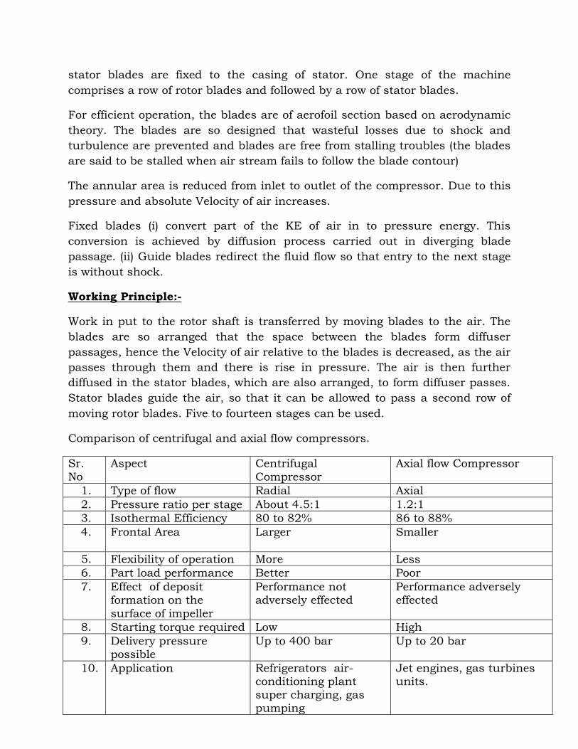
Comparison of centrifugal and axial flow compressors.
Sr.
No
Aspect Centrifugal
Compressor
Axial flow Compressor
1. Type of flow Radial Axial
2. Pressure ratio per stage About 4.5:1 1.2:1
3. Isothermal Efficiency 80 to 82% 86 to 88%
4. Frontal Area Larger Smaller
5. Flexibility of operation More Less
6. Part load performance Better Poor
7. Effect of deposit formation on the
surface of impeller
Performance not adversely effected
Performance adversely effected
8. Starting torque required Low High
9. Delivery pressure possible
Up to 400 bar Up to 20 bar
10. Application Refrigerators air-conditioning plant super charging, gas
pumping
Jet engines, gas turbines units.
