interim storage facility for spent fuel assemblies coming...
TRANSCRIPT

Direction Production Ingénierie CIDEN Centre d'Ingénierie Déconstruction et Environnement
35-37, rue Louis Guérin B.P. 21212 69611 Villeurbanne Cedex France
Téléphone +33 4 72 82 46 46 Télécopie +33 4 72 82 41 20
www.edf.fr
EDF - SA au capital de 911 085 545 euros - 552 081 317 R.C.S Paris
Rédacteur(s) : Thierry LE COURTOIS Nbre de pages : 61
Type de document : NOTE
Filière Technique – Palier - Site :
Domaine(s) métier : DECHET
Titre : Interim storage facility for spent fuel assemblies coming from an EPR plant
ELI0800224 A BPE
Imputation : E230/076871/ECIDEN Affaire(s) Technique(s) :
Bâtiment(s) : Système(s) Elémentaire(s):
Matériel(s) :
Mots-clés :
Résumé : This document was co-written with Farid BENZERARA (Assystem). This document presents a concise and readily understandable description of the design, construction, and operation of the proposed pool - base interim storage facility for spent fuel assemblies from an EPR plant.
Accessibilité : edf Ne peut être transmis à l'extérieur d'EDF que par un Chef de Département
EDF 2008

Référence Indice Page ELI0800224 A 2/61
Interim storage facility for spent fuel assemblies coming from an EPR plant
FICHE DE CONTROLE
Important pour la sûreté : NON
Important pour la gestion des déchets : NON
Important pour l’environnement : NON
Important pour la radioprotection : NON
Important pour la sécurité du personnel : NON Qualité Surveillée : NON
Pré-diffusion formalisée (indice en cours) : OUI
Auprès de : [CNEN] Mme CAHUZAC ; [CNEN] Mme DUTERTRE ; EDF/ENERGY : Mr.WALLS
Vérification indépendante : NON
Auprès de (Nom / Société) :
Rédacteur(s) Vérificateur Approbateur Indice de la note Nom – Visa – Date Nom – Visa – Date Nom – Visa – Date
A
Pré-diffusée
Thierry LE COURTOIS Visé le 20/11/2008
/
Karine PERCHE Visé le 21/11/2008
B
C
D
E

Référence Indice Page ELI0800224 A 3/61
Interim storage facility for spent fuel assemblies coming from an EPR plant
Ce document est la propriété d'EDF. Toute communication, reproduction, publication, même partielle, est interdite sauf autorisation. EDF 2008
SYNTHESIS
PURPOSE
The purpose of this document is to provide a concise and readily understandable description of the design,
construction, and operation of the proposed pool-based interim storage facility for spent fuel assemblies
coming from an EPR plant. The nuclear safety principles whose application is proposed are described and
an outline of the safety provisions and functions is presented.
DESIGN REQUIREMENTS
The description, presented in this document, considers on Reactor Site (RS) facility.
This facility will allow the storage of spent fuel coming from an EPR nuclear plant unit during its 60 years
operating time. The interim storage facility will be designed to be in operation for up to 100 years.
An EPR has approximately 3400 assemblies, all of which will require storage at the end of 60 years of
operation.
The facility can be broken down into a number of functional areas:
• Cask incoming and outgoing transport.
• Cask reception.
• Cask preparation.
• Fuel removal, loading into racks and retrieval.
• Rack movements.
• Long-term storage.
The facilities upstream of the interim storage (spent fuel reactor pool) and downstream (final repository),
along with the cask transport are not covered here, either for incoming or outgoing flasks. An EPR spent fuel
reactor pool and transfer facility are described in PCSR chapter 9.1.
DESIGN OPTIONS AND PREFERRED SOLUTIONS
A number of options for the design and operation of the handling and storage plant have been considered.
These options have been reviewed against UK and International legislation and standards, and against UK
and international operation experience feedback.
• The interim storage facility described is designed to be extendable to allow sufficient capacity for
storage of waste from ea second EPR nuclear plan unit.
• For the storage pool, a facility built at ground level is preferential to a semi-embedded one.
• Underwater unloading with casks under the pool has been preferred compared to underwater
unloading with immersion of the cask.
• The type of spent fuel storage chosen is a storage pool containing square removable racks (4 x
4 = 16 cells).

Référence Indice Page ELI0800224 A 4/61
Interim storage facility for spent fuel assemblies coming from an EPR plant
Ce document est la propriété d'EDF. Toute communication, reproduction, publication, même partielle, est interdite sauf autorisation. EDF 2008
OVERVIEW OF UK POLICIES AND GUIDANCE:
LEGISLATION
The design, construction, operation and decommissioning of the facility will meet the requirements of UK
Legislation.
SAFETY FUNCTIONS
The safety functions of the /facility – building/ and systems are as follows:
• To maintain the primary barrier (fuel cladding).
• To supplement the primary barrier with a secondary barrier at all times.
• To prevent mechanical damage to the fuel primary and secondary barriers.
• To prevent thermal damage to the fuel primary and secondary barriers.
• To prevent long term chemical damage and corrosion damage to the fuel primary and secondary
barriers.
• To prevent staff and members of the public from receiving doses of ionising radiation.
• To ensure the fuel remains sub-critical in all normal and fault conditions.
These safety functions will be a fundamental part of the facility building and system design. Where possible,
risks will be eliminated or minimised by design.
AN UNDERWATER INTERIM SPENT FUEL STORAGE
CASK RECEPTION
Function
To receive incoming casks containing spent fuel, and prepare for interface with cask and fuel handling plant.
Safety Objectives
• To remove residual heat when the cask is vertical.
• To maintain two barriers, and keep the fuel shielded and contained.
• To minimise the possibility of a cask being dropped or lowered uncontrollably and to minimise
the consequences if this does occur.
• To minimise the possibility of collision during handling that could lead to damage to the fuel.
• To maintain fuel integrity in normal operations and during internal and external hazards including
seismic events.
CASK PREPARATION
Function
To prepare the cask and interface with the pool and fuel handling equipment.

Référence Indice Page ELI0800224 A 5/61
Interim storage facility for spent fuel assemblies coming from an EPR plant
Ce document est la propriété d'EDF. Toute communication, reproduction, publication, même partielle, est interdite sauf autorisation. EDF 2008
Safety Objectives
• To remove residual heat when the cask is vertical.
• To maintain two barriers,
• To ensure the fuel is shielded at all times.
• To maintain the integrity of the water containing structures.
CASK UNLOADING AND HANDLING INTO RACKS :
Function
• To transfer the fuel from the transport cask to an available storage rack.
• To transfer any defective fuel to an awaiting damaged fuel cylinder.
• To remove fuel from a storage rack
• To transfer the fuel into the transport cask.
Safety Objectives
• To minimise the possibility of fuel being dropped or lowered uncontrollably and to minimise the
consequences if this does occur.
• To minimise the possibility of collision during handling that could lead to damage to the fuel.
• To maintain adequate shielding of the fuel at all times.
• To minimise the spread of contamination.
• To maintain fuel integrity during normal operation and during internal and external hazards
including seismic events.
RACK MOVEMENTS
Function
• To move the racks from the loading position to the storage positions in the pool.
• To move the racks from its stored positions to the unloading position (at the end of the interim
storage period time).
Safety Objectives
• To minimise the possibility of racks being dropped or lowered uncontrollably and to minimise the
consequences if this does occur.
• To minimise the possibility of collision during handling that could lead to damage to a rack.
• To maintain adequate shielding of the fuel at all times.
• To minimise the spread of contamination.
• To ensure adequate cooling.
• To maintain fuel integrity in normal operations and during internal and external hazards including
seismic events.

Référence Indice Page ELI0800224 A 6/61
Interim storage facility for spent fuel assemblies coming from an EPR plant
Ce document est la propriété d'EDF. Toute communication, reproduction, publication, même partielle, est interdite sauf autorisation. EDF 2008
LONG TERM POOL STORAGE
Function
To safely and securely store the spent fuel in the storage pool for up to 100 years.
Safety Objectives
• 100 year life time for the facility.
• To maintain shielding.
• To preserve the cladding.
• To minimise contamination.
• To cool the fuel.
• To maintain the sub-criticality.
• To protect from mechanical damage.
PRELIMINARY HAZARD A SSESSMENT:
Hazards and initiating faults have been identified and appropriate safety features incorporated into the
preliminary design.
Handling passageway
Pool mast brigde
Assembly mast bridge
Loading rack
Fixed racks in the buffer area
Area for checking the fuel cladding integrity
Detail
Référence Indice Page ELI0800224 A 7/61
Interim storage facility for spent fuel assemblies coming from an EPR plant
Ce document est la propriété d'EDF. Toute communication, reproduction, publication, même partielle, est interdite sauf autorisation. EDF 2008
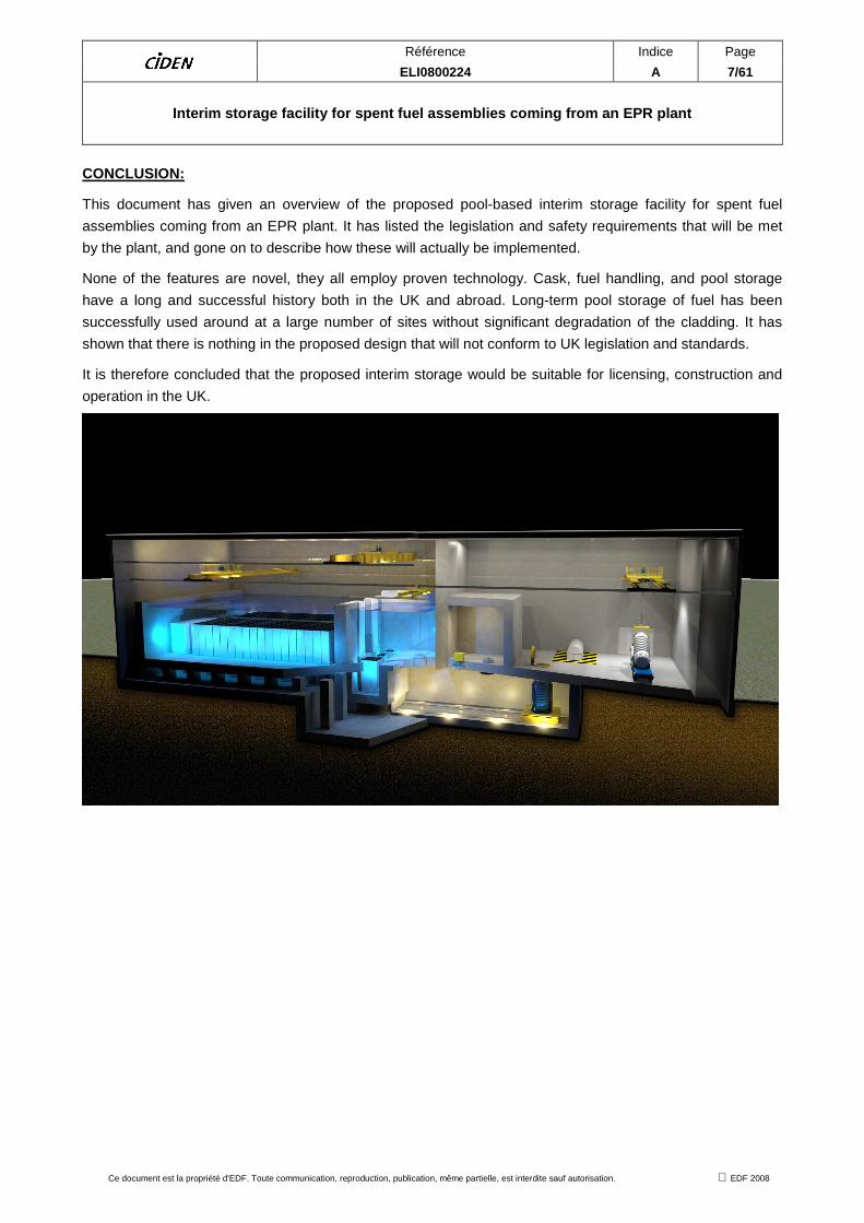
CONCLUSION:
This document has given an overview of the proposed pool-based interim storage facility for spent fuel
assemblies coming from an EPR plant. It has listed the legislation and safety requirements that will be met
by the plant, and gone on to describe how these will actually be implemented.
None of the features are novel, they all employ proven technology. Cask, fuel handling, and pool storage
have a long and successful history both in the UK and abroad. Long-term pool storage of fuel has been
successfully used around at a large number of sites without significant degradation of the cladding. It has
shown that there is nothing in the proposed design that will not conform to UK legislation and standards.
It is therefore concluded that the proposed interim storage would be suitable for licensing, construction and
operation in the UK.

Référence Indice Page ELI0800224 A 8/61
Interim storage facility for spent fuel assemblies coming from an EPR plant
Ce document est la propriété d'EDF. Toute communication, reproduction, publication, même partielle, est interdite sauf autorisation. EDF 2008
CONTENT
1 UPDATE..............................................................................................................9
2 INTRODUCTION AND PURPOSE......................................................................9
2.1 BACKGROUND: INTERIM STORAGE FACILITY.......................................................... 9
2.2 PURPOSE OF THE DOCUMENT................................................................................ 10
3 DESIGN REQUIREMENTS ...............................................................................10
3.1 UNDERWATER STORAGE FACILITY ........................................................................ 10
3.2 SPENT FUEL .............................................................................................................. 10
3.3 BASIC STORAGE TECHNOLOGIES .......................................................................... 11
4 OVERVIEW OF UK POLICIES AND GUIDANCE............... ..............................22
4.1 LEGISLATION............................................................................................................. 22
4.2 SAFETY ASSESSMENT METHODOLOGY ................................................................ 23
5 DESCRIPTION OF THE UNDERWATER INTERIM SPENT FUEL STORAGE FACILITY........................................... ................................................................28
5.1 CASK RECEPTION..................................................................................................... 28
5.2 CASK PREPARATION ................................................................................................ 30
5.3 CASK UNLOADING AND HANDLING INTO RACKS .................................................. 32
5.4 RACK MOVEMENTS................................................................................................... 34
5.5 LONG-TERM POOL STORAGE.................................................................................. 36
6 PRELIMINARY RISK ANALYSIS .......................... ...........................................40
6.1 SAFETY REQUIREMENTS......................................................................................... 40
6.2 ENVIRONMENT DISCHARGE PREDICTION ............................................................. 47
6.3 RADIOLOGICAL PROTECTION.................................................................................. 48
7 CONCLUSION...................................................................................................48
ANNEX
ANNEX 1 : DEFINITIONS .............................. ...................................................................49
ANNEX 2 : INTERNATIONAL EXPERIENCE FEEDBACK........ ......................................52
ANNEX 3 : SUMMARY OF KEY SAFETY ARRANGEMENTS RETAIN ED .....................58

Référence Indice Page ELI0800224 A 9/61
Interim storage facility for spent fuel assemblies coming from an EPR plant
Ce document est la propriété d'EDF. Toute communication, reproduction, publication, même partielle, est interdite sauf autorisation. EDF 2008
1 UPDATE
Index Comments
A Creation of the document
2 INTRODUCTION AND PURPOSE
2.1 BACKGROUND: INTERIM STORAGE FACILITY
The management of spent fuel from nuclear power plants has become a major policy issue for every nuclear
power program in the world. For the nuclear industry, finding sufficient capacity for spent fuel storage is
essential if nuclear power plants are to be allowed to continue to operate. Three management options
currently exist:
• The open, once-through cycle with direct disposal of spent fuel,
• The closed cycle with reprocessing of the spent fuel and recycling of plutonium and uranium in
the form of mixed oxide,
• The “wait and see” approach, where countries continue to evaluate their back end strategy,
while, in the meantime, taking intermediate steps.
In the closed nuclear fuel cycle, further storage capacity may be required to match the arisings of spent fuel
with the available capacity of reprocessing plants.
With respect to the once-through cycle, interim storage of spent fuel is required until the final repository has
been constructed and is in operation.
Therefore, interim storage is the primary spent fuel option in many countries.
Interim storage over a long timescale also allows decay of the residual power and the radioactivity. This
decay characteristic will simplify the design and construction of future reprocessing or disposal facilities.

Référence Indice Page ELI0800224 A 10/61
Interim storage facility for spent fuel assemblies coming from an EPR plant
Ce document est la propriété d'EDF. Toute communication, reproduction, publication, même partielle, est interdite sauf autorisation. EDF 2008
2.2 PURPOSE OF THE DOCUMENT
The purpose of this document is to provide a concise and readily understandable description of the design,
construction, and operation of the proposed pool-based interim storage facility for spent fuel assemblies
coming from an EPR plant. The nuclear safety principles which it is proposed to employ are described and
an outline of the safety provisions and functions is presented.
3 DESIGN REQUIREMENTS
3.1 UNDERWATER STORAGE FACILITY
Away From Reactor (AFR) storage can be broken down into two categories:
• The first is where additional interim storage capacity is constructed at the Reactor Site (RS) but
largely or entirely independent of the reactor and its AR (At Reactor) pool. This AFR (RS)
storage may be wet, in the form of additional pools, or in the form of dry storage facilities.
• The second category of AFR storage is Off the reactor Site (OS) at an independent location. A
large portion of this AFR (OS) capacity is in the form of pools at reprocessing plants, particularly
in France, the UK and the Russian Federation. AFR (OS) interim storage can also be centrally
located at a selected power plant complex and receive spent fuel from other power plants. So
far, there are no AFR (OS) facilities at proposed repository sites.
AR facilities are essentially storage pools in which spent fuel is kept underwater following discharge of the
reactor. These storage pools were mostly built at the same time as the corresponding reactor and are fully
integrated with this latter’s life. While AR pool storage is common to all reactors in order to provide cooling
following discharge from the reactor, AFR pool storage is an option for additional spent fuel storage prior to
disposal or reprocessing.
• Positive experience concerning the underwater storage of spent fuel has been collected over
more than 30 years.
• Underwater storage is an interim solution, while waiting for the definitive choice concerning the
management of spent fuel. Furthermore, it provides an effective, economic and transparent
radiation shield, as well as an excellent and reliable cooling medium for the removal of residual
power from the assemblies. It also decreases the thermal stresses on the fuel cladding (which is
the first containment barrier) and allows long-term storage to be implemented.
• The water allows for easier management of the risk of criticality (compared to a solution of dry
storage facility) either through the use of neutron-poisoning materials or by the addition of boron.
3.2 SPENT FUEL
The spent fuel scheduled for storage at the facility arises from the nuclear power plant EPR.
An EPR possesses 241 combustible assemblies per core, renewed by third every 18 months, which
corresponds to approximately 3400 assemblies to be stored at the conclusion of 60 years of operation.
Residual power of spent fuels
It is estimated that the thermal power dissipated by an assembly at the end of a period of 10 years decay in
the pool reactor will be about 1.4 kW.

Référence Indice Page ELI0800224 A 11/61
Interim storage facility for spent fuel assemblies coming from an EPR plant
Ce document est la propriété d'EDF. Toute communication, reproduction, publication, même partielle, est interdite sauf autorisation. EDF 2008
Dimensional data
The fuel assembly, without hold-down spring, is 4.8m long with a cross section of 214mm x 214mm.
Cladding lifespan – assembly integrity
The integrity of the spent fuel cladding will be protected for the storage period by meeting the following
criteria:
• The maximum cooling water temperature is less than 45°C (data from ECU project) in normal
and accidental conditions.
• The storage pool and handling equipment have been designed to ensure that all fuel, whether
being handled or stored, will always have sufficient water covering it for cooling and shielding
purposes.
• The precise physical and chemical characteristics of the water in contact with claddings are
maintained and checked to ensure non-corrosion of claddings.
Handling and Storage of defective assemblies:
The interim storage facility will allow the reception, preparation and storage of defective assemblies (cladding
failures). The damage may have been detected in the reactor pool, but may also have happened during
spent fuel transfer or during the interim storage phase.
We may take into account, at this stage, that there are ways of managing defective assemblies coming from
a reactor pool or following identification of defective cladding during fuel reception into the facility or during
storage. For example, the defective assemblies can be inserted into over-packaging "cylinders", which are
designed so that the cooling water can circulate freely but in a way that the particles of the fission products in
suspension are walled-in: liquids or gases are not retained by the device.
The facility will be able to manage these "cylinders" (loading and storage of cylinders in the storage pool).
3.3 BASIC STORAGE TECHNOLOGIES
The facility can be broken down into a number of functional areas:
• Incoming and outgoing Cask.
• Cask reception.
• Cask preparation.
• Fuel removal and loading into racks, and retrieval.
• Rack movements.
• Long-term storage.
The facilities upstream of the interim storage (spent fuel reactor pool) and downstream (final repository),
along with cask transport are not covered here, both for incoming and outgoing casks.
Note: The facility will be required to prepare the cask for transport in a manner compliant with transport
requirements.

Référence Indice Page ELI0800224 A 12/61
Interim storage facility for spent fuel assemblies coming from an EPR plant
Ce document est la propriété d'EDF. Toute communication, reproduction, publication, même partielle, est interdite sauf autorisation. EDF 2008
This process area includes devices providing the cooling and purification of the pools, devices related to the
ventilation systems and to the various back-up functions (electrical supplies, operating systems, etc).
The whole installation will also include the following auxiliary facilities:
• A cask reconditioning unit where the maintenance of shipping casks is carried out,
• A waste treatment unit,
• A water intake unit which corresponds to the heat sink (cooling water of the storage pool),
• A power supply unit (back-up).
These installations are not described in this study, but they will be similar to what exists for the EPR unit;
they will be designed with the suitable level of safety, following ALARP and BAT principles.
Spent fuel storage in reactor pool
(AR storage facility) (10 years)
Reception et repackaging
Spent fuel storage pool
Spent fuel retrieval
Final disposal (geologic repository)
The facility studied

Référence Indice Page ELI0800224 A 13/61
Interim storage facility for spent fuel assemblies coming from an EPR plant
Ce document est la propriété d'EDF. Toute communication, reproduction, publication, même partielle, est interdite sauf autorisation. EDF 2008
3.3.1 Choice of the location
The description, presented below, considers a type AFR (RS). The description is not location-specific at this
stage.
The interim storage function described will support a single EPR. The facility is designed to handling all
spent fuel arisings from the EPR, and to be able to retrieve and export fuel at the end of the interim storage
period.
This facility will allow the storage of spent fuel coming from a nuclear plant unit EPR during its operating
time: 60 years. The interim storage facility will be designed to be in operation for up to 100 years.
The interim storage facility described is designed to be extendable to accommodate the storage
requirements of a second EPR nuclear plant unit.
The choice of the final site location will need to take into account, amongst others, the following elements:
• Power supplies.
• Cooling water availability and security.
• Road or rail access.
• Seismic.
• Aircraft crash.
• Flooding.
• Extreme weather.
• Grid access
Sharing of systems with the reactor plant:
The systems which can be shared are:
• Site security.
• Site monitoring and radiological control.
• The road network.
• Cooling water supply.
• Power suppliers and generation.
• Grid supply.
• Other water supplies.
A number of these systems will be reduced or removed following nuclear plant closure. The initial design of
the interim storage will include provision for appropriate replacement of these systems.
Référence Indice Page ELI0800224 A 14/61
Interim storage facility for spent fuel assemblies coming from an EPR plant
Ce document est la propriété d'EDF. Toute communication, reproduction, publication, même partielle, est interdite sauf autorisation. EDF 2008
3.3.2 Design
A number of options for the design and operation of the handling and storage plant have been considered.
These options have been reviewed against UK and International legislation and standards, and against UK
and international operation experience feedback (See Annex 2).
The main options are presented below and a preferred solution identified. The detail of the preferred option
will be further developed during the design and safety assessment phase of the Project.
3.3.2.1 Pool Extension Options
The described facility includes one storage pool, but it may be designed for an additional storage pool (in
case of waste management of two nuclear power plant units). It is not economically viable to build a pool
smaller than 3000 assemblies.
The second pool can be added either at the end of the pool 1 (Diagram 1) or parallel to the length of the
reception hall (Diagram 2).
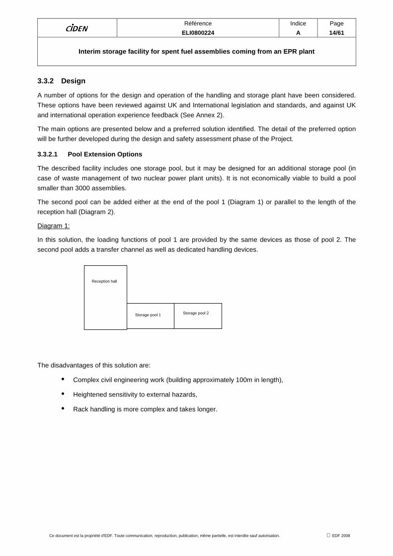
Diagram 1:
In this solution, the loading functions of pool 1 are provided by the same devices as those of pool 2. The
second pool adds a transfer channel as well as dedicated handling devices.
The disadvantages of this solution are:
• Complex civil engineering work (building approximately 100m in length),
• Heightened sensitivity to external hazards,
• Rack handling is more complex and takes longer.
Reception hall
Storage pool 1 Storage pool 2
Référence Indice Page ELI0800224 A 15/61
Interim storage facility for spent fuel assemblies coming from an EPR plant
Ce document est la propriété d'EDF. Toute communication, reproduction, publication, même partielle, est interdite sauf autorisation. EDF 2008
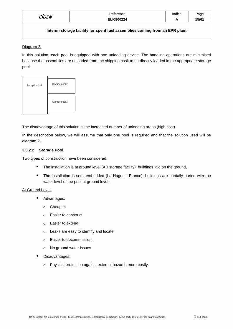
Diagram 2:
In this solution, each pool is equipped with one unloading device. The handling operations are minimised
because the assemblies are unloaded from the shipping cask to be directly loaded in the appropriate storage
pool.
The disadvantage of this solution is the increased number of unloading areas (high cost).
In the description below, we will assume that only one pool is required and that the solution used will be
diagram 2.
3.3.2.2 Storage Pool
Two types of construction have been considered:
• The installation is at ground level (AR storage facility): buildings laid on the ground,
• The installation is semi-embedded (La Hague - France): buildings are partially buried with the
water level of the pool at ground level.
At Ground Level:
• Advantages:
o Cheaper.
o Easier to construct
o Easier to extend.
o Leaks are easy to identify and locate.
o Easier to decommission.
o No ground water issues.
• Disadvantages:
o Physical protection against external hazards more costly.
Reception hall
Storage pool 1
Storage pool 2

Référence Indice Page ELI0800224 A 16/61
Interim storage facility for spent fuel assemblies coming from an EPR plant
Ce document est la propriété d'EDF. Toute communication, reproduction, publication, même partielle, est interdite sauf autorisation. EDF 2008
Semi-embedded:
The experience feedback from similar facilities shows that a semi-buried facility imposes strong technical –
and hence economical - constraints. The difference in cost is estimated at 20%.
• Advantages:
o Lower sensitivity to earthquake, external explosion, aircraft crash.
o Provide sound foundations.
• Disadvantages:
o Extension of the facility (for example by adding a second storage pool) is more
complex:
� Ease of the excavation (more or less complicated depending on the nature of the
ground),
� Impact of the construction of a new storage pool on existing installations (need to
make provision for this at early stage).
� Depth of the groundwater.
o The leak resistance of the outer envelope is more difficult to check, monitor and
ensure (difficulties in tracking and repairing any leakage).
In our example, we will describe a ground-level facility. Both types will employ leak retention outside the pool
walls.
Subsurface:
A further option that has been studied is underground storage as employed in CLAB - Sweden. A subsurface
storage facility is located at a shallow depth (some tens of meters below the surface).
The advantage of such a facility is its increased resistance to external hazard threats, but the facility remains
sensitive due to its connections between the surface and bottom and the need to ensure the tightness of
subsurface facilities in relation to floods and to the protection of surrounding waters (rivers, groundwater).
Furthermore, the safety facilities would not be based on the properties of geological formation confinement.
These do not play the role of "barrier" but ensure a simple physical protection against external hazards such
as APC and explosions.
A subsurface facility entails severe constraints:
• Choice of the location (nature and quality of home ground).
• Transfer operations between on-surface reception facilities towards underground storage section
(CLAB - Sweden).
• Difficulties to remove the heat generated by the assemblies.
• Maintenance of the facility.
Furthermore, a subsurface storage facility makes an extension complex, if not impossible.
This option is not currently considered to be viable.

Référence Indice Page ELI0800224 A 17/61
Interim storage facility for spent fuel assemblies coming from an EPR plant
Ce document est la propriété d'EDF. Toute communication, reproduction, publication, même partielle, est interdite sauf autorisation. EDF 2008
3.3.2.3 Handling facilities
Three cask and fuel handling options have been considered. The significant difference between the options
relates to cask unloading. The three options are:
• Dry unloading,
• Underwater unloading with immersion of the cask,
• Underwater unloading with casks under the pool.
Dry Unloading:
Dry unloading is used at the T0 facility (La Hague - France).
Kinematics of unloading:
1. Cask reception and storage in buffer area.
2. Cask entrance into the unloading hall.
3. Reception and lifting of the cask.
4. Activity control and preparation for opening the cask.
5. Coupling to the unloading cell.
6. Handling of the spent fuels in the thermalisation pit (cooling and rinsing
enclosure).
7. Handling of assemblies from the thermalisation pit to the racks and, then, to
the sloping ramp.
8. Handling of the racks to the storage pool.
1 2 3 475 6 8

Référence Indice Page ELI0800224 A 18/61
Interim storage facility for spent fuel assemblies coming from an EPR plant
Ce document est la propriété d'EDF. Toute communication, reproduction, publication, même partielle, est interdite sauf autorisation. EDF 2008
Dry unloading is characterized by :
• The use of a transfer car for moving the cask once the previous one is vertical.
• The application of negative pressure to the internal cavity of the cask at the preparation area,
before unloading (containment of the radioactive material),
• The implementation of communication between the internal cavity of the cask and the
atmosphere of the unloading cell,
• The handling of assemblies towards a thermalisation pit (function of cooling / flushing) before
putting them into storage racks.
Unloading underwater with immersion of the cask:
The underwater unloading of immersed casks is used at NPH (La Hague - France), in the AR ponds PWR
900MW and 1300MW (except for 1400 and 1650MW: Chooz B and Civaux - France) and at the CLAB facility
- Sweden.
Kinematics of unloading:
1. Cask reception and storage in buffer area.
2. Cask entrance into the unloading hall.
3. Reception and lifting of the cask.
4. Setting up of the protection enclosure.
5. Cooling of the cask and control of activity.
6. Immersion of the cask and opening of the plug.
7. Cask unloading with removal of assemblies in a storage rack.
8. Transfer of the rack to the storage pool.
1 2 3
4
7
5
68
Référence Indice Page ELI0800224 A 19/61
Interim storage facility for spent fuel assemblies coming from an EPR plant
Ce document est la propriété d'EDF. Toute communication, reproduction, publication, même partielle, est interdite sauf autorisation. EDF 2008
The underwater unloading of submerged casks is characterised by:
• Contamination minimisation of the external surface of the cask by a protection enclosure.
• Filling of the internal cavity of the cask with water at the preparation area before unloading
(cooling of assemblies).
• Immersion and emersion of the cask in the unloading pit.
• Underwater opening of the immersed cask.
• Safety systems to ensure that the cask cannot be lifted out of the pool without the cap in place.
• Note: All operations must be considered to be reversible.
• Handling of assemblies with the mast crane.
• Decontamination phase on the external surface of the cask.
• Phase of draining, flushing and drying of the internal cavity of the cask.
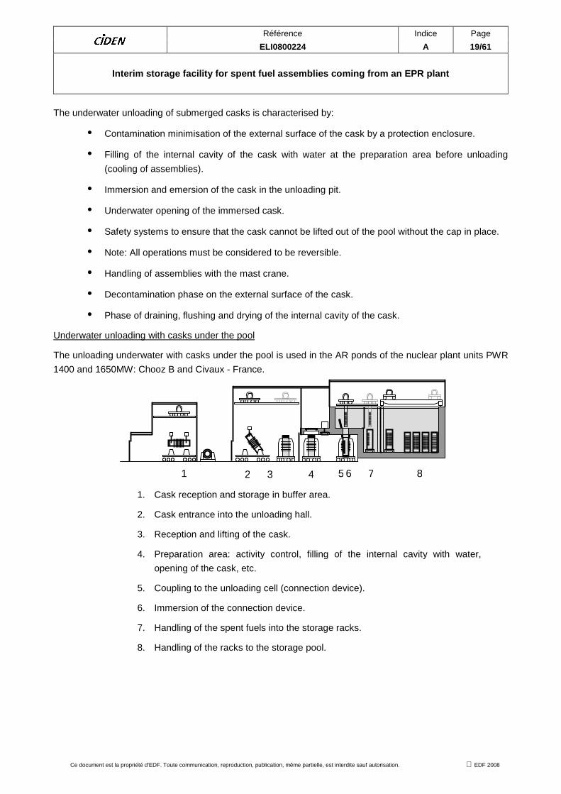
Underwater unloading with casks under the pool
The unloading underwater with casks under the pool is used in the AR ponds of the nuclear plant units PWR
1400 and 1650MW: Chooz B and Civaux - France.
1. Cask reception and storage in buffer area.
2. Cask entrance into the unloading hall.
3. Reception and lifting of the cask.
4. Preparation area: activity control, filling of the internal cavity with water,
opening of the cask, etc.
5. Coupling to the unloading cell (connection device).
6. Immersion of the connection device.
7. Handling of the spent fuels into the storage racks.
8. Handling of the racks to the storage pool.
1 2 3 4 75 6 8

Référence Indice Page ELI0800224 A 20/61
Interim storage facility for spent fuel assemblies coming from an EPR plant
Ce document est la propriété d'EDF. Toute communication, reproduction, publication, même partielle, est interdite sauf autorisation. EDF 2008
Unloading is characterised by:
• The use of a transfer car for moving the cask once the previous one is vertical; this transfer car
is equipped with a cask cooling device.
• Filling of the internal cavity of the cask with water, at the preparation area, before unloading
(flooding of assemblies).
• The presence of a dedicated shielded area to withdraw the cask plug between the preparation
area and unloading pit.
• The implementation of communication (connection device) between the internal cavity of the
cask and the water of the unloading pit.
• The handling of assemblies with the mast crane.
• Phase of draining, flushing and drying of the internal cavity of the cask.
Preferred solution :
Insofar as,
• The dry unloading technique leads to strong operational constraints (external cooling of the cask
only, complex management of cladding failure, strong constraints in terms of design, operation
and maintenance of the unloading cell and difficult fault recovery).
• The underwater unloading is robust from a safety point of view, of lower cost (compared to
unloading cell) and benefits from a solid operational experience feedback. All fault
consequences all reduced compared to handling in air and recovery from faults will much
simpler, safer and not time constrained.
• When associated with wet storage, a wet unloading is preferred.
Both underwater unloading techniques are possible. Underwater unloading possesses many advantages: it
is simple, safe, removes any time pressures, easy recovery, full visibility, easy to reverse operations to
recover, and a good UK experience.
The underwater unloading technique with cask immersion offers better adaptability (or flexibility) by fitting to
all type of casks. It is particularly well-suited to facilities receiving assemblies of different kinds: NPH facility
(Hague - France), CLAB - Sweden), project ECU (EDF -France).
However, cask immersion has a number of disadvantages:
• It involves a lifting height of more than 10m during the immersion and emersion phases,
although the drop height or consequences can be minimised and the crane can be of the high
integrity dual load path type if required.
• It generates a large volume of liquid waste due to the necessary decontamination of equipment
brought into contact with contaminated water (end of the cask, enclosure, plug protection).
• It involves more frequent loads of the main handling crane.
The choice of unloading process with cask under pool is preferred for the following reasons:
• The technique is safer insofar as there are fewer cask handling operations.

Référence Indice Page ELI0800224 A 21/61
Interim storage facility for spent fuel assemblies coming from an EPR plant
Ce document est la propriété d'EDF. Toute communication, reproduction, publication, même partielle, est interdite sauf autorisation. EDF 2008
• Equipment is economically more attractive: a single type of assembly stored (thus a single type
of shipping cask delivered), the same devices as those of the AR pool,
• EDF has sound experience feedback of both unloading underwater techniques: design,
implementation and operation.
3.3.2.4 Spent fuel racks
The solutions existing are of two types:
• Fixed racks permanently implanted in the storage pool. In this case, the handled object is the
assembly.
• Movable racks which are handled between the unloading area and the storage pool. In this case,
the handled object is the rack.
More precisely:
• AREVA NC storage pool, La Hague (type 2):
The spent fuel storage is provided by baskets, made of neutron-poisoning materials.
• EDF storage ponds at nuclear plant units (including EPR):
The spent fuel in AR ponds is stored in fixed (type 1) or removable racks (type 2) made of
neutron-poisoning materials.
Given the projected lifetime of this storage facility, additional safety requirements could be more easily taken
into account in the case of racks. Storing the fuel assemblies in movable racks is considered to be more
reliable and efficient than putting them separately on shelves (fixed racks) and requires less time for loading
and unloading operations.
Furthermore, the use of movable racks allows the simultaneous handling of several assemblies and can limit
the depth of ponds: indeed, handling assemblies, in the case of fixed racks, require an additional water
height corresponding to the length of the assembly.
Overall, reducing the number of handling operations lessens the risk by a factor of 16.
The preferred fuel storage is a storage composed of removable racks (4 x 4 = 16 cells).

Référence Indice Page ELI0800224 A 22/61
Interim storage facility for spent fuel assemblies coming from an EPR plant
Ce document est la propriété d'EDF. Toute communication, reproduction, publication, même partielle, est interdite sauf autorisation. EDF 2008
4 OVERVIEW OF UK POLICIES AND GUIDANCE
4.1 LEGISLATION
The design, construction, operation and decommissioning of the facility will meet the following UK Legislation
requirements:
• Nuclear Installations Act 1965 (as amended) (NIA) relating to the licensing and inspection of
nuclear installations.
• Ionising Radiation Regulations 1999 (IRR).
• Radiation Emergency Preparedness and Public Information Regulations 2001 (REPPIR).
• Management of Health and Safety at Work Regulations 1999.
• Nuclear Reactors (Environmental Impact Assessment for Decommissioning) (Amendment)
Regulations 2006 (EIADR).
• Radioactive Substances act 1993.
• Management of Radioactive Materials And Radioactive Waste On Nuclear Licensed Sites.
• Provision and Use of Work Equipment Regulations.
• Lifting Operations and Lifting Equipment Regulations.
• Personal Protective Equipment at Work Regulations.
• Pressure Systems Safety Regulations.
• Control of Major Accident Hazards Regulations (as amended).
• Dangerous Substances and Explosive Atmospheres Regulations.
• Environment Agency or Scottish Environmental Protection Agency Regulations.
• The Office for Civil Nuclear Security (OCNS) Regulations.

Référence Indice Page ELI0800224 A 23/61
Interim storage facility for spent fuel assemblies coming from an EPR plant
Ce document est la propriété d'EDF. Toute communication, reproduction, publication, même partielle, est interdite sauf autorisation. EDF 2008
4.2 SAFETY ASSESSMENT METHODOLOGY
4.2.1 Safety principles
The following safety principles will be applied at the facility:
Accident Prevention:
• All reasonably practicable steps will be taken to ensure safe plant operation and to prevent
accidents and risks to health at work.
• All reasonably practicable steps will be taken to minimise the consequences of any accident
including radiological consequences.
• The facility will be designed and operated so that in-depth defence against potentially significant
faults or failures is achieved by the provision of several levels of protection.
Radiation:
• No person will receive doses of ionising radiation in excess of statutory dose limits as a result of
normal operation.
• The exposure of any person to radiation and the collective effective dose to staff and the general
public, will be kept as low as is reasonably practicable.
Criticality Control:
• Measures will be incorporated to minimise the likelihood of unplanned criticality. No external
controls will be relied upon to prevent criticality. The safety case will demonstrate acceptable
sub-criticality margins for long-term storage taking account of any uncertainties that may exist.
Radiological waste:
• Production of radioactive waste will, as far as possible, be avoided. Where radioactive waste is
unavoidable, its production will be minimised.
• Radioactive material and radioactive waste will be managed safely throughout its life cycle in a
manner that is consistent with modern standards.
• Remaining radioactive material and radioactive waste will be put into a passively safe state for
interim storage pending future disposal or other long term solution.

Référence Indice Page ELI0800224 A 24/61
Interim storage facility for spent fuel assemblies coming from an EPR plant
Ce document est la propriété d'EDF. Toute communication, reproduction, publication, même partielle, est interdite sauf autorisation. EDF 2008
4.2.2 Safety system policies
These principles will be met by compliance with the following policies:
• Design standards which ensure that risks are “as low as reasonably practicable” (ALARP) or
broadly acceptable for UK Nuclear Installations will be used.
• Plant of well proven design based on experience gained in the handling and storage of spent
fuel at existing facilities in the UK and abroad will be used where possible.
• High standards of design and manufacture appropriate to the safety classification of the plant,
reinforced by Quality Assurance and independent checking to ensure that standards are
achieved will be used.
• The facility will be designed for 100-year life. The design and construction of plant will permit
replacement of equipment as appropriate for 100-year storage life without reducing any safety
functions.
• Extensive commissioning tests will be carried out to confirm that plant has been constructed in
line with design intent and that it functions correctly.
• The plant will be operated in accordance with properly approved and documented procedures.
• The facilities will be designed and constructed to be operated and maintained without placing
unacceptable demands on staff.
4.2.3 Hazards
The plant and systems are designed to control the following radiological hazards:
• Ionising Radiation dose to any person.
• Radiation, ingestion and inhalation hazard from radionuclides.
• Criticality excursions.
4.2.4 Safety functions (see section §6.1.1)
The safety functions of the plant and systems are as follows:
• To maintain the primary barrier (fuel cladding).
• To supplement the primary barrier with a secondary barrier at all times.
• To prevent mechanical damage to the fuel primary and secondary barriers.
• To prevent thermal damage to the fuel primary and secondary barriers.
• To prevent long-term chemical damage and corrosion damage to the fuel primary and secondary
barriers.
• To prevent staff and members of the public from receiving doses of ionising radiation.
• To maintain the fuel sub-critical in all normal and fault conditions.
Référence Indice Page ELI0800224 A 25/61
Interim storage facility for spent fuel assemblies coming from an EPR plant
Ce document est la propriété d'EDF. Toute communication, reproduction, publication, même partielle, est interdite sauf autorisation. EDF 2008
These safety functions will be a fundamental part of the plant and system design. Where possible, risks will
be eliminated or minimised by design through use of :
• Passive systems where possible.
• Engineered control systems that maintain plant operational parameters within a safety envelope.
• Safety systems that reduce the frequency or limit the consequences of fault sequences, and that
achieve and maintain a defined safe state.
• Engineered plant monitoring and alarms.
• Engineered automatic safety systems will mitigate/minimise hazards by providing protective
measures.
• Mechanical protective systems will be used where practicable.
• All items will be accessible for operation and maintenance where possible.
• Simplify and minimise moving parts.
A summary of the key safety arrangements is presented in Annex 2
4.2.5 Safety System Requirements
Although the design of the plant, particularly shielding and pool structure will be based on massive, passive
methods of risk elimination, there will be a requirement for safety systems.
Any safety systems will meet the following requirements:
• Safety systems will be fail-safe.
• During any normally permissible state of plant availability, no single random failure, assumed to
occur anywhere within the systems provided to secure a safety function, will prevent the
performance of that safety function.
• For any Frequent Initiating Event (related to PSA : Probabilistic Safety Assessment), there will
be at least 2 lines of protection to perform any essential function, with diversity between each
line, during any normally permissible state of plant availability, unless it is shown not to be
reasonably practicable.
• For any Infrequent Initiating Event (related to PSA : Probabilistic Safety Assessment), there will
be at least one line of protection to perform any essential function and that line will be provided
with redundancy, during any normally permissible state of plant availability, unless it is shown
not to be reasonably practicable.
• Safety system actions and associated alarms will not be self-resetting, irrespective of the
subsequent state of the initiating fault.
• A safety system will be dedicated to the single task of performing its safety function. Where it is
necessary for other functions to be encompassed, the whole system will be classified as a safety
system and the safety function will not be jeopardised by the other functions.
• Safety systems will be physically separate, independent, isolated from other systems, including
safety-related systems, and share no equipment or services. There will be adequate segregation

Référence Indice Page ELI0800224 A 26/61
Interim storage facility for spent fuel assemblies coming from an EPR plant
Ce document est la propriété d'EDF. Toute communication, reproduction, publication, même partielle, est interdite sauf autorisation. EDF 2008
between independent parts of the safety system (including pipework and cabling) and also
between a safety system and other facility equipment that, in the event of a fault, might
jeopardise the safe working of the safety system.
• Where computers or programmable devices are used in safety-related systems, evidence will be
provided that the hardware and software are designed, manufactured and installed to
appropriate standards.
• Essential services will be provided to ensure the maintenance of a safe plant state in normal
operation and fault conditions.
• User interfaces, comprising controls, indications, recording instrumentation and alarms will be
provided at appropriate locations and will be suitable and sufficient to support effective
monitoring and control of the plant during all plant states.
4.2.6 External Hazard Requirements
4.2.6.1 Seismic Hazard
The seismology and geology of the area around the site and the geology of the site will be evaluated to
derive a design basis earthquake (DBE).
The studies will:
a) establish information on historical and instrumentally recorded earthquakes that have occurred
in the region;
b) be proportionate to the radiological hazard posed by the site, while covering those aspects that
could affect the estimation of the seismic hazard at the site;
c) enable buildings, structures and plant in the nuclear facility to be designed to safely withstand
the ground motions involved, if needed.
An operating basis earthquake (OBE) will also be determined.
The design will be such that no structure, system or component important to safety will be impaired by the
repeated occurrence of ground motions at the OBE level.
In determining the effect of a seismic event on the facility, the simultaneous effect of that event on any other
facility or installation in the vicinity, and on the safety of any system or service that may have a bearing on
safety, will also be taken into account.
4.2.6.2 Aircraft crash
The risk resulting from the air traffic, as well as the possible consequences of a large aircraft crash will be
taken into account consistently with what is done for the buildings of the nuclear island.
With regard to the air traffic, the predicted frequency of aircraft crashes will be determined, for the site, on the
basis of the most recent available data related to general, military and commercial aviation. The need for the
implementation of protective design measures will be defined on this probabilistic basis, in accordance with
the nuclear island design approach.
In addition, the event of a large commercial aircraft will be postulated, regardless of its probability. The
analysis of the possible consequences will include all effects (notably related to fuel) and will take into
account the detailed design of the facility as well as its precise location on the site.
Référence Indice Page ELI0800224 A 27/61
Interim storage facility for spent fuel assemblies coming from an EPR plant
Ce document est la propriété d'EDF. Toute communication, reproduction, publication, même partielle, est interdite sauf autorisation. EDF 2008
Protective measures will be implemented where necessary to achieve the same level safety level requested
for the nuclear island.
4.2.6.3 Extreme Weather Conditions
The facility will be designed to withstand extreme weather conditions that meet the design basis event
criteria.
The types of extreme weather will include abnormal wind loadings, wind-blown debris, precipitation,
accumulated ice and snow deposits, lightning, extremes of high and low temperature, humidity and drought.
The design basis event will take account of reasonable combinations of extreme weather conditions that may
be expected to occur, and of the effect of failure of any non-nuclear hazardous installations off-site and other
nuclear facilities, on- or off-site, during such conditions.
The reasonably foreseeable effects of climate change over the lifetime of the facility will be taken into
account.
4.2.6.4 Flooding
The facility will be designed to withstand flooding conditions that meet the design basis event criteria.
The area around the site will be evaluated to determine the potential for flooding due to external hazards,
e.g. precipitation, high tides, storm surges, barometric effects, overflowing of rivers and upstream structures,
coastal erosion and tsunamis.
The design basis flood will take account, as appropriate, of the combined effects of high tide, wind effects,
wave actions, duration of the flood and flow conditions.

Référence Indice Page ELI0800224 A 28/61
Interim storage facility for spent fuel assemblies coming from an EPR plant
Ce document est la propriété d'EDF. Toute communication, reproduction, publication, même partielle, est interdite sauf autorisation. EDF 2008
5 DESCRIPTION OF THE UNDERWATER INTERIM SPENT FUEL STORAGE FACILITY
This section describes each of the main activities in the facility. Each of the facilities is broken down as
follows:
• Function.
• Description.
• Safety Objectives.
• Key Safety Features.
5.1 CASK RECEPTION
5.1.1 Function
To receive incoming casks containing spent fuel, and prepare for interface with cask and fuel handling plant.
5.1.2 Description
The transport cask arrives at the site by road or rail. It is deposited horizontally on a frame, then driven to the
cask storage buffer area.
Casks need to be cooled when they are in vertical position (they are indeed designed to dissipate the
thermal power of the assemblies they contain when they are in shipping configuration). Thus, they are stored
horizontally in the buffer area.
Transfer from the storage buffer area to the reception hall is performed with a lorry.
The shock absorbing covers front and rear of the cask are removed in the appropriate area of the reception
hall and a contamination survey is performed on the covers and on the surfaces of the cask.

Référence Indice Page ELI0800224 A 29/61
Interim storage facility for spent fuel assemblies coming from an EPR plant
Ce document est la propriété d'EDF. Toute communication, reproduction, publication, même partielle, est interdite sauf autorisation. EDF 2008
The cask is picked up by the hall’s main handling crane, then put down on the transfer car which delivers it to
the preparation area.
The fitting of the protection enclosure around the cooling fins ensures the cooling of the external envelope of
the cask when it is in vertical position. Once in place, the space between envelope and enclosure is filled in
with demineralised water.
5.1.3 Safety Objectives:
The safety objectives of the cask reception equipment will be:
To remove the residual heat when cask is vertical.
To maintain two barriers, and keep the fuel shielded and contained.
To minimise the possibility of a cask being dropped or lowered uncontrollably and to minimise the
consequences if this does occur.
To minimise the possibility of collision during handling that could lead to damage to the fuel.
To maintain fuel integrity in normal operations and during internal and external hazards including seismic
events.
Cooling of the external envelope
Protection enclosure
Transfer car (trolley)

Référence Indice Page ELI0800224 A 30/61
Interim storage facility for spent fuel assemblies coming from an EPR plant
Ce document est la propriété d'EDF. Toute communication, reproduction, publication, même partielle, est interdite sauf autorisation. EDF 2008
5.1.4 Key Safety Features:
• During this phase, the fuel remains inside the sealed cask and so is fully shielded and contained.
• The cooling enclosure provides adequate cooling for the vertical flask.
• After transport, the shock-absorbing covers are removed. The likelihood and consequences of
any drop are minimized by design. The cask is not lifted and transport is performed on a
purpose-built trolley at low speed.
• Trolley and cask support will be seismically qualified.
5.2 CASK PREPARATION
5.2.1 Function:
To prepare the cask and interface with the pool and fuel handling equipment.
5.2.2 Description:
The cask on the trolley is moved into the shielded cell and the shield door is shut.
The cask protection cover is removed after a contamination check of the atmosphere between the protective
cover and the plug (sealing systems). After removal, a contamination check is carried out on the top of the
plug. This activity is performed by operators accessing the top of the flask from a cell above.
A measurement of the activity concentration of the cask internal cavity is performed at the preparation area.
Detection of abnormal activity could indicate a fuel clad defect.
If abnormal activity is detected the following will be implemented:
the implementation of special procedures aimed at limiting the dispersal of this activity
during assembly unloading, individual inspection of the fuel cladding integrity of all the cask assemblies.
When an assembly is found to be defective it will be packaged in an over-packaging "cylinder".
Note: Fuel cladding integrity is not checked when the activity concentration of the cask internal cavity is
satisfactory.
The cask internal cavity is set to atmospheric pressure and then filled with water. This allows the cooling of
the cask internal cavity by water circulation.

Référence Indice Page ELI0800224 A 31/61
Interim storage facility for spent fuel assemblies coming from an EPR plant
Ce document est la propriété d'EDF. Toute communication, reproduction, publication, même partielle, est interdite sauf autorisation. EDF 2008
The plug fixing ring is unscrewed then removed and the fit-up parts are installed.
The transfer car is driven to the plug gripping area and the plug is removed.
After the preparation phase, the cask is transferred under the pool penetration. The following operations are
then performed:
• Cask fit-up,
• Watertightness tests,
• Filling of the penetration with water and pressure balancing,
• Opening pool access valve.
5.2.3 Safety objectives
The safety objectives of the cask preparation equipment will be:
• To remove the residual heat when cask is vertical.
• To maintain two barriers. During cask preparation, the fuel remains inside the sealed cask and
so is fully shielded and contained.
• To maintain the fuel shielding.
• To maintain pool water tightness.
5.2.4 Key Safety Features
• The cask is filled with water for cooling.
Cooling of the inner envelope
Cooling of the outer envelope
Cask cover Plug fixing ring
Plug lifting device

Référence Indice Page ELI0800224 A 32/61
Interim storage facility for spent fuel assemblies coming from an EPR plant
Ce document est la propriété d'EDF. Toute communication, reproduction, publication, même partielle, est interdite sauf autorisation. EDF 2008
• The shielded cell will have a contaminated ventilation system.
• The integrity of the fuel clad is checked before opening the plug.
• The cask plug is removed remotely inside a shielded cell.
• Access to the cell is controlled by Safety Systems.
• The cask connection is controlled and maintained by Safety Systems.
• There is adequate water shielding above the cask.
• All equipment needed for this phase is seismically qualified: penetration, dam pool, and pressure
balancing devices, etc.
5.3 CASK UNLOADING AND HANDLING INTO RACKS
5.3.1 Function
The functions of the cask unloading equipment will be:
• To transfer the fuel from the transport cask to an awaiting storage rack.
• To transfer the defective fuel to an awaiting damaged fuel cylinder.
• To be able to remove fuel from a storage rack
• To transfer the fuel into the transport cask.

Référence Indice Page ELI0800224 A 33/61
Interim storage facility for spent fuel assemblies coming from an EPR plant
Ce document est la propriété d'EDF. Toute communication, reproduction, publication, même partielle, est interdite sauf autorisation. EDF 2008
5.3.2 Description
The lifting device dedicated to unloading grabs each fuel assembly in a cask and puts them down, either
directly in the storage rack (forwarded beforehand) or in a storage buffer located in the unloading pit.
This fuel handling equipment is designed to handle a spent fuel assembly underwater from the time it is in a
spent fuel cask until it has been lowered into the underwater fuel storage area.
The handling height still leaves adequate water covering the fuel assembly to eliminate any radiation hazard
to the operators.
Assemblies for which inspection of the internal cavity was not satisfactory are taken by the handling device
to be put down in an area dedicated to checking the cladding integrity of spent fuel.
Racks in loading pool Penetration
device
Spent fuel mast crane
Mechanical dam

Référence Indice Page ELI0800224 A 34/61
Interim storage facility for spent fuel assemblies coming from an EPR plant
Ce document est la propriété d'EDF. Toute communication, reproduction, publication, même partielle, est interdite sauf autorisation. EDF 2008
5.3.3 Safety Objectives
The safety objectives of the cask unloading equipment will be as follows:
• To minimise the possibility of fuel being dropped or lowered uncontrollably and to minimise the
consequences if this does occur.
• To minimise the possibility of collision during handling that could lead to damage to the fuel.
• To maintain adequate shielding to the fuel at all times.
• To minimise the spread of contamination.
• To maintain fuel integrity during normal operation and in the event of internal and external
hazards including seismic events.
5.3.4 Key safety features
The key safety features of the cask unloading equipment are:
• High integrity fuel lifting equipment.
• Fuel grab mechanically interlocked to prevent release when loaded.
• Adequate shielding provided by water cover
• Lift height controlled and limited by design of the lifting system.
• Hoist operations interlocked and controlled.
• Safety System interlocks.
• Minimised drop height and all lifting done underwater - insufficient to cause damage in the event
of a drop.
• Local operation and Hoist navigation system.
• Locally operated with good visibility and no requirement for quick reaction to any developing
fault.
5.4 RACK MOVEMENTS
5.4.1 Function
• To handle the racks from the loading position to the storage positions in the pool.
• To handle the racks from their stored positions to the unloading position (at the end of the
interim storage period time).

Référence Indice Page ELI0800224 A 35/61
Interim storage facility for spent fuel assemblies coming from an EPR plant
Ce document est la propriété d'EDF. Toute communication, reproduction, publication, même partielle, est interdite sauf autorisation. EDF 2008
5.4.2 Description
Once filled, rack is grabbed by the mast, then handled and positioned in one of the places provided for that
purpose.
The design of the unloading line will allow fuel retrievability. During the design phase, the option of building
an extension to set up the retrieval facility will be considered. This retrieval facility will allow, for example,
directly placing assemblies into the container designed for the geological repository.
5.4.3 Safety objectives
The safety objectives of the rack handling equipment are as follows:
• To minimise the possibility of a rack being dropped or lowered uncontrollably and to minimise
the consequences if this does occur.
• To minimise the possibility of collision during handling that could lead to damage to a rack.
• To maintain adequate shielding to fuel at all times.
• To minimise the spread of contamination.
• To ensure adequate cooling.
• To maintain fuel integrity in normal operations and during internal and external hazards including
seismic events.
5.4.4 Key Safety Features
• High integrity rack lifting equipment.
• Rack grab mechanically interlocked to prevent release when loaded.
• Adequate shielding provided by water cover.
• Lift height minimised and controlled and limited by design of the lifting system.
• Hoist operations interlocked and controlled.
• Safety System interlocks.
• Interlocked prohibited travel areas.
• Anti-collision safety features.
• Slow speed controlled.

Référence Indice Page ELI0800224 A 36/61
Interim storage facility for spent fuel assemblies coming from an EPR plant
Ce document est la propriété d'EDF. Toute communication, reproduction, publication, même partielle, est interdite sauf autorisation. EDF 2008
• Minimised drop height and all lifting done under water - insufficient to cause damage in the
event of a drop.
• Local operation and Hoist navigation system.
• Locally operated with good visibility and no requirement for quick reaction to any developing
fault.
5.5 LONG-TERM POOL STORAGE
5.5.1 Function
To safely and securely store the spent fuel in the storage pool for up to 100 years.
5.5.2 Description
The floor and walls of the main storage pool, along with the other smaller ones (unloading pit), are lined with
layers of stainless steel to prevent leakage of water. Auxiliary systems include: water cooling and
purification, ventilation, instrumentation, leakage monitoring.
In order to ensure radiological shielding for operators, the side walls of the pool and the water cover will be
sufficient: in an AR storage building, pool walls are 1 meter thick and water 4 meters thick.
Usually, retention areas are built under the pool bottom allowing its inspection and used as retention volume
in case of accidental draining of the pool (to avoid pollution of the groundwater).
The height of the storage pool is 10m, which is the sum of the rack height, the water cover required for the
radiological protection and clearances for handling racks.
The cask unloading pits and rack loading pits are about 15m deep, since the height of the assembly
necessary for loading the assemblies into the racks is added.
Storage pool :
• Capacity: 3400 Spent fuel assemblies, that is 213 storage racks (16 assemblies per rack).
• Length: 51m.
• Width: 21m.
• Depth: 10m.
• Volume of water: 10700m3.
Auxiliary Systems :
• Pool water cooling.
• Water purification and filtration.
• Ventilation
• Back up water supplies.

Référence Indice Page ELI0800224 A 37/61
Interim storage facility for spent fuel assemblies coming from an EPR plant
Ce document est la propriété d'EDF. Toute communication, reproduction, publication, même partielle, est interdite sauf autorisation. EDF 2008
Rack unit:
A rack unit is composed of:
• A free-standing stainless steel structure composed of a grid arrangement of 16 vertical square
section parallelepiped cells (including an entry cone to facilitate the insertion of fuel assembly);
each cell is designed to receive one individual fuel assembly and is made of borated stainless
steel.
• A mechanical device avoiding the need to remove the fuel if the rack is dropped or lowered
uncontrollably (risk of criticality).
Rack geometry and design are such that a fuel assembly may be inserted or extracted vertically only by
means of the spent fuel mast bridge.
• Section : 1,4 x 1,4 m
• Height : about 5m,
• Empty weight : 2,4 t
5.5.3 Safety Objectives
• 100-year life for the facility.
• To maintain shielding.
• To preserve the cladding.
• To minimise contamination.
• To cool the fuel.
• To maintain sub-criticality.
• To protect from mechanical damage.
5.5.4 Key Safety Functions
• Passive pool structure.
• Water level, temperature and flow monitoring and alarms.
• Pool leakage monitoring.
• Spent fuel management.
• Pool water loss of cooling or cooling water supply has very slow impact.
• Contaminated ventilation system
• Racks have neutron absorbers to maintain sub-criticality margin.
• Cladding failure will be detected by pool water monitoring.
• Area accessible and fuel visible at all times.
• Area radiation monitoring and alarms.

Référence Indice Page ELI0800224 A 38/61
Interim storage facility for spent fuel assemblies coming from an EPR plant
Ce document est la propriété d'EDF. Toute communication, reproduction, publication, même partielle, est interdite sauf autorisation. EDF 2008
The required safety functional performance of the civil engineering structures under normal operating and
fault conditions will be specified.
Civil construction materials will conform to the design methodologies used, and will be shown to be suitable
for the purpose of enabling the design to be constructed, operated, inspected and maintained throughout the
life of the facility.
It is reminded that during storage, the cladding is the first containment barrier.
The integrity of spent fuel claddings and fuel preservation of the assembly structure are indeed
demonstrated over the duration of the storage provided that the criteria for acceptable temperatures on
claddings and water chemistry in ponds are kept in foreseen values. Therefore, there are no plans to
routinely inspect claddings or the state of preservation of assemblies during storage (feedback from similar
facilities in operation).
Furthermore, it is possible to detect cladding breach, during storage, simply by monitoring pool water activity.

Référence Indice Page ELI0800224 A 39/61
Interim storage facility for spent fuel assemblies coming from an EPR plant
Ce document est la propriété d'EDF. Toute communication, reproduction, publication, même partielle, est interdite sauf autorisation. EDF 2008
Handling passageway
Inspection area
Fixed racks in the buffer area
Loading rack

Référence Indice Page ELI0800224 A 40/61
Interim storage facility for spent fuel assemblies coming from an EPR plant
Ce document est la propriété d'EDF. Toute communication, reproduction, publication, même partielle, est interdite sauf autorisation. EDF 2008
6 PRELIMINARY RISK ANALYSIS
This section is intended to provide a preliminary assessment of the safety of an underwater storage facility
for spent fuel assemblies.
It will show that there is nothing in the proposed design that is not compliant with UK legislation and
standards. Although the detailed design is not complete, the review of UK legislation and the safety
principles to be employed in the store, along with the description of the key safety features demonstrates that
the proposal is licensable in the UK.
Hazards and initiating faults have been identified and appropriate safety features incorporated into the
preliminary design. During the detailed design development phase, safety features will be designed to meet
the requirements and will be shown to provide adequate protection against all faults.
It should be noted that fault studies will include short-decay fuel and defective fuel. It is expected that the fuel
management and monitoring systems will be robust and that the effect of short-decay fuel and defective fuel
on the radiological consequences of any fault will be commensurate with the decrease in frequency, and will
be shown to be acceptable.
6.1 SAFETY REQUIREMENTS
6.1.1 Internal hazards of nuclear origin
6.1.1.1 Dispersal of radioactive materials
Identification
The risk of dispersal of radioactive materials is determined by the radiological inventory available in the
installation. It may have, as origin, an intrinsic failure, the ageing or the attack of a component leading to a
radioactive discharge. The origin may also be a failure of the fuel cooling system, the heating of which can
lead to a deterioration of the fuel cladding.
Prevention
The containment systems, cooling systems and water purification systems, along with all arrangements to
control sub-criticality, ensure the prevention of the risk of dispersal of radioactive substances.
Surveillance of the facility
The implementation of containment, cooling, and purification systems, to prevent the risk of the dispersal of
radioactive substances, requires the monitoring of these systems to detect any failure. This monitoring will be
ensured for all safety functions of the storage facility.
Limitation of consequences
In the event of detection of a radioactivity discharge or a failure of the cooling system (risk of degradation of
the first containment barrier) or degradation of water quality (risk of cladding corrosion), steps are taken
(special configurations of the installation defined in the operating documents) to limit the consequences for
the staff, the public and the environment to an acceptable level.

Référence Indice Page ELI0800224 A 41/61
Interim storage facility for spent fuel assemblies coming from an EPR plant
Ce document est la propriété d'EDF. Toute communication, reproduction, publication, même partielle, est interdite sauf autorisation. EDF 2008
Safety requirements
For all the functions of the storage facility, safety requirements are related to the rod cladding of the fuel
assembly which is the first containment barrier. Other safety requirements are related to the second
containment barrier, cooling systems and the design of the storage racks for control of criticality.
6.1.1.2 Exposure to ionising radiation
Identification
The risk of exposure to ionising radiation is determined by the radiological inventory in the facility. It depends
on the design and on the operation of the facility.
Prevention
The walls of the reception hall provide an additional biological shield between radioactive materials and
members of the public. The cask provides the main biological shield.
From the moment the cask is coupled with the pool, the prevention arrangements are based on water height
and wall thickness.
Alarm and interlock safety systems are employed to protect against faults that could lead to radiation
exposure.
The geographical location of the storage facility will be taken into account for additional arrangements
concerning the risk of external exposure of the public.
Surveillance of the facility
Monitoring, interlocks and alarms will be located in the plant, outside the plant and on the site boundary.
Limitation of consequences
While the facility is in operation, special arrangements (on-site and off-site emergency planning) will manage
and mitigate the consequences of exposure of the staff and public to radiation.
Safety requirements
The safety requirements concern the walls of the reception and hall and the building that houses the storage
pool and Safety Systems (Safety Related Equipments).
6.1.1.3 Criticality
Identification
The risk of criticality is governed by the presence of fissile materials contained in the irradiated fuel
assemblies.
Prevention
The arrangements for preventing the risk of criticality are based on the geometry of the transport cask during
the reception and preparation phases. The level of reliability of the handling crane and its seismic resistance
contribute to prevent the risk of criticality at these stages.

Référence Indice Page ELI0800224 A 42/61
Interim storage facility for spent fuel assemblies coming from an EPR plant
Ce document est la propriété d'EDF. Toute communication, reproduction, publication, même partielle, est interdite sauf autorisation. EDF 2008
During the cask unloading and storage phase, risk prevention is based on:
• rack geometry.
• the use of neutron-poisoning materials.
• the use of a device, which precludes the sliding of assemblies in the event of rack being dropped
or lowered uncontrollably.
• maintenance of storage rack pitch in the event of an earthquake.
• the tightness of the pool even when the cask is coupled (seismically qualified).
• means of reliable and suitable handlings;
Furthermore, in the storage pool, appropriate arrangements will prevent involuntary or abnormal movement.
The design and construction of the storage pool will be such that the assemblies cannot, under any
circumstances, be uncovered during their unloading and storage.
Pool cooling will be permanent in order to avoid the risk of boiling and the uncovering of assemblies.
Safety requirements
The safety requirements relate to the racks and handling means (main crane in reception hall, handling
cranes for assemblies and racks, trolley). The requirements for seismic resistance pertain to the transfer car
(trolley), the racks (maintaining of the storage pitch), the penetration device and the pool (maintaining the
tightness and not uncovering of the assemblies).
6.1.1.4 Residual power removal
Identification
To maintain the integrity of the first containment barrier (the cladding), the residual power of spent fuel will be
removed (heat removal). It is estimated to 4.76 MW (1.4kW per assembly x 3400 assemblies).
Prevention
The arrangements preventing the risk due to heat removal are based on the cooling systems installed:
• External cooling of the assembly during preparation phase (protection enclosure + water
circulation),
• Cooling of the internal assembly cavity during the preparation phase (water circulation),
• Cooling of the assemblies in the unloading area and in the storage pool (water circulation +
cooling devices).
Surveillance of the facility
The surveillance of the normal operation of residual power removal is performed by monitoring the
temperature, water flow and water level of the different cooling systems.

Référence Indice Page ELI0800224 A 43/61
Interim storage facility for spent fuel assemblies coming from an EPR plant
Ce document est la propriété d'EDF. Toute communication, reproduction, publication, même partielle, est interdite sauf autorisation. EDF 2008
Limitation of consequences
In the event of total loss of the water cooling system, thermal inertia will allow sufficient time for either the
restoration of this cooling, or the implementation of an emergency backup.
For example, in a CLAB facility, loss of water from the ponds may occur by evaporation in the event of total
loss of electricity supply and cooling system. The pool water will heat up to close to 100°C in about one
week. If no feed water is supplied, the water level will drop to the top of the spent fuel after approximately
one month.
Safety requirements
The safety requirements concern the cooling systems, flow metering, water level and temperature metering.
6.1.2 Internal hazards of non-nuclear origin
6.1.2.1 Fire
Identification
A fire is an uncontrolled development of a combustion reaction requiring the simultaneous presence of fuel,
oxidizer and activation energy (source of ignition).
The fire hazard in the facility is limited. It is essentially due to the handling devices (cables, oil, etc).
Prevention
Prevention of the fire risk requires design-time limitation of the calorific potential in rooms containing nuclear
materials. Therefore, the use of non-combustible materials is preferred.
As prevention, no significant fire load even on a temporary basis will be introduced into the reception hall and
into the building housing the storage pool.
The temperature is maintained at an acceptable value by the ventilation systems.
Safety requirements
Taking into account the low calorific potential, a risk assessment will be carried out during the basic design to
mitigate the fire risk (surveillance, fire-fighting means, containment, and identification of safety related
equipment, etc.).
Référence Indice Page ELI0800224 A 44/61
Interim storage facility for spent fuel assemblies coming from an EPR plant
Ce document est la propriété d'EDF. Toute communication, reproduction, publication, même partielle, est interdite sauf autorisation. EDF 2008
6.1.2.2 Mechanical risk (associated with handling)
Identification
The risk is related to the handling of spent fuel.
Prevention
All considerations are taken to rely on the handling equipment. On the one hand, design of all handling
devices ensures that the load remains as-is in the event of power loss, or of failure of an internal device. On
the other hand, the main cranes do not threaten assemblies or engineering civil structures in the event of
earthquakes.
Appropriate safety factors will be employed.
Lift heights will be minimised.
During the underwater handling of assemblies, mechanical devices (safety stop) prevent the spent fuel from
being uncovered.
Surveillance of the facility
The surveillance and the maintenance of handling devices serve to lower the occurrence of a failure. Lifting
equipment requires periodic inspection and Non Destructive testing.
Correct performance in operation is ensured by closed-circuit television or operators with a direct line of sight
of the entire handling operations.
Safety requirements
The safety requirements concern the cranes used for cask and assembly handling operations.
6.1.2.3 Internal flooding
Identification
The risk of internal flooding is due to the underwater storage concept: unloading under pool, spent fuel
storage pool, and to a lesser extent, the cooling of the transport cask, washing and drying of empty casks
after unloading.
Prevention
The prevention arrangements are as follows:
• The pool cannot be drained.
• The pool is equipped with anti-overflow devices.
• The tightness of the storage pool is provided by a suitable coating.
• The cofferdams are equipped with gaskets.
• Cofferdams will have collision protection.
• The water from the cleaning and decontamination of casks will be recovered in a retention area,
and then transferred to tanks for processing. The tanks and processing will be similar to the
ones existing for the EPR unit.

Référence Indice Page ELI0800224 A 45/61
Interim storage facility for spent fuel assemblies coming from an EPR plant
Ce document est la propriété d'EDF. Toute communication, reproduction, publication, même partielle, est interdite sauf autorisation. EDF 2008
Surveillance of the facility
The tightness of the pool and the water level are monitored permanently.
6.1.2.4 Explosion
Identification
The risk of explosion is limited. It is mainly due to the formation of hydrogen gas by hydrolysis.
Prevention
The main arrangements consist in appropriate ventilation systems: air exhaust on the upper part of the pool
hall to ensure that the concentration of hydrogen remains well below the lower inflammable limit.
The electrical power sources switchboards, batteries and cabinets will be physically protected and separated
from the rooms containing radioactive substances.
Surveillance of the facility
The hydrogen concentration is monitored in the storage pool area and in the preparation area.
6.1.2.5 Loss of power supplies
Identification
The risk of loss of power supplies is governed by the reliability of external power supply and of the internal
arrangements retained.
Prevention
Arrangements taken to enhance reliability of power supplies consist in having a backup power for systems
participating in the fulfilment of the safety requirements.
The design of all handling devices ensures that they remain as-is in the event of power loss and includes the
possibility of manual fallback to safety position.
Safety requirements
The safety requirements concern the power supply devices involved in providing the safety functions
(backup line and possibly emergency diesel generator set).
6.1.2.6 Chemical and toxic risks
Identification
The chemical and toxic risks are related to the presence of boron, caustic, resins, etc.
Prevention
These substances will be used in accordance with the safety and security legislation.
The choice of the process and chemicals used will be done using BAT principles.

Référence Indice Page ELI0800224 A 46/61
Interim storage facility for spent fuel assemblies coming from an EPR plant
Ce document est la propriété d'EDF. Toute communication, reproduction, publication, même partielle, est interdite sauf autorisation. EDF 2008
6.1.2.7 Human factor
Identification
Human Activities in an underwater storage facility in operation are as follows:
• Handling (casks, assemblies, racks).
• Alarm monitoring and supervision (pool, cooling systems, power supplies, etc.).
• Routine tests (quality of pool water, maintenance of cooling and purification systems, etc.).
Broadly speaking, any event that may directly or indirectly affect the safety functions will be considered:
handling incidents or accidents which may affect the integrity of claddings, loss of cooling systems, etc.
The handling activities in the pool, and in general, all operation and maintenance activities performed on
handling devices (cranes), pool tightness (cofferdams) or the connected circuits, are therefore sensitive
activities to human error.
Prevention
The centralised control in operation is ensured by operators trained not only in the activities to be carried out,
but also in the overall safety of the facility.
Procedures will be available for the operators.
6.1.3 External hazards
6.1.3.1 Seismic hazard
See section §4.2.6.1
6.1.3.2 External flooding hazard
See section §4.2.6.4
6.1.3.3 Extreme weather conditions
See section §4.2.6.3
6.1.3.4 Industrial environment and communications
The man-made hazards are mainly aircraft crash and industrial environment.
6.1.3.4.1 Aircraft crash
See section §4.2.6.2

Référence Indice Page ELI0800224 A 47/61
Interim storage facility for spent fuel assemblies coming from an EPR plant
Ce document est la propriété d'EDF. Toute communication, reproduction, publication, même partielle, est interdite sauf autorisation. EDF 2008
6.1.3.4.2 Industrial environment and communications
An inventory is drawn up of installations near the facility which may present an external hazard risk.
The same applies for routes of communication (roads, railroad, sea or river routes), in particular those along
which hazardous materials may transit. A probabilistic safety assessment will be conducted at the site
specific stage to determine the risk.
6.2 ENVIRONMENT DISCHARGE PREDICTION
Liquid discharges:
In similar facilities, annual doses due to liquid waste arisings during normal operation is approximately 10-5
below the limit of 1mSv per year, i.e. between 10-5 and 10-4mSv per year.
Gaseous discharges:
Reception, preparation and unloading functions:
For the reception, preparation and unloading functions, we consider 20 defective assemblies per year during
cask unloading (i.e. 20 cladding failures per year).
Considering that the released gases are collected and filtered through the ventilation system (one level of
activated charcoal filtration plus two levels of high efficiency particulate air filtration), the following table
shows the initial discharge, the effectiveness of filters and the effective discharge after filtration.
Radionuclide 85Kr 129I 14C 36Cl 3H 134Cs 135Cs 137Cs 79Se Activity 20 rods (GBq) 6.6E+3 5.8E-2 5.6E-2 6.8E-3 6E+1 2E+1 2E-4 2.2E+1 1.8E-5 Filtration 0 100 0 0 0 105 105 105 105 Discharges (GBq)
6.6E+3 5.8E-4 5.6E-2 6.8E-3 6E+1 2E-4 2E-9 2.2E-4 1.8E-10
Storage Function:
For the storage function, we consider a defective assembly per year for the entire store. For this assembly,
we consider the reasonable value of 10 cladding failures.
Given the retention factor of water (99.8% for Iodine and Cesium and 0.2% for noble gases among which the
Krypton), the gaseous discharges in storing will be mainly due to the Krypton (others radionuclides are
considered negligible).
The released Krypton is collected by the ventilation system and is discharged to the chimney.
The released activity (considering the activity of 10 claddings) is equivalent to 3.3E+3 GBq per year, due to
Krypton 85. This estimation per year of the discharge activity is overestimated given the period of radioactive
decay of krypton 85, which is 10.8 years.

Référence Indice Page ELI0800224 A 48/61
Interim storage facility for spent fuel assemblies coming from an EPR plant
Ce document est la propriété d'EDF. Toute communication, reproduction, publication, même partielle, est interdite sauf autorisation. EDF 2008
6.3 RADIOLOGICAL PROTECTION
The objective is reflected in the implementation of a radiological protection approach which constitutes all the
technical and organisational arrangements implemented in view of satisfying the three fundamental
principles of workers’ protection against ionising radiations, such as optimisation of protection and limitation
of individual exposure.
Starting from this approach, an evaluation of the individual and collective projected dose rate will be
established, according to the ALARP principle and taking into account economic and social factors, as well
as a radiological zoning corresponding to this projected evaluation.
The facility will be designed in compliance with the IRR 99 (Ionising Radiations Regulations 1999), and the
ALARP and BAT principles.
7 CONCLUSION
This document has given an overview of the proposed pool-based interim storage facility for spent fuel
assemblies coming from an EPR plant. It has listed the legislation and safety requirements that will be met
by the plant, and gone on to describe how these will actually be implemented.
None of the features are novel, they all employ proven technology. Cask, fuel handling, and pool storage
have a long and successful history in the UK and abroad. Long-term pool storage of fuel has been
successfully used around a large number of sites without significant degradation of the cladding.
It has shown that the proposed design will be compliant with UK legislation and standards (ALARP and BAT
principles). Although the detailed design is not complete, the review of UK legislation and the safety
principles to be employed in the store, along with the description of the key safety features demonstrates that
the proposal is licensable in the UK.
It is therefore concluded that the proposed interim storage is suitable for licensing, construction and
operation in the UK.

Référence Indice Page ELI0800224 A 49/61
Interim storage facility for spent fuel assemblies coming from an EPR plant
Ce document est la propriété d'EDF. Toute communication, reproduction, publication, même partielle, est interdite sauf autorisation. EDF 2008
ANNEX 1 : DEFINITIONS

Référence Indice Page ELI0800224 A 50/61
Interim storage facility for spent fuel assemblies coming from an EPR plant
Ce document est la propriété d'EDF. Toute communication, reproduction, publication, même partielle, est interdite sauf autorisation. EDF 2008
• At-reactor (AR) storage: Spent fuel storage that is integral to or associated with a
reactor and part of the refuelling operation.
• ALARP: As Low as Reasonably Practicable
• Away-From- Reactor on Reactor Site (AFR-RS): Spent fuel storage away from and
independent of the reactor but still on the licensed site of the reactor.
• Away-From-Reactor Off Site (AFR-OS): Spent fuel storage away from the reactor and
off the licensed site of the reactor.
• BAT : Best Available Techniques
• Buffer storage : Storage to provide flexibility between spent fuel receiving rate and
handling capacity.
• Cask : A massive container used in the transport, storage and eventual disposal of
spent fuel. It provides criticality control, shielding, mechanical, chemical and radiological
protection and dissipates heat from the fuel.
• Cladding : An external layer of material (for example of Zircaloy, stainless steel alloys)
directly surrounding fuel that seals and protects the environment from radioactive
material produced during irradiation.
• Cladding defect, cladding failure: Through-wall penetration in fuel cladding caused by
a manufacturing fault or by in-reactor service and/or post irradiation handling and
storage.
• Criticality safety : Prevention of conditions which could initiate a nuclear chain
reaction.
• Dry receiving : Unloading and handling of spent fuel in a dry environment.
• Dry storage : Storage of spent fuel and related components in a gas environment such
as air or inert gas.
• Fuel assembly : A geometrical array of fuel rods, pins, plates, etc, held together by
structural components such as end fittings.
• Fuel rod : A basic component of fuel fabricated for service in a reactor, comprising
fissile and/or fertile material in a pellet form sealed in a metal tube (cladding).
• Interim storage : Storage of spent fuel until it is retrieved for further processing. The
storage period ends when the spent fuel is reprocessed or placed in a geologic
repository.
• Rack (basket): Storage unit composed of 16 cells (each for one assembly).
• Repository : A designated site engineered for the geological disposal of spent fuel as a
radioactive waste.
• Reprocessing: Operation, using separation techniques, to recover the plutonium and
unused uranium in spent fuel for possible further use.

Référence Indice Page ELI0800224 A 51/61
Interim storage facility for spent fuel assemblies coming from an EPR plant
Ce document est la propriété d'EDF. Toute communication, reproduction, publication, même partielle, est interdite sauf autorisation. EDF 2008
• Sipping test: A procedure to detect radioactivity escaping from failed fuel, usually by
isolation or semi-isolation of an irradiated assembly in a chamber or hood, and
collection and analysis of the escaping gases or radioactive species.
• Spent fuel disposal: Emplacement of spent fuel in a repository without intention of
retrieval.
• Spent fuel management: all activities, administrative and operational, that, following
discharge, are involved in the handling, treatment, conditioning, transport, storage, and
reprocessing of spent fuel and its final disposal.
• Spent fuel pool (basin, bay, pool): A water-filled facility designed and operated for
storing, cooling, maintaining and shielding spent fuel assemblies.
• Storage facility: A facility used for the storage of spent fuel.
• Storage pool: A specially designed spent fuel pool for interim storage and associated
operations.
• Storage rack: A structure in a wet (or dry) storage facility that holds spent fuel
assemblies in a configuration to control criticality, provide heat removal, facilitate fuel
handling and to prevent seismic damage.
• tHM : ton of Heavy Metal
• Transport cask (shipping cask, packaging): A heavy protective container used in the
transport of spent fuel and which dissipates heat, provides shielding and containment,
and prevents criticality.

Référence Indice Page ELI0800224 A 52/61
Interim storage facility for spent fuel assemblies coming from an EPR plant
Ce document est la propriété d'EDF. Toute communication, reproduction, publication, même partielle, est interdite sauf autorisation. EDF 2008
ANNEX 2 : INTERNATIONAL EXPERIENCE FEEDBACK

Référence Indice Page ELI0800224 A 53/61
Interim storage facility for spent fuel assemblies coming from an EPR plant
Ce document est la propriété d'EDF. Toute communication, reproduction, publication, même partielle, est interdite sauf autorisation. EDF 2008
ECU project (Entreposage du Combustible Usé: Interi m storage for spent fuel): FRANCE
The purpose of this project was to design and assess the cost of an interim storage for all the spent fuel of
nuclear plant units in operation.
The facility was broken down into three functional areas:
• Cask reception area,
• Areas where are performed reception, preparation, unloading and retrieval of the spent fuel,
• Spent fuel storage ponds composed of four storage units.
The facility also included auxiliary functions (cask reconditioning unit, waste treatment unit, water intake unit,
etc.)
Altogether, the area of the facility was approximately 73 000 m2 (310m x 235m). The area occupied by the
main process and four storage units was approximately 26 000 m2 (225m x 115m).
Each storage unit was 79,7m long, 34,2m wide and +27m high and was made up of 3 ponds.
The main features of each pool were as follows:
• Capacity: 3200 spent fuel assemblies (200 racks).
• 22,4m long.
• 22,2m wide.
• 10m deep.
• Volume of water: 4973m3.
• Inlet and outlet water flow (maximum cooling system): 1700m3/h.
This facility has been designed to use movable racks for PWR 900MW and PWR 1300MW spent fuels. Each
rack was made with neutron-poisoning materials and enabled to store 16 assemblies.
Référence Indice Page ELI0800224 A 54/61
Interim storage facility for spent fuel assemblies coming from an EPR plant
Ce document est la propriété d'EDF. Toute communication, reproduction, publication, même partielle, est interdite sauf autorisation. EDF 2008
Central Interim Storage Facility for Spent Nuclear Fuel (CLAB): Sweden
CLAB is located on the Simpevarp peninsula, close to the Oskarshamn nuclear power plants and is the
interim storage for all spent nuclear fuel from the Swedish nuclear power plants. The facility differs from other
AFRs in that the storage pool is entirely located underground in rock to overcome safety issues such as
impact from aircraft.
The company SBK opted for a subsurface facility. The storage complex is in a rock cavern 25-30 metres
below ground level. It is 120 metres long, 21 metres wide and 27 metres high.
This facility, first operational 1985 and extended in 1988, contains, in addition to receipt and transfer
equipment, five storage ponds of which four are used for storage and one connected to the transport
channel. The receipt ponds are arranged such that cask immersion is into non-contamination water prior to
fuel transfer operations into high packing density fuel canisters (capacity 25 BWR or 9 PWR fuel
assemblies). The high-density packing was made possible by using boron alloyed stainless steel in the
compartments for the fuel assemblies.
The transport cask used for the transport of spent nuclear fuel is TN-17 Mk2, which is a dry transport cask.
This means that the cask and the fuel will be cooled before unloading into the ponds. This is performed by
an external cooling circuit for the cask body, and an internal circuit for the fuel itself.
The spent fuel is transported from the receiving section to the storage section in a fuel elevator. The elevator
shaft is connected to the ponds via a channel. The storage section is also connected to the surface buildings
through a shaft containing a personnel elevator, ventilation ducts and electricity and water supplies.
It is a technically very sophisticated storage facility. The rock cover offers good protection for the stored fuel
against any impact from the outside. The same degree of protection was not deemed necessary for the
receiving section, as the fuel is stored there only for a short period of time.
Some data:
• The maximum capacity is 8000 tHM (about 36000 assemblies).
• Water volume per pool : approximately 3000 m3,
• Total maximum cooling demand : 6,5MW,
• Normal pool temperature : 25-32°C,
• Max. pool temperature during normal operation : 42°C,
• Receiving capacity : 100 casks/year,
• Total volume of excavation rock : approximately 80 000m3,

Référence Indice Page ELI0800224 A 55/61
Interim storage facility for spent fuel assemblies coming from an EPR plant
Ce document est la propriété d'EDF. Toute communication, reproduction, publication, même partielle, est interdite sauf autorisation. EDF 2008
Commissioned in 1985, CLAB has not experienced significant failure. The release of radioactive matter to
the environment has been very low. The experience of the operation including the handling of the transport
casks is very good and demonstrates that the CLAB facility is a safe, reliable and robust facility.

Référence Indice Page ELI0800224 A 56/61
Interim storage facility for spent fuel assemblies coming from an EPR plant
Ce document est la propriété d'EDF. Toute communication, reproduction, publication, même partielle, est interdite sauf autorisation. EDF 2008
Olkiluoto: Finland
The Olkiluoto facility in Finland allows the underwater storage of spent fuel assemblies. It wad commissioned
in 1987, has a capacity of 1270 tHM (about 5080 assemblies) and is designed to store the spent fuel
assemblies for 50 years.
Sellafield: United Kingdom
The UK has a number of operational AFR (OS) facilities all located at the Sellafield reprocessing site. The
total design capacity is about 14000 tHM :
• Design capacity for Oxide Fuel Storage Pool (OFSP) : 2300 tMH. The spent fuel is
transported from the reactor ponds to Sellafield in Multi-Element Bottles (MEBs)
contained within heavily shielded, high-integrity, transport flasks. On arrival at Sellafield,
the flasks are placed in the pool and opened underwater and the MEB containing the
fuel removed. The spent fuel storage pool contains demineralised water with a purge to
maintain low sulphate plus chloride concentration.
• AGR (graphite moderator and coolant of CO2 reactor) Buffer Storage Pool (ABSP) :
1445 tHM,
• Fuel Handling Plant (FHP) : 2650 tHM. The FHP storage concept is based on
“containers”. It is a steel box with a loose fitting deep lid so that the lid traps a gas space
which isolates the container water from the pool water. The spent fuel stored come from
Magnox reactors (uranium metal fuelled, gas cooled, graphite moderated thermal
reactors).
• THORP receipt and storage (TR&S) : 3800 tHM.
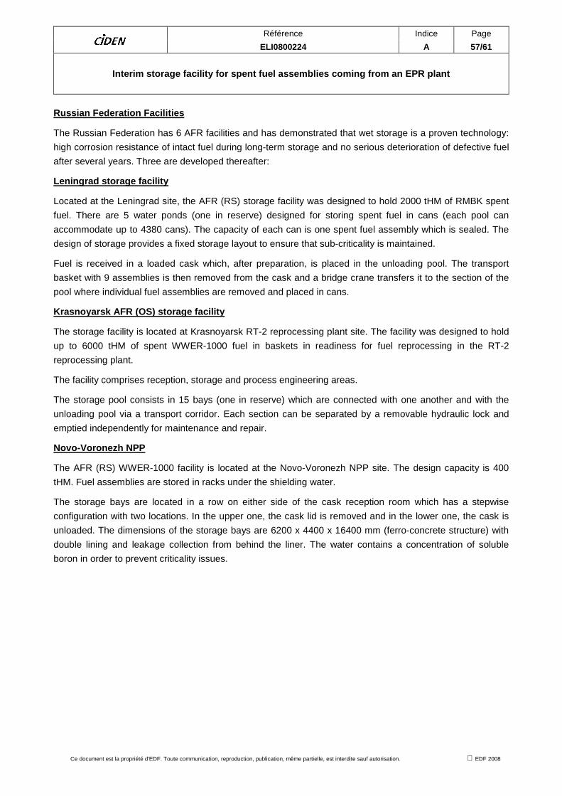
Référence Indice Page ELI0800224 A 57/61
Interim storage facility for spent fuel assemblies coming from an EPR plant
Ce document est la propriété d'EDF. Toute communication, reproduction, publication, même partielle, est interdite sauf autorisation. EDF 2008
Russian Federation Facilities
The Russian Federation has 6 AFR facilities and has demonstrated that wet storage is a proven technology:
high corrosion resistance of intact fuel during long-term storage and no serious deterioration of defective fuel
after several years. Three are developed thereafter:
Leningrad storage facility
Located at the Leningrad site, the AFR (RS) storage facility was designed to hold 2000 tHM of RMBK spent
fuel. There are 5 water ponds (one in reserve) designed for storing spent fuel in cans (each pool can
accommodate up to 4380 cans). The capacity of each can is one spent fuel assembly which is sealed. The
design of storage provides a fixed storage layout to ensure that sub-criticality is maintained.
Fuel is received in a loaded cask which, after preparation, is placed in the unloading pool. The transport
basket with 9 assemblies is then removed from the cask and a bridge crane transfers it to the section of the
pool where individual fuel assemblies are removed and placed in cans.
Krasnoyarsk AFR (OS) storage facility
The storage facility is located at Krasnoyarsk RT-2 reprocessing plant site. The facility was designed to hold
up to 6000 tHM of spent WWER-1000 fuel in baskets in readiness for fuel reprocessing in the RT-2
reprocessing plant.
The facility comprises reception, storage and process engineering areas.
The storage pool consists in 15 bays (one in reserve) which are connected with one another and with the
unloading pool via a transport corridor. Each section can be separated by a removable hydraulic lock and
emptied independently for maintenance and repair.
Novo-Voronezh NPP
The AFR (RS) WWER-1000 facility is located at the Novo-Voronezh NPP site. The design capacity is 400
tHM. Fuel assemblies are stored in racks under the shielding water.
The storage bays are located in a row on either side of the cask reception room which has a stepwise
configuration with two locations. In the upper one, the cask lid is removed and in the lower one, the cask is
unloaded. The dimensions of the storage bays are 6200 x 4400 x 16400 mm (ferro-concrete structure) with
double lining and leakage collection from behind the liner. The water contains a concentration of soluble
boron in order to prevent criticality issues.

Référence Indice Page ELI0800224 A 58/61
Interim storage facility for spent fuel assemblies coming from an EPR plant
Ce document est la propriété d'EDF. Toute communication, reproduction, publication, même partielle, est interdite sauf autorisation. EDF 2008
ANNEX 3 : SUMMARY OF KEY SAFETY ARRANGEMENTS RETAIN ED

Référence Indice Page ELI0800224 A 59/61
Interim storage facility for spent fuel assemblies coming from an EPR plant
Ce document est la propriété d'EDF. Toute communication, reproduction, publication, même partielle, est interdite sauf autorisation. EDF 2008
Reception/conditioning function Safety function Saf ety requirements Surveillance
Cast stored in buffer area Containment Transport cask fitted with shock absorbing covers front and rear.
No surveillance
Exposure Transport cask, distance. Monitoring of the dose rate at site boundary
Criticality Geometry of the basket in transport cask, use of neutron-poisoning materials
No surveillance
Cooling system Natural convection (cooling fins) No surveillance
1st step : Reception of the transport cask
Containment 1st barrier: transport cask plus airtight sealing systems, 2nd barrier : civil engineering structures of reception area + ventilation system (sub-atmospheric pressure, filtration)
1st barrier : No surveillance (short period of time) 2nd barrier : monitoring of the sub-atmospheric pressure.
Exposure Cask, civil engineering structures, distance. Monitoring of the dose rate at site boundary
Criticality Geometry of the basket in transport cask, use of neutron-poisoning materials
No surveillance
Cooling system Natural convection (cooling fins) No surveillance
2nd step : Preparation for cask unloading
After connecting the internal cavity of cask to the cooling system.
Containment 1st barrier : cladding or cylinder (defective assembly), 2nd barrier : Cask internal cavity+ cooling system + ventilation system (sub-atmospheric pressure, filtration), reliability and seismic resistance of the main crane, of the trolley.
1st barrier : monitoring of the cask internal activity (detection of krypton 85) 2sd barrier : monitoring of the sub-atmospheric pressure of the cask internal cavity.
Exposure Civil engineering structures, internal cavity in water, distance, reliability and seismic resistance of the main crane, of the trolley.
Monitoring of the dose rate at site boundary
Criticality Geometry of the basket in cask, use of neutron-poisoning materials, reliability and seismic resistance of the main crane, of the trolley
No surveillance

Référence Indice Page ELI0800224 A 60/61
Interim storage facility for spent fuel assemblies coming from an EPR plant
Ce document est la propriété d'EDF. Toute communication, reproduction, publication, même partielle, est interdite sauf autorisation. EDF 2008
Reception/conditioning function Safety function Saf ety requirements Surveillance
Cooling system Water cooling of the external envelope and the internal cavity Monitoring of the water flow rate
Monitoring of the water temperature
3rd step : Cask unloading and loading of the storage racks
Containment 1st barrier : cladding or cylinder
2nd barrier : civil engineering structures + ventilation system (sub-atmospheric pressure, filtration), unloading under pool, water pool
1st barrier : monitoring of the water activity of pits and of the atmosphere inside building.
2nd barrier : monitoring of the sub-atmospheric pressure inside building and monitoring of tightness of unloading pit.
Exposure Civil engineering structures, water pool, distance. Monitoring of the dose rate at site boundary
Criticality Geometry of the racks, use of neutron-poisoning materials, reliable handlings, anti-tipping devices for racks and whole seismic resistance.
No surveillance
Cooling system Water pool is maintained in temperature by forced circulation (pumps/exchangers)
Monitoring of the water flow rate of pit.
Monitoring of the water temperature of pit.
Interim storage of spent fuel Safety function Safet y requirements Surveillance
Containment 1st barrier : cladding or cylinder
2nd barrier : civil engineering structures + ventilation system (sub-atmospheric pressure, filtration), pool.
1st barrier : monitoring of the water activity of pool and of the atmosphere inside building. 2nd barrier : monitoring of the sub-atmospheric pressure inside building and monitoring of tightness of storage pool.
Exposure Civil engineering structures, pool water, distance. Monitoring of the dose rate at site boundary

Référence Indice Page ELI0800224 A 61/61
Interim storage facility for spent fuel assemblies coming from an EPR plant
Ce document est la propriété d'EDF. Toute communication, reproduction, publication, même partielle, est interdite sauf autorisation. EDF 2008
Reception/conditioning function Safety function Saf ety requirements Surveillance
Criticality Geometry of the racks, use of neutron-poisoning materials, reliable handlings, anti-tipping devices for racks, and whole seismic resistance
No surveillance
Cooling system Water pool is maintained in temperature by forced circulation (pumps/exchangers)
Monitoring of the water flow rate of pool.
Monitoring of the water temperature of pool.
Retrieval of spent fuel assemblies at the end of the time period storage. Safety function Safety requirements Surveillance
Containment Same arrangements as before
Exposure Same arrangements as before
Criticality Same arrangements as before
Cooling system Same arrangements as before
Same arrangements as before