interferometer control matt evans …talk mostly taken from…
TRANSCRIPT

Interferometer Control
Matt Evans…talk mostly taken from…

The control of the VIRGO interferometer for gravitational
wave detection
Pisa, 20th April 2006
Lisa Barsotti
Università degli Studi di PisaScuola di Dottorato Galileo Galilei
Ph.D. in Applied Physics

3 km
European Gravitational Observatory (EGO)
(Cascina-Pisa)

Things to Know
-> If you have a question, raise your hand and wave, or take some other action to draw my attention. This may be difficult because I haven’t slept much this week, so don’t be shy.
->The topic of this talk is “Interferometer Control”, but after years of work in this field I still don’t really know what I’m doing, so I tried to make this talk easy to understand. I probably failed… ask questions.
-> I am American, and I suffer from the common misconception that Americans speak English. This means that I talk fast (because I think I speak English well), but I am difficult to understand (because I’m not really speaking English).
->This talk will require about 15 minutes if I talk fast and nobody stops me.
->I like talking to myself, but not in public…
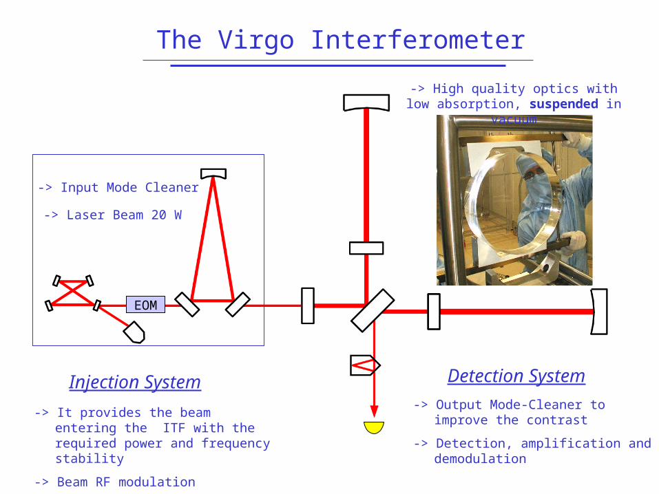
The Virgo Interferometer
Injection System
-> Input Mode Cleaner
-> Laser Beam 20 W
-> It provides the beam entering the ITF with the required power and frequency stability
-> Beam RF modulation
-> High quality optics with low absorption, suspended in vacuum
-> Output Mode-Cleaner to improve the contrast
-> Detection, amplification and demodulation
Detection System
EOM

Virgo Design Sensitivity
Seismic wall @ 4 Hz

Operating Point
The ITF has its nominal sensitivity only at its operating point
resonant light inside the cavities to increase the phase sensitivity
L < 5x10⁻⁹ m RMS (integrated DC-10 kHz)
anti-symmetric port on the dark fringe in order to prevent intensity noise from dominating over shot noise
Constraints on the tolerable fluctuations of the relative position of the mirrors
L < 10-12 m RMS

The Superattenuator is a multi-stage pendulum, with passive attenuation:
10 @ 10 Hz
Suspension System
At lower frequencies the noise is instead totally transferred to the mirror, even amplified by
the pendulum resonances
Residual longitudinal motion of the mirror
L ~ 10-6 m RMS
14
Local active control of the
Superattenuator reduces mirror motion below a
few Hz
10 14

Length Control: Why
Intensity noise based requirement
L < 10-12 m RMS
Residual longitudinal motion of the mirror L ~10-6 m RMS
A global control system is needed to hold the ITF on its operating point by
controlling relative mirror positions

Length Control: Why
Transmitted Power

Filtering
Error signals are filtered to compute correction signals
Hz
Gain
Length Control: What
Pound-Drever-Hall error signals giving the deviation from the operating point are extracted at the output ports of the ITF
Length Sensing
Correction signals are sent to the optics by means of coil-magnet actuators
Actuation
CASB SB
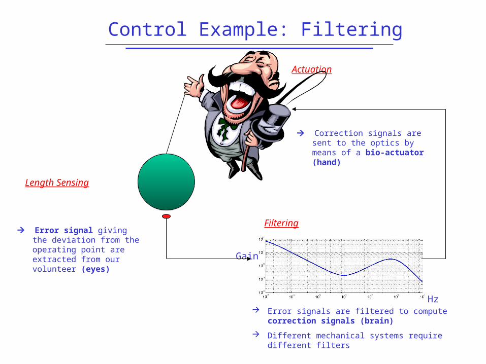
Filtering
Error signals are filtered to compute correction signals (brain)
Different mechanical systems require different filters
Hz
Gain
Control Example: Filtering
Error signal giving the deviation from the operating point are extracted from our volunteer (eyes)
Length Sensing
Correction signals are sent to the optics by means of a bio-actuator (hand)
Actuation

The Length Control Chain
Signals are acquired with 16-bit ADCs @ 20 kHz
Data are transferred via optical
links to the Global Control which computes correction signals
Corrections signals are sent to the DSPs of the involved suspension, passed through DACs and applied to the mirror
Global Control
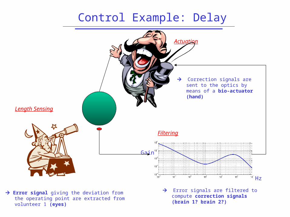
Filtering
Error signals are filtered to compute correction signals (brain 1? brain 2?)
Hz
Gain
Control Example: Delay
Error signal giving the deviation from the operating point are extracted from volunteer 1 (eyes)
Length Sensing
Correction signals are sent to the optics by means of a bio-actuator (hand)
Actuation
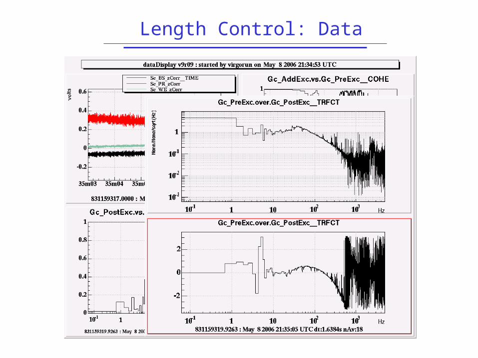
Length Control: Data

The Lock Acquisition Problem
Correction signal
Transmitted power
Only 1 degree of freedom
Correction signal sent to the mirror at a resonance crossing
Error signals are available only when the ITF is around resonance no signals available far from resonance
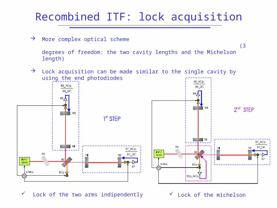
Recombined ITF: lock acquisition
Lock of the two arms indipendently Lock of the michelson
More complex optical scheme (3 degrees of freedom: the two cavity lengths and the Michelson length)
Lock acquisition can be made similar to the single cavity by using the end photodiodes
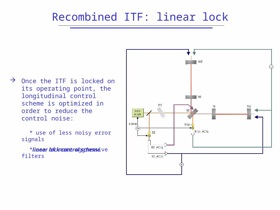
Recombined ITF: linear lock
Once the ITF is locked on its operating point, the longitudinal control scheme is optimized in order to reduce the control noise:
* use of less noisy error signals
* use of more aggressive filters
linear lock control scheme

Recycled ITF: after locking
Frequency Servo used for common arms
GW signal used to control differential arms
BS controlled to keep anti-symmetric port dark
PR controlled to keep power level high

Angular Problem
The end mirrors are 3km away The beam travels this distance
many times Small angles (1 micro-radian)
cause big problems

Angular Sensors
P
Y
P
Y
P
Y

Recycled ITF: angles
There are 6 mirrors to control, each with 2 degrees of freedom
The input beam has 4 DOFs 16 total DOFs

Angular Matrix
P
Y

Other Loops…
Laser SystemBeam positionIntensityModulation Frequency
InfrastructureBuilding temperatureVacuum pressure
Suspension SystemsInertial dampingLocal Control

Conclusions
Control loops should be avoided
Coupled systems should be placed firmly in the rubbish bin without hesitation or remorse
Interferometers are evil Sleep is good