interface panel instruction manual - udesc - cct operator’s manual nx100 maintenance manual ......
TRANSCRIPT
Motoman, Incorporated 805 Liberty LaneWest Carrollton, OH 45449TEL: (937) 847-6200FAX: (937) 847-627724-Hour Service Hotline: (937) 847-3200
Motoman NX100 Controller
Interface Panel Instruction Manual
Part Number: 149648-18CDRevision: 1

The information contained within this document is the proprietary property of Motoman, Inc., and may not be copied, reproduced or transmitted to other parties without the expressed written authorization of Motoman,
Inc.
©2007 by MOTOMANAll Rights Reserved
Because we are constantly improving our products, we reserve the right to change specifications without notice. MOTOMAN is a registered trademark of YASKAWA Electric Manufacturing.
COMPLETE OUR ONLINE SURVEYMotoman is committed to total customer satisfaction! Please give us your feedback on the technical manuals you
received with your Motoman robotic solution.
To participate, go to the following website:
http://www.motoman.com/forms/techpubs.asp

� �������������
�� ������
���&�� �
��� � �������
. �������������������
This manual provides information for the Interface Panel option and contains the following sections:
�����,���/����!,�0���,�Provides general information about the structure of this manual, a list of reference documents, and customer service information.
�����,��*�/���1��2This section provides information regarding the safe use and operation of Motoman products.
�����,��+�/�����!1��������%�����!0���,��Provides detailed instructions for Interface Panel option.
.* !��� ��������,��� ��������������
For additional information refer to the following:
� ������������ ����������������������
� ������ �������������������������
� �� ������������� ���!��������"��"�
� # $���%������ ����!� %���%�� ����%�� ���� $�&!����%�
���� �������
��

������������������
��������� ������������
.+ ������� ��� (�������� ������
If you are in need of technical assistance, contact the Motoman service staff at (937) 847-3200. Please have the following information ready before you call:
� '�&��(!� ��� � �� ��� ��
� )���"��"��(!� �����* �$"+,�����* �$"+,�-�$�"+�
� '�&��. �"�����%& ������� $���&��/��"$ �� ���&����%�
� '�&��.�� ����$ ����%& ������� $���&��/�� ������� ��
������� ����
��

� �������������
�� ������
���&�� �*
�����#�
*. ��� � ������
����������&� ����� �� ��&���������#�������� ����������������3������#3������3��� ������������ ��3� �)��������3� ����3�� ���$�� ������)���������#��� �������&� ����)���� ��������� �������������������� �������� ������$� .
0 ���++ ��-��!����&�"��$�� 1" *������!�� �- �)�.��'�)���"����.� !�.�$��$� ����$���"���'�&����$�'�&��.!� %�2�(-"��" ��%�"�����& ��&�" $� ��%�- �'�&�"���$���" ��)����"�"��&!�� 3� �"+�)�.��'�)�'�42�5�����2�(- ��$$� ���"����� ����*�6
������������ ������������������#"�����0�!�2�2�7�8��9��
)�)�&��,��"�-"+���:��5(;<6��9��������5�::=)�6��9�����������:
��(;'�;(6�***2��&�"����" 2��%
>�"%� �!,�- �& ���� +���$�"����" $�� ��� �2�(- ��� ��"��� ����"&� � ������1"$"+�� ��� ��*-���� ��$ 3�� �!���" $����� �� ,����+��%,��$�%�"�"�- ���&��� ��2����� ������������������� ��������� ���������������������� ����
0 �� ��%% $�-������� ��� ��*-��" $����� �� ,����+��%,�� ��"�,������ �- ���&���!� %�& ���" $�"��������1 $����%����""+������ ��$�& ��% � �%"�"���*"-�- ����� ���� ��"��� �- ��!� %2�
���� �������
��
������������������
��������� �������
(-"���� !�� �"���$$� �� ��- � ����*"+6
� .�$��$���1 "����. �"���2��
� ? ����.� +���$"+�("����. �"���2��
� � �-�"����.� !�@ 1"� ���. �"���2��
� ������"��.� !��. �"���24�
� ���+��%%"+,��� ��"�,��$���" �� �.� !��. �"���25�
*.* ���� � ����(�������
(-"��%�����"���$ ��- � ����*"+��� ���–�"�$ �� $"+���$ ��� �� 1 �"!�–�-���� � �� "�����- ��� !�� �� ��� ���$� 3�"�% 2�)��!���� �$�-"��%����,���!����� �� "����- � ��� �����"��� ��� !�*- �"����"+,��� ��"+,����+��%%"+,��$�%�"�""+�-"�� 3�"�% 2
����������� ��������&&�� ��)���������4�!������ �������& ������������&� �������� ����������� ������� ������������5� ������3���������(�� � 3�$���� ������������� ����3��� �����&� ��������6� #�� ������������������ ����������7��&����� ���)�.�
���������� ��������&&�� ��)������'�!���4������ �������& ������������&� ��������� ��7��&������ ���&�����������5� ����������� ���������&� ��������6� #�� ������������������ ����������7��&����� ���)�.�
��� ������� ��������&&�� ��)��������0��,������� �������& ������������&� ��������� ��7��&����3�����$� �3��� � ����� �����5� ����������� ������������� �&� ��������6� #�� ��7��&����� ���)�.
������������ �������� ��� ������������ ������� � ����� ����� ����� ��� ��������� ����������� ������� ������ �������� �����
������� ����
��
� �������������
�� ������
*.+ 4��� �������)�� ��)���&�
)����� �����,����+��%% ��,������$����"+� +" ��,�%�" �� �� ��� �,���� �1"����,��$��!� �*��/"+� ���- ���&��%���& ��% � �%"�"���*"-�- ��� ��"��� �-"�� 3�"�% 2�)���� ��� ��"1��1 $�*"-�- ��� ��"��� �- � 3�"�% �%����$ ���$��� "���$�+ ���� ��� ��"�2�? ������ +���$"+�"����� ���� ����*�6
� �%���� ���� ��"������ ����"�� ������"A��!��$����$�%�+ ���- � 3�"�% 2���!���" $�� ��� �� �%"�"���*"-�- ��� ��"��� �-"����&�,�- ��� ����B��%�����,�- ��!� %� 3�"�% ,��$���"����$���� ����" ���-���$�& �� �%" $����� �� �-"����&���!� %2
� @���� ��- ���&��� ���*-"� �"�"��"����%�"���� ��"�2����+��%% ���%���-�1 �- � ��-�� $��*- �- !� ��- ���&��� ��2
� �%���� ���� �"������$�%�+ �- ���&�2�)����� �"���%���& �%�$ �*"-"�- ���$��$�1���+ ��$����� ���"+��� �- ���&�������������$�������2
� (- ���&��%���& ����� $�"�;% �+ �!�.����;�.(����%�$ �*- 1 ��"�"����"��� 2
� �������$�� �*"-�)�.��'�)�'�42�5�����,�� �"���2�24,�.���� ��� �; �+!,��� ����/����+������� $�� ��$��"+� 3�"�% �%�" �� 2�' ���������. �"������2��9�����=',����������,�������"����.� !��$�C ��-�.�$��$�� ���? �����$���!���.C)�2
*.8 ����������������#���(����
(- ��� ��� ��"��� �- ���&�,����""� �,���8"�"��!� 3�"�% ,��$��!� %�"����"%� �!�- ��� �B��� ����"&"�"!2�(- ���$""����$ ��*-"�-�- � 3�"�% �*"���& ��� �� $��� �!��-���$�& �� 1" * $�&!�- ��� �2�(- ��� ��%���& ��*�� �� �- �1��"�����"������$ �,�)�.��'�)�'�42�5�������� !���$��$�,��$��- ����������$ ��-��%�!�� ��"���- �"�����"���$��� �� �"$���"��� 3�"�% 2�)$$""������ !�% ���� �� ���� ��� ���$� 3�"�% �%�!�& �� 3�"� $�$ � $"+����!� %�"�����"�,��� ��"�,��$��������"�2�(- � ����*"+��� !� 3�"�% �"�����1"$ $������$��$6
� .� !� � ���$�&���" ��
� <"+-�����"���$������ !�%��
� @����" ����/�
� ;% �+ �!��������%�&�������� $����� �������"�,���&�������� �,��$����+��%%"+�� $�
�- �/������� !� 3�"�% � � 3� �!� ������� ���� ��"�2�' ��"������ ���� ��!��� ��"�"+��� !� 3�"�% �"%% $"� �!2
���� ������
��

������������������
��������� �������
*.9 ������������������#
.� �"�����"��"�� �� "��� ������ �"��� �� ��� ��$� 3�"�% 2�(- � ����*"+���++ �"����� �" $ $�������� % ,�&����� ���� ,� 8"�"+� $ ���,������,��$��� ���*���$�� +���"��2�)$$""������ !�% ���� �� ���� ��� ���$� 3�"�% �%�!�& �� 3�"� $�$ � $"+����!� %�"�����"�,��� ��"�,��$��������"�2�������"��"����� ���� ����*�6
� 7 ���� �-����!�3���" " $�� ��� �� �%"�"���*"-��"������$ �,���������$ �,��$�)�.��'�)�'�42�5�������� !���$��$���� �� �%" $���"�����- � 3�"�% 2
� �$ " !�- �*��/� 1 ��� �� � ��-���&��*"-� �����%��/"+�,��"+�,��$�&���" ��2�
� ���""������������ ������"$ �- ���&��*��/� 1 ��� 2
� 0- 1 ������"&� ,�"������� !� � ������� ���+�"�����-��"D $� �!�"��- �*��/� 1 ��� 2
� ;�"%"� ��� ���*- � �� ��� ��%"+-�+ ����� $�& * ���%�1"+���&���$��- �� 3�"�% ���"�-���"��2
� ���1"$ ��� "�" ����%�"�"$ �- �*��/� ������ �%"��� � ��-"+��$�%�" �� ����� $�� �2
*.: � �) �����)3�,&� �����3��� ������������������#
)����� �����,����+��%% ��,������$����"+� +" ��,�%�" �� �� ��� �,���� �1"����,��$��!� �*��/"+� ���- ���&��%���& ��% � �%"�"���*"-�- ��� ��"��� �-"�� 3�"�% 2��%���� ���� ��"������ ����"�� ������"A��!��$����$�%�+ ���- � 3�"�% 2���!���" $�� ��� �� �%"�"���*"-�- ��� ��"�,�%�����,� � ��"����$ �"+,��$� 3�"�% �" ��� �"���� �-"����&���-���$�& �� �%" $������+��%,��� �� ,��$�%�"�"�- ��!� %2�)���� ��� ��"1��1 $�*"-�- ��� ��"��� �- � 3�"�% �%����$ ���$��� "���$�+ ���� ��� ��"�2�
� ��� ��- ���&���$�*��/� 1 ��� ���& ���� ����� "���!�-�D��$������$""��� 8"�2�7 ���� �- ��� ��"���� ���$� � �� �*� �,��"�,�$ &�"�,� �2�
� 7 ���� �-�������� +���$���� �"����� 2��- �/������� !� 3�"�% � ������� ���� ��"�2�' ��"������ ���� ��!��� ��"�"+��� !� 3�"�% �"%% $"� �!2
� @���� ��- ���&��� ���*-"� �"�"��"����%�"���� ��"�2�7 ���� �-����!�- �� ����-��$"+�- ����+��%%"+�� $�� ���- �*��/� ��2
� �- �/�- �;�.(���&�����- ����+��%%"+�� $�� ������� ���� ��"��& �� ����+��%%"+2�(- ���&��%���& ����� $�"�;% �+ �!�.����;�.(����%�$ �*- 1 ��"�"����"��� 2
� 7��/�����������+��%���$�A�&�������"�&� �% $"��& �� ����+��%��-�+ ���� �%�$ 2�(���1�"$������� �" ��%�"�,����+��%�,����A�&�,���&��/���%�����*�!��& �%�$ �& �� ��!�� �1"� ����� $�� ���� �$� ��$�& �� ��!��-�+ ���� �%�$ �����"��,���� ����" �,���� 3�"�% 2
������ ����
��

� �������������
�� ������
� )!�%�$" "��"������)'(��,�.!� %�. �"�,�� �- ���&�������� �������� ��������+��%�������� �� 1 � �� ������"A��!����$ �-,����* ������$�%�+ ���- ���&�E�@����%�/ ��!�%�$" "��"������)'(��,�.!� %�. �"�2���/"+��!��-�+ ��*"-���- �*�" �� �%"��"��� ����%��*"���#��@�F�>'�0)'')�(FE
� .�% ��� ��"���� 3�"� ���$��$�����*��$���$���% �� 3�"� ��� �"�������*��$�2�.� �"�������*��$���� � ������%���� ���!2�F�>'�0)'')�(F�0�<<�7;�#��@�" �!����� �- � ��� �"�������*��$�2
� (- ���&�������� ������*��%�$" "��"���� ��)'(��,�>� ��. �"�,�� �- ������� ��������+��%��$�%�$" "��"����������� ������% ��� ���%�8"%�%���&��� � ��%�� 2�?� ����� �%���& ��/ �*- �%�/"+�- � �%�$" "��"��2�)���%�$" "��"���%�$ ���- ������� ��*"����-�+ �- �*�!�- ���&���� �� ���$�������� �� 1 � �� ������"A��!����$ �-,����* ������$�%�+ �- ���&���$��- �������� �- ��!� %2�@��&� ��- �/�����%�$" "��"����$ �� 1 �!�%�$ �� ���&���� ��"���� ��� �-��!���-�1 ����� � $�-�D��$�����$�+ ������"��"��2
� �- �/��$� ���!� *����%�$" " $����+��%�����*��� $� ������ ���� � �����!�� 2
� (-"�� 3�"�% �-���%��"�� ������ ��� � � ��"���������!2�;� ��"����" ��� �"����� �%�$ �& * �- ������� ���$��- �� 3�"�% 2�@"��� ���$����/����+������� � ��"�����"���"��& �� �%�/"+��!�%�$" "��"�������� �"��2
� @����� � ��%��!�%�" �� ����� $�� ��& �� �� �$"+��$��$ ���$"+�- ����� ������ $�� ��"�- ��������"� �%����2�
� >� ����� ��� ���� % �����2�
� �%���� ���� �"������$�%�+ �- ���&�2�)����� �"���%���& �%�$ �*"-"�- ���$��$�1���+ ��$����� ���"+��� �- ���&�������������$�������2
���� �������
��

������������������
��������� �������
�,���
�������� ����
��

YASKAWA
NX100 OPTIONSINSTRUCTIONSFOR INTERFACE PANEL FUNCTION
Upon receipt of the product and prior to initial operation, read these instructions thoroughly, and retain for future reference.
MOTOMAN INSTRUCTIONSMOTOMAN- INSTRUCTIONSNX100 INSTRUCTIONSNX100 OPERATOR’S MANUALNX100 MAINTENANCE MANUAL
The NX100 operator’s manual above corresponds to specific usage. Be sure to use the appropriate manual.
YASKAWA MANUAL NO.
HW0482596 51/39
HW0482596
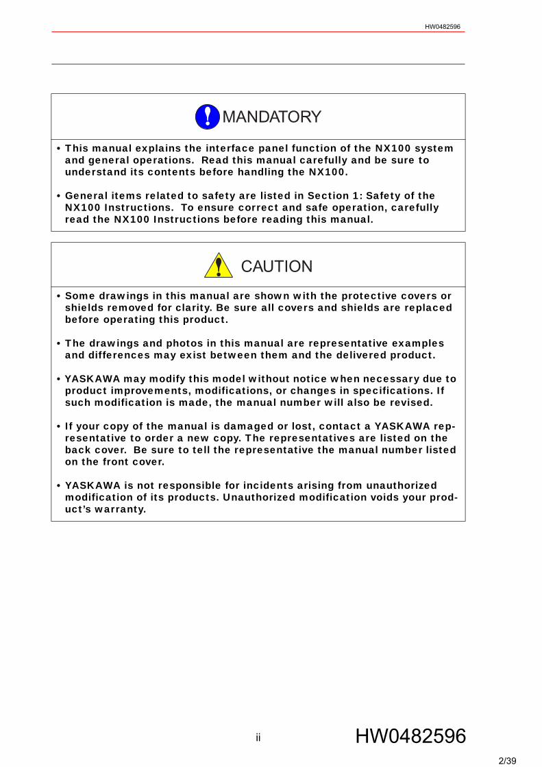
• This manual explains the interface panel function of the NX100 system and general operations. Read this manual carefully and be sure to understand its contents before handling the NX100.
• General items related to safety are listed in Section 1: Safety of the NX100 Instructions. To ensure correct and safe operation, carefully read the NX100 Instructions before reading this manual.
• Some drawings in this manual are shown with the protective covers or shields removed for clarity. Be sure all covers and shields are replaced before operating this product.
• The drawings and photos in this manual are representative examples and differences may exist between them and the delivered product.
• YASKAWA may modify this model without notice when necessary due to product improvements, modifications, or changes in specifications. If such modification is made, the manual number will also be revised.
• If your copy of the manual is damaged or lost, contact a YASKAWA rep-resentative to order a new copy. The representatives are listed on the back cover. Be sure to tell the representative the manual number listed on the front cover.
• YASKAWA is not responsible for incidents arising from unauthorized modification of its products. Unauthorized modification voids your prod-uct’s warranty.
MANDATORY
CAUTION
ii HW04825962/39
HW0482596
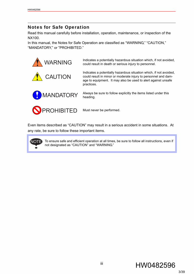
Notes for Safe OperationRead this manual carefully before installation, operation, maintenance, or inspection of the NX100. In this manual, the Notes for Safe Operation are classified as “WARNING,” “CAUTION,” “MANDATORY,” or ”PROHIBITED.”
Even items described as “CAUTION” may result in a serious accident in some situations. At any rate, be sure to follow these important items.
Indicates a potentially hazardous situation which, if not avoided, could result in death or serious injury to personnel.
Indicates a potentially hazardous situation which, if not avoided, could result in minor or moderate injury to personnel and dam-age to equipment. It may also be used to alert against unsafe practices.
Always be sure to follow explicitly the items listed under this heading.
Must never be performed.
To ensure safe and efficient operation at all times, be sure to follow all instructions, even if not designated as “CAUTION” and “WARNING.”
WARNING
CAUTION
MANDATORY
PROHIBITED
NOTE
iii HW04825963/39
HW0482596
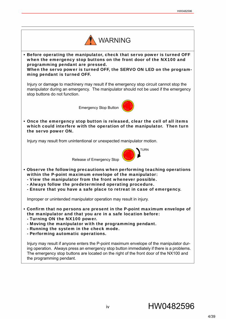
• Before operating the manipulator, check that servo power is turned OFF when the emergency stop buttons on the front door of the NX100 and programming pendant are pressed.When the servo power is turned OFF, the SERVO ON LED on the program-ming pendant is turned OFF.
Injury or damage to machinery may result if the emergency stop circuit cannot stop the manipulator during an emergency. The manipulator should not be used if the emergency stop buttons do not function.
Emergency Stop Button
• Once the emergency stop button is released, clear the cell of all items which could interfere with the operation of the manipulator. Then turn the servo power ON.
Injury may result from unintentional or unexpected manipulator motion.
Release of Emergency Stop
• Observe the following precautions when performing teaching operations within the P-point maximum envelope of the manipulator:- View the manipulator from the front whenever possible.- Always follow the predetermined operating procedure.- Ensure that you have a safe place to retreat in case of emergency.
Improper or unintended manipulator operation may result in injury.
• Confirm that no persons are present in the P-point maximum envelope of the manipulator and that you are in a safe location before:- Turning ON the NX100 power.- Moving the manipulator with the programming pendant.- Running the system in the check mode.- Performing automatic operations.
Injury may result if anyone enters the P-point maximum envelope of the manipulator dur-ing operation. Always press an emergency stop button immediately if there is a problems. The emergency stop buttons are located on the right of the front door of the NX100 and the programming pendant.
WARNING
TURN
iv HW04825964/39
HW0482596
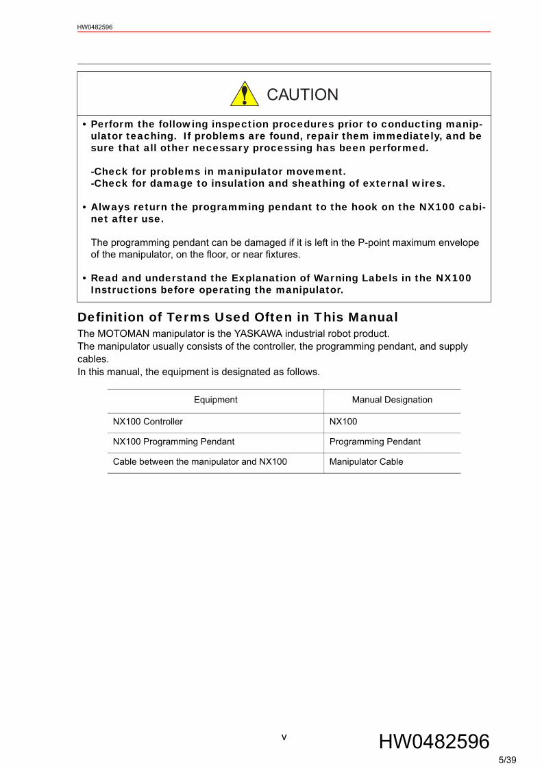
Definition of Terms Used Often in This ManualThe MOTOMAN manipulator is the YASKAWA industrial robot product.The manipulator usually consists of the controller, the programming pendant, and supply cables.In this manual, the equipment is designated as follows.
• Perform the following inspection procedures prior to conducting manip-ulator teaching. If problems are found, repair them immediately, and be sure that all other necessary processing has been performed.
-Check for problems in manipulator movement.-Check for damage to insulation and sheathing of external wires.
• Always return the programming pendant to the hook on the NX100 cabi-net after use.
The programming pendant can be damaged if it is left in the P-point maximum envelope of the manipulator, on the floor, or near fixtures.
• Read and understand the Explanation of Warning Labels in the NX100 Instructions before operating the manipulator.
Equipment Manual Designation
NX100 Controller NX100
NX100 Programming Pendant Programming Pendant
Cable between the manipulator and NX100 Manipulator Cable
CAUTION
v HW04825965/39
HW0482596
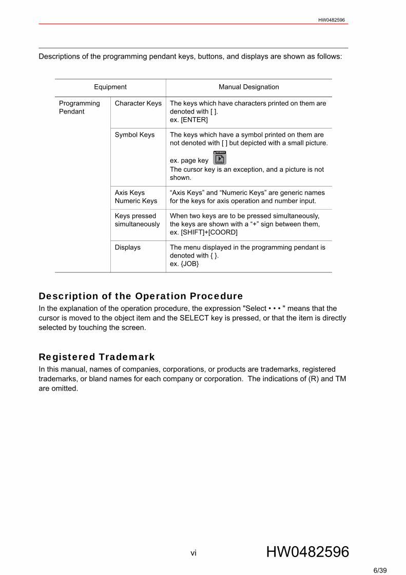
Descriptions of the programming pendant keys, buttons, and displays are shown as follows:
Description of the Operation ProcedureIn the explanation of the operation procedure, the expression "Select • • • " means that the cursor is moved to the object item and the SELECT key is pressed, or that the item is directly selected by touching the screen.
Registered TrademarkIn this manual, names of companies, corporations, or products are trademarks, registered trademarks, or bland names for each company or corporation. The indications of (R) and TM are omitted.
Equipment Manual Designation
Programming Pendant
Character Keys The keys which have characters printed on them are denoted with [ ].ex. [ENTER]
Symbol Keys The keys which have a symbol printed on them are not denoted with [ ] but depicted with a small picture.
ex. page keyThe cursor key is an exception, and a picture is not shown.
Axis KeysNumeric Keys
“Axis Keys” and “Numeric Keys” are generic names for the keys for axis operation and number input.
Keys pressed simultaneously
When two keys are to be pressed simultaneously, the keys are shown with a “+” sign between them, ex. [SHIFT]+[COORD]
Displays The menu displayed in the programming pendant is denoted with { }.ex. {JOB}
GO BACK
PAGE
vi HW04825966/39

HW0482596
1 Outline of Interface Panel Function
2 Display and Operations of Panel Screen2.1 Interface Panel Display . . . . . . . . . . . . . . . . . . . . . . . . . . . . 2-1
Panel Screen Display . . . . . . . . . . . . . . . . . . . . . . . . . . . . . .2-1 Panel Screen Operation by Touch Panel . . . . . . . . . . . . . . .2-2 Panel Screen Operation by PP Keys . . . . . . . . . . . . . . . . . .2-2 Numeric Display . . . . . . . . . . . . . . . . . . . . . . . . . . . . . . . . . .2-3 Input of Numeric Value . . . . . . . . . . . . . . . . . . . . . . . . . . . . .2-3 Change of Panel Screen . . . . . . . . . . . . . . . . . . . . . . . . . . . .2-4 Change of Language on Screen . . . . . . . . . . . . . . . . . . . . . .2-5
3 Data Setting and Touch Panel I/F Instructions3.1 Setting Procedure . . . . . . . . . . . . . . . . . . . . . . . . . . . . . . . . . 3-2
I/F Panel Setting Data and Display Position . . . . . . . . . . . . .3-3 Editing of Setup . . . . . . . . . . . . . . . . . . . . . . . . . . . . . . . . . . .3-4 Editing of Panel Type . . . . . . . . . . . . . . . . . . . . . . . . . . . . . .3-4 Editing of Panel Color . . . . . . . . . . . . . . . . . . . . . . . . . . . . . .3-5 Editing of Panel Name. . . . . . . . . . . . . . . . . . . . . . . . . . . . . .3-5 Editing of Text Color . . . . . . . . . . . . . . . . . . . . . . . . . . . . . . .3-6 Editing of Security . . . . . . . . . . . . . . . . . . . . . . . . . . . . . . . .3-6 Editing of Interlock Enable. . . . . . . . . . . . . . . . . . . . . . . . . . .3-7 Editing of Input . . . . . . . . . . . . . . . . . . . . . . . . . . . . . . . . . . .3-7 Editing of Group Name . . . . . . . . . . . . . . . . . . . . . . . . . . . . .3-8 Initialization of Set Data. . . . . . . . . . . . . . . . . . . . . . . . . . . .3-10
3.2 Details on Interface Panel Setting Items . . . . . . . . . . 3-11
4 Save and Load of Set Data
5 Editing Saved Data
6 Parameters6.1 Clearing the Status of Signals . . . . . . . . . . . . . . . . . . . . . 6-1
Status of General Output Signals at Mode Change . . . . . . .6-2 Status of General Output Signals at Power Supply ON . . . .6-2 Status of Auxiliary Relay Signals at Power Supply ON . . . . .6-2 Status of I/F Panel Signals at Power Supply ON . . . . . . . . .6-3
vii HW04825967/39
HW0482596
6.2 Allocation of General Input Signals to Interface Panel Screens . . . . . . . . . . . . . . . . . . . . . . . . . . . . . . . . . . . . . . . . . . . . 6-4
Notification of the Status of General Input Signals . . . . . . . . 6-46.3 The change of "push button" processing. . . . . . . . . . . . 6-5
The change by the parameter. . . . . . . . . . . . . . . . . . . . . . . . 6-5 Forced reversal of input/output signals. . . . . . . . . . . . . . . . . 6-5
viii HW04825968/39
1-1
HW0482596
HW0482596
1 Outline of Interface Panel Function
This function makes the system construction simple and enables the reduction of operation panel and Interlock panel (hereinafter called "I/L panel") by holding the roles of operation panel and I/L board in the programming pendant (hereinafter called "PP").Users can construct the arbitrary operation panel for PP by setting data in Interface panel set-ting screen.
9/39

2.1 Interface Panel DisplayHW0482596
2 Display and Operations of Panel Screen
2.1 Interface Panel Display
Panel Screen DisplayFollow the operations as below to display the Interface panel.
Operation Explanation
1 Press {I/F Panel} to dis-play the Interface panel screen.
2 Press {I/F Panel} while the Interface panel appears on the screen.
The screen goes back to the previous display.
Due to some conditions during an operation, Interface panel may not appear on the screen. In that case, the massage “Cannot display at current operation mode” appears when {I/F Panel} is pressed.
Short CutMain Menu I/F Panel
JOBDOUTMOVEEND
VARIABLE
B001
IN/OUT
In Out
ROBOT
SYSTEM INFO
CF
FD/CF
ARC WELDING SETUP
DISPLAY SETUP
Aa
JOB CONTENTJOB NAME MOTOMANCONTROL GROUP R1 TOOL **
STEP NO
0000000100020003000400050006000700080009
NOPLABELDOUTMOVJMOVJMOVJMOVJMOVJJUMPEND
OT#(1)ONVJ=100.00VJ=100.00VJ=100.00VJ=100.00VJ=100.00 LABEL
JOB EDIT DISPLAY UTILITY
=> MOVJ VJ=100.00
NOTE
2-1 HW048259610/39

2.1 Interface Panel DisplayHW0482596
Panel Screen Operation by Touch PanelFollow the operations as below to perform ON/OFF operation on the panel screen by Touch panel.
Panel Screen Operation by PP KeysFollow the operations as below to perform ON/OFF operation on the panel screen by PP keys.
Operation Explanation
1 Hold down [INTER-LOCK] and select an appropriate button on the Touch panel.
Operation Explanation
1 Use the arrow key to move to the place where ON/OFF opera-tion is to be performed.
2 Hold down [INTER-LOCK] and press [SELECT].
Set the item “INTERLOCK ENABLE” in the I/F PANEL SETUP screen to “PERMIT”, and operations are allowed without pressing the [INTERLOCK] key.See the item No.8 “Interlock Enable” in the table “Data of Each Setting Items” of "3.2 Details on Interface Panel Setting Items".
Short CutMain Menu I/F Panel
I/F PANEL
DATA EDIT DISPLAY UTILITY
=> MOVJ VJ=100.00
Panel 1 Panel 2 Panel 3 Panel 4 Panel 5
OPERATIONPROH PERMPROH PERM
0 6
HIT COUNT TYPE OF VEHICLE
WELD ON
COUT-UP NO. TYPE OFVEHICLE
PRECEDING
TYPE OFVEHICLE
PRECEDING
COOL WATERERR
COOL WATERERR
WELDALLOWED
WELDALLOWED
PLAY MODE HOLDTEACH MODEOPERATIONREADY
OPERATIONREADY
PLAY MODESELECT
PLAY MODESELECT
HOLDTEACH MODESELECT
TEACH MODESELECT
0 3
COOL WATERERR RESET
COOL WATERERR RESET
STOP WATERSOLENOID
OPEN
STOP WATERSOLENOID
OPEN
ATC/TOOLMNL OPRTNALLOWED
ATC/TOOLMNL OPRTNALLOWED
SHUTTLE OFF-INTRFRNC
SHUTTLE OFF-INTRFRNC
TIMER ERRRESET
TIMER ERRRESET
COOL WATERSWITCH
COOL WATERSWITCH
OPERATIONORIGINALPOSITION
OPERATIONORIGINALPOSITION
Short CutMain Menu I/F Panel
I/F PANEL
DATA EDIT DISPLAY UTILITY
=> MOVJ VJ=100.00
Panel 1 Panel 2 Panel 3 Panel 4 Panel 5
OPERATIONPROH PERMPROH PERM
0 6
HIT COUNT TYPE OF VEHICLE
WELD ON
COUT-UP NO. TYPE OFVEHICLE
PRECEDING
TYPE OFVEHICLE
PRECEDING
COOL WATERERR
COOL WATERERR
WELDALLOWED
WELDALLOWED
PLAY MODE HOLDTEACH MODEOPERATIONREADY
OPERATIONREADY
PLAY MODESELECT
PLAY MODESELECT
HOLDTEACH MODESELECT
TEACH MODESELECT
0 3
STOP WATERSOLENOID
OPEN
STOP WATERSOLENOID
OPEN
ATC/TOOLMNL OPRTNALLOWED
ATC/TOOLMNL OPRTNALLOWED
SHUTTLE OFF-INTRFRNC
SHUTTLE OFF-INTRFRNC
TIMER ERRRESET
TIMER ERRRESET
COOL WATERSWITCH
COOL WATERSWITCH
OPERATIONORIGINALPOSITION
OPERATIONORIGINALPOSITION
COOL WATERERR RESET
COOL WATERERR RESET
SUPPLE-MENT
2-2 HW048259611/39
2.1 Interface Panel DisplayHW0482596
Numeric Display
Follow the operations as below to display numeric values on the panel screen.
Input of Numeric Value
Follow the operations below to input numeric values.
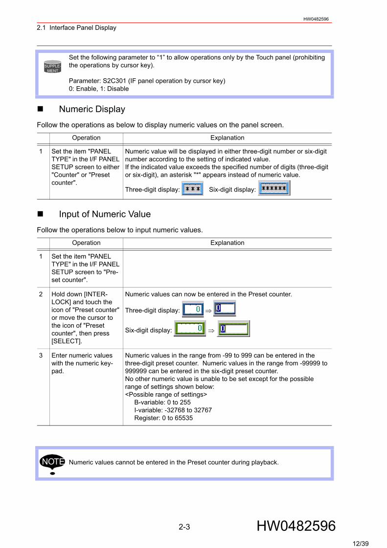
Set the following parameter to “1” to allow operations only by the Touch panel (prohibiting the operations by cursor key).
Parameter: S2C301 (IF panel operation by cursor key)0: Enable, 1: Disable
Operation Explanation
1 Set the item "PANEL TYPE" in the I/F PANEL SETUP screen to either "Counter" or "Preset counter".
Numeric value will be displayed in either three-digit number or six-digit number according to the setting of indicated value.If the indicated value exceeds the specified number of digits (three-digit or six-digit), an asterisk "*" appears instead of numeric value.
Three-digit display: Six-digit display:
Operation Explanation
1 Set the item "PANEL TYPE" in the I/F PANEL SETUP screen to "Pre-set counter".
2 Hold down [INTER-LOCK] and touch the icon of "Preset counter" or move the cursor to the icon of "Preset counter", then press [SELECT].
Numeric values can now be entered in the Preset counter.
Three-digit display: ⇒
Six-digit display: ⇒
3 Enter numeric values with the numeric key-pad.
Numeric values in the range from -99 to 999 can be entered in the three-digit preset counter. Numeric values in the range from -99999 to 999999 can be entered in the six-digit preset counter.No other numeric value is unable to be set except for the possible range of settings shown below:<Possible range of settings>
B-variable: 0 to 255I-variable: -32768 to 32767Register: 0 to 65535
Numeric values cannot be entered in the Preset counter during playback.
SUPPLE-MENT
NOTE
2-3 HW048259612/39
2.1 Interface Panel DisplayHW0482596
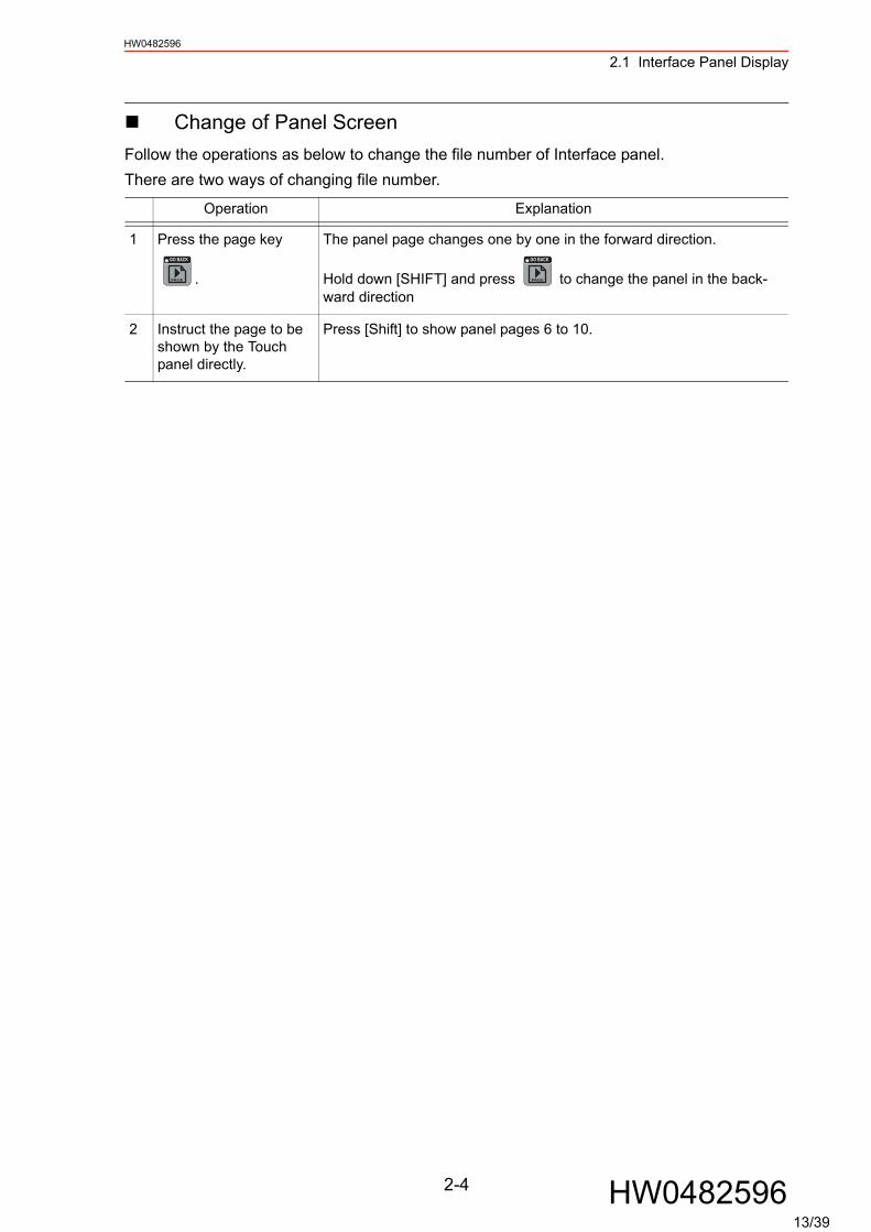
Change of Panel ScreenFollow the operations as below to change the file number of Interface panel.There are two ways of changing file number.
Operation Explanation
1 Press the page key
.
The panel page changes one by one in the forward direction.
Hold down [SHIFT] and press to change the panel in the back-ward direction
2 Instruct the page to be shown by the Touch panel directly.
Press [Shift] to show panel pages 6 to 10.
GO BACK
PAGE
GO BACK
PAGE
2-4 HW048259613/39

2.1 Interface Panel DisplayHW0482596
Change of Language on ScreenThe language can be changed only when bilingual function is enabled.
Operation Explanation
1 Hold down [SHIFT] and
press .
2 The language on the screen changes.
Unless panel names are set in each language mode, the panel names will not be displayed when the screen is changed to the subject language mode.In such a case, set the panel names in the subject language mode.
AREA
Short CutMain Menu I/F Panel
I/F PANEL
DATA EDIT DISPLAY UTILITY
=> MOVJ VJ=100.00
Panel 1 Panel 2 Panel 3 Panel 4 Panel 5
OPERATIONPROH PERMPROH PERM
0 0
HIT COUNT TYPE OF VEHICLE
WELD ON
COUT-UP NO. TYPE OFVEHICLE
PRECEDING
TYPE OFVEHICLE
PRECEDING
COOL WATERERR
COOL WATERERR
WELDALLOWED
WELDALLOWED
PLAY MODE HOLDTEACH MODEOPERATIONREADY
OPERATIONREADY
PLAY MODESELECT
PLAY MODESELECT
HOLDTEACH MODESELECT
TEACH MODESELECT
0 0
COOL WATERERR RESET
COOL WATERERR RESET
STOP WATERSOLENOID
OPEN
STOP WATERSOLENOID
OPEN
ATC/TOOLMNL OPRTNALLOWED
ATC/TOOLMNL OPRTNALLOWED
SHUTTLE OFF-INTRFRNC
SHUTTLE OFF-INTRFRNC
TIMER ERRRESET
TIMER ERRRESET
COOL WATERSWITCH
COOL WATERSWITCH
OPERATIONORIGINALPOSITION
OPERATIONORIGINALPOSITION
Panel 1 Panel 2 Panel 3 Panel 4 Panel 5
SUPPLE-MENT
2-5 HW048259614/39

HW0482596
3 Data Setting and Touch Panel I/F Instructions
Set the security level to "Management" mode. Follow the operations as below to open I/F panel setting screen.
Operation Explanation
1 Select {SYSTEM INFO} under the main menu.
2 Select {I/F PANEL SETUP}. The I/F panel setting screen appears.
Short CutMain Menu I/F Panel
SECURITY
MANAGEMENT MODEMODE
DATA EDIT DISPLAY UTILITY
JOBDOUTMOVEEND
VARIABLE
B001
IN/OUT
In Out
ROBOT
SYSTEM INFO
CF
FD/CF
ARC WELDING
Aa
VERSION
MONITORING TIME
ALARM HISTORY
I/O MSG HISTORY
I/F PANEL SETUP
SECURITY
Short CutMain Menu I/F Panel
DATA EDIT DISPLAY UTILITY
I/F PANEL SETUPGROUP NAME Panel 1ARRANGESETUPPANEL TYPEPANEL COLORPANEL NAMETEXT COLORSECURITYINTERLOCK ENABLEINPUT (DISP)OUTPUT (SETUP)
1AVALIDSELECTOR SWDARK RED
DARK BLUEOPERATIONPROHIBITSIGNALSIGNAL
#10010#10010
AA
LEFT ON
PAGE
3-1 HW048259615/39
3.1 Setting ProcedureHW0482596
3.1 Setting Procedure
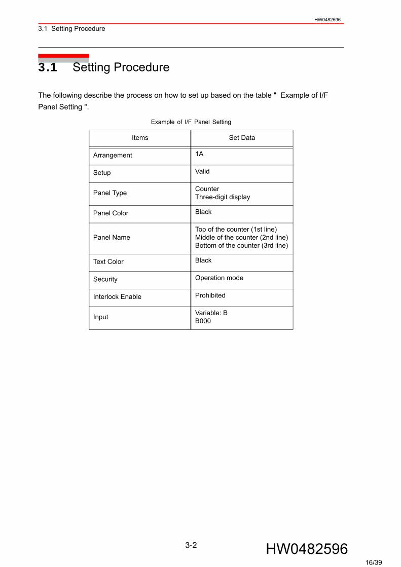
The following describe the process on how to set up based on the table " Example of I/F Panel Setting ".
Example of I/F Panel Setting
Items Set Data
Arrangement 1A
Setup Valid
Panel Type CounterThree-digit display
Panel Color Black
Panel NameTop of the counter (1st line)Middle of the counter (2nd line)Bottom of the counter (3rd line)
Text Color Black
Security Operation mode
Interlock Enable Prohibited
Input Variable: BB000
3-2 HW048259616/39

3.1 Setting ProcedureHW0482596
I/F Panel Setting Data and Display Position
Operation Explanation
1 Move the cursor to the item "ARRANGE" in the I/F panel setting screen, then press [SELECT].
The arrangement setting screen appears.An item with an asterisk "*" indicates that the item has already been set (the setting is enabled).
The display position of set data is as follows:
2 Move the cursor to the position where the item is to be arranged and press [SELECT].
Using the page key or the [PAGE] button changes the con-trol group of the arrangement setting screen and a user can select the position where the item is to be arranged.
Short CutMain Menu I/F Panel
ARRANGE SELECTGROUP NAME Panel 11A
*2A3A
*4A
*1B2B
*3B4B
1C*2C*3C*4C
*1D*2D3D
*4D
*1E*2E*3E*4E
1F2F3F4F
1G2G3G4G
1H2H3H4H
DATA EDIT DISPLAY UTILITY
PAGE
Short CutMain Menu I/F Panel
I/F PANEL
DATA EDIT DISPLAY UTILITY
Panel 1 Panel 2 Panel 3 Panel 4 Panel 5
OPERATIONPROH PERM
OPERATIONPROH PERM
1A
2A
3A
4A
1B
2B
3B
4B
1C
2C
3C
4C
1D
2D
3D
4D
1E
2E
3E
4E
1F
2F
3F
4F
1G
2G
3G
4G
1H
2H
3H
4H
GO BACK
PAGE
3-3 HW048259617/39
3.1 Setting ProcedureHW0482596
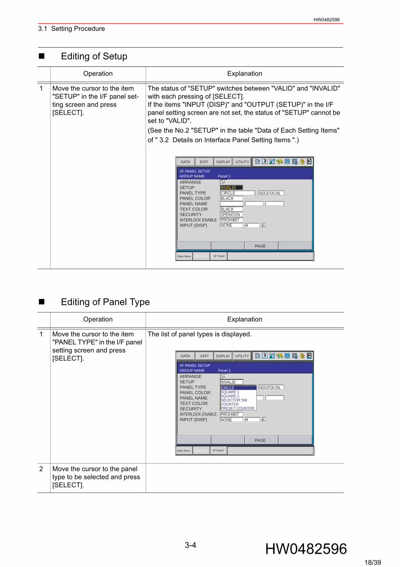
Editing of Setup
Editing of Panel Type
Operation Explanation
1 Move the cursor to the item "SETUP" in the I/F panel set-ting screen and press [SELECT].
The status of "SETUP" switches between "VALID" and "INVALID" with each pressing of [SELECT].If the items "INPUT (DISP)" and "OUTPUT (SETUP)" in the I/F panel setting screen are not set, the status of "SETUP" cannot be set to "VALID".(See the No.2 "SETUP" in the table "Data of Each Setting Items" of " 3.2 Details on Interface Panel Setting Items ".)
Operation Explanation
1 Move the cursor to the item "PANEL TYPE" in the I/F panel setting screen and press [SELECT].
The list of panel types is displayed.
2 Move the cursor to the panel type to be selected and press [SELECT].
Short CutMain Menu I/F Panel
I/F PANEL SETUPGROUP NAME Panel 1ARRANGESETUPPANEL TYPEPANEL COLORPANEL NAMETEXT COLORSECURITYINTERLOCK ENABLEINPUT (DISP)
3AINVALIDCIRCLEBLACK
BLACKOPERATIONPROHIBITNONE
INDICATION ONL
A
DATA EDIT DISPLAY UTILITY
PAGE
Short CutMain Menu I/F Panel
I/F PANEL SETUPGROUP NAME Panel 1ARRANGESETUPPANEL TYPEPANEL COLORPANEL NAMETEXT COLORSECURITYINTERLOCK ENABLEINPUT (DISP)
3AINVALIDCIRCLEBLACK
BLACKOPERATIONPROHIBITNONE
INDICATION ONL
A
DATA EDIT DISPLAY UTILITY
PAGE
CIRCLESQUARE 1SQUARE 2SELECTOR SWCOUNTERPRESET COUNTER
3-4 HW048259618/39
3.1 Setting ProcedureHW0482596
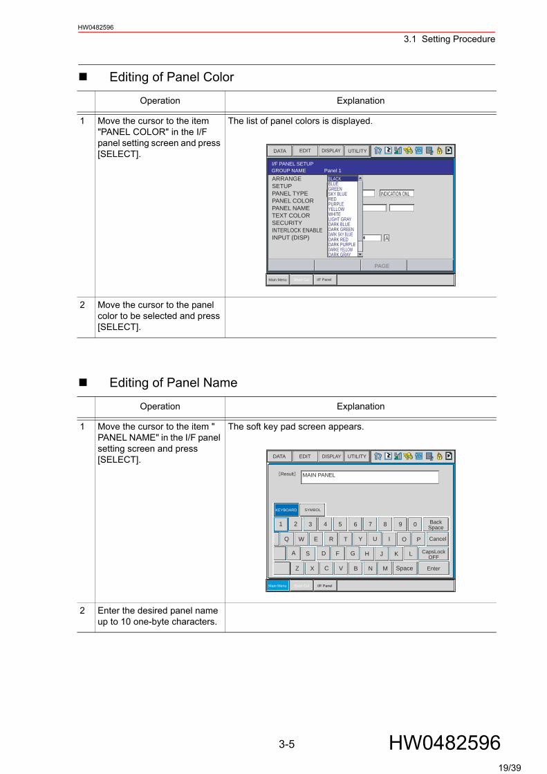
Editing of Panel Color
Editing of Panel Name
Operation Explanation
1 Move the cursor to the item "PANEL COLOR" in the I/F panel setting screen and press [SELECT].
The list of panel colors is displayed.
2 Move the cursor to the panel color to be selected and press [SELECT].
Operation Explanation
1 Move the cursor to the item " PANEL NAME" in the I/F panel setting screen and press [SELECT].
The soft key pad screen appears.
2 Enter the desired panel name up to 10 one-byte characters.
Short CutMain Menu I/F Panel
I/F PANEL SETUPGROUP NAME Panel 1ARRANGESETUPPANEL TYPEPANEL COLORPANEL NAMETEXT COLORSECURITYINTERLOCK ENABLEINPUT (DISP)
3A
INDICATION ONL
A
DATA EDIT DISPLAY UTILITY
PAGE
BLACKBLUEGREENSKY BLUEREDPURPLEYELLOWWHITELIGHT GRAYDARK BLUEDARK GREENDARK SKY BLUEDARK REDDARK PURPLEDARKE YELLOWDARK GRAY
Short CutMain Menu I/F Panel
1 2 3 4 5 6 7 8 9 0
OIUYTREWQ
A S D F
Z X C V
G
B
H
N
J K L
M Space
Result
KEYBOARD SYMBOL
P
BackSpace
DATA EDIT DISPLAY UTILITY
Cancel
Enter
CapsLockOFF
MAIN PANEL
3-5 HW048259619/39
3.1 Setting ProcedureHW0482596
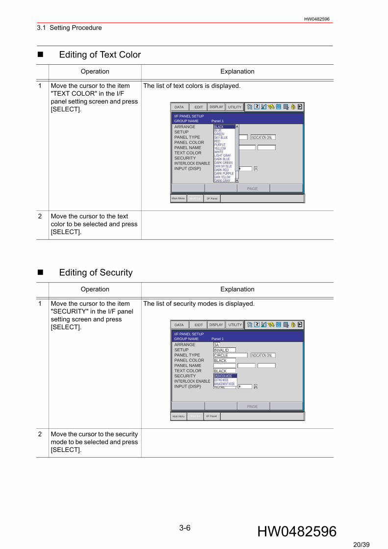
Editing of Text Color
Editing of Security
Operation Explanation
1 Move the cursor to the item "TEXT COLOR" in the I/F panel setting screen and press [SELECT].
The list of text colors is displayed.
2 Move the cursor to the text color to be selected and press [SELECT].
Operation Explanation
1 Move the cursor to the item "SECURITY" in the I/F panel setting screen and press [SELECT].
The list of security modes is displayed.
2 Move the cursor to the security mode to be selected and press [SELECT].
Short CutMain Menu I/F Panel
I/F PANEL SETUPGROUP NAME Panel 1ARRANGESETUPPANEL TYPEPANEL COLORPANEL NAMETEXT COLORSECURITYINTERLOCK ENABLEINPUT (DISP)
3A
INDICATION ONL
A
DATA EDIT DISPLAY UTILITY
PAGE
BLACKBLUEGREENSKY BLUEREDPURPLEYELLOWWHITELIGHT GRAYDARK BLUEDARK GREENDARK SKY BLUEDARK REDDARK PURPLEDARK YELLOWDARK GRAY
Short CutMain Menu I/F Panel
I/F PANEL SETUPGROUP NAME Panel 1ARRANGESETUPPANEL TYPEPANEL COLORPANEL NAMETEXT COLORSECURITYINTERLOCK ENABLEINPUT (DISP)
3AINVALIDCIRCLEBLACK
BLACKOPERATIONPROHIBITNONE
INDICATION ONL
A
DATA EIDT DISPLAY UTILITY
PAGE
OPERATION MODEEDITING MODEMANAGEMENT MODE
3-6 HW048259620/39

3.1 Setting ProcedureHW0482596
Editing of Interlock Enable
Editing of Input
Operation Explanation
1 Move the cursor to the item "INTERLOCK ENABLE" in the I/F panel setting screen and press [SELECT].
The status of INTERLOCK ENABLE switches between "PRO-HIBIT" and "PERMIT" with each pressing of [SELECT].
Be aware that operations are allowed without pressing the [INTERLOCK] key simulta-neously if the item "INTERLOCK ENABLE" is set to "PERMIT".
Operation Explanation
1 Move the cursor to the item "INPUT (DISP)" in the I/F panel setting screen and press [SELECT].
The list of input items is displayed.
2 Move the cursor to the input No. setting area on the right of {INPUT (DISP)}, and press [SELECT].
Enter the input No. with the numeric keypad, and press [ENTER].
Short CutMain Menu I/F Panel
I/F PANEL SETUPGROUP NAME Panel 1ARRANGESETUPPANEL TYPEPANEL COLORPANEL NAMETEXT COLORSECURITYINTERLOCK ENABLEINPUT (DISP)
3AINVALIDCIRCLEBLACK
BLACKOPERATIONPROHIBITNONE A
INDICATION ONL
DATA EDIT DISPLAY UTILITY
PAGE
NOTE
Short CutMain Menu I/F Panel
I/F PANEL SETUPGROUP NAME Panel 1ARRANGESETUPPANEL TYPEPANEL COLORPANEL NAMETEXT COLORSECURITYINTERLOCK ENABLEINPUT (DISP)
3AINVALIDCIRCLEBLACK
BLACKOPERATIONPROHIBITNONE
INDICATION ONL
A
DATA EDIT DISPLAY UTILITY
PAGE
NONESIGNAL
3-7 HW048259621/39
3.1 Setting ProcedureHW0482596
Editing of Group Name
Operation Explanation
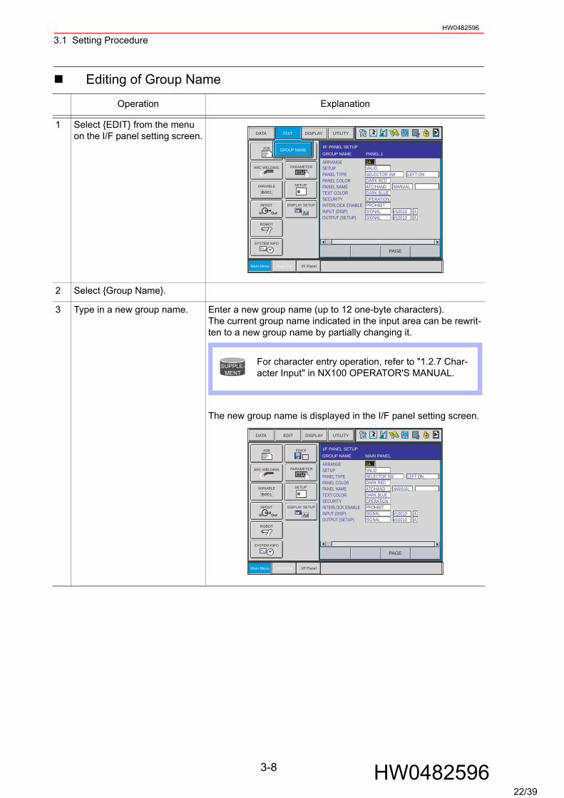
1 Select {EDIT} from the menu on the I/F panel setting screen.
2 Select {Group Name}.
3 Type in a new group name. Enter a new group name (up to 12 one-byte characters).The current group name indicated in the input area can be rewrit-ten to a new group name by partially changing it.
The new group name is displayed in the I/F panel setting screen.
I/F PANEL SETUPGROUP NAME PANEL 1
#10010#10010
AA
DATA EDIT DISPLAY UTILITY
DOUTMOVEEND
B001
In Out
CF
Aa
Main Menu Short Cut I/F Panel
GROUP NAME
SETUP
JOB
ARC WELDING
VARIABLE
IN/OUT
ROBOT
SYSTEM INFO
PARAMETER
DISPLAY SETUP
PAGE
ARRANGESETUPPANEL TYPEPANEL COLORPANEL NAMETEXT COLORSECURITYINTERLOCK ENABLEINPUT (DISP)OUTPUT (SETUP)
1AVALIDSELECTOR SWDARK REDATC/HANDDARK BLUEOPERATIONPROHIBITSIGNALSIGNAL
LEFT ON
MANUAL
For character entry operation, refer to "1.2.7 Char-acter Input" in NX100 OPERATOR'S MANUAL.
SUPPLE-MENT
I/F PANEL SETUPGROUP NAME MAIN PANEL
#10010#10010
AA
DATA DISPLAY UTILITYEDIT
DOUTMOVEEND
B001
In Out
CF
Aa
Main Menu Short Cut I/F Panel
FD/CF
SETUP
JOB
ARC WELDING
VARIABLE
IN/OUT
ROBOT
SYSTEM INFO
PARAMETER
DISPLAY SETUP
PAGE
ARRANGESETUPPANEL TYPEPANEL COLORPANEL NAMETEXT COLORSECURITYINTERLOCK ENABLEINPUT (DISP)OUTPUT (SETUP)
1AVALIDSELECTOR SWDARK REDATC/HANDDARK BLUEOPERATIONPROHIBITSIGNALSIGNAL
LEFT ON
MANUAL
3-8 HW048259622/39
3.1 Setting ProcedureHW0482596
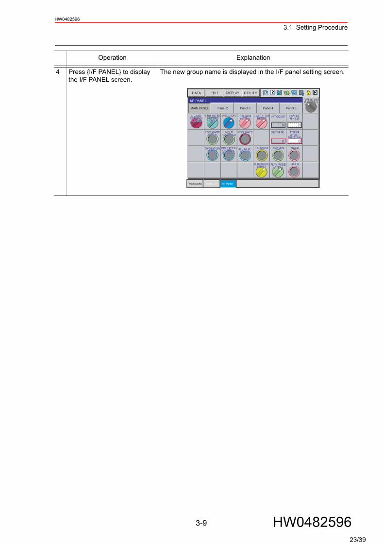
4 Press {I/F PANEL} to display the I/F PANEL screen.
The new group name is displayed in the I/F panel setting screen.
Operation Explanation
Short CutMain Menu I/F Panel
I/F PANEL
DATA EDIT DISPLAY UTILITY
=> MOVJ VJ=100.00
Panel 2 Panel 3 Panel 4 Panel 5MAIN PANEL
OPERATIONPROH PERMPROH PERM
0 0
HIT COUNT TYPE OF VEHICLE
WELD ON
COUT-UP NO. TYPE OFVEHICLE
PRECEDING
TYPE OFVEHICLE
PRECEDING
COOL WATERERR
COOL WATERERR
WELDALLOWED
WELDALLOWED
PLAY MODE HOLDTEACH MODEOPERATIONREADY
OPERATIONREADY
PLAY MODESELECT
PLAY MODESELECT
HOLDTEACH MODESELECT
TEACH MODESELECT
0 0
COOL WATERERR RESET
COOL WATERERR RESET
STOP WATERSOLENOID
OPEN
STOP WATERSOLENOID
OPEN
ATC/TOOLMNL OPRTNALLOWED
ATC/TOOLMNL OPRTNALLOWED
SHUTTLE OFF-INTRFRNC
SHUTTLE OFF-INTRFRNC
TIMER ERRRESET
TIMER ERRRESET
COOL WATERSWITCH
COOL WATERSWITCH
OPERATIONORIGINALPOSITION
OPERATIONORIGINALPOSITION
3-9 HW048259623/39
3.1 Setting ProcedureHW0482596
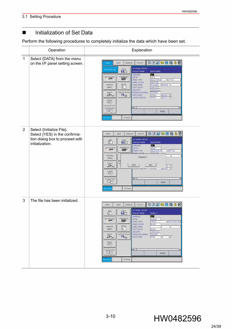
Initialization of Set DataPerform the following procedures to completely initialize the data which have been set.
Operation Explanation
1 Select {DATA} from the menu on the I/F panel setting screen.
2 Select {Initialize File}. Select {YES} in the confirma-tion dialog box to proceed with initialization.
3 The file has been initialized.
I/F PANEL SETUPGROUP NAME MAIN PANEL
#10010#10010
AA
DISPLAY UTILITYEDIT
DOUTMOVEEND
B001
In Out
CF
Aa
Main Menu Short Cut I/F Panel
FD/CF
DATA
INITIALIZE FILE
SETUP
ARC WELDING
VARIABLE
IN/OUT
ROBOT
SYSTEM INFO
PARAMETER
DISPLAY SETUP
PAGE
ARRANGESETUPPANEL TYPEPANEL COLORPANEL NAMETEXT COLORSECURITYINTERLOCK ENABLEINPUT (DISP)OUTPUT (SETUP)
1AVALIDSELECTOR SWDARK REDATC/HANDDARK BLUEOPERATIONPROHIBITSIGNALSIGNAL
LEFT ON
MANUAL
I/F PANEL SETUPGROUP NAME MAIN PANEL
#10010#10010
AA
DATA DISPLAY UTILITYEDIT
DOUTMOVEEND
B001
In Out
CF
Aa
Main Menu Short Cut I/F Panel
FD/CF
SETUP
JOB
ARC WELDING
VARIABLE
IN/OUT
ROBOT
SYSTEM INFO
PARAMETER
DISPLAY SETUP
PAGE
ARRANGESETUPPANEL TYPEPANEL COLORPANEL NAMETEXT COLORSECURITYINTERLOCK ENABLEINPUT (DISP)OUTPUT (SETUP)
1AVALIDSELECTOR SWDARK RED
DARK BLUEOPERATIONPROHIBITSIGNALSIGNAL
LEFT ON
Initialize?
NOYES
I/F PANEL SETUPGROUP NAME PANEL 1
A
DATA DISPLAY UTILITYEDIT
DOUTMOVEEND
B001
In Out
CF
Aa
Main Menu Short Cut I/F Panel
FD/CF
SETUP
JOB
ARC WELDING
VARIABLE
IN/OUT
ROBOT
SYSTEM INFO
PARAMETER
DISPLAY SETUP
PAGE
ARRANGESETUPPANEL TYPEPANEL COLORPANEL NAMETEXT COLORSECURITYINTERLOCK ENABLEINPUT (DISP)
1AINVALIDCIRCLEBLACK
BLACKOPERATIONPROHIBITNONE
INDICATION ONL
3-10 HW048259624/39
3.2 Details on Interface Panel Setting ItemsHW0482596
3.2 Details on Interface Panel Setting Items
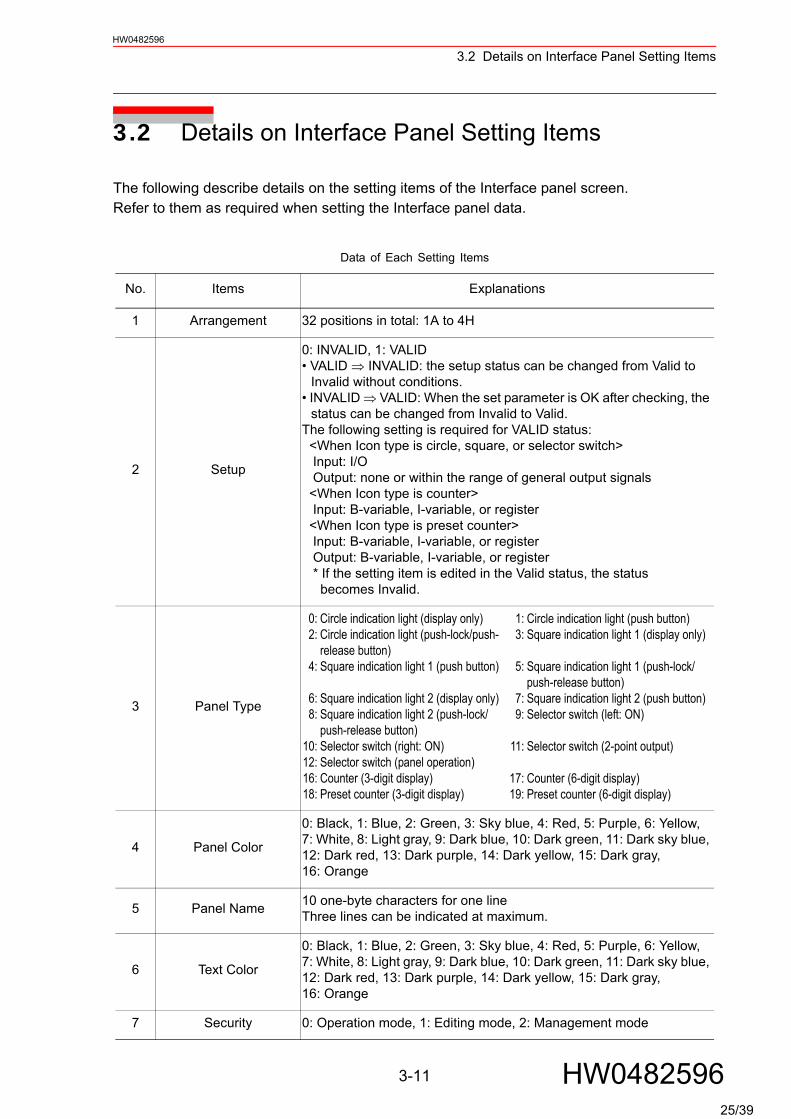
The following describe details on the setting items of the Interface panel screen.Refer to them as required when setting the Interface panel data.
Data of Each Setting Items
No. Items Explanations
1 Arrangement 32 positions in total: 1A to 4H
2 Setup
0: INVALID, 1: VALID• VALID ⇒ INVALID: the setup status can be changed from Valid to
Invalid without conditions.• INVALID ⇒ VALID: When the set parameter is OK after checking, the
status can be changed from Invalid to Valid.The following setting is required for VALID status: <When Icon type is circle, square, or selector switch> Input: I/O Output: none or within the range of general output signals <When Icon type is counter> Input: B-variable, I-variable, or register <When Icon type is preset counter> Input: B-variable, I-variable, or register Output: B-variable, I-variable, or register * If the setting item is edited in the Valid status, the status becomes Invalid.
3 Panel Type
0:2:
4:
6:8:
10:12:16:18:
Circle indication light (display only)Circle indication light (push-lock/push-release button)Square indication light 1 (push button)
Square indication light 2 (display only)Square indication light 2 (push-lock/push-release button)Selector switch (right: ON)Selector switch (panel operation)Counter (3-digit display)Preset counter (3-digit display)
1:3:
5:
7:9:
11:
17:19:
Circle indication light (push button)Square indication light 1 (display only)
Square indication light 1 (push-lock/push-release button)Square indication light 2 (push button)Selector switch (left: ON)
Selector switch (2-point output)
Counter (6-digit display)Preset counter (6-digit display)
4 Panel Color
0: Black, 1: Blue, 2: Green, 3: Sky blue, 4: Red, 5: Purple, 6: Yellow, 7: White, 8: Light gray, 9: Dark blue, 10: Dark green, 11: Dark sky blue, 12: Dark red, 13: Dark purple, 14: Dark yellow, 15: Dark gray, 16: Orange
5 Panel Name 10 one-byte characters for one lineThree lines can be indicated at maximum.
6 Text Color
0: Black, 1: Blue, 2: Green, 3: Sky blue, 4: Red, 5: Purple, 6: Yellow, 7: White, 8: Light gray, 9: Dark blue, 10: Dark green, 11: Dark sky blue, 12: Dark red, 13: Dark purple, 14: Dark yellow, 15: Dark gray, 16: Orange
7 Security 0: Operation mode, 1: Editing mode, 2: Management mode
3-11 HW048259625/39
3.2 Details on Interface Panel Setting ItemsHW0482596
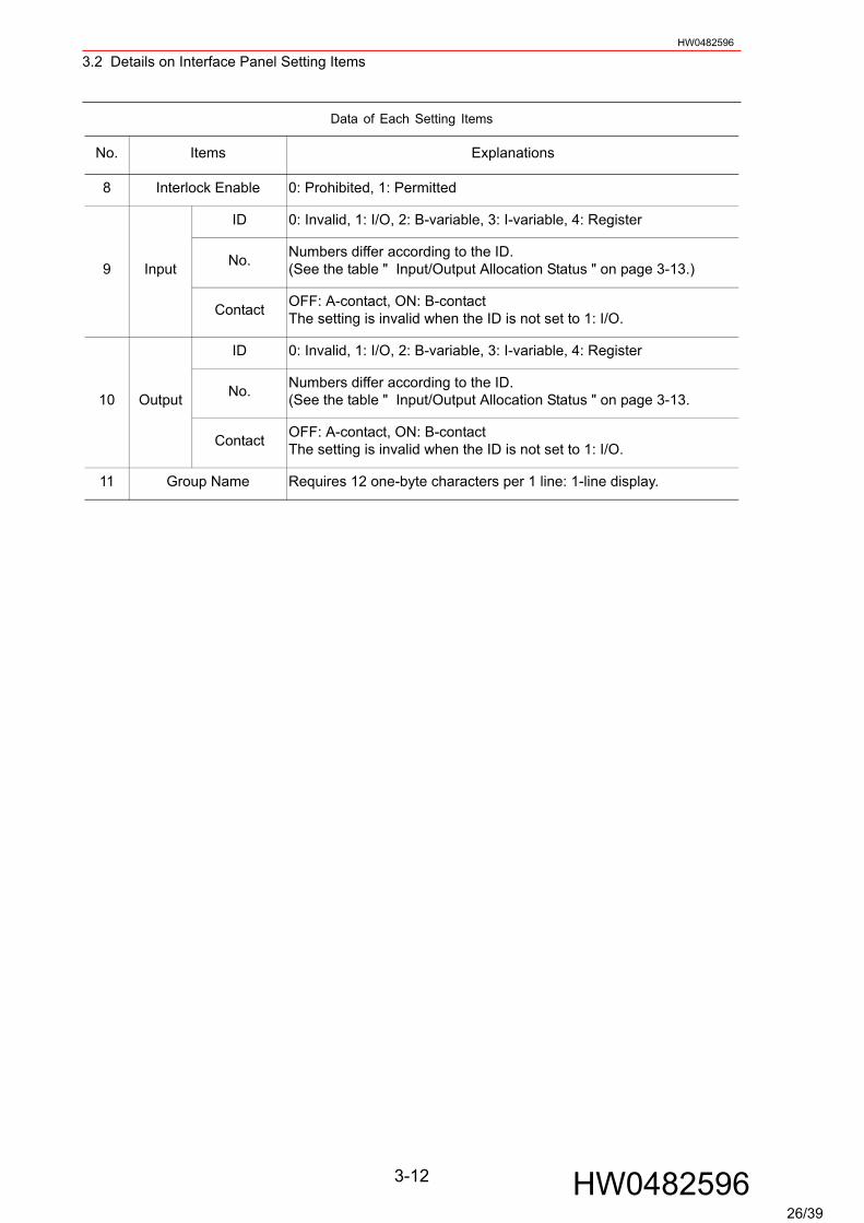
8 Interlock Enable 0: Prohibited, 1: Permitted
9 Input
ID 0: Invalid, 1: I/O, 2: B-variable, 3: I-variable, 4: Register
No. Numbers differ according to the ID.(See the table " Input/Output Allocation Status " on page 3-13.)
Contact OFF: A-contact, ON: B-contactThe setting is invalid when the ID is not set to 1: I/O.
10 Output
ID 0: Invalid, 1: I/O, 2: B-variable, 3: I-variable, 4: Register
No. Numbers differ according to the ID.(See the table " Input/Output Allocation Status " on page 3-13.
Contact OFF: A-contact, ON: B-contactThe setting is invalid when the ID is not set to 1: I/O.
11 Group Name Requires 12 one-byte characters per 1 line: 1-line display.
Data of Each Setting Items
No. Items Explanations
3-12 HW048259626/39

3.2 Details on Interface Panel Setting ItemsHW0482596
Shown below is the status of output signals. The status varies depending on which of "push button" and "push-lock/push-release button" is selected by pressing "circle indication light", "square indication light 1", or "square indication light 2".
When selecting "push button":An input signal (indicated value) of when pressing "push button" is reversed to an output signal (set value).The output signal (set value) of when releasing the button returns to the previous input sta-tus of when pressing the button (indicated value).
When pressing the button: Input = ON ⇒ Output = OFF Input = OFF ⇒ Output= ON
When releasing the button: Input = ON at the time of ⇒ Output = ON Input = OFF at the time of ⇒ Output = OFF*By setting the parameter to S2C410, only "push button" can change the processing by pressing or releasing the button.(See" 6.3 The change of "push button" processing ".)
When selecting "push-lock/push-release button":An input signal (indicated value) of when pressing "push-lock/push-release button" is reversed to an output signal (set value).The status of signal does not change even when the button is released. (The status is held.)
When pressing the button: Input = ON ⇒ Output = OFF Input = OFF ⇒ Output = ON
When releasing the button: Hold the status (= ) of output
When selecting "2-point output" by selector switch: The status of output signal of when pressing a selector switch is as follows.
When pressing a selector switch while the switch is pointing left:Output 1 = OFF, Output 2 = ON
When pressing a selector switch while the switch is pointing right:Output 1 = ON, Output 2 = OFF
SUPPLE-MENT
3-13 HW048259626A/39
3.2 Details on Interface Panel Setting ItemsHW0482596
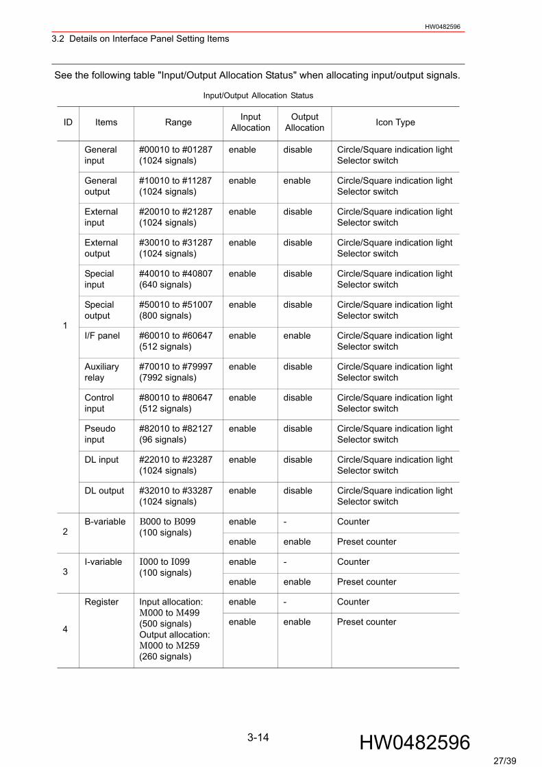
See the following table "Input/Output Allocation Status" when allocating input/output signals.
Input/Output Allocation Status
ID Items Range Input Allocation
Output Allocation Icon Type
1
General input
#00010 to #01287 (1024 signals)
enable disable Circle/Square indication lightSelector switch
General output
#10010 to #11287 (1024 signals)
enable enable Circle/Square indication lightSelector switch
External input
#20010 to #21287 (1024 signals)
enable disable Circle/Square indication lightSelector switch
External output
#30010 to #31287 (1024 signals)
enable disable Circle/Square indication lightSelector switch
Special input
#40010 to #40807 (640 signals)
enable disable Circle/Square indication lightSelector switch
Special output
#50010 to #51007 (800 signals)
enable disable Circle/Square indication lightSelector switch
I/F panel #60010 to #60647(512 signals)
enable enable Circle/Square indication lightSelector switch
Auxiliary relay
#70010 to #79997 (7992 signals)
enable disable Circle/Square indication lightSelector switch
Control input
#80010 to #80647 (512 signals)
enable disable Circle/Square indication lightSelector switch
Pseudo input
#82010 to #82127 (96 signals)
enable disable Circle/Square indication lightSelector switch
DL input #22010 to #23287 (1024 signals)
enable disable Circle/Square indication lightSelector switch
DL output #32010 to #33287 (1024 signals)
enable disable Circle/Square indication lightSelector switch
2B-variable B000 to B099
(100 signals)enable - Counter
enable enable Preset counter
3I-variable I000 to I099
(100 signals)enable - Counter
enable enable Preset counter
4
Register Input allocation:M000 to M499(500 signals)Output allocation:M000 to M259(260 signals)
enable - Counter
enable enable Preset counter
3-14 HW048259627/39
3.2 Details on Interface Panel Setting ItemsHW0482596
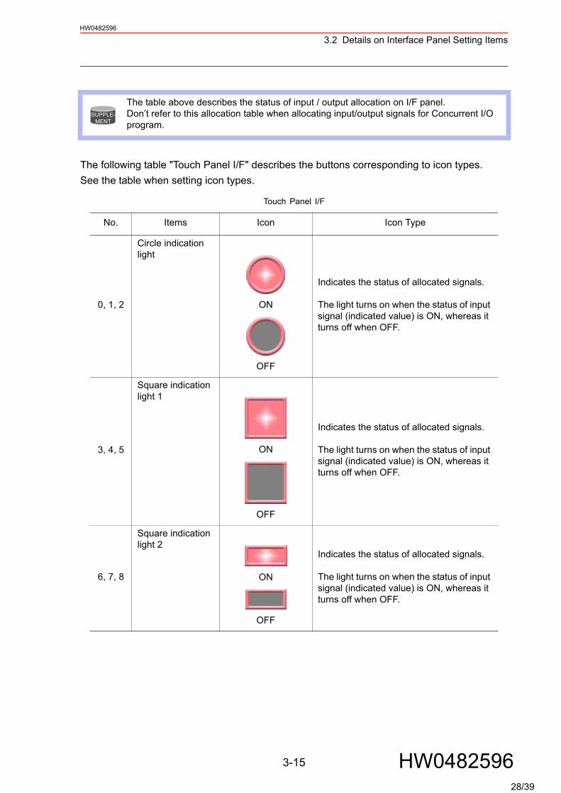
The following table "Touch Panel I/F" describes the buttons corresponding to icon types.See the table when setting icon types.
The table above describes the status of input / output allocation on I/F panel. Don’t refer to this allocation table when allocating input/output signals for Concurrent I/O program.
Touch Panel I/F
No. Items Icon Icon Type
0, 1, 2
Circle indication light
ON
OFF
Indicates the status of allocated signals.
The light turns on when the status of input signal (indicated value) is ON, whereas it turns off when OFF.
3, 4, 5
Square indication light 1
ON
OFF
Indicates the status of allocated signals.
The light turns on when the status of input signal (indicated value) is ON, whereas it turns off when OFF.
6, 7, 8
Square indication light 2
ON
OFF
Indicates the status of allocated signals.
The light turns on when the status of input signal (indicated value) is ON, whereas it turns off when OFF.
SUPPLE-MENT
3-15 HW048259628/39
3.2 Details on Interface Panel Setting ItemsHW0482596
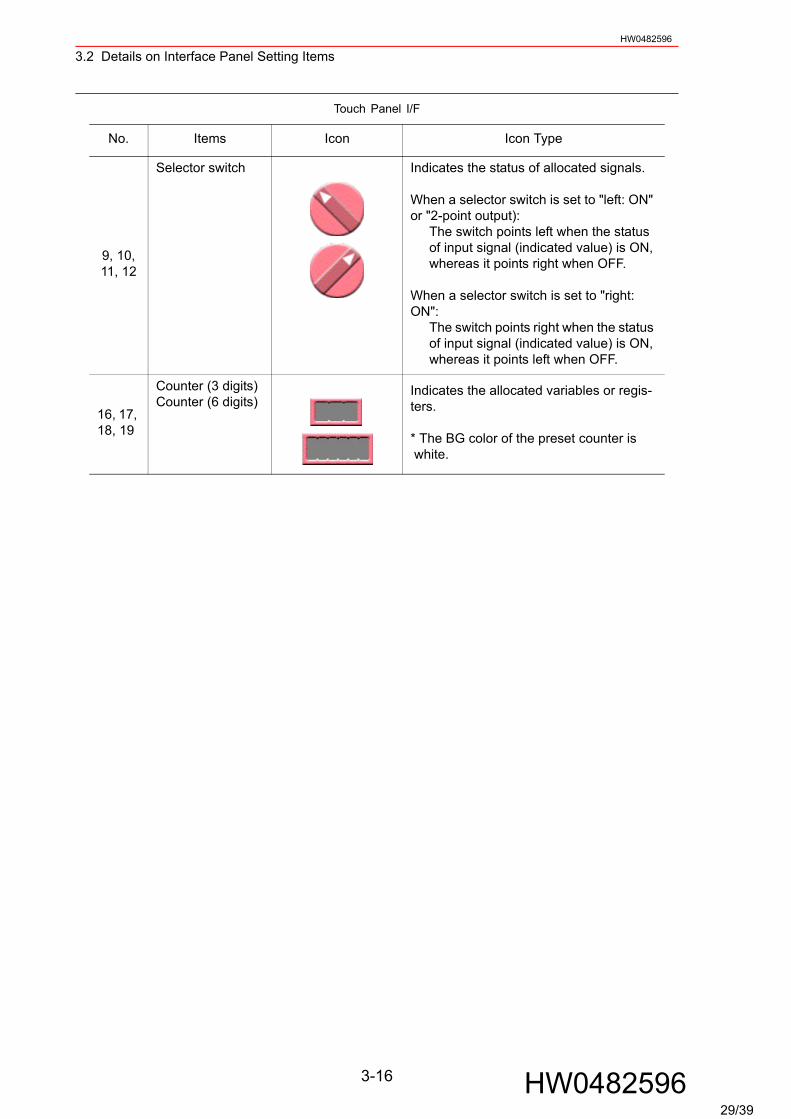
9, 10, 11, 12
Selector switch Indicates the status of allocated signals.
When a selector switch is set to "left: ON" or "2-point output):
The switch points left when the status of input signal (indicated value) is ON, whereas it points right when OFF.
When a selector switch is set to "right: ON":
The switch points right when the status of input signal (indicated value) is ON, whereas it points left when OFF.
16, 17, 18, 19
Counter (3 digits)Counter (6 digits)
Indicates the allocated variables or regis-ters.
* The BG color of the preset counter is white.
Touch Panel I/F
No. Items Icon Icon Type
3-16 HW048259629/39
4-1
HW0482596
HW0482596
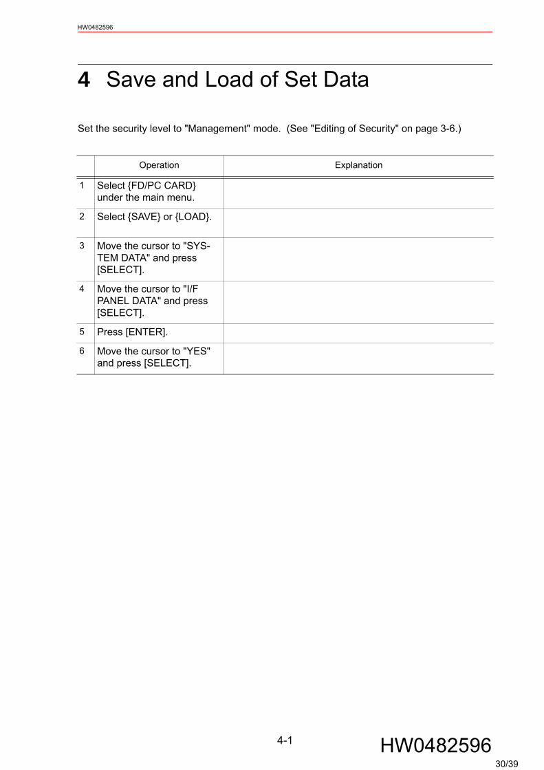
4 Save and Load of Set Data
Set the security level to "Management" mode. (See "Editing of Security" on page 3-6.)
Operation Explanation
1 Select {FD/PC CARD} under the main menu.
2 Select {SAVE} or {LOAD}.
3 Move the cursor to "SYS-TEM DATA" and press [SELECT].
4 Move the cursor to "I/F PANEL DATA" and press [SELECT].
5 Press [ENTER].
6 Move the cursor to "YES" and press [SELECT].
30/39
HW0482596
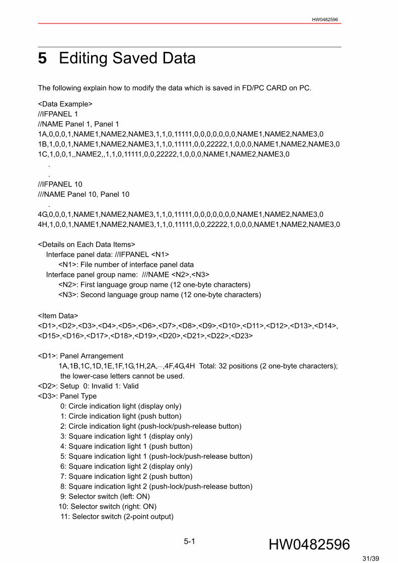
5 Editing Saved Data
The following explain how to modify the data which is saved in FD/PC CARD on PC.
<Data Example>//IFPANEL 1//NAME Panel 1, Panel 11A,0,0,0,1,NAME1,NAME2,NAME3,1,1,0,11111,0,0,0,0,0,0,0,NAME1,NAME2,NAME3,01B,1,0,0,1,NAME1,NAME2,NAME3,1,1,0,11111,0,0,22222,1,0,0,0,NAME1,NAME2,NAME3,01C,1,0,0,1,,NAME2,,1,1,0,11111,0,0,22222,1,0,0,0,NAME1,NAME2,NAME3,0 . .//IFPANEL 10///NAME Panel 10, Panel 10 .4G,0,0,0,1,NAME1,NAME2,NAME3,1,1,0,11111,0,0,0,0,0,0,0,NAME1,NAME2,NAME3,04H,1,0,0,1,NAME1,NAME2,NAME3,1,1,0,11111,0,0,22222,1,0,0,0,NAME1,NAME2,NAME3,0
<Details on Each Data Items> Interface panel data: //IFPANEL <N1> <N1>: File number of interface panel data Interface panel group name: ///NAME <N2>,<N3> <N2>: First language group name (12 one-byte characters) <N3>: Second language group name (12 one-byte characters)
<Item Data><D1>,<D2>,<D3>,<D4>,<D5>,<D6>,<D7>,<D8>,<D9>,<D10>,<D11>,<D12>,<D13>,<D14>,<D15>,<D16>,<D17>,<D18>,<D19>,<D20>,<D21>,<D22>,<D23>
<D1>: Panel Arrangement 1A,1B,1C,1D,1E,1F,1G,1H,2A,⋅⋅⋅,4F,4G,4H Total: 32 positions (2 one-byte characters); the lower-case letters cannot be used.<D2>: Setup 0: Invalid 1: Valid<D3>: Panel Type 0: Circle indication light (display only) 1: Circle indication light (push button) 2: Circle indication light (push-lock/push-release button) 3: Square indication light 1 (display only) 4: Square indication light 1 (push button) 5: Square indication light 1 (push-lock/push-release button) 6: Square indication light 2 (display only) 7: Square indication light 2 (push button) 8: Square indication light 2 (push-lock/push-release button) 9: Selector switch (left: ON) 10: Selector switch (right: ON) 11: Selector switch (2-point output)
5-1 HW048259631/39

HW0482596
12: Selector switch (panel operation) 16: Counter (3-digit display) 17: Counter (6-digit display) 18: Preset counter (3-digit display) 19: Preset counter (6-digit display)<D4>: Panel Color 0: Black 1: Blue 2: Green 3: Sky blue 4: Red 5: Purple 6: Yellow 7: White 8: Light gray 9: Dark blue 10: Dark green 11: Dark sky blue 12: Dark red 13: Dark purple 14: Dark yellow 15: Dark gray 16: Orange<D5>: Text Color Same as the Panel Color<D6>: First language panel name on the 1st line (10 one-byte characters)<D7>: First language panel name on the 2nd line (10 one-byte characters)<D8>: First language panel name on the 3rd line (10 one-byte characters)<D9>: Security 0: Operation mode 1: Editing mode 2: Management mode<D10>: Interlock Enable 0: Prohibited 1: Permitted<D11>: Input Type 0: None 1: Signal (numbers are 5-digit) 2: B-variable (B000 to B099: numbers are 3-digit) 3: I-variable (I000 to I099: numbers are 3-digit) 4: Register (M000 to M499: numbers are 3-digit)<D12>: Number<D13>: Input Contact 0: A-contact 1: B-contact<D14>: Output Type 1 0: None 1: Signal (numbers are 5-digit) 2: B-variable (B000 to B099: numbers are 3-digit) 3: I-variable (I000 to I099: numbers are 3-digit) 4: Register (M000 to M499: numbers are 3-digit)<D15>: Number<D16>: Output Contact 1 0: A-contact 1: B-contact<D17>: Output Type 2 0: None 1: Signal (numbers are 5-digit) 2: B-variable (B000 to B099: numbers are 3-digit) 3: I-variable (I000 to I099: numbers are 3-digit) 4: Register (M000 to M499: numbers are 3-digit)<D18>: Number<D19>: Output Contact 2 0: A-contact 1: B-contact<D20>: Second language panel name on the 1st line (10 one-byte characters)<D21>: Second language panel name on the 2nd line (10 one-byte characters)<D22>: Second language panel name on the 3rd line (10 one-byte characters)<D23>: Optional 0: Standard
5-2 HW048259632/39

HW0482596
• Syntax error will occur when inserting line feeds into the data "Data Example".• Syntax error will occur when the number of commas differs from the saved data in FD/PC card.• Define capital letters for variables.• Wrong signal range or type instruction will make the attribute invalid when loading.• Loading for one item is possible as follow;
//IFPANEL 4///NAME Panel 4, Panel 41A,0,0,0,1,NAME1,NAME2,NAME3,1,1,0,11111,0,0,0,0,0,0,0,NAME1,NAME2,NAME3,0
CAUTION
5-3 HW048259633/39
6.1 Clearing the Status of SignalsHW0482596
6 Parameters
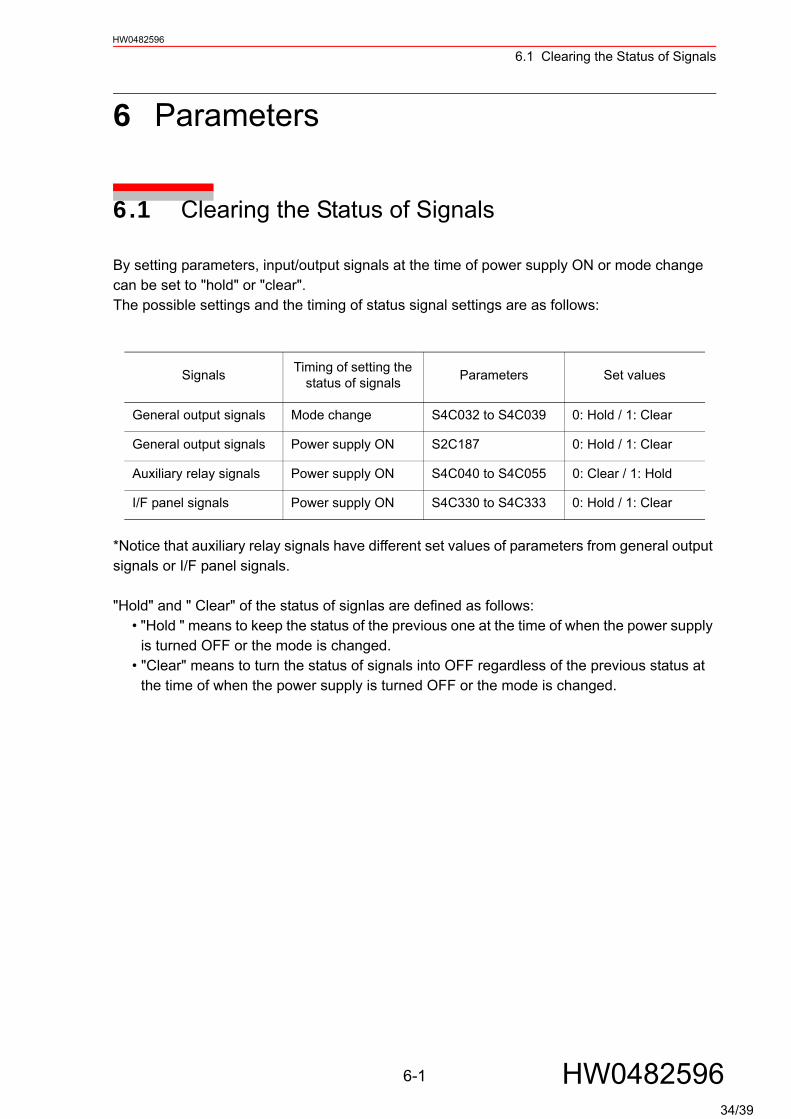
6.1 Clearing the Status of Signals
By setting parameters, input/output signals at the time of power supply ON or mode change can be set to "hold" or "clear".The possible settings and the timing of status signal settings are as follows:
*Notice that auxiliary relay signals have different set values of parameters from general output signals or I/F panel signals.
"Hold" and " Clear" of the status of signlas are defined as follows:• "Hold " means to keep the status of the previous one at the time of when the power supply
is turned OFF or the mode is changed.• "Clear" means to turn the status of signals into OFF regardless of the previous status at
the time of when the power supply is turned OFF or the mode is changed.
Signals Timing of setting the status of signals Parameters Set values
General output signals Mode change S4C032 to S4C039 0: Hold / 1: Clear
General output signals Power supply ON S2C187 0: Hold / 1: Clear
Auxiliary relay signals Power supply ON S4C040 to S4C055 0: Clear / 1: Hold
I/F panel signals Power supply ON S4C330 to S4C333 0: Hold / 1: Clear
6-1 HW048259634/39
6.1 Clearing the Status of SignalsHW0482596
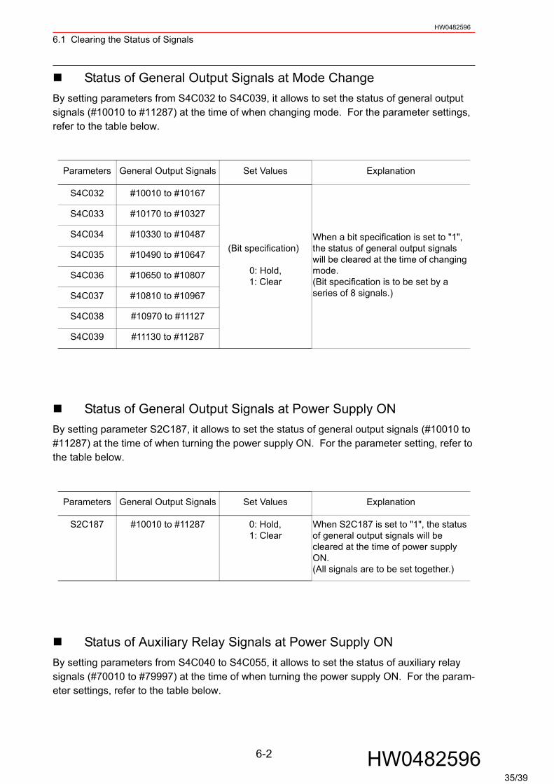
Status of General Output Signals at Mode ChangeBy setting parameters from S4C032 to S4C039, it allows to set the status of general output signals (#10010 to #11287) at the time of when changing mode. For the parameter settings, refer to the table below.
Status of General Output Signals at Power Supply ONBy setting parameter S2C187, it allows to set the status of general output signals (#10010 to #11287) at the time of when turning the power supply ON. For the parameter setting, refer to the table below.
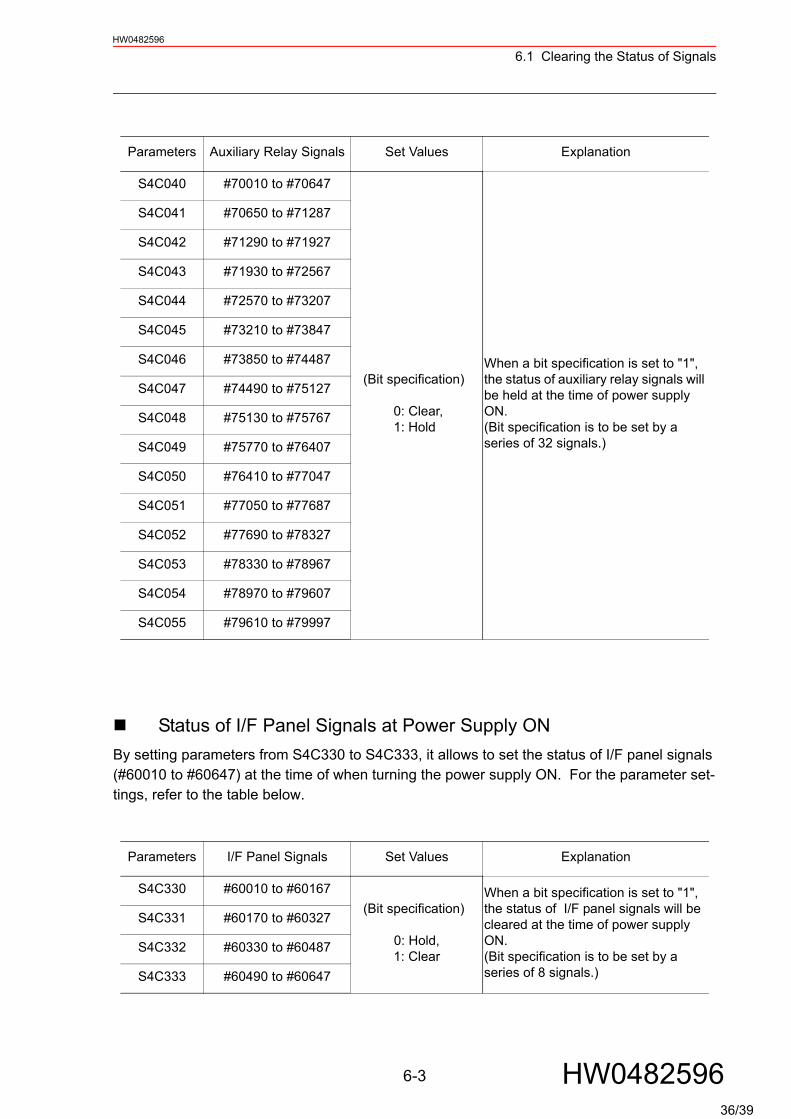
Status of Auxiliary Relay Signals at Power Supply ONBy setting parameters from S4C040 to S4C055, it allows to set the status of auxiliary relay signals (#70010 to #79997) at the time of when turning the power supply ON. For the param-eter settings, refer to the table below.
Parameters General Output Signals Set Values Explanation
S4C032 #10010 to #10167
(Bit specification)
0: Hold, 1: Clear
When a bit specification is set to "1", the status of general output signals will be cleared at the time of changing mode.(Bit specification is to be set by a series of 8 signals.)
S4C033 #10170 to #10327
S4C034 #10330 to #10487
S4C035 #10490 to #10647
S4C036 #10650 to #10807
S4C037 #10810 to #10967
S4C038 #10970 to #11127
S4C039 #11130 to #11287
Parameters General Output Signals Set Values Explanation
S2C187 #10010 to #11287 0: Hold, 1: Clear
When S2C187 is set to "1", the status of general output signals will be cleared at the time of power supply ON.(All signals are to be set together.)
6-2 HW048259635/39
6.1 Clearing the Status of SignalsHW0482596
Status of I/F Panel Signals at Power Supply ONBy setting parameters from S4C330 to S4C333, it allows to set the status of I/F panel signals (#60010 to #60647) at the time of when turning the power supply ON. For the parameter set-tings, refer to the table below.
Parameters Auxiliary Relay Signals Set Values Explanation
S4C040 #70010 to #70647
(Bit specification)
0: Clear,1: Hold
When a bit specification is set to "1", the status of auxiliary relay signals will be held at the time of power supply ON.(Bit specification is to be set by a series of 32 signals.)
S4C041 #70650 to #71287
S4C042 #71290 to #71927
S4C043 #71930 to #72567
S4C044 #72570 to #73207
S4C045 #73210 to #73847
S4C046 #73850 to #74487
S4C047 #74490 to #75127
S4C048 #75130 to #75767
S4C049 #75770 to #76407
S4C050 #76410 to #77047
S4C051 #77050 to #77687
S4C052 #77690 to #78327
S4C053 #78330 to #78967
S4C054 #78970 to #79607
S4C055 #79610 to #79997
Parameters I/F Panel Signals Set Values Explanation
S4C330 #60010 to #60167 (Bit specification)
0: Hold, 1: Clear
When a bit specification is set to "1", the status of I/F panel signals will be cleared at the time of power supply ON.(Bit specification is to be set by a series of 8 signals.)
S4C331 #60170 to #60327
S4C332 #60330 to #60487
S4C333 #60490 to #60647
6-3 HW048259636/39
6.2 Allocation of General Input Signals to Interface Panel ScreensHW0482596
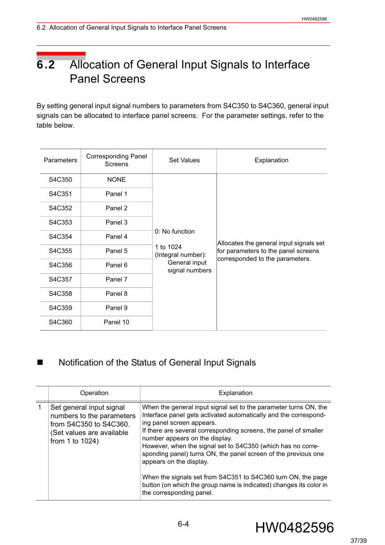
6.2 Allocation of General Input Signals to Interface Panel Screens
By setting general input signal numbers to parameters from S4C350 to S4C360, general input signals can be allocated to interface panel screens. For the parameter settings, refer to the table below.
Notification of the Status of General Input Signals
Parameters Corresponding Panel Screens Set Values Explanation
S4C350 NONE
0: No function
1 to 1024 (Integral number):
General input signal numbers
Allocates the general input signals set for parameters to the panel screens corresponded to the parameters.
S4C351 Panel 1
S4C352 Panel 2
S4C353 Panel 3
S4C354 Panel 4
S4C355 Panel 5
S4C356 Panel 6
S4C357 Panel 7
S4C358 Panel 8
S4C359 Panel 9
S4C360 Panel 10
Operation Explanation
1 Set general input signal numbers to the parameters from S4C350 to S4C360. (Set values are available from 1 to 1024)
When the general input signal set to the parameter turns ON, the Interface panel gets activated automatically and the correspond-ing panel screen appears.If there are several corresponding screens, the panel of smaller number appears on the display.However, when the signal set to S4C350 (which has no corre-sponding panel) turns ON, the panel screen of the previous one appears on the display.
When the signals set from S4C351 to S4C360 turn ON, the page button (on which the group name is indicated) changes its color in the corresponding panel.
6-4 HW048259637/39

6.3 The change of "push button" processingHW0482596
6.3 The change of "push button" processing
The change by the parameter.By setting the parameter to S2C410, when pressing and releasing the "push button", the pro-cessing can be changed. This processing is applicable only when pressing and releasing the "push button". "push-lock/push-release button" or "selector switch" don’t have the same func-tion.
Forced reversal of input/output signalsWhen the set value is S2C410 =0, hold down the [INTERLOCK]+[CANCEL] keys and press the "push button", then an output (set value) signal is forcedly reversed.
In the cases below, the [I/F Panel] button flashes in the lower left of the display notifying the "ON" status of the general input signals set for the parameters.
• The case when the Interface panels are unable to get activated (during imputing charac-ters or numeric values) when the general input signals set for the parameters turn ON.
• The case when a page button of the corresponding panel is not shown when the general input signals set for the parameters turn ON.
Parameter’s set value
Processings when pressing the "push button"
Processings when releasing the "push button"
S2C410 =0
(Common for A- and B-contact set-tings) An input signal (indicated value) of when pressing "push button" is reversed to an output signal (set value).
Input = ON ⇒ Output = OFFInput = OFF ⇒ Output = ON
(Common for A- and B-contact settings) An output (set value) of when pressing "push button" is reversed to an input (indicated value).
When pressing the button Input = ON ⇒ Output = ON
When pressing the button Input = OFF ⇒ Output = OFF
S2C410=1
(When A-contact setting) An output (set value) signal turns to ON.
(When A-contact setting) An output (set value) signal turns to OFF.
(When B-contact setting) An output (set value) signal turns to OFF
(When B-contact setting) An output (set value) signal turns to ON.
SUPPLE-MENT
6-5 HW048259638/39

6.3 The change of "push button" processingHW0482596
The internal signal status is forcedly changed by this processing. Please operate with due caution.NOTE
6-6 HW048259638A/39
NX100 OPTIONSINSTRUCTIONSFOR INTERFACE PANEL FUNCTION
HEAD OFFICE2-1 Kurosaki-Shiroishi, Yahatanishi-ku, Kitakyusyu-shi, 806-0004, JapanPhone +81-93-645-7745 Fax +81-93-645-7746MOTOMAN INC. HEADQUARTERS805 Liberty Lane, West Carrollton, OH 45449, U.S.A.Phone +1-937-847-6200 Fax +1-937-847-6277MOTOMAN ROBOTICS EUROPE ABFranska Vagen 10, Box 4004, SE-390 04 Kalmar, SwedenPhone +46-480-417800 Fax +46-480-417999MOTOMAN ROBOTEC GmbHKammerfeld strasse 1, 85391 Allershausen, GermanyPhone +49-8166-90-100 Fax +49-8166-90-103YASKAWA ELECTRIC KOREA CORPORATION1F, Samyang Bldg. 89-1, Shinchun-dong, Donk-Ku, Daegu, KoreaPhone +82-53-382-7844 Fax +82-53-382-7845YASKAWA ELECTRIC (SINGAPORE) PTE. LTD.151 Lorong Chuan, #04-01, New Tech Park, Singapore 556741Phone +65-6282-3003 Fax +65-6289-3003YASKAWA ELECTRIC (MALAYSIA) SDN. BHD.Unit 47-1 and 2. Jalan PJU 5/9, Dataran Sunway, Kota Damansara, 47810, Petailng Jaya Selangor, MalaysiaPhone +60-3614-08919 Fax +60-3614-08929YASKAWA ELECTRIC (THAILAND) CO., LTD.252/246, 4th Floor. Muang Thai-Phatra office Tower II Rechadapisek Road, Huaykwang Bangkok 10320, ThailandPhone +66-2-693-2200 Fax +66-2-693-4200SHOUGANG MOTOMAN ROBOT CO., LTD.No.7,Yongchang-North Road, Beijing Economic and Technological and Development Area, Beijing 100076, ChinaPhone +86-10-6788-0541 Fax +86-10-6788-0542MOTOMAN MOTHERSON ROBOTICS LTD.910, DLF Galleria, DLF City Phase IV, Gurgaon - 122002 Haryama, indiaPhone +91-124-414-8514 Fax +91-124-414-8016
YASKAWA
YASKAWA ELECTRIC CORPORATION
Specifications are subject to change without noticefor ongoing product modifications and improvements. Printed in Japan December 2007 05-02C
HW0482596MANUAL NO.
5
39/39