interface based on electrooculography for velocity control
TRANSCRIPT

Applied Bionics and BiomechanicsVol. 7, No. 3, September 2010, 199–207
Interface based on electrooculography for velocity control of a robot arm
Eduardo Ianeza∗, Jose M. Azorına, Eduardo Fernandezb and Andres Ubedaa
aVirtual Reality and Robotics Lab, Miguel Hernandez University, Elche, Spain; bBioengineering Institute, Miguel Hernandez University,Elche, Spain
(Received 31 January 2010; final version received 18 June 2010)
This paper describes a technique based on electrooculography to control a robot arm. This technique detects the movementof the eyes, measuring the difference of potential between the cornea and the retina by placing electrodes around the oculararea. The processing algorithm developed to obtain the position of the eye at the blink of the user is explained. The outputof the processing algorithm offers, apart from the direction, four different values (zero to three) to control the velocity of therobot arm according to how much the user is looking in one direction. This allows controlling two degrees of freedom of arobot arm with the eyes movement. The blink has been used to mark some targets in tests. In this paper, the experimentalresults obtained with a real robot arm are shown.
Keywords: electrooculography (EOG); robot; disabled people; human interface
1. Introduction
Nowadays numerous aid systems exist for persons with dis-abilities, which are intended to achieve better mobility ofthe affected person or facilitate the control of devices. Forexample, to improve mobility there are automated wheelchairs, robotic prostheses for the extremities (Jeong et al.2000) or exoskeletons (Sankai 2006). In addition, to con-trol devices there are techniques to detect the eye positionusing a camera (Hutchinson et al. 1989) or brain–machineinterfaces (BCI: brain computer interface), which allowcontrolling things from the cursor of a computer to mobiledevices (Millan et al. 2004, 2005; Iturrate et al. 2009).Themain goal of these systems is to enhance the quality oflife of disabled people, increasing their independence andgranting greater social inclusion. In this paper, the use of arobot arm is proposed to help disabled and/or elder people.
Some of these interfaces use the movements of theeyes in order to control a device, such as videooculography(VOG) or infra-red oculography (IROG) (Hutchinson et al.1989; Oyekoya and Stentiford 2006; Ubeda et al. 2009).These techniques can be used to detect the eye positionusing a camera.
In this paper, the electrooculography technique (EOG)is used to detect eye motion (Ianez et al. 2009). In thistechnique a camera is not used to detect the eye position.The EOG detects the movement of the eyes by measuringthrough electrodes the difference of potential between thecornea and the retina (Nicolau et al. 1995).This techniquehas some important advantages related to the techniquesthat use a camera. With EOG, the eye motion can be de-
∗Corresponding author. Email: [email protected]
tected independently of light conditions. In addition, EOGdoes not depend on head orientation; on the contrary, inVOG or IROG the performance depends on the head posi-tion with regard to the camera. Furthermore, in EOG the eyemotion can be detected even if the eye is partially closed;in VOG and IROG the camera must have direct vision ofthe open eye.
The EOG interface has been used in several works tointeract with devices (Ubeda et al. 2010), or for guidanceof a wheelchair (Barea et al. 2003). It has also been usedto control mobile robots (Ho and Sasaki 2001) and useblinking to control its movement (Duguleana and Mogan2010). These technologies could eventually allow peoplewith severe disabilities to control robots in order to helpthem in their daily life activities.
This paper aims to develop a processing algorithm thatallows obtaining the position of the eye with the EOG tech-nique. This algorithm allows obtaining four different values(from zero to three) for each direction (up, down, right andleft) and the combination of them to achieve diagonals. Us-ing these values, the control of two degrees of freedom of arobot arm with different velocities has been done. The blinkof the user is also detected in order to mark some targetsduring the tests when the robot is over them.
This paper is organised as follows. Section 2 explainsthe theory of electrooculography. In Section 3, the hardwareand processing algorithm are described. Experimental re-sults obtained from the training with a graphical interfaceand a real robot arm are shown in Section 4. Finally, themain results are summarised in Section 5.
ISSN: 1176-2322 print / 1754-2103 onlineCopyright C© 2010 Taylor & FrancisDOI: 10.1080/11762322.2010.503107http://www.informaworld.com
200 E. Ianez et al.
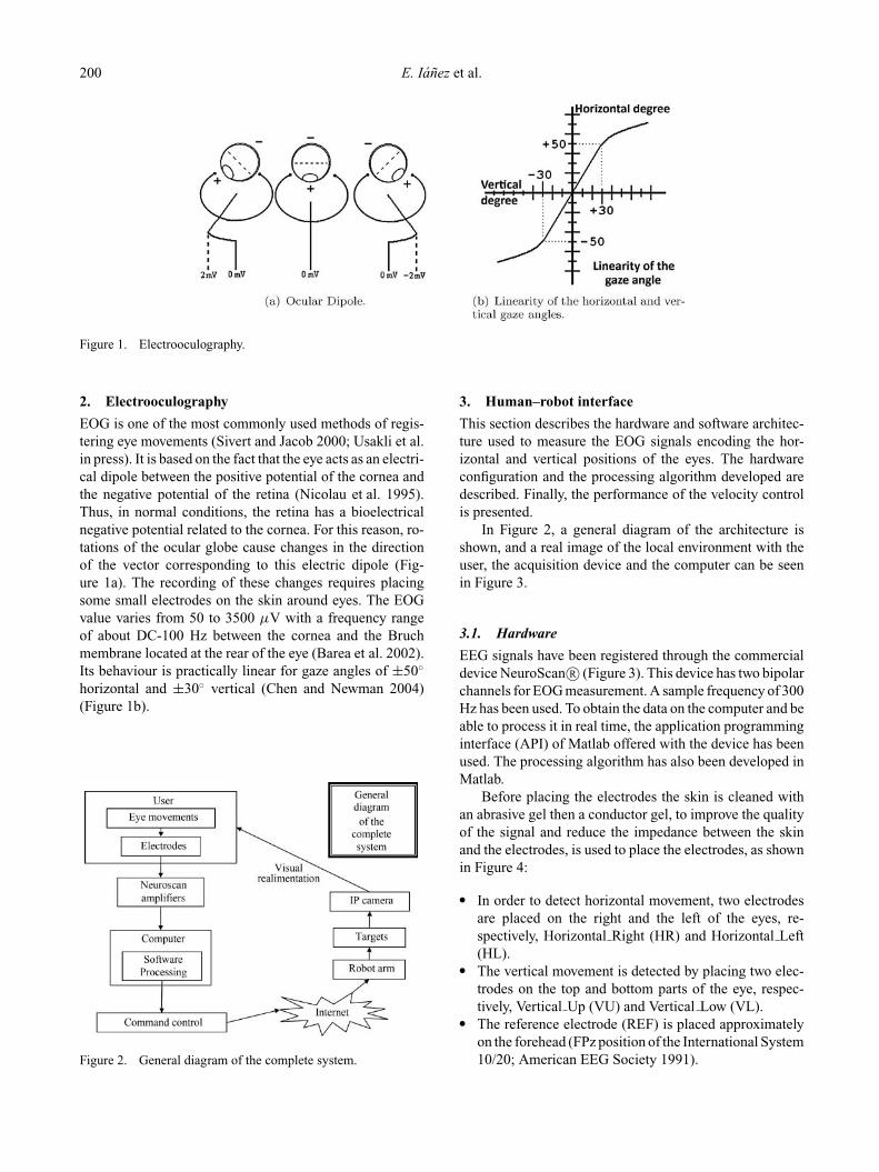
Figure 1. Electrooculography.
2. Electrooculography
EOG is one of the most commonly used methods of regis-tering eye movements (Sivert and Jacob 2000; Usakli et al.in press). It is based on the fact that the eye acts as an electri-cal dipole between the positive potential of the cornea andthe negative potential of the retina (Nicolau et al. 1995).Thus, in normal conditions, the retina has a bioelectricalnegative potential related to the cornea. For this reason, ro-tations of the ocular globe cause changes in the directionof the vector corresponding to this electric dipole (Fig-ure 1a). The recording of these changes requires placingsome small electrodes on the skin around eyes. The EOGvalue varies from 50 to 3500 µV with a frequency rangeof about DC-100 Hz between the cornea and the Bruchmembrane located at the rear of the eye (Barea et al. 2002).Its behaviour is practically linear for gaze angles of ±50◦
horizontal and ±30◦ vertical (Chen and Newman 2004)(Figure 1b).
Figure 2. General diagram of the complete system.
3. Human–robot interface
This section describes the hardware and software architec-ture used to measure the EOG signals encoding the hor-izontal and vertical positions of the eyes. The hardwareconfiguration and the processing algorithm developed aredescribed. Finally, the performance of the velocity controlis presented.
In Figure 2, a general diagram of the architecture isshown, and a real image of the local environment with theuser, the acquisition device and the computer can be seenin Figure 3.
3.1. Hardware
EEG signals have been registered through the commercialdevice NeuroScan R© (Figure 3). This device has two bipolarchannels for EOG measurement. A sample frequency of 300Hz has been used. To obtain the data on the computer and beable to process it in real time, the application programminginterface (API) of Matlab offered with the device has beenused. The processing algorithm has also been developed inMatlab.
Before placing the electrodes the skin is cleaned withan abrasive gel then a conductor gel, to improve the qualityof the signal and reduce the impedance between the skinand the electrodes, is used to place the electrodes, as shownin Figure 4:
� In order to detect horizontal movement, two electrodesare placed on the right and the left of the eyes, re-spectively, Horizontal Right (HR) and Horizontal Left(HL).
� The vertical movement is detected by placing two elec-trodes on the top and bottom parts of the eye, respec-tively, Vertical Up (VU) and Vertical Low (VL).
� The reference electrode (REF) is placed approximatelyon the forehead (FPz position of the International System10/20; American EEG Society 1991).

Applied Bionics and Biomechanics 201
Figure 3. Real image of the local environment with the user, the acquisition hardware and the computer.
3.2. Thresholds
As indicated in Section 1, an application for controllinga robot arm with different velocities has been developed.Therefore, before explaining the processing algorithm it isnecessary to explain the thresholds selected for this pur-pose. Four different thresholds are used:
� The first threshold is used to differentiate a rest state(when the user is looking to the centre) or the noise froma movement; therefore, the output value is zero.
� Every value of the signal between the first and secondthresholds generates an output value of one.
� Every value of the signal between the second and thirdthresholds generates an output value of two.
� And every value of the signal between the third andlast thresholds generates an output value of three. If the
Figure 4. Position of the electrodes on the face around the eyes.Reference electrode (REF), HR (horizontal right) and HL (hor-izontal left) for horizontal movement, VU (vertical up) and VL(vertical low) for vertical movement.
value of the signal is greater than this threshold, a blinkis detected and the blink flag is activated.
The thresholds explained are for one channel and for onedirection. The opposite direction has negative thresholds.Each channel has a total of eight thresholds. An example ofthese thresholds is:
� horizontal thresholds (mV): [−650, −300, −150, −60,50, 105, 230, 650];
� vertical thresholds (mV): [−650, −120, −60, −30, 30,60, 120, 650].
Moreover, thresholds can vary depending on the personand the channel (horizontal and vertical). For example, asthe vertical movement of the eye has a smaller range thevertical thresholds are smaller than the horizontal thresh-olds. As explained in Section 4.2, a function that allowsautomatic calculation of thresholds has been developed.
3.3. Processing algorithm
In previous works a system with an imposed high passfilter of 0.5 Hz was used (Ianez et al. 2008). Because ofthis filter, part of the information of the EOG signal is lost,as it is only able to detect abrupt changes of the gaze. Inthis paper, the signal has been registered from DC, withouta high pass filter, allowing the detection of the degree ofthe gaze. Now, if a user looks in a direction and keeps thegaze, the signal remains stable until the user returns thegaze to the centre. Even so, it is an inconvenience whenprocessing the signal because the signal has a DC level,the baseline, which is not constant over time. This DClevel changes over time due to factors such as the situationof the electrodes, their impedance, or movements of theuser. On that basis, a processing algorithm that is able toestimate the baseline in real time in order to subtract it andgain the original signal, not losing the information aboutthe gaze angle of the user, has been developed.

202 E. Ianez et al.
Figure 5. Processing algorithm.
In Figure 5 a diagram of the processing algorithm and anevolution of the signal in different stages of this processingare shown. The algorithm is explained below.
In the beginning of the test, it is indicated to the userto look at the centre of the screen. These initial instants areused to calculate the baseline factor. Therefore, the first twoseconds of the signal are registered, a low pass filter of 5Hz is applied and the result is averaged. This value is thebaseline factor that is used and updated in the rest of thealgorithm.
Following this, the program starts a loop takingdecisions about the gaze direction and the position of theeye each 0.1 seconds. Even so, an overlap of 1.9 secondshas been taken, giving a signal of 2 seconds to work with.This has been done because filtering only 0.1 seconds (30samples at a frequency sample of 300 Hz) provides onlya few samples and the results obtained for the filtering arenot correct.
The next steps have been applied to each 2 second frag-ment of signal, and each 0.1 second:
� The 2-second signal is filtered with a low pass filter of 5Hz. An example of this signal is shown at top of Figure5(b).
� The last 30 samples (0.1 seconds) are selected.� The baseline factor is subtracted from these samples.
The signal is now centred at zero. The baseline fac-tor is shown at the top of Figure 5(b) and the signalafter subtracting the baseline factor is shown in themiddle.
� The result is averaged and this value is checked with thethresholds explained before.� If the value does not exceed the first threshold, the
user is looking to the centre in a rest position of theeyes, the output is zero.- In this case the baseline factor is updated, because
as it has been indicated before this is not constantin time.
- The loop starts again with the next fragment ofsignal.

Applied Bionics and Biomechanics 203
� If the value does not exceed the first threshold, it ischecked if the value exceeds the last threshold. Inthis case the user has blinked.- The output is zero and the blink flag is activated.- The loop starts again with the next fragment of
signal.� If the value is between the first and the last threshold,
a quantisation of the signal is done as a function ofthe remainder thresholds. An example of a quantisedsignal is shown at the bottom of Figure 5(b) with amark when a blink is detected.- The output is one of the next values: −3, −2, −1,
1, 2 or 3, as a function of the gaze angle and theposition of the eye.
- The loop starts again with the next fragment ofsignal.
The processing is the same for both the horizontal andvertical channels, using the specific thresholds for eachone. The outputs are values between −3 and 3 and a flag toindicate the blink.
In addition, an average of the last three instants of theoutput has been done to avoid possible punctual errors.
3.3.1. Performance of the velocity control
Then, using the output of the processing algorithm, thevelocity control is done. In the initial position, this is in-creased as a function of the output value of the processingalgorithm. For example, if the absolute value of the outputin the horizontal channel is one, an increment of one in thehorizontal position in the direction of the sign is done. If
the output is three, the increment will be three. The incre-ments are in pixels for the user graphical interface and inmillimetres for the robot arm. The graphical interface usedfor the experiments is 360 × 300 pixels and the workspaceused by the robot arm is 360 × 300 mm. The same sizehas been chosen to make the training with the graphicalinterface similar to that of the robot arm for the user.
The same procedure is carried out in the vertical chan-nel, and the combination of both forms a trajectory in thefunction of the gaze direction of the user, with velocity as afunction of the gaze angle. If the user blinks the incrementis zero and a mark is done.
4. Experimental results
In this section, the robot arm used in tests and the softwareto control it are explained. Thereafter, different modes ofa graphical interface designed for training are shown. Sub-sequently, the test protocol is described. Finally, the resultsobtained by training with the graphical interface and therobot arm are described.
4.1. Robot arm
The robot arm FANUC LR Mate 200iB has been used forthe final tests. This robot has six degrees of freedom andcan load up to 5 kg in the end effector. The robot arm isshown in Figure 6. The software used to control the robotarm has been programmed in C++ and it allows us, throughthe libraries of the robot, to make a direct connection withit and send commands with the necessary positions fordrawing the trajectories. The software has been integratedinto Matlab for use in the tests.
Figure 6. Remote environment. Structure with the robot arm FANUC LR Mate 200iB, the IP camera and targets.
204 E. Ianez et al.
The robot arm is installed in a structure (used in thelaboratory for different situations) with a set of illuminators,fixed cameras, and the robot controller (Figure 2). Becausethe robot is not in the same building where the user isperforming the tests, a movable IP camera has been installedallowing us to see it at all times.
Because the detected movements of the eyes can onlybe up/down, left/right and combinations of them, only twodegrees of freedom of the robot have been controlled bythe eye movements. To make the movements of the robotarm, Cartesian coordinates have been used, moving the endeffector of the robot arm in the XY plane and keeping theplane Z and the orientation constant. The range of the robotarm has been limited to a section in the XY plane for safetyreasons. It matches the size of the target paper.
Since the processing algorithm explained in Section 3.3takes decisions each 0.1 seconds, the control program willsend a new command to the robot arm each 0.1 seconds inorder to get a new position. Because the robot takes timein performing a movement and because the commands aresent very quickly (every 0.1 seconds), at specific moments,the robot arm cannot follow all the instructions, generat-ing a delay in the trajectory. On this basis, the time hasbeen included in each instruction of movement. Every timethe robot reads a new instruction of movement, it checksthe time rejecting the command if this time is earlier thana specific value. Although this happens only in concretemoments, it should be taken into account to avoid an accu-mulative delay in the application.
4.2. Graphical interface
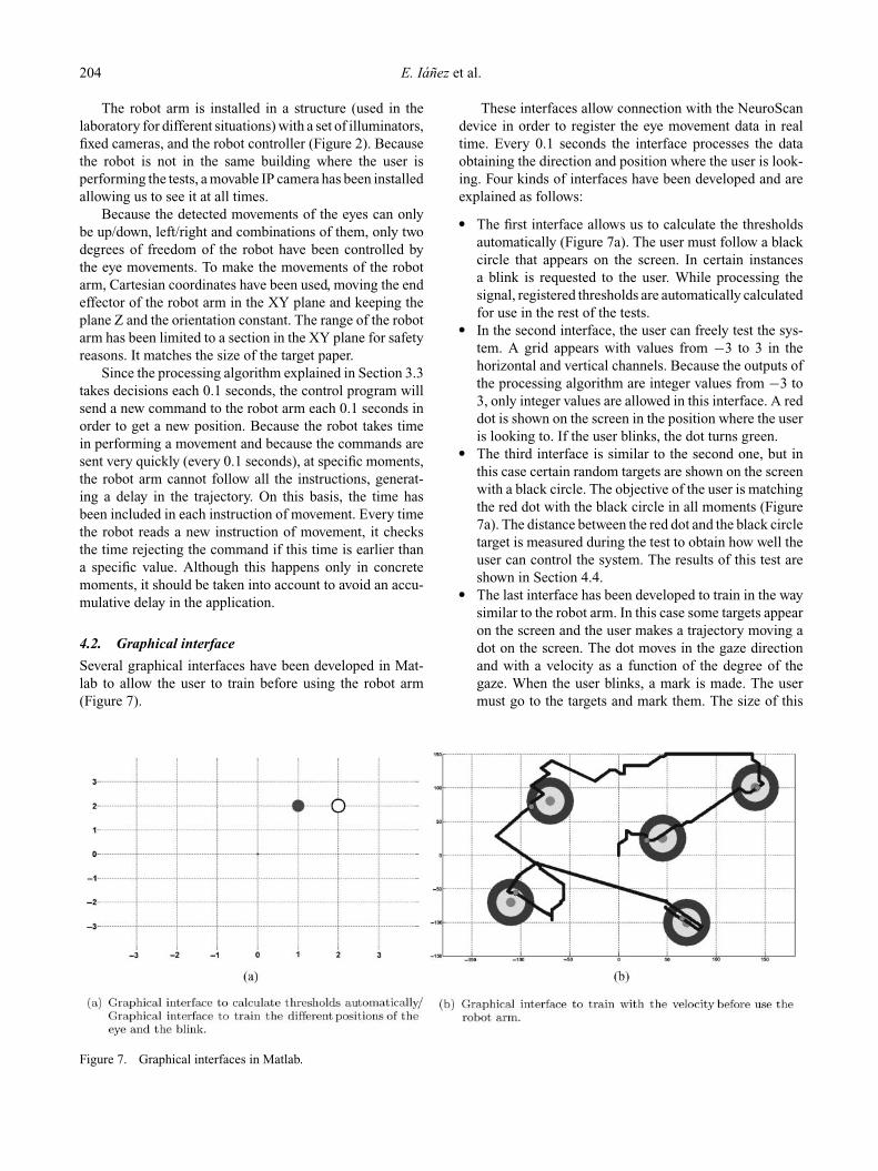
Several graphical interfaces have been developed in Mat-lab to allow the user to train before using the robot arm(Figure 7).
These interfaces allow connection with the NeuroScandevice in order to register the eye movement data in realtime. Every 0.1 seconds the interface processes the dataobtaining the direction and position where the user is look-ing. Four kinds of interfaces have been developed and areexplained as follows:
� The first interface allows us to calculate the thresholdsautomatically (Figure 7a). The user must follow a blackcircle that appears on the screen. In certain instancesa blink is requested to the user. While processing thesignal, registered thresholds are automatically calculatedfor use in the rest of the tests.
� In the second interface, the user can freely test the sys-tem. A grid appears with values from −3 to 3 in thehorizontal and vertical channels. Because the outputs ofthe processing algorithm are integer values from −3 to3, only integer values are allowed in this interface. A reddot is shown on the screen in the position where the useris looking to. If the user blinks, the dot turns green.
� The third interface is similar to the second one, but inthis case certain random targets are shown on the screenwith a black circle. The objective of the user is matchingthe red dot with the black circle in all moments (Figure7a). The distance between the red dot and the black circletarget is measured during the test to obtain how well theuser can control the system. The results of this test areshown in Section 4.4.
� The last interface has been developed to train in the waysimilar to the robot arm. In this case some targets appearon the screen and the user makes a trajectory moving adot on the screen. The dot moves in the gaze directionand with a velocity as a function of the degree of thegaze. When the user blinks, a mark is made. The usermust go to the targets and mark them. The size of this
Figure 7. Graphical interfaces in Matlab.

Applied Bionics and Biomechanics 205
Figure 8. Throughput.
interface is 360 × 300 points. This size has been chosenbecause the workspace of the robot arm is the same,but in millimetres. An example of this interface with atrajectory is shown in Figure 7(b).The last interface has also been used to send appropriatecommand controls to the robot arm when it is activated.However, in this case the user uses the image from theIP camera as visual feedback of the robot arm.
4.3. Tests protocol
If a new user wants to use the system he or she must followthe following phases:
� First, the person must use the application for automaticthreshold calculation in order to establish the thresholdsthat allow detecting the direction of the eyes, the degreeof the gaze, and blinks.
� The second phase is the training of the user and threegraphical interfaces are used:− First, the second interface is used to test thresholds
freely.− Next, the user uses the third interface where the dis-
tances to some random targets are measured.− To finish the training, the user trains with velocity
control in the fourth interface trying to cross thetargets and mark them, performing the movementswith a dot on the screen.
� Finally, the user controls the robot arm in order to marksome targets.
Table 1. Results of the training using the third graphicalinterface in Matlab. The mean ± standard deviation ofthe global, horizontal and vertical Euclidean distance ofthe three users.
Global Horizontal Vertical
User 1 0.23 ± 0.18 0.26 ± 0.22 0.35 ± 0.29User 2 0.21 ± 0.22 0.09 ± 0.17 0.32 ± 0.31User 3 0.28 ± 0.20 0.21 ± 0.23 0.35 ± 0.35
4.4. Results
Different experiments have been performed in order to testthe EOG-based control for the robot arm.
Tables 1 and 2 show the results using the third interfacefor the three users. In each test 10 random targets are shownto the user and the Euclidean distance and the success per-centage of these targets are measured. In Table 1, the meanand standard deviation of the Euclidean distance have beenmeasured independently for both the horizontal and verti-cal channels. The global column indicates the Euclideandistance taking into account both channels simultaneously.The third interface takes into account only the integer val-ues from −3 to 3 for both channels, which are the possibleoutputs for the processing algorithm. In Table 2, the meanand standard deviation of the success percentage have beenmeasured independently for both the horizontal and verticalchannels. The global column indicates the success percent-age taking into account both channels simultaneously. Theresults of the vertical channel are higher than the horizontalchannel. The Euclidean distance is larger and the successpercentage decreases. This is because of the lower range ofthe vertical channel, causing a certain amount of instabilitywhen the user has the eye in a specific position.
The fourth interface has been used to train the user.A comparison between the throughput using the mouseand the EOG velocity control has been done. (Zhang andMacKenzie 2006). In this paper, the throughput is calcu-lated taking into account the distance to the target, time ofarrival and error produced when marked. First, the user
Table 2. Results of the training using the third graphicalinterface in Matlab. Mean ± standard deviation of the global,horizontal and vertical success percentage of the three users.
Global Horizontal Vertical
User 1 88.6 ± 13.1% 95.6 ± 3.0% 90.3 ± 12.8%User 2 85.0 ± 17.5% 98.1 ± 3.7% 85.6 ± 16.7%User 3 83.0 ± 15.1% 95.0 ± 3.9% 85.8 ± 15.3%

206 E. Ianez et al.
Figure 9. Zoom of a trajectory made while marking the targetsand the end effector of the robot arm.
performs the test using the mouse. The user must movethe pointer of the mouse from the centre of the screen to arandom target marking nearest of the centre of the target.The throughput and the standard deviation calculated areshown in Figure 8 (right). Thereafter, the user performs thesame test using the EOG velocity control. The throughputusing EOG is shown in Figure 8 (left). Throughputs arevery different because, first, the EOG velocity control hasa limited velocity. The user can only move 30 pixels withthe maximum velocity while the mouse does not have thislimit. If this limit is eliminated, the results should be moresimilar. Second, the users are people who usually use micein their daily life.
Finally, after completion of the training, the user can usethe robot arm to perform a trajectory in order to cross sometargets and mark them blinking. Figure 9 shows a zoom ofthe piece of paper with the targets. The user is looking atthis image when he or she is controlling the robot arm. Thetrajectory is shown and when the user blinks, an ‘arrow’ ispainted, as shown in the figure. The results have been suc-cessful. The users were able to draw a trajectory and marksome targets while controlling a robot arm with the eyes.
5. Conclusions
In this paper, EOG-based control of a robot arm has beenpresented. Successful results have been obtained control-ling the movement of the robot arm with different velocitiesas a function of the degree and the direction of the positionof the eye.
The users learn how to control gaze direction and theposition of the eye with little training. The users have man-aged to create a trajectory controlling the robot arm andmarking certain targets.
This technology could eventually allow people with se-vere disabilities to control robots only with the movementsof the eyes, which can help them in activities of daily life.
Our future work is focused on detecting with more ac-curacy the degree of the movement of the eyes to performan analogue control of the velocity. In this way, the robotarm could be moved faster according to deviation in thedegree of eyes from the centre position. In addition, theprotocol control of the robot arm will be extended in orderto perform more complex tasks.
AcknowledgementsThis research has been supported by grants DPI2008-06875-C03-03 (Ministerio de Ciencia e Innovacion) and SAF2008-03694 fromthe Spanish Government.
ReferencesAmerican EEG Society. 1991. American Electroencephalographic
Society guidelines for standard electrode position nomencla-ture. J Clin Neurophys. 8(2):200–202.
Barea R, Boquete L, Bergasa LM, Lpez E, Mazo M. 2003. Electro-oculographic guidance of a wheelchair using eye movementscodification. I J Robot Res. 22(7–8):641–652.
Barea R, Boquete L, Mazo M, Lopez E. 2002. Wheelchair guid-ance strategies using EOG. J Intell Robot Syst. 34(3):279–299.
Chen Y, Newman WS. 2004. A human–robot interface basedon electrooculography. In Proceedings of the IEEE Interna-tional Conference on Robotics and Automation, vol. 1, NewOrleans, LA, USA, pp. 243–248. IEEE.
Duguleana M, Mogan G. 2010. Using eye blinking for EOG-basedrobot control. Emerging Trends in Technical Innovation, IFIPAdvances in Information and Communication Technology.Springer Berlin Heidelberg. 314:343–350.
Ho CK, Sasaki M. 2001. Mobile robot control by neural networksEOG gesture recognition. In the 8th International Conferenceon Neural Information Processing, vols. 1–3, pp. 169–175.Shanghai: Fudan University Press.
Hutchinson TE, White KP, Martin WN, Reichert KC, Frey LA.1989. Human–computer interaction using eye-gaze input.IEEE Trans Syst, Man Cybern. 19(2):1527–1534.
Ianez E, Azorın JM, Fernandez E, Morales R. 2008.Electrooculography-based human interface for robot con-trolling. In Proceedings of the 13th Annual Conferenceof the International Functional Electrical Stimulation Soci-ety (IFESS), vol. 53, pp. 305–307. New York: Walter deGruyter.
Ianez E, Azorın JM, Furio MC, Fernandez E, Sabater JM. 2009.EOG and EEG control of robot arms. In IEEE InternationalConference on Robotics and Automation (ICRA 2009). Work-shop on Interfacing the Human and the Robot (IHR). Kobe,Japan, May 12–17.
Iturrate I, Antelis JM, Kubler A, Minguez J. 2009. A noninvasivebrain-actuated wheelchair based on aP300 neurophysiologicalprotocol and automated navigation. Trans Rob. 25(3):614–627.
Jeong Y, Lee D, Kim K, Park J. 2000. A wearable robotic armwith high force-reflection capability. In IEEE InternationalWorkshop on Robot and Human Interactive Communication,Osaka, Japan.
Millan JR, Ferrez PW, Buttfield A. 2005. Non-invasive brain–machine interfaces – Final report. IDIAP Research Institute,ESA.
Millan JR, Renkensb F, Mourinoc J, Gerstnerb W. 2004. Brain-actuated interaction. Artif Intell. 159:241–259.

Applied Bionics and Biomechanics 207
Nicolau MC, Burcet J, Rial RV. 1995. Manual de tecnicas enelectrofisiologıa clınica. Universidad de las Islas Baleares,Palma de Mallorca, Espana, pp. 215.
Oyekoya OK, Stentiford FWM. 2006. Eye tracking: a new inter-face for visual exploration. BT Technol J. 24(3):57–66.
Sankai Y. 2006. Leading edge of cybernics: robot suit HAL. InSICE-ICASE International Joint Conference, Korea, pp. 1–2.
Sibert LE, Jacob RJ. 2000. Evaluation of eye gaze interaction. InProceedings of the SIGCHI Conference on Human Factors inComputing Systems (The Hague, The Netherlands). CHI’00.ACM, pp. 281–288.
Ubeda A, Azorın JM, Ianez E, Sabater JM, 2009. Eye-trackinginterface based on artificial vision for robot. In Proceedings
of The 13th IASTED International Conference on ArtificialIntelligence and Soft Computing. September 7–9, Palma deMallorca, Spain.
Ubeda A, Ianez E, Perez C, Azorın JM. 2010. Haptic and ocularhuman–robot interface. In Proceedings of the IEEE Interna-tional Conference on Robotics and Automation, Workshop onMultimodal Human–Robot Interfaces, pp. 23–27.
Usakli AB, Gurkan S, Aloise F, Vecchiato G, Babiloni F. In press.On the use of electrooculogram for efficient human computerinterfaces. Comput Intell Neurosci.
Zhang X, MacKenzie IS 2007. Evaluating eye tracking with ISO9241 – Part 9. In Proceedings of HCI International. Springer,Heidelberg, pp. 779–788.

International Journal of
AerospaceEngineeringHindawi Publishing Corporationhttp://www.hindawi.com Volume 2010
RoboticsJournal of
Hindawi Publishing Corporationhttp://www.hindawi.com Volume 2014
Hindawi Publishing Corporationhttp://www.hindawi.com Volume 2014
Active and Passive Electronic Components
Control Scienceand Engineering
Journal of
Hindawi Publishing Corporationhttp://www.hindawi.com Volume 2014
International Journal of
RotatingMachinery
Hindawi Publishing Corporationhttp://www.hindawi.com Volume 2014
Hindawi Publishing Corporation http://www.hindawi.com
Journal ofEngineeringVolume 2014
Submit your manuscripts athttp://www.hindawi.com
VLSI Design
Hindawi Publishing Corporationhttp://www.hindawi.com Volume 2014
Hindawi Publishing Corporationhttp://www.hindawi.com Volume 2014
Shock and Vibration
Hindawi Publishing Corporationhttp://www.hindawi.com Volume 2014
Civil EngineeringAdvances in
Acoustics and VibrationAdvances in
Hindawi Publishing Corporationhttp://www.hindawi.com Volume 2014
Hindawi Publishing Corporationhttp://www.hindawi.com Volume 2014
Electrical and Computer Engineering
Journal of
Advances inOptoElectronics
Hindawi Publishing Corporation http://www.hindawi.com
Volume 2014
The Scientific World JournalHindawi Publishing Corporation http://www.hindawi.com Volume 2014
SensorsJournal of
Hindawi Publishing Corporationhttp://www.hindawi.com Volume 2014
Modelling & Simulation in EngineeringHindawi Publishing Corporation http://www.hindawi.com Volume 2014
Hindawi Publishing Corporationhttp://www.hindawi.com Volume 2014
Chemical EngineeringInternational Journal of Antennas and
Propagation
International Journal of
Hindawi Publishing Corporationhttp://www.hindawi.com Volume 2014
Hindawi Publishing Corporationhttp://www.hindawi.com Volume 2014
Navigation and Observation
International Journal of
Hindawi Publishing Corporationhttp://www.hindawi.com Volume 2014
DistributedSensor Networks
International Journal of