interactive illumination with coherent shadow maps
TRANSCRIPT

Eurographics Symposium on Rendering (2007)Jan Kautz and Sumanta Pattanaik (Editors)
Interactive Illumination with Coherent Shadow Maps
Tobias Ritschel1 Thorsten Grosch1 Jan Kautz2 Stefan Müller1
1University of Koblenz-Landau 2University College London
Figure 1: The left image shows a scene with two dragons (280k faces each), where light position, shape and color, as well asobject position, orientation, and all material parameters can be manipulated freely (3.3 FPS). The middle image shows bump,diffuse and specular maps, all with physically plausible shadows (4.6 FPS). In the right image, a fixed local linear light ofarbitrary shape is used (1.8 seconds). All images are rendered with an NVIDIA GF 8 at 1024× 768 pixels.
AbstractWe present a new method for interactive illumination computations based on precomputed visibility using coherentshadow maps (CSMs). It is well-known that visibility queries dominate the cost of physically based rendering.Precomputing all visibility events, for instance in the form of many shadow maps, enables fast queries and allowsfor real-time computation of illumination but requires prohibitive amounts of storage. We propose a losslesscompression scheme for visibility information based on shadow maps that efficiently exploits coherence. Wedemonstrate a Monte Carlo renderer for direct lighting using CSMs that runs entirely on graphics hardware. Wesupport spatially varying BRDFs, normal maps, and environment maps — all with high frequencies, spatial aswell as angular. Multiple dynamic rigid objects can be combined in a scene. As opposed to precomputed radiancetransfer techniques, that assume distant lighting, our method includes distant lighting as well as local area lights ofarbitrary shape, varying intensity, or anisotropic light distribution that can freely vary over time.
Categories and Subject Descriptors (according to ACM CCS): I.3.7 [COMPUTER GRAPHICS]: Three-DimensionalGraphics and Realism; I.3.3 [COMPUTER GRAPHICS]: Color, Shading, Shadowing and Texture
1. Introduction
Physically-based rendering is an important problem in featurefilms, product visualization and many other areas. However,accurate physically-based rendering is expensive, which islargely due to time-consuming visibility tests. In this paper,we develop a data structure, coherent shadow maps (CSMs),that allows fast visibility queries by storing visibility infor-
mation in the form of shadow maps around an object. To thisend, depth maps of an object are created from many differ-ent positions and directions, capturing all geometric details.We introduce a lossless compression method that effectivelycompresses this large collection of depth maps by exploitingcoherence between them. Yet, this compressed data structureallows for fast visibility queries. We demonstrate the effec-
c© The Eurographics Association 2007.

T. Ritschel, T. Grosch, J. Kautz and S. Müller / Interactive Illumination with Coherent Shadow Maps
tiveness of CSMs with an interactive Monte-Carlo rendererthat runs entirely on the GPU. This approach to interactiveillumination removes many drawbacks introduced by alter-native illumination techniques (e.g., precomputed radiancetransfer or soft shadow approximations), as described in thenext section.
Our key contributions are:
• We introduce a novel data structure for fast visibilityqueries based on precomputed depth maps.
• We develop a compression scheme that allows to store thevisibility information from a large collection of depth mapsin a single texture.
• We demonstrate an interactive Monte-Carlo renderer thatenables direct illumination computation on the GPU. Wesupport local and distant lightsources, spatially varyingBRDFs, bump mapping, high-frequency reflections, andmoving rigid objects.
After reviewing previous work in Section 2, we describe ourmethod in Section 3 and give details on the Monte-Carlorenderer in Section 5. Results are presented in Section 6,before we conclude with Section 7.
2. Previous Work
Static Precomputed Radiance Transfer PRT permits therendering of various illumination effects on static objects,such as soft shadows and glossy reflections, in real-time[SKS02,NRH03,LSSS04]. The illumination solution is pa-rameterized by the incident lighting, that is assumed to berepresented by means of basis functions, such as sphericalharmonics [SKS02] or wavelets [NRH03], allowing for effi-cient rendering. PRT exploits the limitation to static objectsby pre-computing all the visibility queries and baking theminto the parameterized solution.
Much work has focused on integrating arbitrary BRDFs[LSSS04,NRH04,WTL06,SM06], bump mapping [Slo06],and enhancing the original low-frequency technique to enableall-frequency lighting [NRH03, NRH04, GKMD06, SM06].Our method seamlessly supports arbitrary BRDFs, bump map-ping, and all-frequency lighting combining the advantages ofa number of previous methods.
Generally, lighting in PRT is assumed to be distant. How-ever, low-frequency localized lighting can be integrated[AKDS04]. When only indirect illumination is considered,local point and spot lights are possible [KAMJ05, KTHS06,HPB06]. In contrast, our technique supports all kinds of inci-dent lighting, including area sources and light field illumina-tion [GGHS03]).
Dynamic Precomputed Radiance Transfer Dynamicscenes are inherently difficult for PRT techniques, since visi-bility cannot be precomputed anymore. Mei et al. [MSW04]precompute visibility on a per-object basis for a discrete set
of directions and store it in the form of uncompressed shadowmaps. This allows them to render multiple rigidly movingobjects under low-frequency distant illumination. However,dynamic local light sources remain infeasible. Similar inspirit, Zhou et al. [ZHL∗05] propose the use of shadow fields,that allow to move individual rigid objects under semi-local(lights may not enter an object’s bounding sphere) or distantillumination, producing correct inter-shadowing. In practice,this technique was limited to low-frequency lighting, as all-frequency lighting updates took several seconds for dynamicscenes.
Related to the previous two techniques, intersection fields[RHCB05] store visibility information along lines in space.For efficiency, shadow computation is separated from illu-mination computation (in the spirit of ambient occlusion),which prohibits the use of large area sources. No compres-sion is used and memory consumption is very high. Sun etal. [SM06] extend wavelet product integrals in order to sep-arate local and global visibility, which also enables rigidlymoving objects. However, interactive updates are limited tofixed view and lighting. In the case of dynamic objects, onlylow-frequency visibility information can be used that has tobe recomputed for every frame.
Our method combines the advantages of previous work.We support all-frequency lighting, dynamically moving rigidobjects, local as well as distant light sources, and dynamicmaterial properties. Nonetheless, the method is fast, supportsprogressive rendering for even faster updates, and is memory-efficient through the use of coherent shadow maps.
Fully dynamic objects are very difficult to handle, as no pre-computation can be employed. Hemispherical rasterization[KLA04] and spherical harmonics exponentiation [RWS∗06]have been proposed for small- or medium-sized scenes un-der low-frequency-illumination. The focus of our work is onhigh-frequency illumination of dynamic, rigid objects.
Shadows Many techniques exist for handling shadows ininteractive applications, including the widely used shadowmap [Wil78] and shadow volume [Cro77] algorithms. Muchwork has been done to extend them to soft shadow generation,e.g. [AAM03, GBP06] to name a few, see [HLHS03] for asurvey. These real-time soft shadow algorithms are generallysuitable for deformable objects. However, they only provideapproximate soft shadows to speed up shadow generation.Furthermore, it is worth noting that none of these methodsprovides accurate integration of BRDF and incident lighting.Instead, it is assumed that the integral of products equals theproduct of integrals.
We use a data structure that is based on shadow maps,but enhance it such that it can be used for physically-basedreal-time rendering. Our representation is suitable only forrigid dynamic objects but does provide accurate illumina-tion computation, including soft shadowing, partial and high-frequency glossy reflections, and so on.
c© The Eurographics Association 2007.

T. Ritschel, T. Grosch, J. Kautz and S. Müller / Interactive Illumination with Coherent Shadow Maps
Direct illumination from environment maps using a smallnumber of uncompressed orthographic shadow maps has beenproposed by Havran et al. [HSK∗05], which forces visibilityinformation to be heavily discretized. A compression schemefor a single shadow map was introduced by Arvo and Hirviko-rpi [AH05]. In contrast to their work, we exploit coherencebetween many shadow maps for compression, not within asingle shadow map.
Monte Carlo We employ Monte Carlo integration [PH04]to accurately compute direct illumination in real-time. Manydifferent strategies exist for enhancing Monte Carlo inte-gration in computer graphics. These strategies, such as ef-ficient sampling for image-based lighting [KK03, ARBJ03,ODJ04, Deb05] or direct sampling of product distributions[VG95, BGH05, TCE05, CJAMJ05, CETC06], are (theoreti-cally) orthogonal to our technique. However, in practice manyof these methods are difficult to use/implement on graphicshardware or require an expensive pre-processing step and aretherefore not used in this work. Of course, we do make useof importance sampling [PH04].
3. Coherent Shadow Maps
In physically-based rendering, most time is spent on visibilityqueries. But in case of rigid objects, the query time can begreatly reduced by precomputing visibility. We seek to effi-ciently store the visibility information around an object in or-der to evaluate the direct lighting equation (integral of BRDF,lighting, and visibility) as quickly as possible. However, thisrequires storing the full field of visibility information, suchthat visibility queries can be performed at every point on theobject and for all possible directions.
This poses two main challenges: First, the memory costfor storing the information at an adequate resolution is pro-hibitive and compression is therefore mandatory. Secondly,discretization introduces aliasing that requires appropriatefiltering.
Central to our approach is a lossless compressed repre-sentation for visibility based on orthographic or perspectivedepth maps. We propose to discretize and sample the visi-bility space by placing a large number of depth maps in thescene, that can be efficiently queried on a GPU at run-time.The depth maps are compressed by exploiting the coherencebetween neighboring depth maps, as we will detail in the nextsubsection (Sec. 3.1).
The actual discretization, i. e., the placement and resolutionof depth maps, depends on the type of supported light sourcesand the minimum size of geometric details, which we explainin Section 4 and 4.4. Fig. 2 shows an example of such adiscretization. This set of depth maps can be used for visibilityqueries, as illustrated in Fig. 6. Aliasing can be reduced usinga generalized percentage-closer filter or Russian Roulette(Sec. 4.5).
Figure 2: Discretization example: An orthographic depthmap is created for N viewing directions (left). All depth mapsare stored in a sequence (right).
3.1. Compression
In the following, we consider a set of N depth maps, eachwith a resolution of M×M pixels. To obtain a high compres-sion rate, a sequence of coherent depth maps is required. Twosuccessive depth maps are coherent, if most pixels containsimilar depth values. Therefore, the first step of our algo-rithm creates a highly coherent permutation of the originaldepth maps. This can be visualized as moving a depth camerathrough a scene, trying to keep the depth images as similaras possible. Different ways to create such a sequence are de-scribed in Section 4.4; for now we assume that the sequencei = 1 . . .N of depth maps is sorted in a coherent order.
In the following, we consider a pixel at a fixed location(x,y) in an arbitrary depth map i. For clarity, we drop the posi-tion index and denote the depth values as z(i) instead of zxy(i).For our compression method, the depth values z1(i) and z2(i)of the first and second intersection point of a ray through x,yare required. As noted by Weiskopf and Ertl [WE03], thedepth comparison works, as long as the depth map contains avalue z ∈ [z1,z2] as shown in Fig. 3. This degree of freedom
z1z2z3z4 zavg
Figure 3: Dual depth values: A standard depth map storesz1, the smallest depth value. An arbitrary value zavg betweenz1 and z2 can be used: The depth comparsion of z1...4 to zavgstill gives the correct result.
is exploited by using an arbitrary depth function z(i) between
c© The Eurographics Association 2007.
T. Ritschel, T. Grosch, J. Kautz and S. Müller / Interactive Illumination with Coherent Shadow Maps
z1(i) and z2(i) that is well suited for compression. A simplechoice are piecewise constant functions (segments). To gen-erate the depth value zavg(0) of the first segment, the largestindex iend is determined, such that
maxz1(1),z1(2), . . . ,z1(iend) <
minz2(1),z2(2), . . . ,z2(iend) . (1)
Intuitively, we are searching for the index iend such that thez1(iend)-value is as large as the minimal z2-value in that range,see Figure 4. Then zavg(0) is set to the average of the min andmax-value, as can be seen in Fig. 4. This process is repeatedfor the following depth values, resulting in n segments. Foreach segment j, the depth value zavg( j) and the end indexiend( j) are stored sequentially in a segment list. In this way,we separate the two curves with a small number of horizontallines. This process is repeated for all pixels of the depth map,resulting in M×M segment lists.
z2(i) zavg(0)
z1(i)
iend(0)
z(i)
i
zavg(1)
zavg(2)
iend(1) iend(2)=N
Figure 4: Depth compression: The lower (green) curveshows a depth pixel z1(i) at a fixed position, depending onthe depth map index i. The upper (red) curve is the depth ofthe second intersection point z2(i). The minimum and max-imum values are denoted with arrows. For a visibility test,the depth values of this pixel can be represented by a list ofonly three segments: (zavg(0), iend(0)),(zavg(1), iend(1)) and(zavg(2), iend(2) = N).
Details on Depth Values There are different ways tochoose zavg. We usually use the depth values of the first andsecond intersection point, as shown in Figure 4. Assuming aclosed two-manifold surface, no correct shadow on the backof an object is required, because the BRDF is zero anywayand the depth values of the first z1 and third z3 intersectionpoint can be used instead. If there is no third intersection,there are two possibilities. One can simply use a large valuefor z3, which allows for better compression as z1 and z3 arefar apart and zavg can be chosen more freely leading to longersegments. However, large z3-values are likely to lead to largezavg depth values, which are problematic for dynamic sceneswith multiple objects (see Section 4.6). In this case other ob-jects might be incorrectly lit. In that case, it is better to use aspherical far plane that clips depth values z3 to the boundingsphere. However, freedom of choosing zavg is reduced here,and compression rates are lower. We use linear depth valuesin all cases [BAS02a].
3.2. Depth Comparison Using CSMs
Using the compressed depth map for visibility testing fromlocation p in a depth map i works like classic shadow map-ping. First, the point p is projected into the coordinate spaceof the i-th depth map by transforming it with the depth mapmatrix Di of depth map i: q = Dip. After perspective division,the local pixel position qxy and the depth value qz of the pointp for depth map i are known. To determine the depth valuezxy stored at position qxy, the segment j that contains i has tobe found:
iend( j−1) < i≤ iend( j).
Because the sequence of iend values is monotonically increas-ing, a binary search to locate segment j in O(logn) is possible.Finally, zxy = zavg( j) is used for a depth comparison with qz.
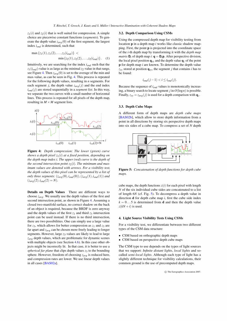
3.3. Depth Cube Maps
A different form of depth maps are depth cube maps[BAS02b], which allow to store depth information from apoint in all directions by storing six perspective depth mapsinto six sides of a cube map. To compress a set of N depth
Figure 5: Concatenation of depth functions for depth cubemaps.
cube maps, the depth functions z(i) for each pixel with lengthN of the six individual cube sides are concatenated to a listof length 6N (cf. Fig. 5). To decompress a depth value indirection d for depth cube map i, first the cube side indexk = 0 . . .5 is determined from d and then the depth valuez(kN + i) is used.
4. Light Source Visibility Tests Using CSMs
For a visibility test, we differentiate between two differenttypes of the CSM data structure:
• CSM based on orthographic depth maps• CSM based on perspective depth cube maps
The CSM type to use depends on the types of light sourcesthat we support: Infinite distant lights, local lights and so-called semi-local lights. Although each type of light has aslightly different technique for visibility calculations, theircommon ground is the use of precomputed depth maps.
c© The Eurographics Association 2007.

T. Ritschel, T. Grosch, J. Kautz and S. Müller / Interactive Illumination with Coherent Shadow Maps
Mapping Function As a general description, each type oflight implements a continuous function D(x) which maps ad-dimensional parameter vector [0 . . .1]d to the location ofa depth map in R4. The number of required dimensions ddepends on the type of light, as described in the followingsubsections. To distinguish between positions and directions,we describe the location of a depth map as (x,y,z,w) ∈R4. Ifw = 0, the depth map of an orthographic camera, looking indirection (x,y,z) is used. If w = 1, the center of the camerais placed at (x,y,z) and a perspective depth cube map isgenerated. A visibility test can now be computed betweenD(x) and arbitrary points p ∈ R3. In most cases, D(x) is apoint on the surface of a light and p is a point on the surfaceof an object. For compression, a discretization D(xi) is usedto generate the N depth maps. All visibility queries selectone of the precomputed depth maps — no depth maps aregenerated during rendering.
4.1. Infinite Distant Lights
The typical application for infinite distant lights is the render-ing with natural light, captured in an environment map, asshown in Fig. 9. Here d = 2 and D is the standard lat-longmapping from spherical coordinates to cartesian directions(w = 0). Visually speaking, an orthographic camera is placedat different locations on the bounding sphere of the object,looking at the center. The extends of the orthographic pro-jection are adjusted to the extend of the bounding sphere.A visibility test between a point p in a direction d can beperformed based on the CSM, as described in Fig. 6. Theartifacts introduced by snapping to a direction D(xi) of thediscretization are discussed in Section 4.5.
p
Depth Map i -1
Depth Map i
Depth Map i +1
zxy
qz
q
Figure 6: Visibility test for infinite distant light: To test if aray, starting from point p in direction d, intersects any object,we first select a precomputed (orthographic) depth map iwith a viewing direction most similar to d. Now we computethe depth map matrix D and project p as q =Dp. The ray isblocked, if qz (the depth of p in view i) is larger than zxy (thedepth value stored in the precomputed depth map).
4.2. Local Lights
Local lights can be placed at arbitrary positions, even close tothe surface of an object. Therefore, depth cube maps are usedto view each part of the object from the light position. Themapping D computes points on the surface (or inside) thelight source (w = 1). The dimension d depends on the shapeof the light source: Linear lights (d = 1), area lights (d = 2)or volumetric lights (d = 3) are possible choices. Local lightscan have an arbitrary shape and radiance distribution buttheir position has to be fixed. However, variation in intensitydistribution can be used to simulate dynamic lights. Similarto distant lights, a visibility test is performed by comparingthe depth value of a point with the depth value stored in adepth cube map, as can be seen in Fig. 7. Fig. 1 shows anexample of illumination from a linear local light.
Semi-local Light 1
p
Local Light
p
Semi-local Light 2
Figure 7: Left: Fixed local light sources. For a set of sam-pling points on the surface of the light, a depth cube map iscreated. Right: Semi-local light sources. To test whether apoint is visible, the orthographic depth map perpendicular tothe light direction is selected.
4.3. Semi-Local Lights
To remove the restriction of a fixed light position, we intro-duce the concept of semi-local light sources. The basic ideafor this type of light is to re-use the information stored in theorthographic depth maps: To test if there is any occluder be-tween a point p and a point l on the light source, we computethe direction vector d = l−p and perform the same visibilitytest as described for infinite distant lights (cf. Fig. 7). There-fore, D and d are identical to infinite distant light sources,but an additional description of the actual shape of the lightis required, as described in Section 5. Semi-local lights canbe placed at arbitrary positions outside the convex hull of theobject, because the CSM contains only the depth informationwhen viewing the object from outside. A light source in theconvex hull would require a depth map generated at the posi-tion of the light source to obtain the depth information insidethe object. Beside this limitation, semi-local lights contain allthe abilities of local lights.
4.4. Enumeration and Discretization
A discretization divides the continuous d-dimensional do-main of D into N = ∏
dk=1 Nk depth map locations. Here, a
c© The Eurographics Association 2007.

T. Ritschel, T. Grosch, J. Kautz and S. Müller / Interactive Illumination with Coherent Shadow Maps
uniform or an adaptive discretization can be chosen. We usea uniform discretization in all our examples. An enumerationis a bijective mapping from this discretization to 1, . . . ,N.The simplest enumeration is scan-line enumeration: First alldepth maps in one dimension are concatenated. Afterwards,the next dimension is added, and so on. To obtain a highcoherence, we use a zig-zag or hilbert space filling curve(cf. Fig. 8). We refer to Section 6 for different compressionrates with different strategies.
Figure 8: The distant Hilbert (left) and zig-zag area (right)curve
4.5. Filtering
Like most sampling-based approaches, shadow mapping suf-fers from aliasing. In our case this results in jagged shadowboundaries when using a low depth map resolution M andbanding artifacts (cf. Fig. 9) when using a small number ofdepth maps N. We propose two different filtering techniquesto reduce the aliasing artifacts that arise from the spatial andangular discretization: Generalized PCF (Percentage CloserFiltering) and Russian Roulette. Generalized PCF selects thenearest 2d depth maps (angularly) and performs four spatialocclusion tests with each, giving 2d+2 depth comparisons.A weighted sum of of each depth comparison’s binary re-sult is computed and returned as the shadow value [RSC87];the weights are based on the fractional error from nearestneighbor sampling. To avoid this time-consuming process,Russian Roulette can be used to randomly select one out of2d+2 possible spatial and angular combinations. The weightscomputed for generalized PCF interpolation serve as proba-bilities for this selection. Russian Roulette filtering convergesto the same result as the d-linear filtering from generalizedPCF, but a visually pleasing result is obtained faster. Fig. 9shows a comparison between the different techniques.
4.6. Extension to Multiple Objects
Although we assume static geometry, multiple moving objectsare possible. To this end, we build one CSM for each object.Objects illuminated by distant or semi-local lights can then bemoved, rotated and scaled freely (Fig. 1). To decide whether apoint p is visible from a semi-local or distant light source, wefirst test if the point is occluded by the object itself. In case ofno occlusion, we inspect the depth maps of the other objects.Fig. 10 shows an example with three objects. To determine
p
A
B
C
Light
qz
zxy
Figure 10: Moving objects: To test if there is any occlusionbetween point p (on object A) and the light source, we firstcompare the depth values of object A. Because there is no self-occlusion, we inspect the depth values of the other objects.For each object, we select the depth map perpendicular to thelight direction and compare the two depth values. Object Bdoes not occlude p because the pixel is outside its depth map.In the depth map of object C, we compute two different depthvalues: Object C occludes p.
the correct depth values, the original depth map matrix D ofthe moving object has to be modified: If the moving objectis transformed by a matrix T, the depth map matrix must bereplaced by D′ = DT−1.
Receiver-Only Objects If an object is only receiving ashadow (like a ground plane, which is not generating ashadow on other objects), no CSM is required for this objectat all. The reason is, that for each pixel of this object, we onlyhave to decide whether it is shadow or not. Therefore, wecompare the depth values of all CSMs with the depth valueof the current pixel (like for moving objects). If the object isplanar (or at least convex), we can ignore self-shadowing ofthe receiving object and omit the CSM. This even allows forshadow-tests for points in a volume.
5. Illumination using CSMs
This section describes the GPU implementation of a MonteCarlo renderer using coherent shadow maps which solves thedirect lighting equation:
L(x,ωo) =∫
Ω
fr(x,ωo,ω)Lin(x,ω)V (x,ω)cos(θ)dω
where fr is the BRDF and Lin is the incoming radiance fromdirection ω . The binary visibility term V can be efficientlyevaluated based on the CSM. Rasterization is done in a con-ventional way, but a Monte Carlo simulation is run for eachpixel in a fragment program. As no interpolation between
c© The Eurographics Association 2007.

T. Ritschel, T. Grosch, J. Kautz and S. Müller / Interactive Illumination with Coherent Shadow Maps
Figure 9: Comparing different filters to reduce aliasing: PCF (3.3 minutes) gives the same quality as Russian Roulette(15.4 seconds) that requires nearly the same time as nearest filtering (11.5 seconds). It shows, that PCF is between 10 and 15times slower, because it always decodes 16 depth values. To exaggerate the effect of aliasing the discretization is set artficiallylow and the number of samples is artficially high in this figure.
Figure 11: Progressive rendering (1024× 768) with a decreasing number of samples per pixel (11.2 s, 1.2 s, 207 ms and 30 ms).
vertices is used, the shading parameters can be adjusted perpixel by a texture and change over time, just as in any otherMonte Carlo renderer. We have successfully used diffuse,specular and normal maps as demonstrated in Fig. 1.
Visibility Queries As described in Section 3, depth valuesare stored in compressed form as segment lists. For each visi-bility test, the segment containing the index i of the selecteddepth map has to be found. The concatenation of all segmentlists is stored sequentially in a texture. To locate the correctentry point for the segment list describing the depth values ofpixel qxy, we use a M×M lookup texture that maps the pixelposition qxy to the starting point of the corresponding seg-ment list. The segment containing i is then found with binarysearch, requiring log(n) texture reads, and some conditionaladds.
To locate the segment containing i in a depth cube mapat direction d requires two steps. First, a cube map of size1×1 is used to map d to an index k = 0 . . .5. Secondly, thesegment containing kN + i is found in the same way as fororthographic depth maps.
Lights In addition to D, each light is defined by two func-tions: A : [0 . . .1]d
′ → R4 describes the surface of the lightsource. For distant and local lights, A is identical to D andd = d′. For semi-local light sources, A is an arbitrary shape
(with arbitrary dimension d′) and D is the standard lat-longmapping. To describe a spatially-varying radiance distribu-tion, a function L : [0 . . .1]d
′ → R3 is used which maps theparameter vector to an RGB-value (Lin). Here, a (video-) en-vironment map with natural lighting, a synthetic sky, or anyother pattern can be used. Both functions may freely varyover time. Additionally, we allow non-uniform emitters, suchas Lambertian or directional emitters. Currently, differentversions of A, D and L are stored in textures with linearfiltering (See Fig. 12).
5.1. Sampling
Importance Sampling We use importance sampling tosolve the direct lighting equation with a set of S incomingdirections ωk, generated from a probability density functionp:
L(x,ωo)≈1S
S
∑k=1
fr(x,ωo,ωk)Lin(x,ωk)V (x,ωk)cos(θk)p(ωk)
Therefore, the inverse cumulative density function (CDF) ofthe incoming radiance P−1
L and the BRDF P−1f are precom-
puted and stored in textures. To generate samples proportionalto a density p, we read the corresponding inverse CDF textureat a uniform random location. For interactive manipulations
c© The Eurographics Association 2007.

T. Ritschel, T. Grosch, J. Kautz and S. Müller / Interactive Illumination with Coherent Shadow Maps
Figure 12: Our implementation uses linear filtering for A,D and L that results in a continuous highlight (Left). A dis-cretization into point lights would result in multiple isolatedhighlights (Right).
of materials, different versions of P−1f for Phong BRDFs
with increasing glossiness are stored. For a Lafortune BRDF,we preintegrate the single lobes and select one of the lobeswith Russian Roulette. Then, the same sampling strategy asdescribed for Phong BRDFs is used. Integrating more sophis-ticated BRDFs would also be possible.
Random Numbers We use a stratified random pattern forsampling. In contrast to more sophisticated patterns [PH04],a stratified pattern benefits from coherent memory access,which is crucial for GPUs and increases performance by asubstantial factor of 1.2 to 1.5. For each pixel, one out of 256different pre-generated two-dimensional patterns of length Sis used. The patterns are stored into a texture of size 256×S.The sampling pattern to use for each pixel depends on thepixel position. To switch the pattern for each frame, it is alsochosen based on another quasi random index, stored in atexture with the same resolution as the framebuffer.
Sampling Distant Illumination For distant illumination,samples can be drawn proportional to fr or to the radiancedistribution Lin stored in the environment map. To reduce theamount of noise, different strategies are applied for diffuseand specular surfaces [PH04]: For diffuse surfaces P−1
L isused while specular surfaces always use P−1
f . If a surfaceis both diffuse and specular, the decision for a diffuse orspecular sample is implemented by Russian Roulette basedon the material roughness kd .
Sampling Local Illumination For local and semi-locallight sources, samples are always drawn proportional to theirradiance distribution L, because samples selected from theBRDF do not hit the light source in most cases.
5.2. Progressive Rendering
Reducing the noise introduced by Monte Carlo rendering isstraightforward: All parameters are kept fixed and the averageof a few successive frames is computed (cf. Fig. 11). There-fore, a number of m frames is rendered and blended together
weighting each frame’s contribution by 1m . This is a clear
advantage over other methods that prevent noise by band-limiting the signals. A user can navigate through the scene ormanipulate it at high interactive rates. After the manipulation,the image converges to an exact solution over time.
6. Results
We demonstrate our approach for different scenes and types oflightsources, as can be seen in the accompanying video. Thesystem used is an Intel Core 2 Duo 6300 with 2 GB RAM andan NVIDIA Geforce 8800. Compression and timing resultsare summarized in Table 1 and Table 2.
Compression Rates As can be seen in Table 1, the compres-sion rate increases with N: It grows roughly with the squareroot of the number of depth maps N. This is, because CSMs’extract’ the relevant depth information from a large num-ber of depth maps. Note, that the visibility information frommore than a million depth maps of the Buddha model (thatrequire several minutes to render) can be squeezed into a sin-gle GPU texture. The average number of segments requiredto compress a depth function z(i) depends on the geometriccomplexity of the object. Objects similar to a sphere (onlyone segment) are well suited, while objects with a strong vari-ation in depth values and thin surfaces (z1 ≈ z2) have smallercompression ratios. As expected, a higher compression isachieved when using the Hilbert enumeration (row three andfour).
Quality When using shadow maps, the most interestingquestion is how the spatial and angular discretization affectsthe image quality (see Fig. 13 and Fig. 14). A finite numberof shadow maps creates banding while a finite resolutionfor each shadow map prevents fine geometric details to castshadows. However, the resulting jagged shadow boundariesand banding artifacts are less visible for realistic natural il-lumination and area light sources than for synthetic pointlights, especially in combination with filtering. Besides fil-tering, the display quality can be improved by using moredepth maps. Due to the good compression behaviour (Table1), large values for N are possible; this only increases the pre-computation time, which grows linear with N. Because ourcompression is based on [WE03], self-shadowing artifactsare mostly removed. However, a depth bias is still requiredfor pixels which start a new segment (z1 = z2).
Several techniques (e.g., [MSW04]) have parameterizedthe visibility function over the surface as a discrete binaryfunction of direction for each vertex. We do not considerthis option, as there is no obvious way to recombine suchrepresentations when multiple occluders are used. Further-more, they require a fine tessellation of all receivers whileour technique does not.
Speed A higher compression ratio also decreases the timefor a visibility query, because fewer operations are required to
c© The Eurographics Association 2007.

T. Ritschel, T. Grosch, J. Kautz and S. Müller / Interactive Illumination with Coherent Shadow Maps
N = 64 × 64N = 128 × 128N = 512 × 512M
= 1
28 ×
128
M =
64
× 64
M =
32
× 32
Number of depth maps More banding →← Less bandingM
ore
feat
ures
→Re
soluti o
n of
dep
th m
aps
← L
ess
feat
ures
Figure 13: Discretization error for converged images. CSMs introduce two forms of discretization: A finite number of shadowmaps creates banding (right, top image) while a finite resolution for each shadow map prevents fine geometric details to castshadows (left, bottom image).
find the location of a segment. However, from our experiencethis has only a small impact on the rendering speed dueto the logarithmic time complexity of the segment search.As can be seen in Table 2, the total rendering time for an1024×768 image with 625 samples is 4.86 s, which meansat least 101.1 M monte carlo samples and (non-coherent)shadow tests per second. This is an order of magnitude fasterthan the number of coherent intersection tests of current raytracing systems for comparable scene complexity [BWSF06].However, our approach is only an approximation due to thediscretization.
7. Conclusions
We have developed a method for fast visibility queries basedon compressed shadow maps. We have proposed to samplevisibility around an object by precomputing a large number
of depth maps in an offline process. The large amount ofmemory that is required for capturing all the visibility detailsis reduced by a new shadow map compression method. Atrun-time, visibility queries are performed by indexing intothe precomputed and compressed depth maps.
This new visibility test is used to perform interactive illumi-nation on the GPU. We have demonstrated that Monte Carlorendering using this visibility test is well-suited for graphicshardware, enabling interactive display of complex local illu-mination effects that were previously impossible. Our illumi-nation method is not band-limited, it converges to the correctsolution when given enough time, and the frame rate doesnot depend on scene complexity. While our method assumesrigid objects with dynamic placement, all light sources andshift-variant BRDFs can be changed on-the-fly with no over-head. Furthermore, we have developed filtering techniques
c© The Eurographics Association 2007.

T. Ritschel, T. Grosch, J. Kautz and S. Müller / Interactive Illumination with Coherent Shadow Maps
Scene Depth Maps (N / total) Uncompressed Compressed Time Ratio
Distant Lat-longBuddha
32×32 1024 32.0 MB 3.0 MB 3 s 10.7 : 1128×128 16384 512.0 MB 18.7 MB 46 s 27.4 : 1512×512 262144 8.1 GB 96.8 MB 744 s 85.3 : 1
1024×1024 1048576 32.7 GB 202.1 MB 2253 s 162.1 : 1
Distant Lat-longXYZ Dragon
32×32 1024 32.0 MB 5.4 MB 5 s 5.0 : 1128×128 16384 512.0 MB 44.2 MB 281 s 11.5 : 1512×512 262144 8.0 GB 242.8 MB 1094 s 33.9 : 1
Distant Lat-longBunny
32×32 1024 32.0 MB 3.9 MB 4 s 8.2 : 1128×128 16384 512.0 MB 19.9 MB 50 s 25.4 : 1512×512 262144 8.0 GB 242.8 MB 844 s 86.2 : 1
Distant Lat-longDragon
32×32 1024 32.0 MB 8.3 MB 3 s 3.9 : 1128×128 16384 512.0 MB 50.0 MB 46 s 10.2 : 1512×512 262144 8.0 GB 249.8 MB 1817 s 32.9 : 1
Local ScanlineDragon
8×8 384 12.0 MB 2.3 MB 3 s 5.2 : 132×32 6144 192.0 MB 13.1 MB 16 s 14.7 : 1
128×128 98304 3.0 GB 63.8 MB 256 s 48.2 : 1256×256 393216 12.2 GB 137.1 MB 1355 s 89.6 : 1
Local HilbertDragon
8×8 384 12.0 MB 1.9 MB 3 s 6.3 : 132×32 6144 192.0 MB 10.0 MB 15 s 19.2 : 1
128×128 98304 3.0 GB 43.0 MB 261 s 71.4 : 1256×256 393216 12.2 GB 90.1 MB 1344 s 136.4 : 1
Local HilbertPlant
32×32 6144 192 MB 4.5 MB 13 s 42 : 164×64 24576 768 MB 8.0 MB 62 s 96 : 1
128×128 98304 3.0 GB 15.6 MB 255 s 170 : 1256×256 393216 12.2 GB 29.4 MB 988 s 418 : 1
Table 1: Compression rates for different objects with shadow map resolution M = 128. For local lights, the total number ofdepth maps is 6N (depth cube maps).
to remove discretization artifacts introduced by the shadowmaps.
There are several directions for future research. Depth mapcompression could be performed on the GPU, possibly evenat near-interactive rates for simple scenes. We would liketo consider global illumination by distributing point-lightsover an object’s surface, which requires to arrange them ina coherent order that is suited for compression. Alternativesearch methods for segment location, e. g., hash tables, are aninteresting avenue of research. Finally, we want to investigateadaptive methods for CSM creation that minimize the numberof required depth maps for a given scene.
Acknowledgments We would like to thank M. Geimer, M. Bie-dermann, R. Trappe and A. Langs for proofreading the paper and S.Pohl for the chair model. The 3D models are courtesy of StanfordUniversity. The light probe images are courtesy of P. Debevec.
References
[AAM03] ASSARSSON U., AKENINE-MÖLLER T.: A Geometry-Based Soft Shadow Volume Algorithm Using Graphics Hardware.
ACM Trans. Graph. 22, 3 (July 2003), 511–520.
[AH05] ARVO J., HIRVIKORPI M.: Compressed Shadow Maps.Vis. Comput. 21, 3 (2005), 125–138.
[AKDS04] ANNEN T., KAUTZ J., DURAND F., SEIDEL H.-P.:Spherical Harmonic Gradients for Mid-Range Illumination. In15th Eurographics Symposium on Rendering (2004), pp. 331–336.
[ARBJ03] AGARWAL S., RAMAMOORTHI R., BELONGIE S.,JENSEN H. W.: Structured Importance Sampling of Environ-ment Maps. ACM Trans. Graph 22, 3 (2003), 605–612.
[BAS02a] BRABEC S., ANNEN T., SEIDEL H.-P.: Practicalshadow mapping. Journal of Graphics Tools 7, 4 (2002), 9–18.
[BAS02b] BRABEC S., ANNEN T., SEIDEL H.-P.: Shadow Map-ping for Hemispherical and Omnidirectional Light Sources. InAdvances in Modelling, Animation and Rendering (ProceedingsComputer Graphics International 2002) (Bradford, UK, 2002),Vince J., Earnshaw R., (Eds.), Springer, pp. 397–408.
[BGH05] BURKE D., GHOSH A., HEIDRICH W.: BidirectionalImportance Sampling for Direct Illumination. In 16th Eurograph-ics Symposium on Rendering (2005), pp. 147–156.
[BWSF06] BENTHIN C., WALD I., SCHERBAUM M., FRIEDRICH
c© The Eurographics Association 2007.

T. Ritschel, T. Grosch, J. Kautz and S. Müller / Interactive Illumination with Coherent Shadow Maps
Figure 14: Comparsion (right) between raytracing (left) and CSMs (middle). The depth map discretization can only approximatea continuous location of sharp features (eg. the cube’s corner) with a discrete location, which results in slightly displacedshadows (red square). The top row uses a distant CSM and the plant a local CSM.
H.: Ray Tracing on the CELL Processor. In IEEE Symposium onInteractive Ray Tracing (2006), pp. 25–23.
[CETC06] CLINE D., EGBERT P. K., TALBOT J. F., CARDON
D. L.: Two Stage Importance Sampling for Direct Lighting. In17th Eurographics Symposium on Rendering (2006), pp. 103–114.
[CJAMJ05] CLARBERG P., JAROSZ W., AKENINE-MÖLLER T.,JENSEN H. W.: Wavelet Importance Sampling: Efficiently Evalu-ating Products of Complex Functions. ACM Trans. Graph. 24, 3(Aug. 2005), 1166–1175.
[Cro77] CROW F.: Shadow Algorithms for Computer Graphics.In Proceedings of ACM SIGGRAPH (July 1977), pp. 242–248.
[Deb05] DEBEVEC P.: A Median Cut Algorithm for Light ProbeSampling. Poster at SIGGRAPH 2005, 2005.
[GBP06] GUENNEBAUD G., BARTHE L., PAULIN M.: Real-timeSoft Shadow Mapping by Backprojection. In 17th EurographicsSymposium on Rendering (2006), pp. 227–234.
[GGHS03] GOESELE M., GRANIER X., HEIDRICH W., SEIDEL
H.-P.: Accurate Light Source Acquisition and Rendering. ACMTrans. Graph. 22, 3 (July 2003), 621–630.
[GKMD06] GREEN P., KAUTZ J., MATUSIK W., DURAND F.:View-dependent precomputed light transport using nonlinear gaus-sian function approximations. In Proceedings of ACM Symposiumin Interactive 3D Graphics and Games (Mar. 2006), pp. 7–14.
[HLHS03] HASENFRATZ J.-M., LAPIERRE M., HOLZSCHUCH
N., SILLION F.: A survey of Real-Time Soft Shadows Algorithms.Computer Graphics Forum 22, 4 (Dec. 2003), 753–774.
[HPB06] HASAN M., PELLACINI F., BALA K.: Direct-to-IndirectTransfer for Cinematic Relighting. ACM Trans. Graph. 25, 3(2006), 1089–1097.
[HSK∗05] HAVRAN V., SMYK M., KRAWCZYK G.,MYSZKOWSKI K., SEIDEL H.-P.: Importance Samplingfor Video Environment Maps. In 16th Eurographics Symposiumon Rendering (Konstanz, Germany, 2005), Bala K., Dutré P.,(Eds.), ACM SIGGRAPH, pp. 31–42.
[KAMJ05] KRISTENSEN A. W., AKENINE-MÖLLER T., JENSEN
H. W.: Precomputed Local Radiance Transfer for Real-TimeLighting Design. ACM Trans. Graph. 24, 3 (2005), 1208–1215.
[KK03] KOLLIG T., KELLER A.: Efficient Illumination by HighDynamic Range Images. In 14th Eurographics Workshop onRendering (Aire-la-Ville, Switzerland, 2003), Eurographics Asso-ciation, pp. 45–50.
[KLA04] KAUTZ J., LEHTINEN J., AILA T.: Hemispherical Ras-terization for Self-Shadowing of Dynamic Objects. In 15th Euro-graphics Symposium on Rendering (June 2004), pp. 179–184.
[KTHS06] KONTKANEN J., TURQUIN E., HOLZSCHUCH N.,SILLION F. X.: Wavelet Radiance Transport for Interactive In-
c© The Eurographics Association 2007.

T. Ritschel, T. Grosch, J. Kautz and S. Müller / Interactive Illumination with Coherent Shadow Maps
Scene Faces Resolution S Time MS / s
Local LinearXYZ Dragon
280k
320×240 16 45.0 ms 27.31024×768 16 170.0 ms 74.21024×768 64 600.0 ms 83.81024×768 625 4860.0 ms 101.1
Distant Lat-longBuddha
80k
1024×768 16 190.0 ms 66.21024×768 64 720.4 ms 69.91024×768 625 6000.0 ms 81.9
Random VisibilityBuddha
80k
1024×768 16 148.0 ms 85.01024×768 625 3707.3 ms 132.5
Coherent VisibilityBuddha
80k
1024×768 16 77.0 ms 163.51024×768 625 261.3 ms 190.4
Table 2: Timings for different scenes. Here N = 1282,M = 128 and a two-lobe Lafortune BRDF with kd = 0.8 is used as inFig. 9. The number of visibility samples per pixel is denoted with S. For random visibility, shadow tests are performed in auniform random direction. For coherent visibility, shadow tests are performed in the same direction for every pixel. The lastcolumn lists million Monte Carlo samples per second.
direct Lighting. In 17th Eurographics Symposium on Rendering(June 2006), pp. 161–172.
[LSSS04] LIU X., SLOAN P.-P., SHUM H.-Y., SNYDER J.: All-Frequency Precomputed Radiance Transfer for Glossy Objects. In15th Eurographics Symposium on Rendering (June 2004), pp. 337–344.
[MSW04] MEI C., SHI J., WU F.: Rendering with SphericalRadiance Transport Maps. Comp. Graph. Forum 23, 3 (2004),281–290.
[NRH03] NG R., RAMAMOORTHI R., HANRAHAN P.: All-Frequency Shadows Using Non-linear Wavelet Lighting Approxi-mation. ACM Trans. Graph. 22, 3 (July 2003), 376–381.
[NRH04] NG R., RAMAMOORTHI R., HANRAHAN P.: TripleProduct Wavelet Integrals for All-Frequency Relighting. ACMTrans. Graph. 23, 3 (Aug. 2004), 477–487.
[ODJ04] OSTROMOUKHOV V., DONOHUE C., JODOIN P.-M.:Fast Hierarchical Importance Sampling with Blue Noise Proper-ties. ACM Trans. Graph 23, 3 (2004), 488–495.
[PH04] PHARR M., HUMPHREYS G.: Physically Based Render-ing : From Theory to Implementation. Morgan Kaufmann, August2004.
[RHCB05] REN Z., HUA W., CHEN L., BAO H.: IntersectionFields for Interactive Global Illumination. The Visual Computer21, 8-10 (2005), 569–578.
[RSC87] REEVES W. T., SALESIN D., COOK R. L.: Render-ing Antialiased Shadows with Depth Maps. Computer Graphics(Proceedings of ACM SIGGRAPH ’87) (1987), 283–291.
[RWS∗06] REN Z., WANG R., SNYDER J., ZHOU K., LIU X.,SUN B., SLOAN P.-P., BAO H., PENG Q., GUO B.: Real-TimeSoft Shadows in Dynamic Scenes using Spherical Harmonic Ex-ponentiation. ACM Trans. Graph. 25, 3 (2006), 977–986.
[SKS02] SLOAN P.-P., KAUTZ J., SNYDER J.: PrecomputedRadiance Transfer for Real-Time Rendering in Dynamic, Low-Frequency Lighting Environments. In Proceedings of ACM SIG-GRAPH (July 2002), pp. 527–536.
[Slo06] SLOAN P.-P.: Normal Mapping for Precomputed RadianceTransfer. In Symposium on Interactive 3D Graphics and Games(2006), pp. 23–26.
[SM06] SUN W., MUKHERJEE A.: Generalized Wavelet ProductIntegral for Rendering Dynamic Glossy Objects. ACM Trans.Graph. 25, 3 (July 2006), 955–966.
[TCE05] TALBOT J., CLINE D., EGBERT P.: Importance Resam-pling for Global Illumination. In 16th Eurographics Symposiumon Rendering (2005), pp. 139–146.
[VG95] VEACH E., GUIBAS L. J.: Optimally Combining Sam-pling Techniques for Monte Carlo Rendering. In Proceedings ofACM SIGGRAPH 95 (Aug. 1995), pp. 419–428.
[WE03] WEISKOPF D., ERTL T.: Shadow Mapping Based onDual Depth Layers. In Eurographics 2003 Short Papers (2003),pp. 53–60.
[Wil78] WILLIAMS L.: Casting Curved Shadows on Curved Sur-faces. In Proceedings of ACM SIGGRAPH (August 1978), pp. 270–274.
[WTL06] WANG R., TRAN J., LUEBKE D.: All-Frequency Re-lighting of Glossy Objects. ACM Trans. Graph. 25, 2 (2006),293–318.
[ZHL∗05] ZHOU K., HU Y., LIN S., GUO B., SHUM H.-Y.: Pre-computed Shadow Fields for Dynamic Scenes. ACM Trans. Graph.24, 3 (2005), 1196–1201.
c© The Eurographics Association 2007.