interactive automated chess set group 4: brett rankin paul conboy samantha lickteig stephen bryant
TRANSCRIPT

Interactive Automated Chess Set
Group 4:Brett RankinPaul ConboySamantha LickteigStephen Bryant
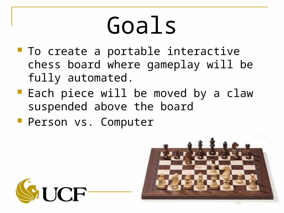
Goals To create a portable interactive chess board
where gameplay will be fully automated. Each piece will be moved by a claw suspended
above the board Person vs. Computer

Specifications 90% chess piece movement accuracy Total weight <100 lbs 12”x12” playing grid

Features and Functions LED lights will be
used to light up the squares on the board RGB, individual
squares, communication with the user(s)

Features and Functions Player modes:
1.) Player vs. Computer
2.) Player vs. Player
3.) Computer vs. Computer

Block Diagram

Physical Chess Table

Mechanical Three Motion Axis One Gripper Sliding A Frame
Structure Overhead Gantry Stability and
Consistent Repeatable Motion Control Needed

Gripper Claw Gripper with Servo Goals Purchase gripper and servo
this was not a design item One Micro Controller I/O
output to command gripper open and closed
Pulse width command signal with a 20 ms period. The pulse on time will very to open and close the gripper.
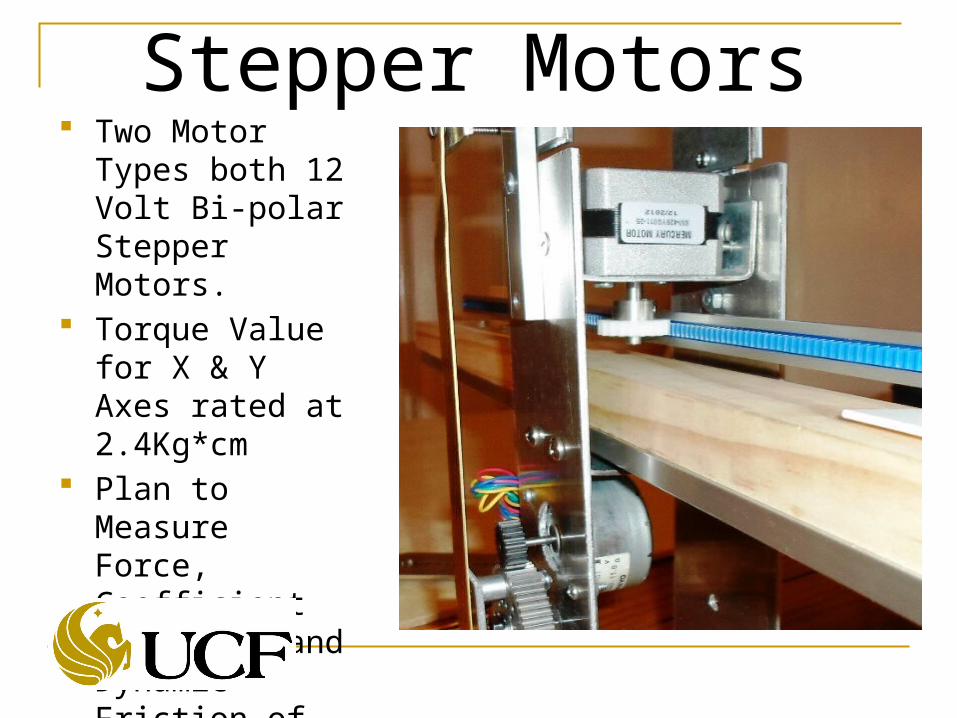
Stepper Motors Two Motor Types
both 12 Volt Bi-polar Stepper Motors.
Torque Value for X & Y Axes rated at 2.4Kg*cm
Plan to Measure Force, Coefficient of Static and Dynamic Friction of our system

Motor Control Design Goals
Single Modular Design for all Three Axes
Easy to bread board Avoid surface mount technology
Must be practical to install heat sink
Minimize micro controller I/O count
Based on proven reference design

Motor Control SchematicL297 L298

Stepper Resolution Each step equals 1.8 degrees of angular
displacement. 200 steps per revolution No feedback needed with stepper motors X and Y axes have the same size gears and
motors, so the scaling is the same Z axis needs one half revolution of the large
gear.1REV = 1.978in 1Step ≈ .01in

Motion Control Circuits X and Y Axes Over travel switches E-Stop Switch X,Y and Z Axes Home Sensors to provide
the micro controller with a starting reference.
Gripper Open and or Closed sensor Home and Gripper position sensors
Digital Discrete Inputs
LED Grid Purpose:
The grid of LEDs have a dual function, to add a lighting aesthetic to the board and visual cues for the player based on what is happening in the game.
The board itself does not have painted on black and white squares, like most chess boards, but rather it has the LEDs under the board turn on or off in a checkerboard pattern to make the distinction between squares.
The visual cues the LEDs give the player is to change color based on whether or not a piece is in danger of being taken, if one of the players are in check, or if a pawn has changed into another piece via the opponent’s side of the board.

LED Grid Parts to use:
MAX7219 8X8 grid LED Driver Plcc6 3 in 1 SMD LED

LED Grid

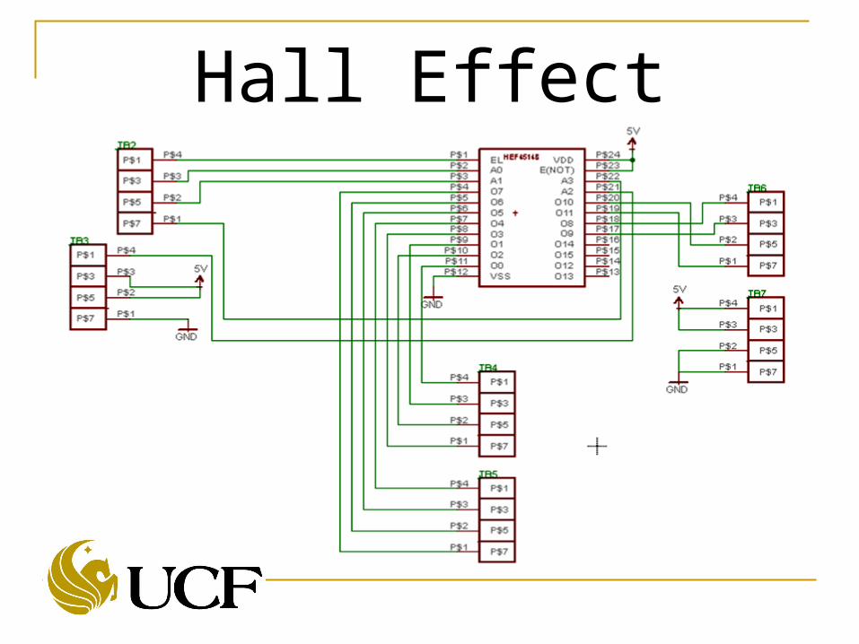
Hall Effect Sensor GridPurpose:
For the microcontroller to understand where the chess pieces are Hall Effect sensors are put under the board and grave yard.
The sensors will read whether or not the chess piece, which has a magnet embedded into it, is on particular squares.

Hall Effect Sensor Grid Parts to use:
4 to 16 Demultiplexer 8 to 1 Multiplexer Uni-polar linear Hall Effect sensors 4 way Discrete Wire-to-Board
surface mounted terminal blocks 1k resistors Schottky Diode

Hall Effect Sensor Grid Specifications:
4 to 16 Demultiplexer(HEF4514):VDD 5VDC
• A0-A3, EL = 5VDC
• O0-O15 5VDC
• E(NOT), VSS= 0V
8 to 1 Multiplexer(74HC151N)o 2.0 VCC,S2-S0 6.0
o 2.0 I0-I7 6.0o E(NOT) = 0V
Uni-polar linear Hall Effect sensors(OH090U):o Vcc , Vout= 5VDCo Magnetic Hysteresis = 10 to 100 Gauss

Hall Effect Sensor Grid Is an Optocoupler Needed?:
4 to 16 Demultiplexer(HEF4514): An optocoupler will be required to communicate with
Microcontroller due to a voltage requirement of the demultiplexer being greater than 3.3VDC.
8 to 1 Multiplexer(74HC151N) Can directly communication with the Microcontroller due to
3.3VDC being within the multiplexer’s operating range.

Hall Effect Sensor Grid

Hall Effect Sensor Grid Hall Effect Sensor Modular Design
Hall Effect Sensor Grid

Hall Effect Sensor Grid

User Interface Displays messages
Prompts the user Informs the user
Will have buttons for input selections
Serial LCD Module 20x4 Blue with White Backlight for Arduino

Microcontroller Requirements
Must run an onboard minimalist chess engine Large development community Easy access to dev tools.
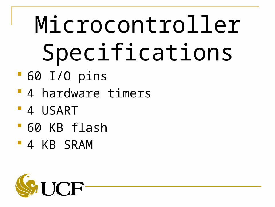
Microcontroller Specifications
60 I/O pins 4 hardware timers 4 USART 60 KB flash 4 KB SRAM

Xmega128A1 8KB SRAM 78 I/O pins 8 UART for Serial 8 Timers for PWM 128KB Flash memory AVRFreaks support community Atmel Tutorials, Atmel software suite

Development Tools A1Xplained Board For testing individual
components Atmel Studio
USB gateway Had to program
using Atmel FLIP No debugging

In System Programming
Ordered an AVR-ISP-MK2
Program in system with PDI
Also has debugging capabilities
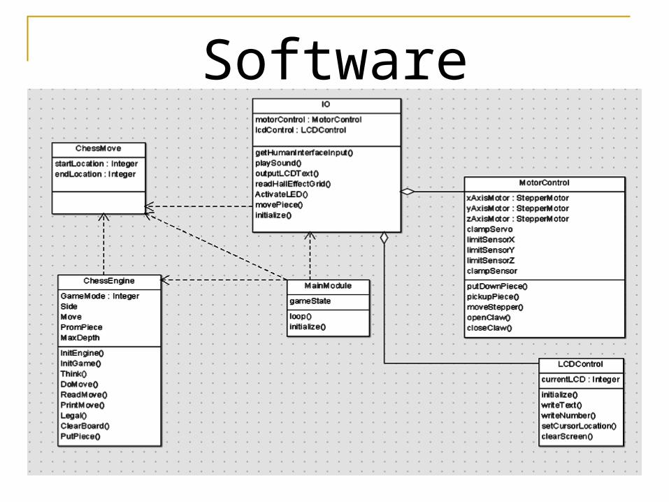
Software
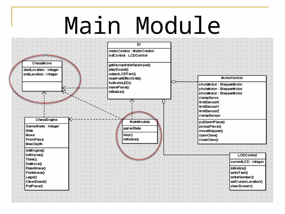
Main Module

Main Module Use only high level
method calls Describes high level
gameplay process Orchestrates
interaction between I/O and Engine
Translates “moves” between chess engine and I/O module representations

Chess Module

Chess Module Contains internal state of
chess game Accepts player moves and
creates AI moves Should use < 4 KB RAM Micro-Max open source
chess engine Smallest chess engine in the
world Our goal was not to
understand, but to interface.

I/O Module

I/O Module Contains functions to interface with
individual I/O devices Exposes high level interface to main
module

Motor Controller All motor I/O
functions grouped together
High level interface including “move piece”

Software Progress Programed A1Xplained over USB Created scaffolding for whole project Ported and created interface to chess
engine Have claw servo working We have single stepper motor to move Created test suite for individual
component testing Got LCDs working with Arduino

Anticipated Problems Motor controller
Currently runs with 1 of 4 wires disconnected
Changing I/O configurations as we go Repeatability Integration issues
Actually putting everything on the board

Test Plan We have
developed a written test plan Acceptance Test
Plan (ATP) where the Acceptance Test Results (ATR) are the final test results
Item # Passed Test Description
4.2.1.1
Connect an Ohm meter across the 12 VDC power and the 12 VMC terminals. Push down and pull up on the E-Stop switch, and activate by hand each of the over travel limit switches one at a time. Each time the circuit is interrupted verify the results match what is shown on the meter display.
4.2.1.2
Use the I/O List in Section 6.4 of the Appendix as a check list to complete this portion of the I/O Check out. This test MUST be conducted with the machine fully de-energized. Ohm out every circuit from the field device to the microcontroller pin. All circuits must have a resistance reading of less than 3 Ohms.
4.2.1.3
Use the I/O List in Section 6.4 of the Appendix as a check list to complete this portion of the I/O Check out. This test will be conducted with the circuit energized. Care must be taken with meter lead placement. Failure to correctly place the meter lead on the correct terminal without contacting other energized circuits could result in equipment damage. Reference the Type and Configuration columns on the I/O List. If the type is output the measurements will be made on the field device. If the type is input the measurement will be made at the microcontroller board input pin. If the configuration is sinking the positive voltmeter lead will be connected to 5 VCC. If the configuration is scouring the negative voltmeter lead will be connected to DC Common. If the signal is an output force the output on and off and measure the voltage. If the signal is an input toggle the field device while measuring the voltage. Verify each signal is working correctly.

Budget to DateIdem Idem # Where is it used? # Bought Price Per Unit Shipping Total Price
Bipolar Stepper Motor SF-ROB-09238 Claw 2 14.95$ 7.99$ 37.89$
Standard Hobby Servo
HT-33322S Claw 1 9.99$ -$ 9.99$
Gear A1M12MYHF102000 Claw 1 41.36$ 9.52$ 50.88$ Gear A1A12MHR101000 Claw 1 15.23$ 9.52$ 24.75$ Gear S10Z10M020T0505 Claw 2 16.75$ 9.52$ 43.02$
1:16 Demux HEF4514B Hall Effect Sensors 2 0.48$ 0.97$ 8:1 Mux 74HC151 Hall Effect Sensors 2 0.16$ 0.33$
Uni-Polar Hall Effect sensor
OH090U Hall Effect Sensors 3 1.99$ 5.97$
AVR Programmer AVR-ISP-MK2 1 38.04$ -$ 38.04$
Serial LCD Module 20x4 Blue with White Backlight for Arduino
HMI 1 24.95$ 5.21$ 30.16$
10uF Capacitor UVR1H100MDD 12 0.04$ 2.25$ 2.72$ 100nF Capacitor NCD103M100Z5UF 12 0.08$ 2.25$ 3.15$
LED Driver Maxim MAX7219
MAX7219CNG+ 6 9.62$ 7.86$ 65.58$
9.53 Kilohm resitor GP50-9531-FTW 10 0.005$ 7.86$ 7.91$ RGB LED VAOS-5050RGB-W1 1 2.03$ 7.86$ 9.89$
Switch NO, through hole, TH
TL1105AF250Q 12 0.2251$ 2.25$ 4.95$
4.7k resistors CSC10A014K70GEK 1 0.17$ 2.25$ 2.42$ Line Priority Encoder M74HC148B1R 4 0.57$ 5.99 8.27$

Sponsors Igus Allied Electronics

$346.90
Total Spent to Date

Total Progress
Hall Effect
LED Grid
Mechanical Assmbly
Motor Control
MCU Design
Software
HMI
0% 20% 40% 60% 80% 100%
CompletedIn Progress