inter partes reviews (“ipr’s”)nationaldocketing.org/resources/documents/2014... · inter...
TRANSCRIPT

Introduction to DocketingInter Partes Reviews(“IPR’s”)
Ashley CampbellU.S. Filing SpecialistMorrison & Foerster LLP

Agenda
• Inter Partes Review Basics
• Trial Timeline and Docketing
• Exemplar Documents
• Brief PRPS overview
2

Inter Partes Review Basics
3
Post Grant Proceedings
• Inter Partes Review • Post Grant Review• Covered Business Method
4

Key Terms• Inter Partes Review (IPR): ▫ Introduced by AIA on September 16, 2012▫ Procedure to challenge the validity of patent claims
• Parties▫ Petitioner / Patent Owner
• Patent Trial and Appeal Board (PTAB):▫ Governing body of trial process
• Patent Review Processing System (PRPS): ▫ The Board’s e-filing and case management system
(like PACER)
5

Inter Partes Review (IPR) • Intended to be quicker, more efficient, and less
expensive for post-grant patent challenges:• Faster to decide▫ Initial determination of specific grounds within 6
months from date of filing▫ Final decision within 12 months after institution (up to
18 for good cause)• Faster to appeal▫ Appealable to the Federal Circuit
6

Litigation-like Benefits
• “Real-time” interaction with Board during proceeding
• Limited Discovery (pros and cons)• Claim Construction• Depositions • Evidence objections / oppositions• Motions• Oral hearing
7

Trial Timeline and Docketing
8

Exemplar Trial Timeline (Overview)
9

Preliminary Stage
• Filing the Petition• Notice According Filing Date• Defects• Patent Owner Mandatory
Notices• Patent Owner Preliminary
Response• Awaiting Decision on
Petition
10

Notice of Filing DateNote: these have been arriving late (after 21 day due date
below)
Awaiting Notice of Filing Date
Notice of Filing DateIdentifying Defects
Petition
Response to Notice of Defects*5 days*
Patent Owner Mandatory Notices*21 Days from
Petition*
PO Preliminary Response (optional)*3 months from
Notice*
Preliminary Stage
Awaiting PTAB Decision on Petition
*6 Months from Notice*
11

Trial Stage (Instituted)
• Decision to Institute Trial for Inter Partes Review ▫ officially starts the Trial
• Board must complete within 3 months from the date of Patent Owner’s Preliminary Response
• Scheduling Order• Oral Hearing• Final Written Decision
12

Decision on Petition
Trial NOT Instituted
Request for RehearingRe Trial Institution
*30 days*
37 CFR 42.71(d)(2)
Trial Instituted
Conference Call (see Decision)
List of Motions 2 days prior to call
Objection to Evidence 10 business days from Decision
Request for Rehearing for any denied grounds
14 days from Decision
Motion to Submit Supplemental Information
1 month from Decision
Demonstrative Exhibits to be served
5 business days prior to hearing
Demonstrative Exhibits to be filed ‐ no later than day of hearing per CFR 42.70(b)
2 business days(best practice)
prior to hearing
Scheduling Order
Trial Stage
Joint Motion to Terminate Proceedings Judgment
Final Decision on Petition 13

Exemplar Documents
14

The Petition1
“Petition for Inter Partes Review”
• First filing• Begins the review process• Power of Attorney required• Must be filed within one year of the third party
being served with an infringement complaint by the patentee▫ Calendar date
15

Petition for Inter Partes Review
16

Notice According Filing Date andTime for Filing Patent Owner Preliminary Response 2
• Accords filing date • Assigns judge to manage proceeding• Addresses any defects or missing information• If there are defects:▫ Will accord filing date, but require an amended petition within 5
business days ▫ Will not accord filing date
17

Exemplar Notice (front page)
18

Exemplar Notice (page 2)
19

Exemplar Notice (last page)
20

Notice Identifying Defects 3
21

Notice Identifying Defects (c’d)
22

Patent Owner (PO) Mandatory Notices 4
• Due 21 days from the filing of the Petition• The Patent Owner’s first filing• Mandatory Notices (usually one document):▫ Real party of interest▫ Related matters▫ Lead and backup counsel
• Power of Attorney
23

Patent Owner (PO) Mandatory Notices
24

Patent Owner (PO) Mandatory Notices
25

Patent Owner (PO) Mandatory Notices
26

Preliminary Patent Owner Response(optional)• Due 3 months from date of Notice According
Filing Date• Patent Owner may also file an election to waive
the preliminary response in order to expedite the proceeding
• Or they can take no action at all
27

Decision to Institute Trial for Inter Partes Review 5
• Board must complete within 3 months from the date of Patent Owner’s Preliminary Response
• This officially starts the trial• Schedules the initial conference call for all parties▫ Both parties must submit a List of Motions two days prior
to the call• Additionally, Petitioner may file a Request for Rehearing
within 14 days of Decision for any grounds that were denied
• If Petition is not instituted, Petitioner has 30 days to file a Request for Rehearing on all grounds
28

Decision (front page)
29

Decision (some grounds denied)Petitioner has 14 days from date of Decision to file Request for Rehearing on denied grounds – 37 CFR 42.71(d)
30

Decision (Orders / Conference Call)
31

Scheduling Order 6(accompanies Decision)
• Sets forth 7 dates1. PO post-institution response to petition and motion to amend (default
4 months)2. Petitioner reply to PO response and opposition to amendment (default
2 months)3. PO reply to petitioner opposition (default 1 month)4. Petitioner motion for observation re cross-examination of reply
witness, motion to exclude evidence, request for oral argument (default 3 weeks)
5. PO response to observation, opposition to motion to exclude (default 2 weeks)
6. Reply to opposition to motion to exclude (default 1 week)7. Oral argument (set upon request)
32

Exemplar Scheduling Order (front page)
33

Exemplar Scheduling Order (Due Date Appendix)
34

Discovery, Motions, etc.(additional due dates will be listed in subsequent orders)
35

Evidence – Trial StageTrial Evidence / Exhibits(Declarations, Affidavits, Deposition Transcripts,
etc.)
37 CFR 42.63
Objection*5 business days from
date of service*
37 CFR 42.64(b)(1)
Response to Objection*10 business days from
Objection*
37 CFR 42.64(b)(2)
36

Motions– Trial Stage
Trial Motion(not listed in scheduling
order)
Opposition*1 month from date of
service*
37 CFR 42.25(a)
Reply to Opposition*1 month from Opposition*
37 CFR 42.25(a)
37

PTAB Decisions – Trial Stage
Trial PTAB Decision(any decision other than
“final”)
Request for Rehearing*14 days from date of
Decision*
42.71(d)(1)
38

Final PTAB Decision – Trial Stage
Final PTAB Decision
Request for Rehearing*30 days from date of
Decision*
42.71(d)(2)
39
Appeal to CAFC*63 days from date of
Decision*

How does it all end?
40

Final Decision
• Issued not more than 1 year from institution of trial
• Potentially closes case• Parties have 30 days to file Request for
Rehearing (to PTAB)• Parties have 63 days to file an Appeal (to the
CAFC)
41

Joint Motion to Terminate Proceedings
• Closes case• Most likely, the parties have entered a
settlement agreement
42

Judgment Request for Adverse Judgment• Closes case• Patent owner agrees to disclaim the claims at
issue
43

PRPS
• The Board’s e-filing and case management system (like PACER)
• http://www.uspto.gov/ip/boards/bpai/prps.jsp
44

Direct Link
45

Search by Case Number
46

Select Case
47

Review Documents• Sort by Filing Date or Paper Number from Notice• View Document• Open and docket accordingly
48

Resources• PTAB▫ http://www.uspto.gov/ip/boards/bpai/prps.jsp
• Quick Start Guide▫ http://www.uspto.gov/ip/boards/bpai/quick_start_g
uide_(03.08.13).pdf• Board Trial Rules and Practice Guide▫ http://www.uspto.gov/ip/boards/bpai/board_trial_r
ules_and_practice_guide.jsp
49

Questions?
50

i la-1212389
Patent No. 8,156,944
Petition For Inter Partes Review
UNITED STATES PATENT AND TRADEMARK OFFICE _______________
BEFORE THE PATENT TRIAL AND APPEAL BOARD _____________
CB Distributors, Inc. and DR Distributors, LLC,
Petitioners
v.
Ruyan Investment (Holdings) Limited,
Patent Owner
Patent No. 8,156,944
Issue Date: April 17, 2012
Title: AEROSOL ELECTRONIC CIGARETTE
_______________
Inter Partes Review No. ______
____________________________________________________________
PETITION FOR INTER PARTES REVIEW
UNDER 35 U.S.C. §§ 311-319 AND 37 C.F.R. § 42.100 et seq.

TABLE OF CONTENTS
Page
ii la-1212389
I. NOTICES AND STATEMENTS ................................................................... 1
II. INTRODUCTION .......................................................................................... 3
III. THE ’944 PATENT ........................................................................................ 4
A. Background .......................................................................................... 4
B. Prosecution History .............................................................................. 7
1. Preliminary Amendments .......................................................................... 7
2. First Office Action and Response .............................................................. 8
3. Second Office Action, Response, and Allowance ..................................... 8
C. Related Inter Partes Reexamination .................................................... 9
1. Request For Reexamination And Office Action ........................................ 9
IV. DETAILED EXPLANATION OF GROUNDS FOR INVALIDITY ......... 11
A. Statutory Grounds For The Challenge Of Each Claim ...................... 11
B. Claim Construction............................................................................. 12
1. Broadest Reasonable Construction .......................................................... 12
2. Run-through Atomizing Chamber ........................................................... 12
C. Ground 1 – Anticipation of claims 1, 2, 5-8, 10, 33, and 35, 37,
and 38 By Liu ..................................................................................... 18
D. Ground 2 – Obviousness of Claim 20 Based on Liu .......................... 29
E. Ground 3 – Obviousness of Claims 3, 4, 12, 15, 17, and 26
Based On Liu In View Of Susa .......................................................... 30
F. Ground 4 – Obviousness of Claims 1-4, 8-12, 15-26, 33-34, 36,
and 38 Based on Hon ’494 In View of Liu ........................................ 36
G. Ground 5 – Obviousness of Claims 39-41 Based On Hon ’494
In View of Liu and Susa ..................................................................... 47
V. CONCLUSION ............................................................................................. 54

iii la-1212389
Exhibit List for Inter Partes Review of U.S. Patent No. 8,156,944
Exhibit Description Exhibit #
U.S. Patent No. 8,156,944 to Han 1001
Request for Certificate of Correction dated June 11, 2012 1002
WO 2007/131449 A1 to Hon 1003
CN Patent No. 2719043 1004
CN Patent Application No. 200620090805 1005
Certified English Translation of CN Patent Application No.
200620090805 dated October 6, 2011
1006
WO 2004/095955 A1 to Hon 1007
WO 2005/099494 A1 to Hon 1008
Certified English Translation of WO 2005/099494 A1 to Hon dated
June 17, 2013
1009
Office Action dated February 2, 2011 1010
Response to Office Action dated February 22, 2011 1011
Office Action dated April 12, 2011 1012
Response to Office Action dated October 12, 2011 1013
Inter Partes Reexamination Request dated September 13, 2012 1014
Order Granting Reexamination dated November 27, 2012 1015

iv la-1212389
Office Action dated November 27, 2012 1016
Response to Office Action dated January 28, 2013 1017
Third Party Response dated February 27, 2013 1018
WO 2007/078273 A1 to Liu 1019
EP 0845220 A1 to Susa et al. 1020

1 la-1212389
Petitioners CB Distributors, Inc. and DR Distributors, LLC (“Petitioners”)
respectfully petition for inter partes review of claims 1-12, 15-26, and 33-41 of
U.S. Patent No. 8,156,944 (“the ’944 patent” (Ex. 1001)) in accordance with
35 U.S.C. §§ 311-319 and 37 C.F.R. § 42.100 et seq.
I. NOTICES AND STATEMENTS
Pursuant to 37 C.F.R. § 42.8(b)(1), Petitioners identify CB Distributors, Inc.
and DR Distributors, LLC as the real parties-in-interest.
Pursuant to 37 C.F.R. § 42.8(b)(2), Petitioners identify the following related
inter partes reexamination and litigation involving the ’944 patent.
On September 13, 2012, a Request for Inter Partes Reexamination of the
’944 patent was filed by Fin Branding Group, LLC (“Fin”). On November 27,
2012, the PTO granted the Inter Partes Reexamination Request (Control No.
95/002,235) and issued an Office Action. The patent owner filed a Response to the
Office Action on January 28, 2013 and filed a Supplemental Amendment on
February 5, 2013. On February 27, 2013, Fin filed a Third Party Response. The
Inter Partes Reexamination is discussed in more detail in Section III, Part C,
below.
On June 22, 2012, Ruyan Investment (Holdings) Limited filed nine lawsuits
in the Central District of California asserting infringement of the ’944 patent:
Ruyan Investment (Holdings) Limited v. Sottera, Inc., No. CV12-5454; Ruyan

2 la-1212389
Investment (Holdings) Limited v. LOEC, Inc., No. CV12-5455; Ruyan Investment
(Holdings) Limited v. CB Distributors, Inc. and DR Distributors, LLC, No. CV12-
5456; Ruyan Investment (Holdings) Limited v. The Safe Cig, LLC, No. CV12-5462;
Ruyan Investment (Holdings) Limited v. Vapor Corp., No. CV12-5466; Ruyan
Investment (Holdings) Limited v. Fin Branding Group, LLC, No. CV12-5468;
Ruyan Investment (Holdings) Limited v. Barjan LLC, No. CV12-5470; Ruyan
Investment (Holdings) Limited v. Spark Industries, LLC, No. CV12-5471; Ruyan
Investment (Holdings) Limited v. Nicotek LLC, No. CV12-5477; Ruyan Investment
(Holdings) Limited v. Logic Technology Development LLC, No. CV12-5482.
All cases were consolidated for pre-trial purposes as Ruyan Investment
(Holdings) Limited v. Sottera, Inc., No. CV12-5454 on December 19, 2012. On
February 25, 2013 the Court stayed all proceedings in light of the inter partes
reexamination requested by Fin.
Pursuant to 37 C.F.R. § 42.8(b)(3), Petitioners identify the following counsel
and a power of attorney accompanies this Petition.
Lead Counsel Backup Counsel
David L. Fehrman
Registration No.: 28,600
MORRISON & FOERSTER LLP
707 Wilshire Blvd.
Mehran Arjomand
Registration No.: 48,231
MORRISON & FOERSTER LLP
707 Wilshire Blvd.
3 la-1212389
Los Angeles, California 90017-3543
Tel: (213) 892-5601
Fax: (213) 892-5454
Los Angeles, California 90017
Tel: (213) 892-5630
Fax: (323) 210-1329
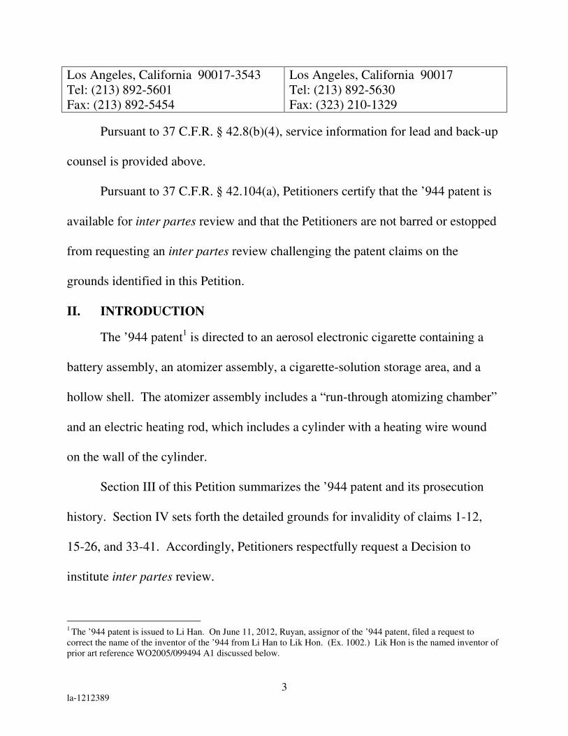
Pursuant to 37 C.F.R. § 42.8(b)(4), service information for lead and back-up
counsel is provided above.
Pursuant to 37 C.F.R. § 42.104(a), Petitioners certify that the ’944 patent is
available for inter partes review and that the Petitioners are not barred or estopped
from requesting an inter partes review challenging the patent claims on the
grounds identified in this Petition.
II. INTRODUCTION
The ’944 patent1 is directed to an aerosol electronic cigarette containing a
battery assembly, an atomizer assembly, a cigarette-solution storage area, and a
hollow shell. The atomizer assembly includes a “run-through atomizing chamber”
and an electric heating rod, which includes a cylinder with a heating wire wound
on the wall of the cylinder.
Section III of this Petition summarizes the ’944 patent and its prosecution
history. Section IV sets forth the detailed grounds for invalidity of claims 1-12,
15-26, and 33-41. Accordingly, Petitioners respectfully request a Decision to
institute inter partes review.
1 The ’944 patent is issued to Li Han. On June 11, 2012, Ruyan, assignor of the ’944 patent, filed a request to
correct the name of the inventor of the ’944 from Li Han to Lik Hon. (Ex. 1002.) Lik Hon is the named inventor of
prior art reference WO2005/099494 A1 discussed below.

4 la-1212389
III. THE ’944 PATENT
A. Background
As noted above, the ’944 patent is directed to an aerosol electronic cigarette.
In an embodiment shown in Figures 1 and 22 above, the aerosol electronic cigarette
comprises a hollow shell (a), containing a battery assembly and an atomizer
assembly. A removable cigarette bottle assembly in a hollow cigarette holder shell
and mouthpiece (b) can be inserted into hollow shell (a) to fit into the atomizer
assembly. (Col. 2, ll. 1-2; col. 6, 56-58.) The atomizer assembly includes a porous
2 The drawings from the corresponding published PCT application WO2007/131449 A1 (Ex. 1003) are substituted
in place of the illegible drawings from the ’944 patent.

5 la-1212389
component and a heating rod. Several different atomizer assemblies are disclosed.
One embodiment of the atomizer is shown in Figures 5- 8, reproduced below.
The porous component 81 has a “run-through” atomizing chamber 811 and a
half sphere protuberance 812 at its exit end, which fits into the cigarette bottle
assembly. (Col. 6, ll. 13-34.) The heating rod 82 includes a cylinder 821 with a
heating wire 822 wound on the wall of cylinder 821. The rod extends along the
length of the atomizing chamber 811, as shown in Figures 7 and 8.
The diameter of heating rod 82 is less than the diameter of atomizing
chamber 811, creating a clearance between the heating rod and atomizing chamber,
thus forming a negative pressure cavity 83. (Col. 6, ll. 37-42.) A run-through hole
813 formed in the protruding half sphere 812 is indicated as connecting to the run-

6 la-1212389
through atomizing chamber 811. (Col. 6, ll. 23-28.) However, the precise location
and extent of such hole is unclear, as it is depicted differently in each of Figures 5
and 8. The specification indicates that when the smoker inhales, the cavity of the
cigarette holder shell is in a negative pressure state. (Col. 7, ll. 8-9.)
A second embodiment is shown in Figures 13-16 and includes a similar
structure of a heating rod extending along the length of the run-through chamber.
A third embodiment is shown in Figures 17 and 18, reproduced below. In this
embodiment, a heating wire is wound around a portion of a porous component 81
which extends across a central opening of the porous component and frame 82 to
which it is attached.
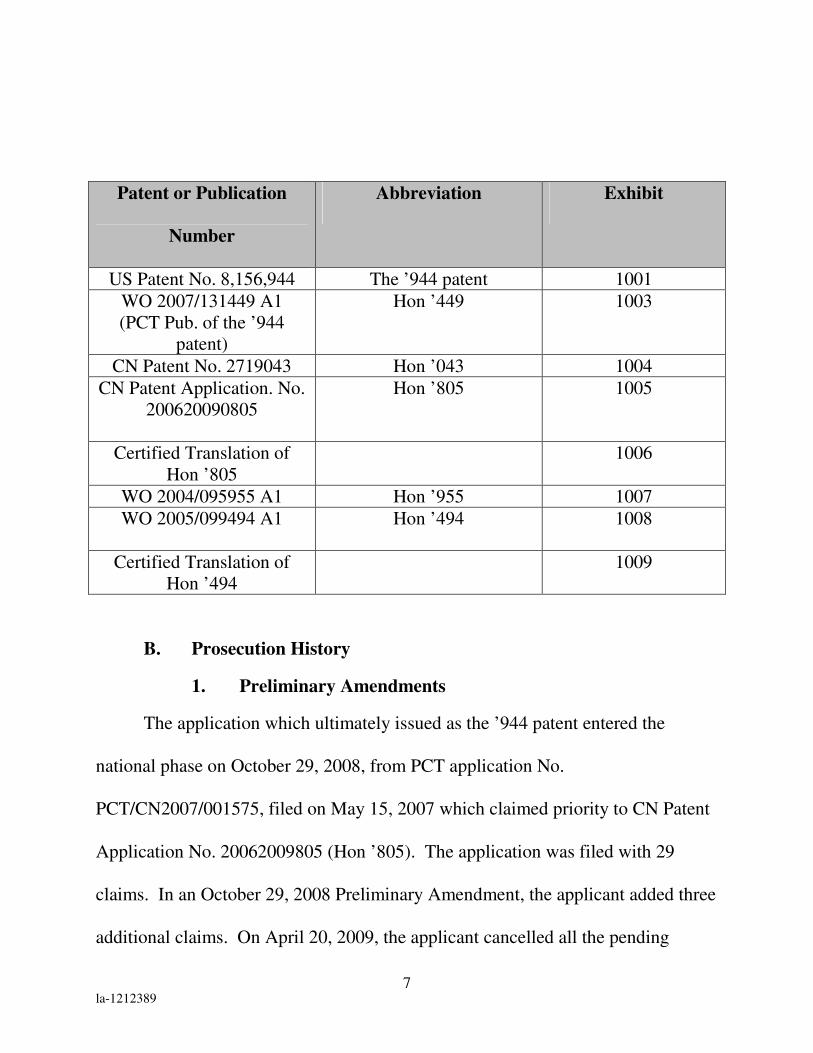
Before summarizing the prosecution history and the inter partes
reexamination and presenting the grounds of invalidity, Petitioners provide a table
listing the relevant patents and publications to Hon with accompanying
abbreviations and exhibit numbers for the Board’s benefit.
7 la-1212389
Patent or Publication
Number
Abbreviation Exhibit
US Patent No. 8,156,944 The ’944 patent 1001
WO 2007/131449 A1
(PCT Pub. of the ’944
patent)
Hon ’449 1003
CN Patent No. 2719043 Hon ’043 1004
CN Patent Application. No.
200620090805
Hon ’805 1005
Certified Translation of
Hon ’805
1006
WO 2004/095955 A1 Hon ’955 1007
WO 2005/099494 A1
Hon ’494 1008
Certified Translation of
Hon ’494
1009
B. Prosecution History
1. Preliminary Amendments
The application which ultimately issued as the ’944 patent entered the
national phase on October 29, 2008, from PCT application No.
PCT/CN2007/001575, filed on May 15, 2007 which claimed priority to CN Patent
Application No. 20062009805 (Hon ’805). The application was filed with 29
claims. In an October 29, 2008 Preliminary Amendment, the applicant added three
additional claims. On April 20, 2009, the applicant cancelled all the pending

8 la-1212389
claims in a Second Preliminary Amendment, and replaced them with 27 new
claims (33-59).
2. First Office Action and Response
On February 2, 2011, the Examiner issued a Restriction Requirement noting
that claims 33-36 and 38-59 (Group I) were directed to the embodiment shown in
Figure 5, whereas claim 37 (Group II) was directed to the embodiment shown in
Figure 17. (Ex. 1010 at 2.) On February 22, 2011, the applicant elected Group I
and cancelled claim 37. (Ex. 1011 at 1.)
3. Second Office Action, Response, and Allowance
A second Office Action was mailed on April 12, 2011. In this Office Action
(Ex. 1012), pending claims 34, 36, and 60 were objected to and claims 33, 35, and
38-69 were rejected either as being indefinite under 35 U.S.C. 112, second
paragraph, or obvious over Chinese Patent No. 2719043 to Hon (Hon ’043), or
obvious over Hon ’043 in view of PCT Application No. WO 2004/095955 A1 to
Hon (Hon ’955).
The applicant filed a response on October 12, 2011. (Ex. 1013.) With
regard to claims 35, 38, 42 and 44-45, which were rejected as indefinite, the
applicant argued for certain claims (35, 44, and 45) and amended other claims (38
and 42) to overcome the indefiniteness rejection. (Id. at 14.) With respect to the
obviousness rejections, the applicant argued that Hon ’043 “is not prior art to the

9 la-1212389
present claims” because the application was entitled to the earlier May 16, 2006
filing date of its foreign priority document Hon ’805. This argument was incorrect,
because Hon ’043 is prior art under 35 U.S.C. § 102(b) as it issued on August 24,
2005, more than one year prior to May 15, 2007.3 The applicant further stated that
the priority document “is substantially the same as the current specification and
figures.” This is also incorrect, as the figures and description of the Hon ’805 are
substantially different from those of the application that issued as the Hon ’944
patent, as discussed in more detail below.
Nevertheless, on December 6, 2011, in response to the applicant’s
amendment and response, the Examiner issued a Notice of Allowance.
C. Related Inter Partes Reexamination
1. Request For Reexamination And Office Action
On September 13, 2012, a Request for Inter Partes Reexamination of the
’944 patent (Ex. 1014, “Inter Partes Reexamination Request”) was filed by Fin
stating six proposed grounds for rejections. The first two proposed grounds for
rejection were based on WO 2005/099494 to Hon (“Hon ’494” 4) (anticipation) and
Hon ’494 in view of Hon ’955 (obviousness).
3 May 17, 2007 is the filing date of Hon ’944’s PCT Application, which is the “date of application for patent in the
United States” for purposes of 35 U.S.C. § 102(b). 4 Hon ’043 claims priority to Chinese Application No. 200420031182.0, which is also the Chinese priority
application for Hon ’494. As explained below in § IV, Part C, Hon ’494 is also prior art to the ’944 patent under 35
U.S.C. § 102(b).

10 la-1212389
On November 27, 2012, the PTO granted the Inter Partes Reexamination
Request (Ex. 1015) and issued an Office Action (Ex. 1016). In the Office Action,
with regard to anticipation by Hon ’494, the Examiner adopted the proposed
rejections for claims 1-4, 8-12, 15-26, 33, 34, 36, and 38. (Id. at 5-9.) The
Examiner declined to adopt the proposed rejections for claims 5-7, 35, 37 and 39-
41, stating that Hon ’494 does not disclose a coiled wire (claims 5-7) wound
outside the wall of the cylinder (claims 35 and 37), and does not disclose mandrils
on the walls of both ends of the cylinder (claims 39-41). (Id. at 5, 9-10.)
With regard to obviousness based on Hon ’494 in view of Hon ’955, the
Examiner adopted the proposed rejections for claims 1, 2, 5, 6, 8-12, 15-17, 24, 26,
33-36, and 38 but declined to adopt the proposed rejections for claims 7, 13, 14,
27-32, 37, and 39-41. (Id. at 10-11.) The Examiner stated that the combination
does not disclose a coiled wire on the outer surface of the cylinder (claims 7 and
37) or mandrils on the walls of both ends of the cylinder (claims 39-41). (Id. at 11-
12.)
On January 28, 2013, the Patent Owner filed a Response to the Office
Action. (Ex. 1017.) The Response argued that the Hon ’494 does not disclose a
run-through atomizing chamber or an electric heating rod. (Id., pp. 10-16.) Fin
filed comments in response on February, 27 2013. (Ex. 1018.)

11 la-1212389
IV. DETAILED EXPLANATION OF GROUNDS FOR INVALIDITY
Pursuant to 37 C.F.R. § 42.104(b), Petitioners respectfully request the
cancellation of claims 1-12, 15-26, and 33-41 of the ’944 patent based on the
grounds of invalidity as set forth in this Petition.
A. Statutory Grounds For The Challenge Of Each Claim
Ground 1 – Anticipation under 35 U.S.C. § 102(e) of claims 1, 2, 5-8, 10,
33, 35, 37, and 38 based on WO2007/078273 A1 to Liu (“Liu,”
Ex. 1019);
Ground 2 – Obviousness under 35 U.S.C. § 103(a) of claim 20 based on
Liu;
Ground 3 – Obviousness under 35 U.S.C. § 103(a) of claims 3, 4, 12, 15,
17, and 26 based on Liu in view of EP 0845220 A1 to Susa et
al. (“Susa,” Ex. 1020);
Ground 4 – Obviousness under 35 U.S.C. § 103(a) of claims 1-4, 8-12, 15-
26, 33-34, 36, and 38 based on Hon ’494 in view of Liu; and
Ground 5 – Obviousness under 35 U.S.C. § 103(a) of claims 39-41 based
on Hon ’494 in view of Liu and Susa.
Before addressing these grounds of invalidity, Petitioners set forth how the
challenged claims are to be construed. 37 C.F.R. § 42.104(b)(3). Petitioners then
present a discussion of how the claims are unpatentable under the statutory

12 la-1212389
grounds raised. 37 C.F.R. § 42.104(b)(4). Finally, Petitioners set forth a claim
chart that specifies where each element of a challenged claim is met by the prior
art. 37 C.F.R. § 42.104(b)(4). The showing in these sections establishes a
reasonable likelihood of prevailing as to each ground of invalidity with respect to
the challenged claims as to that ground.
B. Claim Construction
1. Broadest Reasonable Construction
Petitioners note that a claim is given the “broadest reasonable construction in
light of the specification” in inter partes review. See 37 C.F.R. § 42.100(b). In
general, terms should be given their ordinary and accustomed meaning as
understood by one of ordinary skill in the art. It is submitted that the term “run-
through atomizing chamber” requires additional detailed analysis, as discussed
below.
2. Run-through Atomizing Chamber
The term “run-through atomizing chamber” should be interpreted as broadly
as possible in a manner consistent with the specification. It is apparent that the
Patent Owner is attempting to ascribe a narrow meaning to this term in the co-
pending reexamination in its attempts to distinguish prior art. (See Ex. 1017, pp.
10-14.) However, these arguments should be rejected, as they do not in any way
reflect the broadest reasonable construction consistent with the specification.

13 la-1212389
The term “run-through atomizing chamber” is not defined in the
specification. Rather, the term is simply introduced, and it is stated with reference
to Figures 5-8, (Fig. 7 is reproduced below) that the body of the porous component
82 “has a run-through atomizing chamber (811),” the “diameter of the electric
heating rod (82) is less than the diameter of the atomizing chamber (811),” and
“there is a clearance between the electric heating rod (82) and interior wall of the
atomizing chamber (811), which forms a negative pressure cavity (83).” (Ex.
1001, col. 6, ll. 15-21.)
Air flow through the device is described at Col. 7, ll. 22-47. This discussion
indicates that the user’s smoking action causes negative pressure to be created in
the cavity 83, and that small-diameter fine drips are suspended to form gasoloid.
The drips are atomized by the heating rod along the full length of the chamber.
Applying the broadest reasonable construction consistent with the
specification, the term “run-through atomizing chamber” means a chamber having

14 la-1212389
a flow in which atomization occurs along the length thereof. There is no
requirement that the input and output ends of the chamber be unblocked, as argued
by the Patent Owner during reexamination. (Ex. 1017, p. 11-14.) The claim
recites an atomizing chamber, not what may be located at arbitrarily defined ends
of the chamber. Liquid is atomized as it runs through the entire length of the
chamber.
The difference between a run-through atomizing chamber and other
atomizers is apparent from a comparison of the elected embodiment with the non-
elected embodiment illustrated in Figs. 17 and 18 below. An atomizing chamber
having a path in which atomization occurs along its length is shown in Figures 5-8,
the elected embodiment, as well as in the embodiment of Figures 13-16. In
contrast, the atomizer assembly of the non-elected embodiment does not have such
a path.
This embodiment includes a frame 82 and a porous component 81 having a
coiled heating element wrapped around a bar that extends across the space defined

15 la-1212389
by the frame 82. The space is where atomization occurs, and may therefore be
considered an atomizing chamber. Notably, however, in contrast to the other
embodiments it is not referred to as a “run-through” chamber and atomization does
not occur along the length of a run-through path.
The term “run-through atomizing chamber” should not be construed to mean
simply having an unblocked input end and unblocked output end as argued by the
Patent Owner in the reexamination, as such does not relate to the chamber itself.
Moreover, this argument is completely belied by the ‘944 patent itself. In the
reexamination, after arguing that the run-through chamber must have open ends,
the Patent Owner attempted to distinguish Hon ‘494 by submitting the sketch
below showing that the exit end in Hon ‘494 has an arch that restricts flow and
asserting that in Hon ‘494 there is no “open and unrestricted pathway through the
atomizing chamber, i.e., there is no run-through chamber.” (Ex. 1017, p 14)
However, the end of the run-through chamber in the ‘944 patent itself is even more
closed and restricted than in the sketch of Hon ‘494. Specifically, the exit end of
the run-through chamber of Figures 5-8 has the half sphere protuberance 812 and is

16 la-1212389
therefore partially closed and will obstruct flow at least as much as the arch in
Hon’494.
This protruberance is discussed in the very same paragraph of the specification
which introduces the run-through chamber (Ex. 1001, col. 6, ll. 13-34.) Thus, the
Patent Owner’s construction of run-through atomizing chamber would exclude the
very embodiment of the ‘944 patent that describes the chamber.
The term “run-through” must be accorded some meaning, as “[c]laims must
be interpreted with an eye towards giving effect to all terms in the claim.” See e.g.
Bicon, Inc. v. Straumann Co., 441 F.3d 945, 950 (Fed. Cir. 2006); Elekta
Instrument S.A. v. O.U.R. Scientific Int'l, Inc., 214 F.3d 1302, 1305-07 (Fed. Cir.
2000) (refusing to adopt a claim construction which would render claim language
superfluous). A construction of the term “run-through atomizing chamber” which
includes reference to atomization occurring along the length of the flow path gives
meaning to the term “run-through” while remaining consistent with the
specification.

17 la-1212389
This construction is also consistent with the priority application (Hon ’805).
This application discloses embodiments of an atomizer similar to the atomizer of
Figures 16-17 of the ’944 patent. These are shown in Figures 8-11, reproduced
below.
As is the case with respect to Figures. 16 and 17, these atomizers have
heating elements that extend across the flow path rather than along it. Also, the
description of these atomizers does not refer to them as being run-through
atomizing chambers. Rather, it is stated that “atomizer 307 can be the ones as
shown in figures 8 and 9 being a capillary impregnation type atomizer, or can be
the ones shown in figures 10 and 11 being a spray type atomizer.” (Ex. 1006, at
13.)
In view of the foregoing, “run-through atomizing chamber” should be
construed as a chamber having a flow in which atomization occurs along the length
thereof.
18 la-1212389
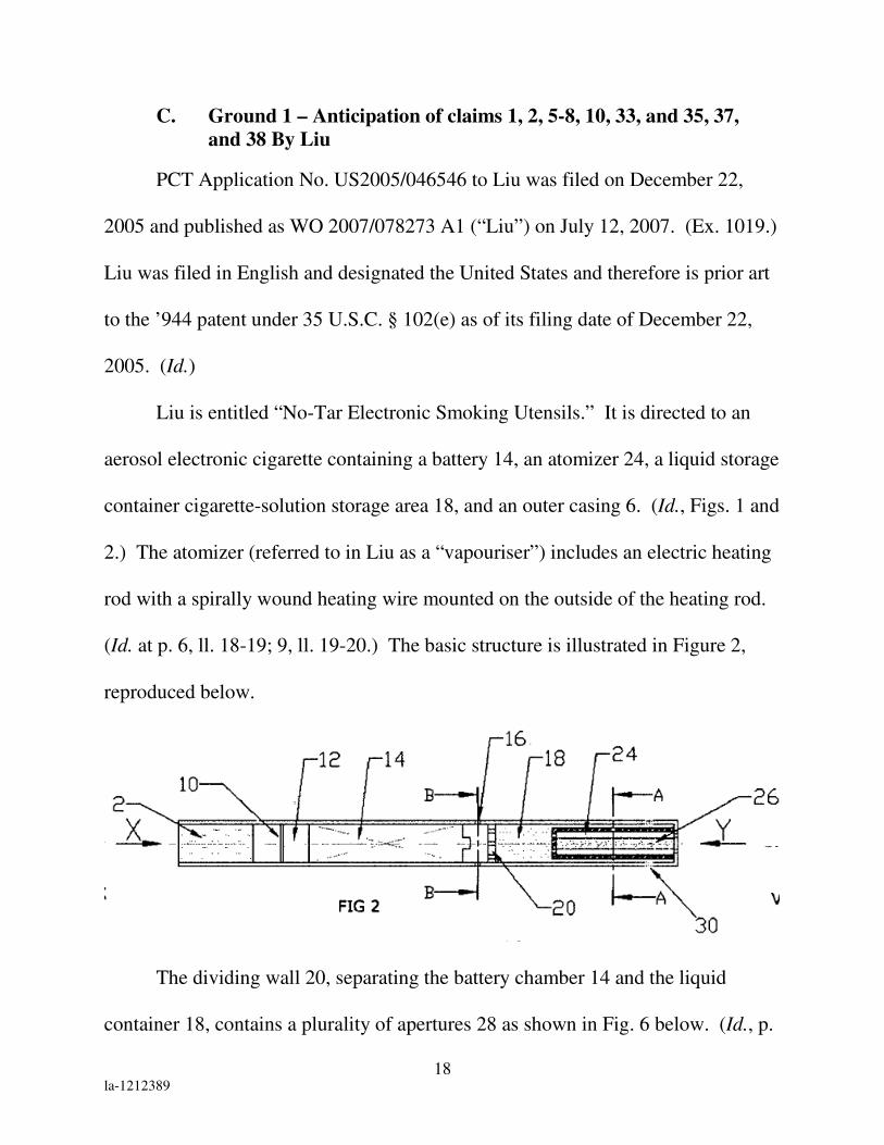
C. Ground 1 – Anticipation of claims 1, 2, 5-8, 10, 33, and 35, 37,
and 38 By Liu
PCT Application No. US2005/046546 to Liu was filed on December 22,
2005 and published as WO 2007/078273 A1 (“Liu”) on July 12, 2007. (Ex. 1019.)
Liu was filed in English and designated the United States and therefore is prior art
to the ’944 patent under 35 U.S.C. § 102(e) as of its filing date of December 22,
2005. (Id.)
Liu is entitled “No-Tar Electronic Smoking Utensils.” It is directed to an
aerosol electronic cigarette containing a battery 14, an atomizer 24, a liquid storage
container cigarette-solution storage area 18, and an outer casing 6. (Id., Figs. 1 and
2.) The atomizer (referred to in Liu as a “vapouriser”) includes an electric heating
rod with a spirally wound heating wire mounted on the outside of the heating rod.
(Id. at p. 6, ll. 18-19; 9, ll. 19-20.) The basic structure is illustrated in Figure 2,
reproduced below.
The dividing wall 20, separating the battery chamber 14 and the liquid
container 18, contains a plurality of apertures 28 as shown in Fig. 6 below. (Id., p.

19 la-1212389
6, ll. 2-7.) The cylindrical vapouriser housing also includes a plurality of apertures
28 to allow air and liquid to be drawn into the vapouriser as shown in Fig. 5.
In Figure 2 above, the user of the electronic cigarette draws in air via the
mouthpiece end Y. (Id., p. 4, ll. 6-7, 24-25.) As the user draws on the cigarette
mouthpiece, air is drawn into the cigarette through a plurality of apertures 16 on
the outside shell and into the battery chamber 14. (Id., p. 5-6, ll. 32-2.) The air in
the battery chamber is sucked into the liquid container 18 through apertures 22
where it mixes with the liquid solution. (Id., p. 7, ll. 16-19.) The air and liquid
solution mixture is then drawn into the porous walls of the vapouriser heater
assembly which contain apertures 28. (Id., Fig. 5; p. 6, ll. 20-22; p. 7, ll. 16-19.)
The liquid solution is then vaporized inside the vapouriser before being inhaled via
the mouthpiece. (Id.) The flow of air through the cigarette indicates the space in
between the vapouriser housing 24 and the heating rod 26 forms a negative
pressure cavity as the user inhales.

20 la-1212389
The vapouriser assembly includes a “heater wire 26 spirally wound on a
central ceramic insulating rod.” (Id., p. 6, ll. 18-19; p. 9, ll. 19-20.) As shown in
Figure 2, above, the central rod 26 extends along the length of the vapouriser 24.
Thus, the vapouriser disclosed in Liu is essentially the same as the run-
through atomizer found in the ’944 patent. Liu discloses precisely what the
Examiner had found was missing from the prior art in the inter partes
reexamination, i.e., a cylinder with heating wire wound on the wall of the cylinder
inside an atomizer assembly. It is submitted that Liu anticipates each of claims 1,
2, 5-8, 10, 33, and 35, 37 and 38. The claim charts below specify where each
claim element is found in Liu.
U.S. Patent No. 8,156,944 Liu
1[a]. 5 An aerosol electronic cigarette,
comprising:
Liu discloses an aerosol electronic
cigarette. See, e.g., Fig. 2; p. 2, ll. 6-9.
5 The limitations of certain claims were numbered (e.g., 1[a], 1[b], 1[c], etc.) so that these limitations can be
referenced in other claims.

21 la-1212389
U.S. Patent No. 8,156,944 Liu
1[b]. a battery assembly, Liu discloses a battery assembly. See,
e.g., Fig. 2; p. 5, ll. 31-32 (“a cylindrical
battery chamber 12 for housing a
battery 14).
1[c]. an atomizer assembly, Liu discloses an atomizer assembly 24.
See, e.g., Fig. 2; p. 6, ll. 15-17
(“cylindrical vapouriser heater
assembly”); p. 8, ll. 5-6.
1[d]. a cigarette-solution storage area, Liu discloses a cigarette-solution
storage area 18. See, e.g., Fig. 2; p. 5,
ll. 9-10, (“the simulated cigarette of the
example is provided with a container
for a liquid mixture”); p. 6, ll. 2-4, 9-15,
29-30 (“a cylindrical liquid container 18
separated from the battery chamber by a
dividing wall 20. … that may contain
any suitable chemicals, and may be
provided with or without nicotine.”).

22 la-1212389
U.S. Patent No. 8,156,944 Liu
1[e]. and a hollow shell having a
mouthpiece:
Liu discloses a hollow shell 6 having a
mouthpiece 4. See, e.g., Fig. 1; p. 5, ll.
7 (“mouthpiece end”), 14-15 (“outer
casing”).
1[f]. the battery assembly connects
with the atomizer assembly, and both
are located in the shell;
Liu discloses a battery 14 that connects
with the atomizer assembly to provide
current to the heater 26, and both are
located in the shell. See, e.g., Figs. 2
and 7; p. 3, ll. 24-27; p.5, ll. 11-12.

23 la-1212389
U.S. Patent No. 8,156,944 Liu
1[g]. the cigarette solution storage area
is located in one end of the shell
adjacent to the mouthpiece, and fits with
at least a portion of the said atomizer
assembly inside it;
Liu discloses a container for storing a
liquid mixture 18 located in one end of
the shell adjacent to the mouthpiece end
4 and fits with at least a portion of the
cylindrical vapouriser heater assembly
24 inside it. See, e.g., Fig. 2. The
container 18 surrounds the heater
assembly 24 and extends to the
mouthpiece.
1[h]. the shell has through-air-inlets; Liu discloses a shell 6 with through-air-
inlets. See, e.g., Figs. 1, 2, and 4; pp. 5-
6, ll. 32-2 (“the cigarette outer casing 6,
adjacent to the battery chamber 12 is
provided with a plurality of apertures 16
to permit the entry of air.”).

24 la-1212389
U.S. Patent No. 8,156,944 Liu
1[i]. the atomizer assembly includes an
atomizer comprising an electric heating
rod and a run-through atomizing
chamber; the electric heating rod
comprises a cylinder and a heating
element provided at the wall of the
cylinder,
Liu discloses an atomizer assembly 24
including an electric heating rod located
in a run-through atomizing chamber.
The electric heating rod is cylindrical
and includes a spirally wound heater
wire 26 provided at the wall of the
cylinder. See e.g., Fig. 2; p. 6, ll. 18-19
(“The vapouriser heater assembly
housing houses a heater wire 26 spirally
wound on a central ceramic insulating
rod.”).
Liu discloses the vapouriser assembly
has a run-through atomization chamber,
i.e., atomization occurs along the length
of the chamber. See, e.g., Figs. 2, 5; p.
7, ll. 16-19 (“As the user draws on the
cigarette mouthpiece, air is drawn into
the battery chamber, into the liquid
container to mix with the liquid
mixture, and into the heater assembly.
The resulting vapor is drawn into the
mouth of the user.”); p. 6, ll. 20-22.
The central rod 26 extends lengthwise
along the vapouriser chamber 24. See
Fig. 2.

25 la-1212389
U.S. Patent No. 8,156,944 Liu
1[j]. the electric heating rod is in the
said atomizing chamber and
The electric heating rod is in the
atomizing chamber. See, e.g., Fig. 2; p.
6, ll. 18-19 (“The vapouriser heater
assembly housing houses a heater wire
26 spirally wound on a central ceramic
insulating rod.”).
1[k]. there is a negative pressure cavity
in the atomizing chamber.
The space in between the atomizer
housing 24 and the heating rod 26 forms
a negative pressure cavity (as a user
inhales). See, e.g., Fig. 2; p. 4, ll. 6-9;
p. 9, ll. 22-24 (“suction on the
mouthpiece by the user causes air to be
drawn through the porous container for
the liquid, over the heated vapouriser,
into the mouthpiece and into the mouth
of the user.”).
2. An aerosol electronic cigarette
according to claim 1, further comprising
a cigarette solution in the cigarette
solution storage area, the cigarette
solution comprising nicotine.
Liu discloses a cigarette solution in the
cigarette solution storage area, the
cigarette solution including nicotine.
See, e.g., Fig. 2; p. 5, ll. 9-10, (“the
stimulated cigarette of the example is
provided with a container for a liquid
mixture”); p. 6, ll. 2-4, 9-15, 29-30 (“a
cylindrical liquid container 18 separated
from the battery chamber by a dividing
wall 20. … that may contain any
suitable chemicals, and may be
provided with or without nicotine.”).

26 la-1212389
U.S. Patent No. 8,156,944 Liu
5. An aerosol electronic cigarette
according to claim 1, wherein the
heating element is a coiled wire.
Liu discloses the heating element 26 is a
coiled wire. See, e.g., Fig. 2; p. 3, ll. 6-
8 (“In a preferred arrangement the
heater means include an electrical
heater mounted on an electrical
insulating support, for example a
spirally wound heater wire”).
6. An aerosol electronic cigarette
according to claim 5, wherein the coiled
wire extends along the length of the
cylinder.
Liu discloses the coiled wire 26 extends
along the longitudinal length of the
supporting rod 26 as shown in fig. 2.
See, e.g., Fig. 2; p. 9, ll. 19-20 (“a
spirally wound electrical heater
mounted on an electrical insulating
support”).
7. An aerosol electronic cigarette
according to claim 5, wherein the coiled
wire is on the outer surface of the
cylinder.
Liu discloses the spirally wound heating
wire is mounted on the outside of the
heating rod. See, e.g., Figs. 2 and 4;
p.6, ll. 18-19 (“The vapouriser heater
housing assembly houses a heater wire
26 spirally wound on a central ceramic
insulating rod.”); p. 9, ll. 19-20 (“a
spirally wound electrical heater
mounted on an electrical insulating
support”).
8. An aerosol electronic cigarette
according to claim 1, wherein the
cylinder is inside the run through
chamber.
Liu discloses the electric heating rod is
inside the run-through chamber. See,
e.g., Fig. 2; p. 6, ll. 18-19 (“The
vapouriser heater assembly housing
houses a heater wire 26 spirally wound
on a central ceramic insulating rod.”).
10[a]. An aerosol electronic cigarette,
comprising:
See claim 1[a].
10[b]. a battery assembly, See claim 1[b].
10[c]. an atomizer assembly, See claim 1[c].
10[d]. a cigarette solution storage area, See claim 1[d].
10[e]. and a shell that is hollow and
comprises a mouthpiece:
See claim 1[e].
27 la-1212389
U.S. Patent No. 8,156,944 Liu
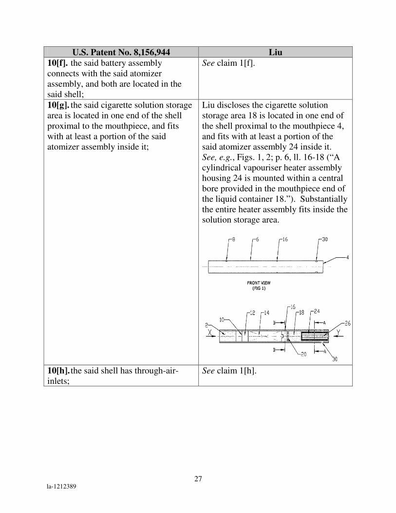
10[f]. the said battery assembly
connects with the said atomizer
assembly, and both are located in the
said shell;
See claim 1[f].
10[g]. the said cigarette solution storage
area is located in one end of the shell
proximal to the mouthpiece, and fits
with at least a portion of the said
atomizer assembly inside it;
Liu discloses the cigarette solution
storage area 18 is located in one end of
the shell proximal to the mouthpiece 4,
and fits with at least a portion of the
said atomizer assembly 24 inside it.
See, e.g., Figs. 1, 2; p. 6, ll. 16-18 (“A
cylindrical vapouriser heater assembly
housing 24 is mounted within a central
bore provided in the mouthpiece end of
the liquid container 18.”). Substantially
the entire heater assembly fits inside the
solution storage area.
10[h]. the said shell has through-air-
inlets;
See claim 1[h].

28 la-1212389
U.S. Patent No. 8,156,944 Liu
10[i]. the atomizer assembly is an
atomizer, which includes a porous
component and
Liu discloses the atomizer assembly is
an atomizer 24, which includes a porous
component. See e.g. Fig. 5; p. 6, ll. 20-
22 (“The walls of heater housing 24 are
provided with a plurality of apertures 28
to permit entry of the liquid/air from the
liquid container 18 into the heater
housing 24.”). Section A-A in Fig. 5
shows apertures at the end of the
housing as well as around the
circumference.
10[j]. an electric heating rod; wherein
the electric heating rod comprises a
cylinder and a heating element provided
at the wall of the cylinder,
See claim 1[i].
10[k]. the said porous component has a
run-through atomizing chamber;
Liu discloses the atomizer assembly
includes a porous component. See
claim 10[i]. Liu discloses the atomizer
assembly includes a run-through
chamber. See claim 1[i].
10[l]. the electric heating rod is in the
said atomizing chamber and
See claim 1[j].
10[m]. there is a negative pressure
cavity in the atomizing chamber.
See claim 1[k].
33. An aerosol electronic cigarette of
claim 10, wherein the heating element
comprises a heating wire.
Liu discloses the heating element 26 is a
heating wire. See, e.g., Fig. 2; p. 3, ll.
6-8 (“In a preferred arrangement the
heater means includes an electrical
heater mounted on an electrical
insulating support, for example a
spirally wound heater wire.”).

29 la-1212389
U.S. Patent No. 8,156,944 Liu
35. An aerosol electronic cigarette of
claim 10, wherein the heating element
comprises a coiled heating wire, which
is wound at the wall of the cylinder.
See claim 6.
37. An aerosol electronic cigarette of
claim 10, wherein the electric heating
element is provided outside the wall of
the cylinder.
See claim 7.
38. An aerosol electronic cigarette of
claim 10, further comprising a cigarette
solution comprising nicotine.
See claim 2.
D. Ground 2 – Obviousness of Claim 20 Based on Liu
Liu does not disclose the materials of the heater assembly housing but does
disclose materials for the container. However, Liu discloses that “at least a portion
of the container [18] is formed of a porous material to facilitate distribution of
liquid through the container, prior to being fed to the heater means.” (Ex. 1019, p.
3, ll. 1-3.) This porous material can be made of “foamed metal, foamed ceramic or
special fibre.” (Id., p. 3, ll. 3-4.) It would have been obvious to also make the
heater housing assembly out of one of these materials in view of the similar
requirement to distribute liquid into the heater means.
U.S. Patent No. 8,156,944 Liu
20. An aerosol electronic cigarette of
claim 10, wherein the said porous
component is made of foamed nickel,
stainless steel fiber felt, polymer or
ceramics.
See claim 10 of Liu anticipation chart.
It would be obvious for a heater housing
assembly to have a porous component
made of any of the claimed materials.
See, e.g., p. 3, ll. 3-4 (“Suitable
materials include, for example, foamed
metal, foamed ceramic, or special
fibre.”).

30 la-1212389
E. Ground 3 – Obviousness of Claims 3, 4, 12, 15, 17, and 26 Based
On Liu In View Of Susa
Susa issued on June 3, 1998 and therefore qualifies as prior art to the ’944
patent under 35 U.S.C. § 102(b) as it was published more than one year prior to
May 15, 2007. (Ex. 1020.) Susa is entitled “Flavor Producing Article.” The basic
structure is illustrated in Fig. 1, reproduced below.
Susa is directed to a simulated smoking flavor producing article. The
embodiment in Fig. 1 discloses a flavor producing article consisting of detachable
parts (12a and 12b), a rechargeable battery 62, a container of liquid material 36, a
ceramic heater 42, and supporting means for the heater 44. (Ex. 1020, at col 10, ll.
2-8; 24-30.)
As shown above in Figure 1, Susa discloses a shell (casing 12) that includes
first and second detachable sections 12a and 12b. (Id., col. 13, ll. 5-6.) The first
detachable section 12a includes the mouthpiece 16. (Id.) It would have been
obvious to one of ordinary skill in the art in view of Susa to provide detachable

31 la-1212389
sections (as recited in claims 3 and 4) to allow the battery disclosed in Liu to be
replaced. This combination is obvious because it uses a known technique
(detachable parts of an electronic cigarette to allow for replacement of a battery) to
improve a similar device (the electronic cigarette of Liu) in the same way. In
addition, allowing for the replacement of the battery would enhance commercial
opportunities and make the product more desirable by reducing the need to replace
the entire device when the battery is depleted.
With respect to claims 15 and 25, Susa discloses a rechargeable battery 66.
(Id., col. 8, ll.43-45.) It would have been obvious to one of ordinary skill in the art
in view of Susa to replace the battery disclosed in Liu with a rechargeable one
having a slot for charging in order to provide means for continued use of the
electronic cigarette after the battery’s initial charge has been depleted. The
rationale supporting such a combination is that it is simply using a known
technique (a rechargeable battery having a charging slot) to improve a similar
device (the electronic cigarette of Liu) and the results are predictable. Using a
rechargeable battery (and providing ability for the rechargeable battery to be
recharged) would enhance commercial opportunities and make the product more
desirable by reducing the need to replace the entire device when the battery is
depleted.

32 la-1212389
With respect to claim 12, Susa discloses an operating indicator, an electronic
circuit board, and an airflow sensor connected to a battery where the signal output
of the airflow sensor is connected with the electronic circuit board. (Id., col. 8. ll.
43-45, col. 14, ll. 11-20, col. 16, ll. 11-26.) It would have been obvious to one of
ordinary skill in the art in view of Susa to connect the air flow sensor and control
circuit board to the battery and LED operating indicator disclosed in Liu in order to
provide means to indicate to the user of the electronic cigarette when the device is
operational. This combination is obvious because it simply applies a known
technique (use of an airflow sensor connected to an electronic circuit board) to a
known device (the operating indicator and battery of Liu) to yield predictable
results.
With respect to claim 17, Susa discloses that the electronic circuit board
includes an electronic switch circuit. (Id., col. 16, ll. 37-38.) It would have been
obvious to one of ordinary skill in the art in view of Susa to add a switch to the
electronic cigarette disclosed in Liu. This combination is simply applying a known
technique (an electronic circuit board with an electronic circuit switch) to a known
device (the electronic cigarette of Liu) to yield predictable results. In addition,
electronic switches are well known in the art and a person skilled in the art would
merely be using such a familiar element for its well-known purpose.

33 la-1212389
Each element of claims 3, 4, 12, 15, 17, and 26 is disclosed in Liu and Susa
as set forth in the claim chart below. The obviousness of the combination is
discussed above.
U.S. Patent No. 8,156,944 Liu in view of Susa
3. An aerosol electronic cigarette
according to claim 1, wherein the shell
comprises first and second detachable
sections.
See claim 1 of Liu anticipation chart.
Susa discloses a shell (casing 12) that
includes first and second detachable
sections 12a and 12b. See, e.g., Fig. 1;
col. 3, ll. 11-18.
4. An aerosol electronic cigarette of
claim 3, wherein the first detachable
section comprises the mouthpiece.
Susa discloses the first detachable
section 12a includes the mouthpiece 16.
See, e.g., Fig. 1; col. 13, ll. 5-6.
12. An aerosol electronic cigarette of
claim 10, wherein the said battery
assembly includes a battery, and an
operating indicator, an electronic circuit
board, and an airflow sensor, which are
connected with the said battery; the
signal output of the said airflow sensor
is connected with the said electronic
Re: limitations of claim 10, see Liu
anticipation chart, claim 10. Liu
discloses a battery assembly. See, e.g.,
Fig 2; col. 8, ll. 43-45. Liu discloses an
operating indicator 8. See, e.g., Fig. 2;
p. 5, ll. 22-26 (“[M]ounted on the
cigarette casing 6 is a light emitting
diode (LED) 8. The LED is for the

34 la-1212389
U.S. Patent No. 8,156,944 Liu in view of Susa
circuit board.
purpose of monitoring/indicating.”); p.
3, ll. 15-18 (“Indicating/monitoring
means may be included for the purpose
of indicating a range of activities”).
Susa also discloses wherein the battery
assembly includes a battery. See, e.g.,
col 8, ll. 43-45 (“The power supply 62
is preferably a DC power supply, e.g., a
commercially available dry cell or
rechargeable cell.”). Susa discloses an
operating indicator. See., e.g., col. 14,
ll. 11-20 (“an electric display means can
be sued to monitor the remaining
amount in the material container 32, and
an example of the electric display
means includes a means for using a
light-emitting diode disposed on the
outer surface of the casing main
body.”).
Susa discloses an airflow sensor
connected to an electronic circuit board.
See, e.g., Fig. 14; col. 16, ll. 11-26
(“[W]hen the user starts an inhaling
operation, the gas flow, the flow
velocity of which is increased by the
orifice 112, pivots the vane clockwise in
Fig. 14, so that the lever 104 and
contact 108 come into contact with each
other. The inhaling operation signal of
the user which is detected in this
manner by the swing vane type sensor is
transmitted to a control circuit 72.”).

35 la-1212389
U.S. Patent No. 8,156,944 Liu in view of Susa
15[a]. An aerosol electronic cigarette
of claim 12, wherein the said battery is a
rechargeable battery, which has a
charging slot on it;
Susa discloses the battery is 62 a
rechargeable battery stored in a power
supply holder 62. See, e.g., Fig. 14;
col. 8, ll. 43-45 (The power supply 62 is
preferably a DC power supply, e.g., a
commercially available dry cell or
rechargeable cell.”); col. 14, ll. 25-26
(“power supply 62 is stored in a power
supply holder 66.”). It would be
obvious to one of ordinary skill of the
art that if a rechargeable battery was
used it could be a conventional type
having a charging slot.
15[b]. the said operating indicator
comprises a LED.
Liu discloses the operating indicator is
an LED. See, e.g., p. 5, ll. 22-26
(“Adjacent and inner the tip end 2 of the
cigarette and mounted on the cigarette
casing 6 is a light emitting diode (LED)
8. The LED is for the purpose of
monitoring/indicating”).
Susa also discloses the operating
indicator comprises an LED. See, e.g.,
col. 14, ll. 11-20 (“an electric display
means can be used to monitor the
remaining amount in the material
container 32 … and an example of the
electric display means includes a means
for using a light-emitting diode
disposed on the outer surface of the
casing main body.”).

36 la-1212389
U.S. Patent No. 8,156,944 Liu in view of Susa
17. An aerosol electronic cigarette of
claim 12, wherein the said electronic
circuit board includes an electronic
switch circuit.
Susa discloses that the electronic circuit
board includes an electronic switch
circuit. See, e.g., col. 16, ll. 37-38
(“The electric contacts 122 and 124
constitute the switch of a sensor
circuit.”)
26. An aerosol electronic cigarette of
claim 10, wherein the said aerosol
electronic cigarette is configured to
connect to a charging device; the said
battery is a rechargeable battery.
Re: limitations of claim 10, see Liu
anticipation chart, claim 10. Susa
discloses a rechargeable battery as
discussed above at claim 15[a]. It is
well known to charge electronic devices
(such as electric toothbrushes and
wireless telephones) by connecting
them to a charging device.
F. Ground 4 – Obviousness of Claims 1-4, 8-12, 15-26, 33-34, 36, and
38 Based on Hon ’494 In View of Liu
Hon ’494 was published on October 27, 2005 and therefore qualifies as prior
art to the ’944 patent under 35 U.S.C. § 102(b) because Hon ’494 was published
more than one year prior to May 15, 2007.6 (Ex. 1008.) A certified English
translation of Hon ’494 is provided. (Ex. 1009.)
Hon ’494 is entitled “Electronic Atomization Cigarette.” It is directed to an
aerosol electronic cigarette containing a battery assembly, an atomizer assembly, a 6 May 17, 2007 is the filing date of Hon ’944’s PCT Application, which is the “date of application for patent in the
United States” for purposes of 35 U.S.C. § 102(b).

37 la-1212389
cigarette-solution storage area, and a hollow shell. (Id., Fig. 1; p. 3, ll. 14-19; p. 4,
l. 21.) As shown in Figure 1 below, the aerosol electronic cigarette comprises a
hollow shell 14, containing a battery assembly 2 and an atomizer assembly 9.
A mouthpiece 15 can be detached to allow for the replacement of the liquid-
supply bottle 11, which is inserted into the hollow shell 14. (Id., p. 4, ll. 34-37.)
The detachable mouthpiece is illustrated in Figure 11 below.
The atomizer assembly is an atomizer, which includes a porous component
27 and a heating element RL. (Id., p. 3, ll. 24-38.) One embodiment of the
atomizer assembly is shown in Figure 6 below. (Id.) The porous component 27
has an atomizing chamber and a bulge 36 (the “arch” as argued by the Patent
Owner), which fits into the cigarette bottle assembly. (Id.)

38 la-1212389
Hon ’494 discloses a LED 1 and a rechargeable battery 2 that appears to be
removable. (Id., Fig. 1; p. 4, l. 21.) It would have been obvious to one of ordinary
skill to use a known rechargeable battery having a slot as the battery in Hon ’494.
Such is merely the simple substitution of one known type of battery for another. In
this regard, it is noted that the ’944 patent does not in any way indicate that the
battery 3 is a new type of battery.
Liu discloses a vapouriser assembly including a spirally wound heater wire
26 mounted on the outside of a central ceramic insulating rod. (Id., p. 6, ll. 18-19;
p. 9, ll. 19-20.) As shown in Figure 2, the central rod 26 extends lengthwise along
the vapouriser 24.

39 la-1212389
The vapouriser assembly therefore has a run-through chamber in which
atomization occurs along the flow path.
It would have been obvious to employ a vapouriser assembly as disclosed by
Liu (including the central rod extending lengthwise along the vapouriser with a
spirally wound heater wire inside the vapouriser assembly) in the electronic
cigarette of Hon ’494. This combination is simply applying a known technique (a
run-through atomization chamber) to a known device (the electronic cigarette of
Hon ’494) to yield predictable results.
It is submitted that the elements of claims 1-4, 8-12, 15-26, 33-34, 36, and
38 are disclosed in Hon ’494 and Liu as set forth in the claim chart below. The
obviousness of the combination is discussed above.
U.S. Patent No. 8,156,944 Hon ’494 and Liu
1[a]. An aerosol electronic cigarette,
comprising:
Hon ’494 discloses an aerosol electronic
cigarette. See, e.g., Abstract.
1[b]. a battery assembly, Hon ’494 discloses a rechargeable
battery 2. See, e.g., Fig. 1; p. 4, l. 21.
1[c]. an atomizer assembly, Hon ’494 discloses an atomizer 9 with
an atomization cavity 10. See, e.g., Fig.
1; p. 3, ll. 24-26.

40 la-1212389
U.S. Patent No. 8,156,944 Hon ’494 and Liu
1[d]. a cigarette-solution storage area, Hon ’494 discloses a liquid-supplying
bottle 11, which can contain nicotine
solution. See, e.g., Fig. 1; p. 3, 17; p.4,
ll. 34-37.
1[e]. and a hollow shell having a
mouthpiece:
Hon ’494 discloses a shell 14 having a
mouthpiece 15. See, e.g., p. 1, l. 39; p.
4, ll. 17-18.
1[f]. the battery assembly connects
with the atomizer assembly, and both
are located in the shell;
Hon ’494 discloses a battery that is
connected to the atomizer and both are
located in the shell. See, e.g., Fig. 1.
1[g]. the cigarette solution storage
area is located in one end of the shell
adjacent to the mouthpiece, and fits with
at least a portion of the said atomizer
assembly inside it;
Hon ’494 discloses a liquid supplying
bottle 11 located on one end of the shell
that is in contact with a portion of the
atomizer 9. See, e.g., Figs. 1, 6; p. 1, l.
39; p. 4, ll. 17-18, 24-26.
1[h]. the shell has through-air-inlets; Hon ’494 discloses a shell 14 with air
inlets 4. See, e.g., Fig. 1; p.1, l. 39-40,
p.3, l. 15.
1[i]. the atomizer assembly includes
an atomizer comprising an electric
heating rod and a run-through atomizing
chamber; the electric heating rod
comprises a cylinder and a heating
element provided at the wall of the
cylinder,
See claim 1[i] of Liu anticipation chart.
1[j]. the electric heating rod is in the
said atomizing chamber and
See claim 1[j] of Liu anticipation chart.
1[k]. there is a negative pressure
cavity in the atomizing chamber.
See claim 1[k] of Liu anticipation chart.

41 la-1212389
U.S. Patent No. 8,156,944 Hon ’494 and Liu
2. An aerosol electronic cigarette
according to claim 1, further comprising
a cigarette solution in the cigarette
solution storage area, the cigarette
solution comprising nicotine.
Hon ’494 discloses a liquid-supplying
bottle 11 containing nicotine solution.
See, e.g., p. 4, ll. 34-37.
3. An aerosol electronic cigarette
according to claim 1, wherein the shell
comprises first and second detachable
sections.
Hon ’494 discloses a mouthpiece 15
that is provided in the shell 14. See,
e.g., p. 3, ll. 17-18. The mouthpiece is
threaded and can be detached. See, e.g.,
p. 4, ll. 34-37.
4. An aerosol electronic cigarette of
claim 3, wherein the first detachable
section comprises the mouthpiece.
See claim 3.
8. An aerosol electronic cigarette
according to claim 1, wherein the
cylinder is inside the run through
chamber.
See claim 8 of Liu anticipation chart.
9. An aerosol electronic cigarette of
claim 1, wherein the solution storage
area comprises a cigarette-bottle
assembly.
Hon ’494 discloses a liquid-supplying
bottle 11 containing nicotine solution.
See, e.g., p. 4, ll. 34-37.
10[a]. An aerosol electronic cigarette,
comprising:
See claim 1[a].
10[b]. a battery assembly, See claim 1[b].
10[c]. an atomizer assembly, See claim 1[c].
10[d]. a cigarette solution storage area, See claim 1[d].
10[e]. and a shell that is hollow and
comprises a mouthpiece:
See claim 1[e].
10[f]. the said battery assembly
connects with the said atomizer
assembly, and both are located in the
said shell;
See claim 1[f].
10[g]. the said cigarette solution
storage area is located in one end of the
shell proximal to the mouthpiece, and
fits with at least a portion of the said
atomizer assembly inside it;
See claim 1[g].

42 la-1212389
U.S. Patent No. 8,156,944 Hon ’494 and Liu
10[h]. the said shell has through-air-
inlets;
See claim 1[h].
10[i]. the atomizer assembly is an
atomizer, which includes a porous
component and
See claim 10[i] of Liu anticipation
chart.
10[j]. an electric heating rod; wherein
the electric heating rod comprises a
cylinder and a heating element provided
at the wall of the cylinder,
See claim 1[i] of Liu anticipation chart.
10[k]. the said porous component has a
run-through atomizing chamber;
See claim 10[k] of Liu anticipation
chart.
10[l]. the electric heating rod is in the
said atomizing chamber and
See claim 1[j] of Liu anticipation chart.
10[m]. there is a negative pressure
cavity in the atomizing chamber.
See claim 1[k] of Liu anticipation chart.
11. An aerosol electronic cigarette of
claim 10, wherein a restriction
component is detachably set on one end
of the said porous component; there is a
restriction hole on the principal part of
the said restriction component; the said
restriction hole corresponds to the said
atomizing chamber; the diameter of the
said restriction hole is less than the
inner diameter of the atomizing
chamber.
Hon ’494 discloses a “through hole
[that] is provided on the vapor-liquid
separator 7, [which] can be made of
plastic or silicon rubber.” See, e.g.,
Figs. 1, 2, 9; p. 3, ll. 38-40. The
diameter of the through hole is less than
the inner diameter of the atomizing
chamber. See, e.g., Figs. 1, 2.
12. An aerosol electronic cigarette of
claim 10, wherein the said battery
assembly includes a battery, and an
operating indicator, an electronic circuit
board, and an airflow sensor, which are
connected with the said battery; the
signal output of the said airflow sensor
is connected with the said electronic
circuit board.
Hon ’494 discloses a LED 1, a
rechargeable battery 2, an electronic
circuit board 3, and a sensor 6. See,
e.g., Fig. 1; p. 3, ll. 15-16; p. 4, l. 21.
“When a smoker smokes … the air
pressure difference … will cause the
sensor 6 to output an actuating signal,
the electronic circuit board 3 connected
therewith goes into operation . . . and
the LED 1 can be lit under the supply of
the rechargeable battery 2.” See, e.g., p.
4, ll. 1-14, 21.

43 la-1212389
U.S. Patent No. 8,156,944 Hon ’494 and Liu
15[a]. An aerosol electronic cigarette of
claim 12, wherein the said battery is a
rechargeable battery, which has a
charging slot on it;
Hon ’494 discloses a rechargeable
battery 2. See, e.g., Fig. 1; p. 1, ll. 15-
16; p. 4, l. 21.
15[b]. the said operating indicator
comprises a LED.
Hon ’494 discloses a LED 1 that “can
be lit under the supply of the
rechargeable battery 2” to indicate
operation. See, e.g., Fig. 1; p. 4, l. 21.
16. An aerosol electronic cigarette of
claim 12, wherein the said airflow
sensor comprises a semiconductor
force-sensitive chip capacitance sensor
or an inductance sensor.
Hon ’494 discloses an inductance
sensor 6 with a Reed switch K1 within
the sensor. See, e.g., Fig. 4; p. 3, ll. 21-
24; p. 4, ll. 11-18.
17. An aerosol electronic cigarette of
claim 12, wherein the said electronic
circuit board includes an electronic
switch circuit.
The electronic circuit board disclosed in
Hon ’494 includes an “electronic
switching circuit.” See, e.g., Abstract;
p. 1, ll. 45-46.

44 la-1212389
U.S. Patent No. 8,156,944 Hon ’494 and Liu
18. An aerosol electronic cigarette of
claim 12, wherein the said airflow
sensor has a silica gel corrugated
membrane, which connects with
magnetic steel with a reed relay on one
of its ends; both ends of the said reed
relay correspond to relay electrodes
respectively.
Hon ’494 discloses an inductance
sensor 6 with a silicon gel check valve
31 and a Reed switch K1 outside the
valve. See, e.g., Figs. 4,10; p. 2, ll. 4-9.
The silicon gel check valve is connected
with a “third magnetic steel” with the
Reed switch on one of its ends. See id.
Both ends of the Reed switch are
connected to replay electrodes. See,
e.g., Fig. 4.

45 la-1212389
U.S. Patent No. 8,156,944 Hon ’494 and Liu
19. An aerosol electronic cigarette of
claim 12, wherein the said airflow
sensor has a silica gel corrugated
membrane, which connects with
magnetic steel with a Hall element or a
magneto-diode or a magneto-triode on
one of its ends.
Hon ’494 discloses that the silicon gel
check valve 31 is connected with a
“third magnetic steel” with the Reed
switch K1 on one of its ends. See, e.g.,
Fig. 4; Fig. 10; p. 2, ll. 4-9. The “Reed
switch K1 can also be made of Hall
device or magneto diode or magneto
triode instead.” See, e.g., p. 5, ll. 9-10.
20. An aerosol electronic cigarette of
claim 10, wherein the said porous
component is made of foamed nickel,
stainless steel fiber felt, polymer or
ceramics.
Hon ’494 discloses that “the porous
body 27, which can be made of foam
nickel, stainless steel fiber felt, high
molecule polymer foam and foam
ceramic.” See, e.g., p. 3, ll. 35-37.
21. An aerosol electronic cigarette of
claim 10, wherein the said cigarette
solution storage area includes a hollow
mouthpiece-shell, and a perforated
component for liquid storage inside the
shell; one end of the said mouthpiece
shell plugs into the said shell.
Hon ’494 discloses a “liquid-supplying
bottle 11 and a mouthpiece 15 are
sequentially provided within the shell
14.” See, e.g., Fig. 11; p. 3, ll. 17-18,
The solution storage porous body 28 is
provided inside the shell. See, e.g., Fig.
11; p. 3, ll. 17-18; p. 4, ll. 34-37. One
end of the mouthpiece shell plugs into
the shell. See id.

46 la-1212389
U.S. Patent No. 8,156,944 Hon ’494 and Liu
22. An aerosol electronic cigarette of
claim 21, wherein the said air channel is
located in the center of one end surface
of the said cigarette holder shell.
Hon ’494 discloses the air channel is
located in the center of one end surface
of the cigarette holder shell. See, e.g.,
Fig. 5; p. 5, ll. 4-10.
23. An aerosol electronic cigarette of
claim 21, wherein one end of the said
porous component lies against one end
surface of the said perforated
component for liquid storage, and
contacts the perforated component for
liquid storage.
See claim 21.
24. An aerosol electronic cigarette of
claim 21, wherein the said perforated
component for liquid storage comprises
PLA fiber, terylene fiber or nylon fiber.
Hon ’494 discloses that the “solution
storage porous body 28 is provided in
the liquid-supplying bottle, and can be
filled with polypropylene fiber, terylene
fiber or nylon fiber.” See, e.g., p. 3, ll.
43-44.
25. An aerosol electronic cigarette of
claim 21, wherein the said perforated
component for liquid storage comprises
plastic foam molding, or column of
multi-layer plates made through plastic
injection with PVC, PP or PC.
Hon ’494 discloses that the “solution
storage porous body 28 is provided in
the liquid-supplying bottle, and can be .
. . made of a column formed by molding
polyvinyl chloride, polypropylene,
polycarbonate into a stack of laminated
layers.” See, e.g., p. 3, ll. 43-47.

47 la-1212389
U.S. Patent No. 8,156,944 Hon ’494 and Liu
26. An aerosol electronic cigarette of
claim 10, wherein the said aerosol
electronic cigarette is configured to
connect to a charging device; the said
battery is a rechargeable battery.
See claim 15[a].
33. An aerosol electronic cigarette of
claim 10, wherein the heating element
comprises a heating wire.
Hon ’494 discloses a “heating element
[that] can be made of platinum wire.”
See, e.g., p. 2, ll. 16-17; p. 3, ll. 27-28.
34. An aerosol electronic cigarette of
claim 33, wherein the said heating wire
is made of platinum wire, nickel-
chromium alloy wire or iron-chromium
alloy wire containing rare earth, or is
flaked.
Hon ’494 discloses a “heating element
[that] can be made of platinum wire,
nickel chromium alloy or iron
chromium aluminum alloy wire with
rare earth element, or may be made into
a sheet form with conductive ceramics
or PTC ceramics” See, e.g., p. 2, ll. 16-
18.
36. An aerosol electronic cigarette of
claim 10, wherein the solution storage
area comprises a cigarette-bottle
assembly.
See claim 9.
38. An aerosol electronic cigarette of
claim 10, further comprising a cigarette
solution comprising nicotine.
See claim 2.
G. Ground 5 – Obviousness of Claims 39-41 Based On Hon ’494 In
View of Liu and Susa
As discussed above, in the inter partes reexamination, the Examiner noted
that with regard to claim 41, Hon ’494 does not disclose mandrils on the walls of
the heating element to support the heating element. However, Susa discloses
mandrils (referred to as supporting members) 44 to support a heating element as
shown in Fig. 9 below. (Ex. 1020, col. 7, ll. 30-32.)

48 la-1212389
As seen in Figure 9 above, the supporting members are on the wall of both
ends of the heating element in Susa. Thus, Susa discloses precisely what the
Examiner had found was missing from the prior art in the inter partes
reexamination: mandrils for supporting a heating element.
Liu discloses a spirally wound heater wire mounted on the outside of a
central ceramic insulating rod inside a vapouriser (Ex. 1019, p. 6, ll. 18-19; p. 9, ll.
19-20) and Susa discloses mandrils (referred to as supporting members) 44 to
support the heating element on the wall of both ends of the heating element (Ex.
1020, Figs. 1, 13; col. 7, ll. 30-32). It would have been obvious to add the
mandrils disclosed in Susa to the heating rod disclosed in Liu because it is simply
applying a known technique (mandrils to support a heating element) to a known
device (the heating rod of Liu inside the atomizer disclosed in’494) to yield
predictable results. The rationale on why it would have been obvious to one of
ordinary skill in the art to use the atomizer disclosed in Liu in the electronic
cigarette disclosed in Hon ’494 is discussed above. (See Section IV, Part F.)
Hon ’494 discloses an atomizer 9 containing a porous body 27 with a bulge
36 on one end that is in contact with the liquid supplying bottle 11 via the bulge.
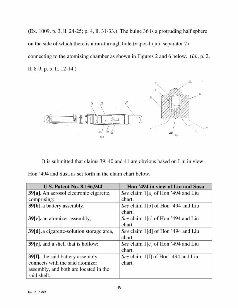
49 la-1212389
(Ex. 1009, p. 3, ll. 24-25; p. 4, ll. 31-33.) The bulge 36 is a protruding half sphere
on the side of which there is a run-through hole (vapor-liquid separator 7)
connecting to the atomizing chamber as shown in Figures 2 and 6 below. (Id., p. 2,
ll. 8-9; p. 5, ll. 12-14.)
It is submitted that claims 39, 40 and 41 are obvious based on Liu in view
Hon ’494 and Susa as set forth in the claim chart below.
U.S. Patent No. 8,156,944 Hon ’494 in view of Liu and Susa
39[a]. An aerosol electronic cigarette,
comprising:
See claim 1[a] of Hon ’494 and Liu
chart.
39[b]. a battery assembly, See claim 1[b] of Hon ’494 and Liu
chart.
39[c]. an atomizer assembly, See claim 1[c] of Hon ’494 and Liu
chart.
39[d]. a cigarette-solution storage area, See claim 1[d] of Hon ’494 and Liu
chart.
39[e]. and a shell that is hollow: See claim 1[e] of Hon ’494 and Liu
chart.
39[f]. the said battery assembly
connects with the said atomizer
assembly, and both are located in the
said shell;
See claim 1[f] of Hon ’494 and Liu
chart.

50 la-1212389
U.S. Patent No. 8,156,944 Hon ’494 in view of Liu and Susa
39[g]. the said cigarette solution storage
area is located in one end of the shell,
and fits with at least a portion of the
said atomizer assembly inside it;
See claim 1[g] of Hon ’494 and Liu
chart.
39[h]. the said shell has through-air-
inlets;
See claim 1[h] of Hon ’494 and Liu
chart.
39[i]. the atomizer assembly is an
atomizer, which includes a porous
component and an electric heating rod;
See claims 1[i] and 10[i] of Liu
anticipation chart.
39[j]. wherein the electric heating rod
comprises a cylinder and a heating
element provided at the wall of the
cylinder,
See claim 1[i] of Liu anticipation chart.
39[k]. the said porous component has a
run-through atomizing chamber;
See claim 10[k] of Liu anticipation
chart.
39[l]. the electric heating rod is in the
said atomizing chamber and
See claim 1[j] of Liu anticipation chart.
39[m]. there is a negative pressure
cavity in the atomizing chamber,
See claim 1[k] of Liu anticipation chart.
39[n]. wherein said heating element is
heating wire, which is wound on the
wall of the cylinder;
See claim 7 of Liu anticipation chart.

51 la-1212389
U.S. Patent No. 8,156,944 Hon ’494 in view of Liu and Susa
39[o]. on the wall of both ends of the
cylinder, there are mandrils
respectively;
Susa discloses mandrils to support a
heating element. See, e.g., Fig. 9; col.
7, ll. 30-32 (“The ceramic heater 42 is
fixed on the inner surface of the casing
main body 14 through a support
member 44.”). As shown in Fig 9
below, Susa discloses mandrils on the
wall of both ends of the heating
element.

52 la-1212389
U.S. Patent No. 8,156,944 Hon ’494 in view of Liu and Susa
39[p]. the said porous component has a
protuberance on one end, and the
protuberance fits with the cigarette
solution storage area;
Hon ’494 discloses a porous body 27
with a bulge 36 on one end that “is in
contact with the liquid supplying bottle
11 via the bulge.” See, e.g., Figs. 1, 6;
p. 3, ll. 24-25; p. 4, ll. 31-33.
39[q]. the said protuberance is a
protruding half sphere, on the side of
which there is a run-through hole
connecting to the atomizing chamber.
The bulge 36 is a protruding half sphere
on the side of which there is a run-
through hole (vapor-liquid separator 7)
connecting to the atomizing chamber.
See, e.g., Figs. 2, 6; p. 2, l. 8-9; p. 5, ll.
12-14.).
40. An aerosol electronic cigarette of
claim 39, wherein the said heating wire
is made of platinum wire, nickel-
chromium alloy wire or iron-chromium
alloy wire containing rare earth, or is
flaked.
See claim 34 of Hon ’494 and Liu chart.
See, e.g., Figs. 2, 6; p. 2, ll. 8-9; p. 5, ll.
12-14.).
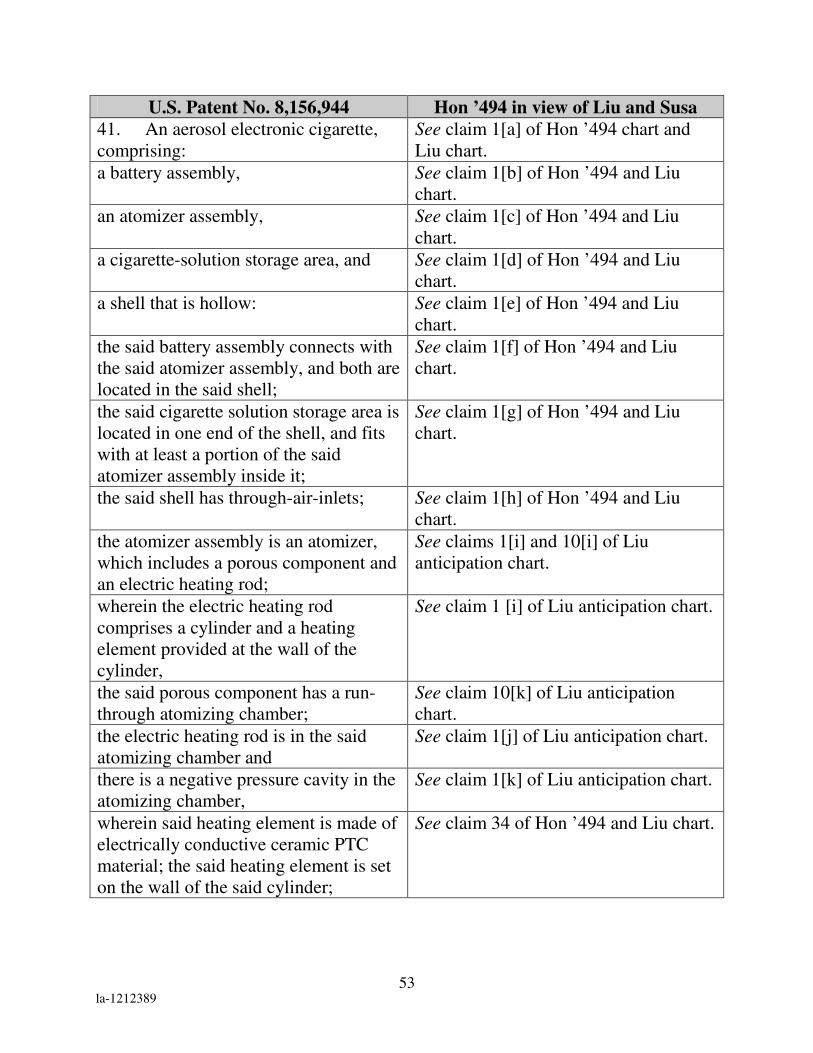
53 la-1212389
U.S. Patent No. 8,156,944 Hon ’494 in view of Liu and Susa
41. An aerosol electronic cigarette,
comprising:
See claim 1[a] of Hon ’494 chart and
Liu chart.
a battery assembly, See claim 1[b] of Hon ’494 and Liu
chart.
an atomizer assembly, See claim 1[c] of Hon ’494 and Liu
chart.
a cigarette-solution storage area, and See claim 1[d] of Hon ’494 and Liu
chart.
a shell that is hollow: See claim 1[e] of Hon ’494 and Liu
chart.
the said battery assembly connects with
the said atomizer assembly, and both are
located in the said shell;
See claim 1[f] of Hon ’494 and Liu
chart.
the said cigarette solution storage area is
located in one end of the shell, and fits
with at least a portion of the said
atomizer assembly inside it;
See claim 1[g] of Hon ’494 and Liu
chart.
the said shell has through-air-inlets; See claim 1[h] of Hon ’494 and Liu
chart.
the atomizer assembly is an atomizer,
which includes a porous component and
an electric heating rod;
See claims 1[i] and 10[i] of Liu
anticipation chart.
wherein the electric heating rod
comprises a cylinder and a heating
element provided at the wall of the
cylinder,
See claim 1 [i] of Liu anticipation chart.
the said porous component has a run-
through atomizing chamber;
See claim 10[k] of Liu anticipation
chart.
the electric heating rod is in the said
atomizing chamber and
See claim 1[j] of Liu anticipation chart.
there is a negative pressure cavity in the
atomizing chamber,
See claim 1[k] of Liu anticipation chart.
wherein said heating element is made of
electrically conductive ceramic PTC
material; the said heating element is set
on the wall of the said cylinder;
See claim 34 of Hon ’494 and Liu chart.

54 la-1212389
U.S. Patent No. 8,156,944 Hon ’494 in view of Liu and Susa
on the wall of both ends of the said
cylinder, there are mandrils
respectively;
See claim 39[o].
the said porous component has a
protuberance on one end, and the said
protuberance fits with the said cigarette
solution storage area;
See claim 39[p].
the said protuberance is a half sphere,
on the side of which there is a run-
through hole connecting to the said
atomizing chamber.
See claim 39[q].
V. CONCLUSION
For the reasons described above, there is a reasonable likelihood that
Petitioners will prevail as to each of claims 1-12, 15-26, and 33-41 of the
’944 patent. Accordingly, inter partes review of claims 1-12, 15-26, and 33-41 of
the ’944 patent is respectfully requested.

55 la-1212389
The USPTO is authorized to charge any required fees, including the fee as
set forth in 37 C.F.R. § 42.15(a) and any excess claim fees, to Deposit Account No.
03-1952 referencing Docket No. 71076-0000001.
Dated: June 27, 2013 Respectfully submitted,
By__/David L. Fehrman /_______
David L. Fehrman
Registration No.: 28,600
MORRISION & FOERSTER LLP
707 Wilshire Blvd., Suite 6000
Los Angeles, California 90017
(213) 892-5601
By___/Mehran Arjomand/_______
Mehran Arjomand
Registration No.: 48,231
MORRISON & FOERSTER LLP
707 Wilshire Blvd., Suite 6000
Los Angeles, California 90017
(213)892-5630

56 la-1212389
Certificate of Service (37 C.F.R. § 42.6(e)(4))
I hereby certify that the attached Petition for Inter Partes Review and
supporting materials were served as of the below date by U.S. Express Mail on the
Patent Owner at the correspondence address(es) indicated for U.S. Patent
No. 8,156,944:
PERKINS COIE LLP – LOS General
P.O. Box 1247
Seattle, WA 98111-1247
Dated: June 27, 2013 ___/David L. Fehrman /________
David L. Fehrman

[email protected] 571-272-7822 Paper No. 5
UNITED STATES PATENT AND TRADEMARK OFFICE ____________
BEFORE THE PATENT TRIAL AND APPEAL BOARD
____________
WAVELOCK ADVANCED TECHNOLOGY CO., LTD. Petitioner
v.
TEXTRON INNOVATIONS INC. Patent Owner
____________
Case IPR2013-00149 Patent 6,455,138 ____________
Mailed: February 21, 2013
Before LAWRENCE J. BANKS, Trial Paralegal.
NOTICE OF FILING DATE ACCORDED TO PETITION AND
TIME FOR FILING PATENT OWNER PRELIMINARY RESPONSE
The petition for inter partes review in the above proceeding has been
accorded the filing date of February 15, 2013.
Administrative Patent Judge Sally C. Medley has been designated to
manage the proceeding. 37 C.F.R. § 42.5.

Case IPR2013-00149 Patent 6,455,138
2
Patent Owner may file a preliminary response to the petition no later
than three months from the date of this notice. The preliminary response is
limited to setting forth the reasons why the requested review should not be
instituted. Patent Owner may also file an election to waive the preliminary
response to expedite the proceeding. For more information, please consult
the Office Patent Trial Practice Guide, 77 Fed. Reg. 48756 (Aug. 14, 2012),
which is available on the Board Web site at http://www.uspto.gov/PTAB.
Patent Owner is advised of the requirement to submit mandatory
notice information under 37 C.F.R. § 42.8(a)(2) within 21 days of service of
the petition.
The parties are advised that under 37 C.F.R. § 42.10(c), recognition of
counsel pro hac vice requires a showing of good cause. The parties are
authorized to file motions for pro hac vice admission under 37 C.F.R. §
42.10(c). Such motions shall be filed in accordance with the “Order --
Authorizing Motion for Pro Hac Vice Admission” in Case IPR2013-00010
(MPT), a copy of which is available on the Board Web site under
“Representative Orders, Decisions, and Notices.”
The parties are reminded that unless otherwise permitted by 37 C.F.R.
§ 42.6(b)(2), all filings in this proceeding must be made electronically in the
Patent Review Processing System (PRPS), accessible from the Board Web
site at http://www.uspto.gov/PTAB. To file documents, users must first
obtain a user ID and password by registering with PRPS. Information
regarding how to register with and use PRPS is available at the Board Web
site.
If there are any questions pertaining to this notice, please contact
Lawrence J. Banks at 571-272-3450 or the Patent Trial and Appeal Board at
571-272-7822.

Case IPR2013-00149 Patent 6,455,138
3
PETITIONER:
Mehran Arjomand MORRISON & FOERSTER LLP 555 West Fifth Street Los Angeles, CA 90013-1024 Tel: 213.892.5630 Fax: 323.210.1329 [email protected] Jonathan Bockman MORRISON & FOERSTER LLP 1650 Tysons Blvd., Suite 400 McLean, VA 22102-4220 Tel: 703.760.7769 Fax: 703.760.7777 [email protected]
PATENT OWNER:
TEXTRON SYSTEMS CORPORATION 201 Lowell Street Wilmington MA 01887-2941

[email protected] Paper 7
571-272-7822 Entered: January 16, 2013
UNITED STATES PATENT AND TRADEMARK OFFICE
____________
BEFORE THE PATENT TRIAL AND APPEAL BOARD
____________
KYOCERA CORPORATION.
Petitioner,
v.
ADC TECHNOLOGY INC.
Patent Owner.
____________
Case IPR2013-00107
Patent 8,103,313
____________
Before Andrew Kellogg, Trial Paralegal
NOTICE OF FILING DATE ACCORDED TO PETITION
AND
TIME FOR FILING PATENT OWNER PRELIMINARY RESPONSE
The petition for inter partes review in the above proceeding has been
accorded the filing date of January 11, 2013.
Administrative Patent Judge Brian J. McNamara has been designated to
manage the proceeding. 37 C.F.R. § 42.5.
A review of the petition identified the following defect(s):

Case IPR2013-00107
Patent 8,103,313
2
Improper usages of claim charts: The rules require that a petition identify
how the challenged claims are to be construed and how the claims are unpatentable
under the statutory grounds raised. This information is to be provided pursuant to
the page limit requirements, which require double spacing. Additionally, the rules
require that the petition specify where each element of a challenged claim is to be
found in the prior art. The element by element showing may be provided in a
claim chart, which is permitted to be written with single spacing. See 37 C.F.R
§42.6(a)(2)(iii).
Excess Pages: A petition for inter partes review is limited to 60 pages. 37
C.F.R §42.24(a)(i). While the page limit does not apply to “a table of contents, a
table of authorities, a certificate of service, or appendix of exhibits,” it is applicable
to “any statement of material facts to be admitted or denied in support of the
petition or motion.” 37 C.F.R §42.24(a). Therefore, in this Petition, both the title
page containing related matters and the claim charts containing analysis count
against the 60 page limit.
Petitioner must correct the defect(s) within FIVE BUSINESS DAYS from
this notice. Failure to correct the defect(s) may result in an order to show cause as
to why the Board should institute the trial. No substantive changes (e.g., new
grounds) may be made to the petition.
Patent Owner may file a preliminary response to the petition no later than
three months from the date of this notice. The preliminary response is limited to
setting forth the reasons why the requested review should not be instituted. Patent
Owner may also file an election to waive the preliminary response to expedite the
proceeding. For more information, please consult the Office Patent Trial Practice
Guide, 77 Fed. Reg. 48756 (Aug. 14, 2012), which is available on the Board Web
site at http://www.uspto.gov/PTAB.
Case IPR2013-00107
Patent 8,103,313
3
Patent Owner is advised of the requirement to submit mandatory notice
information under 37 C.F.R. § 42.8(a)(2) within 21 days of service of the petition.
The parties are advised that under 37 C.F.R. § 42.10(c), recognition of
counsel pro hac vice requires a showing of good cause. The parties are authorized
to file motions for pro hac vice admission under 37 C.F.R. § 42.10(c). Such
motions shall be filed in accordance with the “Order -- Authorizing Motion for Pro
Hac Vice Admission” in Case IPR2013-00010 (MPT), a copy of which is available
on the Board Web site under “Representative Orders, Decisions, and Notices.”
The parties are reminded that unless otherwise permitted by 37 C.F.R.
§ 42.6(b)(2), all filings in this proceeding must be made electronically in the Patent
Review Processing System (PRPS), accessible from the Board Web site at
http://www.uspto.gov/PTAB.
If there are any questions pertaining to this notice, please contact Andrew Kellogg
at 571-272-5366 or the Patent Trial and Appeal Board at 571-272-7822.
PETITIONER:
Richard Bauer
and
Michael S. Tomsa
KATTEN MUCHIN ROSENMAN LLP
2900 K Street NW - Suite 200
Washington, DC 20007-5118
PATENT OWNER:
DAVIS & BUJOLD, P.L.L.C.
112 Pleasant Street
Concord, NH 03301

LEGAL27290455.1
UNITED STATES PATENT AND TRADEMARK OFFICE
__________________
BEFORE THE PATENT TRIAL AND APPEAL BOARD
__________________
CB DISTRIBUTORS, INC. and DR DISTRIBUTORS, LLC
Petitioner
v.
RUYAN INVESTMENT (HOLDINGS) LIMITED Patent Owner
__________________
Case IPR2013-00387 Patent 8,156,944
__________________
PATENT OWNER’S MANDATORY NOTICES

Case IPR2013-00387 Patent 8,156,944
Attorney Docket No. 76320-0010
2 LEGAL27290455.1
Mail Stop PATENT BOARD Patent Trial and Appeal Board U.S. Patent & Trademark Office P.O. Box 1450 Alexandria, VA 22313-1450
Pursuant to 37 C.F.R. § 42.8, Patent Owner, Ruyan Investment (Holdings) Limited,
submits the following Mandatory Notices in response to the Petition for Inter Partes Review
on U.S. Patent No. 8,156,944.
1. Real Party-In-Interest
In accordance with 37 C.F.R. § 42.8(b)(1), Patent Owner identifies the real party-
in interest as Ruyan Investment (Holdings) Limited; formerly doing business as SBT
Investment (Holdings) Limited, formerly doing business as Best Partners Worldwide
Limited. Ruyan Investment (Holdings) Limited is a wholly owned subsidiary of
Dragonite International Limited; formerly doing business as Ruyan Group (Holdings)
Limited.
2. Related Matters
In accordance with 37 C.F.R. § 42.8(b)(2), Patent Owner identifies the following
related judicial proceedings:
a. Ruyan Investment (Holdings) Limited v. Sottera Inc, Civil Action No. 2:12-cv-05454-GAF-FFM, U.S. District Court for the Central District of California (following litigation matters b through j) are currently consolidated under this lead case);
b. Ruyan Investment (Holdings) Limited v. LOEC Inc, Civil Action No. 2:12-cv-05455-GAF-FFM, U.S. District Court for the Central District of California;
c. Ruyan Investment (Holdings) Limited v. CB Distributors Inc et al, Civil Action No. 2:12-cv-05456-GAF-FFM, U.S. District Court for the Central District of California;
d. Ruyan Investment (Holdings) Limited v. The Safe Cig LLC, Civil Action No 2:12-cv-05462-GAF-FFM, U.S. District Court for the Central District of California;
e. Ruyan Investment (Holdings) Limited v. Vapor Corp, Civil Action No, 2:12-cv-05466-GAF-FFM, U.S. District Court for the Central District of California;

Case IPR2013-00387 Patent 8,156,944
Attorney Docket No. 76320-0010
3 LEGAL27290455.1
f. Ruyan Investment (Holdings) Limited v. Finiti Branding Group LLC, Civil Action No. 2:12-cv-05468-GAF-FFM, U.S. District Court for the Central District of California;
g. Ruyan Investment (Holdings) Limited v. Barjan LLC et al, Civil Action No. 2:12-cv-05470-GAF-FFM, U.S. District Court for the Central District of California;
h. Ruyan Investment (Holdings) Limited v. Spark Industries LLC, Civil Action No. 2:12-cv-05472-GAF-FFM, U.S. District Court for the Central District of California;
i. Ruyan Investment (Holdings) Limited v. Nicotek LLC, Civil Action No. 2:12-cv-05477-GAF-FFM, U.S. District Court for the Central District of California; and
j. Ruyan Investment (Holdings) Limited v. Logic Technology Development LLC, Civil Action No. 2:12-cv-05482-GAF-FFM, U.S. District Court for the Central District of California.
In addition, Patent Owner identified the following related administrative matters:
k. Inter Partes Reexamination No. 95/002,235 of U.S. Patent No. 8,156,944 before the U.S. Patent Office, filed by FIN Branding Group, LLC;
l. U.S. Patent No. 8,365,742, issued February 5, 2013 to Lik Hon, filed April 5, 2011 as U.S. Patent Application No. 13/079,937; and
m. U.S. Application Pub. No. US2013-0125906A1 to Lik Hon, filed May 23, 2013 as U.S. Patent Application No. 13/740,011.
3. Lead and Back-Up Counsel
In accordance with 37 C.F.R. § 42.8(b)(3), Patent Owner identifies Michael J.
Wise as lead counsel and Kenneth H. Ohriner as back-up counsel:
Michael J. Wise, Lead Counsel USPTO Reg. No. 34,047
PERKINS COIE LLP 1888 Century Park East, Suite 1700 Los Angeles, CA 90067 Phone: 310-788-3210 Facsimile: 310-788-3399 Email: [email protected] Kenneth H. Ohriner, Back-up Counsel

Case IPR2013-00387 Patent 8,156,944
Attorney Docket No. 76320-0010
4 LEGAL27290455.1
USPTO Reg. No. 31,646
PERKINS COIE LLP 1888 Century Park East, Suite 1700 Los Angeles, CA 90067 Phone: 310-788-3267 Facsimile: 310-788-3399 Email: [email protected]
4. Service Information
In accordance with 37 C.F.R. § 42.8(b)(4), Patent Owner identifies the following
service information:
Patent Docketing PERKINS COIE LLP P.O. Box 1247 Seattle, WA 98111-1247 Phone: 206-359-8248 Facsimile: 206-359-9248 Email: [email protected]
Respectfully submitted,
Date: July 17, 2013 By: /Michael J. Wise/ Michael J. Wise, Reg. No. 34,047 Perkins Coie LLP 1888 Century Park East, Suite 1700 Los Angeles, CA 90067 Phone: 310-788-3210 Facsimile: 310-788-3399

Case IPR2013-00387 Patent 8,156,944
Attorney Docket No. 76320-0010
-5- LEGAL27290455.1
CERTIFICATE OF SERVICE
I hereby certify that on this 17th day of July, 2013, a true and correct copy of the
foregoing PATENT OWNER’S MANDATORY NOTICES was served via electronic
mail and First-Class U.S. Mail upon the following counsel of record for Petitioners CB
DISTRIBUTORS, INC. And DR DISTRIBUTORS, LLC:
David L. Fehrman, Lead Counsel Mehran Arjomand, Back-up Counsel
Morrison & Foerster LLP 707 Wilshire Blvd.
Los Angeles, CA 90017-3543 [email protected]
/Amy Candeloro/
Amy Candeloro Paralegal Perkins Coie LLP

[email protected] Paper 7
Tel: 571-272-7822 Entered: December 30, 2013
UNITED STATES PATENT AND TRADEMARK OFFICE
_______________
BEFORE THE PATENT TRIAL AND APPEAL BOARD
_______________
CB DISTRIBUTORS, INC. and
DR DISTRIBUTORS, LLC
Petitioner
v.
RUYAN INVESTMENT (HOLDINGS) LIMITED
Patent Owner
____________
Case IPR2013-00387
Patent 8,156,944 B2
_______________
Before JACQUELINE WRIGHT BONILLA, BRIAN J. McNAMARA, and
TRENTON A. WARD, Administrative Patent Judges.
BONILLA, Administrative Patent Judge.
DECISION
Institution of Inter Partes Review
37 C.F.R. § 42.108

IPR2013-00387
Patent 8,156,944 B2
2
I. INTRODUCTION
CB Distributors, Inc. and DR Distributors, LLC (collectively “CB
Distributors”) filed a petition (Paper 1, “Pet.”) to institute an inter partes review of
claims 1-12, 15-26, and 33-41 of U.S. Patent No. 8,156,944 B2 (Ex. 1001) (“the
’944 patent”) pursuant to 35 U.S.C. § 311 et seq. Ruyan Investment (Holdings)
Limited (“Ruyan”) did not file a preliminary response. We have jurisdiction under
35 U.S.C. § 314.
The standard for instituting an inter partes review is set forth in 35 U.S.C.
§ 314(a), which provides:
THRESHOLD—The Director may not authorize an inter partes
review to be instituted unless the Director determines that the
information presented in the petition filed under section 311 and any
response filed under section 313 shows that there is a reasonable
likelihood that the petitioner would prevail with respect to at least 1 of
the claims challenged in the petition.
For the reasons set forth below, we conclude that CB Distributors has
established a reasonable likelihood that it will prevail in showing the
unpatentability of at least one challenged claim. Pursuant to 35 U.S.C. § 314, we
institute an inter partes review of claims 1-12, 15-26, and 33-38, but not claims 39-
41, of the ’944 patent.
A. Related Matters
CB Distributors indicates that a third party, Fin Branding Group, LLC
(“Fin”), requested inter partes reexamination of the ’944 patent, i.e., reexamination
proceeding 95/002,235. Pet. 1. In an Order entered July 24, 2013, the Board
stayed that reexamination in view of this inter partes review. Paper 6.
CB Distributors also indicates that Ruyan filed lawsuits asserting
infringement of the ’944 patent against nine different defendants in U.S. District

IPR2013-00387
Patent 8,156,944 B2
3
Court for the Central District of California, including Ruyan Investment (Holdings)
Limited v. CB Distributors, Inc. and DR Distributors, LLC, No. CV12-5456, and
Ruyan Investment (Holdings) Limited v. Fin Branding Group, LLC, No. CV12-
5468. Pet. 1-2. The district court consolidated all nine cases for pre-trial purposes
as Ruyan Investment (Holdings) Limited v. Sottera, Inc., No. CV12-5454. Id. at 2.
On February 25, 2013, the district court stayed all proceedings in light of the inter
partes reexamination requested by Fin. Id.
B. The ’944 Patent (Ex. 1001)
The ’944 patent relates generally to an aerosol electronic cigarette that
contains nicotine, but not tar, and “substitutes for cigarettes and helps the smokers
to quit smoking.” Ex. 1001, 1: 5-7, 57-60. Figure 1 of the ’944 patent, as
reproduced in better quality in the petition, is reproduced below.
Pet. 4; Ex. 1001, Fig. 1. Figure 1 depicts a side section view of an aerosol
electronic cigarette comprising a battery assembly, an atomizer assembly, a
cigarette bottle assembly, and shell a. Id. at 5:38-42; 1:62-65. The battery
assembly includes battery 3, operating indicator 1, electronic circuit board 4, and
airflow sensor 5. The atomizer assembly is atomizer 8. Id. at 6:13-15. The
cigarette bottle assembly includes a perforated component for liquid storage 9
inside hollow cigarette holder shell b. Id. at 6:56-58.

IPR2013-00387
Patent 8,156,944 B2
4
Figures 5-8 of the ’944 patent, as reproduced in better quality in the petition,
are reproduced below.
Pet. 5; Ex. 1001, Figs. 5-8. Figure 5 depicts a side section view of porous
component 81 and run-through atomizing chamber 811 of atomizer 8 (shown in
Figure 1). Figure 6 depicts electric heating rod 82 of atomizer 8. Figure 7 depicts
a side section of atomizer 8, including porous component 81, electric heating rod
82 (shown in Figure 6), and negative pressure cavity 83. Figure 8 depicts a cubic
structure of atomizer 8. Ex. 1001, 4:44-55; 6:13-42.
C. Illustrative Claims
Claims 1, 10, 39, and 41 are independent. Claims 2-9 depend, directly or
indirectly, on claim 1, which is reproduced below:
1. An aerosol electronic cigarette, comprising:
a battery assembly, an atomizer assembly, a cigarette-solution
storage area, and a hollow shell having a mouthpiece;

IPR2013-00387
Patent 8,156,944 B2
5
the battery assembly connects with the atomizer assembly, and
both are located in the shell;
the cigarette solution storage area is located in one end of the
shell adjacent to the mouthpiece, and fits with at least a portion of the
said atomizer assembly inside it;
the shell has through-air-inlets;
the atomizer assembly includes an atomizer comprising an
electric heating rod and a run-through atomizing chamber;
the electric heating rod comprises a cylinder and a heating
element provided at the wall of the cylinder,
the electric heating rod is in the said atomizing chamber and
there is a negative pressure cavity in the atomizing chamber.
Id. at 9:2-16 (emphasis and indentation added).
Claims 11, 12, 15-26, and 33-38 depend, directly or indirectly, on claim 10,
which is reproduced below:
10. An aerosol electronic cigarette, comprising:
a battery assembly, an atomizer assembly, a cigarette solution
storage area, and a shell that is hollow and comprises a mouthpiece;
the said battery assembly connects with the said atomizer
assembly, and both are located in the said shell;
the said cigarette solution storage area is located in one end of
the shell proximal to the mouthpiece, and fits with at least a portion of
the said atomizer assembly inside it;
the said shell has through-air-inlets;
the atomizer assembly is an atomizer, which includes a porous
component and an electric heating rod;
wherein the electric heating rod comprises a cylinder and a
heating element provided at the wall of the cylinder, the said porous
component has a run-through atomizing chamber;
the electric heating rod is in the said atomizing chamber and
there is a negative pressure cavity in the atomizing chamber.

IPR2013-00387
Patent 8,156,944 B2
6
Id. at 9:36-52 (emphasis and indentation added). Independent claims 39 and 41 are
similar to claim 10, but further recite elements relating to the heating element, as
well as additional elements relating to “a protuberance on one end” of the porous
component. Id. at 11:23-12-37. Claim 40 depends on claim 39. Id. at 12:9-12.
D. Prior Art Relied Upon
CB Distributors relies upon the following prior art references:
Liu WO 2007/078273 A1 July 12, 2007 Ex. 1019
Susa EP 0 845 220 A1 June 3, 1998 Ex. 1020
Hon ’494 WO 2005/099494 A1 Oct. 27, 2005 Ex. 1008
(English translation Ex. 1009)
E. Alleged Grounds of Unpatentability
CB Distributors contends that claims 1-12, 15-26, and 33-41 of the
’944 patent are unpatentable under 35 U.S.C. §§ 102(b) and 103(a) based on the
following five grounds. Pet. 11.
Reference(s) Basis Claims Challenged
Liu § 102 1, 2, 5-8, 10, 33, 35, 37, and 38
Liu § 103 20
Liu and Susa § 103 3, 4, 12, 15, 17, and 26
Hon ’494 and Liu § 103 1-4, 8-12, 15-26, 33, 34, 36, and 38
Hon ’494, Liu, and Susa § 103 39-41
II. ANALYSIS
A. Claim Construction
Consistent with the statute and legislative history of the Leahy-Smith
America Invents Act, Pub. L. 112-29, 125 Stat. 284, 329 (2011), the Board

IPR2013-00387
Patent 8,156,944 B2
7
construes claims in an unexpired patent by applying the broadest reasonable
interpretation in light of the specification. 37 C.F.R. § 42.100(b); see also Office
Patent Trial Practice Guide, 77 Fed. Reg. 48,756, 48,766 (Aug. 14, 2012). Claim
terms are also given their ordinary and customary meaning as would be understood
by one of ordinary skill in the art in the context of the entire disclosure. In re
Translogic Tech., Inc., 504 F.3d 1249, 1257 (Fed. Cir. 2007).
1. “Run-through atomizing chamber”
All challenged independent claims recite an atomizer assembly that
“includes an atomizer comprising an electric heating rod and a run-through
atomizing chamber.” CB Distributors contends that “run-through atomizing
chamber” means “a chamber having a flow in which atomization occurs along the
length thereof,” and does not require “that the input and output ends of the
chamber be unblocked.” Pet. 13-14. For the purposes of this decision, we adopt
that claim construction, which is logical when reading each challenged claim as a
whole, and is consistent with disclosures in the Specification of the ’944 patent.
For example, one embodiment of the atomizing chamber is “run-through
atomizing chamber (811),” as described in the Specification and shown in
Figures 5, 7, and 8 of the ’944 patent. Ex. 1001, 6:13-16; Figs. 5, 7, 8. The
Specification discloses that the “diameter of the electric heating rod (82) is less
than the diameter of the atomizing chamber (811),” and that “electric heating rod
(82) enters into the atomizing chamber (811), and there is a clearance between the
electric heating rod (82) and interior wall of the atomizing chamber (811), which
forms a negative pressure cavity (83).” Id. at 6:16-21. Independent claims 1 and
10, and the Specification, indicate that the electric heating rod includes “a cylinder
and a heating element provided at the wall of the cylinder.” Id. at 2:44-46.

IPR2013-00387
Patent 8,156,944 B2
8
Consistently, a “run-through atomizing chamber” in the challenged claims
refers to a chamber inside an atomizer, where that chamber is defined by an
interior wall of a component in the atomizer creating the chamber, e.g., the interior
wall of cylindrical porous component 81, as shown in Figures 5 and 7 of the
’944 patent. Although the Specification does not define “run-through” per se, a
reading of independent claim 1, 10, 39, or 41, in view of the Specification,
indicates that this phrase means that the atomizing chamber runs through, i.e.,
inside and along the length of, the atomizer and its electric heating rod, and
atomization occurs along (i.e., runs through) the length of the chamber.
2. “Negative pressure cavity in the atomizing chamber”
All challenged independent claims recite an atomizer assembly where “there
is a negative pressure cavity in the atomizing chamber.” As noted above, the
’944 patent Specification discloses that a clearance exists between the heating rod
and an interior wall of a component in the atomizer that defines the run-through
atomizing chamber. Id. at 2:40-42; 6:13-21, 40-41. The Specification also
discloses that the “clearance forms a negative pressure cavity.” Id. The
Specification describes that when a person inhales, within shell b, “one end of the
airflow sensor (5) forms a normal pressure cavity, while the other end forms a
negative pressure cavity.” Id. at 7:8-11. As further described in the Specification,
and shown in Figure 1, “air enters the normal pressure cavity through the air inlet
(a1), passes the check valve (7) via the airflow passage in the airflow sensor (5),
and flows to the negative pressure cavity (83) in the atomizer (8).” Id. at 7:22-25;
Fig. 1.
In addition, the Specification discloses that because “negative pressure
cavity (83) provides the negative pressure compared with the outside, the air flow
sprays into it, bringing the cigarette liquid from the porous component (81) to

IPR2013-00387
Patent 8,156,944 B2
9
spray into the negative pressure cavity (83) in the form of fine drips.” Id. at 7:25-
29. After the fine drips enter into the negative pressure cavity, the heating rod
heats the drips for atomization. Id. at 7:30-32. After atomization, the drips form a
“gasoloid, which is discharged through the negative pressure cavity (83) and run-
through hole (813),” and into shell b, and absorbed by air channel b1. Id. at 7:32-
43.
In other words, negative pressure in cavity 83 causes an air and liquid
mixture to form fine drips as the mixture leaves the porous component and enters
cavity 83. The above-mentioned disclosures in the Specification, as a whole,
indicate that cavity 83 has a negative pressure compared to pressure outside that
cavity, i.e., outside the run-through atomizing chamber, e.g., outside porous
component 81, as depicted in Figures 5 and 7 of the Specification.
For the purposes of this decision, consistent with each independent claim as
a whole, an ordinary meaning of the phrase “negative pressure”1 in relation to a
distinct cavity, as well as disclosures in the Specification, we interpret “negative
pressure cavity” to refer to a cavity within the run-through atomizing chamber of
the atomizer, where pressure inside that cavity is negative compared to pressure
outside the cavity. For example, pressure inside the negative pressure cavity is
negative compared to pressure outside the atomizer assembly, within the recited
shell of the electronic cigarette.
1 See, e.g., OXFORD DICTIONARY OF SCIENCE 633 (4th ed. 1999) (defining
“pressure” as the “force normally acting on unit area of a surface or the ratio of
force to area”).

IPR2013-00387
Patent 8,156,944 B2
10
3. “Cigarette solution storage area”
All challenged independent claims recite a “cigarette solution storage area”
that is “located in one end of the shell” and “fits with at least a portion of the said
atomizer assembly inside it.”
An example of the recited “cigarette solution storage area” is “perforated
component for liquid storage (9),” located inside shell b, as shown in Figure 1 and
described in the ’944 patent Specification. Id. at 6:56-58. Dependent claim 2, for
instance, recites “a cigarette solution in the cigarette solution storage area, the
cigarette solution comprising nicotine.” Id. at 9:34-36. Such claim language
indicates that the cigarette solution storage area is capable of storing a cigarette
solution, such as one comprising nicotine. See also id. at 11:21-23 (claim 38,
reciting “a cigarette solution comprising nicotine”).
As depicted in Figures 1, 5, and 7, and described in the Specification, porous
component 81 of atomizer 8 (part of the atomizer assembly) “has a protuberance
on one end,” i.e., protuberance 812, that fits inside perforated component for liquid
storage 9. Id. at 2:46-50; 4:44-45; 6:23-30; see Figure 1 (depicting a protuberance
on atomizer 8 fitting inside perforated component for liquid storage 9).
For the purposes of this decision, consistent with each claim as a whole, as
well as disclosures in the Specification, a “cigarette solution storage area” that “fits
with at least a portion of the said atomizer assembly inside it” means that at least a
part of an atomizer, such as a protuberance on a component of an atomizer, is
located inside the cigarette solution storage area, which is capable of storing a
cigarette solution, such as one comprising nicotine. See also, Ex. 1001, claim 2,
9:17-19.

IPR2013-00387
Patent 8,156,944 B2
11
4. “Porous component”
Independent claims 10, 39, and 41 recite an atomizer that “includes a porous
component.” Claim 20, which depends on claim 10, recites that the “porous
component is made of foamed nickel, stainless steel fiber felt, polymer or
ceramics.”
An example of the porous component is porous component 81, shown in
Figures 5, 7, and 8 of the Specification of the ’944 patent (reproduced above).
Pet. 5; Ex. 1001, Figs. 5, 7, 8. The Specification describes that “porous component
(81) is made of foamed nickel, stainless steel fiber felt, macromolecular polymer
foam or foamed ceramics, providing the remarkable capabilities in liquid
absorption and diffusion, and the ability to absorb the liquid stored in the cigarette
bottle assembly.” Ex. 1001, 6:30-34. The Specification also states that porous
component 81 “absorbs the cigarette liquid from the perforated component for
liquid storage (9).” Id. at 7:3-7. The Specification further describes that “[a]fter
atomization, the big-diameter fine drips are re-absorbed by the porous component
(81) under the action of vortex.” Id. at 7:32-37.
For the purposes of this decision, consistent with disclosures in the
Specification as well as an ordinary meaning of the phrase “porous,”2 we interpret
a “porous component” to be a component of the atomizer assembly in the
electronic cigarette that includes pores and is permeable to liquid, such as cigarette
solution from the cigarette solution storage area.
2 See, e.g., Random House Webster’s College Dictionary 1051 (1995) (defining
“porous” as “permeable by water, air, etc.” or “full of pores”).

IPR2013-00387
Patent 8,156,944 B2
12
B. Discussion
1. 35 U.S.C. § 102(b) Ground Based on Liu
CB Distributors contends that Liu anticipates 1, 2, 5-8, 10, 33, 35, 37, and
38. Pet. 11, 18-29. CB Distributors uses claim charts to explain how the reference
allegedly discloses the claimed subject matter. Id.
a. Liu (Ex. 1019)
Liu relates generally to a no-tar electronic smoking utensil. Ex. 1019, 1:6-7.
Figures 1-6 in Liu illustrate an embodiment described in this reference. Figures 1-
6 are reproduced below.
Figure 1 depicts a side view of a “simulated cigarette,” including outer casing 6.
Id. at 4:15-16; 5:14-15. Figures 2-6 present different sectional viewpoints of the
simulated cigarette of Figure 1. Id. at 4:18-31. Figure 3 depicts a tip end view,

IPR2013-00387
Patent 8,156,944 B2
13
looking in the direction of arrow X in Figure 2. Figure 4 depicts mouthpiece end 4
(as shown in Figure 1), looking at the direction of arrow Y in Figure 2. As
depicted in Figures 2 and 6, the simulated cigarette comprises battery chamber 12
including a plurality of apertures 16, and cylinder liquid container 18 separated
from the battery chamber by dividing wall 20 that comprises a plurality of
apertures 22. Liquid container 18 “is formed of porous inorganic material,” which
“facilitates the distribution and the mixing of the air and liquid mixture.” Id. at
6:11-14.
As shown in Figures 2 and 5, the simulated cigarette also comprises
cylindrical vapouriser heater assembly housing 24, which is “mounted within a
central bore provided in the mouthpiece end of the liquid container 18.” Id. at
6:16-18. Housing 24 houses heater wire 26 spirally wound on a central ceramic
insulating rod. Id. at 6: 18-19. As described in Liu, “walls of the heater housing
24 are provided with a plurality of apertures 28 to permit entry of the liquid/air
from the liquid container 18 into the heater housing 24.” Id. at 6:20-22.
Liu describes that as “the user draws on the cigarette mouthpiece, air is
drawn into the battery chamber [12], into the liquid container [18] to mix with the
liquid mixture, and into the heater assembly [24],” and the “resulting vapour is
drawn into the mouth of the user.” Id. at 7:16-19. Liu further describes that “in
use, suction on the mouthpiece by the user causes air to be drawn through the
porous container for liquid [18], over the heated vapouriser, into the mouthpiece
and into the mouth of the user.” Id. at 4:6-8; see also 9:21-24.
b. Analysis
As noted above, CB Distributors uses claim charts to explain how Liu
allegedly discloses every element recited in each of claims 1, 2, 5-8, 10, 33, 35, 37,
and 38. Pet. 11, 18-29.

IPR2013-00387
Patent 8,156,944 B2
14
For example, CB Distributors points to disclosure in Liu as corresponding to
certain elements recited in independent claims 1 and 10 as follows:
’944 patent claim element Disclosure in Liu
“an atomizer assembly” Vapouriser heater assembly housing 24
“a cigarette solution storage area” Liquid container 18
“negative pressure cavity in the
atomizing chamber”
“suction on the mouthpiece by the user
causes air to be drawn through the porous
container for liquid, over the heated
vapouriser, into the mouthpiece and into
the mouth of the user” (citing Ex 1019,
4:6-9; 9:22-24, Fig. 2)
“porous component” (claim 10) Walls of heater assembly housing 24
“provided with a plurality of apertures 28
to permit entry of the liquid/air from the
liquid container 18 into the heater housing
24” (citing Ex. 1019, 6:20-11, Fig. 5)
Pet. 21, 25, 26, and 28.
As stated in Liu, a portion of liquid container 18 “is formed of a porous
material to facilitate distribution of the liquid through the container, prior to being
fed to the heater means.” Ex. 1019, 3:1-3; Pet. 21. That liquid mixture may
contain nicotine. Id. at 3:10-13. Thus, CB Distributors argues that Liu discloses
that “liquid container 18” stores a cigarette solution. Pet. 21. Liu also discloses
that “vapouriser heater assembly housing 24” houses an electric heating rod (i.e.,
“heater wire 26 spirally wound on a central ceramic insulating rod”), which is
capable of vaporizing for inhalation, i.e., atomizing, a cigarette solution. Id. at
6:16-22; 7:16-19; Pet. 21, 24. As shown in Figure 1 of Liu, housing 24 (an
atomizer assembly) fits inside liquid container 18 (a cigarette-solution storage

IPR2013-00387
Patent 8,156,944 B2
15
area), as recited in the challenged independent claims. Id. at Fig. 1; Pet. 23. CB
Distributors argues that Figure 1 of Liu identifies these components and depicts a
“run-through atomizing chamber,” i.e., a chamber inside housing 24 that contains
the heating rod, which runs along the length of housing 24. Id.
In relation to the “negative pressure cavity in the atomizing chamber” recited
in independent claims 1 and 10, CB Distributors argues that Liu discloses that after
a user draws on a cigarette mouthpiece, air goes into battery chamber 14, and “air
in the battery chamber is sucked into the liquid container 18 through apertures 22
where it mixes with the liquid solution.” Pet. 19 (citing Ex. 1019, 7:16-19).
According to CB Distributors, “air and liquid solution mixture is then drawn into
the porous walls of the vapouriser heater assembly [24] which contain apertures
28.” Id. (citing Ex. 1019, Fig. 5; 6:20-22; 7:16-19). CB Distributors also contends
that “flow of air through the cigarette indicates the space in between the vapouriser
housing 24 and the heating rod 26 forms a negative pressure cavity as the user
inhales.” Id.
As discussed above, we interpret this “negative pressure cavity” element as
referring to a cavity within a run-through atomizing chamber of an atomizer, where
pressure inside that cavity is negative compared to pressure outside the cavity.
CB Distributors contends this cavity in Liu, as shown in Fig. 2 of that reference, is
located between the inner wall of heater assembly housing 24 and heater wire 26.
Pet. 25; Ex. 1019, Fig. 2. Consistent with CB Distributors’s arguments, in a claim
chart, CB Distributors points to disclosure in Liu stating that “suction on the
mouthpiece by the user causes air to be drawn through the porous container for the
liquid, over the heated vapouriser, into the mouthpiece and into the mouth of the
user.” Pet. 25, 28 (citing Ex 1019, 4:6-9; 9:22-24). Along these lines, we note that
Liu describes that “the flow of fluids through the cigarette is caused solely or

IPR2013-00387
Patent 8,156,944 B2
16
principally by the suction of the user.” Ex. 1019, 2:24-26. In addition, as
CB Distributors points out, Liu discloses that “walls of the heater housing 24 are
provided with a plurality of apertures 28 to permit entry of the liquid/air from the
liquid container 18 into the heater housing 24.” Id. at 6:20-22; Pet. 28.
In other words, Liu indicates that when a user inhales, liquid from container
18 moves into the atomizing chamber inside housing 24. See, e.g., Ex. 1019, 7:16-
19. CB Distributors argues that negative pressure, via suction on the mouthpiece,
exists necessarily inside vapouriser housing 24 relative to pressure outside housing
24 in order for liquid to move in that direction. Pet. 25. Thus, while Liu does not
mention “negative pressure” per se, by virtue of its discussion of suction and how
liquid flows inside the cigarette, Liu discloses inherently (necessarily) that pressure
in the cavity between the inner wall of heater assembly housing 24 and heater wire
26 is negative as compared to pressure existing inside liquid container 18. We are
persuaded that CB Distributors has shown a reasonable a likelihood that it will
prevail on its contention that Liu anticipates independent claim 1.
In addition, we are persuaded likewise that CB Distributors has shown a
reasonable likelihood that it will prevail on its contention that Liu anticipates
independent claim 10. For example, as discussed above, the “porous component”
of claim 10 refers to a component in the electronic cigarette that includes pores and
is permeable to liquid, i.e., allows liquid to pass through it. CB Distributors
contends that Liu discloses that an “air and liquid solution mixture is [] drawn into
the porous walls of the vapouriser heater assembly which contain apertures 28.”
Pet. 19 (citing Ex. 1019, Fig. 5; 6:20-22; 7:16-19). In other words, apertures 28 in
the walls housing 24 correspond to pores, and therefore the “walls of heater
housing 24” correspond to a porous component. Id. at 28.

IPR2013-00387
Patent 8,156,944 B2
17
Based on the record before us, CB Distributors has demonstrated a
reasonable likelihood of prevailing on its assertion that Liu anticipates independent
claims 1 and 10.
In addition, CB Distributors argues that Liu discloses the claimed subject
matter recited in dependent claims 2, 5-8, 33, 35, 37, and 38, as presented in the
petition and claim charts. Liu describes that the liquid in container 18 may contain
nicotine, as recited in claims 2 and 38. Pet. 25, 29; Ex. 1019, 6:29-30. Liu also
describes a “heater wire 26 spirally wound on a central ceramic insulating rod” that
corresponds to a “coiled wire” that “extends along the length of” and “on the outer
surface of,” or “on the outside of,” a cylinder, as recited in dependent claims 5-8,
33, 35, and 37. Pet. 26, 28-29; Ex. 1019, 6:18-19. We are persuaded that CB
Distributors has demonstrated a reasonable likelihood of prevailing on its assertion
that Liu anticipates dependent claims 2, 5-8, 33, 35, 37, and 38.
2. 35 U.S.C. § 103(a) Ground Based on Hon ’494 and Liu
CB Distributors contends that claims 1-4, 8-12, 15-26, 33-34, 36, and 38 of
the ’944 patent would have been obvious over Hon ’494 and Liu. Pet. 11, 36-47.
Again, CB Distributors uses claim charts to explain how the references allegedly
teach or suggest the claimed subject matter. Id. We discuss Liu above.
a. Hon ’494 (Ex. 1009)
Hon ’494 relates to an aerosol electronic cigarette. Ex. 1009, 1:35-37.
Figures 1 and 6 in Hon ’494 are reproduced below.

IPR2013-00387
Patent 8,156,944 B2
18
Figure 1 depicts the structure of an electronic cigarette, which includes air inlet 4,
normal pressure cavity 5, sensor 6, negative pressure cavity 8, vapor-liquid
separator 7, atomizer 9, liquid-supplying bottle 11, mouthpiece 15, and shell 14.
Ex. 1009, Fig. 1, 3:14-21. Figure 6 depicts a structural diagram of the atomizer,
which includes atomization cavity 10, heating element RL, first piezoelectric
element M1, atomization cavity wall 25, and porous body 27. Id. at 2:48, 3:26-29,
35-38.
As described in Hon ’494, “solution storage porous body 28 in the liquid-
supplying bottle 11 will be in contact with the bulge 36 on the atomizer 9, thereby
achieving the capillary infiltration liquid-supplying.” Id. at 4:31-33; 3:24-25;
Figs. 1, 6, and 11. Hon ’494 further discloses that heating element RL “can be
made of platinum wire, nickel chromium alloy or iron chromium aluminum alloy

IPR2013-00387
Patent 8,156,944 B2
19
wire with rare earth element” and “can also be made into a sheet form.” Id. at
3:27-29. Porous body 27 in atomizer 9 “can be made of foam nickel, stainless steel
fiber felt, high molecular polymer foam and foam ceramic,” and that “atomization
cavity wall 25 can be made of aluminum oxide or ceramic.” Id. at 3:35-38; Fig. 6.
In addition, Hon ’494 describes that “[w]hen a smoker smokes, the
mouthpiece 15 is under negative pressure, the air pressure difference or high speed
stream between the normal pressure cavity 5 and the negative pressure cavity 8
will cause the sensor 6 to output and actuating signal,” which causes the cigarette
to go into operation. Id. at 4:11-14. Hon ’494 teaches that air enters normal
pressure cavity 5 through air inlet 4, goes through a hole in vapor-liquid separator
7, and flows into atomization cavity 10 of atomizer 9. Id. at 4:21-24. A “high
speed stream passing through the ejection hold drives the nicotine solution in the
porous body 27 to eject into the atomization cavity 10 in the form of droplet,”
where the nicotine solution is atomized by element M1 and further atomized by
heating element RL. Id. at 4:24-27. After atomization, larger diameter droplets are
reabsorbed by porous body 27, and smaller diameter droplets form aerosols, which
are sucked out via passage 12, gas vent 17 and mouthpiece 15. Id. at 4:28-31.
b. Analysis
As noted above, CB Distributors uses claim charts to explain how Hon ’494,
in view of Liu, allegedly teaches or suggests every element recited in each of
claims 1-4, 8-12, 15-26, 33-34, 36, and 38. Pet. 11, 36-47.
For example, CB Distributors points to disclosure in Hon ’494 as
corresponding to certain elements recited in independent claims 1 and 10 as
follows:

IPR2013-00387
Patent 8,156,944 B2
20
’944 patent claim element Disclosure in Hon ’494
“an atomizer assembly” Atomizer 9 with atomization cavity 10
and heating element RL
“a cigarette solution storage area”
that “fits with at least a portion of
the said atomizer assembly inside
it”
Liquid-supplying bottle 11 that fits with
bulge 36 of atomizer 9 inside it
“porous component” (claim 10) Porous component 27
Pet. 37, 39-42.
Hon ’494 also indicates that inhalation (“smoking”) by a user causes a “high
speed stream,” which leads to liquid (“nicotine solution”) flowing from porous
body 27 into atomization cavity 10 of atomizer 9. Ex. 1009, 4:11-27. In other
words, it is a reasonable position that a “negative pressure cavity” exists
necessarily in atomization cavity 10 in relation to pressure outside that cavity.
CB Distributors recognizes, however, that Hon ’494 does not describe a run-
through atomizing chamber or electric heating rod comprising a cylinder, and
therefore, does not disclose a negative pressure cavity in that atomizing chamber,
as required in claims 1 and 10. Pet. 40-42. CB Distributors points to Liu for such
disclosures, as discussed above. Id.
CB Distributors contends that it “would have been obvious to employ a
vapouriser assembly as disclosed by Liu (including the central rod extending
lengthwise along the vapouriser with a spirally wound heater wire inside the
vapouriser assembly) in the electronic cigarette of Hon ’494.” Id. at 39.
According to CB Distributors, the “combination is simply applying a known
technique (a run-through atomization chamber) to a known device (the electronic
cigarette of Hon ’494) to yield predictable results.” Id.

IPR2013-00387
Patent 8,156,944 B2
21
Based on the record before us, we are persuaded by CB Distributor’s
arguments. Liu and Hon ’494 describe similar electronic cigarettes. Atomizer 9 in
Hon ’494 uses a differently shaped heating element, located in a different place in
atomizing chamber 10, as compared to the location of such elements in Liu’s
atomizer (housing 24). Atomizer 9 (comprising porous body 27) in Hon ’494 does
not have a “run-through atomizing chamber” as construed above, because, for
example, heating element RL does not run along the length of cavity 10, but rather
is perpendicular to it. See Ex. 1009, Figs. 1, 6. Liu, on the other hand, discloses an
atomizer assembly (housing 24) including a cylinder electric heating rod (“heater
wire 26 spirally wound on a central ceramic insulating rod”) that runs along a run-
through atomizing chamber, as discussed previously.
As stated in KSR, the “combination of familiar elements according to known
methods is likely to be obvious when it does no more than yield predictable
results.” KSR Int’l Co. v. Teleflex Inc., 550 U.S. 398, 416 (2007). Based on the
record before us, we are persuaded that CB Distributors provides an articulated
reasoning to substitute a cylinder electric heating rod (as taught in Liu) that runs
along the length of atomizing chamber 10 for the heating element RL (as taught in
Hon ’494), because such a substitution appears to be merely a “predictable use of
prior art elements according to their established functions.” KSR, 550 U.S. at 417.
Based on the record before us, CB Distributors has demonstrated a
reasonable likelihood of prevailing on its assertion that independent claims 1 and
10 would have been obvious over Hon ’494 in view of Liu.
In addition, CB Distributors argues that Hon ’494 and Liu teach the claimed
subject matter recited in dependent claims 2-4, 8, 9, 11, 12, 15-26, 33-34, 36, and
38, as presented in the petition and claim charts. For instance, in relation to claim
18, as noted by CB Distributors, Hon ’494 discloses a first magnetic steel, a second

IPR2013-00387
Patent 8,156,944 B2
22
magnetic steel, and a Reed switch between them, as well as a silicon gel check
valve, within sensor 6. Ex. 1009, 2:4-9; Figs. 1, 4, 10; Pet. 44. In addition, Hon
’494 describes a third magnetic steel in the silicon gel check valve, and a Reed
switch outside the valve. Id. In relation to claim 20, Hon ’494 discloses that
porous body 27 in atomizer 9 “can be made of foam nickel, stainless steel fiber
felt, high molecular polymer foam and foam ceramic.” Id. at 3:35-38; Fig. 6; Pet.
45. CB Distributors has demonstrated a reasonable likelihood of prevailing on its
assertion that dependent claims 18 and 20, as well as dependent claims 2-4, 8, 9,
11, 12, 15-17, 19, 21-26, 33-34, 36, and 38, would have been obvious over Hon
’494 in view of Liu.
3. 35 U.S.C. § 103(a) Ground Based on Hon ’494, Liu and Susa
CB Distributors contends that claims 39-41 of the ’944 patent would have
been obvious over Hon ’494 in view of Liu and Susa. Pet. 11, 47-54. CB
Distributors uses claim charts to explain how the references allegedly teach or
suggest the claimed subject matter. Id. We discuss Liu and Hon ’494 above.
c. Susa (Ex. 1020)
Susa describes a simulated smoking article, or “flavor generation article.”
Ex. 1009, 1:14-17; 2:13-21. Figure 1 in Susa is reproduced below.
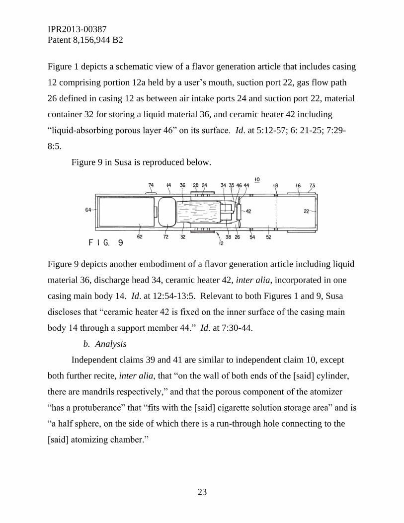
IPR2013-00387
Patent 8,156,944 B2
23
Figure 1 depicts a schematic view of a flavor generation article that includes casing
12 comprising portion 12a held by a user’s mouth, suction port 22, gas flow path
26 defined in casing 12 as between air intake ports 24 and suction port 22, material
container 32 for storing a liquid material 36, and ceramic heater 42 including
“liquid-absorbing porous layer 46” on its surface. Id. at 5:12-57; 6: 21-25; 7:29-
8:5.
Figure 9 in Susa is reproduced below.
Figure 9 depicts another embodiment of a flavor generation article including liquid
material 36, discharge head 34, ceramic heater 42, inter alia, incorporated in one
casing main body 14. Id. at 12:54-13:5. Relevant to both Figures 1 and 9, Susa
discloses that “ceramic heater 42 is fixed on the inner surface of the casing main
body 14 through a support member 44.” Id. at 7:30-44.
b. Analysis
Independent claims 39 and 41 are similar to independent claim 10, except
both further recite, inter alia, that “on the wall of both ends of the [said] cylinder,
there are mandrils respectively,” and that the porous component of the atomizer
“has a protuberance” that “fits with the [said] cigarette solution storage area” and is
“a half sphere, on the side of which there is a run-through hole connecting to the
[said] atomizing chamber.”

IPR2013-00387
Patent 8,156,944 B2
24
CB Distributors contends that most elements of claims 39-41 are disclosed
in Hon ’494 and/or Liu. For example, above and beyond the elements discussed
above, CB Distributors contends that that Hon ’494 discloses atomizer 9 including
porous body 27 with bulge 36 on one end that is in contact with liquid supplying
bottle 11. Pet. 48. CB Distributors contends that Susa discloses the “mandrils”
element of the challenged claims. Id.
Notably, CB Distributors further contends that Hon ’494 describes a relevant
protuberance that is a half sphere, “on the side of which there is a run-through hole
connecting to the atomizing chamber,” as recited in claims 39 (“39[q]”) and 41.
Pet. 52, 54 (citing Ex. 1009, Figs. 2, 6; 2:8-9; 5:12-14). As argued by CB
Distributors, Hon ’494 discloses that “bulge 36 is a protruding half sphere on the
side of which there is a run-through hole (vapor-liquid separator 7) connecting to
the atomizing chamber.” Id.; see also id. at 49 (citing Ex. 1009, 2:8-9; 5:12-14).
As indicated by CB Distributors, Hon ’494 describes, and depicts in Figures
1 and 6, porous body 27 (i.e., a “porous component”) of atomizer 9 having a
protruding half sphere that fits with liquid supplying bottle 11 (i.e., a “cigarette
solution storage area”). We are not persuaded, however, that CB Distributors
establishes reasonably that Hon ’494 describes or suggests a “protruding half
sphere, on the side of which there is a run-through hole connecting to the [said]
atomizing chamber,” as recited in independent claims 39 and 41 (emphasis added).
The ’944 patent Specification depicts an example of the “run-through hole”
in Figure 8, and states that “protuberance (812) is a protruding half sphere, on the
side of which there is a run-through hole (813) connecting to the atomizing
chamber (811).” Ex. 1001, 6:23-28. By contrast, CB Distributors contends that
vapor-liquid separator 7 in Hon ’494 corresponds to the recited “run-through hole.”
Pet. 49, 52, 54.

IPR2013-00387
Patent 8,156,944 B2
25
Hon ’494 discloses that “air enters the normal pressure cavity 5 through the
air inlet 4, passes through the air passage 18 of the sensor and then the through
hole in the vapor-liquid separator 7, and flows into the atomization cavity 10 in the
atomizer 9.” Ex. 1009, 4:21-24. As described in Hon ’494 and depicted in its
figures, however, the “through hole in the vapor-liquid separator 7” is not located
on the side of the protruding half sphere of porous body 27 on atomizer 9. Rather,
the through hole of vapor-liquid separator 7 is located on the opposite end of the
atomizer. See, e.g., Ex. 1009, Figs. 1 and 9. CB Distributors does not explain
adequately, nor cite evidence of record explaining, how Hon ’494, or other cited
reference, discloses or suggests a run-through hole connecting to a run-through
atomizing chamber, where that hole is located on the side of a protruding half
sphere of the porous component of an atomizer.
Thus, we are not persuaded that CB Distributors has demonstrated a
reasonable likelihood of prevailing on its assertion that independent claims 39 and
41, and therefore claim 40, which depends on claim 39, would have been obvious
over Hon ’494 in view of Liu and Susa.
4. Remaining § 103(a) Grounds of Unpatentability
CB Distributors asserts two other grounds, contending that claim 20 would
have been obvious over Liu, and that claims 3, 4, 12, 15, 17, and 26 would have
been obvious over Liu in view of Susa. Pet. 11, 29-36. Those grounds of
unpatentability are redundant in light of the obviousness ground discussed above,
and on the basis of which we institute inter partes review of the same claims. We
do not authorize an inter partes review on the redundant grounds. See 37 C.F.R.
§ 42.108(a).

IPR2013-00387
Patent 8,156,944 B2
26
III. CONCLUSION
For the foregoing reasons, we are persuaded that CB Distributors has
demonstrated that there is a reasonable likelihood of its proving unpatentability of
claims 1-12, 15-26, and 33-38, but not claims 39-41, of the ’944 patent by a
preponderance of the evidence. CB Distributors also challenges dependent claims
3, 4, 12, 15, 17, 20, and 26 on additional obviousness grounds. We consider these
additional grounds to be redundant to the ones listed above, and deny the petition
as to them. The Board has not made a final determination on the patentability of
the challenged claims.
IV. ORDER
For the reasons given, it is
ORDERED that the Petition is granted as to claims 1-12, 15-26, and
33-38 of the ’944 patent with respect to the following alleged grounds:
1. Claims 1, 2, 5-8, 10, 33, 35, 37, and 38 under 35 U.S.C. § 102 as
anticipated by Liu; and
2. Claims 1-4, 8-12, 15-26, 33, 34, 36, and 38 under 35 U.S.C. § 103
as obvious over Hon ’494 in view of Liu;
FURTHER ORDERED that pursuant to 35 U.S.C. § 314(a), inter
partes review of the ʼ944 patent is hereby instituted commencing on the entry date
of this Order, and pursuant to 35 U.S.C. § 314(c) and 37 C.F.R. § 42.4, notice is
hereby given of the institution of a trial;
FURTHER ORDERED that all other grounds presented in CB
Distributors’s petition are denied, and no ground other than those specifically

IPR2013-00387
Patent 8,156,944 B2
27
granted above is authorized for the inter partes review as to claims 1-12, 15-26,
and 33-38; and
FURTHER ORDERED that an initial conference call with the Board
is scheduled for 11 AM Eastern Time on January 31, 2014. The parties are
directed to the Office Trial Practice Guide, 77 Fed. Reg. 48756, 48765-66 (Aug.
14, 2012) for guidance in preparing for the initial conference call, and should be
prepared to discuss any proposed changes to the Scheduling Order entered
herewith and any motions the parties anticipate filing during the trial.
For PETITIONER:
David L. Fehrman
Mehran Arjomand
Morrison & Foerester, LLP
For PATENT OWNER:
Michael J. Wise
Kenneth H. Ohriner
Perkins Coie, LLP

[email protected] Paper 8
Tel: 571-272-7822 Entered: December 30, 2013
UNITED STATES PATENT AND TRADEMARK OFFICE
_____________
BEFORE THE PATENT TRIAL AND APPEAL BOARD
____________
CB DISTRIBUTORS, INC. and
DR DISTRIBUTORS, LLC
Petitioner
v.
RUYAN INVESTMENT (HOLDINGS) LIMITED
Patent Owner
____________
Case IPR2013-00387
Patent 8,156,944 B2
_______________
Before JACQUELINE WRIGHT BONILLA, BRIAN J. McNAMARA, and
TRENTON A. WARD, Administrative Patent Judges.
BONILLA, Administrative Patent Judge.
SCHEDULING ORDER
IPR2013-00387
Patent 8,156,944 B2
2
A. INITIAL CONFERENCE CALL
An initial conference call with the Board is scheduled for 11:00 a.m. Eastern
Time on January 31, 2014.
B. DUE DATES
This order sets due dates for the parties to take action in this trial. The
parties may stipulate to different dates for DUE DATES 1 through 3 (earlier or
later, but no later than DUE DATE 4). A notice of the stipulation, specifically
identifying the changed due dates, must be promptly filed. The parties may not
stipulate to an extension of DUE DATES 4-7.
In stipulating to difference times, the parties should consider the effect of the
stipulation on times to object to evidence (37 C.F.R. § 42.64(b)(1)), to supplement
evidence (37 C.F.R. § 42.64(b)(2)), to conduct cross-examination (37 C.F.R.
§ 42.53(d)(2)), and to file papers relying on the evidence and cross-examination
testimony (see section B, below).
The parties are reminded that the Testimony Guidelines appended to the
Office Patent Trial Practice Guide, 77 Fed. Reg. 48756, 48772 (Aug. 14, 2012)
(Appendix D), apply to this proceeding. The Board may impose an appropriate
sanction for failure to adhere to the Testimony Guidelines. 37 C.F.R. § 42.12. For
example, reasonable expenses and attorney fees incurred by a party may be levied
on a person who impedes, delays, or frustrates the fair examination of a witness.
1. DUE DATE 1
The patent owner may file—
a. A response to the petition (37 C.F.R. § 42.120), and
b. A motion to amend the patent (37 C.F.R. § 42.121).

IPR2013-00387
Patent 8,156,944 B2
3
Any such response or motion to amend by the patent owner must be filed by
DUE DATE 1. If the patent owner elects not to file anything, the patent owner
must arrange a conference call with the parties and the Board. The patent owner is
cautioned that any argument for patentability not raised and fully briefed in the
response will be deemed waived.
2. DUE DATE 2
The petitioner may file a reply to the patent owner’s response and an
opposition to the patent owner’s motion to amend. Any such filing must be made
by DUE DATE 2.
3. DUE DATE 3
The patent owner may file a reply to the petitioner’s opposition to patent
owner’s motion to amend. Any such filing must be made by DUE DATE 3.
4. DUE DATE 4
a. The petitioner may file a motion for an observation on the cross-
examination testimony of a reply witness. (See section C, below). Any such filing
must be made by DUE DATE 4.
b. Each party may file a motion to exclude evidence (37 C.F.R. § 42.64(c))
and a request for oral argument (37 C.F.R. § 42.70(a)). Any such filing must be
made by DUE DATE 4.
5. DUE DATE 5
a. The patent owner may file a reply to a petitioner’s observation on cross-
examination testimony. Any such filing must be made by DUE DATE 5.
IPR2013-00387
Patent 8,156,944 B2
4
b. Each party may file an opposition to a motion to exclude evidence. Any
such filing must be made by DUE DATE 5.
6. DUE DATE 6
Each party may file a reply to an opposition to a motion to exclude evidence.
Any such filing must be made by DUE DATE 6.
7. DUE DATE 7
The oral argument (if requested by either party) is set for DUE DATE 7.
C. CROSS-EXAMINATION
Except as the parties might otherwise agree, for each due date –
1. Cross-examination begins after any supplemental evidence is due.
37 C.F.R. § 42.53(d)(2).
2. Cross-examination ends no later than a week before the filing date
for any paper in which the cross-examination testimony is expected to be
used. Id.
D. MOTION FOR OBSERVATION ON CROSS-EXAMINATION
A motion for observation on cross-examination provides the petitioner with
a mechanism to draw the Board’s attention to relevant cross-examination
testimony of a reply witness, since no further substantive paper is permitted after
the reply. See Office Patent Trial Practice Guide, 77 Fed. Reg. 48756, 48768
(Aug. 14, 2012). The observation should not exceed a single, short paragraph.
The patent owner may respond to the observation. Any response must be equally
concise and specific.

IPR2013-00387
Patent 8,156,944 B2
5
DUE DATE APPENDIX
DUE DATE 1…………………………………………..…………...March 17, 2014
Patent owner’s response to the petition
Patent owner’s motion to amend the patent
DUE DATE 2……………………………………………….......……...June 2, 2014
Petitioner’s reply to Patent Owner’s response to petition
Petitioner’s opposition to Patent Owner’s motion to amend
DUE DATE 3……………………………………………..………..….July 2, 2014
Patent Owner’s reply to Petitioner’s opposition
to Patent Owner’s motion to amend
DUE DATE 4……………………………………………....……….…July 28, 2014
Petitioner’s motion for observation regarding
cross-examination of reply witness
Motion to exclude evidence
Request for oral argument
DUE DATE 5………………………………………….………………Aug. 7, 2014
Patent Owner’s response to observation
Opposition to motion to exclude evidence
DUE DATE 6………………………………………………...…….August 14, 2014
Reply to opposition to motion to exclude evidence
DUE DATE 7…………………………………………………..September 18, 2014
Oral argument (if requested)

IPR2013-00387
Patent 8,156,944 B2
6
For PETITIONER:
David L. Fehrman
Mehran Arjomand
Morrison & Foerester, LLP
For PATENT OWNER:
Michael J. Wise
Kenneth H. Ohriner
Perkins Coie, LLP