intel's mcs-51 family of microcontrollers and its ... viz 8085, z-80, 6502, ... 8c0d 7e mov a,m...
TRANSCRIPT

SEVEN SEGMENT DISPLAY INTERFACE
1
CONTENTS
PAGE NO
1.0 Introduction 2
2.0 Description of the Circuit 2
3.0 Installation 4
4.0 Demonstration Examples 5
4.1 Demonstration Program for MPS 85-3 Trainer 5
4.2 Demonstration Program for ESA 85-2 Trainer 6
4.3 Demonstration Program for ESA-80 Trainer 7
4.4 Demonstration Program for ESA-31 Trainer 8
4.5 Demonstration Program for ESA-68K Trainer 10
4.6 Demonstration Program for ESA 86/88-2 Trainer 11
4.7 Demonstration Program for ESA-196 Trainer 12
4.8 Demonstration Program for ESA 68K-2 Trainer 14
4.9 Demonstration Program for ESA-51 Trainer 15
4.10 Demonstration Program for ESA 86/88-3 Trainer 17
4.11 Demonstration Program for ESA-51E Trainer 18
4.12 Demonstration Program for ESA 86/88E Trainer 20
5.0 Exercises 21
Appendix A : Component Layout Diagram
Appendix B : Schematic Diagram

SEVEN SEGMENT DISPLAY INTERFACE
2
SEVEN SEGMENT DISPLAY INTERFACE
1.0 INTRODUCTION
Electro Systems Associates Private Limited (ESA) manufactures trainers for most of the popular
microcomputers viz 8085, Z-80, 6502, 8086/8088 and 68000. ESA offers a variety of modules
which can be interfaced to these trainers. These modules can be effectively used for
teaching/training in the laboratories.
The present manual describes one such interface module seven segment display interface. In
many microprocessor controlled instruments, information processed by the microprocessor has
to be displayed on a front panel. The interfacing technique presented here uses four 7-segment
display units, shift registers and only 4 I/O lines - one for control, one for data and the other two for
power supply.
The advantages of this technique are :
a. The hardware is relatively simple.
b. Only four lines including power supply lines are required for interfacing. Thus the
interconnections with the front panel are minimized.
c. Any segment combinations can be displayed, as the coding is done by software.
This manual describes the operation of the circuit and the installation details. Some demonstration
programs and exercises are also presented to illustrate the application of the interface. Component
layout and the schematic diagram is given in Appendix A and Appendix B respectively.
2.0 DESCRIPTION OF THE CIRCUIT
Please refer to the schematic diagram of this interface, (Appendix B). This interface provides a four-
digit 7 segment display driven by the outputs of four cascaded serial- in - parallel- out shift
registers. Data to be displayed is transmitted serially, bit by bit, to the interface over the port line
PB0. Each bit is clocked into the shift registers by providing a common clock through the port line
PC0. Thus, information for all the four digits is provided by 32 bits clocked into the shift registers
serially.
It can be seen from the circuit that the first bit, after 32 clock pulses, is available at H output of the
shift register U4 and thus controls the H segment of the digit D0. The segments controlled by other
bits can be determined similarly.

SEVEN SEGMENT DISPLAY INTERFACE
3
DISPLAY CODES :
Since the outputs of shift registers are connected to the cathode sides of LED segments, low input
must be given to the segments for making them glow and high inputs for making them blank.
Each display has 7 bar segments and a dot (a,b,c,d,e,f,g,h) as shown in figure below. For
displaying any character, its corresponding segments must be given low inputs.
a
f b
g
e c
d . h
Example :
For displaying digit 3 segments a, b, c, d, g must be given low inputs (i.e. 0s) and the rest high
inputs (i.e 1 s) as shown below.
Segment h g f e d c b a
Bit 7 6 5 4 3 2 1 0
Input 1 0 1 1 0 0 0 0
Hex Code B 0
Display codes of some characters are given below in Table 2-1 for reference.
TABLE 2-1
DISPLAY CODES
APPLIED CODE
(HEX)
DISPLAYED
DIGIT
APPLIED CODE
(HEX)
DISPLAYED
DIGIT
C0 0 80 8
F9 1 90 9
A4 2 88 A
B0 3 83 b
99 4 C6 C
92 5 A1 d
82 6 86 E
F8 7 8E F
3.0 INSTALLATION

SEVEN SEGMENT DISPLAY INTERFACE
4
The interface is housed in a plastic enclosure which has a locking mechanism. To open the cover,
push in the locking mechanism with a finger and lift the cover to open.
The interface module has a 26-pin connector at one edge of the card. This is used for connecting the
interface to the trainer with a flat cable connector set. The +5V DC power required by this
interface is drawn from the trainer via the flat cable connector set.
Table 3-1 shows the connector on various trainers to which this interface can be connected. Some
trainers have two connectors and either may be used for connecting this interface. The
demonstration programs presented in this manual assumes that the interface is connected to
connectors shown in column A. If the connector shown in column B is used, then user has to
change the port addresses appropriately. User may refer to the component layout diagrams of
respective ESA trainers to locate the connectors mentioned here.
TABLE-3.1
MICROPROCESSOR
TRAINER
A B
MPS85-3 J2 J1
ESA85-2 J2 J1
ESA-80 J2 J1
ESA-65 P4
ESA-68K P3 P4
ESA 68K-2 J2 J1
ESA 68-2 J1 J6
ESA 196 J1 J2
ESA-31 J2 J1
ESA-51 J10 J7
ESA-51E J5 J3
ESA-86/88-2 J4 J5
ESA-86/88-3 J8 J9
ESA-86/88E J4 J6
4.0 DEMONSTRATION EXAMPLES

SEVEN SEGMENT DISPLAY INTERFACE
5
DESCRIPTION OF DEMO PROGRAMS
The sample program presented here displays the message "ELECTRO-SYS-TEMS" in a rotating
fashion. In other words, It first blanks the display, Then displays "ELEC", then "TRO-", then
"SYS-", and then "TEMS". These groups are displayed one after another with suitable delays.
The program goes on repeating the entire display sequence. This program is written as an infinite
loop, and hence user must press RESET key to recover from it.
4.1 DEMONSTRATION PROGRAM FOR MPS 85-3 TRAINER
; Assume the interface is connected over J2 of the trainer
; The trainer can be in KEYBOARD MODE or SERIAL MODE.
STRING EQU 8C40H
ADDRESS OPCODE LABEL MNEMONIC COMMENTS
8C00 3E 80 MVI A,80H ;Configure 8255
;for mode 0
8C02 D3 43 OUT 43H ;All ports as O/P
8C04 21 40 8C LOOP4: LXI H,STRING ;Start of display codes
8C07 16 05 MVI D,05 ;5 groups
8C09 06 04 LOOP3: MVI B,04 ;4 characters/group
8C0B 0E 08 LOOP2: MVI C,08 ;8 segments/character
8C0D 7E MOV A,M ;Get display code
8C0E 23 INX H ;Increment pointer
8C0F 07 LOOP1: RLC ;Get one data bit
8C10 5F MOV E,A ;and output it.
8C11 D3 41 OUT 41H
8C13 3E 01 MVI A,01
8C15 D3 42 OUT 42H ;Output the clock to
8C17 3D DCR A
8C18 D3 42 OUT 42H ;Shift register
8C1A 7B MOV A,E
8C1B 0D DCR C ;All Bits over?
8C1C C2 0F 8C JNZ LOOP1 ;No, Continue
8C1F 05 DCR B ;All Character over
8C20 C2 0B 8C JNZ LOOP2 ;No, continue
8C23 CD 30 8C CALL DELAY ;Introduce delay
8C26 CD 30 8C CALL DELAY ;Introduce delay
8C29 15 DCR D ;All groups over?
8C2A C2 09 8C JNZ LOOP3 ;No, Continue
8C2D C3 04 8C JMP LOOP4 ;Yes, start from
;beginning
SEVEN SEGMENT DISPLAY INTERFACE
6
8C30 01 FF FF DELAY: LXI B,0FFFFH ;Delay subroutine
8C33 0B DLY1: DCX B
8C34 78 MOV A,B
8C35 B1 ORA C
8C36 C2 33 8C JNZ DLY1
8C39 C9 RET
ORG 8C40H
8C40 FF FF FF FF STRING DB 0FFH,0FFH,0FFH,0FFH
8C44 C6 86 C7 86 DB 0C6H,86H,0C7H,86H
8C48 BF C0 DE 87 DB 0BFH,0C0H,0DEH,87H
8C4C BF 92 91 92 DB 0BFH,92H,91H,92H
8C50 92 C8 86 87 DB 92H,0C8H,86H,87H
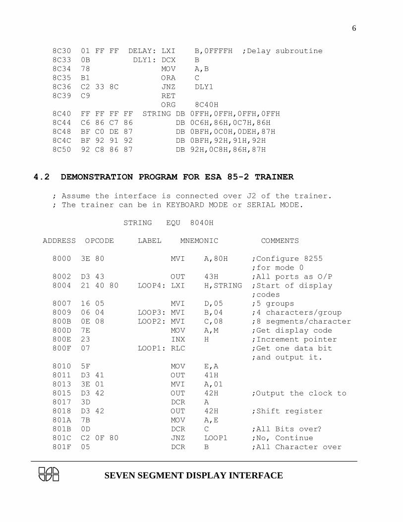
4.2 DEMONSTRATION PROGRAM FOR ESA 85-2 TRAINER
; Assume the interface is connected over J2 of the trainer.
; The trainer can be in KEYBOARD MODE or SERIAL MODE.
STRING EQU 8040H
ADDRESS OPCODE LABEL MNEMONIC COMMENTS
8000 3E 80 MVI A,80H ;Configure 8255
;for mode 0
8002 D3 43 OUT 43H ;All ports as O/P
8004 21 40 80 LOOP4: LXI H,STRING ;Start of display
;codes
8007 16 05 MVI D,05 ;5 groups
8009 06 04 LOOP3: MVI B,04 ;4 characters/group
800B 0E 08 LOOP2: MVI C,08 ;8 segments/character
800D 7E MOV A,M ;Get display code
800E 23 INX H ;Increment pointer
800F 07 LOOP1: RLC ;Get one data bit
;and output it.
8010 5F MOV E,A
8011 D3 41 OUT 41H
8013 3E 01 MVI A,01
8015 D3 42 OUT 42H ;Output the clock to
8017 3D DCR A
8018 D3 42 OUT 42H ;Shift register
801A 7B MOV A,E
801B 0D DCR C ;All Bits over?
801C C2 0F 80 JNZ LOOP1 ;No, Continue
801F 05 DCR B ;All Character over

SEVEN SEGMENT DISPLAY INTERFACE
7
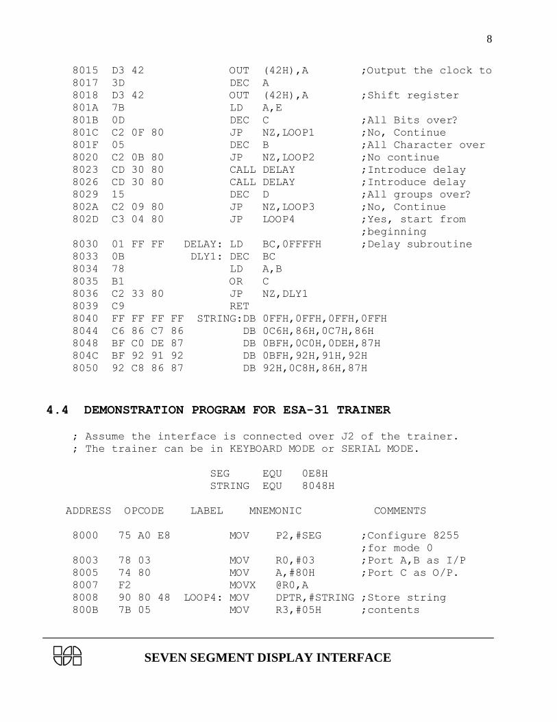
8020 C2 0B 80 JNZ LOOP2 ;No continue
8023 CD 30 80 CALL DELAY ;Introduce delay
8026 CD 30 80 CALL DELAY ;Introduce delay
8029 15 DCR D ;All groups over?
802A C2 09 80 JNZ LOOP3 ;No, Continue
802D C3 04 80 JMP LOOP4 ;Yes, start from
;beginning
8030 01 FF FF DELAY: LXI B,0FFFFH ;Delay subroutine
8033 0B DLY1: DCX B
8034 78 MOV A,B
8035 B1 ORA C
8036 C2 33 80 JNZ DLY1
8039 C9 RET
ORG 8040H
8040 FF FF FF FF STRING DB 0FFH,0FFH,0FFH,0FFH
8044 C6 86 C7 86 DB 0C6H,86H,0C7H,86H
8048 BF C0 DE 87 DB 0BFH,0C0H,0DEH,87H
804C BF 92 91 92 DB 0BFH,92H,91H,92H
8050 92 C8 86 87 DB 92H,0C8H,86H,87H
4.3 DEMONSTRATION PROGRAM FOR ESA-80 TRAINER
; Assume the interface is connected over J2 of the trainer.
; The trainer can be in KEYBOARD MODE or SERIAL MODE.
STRING EQU 8040H
ADDRESS OPCODE LABEL MNEMONIC COMMENTS
8000 3E 80 LD A,80H ;Configure 8255
;for mode 0
8002 D3 43 OUT (43H),A ;All ports as O/P
8004 21 40 80 LOOP4: LD HL,STRING ;Start of
;display codes
8007 16 05 LD D,05 ;5 groups
8009 06 04 LOOP3: LD B,04 ;4 characters/group
800B 0E 08 LOOP2: LD C,08 ;8 segments/
;character
800D 7E LD A,(HL) ;Get display code
800E 23 INC HL ;Increment pointer
800F 07 LOOP1: RLCA ;Get one data
8010 5F LD E,A
8011 D3 41 OUT (41H),A ;bit and Output it.
8013 3E 01 LD A,01
SEVEN SEGMENT DISPLAY INTERFACE
8
8015 D3 42 OUT (42H),A ;Output the clock to
8017 3D DEC A
8018 D3 42 OUT (42H),A ;Shift register
801A 7B LD A,E
801B 0D DEC C ;All Bits over?
801C C2 0F 80 JP NZ,LOOP1 ;No, Continue
801F 05 DEC B ;All Character over
8020 C2 0B 80 JP NZ,LOOP2 ;No continue
8023 CD 30 80 CALL DELAY ;Introduce delay
8026 CD 30 80 CALL DELAY ;Introduce delay
8029 15 DEC D ;All groups over?
802A C2 09 80 JP NZ,LOOP3 ;No, Continue
802D C3 04 80 JP LOOP4 ;Yes, start from
;beginning
8030 01 FF FF DELAY: LD BC,0FFFFH ;Delay subroutine
8033 0B DLY1: DEC BC
8034 78 LD A,B
8035 B1 OR C
8036 C2 33 80 JP NZ,DLY1
8039 C9 RET
8040 FF FF FF FF STRING:DB 0FFH,0FFH,0FFH,0FFH
8044 C6 86 C7 86 DB 0C6H,86H,0C7H,86H
8048 BF C0 DE 87 DB 0BFH,0C0H,0DEH,87H
804C BF 92 91 92 DB 0BFH,92H,91H,92H
8050 92 C8 86 87 DB 92H,0C8H,86H,87H
4.4 DEMONSTRATION PROGRAM FOR ESA-31 TRAINER
; Assume the interface is connected over J2 of the trainer.
; The trainer can be in KEYBOARD MODE or SERIAL MODE.
SEG EQU 0E8H
STRING EQU 8048H
ADDRESS OPCODE LABEL MNEMONIC COMMENTS
8000 75 A0 E8 MOV P2,#SEG ;Configure 8255
;for mode 0
8003 78 03 MOV R0,#03 ;Port A,B as I/P
8005 74 80 MOV A,#80H ;Port C as O/P.
8007 F2 MOVX @R0,A
8008 90 80 48 LOOP4: MOV DPTR,#STRING ;Store string
800B 7B 05 MOV R3,#05H ;contents

SEVEN SEGMENT DISPLAY INTERFACE
9
800D 79 04 LOOP3: MOV R1,#4 ;4 Characters/Group
800F 7A 08 LOOP2: MOV R2,#08H ;8 Segments/
;Character
8011 E4 CLR A ;Get display code
8012 93 MOVC A,@A+DPTR
8013 A3 INC DPTR ;Increment pointer
8014 23 LOOP1: RL A
8015 FC MOV R4,A
8016 78 01 MOV R0,#1
8018 F2 MOVX @R0,A ;Output it.
8019 74 01 MOV A,#01H
801B 78 02 MOV R0,#02
801D F2 MOVX @R0,A ;Output the clock to
801E 14 DEC A
801F F2 MOVX @R0,A ;Shift register
8020 EC MOV A,R4
8021 1A DEC R2 ;All bits over
8022 BA 00 EF CJNE R2,#0,LOOP1 ;No continue
8025 19 DEC R1 ;All characters over
8026 B9 00 E6 CJNE R1,#0,LOOP2 ;No continue
8029 12 80 35 LCALL DELAY ;Introduce
802C 12 80 35 LCALL DELAY ;delay routine
802F 1B DEC R3 ;All groups over
8030 BB 00 DA CJNE R3,#0,LOOP3 ;No, continue
8033 80 D3 SJMP LOOP4 ;Yes, start
;from LOOP4
8035 C0 83 DELAY: PUSH DPH ;Delay subroutine
8037 C0 82 PUSH DPL
8039 90 00 00 MOV DPTR,#0
803C A3 DELAY1: INC DPTR
803D E5 83 MOV A,DPH
803F 45 82 ORL A,DPL
8041 70 F9 JNZ DELAY1
8043 D0 82 POP DPL
8045 D0 83 POP DPH
8047 22 RET
8048 FF FF STRING: DB 0FF,0FF
804A FF FF DB 0FF,0FF
804C C6 86 DB 0C6,86
804E C7 86 DB 0C7,86
8050 BF C0 DB 0BF,0C0
8052 DE 87 DB 0DE,87
8054 BF 92 DB 0BF,92
8056 91 92 DB 91, 92
8058 92 C8 DB 92, 0C8

SEVEN SEGMENT DISPLAY INTERFACE
10
805A 86 87 DB 86, 87
4.5 DEMONSTRATION PROGRAM FOR ESA-68K TRAINER
; Assume the interface is connected over P3 of the trainer.
ADDRESS OPCODE LABEL MNEMONIC COMMENTS
40600 20 7C 00 START: MOVEA.L #$4064C,A0 ;Point to the
04 06 4C ;Message area
40606 13 FC 00 MOVE.B #$80,$80306 ;Configure
80 00 08 ;8255 for mode 0
03 06 ;All ports output
4060E 30 3C 00 MOVE #04,D0 ;5 groups
04
40612 32 3C 00 NEXTGR: MOVE #03,D1 ;4 Characters
03 ;per group
40616 34 3C 00 NEXTCH: MOVE #07,D2 ;8 Segments
07 ;per character
4061A 16 18 MOVE.B (A0)+,D3 ;Get display
;code.
4061C E3 1B NEXTSEG: ROL.B #01,D3
4061E 13 C3 00 MOVE.B D3,$80302 ;Output a bit
08 03 02 ;from display
;code through
;Port PB0.
40624 13 FC 00 MOVE.B #01,$80304 ;Output clock
01 00 08 ;over PC0
03 04
4062C 13 FC 00 MOVE.B #00,$80304
00 00 08
03 04
40634 51 CA FF DBRA D2,$NEXTSEG ;If all bits
E6 ;are not over
;go for next one
40638 51 C9 FF DBRA D1,$NEXTCH ;If all chara-
DC ;cters are not
;over,go for
;next one.
4063C 26 3C 00 MOVE.L #$50000,D3 ;Introduce
05 00 00 ;delay
40642 53 83 LOOP: SUBQ.L #01,D3
40644 66 FC BNE $LOOP
40646 51 C8 FF DBRA D0,NEXTGR ;If all groups

SEVEN SEGMENT DISPLAY INTERFACE
11
CA ;are not over,
;go for next
;one.
4064A 60 B4 BRA $START ;Else,go back
;to beginning.
4064C FF FF FF STRING: DC.W $FFFF,$FFFF ;Display codes
FF
C6 86 C7 DC.W $C686,$C786
86
BF C0 DE DC.W $BFC0,$DE87
87
BF 92 91 DC.W $BF92,$9192
92
92 C8 86 DC.W $92C8,$8687
87
4.6 DEMONSTRATION PROGRAM FOR ESA 86/88-2 TRAINER
; Assume the interface is connected over J4 of the trainer.
; The trainer can be in KEYBOARD MODE or SERIAL MODE.
ORG EQU 00H
CMD55 EQU FFE6H
MODE EQU 80H
STRING EQU 2050H
ADDRESS OPCODE LABEL MNEMONIC COMMENTS
2000 BA E6 FF MOVW DX,#CMD55 ;Configure 8255
2003 B0 80 MOVB AL,#MODE ;All ports output
2005 EE OUTB DX
2006 BE 50 20 LOOP4: MOVW SI,#STRING ;Start of
;display codes
2009 B1 05 MOVB CL,#05 ;5 groups
200B B5 04 LOOP3: MOVB CH,#04 ;4 characters/group
200D B3 08 LOOP2: MOVB BL,#08 ;8 Segments/
;character
200F 8A 04 MOVB AL,[SI] ;Get the
;display code
2011 46 INCW SI ;Increment pointer
2012 D0 C0 LOOP1: ROLB AL,1 ;Get one data bit
2014 BA E2 FF MOVW DX,#0FFE2
2017 EE OUTB DX ;and Output it.
2018 88 C4 MOVB AH,AL

SEVEN SEGMENT DISPLAY INTERFACE
12
201A B0 01 MOVB AL,#01 ;Output the clock
201C BA E4 FF MOVW DX,#0FFE4
201F EE OUTB DX ;to Shift register
2020 FE C8 DECB AL
2022 EE OUTB DX
2023 88 E0 MOVB AL,AH
2025 FE CB DECB BL ;All Bits over?
2027 75 E9 JNZ LOOP1 ;No, continue
2029 FE CD DECB CH ;All charac-
;ters over?
202B 75 E0 JNZ LOOP2 ;No continue
202D E8 06 00 CALL DELAY ;Introduce delay
2030 FE C9 DECB CL ;All groups over?
2032 75 D7 JNZ LOOP3 ;No continue
2034 EB D0 JMP LOOP4 ;Yes. start from
;beginning.
2036 51 DELAY: PUSH CX ;Delay subroutine
2037 B9 FF FF MOV CX,#0FFFF
203A 90 XCHGW AX,AX
203B 90 XCHGW AX,AX
203C 90 XCHGW AX,AX
203D E2 FB LOOP 203AH
203F B9 FF FF MOVW CX,#0FFFF
2042 90 XCHGW AX,AX
2043 90 XCHGW AX,AX
2044 90 XCHGW AX,AX
2045 E2 FB LOOP 2042H
2047 59 POP CX
2048 C3 RET
ORG 2050H
2050 FF FF FF FF STRING:DB 0FFH,0FFH,0FFH,0FFH
2054 C6 86 C7 86 DB 0C6H,86H,0C7H,86H
2058 BF C0 DE 87 DB 0BFH,0C0H,0DEH,87H
205C BF 92 91 92 DB 0BFH,92H,91H,92H
2060 92 C8 86 87 DB 92H,0C8H,86H,87H
4.7 DEMONSTRATION PROGRAM FOR ESA 196 TRAINER
;Assume the interface is connected over J1 of the trainer.
;The trainer can be in KEYBOARD MODE or SERIAL MODE.
REG1 EQU 52H
REG2 EQU 60H
REG3 EQU 56H
REG4 EQU 64H

SEVEN SEGMENT DISPLAY INTERFACE
13
REG5 EQU 68H
REG7 EQU 76H
REG9 EQU 80H
REG10 EQU 88H
PORT_A EQU 200H
PORT_B EQU 202H
PORT_C EQU 204H
CMD_PORT EQU 206H
ADDRESS OPCODE LABLE MNEMONIC COMMENTS
8000 B1 80 52 LDB REG1,#80H ;CONFIGURE 8255
8003 C7 01 06 02 STB REG1,CMD_PORT ;IN MODE 0. ALL
8007 52 ;PORTS O/P.
8008 A1 80 80 60 LOOP4: LD REG2,#MSG ;START OF DISPLAY
800C B1 05 56 LDB REG3,#05H ;CODES. 5 GROUPS.
800F B1 04 64 LOOP3: LDB REG4,#04H ;4 CHARACTES/GROUP.
8012 B1 08 68 LOOP2: LDB REG5,#08H ;8 SEGMENTS/CHARACTER.
8015 B2 60 52 LDB REG1,[REG2] ;GET DISPLAY CODE.
8018 07 60 INC REG2 ;INCREMENT POINTER.
801A B0 52 80 LOOP1: LDB REG9,REG1 ;GET ONE DATA BIT
801D 19 01 80 SHLB REG9,#1H ;AND O/P IT.
8020 71 80 52 ANDB REG1,#80H ;ROTATE LEFT.
8023 18 07 52 SHRB REG1,#7H
8026 90 80 52 ORB REG1,REG9
8029 B0 52 76 LDB REG7,REG1
802C C7 01 02 02 STB REG1,PORT_B
8030 52
8031 B1 01 52 LDB REG1,#01H
8034 C7 01 04 02 STB REG1,PORT_C ;O/P THE CLOCK.
8038 52
8039 15 52 DECB REG1
803B C7 01 04 02 STB REG1,PORT_C ;SHIFT REGISTER.
803F 52
8040 B0 76 52 LDB REG1,REG7
8043 15 68 DECB REG5 ;ALL BITS OVER?
8045 D7 D3 JNE LOOP1 ;NO. LOOP BACK.
8047 15 64 DECB REG4 ;ALL CHARACTERS OVER?
8049 D7 C7 BNE LOOP2 ;NO. LOOP BACK.
804B EF 13 00 LCALL DELAY ;CALL DELAY ROUTINE.
804E EF 10 00 LCALL DELAY
8051 EF 0D 00 LCALL DELAY
8054 EF 0A 00 LCALL DELAY
8057 EF 07 00 LCALL DELAY
805A 15 56 DECB REG3 ;ALL GROUPS OVER?
SEVEN SEGMENT DISPLAY INTERFACE
14
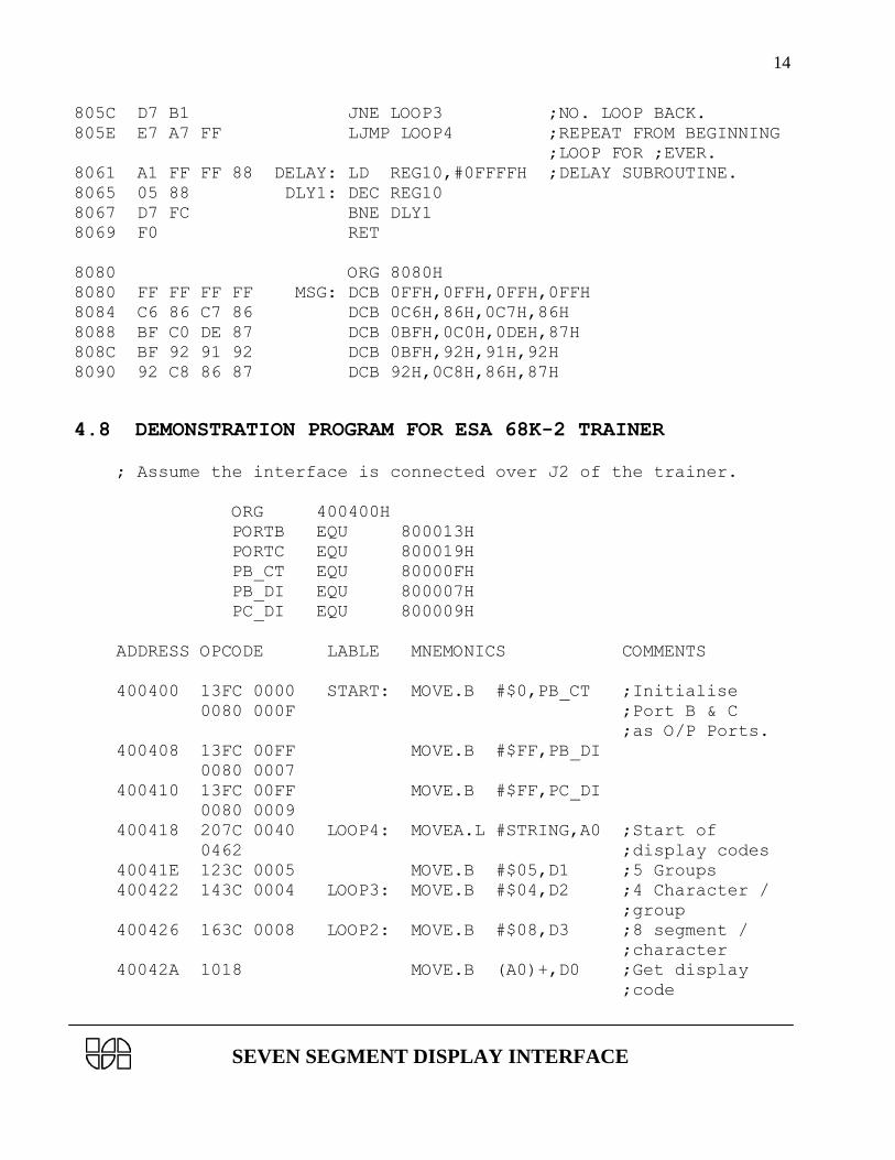
805C D7 B1 JNE LOOP3 ;NO. LOOP BACK.
805E E7 A7 FF LJMP LOOP4 ;REPEAT FROM BEGINNING
;LOOP FOR ;EVER.
8061 A1 FF FF 88 DELAY: LD REG10,#0FFFFH ;DELAY SUBROUTINE.
8065 05 88 DLY1: DEC REG10
8067 D7 FC BNE DLY1
8069 F0 RET
8080 ORG 8080H
8080 FF FF FF FF MSG: DCB 0FFH,0FFH,0FFH,0FFH
8084 C6 86 C7 86 DCB 0C6H,86H,0C7H,86H
8088 BF C0 DE 87 DCB 0BFH,0C0H,0DEH,87H
808C BF 92 91 92 DCB 0BFH,92H,91H,92H
8090 92 C8 86 87 DCB 92H,0C8H,86H,87H
4.8 DEMONSTRATION PROGRAM FOR ESA 68K-2 TRAINER
; Assume the interface is connected over J2 of the trainer.
ORG 400400H
PORTB EQU 800013H
PORTC EQU 800019H
PB_CT EQU 80000FH
PB_DI EQU 800007H
PC_DI EQU 800009H
ADDRESS OPCODE LABLE MNEMONICS COMMENTS
400400 13FC 0000 START: MOVE.B #$0,PB_CT ;Initialise
0080 000F ;Port B & C
;as O/P Ports.
400408 13FC 00FF MOVE.B #$FF,PB_DI
0080 0007
400410 13FC 00FF MOVE.B #$FF,PC_DI
0080 0009
400418 207C 0040 LOOP4: MOVEA.L #STRING,A0 ;Start of
0462 ;display codes
40041E 123C 0005 MOVE.B #$05,D1 ;5 Groups
400422 143C 0004 LOOP3: MOVE.B #$04,D2 ;4 Character /
;group
400426 163C 0008 LOOP2: MOVE.B #$08,D3 ;8 segment /
;character
40042A 1018 MOVE.B (A0)+,D0 ;Get display
;code
SEVEN SEGMENT DISPLAY INTERFACE
15
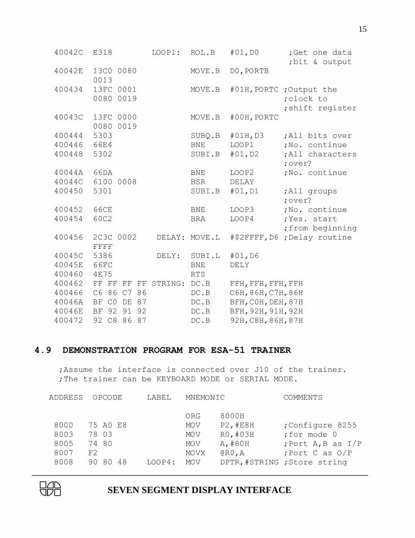
40042C E318 LOOP1: ROL.B #01,D0 ;Get one data
;bit & output
40042E 13C0 0080 MOVE.B D0,PORTB
0013
400434 13FC 0001 MOVE.B #01H,PORTC ;Output the
0080 0019 ;clock to
;shift register
40043C 13FC 0000 MOVE.B #00H,PORTC
0080 0019
400444 5303 SUBQ.B #01H,D3 ;All bits over
400446 66E4 BNE LOOP1 ;No. continue
400448 5302 SUBI.B #01,D2 ;All characters
;over?
40044A 66DA BNE LOOP2 ;No. continue
40044C 6100 0008 BSR DELAY
400450 5301 SUBI.B #01,D1 ;All groups
;over?
400452 66CE BNE LOOP3 ;No. continue
400454 60C2 BRA LOOP4 ;Yes. start
;from beginning
400456 2C3C 0002 DELAY: MOVE.L #$2FFFF,D6 ;Delay routine
FFFF
40045C 5386 DELY: SUBI.L #01,D6
40045E 66FC BNE DELY
400460 4E75 RTS
400462 FF FF FF FF STRING: DC.B FFH,FFH,FFH,FFH
400466 C6 86 C7 86 DC.B C6H,86H,C7H,86H
40046A BF C0 DE 87 DC.B BFH,C0H,DEH,87H
40046E BF 92 91 92 DC.B BFH,92H,91H,92H
400472 92 C8 86 87 DC.B 92H,C8H,86H,87H
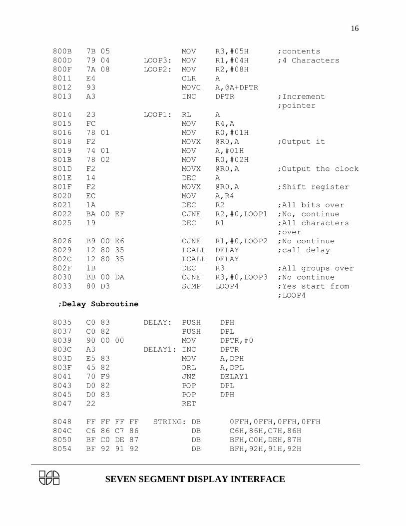
4.9 DEMONSTRATION PROGRAM FOR ESA-51 TRAINER
;Assume the interface is connected over J10 of the trainer.
;The trainer can be KEYBOARD MODE or SERIAL MODE.
ADDRESS OPCODE LABEL MNEMONIC COMMENTS
ORG 8000H
8000 75 A0 E8 MOV P2,#E8H ;Configure 8255
8003 78 03 MOV R0,#03H ;for mode 0
8005 74 80 MOV A,#80H ;Port A,B as I/P
8007 F2 MOVX @R0,A ;Port C as O/P
8008 90 80 48 LOOP4: MOV DPTR,#STRING ;Store string
SEVEN SEGMENT DISPLAY INTERFACE
16
800B 7B 05 MOV R3,#05H ;contents
800D 79 04 LOOP3: MOV R1,#04H ;4 Characters
800F 7A 08 LOOP2: MOV R2,#08H
8011 E4 CLR A
8012 93 MOVC A,@A+DPTR
8013 A3 INC DPTR ;Increment
;pointer
8014 23 LOOP1: RL A
8015 FC MOV R4,A
8016 78 01 MOV R0,#01H
8018 F2 MOVX @R0,A ;Output it
8019 74 01 MOV A,#01H
801B 78 02 MOV R0,#02H
801D F2 MOVX @R0,A ;Output the clock
801E 14 DEC A
801F F2 MOVX @R0,A ;Shift register
8020 EC MOV A,R4
8021 1A DEC R2 ;All bits over
8022 BA 00 EF CJNE R2,#0,LOOP1 ;No, continue
8025 19 DEC R1 ;All characters
;over
8026 B9 00 E6 CJNE R1,#0,LOOP2 ;No continue
8029 12 80 35 LCALL DELAY ;call delay
802C 12 80 35 LCALL DELAY
802F 1B DEC R3 ;All groups over
8030 BB 00 DA CJNE R3,#0,LOOP3 ;No continue
8033 80 D3 SJMP LOOP4 ;Yes start from
;LOOP4
;Delay Subroutine
8035 C0 83 DELAY: PUSH DPH
8037 C0 82 PUSH DPL
8039 90 00 00 MOV DPTR,#0
803C A3 DELAY1: INC DPTR
803D E5 83 MOV A,DPH
803F 45 82 ORL A,DPL
8041 70 F9 JNZ DELAY1
8043 D0 82 POP DPL
8045 D0 83 POP DPH
8047 22 RET
8048 FF FF FF FF STRING: DB 0FFH,0FFH,0FFH,0FFH
804C C6 86 C7 86 DB C6H,86H,C7H,86H
8050 BF C0 DE 87 DB BFH,C0H,DEH,87H
8054 BF 92 91 92 DB BFH,92H,91H,92H
SEVEN SEGMENT DISPLAY INTERFACE
17
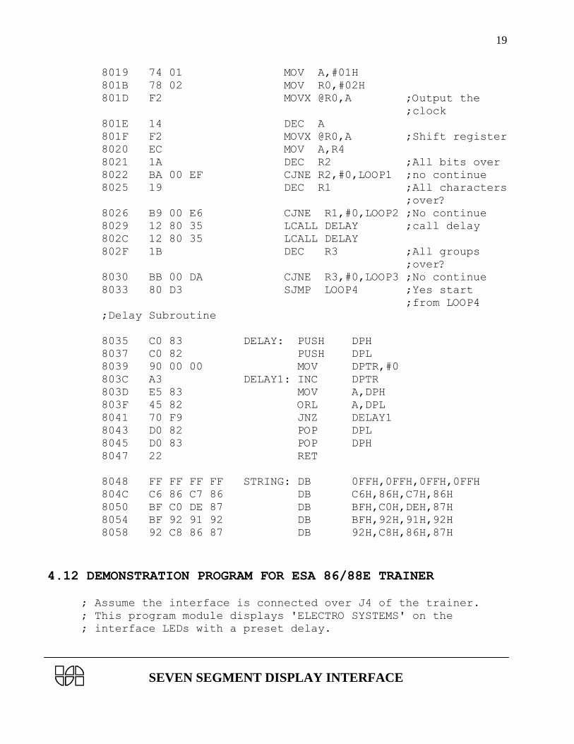
8058 92 C8 86 87 DB 92H,C8H,86H,87H
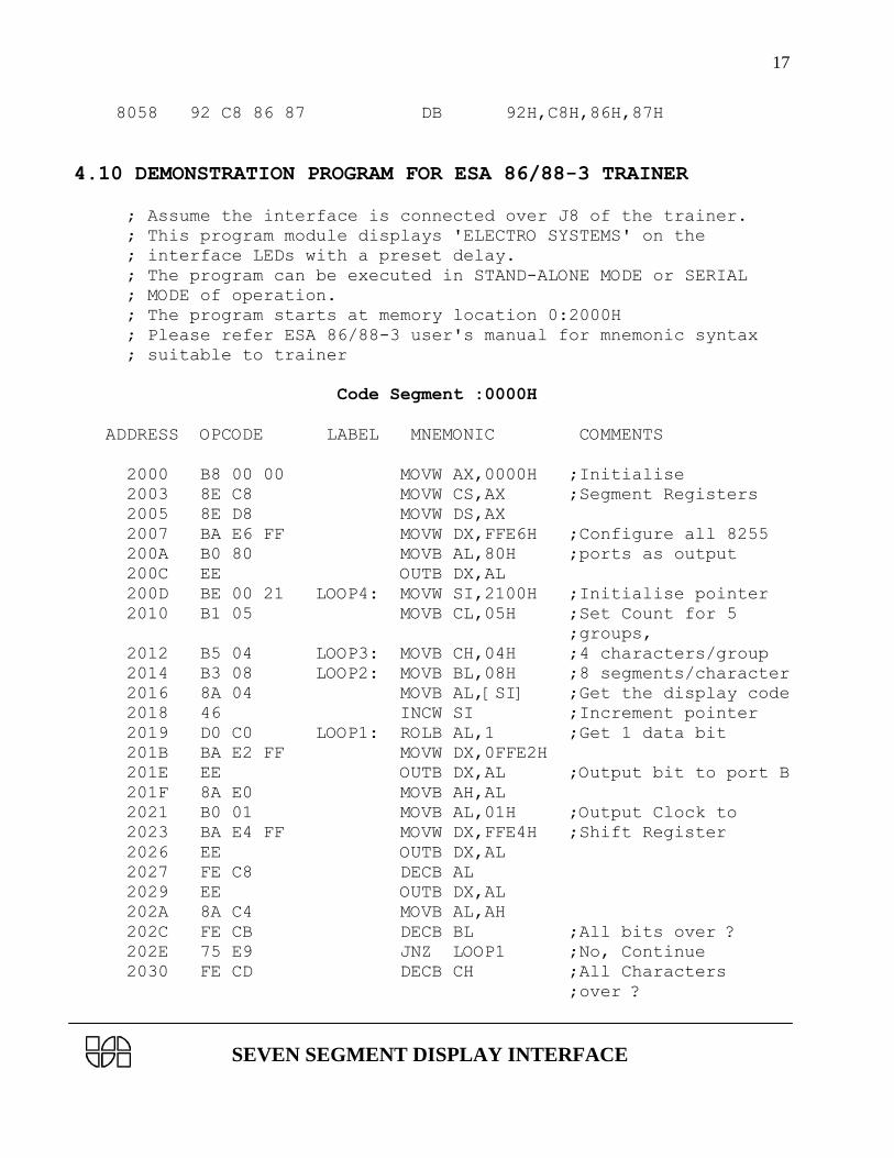
4.10 DEMONSTRATION PROGRAM FOR ESA 86/88-3 TRAINER
; Assume the interface is connected over J8 of the trainer.
; This program module displays 'ELECTRO SYSTEMS' on the
; interface LEDs with a preset delay.
; The program can be executed in STAND-ALONE MODE or SERIAL
; MODE of operation.
; The program starts at memory location 0:2000H
; Please refer ESA 86/88-3 user's manual for mnemonic syntax
; suitable to trainer
Code Segment :0000H
ADDRESS OPCODE LABEL MNEMONIC COMMENTS
2000 B8 00 00 MOVW AX,0000H ;Initialise
2003 8E C8 MOVW CS,AX ;Segment Registers
2005 8E D8 MOVW DS,AX
2007 BA E6 FF MOVW DX,FFE6H ;Configure all 8255
200A B0 80 MOVB AL,80H ;ports as output
200C EE OUTB DX,AL
200D BE 00 21 LOOP4: MOVW SI,2100H ;Initialise pointer
2010 B1 05 MOVB CL,05H ;Set Count for 5
;groups,
2012 B5 04 LOOP3: MOVB CH,04H ;4 characters/group
2014 B3 08 LOOP2: MOVB BL,08H ;8 segments/character
2016 8A 04 MOVB AL,[SI] ;Get the display code
2018 46 INCW SI ;Increment pointer
2019 D0 C0 LOOP1: ROLB AL,1 ;Get 1 data bit
201B BA E2 FF MOVW DX,0FFE2H
201E EE OUTB DX,AL ;Output bit to port B
201F 8A E0 MOVB AH,AL
2021 B0 01 MOVB AL,01H ;Output Clock to
2023 BA E4 FF MOVW DX,FFE4H ;Shift Register
2026 EE OUTB DX,AL
2027 FE C8 DECB AL
2029 EE OUTB DX,AL
202A 8A C4 MOVB AL,AH
202C FE CB DECB BL ;All bits over ?
202E 75 E9 JNZ LOOP1 ;No, Continue
2030 FE CD DECB CH ;All Characters
;over ?

SEVEN SEGMENT DISPLAY INTERFACE
18
2032 75 E0 JNZ LOOP2 ;No, Continue
2034 E8 06 00 CALL DELAY ;Introduce delay
2037 FE C9 DECB CL ;All groups over
2039 75 D7 JNZ LOOP3 ;No, Continue
203B EB D0 JMP LOOP4 ;Repeat continuously
203D 51 DELAY: PUSH CX ;Delay Subroutine
203E B9 FF FF MOVW CX,0FFFFH
2041 E2 FE LOOP $
2043 B9 FF FF MOVW CX,0FFFFH
2046 E2 FE LOOP $
2048 59 POP CX
2049 C3 RET
2100 ORG 2100H ;Display Codes table
2100 FF FF FF FF DB 0FFH,0FFH,0FFH,0FFH
2104 C6 86 C7 86 DB 0C6H,086H,0C7H,086H
2108 BF C0 DE 87 DB 0BFH,0C0H,0DEH,087H
210C BF 92 91 92 DB 0BFH,092H,091H,092H
2110 92 C8 86 87 DB 092H,0C8H,086H,087H
4.11 DEMONSTRATION PROGRAM FOR ESA-51E TRAINER
;Assume the interface is connected over J5 of the trainer.
;The trainer can be in BOARD MODE or SERIAL MODE.
ADDRESS OPCODE LABEL MNEMONIC COMMENTS
ORG 8000H
8000 75 A0 E8 MOV P2,#E8H ;Configure 8255
8003 78 03 MOV R0,#03H ;ALL ports as
8005 74 80 MOV A,#80H ;O/P
8007 F2 MOVX @R0,A
8008 90 80 48 LOOP4: MOV DPTR,#STRING ;Store string
800B 7B 05 MOV R3,#05H ;contents
800D 79 04 LOOP3: MOV R1,#04H ;5 Groups,
800F 7A 08 LOOP2: MOV R2,#08H ;4 Characters
8011 E4 CLR A ;8 segments
8012 93 MOVC A,@A+DPTR
8013 A3 INC DPTR ;Increment
;pointer
8014 23 LOOP1: RL A
8015 FC MOV R4,A
8016 78 01 MOV R0,#01H
8018 F2 MOVX @R0,A ;Output it
SEVEN SEGMENT DISPLAY INTERFACE
19
8019 74 01 MOV A,#01H
801B 78 02 MOV R0,#02H
801D F2 MOVX @R0,A ;Output the
;clock
801E 14 DEC A
801F F2 MOVX @R0,A ;Shift register
8020 EC MOV A,R4
8021 1A DEC R2 ;All bits over
8022 BA 00 EF CJNE R2,#0,LOOP1 ;no continue
8025 19 DEC R1 ;All characters
;over?
8026 B9 00 E6 CJNE R1,#0,LOOP2 ;No continue
8029 12 80 35 LCALL DELAY ;call delay
802C 12 80 35 LCALL DELAY
802F 1B DEC R3 ;All groups
;over?
8030 BB 00 DA CJNE R3,#0,LOOP3 ;No continue
8033 80 D3 SJMP LOOP4 ;Yes start
;from LOOP4
;Delay Subroutine
8035 C0 83 DELAY: PUSH DPH
8037 C0 82 PUSH DPL
8039 90 00 00 MOV DPTR,#0
803C A3 DELAY1: INC DPTR
803D E5 83 MOV A,DPH
803F 45 82 ORL A,DPL
8041 70 F9 JNZ DELAY1
8043 D0 82 POP DPL
8045 D0 83 POP DPH
8047 22 RET
8048 FF FF FF FF STRING: DB 0FFH,0FFH,0FFH,0FFH
804C C6 86 C7 86 DB C6H,86H,C7H,86H
8050 BF C0 DE 87 DB BFH,C0H,DEH,87H
8054 BF 92 91 92 DB BFH,92H,91H,92H
8058 92 C8 86 87 DB 92H,C8H,86H,87H
4.12 DEMONSTRATION PROGRAM FOR ESA 86/88E TRAINER
; Assume the interface is connected over J4 of the trainer.
; This program module displays 'ELECTRO SYSTEMS' on the
; interface LEDs with a preset delay.

SEVEN SEGMENT DISPLAY INTERFACE
20
; The program can be executed in STAND-ALONE MODE or SERIAL
; MODE of operation.
; The program starts at memory location 0:2000H
; Please refer ESA 86/88E user's manual for mnemonic syntax
; suitable to trainer
Code Segment :0000H
ADDRESS OPCODE LABEL MNEMONIC COMMENTS
2000 B8 00 00 MOVW AX,0000H ;Initialise
2003 8E C8 MOVW CS,AX ;Segment Registers
2005 8E D8 MOVW DS,AX
2007 BA E6 FF MOVW DX,FFE6H ;Configure all 8255
200A B0 80 MOVB AL,80H ;ports as output
200C EE OUTB DX,AL
200D BE 00 21 LOOP4: MOVW SI,2100H ;Initialise pointer
2010 B1 05 MOVB CL,05H ;Set Count for 5
;groups,
2012 B5 04 LOOP3: MOVB CH,04H ;4 characters/group
2014 B3 08 LOOP2: MOVB BL,08H ;8 segments/character
2016 8A 04 MOVB AL,[SI] ;Get the display code
2018 46 INCW SI ;Increment pointer
2019 D0 C0 LOOP1: ROLB AL,1 ;Get 1 data bit
201B BA E2 FF MOVW DX,0FFE2H
201E EE OUTB DX,AL ;Output bit to port B
201F 8A E0 MOVB AH,AL
2021 B0 01 MOVB AL,01H ;Output Clock to
2023 BA E4 FF MOVW DX,FFE4H ;Shift Register
2026 EE OUTB DX,AL
2027 FE C8 DECB AL
2029 EE OUTB DX,AL
202A 8A C4 MOVB AL,AH
202C FE CB DECB BL ;All bits over ?
202E 75 E9 JNZ LOOP1 ;No, Continue
2030 FE CD DECB CH ;All Characters
;over ?
2032 75 E0 JNZ LOOP2 ;No, Continue
2034 E8 06 00 CALL DELAY ;Introduce delay
2037 FE C9 DECB CL ;All groups over
2039 75 D7 JNZ LOOP3 ;No, Continue
203B E9 CF FF JMP LOOP4 ;Repeat continuously
203E 51 DELAY: PUSH CX ;Delay Subroutine
203F B9 FF FF MOVW CX,0FFFFH
2042 E2 FE LOOP $

SEVEN SEGMENT DISPLAY INTERFACE
21
2044 B9 FF FF MOVW CX,0FFFFH
2047 E2 FE LOOP $
2049 59 POP CX
204A C3 RET
2100 ORG 2100H ;Display Codes table
2100 FF FF FF FF DB 0FFH,0FFH,0FFH,0FFH
2104 C6 86 C7 86 DB 0C6H,086H,0C7H,086H
2108 BF C0 DE 87 DB 0BFH,0C0H,0DEH,087H
210C BF 92 91 92 DB 0BFH,092H,091H,092H
2110 92 C8 86 87 DB 092H,0C8H,086H,087H
5.0 EXERCISES
The sample program presented in this manual demonstrated some specific applications of this
interface. A few exercises are presented below to enable the user to gain a better understanding of
the interface. Users are encouraged to visualise other applications and develop software
accordingly.
a. Display the following sequence of digits in a right to left scrolling fashion with appropriate
delay.
1 2 3 4 5 6 7 8 9 0 -
b. Display time with the left two digits showing minutes and the right two digits showing
seconds. Use decimal point as delimiter.
c. The four digit display is required to show the outflow of fuel from a petrol pump. Initially,
the display should be as shown below:
Then increment the left two digits from 00 to 99 with a fixed delay. The right two digits should
constantly display Lt.