intelligent load frequency control in an isolated wind
TRANSCRIPT
Department of Electrical Engineering
Intelligent Load Frequency Control in an
Isolated Wind-Solar PV-Micro Turbine-Diesel
Based Micro-Grid using V2G Integration
—
Submitted by Wondwosen Eshetu Addisu
Master’s thesis in Electrical Engineering, June 2017
Department of Electrical Engineering
Intelligent Load Frequency Control in an
Isolated Wind-Solar PV-Micro Turbine-Diesel
Based Micro-Grid using V2G Integration
—
Submitted by Wondwosen Eshetu Addisu
Master’s thesis in Electrical Engineering, June 2017

i
Acknowledgement
First of all, I thank God for he has given me the chance to start and then the strength, courage
and patience to finalize this study. Everything happened in his will.
I would like to express sincere gratitude to my academic supervisors, Associate Prof. Dr. Pawan
Sharma and Dr. Charu Sharma. They have been wise, patient and trusted advisor throughout
the entire process. This thesis would not have been possible without their support and
encouragement. Their experience and input has been valuable during the thesis project.
Special thanks to Associate Prof. Dr. Trond Østrem, Dr. Bjarte Hoff, Prof. Lars Norum, Prof.
Per-Ole Nyman and all the other lecturers for the guidance and lectures they provided in their
respective courses. I would also like thanks to all my colleagues at UiT, The Arctic University
of Norway, for these two years of studies, sharing their knowledge and participating in different
projects and courses at the University.
I would like to thank my parents for being a constant source of encouragement and motivation
throughout my pursuit of the master degree.
Last, but certainly not least, I want to thank my wife, Dirb Tilahun, and daughters, Yohanna
and Kalkidan, for their love, faith and patience they were showing me during my whole work.
I could not have accomplished this work without her support. Dirb is always my life!
Wondwosen Eshetu Addisu
Narvik, 06/06/2017

ii
Abstract
Modern power systems need more intelligence and flexibility to maintain and control a
generation load balance from subsequent serious disturbances due to the emerging of more
renewable energy sources. This problem is becoming more significant today because of the
increasing number of micro-grids (MGs). MGs usually use renewable energies in electrical
production those fluctuate naturally. So, fluctuation and usual uncertainties in power systems
cause the conventional controllers to be less efficient to provide a proper load frequency control
(LFC) performance for a wide range of operating condition. Therefore, this thesis presents an
intelligent control technique which is based on Adaptive Neuro-Fuzzy Inference System
(ANFIS) architecture for an isolated wind-Solar PV-micro turbine-diesel based micro-grid
(MG) system using Vehicle-to-Grid (V2G) integration. Accordingly, the V2G technology, the
electric vehicle (EVs) may act as mobile energy storage units that could be a better solution for
the inadequate LFC capacity and thereby to improve the frequency stability in an isolated MG.
The performance of the proposed intelligent controller (ANFIs) is compared with conventional
proportional-integral-derivative (PID) controller, Interval type-1 (IT1) Fuzzy controller and
Interval type-2 (IT2) Fuzzy controller design methods. The results show that ANFIS based
neuro-fuzzy LFC controller is having less settling time and improve dynamic responses for the
considered MG system.
Keywords: Intelligent control technique; EV; V2G; LFC; Interval type-1 Fuzzy control;
Interval type-2 Fuzzy control; Proportional-Integral-Derivative control; Adaptive Neuro-Fuzzy
Inference System; Micro-Grid.
iii
Contents Acknowledgement .................................................................................................................................... i
Abstract ................................................................................................................................................... ii
List of Tables ........................................................................................................................................... v
List of Figures ........................................................................................................................................ vi
Chapter 1 Introduction............................................................................................................................ 1
1.1 Research Motivation ..................................................................................................................... 1
1.2 Micro Grid as a Viable Alternative ............................................................................................... 1
1.3 Technical challenges facing for Micro-grids implementation ...................................................... 2
1.4 The Problem; Load Frequency Control in a Micro Grid using V2G ............................................ 2
1.5 Proposed Solution; Intelligent Load Frequency Control Technique ............................................. 2
1.6 Thesis Organization ...................................................................................................................... 3
1.7 Thesis Contributions ..................................................................................................................... 3
Chapter 2 Literature Study ..................................................................................................................... 5
2.1 Vehicle to Grid (V2G) Technology .............................................................................................. 5
2.2 Role of V2G technology in a power system ................................................................................. 5
2.3 Load Frequency control ................................................................................................................ 6
2.4 LFC in micro-grids........................................................................................................................ 7
2.5 LFC in micro-grid with V2G ........................................................................................................ 7
2.6 Intelligent Techniques for LFC in micro grids ............................................................................. 8
2.7 Intelligent techniques for LFC in micro-grid with V2G ............................................................... 9
Chapter 3 Modelling of the Isolated Micro-Grid using V2G Integration ............................................. 10
3.1 Micro-grid modelling .................................................................................................................. 10
3.2 Model of MT ............................................................................................................................... 11
3.3 Model of Electric Vehicle ........................................................................................................... 12
3.4 Model of DG ............................................................................................................................... 13
3.5 Wind turbine and solar PV model ............................................................................................... 14
3.6 General scheme of the MG with LFC controller ........................................................................ 15
Chapter 4 The Proposed Controllers .................................................................................................... 18
4.1 Conventional Controller .............................................................................................................. 18
4.2 Artificial Intelligent Controller ................................................................................................... 18
4.2.1 Interval Type-1 Fuzzy Logic Controller .............................................................................. 18
4.2.2 Interval Type-2 Fuzzy Logic Controller .............................................................................. 23
4.2.3 Adaptive Neuro Fuzzy controller (ANFIS) ......................................................................... 27
Chapter 5 Simulation Results ............................................................................................................... 34
iv
5.1 Case 1: Load Disturbance .......................................................................................................... 34
5.1.1 Case1(A)-Without considering the constraints of MT, DG and EVs. ................................. 34
5.1.2 Case 1(B)-With considering the constraints of MT, DG and EVs ...................................... 43
5.1.3. Comparative study (Without and with considering the constraints of MT, DG and EVs) . 45
5.2 Case 2: Load disturbance and one of the EVs removed from the LFC system after 60 second. 47
5.2.1. Case 2(A)-Without considering the constraints of MT, DG and EVs ................................ 48
5.2.2. Case 2(B)-With considering the constraints of MT, DG and EVs ..................................... 50
5.3 Case 3: Active power disturbances from PVs ............................................................................. 53
5.3.1. Case 3(A)-Without considering the constraints of MT, DG and EVs. ............................... 53
5.3.2. Case 3(B) With considering the constraints of MT, DG and EVs. ..................................... 56
5.4 Case 4: Active power fluctuation of wind power generation. ..................................................... 58
5.4.1. Case 4(A)-Without considering the constraints of MT, DG and EVs ................................ 58
5.4.2. Case 4(B)-With considering the constraints of MT, DG and EVs ..................................... 61
5.5 Case 5: Power fluctuation of wind power generation, load and solar PVs. ................................ 63
5.5.1. Case 5(A)-Without considering the constraints of MT, DG and EVs ................................ 64
5.5.2. Case 5(B)-With considering the constraints of MT, DG and EVs ..................................... 69
5.6. Case 6: power fluctuations of wind power generation, load, solar and with a sudden fault. ..... 71
5.6.1. Case 6(A) Without considering the constraints of MT, DG and EVs ................................ 72
5.6.2. Case 6(B) With considering the constraints of MT, DG and EVs ...................................... 74
CHAPTER 6 Conclusions and Future Scopes.................................................................................... 77
6.1 Summary of contributions and conclusion .................................................................................. 77
6.2 Future Scopes .............................................................................................................................. 78
References ............................................................................................................................................. 80

v
List of Tables Table 1 - Parameters of the micro-grid model. .............................................................................. 17
Table 2 - Rule base fuzzy logic controller. ...................................................................................... 22
Table 3 - Parameters of the PID and Fuzzy controllers. .............................................................. 33
Table 4 - Comparison between conventional PID controller, type-1 and type-2 fuzzy
controller and ANFIS controller. ....................................................................................................... 41
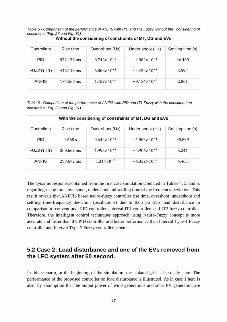
Table 5 - Comparison of the performance of ANFIS with PID and IT1 Fuzzy without the
considering of constraints (Fig. 27 and Fig. 31) ............................................................................. 47
Table 6 - Comparison of the performance of ANFIS with PID and IT1 Fuzzy with the
consideration constraints (Fig. 29 and Fig. 31) .............................................................................. 47

vi
List of Figures Figure 1 - Layout of isolated micro-grid ........................................................................................... 10
Figure 2 - The transfer function model of the Micro Turbine for LFC ......................................... 11
Figure 3 - The transfer function model of EV model for LFC ....................................................... 12
Figure 4 - Total energy model [23]. .................................................................................................. 13
Figure 5 - The transfer function model of Diesel Generator for LFC .......................................... 14
Figure 6 - The control model of the Micro-Grid including LFC. ................................................... 15
Figure 7 - Block diagram of Fuzzy logic controller (for both IT1 and IT2).................................. 19
Figure 8 - FIS editor of Mamdani Interval type-1 Fuzzy logic toolbox. ....................................... 20
Figure 9 - Membership functions of IT1 fuzzy control used in this thesis; (I) and (II) are input
patterns (III) is output pattern. ........................................................................................................... 21
Figure 10 - Structure of IT1 fuzzy logic controller. ......................................................................... 23
Figure 11 - The Structure of FLC, (A) is interval type-1 and (B) is interval type-2. .................. 24
Figure 12 - Implementation of Type -2 Fuzzy inference system in MATLAB ............................ 25
Figure 13 - The FIS editor of Mamdani Interval type-2 Fuzzy logic toolbox (I) and
Membership functions of IT2 fuzzy control used in this thesis; (II) and (III) are input patterns
(IV) is output pattern. .......................................................................................................................... 27
Figure 14 - Block diagram of Neuro-Fuzzy controller. .................................................................. 28
Figure 15 - Architecture of ANFIS .................................................................................................... 29
Figure 16 - ANFIS training process ................................................................................................. 31
Figure 17 - MATLAB ANFIS model of rule base for the first case. ............................................ 32
Figure 18 - Structure of adaptive neuro-fuzzy model FIS Wizard for the first case. ................ 33
Figure 19 - FIS editor (Sugeno model) with two inputs and one output. .................................... 35
Figure 20 - The frequency deviation Input membership function after completion of training 35
Figure 21 - Derivative of frequency deviation Input membership function after completion of
training. ................................................................................................................................................. 36
Figure 22 - Output membership function after completion of training. ....................................... 36
Figure 23 - ANFIS Rule Editor. ......................................................................................................... 37
Figure 24 - ANFIS Rule Viewer. ....................................................................................................... 38
Figure 25 - ANFIS Designer, training data with hybrid optimization method. ........................... 38
Figure 26 - Surface view created by ANFIS. .................................................................................. 39
Figure 27 - Frequency deviation of the isolated micro-grid without constraints in case 1(A). 40
Figure 28 - The output power increment of MT, DG, EV1, and EV2 without considering
constraints in case 1(A); (I) using PID controller, (II) using IT1 Fuzzy controller, (III) using IT2
Fuzzy controller and (IV) using ANFIS controller. ......................................................................... 42
Figure 29 - Frequency deviation of the isolated micro-grid with constraints in case 1(B). ...... 43
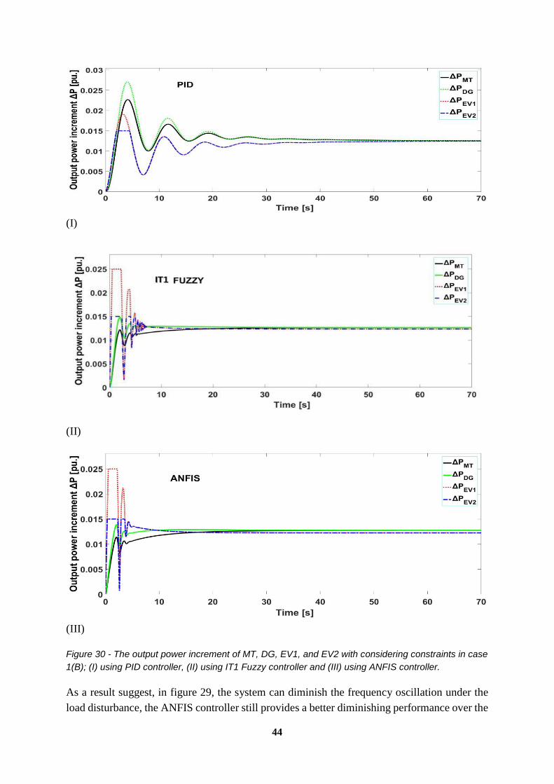
Figure 30 - The output power increment of MT, DG, EV1, and EV2 with considering
constraints in case 1(B); (I) using PID controller, (II) using IT1 Fuzzy controller and (III) using
ANFIS controller. ................................................................................................................................ 44
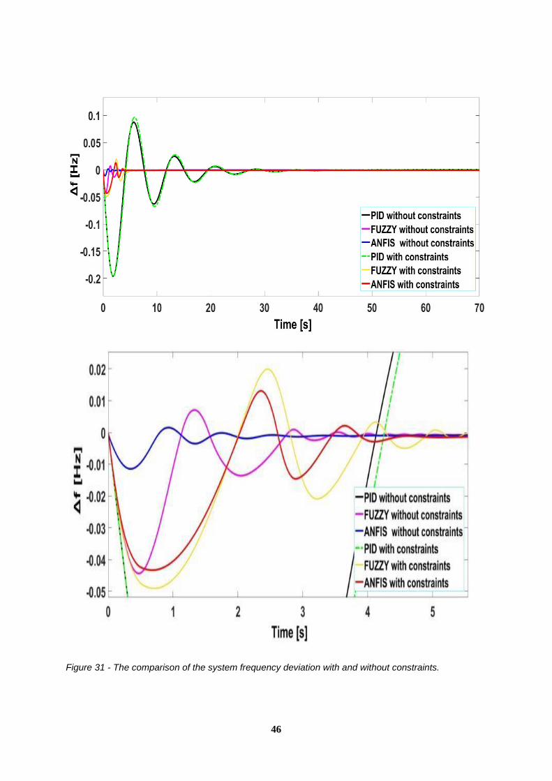
Figure 31 - The comparison of the system frequency deviation with and without constraints.
............................................................................................................................................................... 46
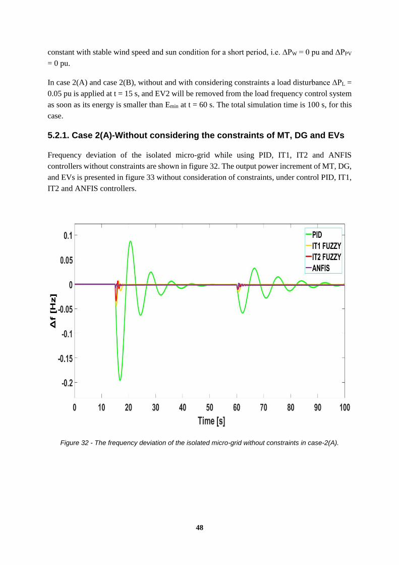
Figure 32 - The frequency deviation of the isolated micro-grid without constraints in case-
2(A). ...................................................................................................................................................... 48

vii
Figure 33 - The output power increment of MT, DG, EV1, EV2 without considering
constraints in case 2(A); (I) using PID controller, (II) using IT1 Fuzzy controller, (III) using IT2
Fuzzy controller and (IV) using ANFIS controller. ......................................................................... 50
Figure 34 - The frequency deviation of the isolated micro-grid with constraints in case 2(B). 51
Figure 35 - The output power increment of MT, DG, EV1, and EV2 with constraints in case
2(B); (I) using PID controller, (II) using IT1 Fuzzy controller and (III) using ANFIS controller.52
Figure 36 - The active power disturbance from Solar PVs. ......................................................... 53
Figure 37 - The frequency deviation of the isolated micro-grid without constraints in case
3(A). ...................................................................................................................................................... 54
Figure 38 - The output power increment of MT, DG, EV1, and EV2 without considering
constraints in case 3(A); (I) using PID controller, (II) using IT1 Fuzzy controller, (III) using IT2
Fuzzy controller and (IV) using ANFIS controller. ......................................................................... 56
Figure 39 - The frequency deviation of the isolated micro-grid with constraints in case 3(B). 56
Figure 40 - The output power increment of MT, DG, EV1, and EV2 with considering ............ 57
Figure 41 - The power fluctuation of wind power generation. ...................................................... 58
Figure 42 - The frequency deviation of the isolated micro-grid without constraints in case
4(A). ...................................................................................................................................................... 59
Figure 43 - The output power increment of MT, DG, EV1, and EV2 without considering
constraints in case 4(A); (I) using PID controller, (II) using IT1 Fuzzy controller, (III) using IT2
Fuzzy controller and (IV) using ANFIS controller. ......................................................................... 61
Figure 44 - The frequency deviation of the isolated micro-grid with constraints in case 4(B). 61
Figure 45 - The output power increment of MT, DG, EV1, and EV2 with considering
constraints in case 4(B); (I) using PID controller, (II) using IT1 Fuzzy controller and (III) using
ANFIS controller. ................................................................................................................................ 62
Figure 46 - The power disturbances applied in this case (case 5). ............................................ 63
Figure 47 - MATLAB ANFIS model of rule base for this case. .................................................... 64
Figure 48 - Surface view created by ANFIS for in this case (case 5(A)). .................................. 64
Figure 49 - The frequency deviation of the isolated micro-grid without constraints in case
5(A). ...................................................................................................................................................... 66
Figure 50 - The output power increment of MT, DG, EV1, and EV2 without considering
constraints in case 5(A); (I) using PID controller, (II) using IT1 Fuzzy controller, (III) using IT2
Fuzzy controller and (IV) using ANFIS controller. ......................................................................... 68
Figure 51 - The frequency deviation of the isolated micro-grid with constraints in case 5(B). 69
Figure 52 - The output power increment of MT, DG, EV1, and EV2 with considering
constraints in case 5(b); (I) using PID controller, (II) using IT1 Fuzzy controller and (III) using
ANFIS controller. ................................................................................................................................ 70
Figure 53 - The power disturbance applied in case 6. .................................................................. 71
Figure 54 - The frequency deviation of the isolated micro-grid without constraints in case
6(A). ...................................................................................................................................................... 72
Figure 55 - The output power increment of MT, DG, EV1, and EV2 without considering
constraints in case 6(A); (I) using PID controller, (II) using IT1 Fuzzy controller, (III) using IT2
Fuzzy controller and (IV) using ANFIS controller. ......................................................................... 74
Figure 56 - The frequency deviation of the isolated micro-grid with constraints in case 6(B). 74
Figure 57 - The output power increment of MT, DG, EV1, and EV2 with considering
constraints in case 6(B); (I) using PID controller, (II) using IT1 Fuzzy controller and (III) using
ANFIS controller. ................................................................................................................................ 75

viii
1
Chapter 1
Introduction
1.1 Research Motivation
In recent years, the impact of fossil fuel on the environment, especially the global warming and
the harmful effects of carbon emissions have created a new demand for clean and sustainable
energy sources [1]. Environmental issues are now playing an ever-increasing vital role on the
political agenda. Power generation by conventional energy sources has always been a major
source of air pollution, and much effort has been devoted to developing cleaner generation
technologies. However, the relatively recent concerns about global warming and sustainability
have started to change the way power systems operate and expand. It is estimated that power
generation contributes about one-third of the global CO2 emissions so that many countries in
the world have set a target for renewable energy generation (REG) to contribute 20% or more
of their total energy production by about 2020 [2]. The renewable energy sources are used for
power generation which could be integrated to the distribution voltage level. A micro-grid
(MG) concept is needed to integrate the renewable energy sources (RES) in the electric grid.
MGs are small power grids: - it can be part of an electric distribution system or can be a small
independent power grid of an isolated or remote area, i.e., where there is no access of primary
grid power. If a MG is grid connected, the loads can be supplied by the connected primary grid
power system. Otherwise, the system is working in an isolated mode. In islanded mode, the
unavailability of grid requires specific management of micro-sources (MSs) and load, because
they cannot simply generate and consume by their willing. MG disconnection from main grid
demand that total power produced by MSs should equal to the power consumed by the loads
plus the line losses within micro-grid.
1.2 Micro Grid as a Viable Alternative
Micro-grids (MG) are becoming viable alternative to centralized generation and bulk
transmission of power by offering a localized power production, regulation, and consumption.
According to the 24th edition of the World Energy Resources report, most countries have
achieved more diversified energy integrating with growth in community ownerships and an
evolution of micro-grids [53]. A typical MG consists of distribution sources, for example,
micro-turbines, diesel generators, renewable sources and loads. Rapid improvements in
performance and cost of energy storage technologies during the last few years are making MGs
an economically viable option for the power system in the near future [3], [47], [48].
2
1.3 Technical challenges facing for Micro-grids implementation
Nowadays, smart grids-micro grids are facing various challenges due to renewable energy
source penetration, load fluctuation, and electric vehicles EVs integration. MG frequency,
voltage, and protection are the most critical challenges facing for MGs implementation.
Due to the intermittent nature of renewable energy sources, large frequency fluctuation occurs
when the load frequency control capacity is not enough to compensate for the imbalance of
generation and demand. This problem may become intensified when the system is working in
isolated operation mode [30]. In an isolated power system, the operation is often very
challenging because of their small system inertia. Although, the inertia energy in a power
system can partly overcome the disturbances which caused whether by the load or by the
intermittent nature of renewable energy sources, it is still difficult to keep the frequency
deviation within the acceptable limits [3].
1.4 The Problem; Load Frequency Control in a Micro Grid using V2G
Due to renewable sources fluctuation and electric vehicles integration, the isolated MG system
state parameters and operating conditions change rapidly. Moreover, there are some constraints
in the LFC units including generation rate constraints and capacity constraints, which
conventional controllers cannot overcome. Thus, for isolated MG LFC with V2G, a controller
with robust performance over a wide range of system operation conditions is highly desirable
[3].
1.5 Proposed Solution; Intelligent Load Frequency Control Technique
This thesis has presented an intelligent control technique of the isolated micro-grid system with
EVs, distributed generations to obtain a satisfied performance on the load frequency control by
using Adaptive Neuro-Fuzzy Inference System (ANFIS). Accordingly, the vehicle to grid
(V2G) technology, the electric vehicle (EVs) may act as mobile energy storage units that could
be a better solution for the inadequate LFC capacity thereby improving the frequency stability
in an isolated micro grid. This intelligent control, in turn, will improve the frequency stability
with complex operation conditions like the random renewable energy sources and the load
disturbances. Neuro-Fuzzy system can combine the parallel and learning abilities of neural
networks (NNs) with human-like knowledge representation and explanation abilities of fuzzy
system. The performances of ANFIS based controller, Interval Type-1 and Type-2 Fuzzy Logic
Control (FLC) and the conventional PID control are compared to highlight the supremacy of
hybrid controller over conventional controller.

3
1.6 Thesis Organization
The organization of the thesis is as follows:
Chapter 1 gives a general introduction to Micro-Grid LFC. The viability of MG as an
alternative, technical challenges facing for MG implementation, the problem on LFC in MG
using V2G, the proposed solution presented the main motivation and at the last thesis
contributions are briefly reviewed.
Chapter 2 presents literature study. The past achievement in the Vehicle to Grid (V2G)
technology, the role of V2G technology in a power system, LFC, LFC in MGs, LFC in MGs
with V2G, Intelligent techniques for LFC in MGs and Intelligent techniques for LFC in MG
with V2G literature is reviewed.
Chapter 3 presents modelling of the isolated MG using V2G integration. The MG
modelling, model of MT, EVs, DG, wind turbine and solar PV and general scheme of the MG
with LFC controller designed state space equation based on the model are presented in
briefly.
Chapter 4 propose different controllers for MG LFC. (1) Conventional Controller,
Proportional Integral Derivative (PID). (2) Artificial intelligent controller: - (2.1) Interval
type-1 Fuzzy Logic controller (IT1 FLC) and (2.2) Interval type-2 Fuzzy Logic controller
(IT2 FLC) (2.3) Adaptive Neuro-Fuzzy Controller (ANFIS) and its procedural steps to design
the ANFIS.
In Chapter 5 the robustness and effectiveness of the proposed ANFIS over the
conventional PID, IT1 and IT2 fuzzy controller is presented numerical time-domain simulated
results.
Conclusion and future scopes are stated in Chapter 6.
1.7 Thesis Contributions
The main contribution of this thesis are as follows:
I. A literature study of the V2G technology in a power system.
II. State space modelling of the considered isolated MG using V2G Integration.
III. Present an intelligent coordination control techniques for LFC between micro-turbine,
diesel generator, and EVs to achieve a satisfied performance on load frequency.

4
IV. Demonstrate the performance of ANFIS with system stability performances, the
considered isolated micro-grid with MT, DG, EVs, solar PV, and wind farm is modelled in
MATLAB/SIMULINK environment.

5
Chapter 2
Literature Study
2.1 Vehicle to Grid (V2G) Technology
Amory Lovins determined V2G in 1995 and was developed by William Kempton. The primary
concept of V2G is that EVs can provide energy to the electric power systems when it is parked,
the battery of EVs can charge during low demand times and discharge when power is needed.
Statistically speaking, private cars remain idle for almost 95% of the day [3], [4].
V2G describes a system in which the EVs communicates with the power grid to provide grid
support by either delivering power to the grid or by throttling their charging rate.V2G
technology utilizes the stored energy in the electric vehicles’ batteries and supplies this energy
to the grid, whenever requested by the grid operators. A fleet of such electric vehicles would
provide a considerable amount of energy storage. Thus, like distributed energy resources, the
V2G technique can reduce the stress on the overloaded distribution systems by meeting demand
locally, especially during peak hours [5].
2.2 Role of V2G technology in a power system
V2G technology can provide many services to achieve various benefit. The implementation of
V2G can provide frequency regulation, harmonics filtering and even failure recovery to power
system during blackout. The advantage of V2G is not only the privilege for power utility in
micro-grids but also EV owners [6], [7], [8].
V2G can help improve the reliability and stability of the grid, alleviate power shortages, reduce
air pollution, improve ancillary services, frequency regulation to grid operation, and improve
overall system efficiency. For instant, V2Gs can play a significant role in helping to balance
supply and demand by valley filling and peak shaving. The electric vehicle battery pack
charged at night during low demand, and then the stored power can be fed power back into the
grid during high demand periods, thus helping to stabilize the grid’s voltage and frequency, and
providing a spinning reserve to meet sudden power demand changes. The most important role
for V2G may also be used to support renewable energy sources. The two largest renewable
sources likely photovoltaic PV and wind turbines both are intermittent, for example, they store
excess energy produced during windy periods, and feeding it back into grid during high loads,
thus effectively stabilizing the intermittency of wind power [8], [9], [10].
According to [11] peak-shaving and valley-filling control using V2G system proposed and the
simulation results demonstrate that the V2G peak-saving and valley-filling control strategy and
its constraints are reasonable and efficient.

6
2.3 Load Frequency control
Load frequency control (LFC) is a critical issue in power system operation and control of
supplying for sufficient and reliable electric power with high quality. LFC is one of the
important control problems in electrical power system operation and design; Nowadays is
becoming more significant. Because of the increasing changing structure, size, emerging new
distributed renewable energy sources with uncertainties, environmental constraints, and as well
as the Micro Grid and Battery storage technologies has made frequency control a challenging
task. Many studies have focused on damping frequency control and voltage stability and related
issues, but there has been much less work on the power system frequency control, in the last
two decades [12], [13].
Significant frequency fluctuation occurs when the load frequency control capacity less efficient
to provide the imbalance of power generation and demand. This problem may become enlarged
when the system is working in an isolated operation mode. LFC Control Strategies
In general, in research papers LFC controllers techniques are proposed based on:
1. Classical control techniques
A) LQR based controlling techniques
B) Proportional, derivative, integral controlling techniques
2. Soft computing artificial intelligence techniques
A) Fuzzy logic-based techniques
B) Neural Network-based techniques
C) Genetic algorithm based techniques
D) Particle swarm based techniques
E) Hybrid and other based techniques
The descriptions of load frequency control techniques are described by different researchers
[27].
Load frequency control problem for single area thermal power system is presented [14], the
LFC scheme of one area thermal system with single time delay is introduced in [15]. For single
area hydropower system LFC problem is presented, the transient speed response of a single,
isolate-governed hydro-generator operating at near full load discussed in briefly in [16]. In [17],
the LFC of an isolated small hydropower system presented.
7
The LFC problem becomes even more complex by integration of renewable energy sources
such as wind farms because of fluctuating output power due to intermittent nature of wind
speed. Thus the LFC needs to be addressed differently [12]. The authors of [18] discuss in detail
modification of unit commitment, economic dispatch, regulation and frequency regulation
control when the level of wind generation capacity is significant.
LFC control methods have been applied in traditional thermal power generation system and
hydro power generation power system. In [19] Fosha and Elgerd used a state variable model
and regulated problem of optimal control theory to develop new feedback control law for two-
area interconnected non-reheat type thermal power system. In [20], a linear regulator design
method proposed for frequency control based on optimal linear regulator theory.
2.4 LFC in micro-grids
Recently, economical harvesting electrical energy on a vast scale considering the environment
issues is undoubtedly one of the big challenges, micro-grid might consider as a best solution.
The MGs promise to facilitate the widely penetration of renewable energy and energy storage
devices into the power system. Due to high diversity in generation and loads, the MGs exhibit
large nonlinearities, changing dynamics, and uncertainties that may require advanced
robust/intelligent control strategies to solve [13].
In [20], to intensify the frequency control performance and robustness in the presence of
uncertainties, the mixed H2 / H∞ and PSO-based mixed H2 / H∞ are proposed for tuning
proportional-integral-derivative parameters. The authors of [21] proposed a fuzzy-based
proportional-integral (PI) control strategy, the stability of hybrid MG system.
2.5 LFC in micro-grid with V2G
The battery storage of the electric vehicle is one of the emerging technologies; it can act as a
load reacting to the change in power supply. Literature shows that very little work has been
done on control aspect of EVs and the grid. In [22] [23], to utilize an EVs for frequency control
has been discussed by developing an optimal aggregator and a similar work is found in [24].
There where an integration of V2G in a Danish farm has been reviewed in detail; on the other
hand, more importance has been given to energy storage rather than the V2G concept. The
authors of [25] [26] analyses the impact of EVs on distribution grid using load flow techniques,
these works, nevertheless, haven’t used any controlled techniques for charging or discharging
of EVs energy to the grid.
8
2.6 Intelligent Techniques for LFC in micro grids
Modern power systems require increased intelligence techniques and flexibility in the control
and optimization to ensure the performance of maintaining a generation-load balance, following
serious disturbances, this issue is becoming more significant today because of the increasing
number of MGs. The LFC classical controllers are not visible in practical system because of
nonlinear characteristics generation rate constraint and saturation [28]. Therefore, there is a
need to controller techniques which can overcome the problem. The soft computing / Artificial
Intelligence (AI) techniques like Fuzzy, Neural Network, Genetic Algorithm, hybrid and other
techniques approach is more suitable for such a case.
The concept of fuzzy logic developed by Lotfi Zadeh in 1969 address uncertainty and
imprecision which widely exist in engineering problems. The FLC concept departs significantly
from traditional control theory, i.e., mainly based on mathematical models of the controlled
process. The mathematical modeling of Fuzzy: - is the method of describing characteristics of
a system by using fuzzy inference rules. The method has a differentiating feature in that it can
denote linguistically complex nonlinear systems. It is, however, very hard to identify the rules
and tune the membership functions of the fuzzy reasoning. Fuzzy controllers commonly built
with the use of fuzzy rules. These fuzzy rules are obtained either from domain experts or by
inspecting the people who are professional on currently using this control. Membership
functions of the fuzzy sets will be determined from the information accessible from the domain
experts. The structure of such rules and membership functions require tuning. That is,
performance of the controller must be measured and membership function and rules adjusted
based upon the performance.
The Modern era of artificial neural networks (ANN) began with the pioneering work of
McCulloch and Pitts in 1943 with the/known McCulloch-Pitts model. ANNs usually referred
to neural networks; have been driven by the recognition that the human brain does certain tasks
much more efficiently in an entirely different way than the conventional digital computers.
They are non-linear by nature, which excellent features like fault-tolerance and capability for
self-learning, which gives them robust and quite suited for parallel processing. ANN performs
the function of non-linear mapping. If an input set of data corresponds to a definite signal
pattern, network can be trained to give correspondingly desired pattern at the output. ANN
techniques are relatively easy to implement and do not require any prior knowledge of the
system model [29].
To enable a system to deal with cognitive uncertainties in a manner more like humans, one
combines the concept of fuzzy logic into the neural networks. The resulting hybrid system is
called neural fuzzy, fuzzy neural, fuzzy-neuro or neuro-fuzzy network.
The LFC problem in micro-grids has tackled in the literature by different intelligent techniques
[1], [21], [28], [37].
9
2.7 Intelligent techniques for LFC in micro-grid with V2G
The complexity and uncertainty of the power system raised by the entrance of distributed
generation sources and micro-grids. The fluctuation in the generated power might cause some
problems in the function of conventional controllers. As a result, modern power system requires
an increased intelligent techniques and flexibility in the control and optimization to ensure the
capability of a generated load balance, following serious disturbances. The authors of [31],
proposed a new combination of the General Type II Fuzzy Logic Sets (GT2FLS) and the
Modified Harmony Search Algorithm (MHSA) technique was applied for adaptive tuning of
Proportional-Integral (PI) controller.
10
Chapter 3
Modelling of the Isolated Micro-Grid using V2G
Integration
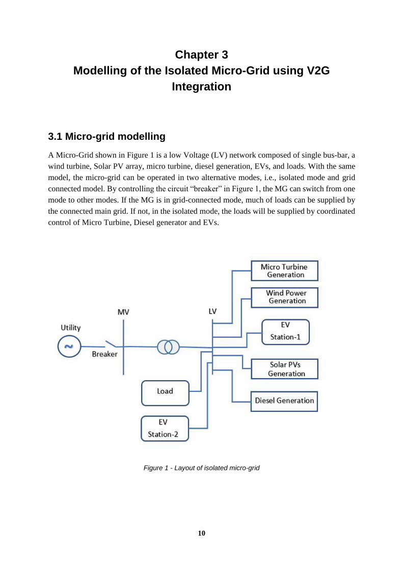
3.1 Micro-grid modelling
A Micro-Grid shown in Figure 1 is a low Voltage (LV) network composed of single bus-bar, a
wind turbine, Solar PV array, micro turbine, diesel generation, EVs, and loads. With the same
model, the micro-grid can be operated in two alternative modes, i.e., isolated mode and grid
connected model. By controlling the circuit “breaker” in Figure 1, the MG can switch from one
mode to other modes. If the MG is in grid-connected mode, much of loads can be supplied by
the connected main grid. If not, in the isolated mode, the loads will be supplied by coordinated
control of Micro Turbine, Diesel generator and EVs.
Figure 1 - Layout of isolated micro-grid
11
3.2 Model of MT
A micro turbine is a small-scale power generation equipment. It has an advantage of fast
starring speed, durability, and high efficiency, compared with traditional generators. MT can
follow load demand variations by using a power control mechanisms within short intervals of
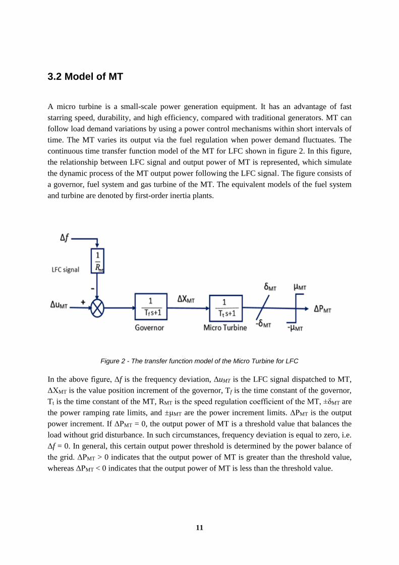
time. The MT varies its output via the fuel regulation when power demand fluctuates. The
continuous time transfer function model of the MT for LFC shown in figure 2. In this figure,
the relationship between LFC signal and output power of MT is represented, which simulate
the dynamic process of the MT output power following the LFC signal. The figure consists of
a governor, fuel system and gas turbine of the MT. The equivalent models of the fuel system
and turbine are denoted by first-order inertia plants.
Figure 2 - The transfer function model of the Micro Turbine for LFC
In the above figure, Δf is the frequency deviation, ΔuMT is the LFC signal dispatched to MT,
ΔXMT is the value position increment of the governor, Tf is the time constant of the governor,
Tt is the time constant of the MT, RMT is the speed regulation coefficient of the MT, ±δMT are
the power ramping rate limits, and ±μMT are the power increment limits. ΔPMT is the output
power increment. If ΔPMT = 0, the output power of MT is a threshold value that balances the
load without grid disturbance. In such circumstances, frequency deviation is equal to zero, i.e.
Δf = 0. In general, this certain output power threshold is determined by the power balance of
the grid. ΔPMT > 0 indicates that the output power of MT is greater than the threshold value,
whereas ΔPMT < 0 indicates that the output power of MT is less than the threshold value.
12
3.3 Model of Electric Vehicle
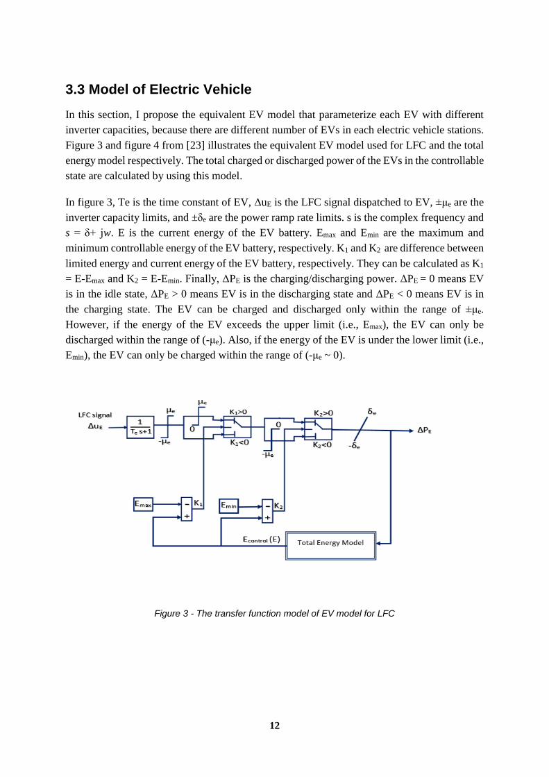
In this section, I propose the equivalent EV model that parameterize each EV with different
inverter capacities, because there are different number of EVs in each electric vehicle stations.
Figure 3 and figure 4 from [23] illustrates the equivalent EV model used for LFC and the total
energy model respectively. The total charged or discharged power of the EVs in the controllable
state are calculated by using this model.
In figure 3, Te is the time constant of EV, ΔuE is the LFC signal dispatched to EV, ±μe are the
inverter capacity limits, and ±δe are the power ramp rate limits. s is the complex frequency and
s = δ+ jw. E is the current energy of the EV battery. Emax and Emin are the maximum and
minimum controllable energy of the EV battery, respectively. K1 and K2 are difference between
limited energy and current energy of the EV battery, respectively. They can be calculated as K1
= E-Emax and K2 = E-Emin. Finally, ΔPE is the charging/discharging power. ΔPE = 0 means EV
is in the idle state, ΔPE > 0 means EV is in the discharging state and ΔPE < 0 means EV is in
the charging state. The EV can be charged and discharged only within the range of ±μe.
However, if the energy of the EV exceeds the upper limit (i.e., Emax), the EV can only be
discharged within the range of (-μe). Also, if the energy of the EV is under the lower limit (i.e.,
Emin), the EV can only be charged within the range of (-μe ~ 0).
Figure 3 - The transfer function model of EV model for LFC
13
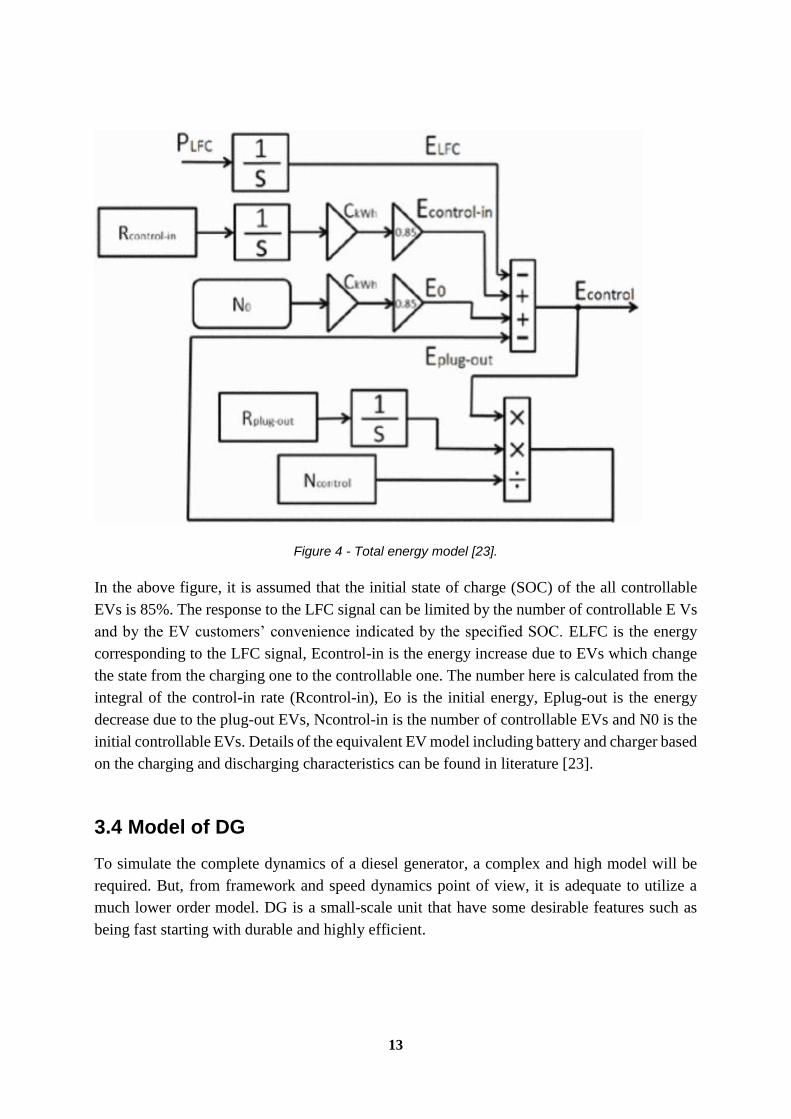
Figure 4 - Total energy model [23].
In the above figure, it is assumed that the initial state of charge (SOC) of the all controllable
EVs is 85%. The response to the LFC signal can be limited by the number of controllable E Vs
and by the EV customers’ convenience indicated by the specified SOC. ELFC is the energy
corresponding to the LFC signal, Econtrol-in is the energy increase due to EVs which change
the state from the charging one to the controllable one. The number here is calculated from the
integral of the control-in rate (Rcontrol-in), Eo is the initial energy, Eplug-out is the energy
decrease due to the plug-out EVs, Ncontrol-in is the number of controllable EVs and N0 is the
initial controllable EVs. Details of the equivalent EV model including battery and charger based
on the charging and discharging characteristics can be found in literature [23].
3.4 Model of DG
To simulate the complete dynamics of a diesel generator, a complex and high model will be
required. But, from framework and speed dynamics point of view, it is adequate to utilize a
much lower order model. DG is a small-scale unit that have some desirable features such as
being fast starting with durable and highly efficient.
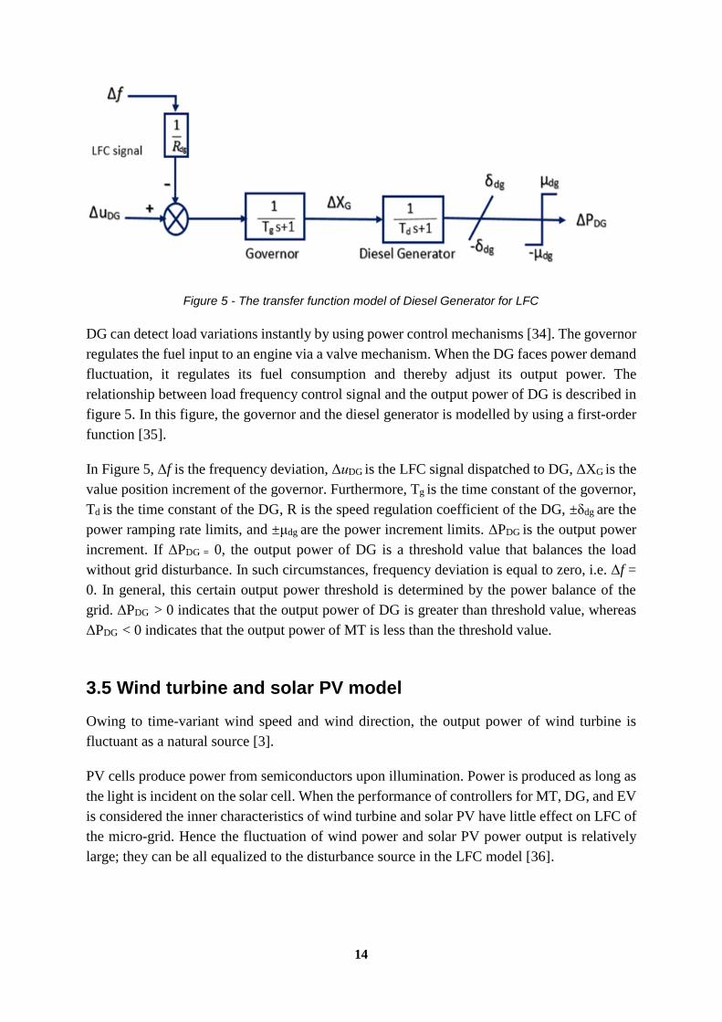
14
Figure 5 - The transfer function model of Diesel Generator for LFC
DG can detect load variations instantly by using power control mechanisms [34]. The governor
regulates the fuel input to an engine via a valve mechanism. When the DG faces power demand
fluctuation, it regulates its fuel consumption and thereby adjust its output power. The
relationship between load frequency control signal and the output power of DG is described in
figure 5. In this figure, the governor and the diesel generator is modelled by using a first-order
function [35].
In Figure 5, Δf is the frequency deviation, ΔuDG is the LFC signal dispatched to DG, ΔXG is the
value position increment of the governor. Furthermore, Tg is the time constant of the governor,
Td is the time constant of the DG, R is the speed regulation coefficient of the DG, ±δdg are the
power ramping rate limits, and ±μdg are the power increment limits. ΔPDG is the output power
increment. If ΔPDG = 0, the output power of DG is a threshold value that balances the load
without grid disturbance. In such circumstances, frequency deviation is equal to zero, i.e. Δf =
0. In general, this certain output power threshold is determined by the power balance of the
grid. ΔPDG > 0 indicates that the output power of DG is greater than threshold value, whereas
ΔPDG < 0 indicates that the output power of MT is less than the threshold value.
3.5 Wind turbine and solar PV model
Owing to time-variant wind speed and wind direction, the output power of wind turbine is
fluctuant as a natural source [3].
PV cells produce power from semiconductors upon illumination. Power is produced as long as
the light is incident on the solar cell. When the performance of controllers for MT, DG, and EV
is considered the inner characteristics of wind turbine and solar PV have little effect on LFC of
the micro-grid. Hence the fluctuation of wind power and solar PV power output is relatively
large; they can be all equalized to the disturbance source in the LFC model [36].
15
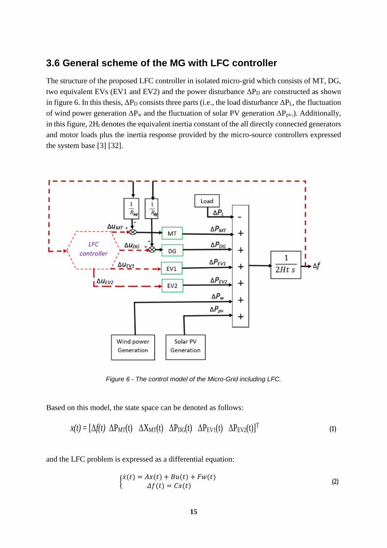
3.6 General scheme of the MG with LFC controller
The structure of the proposed LFC controller in isolated micro-grid which consists of MT, DG,
two equivalent EVs (EV1 and EV2) and the power disturbance ΔPD are constructed as shown
in figure 6. In this thesis, ΔPD consists three parts (i.e., the load disturbance ΔPL, the fluctuation
of wind power generation ΔPw and the fluctuation of solar PV generation ΔPpv.). Additionally,
in this figure, 2Ht denotes the equivalent inertia constant of the all directly connected generators
and motor loads plus the inertia response provided by the micro-source controllers expressed
the system base [3] [32].
Figure 6 - The control model of the Micro-Grid including LFC.
Based on this model, the state space can be denoted as follows:
x(t) = [Δf(t) ΔPMT(t) ΔXMT(t) ΔPDG(t) ΔPEV1(t) ΔPEV2(t)]T (1)
and the LFC problem is expressed as a differential equation:
{�̇�(𝑡) = 𝐴𝑥(𝑡) + 𝐵𝑢(𝑡) + 𝐹𝑤(𝑡)
𝛥𝑓(𝑡) = 𝐶𝑥(𝑡) (2)
16
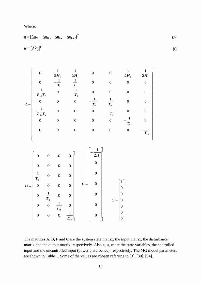
Where:
u = [ΔuMT ΔuDG ΔuEV1 ΔuEV2]T (3)
w = [ΔPD]T (4)
2
1
1000000
01
00000
001
0001
0011
000
00001
01
000011
0
2
1
2
100
2
1
2
10
e
e
ggdg
dd
ffmt
tt
tttt
T
T
TTR
TT
TTR
TT
HHHH
A
2
1
1000
01
00
001
0
0000
0001
0000
0000
e
e
g
f
T
T
T
T
B
0
0
0
0
0
0
2
1
tH
F
0
0
0
0
0
0
1
C
The matrixes A, B, F and C are the system state matrix, the input matrix, the disturbance
matrix and the output matrix, respectively. Also,x, u, w are the state variables, the controlled
input and the uncontrolled input (power disturbance), respectively. The MG model parameters
are shown in Table 1. Some of the values are chosen referring to [3], [30], [34].
17
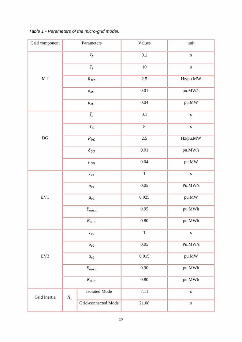
Table 1 - Parameters of the micro-grid model.
Grid component Parameters Values unit
MT
𝑇𝑓 0.1 s
𝑇𝑡 10 s
𝑅𝑀𝑇 2.5 Hz/pu.MW
𝛿𝑀𝑇 0.01 pu.MW/s
𝜇𝑀𝑇 0.04 pu.MW
DG
𝑇𝑔 0.1 s
𝑇𝑑 8 s
𝑅𝐷𝐺 2.5 Hz/pu.MW
𝛿𝐷𝐺 0.01 pu.MW/s
𝜇𝐷𝐺 0.04 pu.MW
EV1
𝑇𝑒1 1 s
𝛿𝑒1 0.05 Pu.MW/s
𝜇𝑒1 0.025 pu.MW
𝐸𝑚𝑎𝑥. 0.95 pu.MWh
𝐸𝑚𝑖𝑛. 0.80 pu.MWh
EV2
𝑇𝑒2 1 s
𝛿𝑒2 0.05 Pu.MW/s
𝜇𝑒2 0.015 pu.MW
𝐸𝑚𝑎𝑥. 0.90 pu.MWh
𝐸𝑚𝑖𝑛. 0.80 pu.MWh
Grid Inertia 𝐻𝑡
Isolated Mode 7.11 s
Grid-connected Mode 21.08 s

18
Chapter 4
The Proposed Controllers
4.1 Conventional Controller
In conventional control scheme, Proportional integral derivative (PID) controller is considered
as the standard control design, and it is also taken as a generic control loop feedback mechanism
which is broadly accepted by industrial applications. The performance specification of the
system depends on the values of proportional gain Kp, integral gain Ki, and derivative gains Kd.
By varying the gain, parameters required performance of the system can be achieved. The
controller output u(t) in terms of error e(t) is given as [1]:
𝑢(𝑡) = 𝐾𝑝𝑒(𝑡) + 𝐾𝑖 ∫ 𝑒(𝑡)𝑑𝑡 + 𝐾𝑑𝑑𝑒(𝑡)
𝑑𝑡 (5)
This equation can be written as;
𝑢(𝑡) = 𝐾𝑝 (𝑒(𝑡) +1
𝑇𝑖∫ 𝑒(𝑡)𝑑𝑡 + 𝑇𝑑
𝑑𝑒(𝑡)
𝑑𝑡) (6)
Where Ti, and Td are integral and derivative time constants. The variable error, i.e., e(t), is equal
to the real system frequency deviation (Δf). The proposed PID controller, figure 6, is implemented
as per equation (5).
4.2 Artificial Intelligent Controller
To regulate a quality of generation of electricity in any power system must control the system
output so that the voltage and frequency maintained. Accordingly, the control system is
necessary for power systems, particularly at isolated hybrid system [37].
In this study, I used three different intelligent controllers, i.e., Interval Type-1 Fuzzy (IT1
Fuzzy), Interval Type-2 Fuzzy (IT2 Fuzzy) logic controller and Adaptive Neuro-Fuzzy
Controller to control the LFC of the MG power system.
4.2.1 Interval Type-1 Fuzzy Logic Controller
19
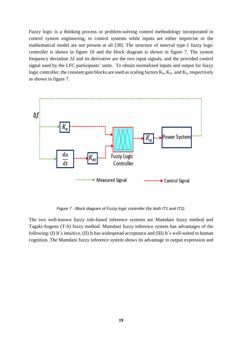
Fuzzy logic is a thinking process or problem-solving control methodology incorporated in
control system engineering, to control systems while inputs are either imprecise or the
mathematical model are not present at all [38]. The structure of interval type-1 fuzzy logic
controller is shown in figure 10 and the block diagram is shown in figure 7. The system
frequency deviation Δf and its derivative are the two input signals, and the provided control
signal used by the LFC participants’ units. To obtain normalized inputs and output for fuzzy
logic controller, the constant gain blocks are used as scaling factors Ke, Kec, and Ku, respectively
as shown in figure 7.
Figure 7 - Block diagram of Fuzzy logic controller (for both IT1 and IT2).
The two well-known fuzzy rule-based inference systems are Mamdani fuzzy method and
Tagaki-Sugeno (T-S) fuzzy method. Mamdani fuzzy inference system has advantages of the
following: (I) It’s intuitive, (II) It has widespread acceptance and (III) It’s well-suited to human
cognition. The Mamdani fuzzy inference system shows its advantage in output expression and
20
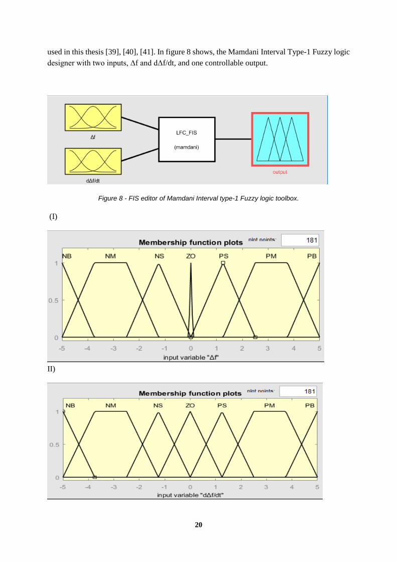
used in this thesis [39], [40], [41]. In figure 8 shows, the Mamdani Interval Type-1 Fuzzy logic
designer with two inputs, Δf and dΔf/dt, and one controllable output.
Figure 8 - FIS editor of Mamdani Interval type-1 Fuzzy logic toolbox.
(I)
II)

21
III)
Figure 9 - Membership functions of IT1 fuzzy control used in this thesis; (I) and (II) are input patterns
(III) is output pattern.
The membership for the input and output variables are sown in figure 9. As can be observed
from this figure, trapezoidal and triangular membership functions are both applied. The input
and output variables in the proposed controller are represented as set of seven-linguistic
variables and defined namely as the following,
NB - Negative Big
NM - Negative Medium
NS - Negative Small
ZO - Zero
PS - Positive Small
PM - Positive Medium, and
PB - Positive Big.
Each the above fuzzy variable has a member of the subsets with a degree of membership
varying between [-5, 5].
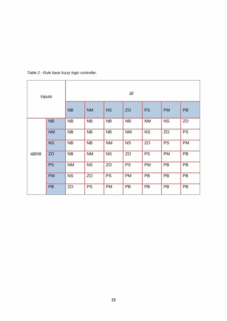
There are totally 49 fuzzy rules that are considered in this design, which is shown in Table 2.
This rule base works on the vector composed of the two input signals. The “T-norms” are based
on interpreting the “and” by taking the minimum of the two membership values. First crisp
inputs are mapped to linguistic values and then combined based on all the rules by using “sum”
method. Finally, the “centroid” method is used for defuzzification, for converting the output to
a crisp value [42].
22
Table 2 - Rule base fuzzy logic controller.
Inputs
Δf
NB
NM
NS
ZO
PS
PM
PB
dΔf/dt
NB NB NB NB NB NM NS ZO
NM NB NB NB NM NS ZO PS
NS NB NB NM NS ZO PS PM
ZO NB NM NS ZO PS PM PB
PS NM NS ZO PS PM PB PB
PM NS ZO PS PM PB PB PB
PB ZO PS PM PB PB PB PB
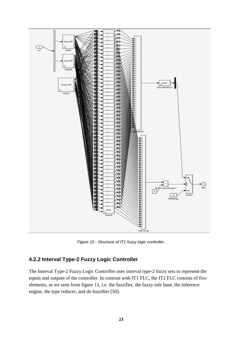
23
Figure 10 - Structure of IT1 fuzzy logic controller.
4.2.2 Interval Type-2 Fuzzy Logic Controller
The Interval Type-2 Fuzzy Logic Controller uses interval type-2 fuzzy sets to represent the
inputs and outputs of the controller. In contrast with IT1 FLC, the IT2 FLC consists of five
elements, as we seen from figure 11, i.e. the fuzzifier, the fuzzy rule base, the inference
engine, the type reducer, and de-fuzzifier [50].
24
Figure 11 - The Structure of FLC, (A) is interval type-1 and (B) is interval type-2.
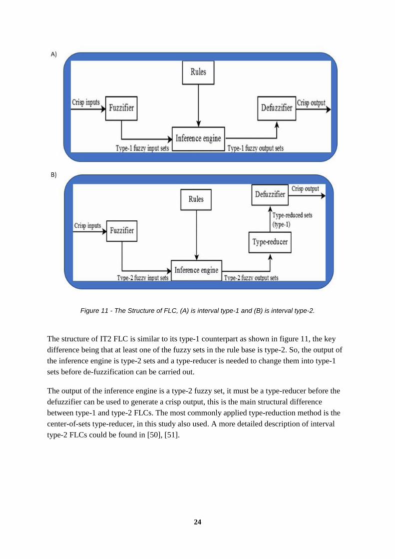
The structure of IT2 FLC is similar to its type-1 counterpart as shown in figure 11, the key
difference being that at least one of the fuzzy sets in the rule base is type-2. So, the output of
the inference engine is type-2 sets and a type-reducer is needed to change them into type-1
sets before de-fuzzification can be carried out.
The output of the inference engine is a type-2 fuzzy set, it must be a type-reducer before the
defuzzifier can be used to generate a crisp output, this is the main structural difference
between type-1 and type-2 FLCs. The most commonly applied type-reduction method is the
center-of-sets type-reducer, in this study also used. A more detailed description of interval
type-2 FLCs could be found in [50], [51].
25
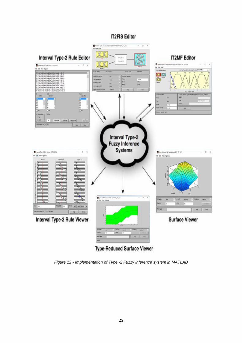
Figure 12 - Implementation of Type -2 Fuzzy inference system in MATLAB
26
(I)
II)
III)

27
IV)
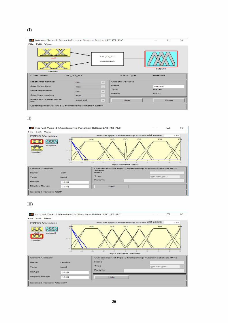
Figure 13 - The FIS editor of Mamdani Interval type-2 Fuzzy logic toolbox (I) and Membership
functions of IT2 fuzzy control used in this thesis; (II) and (III) are input patterns (IV) is output pattern.
The interval type-2 fuzzy rules are the same to as IT1 Fuzzy rules as shown in Table 2, In the
IT2 FLC delf means Δf, and similarly, derdelf means dΔf/dt. The rules of IT2 FLC are edited
using Mamdani method as given in figure 13.
4.2.3 Adaptive Neuro Fuzzy controller (ANFIS)
I) ANFIS structure and control
Adaptive Neuro-Fuzzy Inference System (ANFIS) is an intelligent neuro-Fuzzy technique,
which was originally proposed by Jang in 1993 [43]. Neuro-fuzzy techniques are developed
from the fusion of Artificial Neural Network (ANN) and Fuzzy Inference Systems (FIS).
ANFIS have an advantage of both fuzzy and ANN [43], [44]. It combines the learning power
of neural network with knowledge representation of fuzzy logic to implement a different mode
of functions and consequently to tune the parameters of fuzzy inference system. The proposed
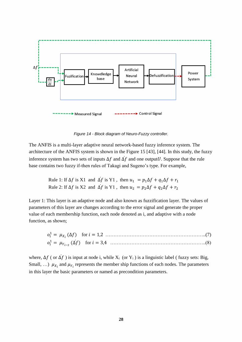
block diagram of the neuro-fuzzy controller for this study is given in figure 14 [44]. In this
figure, the control signal (the control input U) represents all controllable variables, i.e., (ΔuMT,
ΔuDG , ΔuEV1 , and ΔuEV2).
28
Figure 14 - Block diagram of Neuro-Fuzzy controller.
The ANFIS is a multi-layer adaptive neural network-based fuzzy inference system. The
architecture of the ANFIS system is shown in the Figure 15 [43], [44]. In this study, the fuzzy
inference system has two sets of inputs Δ𝑓 and Δ�̇� and one output𝑈. Suppose that the rule
base contains two fuzzy if-then rules of Takagi and Sugeno’s type. For example,
Rule 1: If Δ𝑓 is X1 and Δ�̇� is Y1 , then 𝑢1 = 𝑝1∆𝑓 + 𝑞1∆𝑓 + 𝑟1
Rule 2: If Δ𝑓 is X2 and Δ�̇� is Y1 , then 𝑢2 = 𝑝2∆𝑓 + 𝑞2∆𝑓 + 𝑟2
Layer 1: This layer is an adaptive node and also known as fuzzification layer. The values of
parameters of this layer are changes according to the error signal and generate the proper
value of each membership function, each node denoted as i, and adaptive with a node
function, as shown;
𝑜𝑖1 = 𝜇𝑋𝑖
(∆𝑓) for 𝑖 = 1,2 ……………………………………………………..(7)
𝑜𝑖1 = 𝜇𝑌𝑖−2
(∆�̇�) for 𝑖 = 3,4 …………………………………………………..(8)
where, ∆𝑓 ( or ∆�̇� ) is input at node i, while Xi (or Yi ) is a linguistic label ( fuzzy sets: Big,
Small, …) 𝜇𝑋𝑖 and 𝜇𝑌𝑖
represents the member ship functions of each nodes. The parameters
in this layer the basic parameters or named as precondition parameters.
29
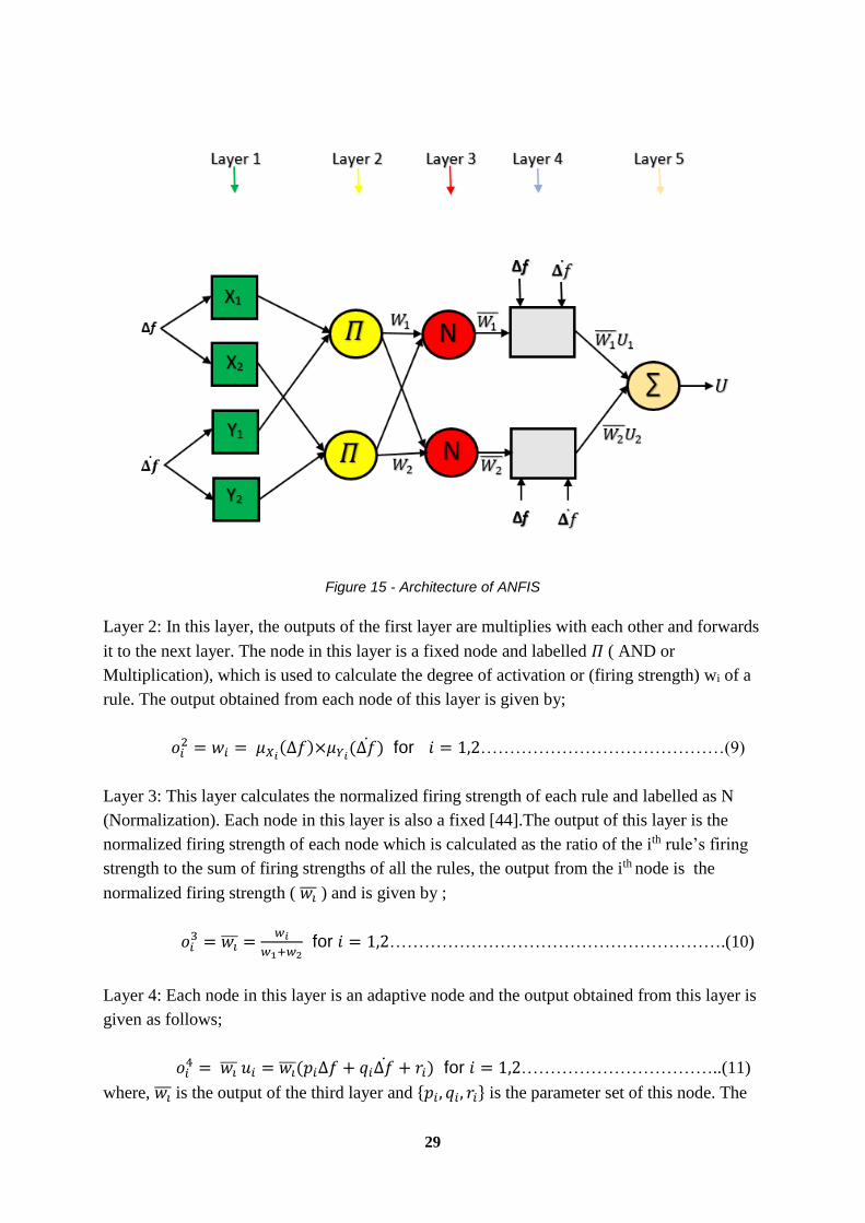
Figure 15 - Architecture of ANFIS
Layer 2: In this layer, the outputs of the first layer are multiplies with each other and forwards
it to the next layer. The node in this layer is a fixed node and labelled 𝛱 ( AND or
Multiplication), which is used to calculate the degree of activation or (firing strength) wi of a
rule. The output obtained from each node of this layer is given by;
𝑜𝑖2 = 𝑤𝑖 = 𝜇𝑋𝑖
(∆𝑓)×𝜇𝑌𝑖(∆�̇�) for 𝑖 = 1,2……………………………………(9)
Layer 3: This layer calculates the normalized firing strength of each rule and labelled as N
(Normalization). Each node in this layer is also a fixed [44].The output of this layer is the
normalized firing strength of each node which is calculated as the ratio of the ith rule’s firing
strength to the sum of firing strengths of all the rules, the output from the ith node is the
normalized firing strength ( 𝑤𝑖̅̅ ̅ ) and is given by ;
𝑜𝑖3 = 𝑤𝑖̅̅ ̅ =
𝑤𝑖
𝑤1+𝑤2 for 𝑖 = 1,2………………………………………………….(10)
Layer 4: Each node in this layer is an adaptive node and the output obtained from this layer is
given as follows;
𝑜𝑖4 = 𝑤𝑖̅̅ ̅ 𝑢𝑖 = 𝑤𝑖̅̅ ̅(𝑝𝑖∆𝑓 + 𝑞𝑖∆�̇� + 𝑟𝑖) for 𝑖 = 1,2……………………………..(11)
where, 𝑤𝑖̅̅ ̅ is the output of the third layer and {𝑝𝑖, 𝑞𝑖, 𝑟𝑖} is the parameter set of this node. The

30
parameter in this layer are referred to as consequent parameter.
Layer 5: This layer is the last layer of ANFIS architecture which result the output U and
labelled as ∑, which computes the overall output as a summation of all incoming signals to
the node which is given by;
𝑜𝑖5 = 𝑈 = ∑𝑤𝑖̅̅ ̅𝑢𝑖 =
∑𝑤𝑖𝑢𝑖
∑𝑤𝑖 ……………………………………………………..(12)
The ANFIS methods of implementing a hybrid-learning algorithm that consists of a
combination of, the least squares methods are used to set the parameters of linear
consequently, as well as gradient-descent, which is used to identify the parameters of the
premise.
Since ANFIS designer starts with the pre-structured system, the input and output membership
functions variables contain more information that Neural Network has to drive from sampled
data sets. Knowledge regarding the system under design can be used right from the start, the
rules are in the linguistic forms and so intermediate results can be analysed and interpreted
easily. Modification of rules is possible during the training and optimization can be analysed
and interpreted easily [45].
II) Procedural steps to design the ANFIS
The first step for making an adaptive neuro-fuzzy is to draw a load frequency control using
fuzzy logic controller i.e. figure 7, [44]. The data of two inputs and output of fuzzy controller
gives the training data. The data arranged as column vectors. Input 1, frequency deviation and
input 2, the derivative of frequency deviation and the third column data is fuzzy output.
ANFSEDIT toolbox is used to generate ANFIS.fis file in MATLAB software. The data loaded
in ANFISEDIT. The ANFIS tanning process sown in figure 16 [12], [44]. We generate the
initial FIS model before starting FIS training by defining the number and type of membership
functions for input. The two partitioning techniques are used by ANFIS to generate the initial
FIS model, i.e., Grid partition and Subtractive clustering. Grid partition generates a single-
output Sugeno-type FIS by using grid partition on the data whereas Subtractive clustering
generate an initial model for ANFIS training by first applying subtractive clustering on the data.
In this thesis, I have chosen the grid partition method to define the fuzzy partition of input data.
The ANFIS provide 8 types of membership function (MF) including, Triangular membership

31
function, Gbell MF type, Gaussian MF, etc. The Gbell membership function was suitable for
the present study.
Figure 16 - ANFIS training process
After loading and generating the training data and the initial FIS structure, respectively, then
we can start training the FIS. There are two learning algorithms in MATLAB ANFIS, back
propagation, and hybrid algorithm. For this study, the input/output data trained through hybrid
algorithm by selecting the appropriate number of epochs with zero error tolerances. The great
32
advantage of ANFIS design method comparing with fuzzy design method consists in the small
number of input and output membership functions (usually 2…4), which implies the same
maximum number of rules. Hence, the rule base and the occupied memory became very small
[49].
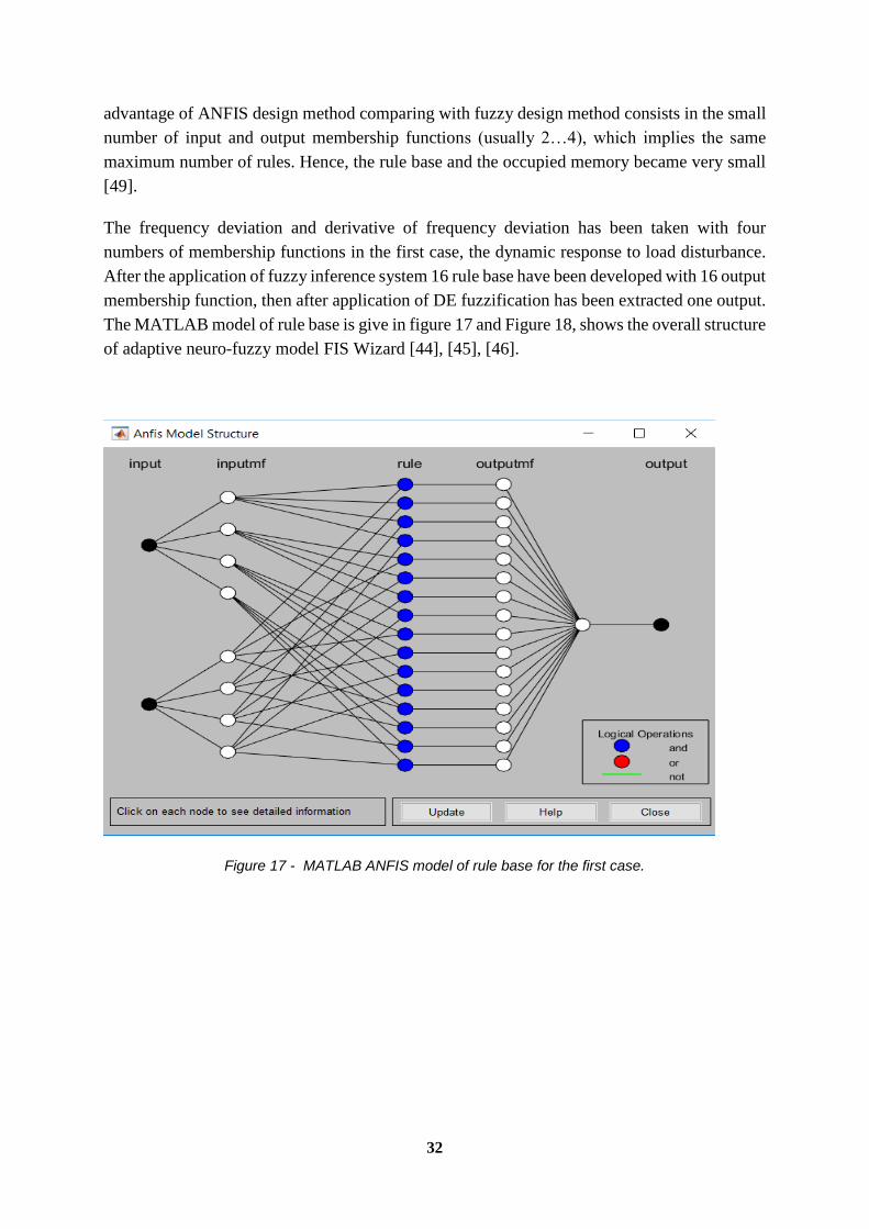
The frequency deviation and derivative of frequency deviation has been taken with four
numbers of membership functions in the first case, the dynamic response to load disturbance.
After the application of fuzzy inference system 16 rule base have been developed with 16 output
membership function, then after application of DE fuzzification has been extracted one output.
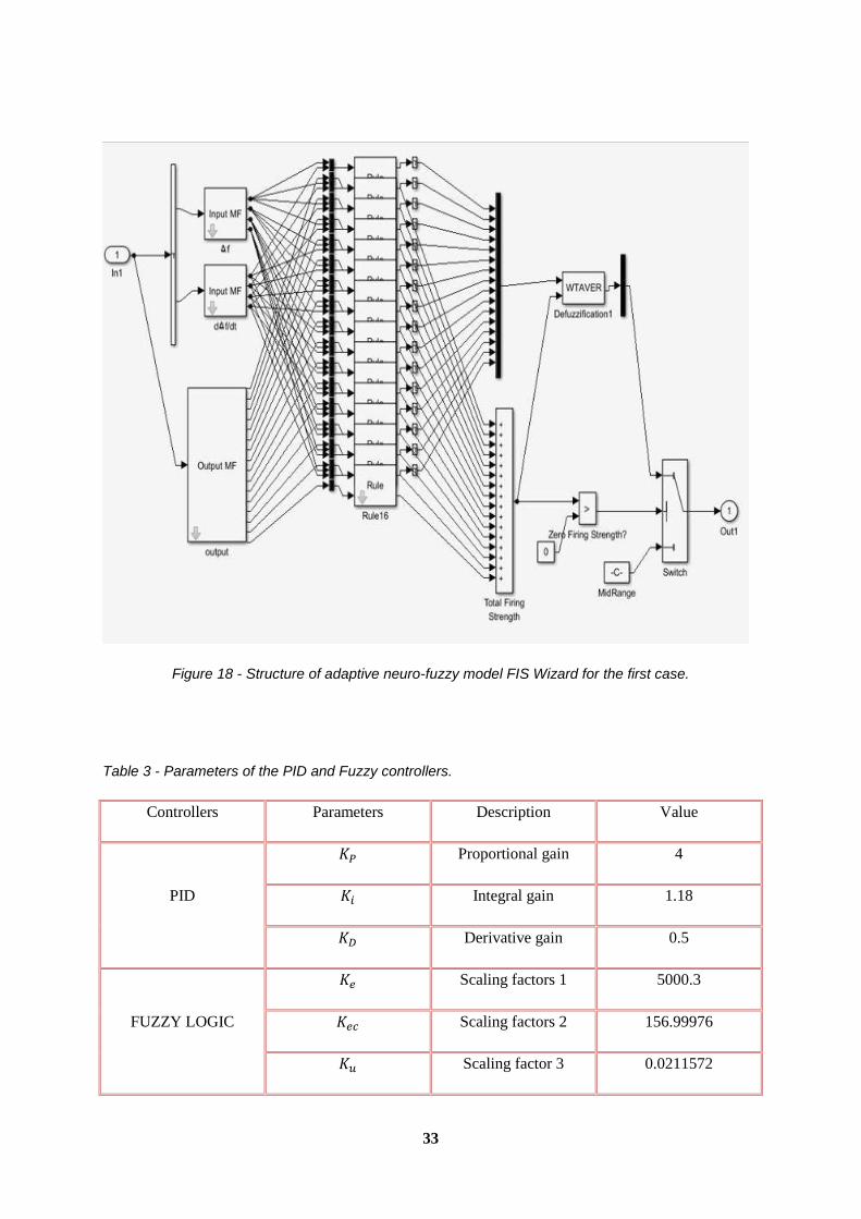
The MATLAB model of rule base is give in figure 17 and Figure 18, shows the overall structure
of adaptive neuro-fuzzy model FIS Wizard [44], [45], [46].
Figure 17 - MATLAB ANFIS model of rule base for the first case.
33
Figure 18 - Structure of adaptive neuro-fuzzy model FIS Wizard for the first case.
Table 3 - Parameters of the PID and Fuzzy controllers.
Controllers Parameters Description Value
PID
𝐾𝑃 Proportional gain 4
𝐾𝑖 Integral gain 1.18
𝐾𝐷 Derivative gain 0.5
FUZZY LOGIC
𝐾𝑒 Scaling factors 1 5000.3
𝐾𝑒𝑐 Scaling factors 2 156.99976
𝐾𝑢 Scaling factor 3 0.0211572
34
Chapter 5
Simulation Results
In this chapter, to demonstrate the performance of the proposed LFC based on ANFIS
controller; several simulations are presented. The simulations are carried out based on the
model as mentioned earlier of Micro-grid, i.e. figure 5 with the system parameters given in
table 1 and table 3.
A. The comparison of the PID controller, interval type-1 fuzzy controller (Mamdani
model), interval type-2 fuzzy controllers (Mamdani model) and ANFIS based Neuro-
Fuzzy controller to damp the modelled MG system frequency oscillation are presented
without the consideration of the constraints of MT, DG, and EVs in each first sub cases
has presented, i.e. Case1(A), Case2(A), Case3(A), Case4(A), Case5(A) and Case6(A).
B. The comparison of the PID controller, interval type-1 fuzzy controller (Mamdani
model) and ANFIS based Neuro-Fuzzy controller to damp the modelled MG system
frequency oscillation are presented with the consideration of the constraints of MT,
DG, and EVs in each second sub cases has presented. i.e. Case1(B), Case2(B),
Case3(B), Case4(B), Case5(B) and Case6(B).
It is stablished in the MATLAB/SIMULINK environment. The simulations of cases studies are
achieved by using MATLAB version R2016b and for Interval type-2 fuzzy MATLAB version
7.8.0 (R2009a).
5.1 Case 1: Load Disturbance
In this case, a step load disturbance of ΔPL = 0.05 pu is applied at t = 0 s. By the assumption
that the output power of wind generations and solar PV generation are constant with steady
wind speed and sun condition for a short period, i.e. ΔPW = 0 pu and ΔPPV = 0 pu. The
performance of the ANFIS controller on load disturbance investigated. A clear comparison
with the conventional PID controller, Interval type-1 and Interval type-2 fuzzy controller under
the consideration of constraints and without constraints, different performance measures such
as settling time, rise time, overshoots and undershoot are computed as shown in Table 4, 5 and
6. The total simulation time is 70 second.
5.1.1 Case1(A)-Without considering the constraints of MT, DG and EVs.
For this scenario, there are no output constraints of MT, DG, and EVs. The design of ANFIS
neuro-fuzzy based controller is set as follows: as presented in chapter 4 section 4.2.3. Part (II)
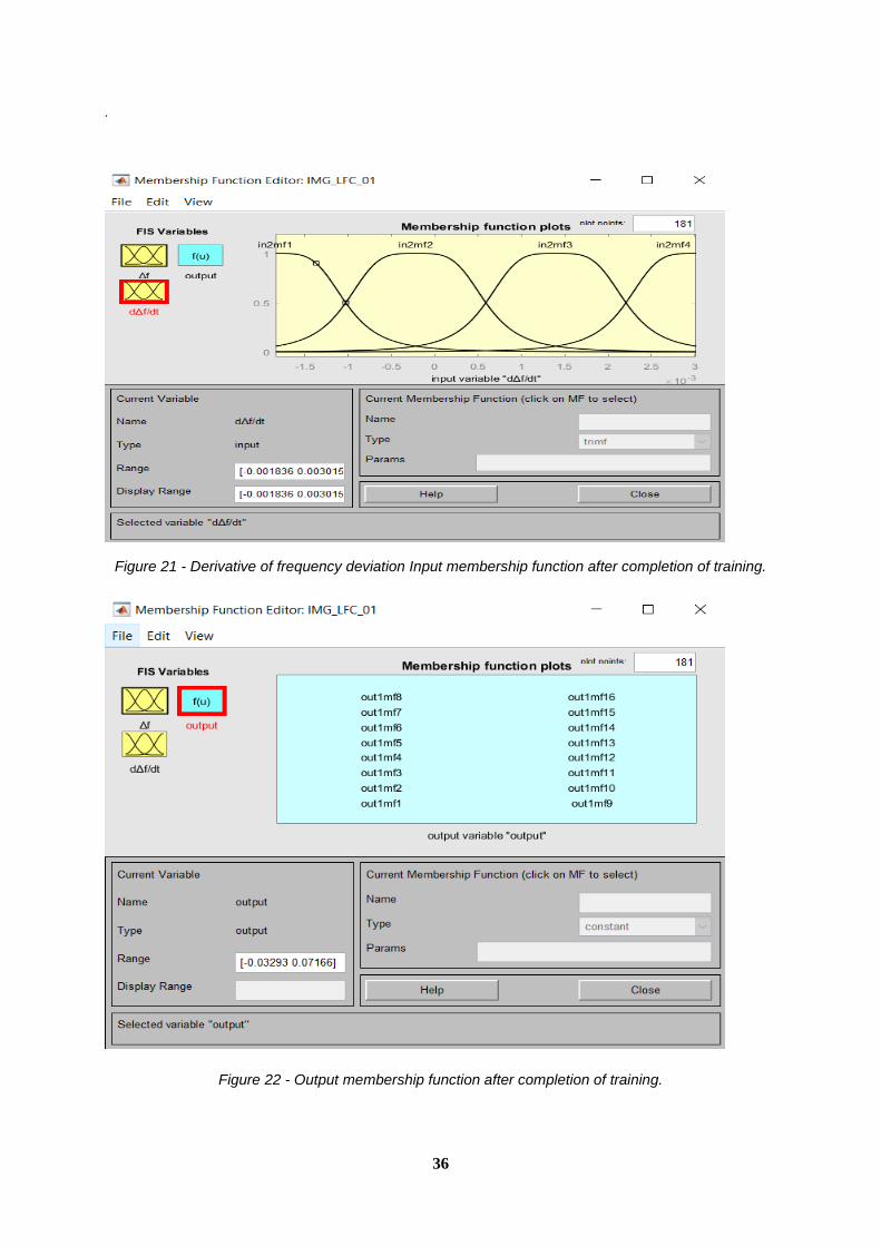
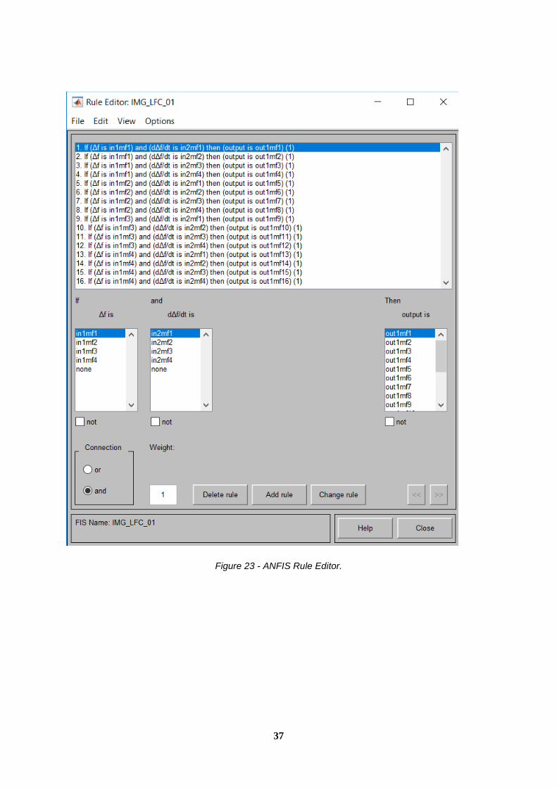
Procedural steps to design the ANFIS). Figure 19, shows the membership editor (FIS editor)
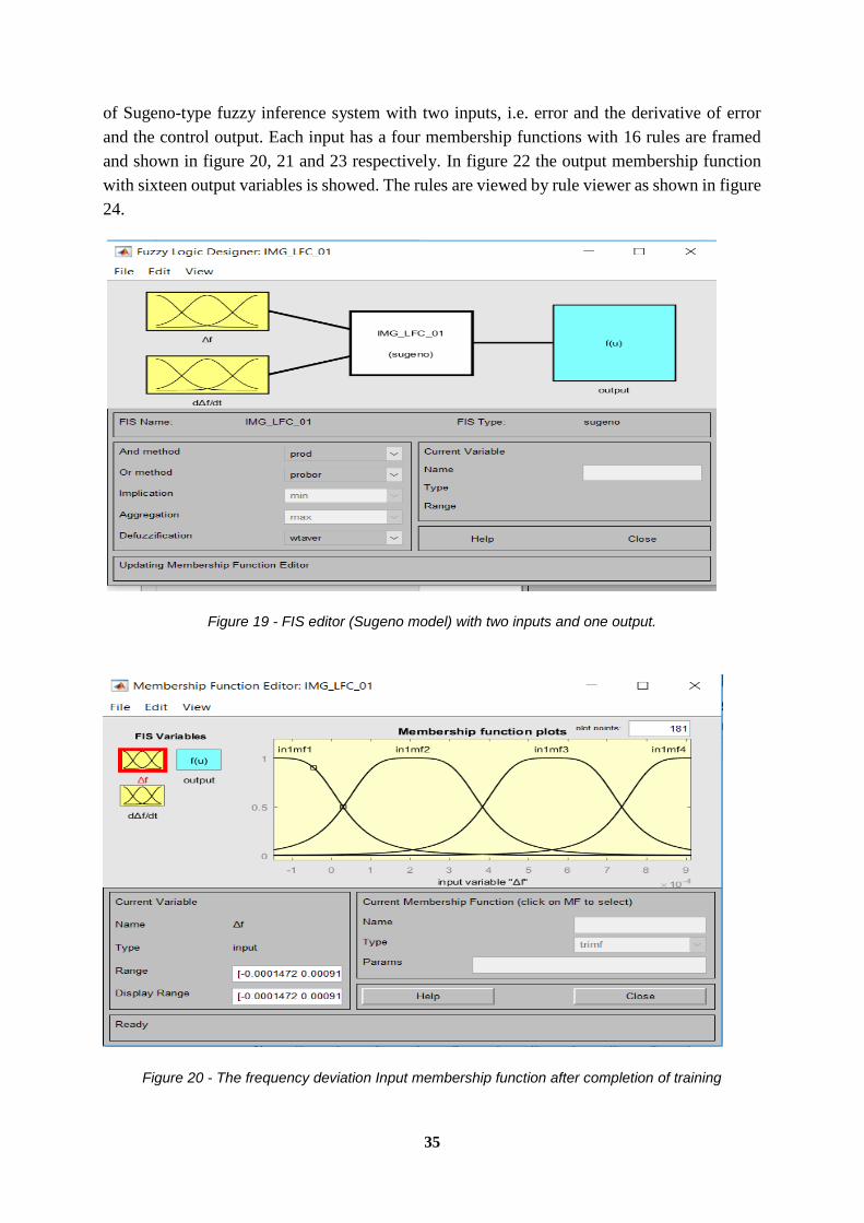
35
of Sugeno-type fuzzy inference system with two inputs, i.e. error and the derivative of error
and the control output. Each input has a four membership functions with 16 rules are framed
and shown in figure 20, 21 and 23 respectively. In figure 22 the output membership function
with sixteen output variables is showed. The rules are viewed by rule viewer as shown in figure
24.
Figure 19 - FIS editor (Sugeno model) with two inputs and one output.
Figure 20 - The frequency deviation Input membership function after completion of training
36
.
Figure 21 - Derivative of frequency deviation Input membership function after completion of training.
Figure 22 - Output membership function after completion of training.
37
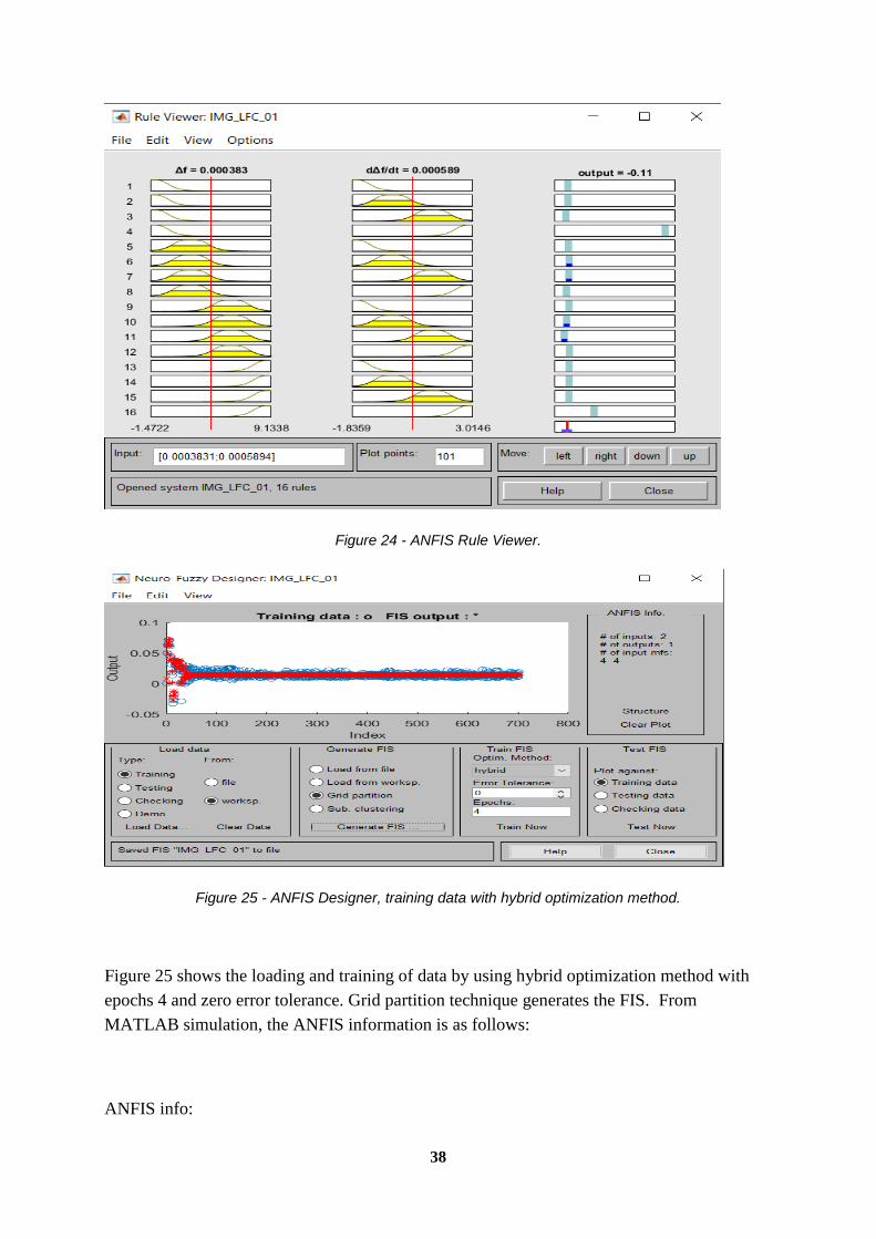
Figure 23 - ANFIS Rule Editor.
38
Figure 24 - ANFIS Rule Viewer.
Figure 25 - ANFIS Designer, training data with hybrid optimization method.
Figure 25 shows the loading and training of data by using hybrid optimization method with
epochs 4 and zero error tolerance. Grid partition technique generates the FIS. From
MATLAB simulation, the ANFIS information is as follows:
ANFIS info:
39
Number of nodes: 53
Number of linear parameters: 48
Number of nonlinear parameters: 24
Total number of parameters: 72
Number of training data pairs: 701
Number of checking data pairs: 0
Number of fuzzy rules: 16
Start training ANFIS …
1 0.00404137
2 0.00428166
Designated epoch number reached --> ANFIS training completed at epoch 2.
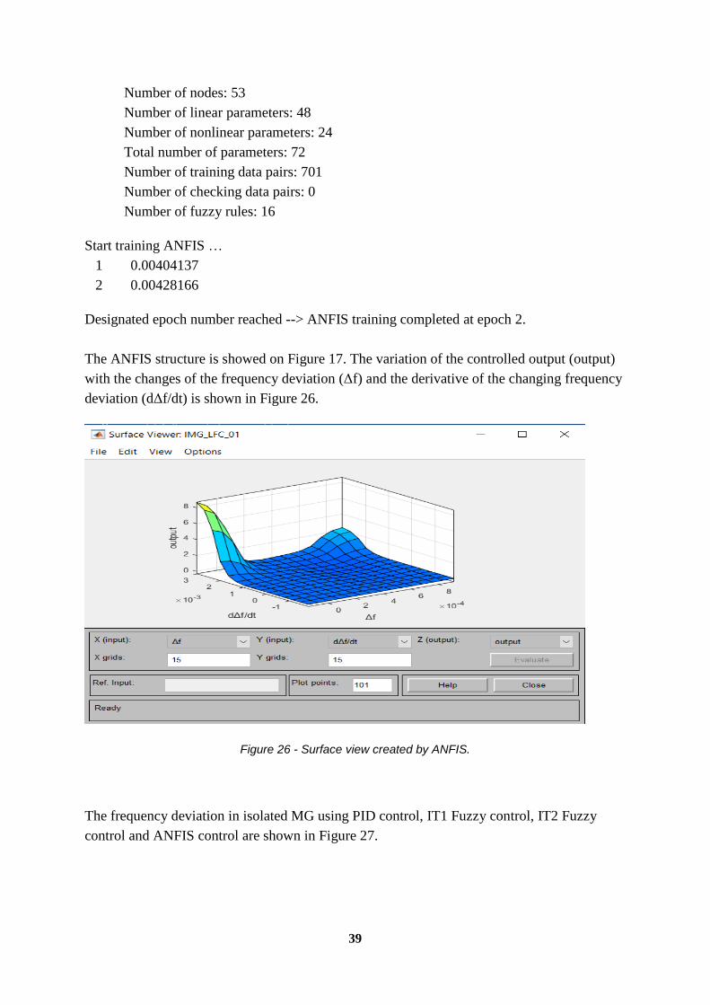
The ANFIS structure is showed on Figure 17. The variation of the controlled output (output)
with the changes of the frequency deviation (Δf) and the derivative of the changing frequency
deviation (dΔf/dt) is shown in Figure 26.
Figure 26 - Surface view created by ANFIS.
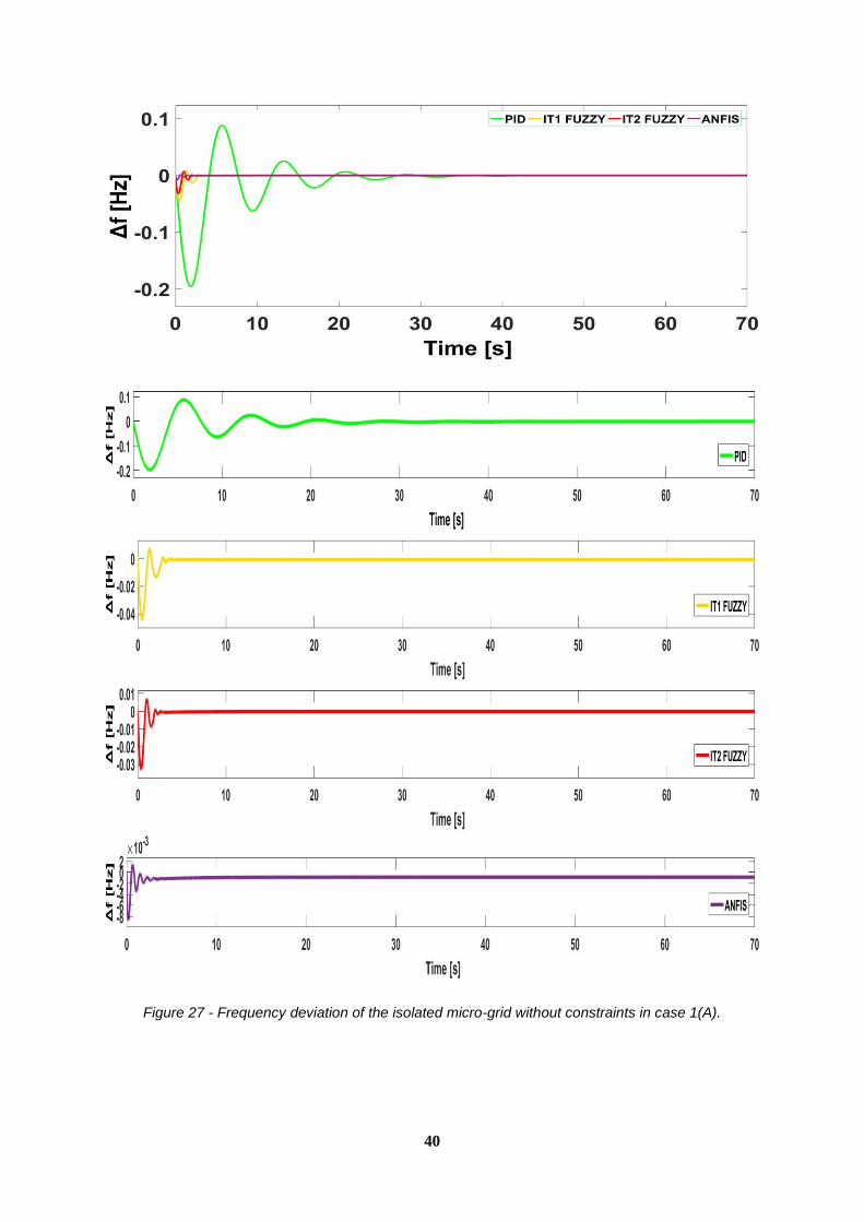
The frequency deviation in isolated MG using PID control, IT1 Fuzzy control, IT2 Fuzzy
control and ANFIS control are shown in Figure 27.
40
Figure 27 - Frequency deviation of the isolated micro-grid without constraints in case 1(A).

41
Table 4 - Comparison between conventional PID controller, type-1 and type-2 fuzzy controller and
ANFIS controller.
Without considering the constraints of MT, DG and EVs
Controllers Rise time Over shoot (Hz) Under shoot (Hz) Settling time (s)
PID 972.136 ms 8.746×10⁻² −1.962×10⁻¹ 36.469
FUZZY
(IT1) 445.119 ms 6.868×10⁻³ −4.432×10⁻² 3.594
IT2 FUZZY 298.757 ms 6.370×10⁻³ −3.299×10⁻² 2.784
ANFIS 174.568 ms 1.422×10⁻³ −9.134×10⁻³ 2.061
According to the comparison of Table 4 and Figure 27. The overshoot and undershoot in the
first swing has significantly reduced, and the proposed ANFIS controller has quickly damped
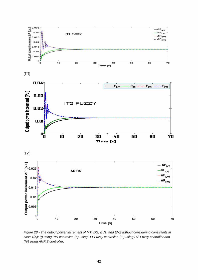
the system frequency oscillation, the settling time and the rise time is also much shorter, better
than in comparison with PID, IT1, and IT2 controllers. We can see that from figure 28 that
ANFIS controller achieve stables output power of MT, DG, and EVs in a shorter time and less
adjustment frequency, this illustrates that the equipment life of EVs batteries, DG and MT.
(I)
(II)
42
(III)
(IV)
Figure 28 - The output power increment of MT, DG, EV1, and EV2 without considering constraints in
case 1(A); (I) using PID controller, (II) using IT1 Fuzzy controller, (III) using IT2 Fuzzy controller and
(IV) using ANFIS controller.
43
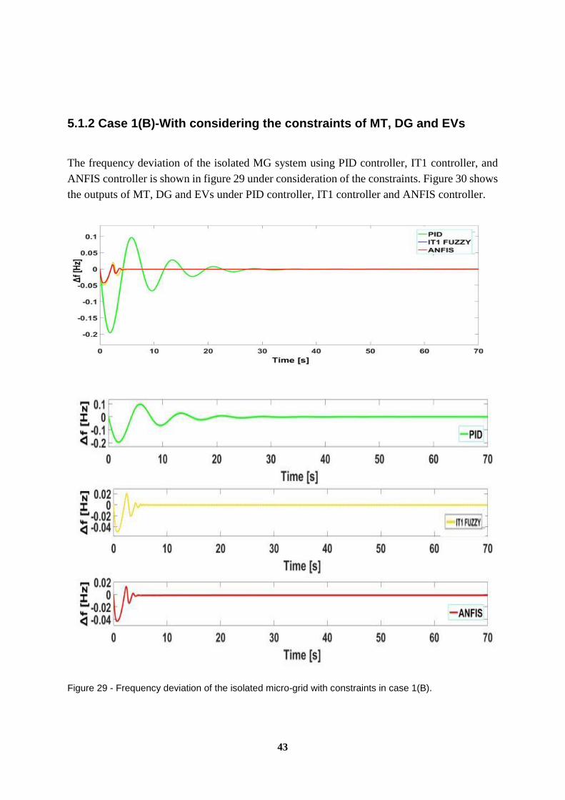
5.1.2 Case 1(B)-With considering the constraints of MT, DG and EVs
The frequency deviation of the isolated MG system using PID controller, IT1 controller, and
ANFIS controller is shown in figure 29 under consideration of the constraints. Figure 30 shows
the outputs of MT, DG and EVs under PID controller, IT1 controller and ANFIS controller.
Figure 29 - Frequency deviation of the isolated micro-grid with constraints in case 1(B).
44
(I)
(II)
(III)
Figure 30 - The output power increment of MT, DG, EV1, and EV2 with considering constraints in case
1(B); (I) using PID controller, (II) using IT1 Fuzzy controller and (III) using ANFIS controller.
As a result suggest, in figure 29, the system can diminish the frequency oscillation under the
load disturbance, the ANFIS controller still provides a better diminishing performance over the

45
PID controller and IT1 controller. On the other hand, in figure 30, the output power increment
of the two EVs are various from each other because of their different inverter capacity limit.
Using a well-tuned PID and FUZZY, i.e. IT1 fuzzy controller, the output power increment of
both EV1 and EV2 reaches the upper capacity limit of their respective inverter and remain
saturated for a long time. The stability of the output power of EVs much better in the ANFIS
controller than PID controller and IT1 fuzzy controller as shown in figure 30.
5.1.3. Comparative study (Without and with considering the constraints of MT, DG and EVs)
Because of the EVs have been considered in this thesis as an equivalent power source, the
different structures of electric vehicles have no impact on the controller. So, the impact of
different electric vehicle capacity on the LFC is determined by the constraints of inverter
capacity limit of equivalent EVs. Figure 31 shows, the comparison of PID controller, FUZZU
(IT1 Fuzzy) controller and ANFIS controller with and without considering the constraints. In
table 5 and 6 presents the comparison of the performance of ANFIS with PID and IT1 Fuzzy
without and with the considering of constraints, respectively.
46
Figure 31 - The comparison of the system frequency deviation with and without constraints.
47
Table 5 - Comparison of the performance of ANFIS with PID and IT1 Fuzzy without the considering of constraints (Fig. 27 and Fig. 31)
Without the considering of constraints of MT, DG and EVs
Controllers Rise time Over-shoot (Hz) Under shoot (Hz) Settling time (s)
PID 972.136 ms 8.746×10⁻² −1.962×10⁻¹ 36.469
FUZZY(IT1) 445.119 ms 6.868×10⁻³ −4.432×10⁻² 3.594
ANFIS 174.568 ms 1.422×10⁻³ −9.134×10⁻³ 2.061
Table 6 - Comparison of the performance of ANFIS with PID and IT1 Fuzzy with the consideration
constraints (Fig. 29 and Fig. 31)
With the considering of constraints of MT, DG and EVs
Controllers Rise time Over-shoot (Hz) Under shoot (Hz) Settling time (s)
PID 1.565 s 9.642×10⁻² −1.963×10⁻¹ 39.839
FUZZY(IT1) 300.669 ms 1.995×10⁻² −4.906×10⁻² 5.241
ANFIS 293.672 ms 1.31×10⁻² −4.332×10⁻² 4.465
The dynamic responses obtained from the first case simulation tabulated in Tables 4, 5, and 6,
regarding rising time, overshoot, undershoot and settling time of the frequency deviation. This
result reveals that ANFFIS based neuro-fuzzy controller rise time, overshoot, undershoot and
settling time-frequency deviation (oscillations) due to 0.05 pu step load disturbance in
comparison to conventional PID controller, interval IT1 controller, and IT2 fuzzy controller.
Therefore, the intelligent control techniques approach using Neuro-Fuzzy concept is more
accurate and faster than the PID controller and better performance than Interval Type-1 Fuzzy
controller and Interval Type-2 Fuzzy controller scheme.
5.2 Case 2: Load disturbance and one of the EVs removed from the LFC system after 60 second.
In this scenario, at the beginning of the simulation, the isolated grid is in steady state. The
performance of the proposed controller on load disturbance is illustrated. As in case 1 here is
also, by assumption that the output power of wind generations and solar PV generation are
48
constant with stable wind speed and sun condition for a short period, i.e. ΔPW = 0 pu and ΔPPV
= 0 pu.
In case 2(A) and case 2(B), without and with considering constraints a load disturbance ΔPL =
0.05 pu is applied at t = 15 s, and EV2 will be removed from the load frequency control system
as soon as its energy is smaller than Emin at t = 60 s. The total simulation time is 100 s, for this
case.
5.2.1. Case 2(A)-Without considering the constraints of MT, DG and EVs Frequency deviation of the isolated micro-grid while using PID, IT1, IT2 and ANFIS
controllers without constraints are shown in figure 32. The output power increment of MT, DG,
and EVs is presented in figure 33 without consideration of constraints, under control PID, IT1,
IT2 and ANFIS controllers.
Figure 32 - The frequency deviation of the isolated micro-grid without constraints in case-2(A).
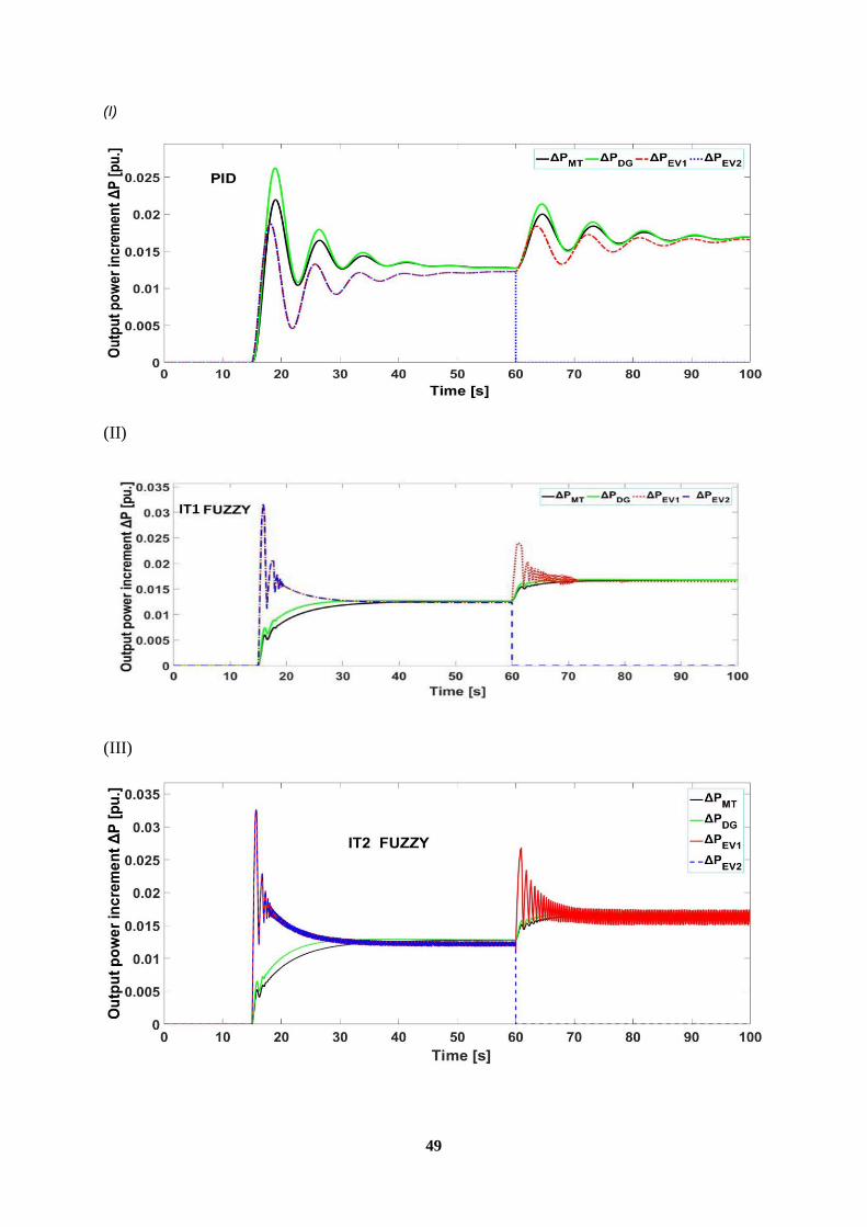
49
(I)
(II)
(III)
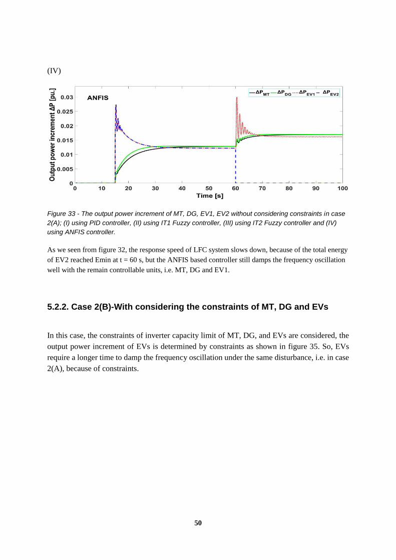
50
(IV)
Figure 33 - The output power increment of MT, DG, EV1, EV2 without considering constraints in case
2(A); (I) using PID controller, (II) using IT1 Fuzzy controller, (III) using IT2 Fuzzy controller and (IV)
using ANFIS controller.
As we seen from figure 32, the response speed of LFC system slows down, because of the total energy
of EV2 reached Emin at t = 60 s, but the ANFIS based controller still damps the frequency oscillation
well with the remain controllable units, i.e. MT, DG and EV1.
5.2.2. Case 2(B)-With considering the constraints of MT, DG and EVs
In this case, the constraints of inverter capacity limit of MT, DG, and EVs are considered, the
output power increment of EVs is determined by constraints as shown in figure 35. So, EVs
require a longer time to damp the frequency oscillation under the same disturbance, i.e. in case
2(A), because of constraints.
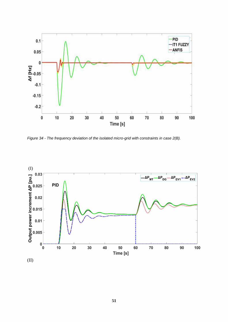
51
Figure 34 - The frequency deviation of the isolated micro-grid with constraints in case 2(B).
(I)
(II)
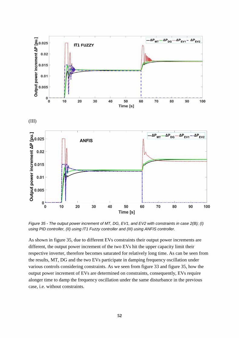
52
(III)
Figure 35 - The output power increment of MT, DG, EV1, and EV2 with constraints in case 2(B); (I)
using PID controller, (II) using IT1 Fuzzy controller and (III) using ANFIS controller.
As shown in figure 35, due to different EVs constraints their output power increments are
different, the output power increment of the two EVs hit the upper capacity limit their
respective inverter, therefore becomes saturated for relatively long time. As can be seen from
the results, MT, DG and the two EVs participate in damping frequency oscillation under
various controls considering constraints. As we seen from figure 33 and figure 35, how the
output power increment of EVs are determined on constraints, consequently, EVs require
alonger time to damp the frequency oscillation under the same disturbance in the previous
case, i.e. without constraints.
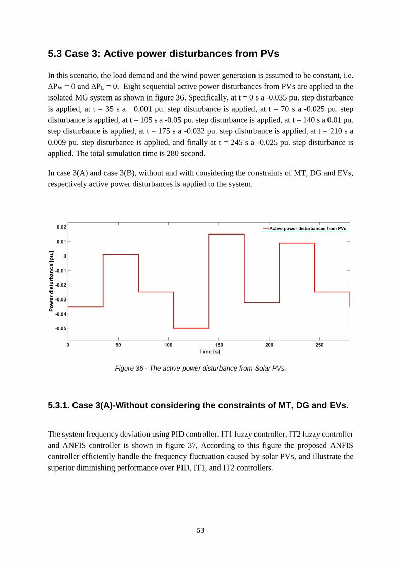
53
5.3 Case 3: Active power disturbances from PVs
In this scenario, the load demand and the wind power generation is assumed to be constant, i.e.
ΔPW = 0 and ΔPL = 0. Eight sequential active power disturbances from PVs are applied to the
isolated MG system as shown in figure 36. Specifically, at t = 0 s a -0.035 pu. step disturbance
is applied, at t = 35 s a 0.001 pu. step disturbance is applied, at t = 70 s a -0.025 pu. step
disturbance is applied, at t = 105 s a -0.05 pu. step disturbance is applied, at t = 140 s a 0.01 pu.
step disturbance is applied, at t = 175 s a -0.032 pu. step disturbance is applied, at t = 210 s a
0.009 pu. step disturbance is applied, and finally at t = 245 s a -0.025 pu. step disturbance is
applied. The total simulation time is 280 second.
In case 3(A) and case 3(B), without and with considering the constraints of MT, DG and EVs,
respectively active power disturbances is applied to the system.
Figure 36 - The active power disturbance from Solar PVs.
5.3.1. Case 3(A)-Without considering the constraints of MT, DG and EVs.
The system frequency deviation using PID controller, IT1 fuzzy controller, IT2 fuzzy controller
and ANFIS controller is shown in figure 37, According to this figure the proposed ANFIS
controller efficiently handle the frequency fluctuation caused by solar PVs, and illustrate the
superior diminishing performance over PID, IT1, and IT2 controllers.
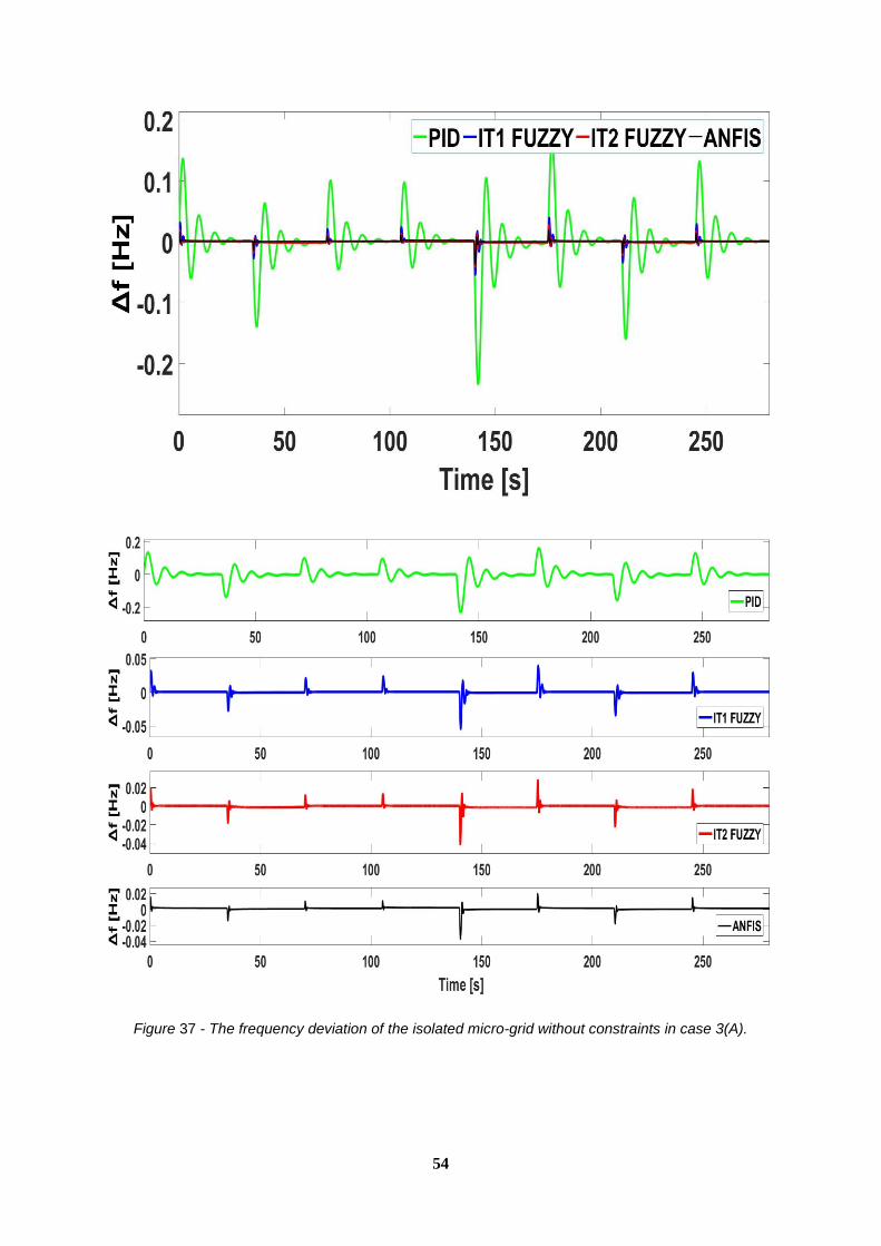
54
Figure 37 - The frequency deviation of the isolated micro-grid without constraints in case 3(A).
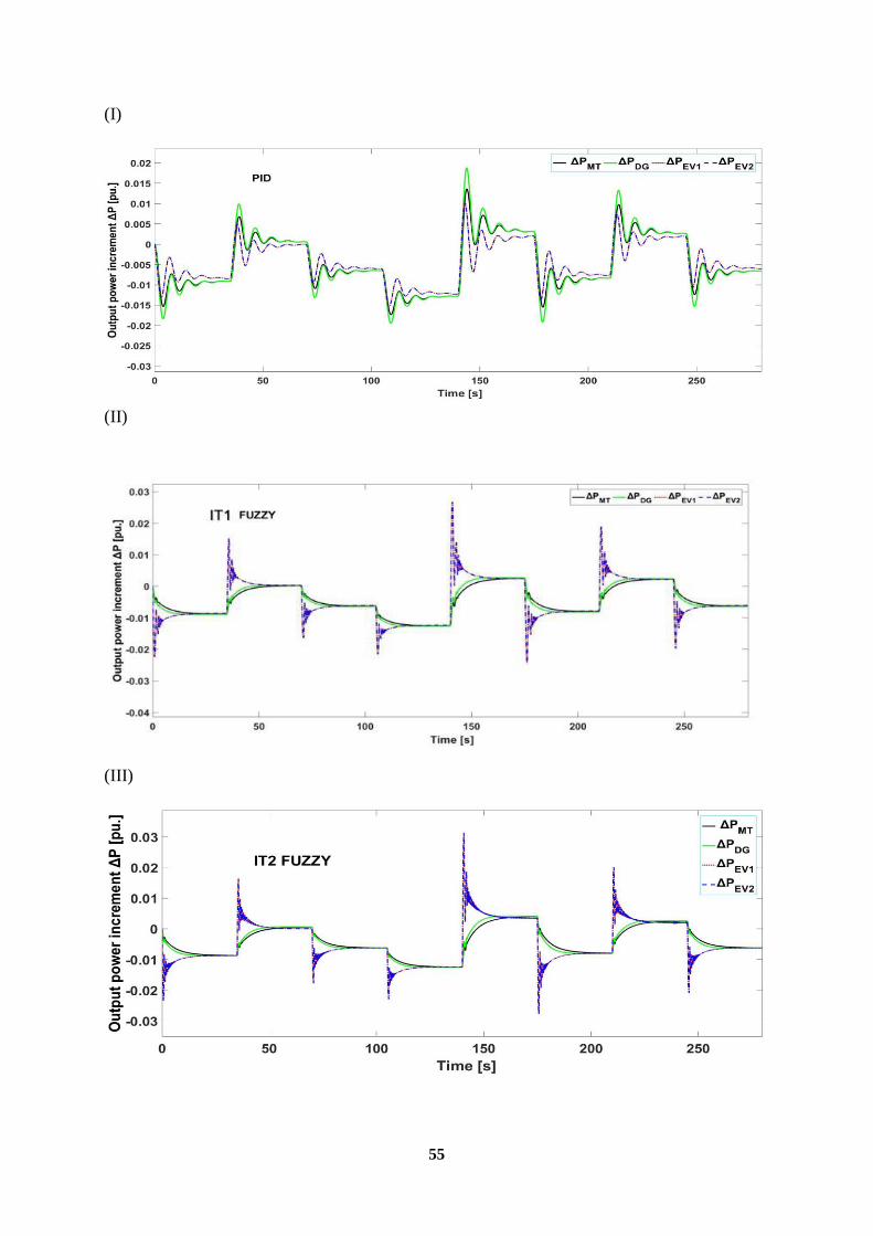
55
(I)
(II)
(III)
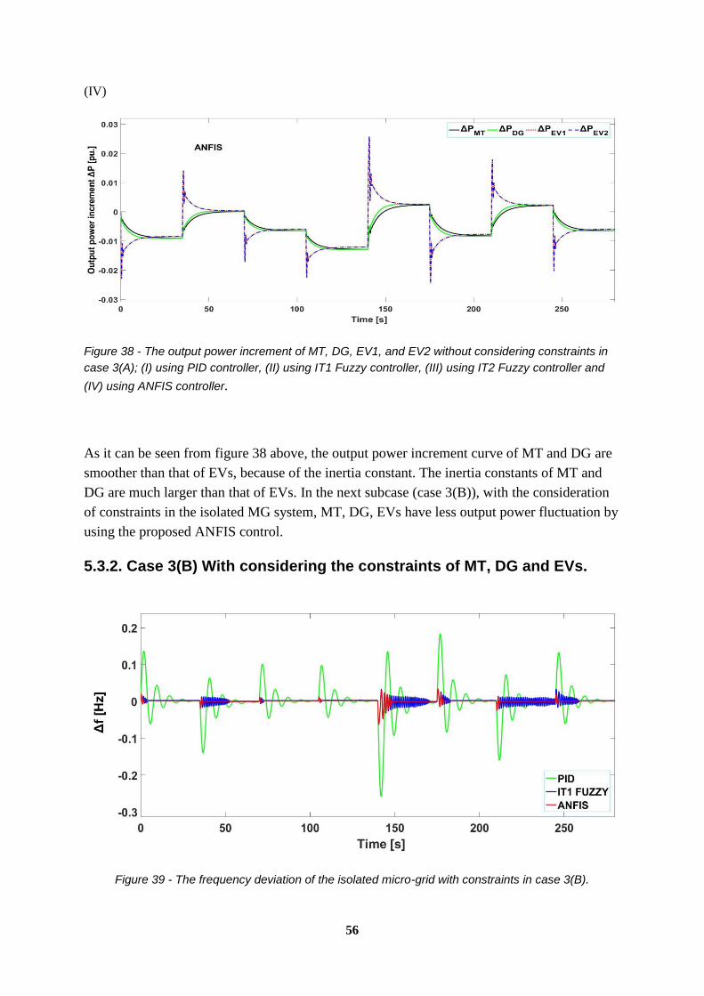
56
(IV)
Figure 38 - The output power increment of MT, DG, EV1, and EV2 without considering constraints in
case 3(A); (I) using PID controller, (II) using IT1 Fuzzy controller, (III) using IT2 Fuzzy controller and
(IV) using ANFIS controller.
As it can be seen from figure 38 above, the output power increment curve of MT and DG are
smoother than that of EVs, because of the inertia constant. The inertia constants of MT and
DG are much larger than that of EVs. In the next subcase (case 3(B)), with the consideration
of constraints in the isolated MG system, MT, DG, EVs have less output power fluctuation by
using the proposed ANFIS control.
5.3.2. Case 3(B) With considering the constraints of MT, DG and EVs.
Figure 39 - The frequency deviation of the isolated micro-grid with constraints in case 3(B).
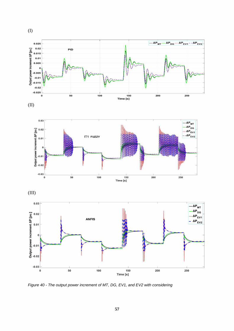
57
(I)
(II)
(III)
Figure 40 - The output power increment of MT, DG, EV1, and EV2 with considering
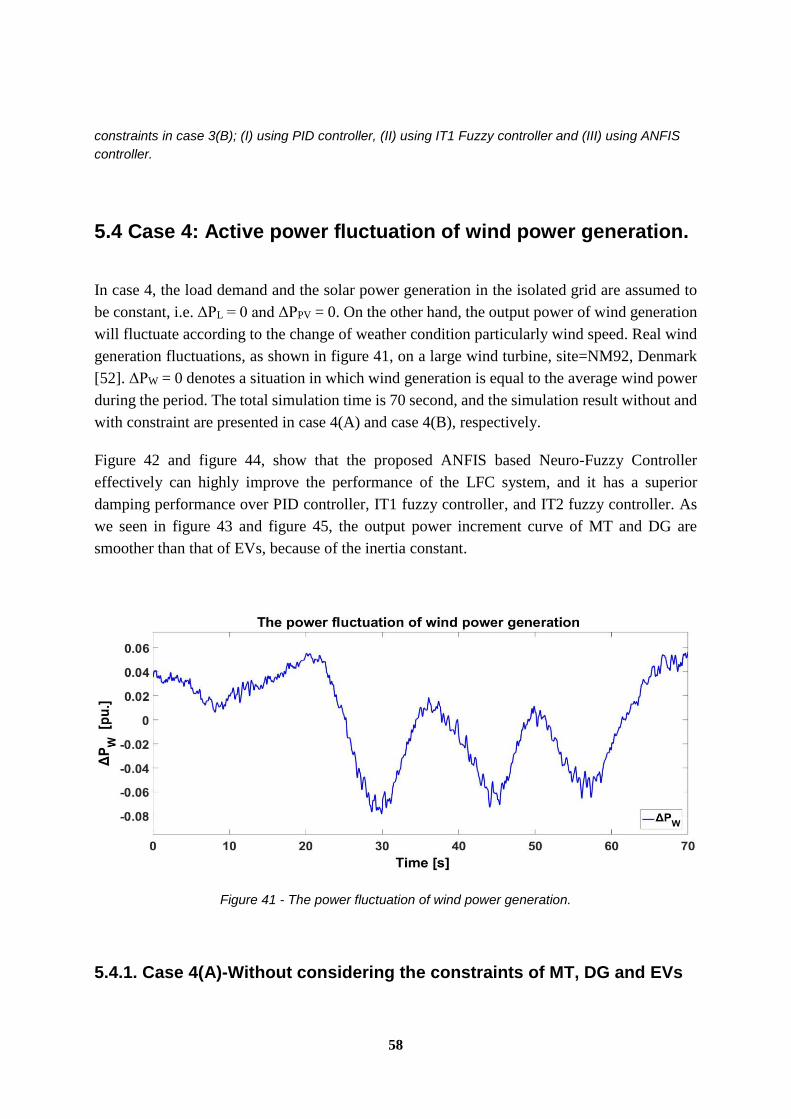
58
constraints in case 3(B); (I) using PID controller, (II) using IT1 Fuzzy controller and (III) using ANFIS
controller.
5.4 Case 4: Active power fluctuation of wind power generation.
In case 4, the load demand and the solar power generation in the isolated grid are assumed to
be constant, i.e. ΔPL = 0 and ΔPPV = 0. On the other hand, the output power of wind generation
will fluctuate according to the change of weather condition particularly wind speed. Real wind
generation fluctuations, as shown in figure 41, on a large wind turbine, site=NM92, Denmark
[52]. ΔPW = 0 denotes a situation in which wind generation is equal to the average wind power
during the period. The total simulation time is 70 second, and the simulation result without and
with constraint are presented in case 4(A) and case 4(B), respectively.
Figure 42 and figure 44, show that the proposed ANFIS based Neuro-Fuzzy Controller
effectively can highly improve the performance of the LFC system, and it has a superior
damping performance over PID controller, IT1 fuzzy controller, and IT2 fuzzy controller. As
we seen in figure 43 and figure 45, the output power increment curve of MT and DG are
smoother than that of EVs, because of the inertia constant.
Figure 41 - The power fluctuation of wind power generation.
5.4.1. Case 4(A)-Without considering the constraints of MT, DG and EVs
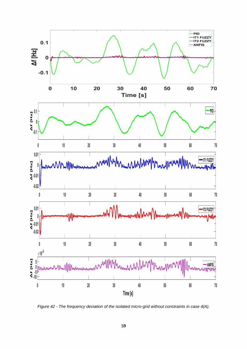
59
Figure 42 - The frequency deviation of the isolated micro-grid without constraints in case 4(A).

60
(I)
(II)
(III)
(IV)
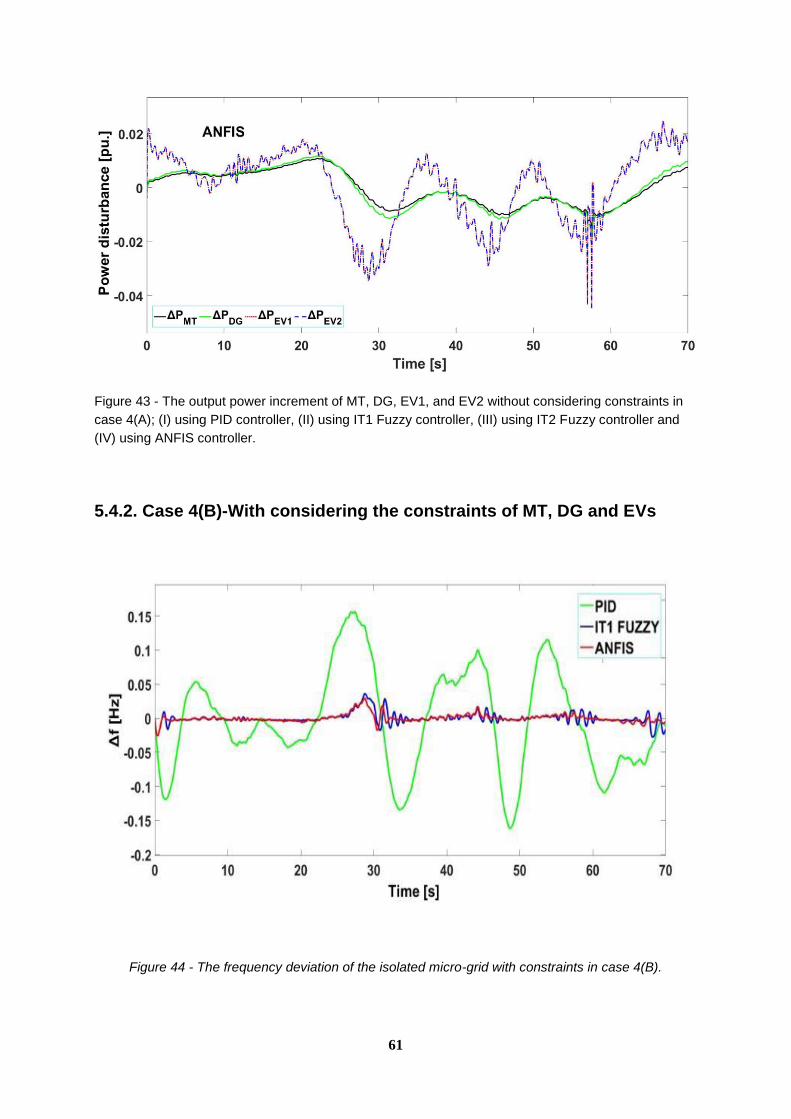
61
Figure 43 - The output power increment of MT, DG, EV1, and EV2 without considering constraints in
case 4(A); (I) using PID controller, (II) using IT1 Fuzzy controller, (III) using IT2 Fuzzy controller and
(IV) using ANFIS controller.
5.4.2. Case 4(B)-With considering the constraints of MT, DG and EVs
Figure 44 - The frequency deviation of the isolated micro-grid with constraints in case 4(B).
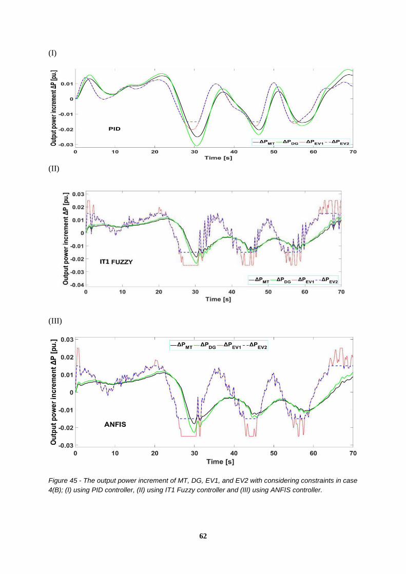
62
(I)
(II)
(III)
Figure 45 - The output power increment of MT, DG, EV1, and EV2 with considering constraints in case
4(B); (I) using PID controller, (II) using IT1 Fuzzy controller and (III) using ANFIS controller.
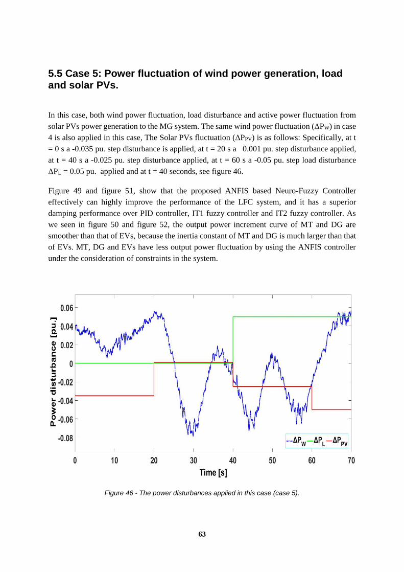
63
5.5 Case 5: Power fluctuation of wind power generation, load and solar PVs.
In this case, both wind power fluctuation, load disturbance and active power fluctuation from
solar PVs power generation to the MG system. The same wind power fluctuation (ΔPW) in case
4 is also applied in this case, The Solar PVs fluctuation (ΔPPV) is as follows: Specifically, at t
= 0 s a -0.035 pu. step disturbance is applied, at t = 20 s a 0.001 pu. step disturbance applied,
at t = 40 s a -0.025 pu. step disturbance applied, at t = 60 s a -0.05 pu. step load disturbance
ΔPL = 0.05 pu. applied and at t = 40 seconds, see figure 46.
Figure 49 and figure 51, show that the proposed ANFIS based Neuro-Fuzzy Controller
effectively can highly improve the performance of the LFC system, and it has a superior
damping performance over PID controller, IT1 fuzzy controller and IT2 fuzzy controller. As
we seen in figure 50 and figure 52, the output power increment curve of MT and DG are
smoother than that of EVs, because the inertia constant of MT and DG is much larger than that
of EVs. MT, DG and EVs have less output power fluctuation by using the ANFIS controller
under the consideration of constraints in the system.
Figure 46 - The power disturbances applied in this case (case 5).
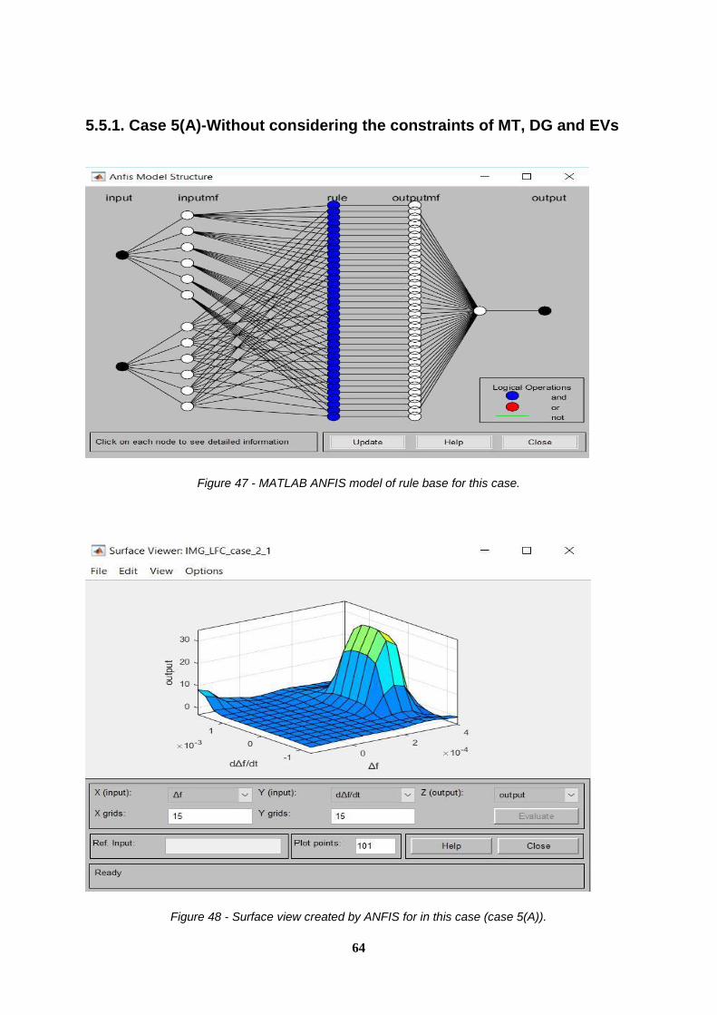
64
5.5.1. Case 5(A)-Without considering the constraints of MT, DG and EVs
Figure 47 - MATLAB ANFIS model of rule base for this case.
Figure 48 - Surface view created by ANFIS for in this case (case 5(A)).

65
ANFIS info:
Number of nodes: 101
Number of linear parameters: 108
Number of nonlinear parameters: 36
Total number of parameters: 144
Number of training data pairs: 701
Number of checking data pairs: 0
Number of fuzzy rules: 36
Start training ANFIS...
1 0.00903368
2 0.00931277
Designated epoch number reached --> ANFIS training completed at epoch 2.
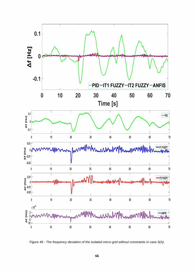
66
Figure 49 - The frequency deviation of the isolated micro-grid without constraints in case 5(A).
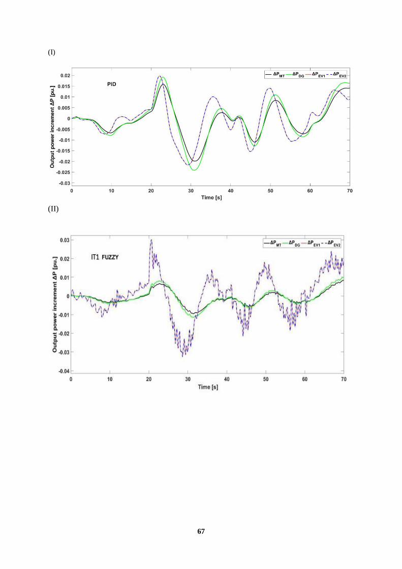
67
(I)
(II)
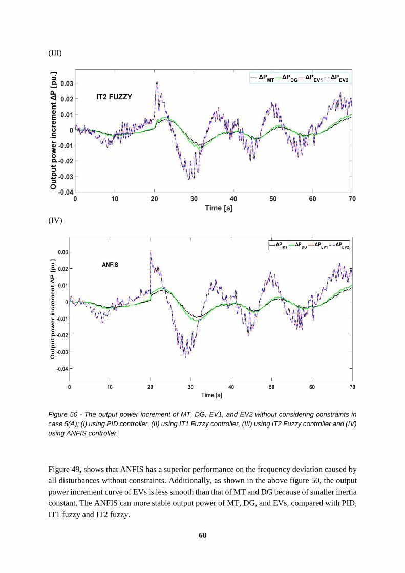
68
(III)
(IV)
Figure 50 - The output power increment of MT, DG, EV1, and EV2 without considering constraints in
case 5(A); (I) using PID controller, (II) using IT1 Fuzzy controller, (III) using IT2 Fuzzy controller and (IV)
using ANFIS controller.
Figure 49, shows that ANFIS has a superior performance on the frequency deviation caused by
all disturbances without constraints. Additionally, as shown in the above figure 50, the output
power increment curve of EVs is less smooth than that of MT and DG because of smaller inertia
constant. The ANFIS can more stable output power of MT, DG, and EVs, compared with PID,
IT1 fuzzy and IT2 fuzzy.

69
5.5.2. Case 5(B)-With considering the constraints of MT, DG and EVs
Figure 51 - The frequency deviation of the isolated micro-grid with constraints in case 5(B).
(I)
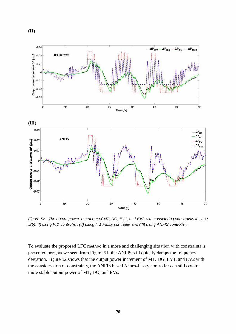
70
(II)
(III)
Figure 52 - The output power increment of MT, DG, EV1, and EV2 with considering constraints in case
5(b); (I) using PID controller, (II) using IT1 Fuzzy controller and (III) using ANFIS controller.
To evaluate the proposed LFC method in a more and challenging situation with constraints is
presented here, as we seen from Figure 51, the ANFIS still quickly damps the frequency
deviation. Figure 52 shows that the output power increment of MT, DG, EV1, and EV2 with
the consideration of constraints, the ANFIS based Neuro-Fuzzy controller can still obtain a
more stable output power of MT, DG, and EVs.
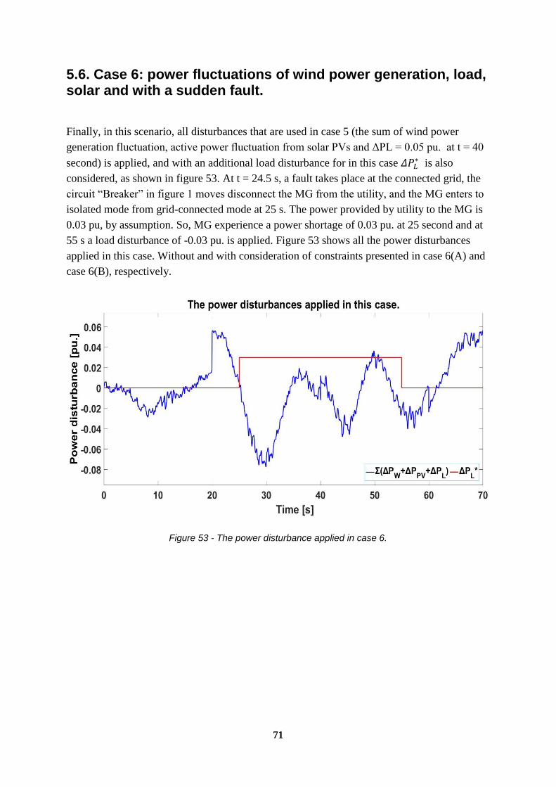
71
5.6. Case 6: power fluctuations of wind power generation, load, solar and with a sudden fault.
Finally, in this scenario, all disturbances that are used in case 5 (the sum of wind power
generation fluctuation, active power fluctuation from solar PVs and ΔPL = 0.05 pu. at t = 40
second) is applied, and with an additional load disturbance for in this case 𝛥𝑃𝐿∗ is also
considered, as shown in figure 53. At t = 24.5 s, a fault takes place at the connected grid, the
circuit “Breaker” in figure 1 moves disconnect the MG from the utility, and the MG enters to
isolated mode from grid-connected mode at 25 s. The power provided by utility to the MG is
0.03 pu, by assumption. So, MG experience a power shortage of 0.03 pu. at 25 second and at
55 s a load disturbance of -0.03 pu. is applied. Figure 53 shows all the power disturbances
applied in this case. Without and with consideration of constraints presented in case 6(A) and
case 6(B), respectively.
Figure 53 - The power disturbance applied in case 6.
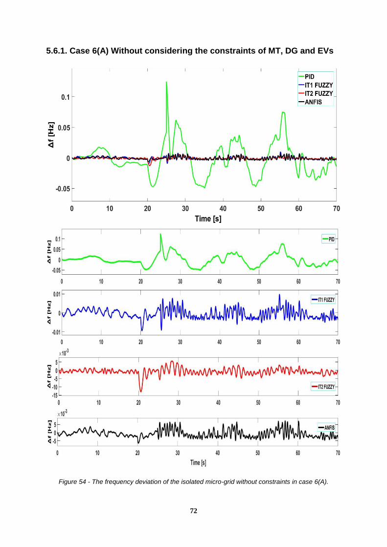
72
5.6.1. Case 6(A) Without considering the constraints of MT, DG and EVs
Figure 54 - The frequency deviation of the isolated micro-grid without constraints in case 6(A).
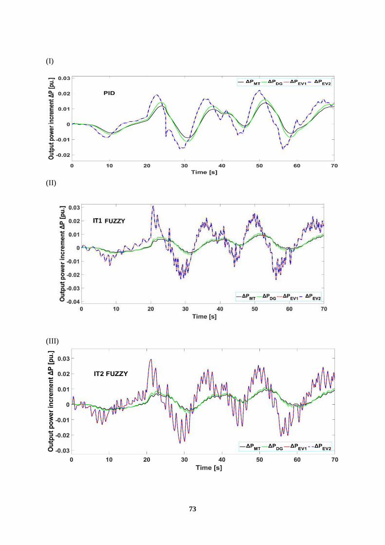
73
(I)
(II)
(III)
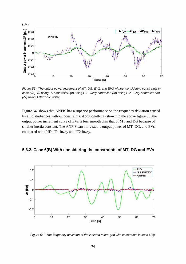
74
(IV)
Figure 55 - The output power increment of MT, DG, EV1, and EV2 without considering constraints in
case 6(A); (I) using PID controller, (II) using IT1 Fuzzy controller, (III) using IT2 Fuzzy controller and
(IV) using ANFIS controller.
Figure 54, shows that ANFIS has a superior performance on the frequency deviation caused
by all disturbances without constraints. Additionally, as shown in the above figure 55, the
output power increment curve of EVs is less smooth than that of MT and DG because of
smaller inertia constant. The ANFIS can more stable output power of MT, DG, and EVs,
compared with PID, IT1 fuzzy and IT2 fuzzy.
5.6.2. Case 6(B) With considering the constraints of MT, DG and EVs
Figure 56 - The frequency deviation of the isolated micro-grid with constraints in case 6(B).
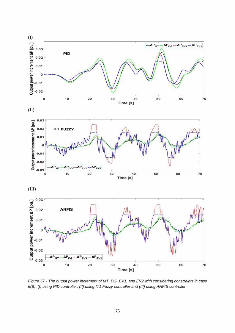
75
(I)
(II)
(III)
Figure 57 - The output power increment of MT, DG, EV1, and EV2 with considering constraints in case
6(B); (I) using PID controller, (II) using IT1 Fuzzy controller and (III) using ANFIS controller.

76
To evaluate the proposed LFC method in a more and challenging situation with constraints is
presented here. As we seen from Figure 56, the ANFIS still quickly damps the frequency
deviation. Figure 57 shows that the output power increment of MT, DG, EV1, and EV2 with
the consideration of constraints, the ANFIS based Neuro-Fuzzy controller can still obtain
more stable output power of MT, DG and EVs.
77
CHAPTER 6
Conclusions and Future Scopes
6.1 Summary of contributions and conclusion
The consistent increase in the penetration of renewable energy sources and continuous load
disturbances in a power system, especially in isolated MG, the virtual inertia system might not
stable and cannot maintain and stabilize the frequency deviation within the acceptable
frequency performance, leading to instability and system collapse. In this, an intelligent control
technique which is based on Adaptive Neuro-Fuzzy Inference System architecture for LFC in
an isolated MG system using V2G integration has been proposed under different conditions
with fluctuating renewable energy generation and load disturbance. The performance of the
proposed intelligent controller has compared with conventional proportional-integral-
derivative (PID) controller, Interval type-1 (IT1) Fuzzy controller and Interval type-2 (IT2)
Fuzzy controller design methods.
The research performed in this thesis work includes the followings: -
I) A deep literature study of V2G technology, the role of V2G technology in a power system,
load frequency control, LFC in micro-grid, LFC in MG with V2G, an intelligent technique for
LFC in micro-grids and an intelligent technique for LFC in MG with V2G (Chapter 2).
II) State space modeling of the isolated micro-grid using V2G integration for LFC, which
included MG modelling, model of MT, model of electric vehicles, model of DG, wind turbine
and solar PV model, and the general scheme of the isolated micro-grid using V2G integrations
(Chapter 3).
III) An intelligent coordination control techniques for LFC between micro-turbine, diesel
generator and EVs to achieve a satisfied performance on load frequency. Artificial intelligent
controllers for LFC, (a) Interval Type-1 Fuzzy Logic controller design for LFC (Chapter 4)
4.2.1), (b) Interval Type-2 Fuzzy Logic controller design for LFC (Chapter 4), 4.2.2), and (c)
Adaptive Neuro-Fuzzy controller (ANFIS) design for LFC (Chapter 4), 4.2.3).
IV) Demonstrated the performance of ANFIS with system stability performances, the
considered isolated micro-grid with MT, DG, EVs, solar PV, and wind farm is modelled in
MATLAB/SIMULINK environment (Chapter 5).
• The state space modelling for LFC of the isolated Wind-Solar PV-Micro Turbine-
Diesel Based Micro-Grid using V2G Integration has been developed with
conventional controller, i.e. PID controller. The performance of the system with PID
controller has been used for comparison with the proposed intelligent controllers
78
designed in the thesis has been proposed under different conditions with fluctuating
renewable energy generation and load disturbance.
• Interval Type-1 Fuzzy logic controller (Mamdani model) has been designed and
investigated with the basic structure for isolated micro-grid load frequency control
under the consideration constraints and without constraints of MT, DG, and EVs. The
IT1 Fuzzy logic controller (Mamdani model) showed better performance than the
conventional PID controller.
• Interval Type-2 Fuzzy logic controller (Mamdani model) has been designed and
investigated. The result show that using IT2 fuzzy controller (Mamdani model) in real-
world application might be a good option since this type of system is a better suitable
system than PID and IT1 Fuzzy logic controllers to manage high levels of uncertainty,
as shown in the results in Table 4.
• A novel Adaptive Neuro-Fuzzy Inference System architecture for an isolated wind-
Solar PV-Micro Turbine-Diesel based micro-grid system using (V2G) integration has
been designed to improve system frequency stability. The performance improvement
of the proposed controller is to compare with conventional PID, IT1 Fuzzy controller
and IT2 fuzzy controller regarding of rise time, over-shoot, under-shoot and settling
time of the frequency deviation, (Chapter 5), Case 1)).
It is concluded that the proposed intelligent controller, ANFIS based Neuro-Fuzzy controller,
it significantly improved the stability, reliability, economical and dynamic performance of the
device and the whole isolated micro-grid. It has been shown that the ANFIs based Neuro-Fuzzy
controller is effective and provides significant improvement in system performance by combine
the benefits of the parallel and learning abilities of neural networks with human like knowledge
representation and explanation abilities of fuzzy system. According the general scheme of the
MG with LFC controller (Chapter 3) 3.6) model, both load disturbance and the output power
of renewable energy sources are considered as ΔP. Therefore, the proposed controller can be
used in different configurations of MG, including different loads, renewable energy sources
and grid topologies. This has shown the credibility to implement the proposed method in real
the power system.
6.2 Future Scopes
The following investigations are recommended for future research based on the results
presented in this thesis work: -

79
➢ This thesis presented and proposed for only active power controls of MT, DG, and EVs
for LFC. But in the real time when there is a power interruption both the voltage and
frequency fluctuation occur, so the use of reactive power to stabilize the system has to
be done in the future by using intelligent control techniques.
➢ In this thesis, the isolated micro-grid is based on two renewable energy, i.e. wind energy
source and Solar PV energy source. In the power industry, many another type of
renewable energies, for example, Tide power is also receiving increasing interest, so in
the future may be to integrate more renewable energy sources and design the
corresponding solution.
➢ The communication delay may have an influence on the performance of the controller
since the optimal decisions of the stated coordinated controller depend on real-time
information from micro-grid distribution system.
➢ Further study can be made using optimisation methods such as Particle Swarm
Optimization, Genetic Algorithm, etc. to tune the controller’s parameters.
80
References
1. Manoj Singh Bish, Sathans “Fuzzy based intelligent frequency control strategy in
standalone hybrid AC microgrid” IEEE Control Applications (CCA), 11 December 2014. Date
Added to IEEE Xplore: 11 December 2014 IEEE Conference on Control Applications (CCA).
2. Machowski, Jan, Janusz Bialek, and Jim Bumby. “Power system dynamics: stability and
control”. John Wiley & Sons, 2011.
3. Jun Yang, Zhili Zeng, Yufei Tang, Jun Yan, Haibo He, Yunliang Wu, " Load frequency
control in an isolated micro grid system with electric vehicles based on MGPT" Energies 2015,
Vol. 8, pp. 2145-2164.
4. Ma, Y., Zhang, B., Zhou, X., Gao, Z., Wu, Y., Yin, J., & Xu, X. (2016, May). “An overview
on V2G strategies to impacts from EV integration into power system.” In Control and Decision
Conference (CCDC), 2016 Chinese (pp. 2895-2900). IEEE.
5. Singh, Mukesh, Praveen Kumar, and Indrani Kar. "Implementation of vehicle to grid
infrastructure using fuzzy logic controller." IEEE Transactions on Smart Grid 3.1 (2012):
565-577.
6. Shumei, C., Xiaofei, L., Dewen, T., Qianfan, Z., & Liwei, S. (2011, August).
“Theconstruction and simulation of V2G system in micro-grid”. In Electrical Machines and
Systems (ICEMS), 2011 International Conference on (pp. 1-4). IEEE.
7. Monteiro, V., Pinto, J. G., Exposto, B., Gonçalves, H., Ferreira, J. C., Couto, C., & Afonso,
J. L. (2012, October). “Assessment of a battery charger for electric vehicles with reactive power
control”. In IECON 2012-38th Annual Conference on IEEE Industrial Electronics Society (pp.
5142-5147). IEEE.
8. Han, Sekyung, Soohee Han, and Kaoru Sezaki. "Development of an optimal vehicle-to-grid
aggregator for frequency regulation." IEEE Transactions on smart grid 1.1 (2010): 65-72.
9. Pillai, Jayakrishnan Radhakrishna, and Birgitte Bak-Jensen. "Integration of vehicle-to-grid
in the western Danish power system." IEEE Transactions on Sustainable Energy 2.1 (2011):
12-19.
10. Madawala, Udaya K., and Duleepa J. Thrimawithana. "A bidirectional inductive power
interface for electric vehicles in V2G systems." IEEE Transactions on Industrial Electronics
58.10 (2011): 4789-4796.
11. Wang, Zhenpo, and Shuo Wang. "Grid power peak shaving and valley filling using vehicle-
to-grid systems." IEEE Transactions on Power delivery 28.3 (2013): 1822-1829.
81
12. Bevrani, Hassan, et al. "Intelligent LFC concerning high penetration of wind power:
synthesis and real-time application." IEEE Transactions on Sustainable Energy 5.2 (2014): 655-
662.
13. Bevrani, Hassan. “Robust power system frequency control”. Vol. 85. New York: Springer,
2009. (Book)
14. Ashmole, P. H., D. R. Battlebury, and R. K. Bowdler. "Power-system model for large
frequency disturbances." Electrical Engineers, Proceedings of the Institution of 121.7 (1974):
601-608.
15. Jiang, L., et al. "Delay-dependent stability for load frequency control with constant and
time-varying delays." IEEE Transactions on Power systems 27.2 (2012): 932-941.
16. Foord, T. R. "Step response of a governed hydrogenerator." Electrical Engineers,
Proceedings of the IEEE, 125.11
17. Doolla, Suryanarayana, and T. S. Bhatti. "Load frequency control of an isolated small-hydro
power plant with reduced dump load." IEEE Transactions on Power Systems 21.4 (2006): 1912-
1919.
18. Schlueter, R. A., et al. "Modification of power system operation for significant wind
generation penetration." IEEE Transactions on Power Apparatus and Systems 1 (1983): 153-
161.
19. Fosha, Charles, and Olle Elgerd. "The megawatt-frequency control problem: a new
approach via optimal control theory." IEEE Transactions on Power Apparatus and Systems
4.PAS-89 (1970): 563-577.
20. Vachirasricirikul, Sitthidet, and Issarachai Ngamroo. "Robust controller design of
microturbine and electrolyzer for frequency stabilization in a microgrid system with plug-in
hybrid electric vehicles." International Journal of Electrical Power & Energy Systems 43.1
(2012): 804-811.
21. Li, Xiangjun, Yu-Jin Song, and Soo-Bin Han. "Frequency control in micro-grid power
system combined with electrolyzer system and fuzzy PI controller." Journal of Power Sources
180.1 (2008): 468-475.
22. Han, Sekyung, Soohee Han, and Kaoru Sezaki. "Development of an optimal vehicle-to-grid
aggregator for frequency regulation." IEEE Transactions on smart grid 1.1 (2010): 65-72.
23. Shimizu, Koichiro, et al. "Load frequency control in power system using vehicle-to-grid
system considering the customer convenience of electric vehicles." Power System Technology
(POWERCON), 2010 International Conference on. IEEE, 2010.

82
24. Pillai, Jayakrishnan Radhakrishna, and Birgitte Bak-Jensen. "Integration of vehicle-to-grid
in the western Danish power system." IEEE Transactions on Sustainable Energy 2.1 (2011):
12-19.
25. Clement-Nyns, Kristien, Edwin Haesen, and Johan Driesen. "The impact of charging plug-
in hybrid electric vehicles on a residential distribution grid." IEEE Transactions on Power
Systems 25.1 (2010): 371-380.
26. Singh, Mukesh, Indrani Kar, and Praveen Kumar. "Influence of EV on grid power quality
and optimizing the charging schedule to mitigate voltage imbalance and reduce power loss."
Power Electronics and Motion Control Conference (EPE/PEMC), 2010 14th International.
IEEE, 2010.
27. Umrao, Rahul, et al. "Load frequency control methodologies for power system." Power,
Control and Embedded Systems (ICPCES), 2012 2nd International Conference on. IEEE, 2012.
28. Mallesham, G., S. Mishra, and A. N. Jha. "Automatic generation control of microgrid using
artificial intelligence techniques." 2012 IEEE Power and Energy Society General Meeting.
IEEE, 2012.
29. Fozdar, Manoj, C. M. Arora, and V. R. Gottipati. "Recent trends in intelligent techniques
to power systems." Universities Power Engineering Conference, 2007. UPEC 2007. 42nd
International. IEEE, 2007.
30. Tang, Yufei, et al. "Frequency control using on-line learning method for island smart grid
with EVs and PVs." 2014 International Joint Conference on Neural Networks (IJCNN). IEEE,
2014.
31. Khooban, Mohammad-Hassan, et al. "A robust adaptive load frequency control for micro-
grids."ISA transactions 65 (2016): 220-229.
32. Awad, Bieshoy, Janaka Ekanayake, and Nick Jenkins. "Intelligent load control for
frequency regulation in MicroGrids." Intelligent Automation & Soft Computing 16.2 (2010):
303-318.
33. Bevrani, Hassan, Mohammad Ramin Feizi, and Sirwan Ataee. "Robust Frequency Control
in an Islanded Microgrid: H∞ and μ-Synthesis Approaches." IEEE Transactions on Smart Grid
7.2 (2016): 706-717.
34. Izumi, Yuya, Tomonobu Senjyu, and Atsushi Yona. "Load frequency control by using
demand response with ℋ∞ in isolated power systems." Harmonics and Quality of Power
(ICHQP), 2012 IEEE 15th International Conference on. IEEE, 2012.
35. Senjyu, Tomonobu, et al. "A hybrid power system using alternative energy facilities in
isolated island." IEEE Transactions on energy conversion 20.2 (2005): 406-414.
83
36. Toge, Masato, Yu Kurita, and Shinichi Iwamoto. "Supplementary load frequency control
with storage battery operation considering SOC under large-scale wind power
penetration." Power and Energy Society General Meeting (PES), 2013 IEEE. IEEE, 2013.
37. Al-Barazanchi, Sardar Adil Mohammed, and Ahmet Mete Vural. "Modeling and intelligent
control of a stand-alone PV-Wind-Diesel-Battery hybrid system." Control, Instrumentation,
Communication and Computational Technologies (ICCICCT), 2015 International Conference
on. IEEE, 2015.
38. S. Prakash and S. K. Sinha “Four area Load Frequency Control of interconnected hydro-
thermal power system by Intelligent PID control technique” 2012 Students Conference on
Engineering and Systems, March 2012, pp.1-6
39. Eberhart, Russell C. "Overview of computational intelligence [and biomedical engineering
applications]." Engineering in Medicine and Biology Society, 1998. Proceedings of the 20th
Annual International Conference of the IEEE. Vol. 3. IEEE, 1998.
40. Chai, Yuanyuan, Limin Jia, and Zundong Zhang. "Mamdani model based adaptive neural
fuzzy inference system and its application in traffic level of service evaluation." Fuzzy Systems
and Knowledge Discovery, 2009. FSKD'09. Sixth International Conference on. Vol. 4. IEEE,
2009.
41. Bevrani, Hassan, and Pourya Ranjbar Daneshmand. "Fuzzy logic-based load-frequency
control concerning high penetration of wind turbines." IEEE systems journal 6.1 (2012): 173-
180.
42. Bevrani, Hassan, et al. "Intelligent frequency control in an AC microgrid: Online PSO-
based fuzzy tuning approach." IEEE Transactions on Smart Grid 3.4 (2012): 1935-1944.
43. Jang, J-SR. "ANFIS: adaptive-network-based fuzzy inference system." IEEE transactions
on systems, man, and cybernetics 23.3 (1993): 665-685.
44. Nath, Vivek, and D. K. Sambariya. "Design and performance analysis of adaptive neuro
fuzzy controller for load frequency control of multi-power system." Intelligent Systems and
Control (ISCO), 2016 10th International Conference on. IEEE, 2016.
45. Dhanalakshmi, R., and S. Palaniswami. "ANFIS based Neuro-Fuzzy Controller in LFC of
Wind-Micro Hydro-Diesel Hybrid Power System." International Journal of computer
applications 42.6 (2012): 28-35.
46. Menghal, P. M., and A. Jaya Laxmi. "Scalar control of an induction motor using artificial
intelligent controller." Power, Automation and Communication (INPAC), 2014 International
Conference on. IEEE, 2014.
84
47. Zubieta, Luis Eduardo. "Are microgrids the future of energy? Dc microgrids from concept
to demonstration to deployment." IEEE Electrification Magazine 4.2 (2016): 37-44.
48. Khodaei, Amin. "Provisional microgrid planning." IEEE Transactions on Smart
Grid (2015).
49. Surya Prakash, A.K. Bhardwaj and S.K. Shinha “Neuro fuzzy hybrid intelligent approach
for four -area load frequency control of interconnected power system” 2012 2nd International
Conference on Power, Control and Embedded Systems, Dec. 2012, pp.1-7. IEEE, 29 April
2013.
50. J. M. Mendel “Uncertain Rule-Based Fuzzy Logic Systems: Introduction and New
Directions” Prentice Hall, 2001.
51. Souran, Davood M., et al. "A performance comparison of classical PID, Type-1 and Type-
2 fuzzy controller in a three-tank level control system." Robotics and Manufacturing
Automation (ROMA), 2014 IEEE International Symposium on. IEEE, 2014.
52. Database of Wind Characteristics. Available online: http://www.winddata.com/ (accessed
on 3. March 2017 12:19 AM).
53. World Energy Council https://www.worldenergy.org/

85