intelligent degassing studies on controlling · pdf file1 intelligent degassing –...
TRANSCRIPT
1
INTELLIGENT DEGASSING –
STUDIES ON CONTROLLING THE PROCESS OF
HYDROGEN REMOVAL FROM ALUMINIUM
Ronny SIMON *, Roger KENDRICK
**
* Foseco Europe, Borken, Germany
** Foseco Europe, Tamworth, Great Britain
ABSTRACT
Hydrogen removal and control are a vital part of the metal treatment process in Aluminium
casting production. Many years ago the options were only chemical addition in tablet form
or inert gas bubbled through a lance. Degassing times were long and often the bottleneck in
production but this situation changed with the introduction of rotary degassing. The use of
highly efficient pumping rotors has now given the foundry the option of removing
hydrogen in a short time. Rotary degassing is now the Industry standard but a greater
understanding is required for full process control. This study looks at rotor wear and the
impact on degassing efficiency comparing the advanced pumping rotor with a simple non-
pumping design and the findings help to further improve the rotary degassing process. A
degassing process with an intelligent Foundry Degassing Unit offers a further step forward
in Process Control.
Keywords: Aluminium. Aluminium alloys, Hydrogen solubilty, Hydrogen removal,
Degassing, Rotor design, Process control
1. INTRODUCTION
In order for an Aluminium foundry to remain competitive then productivity and cost
effectiveness becomes ever more important. Quality standards need to improve
continuously as reject rates are now measured in parts per million and so every step of the
production process must be carefully controlled. The target is for every stage of the process
to be stable and consistent all year round and where metal treatment is concerned there is
often little chance for a second metal treatment should the first not achieve the required
specification. In order to avoid problems, the degassing parameters are normally set for the
worst case conditions and so for most of the year the melt is over-degassed, wasting
nitrogen, and using excessive energy and in the most severe cases making metal treatment
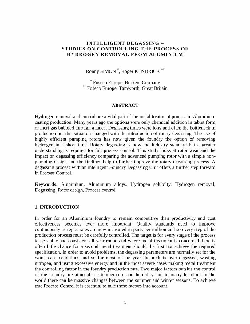
the controlling factor in the foundry production rate. Two major factors outside the control
of the foundry are atmospheric temperature and humidity and in many locations in the
world there can be massive changes between the summer and winter seasons. To achieve
true Process Control it is essential to take these factors into account.
2
Figure 1 : Impact on atmospheric humidity on hydrogen solubility
Another important factor is the rotor itself which changes in shape during its full service
life. The greater the variation in rotor performance over service life so the more certain it is
that over-degassing is required in the early stages of its service. The use of a rotor that
performs equally well from Day One to the end of its service life would enable the foundry
to work to closer tolerances on degassing time, inert gas usage and rotor speed. If this is not
possible then a Foundry Degassing Unit that takes rotor life into account would be
beneficial.
As we considered this subject to be of such great importance FOSECO decided to make a
series of laboratory and foundry trials to link the scientific and practical aspects of rotor
design and rotor wear.
2. ROTOR CHARACTERISATION
The purposes of mixing are manifold, and can be summarized generically across most
industries as follows:
Homogenization
Gas dispersion
Suspension of solids
Liquid-liquid blending
Heat transfer
Reactions.
The objectives of an aluminium batch degasser can now be considered in the light of the
preceding discussions of stirred tank reactors. Hydrogen removal is still frequently the
primary function of a batch degasser to remove dissolved hydrogen from molten
aluminium. This is accomplished by the passage of an inert purge gas through the melt. The
dissolved hydrogen seeks to equilibrate with the initially hydrogen free purge gas bubbles,
which rise to the surface, carrying hydrogen out of the system2. The finer the gas bubbles,
the greater the surface area and therefore the longer the residence time for the inert gas in
the melt.
3
Batch degassers are also used to clean aluminium melts. Aluminium generally has a variety
of non-metallic solid inclusions which can be detrimental to properties of castings3.
Nowadays the addition of salt fluxes supports the inclusion removal. The fluxes are
typically granular and entrained in the melt, for example by creating a vortex and pouring
flux onto the surface or into the vortex. The flux is distributed throughout the melt, where it
encounters inclusions, which become attached, and carried to the surface when the stirring
stops.
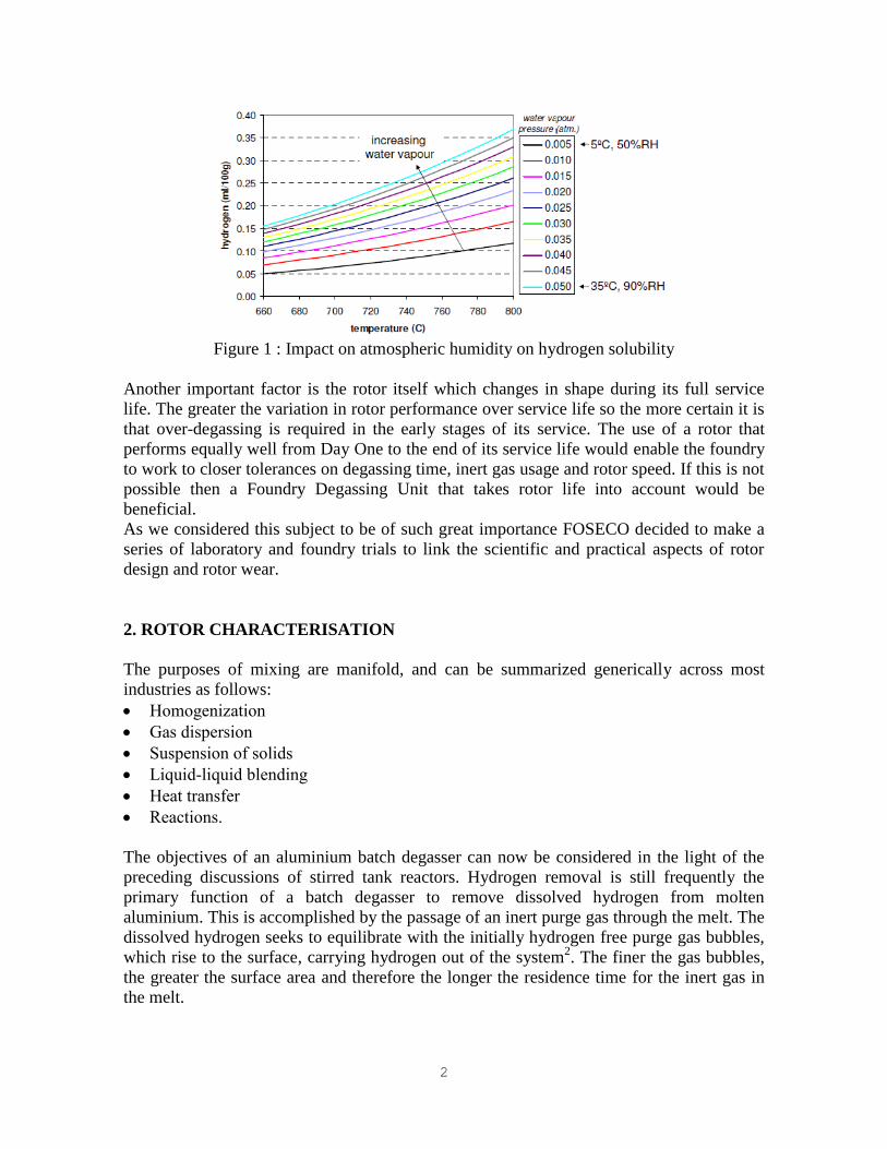
Pumping rotor Non-pumping rotor
Figure 2: Different gas bubble distribution
FOSECO favors rotors that offer a pumping action as opposed to the simpler and less
effective bubble choppers offered by competitors. The pumping action of these powerful
rotors draws metal from below and creates intensive mixing of the inert gas and the melt
within the rotor chamber.
3. HOMOGENIZING CAPABILITY OF ROTORS IN WATER
A well designed degassing system will have two key attributes. Firstly the melt will be
rapidly mixed to achieve and maintain chemical and thermal homogeneity throughout the
process. It is important that the time required to achieve good mixing is substantially less
than the metal treatment time, otherwise the applied treatment will be spatially
inhomogeneous in the melt. Whilst of concern in a degassing process, this is even more
problematic if the rotary system is being used for chemical dissolution (e.g. chemical grain
refiner, modifier or master alloy addition). Secondly, the turbulence generated by the rotor
will result in a small average size of inert gas bubbles, which the well mixed flow patterns
will ensure are well distributed throughout the melt.4
4
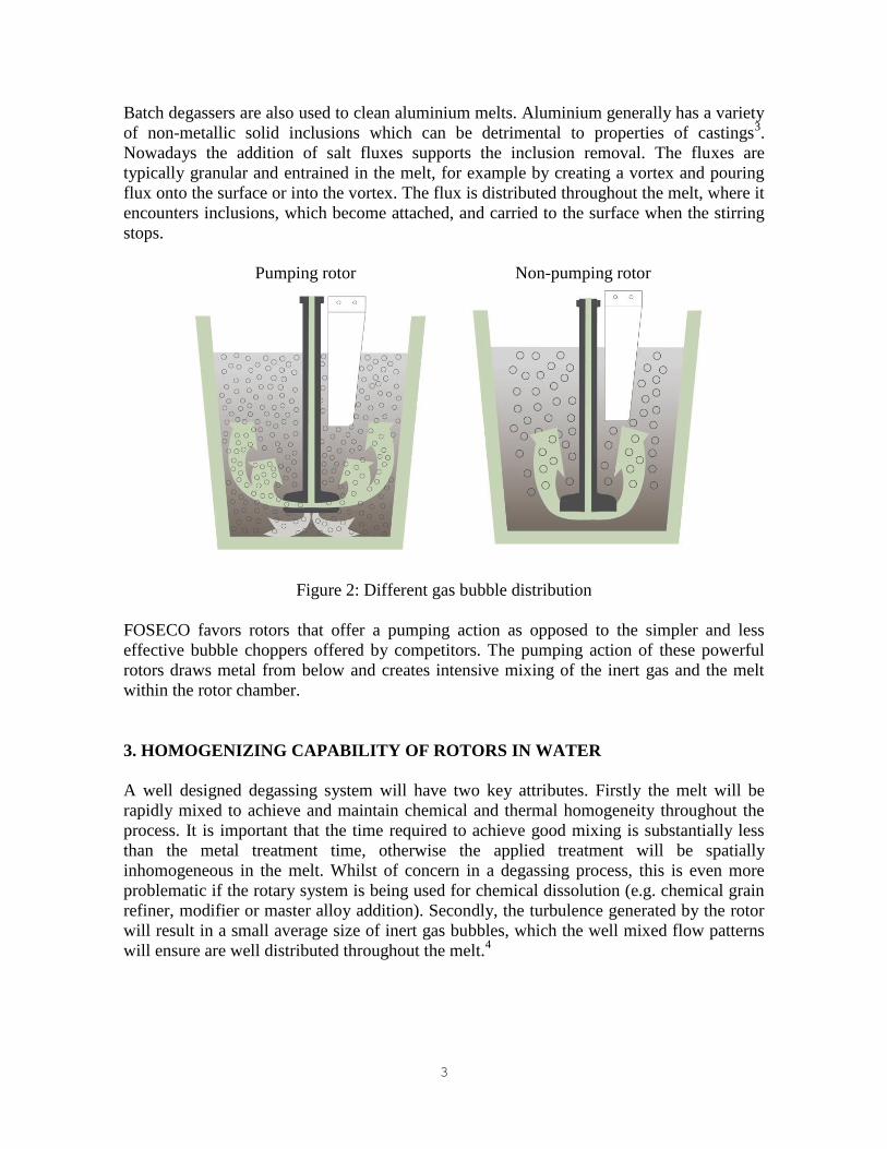
Previous water model trials and experiences from the field have shown a huge difference in
mixing capability of different rotors. The pictures (Fig 3a) are taken 4 seconds after adding
an ink; the FDR pumping rotor provides an almost homogenous ink distribution whilst the
non-pumping rotor results in insufficient mixing:
Pumping rotor Non-pumping rotor
Figure 3a: Rotor operating in Perspex tank filled with water after ink addition.
Figure 3b : QR code link to a movie with mixing trial results
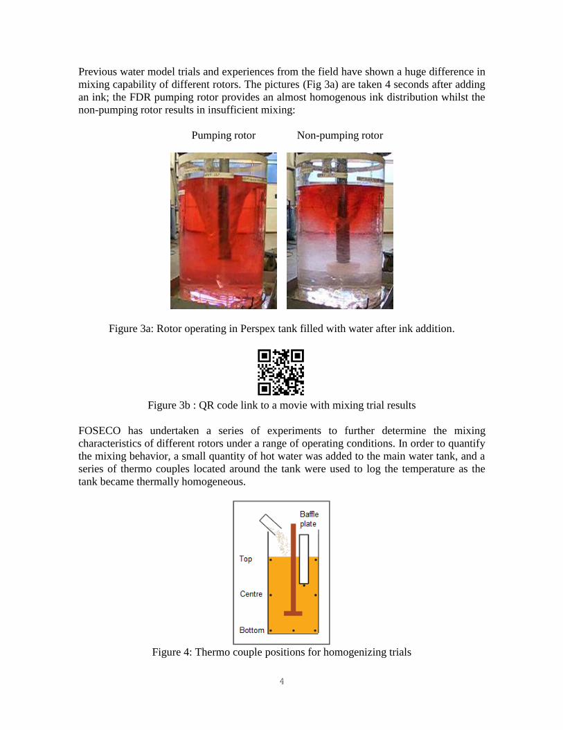
FOSECO has undertaken a series of experiments to further determine the mixing
characteristics of different rotors under a range of operating conditions. In order to quantify
the mixing behavior, a small quantity of hot water was added to the main water tank, and a
series of thermo couples located around the tank were used to log the temperature as the
tank became thermally homogeneous.
Figure 4: Thermo couple positions for homogenizing trials

5
Various degassing rotors were attached to a FOSECO Foundry Degassing Unit, and
immersed in a water-filled Perspex tank. The same tank was used as in the previous
experiments to measure rotor power: diameter 60 cm, water depth ~90 cm, with the rotor
positioned 20 cm above the base. The mass of water in the tank was typically 250-260 kg.
A series of Type T thermocouples were located in the tank, at the locations indicated in
Figure 4.
For each experiment approximately 7 kg of hot water (80 °C) as added to the tank once
steady mixing conditions were established. Typically the addition time was 15-20 s. The
complete tests ran for 1-2 minutes. A small nitrogen flow of 10 liters/minute was
maintained during all tests. The average homogeneous temperature rise in the complete
series of tests was ~1.3 K. The temperatures were logged at 100 ms intervals using a multi-
channel Data Logger; the plotted data were normalized to compare the mixing efficiency of
different rotor designs.
The MTS FDR rotor shown in Figure 5 – designed to give a good mixing for the MTS 1500
automated granulate addition – provides an excellent mixing. The temperature in all three
measurement levels is the same almost from the beginning; the water is completely
homogenized during the first 10 to 15 seconds after hot water addition.
Figure 5: Temperature distribution for an MTS FDR rotor at 400 rpm
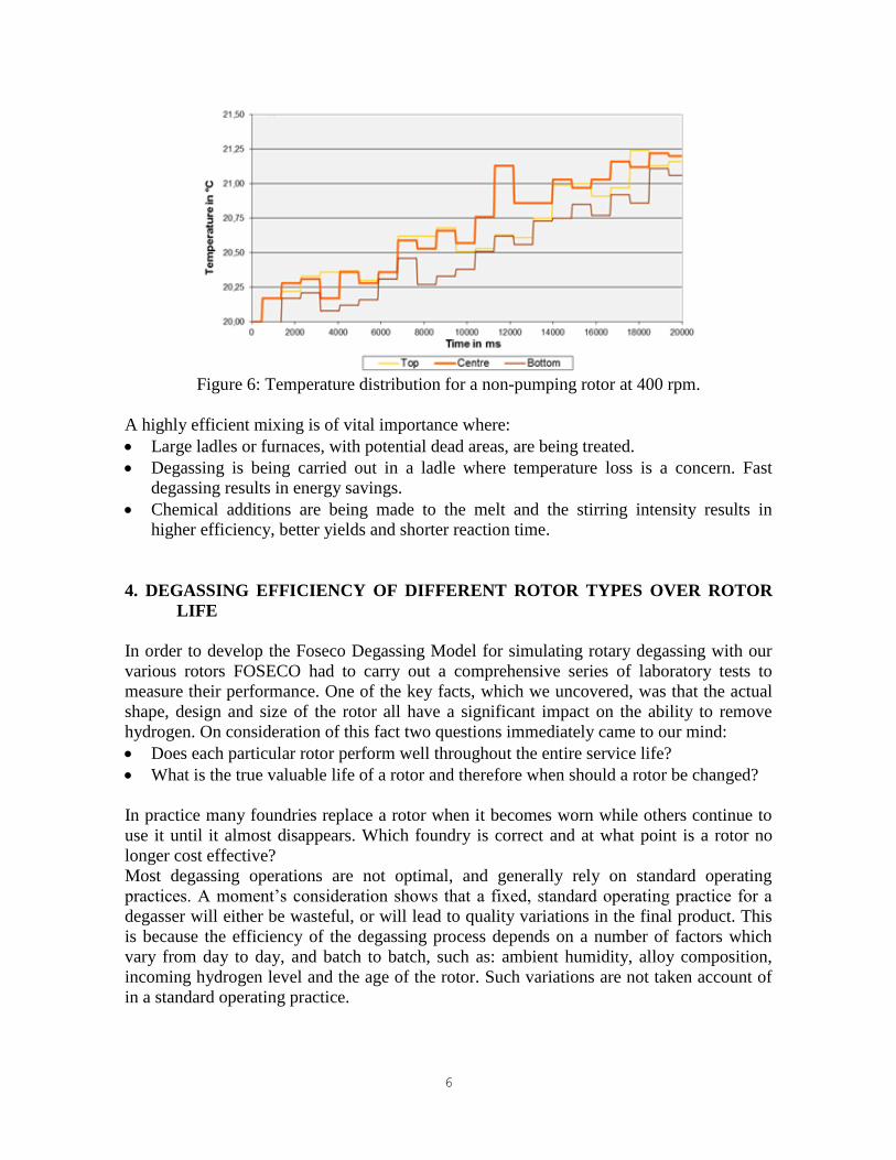
The non-pumping rotor shown in Figure 6 runs with the same parameters. Over the whole
logging period of time the temperature in the three measurements levels varies widely.
During the 20 seconds of recording the temperature the melt is not fully homogenized.
6
Figure 6: Temperature distribution for a non-pumping rotor at 400 rpm.
A highly efficient mixing is of vital importance where:
Large ladles or furnaces, with potential dead areas, are being treated.
Degassing is being carried out in a ladle where temperature loss is a concern. Fast
degassing results in energy savings.
Chemical additions are being made to the melt and the stirring intensity results in
higher efficiency, better yields and shorter reaction time.
4. DEGASSING EFFICIENCY OF DIFFERENT ROTOR TYPES OVER ROTOR
LIFE
In order to develop the Foseco Degassing Model for simulating rotary degassing with our
various rotors FOSECO had to carry out a comprehensive series of laboratory tests to
measure their performance. One of the key facts, which we uncovered, was that the actual
shape, design and size of the rotor all have a significant impact on the ability to remove
hydrogen. On consideration of this fact two questions immediately came to our mind:
Does each particular rotor perform well throughout the entire service life?
What is the true valuable life of a rotor and therefore when should a rotor be changed?
In practice many foundries replace a rotor when it becomes worn while others continue to
use it until it almost disappears. Which foundry is correct and at what point is a rotor no
longer cost effective?
Most degassing operations are not optimal, and generally rely on standard operating
practices. A moment’s consideration shows that a fixed, standard operating practice for a
degasser will either be wasteful, or will lead to quality variations in the final product. This
is because the efficiency of the degassing process depends on a number of factors which
vary from day to day, and batch to batch, such as: ambient humidity, alloy composition,
incoming hydrogen level and the age of the rotor. Such variations are not taken account of
in a standard operating practice.
7
FOSECO also has a novel probe for measuring dissolved hydrogen in molten aluminium,
marketed as ALSPEK H. One of the attractive features of ALSPEK H is its suitability for
measuring degassing curves in real time, in a stirred melt purged with inert gas.
A sequential degassing experiment was undertaken to quantify the influence of the changes
in rotor diameter and design over rotor service life. Before its first use, the rotors were
given a standard annealing practice designed to remove residual moisture. Periodically a
series of typically 3-5 degassing curves were obtained using ALSPEK H. Prior to each of
these runs, the melts were either initially up-gassed with N2-H2 mixed gas to a reasonable
level of dissolved hydrogen, or new melt coming from the melting furnace was used.
All trials were carried out in a 200 kg crucible furnace with AlSi10Mg alloy at 750 °C. The
rotors run at recommended rotation speed with 15 l/min nitrogen purging gas. The ambient
conditions were checked on a daily base, the humidity was always between 52 and
54 % rH.
For a better comparability the rotor life in this study is given in a percentage of total rotor
life. The target for degassing was 0, 08 ml H2 / 100 g Al.
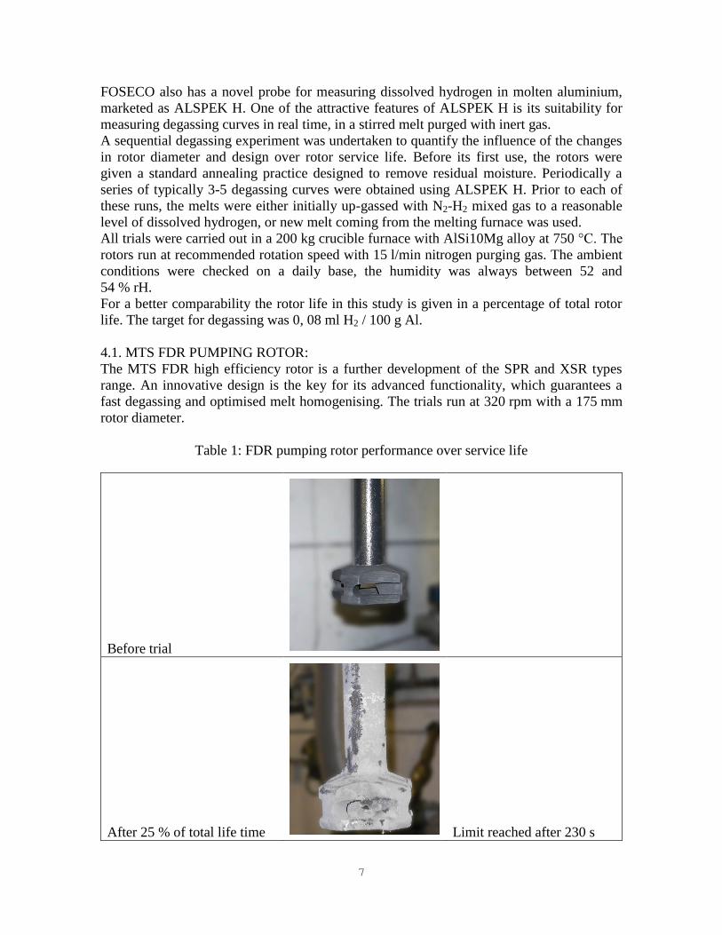
4.1. MTS FDR PUMPING ROTOR:
The MTS FDR high efficiency rotor is a further development of the SPR and XSR types
range. An innovative design is the key for its advanced functionality, which guarantees a
fast degassing and optimised melt homogenising. The trials run at 320 rpm with a 175 mm
rotor diameter.
Table 1: FDR pumping rotor performance over service life
Before trial
After 25 % of total life time Limit reached after 230 s
8
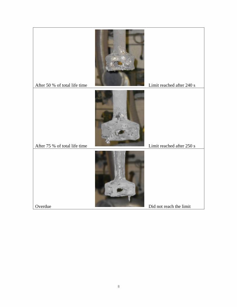
After 50 % of total life time Limit reached after 240 s
After 75 % of total life time Limit reached after 250 s
Overdue Did not reach the limit

9
Figure 7 : Degassing curves for FDR 175 pumping rotor at different service life
The various FDR rotor degassing curves in Figure 7 are very similar to each other. The
degassing efficiency over rotor life decreases slightly from 230 seconds to 250 seconds to
reach a very low hydrogen level of 0, 08 ml H2 / 100 g Al. In our trials the 20 seconds time
increase reflects less than 10 percent change in degassing efficiency. A loss in outer
diameter and more rounded edges are mostly compensated by oxidation of the graphite
actually increasing the pumping chamber size thereby increasing efficiency. The
combination of design and pumping effect ensures a stable degassing behaviour over rotor
service life.
All parameter settings which are normally done during the commissioning process, with a
set of consumables at the beginning of its life cycle, must take into consideration the extra
degassing time required to reach the quality limits when rotors near the end of their service
life.
Moreover the trials show that the rotor loses efficiency dramatically once its replacement is
overdue. As soon as efficiency reduces significantly as critical parts of the rotor are fully
consumed, or parts of the bottom plate, which generates the pumping effect, have gone then
the rotor must be changed. Foundries should introduce a system to define the limits to a
rotor change. This can be done by either a fixed treatment number or a limiting sample.
4.2. NON-PUMPING ROTORS:
Non-pumping rotors are simple bubble choppers offering little or no mixing, inefficient gas
distribution and untreated volumes near the bottom area of round treatment vessels. This
makes it impossible to treat rectangular or other non-round shapes.
The trials run at 320 rpm with a 175 mm rotor diameter. The non-pumping rotor as shown
in Figure 8 did not reach the 0, 08 ml H2 / 100 g Al limit, even with variations in the
treatment parameters it was impossible to degas to this level. The limit for the comparison
is 0,10 ml H2 / 100 g Al now.

10
Table 2 : Non-pumping rotor performance over service life
Before trial
After 10 % of total life time Higher hydrogen limit
reached after 220 s
After 36 % of total life time Higher hydrogen limit
reached after 240 s
After 95 % of total life time Higher hydrogen limit
reached after 260 s
11
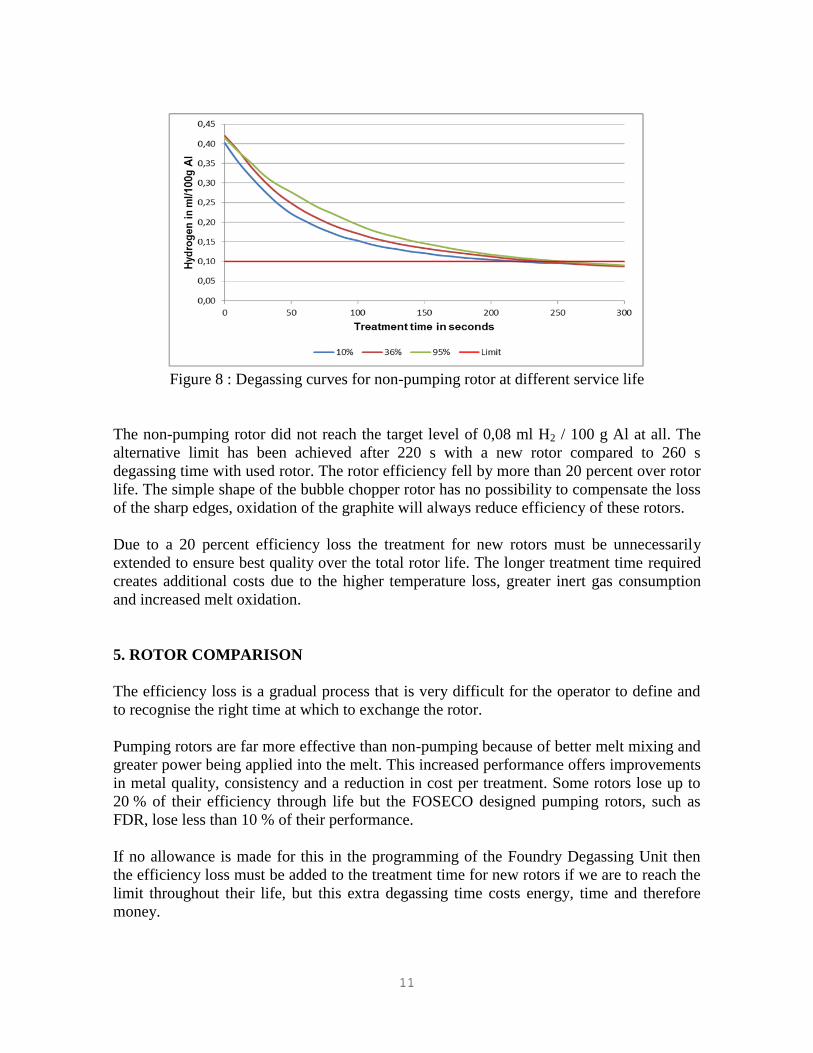
Figure 8 : Degassing curves for non-pumping rotor at different service life
The non-pumping rotor did not reach the target level of 0,08 ml H2 / 100 g Al at all. The
alternative limit has been achieved after 220 s with a new rotor compared to 260 s
degassing time with used rotor. The rotor efficiency fell by more than 20 percent over rotor
life. The simple shape of the bubble chopper rotor has no possibility to compensate the loss
of the sharp edges, oxidation of the graphite will always reduce efficiency of these rotors.
Due to a 20 percent efficiency loss the treatment for new rotors must be unnecessarily
extended to ensure best quality over the total rotor life. The longer treatment time required
creates additional costs due to the higher temperature loss, greater inert gas consumption
and increased melt oxidation.
5. ROTOR COMPARISON
The efficiency loss is a gradual process that is very difficult for the operator to define and
to recognise the right time at which to exchange the rotor.
Pumping rotors are far more effective than non-pumping because of better melt mixing and
greater power being applied into the melt. This increased performance offers improvements
in metal quality, consistency and a reduction in cost per treatment. Some rotors lose up to
20 % of their efficiency through life but the FOSECO designed pumping rotors, such as
FDR, lose less than 10 % of their performance.
If no allowance is made for this in the programming of the Foundry Degassing Unit then
the efficiency loss must be added to the treatment time for new rotors if we are to reach the
limit throughout their life, but this extra degassing time costs energy, time and therefore
money.
12
6. INTELLIGENT DEGASSING
It is clear then that for maximum process control it would be advantageous to include
atmospheric conditions and rotor performance into the program controlling the Degassing
Process. If a Foundry Degassing Unit was capable of considering the prevailing conditions
then it could adjust the treatment parameters to achieve optimum degassing.
Several years ago FOSECO worked with Technology Strategy Consultants (tsc) Ltd to
develop a batch degassing model, called the Foseco Degassing Model. It was developed
from first mathematical principles and was designed as a tool to help FOSECO to analyse
quickly our customers' operations and to make suggestions for their improvement. The
Foseco Degassing Model has already proven to be valuable when commissioning new
Foundry Degassing Units to ensure optimum performance.
The model makes rapid calculation of the likely degassing performance, given basic data
concerning a customer's operation. These include the composition of the alloy being
degassed, the Degassing Unit operational parameters (rotor speed, rotor size, rotor type and
purge time), the geometry of the crucible, and the ambient temperature and humidity. Any
or all of this data can be modified, and the degassing performance instantly recalculated.
The mathematical model behind this software is based on data generated in FOSECO’s
Research and Development facility while also using published data concerning the kinetics
of hydrogen degassing (e.g. hydrogen solubility, diffusivity, mass transfer rates and stable
bubble sizes). An extensive program of experimental work was undertaken to measure rotor
power and degassing kinetics in water, in order to provide specific information about
individual rotors.
It is therefore possible to use this mathematical model to make the decisions needed to
convert the incoming information from the Foundry Degassing Unit and to convert this into
an instruction of which parameters to use during the treatment itself.
The Foundry Degassing Unit can therefore decide which rotor speed and nitrogen flow rate
should be used to achieve a certain quality standard of alloy.
The foundry can decide whether to aim for the fastest degassing time or the lowest
consumable use in order to hit specification and changes in atmospheric condition and
metal temperature can be easily overcome. As the rotor ages so the treatment will adjust
accordingly.
7. CONCLUSIONS
Pumping Rotors are far more efficient than non-pumping rotors in terms of mixing,
improving metal quality, offering melt quality consistency and reducing the cost per
treatment
All degassing rotors lose efficiency over rotor life, but depending on the design the loss
can be less than 10 % for the FDR pumping style and more than 20 % for very simple
designs. So the less efficient non-pumping rotor becomes even less effective during
service.
13
Currently the efficiency loss experienced must be added to the treatment time for new
rotors to reach the limit throughout their service life, this results in inefficiency of the
treatment process.
Extensive laboratory work has enabled FOSECO and tsc to develop a mathematical
model which can be the basis of an intelligent system
Changes in external conditions can now be catered for during normal foundry
production conditions
Degassing with such a Foundry Degassing Unit offers a further step forward in Process
Control.
ACKNOWLEDGMENTS
We would like to thank Dr Paul Evans and Dr Ricky Ricks from tsc – Technology Strategy
Consultants, Shipston-on-Stour (Great Britain) for their work on theoretical foundations.
Kerstin Berndt, Martin Freyn and Marvin Kunze carried out all the trials in different
foundries and the Borken laboratory to get this enormous amount of data, you did a great
job.
REFERENCES
1) R.R. Hemrajani and G.B. Tatterson, in “The Handbook of Industrial Mixing”, editors
E.L. Paul, V.A. Atiemo-Obeng and S.M. Kresta, Wiley Interscience (2004).
2) G. K. Sigworth and T. A. Eng, Met. Trans. B 13(3), p447 (1982).
3) R. J Anderson, Metallurgy of Aluminium, H.C Baird and Co.(1930).
4) M. Zlokarnik, “Stirring: Theory and Practice”, Wiley-VCH, Weinheim (2001).