intelligent cutter suction dredging using the logic based ...ceur-ws.org/vol-1620/paper5.pdf ·...
TRANSCRIPT
Intelligent Cutter Suction Dredging Using the Logic
Based Framework LPS
F. Sadri
Department of Computing, Imperial College London, UK
Abstract. LPS (Logic-based Production System) is a framework that
combines logic programs with reactive rules and a destructively-
updated database. The logic programs provide proactive behavior and
allow definitions of processes, and the reactive rules provide reactive
behavior. This paper describes a first attempt in using LPS to model
the operations of cutter suction dredging (CSD). It is the result of a
year-long consultation with experts from the Dredging Engineering
Research Centre at Hohai University. LPS was chosen for this appli-
cation because its combination of proactivity and reactivity was
thought to be a good match for CSD operations. These require pro-
cesses for normal operations, as well as constant monitoring to identi-
fy any operational problems that may be arising and taking reactive
correction steps.
Keywords: Reactive rules, Process modelling, Artificial intelligence,
Executable model
1 Introduction
LPS (Logic-based Production System) [2,3,4,5,6,7] is a logic-based state transition
framework inspired by logic programming and artificial intelligence. It combines
logic programs with reactive rules and a destructively-updated database. The logic
programs provide goal-driven proactive behavior and definitions of processes and the
reactive rules provide event-driven reactive behavior. LPS has both operational and
declarative semantics and the operational semantics has been proved sound in general
and complete in certain special cases.
LPS has been implemented in XSB Prolog and in Java, and has been used for a
variety of small trial applications, including stock control, teleo-reactive robotics,
workflow and gaming. This paper describes a first attempt in using LPS to model the
operations of cutter suction dredging. It is the result of a year-long consultation with
experts from the Dredging Engineering Research Centre at Hohai University, and
uses their data [8] on dredging parameters.
Dredging engineering plays an important role in port construction, flood control
and drainage, reclamation projects, and other aspects of environmental manipulation
and protection. There are different types of dredgers which operate differently and are
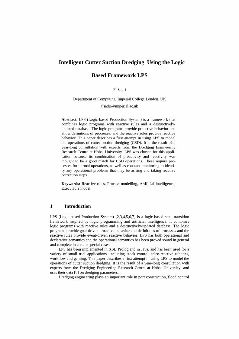
suitable for different types of soil [12]. In this paper we concentrate on cutter suction
dredgers (CSDs), e.g. in Figure1,which are some of the most widely used types of
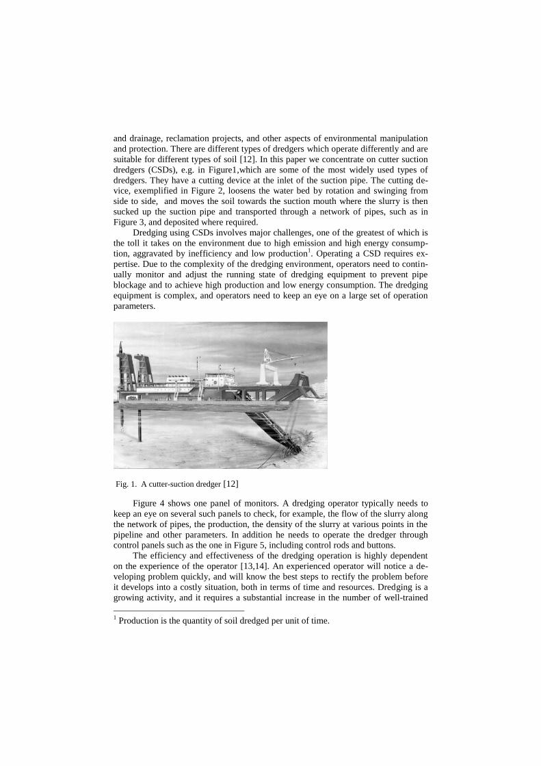
dredgers. They have a cutting device at the inlet of the suction pipe. The cutting de-
vice, exemplified in Figure 2, loosens the water bed by rotation and swinging from
side to side, and moves the soil towards the suction mouth where the slurry is then
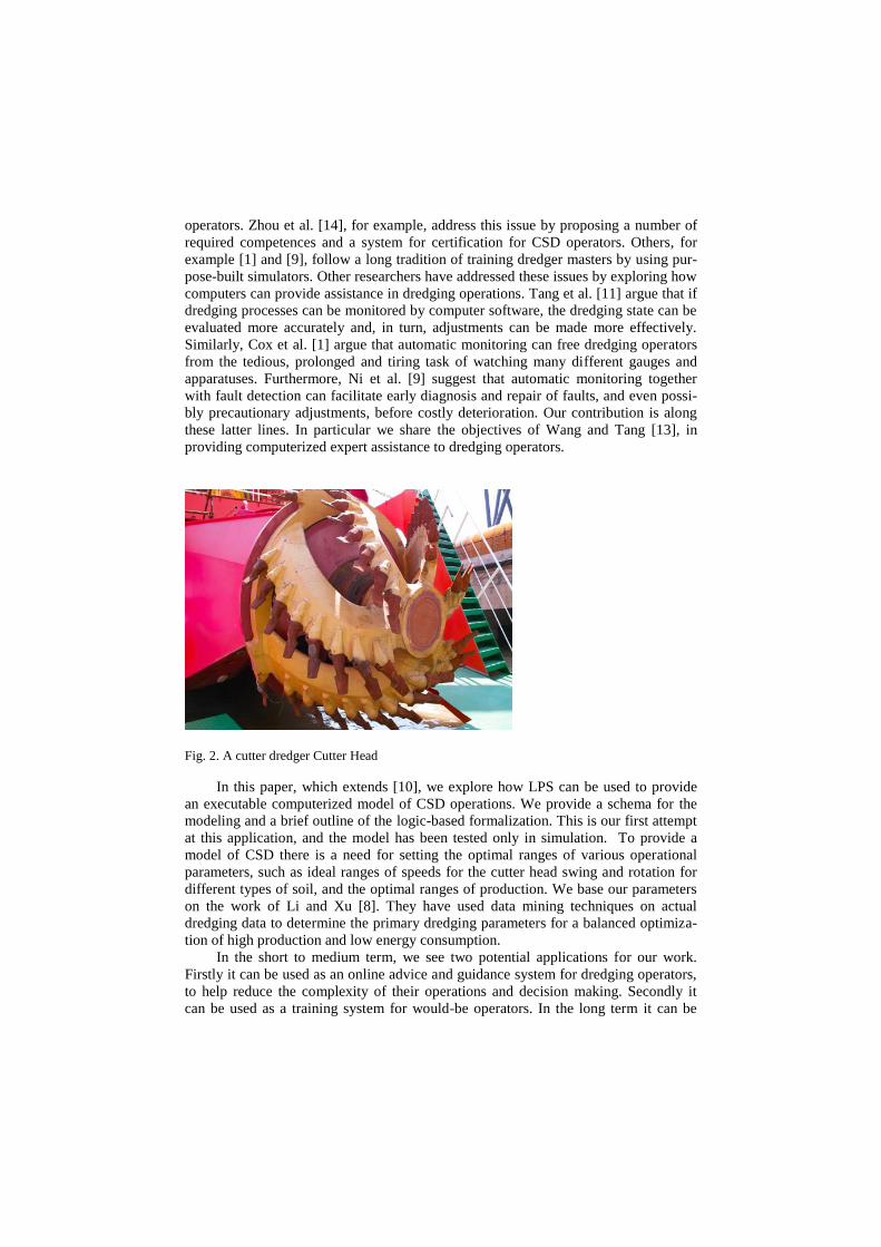
sucked up the suction pipe and transported through a network of pipes, such as in
Figure 3, and deposited where required.
Dredging using CSDs involves major challenges, one of the greatest of which is
the toll it takes on the environment due to high emission and high energy consump-
tion, aggravated by inefficiency and low production1. Operating a CSD requires ex-
pertise. Due to the complexity of the dredging environment, operators need to contin-
ually monitor and adjust the running state of dredging equipment to prevent pipe
blockage and to achieve high production and low energy consumption. The dredging
equipment is complex, and operators need to keep an eye on a large set of operation
parameters.
Fig. 1. A cutter-suction dredger [12]
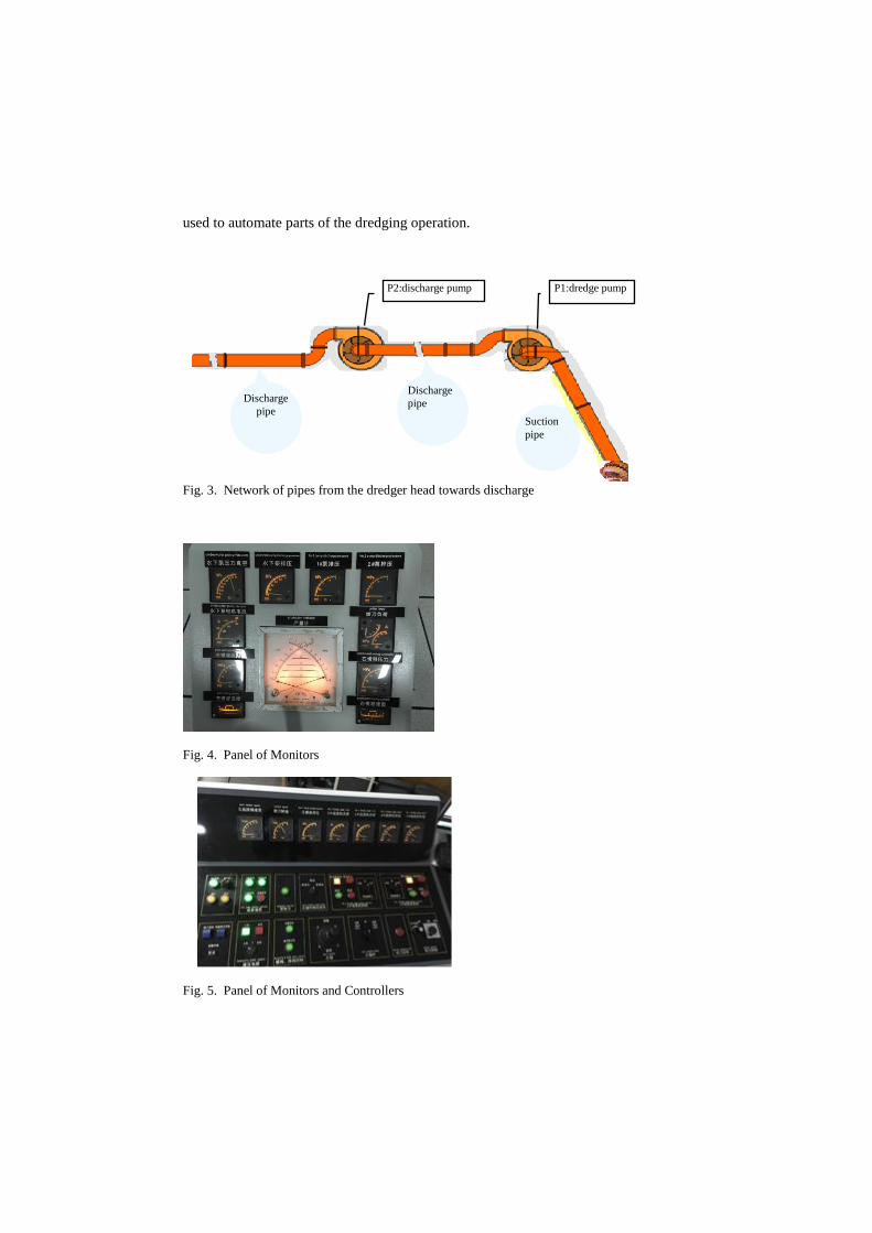
Figure 4 shows one panel of monitors. A dredging operator typically needs to
keep an eye on several such panels to check, for example, the flow of the slurry along
the network of pipes, the production, the density of the slurry at various points in the
pipeline and other parameters. In addition he needs to operate the dredger through
control panels such as the one in Figure 5, including control rods and buttons.
The efficiency and effectiveness of the dredging operation is highly dependent
on the experience of the operator [13,14]. An experienced operator will notice a de-
veloping problem quickly, and will know the best steps to rectify the problem before
it develops into a costly situation, both in terms of time and resources. Dredging is a
growing activity, and it requires a substantial increase in the number of well-trained
1 Production is the quantity of soil dredged per unit of time.
operators. Zhou et al. [14], for example, address this issue by proposing a number of
required competences and a system for certification for CSD operators. Others, for
example [1] and [9], follow a long tradition of training dredger masters by using pur-
pose-built simulators. Other researchers have addressed these issues by exploring how
computers can provide assistance in dredging operations. Tang et al. [11] argue that if
dredging processes can be monitored by computer software, the dredging state can be
evaluated more accurately and, in turn, adjustments can be made more effectively.
Similarly, Cox et al. [1] argue that automatic monitoring can free dredging operators
from the tedious, prolonged and tiring task of watching many different gauges and
apparatuses. Furthermore, Ni et al. [9] suggest that automatic monitoring together
with fault detection can facilitate early diagnosis and repair of faults, and even possi-
bly precautionary adjustments, before costly deterioration. Our contribution is along
these latter lines. In particular we share the objectives of Wang and Tang [13], in
providing computerized expert assistance to dredging operators.
Fig. 2. A cutter dredger Cutter Head
In this paper, which extends [10], we explore how LPS can be used to provide
an executable computerized model of CSD operations. We provide a schema for the
modeling and a brief outline of the logic-based formalization. This is our first attempt
at this application, and the model has been tested only in simulation. To provide a
model of CSD there is a need for setting the optimal ranges of various operational
parameters, such as ideal ranges of speeds for the cutter head swing and rotation for
different types of soil, and the optimal ranges of production. We base our parameters
on the work of Li and Xu [8]. They have used data mining techniques on actual
dredging data to determine the primary dredging parameters for a balanced optimiza-
tion of high production and low energy consumption.
In the short to medium term, we see two potential applications for our work.
Firstly it can be used as an online advice and guidance system for dredging operators,
to help reduce the complexity of their operations and decision making. Secondly it
can be used as a training system for would-be operators. In the long term it can be
used to automate parts of the dredging operation.
Fig. 3. Network of pipes from the dredger head towards discharge
Fig. 4. Panel of Monitors
Fig. 5. Panel of Monitors and Controllers
P1:dredge pump P2:discharge pump
Suction
pipe
Discharge
pipe Discharge
pipe
2 A Schema of Intelligent Cutter Suction Dredging Using LPS
LPS seems particularly well suited to the task of modeling intelligent dredging for
several reasons. It allows the representation of the state of the dredging task in terms
of the task’s operational parameters, and it provides a language that can model both
processes for proactive behavior and event-driven production system-type rules for
reactive behavior. Thus it can model “normal” operations when everything is going
well, and it can model how an abnormality and operational problem can be identified
and what steps need to be taken to rectify it. Moreover, the LPS model is executable,
in the sense that given periodic input of the dredger sensor readings and monitors, it
outputs the next course of actions with their suitable operational parameters.
A schema for modeling CSD in LPS is presented in Figure 6. This includes two
parts. On the left there is knowledge for intelligent decision-making in dredging using
data mining and statistical methods [8]. A small part of this knowledge is summa-
rized in Table 1. This shows suitable ranges of some CSD parameters optimal for high
production and low energy consumption. These ranges have been extracted for differ-
ent types of soil, for example sand, rock and clay. The table focuses on parameters for
sand dredging. This data informs the rest of the schema on the right side of Figure 6
which consists of the model in the LPS framework, which we describe below.
2.1 LPS Framework for Modeling Cutter Suction Dredging
The LPS model of dredging involves basic dredging data, dynamic dredging state data,
dredging processes, and dredging operation monitoring and fault detection.
The LPS language consists of:
a) A (deductive) Database, DB
b) Process definitions, Levents
c) Reactive Rules, R
d) A Domain Theory, D
A detailed description of the language can be found in [7]. Here we summarize the
language to the extent that is sufficient to describe a schema that can be used to engi-
neer the dredging application.
The database DB allows representation of static (non-changing) and dynamic
(changing) data, as well as definitions of concepts. The static and dynamic parts of the
database incorporate basic and dynamic dredging state data, respectively. Basic
dredging data involves type of the dredging area, type of soil and optimal ranges of
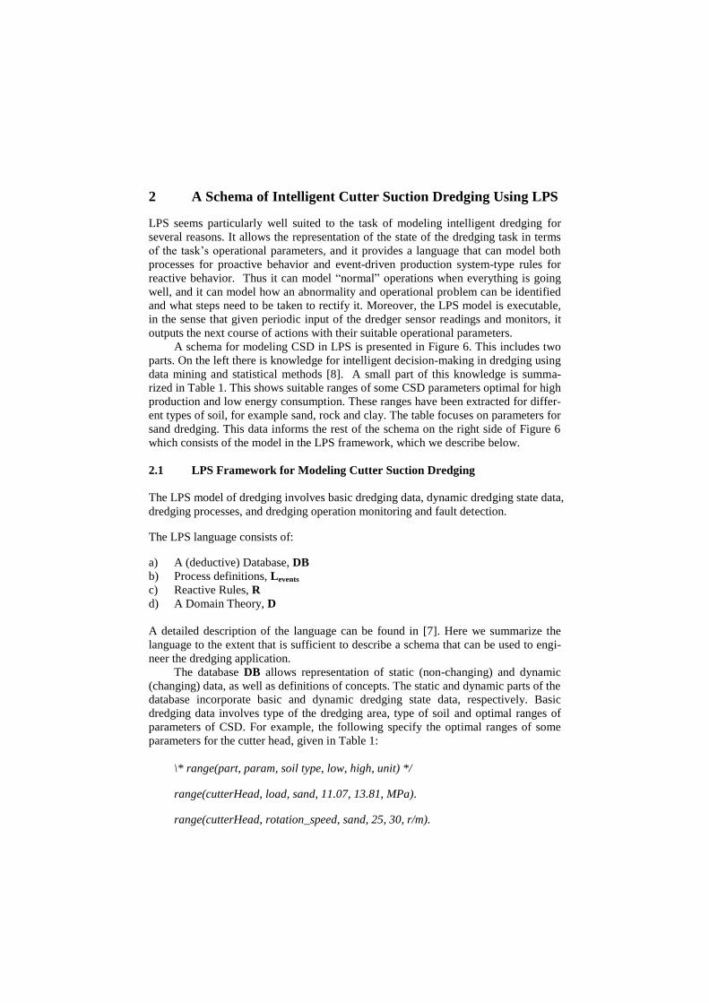
parameters of CSD. For example, the following specify the optimal ranges of some
parameters for the cutter head, given in Table 1:
\* range(part, param, soil type, low, high, unit) */
range(cutterHead, load, sand, 11.07, 13.81, MPa).
range(cutterHead, rotation_speed, sand, 25, 30, r/m).

range(cutterHead, swing_speed, sand, 9.62, 10.61, m/min).
Dynamic dredging state data involves the changing operational state of the dredging,
for example indicated by the monitors and sensors, indicating production, cutter head
load, slurry density and speed in various locations along the networks of pipes. For
example:
even(cutter_load).
indicates that currently cutter load is even. This may change during the operation if
the teeth of the cutter head are damaged, for example. In the simulation the monitor
readings are also considered part of the dynamic part of the knowledge base. For ex-
ample:
\* reading(part, param, value) */
reading(cutterHead, load, 12).
stating that the current monitor reading for cutter head load is 12, and
reading(dischargePipe, production, 1.4).
stating that the current monitor reading for production at the discharge pipe is 1.4.
The concept definitions in DB allow representation of concepts and parameters
that depend on other concepts and parameters. For example the following states that
the value of an operational parameter, Param, for equipment part, Part, is low if for
the given soil type, S, the read value of the parameter lies below the lower bound of
the parameter’s optimal range.
low(Part, Param) :- soil_type(S), range(Part, Param, S, L, H, Unit),
reading(Part, Param, V), V<L.2
In addition, the concept definitions in DB are used to specify how operational and
mechanical faults can be recognised during dredging. Such faults will, in turn, trigger
the reactive rules, R. These have the flavor of production rules, and are used to moni-
tor the state of the dredging operation, to detect faults, and to trigger correction pro-
cedures.
The process definitions, Levents, incorporate dredging procedures, both for nor-
mal operations and for fault correction. We will show some examples of rules in R
and clauses in Levents later. The domain theory, D, allows the system to reason about
the expected effects and preconditions of actions. Below we summarize some of the
operational and mechanical faults that we have catered for within the LPS schema.
2 For ease of reading we have dropped the time parameters in most of the formalisa-
tion presented in this paper.

LPS FRAMEWORK
Data recorded
when dredging
Data mining
---
high production
and
low energy consumption
Dredging
knowledge
BASIC DREDGING DATA:
1. Type of area
2. Type of soil
3. Parameters of CSD
DYNAMIC DREDGING STATE DATA:
1. Phrase of operation
2. Current point on the project area
3. Current monitor reading
DREDGING PROCEDURES:
1. Normal Procedures
2. Fault Correction Procedures
3. Fault Identification
DREDGING OPERATION
MONITORING and
FAULT DETECTION
Static Database
Dynamic Database
Process Definition
Concept Definitions
Reactive Rules
Domain Theory
Fig. 6. A schema of intelligent dredging for cutter suction dredger using LPS
2.2 Identification and Resolution of Operational/Mechanical Faults
During dredging various problems can be encountered, all ultimately resulting in the
lowering of production. Expert operators have developed effective ways of identify-
ing the causes of such problems and procedures for resolving them. These types of
problems have been studied through fault tree analysis in CSD safety performance
[15] and a CSD simulator has been developed in Dredging Engineering Research
Centre of Hohai University in China [9]. Out LPS model is the result of year-long
consultation with these colleagues. Here are some examples of faults that may arise
and indicators for recognizing them. These have been formalized in our LPS system.
The suction mouth (inlet) problem: This occurs when there is a blockage of the suc-
tion mouth, for example if debris or a piece of rock is stuck at the mouth of the suc-
tion pipe. An expert operator identifies this problem via the monitors by seeing that
vacuum in the suction pipe (Figure 3) is high, but slurry speed and slurry density in
the suction pipe are low, i.e. the suction pump is working (creating the high vacuum),
but the slurry is not getting sucked up the pipe effectively, as something is blocking it.

Table 1. Optimal ranges of dredging parameters of a CSD for sand
The cutter head problem: This occurs when some of the blades of the cutter head are
broken. An expert operator identifies this problem via the monitors by seeing that
vacuum is high, but slurry speed and slurry density in the suction pipe are low. In
addition the cutter load is uneven. This latter is what distinguishes this problem from
the one above. The unevenness of the cutter load occurs because as the cutter rotates
the load is normal where the blades are not damaged and is low where they are dam-
aged.
The suction pipe problem: This occurs when too much slurry collects in the suction
pipe and blocks it. In this case in the suction pipe slurry speed is low and slurry densi-
ty is high, and in the discharge pipe (Figure 3) slurry density is low.
Table 2 summarizes these faults (ignoring the discharge pipes for simplicity).
There Low means less than the lower end of the optimal range given in Table 1, High
means higher that the upper end of the optimal range, and Normal means within the
range. Cutter load uneven means the cutter load varies significantly (according to
some expert heuristic) during each rotation of the cutter head.
Parameters Optimal
Range Parameters Optimal Range
Cutter Head
Rotation
Speed
(25, 30) r/min Dredging Pump Vacuum (0.4, 1.08) MPa
Cutter Head
Swing
Speed
(9.62, 10.61)
m/min Dredging Pump Rotation
Speed (225, 228) r/min
Cutter Head
Load (11.07, 13.81)
MPa Depth of a Cut (1.82, 1.84) m
Slurry Den-
sity in Dis-
charge Pipe
(47.5, 59) % Production (1.68, 1.89) m3/sec
Slurry Speed
in Discharge
Pipe
(4.94, 5.08)
m/sec Energy Consumption (1.4, 1.57) kw/h
Slurry Den-
sity in Suc-
tion Pipe
(46.5, 59) % Slurry Speed in Suction
Pipe
(4.95, 5.10) m/sec
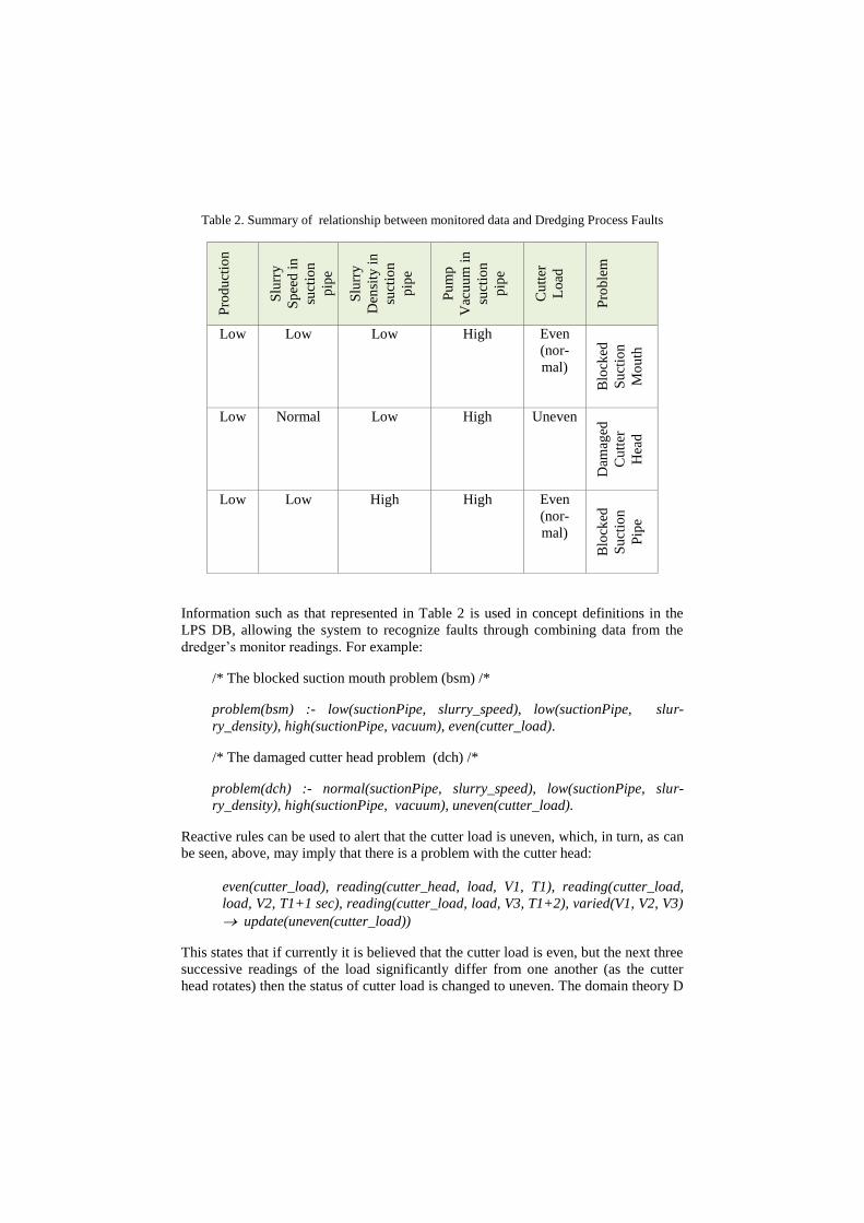
Table 2. Summary of relationship between monitored data and Dredging Process Faults P
rod
uct
ion
Slu
rry
Sp
eed
in
suct
ion
pip
e
Slu
rry
Den
sity
in
suct
ion
pip
e
Pu
mp
Vac
uu
m i
n
suct
ion
pip
e
Cu
tter
Lo
ad
Pro
ble
m
Low Low Low High Even
(nor-
mal)
Blo
cked
Su
ctio
n
Mo
uth
Low Normal Low High Uneven
Dam
aged
Cu
tter
Hea
d
Low Low High High Even
(nor-
mal)
Blo
cked
Su
ctio
n
Pip
e
Information such as that represented in Table 2 is used in concept definitions in the
LPS DB, allowing the system to recognize faults through combining data from the
dredger’s monitor readings. For example:
/* The blocked suction mouth problem (bsm) /*
problem(bsm) :- low(suctionPipe, slurry_speed), low(suctionPipe, slur-
ry_density), high(suctionPipe, vacuum), even(cutter_load).
/* The damaged cutter head problem (dch) /*
problem(dch) :- normal(suctionPipe, slurry_speed), low(suctionPipe, slur-
ry_density), high(suctionPipe, vacuum), uneven(cutter_load).
Reactive rules can be used to alert that the cutter load is uneven, which, in turn, as can
be seen, above, may imply that there is a problem with the cutter head:
even(cutter_load), reading(cutter_head, load, V1, T1), reading(cutter_load,
load, V2, T1+1 sec), reading(cutter_load, load, V3, T1+2), varied(V1, V2, V3)
update(uneven(cutter_load))
This states that if currently it is believed that the cutter load is even, but the next three
successive readings of the load significantly differ from one another (as the cutter
head rotates) then the status of cutter load is changed to uneven. The domain theory D
provides this updating of the status. Notice that the three readings of the cutter load
collectively provide a complex event that can trigger the reactive rule.
Other reactive rules are triggered when problems are recognized, for example,
when there is blocked suction mouth problem its specific corrective procedure has to
be executed:
problem(bsm) solve(bsm)
Expert corrective procedures for dealing with such faults are formalized as process
definitions in the Levents component of LPS. The process for dealing with the suction
mouth problem might be summarized as follows:
Stop the discharge pumps, the suction pump and the rotation of the cutter
head, so that the slurry flows down in the discharge pipe. This may remove
the blockage.
Wait for 5 minutes.
Restart everything (discharge pumps, the suction pump and the cutter head
rotation at a “normal” speed) and resume “normal” operation from where it
was suspended.
After 5 minutes recheck the relevant monitors (slurry density and vacuum in
suction pipe).
If the problem is resolved carry on.
If the problem is not resolved do the first step above, then lift the cutter head
above water and remove blockage manually, then restart and resume the
normal dredging process from the location of the dredging unit where the
process was suspended.
2.3 The Operational Semantics (OS) of LPS
All the components of LPS summarized above work together within an operational
semantics. The OS has been described formally and in detail in [7]. We do not repeat
that description here. Here we explain how it is applicable to the dredging problem.
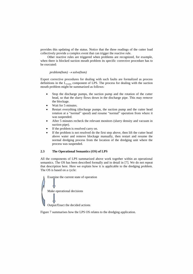
The OS is based on a cycle:
Examine the current state of operation
Make operational decisions
Output/Enact the decided actions
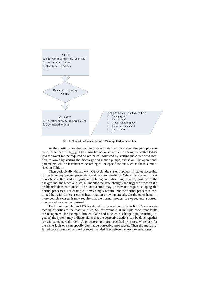
Figure 7 summarises how the LPS OS relates to the dredging application.
D esision /R easoning
C entre
IN PU T
1. E quipm ent param eters (as sta tes)
2 . E nvironm ent Factors
3 . M onitors’ read ings
........
O U T PU T
1. O perational dredging param eters
2 . O perational actions
........
O PE R A T IO N A L PA R A M E T E R S
� Sw ing speed
� Slurry speed
� C utter ro tation speed
� Pum p ro tation speed
� Slurry density
..........
Fig. 7. Operational semantics of LPS as applied to Dredging
At the starting state the dredging model initializes the normal dredging process-
es, as described in Levents. These involve actions such as lowering the cutter ladder
into the water (at the required co-ordinates), followed by starting the cutter head rota-
tion, followed by starting the discharge and suction pumps, and so on. The operational
parameters will be instantiated according to the specifications such as those summa-
rized in Table 1.
Then periodically, during each OS cycle, the system updates its status according
to the latest equipment parameters and monitor readings. While the normal proce-
dures (e.g. cutter head swinging and rotating and advancing forward) progress in the
background, the reactive rules, R, monitor the state changes and trigger a reaction if a
problem/fault is recognized. The intervention may or may not require stopping the
normal processes. For example, it may simply require that the normal process is con-
tinued but with different cutter head rotation or swing speeds. On the other hand, in
more complex cases, it may require that the normal process is stopped and a correc-
tive procedure executed instead.
Each fault modeled in LPS is catered for by reactive rules in R. LPS allows at-
taching priorities to the reactive rules. So, for example, if multiple concurrent faults
are recognized (for example, broken blade and blocked discharge pipe occurring to-
gether) the system may indicate either that the corrective actions can be done together
(or with some partial ordering), or according to pre-specified priorities. Moreover, for
the same fault one can specify alternative corrective procedures. Then the most pre-
ferred procedures can be tried or recommended first before the less preferred ones.

3 Conclusions
In this paper we presented a schema of intelligent cutter suction dredging using LPS.
LPS provides a language for representing concepts, processes and the states of opera-
tion, and an operational semantics for integrating and operationalizing these.
The LPS system and the model of dredging have been implemented in (XSB)
Prolog, and tested by simulating a small sand dredging project. The formalization
exercise and the resulting experiment have proved promising. Via a simple interface,
as in Figure 8, we input and update monitor readings (2nd
column) and observe what
recommendations the LPS system would give to the dredger operator (the bottom
panel). The other panels indicate any problems the system has identified. They also
indicate according to what corrective procedure the system is making recommenda-
tions to the operator.
For future work the system has to be tested more systematically and with more
complex scenarios. Ultimately, the software has to be integrated, with the hardware of
the dredging equipment sensors and monitors for more realistic experiments.
Acknowledgements
We are grateful to Kit Lawes for running the experiments of the LPS dredging sys-
tem. We are also grateful to colleagues H. M. Xu and F.S. Ni from the Dredging En-
gineering Research Centre, Hohai University for intensive consultations regarding
dredging. We would also like to thank the referees for their helpful comments.
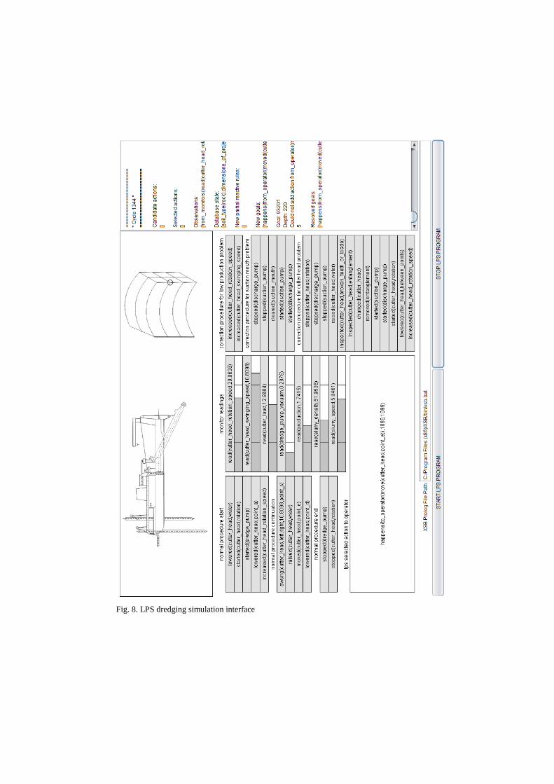
Fig. 8. LPS dredging simulation interface

References
1. Cox, C.M. Eygenraam, J.A. Granneman, C.C.O.N. and Njoo, M.: A Training
Simulator for Cutter Suction Dredgers: Bridging the Gap between Theory and
Practice. Terra et Aqua Journal, Number 63 (1996)
2. Kowalski, R. and Sadri, F.: Integrating Logic Programming and Production Sys-
tems in Abductive Logic Programming Agents. In: Third International Conference
on Web Reasoning and Rule Systems, Chantilly, Virginia, USA, pp. 1-23. (2009)
3. Kowalski, R. and Sadri, F.: An Agent Language with Destructive Assignment and
Model-Theoretic Semantics. In: Dix J., Leite J., Governatori G., and Jamroga W.
(eds.), 11th International Workshop on Computational Logic in Multi-Agent Sys-
tems (CLIMA), pp. 200-218. (2010)
4. Kowalski, R. and Sadri, F.: Abductive Logic Programming Agents with Destruc-
tive Databases. Annals of Mathematics and Artificial Intelligence. 62(1): 129-158
(2011)
5. Kowalski, R. and Sadri, F.: A Logic-Based Framework for Reactive Systems.
Rules on the Web: Research and Applications 2012 - RuleML 2012, Springer-
Verlag. Bikakis A. and Giurca A. (Eds.). LNCS 7438, pp. 1–15. (2012)
6. Kowalski, R. and Sadri, F.: A Logical Characterization of a Reactive System Lan-
guage. In: A. Bikakis et al. (Eds.) RuleML 2014, LNCS 8620, Springer Interna-
tional Publishing Switzerland, pp. 22-36 .(2014)
7. Kowalski, R. and Sadri, F.: Model-theoretic and operational semantics for Reac-
tive Computing. New Generation Computing, 33(1): 33-67 (2015)
8. Li, K. K. and Xu, H. M.: Multivariate principal component analysis for production
and energy consumption of cutter suction dredger. Applied Mechanics and Mate-
rials. 644-650: 2211-2215 (2014)
9. Ni, F. S., Zhao, L. J., Gu Lei, Jiang, S.: Simulation of dredging processes of a
cutter suction dredger. International Conference on Audio, Language and Image
Processing, ICALIP2010, pp. 628-632. (2010)
10. F. Sadri, H. M. Xu and F.S. Ni: A Schema for Intelligent Dredging for Cutter
Suction Dredger Using LPS. In: WORLD DREDGING CONGRESS XXI, June
13 - 17, Miami, Florida, USA (2016)
11. Tang, J. Z., Wang, Q. F., Tianyu Z.: Automatic monitoring and control of cutter
suction dredger. Automation in Construction. 18(2):194-203 (2009)
12. Vlasblom, W.J.: Designing Dredging Equipment: Chapter 3 Cutter suction dredg-
er. Wb3408b (2005)
13. Wang, Q., and Tang, J.: Research on expert system for dredging production opti-
mixation. In: 6th World Congress on Intelligent Control and Automation. Dalian,
China June, pp. 21-23. (2006)
14. Zhou, L.Y., Ooijens, S.C., Roosendaal, L.A. and Shi, W.: Development, practical
use and implementation of cutter suction dredger operator competence and certifi-
cation system (DOCS). In: WODCON XX - The Art of Dredging, June 2013, Bel-
gium (2013)
15. Zhou, Y. G. and Xu H. M.: The Application of Fault Tree Analysis in the Safety
Performance of Cutter Suction Dredger. Applied Mechanics and Materials. 405-
408: 3298-3301 (2013)