intelligen: a distributed workflow system for discovering protein
TRANSCRIPT
To Appear in Special Issue on Bioinformatics, International Journal on Distributed and Parallel Databases, 2002.
IntelliGEN: A Distributed Workflow
System for Discovering
Protein-Protein Interactions
Krys J. Kochut1, Jonathan Arnold2, Amit Sheth1, John Miller1, Eileen Kraemer1, Budak Arpinar1, Jorge Cardoso1
1Department of Computer Science 2Department of GeneticsUniversity of GeorgiaAthens, GA. 30602
Keywords: workflow management, biological process, bioinformatics, protein-proteininteraction, laboratory information management

To Appear in Special Issue on Bioinformatics, International Journal on Distributed and Parallel Databases, 2002.
1. Introduction
In the new millennium biology has gone through a paradigm shift with the adventof Genomics, the study of the structure, function, and evolution of whole genomes. Theterm “genomics” was coined in 1986, and institutional support for this new disciplinebegan with the creation of the National Center for Human Genome Research (NCHGR)in 1989. The initial goal of this discipline was the determination of the entire DNAsequence of a human being (a human genome) and several related model organisms thathave played a central role in Genetics, including the bacterium Escherichia coli, the yeastSaccharomyces cerevisiae, the worm Canerohabditis elegans, and the fruit flyDrosophila melanogaster. Sequencing the human genome and those of each modelsystem were daunting distributed computing tasks which required collecting, storing,integrating, retrieving, and distributing 3 billion base pairs (bp) of sequence on the humangenome alone.
Many aspects of computer science were brought to bear to solve these problems(Venter et al., 2001, International Human Genome Sequencing Consortium, 2001). Whatgenomics promises is that with the availability of the complete genetic blueprints of avariety of living systems, we will be able to unlock how living cells function and evolve.Already genetics has given us the Central Dogma: DNA) Deoxyribonucleic Acid, a longpolymer composed of four bases (or letters) makes up the double helix, encodes ourgenetic blueprint; RNA) genes in our genetic blueprint are transcribed into a relatedinformation molecule called RNA to carry the instructions in the blueprint out into thecell; protein) the message is translated into proteins (another information molecule with a20 letter alphabet), which carry out the work of the cell. The tools of genomics for thefirst time provide new experiments that describe the complete blueprint (DNA), thecellular levels of all RNAs (RNA profiling), and the cellular levels of all proteins (proteinprofiling), i.e., not only the information on what a cell is to do (as encoded in the DNA)but what the cell is doing (by RNA and protein profiling).
The paradigm shift in biology is that it is becoming an information science. Thismeans biology is becoming: 1) data driven and informatics-based, with billions of basepairs of DNA sequence in public databases (http://ncbi.nih.gov), used to collect, store,integrate, retrieve, and distribute the avalanche of genomics data; 2) high throughput andcomputational, with new technologies not only to sequence a genome but to describe thefull state of the cell as with new technologies like RNA profiling (DeRisi et al., 1997); 3)hierarchical in its organization of information along the pathway of the Central Dogma;4) inherently mathematical, in order to have the ability to organize and analyze the data;5) systems science-oriented, with a focus on living systems as complex networks(Strogatz, 2001). This paradigm shift is driven by the promise of being able tounderstand important complex traits at a cellular level. These traits include heart diseaseand cancer on one hand, and fundamental processes such as metabolism, development,survival, biological clocks, and mating on the other hand, all controlled by many genes atonce.

To Appear in Special Issue on Bioinformatics, International Journal on Distributed and Parallel Databases, 2002.
Since 1989, a number of new computational problems have emerged, andcomputer scientists have played a fundamental role in the birth of this new discipline.Genome projects by their nature are distributed (Hall et al., 2002). The overall task ofsequencing any genome requires the collaboration of scientists at many sites working ona hierarchically organized project. The scientists take on different well-defined tasks inthe project and then transmit the information they produce to other scientists engaged inother tasks to complete the project.
A large genomics project involves a significant number of researchers,technicians, and other support personnel directly involved in the lab activities. All thepeople perform dozens of tasks, either manual (e.g. performing laboratory experiments),computer assisted (e.g. looking for related genes in the GENBANK database), orsometimes performed entirely automatically by the computer (e.g. genomic sequenceassembly). Typically, the tasks must be performed in a specific sequence according tothe adopted experimental method. In addition, most of these tasks require vast amountsof support data from a variety of disparate sources, ranging from local flat files, databaseservers storing experimental results, to a wealth of Web accessible data sources, such asGENBANK and the Protein Database. It has become apparent that managing suchprojects poses overwhelming problems and may lead to results of lower or evenunacceptable quality, or possibly drastically increased project costs.
In this paper, we present a design and an initial implementation of a distributedworkflow system created to schedule and support activities in a genomics laboratoryfocused on what genes do. This project investigates which proteins work together toaccomplish tasks in the cell, discovering protein-protein interactions of fungi, specificallyNeurospora crassa. Our goal is to create a highly flexible workflow system thatefficiently coordinates, manages and schedules lab activities, including those involvingcollection, use and sharing of the necessary experimental data. Our approach ofdeveloping, adapting and applying workflow technology is presented in some detail usingone distinct part of a larger workflow to discover protein-protein interactions. In addition,novel features of our system include the ability to monitor the quality and timeliness ofthe results and if necessary, suggesting and incorporating changes to the selected tasksand/or their scheduling.
A primary contribution of this work is in-depth modeling and study of a distinctpart of very complex biological process, which allows us to demonstrate the benefit ofbioinformatics with the focus on support for process aspects of informatics challenges. Inparticular, it demonstrates the needs for workflow management to enable faster discoveryof biological processes such as protein-protein discovery by enabling effective processingand analysis of laboratory experiment data. Considering just the number of tasks whoseexecution need to be coordinated shows that such activities are nearly impossible withoutthe automation afforded by workflow management. For the workflow managementresearch, it allows us to show several requirements, including:
• workflows with varied task interconnections and complex data exchanges betweentasks

To Appear in Special Issue on Bioinformatics, International Journal on Distributed and Parallel Databases, 2002.
• very large number (tens of thousands) of task executions in a distributed environmentinvolving multiple computers and multiple laboratories,
• processes requiring adaptation to reflect what is learned and addressing new detailsnot addressed earlier, and requiring exception handling to prevent loss of extensivework performed, and
• ability to assess quality of scientific results.
In this paper, we discuss in detail the issues of complexity, quality of servicemeasurement, as well as adaptation. However, our experience in using the protein-protein interaction workflow has not been long enough to discuss comprehensive aspectsof exception handling. By using state of the art research in workflow management for achallenging biology problem, this work also demonstrate the current capabilities andfuture requirements in one instance of collaboration between biologists and computerscientists. While earlier workflow systems have been used to automate laboratoryexperiments, we believe that IntelliGEN demonstrates a new generation of optimizedlaboratory workflows that cannot be supported by homegrown (such as script based) orcurrently available commercial laboratory information systems.
2. Background
2.1. Protein-Protein Interactions
Genomics is only a beginning in discovering and investigating biologicalphenomena that drive humans and life. The blueprints are here, but what do they mean?How do we decipher the Rosetta Stone now available on many organisms and makeGenomics a hypothesis-driven science? The focus on what cells do will initially followthe path of sequencing simpler systems, such as microbes. Microbes have small genomeswith 7 to 49 Mbp of DNA (Bennett and Arnold, 2001), and many of them, like those inthe Fungal Kingdom, share properties with their more complex relatives. For example,the filamentous fungus N. crassa has a biological clock (Lee et al., 2000); however, thesesimpler microbial systems remain more tractable for analyzing what their cells are doing(Davis, 2000).
One way to describe how living systems function is to think in terms of anothermetaphor from computer science: a living system is a biological circuit. Each organismis a network of biochemical reactions, as shown in Figure 1. In the past the focus ofbiologists is to carve out one small piece of the larger genomic circuit diagram and focusfor 20-30 years on understanding one tiny piece of the biological circuit. A classicexample is the Nobel Prize winning work of Jacob and Monod to construct the firstbiological circuit describing how E. coli combusts (i.e., metabolizes) lactose and derivesenergy from the process. In particular, Figure 1 shows one of the early paradigms foreukaryotic gene regulation in N. crassa (Geever et al., 1989), which describes how N.crassa metabolizes quinic acid, a compound from which the organism derives energy tolive.
The paradigm shift through genomics is to move from one small part of the circuitin Figure 1 to the whole circuit. A major goal of genomics is to reconstruct the entire

To Appear in Special Issue on Bioinformatics, International Journal on Distributed and Parallel Databases, 2002.
biological circuit for an organism to describe all of its functions. The hope is that by asystems approach we can quickly reconstruct large
Figure 1: A kinetics model of quinic acid metabolism represented as a biological circuit
complex networks and show how these biological circuits can provide predictions aboutcomplex traits involving many genes, such as heart disease, cancer, metabolism,biological clocks, development, viability, and mating involving many genes. Thereconstruction of such a network requires a diverse array of experimental tasks to becarried out. To make the task concrete we focus now on one small piece of the wholecircuit, taking the qa cluster as an example. This is appropriate because it was in thismodel system that the biochemical function of genes was first discovered sixty years ago(Beadle and Tatum, 1941).
The specification of the model in Figure 1 begins by writing down the chemicalreactions of the known participants in quinic acid (QA) metabolism. The circles on the
qa-x0
qa-x1
Dxr
Dxp
Sx
Lx
Ax
qa-xp
qa-xr
qa-20
qa-21
D2r
D2p
S2
L2
A2
qa-2p
qa-2r
qa-40
qa-41
D4r
D4p
S4
L4
A4
qa-4r
qa-30
qa-31
D3r
D3p
S3
L3
A3
qa-3r
qa-y0
qa-y1
Dyr
Dyp
Sy
Ly
Ay
qa-yr
qa-1S0
qa-1S1
D1Sr
D1Sp
S1S
L1S
A1S
qa-1Sr
qa-1F0
qa-1F1
D1Fr
D1Fp
S1F
L1F
AIF
qa-1Fr
qa-1Sp qa-1Fp
qa-1Sp/QASA
Sucrose
qa-1Sp/qa-1Fp
QA
DHS
PCA
DHQ
qa-4p qa-3p qa-yp
T2QAe
T4
M2
M4
M1
M3
I2

To Appear in Special Issue on Bioinformatics, International Journal on Distributed and Parallel Databases, 2002.
wiring schematic denote reactions, and the boxes are reactants. Arrows indicate thereactants entering a reaction, and outgoing arrows indicate the products of a reaction.Reactants include the 7 genes in the qa gene cluster (qa-x, qa-2, qa-4, qa-3, qa-y, qa-1S,qa-1F) (Geever et al., 1989) in the boxes at the top of the circuit. These genes can beeither in an unbound ('off' state) or a bound state ('on' state) with a protein (i.e.,transcriptional activator) produced by the qa-1F gene as indicated by a superscript, 0 or1, respectively. These are in turn transcribed into RNA species (superscripted with an r)carrying the message of the genetic blueprint out into the cell, where in turn themessenger RNAs are translated into protein products (superscripted with a p) to carry outthe work of the cell. The first four rows of the circuit are simply a restatement of theCentral Dogma.
What remains is to specify in the circuit what the proteins are doing. One proteinqa-1Fp turns on the circuit, and another protein qa-1Sp turns off the circuit. There are atleast 7 protein/DNA interactions between qa-1Fp, and regions near the genes in the qacluster. These protein/DNA interactions determine whether or not a gene is on or off.The bound state leads to activation of all seven genes while the unbound state toinactivation of all seven genes.
Proteins can collaborate as molecular machines to carry out the work in the cell.These collaborations are called protein-protein interactions, and their identification is thewhole purpose of the workflow described in this paper. There is one identified protein-protein interaction in the biological circuit between the repressor, qa-1Sp, and thetranscriptional activator, qa-1Fp. The repressor protein in some unknown way blocks theactivator from working.
The cell must also adapt to its environment and acquire energy to live. QA is theenergy source for the cell and is hypothesized to be the cell signal that interacts with thebound complex of qa-1Sp/qa-1Fp to promote induction (Geever et al., 1989). When thecomplex forms, the system is in the off state. The presence of QA switches the systemfrom the off to on state by favoring the unbound state of the transcriptional activator.
In the lower half of the circuit a total of 4 out of the 7 protein products participateon a known biochemical pathway ultimately converting QA into products feeding into theenergy producing Kreb’s Cycle. There are at least two cellular states for QA,extracellular (denoted with an e) or intracellular QA. The cell only goes to work on QAwhen it is imported into the cell. One of the genes, qa-y, produces a permease, qa-yp,which is thought to be involved in the transport of QA into the cell.
For most reactions, mass balance leads to a specification of a system ofdifferential equations to describe this reaction network or biological circuit (Bhalla andIyengar, 1999). The boxes in the middle of this diagram with the RNA and proteinspecies are the observables. The boxes at the bottom are the reactants in the underlyingbiochemical pathway. The model is a first approximation of what needs to be consideredto predict induction of the qa cluster and its products. This model is a highly simplifiedversion of what the cell is actually doing with the QA. We have not put the molecularmachine that transcribes DNA into messenger RNA. Neither have we put in the

To Appear in Special Issue on Bioinformatics, International Journal on Distributed and Parallel Databases, 2002.
molecular machine that translates messenger RNA into protein. As a first approximation,transcriptional and translational machinery are treated as an infinite resource, available asneeded. The aim is to introduce only enough of the “wiring schematic” of the organisminto the model to make the model predictive about how the system responds when thesystem is perturbed genetically, environmentally, or chemically.
The model is then fitted to the observed RNA and protein profiles (the boxes inthe third and fourth rows of the circuit) and evaluated for fit in the presence of variedperturbations. The system is perturbed genetically when the qa-2 gene is knocked out,and the system observed. The system is perturbed chemically when an inhibitor is addedto inhibit the qa-2p gene product, and the system is observed. The system is perturbedenvironmentally when sucrose is added or removed as the preferred carbon source, andthe system is observed. In each perturbation the circuit is simulated with a reactionnetwork simulator, which leads to predictions of the messenger RNA and protein profilesover time. The predicted RNA and protein profiles either match or do not match theobserved profiles. In all likelihood, it will be necessary to add additional components tothe wiring schematic in Figure 1 even in this well-understood paradigm of eukaryoticgene regulation (Geever et al., 1989).
Imagine extending this whole process to the cell. One starting point may besomething like a cell with only 256 genes (Hutchison et al., 1999) in a very smallmicrobial genome. Can we build the circuit and show that the circuit describes how thecell functions? This is hypothesis-driven genomics. To carry out this program on amodel microbial system requires the completion of different tasks with the geneticblueprint in hand, including:
1) genetic, chemical, or environmental perturbation of the cell, 2) RNA and protein profiling to describing the state of the cell after perturbation,3) building protein/protein and protein/DNA interaction maps to build the links
in the biological circuit (Vidal, 2001), 4) fitting the kinetics models to observed messenger RNA and protein profiles, 5) evaluating the fit of the model, 6) searching for an improved model, 7) storing the intermediate circuit model for later query; and 8) repeating the process.
We model this process as an automated workflow. In the next several sections wewill describe one distinct part of this larger workflow, identifying the protein-proteinlinks in the circuits. It is clear that there are many subtasks that will be carried out bydifferent groups of researchers. Then there is the challenge of integrating the informationto carry out the fitting process, not to mention the computational task of fitting a largereaction network.
As with sequencing the human genome, the process of computing life, i.e.identifying the biological circuit, involves many new computational problems. One ofthese is constructing software that allows the design, construction, execution,management, and adaptation of workflows to carry out circuit identification or somesubset of the tasks needed for circuit identification. The experiments require typicallyover 100,000 task executions. The tasks are complex, and as the project unfolds over the

To Appear in Special Issue on Bioinformatics, International Journal on Distributed and Parallel Databases, 2002.
course of several years new technologies become available, or discoveries are made thatrequire the workflow to be adapted. Data routinely come from multiple sources inmultiple storage media. There is also the challenge of database integration and efficientstorage and integration of data with complex structure. The problem of constructing amap of all the protein-protein interactions requires new algorithms similar to the ones inphysical mapping (Vidal, 2001). Once the data are integrated, novel algorithms areneeded for simulating the large reaction networks, which are at the heart of the dataintegration step.
2.2. Process Management and Workflow Systems
A workflow is an activity involving the coordinated execution of multiple tasksperformed by different processing entities (Krishnakumar and Sheth, 1995). These taskscould be manual, or automated, either created specifically for the purpose of theworkflow application being developed, or possibly already existing as legacy programs.A workflow process is an automated organizational process involving both human(manual) and automated tasks.
Workflow management is the automated coordination, control andcommunication of work as is required to satisfy workflow processes. A WorkflowManagement System (WfMS) is a set of tools providing support for the necessaryservices of workflow creation (which includes process definition), workflow enactment,and administration and monitoring of workflow processes (Hollingsworth 1994). Thedeveloper of a workflow application relies on tools for the specification of the workflowprocess and the data it manipulates. The specification tools cooperate closely with theworkflow repository service, which stores workflow definitions. The workflow process isbased on a formalized workflow model that is used to capture data and control-flowbetween workflow tasks.
The workflow enactment service (including a workflow manager and theworkflow runtime system) consists of execution-time components that provide theexecution environment for the workflow process. A workflow runtime system isresponsible for enforcing inter-task dependencies, task scheduling, workflow datamanagement, and for ensuring a reliable execution environment. Administrative andmonitoring tools are used for management of user and work group roles, defining policies(e.g., security, authentication), audit management, process monitoring, tracking, andreporting of data generated during workflow enactment.
Workflow technology has matured to some extent, and current products are ableto support a range of applications (for technology and state of the art overview, see(Georgakopoulos et al., 1995; Dogac et al., 1998; Aalst and Hee, 2002). Nevertheless,many additional limitations remain, especially in supporting more demandingapplications, more dynamic environments and for better support for human involvementin organizational activities and better support for Quality of Service (QoS) management(Sheth et al., 1999; Cardoso et al. 2002). In this paper, we focus on problems involved insupporting a large genomics project, in which a number of additional demands are placedon the workflow management system. These demands include high adaptability to

To Appear in Special Issue on Bioinformatics, International Journal on Distributed and Parallel Databases, 2002.
varying experimental conditions in the lab, automatic quality assessment of theexperimental results, as well as assisting the workflow administrator and researchers inintroducing changes in the workflow due to inadequate quality or timeliness of theresults. Research issues based on these requirements have been investigated as part of theMETEOR project and workflow management system developed at the LSDIS lab of theComputer Science Department at the University of Georgia (http://lsdis.cs.uga.edu),which we use in this effort.
2.3. Fungal Genome Database
The Fungal Genome Database (FGDB) (Kochut et al., 1993; Prade et al., 1997)is a 10-year development effort that supports storage, retrieval, and distribution of all ofour data over the Web (at http://gene.genetics.uga.edu) for physical mapping, geneticmapping, sequencing, and now protein-protein interaction mapping experiments. Animportant scientific contribution of FGDB is its support of ordered sequences of genomicobjects in order to meet the efficient computation requirements involving genome data.FGDB is implemented in the object-relational database system, Oracle 8i EnterpriseEdition, on a SUN Enterprise 250 server. The outline of the database schema ispresented in Figure 2 in the form of a UML (Unified Modeling Language) class diagram(Rumbaugh et al., 1998).

To Appear in Special Issue on Bioinformatics, International Journal on Distributed and Parallel Databases, 2002.

To Appear in Special Issue on Bioinformatics, International Journal on Distributed and Parallel Databases, 2002.
Figure 2: Database Schema (more detailed schema at http://gene.genetics.uga.edu/database)
We have also developed Java-based tools to visualize the data in FGDB, whichcan be downloaded from our web site (Hall et al., 2001a; Xu et al., 2001, Zhang, 2001;Tian, 2001). FGDB supports physical mapping of Aspergillus nidulans, N. crassa,Aspergillus flavus, Nectria haematococca, and Pneumocystis carinii and sequencingprojects for N. crassa and P. carinii.
2.4. Workflow Management System METEOR
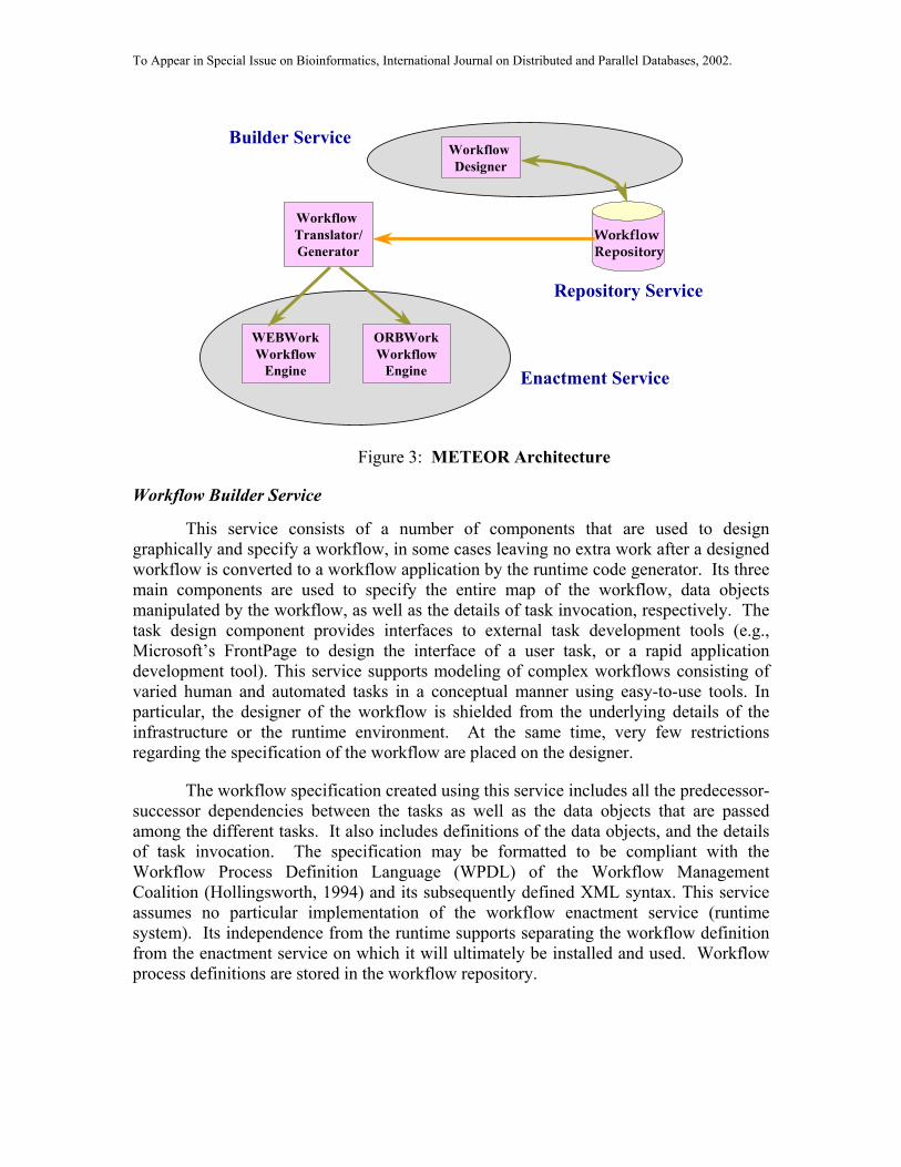
METEOR is a comprehensive Workflow Management System. METEOR’sarchitecture includes a collection of four services: Workflow Builder, WorkflowRepository, Workflow Enactment, and Workflow Manager. Workflow Enactmentincludes two services: ORBWork and WebWork. Both ORBWork and WebWork usefully distributed implementations. WebWork (Miller et al., 1998), an entirely Web-basedenactment service, is a comparatively light-weight implementation that is well-suited fora variety of enterprise workflow process applications that involve limited data exchangeand do not need to be dynamically changed. ORBWork (Kochut et al., 1999) (used in thisproject) is better suited for more demanding, mission-critical enterprise applicationsrequiring high scalability, robustness and dynamic modifications. The overall architectureof the system is shown in Figure 3.
To Appear in Special Issue on Bioinformatics, International Journal on Distributed and Parallel Databases, 2002.
Workflow Designer
Workflow Repository
Builder Service
WEBWorkWorkflow
Engine
Workflow Translator/Generator
ORBWorkWorkflow
Engine Enactment Service
Repository Service
Figure 3: METEOR Architecture
Workflow Builder Service
This service consists of a number of components that are used to designgraphically and specify a workflow, in some cases leaving no extra work after a designedworkflow is converted to a workflow application by the runtime code generator. Its threemain components are used to specify the entire map of the workflow, data objectsmanipulated by the workflow, as well as the details of task invocation, respectively. Thetask design component provides interfaces to external task development tools (e.g.,Microsoft’s FrontPage to design the interface of a user task, or a rapid applicationdevelopment tool). This service supports modeling of complex workflows consisting ofvaried human and automated tasks in a conceptual manner using easy-to-use tools. Inparticular, the designer of the workflow is shielded from the underlying details of theinfrastructure or the runtime environment. At the same time, very few restrictionsregarding the specification of the workflow are placed on the designer.
The workflow specification created using this service includes all the predecessor-successor dependencies between the tasks as well as the data objects that are passedamong the different tasks. It also includes definitions of the data objects, and the detailsof task invocation. The specification may be formatted to be compliant with theWorkflow Process Definition Language (WPDL) of the Workflow ManagementCoalition (Hollingsworth, 1994) and its subsequently defined XML syntax. This serviceassumes no particular implementation of the workflow enactment service (runtimesystem). Its independence from the runtime supports separating the workflow definitionfrom the enactment service on which it will ultimately be installed and used. Workflowprocess definitions are stored in the workflow repository.

To Appear in Special Issue on Bioinformatics, International Journal on Distributed and Parallel Databases, 2002.
Workflow Repository Service
The METEOR Repository Service is responsible for maintaining informationabout workflow definitions and associated workflow applications. The graphical tools inthe workflow builder service communicate with the repository service and retrieve,update, and store workflow definitions. The tools are capable of browsing the contents ofthe repository and incorporating fragments (either sub-workflows or individual tasks) ofalready existing workflow definitions into the one currently being created. Therepository service is also available to the enactment service (see below) and provides thenecessary information about a workflow application to be invoked.
The first version of the repository service was based on the Interface I API, asspecified by WfMC (Hollingsworth, 1994). Subsequently, we have built the secondversion of the workflow repository (Arpinar et al., 2001), in which workflows are storedas XML-documents to facilitate their Web-interchange on a distributed system managedby METEOR. The researcher (or a service of the METEOR system itself) can query theworkflow repository in order to introduce dynamic changes needed for workflowadaptation, as described later.
ORBWork Enactment System
The task of the enactment service is to provide an execution environment forprocessing workflow instances. Both ORBWork and WebWork have suitable codegenerators that can be used to build workflow applications from the workflowspecifications generated by the design service or those stored in the repository. In thecase of ORBWork, the code generator outputs specifications for task schedulers (seebelow), including task routing information, task invocation details, data object accessinformation, user interface templates, and other necessary data. The code generator alsooutputs the code necessary to maintain and manipulate data objects created by the datadesigner. The task invocation details are used to create the corresponding “wrapper”code for incorporating legacy applications with relative ease. The management servicesupports monitoring and administering workflow instances as well as configuration andinstallation of the enactment services.
Adaptability and Dynamic Workflows
Recently, there has been an increasing interest in developing WfMSs capable ofsupporting adaptive and dynamic workflows. Such systems must be uniquely sensitive toa rapidly changing process execution triggered by collaborative decision points, context-sensitive information updates, and other external events. The majority of current workaddresses relevant issues at modeling and language levels (Krishnakumar and Sheth,1995; Ellis et al., 1995; Jablonski et al., 1997, McClatchey et al., 1997; Han and Sheth,1998; Reichert and Dadam, 1998) while the relevant issues involving organizationalchanges appear in (Ellis et al., 1995; Hermann, 1995). A particularly different approachto supporting adaptive workflow (capable of reacting to the changes in local rules andother conditions) has been developed using the notion of migrating workflows) (Cichockiet al., 1997). Related issues of integrating workflow or coordination technologies andcollaborative technologies are investigated in (Guimaraes et al., 1997; Sheth, 1997).

To Appear in Special Issue on Bioinformatics, International Journal on Distributed and Parallel Databases, 2002.
ORBWork utilizes a fully distributed scheduler in that the schedulingresponsibilities are shared among a number of participating task schedulers, according tothe designed workflow map (Kochut et al., 1999). Each task scheduler receives thescheduling specifications at startup from the Workflow Repository (currently, therepository service sends the specifications via the HTTP protocol). Each set of taskspecifications includes the input dependency (input transitions), output transitions withassociated conditions, and data objects sent into and out of the task. In the case of ahuman task (performed directly by an end-user), the specifications include an HTMLtemplate of the end-user interface page(s). In the case of a non-transactional automatictask (typically performed by a computer program), the specifications also include a taskdescription and the details of its invocation. Finally, in the case of a transactional task,the specification includes the details of accessing the desired database and the databasequery.
When a task is ready to execute, a task scheduler activates an associated taskmanager. The task manager oversees the execution of the task itself. Figure 4 presents aview of the ORBWork’s distributed scheduler. Note that scheduling components and theassociated tasks and task managers are distributed among four different hosts. Theassignment of these components to hosts can be modified at runtime.
The partitioning of various components (scheduler’s layout), including taskschedulers, task managers and tasks, among the participating hosts is flexible. AnORBWork administrator may move any of the components from one host to another. Inthe fully distributed layout, it is possible to place all of the workflow components ondifferent hosts.
TASKScheduler
TASKScheduler
TASKScheduler
TASKScheduler
TASKScheduler
TASKManager
TASKManager
TASKManager
TASK TASK
TASKHOST 1
HOST 2
HOST 3
HOST 4
Figure 4: ORBWork’s Distributed Scheduler
Each task scheduler provides a well-constrained subset of the HTTP protocol, andthus implements a lightweight, local Web server. This enables an ORBWorkadministrator to interact directly with a selected task scheduler and modify its scheduling

To Appear in Special Issue on Bioinformatics, International Journal on Distributed and Parallel Databases, 2002.
specifications from a common Web browser. It also enables the end-user to accessworkflow instances residing on the task’s worklist. This set up naturally supports amobile user.
The ORBWork scheduler and its supporting components have been designed insuch a way that the enactment service can be used to support a variety of dynamicchanges both to the workflow schema and to the individual workflow instances. Theworkflow administrator can easily modify the workflow schema at runtime by acquiringnew information from the workflow repository, or even by modifying the specification bydirect interaction with the scheduler.
We divide the dynamic changes in ORBWork into two categories: primitivechanges and composite changes. A primitive change is composed of “atomic” changesthat can only be applied to a process definition totally or not applied at all (e.g., adding asynchronous transition between two tasks). A composite change is composed of asequence of primitive changes that describe a complicated process definition change(e.g., adding a task between two existing tasks can be achieved by applying a sequence ofprimitive changes as we will see in the following sections). Primitive changes can befurther divided into immediate changes and incremental changes. Immediate changes arechanges that can be introduced into workflow run-time in one step without losing thecorrectness and consistency of the workflow. In the context of ORBWork run-time, onestep means reloading the necessary process definition files. On the other hand, there aresituations when we cannot apply the changes to a particular task in “one shot”. Considerthat we want to change the input/output dependencies of a task, where several workflowinstances are pending on this task (waiting for necessary transitions from the predecessortasks in order to invoke the task). If we just update the task specifications without takingcare of all these already existing workflow instances, they may work incorrectly.Incremental changes address that problem. Such changes are introduced into theworkflow enactment system step by step and guarantee the correctness and consistency ofthe whole workflow system. In practice, most of the primitive changes in a workflowsystem are incremental.
Another very important issue of implementing a dynamic workflow system ishow should different versions of a workflow/task schema the workflow enactment systemsupport. We say that a particular task is in a stable state if all input/output dependencies,input/output parameters of the workflow instances residing on that task scheduler, are thesame. Consider the following scenario: A workflow system is normally running and withseveral instances working simultaneously. The workflow administrator decides to dosome changes to the input dependencies of a task and several instances are under thecontrol of this task’s scheduler. From the earlier discussion, we know that some instancesshould still use the old input dependency schema while new instances should use the newversion of the input dependencies. At some time, the task scheduler may be schedulingtwo workflow instances with different input dependencies. In such a case, the task isunstable. Moreover, if we try to change the input dependencies of that unstable task, thetask scheduler will finally have three different versions of input dependencies. If theadministrator keeps making changes, the task scheduler may have four, five, six or more
To Appear in Special Issue on Bioinformatics, International Journal on Distributed and Parallel Databases, 2002.
input dependency versions. In our current implementation, we only allow two versions ofa process definition to exist for the workflow instances residing on a particular task.
An additional issue worth mentioning here is how to suspend the task scheduler.When dynamic changes are introduced to a particular task, we will force the ORBWorkruntime to suspend that task scheduler. In our implementation, we divide the suspendoperation into three different types: suspend input transition; suspend output transition;suspend both input/output transitions. After applying the “suspend input transition”operation, no workflow instance is allowed to “flow” to this task by making a transitioncall on this task’s scheduler. Similarly, the “suspend output transition” operation keepsany existing workflow instance on that task from making a transition call to a successortask’s scheduler. The third suspend operation is the combination of the previous two.
A detailed description of possible changes and how they are implemented is described in(Chen, 2000). The types of dynamic modifications currently offered in ORBWork arepresented in Table 1. However, sometimes a predefined schedule of tasks may need to bealtered for just a single workflow instance, without introducing permanent changes to theworkflow schema. The ORBWork process manager allows the per-instance changes ofsimilar types as described above, but only those associated with a single instance, ratherthan with the whole workflow schema. The changes cease to exist, once the instancecompletes. Theoretical aspects of introducing dynamic changes to workflow systems areexamined in (Aalst and Basten, 1999).

To Appear in Special Issue on Bioinformatics, International Journal on Distributed and Parallel Databases, 2002.
Change Type Change Type After the change
AND to OR Join incremental A single predecessor tasks needs to be completed inorder to execute a given task
OR to AND Join immediate All of the predecessor tasks need to be completed inorder to execute a given task
AND to OR Split immediate A single successor task will be activated after a giventask completes
OR to AND Split immediate All successor tasks will be activated after a given taskcompletes
Add ANDTransition
incremental One more task will be activated after a given taskcompletes
Add ORTransition
immediate One more task may be activated after a given taskcompletes
Delete Transition incremental A given transition will not be attempted (either ANDor OR)
Add ObjectTransfer
incremental One more data object will be transferred along a giventransition
Delete ObjectTransfer
incremental A data object will not be transferred along a giventransition
ParameterMapping Change
incremental An incoming data object will be assigned to adifferent parameter of a given task
Parameter TypeChange
incremental A given task will accept a new data object type for agiven parameter
Task Type Change incremental A different task type (e.g. automatic instead ofhuman) will be invoked
Task InvocationChange
composite A different task will be invoked (but within the sametask type)
Insertion of a Task composite A new task will be performed, if enabled
Deletion of a Task composite A given task will not be performed
Table 1: Types of dynamic modifications available in ORBWork
Support for Scalability and Fault Tolerance
The fully distributed architecture of ORBWork yields significant benefits in thearea of scalability. As mentioned, all of the workflow components of a designed anddeployed workflow (this includes individual task schedulers, task managers, and taskprograms) may be distributed to different hosts. However, in practice it may be sufficientto deploy groups of less frequently used task scheduler/manager/programs to the same
To Appear in Special Issue on Bioinformatics, International Journal on Distributed and Parallel Databases, 2002.
host. At the same time, heavily utilized tasks may be spread out across a number ofavailable workflow hosts, allowing for better load sharing.
The features of ORBWork designed to handle dynamic workflows are also veryuseful in supporting scalability. As load increases, an ORBWork administrator may electto move a portion of the currently running workflow to a host (or hosts) that becomeavailable for use in the workflow. The migration can be performed at the time thedeployed workflow is running. Simply, the workflow administrator may suspend andshutdown a given task scheduler and transfer it to a new host. Because of the way taskschedulers locate their successors, the predecessors of the moved task scheduler will notnotice the changed location of the task. If the associated task must be executed on aspecific host (for example it is a legacy application), the associated task manager may beleft in place, while only the scheduler is transferred.
In the case that a group of task schedulers is deployed to the same host, theORBWork administrator has the option to combine them into a single “master”scheduler. Such a master scheduler controls a number of individual task schedulers thatshare the same heavyweight process. This allows the administrator to control theutilization of the participating host even further, while having many individual operatingsystem-level processes (task schedulers) could potentially burden the host system.
The distributed design of ORBWork offers no single point of failure for anongoing workflow instance. Since the individual task schedulers cooperate in thescheduling of workflow instances, a failure of a single scheduler does not bring the wholesystem down, and other existing workflow instances may continue execution.
The error handling and recovery framework for ORBWork (Worah et al., 1997)has also been defined in a scalable manner. All errors are organized into error classhierarchies, partitioning the recovery mechanism across local hosts, encapsulating andhandling errors and failures as close to the point of origination as possible, andminimizing the dependence on low-level operating system-specific functionality of thelocal computer systems. Complementary work on exception handling, especially onfinding alternatives to deal with exceptions, is described in (Luo et al., 2002).
3. Discovering Protein-Protein Interactions
With the completion of the sequencing of the human genome and that of othermodel systems a major new direction has been the characterization of the proteome, thecollection of all proteins in the cell, to figure out what cells are doing besides datastorage. The genetic blueprint is here. The genome is known. What functions does thegenome encode and program through the Central Dogma?
One new direction is to identify all of the proteins produced by the geneticblueprint. In this way we obtain a task list for the organism. This effort has led in anumber of directions because in many ways protein structure is much richer than that of

To Appear in Special Issue on Bioinformatics, International Journal on Distributed and Parallel Databases, 2002.
DNA. One direction is simply to isolate and characterize all the proteins in the cell.Isolating proteins allows biochemists to examine their function.
From here several directions can be chosen. One direction has been identifyingthe structures of all proteins in the cell (Skolnick et al., 2000). High-throughput methodsfor obtaining molecular structures on all proteins are being developed. These molecularstructures provide valuable insights into how proteins carry out their tasks. Proteins,unlike DNA, have a vast repertoire of structures to carry out the diversity of functions.
Once the proteins are identified and characterized, a second interest is how theyassemble into the molecular machines that carry out the work in the cell. Some of theselarger cooperative structures in cell have names like the transcriptosome, splicesome,proteasome, ribosome, cytoskeleton, mitochondrion, circadian clock, spindle, and MAPkinase cascades to carry out basic processes in the cell like transcription, RNA splicing,translation, energy metabolism, cell division, and signaling (Vidal, 2001).
Identifying all of the protein-protein interactions is fundamental to searching forconnections relevant to a particular process, such as the link qa-1Sp/qa-1Fp in thebiological circuit of Figure 1. Knowing which proteins work together is part ofspecifying the biological circuit describing a particular biological process. The collectionof protein-protein interactions can be visualized as a map, in which proteins are the nodesand the edges are the interactions (Figure 5). A protein-protein interaction network ormap then represents a search grid on which biological circuits are constructed. The maptells the researcher what connections he or she may need to consider in the circuit.
Figure 5: Protein-Protein Interaction Map of S. cerevisiae from (Ito et al., 2000) visualized as a“Protein Mobile”.
We refer to this Calder-like visualization of a protein-protein interaction map as a“protein mobile”. The goal of this paper is to describe a distributed automated workflowto generate this protein mobile accessible over the Web (Fang, Miller, and Arnold, 2002;Kraemer et al., 2001). The example shown is part of the protein-protein interaction mapfor the yeast S. cerevisiae (Ito et al., 2000). Eight composite steps comprise theworkflow to generate such a map.

To Appear in Special Issue on Bioinformatics, International Journal on Distributed and Parallel Databases, 2002.
Step 1 (GetGenes). In eukaryotic systems like humans a major complication isidentifying all of the genes that produce the proteins. The complication is that genes ineukaryotes contain regions of DNA called introns, which are not transcribed. The intronsare cut out of primary transcript to form mature transcript. A geneticist can isolate all theRNAs in a cell and reverse the process of transcription with the enzyme reversetranscriptase to make complementary DNAs or cDNAs that identify correctly what DNAsequence is ultimately used to make a protein. These cDNAs can be used to create alibrary of clones called a cDNA library. The first step in the process of identifying allprotein-protein interactions is to make a large cDNA library that contains most of thegenes in the organism with the introns conveniently spliced out. Ultimately, this cDNAlibrary can be used to make the proteins needed to test for interactions among them.
The main limitation of this strategy to get to the DNA sequence encoding aprotein is that cDNA libraries typically do not have all of the genes. Alternativestrategies are resorted to. One of these is computational. A large clone is sequenced, andalgorithms for gene identification are utilized based on the grammar of DNA to identifygenes (Kraemer et al., 2001). Then the genes are extracted directly from the clone by atechnique known as polymerase chain reaction, a way to amplify a specific region ofDNA from a DNA source like a clone.
Step 2 (GenExpLib sub-workflow). The next step is to build an interactiondetector. A standard way to detect interactions is the yeast S. cerevisiae 2-hybrid system.The goal is to use proteins in the cell to reconstitute a transcriptional activator like GAL4in S. cerevisiae and to hook up the transcription factor to a collection of reporter geneswhich come on only when the protein-protein interaction is present. The GAL4 gene hastwo parts, an activation domain (AD) and a binding domain (BD). The AD-domaininteracts with another protein to turn on transcription. The binding domain binds to theDNA to activate transcription. The reporter genes are put downstream of the AD-domainto report transcription.
To test for an interaction, one cDNA is fused to the AD-domain. Another cDNAis fused to the BD-domain. If the two cDNAs ultimately produce proteins that interact,then the activation domain (AD) will be brought together with the binding domain (BD)to reconstitute the GAL4 protein, and transcription will be initiated. The library ofcDNAs fused to the AD-domains is referred to as the library of prey clones. They are thekey that enters the lock. The library of cDNAs fused to the BD-domains is referred to asthe library of bait clones. They are the lock waiting for the key. When the bait and preycome together through the protein-protein interaction, the GAL4 protein is reconstituted,and transcription initiates. In summary, Step 2 is to build the bait and prey libraries.
Step 3 (GenExpLib sub-workflow). Neurospora crassa has ~11,000 genes, andit is not possible to screen one by one for the 121,000,000 possible interactions. Insteadwe use the fact that most proteins do not interact with each other. Instead of screeningeach pair of potential interactors one at a time, we create pools of bait or prey. There arethree pooling strategies that have been used to date.
96 prey encounter 96 bait. In this strategy pools of 96 bait and 96 prey clonesare created separately, and the pools are ultimately tested against each other (Ito et al.,2000). Each such experiment tests for one or more interactions in a pool of ~10,000

To Appear in Special Issue on Bioinformatics, International Journal on Distributed and Parallel Databases, 2002.
interactions. In this way, (Ito et al., 2000) screened about 10% of the 36,000,000possible interactions in the yeast S. cerevisiae.
1 prey encounters an array of all baits. In this strategy all bait clones arerobotically arrayed on solid media where the individual proteins are expressed (Uetz etal., 2001). In the case of N. crassa, this would mean arraying up to 11,000 differentgenes on solid media and introducing one prey at each point on the array to test for theinteraction. This approach is more easily automated than the first strategy.
All prey encounter 96 baits. In this strategy a mixture of all prey clones in theprey library is created and then tested against a plate of of 96 baits (Uetz et al., 2001).The entire prey library is allowed to interact with each of the 96 baits individually. Thisprotocol constitutes a high-throughput screen. The plates of 96 baits can be processedrobotically. The pool of prey is large. This allowed the creation of the first protein-protein interaction map for the yeast S. cerevisiae (Uetz et al., 2001). The limitation isthat there are many more false positives in this screen than strategies 1 or 2. This strategyprovides a rough sketch of the map, while the first or second strategy provide detailedsketching.
In that there is a mixture of strategies available, the workflow needs to beadaptive. First, the entire portrait of the protein-protein interaction map needs to beobtained, and then the details need to be sketched in. As interesting connected subsets inthe map are uncovered, likely to correspond to interesting molecular machines, a switchneeds to be made to a more detailed sketching process. Also, the workflow needs to beadaptive in the sense that new technologies will come on line to detect protein-proteininteractions more effectively, and these new technologies need to be introduced into theworkflow. Finally, each detector is characterized in part by its false positive rate andfalse negative rate in detecting interactions. As researchers gain more experience inbuilding these maps, there will be an evolution in quality standards that will also mandatealterations in the workflow.
Step 3 of the workflow is to create the bait and prey pools of cDNAs, which areultimately used to test for a protein-protein interaction.
Step 4 (IDRemGen and InterMating). In step 4, the bait and prey pools ofclones are brought together to detect the interaction. The mechanism for bringing themtogether is called an interaction mating (Hudson et al., 1997). A female strain (alpha) ofthe yeast S. cerevisiae is transformed with the pool of bait clones; a male strain (a) of theyeast S. cerevisiae is transformed with the pool of prey clones. Transformation is theprocess of introducing foreign DNA into a host; the strains of S. cerevisiae are thencapable of expressing the proteins of interest. The female and male strains are mated tobring the bait and prey pools together. In strategy 2 this means simply pinningrobotically each bait strain on the solid media with the prey strain. Those grid pointswith the reporter genes on can be visually scored on the array. Step 4 is the interactionmating bringing bait and prey together. The resulting images of the arrays or thepositives on plates can be digitally captured.
A number of controls are introduced at this point to confirm the interaction.Three reporter genes exist downstream of the BD ('bait') gene, and each of the reportersgive a vote on whether or not the interaction is real. A separate experiment highlights the
To Appear in Special Issue on Bioinformatics, International Journal on Distributed and Parallel Databases, 2002.
vote of each reporter gene. In strategy 2, for example, three arrays need to be generated,one for each reporter gene to score visually whether or not a particular reporter genevotes yes to the interaction.
It is possible to alter the threshold of the detector for one reporter gene simply byadding an inhibitor called 3AT to poison the protein product of one reporter gene. Thepresence of the inhibitor means that the detected protein-protein interaction must bestronger to counteract the effects of the inhibitor. In strategy 2, each threshold selected asindexed by the 3AT concentration used in the solid media operates the detector at adifferent threshold.
Lastly, different protein pairs may or may not interact in the yeast S. cerevisiae. Itis possible to repeat the whole experiment in a different host like E. coli in order toreduce false negatives in the interaction detector.
As a consequence, the workflow is inherently adaptive depending on the structureof the protein-protein interaction map, the interesting features in the uncovered map, andwhat regions of the table of all possible interactions are missing.
Step 5 (RobotPickColonies). In step 5, we need to identify what genes arepositive in the pools. In strategy 1, we do not know which of the 96 prey reacted withwhich of the 96 baits. The positives are robotically picked. The DNA of the positives isextracted and sequenced. By comparing the resulting sequences of the bait and preyclones, we can positively identify the partners that are interacting. These sequences aresometimes referred to as Interaction Sequence Tags (ISTs), and they allow screening forthe protein-protein interactions based on the availability of the genomic sequence of theorganism of interest. Step 5 is the identification of the interactors by sequencing.
Step 6 (FGDB). In step 6, the interactors identified through their ISTs are loadedinto the Fungal Genome Database FGDB (Kochut et al., 1993). The FGDB database isweb-accessible at http://gene.genetics.uga.edu to the scientific community to make use ofthe information. Step 6 involves storing, retrieving, releasing, and sharing the ISTS overthe Web from FGDB.
Step 7 (Layout). Once the ISTs are available, the data are ready to be assembledinto a protein-protein interaction map. The strongly connected components in the graphwill allow the identification of putative protein complexes. Several algorithms for layingout these maps have been coded in Java and tested (Zhang, 2001). While the ISTs can bestored as tables of all the directional pairwise interactions in a relational database, theonly way to begin to make sense of this information is graphically. A criticalintermediate step in visualization is assembling the graph describing the protein-proteininteractions and highlighting its features on the graph. The nodes of the graph areproteins, and the directed edges are the interactions. The graph captures the biology andis ultimately rendered in various forms like the protein mobile in Figure 5, which is ofgreat interest to biologists. There are many difficult algorithmic problems withidentifying this graph. Interacting with the graph is believed to be key to locatingbiologically relevant clusters. Step 7 is assembling the protein-protein interaction map asrepresented in a graph.
Step 8 (J3DV). The last step in the workflow is visualizing the protein-proteininteraction map over the Web. To this end a Java-based server was created to provide the

To Appear in Special Issue on Bioinformatics, International Journal on Distributed and Parallel Databases, 2002.
interface between FGDB and Java objects for map rendering (Fang et al., 2002). Second,a Java 3D client software was created to visualize the map (Tian, 2001; Zhang, 2001).The map is rendered over the Web and provides a view of the data allowing adaptation ofthe workflow and interpretation of the protein-protein interaction mapping data. The laststep is visualizing the protein-protein interaction map before returning to Step 1 tocontinue map construction.
Each of the composite tasks above contain about 10 individual tasks, and so inStrategy 3, for example, it would be necessary to execute an instance through theworkflow about 500 times. Each instance has at least one control. We are talking aboutmanaging the execution of ~75,000 tasks with an automated workflow. The tasksthemselves are distributed between several experimental locations and over severalcomputers and robots. For example, the libraries are generated in one laboratory, and therobots are located in a different laboratory. The FGDB is located on one server, and themap assembly routine is located on a different server. Image capture involves otherworkstations.
4. IntelliGEN: Workflow For Protein-Protein Interaction DiscoveryIntelliGEN is a comprehensive system for genomic data and process management.
It implements the overall workflow, as described above. It reuses in part two of ourearlier works: (b) GeneFlow (Hall et al., 2002) build as part of a laboratory informationsystem for managing distributed high throughput sequencing, which supports steps6through 8 of the overall workflow, and (b) graphical tools to visualize the mapping andsequencing data (Hall et al., 2001a). The graphical database tools also support XMLmessaging to exchange genomic information with other databases and applications (Xu etal., 2001). While earlier workflow systems have been used to automate laboratoryexperiments (Bonner et al., 1996, Goodman et al., 1998), we believe that currentadvances in adaptive workflow technologies can improve dramatically the quality ofexperiments by optimizing laboratory workflows.
In the near term, the core objective of the proposed system is running protein-protein interaction mapping workflows. However, we plan to use the system in othertypes of genomic workflows to automate identification of a biological circuit. The rest ofthis section contains a brief discussion of the specific capabilities of IntelliGEN. Thearchitecture of IntelliGEN is shown in Figure 6.

To Appear in Special Issue on Bioinformatics, International Journal on Distributed and Parallel Databases, 2002.
Figure 6: IntelliGEN Architecture
IntelliGEN’s workflow network is presented in Figure 7 (GeneFlow is asubworkflow of this workslow; its tasks are not shown), and a subset of this workflow isused to process the ISTs (Interaction Sequence Tags). These workflow networks arepresented here as screen shots of METEOR’s Builder service. The top-level proteininteraction workflow includes some high-level network tasks (which include furthertasks, acting as subworkflows), such as GetGenes, GenExpLib, IdRemGen, InterMating,and RobotPickColonies. These high-level steps correspond to getting genes from a cDNAlibrary or cosmid library, generating expression libraries by recombinational cloning,eliminating spontaneously activating genes from the mapping experiments, performinginteraction matings and finally robotically screening (picking) positive interactions,respectively. These tasks are further divided into several sub-tasks. As an illustration, theinternal tasks of GetGenes are depicted in Figure 8.
W ORKFLOWDESIGNER
FUNGAL GENOM E DATABASE
CORE
TASK
TASK
WEB
DB
M OBILETASK
MANAGER
TASK
TASKM ANAGER
TASK
TASKM ANAGER
TASKM ANAGER
TASKMANAGER
MOBILETASK
QUALITYM ONITOR
M ETEOR-ORBW orkFUNGAL GENOM E
PROCESS M ANAGER
XM L M APPINGTOOL
QUALITY M ETRIC SPECIFICATION
TOOL
QUALITY M ETRIC SPECIFICATION
TOOL
INTELLIGENT ADAPTATION& SIM ULATION AGENTS

To Appear in Special Issue on Bioinformatics, International Journal on Distributed and Parallel Databases, 2002.
Figure 7: Graphical Design Tool Displaying Top-Level Protein Interaction Workflow
Figure 8: The Details of GetGenes Sub-Workflow
The GetGenes subworkflow may be initiated by obtaining genes from our cDNAlibraries or from our cosmid libraries (Kelkar et al., 2001). The subsequent steps includethe following activities: Clones are chosen from a library for protein-protein interactionmapping. If we elect to get genes from the cosmid libraries, genes are identified (Kraemer

To Appear in Special Issue on Bioinformatics, International Journal on Distributed and Parallel Databases, 2002.
et al., 2001). DNA is extracted from the cosmid; a particular gene amplified by PCR andrecombinationally cloned into a Gateway entry vector pENTR 1A; alternatively, a cDNAcollection in a Gateway entry vector is accessed, a plate pulled, and the associated genesbeing processed with their associated BLAST reports are displayed (not shown). All ofthese activities require numerous software components and a laboratory informationsystem is used to track micro-titer plates and data, forwarding the relevant information tothe follow-up tasks in the workflow. As data are tracked, an adaptive component isneeded to suggest corrective action when a failure occurs during the workflow so that thethroughput is sustained, or when a new interesting interaction is discovered.
In Table 2, we list some of the well-known biological software systems used inthe protein interaction workflow. The individual tasks in this workflow are spread acrossseveral UNIX servers at UGA in two laboratories and a central location. TheASSEMBLY_1 and ASSEMBLY_2 sub-workflows are executed on separate servers.The annotation sub-workflow, which is computation intensive, is executed on a 32processor SGI Origin 2000 server. The remaining tasks run on another server. Roleswere created for sequence finisher, submitter, and annotator. The Web interface toMETEOR creates URL’s for each role with links to all tasks associated with that role.
ASSEMBLY_X Phred (Ewing and Green, 1998)PhrapConsed (Gordon et al., 1998)
Base CallingSequence AssemblyEditing and Primer Design
HTG_Submission Sequin Submits sequence to NCBI
ANNOTATION BLAST (Altschul et al., 1997)GeneMark.hmm
Sequence Similarity SearchGene identification
Table 2: Comonly used biological software systems incorporated in IntelliGEN
In the final step of the workflow, in which a researcher is creating the protein-proteininteraction map, we use a software system to assist the researcher in constructing themap. A screen shot of the tool (invoked automatically by IntelliGEN) is presented as anillustration in Figure 9.
IntelliGEN incorporates subsystems for quality measurement and intelligent adaptation.These two novel components are briefly described in the following two sections.

To Appear in Special Issue on Bioinformatics, International Journal on Distributed and Parallel Databases, 2002.
Figure 9: Screen shot of the protein-protein interaction layout tool
4.1. Quality of Service Management
Workflow systems have been used to support various types of processes for morethan a decade now. Workflows modeling genomic applications, such as proteininteraction mapping, require the specification of Quality of Service (QoS) items such asproducts to be delivered, deadlines, quality of products, quality of information (e.g.,accurate protein interaction maps), reliability, and cost of services (Cardoso, et al. 2002).
Low-level script-based applications or other traditional workflow approaches donot permit flexible specification and realization of such quality requirements. Thus, theyare less suitable for mission critical applications such as a protein interaction workflow.A vital goal is the ability to construct and deploy truly dependable workflows withcontinuous availability and predictable QoS metrics.
The management of QoS metrics directly impacts the success of genomicexperiments. Therefore, when experiments are created or managed using workflows, theunderlying workflow system must accept the specifications and be able to estimate,monitor, and control the QoS of processes.
For genomic laboratories, being able to characterize workflows based on QoS hasfour direct advantages. First, it allows laboratories to translate their experiments into theirprocesses more efficiently, since workflow can be designed according to QoS metrics.Second, it allows for the selection and execution of workflows based on their QoS, tobetter follow experimental strategies. Third, it makes possible the monitoring ofworkflows based on QoS. QoS monitoring allows adaptation strategies to be triggeredwhen undesired metrics are identified or threshold values violated. Fourth, it allows for

To Appear in Special Issue on Bioinformatics, International Journal on Distributed and Parallel Databases, 2002.
the evaluation of alternative strategies when adaptation is necessary. The environmenthas an important impact on the strategies, methodologies, and structure of geneticworkflows. Thus, in order to complete a workflow according to the initial QoSrequirements, the workflow will likely be adapted, modified, and rescheduled, due tounexpected progress delays, or technical conditions. When adaptation is necessary, a setof potential alternatives is generated with the objective of changing a workflow, such asits QoS continues to meet initial requirements. For each alternative, prior to actuallycarrying out the adaptation, it is necessary to estimate its impact on the QoS of themodified workflow.
We have enhanced our workflow system to support processes constrained by QoSrequirements, such as the protein interaction workflow. The enhancements include thedevelopment and support of a comprehensive QoS model and the implementation ofmethodologies (a mathematical model and simulation) to compute and predict workflowQoS. We have developed a stochastic workflow reduction algorithm (SWR) for the step-by-step computation of QoS metrics.
One of the main modules, the Quality Monitor, oversees the execution of theworkflows and checks the quality of produced data according to QoS specifications. Ifthe quality drops below a certain threshold the Intelligent Adaptation subsystem isinvoked to suggest corrective actions and adapt the workflow (as described in thefollowing subsection) so that the initial QoS requirements can be met.
The quality monitor displays QoS metrics in several formats. It is possible tocolor code the protein-protein interaction by whether or not a particular link is supportedby two or more experiments, the number of votes for the interaction by the 4 reporters,and the number of controls satisfied in Figure 5 (Zhang, 2001). Another possibility is thetraditional quality control chart with the measures of quality on the y-axis and the courseof the experiment (i.e., plate number in the high-throughput screen) on the x-axis. In thehigh-throughput screen, quality measures include false negative and false positive ratesper plate, the average number of positive votes per positive from one bait plate, thenumber of controls satisfied per bait plate, and estimated coverage.
4.2. Adaptation
Traditional WfMSs are adequate to support workflows with a defined structureand with no need to account for ad hoc deviations or dynamic extensions at run-time(Reichert and Dadam, 1998). But, recently there has been an increasing demand indeveloping WfMSs with dynamic capabilities, with a special emphasis to dynamicchanges at the instance level. This makes sense since there are in reality very fewworkflows that are static (i.e. without a need to change their structures over time). Asworkflow processes are instantiated, changes in the environment or in previous activitiesmay invalidate the current workflow instances, requiring adaptation procedures to becarried out. It is therefore important to be able to continuously repair or improve theexecution of a workflow process (Berry and Myers, 1998).
A critical challenge for the IntelliGEN management system is its ability torespond effectively to changes. Changes may range from ad-hoc modifications of the

To Appear in Special Issue on Bioinformatics, International Journal on Distributed and Parallel Databases, 2002.
process for a single experiment due to a control failing, improvement in the process toincorporate a new technique or instrument, or to a restructuring of the process to improveits efficiency. For example, it may happen that gene identification evolves to the pointthat gene extraction from an available cosmid library becomes feasible (Kelkar et al.,2001; Hudson et al., 1997) as opposed to extracting genes from a cDNA library. As aresult, the run-time process used in practice is often much more variable than the processspecified at design-time. It has been our experience in physical mapping and sequencingthat workflows are constantly being improved. If the researchers are forced to bypass theworkflow management system quite frequently, the system becomes more a liability thanan asset. Thus, in ORBWork system we have implemented a layer that permits therealization of dynamic change of instances in a consistent manner (Chen, 2000). Theimplemented module guarantee that all consistency constraints that have been ensuredprior to a dynamic change are also ensured after the workflow instances have beenmodified (Reichert and Dadam, 1998).
When adaptation is required in the protein-protein interaction workflow, it isnecessary to evaluate alternatives with the objective of changing the workflow such as itsQoS continues to meet initial requirements. Adaptation procedures are evaluated basedon their impact on workflow QoS that include: 1) time of execution; 2) cost of execution;3) and quality of execution. The application of a specific adaptation procedure isconstrained with the objectives set by the initial project and includes: 1) time remaining;2) budget remaining; 3) and current measures of quality like coverage, false positive rate,and false negative rate.
Some of the changes include the type of screen, the controls to be executed, the3AT concentration, and the type of interaction trap. To make today’s workflowmanagement systems more flexible, it is crucial to know what kind of changes need to besupported. Changes can be triggered by developments outside the management system,i.e., the context/environment. There are three basic types of external circumstances thatmay trigger a change in the protein-protein interaction workflow: (1) discovery (e.g. of anew molecular machine), (2) changing quality standards (i.e., the change is triggered byrefinements to the map of quality standards), (3) changing technology for detectingprotein-protein interactions (i.e., due to the development of new technologies or changesin the technical infrastructure). A change can also be triggered by developments insidethe system. These changes are not initiated by the environment, but by problems detectedinside the management system itself (e.g., logical design errors or technical problems). Itis important to classify the type of changes that may occur. Thus, we characterizechanges as either ad-hoc or evolutionary changes:
Ad-hoc changes may be the result of an error, an exception, a rare event, or specialdemands created by the presence of a promiscuous protein. Ad-hoc changes affectonly one case (i.e., one bait plate) or a selected group of cases (a selected group ofplates). They occur on an individual or selective basis. In general, it is not necessaryto change the workflow definition, since the same change will likely not be neededagain. An example of an ad-hoc change is the need to skip a task in case of anemergency (i.e., the reagent 5FOA was degraded or the PCR kit failed). This type ofchange is often initiated by some external factor. Typical problems related to ad-hoc

To Appear in Special Issue on Bioinformatics, International Journal on Distributed and Parallel Databases, 2002.
changes are deciding what kinds of changes are allowed and the fact that it isimpossible to foresee all possible ad-hoc changes.
Evolutionary changes are of a structural nature. From a certain moment in time, theworkflow changes for all new instances created. It is possible that the existing runninginstances may be influenced. An evolutionary change is applied to a workflow as aresult of the adoption of a new mapping strategy, reengineering efforts, or a permanentalteration of external conditions (e.g., a change of interaction trap). Evolutionarychange is typically initiated by a researcher to improve efficiency, quality orresponsiveness to the community, or is forced by improved quality standards. As anexample, we have two strategies for creating the protein-protein interaction map. Onestrategy involves the high throughput screen and the other the clone-by-clone screen.They differ on the basis of the size of the bait and prey pools being interrogated. Thehigh-throughput screen is estimated to take 31 weeks to finish with a pool size of 96baits vs. the whole AD-library, but it is 3-fold less sensitive than the clone-by-clonescreen. In contrast, we can perform only about 650 clone-by-clone screens in a year.Once the map is sketched by the high-throughput screen, we want to turn to the clone-by-clone screen to color in the finer details of the map. Alternatively, once a humanobserver finds interesting clusters by the high throughput screen, more sensitive(although slower) clone-by-clone screens may be interjected to respond to communityinterest. Adaptive workflows can then be used to adjust the overall experimentalstrategy for finding protein-protein interactions using a task replacement policy.
Both ad-hoc and evolutionary changes are possible at entry time or and on-the-flyto running instances. Customizing the process definition for a single case before theprocessing is started corresponds to an ad-hoc change at entry time. If such acustomization is also allowed after a workflow processing is started, we define it as anon-the-fly change. If evolutionary changes are only possible at entry time, then only thenew cases that are started after the change took place have to run according to theupdated workflow definition; all other cases run according to the old workflow definition.On-the-fly evolutionary changes are more difficult to handle since for each runningworkflow instance it must be decided how to deal with the change (Aalst and Jablonski,2000). It is especially difficult to introduce changes while workflow instances are beingprocessed. For workflow instances that are active (started, but not finished) at the time ofthe change the transactional tasks (possibly subworkflows) can be rolled back, andrestarted under the new plan, or the instances in progress be allowed to continue underthe modified workflow.
4.3. System PerformanceThe nature of the protein-protein interaction workflow is that all of the tasks are of longduration. As an example, each of the high-throughput screens involves processing 500“bait” library plates in a 2-hybrid screen for interactions. Unassisted (manual) processingtypically takes one month per plate. Using IntelliGEN, we are able to process up to 16plates per week, which translates to 64-fold productivity gain.
Table 3 illustrates the duration of the individual steps of in the workflow. Thetimes are for an individual work item, which in the case of the protein-proteininteractions is processing of a single plate. As easily seen, the system overhead

To Appear in Special Issue on Bioinformatics, International Journal on Distributed and Parallel Databases, 2002.
introduced by IntelliGEN is negligible in comparison to the task processing time. Taskactivation time is below one second.
In addition, our estimate is that it will take approximately 75,000 task executionsto complete the project, which will take roughly 3 years. This translates to about 75 tasksper day, on average, a rather small number.
Task Time CommentsStep 1 overnight Mix of automatic and manual (human) tasksStep 2 1 day A manual taskStep 3 Less than 1 day A manual taskStep 4 4-5 days A manual taskStep 5 1-2 days Performed by a robotStep 6 1 day Largely automatic; sequence assembly and BLAST
searchesStep 7 Several minutes Human with computer assistance
Table 3: Approximate timings for individual workflow steps
5. Conclusions and Future ResearchWe have successfully applied workflow technology to a large genomic project of
mapping protein-protein interactions of fungi. We have built on the success of ourprevious workflow project for sequencing for N. crassa. It is an ongoing project andchanges are made to both the workflow engine, and the workflow specification, asnecessitated by the laboratory work. Because of the fact that we used our distributed anddynamic enactment system ORBWork, it is possible to make changes to the deployedsystem. In the near future, we intend to experiment with adding to IntelliGEN agentscapable of performing adaptive changes without human involvement.
The use of workflows and workflow systems to conduct and coordinate genomicexperiments in a heterogeneous and distributed environment has an immediateoperational requirement: the management of workflow quality of service. Theexperiments cannot be undertaken while ignoring the importance of quality of servicemeasurements. When adaptation is required, an adaptation agent will use QoSinformation – such as task the time and the cost of each task, and the final qualitystandards to be achieved (Cardoso et al., 2002) – to select a set of adaptation strategies tobe applied to a workflow requiring changes. In the case that the intelligent agent isattempting to maximize coverage given the budget and time constraints, it will benecessary to invoke a simulation agent. A protein-protein interaction can be simulated aspreviously described (Miller et al., 1995). The proposed strategy can be applied to manysimulations of the protein-protein interaction map, and an average coverage of thenetworks can be estimated. In this way different proposed workflows can be evaluatedwith respect to coverage.

To Appear in Special Issue on Bioinformatics, International Journal on Distributed and Parallel Databases, 2002.
References1. Aalst, W., and K. Hee, Workflow Management: Models, Methods, and Systems, MIT Press, January
2002.2. Aalst, W. and S. Jablonski. Dealing with Workflow Change: Identification of Issues and
Solutions. International Journal of Computer Systems, Science, and Engineering, 15(5):267-276, 2000.
3. Aalst W. and T. Basten. 1999. Inheritance of Workflows: An approach to tackling problemsrelated to change. Computing Science Reports 99/06, Eindhoven University of Technology,Eindhoven.
4. Altschul, S, T Madden, A Schaffer, J Zhang, Z Zhang, W Miller, and D Lipman 1997.Gapped BLAST and PST-BLAST: a new generation of protein database search programs.Nucleic Acis Research 25: 3389-3402.
5. Ansari, M, L. Ness, M. Rusinkiewicz, and A. Sheth 1992. “Using Flexible Transactions toSupport Multisystem Telecommunication Applications,” Proceedings of the 18th Intl.Conference on Very Large Data-bases, August 1992, pp. 65-76.
6. Arnold, J 1997. Editorial. Fungal Genetics and Biology 21:254-257.7. Arnold, J and MT Cushion 1997. Constructing a physical map of the Pneumocystis genome.
J. Euk. Microbiol. 44: 8S.8. Arpinar, B, J Miller, and A Sheth 2001. An efficient data extraction and storage utility for
XML documents, 39th ACM Southeast Conference, Athens, GA March 2001, pp. 293-295.9. Beadle, GW and EL Tatum. 1941. Genetic control of biochemical reactions in Neurospora.
Proceedings of the National Academy of Sciences USA 27:499-506.10. Bennett, JW and J Arnold 2001. Genomics of fungi. The Mycota VIII. Biology of the
Fungal Cell. Howard/Gow (eds.), Springer-Verlag, NY, NY pp. 267-297.11. Berry, P. M. and K. L. Myers (1998). Adaptive Process Management: An AI Perspective.
ACM Conference on Computer Supported Cooperative Work, Seattle, Washington.12. Bhalla, US and R Iyengar 1999. Emergent properties of networks of biological signaling
pathways. Science 283: 381-387.13. Bhandarkar, SM, and J Arnold 1994. Parallel simulated annealing on the hypercube for
chromosome reconstruction, invited paper Proc 14th IMACS World Congress onComputational and Applied Mathematics. Atlanta, GA, July 1994, Vol. 3, pp. 1109-1112.
14. Bhandarkar, SM, S Chirravuri, S Machaka, and J Arnold 1998. Parallel computing forchromosome reconstruction via ordering of DNA sequences. Parallel Computing 24: 1177-1204.
15. Bhandarkar, SM, SA Machaka, SS Shete, and RN Kota 2001. Parallel computation of amaximum likelihood estimator of a physical map. Genetics 157: 1021-1043.
16. Bonner, A.J., A. Shrufi and S. Rozen. LabFlow-1: a Database Benchmark for High-Throughput Workflow Management. In Proceedings, Fifth International Conference onExtending Database Technology (EDBT), Avignon, France, March 1996, pages 463-478.Springer-Verlag, Lecture Notes in Computer Science, volume 1057.
17. Cardoso, J., J. Miller and A. Sheth, Workflow Quality of Service: Its Specification andComputation, Technical Report, LSDIS Lab, Computer Science, University of Georgia, April2002.
18. Chen, Y. 2000. Design and Implementation of Dynamic Process Definition Modifications inOrbWork Enactment System, Masters Thesis, UGA.
19. Cichocki, A. and M. Rusinkiewicz, 1997. Migrating Workflows, Advances in WorkflowManagement Systems and Interoperability, Istanbul, Turkey.

To Appear in Special Issue on Bioinformatics, International Journal on Distributed and Parallel Databases, 2002.
20. Cuticchia, AJ, J Arnold, H Brody, and WE Timberlake 1992. CMAP: contig mapping andanalysis package: a relational database for chromosome reconstruction. CABIOS 8: 467-474.
21. Davis, RH 2000. Neurospora Contributions of a Model Organism. Oxford University Press,NY, NY.
22. DeRisi, JL, VR Iyer and PO Brown 1997. Exploring the metabolic and genetic control ofgene expression on a genomic scale. Science 278:680-686.
23. Dogac, L, A. Kalinechenko, T Ozsu and A Sheth 1998. Eds. Workflow Management Systemsand Interoperability, NATO ASI Series F, Vol. 164, Springer Verlag, 1998, 524 pages.
24. C. Ellis, K. Keddara, and G. Rozenberg, 1995. Dynamic Changes within Workflow Systemsin Proc. of the Conf. on Organizational Computing Systems (COOCS’95)}.
25. Ewing, B and P Green 1998. Base calling of automated sequencer traces using Phred II: errorprobability. Genome Research 8: 186-194.
26. Fang, X, J Arnold, and JA Miller 2002. JSDV: a java-based 3D database visualization tool.Software--Practice and Experience, in press.
27. Geever, RF, L Huiet, JA Baum, BM Tyler, VB Patel, BJ Rutledge, ME Case, and NH Giles.1989. DNA sequence, organization and regulation of the qa gene cluster of Neurosporacrassa. J. Mol. Biol. 207: 15-34.
28. Georgakopoulos, D, M Hornick and A Sheth 1995. “An Overview of WorkfLowManagement: From Process Modeling to Infrastructure for Automation,” Distributed andParallel Databases Journal, 3 (2), April 1995, pp. 119-153.
29. Goodman, N., Rozen, S. and Stein, L.D. (1998). The LabFlow System for WorkflowManagement in Large Scale Biology Research Laboratories. 6th Int. Conf. on IntelligentSystems for Molecular Biology, Montreal, Canada, AAAI Press, Menlo Park: pp. 69-77.
30. Gordon, D., C. Abajian, and P. Green. 1998. Consed: A graphical tool for sequence finishing.Genome Research. 8:195-202.
31. Guimaraes, N, P. Antunes, and A. Pereira, 1997. The Integration of Workflow Systems andCollaboration Tools, Advances in Workflow Management Systems and Interoperability},Istanbul, Turkey.
32. Hall, RD, JA Miller, J Arnold, KJ Kochut, AP Sheth, and MJ Weise 2002. Using workflowto build an information management system for a geographically distributed genomesequencing initiative. In “Genomics of Plants and Fungi”, R.A. Prade and H.J Bohner (eds.),Marcel Dekker, Inc. NY, NY. (in press).
33. Hall, RD, S Bhandarkar, and J Arnold 2001a. ODS2: a multi-platform software applicationfor creating integrated physical and genetic maps. Genetics 157: 1045-1056. Also in In Hall,RD (1999). New Computational Tools for Genome Mapping. Ph.D. Dissertation. Universityof Georgia.
34. Hall, D., New Computational Tools for Genome Mapping. Ph.D. Dissertation. University ofGeorgia, 1999.
35. Hall, D., J Miller, M Weise, J Arnold, K Kochut, and A Sheth 2001b. Using workflow tobuild an information management system for a geographically distributed genome initiative.Submitted. In Hall, RD 1999. New Computational Tools for Genome Mapping. Ph.D.Dissertation. University of Georgia
36. Han, Y. and A. Sheth, "On Adaptive Workflow Modeling," the 4th International Conferenceon Information Systems Analysis and Synthesis, Orlando, Florida, July, 1998
37. Hensinger, C, M. Reichert, Th. Bauer, Th. Strzeletz, and P. Dadam, ADEPTworkflow - AdvancedWorkflow Technology for the Efficient Support of Adaptive, Enterprise-wide Processes, Conferenceon Extending Database Technology, Konstanz, Germany, March 2000.
38. Hermann, T. 1995. Workflow Management Systems: Ensuring Organizational Flexibility byPossibilities of Adaptation and Negotiation, in Proc. of the Conf. on OrganizationalComputing Systems (COOCS’95)}.
39. http://gene.genetics.uga.edu. Fungal Genome Resource.

To Appear in Special Issue on Bioinformatics, International Journal on Distributed and Parallel Databases, 2002.
40. Hollingsworth, D 1994. The Workflow Reference Model. The Workflow Management Coalition41. Hudson, JR, EP Dawson, KL Rushing, CH Jackson, D Lockshon, D Conover, C Lanciault,
JR Harris, SJ Simmons, R Rothstein, and S Fields 1997. The complete set of predicted genesfrom Saccharomyces cerevisiae in a readily usable form. Genome Research 7: 1169-117.
42. Hutchison, CA, SN PETERSON, SR GILL et al. 1999. Global transposon mutagenesis anda minimal Mycoplasma genome. Science 286: 2165-2169.
43. International Human Genome Sequencing Consortium 2001. Initial sequencing and analysisof the human genome. Nature 409: 860-918.
44. Ito, T., K Tashiro, S Muta, R Ozawa, T Chiba, M Nishizawa, K Yamamoto, S Kuhara, and Y.Sakaki 2000. Toward a protein-protein interaction map of the budding yeast: acomprehensive system to to examine two-hybrid interactions in all possible combinationsbetween the yeast proteins. PNAS USA 97: 1143-1147.
45. Jablonski, S., K. Stein, and M. Teschke, 1997. Experiences in Workflow Management forScientific Computing, Proceedings of the Workshop on Workflow Management in Scientificand Engineering Applications (at DEXA97), Toulouse, France.
46. JDO 2000. Java Data Object Expert Group. Java Data Object. JSR000012, Version 0.8.http://java.sun.com/aboutJava/communityprocess/review/jsr012/index.html.
47. Kececioglu, JD and EW Myers 1995. Combinatorial algorithms for DNA sequenceassembly. Algorithmica 13: 7-51.
48. Kececioglu, J, H-P Lenhof, K Mehlhorn, P Mutzel, K Reinert, and M Vingron 2000. Apolyhedral approach to sequence alignment problems. Discrete Applied Mathematics 104:143-186.
49. Kelkar, HS, J. Griffith, ME Case, SF Covert, RD Hall, CH Keith, JS Oliver, MJ Orbach, MSSachs, JR Wagner, MJ Weise, J Wunderlich, and J Arnold 2001. The Neurospora crassagenome: cosmid libraries sorted by chromosome. Genetics 157: 979-990.
50. Kochut, KJ, J Arnold, JA Miller and WD Potter 1993. Design of an object-oriented databasefor reverse genetics, p. 234-242. In L. Hunter and D. Searls and J. Shavlik (ed.), Proceedings,First International Conference on Intelligent Systems for Molecular Biology. AAAI Press,Menlo Park, CA.
51. Kochut, KJ, AP Sheth, JA Miller 1999. Optimizing workflows. Component Strategies 1: 45-57 (SIGS Publications, Inc).
52. Kraemer, E, J Wang, J Guo, S Hopkins, and J Arnold 2001. An analysis of gene-findingapproaches for Neurospora crassa. Bioinformatics 17: 901-912.
53. Krishnakumar N. and A. Sheth, 1995. Managing Heterogeneous Multi-system Tasks toSupport Enterprise-wide Operations, Distributed and Parallel Databases Journal, 3 (2).
54. Lee, K, JJ Loros, and JC Dunlap 2000. Interconnected feedback loops in the NeurosporaCircadian system. Science 289: 107-110.
55. Luo, Z A Sheth, KJ Kochut, and JA Miller 2000. Exception Handling in Workflow systems.Applied Intelligence: the International Journal of AI, Neural Networks, and ComplexProblem-Solving Technologies, Vol. 13, No. 2, September/October, 2000, pp. 125-147.
56. Luo, Z, A. Sheth, K. Kochut, and B. Arpinar, Exception Handling for Conflict Resolution inCross-Organizational Workflows, Technical Report, LSDIS Lab, Computer Science,University of Georgia, April 2002.
57. McClatchey, R., J.-M. Le Geoff, N. Baker, W. Harris, and Z. Kovacs, 1997. A DistributedWorkflow and Product Data Management Application for the Construction of Large ScaleScientific Apparatus, Advances in Workflow Management Systems and Interoperability},Istanbul, Turkey.
58. METEOR project home page, http://lsdis.cs.uga.edu/proj/meteor/meteor.html59. Miller, D, J Guo, E Kraemer, and Y Xiong 2001. On-the-fly calculation and verification of
consistent steering transactions. IEEE Supercomputing, in press.
To Appear in Special Issue on Bioinformatics, International Journal on Distributed and Parallel Databases, 2002.
60. Miller, JA, J Arnold, KJ Kochut, AJ Cuticchia, and WD Potter 1991. Query drivensimulation as a tool for genetic engineers. Proceedings of the International Conference onSimulation in Engineering Education. Newport Beach, CA pp. 67-72 Also athttp://chief.cs.uga.edu/~miller/papers
61. Miller, JA, A Sheth, KJ Kochut, and X Wang 1996. “CORBA-Based Run Time Architecturesfor Workflow Management Systems”, Journal of Database Management, Special Issue onMultidatabases, Vol. 7, No. 1 Winter 1996) pp.16-27.
62. Miller, JA, A Sheth, KJ Kochut, X Wang, and A Murugan 1995. Simulation modeling withworkflow technology. Proceedings of the 1995 Winter Simulation Conference, December,1995, pp. 612-619. Also at http://chief.cs.uga.edu/~miller/papers.
63. Miller, J, D Palaniswami, A Sheth, K Kochut, H Singh 1998. WebWork: METEOR’s Web-based workflow management system. Journal of Intelligent Information Systems (JIIS) 10:186-215.
64. OMG 2001. OMG, UML Resources Page, http://www.omg.org/technology/uml.65. Perkins, DD 1992. Neurospora: the organism behind the molecular revolution. Genetics
130: 687-701.66. Perkins, DD 1993. Neurospora crassa Genetic Maps. In Genetic Maps: Locus Maps of
Complex Genomes S.J. O'Brien (ed.) Cold Spring Harbor Press, Cold Spring Harbor, NY,pp. 3.11-3.20.
67. Perkins, DD, BC Turner, and EG Barry 1976. Strains of Neurospora collected from nature.Evolution 30: 281-313.
68. Perkins, DD, MA Sachs, and A Radford 2001. The Neuorspora Compendium ChromosomalLoci. Academic Press, NY, NY.
69. Prade, RA, J Griffith, K Kochut, J Arnold and WE Timberlake. 1997. In vitro reconstructionof the Aspergillus (=Emericella) nidulans genome. Proceedings of the National Academy ofSciences USA 94:14564-14569.
70. Reichert, M. and P. Dadam (1998). "ADEPTflex - Supporting Dynamic Changes ofWorkflows Without Losing Control." Journal of Intelligent Information Systems - SpecialIssue on Workflow Managament 10(2): 93-129.
71. Rumbaugh, J., Ivar Jacobson, and Grady Booch 1998. The Unified Modeling LanguageReference Manual, Addison-Wesley, 1998.
72. Sheth, A, D Worah, KJ Kochut, JA Miller, KE Zheng, D Palaniswami, S Das 1997. TheMETEOR workflow management system and its use in prototyping significant healthcareapplications. Proceedings 1997 Toward an Electronic Patient Record Conference (TEPR’97). Vol. 2, Nashville, TN pp. 267-278.
73. Sheth, A. 1997. From Contemporary Workflow Process Automation to Adaptive andDynamic Work Activity Coordination and Collaboration, Proceedings of the Workshop onWorkflows in Scientific and Engineering Applications, Toulouse, France.
74. Sheth, A and KJ Kochut 1998. “Workflow Applications to Research Agenda: Scalable andDynamic Work Coordination and Collaboration Systems,” Workflow Management Systemsand Interoperability, A. Dogac et al [Eds], Springer Verlag, 1998, pp. 35-60.
75. Sheth, A KJ Kochut, JA Miller, D Worah, S Das, D Lin, D Pallaniswami, J Lynch, IShevchenko 1996. Supporting State-Wide Immunization Tracking Using Multi-ParadigmWorkflow Technology, Proceedings of the 22nd International Conference on Very LargeData Bases, Bombay, India, pp. 263-273.
76. Sheth, A, W Aalst, and I Arpinar 1999. “Processes Driving the Networked Economy,” IEEEConcurrency, 7 (3), July-September 1999, pp. 18-31.
77. Skolnick, J, J.S. Fetrow, and A. Kolinski 2000. Structural genomics and its importance forgene function analysis. Nature Biotechnology 18: 283-287.
78. Strogatz, SH 2001. Exploring complex networks. Nature 410: 268-276.
To Appear in Special Issue on Bioinformatics, International Journal on Distributed and Parallel Databases, 2002.
79. Tian, Hui, "Storage Management Issues for High Performance Database Visualization,"Proceedings of the 39th Annual Southeastern ACM Conference, Athens, Georgia (March2001) pp. 251-256.
80. Uetz, P, L Glot, G Cagney, TA Mansfield, RS Judson, JR Knight, D Lockshon, V Narayan,M Srinivasan, P Pochart, A Qureshi-Emili, B Godwin, D Conover, T Kalbfleish, G.Vijayadamodar, M. Yang, M. Johnston, S. Fields, and JM Rothberg 2001. A comprehensiveanalysis of protein-protein interactions in Sacharomyces cerevisiae. Nature 403: 623-627.
81. Venter, JC, MD Adams, EW Myers et al 2001. The sequence of the human genome. Science291: 13040-1351.
82. Vidal, M (2001). Protein-protein interactions. Encyclopedia of Genetics, in press.83. Watson, RT, GM Zinkhan, and LF Pitt 2000. Object-orientation: a new perspective on
strategy. Paper read at Academic Industry Working Conference on Research Challenges,April 27-29, at Buffalo, NY.
84. Worah, D., A. Sheth, K. Kochut, J. Miller, 1997. "An Error Handling Framework for theORBWork Workflow Enactment Service of METEOR," Technical Report, LSDIS Lab. Dept.of Computer Science, Univ. of Georgia.
85. Workflow Management Coalition Standards, http://www.aiim.org/wfmc/mainframe.htm86. Wu, S, A Sheth, JA Miller, and Z Luo 2002. Authorization and access control of application
data in workflow systems. Journal of Intelligent Information Systems 17, Issue 1, KluwerAcademic Publishers, January 2002 (in press).
87. Xu, P, L Wen, G Benegal, X. Wang, and GA Buck 2001. Identification of a spliced leaderRNA binding protein from Trypanosoma cruzi. Mol. Bioch. Parasitol. 112: 39-40.
88. Zhang, Y, A visualization system for protein interaction mapping using Java 3D technology,Masters Thesis, UGA, 2001.