intel netstructure™ ss7 protocols tup programmer’s … · intel® netstructure™ ss7 protocols...
TRANSCRIPT

Intel® NetStructure™ SS7 Protocols TUP Programmer’s Manual
Document Reference: U09SSS
TUP Programmer’s Manual Issue 8 Page 2
Disclaimer
The product may contain design defects or errors known as errata, which may cause the product to deviate from published specifications.�
Information in this document is provided in connection with Intel® products. No license, express or implied, by estoppel or otherwise, to any intellectual property rights is granted by this document. Except as provided in Intel’s Terms and Conditions of Sale for such products, Intel assumes no liability whatsoever, and Intel disclaims any express or implied warranty, relating to sale and/or use of Intel products including liability or warranties relating to fitness for a particular purpose, merchantability, or infringement of any patent, copyright or other intellectual property right. Intel products are not designed, intended or authorized for use in any medical, life saving, or life sustaining applications or for any other application in which the failure of the Intel product could create a situation where personal injury or death may occur. Intel may make changes to specifications and product descriptions at any time, without notice.
Intel and Intel NetStructure are trademarks or registered trademarks of Intel Corporation or its subsidiaries in the United States and other countries.�
* Other names and brands may be claimed as the property of others.
Copyright © 1993-2003 Intel Corporation. All rights reserved. No part of this document may be copied, or reproduced in any form, or by any means without prior written consent of Intel.
TUP Programmer’s Manual Issue 8 Page 3
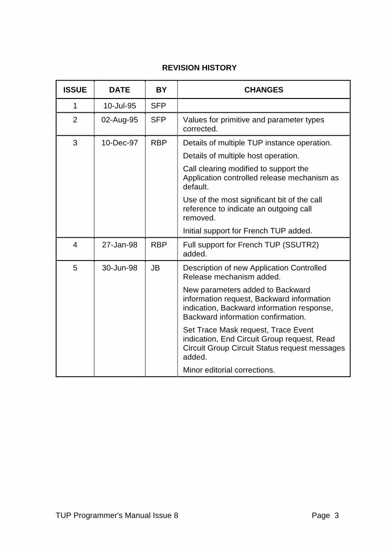
REVISION HISTORY
ISSUE DATE BY CHANGES
1 10-Jul-95 SFP
2 02-Aug-95 SFP Values for primitive and parameter types corrected.
3 10-Dec-97 RBP Details of multiple TUP instance operation.
Details of multiple host operation.
Call clearing modified to support the Application controlled release mechanism as default.
Use of the most significant bit of the call reference to indicate an outgoing call removed.
Initial support for French TUP added.
4 27-Jan-98 RBP Full support for French TUP (SSUTR2) added.
5 30-Jun-98 JB Description of new Application Controlled Release mechanism added.
New parameters added to Backward information request, Backward information indication, Backward information response, Backward information confirmation.
Set Trace Mask request, Trace Event indication, End Circuit Group request, Read Circuit Group Circuit Status request messages added.
Minor editorial corrections.
TUP Programmer’s Manual Issue 8 Page 4
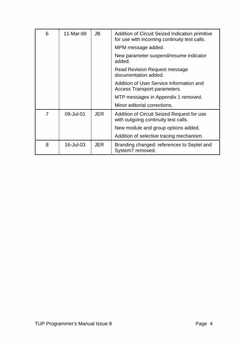
6 11-Mar-99 JB Addition of Circuit Seized Indication primitive for use with incoming continuity test calls.
MPM message added.
New parameter suspend/resume indicator added.
Read Revision Request message documentation added.
Addition of User Service Information and Access Transport parameters.
MTP messages in Appendix 1 removed.
Minor editorial corrections.
7 09-Jul-01 JER Addition of Circuit Seized Request for use with outgoing continuity test calls.
New module and group options added.
Addition of selective tracing mechanism.
8 16-Jul-03 JER Branding changed: references to Septel and System7 removed.
TUP Programmer’s Manual Issue 8 Page 5
CONTENTS
1 INTRODUCTION ................................................................................................. 9
2 ABBREVIATIONS ............................................................................................. 10
3 RELATED DOCUMENTATION ......................................................................... 10
4 FEATURE OVERVIEW...................................................................................... 11
5 GENERAL DESCRIPTION................................................................................ 12
5.1 Module Overview............................................................................................ 12 5.2 Module Configuration ..................................................................................... 12
6 INTERNAL DATA STRUCTURES..................................................................... 13
6.1 Global Data Structure..................................................................................... 13 6.2 Circuit Group Data Structure .......................................................................... 13 6.3 Per Circuit Data Structure .............................................................................. 13
7 INTERFACE TO SYSTEM SERVICES.............................................................. 14
7.1 System Functions........................................................................................... 14 7.2 Timer Operation ............................................................................................. 14
8 INTERFACE TO MESSAGE TRANSFER PART............................................... 15
9 CALL CONTROL INTERFACE ......................................................................... 16
9.1 Message Format ............................................................................................ 17 9.1.1 TUP-Transmit Request ........................................................................... 17 9.1.2 TUP-Receive Indication .......................................................................... 18
9.2 User data format for TX_REQ and RX_IND primitives................................... 19 9.3 Call control primitives, user application to TUP module ................................. 22
9.3.1 Alerting request ....................................................................................... 23 9.3.2 Backward information request................................................................. 24 9.3.3 Backward information response.............................................................. 25 9.3.4 Charging request..................................................................................... 26 9.3.5 Charging acknowledgement request....................................................... 26 9.3.6 Circuit seized request.............................................................................. 27 9.3.7 Collection charging request..................................................................... 27 9.3.8 Continuity report request......................................................................... 27 9.3.9 End-to-end information request .............................................................. 28 9.3.10 Forward information request ................................................................... 28 9.3.11 Forward transfer request......................................................................... 28 9.3.12 Release request ...................................................................................... 29 9.3.13 Release response ................................................................................... 30 9.3.14 Resume request...................................................................................... 30 9.3.15 Setup request.......................................................................................... 31 9.3.16 Setup response....................................................................................... 32 9.3.17 Suspend request..................................................................................... 33 9.3.18 Tariff change request .............................................................................. 33 9.3.19 User-to-user information request ............................................................ 34
TUP Programmer’s Manual Issue 8 Page 6
9.4 Call control primitives, TUP module to user application ................................. 35 9.4.1 Alerting Indication ................................................................................... 36 9.4.2 Backward information indication ............................................................. 36 9.4.3 Backward Information Confirmation........................................................ 37 9.4.4 Calling Party Clear Indication.................................................................. 37 9.4.5 Charging Indication ................................................................................. 38 9.4.6 Charging Acknowledgement Indication................................................... 38 9.4.7 Circuit Seized Indication.......................................................................... 39 9.4.8 Collection Charging Indication ................................................................ 39 9.4.9 Continuity Report Indication .................................................................... 39 9.4.10 End-to-End Information Indication .......................................................... 40 9.4.11 Forward Information Indication................................................................ 40 9.4.12 Forward Transfer Indication .................................................................... 40 9.4.13 Release Indication .................................................................................. 41 9.4.14 Release Confirmation ............................................................................. 42 9.4.15 Resume Indication .................................................................................. 42 9.4.16 Setup Indication ...................................................................................... 43 9.4.17 Setup Confirmation ................................................................................. 44 9.4.18 Suspend Indication ................................................................................. 44 9.4.19 Tariff Change Indication.......................................................................... 45 9.4.20 User-to-User Information Indication ........................................................ 45
9.5 Mapping Call Control Primitives to Network Messages.................................. 46 9.6 Parameter Definitions..................................................................................... 48
9.6.1 Access Transport .................................................................................... 50 9.6.2 Additional calling party information ......................................................... 50 9.6.3 Additional cause information................................................................... 51 9.6.4 Additional routing information ................................................................. 51 9.6.5 Backward call indicators.......................................................................... 52 9.6.6 Called party number................................................................................ 53 9.6.7 Calling party’s category........................................................................... 55 9.6.8 Calling party number ............................................................................... 55 9.6.9 Cause indicators ..................................................................................... 57 9.6.10 Charging information............................................................................... 59 9.6.11 Closed user group interlock code............................................................ 59 9.6.12 Continuity indicators................................................................................ 60 9.6.13 Event information .................................................................................... 60 9.6.14 Forward call indicators ............................................................................ 61 9.6.15 Generic number ...................................................................................... 62 9.6.16 IAI national use octet .............................................................................. 64 9.6.17 Incoming trunk and transit identity .......................................................... 64 9.6.18 Information indicators.............................................................................. 64 9.6.19 Information request indicators................................................................. 65 9.6.20 Message number field............................................................................. 66 9.6.21 Nature of connection indicators .............................................................. 67 9.6.22 Number of metering pulses..................................................................... 68 9.6.23 Optional forward call indicators ............................................................... 68 9.6.24 Original called number ............................................................................ 69 9.6.25 Packet charging ...................................................................................... 70 9.6.26 Redirection information ........................................................................... 71 9.6.27 Signalling point code............................................................................... 71
TUP Programmer’s Manual Issue 8 Page 7
9.6.28 SSUTR2 Additional called party information ........................................... 72 9.6.29 SSUTR2 Further redirection information................................................. 73 9.6.30 Subsequent number................................................................................ 74 9.6.31 Suspend/resume indicator ...................................................................... 74 9.6.32 Tariff indicators ....................................................................................... 75 9.6.33 Tariff factor.............................................................................................. 75 9.6.34 Time indicator ......................................................................................... 76 9.6.35 Transmission medium requirement......................................................... 76 9.6.36 TUP information indicator ....................................................................... 77 9.6.37 TUP Information request indicators......................................................... 78 9.6.38 User service information ......................................................................... 78 9.6.39 User to user information.......................................................................... 79
9.7 Use of call control primitives........................................................................... 80 9.7.1 Call clearing procedure............................................................................... 80 9.7.2 Call collision procedure............................................................................... 80
10 MANAGEMENT INTERFACE ........................................................................ 82
10.1 Circuit Group Supervision Control Request ................................................... 84 10.2 Circuit Group Supervision Control Confirmation ............................................ 86 10.3 Circuit Group Supervision Control Indication ................................................. 88 10.4 Remote Point Code Status Indication ............................................................ 90 10.5 Local Overload Request................................................................................. 92
11 NON-PRIMITIVE INTERFACE....................................................................... 94
11.1 Configuration Request ................................................................................... 95 11.2 Configure Circuit Group Request ................................................................. 100 11.3 Configure Timers Request ........................................................................... 106 11.4 End Circuit Group Request .......................................................................... 114 11.5 Read TUP RAM Request ............................................................................. 115 11.6 Read Circuit Group Request ........................................................................ 116 11.7 Read Circuit Request ................................................................................... 117 11.8 Read Revision Request................................................................................ 118 11.9 Set Trace Mask Request.............................................................................. 119 11.10 Set Selective Trace Mask Request........................................................... 123 11.11 Read Circuit Group Circuit Status Request .............................................. 124 11.12 Maintenance Event Indication .................................................................. 127 11.13 Software Event Indication......................................................................... 130 11.14 Management Event Indication .................................................................. 132 11.15 Trace Event Indication.............................................................................. 133 11.16 Selective Trace Event Indication .............................................................. 134
12 APPENDIX 1................................................................................................ 136
12.1 Message Type Table.................................................................................... 136
13 APPENDIX 2................................................................................................ 138
13.1 Timer Services ............................................................................................. 138 13.2 Keep Time.................................................................................................... 138 13.3 Timer Expiry ................................................................................................. 139
14 APPENDIX 3................................................................................................ 140
14.1 Chinese National Telephone Network (GF001-9001) .................................. 140
TUP Programmer’s Manual Issue 8 Page 8
14.2 Point code size............................................................................................. 140 14.3 Subscriber Local Busy (SLB) message........................................................ 140 14.4 Subscriber Trunk Busy (STB) message ....................................................... 140 14.5 Calling party clear (CCL) message .............................................................. 140 14.6 Mapping Call Control Primitives to Network Messages................................ 141
15 APPENDIX 4................................................................................................ 143
15.1 French national telephone network (SSUTR2)............................................. 143 15.2 Mapping call control primitives to network messages .................................. 145 15.3 Parameters definitions ................................................................................. 147
15.3.1 Additional calling party information ....................................................... 147 15.3.2 Backward call indicators........................................................................ 147 15.3.3 Called party number.............................................................................. 149 15.3.4 Calling party’s category......................................................................... 150 15.3.5 Calling party number ............................................................................. 150 15.3.6 Cause indicators ................................................................................... 151 15.3.7 Closed User Group interlock Code ....................................................... 152 15.3.8 Forward call indicators .......................................................................... 152 15.3.9 Information request indicators............................................................... 152 15.3.10 Nature of connection indicators ......................................................... 153 15.3.11 Optional Forward Call Indicators ....................................................... 153 15.3.12 Original Called Number ..................................................................... 153 15.3.13 Transmission Medium Requirement.................................................. 153
15.4 Circuit Group Supervision Control Request & Indication messages ............ 154
TUP Programmer’s Manual Issue 8 Page 9
1 INTRODUCTION
The TUP module is a portable software implementation of the Signalling System Number 7, Telephone User Part (TUP). This is the Programmer’s Manual, intended for users developing their own application programs that will interface with and use the functionality provided by the TUP module.
In addition to supporting TUP functionality as specified by ITU recommendations the module can be configured to support French SSUTR2 and Chinese GF001-9001 TUP operation.
The module uses the services provided by the Message Transfer Part (MTP) to exchange signalling messages with remote signalling points. It supports a number of both way telephony circuits. The circuits can be divided into a number of circuit groups, each group may be assigned different attributes allowing the user considerable flexibility in configuring the module.
The TUP module is event driven and uses standard structured message types. It is intended to be used in conjunction with the MTP module, either on Intel® hardware platforms or on user supplied hardware. However, the software is portable and the well-defined message structure and the independent nature of the module allows the TUP module to be used with alternative MTP implementations if required.
This manual provides an overview of the internal operation of the TUP module, defines the structure of all messages that can be sent to, or issued by, the module and also describes all the configuration parameters.
TUP Programmer’s Manual Issue 8 Page 10
2 ABBREVIATIONS
- ITU The International Telecommunication Union (Previously CCITT)
- DPC Destination Point Code
- MCI Malicious Call Identification
- MTP Message Transfer Part
- OPC Originating Point Code
- SIO Service Information Octet
- SIF Signalling Information Field
- SS7 Signalling System Number 7
- SSF Sub-Service Field
- SSUTR2 Sous-Système Utilisateur Téléphonie R2 (French TUP)
- TUP Telephony User Part
3 RELATED DOCUMENTATION
[1] ITU recommendations Q.721 - Q.725 (TUP)
[2] French SSUTR2 (Système de signalisation par canal sémaphore CCITT no.7) Specification VN4, VN5 & VN6
[3] China TUP Specification GF001-9001
[4] Software Environment Programmer's Manual
[5] SS7 Programmer's Manual for PCCS6
TUP Programmer’s Manual Issue 8 Page 11
4 FEATURE OVERVIEW
Key features of the TUP module include:
- Implementation of ITU recommendation Q.721 - Q.724 (Blue book 1988)
- Configuration options on a per circuit group basis
- User interface common with other Intel® NetStructure™ SS7 Protocols
- Message oriented interface
- Support for both en-block and overlap address signalling
- Full user control of Circuit supervisory functions - Reset, Blocking & Unblocking
- Support for incoming continuity recheck test calls.
- Support for circuit group as well as individual circuit supervision messages
- Support for 14 bit and 24 bit Signalling Point Codes
- Optional support for French TUP specified by SSUTR2 VN4/VN5/VN6
- Optional support for Chinese TUP specified by GF001-9001
- Debug tracing of messages exchanged with the user and with MTP.
TUP Programmer’s Manual Issue 8 Page 12
5 GENERAL DESCRIPTION
5.1 Module Overview
The TUP module implements the Telephony User Part functionality as defined in ITU recommendations Q.721 - Q.724. The module interface is message based. The module reads messages from a single message input queue and sends responses and indications to the message input queues of the other modules in the system.
The application interface uses primitives based on the ITU-T ISDN User Part (ISUP) formats and codes (specified in ITU-T Recommendation Q.763), in common to other Intel® NetStructure™ SS7 protocols. This allows the same user application to interface with other telephony user parts as required.
Each circuit is identified internally by a logical Circuit Identifier (cid). Circuit Identifiers range from 0 up to one less than the total number of circuits supported. A circuit must be assigned to a circuit group before it can be used.
Circuit groups allow a number of circuits to be configured with common attributes. They are identified by the logical Group Identifier (gid) which ranges from 0 to one less than the total number of circuit groups supported. The Circuit Identification Code (CIC) of the first circuit in the group and the Circuit Identifier (cid) that will be used for this circuit are defined for each circuit group. Further circuits may be included in the group providing that the CIC of the last circuit is no more than 31 greater than the first CIC. The circuits do not need to lie in a contiguous block. The Circuit Identifier cid for each additional circuit will have the same offset from the first cid as the CIC has from the first CIC.
All protocol primitives between the application and the TUP module use a Call Reference (call_ref) to identify the circuit used for the call. The call reference is identical to the Circuit Identifier (cid) with the exception that for messages issued by the TUP module relating to outgoing calls the most significant bit of the call_ref is set to one.
Note: This feature is retained for backwards compatibility and will be removed in a future release so that the call_ref will be identical to the cid. The TUP module now ignores the setting of the most significant bit of the call_ref and it is recommended that existing applications which placed significance on this bit be modified to ignore it also.
5.2 Module Configuration
The user configures the module for operation in two stages. The first message sent to the module must be a global configuration message. This configures environment dependent parameters. In general, these parameters will be fixed for any single application. Optionally, a configure timers message may be sent at this stage.
Each circuit group must then be configured with a configuration message before attempting to originate or accept calls.
TUP Programmer’s Manual Issue 8 Page 13
6 INTERNAL DATA STRUCTURES
This chapter describes the internal data structures used by the TUP module. This description is intended to assist the user in understanding the operation of the module. It is not necessary to acquire detailed knowledge of these structures in order to use the module.
6.1 Global Data Structure
The entire data storage used by the module is contained in a single contiguous data structure. This structure contains global configuration settings, per circuit storage, circuit group configuration data, and per-call storage all relating to operation of the TUP protocol. It also contains internal event queues, timer control structures and internal buffers for message processing.
6.2 Circuit Group Data Structure
Each circuit group has a data structure within the global data structure which contains the user supplied configuration parameters for the circuit group (e.g. Signalling Point Codes, Circuit Identification and Configuration Options). The information in the circuit group data structure applies to all circuits in the circuit group.
6.3 Per Circuit Data Structure
Each circuit has a data structure within the global data structure which is used to store the current state of state machines associated with the circuit and any current call details.
TUP Programmer’s Manual Issue 8 Page 14
7 INTERFACE TO SYSTEM SERVICES
7.1 System Functions
In addition to the primitive interface and the management interface to the TUP module (which are described in later sections) the module requires a few basic system services to be supplied by the underlying operating system. This functionality is usually supplied by the appropriate Development package.
The following functions are required for inter-task communication:
GCT_send Sends a message to another task.
GCT_receive Accept next message from input event queue, blocking the task if no message is ready.
GCT_grab As receive but not blocking if no message is ready.
The following functions are required for allocation of inter-task messages: getm Allocate a message. relm Release a message.
7.2 Timer Operation
In order to provide internal implementation of the TUP protocol timers the module needs to receive a periodic timer tick message. This is usually achieved using either the Enhanced Driver Module or the Timer module in which case the following messages are used by the TUP module: KEEP_TIME Issued by TUP module to initialise the timer services
TM_EXP Issued by the timer module to notify of time-out.
The format of these messages is described in Appendix 2.
The user should note that whilst the timer functionality is usually provided by the supplied timer module, the timer functionality required by the TUP module is very basic (just a single message being issued on a periodic basis). In most cases it is a trivial exercise to implement this functionality using the users own choice of operating environment if required.
TUP Programmer’s Manual Issue 8 Page 15
8 INTERFACE TO MESSAGE TRANSFER PART
The TUP module communicates with the Message Transfer Part (MTP) using the following primitives, all of which are defined in ITU Recommendation Q.704: MTP-TRANSFER-REQ Transmit request to MTP. MTP-TRANSFER-IND Receive indication from MTP. MTP-PAUSE Point code unavailable indication from MTP. MTP-RESUME Point code available indication from MTP. MTP-STATUS Signalling point congested or remote user unavailable indication from MTP.
The message format used to convey these primitives is defined in the SS7 Programmer’s Manual for PCCS6.
The TUP module is usually used in conjunction with the MTP module. However, the use of primitives in accordance with Q.704 ensures that it can also be integrated with other MTP implementations as and when required.
To provide further flexibility the TUP module supports the use of either T_FRAMEs and R_FRAMEs or the use of MSGs for MTP-TRANSFERs between the TUP and MTP.
T_FRAMES and R_FRAMES are most useful when TUP module is running on the same processor as the MTP3 module, whilst MSGs are generally used when TUP module is running on a different processor than the one used for the MTP.
A module configuration option (TUPF_TFRM) allows the user to select between sending T_FRAMEs or sending MSGs. Receipt of both R_FRAMEs and MSGs is supported in either mode.
TUP Programmer’s Manual Issue 8 Page 16
9 CALL CONTROL INTERFACE
The call control interface allows protocol primitive messages to be exchanged between the local user and the TUP module. All primitives at the call control interface are passed by sending messages between the modules. One message type is used to send request messages from the user to the TUP module whilst a second message type is used to send indications in the other direction.
The message types are:
CAL_MSG_TX_REQ Conveys primitive from local user to TUP. CAL_MSG_RX_IND Conveys primitive from TUP to local user.
The basic structure of each message (irrespective of the message type) is the same. The message contains a message header, the length of the user data and the user data. The message must be contained in a single buffer that should be allocated by the sending module (using the getm function) and either released (using the relm function) or passed to another module by the receiving module. The getm and relm functions are described in Section 7.
TUP Programmer’s Manual Issue 8 Page 17
9.1 Message Format
9.1.1 TUP-Transmit Request
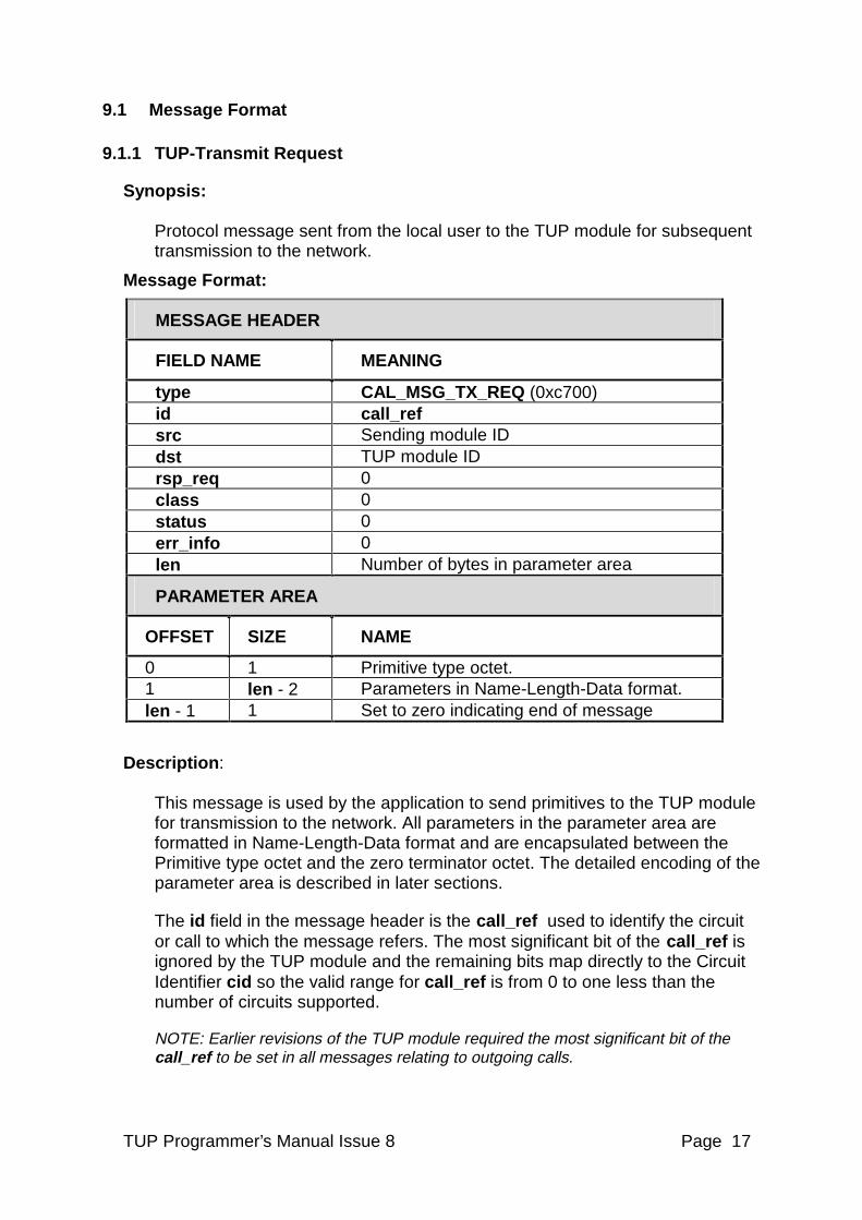
Synopsis: Protocol message sent from the local user to the TUP module for subsequent transmission to the network.
Message Format:
MESSAGE HEADER
FIELD NAME MEANING
type CAL_MSG_TX_REQ (0xc700) id call_ref src Sending module ID dst TUP module ID rsp_req 0 class 0 status 0 err_info 0 len Number of bytes in parameter area
PARAMETER AREA
OFFSET SIZE NAME
0 1 Primitive type octet. 1 len - 2 Parameters in Name-Length-Data format. len - 1 1 Set to zero indicating end of message
Description: This message is used by the application to send primitives to the TUP module for transmission to the network. All parameters in the parameter area are formatted in Name-Length-Data format and are encapsulated between the Primitive type octet and the zero terminator octet. The detailed encoding of the parameter area is described in later sections.
The id field in the message header is the call_ref used to identify the circuit or call to which the message refers. The most significant bit of the call_ref is ignored by the TUP module and the remaining bits map directly to the Circuit Identifier cid so the valid range for call_ref is from 0 to one less than the number of circuits supported.
NOTE: Earlier revisions of the TUP module required the most significant bit of the call_ref to be set in all messages relating to outgoing calls.
TUP Programmer’s Manual Issue 8 Page 18
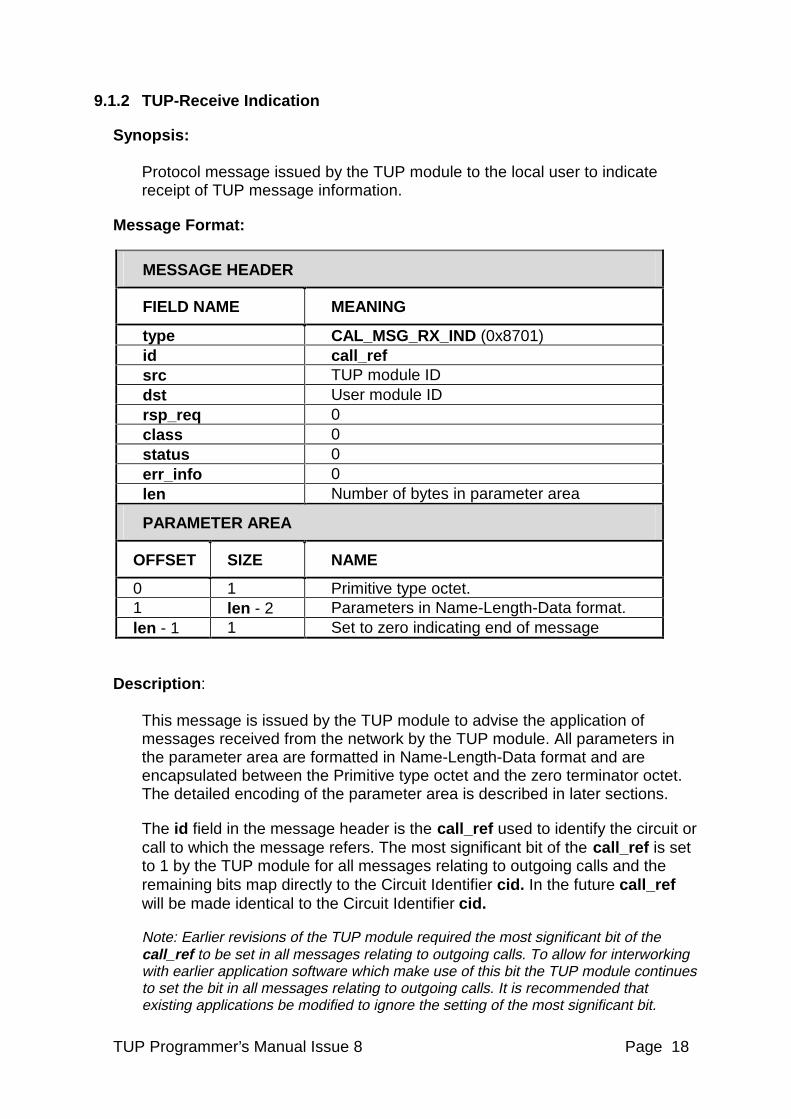
9.1.2 TUP-Receive Indication
Synopsis: Protocol message issued by the TUP module to the local user to indicate receipt of TUP message information.
Message Format:�
MESSAGE HEADER
FIELD NAME MEANING
type CAL_MSG_RX_IND (0x8701) id call_ref src TUP module ID dst User module ID �rsp_req 0 class 0 status 0 err_info 0 len Number of bytes in parameter area
PARAMETER AREA
OFFSET SIZE NAME
0 1 Primitive type octet. 1 len - 2 Parameters in Name-Length-Data format. len - 1 1 Set to zero indicating end of message
Description: This message is issued by the TUP module to advise the application of messages received from the network by the TUP module. All parameters in the parameter area are formatted in Name-Length-Data format and are encapsulated between the Primitive type octet and the zero terminator octet. The detailed encoding of the parameter area is described in later sections.
The id field in the message header is the call_ref used to identify the circuit or call to which the message refers. The most significant bit of the call_ref is set to 1 by the TUP module for all messages relating to outgoing calls and the remaining bits map directly to the Circuit Identifier cid. In the future call_ref will be made identical to the Circuit Identifier cid.
Note: Earlier revisions of the TUP module required the most significant bit of the call_ref to be set in all messages relating to outgoing calls. To allow for interworking with earlier application software which make use of this bit the TUP module continues to set the bit in all messages relating to outgoing calls. It is recommended that existing applications be modified to ignore the setting of the most significant bit.
TUP Programmer’s Manual Issue 8 Page 19
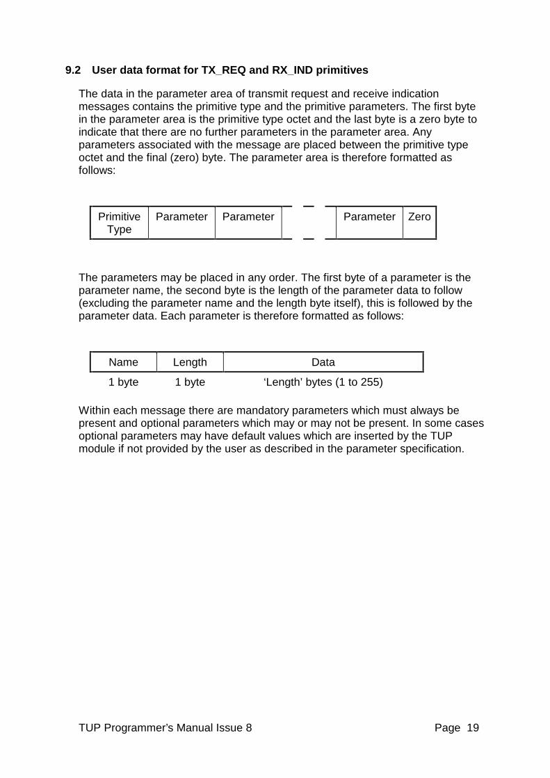
9.2 User data format for TX_REQ and RX_IND primitives
The data in the parameter area of transmit request and receive indication messages contains the primitive type and the primitive parameters. The first byte in the parameter area is the primitive type octet and the last byte is a zero byte to indicate that there are no further parameters in the parameter area. Any parameters associated with the message are placed between the primitive type octet and the final (zero) byte. The parameter area is therefore formatted as follows:
Primitive Type
Parameter Parameter Parameter Zero
The parameters may be placed in any order. The first byte of a parameter is the parameter name, the second byte is the length of the parameter data to follow (excluding the parameter name and the length byte itself), this is followed by the parameter data. Each parameter is therefore formatted as follows:
Name Length Data
1 byte 1 byte ‘Length’ bytes (1 to 255) Within each message there are mandatory parameters which must always be present and optional parameters which may or may not be present. In some cases optional parameters may have default values which are inserted by the TUP module if not provided by the user as described in the parameter specification.
TUP Programmer’s Manual Issue 8 Page 20
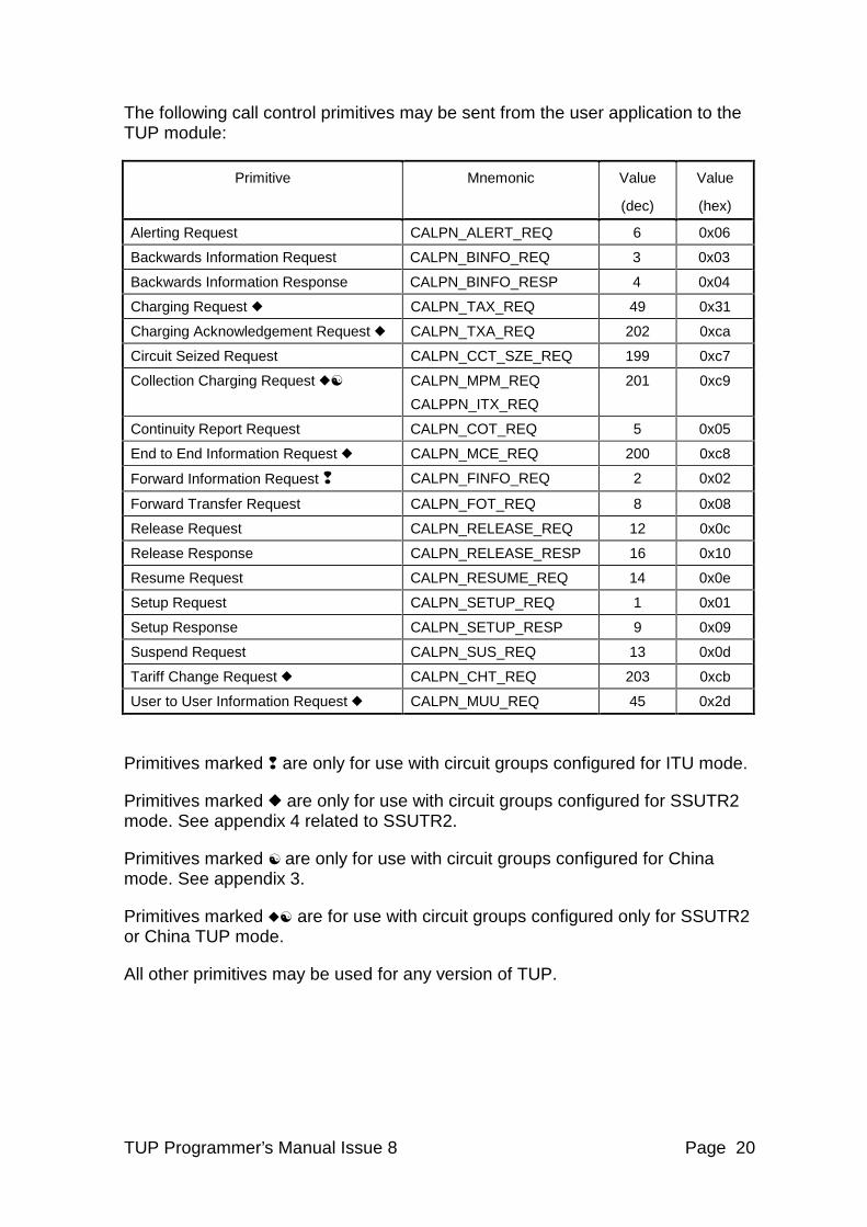
The following call control primitives may be sent from the user application to the TUP module:
Primitive Mnemonic Value
(dec)
Value
(hex)
Alerting Request CALPN_ALERT_REQ 6 0x06
Backwards Information Request CALPN_BINFO_REQ 3 0x03
Backwards Information Response CALPN_BINFO_RESP 4 0x04
Charging Request X CALPN_TAX_REQ 49 0x31
Charging Acknowledgement Request X CALPN_TXA_REQ 202 0xca
Circuit Seized Request CALPN_CCT_SZE_REQ 199 0xc7
Collection Charging Request XB CALPN_MPM_REQ
CALPPN_ITX_REQ
201 0xc9
Continuity Report Request CALPN_COT_REQ 5 0x05
End to End Information Request X CALPN_MCE_REQ 200 0xc8
Forward Information Request q CALPN_FINFO_REQ 2 0x02
Forward Transfer Request CALPN_FOT_REQ 8 0x08
Release Request CALPN_RELEASE_REQ 12 0x0c
Release Response CALPN_RELEASE_RESP 16 0x10
Resume Request CALPN_RESUME_REQ 14 0x0e
Setup Request CALPN_SETUP_REQ 1 0x01
Setup Response CALPN_SETUP_RESP 9 0x09
Suspend Request CALPN_SUS_REQ 13 0x0d
Tariff Change Request X CALPN_CHT_REQ 203 0xcb
User to User Information Request X CALPN_MUU_REQ 45 0x2d
Primitives marked q are only for use with circuit groups configured for ITU mode.
Primitives marked X are only for use with circuit groups configured for SSUTR2 mode. See appendix 4 related to SSUTR2.
Primitives marked B are only for use with circuit groups configured for China mode. See appendix 3.
Primitives marked XB are for use with circuit groups configured only for SSUTR2 or China TUP mode.
All other primitives may be used for any version of TUP.
TUP Programmer’s Manual Issue 8 Page 21
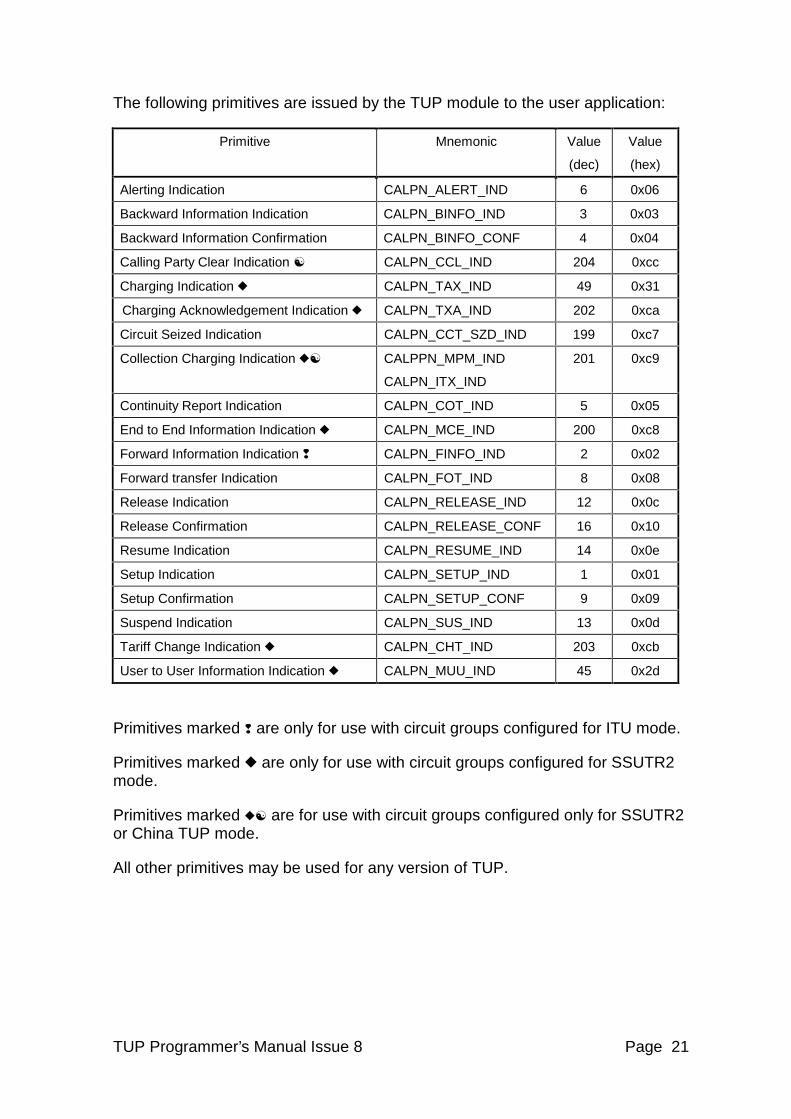
The following primitives are issued by the TUP module to the user application:
Primitive Mnemonic Value
(dec)
Value
(hex)
Alerting Indication CALPN_ALERT_IND 6 0x06
Backward Information Indication CALPN_BINFO_IND 3 0x03
Backward Information Confirmation CALPN_BINFO_CONF 4 0x04
Calling Party Clear Indication B CALPN_CCL_IND 204 0xcc
Charging Indication X CALPN_TAX_IND 49 0x31
Charging Acknowledgement Indication X CALPN_TXA_IND 202 0xca
Circuit Seized Indication CALPN_CCT_SZD_IND 199 0xc7
Collection Charging Indication XB CALPPN_MPM_IND
CALPN_ITX_IND
201 0xc9
Continuity Report Indication CALPN_COT_IND 5 0x05
End to End Information Indication X CALPN_MCE_IND 200 0xc8
Forward Information Indication q CALPN_FINFO_IND 2 0x02
Forward transfer Indication CALPN_FOT_IND 8 0x08
Release Indication CALPN_RELEASE_IND 12 0x0c
Release Confirmation CALPN_RELEASE_CONF 16 0x10
Resume Indication CALPN_RESUME_IND 14 0x0e
Setup Indication CALPN_SETUP_IND 1 0x01
Setup Confirmation CALPN_SETUP_CONF 9 0x09
Suspend Indication CALPN_SUS_IND 13 0x0d
Tariff Change Indication X CALPN_CHT_IND 203 0xcb
User to User Information Indication X CALPN_MUU_IND 45 0x2d
Primitives marked q are only for use with circuit groups configured for ITU mode.
Primitives marked X are only for use with circuit groups configured for SSUTR2 mode.
Primitives marked XB are for use with circuit groups configured only for SSUTR2 or China TUP mode.
All other primitives may be used for any version of TUP.
TUP Programmer’s Manual Issue 8 Page 22
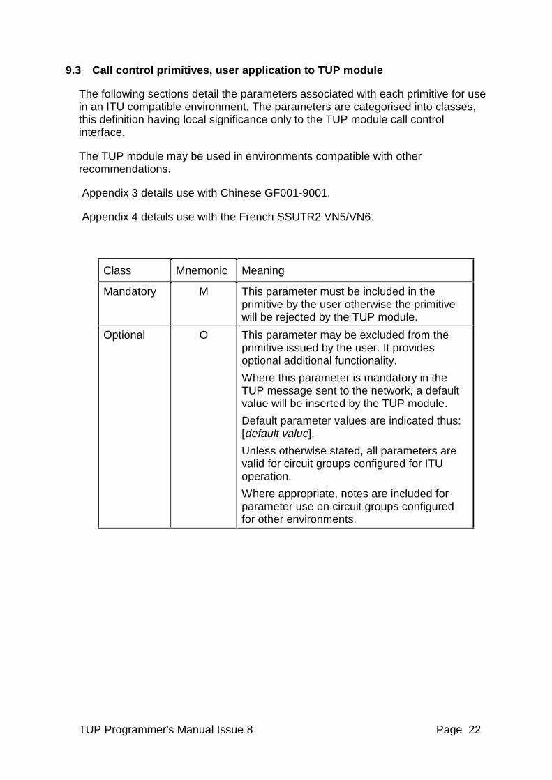
9.3 Call control primitives, user application to TUP module
The following sections detail the parameters associated with each primitive for use in an ITU compatible environment. The parameters are categorised into classes, this definition having local significance only to the TUP module call control interface.
The TUP module may be used in environments compatible with other recommendations.
Appendix 3 details use with Chinese GF001-9001.
Appendix 4 details use with the French SSUTR2 VN5/VN6.
Class Mnemonic Meaning
Mandatory M This parameter must be included in the primitive by the user otherwise the primitive will be rejected by the TUP module.
Optional O This parameter may be excluded from the primitive issued by the user. It provides optional additional functionality.
Where this parameter is mandatory in the TUP message sent to the network, a default value will be inserted by the TUP module.
Default parameter values are indicated thus: [default value].
Unless otherwise stated, all parameters are valid for circuit groups configured for ITU operation.
Where appropriate, notes are included for parameter use on circuit groups configured for other environments.
TUP Programmer’s Manual Issue 8 Page 23
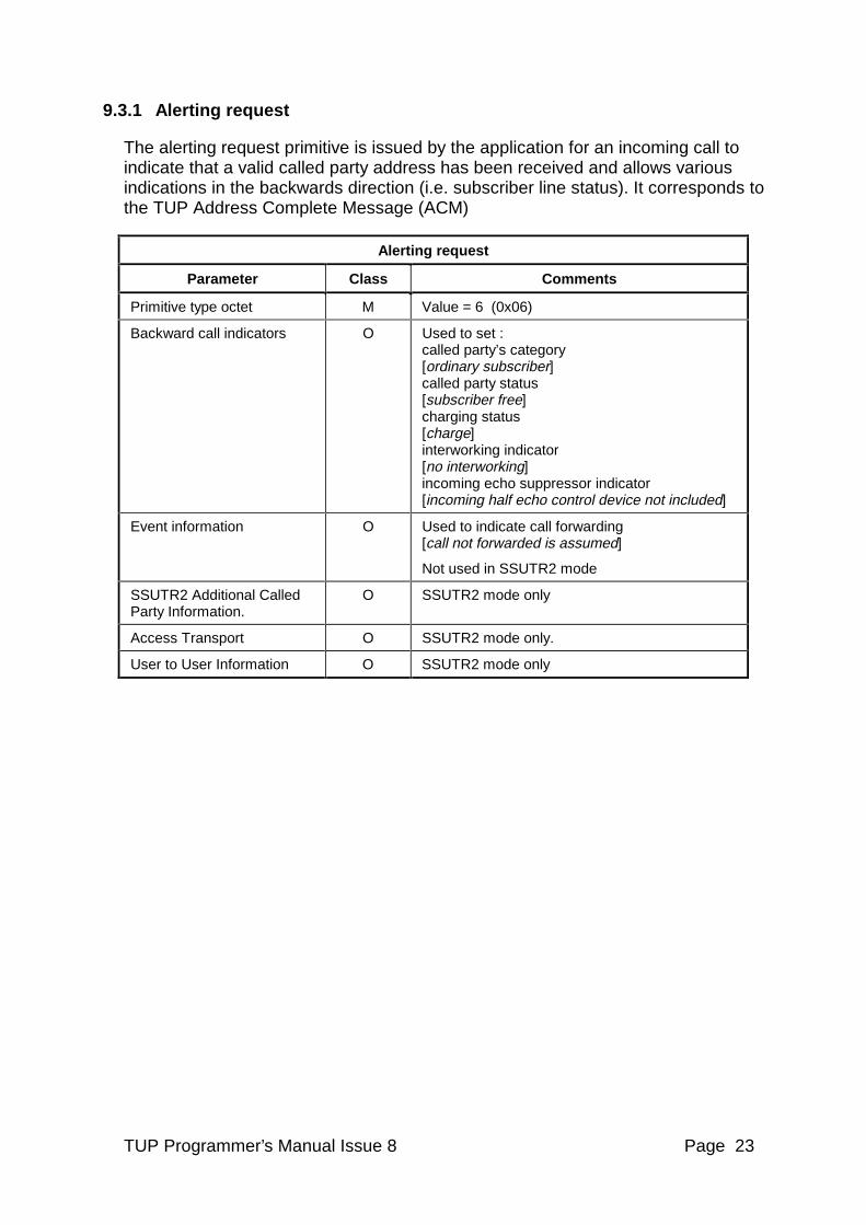
9.3.1 Alerting request
The alerting request primitive is issued by the application for an incoming call to indicate that a valid called party address has been received and allows various indications in the backwards direction (i.e. subscriber line status). It corresponds to the TUP Address Complete Message (ACM)
Alerting request
Parameter Class Comments
Primitive type octet M Value = 6 (0x06)
Backward call indicators O Used to set : called party’s category [ordinary subscriber] called party status [subscriber free] charging status [charge] interworking indicator [no interworking] incoming echo suppressor indicator [incoming half echo control device not included]
Event information O Used to indicate call forwarding [call not forwarded is assumed]
Not used in SSUTR2 mode
SSUTR2 Additional Called Party Information.
O SSUTR2 mode only
Access Transport O SSUTR2 mode only.
User to User Information O SSUTR2 mode only
TUP Programmer’s Manual Issue 8 Page 24
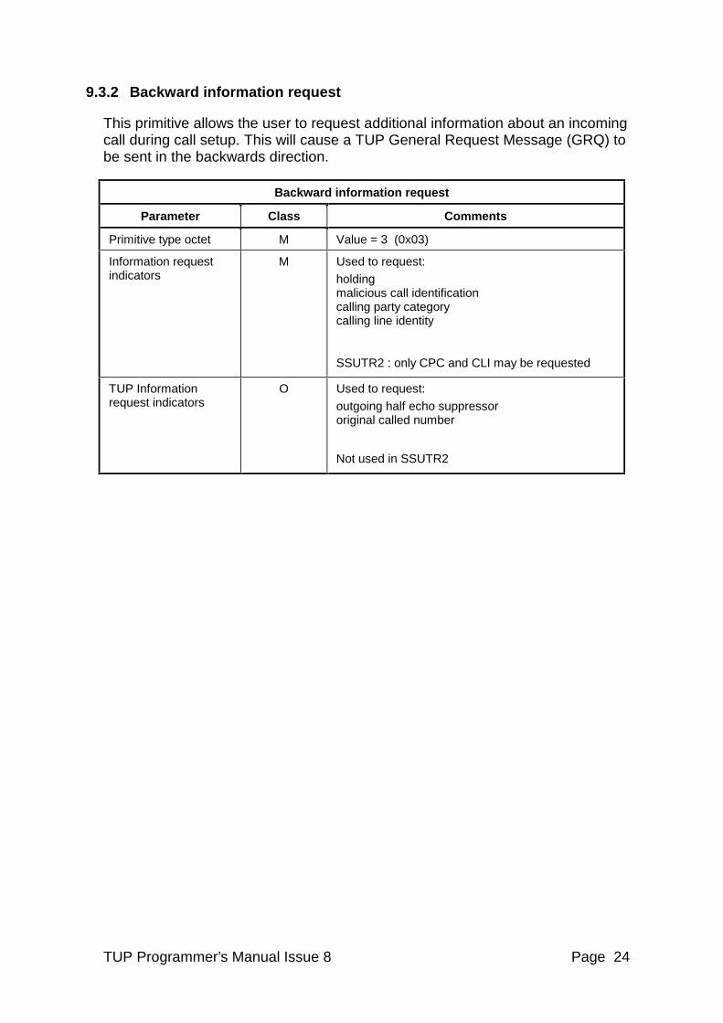
9.3.2 Backward information request
This primitive allows the user to request additional information about an incoming call during call setup. This will cause a TUP General Request Message (GRQ) to be sent in the backwards direction.
Backward information request
Parameter Class Comments
Primitive type octet M Value = 3 (0x03)
Information request indicators
M Used to request:
holding malicious call identification calling party category calling line identity
SSUTR2 : only CPC and CLI may be requested
TUP Information request indicators
O Used to request:
outgoing half echo suppressor original called number
Not used in SSUTR2
TUP Programmer’s Manual Issue 8 Page 25
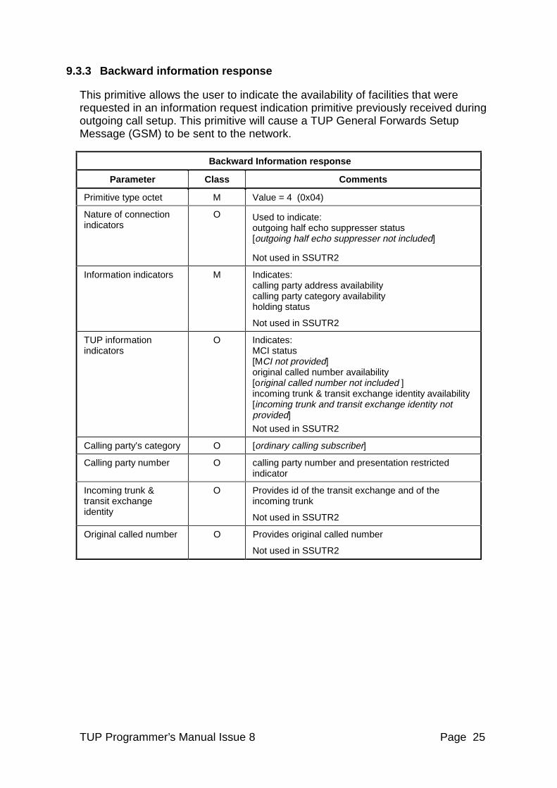
9.3.3 Backward information response
This primitive allows the user to indicate the availability of facilities that were requested in an information request indication primitive previously received during outgoing call setup. This primitive will cause a TUP General Forwards Setup Message (GSM) to be sent to the network.
Backward Information response
Parameter Class Comments
Primitive type octet M Value = 4 (0x04)
Nature of connection indicators
O Used to indicate: outgoing half echo suppresser status [outgoing half echo suppresser not included]
Not used in SSUTR2
Information indicators M Indicates: calling party address availability calling party category availability holding status
Not used in SSUTR2
TUP information indicators
O Indicates: MCI status [MCI not provided] original called number availability [original called number not included ] incoming trunk & transit exchange identity availability [incoming trunk and transit exchange identity not provided]
Not used in SSUTR2
Calling party’s category O [ordinary calling subscriber]
Calling party number O calling party number and presentation restricted indicator
Incoming trunk & transit exchange identity
O Provides id of the transit exchange and of the incoming trunk
Not used in SSUTR2
Original called number O Provides original called number
Not used in SSUTR2
TUP Programmer’s Manual Issue 8 Page 26
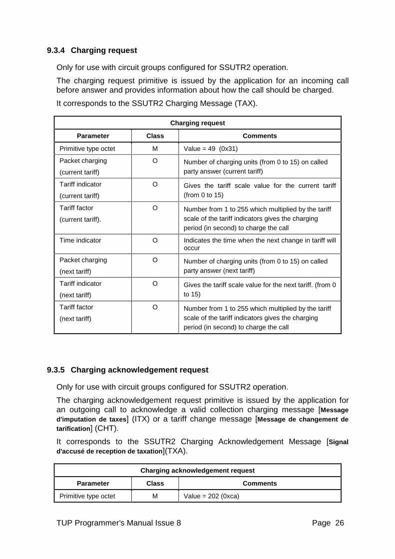
9.3.4 Charging request
Only for use with circuit groups configured for SSUTR2 operation.
The charging request primitive is issued by the application for an incoming call before answer and provides information about how the call should be charged.
It corresponds to the SSUTR2 Charging Message (TAX).
Charging request
Parameter Class Comments
Primitive type octet M Value = 49 (0x31)
Packet charging
(current tariff)
O Number of charging units (from 0 to 15) on called party answer (current tariff)
Tariff indicator
(current tariff)
O Gives the tariff scale value for the current tariff (from 0 to 15)
Tariff factor
(current tariff).
O Number from 1 to 255 which multiplied by the tariff scale of the tariff indicators gives the charging period (in second) to charge the call
Time indicator O Indicates the time when the next change in tariff will occur
Packet charging
(next tariff)
O Number of charging units (from 0 to 15) on called party answer (next tariff)
Tariff indicator
(next tariff)
O Gives the tariff scale value for the next tariff. (from 0 to 15)
Tariff factor
(next tariff)
O Number from 1 to 255 which multiplied by the tariff scale of the tariff indicators gives the charging period (in second) to charge the call
9.3.5 Charging acknowledgement request
Only for use with circuit groups configured for SSUTR2 operation.
The charging acknowledgement request primitive is issued by the application for an outgoing call to acknowledge a valid collection charging message [Message d’imputation de taxes] (ITX) or a tariff change message [Message de changement de tarification] (CHT).
It corresponds to the SSUTR2 Charging Acknowledgement Message [Signal d'accusé de reception de taxation ](TXA).
Charging acknowledgement request
Parameter Class Comments
Primitive type octet M Value = 202 (0xca)
TUP Programmer’s Manual Issue 8 Page 27
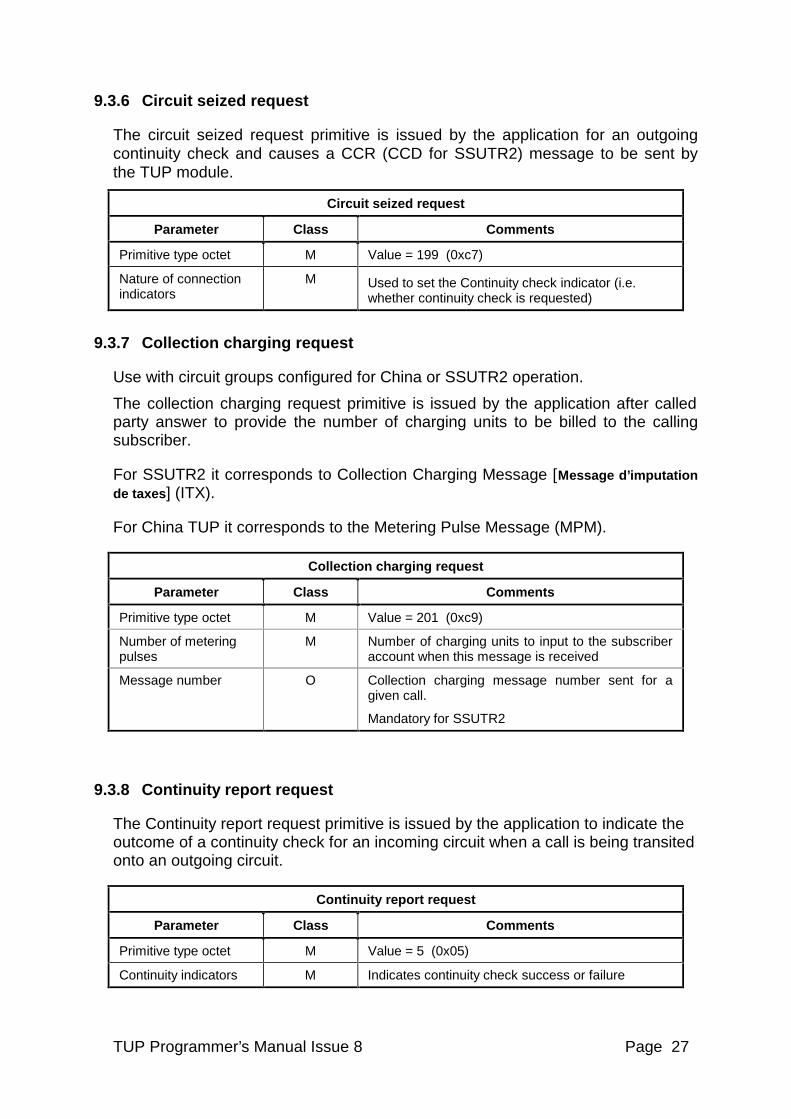
9.3.6 Circuit seized request
The circuit seized request primitive is issued by the application for an outgoing continuity check and causes a CCR (CCD for SSUTR2) message to be sent by the TUP module.
Circuit seized request
Parameter Class Comments
Primitive type octet M Value = 199 (0xc7)
Nature of connection indicators
M Used to set the Continuity check indicator (i.e. whether continuity check is requested)
9.3.7 Collection charging request
Use with circuit groups configured for China or SSUTR2 operation.
The collection charging request primitive is issued by the application after called party answer to provide the number of charging units to be billed to the calling subscriber.
For SSUTR2 it corresponds to Collection Charging Message [Message d’imputation de taxes] (ITX).
For China TUP it corresponds to the Metering Pulse Message (MPM).
Collection charging request
Parameter Class Comments
Primitive type octet M Value = 201 (0xc9)
Number of metering pulses
M Number of charging units to input to the subscriber account when this message is received
Message number O Collection charging message number sent for a given call.
Mandatory for SSUTR2
9.3.8 Continuity report request
The Continuity report request primitive is issued by the application to indicate the outcome of a continuity check for an incoming circuit when a call is being transited onto an outgoing circuit.
Continuity report request
Parameter Class Comments
Primitive type octet M Value = 5 (0x05)
Continuity indicators M Indicates continuity check success or failure
TUP Programmer’s Manual Issue 8 Page 28
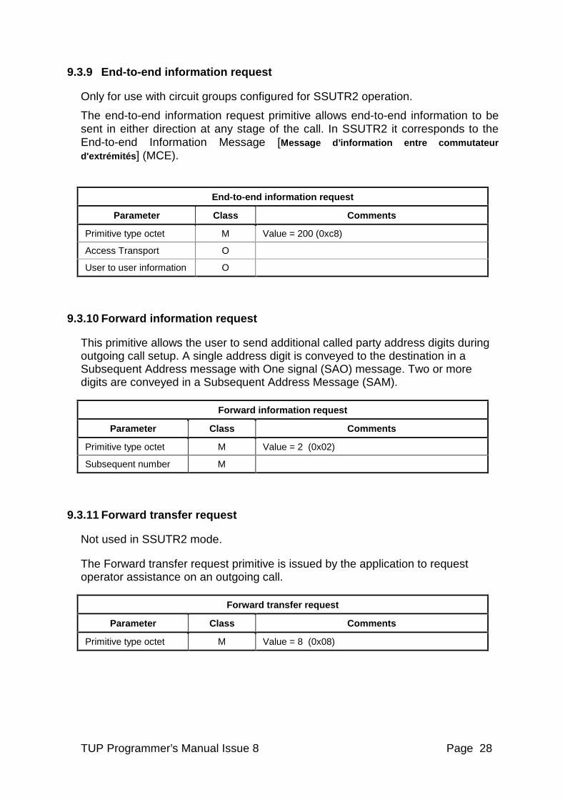
9.3.9 End-to-end information request
Only for use with circuit groups configured for SSUTR2 operation.
The end-to-end information request primitive allows end-to-end information to be sent in either direction at any stage of the call. In SSUTR2 it corresponds to the End-to-end Information Message [Message d’information entre commutateur d'extrémités ] (MCE).
End-to-end information request
Parameter Class Comments
Primitive type octet M Value = 200 (0xc8)
Access Transport O
User to user information O
9.3.10 Forward information request
This primitive allows the user to send additional called party address digits during outgoing call setup. A single address digit is conveyed to the destination in a Subsequent Address message with One signal (SAO) message. Two or more digits are conveyed in a Subsequent Address Message (SAM).
Forward information request
Parameter Class Comments
Primitive type octet M Value = 2 (0x02)
Subsequent number M
9.3.11 Forward transfer request
Not used in SSUTR2 mode.
The Forward transfer request primitive is issued by the application to request operator assistance on an outgoing call.
Forward transfer request
Parameter Class Comments
Primitive type octet M Value = 8 (0x08)
TUP Programmer’s Manual Issue 8 Page 29
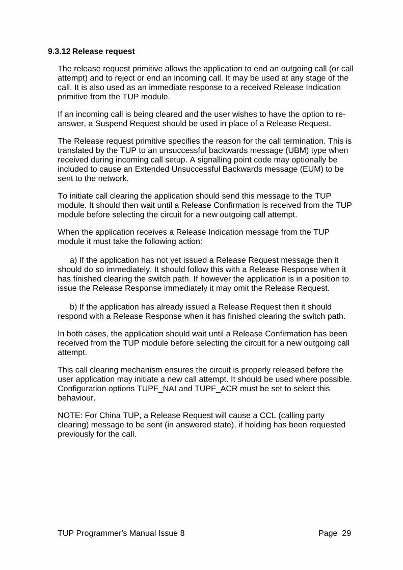
9.3.12 Release request
The release request primitive allows the application to end an outgoing call (or call attempt) and to reject or end an incoming call. It may be used at any stage of the call. It is also used as an immediate response to a received Release Indication primitive from the TUP module.
If an incoming call is being cleared and the user wishes to have the option to re-answer, a Suspend Request should be used in place of a Release Request.
The Release request primitive specifies the reason for the call termination. This is translated by the TUP to an unsuccessful backwards message (UBM) type when received during incoming call setup. A signalling point code may optionally be included to cause an Extended Unsuccessful Backwards message (EUM) to be sent to the network.
To initiate call clearing the application should send this message to the TUP module. It should then wait until a Release Confirmation is received from the TUP module before selecting the circuit for a new outgoing call attempt.
When the application receives a Release Indication message from the TUP module it must take the following action: a) If the application has not yet issued a Release Request message then it should do so immediately. It should follow this with a Release Response when it has finished clearing the switch path. If however the application is in a position to issue the Release Response immediately it may omit the Release Request. b) If the application has already issued a Release Request then it should respond with a Release Response when it has finished clearing the switch path.
In both cases, the application should wait until a Release Confirmation has been received from the TUP module before selecting the circuit for a new outgoing call attempt.
This call clearing mechanism ensures the circuit is properly released before the user application may initiate a new call attempt. It should be used where possible. Configuration options TUPF_NAI and TUPF_ACR must be set to select this behaviour.
NOTE: For China TUP, a Release Request will cause a CCL (calling party clearing) message to be sent (in answered state), if holding has been requested previously for the call.
TUP Programmer’s Manual Issue 8 Page 30
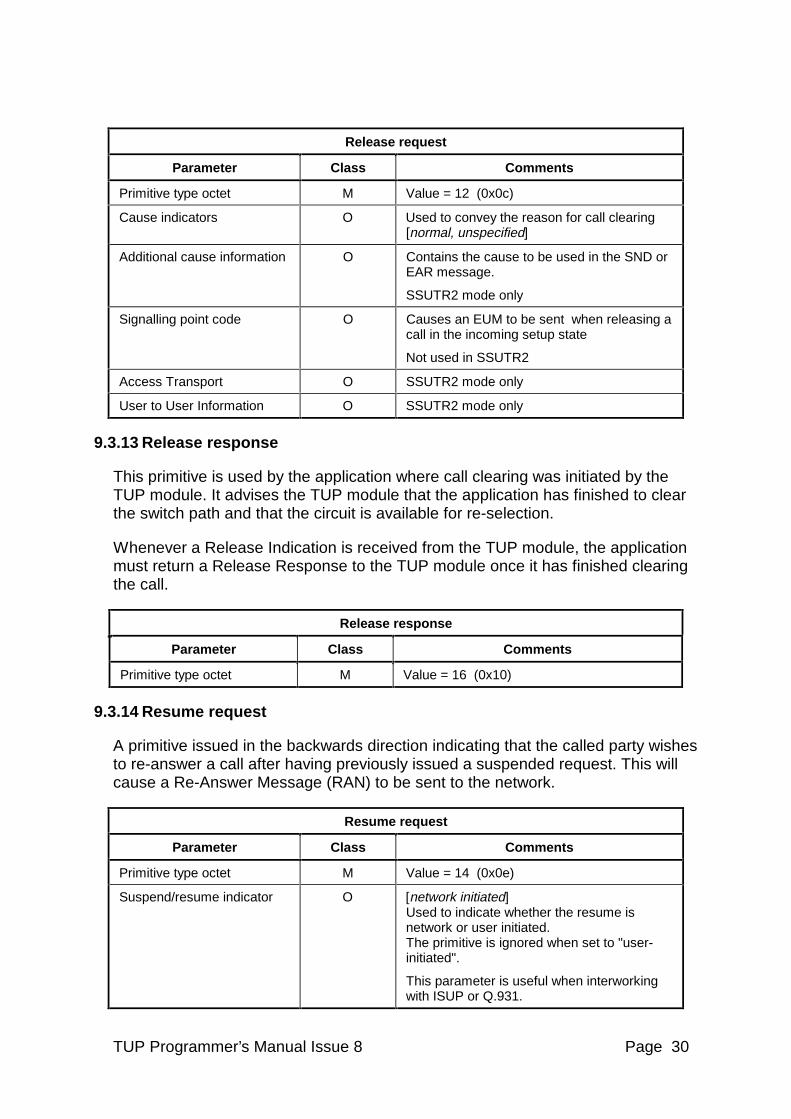
Release request
Parameter Class Comments
Primitive type octet M Value = 12 (0x0c)
Cause indicators O Used to convey the reason for call clearing [normal, unspecified]
Additional cause information O Contains the cause to be used in the SND or EAR message.
SSUTR2 mode only
Signalling point code O Causes an EUM to be sent when releasing a call in the incoming setup state
Not used in SSUTR2
Access Transport O SSUTR2 mode only
User to User Information O SSUTR2 mode only
9.3.13 Release response
This primitive is used by the application where call clearing was initiated by the TUP module. It advises the TUP module that the application has finished to clear the switch path and that the circuit is available for re-selection.
Whenever a Release Indication is received from the TUP module, the application must return a Release Response to the TUP module once it has finished clearing the call.
Release response
Parameter Class Comments
Primitive type octet M Value = 16 (0x10)
9.3.14 Resume request
A primitive issued in the backwards direction indicating that the called party wishes to re-answer a call after having previously issued a suspended request. This will cause a Re-Answer Message (RAN) to be sent to the network.
Resume request
Parameter Class Comments
Primitive type octet M Value = 14 (0x0e)
Suspend/resume indicator O [network initiated] Used to indicate whether the resume is network or user initiated. The primitive is ignored when set to "user-initiated".
This parameter is useful when interworking with ISUP or Q.931.
TUP Programmer’s Manual Issue 8 Page 31
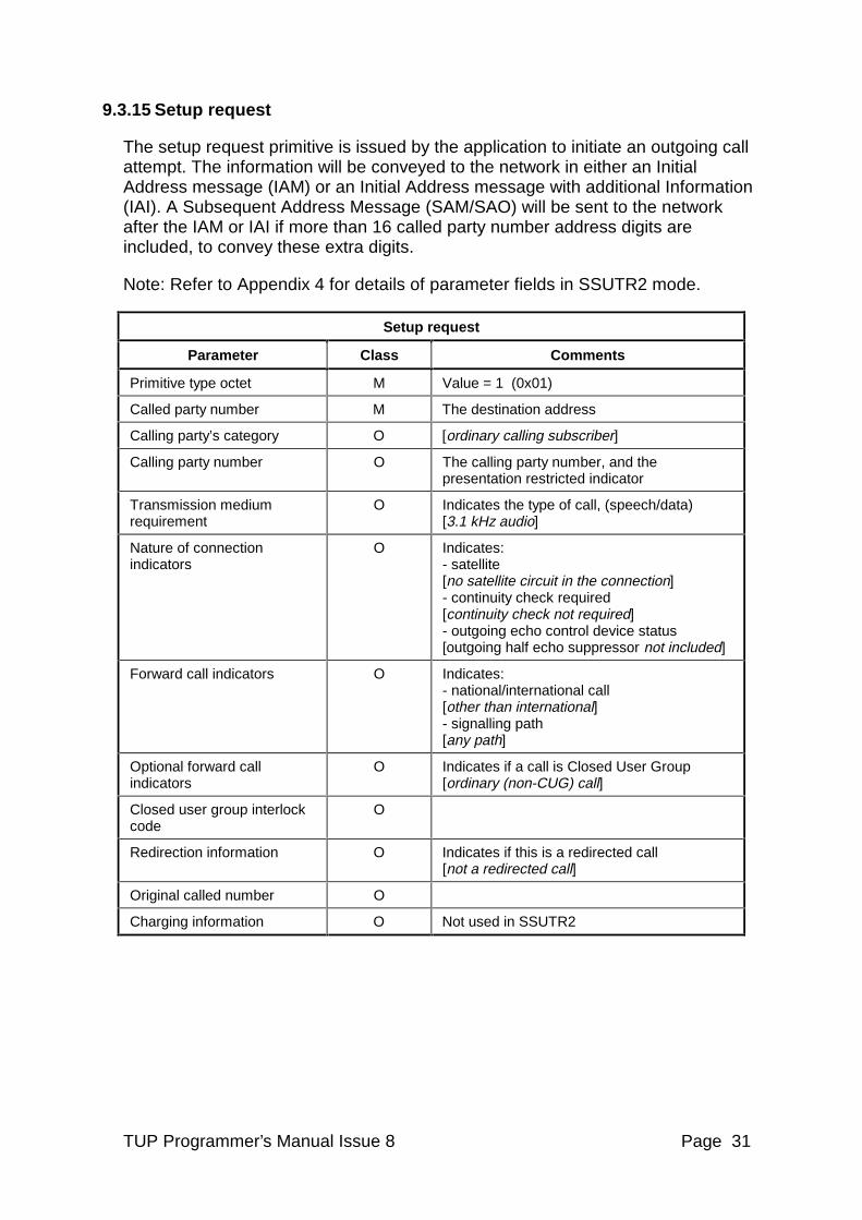
9.3.15 Setup request
The setup request primitive is issued by the application to initiate an outgoing call attempt. The information will be conveyed to the network in either an Initial Address message (IAM) or an Initial Address message with additional Information (IAI). A Subsequent Address Message (SAM/SAO) will be sent to the network after the IAM or IAI if more than 16 called party number address digits are included, to convey these extra digits.
Note: Refer to Appendix 4 for details of parameter fields in SSUTR2 mode.
Setup request
Parameter Class Comments
Primitive type octet M Value = 1 (0x01)
Called party number M The destination address
Calling party’s category O [ordinary calling subscriber]
Calling party number O The calling party number, and the presentation restricted indicator
Transmission medium requirement
O Indicates the type of call, (speech/data) [3.1 kHz audio]
Nature of connection indicators
O Indicates: - satellite [no satellite circuit in the connection] - continuity check required [continuity check not required] - outgoing echo control device status [outgoing half echo suppressor not included]
Forward call indicators O Indicates: - national/international call [other than international] - signalling path [any path]
Optional forward call indicators
O Indicates if a call is Closed User Group [ordinary (non-CUG) call]
Closed user group interlock code
O
Redirection information O Indicates if this is a redirected call [not a redirected call]
Original called number O
Charging information O Not used in SSUTR2
TUP Programmer’s Manual Issue 8 Page 32
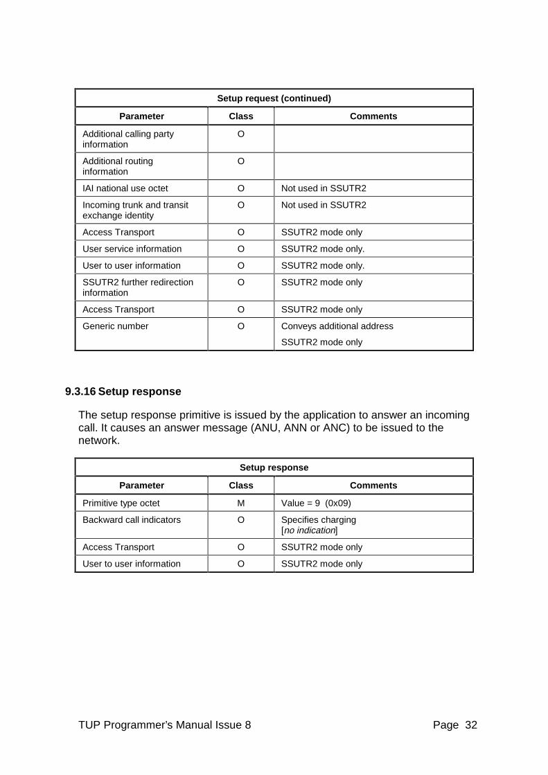
Setup request (continued)
Parameter Class Comments
Additional calling party information
O
Additional routing information
O
IAI national use octet O Not used in SSUTR2
Incoming trunk and transit exchange identity
O Not used in SSUTR2
Access Transport O SSUTR2 mode only
User service information O SSUTR2 mode only.
User to user information O SSUTR2 mode only.
SSUTR2 further redirection information
O SSUTR2 mode only
Access Transport O SSUTR2 mode only
Generic number O Conveys additional address
SSUTR2 mode only
9.3.16 Setup response
The setup response primitive is issued by the application to answer an incoming call. It causes an answer message (ANU, ANN or ANC) to be issued to the network.
Setup response
Parameter Class Comments
Primitive type octet M Value = 9 (0x09)
Backward call indicators
O Specifies charging [no indication]
Access Transport O SSUTR2 mode only
User to user information O SSUTR2 mode only
TUP Programmer’s Manual Issue 8 Page 33
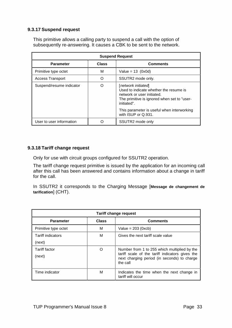
9.3.17 Suspend request
This primitive allows a calling party to suspend a call with the option of subsequently re-answering. It causes a CBK to be sent to the network.
Suspend Request
Parameter Class Comments
Primitive type octet M Value = 13 (0x0d)
Access Transport O SSUTR2 mode only.
Suspend/resume indicator O [network initiated] Used to indicate whether the resume is network or user initiated. The primitive is ignored when set to "user-initiated".
This parameter is useful when interworking with ISUP or Q.931.
User to user information O SSUTR2 mode only
9.3.18 Tariff change request
Only for use with circuit groups configured for SSUTR2 operation.
The tariff change request primitive is issued by the application for an incoming call after this call has been answered and contains information about a change in tariff for the call.
In SSUTR2 it corresponds to the Charging Message [Message de changement de tarification] (CHT).
Tariff change request
Parameter Class Comments
Primitive type octet M Value = 203 (0xcb)
Tariff indicators
(next)
M Gives the next tariff scale value
Tariff factor
(next)
O Number from 1 to 255 which multiplied by the tariff scale of the tariff indicators gives the next charging period (in seconds) to charge the call
Time indicator M Indicates the time when the next change in tariff will occur
TUP Programmer’s Manual Issue 8 Page 34
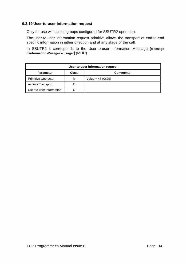
9.3.19 User-to-user information request
Only for use with circuit groups configured for SSUTR2 operation.
The user-to-user information request primitive allows the transport of end-to-end specific information in either direction and at any stage of the call.
In SSUTR2 it corresponds to the User-to-user Information Message [Message d'information d'usager à usager ] (MUU).
User-to-user information request
Parameter Class Comments
Primitive type octet M Value = 45 (0x2d)
Access Transport O
User to user information O
TUP Programmer’s Manual Issue 8 Page 35
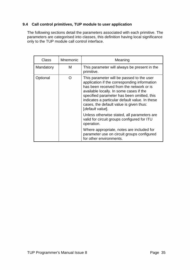
9.4 Call control primitives, TUP module to user application
The following sections detail the parameters associated with each primitive. The parameters are categorised into classes, this definition having local significance only to the TUP module call control interface.
Class Mnemonic Meaning
Mandatory M This parameter will always be present in the primitive.
Optional O This parameter will be passed to the user application if the corresponding information has been received from the network or is available locally. In some cases if the specified parameter has been omitted, this indicates a particular default value. In these cases, the default value is given thus: [default value].
Unless otherwise stated, all parameters are valid for circuit groups configured for ITU operation.
Where appropriate, notes are included for parameter use on circuit groups configured for other environments.
TUP Programmer’s Manual Issue 8 Page 36
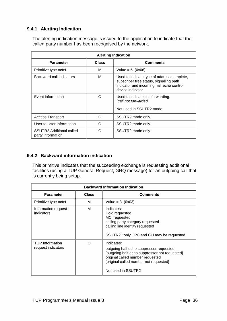
9.4.1 Alerting Indication
The alerting indication message is issued to the application to indicate that the called party number has been recognised by the network.
Alerting Indication
Parameter Class Comments
Primitive type octet M Value = 6 (0x06)
Backward call indicators M Used to indicate type of address complete, subscriber free status, signalling path indicator and incoming half echo control device indicator
Event information O Used to indicate call forwarding. [call not forwarded]
Not used in SSUTR2 mode
Access Transport O SSUTR2 mode only.
User to User Information O SSUTR2 mode only.
SSUTR2 Additional called party information
O SSUTR2 mode only
9.4.2 Backward information indication
This primitive indicates that the succeeding exchange is requesting additional facilities (using a TUP General Request, GRQ message) for an outgoing call that is currently being setup.
Backward Information Indication
Parameter Class Comments
Primitive type octet M Value = 3 (0x03)
Information request indicators
M Indicates: Hold requested MCI requested calling party category requested calling line identity requested
SSUTR2 : only CPC and CLI may be requested.
TUP Information request indicators
O Indicates:
outgoing half echo suppressor requested [outgoing half echo suppressor not requested] original called number requested [original called number not requested]
Not used in SSUTR2
TUP Programmer’s Manual Issue 8 Page 37
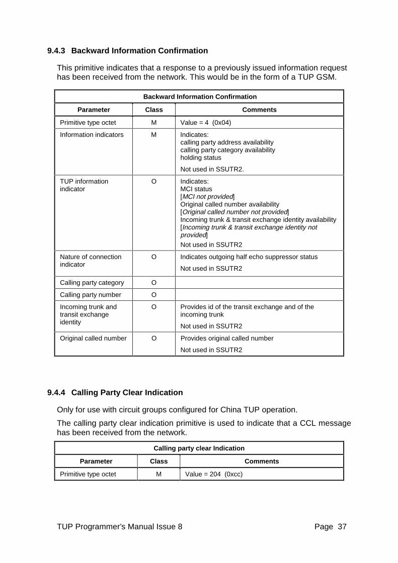
9.4.3 Backward Information Confirmation
This primitive indicates that a response to a previously issued information request has been received from the network. This would be in the form of a TUP GSM.
Backward Information Confirmation
Parameter Class Comments
Primitive type octet M Value = 4 (0x04)
Information indicators M Indicates: calling party address availability calling party category availability holding status
Not used in SSUTR2.
TUP information indicator
O Indicates: MCI status [MCI not provided] Original called number availability [Original called number not provided] Incoming trunk & transit exchange identity availability [Incoming trunk & transit exchange identity not provided]
Not used in SSUTR2
Nature of connection indicator
O Indicates outgoing half echo suppressor status
Not used in SSUTR2
Calling party category O
Calling party number O
Incoming trunk and transit exchange identity
O Provides id of the transit exchange and of the incoming trunk
Not used in SSUTR2
Original called number O Provides original called number
Not used in SSUTR2
9.4.4 Calling Party Clear Indication
Only for use with circuit groups configured for China TUP operation.
The calling party clear indication primitive is used to indicate that a CCL message has been received from the network.
Calling party clear Indication
Parameter Class Comments
Primitive type octet M Value = 204 (0xcc)
TUP Programmer’s Manual Issue 8 Page 38
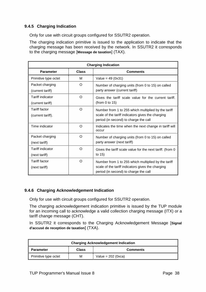
9.4.5 Charging Indication
Only for use with circuit groups configured for SSUTR2 operation.
The charging indication primitive is issued to the application to indicate that the charging message has been received by the network. In SSUTR2 it corresponds to the charging message [Message de taxation] (TAX).
Charging Indication
Parameter Class Comments
Primitive type octet M Value = 49 (0x31)
Packet charging
(current tariff)
O Number of charging units (from 0 to 15) on called party answer (current tariff)
Tariff indicator
(current tariff)
O Gives the tariff scale value for the current tariff. (from 0 to 15)
Tariff factor
(current tariff).
O Number from 1 to 255 which multiplied by the tariff scale of the tariff indicators gives the charging period (in second) to charge the call
Time indicator O Indicates the time when the next change in tariff will occur
Packet charging
(next tariff)
O Number of charging units (from 0 to 15) on called party answer (next tariff)
Tariff indicator
(next tariff)
O Gives the tariff scale value for the next tariff. (from 0 to 15)
Tariff factor
(next tariff)
O Number from 1 to 255 which multiplied by the tariff scale of the tariff indicators gives the charging period (in second) to charge the call
9.4.6 Charging Acknowledgement Indication
Only for use with circuit groups configured for SSUTR2 operation.
The charging acknowledgement indication primitive is issued by the TUP module for an incoming call to acknowledge a valid collection charging message (ITX) or a tariff change message (CHT).
In SSUTR2 it corresponds to the Charging Acknowledgement Message [Signal d'accusé de reception de taxation ] (TXA).
Charging Acknowledgement Indication
Parameter Class Comments
Primitive type octet M Value = 202 (0xca)
TUP Programmer’s Manual Issue 8 Page 39
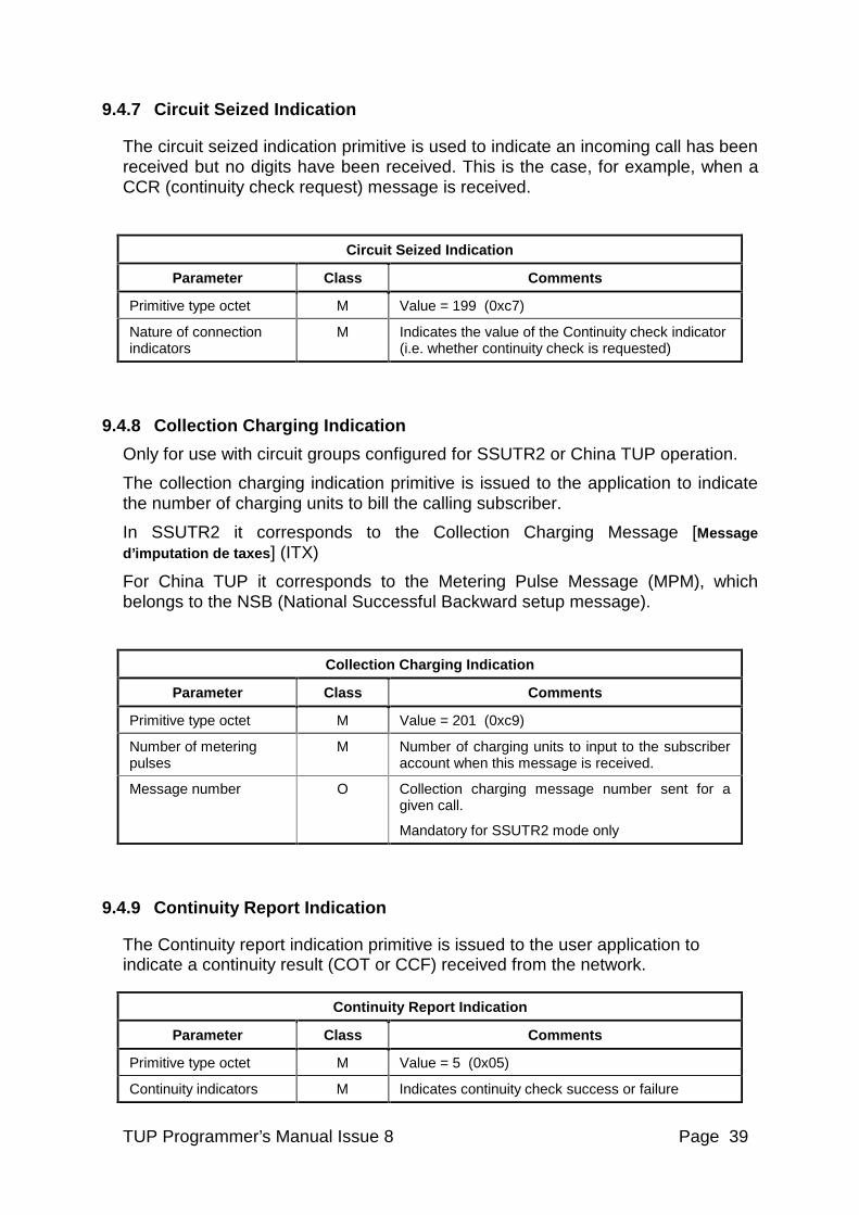
9.4.7 Circuit Seized Indication
The circuit seized indication primitive is used to indicate an incoming call has been received but no digits have been received. This is the case, for example, when a CCR (continuity check request) message is received.
Circuit Seized Indication
Parameter Class Comments
Primitive type octet M Value = 199 (0xc7)
Nature of connection indicators
M Indicates the value of the Continuity check indicator (i.e. whether continuity check is requested)
9.4.8 Collection Charging Indication
Only for use with circuit groups configured for SSUTR2 or China TUP operation.
The collection charging indication primitive is issued to the application to indicate the number of charging units to bill the calling subscriber.
In SSUTR2 it corresponds to the Collection Charging Message [Message d’imputation de taxes] (ITX)
For China TUP it corresponds to the Metering Pulse Message (MPM), which belongs to the NSB (National Successful Backward setup message).
Collection Charging Indication
Parameter Class Comments
Primitive type octet M Value = 201 (0xc9)
Number of metering pulses
M Number of charging units to input to the subscriber account when this message is received.
Message number O Collection charging message number sent for a given call.
Mandatory for SSUTR2 mode only
9.4.9 Continuity Report Indication
The Continuity report indication primitive is issued to the user application to indicate a continuity result (COT or CCF) received from the network.
Continuity Report Indication
Parameter Class Comments
Primitive type octet M Value = 5 (0x05)
Continuity indicators M Indicates continuity check success or failure
TUP Programmer’s Manual Issue 8 Page 40
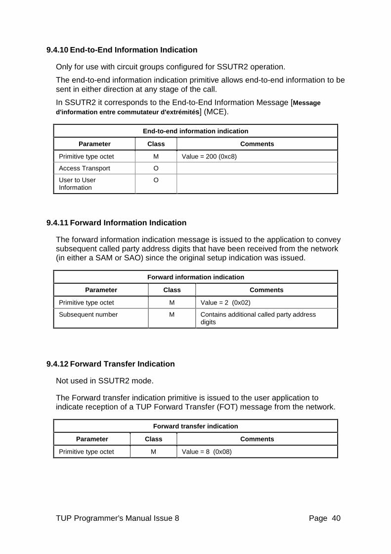
9.4.10 End-to-End Information Indication
Only for use with circuit groups configured for SSUTR2 operation.
The end-to-end information indication primitive allows end-to-end information to be sent in either direction at any stage of the call.
In SSUTR2 it corresponds to the End-to-End Information Message [Message d'information entre commutateur d'extrémité s] (MCE).
End-to-end information indication
Parameter Class Comments
Primitive type octet M Value = 200 (0xc8)
Access Transport O
User to User Information
O
9.4.11 Forward Information Indication
The forward information indication message is issued to the application to convey subsequent called party address digits that have been received from the network (in either a SAM or SAO) since the original setup indication was issued.
Forward information indication
Parameter Class Comments
Primitive type octet M Value = 2 (0x02)
Subsequent number M Contains additional called party address digits
9.4.12 Forward Transfer Indication
Not used in SSUTR2 mode.
The Forward transfer indication primitive is issued to the user application to indicate reception of a TUP Forward Transfer (FOT) message from the network.
Forward transfer indication
Parameter Class Comments
Primitive type octet M Value = 8 (0x08)
TUP Programmer’s Manual Issue 8 Page 41
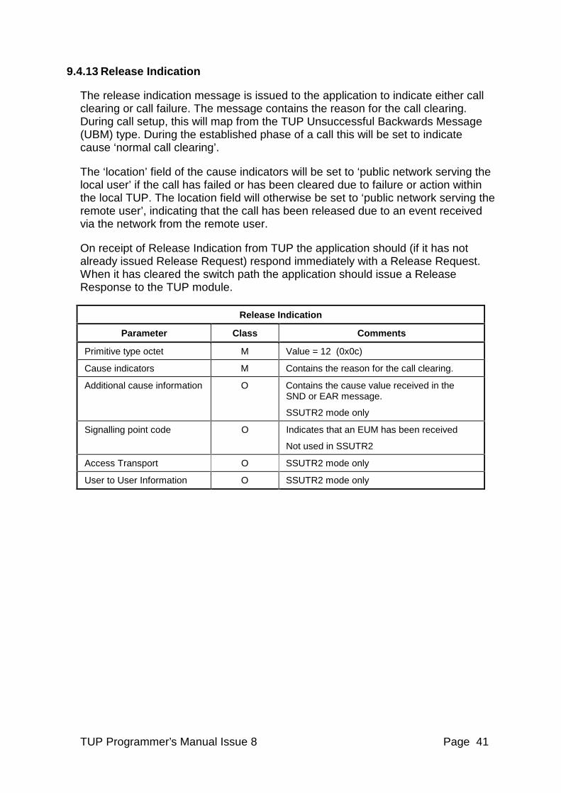
9.4.13 Release Indication
The release indication message is issued to the application to indicate either call clearing or call failure. The message contains the reason for the call clearing. During call setup, this will map from the TUP Unsuccessful Backwards Message (UBM) type. During the established phase of a call this will be set to indicate cause ‘normal call clearing’.
The ‘location’ field of the cause indicators will be set to ‘public network serving the local user’ if the call has failed or has been cleared due to failure or action within the local TUP. The location field will otherwise be set to ‘public network serving the remote user’, indicating that the call has been released due to an event received via the network from the remote user.
On receipt of Release Indication from TUP the application should (if it has not already issued Release Request) respond immediately with a Release Request. When it has cleared the switch path the application should issue a Release Response to the TUP module.
Release Indication
Parameter Class Comments
Primitive type octet M Value = 12 (0x0c)
Cause indicators M Contains the reason for the call clearing.
Additional cause information O Contains the cause value received in the SND or EAR message.
SSUTR2 mode only
Signalling point code O Indicates that an EUM has been received
Not used in SSUTR2
Access Transport O SSUTR2 mode only
User to User Information O SSUTR2 mode only
TUP Programmer’s Manual Issue 8 Page 42
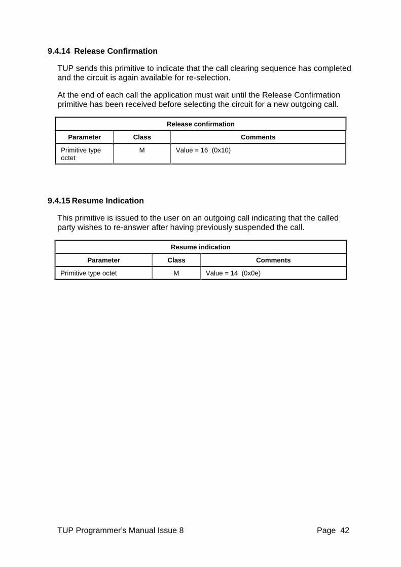
9.4.14 Release Confirmation
TUP sends this primitive to indicate that the call clearing sequence has completed and the circuit is again available for re-selection.
At the end of each call the application must wait until the Release Confirmation primitive has been received before selecting the circuit for a new outgoing call.
Release confirmation
Parameter Class Comments
Primitive type octet
M Value = 16 (0x10)
9.4.15 Resume Indication
This primitive is issued to the user on an outgoing call indicating that the called party wishes to re-answer after having previously suspended the call.
Resume indication
Parameter Class Comments
Primitive type octet M Value = 14 (0x0e)
TUP Programmer’s Manual Issue 8 Page 43
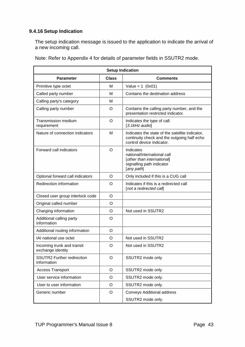
9.4.16 Setup Indication
The setup indication message is issued to the application to indicate the arrival of a new incoming call.
Note: Refer to Appendix 4 for details of parameter fields in SSUTR2 mode.
Setup Indication
Parameter Class Comments
Primitive type octet M Value = 1 (0x01)
Called party number M Contains the destination address
Calling party’s category M
Calling party number O Contains the calling party number, and the presentation restricted indicator.
Transmission medium requirement
O Indicates the type of call. [3.1kHz audio]
Nature of connection indicators M Indicates the state of the satellite indicator, continuity check and the outgoing half echo control device indicator.
Forward call indicators O Indicates national/international call [other than international] signalling path indicator [any path]
Optional forward call indicators O Only included if this is a CUG call
Redirection information O Indicates if this is a redirected call [not a redirected call]
Closed user group interlock code O
Original called number O
Charging information O Not used in SSUTR2
Additional calling party information
O
Additional routing information O
IAI national use octet O Not used in SSUTR2
Incoming trunk and transit exchange identity
O Not used in SSUTR2
SSUTR2 Further redirection information
O SSUTR2 mode only
Access Transport O SSUTR2 mode only
User service information O SSUTR2 mode only.
User to user information O SSUTR2 mode only.
Generic number O Conveys Additional address
SSUTR2 mode only.
TUP Programmer’s Manual Issue 8 Page 44
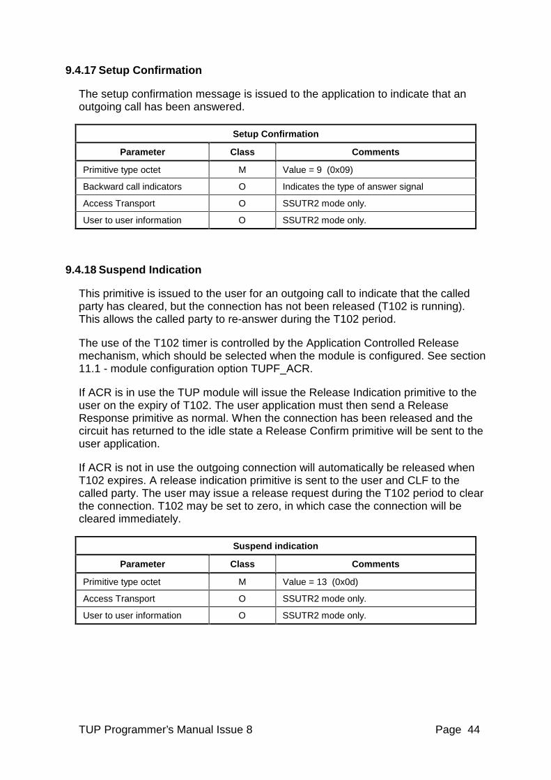
9.4.17 Setup Confirmation
The setup confirmation message is issued to the application to indicate that an outgoing call has been answered.
Setup Confirmation
Parameter Class Comments
Primitive type octet M Value = 9 (0x09)
Backward call indicators O Indicates the type of answer signal
Access Transport O SSUTR2 mode only.
User to user information O SSUTR2 mode only.
9.4.18 Suspend Indication
This primitive is issued to the user for an outgoing call to indicate that the called party has cleared, but the connection has not been released (T102 is running). This allows the called party to re-answer during the T102 period.
The use of the T102 timer is controlled by the Application Controlled Release mechanism, which should be selected when the module is configured. See section 11.1 - module configuration option TUPF_ACR.
If ACR is in use the TUP module will issue the Release Indication primitive to the user on the expiry of T102. The user application must then send a Release Response primitive as normal. When the connection has been released and the circuit has returned to the idle state a Release Confirm primitive will be sent to the user application.
If ACR is not in use the outgoing connection will automatically be released when T102 expires. A release indication primitive is sent to the user and CLF to the called party. The user may issue a release request during the T102 period to clear the connection. T102 may be set to zero, in which case the connection will be cleared immediately.
Suspend indication
Parameter Class Comments
Primitive type octet M Value = 13 (0x0d)
Access Transport O SSUTR2 mode only.
User to user information O SSUTR2 mode only.
TUP Programmer’s Manual Issue 8 Page 45
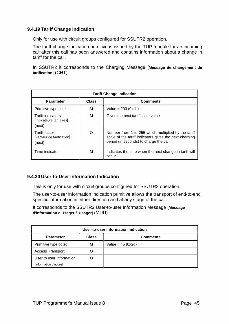
9.4.19 Tariff Change Indication
Only for use with circuit groups configured for SSUTR2 operation.
The tariff change indication primitive is issued by the TUP module for an incoming call after this call has been answered and contains information about a change in tariff for the call.
In SSUTR2 it corresponds to the Charging Message [Message de changement de tarification] (CHT)
Tariff Change Indication
Parameter Class Comments
Primitive type octet M Value = 203 (0xcb)
Tariff indicators [Indicateurs tarifaires]
(next)
M Gives the next tariff scale value
Tariff factor [Facteur de tarification]
(next)
O Number from 1 to 255 which multiplied by the tariff scale of the tariff indicators gives the next charging period (in seconds) to charge the call
Time indicator
M Indicates the time when the next change in tariff will occur
9.4.20 User-to-User Information Indication
This is only for use with circuit groups configured for SSUTR2 operation.
The user-to-user information indication primitive allows the transport of end-to-end specific information in either direction and at any stage of the call.
It corresponds to the SSUTR2 User-to-user Information Message [Message d'information d'Usager à Usager ] (MUU).
User-to-user information indication
Parameter Class Comments
Primitive type octet M Value = 45 (0x2d)
Access Transport O
User to user information
[Information d'accès]
O
TUP Programmer’s Manual Issue 8 Page 46
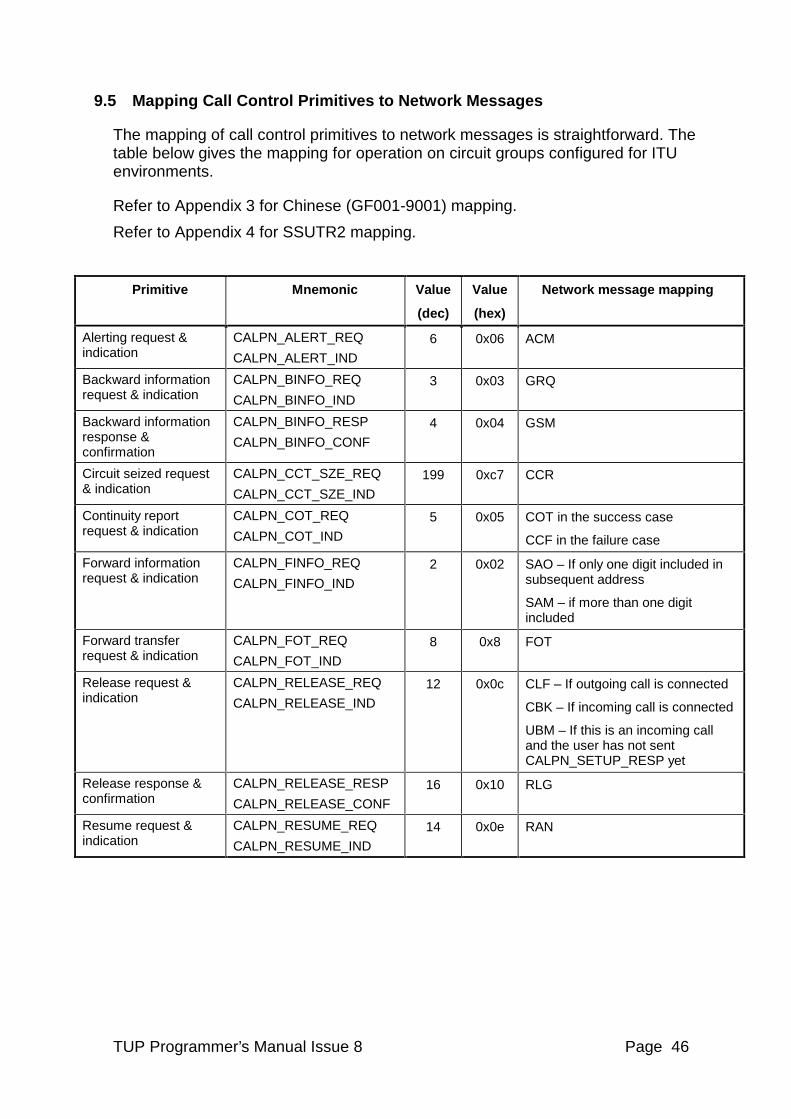
9.5 Mapping Call Control Primitives to Network Messages
The mapping of call control primitives to network messages is straightforward. The table below gives the mapping for operation on circuit groups configured for ITU environments.
Refer to Appendix 3 for Chinese (GF001-9001) mapping.
Refer to Appendix 4 for SSUTR2 mapping.
Primitive Mnemonic Value
(dec)
Value
(hex)
Network message mapping
Alerting request & indication
CALPN_ALERT_REQ
CALPN_ALERT_IND
6 0x06 ACM
Backward information request & indication
CALPN_BINFO_REQ
CALPN_BINFO_IND
3 0x03 GRQ
Backward information response & confirmation
CALPN_BINFO_RESP
CALPN_BINFO_CONF
4 0x04 GSM
Circuit seized request & indication
CALPN_CCT_SZE_REQ
CALPN_CCT_SZE_IND
199 0xc7 CCR
Continuity report request & indication
CALPN_COT_REQ
CALPN_COT_IND
5 0x05 COT in the success case
CCF in the failure case
Forward information request & indication
CALPN_FINFO_REQ
CALPN_FINFO_IND
2 0x02 SAO – If only one digit included in subsequent address
SAM – if more than one digit included
Forward transfer request & indication
CALPN_FOT_REQ
CALPN_FOT_IND
8 0x8 FOT
Release request & indication
CALPN_RELEASE_REQ
CALPN_RELEASE_IND
12 0x0c CLF – If outgoing call is connected
CBK – If incoming call is connected
UBM – If this is an incoming call and the user has not sent CALPN_SETUP_RESP yet
Release response & confirmation
CALPN_RELEASE_RESP
CALPN_RELEASE_CONF
16 0x10 RLG
Resume request & indication
CALPN_RESUME_REQ
CALPN_RESUME_IND
14 0x0e RAN
TUP Programmer’s Manual Issue 8 Page 47
Primitive Mnemonic Value
(dec)
Value
(hex)
Network message mapping
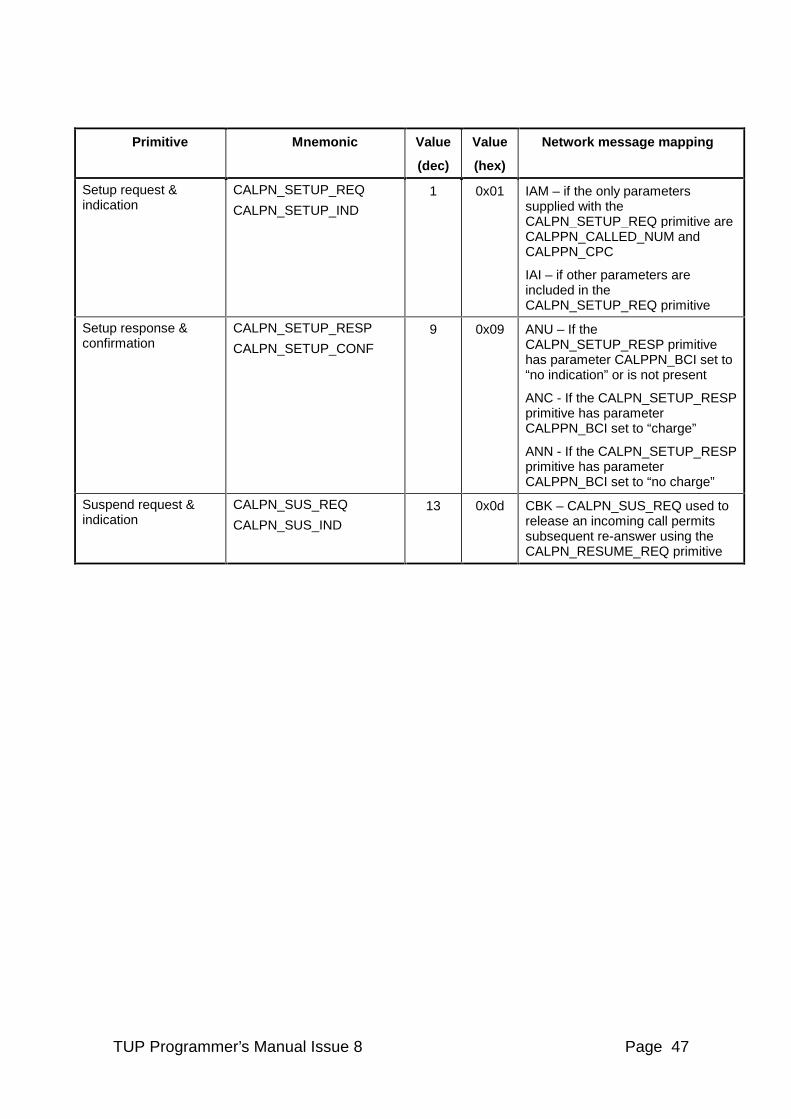
Setup request & indication
CALPN_SETUP_REQ
CALPN_SETUP_IND
1 0x01 IAM – if the only parameters supplied with the CALPN_SETUP_REQ primitive are CALPPN_CALLED_NUM and CALPPN_CPC
IAI – if other parameters are included in the CALPN_SETUP_REQ primitive
Setup response & confirmation
CALPN_SETUP_RESP
CALPN_SETUP_CONF
9 0x09 ANU – If the CALPN_SETUP_RESP primitive has parameter CALPPN_BCI set to “no indication” or is not present
ANC - If the CALPN_SETUP_RESP primitive has parameter CALPPN_BCI set to “charge”
ANN - If the CALPN_SETUP_RESP primitive has parameter CALPPN_BCI set to “no charge”
Suspend request & indication
CALPN_SUS_REQ
CALPN_SUS_IND
13 0x0d CBK – CALPN_SUS_REQ used to release an incoming call permits subsequent re-answer using the CALPN_RESUME_REQ primitive
TUP Programmer’s Manual Issue 8 Page 48
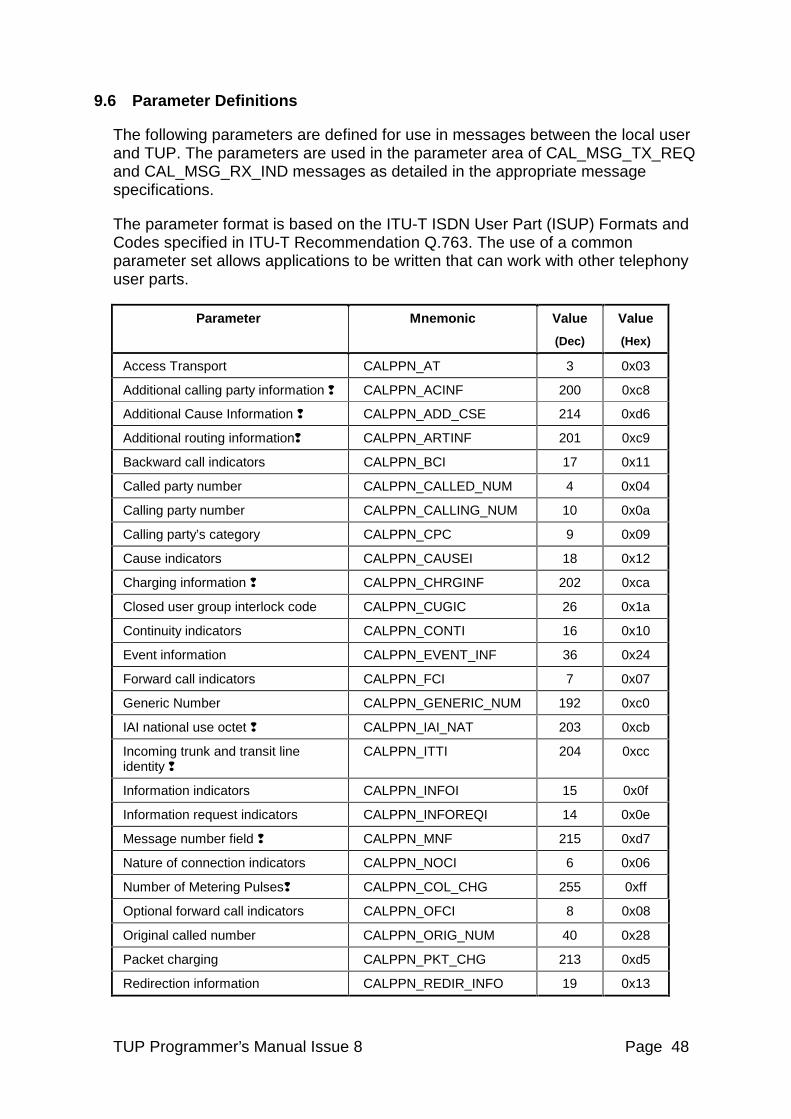
9.6 Parameter Definitions
The following parameters are defined for use in messages between the local user and TUP. The parameters are used in the parameter area of CAL_MSG_TX_REQ and CAL_MSG_RX_IND messages as detailed in the appropriate message specifications.
The parameter format is based on the ITU-T ISDN User Part (ISUP) Formats and Codes specified in ITU-T Recommendation Q.763. The use of a common parameter set allows applications to be written that can work with other telephony user parts.
Parameter Mnemonic Value
(Dec)
Value
(Hex)
Access Transport CALPPN_AT 3 0x03
Additional calling party information q CALPPN_ACINF 200 0xc8
Additional Cause Information q CALPPN_ADD_CSE 214 0xd6
Additional routing informationq CALPPN_ARTINF 201 0xc9
Backward call indicators CALPPN_BCI 17 0x11
Called party number CALPPN_CALLED_NUM 4 0x04
Calling party number CALPPN_CALLING_NUM 10 0x0a
Calling party’s category CALPPN_CPC 9 0x09
Cause indicators CALPPN_CAUSEI 18 0x12
Charging information q CALPPN_CHRGINF 202 0xca
Closed user group interlock code CALPPN_CUGIC 26 0x1a
Continuity indicators CALPPN_CONTI 16 0x10
Event information CALPPN_EVENT_INF 36 0x24
Forward call indicators CALPPN_FCI 7 0x07
Generic Number CALPPN_GENERIC_NUM 192 0xc0
IAI national use octet q CALPPN_IAI_NAT 203 0xcb
Incoming trunk and transit line identity q
CALPPN_ITTI 204 0xcc
Information indicators CALPPN_INFOI 15 0x0f
Information request indicators CALPPN_INFOREQI 14 0x0e
Message number field q CALPPN_MNF 215 0xd7
Nature of connection indicators CALPPN_NOCI 6 0x06
Number of Metering Pulsesq CALPPN_COL_CHG 255 0xff
Optional forward call indicators CALPPN_OFCI 8 0x08
Original called number CALPPN_ORIG_NUM 40 0x28
Packet charging CALPPN_PKT_CHG 213 0xd5
Redirection information CALPPN_REDIR_INFO 19 0x13
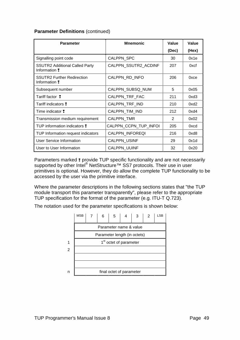
TUP Programmer’s Manual Issue 8 Page 49
Parameter Definitions (continued)
Parameter Mnemonic Value
(Dec)
Value
(Hex)
Signalling point code CALPPN_SPC 30 0x1e
SSUTR2 Additional Called Party Information q
CALPPN_SSUTR2_ACDINF 207 0xcf
SSUTR2 Further Redirection Information q
CALPPN_RD_INFO 206 0xce
Subsequent number CALPPN_SUBSQ_NUM 5 0x05
Tariff factor q CALPPN_TRF_FAC 211 0xd3
Tariff indicators q CALPPN_TRF_IND 210 0xd2
Time indicator q CALPPN_TIM_IND 212 0xd4
Transmission medium requirement CALPPN_TMR 2 0x02
TUP information indicators q CALPPN_CCPN_TUP_INFOI 205 0xcd
TUP Information request indicators CALPPN_INFOREQI 216 0xd8
User Service Information CALPPN_USINF 29 0x1d
User to User Information CALPPN_UUINF 32 0x20
Parameters marked q provide TUP specific functionality and are not necessarily supported by other Intel® NetStructure™ SS7 protocols. Their use in user primitives is optional. However, they do allow the complete TUP functionality to be accessed by the user via the primitive interface.
Where the parameter descriptions in the following sections states that "the TUP module transport this parameter transparently", please refer to the appropriate TUP specification for the format of the parameter (e.g. ITU-T Q.723).
The notation used for the parameter specifications is shown below:
MSB 7 6 5 4 3 2 LSB
Parameter name & value
Parameter length (in octets)
1 1st octet of parameter
2
n final octet of parameter
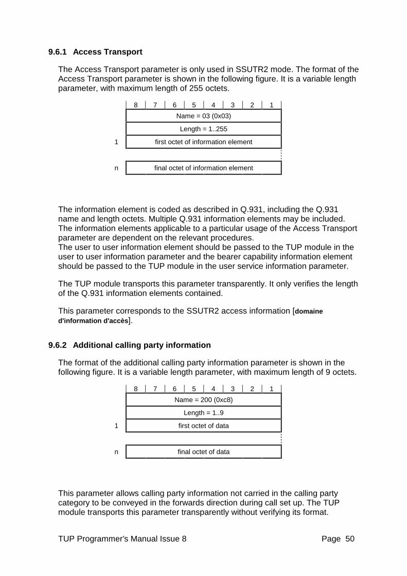
TUP Programmer’s Manual Issue 8 Page 50
9.6.1 Access Transport
The Access Transport parameter is only used in SSUTR2 mode. The format of the Access Transport parameter is shown in the following figure. It is a variable length parameter, with maximum length of 255 octets.
8 7 6 5 4 3 2 1
Name = 03 (0x03)
Length = 1..255
1 first octet of information element
n final octet of information element
The information element is coded as described in Q.931, including the Q.931 name and length octets. Multiple Q.931 information elements may be included. The information elements applicable to a particular usage of the Access Transport parameter are dependent on the relevant procedures. The user to user information element should be passed to the TUP module in the user to user information parameter and the bearer capability information element should be passed to the TUP module in the user service information parameter.
The TUP module transports this parameter transparently. It only verifies the length of the Q.931 information elements contained.
This parameter corresponds to the SSUTR2 access information [domaine d'information d'accès ].
9.6.2 Additional calling party information
The format of the additional calling party information parameter is shown in the following figure. It is a variable length parameter, with maximum length of 9 octets.
8 7 6 5 4 3 2 1
Name = 200 (0xc8)
Length = 1..9
1 first octet of data
n final octet of data
This parameter allows calling party information not carried in the calling party category to be conveyed in the forwards direction during call set up. The TUP module transports this parameter transparently without verifying its format.
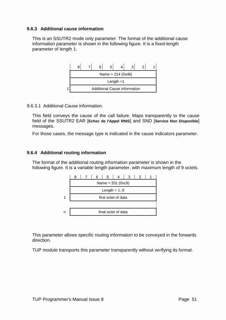
TUP Programmer’s Manual Issue 8 Page 51
9.6.3 Additional cause information
This is an SSUTR2 mode only parameter. The format of the additional cause information parameter is shown in the following figure. It is a fixed-length parameter of length 1.
8 7 6 5 4 3 2 1
Name = 214 (0xd6)
Length =1
1 Additional Cause information
9.6.3.1 Additional Cause information.
This field conveys the cause of the call failure. Maps transparently to the cause field of the SSUTR2 EAR [Echec de l’Appel RNIS] and SND [Service Non Disponible] messages.
For those cases, the message type is indicated in the cause indicators parameter.
9.6.4 Additional routing information
The format of the additional routing information parameter is shown in the following figure. It is a variable length parameter, with maximum length of 9 octets.
8 7 6 5 4 3 2 1
Name = 201 (0xc9)
Length = 1..9
1 first octet of data
n final octet of data
This parameter allows specific routing information to be conveyed in the forwards direction.
TUP module transports this parameter transparently without verifying its format.
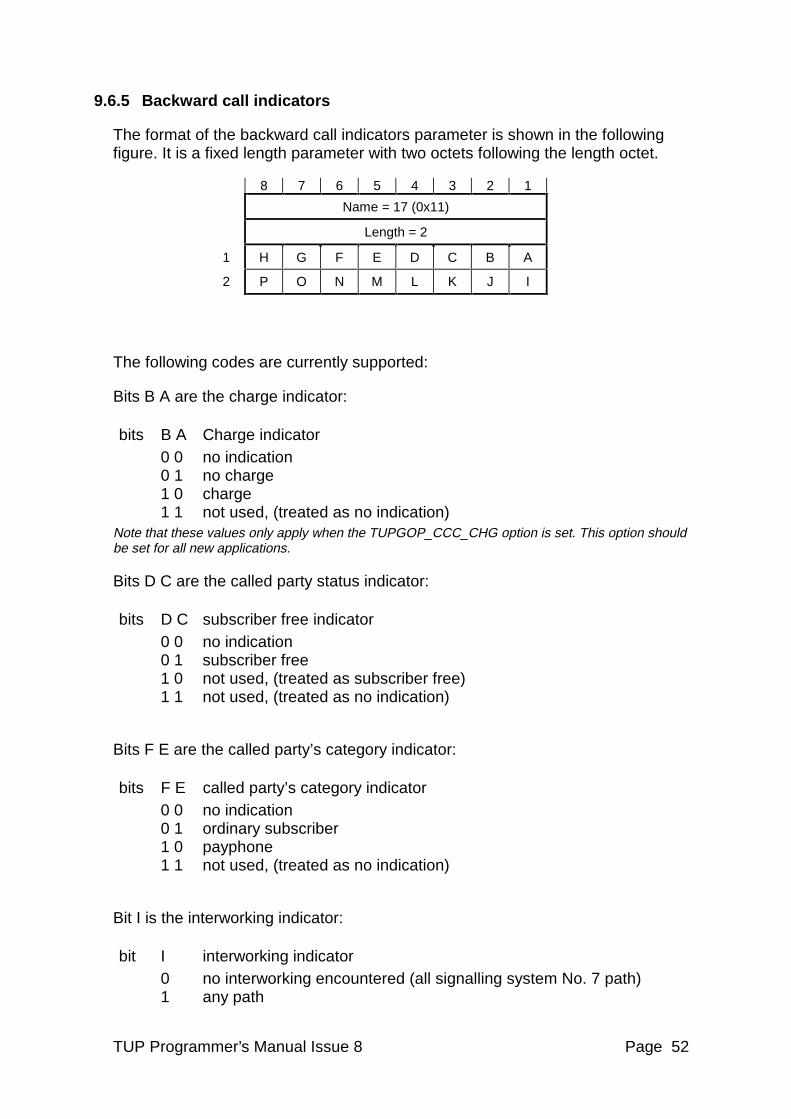
TUP Programmer’s Manual Issue 8 Page 52
9.6.5 Backward call indicators
The format of the backward call indicators parameter is shown in the following figure. It is a fixed length parameter with two octets following the length octet.
8 7 6 5 4 3 2 1
Name = 17 (0x11)
Length = 2
1 H G F E D C B A
2 P O N M L K J I
The following codes are currently supported:
Bits B A are the charge indicator:
bits B A Charge indicator 0 0 no indication 0 1 no charge 1 0 charge 1 1 not used, (treated as no indication)
Note that these values only apply when the TUPGOP_CCC_CHG option is set. This option should be set for all new applications.
Bits D C are the called party status indicator:
bits D C subscriber free indicator 0 0 no indication 0 1 subscriber free 1 0 not used, (treated as subscriber free) 1 1 not used, (treated as no indication)
Bits F E are the called party’s category indicator:
bits F E called party’s category indicator 0 0 no indication 0 1 ordinary subscriber 1 0 payphone 1 1 not used, (treated as no indication)
Bit I is the interworking indicator:
bit I interworking indicator 0 no interworking encountered (all signalling system No. 7 path) 1 any path
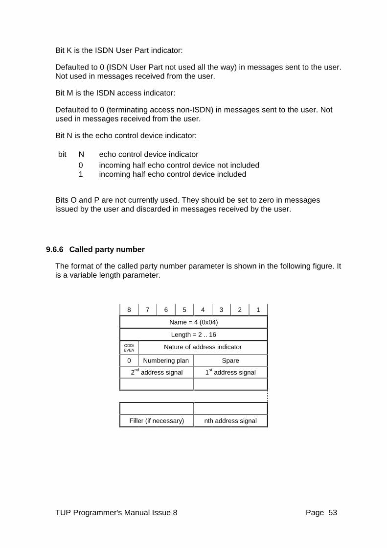
TUP Programmer’s Manual Issue 8 Page 53
Bit K is the ISDN User Part indicator:
Defaulted to 0 (ISDN User Part not used all the way) in messages sent to the user. Not used in messages received from the user.
Bit M is the ISDN access indicator:
Defaulted to 0 (terminating access non-ISDN) in messages sent to the user. Not used in messages received from the user.
Bit N is the echo control device indicator:
bit N echo control device indicator 0 incoming half echo control device not included 1 incoming half echo control device included
Bits O and P are not currently used. They should be set to zero in messages issued by the user and discarded in messages received by the user.
9.6.6 Called party number
The format of the called party number parameter is shown in the following figure. It is a variable length parameter.
8 7 6 5 4 3 2 1
Name = 4 (0x04)
Length = 2 .. 16
ODD/EVEN Nature of address indicator
0 Numbering plan Spare
2nd address signal 1st address signal
Filler (if necessary) nth address signal
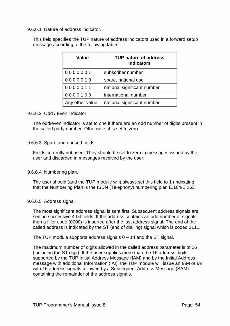
TUP Programmer’s Manual Issue 8 Page 54
9.6.6.1 Nature of address indicator.
This field specifies the TUP nature of address indicators used in a forward setup message according to the following table:
Value TUP nature of address indicators
0 0 0 0 0 0 1 subscriber number
0 0 0 0 0 1 0 spare, national use
0 0 0 0 0 1 1 national significant number
0 0 0 0 1 0 0 international number
Any other value national significant number
9.6.6.2 Odd / Even indicator.
The odd/even indicator is set to one if there are an odd number of digits present in the called party number. Otherwise, it is set to zero.
9.6.6.3 Spare and unused fields.
Fields currently not used. They should be set to zero in messages issued by the user and discarded in messages received by the user.
9.6.6.4 Numbering plan.
The user should (and the TUP module will) always set this field to 1 (indicating that the Numbering Plan is the ISDN (Telephony) numbering plan E.164/E.163.
9.6.6.5 Address signal.
The most significant address signal is sent first. Subsequent address signals are sent in successive 4-bit fields. If the address contains an odd number of signals then a filler code (0000) is inserted after the last address signal. The end of the called address is indicated by the ST (end of dialling) signal which is coded 1111.
The TUP module supports address signals 0 – 14 and the ST signal.
The maximum number of digits allowed in the called address parameter is of 26 (including the ST digit). If the user supplies more than the 16 address digits supported by the TUP Initial Address Message (IAM) and by the Initial Address message with additional Information (IAI), the TUP module will issue an IAM or IAI with 16 address signals followed by a Subsequent Address Message (SAM) containing the remainder of the address signals.
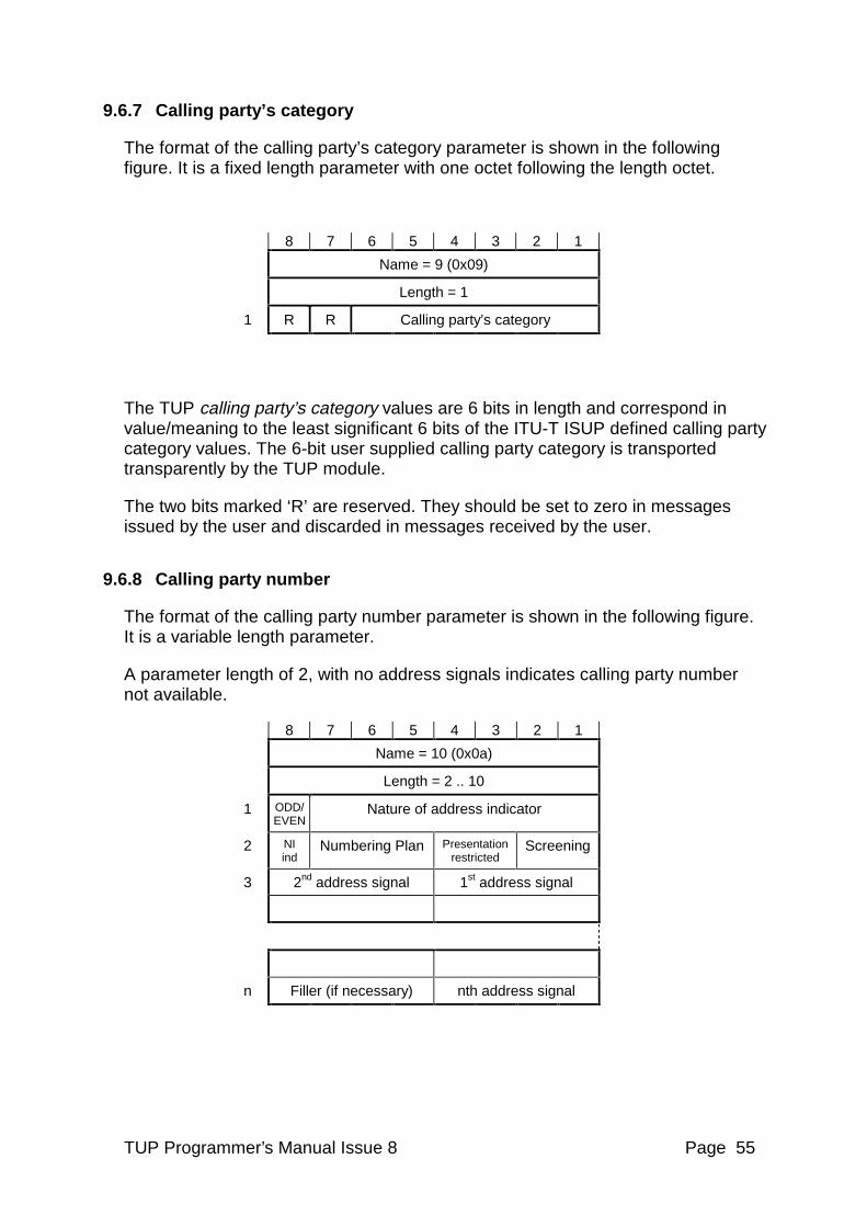
TUP Programmer’s Manual Issue 8 Page 55
9.6.7 Calling party’s category
The format of the calling party’s category parameter is shown in the following figure. It is a fixed length parameter with one octet following the length octet.
8 7 6 5 4 3 2 1
Name = 9 (0x09)
Length = 1
1 R R Calling party’s category
The TUP calling party’s category values are 6 bits in length and correspond in value/meaning to the least significant 6 bits of the ITU-T ISUP defined calling party category values. The 6-bit user supplied calling party category is transported transparently by the TUP module.
The two bits marked ‘R’ are reserved. They should be set to zero in messages issued by the user and discarded in messages received by the user.
9.6.8 Calling party number
The format of the calling party number parameter is shown in the following figure. It is a variable length parameter.
A parameter length of 2, with no address signals indicates calling party number not available.
8 7 6 5 4 3 2 1
Name = 10 (0x0a)
Length = 2 .. 10
1 ODD/ EVEN
Nature of address indicator
2 NI ind
Numbering Plan Presentation restricted
Screening
3 2nd address signal 1st address signal
n Filler (if necessary) nth address signal
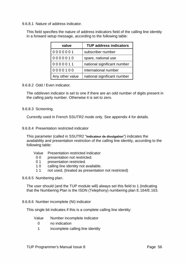
TUP Programmer’s Manual Issue 8 Page 56
9.6.8.1 Nature of address indicator.
This field specifies the nature of address indicators field of the calling line identity in a forward setup message, according to the following table:
value TUP address indicators
0 0 0 0 0 0 1 subscriber number
0 0 0 0 0 1 0 spare, national use
0 0 0 0 0 1 1 national significant number
0 0 0 0 1 0 0 international number
Any other value national significant number
9.6.8.2 Odd / Even indicator.
The odd/even indicator is set to one if there are an odd number of digits present in the calling party number. Otherwise it is set to zero.
9.6.8.3 Screening.
Currently used in French SSUTR2 mode only. See appendix 4 for details.
9.6.8.4 Presentation restricted indicator
This parameter (called in SSUTR2 "Indicateur de divulgation") indicates the availability and presentation restriction of the calling line identity, according to the following table:
Value Presentation restricted indicator 0 0 presentation not restricted. 0 1 presentation restricted. 1 0 calling line identity not available. 1 1 not used, (treated as presentation not restricted)
9.6.8.5 Numbering plan.
The user should (and the TUP module will) always set this field to 1 (indicating that the Numbering Plan is the ISDN (Telephony) numbering plan E.164/E.163.
9.6.8.6 Number incomplete (NI) indicator
This single bit indicates if this is a complete calling line identity:
Value Number incomplete indicator 0 no indication 1 incomplete calling line identity
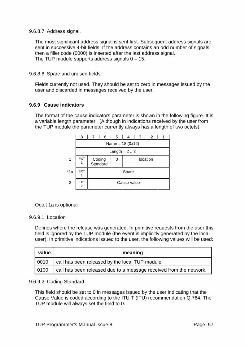
TUP Programmer’s Manual Issue 8 Page 57
9.6.8.7 Address signal.
The most significant address signal is sent first. Subsequent address signals are sent in successive 4-bit fields. If the address contains an odd number of signals then a filler code (0000) is inserted after the last address signal. The TUP module supports address signals 0 – 15.
9.6.8.8 Spare and unused fields.
Fields currently not used. They should be set to zero in messages issued by the user and discarded in messages received by the user.
9.6.9 Cause indicators
The format of the cause indicators parameter is shown in the following figure. It is a variable length parameter. (Although in indications received by the user from the TUP module the parameter currently always has a length of two octets).
8 7 6 5 4 3 2 1
Name = 18 (0x12)
Length = 2 .. 3
1 EXT 1
Coding Standard
0 location
*1a EXT 1
Spare
2 EXT2
Cause value
Octet 1a is optional
9.6.9.1 Location
Defines where the release was generated. In primitive requests from the user this field is ignored by the TUP module (the event is implicitly generated by the local user). In primitive indications issued to the user, the following values will be used:
value meaning
0010 call has been released by the local TUP module
0100 call has been released due to a message received from the network.
9.6.9.2 Coding Standard
This field should be set to 0 in messages issued by the user indicating that the Cause Value is coded according to the ITU-T (ITU) recommendation Q.764. The TUP module will always set the field to 0.
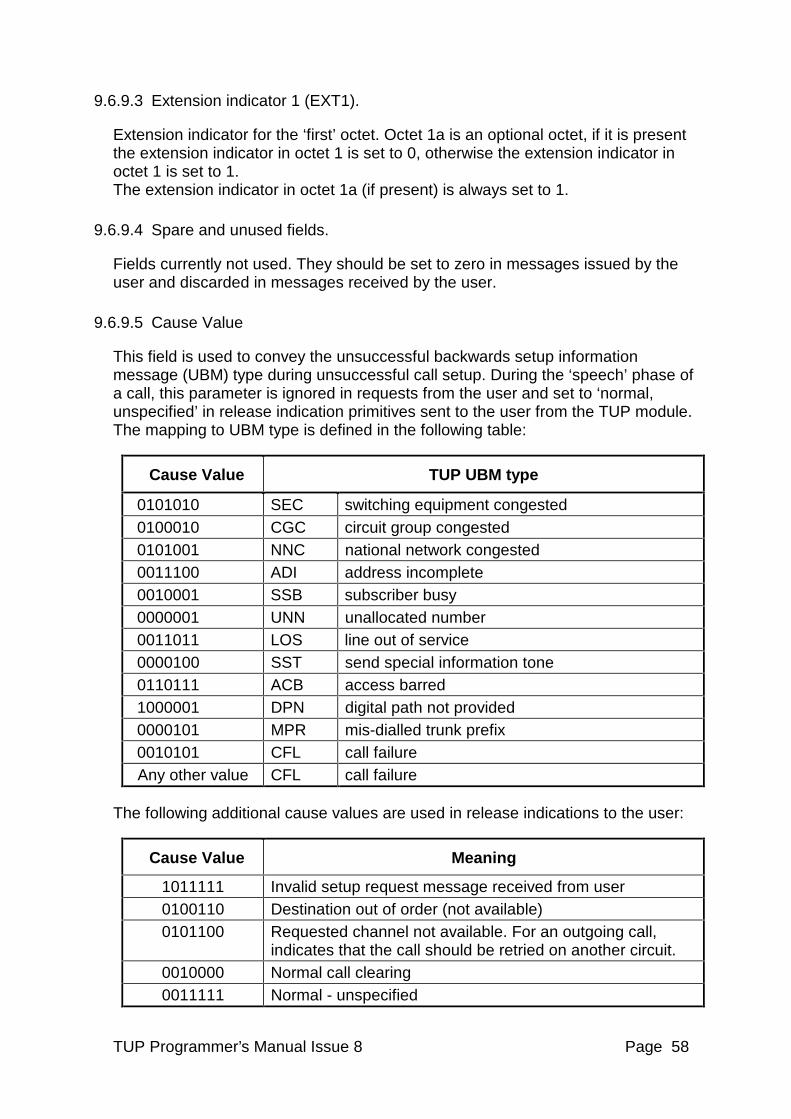
TUP Programmer’s Manual Issue 8 Page 58
9.6.9.3 Extension indicator 1 (EXT1).
Extension indicator for the ‘first’ octet. Octet 1a is an optional octet, if it is present the extension indicator in octet 1 is set to 0, otherwise the extension indicator in octet 1 is set to 1. The extension indicator in octet 1a (if present) is always set to 1.
9.6.9.4 Spare and unused fields.
Fields currently not used. They should be set to zero in messages issued by the user and discarded in messages received by the user.
9.6.9.5 Cause Value
This field is used to convey the unsuccessful backwards setup information message (UBM) type during unsuccessful call setup. During the ‘speech’ phase of a call, this parameter is ignored in requests from the user and set to ‘normal, unspecified’ in release indication primitives sent to the user from the TUP module. The mapping to UBM type is defined in the following table:
Cause Value TUP UBM type
0101010 SEC switching equipment congested 0100010 CGC circuit group congested 0101001 NNC national network congested 0011100 ADI address incomplete 0010001 SSB subscriber busy 0000001 UNN unallocated number 0011011 LOS line out of service 0000100 SST send special information tone 0110111 ACB access barred 1000001 DPN digital path not provided 0000101 MPR mis-dialled trunk prefix 0010101 CFL call failure Any other value CFL call failure
The following additional cause values are used in release indications to the user:
Cause Value Meaning
1011111 Invalid setup request message received from user 0100110 Destination out of order (not available) 0101100 Requested channel not available. For an outgoing call,
indicates that the call should be retried on another circuit. 0010000 Normal call clearing 0011111 Normal - unspecified
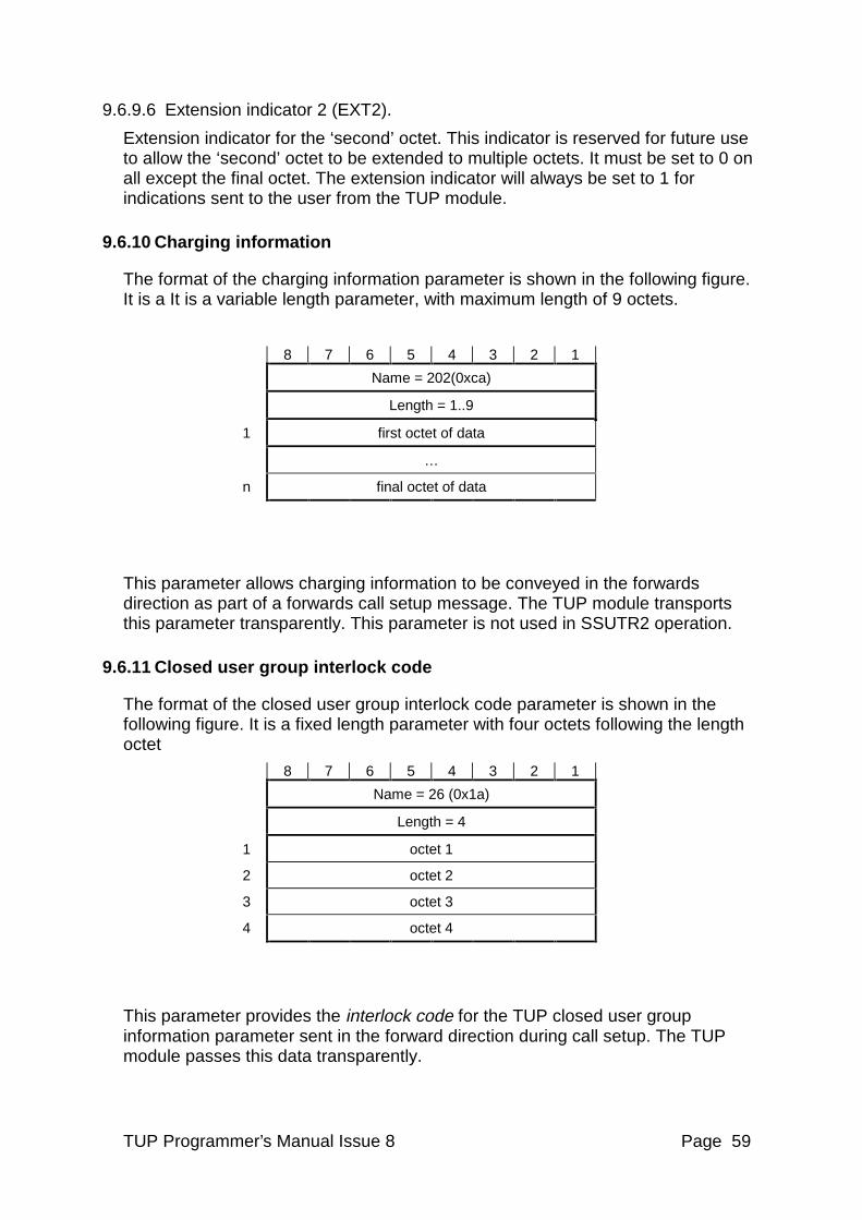
TUP Programmer’s Manual Issue 8 Page 59
9.6.9.6 Extension indicator 2 (EXT2).
Extension indicator for the ‘second’ octet. This indicator is reserved for future use to allow the ‘second’ octet to be extended to multiple octets. It must be set to 0 on all except the final octet. The extension indicator will always be set to 1 for indications sent to the user from the TUP module.
9.6.10 Charging information
The format of the charging information parameter is shown in the following figure. It is a It is a variable length parameter, with maximum length of 9 octets.
8 7 6 5 4 3 2 1
Name = 202(0xca)
Length = 1..9
1 first octet of data
…
n final octet of data
This parameter allows charging information to be conveyed in the forwards direction as part of a forwards call setup message. The TUP module transports this parameter transparently. This parameter is not used in SSUTR2 operation.
9.6.11 Closed user group interlock code
The format of the closed user group interlock code parameter is shown in the following figure. It is a fixed length parameter with four octets following the length octet
8 7 6 5 4 3 2 1
Name = 26 (0x1a)
Length = 4
1 octet 1
2 octet 2
3 octet 3
4 octet 4
This parameter provides the interlock code for the TUP closed user group information parameter sent in the forward direction during call setup. The TUP module passes this data transparently.
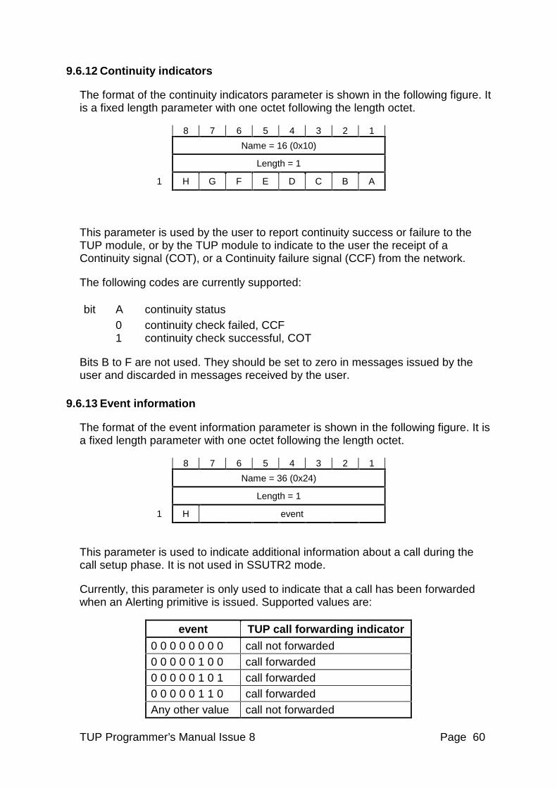
TUP Programmer’s Manual Issue 8 Page 60
9.6.12 Continuity indicators
The format of the continuity indicators parameter is shown in the following figure. It is a fixed length parameter with one octet following the length octet.
8 7 6 5 4 3 2 1
Name = 16 (0x10)
Length = 1
1 H G F E D C B A
This parameter is used by the user to report continuity success or failure to the TUP module, or by the TUP module to indicate to the user the receipt of a Continuity signal (COT), or a Continuity failure signal (CCF) from the network.
The following codes are currently supported:
bit A continuity status 0 continuity check failed, CCF 1 continuity check successful, COT
Bits B to F are not used. They should be set to zero in messages issued by the user and discarded in messages received by the user.
9.6.13 Event information
The format of the event information parameter is shown in the following figure. It is a fixed length parameter with one octet following the length octet.
8 7 6 5 4 3 2 1
Name = 36 (0x24)
Length = 1
1 H event
This parameter is used to indicate additional information about a call during the call setup phase. It is not used in SSUTR2 mode.
Currently, this parameter is only used to indicate that a call has been forwarded when an Alerting primitive is issued. Supported values are:
event TUP call forwarding indicator
0 0 0 0 0 0 0 0 call not forwarded 0 0 0 0 0 1 0 0 call forwarded 0 0 0 0 0 1 0 1 call forwarded 0 0 0 0 0 1 1 0 call forwarded Any other value call not forwarded
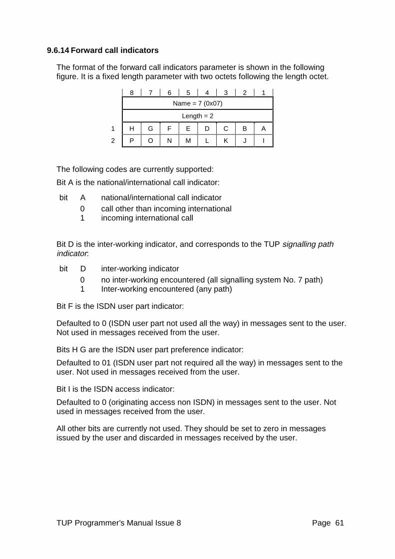
TUP Programmer’s Manual Issue 8 Page 61
9.6.14 Forward call indicators
The format of the forward call indicators parameter is shown in the following figure. It is a fixed length parameter with two octets following the length octet.
8 7 6 5 4 3 2 1
Name = 7 (0x07)
Length = 2
1 H G F E D C B A
2 P O N M L K J I
The following codes are currently supported:
Bit A is the national/international call indicator:
bit A national/international call indicator 0 call other than incoming international 1 incoming international call
Bit D is the inter-working indicator, and corresponds to the TUP signalling path indicator:
bit D inter-working indicator 0 no inter-working encountered (all signalling system No. 7 path) 1 Inter-working encountered (any path)
Bit F is the ISDN user part indicator:
Defaulted to 0 (ISDN user part not used all the way) in messages sent to the user. Not used in messages received from the user.
Bits H G are the ISDN user part preference indicator:
Defaulted to 01 (ISDN user part not required all the way) in messages sent to the user. Not used in messages received from the user.
Bit I is the ISDN access indicator:
Defaulted to 0 (originating access non ISDN) in messages sent to the user. Not used in messages received from the user.
All other bits are currently not used. They should be set to zero in messages issued by the user and discarded in messages received by the user.
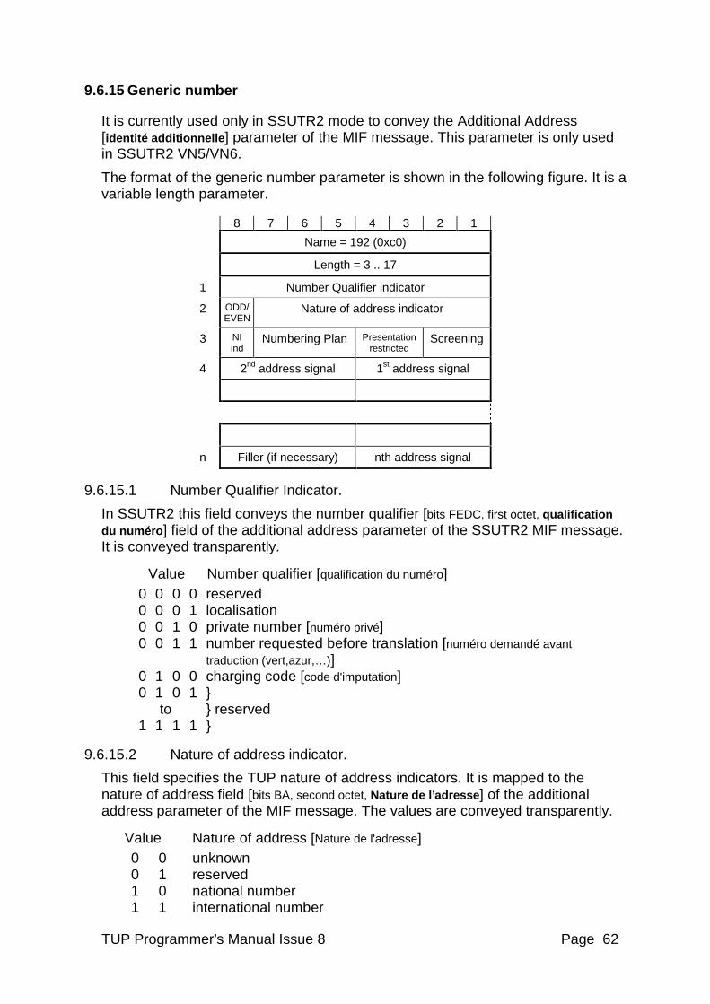
TUP Programmer’s Manual Issue 8 Page 62
9.6.15 Generic number
It is currently used only in SSUTR2 mode to convey the Additional Address [identité additionnelle ] parameter of the MIF message. This parameter is only used in SSUTR2 VN5/VN6.
The format of the generic number parameter is shown in the following figure. It is a variable length parameter.
8 7 6 5 4 3 2 1
Name = 192 (0xc0)
Length = 3 .. 17
1 Number Qualifier indicator
2 ODD/ EVEN
Nature of address indicator
3 NI ind
Numbering Plan Presentation restricted
Screening
4 2nd address signal 1st address signal
n Filler (if necessary) nth address signal
9.6.15.1 Number Qualifier Indicator.
In SSUTR2 this field conveys the number qualifier [bits FEDC, first octet, qualification du numéro ] field of the additional address parameter of the SSUTR2 MIF message. It is conveyed transparently.
Value Number qualifier [qualification du numéro] 0 0 0 0 reserved 0 0 0 1 localisation 0 0 1 0 private number [numéro privé] 0 0 1 1 number requested before translation [numéro demandé avant
traduction (vert,azur,…)] 0 1 0 0 charging code [code d'imputation] 0 1 0 1 } to } reserved 1 1 1 1 }
9.6.15.2 Nature of address indicator.
This field specifies the TUP nature of address indicators. It is mapped to the nature of address field [bits BA, second octet, Nature de l’adresse] of the additional address parameter of the MIF message. The values are conveyed transparently.
Value Nature of address [Nature de l'adresse] 0 0 unknown 0 1 reserved 1 0 national number 1 1 international number
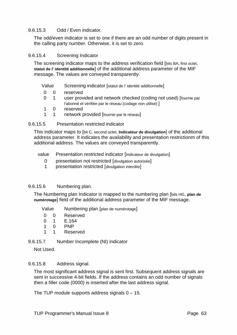
TUP Programmer’s Manual Issue 8 Page 63
9.6.15.3 Odd / Even indicator.
The odd/even indicator is set to one if there are an odd number of digits present in the calling party number. Otherwise, it is set to zero.
9.6.15.4 Screening Indicator
The screening indicator maps to the address verification field [bits BA, first octet, statut de l' identité additionnelle ] of the additional address parameter of the MIF message. The values are conveyed transparently.
Value Screening indicator [statut de l' identité additionnelle] 0 0 reserved 0 1 user provided and network checked (coding not used) [fournie par
l'abonné et vérifiée par le réseau (codage non utilisé) ] 1 0 reserved 1 1 network provided [fournie par le réseau]
9.6.15.5 Presentation restricted indicator
This indicator maps to [bit C, second octet, Indicateur de divulgation] of the additional address parameter. It indicates the availability and presentation restrictionm of this additional address. The values are conveyed transparently.
value Presentation restricted indicator [Indicateur de divulgation] 0 presentation not restricted [divulgation autorisée] 1 presentation restricted [divulgation interdite]
9.6.15.6 Numbering plan.
The Numbering plan Indicator is mapped to the numbering plan [bits HG, plan de numérotage ] field of the additional address parameter of the MIF message.
Value Numbering plan [plan de numérotage] 0 0 Reserved 0 1 E.164 1 0 PNP 1 1 Reserved
9.6.15.7 Number Incomplete (NI) indicator
Not Used.
9.6.15.8 Address signal.
The most significant address signal is sent first. Subsequent address signals are sent in successive 4-bit fields. If the address contains an odd number of signals then a filler code (0000) is inserted after the last address signal.
The TUP module supports address signals 0 – 15.
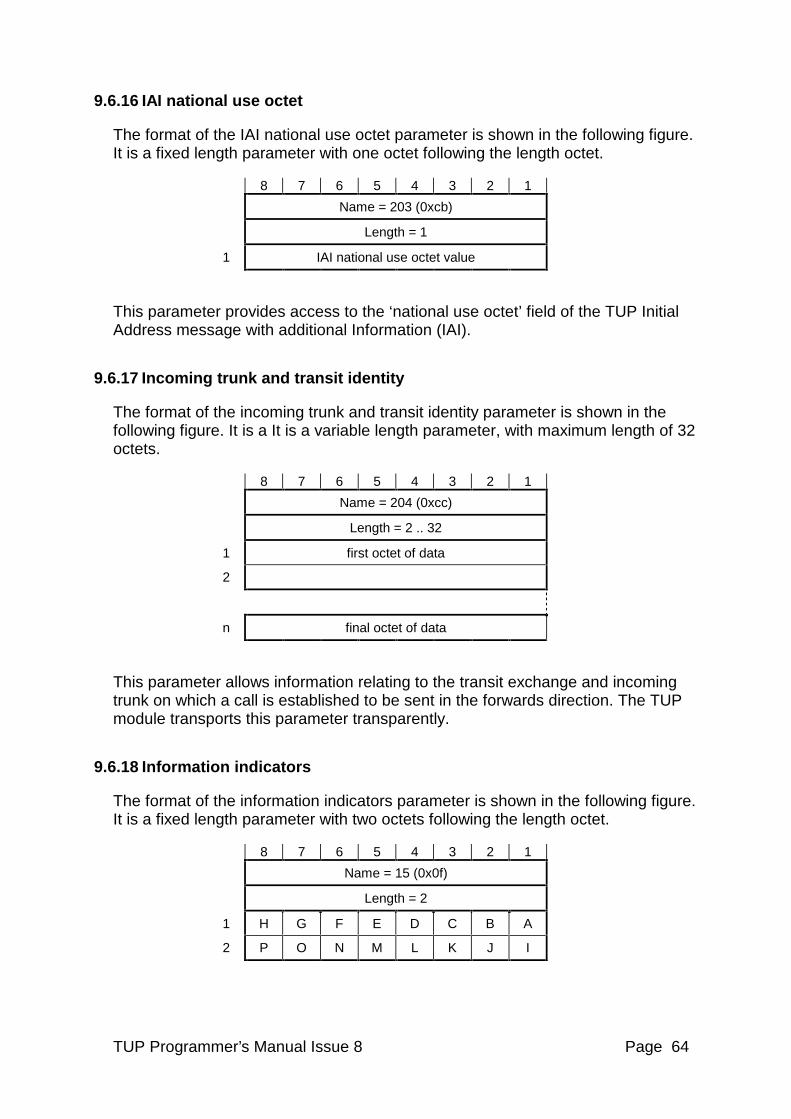
TUP Programmer’s Manual Issue 8 Page 64
9.6.16 IAI national use octet
The format of the IAI national use octet parameter is shown in the following figure. It is a fixed length parameter with one octet following the length octet.
8 7 6 5 4 3 2 1
Name = 203 (0xcb)
Length = 1
1 IAI national use octet value
This parameter provides access to the ‘national use octet’ field of the TUP Initial Address message with additional Information (IAI).
9.6.17 Incoming trunk and transit identity
The format of the incoming trunk and transit identity parameter is shown in the following figure. It is a It is a variable length parameter, with maximum length of 32 octets.
8 7 6 5 4 3 2 1
Name = 204 (0xcc)
Length = 2 .. 32
1 first octet of data
2
n final octet of data
This parameter allows information relating to the transit exchange and incoming trunk on which a call is established to be sent in the forwards direction. The TUP module transports this parameter transparently.
9.6.18 Information indicators
The format of the information indicators parameter is shown in the following figure. It is a fixed length parameter with two octets following the length octet.
8 7 6 5 4 3 2 1
Name = 15 (0x0f)
Length = 2
1 H G F E D C B A
2 P O N M L K J I
TUP Programmer’s Manual Issue 8 Page 65
Bits A and B indicate the availability if the calling party number:
bits A B 0 0 calling party number not included 0 1 calling party number not available 1 0 spare 1 1 calling party number included
Bit C is the hold provided indicator:
bit C 0 hold not provided 1 hold provided
Bit F is the calling party category response indicator. In primitive indications sent to the user from the TUP module it indicates that the calling party category has been received from the network. In primitive requests from the user to the TUP module this bit controls the inclusion of the calling party category in messages sent to the network. If the user supplies the calling party category, but does not set this bit, the calling party category will not conveyed in the TUP message sent to the network.
Bit F calling party category response indicator 0 calling party category not included 1 calling party category included
All other bits are currently not used. They should be set to zero in messages issued by the user and discarded in messages received by the user.
9.6.19 Information request indicators
The format of the information request indicators parameter is shown in the following figure. It is a fixed length parameter with two octets following the length octet.
8 7 6 5 4 3 2 1
Name = 14 (0x0e)
Length = 2
1 H G F E D C B A
2 P O N M L K J I
The following codes are currently supported.
Bit A is used to request calling line identity:
bit A 0 calling line identity not requested 1 calling line identity requested
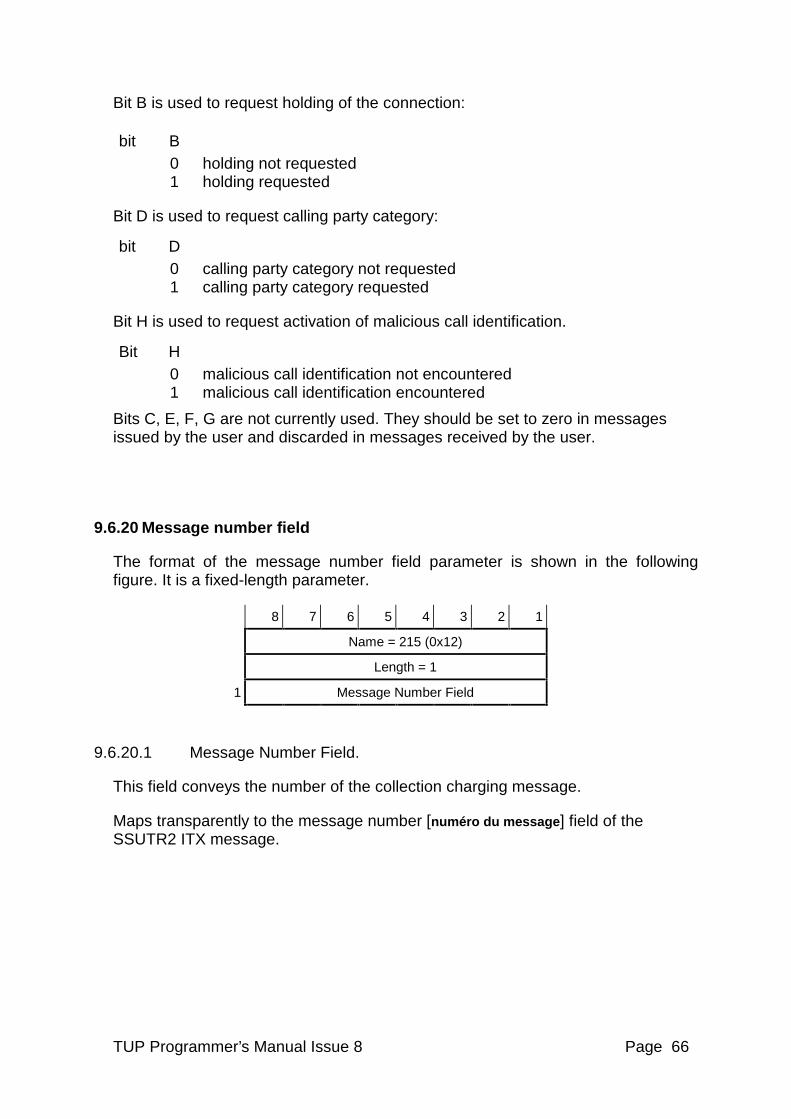
TUP Programmer’s Manual Issue 8 Page 66
Bit B is used to request holding of the connection:
bit B 0 holding not requested 1 holding requested
Bit D is used to request calling party category:
bit D 0 calling party category not requested 1 calling party category requested
Bit H is used to request activation of malicious call identification.
Bit H 0 malicious call identification not encountered 1 malicious call identification encountered
Bits C, E, F, G are not currently used. They should be set to zero in messages issued by the user and discarded in messages received by the user.
9.6.20 Message number field
The format of the message number field parameter is shown in the following figure. It is a fixed-length parameter.
8 7 6 5 4 3 2 1
Name = 215 (0x12)
Length = 1
1 Message Number Field
9.6.20.1 Message Number Field.
This field conveys the number of the collection charging message.
Maps transparently to the message number [numéro du message ] field of the SSUTR2 ITX message.
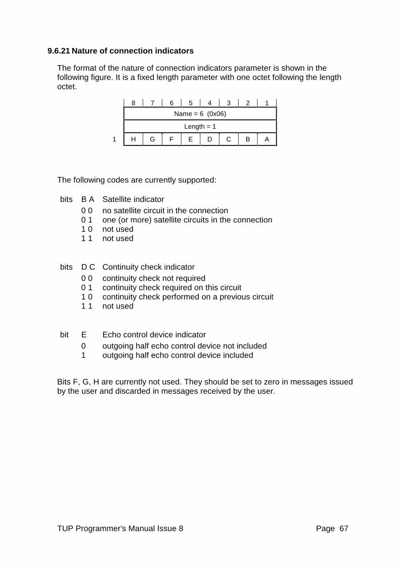
TUP Programmer’s Manual Issue 8 Page 67
9.6.21 Nature of connection indicators
The format of the nature of connection indicators parameter is shown in the following figure. It is a fixed length parameter with one octet following the length octet.
8 7 6 5 4 3 2 1
Name = 6 (0x06)
Length = 1
1 H G F E D C B A
The following codes are currently supported:
bits B A Satellite indicator 0 0 no satellite circuit in the connection 0 1 one (or more) satellite circuits in the connection 1 0 not used 1 1 not used
bits D C Continuity check indicator 0 0 continuity check not required 0 1 continuity check required on this circuit 1 0 continuity check performed on a previous circuit 1 1 not used
bit E Echo control device indicator 0 outgoing half echo control device not included 1 outgoing half echo control device included
Bits F, G, H are currently not used. They should be set to zero in messages issued by the user and discarded in messages received by the user.
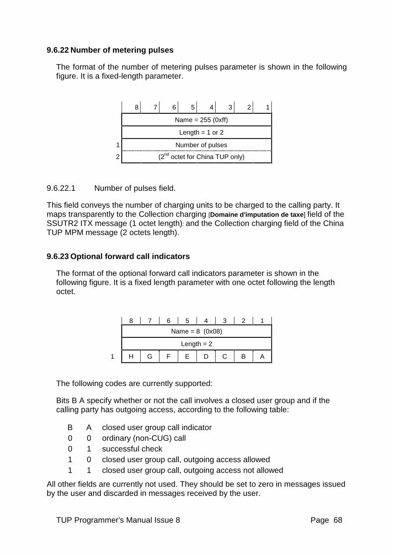
TUP Programmer’s Manual Issue 8 Page 68
9.6.22 Number of metering pulses
The format of the number of metering pulses parameter is shown in the following figure. It is a fixed-length parameter.
8 7 6 5 4 3 2 1
Name = 255 (0xff)
Length = 1 or 2
1 Number of pulses
2 (2nd octet for China TUP only)
9.6.22.1 Number of pulses field.
This field conveys the number of charging units to be charged to the calling party. It maps transparently to the Collection charging [Domaine d’imputation de taxe] field of the SSUTR2 ITX message (1 octet length): and the Collection charging field of the China TUP MPM message (2 octets length).
9.6.23 Optional forward call indicators
The format of the optional forward call indicators parameter is shown in the following figure. It is a fixed length parameter with one octet following the length octet.
8 7 6 5 4 3 2 1
Name = 8 (0x08)
Length = 2
1 H G F E D C B A
The following codes are currently supported:
Bits B A specify whether or not the call involves a closed user group and if the calling party has outgoing access, according to the following table:
B A closed user group call indicator 0 0 ordinary (non-CUG) call 0 1 successful check 1 0 closed user group call, outgoing access allowed 1 1 closed user group call, outgoing access not allowed
All other fields are currently not used. They should be set to zero in messages issued by the user and discarded in messages received by the user.
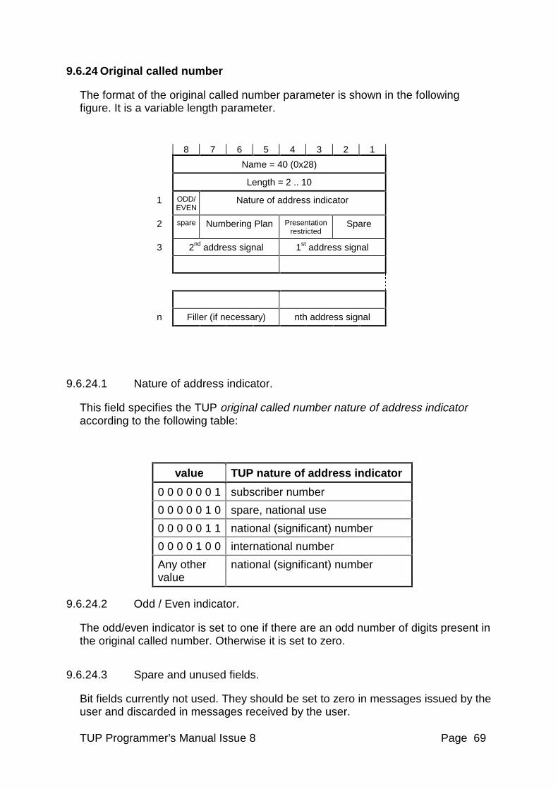
TUP Programmer’s Manual Issue 8 Page 69
9.6.24 Original called number
The format of the original called number parameter is shown in the following figure. It is a variable length parameter.
8 7 6 5 4 3 2 1
Name = 40 (0x28)
Length = 2 .. 10
1 ODD/ EVEN
Nature of address indicator
2 spare Numbering Plan Presentation restricted
Spare
3 2nd address signal 1st address signal
n Filler (if necessary) nth address signal
9.6.24.1 Nature of address indicator.
This field specifies the TUP original called number nature of address indicator according to the following table:
value TUP nature of address indicator
0 0 0 0 0 0 1 subscriber number
0 0 0 0 0 1 0 spare, national use
0 0 0 0 0 1 1 national (significant) number
0 0 0 0 1 0 0 international number
Any other value
national (significant) number
9.6.24.2 Odd / Even indicator.
The odd/even indicator is set to one if there are an odd number of digits present in the original called number. Otherwise it is set to zero.
9.6.24.3 Spare and unused fields.
Bit fields currently not used. They should be set to zero in messages issued by the user and discarded in messages received by the user.
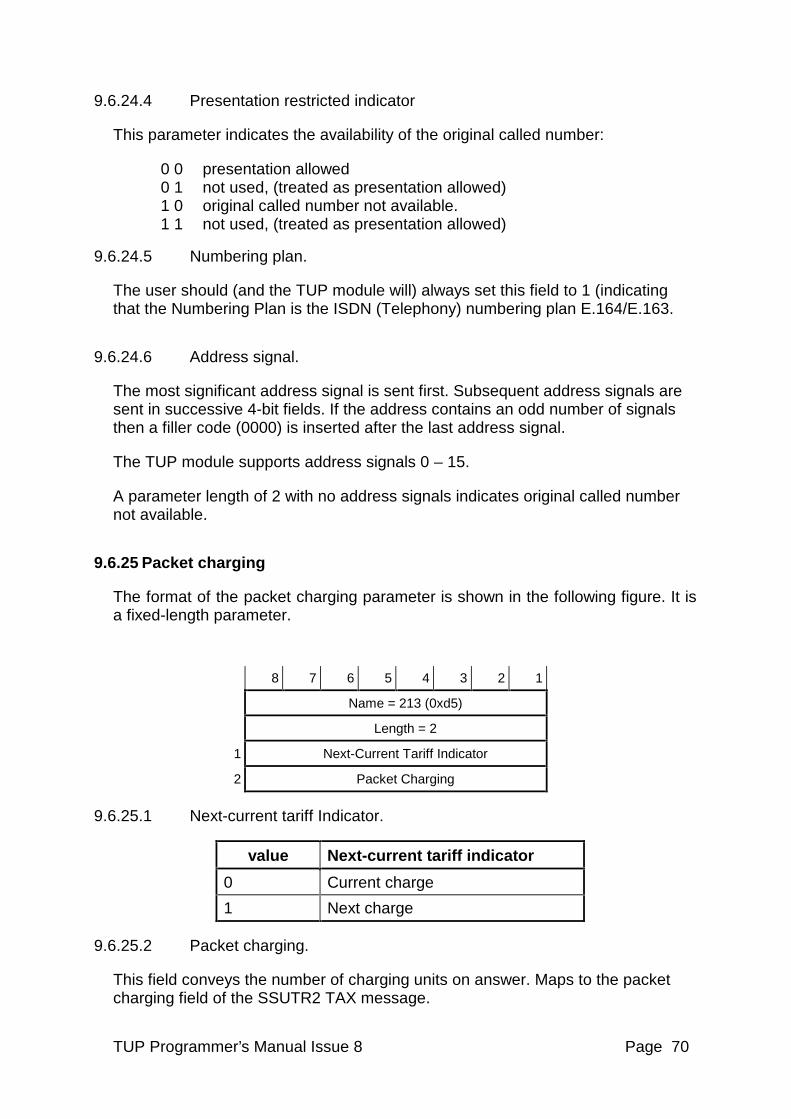
TUP Programmer’s Manual Issue 8 Page 70
9.6.24.4 Presentation restricted indicator
This parameter indicates the availability of the original called number:
0 0 presentation allowed 0 1 not used, (treated as presentation allowed) 1 0 original called number not available. 1 1 not used, (treated as presentation allowed)
9.6.24.5 Numbering plan.
The user should (and the TUP module will) always set this field to 1 (indicating that the Numbering Plan is the ISDN (Telephony) numbering plan E.164/E.163.
9.6.24.6 Address signal.
The most significant address signal is sent first. Subsequent address signals are sent in successive 4-bit fields. If the address contains an odd number of signals then a filler code (0000) is inserted after the last address signal.
The TUP module supports address signals 0 – 15.
A parameter length of 2 with no address signals indicates original called number not available.
9.6.25 Packet charging
The format of the packet charging parameter is shown in the following figure. It is a fixed-length parameter.
8 7 6 5 4 3 2 1
Name = 213 (0xd5)
Length = 2
1 Next-Current Tariff Indicator
2 Packet Charging
9.6.25.1 Next-current tariff Indicator.
value Next-current tariff indicator
0 Current charge
1 Next charge
9.6.25.2 Packet charging.
This field conveys the number of charging units on answer. Maps to the packet charging field of the SSUTR2 TAX message.
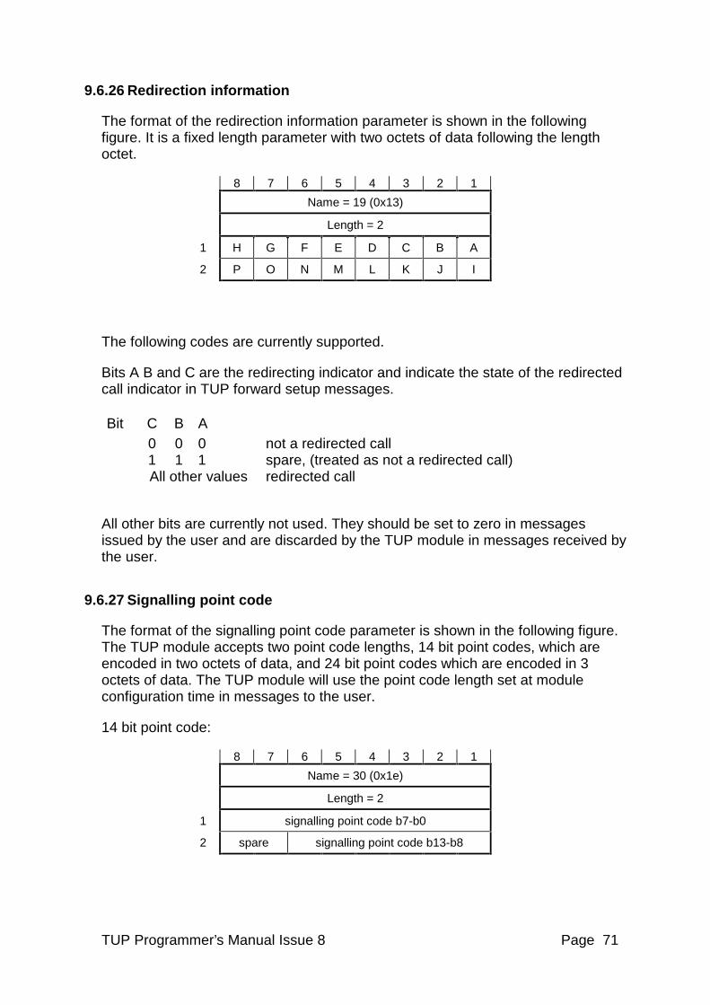
TUP Programmer’s Manual Issue 8 Page 71
9.6.26 Redirection information
The format of the redirection information parameter is shown in the following figure. It is a fixed length parameter with two octets of data following the length octet.
8 7 6 5 4 3 2 1
Name = 19 (0x13)
Length = 2
1 H G F E D C B A
2 P O N M L K J I
The following codes are currently supported.
Bits A B and C are the redirecting indicator and indicate the state of the redirected call indicator in TUP forward setup messages.
Bit C B A 0 0 0 not a redirected call 1 1 1 spare, (treated as not a redirected call) All other values redirected call
All other bits are currently not used. They should be set to zero in messages issued by the user and are discarded by the TUP module in messages received by the user.
9.6.27 Signalling point code
The format of the signalling point code parameter is shown in the following figure. The TUP module accepts two point code lengths, 14 bit point codes, which are encoded in two octets of data, and 24 bit point codes which are encoded in 3 octets of data. The TUP module will use the point code length set at module configuration time in messages to the user.
14 bit point code:
8 7 6 5 4 3 2 1
Name = 30 (0x1e)
Length = 2
1 signalling point code b7-b0
2 spare signalling point code b13-b8
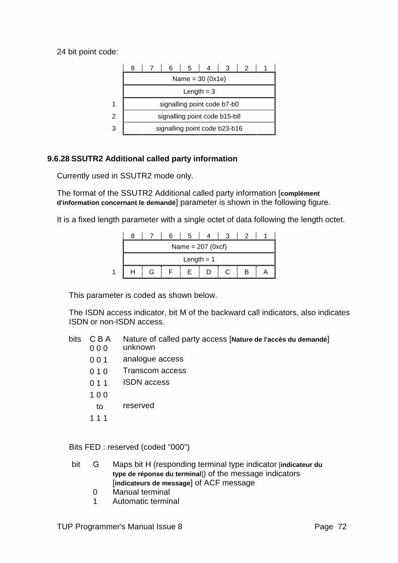
TUP Programmer’s Manual Issue 8 Page 72
24 bit point code:
8 7 6 5 4 3 2 1
Name = 30 (0x1e)
Length = 3
1 signalling point code b7-b0
2 signalling point code b15-b8
3 signalling point code b23-b16
9.6.28 SSUTR2 Additional called party information
Currently used in SSUTR2 mode only.
The format of the SSUTR2 Additional called party information [complément d'information concernant le demandé ] parameter is shown in the following figure.
It is a fixed length parameter with a single octet of data following the length octet.
8 7 6 5 4 3 2 1
Name = 207 (0xcf)
Length = 1
1 H G F E D C B A
This parameter is coded as shown below.
The ISDN access indicator, bit M of the backward call indicators, also indicates ISDN or non-ISDN access.
bits C B A Nature of called party access [Nature de l'accès du demandé ] 0 0 0 unknown
0 0 1 analogue access
0 1 0 Transcom access
0 1 1 ISDN access
1 0 0
to reserved
1 1 1
Bits FED : reserved (coded "000")
bit G Maps bit H (responding terminal type indicator [indicateur du type de réponse du terminal ]) of the message indicators [indicateurs de message ] of ACF message
0 Manual terminal 1 Automatic terminal
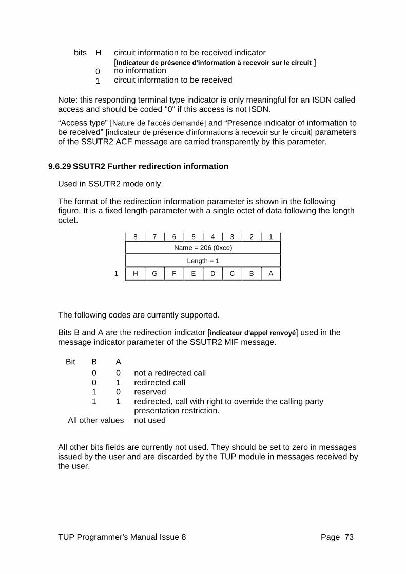
TUP Programmer’s Manual Issue 8 Page 73
bits H circuit information to be received indicator [Indicateur de présence d'information à recevoir sur le circuit ]
0 no information 1 circuit information to be received
Note: this responding terminal type indicator is only meaningful for an ISDN called access and should be coded "0" if this access is not ISDN.
“Access type” [Nature de l'accès demandé] and “Presence indicator of information to be received” [indicateur de présence d'informations à recevoir sur le circuit] parameters of the SSUTR2 ACF message are carried transparently by this parameter.
9.6.29 SSUTR2 Further redirection information
Used in SSUTR2 mode only.
The format of the redirection information parameter is shown in the following figure. It is a fixed length parameter with a single octet of data following the length octet.
8 7 6 5 4 3 2 1
Name = 206 (0xce)
Length = 1
1 H G F E D C B A
The following codes are currently supported.
Bits B and A are the redirection indicator [indicateur d'appel renvoyé ] used in the message indicator parameter of the SSUTR2 MIF message.
Bit B A 0 0 not a redirected call 0 1 redirected call 1 0 reserved 1 1 redirected, call with right to override the calling party
presentation restriction. All other values not used
All other bits fields are currently not used. They should be set to zero in messages issued by the user and are discarded by the TUP module in messages received by the user.
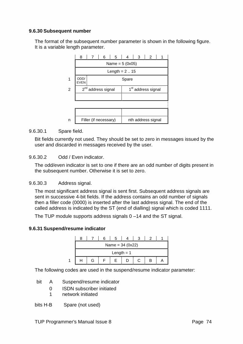
TUP Programmer’s Manual Issue 8 Page 74
9.6.30 Subsequent number
The format of the subsequent number parameter is shown in the following figure. It is a variable length parameter.
8 7 6 5 4 3 2 1
Name = 5 (0x05)
Length = 2 .. 15
1 ODD/ EVEN
Spare
2 2nd address signal 1st address signal
n Filler (if necessary) nth address signal
9.6.30.1 Spare field.
Bit fields currently not used. They should be set to zero in messages issued by the user and discarded in messages received by the user.
9.6.30.2 Odd / Even indicator.
The odd/even indicator is set to one if there are an odd number of digits present in the subsequent number. Otherwise it is set to zero.
9.6.30.3 Address signal.
The most significant address signal is sent first. Subsequent address signals are sent in successive 4-bit fields. If the address contains an odd number of signals then a filler code (0000) is inserted after the last address signal. The end of the called address is indicated by the ST (end of dialling) signal which is coded 1111.
The TUP module supports address signals 0 –14 and the ST signal.
9.6.31 Suspend/resume indicator
8 7 6 5 4 3 2 1
Name = 34 (0x22)
Length = 1
1 H G F E D C B A
The following codes are used in the suspend/resume indicator parameter:
bit A Suspend/resume indicator 0 ISDN subscriber initiated 1 network initiated
bits H-B Spare (not used)
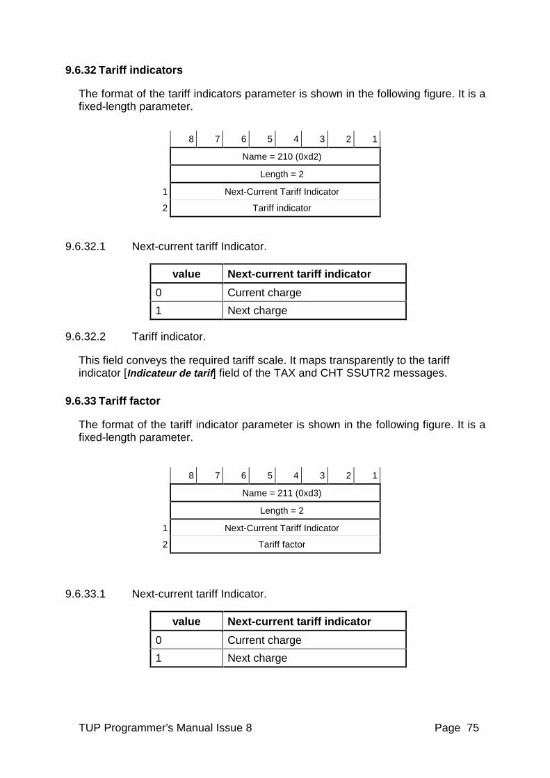
TUP Programmer’s Manual Issue 8 Page 75
9.6.32 Tariff indicators
The format of the tariff indicators parameter is shown in the following figure. It is a fixed-length parameter.
8 7 6 5 4 3 2 1
Name = 210 (0xd2)
Length = 2
1 Next-Current Tariff Indicator
2 Tariff indicator
9.6.32.1 Next-current tariff Indicator.
value Next-current tariff indicator
0 Current charge
1 Next charge
9.6.32.2 Tariff indicator.
This field conveys the required tariff scale. It maps transparently to the tariff indicator [Indicateur de tarif] field of the TAX and CHT SSUTR2 messages.
9.6.33 Tariff factor
The format of the tariff indicator parameter is shown in the following figure. It is a fixed-length parameter.
8 7 6 5 4 3 2 1
Name = 211 (0xd3)
Length = 2
1 Next-Current Tariff Indicator
2 Tariff factor
9.6.33.1 Next-current tariff Indicator.
value Next-current tariff indicator
0 Current charge
1 Next charge
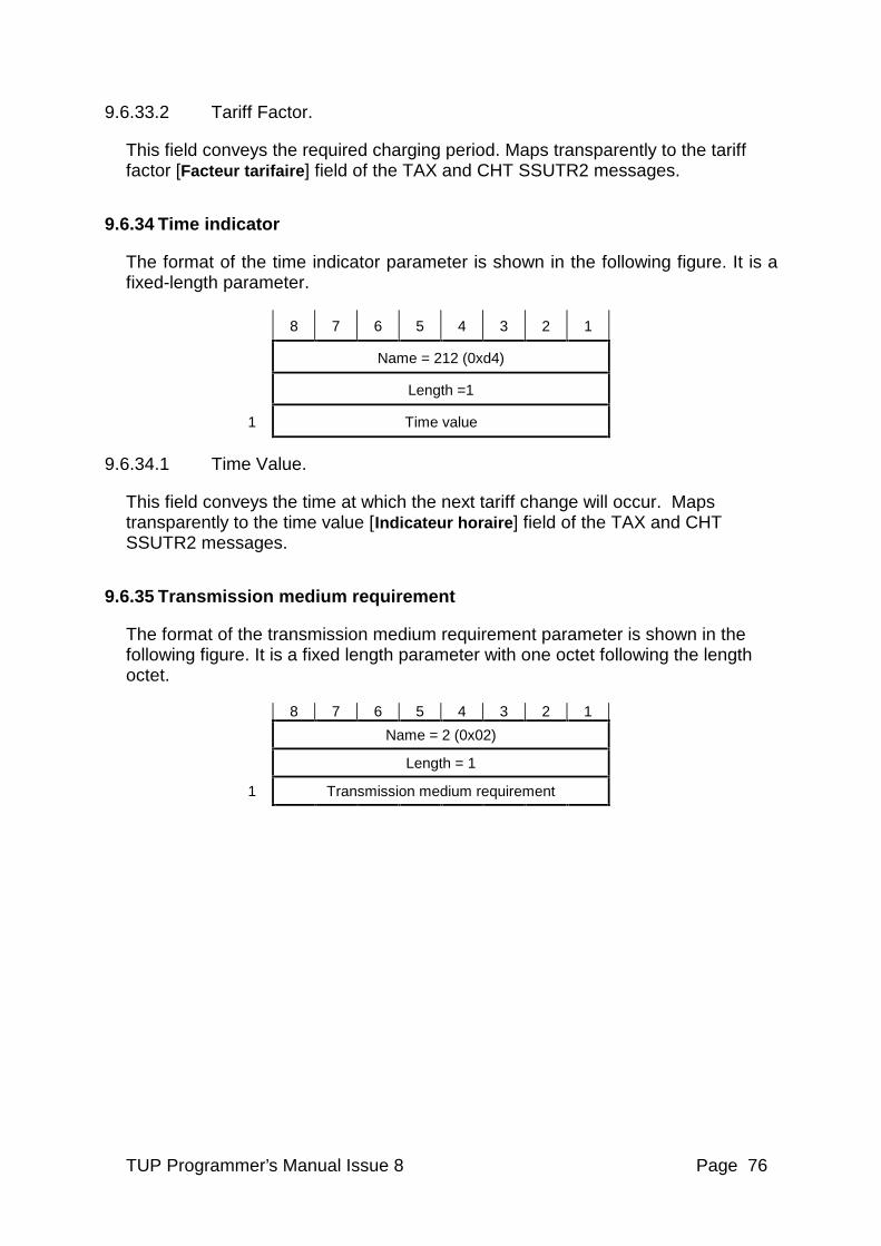
TUP Programmer’s Manual Issue 8 Page 76
9.6.33.2 Tariff Factor.
This field conveys the required charging period. Maps transparently to the tariff factor [Facteur tarifaire] field of the TAX and CHT SSUTR2 messages.
9.6.34 Time indicator
The format of the time indicator parameter is shown in the following figure. It is a fixed-length parameter.
8 7 6 5 4 3 2 1
Name = 212 (0xd4)
Length =1
1 Time value
9.6.34.1 Time Value.
This field conveys the time at which the next tariff change will occur. Maps transparently to the time value [Indicateur horaire] field of the TAX and CHT SSUTR2 messages.
9.6.35 Transmission medium requirement
The format of the transmission medium requirement parameter is shown in the following figure. It is a fixed length parameter with one octet following the length octet.
8 7 6 5 4 3 2 1
Name = 2 (0x02)
Length = 1
1 Transmission medium requirement
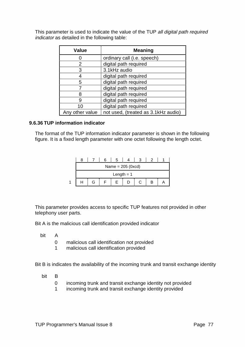
TUP Programmer’s Manual Issue 8 Page 77
This parameter is used to indicate the value of the TUP all digital path required indicator as detailed in the following table:
Value Meaning
0 ordinary call (i.e. speech) 2 digital path required 3 3.1kHz audio 4 digital path required 5 digital path required 7 digital path required 8 digital path required 9 digital path required
10 digital path required Any other value not used, (treated as 3.1kHz audio)
9.6.36 TUP information indicator
The format of the TUP information indicator parameter is shown in the following figure. It is a fixed length parameter with one octet following the length octet.
8 7 6 5 4 3 2 1
Name = 205 (0xcd)
Length = 1
1 H G F E D C B A
This parameter provides access to specific TUP features not provided in other telephony user parts.
Bit A is the malicious call identification provided indicator
bit A 0 malicious call identification not provided 1 malicious call identification provided
Bit B is indicates the availability of the incoming trunk and transit exchange identity
bit B 0 incoming trunk and transit exchange identity not provided 1 incoming trunk and transit exchange identity provided
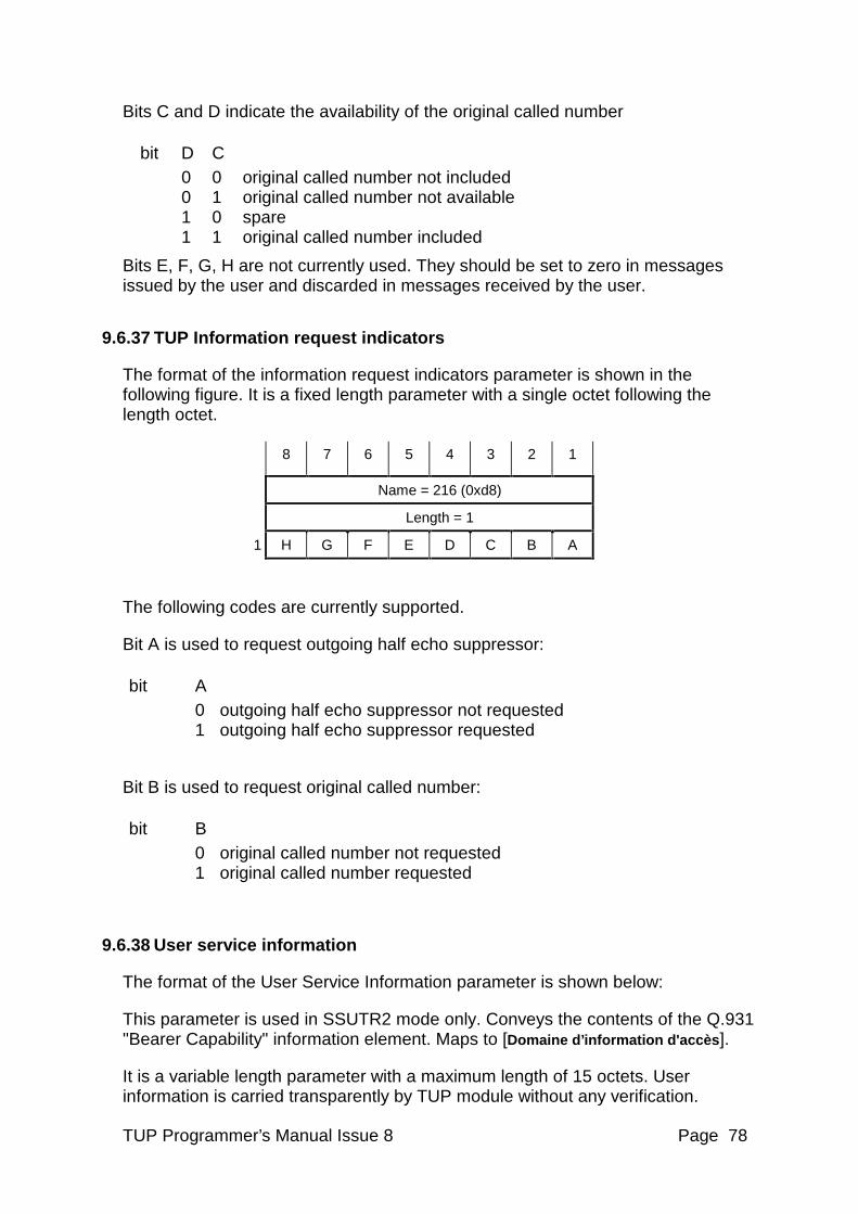
TUP Programmer’s Manual Issue 8 Page 78
Bits C and D indicate the availability of the original called number
bit D C 0 0 original called number not included 0 1 original called number not available 1 0 spare 1 1 original called number included
Bits E, F, G, H are not currently used. They should be set to zero in messages issued by the user and discarded in messages received by the user.
9.6.37 TUP Information request indicators
The format of the information request indicators parameter is shown in the following figure. It is a fixed length parameter with a single octet following the length octet.
8 7 6 5 4 3 2 1
Name = 216 (0xd8)
Length = 1
1 H G F E D C B A
The following codes are currently supported.
Bit A is used to request outgoing half echo suppressor:
bit A 0 outgoing half echo suppressor not requested 1 outgoing half echo suppressor requested
Bit B is used to request original called number:
bit B 0 original called number not requested 1 original called number requested
9.6.38 User service information
The format of the User Service Information parameter is shown below:
This parameter is used in SSUTR2 mode only. Conveys the contents of the Q.931 "Bearer Capability" information element. Maps to [Domaine d’information d'accès ].
It is a variable length parameter with a maximum length of 15 octets. User information is carried transparently by TUP module without any verification.
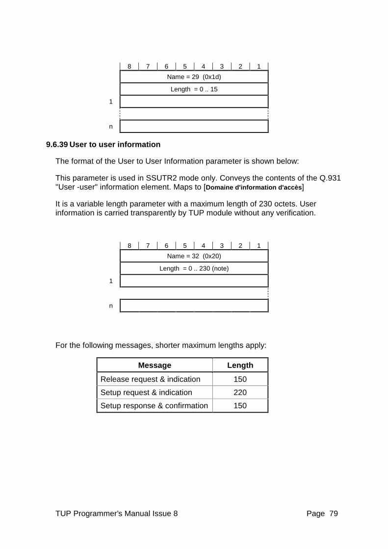
TUP Programmer’s Manual Issue 8 Page 79
8 7 6 5 4 3 2 1
Name = 29 (0x1d)
Length = 0 .. 15
1
n
9.6.39 User to user information
The format of the User to User Information parameter is shown below:
This parameter is used in SSUTR2 mode only. Conveys the contents of the Q.931 "User -user" information element. Maps to [Domaine d'information d'accès ]
It is a variable length parameter with a maximum length of 230 octets. User information is carried transparently by TUP module without any verification.
8 7 6 5 4 3 2 1
Name = 32 (0x20)
Length = 0 .. 230 (note)
1
n
For the following messages, shorter maximum lengths apply:
Message Length
Release request & indication 150
Setup request & indication 220
Setup response & confirmation 150
TUP Programmer’s Manual Issue 8 Page 80
9.7 Use of call control primitives
9.7.1 Call clearing procedure
The current TUP module supports a full handshake mechanism during call release. This is known as the Application Controlled Release mechanism. It ensures that the TUP module has received a release action from both the network and the user before it considers the circuit idle.
This is significant in the case where the network sends IAM on a circuit immediately after sending clear forward. Early versions of the TUP module acknowledged the clear forward with a release guard at the same time as issuing a Release Indication primitive to the user. In the case of user failure or where the user was slow in sending a Release Request, the user could unintentionally release the new incoming call.
The Application Controlled Release mechanism prevents these problems. Two requirements are placed on the user.
• If the user receives a Release Indication primitive from TUP the user must acknowledge it with a Release Response primitive, indicating that the application has completed release of the circuit. The user must then wait until the TUP module responds with a Release Confirmation primitive before attempting a new call on this circuit.
The TUP module will continue to send Release Indication until the user issues Release Response. The user may send a Release Request prior to the Release Response. (This may be useful if it is not possible for the application to complete release of the circuit immediately.) If an IAM message is received from the network before the user issues Release Response the circuit is automatically blocked. When the user does issue the Release Response primitive the circuit is automatically unblocked.
• If the user sends a Release Request primitive to TUP to initiate release of the circuit, the user must wait for the TUP module to acknowledge it with a Release Confirmation primitive before attempting a new call on that circuit. If the user does attempt to set up a call before the TUP module has sent Release Confirmation, the Setup Request primitive will be discarded. A maintenance event is indicated to the Maintenance module.
Note: All new user applications should make use of the Application Controlled Release mechanism. It is enabled by setting the TUPF_ACR and TUPF_NAI options in the module configuration message.
9.7.2 Call collision procedure
If a dual seizure occurs for one circuit, in respect to the priority setting (bits 1 and 2 of the OGC_PRI group option) defined at each end for this circuit, the user (application) at the point code with the lower priority will receive the incoming setup indication from its TUP module. This indicates it is the responsibility of the
TUP Programmer’s Manual Issue 8 Page 81
user to re-attempt the call on another circuit, but the user does not need to release its initial unsuccessful call attempt.
Note that the point code which succeeds to initiate a call (because it has the higher priority) will not receive any indication that dual seizure occurred because the received IAM is discarded by the TUP module.
TUP Programmer’s Manual Issue 8 Page 82
10 MANAGEMENT INTERFACE
The management interface allows the user to interface with the Circuit Group Control (CGC) block of the TUP module. The interface is message based and uses the same basic message structure as defined previous sections. The messages available allow the user to carry out the following circuit supervision functions: Reset a circuit or circuit group Abort a reset cycle Block a circuit or circuit group (Maintenance, Hardware or Software) Unblock a circuit or circuit group (Maintenance, Hardware or Software) Abort a blocking/unblocking attempt Commands originated by the user take the form of a Circuit Group Supervision Request. On completion of command execution the user receives notification in the form of a Circuit Group Supervision Confirmation, indicating that the expected response or acknowledgement has been received from the network for the command. Events initiated at the remote end of the network are notified to the user in a Circuit Group Supervision Indication.
The TUP module supports the following blocking types.
• Hardware Blocking: This is typically invoked due to PCM loss or other hardware failure. Hardware blocking causes any active calls to be released on all affected circuits.
• Software Blocking: Invoked when the system detects an internal fault affects a individual circuit or group of circuits. Software blocking causes any active calls to be release on all affected circuits.
It is recommended that software blocking is not used as it is not a feature supported by other Intel® NetStructure™ SS7 protocols.
• Maintenance Blocking: Invoked following a user command. Maintenance blocking does not cause active calls to be released but upon the circuit becoming idle will prevent further calls.
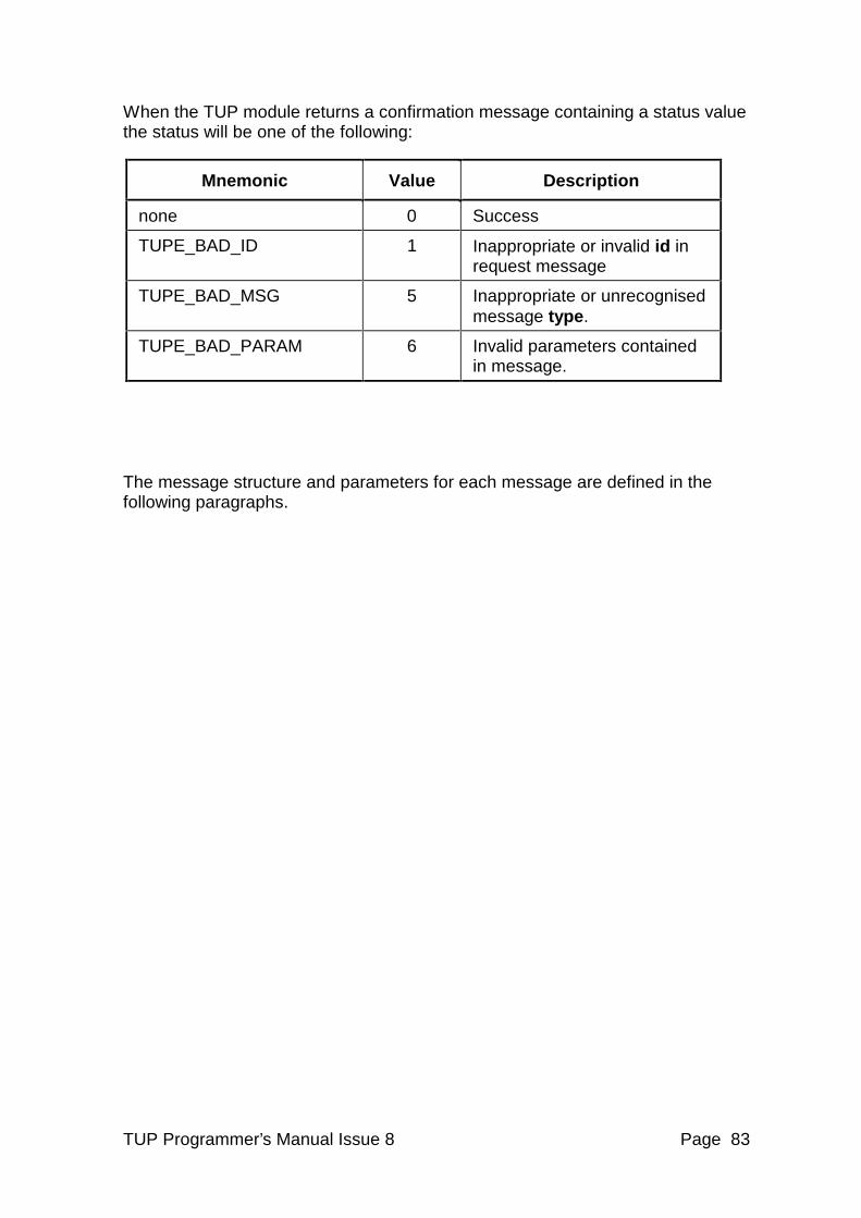
TUP Programmer’s Manual Issue 8 Page 83
When the TUP module returns a confirmation message containing a status value the status will be one of the following:
Mnemonic Value Description
none 0 Success
TUPE_BAD_ID 1 Inappropriate or invalid id in request message
TUPE_BAD_MSG 5 Inappropriate or unrecognised message type.
TUPE_BAD_PARAM 6 Invalid parameters contained in message.
The message structure and parameters for each message are defined in the following paragraphs.
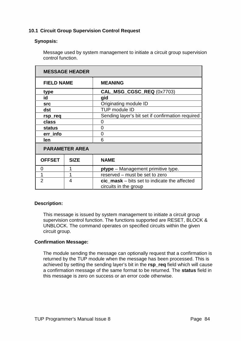
TUP Programmer’s Manual Issue 8 Page 84
10.1 Circuit Group Supervision Control Request
Synopsis: Message used by system management to initiate a circuit group supervision control function.
MESSAGE HEADER
FIELD NAME MEANING
type CAL_MSG_CGSC_REQ (0x7703) id gid src Originating module ID dst TUP module ID rsp_req Sending layer’s bit set if confirmation required class 0 status 0 err_info 0 len 6
PARAMETER AREA
OFFSET SIZE NAME
0 1 ptype – Management primitive type. 1 1 reserved – must be set to zero 2 4 cic_mask – bits set to indicate the affected
circuits in the group
Description: This message is issued by system management to initiate a circuit group supervision control function. The functions supported are RESET, BLOCK & UNBLOCK. The command operates on specified circuits within the given circuit group.
Confirmation Message: The module sending the message can optionally request that a confirmation is returned by the TUP module when the message has been processed. This is achieved by setting the sending layer’s bit in the rsp_req field which will cause a confirmation message of the same format to be returned. The status field in this message is zero on success or an error code otherwise.
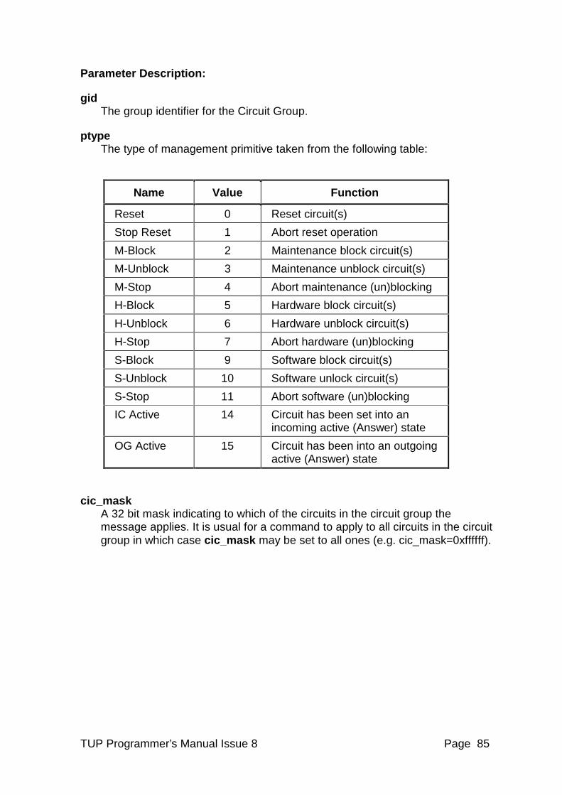
TUP Programmer’s Manual Issue 8 Page 85
Parameter Description:
gid The group identifier for the Circuit Group.
ptype The type of management primitive taken from the following table:
Name Value Function
Reset 0 Reset circuit(s)
Stop Reset 1 Abort reset operation
M-Block 2 Maintenance block circuit(s)
M-Unblock 3 Maintenance unblock circuit(s)
M-Stop 4 Abort maintenance (un)blocking
H-Block 5 Hardware block circuit(s)
H-Unblock 6 Hardware unblock circuit(s)
H-Stop 7 Abort hardware (un)blocking
S-Block 9 Software block circuit(s)
S-Unblock 10 Software unlock circuit(s)
S-Stop 11 Abort software (un)blocking
IC Active 14 Circuit has been set into an incoming active (Answer) state
OG Active 15 Circuit has been into an outgoing active (Answer) state
cic_mask A 32 bit mask indicating to which of the circuits in the circuit group the message applies. It is usual for a command to apply to all circuits in the circuit group in which case cic_mask may be set to all ones (e.g. cic_mask=0xffffff).
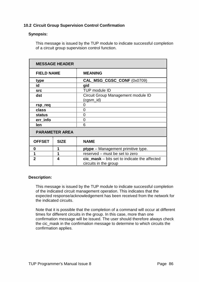
TUP Programmer’s Manual Issue 8 Page 86
10.2 Circuit Group Supervision Control Confirmation
Synopsis: This message is issued by the TUP module to indicate successful completion of a circuit group supervision control function.
MESSAGE HEADER
FIELD NAME MEANING
type CAL_MSG_CGSC_CONF (0x0709) id gid src TUP module ID dst Circuit Group Management module ID
(cgsm_id) rsp_req 0 class 0 status 0 err_info 0 len 6
PARAMETER AREA
OFFSET SIZE NAME
0 1 ptype – Management primitive type. 1 1 reserved – must be set to zero 2 4 cic_mask – bits set to indicate the affected
circuits in the group
Description: This message is issued by the TUP module to indicate successful completion of the indicated circuit management operation. This indicates that the expected response/acknowledgement has been received from the network for the indicated circuits. Note that it is possible that the completion of a command will occur at different times for different circuits in the group. In this case, more than one confirmation message will be issued. The user should therefore always check the cic_mask in the confirmation message to determine to which circuits the confirmation applies.
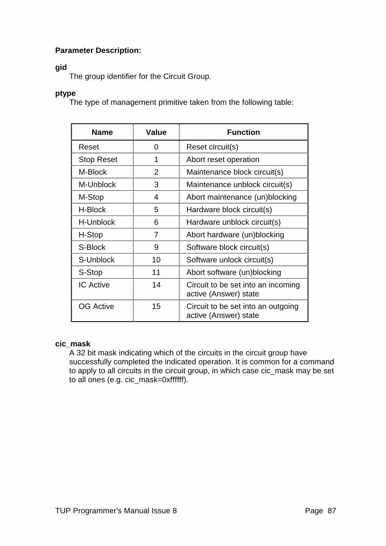
TUP Programmer’s Manual Issue 8 Page 87
Parameter Description:
gid The group identifier for the Circuit Group.
ptype The type of management primitive taken from the following table:
Name Value Function
Reset 0 Reset circuit(s)
Stop Reset 1 Abort reset operation
M-Block 2 Maintenance block circuit(s)
M-Unblock 3 Maintenance unblock circuit(s)
M-Stop 4 Abort maintenance (un)blocking
H-Block 5 Hardware block circuit(s)
H-Unblock 6 Hardware unblock circuit(s)
H-Stop 7 Abort hardware (un)blocking
S-Block 9 Software block circuit(s)
S-Unblock 10 Software unlock circuit(s)
S-Stop 11 Abort software (un)blocking
IC Active 14 Circuit to be set into an incoming active (Answer) state
OG Active 15 Circuit to be set into an outgoing active (Answer) state
cic_mask A 32 bit mask indicating which of the circuits in the circuit group have successfully completed the indicated operation. It is common for a command to apply to all circuits in the circuit group, in which case cic_mask may be set to all ones (e.g. cic_mask=0xffffff).
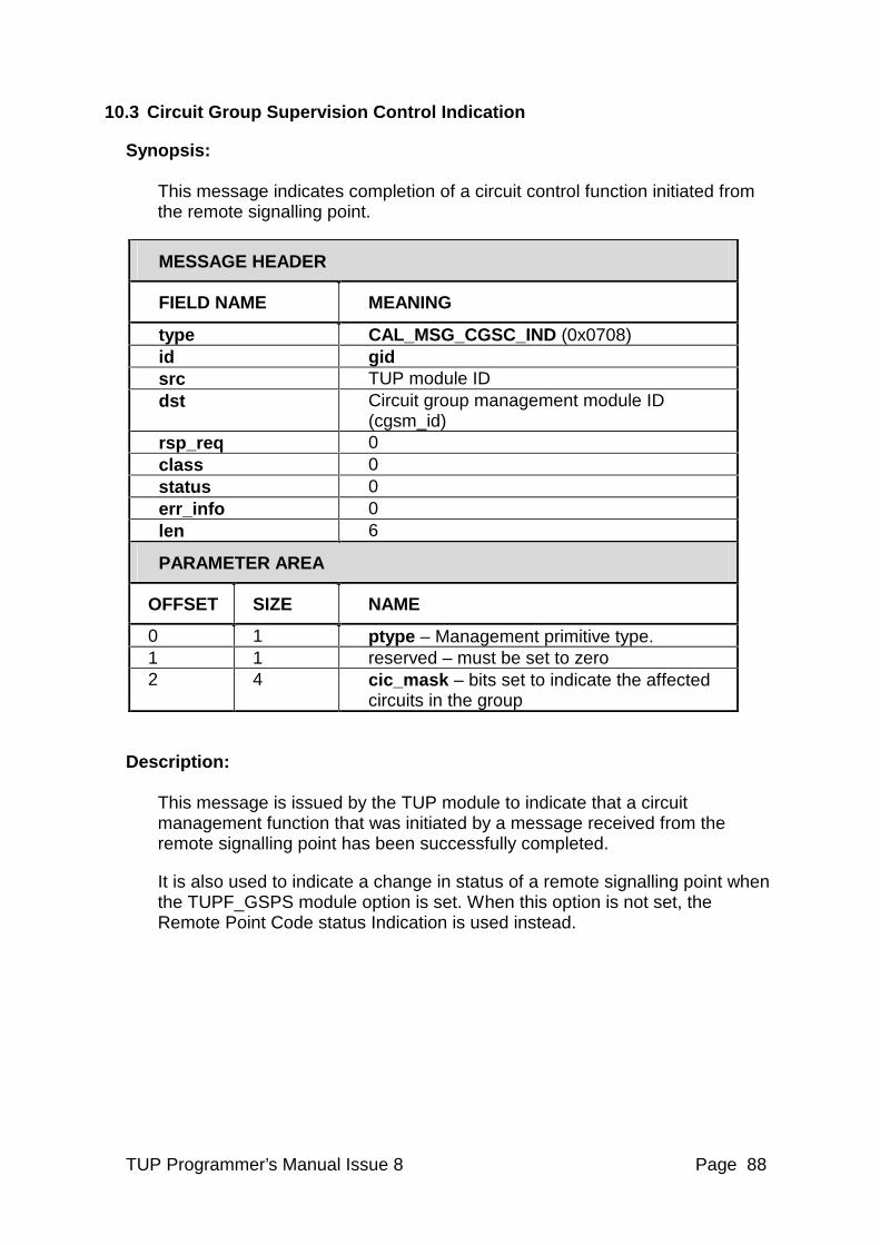
TUP Programmer’s Manual Issue 8 Page 88
10.3 Circuit Group Supervision Control Indication
Synopsis: This message indicates completion of a circuit control function initiated from the remote signalling point.
MESSAGE HEADER
FIELD NAME MEANING
type CAL_MSG_CGSC_IND (0x0708) id gid src TUP module ID dst Circuit group management module ID
(cgsm_id) rsp_req 0 class 0 status 0 err_info 0 len 6
PARAMETER AREA
OFFSET SIZE NAME
0 1 ptype – Management primitive type. 1 1 reserved – must be set to zero 2 4 cic_mask – bits set to indicate the affected
circuits in the group
Description: This message is issued by the TUP module to indicate that a circuit management function that was initiated by a message received from the remote signalling point has been successfully completed.
It is also used to indicate a change in status of a remote signalling point when the TUPF_GSPS module option is set. When this option is not set, the Remote Point Code status Indication is used instead.
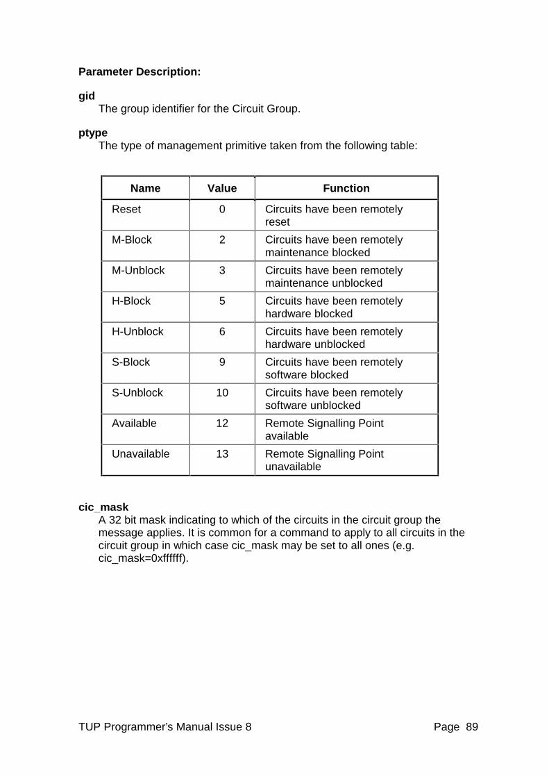
TUP Programmer’s Manual Issue 8 Page 89
Parameter Description:
gid The group identifier for the Circuit Group.
ptype The type of management primitive taken from the following table:
Name Value Function
Reset 0 Circuits have been remotely reset
M-Block 2 Circuits have been remotely maintenance blocked
M-Unblock 3 Circuits have been remotely maintenance unblocked
H-Block 5 Circuits have been remotely hardware blocked
H-Unblock 6 Circuits have been remotely hardware unblocked
S-Block 9 Circuits have been remotely software blocked
S-Unblock 10 Circuits have been remotely software unblocked
Available 12 Remote Signalling Point available
Unavailable 13 Remote Signalling Point unavailable
cic_mask A 32 bit mask indicating to which of the circuits in the circuit group the message applies. It is common for a command to apply to all circuits in the circuit group in which case cic_mask may be set to all ones (e.g. cic_mask=0xffffff).
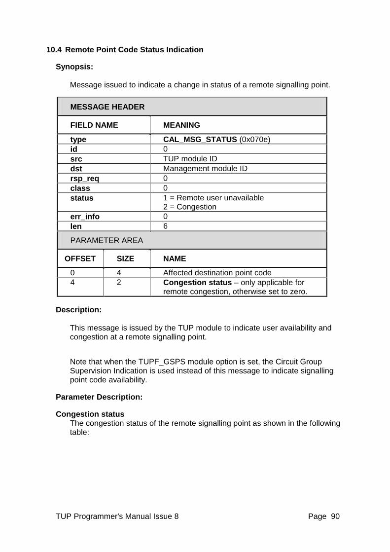
TUP Programmer’s Manual Issue 8 Page 90
10.4 Remote Point Code Status Indication
Synopsis: Message issued to indicate a change in status of a remote signalling point.
MESSAGE HEADER
FIELD NAME MEANING
type CAL_MSG_STATUS (0x070e) id 0 src TUP module ID dst Management module ID rsp_req 0 class 0 status 1 = Remote user unavailable
2 = Congestion err_info 0 len 6
PARAMETER AREA
OFFSET SIZE NAME
0 4 Affected destination point code 4 2 Congestion status – only applicable for
remote congestion, otherwise set to zero.
Description: This message is issued by the TUP module to indicate user availability and congestion at a remote signalling point.
Note that when the TUPF_GSPS module option is set, the Circuit Group Supervision Indication is used instead of this message to indicate signalling point code availability.
Parameter Description:
Congestion status The congestion status of the remote signalling point as shown in the following table:
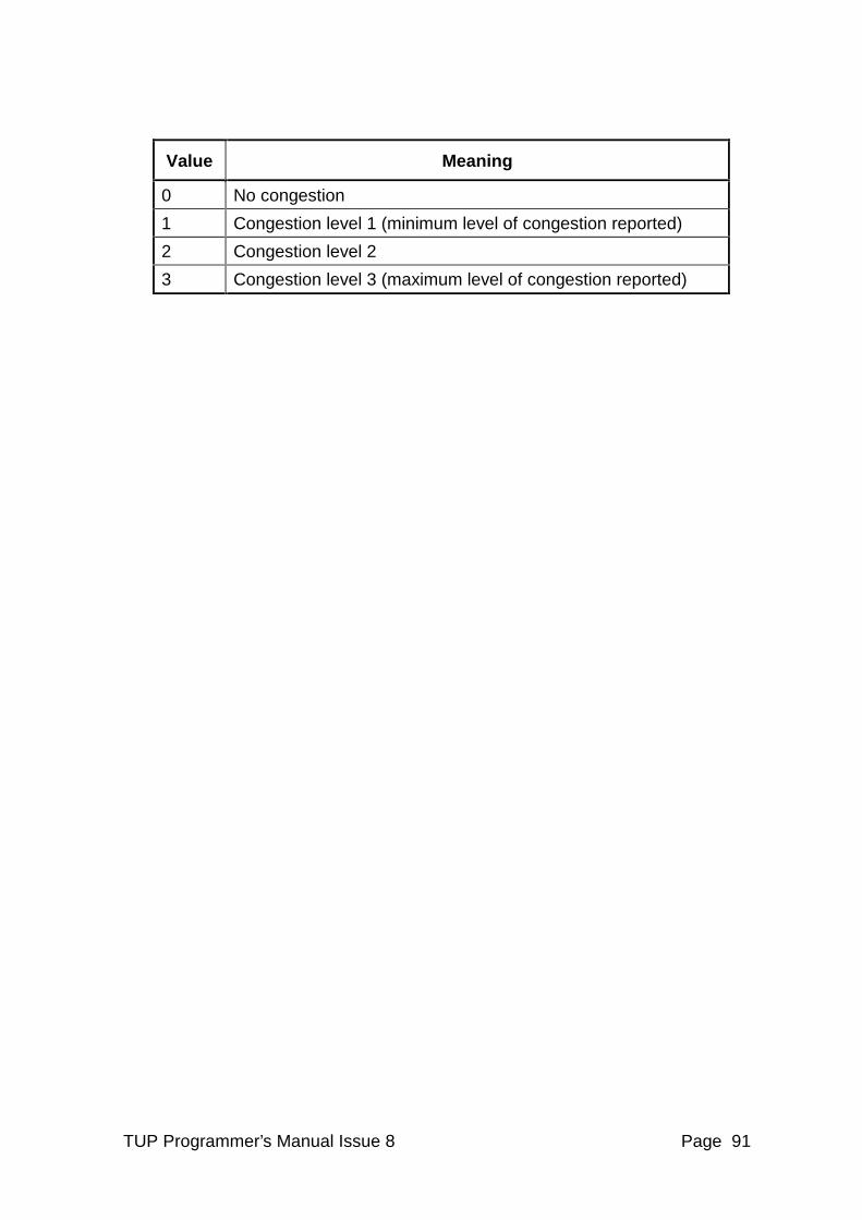
TUP Programmer’s Manual Issue 8 Page 91
Value Meaning
0 No congestion
1 Congestion level 1 (minimum level of congestion reported)
2 Congestion level 2
3 Congestion level 3 (maximum level of congestion reported)
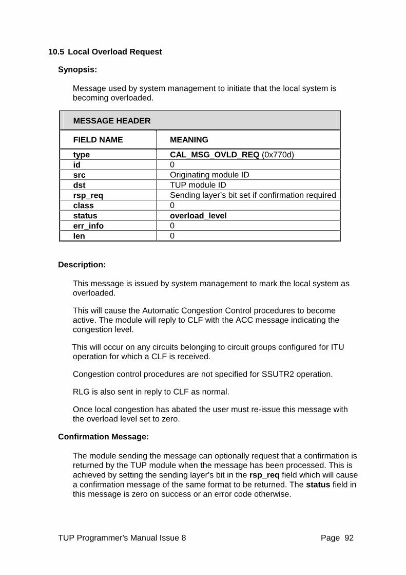
TUP Programmer’s Manual Issue 8 Page 92
10.5 Local Overload Request
Synopsis: Message used by system management to initiate that the local system is becoming overloaded.
MESSAGE HEADER
FIELD NAME MEANING
type CAL_MSG_OVLD_REQ (0x770d) id 0 src Originating module ID dst TUP module ID rsp_req Sending layer’s bit set if confirmation required class 0 status overload_level err_info 0 len 0
Description: This message is issued by system management to mark the local system as overloaded.
This will cause the Automatic Congestion Control procedures to become active. The module will reply to CLF with the ACC message indicating the congestion level.
This will occur on any circuits belonging to circuit groups configured for ITU operation for which a CLF is received.
Congestion control procedures are not specified for SSUTR2 operation.
RLG is also sent in reply to CLF as normal.
Once local congestion has abated the user must re-issue this message with the overload level set to zero.
Confirmation Message: The module sending the message can optionally request that a confirmation is returned by the TUP module when the message has been processed. This is achieved by setting the sending layer’s bit in the rsp_req field which will cause a confirmation message of the same format to be returned. The status field in this message is zero on success or an error code otherwise.
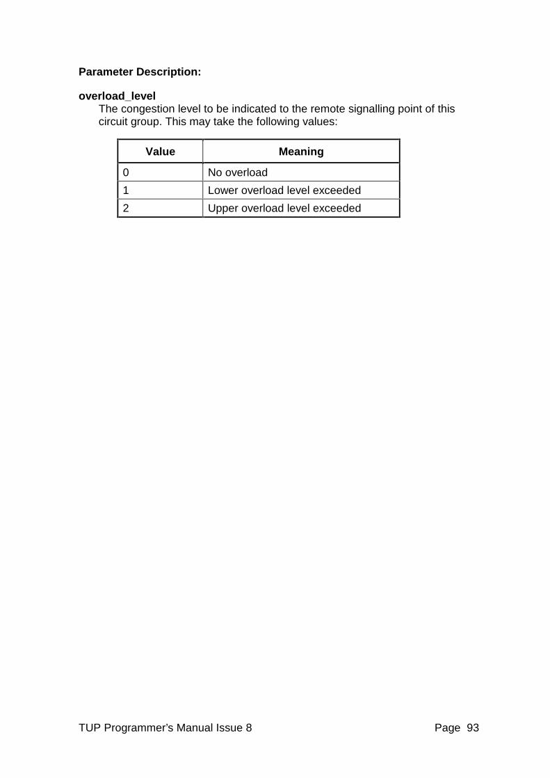
TUP Programmer’s Manual Issue 8 Page 93
Parameter Description:
overload_level The congestion level to be indicated to the remote signalling point of this circuit group. This may take the following values:
Value Meaning
0 No overload
1 Lower overload level exceeded
2 Upper overload level exceeded
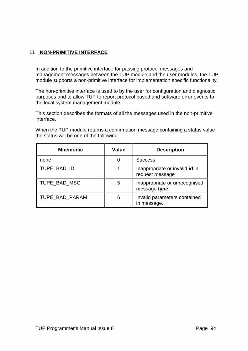
TUP Programmer’s Manual Issue 8 Page 94
11 NON-PRIMITIVE INTERFACE
In addition to the primitive interface for passing protocol messages and management messages between the TUP module and the user modules, the TUP module supports a non-primitive interface for implementation specific functionality.
The non-primitive interface is used to by the user for configuration and diagnostic purposes and to allow TUP to report protocol based and software error events to the local system management module.
This section describes the formats of all the messages used in the non-primitive interface.
When the TUP module returns a confirmation message containing a status value the status will be one of the following:
Mnemonic Value Description
none 0 Success
TUPE_BAD_ID 1 Inappropriate or invalid id in request message
TUPE_BAD_MSG 5 Inappropriate or unrecognised message type.
TUPE_BAD_PARAM 6 Invalid parameters contained in message.
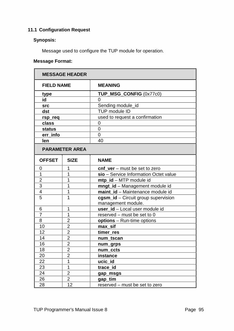
TUP Programmer’s Manual Issue 8 Page 95
11.1 Configuration Request
Synopsis: Message used to configure the TUP module for operation.
Message Format:
MESSAGE HEADER
FIELD NAME MEANING
type TUP_MSG_CONFIG (0x77c0) id 0 src Sending module_id dst TUP module ID rsp_req used to request a confirmation class 0 status 0 err_info 0 len 40
PARAMETER AREA
OFFSET SIZE NAME
0 1 cnf_ver – must be set to zero 1 1 sio – Service Information Octet value 2 1 mtp_id – MTP module id 3 1 mngt_id – Management module id 4 1 maint_id – Maintenance module id 5 1 cgsm_id – Circuit group supervision
management module. 6 1 user_id – Local user module id 7 1 reserved – must be set to 0 8 2 options – Run-time options 10 2 max_sif 12 2 timer_res 14 2 num_tscan 16 2 num_grps 18 2 num_ccts 20 2 instance 22 1 ucic_id 23 1 trace_id 24 2 gap_msgs 26 2 gap_tim 28 12 reserved – must be set to zero
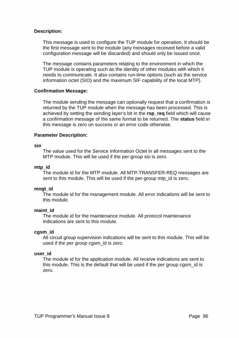
TUP Programmer’s Manual Issue 8 Page 96
Description: This message is used to configure the TUP module for operation. It should be the first message sent to the module (any messages received before a valid configuration message will be discarded) and should only be issued once.
The message contains parameters relating to the environment in which the TUP module is operating such as the identity of other modules with which it needs to communicate. It also contains run-time options (such as the service information octet (SIO) and the maximum SIF capability of the local MTP).
Confirmation Message: The module sending the message can optionally request that a confirmation is returned by the TUP module when the message has been processed. This is achieved by setting the sending layer’s bit in the rsp_req field which will cause a confirmation message of the same format to be returned. The status field in this message is zero on success or an error code otherwise.
Parameter Description:
sio The value used for the Service Information Octet in all messages sent to the MTP module. This will be used if the per-group sio is zero.
mtp_id The module id for the MTP module. All MTP-TRANSFER-REQ messages are sent to this module. This will be used if the per-group mtp_id is zero.
mngt_id The module id for the management module. All error indications will be sent to this module.
maint_id The module id for the maintenance module. All protocol maintenance indications are sent to this module.
cgsm_id All circuit group supervision indications will be sent to this module. This will be used if the per group cgsm_id is zero.
user_id The module id for the application module. All receive indications are sent to this module. This is the default that will be used if the per group cgsm_id is zero.
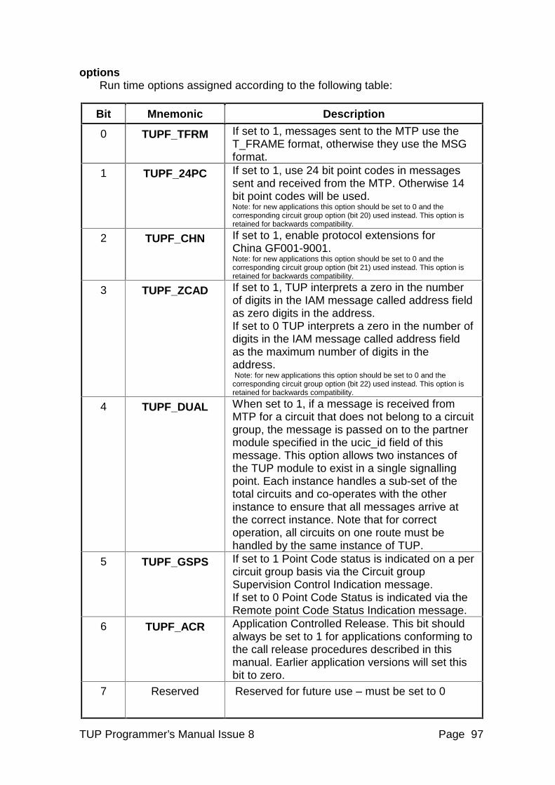
TUP Programmer’s Manual Issue 8 Page 97
options Run time options assigned according to the following table:
Bit Mnemonic Description
0 TUPF_TFRM If set to 1, messages sent to the MTP use the T_FRAME format, otherwise they use the MSG format.
1 TUPF_24PC If set to 1, use 24 bit point codes in messages sent and received from the MTP. Otherwise 14 bit point codes will be used. Note: for new applications this option should be set to 0 and the corresponding circuit group option (bit 20) used instead. This option is retained for backwards compatibility.
2 TUPF_CHN If set to 1, enable protocol extensions for China GF001-9001. Note: for new applications this option should be set to 0 and the corresponding circuit group option (bit 21) used instead. This option is retained for backwards compatibility.
3 TUPF_ZCAD If set to 1, TUP interprets a zero in the number of digits in the IAM message called address field as zero digits in the address. If set to 0 TUP interprets a zero in the number of digits in the IAM message called address field as the maximum number of digits in the address. Note: for new applications this option should be set to 0 and the corresponding circuit group option (bit 22) used instead. This option is retained for backwards compatibility.
4 TUPF_DUAL When set to 1, if a message is received from MTP for a circuit that does not belong to a circuit group, the message is passed on to the partner module specified in the ucic_id field of this message. This option allows two instances of the TUP module to exist in a single signalling point. Each instance handles a sub-set of the total circuits and co-operates with the other instance to ensure that all messages arrive at the correct instance. Note that for correct operation, all circuits on one route must be handled by the same instance of TUP.
5 TUPF_GSPS If set to 1 Point Code status is indicated on a per circuit group basis via the Circuit group Supervision Control Indication message. If set to 0 Point Code Status is indicated via the Remote point Code Status Indication message.
6 TUPF_ACR Application Controlled Release. This bit should always be set to 1 for applications conforming to the call release procedures described in this manual. Earlier application versions will set this bit to zero.
7 Reserved Reserved for future use – must be set to 0
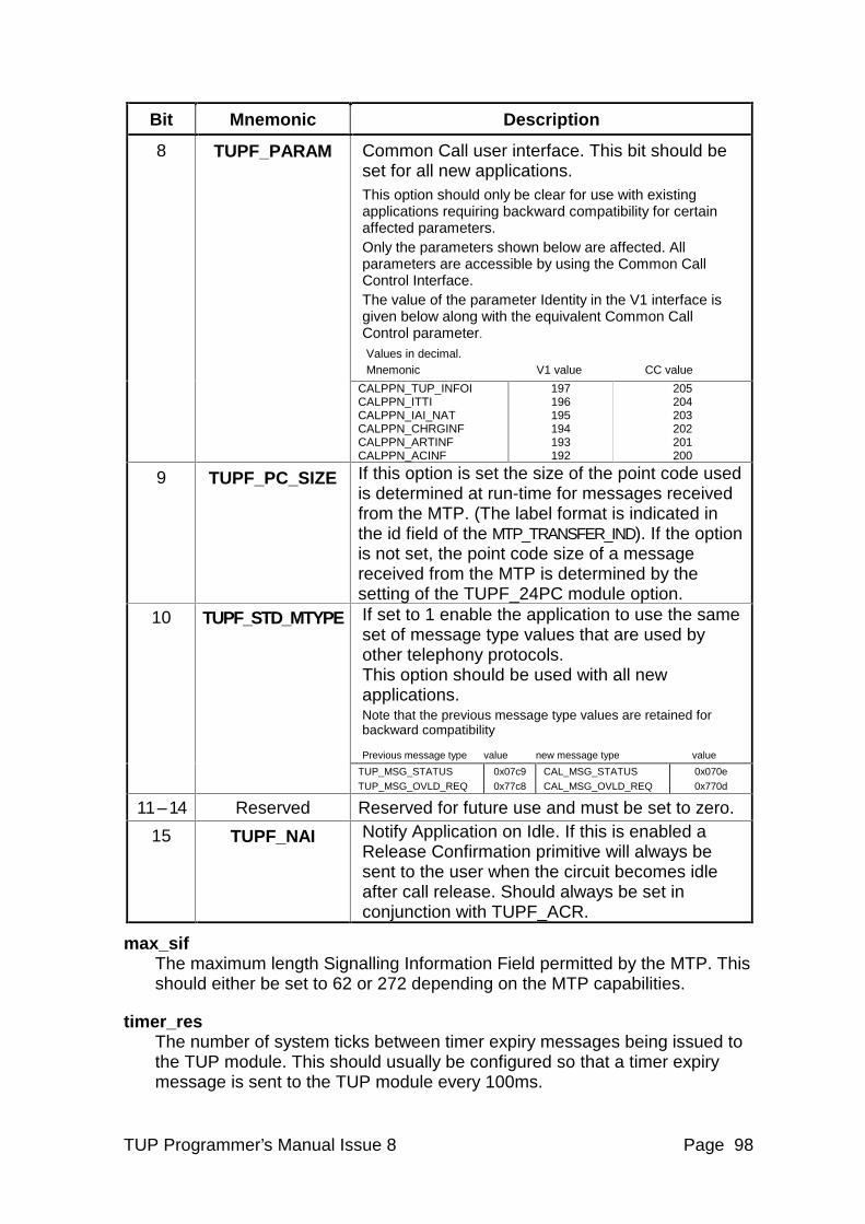
TUP Programmer’s Manual Issue 8 Page 98
Bit Mnemonic Description
Common Call user interface. This bit should be set for all new applications. This option should only be clear for use with existing applications requiring backward compatibility for certain affected parameters. Only the parameters shown below are affected. All parameters are accessible by using the Common Call Control Interface. The value of the parameter Identity in the V1 interface is given below along with the equivalent Common Call Control parameter. Values in decimal. Mnemonic V1 value CC value
8 TUPF_PARAM
CALPPN_TUP_INFOI CALPPN_ITTI CALPPN_IAI_NAT CALPPN_CHRGINF CALPPN_ARTINF CALPPN_ACINF
197 196 195 194 193 192
205 204 203 202 201 200
9 TUPF_PC_SIZE If this option is set the size of the point code used is determined at run-time for messages received from the MTP. (The label format is indicated in the id field of the MTP_TRANSFER_IND). If the option is not set, the point code size of a message received from the MTP is determined by the setting of the TUPF_24PC module option. If set to 1 enable the application to use the same set of message type values that are used by other telephony protocols. This option should be used with all new applications. Note that the previous message type values are retained for backward compatibility Previous message type value new message type value
10 TUPF_STD_MTYPE
TUP_MSG_STATUS
TUP_MSG_OVLD_REQ
0x07c9
0x77c8
CAL_MSG_STATUS
CAL_MSG_OVLD_REQ 0x070e
0x770d
11 – 14 Reserved Reserved for future use and must be set to zero.
15 TUPF_NAI Notify Application on Idle. If this is enabled a Release Confirmation primitive will always be sent to the user when the circuit becomes idle after call release. Should always be set in conjunction with TUPF_ACR.
max_sif The maximum length Signalling Information Field permitted by the MTP. This should either be set to 62 or 272 depending on the MTP capabilities.
timer_res The number of system ticks between timer expiry messages being issued to the TUP module. This should usually be configured so that a timer expiry message is sent to the TUP module every 100ms.
TUP Programmer’s Manual Issue 8 Page 99
num_tscan The number of timer expiry messages received for each full scan of the protocol timer table. This should usually be set to 10 so that each timer is checked once per second (or every 10 timer expiry messages).
num_grps This limits the number of circuit groups that the module will maintain and must be less than (or equal to) the maximum number of circuit groups that the module is capable of supporting. The TUP module continually scans all its circuit groups for protocol activity (such as timer expiry). The user may limit the number of circuit groups to the maximum that the application will use. This will exclude groups that will never be configured by the application from the circuit group processing that the TUP module performs.
num_ccts This limits the number of circuits that the module will maintain and must be less than (or equal to) the maximum number of circuits that the module is capable of supporting. The TUP module continually scans all its circuits for protocol activity (such as timer expiry). The user may limit the number of circuits to the maximum that the application will use. This will exclude circuits that will never be configured by the application from the circuit processing that the TUP module performs.
instance This assigns the instance value for this invocation of the TUP module in replicated TUP operation.
ucic_id Unrecognised CIC module id. Module id to which messages will be relayed if the TUPF_DUAL option bit is set and the circuit identity code in the message is not one handled by this TUP instance.
trace_id Trace module id. Module id to which trace messages will be sent. If this parameter is not supplied (set to zero) trace messages will be sent to the management module id.
gap_msgs In order to reduce traffic load when circuits are (un)blocked or reset by the user, the TUP module issues messages for gap_msgs circuits every gap_tim system ticks. (Only used when TUPGOP_NO_CGB or TUPGOP_NO_GRS options are selected). Recommended setting = 5.
gap_tim The time in system ticks between issuing (un)blocking (or reset) messages for gap_msgs circuits when the user application requests (un)blocking (or reset) for a number of circuits. (Only used when TUPGOP_NO_CGB or TUPGOP_NO_GRS options are selected). Recommended setting = 1.
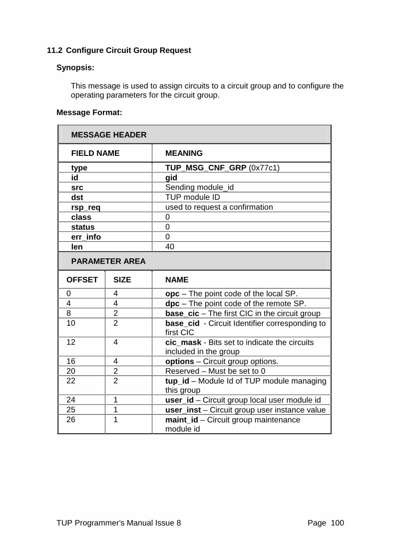
TUP Programmer’s Manual Issue 8 Page 100
11.2 Configure Circuit Group Request
Synopsis: This message is used to assign circuits to a circuit group and to configure the operating parameters for the circuit group.
Message Format:
MESSAGE HEADER
FIELD NAME MEANING
type TUP_MSG_CNF_GRP (0x77c1) id gid src Sending module_id dst TUP module ID rsp_req used to request a confirmation class 0 status 0 err_info 0 len 40
PARAMETER AREA
OFFSET SIZE NAME
0 4 opc – The point code of the local SP. 4 4 dpc – The point code of the remote SP. 8 2 base_cic – The first CIC in the circuit group 10 2 base_cid - Circuit Identifier corresponding to
first CIC 12 4 cic_mask - Bits set to indicate the circuits
included in the group 16 4 options – Circuit group options. 20 2 Reserved – Must be set to 0 22 2 tup_id – Module Id of TUP module managing
this group 24 1 user_id – Circuit group local user module id 25 1 user_inst – Circuit group user instance value 26 1 maint_id – Circuit group maintenance
module id
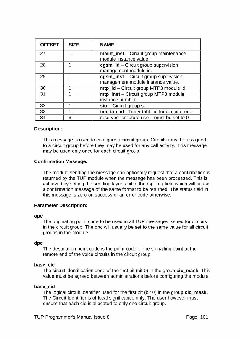
TUP Programmer’s Manual Issue 8 Page 101
OFFSET SIZE NAME
27 1 maint_inst – Circuit group maintenance module instance value
28 1 cgsm_id – Circuit group supervision management module id.
29 1 cgsm_inst – Circuit group supervision management module instance value.
30 1 mtp_id – Circuit group MTP3 module id. 31 1 mtp_inst – Circuit group MTP3 module
instance number. 32 1 sio – Circuit group sio 33 1 tim_tab_id –Timer table id for circuit group. 34 6 reserved for future use – must be set to 0
Description: This message is used to configure a circuit group. Circuits must be assigned to a circuit group before they may be used for any call activity. This message may be used only once for each circuit group.
Confirmation Message: The module sending the message can optionally request that a confirmation is returned by the TUP module when the message has been processed. This is achieved by setting the sending layer’s bit in the rsp_req field which will cause a confirmation message of the same format to be returned. The status field in this message is zero on success or an error code otherwise.
Parameter Description:
opc The originating point code to be used in all TUP messages issued for circuits in the circuit group. The opc will usually be set to the same value for all circuit groups in the module.
dpc The destination point code is the point code of the signalling point at the remote end of the voice circuits in the circuit group.
base_cic The circuit identification code of the first bit (bit 0) in the group cic_mask. This value must be agreed between administrations before configuring the module.
base_cid The logical circuit Identifier used for the first bit (bit 0) in the group cic_mask. The Circuit Identifier is of local significance only. The user however must ensure that each cid is allocated to only one circuit group.
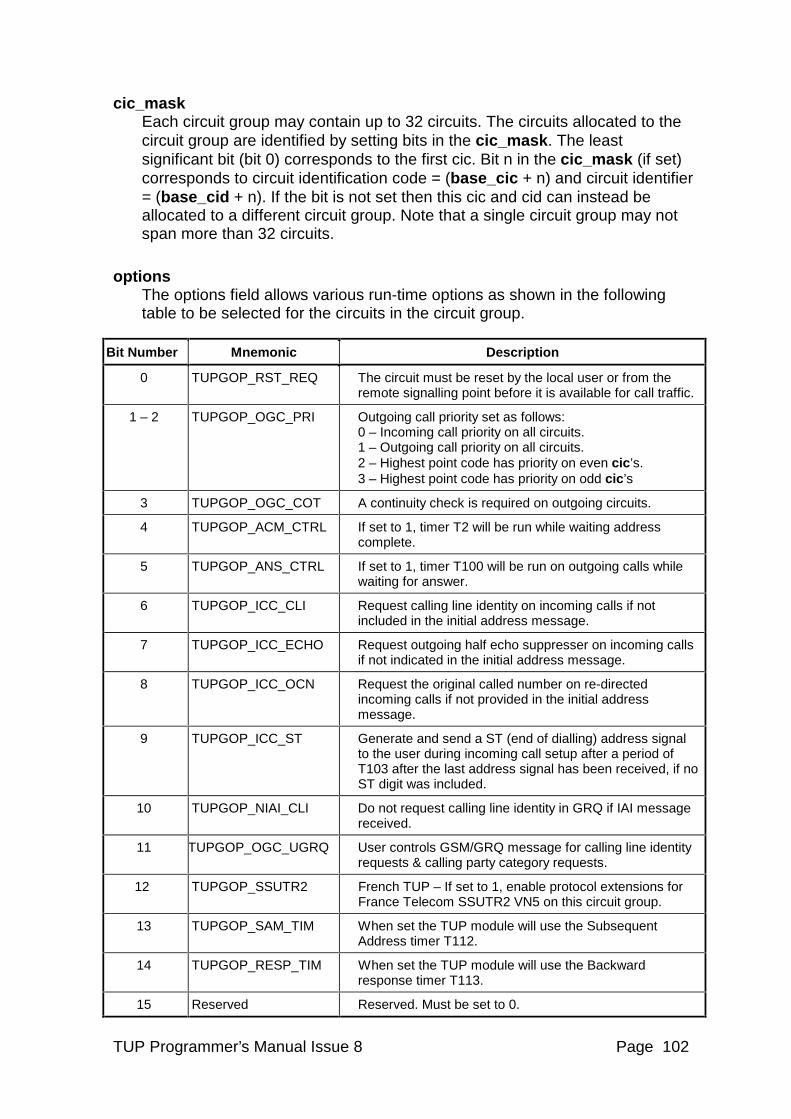
TUP Programmer’s Manual Issue 8 Page 102
cic_mask Each circuit group may contain up to 32 circuits. The circuits allocated to the circuit group are identified by setting bits in the cic_mask. The least significant bit (bit 0) corresponds to the first cic. Bit n in the cic_mask (if set) corresponds to circuit identification code = (base_cic + n) and circuit identifier = (base_cid + n). If the bit is not set then this cic and cid can instead be allocated to a different circuit group. Note that a single circuit group may not span more than 32 circuits.
options The options field allows various run-time options as shown in the following table to be selected for the circuits in the circuit group.
Bit Number Mnemonic Description
0 TUPGOP_RST_REQ The circuit must be reset by the local user or from the remote signalling point before it is available for call traffic.
1 – 2 TUPGOP_OGC_PRI Outgoing call priority set as follows: 0 – Incoming call priority on all circuits. 1 – Outgoing call priority on all circuits. 2 – Highest point code has priority on even cic’s. 3 – Highest point code has priority on odd cic’s
3 TUPGOP_OGC_COT A continuity check is required on outgoing circuits.
4 TUPGOP_ACM_CTRL If set to 1, timer T2 will be run while waiting address complete.
5 TUPGOP_ANS_CTRL If set to 1, timer T100 will be run on outgoing calls while waiting for answer.
6 TUPGOP_ICC_CLI Request calling line identity on incoming calls if not included in the initial address message.
7 TUPGOP_ICC_ECHO Request outgoing half echo suppresser on incoming calls if not indicated in the initial address message.
8 TUPGOP_ICC_OCN Request the original called number on re-directed incoming calls if not provided in the initial address message.
9 TUPGOP_ICC_ST Generate and send a ST (end of dialling) address signal to the user during incoming call setup after a period of T103 after the last address signal has been received, if no ST digit was included.
10 TUPGOP_NIAI_CLI Do not request calling line identity in GRQ if IAI message received.
11 TUPGOP_OGC_UGRQ User controls GSM/GRQ message for calling line identity requests & calling party category requests.
12 TUPGOP_SSUTR2 French TUP – If set to 1, enable protocol extensions for France Telecom SSUTR2 VN5 on this circuit group.
13 TUPGOP_SAM_TIM When set the TUP module will use the Subsequent Address timer T112.
14 TUPGOP_RESP_TIM When set the TUP module will use the Backward response timer T113.
15 Reserved Reserved. Must be set to 0.
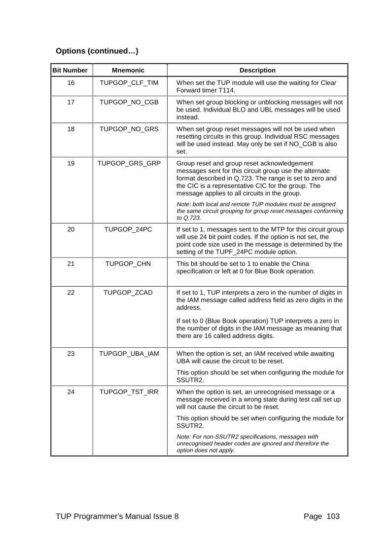
TUP Programmer’s Manual Issue 8 Page 103
Options (continued…)
Bit Number Mnemonic Description
16 TUPGOP_CLF_TIM When set the TUP module will use the waiting for Clear Forward timer T114.
17 TUPGOP_NO_CGB When set group blocking or unblocking messages will not be used. Individual BLO and UBL messages will be used instead.
18 TUPGOP_NO_GRS When set group reset messages will not be used when resetting circuits in this group. Individual RSC messages will be used instead. May only be set if NO_CGB is also set.
19 TUPGOP_GRS_GRP Group reset and group reset acknowledgement messages sent for this circuit group use the alternate format described in Q.723. The range is set to zero and the CIC is a representative CIC for the group. The message applies to all circuits in the group.
Note: both local and remote TUP modules must be assigned the same circuit grouping for group reset messages conforming to Q.723.
20 TUPGOP_24PC If set to 1, messages sent to the MTP for this circuit group will use 24 bit point codes. If the option is not set, the point code size used in the message is determined by the setting of the TUPF_24PC module option.
21 TUPGOP_CHN This bit should be set to 1 to enable the China specification or left at 0 for Blue Book operation.
22 TUPGOP_ZCAD If set to 1, TUP interprets a zero in the number of digits in the IAM message called address field as zero digits in the address.
If set to 0 (Blue Book operation) TUP interprets a zero in the number of digits in the IAM message as meaning that there are 16 called address digits.
23 TUPGOP_UBA_IAM When the option is set, an IAM received while awaiting UBA will cause the circuit to be reset.
This option should be set when configuring the module for SSUTR2.
24 TUPGOP_TST_IRR When the option is set, an unrecognised message or a message received in a wrong state during test call set up will not cause the circuit to be reset.
This option should be set when configuring the module for SSUTR2.
Note: For non-SSUTR2 specifications, messages with unrecognised header codes are ignored and therefore the option does not apply.
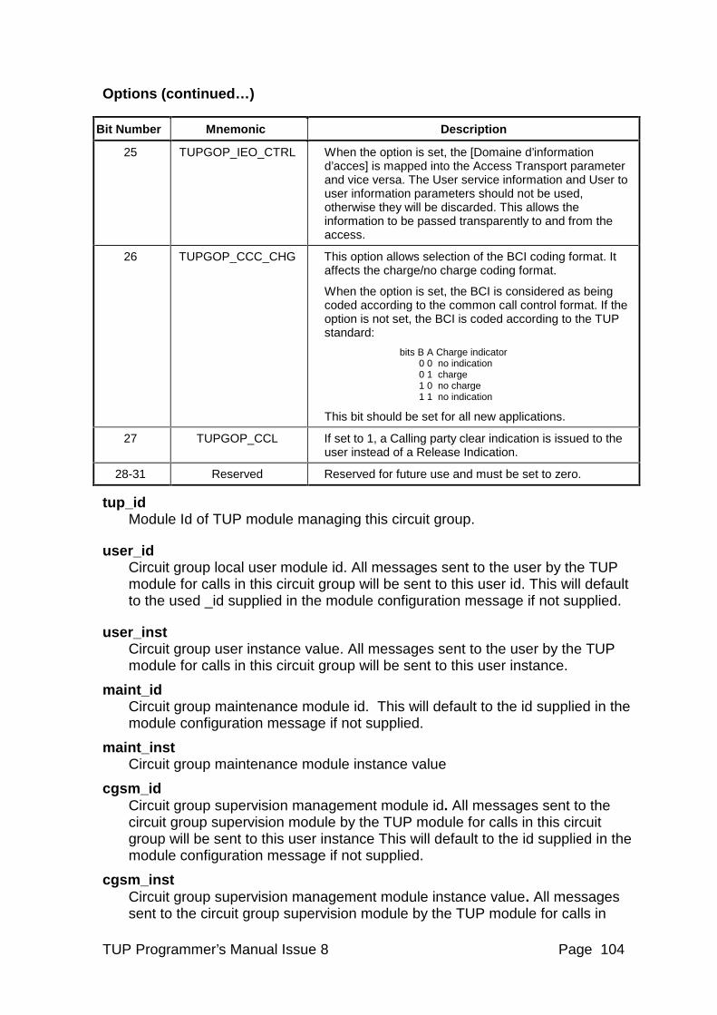
TUP Programmer’s Manual Issue 8 Page 104
Options (continued…)
Bit Number Mnemonic Description
25 TUPGOP_IEO_CTRL When the option is set, the [Domaine d’information d’acces] is mapped into the Access Transport parameter and vice versa. The User service information and User to user information parameters should not be used, otherwise they will be discarded. This allows the information to be passed transparently to and from the access.
26 TUPGOP_CCC_CHG This option allows selection of the BCI coding format. It affects the charge/no charge coding format.
When the option is set, the BCI is considered as being coded according to the common call control format. If the option is not set, the BCI is coded according to the TUP standard:
bits B A Charge indicator 0 0 no indication 0 1 charge 1 0 no charge 1 1 no indication
This bit should be set for all new applications.
27 TUPGOP_CCL If set to 1, a Calling party clear indication is issued to the user instead of a Release Indication.
28-31 Reserved Reserved for future use and must be set to zero.
tup_id Module Id of TUP module managing this circuit group.
user_id Circuit group local user module id. All messages sent to the user by the TUP
module for calls in this circuit group will be sent to this user id. This will default to the used _id supplied in the module configuration message if not supplied.
user_inst Circuit group user instance value. All messages sent to the user by the TUP
module for calls in this circuit group will be sent to this user instance.
maint_id Circuit group maintenance module id. This will default to the id supplied in the
module configuration message if not supplied.
maint_inst Circuit group maintenance module instance value
cgsm_id Circuit group supervision management module id. All messages sent to the
circuit group supervision module by the TUP module for calls in this circuit group will be sent to this user instance This will default to the id supplied in the module configuration message if not supplied.
cgsm_inst Circuit group supervision management module instance value. All messages
sent to the circuit group supervision module by the TUP module for calls in
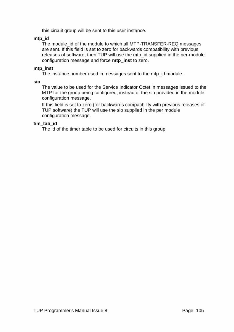
TUP Programmer’s Manual Issue 8 Page 105
this circuit group will be sent to this user instance.
mtp_id The module_id of the module to which all MTP-TRANSFER-REQ messages
are sent. If this field is set to zero for backwards compatibility with previous releases of software, then TUP will use the mtp_id supplied in the per-module configuration message and force mtp_inst to zero.
mtp_inst The instance number used in messages sent to the mtp_id module.
sio The value to be used for the Service Indicator Octet in messages issued to the
MTP for the group being configured, instead of the sio provided in the module configuration message.
If this field is set to zero (for backwards compatibility with previous releases of TUP software) the TUP will use the sio supplied in the per module configuration message.
tim_tab_id The id of the timer table to be used for circuits in this group
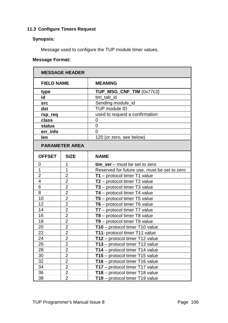
TUP Programmer’s Manual Issue 8 Page 106
11.3 Configure Timers Request
Synopsis: Message used to configure the TUP module timer values.
Message Format:
MESSAGE HEADER
FIELD NAME MEANING
type TUP_MSG_CNF_TIM (0x77c3) id tim_tab_id src Sending module_id dst TUP module ID rsp_req used to request a confirmation class 0 status 0 err_info 0 len 120 (or zero, see below)
PARAMETER AREA
OFFSET SIZE NAME
0 1 tim_ver – must be set to zero 1 1 Reserved for future use, must be set to zero 2 2 T1 – protocol timer T1 value 4 2 T2 – protocol timer T2 value 6 2 T3 – protocol timer T3 value 8 2 T4 – protocol timer T4 value 10 2 T5 – protocol timer T5 value 12 2 T6 – protocol timer T6 value 14 2 T7 – protocol timer T7 value 16 2 T8 – protocol timer T8 value 18 2 T9 – protocol timer T9 value 20 2 T10 – protocol timer T10 value 22 2 T11- protocol timer T11 value 24 2 T12 – protocol timer T12 value 26 2 T13 – protocol timer T13 value 28 2 T14 – protocol timer T14 value 30 2 T15 – protocol timer T15 value 32 2 T16 – protocol timer T16 value 34 2 T17 – protocol timer T17 value 36 2 T18 – protocol timer T18 value 38 2 T19 – protocol timer T19 value
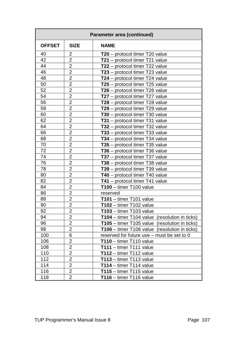
TUP Programmer’s Manual Issue 8 Page 107
Parameter area (continued)
OFFSET SIZE NAME
40 2 T20 – protocol timer T20 value 42 2 T21 – protocol timer T21 value 44 2 T22 – protocol timer T22 value 46 2 T23 – protocol timer T23 value 48 2 T24 – protocol timer T24 value 50 2 T25 – protocol timer T25 value 52 2 T26 – protocol timer T26 value 54 2 T27 – protocol timer T27 value 56 2 T28 – protocol timer T28 value 58 2 T29 – protocol timer T29 value 60 2 T30 – protocol timer T30 value 62 2 T31 – protocol timer T31 value 64 2 T32 – protocol timer T32 value 66 2 T33 – protocol timer T33 value 68 2 T34 – protocol timer T34 value 70 2 T35 – protocol timer T35 value 72 2 T36 – protocol timer T36 value 74 2 T37 – protocol timer T37 value 76 2 T38 – protocol timer T38 value 78 2 T39 – protocol timer T39 value 80 2 T40 – protocol timer T40 value 82 2 T41 – protocol timer T41 value 84 2 T100 – timer T100 value 86 2 reserved 88 2 T101 – timer T101 value 90 2 T102 – timer T102 value 92 2 T103 – timer T103 value 94 2 T104 – timer T104 value (resolution in ticks) 96 2 T105 – timer T105 value (resolution in ticks) 98 2 T106 – timer T106 value (resolution in ticks) 100 6 reserved for future use – must be set to 0 106 2 T110 – timer T110 value 108 2 T111 – timer T111 value 110 2 T112 – timer T112 value 112 2 T113 – timer T113 value 114 2 T114 – timer T114 value 116 2 T115 – timer T115 value 118 2 T116 – timer T116 value
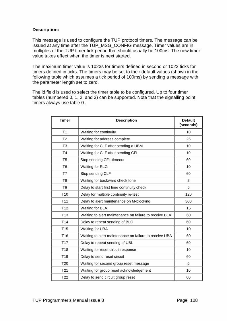
TUP Programmer’s Manual Issue 8 Page 108
Description: This message is used to configure the TUP protocol timers. The message can be issued at any time after the TUP_MSG_CONFIG message. Timer values are in multiples of the TUP timer tick period that should usually be 100ms. The new timer value takes effect when the timer is next started. The maximum timer value is 1023s for timers defined in second or 1023 ticks for timers defined in ticks. The timers may be set to their default values (shown in the following table which assumes a tick period of 100ms) by sending a message with the parameter length set to zero.
The id field is used to select the timer table to be configured. Up to four timer tables (numbered 0, 1, 2, and 3) can be supported. Note that the signalling point timers always use table 0 .
Timer Description Default (seconds)
T1 Waiting for continuity 10
T2 Waiting for address complete 25
T3 Waiting for CLF after sending a UBM 10
T4 Waiting for CLF after sending CFL 10
T5 Stop sending CFL timeout 60
T6 Waiting for RLG 10
T7 Stop sending CLF 60
T8 Waiting for backward check tone 2
T9 Delay to start first time continuity check 5
T10 Delay for multiple continuity re-test 120
T11 Delay to alert maintenance on M-blocking 300
T12 Waiting for BLA 15
T13 Waiting to alert maintenance on failure to receive BLA 60
T14 Delay to repeat sending of BLO 60
T15 Waiting for UBA 10
T16 Waiting to alert maintenance on failure to receive UBA 60
T17 Delay to repeat sending of UBL 60
T18 Waiting for reset circuit response 10
T19 Delay to send reset circuit 60
T20 Waiting for second group reset message 5
T21 Waiting for group reset acknowledgement 10
T22 Delay to send circuit group reset 60
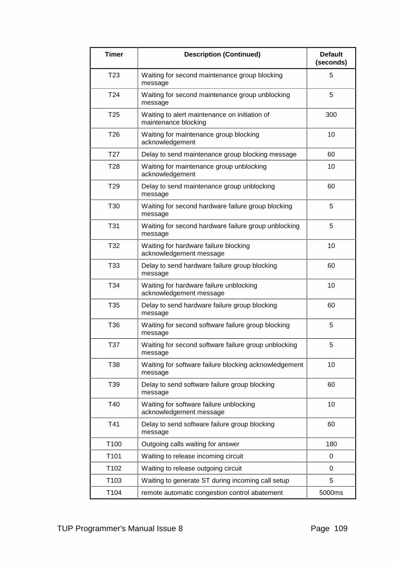
TUP Programmer’s Manual Issue 8 Page 109
Timer Description (Continued) Default (seconds)
T23 Waiting for second maintenance group blocking message
5
T24 Waiting for second maintenance group unblocking message
5
T25 Waiting to alert maintenance on initiation of maintenance blocking
300
T26 Waiting for maintenance group blocking acknowledgement
10
T27 Delay to send maintenance group blocking message 60
T28 Waiting for maintenance group unblocking acknowledgement
10
T29 Delay to send maintenance group unblocking message
60
T30 Waiting for second hardware failure group blocking message
5
T31 Waiting for second hardware failure group unblocking message
5
T32 Waiting for hardware failure blocking acknowledgement message
10
T33 Delay to send hardware failure group blocking message
60
T34 Waiting for hardware failure unblocking acknowledgement message
10
T35 Delay to send hardware failure group blocking message
60
T36 Waiting for second software failure group blocking message
5
T37 Waiting for second software failure group unblocking message
5
T38 Waiting for software failure blocking acknowledgement message
10
T39 Delay to send software failure group blocking message
60
T40 Waiting for software failure unblocking acknowledgement message
10
T41 Delay to send software failure group blocking message
60
T100 Outgoing calls waiting for answer 180
T101 Waiting to release incoming circuit 0
T102 Waiting to release outgoing circuit 0
T103 Waiting to generate ST during incoming call setup 5
T104 remote automatic congestion control abatement 5000ms
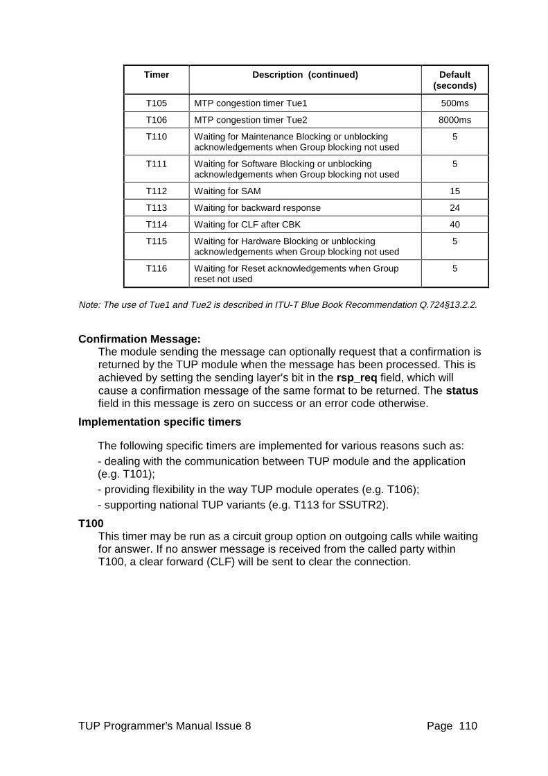
TUP Programmer’s Manual Issue 8 Page 110
Timer Description (continued) Default (seconds)
T105 MTP congestion timer Tue1 500ms
T106 MTP congestion timer Tue2 8000ms
T110 Waiting for Maintenance Blocking or unblocking acknowledgements when Group blocking not used
5
T111 Waiting for Software Blocking or unblocking acknowledgements when Group blocking not used
5
T112 Waiting for SAM 15
T113 Waiting for backward response 24
T114 Waiting for CLF after CBK 40
T115 Waiting for Hardware Blocking or unblocking acknowledgements when Group blocking not used
5
T116 Waiting for Reset acknowledgements when Group reset not used
5
Note: The use of Tue1 and Tue2 is described in ITU-T Blue Book Recommendation Q.724§13.2.2.
Confirmation Message: The module sending the message can optionally request that a confirmation is returned by the TUP module when the message has been processed. This is achieved by setting the sending layer’s bit in the rsp_req field, which will cause a confirmation message of the same format to be returned. The status field in this message is zero on success or an error code otherwise.
Implementation specific timers
The following specific timers are implemented for various reasons such as: - dealing with the communication between TUP module and the application (e.g. T101); - providing flexibility in the way TUP module operates (e.g. T106); - supporting national TUP variants (e.g. T113 for SSUTR2).
T100 This timer may be run as a circuit group option on outgoing calls while waiting for answer. If no answer message is received from the called party within T100, a clear forward (CLF) will be sent to clear the connection.
TUP Programmer’s Manual Issue 8 Page 111
T101 The use of timer T101 is controlled by the Application Controlled Release (TUPF_ACR) option.
Configuration option TUPF_ACR should be selected for all new applications.
Timer T101 is not used if the TUPF_ACR option is selected.
If the TUPF_ACR option is not selected the TUP module will automatically release an incoming call in response to a CLF (clear forwards) received from the network. If T101 is configured with a zero duration a Release Guard (RLG) is sent to the network immediately. T101 has a default duration of zero. If the user wishes to have control of this RLG message without using the TUPF_ACR option, timer T101 may be set non zero. T101 will then be run after CLF has been received. During this period, the user may issue a Release Response primitive to indicate that the incoming connection has been cleared. If T101 expires, RLG will be issued to the network.
T102
Timer T102 is the re-answer timer. Used on outgoing calls when the remote called party clears the call. It provides a period during which the called party may re-answer. It has two modes of operation based on the setting of the Application Controlled Release option (TUPF_ACR).
Configuration option TUPF_ACR should be selected for all new applications.
If TUPF_ACR is selected: Timer T102 is started when the network indicates called party clear down by sending the CBK message. A Suspend Indication primitive is sent to the user. If timer T102 subsequently expires a Release Indication primitive is sent to the user. The user is then required to send a Release Response primitive to initiate forward release of the call as normal. The called party may re-answer at any time until this Release Indication primitive is sent to the user. If T102 is set to 0 (zero duration), T102 is given a default duration equal to the setting value of T6 plus 2 seconds.
If TUPF_ACR is not selected: Timer T102 is started when the network indicates called party clear down by sending the CBK message. A Suspend Indication primitive is sent to the user. If the T102 timer subsequently expires, TUP module automatically initiates the connection release by sending CLF to the network. During the T102 period, the user may release the call using the Release Request primitive or the called party may re-answer. If T102 is set to 0 (zero duration), the call is released immediately and no reanswer is possible.
T103 T103 may be run (as a circuit group option) during the call setup phase of an incoming call. If no ST digit (end of dialling) has been received on T103 expiry, an ST digit will be generated locally and sent to the user (in a forwards information indication primitive). This operation is local only and does not cause any signals to be sent to the network.
TUP Programmer’s Manual Issue 8 Page 112
T104 This is the period between reducing the stored congestion level of a remote signalling point by one level. Remote signalling point congestion is indicated by the receipt of an ACC (automatic congestion control) message from the network. The user is informed of the congestion status of a remote signalling point with the CAL_MSG_STATUS_IND message or CAL_MSG_CGSC_IND depending on the setting of option TUPF_GSPS in the module configuration message.
T105 This timer implements the TUP signalling congestion control timer Tue1. It is started on receipt of a congestion primitive from the MTP and causes any further received congestion primitives to be ignored for the time that it is active. The user is informed of the signalling congestion status with the CAL_MSG_STATUS_IND message or CAL_MSG_CGSC_IND depending on the setting of option TUPF_GSPS in the module configuration message.
T106 This timer implements the TUP signalling congestion control timer Tue2. It is the period between reducing the signalling congestion level by one step after the last congestion primitive has been received from the MTP.
T110 This timer is started when all the individual Maintenance blocking (or unblocking) messages have been sent out. On expiry, a Maintenance blocking (or unblocking) confirmation is sent to the user for those circuits for which a BLA has been received.
(Only used when TUPGOP_NO_CGB option is set.)
T111 This timer is started when all the individual Software blocking (or unblocking) messages have been sent out. On expiry, a Software blocking (or unblocking) confirmation is sent to the user for those circuits for which a BLA has been received.
(Only used when TUPGOP_NO_CGB option is set.)
T112 This timer is started after reception of an Initial Address message. A call failure message will be sent if the Initial Address is not followed by a Subsequent Address message. The timer is not re-started after receipt of the first Subsequent Address message.
(Only used when circuit group option TUPGOP_SAM_TIM is set.)
T113 This timer is started on receipt of an Initial Address message. The call will be released if no backward message is received after the outgoing Initial Address message.
(Only used when circuit group option TUPGOP_RESP_TIM is set.)
TUP Programmer’s Manual Issue 8 Page 113
T114 This timer is started after transmission of clear back message on an incoming call. A call fail message is sent if this timer expires before a clear forward is received in reply.
(Only used when circuit group option TUPGOP_CLF_TIM is set.)
T115 This timer is started when all the individual Hardware blocking (or unblocking) messages have been sent out. On expiry, a Hardware blocking (or unblocking) confirmation is sent to the user for those circuits for which a BLA has been received. (Only used when TUPGOP_NO_CGB option is set.)
T116 This timer is started when all the individual Reset messages have been sent out. On expiry, a Reset confirmation is sent to the user for those circuits for which a RLG has been received. (Only used when TUPGOP_NO_GRS option is set.)
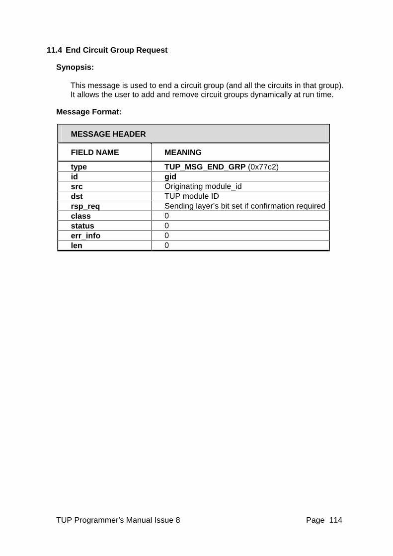
TUP Programmer’s Manual Issue 8 Page 114
11.4 End Circuit Group Request
Synopsis: This message is used to end a circuit group (and all the circuits in that group). It allows the user to add and remove circuit groups dynamically at run time.
Message Format:
MESSAGE HEADER
FIELD NAME MEANING
type TUP_MSG_END_GRP (0x77c2) id gid src Originating module_id dst TUP module ID rsp_req Sending layer’s bit set if confirmation required class 0 status 0 err_info 0 len 0
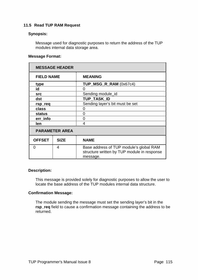
TUP Programmer’s Manual Issue 8 Page 115
11.5 Read TUP RAM Request
Synopsis: Message used for diagnostic purposes to return the address of the TUP modules internal data storage area.
Message Format:
MESSAGE HEADER
FIELD NAME MEANING
type TUP_MSG_R_RAM (0x67c4) id 0 src Sending module_id dst TUP_TASK_ID rsp_req Sending layer’s bit must be set class 0 status 0 err_info 0 len 4
PARAMETER AREA
OFFSET SIZE NAME
0 4 Base address of TUP module’s global RAM structure written by TUP module in response message.
Description: This message is provided solely for diagnostic purposes to allow the user to locate the base address of the TUP modules internal data structure.
Confirmation Message: The module sending the message must set the sending layer’s bit in the rsp_req field to cause a confirmation message containing the address to be returned.
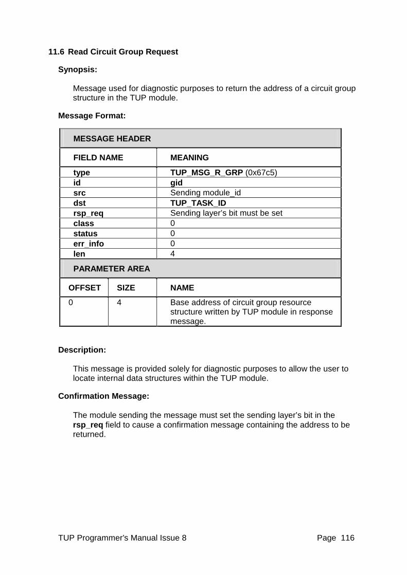
TUP Programmer’s Manual Issue 8 Page 116
11.6 Read Circuit Group Request
Synopsis: Message used for diagnostic purposes to return the address of a circuit group structure in the TUP module.
Message Format:
MESSAGE HEADER
FIELD NAME MEANING
type TUP_MSG_R_GRP (0x67c5) id gid src Sending module_id dst TUP_TASK_ID rsp_req Sending layer’s bit must be set class 0 status 0 err_info 0 len 4
PARAMETER AREA
OFFSET SIZE NAME
0 4 Base address of circuit group resource structure written by TUP module in response message.
Description: This message is provided solely for diagnostic purposes to allow the user to locate internal data structures within the TUP module.
Confirmation Message: The module sending the message must set the sending layer’s bit in the rsp_req field to cause a confirmation message containing the address to be returned.
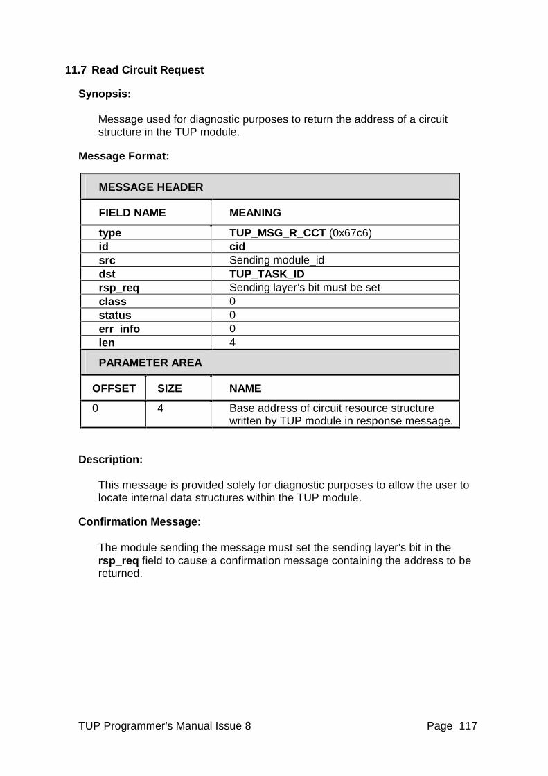
TUP Programmer’s Manual Issue 8 Page 117
11.7 Read Circuit Request
Synopsis: Message used for diagnostic purposes to return the address of a circuit structure in the TUP module.
Message Format:
MESSAGE HEADER
FIELD NAME MEANING
type TUP_MSG_R_CCT (0x67c6) id cid src Sending module_id dst TUP_TASK_ID rsp_req Sending layer’s bit must be set class 0 status 0 err_info 0 len 4
PARAMETER AREA
OFFSET SIZE NAME
0 4 Base address of circuit resource structure written by TUP module in response message.
Description: This message is provided solely for diagnostic purposes to allow the user to locate internal data structures within the TUP module.
Confirmation Message: The module sending the message must set the sending layer’s bit in the rsp_req field to cause a confirmation message containing the address to be returned.
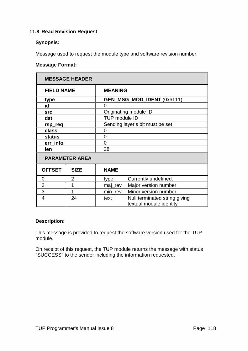
TUP Programmer’s Manual Issue 8 Page 118
11.8 Read Revision Request
Synopsis: Message used to request the module type and software revision number.
Message Format:
MESSAGE HEADER
FIELD NAME MEANING
type GEN_MSG_MOD_IDENT (0x6111) id 0 src Originating module ID dst TUP module ID rsp_req Sending layer’s bit must be set class 0 status 0 err_info 0 len 28
PARAMETER AREA
OFFSET SIZE NAME
0 2 type Currently undefined. 2 1 maj_rev Major version number 3 1 min_rev Minor version number 4 24 text Null terminated string giving
textual module identity
Description: This message is provided to request the software version used for the TUP module.
On receipt of this request, the TUP module returns the message with status "SUCCESS" to the sender including the information requested.
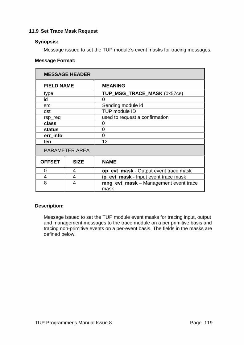
TUP Programmer’s Manual Issue 8 Page 119
11.9 Set Trace Mask Request
Synopsis:
Message issued to set the TUP module’s event masks for tracing messages.
Message Format:
MESSAGE HEADER
FIELD NAME MEANING
type TUP_MSG_TRACE_MASK (0x57ce) id 0 src Sending module id dst TUP module ID rsp_req used to request a confirmation class 0 status 0 err_info 0 len 12
PARAMETER AREA
OFFSET SIZE NAME
0 4 op_evt_mask - Output event trace mask 4 4 ip_evt_mask - Input event trace mask 8 4 mng_evt_mask – Management event trace
mask
Description: Message issued to set the TUP module event masks for tracing input, output and management messages to the trace module on a per primitive basis and tracing non-primitive events on a per-event basis. The fields in the masks are defined below.
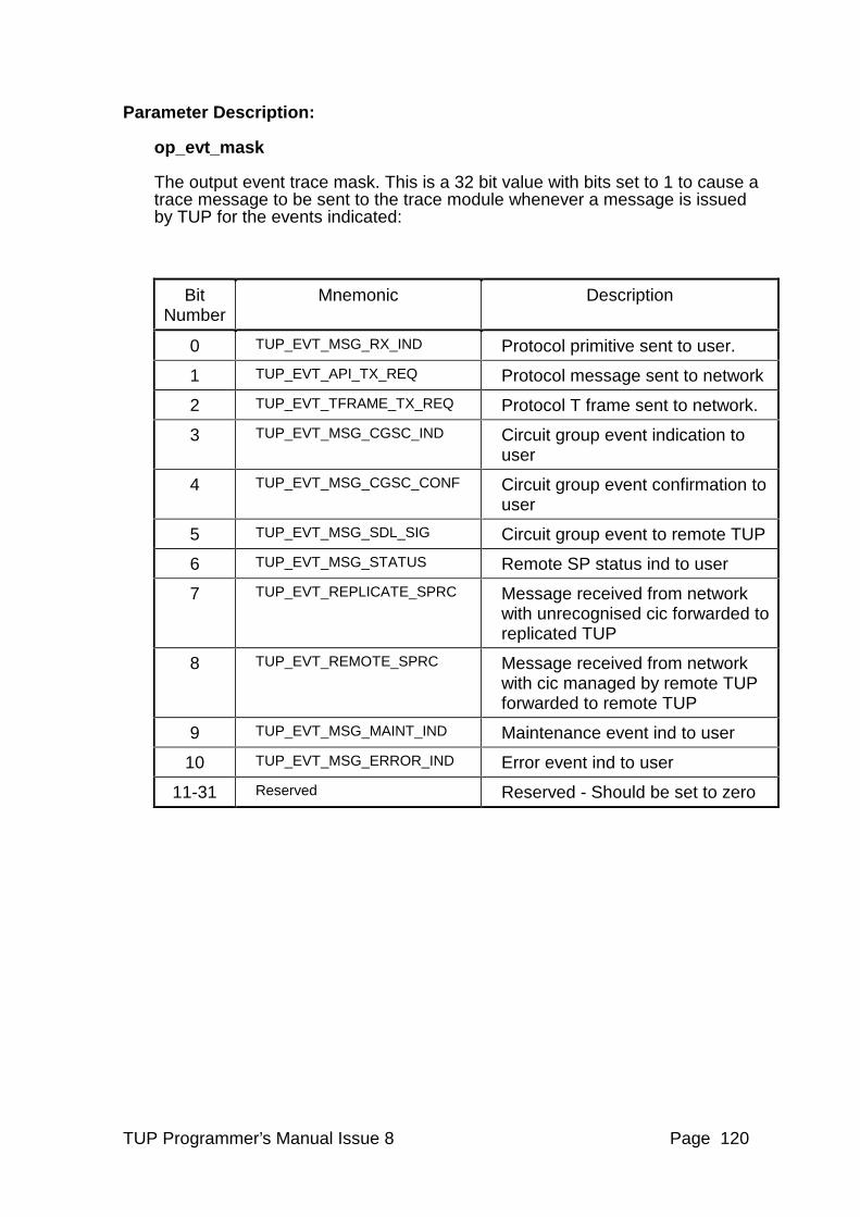
TUP Programmer’s Manual Issue 8 Page 120
Parameter Description:
op_evt_mask The output event trace mask. This is a 32 bit value with bits set to 1 to cause a trace message to be sent to the trace module whenever a message is issued by TUP for the events indicated:
Bit Number
Mnemonic Description
0 TUP_EVT_MSG_RX_IND Protocol primitive sent to user.
1 TUP_EVT_API_TX_REQ Protocol message sent to network
2 TUP_EVT_TFRAME_TX_REQ Protocol T frame sent to network.
3 TUP_EVT_MSG_CGSC_IND Circuit group event indication to user
4 TUP_EVT_MSG_CGSC_CONF Circuit group event confirmation to user
5 TUP_EVT_MSG_SDL_SIG Circuit group event to remote TUP
6 TUP_EVT_MSG_STATUS Remote SP status ind to user
7 TUP_EVT_REPLICATE_SPRC Message received from network with unrecognised cic forwarded to replicated TUP
8 TUP_EVT_REMOTE_SPRC Message received from network with cic managed by remote TUP forwarded to remote TUP
9 TUP_EVT_MSG_MAINT_IND Maintenance event ind to user
10 TUP_EVT_MSG_ERROR_IND Error event ind to user
11-31 Reserved Reserved - Should be set to zero
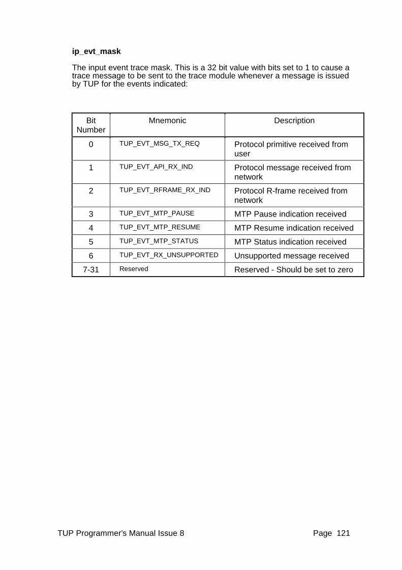
TUP Programmer’s Manual Issue 8 Page 121
ip_evt_mask The input event trace mask. This is a 32 bit value with bits set to 1 to cause a trace message to be sent to the trace module whenever a message is issued by TUP for the events indicated:
Bit Number
Mnemonic Description
0 TUP_EVT_MSG_TX_REQ Protocol primitive received from user
1 TUP_EVT_API_RX_IND Protocol message received from network
2 TUP_EVT_RFRAME_RX_IND Protocol R-frame received from network
3 TUP_EVT_MTP_PAUSE MTP Pause indication received
4 TUP_EVT_MTP_RESUME MTP Resume indication received
5 TUP_EVT_MTP_STATUS MTP Status indication received
6 TUP_EVT_RX_UNSUPPORTED Unsupported message received
7-31 Reserved Reserved - Should be set to zero
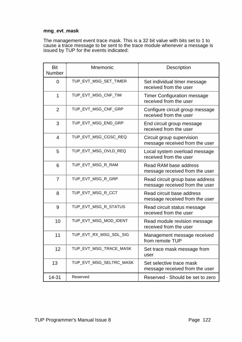
TUP Programmer’s Manual Issue 8 Page 122
mng_evt_mask The management event trace mask. This is a 32 bit value with bits set to 1 to cause a trace message to be sent to the trace module whenever a message is issued by TUP for the events indicated:
Bit Number
Mnemonic Description
0 TUP_EVT_MSG_SET_TIMER Set individual timer message received from the user
1 TUP_EVT_MSG_CNF_TIM Timer Configuration message received from the user
2 TUP_EVT_MSG_CNF_GRP Configure circuit group message received from the user
3 TUP_EVT_MSG_END_GRP End circuit group message received from the user
4 TUP_EVT_MSG_CGSC_REQ Circuit group supervision message received from the user
5 TUP_EVT_MSG_OVLD_REQ Local system overload message received from the user
6 TUP_EVT_MSG_R_RAM Read RAM base address message received from the user
7 TUP_EVT_MSG_R_GRP Read circuit group base address message received from the user
8 TUP_EVT_MSG_R_CCT Read circuit base address message received from the user
9 TUP_EVT_MSG_R_STATUS Read circuit status message received from the user
10 TUP_EVT_MSG_MOD_IDENT Read module revision message received from the user
11 TUP_EVT_RX_MSG_SDL_SIG Management message received from remote TUP
12 TUP_EVT_MSG_TRACE_MASK Set trace mask message from user
13 TUP_EVT_MSG_SELTRC_MASK Set selective trace mask message received from the user
14-31 Reserved Reserved - Should be set to zero
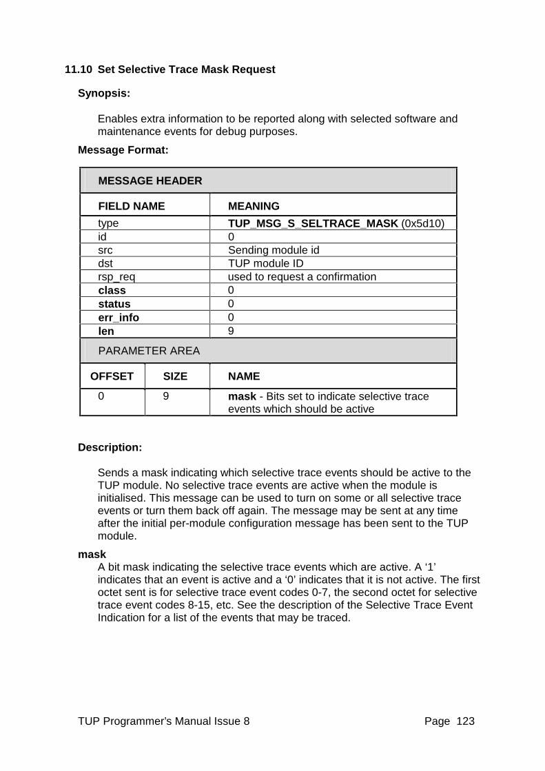
TUP Programmer’s Manual Issue 8 Page 123
11.10 Set Selective Trace Mask Request
Synopsis: Enables extra information to be reported along with selected software and maintenance events for debug purposes.
Message Format:
MESSAGE HEADER
FIELD NAME MEANING
type TUP_MSG_S_SELTRACE_MASK (0x5d10) id 0 src Sending module id dst TUP module ID rsp_req used to request a confirmation class 0 status 0 err_info 0 len 9
PARAMETER AREA
OFFSET SIZE NAME
0 9 mask - Bits set to indicate selective trace events which should be active
Description: Sends a mask indicating which selective trace events should be active to the TUP module. No selective trace events are active when the module is initialised. This message can be used to turn on some or all selective trace events or turn them back off again. The message may be sent at any time after the initial per-module configuration message has been sent to the TUP module.
mask A bit mask indicating the selective trace events which are active. A ‘1’ indicates that an event is active and a ‘0’ indicates that it is not active. The first octet sent is for selective trace event codes 0-7, the second octet for selective trace event codes 8-15, etc. See the description of the Selective Trace Event Indication for a list of the events that may be traced.
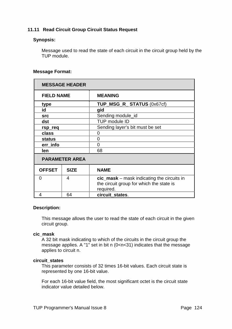
TUP Programmer’s Manual Issue 8 Page 124
11.11 Read Circuit Group Circuit Status Request
Synopsis: Message used to read the state of each circuit in the circuit group held by the TUP module.
Message Format:
MESSAGE HEADER
FIELD NAME MEANING
type TUP_MSG_R_ STATUS (0x67cf) id gid src Sending module_id dst TUP module ID rsp_req Sending layer’s bit must be set class 0 status 0 err_info 0 len 68
PARAMETER AREA
OFFSET SIZE NAME
0 4 cic_mask – mask indicating the circuits in the circuit group for which the state is required.
4 64 circuit_states. Description:
This message allows the user to read the state of each circuit in the given circuit group.
cic_mask A 32 bit mask indicating to which of the circuits in the circuit group the message applies. A "1" set in bit n (0<n<31) indicates that the message applies to circuit n.
circuit_states This parameter consists of 32 times 16-bit values. Each circuit state is represented by one 16-bit value.
For each 16-bit value field, the most significant octet is the circuit state indicator value detailed below.
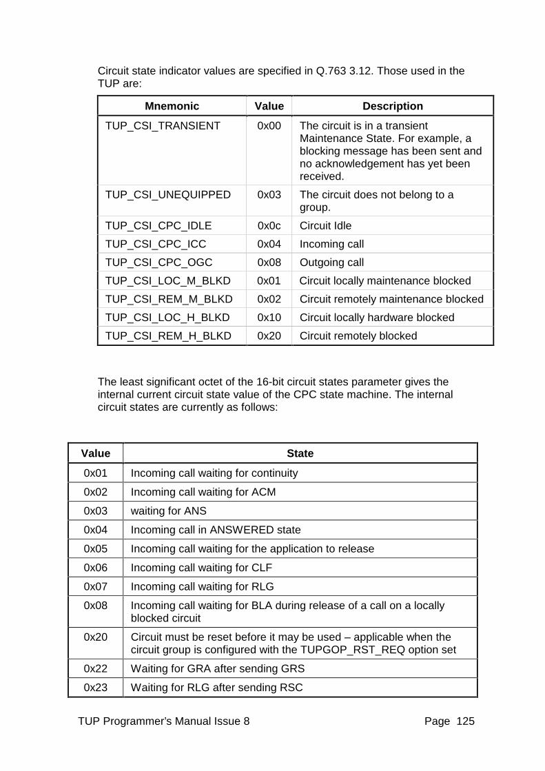
TUP Programmer’s Manual Issue 8 Page 125
Circuit state indicator values are specified in Q.763 3.12. Those used in the TUP are:
Mnemonic Value Description
TUP_CSI_TRANSIENT 0x00 The circuit is in a transient Maintenance State. For example, a blocking message has been sent and no acknowledgement has yet been received.
TUP_CSI_UNEQUIPPED 0x03 The circuit does not belong to a group.
TUP_CSI_CPC_IDLE 0x0c Circuit Idle
TUP_CSI_CPC_ICC 0x04 Incoming call
TUP_CSI_CPC_OGC 0x08 Outgoing call
TUP_CSI_LOC_M_BLKD 0x01 Circuit locally maintenance blocked
TUP_CSI_REM_M_BLKD 0x02 Circuit remotely maintenance blocked
TUP_CSI_LOC_H_BLKD 0x10 Circuit locally hardware blocked
TUP_CSI_REM_H_BLKD 0x20 Circuit remotely blocked
The least significant octet of the 16-bit circuit states parameter gives the internal current circuit state value of the CPC state machine. The internal circuit states are currently as follows:
Value State
0x01 Incoming call waiting for continuity
0x02 Incoming call waiting for ACM
0x03 waiting for ANS
0x04 Incoming call in ANSWERED state
0x05 Incoming call waiting for the application to release
0x06 Incoming call waiting for CLF
0x07 Incoming call waiting for RLG
0x08 Incoming call waiting for BLA during release of a call on a locally blocked circuit
0x20 Circuit must be reset before it may be used – applicable when the circuit group is configured with the TUPGOP_RST_REQ option set
0x22 Waiting for GRA after sending GRS
0x23 Waiting for RLG after sending RSC
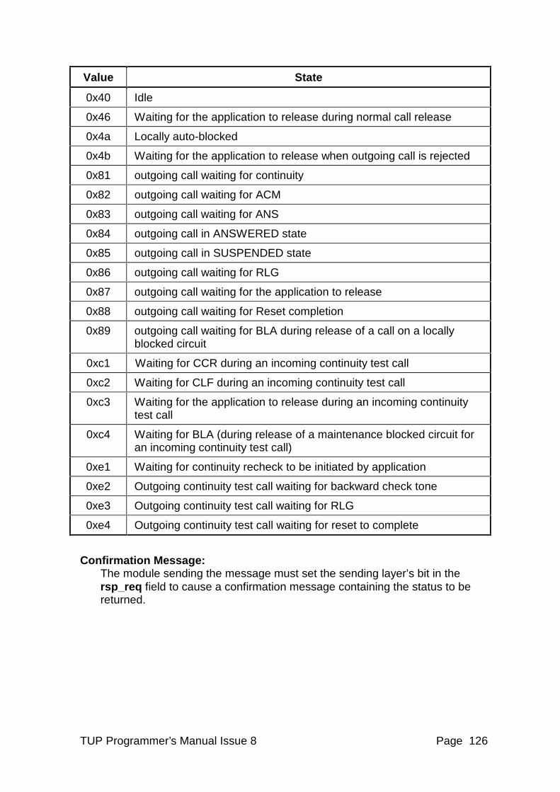
TUP Programmer’s Manual Issue 8 Page 126
Value State
0x40 Idle
0x46 Waiting for the application to release during normal call release
0x4a Locally auto-blocked
0x4b Waiting for the application to release when outgoing call is rejected
0x81 outgoing call waiting for continuity
0x82 outgoing call waiting for ACM
0x83 outgoing call waiting for ANS
0x84 outgoing call in ANSWERED state
0x85 outgoing call in SUSPENDED state
0x86 outgoing call waiting for RLG
0x87 outgoing call waiting for the application to release
0x88 outgoing call waiting for Reset completion
0x89 outgoing call waiting for BLA during release of a call on a locally blocked circuit
0xc1 Waiting for CCR during an incoming continuity test call
0xc2 Waiting for CLF during an incoming continuity test call
0xc3 Waiting for the application to release during an incoming continuity test call
0xc4 Waiting for BLA (during release of a maintenance blocked circuit for an incoming continuity test call)
0xe1 Waiting for continuity recheck to be initiated by application
0xe2 Outgoing continuity test call waiting for backward check tone
0xe3 Outgoing continuity test call waiting for RLG
0xe4 Outgoing continuity test call waiting for reset to complete
Confirmation Message: The module sending the message must set the sending layer’s bit in the rsp_req field to cause a confirmation message containing the status to be returned.
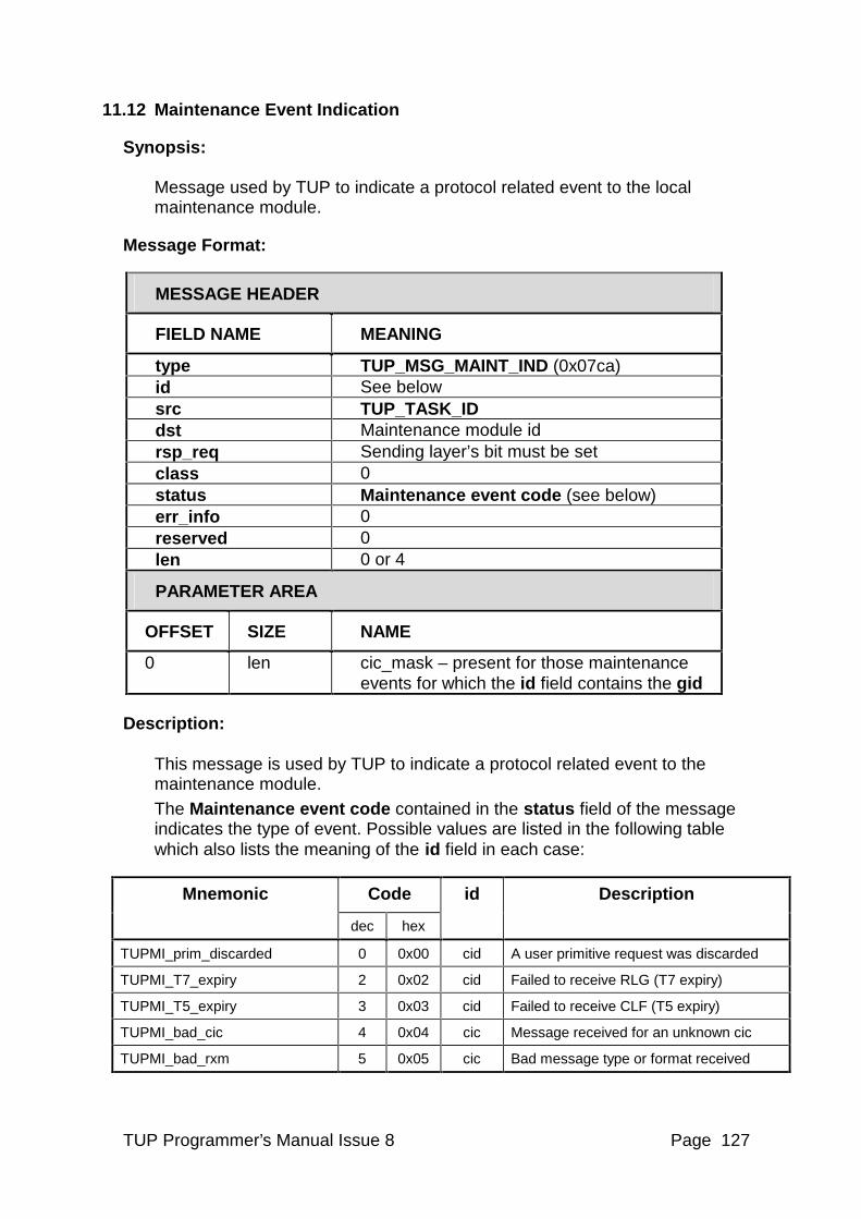
TUP Programmer’s Manual Issue 8 Page 127
11.12 Maintenance Event Indication
Synopsis: Message used by TUP to indicate a protocol related event to the local maintenance module.
Message Format:
MESSAGE HEADER
FIELD NAME MEANING
type TUP_MSG_MAINT_IND (0x07ca) id See below src TUP_TASK_ID dst Maintenance module id rsp_req Sending layer’s bit must be set class 0 status Maintenance event code (see below) err_info 0 reserved 0 len 0 or 4
PARAMETER AREA
OFFSET SIZE NAME
0 len cic_mask – present for those maintenance events for which the id field contains the gid
Description: This message is used by TUP to indicate a protocol related event to the maintenance module.
The Maintenance event code contained in the status field of the message indicates the type of event. Possible values are listed in the following table which also lists the meaning of the id field in each case:
Code Mnemonic
dec hex
id Description
TUPMI_prim_discarded 0 0x00 cid A user primitive request was discarded
TUPMI_T7_expiry 2 0x02 cid Failed to receive RLG (T7 expiry)
TUPMI_T5_expiry 3 0x03 cid Failed to receive CLF (T5 expiry)
TUPMI_bad_cic 4 0x04 cic Message received for an unknown cic
TUPMI_bad_rxm 5 0x05 cic Bad message type or format received
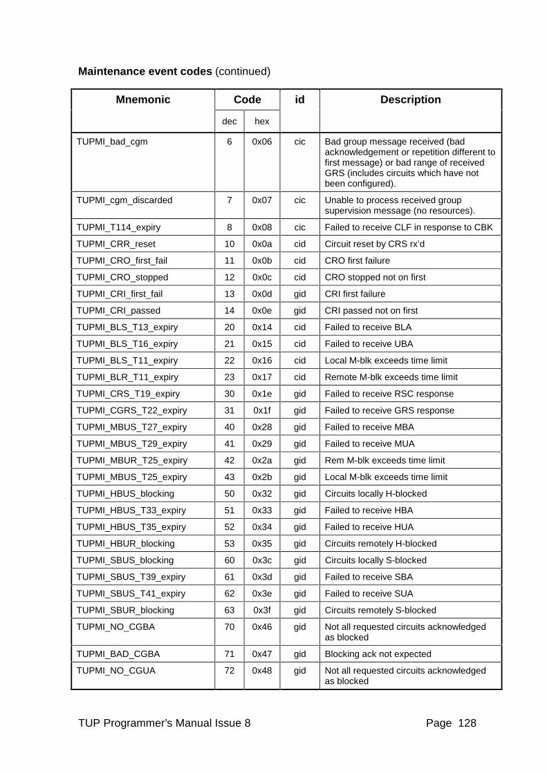
TUP Programmer’s Manual Issue 8 Page 128
Maintenance event codes (continued)
Code Mnemonic
dec hex
id Description
TUPMI_bad_cgm 6 0x06 cic Bad group message received (bad acknowledgement or repetition different to first message) or bad range of received GRS (includes circuits which have not been configured).
TUPMI_cgm_discarded 7 0x07 cic Unable to process received group supervision message (no resources).
TUPMI_T114_expiry 8 0x08 cic Failed to receive CLF in response to CBK
TUPMI_CRR_reset 10 0x0a cid Circuit reset by CRS rx’d
TUPMI_CRO_first_fail 11 0x0b cid CRO first failure
TUPMI_CRO_stopped 12 0x0c cid CRO stopped not on first
TUPMI_CRI_first_fail 13 0x0d gid CRI first failure
TUPMI_CRI_passed 14 0x0e gid CRI passed not on first
TUPMI_BLS_T13_expiry 20 0x14 cid Failed to receive BLA
TUPMI_BLS_T16_expiry 21 0x15 cid Failed to receive UBA
TUPMI_BLS_T11_expiry 22 0x16 cid Local M-blk exceeds time limit
TUPMI_BLR_T11_expiry 23 0x17 cid Remote M-blk exceeds time limit
TUPMI_CRS_T19_expiry 30 0x1e gid Failed to receive RSC response
TUPMI_CGRS_T22_expiry 31 0x1f gid Failed to receive GRS response
TUPMI_MBUS_T27_expiry 40 0x28 gid Failed to receive MBA
TUPMI_MBUS_T29_expiry 41 0x29 gid Failed to receive MUA
TUPMI_MBUR_T25_expiry 42 0x2a gid Rem M-blk exceeds time limit
TUPMI_MBUS_T25_expiry 43 0x2b gid Local M-blk exceeds time limit
TUPMI_HBUS_blocking 50 0x32 gid Circuits locally H-blocked
TUPMI_HBUS_T33_expiry 51 0x33 gid Failed to receive HBA
TUPMI_HBUS_T35_expiry 52 0x34 gid Failed to receive HUA
TUPMI_HBUR_blocking 53 0x35 gid Circuits remotely H-blocked
TUPMI_SBUS_blocking 60 0x3c gid Circuits locally S-blocked
TUPMI_SBUS_T39_expiry 61 0x3d gid Failed to receive SBA
TUPMI_SBUS_T41_expiry 62 0x3e gid Failed to receive SUA
TUPMI_SBUR_blocking 63 0x3f gid Circuits remotely S-blocked
TUPMI_NO_CGBA 70 0x46 gid Not all requested circuits acknowledged as blocked
TUPMI_BAD_CGBA 71 0x47 gid Blocking ack not expected
TUPMI_NO_CGUA 72 0x48 gid Not all requested circuits acknowledged as blocked
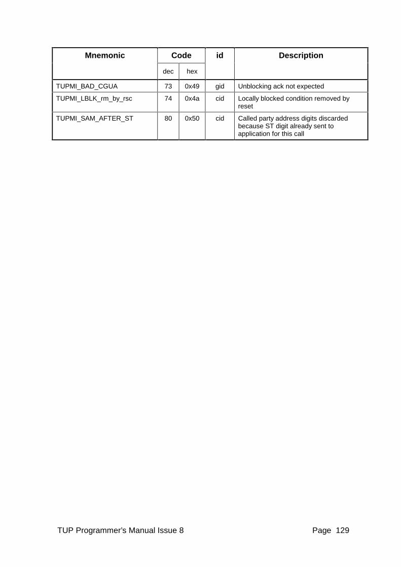
TUP Programmer’s Manual Issue 8 Page 129
Code Mnemonic
dec hex
id Description
TUPMI_BAD_CGUA 73 0x49 gid Unblocking ack not expected
TUPMI_LBLK_rm_by_rsc 74 0x4a cid Locally blocked condition removed by reset
TUPMI_SAM_AFTER_ST 80 0x50 cid Called party address digits discarded because ST digit already sent to application for this call
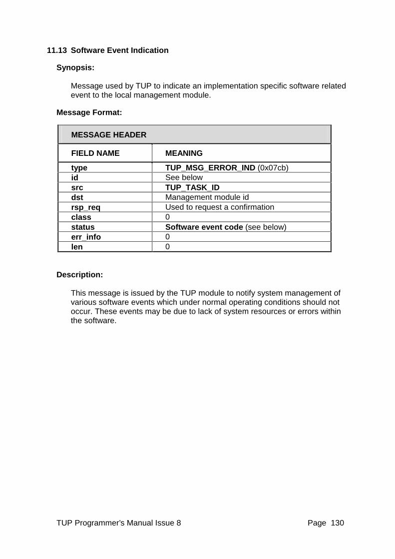
TUP Programmer’s Manual Issue 8 Page 130
11.13 Software Event Indication
Synopsis: Message used by TUP to indicate an implementation specific software related event to the local management module.
Message Format:
MESSAGE HEADER
FIELD NAME MEANING
type TUP_MSG_ERROR_IND (0x07cb) id See below src TUP_TASK_ID dst Management module id rsp_req Used to request a confirmation class 0 status Software event code (see below) err_info 0 len 0
Description: This message is issued by the TUP module to notify system management of various software events which under normal operating conditions should not occur. These events may be due to lack of system resources or errors within the software.
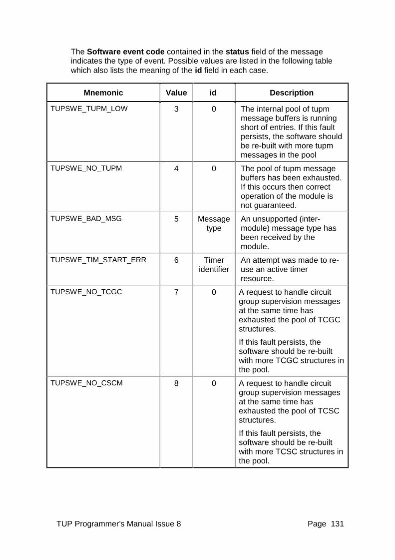
TUP Programmer’s Manual Issue 8 Page 131
The Software event code contained in the status field of the message indicates the type of event. Possible values are listed in the following table which also lists the meaning of the id field in each case.
Mnemonic Value id Description
TUPSWE_TUPM_LOW 3 0 The internal pool of tupm message buffers is running short of entries. If this fault persists, the software should be re-built with more tupm messages in the pool
TUPSWE_NO_TUPM 4 0 The pool of tupm message buffers has been exhausted. If this occurs then correct operation of the module is not guaranteed.
TUPSWE_BAD_MSG 5 Message type
An unsupported (inter-module) message type has been received by the module.
TUPSWE_TIM_START_ERR 6 Timer identifier
An attempt was made to re-use an active timer resource.
TUPSWE_NO_TCGC 7 0 A request to handle circuit group supervision messages at the same time has exhausted the pool of TCGC structures.
If this fault persists, the software should be re-built with more TCGC structures in the pool.
TUPSWE_NO_CSCM 8 0 A request to handle circuit group supervision messages at the same time has exhausted the pool of TCSC structures.
If this fault persists, the software should be re-built with more TCSC structures in the pool.
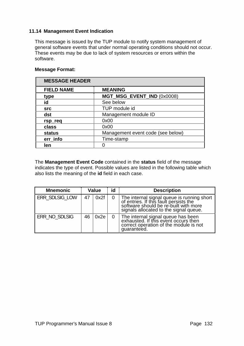
TUP Programmer’s Manual Issue 8 Page 132
11.14 Management Event Indication
This message is issued by the TUP module to notify system management of general software events that under normal operating conditions should not occur. These events may be due to lack of system resources or errors within the software.
Message Format:
MESSAGE HEADER
FIELD NAME MEANING type MGT_MSG_EVENT_IND (0x0008) id See below src TUP module id dst Management module ID rsp_req 0x00 class 0x00 status Management event code (see below) err_info Time-stamp len 0
The Management Event Code contained in the status field of the message indicates the type of event. Possible values are listed in the following table which also lists the meaning of the id field in each case.
Mnemonic Value id Description ERR_SDLSIG_LOW 47 0x2f 0 The internal signal queue is running short
of entries. If this fault persists the software should be re-built with more signals allocated to the signal queue.
ERR_NO_SDLSIG 46 0x2e 0 The internal signal queue has been exhausted. If this event occurs then correct operation of the module is not guaranteed.
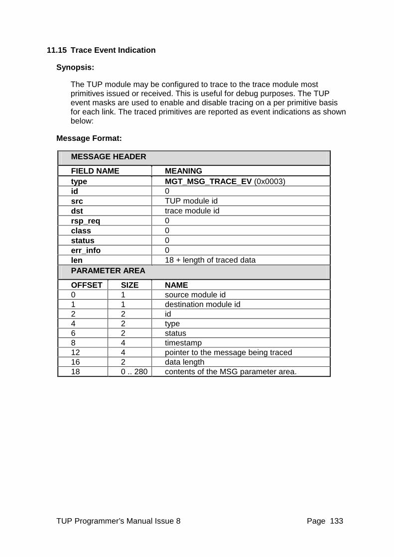
TUP Programmer’s Manual Issue 8 Page 133
11.15 Trace Event Indication
Synopsis:
The TUP module may be configured to trace to the trace module most primitives issued or received. This is useful for debug purposes. The TUP event masks are used to enable and disable tracing on a per primitive basis for each link. The traced primitives are reported as event indications as shown below:
Message Format:
MESSAGE HEADER
FIELD NAME MEANING type MGT_MSG_TRACE_EV (0x0003) id 0 src TUP module id dst trace module id rsp_req 0 class 0 status 0 err_info 0 len 18 + length of traced data PARAMETER AREA
OFFSET SIZE NAME 0 1 source module id 1 1 destination module id 2 2 id 4 2 type 6 2 status 8 4 timestamp 12 4 pointer to the message being traced 16 2 data length 18 0 .. 280 contents of the MSG parameter area.
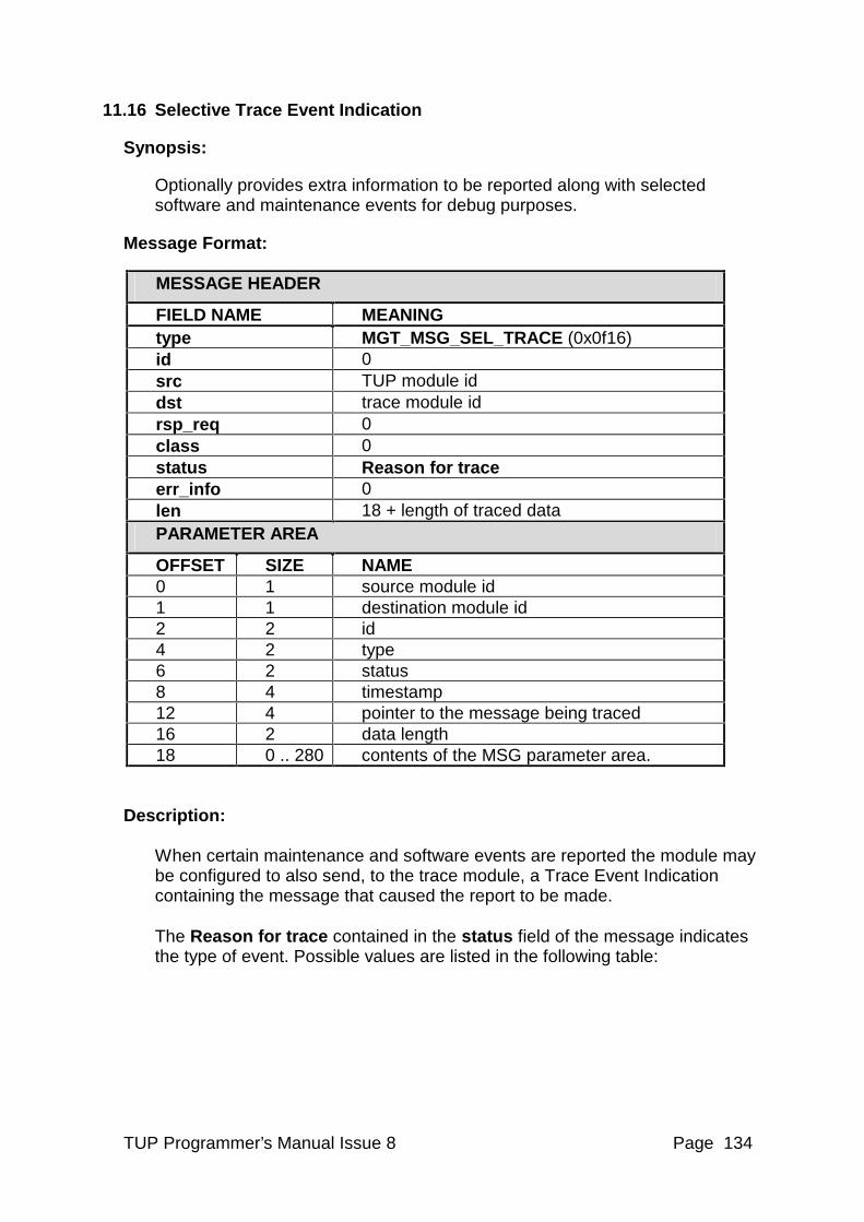
TUP Programmer’s Manual Issue 8 Page 134
11.16 Selective Trace Event Indication
Synopsis:
Optionally provides extra information to be reported along with selected software and maintenance events for debug purposes.
Message Format:
MESSAGE HEADER
FIELD NAME MEANING type MGT_MSG_SEL_TRACE (0x0f16) id 0 src TUP module id dst trace module id rsp_req 0 class 0 status Reason for trace err_info 0 len 18 + length of traced data PARAMETER AREA
OFFSET SIZE NAME 0 1 source module id 1 1 destination module id 2 2 id 4 2 type 6 2 status 8 4 timestamp 12 4 pointer to the message being traced 16 2 data length 18 0 .. 280 contents of the MSG parameter area.
Description: When certain maintenance and software events are reported the module may be configured to also send, to the trace module, a Trace Event Indication containing the message that caused the report to be made. The Reason for trace contained in the status field of the message indicates the type of event. Possible values are listed in the following table:
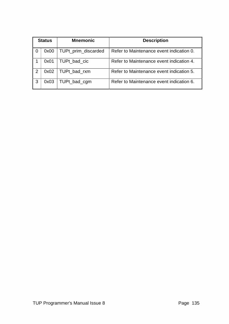
TUP Programmer’s Manual Issue 8 Page 135
Status Mnemonic Description
0 0x00 TUPt_prim_discarded Refer to Maintenance event indication 0.
1 0x01 TUPt_bad_cic Refer to Maintenance event indication 4.
2 0x02 TUPt_bad_rxm Refer to Maintenance event indication 5.
3 0x03 TUPt_bad_cgm Refer to Maintenance event indication 6.
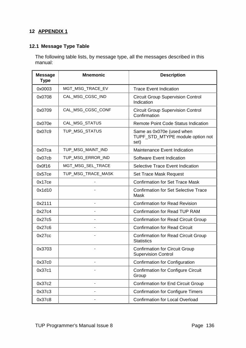
TUP Programmer’s Manual Issue 8 Page 136
12 APPENDIX 1
12.1 Message Type Table
The following table lists, by message type, all the messages described in this manual:
Message Type
Mnemonic Description
0x0003 MGT_MSG_TRACE_EV Trace Event Indication
0x0708 CAL_MSG_CGSC_IND Circuit Group Supervision Control Indication
0x0709 CAL_MSG_CGSC_CONF Circuit Group Supervision Control Confirmation
0x070e CAL_MSG_STATUS Remote Point Code Status Indication
0x07c9 TUP_MSG_STATUS Same as 0x070e (used when TUPF_STD_MTYPE module option not set)
0x07ca TUP_MSG_MAINT_IND Maintenance Event Indication
0x07cb TUP_MSG_ERROR_IND Software Event Indication
0x0f16 MGT_MSG_SEL_TRACE Selective Trace Event Indication
0x57ce TUP_MSG_TRACE_MASK Set Trace Mask Request
0x17ce - Confirmation for Set Trace Mask
0x1d10 - Confirmation for Set Selective Trace Mask
0x2111 - Confirmation for Read Revision
0x27c4 - Confirmation for Read TUP RAM
0x27c5 - Confirmation for Read Circuit Group
0x27c6 - Confirmation for Read Circuit
0x27cc - Confirmation for Read Circuit Group Statistics
0x3703 - Confirmation for Circuit Group Supervision Control
0x37c0 - Confirmation for Configuration
0x37c1 - Confirmation for Configure Circuit Group
0x37c2 - Confirmation for End Circuit Group
0x37c3 - Confirmation for Configure Timers
0x37c8 - Confirmation for Local Overload
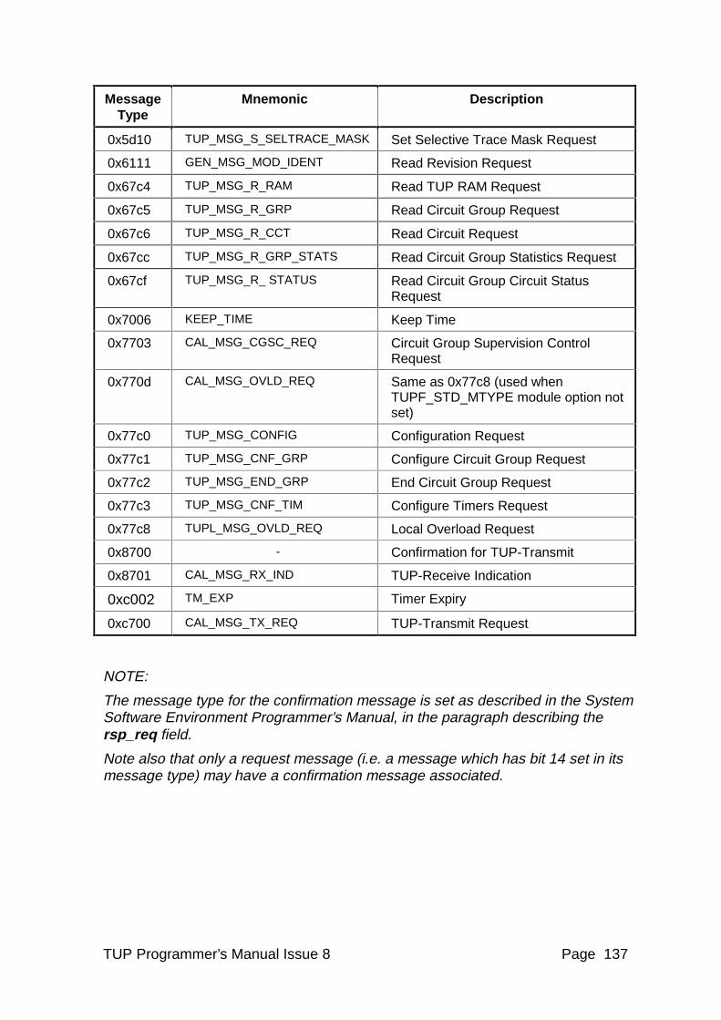
TUP Programmer’s Manual Issue 8 Page 137
Message Type
Mnemonic Description
0x5d10 TUP_MSG_S_SELTRACE_MASK Set Selective Trace Mask Request
0x6111 GEN_MSG_MOD_IDENT Read Revision Request
0x67c4 TUP_MSG_R_RAM Read TUP RAM Request
0x67c5 TUP_MSG_R_GRP Read Circuit Group Request
0x67c6 TUP_MSG_R_CCT Read Circuit Request
0x67cc TUP_MSG_R_GRP_STATS Read Circuit Group Statistics Request
0x67cf TUP_MSG_R_ STATUS Read Circuit Group Circuit Status Request
0x7006 KEEP_TIME Keep Time
0x7703 CAL_MSG_CGSC_REQ Circuit Group Supervision Control Request
0x770d CAL_MSG_OVLD_REQ Same as 0x77c8 (used when TUPF_STD_MTYPE module option not set)
0x77c0 TUP_MSG_CONFIG Configuration Request
0x77c1 TUP_MSG_CNF_GRP Configure Circuit Group Request
0x77c2 TUP_MSG_END_GRP End Circuit Group Request
0x77c3 TUP_MSG_CNF_TIM Configure Timers Request
0x77c8 TUPL_MSG_OVLD_REQ Local Overload Request
0x8700 - Confirmation for TUP-Transmit
0x8701 CAL_MSG_RX_IND TUP-Receive Indication
0xc002 TM_EXP Timer Expiry
0xc700 CAL_MSG_TX_REQ TUP-Transmit Request
NOTE:
The message type for the confirmation message is set as described in the System Software Environment Programmer’s Manual, in the paragraph describing the rsp_req field.
Note also that only a request message (i.e. a message which has bit 14 set in its message type) may have a confirmation message associated.
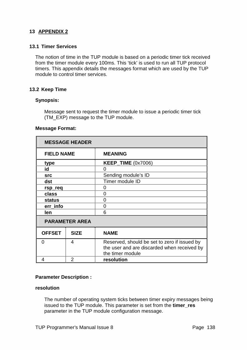
TUP Programmer’s Manual Issue 8 Page 138
13 APPENDIX 2
13.1 Timer Services
The notion of time in the TUP module is based on a periodic timer tick received from the timer module every 100ms. This ‘tick’ is used to run all TUP protocol timers. This appendix details the messages format which are used by the TUP module to control timer services.
13.2 Keep Time
Synopsis: Message sent to request the timer module to issue a periodic timer tick (TM_EXP) message to the TUP module.
Message Format:
MESSAGE HEADER
FIELD NAME MEANING
type KEEP_TIME (0x7006) id 0 src Sending module’s ID dst Timer module ID rsp_req 0 class 0 status 0 err_info 0 len 6
PARAMETER AREA
OFFSET SIZE NAME
0 4 Reserved, should be set to zero if issued by the user and are discarded when received by the timer module
4 2 resolution
Parameter Description :
resolution The number of operating system ticks between timer expiry messages being issued to the TUP module. This parameter is set from the timer_res parameter in the TUP module configuration message.
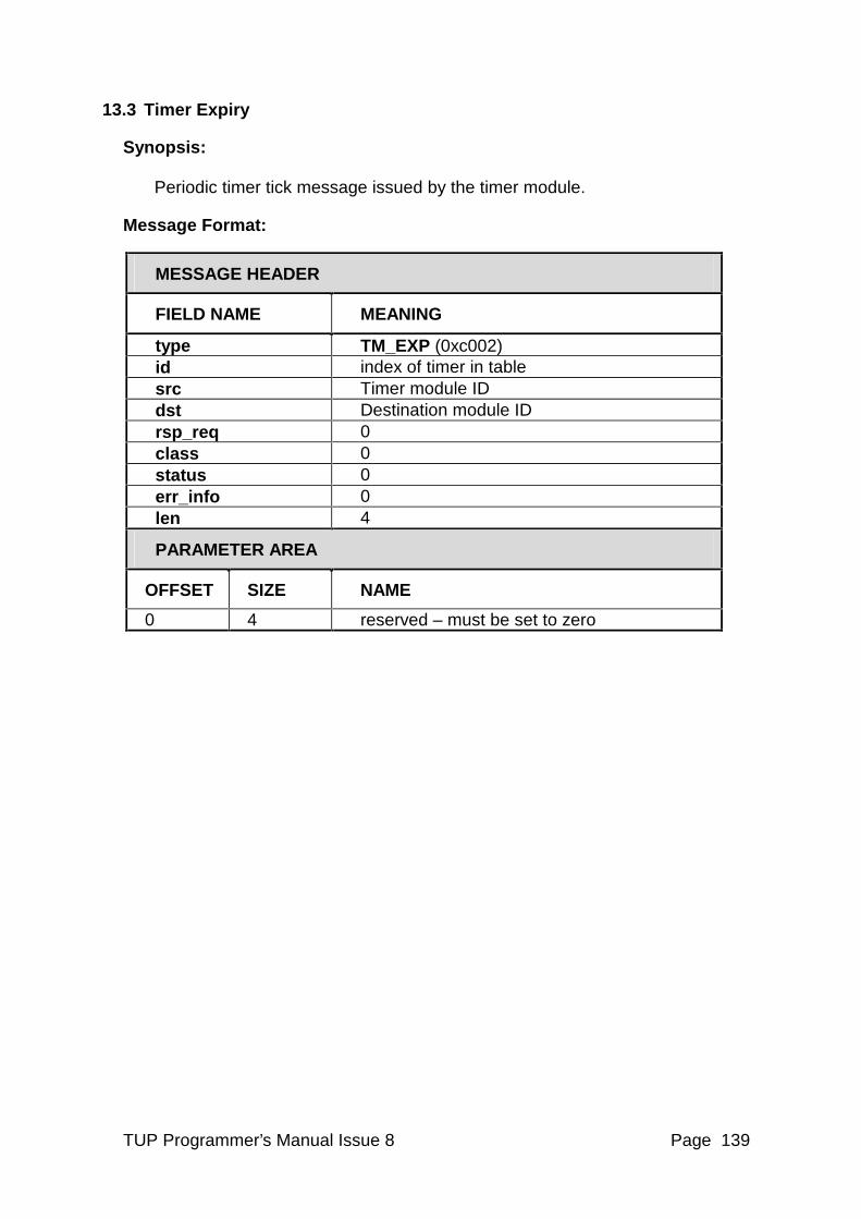
TUP Programmer’s Manual Issue 8 Page 139
13.3 Timer Expiry
Synopsis: Periodic timer tick message issued by the timer module.
Message Format:
MESSAGE HEADER
FIELD NAME MEANING
type TM_EXP (0xc002) id index of timer in table src Timer module ID dst Destination module ID rsp_req 0 class 0 status 0 err_info 0 len 4
PARAMETER AREA
OFFSET SIZE NAME
0 4 reserved – must be set to zero
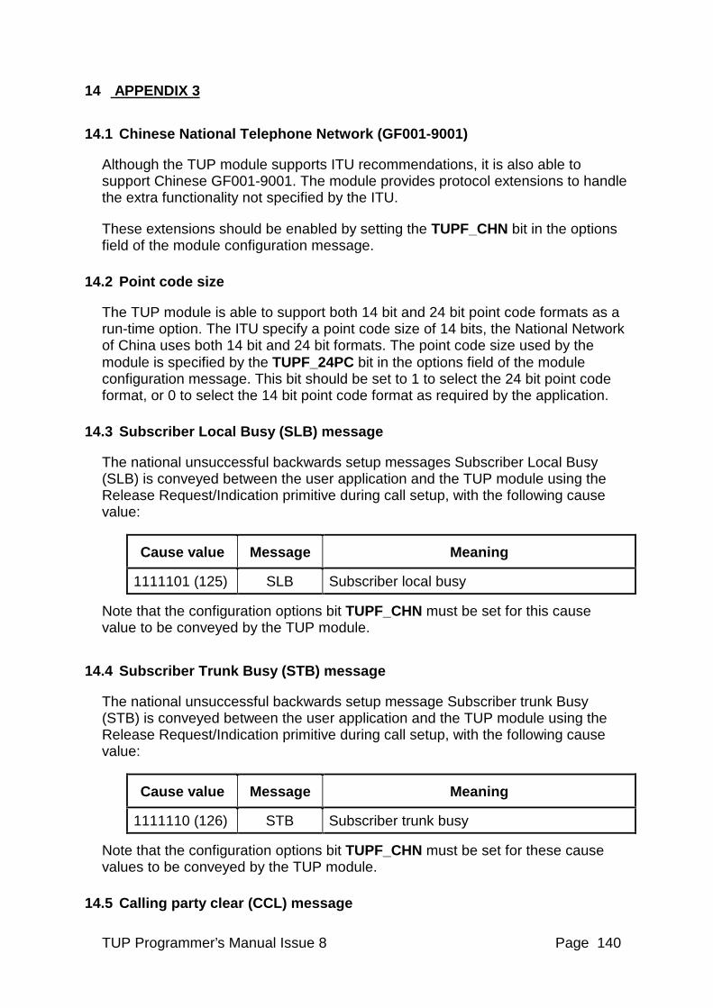
TUP Programmer’s Manual Issue 8 Page 140
14 APPENDIX 3
14.1 Chinese National Telephone Network (GF001-9001)
Although the TUP module supports ITU recommendations, it is also able to support Chinese GF001-9001. The module provides protocol extensions to handle the extra functionality not specified by the ITU.
These extensions should be enabled by setting the TUPF_CHN bit in the options field of the module configuration message.
14.2 Point code size
The TUP module is able to support both 14 bit and 24 bit point code formats as a run-time option. The ITU specify a point code size of 14 bits, the National Network of China uses both 14 bit and 24 bit formats. The point code size used by the module is specified by the TUPF_24PC bit in the options field of the module configuration message. This bit should be set to 1 to select the 24 bit point code format, or 0 to select the 14 bit point code format as required by the application.
14.3 Subscriber Local Busy (SLB) message
The national unsuccessful backwards setup messages Subscriber Local Busy (SLB) is conveyed between the user application and the TUP module using the Release Request/Indication primitive during call setup, with the following cause value:
Cause value Message Meaning
1111101 (125) SLB Subscriber local busy
Note that the configuration options bit TUPF_CHN must be set for this cause value to be conveyed by the TUP module.
14.4 Subscriber Trunk Busy (STB) message
The national unsuccessful backwards setup message Subscriber trunk Busy (STB) is conveyed between the user application and the TUP module using the Release Request/Indication primitive during call setup, with the following cause value:
Cause value Message Meaning
1111110 (126) STB Subscriber trunk busy
Note that the configuration options bit TUPF_CHN must be set for these cause values to be conveyed by the TUP module.
14.5 Calling party clear (CCL) message
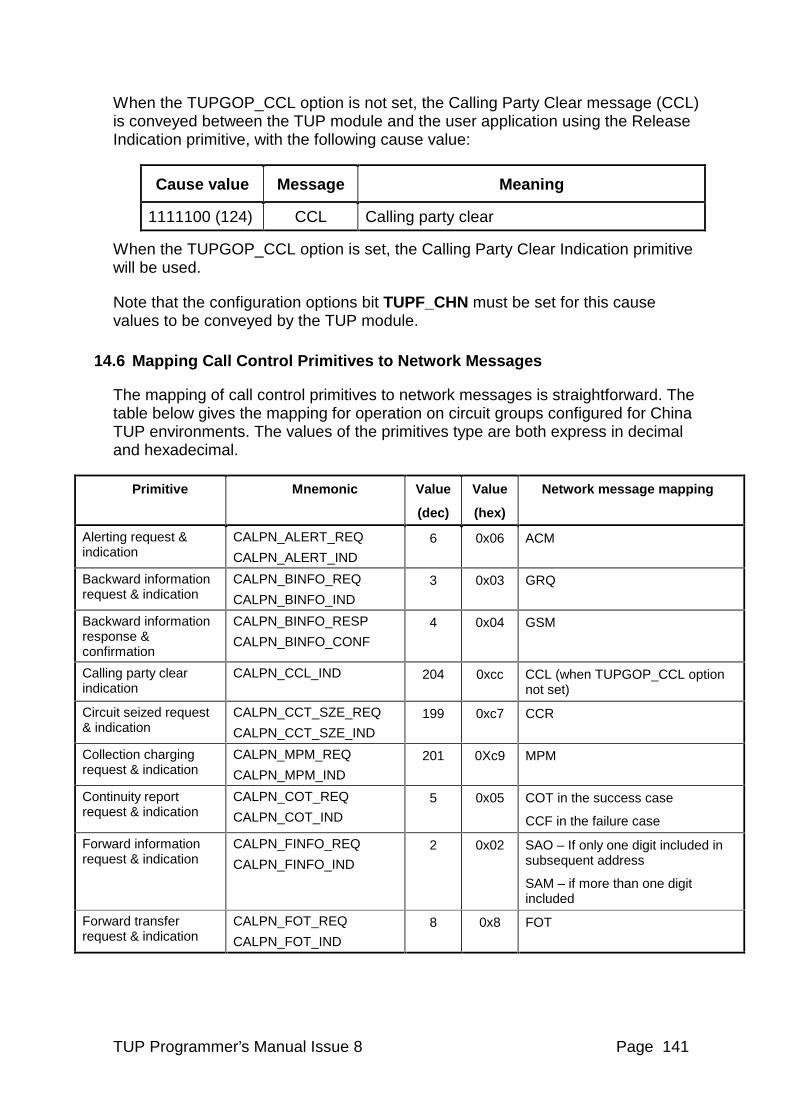
TUP Programmer’s Manual Issue 8 Page 141
When the TUPGOP_CCL option is not set, the Calling Party Clear message (CCL) is conveyed between the TUP module and the user application using the Release Indication primitive, with the following cause value:
Cause value Message Meaning
1111100 (124) CCL Calling party clear
When the TUPGOP_CCL option is set, the Calling Party Clear Indication primitive will be used.
Note that the configuration options bit TUPF_CHN must be set for this cause values to be conveyed by the TUP module.
14.6 Mapping Call Control Primitives to Network Messages
The mapping of call control primitives to network messages is straightforward. The table below gives the mapping for operation on circuit groups configured for China TUP environments. The values of the primitives type are both express in decimal and hexadecimal.
Primitive Mnemonic Value
(dec)
Value
(hex)
Network message mapping
Alerting request & indication
CALPN_ALERT_REQ
CALPN_ALERT_IND
6 0x06 ACM
Backward information request & indication
CALPN_BINFO_REQ
CALPN_BINFO_IND
3 0x03 GRQ
Backward information response & confirmation
CALPN_BINFO_RESP
CALPN_BINFO_CONF
4 0x04 GSM
Calling party clear indication
CALPN_CCL_IND 204 0xcc CCL (when TUPGOP_CCL option not set)
Circuit seized request & indication
CALPN_CCT_SZE_REQ
CALPN_CCT_SZE_IND
199 0xc7 CCR
Collection charging request & indication
CALPN_MPM_REQ
CALPN_MPM_IND
201 0Xc9 MPM
Continuity report request & indication
CALPN_COT_REQ
CALPN_COT_IND
5 0x05 COT in the success case
CCF in the failure case
Forward information request & indication
CALPN_FINFO_REQ
CALPN_FINFO_IND
2 0x02 SAO – If only one digit included in subsequent address
SAM – if more than one digit included
Forward transfer request & indication
CALPN_FOT_REQ
CALPN_FOT_IND
8 0x8 FOT
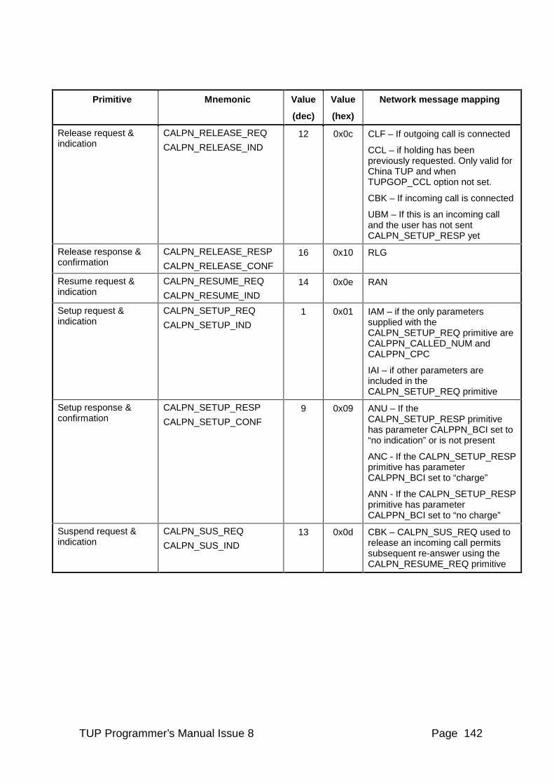
TUP Programmer’s Manual Issue 8 Page 142
Primitive Mnemonic Value
(dec)
Value
(hex)
Network message mapping
Release request & indication
CALPN_RELEASE_REQ
CALPN_RELEASE_IND
12 0x0c CLF – If outgoing call is connected
CCL – if holding has been previously requested. Only valid for China TUP and when TUPGOP_CCL option not set.
CBK – If incoming call is connected
UBM – If this is an incoming call and the user has not sent CALPN_SETUP_RESP yet
Release response & confirmation
CALPN_RELEASE_RESP
CALPN_RELEASE_CONF
16 0x10 RLG
Resume request & indication
CALPN_RESUME_REQ
CALPN_RESUME_IND
14 0x0e RAN
Setup request & indication
CALPN_SETUP_REQ
CALPN_SETUP_IND
1 0x01 IAM – if the only parameters supplied with the CALPN_SETUP_REQ primitive are CALPPN_CALLED_NUM and CALPPN_CPC
IAI – if other parameters are included in the CALPN_SETUP_REQ primitive
Setup response & confirmation
CALPN_SETUP_RESP
CALPN_SETUP_CONF
9 0x09 ANU – If the CALPN_SETUP_RESP primitive has parameter CALPPN_BCI set to “no indication” or is not present
ANC - If the CALPN_SETUP_RESP primitive has parameter CALPPN_BCI set to “charge”
ANN - If the CALPN_SETUP_RESP primitive has parameter CALPPN_BCI set to “no charge”
Suspend request & indication
CALPN_SUS_REQ
CALPN_SUS_IND
13 0x0d CBK – CALPN_SUS_REQ used to release an incoming call permits subsequent re-answer using the CALPN_RESUME_REQ primitive
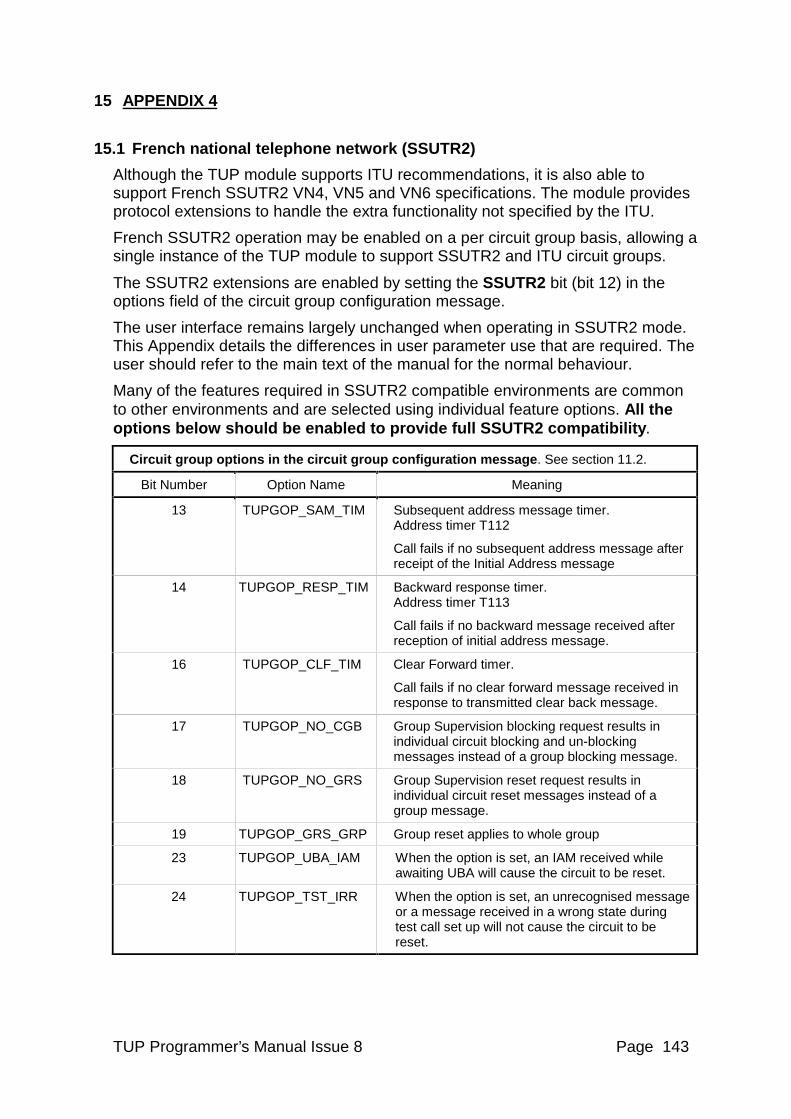
TUP Programmer’s Manual Issue 8 Page 143
15 APPENDIX 4
15.1 French national telephone network (SSUTR2)
Although the TUP module supports ITU recommendations, it is also able to support French SSUTR2 VN4, VN5 and VN6 specifications. The module provides protocol extensions to handle the extra functionality not specified by the ITU.
French SSUTR2 operation may be enabled on a per circuit group basis, allowing a single instance of the TUP module to support SSUTR2 and ITU circuit groups.
The SSUTR2 extensions are enabled by setting the SSUTR2 bit (bit 12) in the options field of the circuit group configuration message.
The user interface remains largely unchanged when operating in SSUTR2 mode. This Appendix details the differences in user parameter use that are required. The user should refer to the main text of the manual for the normal behaviour.
Many of the features required in SSUTR2 compatible environments are common to other environments and are selected using individual feature options. All the options below should be enabled to provide full SSUTR2 compatibility.
Circuit group options in the circuit group configuration message. See section 11.2.
Bit Number Option Name Meaning
13 TUPGOP_SAM_TIM Subsequent address message timer. Address timer T112
Call fails if no subsequent address message after receipt of the Initial Address message
14 TUPGOP_RESP_TIM Backward response timer. Address timer T113
Call fails if no backward message received after reception of initial address message.
16 TUPGOP_CLF_TIM Clear Forward timer.
Call fails if no clear forward message received in response to transmitted clear back message.
17 TUPGOP_NO_CGB Group Supervision blocking request results in individual circuit blocking and un-blocking messages instead of a group blocking message.
18 TUPGOP_NO_GRS Group Supervision reset request results in individual circuit reset messages instead of a group message.
19 TUPGOP_GRS_GRP Group reset applies to whole group
23 TUPGOP_UBA_IAM When the option is set, an IAM received while awaiting UBA will cause the circuit to be reset.
24 TUPGOP_TST_IRR When the option is set, an unrecognised message or a message received in a wrong state during test call set up will not cause the circuit to be reset.
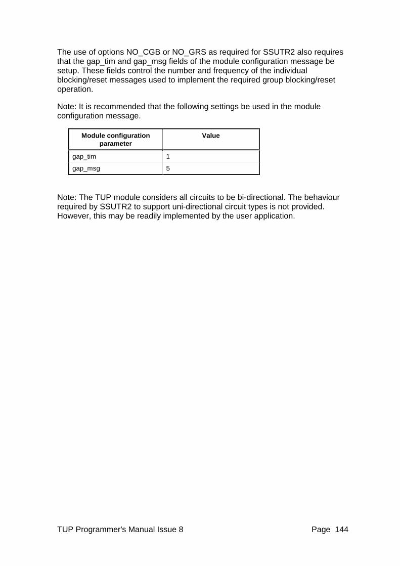
TUP Programmer’s Manual Issue 8 Page 144
The use of options NO_CGB or NO_GRS as required for SSUTR2 also requires that the gap_tim and gap_msg fields of the module configuration message be setup. These fields control the number and frequency of the individual blocking/reset messages used to implement the required group blocking/reset operation.
Note: It is recommended that the following settings be used in the module configuration message.
Module configuration parameter
Value
gap_tim 1
gap_msg 5
Note: The TUP module considers all circuits to be bi-directional. The behaviour required by SSUTR2 to support uni-directional circuit types is not provided. However, this may be readily implemented by the user application.
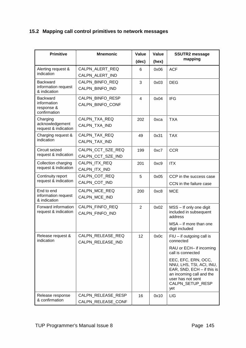
TUP Programmer’s Manual Issue 8 Page 145
15.2 Mapping call control primitives to network messages
Primitive Mnemonic Value
(dec)
Value
(hex)
SSUTR2 message mapping
Alerting request & indication
CALPN_ALERT_REQ
CALPN_ALERT_IND
6 0x06 ACF
Backward information request & indication
CALPN_BINFO_REQ
CALPN_BINFO_IND
3 0x03 DEG
Backward information response & confirmation
CALPN_BINFO_RESP
CALPN_BINFO_CONF
4 0x04 IFG
Charging acknowledgement request & indication
CALPN_TXA_REQ
CALPN_TXA_IND
202 0xca TXA
Charging request & indication
CALPN_TAX_REQ
CALPN_TAX_IND
49 0x31 TAX
Circuit seized request & indication
CALPN_CCT_SZE_REQ
CALPN_CCT_SZE_IND
199 0xc7 CCR
Collection charging request & indication
CALPN_ITX_REQ
CALPN_ITX_IND
201 0xc9 ITX
Continuity report request & indication
CALPN_COT_REQ
CALPN_COT_IND
5 0x05 CCP in the success case
CCN in the failure case
End to end information request & indication
CALPN_MCE_REQ
CALPN_MCE_IND
200 0xc8 MCE
Forward information request & indication
CALPN_FINFO_REQ
CALPN_FINFO_IND
2 0x02 MSS – If only one digit included in subsequent address
MSA – if more than one digit included
Release request & indication
CALPN_RELEASE_REQ
CALPN_RELEASE_IND
12 0x0c FIU – if outgoing call is connected
RAU or ECH– if incoming call is connected
EEC, EFC, ERN, OCC, NNU, LHS, TSI, ACI, INU, EAR, SND, ECH – if this is an incoming call and the user has not sent CALPN_SETUP_RESP yet
Release response & confirmation
CALPN_RELEASE_RESP
CALPN_RELEASE_CONF
16 0x10 LIG
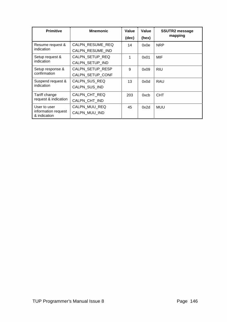
TUP Programmer’s Manual Issue 8 Page 146
Primitive Mnemonic Value
(dec)
Value
(hex)
SSUTR2 message mapping
Resume request & indication
CALPN_RESUME_REQ
CALPN_RESUME_IND
14 0x0e NRP
Setup request & indication
CALPN_SETUP_REQ
CALPN_SETUP_IND
1 0x01 MIF
Setup response & confirmation
CALPN_SETUP_RESP
CALPN_SETUP_CONF
9 0x09 RIU
Suspend request & indication
CALPN_SUS_REQ
CALPN_SUS_IND
13 0x0d RAU
Tariff change request & indication
CALPN_CHT_REQ
CALPN_CHT_IND
203 0xcb CHT
User to user information request & indication
CALPN_MUU_REQ
CALPN_MUU_IND
45 0x2d MUU
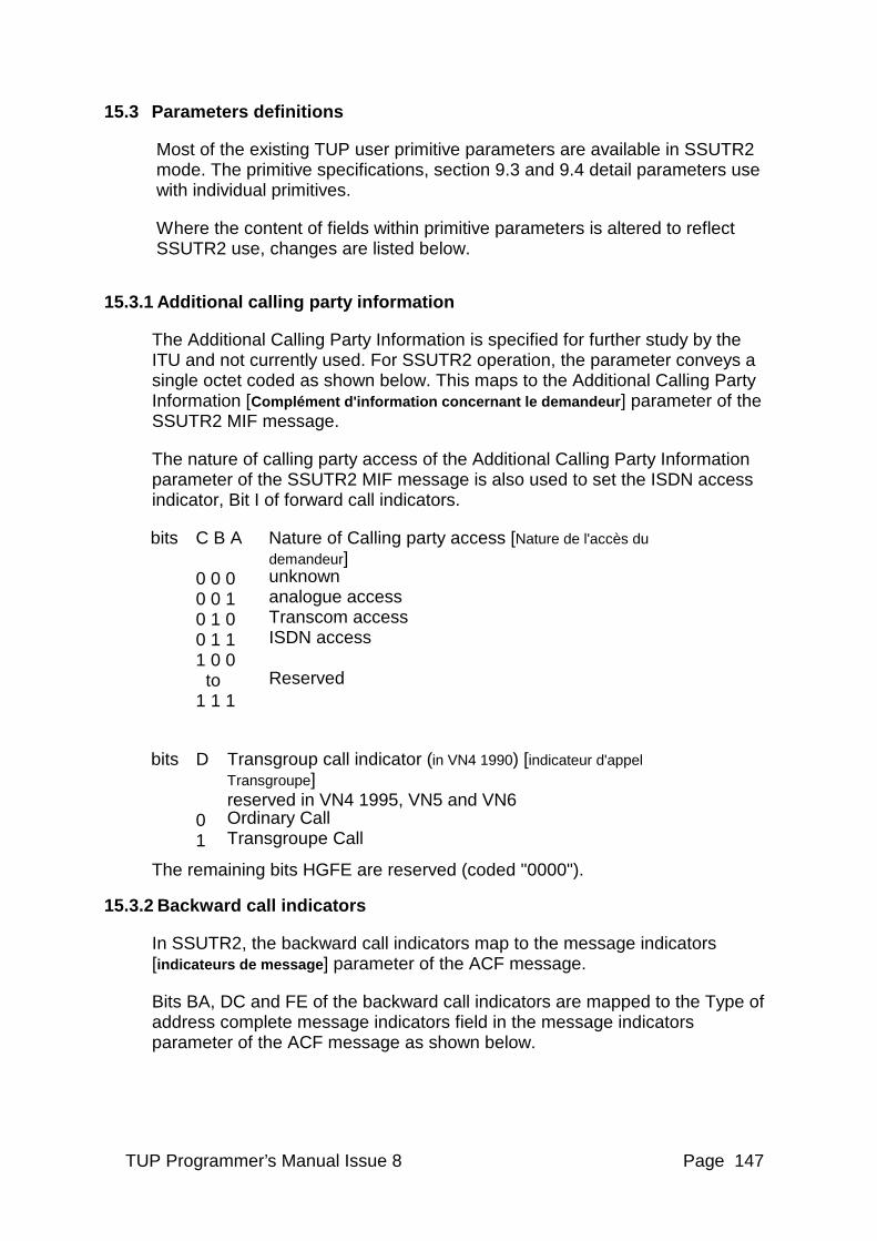
TUP Programmer’s Manual Issue 8 Page 147
15.3 Parameters definitions
Most of the existing TUP user primitive parameters are available in SSUTR2 mode. The primitive specifications, section 9.3 and 9.4 detail parameters use with individual primitives.
Where the content of fields within primitive parameters is altered to reflect SSUTR2 use, changes are listed below.
15.3.1 Additional calling party information
The Additional Calling Party Information is specified for further study by the ITU and not currently used. For SSUTR2 operation, the parameter conveys a single octet coded as shown below. This maps to the Additional Calling Party Information [Complément d'information concernant le demandeur ] parameter of the SSUTR2 MIF message.
The nature of calling party access of the Additional Calling Party Information parameter of the SSUTR2 MIF message is also used to set the ISDN access indicator, Bit I of forward call indicators.
bits C B A Nature of Calling party access [Nature de l'accès du demandeur]
0 0 0 unknown 0 0 1 analogue access 0 1 0 Transcom access 0 1 1 ISDN access 1 0 0 to Reserved 1 1 1
bits D Transgroup call indicator (in VN4 1990) [indicateur d'appel Transgroupe] reserved in VN4 1995, VN5 and VN6
0 Ordinary Call 1 Transgroupe Call
The remaining bits HGFE are reserved (coded "0000").
15.3.2 Backward call indicators
In SSUTR2, the backward call indicators map to the message indicators [indicateurs de message] parameter of the ACF message.
Bits BA, DC and FE of the backward call indicators are mapped to the Type of address complete message indicators field in the message indicators parameter of the ACF message as shown below.
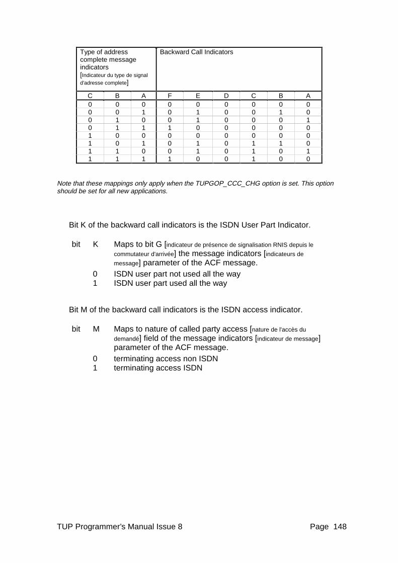
TUP Programmer’s Manual Issue 8 Page 148
Type of address complete message indicators [Indicateur du type de signal d’adresse complete]
Backward Call Indicators
C B A F E D C B A 0 0 0 0 0 0 0 0 0 0 0 1 0 1 0 0 1 0 0 1 0 0 1 0 0 0 1 0 1 1 1 0 0 0 0 0 1 0 0 0 0 0 0 0 0 1 0 1 0 1 0 1 1 0 1 1 0 0 1 0 1 0 1 1 1 1 1 0 0 1 0 0
Note that these mappings only apply when the TUPGOP_CCC_CHG option is set. This option should be set for all new applications.
Bit K of the backward call indicators is the ISDN User Part Indicator.
bit K Maps to bit G [indicateur de présence de signalisation RNIS depuis le
commutateur d'arrivée] the message indicators [indicateurs de
message] parameter of the ACF message. 0 ISDN user part not used all the way 1 ISDN user part used all the way
Bit M of the backward call indicators is the ISDN access indicator.
bit M Maps to nature of called party access [nature de l'accès du
demandé] field of the message indicators [indicateur de message] parameter of the ACF message.
0 terminating access non ISDN 1 terminating access ISDN
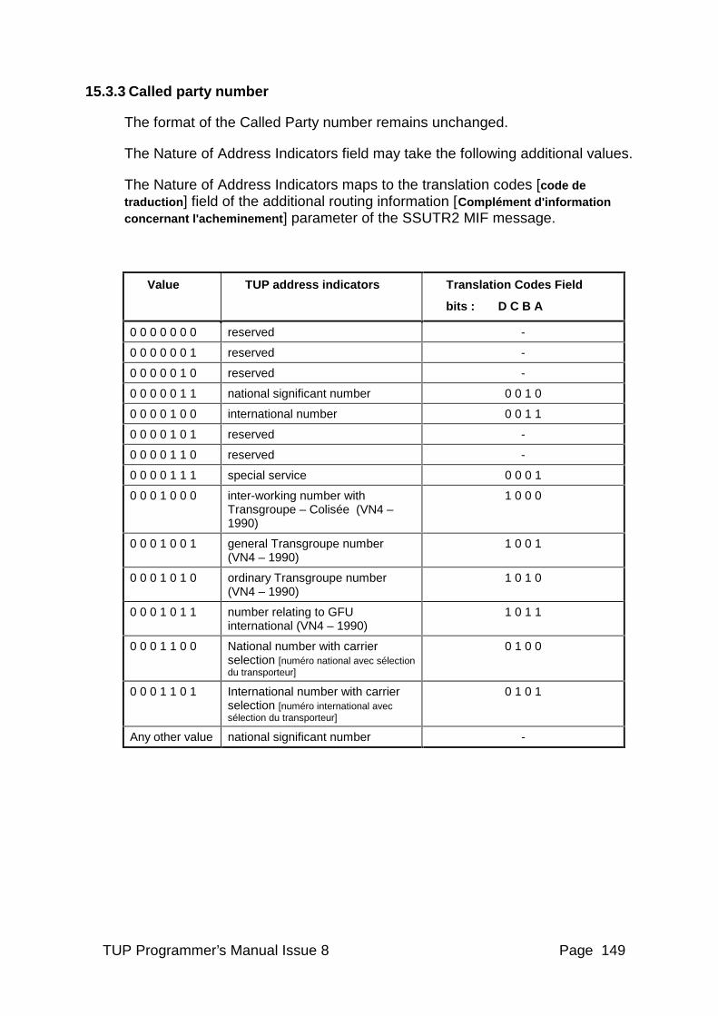
TUP Programmer’s Manual Issue 8 Page 149
15.3.3 Called party number
The format of the Called Party number remains unchanged.
The Nature of Address Indicators field may take the following additional values.
The Nature of Address Indicators maps to the translation codes [code de traduction] field of the additional routing information [Complément d'information concernant l'acheminement ] parameter of the SSUTR2 MIF message.
Value TUP address indicators Translation Codes Field
bits : D C B A
0 0 0 0 0 0 0 reserved -
0 0 0 0 0 0 1 reserved -
0 0 0 0 0 1 0 reserved -
0 0 0 0 0 1 1 national significant number 0 0 1 0
0 0 0 0 1 0 0 international number 0 0 1 1
0 0 0 0 1 0 1 reserved -
0 0 0 0 1 1 0 reserved -
0 0 0 0 1 1 1 special service 0 0 0 1
0 0 0 1 0 0 0 inter-working number with Transgroupe – Colisée (VN4 – 1990)
1 0 0 0
0 0 0 1 0 0 1 general Transgroupe number (VN4 – 1990)
1 0 0 1
0 0 0 1 0 1 0 ordinary Transgroupe number (VN4 – 1990)
1 0 1 0
0 0 0 1 0 1 1 number relating to GFU international (VN4 – 1990)
1 0 1 1
0 0 0 1 1 0 0 National number with carrier selection [numéro national avec sélection du transporteur]
0 1 0 0
0 0 0 1 1 0 1 International number with carrier selection [numéro international avec sélection du transporteur]
0 1 0 1
Any other value national significant number -
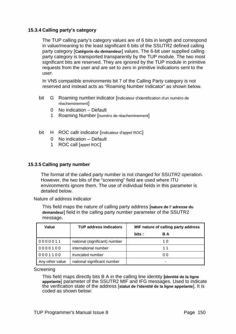
TUP Programmer’s Manual Issue 8 Page 150
15.3.4 Calling party’s category
The TUP calling party’s category values are of 6 bits in length and correspond in value/meaning to the least significant 6 bits of the SSUTR2 defined calling party category [Catégorie du demandeur ] values. The 6-bit user supplied calling party category is transported transparently by the TUP module. The two most significant bits are reserved. They are ignored by the TUP module in primitive requests from the user and are set to zero in primitive indications sent to the user.
In VN5 compatible environments bit 7 of the Calling Party category is not reserved and instead acts as “Roaming Number Indicator” as shown below.
bit G Roaming number indicator [Indicateur d’identification d'un numéro de réacheminement]
0 No indication – Default 1 Roaming Number [numéro de réacheminement]
bit H ROC callr indicator [Indicateur d'appel ROC] 0 No indication – Default 1 ROC call [appel ROC]
15.3.5 Calling party number
The format of the called party number is not changed for SSUTR2 operation. However, the two bits of the “screening” field are used where ITU environments ignore them. The use of individual fields in this parameter is detailed below.
Nature of address indicator
This field maps the nature of calling party address [nature de l’ adresse du demandeur] field in the calling party number parameter of the SSUTR2 message.
Value TUP address indicators MIF nature of calling party address
bits : B A
0 0 0 0 0 1 1 national (significant) number 1 0
0 0 0 0 1 0 0 international number 1 1
0 0 0 1 1 0 0 truncated number 0 0
Any other value national significant number -
Screening
This field maps directly bits B A in the calling line identity [identité de la ligne appelante ] parameter of the SSUTR2 MIF and IFG messages. Used to indicate the verification state of the address [statut de l'identité de la ligne appelante ]. It is coded as shown below:
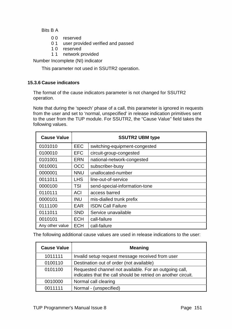
TUP Programmer’s Manual Issue 8 Page 151
Bits B A
0 0 reserved 0 1 user provided verified and passed 1 0 reserved 1 1 network provided
Number Incomplete (NI) indicator
This parameter not used in SSUTR2 operation.
15.3.6 Cause indicators
The format of the cause indicators parameter is not changed for SSUTR2 operation.
Note that during the ‘speech’ phase of a call, this parameter is ignored in requests from the user and set to ‘normal, unspecified’ in release indication primitives sent to the user from the TUP module. For SSUTR2, the “Cause Value” field takes the following values.
Cause Value SSUTR2 UBM type
0101010 EEC switching-equipment-congested 0100010 EFC circuit-group-congested 0101001 ERN national-network-congested 0010001 OCC subscriber-busy 0000001 NNU unallocated-number 0011011 LHS line-out-of-service 0000100 TSI send-special-information-tone 0110111 ACI access barred 0000101 INU mis-dialled trunk prefix 0111100 EAR ISDN Call Failure 0111011 SND Service unavailable 0010101 ECH call-failure Any other value ECH call-failure
The following additional cause values are used in release indications to the user:
Cause Value Meaning
1011111 Invalid setup request message received from user 0100110 Destination out of order (not available) 0101100 Requested channel not available. For an outgoing call,
indicates that the call should be retried on another circuit. 0010000 Normal call clearing 0011111 Normal - (unspecified)
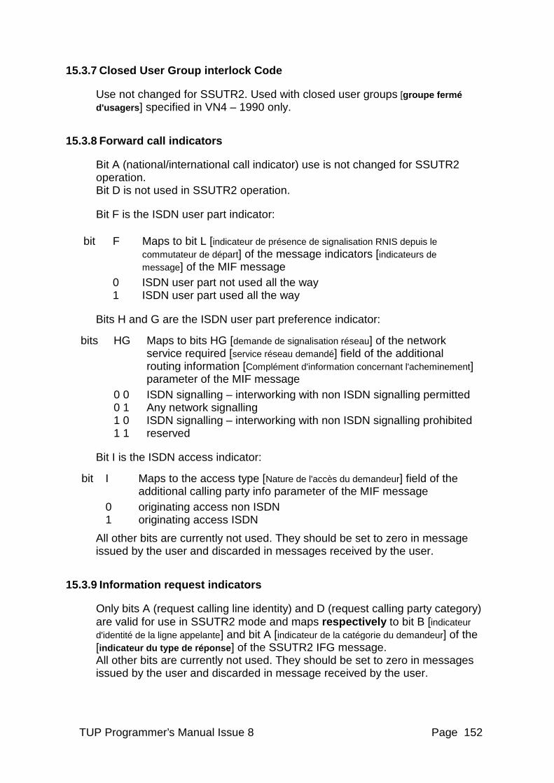
TUP Programmer’s Manual Issue 8 Page 152
15.3.7 Closed User Group interlock Code
Use not changed for SSUTR2. Used with closed user groups [groupe fermé d'usagers ] specified in VN4 – 1990 only.
15.3.8 Forward call indicators
Bit A (national/international call indicator) use is not changed for SSUTR2 operation. Bit D is not used in SSUTR2 operation.
Bit F is the ISDN user part indicator:
bit F Maps to bit L [indicateur de présence de signalisation RNIS depuis le commutateur de départ] of the message indicators [indicateurs de message] of the MIF message
0 ISDN user part not used all the way 1 ISDN user part used all the way
Bits H and G are the ISDN user part preference indicator:
bits HG Maps to bits HG [demande de signalisation réseau] of the network service required [service réseau demandé] field of the additional routing information [Complément d'information concernant l'acheminement] parameter of the MIF message
0 0 ISDN signalling – interworking with non ISDN signalling permitted 0 1 Any network signalling 1 0 ISDN signalling – interworking with non ISDN signalling prohibited 1 1 reserved
Bit I is the ISDN access indicator:
bit I Maps to the access type [Nature de l'accès du demandeur] field of the additional calling party info parameter of the MIF message
0 originating access non ISDN 1 originating access ISDN
All other bits are currently not used. They should be set to zero in message issued by the user and discarded in messages received by the user.
15.3.9 Information request indicators
Only bits A (request calling line identity) and D (request calling party category) are valid for use in SSUTR2 mode and maps respectively to bit B [indicateur d'identité de la ligne appelante] and bit A [indicateur de la catégorie du demandeur] of the [indicateur du type de réponse ] of the SSUTR2 IFG message. All other bits are currently not used. They should be set to zero in messages issued by the user and discarded in message received by the user.
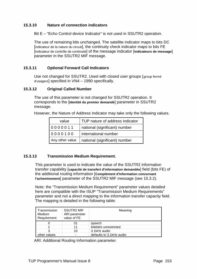
TUP Programmer’s Manual Issue 8 Page 153
15.3.10 Nature of connection indicators
Bit E – “Echo Control device Indicator” is not used in SSUTR2 operation.
The use of remaining bits unchanged. The satellite indicator maps to bits DC [indicateur de la nature du circuit], the continuity check indicator maps to bits FE [indicateur de contrôle de continuité] of the message indicator [indicateurs de message] parameter in the SSUTR2 MIF message.
15.3.11 Optional Forward Call Indicators
Use not changed for SSUTR2. Used with closed user groups [group fermé d'usagers] specified in VN4 – 1990 specifically.
15.3.12 Original Called Number
The use of this parameter is not changed for SSUTR2 operation. It corresponds to the [Identité du premier demandé ] parameter in SSUTR2 message.
However, the Nature of Address Indicator may take only the following values.
value TUP nature of address indicator
0 0 0 0 0 1 1 national (significant) number
0 0 0 0 1 0 0 international number
Any other value national (significant) number
15.3.13 Transmission Medium Requirement.
This parameter is used to indicate the value of the SSUTR2 information transfer capability [capacité de transfert d'information demandée ] field (bits FE) of the additional routing information [Complément d'information concernant l'acheminement ] parameter of the SSUTR2 MIF message (see 15.3.2).
Note: the “Transmission Medium Requirement” parameter values detailed here are compatible with the ISUP “Transmission Medium Requirements” parameter and not a direct mapping to the information transfer capacity field. The mapping is detailed in the following table:
Transmission Medium Requirement
SSUTR2 MIF ARI parameter value of FE
Meaning
0 01 speech 2 11 64kbit/s unrestricted 3 10 3.1kHz audio
other values - defaults to 3.1kHz audio
ARI: Additional Routing Information parameter.
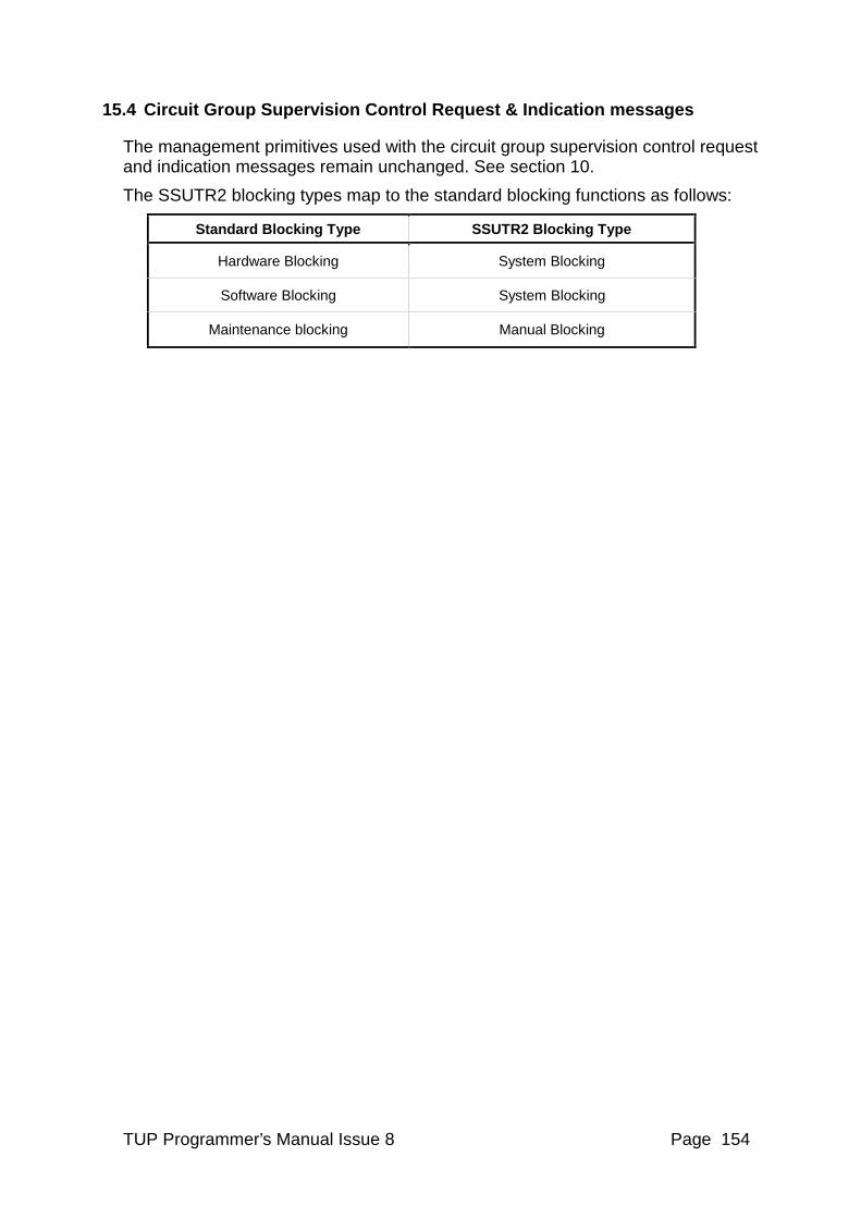
TUP Programmer’s Manual Issue 8 Page 154
15.4 Circuit Group Supervision Control Request & Indication messages
The management primitives used with the circuit group supervision control request and indication messages remain unchanged. See section 10.
The SSUTR2 blocking types map to the standard blocking functions as follows:
Standard Blocking Type SSUTR2 Blocking Type
Hardware Blocking System Blocking
Software Blocking System Blocking
Maintenance blocking Manual Blocking