intel netstructure dm3 architecture for compactpci on...
TRANSCRIPT
Intel NetStructure® DM3 Architecture for CompactPCI on WindowsConfiguration Guide
May 2006
05-1746-005

DM3 Architecture on Windows Configuration Guide – May 2006
INFORMATION IN THIS DOCUMENT IS PROVIDED IN CONNECTION WITH INTEL® PRODUCTS. NO LICENSE, EXPRESS OR IMPLIED, BY ESTOPPEL OR OTHERWISE, TO ANY INTELLECTUAL PROPERTY RIGHTS IS GRANTED BY THIS DOCUMENT. EXCEPT AS PROVIDED IN INTEL'S TERMS AND CONDITIONS OF SALE FOR SUCH PRODUCTS, INTEL ASSUMES NO LIABILITY WHATSOEVER, AND INTEL DISCLAIMS ANY EXPRESS OR IMPLIED WARRANTY, RELATING TO SALE AND/OR USE OF INTEL PRODUCTS INCLUDING LIABILITY OR WARRANTIES RELATING TO FITNESS FOR A PARTICULAR PURPOSE, MERCHANTABILITY, OR INFRINGEMENT OF ANY PATENT, COPYRIGHT OR OTHER INTELLECTUAL PROPERTY RIGHT. Intel products are not intended for use in medical, life saving, life sustaining, critical control or safety systems, or nuclear facility applications.
Intel may make changes to specifications and product descriptions at any time, without notice.
This Intel NetStructure® DM3 Architecture for CompactPCI on Windows Configuration Guide as well as the software described in it is furnished under license and may only be used or copied in accordance with the terms of the license. The information in this manual is furnished for informational use only, is subject to change without notice, and should not be construed as a commitment by Intel Corporation. Intel Corporation assumes no responsibility or liability for any errors or inaccuracies that may appear in this document or any software that may be provided in association with this document.
Except as permitted by such license, no part of this document may be reproduced, stored in a retrieval system, or transmitted in any form or by any means without the express written consent of Intel Corporation.
Copyright © 2002-2006, Intel Corporation
Dialogic, Intel, Intel logo, and Intel NetStructure are trademarks or registered trademarks of Intel Corporation or its subsidiaries in the United States and other countries.
* Other names and brands may be claimed as the property of others.
Publication Date: May 2006
Document Number: 05-1746-005
Intel 1515 Route 10 Parsippany, NJ 07054
For Technical Support, visit the Intel Telecom Support Resources website at: http://developer.intel.com/design/telecom/support
For Products and Services Information, visit the Intel Telecom and Compute Products website at: http://www.intel.com/design/network/products/telecom
For Sales Offices and other contact information, visit the Buy Telecom Products page at: http://www.intel.com/buy/networking/telecom.htm
DM3 Architecture on Windows Configuration Guide – May 2006 3
Contents
Revision History . . . . . . . . . . . . . . . . . . . . . . . . . . . . . . . . . . . . . . . . . . . . . . . . . . . . . . . . . . . . . . 8
About This Publication . . . . . . . . . . . . . . . . . . . . . . . . . . . . . . . . . . . . . . . . . . . . . . . . . . . . . . . 11
Purpose . . . . . . . . . . . . . . . . . . . . . . . . . . . . . . . . . . . . . . . . . . . . . . . . . . . . . . . . . . . . . . . 11Applicability . . . . . . . . . . . . . . . . . . . . . . . . . . . . . . . . . . . . . . . . . . . . . . . . . . . . . . . . . . . . 11Intended Audience. . . . . . . . . . . . . . . . . . . . . . . . . . . . . . . . . . . . . . . . . . . . . . . . . . . . . . . 11How to Use This Publication . . . . . . . . . . . . . . . . . . . . . . . . . . . . . . . . . . . . . . . . . . . . . . . 12Related Information . . . . . . . . . . . . . . . . . . . . . . . . . . . . . . . . . . . . . . . . . . . . . . . . . . . . . . 12
1 Configuration Overview . . . . . . . . . . . . . . . . . . . . . . . . . . . . . . . . . . . . . . . . . . . . . . . . . . . . . . . 13
1.1 Major Configuration Steps . . . . . . . . . . . . . . . . . . . . . . . . . . . . . . . . . . . . . . . . . . . . . . . . . 131.2 The Configuration Process . . . . . . . . . . . . . . . . . . . . . . . . . . . . . . . . . . . . . . . . . . . . . . . . 13
2 Configuration Manager (DCM) Details . . . . . . . . . . . . . . . . . . . . . . . . . . . . . . . . . . . . . . . . . . . 15
2.1 Configuration Manager (DCM). . . . . . . . . . . . . . . . . . . . . . . . . . . . . . . . . . . . . . . . . . . . . . 152.2 TDM Bus Parameters . . . . . . . . . . . . . . . . . . . . . . . . . . . . . . . . . . . . . . . . . . . . . . . . . . . . 182.3 Configuration File Sets . . . . . . . . . . . . . . . . . . . . . . . . . . . . . . . . . . . . . . . . . . . . . . . . . . . 192.4 Media Loads . . . . . . . . . . . . . . . . . . . . . . . . . . . . . . . . . . . . . . . . . . . . . . . . . . . . . . . . . . . 20
2.4.1 Features Supported . . . . . . . . . . . . . . . . . . . . . . . . . . . . . . . . . . . . . . . . . . . . . . . 202.4.2 Fixed and Flexible Routing Configuration. . . . . . . . . . . . . . . . . . . . . . . . . . . . . . . 262.4.3 Media Load Configuration File Sets . . . . . . . . . . . . . . . . . . . . . . . . . . . . . . . . . . . 27
2.5 PCD Files for DMN160TEC and DMT160TEC Boards . . . . . . . . . . . . . . . . . . . . . . . . . . . 292.6 Mixing ISDN, CAS, R2MF, and Clear Channel on the same Board . . . . . . . . . . . . . . . . . 292.7 CT Bus (TDM) Clocking. . . . . . . . . . . . . . . . . . . . . . . . . . . . . . . . . . . . . . . . . . . . . . . . . . . 30
2.7.1 Primary Clock Fallback . . . . . . . . . . . . . . . . . . . . . . . . . . . . . . . . . . . . . . . . . . . . . 302.7.2 Reference Master Fallback. . . . . . . . . . . . . . . . . . . . . . . . . . . . . . . . . . . . . . . . . . 31
3 CONFIG File Details . . . . . . . . . . . . . . . . . . . . . . . . . . . . . . . . . . . . . . . . . . . . . . . . . . . . . . . . . . 33
3.1 CONFIG File Formatting Conventions. . . . . . . . . . . . . . . . . . . . . . . . . . . . . . . . . . . . . . . . 333.2 CONFIG File Sections . . . . . . . . . . . . . . . . . . . . . . . . . . . . . . . . . . . . . . . . . . . . . . . . . . . . 343.3 [Encoder] Section . . . . . . . . . . . . . . . . . . . . . . . . . . . . . . . . . . . . . . . . . . . . . . . . . . . . . . . 363.4 [LineAdmin.x] Section . . . . . . . . . . . . . . . . . . . . . . . . . . . . . . . . . . . . . . . . . . . . . . . . . . . . 373.5 [NFAS] Section . . . . . . . . . . . . . . . . . . . . . . . . . . . . . . . . . . . . . . . . . . . . . . . . . . . . . . . . . 383.6 [CAS] Section . . . . . . . . . . . . . . . . . . . . . . . . . . . . . . . . . . . . . . . . . . . . . . . . . . . . . . . . . . 39
3.6.1 CAS Signaling Parameters . . . . . . . . . . . . . . . . . . . . . . . . . . . . . . . . . . . . . . . . . . 393.6.2 Transition Signal . . . . . . . . . . . . . . . . . . . . . . . . . . . . . . . . . . . . . . . . . . . . . . . . . . 403.6.3 Pulse Signal . . . . . . . . . . . . . . . . . . . . . . . . . . . . . . . . . . . . . . . . . . . . . . . . . . . . . 423.6.4 Train Signal. . . . . . . . . . . . . . . . . . . . . . . . . . . . . . . . . . . . . . . . . . . . . . . . . . . . . . 443.6.5 Sequence Signal. . . . . . . . . . . . . . . . . . . . . . . . . . . . . . . . . . . . . . . . . . . . . . . . . . 46
3.7 [CHP] Section . . . . . . . . . . . . . . . . . . . . . . . . . . . . . . . . . . . . . . . . . . . . . . . . . . . . . . . . . . 483.8 [TSC] Section. . . . . . . . . . . . . . . . . . . . . . . . . . . . . . . . . . . . . . . . . . . . . . . . . . . . . . . . . . . 503.9 [0x1b] Section . . . . . . . . . . . . . . . . . . . . . . . . . . . . . . . . . . . . . . . . . . . . . . . . . . . . . . . . . . 513.10 [NetTSC] Section . . . . . . . . . . . . . . . . . . . . . . . . . . . . . . . . . . . . . . . . . . . . . . . . . . . . . . . . 52
4 Configuration Procedures . . . . . . . . . . . . . . . . . . . . . . . . . . . . . . . . . . . . . . . . . . . . . . . . . . . . . 53
4.1 Assumptions and Prerequisites . . . . . . . . . . . . . . . . . . . . . . . . . . . . . . . . . . . . . . . . . . . . . 53

4 DM3 Architecture on Windows Configuration Guide – May 2006
Contents
4.2 Order of Procedures . . . . . . . . . . . . . . . . . . . . . . . . . . . . . . . . . . . . . . . . . . . . . . . . . . . . . . 544.3 Starting the Configuration Manager (DCM) . . . . . . . . . . . . . . . . . . . . . . . . . . . . . . . . . . . . 54
4.3.1 Modifying Settings for Remote DCM on Systems Using the Windows* Server 2003 SP1 Operating System . . . . . . . . . . . . . . . . . . . . . . . . . . . . . . . . . . . . . . . . . . . . . 56
4.4 Selecting a Configuration File Set . . . . . . . . . . . . . . . . . . . . . . . . . . . . . . . . . . . . . . . . . . . 574.5 Configuring Trunks . . . . . . . . . . . . . . . . . . . . . . . . . . . . . . . . . . . . . . . . . . . . . . . . . . . . . . . 594.6 Configuring PDK Variants. . . . . . . . . . . . . . . . . . . . . . . . . . . . . . . . . . . . . . . . . . . . . . . . . . 604.7 Setting the TDM Bus Clock Source . . . . . . . . . . . . . . . . . . . . . . . . . . . . . . . . . . . . . . . . . . 614.8 Setting the Bus Companding Method . . . . . . . . . . . . . . . . . . . . . . . . . . . . . . . . . . . . . . . . . 634.9 Configuring the Network Interface Connector. . . . . . . . . . . . . . . . . . . . . . . . . . . . . . . . . . . 644.10 Modifying Other DCM Property Sheet Parameters. . . . . . . . . . . . . . . . . . . . . . . . . . . . . . . 664.11 Modifying the FCD File by Editing the CONFIG File. . . . . . . . . . . . . . . . . . . . . . . . . . . . . . 674.12 Initializing the System. . . . . . . . . . . . . . . . . . . . . . . . . . . . . . . . . . . . . . . . . . . . . . . . . . . . . 684.13 Reconfiguring the System. . . . . . . . . . . . . . . . . . . . . . . . . . . . . . . . . . . . . . . . . . . . . . . . . . 68
5 DCM Parameter Reference . . . . . . . . . . . . . . . . . . . . . . . . . . . . . . . . . . . . . . . . . . . . . . . . . . . . . 71
5.1 Driver Property Sheet . . . . . . . . . . . . . . . . . . . . . . . . . . . . . . . . . . . . . . . . . . . . . . . . . . . . . 715.2 Dual Resilient Property Sheet. . . . . . . . . . . . . . . . . . . . . . . . . . . . . . . . . . . . . . . . . . . . . . . 735.3 Logical Property Sheet . . . . . . . . . . . . . . . . . . . . . . . . . . . . . . . . . . . . . . . . . . . . . . . . . . . . 745.4 Misc Property Sheet . . . . . . . . . . . . . . . . . . . . . . . . . . . . . . . . . . . . . . . . . . . . . . . . . . . . . . 745.5 Network Property Sheet . . . . . . . . . . . . . . . . . . . . . . . . . . . . . . . . . . . . . . . . . . . . . . . . . . . 785.6 PDK Configuration Property Sheet . . . . . . . . . . . . . . . . . . . . . . . . . . . . . . . . . . . . . . . . . . . 795.7 Physical Property Sheet . . . . . . . . . . . . . . . . . . . . . . . . . . . . . . . . . . . . . . . . . . . . . . . . . . . 805.8 SIU Server Property Sheet . . . . . . . . . . . . . . . . . . . . . . . . . . . . . . . . . . . . . . . . . . . . . . . . . 855.9 System Property Sheet. . . . . . . . . . . . . . . . . . . . . . . . . . . . . . . . . . . . . . . . . . . . . . . . . . . . 855.10 TDM Bus Configuration Property Sheet . . . . . . . . . . . . . . . . . . . . . . . . . . . . . . . . . . . . . . . 855.11 Telephony Bus Property Sheet. . . . . . . . . . . . . . . . . . . . . . . . . . . . . . . . . . . . . . . . . . . . . . 945.12 Trunk Configuration Property Sheet . . . . . . . . . . . . . . . . . . . . . . . . . . . . . . . . . . . . . . . . . . 955.13 Version (Version Info.) Property Sheet . . . . . . . . . . . . . . . . . . . . . . . . . . . . . . . . . . . . . . . . 97
6 CONFIG File Parameter Reference . . . . . . . . . . . . . . . . . . . . . . . . . . . . . . . . . . . . . . . . . . . . . . 99
6.1 [0x44] Parameters . . . . . . . . . . . . . . . . . . . . . . . . . . . . . . . . . . . . . . . . . . . . . . . . . . . . . . 1006.2 [0x2a] Parameters . . . . . . . . . . . . . . . . . . . . . . . . . . . . . . . . . . . . . . . . . . . . . . . . . . . . . . 1006.3 [0x2b] Parameters . . . . . . . . . . . . . . . . . . . . . . . . . . . . . . . . . . . . . . . . . . . . . . . . . . . . . . 1016.4 [0x2c] Parameters. . . . . . . . . . . . . . . . . . . . . . . . . . . . . . . . . . . . . . . . . . . . . . . . . . . . . . . 1026.5 [encoder] Parameters . . . . . . . . . . . . . . . . . . . . . . . . . . . . . . . . . . . . . . . . . . . . . . . . . . . . 1056.6 [recorder] Parameters. . . . . . . . . . . . . . . . . . . . . . . . . . . . . . . . . . . . . . . . . . . . . . . . . . . . 1096.7 [0x39] Parameters . . . . . . . . . . . . . . . . . . . . . . . . . . . . . . . . . . . . . . . . . . . . . . . . . . . . . . 1106.8 [0x3b] Parameters . . . . . . . . . . . . . . . . . . . . . . . . . . . . . . . . . . . . . . . . . . . . . . . . . . . . . . 1116.9 [0x3b.x] Parameters . . . . . . . . . . . . . . . . . . . . . . . . . . . . . . . . . . . . . . . . . . . . . . . . . . . . . 1136.10 [lineAdmin.x] Parameters (Digital Voice) . . . . . . . . . . . . . . . . . . . . . . . . . . . . . . . . . . . . . 1146.11 [NFAS] Parameters. . . . . . . . . . . . . . . . . . . . . . . . . . . . . . . . . . . . . . . . . . . . . . . . . . . . . . 1236.12 [NFAS.x] Parameters . . . . . . . . . . . . . . . . . . . . . . . . . . . . . . . . . . . . . . . . . . . . . . . . . . . . 1246.13 [CAS] Parameters for T1 E&M Signals. . . . . . . . . . . . . . . . . . . . . . . . . . . . . . . . . . . . . . . 1266.14 [CAS] Parameters for T1 Loop Start Signals . . . . . . . . . . . . . . . . . . . . . . . . . . . . . . . . . . 1286.15 [CAS] Parameters for T1 Ground Start Signals . . . . . . . . . . . . . . . . . . . . . . . . . . . . . . . . 1336.16 [CAS] User-defined CAS and Tone Signal Parameters . . . . . . . . . . . . . . . . . . . . . . . . . . 1376.17 [CAS] User-defined Signals for Selectable Rings Parameters . . . . . . . . . . . . . . . . . . . . . 1386.18 [CCS] Parameters. . . . . . . . . . . . . . . . . . . . . . . . . . . . . . . . . . . . . . . . . . . . . . . . . . . . . . . 1406.19 [CHP] Parameters. . . . . . . . . . . . . . . . . . . . . . . . . . . . . . . . . . . . . . . . . . . . . . . . . . . . . . . 145

DM3 Architecture on Windows Configuration Guide – May 2006 5
Contents
6.20 [CHP] T1 Protocol Variant Definitions . . . . . . . . . . . . . . . . . . . . . . . . . . . . . . . . . . . . . . . 1466.21 [CHP] ISDN Protocol Variant Definitions . . . . . . . . . . . . . . . . . . . . . . . . . . . . . . . . . . . . . 1636.22 [TSC] Parameters . . . . . . . . . . . . . . . . . . . . . . . . . . . . . . . . . . . . . . . . . . . . . . . . . . . . . . 1726.23 [TSC] defineBSet Parameters . . . . . . . . . . . . . . . . . . . . . . . . . . . . . . . . . . . . . . . . . . . . . 172
6.23.1 Gain Parameters. . . . . . . . . . . . . . . . . . . . . . . . . . . . . . . . . . . . . . . . . . . . . . . . . 1796.24 [0x1b] Parameters . . . . . . . . . . . . . . . . . . . . . . . . . . . . . . . . . . . . . . . . . . . . . . . . . . . . . . 1816.25 [0x1d] Parameters . . . . . . . . . . . . . . . . . . . . . . . . . . . . . . . . . . . . . . . . . . . . . . . . . . . . . . 1946.26 [NetTSC] Parameters . . . . . . . . . . . . . . . . . . . . . . . . . . . . . . . . . . . . . . . . . . . . . . . . . . . 1946.27 [sigDet] Parameters . . . . . . . . . . . . . . . . . . . . . . . . . . . . . . . . . . . . . . . . . . . . . . . . . . . . . 1996.28 [0x40] Parameters . . . . . . . . . . . . . . . . . . . . . . . . . . . . . . . . . . . . . . . . . . . . . . . . . . . . . . 200
Glossary . . . . . . . . . . . . . . . . . . . . . . . . . . . . . . . . . . . . . . . . . . . . . . . . . . . . . . . . . . . . . . . . . . 203
Numerical Index of Parameters . . . . . . . . . . . . . . . . . . . . . . . . . . . . . . . . . . . . . . . . . . . . . . . . 211
Index . . . . . . . . . . . . . . . . . . . . . . . . . . . . . . . . . . . . . . . . . . . . . . . . . . . . . . . . . . . . . . . . . . . . . 215
6 DM3 Architecture on Windows Configuration Guide – May 2006
Contents
Figures
1 DCM Main Window. . . . . . . . . . . . . . . . . . . . . . . . . . . . . . . . . . . . . . . . . . . . . . . . . . . . . . . . . . . 162 Misc Property Sheets . . . . . . . . . . . . . . . . . . . . . . . . . . . . . . . . . . . . . . . . . . . . . . . . . . . . . . . . . 173 TDM Bus Configuration Property Sheet . . . . . . . . . . . . . . . . . . . . . . . . . . . . . . . . . . . . . . . . . . . 184 Conference Density Limitations on DM/IP601-2E1-100cPCI Boards. . . . . . . . . . . . . . . . . . . . . 245 Cluster Configurations for Fixed and Flexible Routing . . . . . . . . . . . . . . . . . . . . . . . . . . . . . . . . 276 Clock Fallback . . . . . . . . . . . . . . . . . . . . . . . . . . . . . . . . . . . . . . . . . . . . . . . . . . . . . . . . . . . . . . 317 AGC Gain vs. Input Average . . . . . . . . . . . . . . . . . . . . . . . . . . . . . . . . . . . . . . . . . . . . . . . . . . . 368 Pre-transition ABCD Bit States. . . . . . . . . . . . . . . . . . . . . . . . . . . . . . . . . . . . . . . . . . . . . . . . . . 409 Example of Off-hook Transition Signal (0xC15CA001) . . . . . . . . . . . . . . . . . . . . . . . . . . . . . . . 4110 Example of Wink Pulse Signal (0xC15CA011). . . . . . . . . . . . . . . . . . . . . . . . . . . . . . . . . . . . . . 4311 Example of T1 Loop Start Train Signal (0xC15CA032) . . . . . . . . . . . . . . . . . . . . . . . . . . . . . . . 4612 Example of T1 Loop Start Sequence Signal (0xC15CA033) . . . . . . . . . . . . . . . . . . . . . . . . . . . 4813 Computer Name Dialog Box. . . . . . . . . . . . . . . . . . . . . . . . . . . . . . . . . . . . . . . . . . . . . . . . . . . . 5514 Assign Firmware File Dialog Box . . . . . . . . . . . . . . . . . . . . . . . . . . . . . . . . . . . . . . . . . . . . . . . . 5815 Physical Property Sheet . . . . . . . . . . . . . . . . . . . . . . . . . . . . . . . . . . . . . . . . . . . . . . . . . . . . . . . 6716 DTMF Tone Generation . . . . . . . . . . . . . . . . . . . . . . . . . . . . . . . . . . . . . . . . . . . . . . . . . . . . . . 186

DM3 Architecture on Windows Configuration Guide – May 2006 7
Contents
Tables
1 Channel Densities by Board and Media Load (non-Universal) . . . . . . . . . . . . . . . . . . . . . . . . . 232 Channel Densities by Board and Media Load (Universal) . . . . . . . . . . . . . . . . . . . . . . . . . . . . 253 Channel Densities for High Density Station Interface Boards . . . . . . . . . . . . . . . . . . . . . . . . . . 264 Intel NetStructure High Density Station Interface Country Codes . . . . . . . . . . . . . . . . . . . . . . . 28
DM3 Architecture on Windows Configuration Guide — May 2006 8
Revision History
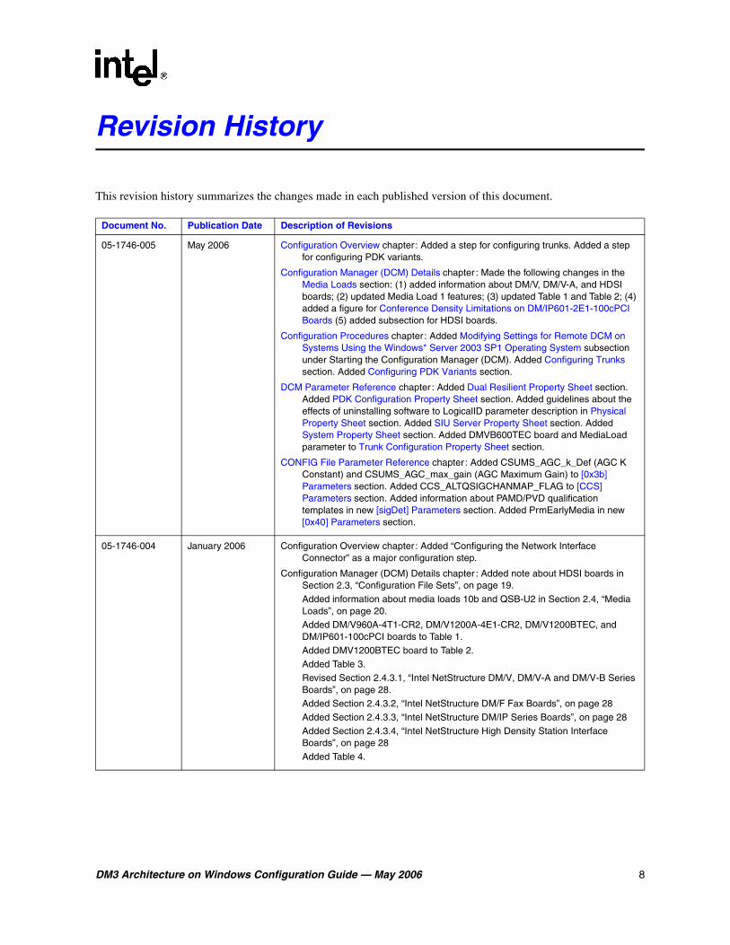
This revision history summarizes the changes made in each published version of this document.
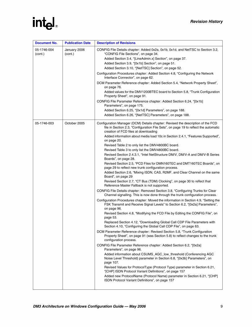
Document No. Publication Date Description of Revisions
05-1746-005 May 2006 Configuration Overview chapter : Added a step for configuring trunks. Added a step for configuring PDK variants.
Configuration Manager (DCM) Details chapter : Made the following changes in the Media Loads section: (1) added information about DM/V, DM/V-A, and HDSI boards; (2) updated Media Load 1 features; (3) updated Table 1 and Table 2; (4) added a figure for Conference Density Limitations on DM/IP601-2E1-100cPCI Boards (5) added subsection for HDSI boards.
Configuration Procedures chapter : Added Modifying Settings for Remote DCM on Systems Using the Windows* Server 2003 SP1 Operating System subsection under Starting the Configuration Manager (DCM). Added Configuring Trunks section. Added Configuring PDK Variants section.
DCM Parameter Reference chapter : Added Dual Resilient Property Sheet section. Added PDK Configuration Property Sheet section. Added guidelines about the effects of uninstalling software to LogicalID parameter description in Physical Property Sheet section. Added SIU Server Property Sheet section. Added System Property Sheet section. Added DMVB600TEC board and MediaLoad parameter to Trunk Configuration Property Sheet section.
CONFIG File Parameter Reference chapter : Added CSUMS_AGC_k_Def (AGC K Constant) and CSUMS_AGC_max_gain (AGC Maximum Gain) to [0x3b] Parameters section. Added CCS_ALTQSIGCHANMAP_FLAG to [CCS] Parameters section. Added information about PAMD/PVD qualification templates in new [sigDet] Parameters section. Added PrmEarlyMedia in new [0x40] Parameters section.
05-1746-004 January 2006 Configuration Overview chapter : Added “Configuring the Network Interface Connector” as a major configuration step.
Configuration Manager (DCM) Details chapter : Added note about HDSI boards in Section 2.3, “Configuration File Sets”, on page 19.Added information about media loads 10b and QSB-U2 in Section 2.4, “Media Loads”, on page 20.Added DM/V960A-4T1-CR2, DM/V1200A-4E1-CR2, DM/V1200BTEC, and DM/IP601-100cPCI boards to Table 1.Added DMV1200BTEC board to Table 2.Added Table 3.Revised Section 2.4.3.1, “Intel NetStructure DM/V, DM/V-A and DM/V-B Series Boards”, on page 28.Added Section 2.4.3.2, “Intel NetStructure DM/F Fax Boards”, on page 28Added Section 2.4.3.3, “Intel NetStructure DM/IP Series Boards”, on page 28Added Section 2.4.3.4, “Intel NetStructure High Density Station Interface Boards”, on page 28Added Table 4.
DM3 Architecture on Windows Configuration Guide — May 2006 9
Revision History
05-1746-004 (cont.)
January 2006 (cont.)
CONFIG File Details chapter : Added 0x2a, 0x1b, 0x1d, and NetTSC to Section 3.2, “CONFIG File Sections”, on page 34.Added Section 3.4, “[LineAdmin.x] Section”, on page 37.Added Section 3.9, “[0x1b] Section”, on page 51.Added Section 3.10, “[NetTSC] Section”, on page 52.
Configuration Procedures chapter : Added Section 4.8, “Configuring the Network Interface Connector”, on page 62.
DCM Parameter Reference chapter : Added Section 5.4, “Network Property Sheet”, on page 76.Added values for the DMV1200BTEC board to Section 5.8, “Trunk Configuration Property Sheet”, on page 91.
CONFIG File Parameter Reference chapter : Added Section 6.24, “[0x1b] Parameters”, on page 175.Added Section 6.25, “[0x1d] Parameters”, on page 188.Added Section 6.26, “[NetTSC] Parameters”, on page 188.
05-1746-003 October 2005 Configuration Manager (DCM) Details chapter : Revised the description of the FCD file in Section 2.3, “Configuration File Sets”, on page 19 to reflect the automatic creation of FCD files at downloadingAdded information about media load 10c in Section 2.4.1, “Features Supported”, on page 20.Revised Table 2 to only list the DMV4800BC board.Revised Table 3 to only list the DMV4800BC board.Revised Section 2.4.3.1, “Intel NetStructure DM/V, DM/V-A and DM/V-B Series Boards”, on page 28.Revised Section 2.5, “PCD Files for DMN160TEC and DMT160TEC Boards”, on page 29 to reflect new trunk configuration process.Added Section 2.6, “Mixing ISDN, CAS, R2MF, and Clear Channel on the same Board”, on page 29Revised Section 2.7, “CT Bus (TDM) Clocking”, on page 30 to reflect that Reference Master Fallback is not supported.
CONFIG File Details chapter : Removed Section 3.8, “Configuring Trunks for Clear Channel signalling. This is now done through the trunk configuration process.
Configuration Procedures chapter : Moved the information in Section 4.9, “Setting the FSK Transmit and Receive Signal Levels” to Section 6.2, “[0x2a] Parameters”, on page 96.Revised Section 4.8, “Modifying the FCD File by Editing the CONFIG File”, on page 53.Replaced Section 4.12, “Downloading Global Call CDP File Parameters with Section 4.10, “Configuring the Global Call CDP File”, on page 63.
DCM Parameter Reference chapter : Revised Section 5.8, “Trunk Configuration Property Sheet”, on page 91 (was Section 5.8) to reflect changes to the trunk configuration process.
CONFIG File Parameter Reference chapter : Added Section 6.2, “[0x2a] Parameters”, on page 96.Added information about CSUMS_AGC_low_threshold (Conferencing AGC Noise Level Threshold) parameter in Section 6.8, “[0x3b] Parameters”, on page 107.Revised Values for ProtocolType (Protocol Type) parameter in Section 6.21, “[CHP] ISDN Protocol Variant Definitions”, on page 157Added new ProtocolName (Protocol Name) parameter in Section 6.21, “[CHP] ISDN Protocol Variant Definitions”, on page 157
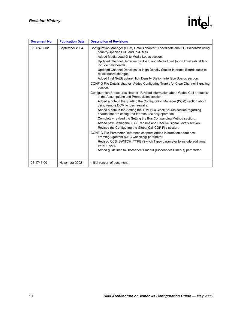
Document No. Publication Date Description of Revisions
10 DM3 Architecture on Windows Configuration Guide — May 2006
Revision History
05-1746-002 September 2004 Configuration Manager (DCM) Details chapter : Added note about HDSI boards using country-specific FCD and PCD files.Added Media Load 9f to Media Loads section.Updated Channel Densities by Board and Media Load (non-Universal) table to include new boards.Updated Channel Densities for High Density Station Interface Boards table to reflect board changes.Added Intel NetStructure High Density Station Interface Boards section.
CONFIG File Details chapter : Added Configuring Trunks for Clear Channel Signaling section.
Configuration Procedures chapter : Revised information about Global Call protocols in the Assumptions and Prerequisites section.Added a note in the Starting the Configuration Manager (DCM) section about using remote DCM across firewalls.Added a note in the Setting the TDM Bus Clock Source section regarding boards that are configured for resource only operation.Completely revised the Setting the Bus Companding Method section.Added new Setting the FSK Transmit and Receive Signal Levels section.Revised the Configuring the Global Call CDP File section.
CONFIG File Parameter Reference chapter : Added information about new FramingAlgorithm (CRC Checking) parameter.Revised CCS_SWITCH_TYPE (Switch Type) parameter to include additional switch types.Added guidelines to DisconnectTimeout (Disconnect Timeout) parameter.
05-1746-001 November 2002 Initial version of document.
Document No. Publication Date Description of Revisions
DM3 Architecture on Windows Configuration Guide — May 2006 11
About This Publication
The following topics provide information about this Intel® DM3 Architecture for CompactPCI on Windows Configuration Guide:
• Purpose
• Applicability
• Intended Audience
• How to Use This Publication
• Related Information
Purpose
This guide provides information about configuring Intel NetStructure® CompactPCI* boards that are based on the DM3 architecture in a Windows* environment. Configuration procedures are included, as well as descriptions of configuration files and configuration parameters.
Applicability
This document is published for Intel® Dialogic® System Release 6.1 CompactPCI* for Windows operating systems.
This document may also be applicable to later Intel Dialogic system releases, including service updates, on Windows. Check the Release Guide for your software release to determine whether this document is supported.
Intended Audience
This information is intended for:
• System, application, and technology developers
• Toolkit vendors
• VAR/system integrators
• System and network administrators

12 DM3 Architecture on Windows Configuration Guide — May 2006
About This Publication
How to Use This Publication
This information is organized as follows:
• Chapter 1, “Configuration Overview” describes the major configuration steps in the order in which they are performed and provides a brief overview of each aspect of configuring a system containing Intel NetStructure on DM3 architecture boards.
• Chapter 2, “Configuration Manager (DCM) Details” provides details about using the configuration manager (DCM), selecting configuration files and setting configuration parameters.
• Chapter 3, “CONFIG File Details” provides additional detailed information about specific aspects of configuring a system that relate to the .config (CONFIG) files.
• Chapter 4, “Configuration Procedures” contains detailed procedural information for configuring a system that uses Intel NetStructure on DM3 architecture boards.
• Chapter 5, “DCM Parameter Reference” describes each parameter associated with the DCM. Included are a description, a list of values, and configuration guidelines.
• Chapter 6, “CONFIG File Parameter Reference” describes each parameter associated with CONFIG files. Included are a description, a list of values, and configuration guidelines.
Related Information
For additional information related to configuring an Intel® telecom product, see the following:
• For timely information that may affect configuration, see the Release Guide and Release Update. Be sure to check the Release Update for the system release you are using for any updates or corrections to this publication.
• For information about installing the system software, see the systems software installation guide supplied with your release.
• For additional information about the configuration manager (DCM), including parameter information, refer to the DCM Online Help supplied with your system release.
• For information about administrative functions relating to the Intel NetStructure boards, see the systems administration guide supplied with your release.
• For information about administrative functions relating to the SNMP agent software, see the SNMP Agent Software Administration Guide.
• For information about configuring a third-party board as the TDM bus clock master, refer to the DCM Online Help.
• http://developer.intel.com/design/telecom/support (for technical support)
• http://www.intel.com/design/network/products/telecom (for product information)

DM3 Architecture on Windows Configuration Guide — May 2006 13
11.Configuration Overview
The configuration overview describes the major configuration steps in the order in which they are performed. It also provides a brief overview of each aspect of configuring a system containing Intel® Dialogic® or Intel NetStructure® boards that are based on the DM3 Architecture.
• Major Configuration Steps . . . . . . . . . . . . . . . . . . . . . . . . . . . . . . . . . . . . . . . . . . . . . . 13
• The Configuration Process . . . . . . . . . . . . . . . . . . . . . . . . . . . . . . . . . . . . . . . . . . . . . . 13
1.1 Major Configuration Steps
The following major steps are used to configure a system containing an Intel Dialogic or Intel NetStructure on DM3 Architecture board:
1. Starting the configuration manager (DCM)
2. Selecting a configuration file set (optional)
3. Configuring trunks (optional)
4. Configuring PDK Variants (optional)
5. Setting the TDM bus clock source (optional)
6. Setting the Bus companding method for DM3 configurations
7. Configuring the Network Interface Connector
8. Modifying other DCM property sheet parameters (optional)
9. Modifying FCD parameters
10. Initializing the system
11. Reconfiguring the system (optional)
Detailed information about the board configuration procedures is provided in Chapter 4, “Configuration Procedures”.
1.2 The Configuration Process
Once the Intel® Dialogic® System Release is installed, you start the configuration process by invoking the configuration manager (DCM). The configuration parameters that you select in the DCM are used by the downloader to initialize the system when the boards are started. For detailed procedures, see Chapter 4, “Configuration Procedures”. An overview of the configuration process is as follows:
Starting the configuration manager (DCM)Within the DCM, each board has a set of property sheets that display the board’s configuration parameters, grouped together on tabs according to the type of board functionality they affect
14 DM3 Architecture on Windows Configuration Guide — May 2006
Configuration Overview
(for example, the Network or Driver tabs). For details about the DCM, including property sheets and parameters, see the DCM Online Help.
Selecting a Configuration File SetTwo configuration files, a Product Configuration Description (PCD) file and a Feature Configuration Description (FCD) file, must be downloaded to each DM3 Architecture board in your system. The purpose of the PCD file is to determine the software components your system will use. The purpose of the FCD file is to adjust the settings of the components that make up each product. Each PCD and FCD file for a configuration has the same name; only the extensions (.pcd and .fcd) differ.
Configuring trunksThis step involves using the DCM to assign a protocol to each trunk on the board.
Configuring PDK VariantsThis step involves using the DCM to choose country dependent parameter (CDP) file variants for each T1 trunk that uses the CAS protocol or to each E1 trunk that uses the R2MF protocol.
Setting the TDM Bus Clock SourceThis step involves using the DCM to access the TDM Bus Configuration property sheet and setting the clock source. The source for clocking depends on the bus mode in which the system runs. The bus mode is determined by the capability of the devices installed in your system. The system automatically determines the bus mode on the basis of installed devices.
Setting the Bus Companding Method for DM3 ConfigurationsThis step involves setting the companding method used by the TDM Bus to agree with that of the boards connected to the network trunks in the system.
Configuring the Network Interface ConnectorThis step involves using the DCM to access each board’s Network property sheet and setting the following parameters: IPAddress, SubnetMask, TargetName, HostName, UserName, and GatewayIPAddress.
Modifying Other DCM Property Sheet ParametersThis step provides instructions for modifying additional DCM parameters. For details about DCM property sheets and associated parameters, refer to the DCM Online Help supplied with your system release.
Modifying FCD File ParametersIt is sometimes necessary to adjust the parameters within the FCD file; this is done by editing the associated CONFIG file. The FCD file, and configuration file sets (.pcd, .fcd, and .config files) are located in \data under INTEL_DIALOGIC_DIR, the environment variable for the directory in which the software is installed. For details about configuration file sets, refer to Section 2.3, “Configuration File Sets”, on page 19. For details about CONFIG files, refer to Chapter 3, “CONFIG File Details”.
Initializing the SystemDuring system initialization, all required firmware for an Intel NetStructure product is downloaded and configured using the identified configuration files and parameter settings.
Reconfiguring a SystemIf hardware is added or configuration parameters need to be changed, the system must be reconfigured. Parameter changes can be made by invoking the DCM and changing the parameter values as needed. The system is then re-initialized by starting the system service.

DM3 Architecture on Windows Configuration Guide — May 2006 15
22.Configuration Manager (DCM) Details
This chapter provides an overview of the configuration manager (DCM) graphical user interface including information to help you select configuration files.
• Configuration Manager (DCM). . . . . . . . . . . . . . . . . . . . . . . . . . . . . . . . . . . . . . . . . . . 15
• TDM Bus Parameters . . . . . . . . . . . . . . . . . . . . . . . . . . . . . . . . . . . . . . . . . . . . . . . . . . 18
• Configuration File Sets . . . . . . . . . . . . . . . . . . . . . . . . . . . . . . . . . . . . . . . . . . . . . . . . . 19
• Media Loads . . . . . . . . . . . . . . . . . . . . . . . . . . . . . . . . . . . . . . . . . . . . . . . . . . . . . . . . . 20
• PCD Files for DMN160TEC and DMT160TEC Boards. . . . . . . . . . . . . . . . . . . . . . . . 29
• Mixing ISDN, CAS, R2MF, and Clear Channel on the same Board. . . . . . . . . . . . . . . 29
• CT Bus (TDM) Clocking. . . . . . . . . . . . . . . . . . . . . . . . . . . . . . . . . . . . . . . . . . . . . . . . 30
2.1 Configuration Manager (DCM)
The configuration manager (DCM) utility is a graphical user interface (GUI) that allows you to customize board, system, and TDM bus configurations. The interface is used to modify parameter settings, select different configuration file sets, start and stop the system, and start and stop individual boards. In addition, the DCM can start the system using the default configuration settings.
The DCM main window contains pull-down menus, shortcut icons, a system window, and a status window. The system window contains a tree structure of the boards installed in your system. The top line of the display, Configured Devices on..., shows the name of the computer you connected to. If you entered an IP address instead of a computer name, the IP address is shown. Refer to Figure 1.

16 DM3 Architecture on Windows Configuration Guide — May 2006
Configuration Manager (DCM) Details
Figure 1. DCM Main Window
The first level of the tree structure shows the board families or categories of boards currently installed in your system, and the TDM bus, which refers to the resource bus used to carry information between boards. The next level displays the model names of the boards in your system. If the board model names are not displayed, click the family name node(s) to expand the tree structure.
The status window, located at the bottom of the main window, is used to display descriptive text when administrative events are received. For example, it will display “System started” when the system is started and “Device detected” when a device has been detected. The DCM also supports rollover help. When selecting a menu item, or when the mouse is on a particular tool bar icon, a description of the menu item or icon is displayed in the status window.
Within the DCM, each board has a set of property sheets that display the board’s configuration parameters. Each property sheet displays a different set of parameters based on the functionality they affect. To access a board’s property sheets, double-click on the board model name in the system window. The Misc property sheet is displayed by default. Refer to Figure 2.
DM3 Architecture on Windows Configuration Guide — May 2006 17
Configuration Manager (DCM) Details
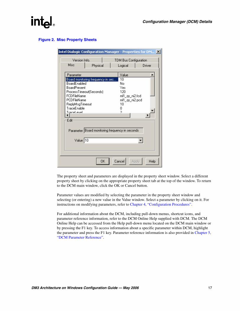
Figure 2. Misc Property Sheets
The property sheet and parameters are displayed in the property sheet window. Select a different property sheet by clicking on the appropriate property sheet tab at the top of the window. To return to the DCM main window, click the OK or Cancel button.
Parameter values are modified by selecting the parameter in the property sheet window and selecting (or entering) a new value in the Value window. Select a parameter by clicking on it. For instructions on modifying parameters, refer to Chapter 4, “Configuration Procedures”.
For additional information about the DCM, including pull-down menus, shortcut icons, and parameter reference information, refer to the DCM Online Help supplied with DCM. The DCM Online Help can be accessed from the Help pull-down menu located on the DCM main window or by pressing the F1 key. To access information about a specific parameter within DCM, highlight the parameter and press the F1 key. Parameter reference information is also provided in Chapter 5, “DCM Parameter Reference”.
18 DM3 Architecture on Windows Configuration Guide — May 2006
Configuration Manager (DCM) Details
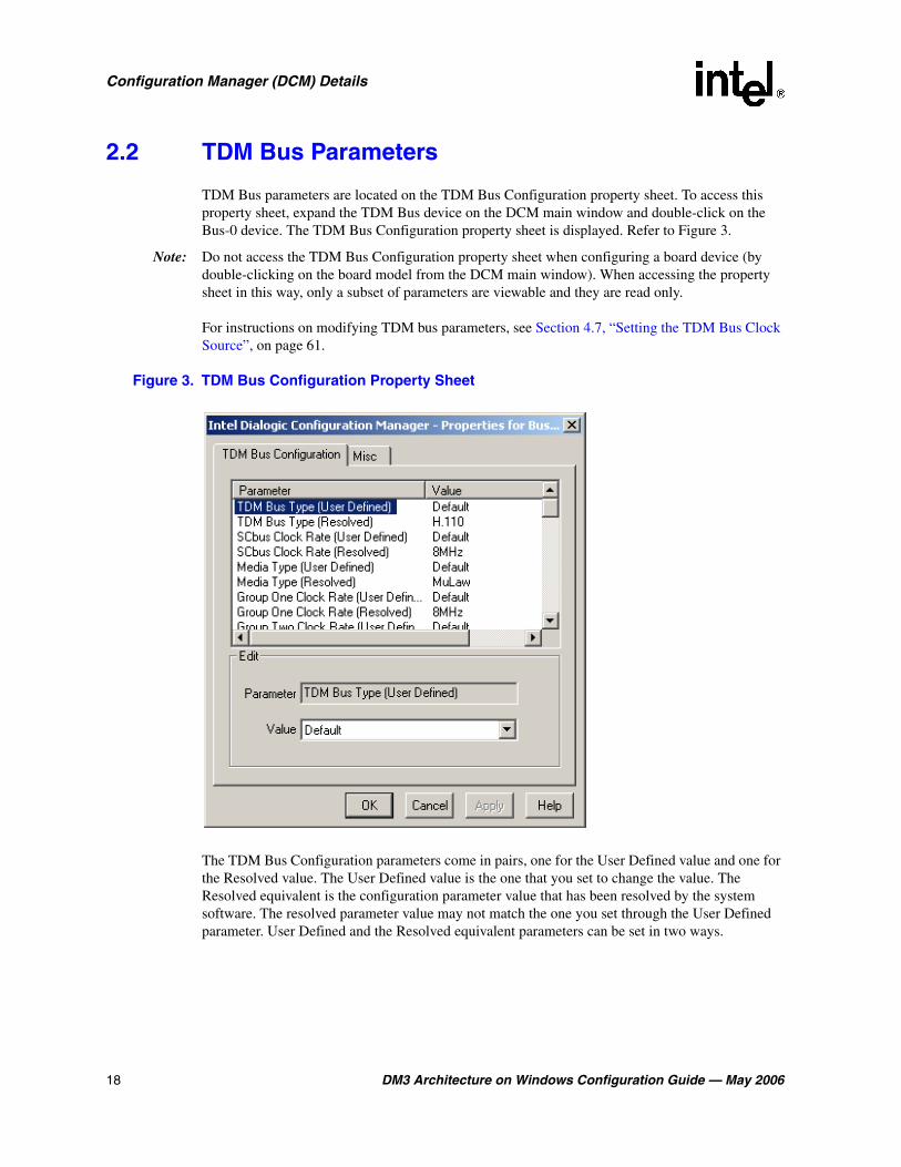
2.2 TDM Bus Parameters
TDM Bus parameters are located on the TDM Bus Configuration property sheet. To access this property sheet, expand the TDM Bus device on the DCM main window and double-click on the Bus-0 device. The TDM Bus Configuration property sheet is displayed. Refer to Figure 3.
Note: Do not access the TDM Bus Configuration property sheet when configuring a board device (by double-clicking on the board model from the DCM main window). When accessing the property sheet in this way, only a subset of parameters are viewable and they are read only.
For instructions on modifying TDM bus parameters, see Section 4.7, “Setting the TDM Bus Clock Source”, on page 61.
Figure 3. TDM Bus Configuration Property Sheet
The TDM Bus Configuration parameters come in pairs, one for the User Defined value and one for the Resolved value. The User Defined value is the one that you set to change the value. The Resolved equivalent is the configuration parameter value that has been resolved by the system software. The resolved parameter value may not match the one you set through the User Defined parameter. User Defined and the Resolved equivalent parameters can be set in two ways.

DM3 Architecture on Windows Configuration Guide — May 2006 19
Configuration Manager (DCM) Details
Set the parameter to a value of Default In this case, the value of the User Defined parameter is set to a value of Default and the system software determines the value of the parameter. The actual value is then indicated in the parameter’s Resolved equivalent.
For example, if the NETREF One FRU (User Defined) parameter is set to an H.100/H.110 enabled device, and the Derive Primary Clock From (User Defined) parameter is set to a value of Default, then the Derive Primary Clock From (Resolved) parameter will be set to NETREF_1.
Set the parameter to a specific valueIn this case, the value of the User Defined parameter is set to a specific value. The system software will attempt to configure the system with the parameter when you click the Apply button on the DCM property sheet. If the value can be applied, the Resolved equivalent will be set to the same value as the User Defined parameter. If the system cannot be configured with the User Defined value, the system will select another value and display it in the parameter’s resolved equivalent.
For example, if the Derive Primary Clock From (User Defined) parameter is set to a value of InternalOscillator, then the Derive Primary Clock From (Resolved) parameter will be set to a value of InternalOscillator.
Note: If the system software cannot configure the system with the User Defined value, only the Resolved equivalent will indicate the parameter’s true value; the User Defined parameter will remain set to the inapplicable value. Therefore, you must always double-check the Resolved equivalent to be sure of the parameter’s true value.
2.3 Configuration File Sets
The PCDFileName and FCDFileName parameters are displayed from the DCM Misc property sheet. These files are part of a configuration file set. The set of files associated with a specific configuration all have the same name; only the extensions (.pcd, .fcd and .config) differ. A set of these files with the same name are used for a specific board type. The board type can include a single board or a group of similar boards. Depending on the board type and the protocol that the board will use, a specific FCD and PCD file are downloaded to that board as identified in the DCM. If the FCD file needs to be modified, the CONFIG file in that same set is used.
The files associated with configuration file sets include:
CONFIG FileThe CONFIG file (.config), located in the data directory under INTEL_DIALOGIC_DIR (the environment variable for the directory in which the software is installed), contains the modifiable parameter settings used to configure board components. For additional information about CONFIG files, see Chapter 3, “CONFIG File Details”.
Feature Configuration Description (FCD) FileThe FCD file is not included with the system software, but is created and downloaded to a board when the associated PCD file is downloaded to the board. The FCD file is also copied to the data directory.
An FCD file (.fcd), located in the data directory under INTEL_DIALOGIC_DIR, must be downloaded to each board in the system. The purpose of the FCD file is to adjust the settings of the components that make up each product. For example, the FCD file may contain

20 DM3 Architecture on Windows Configuration Guide — May 2006
Configuration Manager (DCM) Details
instructions to set certain country codes, or may send messages that configure the Telephony Service Provider (TSP) component to operate with a particular network protocol.
The FCD file defines a simple message form that the downloader parses and sends to a specific component. These parameters are sent to a component within a message and can be thought of as configurable features of a component. The FCD file is created automatically from the associated CONFIG file during the board initialization process. For information about changing FCD file parameters, see Section 4.11, “Modifying the FCD File by Editing the CONFIG File”, on page 67.
Note: The FCD file should not be edited directly. If parameters require modification, the changes are made by editing the associated CONFIG file. Also, an FCD file should not be copied from another directory to the data directory.
Note: HDSI boards use country-specific FCD and PCD files. Depending on the FCD/PCD files selected for an HDSI board, the PCM encoding method will be set to either A law or Mu law, based on the default value for that country. If this value is not the same as the TDM Bus Media Type parameter setting, the HDSI board will fail to download.
Product Configuration Description (PCD) FileA PCD file (.pcd), located in the data directory under INTEL_DIALOGIC_DIR, must be downloaded to each board in the system. The purpose of the PCD file is to determine the software components your system will use. It defines the product by mapping download object files to specific processors, configuring the kernel for each processor and setting the number of component instances to run on each processor.
Note: The PCD file should not be modified by the user.
2.4 Media Loads
Media loads are pre-defined sets of features. A media load consists of a configuration file set (PCD, FCD, and CONFIG files) and an associated firmware load that are downloaded to each board. Universal media loads simultaneously support voice, fax, and conferencing resources.
• Features Supported
• Fixed and Flexible Routing Configuration
• Media Load Configuration File Sets
2.4.1 Features Supported
The media loads, or feature sets, are numbered (for example, 1, 2, 9b) for identification purposes and apply to the following boards:
• Intel NetStructure® DM/V, DM/V-A, DM/V-B, and DM/IP Boards
• Intel NetStructure® High Density Station Interface Boards
2.4.1.1 Intel NetStructure® DM/V, DM/V-A, DM/V-B, and DM/IP Boards
Intel NetStructure® DM/V, DM/V-A, and DM/V-B boards are supported by media loads 1 through 10 and universal media loads 1 through 4. Intel NetStructure® DM/IP boards are supported by media loads 2 and 11. The features supported by each media load are as follows:
DM3 Architecture on Windows Configuration Guide — May 2006 21
Configuration Manager (DCM) Details
Media Load 1 – Basic Voice
• Provides play, record, digit generation, and digit detection
• All half duplex voice operations
• Supports the following coders:
– 64 kbps and 48 kbps G.711 PCM VOX and WAV
– 24 kbps & 32 kbps OKI ADPCM VOX and WAV
– 64/88/128/176 kbps Linear PCM VOX and WAV
• Speed control on 8 kHz coders
• Speed control on 6 kHz coders (DM/V-A and DM/V-B boards only)
• Volume control
• Cached prompts
• GTG/GTD
• Call progress analysis
• Transaction record
Note: Density limitations may exist for transaction record. Check the specific media load for details.
• All call control features when using a board with a network interface
Media Load 1b – Basic Voice Plus
• All Basic Voice features (see Media Load 1)
• ADSI/2-way FSK/ETSI-FSK
Media Load 2 – Enhanced Voice
• All Basic Voice features (see Media Load 1)
• Continuous speech processing (CSP)
• Enhanced coders:
– G.726 at 16 kbps, 24 kbps, 32 kbps, and 40 kbps
– GSM (TIPHON* and Microsoft*)
– IMA ADPCM
– TrueSpeech
• Silence Compressed Record (G.711, OKI ADPCM, Linear 8kHz, and G.726)
• IP transcoders (Intel NetStructure DM/IP Series boards only)
– G.711: 1 frame/packet at 10, 20, or 30 ms (A-law or mu-law)
– G.723: 1, 2, or 3 frames/packet at 30 ms (silence compression with VAD and CNG)
– G.729: 1, 2, 3, or 4 frames/packet at 10 ms (silence compression with VAD and CNG)
– GSM: 1, 2, or 3 frames/packet at 20 ms (silence compression with VAD and CNG)
• ADSI/2-way FSK/ETSI-FSK (DM/V-B boards only)
Media Load 2b - All Enhanced Voice Features (see Media Load 2) plus
• CSP streaming to CT Bus

22 DM3 Architecture on Windows Configuration Guide — May 2006
Configuration Manager (DCM) Details
Media Load 2c – All Enhanced Voice Features (see Media Load 2) plus
• Enhanced Echo Cancellation (in addition to standard 16 ms tap length, provides selectable tap lengths of 32 ms and 64 ms)
• CSP streaming to CT Bus
Media Load 5 – All Enhanced Voice Features (see Media Load 2) plus
• V.17 Fax
Media Load 5bc – Enhanced Echo Cancellation
• All Enhanced Voice features (see Media Load 2)
• All Fax Features (see Media Load 5)
• CSP CT Bus Streaming
• Enhanced Echo Cancellation (see Media Load 2c)
Media Load 9b – Conferencing Only (Rich Conferencing)
• Traditional conferencing plus :
– Echo cancellation (16 ms)
– Signal detection
– Tone clamping
– Tone generation
Media Load 9c – Conferencing Only (Basic Conferencing - No Signal Detection, No Tone Clamping, No Tone Generation, No Echo Cancellation)
Media Load 9d – Conferencing Only (Standard Conferencing)
• This media load provides the same support as Media Load 9b, except for the following:
– No Echo Cancellation
Media Load 10 – Enhanced Voice Plus Conferencing
• All Enhanced Voice features (see Media Load 2)
• Rich Conferencing (see Media Load 9b)
Media Load 10b – Basic Voice (see Media Load 1b) plus
• Rich Conferencing (see Media Load 9b)
• ADSI/2-way FSK/ETSI-FSK
Note: Media Load 10b is only supported for ISDN protocols.
Media Load 10C – Basic Voice plus Conferencing
• All Basic Voice features (see Media Load 1b)
• Conferencing (see Media Load 9c)

DM3 Architecture on Windows Configuration Guide — May 2006 23
Configuration Manager (DCM) Details
Media Load 11 – Enhanced Voice plus Conferencing (Intel NetStructure DM/IP Series boards only)
• All Enhanced Voice features (see Media Load 2)
Note: Enhanced voice is not supported on the DM/IP601-2E1-100cPCI board. For this board, only basic coders are supported.
• Conferencing
For a list of channel densities based on non-Universal media load configurations, refer to Table 1.
Universal Media Loads - Universal media loads support different combinations of Voice, Fax, and Conferencing. For a list of channel densities based on Universal media load configurations, refer to Table 2.
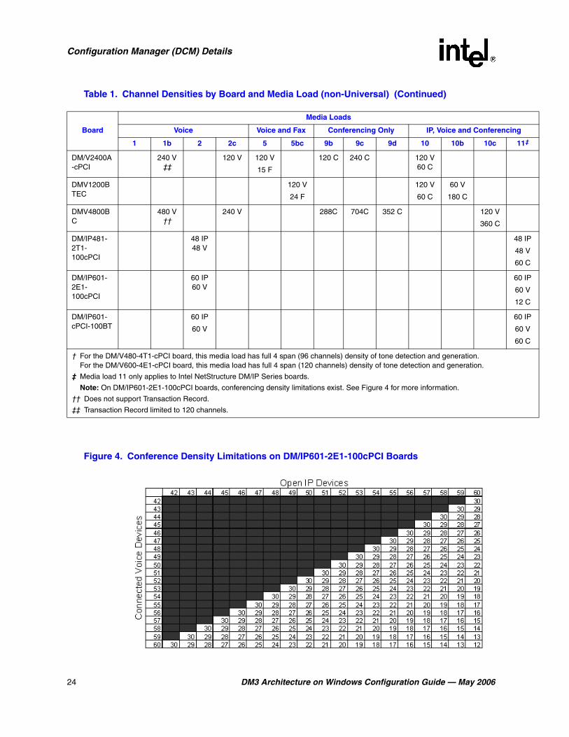
Table 1. Channel Densities by Board and Media Load (non-Universal)
Board
Media Loads
Voice Voice and Fax Conferencing Only IP, Voice and Conferencing
1 1b 2 2c 5 5bc 9b 9c 9d 10 10b 10c 11‡
DM/V480-4T1-cPCI †
48
DM/V600-4E1-cPCI †
60
DM/V960-4T1-cPCI
96 V
DM/V1200-4E1-cPCI
120V
DM/V480A-2T1-cPCI
DM/V480A-2T1-CR2
48 V 48 V
60 C
DM/V600A-2E1-cPCI
DM/V600A-2E1-CR2
60 V 60 V
60 C
DM/V960A-4T1-cPCI
DM/V960A-4T1-CR2
96 V 96 V
DM/V1200A-4E1-cPCI
DM/V1200A-4E1-CR2
120 V 120 V
† For the DM/V480-4T1-cPCI board, this media load has full 4 span (96 channels) density of tone detection and generation. For the DM/V600-4E1-cPCI board, this media load has full 4 span (120 channels) density of tone detection and generation.
‡ Media load 11 only applies to Intel NetStructure DM/IP Series boards.
Note: On DM/IP601-2E1-100cPCI boards, conferencing density limitations exist. See Figure 4 for more information.
†† Does not support Transaction Record.
‡‡ Transaction Record limited to 120 channels.
24 DM3 Architecture on Windows Configuration Guide — May 2006
Configuration Manager (DCM) Details
Figure 4. Conference Density Limitations on DM/IP601-2E1-100cPCI Boards
DM/V2400A-cPCI
240 V ‡‡
120 V 120 V
15 F
120 C 240 C 120 V60 C
DMV1200BTEC
120 V
24 F
120 V
60 C
60 V
180 C
DMV4800BC
480 V ††
240 V 288C 704C 352 C 120 V
360 C
DM/IP481-2T1-100cPCI
48 IP48 V
48 IP
48 V
60 C
DM/IP601-2E1-100cPCI
60 IP60 V
60 IP
60 V
12 C
DM/IP601-cPCI-100BT
60 IP
60 V
60 IP
60 V
60 C
Table 1. Channel Densities by Board and Media Load (non-Universal) (Continued)
Board
Media Loads
Voice Voice and Fax Conferencing Only IP, Voice and Conferencing
1 1b 2 2c 5 5bc 9b 9c 9d 10 10b 10c 11‡
† For the DM/V480-4T1-cPCI board, this media load has full 4 span (96 channels) density of tone detection and generation. For the DM/V600-4E1-cPCI board, this media load has full 4 span (120 channels) density of tone detection and generation.
‡ Media load 11 only applies to Intel NetStructure DM/IP Series boards.
Note: On DM/IP601-2E1-100cPCI boards, conferencing density limitations exist. See Figure 4 for more information.
†† Does not support Transaction Record.
‡‡ Transaction Record limited to 120 channels.
DM3 Architecture on Windows Configuration Guide — May 2006 25
Configuration Manager (DCM) Details
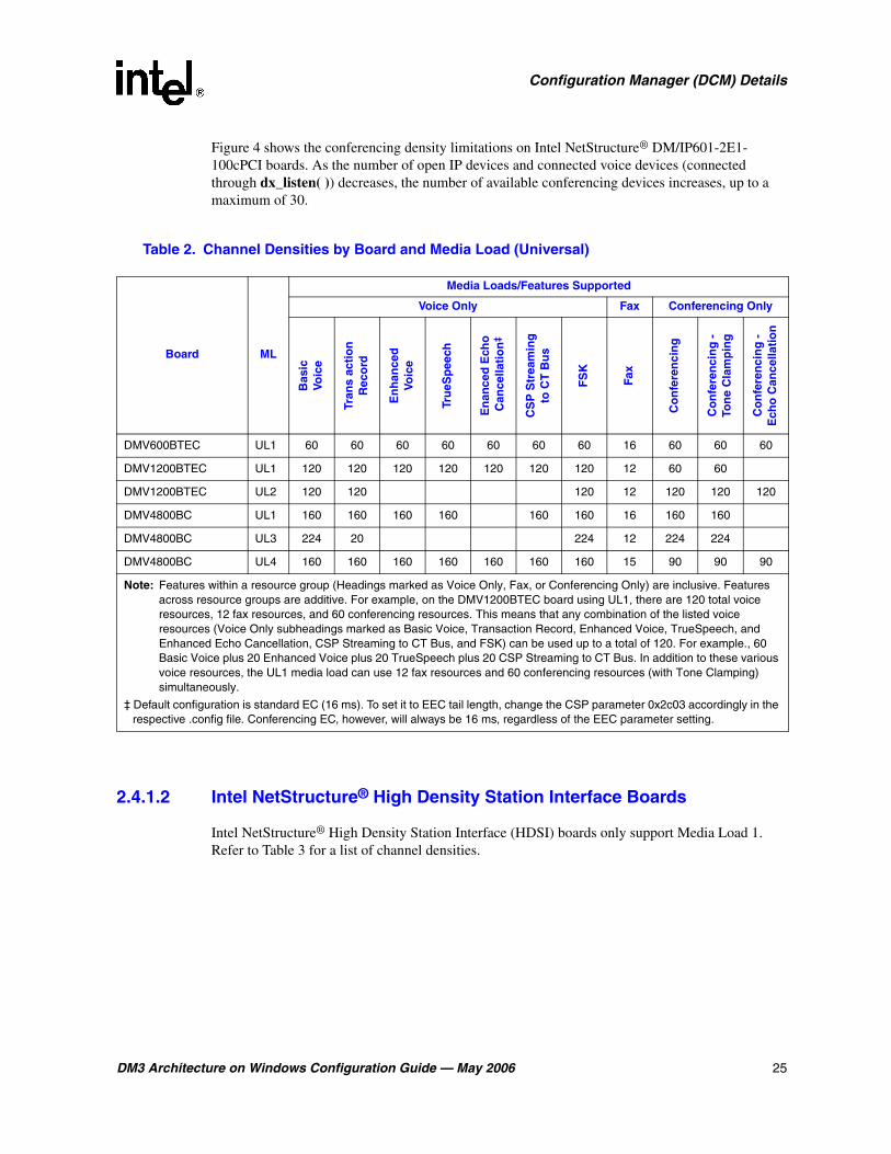
Figure 4 shows the conferencing density limitations on Intel NetStructure® DM/IP601-2E1-100cPCI boards. As the number of open IP devices and connected voice devices (connected through dx_listen( )) decreases, the number of available conferencing devices increases, up to a maximum of 30.
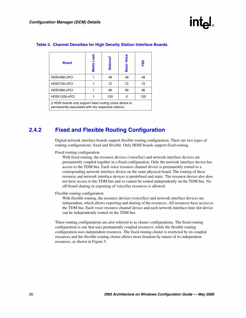
2.4.1.2 Intel NetStructure® High Density Station Interface Boards
Intel NetStructure® High Density Station Interface (HDSI) boards only support Media Load 1. Refer to Table 3 for a list of channel densities.
Table 2. Channel Densities by Board and Media Load (Universal)
Board ML
Media Loads/Features Supported
Voice Only Fax Conferencing OnlyB
asic
Voic
e
Tran
s ac
tio
nR
eco
rd
En
han
ced
Voic
e
Tru
eSp
eech
En
ance
d E
cho
Can
cella
tio
n‡
CS
P S
trea
min
gto
CT
Bu
s
FS
K
Fax
Co
nfe
ren
cin
g
Co
nfe
ren
cin
g -
To
ne
Cla
mp
ing
Co
nfe
ren
cin
g -
E
cho
Can
cella
tio
n
DMV600BTEC UL1 60 60 60 60 60 60 60 16 60 60 60
DMV1200BTEC UL1 120 120 120 120 120 120 120 12 60 60
DMV1200BTEC UL2 120 120 120 12 120 120 120
DMV4800BC UL1 160 160 160 160 160 160 16 160 160
DMV4800BC UL3 224 20 224 12 224 224
DMV4800BC UL4 160 160 160 160 160 160 160 15 90 90 90
Note: Features within a resource group (Headings marked as Voice Only, Fax, or Conferencing Only) are inclusive. Features across resource groups are additive. For example, on the DMV1200BTEC board using UL1, there are 120 total voice resources, 12 fax resources, and 60 conferencing resources. This means that any combination of the listed voice resources (Voice Only subheadings marked as Basic Voice, Transaction Record, Enhanced Voice, TrueSpeech, and Enhanced Echo Cancellation, CSP Streaming to CT Bus, and FSK) can be used up to a total of 120. For example., 60 Basic Voice plus 20 Enhanced Voice plus 20 TrueSpeech plus 20 CSP Streaming to CT Bus. In addition to these various voice resources, the UL1 media load can use 12 fax resources and 60 conferencing resources (with Tone Clamping) simultaneously.
‡ Default configuration is standard EC (16 ms). To set it to EEC tail length, change the CSP parameter 0x2c03 accordingly in the respective .config file. Conferencing EC, however, will always be 16 ms, regardless of the EEC parameter setting.
26 DM3 Architecture on Windows Configuration Guide — May 2006
Configuration Manager (DCM) Details
2.4.2 Fixed and Flexible Routing Configuration
Digital network interface boards support flexible routing configuration. There are two types of routing configurations: fixed and flexible. Only HDSI boards support fixed routing.
Fixed routing configurationWith fixed routing, the resource devices (voice/fax) and network interface devices are permanently coupled together in a fixed configuration. Only the network interface device has access to the TDM bus. Each voice resource channel device is permanently routed to a corresponding network interface device on the same physical board. The routing of these resource and network interface devices is predefined and static. The resource device also does not have access to the TDM bus and so cannot be routed independently on the TDM bus. No off-board sharing or exporting of voice/fax resources is allowed.
Flexible routing configuration With flexible routing, the resource devices (voice/fax) and network interface devices are independent, which allows exporting and sharing of the resources. All resources have access to the TDM bus. Each voice resource channel device and each network interface time slot device can be independently routed on the TDM bus.
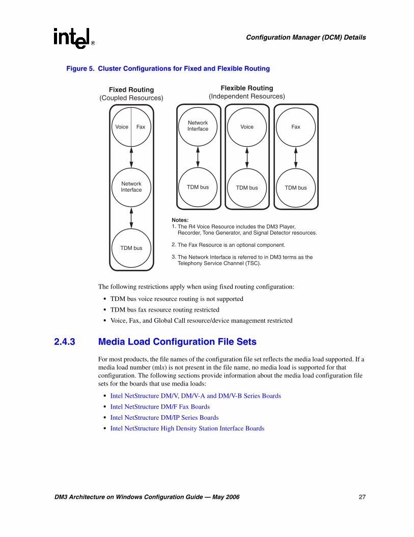
These routing configurations are also referred to as cluster configurations. The fixed routing configuration is one that uses permanently coupled resources, while the flexible routing configuration uses independent resources. The fixed routing cluster is restricted by its coupled resources and the flexible routing cluster allows more freedom by nature of its independent resources, as shown in Figure 5.
Table 3. Channel Densities for High Density Station Interface Boards
Board
Med
ia L
oad
Sta
tio
ns‡
Bas
ic V
oic
e
FS
K
HDSI/480-cPCI 1 48 48 48
HDSI/720-cPCI 1 72 72 72
HDSI/960-cPCI 1 96 96 96
HDSI/1200-cPCI 1 120 0 120
‡ HDSI boards only support fixed routing (voice device is permanently associated with the respective station).
DM3 Architecture on Windows Configuration Guide — May 2006 27
Configuration Manager (DCM) Details
Figure 5. Cluster Configurations for Fixed and Flexible Routing
The following restrictions apply when using fixed routing configuration:
• TDM bus voice resource routing is not supported
• TDM bus fax resource routing restricted
• Voice, Fax, and Global Call resource/device management restricted
2.4.3 Media Load Configuration File Sets
For most products, the file names of the configuration file set reflects the media load supported. If a media load number (mlx) is not present in the file name, no media load is supported for that configuration. The following sections provide information about the media load configuration file sets for the boards that use media loads:
• Intel NetStructure DM/V, DM/V-A and DM/V-B Series Boards
• Intel NetStructure DM/F Fax Boards
• Intel NetStructure DM/IP Series Boards
• Intel NetStructure High Density Station Interface Boards
Voice Fax
NetworkInterface
TDM bus
The R4 Voice Resource includes the DM3 Player, Recorder, Tone Generator, and Signal Detector resources.
The Fax Resource is an optional component.
The Network Interface is referred to in DM3 terms as the Telephony Service Channel (TSC).
Notes:1.
2.
3.
Fixed Routing(Coupled Resources)
Flexible Routing(Independent Resources)
Voice
TDM bus
NetworkInterface
TDM bus
Fax
TDM bus

28 DM3 Architecture on Windows Configuration Guide — May 2006
Configuration Manager (DCM) Details
2.4.3.1 Intel NetStructure DM/V, DM/V-A and DM/V-B Series Boards
Media load configuration files for DM/V Series, DM/V-A Series, and DM/V-B Series boards are identified by having an mlx or ulx prefix, where x represents the specific media load.
For DM/V, DM/V-A, and DM/V-B boards, media loads support flexible routing and the configuration file sets are customized by feature set. For example, a DMV4800BC board using ml10c_cpciresb.pcd supports the media load 10c configuration.
2.4.3.2 Intel NetStructure DM/F Fax Boards
DM/F boards are fax resource only boards and do not have PSTN interfaces or associated protocols. For a DM/F300-cPCI board, the PCD file is fax30.pcd.
2.4.3.3 Intel NetStructure DM/IP Series Boards
Configuration files for DM/IP boards are identified by having an ipvs prefix and an evr (exportable voice resource) in the filename. Exportable voice resource denotes flexible routing. Fixed routing is not supported on these boards.
For example, the DM/IP601-cPCI-100BT board uses the following PCD files:
• ipvs_evr_r_311c.pcd supports media load 2.
• ipvs_evr_r_ml11_311c.pcd supports media load 11.
2.4.3.4 Intel NetStructure High Density Station Interface Boards
Configuration files for Intel NetStructure High Density Station Interface boards are prefaced with a country code. This code represents the country-specific protocol that is supported. For example, the HDSI CONFIG file for Austria E1 (code = at), supporting 48 channels is:
• at_hdsi_48_play_rec.config
Refer to Table 4 for a list of country codes for all supported countries.
Table 4. Intel NetStructure High Density Station Interface Country Codes
Code Country
at Austria
au Australia
be Belgium
ch Switzerland
de Germany
dk Denmark
es Spain
fr France
gb United Kingdom

DM3 Architecture on Windows Configuration Guide — May 2006 29
Configuration Manager (DCM) Details
2.5 PCD Files for DMN160TEC and DMT160TEC Boards
The DMN160TEC and DMT160TEC boards support a total of 16 trunks that can be configured individually as either T-1 or E-1 interfaces.
In addition, each trunk within a protocol group can be configured to use a different ISDN protocol supported by the line type (T-1 or E-1) assigned to the trunk. This is accomplished by creating a composite PCD file. The PCD file is configured using the DCM Trunk Configuration property sheet in the Configuration Manager (DCM) utility. When creating a PCD file, the utility also creates an associated CONFIG file. The associated FCD file is automatically created when the PCD file is downloaded to the board.
For additional information about configuring DMN160TEC and DMT160TEC trunks, see Section 5.12, “Trunk Configuration Property Sheet”, on page 95.
2.6 Mixing ISDN, CAS, R2MF, and Clear Channel on the same Board
You can mix ISDN and Clear Channel trunks on the same DMN160TEC board and you can mix ISDN, CAS, R2MF, and Clear Channel trunks on the same DM/V-B or DMT160TEC board using
hk Hong Kong
ie Ireland
it Italy
jp Japan
lu Luxembourg
mx Mexico
my Malaysia
nl Netherlands
no Norway
nz New Zealand
pt Portugal
se Sweden
sg Singapore
us United States
za South Africa
Table 4. Intel NetStructure High Density Station Interface Country Codes (Continued)
Code Country
30 DM3 Architecture on Windows Configuration Guide — May 2006
Configuration Manager (DCM) Details
the configuration manager (DCM) Trunk Configuration property sheet. The Trunk Configuration property sheet includes Clear Channel values as well as ISDN, CAS, and R2MF protocol values.
For additional information about mixing protocols on the same board, see Section 5.12, “Trunk Configuration Property Sheet”, on page 95.
2.7 CT Bus (TDM) Clocking
The system provides clocking and clock fallback to maintain timing in the event that the current clock source fails. The following provides reference information about the types of clock fallback:
• Primary Clock Fallback
• Reference Master Fallback
2.7.1 Primary Clock Fallback
For the following discussion, refer to Figure 6, “Clock Fallback”, on page 31 for an illustration of the CT Bus clocking concepts.
The Primary Clock Master is a device (board) that provides timing to all other devices attached to the bus. The Primary Clock Master drives bit and framing clocks for all of the other boards (slaves) in the system via CT Bus Line A or Line B.This bus clocking is synchronized to either the board's internal oscillator or, preferably, to the NetRef1 line which provides a timing reference (8 kHz) derived from a T1 or E1 interface signal.
The timing reference is provided by the Reference Master board. A T1 or E1 trunk on the Reference Master board is the source for the T1 or E1 interface signal from which the 8 kHz timing reference is derived. The timing reference is sent from the Reference Master board to the NetRef1 line.
In addition, a Secondary Clock Master can be defined as a backup for the same purpose. This board, like the Primary Clock Master, is capable of driving the bit and framing clocks for all of the other boards in the system. The Secondary Clock Master uses whichever CT Bus line (A or B) is not defined for the Primary Master Clock. If the system senses a failure of the Primary Clock Master, the system will cause the clock source to fall back to the Secondary Clock Master. The Secondary Clock Master, like the primary, also provides clocking that is synchronized to either the board's internal oscillator or, preferably, to the NetRef1 line.

DM3 Architecture on Windows Configuration Guide — May 2006 31
Configuration Manager (DCM) Details
Figure 6. Clock Fallback
In the case where the Primary Clock Master has failed, and the clock source falls back to the Secondary Clock Master, the system selects a new Secondary Clock Master, assuming that a board in the system meets the criteria for a clock master.
If the Primary Clock Master fails and no Secondary Clock Master has been defined, the system will automatically choose another board to be Primary Clock Master, if another board in the system is clock master capable.
Both the Primary and Secondary Clock Masters are defined by the user. For instructions on specifying the clock source, see Section 4.7, “Setting the TDM Bus Clock Source”, on page 61. For parameter reference information, see Section 5.10, “TDM Bus Configuration Property Sheet”, on page 85.
2.7.2 Reference Master Fallback
In addition to supporting clock master fallback, the system also provides for fallback in the event the board designated as the Reference Master fails. The failure could be caused by degradation of the board itself, or by a degradation of the T1 or E1 trunk from which the reference signal is derived. A second line on the same board or a line on a second board can be assigned as the Reference Master Fallback board (the user must specify the trunk to be used on the Reference Master Fallback board). In the event that the Network Reference board stops providing a reliable signal to drive the NetRef1 line, the system will switch to the Reference Master Fallback board for this purpose.
Line A
Line B
NetRef1
CT Bus
PrimaryClock
Master
SecondaryClock
Master
Slave(Secondary
Clock MasterCapable)
ReferenceMaster
ReferenceMaster
Fallback
T1/E1Trunk
T1/E1Trunk

32 DM3 Architecture on Windows Configuration Guide — May 2006
Configuration Manager (DCM) Details
DM3 Architecture on Windows Configuration Guide — May 2006 33
33.CONFIG File Details
This chapter provides background information about CONFIG (.config) files including directory location and formatting conventions. This chapter also includes information to help you set the parameters contained in the CONFIG file including the following:
• CONFIG File Formatting Conventions . . . . . . . . . . . . . . . . . . . . . . . . . . . . . . . . . . . . . 33
• CONFIG File Sections. . . . . . . . . . . . . . . . . . . . . . . . . . . . . . . . . . . . . . . . . . . . . . . . . . 34
• [Encoder] Section . . . . . . . . . . . . . . . . . . . . . . . . . . . . . . . . . . . . . . . . . . . . . . . . . . . . . 36
• [LineAdmin.x] Section . . . . . . . . . . . . . . . . . . . . . . . . . . . . . . . . . . . . . . . . . . . . . . . . . 37
• [NFAS] Section . . . . . . . . . . . . . . . . . . . . . . . . . . . . . . . . . . . . . . . . . . . . . . . . . . . . . . . 38
• [CAS] Section . . . . . . . . . . . . . . . . . . . . . . . . . . . . . . . . . . . . . . . . . . . . . . . . . . . . . . . . 39
• [CHP] Section . . . . . . . . . . . . . . . . . . . . . . . . . . . . . . . . . . . . . . . . . . . . . . . . . . . . . . . . 48
• [TSC] Section . . . . . . . . . . . . . . . . . . . . . . . . . . . . . . . . . . . . . . . . . . . . . . . . . . . . . . . . 50
• [0x1b] Section . . . . . . . . . . . . . . . . . . . . . . . . . . . . . . . . . . . . . . . . . . . . . . . . . . . . . . . . 51
• [NetTSC] Section . . . . . . . . . . . . . . . . . . . . . . . . . . . . . . . . . . . . . . . . . . . . . . . . . . . . . 52
3.1 CONFIG File Formatting Conventions
The CONFIG (.config) files, located in the data directory under INTEL_DIALOGIC_DIR (the environment variable for the directory in which the software is installed), are ASCII files that contain component configuration information required by Intel® telecom boards. When manually editing the CONFIG file, use the following formatting conventions:
ParametersMany CONFIG file parameters use the SetParm command to assign values. The format is SetParm followed by an equal sign, followed by the hexadecimal parameter number, followed by a comma, followed by the parameter value:
SetParm=parameter-number, parameter-value
Additional commands used to set parameters include:
• AddNFASInterface (see “GroupID (Group Identifier)”, on page 124)
• transition, pulse, train, and sequence (see Section 3.6, “[CAS] Section”, on page 39)
• Variant (see Section 3.7, “[CHP] Section”, on page 48)
• defineBSet (see Section 3.8, “[TSC] Section”, on page 50).
SectionsConfiguration parameters are grouped into sections. In general, each section begins with a section name enclosed in square brackets. (The section names are listed and described in

34 DM3 Architecture on Windows Configuration Guide — May 2006
CONFIG File Details
Section 3.2, “CONFIG File Sections”, on page 34.) The parameters for the section immediately follow the section name.
[section-name]
Some sections group parameters that apply to a specific network interface (trunk) or channel (line). These section names are followed by a period (.) and the trunk number. For sections that group parameters like this, there is a separate section for each trunk.
[section-name.trunk-number]
CommentsComments can be added to the CONFIG file. If you use an exclamation point (!) anywhere on a line, all text to the right of the exclamation point until the end of the line is treated as a comment (ignored).
! comment
For a list of all CONFIG file parameters, see Chapter 6, “CONFIG File Parameter Reference”.
3.2 CONFIG File Sections
CONFIG file parameters are grouped in sections based on the board components and subcomponents being configured. Modifiable CONFIG file sections include the following:
Note: CAS and R2MF protocols are configured using Protocol Development Kit (PDK) parameters. For more information, see the Global Call Country Dependent Parameters (CDP) for PDK Protocols Configuration Guide.
[0x44]Defines the companding method (along with the [TSC] encoding parameter 0x1209) for DI Series Station Interface boards. This section only applies to DI Series boards.
[0x2a]Defines a parameter used to adjust the transmit and receive signal levels of two-way Frequency Shift Keying (FSK).
[0x2b]Defines a parameter used to enable streaming of echo cancellation data over the TDM bus in Continuous Speech Processing (CSP) applications. This section is only applicable in media load 2c CONFIG files.
[0x2c]Defines parameters used to set the tail length, or tap length, of the enhanced echo canceller in Continuous Speech Processing (CSP) applications. This section also defines the parameters associated with Silence Compressed Streaming (SCS).
[encoder]Defines parameters used during the encoding process that utilize the Automatic Gain Control (AGC) and Silence Compressed Record (SCR) algorithms. For details about setting algorithm parameters, see Section 3.3, “[Encoder] Section”, on page 36.
[recorder]Defines recording parameters used during the recording process including the enabling and disabling of AGC and SCR on a per board basis.
DM3 Architecture on Windows Configuration Guide — May 2006 35
CONFIG File Details
[0x39]Defines conferencing parameters applicable to all conferencing lines on a board.
[0x3b]Defines conferencing parameters applicable to conferencing lines on a board. The [0x3b] parameters apply to all conferencing lines on the board. The [0x3b.x] parameters apply specifically to trunk x on the board.
[lineAdmin.x]Defines line device parameters applicable to each trunk on a board that has T1 or E1 trunks. For additional information, see Section 3.4, “[LineAdmin.x] Section”, on page 37.
[NFAS] and [NFAS.x]Non-Facility Associated Signaling (NFAS). Defines the Primary D channel and NFAS trunk parameters. The [NFAS] section defines the number of NFAS groups on a board. The [NFAS.x] sections define the parameters specific to each group. For details about setting the NFAS parameters, see Section 3.5, “[NFAS] Section”, on page 38.
[CAS]Channel Associated Signaling (CAS). Defines the signaling types used by a CAS protocol and the [TSC] section assigns these signaling types to voice channels. For details about the different CAS signals, see Section 3.6, “[CAS] Section”, on page 39.
[CCS] and [CCS.x]Common Channel Signaling (CCS). Defines common channel signaling parameters applicable to technologies such as ISDN. The [CCS] section defines board-based parameters and the [CCS.x] section defines the line-based parameters.
[CHP]Channel Protocol (CHP). Defines the telephony communication protocol that is used on each network interface using the Variant Define n command. For details about setting [CHP] parameters using the Variant Define n command, see Section 3.7, “[CHP] Section”, on page 48.
[TSC]Telephony Service Component (TSC). Defines sets of B channels and associated characteristics using the defineBSet command. For details about setting [TSC] parameters using the defineBSet command, see Section 3.8, “[TSC] Section”, on page 50.
[0x1b]Defines DM/IP technology parameters relating to echo cancellation, packet loss recovery, volume controls to network output, and gain controls applied to data received from the network. For details about setting 0x1b parameters, see Section 3.9, “[0x1b] Section”, on page 51. This parameter only applies to DM/IP boards.
[0x1d]Defines the Type of Service (TOS) byte in an IP header of transmitted datagrams to improve the mobility of UDP/TCP packets. This parameter only applies to DM/IP boards.
[NetTSC]The Network Telephony Service Component (NetTSC) resides on the control processor and manages the print level and debug level parameters. For details about setting NetTSC parameters, see Section 3.10, “[NetTSC] Section”, on page 52. The NetTSC parameters only apply to DM/IP boards.

36 DM3 Architecture on Windows Configuration Guide — May 2006
CONFIG File Details
3.3 [Encoder] Section
The encoder parameters are used to perform an encoding process on a media stream. Automatic Gain Control (AGC) and Silence Compressed Record (SCR) are two algorithms used as part of this encoding process.
The AGC is an algorithm for normalizing an input signal to a target record level. The target record level should be chosen to be the optimum level for an encoder and, at the same time, produce a suitable playback level for a listener.
The AGC algorithm is controlled by three parameters: PrmAGCk, PrmAGCmax_gain, and PrmAGClow_threshold. PrmAGCk is a target output level. PrmAGCmax_gain is the a limit on the possible maximum gain. The ratio, PrmAGCk/PrmAGCmax_gain gives the AGC High Threshold value. This is the threshold for which inputs above it produce output level at the PrmAGCk level and inputs with a level below it produce outputs which linearly decrease with the input level. The PrmAGClow_threshold, on the other hand, is an upper limit for a noise level estimate. That is, a signal with a level above the PrmAGClow_threshold is declared speech, independently of whether it is or not. Below the threshold, the AGC algorithm itself tries to discriminate between voiced and unvoiced signals.
Figure 7 is a graphical representation of the AGC gain relative to input average.
Figure 7. AGC Gain vs. Input Average
The SCR algorithm operates on 1 millisecond blocks of speech and uses a twofold approach to determine whether a sample is speech or silence. Two Probability of Speech values are calculated using a Zero Crossing algorithm and an Energy Detection algorithm. These values are combined to calculate a Combined Probability of Speech.
LowThreshold (variable)
HighThreshold
Maximum Gain
Maximum Gain = AGCk/High Threshold
AGCk/Input Average
Gain
Input Average
The same gain as when Input Average > Low Threshold

DM3 Architecture on Windows Configuration Guide — May 2006 37
CONFIG File Details
The Zero Crossing algorithm counts the number of times a sample block crosses a zero line, thus establishing a rough “average frequency” for the sample. If the count for the sample falls within a predetermined range, the sample is considered speech.
The Energy Detection algorithm allows user input at the component level of a background noise threshold range via the SCR_LO_THR and SCR_HI_THR parameters. Signals above the high threshold are declared speech and signals below the low threshold are declared silence.
SCR declares speech or silence for the current 1 millisecond sample based on the following:
• previous 1 millisecond sample declaration (speech or silence)
• Combined Probability of Speech in relation to the Speech Probability Threshold (SCR_PR_SP)
• Combined Probability of Speech in relation to the Silence Probability Threshold (SCR_PR_SIL)
• Trailing Silence (SCR_T) relative to Silence Duration
The logic is as follows:
Previous sample = Silence
If Combined Probability of Speech > Speech Probability Threshold then Declare Speech else Declare Silence
Previous sample = Speech
If Combined Probability of Speech > Silence Probability Threshold then Declare Speech else If Silence Duration < Trailing Silence then Declare Speech else Declare Silence
3.4 [LineAdmin.x] Section
The Line Administration (LCON) component resides on the control processor and manages line devices. There is one instance of the LCON component for each line (span).
There is a [lineAdmin.x] section in the CONFIG file for each line on the board. The parameters defined in a [lineAdmin.x] section apply to the line specified, for example, parameters in the [lineAdmin.3] section apply to line 3.
Line Administrator parameters are modified by editing the respective lines in the [lineAdmin.x] section of the CONFIG file. For example, to change the SignalingType parameter (parameter number=0x1602) from a value of CAS to CCS for the second T-1 span, you would change the value in the [lineAdmin.2] section of the CONFIG file from 4 to 5.

38 DM3 Architecture on Windows Configuration Guide — May 2006
CONFIG File Details
Following is an excerpt from the [lineAdmin.2] section of a CONFIG file that illustrates that part of the file before and after editing.
Before editing:
[lineAdmin.2] SetParm=0x1601,0 !LineType (dsx1_D4=0, dsx1_ESF=1) SetParm=0x1602,4 !SignalingType (CAS=4, CCS=5, Clear=6) SetParm=0x1603,7 !Coding (B8ZS=7, AMI=8)
After editing:
[lineAdmin.2] SetParm=0x1601,0 !LineType (dsx1_D4=0, dsx1_ESF=1) SetParm=0x1602,5 !SignalingType (CAS=4, CCS=5, Clear=6) SetParm=0x1603,7 !Coding (B8ZS=7, AMI=8)
For information about each Line Administrator parameter, see Section 6.10, “[lineAdmin.x] Parameters (Digital Voice)”, on page 114.
3.5 [NFAS] Section
Non-Facility-Associated Signaling (NFAS) uses a single ISDN PRI D channel to provide signaling and control for up to 10 ISDN PRI lines. Normally, on an ISDN PRI line, one D channel is used for signaling and 23 B channels (bearer channels) are used for transferring information. In an NFAS configuration, therefore, one D channel can support the signaling and control for up to 239 B channels. The trunk that provides the signaling is called the primary D channel. The trunks that use all 24 channels as B channels are called NFAS trunks.
Notes: 1. For a board containing multiple primary D channels, the maximum number of trunks supported by each NFAS group on that board is reduced. This is due to the additional message load on the board’s CPU.
2. NFAS is supported on only the ISDN NI-2, 4ESS, 5ESS, and DMS protocols.
3. NFAS D channel backup (DCBU) is supported only on ISDN NI-2 protocol.
4. When NFAS is used, the SignalingType parameter in the [lineAdmin] section of the CONFIG file must be modified. For details about this parameter modification, see Section 6.10, “[lineAdmin.x] Parameters (Digital Voice)”, on page 114.
The CONFIG file contains an [NFAS] section and multiple [NFAS.x] sections. The [NFAS] section defines the number of NFAS instances created, that is, defines the number of NFAS groups. For each NFAS group, there is an [NFAS.x] section in the CONFIG file. For example, if there are two NFAS groups defined in the [NFAS] section, there will be two [NFAS.x] sections, [NFAS.1] and [NFAS.2].
NFAS parameters are modified by editing the respective lines in the [NFAS] and [NFAS.x] sections of the CONFIG file. For example, to increase the number of NFAS groups per board from one to four, change the value of NFAS_INSTANCE_MAP (parameter = 0x3E02) from a value of 1 (one group per board) to a binary value of 1111 (four NFAS groups per board) represented by 0xF.

DM3 Architecture on Windows Configuration Guide — May 2006 39
CONFIG File Details
Following is an excerpt from the [NFAS] section of a CONFIG file that illustrates that part of the file before and after editing.
Before editing:
[NFAS] SetParm=0x3e02,0x1 !INSTANCE MAP, default = 1 (1 group/board)
After editing:
[NFAS] SetParm=0x3e02,0xf !INSTANCE MAP - 4 NFAS groups/board
3.6 [CAS] Section
Information about the [CAS] section of the CONFIG file is given in the following sections:
• CAS Signaling Parameters
• Transition Signal
• Pulse Signal
• Train Signal
• Sequence Signal
3.6.1 CAS Signaling Parameters
The Channel Associated Signaling (CAS) component is responsible for managing the generation and detection of digital line signaling functions required to manage voice channels. Each CAS instance corresponds to the CHP instance of the same voice channel.
The [CAS] section of the CONFIG file is a subcomponent of the [TSC] section. Commands in the [CAS] section define the signaling types used by a CAS protocol, and the [TSC] section assigns these signaling type to voice channels. For example, many CAS protocols use off-hook and wink signals, which can be defined in this section. For an explanation of the [TSC] section of the CONFIG file, see Section 3.8, “[TSC] Section”, on page 50.
Note: The CAS signaling parameters should only be modified by experienced users if the default settings do not match what the line carrier or PBX is sending or expecting for the line protocol configuration running on the card.
CAS parameters are defined using the following signal definition types:
Transition SignalThis signaling state changes from the current signaling state to a new signaling state.
Pulse SignalThis signaling state changes from the current signaling state to a new signaling state, and then reverts to the original signaling state.

40 DM3 Architecture on Windows Configuration Guide — May 2006
CONFIG File Details
Train SignalThis signaling state alternates between two predefined signaling states in a regular defined pattern (series of pulses).
Sequence SignalThis signaling state is defined by a set of train signals.
For information about specific CAS parameters, see the following sections:
• Section 6.13, “[CAS] Parameters for T1 E&M Signals”, on page 126
• Section 6.14, “[CAS] Parameters for T1 Loop Start Signals”, on page 128
• Section 6.15, “[CAS] Parameters for T1 Ground Start Signals”, on page 133
3.6.2 Transition Signal
The transition command defines an ABCD-bit transition from one state to another. It is used to define the CAS transition signals required by a protocol. The transition command uses the following syntax:
transition = SignalId, PreVal, PostVal, PreTm, PostTm
The transition signal definition includes the following values:
SignalIdUnique identifier (parameter number) of the transition signal. The Channel Protocol (CHP) uses the SignalId to recognize the transition when it is received, and also to generate the transition when needed.
Note: SignalId should not be modified by the user.
PreValDefines the ABCD bit states on the line before the transition occurs. The four least significant bits represent the ABCD signaling bits (0 or 1). The four most significant bits represent a mask (A'B'C'D') that specifies if each corresponding signaling bit value counts. If a mask bit is set to 1, the corresponding signaling bit is counted. If a mask bit is set to 0, the corresponding signaling bit is ignored. See Figure 8.
Figure 8. Pre-transition ABCD Bit States
PostValDefines the ABCD bit states on the line after the transition occurs. The format of this field is the same as the PreVal field.
PreTmDefines the minimum amount of time, in milliseconds, for the duration of the pre-transition interval.
A' B' C' D'
SignalingBits
A B C D
Mask

DM3 Architecture on Windows Configuration Guide — May 2006 41
CONFIG File Details
PostTmDefines the minimum amount of time, in milliseconds, for the duration of the post-transition interval.
Transition Example
The following is an example of a transition command that defines a transition signal:
transition = 0xC15CA001, 0xF0,0xFF, 100, 300
In the example shown, the transition signal is defined as having the following values:
SignalId = 0xC15CA001Defines the CAS T1 E&M transition signal off-hook.
PreVal = 0xF0 (11110000)Defines the mask as having a hexadecimal value of F (1111) and the signaling bits as having a hexadecimal value of 0 (0000). Since all of the mask bits are 1, all of the signaling bits are significant. Thus, the A, B, C, and D bits all have a value of 0 before the transition.
PostVal = 0xFF (11111111)Defines both the mask and the signaling bits as having a hexadecimal value of F (1111). Since all of the mask bits are 1, all of the signaling bits are significant. Thus, the A, B, C, and D bits all have a value of 1 after the transition.
PreTm = 100 msSpecifies that the PreTm signaling bits must be present for at least 100 ms before they transition to the PostVal signaling values.
PostTm = 300 msSpecifies that the PostVal signaling bits must be present for at least 300 ms before the signal is reported to the protocol (or if the signal is being sent, then the CAS subcomponent ensures that the PostVal signaling value is generated for at least 300 ms).
Figure 9 is a graphical representation of this signal definition.
Figure 9. Example of Off-hook Transition Signal (0xC15CA001)
PreTm PostTm
PreValABCD=0000
PostValABCD=1111
100 msec 300 msec
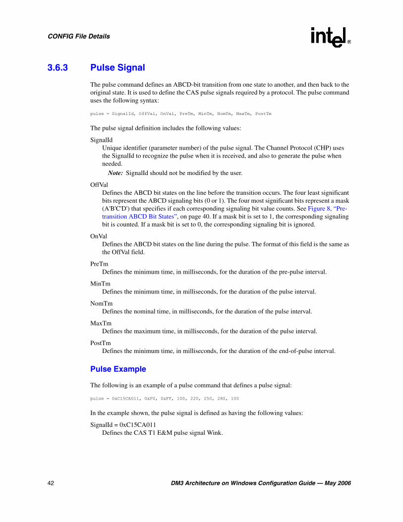
42 DM3 Architecture on Windows Configuration Guide — May 2006
CONFIG File Details
3.6.3 Pulse Signal
The pulse command defines an ABCD-bit transition from one state to another, and then back to the original state. It is used to define the CAS pulse signals required by a protocol. The pulse command uses the following syntax:
pulse = SignalId, OffVal, OnVal, PreTm, MinTm, NomTm, MaxTm, PostTm
The pulse signal definition includes the following values:
SignalId Unique identifier (parameter number) of the pulse signal. The Channel Protocol (CHP) uses the SignalId to recognize the pulse when it is received, and also to generate the pulse when needed.
Note: SignalId should not be modified by the user.
OffVal Defines the ABCD bit states on the line before the transition occurs. The four least significant bits represent the ABCD signaling bits (0 or 1). The four most significant bits represent a mask (A'B'C'D') that specifies if each corresponding signaling bit value counts. See Figure 8, “Pre-transition ABCD Bit States”, on page 40. If a mask bit is set to 1, the corresponding signaling bit is counted. If a mask bit is set to 0, the corresponding signaling bit is ignored.
OnVal Defines the ABCD bit states on the line during the pulse. The format of this field is the same as the OffVal field.
PreTm Defines the minimum time, in milliseconds, for the duration of the pre-pulse interval.
MinTm Defines the minimum time, in milliseconds, for the duration of the pulse interval.
NomTm Defines the nominal time, in milliseconds, for the duration of the pulse interval.
MaxTm Defines the maximum time, in milliseconds, for the duration of the pulse interval.
PostTm Defines the minimum time, in milliseconds, for the duration of the end-of-pulse interval.
Pulse Example
The following is an example of a pulse command that defines a pulse signal:
pulse = 0xC15CA011, 0xF0, 0xFF, 100, 220, 250, 280, 100
In the example shown, the pulse signal is defined as having the following values:
SignalId = 0xC15CA011Defines the CAS T1 E&M pulse signal Wink.
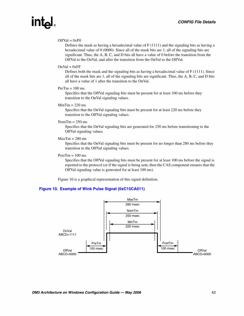
DM3 Architecture on Windows Configuration Guide — May 2006 43
CONFIG File Details
OffVal = 0xF0Defines the mask as having a hexadecimal value of F (1111) and the signaling bits as having a hexadecimal value of 0 (0000). Since all of the mask bits are 1, all of the signaling bits are significant. Thus, the A, B, C, and D bits all have a value of 0 before the transition from the OffVal to the OnVal, and after the transition from the OnVal to the OffVal.
OnVal = 0xFFDefines both the mask and the signaling bits as having a hexadecimal value of F (1111). Since all of the mask bits are 1, all of the signaling bits are significant. Thus, the A, B, C, and D bits all have a value of 1 after the transition to the OnVal.
PreTm = 100 msSpecifies that the OffVal signaling bits must be present for at least 100 ms before they transition to the OnVal signaling values.
MinTm = 220 msSpecifies that the OnVal signaling bits must be present for at least 220 ms before they transition to the OffVal signaling values.
NomTm = 250 msSpecifies that the OnVal signaling bits are generated for 250 ms before transitioning to the OffVal signaling values.
MaxTm = 280 msSpecifies that the OnVal signaling bits must be present for no longer than 280 ms before they transition to the OffVal signaling values.
PostTm = 100 msSpecifies that the OffVal signaling bits must be present for at least 100 ms before the signal is reported to the protocol (or if the signal is being sent, then the CAS component ensures that the OffVal signaling value is generated for at least 100 ms).
Figure 10 is a graphical representation of this signal definition.
Figure 10. Example of Wink Pulse Signal (0xC15CA011)
PreTm PostTm
NomTm
MinTm
MaxTm
OffValABCD=0000
OffValABCD=0000
OnValABCD=1111
100 msec
250 msec
100 msec
220 msec
280 msec
44 DM3 Architecture on Windows Configuration Guide — May 2006
CONFIG File Details
3.6.4 Train Signal
The train command defines a set of transitions from one signaling state to another in a predefined pattern (set of pulses). It is used to define CAS signals required by a protocol. The train command uses the following syntax:
train = SignalId, OffVal, OnVal, PulseTmlMin, PulseTmMax, PulseTmNom, preTm, interTmMin, interTmMax, interTmNom, postTm, digitCount, pulseCount, label, pulseCount, label, ...
The train signal definition includes the following values:
SignalId Unique identifier (parameter number) of the train signal. The Channel Protocol (CHP) uses the SignalId to recognize the train when it is received, and also to generate the train when needed.
Note: SignalId should not be modified by the user.
OffVal Defines the ABCD bit states on the line before the transition occurs. The four least significant bits represent the ABCD signaling bits (0 or 1). The four most significant bits represent a mask (A'B'C'D') that specifies if each corresponding bit value counts. See Figure 8, “Pre-transition ABCD Bit States”, on page 40. If a mask bit is set to 1, the corresponding signaling bit is counted. If a mask bit is set to 0, the corresponding signaling bit is ignored.
OnVal Defines the ABCD bit states on the line during one pulse of the train. The format of this field is the same as the OffVal field.
PulseTmMin Defines the minimum time, in milliseconds, for the duration of the pulse interval.
PulseTmMaxDefines the maximum time, in milliseconds, for the duration of the pulse interval.
PulseTmNom Defines the nominal time, in milliseconds, for the duration of the pulse interval.
preTm Defines the minimum time, in milliseconds, for the duration of the pre-train interval.
interTmMin Defines the minimum time, in milliseconds, for the duration of the inter-pulse interval.
interTmMax Defines the maximum time, in milliseconds, for the duration of the inter-pulse interval.
interTmNom Defines the nominal time, in milliseconds, for the duration of the inter-pulse interval.
postTm Defines the maximum time, in milliseconds, for the duration of the post-train interval.
digitCount Defines the number of digit definitions in the train. The pulse count for each digit (ASCII character) is defined by the label pairs following digitCount.

DM3 Architecture on Windows Configuration Guide — May 2006 45
CONFIG File Details
pulseCount Defines the number of train pulses that define the digit (ASCII character) identified by the label parameter.
label Defines the digit (ASCII character) associated with the corresponding pulseCount value.
Train Example
The following is an example of a train command that defines a train signal:
train = 0xC15CA032, 0xCC, 0xC4, 31, 33, 32, 600, 62, 66, 64, 20, 12, 10, 0, 1, 1, 2, 2, 3, 3, 4, 4, 5, 5, 6, 6, 7, 7, 8, 8, 9, 9, 11, #, 12, *
In the example shown, the train signal is defined as having the following values:
SignalId = 0xC15CA032Defines the CAS T1 loop start train signal parameter.
OffVal = 0xCCDefines both the mask and the signaling bits as having a hexadecimal value of C (1100). Since only mask bits A and B have a value of 1, only signaling bits A and B are significant. Thus, the A and B bits both have a value of 1 before the transition from the OffVal to the OnVal.
OnVal = 0xC4Defines the mask as having a hexadecimal value of C (1100) and the signaling bits as having a hexadecimal value of 4 (0100). Since mask bits A and B have a value of 1, signaling bits A and B are significant. Thus, the A bit has a value of 0 and the B bit has a value of 1 after the transition to the OnVal.
PulseTmMin = 31Specifies that the OnVal signaling bits must be present for at least 31 ms before they transition to the OffVal signaling values.
PulseTmMax = 33Specifies that the OnVal signaling bits must be present for no longer than 33 ms before they transition to the OffVal signaling values.
PulseTmNom = 32Specifies that the OnVal signaling bits must be present for 32 ms before they transition to the OffVal signaling values.
preTm = 600Specifies that the OffVal signaling bits must be present for 600 ms before the train signal begins.
interTmMin = 62Specifies that the OffVal signaling bits must be present for at least 62 ms before they transition to the OnVal signaling values.
interTmMax = 66Specifies that the OffVal signaling bits must be present for no longer than 66 ms before they transition to the OnVal signaling values.
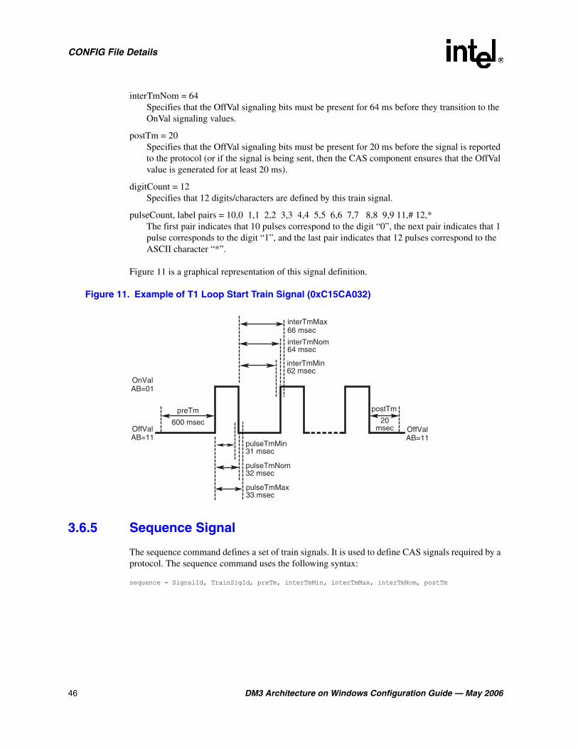
46 DM3 Architecture on Windows Configuration Guide — May 2006
CONFIG File Details
interTmNom = 64Specifies that the OffVal signaling bits must be present for 64 ms before they transition to the OnVal signaling values.
postTm = 20Specifies that the OffVal signaling bits must be present for 20 ms before the signal is reported to the protocol (or if the signal is being sent, then the CAS component ensures that the OffVal value is generated for at least 20 ms).
digitCount = 12Specifies that 12 digits/characters are defined by this train signal.
pulseCount, label pairs = 10,0 1,1 2,2 3,3 4,4 5,5 6,6 7,7 8,8 9,9 11,# 12,*The first pair indicates that 10 pulses correspond to the digit “0”, the next pair indicates that 1 pulse corresponds to the digit “1”, and the last pair indicates that 12 pulses correspond to the ASCII character “*”.
Figure 11 is a graphical representation of this signal definition.
Figure 11. Example of T1 Loop Start Train Signal (0xC15CA032)
3.6.5 Sequence Signal
The sequence command defines a set of train signals. It is used to define CAS signals required by a protocol. The sequence command uses the following syntax:
sequence = SignalId, TrainSigId, preTm, interTmMin, interTmMax, interTmNom, postTm
preTm
OffValAB=11
OffValAB=11
OnValAB=01
postTm
20msec
600 msec
interTmNom64 msec
interTmMin62 msec
pulseTmMax33 msec
pulseTmNom32 msec
pulseTmMin31 msec
interTmMax66 msec

DM3 Architecture on Windows Configuration Guide — May 2006 47
CONFIG File Details
The sequence signal definition includes the following values:
SignalId Unique identifier (parameter number) of the sequence signal. The Channel Protocol (CHP) uses the SignalId to recognize the sequence when it is received, and also to generate the sequence when needed.
Note: SignalId should not be modified by the user.
TrainSigId Defines the train signal that the sequence signal uses.
preTmDefines the minimum time, in milliseconds, for the duration of the pre-sequence interval.
interTmMin Defines the minimum time, in milliseconds, for the duration of the inter-train interval.
interTmMax Defines the maximum time, in milliseconds, for the duration of the inter-train interval.
interTmNom Defines the nominal time, in milliseconds, for the duration of the inter-train interval.
postTm Defines the minimal time, in milliseconds, for the duration of the post-sequence interval.
Sequence Example
The following is an example of a sequence command that defines a sequence signal:
sequence = 0xC15CA033, 0xC15CA032, 720, 640, 680, 660, 1600
In the example shown, the sequence signal is defined as having the following values:
SignalId = 0xC15CA033Specifies the CAS T1 loop start sequence signal parameter.
TrainSigId = 0xC15CA032Specifies the train signal definition that the sequence signal uses.
preTm = 720Specifies that the OffVal signaling bits (as defined in the train definition) must be present for 720 ms before the sequence signal begins (that is, before the first train signal begins).
interTmMin = 640Specifies that the OffVal signaling bits (as defined in the train definition) must be present for at least 640 ms between train signals.
interTmMax = 680Specifies that the OffVal signaling bits (as defined in the train definition) must be present for no longer than 680 ms between train signals.
interTmNom = 660Specifies that the OffVal signaling bits (as defined in the train definition) must be present for 660 ms between train signals.

48 DM3 Architecture on Windows Configuration Guide — May 2006
CONFIG File Details
postTm = 1600 Specifies that the OffVal signaling bits (as defined in the train definition) must be present for 1600 ms before the signal is reported to the protocol (or if the signal is being sent, then the CAS component ensures that the OffVal value is generated for at least 1600 ms).
Figure 12 is a graphical representation of this signal definition.
Figure 12. Example of T1 Loop Start Sequence Signal (0xC15CA033)
3.7 [CHP] Section
The Channel Protocol (CHP) component implements the telephony communication protocol that is used on each network interface. There are different versions of this component for handling different signaling types as well as different protocol types on different B channels. There is one CHP instance created for each B channel in the system.
The [CHP] section of the CONFIG file is a subset of the [TSC] section. Protocol-specific parameters, primarily in the form of variants, are defined in the [CHP] section. The selection of which of these protocol variants to use on which line (span) is determined in the [TSC] section. For more information on protocol variants selection, see Section 3.8, “[TSC] Section”, on page 50.
A number of protocol variants are defined in the [CHP] section of the CONFIG file. Variants are defined by the Variant Define n command, where n is the variant identifier. The Variant Define n command defines variant “n” as all of the parameter definitions in the [CHP] section preceding the command.
Note: If a parameter is defined multiple times prior to the Variant Define n command, then only the last definition of the parameter is used for that variant.
Note: [CHP] T1 Protocol variants are configured using Protocol Development Kit (PDK) parameters. For more information, see the Global Call Country Dependent Parameters (CDP) for PDK Protocols Configuration Guide.
preTm postTm
1600 msec720 msec
interTmMax680 msec
interTmNom660 msec
interTmMin640 msec
Train 1 Train X
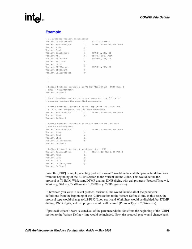
DM3 Architecture on Windows Configuration Guide — May 2006 49
CONFIG File Details
Example
! T1 Protocol variant definitions Variant VariantFormat 1 !T1 CAS format Variant ProtocolType 1 !E&M=1,LS-FXS=2,GS-FXS=3 Variant Wink y Variant Dial y Variant DialFormat 1 !DTMF=1, MF, DP Variant ANI 0 !No=0, Pre, Post Variant ANIFormat 1 !DTMF=1, MF, DP Variant ANICount 0 Variant DNIS y Variant DNISFormat 1 !DTMF=1, MF, DP Variant DNISCount 0 Variant CallProgress y . . .
! Define Protocol Variant 2 as T1 E&M Wink Start, DTMF Dial & ! DNIS + callProgress Variant Define 2
! Note: Previous variant parms are kept, and the following ! commands replace the specified parameters
! Define Protocol Variant 5 as T1 Loop Start FXS, DTMF Dial ! & DNIS, callProgress, and DialTone detection. Variant ProtocolType 2 !E&M=1,LS-FXS=2,GS-FXS=3 Variant Wink n Variant Define 5
! Define Protocol Variant 4 as T1 E&M Wink Start, no tone ! and no callProgress Variant ProtocolType 1 !E&M=1,LS-FXS=2,GS-FXS=3 Variant Wink y Variant Dial n Variant DNIS n Variant CallProgress n Variant Define 4
! Define Protocol Variant 6 as Ground Start FXS Variant ProtocolType 3 !E&M=1,LS-FXS=2,GS-FXS=3 Variant Wink n Variant Dial y Variant DNIS y Variant CallProgress y Variant Define 6
From the [CHP] example, selecting protocol variant 2 would include all the parameter definitions from the beginning of the [CHP] section to the Variant Define 2 line. This would define the protocol as T1 E&M Wink start, DTMF dialing, DNIS digits, with call progress (ProtocolType = 1, Wink = y, Dial = y, DialFormat = 1, DNIS = y, CallProgress = y).
If, however, you were to select protocol variant 5, this would include all of the parameter definitions from the beginning of the [CHP] section to the Variant Define 5 line. In this case, the protocol type would change to LS-FSX (Loop start) and Wink Start would be disabled, but DTMF dialing, DNIS digits, and call progress would still be used (ProtocolType = 2, Wink = n).
If protocol variant 4 were selected, all of the parameter definitions from the beginning of the [CHP] section to the Variant Define 4 line would be included. Now, the protocol type would change back

50 DM3 Architecture on Windows Configuration Guide — May 2006
CONFIG File Details
to E&M Wink start with no DTMF dialing, no DNIS digits, and no call progress (ProtocolType = 1, Wink = y, Dial = n, DNIS = n, CallProgress = n).
You may also create your own variant if none of the existing defined protocol variants match your need. For example, to create a new protocol variant in which you want to use E&M Immediate start (instead of Wink start) with no ANI/DNIS digits provided, you may add another Variant Define n after the Variant Define 2 statement. In this example, we can use n = 1 because this number has not yet been defined in the CONFIG file. That part of the [CHP] section would then become:
! Define Protocol Variant 2 as T1 E&M Wink Start, DTMF Dial & DNIS + callProgress Variant Define 2 ! Define Protocol Variant 1 as T1 E&M Immediate Start, DTMF Dial + callProgress Variant Wink n Variant DNIS n Variant Define 1
By disabling DNIS in protocol variant 1, which follows protocol variant 2, we have also caused DNIS to be disabled in protocol variant 5. DNIS was originally enabled in protocol variant 5 because protocol variant 5 followed protocol variant 2 which defined it as enabled. We will now need to re-enable DNIS in protocol variant 5 as shown in the following example:
! Define Protocol Variant 5 as T1 Loop Start FXS, DTMF Dial ! & DNIS, callProgress, and DialTone detection. ! Add DNIS back to this protocol variant Variant DNIS y Variant ProtocolType 2 ! E&M=1, LS-FXS=2, GS-FXS=3 Variant Wink n Variant Define 5
Although protocol variants are defined in the [CHP] section, protocol variants are assigned in the [TSC] section of the CONFIG file. Selecting a particular Variant Define n is accomplished by changing the values of the Inbound and Outbound parameters for a particular line. The Inbound and Outbound parameters are the sixth and seventh parameters respectively in the defineBSet command in the [TSC] section of the CONFIG file.
For information about the defineBSet command and setting TSC parameters, see Section 3.8, “[TSC] Section”, on page 50.
For information about each CHP parameter, see the following sections:
• Section 6.19, “[CHP] Parameters”, on page 145
• Section 6.20, “[CHP] T1 Protocol Variant Definitions”, on page 146
• Section 6.21, “[CHP] ISDN Protocol Variant Definitions”, on page 163
3.8 [TSC] Section
The [TSC] section of the CONFIG file defines a set of B channels and associated characteristics using the defineBSet command. The syntax of the defineBSet command is:
defineBSet = SetId, LineId, StartChan, NumChans, BaseProtocol, Inbound, OutBound, DChanDesc, Admin, Width, BChanId, SlotId, Direction, Count, [BChanId, SlotId, Direction, Count,] 0
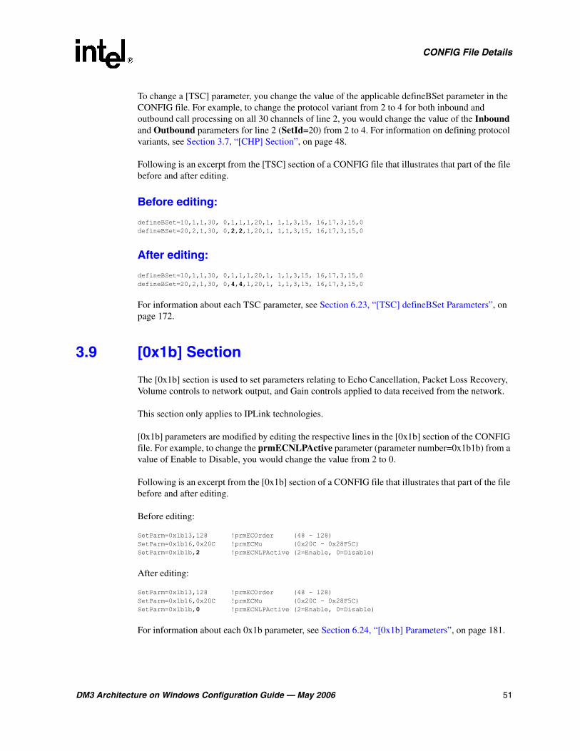
DM3 Architecture on Windows Configuration Guide — May 2006 51
CONFIG File Details
To change a [TSC] parameter, you change the value of the applicable defineBSet parameter in the CONFIG file. For example, to change the protocol variant from 2 to 4 for both inbound and outbound call processing on all 30 channels of line 2, you would change the value of the Inbound and Outbound parameters for line 2 (SetId=20) from 2 to 4. For information on defining protocol variants, see Section 3.7, “[CHP] Section”, on page 48.
Following is an excerpt from the [TSC] section of a CONFIG file that illustrates that part of the file before and after editing.
Before editing:
defineBSet=10,1,1,30, 0,1,1,1,20,1, 1,1,3,15, 16,17,3,15,0 defineBSet=20,2,1,30, 0,2,2,1,20,1, 1,1,3,15, 16,17,3,15,0
After editing:
defineBSet=10,1,1,30, 0,1,1,1,20,1, 1,1,3,15, 16,17,3,15,0 defineBSet=20,2,1,30, 0,4,4,1,20,1, 1,1,3,15, 16,17,3,15,0
For information about each TSC parameter, see Section 6.23, “[TSC] defineBSet Parameters”, on page 172.
3.9 [0x1b] Section
The [0x1b] section is used to set parameters relating to Echo Cancellation, Packet Loss Recovery, Volume controls to network output, and Gain controls applied to data received from the network.
This section only applies to IPLink technologies.
[0x1b] parameters are modified by editing the respective lines in the [0x1b] section of the CONFIG file. For example, to change the prmECNLPActive parameter (parameter number=0x1b1b) from a value of Enable to Disable, you would change the value from 2 to 0.
Following is an excerpt from the [0x1b] section of a CONFIG file that illustrates that part of the file before and after editing.
Before editing:
SetParm=0x1b13,128 !prmECOrder (48 - 128) SetParm=0x1b16,0x20C !prmECMu (0x20C - 0x28F5C) SetParm=0x1b1b,2 !prmECNLPActive (2=Enable, 0=Disable)
After editing:
SetParm=0x1b13,128 !prmECOrder (48 - 128) SetParm=0x1b16,0x20C !prmECMu (0x20C - 0x28F5C) SetParm=0x1b1b,0 !prmECNLPActive (2=Enable, 0=Disable)
For information about each 0x1b parameter, see Section 6.24, “[0x1b] Parameters”, on page 181.
52 DM3 Architecture on Windows Configuration Guide — May 2006
CONFIG File Details
3.10 [NetTSC] Section
The Network Telephony Service Component (NetTSC) resides on the control processor and manages print level and debug level parameters. The [NetTSC] section is used to set parameters relating to the H.323 print level and the NetTSC debug level.
This section only applies to IPLink technologies.
[NetTSC] parameters are modified by editing the respective lines in the [NetTSC] section of the CONFIG file. For example, to change the prmDebugLevelStream parameter (parameter number=0x1e10) value from ERROR to Warning, you would change the value from 2 to 3.
Following is an excerpt from the [NetTSC] section of a CONFIG file that illustrates that part of the file before and after editing.
Before editing:
SetParm=0x1e0e,2 !prmDebugLevelStack (0=OFF, 1=FATAL, 2=ERROR, 3=Warning, 4=Info, 5=Expand) SetParm=0x1e0f,2 !prmDebugLevelMsg (0=OFF, 1=FATAL, 2=ERROR, 3=Warning, 4=Info, 5=Expand) SetParm=0x1e10,2 !prmDebugLevelStream (0=OFF, 1=FATAL, 2=ERROR, 3=Warning, 4=Info, 5=Expand)
After editing:
SetParm=0x1e0e,2 !prmDebugLevelStack (0=OFF, 1=FATAL, 2=ERROR, 3=Warning, 4=Info, 5=Expand) SetParm=0x1e0f,2 !prmDebugLevelMsg (0=OFF, 1=FATAL, 2=ERROR, 3=Warning, 4=Info, 5=Expand) SetParm=0x1e10,3 !prmDebugLevelStream (0=OFF, 1=FATAL, 2=ERROR, 3=Warning, 4=Info, 5=Expand)
For information about each NetTSC parameter, see Section 6.26, “[NetTSC] Parameters”, on page 194.
DM3 Architecture on Windows Configuration Guide — May 2006 53
44.Configuration Procedures
The following information provides detailed procedures for each major step in the configuration process (some steps may not apply to your configuration):
• Assumptions and Prerequisites . . . . . . . . . . . . . . . . . . . . . . . . . . . . . . . . . . . . . . . . . . . 53
• Order of Procedures. . . . . . . . . . . . . . . . . . . . . . . . . . . . . . . . . . . . . . . . . . . . . . . . . . . . 54
• Starting the Configuration Manager (DCM) . . . . . . . . . . . . . . . . . . . . . . . . . . . . . . . . . 54
• Selecting a Configuration File Set . . . . . . . . . . . . . . . . . . . . . . . . . . . . . . . . . . . . . . . . . 57
• Configuring Trunks . . . . . . . . . . . . . . . . . . . . . . . . . . . . . . . . . . . . . . . . . . . . . . . . . . . . 59
• Configuring PDK Variants. . . . . . . . . . . . . . . . . . . . . . . . . . . . . . . . . . . . . . . . . . . . . . . 60
• Setting the TDM Bus Clock Source . . . . . . . . . . . . . . . . . . . . . . . . . . . . . . . . . . . . . . . 61
• Setting the Bus Companding Method . . . . . . . . . . . . . . . . . . . . . . . . . . . . . . . . . . . . . . 63
• Configuring the Network Interface Connector . . . . . . . . . . . . . . . . . . . . . . . . . . . . . . . 64
• Modifying Other DCM Property Sheet Parameters. . . . . . . . . . . . . . . . . . . . . . . . . . . . 66
• Modifying the FCD File by Editing the CONFIG File . . . . . . . . . . . . . . . . . . . . . . . . . 67
• Initializing the System . . . . . . . . . . . . . . . . . . . . . . . . . . . . . . . . . . . . . . . . . . . . . . . . . . 68
• Reconfiguring the System . . . . . . . . . . . . . . . . . . . . . . . . . . . . . . . . . . . . . . . . . . . . . . . 68
4.1 Assumptions and Prerequisites
The following assumptions and prerequisites exist regarding the configuration procedures:
• All required software, including prerequisites, have been installed according to the procedures in the software installation guide supplied with your release.
• The release was installed in the default directory under INTEL_DIALOGIC_DIR, the environment variable for the directory in which the software is installed. Command instructions, directories paths and environment variable are shown relative to the default installation directory.
• You have administrative privileges on the local computer and on any remote computer you connect to in order to use the configuration manager (DCM). Contact your network administrator to set up administrative privileges as required.
• If applicable, the Global Call protocols have been installed. The Global Call protocols are provided as part of the release. For information about country dependent parameters associated with a protocol, see the Global Call Country Dependent Parameters (CDP) for PDK Protocols Configuration Guide.
• If applicable, TDM bus resources have been reserved for third party boards as described in the configuration manager (DCM) Online Help.

54 DM3 Architecture on Windows Configuration Guide — May 2006
Configuration Procedures
4.2 Order of Procedures
Procedures that are required when initially configuring any system are noted as such. The additional procedures may be required depending on your system. Except for the required procedures, configuration procedures should be performed in the order presented. FCD file parameter modifications can be made any time prior to initializing the system.
1. Starting the Configuration Manager (DCM) (required)
2. Selecting a Configuration File Set
3. Configuring Trunks
4. Configuring PDK Variants
5. Setting the TDM Bus Clock Source
6. Setting the Bus Companding Method
7. Configuring the Network Interface Connector
8. Modifying Other DCM Property Sheet Parameters
9. Modifying the FCD File by Editing the CONFIG File
10. Initializing the System (required)
11. Reconfiguring the System
4.3 Starting the Configuration Manager (DCM)
Note: Online Help is available for all parameters accessible through the configuration manager (DCM); to access the help, choose Help > Contents in the DCM main window.
To start the DCM, perform the following steps:
1. From the Windows* Start menu, choose Programs > System Release > Configuration Manager-DCM to access the Configuration Manager (DCM). The Computer Name dialog box will appear (Figure 13).
Note: The Computer Name dialog box displays automatically the first time you run the DCM with the local computer name as the default. If the Computer Name dialog box is not already displayed, you can get it by choosing File > Connect or by clicking the Connect icon on the DCM main window.
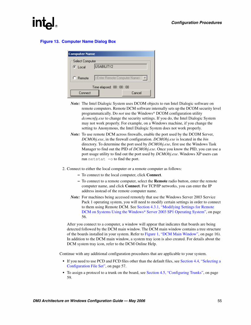
DM3 Architecture on Windows Configuration Guide — May 2006 55
Configuration Procedures
Figure 13. Computer Name Dialog Box
Note: The Intel Dialogic System uses DCOM objects to run Intel Dialogic software on remote computers. Remote DCM software internally sets up the DCOM security level programmatically. Do not use the Windows* DCOM configuration utility dcomcnfg.exe to change the security settings. If you do, the Intel Dialogic System may not work properly. For example, on a Windows machine, if you change the setting to Anonymous, the Intel Dialogic System does not work properly.
Note: To use remote DCM across firewalls, enable the port used by the DCOM Server, DCMObj.exe, in the firewall configuration. DCMObj.exe is located in the bin directory. To determine the port used by DCMObj.exe, first use the Windows Task Manager to find out the PID of DCMObj.exe. Once you know the PID, you can use a port usage utility to find out the port used by DCMObj.exe. Windows XP users can run netstat -o to find the port.
2. Connect to either the local computer or a remote computer as follows:
– To connect to the local computer, click Connect.
– To connect to a remote computer, select the Remote radio button, enter the remote computer name, and click Connect. For TCP/IP networks, you can enter the IP address instead of the remote computer name.
Note: For machines being accessed remotely that use the Windows Server 2003 Service Pack 1 operating system, you will need to modify certain settings in order to connect to them using Remote DCM. See Section 4.3.1, “Modifying Settings for Remote DCM on Systems Using the Windows* Server 2003 SP1 Operating System”, on page 56.
After you connect to a computer, a window will appear that indicates that boards are being detected followed by the DCM main window. The DCM main window contains a tree structure of the boards installed in your system. Refer to Figure 1, “DCM Main Window”, on page 16). In addition to the DCM main window, a system tray icon is also created. For details about the DCM system tray icon, refer to the DCM Online Help.
Continue with any additional configuration procedures that are applicable to your system.
• If you need to use PCD and FCD files other than the default files, see Section 4.4, “Selecting a Configuration File Set”, on page 57.
• To assign a protocol to a trunk on the board, see Section 4.5, “Configuring Trunks”, on page 59.

56 DM3 Architecture on Windows Configuration Guide — May 2006
Configuration Procedures
• To configure PDK variants for trunks using the CAS or R2MF protocols, see Section 4.6, “Configuring PDK Variants”, on page 60.
• If you need to configure the TDM bus, see Section 4.7, “Setting the TDM Bus Clock Source”, on page 61.
• If you are using a T1 or E1 product, see Section 4.8, “Setting the Bus Companding Method”, on page 63.
• If you are using Intel NetStructure DM/IP Series boards in your system, see Section 4.9, “Configuring the Network Interface Connector”, on page 64.
• If you need to change additional DCM parameters, see Section 4.10, “Modifying Other DCM Property Sheet Parameters”, on page 66.
• If you need to change parameter settings in the FCD file, see Section 4.11, “Modifying the FCD File by Editing the CONFIG File”, on page 67.
When you are satisfied with all configuration information, proceed with Section 4.12, “Initializing the System”, on page 68.
4.3.1 Modifying Settings for Remote DCM on Systems Using the Windows* Server 2003 SP1 Operating System
Due to security enhancements implemented in Windows Server 2003 SP1, Remote DCM will not work with this operating system. For Remote DCM to work on the machine being accessed remotely, you will need to modify the security settings on the remote machine to that of the pre-service pack state by performing the following:
1. Select Start > Control Panel > Administrative Tools > Component Services.
2. From the Component Services window, select Console Root > Component Services > Computers > My Computer.
3. Right-click on My Computer and select Properties from the drop-down menu.
4. Select the COM Security tab in the My Computer Properties dialog box.
5. In the Access Permissions section of the My Computer Properties dialog box, click the Edit Limits... button. The Access Permission dialog box will appear. With ANONYMOUS LOGON highlighted in the Group or user names: panel, verify that both Local Access and Remote Access in the lower panel have the Allow box checked. Click the OK button.
6. In the Launch and Activation Permissions section of the My Computer Properties dialog box, click the Edit Limits... button. The Launch Permission dialog box will appear. With Everyone highlighted in the Group or user names: panel, check that the Allow box is checked for all of the items in the lower panel and then click OK.
7. Click the OK button in the My Computer Properties dialog box.
8. Exit from Component Services and close the Administrative Tools window.
DM3 Architecture on Windows Configuration Guide — May 2006 57
Configuration Procedures
9. Create or Modify the following registry value: "HKEY_LOCAL_MACHINE\SOFTWARE\Policies\Microsoft\Windows NT\RPC\RestrictRemoteClients". This is a DWORD value that has to be set to 0 for Remote DCM to work.
10. Reboot the machine. You should now be able to manage this machine remotely using DCM. Refer to the Microsoft support website for additional information about these security enhancements in the new service packs.
4.4 Selecting a Configuration File Set
The first time you configure a board, you can select configuration files other than the default files assigned by the system, in one of these ways: by modifying parameters on the Misc property sheet, by using the Assign Firmware File dialog box, or by modifying parameters on the Trunk Configuration property sheet. For details about configuration file sets, see Section 2.3, “Configuration File Sets”, on page 19.
To select different configuration files using the Misc property sheet, perform the following:
1. Double-click the board model name on the DCM main window to display the board’s property sheets. Refer to Figure 2, “Misc Property Sheets”, on page 17.
Note: You must use this procedure if you want to assign a different PCD/FCD file set to the board.
2. Click the Misc property sheet tab to view all of the Misc property sheet parameters associated with the board.
3. Select the FCDFileName parameter by clicking on it; the selected parameter and its current value are displayed on the bottom of the property sheet.
4. In the Value window of the property sheet, type the name of the FCD file to be assigned to this board.
5. Select the PCDFileName parameter by clicking on it; the selected parameter and its current value are displayed on the bottom of the property sheet.
6. In the Value window of the property sheet, type the name of the PCD file to be assigned to this board.
7. Click the OK button to save all your changes and return to the DCM main window.
To select different configuration files using the Assign Firmware File dialog box, perform the following:
1. From the DCM System pull-down menu, select the Auto Detect Devices option. The Assign Firmware File dialog box will appear. Refer to Figure 14, “Assign Firmware File Dialog Box”, on page 58.

58 DM3 Architecture on Windows Configuration Guide — May 2006
Configuration Procedures
2. In the Available Firmware window, select the PCD file that corresponds to the configuration file set you want to assign to this board.
3. Click the OK button. The selected PCD file name will be assigned to the PCDFileName parameter located on the board’s Misc property sheet. The corresponding FCD file will be assigned to the FCDFileName parameter also located on the board’s Misc property sheet.
To select different configuration files using the Trunk Configuration property sheet, perform the following:
Note: This procedure only applies to DMV600BTEC, DMV1200TEC, DNM160TEC and DMT160TEC boards.
1. From the DCM Main Window, Figure 1, highlight the board you wish to configure and choose Configure Device from the Device drop down menu. The property sheets for this board will appear.
2. Select the Trunk Configuration property sheet, and assign a protocol type to each trunk on the board. Then click OK to save the configuration. The configuration files will then be generated and set. See Section 5.12, “Trunk Configuration Property Sheet”, on page 95.
Figure 14. Assign Firmware File Dialog Box
Continue with any additional configuration procedures that are applicable to your system.
• To assign a protocol to a trunk on the board, see Section 4.5, “Configuring Trunks”, on page 59.

DM3 Architecture on Windows Configuration Guide — May 2006 59
Configuration Procedures
• To configure PDK variants for trunks using the CAS or R2MF protocols, see Section 4.6, “Configuring PDK Variants”, on page 60.
• If you need to configure the TDM bus, see Section 4.7, “Setting the TDM Bus Clock Source”, on page 61.
• If you are using a T1 or E1 product, see Section 4.8, “Setting the Bus Companding Method”, on page 63.
• If you are using Intel NetStructure DM/IP Series boards in your system, see Section 4.9, “Configuring the Network Interface Connector”, on page 64.
• If you need to change additional DCM parameters, see Section 4.10, “Modifying Other DCM Property Sheet Parameters”, on page 66.
• If you need to change parameter settings in the FCD file, see Section 4.11, “Modifying the FCD File by Editing the CONFIG File”, on page 67.
When you are satisfied with all configuration information, proceed with Section 4.12, “Initializing the System”, on page 68.
4.5 Configuring Trunks
Note: This procedure only applies to the DM/V600B, DM/V1200B, DMN160, and DMT160 boards.
The Trunk Configuration property sheet allows you to assign a protocol to each trunk on the board. You may assign the same protocol or different protocols to each trunk on the board, but all of the protocols must belong to the same group. See Section 5.12, “Trunk Configuration Property Sheet”, on page 95 for more information.
1. From the DCM main window, Figure 1, highlight the board you wish to configure and choose Configure Device from the Device drop-down menu. The property sheets for this board will appear.
2. Select the Trunk Configuration property sheet.
3. Select the first trunk you wish to assign a protocol (other than the default value) to, by highlighting that trunk. The trunk name will appear in the Parameter box.
4. From the Value drop-down menu, select a different protocol for that trunk.
5. Repeat steps 3 and 4 for each trunk to which you wish to assign a different protocol.
6. When you have completed assigning different protocols to the trunks, click the Apply button. A message will appear telling you that the system will generate a composite configuration file set.
7. Click the OK button to return to the DCM main window.
60 DM3 Architecture on Windows Configuration Guide — May 2006
Configuration Procedures
Continue with any additional configuration procedures that are applicable to your system.
• To configure PDK variants for trunks using the CAS or R2MF protocols, see Section 4.6, “Configuring PDK Variants”, on page 60.
• If you need to configure the TDM bus, see Section 4.7, “Setting the TDM Bus Clock Source”, on page 61.
• If you are using a T1 or E1 product, see Section 4.8, “Setting the Bus Companding Method”, on page 63.
• If you are using Intel NetStructure DM/IP Series boards in your system, see Section 4.9, “Configuring the Network Interface Connector”, on page 64.
• If you need to change additional DCM parameters, see Section 4.10, “Modifying Other DCM Property Sheet Parameters”, on page 66.
• If you need to change parameter settings in the FCD file, see Section 4.11, “Modifying the FCD File by Editing the CONFIG File”, on page 67.
When you are satisfied with all configuration information, proceed with Section 4.12, “Initializing the System”, on page 68.
4.6 Configuring PDK Variants
Note: This procedure only applies to boards having network interfaces, and to trunks that are configured for the CAS or R2MF protocols.
The PDK Configuration property sheet allows you to choose country dependent parameter (CDP) files for T1 trunks that use the CAS protocol or for E1 trunks that use the R2MF protocol. For each trunk selected, a list of applicable CDP file variants is presented, allowing you to assign a specific CDP file to that trunk. See Section 5.6, “PDK Configuration Property Sheet”, on page 79 for more information.
1. From the DCM main window, Figure 1, highlight the board you wish to configure and choose Configure Device from the Device drop-down menu. The property sheets for this board will appear.
2. Select the PDK Configuration property sheet.
3. If all of the trunks on the board have been configured for either the CAS or R2MF protocol, and you wish to assign the same country dependent parameter (CDP) variant file (other than the default value) to all trunks on the board, highlight PDKTrunk 0. Otherwise, proceed to step 4.
3a. From the Variant drop-down menu, select a CDP variant file by highlighting the file and clicking the Set button.
Note: If you wish to remove a previously assigned CDP variant file, highlight the variant under that trunk in the window and click the Remove button.
3b. Repeat this step for each additional CDP variant file you wish to assign to all of the trunks on this board.
DM3 Architecture on Windows Configuration Guide — May 2006 61
Configuration Procedures
Note: When multiple CDP file variants are assigned to a trunk, an application can dynamically change variants on that trunk.
3c. Click the Apply button and then click the OK button to return to the DCM main window.
4. If not all trunks on the board have been configured for CAS or R2MF, or if you wish to assign additional CDP variant files to individual trunks:
4a. Highlight the trunk to which you wish to assign a CDP variant file.
4b. Choose a CDP variant file from the Variant drop-down list and click the Set button.
Note: If you wish to remove a previously assigned CDP variant file, highlight the variant under that trunk in the window and click the Remove button.
4c. Repeat steps 4a and 4b for each trunk on the board that you wish to assign CDP variant files.
4d. Click the Apply button and then click the OK button to return to the DCM main window.
See the Global Call Country Dependent Parameters (CDP) for PDK Protocols Configuration Guide for information about configuring the parameters contained in an individual country dependent parameters (CDP) file.
The protocol package is included with the system software or can be found at: http://resouce.intel.com/telecom/support/releases/protocols/index.htm
Continue with any additional configuration procedures that are applicable to your system.
• If you need to configure the TDM bus, see Section 4.7, “Setting the TDM Bus Clock Source”, on page 61.
• If you are using a T1 or E1 product, see Section 4.8, “Setting the Bus Companding Method”, on page 63.
• If you are using Intel NetStructure DM/IP Series boards in your system, see Section 4.9, “Configuring the Network Interface Connector”, on page 64.
• If you need to change additional DCM parameters, see Section 4.10, “Modifying Other DCM Property Sheet Parameters”, on page 66.
• If you need to change parameter settings in the FCD file, see Section 4.11, “Modifying the FCD File by Editing the CONFIG File”, on page 67.
4.7 Setting the TDM Bus Clock Source
The default clock source is the internal oscillator of the Primary Master board. You should derive clocking from a digital network trunk if available, not from a board’s internal oscillator. The internal oscillator should be used as the clock source only for internal testing purposes.
Note: When configuring a board that has front-end capability as resource only, the system will not detect this and might select this board as clock master. In this event, the user must manually configure another board in the system as the clock master.
62 DM3 Architecture on Windows Configuration Guide — May 2006
Configuration Procedures
1. To access the clocking settings in the DCM, double-click Bus-0 under TDM Bus in the DCM tree structure of configured devices. Refer to Figure 1, “DCM Main Window”, on page 16. The TDM Bus Configuration property sheet for Bus-0 is displayed. Refer to Figure 3, “TDM Bus Configuration Property Sheet”, on page 18.
Note: To configure a third-party board installed in your system, refer to the DCM Online Help.
2. Designate a board as the primary master by performing the following:
2a. Select the Primary Master FRU (User Defined) parameter.
2b. In the Value list box select the name of the board that will provide the clocking to the bus.
2c. Click Apply.
3. If the Primary Master board is deriving system clocking from a digital network trunk connected to a Network Reference (NETREF) board (also known as the Reference Master board), perform the following. Otherwise, if you are using the Primary Master board’s internal oscillator as the clocking source, skip to Step 4.
3a. Select the NETREF One FRU (User Defined) parameter.
3b. In the Value box, type the name of the board that contains the network interface which will provide a network reference clock to the system. The board name you enter should be the same name as displayed in the DCM main window.
3c. Click Apply.
3d. Specify the source of the network reference clock (specifically, the trunk on the board containing the digital network interface providing the clock) via the Derive NETREF One From (User Defined) parameter.
3e. Click Apply.
4. Configure the Primary Master board to use the correct clock reference by setting the Derive Primary Clock From (User Defined) parameter to either NETREF_1 or Internal Oscillator.
5. Click OK.
6. Designate a board as the secondary clock master by performing the following:
6a. Select the Secondary Master FRU (User Defined) parameter.
6b. In the Value list box, select the name of the board that will provide the clocking to the bus if the primary master fails.
6c. Click Apply.
6d. Configure the Secondary Master board to use the correct clock reference by setting the Derive Secondary Clock From (User Defined) parameter to either NETREF_1 or Internal Oscillator.
6e. Click OK.
DM3 Architecture on Windows Configuration Guide — May 2006 63
Configuration Procedures
Continue with any additional configuration procedures that are applicable to your system.
• If you are using a T1 or E1 product, see Section 4.8, “Setting the Bus Companding Method”, on page 63.
• If you are using Intel NetStructure DM/IP Series boards in your system, see Section 4.9, “Configuring the Network Interface Connector”, on page 64.
• If you need to change additional DCM parameters, see Section 4.10, “Modifying Other DCM Property Sheet Parameters”, on page 66.
• If you need to change parameter settings in the FCD file, see Section 4.11, “Modifying the FCD File by Editing the CONFIG File”, on page 67.
When you are satisfied with all configuration information, proceed with Section 4.12, “Initializing the System”, on page 68.
4.8 Setting the Bus Companding Method
The bus companding method is defined using the Media Type (User Defined) parameter. This parameter is associated with the TDM Bus Configuration for Bus-0 in DCM. Initially, the Media Type (User Defined) value is set to Default. This causes the system to default to the value determined by the Media Type (Resolved) parameter. In this case, the bus companding method as indicated by Media Type (Resolved) parameter is:
• mu-law: If only T1 boards are installed in the system.
• mu-law: If resource only boards (not connected to a T1 or E1 trunk) are combined with boards that can be configured for mu-law.
• A-law: If only E1 boards are installed in the system.
• A-law: If resource only boards (not connected to a T1 or E1 trunk) are combined with boards that can be configured for A-law.
Depending on the boards installed in the system, the following conditions apply:
• For a DMN160TEC or DMT160TEC board whose trunks can individually connect to either T1 or E1 interfaces, the companding method will automatically be converted on the board, if necessary, on a trunk-by-trunk basis to agree with that of the TDM Bus companding method. For example, if the TDM Bus is set to mu-law, the board will perform A-law to mu-law conversion between the board and TDM Bus for the E1 trunks.
• For boards that have a physical network interface, but are configured as resource only (i. e. no protocol loaded), the firmware will still determine the network interfaces and force the resolution of the Media Type to be either A-law for E1 physical interfaces or mu-law for T1 physical interfaces.
• If boards that can only be resolved as mu-law and boards that can only be resolved as A-law are installed in the same system, the system will not complete the initialization process and will log an error.

64 DM3 Architecture on Windows Configuration Guide — May 2006
Configuration Procedures
If desired, follow these instructions to set the bus companding method:
1. Double-click Bus-0 under TDM Bus in the DCM main window to display the TDM Bus Configuration property sheet for Bus-0.
2. Select the Media Type (User Defined) parameter by clicking on it.
3. Select A-Law or mu-Law, as appropriate, from the pull-down menu.
4. Click OK to set the parameter and return to the DCM main window.
Continue with any additional configuration procedures that are applicable to your system.
• If you are using Intel NetStructure DM/IP Series boards in your system, see Section 4.9, “Configuring the Network Interface Connector”, on page 64.
• If you need to change additional DCM parameters, see Section 4.10, “Modifying Other DCM Property Sheet Parameters”, on page 66.
• If you need to change parameter settings in the FCD file, see Section 4.11, “Modifying the FCD File by Editing the CONFIG File”, on page 67.
When you are satisfied with all configuration information, proceed with Section 4.12, “Initializing the System”, on page 68.
4.9 Configuring the Network Interface Connector
To configure the Network Interface Connector (NIC) for an Intel NetStructure DM/IP Series board, perform the following procedure:
1. Double-click on the Intel NetStructure DM/IP Series board in the DCM main window.
2. Click the Network property sheet.
Note: The IPAddress, SubnetMask, and GatewayIPAddress parameters (on the Network property sheet) must be filled in for successful functioning of the Intel NetStructure DM/IP Series board.
3. Select the IPAddress parameter by clicking on it; the parameter and its current value are displayed on the bottom of the property sheet.
4. In the Value box of the property sheet, type the IP address to be assigned to the NIC on the T1 NIC or E1 NIC board. Use the format xxx.xxx.xxx.xxx (for example, 146.152.187.42). Incoming calls to this board should be directed to the IP address specified by this parameter.
Note: Each T1 NIC or E1 NIC board in the system must have a unique IPAddress parameter setting.
5. Click Apply to save the change.
6. Select the SubnetMask parameter; the parameter and its current value are displayed on the bottom of the property sheet.

DM3 Architecture on Windows Configuration Guide — May 2006 65
Configuration Procedures
7. In the Value box of the property sheet, type the IP address where Ethernet* packets are to be sent (and according to site IP procedures). Use the xxx.xxx.xxx.xxx format (for example, 255.255.255.10). This parameter determines whether Ethernet packets are sent directly to a particular address or sent to a default router.
8. Click Apply to save the change.
9. Select the TargetName parameter; the parameter and its current value are displayed on the bottom of the property sheet.
10. In the Value box of the property sheet, type the name of the NIC on the T1 NIC or E1 NIC board. You can choose any name.
11. Click Apply to save the change.
12. Select the HostName parameter; the parameter and its current value are displayed on the bottom of the property sheet.
13. In the Value box of the property sheet, type the name of the host machine.
14. Click Apply to save the change.
15. Select the UserName parameter; the parameter and its current value are displayed on the bottom of the property sheet.
16. In the Value box of the property sheet, type any name with valid log-in access to the host machine that was named in the HostName parameter.
17. Click Apply to save the change.
18. Select the GatewayIPAddress parameter; the parameter and its current value are displayed on the bottom of the property sheet.
19. In the Value box of the property sheet, type the IP address of the default router for the Ethernet interface using the xxx.xxx.xxx.xxx format (for example, 255.255.255.0).
20. Click Apply to save the change.
21. Click OK to return to the DCM main window.
Continue with any additional configuration procedures that are applicable to your system.
• If you need to change additional DCM parameters, see Section 4.10, “Modifying Other DCM Property Sheet Parameters”, on page 66.
• If you need to change parameter settings in the FCD file, see Section 4.11, “Modifying the FCD File by Editing the CONFIG File”, on page 67.
When you are satisfied with all configuration information, proceed with Section 4.12, “Initializing the System”, on page 68.

66 DM3 Architecture on Windows Configuration Guide — May 2006
Configuration Procedures
4.10 Modifying Other DCM Property Sheet Parameters
Within the DCM, each board has a set of property sheets that display the board’s configuration parameters, grouped together on tabs according to the type of board functionality that they affect. To change a board’s configuration parameters, follow this procedure:
1. Double-click the board model name in the DCM main window to display the board’s property sheets. The Misc Property Sheet is displayed; see Figure 2, “Misc Property Sheets”, on page 17.
2. Click a property sheet tab to view all of the board parameters associated with a particular property sheet. For example, to view the parameters associated with the Physical property sheet, click the Physical tab. Refer to Figure 15.
Refer to the DCM Online Help for a description of property sheets and parameters. The DCM Online Help can be accessed from the Help pull-down menu located on the DCM main window or by pressing the F1 key. To access information about a specific parameter, highlight the parameter in the DCM and press the F1 key.
3. Select a parameter by clicking it; the selected parameter and its current value are displayed on the bottom of the property sheet.
4. In the Value box of the property sheet, type the parameter value or select a value from the drop-down list.
5. Click Apply to save the change.
6. Repeat this procedure for all parameters that need to be modified.
7. Click OK to save all your changes and return to the DCM main window.
Continue with any additional configuration procedures that are applicable to your system.
• If you need to change additional FCD file parameters, see Section 4.11, “Modifying the FCD File by Editing the CONFIG File”, on page 67.
When you are satisfied with all configuration information, proceed with Section 4.12, “Initializing the System”, on page 68.
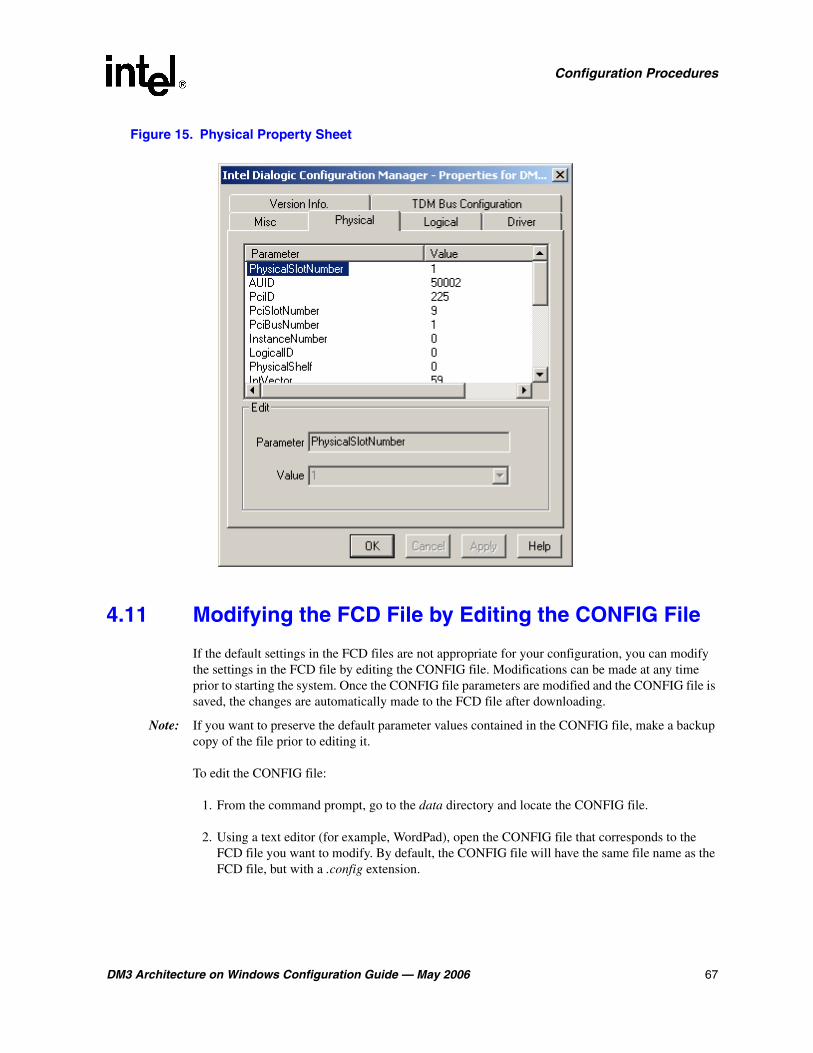
DM3 Architecture on Windows Configuration Guide — May 2006 67
Configuration Procedures
Figure 15. Physical Property Sheet
4.11 Modifying the FCD File by Editing the CONFIG File
If the default settings in the FCD files are not appropriate for your configuration, you can modify the settings in the FCD file by editing the CONFIG file. Modifications can be made at any time prior to starting the system. Once the CONFIG file parameters are modified and the CONFIG file is saved, the changes are automatically made to the FCD file after downloading.
Note: If you want to preserve the default parameter values contained in the CONFIG file, make a backup copy of the file prior to editing it.
To edit the CONFIG file:
1. From the command prompt, go to the data directory and locate the CONFIG file.
2. Using a text editor (for example, WordPad), open the CONFIG file that corresponds to the FCD file you want to modify. By default, the CONFIG file will have the same file name as the FCD file, but with a .config extension.
68 DM3 Architecture on Windows Configuration Guide — May 2006
Configuration Procedures
3. Edit the CONFIG file as necessary.
For a detailed description of the CONFIG file sections and formatting conventions, see Chapter 3, “CONFIG File Details”. For details about CONFIG file parameters, see Chapter 6, “CONFIG File Parameter Reference”.
4. Save and close the CONFIG file.
Note: The modified FCD file is automatically created when the PCD file and modified CONFIG file are downloaded to the board.
4.12 Initializing the System
Note: The new configuration settings will not take effect until the system is initialized. Before system initialization, make sure you perform all of the necessary configuration procedures.
To initialize the system for the first time, proceed as follows:
1. From the DCM main window, select the root of the tree structure (Configured Devices on...).
2. Choose Device > Enable Device(s) or click the Enable Device(s) icon on the DCM toolbar.
3. Choose System > Start System or click the Start all Enabled Devices icon on the DCM toolbar.
4. Verify the system has started (indicated by a status of “Started” in the System status line at the bottom of the DCM main window).
5. After starting the system for the first time, you may want to use some of the tools, such as demo programs, provided by the system software to verify that your system is operating properly.
6. If you have problems, see the Troubleshooting section of the Administration Guide. Problems on initial startup are typically caused by errors in your configuration settings.
Once the system is initialized for the first time, the system can be reconfigured and re-initialized as described in Section 4.13, “Reconfiguring the System”, on page 68.
4.13 Reconfiguring the System
Once the Intel Dialogic system is initialized for the first time, if you need to modify and re-download the parameters, following these instructions to reconfigure the system:
1. Before you stop the system, stop the application ensuring all channels have been closed.
2. Launch the configuration manager utility by choosing Programs > Intel Dialogic System Release > Configuration Manager-DCM from the Windows Start menu. The DCM main window is displayed. Refer to Figure 1, “DCM Main Window”, on page 16.

DM3 Architecture on Windows Configuration Guide — May 2006 69
Configuration Procedures
3. Stop either the complete system or a single board, as appropriate:
• To stop the system, choose System > Stop System or click the Stop System icon in the DCM main window before changing parameter values. The system is stopped once “Stopped” is displayed on the System status line at the bottom of the DCM main window.
• To stop a single board, choose Device > Stop Device.
4. Double-click the board model name to display the configuration data property sheets pertaining to the board. Refer to Figure 1, “DCM Main Window”, on page 16.
5. If you wish to restore the board’s DCM parameter settings to their default values, choose Device > Restore Defaults in the DCM main window. This resets all of the board’s modified parameters to their default values in the DCM.
6. If you wish to reset the FCD file parameters to their default values, perform the following:
Note: This step only applies if a backup copy of the CONFIG file was made prior to modifying the parameters.
6a. Rename the backup CONFIG file to its original file name.
6b. Generate a new FCD file as described in Section 4.11, “Modifying the FCD File by Editing the CONFIG File”, on page 67.
7. Modify parameters as described in any of the following procedures that apply:
• Section 4.4, “Selecting a Configuration File Set”, on page 57
• Section 4.7, “Setting the TDM Bus Clock Source”, on page 61
• Section 4.8, “Setting the Bus Companding Method”, on page 63
• Section 4.9, “Configuring the Network Interface Connector”, on page 64
• Section 4.10, “Modifying Other DCM Property Sheet Parameters”, on page 66
• Section 4.11, “Modifying the FCD File by Editing the CONFIG File”, on page 67
8. When you’re finished changing parameters, restart the system or a single board, as appropriate:
• Start the whole system by choosing System > Start System or clicking the Start System icon in the DCM main window. The system is started once “Started” is displayed on the System status line at the bottom of the DCM main window. The firmware and new configuration settings are downloaded once the system is started.
• To start a single board, choose Device > Start Device. The firmware and new configuration settings are downloaded to the board once the board is started.
For detailed procedures about reconfiguration and other administrative tasks, see the system release administration guide supplied with your software.

70 DM3 Architecture on Windows Configuration Guide — May 2006
Configuration Procedures
DM3 Architecture on Windows Configuration Guide — May 2006 71
55.DCM Parameter Reference
This section lists and describes all parameters contained in the configuration manager (DCM). Parameters are grouped by the property sheet on which they reside. Property sheets are described in alphabetical order and include the following:
• Driver Property Sheet . . . . . . . . . . . . . . . . . . . . . . . . . . . . . . . . . . . . . . . . . . . . . . . . . . 71
• Dual Resilient Property Sheet . . . . . . . . . . . . . . . . . . . . . . . . . . . . . . . . . . . . . . . . . . . . 73
• Logical Property Sheet . . . . . . . . . . . . . . . . . . . . . . . . . . . . . . . . . . . . . . . . . . . . . . . . . 74
• Misc Property Sheet. . . . . . . . . . . . . . . . . . . . . . . . . . . . . . . . . . . . . . . . . . . . . . . . . . . . 74
• Network Property Sheet. . . . . . . . . . . . . . . . . . . . . . . . . . . . . . . . . . . . . . . . . . . . . . . . . 78
• PDK Configuration Property Sheet . . . . . . . . . . . . . . . . . . . . . . . . . . . . . . . . . . . . . . . . 79
• Physical Property Sheet . . . . . . . . . . . . . . . . . . . . . . . . . . . . . . . . . . . . . . . . . . . . . . . . . 80
• SIU Server Property Sheet. . . . . . . . . . . . . . . . . . . . . . . . . . . . . . . . . . . . . . . . . . . . . . . 85
• System Property Sheet. . . . . . . . . . . . . . . . . . . . . . . . . . . . . . . . . . . . . . . . . . . . . . . . . . 85
• TDM Bus Configuration Property Sheet . . . . . . . . . . . . . . . . . . . . . . . . . . . . . . . . . . . . 85
• Telephony Bus Property Sheet. . . . . . . . . . . . . . . . . . . . . . . . . . . . . . . . . . . . . . . . . . . . 94
• Trunk Configuration Property Sheet . . . . . . . . . . . . . . . . . . . . . . . . . . . . . . . . . . . . . . . 95
• Version (Version Info.) Property Sheet . . . . . . . . . . . . . . . . . . . . . . . . . . . . . . . . . . . . . 97
5.1 Driver Property Sheet
The Driver property sheet allows you to optimize the board’s throughput by customizing certain aspects of the board’s device driver. The Driver property sheet contains the following parameters:
• doDMA
• freeOrphanOnDepletion
• maxOrphanStrmSize
• orphanageMsgLen
• orphanageMsgTimeout
• orphanStrmTableSize
• outStrmQuantum
• sramInQuantum
• sramOutQuantum
• sramOutTimer
72 DM3 Architecture on Windows Configuration Guide — May 2006
DCM Parameter Reference
doDMA
Description: The doDMA parameter indicates whether DMA (direct memory access) read access is enabled or disabled.
Values:
• 0: Off (DMA read access is disabled)
• 1 [default]: On (DMA read access is enabled)
freeOrphanOnDepletion
Description: The freeOrphanOnDepletion parameter specifies whether the protocol driver frees the orphan buffer after it has been read completely.
Values:
• 0 [default]: No (do not free the orphan buffer)
• 1: Yes (free the orphan buffer)
maxOrphanStrmSize
Description: The maxOrphanStrmSize parameter specifies the maximum size, in bytes, of each orphan stream buffer. When this value is set to 0, the protocol driver attempts to allocate as much buffer as possible.
Values: A positive integer (byte). The default value is 0.
Guidelines: Use the maxOrphanStrmSize parameter default value.
orphanageMsgLen
Description: The orphanageMsgLen parameter specifies the maximum size, in bytes, of the message orphan buffer.
Values: 8096 to 32768 (bytes). The default value is 8192.
Guidelines: Use the orphanageMsgLen parameter default value.
orphanageMsgTimeout
Description: The orphanageMsgTimeout parameter specifies the time out, in seconds, for orphan messages.
Values: 3 to 180 (seconds). The default value is 30.
Guidelines: Use the orphanageMsgTimeout parameter default value.
orphanStrmTableSize
Description: The orphanStrmTableSize parameter specifies the maximum number of streams in the orphan table.
Values: A positive integer. The default value is 256.
DM3 Architecture on Windows Configuration Guide — May 2006 73
DCM Parameter Reference
Guidelines: Use the orphanStrmTableSize parameter default value.
outStrmQuantum
Description: The outStrmQuantum parameter specifies the maximum number of outbound data blocks per stream. The protocol driver uses this value during its outbound session to allow all ready streams equal priority to the SRAM.
Values: 1 to 10 (The default value is 1.)
Guidelines: Use the outStrmQuantum parameter default value.
sramInQuantum
Description: The sramInQuantum parameter specifies the maximum number of inbound data blocks for all streams. The protocol driver uses this value during an inbound session to cap the total number of data blocks read from the SRAM. When this parameter is set to 0, there is no limit for inbound data blocks for all streams.
Values: 0 to 120 (The default value is 0.)
Guidelines: Use the sramInQuantum parameter default value.
sramOutQuantum
Description: The sramInQuantum parameter specifies the maximum number of outbound data blocks for all streams. The protocol driver uses this value during an outbound session to cap the total number of data blocks written to the SRAM.
Values: 1 to 120 (The default value is 120.)
Guidelines: Use the sramOutQuantum parameter default value.
sramOutTimer
Description: The sramOutTimer parameter specifies the outbound timer rate in milliseconds.
Values: 1 to 100 (milliseconds). The default value is 12.
Guidelines: Use the sramOutTimer parameter default value.
5.2 Dual Resilient Property Sheet
The Dual Resilient property sheet contains parameters to configure a Signaling System 7 (SS7) application that uses two Signaling Interface Units (SIUs) in a dual resilient operation.
• SIU B IP Address
74 DM3 Architecture on Windows Configuration Guide — May 2006
DCM Parameter Reference
SIU B IP Address
Description: This parameter is a read-only parameter. It identifies the IP address of Signaling Interface Unit (SIU) B in a dual-resilient SIU system.
Values: The default value is 111.112.113.114.
Guidelines: This is a read-only parameter.
5.3 Logical Property Sheet
The Logical property sheet contains the following parameters:
• CurrentState
CurrentState
Description: The CurrentState parameter is a read-only parameter that specifies the current state of the board.
Values:
• Initialized: Board detected
• Reset: Board reset by downloader
• ConfigPending: Board configuration pending
• Configured: Board configuration complete
• Running: Board running
• Quiescent: Board I/O activities have been closed in preparation for a shutdown
• Shutdown: Board stopped
Guidelines: The CurrentState parameter is read-only and cannot be modified by the user.
5.4 Misc Property Sheet
The Misc property sheet contains miscellaneous parameters that include the following:
• PassiveMode
• Board monitoring frequency in seconds
• BoardEnabled
• BoardPresent
• ProcessTimeout(Seconds)
• FCDFileName
• PCDFileName
• ReplyMsgTimeout
• TraceEnable
• TraceLevel

DM3 Architecture on Windows Configuration Guide — May 2006 75
DCM Parameter Reference
• AdministrativeStatus
• OperationalStatus
• Physical State
• PnPAutoDownload
PassiveMode
Note: The PassiveMode parameter is only applicable to the TDM Bus, Bus-0 device. Also, it is the only Misc property sheet parameter applicable to the Bus-0 device.
Description: The PassiveMode parameter specifies whether clocking faults are handled or ignored by the system software.
Values:
• True: The system software will not respond to clocking faults.
• False [default]: The system software handles clocking faults (such as, performing clock fallback)
Guidelines: Set PassiveMode parameter to False to implement clock fallback support.
Board monitoring frequency in seconds
Description: The Board monitoring frequency in seconds parameter specifies in seconds, the frequency at which the board status is monitored.
Values: Time (seconds). The default value is 10.
Guidelines: The Board monitoring frequency in seconds parameter is read/write.
BoardEnabled
Description: The BoardEnabled parameter specifies whether or not the Intel Dialogic system software should download firmware to activate the board.
Values:
• Yes [default]
• No
Guidelines: Set the BoardEnabled parameter to a value of No to temporarily suspend the use of a board.
BoardPresent
Description: The BoardPresent parameter indicates whether or not the board is physically present in the system and was detected by the Intel Dialogic system software. A value of No is displayed if you enter configuration data for a board that is not in the system or if a board is improperly installed or malfunctioning.
Values:
• Yes
• No
76 DM3 Architecture on Windows Configuration Guide — May 2006
DCM Parameter Reference
Guidelines: The BoardPresent parameter is read only and cannot be modified by the user.
ProcessTimeout(Seconds)
Description: The ProcessTimeout(Seconds) parameter specifies the amount of time in seconds that the downloader will wait for a child process to complete.
Values: 10 to 120 (seconds). The default value is 120.
FCDFileName
Description: The FCDFileName parameter specifies the name of a board’s Feature Configuration Description (FCD) file. The purpose of the FCD file is to adjust the component settings that make up each product. Each board in the system requires an FCD file.
Values: A valid FCD file name.
Guidelines: To ensure that an applicable FCD file is downloaded to your board, use the Restore Device Defaults option from the DCM Action menu to invoke the Assign Firmware File dialog box. The Assign Firmware File dialog box allows you to select a PCD File to download to your board. When you select a PCD file from the Assign Firmware File dialog box’s Available Firmware list, the system automatically selects the applicable FCD file.
Note: HDSI boards use country-specific FCD and PCD files. Depending on the FCD/PCD files selected for an HDSI board, the PCM encoding method will be set to either A law or Mu law, based on the default value for that country. If this value is not the same as the TDM Bus Media Type parameter setting, the HDSI board will fail to download.
PCDFileName
Description: The PCDFileName parameter specifies the name of a board’s Product Configuration Description (PCD) file. The PCD file lists object files and maps them to specific processors, configures the kernel for each processor, and sets the number of component instances to run on each processor. Each board in the system requires a PCD file.
Values: A valid PCD file name.
Guidelines: To ensure that an applicable PCD file is downloaded to your board, use the Restore Device Defaults option from the DCM’s Action menu to invoke the Assign Firmware File dialog box. The Assign Firmware File dialog box allows you to select a PCD File to download to your board. When you select a PCD file from the Assign Firmware File dialog box’s Available Firmware list, the system automatically selects the applicable FCD file as well.
ReplyMsgTimeout
Description: The ReplyMsgTimeout parameter specifies the maximum time in seconds that the downloader will wait for a reply message.
Values: 10 to 30 (seconds). The default value is 10.

DM3 Architecture on Windows Configuration Guide — May 2006 77
DCM Parameter Reference
TraceEnable
Description: The TraceEnable parameter indicates whether trace logging of the download process is enabled or disabled. When trace logging is enabled, a log file called brdn.log, where n equals the board number, is created in \bin under INTEL_DIALOGIC_DIR, the environment variable for the directory in which the software is installed.
Values:
• 0: Off (trace logging is disabled) [default]
• 1: On (trace logging is enabled)
TraceLevel
Description: The TraceLevel parameter specifies the detail level of trace logging.
Values:
• 2 [default]: Display errors only
• 3: Display all details
AdministrativeStatus
Description: The AdministrativeStatus parameter indicates the status of the currently selected device.
Values:
• Initial: The software representation of the board is created when the board’s Physical State parameter is In_System_Locked.
• Stopped: The currently selected device is not running
• Started: The currently selected device is running.
• StopPending: The system software is in the process of stopping the currently selected device.
• StartPending: The system software is in the process of starting the currently selected device.
• Disabled: The currently selected device is not started when the system is started.
• Diagnose: Diagnostics are currently being run on the device.
Guidelines: The AdministrativeStatus parameter is read only and cannot be modified by the user.
OperationalStatus
Description: The OperationalStatus parameter indicates the integrity of the currently selected device.
Values:
• Initial: The software representation of the board is created when the board’s Physical State parameter is In_System_Locked.
• Ok: The currently selected device is operating normally.
• Degraded: The currently selected device is operating at a below optimum level.
• Failed: The currently selected device has failed. Use the Windows* Event Viewer to determine the nature of the problem.

78 DM3 Architecture on Windows Configuration Guide — May 2006
DCM Parameter Reference
Physical State
Description: The Physical State parameter indicates the physical state of a board.
Values:
• In_System_Locked: The board is fully installed and recognized by the system.
• Out_Of_System: The board has been physically removed from the system, but not from the registry (DCM database).
• In_System_Unlocked: The board is physically installed, but the handles are in the open position.
Guidelines: The Physical State parameter is read only and cannot be modified by the user.
PnPAutoDownload
Description: The PnPAutoDownload parameter determines whether or not the Plug and Play* subsystem automatically starts the board when the system reboots.
Values:
• No [default]
• Yes
Guidelines: The PnPAutoDownload parameter should not be modified by the user. If System/Device Autostart (from the DCM Settings pull-down menu) is set to Detect and Start, then the system software automatically resets this parameter to Yes for all boards in your chassis.
5.5 Network Property Sheet
The Network property sheet contains parameters that allow you to configure the network interfaces on an Intel NetStructure® DM/IP board. The Network property sheet contains the following parameters:
• IPAddress
• SubnetMask
• TargetName
• HostName
• UserName
• GatewayIPAddress
IPAddress
Description: The IPAddress parameter specifies the IP address to be assigned to the network interface card (NIC) on the Intel NetStructure DM/IP board. Incoming calls to the board should be directed to this address.
Values: A valid IP address in the format 123.123.123.123. (The default value is 0.0.0.0.)
Guidelines: Each board in the system must have a different IP address. Extra spaces in this parameter field may cause the board to fail at download.
DM3 Architecture on Windows Configuration Guide — May 2006 79
DCM Parameter Reference
SubnetMask
Description: The SubnetMask parameter determines whether Ethernet* packets should be sent directly to a particular address or to a default router.
Values: A dotted decimal IP address format where 255 is the mask. (The default value is 255.255.255.0.)
Guidelines: Set the SubnetMask parameter according to site IP procedures. Extra spaces in this parameter field may cause the board to fail at download.
TargetName
Description: The TargetName parameter specifies the name of the NIC on the Intel NetStructure DM/IP board.
Values: The name of the NIC on the board.
Guidelines: Extra spaces in this parameter field may cause the board to fail at download.
HostName
Description: The HostName parameter specifies the name of the host machine whose IP address is defined using the HostIPAddress parameter.
Values: The name of the host machine whose address is defined in the HostIPAddress parameter.
Guidelines: Extra spaces in this parameter field may cause the board to fail at download.
UserName
Description: The UserName parameter specifies the user name with log in access to the host machine.
Values: A valid username with log in access to the host machine specified in the HostName parameter.
Guidelines: Extra spaces in this parameter field may cause the board to fail at download.
GatewayIPAddress
Description: The GatewayIPAddress parameter specifies the IP address of the default router for the Ethernet interface.
Values: A valid IP address in the format 123.123.123.123. (The default value is 0.0.0.0.)
Guidelines: Extra spaces in this parameter field may cause the board to fail at download.
5.6 PDK Configuration Property Sheet
The PDK Configuration property sheet allows you to choose country dependent parameter (CDP) files for T1 trunks that use the CAS protocol or for E1 trunks that use the R2MF protocol. For each
80 DM3 Architecture on Windows Configuration Guide — May 2006
DCM Parameter Reference
trunk selected, a list of applicable CDP file variants is presented, allowing you to assign a specific CDP file to that trunk.
The PDK Configuration property sheet contains the following parameters:
• PDKTrunk 0
• PDKTrunk 1 (to PDKTrunk 16)
Note: After changing a trunk’s configuration, the board must be re-initialized (started) for the configuration to take effect.
Note: You may configure certain parameters in a CDP file prior to assigning the file to a trunk. For information about modifying parameters in a CDP file, see the Global Call Country Dependent Parameters (CDP) for PDK Protocols Configuration Guide.
PDKTrunk 0
Description: The PDKTrunk 0 parameter is used to assign the same CDP file variant to all trunks on a board.
Values: Any CDP file variant available for the board.
Guidelines: This parameter applies to any DM3 board that has network interfaces and is PDK capable.
PDKTrunk 1 (to PDKTrunk 16)
Description: The PDKTrunk 1 (to PDKTrunk 16) parameter identifies a network interface. This parameter allows you to assign additional CDP file variants to each PDK-capable trunk on a board, on a trunk-by-trunk basis. When multiple CDP file variants are assigned to a trunk, the application can dynamically change variants on that trunk.
Values: Any CDP file variant available for the board.
Guidelines: This parameter applies to any DM3 board that has network interfaces and is PDK capable.
5.7 Physical Property Sheet
The Physical property sheet contains parameters for configuring the way the board works with your system, for example, the memory address and interrupt used by the boards. The Physical property sheet contains the following parameters:
• PhysicalSlotNumber (CompactPCI Boards)
• AUID
• PciID
• PciSlotNumber
• PciBusNumber
• InstanceNumber
• LogicalID
DM3 Architecture on Windows Configuration Guide — May 2006 81
DCM Parameter Reference
• PhysicalShelf
• IntVector
• IRQLevel
• PLXlength
• PLXAddr
• SRAMlength
• SRAMAddr
• SRAMSize
• DlgcOUI
• PrimaryBoardID
• SecondaryBoardID
• SerialNumber
PhysicalSlotNumber (CompactPCI Boards)
Description: The PhysicalSlotNumber parameter specifies the number of the physical slot in which the CompactPCI board is installed.
Values: A positive integer or hexadecimal value.
Guidelines: The PhysicalSlotNumber parameter is read-only. A value of 1 indicates the first slot in the chassis. (The chassis slot numbers are usually marked on the front of the chassis.)
AUID
Description: The AUID parameter defines the Addressable Unit Identifier (AUID) of the Intel NetStructure board. The AUID is a unique string of numbers that identifies an Intel Dialogic system component with which communications may be initiated. In the context of the DCM, the AUID is a unique identifier for a board.
Values: A positive integer or hexadecimal value
Guidelines: The AUID parameter is read only and cannot be modified by the user.
PciID
Description: The PciID parameter is a positive integer or hexadecimal value in which the lower 5 bits specify a board's rotary-switch setting (PCI boards) or the physical slot number location of the board (CompactPCI boards). The rotary-switch setting for PCI boards can be the same for all boards in the system if the value is set to 0.
Values: A positive integer or hexadecimal value
Guidelines: The PciID parameter is set by the system software and should not be changed by the user.

82 DM3 Architecture on Windows Configuration Guide — May 2006
DCM Parameter Reference
PciSlotNumber
Description: The PciSlotNumber denotes the number of the slot in which the board is installed.
Values: A positive integer or hexadecimal value
Guidelines: The PciSlotNumber parameter is set by the system software and should not be changed by the user.
PciBusNumber
Description: The PciBusNumber parameter indicates the number of the bus on which the board is installed.
Values: A positive integer or hexadecimal value
Guidelines: The PciBusNumber parameter is set by the system software and should not be changed by the user.
InstanceNumber
Description: The InstanceNumber parameter is the driver-assigned ID used to identify a board in the system. Driver-assigned IDs start from 0 and ID assignments are made in the order in which the boards were detected when the system started.
Values: A positive integer.
Guidelines: The InstanceNumber parameter is set by the system software and should not be changed by the user.
LogicalID
Description: The LogicalID parameter is a user-assigned identification number used by the drivers to identify the board.
Values: A positive integer from 0 to 255. The default is the value of the InstanceNumber parameter.
Guidelines: If you uninstall and then reinstall the system software without performing a backup and migration, there is no guarantee that the previously assigned logical ID numbers will be preserved.
PhysicalShelf
Description: The PhysicalShelf parameter denotes the number of the shelf in which the board is installed. Individual chassis can be assigned unique shelf identification numbers. The shelf identification number for a chassis can then be reported by any board that is plugged into the chassis backplane.
Values: A positive integer or hexadecimal value
Guidelines: The PhysicalShelf parameter is determined by the chassis. It cannot be modified through the DCM.

DM3 Architecture on Windows Configuration Guide — May 2006 83
DCM Parameter Reference
IntVector
Description: The IntVector parameter identifies the vector associated with the board interrupt.
Values: Vector number set by the system software.
Guidelines: The IntVector parameter is set by the system software and should not be changed by the user.
IRQLevel
Description: The IRQLevel parameter specifies the interrupt request level assigned to a board by the system.
Values: Interrupt request level set by the system software.
Guidelines: The IRQLevel parameter is set by the system software and should not be changed by the user.
PLXlength
Description: The PLXlength parameter is the number of consecutive addresses past the first assigned address. This parameter is for information purposes only.
Values: Positive number set by the system software.
Guidelines: The PLXlength parameter is set by the system software and should not be changed by the user.
PLXAddr
Description: The PLXAddr parameter is the physical address assigned to a board by the operating system. This parameter is for information purposes only.
Values: Physical address set by the system software.
Guidelines: The PLXAddr parameter is set by the system software and should not be changed by the user.
SRAMlength
Description: The SRAMlength parameter specifies the size, in bytes, of the shared RAM. This parameter is for information purposes only.
Values: A positive number (bytes) set by the system software.
Guidelines: The SRAMlength parameter is set by the system software and should not be changed by the user.
SRAMAddr
Description: The SRAMAddr parameter specifies the system’s physical memory address assigned or mapped to the shared RAM.
Values: Memory address set by the system software.
84 DM3 Architecture on Windows Configuration Guide — May 2006
DCM Parameter Reference
Guidelines: The SRAMAddr parameter is set by the system software and should not be changed by the user.
SRAMSize
Description: The SRAMSize parameter The size, in bytes, of the physical shared RAM installed on a board.
Values: A positive number (bytes) set by the system software.
Guidelines: The SRAMSize parameter is set by the system software and should not be changed by the user.
DlgcOUI
Description: The DlgcOUI parameter specifies the unique ID number assigned to DM3 architecture boards by the Institute of Electrical and Electronic Engineers (IEEE).
Values: Unique identification number set by the system software.
Guidelines: The DlgcOUI parameter is set by the system software and should not be changed by the user.
PrimaryBoardID
Description: The PrimaryBoardID parameter is the Product Assembly Type and DM3 Model Number assigned to a board.
Values: Model number set by the system software.
Guidelines: The PrimaryBoardID parameter is set by the system software and should not be changed by the user.
SecondaryBoardID
Description: The SecondaryBoardID parameter is used to further specify the DM3 Model Number assigned to the board.
Values: Model number set by the system software.
Guidelines: The SecondaryBoardID parameter is currently not used.
SerialNumber
Description: The SerialNumber parameter specifies the unique serial number of the board.
Values: Serial number set by the system software.
Guidelines: The SerialNumber parameter is set by the system software and should not be changed by the user.

DM3 Architecture on Windows Configuration Guide — May 2006 85
DCM Parameter Reference
5.8 SIU Server Property Sheet
The Signaling Interface Unit (SIU) Server property sheet contains parameters for the DataKinetics System 7 Signaling Interface Unit (SIU).
• SIU A IP Address
SIU A IP Address
Description: This parameter is a read-only parameter. It identifies the IP address of Signaling Interface Unit (SIU) A in a single SIU or dual-resilient system.
Values: The default value is 111.112.113.114.
Guidelines: This is a read-only parameter.
5.9 System Property Sheet
The System property sheet contains parameters for configuring Signaling System 7 (SS7) boards.
• ConfigFile
ConfigFile
Description: The ConfigFile parameter is a read-only parameter. It specifies the path to the gcss7.cfg file that contains the parameters used to configure the Global Call SS7 software.
Guidelines: This is a read-only parameter.
5.10 TDM Bus Configuration Property Sheet
The TDM Bus Configuration property sheet contains parameters for configuring the TDM Bus. (For a discussion of TDM Bus concepts, see Section 2.7, “CT Bus (TDM) Clocking”, on page 30.) User Defined parameters are provided in this section; Resolved equivalent parameters are not listed in this section. For more information about User Defined and Resolved equivalent parameters, refer to Section 2.2, “TDM Bus Parameters”, on page 18.
Note: To access the TDM Bus Configuration property sheet, expand the TDM Bus device in the DCM main window, then double-click on the Bus-0 device. Do not access the TDM Bus Configuration property sheet when configuring a board device (by double-clicking on the board model from the DCM main window). When accessing the property sheet in this way, only a subset of parameters are viewable and they are all read only.
• Attached to TDM Buses
• TDM Bus Type (User Defined)
• SCbus Clock Rate (User Defined)
• Media Type (User Defined)
• Group One Clock Rate (User Defined)

86 DM3 Architecture on Windows Configuration Guide — May 2006
DCM Parameter Reference
• Group Two Clock Rate (User Defined)
• Group Three Clock Rate (User Defined)
• Group Four Clock Rate (User Defined)
• Using Compatibility Clocks (User Defined)
• Primary Lines (User Defined)
• Using Primary Master (User Defined)
• Using Secondary Master (User Defined)
• Using NETREF One (User Defined)
• Using NETREF Two (User Defined)
• Primary Master FRU (User Defined)
• Derive Primary Clock From (User Defined)
• Secondary Master FRU (User Defined)
• Derive Secondary Clock From (User Defined)
• NETREF One FRU (User Defined)
• Derive NETREF One From (User Defined)
• NETREF One Clock Rate (User Defined)
• NETREF Two FRU (User Defined)
• Derive NETREF Two From (User Defined)
• NETREF Two Clock Rate (User Defined)
Attached to TDM Buses
Description: The Attached to TDM Buses parameter is a read-only parameter that indicates to which TDM bus the currently selected device is attached.
Values: 0 to 20
TDM Bus Type (User Defined)
Description: The TDM Bus Type (Resolved/User Defined) parameter determines the bus mode for the currently selected TDM bus.
Values:
• Default [default]: The value of this parameter is to be determined by the system software.
• MVIP: The mode for the selected bus is MVIP.
• SCbus: The mode for the selected bus is SCbus.
• H.100: The mode for the selected bus is H.100.
• H.110: The mode for the selected bus is H.110.
Guidelines: Use the TDM Bus Type (User Defined) parameter default value. The value you set for this parameter may not be accepted by the system software. To determine the value that the system will use, check the value of the Resolved Equivalent.
DM3 Architecture on Windows Configuration Guide — May 2006 87
DCM Parameter Reference
SCbus Clock Rate (User Defined)
Description: The SCbus Clock Rate (User Defined) parameter determines the clock rate for the SCbus and only applies when the bus is running in SCbus mode (that is, when the TDM Bus Type parameter is set to SCbus).
Note: This parameter does not apply to DM3 architecture boards.
Values:
• Default [default]: The value of this parameter is to be determined by the system software. Its current value is indicated by the Resolved Equivalent.
• 2MHz: The SCbus operates at 2 MHz.
• 4MHz: The SCbus operates at 4 MHz.
• 8MHz: The SCbus operates at 8 MHz.
Media Type (User Defined)
Description: The Media Type (User Defined) parameter determines the encoding method for the currently selected TDM bus.
Values:
• Default [default]: The value of this parameter is to be determined by the system software. Its current value is indicated by the Resolved Equivalent.
• ALaw: The encoding method is A-law (this is the method that should be used for E1 trunks).
• MuLaw: The encoding method is mu-law (this is the method that should be used for T1 trunks).
• ClearChannel: This value is currently not supported.
Group One Clock Rate (User Defined)
Description: The Group One Clock Rate (User Defined) parameter determines the clock rate for the first group of streams, in the first set of streams, in an H.100/H.110 bus. The first set of sixteen streams in the H.100/110 bus is divided into four groups of four streams each. Each group can operate at a different clock speed. (The second set of sixteen streams in the H.100/110 bus always operates at 8 MHz).
Values:
• Default [default]: The value of this parameter is to be determined by the system software. Its current value is indicated by the Resolved Equivalent.
• 2MHz: The first four-stream group operates at 2 MHz.
• 4MHz: The first four-stream group operates at 4 MHz.
• 8MHz: The first four-stream group operates at 8 MHz.
Group Two Clock Rate (User Defined)
Description: The Group Two Clock Rate (User Defined) parameter determines the clock rate for the second group of streams, in the first set of streams, in an H.100/H.110 bus. The first set of sixteen streams in the H.100/110 bus is divided into four groups of four streams each. Each

88 DM3 Architecture on Windows Configuration Guide — May 2006
DCM Parameter Reference
group can operate at a different clock speed. (The second set of sixteen streams in the H.100/110 bus always operates at 8 MHz).
Values:
• Default [default]: The value of this parameter is to be determined by the system software. Its current value is indicated by the Resolved Equivalent.
• 2MHz: The second four-stream group operates at 2 MHz.
• 4MHz: The second four-stream group operates at 4 MHz.
• 8MHz: The second four-stream group operates at 8 MHz.
Group Three Clock Rate (User Defined)
Description: The Group Three Clock Rate (User Defined) parameter determines the clock rate for the third group of streams, in the first set of streams, in an H.100/H.110 bus. The first set of sixteen streams in the H.100/110 bus is divided into four groups of four streams each. Each group can operate at a different clock speed. (The second set of sixteen streams in the H.100/110 bus always operates at 8 MHz).
Values:
• Default [default]: The value of this parameter is to be determined by the system software. Its current value is indicated by the Resolved Equivalent.
• 2MHz: The third four-stream group operates at 2 MHz.
• 4MHz: The third four-stream group operates at 4 MHz.
• 8MHz: The third four-stream group operates at 8 MHz.
Group Four Clock Rate (User Defined)
Description: The Group Four Clock Rate (User Defined) parameter determines the clock rate for the fourth group of streams, in the first set of streams, in an H.100/H.110 bus. The first set of sixteen streams in the H.100/110 bus is divided into four groups of four streams each. Each group can operate at a different clock speed. (The second set of sixteen streams in the H.100/110 bus always operates at 8 MHz).
Values:
• Default [default]: The value of this parameter is to be determined by the system software. Its current value is indicated by the Resolved Equivalent.
• 2MHz: The fourth four-stream group operates at 2 MHz.
• 4MHz: The fourth four-stream group operates at 4 MHz.
• 8MHz: The fourth four-stream group operates at 8 MHz.
DM3 Architecture on Windows Configuration Guide — May 2006 89
DCM Parameter Reference
Using Compatibility Clocks (User Defined)
Description: The Using Compatibility Clocks (User Defined) parameter indicates whether the Springware compatibility clock is used.
Note: This parameter does not apply to DM3 architecture boards.
Values:
• Default [default]: The value of this parameter is to be determined by the system software. Its current value is indicated by the Resolved Equivalent.
• Yes: The compatibility clock is in use.
• No: The compatibility clock is not in use.
Primary Lines (User Defined)
Description: The Primary Lines (User Defined) parameter determines whether the Primary Line is Line A or Line B. The line that is not selected as the Primary Line serves as the Secondary Line.
Values:
• Default [default]: The value of this parameter is to be determined by the system software. Its current value is indicated by the Resolved Equivalent.
• A: The primary line is Line A.
• B: The primary line is Line B.
Using Primary Master (User Defined)
Description: The Using Primary Master (User Defined) parameter indicates whether or not the device specified by the Primary Master FRU parameter is the Clock Master for the currently selected bus. Use this parameter to take the Primary Master FRU offline in the event that it needs to be replaced.
Values:
• Default [default]: The value of this parameter is to be determined by the system software. Its current value is indicated by the Resolved Equivalent.
• No: The device specified by the Primary Master FRU parameter is not the Clock Master for the currently selected bus. This value is set by the system for a short period when the Primary Master FRU fails and the Secondary Master FRU is being promoted to bus master. Otherwise, this parameter cannot have the value No when the system is running.
• Yes: The device specified by the Primary Master FRU parameter is the Clock Master for the currently selected bus.
90 DM3 Architecture on Windows Configuration Guide — May 2006
DCM Parameter Reference
Using Secondary Master (User Defined)
Description: The Using Secondary Master (User Defined) parameter
Values:
• Default [default]: The value of this parameter is to be determined by the system software. Its current value is indicated by the Resolved Equivalent.
• No: The device specified by the Primary Master FRU parameter is not the Clock Master for the currently selected bus. This value is set by the system for a short period when the Primary Master FRU fails and the Secondary Master FRU is being promoted to bus master. Otherwise, this parameter cannot have the value No when the system is running.
• Yes: The device specified by the Secondary Master FRU parameter is the Clock Master for the currently selected bus.
Using NETREF One (User Defined)
Description: The Using NETREF One (User Defined) parameter determines whether or not NETREF_1 is used as the source of clocking for the current Clock Master. This parameter enables you to temporarily disconnect the network interface that drives NETREF_1 (as determined by the Derive NETREF One From parameter).
If this parameter is set to Yes, Derive NETREF One From (Resolved) is set to the value specified by Derive NETREF One From (User Defined) and NETREF One FRU (Resolved) is set to the value specified by NETREF One FRU (User Defined).
Values:
• Default [default]: The value of this parameter is to be determined by the system software. Its current value is indicated by the Resolved Equivalent.
• No: NETREF_1 is not in use. (Derive NETREF One From (Resolved) and NETREF One FRU (Resolved) parameters are both set to Not Applicable.)
• Yes: NETREF_1 is in use. (Derive NETREF One From (Resolved) is set to the value specified by Derive NETREF One From (User Defined) and NETREF One FRU (Resolved) is set to the value specified by NETREF One FRU (User Defined).
Using NETREF Two (User Defined)
Note: This parameter is not supported in this release.
Description: The Using NETREF Two (User Defined) parameter determines whether or not NETREF_2 is used as the source of clocking for the current Clock Master. This parameter
DM3 Architecture on Windows Configuration Guide — May 2006 91
DCM Parameter Reference
enables you to temporarily disconnect the network interface that drives NETREF_2 (as determined by the Derive NETREF Two From parameter).
Values:
• Default [default]: The value of this parameter is to be determined by the system software. Its current value is indicated by the Resolved Equivalent.
• No: NETREF_2 is not in use. (Derive NETREF Two From(Resolved) and NETREF Two FRU (Resolved) parameters are both set to Not Applicable.)
• Yes: NETREF_2 is in use. (Derive NETREF Two From(Resolved) is set to the value specified by Derive NETREF Two From (User Defined) and NETREF Two FRU (Resolved) is set to the value specified by NETREF Two FRU (User Defined).)
Primary Master FRU (User Defined)
Description: The Primary Master FRU (User Defined) parameter identifies the field replaceable unit (FRU) or technology that drives the clocking line specified by the Primary Lines parameter.
Values:
• Default [default]: The value of this parameter is to be determined by the system software. Its current value is indicated by the Resolved Equivalent.
• <device name>: Name of the device (board) that drives the TDM Bus clocking.
Guidelines: Do not use a board with front-end capability that is configured as resource only for the Primary Master FRU.
Derive Primary Clock From (User Defined)
Description: The Derive Primary Clock From (User Defined) parameter specifies the clock source that the Primary Master FRU uses to drive the primary line.
Values:
• Default [default]: The value of this parameter is to be determined by the system software. Its current value is indicated by the Resolved Equivalent.
• FrontEnd_1: Not applicable to DM3 boards.
• FrontEnd_2: Not applicable to DM3 boards.
• FrontEnd_3: Not applicable to DM3 boards.
• FrontEnd_4: Not applicable to DM3 boards.
• InternalOscillator: The Primary Master derives clocking from its own internal circuitry.
• NETREF_1: The Primary Master derives clocking from NETREF_1.
• NETREF_2: The Primary Master derives clocking from NETREF_2.
Note: This selection is not supported for this release.
92 DM3 Architecture on Windows Configuration Guide — May 2006
DCM Parameter Reference
Secondary Master FRU (User Defined)
Description: The Secondary Master FRU (User Defined) parameter specifies the FRU or technology that drives clocking for the secondary line.
Values:
• Default [default]: The value of this parameter is to be determined by the system software. Its current value is indicated by the Resolved Equivalent.
• <device name>: Device name of an H.100/110-enabled FRU.
Guidelines: Do not use a board with front-end capability that is configured as resource only for the Secondary Master FRU.
Derive Secondary Clock From (User Defined)
Description: The Derive Secondary Clock From (User Defined) parameter specifies the clock source that the Secondary Master FRU uses to drive the Secondary Line.
Values:
• Default [default]: The value of this parameter is to be determined by the system software. Its current value is indicated by the Resolved Equivalent.
• InternalOscillator: The Secondary Master derives clocking from its own circuitry.
• NETREF_1: The Secondary Master derives clocking from NETREF_1.
• NETREF_2: The Secondary Master derives clocking from NETREF_2 (if applicable).
NETREF One FRU (User Defined)
Description: The NETREF One FRU (User Defined) parameter identifies the FRU containing the interface to the network line that drives NETREF_1. This parameter identifies the Network Reference (NETREF) board, also known as the Reference Master board.
Values:
• Default [default]: The value of this parameter is to be determined by the system software. Its current value is indicated by the Resolved Equivalent.
• <device name>: Device name of an H.100/H.110-enabled FRU.
DM3 Architecture on Windows Configuration Guide — May 2006 93
DCM Parameter Reference
Derive NETREF One From (User Defined)
Description: The Derive NETREF One From (User Defined) parameter specifies the network interface that determines the clocking for the NETREF_1 line. The indicated interface is on the FRU designated by the NETREF One FRU parameter.
Values:
• Default [default]: The value of this parameter is to be determined by the system software. Its current value is indicated by the Resolved Equivalent.
• NetworkInterfaceOne: NETREF_1 is derived from interface 1 on the FRU designated by the NETREF One FRU parameter.
• NetworkInterfaceTwo: NETREF_1 is derived from interface 2 on the FRU designated by the NETREF One FRU parameter.
• NetworkInterfaceThree: NETREF_1 is derived from interface 3 on the FRU designated by the NETREF One FRU parameter.
• NetworkInterfaceFour: NETREF_1 is derived from interface 4 on the FRU designated by the NETREF One FRU parameter.
NETREF One Clock Rate (User Defined)
Description: The NETREF One Clock Rate (User Defined) parameter specifies
Values:
• Default [default]: The value of this parameter is to be determined by the system software. Its current value is indicated by the Resolved Equivalent.
• 8KHz
• 1.536MHz
• 1.544MHz
• 2.048MHz
NETREF Two FRU (User Defined)
Note: This parameter is not supported in this release.
Description: The NETREF Two FRU (User Defined) parameter identifies the FRU containing the interface to the network line that drives NETREF_2.
Values:
• Default [default]: The value of this parameter is to be determined by the system software. Its current value is indicated by the Resolved Equivalent.
• <device name>: Device name of an H.100/H.110-enabled FRU.
94 DM3 Architecture on Windows Configuration Guide — May 2006
DCM Parameter Reference
Derive NETREF Two From (User Defined)
Note: This parameter is not supported in this release.
Description: The Derive NETREF Two From (User Defined) parameter specifies the network interface that determines the clocking for the NETREF_2 line. The indicated interface is on the FRU designated by the NETREF Two FRU parameter.
Values:
• Default [default]: The value of this parameter is to be determined by the system software. Its current value is indicated by the Resolved Equivalent.
• NetworkInterfaceOne: NETREF_2 is derived from interface 1 on the FRU designated by the NETREF Two FRU parameter.
• NetworkInterfaceTwo: NETREF_2 is derived from interface 2 on the FRU designated by the NETREF Two FRU parameter.
• NetworkInterfaceThree: NETREF_2 is derived from interface 3 on the FRU designated by the NETREF Two FRU parameter.
• NetworkInterfaceFour: NETREF_2 is derived from interface 4 on the FRU designated by the NETREF Two FRU parameter.
NETREF Two Clock Rate (User Defined)
Note: This parameter is not supported in this release.
Description: The NETREF Two Clock Rate (User Defined) parameter determines the clock rate for the NETREF_2 line.
Values:
• Default [default]: The value of this parameter is to be determined by the system software. Its current value is indicated by the Resolved Equivalent.
• 8KHz
• 1.536MHz
• 1.544MHz
• 2.048MHz
5.11 Telephony Bus Property Sheet
The Telephony Bus property sheet contains parameters for configuring the telephony bus, which connects boards to one another.
• PCMEncoding
• BusType
DM3 Architecture on Windows Configuration Guide — May 2006 95
DCM Parameter Reference
PCMEncoding
Description: The PCMEncoding parameter specifies the Pulse Code Modulation (PCM) encoding method(s) used on the selected board.
Values:
• Automatic [default]: The board will use mu-law for T1 configured interfaces and will use A-law for E1 configured interfaces.
• ULAW: mu-law encoding is used for all interfaces.
• ALAW: A-law encoding is used for all interfaces.
BusType
Description: The BusType parameter specifies the type of expansion bus cable that is connected to the board.
Note: The BusType parameter does not apply to DM3 architecture boards.
Values:
• None
• TDM Bus
5.12 Trunk Configuration Property Sheet
The Trunk Configuration property sheet contains parameters for configuring the interfaces on DMV600BTEC, DMV1200BTEC, DMN160TEC and DMT160TEC boards. Each parameter is in the format Trunkx, were x denotes the trunk number (1 to 2 for the DMV600BTEC board, 1 to 4 for the DMV1200BTEC board, and 1 to 16 for the DMN160TEC and DMT160TEC boards).
In addition, the Trunk Configuration property sheet contains media load information for the DMV-B boards.
• MediaLoad
• Trunk1 (to Trunk16)
MediaLoad
Description: Media loads are pre-defined sets of features supported by certain DM3 configuration files. The configuration files that incorporate media loads are intended for DM3 boards that use flexible routing configuration. For more information, see Section 2.4.2, “Fixed and Flexible Routing Configuration”, on page 26.
Values: For a list of supported media loads, see Section 2.4, “Media Loads”, on page 20.
Guidelines: This parameter does not apply to DMN160TEC and DMT160TEC boards.

96 DM3 Architecture on Windows Configuration Guide — May 2006
DCM Parameter Reference
Trunk1 (to Trunk16)
Description: The Trunk1 (to Trunk16) parameter specifies the protocol or Clear Channel value and a line type to use for each interface on a DMV600BTEC, DMV1200BTEC, DMN160TEC or DMT160TEC board. The values you choose for a given board must all be from the same group.
Values:
For DMV600BTEC and DMV1200BTEC boards:
• 4ESS (T1, Group 1)
• 5ESS (T1, Group 1)
• CAS (T1, Group 1)
• DASS2 (E1, Group 2)
• DMS (T1, Group 1)
• DPNSS (E1, Group 2)
• E1CC (E1, Group 1)
• NET5 (E1, Group 1)
• NI2 (T1, Group 1)
• NTT (T1, Group 1)
• QSIGE1 (E1, Group 1)
• QSIGT1 (T1, Group 1)
• R2MF (E1, Group 1)
• T1CC (T1, Group 1)
For DMN160TEC boards:
• 4ESS (T1, Group 1)
• 5ESS (T1, Group 1)
• DMS (T1, Group 1)
• E1CC (E1, Group 1)
• ISDNE1CC (E1, Group 1)
• ISDNT1CC (T1, Group 1)
• NET5 (E1, Group 1)
• NI2 (T1, Group 1)
• NTT (T1, Group 1)
• QSIGE1 (E1, Group 1)
• QSIGT1 (T1, Group 1)
• T1CC (T1, Group 1)
For DMT160TEC boards:
• 4ESS (T1, Group 1)
• 5ESS (T1, Group 1)
• CAS (T1, Group 1)
DM3 Architecture on Windows Configuration Guide — May 2006 97
DCM Parameter Reference
• DMS (T1, Group 1)
• E1CC (E1, Group 1)
• ISDNE1CC (E1, Group 1)
• ISDNT1CC (T1, Group 1)
• NET5 (E1, Group 1)
• NI2 (T1, Group 1)
• NTT (T1, Group 1)
• QSIGE1 (E1, Group 1)
• QSIGT1 (T1, Group 1)
• R2MF (E1, Group 1)
• T1CC (T1, Group 1)
Guidelines: You can assign different T1 and E1 protocols from the above lists to different trunks on the same board provided the protocols are all from the same group. The following values are for Clear Channel signalling: E1CC, ISDNE1CC, T1CC, and ISDNT1CC. After assigning T1 or E1 protocols, use the PDK Configuration property sheet to assign country dependent parameter files if appplicable. For more information, see Section 5.6, “PDK Configuration Property Sheet”, on page 79.
Note: After changing a trunk’s configuration, the board must be re-initialized (started) for the configuration to take effect.
5.13 Version (Version Info.) Property Sheet
The Version (Version Info.) property sheet contains parameters that identify kernel versions and include the following:
• CPBKVersion
• CPRTKVersion
• SPBKVersion
• SPRTKVersion
CPBKVersion
Description: The CPBKVersion parameter indicates the control processor boot kernel version.
Values: Version number set by the system software.
Guidelines: The CPBKVersion parameter should not be modified by the user.
CPRTKVersion
Description: The CPRTKVersion parameter indicates the control processor runtime kernel version.
Values: Version number set by the system software.
Guidelines: The CPRTKVersion parameter should not be modified by the user.

98 DM3 Architecture on Windows Configuration Guide — May 2006
DCM Parameter Reference
SPBKVersion
Description: The SPBKVersion parameter indicates the signal processor boot kernel version.
Values: Version number set by the system software.
Guidelines: The SPBKVersion parameter should not be modified by the user.
SPRTKVersion
Description: The SPRTKVersion parameter indicates the signal processor runtime kernel version.
Values: Version number set by the system software.
Guidelines: The SPRTKVersion parameter should not be modified by the user.

DM3 Architecture on Windows Configuration Guide — May 2006 99
66.CONFIG File Parameter Reference
This chapter lists and describes the parameters contained in the CONFIG files. Parameters are listed in the same order as they appear in the CONFIG files and they are grouped according to the CONFIG file sections. Within the CONFIG files, the parameters are grouped in the following sections.
• [0x44] Parameters . . . . . . . . . . . . . . . . . . . . . . . . . . . . . . . . . . . . . . . . . . . . . . . . . . . . . 100
• [0x2a] Parameters . . . . . . . . . . . . . . . . . . . . . . . . . . . . . . . . . . . . . . . . . . . . . . . . . . . . . 100
• [0x2b] Parameters . . . . . . . . . . . . . . . . . . . . . . . . . . . . . . . . . . . . . . . . . . . . . . . . . . . . . 101
• [0x2c] Parameters . . . . . . . . . . . . . . . . . . . . . . . . . . . . . . . . . . . . . . . . . . . . . . . . . . . . . 102
• [encoder] Parameters . . . . . . . . . . . . . . . . . . . . . . . . . . . . . . . . . . . . . . . . . . . . . . . . . . . 105
• [recorder] Parameters. . . . . . . . . . . . . . . . . . . . . . . . . . . . . . . . . . . . . . . . . . . . . . . . . . . 109
• [0x39] Parameters . . . . . . . . . . . . . . . . . . . . . . . . . . . . . . . . . . . . . . . . . . . . . . . . . . . . . 110
• [0x3b] Parameters . . . . . . . . . . . . . . . . . . . . . . . . . . . . . . . . . . . . . . . . . . . . . . . . . . . . . 111
• [0x3b.x] Parameters . . . . . . . . . . . . . . . . . . . . . . . . . . . . . . . . . . . . . . . . . . . . . . . . . . . . 113
• [lineAdmin.x] Parameters (Digital Voice) . . . . . . . . . . . . . . . . . . . . . . . . . . . . . . . . . . . 114
• [NFAS] Parameters . . . . . . . . . . . . . . . . . . . . . . . . . . . . . . . . . . . . . . . . . . . . . . . . . . . . 123
• [NFAS.x] Parameters . . . . . . . . . . . . . . . . . . . . . . . . . . . . . . . . . . . . . . . . . . . . . . . . . . . 124
• [CAS] Parameters for T1 E&M Signals . . . . . . . . . . . . . . . . . . . . . . . . . . . . . . . . . . . . 126
• [CAS] Parameters for T1 Loop Start Signals . . . . . . . . . . . . . . . . . . . . . . . . . . . . . . . . 128
• [CAS] Parameters for T1 Ground Start Signals . . . . . . . . . . . . . . . . . . . . . . . . . . . . . . 133
• [CAS] User-defined CAS and Tone Signal Parameters. . . . . . . . . . . . . . . . . . . . . . . . . 137
• [CAS] User-defined Signals for Selectable Rings Parameters . . . . . . . . . . . . . . . . . . . 138
• [CCS] Parameters . . . . . . . . . . . . . . . . . . . . . . . . . . . . . . . . . . . . . . . . . . . . . . . . . . . . . 140
• [CHP] Parameters . . . . . . . . . . . . . . . . . . . . . . . . . . . . . . . . . . . . . . . . . . . . . . . . . . . . . 145
• [CHP] T1 Protocol Variant Definitions . . . . . . . . . . . . . . . . . . . . . . . . . . . . . . . . . . . . . 146
• [CHP] ISDN Protocol Variant Definitions . . . . . . . . . . . . . . . . . . . . . . . . . . . . . . . . . . 163
• [TSC] Parameters. . . . . . . . . . . . . . . . . . . . . . . . . . . . . . . . . . . . . . . . . . . . . . . . . . . . . . 172
• [TSC] defineBSet Parameters . . . . . . . . . . . . . . . . . . . . . . . . . . . . . . . . . . . . . . . . . . . . 172
• [0x1b] Parameters . . . . . . . . . . . . . . . . . . . . . . . . . . . . . . . . . . . . . . . . . . . . . . . . . . . . . 181
• [0x1d] Parameters . . . . . . . . . . . . . . . . . . . . . . . . . . . . . . . . . . . . . . . . . . . . . . . . . . . . . 194
• [NetTSC] Parameters. . . . . . . . . . . . . . . . . . . . . . . . . . . . . . . . . . . . . . . . . . . . . . . . . . . 194
100 DM3 Architecture on Windows Configuration Guide — May 2006
CONFIG File Parameter Reference
• [sigDet] Parameters. . . . . . . . . . . . . . . . . . . . . . . . . . . . . . . . . . . . . . . . . . . . . . . . . . . . 199
• [0x40] Parameters . . . . . . . . . . . . . . . . . . . . . . . . . . . . . . . . . . . . . . . . . . . . . . . . . . . . . 200
Note: Not all parameters are included in each CONFIG file, as this depends on the board supported by that particular file. CONFIG file parameters that should not be modified by the user are omitted from this document. Exceptions are made for parameters that, although they should not be modified by the user, are needed in understanding a particular set of parameters (for example, the [TSC] defineBSet Width parameter). For these exceptions, the parameter description states that the value should not be modified by the user.
6.1 [0x44] Parameters
Companding
Number: 0x4401
Description: The Companding parameter controls the encoding of audio for music played when placing a station on hold.
Note: This parameter only applies to DI Series Station Interface boards.
Values:
• 0 [default]: mu-law
• 1: A-law
Guidelines: The Companding parameter must be set to the same encoding method as set in the Encoding parameter 0x1209. For details about the Encoding parameter, refer to Section 6.22, “[TSC] Parameters”, on page 172.
HDSI boards use country-specific PCD and FCD files. Depending on the PCD/FCD files selected for an HDSI board, the PCM encoding method will be set to either A-law or Mu-law, based on the default value for that country. If this value is not the same as the TDM bus value, the HDSI board will fail to download.
To change the PCM encoding method for the HDSI board from the default value, you will need to edit the Companding parameter in the associated Config file and then restart the system. For additional information about modifying FCD file parameters, see Section 4.11, “Modifying the FCD File by Editing the CONFIG File”, on page 67.
6.2 [0x2a] Parameters
FSK Transmit and Receive Signal Level
Number: 0x2a
Description: Two-way Frequency Shift Keying (FSK) and ETSI FSK allow the exchange of small amounts of data between a telephone and the server using FSK as the transport layer. The two-way FSK functionality allows products to transmit and receive half-duplex FSK Bell 202
DM3 Architecture on Windows Configuration Guide — May 2006 101
CONFIG File Parameter Reference
1200 bps data over the Public Switch Telephone Network (PSTN). ETSI FSK functionality is based on the specification ETSI 201 912.
The Transmit and Receive Signal Level parameters allow you to adjust the signal level of both the transmit and receive FSK signal levels.
Values:
• -50 to -5dbm: For FSK transmit signal level
• -60 to -5dbm: For FSK receive signal level
Guidelines: To set the signal level of the FSK transmit signal to other than the default value of -14 dbm, you will need to edit the applicable CONFIG file. For example, to set the FSK transmit signal level to a value of -20dbm, you need to add a new section [0x2a] at the end of the CONFIG file and include the FSK Transmit Signal Level parameter in that section as follows:
[0x2a] SetParm=0x2a04,-20!FM_ParmFSKTxSignalLevel
To set the signal level of the FSK receive signal to other than the default value of -46dbm, you also need to edit the CONFIG file by adding the FSK Receive Signal parameter to the new [0x2a] section. For example, to set the receive signal level to a value of -15dbm, add the line shown in bold to the new section you created for the FSK Transmit Signal Level parameter:
[0x2a] SetParm=0x2a04,-20!FM_ParmFSKTxSignalLevel SetParm=0x2a00,-15!FM_ParmFSKRxSignalLevel
6.3 [0x2b] Parameters
The [0x2b] section of the CONFIG file is used to enable streaming of echo cancellation data over the TDM bus in Continuous Speech Processing (CSP) applications. The [0x2b] section is only applicable to media load CONFIG files that include the EC Streaming to TDM Bus parameter. For additional information, refer to Section 2.4, “Media Loads”, on page 20.
EC Streaming to TDM Bus
Number: 0x2b12
Description: The EC Streaming to TDM Bus parameter specifies whether to enable streaming of echo-cancellation data over the time division multiplexing (TDM) bus in Continuous Speech Processing (CSP) applications. This parameter is set on a per channel basis.
Values:
• 0x01: Enabled
• 0x02 [default]: Disabled
Guidelines: The EC Streaming to TDM Bus parameter is only used with media load CONFIG files that support this parameter. For more information about media loads and board densities, see Section 2.4, “Media Loads”, on page 20.
102 DM3 Architecture on Windows Configuration Guide — May 2006
CONFIG File Parameter Reference
6.4 [0x2c] Parameters
.The [0x2c] section defines parameters used for echo cancellation and for Silence Compressed Streaming (SCS).
EC Mode
Number: 0x2c1f
Description: The EC Mode parameter is used with the EC Tail Length parameter to modify the echo cancellation tail length, or tap length, used in Continuous Speech Processing (CSP) applications, from the default 16 ms to another supported value. This parameter is set on a per board basis.
Values:
• 0x02: For tap length of 24, 32, or 64 ms
Guidelines: The EC Mode parameter is used with media load 2c CONFIG files only (Enhanced Echo Cancellation). For more information about media loads and board densities, see Section 2.4, “Media Loads”, on page 20.
EC Tail Length
Number: 0x2c03
Description: The EC Tail Length parameter specifies the echo cancellation tail length, or tap length, used in Continuous Speech Processing (CSP) applications. This parameter is set on a per board basis; it is used in conjunction with the EC Mode parameter.
Values:
• 0x80: 16 ms (default)
• 0xC0: 24 ms
• 0x100: 32 ms
• 0x200: 64 ms
Guidelines: The EC Tail Length parameter is used with select enhanced voice media loads (Enhanced Echo Cancellation) only. For more information about media loads and board densities, see Section 2.4, “Media Loads”, on page 20. When determining the tail length value, consider the length of the echo path delay your system will encounter as well as your overall system configuration. Longer tail lengths are provided to handle echo with longer path delays. To achieve better performance (that is, faster convergence and less noise), use the shortest tail length setting that is consistent with the expected echo path delay. The tail length setting should be at least as long as the expected echo path delay, if not longer.
SCS_PR_SP (SCS Speech Probability Threshold)
Number: 0x2c14
Description: The SCS_PR_SP parameter is used for silence compressed streaming (SCS) in continuous speech processing (CSP) applications. It sets the threshold that the calculated

DM3 Architecture on Windows Configuration Guide — May 2006 103
CONFIG File Parameter Reference
probability of speech value is compared to in declaring speech. If the probability of speech is greater than this parameter, speech is declared.
The SCS_PR_SP parameter primarily affects the sensitivity of detecting speech at the leading time of a speech period versus false speech detection. This parameter is defined as:
(Probability Value) * 223
Note: Multiplying by 223 converts the value into a linear 24-bit value that accommodates the 24-bit DSPs used on DM3 boards.
For example, for a speech probability threshold of 0.58, SCS_PR_SP would have a value of:
0.58 * 223 = 4865393
Values:
• 4194304 to 223 (0.50 to 1.00 probability)
• 6710886 [default]
Guidelines: This parameter is not included in the configuration file. If you want to modify the parameter value, you must add this parameter manually in the configuration file in the [0x2c] section.
SCS_PR_SIL (SCS Silence Probability Threshold)
Number: 0x2c15
Description: This parameter is used for silence compressed streaming (SCS) in continuous speech processing (CSP) applications. It sets the threshold that the calculated probability of speech value is compared to in declaring silence. If the probability of speech is less than this parameter, silence is declared.
The SCS_PR_SIL parameter primarily affects the sensitivity of detecting silence at the trailing time of a speech period versus false silence detection. SCS_PR_SIL is defined as:
(Probability Value) * 223
Note: Multiplying by 223 converts the value into a linear 24-bit value that accommodates the 24-bit DSPs used on DM3 boards.
For example, for a silence probability threshold of 0.39, SCS_PR_SIL would have a value of:
0.39 * 223 = 3271557
Values:
• 0 to 4194304 (0.0 to 0.50 probability)
• 2097152 [default]
SCS_LO_THR (SCS Low Background Noise Threshold)
Number: 0x2c16
Description: The SCS_LO_THR parameter is used for silence compressed streaming (SCS) in continuous speech processing (CSP) applications. It controls the low threshold for background
104 DM3 Architecture on Windows Configuration Guide — May 2006
CONFIG File Parameter Reference
noise estimation, and along with the SCS_HI_THR parameter, forms a range of loudness. Any signal below this threshold is declared silence.
SCS_LO_THR is defined as:
10(dB value/20) * 223
Note: Multiplying by 223 converts the value into a linear 24-bit value that accommodates the 24-bit DSPs used on DM3 boards.
For example, for a low noise threshold of -78 dB, SCS_LO_THR would have a value of:
10(-78/20) * 223 = 1057
Values:
• 839 to 83887 (-80 dB to -40 dB)
• 11286 [default]
Guidelines: Increasing the low background noise threshold increases the probability of losing speech and decreases the probability of recording noise.
SCS_HI_THR (SCS High Background Noise Threshold)
Number: 0x2c17
Description: The SCS_HI_THR parameter is used for silence compressed streaming (SCS) in continuous speech processing (CSP) applications. It controls the high threshold for background noise estimation and, along with SCS_LO_THR parameter, forms a range of loudness. Any signal above this threshold is declared speech.
SCS_HI_THR is defined as:
10(dB value/20) * 223
Note: Multiplying by 223 converts the value into a linear 24-bit value that accommodates the 24-bit DSPs used on DM3 boards.
For example, for a high noise threshold of -20 dB, SCS_HI_THR would have a value of:
10(-20/20) * 223 = 838861
Values:
• 83887 to 223+ (-40 dB to 0 dB)
• 838861 [default]
Guidelines: Reducing the high background noise threshold increases the probability of streaming noise and decreases the probability of losing speech.
SCS_T (SCS Trailing Silence)
Number: 0x2c24
Description: The SCS_T parameter is used for silence compressed streaming (SCS) in continuous speech processing (CSP) applications. It defines the duration of silence allowed after the end of a speech block before silence compression begins.
Values:
DM3 Architecture on Windows Configuration Guide — May 2006 105
CONFIG File Parameter Reference
• 100 to 1000 milliseconds (Values must be entered in 10 millisecond increments. For example, 200, 210, 220 milliseconds)
• 200 milliseconds [default]
Guidelines: If this value is set too low, words and sentences will run together. If it is set too high, silence compression efficiency will be reduced, resulting in larger files.
SCS_Initial_data (SCS duration of initial stream data)
Number: 0x2c25
Description: The SCS_Initial_data parameter is used for silence compressed streaming (SCS) in continuous speech processing (CSP) applications. It controls the initial data to be streamed to the application regardless of the presence of silence or non-silence on the line. This initial data can be used by the application to qualify background noise and line conditions.
Values: 0 [default] to 2000 milliseconds (Values must be entered in 10 millisecond increments. For example, 200, 210, 220 milliseconds)
6.5 [encoder] Parameters
The [encoder] section of the CONFIG file includes the following parameters:
• PrmAGCk (AGC K Constant)
• PrmAGClow_threshold (AGC Noise Level Lower Threshold)
• PrmAGCmax_gain (AGC Maximum Gain)
• SCR_T (SCR Trailing Silence)
• RM_ISCR (VAD Silence Compression)
• SCR_PR_SP (SCR Speech Probability Threshold)
• SCR_PR_SIL (SCR Silence Probability Threshold)
• SCR_LO_THR (SCR Low Background Noise Threshold)
• SCR_HI_THR (SCR High Background Noise Threshold)
PrmAGCk (AGC K Constant)
Number: 0x401
Description: The PrmAGCk parameter is the target output level to the TDM bus divided by 32 (to limit K to the range 0 to -1). Note that K is the average level for the output.
PrmAGCk is defined as: K * 223
K is defined as (10(output level in dB)/20)/32. Multiplying by 223 converts the value into a linear 24-bit value that accommodates the 24-bit DSPs used on DM3 boards. Therefore, K = 0.006529 corresponds to -13.6 dB average, since 0.006529 = (10(-13.6/20))/32. Note that -13.6 dB average would result in -6.6 dBm level of the analog output signal.
Values: 0x2061 to 0xD5F1 (-30.0 dB to -13.6 dB output levels)
106 DM3 Architecture on Windows Configuration Guide — May 2006
CONFIG File Parameter Reference
Guidelines: It is recommended that the value be set in the range of -30.0 dB to -13.6 dB. Higher values (-50.0 dB for example) may result in strong peak to average compression if it is enabled or just severe clipping if peak to average compression is disabled.
Here is a sample calculation to obtain a hexadecimal value of PrmAGCk for an output level of -19.6 dB:
(10(-19.6/20))/32 * 223 = 0x006B39
PrmAGClow_threshold (AGC Noise Level Lower Threshold)
Number: 0x405
Description: The PrmAGClow_threshold parameter defines the lower threshold for noise level estimates. Any signal above this threshold will be considered speech. Thus, this threshold should be set quite high in order to let the AGC algorithm determine when there are voiced and unvoiced periods. The parameter is given in terms of the average level.
PrmAGClow_threshold is defined as: 10(output level in dB)/20 * 223. Multiplying by 223 converts the value into a linear 24-bit value that accommodates the 24-bit DSPs used on DM3 boards.
Note: The AGC high threshold is determined by the ratio of the PrmAGCk value over the PrmAGCmax_gain value.
Values: 0x20C5 to 0x3000 (-60 dB to -25 dB)
Guidelines: It is recommended that the value be set in the range of -60 dB to -40 dB.
Here is a sample calculation to get a hexadecimal value of PrmAGClow_threshold for a noise threshold level of -50 dBavg:
10(-50/20) * 223 = 0x679F
PrmAGCmax_gain (AGC Maximum Gain)
Number: 0x408
Description: The PrmAGCmax_gain parameter defines the maximum gain divided by 32. This parameter controls the maximum possible gain applied by the AGC algorithm. It also implies the High Threshold Level above which all the inputs produce the target output levels and below which produce the levels linearly decreasing with their input level.
PrmAGCmax_gain is defined as: ((10((maximum gain in dB)/20))/32) * 223. Multiplying by 223 converts the value into a linear 24-bit value that accommodates the 24-bit DSPs used on DM3 boards.
Values: 0x040000 to 0x7E7DB9 (0 dB to 30 dB)
Guidelines: It is recommended that the value be set in the range of 0 dB to 30 dB.
Here is a sample calculation to obtain a hexadecimal value of PrmAGCmax_gain for a maximum gain of 21 dB:
((10(21/20))/32) * 223
DM3 Architecture on Windows Configuration Guide — May 2006 107
CONFIG File Parameter Reference
SCR_T (SCR Trailing Silence)
Number: 0x415
Description: The SCR_T parameter is used for Silence Compressed Recording and defines the duration of silence allowed following speech before SCR begins (trailing silence).
Values: 100 to 1000 (milliseconds)
Guidelines: If it is set too low, words and sentences will run together; if it is set too high, SCR efficiency will be reduced, resulting in larger files.
RM_ISCR (VAD Silence Compression)
Number: 0x416
Description: The dx_reciottdata() function, used to record voice data, has two new modes:
• RM_VADNOTIFY - generates a TDX_VAD event on detection of VAD during the recording operation.
• RM_ISCR - adds initial silence compression to the VAD detection capability.
Note: The RM_ISCR mode can only be used in conjunction with RM_VADNOTIYFY.
The RM_ISCR parameter is used to add initial silence compression to the VAD capability. Initial silence refers to the amount of silence on the line before voice activity is detected. When using RM_ISCR, the default value for the amount of initial silence allowable is 3 seconds. Any initial silence longer than that will be truncated (eliminated) to the default allowable amount. This default value can be changed, however, by adding the RM_ISCR parameter to the [encoder] section of the CONFIG file.
For example, to change the default value for the amount of allowable silence to 6 seconds when using RM_ISCR, you would add the following to the [encoder] section:
SetParm=0x416,6
Note: This parameter only applies to the DM/V, DM/V-A, DM/V-B, DM/VF, DMV160LP Combined Media, and DM/IP boards.
For additional information about this enhancement, refer to the Voice API Programming Guide.
SCR_PR_SP (SCR Speech Probability Threshold)
Number: 0x417
Description: The SCR_PR_SP parameter is used for Silence Compressed Recording and sets the threshold that the calculated probability of speech value is compared to in declaring speech. If the probability of speech is greater than this parameter, speech is declared.
The SCR_PR_SP parameter primarily affects the sensitivity of detecting speech at the leading time of a speech period versus false speech detection.
SCR_PR_SP is defined as: (Probability Value) * 223. Multiplying by 223 converts the value into a linear 24-bit value that accommodates the 24-bit DSPs used on DM3 boards.
Values: 4194304 to 223 (0.50 to 1.00 probability)
108 DM3 Architecture on Windows Configuration Guide — May 2006
CONFIG File Parameter Reference
Guidelines: For example, for a speech probability threshold of 0.58, SCR_PR_SP would have a value of:
0.58 * 223 = 4865392
SCR_PR_SIL (SCR Silence Probability Threshold)
Number: 0x418
Description: The SCR_PR_SIL parameter is used for Silence Compressed Recording and sets the threshold that the calculated probability of speech value is compared to in declaring silence. If the probability of speech is less than this parameter, silence is declared.
The SCR_PR_SIL parameter primarily affects the sensitivity of detecting silence at the trailing time of a speech period versus false silence detection.
SCR_PR_SIL is defined as: (Probability Value) * 223. Multiplying by 223 converts the value into a linear 24-bit value that accommodates the 24-bit DSPs used on DM3 boards.
Values: 0 to 4194304 (0.0 to 0.50 probability)
Guidelines: For example, for a silence probability threshold of 0.39, SCR_PR_SIL would have a value of:
0.39 * 223 = 3271557
SCR_LO_THR (SCR Low Background Noise Threshold)
Number: 0x419
Description: The SCR_LO_THR parameter is used for Silence Compressed Recording and controls the low threshold for background noise estimation and, along with SCR_HI_THR parameter, forms a range of loudness. Any signal below this threshold is declared silence. Increasing this threshold increases the probability of losing speech and decreases the probability of recording noise.
SCR_LO_THR is defined as: 10(dB value/20) * 223. Multiplying by 223 converts the value into a linear 24-bit value that accommodates the 24-bit DSPs used on DM3 boards.
Values: 839 to 83887 (-80 dB to -40 dB)
Guidelines: For example, for a low noise threshold of -78 dB, SCR_LO_THR would have a value of:
10(-78/20) * 223 = 1056
SCR_HI_THR (SCR High Background Noise Threshold)
Number: 0x41A
Description: The SCR_HI_THR parameter is used for Silence Compressed Recording and controls the high threshold for background noise estimation and, along with SCR_LO_THR parameter, forms a range of loudness. Any signal above this threshold is declared speech.
DM3 Architecture on Windows Configuration Guide — May 2006 109
CONFIG File Parameter Reference
Reducing this threshold increases the probability of recording noise and decreases the probability of losing speech.
SCR_HI_THR is defined as: 10(dB value/20) * 223. Multiplying by 223 converts the value into a linear 24-bit value that accommodates the 24-bit DSPs used on DM3 boards.
Values: 83887 to 223+ (-40 dB to 0 dB)
Guidelines: For example, for a high noise threshold of -20 dB, SCR_HI_THR would have a value of:
10(-20/20) * 223 = 838860
6.6 [recorder] Parameters
The [recorder] section of the CONFIG file includes the following parameters:
• Duration (Record Duration)
• BufferTruncate (Buffer Truncate)
• BeepSignalID (Pre-Recording Beep)
• AGCOnOff (AGC Flag)
• SCR (SCR Flag)
Duration (Record Duration)
Number: 0x200
Description: The Duration parameter specifies the maximum duration (in milliseconds) for which to record. The maximum duration time is 72 hours (259,200,000 ms).
Values: 0 to 259,200,000 (milliseconds)
Guidelines: The time specified must be divisible by 4.
BufferTruncate (Buffer Truncate)
Number: 0x202
Description: The BufferTruncate parameter specifies the amount of data (in milliseconds) to truncate from the record buffer at the end of a recording.
Values: 0 to 4000 (milliseconds)
Guidelines: The suggested range is about 50 to 150 ms (varies with coder).
110 DM3 Architecture on Windows Configuration Guide — May 2006
CONFIG File Parameter Reference
BeepSignalID (Pre-Recording Beep)
Number: 0x203
Description: The BeepSignalID parameter is the signal identifier of the beep tone preceding the recording.
Values:
• 0x21: 444 Hz tone for 400 ms
• 0x22: 1000 Hz tone for 400 ms
AGCOnOff (AGC Flag)
Number: 0x205
Description: The AGCOnOff parameter enables or disables Automatic Gain Control (AGC) on a per board basis. These settings can be changed for individual channels using API calls.
Values:
• 0: Disable AGC
• 1: Enable AGC
SCR (SCR Flag)
Number: 0x209
Description: The SCR parameter enables or disables Silence Compressed Recording (SCR) on a per board basis. These settings can be changed for individual channels using API calls.
Values:
• 9: Enable SCR
• 10: Disable SCR
6.7 [0x39] Parameters
The [0x39] section of the CONFIG file includes a single parameter.
ToneClamping (Tone Clamping)
Number: 0x3925
Description: The ToneClamping parameter is used to disable conference tone clamping. Tone clamping reduces the amount of DTMF tones heard in a conference.
Note: To also disable the conference notification tone on Dialogic Integrated Series boards (or any Intel Dialogic voice board), modifications to the NotificationTone parameter are also required. For details, see “NotificationTone (Conferencing Notification Tone)”, on page 113.
Values: 0
DM3 Architecture on Windows Configuration Guide — May 2006 111
CONFIG File Parameter Reference
Guidelines: Tone clamping is enabled by default on Dialogic Integrated Series boards. To disable tone clamping, the ToneClamping parameter must be added to the [0x39] section of the CONFIG file (using the SetParm format) and set to a value of 0. To re-enable tone clamping, the ToneClamping parameter must be removed from the [0x39] section of the CONFIG file.
6.8 [0x3b] Parameters
The [0x3b] section of the CONFIG file includes the following parameters:
• ActiveTalkerNotifyInterval (Active Talker Notification Interval)
• CSUMS_AGC_k_Def (Conferencing AGC K Constant)
• CSUMS_AGC_low_threshold (Conferencing AGC Noise Level Threshold)
• CSUMS_AGC_max_gain (Conferencing AGC Maximum Gain)
ActiveTalkerNotifyInterval (Active Talker Notification Interval)
Number: 0x3b02
Description: The ActiveTalkerNotifyInterval parameter is the periodic duration at which a message listing the active talkers in a conference is sent to the host.
Values represent 10 millisecond units. For example, to send a notification message once per second, the ActiveTalkerNotifyInterval parameter should be set to a value of 100 (1 second = 1000 ms / 10 = 100).
Values: 0 to 1000 (10 ms units)
Guidelines: If a low value is used, it can affect system performance due to the more frequent updating of the status (which results in a high quantity of internal notification messages). If a high value is used, it will result in less frequent updating of status, but the non-silence energy of a conferee may not be reported if it occurs between notification updates. For example, if the notification interval is set to 2 seconds and a conferee only says “yes” or “no” quickly in between notifications, that vocalization by the conferee will not be reported.
CSUMS_AGC_k_Def (Conferencing AGC K Constant)
Number: 0x3b13
Description: The CSUMS_AGC_k_Def parameter is the target output level to the TDM bus. Note that K is the average level for the output.
CSUMS_AGC_k_Def is defined as: K * 223. K is defined as 10(output level in dB)/20. Multiplying by 223 converts the value into a linear 24-bit value that accommodates the 24-bit DSPs used on DM3 boards. Therefore, K = 0.0562341 corresponds to -25 dB average, since 0.0562341= 10(-25/20). Note that -25 dB average would result in -18 dBm level of the analog output signal.
Values: 0x040c37 to 0x1abe34 (-30.0 dB to -13.6 dB output levels) The default value is 0x0732ae (-25 dB)

112 DM3 Architecture on Windows Configuration Guide — May 2006
CONFIG File Parameter Reference
Guidelines: To change the conferencing AGC K constant value, add the following parameter content to the applicable CONFIG file in the [0x3b] section:
SetParm=0x3b13,<value>
The following example sets the AGC K constant value to -13.6 dB:
SetParm=0x3b13,0x1abe34
The calculation to get the hexadecimal value of an AGC K constant value of -13.6 dB is:
10(-13.6/20) * 223 = 0x1abe34
It is recommended that the value be set in the range of -30.0 dB to -13.6 dB. Higher values may result in strong peak to average compression if it is enabled or just severe clipping if peak to average compression is disabled. The higher output level may also result in higher echo.
CSUMS_AGC_low_threshold (Conferencing AGC Noise Level Thresh-old)
Number: 0x3b1f
Description: The CSUMS_AGC_low_threshold parameter defines the upper threshold for noise level estimates. Any signal above this threshold will be considered speech. Thus, this threshold should be set quite high in order to let the AGC alogorithm determine when there are voiced and unvoiced periods. The parameter is given in terms of the average level.
CSUMS_AGC_low_threshold is defined as: 10(outputlevel in dB)/20 * 223. Multiplying by 223 converts the value into a linear 24-bit value that accommodates the 24-bit DSPs used on the DM3 boards.
Values: 0x0020c5 to 0x0732ae (-60 dBavg to -25 dBavg) The default value is 0x0147ae (-40 dBavg)
Guidelines: To change the conferencing AGC noise level threshold, add the following parameter content to the applicable CONFIG file in the [0x3b] section:
SetParm=0x3b1f,<value>
The following example sets the AGC noise level to a value of -50 dBavg:
SetParm=0x3b1f,0x00679f
The calculation to get the hexadecimal value for an AGC noise threshold level of -50 dBavg is:
10(-50/20) * 223 = 0x00679f
It is recommended that the value be set in the range of -60 dB to -40 dB. Do not exceed the AGC high level threshold which is set to -34.6 dB in the current DM3 system.
CSUMS_AGC_max_gain (Conferencing AGC Maximum Gain)
Number: 0x3b1e
Description: The CSUMS_AGC_max_gain parameter defines the maximum gain divided by 32. This parameter controls the maximum possible gain applied by the AGC algorithm. The ratio, CSUMS_AGC_k_Def over CSUMS_AGC_max_gain, gives the AGC high threshold value. This is the threshold for which inputs above it produce output level at the

DM3 Architecture on Windows Configuration Guide — May 2006 113
CONFIG File Parameter Reference
CSUMS_AGC_k_Def level and inputs with a level below it produce outputs which linearly decrease with the input level.
CSUMS_AGC_max_gain is defined as: ((10(maximum gain in dB/20))/32) * 223. Multiplying by 223 converts the value into a linear 24-bit value that accommodates the 24-bit DSPs used on DM3 boards.
Values: 0x040000 to 0x7e7db9 (0 dB to 30 dB) The default value is 0x0c17e6 (9.6 dB)
Guidelines: To change the conferencing AGC maximum gain value, add the following parameter content to the applicable CONFIG file in the [0x3b] section:
SetParm=0x3b1e,<value>
The following example sets the AGC maximum gain value to 21 dB:
SetParm=0x3b1e,0x2ce178
The calculation to get the hexadecimal value for an AGC maximum gain of 21 dB is:
((10(21/20))/32) * 223 = 0x2ce178
It is recommended that the value be set in the range of 0 dB to 30 dB.
6.9 [0x3b.x] Parameters
The [0x3b.x] section of the CONFIG file includes a single parameter.
NotificationTone (Conferencing Notification Tone)
Number: 0x3b06
Description: The NotificationTone parameter is used to disable the conferencing notification tone on DM/V-A, DM/V-B, and Dialogic Integrated (DI) Series boards. The conferencing notification tone is generated to alert conferees when a party enters or exits a conference.
Note: To also disable tone clamping on Dialogic Integrated Series boards, modifications to the ToneClamping parameter are required. For details, see “ToneClamping (Tone Clamping)”, on page 110.
Values: 0
Guidelines: This tone is enabled by default and the NotificationTone parameter must be added to the CONFIG file to disable the tone. To re-enable the tone, the NotificationTone parameter must be removed from the [0x3b.x] sections of the CONFIG file.
To disable the conferencing notification tone, the NotificationTone parameter must be added to the [0x3b.x] sections of the CONFIG file and set to a value of 0. Each [0x3b.x] section applies to

114 DM3 Architecture on Windows Configuration Guide — May 2006
CONFIG File Parameter Reference
a specific conferencing line. That is, [0x3b.1] applies to conferencing line 1, [0x3b.2] applies to conferencing line 2, and so on.
For DM/V-A and DM/V-B boards, there are 30 conferencing lines, and therefore, 30 [0x3b.x] sections in the CONFIG file: [0x3b.1] through [0x3b.30].
For the DI/0408-LS-A Dialogic Integrated Series board, there are three conferencing lines, and therefore, three [0x3b.x] sections in the CONFIG file: [0x3b.1] through [0x3b.3].
For the DI/SI-16, DI/SI-24. and DI/SI-32 Dialogic Integrated Series boards, there are five conferencing lines, and therefore, five [0x3b.x] sections in the CONFIG file: [0x3b.1] through [0x3b.5].
6.10 [lineAdmin.x] Parameters (Digital Voice)
For digital voice boards, the line administration parameters are associated with an individual T1 or E1 trunk. The parameters defined in the [lineAdmin.x] section are associated with line x. For example, parameters in the [lineAdmin.3] section of the CONFIG file are associated with line 3. Digital voice line administration parameters include:
• LineType (Line Type)
• SignalingType (Signaling Type)
• Coding (Coding)
• ZeroCodeSuppression (Zero Code Suppression)
• FramingAlgorithm (CRC Checking)
• LOSDeclaredTime (LOS Declared Time)
• LOSClearedTime (LOS Cleared Time)
• REDCFADecay (RED CFA Decay)
• REDCFADeclareTime (RED CFA Declare Time)
• REDCFAClearedTime (RED CFA Cleared Time)
• YellowCFADeclareTime (Yellow CFA Declare Time)
• YellowCFAClearTime (Yellow CFA Clear Time)
• RAICRCCFADeclareTime (RAI CRC CFA Declare Time)
• RAICRCCFAClearTime (RAI CRC CFA Clear Time)
• Initial Alarm State
• BPVS Threshold Range
• OOF Threshold Range
• FERR Threshold Range
• ECS Threshold Range
• CECS Threshold Range

DM3 Architecture on Windows Configuration Guide — May 2006 115
CONFIG File Parameter Reference
LineType (Line Type)
Number: 0x1601
Description: The LineType parameter defines the physical line type (T1 or E1) and the framing format (for example, D4 or ESF). Framing formats include:
D4 framing (D4)For T1 lines, in D4 framing, 12 frames of 193 bits each (2,316 bits total) constitute a superframe. This framing format supports AB signaling.
Extended superframe (ESF)For T1 lines, in ESF framing, 24 frames of 193 bits each (4,632 bits total) constitute an extended superframe. This framing format supports ABCD signaling.
CEPT E1For E1 lines, uses CEPT E1 framing.
Cyclic redundancy check 4 (CRC-4) multi-frameFor E1 lines, this provides for CRC error detection. In this framing format, E1 lines have an extra framing that can coexist with the standard framing and the time slot 16 signaling framing. This extra framing is used to compute and check CRC-4 on incoming lines, to detect remote CRC-4 alarms, and to notify the remote line of CRC-4 errors. When CRC-4 framing is enabled, all CRC-related statistics will be collected and reported, and the RAI_CRC_CFA alarm will be detected and reported.
AnalogAnalog is the framing used for DI Series boards.
Values:
• 0: T1 D4 (dsx1_D4)
• 1: T1 ESF (dsx1_ESF)
• 2: E1 CEPT E1 (dsx1_E1)
• 3: E1 CRC 4 multi-frame (dsx1_E1_CRC)
• 4: analog
SignalingType (Signaling Type)
Number: 0x1602
Description: The SignalingType parameter defines the signaling type to be used by the T1 or E1 line. Signaling types include:
Channel associated signaling (CAS)In CAS, the signaling for each channel is directly associated with that channel. T1 robbed-bit signaling is an example of CAS.
Common channel signaling (CCS)In CCS, a common channel carries the signaling for all of the channels on that T1 or E1 line. ISDN is an example of CCS, where the D channel is used to carry the signaling for all of the B channels.

116 DM3 Architecture on Windows Configuration Guide — May 2006
CONFIG File Parameter Reference
Clear channel signaling (Clear)In this type, none of the channels on the T1 or E1 line are used for signaling purposes. Clear channel signaling is the ability to access telephony channels in the system and configure them to a user-defined call control protocol, or to simply leave the lines ‘clear’. The resources should have access to the telephony bus for media routing purposes, as well as signal detection, signal generation, and tone generation capabilities, if desired.
Note: In a clear channel configuration, the CT Bus does not preserve frames, so any in-band signaling is lost. That is, T1 CAS robbed bit signaling cannot be performed on a line configured to use clear channel signaling.
Values:
• 4: CAS
• 5: CCS
• 6: Clear
Guidelines: When using Non-Facility-Associated Signaling (NFAS), Signaling Type is dependent on whether the T1 line is a primary, standby (DCBU), or NFAS ISDN trunk. The primary trunk must be set to CCS, and the standby and NFAS trunks must be set to Clear.
Note: NFAS is supported on only the ISDN NI-2, 4ESS, 5ESS and DMS protocols, and NFAS D channel backup (DCBU) is supported only on ISDN NI-2 protocol.
For additional parameters that need to be modified for NFAS, see Section 6.11, “[NFAS] Parameters”, on page 123
Coding (Coding)
Number: 0x1603
Description: The Coding parameter defines the coding scheme to be used by a digital line type. Coding schemes include:
Modified alternate mark inversion (B8ZS)This is a modified AMI code that only applies to T1 lines and is used to preserve one’s density on the line. Whenever eight consecutive zeros occur on the line, they are replaced by an 8-bit string that violates the bipolar signaling. If the preceding pulse was positive, the polarity of the substituted eight bits is 000+-0-+. If the preceding pulse was negative, the polarity of the substituted eight bits is 000-+0+-.
Alternate mark inversion (AMI)This is a bipolar signal conveying binary digits in which each successive 1 (mark) is of the opposite polarity. If the previous mark was a positive pulse, then the next mark will be a negative pulse. Spaces have an amplitude of zero (no pulse).
High density bipolar three zero (HDB3)High density bipolar three zero is a modified AMI code that only applies to E1 and is used to preserve one’s density on the line. Whenever four consecutive zeros appear, the four-zeros group is replaced with an HDB3 code. This could be either of two HDB3 codes, depending on whether there was an odd or even number of ones since the last bipolar violation. If an odd number of ones occurred, the substituted four bits are 000V, where V represents a bipolar

DM3 Architecture on Windows Configuration Guide — May 2006 117
CONFIG File Parameter Reference
violation. If an even number of ones occurred, the substituted four bits are P00V, where P represents a parity bit and V represents a bipolar violation.
Values:
• 7: B8ZS
• 8: AMI
• 9: HDB3
ZeroCodeSuppression (Zero Code Suppression)
Number: 0x1604
Description: The ZeroCodeSuppression parameter is an algorithm used by T1 lines that inserts a 1 bit into a stream to prevent the transmission of eight or more consecutive 0 bits, which could produce timing errors. Instead, this algorithm maintains a minimum one’s density to reduce timing errors.
Values:
• 10: Bell - Bell zero code suppression (Jam Bit 7)
• 11: GTE - GTE zero code suppression (Jam Bit 8, except in signaling frames when Jam Bit 7 is used if the signaling bit is 0)
• 12: DDS - Digital Data Service zero code suppression (data byte is replaced with 10011000)
• 13: None - No zero code suppression is used.
Guidelines: The ZeroCodeSuppression parameter is used when AMI line-coding is used, that is, when the Coding parameter is set to AMI. Since AMI does not perform zero code suppression, the ZeroCodeSuppression parameter ensures there are no long strings of consecutive zeros on the line.
If the Coding parameter is set to B8ZS or HDB3 (for E1), then zero code suppression is performed by the line-coding and the ZeroCodeSuppression parameter is ignored.
FramingAlgorithm (CRC Checking)
Number: 0x1624
Description: A T1 front end can run two different framing algorithms when configured as extended superframe (ESF): a default algorithm and an alternate CRC-6 checking algorithm. The CRC-6 checking algorithm allows the circuit to confirm the CRC-6 bits in the received multiframe, as a guard against mimic framing patterns, before forcing a new frame alignment. The CRC Checking parameter allows you to enable the CRC-6 checking algorithm.
Values:
• 0: Default algorithm
• 1: Alternate CRC-6 checking algorithm

118 DM3 Architecture on Windows Configuration Guide — May 2006
CONFIG File Parameter Reference
Guidelines: This parameter only applies to T1 trunks whose Line Type parameter (0x1601) is set to 1 (dsx1_ESF). For all other Line Types, this parameter is invalid.
To include this parameter and enable CRC checking, you must edit the applicable CONFIG file by adding the following line at the end of each [lineAdmin] section of the CONFIG file:
SetParm=0x1624,1! CRC checking OFF=0 (default), CRC checking ON=1
After editing the CONFIG file, you will need to generate a new FCD file. Refer to Section 4.11, “Modifying the FCD File by Editing the CONFIG File”, on page 67 for more information.
LOSDeclaredTime (LOS Declared Time)
Number: 0x160c
Description: The LOSDeclaredTime parameter defines the number of milliseconds for which no signal is detected at the input port before a loss of signal (LOS) or carrier-failure alarm (CFA) can be declared.
Values: 0 to 2500 (milliseconds)
LOSClearedTime (LOS Cleared Time)
Number: 0x160d
Description: The LOSClearedTime parameter defines the number of milliseconds for which a signal must be detected at the input port before a declared LOS or CFA can be cleared.
Values: 0 to 2500 (milliseconds)
REDCFADecay (RED CFA Decay)
Number: 0x1609
Description: The REDCFADecay parameter is the denominator of the fraction used to calculate the decay slope in the integration process when RED CFA condition has not been declared and LOS or LOF is intermittent.
Values: 4 to 15 (1/4 to 1/15)
REDCFADeclareTime (RED CFA Declare Time)
Number: 0x160a
Description: The REDCFADeclareTime parameter defines the number of milliseconds that a red alarm condition must be received at the input port before a RED CFA condition can be declared.
Values: 0 to 2500 (milliseconds)

DM3 Architecture on Windows Configuration Guide — May 2006 119
CONFIG File Parameter Reference
REDCFAClearedTime (RED CFA Cleared Time)
Number: 0x160b
Description: The REDCFAClearedTime parameter defines the number of milliseconds that a normal signal must be received at the input port before a declared RED CFA condition can be cleared.
Values: 1000 to 15000 (milliseconds)
YellowCFADeclareTime (Yellow CFA Declare Time)
Number: 0x160e
Description: The YellowCFADeclareTime parameter defines the number of milliseconds for which a Remote Alarm Indication (RAI) signal is detected at the input port before a yellow CFA condition can be declared.
Values: 0 to 2500 (milliseconds)
YellowCFAClearTime (Yellow CFA Clear Time)
Number: 0x160f
Description: The YellowCFAClearTime parameter defines the number of milliseconds for which a RAI signal is not detected at the input port before a declared yellow CFA condition can be cleared.
Values: 0 to 2500 (milliseconds)
RAICRCCFADeclareTime (RAI CRC CFA Declare Time)
Number: 0x1610
Description: The RAICRCCFADeclareTime parameter defines the number of seconds for which a RAI signal and CRC Error is detected at the input port before a RAI CRC CFA can be declared.
Values: 0 to 450 (milliseconds)
RAICRCCFAClearTime (RAI CRC CFA Clear Time)
Number: 0x1611
Description: The RAICRCCFAClearTime parameter defines the number of seconds for which a RAI signal and Remote CRC Error is not detected at the input port before a declared RAI CRC CFA can be cleared.
Values: 0 to 450 (milliseconds)

120 DM3 Architecture on Windows Configuration Guide — May 2006
CONFIG File Parameter Reference
InitialBitPattern (Initial CAS Signaling Bit Pattern)
Number: 0x1625
Description: The InitialBitPattern parameter defines the values of the CAS ABCD signaling bits that are transmitted for all channels on the specified line at the time the firmware is downloaded and intialized.
Values: 0x0 to 0xf, where the hexadecimal value represents the binary ABCD bit values. For example, 0xd defines the ABCD bit pattern as 1101.
Guidelines: For a T1 line, the default is 0x0. For an E1 line, the default is 0xd.
Initial Alarm State
Number: 0x1626
Description: Trunk preconditioning allows boards to be placed in an alarm state during board initialization. This enhancement applies to the following boards:
• Intel NetStructure DM/V, DM/V-A, DM/V-B and DM/VF Combined Media Boards
• Intel NetStructure DM/N Digital Telephony Interface Boards
• Intel NetStructure DM/IP Boards
While Intel telecom boards are starting up and are connected to network trunks, there is a period where the digital network interface begins transmitting frames and idle CAS signaling. This state can exist for a minute or more before the board and application program are prepared to handle calls. During this time, a service provider (CO) may begin alerting (ringing) for inbound calls, but the calls cannot be answered because the board or application has not finished initializing. This results in lost calls.
The Initial Alarm State parameter allows you to place trunks in an alarm state while the board is being initialized. This prevents the service provider from sending calls. The alarm clears and the trunks go inservice as soon as the first gc_OpenEx( ) (or gc_Open( )) function for a trunk is

DM3 Architecture on Windows Configuration Guide — May 2006 121
CONFIG File Parameter Reference
executed in the application. (For T1 trunks, alarms clear after a 15-second delay to verify valid signaling.)
Values:
• 0: No alarm is transmitted on the trunk; all trunk time slots signal Out of Service (Default)
• 1: TransmitAIS - An Alarm Indication Signal (AIS) alarm is transmitted on the trunk.
• 2: TransmitRAI - A Remote Alarm Indication (RAI) alarm is transmitted on the trunk.
Note: The default behavior also applies if the Initial Alarm State parameter is not used. The Initial Alarm State parameter setting applies only upon board initialization. After the initial alarm state is cleared (by gc_OpenEx( ) or gc_Open( )), trunks do not return to the initial alarm state unless you restart the board. Stopping the board or unloading the application does not return a board to its initial alarm state.
Note: An RAI alarm could result from a response to a loss of sync from the network side. If the Initial Alarm State parameter is set to 2, but a loss of sync (or similar condition) persists even after the board is initialized and gc_OpenEx( ) or gc_Open( ) is invoked, the RAI will continue to be transmitted until the network condition is cleared.
Note: A board could transmit other alarms, as a response to a network condition, that are unrelated to this parameter. Those alarms will persist until the network condition is cleared.
Guidelines: To use the Initial Alarm State parameter, it must be manually added to the .config file that was selected for your board. The hexadecimal parameter number 0x1626 must be added in the [lineAdmin] section for each trunk on the board. For example:
[lineAdmin.1] SetParm=0x1626,1 ! IntialAlarmState (None=0, AIS=1, RAI=2)
[lineAdmin.2] SetParm=0x1626,1 ! IntialAlarmState (None=0, AIS=1, RAI=2)
[lineAdmin.3] SetParm=0x1626,1 ! IntialAlarmState (None=0, AIS=1, RAI=2)
[lineAdmin.4] SetParm=0x1626,1 ! IntialAlarmState (None=0, AIS=1, RAI=2)
BPVS Threshold Range
Number: 0x1639
Description: To support the Global Call Alarm Management System (GCAMS) enhancements, this parameter allows you to change the default threshold value of the Bipolar Violation Count Saturation (BPVS) alarm (T1 or E1 alarm) by adding a parameter in the CONFIG file (.config) that corresponds to the PCD file in use on your board. The change is made per span. After threshold parameters are added, the FCD file is automatically updated when the new PCD file and modified CONFIG files are downloaded to the board.
Values: 0 to 255
Guidelines: To modify the default threshold for the BPVS alarm, add the following parameter (sample value of 100 shown) to the [lineAdmin.x] section of a CONFIG file:
SetParm=0x1639,100 ! BPVS threshold range 0 - 255, default 255
122 DM3 Architecture on Windows Configuration Guide — May 2006
CONFIG File Parameter Reference
OOF Threshold Range
Number: 0x163a
Description: To support the Global Call Alarm Management System (GCAMS) enhancements, this parameter allows you to change the default threshold value of the Out of Frame Error Count Saturation (OOF) alarm (T1 alarm) by adding a parameter in the CONFIG file (.config) that corresponds to the PCD file in use on your board. The change is made per span. After threshold parameters are added, the FCD file is automatically updated when the new PCD file and modified CONFIG files are downloaded to the board.
Values: 0 to 255
Guidelines: To modify the default threshold for the OOF alarm, add the following parameter (sample value of 100 shown) to the [lineAdmin.x] section of a CONFIG file:
SetParm=0x163a,100 ! OOF threshold range 0 - 255, default 0
FERR Threshold Range
Number: 0x163b
Description: To support the Global Call Alarm Management System (GCAMS) enhancements, this parameter allows you to change the default threshold value of the Two out of Four Consecutive Frame Bits (F bit) in Error (FERR) alarm (T1 alarm) by adding a parameter in the CONFIG file (.config) that corresponds to the PCD file in use on your board. The change is made per span. After threshold parameters are added, the FCD file is automatically updated when the new PCD file and modified CONFIG files are downloaded to the board.
Values: 0 to 255
Guidelines: To modify the default threshold for the FERR alarm, add the following parameter (sample value of 100 shown) to the [lineAdmin.x] section of a CONFIG file:
SetParm=0x163b,100 ! FERR threshold range 0 - 255, default 0
ECS Threshold Range
Number: 0x163c
Description: To support the Global Call Alarm Management System (GCAMS) enhancements, this parameter allows you to change the default threshold value of the Frame Bit Error Count Saturation (ECS) alarm (T1 or E1 alarm) by adding a parameter in the CONFIG file (.config) that corresponds to the PCD file in use on your board. The change is made per span. After threshold parameters are added, the FCD file is automatically updated when the new PCD file and modified CONFIG files are downloaded to the board.
Values: 0 to 255
Guidelines: To modify the default threshold for the ECS alarm, add the following parameter (sample value of 100 shown) to the [lineAdmin.x] section of a CONFIG file:
SetParm=0x163c,100 ! ECS threshold range 0 - 255, default 0
DM3 Architecture on Windows Configuration Guide — May 2006 123
CONFIG File Parameter Reference
CECS Threshold Range
Number: 0x163d
Description: To support the Global Call Alarm Management System (GCAMS) enhancements, this parameter allows you to change the default threshold value of the CRC4 Error Count Saturation (CECS) alarm (E1 alarm) by adding a parameter in the CONFIG file (.config) that corresponds to the PCD file in use on your board. The change is made per span. After threshold parameters are added, the FCD file is automatically updated when the new PCD file and modified CONFIG files are downloaded to the board.
Values: 0 to 255
Guidelines: To modify the default threshold for the CECS alarm, add the following parameter (sample value of 100 shown) to the [lineAdmin.x] section of a CONFIG file:
SetParm=0x163d,100 ! CECS threshold range 0 - 255, default 255
6.11 [NFAS] Parameters
Non-Facility-Associated Signaling (NFAS) uses a single ISDN PRI D channel to provide signaling and control for multiple ISDN PRI lines. When using NFAS, modifications also need to be made to other sections of the CONFIG file. For details, see the following:
• “SignalingType (Signaling Type)”, on page 115.
• Section 6.12, “[NFAS.x] Parameters”, on page 124.
There is only one NFAS component level parameter.
NFAS_INSTANCE_MAP (NFAS Instance Map)
Number: 0x3E02
Description: The NFAS_INSTANCE_MAP parameter defines the number of NFAS groups or NFAS instances created on a particular board. One NFAS group is created for each primary D channel on the board.
Values:
• 0x0: 0 (0000)
• 0x1: 1 (0001)
• 0x3: 2 (0011)
• 0x7: 3 (0111)
• 0xF: 4 (1111)
Guidelines: The NFAS_INSTANCE_MAP parameter value is a hexadecimal bitmap that represents the number of NFAS groups that are needed. The bitmap’s least significant bit correlates to the first NFAS instance, the next least significant bit corresponds to the second NFAS instance, and so on. So, starting with the least significant bit and working towards the most significant bit, set each bit’s value to 1 for each NFAS instance needed. For example, to create three NFAS groups, set the value of the NFAS_INSTANCE_MAP parameter to 0x07 (0111).

124 DM3 Architecture on Windows Configuration Guide — May 2006
CONFIG File Parameter Reference
6.12 [NFAS.x] Parameters
Non-Facility-Associated Signaling (NFAS) uses a single ISDN PRI D channel to provide signaling and control for multiple ISDN PRI lines. For each group defined by the NFAS_INSTANCE_MAP parameter, there will be an [NFAS.x] section in the CONFIG file. For example, [NFAS.1] corresponds to the NFAS instance for the first group, [NFAS.2] corresponds to the NFAS instance for the second group, and so on.
When using NFAS, modifications also need to be made to other sections of the CONFIG file. For details, see the following parameters:
• “NFAS_INSTANCE_MAP (NFAS Instance Map)”, on page 123.
• “SignalingType (Signaling Type)”, on page 115
NFAS instance level parameters include:
• GroupID (Group Identifier)
• NFAS_PrimaryIntID (Primary Instance Identifier)
• NFAS_Standby_IntID (Standby Instance Identifier)
GroupID (Group Identifier)
Number: 0x3E00
Description: The GroupID parameter is defined for each NFAS group created. This parameter defines the NFAS group including the trunks that are assigned to it.
Values: 1 to 4
Guidelines: When setting this parameter, the trunks assigned to the group must also be defined. For each group, multiple trunks are identified and added in recurring sets of triplets, using the following command:
AddNFASInterface(x)= a,b,c, a',b',c', ...
Where:
x = GroupIDNFAS group into which the interface needs to be added. For [NFAS.x], this would be “x”.
a = InterfaceIDUnique number for this interface assigned by the user. A maximum of 10 interfaces can be assigned to a single group.
b = BoardNumberLogical board number (as defined by the Logical ID parameter) on which the trunk being assigned to the InterfaceID resides.
c = InstanceNumberInstance number of the trunk that is being assigned to the InterfaceID. Trunks are numbered sequentially based on their physical location on the boards, from top to bottom.
For example, to add all four trunks on board 2 and the first two trunks on board 3 to the fourth NFAS group, enter the following to the [NFAS.4] section in the CONFIG file:
DM3 Architecture on Windows Configuration Guide — May 2006 125
CONFIG File Parameter Reference
[NFAS.4] AddNFASInterface(4)=0,2,1, 1,2,2, 2,2,3, 3,2,4, 4,3,1, 5,3,2 SetParm=0x3E04,0
NFAS_PrimaryIntID (Primary Instance Identifier)
Number: 0x3E04
Description: The NFAS_PrimaryIntID parameter defines the primary D channel used by the NFAS group and is set for every [NFAS.x] group that is created.
Values: 0 to 9 (valid InterfaceID value)
Guidelines: The parameter is set to one of the [NFAS.x] InterfaceIDs defined by the GroupID parameter’s AddNFASInterface command. For details, see “GroupID (Group Identifier)”, on page 124.
For example, to define the primary D channel for NFAS group 4 to be the second trunk on board 3, enter the following to the [NFAS.4] section in the CONFIG file:
[NFAS.4] AddNFASInterface(4)=0,2,1, 1,2,2, 2,2,3, 3,2,4, 4,3,1, 5,3,2 SetParm=0x3e04,5
NFAS_Standby_IntID (Standby Instance Identifier)
Number: 0x3E05
Description: The NFAS_Standby_IntID parameter defines the standby, or backup, D channel used by the NFAS group. This parameter is set for every [NFAS.x] group that implements D channel backup (DCBU).
Note: DCBU is supported only on DM/V, DM/N, DM/T, DMN160TEC, and DMT160TEC boards using ISDN 4ESS, 5ESS, and NI-2.
Values: 0 to 9 (valid InterfaceID value)
Guidelines: The parameter is set to one of the [NFAS.x] InterfaceIDs defined by the GroupID parameter’s AddNFASInterface command. For details about the AddNFASInterface command, see “GroupID (Group Identifier)”, on page 124.
In the example:
[NFAS.4] AddNFASInterface(4)=0,2,1, 1,2,2, 2,2,3, 3,2,4, 4,3,1, 5,3,2 SetParm=0x3e04,5
to define the first trunk on board 2 the standby D channel for the fourth NFAS group, add parameter 0x3e05 to the [NFAS.4] section of the CONFIG file and set it to a value of 0:
[NFAS.4] AddNFASInterface(4)=0,2,1, 1,2,2, 2,2,3, 3,2,4, 4,3,1, 5,3,2 SetParm=0x3e04,5 SetParm=0x3e05,0

126 DM3 Architecture on Windows Configuration Guide — May 2006
CONFIG File Parameter Reference
6.13 [CAS] Parameters for T1 E&M Signals
The basis for the T1 E&M wink protocol is Channel Associated Signaling (CAS). The CAS component is responsible for the generation and detection of CAS signals on the phone network interface. The CAS T1 E&M wink signals are defined in this section of the CONFIG file and assigned as variants in the [CHP] T1 Protocol Variant Definition section of the CONFIG file. For details, see Section 6.20, “[CHP] T1 Protocol Variant Definitions”, on page 146.
Note: The CAS signaling parameters should only be modified by experienced users if the default settings do not match what the line carrier or PBX is sending or expecting for the line protocol configuration running on the card.
CAS T1 E&M wink parameters include:
• Offhook (E&M Off-hook Signal)
• Onhook (E&M On-hook Signal)
• FlashOnhook (E&M Flash On-hook Signal)
• Wink (E&M Wink Signal)
• Flash (E&M Flash Signal)
Offhook (E&M Off-hook Signal)
Number: 0xC15CA001
Description: The Offhook parameter defines the transition signal from an on-hook state to an off-hook state. For detailed information about transition signals and their associated values, see Section 3.6.2, “Transition Signal”, on page 40.
Values:
• PreVal: 0xF0 (11110000)
• PostVal: 0xFF (11111111)
• PreTm: 100 ms
• PostTm: 300 ms
Onhook (E&M On-hook Signal)
Number: 0xC15CA002
Description: The Onhook parameter defines the transition signal from an off-hook state to an on-hook state. For detailed information about transition signals and their associated values, see Section 3.6.2, “Transition Signal”, on page 40.
Values:
• PreVal: 0xFF (11111111)
• PostVal: 0xF0 (11110000)
• PreTm: 300 ms
• PostTm: 100 ms

DM3 Architecture on Windows Configuration Guide — May 2006 127
CONFIG File Parameter Reference
FlashOnhook (E&M Flash On-hook Signal)
Number: 0xC15CA003
Description: The FlashOnhook parameter defines the transition signal from an off-hook state to a flash on-hook state during a blind transfer. For detailed information about transition signals and their associated values, see Section 3.6.2, “Transition Signal”, on page 40.
Values:
• PreVal: 0xFF (11111111)
• PostVal: 0xF0 (11110000)
• PreTm: 300 ms
• PostTm: 1000 ms
Wink (E&M Wink Signal)
Number: 0xC15CA011
Description: The Wink parameter defines a pulse signal for the purposes of protocol hand-shaking and is typically used as an acknowledgment signal to the line carrier or PBX. It is most often used to acknowledge signaling bit changes detected from the carrier or to signal the start or end of digit collection. The signal transitions from OffVal to OnVal and back to OffVal. For detailed information about pulse signals and their associated values, see Section 3.6.3, “Pulse Signal”, on page 42.
Values:
• OffVal: 0xF0 (11110000)
• OnVal: 0xFF (11111111)
• PreTm: 100 ms
• MinTm: 210 ms
• NomTm: 250 ms
• MaxTm: 280 ms
• PostTm: 100 ms
Flash (E&M Flash Signal)
Number: 0xC15CA012
Description: The Flash parameter defines a pulse signal for the purposes of requesting special processing. This signal is typically sent to transfer a call to another phone or channel while the call is connected and in progress. The signal goes from OffVal to OnVal and back to OffVal. For

128 DM3 Architecture on Windows Configuration Guide — May 2006
CONFIG File Parameter Reference
detailed information about pulse signals and their associated values, see Section 3.6.3, “Pulse Signal”, on page 42.
Values:
• OffVal: 0xFF (11111111)
• OnVal: 0xF0 (11110000)
• PreTm: 100 ms
• MinTm: 210 ms
• NomTm: 250 ms
• MaxTm: 280 ms
• PostTm: 100 ms
6.14 [CAS] Parameters for T1 Loop Start Signals
The basis for the T1 loop start protocol is Channel Associated Signaling (CAS). The CAS component is responsible for the generation and detection of CAS signals on the phone network interface. The CAS T1 loop start signals are defined in this section of the CONFIG file and assigned as variants in the [CHP] T1 Protocol Variant Definition section of the CONFIG file. For details, see Section 6.20, “[CHP] T1 Protocol Variant Definitions”, on page 146.
Note: The CAS signaling parameters should only be modified by experienced users if the default settings do not match what the line carrier or PBX is sending or expecting for the line protocol configuration running on the card.
CAS T1 loop start parameters include:
• PBX_Open (Loop Start PBX Open Signal)
• PBX_Close (Loop Start PBX Close Signal)
• Net_Answer (Loop Start Net Answer Signal)
• Net_Drop (Loop Start Net Drop Signal)
• Net_Abandon (Loop Start Net Abandon Signal)
• Net_RingOn (Loop Start Net Ring On Signal)
• Net_RingOff (Loop Start Net Ring Off Signal)
• PBX_FlashOpen (Loop Start PBX Flash Open Signal)
• Net_FlashDrop (Loop Start Net Flash Drop Signal)
• PBX_Flash (Loop Start PBX Flash Signal)
• Loop Start Train Definition
• Loop Start Sequence Definition

DM3 Architecture on Windows Configuration Guide — May 2006 129
CONFIG File Parameter Reference
PBX_Open (Loop Start PBX Open Signal)
Number: 0xC15CA021
Description: The PBX_Open parameter defines the transition signal sent to drop a call. In an analog environment, the station goes from off-hook to on-hook. For detailed information about transition signals and their associated values, see Section 3.6.2, “Transition Signal”, on page 40.
Values:
• PreVal: 0xFF (11111111)
• PostVal: 0xF5 (11110101)
• PreTm: 100 ms
• PostTm: 100 ms
PBX_Close (Loop Start PBX Close Signal)
Number: 0xC15CA022
Description: The PBX_Close parameter defines the transition signal sent to make an outbound call, or to answer an incoming call. In an analog environment, the station goes from on-hook to off-hook. For detailed information about transition signals and their associated values, see Section 3.6.2, “Transition Signal”, on page 40.
Values:
• PreVal: 0xF5 (11110101)
• PostVal: 0xFF (11111111)
• PreTm: 100 ms
• PostTm: 100 ms
Net_Answer (Loop Start Net Answer Signal)
Number: 0xC15CA023
Description: The Net_Answer parameter defines the transition signal that, when received, indicates that the network has answered an outbound call. In an analog environment, when the station goes off-hook, the network answers with loop current. For detailed information about transition signals and their associated values, see Section 3.6.2, “Transition Signal”, on page 40.
Values:
• PreVal: 0xF5 (11110101)
• PostVal: 0xF0 (11110000)
• PreTm: 100 ms
• PostTm: 100 ms
Net_Drop (Loop Start Net Drop Signal)
Number: 0xC15CA024
Description: The Net_Drop parameter defines the transition signal that, when received, indicates that the network has dropped the call. In an analog environment, with the station off-

130 DM3 Architecture on Windows Configuration Guide — May 2006
CONFIG File Parameter Reference
hook, the network hangs up by dropping loop current. For detailed information about transition signals and their associated values, see Section 3.6.2, “Transition Signal”, on page 40.
Values:
• PreVal: 0xA0 (10100000)
• PostVal: 0xAA (10101010)
• PreTm: 100 ms
• PostTm: 100 ms
Net_Abandon (Loop Start Net Abandon Signal)
Number: 0xC15CA025
Description: The Net_Abandon parameter defines the transition signal that, when received, indicates the network has dropped an offered call, that is, the network stops ringing the line. For detailed information about transition signals and their associated values, see Section 3.6.2, “Transition Signal”, on page 40.
Values:
• PreVal: 0xF0 (11110000)
• PostVal: 0xF5 (11110101)
• PreTm: 1300 ms
• PostTm: 4500 ms
Net_RingOn (Loop Start Net Ring On Signal)
Number: 0xC15CA026
Description: The Net_RingOn parameter defines the transition signal that, when received, indicates that the network is ringing the line, and an inbound call is offered. In an analog environment, the station is on-hook and the network rings the station. This is the leading edge of the ring. For detailed information about transition signals and their associated values, see Section 3.6.2, “Transition Signal”, on page 40.
Values:
• PreVal: 0xF5 (11110101)
• PostVal: 0xF0 (11110000)
• PreTm: 3900 ms
• PostTm: 50 ms
Net_RingOff (Loop Start Net Ring Off Signal)
Number: 0xC15CA027
Description: The Net_RingOff parameter defines the transition signal that, when received, indicates that the network is still offering an inbound call, but has stopped ringing the line. In an analog environment, the station is on-hook and the network pauses between rings. This is the
DM3 Architecture on Windows Configuration Guide — May 2006 131
CONFIG File Parameter Reference
trailing edge of the ring. For detailed information about transition signals and their associated values, see Section 3.6.2, “Transition Signal”, on page 40.
Values:
• PreVal: 0xF0 (11110000)
• PostVal: 0xF5 (11110101)
• PreTm: 1300 ms
• PostTm: 0 ms
PBX_FlashOpen (Loop Start PBX Flash Open Signal)
Number: 0xC15CA029
Description: When flash hook transfer is enabled, the PBX_FlashOpen parameter defines the transition signal that is sent to drop a call. In an analog environment, the station drops the call with a flash hook. For detailed information about transition signals and their associated values, see Section 3.6.2, “Transition Signal”, on page 40.
Values:
• PreVal: 0xFF (11111111)
• PostVal: 0xF5 (11110101)
• PreTm: 100 ms
• PostTm: 1000 ms
Net_FlashDrop (Loop Start Net Flash Drop Signal)
Number: 0xC15CA02A
Description: When flash hook transfer is enabled, the Net_FlashDrop parameter defines the transition signal that, when received, indicates that the network has dropped the call. For detailed information about transition signals and their associated values, see Section 3.6.2, “Transition Signal”, on page 40.
Values:
• PreVal: 0xA0 (10100000)
• PostVal: 0xAA (10101010)
• PreTm: 100 ms
• PostTm: 1000 ms
132 DM3 Architecture on Windows Configuration Guide — May 2006
CONFIG File Parameter Reference
PBX_Flash (Loop Start PBX Flash Signal)
Number: 0xC15CA031
Description: The PBX_Flash parameter defines the pulse signal used to initiate a blind transfer while the call is connected. For detailed information about pulse signals and their associated values, see Section 3.6.3, “Pulse Signal”, on page 42.
Values:
• OffVal: 0xFF (11111111)
• OnVal: 0xF5 (11110101)
• PreTm: 100 ms
• MinTm: 210 ms
• NomTm: 250 ms
• MaxTm: 280 ms
• PostTm: 100 ms
Loop Start Train Definition
Number: 0xC15CA032
Description: The Loop Start Train Definition defines a set of transitions from one signaling state to another in a predefined pattern (set of pulses). This parameter is used to define CAS signals required by a protocol. For detailed information about transition signals and their associated values, see Section 3.6.2, “Transition Signal”, on page 40.
Values:
• OffVal: 0xCC (11001100)
• OnVal: 0xC4 (11000100)
• pulseTmMin: 32
• pulseTmMax: 32
• pulseTmNom: 32
• preTm: 600
• interTmMin: 64
• interTmMax: 64
• interTmNom: 64
• postTm: 20
• digitCount: 12
• pulseCount: 10,0
• label: 1,1,2,2,3,3,4,4,5,5,6,6,7,7,8,8,9,9,11,#,12,*
Loop Start Sequence Definition
Number: 0xC15CA033
Description: The Loop Start Sequence Definition defines a set of trains for use with HDSI and Dialogic Integrated Series boards. This parameter is used to define CAS signals required by a

DM3 Architecture on Windows Configuration Guide — May 2006 133
CONFIG File Parameter Reference
protocol. For detailed information about sequence signals and their associated values, see Section 3.6.5, “Sequence Signal”, on page 46.
Values:
• TrainSigId: 0xC15CA03
• preTm: 2
• interTmMin: 720
• interTmMax: 660
• interTmNom: 660
• postTm: 1600
6.15 [CAS] Parameters for T1 Ground Start Signals
The basis for the T1 ground start protocol is Channel Associated Signaling (CAS). The CAS component is responsible for the generation and detection of CAS signals on the phone network interface. The CAS T1 ground start signals are defined in this section of the CONFIG file and assigned as variants in the [CHP] T1 Protocol Variant Definition section of the CONFIG file. For details, see Section 6.20, “[CHP] T1 Protocol Variant Definitions”, on page 146.
Note: The CAS signaling parameters should only be modified by experienced users if the default settings do not match what the line carrier or PBX is sending or expecting for the line protocol configuration running on the card.
CAS T1 ground start parameters include:
• PBX_Ground (Ground Start PBX Ground Signal)
• PBX_Answer (Ground Start PBX Answer Signal)
• PBX_Release (Ground Start PBX Release Signal)
• PBX_Drop (Ground Start PBX Drop Signal)
• Net_Ground (Ground Start Net Ground Signal)
• Net_Drop (Ground Start Net Drop Signal)
• Ring_On (Ground Start Ring On Signal)
• Ring_Off (Ground Start Ring Off Signal)
• PBX_FlashDrop (Ground Start PBX Flash Drop Signal)
• Net_FlashDrop (Ground Start Net Flash Drop Signal)
• Net_Answer (Ground Start Net Answer Signal)
• PBX_Flash (Ground Start PBX Flash Signal)
PBX_Ground (Ground Start PBX Ground Signal)
Number: 0xC15CA041
Description: The PBX_Ground parameter defines the transition signal sent by the station to make an outbound call, or to answer an incoming call (off-hook). From the station side, it is the GS-FXS transmitting a generic seize, and from the corresponding office or network side, it is the
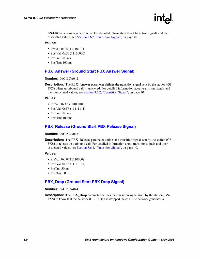
134 DM3 Architecture on Windows Configuration Guide — May 2006
CONFIG File Parameter Reference
GS-FXO receiving a generic seize. For detailed information about transition signals and their associated values, see Section 3.6.2, “Transition Signal”, on page 40.
Values:
• PreVal: 0xF5 (11110101)
• PostVal: 0xF0 (11110000)
• PreTm: 100 ms
• PostTm: 100 ms
PBX_Answer (Ground Start PBX Answer Signal)
Number: 0xC15CA042
Description: The PBX_Answer parameter defines the transition signal sent by the station (GS-FXS) when an inbound call is answered. For detailed information about transition signals and their associated values, see Section 3.6.2, “Transition Signal”, on page 40.
Values:
• PreVal: 0xA5 (10100101)
• PostVal: 0xFF (11111111)
• PreTm: 100 ms
• PostTm: 100 ms
PBX_Release (Ground Start PBX Release Signal)
Number: 0xC15CA043
Description: The PBX_Release parameter defines the transition signal sent by the station (GS-FXS) to release an outbound call. For detailed information about transition signals and their associated values, see Section 3.6.2, “Transition Signal”, on page 40.
Values:
• PreVal: 0xF0 (11110000)
• PostVal: 0xF5 (11110101)
• PreTm: 50 ms
• PostTm: 50 ms
PBX_Drop (Ground Start PBX Drop Signal)
Number: 0xC15CA044
Description: The PBX_Drop parameter defines the transition signal used by the station (GS-FXS) to know that the network (GS-FXO) has dropped the call. The network generates a

DM3 Architecture on Windows Configuration Guide — May 2006 135
CONFIG File Parameter Reference
GS_Net_Drop signal. For detailed information about transition signals and their associated values, see Section 3.6.2, “Transition Signal”, on page 40.
Values:
• PreVal: 0xFF (11111111)
• PostVal: 0xF5 (11110101)
• PreTm: 50 ms
• PostTm: 100 ms
Net_Ground (Ground Start Net Ground Signal)
Number: 0xC15CA045
Description: The Net_Ground parameter defines the transition signal sent by the network (GS-FXO) to make an outbound call, or to answer an incoming call. For detailed information about transition signals and their associated values, see Section 3.6.2, “Transition Signal”, on page 40.
Values:
• PreVal: 0xAA (10101010)
• PostVal: 0xA0 (10100000)
• PreTm: 100 ms
• PostTm: 50 ms
Net_Drop (Ground Start Net Drop Signal)
Number: 0xC15CA046
Description: The Net_Drop parameter defines the transition signal that, when received by the station (GS-FXS), indicates that the network has dropped the call. For detailed information about transition signals and their associated values, see Section 3.6.2, “Transition Signal”, on page 40.
Values:
• PreVal: 0xA0 (10100000)
• PostVal: 0xAA (10101010)
• PreTm: 100 ms
• PostTm: 50 ms
Ring_On (Ground Start Ring On Signal)
Number: 0xC15CA047
Description: The Ring_On parameter defines the transition signal generated by the network (GS-FXO) to ring the line, and indicate an inbound call is offered to the station (GS-FXS). This
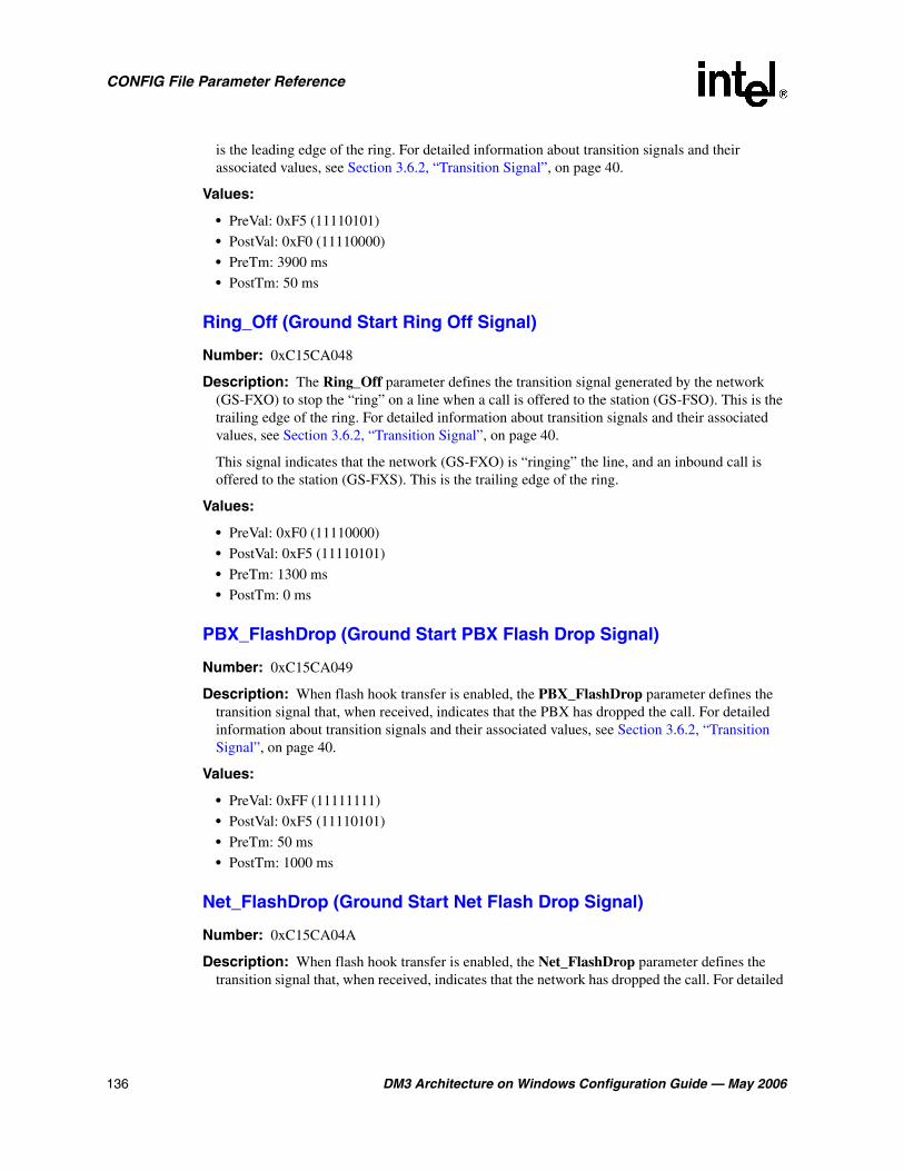
136 DM3 Architecture on Windows Configuration Guide — May 2006
CONFIG File Parameter Reference
is the leading edge of the ring. For detailed information about transition signals and their associated values, see Section 3.6.2, “Transition Signal”, on page 40.
Values:
• PreVal: 0xF5 (11110101)
• PostVal: 0xF0 (11110000)
• PreTm: 3900 ms
• PostTm: 50 ms
Ring_Off (Ground Start Ring Off Signal)
Number: 0xC15CA048
Description: The Ring_Off parameter defines the transition signal generated by the network (GS-FXO) to stop the “ring” on a line when a call is offered to the station (GS-FSO). This is the trailing edge of the ring. For detailed information about transition signals and their associated values, see Section 3.6.2, “Transition Signal”, on page 40.
This signal indicates that the network (GS-FXO) is “ringing” the line, and an inbound call is offered to the station (GS-FXS). This is the trailing edge of the ring.
Values:
• PreVal: 0xF0 (11110000)
• PostVal: 0xF5 (11110101)
• PreTm: 1300 ms
• PostTm: 0 ms
PBX_FlashDrop (Ground Start PBX Flash Drop Signal)
Number: 0xC15CA049
Description: When flash hook transfer is enabled, the PBX_FlashDrop parameter defines the transition signal that, when received, indicates that the PBX has dropped the call. For detailed information about transition signals and their associated values, see Section 3.6.2, “Transition Signal”, on page 40.
Values:
• PreVal: 0xFF (11111111)
• PostVal: 0xF5 (11110101)
• PreTm: 50 ms
• PostTm: 1000 ms
Net_FlashDrop (Ground Start Net Flash Drop Signal)
Number: 0xC15CA04A
Description: When flash hook transfer is enabled, the Net_FlashDrop parameter defines the transition signal that, when received, indicates that the network has dropped the call. For detailed

DM3 Architecture on Windows Configuration Guide — May 2006 137
CONFIG File Parameter Reference
information about transition signals and their associated values, see Section 3.6.2, “Transition Signal”, on page 40.
Values:
• PreVal: 0xA0 (10100000)
• PostVal: 0xAA (10101010)
• PreTm: 100 ms
• PostTm: 1000 ms
Net_Answer (Ground Start Net Answer Signal)
Number: 0xC15CA04B
Description: The Net_Answer parameter defines the transition signal that, when received, indicates that the network has answered an outbound call. For detailed information about transition signals and their associated values, see Section 3.6.2, “Transition Signal”, on page 40.
Values:
• PreVal: 0xAA (10101010)
• PostVal: 0xA0 (10100000)
• PreTm: 100 ms
• PostTm: 50 ms
PBX_Flash (Ground Start PBX Flash Signal)
Number: 0xC15CA051
Description: The PBX_Flash parameter defines the pulse signal used by the station to initiate a blind transfer while the call is connected. For detailed information about pulse signals and their associated values, see Section 3.6.3, “Pulse Signal”, on page 42.
Values:
• OffVal: 0xFF (11111111)
• OnVal: 0xF5 (11110101)
• PreTm: 100 ms
• MinTm: 210 ms
• NomTm: 250 ms
• MaxTm: 280 ms
• PostTm: 100 ms
6.16 [CAS] User-defined CAS and Tone Signal Parameters
The CAS component is responsible for the generation and detection of CAS signals on the phone network interface. The CAS user-defined and tone signals are defined in this section of the
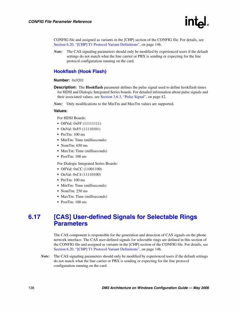
138 DM3 Architecture on Windows Configuration Guide — May 2006
CONFIG File Parameter Reference
CONFIG file and assigned as variants in the [CHP] section of the CONFIG file. For details, see Section 6.20, “[CHP] T1 Protocol Variant Definitions”, on page 146.
Note: The CAS signaling parameters should only be modified by experienced users if the default settings do not match what the line carrier or PBX is sending or expecting for the line protocol configuration running on the card.
Hookflash (Hook Flash)
Number: 0x9201
Description: The Hookflash parameter defines the pulse signal used to define hookflash times for HDSI and Dialogic Integrated Series boards. For detailed information about pulse signals and their associated values, see Section 3.6.3, “Pulse Signal”, on page 42.
Note: Only modifications to the MinTm and MaxTm values are supported.
Values:
For HDSI Boards:
• OffVal: 0xFF (11111111)
• OnVal: 0xF5 (11110101)
• PreTm: 100 ms
• MinTm: Time (milliseconds)
• NomTm: 650 ms
• MaxTm: Time (milliseconds)
• PostTm: 100 ms
For Dialogic Integrated Series Boards:
• OffVal: 0xCC (11001100)
• OnVal: 0xC4 (11110100)
• PreTm: 100 ms
• MinTm: Time (milliseconds)
• NomTm: 250 ms
• MaxTm: Time (milliseconds)
• PostTm: 100 ms
6.17 [CAS] User-defined Signals for Selectable Rings Parameters
The CAS component is responsible for the generation and detection of CAS signals on the phone network interface. The CAS user-defined signals for selectable rings are defined in this section of the CONFIG file and assigned as variants in the [CHP] section of the CONFIG file. For details, see Section 6.20, “[CHP] T1 Protocol Variant Definitions”, on page 146.
Note: The CAS signaling parameters should only be modified by experienced users if the default settings do not match what the line carrier or PBX is sending or expecting for the line protocol configuration running on the card.
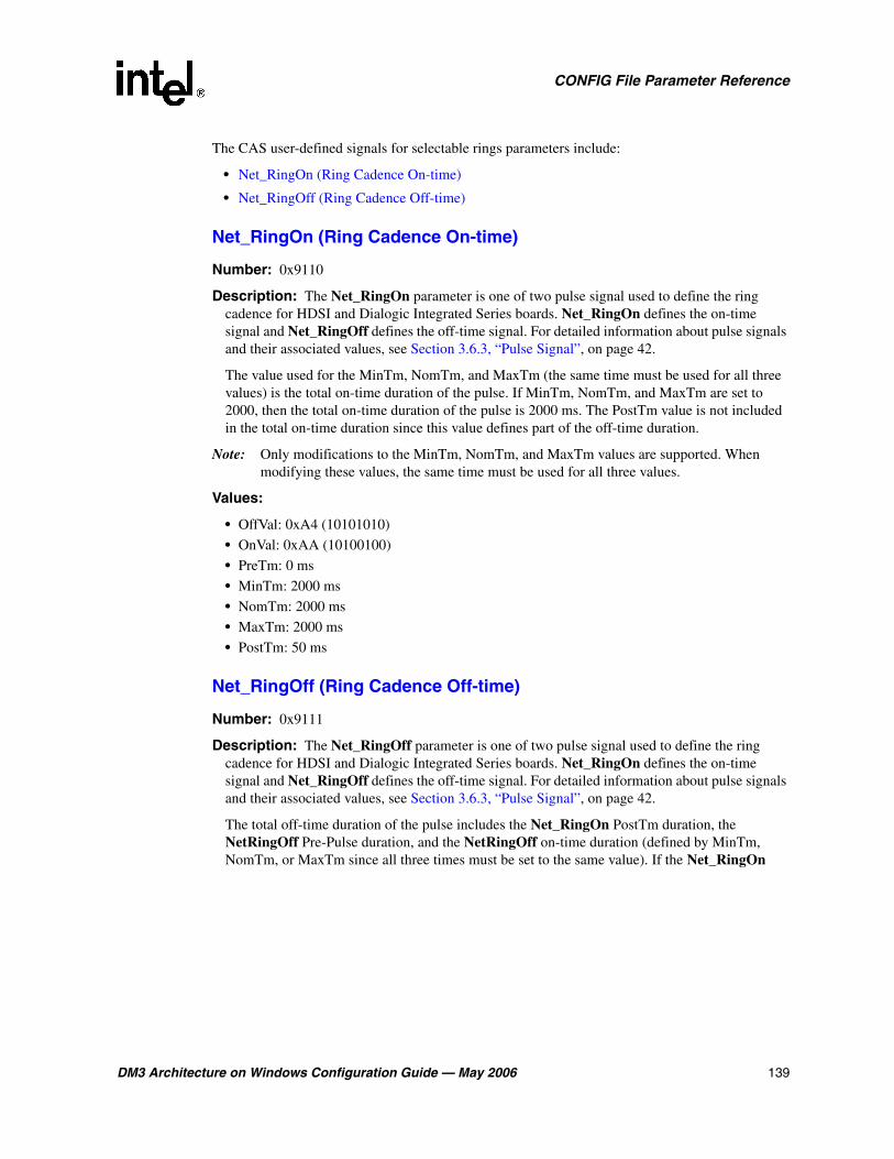
DM3 Architecture on Windows Configuration Guide — May 2006 139
CONFIG File Parameter Reference
The CAS user-defined signals for selectable rings parameters include:
• Net_RingOn (Ring Cadence On-time)
• Net_RingOff (Ring Cadence Off-time)
Net_RingOn (Ring Cadence On-time)
Number: 0x9110
Description: The Net_RingOn parameter is one of two pulse signal used to define the ring cadence for HDSI and Dialogic Integrated Series boards. Net_RingOn defines the on-time signal and Net_RingOff defines the off-time signal. For detailed information about pulse signals and their associated values, see Section 3.6.3, “Pulse Signal”, on page 42.
The value used for the MinTm, NomTm, and MaxTm (the same time must be used for all three values) is the total on-time duration of the pulse. If MinTm, NomTm, and MaxTm are set to 2000, then the total on-time duration of the pulse is 2000 ms. The PostTm value is not included in the total on-time duration since this value defines part of the off-time duration.
Note: Only modifications to the MinTm, NomTm, and MaxTm values are supported. When modifying these values, the same time must be used for all three values.
Values:
• OffVal: 0xA4 (10101010)
• OnVal: 0xAA (10100100)
• PreTm: 0 ms
• MinTm: 2000 ms
• NomTm: 2000 ms
• MaxTm: 2000 ms
• PostTm: 50 ms
Net_RingOff (Ring Cadence Off-time)
Number: 0x9111
Description: The Net_RingOff parameter is one of two pulse signal used to define the ring cadence for HDSI and Dialogic Integrated Series boards. Net_RingOn defines the on-time signal and Net_RingOff defines the off-time signal. For detailed information about pulse signals and their associated values, see Section 3.6.3, “Pulse Signal”, on page 42.
The total off-time duration of the pulse includes the Net_RingOn PostTm duration, the NetRingOff Pre-Pulse duration, and the NetRingOff on-time duration (defined by MinTm, NomTm, or MaxTm since all three times must be set to the same value). If the Net_RingOn
140 DM3 Architecture on Windows Configuration Guide — May 2006
CONFIG File Parameter Reference
PostTm is set to 50 ms, the Net_RingOff PreTm duration is set to 50 ms, and the Net_RingOff on-time duration is set to 3900 ms, the total off-time duration is 4000 ms.
Note: Only modifications to the MinTm, NomTm, and MaxTm values are supported. When modifying these values, the same time must be used for all three values.
Values:
• OffVal: 0xA4 (10100100)
• OnVal: 0xA4 (10100100)
• PreTm: 50 ms
• MinTm: 3900 ms
• NomTm: 3900 ms
• MaxTm: 3900 ms
• PostTm: 0 ms
6.18 [CCS] Parameters
Common Channel Signaling (CCS) supports ISDN PRI out-of-band signaling utilizing the Q.931 signaling protocol for messaging. The parameters in the [CCS] and [CCS.x] sections of the CONFIG file define the number of CCS component instances created and configure the parameters associated with each CCS instance.
The CCS parameters include:
• INSTANCE_MAP (Instance Map)
• CCS_TMR_302 (Q.931 Timer 302)
• CCS_TMR_303 (Q.931 Timer 303)
• CCS_TMR_304 (Q.931 Timer 304)
• CCS_TMR_305 (Q.931 Timer 305)
• CCS_TMR_308 (Q.931 Timer 308)
• CCS_TMR_310 (Q.931 Timer 310)
• CCS_TMR_313 (Q.931 Timer 313)
• CCS_TEI_RETRY (TEI Retry Timer)
• CCS_TEI_STABILITY (TEI Stability Timer)
• SYMMETRICAL_LINK (Symmetrical Command Response Protocol)
• CCS_PROTOCOL_MODE (ISDN Protocol Mode)
• CCS_SWITCH_TYPE (Switch Type)
• L2_TRACE (Layer 2 Access Flag)
• CCS_ALTQSIGCHANMAP_FLAG (Alternate QSIG Channel Mapping)

DM3 Architecture on Windows Configuration Guide — May 2006 141
CONFIG File Parameter Reference
INSTANCE_MAP (Instance Map)
Number: 0x05
Description: The INSTANCE_MAP parameter is a bitmap that defines the number of CCS instances created. A CCS instance is created for each network interface that supports common channel signaling. The bitmap’s least significant bit corresponds to the CCS instance associated with the first network interface on the board. The next least significant bit corresponds to the CCS instance associated with the second network interface on the board, and so on. If the bit associated with a network interface has a value of 1, then a CCS instance is created for that network interface. For example, a value of 0x5 (0101) means that CCS instances 1 and 3 are created allowing for common channel signaling on network interfaces 1 and 3.
Values: 0 to 0xffff
CCS_TMR_302 (Q.931 Timer 302)
Number: 0x14
Description: The CCS_TMR_302 parameter is an ISDN Layer 3 timer. For exact timer definitions, refer to the Q.931 specification and the switch specifications.
Note: This parameter only applies to E1 boards.
Values:
• 0: Use the default value for the switch (15000 ms)
• -1: Disable the timer (has the same effect as setting the timer value to 0)
• n > 1: Timer value (milliseconds)
CCS_TMR_303 (Q.931 Timer 303)
Number: 0x0b
Description: The CCS_TMR_303 parameter is an ISDN Layer 3 timer. For exact timer definitions, refer to the Q.931 specification and the switch specifications.
Values:
• 0: Use the default value for the switch (4000 ms)
• -1: Disable the timer (has the same effect as setting the timer value to 0)
• n > 1: Timer value (milliseconds)

142 DM3 Architecture on Windows Configuration Guide — May 2006
CONFIG File Parameter Reference
CCS_TMR_304 (Q.931 Timer 304)
Number: 0x0c
Description: The CCS_TMR_304 parameter is an ISDN Layer 3 timer. For exact timer definitions, refer to the Q.931 specification and the switch specifications.
Note: This parameter only applies to E1 boards.
Values:
• 0: Use the default value for the switch (30000 ms)
• -1: Disable the timer (has the same effect as setting the timer value to 0)
• n > 1: Timer value (milliseconds)
CCS_TMR_305 (Q.931 Timer 305)
Number: 0x0d
Description: The CCS_TMR_305 parameter is an ISDN Layer 3 timer. For exact timer definitions, refer to the Q.931 specification and the switch specifications.
Values:
• 0: Use the default value for the switch (4000 ms for T1, 30000 ms for E1)
• -1: Disable the timer (has the same effect as setting the timer value to 0)
• n > 1: Timer value (milliseconds)
CCS_TMR_308 (Q.931 Timer 308)
Number: 0x0e
Description: The CCS_TMR_308 parameter is an ISDN Layer 3 timer. For exact timer definitions, refer to the Q.931 specification and the switch specifications.
Values:
• 0: Use the default value for the switch (4000 ms)
• -1: Disable the timer (has the same effect as setting the timer value to 0)
• n > 1: Timer value (milliseconds)
CCS_TMR_310 (Q.931 Timer 310)
Number: 0x0f
Description: The CCS_TMR_310 parameter is an ISDN Layer 3 timer. For exact timer definitions, refer to the Q.931 specification and the switch specifications.
Values:
• 0: Use the default value for the switch (10000 ms)
• -1: Disable the timer (has the same effect as setting the timer value to 0)
• n > 1: Timer value (milliseconds)

DM3 Architecture on Windows Configuration Guide — May 2006 143
CONFIG File Parameter Reference
CCS_TMR_313 (Q.931 Timer 313)
Number: 0x10
Description: The CCS_TMR_313 parameter is an ISDN Layer 3 timer. For exact timer definitions, refer to the Q.931 specification and the switch specifications.
Values:
• 0: Use the default value for the switch (4000 ms)
• -1: Disable the timer (has the same effect as setting the timer value to 0)
• n > 1: Timer value (milliseconds)
CCS_TEI_RETRY (TEI Retry Timer)
Number: 0x15
Description: The CCS_TEI_RETRY parameter defines the maximum amount of time that the data link remains in state 4 (TEI_ASSIGNED) before transitioning to state 5 (TEI_WAIT_ESTABLISH).
Values: Time (milliseconds)
CCS_TEI_STABILITY (TEI Stability Timer)
Number: 0x16
Description: The CCS_TEI_STABILITY parameter defines the minimum transition time between data link state 4 (TEI_ASSIGNED) and data link state 5 (TEI_WAIT_ESTABLISH).
Values: 0 to 100,000 (milliseconds)
SYMMETRICAL_LINK (Symmetrical Command Response Protocol)
Number: 0x13
Description: The SYMMETRICAL_LINK parameter enables or disables symmetrical data link operations.
Values:
• 0: Disable symmetrical data link operations
• 1: Enable symmetrical data link operations
CCS_PROTOCOL_MODE (ISDN Protocol Mode)
Number: 0x17
Description: The CCS_PROTOCOL_MODE parameter sets the network user-side protocol. User-side protocol is also known as TE (terminal emulation) protocol and Network-side protocol
144 DM3 Architecture on Windows Configuration Guide — May 2006
CONFIG File Parameter Reference
is also known as NT (network termination) protocol. This parameter also can be used to configure QSIG Master/Slave.
Note: Master/Slave mode pertains to QSIG protocols only.
Note: With the exception of the QSIG protocol (where the User-side and Network-side protocols are symmetrical), using the CSS_PROTOCOL_MODE parameter to configure a Network-side protocol is supported for back-to-back testing purposes only. The Network-side firmware is not fully qualified for operation in a deployment environment.
Values:
• 0: User or Slave Mode (QSIG)
• 1: Network or Master Mode (QSIG)
CCS_SWITCH_TYPE (Switch Type)
Number: 0x07
Description: The CCS_SWITCH_TYPE parameter defines the network switch type.
Values:
• 1: 4ESS
• 2: 5ESS
• 3: DMS
• 4: NTT
• 6: DASS2
• 7: NET5
• 10: QSIGE1
• 11: QSIGT1
• 12: NI2
• 13: DPNSS
L2_TRACE (Layer 2 Access Flag)
Number: 0x09
Description: The L2_TRACE parameter is the ISDN Layer 2 access flag. When Layer 2 (Data Link layer) access is disabled, ISDN Link Access Protocol for the D channel (LAPD) functionality is obtained by accessing ISDN Call Control and Layer 3 (Network layer). When Layer 2 access is enabled, call control is no longer supported for the channels on this line and ISDN LAPD functionality is obtained by accessing Layer 2 directly.
Values:
• 0: Disable Layer 2 access
• 1: Enable Layer 2 access
DM3 Architecture on Windows Configuration Guide — May 2006 145
CONFIG File Parameter Reference
CCS_ALTQSIGCHANMAP_FLAG (Alternate QSIG Channel Mapping)
Number: 0x26
Description: This parameter enables bearer channel timeslots to use a sequentially-ordered logical channel numbering scheme, from 1 to 30, for the QSIG protocol. If not enabled, bearer channel timeslots are numbered from 1 to 15 and 17 to 31. In this mode, channel 16 is invalid as it is reserved for signaling.
Note: This parameter only applies to E1 boards.
Values:
• 0: disabled
• 1: enabled
Guidelines: To enable the alternate QSIG channel mapping scheme, add the following parameter content in the appropriate [CCS.x] section of a CONFIG file:
[CCS.1]
...
SetParm=0x26, 1 !Enable QSIG sequential channel mapping scheme]
6.19 [CHP] Parameters
The Channel Protocol (CHP) component implements the telephony communication protocol that is used on the network interface. The CHP component parameters include:
• R4Compatibility (R4 Compatibility Flag)
• InitialChanState (Initial Channel State)
• DisableBlock (Disable Block)
R4Compatibility (R4 Compatibility Flag)
Number: 0x1310
Description: The R4Compatibility parameter enables or disables R4 (Global Call) compatibility features. This parameter also enables retrieval of DNIS and ANI information in the offered call state.
Values:
• 0: Disable R4 compatibility [default]
• 1: Enable R4 compatibility
• 2: Disable R4 compatibility
InitialChanState (Initial Channel State)
Number: 0x1311
Description: The InitialChanState parameter defines the initial B channel state (CHP channel state) at the end of system initialization. The initial state of the ISDN B channel is either
146 DM3 Architecture on Windows Configuration Guide — May 2006
CONFIG File Parameter Reference
InService or OutOfService. Once the board is initialized, this initial state will be set on all channels of the board until a user application is invoked and explicitly modifies the state of the channel.
Values:
• 1: InService
• 2: OutOfService
Guidelines: This parameter must be set to OutOfService for ISDN protocols.
DisableBlock (Disable Block)
Number: 0x1312
Description: The DisableBlock parameter defines whether or not a blocking pattern (message) is sent on a channel when the channel is in the OutofService state. When DisableBlock is disabled, no pattern is sent (the switch will not present calls to the B channel).
When DisableBlock is enabled and a channel is in the InService state (InitialChanState=1), the protocol will send a non-blocking pattern on the channel (the switch will present calls to the B channel). When DisableBlock is enabled and a channel is in the OutofService state (InitialChanState=2), the protocol will send a blocking pattern on the channel (the switch will present calls to the B channel but these calls will be abandoned by the switch since the application will not respond to the call).
Values:
• 0: Disable blocking
• 1: Enable blocking
6.20 [CHP] T1 Protocol Variant Definitions
The CHP parameters define the line configurations that will be used by each network interface on the Intel telecom board. Within the [CHP] section of the CONFIG file, different possible T1 protocol variants (protocol configuration settings) can be implemented and are defined using the Variant Define n command. The Variant Define n is later set for each network channel in the [TSC] defineBSet section of the CONFIG file.
Note: Not all of the following variants exist in all CONFIG files. For PDK parameters in particular, refer to the Global Call Country Dependent Parameters (CDP) for PDK Protocols Configuration Guide.
For a detailed description of the Variant Define n command, see Section 3.7, “[CHP] Section”, on page 48. For a detailed description of the defineBSet command, also see Section 3.8, “[TSC] Section”, on page 50.
Although T1 signals (E&M wink, loop start and ground start) are assigned as part of the T1 protocol variant definitions, these signals are defined in the [CAS] section of the CONFIG file. For detailed information about specific T1 signal definitions, see the following:
• Section 6.13, “[CAS] Parameters for T1 E&M Signals”, on page 126
• Section 6.14, “[CAS] Parameters for T1 Loop Start Signals”, on page 128
DM3 Architecture on Windows Configuration Guide — May 2006 147
CONFIG File Parameter Reference
• Section 6.15, “[CAS] Parameters for T1 Ground Start Signals”, on page 133
Unless otherwise noted, T1 Protocol Variant parameters apply to all signal types: E&M wink, loop start, and ground start. Parameters that only apply to a specific signal type are prefaced with the applicable signal type. For example, the parameter EM_offhook only applies to E&M wink signaling and the parameter ProtocolType applies to E&M wink, loop start, and ground start signaling.
The T1 Protocol Variant parameters include:
• ProtocolType (Protocol Type)
• Wink (Wink Flag)
• StartTimeout (Start Timeout)
• FarEndAnswer (Far End Answer)
• AnswerTimeout (Answer Timeout)
• ReconnectTimeout (Reconnect Timeout)
• DisconnectTimeout (Disconnect Timeout)
• InterCallDelay (Inter-call Delay)
• Dial (Outbound Dialing Flag)
• DialFormat (Dial Digits Format)
• ANI (ANI Flag)
• ANIFormat (ANI Digit Format)
• ANICount (ANI Digit Count)
• DNIS (DNIS Flag)
• DNISFormat (DNIS Digit Format)
• DNISCount (DNIS Digit Count)
• PreDigitTimeout (Pre-digit Timeout)
• InterDigitTimeout (Inter-digit Timeout)
• CallProgress (Call Progress Detection)
• CaRingingSet (Ringing Signal)
• CaBusySet (Busy Signal)
• CaSitSet (SIT Signal)
• CaFaxSet (Fax Signal)
• CaPvdId (Voice Detection Signal)
• CaPamdId (Answering Machine Signal)
• CaSignalTimeout (Signal Timeout)
• CaAnswerTimeout (Answer Timeout)
• CaPvdTimeout (Voice Detection Timeout)
• DialToneId (Dial Tone Signal)
• CaDialTimeout (Dial Timeout)
• BlindTransfer (Blind Transfer)
148 DM3 Architecture on Windows Configuration Guide — May 2006
CONFIG File Parameter Reference
• BtDialToneId (DTD Signal)
• BtStartTimeout (DTD Timeout)
• BtAddressDef (Address Definition)
• BtOrigFormat (Originator Address Digits)
• BtDestFormat (Destination Address Digits)
• BtCancelDigitsFormat (Cancel Digits Format)
• BtCancelFlashCount (Cancel Flash Count)
• BtCancelInterFlashDuration (Cancel Inter-flash Duration)
• BtCancelDigits (Cancel Digits)
• BtDestSuffix (Destination Suffix Digits)
• BtDestPrefix (Destination Prefix Digits)
• BtOrigPrefix (Originator Prefix Digits)
• BtOrigSuffix (Originator Suffix Digits)
• PolarityDetection (Polarity Flag)
• EM_Offhook (E&M Off-hook Signal)
• EM_Onhook (E&M On-hook Signal)
• EM_FlashOnhook (E&M Flash On-hook Signal)
• EM_Wink (E&M Wink Signal)
• EM_Flash (E&M Flash Signal)
• LS_PBX_Open (Loop Start PBX Open)
• LS_PBX_FlashOpen (Loop Start PBX Flash Open Signal)
• LS_PBX_Close (Loop Start PBX Close Signal)
• LS_PBX_Flash (Loop Start PBX Flash Signal)
• LS_Net_Answer (Loop Start Net Answer Signal)
• LS_Net_Drop (Loop Start Net Drop Signal)
• LS_Net_FlashDrop (Loop Start Net Flash Drop Signal)
• LS_Net_Abandon (Loop Start Net Abandon)
• LS_Net_RingOn (Loop Start Net Ring On Signal)
• LS_Net_RingOff (Loop Start Net Ring Off)
• GS_PBX_Ground (Ground Start PBX Ground Signal)
• GS_PBX_Answer (Ground Start PBX Answer Signal)
• GS_PBX_Release (Ground Start PBX Release Signal)
• GS_PBX_Drop (Ground Start PBX Drop Signal)
• GS_PBX_FlashDrop (Ground Start PBX Flash Drop Signal)
• GS_PBX_Flash (Ground Start PBX Flash Signal)
• GS_Net_Ground (Ground Start Net Ground Signal)
• GS_Net_Drop (Ground Start Net Drop Signal)
• GS_Net_FlashDrop (Ground Start Flash Drop Signal)
DM3 Architecture on Windows Configuration Guide — May 2006 149
CONFIG File Parameter Reference
• GS_Net_RingOn (Ground Start Net Ring On Signal)
• GS_Net_RingOff (Ground Start Net Ring Off Signal)
ProtocolType (Protocol Type)
Description: The ProtocolType parameter defines the type of T1 protocol used on a channel.
Note: The ProtocolType parameter is also used when defining ISDN protocol variants.
Values:
• 1: E&M wink
• 2: Loop start-FXS
• 3: Ground start-FXS
• 4: Loop start-FXO (This value is not supported.)
• 5: Ground start-FXO (Supported by HDSI and Dialogic Integrated Series boards only.)
Wink (Wink Flag)
Description: The Wink parameter enables wink detection for outbound calls and wink generation for inbound calls. This parameter is enabled only when using T1 E&M wink protocols. For all other protocols, this parameter is disabled.
If wink detection (generation) is enabled, up to three winks are supported in a sequence. Examples of CONFIG file settings for ANI, Wink, DNIS, and R4Compatibility parameters for 1, 2, and 3 wink sequences are as follows:
• 1 Wink Example: Seize (Wink) DNIS (Answer) ANI
Variant ANI 2 ! No=0, Pre=1, Post=2 Variant Wink 1 ! 1 wink sequence Variant DNIS y ! Enable DNIS collection SetParm=0x1310,1 ! R4 Compatibility Flag ! 0=default, 1=enable, 2=disable
In the 1 Wink example, ANI information is collected after the call is answered, there is one wink in the sequence, DNIS information is collected, and the R4 Compatibility Flag is turned on.
• 2 Wink Example: Seize (Wink) ANI (DNIS) (Wink) Answer
Variant ANI 1 ! No=0, Pre=1, Post=2 Variant Wink 2 ! 1 wink sequence Variant DNIS y ! Enable DNIS collection SetParm=0x1310,1 ! R4 Compatibility Flag ! 0=default, 1=enable, 2=disable
In the 2 Wink example, ANI information is collected before the call is answered, there are two winks in the sequence, DNIS information is collected, and the R4 Compatibility Flag is turned on.
• 3 Wink Example: Seize (Wink) DNIS (Wink) ANI (Wink) Answer

150 DM3 Architecture on Windows Configuration Guide — May 2006
CONFIG File Parameter Reference
Variant ANI 1 ! No=0, Pre=1, Post=2 Variant Wink 3 ! 1 wink sequence Variant DNIS y ! Enable DNIS collection SetParm=0x1310,2 ! R4 Compatibility Flag ! 0=default, 1=enable, 2=disable
In the 3 Wink example, ANI information is collected before the call is answered, there are three winks in the sequence, DNIS information is collected, and the R4 Compatibility Flag is turned off.
Values:
• 0 or n: Disable wink
• 1 or y: Enable 2 winks in the sequence
• 2: Enable 1 wink in the sequence
• 3: Enable 3 winks in the sequence
StartTimeout (Start Timeout)
Description: The StartTimeout parameter is defined differently depending on the T1 protocol used. Depending on the value of the ProtocolType parameter, the StartTimeout parameter is defined as follows:
E&M winkThe amount of time that a call originator will wait for a wink once it has seized the line for an outbound call. The outbound call will fail if this time is exceeded.
Ground startThe amount of time that a call originator will wait for the dial tone signal once it has seized the line for an outbound call. The outbound call will fail if this time is exceeded.
Loop startThe call originator will wait the specified amount of time after seizing the line for an outbound call, and then proceed to sending digits (that is, can be used to for dial tone before dialing).
Values: n > 0 (milliseconds)
FarEndAnswer (Far End Answer)
Description: The FarEndAnswer parameter defines whether the network will provide far end (remote) answer signaling. This parameter is enabled when using T1 loop start protocols only. For all other T1 protocols, this parameter is disabled.
Values:
• y: Enable far end answer support
• n: Disable far end answer support
AnswerTimeout (Answer Timeout)
Description: The AnswerTimeout parameter defines the maximum amount of time allowed to answer a call once a remote party has sent its last wink. If the time is exceeded, the call fails.

DM3 Architecture on Windows Configuration Guide — May 2006 151
CONFIG File Parameter Reference
Otherwise, the timer is reset once the call is answered. This parameter is enabled only when using T1 E&M wink protocols. For all other T1 protocols, this parameter is disabled.
Values: n > 0 (milliseconds)
ReconnectTimeout (Reconnect Timeout)
Description: The ReconnectTimeout parameter defines the maximum amount of time allowed between a local disconnect (MsgDropCall) and a reconnect (MSgReconnectCall).
Values: n > 0 (milliseconds)
DisconnectTimeout (Disconnect Timeout)
Description: The DisconnectTimeout parameter defines the time before a remote drop is considered to be a disconnect. If MsgDropCall is followed by a MsgReconnectCall within this time period, then the call will be reconnected and remain in the connected state.
Note: The DisconnectTimeout parameter is also used when defining ISDN protocol variants.
Values: n > 0 (milliseconds)
Guidelines: For DNM160TEC and DMT160TEC boards, when there are 16 or more trunks in one NFAS group and calls are made on every channel at a very fast rate, the firmware may start missing calls. In this case, increase the value of the DisconnectTimeout parameter to at least 3000 milliseconds.
InterCallDelay (Inter-call Delay)
Description: The InterCallDelay parameter defines the minimum amount of time between outbound calls. This is the time the firmware will wait after a call is dropped and before making another call from the same channel.
Note: The InterCallDelay parameter is also used when defining ISDN Protocol variants, including E1.
Values: n > 0 (milliseconds)
Dial (Outbound Dialing Flag)
Description: The Dial parameter enables or disables outbound dialing.
Values:
• y: Enable outbound dialing
• n: Disable outbound dialing

152 DM3 Architecture on Windows Configuration Guide — May 2006
CONFIG File Parameter Reference
DialFormat (Dial Digits Format)
Description: The DialFormat parameter defines the format of the dial digits.
Values:
• 1: Dual Tone Multi-Frequency (DTMF)
• 2: Multi-Frequency (MF)
• 3: Dial Pulse (DP)
ANI (ANI Flag)
Description: The ANI parameter enables or disables the collection of ANI data. When the parameter is enabled, it also defines when the data is collected, before or after the call is answered.
Values:
• 0: Disable ANI data collection
• 1: Enable ANI data collection - pre-answer
• 2: Enable ANI data collection - post-answer
ANIFormat (ANI Digit Format)
Description: The ANIFormat parameter defines the format of the ANI digits.
Values:
• 1: Dual Tone Multi-Frequency (DTFM)
• 2: Multi-Frequency (MF)
• 3: Dial Pulse (DP)
• 4: Frequency Shift Keying, United States (FSK_US)
• 5: Frequency Shift Keying, Japan (FSK_JP)
• 6: Frequency Shift Keying, United Kingdom (FSK_UK - This value is not supported.)
ANICount (ANI Digit Count)
Description: The ANICount parameter defines the number of ANI digits to collect from the incoming call. If the parameter is set to 0, then digit collection will stop after the time-out period set by the PreDigitTimeout and InterDigitTimeout parameters defined in the [CHP] Variant Define n section of the CONFIG file. For details see:
• Section 3.7, “[CHP] Section”, on page 48
• “InterDigitTimeout (Inter-digit Timeout)”, on page 153
• “PreDigitTimeout (Pre-digit Timeout)”, on page 153
Values:
• 0: Collect all the digits provided
• n: Number of digits to collect
DM3 Architecture on Windows Configuration Guide — May 2006 153
CONFIG File Parameter Reference
DNIS (DNIS Flag)
Description: The DNIS parameter enables or disables DNIS data collection for inbound calls.
Values:
• y: Enable DNIS collection
• n: Disable DNIS collection
DNISFormat (DNIS Digit Format)
Description: The DNISFormat parameter defines the format of the DNIS digits.
Values:
• 1: Dual Tone Multi-Frequency (DTMF)
• 2: Multi-Frequency (MF)
• 3: Dial Pulse (DP)
DNISCount (DNIS Digit Count)
Description: The DNISCount parameter defines the number of DNIS digits to collect from the incoming call. If the parameter is set to 0, then digit collection will stop after the time-out period set by the PreDigitTimeout and InterDigitTimeout parameters defined in the [CHP] Variant Define n section of the CONFIG file. For details see:
• Section 3.7, “[CHP] Section”, on page 48
• “InterDigitTimeout (Inter-digit Timeout)”, on page 153
• “PreDigitTimeout (Pre-digit Timeout)”, on page 153
Values:
• 0: Collect all the digits provided
• n: Number of digits to collect
PreDigitTimeout (Pre-digit Timeout)
Description: The PreDigitTimeout parameter defines the maximum amount of time that the protocol will wait to receive digits once a call has been initiated. E&M wink-start protocols start this time from the end of the wink.
Values: n > 0 (the value must be a multiple of 10 ms)
InterDigitTimeout (Inter-digit Timeout)
Description: The InterDigitTimeout parameter defines the maximum amount of time between digits. If a digit is not followed by another within this time limit, then digit collection is terminated.
Values: n > 0 (the value must be a multiple of 10 ms)

154 DM3 Architecture on Windows Configuration Guide — May 2006
CONFIG File Parameter Reference
CallProgress (Call Progress Detection)
Description: The CallProgress parameter enables or disables call progress detection for call setup on outbound calls.
Note: The CallProgress parameter is also used when defining ISDN protocol variants.
Values:
• y: Enable call progress detection
• n: Disable call progress detection
CaRingingSet (Ringing Signal)
Description: The CaRingingSet parameter defines the signal set used to detect ringing for call progress analysis. The CaRingingSet parameter is also used when defining ISDN protocol variants.
Notes: 1. Modification of the CaRingingSet parameter is not supported.
2. The CaRingingSet parameter is also used when defining ISDN protocol variants.
Values: 0x024940
CaBusySet (Busy Signal)
Description: The CaBusySet parameter defines the signal set used to detect busy for call progress analysis.
Notes: 1. Modification of the CaBusySet parameter is not supported.
2. The CaBusySet parameter is also used when defining ISDN protocol variants.
Values: 0x004DE0
CaSitSet (SIT Signal)
Description: The CaSitSet parameter defines the signal set used to detect Standard Information Tones (SIT) for call progress analysis.
Notes: 1. Modification of the CaSitSet parameter is not supported.
2. The CaSitSet parameter is also used when defining ISDN protocol variants.
Values: 0x02F240
CaFaxSet (Fax Signal)
Description: The CaFaxSet parameter defines the signal set used to detect fax tones for call progress analysis.
Notes: 1. Modification of the CaFaxSet parameter is not supported.
2. The CaFaxSet parameter is also used when defining ISDN protocol variants.
Values: 0x014B80

DM3 Architecture on Windows Configuration Guide — May 2006 155
CONFIG File Parameter Reference
CaPvdId (Voice Detection Signal)
Description: The CaPvdId parameter defines the signal to use for Positive Voice Detection (PVD) for call progress analysis.
Notes: 1. Modification of the CaPvdId parameter is not supported.
2. The CaPvdId parameter is also used when defining ISDN protocol variants.
Values: 0x01F4C1
CaPamdId (Answering Machine Signal)
Description: The CaPamdId parameter defines the signal to use for Positive Answering Machine Detection (PAMD) for call progress analysis.
Notes: 1. Modification of the CaPamdId parameter is not supported.
2. The CaPamdId parameter is also used when defining ISDN protocol variants.
Values: 0x01A041
CaSignalTimeout (Signal Timeout)
Description: The CaSignalTimeout parameter defines the maximum amount of time to wait to detect a call progress tone from one of the call analysis signal sets. For T1 loop start and ground start protocols, if this time is exceeded, then the outbound call will fail with the reason being NoAnswer.
Note: The CaSignalTimeout parameter is also used when defining ISDN protocol variants.
Values: n > 0 (the value must be a multiple of 10 ms)
CaAnswerTimeout (Answer Timeout)
Description: The CaAnswerTimeout parameter defines the maximum amount of time (in milliseconds) that call analysis will wait for ringback to stop. This is equivalent to the number of rings. For T1 loop start and ground start protocols, if this time is exceeded, then the outbound call will fail with the reason being NoAnswer.
Note: The CaAnswerTimeout parameter is also used when defining ISDN protocol variants.
Values: n > 0 (the value must be a multiple of 10 ms)
CaPvdTimeout (Voice Detection Timeout)
Description: The CaPvdTimeout parameter defines the maximum amount of time that call analysis will wait to detect positive answering machine detection (PAMD) or positive voice

156 DM3 Architecture on Windows Configuration Guide — May 2006
CONFIG File Parameter Reference
detection (PVD) once ringback has ceased. If this time is exceeded, then connection type will be reported as “Unknown”, that is, not fax, PAMD, or PVD.
Note: The CaPvdTimeout parameter is also used when defining ISDN protocol variants.
Values: n > 0 (the value is expressed in multiples of 10 milliseconds. For example, a value of 200 equals 2000 milliseconds, or 2 seconds)
• For analog boards: default = 800
• For digital boards: default = 400
DialToneId (Dial Tone Signal)
Description: The DialToneId parameter defines the signal to use for dial tone detection. This parameter is used for loop start protocols. If this is set to 0 (Null), then dial tone detection is disabled.
Values:
• 0: Disable dial tone detection
• 0x00A261: Enable dial tone detection
CaDialTimeout (Dial Timeout)
Description: The CaDialTimeout parameter defines the maximum amount of time that call analysis will wait to detect a tone, for example, busy, SIT tones, and ring back.
Values: n > 0 (the value must be a multiple of 10 ms)
BlindTransfer (Blind Transfer)
Description: The BlindTransfer parameter enables or disables blind transfer.
Values:
• 0: Disable blind transfer
• 1: Enable blind transfer
BtDialToneId (DTD Signal)
Description: The BtDialToneId parameter works together with the DialToneId parameter and defines the signal used for dial tone detection in a blind transfer. If BtDialToneId is 0, then the protocol will wait for a time period (BtStartTimeout) before sending digits after generating a flash.
Values:
• 0: Pause (the pause time is equal to the value of BtStartTimeout)• n: Signal parameter number
BtStartTimeout (DTD Timeout)
Description: The BtStartTimeout parameter is used only when the BtDialToneId parameter is set to a value of 0 (zero). This parameter defines the maximum amount of time that the protocol

DM3 Architecture on Windows Configuration Guide — May 2006 157
CONFIG File Parameter Reference
will wait for detecting dial tone after a flash has been generated. Once the BtStartTimeout value has been reached, a transfer failure will occur with the reason being ProtocolError, and the call will return to the connected state.
If the BtDialToneId parameter is set to 0 (zero), BtStartTimeout is the time period that the protocol will wait after a flash has been generated before sending digits
Values: n > 0 (milliseconds)
BtAddressDef (Address Definition)
Description: The BtAddressDef parameter defines what addresses will be sent on a blind transfer, and the order in which they will be sent. Addresses are analogous to phone numbers dialed (destination = DNIS), or dialing from (origination = ANI).
Values:
• 1: None
• 2: Destination
• 3: Origination
• 4: Destination, Origination
• 5: Origination, Destination
BtOrigFormat (Originator Address Digits)
Description: The BtOrigFormat parameter defines the format of the originator address digits in a blind transfer. The address is analogous to ANI (caller ID) information.
Values:
• 1: Dual Tone Multi-Frequency (DTMF)
• 2: Multi-Frequency (MF)
• 3: Dial Pulse (DP)
BtDestFormat (Destination Address Digits)
Description: The BtDestFormat parameter defines the format of destination address digits in a blind transfer. The address is analogous to DNIS information.
Values:
• 1: Dual Tone Multi-Frequency (DTMF)
• 2: Multi-Frequency (MF)
• 3: Dial Pulse (DP)
158 DM3 Architecture on Windows Configuration Guide — May 2006
CONFIG File Parameter Reference
BtCancelDigitsFormat (Cancel Digits Format)
Description: The BtCancelDigitsFormat parameter defines the format of Cancel digits in a blind transfer.
Values:
• 1: Dual Tone Multi-Frequency (DTMF)
• 2: Multi-Frequency (MF)
• 3: Dial Pulse (DP)
BtCancelFlashCount (Cancel Flash Count)
Description: The BtCancelFlashCount parameter defines the number of flashes to be sent to cancel or abort a transfer.
Values: n > 0
BtCancelInterFlashDuration (Cancel Inter-flash Duration)
Description: The BtCancelInterFlashDuration parameter defines the time between flashes for canceling or aborting a transferred call.
Values: n > 0 (milliseconds)
BtCancelDigits (Cancel Digits)
Description: The BtCancelDigits parameter defines the digits to dial after the flash sequence to cancel or abort a call transfer; for example, *69.
Values: Digits
BtDestSuffix (Destination Suffix Digits)
Description: The BtDestSuffix parameter defines the digits to be dialed immediately following the destination address (dialed number/DNIS) in a blind transfer; for example, *34.
Values: Digits
BtDestPrefix (Destination Prefix Digits)
Description: The BtDestPrefix parameter defines the digits to be dialed immediately before the destination address (dialed number/DNIS) in a blind transfer; for example, *54.
Values: Digits
BtOrigPrefix (Originator Prefix Digits)
Description: The BtOrigPrefix parameter defines the digits to be dialed immediately before the originator address (calling number/ANI) in a blind transfer; for example, *94.
Values: Digits
DM3 Architecture on Windows Configuration Guide — May 2006 159
CONFIG File Parameter Reference
BtOrigSuffix (Originator Suffix Digits)
Description: The BtOrigSuffix parameter defines the digits to be dialed immediately following the originator address (calling number/ANI) in a blind transfer; for example, *64.
Values: Digits
PolarityDetection (Polarity Flag)
Description: The PolarityDetection parameter defines whether the CO reverses battery polarity as the first step before sending the call ring. In Japan, the CO (Nippon Telephone and Telegraph, NTT) reverses the loop polarity prior to sending a call. When PolarityDetection parameter is enabled, the polarity reversal sent from the CO in NTT is used when detecting the incoming call.
Values:
• 0: Disable polarity reversal (normal polarity)
• 1: Enable polarity reversal (reverse polarity)
EM_Offhook (E&M Off-hook Signal)
Description: The EM_Offhook parameter defines the T1 E&M wink off-hook CAS transition signal id. This signal is sent to make an outbound call, or to answer an incoming call. Receiving this signal indicates that the network is offering a call.
Values: 0xC15CA001
EM_Onhook (E&M On-hook Signal)
Description: The EM_Onhook parameter defines the T1 E&M wink on-hook CAS transition signal id. This signal is sent to drop a call.
Values: 0xC15CA002
EM_FlashOnhook (E&M Flash On-hook Signal)
Description: The EM_FlashOnhook parameter defines the T1 E&M wink on-hook CAS transition signal used when flash hook transfer (blind transfer) is enabled. It defines the transition signal from an off-hook state to a flash on-hook state during a blind transfer. This signal is sent to drop a call.
Values: 0xC15CA003
EM_Wink (E&M Wink Signal)
Description: The EM_Wink parameter defines the T1 E&M wink CAS pulse signal ID. This signal is used as part of the inbound call setup for wink-start E&M protocols. The signal is sent to tell the far end to proceed with the call in response to EM_Offhook.
Values: 0xC15CA011
160 DM3 Architecture on Windows Configuration Guide — May 2006
CONFIG File Parameter Reference
EM_Flash (E&M Flash Signal)
Description: The EM_Flash parameter defines the T1 E&M wink flash CAS pulse signal ID. This signal is used to initiate a blind transfer while the call is connected.
Values: 0xC15CA012
LS_PBX_Open (Loop Start PBX Open)
Description: The LS_PBX_Open parameter defines the T1 loop start PBX Open CAS transition signal ID. This signal is sent to drop a call.
Values: 0xC15CA021
LS_PBX_FlashOpen (Loop Start PBX Flash Open Signal)
Description: The LS_PBX_FlashOpen parameter defines the T1 loop start PBX Open CAS transition signal to use when flash hook transfer is enabled. This signal is sent to drop a call.
Values: 0xC15CA029
LS_PBX_Close (Loop Start PBX Close Signal)
Description: The LS_PBX_Close parameter defines the T1 loop start PBX Close CAS transition signal ID. This signal is sent to make an outbound call, or to answer an incoming call.
Values: 0xC15CA022
LS_PBX_Flash (Loop Start PBX Flash Signal)
Description: The LS_PBX_Flash parameter defines the T1 loop start PBX flash CAS pulse signal ID. This signal is used to initiate a blind transfer while the call is connected.
Values: 0xC15CA031
LS_Net_Answer (Loop Start Net Answer Signal)
Description: The LS_Net_Answer parameter defines the T1 loop start Net Answer CAS transition signal ID. Receiving this signal indicates that the network has answered an outbound call.
Values: 0xC15CA023
LS_Net_Drop (Loop Start Net Drop Signal)
Description: The LS_Net_Drop parameter defines the T1 loop start Net Drop CAS transition signal ID. Receiving this signal indicates that the network has dropped the call.
Values: 0xC15CA024

DM3 Architecture on Windows Configuration Guide — May 2006 161
CONFIG File Parameter Reference
LS_Net_FlashDrop (Loop Start Net Flash Drop Signal)
Description: The LS_Net_FlashDrop parameter defines the T1 loop start Net Drop CAS transition signal to use when flash hook transfer is enabled. Receiving this signal indicates that the network has dropped the call.
Values: 0xC15CA02A
LS_Net_Abandon (Loop Start Net Abandon)
Description: The LS_Net_Abandon parameter defines the T1 loop start Net Abandon CAS transition signal ID. Receiving this signal indicates that the network has dropped an offered call, that is, ringing has stopped.
Values: 0xC15CA025
LS_Net_RingOn (Loop Start Net Ring On Signal)
Description: The LS_Net_RingOn parameter defines the T1 loop start Net Ring On CAS transition signal ID. Receiving this signal indicates that the network is ringing the line, and an inbound call is offered. This is the leading edge of the ring.
Values: 0xC15CA026
LS_Net_RingOff (Loop Start Net Ring Off)
Description: The LS_Net_RingOff parameter defines the T1 loop start Net Ring Off CAS transition signal ID. Receiving this signal indicates that the network is “ringing” the line, and an inbound call is offered. This is the trailing edge of the ring.
Values: 0xC15CA027
GS_PBX_Ground (Ground Start PBX Ground Signal)
Description: The GS_PBX_Ground parameter defines the T1 ground start PBX Ground CAS transition signal ID. This signal is sent by the station to make an outbound call, or to answer an incoming call (off-hook). From the station side, it is the GS-FXS transmitting a generic seize, and from the corresponding office or network side, it is the GS-FXO receiving a generic seize.
Values: 0xC15CA041
GS_PBX_Answer (Ground Start PBX Answer Signal)
Description: The GS_PBX_Answer parameter defines the T1 ground start PBX Answer CAS transition signal ID. This signal is sent by the station (GS-FXS) when an inbound call is answered.
Values: 0xC15CA042
162 DM3 Architecture on Windows Configuration Guide — May 2006
CONFIG File Parameter Reference
GS_PBX_Release (Ground Start PBX Release Signal)
Description: The GS_PBX_Release parameter defines the T1 ground start PBX Release CAS transition signal ID. This signal is sent by the station (GS-FXS) to release an outbound call.
Values: 0xC15CA043
GS_PBX_Drop (Ground Start PBX Drop Signal)
Description: The GS_PBX_Drop parameter defines the T1 ground start PBX Drop CAS transition signal ID. This signal is used by the station (GS-FXS) to know that the network (GS-FXO) has dropped the call. The network generates a GS_Net_Drop signal.
Values: 0xC15CA044
GS_PBX_FlashDrop (Ground Start PBX Flash Drop Signal)
Description: The GS_PBX_FlashDrop parameter defines the T1 ground start PBX Drop CAS transition signal ID. This signal is sent to drop a call when flash hook transfer is enabled.
Values: 0xC15CA049
GS_PBX_Flash (Ground Start PBX Flash Signal)
Description: The GS_PBX_Flash parameter defines the T1 ground start PBX flash CAS pulse signal ID. This signal is used by the station to initiate a blind transfer while the call is connected.
Values: 0xC15CA051
GS_Net_Ground (Ground Start Net Ground Signal)
Description: The GS_Net_Ground parameter defines the T1 ground start Net Ground CAS transition signal ID. Receiving this signal indicates that the network has answered an outbound call, or that the network is offering an inbound call.
Values: 0xC15CA045
GS_Net_Drop (Ground Start Net Drop Signal)
Description: The GS_Net_Drop parameter defines the T1 loop start Net Drop CAS transition signal ID. Receiving this signal indicates that the network has dropped the call.
Values: 0xC15CA046
GS_Net_FlashDrop (Ground Start Flash Drop Signal)
Description: The GS_Net_FlashDrop parameter defines the T1 ground start Net Drop CAS transition signal to use when flash hook transfer is enabled. Receiving this signal indicates that the network has dropped the call.
Values: 0xC15CA04A

DM3 Architecture on Windows Configuration Guide — May 2006 163
CONFIG File Parameter Reference
GS_Net_RingOn (Ground Start Net Ring On Signal)
Description: The GS_Net_RingOn parameter defines the T1 ground start Net Ring On CAS transition signal ID. Receiving this signal indicates that the network (GS-FXO) is “ringing” the line, and an inbound call is offered to the station (GS-FXS). This is the leading edge of the ring.
Values: 0xC15CA047
GS_Net_RingOff (Ground Start Net Ring Off Signal)
Description: The GS_Net_RingOff parameter defines the T1 ground start Net Ring Off CAS transition signal ID. The signal generated by the network (GS-FXO) to stop the “ring” on a line when a call is offered to the station (GS_FSO). This is the trailing edge of the ring.
Values: 0xC15CA048
6.21 [CHP] ISDN Protocol Variant Definitions
The CHP parameters define line configurations. Within the [CHP] section of the CONFIG file, ISDN protocol variants are defined using the Variant Define n command. For a detailed description of the Variant Define n command, see Section 3.7, “[CHP] Section”, on page 48.
The ISDN protocol variant parameters include:
• ProtocolType (Protocol Type)
• ProtocolName (Protocol Name)
• InterCallDelay (Inter-call Delay)
• DisconnectTimeout (Disconnect Timeout)
• Layer1Protocol (Layer 1 Protocol)
• InfoTransferRate (Information Transfer Rate)
• InfoTransferCap (Information Transfer Cap)
• CalledNumberType (Called Number Type)
• CalledNumberPlan (Called Number Plan)
• CalledNumberCount (Called Number Count)
• CallingNumberType (Calling Number Type)
• CallingNumberPlan (Calling Number Plan)
• CallingNumberPresentation (Calling Number Presentation)
• CallingNumberScreening (Calling Number Screening)
• CallingNumberCount (Calling Number Count)
• CallProgress (Call Progress)
• CaHdgLoHiGl (Hello Edge/Low Glitch/High Glitch)
• CaAnsdglPSV (Answer Deglitcher/PAMD Speed Value)
• CaHdgLoHiGl (Hello Edge/Low Glitch/High Glitch)
• CaBusySet (Busy Signal)
164 DM3 Architecture on Windows Configuration Guide — May 2006
CONFIG File Parameter Reference
• CaSitSet (SIT Signal)
• CaFaxSet (Fax Signal)
• CaPvdId (Voice Detection Signal)
• CaPamdId (Answering Machine Signal)
• CaSignalTimeout (Signal Timeout)
• CaAnswerTimeout (Answer Timeout)
• CaPvdTimeout (Voice Detection Timeout)
ProtocolType (Protocol Type)
Description: The ProtocolType parameter defines the type of ISDN protocol used on a channel. The value of the parameter is dependent on the firmware being downloaded and the CONFIG files used. For example, when downloading the ml2_qsa_4ess.config file, ProtocolType should be set to a value of 1.
Note: The ProtocolType parameter is also used when defining T1 protocol variants.
Values:
• 1: 4ESS and NI-2
• 2: 5ESS
• 3: DMS100 and DMS250
• 4: NTT
• 7: NET5
• 8: DASS2
• 9: DPNSS
• 10: QSIGE1
• 11: QSIGT1
ProtocolName (Protocol Name)
Description: The ProtocolName parameter associates a unique name with the variant and is used to match protocols to variants.
Values:
• “4ESS”
• “NI-2”
• “5ESS”
• “DMS”
• “NTT”
• “NET5”
• “QSIGE1”
• “QSIGT1”
DM3 Architecture on Windows Configuration Guide — May 2006 165
CONFIG File Parameter Reference
InterCallDelay (Inter-call Delay)
Description: The InterCallDelay parameter defines the minimum amount of time between outbound calls.
Note: The InterCallDelay parameter is also used when defining T1 protocol variants.
Values: n > 0 (milliseconds)
DisconnectTimeout (Disconnect Timeout)
Description: The DisconnectTimeout parameter defines the time delay between proceeding and alert/connect. The call will transition to idle after this time period (sooner if ClearConf is received).
Note: The DisconnectTimeout parameter is also used when defining T1 protocol variants.
Values: n > 0 (milliseconds)
Guidelines: None. For DMN160TEC and DMT160TEC boards, when there are 16 or more trunks in one NFAS group and calls are made on every channel at a very fast rate, the firmware may start missing calls. In this case, increase the value of the DisconnectTimeout parameter to at least 3000 milliseconds.
Layer1Protocol (Layer 1 Protocol)
Description: The Layer1Protocol parameter defines the User Layer 1 Protocol.
Values:
• 0x00: Protocol not present
• 0x01: CCITT
• 0x02: G.711 mu-law
• 0x03: G.711 A-law
• 0x04: G.721 ADPCM
• 0x05: G.721 kHz
• 0x06: 384 kHz Video
• 0x07: NS Rate Adaption
• 0x08: V120 Rate Adaption
• 0x09: X.31 HDLC

166 DM3 Architecture on Windows Configuration Guide — May 2006
CONFIG File Parameter Reference
InfoTransferRate (Information Transfer Rate)
Description: The InfoTransferRate parameter defines the information transfer rate.
Values:
• 0x00: Rate undefined
• 0x10: 64 kbps
• 0x11: 128 kbps
• 0x13: 384 kbps
• 0x15: 1536 kbps
• 0x17: 1920 kbps
• 0x18: Multi-rate
InfoTransferCap (Information Transfer Cap)
Description: The InfoTransferCap parameter defines the information transfer capability.
Values:
• 0x00: Speech
• 0x08: Unrestricted digital
• 0x09: Restricted digital
• 0x10: 3 kHz
• 0x11: 7 kHz
• 0x18: Video
CalledNumberType (Called Number Type)
Description: The CalledNumberType parameter defines the type of outbound calls (Called Party Numbers).
Values:
• 0x00: Unknown
• 0x01: International
• 0x02: National
• 0x03: Network specific
• 0x04: Network subscriber
• 0x06: Network abbreviated
DM3 Architecture on Windows Configuration Guide — May 2006 167
CONFIG File Parameter Reference
CalledNumberPlan (Called Number Plan)
Description: The CalledNumberPlan parameter defines the numbering plan to use for outbound calls (Called Party Numbers).
Values:
• 0x00: Unknown
• 0x01: ISDN
• 0x02: Telephony
• 0x03: Date X.121
• 0x04: Telex F.69
• 0x08: National standard
• 0x09: Private
CalledNumberCount (Called Number Count)
Description: The CalledNumberCount parameter defines the number of digits to collect from an incoming call.
Values:
• 0: Collect all the digits provided
• n: Number of digits to collect
CallingNumberType (Calling Number Type)
Description: The CallingNumberType parameter defines the type of outbound call (Calling Party Number).
Values:
• 0x00: Unknown
• 0x01: International
• 0x02: National
• 0x03: Network specific
• 0x04: Network subscriber
• 0x06: Network abbreviated

168 DM3 Architecture on Windows Configuration Guide — May 2006
CONFIG File Parameter Reference
CallingNumberPlan (Calling Number Plan)
Description: The CallingNumberPlan parameter defines the numbering plan to use for outbound calls (Calling Party Numbers).
Values:
• 0x00: Unknown
• 0x01: ISDN
• 0x02: Telephony
• 0x03: Date X.121
• 0x04: Telex F.69
• 0x08: National standard
• 0x09: Private
CallingNumberPresentation (Calling Number Presentation)
Description: The CallingNumberPresentation parameter defines the presentation for calling number (outbound calls).
Values:
• 0x00: Allowed
• 0x01: Restricted
• 0x02: Not available
CallingNumberScreening (Calling Number Screening)
Description: The CallingNumberScreening parameter defines the screening for calling number (outbound calls).
Values:
• 0x00: User provided
• 0x01: Verified and passed
• 0x02: Verified and failed
• 0x03: Network provided
CallingNumberCount (Calling Number Count)
Description: The CallingNumberCount parameter defines the number of Calling Party Number digits to collect from incoming call.
Values:
• 0: Collect all the digits provided
• n: Number of digits to collect

DM3 Architecture on Windows Configuration Guide — May 2006 169
CONFIG File Parameter Reference
CallProgress (Call Progress)
Description: The CallProgress parameter enables or disables call progress detection for call setup.
Note: The CallProgress parameter is also used when defining T1 protocol variants.
Values:
• y: Enable call progress detection
• n: Disable call progress detection
CaHdgLoHiGl (Hello Edge/Low Glitch/High Glitch)
The CaHdgLoHiGl parameter combines three parameters into one. They include the Hello Edge, Low Glitch, and High Glitch parameters. The values for all three parameters are contained in the CaHdgLoHiGl parameter value, 0xFF020F13, where 02 is the default hexadecimal value (2 decimal) for the Hello Edge parameter, 0F is the default hexadecimal value (15 decimal) for the Low Glitch parameter, and 13 is the hexadecimal value (19 decimal) for the High Glitch parameter.
Description: The Hello Edge parameter defines the point at which a connect will be returned to the application.
Values:
• 1: Rising edge (immediately when a connect is detected)
• 2: Falling edge (after the end of the salutation)
Description: The Low Glitch parameter defines, in intervals of 10 milliseconds, the maximum silence period to ignore. This maximum silence period helps to eliminate spurious silence intervals.
Values: The default value is 15 decimal (150 milliseconds).
Description: The High Glitch parameter defines, in intervals of 10 milliseconds, the maximum nonsilence period to ignore. This maximum nonsilence period helps to eliminate spurious nonsilence intervals.
Values: The default value is 19 decimal (190 milliseconds).
CaAnsdglPSV (Answer Deglitcher/PAMD Speed Value)
The CaAnsdglPSV parameter combines two parameters into one. They include the Answer Deglitcher and PAMD Speed Value parameters. The values for both parameters are contained in the CaAnsdglPSV parameter value, 0xFFFFFF01, where 01 is the default hexadecimal value (1 decimal) for the PAMD Speed Value parameter and FF is the default hexadecimal value (-1

170 DM3 Architecture on Windows Configuration Guide — May 2006
CONFIG File Parameter Reference
decimal) for the Answer Deglitcher parameter, which corresponds to disabling it. This parameter should only be enabled if you are concerned with measuring the length of the salutation.
Description: The Answer Deglitcher parameter defines the maximum silence period, in 10 millisecond intervals, allowed between words in a salutation.
Values: The default value is -1 (FFFF), for disabled.
Description: The PAMD Speed Value parameter defines the PAMD algorithm: PAMD_ACCU, PAMD_FULL, and PAMD_QUICK. PAMD_QUICK provides the fastest results based on the connect circumstances, but is the least accurate. PAMD_FULL performs hiss noise analysis to determine if this is an answer machine response, and then performs a full evaluation of the voice response if the hiss information is not sufficient to make the decision. PAMD_ACCU will not perform hiss noise analysis, since this is not required with today’s digital answering systems, but will perform a full answer size voice response to achieve the most accurate result.
Values:
• 1 [default]: PAMD_ACCU
• 2: PAMD_FULL
• 3: PAMD_QUICK
CaRingingSet (Ringing Signal)
Description: The CaRingingSet parameter defines the signal set used to detect ringing for call progress analysis.
Note: The CaRingingSet parameter is also used when defining T1 protocol variants.
Values: 0x024940
CaBusySet (Busy Signal)
Description: The CaBusySet parameter defines the signal set used to detect busy for call progress analysis.
Note: The CaBusySet parameter is also used when defining T1 protocol variants.
Values: 0x004DE0
CaSitSet (SIT Signal)
Description: The CaSiteSet parameter defines the signal set used to detect Special Information Tones (SIT) tones for call progress analysis.
Note: The CaSiteSet parameter is also used when defining T1 protocol variants.
Values: 0x02F240
DM3 Architecture on Windows Configuration Guide — May 2006 171
CONFIG File Parameter Reference
CaFaxSet (Fax Signal)
Description: The CaFaxSet parameter defines the signal set used to detect fax tones for call progress analysis.
Note: The CaFaxSet parameter is also used when defining T1 protocol variants.
Values: 0x014B80
CaPvdId (Voice Detection Signal)
Description: The CaPvdId parameter defines the signal to use for positive voice detection in call progress analysis.
Note: The CaPvdId parameter is also used when defining T1 protocol variants.
Values: 0x01F4C1
CaPamdId (Answering Machine Signal)
Description: The CaPamdId parameter defines the signal to use for positive answering machine detection in call progress analysis.
Note: The CaPamdId parameter is also used when defining T1 protocol variants.
Values: 0x01A041
CaSignalTimeout (Signal Timeout)
Description: The CaSignalTimeout parameter defines the maximum amount of time to wait to detect a call progress tone from one of the call analysis signal sets. For T1 loop start and ground start protocols, if this time is exceeded, then the outbound call will fail with the reason being NoAnswer.
Note: The CaSignalTimeout parameter is also used when defining T1 protocol variants.
Values: n > 0 (the value must be a multiple of 10 ms)
CaAnswerTimeout (Answer Timeout)
Description: The CaAnswerTimeout parameter defines the maximum amount of time that call analysis will wait for ringback to stop (equivalent to the number of rings). If this time is exceeded, then the outbound call will fail with the reason being NoAnswer.
Note: The CaAnswerTimeout parameter is also used when defining T1 protocol variants.
Values: n > 0 (the value must be a multiple of 10 ms)
CaPvdTimeout (Voice Detection Timeout)
Description: The CaPvdTimeout parameter defines the maximum amount of time that call analysis will wait to detect positive answering machine detection (PAMD) or positive voice detection (PVD) once ringback has ceased. If this time is exceeded, then the call state will
172 DM3 Architecture on Windows Configuration Guide — May 2006
CONFIG File Parameter Reference
transition to “Connected” with the reason being Normal. If PAMD or PVD is detected within this time period, then the “Connected” reason will be PAMD or PVD respectively.
Note: The CaPvdTimeout parameter is also used when defining T1 protocol variants.
Values: n > 0 (the value is expressed in multiples of 10 milliseconds. For example, a value of 200 equals 2000 milliseconds, or 2 seconds)
• For analog boards: default = 800
• For digital boards: default = 400
6.22 [TSC] Parameters
The parameter in the [TSC] section of the CONFIG file is associated with the B channel sets.
Encoding (Encoding Method)
Number: 0x1209
Description: The Encoding parameter defines the encoding method used on a line.
Values:
• 1: A-law
• 2: mu-law
6.23 [TSC] defineBSet Parameters
The parameters defined by the defineBSet command in the [TSC] section of the CONFIG file are associated with the B channel sets. The syntax of the defineBSet command is:
defineBSet = SetId, LineId, StartChan, NumChans, BaseProtocol, Inbound, OutBound, DChanDesc, Admin, Width, BChanId, SlotId, Direction, Count, [BChanId, SlotId, Direction, Count,] 0
Note: The [TSC] defineBSet parameters do not have parameter numbers explicitly defined within the CONFIG file.
The defineBSet parameters include:
• SetId (Set Identifier)
• LineId (Line Identifier)
• StartChan (Start Channel)
• NumChans (Number of B Channels)
• BaseProtocol (Base Protocol)
• Inbound (Inbound Variant)
• Outbound (Outbound Variant)
• DChanDesc (D Channel Identifier)
• Admin (Admin)
DM3 Architecture on Windows Configuration Guide — May 2006 173
CONFIG File Parameter Reference
• Width (Width)
• BChanId (B Channel Identifier)
• SlotId (Slot Identifier)
• Direction (Direction)
• Count (Count)
SetId (Set Identifier)
Description: The SetId parameter is an arbitrary identifier set by the user that identifies the B channel set in which the B channels are a member.
Values: Number
Guidelines: Each B channel set must have a unique identifier.
For example, for each line on a board, SetId can be set sequentially to a value that is a multiple of 10 as follows:
defineBSet=10,1,1,23, 0,1,1,1,20,1, 1,1,3,23,0 defineBSet=20,2,1,23, 0,1,1,2,20,1, 1,1,3,23,0 defineBSet=30,3,1,23, 0,1,1,3,20,1, 1,1,3,23,0 defineBSet=40,4,1,23, 0,1,1,4,20,1, 1,1,3,23,0
LineId (Line Identifier)
Description: The LineId parameter defines the T1 or E1 line that carries all of the B channels in the set.
Values: 1 to 16
Guidelines: For example, on a board with four network interfaces, the value of LineId is set to 1 for line 1, 2 for line 2, and so on for each line as follows:
defineBSet=10,1,1,23, 0,1,1,1,20,1, 1,1,3,23,0 defineBSet=20,2,1,23, 0,1,1,1,20,1, 1,1,3,23,0 defineBSet=30,3,1,23, 0,1,1,1,20,1, 1,1,3,23,0 defineBSet=40,4,1,23, 0,1,1,1,20,1, 1,1,3,23,0
StartChan (Start Channel)
Description: The StartChan parameter defines the first B channel in the set. This parameter is used in combination with the NumChans parameter to define a contiguous set of B channels.
Values: The value range depends on the technology, because the number of available B channels varies.
• 1 to 24: T1
• 1 to 30: E1
• 1 to 31: E1 clear channel
Guidelines: For example, on a T1 line where 23 of the 24 channels are used as B channels, the value of StartChan is set to 1 as follows:
defineBSet=10,1,1,23, 0,1,1,1,20,1, 1,1,3,23,0 defineBSet=20,2,1,23, 0,1,1,1,20,1, 1,1,3,23,0 defineBSet=30,3,1,23, 0,1,1,1,20,1, 1,1,3,23,0 defineBSet=40,4,1,23, 0,1,1,1,20,1, 1,1,3,23,0
174 DM3 Architecture on Windows Configuration Guide — May 2006
CONFIG File Parameter Reference
NumChans (Number of B Channels)
Description: The NumChans parameter defines the total number of B channels in the set. This parameter is used in combination with the StartChan parameter to define a contiguous set of B channels.
Values: The range of values varies with technology because the number of time slots varies.
• 1 to 24: T1
• 1 to 30: E1
• 1 to 31: E1 clear channel
Guidelines: For example, on a T1 line, a value of 1 for StartChan and a value of 23 for NumChans defines 23 B channels numbered from 1 to 23:
defineBSet=10,1,1,23, 0,1,1,1,20,1, 1,1,3,23,0 defineBSet=20,2,1,23, 0,1,1,2,20,1, 1,1,3,23,0 defineBSet=30,3,1,23, 0,1,1,3,20,1, 1,1,3,23,0 defineBSet=40,4,1,23, 0,1,1,4,20,1, 1,1,3,23,0
BaseProtocol (Base Protocol)
Description: The BaseProtocol parameter defines the base protocol on which the B channel set will run.
Values:
• 0: T1 CAS, ISDN or Global Call protocols (where the default protocol is defined by the firmware) or clear channel
• 7: Circa Analog - Supports Circa L feature phones (Dialogic Integrated Series boards)
Guidelines: For T1 CAS, ISDN, and Global Call protocols, each firmware load supports only only one base protocol, so this parameter will be set to 0 for these protocols. This parameter is also set to 0 for clear channel. Clear channel is the ability to access telephony channels in the system and configure them to a user-defined call control protocol, or to simply leave the lines “clear”. The resources should have access to the telephony bus for media routing purposes, as well as signal detection, signal generation, and tone generation capabilities, if desired.
For example, on T1 ISDN lines, BaseProtocol is set to a value of 0 as follows:
defineBSet=10,1,1,23, 0,1,1,1,20,1, 1,1,3,23,0 defineBSet=20,2,1,23, 0,1,1,1,20,1, 1,1,3,23,0 defineBSet=30,3,1,23, 0,1,1,1,20,1, 1,1,3,23,0 defineBSet=40,4,1,23, 0,1,1,1,20,1, 1,1,3,23,0
Inbound (Inbound Variant)
Description: The Inbound parameter selects one of the protocol type variant parameter sets defined in the [CHP] section of the CONFIG file to use for inbound calls. The protocol variant defines the type of protocol running on the set of B channels.
Values:
• 0: Clear channel (disable inbound calls)
• n: Variant identifier as defined in the [CHP] section of the CONFIG file
DM3 Architecture on Windows Configuration Guide — May 2006 175
CONFIG File Parameter Reference
Guidelines: This parameter is set to 0 for clear channel. Clear channel is the ability to access telephony channels in the system and configure them to a user-defined call control protocol, or to simply leave the lines “clear”. The resources should have access to the telephony bus for media routing purposes, as well as signal detection, signal generation, and tone generation capabilities, if desired.
For example, on T1 ISDN lines, Inbound is set to a value of 1 as follows:
defineBSet=10,1,1,23, 0,1,1,1,20,1, 1,1,3,23,0 defineBSet=20,2,1,23, 0,1,1,1,20,1, 1,1,3,23,0 defineBSet=30,3,1,23, 0,1,1,1,20,1, 1,1,3,23,0 defineBSet=40,4,1,23, 0,1,1,1,20,1, 1,1,3,23,0
Outbound (Outbound Variant)
Description: The Outbound parameter selects one of the protocol type variant parameter sets defined in the [CHP] section of the CONFIG file to use for outbound calls. The protocol variant defines the type of protocol running on the set of B channels.
Values:
• 0: Clear channels (disable outbound calls)
• n: Variant identifier as defined in the [CHP] section of the CONFIG file
Guidelines: This parameter is set to 0 for clear channel (disable outbound calls). Clear channel is the ability to access telephony channels in the system and configure them to a user-defined call control protocol, or to simply leave the lines “clear”. The resources should have access to the telephony bus for media routing purposes, as well as signal detection, signal generation, and tone generation capabilities, if desired.
For example, on T1 ISDN lines, Outbound is set to a value of 1 as follows:
defineBSet=10,1,1,23, 0,1,1,1,20,1, 1,1,3,23,0 defineBSet=20,2,1,23, 0,1,1,1,20,1, 1,1,3,23,0 defineBSet=30,3,1,23, 0,1,1,1,20,1, 1,1,3,23,0 defineBSet=40,4,1,23, 0,1,1,1,20,1, 1,1,3,23,0
DChanDesc (D Channel Identifier)
Description: The DChanDesc parameter is an ISDN parameter that identifies which trunk the D-channel resides for this B-set. This parameter is ignored for T1 CAS, clear channel, and Global Call protocols.
Values: 1 to 16
Guidelines: For example, on a board with four T1 ISDN lines, DChanDesc is set as follows:
defineBSet=10,1,1,24, 0,1,1,1,20,1, 1,1,3,24,0 defineBSet=20,2,1,24, 0,1,1,2,20,1, 1,1,3,24,0 defineBSet=30,3,1,24, 0,1,1,3,20,1, 1,1,3,24,0 defineBSet=40,4,1,24, 0,1,1,4,20,1, 1,1,3,24,0

176 DM3 Architecture on Windows Configuration Guide — May 2006
CONFIG File Parameter Reference
Admin (Admin)
Description: The Admin parameter is an arbitrary 32-bit value set by the user that is exported to the TSC_AttrAdminGroup attribute of the TSC cluster for each B channel in the set. This attribute can be used to find and/or allocate TSC clusters.
Values: 0 to 0xFFFFFFFF
Guidelines: For example, on a T1 line, Admin is set to a value of 20 as follows:
defineBSet=10,1,1,23, 0,1,1,1,20,1, 1,1,3,23,0 defineBSet=20,2,1,23, 0,1,1,1,20,1, 1,1,3,23,0 defineBSet=30,3,1,23, 0,1,1,1,20,1, 1,1,3,23,0 defineBSet=40,4,1,23, 0,1,1,1,20,1, 1,1,3,23,0
Width (Width)
Description: The Width parameter specifies the number of time slots used by each B channel. Currently, only one time slot per channel is used.
Note: This Width should not be modified by the user.
Values: 1
Guidelines: For example, on a T1 line, Width is set to a value of 1 as follows:
defineBSet=10,1,1,23, 0,1,1,1,20,1, 1,1,3,23,0 defineBSet=20,2,1,23, 0,1,1,1,20,1, 1,1,3,23,0 defineBSet=30,3,1,23, 0,1,1,1,20,1, 1,1,3,23,0 defineBSet=40,4,1,23, 0,1,1,1,20,1, 1,1,3,23,0
BChanId (B Channel Identifier)
Description: The BChanId parameter defines the initial B channel in the set to which the TSC instance is associated. It is also the channel to which the initial time slot, defined by SlotId, will be mapped. B channels are then sequentially mapped to time slots for a count of Count.
Values: The range of values varies with technology because the number of time slots varies.
• 1 to 24: T1
• 1 to 31: E1
Guidelines: For example, on a T1 board where the D channel is mapped to time slot 24 on all four lines, BChanId and SlotId are set to a value of 1 and NumChans is set to a value of 23. This defines 23 B channels numbered 1 to 23 mapped to time slots 1 to 23.
defineBSet=10,1,1,23,0,1,1,1,20,1, 1,1,3,23,0 defineBSet=20,2,1,23,0,1,1,2,20,1, 1,1,3,23,0 defineBSet=30,3,1,23,0,1,1,3,20,1, 1,1,3,23,0 defineBSet=40,4,1,23,0,1,1,4,20,1, 1,1,3,23,0
For E1 ISDN lines that usually contain a D channel mapped to time slot 16, the mapping of channels to time slots occurs in two sets of BChanId, SlotId, Direction and Count definitions. The first set of definitions maps time slots before the D channel and the second set maps time slots after the D channel.
For example, on an E1 ISDN board with four network interfaces, where time slot 16 is used for signaling on all four lines, BChanId would be defined on each line as follows:

DM3 Architecture on Windows Configuration Guide — May 2006 177
CONFIG File Parameter Reference
defineBSet=10,1,1,30, 0,1,1,1,20,1, 1,1,3,15, 16,17,3,15,0 defineBSet=20,2,1,30, 0,1,1,1,20,1, 1,1,3,15, 16,17,3,15,0 defineBSet=30,3,1,30, 0,1,1,1,20,1, 1,1,3,15, 16,17,3,15,0 defineBSet=40,4,1,30, 0,1,1,1,20,1, 1,1,3,15, 16,17,3,15,0
In this example, channels 1 to 15 are mapped to time slots 1 to 15 and channels 16 to 30 are mapped to time slots 17 to 31.
For E1 clear channel lines where the time slot 16 is not used for signaling, additional defineBSet commands are added to clear channel 31. Both StartChan and BChanId are set to a value of 31, NumChans and Count are set to a value of 1, and SlotId is set to 16 as follows:
defineBSet=50,1,31,1, 0,0,0,1,21,1, 31,16,3,1,0 defineBSet=60,2,31,1, 0,0,0,1,21,1, 31,16,3,1,0 defineBSet=70,3,31,1, 0,0,0,1,21,1, 31,16,3,1,0 defineBSet=80,4,31,1, 0,0,0,1,21,1, 31,16,3,1,0
SlotId (Slot Identifier)
Description: The SlotId parameter defines the logical time slot the initial B channel, defined by BChanId, is using. B channels are then sequentially mapped to time slots for a count of Count.
Values: The range of values varies with technology because the number of time slots varies.
• 1 to 24: T1
• 1 to 31: E1 ISDN
• 1 to 31: E1 clear channel
Guidelines: For E1 ISDN, the mapping of channels to time slots occurs in two sets of BChanId, SlotId, Direction and Count definitions. The first set of definitions maps the time slots before the D channel, and the second set maps the slots after the D channel.
For example, on an E1 ISDN board with four network interfaces, where time slot 16 is used for signaling on all four lines, SlotId for all four lines would be as follows
defineBSet=10,1,1,30, 0,1,1,1,20,1, 1,1,3,15, 16,17,3,15,0 defineBSet=20,2,1,30, 0,1,1,1,20,1, 1,1,3,15, 16,17,3,15,0 defineBSet=30,3,1,30, 0,1,1,1,20,1, 1,1,3,15, 16,17,3,15,0 defineBSet=40,4,1,30, 0,1,1,1,20,1, 1,1,3,15, 16,17,3,15,0
For all lines in this example, channels 1 to 15 are sequentially mapped to time slots 1 to 15 and channels 16 to 30 are mapped to time slots 17 to 31.
For E1 clear channel lines where time slot 16 is not used for signaling, additional defineBSet commands are added to clear channel 31 and to map time slot 16. Both StartChan and BChanId are set to a value of 31, NumChans and Count are set to a value of 1, and SlotId is set to 16 as follows:
defineBSet=50,1,31,1, 0,0,0,1,21,1, 31,16,3,1,0 defineBSet=60,2,31,1, 0,0,0,1,21,1, 31,16,3,1,0 defineBSet=70,3,31,1, 0,0,0,1,21,1, 31,16,3,1,0 defineBSet=80,4,31,1, 0,0,0,1,21,1, 31,16,3,1,0
178 DM3 Architecture on Windows Configuration Guide — May 2006
CONFIG File Parameter Reference
Direction (Direction)
Description: The Direction parameter defines the direction in which the data can be sent: inbound, outbound, or both.
Values:
• 1: Inbound
• 2: Outbound
• 3: Both
Guidelines: For example, on an T1 line where data is transferred both inbound and outbound, Direction is set to a value of 3 as follows:
defineBSet=10,1,1,23, 0,1,1,1,20,1, 1,1,3,23,0 defineBSet=20,2,1,23, 0,1,1,2,20,1, 1,1,3,23,0 defineBSet=30,3,1,23, 0,1,1,3,20,1, 1,1,3,23,0 defineBSet=40,4,1,23, 0,1,1,4,20,1, 1,1,3,23,0
Count (Count)
Description: The Count parameter defines the number of time slots that are being mapped to B channels. This value is limited to the value of NumChans since only the number of channels that exist on a line can be mapped to a time slots.
Values: 1 to NumChans
Guidelines: For example, on a T1 line containing two network interfaces, where time slot 24 is used as a D channel on both lines, the Count for both lines would be as follows:
defineBSet=10,1,1,23, 0,1,1,1,20,1, 1,1,3,23,0 defineBSet=20,2,1,23, 0,1,1,1,20,1, 1,1,3,23,0
For an E1 line, Count is set to a value of 30 for lines that contain only B channels. For lines that contain a single D channel, the mapping of channels to time slots occurs in two sets of BChanId, SlotId, Direction and Count definitions. The first set of definitions maps the time slots before the D channel, and the second set maps the slots after the D channel. For example, on an E1 board with four network interfaces, where time slot 16 is used for signaling on all four lines, the Count for all four lines would be as follows:
defineBSet=10,1,1,30, 0,1,1,1,20,1, 1,1,3,15, 16,17,3,15,0 defineBSet=20,2,1,30, 0,1,1,1,20,1, 1,1,3,15, 16,17,3,15,0 defineBSet=30,3,1,30, 0,1,1,1,20,1, 1,1,3,15, 16,17,3,15,0 defineBSet=40,4,1,30, 0,1,1,1,20,1, 1,1,3,15, 16,17,3,15,0
For all lines in this example, channels 1 to 15 are mapped to time slots 1 to 15 and channels 16 to 30 are mapped to time slots 17 to 31.
For E1 clear channel lines where the time slot 16 is not used for signaling, additional defineBSet commands are added to clear channel 31 and to map time slot 16. Count is set to a value of 1 (also the value of NumChans) as follows:
defineBSet=50,1,31,1, 0,0,0,1,21,1, 31,16,3,1,0 defineBSet=60,2,31,1, 0,0,0,1,21,1, 31,16,3,1,0 defineBSet=70,3,31,1, 0,0,0,1,21,1, 31,16,3,1,0 defineBSet=80,4,31,1, 0,0,0,1,21,1, 31,16,3,1,0
DM3 Architecture on Windows Configuration Guide — May 2006 179
CONFIG File Parameter Reference
6.23.1 Gain Parameters
The Gain parameters define the transmit and receive gain for the DMV160LP Series (DMV160LP and DMV160LPHIZ), DI Series Station Interface (DI/408-LS-A-R2 and DI/SI32-R2), and the High Density Station Interface boards. The Gain parameters include:
• Tx Gain Min
• Tx Gain Max
• Tx Base Gain
• Tx Gain
• Rx Gain Min
• Rx Gain Max
• Rx Base Gain
• Rx Gain
Tx Gain Min
Number: 0x120F
Description: The Tx Gain Min parameter defines the minimum gain toward the station or trunk transmitting from the CT Bus.
Values: -31 dB (This is the default value for all boards except the HDSI series, which is -9 dB.)
Guidelines: For best results, the value should not be changed from the default.
Tx Gain Max
Number: 0x1210
Description: The Tx Gain Max parameter defines the maximum gain toward the station or trunk transmitting from the CT Bus.
Values: + 31 dB (This is the default value for all boards except the HDSI series, which is +3 dB.)
Guidelines: For best results, the value should not be changed from the default.
Tx Base Gain
Number: 0x120C
Values: +3 dB for DMV160LP Series and DI/0408-LS-A-R2 trunks; -3 dB for all DI/SI32-R2 variants and DI/0408-LS-A-R2 stations
Guidelines: The Tx Base Gain and Tx Gain parameters should be set to the same value.

180 DM3 Architecture on Windows Configuration Guide — May 2006
CONFIG File Parameter Reference
Tx Gain
Number: 0x120D
Description: The Tx Gain parameter defines the gain toward the station or trunk transmitting from the CT Bus.
Values: +3 dB for DMV160LP Series and DI/0408-LS-A-R2 trunks; -3 dB for all DI/SI32-R2 variants and DI/0408-LS-A-R2 stations
Guidelines: The Tx Gain and Tx Base Gain parameters should be set to the same value.
Rx Gain Min
Number: 0x121B
Description: The Rx Gain Min parameter defines the minimum gain away from the station or trunk received by the CT Bus.
Values: -31 dB (This is the default value for all boards except the HDSI series, which is -9 dB.)
Guidelines: For best results, the value should not be changed from the default.
Rx Gain Max
Number: 0x121C
Description: The Rx Gain Max parameter defines the maximum gain away from the station or trunk received by the CT Bus.
Values: +31 dB (This is the default value for all boards except the HDSI series, which is +3 dB.)
Guidelines: For best results, the value should not be changed from the default.
Rx Base Gain
Number: 0x1218
Values: +3 dB for DMV160LP Series and DI/0408-LS-A-R2 trunks; -3 dB for all DI/SI32-R2 variants and DI/0408-LS-A-R2 stations
Guidelines: The Rx Base Gain and Rx Gain parameters should be set to the same value.
Rx Gain
Number: 0x1219
Description: The Rx Gain Parameter defines the gain away from the station or trunk received by the CT Bus.
Values: +3 dB for DMV160LP Series and DI/0408-LS-A-R2 trunks; -3 dB for all DI/SI32-R2 variants and DI/0408-LS-A-R2 stations
Guidelines: The Rx Gain and Rx Base Gain parameters should be set to the same value.

DM3 Architecture on Windows Configuration Guide — May 2006 181
CONFIG File Parameter Reference
6.24 [0x1b] Parameters
The [0x1b] section only appears in CONFIG files that are associated with DM/IP boards. The following parameters only apply to DM/IP boards:
• PrmAGCActive (AGC Enable)
• PrmAGCnf_attfast (Fast Attack Filter Coefficient)
• PrmAGCnf_attslow (Slow Attack Filter Coefficient)
• PrmAGCgain_inc_speech (Gain Inc Value)
• PrmAGCmax_gain (Maximum Gain Limit)
• PrmAGCMEM_max_size (Maximum Memory Size)
• PrmAGCMEM_sil_reset (Memory Size Reset)
• PrmAGClow_threshold (Noise Floor Estimate)
• PrmAGCk (Target Output Level)
• PrmCEDCadence (CED Cadence)
• PrmCNGCadenceMin (CNG Minimum Cadence)
• PrmCNGCadenceMax (CNG Maximum Cadence)
• PrmCNGCadenceSilence (CNG Silence)
• PrmDTMFGainCtrl (DTMF Gain Control)
• PrmDTMFVolCrtl (DTMF Volume Control)
• PrmDTMFDurationDflt (DTMF On Time)
• PrmDTMFOffTimeDflt (DTMF Off Time)
• PrmDTMFXferMode (DTMF Transmission Mode)
• PrmECActive (Echo Cancellation)
• PrmECOrder (Number of Taps)
• PrmECNLPActive (NLP Enable)
• PrmECMu (Convergence Rate)
• PrmECResSpFlagEnableDisable (Residual Speech Flag)
• PrmECSuppressGain (Suppress Gain)
• PrmGainCtrl (Gain Control)
• PrmVolCtrl (Volume Control)
• PrmOptLatPktsTx (PLR Optimal Latency)
• PrmMaxLatPktsTx (PLR Maximum Latency)
• PrmRedDepth (Redundancy)
• PrmFaxEnable (Fax Enable)
• PrmT38ECOverride (ECM Override)
• PrmT38DFOverride (Limit Image Encoding Method)
• PrmT38BROverride (Limit Modulation and Bit Rates)
• PrmT38TCFThrshld (Local Training Maximum Error Tolerance)

182 DM3 Architecture on Windows Configuration Guide — May 2006
CONFIG File Parameter Reference
• PrmT38IndSecBlocks (Fax IND Redundancy Factor)
• PrmT38V21SecBlocks (Fax V21 Redundancy Factor)
• PrmT38HSECMSecBlocks (Fax HSECM Redundancy Factor)
• T38HSSecBlocks (Fax HS Redundancy Factor)
• PrmT38HSEOFSecBlocks (Fax HSEOF Redundancy Factor)
• PrmT38HSEOTSecBlocks (Fax HSEOT Redundancy Factor)
• PrmT38TxThrshld (Transmit Hold Back Threshold)
• PrmT38TCFMethod (Local or End-to-End Training)
• PrmT38TxPower (Transmit Power Level)
• PrmT38SpoofLevel (Spoofing Level)
• PrmHPFActive (HPF Enable)
PrmAGCActive (AGC Enable)
Number: 0x1b1c
Description: The PrmAGCActive parameter allows you to enable or disable the automatic gain control (AGC) of the DM/IP. The AGC maintains a uniform signal power level as the signal is retrieved from the bus.
Values:
• 0: Disable AGC
• 1: Enable AGC
PrmAGCnf_attfast (Fast Attack Filter Coefficient)
Number: 0x1b61
Description: The PrmAGCnf_attfast parameter sets the noise floor fast attack filter coefficient.
Values: 0 to 0xFFFFFF
PrmAGCnf_attslow (Slow Attack Filter Coefficient)
Number: 0x1b62
Description: The PrmAGCnf_attslow parameter sets the noise floor slow attack filter coefficient.
Values: 0 to 0xFFFFFF
PrmAGCgain_inc_speech (Gain Inc Value)
Number: 0x1b60
Description: The PrmAGCgain_inc_speech parameter sets the maximum attack rate.
Values: 0 to 0xFFFFFF

DM3 Architecture on Windows Configuration Guide — May 2006 183
CONFIG File Parameter Reference
PrmAGCmax_gain (Maximum Gain Limit)
Number: 0x1b5e
Description: The PrmAGCmax_gain parameter defines the limit of maximum gain allowed.
Values: 0 to 0xFFFFFF
PrmAGCMEM_max_size (Maximum Memory Size)
Number: 0x1b64
Description: The PrmAGCMEM_max_size parameter sets the maximum memory size.
Note: This parameter should not be adjusted.
PrmAGCMEM_sil_reset (Memory Size Reset)
Number: 0x1b63
Description: The PrmAGCMEM_sil_reset parameter sets the memory size reset during silence.
Note: This parameter should not be adjusted.
PrmAGClow_threshold (Noise Floor Estimate)
Number: 0x1b5d
Description: The PrmAGClow_threshold parameter sets the upper limit for the noise floor estimate.
Values: 0 to 0xFFFFFF
PrmAGCk (Target Output Level)
Number: 0x1b5f
Description: The PrmAGCk parameter defines the output level at which the AGC will attempt to maintain the signal.
Values: 0 to 0xFFFFFF
PrmCEDCadence (CED Cadence)
Number: 0x1b53
Description: The PrmCEDCadence parameter is used to adjust the duration in milliseconds of the Called Station Identification (CED) signal.
DM/IP uses the cadence mechanism to determine if a tone is a fax tone or a DTMF tone, based on the signal’s cadence. This mechanism can be adjusted using the PrmCEDCadence, PrmCNGCadenceMin, PrmCNGCadenceMax, and PrmCNGCadenceSilence parameters.
Values: 0 to 400 (milliseconds)
184 DM3 Architecture on Windows Configuration Guide — May 2006
CONFIG File Parameter Reference
PrmCNGCadenceMin (CNG Minimum Cadence)
Number: 0x1b54
Description: The PrmCNGCadenceMin parameter is used to adjust the minimum duration in milliseconds that the cadence mechanism will recognize the CalliNG (CNG) Tone signal as a fax calling tone (also known as an auto fax tone).
DM/IP uses the cadence mechanism to determine if a tone is a fax tone or a DTMF tone, based on the signal’s cadence. This mechanism can be adjusted using the PrmCEDCadence, PrmCNGCadenceMin, PrmCNGCadenceMax, and PrmCNGCadenceSilence parameters.
Values: 0 to 700 (milliseconds)
PrmCNGCadenceMax (CNG Maximum Cadence)
Number: 0x1b55
Description: The PrmCNGCadenceMax parameter is used to adjust the maximum duration in milliseconds that the cadence mechanism will recognize the CalliNG (CNG) Tone signal as a fax calling tone (also known as an auto fax tone).
DM/IP uses the cadence mechanism to determine if a tone is a fax tone or a DTMF tone, based on the signal’s cadence. This mechanism can be adjusted using the PrmCEDCadence, PrmCNGCadenceMin, PrmCNGCadenceMax, and PrmCNGCadenceSilence parameters.
Values: 500 to 1000 (milliseconds)
PrmCNGCadenceSilence (CNG Silence)
Number: 0x1b56
Description: The PrmCNGCadenceSilence parameter is used to adjust the silence period between consecutive CNG tones so that the cadence mechanism will recognize the (CNG) tone signal as a fax calling tone (also known as an auto fax tone). Otherwise, an arbitrary 1100 Hz tone can trigger a fax transmission.
DM/IP uses the cadence mechanism to determine if a tone is a fax tone or a DTMF tone, based on the signal’s cadence. This mechanism can be adjusted using the PrmCEDCadence, PrmCNGCadenceMin, PrmCNGCadenceMax, and PrmCNGCadenceSilence parameters.
Values: 0 to 5000 (milliseconds)
PrmDTMFGainCtrl (DTMF Gain Control)
Number: 0x1b4b
Description: The PrmDTMFGainCtrl parameter is a gain factor by which the signal is amplified, and can be any value between 1 and 8 inclusive. A Gain Control value of 1 results in no amplification.
The PrmDTMFGainCtrl parameter is used in conjunction with the PrmDTMFVolCrtl attenuation setting parameter to govern the overall signal power level of the signals before they are transmitted to the TDM bus in the direction of the PSTN interface. The product of the
DM3 Architecture on Windows Configuration Guide — May 2006 185
CONFIG File Parameter Reference
PrmDTMFGainCtrl setting and the PrmDTMFVolCrtl together determine the overall amplification of the DTMF signal.
Values: 0x1 to 0x8
Guidelines: It is recommended that this parameter be modified one integer at a time and the results evaluated. If the volume of the signal is weak, increase this value. If the volume is too strong, decrease this value.
PrmDTMFVolCrtl (DTMF Volume Control)
Number: 0x1b4a
Description: The PrmDTMFVolCrtl parameter is essentially a scale (attenuation) factor by which the signal is multiplied. It allows you to fine tune the signal level. The equivalent decimal values range between 0 and 0.999999.
The PrmDTMFVolCrtl parameter is used in conjunction with the PrmDTMFGainCtrl parameter to govern the signal power level of the DTMF signals before they are transmitted onto the TDM bus in the direction of the PSTN interface.
To determine the hexadecimal value of the PrmDTMFVolCrtl parameter, multiply the desired decimal value by 223 and then convert that number into the corresponding hexadecimal value. For example, to define a volume control value of 0.7, multiple 0.7 by 223 (8388608) and convert the product to hexadecimal:
0.7 * 8388608 = 5872025.6 (5872026) = 0x599D1E
Values: 0x0 to 0x7FFFFF
Guidelines: If the volume is too weak, increase the value. If the volume is too strong, decrease the value.
PrmDTMFDurationDflt (DTMF On Time)
Number: 0x1b0f
Description: The PrmDTMFDurationDflt parameter is used when no on-time and off-time is passed to the coder (only the digit itself is passed). It sets the length of time in milliseconds that the DTMF tone is on. Dual Tone Multi-Frequency (DTMF) tones are comprised of two parts: on-time and off-time. The duration of each can be set separately, to ensure transmission of DTMF tones of sufficient length to be recognized by the receiving side. See Figure 16, “DTMF Tone Generation”, on page 186.

186 DM3 Architecture on Windows Configuration Guide — May 2006
CONFIG File Parameter Reference
Figure 16. DTMF Tone Generation
Values: 0x64 to 0xF0
Guidelines: Use the default value as set in the CONFIG files.
PrmDTMFOffTimeDflt (DTMF Off Time)
Number: 0x1b10
Description: The PrmDTMFOffTimeDflt parameter is used when no on-time and off-time is passed to the coder (only the digit itself is passed). It sets the length of time in milliseconds that the DTMF tone is off following the DTMF On Time. Dual Tone Multi-Frequency (DTMF) tones are comprised of two parts: on-time and off-time. The duration of each can be set separately, to ensure transmission of DTMF tones of sufficient length to be recognized by the receiving side. See Figure 16, “DTMF Tone Generation”, on page 186.
Values: 0x3C to 0xF0
Guidelines: Use the default value as set in the CONFIG files.
PrmDTMFXferMode (DTMF Transmission Mode)
Number: 0x1b06
Description: The PrmDTMFXferMode parameter allows you to select the method for transmitting the Dual Tone Multi-Frequency (DTMF) signals. DTMF signals can be transmitted over the IP network either in-band as a standard voice packet or over the H.245 channel as a special out-of-band DTMF packet.
Note: If out-of-band DTMF transmission is selected, the application may not use User Input Indication.
Values:
• 0: No DTMF signals are transmitted
• 1: DTMF signals are transmitted in-band
• 2: DTMF signals are transmitted out-of-band
• 3: Reserved
DTMFOff Time
DTMFOn Time

DM3 Architecture on Windows Configuration Guide — May 2006 187
CONFIG File Parameter Reference
PrmECActive (Echo Cancellation)
Number: 0x1b12
Description: The PrmECActive parameter enables or disables echo cancellation in the DM/IP gateway. In most cases the echo canceler should be enabled.
Because IP telephony is based on placing long distance calls using local central office circuits, the end points do not receive echo canceled signals. The DM/IP gateway, therefore, must provide the equivalent of Telco grade, long distance echo cancellation. The DM/IP echo canceler provides this capability by removing the echo from the remote channel arriving from the public switched telephone network (PSTN) interface. Parameters used to control the operation of the echo canceler are: PrmECOrder, PrmECMu, and PrmECNLPActive.
Values:
• 0: Disable echo cancellation
• 1: Enable echo cancellation
Guidelines: For applications designed to run over a completely digital network, disable the echo canceler to free up MIPS.
PrmECOrder (Number of Taps)
Number: 0x1b13
Description: The PrmECOrder parameter defines the number of taps (1 tap = 0.125 millisecond) that the echo canceler samples.
Because IP telephony is based on placing long distance calls using local central office circuits, the end points do not receive echo canceled signals. The DM/IP gateway, therefore, must provide the equivalent of Telco grade, long distance echo cancellation. The DM/IP echo canceler provides this capability by removing the echo from the remote channel arriving from the public switched telephone network (PSTN) interface. Parameters used to control the operation of the echo canceler are: PrmECOrder, PrmECMu and PrmECNLPActive.
Values: 48 to 128 taps
PrmECNLPActive (NLP Enable)
Number: 0x1b1b
Description: The PrmECNLPActive parameter allows you to enable or disable the echo canceler’s nonlinear processor (NLP). When the NLP is enabled, the echo canceler uses its comfort noise estimation and generation mechanism to suppress any echo present at the local end.
Because IP telephony is based on placing long distance calls using local central office circuits, the end points do not receive echo canceled signals. The DM/IP gateway, therefore, must provide the equivalent of Telco grade, long distance echo cancellation. The DM/IP echo canceler provides this capability by removing the echo from the remote channel arriving from the public

188 DM3 Architecture on Windows Configuration Guide — May 2006
CONFIG File Parameter Reference
switched telephone network (PSTN) interface. Parameters used to control the operation of the echo canceler are: PrmECOrder, PrmECMu, and PrmECNLPActive.
Values:
• 0: Disable NLP
• 2: Enable NLP
PrmECMu (Convergence Rate)
Number: 0x1b16
Description: The PrmECMu parameter defines the rate of convergence of the echo path estimation algorithm. The higher the value, the faster the convergence rate.
Note: This parameter should not be adjusted without first consulting Customer Engineering.
Values: 0x20C to 0x28F5C
PrmECResSpFlagEnableDisable (Residual Speech Flag)
Number: 0x1b65
Description: The PrmECResSpFlagEnableDisable parameter enables both Echo Return Loss (ERL) and other proprietary double-talk mechanisms. If this parameter is disabled, then only ERL is enabled.
Values:
• 0: Disable other proprietary double-talk mechanisms (ERL only is enabled)
• 1: Enable ERL and other proprietary double-talk mechanisms
PrmECSuppressGain (Suppress Gain)
Number: 0x1b66
Description: The PrmECSuppressGain parameter is used only when echo cancellation is enabled.
Values: 0x0 to 0xFFFFFF
PrmGainCtrl (Gain Control)
Number: 0x1b39
Description: The PrmGainCtrl parameter is used in conjunction with the PrmVolCtrl parameter to govern the overall signal power level of the decoded PCM data before it is transmitted to the TDM bus in the direction of the PSTN interface.
The product of the PrmGainCtrl setting and the PrmVolCtrl attenuation setting, together determine the overall amplification of the signal.
Values: 0x1 to 0x8
DM3 Architecture on Windows Configuration Guide — May 2006 189
CONFIG File Parameter Reference
Guidelines: A value of 1 results in no amplification. If the volume of the signal is weak, increase this value. If the volume is too strong, decrease this value.It is recommended that this parameter be modified one integer at a time and the results evaluated.
PrmVolCtrl (Volume Control)
Number: 0x1b14
Description: The PrmVolCtrl parameter is used in conjunction with the PrmGainCtrl parameter to govern the signal power level of the decoded PCM data before it is transmitted onto the TDM bus in the direction of the PSTN interface.
The PrmVolCtrl parameter is essentially a scale (attenuation) factor by which the signal is multiplied. It allows you to fine tune the signal level. This parameter must assume a hexadecimal value corresponding to the digital signal processor’s (DSPs) 24-bit fractional representation. The equivalent decimal values range between 0.0 and 0.999999.
To determine the hexadecimal value, multiply the desired decimal value by 223 and then convert that number into the corresponding hexadecimal value. For example, to define a volume control value of 0.7, multiple 0.7 by 223 (8388608) and convert the product to hexadecimal:
0.7 * 8388608 = 5872025.6 (5872026) = 0x599D1E
Values: 0x0 to 0x7FFFFF
Guidelines: If the volume is too weak, increase the value. If the volume is too strong, decrease the value.
PrmOptLatPktsTx (PLR Optimal Latency)
Number: 0x1b07
Description: The PrmOptLatPktsTx parameter defines the amount of Packet Loss Recovery (PLR) latency (delay) that can be introduced by defining the number of frames that can be buffered.
The Packet Loss Recovery module attempts to restore packets arriving at the receive end as close as possible to their original time-stamped positions. Arriving packets are decomposed into individual frames, each with a unique time stamp.
Each new frame is then stored in an elastic buffer before sending it to the decoder. This is done to allow packets arriving out of order to be inserted in the queue in the correct order. The size of this elastic buffer is defined by the number of frames stored and is controlled by both the PrmOptLatPktsTx parameter and the PrmMaxLatPktsTx parameter.
Values: 0x1 to 0x6 (frames)
Guidelines: While the number of frames to be buffered should be set as high as possible for best quality, too high a value will add unnecessary latency to the system. Generally, the number of frames buffered should be the same size or slightly larger than the number of frames per packet.

190 DM3 Architecture on Windows Configuration Guide — May 2006
CONFIG File Parameter Reference
PrmMaxLatPktsTx (PLR Maximum Latency)
Number: 0x1b08
Description: The PrmMaxLatPktsTx parameter defines the maximum number of frames to be buffered in the Packet Loss Recovery (PLR) frame list. This parameter adds latency only when the buffer is already filled and additional frames arrive before there is space in the buffer. This provides for bursts of packets to arrive, which would have to be discarded otherwise.
The Packet Loss Recovery module attempts to restore packets arriving at the receive end as close as possible to their original time-stamped positions. Arriving packets are decomposed into individual frames, each with a unique time stamp.
Each new frame is then stored in an elastic buffer before sending it to the decoder. This is done to allow packets arriving out of order to be inserted in the queue in the correct order. The size of this elastic buffer is defined by the number of frames stored and is controlled by both the PrmOptLatPktsTx parameter and the PrmMaxLatPktsTx parameter.
Values: 0x1 to 0x10 (frames)
PrmRedDepth (Redundancy)
Number: 0x1b15
Description: The PrmRedDepth parameter sets the number of times that a frame is re-transmitted. This complies with RFC 2198 specification for redundancy.
Values: 1 to 4
PrmFaxEnable (Fax Enable)
Number: 0x1B01
Description: The PrmFaxEnable parameter enables or disables the DM/IP support for fax transmission. The DM/IP gateway supports the T.30 fax handshake protocol over the T.38 IP network.
Values:
• 0: Disable fax support
• 1: Enable fax support
PrmT38ECOverride (ECM Override)
Number: 0x1b3c
Description: The PrmT38ECOverride parameter allows you to override the Error Correction Mode (ECM) for all calls. If the PrmT38ECOverride parameter is enabled, then the gateway will limit the negotiated fax session to only non-ECM calls. This parameter enables the receiving fax device to request missing or erroneous scan lines.
Values:
• 0: Disable (Do not override the ECM)
• 1: Enable (Override the ECM)
DM3 Architecture on Windows Configuration Guide — May 2006 191
CONFIG File Parameter Reference
PrmT38DFOverride (Limit Image Encoding Method)
Number: 0x1b3d
Description: The PrmT38DFOverride parameter limits the type of image encoding method used by the DM/IP.
Values:
• 0: Disable (Enables all image encoding methods)
• 1: MH_ONLY (Disables MR+ image encoding)
• 2: MR_BEST (Disables MMR+ image encoding)
Guidelines: For most images, MMR encoding is smaller than MR, and MR is smaller than MH. If the encoding method is set to MH_ONLY, then the gateway will limit the negotiated image encoding to only MH. If the encoding method is set to MR_BEST, then the gateway will limit the negotiated image encoding to either MH or MR.
PrmT38BROverride (Limit Modulation and Bit Rates)
Number: 0x1b3e
Description: The PrmT38BROverride parameter limits the modulation and bit rates for all fax calls.
Values:
• 0: Enable all modulations and bit rates
• 1: V27_ONLY (disables V.29+)
• 2: V29_BEST (disables V.17+)
Guidelines: Each modulation has its own range and baud rate that it supports. For V.27, the rates are 2400 and 4800 baud. For V.29, the rates are 7200 and 9600 baud. For V.17, the range is 7200 to 14400. Setting this parameter to V27_ONLY limits the negotiate fax session to just V.27. Setting this parameter to V29_BEST limits the negotiate fax session to V.27 or V.29.
PrmT38TCFThrshld (Local Training Maximum Error Tolerance)
Number: 0x1b3f
Description: The PrmT38TCFThrshld parameter sets the local modem training maximum error tolerance. If the error rate is higher than the value set, the call will retrain at a lower bit rate. The tolerance is set as a percentage of the bit rate.
Values: 0 to 100 (%)
PrmT38IndSecBlocks (Fax IND Redundancy Factor)
Number: 0x1b4d
Description: ThePrmT38IndSecBlocks parameter defines the number of secondary blocks to send with each fax packet for IND events.
Values: 0 to 15
192 DM3 Architecture on Windows Configuration Guide — May 2006
CONFIG File Parameter Reference
PrmT38V21SecBlocks (Fax V21 Redundancy Factor)
Number: 0x1b4e
Description: The PrmT38V21SecBlocks parameter defines the number of V.21 secondary blocks to send with each fax packet.
Values: 0 to 15
PrmT38HSECMSecBlocks (Fax HSECM Redundancy Factor)
Number: 0x1b4f
Description: The PrmT38HSECMSecBlocks parameter defines the number of high speed Error Correction Mode (ECM) secondary blocks to send with each fax packet.
Values: 0 to 3
T38HSSecBlocks (Fax HS Redundancy Factor)
Number: 0x1b50
Description: The T38HSSecBlocks parameter defines the number of high speed secondary blocks to send with each fax packet.
Values: 0 to 3
PrmT38HSEOFSecBlocks (Fax HSEOF Redundancy Factor)
Number: 0x1b51
Description: The PrmT38HSEOFSecBlocks parameter defines the number of high speed End of Frame (EOF) secondary blocks to send with each fax packet.
Values: 0 to 3
PrmT38HSEOTSecBlocks (Fax HSEOT Redundancy Factor)
Number: 0x1b52
Description: The PrmT38HSEOTSecBlocks parameter defines the number of high speed End of Text (EOT) secondary blocks to send with each fax packet.
Values: 0 to 15
PrmT38TxThrshld (Transmit Hold Back Threshold)
Number: 0x1b40
Description: The PrmT38TxThrshld parameter allows you to define the transmit hold back threshold.
Values: 0 to 100 (milliseconds)
DM3 Architecture on Windows Configuration Guide — May 2006 193
CONFIG File Parameter Reference
Guidelines: Increasing the time (in milliseconds) permits the system to better handle timing jitter without generating image errors, but reduces the tolerance for total end-to-end network delay.
PrmT38TCFMethod (Local or End-to-End Training)
Number: 0x1b41
Description: The PrmT38TCFMethod parameter specifies whether the modem training is local or end-to-end across the network.
Values:
• 0: Local training
• 1: End-to-end training
PrmT38TxPower (Transmit Power Level)
Number: 0x1b42
Description: The PrmT38TxPower parameter specifies the transmit power level gain for all modes. The value is set in terms of -dBm0.
Values: -3 to -60 (dBm)
PrmT38SpoofLevel (Spoofing Level)
Number: 0x1b5b
Description: The PrmT38SpoofLevel parameter enables proactive algorithms in the T.38 coder to compensate for excessive round trip delay in the IP network.
Note: Only level 0 is currently supported.
Values:
• 0: None [default]
• 1: Level 1
Guidelines: Level 0 (default) is for networks with a maximum 2 seconds round trip delay. Level 1 is for networks with delays up to 3 seconds.
PrmHPFActive (HPF Enable)
Number: 0x1b1d
Description: The PrmHPFActive parameter allows you to enable or disable the high pass filter (HPF). When enabled, the HPF removes DC and very low frequency corruption from the data.
Values:
• 0: Disable HPF
• 1: Enable HPF

194 DM3 Architecture on Windows Configuration Guide — May 2006
CONFIG File Parameter Reference
6.25 [0x1d] Parameters
The [0x1d] section only applies to CONFIG files that are selected with DM/IP boards. The PrmTOS parameter is in this section.
PrmTOS (Type of Service)
Number: 0x1d01
Description: The PrmTOS parameter sets the Type of Service (TOS) byte in the IP header of transmitted datagrams to improve the mobility of the UDP/TCP packets. The TOS byte is set at board initialization time when the PCD file is downloaded to the board.
Values:
• 0x10: LOWDELAY - selects a minimum delay link or circuit for the datagram
• 0x08: THROUGHPUT - selects a high throughput link or circuit for the datagram
• 0x04: RELIABILITY - selects a high reliability link or circuit for the datagram
• 0x02: MINCOST - selects a minimum cost link or circuit for the datagram
• 0x00: No Priority - the datagram has no priority assigned
6.26 [NetTSC] Parameters
The [NetTSC] section only appears in the CONFIG files that are associated with DM/IP boards. The following parameters only apply to DM/IP boards:
• PrmIPLinkMode (IPLink Mode)
• PrmDebugLevelRAS (Gatekeeper Module)
• PrmDebugLevelH245 (H.245 Channel)
• PrmDebugLevelMsg (Message Module)
• PrmDebugLevelQ931 (Q.931 Channel)
• PrmDebugLevelRVModule (Radvision Module)
• PrmDebugLevelStack (Stack Module)
• PrmDebugLevelRVSTACK (Radvision Stack Module)
• PrmDebugLevelStates (State Machine Module)
• PrmDebugLevelStream (Stream Module)
• PrmDebugLevelTimer (Timer Module)
• PrmDebugLevelUtil (Utilities Module)
• PrmDataDbgLvl (Data Module)
• PrmDebugLevelMNTI (MNTI Module)
• PrmEventsDbgLvl (Events Module)
• PrmExitNotifyDbgLvl (Exit Notify Module)
• PrmInitDbgLvl (Initial Module)
DM3 Architecture on Windows Configuration Guide — May 2006 195
CONFIG File Parameter Reference
• PrmParamDbgLvl (Parameter)
• PrmRecvMsgDbgLvl (Receive Message)
• PrmSendMsgDbgLvl (Send Message)
• PrmRTCDbgLvl (Run Time Control)
PrmIPLinkMode (IPLink Mode)
Number: 0x1E38
Description: The PrmIPLinkMode parameter defines whether applications will use the H.323 protocol stack supplied by Intel or the Internet Protocol Voice Streaming (IPVS) resource. Selecting DM/IP will provide embedded H.323 signaling using the H.323 component that uses the RadVision H.323 stack on PPC. Selecting IPVS will enable the application to implement its own protocol stack on the host and use IPVS only for the RTP/RTCP protocol stack.
Values:
• 0: DM/IP (Use the H.323 stack supplied by Intel)
• 1: IPVS (Use the IPVS resource H.323 stack)
PrmDebugLevelRAS (Gatekeeper Module)
Number: 0x1E39
Note: This parameter appears in the CONFIG file but is not supported. Do not change the default value.
PrmDebugLevelH245 (H.245 Channel)
Number: 0x1E31
Note: This parameter appears in the CONFIG file but is not supported. Do not change the default value.
PrmDebugLevelMsg (Message Module)
Number: 0x1E0F
Description: The PrmDebugLevelMsg parameter defines the H.323 print level for the Message Module.
Values:
• 0: Off
• 1: Fatal errors only
• 2: Error (Adds non-fatal error printouts)
• 3: Warning (Adds warning printouts)
• 4: Info (Adds trace printouts)
• 5: Expand (Adds expanded printouts)
196 DM3 Architecture on Windows Configuration Guide — May 2006
CONFIG File Parameter Reference
PrmDebugLevelQ931 (Q.931 Channel)
Number: 0x1E32
Note: This parameter appears in the CONFIG file but is not supported. Do not change the default value.
PrmDebugLevelRVModule (Radvision Module)
Number: 0x1E2A
Note: This parameter appears in the CONFIG file but is not supported. Do not change the default value.
PrmDebugLevelStack (Stack Module)
Number: 0x1E0E
Note: This parameter appears in the CONFIG file but is not supported. Do not change the default value.
PrmDebugLevelRVSTACK (Radvision Stack Module)
Number: 0x1E1E
Note: This parameter appears in the CONFIG file but is not supported. Do not change the default value.
PrmDebugLevelStates (State Machine Module)
Number: 0x1E11
Description: The PrmDebugLevelStates parameter defines the H.323 print level for the State Machine Module.
Values:
• 0: Off
• 1: Fatal errors only
• 2: Error (Adds non-fatal error printouts)
• 3: Warning (Adds warning printouts)
• 4: Info (Adds trace printouts)
• 5: Expand (Adds expanded printouts)
PrmDebugLevelStream (Stream Module)
Number: 0x1E10
Note: This parameter appears in the CONFIG file but is not supported. Do not change the default value.
DM3 Architecture on Windows Configuration Guide — May 2006 197
CONFIG File Parameter Reference
PrmDebugLevelTimer (Timer Module)
Number: 0x1E12
Note: This parameter appears in the CONFIG file but is not supported. Do not change the default value.
PrmDebugLevelUtil (Utilities Module)
Number: 0x1E13
Note: This parameter appears in the CONFIG file but is not supported. Do not change the default value.
PrmDataDbgLvl (Data Module)
Number: 0x1E26
Description: The PrmDataDbgLvl parameter sets the NetTSC debug level for the Data Module.
Values:
• 0: Off
• 1: Information
• 2: Warning
• 3: Error
• 4: Fatal
PrmDebugLevelMNTI (MNTI Module)
Number: 0x1E14
Note: This parameter appears in the CONFIG file but is not supported. Do not change the default value.
PrmEventsDbgLvl (Events Module)
Number: 0x1E27
Description: The PrmEventsDbgLvl parameter sets the NetTSC debug level for the Events Module.
Values:
• 0: Off
• 1: Information
• 2: Warning
• 3: Error
• 4: Fatal
198 DM3 Architecture on Windows Configuration Guide — May 2006
CONFIG File Parameter Reference
PrmExitNotifyDbgLvl (Exit Notify Module)
Number: 0x1E25
Description: The PrmExitNotifyDbgLvl parameter sets the NetTSC debug level for the Exit Notify Module.
Values:
• 0: Off
• 1: Information
• 2: Warning
• 3: Error
• 4: Fatal
PrmInitDbgLvl (Initial Module)
Number: 0x1E35
Description: The PrmInitDbgLvl parameter sets the NetTSC debug level for the initial module.
Values:
• 0: Off
• 1: Information
• 2: Warning
• 3: Error
• 4: Fatal
PrmParamDbgLvl (Parameter)
Number: 0x1E37
Description: The PrmParamDbgLvl parameter sets the NetTSC debug level for the initial module.
Values:
• 0: Off
• 1: Information
• 2: Warning
• 3: Error
• 4: Fatal

DM3 Architecture on Windows Configuration Guide — May 2006 199
CONFIG File Parameter Reference
PrmRecvMsgDbgLvl (Receive Message)
Number: 0x1E33
Description: The PrmRecvMsgDbgLvl parameter sets the NetTSC debug level for Receive Messages.
Values:
• 0: Off
• 1: Information
• 2: Warning
• 3: Error
• 4: Fatal
PrmSendMsgDbgLvl (Send Message)
Number: 0x1E34
Description: The PrmSendMsgDbgLvl parameter sets the NetTSC debug level for Send Messages.
Values:
• 0: Off
• 1: Information
• 2: Warning
• 3: Error
• 4: Fatal
PrmRTCDbgLvl (Run Time Control)
Number: 0x1E36
Description: The PrmRTCDbgLvl parameter sets the NetTSC debug level for Run Time Control (RTC).
Values:
• 0: Off
• 1: Information
• 2: Warning
• 3: Error
• 4: Fatal
6.27 [sigDet] Parameters
The signal detector section of the CONFIG file may include qualification templates for positive answering machine detection (PAMD) and positive voice detection (PVD) used in call progress analysis.

200 DM3 Architecture on Windows Configuration Guide — May 2006
CONFIG File Parameter Reference
A tech note was written to provide instructions for modifying the PAMD and PVD qualification template parameters on DM3 boards to accomplish higher successful PAMD and PVD rates. For further information about these parameters, see the tech note at http://resource.intel.com/telecom/support/tnotes/tnbyos/2000/tn030.htm. Although the tech note was written for System Release 5.1.1 Feature Pack 1 for Windows, the information applies to subsequent releases.
The modified parameters have now become the default in the firmware, so it is no longer necessary to tune the PAMD and PVD parameters as explained in the tech note. Operating with these new default values should result in improved accuracy of call progress analysis on DM3 boards. However, although these values are the most commonly used, they may not be suitable for every application environment. If needed, the PAMD and PVD templates are still tunable, as explained in the tech note, to achieve even better results based on the individual application environment.
Note: DM/IP boards use a slightly different version of PVD/PAMD qualification templates; the values are adjusted for gain loss. CONFIG files for DM/IP boards do include PAMD/PVD qualification templates.
The default PAMD qualification template ID is 106561 (0x1a041), but other valid PAMD qualification template IDs that can be defined in the CONFIG file are:
• 106564 (0x1a044)
• 106565 (0x1a045)
• 106566 (0x1a046)
• 106567 (0x1a047)
The default PVD qualification template ID is 128193 (0x1f4c1), but other valid PVD qualification template IDs that can be defined in the CONFIG file are:
• 128194 (0x1f4c2)
• 128195 (0x1f4c3)
• 128196 (0x1f4c4)
• 128197 (0x1f4c5)
6.28 [0x40] Parameters
The [0x40] section is only used in CONFIG files that are associated with DM/IP boards. This section contains the following parameter:
• PrmEarlyMedia (Early Media and SIP re-INVITE)
PrmEarlyMedia (Early Media and SIP re-INVITE)
Number: 0x400a
Description: The PrmEarlyMedia parameter serves to notify the Global Call library that the firmware load on a DM/IP board supports the ipm_ModifyMedia( ) function, which is
DM3 Architecture on Windows Configuration Guide — May 2006 201
CONFIG File Parameter Reference
necessary for early media and SIP re-INVITE support. For more information on early media and SIP re-INVITE, see the Global Call IP Technology Guide.
Values:
• 0: disabled (default)
• 1: enabled
Guidelines: The default value disables the early media and SIP re-INVITE capabilities in the Global Call library. To enable either of these features in the Global Call library, add the following PrmEarlyMedia parameter content to the CONFIG file in a [0x40] section:
[0x40]
SetParm=0x400a, 1 ! PrmEarlyMedia (0=Disabled, 1=Enabled)

202 DM3 Architecture on Windows Configuration Guide — May 2006
CONFIG File Parameter Reference
DM3 Architecture on Windows Configuration Guide — May 2006 203
Glossary
0x1b: Section of the CONFIG file that defines parameters relating to data received from the network. The parameters associated with this section have parameter numbers that start with 0x1b and only apply to DM/IP technologies.
0x1d: section of the CONFIG file that defines a parameter for type of service. This section only applies to DM/IP technologies.
0x2a: Section of the CONFIG file that defines parameters for two-way FSK and ETSI FSK.
0x2b: Section of the CONFIG file that defines parameters relating to echo cancellation used in Continuous Speech Processing (CSP) applications.
0x2c: Section of the CONFIG file that defines echo cancellation parameters used in Continuous Speech Processing (CSP) applications, as well as parameters associated with Silence Compressed Streaming (SCS).
0x39: Section of the CONFIG file that defines conferencing parameters applicable to all conferencing lines on a board.
0x3b: Section of the CONFIG file that defines parameters relating to conferencing.
0x44: Section of the CONFIG file that defines the companding method for DI Series Station Interface boards.
4ESS: A T1 protocol switch primarily used for switching digital voice, but it also supports ISDN protocols.
5ESS: A T1 protocol switch used for switching digital voice and data channels, and supports both basic rate and primary rate ISDN.
AGC: Automatic Gain Control is an encoding process that attempts to maintain a constant volume during voice recording.
alternate mark inversion: See AMI.
AMI: Alternate mark inversion is a form of bipolar signaling in which each successive mark is of the opposite polarity and spaces have zero amplitude.
Automatic Gain Control: See AGC.
base protocol: The protocol implemented by the CHP component. Protocol variants are derived from this base. Compare with protocol variant.
B channel: An ISDN bearer channel that carries voice, fax and compressed video.
CAS: Channel Associated Signaling is the component responsible for managing the generation and detection of digital line signaling functions required to manage voice channels. Channel Associated Signaling also applies to a signaling method in which the signaling for that channel is directly associated with the channel.
204 DM3 Architecture on Windows Configuration Guide — May 2006
CCS: Common Channel Signaling is the component that applies to technologies such as ISDN that use common channel signaling. Common Channel Signaling also applies, in general, to a signaling method in which the signaling for a group of channels is carried on a separate (common) channel.
CDP: Country Dependent Parameters file defining parameters necessary for configuring products to different country requirements. This file has a .cdp extension.
CEPT: European Conference of Postal and Telecommunications Administrations. A group of European countries organized for the purpose of setting telecommunications standards in Europe.
CFA: Carrier-Failure Alarm.
CHP: Channel Protocol is the component responsible for implementing the telephony communication protocol that is used on each network interface.
clear channel: A signaling configuration where none of the line’s bandwidth is used for signaling. Clear channel signaling is the ability to access telephony channels in the system and configure them to a user defined call control protocol, or to simply leave the lines ‘clear’. The resources should have access to the telephony bus for media routing purposes, as well as signal detection, signal generation, and tone generation capabilities, if desired. NFAS is an example of clear channel signaling.
clock master: The device (board) that provides timing to all other devices attached to the TDM bus. The clock master drives bit and framing clocks for all of the other boards (slaves) in the system.
cluster: A collection of component instances that share specific TDM time slots on the network interface and which therefore operate on the same media stream data. The cluster concept in the Intel® Dialogic® architecture corresponds generally but not exactly to the concept of a “group” in S.100 or to a “channel” in conventional Dialogic architectural terminology. Component instances are bound to a particular cluster and its assigned time slots in an allocation operation.
CNG: Comfort Noise Generation.
CONFIG: A text-input configuration file containing component-specific parameters. This file has a .config extension and is used to create an FCD file.
configuration file: See CONFIG file.
configuration file set: A set of files associated with a specific board configuration. All the files in the set have the same name, but different extensions. The set includes the CONFIG, FCD, and PCD files.
Country Dependent Parameters: See CDP.
CRC: Cyclic Redundancy Check.
CT Bus: Computer Telephony bus. A time division multiplexing communications bus that provides 4096 time slots for transmission of digital information between CT Bus products. See TDM bus.
D channel: An ISDN channel that carries signaling information.

DM3 Architecture on Windows Configuration Guide — May 2006 205
D4: A T1 protocol switch that supports T1 robbed bit signaling and provides D4 framing, but does not support ISDN protocols.
DCM: Configuration Manager - a software program that allows you to configure system-level and certain board-level parameters.
DM3: An architecture on which a whole set of Intel telecom products is built. The DM3 architecture is open, layered, and flexible, encompassing hardware as well as software components.
DMA: Direct memory access.
DMS: A T1 protocol switch (DMS-100) for primary rate ISDN applications.
Driver property sheet: DCM property sheet that contains parameters to optimize the board’s throughput by customizing certain aspects of the board’s device driver.
DTD: Dial Tone Detection.
DTMF: Dual Tone Multi-Frequency. Touchtone dialing.
E&M: Two-way telephony signaling that uses an “E” (far end) lead and an “M” (near-end) lead. Signaling is accomplished by applying -48 volts DC to the leads.
encoder: The component responsible for performing an encoding process on a media stream.
FCD: Feature Configuration Description file that lists any non-default parameter settings that are necessary to configure a hardware/firmware product for a particular feature set. This file has a .fcd extension.
Feature Configuration Description: See FCD.
fixed routing: A routing configuration where the resource devices (voice/fax) and network interface devices are permanently coupled together in a fixed configuration. Only the network interface time slot device has access to the CT Bus.
flash: While the phone is off-hook, quickly pressing and releasing the flash hook to signal the central office or PBX that you are requesting special processing, for example, call waiting.
flash hook: The plunger the phone’s handset rests on while on-hook.
flexible routing: A routing configuration where the resource devices (voice/fax) and network interface devices are independent, which allows exporting and sharing of the resources. All resources have access to the CT Bus.
FRU: Field replaceable unit.
FXO: Foreign Exchange Office - a device at a central site that permits extending PBX services to remote sites. The FXO emulates a phone to the PBX.
FXS: Foreign Exchange Station - a device located remotely from a PBX that permits extending PBX services to remote sites. The FXS emulates a PBX to the remote phone.

206 DM3 Architecture on Windows Configuration Guide — May 2006
ground start: A two-way, two-wire (tip and ring) signaling method similar to loop start in which the current flows in a circuit. Ground start is normally between a PBX and central office and seizure of the line is accomplished by momentarily grounding one of the circuit wires, usually the ring of the tip and ring circuit.
HDB3: A modified AMI signaling code that only applies to E1 and is used to preserve one’s density on the line.
high density bipolar three zero: See HDB3.
in-band signaling: A signaling scheme where both the data and the signaling information for the data are carried over the same channels.
instance: A component instance is an addressable unit within the software architecture; it represents a single thread of control. The system resource management and messaging services operate at the instance level. A set of component instances that make up a resource instance communicate with one another using the system messaging services. A set of component instances is usually associated with a channel of call processing.
IPVS: IP Voice Streaming
ISDN: Integrated Services Digital Network. See primary rate ISDN.
LAPD: Link Access Protocol for the D channel.
Layer 1: Physical layer of the OSI model that address the physical aspects of network access.
Layer 2: Data Link layer of the OSI model that address data transfer and routing.
Layer 3: Network layer of the OSI model that addresses line communication procedures.
LCON: See LineAdmin.
LineAdmin: Line Administration component responsible for managing line devices.
LOF: Loss of frame.
Logical property sheet: DCM property sheet that contains parameters for configuring a board’s trunk interface.
LOS: Loss of signal.
loop start: A two-way, two-wire (tip and ring) signaling method in which the current used for signaling flows in a circuit (loop) between a telephone and PBX or a telephone and central office. Seizure of the line is accomplished by going off-hook which causes current to flow in a circuit (loop).
LOF: Loss of Frame.
media loads: Pre-defined, numbered sets of features supported by DM3 architecture boards.
MF: Multi-Frequency
Misc property sheet: DCM property sheet that contains the parameters that define the configuration file set for the board (PCDFileName and FCDFileName), as well as, system-level and miscellaneous parameters.
DM3 Architecture on Windows Configuration Guide — May 2006 207
MLM: Load Module.
Net5: An E1 protocol switch. Net5 is a European ISDN primary rate switch.
NFAS: Non-Facility-Associated Signaling is a form of out-of-band signaling where a single ISDN primary rate D channel provides signaling and control for up to 10 ISDN primary rate lines.
NI-2: National ISDN-2. A U.S. standard software interface that can be installed on most switch types, providing maximum interoperability with ISDN lines.
NIC: Network interface card.
NTT: A T1 protocol switch (INS-Net 1500) that is used by Nippon Telephone and Telegraph (NTT) for primary rate ISDN.
on-hook: The signaling state that occurs when a handset is sitting on the phone (the phone’s inactive state) and the flash hook is depressed. Compare with off-hook.
off-hook: The signaling state that occurs when the handset is removed from the phone and the flash hook is released. When a phone is taken off-hook it signals the central office or PBX that it needs attention, for example, to make a call or to answering an incoming call. Compare with on-hook.
OSI: Open Standards Interconnections. ISO-developed open standards-based framework for inter-system communications. The OSI model categorizes the communication process into seven layers. Layers 1 to 4 address network access and Layers 5 to 7 address messaging.
out-of-band signaling: A signaling scheme where the signaling is carried over channels separate from the channels carrying the data.
PAMD: Positive answering machine detection.
PBLM: Processor Boot Load Module.
PBX: Private Branch Exchange.
PCD: Product Configuration Description file that contains product or platform configuration description information. This file has a .pcd extension.
PCM: Pulse Code Modulation.
PDK: Protocol Development Kit.
PDK Configuration property sheet: DCM property sheet that contains parameters for assigning country dependent parameter (CDP) files to T1 trunks that use the CAS protocol or to E1 trunks that use the R2MF protocol.
Physical property sheet: DCM property sheet that contains parameters that relate to the physical aspects of the board including physically identifying the board.
PLM: Processor Load Module.

208 DM3 Architecture on Windows Configuration Guide — May 2006
port: A logical entity that represents the point at which PCM data can flow into or out of a component instance or interface in a cluster. The port abstraction provides a high-level means of defining potential data flow paths within clusters and controlling the actual data flow using simple protocols. Ports are classified and designated in terms of data flow direction and the type of entity that provides the port.
primary D channel: the D channel that provides the signaling and control in an NFAS configuration.
primary rate ISDN: An application that uses a single channel to carry the signaling for all other channels on a line. On a T1 line, the application uses channels 1 through 23 (B channels) to carry data, digital voice, and compressed video. Channel 24 (D channel) carries the signaling for all 23 B channels. On an E1 line, the application uses channels 1 through 15 and 17 through 31 (B channels) to carry data, digital voice, and compressed video. Channel 16 (D channel) carries the signaling for all 30 B channels.
Product Configuration Description: See PCD.
property sheet: A grouping of parameters in DCM that is based on functionality.
protocol variant: A version of the base protocol that has been customized by a set of parameters. This parameter set configures a CHP component to support a particular T1 telephony protocol. Features such as wink start, DTMF DNIS and MF ANI are enabled and tuned by the parameters in a protocol variant. Compare with base protocol.
pulse: A temporary state change from the current signal state to a new signaling state, and then back to the original signaling state. Compare with sequence, train and transition.
PVD: Positive voice detection.
Q.931: Primary rate ISDN D channel signaling protocol standard. (ITU-T Recommendation I.451). The protocol defines the signaling packet, including message type and content, and allows for voice and data transfer on a single trunk.
QSIG: A T1 and E1 protocol switch. QSIG is an ISDN signaling and control protocol used for communications between two or more Private Integrated Network Exchange applications (PSS1). The signaling protocol for this standard is defined by Q.931.
R2MF: An E1 protocol switch. R2MF is an in-band common channel signaling protocol that uses channel 16 to convey the signaling for the 30 voice channels. This international signaling system is used mostly in Europe and Asia in non-ISDN applications to permit the transmission of numerical and other information relating to the called and calling subscriber lines.
RAI: Remote Alarm Indication.
Rate Adaption: Conversion of digital data into a different transfer speed (rate) and form.
recorder: The component responsible for a resource’s message exchanges with the host, as well as media stream management and encoder component control functions.
red alarm: An alarm generated by the device at the receiving end of a T1 or E1 line to report a loss of signal or frame alignment (synchronization) in the signal being received (incoming data).

DM3 Architecture on Windows Configuration Guide — May 2006 209
resource: A conceptual entity that provides a specific functionality to a host application. A resource contains a well defined interface or message set, which the host application utilizes when accessing the resource. Resource firmware consists of multiple components that run on top of the core platform software (which includes the platform-specific DM3 kernel and device driver). The Global Call resource is an example of such a resource, providing all of the features and functionality necessary for handling calls on the platform.
SCR: Silence Compressed Record is an encoding process that compresses silence during voice recording.
SCS: Silence Compressed Streaming refers to the process of streaming audio energy to the host application with silence periods significantly reduced.
sequence: A set of train signals. Compare with pulse, train and transition.
Silence Compressed Record: See SCR.
Silence Compressed Streaming: See SCS
SIT: Special Information Tones
slave: Device (board) that is not a clock master, but instead, derives its timing from the TDM bus.
system tray: In a Windows* operating system, an area of the interface (normally in the lower, right-hand corner) that contains icons, or short cuts, for launching applications.
TDM: Time division multiplexing.
TDM bus: Time division multiplexing bus. A resource sharing bus such as the SCbus or CT Bus that allows information to be transmitted and received among resources over multiple data lines.
TDM Bus Configuration property sheet: DCM property sheet that contains parameters for configuring the TDM bus.
TEI: Terminal Endpoint Identifier. TEI defines which device(s) attached to a BRI ISDN line is communicating with the CO.
Telephony Bus property sheet: (CM property sheet for setting PCM encoding method and bus type.
time division multiplex: A multiplexing scheme in which a number of low speed digital signals are incorporated onto a high speed line in a byte-interleave pattern.
train: A set of transitions from one signaling state to another in a predefined pattern (set of pulses). Compare with pulses, sequence and transition.
transition: A permanent state change from the current signal state to a new signaling state. Compare with pulse, sequence and train.
Trunk Configuration property sheet: DCM property sheet for configuring network interfaces on certain Intel NetStructure boards.
210 DM3 Architecture on Windows Configuration Guide — May 2006
TS16: An E1 protocol switch. TS16 is a type of clear channel signaling which allows time slot 16 to be used for data instead of signaling.
TSC: Telephony Service Component is the component responsible for managing the B channel sets.
Version Info. DCM property sheet that contains parameters that identify control processor and signal processor kernel versions.
VAD: Voice Activity Detection.
wink: A single pulse used sent from a phone, central office, or PBX as part of protocol hand-shaking.
yellow alarm: An alarm generated by the device at the receiving end of a T1 or E1 line and sent to the device at the transmitting (remote) end to signify that a red alarm condition exists at the receiving (local) end. The yellow alarm is sent to the transmitting device as long as the red alarm condition exists at the receiving end.

DM3 Architecture on Windows Configuration Guide — May 2006 211
Numerical Index of Parameters
0x05 . . . . . . . . . . . . . . . . . . . 141
0x07 . . . . . . . . . . . . . . . . . . . 144
0x09 . . . . . . . . . . . . . . . . . . . 144
0x0b . . . . . . . . . . . . . . . . . . . 141
0x0c . . . . . . . . . . . . . . . . . . . 142
0x0d . . . . . . . . . . . . . . . . . . . 142
0x0e . . . . . . . . . . . . . . . . . . . 142
0x0f. . . . . . . . . . . . . . . . . . . . 142
0x10 . . . . . . . . . . . . . . . . . . . 143
0x13 . . . . . . . . . . . . . . . . . . . 143
0x14 . . . . . . . . . . . . . . . . . . . 141
0x15 . . . . . . . . . . . . . . . . . . . 143
0x16 . . . . . . . . . . . . . . . . . . . 143
0x17 . . . . . . . . . . . . . . . . . . . 143
0x26 . . . . . . . . . . . . . . . . . . . 145
0x200 . . . . . . . . . . . . . . . . . . 109
0x202 . . . . . . . . . . . . . . . . . . 109
0x203 . . . . . . . . . . . . . . . . . . 110
0x205 . . . . . . . . . . . . . . . . . . 110
0x209 . . . . . . . . . . . . . . . . . . 110
0x401 . . . . . . . . . . . . . . . . . . 105
0x405 . . . . . . . . . . . . . . . . . . 106
0x408 . . . . . . . . . . . . . . . . . . 106
0x415 . . . . . . . . . . . . . . . . . . 107
0x416 . . . . . . . . . . . . . . . . . . 107
0x417 . . . . . . . . . . . . . . . . . . 107
0x418 . . . . . . . . . . . . . . . . . . 108
0x419 . . . . . . . . . . . . . . . . . . 108
0x41a . . . . . . . . . . . . . . . . . . 108
0x1209 . . . . . . . . . . . . . . . . . 172
0x120C. . . . . . . . . . . . . . . . . 179
0x120D. . . . . . . . . . . . . . . . . 180
0x120F . . . . . . . . . . . . . . . . . 179
0x1210 . . . . . . . . . . . . . . . . . 179
0x1218 . . . . . . . . . . . . . . . . . 180
0x1219 . . . . . . . . . . . . . . . . . 180
0x121B . . . . . . . . . . . . . . . . 180
0x121C . . . . . . . . . . . . . . . . 180
0x1310 . . . . . . . . . . . . . . . . . 145
0x1311 . . . . . . . . . . . . . . . . . 145
0x1312 . . . . . . . . . . . . . . . . . 146
0x1601 . . . . . . . . . . . . . . . . . 115
0x1602 . . . . . . . . . . . . . . . . . 115
0x1603 . . . . . . . . . . . . . . . . . 116
0x1604 . . . . . . . . . . . . . . . . . 117
0x1609 . . . . . . . . . . . . . . . . . 118
0x160a . . . . . . . . . . . . . . . . . 118
0x160b . . . . . . . . . . . . . . . . . 119
0x160c . . . . . . . . . . . . . . . . . 118
0x160d . . . . . . . . . . . . . . . . . 118
0x160e . . . . . . . . . . . . . . . . . 119
0x160f . . . . . . . . . . . . . . . . . 119
0x1610 . . . . . . . . . . . . . . . . . 119
0x1611 . . . . . . . . . . . . . . . . . 119
0x1624 . . . . . . . . . . . . . . . . . 117
0x1625 . . . . . . . . . . . . . . . . . 120
0x1626 . . . . . . . . . . . . . . . . . 120
0x1639 . . . . . . . . . . . . . . . . . 121
0x163a . . . . . . . . . . . . . . . . . 122
0x163b . . . . . . . . . . . . . . . . . 122
0x163c . . . . . . . . . . . . . . . . . 122
0x163d . . . . . . . . . . . . . . . . . 123
0x1b01 . . . . . . . . . . . . . . . . . 190
0x1b06 . . . . . . . . . . . . . . . . . 186
0x1b07 . . . . . . . . . . . . . . . . . 189
0x1b08 . . . . . . . . . . . . . . . . . 190
0x1b0f . . . . . . . . . . . . . . . . . 185
0x1b10 . . . . . . . . . . . . . . . . . 186
0x1b12 . . . . . . . . . . . . . . . . . 187
0x1b13 . . . . . . . . . . . . . . . . . 187
0x1b14 . . . . . . . . . . . . . . . . . 189
0x1b15 . . . . . . . . . . . . . . . . . 190

212 DM3 Architecture on Windows Configuration Guide — May 2006
0x1b16 . . . . . . . . . . . . . . . . . 188
0x1b1b . . . . . . . . . . . . . . . . . 187
0x1b1c . . . . . . . . . . . . . . . . . 182
0x1b1d . . . . . . . . . . . . . . . . . 193
0x1b39 . . . . . . . . . . . . . . . . . 188
0x1b3c . . . . . . . . . . . . . . . . . 190
0x1b3d . . . . . . . . . . . . . . . . . 191
0x1b3e . . . . . . . . . . . . . . . . . 191
0x1b3f . . . . . . . . . . . . . . . . . 191
0x1b40 . . . . . . . . . . . . . . . . . 192
0x1b41 . . . . . . . . . . . . . . . . . 193
0x1b42 . . . . . . . . . . . . . . . . . 193
0x1b4a . . . . . . . . . . . . . . . . . 185
0x1b4b . . . . . . . . . . . . . . . . . 184
0x1b4d . . . . . . . . . . . . . . . . . 191
0x1b4e . . . . . . . . . . . . . . . . . 192
0x1b4f . . . . . . . . . . . . . . . . . 192
0x1b50 . . . . . . . . . . . . . . . . . 192
0x1b51 . . . . . . . . . . . . . . . . . 192
0x1b52 . . . . . . . . . . . . . . . . . 192
0x1b53 . . . . . . . . . . . . . . . . . 183
0x1b54 . . . . . . . . . . . . . . . . . 184
0x1b55 . . . . . . . . . . . . . . . . . 184
0x1b56 . . . . . . . . . . . . . . . . . 184
0x1b5b . . . . . . . . . . . . . . . . . 193
0x1b5d . . . . . . . . . . . . . . . . . 183
0x1b5e . . . . . . . . . . . . . . . . . 183
0x1b5f . . . . . . . . . . . . . . . . . 183
0x1b60 . . . . . . . . . . . . . . . . . 182
0x1b61 . . . . . . . . . . . . . . . . . 182
0x1b62 . . . . . . . . . . . . . . . . . 182
0x1b63 . . . . . . . . . . . . . . . . . 183
0x1b64 . . . . . . . . . . . . . . . . . 183
0x1b65 . . . . . . . . . . . . . . . . . 188
0x1b66 . . . . . . . . . . . . . . . . . 188
0x1d01 . . . . . . . . . . . . . . . . . 194
0x1e0e . . . . . . . . . . . . . . . . . 196
0x1e0f . . . . . . . . . . . . . . . . . 195
0x1e10 . . . . . . . . . . . . . . . . . 196
0x1e11 . . . . . . . . . . . . . . . . . 196
0x1e12 . . . . . . . . . . . . . . . . . 197
0x1e13 . . . . . . . . . . . . . . . . . 197
0x1e14 . . . . . . . . . . . . . . . . . 197
0x1e1e . . . . . . . . . . . . . . . . . 196
0x1e25 . . . . . . . . . . . . . . . . . 198
0x1e26 . . . . . . . . . . . . . . . . . 197
0x1e27 . . . . . . . . . . . . . . . . . 197
0x1e2a . . . . . . . . . . . . . . . . . 196
0x1e31 . . . . . . . . . . . . . . . . . 195
0x1e32 . . . . . . . . . . . . . . . . . 196
0x1e33 . . . . . . . . . . . . . . . . . 199
0x1e34 . . . . . . . . . . . . . . . . . 199
0x1e35 . . . . . . . . . . . . . . . . . 198
0x1e36 . . . . . . . . . . . . . . . . . 199
0x1e37 . . . . . . . . . . . . . . . . . 198
0x1e38 . . . . . . . . . . . . . . . . . 195
0x1e39 . . . . . . . . . . . . . . . . . 195
0x2a . . . . . . . . . . . . . . . . . . . 100
0x2b12. . . . . . . . . . . . . . . . . 101
0x2c03 . . . . . . . . . . . . . . . . . 102
0x2c14 . . . . . . . . . . . . . . . . . 102
0x2c15 . . . . . . . . . . . . . . . . . 103
0x2c16 . . . . . . . . . . . . . . . . . 103
0x2c17 . . . . . . . . . . . . . . . . . 104
0x2c1f . . . . . . . . . . . . . . . . . 102
0x2c24 . . . . . . . . . . . . . . . . . 104
0x2c25 . . . . . . . . . . . . . . . . . 105
0x3925. . . . . . . . . . . . . . . . . 110
0x3b02. . . . . . . . . . . . . . . . . 111
0x3b06. . . . . . . . . . . . . . . . . 113
0x3b13. . . . . . . . . . . . . . . . . 111
0x3b1e . . . . . . . . . . . . . . . . . 112
0x3b1f . . . . . . . . . . . . . . . . . 112
0x3e00 . . . . . . . . . . . . . . . . . 124
0x3e02 . . . . . . . . . . . . . . . . . 123
0x3e04 . . . . . . . . . . . . . . . . . 125
0x3e05 . . . . . . . . . . . . . . . . . 125
0x400a . . . . . . . . . . . . . . . . . 200
0x4401. . . . . . . . . . . . . . . . . 100
0x9110. . . . . . . . . . . . . . . . . 139

DM3 Architecture on Windows Configuration Guide — May 2006 213
0x9111 . . . . . . . . . . . . . . . . . 139
0x9201 . . . . . . . . . . . . . . . . . 138
0xC15CA001 . . . . . . . . . . . 126
0xC15CA002 . . . . . . . . . . . 126
0xC15CA003 . . . . . . . . . . . 127
0xC15CA011 . . . . . . . . . . . 127
0xC15CA012 . . . . . . . . . . . 127
0xC15CA021 . . . . . . . . . . . 129
0xC15CA022 . . . . . . . . . . . 129
0xC15CA023 . . . . . . . . . . . 129
0xC15CA024 . . . . . . . . . . . 129
0xC15CA025 . . . . . . . . . . . 130
0xC15CA026 . . . . . . . . . . . 130
0xC15CA027 . . . . . . . . . . . 130
0xC15CA029 . . . . . . . . . . . 131
0xC15CA02A . . . . . . . . . . . 131
0xC15CA031 . . . . . . . . . . . 132
0xC15CA032 . . . . . . . . . . . 132
0xC15CA033 . . . . . . . . . . . 132
0xC15CA041 . . . . . . . . . . . 133
0xC15CA042 . . . . . . . . . . . 134
0xC15CA043 . . . . . . . . . . . 134
0xC15CA044 . . . . . . . . . . . 134
0xC15CA045 . . . . . . . . . . . 135
0xC15CA046 . . . . . . . . . . . 135
0xC15CA047 . . . . . . . . . . . 135
0xC15CA048 . . . . . . . . . . . 136
0xC15CA049 . . . . . . . . . . . 136
0xC15CA04A . . . . . . . . . . . 136
0xC15CA04B . . . . . . . . . . . 137
0xC15CA051 . . . . . . . . . . . 137

214 DM3 Architecture on Windows Configuration Guide — May 2006

DM3 Architecture on Windows Configuration Guide — May 2006 215
Index
Symbols[0x1b] CONFIG file section 35, 51[0x2b] CONFIG file section 34[0x2c] CONFIG file section 34, 102[0x39] CONFIG file section 35[0x3b] CONFIG file section 35[0x40] CONFIG file section 200[0x44] CONFIG file section 34[CAS] CONFIG file section 35, 39[CCS] CONFIG file section 35, 140[CHP] CONFIG file section 35, 48, 145[CHP] ISDN Protocol CONFIG file section 163[encoder] CONFIG file section 36[lineAdmin] CONFIG file section 35, 114[NFAS] CONFIG file section 35, 38, 123[recorder] CONFIG file section 34[TSC] CONFIG file section 35, 50, 172[TSC] defineBSet CONFIG file section 172
AA Law
encoding parameter 172Layer 1 Protocol 165
accessing property sheets 16ActiveTalkerNotifyInterval parameter 111Address Definition parameter 157Admin parameter 176AdministrativeStatus parameter 77ADPCM Layer 1 Protocol 165AGC
algorithm 36parameters 105-106
AGC Enable parameter 182AGC Flag parameter 110AGC K Constant parameter 105AGC K Constant parameter (conferencing) 111AGC Maximum Gain parameter 106AGC Maximum Gain parameter (conferencing) 112AGCOnOff parameter 110alternate mark inversion (AMI) 116, 117ANI (Flag) parameter 152ANI Digit Count (ANICount) parameter 152ANI Digit Format (ANIFormat) parameter 152Answer Deglitcher parameter 170
Answer Timeout parameter 155, 171Answering Machine Signal parameter 155, 171AnswerTimeout parameter 150Assign Firmware File Dialog box 58Attached to TDM Buses parameter 86automatic gain control. See AGC
BB Channel Identifier parameter 176B channel set
defineBSet command 50parameters 172-178
B8ZS 116background noise threshold, high 108background noise threshold, low 108BaseProtocol parameter 174BChanId parameter 176beep tone 110BeepSignalID parameter 110Bell zero code suppression 117blind transfer 132, 137BlindTransfer parameter 156blocking pattern 146Board monitoring frequency in seconds parameter 75BoardEnabled parameter 75BoardPresent parameter 75boards
configuration files 57BPVS Threshold Range parameter 121BtAddressDef parameter 157BtCancelDigits parameter 158BtCancelDigitsFormat parameter 158BtCancelFlashCount parameter 158BtCancelInterFlashDuration parameter 158BtDestFormat parameter 157BtDestPrefix parameter 158BtDestSuffix parameter 158BtDialToneId parameter 156BtOrigFormat parameter 157BtOrigPrefix parameter 158BtOrigSuffix parameter 159BtStartTimeout parameter 156Buffer Truncate parameter 109BufferTruncate parameter 109bus companding method

216 DM3 Architecture on Windows Configuration Guide — May 2006
setting for DM3 configurations 63BusType parameter 95Busy Signal parameter 154, 170
CCaAnsdglPSV parameter 169CaAnswerTimeout parameter 155, 171CaBusySet parameter 154, 170CaDialTimeout parameter 156CaFaxSet parameter 154, 171CaHdgLoHiGl parameter 169Call Progress Detection parameter 154Call Progress Flag parameter 169CalledNumberCount parameter 167CalledNumberPlan parameter 167CalledNumberType parameter 166CallingNumberCount parameter 168CallingNumberPlan parameter 168CallingNumberPresentation parameter 168CallingNumberScreening parameter 168CallingNumberType parameter 167CallProgress parameter 154, 169Cancel Digits Format parameter 158Cancel Digits parameter 158Cancel Flash Count parameter 158Cancel Inter-flash Duration parameter 158CaPamdId parameter 155, 171CaPvdId parameter 155, 171CaPvdTimeout parameter 155, 171CaRingingSet parameter 154, 170CAS
CONFIG file section 35, 39configuring 34setting signaling type 115signal definitions 39T1 E&M parameters 126-128T1 ground start parameters 133-137T1 loop start parameters 128-133user-defined CAS and tone signals 137user-defined selectable ring signals 138
CaSignalTimeout parameter 155, 171CaSitSet parameter 154, 170CCS
CONFIG file section 35parameters 140-144
CCS_ALTQSIGCHANMAP_FLAG parameter 145CCS_PROTOCOL_MODE parameter 143CCS_SWITCH_TYPE parameter 144CCS_TEI_RETRY parameter 143CCS_TEI_STABILITY parameter 143CCS_TMR_302 parameter 141
CCS_TMR_303 parameter 141CCS_TMR_304 parameter 142CCS_TMR_305 parameter 142CCS_TMR_308 parameter 142CCS_TMR_310 parameter 142CCS_TMR_313 parameter 143CDP file
configuring 61CECS Threshold Range parameter 123CED Cadence parameter 183CFA parameters
RAI CRC 119RAICRCCFAClearTime 119RAICRCCFADeclareTime 119red alarm 118, 119REDCFAClearedTime 119REDCFADecay 118REDCFADeclareTime 118yellow alarm 119YellowCFAClearTime 119YellowCFADeclareTime 119
Channel Associated Signaling. See CASchannel densities 25Channel Protocol. See CHPchannel set. See B channel setchannel state 145CHP
CONFIG file section 35, 48ISDN protocol variants 163-172parameters 145-146T1 protocol variants 146-163
clear channelSee also defineBSet parametersmixing with ISDN protocols 29setting signaling type 116
clock fallback concepts 30clock source
setting for H.100 and H.110 mode systems (CT Bus) 61clocking
CT Bus 30cluster configuration 26CNG Maximum Cadence parameter 184CNG Minimum Cadence parameter 184CNG Silence parameter 184Coding parameter 116comments
CONFIG file 34Common Channel Signaling. See CCSCompanding parameter 100Computer Name Dialog box 55conferencing
active talker notification interval 111AGC K constant 111AGC low threshold 112
DM3 Architecture on Windows Configuration Guide — May 2006 217
AGC maximum gain 112tone clamping 110
Conferencing Notification Tone parameter 113CONFIG file 19
[0x1b section 51[CAS] section 39[CHP] section 48[encoder] section 36[NFAS] section 38[TSC] section 50formatting conventions 33
CONFIG file section 199CONFIG file
See also configuration file setsconfiguration
DCM property sheet parameters 66network interface connector (NIC) 64
configuration file sets 19, 27Configuration Manager
starting 54configuration manager See DCM 15configuring Global Call CDP file 61connecting to a computer 55context sensitive help See Online HelpConvergence Rate parameter 188Count parameter 178coupled resources 26CPBKVersion parameter 97CPRTKVersion parameter 97CRC checking parameter 117CRC error 119CRC-4 multiframe 115CSUMS_AGC_k_Def parameter 111CSUMS_AGC_low_threshold parameter 112CSUMS_AGC_max_gain parameter 112CT Bus
clock fallback concepts 30primary clock fallback 30setting the clock source 61
CT Bus clocking 30CTBus parameters See TDM Bus parametersCurrentState parameter 74
DD channel backup 125D Channel Identifier parameter 175D4 framing 115Data Module parameter 197DCBU 125DChanDesc parameter 175DCM 15
See also property sheets
connecting to a computer 55main window 16Online Help 17property sheet parameters 66running remotely 56starting 54starting the GUI 54
DCOM 55default settings, restoring 69defineBSet
command 50parameters 172-178
Derive NETREF Two From (User Defined) parameter 94Derive Primary Clock From (User Defined) parameter 91Derive Secondary Clock From (User Defined) parameter 92Destination Address Digits parameter 157Destination Prefix Digits parameter 158Destination Suffix Digits parameter 158Dial Digits Format parameter 152Dial parameter 151Dial Timeout parameter 156dial tone detection 156Dial Tone Signal parameter 156DialFormat (Dial Digits Format 152DialFormat parameter 152DialToneId parameter 156Digital Data Service zero code suppression 117Direction parameter 178DisableBlock parameter 146DisconnectTimeout parameter 151, 165DlgcOUI parameter 84DM/IP Series boards 28DM/V, DM/V-A, and DM/V-B Series boards 28DNIS (Flag) parameter 153DNIS Digit Count parameter 153DNIS Digit Format parameter 153DNISCount parameter 153DNISFormat parameter 153doDMA parameter 72Driver property sheet 71DTD Signal parameter 156DTD Timeout parameter 156DTMF Gain Control parameter 184DTMF Off Time parameter 186DTMF On Time parameter 185DTMF Transmission Mode parameter 186DTMF Volume Control parameter 185Dual Resilient property sheet 73Duration parameter 109
218 DM3 Architecture on Windows Configuration Guide — May 2006
EE&M Flash On-hook Signal parameter 127, 159E&M Flash Signal parameter 127, 160E&M Off-hook Signal parameter 126, 159E&M On-hook Signal parameter 126, 159E&M signals
flash 127flash on-hook 127off-hook 126on-hook 126wink 127
E&M Wink Signal parameter 127, 159E1 framing 115early media 200EC Mode parameter 102EC Streaming to TDM Bus parameter 101EC Tail Length parameter 102Echo Cancellation parameter 187echo cancellation parameters 101-102ECM Override parameter 190ECS Threshold Range parameter 122EM_Flash parameter 160EM_FlashOnhook parameter 159EM_Offhook parameter 159EM_Onhook parameter 159EM_Wink parameter 159encoder
CONFIG file section 36parameters 105-109
Encoding (Method) parameter 172encoding method, DI boards 100ESF 115Events Module parameter 197Exit Notify Module parameter 198extended superframe 115
FFarEndAnswer parameter 150Fast Attack Filter Coefficient parameter 182Fax Enable parameter 190Fax HS Redundancy Factor parameter 192Fax HSECM Redundancy Factor parameter 192Fax HSEOF Redundancy Factor parameter 192Fax HSEOT Redundancy Factor parameter 192Fax IND Redundancy Factor parameter 191Fax Signal parameter 154, 171Fax V21 Redundancy Factor parameter 192FCD file 14
modifying 67FCD files 19
See also configuration file sets, fcdgen, PDK Configuration Utility
FCDFileName parameter 76feature configuration description 14Feature Description File. See FCD filesFERR Threshold Range parameter 122fixed routing 26
See also media loadsfixed routing configuration restrictions 27Flash parameter 127FlashOnHook parameter 127flexible routing 26
See also media loadsformatting conventions
CONFIG file 33Framing Alogorithm parameter 117framing format 115freeOrphanOnDepletion parameter 72FSK signal level
receive signal 101setting 100transmit signal 101
FSK Transmit and Receive Signal Level parameter 100
GGain Control parameter 188Gain Inc Value parameter 182Gain parameters 179Gatekeeper Module parameter 195GatewayIPAddress parameter 79Global Call protocols 53
base protocol 174Ground Start Flash Drop Signal parameter 162Ground Start Net Answer Signal parameter 137Ground Start Net Drop Signal parameter 135, 162Ground Start Net Flash Drop Signal parameter 136Ground Start Net Ground Signal parameter 135, 162Ground Start Net Ring Off Signal parameter 163Ground Start Net Ring On Signal parameter 163Ground Start PBX Answer Signal parameter 134, 161Ground Start PBX Drop Signal parameter 162Ground Start PBX Flash Drop Signal parameter 136, 162Ground Start PBX Flash Signal parameter 137, 162Ground Start PBX Ground Signal parameter 133, 161Ground Start PBX Release Signal parameter 134, 162Ground Start Ring Off Signal parameter 136Ground Start Ring On Signal parameter 135ground start signal
net answer 137net drop 135net flash drop 136
DM3 Architecture on Windows Configuration Guide — May 2006 219
net ground 135PBX answer 134PBX drop 134PBX flash 137PBX flash drop 136PBX ground 133PBX release 134ring off 136ring on 135
Group Four Clock Rate (User Defined) parameter 88Group Identifier parameter 124Group One Clock Rate (User Defined) parameter 87Group Three Clock Rate (User Defined) parameter 88Group Two Clock Rate (User Defined) parameter 87GroupID parameter 124GS_Net_Drop parameter 162GS_Net_FlashDrop parameter 162GS_Net_Ground parameter 162GS_Net_RingOff parameter 163GS_Net_RingOn parameter 163GS_PBX_Answer parameter 161GS_PBX_Drop parameter 162GS_PBX_Flash parameter 162GS_PBX_FlashDrop parameter 162GS_PBX_Ground parameter 161GS_PBX_Release parameter 162GTE zero code suppression 117
HH.245 Channel parameter 195HDB3 116Hello Edge parameter 169help See Online Helphigh background noise threshold 108high density bipolar three zero 116High Density Station Interface boards 28High Glitch parameter 169Hookflash parameter 138HostName parameter 79HPF Enable parameter 193
IInbound (Variant) parameter 174inbound protocol variant 174independent resources 26InfoTransferCap parameter 166InfoTransferRate parameter 166Initial Alarm State parameter 120Initial CAS Signaling Bit Pattern parameter 120Initial Module parameter 198
InitialChanState (Initial Channel State) parameter 145initializing the system 14, 68INSTANCE_MAP parameter 141InstanceNumber parameter 82InterCallDelay parameter 151, 165InterDigitTimeout parameter 153IntVector parameter 83IPAddress parameter 78IPLink Mode parameter 195IRQLevel parameter 83ISDN Protocol Mode parameter 143ISDN protocol variants 163-172
LL2_TRACE parameter 144LAPD 144Layer 2 access flag 144Layer 2 Access Flag parameter 144Layer 3 LAPD functionality 144Layer1Protocol parameter 165leading edge, ring
ground start 136loop start 130
Limit Image Encoding Method parameter 191Limit Modulation and Bit Rates parameter 191line
administration 37, 114configurations, ISDN protocols 163configurations, T1 protocols 146
lineAdminCONFIG file section 35
line-coding 117LineId parameter 173Linetype parameter 115Link Access Protocol for the D channel 144Local or End-to-End Training parameter 193Local Training Maximum Error Tolerance parameter 191Logical property sheet 74LogicalID parameter 82Loop Start Net Abandon parameter 161Loop Start Net Abandon Signal parameter 130Loop Start Net Answer Signal parameter 129, 160Loop Start Net Drop Signal parameter 129, 160Loop Start Net Flash Drop Signal parameter 131, 161Loop Start Net Ring Off parameter 161Loop Start Net Ring Off Signal parameter 130Loop Start Net Ring On Signal parameter 130, 161Loop Start PBX Close Signal parameter 129, 160Loop Start PBX Flash Open Signal parameter 131, 160Loop Start PBX Flash Signal parameter 132, 160
220 DM3 Architecture on Windows Configuration Guide — May 2006
Loop Start PBX Open parameter 160Loop Start PBX Open Signal parameter 129Loop Start Sequence Definition parameter 132loop start signals
net abandon 130net answer 129net drop 129net flash drop 131net ring off 130net ring on 130PBX close 129PBX flash 132PBX flash open 131PBX open 129sequence 132train 132
Loop Start Train Definition parameter 132LOSClearedTime parameter 118low background noise threshold 108Low Glitch parameter 169LS_Net_Abandon parameter 161LS_Net_Answer parameter 160LS_Net_Drop parameter 160LS_Net_FlashDrop parameter 161LS_Net_RingOff parameter 161LS_Net_RingOn parameter 161LS_PBX_Close parameter 160LS_PBX_Flash parameter 160LS_PBX_FlashOpen parameter 160LS_PBX_Open parameter 160
Mmain window, DCM 16maximum gain 106Maximum Gain Limit parameter 183Maximum Memory Size parameter 183maxOrphanStrmSize paraemter 72media loads 20
configuration file sets 27DM/IP Series boards 28DM/V, DM/V-A, and DM/V-B Series boards 28flexible routingHigh Density Station Interface boards 28
Media Type (User Defined) parameter 87Memory Size Reset parameter 183Message Module parameter 195minimum one’s density 117Misc property sheet 74Misc property sheet display 17Mixing ISDN, CAS, R2MF, and Clear Channel protocols 29MNTI Module parameter 197modified alternate mark inversion 116
modifying DCM parameters 17, 66modifying FCD file 67Mu Law
encoding parameter 172Layer 1 Protocol 165
Nnet abandon 130net answer
ground start 137loop start 129
net dropground start 135loop start 129
net flash dropground start 136loop start 131
net ground 135net ring off 130net ring on 130Net_Abandon parameter 130Net_Answer parameter 129, 137Net_Drop parameter 129, 135Net_FlashDrop parameter 131, 136Net_Ground parameter 135Net_RingOff parameter 130, 139Net_RingOn parameter 130Net_RingOn parameter Ring Cadence On-time
parameter 139NETREF One Clock Rate (User Defined) parameter 93NETREF One FRU (User Defined) parameter 92NETREF Two Clock Rate (User Defined) parameter 94NETREF Two FRU (User Defined) parameter 93network interface connector (NIC) 64network interface. See lineNetwork property sheet 78network termination protcol 144NFAS 38
CONFIG file section 35, 38groups 123parameters 123-125primary D channel 125standby D channel 125trunk assignment 124
NFAS DCBU 125NFAS_INSTANCE_MAP parameter 123NFAS_PrimaryIntID parameter 125NFAS_Standby_IntID parameter 125NLP Enable parameter 187Noise Floor Estimate parameter 183noise level lower threshold 106Non-Facility-Associated signaling. See NFAS
DM3 Architecture on Windows Configuration Guide — May 2006 221
NotificationTone parameter, conferencingnotification tone 113
Number of B Channels parameter 174Number of Taps parameter 187NumChans parameter 174
Ooff-hook
ground start 133, 134loop start 129
off-hook E&M 126Offhook parameter 126on-hook
E&M 126loop start 129
Onhook parameter 126Online Help 17OOF Threshold Range parameter 122OperationalStatus parameter 77Originator Address Digits parameter 157Originator Prefix Digits parameter 158Originator Suffix Digits parameter 159orphanageMsgLen parameter 72orphanageMsgTimeout parameter 72orphanStrmTableSize parameter 72Outbound (Variant) parameter 175Outbound Dialing Flag parameter 151outbound protocol variant 175out-of-band signaling 140outStrmQuantum parameter 73
PPAMD 155PAMD Speed Value parameter 170Parameter parameter 198parameters
See also property sheets, CONFIG filemodifying DCM 17, 66
PassiveMode parameter 75PBX answer 134PBX close 129PBX drop 134PBX flash
ground start 137loop start 132
PBX flash drop 136PBX flash open 131PBX ground 133PBX release 134PBX_Answer parameter 134
PBX_Close parameter 129PBX_Flash parameter 132, 137PBX_FlashDrop parameter 136PBX_FlashOpen parameter 131PBX_Ground parameter 133PBX_Open parameter 129PBX_Release parameter 134PCD file 14PCD files 20
See also configuration file setsDMN160TEC and DMT160TEC boards 29
PCDFileName parameter 76PciBusNumber parameter 82PciID parameter 81PciSlotNumber parameter 82PCMEncoding parameter 95PDK Configuration property sheet 79Physical property sheet 67, 80Physical State parameter 78PhysicalShelf parameter 82PhysicalSlotNumber parameter 81PLR Maximum Latency parameter 190PLR Optimal Latency parameter 189PLXAddr parameter 83PLXlength parameter 83PnPAutoDownload parameter 78PolarityDetection (Polarity Flag) parameter 159Positive Answering Machine Detection 155, 199Positive Voice Detection 155, 199PreDigitTimeout parameter 153Pre-Recording Beep parameter 110pre-recording beep signal 110prerequisites to configuration 53primary clock fallback 30primary D channel identifier 125Primary Instance Identifier parameter 125Primary Lines (User Defined) parameters 89Primary Master FRU (User Defined) parameter 91PrimaryBoardID parameter 84PrmAGCActive parameter 182PrmAGCgain_inc_speech parameter 182PrmAGCk parameter 105, 183PrmAGClow_threshold parameter 183PrmAGCmax_gain parameter 106, 183PrmAGCMEM_max_size parameter 183PrmAGCMEM_sil_reset parameter 183PrmAGCnf_attfast parameter 182PrmAGCnf_attslow parameter Slow Attack Filter Coefficient
parameter 182PrmCEDCadence parameter 183PrmCNGCadenceMax parameter 184

222 DM3 Architecture on Windows Configuration Guide — May 2006
PrmCNGCadenceMin parameter 184PrmCNGCadenceSilence parameter 184PrmDataDbgLvl parameter 197PrmDebugLevelH245 parameter 195PrmDebugLevelMsg parameter 195PrmDebugLevelQ931 parameter 196PrmDebugLevelRAS parameter 195PrmDebugLevelRVModule parameter 196PrmDebugLevelStack parameter 196PrmDebugLevelStates parameter 196PrmDebugLevelStream parameter 196PrmDebugLevelTimer parameter 197PrmDebugLevelUtil parameter 197PrmDTMFDurationDflt parameter 185PrmDTMFGainCtrl parameter 184PrmDTMFOffTimeDflt parameter 186PrmDTMFVolCrtl parameter 185PrmDTMFXferMode parameter 186PrmEarlyMedia parameter 200PrmECActive parameter 187PrmECMu parameter 188PrmECNLPActive parameter 187PrmECOrder parameter 187PrmECResSpFlagEnableDisable parameter 188PrmECSuppressGain parameter 188PrmEventsDbgLvl parameter 197PrmExitNotifyDbgLvl parameter 198PrmFaxEnable parameter 190PrmGainCtrl parameter 188PrmHPFActive parameter 193PrmInitDbgLvl parameter 198PrmIPLinkMode parameter 195PrmMaxLatPktsTx parameter 190PrmOptLatPktsTx parameter 189PrmParamDbgLvl parameter 198PrmRecvMsgDbgLvl parameter 199PrmRedDepth parameter 190PrmRTCDbgLvl parameter 199PrmSendMsgDbgLvl parameter 199PrmT38BROverride parameter 191PrmT38DFOverride parameter 191PrmT38ECOverride parameter 190PrmT38HSECMSecBlocks parameter 192PrmT38HSEOFSecBlocks parameter 192PrmT38HSEOTSecBlocks parameter 192PrmT38IndSecBlocks parameter 191PrmT38SpoofLevel parameter 193PrmT38TCFMethod parameter 193PrmT38TCFThrshld parameter 191PrmT38TxPower parameter 193
PrmT38TxThrshld parameter 192PrmT38V21SecBlocks parameter 192PrmTOS parameter 194PrmVolCtrl parameter 189probability of silence threshold 108probability of speech threshold 107ProcessTimeout(Seconds) parameter 76product configuration description 14Product Configuration Description file 20property sheets
accessing 16display of Misc property sheet 17Driver 71Logical 74Misc 74Network 67, 78PDK Configuration 79Physical 80TDM Bus Configuration 18, 85Telephony Bus 94Trunk Configuration 95Version 97
Protocol Development Kit (PDK) 34, 48protocol variants
assigning inbound 174assigning outbound, 175ISDN 163-172T1 146-163
ProtocolName parameter 164protocols
mixing ISDN, CAS, R2MF, and Clear Channel 29ProtocolType parameter 149, 164pulse signals 42PVD 155
QQ.931 Channel parameter 196Q.931 Timer 302 parameter 141Q.931 Timer 303 parameter 141Q.931 Timer 304 parameter 142Q.931 Timer 305 parameter 142Q.931 Timer 308 parameter 142Q.931 Timer 310 parameter 142Q.931 Timer 313 parameter 143Q.931 timers 141-143QSIC channel mapping, alternate 145QSIG Master/Slave protocol 144
RR2MF, configuring 34R4 compatibility flag 145
DM3 Architecture on Windows Configuration Guide — May 2006 223
R4Compatibility (Flag) parameter 145Radvision Module parameter 196RAI signal 119RAICRCCFAClearTime parameter 119RAICRCCFADeclareTime parameter 119Receive Message parameter 199receive signal level 101reconfiguring 14reconfiguring the system 68ReconnectTimeout parameter 151Record Duration parameter 109recorder CONFIG file section 34recorder parameters 109-110recording
duration 109pre-recoding beep signal 110truncate buffer 109
REDCFAClearedTime parameter 119REDCFADecay parameter 118REDCFADeclareTime parameter 118Redundancy parameter 190reference master fallback 31remote DCM 56ReplyMsgTimeout parameter 76Residual Speech Flag parameter 188Resolved TDM Bus parameters 18resources, coupled/independent 26restoring default settings 69restrictions, routing configuration 27Ring Cadence Off-time parameter 139ring off 136ring on 135Ring_Off parameter 136Ring_On parameter 135Ringing Signal parameter 154, 170RM_ISCR (VAD Silence Compression) parameter 107rmDebugLevelMNTI parameter 197routing configuration restrictions 27routing configurations 26
See also media loadsRun Time Control parameter 199Rx Base Gain parameter 180Rx Gain Max parameter 180Rx Gain Min parameter 180Rx Gain parameter 180
SSCbus Clock Rate (User Defined) parameter 87SCD file
configuration file sets 19
SCRconcepts 36parameters 107-109
SCR (flag) parameter 110SCR High Background Noise Threshold parameter 108SCR Low Background Noise Threshold parameter 108SCR Silence Probability Threshold parameter 108SCR Speech Probability Threshold parameter 107SCR Trailing Silence parameter 107SCR_HI_THR parameter 108SCR_LO_THR parameter 108SCR_PR_SIL parameter 108SCR_PR_SP parameter 107SCR_T parameter 107SCSSCS duration of initial stream data parameter 105SCS High Background Noise Threshold parameter 104SCS Low Background Noise Threshold parameter 103SCS parameters 102-105SCS Silence Probabilty Threshold parameter 103SCS Speech Probabilty Threshold parameter 102, 104SCS_HI_THR parameter 104SCS_Initial_data parameter 105SCS_LO_THR parameter 103SCS_PR_SIL parameter 103SCS_PR_SP parameter 102, 104Secondary Master FRU (User Defined) parameter 92SecondaryBoardID parameter 84sections. CONFIG file 34security settings for remote DCM 56selectable ring signals, user-defined 138Send Message parameter 199sequence signals 46
CAS loop start 132SerialNumber parameter 84SetId parameter 173setting the bus companding method for DM3
configurations 63setting the FSK signal level 100 199sigDet CONFIG file section 199Signal Timeout parameter 155, 171signaling
See also CAS, CCS, clear channel, NFASout-of-band 140
SignalingType parameter 115signals
pulse 42sequence 46train 44transition 40
silence compressed recording. See SCR

224 DM3 Architecture on Windows Configuration Guide — May 2006
Silence Compressed Streaming. See SCS.silence probabilty threshold 108SIP re-INVITE 200SIT detection
ISDN protocol 170T1 protocol 154
SIT Signal parameter 154, 170Slot Identifier parameter 177SlotId parameter 177span. See lineSPBKVersion parameter 98speech probability threshold 107Spoofing Level parameter 193SPRTKVersion parameter 98SRAMAddr parameter 83sramInQuantum parameter 73SRAMlength parameter 83sramOutQuantum parameter 73sramOutTimer parameter 73SRAMSize parameter 84Stack Module parameter 196Standard Information Tones. See SIT 154standby D channel identifier 125Standby Instance Identifier parameter 125Start Channel (StartChan) parameter 173starting, the system or board 69StartTimeout parameter 150State Machine Module parameter 196stopping, the system or board 69Stream Module parameter 196SubnetMask parameter 79Suppress Gain parameter 188Switch Type parameter 144Symmetrical Command Response Protocol parameter 143symmetrical data link 143SYMMETRICAL_LINK parameter 143system initialization 14, 68
TT1 protocol variants 146-163T38HSSecBlocks parameter 192Target Output Level parameter 183TargetName parameter 79TDM Bus Configuration property sheet 18, 85TDM Bus parameters 18TDM Bus Type (Resoved/User Defined) parameter 86TEI Retry Timer parameter 143TEI stability timer 143TEI Stability Timer parameter 143Telephony Bus property sheet 94
terminal emulation protcol 143third-party board 62third-party boards 53thresholds
AGC Noise Level Lower Threshold parameter 106SCR high background noise 108SCR low background noise 108SCR silence probability 108SCR speech probability 107
Timer Module parameter 197timers
Q.931 141-143TEI retry 143TEI stability 143
Tone Clamping parameter 110TraceEnable parameter 77TraceLevel parameter 77trailing edge, ring
ground start 136, 163loop start 131
trailing silence 107train signals 44
CAS loop start 132transfer, blind 132transition signals 40Transmit Hold Back Threshold parameter 192Transmit Power Level parameter 193transmit signal level 101truncate buffer 109Trunk Configuration property sheet 95trunk. See lineTSC
CONFIG file section 35, 50defineBSet parameters 172-178parameters 172
Tx Base Gain parameter 179Tx Gain Max parameter 179Tx Gain Min parameter 179Tx Gain parameter 180Type of Service parameter 194
UUser Defined TDM Bus parameters 18user-defined signals
CAS and tone 137selectable rings 138
UserName parameter 79Using Compatibility Clocks (User Defined) parameter 89Using NETREF One (User Defined) parameter 90Using NETREF Two (User Defined) parameter 90Using Primary Master (User Defined) parameters 89Using Secondary Master (User Defined) parameters 90
DM3 Architecture on Windows Configuration Guide — May 2006 225
Utilities Module parameter 197
VVAD Silence Compression parameter 107Variant Define n command 48Version property sheet 97Voice Detection Signal parameter 155, 171Voice Detection Timeout parameter 155, 171Volume Control parameter 189
WWidth parameter 176Wink (Flag) parameter 149Wink parameter 127
YYellowCFAClearTime parameter 119YellowCFADeclareTime parameter 119
ZZeroCodeSuppression parameter 117

226 DM3 Architecture on Windows Configuration Guide — May 2006