intel fpga low latency ethernet 10g mac user guide€¦ · · 2018-04-273.6 flow control ... •...
TRANSCRIPT
Low Latency Ethernet 10G MACIntel® FPGA IP User Guide
Updated for Intel® Quartus® Prime Design Suite: 18.0
SubscribeSend Feedback
UG-01144 | 2018.06.06Latest document on the web: PDF | HTML

Contents
1. About LL Ethernet 10G MAC............................................................................................ 51.1. Features...............................................................................................................6
1.1.1. LL Ethernet 10G MAC and Legacy 10-Gbps Ethernet MAC................................ 71.2. Release Information...............................................................................................91.3. LL Ethernet 10G MAC Operating Modes.....................................................................91.4. Device Family Support..........................................................................................111.5. Performance and Resource Utilization..................................................................... 14
1.5.1. Resource Utilization..................................................................................141.5.2. TX and RX Latency...................................................................................15
2. Getting Started............................................................................................................. 182.1. Introduction to Intel FPGA IP Cores........................................................................ 182.2. Installing and Licensing Intel FPGA IP Cores............................................................ 192.3. Generating IP Cores (Intel Quartus Prime Pro Edition)...............................................202.4. IP Core Generation Output (Intel Quartus Prime Pro Edition)......................................222.5. Files Generated for Intel IP Cores (Legacy Parameter Editor)..................................... 252.6. Simulating Intel FPGA IP Cores.............................................................................. 252.7. Creating a Signal Tap Debug File to Match Your Design Hierarchy .............................. 262.8. Parameter Settings for the LL Ethernet 10G MAC Intel FPGA IP Core........................... 262.9. Upgrading the LL Ethernet 10G MAC Intel FPGA IP Core............................................ 292.10. Design Considerations for the LL Ethernet 10G MAC Intel FPGA IP Core..................... 30
2.10.1. Migrating from Legacy Ethernet 10G MAC to LL Ethernet 10G MAC................302.10.2. Timing Constraints................................................................................. 312.10.3. Jitter on PLL Clocks................................................................................ 32
3. LL Ethernet 10G MAC Intel FPGA IP Design Examples...................................................333.1. LL Ethernet 10G MAC Intel FPGA IP Design Example for Intel Stratix 10 Devices...........333.2. LL Ethernet 10G MAC Intel FPGA IP Design Example for Intel Arria 10 Devices............. 333.3. LL Ethernet 10G MAC Intel FPGA IP Design Example for Intel Cyclone 10 Devices......... 33
4. Functional Description.................................................................................................. 354.1. Architecture........................................................................................................ 354.2. Interfaces...........................................................................................................364.3. Frame Types....................................................................................................... 374.4. TX Datapath........................................................................................................37
4.4.1. Padding Bytes Insertion........................................................................... 384.4.2. Address Insertion.....................................................................................384.4.3. CRC-32 Insertion..................................................................................... 384.4.4. XGMII Encapsulation................................................................................ 404.4.5. Inter-Packet Gap Generation and Insertion.................................................. 414.4.6. XGMII Transmission..................................................................................414.4.7. Unidirectional Feature...............................................................................424.4.8. TX Timing Diagrams................................................................................. 43
4.5. RX Datapath....................................................................................................... 464.5.1. XGMII Decapsulation................................................................................ 464.5.2. CRC Checking..........................................................................................474.5.3. Address Checking.................................................................................... 474.5.4. Frame Type Checking............................................................................... 48
Contents
Low Latency Ethernet 10G MAC Intel® FPGA IP User Guide2
4.5.5. Length Checking...................................................................................... 484.5.6. CRC and Padding Bytes Removal................................................................494.5.7. Overflow Handling....................................................................................504.5.8. RX Timing Diagrams.................................................................................50
4.6. Flow Control.......................................................................................................514.6.1. IEEE 802.3 Flow Control........................................................................... 524.6.2. Priority-Based Flow Control....................................................................... 54
4.7. Reset Requirements............................................................................................. 554.8. Supported PHYs...................................................................................................56
4.8.1. 10GBASE-R Register Mode........................................................................ 574.9. XGMII Error Handling (Link Fault)...........................................................................584.10. IEEE 1588v2..................................................................................................... 60
4.10.1. Architecture.......................................................................................... 624.10.2. TX Datapath.......................................................................................... 634.10.3. RX Datapath..........................................................................................644.10.4. Frame Format........................................................................................64
5. Configuration Registers................................................................................................ 705.1. Register Map.......................................................................................................70
5.1.1. Mapping 10-Gbps Ethernet MAC Registers to LL Ethernet 10G MAC Registers... 705.2. Register Access................................................................................................... 735.3. Primary MAC Address........................................................................................... 735.4. MAC Reset Control Register...................................................................................755.5. TX_Configuration and Status Registers................................................................... 755.6. Flow Control Registers.......................................................................................... 785.7. Unidirectional Control Registers............................................................................. 805.8. RX Configuration and Status Registers.................................................................... 805.9. Timestamp Registers............................................................................................85
5.9.1. Calculating Timing Adjustments................................................................. 895.10. ECC Registers....................................................................................................915.11. Statistics Registers.............................................................................................92
6. Interface Signals.......................................................................................................... 976.1. Clock and Reset Signals........................................................................................976.2. Speed Selection Signal......................................................................................... 996.3. Error Correction Signals...................................................................................... 1006.4. Unidirectional Signals......................................................................................... 1006.5. Avalon-MM Programming Signals..........................................................................1006.6. Avalon-ST Data Interfaces...................................................................................101
6.6.1. Avalon-ST TX Data Interface Signals.........................................................1016.6.2. Avalon-ST RX Data Interface Signals.........................................................1026.6.3. Avalon-ST Data Interface Clocks...............................................................103
6.7. Avalon-ST Flow Control Signals............................................................................ 1036.8. Avalon-ST Status Interface..................................................................................104
6.8.1. Avalon-ST TX Status Signals.................................................................... 1046.8.2. Avalon-ST RX Status Signals....................................................................105
6.9. PHY-side Interfaces............................................................................................ 1076.9.1. XGMII TX Signals................................................................................... 1076.9.2. XGMII RX Signals...................................................................................1096.9.3. GMII TX Signals..................................................................................... 1106.9.4. GMII RX Signals.....................................................................................111
Contents
Low Latency Ethernet 10G MAC Intel® FPGA IP User Guide3
6.9.5. MII TX Signals....................................................................................... 1126.9.6. MII RX Signals.......................................................................................112
6.10. IEEE 1588v2 Interfaces.....................................................................................1136.10.1. IEEE 1588v2 Egress TX Signals.............................................................. 1136.10.2. IEEE 1588v2 Ingress RX Signals.............................................................1176.10.3. IEEE 1588v2 Interface Clocks.................................................................118
7. Low Latency Ethernet 10G MAC Intel FPGA IP User Guide Archives............................ 119
8. Document Revision History for Low Latency Ethernet 10G MAC Intel FPGA IP UserGuide..................................................................................................................... 120
Contents
Low Latency Ethernet 10G MAC Intel® FPGA IP User Guide4
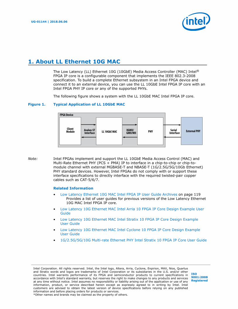
1. About LL Ethernet 10G MACThe Low Latency (LL) Ethernet 10G (10GbE) Media Access Controller (MAC) Intel®FPGA IP core is a configurable component that implements the IEEE 802.3-2008specification. To build a complete Ethernet subsystem in an Intel FPGA device andconnect it to an external device, you can use the LL 10GbE Intel FPGA IP core with anIntel FPGA PHY IP core or any of the supported PHYs.
The following figure shows a system with the LL 10GbE MAC Intel FPGA IP core.
Figure 1. Typical Application of LL 10GbE MAC
ClientModule
FPGA Device
External PHYInterfaceAvalon-ST XGMII/
GMII/MII10M/100M/
LL 10GbE MAC
PHY Serial Interface
Note: Intel FPGAs implement and support the LL 10GbE Media Access Control (MAC) andMulti-Rate Ethernet PHY (PCS + PMA) IP to interface in a chip-to-chip or chip-to-module channel with external MGBASE-T and NBASE-T (1G/2.5G/5G/10Gb Ethernet)PHY standard devices. However, Intel FPGAs do not comply with or support theseinterface specifications to directly interface with the required twisted-pair coppercables such as CAT-5/6/7.
Related Information
• Low Latency Ethernet 10G MAC Intel FPGA IP User Guide Archives on page 119Provides a list of user guides for previous versions of the Low Latency Ethernet10G MAC Intel FPGA IP core.
• Low Latency 10G Ethernet MAC Intel Arria 10 FPGA IP Core Design Example UserGuide
• Low Latency 10G Ethernet MAC Intel Stratix 10 FPGA IP Core Design ExampleUser Guide
• Low Latency 10G Ethernet MAC Intel Cyclone 10 FPGA IP Core Design ExampleUser Guide
• 1G/2.5G/5G/10G Multi-rate Ethernet PHY Intel Stratix 10 FPGA IP Core User Guide
UG-01144 | 2018.06.06
Intel Corporation. All rights reserved. Intel, the Intel logo, Altera, Arria, Cyclone, Enpirion, MAX, Nios, Quartusand Stratix words and logos are trademarks of Intel Corporation or its subsidiaries in the U.S. and/or othercountries. Intel warrants performance of its FPGA and semiconductor products to current specifications inaccordance with Intel's standard warranty, but reserves the right to make changes to any products and servicesat any time without notice. Intel assumes no responsibility or liability arising out of the application or use of anyinformation, product, or service described herein except as expressly agreed to in writing by Intel. Intelcustomers are advised to obtain the latest version of device specifications before relying on any publishedinformation and before placing orders for products or services.*Other names and brands may be claimed as the property of others.
ISO9001:2008Registered

1.1. Features
This Intel FPGA IP core is designed to the IEEE 802.3–2008 Ethernet Standardavailable on the IEEE website (www.ieee.org). All LL 10GbE Intel FPGA IP corevariations include MAC only and are in full-duplex mode. These Intel FPGA IP corevariations offer the following features:
• MAC features:
— Full-duplex MAC in eight operating modes: 10G, 1G/10G, 1G/2.5G, 1G/2.5G/10G, 10M/100M/1G/2.5G/5G/10G (USXGMII), 10M/100M/1G/10G, 10M/100M/1G/2.5G, and 10M/100M/1G/2.5G/10G.
— Three variations for selected operating modes: MAC TX only block, MAC RXonly block, and both MAC TX and MAC RX block.
— 10GBASE-R register mode on the TX and RX datapaths, which enables lowerlatency.
— Programmable promiscuous (transparent) mode.
— Unidirectional feature as specified by IEEE 802.3 (Clause 66).
— Priority-based flow control (PFC) with programmable pause quanta. PFCsupports 2 to 8 priority queues.
• Interfaces:
— Client-side—32-bit Avalon®-ST interface.
— Management—32-bit Avalon-MM interface.
— PHY-side—32-bit XGMII for 10GbE, 16-bit GMII for 2.5GbE, 8-bit GMII for1GbE, or 4-bit MII for 10M/100M.
• Frame structure control features:
— Virtual local area network (VLAN) and stacked VLAN tagged frames decoding(type 'h8100).
— Cyclic redundancy code (CRC)-32 computation and insertion on the TXdatapath. Optional CRC checking and forwarding on the RX datapath.
— Deficit idle counter (DIC) for optimized performance with average inter-packetgap (IPG) for LAN applications.
— Supports programmable IPG.
— Ethernet flow control using pause frames.
— Programmable maximum length of TX and RX data frames up to 64 Kbytes(KB).
— Preamble passthrough mode on TX and RX datapaths, which allows userdefined preamble in the client frame.
— Optional padding insertion on the TX datapath and termination on the RXdatapath.
• Frame monitoring and statistics:
— Optional CRC checking and forwarding on the RX datapath.
— Optional statistics collection on TX and RX datapaths.
1. About LL Ethernet 10G MAC
UG-01144 | 2018.06.06
Low Latency Ethernet 10G MAC Intel® FPGA IP User Guide6
• Optional timestamping as specified by the IEEE 1588v2 standard for the followingconfigurations:
— 10GbE MAC with 10GBASE-R PHY IP core
— 1G/10GbE MAC with 1G/10GbE PHY IP core
— 1G/2.5GbE MAC with 1G/2.5G Multi-rate Ethernet PHY IP core
— 1G/2.5G/10GbE MAC with 1G/2.5G/10G (MGBASE-T) Multi-rate Ethernet PHYIP core
— 10M/100M/1G/10GbE MAC with 10M-10GbE PHY IP core
— 10M/100M/1G/2.5G/5G/10G (USXGMII) MAC with 1G/2.5G/5G/10G Multi-rateEthernet PHY Intel FPGA IP core
1.1.1. LL Ethernet 10G MAC and Legacy 10-Gbps Ethernet MAC
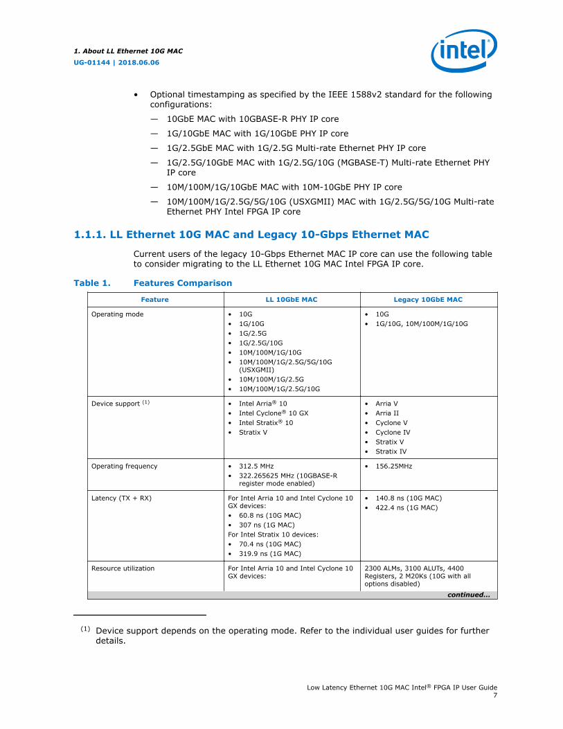
Current users of the legacy 10-Gbps Ethernet MAC IP core can use the following tableto consider migrating to the LL Ethernet 10G MAC Intel FPGA IP core.
Table 1. Features Comparison
Feature LL 10GbE MAC Legacy 10GbE MAC
Operating mode • 10G• 1G/10G• 1G/2.5G• 1G/2.5G/10G• 10M/100M/1G/10G• 10M/100M/1G/2.5G/5G/10G
(USXGMII)• 10M/100M/1G/2.5G• 10M/100M/1G/2.5G/10G
• 10G• 1G/10G, 10M/100M/1G/10G
Device support (1) • Intel Arria® 10• Intel Cyclone® 10 GX• Intel Stratix® 10• Stratix V
• Arria V• Arria II• Cyclone V• Cyclone IV• Stratix V• Stratix IV
Operating frequency • 312.5 MHz• 322.265625 MHz (10GBASE-R
register mode enabled)
• 156.25MHz
Latency (TX + RX) For Intel Arria 10 and Intel Cyclone 10GX devices:• 60.8 ns (10G MAC)• 307 ns (1G MAC)For Intel Stratix 10 devices:• 70.4 ns (10G MAC)• 319.9 ns (1G MAC)
• 140.8 ns (10G MAC)• 422.4 ns (1G MAC)
Resource utilization For Intel Arria 10 and Intel Cyclone 10GX devices:
2300 ALMs, 3100 ALUTs, 4400Registers, 2 M20Ks (10G with alloptions disabled)
continued...
(1) Device support depends on the operating mode. Refer to the individual user guides for furtherdetails.
1. About LL Ethernet 10G MAC
UG-01144 | 2018.06.06
Low Latency Ethernet 10G MAC Intel® FPGA IP User Guide7
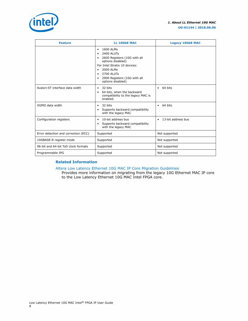
Feature LL 10GbE MAC Legacy 10GbE MAC
• 1600 ALMs• 2400 ALUTs• 2600 Registers (10G with all
options disabled)For Intel Stratix 10 devices:• 2000 ALMs• 2700 ALUTs• 2900 Registers (10G with all
options disabled)
Avalon-ST interface data width • 32 bits• 64 bits, when the backward
compatibility to the legacy MAC isenabled.
• 64 bits
XGMII data width • 32 bits• Supports backward compatibility
with the legacy MAC
• 64 bits
Configuration registers • 10-bit address bus• Supports backward compatibility
with the legacy MAC
• 13-bit address bus
Error detection and correction (ECC) Supported Not supported
10GBASE-R register mode Supported Not supported
96-bit and 64-bit ToD clock formats Supported Not supported
Programmable IPG Supported Not supported
Related Information
Altera Low Latency Ethernet 10G MAC IP Core Migration GuidelinesProvides more information on migrating from the legacy 10G Ethernet MAC IP coreto the Low Latency Ethernet 10G MAC Intel FPGA core.
1. About LL Ethernet 10G MAC
UG-01144 | 2018.06.06
Low Latency Ethernet 10G MAC Intel® FPGA IP User Guide8
1.2. Release Information
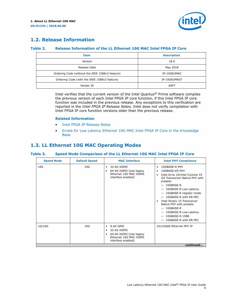
Table 2. Release Information of the LL Ethernet 10G MAC Intel FPGA IP Core
Item Description
Version 18.0
Release Date May 2018
Ordering Code (without the IEEE 1588v2 feature) IP-10GEUMAC
Ordering Code (with the IEEE 1588v2 feature) IP-10GEUMACF
Vendor ID 6AF7
Intel verifies that the current version of the Intel Quartus® Prime software compilesthe previous version of each Intel FPGA IP core function, if this Intel FPGA IP corefunction was included in the previous release. Any exceptions to this verification arereported in the Intel FPGA IP Release Notes. Intel does not verify compilation withIntel FPGA IP core function versions older than the previous release.
Related Information
• Intel FPGA IP Release Notes
• Errata for Low Latency Ethernet 10G MAC Intel FPGA IP Core in the KnowledgeBase
1.3. LL Ethernet 10G MAC Operating Modes
Table 3. Speed Mode Comparison of the LL Ethernet 10G MAC Intel FPGA IP Core
Speed Mode Default Speed MAC Interface Intel PHY Compliance
10G 10G • 32-bit XGMII• 64-bit XGMII (Use legacy
Ethernet 10G MAC XGMIIinterface enabled)
• 10GBASE-R PHY• 10GBASE-KR PHY• Intel Arria 10/Intel Cyclone 10
GX Transceiver Native PHY withpresets:— 10GBASE-R— 10GBASE-R Low Latency— 10GBASE-R register mode— 10GBASE-R with KR-FEC
• Intel Stratix 10 TransceiverNative PHY with presets:— 10GBASE-R— 10GBASE-R Low Latency— 10GBASE-R 1588— 10GBASE-R with KR-FEC
1G/10G 10G • 8-bit GMII• 32-bit XGMII• 64-bit XGMII (Use legacy
Ethernet 10G MAC XGMIIinterface enabled)
1G/10GbE Ethernet PHY IP
continued...
1. About LL Ethernet 10G MAC
UG-01144 | 2018.06.06
Low Latency Ethernet 10G MAC Intel® FPGA IP User Guide9
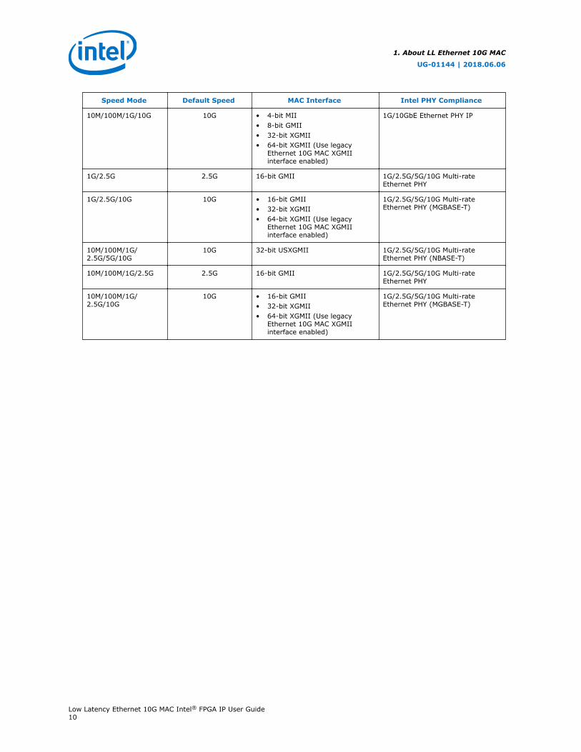
Speed Mode Default Speed MAC Interface Intel PHY Compliance
10M/100M/1G/10G 10G • 4-bit MII• 8-bit GMII• 32-bit XGMII• 64-bit XGMII (Use legacy
Ethernet 10G MAC XGMIIinterface enabled)
1G/10GbE Ethernet PHY IP
1G/2.5G 2.5G 16-bit GMII 1G/2.5G/5G/10G Multi-rateEthernet PHY
1G/2.5G/10G 10G • 16-bit GMII• 32-bit XGMII• 64-bit XGMII (Use legacy
Ethernet 10G MAC XGMIIinterface enabled)
1G/2.5G/5G/10G Multi-rateEthernet PHY (MGBASE-T)
10M/100M/1G/2.5G/5G/10G
10G 32-bit USXGMII 1G/2.5G/5G/10G Multi-rateEthernet PHY (NBASE-T)
10M/100M/1G/2.5G 2.5G 16-bit GMII 1G/2.5G/5G/10G Multi-rateEthernet PHY
10M/100M/1G/2.5G/10G
10G • 16-bit GMII• 32-bit XGMII• 64-bit XGMII (Use legacy
Ethernet 10G MAC XGMIIinterface enabled)
1G/2.5G/5G/10G Multi-rateEthernet PHY (MGBASE-T)
1. About LL Ethernet 10G MAC
UG-01144 | 2018.06.06
Low Latency Ethernet 10G MAC Intel® FPGA IP User Guide10

1.4. Device Family Support
Table 4. Intel FPGA IP Core Device Support Levels
Device Support Level Definition
Preliminary Intel verifies the IP core with preliminary timing models for this device family.The IP core meets all functional requirements, but might still be undergoingtiming analysis for the device family. This IP core can be used in productiondesigns with caution.
Final Intel verifies the IP core with final timing models for this device family. The IPcore meets all functional and timing requirements for the device family. This IPcore is ready to be used in production designs.
The IP core provides the following support for Intel FPGA device families.
Table 5. Device Family Support for LL 10GbE MAC
Device Family Support Minimum Speed Grade
With 1588 Feature Without 1588 Feature
Intel Stratix 10 Preliminary -I2, -E2 -I3, -C3
Intel Arria 10 Final -I2, -E2 -I3, -E3
Intel Cyclone 10 GX Final -I5, -E5 -I6, -E6
Stratix V Final -I3, -C3 -I4, -C4
Arria V Final -I3, -C3 -I4, -C4
The following table lists possible LL 10GbE MAC and PHY configurations and thedevices each configuration supports:
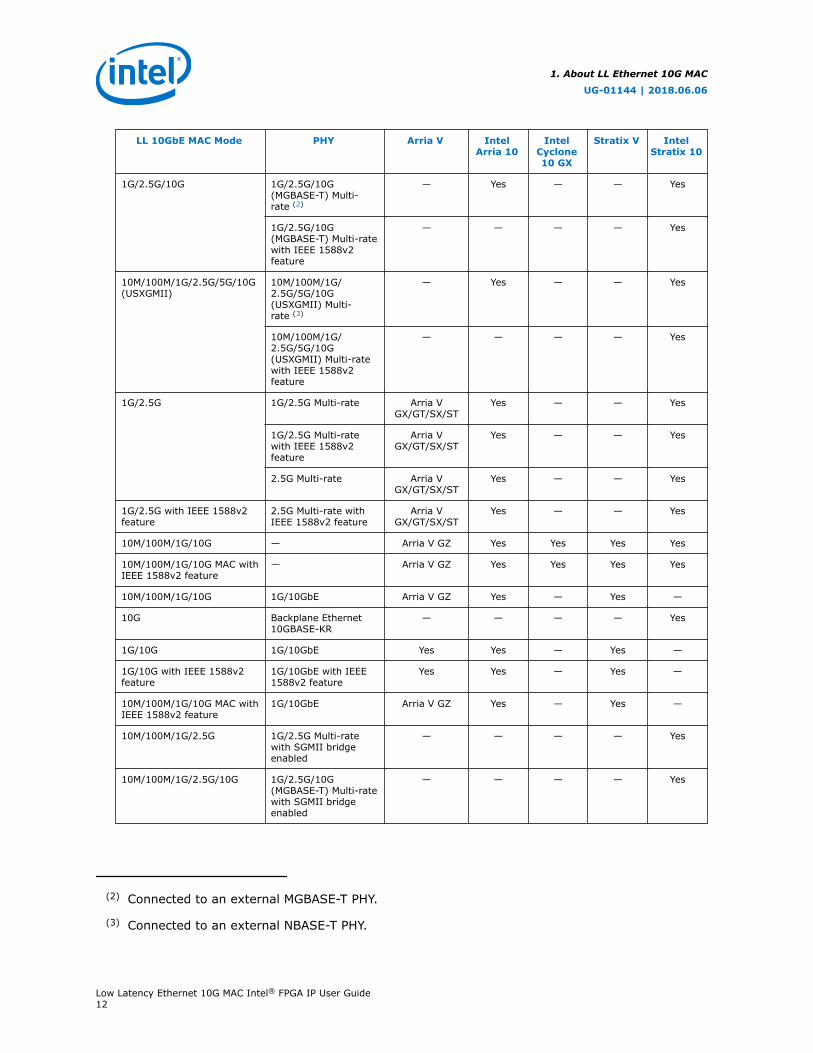
Table 6. Device Family Support for LL 10GbE MAC and PHY Configurations
LL 10GbE MAC Mode PHY Arria V IntelArria 10
IntelCyclone10 GX
Stratix V IntelStratix 10
10G 10GBASE-R Arria V GZ — — Yes —
10GBASE-R with IEEE1588v2 feature
Arria V GZ — — Yes —
• 10GBASE-R• 10GBASE-R Low
Latency• 10GBASE-R
Register Mode• 10GBASE-R with
KR-FEC
— Yes Yes —
• 10GBASE-R• 10GBASE-R Low
Latency• 10GBASE-R with
IEEE 1588v2feature
• 10GBASE-R withKR-FEC
— — — — Yes
continued...
1. About LL Ethernet 10G MAC
UG-01144 | 2018.06.06
Low Latency Ethernet 10G MAC Intel® FPGA IP User Guide11
LL 10GbE MAC Mode PHY Arria V IntelArria 10
IntelCyclone10 GX
Stratix V IntelStratix 10
1G/2.5G/10G 1G/2.5G/10G(MGBASE-T) Multi-rate (2)
— Yes — — Yes
1G/2.5G/10G(MGBASE-T) Multi-ratewith IEEE 1588v2feature
— — — — Yes
10M/100M/1G/2.5G/5G/10G(USXGMII)
10M/100M/1G/2.5G/5G/10G(USXGMII) Multi-rate (3)
— Yes — — Yes
10M/100M/1G/2.5G/5G/10G(USXGMII) Multi-ratewith IEEE 1588v2feature
— — — — Yes
1G/2.5G 1G/2.5G Multi-rate Arria VGX/GT/SX/ST
Yes — — Yes
1G/2.5G Multi-ratewith IEEE 1588v2feature
Arria VGX/GT/SX/ST
Yes — — Yes
2.5G Multi-rate Arria VGX/GT/SX/ST
Yes — — Yes
1G/2.5G with IEEE 1588v2feature
2.5G Multi-rate withIEEE 1588v2 feature
Arria VGX/GT/SX/ST
Yes — — Yes
10M/100M/1G/10G — Arria V GZ Yes Yes Yes Yes
10M/100M/1G/10G MAC withIEEE 1588v2 feature
— Arria V GZ Yes Yes Yes Yes
10M/100M/1G/10G 1G/10GbE Arria V GZ Yes — Yes —
10G Backplane Ethernet10GBASE-KR
— — — — Yes
1G/10G 1G/10GbE Yes Yes — Yes —
1G/10G with IEEE 1588v2feature
1G/10GbE with IEEE1588v2 feature
Yes Yes — Yes —
10M/100M/1G/10G MAC withIEEE 1588v2 feature
1G/10GbE Arria V GZ Yes — Yes —
10M/100M/1G/2.5G 1G/2.5G Multi-ratewith SGMII bridgeenabled
— — — — Yes
10M/100M/1G/2.5G/10G 1G/2.5G/10G(MGBASE-T) Multi-ratewith SGMII bridgeenabled
— — — — Yes
(2) Connected to an external MGBASE-T PHY.
(3) Connected to an external NBASE-T PHY.
1. About LL Ethernet 10G MAC
UG-01144 | 2018.06.06
Low Latency Ethernet 10G MAC Intel® FPGA IP User Guide12

Related Information
• Intel Stratix 10 10GBASE-KR PHY IP Core User Guide
• 1G/2.5G/5G/10G Multi-rate Ethernet PHY Intel Stratix 10 FPGA IP Core User Guide
1. About LL Ethernet 10G MAC
UG-01144 | 2018.06.06
Low Latency Ethernet 10G MAC Intel® FPGA IP User Guide13
1.5. Performance and Resource Utilization
1.5.1. Resource Utilization
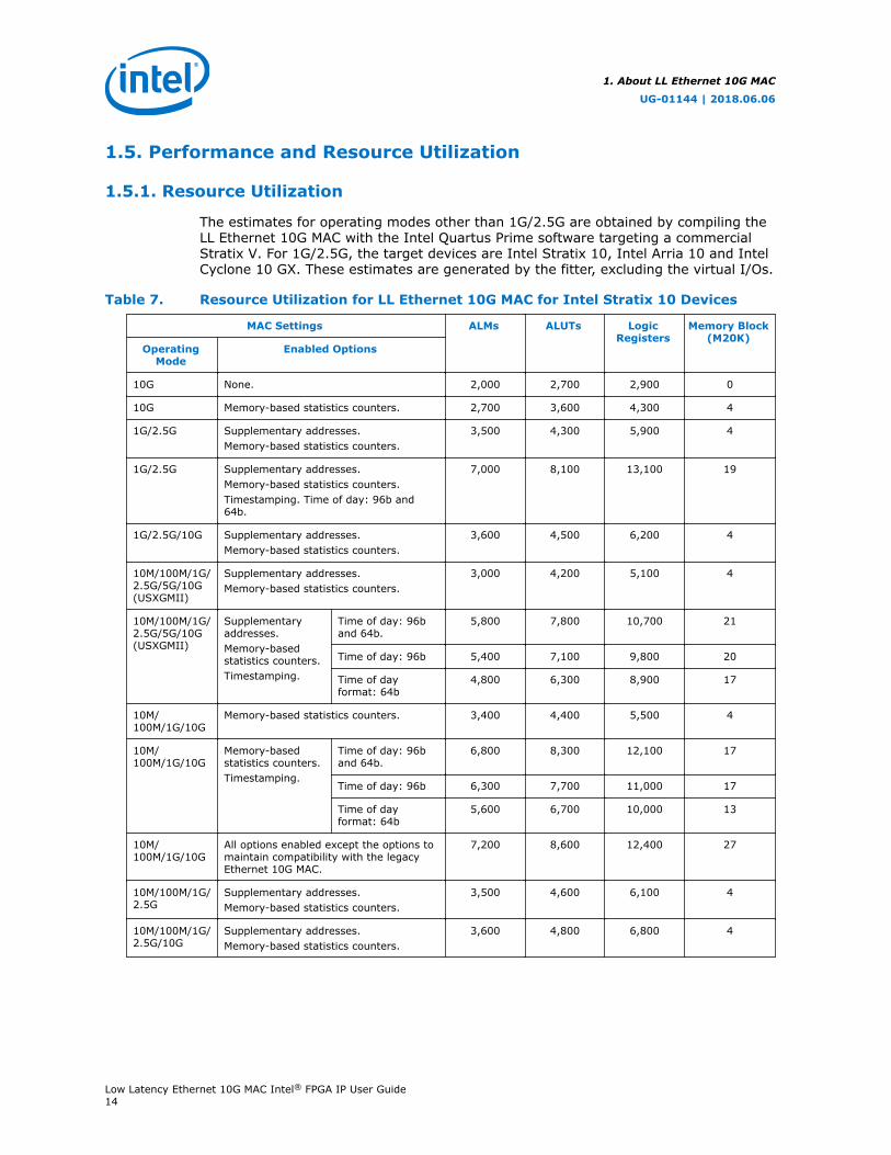
The estimates for operating modes other than 1G/2.5G are obtained by compiling theLL Ethernet 10G MAC with the Intel Quartus Prime software targeting a commercialStratix V. For 1G/2.5G, the target devices are Intel Stratix 10, Intel Arria 10 and IntelCyclone 10 GX. These estimates are generated by the fitter, excluding the virtual I/Os.
Table 7. Resource Utilization for LL Ethernet 10G MAC for Intel Stratix 10 Devices
MAC Settings ALMs ALUTs LogicRegisters
Memory Block(M20K)
OperatingMode
Enabled Options
10G None. 2,000 2,700 2,900 0
10G Memory-based statistics counters. 2,700 3,600 4,300 4
1G/2.5G Supplementary addresses.Memory-based statistics counters.
3,500 4,300 5,900 4
1G/2.5G Supplementary addresses.Memory-based statistics counters.Timestamping. Time of day: 96b and64b.
7,000 8,100 13,100 19
1G/2.5G/10G Supplementary addresses.Memory-based statistics counters.
3,600 4,500 6,200 4
10M/100M/1G/2.5G/5G/10G(USXGMII)
Supplementary addresses.Memory-based statistics counters.
3,000 4,200 5,100 4
10M/100M/1G/2.5G/5G/10G(USXGMII)
Supplementaryaddresses.Memory-basedstatistics counters.Timestamping.
Time of day: 96band 64b.
5,800 7,800 10,700 21
Time of day: 96b 5,400 7,100 9,800 20
Time of dayformat: 64b
4,800 6,300 8,900 17
10M/100M/1G/10G
Memory-based statistics counters. 3,400 4,400 5,500 4
10M/100M/1G/10G
Memory-basedstatistics counters.Timestamping.
Time of day: 96band 64b.
6,800 8,300 12,100 17
Time of day: 96b 6,300 7,700 11,000 17
Time of dayformat: 64b
5,600 6,700 10,000 13
10M/100M/1G/10G
All options enabled except the options tomaintain compatibility with the legacyEthernet 10G MAC.
7,200 8,600 12,400 27
10M/100M/1G/2.5G
Supplementary addresses.Memory-based statistics counters.
3,500 4,600 6,100 4
10M/100M/1G/2.5G/10G
Supplementary addresses.Memory-based statistics counters.
3,600 4,800 6,800 4
1. About LL Ethernet 10G MAC
UG-01144 | 2018.06.06
Low Latency Ethernet 10G MAC Intel® FPGA IP User Guide14
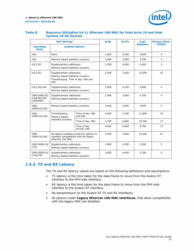
Table 8. Resource Utilization for LL Ethernet 10G MAC for Intel Arria 10 and IntelCyclone 10 GX Devices
MAC Settings ALMs ALUTs LogicRegisters
Memory Block(M20K)
OperatingMode
Enabled Options
10G None. 1,600 2,400 2,600 0
10G Memory-based statistics counters. 2,000 3,200 3,700 4
1G/2.5G Supplementary addresses.Memory-based statistics counters.
2,700 4,000 5,000 5
1G/2.5G Supplementary addresses.Memory-based statistics counters.Timestamping. Time of day: 96b and64b.
5,300 7,600 12,000 20
1G/2.5G/10G Supplementary addresses.Memory-based statistics counters.
2,900 4,100 5,600 4
10M/100M/1G/2.5G/5G/10G(USXGMII)
Supplementary addresses.Memory-based statistics counters.
2,400 3,900 4,700 4
10M/100M/1G/10G
Memory-based statistics counters. 2,600 3,900 4,900 4
10M/100M/1G/10G
Timestamping.Memory-basedstatistics counters.
Time of day: 96band 64b.
5,000 7,200 11,800 19
Time of day: 96b 4,700 6,800 10,700 17
Time of dayformat: 64b
4,200 6,000 9,700 13
10M/100M/1G/10G
All options enabled except the options tomaintain compatibility with the legacyEthernet 10G MAC.
5,400 7,600 12,200 27
10M/100M/1G/2.5G
Supplementary addresses.Memory-based statistics counters.
2,900 4,300 5,500 5
10M/100M/1G/2.5G/10G
Supplementary addresses.Memory-based statistics counters.
3,000 4,400 5,700 5
1.5.2. TX and RX Latency
The TX and RX latency values are based on the following definitions and assumptions:
• TX latency is the time taken for the data frame to move from the Avalon-STinterface to the PHY-side interface.
• RX latency is the time taken for the data frame to move from the PHY-sideinterface to the Avalon-ST interface.
• No backpressure on the Avalon-ST TX and RX interfaces.
• All options under Legacy Ethernet 10G MAC interfaces, that allow compatibilitywith the legacy MAC are disabled.
1. About LL Ethernet 10G MAC
UG-01144 | 2018.06.06
Low Latency Ethernet 10G MAC Intel® FPGA IP User Guide15
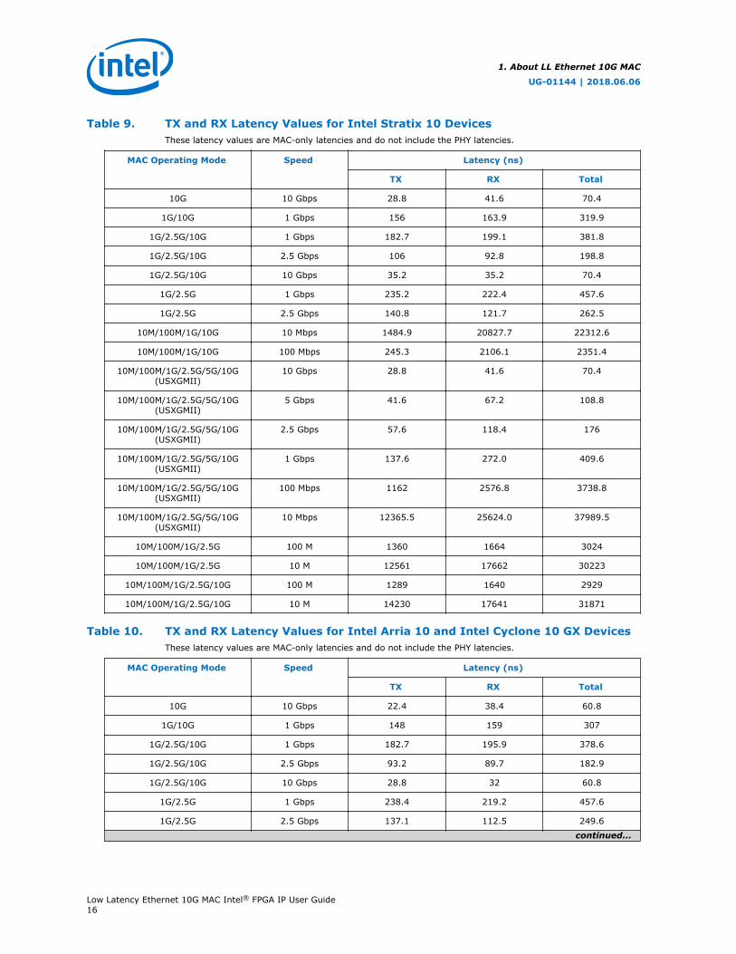
Table 9. TX and RX Latency Values for Intel Stratix 10 DevicesThese latency values are MAC-only latencies and do not include the PHY latencies.
MAC Operating Mode Speed Latency (ns)
TX RX Total
10G 10 Gbps 28.8 41.6 70.4
1G/10G 1 Gbps 156 163.9 319.9
1G/2.5G/10G 1 Gbps 182.7 199.1 381.8
1G/2.5G/10G 2.5 Gbps 106 92.8 198.8
1G/2.5G/10G 10 Gbps 35.2 35.2 70.4
1G/2.5G 1 Gbps 235.2 222.4 457.6
1G/2.5G 2.5 Gbps 140.8 121.7 262.5
10M/100M/1G/10G 10 Mbps 1484.9 20827.7 22312.6
10M/100M/1G/10G 100 Mbps 245.3 2106.1 2351.4
10M/100M/1G/2.5G/5G/10G(USXGMII)
10 Gbps 28.8 41.6 70.4
10M/100M/1G/2.5G/5G/10G(USXGMII)
5 Gbps 41.6 67.2 108.8
10M/100M/1G/2.5G/5G/10G(USXGMII)
2.5 Gbps 57.6 118.4 176
10M/100M/1G/2.5G/5G/10G(USXGMII)
1 Gbps 137.6 272.0 409.6
10M/100M/1G/2.5G/5G/10G(USXGMII)
100 Mbps 1162 2576.8 3738.8
10M/100M/1G/2.5G/5G/10G(USXGMII)
10 Mbps 12365.5 25624.0 37989.5
10M/100M/1G/2.5G 100 M 1360 1664 3024
10M/100M/1G/2.5G 10 M 12561 17662 30223
10M/100M/1G/2.5G/10G 100 M 1289 1640 2929
10M/100M/1G/2.5G/10G 10 M 14230 17641 31871
Table 10. TX and RX Latency Values for Intel Arria 10 and Intel Cyclone 10 GX DevicesThese latency values are MAC-only latencies and do not include the PHY latencies.
MAC Operating Mode Speed Latency (ns)
TX RX Total
10G 10 Gbps 22.4 38.4 60.8
1G/10G 1 Gbps 148 159 307
1G/2.5G/10G 1 Gbps 182.7 195.9 378.6
1G/2.5G/10G 2.5 Gbps 93.2 89.7 182.9
1G/2.5G/10G 10 Gbps 28.8 32 60.8
1G/2.5G 1 Gbps 238.4 219.2 457.6
1G/2.5G 2.5 Gbps 137.1 112.5 249.6
continued...
1. About LL Ethernet 10G MAC
UG-01144 | 2018.06.06
Low Latency Ethernet 10G MAC Intel® FPGA IP User Guide16
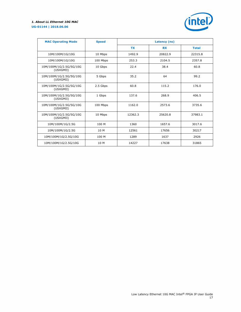
MAC Operating Mode Speed Latency (ns)
TX RX Total
10M/100M/1G/10G 10 Mbps 1492.9 20822.9 22315.8
10M/100M/1G/10G 100 Mbps 253.3 2104.5 2357.8
10M/100M/1G/2.5G/5G/10G(USXGMII)
10 Gbps 22.4 38.4 60.8
10M/100M/1G/2.5G/5G/10G(USXGMII)
5 Gbps 35.2 64 99.2
10M/100M/1G/2.5G/5G/10G(USXGMII)
2.5 Gbps 60.8 115.2 176.0
10M/100M/1G/2.5G/5G/10G(USXGMII)
1 Gbps 137.6 268.9 406.5
10M/100M/1G/2.5G/5G/10G(USXGMII)
100 Mbps 1162.0 2573.6 3735.6
10M/100M/1G/2.5G/5G/10G(USXGMII)
10 Mbps 12362.3 25620.8 37983.1
10M/100M/1G/2.5G 100 M 1360 1657.6 3017.6
10M/100M/1G/2.5G 10 M 12561 17656 30217
10M/100M/1G/2.5G/10G 100 M 1289 1637 2926
10M/100M/1G/2.5G/10G 10 M 14227 17638 31865
1. About LL Ethernet 10G MAC
UG-01144 | 2018.06.06
Low Latency Ethernet 10G MAC Intel® FPGA IP User Guide17
2. Getting StartedThis chapter provides a general overview of the Intel FPGA IP core design flow to helpyou quickly get started with LL Ethernet 10G MAC.
2.1. Introduction to Intel FPGA IP Cores
Intel and strategic IP partners offer a broad portfolio of configurable IP coresoptimized for Intel FPGA devices.
The Intel Quartus Prime software installation includes the Intel FPGA IP library.Integrate optimized and verified Intel FPGA IP cores into your design to shorten designcycles and maximize performance. The Intel Quartus Prime software also supportsintegration of IP cores from other sources. Use the IP Catalog (Tools ➤ IP Catalog)to efficiently parameterize and generate synthesis and simulation files for your customIP variation. The Intel FPGA IP library includes the following types of IP cores:
• Basic functions
• DSP functions
• Interface protocols
• Low power functions
• Memory interfaces and controllers
• Processors and peripherals
This document provides basic information about parameterizing, generating,upgrading, and simulating stand-alone IP cores in the Intel Quartus Prime software.
UG-01144 | 2018.06.06
Intel Corporation. All rights reserved. Intel, the Intel logo, Altera, Arria, Cyclone, Enpirion, MAX, Nios, Quartusand Stratix words and logos are trademarks of Intel Corporation or its subsidiaries in the U.S. and/or othercountries. Intel warrants performance of its FPGA and semiconductor products to current specifications inaccordance with Intel's standard warranty, but reserves the right to make changes to any products and servicesat any time without notice. Intel assumes no responsibility or liability arising out of the application or use of anyinformation, product, or service described herein except as expressly agreed to in writing by Intel. Intelcustomers are advised to obtain the latest version of device specifications before relying on any publishedinformation and before placing orders for products or services.*Other names and brands may be claimed as the property of others.
ISO9001:2008Registered
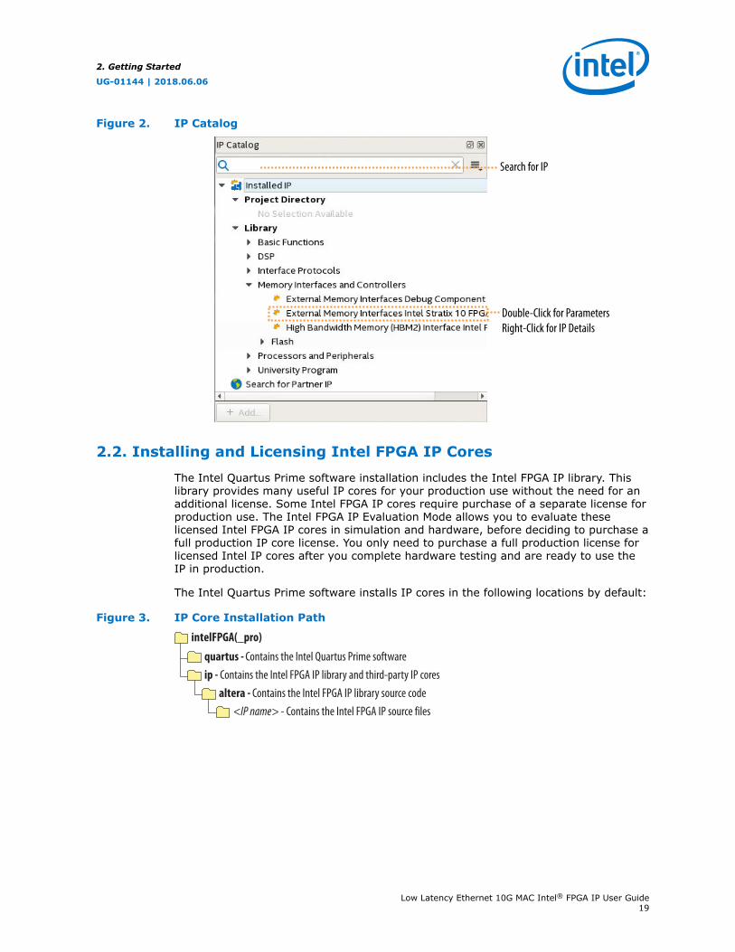
Figure 2. IP Catalog
Double-Click for ParametersRight-Click for IP Details
Search for IP
2.2. Installing and Licensing Intel FPGA IP Cores
The Intel Quartus Prime software installation includes the Intel FPGA IP library. Thislibrary provides many useful IP cores for your production use without the need for anadditional license. Some Intel FPGA IP cores require purchase of a separate license forproduction use. The Intel FPGA IP Evaluation Mode allows you to evaluate theselicensed Intel FPGA IP cores in simulation and hardware, before deciding to purchase afull production IP core license. You only need to purchase a full production license forlicensed Intel IP cores after you complete hardware testing and are ready to use theIP in production.
The Intel Quartus Prime software installs IP cores in the following locations by default:
Figure 3. IP Core Installation Path
intelFPGA(_pro)
quartus - Contains the Intel Quartus Prime softwareip - Contains the Intel FPGA IP library and third-party IP cores
altera - Contains the Intel FPGA IP library source code<IP name> - Contains the Intel FPGA IP source files
2. Getting Started
UG-01144 | 2018.06.06
Low Latency Ethernet 10G MAC Intel® FPGA IP User Guide19
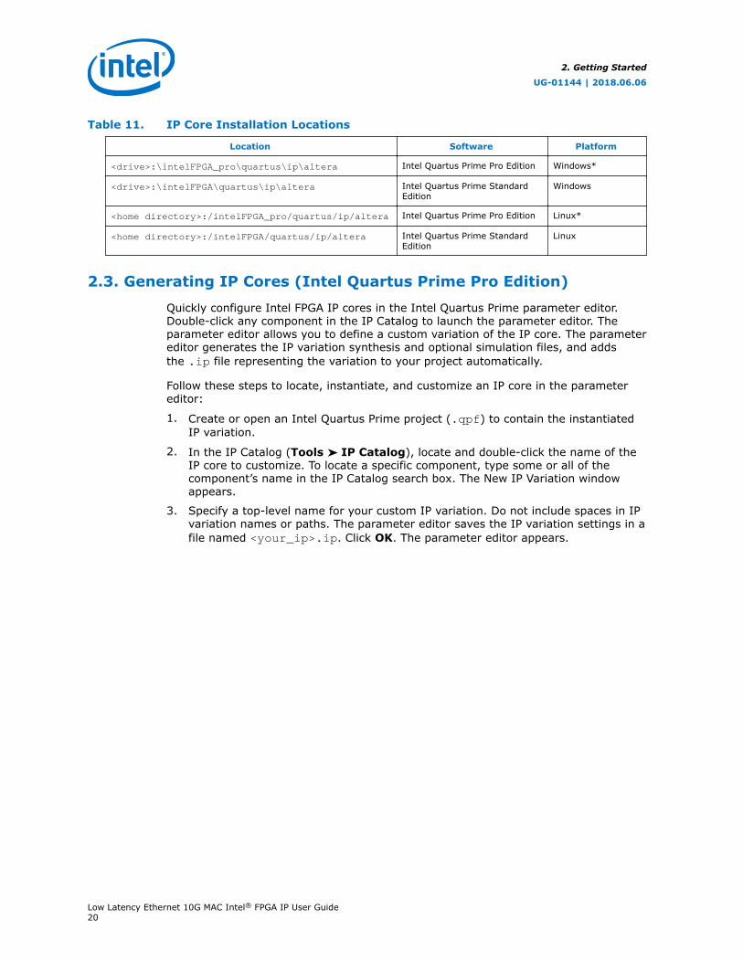
Table 11. IP Core Installation Locations
Location Software Platform
<drive>:\intelFPGA_pro\quartus\ip\altera Intel Quartus Prime Pro Edition Windows*
<drive>:\intelFPGA\quartus\ip\altera Intel Quartus Prime StandardEdition
Windows
<home directory>:/intelFPGA_pro/quartus/ip/altera Intel Quartus Prime Pro Edition Linux*
<home directory>:/intelFPGA/quartus/ip/altera Intel Quartus Prime StandardEdition
Linux
2.3. Generating IP Cores (Intel Quartus Prime Pro Edition)
Quickly configure Intel FPGA IP cores in the Intel Quartus Prime parameter editor.Double-click any component in the IP Catalog to launch the parameter editor. Theparameter editor allows you to define a custom variation of the IP core. The parametereditor generates the IP variation synthesis and optional simulation files, and addsthe .ip file representing the variation to your project automatically.
Follow these steps to locate, instantiate, and customize an IP core in the parametereditor:
1. Create or open an Intel Quartus Prime project (.qpf) to contain the instantiatedIP variation.
2. In the IP Catalog (Tools ➤ IP Catalog), locate and double-click the name of theIP core to customize. To locate a specific component, type some or all of thecomponent’s name in the IP Catalog search box. The New IP Variation windowappears.
3. Specify a top-level name for your custom IP variation. Do not include spaces in IPvariation names or paths. The parameter editor saves the IP variation settings in afile named <your_ip>.ip. Click OK. The parameter editor appears.
2. Getting Started
UG-01144 | 2018.06.06
Low Latency Ethernet 10G MAC Intel® FPGA IP User Guide20
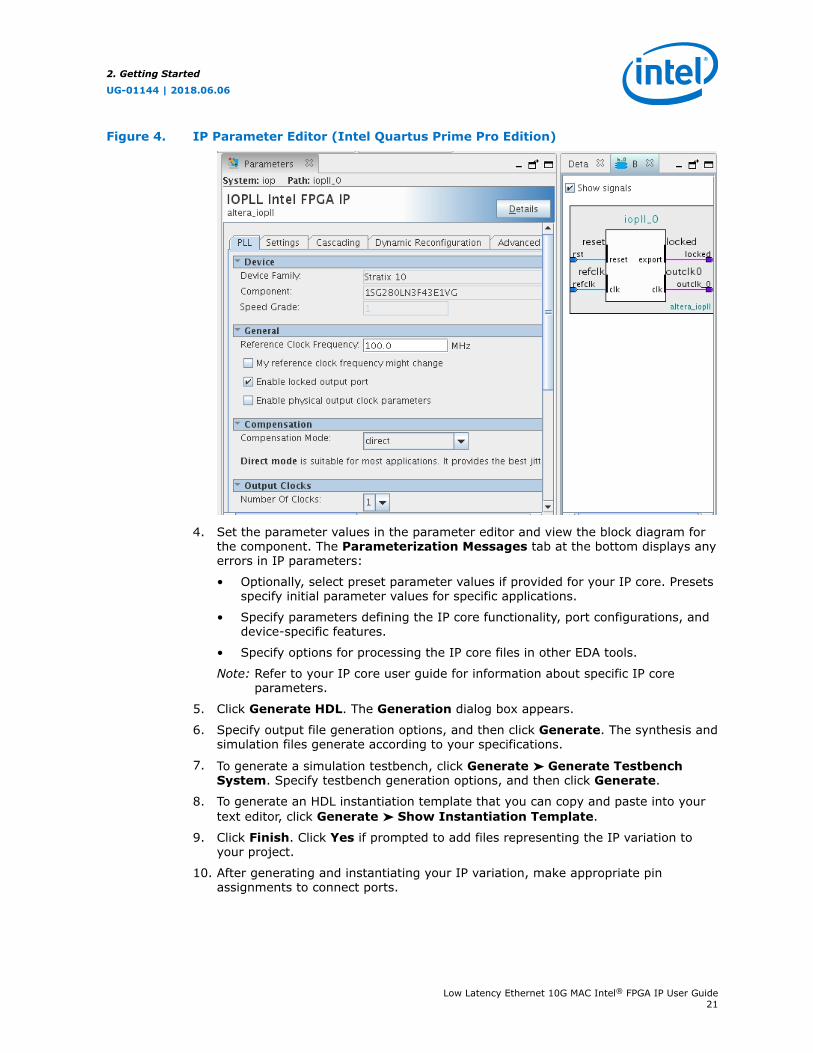
Figure 4. IP Parameter Editor (Intel Quartus Prime Pro Edition)
4. Set the parameter values in the parameter editor and view the block diagram forthe component. The Parameterization Messages tab at the bottom displays anyerrors in IP parameters:
• Optionally, select preset parameter values if provided for your IP core. Presetsspecify initial parameter values for specific applications.
• Specify parameters defining the IP core functionality, port configurations, anddevice-specific features.
• Specify options for processing the IP core files in other EDA tools.
Note: Refer to your IP core user guide for information about specific IP coreparameters.
5. Click Generate HDL. The Generation dialog box appears.
6. Specify output file generation options, and then click Generate. The synthesis andsimulation files generate according to your specifications.
7. To generate a simulation testbench, click Generate ➤ Generate TestbenchSystem. Specify testbench generation options, and then click Generate.
8. To generate an HDL instantiation template that you can copy and paste into yourtext editor, click Generate ➤ Show Instantiation Template.
9. Click Finish. Click Yes if prompted to add files representing the IP variation toyour project.
10. After generating and instantiating your IP variation, make appropriate pinassignments to connect ports.
2. Getting Started
UG-01144 | 2018.06.06
Low Latency Ethernet 10G MAC Intel® FPGA IP User Guide21
Note: Some IP cores generate different HDL implementations according to the IPcore parameters. The underlying RTL of these IP cores contains a uniquehash code that prevents module name collisions between different variationsof the IP core. This unique code remains consistent, given the same IPsettings and software version during IP generation. This unique code canchange if you edit the IP core's parameters or upgrade the IP core version.To avoid dependency on these unique codes in your simulation environment,refer to Generating a Combined Simulator Setup Script.
Related Information
• Intel FPGA IP Release Notes
• IP User Guide Documentation
• Low Latency 10G Ethernet MAC Intel Arria 10 FPGA IP Core Design Example UserGuide
• Low Latency 10G Ethernet MAC Intel Stratix 10 FPGA IP Core Design ExampleUser Guide
• Low Latency 10G Ethernet MAC Intel Cyclone 10 FPGA IP Core Design ExampleUser Guide
2.4. IP Core Generation Output (Intel Quartus Prime Pro Edition)
The Intel Quartus Prime software generates the following output file structure forindividual IP cores that are not part of a Platform Designer system.
2. Getting Started
UG-01144 | 2018.06.06
Low Latency Ethernet 10G MAC Intel® FPGA IP User Guide22
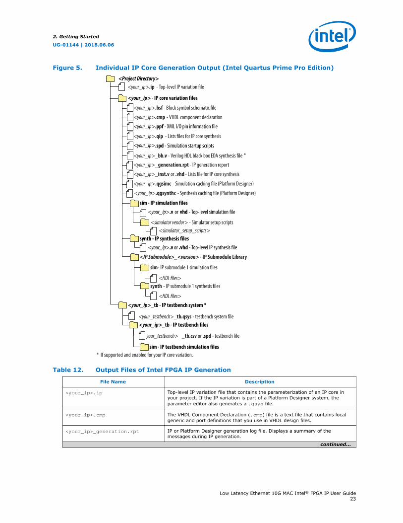
Figure 5. Individual IP Core Generation Output (Intel Quartus Prime Pro Edition)
<Project Directory>
<your_ip>_inst.v or .vhd - Lists file for IP core synthesis
<your_ip>.qip - Lists files for IP core synthesis
synth - IP synthesis files
<IP Submodule>_<version> - IP Submodule Library
sim
<your_ip>.v or .vhd - Top-level IP synthesis file
sim - IP simulation files
<simulator vendor> - Simulator setup scripts<simulator_setup_scripts>
<your_ip> - IP core variation files
<your_ip>.ip - Top-level IP variation file
<your_ip>_generation.rpt - IP generation report
<your_ip>.bsf - Block symbol schematic file
<your_ip>.ppf - XML I/O pin information file
<your_ip>.spd - Simulation startup scripts
*
<your_ip>.cmp - VHDL component declaration
<your_ip>.v or vhd - Top-level simulation file
synth
- IP submodule 1 simulation files
- IP submodule 1 synthesis files
<your_ip>_bb.v - Verilog HDL black box EDA synthesis file
<HDL files>
<HDL files>
<your_ip>_tb - IP testbench system *
<your_testbench>_tb.qsys - testbench system file<your_ip>_tb - IP testbench files
your_testbench> _tb.csv or .spd - testbench file
sim - IP testbench simulation files * If supported and enabled for your IP core variation.
<your_ip>.qgsimc - Simulation caching file (Platform Designer)
<your_ip>.qgsynthc - Synthesis caching file (Platform Designer)
Table 12. Output Files of Intel FPGA IP Generation
File Name Description
<your_ip>.ip Top-level IP variation file that contains the parameterization of an IP core inyour project. If the IP variation is part of a Platform Designer system, theparameter editor also generates a .qsys file.
<your_ip>.cmp The VHDL Component Declaration (.cmp) file is a text file that contains localgeneric and port definitions that you use in VHDL design files.
<your_ip>_generation.rpt IP or Platform Designer generation log file. Displays a summary of themessages during IP generation.
continued...
2. Getting Started
UG-01144 | 2018.06.06
Low Latency Ethernet 10G MAC Intel® FPGA IP User Guide23

File Name Description
<your_ip>.qgsimc (Platform Designersystems only)
Simulation caching file that compares the .qsys and .ip files with the currentparameterization of the Platform Designer system and IP core. This comparisondetermines if Platform Designer can skip regeneration of the HDL.
<your_ip>.qgsynth (PlatformDesigner systems only)
Synthesis caching file that compares the .qsys and .ip files with the currentparameterization of the Platform Designer system and IP core. This comparisondetermines if Platform Designer can skip regeneration of the HDL.
<your_ip>.qip Contains all information to integrate and compile the IP component.
<your_ip>.csv Contains information about the upgrade status of the IP component.
<your_ip>.bsf A symbol representation of the IP variation for use in Block Diagram Files(.bdf).
<your_ip>.spd Input file that ip-make-simscript requires to generate simulation scripts.The .spd file contains a list of files you generate for simulation, along withinformation about memories that you initialize.
<your_ip>.ppf The Pin Planner File (.ppf) stores the port and node assignments for IPcomponents you create for use with the Pin Planner.
<your_ip>_bb.v Use the Verilog blackbox (_bb.v) file as an empty module declaration for useas a blackbox.
<your_ip>_inst.v or _inst.vhd HDL example instantiation template. Copy and paste the contents of this fileinto your HDL file to instantiate the IP variation.
<your_ip>.regmap If the IP contains register information, the Intel Quartus Prime softwaregenerates the .regmap file. The .regmap file describes the register mapinformation of master and slave interfaces. This file complementsthe .sopcinfo file by providing more detailed register information about thesystem. This file enables register display views and user customizable statisticsin System Console.
<your_ip>.svd Allows HPS System Debug tools to view the register maps of peripherals thatconnect to HPS within a Platform Designer system.During synthesis, the Intel Quartus Prime software stores the .svd files forslave interface visible to the System Console masters in the .sof file in thedebug session. System Console reads this section, which Platform Designerqueries for register map information. For system slaves, Platform Designeraccesses the registers by name.
<your_ip>.v <your_ip>.vhd HDL files that instantiate each submodule or child IP core for synthesis orsimulation.
mentor/ Contains a msim_setup.tcl script to set up and run a simulation.
aldec/ Contains a script rivierapro_setup.tcl to setup and run a simulation.
/synopsys/vcs
/synopsys/vcsmx
Contains a shell script vcs_setup.sh to set up and run a simulation.Contains a shell script vcsmx_setup.sh and synopsys_sim.setup file toset up and run a simulation.
/cadence Contains a shell script ncsim_setup.sh and other setup files to set up andrun an simulation.
/xcelium Contains an Parallel simulator shell script xcelium_setup.sh and other setupfiles to set up and run a simulation.
/submodules Contains HDL files for the IP core submodule.
<IP submodule>/ Platform Designer generates /synth and /sim sub-directories for each IPsubmodule directory that Platform Designer generates.
2. Getting Started
UG-01144 | 2018.06.06
Low Latency Ethernet 10G MAC Intel® FPGA IP User Guide24
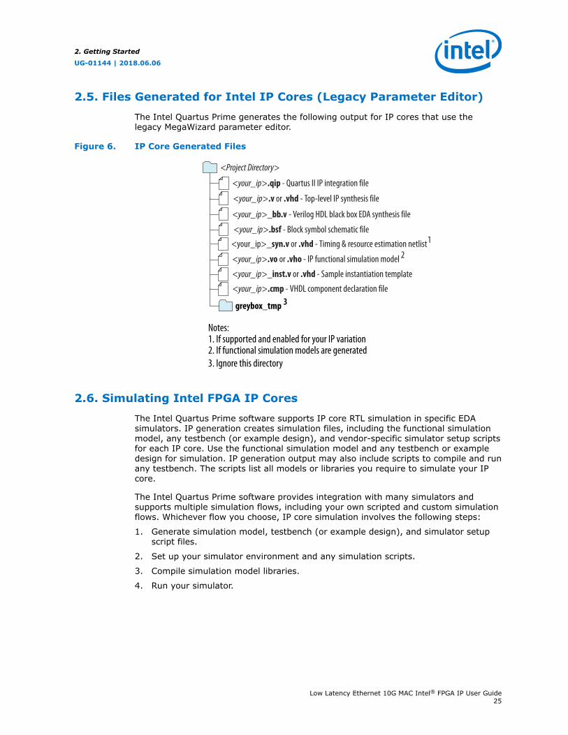
2.5. Files Generated for Intel IP Cores (Legacy Parameter Editor)
The Intel Quartus Prime generates the following output for IP cores that use thelegacy MegaWizard parameter editor.
Figure 6. IP Core Generated Files
Notes:1. If supported and enabled for your IP variation2. If functional simulation models are generated3. Ignore this directory
<Project Directory>
<your_ip>.v or .vhd - Top-level IP synthesis file
<your_ip>_inst.v or .vhd - Sample instantiation template
<your_ip>.bsf - Block symbol schematic file
<your_ip>.vo or .vho - IP functional simulation model 2<your_ip>_syn.v or .vhd - Timing & resource estimation netlist1
<your_ip>_bb.v - Verilog HDL black box EDA synthesis file
<your_ip>.qip - Quartus II IP integration file
greybox_tmp 3
<your_ip>.cmp - VHDL component declaration file
2.6. Simulating Intel FPGA IP Cores
The Intel Quartus Prime software supports IP core RTL simulation in specific EDAsimulators. IP generation creates simulation files, including the functional simulationmodel, any testbench (or example design), and vendor-specific simulator setup scriptsfor each IP core. Use the functional simulation model and any testbench or exampledesign for simulation. IP generation output may also include scripts to compile and runany testbench. The scripts list all models or libraries you require to simulate your IPcore.
The Intel Quartus Prime software provides integration with many simulators andsupports multiple simulation flows, including your own scripted and custom simulationflows. Whichever flow you choose, IP core simulation involves the following steps:
1. Generate simulation model, testbench (or example design), and simulator setupscript files.
2. Set up your simulator environment and any simulation scripts.
3. Compile simulation model libraries.
4. Run your simulator.
2. Getting Started
UG-01144 | 2018.06.06
Low Latency Ethernet 10G MAC Intel® FPGA IP User Guide25
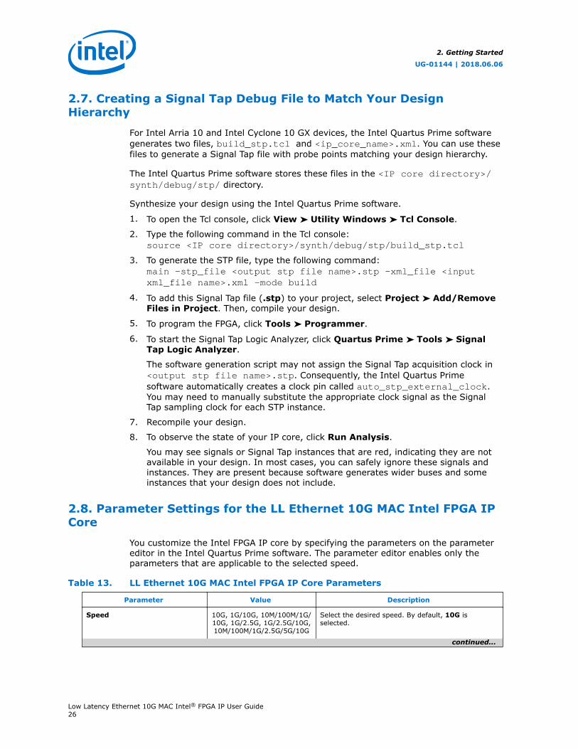
2.7. Creating a Signal Tap Debug File to Match Your DesignHierarchy
For Intel Arria 10 and Intel Cyclone 10 GX devices, the Intel Quartus Prime softwaregenerates two files, build_stp.tcl and <ip_core_name>.xml. You can use thesefiles to generate a Signal Tap file with probe points matching your design hierarchy.
The Intel Quartus Prime software stores these files in the <IP core directory>/synth/debug/stp/ directory.
Synthesize your design using the Intel Quartus Prime software.
1. To open the Tcl console, click View ➤ Utility Windows ➤ Tcl Console.
2. Type the following command in the Tcl console:source <IP core directory>/synth/debug/stp/build_stp.tcl
3. To generate the STP file, type the following command:main -stp_file <output stp file name>.stp -xml_file <inputxml_file name>.xml -mode build
4. To add this Signal Tap file (.stp) to your project, select Project ➤ Add/RemoveFiles in Project. Then, compile your design.
5. To program the FPGA, click Tools ➤ Programmer.
6. To start the Signal Tap Logic Analyzer, click Quartus Prime ➤ Tools ➤ SignalTap Logic Analyzer.
The software generation script may not assign the Signal Tap acquisition clock in<output stp file name>.stp. Consequently, the Intel Quartus Primesoftware automatically creates a clock pin called auto_stp_external_clock.You may need to manually substitute the appropriate clock signal as the SignalTap sampling clock for each STP instance.
7. Recompile your design.
8. To observe the state of your IP core, click Run Analysis.
You may see signals or Signal Tap instances that are red, indicating they are notavailable in your design. In most cases, you can safely ignore these signals andinstances. They are present because software generates wider buses and someinstances that your design does not include.
2.8. Parameter Settings for the LL Ethernet 10G MAC Intel FPGA IPCore
You customize the Intel FPGA IP core by specifying the parameters on the parametereditor in the Intel Quartus Prime software. The parameter editor enables only theparameters that are applicable to the selected speed.
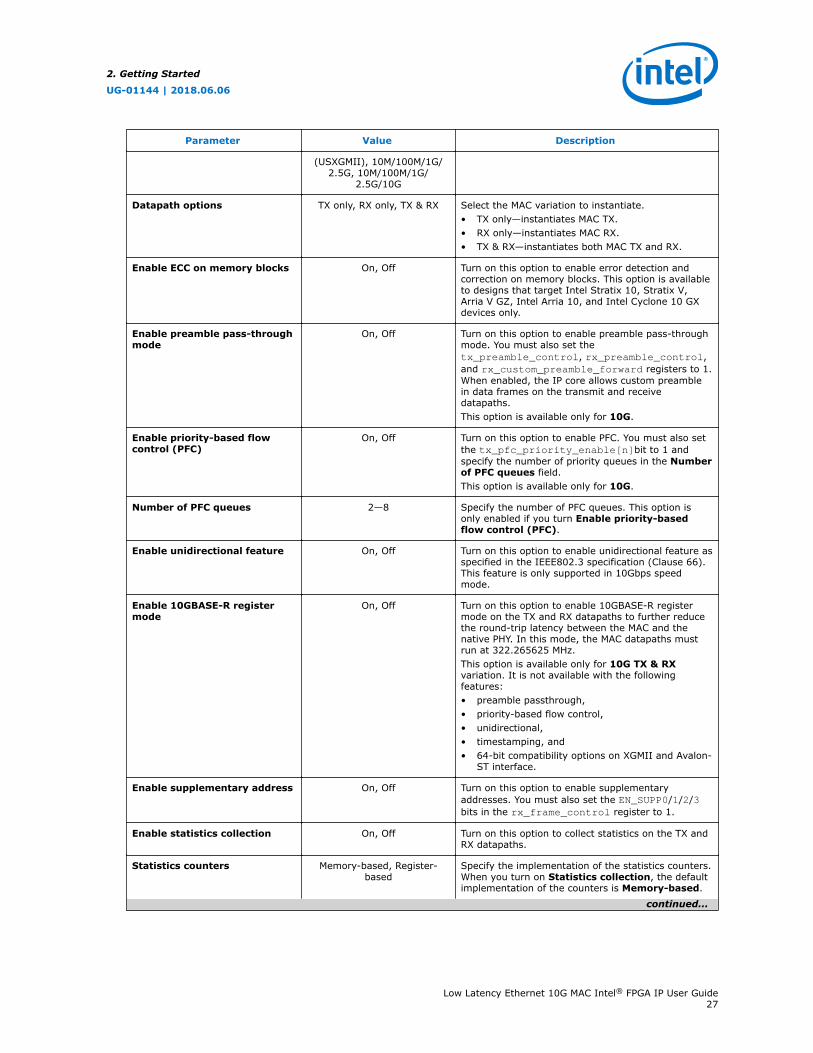
Table 13. LL Ethernet 10G MAC Intel FPGA IP Core Parameters
Parameter Value Description
Speed 10G, 1G/10G, 10M/100M/1G/10G, 1G/2.5G, 1G/2.5G/10G,10M/100M/1G/2.5G/5G/10G
Select the desired speed. By default, 10G isselected.
continued...
2. Getting Started
UG-01144 | 2018.06.06
Low Latency Ethernet 10G MAC Intel® FPGA IP User Guide26
Parameter Value Description
(USXGMII), 10M/100M/1G/2.5G, 10M/100M/1G/
2.5G/10G
Datapath options TX only, RX only, TX & RX Select the MAC variation to instantiate.• TX only—instantiates MAC TX.• RX only—instantiates MAC RX.• TX & RX—instantiates both MAC TX and RX.
Enable ECC on memory blocks On, Off Turn on this option to enable error detection andcorrection on memory blocks. This option is availableto designs that target Intel Stratix 10, Stratix V,Arria V GZ, Intel Arria 10, and Intel Cyclone 10 GXdevices only.
Enable preamble pass-throughmode
On, Off Turn on this option to enable preamble pass-throughmode. You must also set thetx_preamble_control, rx_preamble_control,and rx_custom_preamble_forward registers to 1.When enabled, the IP core allows custom preamblein data frames on the transmit and receivedatapaths.This option is available only for 10G.
Enable priority-based flowcontrol (PFC)
On, Off Turn on this option to enable PFC. You must also setthe tx_pfc_priority_enable[n]bit to 1 andspecify the number of priority queues in the Numberof PFC queues field.This option is available only for 10G.
Number of PFC queues 2—8 Specify the number of PFC queues. This option isonly enabled if you turn Enable priority-basedflow control (PFC).
Enable unidirectional feature On, Off Turn on this option to enable unidirectional feature asspecified in the IEEE802.3 specification (Clause 66).This feature is only supported in 10Gbps speedmode.
Enable 10GBASE-R registermode
On, Off Turn on this option to enable 10GBASE-R registermode on the TX and RX datapaths to further reducethe round-trip latency between the MAC and thenative PHY. In this mode, the MAC datapaths mustrun at 322.265625 MHz.This option is available only for 10G TX & RXvariation. It is not available with the followingfeatures:• preamble passthrough,• priority-based flow control,• unidirectional,• timestamping, and• 64-bit compatibility options on XGMII and Avalon-
ST interface.
Enable supplementary address On, Off Turn on this option to enable supplementaryaddresses. You must also set the EN_SUPP0/1/2/3bits in the rx_frame_control register to 1.
Enable statistics collection On, Off Turn on this option to collect statistics on the TX andRX datapaths.
Statistics counters Memory-based, Register-based
Specify the implementation of the statistics counters.When you turn on Statistics collection, the defaultimplementation of the counters is Memory-based.
continued...
2. Getting Started
UG-01144 | 2018.06.06
Low Latency Ethernet 10G MAC Intel® FPGA IP User Guide27
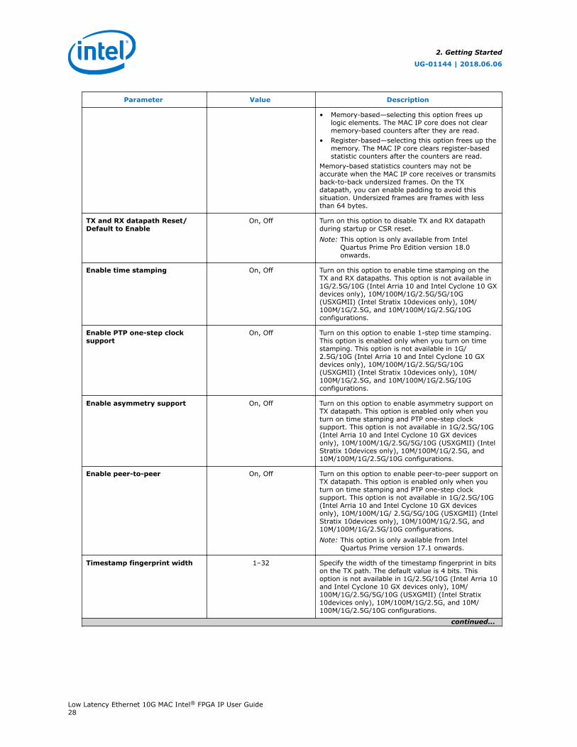
Parameter Value Description
• Memory-based—selecting this option frees uplogic elements. The MAC IP core does not clearmemory-based counters after they are read.
• Register-based—selecting this option frees up thememory. The MAC IP core clears register-basedstatistic counters after the counters are read.
Memory-based statistics counters may not beaccurate when the MAC IP core receives or transmitsback-to-back undersized frames. On the TXdatapath, you can enable padding to avoid thissituation. Undersized frames are frames with lessthan 64 bytes.
TX and RX datapath Reset/Default to Enable
On, Off Turn on this option to disable TX and RX datapathduring startup or CSR reset.Note: This option is only available from Intel
Quartus Prime Pro Edition version 18.0onwards.
Enable time stamping On, Off Turn on this option to enable time stamping on theTX and RX datapaths. This option is not available in1G/2.5G/10G (Intel Arria 10 and Intel Cyclone 10 GXdevices only), 10M/100M/1G/2.5G/5G/10G(USXGMII) (Intel Stratix 10devices only), 10M/100M/1G/2.5G, and 10M/100M/1G/2.5G/10Gconfigurations.
Enable PTP one-step clocksupport
On, Off Turn on this option to enable 1-step time stamping.This option is enabled only when you turn on timestamping. This option is not available in 1G/2.5G/10G (Intel Arria 10 and Intel Cyclone 10 GXdevices only), 10M/100M/1G/2.5G/5G/10G(USXGMII) (Intel Stratix 10devices only), 10M/100M/1G/2.5G, and 10M/100M/1G/2.5G/10Gconfigurations.
Enable asymmetry support On, Off Turn on this option to enable asymmetry support onTX datapath. This option is enabled only when youturn on time stamping and PTP one-step clocksupport. This option is not available in 1G/2.5G/10G(Intel Arria 10 and Intel Cyclone 10 GX devicesonly), 10M/100M/1G/2.5G/5G/10G (USXGMII) (IntelStratix 10devices only), 10M/100M/1G/2.5G, and10M/100M/1G/2.5G/10G configurations.
Enable peer-to-peer On, Off Turn on this option to enable peer-to-peer support onTX datapath. This option is enabled only when youturn on time stamping and PTP one-step clocksupport. This option is not available in 1G/2.5G/10G(Intel Arria 10 and Intel Cyclone 10 GX devicesonly), 10M/100M/1G/ 2.5G/5G/10G (USXGMII) (IntelStratix 10devices only), 10M/100M/1G/2.5G, and10M/100M/1G/2.5G/10G configurations.Note: This option is only available from Intel
Quartus Prime version 17.1 onwards.
Timestamp fingerprint width 1–32 Specify the width of the timestamp fingerprint in bitson the TX path. The default value is 4 bits. Thisoption is not available in 1G/2.5G/10G (Intel Arria 10and Intel Cyclone 10 GX devices only), 10M/100M/1G/2.5G/5G/10G (USXGMII) (Intel Stratix10devices only), 10M/100M/1G/2.5G, and 10M/100M/1G/2.5G/10G configurations.
continued...
2. Getting Started
UG-01144 | 2018.06.06
Low Latency Ethernet 10G MAC Intel® FPGA IP User Guide28
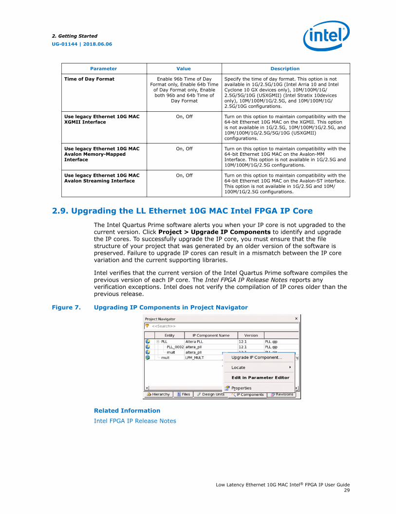
Parameter Value Description
Time of Day Format Enable 96b Time of DayFormat only, Enable 64b Time
of Day Format only, Enableboth 96b and 64b Time of
Day Format
Specify the time of day format. This option is notavailable in 1G/2.5G/10G (Intel Arria 10 and IntelCyclone 10 GX devices only), 10M/100M/1G/2.5G/5G/10G (USXGMII) (Intel Stratix 10devicesonly), 10M/100M/1G/2.5G, and 10M/100M/1G/2.5G/10G configurations.
Use legacy Ethernet 10G MACXGMII Interface
On, Off Turn on this option to maintain compatibility with the64-bit Ethernet 10G MAC on the XGMII. This optionis not available in 1G/2.5G, 10M/100M/1G/2.5G, and10M/100M/1G/2.5G/5G/10G (USXGMII)configurations.
Use legacy Ethernet 10G MACAvalon Memory-MappedInterface
On, Off Turn on this option to maintain compatibility with the64-bit Ethernet 10G MAC on the Avalon-MMInterface. This option is not available in 1G/2.5G and10M/100M/1G/2.5G configurations.
Use legacy Ethernet 10G MACAvalon Streaming Interface
On, Off Turn on this option to maintain compatibility with the64-bit Ethernet 10G MAC on the Avalon-ST interface.This option is not available in 1G/2.5G and 10M/100M/1G/2.5G configurations.
2.9. Upgrading the LL Ethernet 10G MAC Intel FPGA IP Core
The Intel Quartus Prime software alerts you when your IP core is not upgraded to thecurrent version. Click Project > Upgrade IP Components to identify and upgradethe IP cores. To successfully upgrade the IP core, you must ensure that the filestructure of your project that was generated by an older version of the software ispreserved. Failure to upgrade IP cores can result in a mismatch between the IP corevariation and the current supporting libraries.
Intel verifies that the current version of the Intel Quartus Prime software compiles theprevious version of each IP core. The Intel FPGA IP Release Notes reports anyverification exceptions. Intel does not verify the compilation of IP cores older than theprevious release.
Figure 7. Upgrading IP Components in Project Navigator
Related Information
Intel FPGA IP Release Notes
2. Getting Started
UG-01144 | 2018.06.06
Low Latency Ethernet 10G MAC Intel® FPGA IP User Guide29
2.10. Design Considerations for the LL Ethernet 10G MAC IntelFPGA IP Core
2.10.1. Migrating from Legacy Ethernet 10G MAC to LL Ethernet 10G MAC
Intel recommends that you opt for the following migration paths. These migrationpaths allow you to take advantage of the benefits of LL Ethernet 10G MAC—lowresource count and low latency.
2.10.1.1. Migration—32-bit Datapath on Avalon-ST Interface
Follow these steps to implement 32-bit datapath on the Avalon-ST and Avalon-MMinterfaces.
1. Instantiate the LL Ethernet 10G MAC Intel FPGA IP core in your design. If you areusing a PHY with 64-bit SDR XGMII interface, turn on the Use legacy Ethernet10G MAC XGMII Interface option.
2. Modify your user logic to accommodate 32-bit datapaths on Avalon-ST TX and RXdata interfaces.
3. Ensure that tx_312_5_clk and rx_312_5_clk are connected to 312.5 MHzclock sources. Intel recommends that you use the same clock source for theseclock signals.
4. Update the register offsets to the offsets of the LL Ethernet 10G MAC Intel FPGA IPcore. The configuration registers of the LL Ethernet 10G MAC Intel FPGA IP coreallow access to new features such as error correction and detection on memoryblocks.
5. If you turn on the Use legacy Ethernet 10G MAC XGMII Interface option, adda 156.25 MHz clock source for tx_156_25_clk and rx_156_25_clk. This156.25 MHz clock source must be rise-to-rise synchronous to the 312.5 MHz clocksource.
6. Ensure that csr_clk is within 125 MHz to 156.25 MHz. Otherwise, some statisticcounters may not be accurate.
2.10.1.2. Migration—Maintains 64-bit on Avalon-ST Interface
Follow these steps to implement 32-bit to 64-bit adapters on the Avalon-ST interfaceand XGMII, and uses the same register offsets to maintain backward compatibilitywith the legacy 10-Gbps Ethernet (10GbE) MAC IP core.
2. Getting Started
UG-01144 | 2018.06.06
Low Latency Ethernet 10G MAC Intel® FPGA IP User Guide30
1. Instantiate the LL Ethernet 10G MAC Intel FPGA IP core in your design. Tomaintain compatibility on the interfaces, turn on the Use legacy Ethernet 10GMAC XGMII Interface, Use legacy Ethernet 10G MAC Avalon Memory-Mapped Interface, and Use legacy Ethernet 10G MAC Avalon StreamingInterface options.
2. Ensure that tx_312_5_clk and rx_312_5_clk are connected to 312.5 MHzclock sources. Intel recommends that you use the same clock source for theseclock signals.
3. Add a 156.25 MHz clock source for tx_156_25_clk and rx_156_25_clk. This156.25 MHz clock source must be rise-to-rise synchronous to the 312.5 MHz clocksource.
4. Ensure that csr_clk is within 125 MHz to 156.25 MHz. Otherwise, some statisticcounters may not be accurate.
Related Information
Altera Low Latency Ethernet 10G MAC IP Core Migration Guidelines
2.10.2. Timing Constraints
Intel provides timing constraint files (.sdc) to ensure that the IP core meets thedesign timing requirements in Intel FPGA devices. The files constraint the false pathsand multicycle paths in the IP core. The timing constraints files are specified in the<variation_name>.qip file and is automatically included in the Intel Quartus Primeproject files.
The timing constraints files are in the IP directory. You can edit these files asnecessary. They are for clock crossing logic and grouped as below:
• Pseudo-static CSR fields
• Clock crosser
• Dual clock FIFO
Note: For the IP core to work correctly, there must be no other timing constraints filescutting or overriding the paths, for example, set_false_path, set_clock_groups,at the project level.
Note: If you enable IEEE 1588v2 in 10G speed, Intel recommends that you add the followingconstraint in the Intel Quartus Prime Settings File (.qsf):
set_instance_assignment -name GLOBAL_SIGNAL OFF -to"*|alt_em10g32:alt_em10g32_0|alt_em10g32_clk_rst:clk_rst_inst|alt_em10g32_rst_cnt:tx_reset_count_inst|rst_n_out"
2.10.2.1. Pseudo-Static CSR Fields
Most of the configuration registers in the MAC IP core must not be programmed whenthe MAC is in operation. As such, they are not synchronized to reduce resource usage.These registers are all in the set_false_path constraint.
2.10.2.2. Clock Crosser
Clock crossers perform multi-bit signals crossing from one clock domain to another.
2. Getting Started
UG-01144 | 2018.06.06
Low Latency Ethernet 10G MAC Intel® FPGA IP User Guide31
The working principle of the clock crosser is to let the crossed-over data stabilize firstbefore indicating that the data is valid in the latched clock domain. Using suchstructure, the data bits must not skew for more than one latched clock period. Thetiming constraint file applies a common timing check over all the clock crossersirrespective of their latched clock domain. This is over-pessimistic for signals crossinginto the CSR clock, but there are no side-effects, like significant run-time impact andfalse violations, during the internal testing. If your design runs into clock crossertiming violation paths within the IP and the latched clock domain is csr_clk, you candismiss the violation manually or by editing the .sdc file if the violation is less thanone csr_clk period.
The timing constraint file uses the set_net_delay to constraint the fitter placementand set_max_skew to perform timing check on the paths. For a project with veryhigh device utilization, Intel recommends that you implement addition steps like floorplanning or Logic Lock to aid the place-and-route process. The additional steps cangive a more consistent timing closure along these paths instead of only relying on theset_net_delay.
A caveat of using set_max_skew is that it does not analyze whether the insertiondelay of the path in concern exceeds a limit. In other words, a path could meet skewrequirement but have longer than expected insertion delay. If this is not checked, itmay cause functional failure in certain latency-sensitive paths. Therefore, a customscript (alt_em10g32_clock_crosser_timing_info.tcl) is available for you tocheck that the round-trip clock crosser delay is within expectation. To use this script,manually add it to the user flow and run it. To ensure that the IP core operatescorrectly, the results must be positive (no error).
2.10.2.3. Dual Clock FIFO
The bit skew of the dual clock FIFO gray-coded pointers must be within one 312.5 MHzclock period.
The timing constraint file uses the set_net_delay to constraint the fitter placementand set_max_skew to perform timing check on the paths. For a project with veryhigh device utilization, Intel recommends that you implement addition steps like floorplanning or Logic Lock to aid the place-and-route process. The additional steps cangive a more consistent timing closure along these paths instead of only relying on theset_net_delay.
2.10.3. Jitter on PLL Clocks
To minimize jitter, the advanced transmit (ATX) PLL and the fractional PLL (fPLL) cansource the input reference clock directly from the reference clock buffer withoutpassing through the reference clock network. You must ensure that a locationconstraint is added to your design to achieve a correct placement on the device.
2. Getting Started
UG-01144 | 2018.06.06
Low Latency Ethernet 10G MAC Intel® FPGA IP User Guide32
3. LL Ethernet 10G MAC Intel FPGA IP Design ExamplesIntel offers design examples that you can simulate, compile, and test in hardware.
The implementation of the LL Ethernet 10G MAC Intel FPGA IP core on hardwarerequires additional components specific to the targeted device.
3.1. LL Ethernet 10G MAC Intel FPGA IP Design Example for IntelStratix 10 Devices
The LL Ethernet 10G MAC Intel FPGA IP core offers design examples that you cangenerate through the IP catalog in the Intel Quartus Prime Pro Edition software.
For detailed information about the LL Ethernet 10G MAC Intel FPGA IP designexamples, refer to Low Latency Ethernet 10G MAC Intel Stratix 10 FPGA IP DesignExample User Guide.
Related Information
Intel FPGA Low Latency Ethernet 10G MAC Intel Stratix 10 FPGA IP Design ExampleUser Guide
3.2. LL Ethernet 10G MAC Intel FPGA IP Design Example for IntelArria 10 Devices
The LL Ethernet 10G MAC Intel FPGA IP core offers design examples that you cangenerate through the IP catalog in the Intel Quartus Prime software.
For detailed information about the LL Ethernet 10G MAC Intel FPGA IP designexamples, refer to Low Latency Ethernet 10G MAC Intel Arria 10 FPGA IP DesignExample User Guide.
Related Information
Intel FPGA Low Latency Ethernet 10G MAC Intel Arria 10 FPGA IP Design ExampleUser Guide
3.3. LL Ethernet 10G MAC Intel FPGA IP Design Example for IntelCyclone 10 Devices
The LL Ethernet 10G MAC Intel FPGA IP core offers design examples that you cangenerate through the IP catalog in the Intel Quartus Prime Pro Edition software.
For detailed information about the LL Ethernet 10G MAC Intel FPGA IP designexamples, refer to Low Latency Ethernet 10G MAC Intel Cyclone 10 FPGA IP DesignExample User Guide.
UG-01144 | 2018.06.06
Intel Corporation. All rights reserved. Intel, the Intel logo, Altera, Arria, Cyclone, Enpirion, MAX, Nios, Quartusand Stratix words and logos are trademarks of Intel Corporation or its subsidiaries in the U.S. and/or othercountries. Intel warrants performance of its FPGA and semiconductor products to current specifications inaccordance with Intel's standard warranty, but reserves the right to make changes to any products and servicesat any time without notice. Intel assumes no responsibility or liability arising out of the application or use of anyinformation, product, or service described herein except as expressly agreed to in writing by Intel. Intelcustomers are advised to obtain the latest version of device specifications before relying on any publishedinformation and before placing orders for products or services.*Other names and brands may be claimed as the property of others.
ISO9001:2008Registered

Related Information
Intel FPGA Low Latency Ethernet 10G MAC Intel Cyclone 10 FPGA IP Design ExampleUser Guide
3. LL Ethernet 10G MAC Intel FPGA IP Design Examples
UG-01144 | 2018.06.06
Low Latency Ethernet 10G MAC Intel® FPGA IP User Guide34
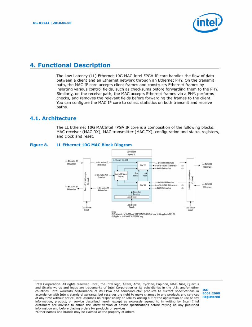
4. Functional DescriptionThe Low Latency (LL) Ethernet 10G MAC Intel FPGA IP core handles the flow of databetween a client and an Ethernet network through an Ethernet PHY. On the transmitpath, the MAC IP core accepts client frames and constructs Ethernet frames byinserting various control fields, such as checksums before forwarding them to the PHY.Similarly, on the receive path, the MAC accepts Ethernet frames via a PHY, performschecks, and removes the relevant fields before forwarding the frames to the client.You can configure the MAC IP core to collect statistics on both transmit and receivepaths.
4.1. Architecture
The LL Ethernet 10G MACIntel FPGA IP core is a composition of the following blocks:MAC receiver (MAC RX), MAC transmitter (MAC TX), configuration and status registers,and clock and reset.
Figure 8. LL Ethernet 10G MAC Block Diagram
MAC TX
Control & StatusRegisters
MAC RX
Clock & Reset
LL Ethernet 10G MAC
CSR Adapter(Optional)
Avalo
n-ST
32/6
4b Ad
apte
r(O
ption
al)
XGM
II SDR
32/6
4b Ad
apte
r(O
ption
al)
32-Bit XGMII TX Interface8- or 16-Bit GMII TX Interface4-Bit MII TX Interface
32-Bit XGMII RX Interface8- or 16-Bit GMII RX Interface4-Bit MII RX Interface
64-Bit Avalon-ST RX Interface
64-Bit Avalon-ST TX Interface
64-Bit XGMII RX Interface
64-Bit XGMII TX Interface
FlowControl
LinkFault
RespectiveDomains
Clock & ResetSignals Clock & Reset
SignalsClock & Reset
Signals
32-Bit Avalon-STTX Interface
32-Bit Avalon-MMInterface
32-Bit Avalon-STRX Interface
Notes: (1) 8-bit applies to 1G/10G and 10M/100M/1G/10G MAC only. 16-bit applies to 1G/2.5G.(2) Applies to 10M/100M/1G/10G MAC only.
(1)
(1)
(2)
(2)
UG-01144 | 2018.06.06
Intel Corporation. All rights reserved. Intel, the Intel logo, Altera, Arria, Cyclone, Enpirion, MAX, Nios, Quartusand Stratix words and logos are trademarks of Intel Corporation or its subsidiaries in the U.S. and/or othercountries. Intel warrants performance of its FPGA and semiconductor products to current specifications inaccordance with Intel's standard warranty, but reserves the right to make changes to any products and servicesat any time without notice. Intel assumes no responsibility or liability arising out of the application or use of anyinformation, product, or service described herein except as expressly agreed to in writing by Intel. Intelcustomers are advised to obtain the latest version of device specifications before relying on any publishedinformation and before placing orders for products or services.*Other names and brands may be claimed as the property of others.
ISO9001:2008Registered
4.2. Interfaces
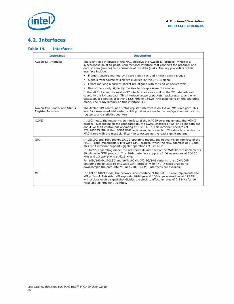
Table 14. Interfaces
Interfaces Description
Avalon-ST Interface The client-side interface of the MAC employs the Avalon-ST protocol, which is asynchronous point-to-point, unidirectional interface that connects the producer of adata stream (source) to a consumer of the data (sink). The key properties of thisinterface include:• Frame transfers marked by startofpacket and endofpacket signals.• Signals from source to sink are qualified by the valid signal.• Errors marking a current packet are aligned with the end-of-packet cycle.• Use of the ready signal by the sink to backpressure the source.In the MAC IP core, the Avalon-ST interface acts as a sink in the TX datapath andsource in the RX datapath. This interface supports packets, backpressure, and errordetection. It operates at either 312.5 MHz or 156.25 MHz depending on the operatingmode. The ready latency on this interface is 0.
Avalon-MM Control and StatusRegister Interface
The Avalon-MM control and status register interface is an Avalon-MM slave port. Thisinterface uses word addressing which provides access to the configuration and statusregisters, and statistics counters.
XGMII In 10G mode, the network-side interface of the MAC IP core implements the XGMIIprotocol. Depending on the configuration, the XGMII consists of 32- or 64-bit data busand 4- or 8-bit control bus operating at 312.5 MHz. This interface operates at322.265625 MHz if the 10GBASE-R register mode is enabled. The data bus carries theMAC frame with the most significant byte occupying the least significant lane.
GMII In 1G/10G and 10M/100M/1G/10G operating modes, the network-side interface of theMAC IP core implements 8 bits wide GMII protocol when the MAC operates at 1 Gbps.This 8-bit interface supports gigabit operations at 125 MHz.In 1G/2.5G operating mode, the network-side interface of the MAC IP core implements16 bits wide GMII protocol. This 16-bit interface supports 2.5G operations at 156.25MHz and 1G operations at 62.5 MHz.For 10M/100M/1G/2.5G and 10M/100M/1G/2.5G/10G variants, the 10M/100Moperating mode uses 16 bits wide GMII protocol with TX /RX clock enabled todownsample the data rate /10 and /100. No MII interfaces are available.
MII In 10M or 100M mode, the network-side interface of the MAC IP core implements theMII protocol. This 4-bit MII supports 10-Mbps and 100-Mbps operations at 125 MHz,with a clock enable signal that divides the clock to effective rates of 2.5 MHz for 10Mbps and 25 MHz for 100 Mbps.
4. Functional Description
UG-01144 | 2018.06.06
Low Latency Ethernet 10G MAC Intel® FPGA IP User Guide36
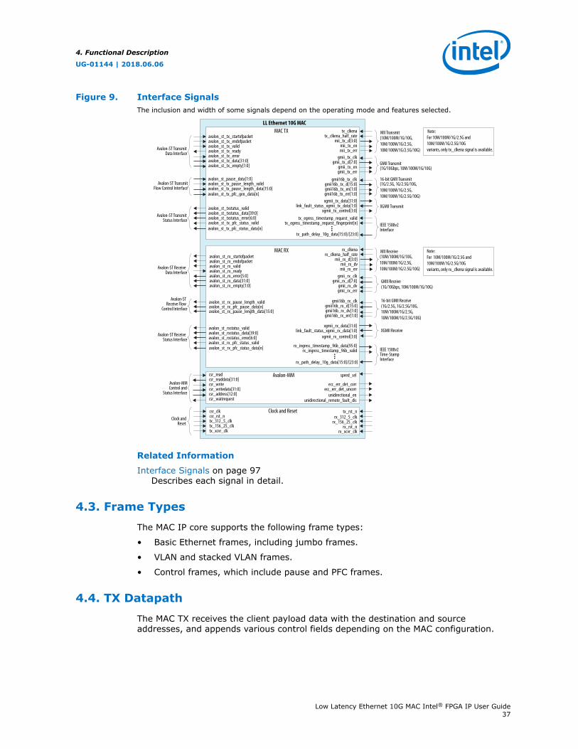
Figure 9. Interface SignalsThe inclusion and width of some signals depend on the operating mode and features selected.
MAC RX
MAC TXLL Ethernet 10G MAC
XGMII Transmit xgmii_tx_data[31:0]
link_fault_status_xgmii_tx_data[1:0]xgmii_tx_control[3:0]
GMII Transmit(1G/10Gbps, 10M/100M/1G/10G)
gmii_tx_clkgmii_tx_d[7:0]
gmii_tx_engmii_tx_err
MII Transmit(10M/100M/1G/10G,10M/100M/1G/2.5G,10M/100M/1G/2.5G/10G)
tx_clkenatx_clkena_half_rate
mii_tx_d[3:0]mii_tx_enmii_tx_err
tx_egress_timestamp_request_validtx_egress_timestamp_request_fingerprint[n]
tx_path_delay_10g_data[15:0]/[23:0]
IEEE 1588v2Interface
gmii_rx_clkgmii_rx_d[7:0]
gmii_rx_dvgmii_rx_err
GMII Receive(1G/10Gbps, 10M/100M/1G/10G)
rx_clkenarx_clkena_half_rate
mii_rx_d[3:0]mii_rx_dvmii_rx_err
MII Receive(10M/100M/1G/10G,10M/100M/1G/2.5G,10M/100M/1G/2.5G/10G)
avalon_st_rxstatus_validavalon_st_rxstatus_data[39:0]avalon_st_rxstatus_error[6:0]avalon_st_rx_pfc_status_validavalon_st_rx_pfc_status_data[n]
Avalon-ST ReceiveStatus Interface
avalon_st_rx_pause_length_valid
avalon_st_rx_pause_length_data[15:0]avalon_st_rx_pfc_pause_data[n]
Avalon-STReceive Flow
Control Interface
avalon_st_rx_startofpacketavalon_st_rx_endofpacketavalon_st_rx_validavalon_st_rx_readyavalon_st_rx_error[5:0]avalon_st_rx_data[31:0]avalon_st_rx_empty[1:0]
Avalon-ST ReceiveData Interface
Avalon-ST TransmitStatus Interface
avalon_st_txstatus_validavalon_st_txstatus_data[39:0]avalon_st_txstatus_error[6:0]avalon_st_tx_pfc_status_validavalon_st_tx_pfc_status_data[n]
Avalon-ST TransmitFlow Control Interface
avalon_st_pause_data[1:0]avalon_st_tx_pause_length_validavalon_st_tx_pause_length_data[15:0]avalon_st_tx_pfc_gen_data[n]
Avalon-ST TransmitData Interface
avalon_st_tx_startofpacketavalon_st_tx_endofpacketavalon_st_tx_validavalon_st_tx_readyavalon_st_tx_erroravalon_st_tx_data[31:0]avalon_st_tx_empty[1:0]
Avalon-MMControl and
Status Interface
csr_readcsr_readdata[31:0]csr_writecsr_writedata[31:0]csr_address[12:0]csr_waitrequest
speed_sel
ecc_err_det_correcc_err_det_uncorr
unidirectional_enunidirectional_remote_fault_dis
Avalon-MM
Clock andReset
csr_clkcsr_rst_ntx_312_5_clktx_156_25_clk
rx_156_25_clkrx_rst_n
tx_rst_nrx_312_5_clk
tx_xcvr_clk rx_xcvr_clk
Clock and Reset
rx_ingress_timestamp_96b_data[95:0]rx_ingress_timestamp_96b_valid
rx_path_delay_10g_data[15:0]/[23:0]
IEEE 1588v2Time-StampInterface
xgmii_rx_data[31:0]link_fault_status_xgmii_rx_data[1:0] XGMII Receive
xgmii_rx_control[3:0]
16-bit GMII Transmit(1G/2.5G, 1G/2.5G/10G,10M/100M/1G/2.5G, 10M/100M/1G/2.5G/10G)
gmii16b_tx_clkgmii16b_tx_d[15:0]gmii16b_tx_en[1:0]gmii16b_tx_err[1:0]
gmii16b_rx_clkgmii16b_rx_d[15:0]gmii16b_rx_dv[1:0]gmii16b_rx_err[1:0]
16-bit GMII Receive(1G/2.5G, 1G/2.5G/10G,10M/100M/1G/2.5G,10M/100M/1G/2.5G/10G)
Note:For 10M/100M/1G/2.5G and 10M/100M/1G/2.5G/10G variants, only tx_clkena signal is available.
Note:For 10M/100M/1G/2.5G and 10M/100M/1G/2.5G/10G variants, only rx_clkena signal is available.
Related Information
Interface Signals on page 97Describes each signal in detail.
4.3. Frame Types
The MAC IP core supports the following frame types:
• Basic Ethernet frames, including jumbo frames.
• VLAN and stacked VLAN frames.
• Control frames, which include pause and PFC frames.
4.4. TX Datapath
The MAC TX receives the client payload data with the destination and sourceaddresses, and appends various control fields depending on the MAC configuration.
4. Functional Description
UG-01144 | 2018.06.06
Low Latency Ethernet 10G MAC Intel® FPGA IP User Guide37
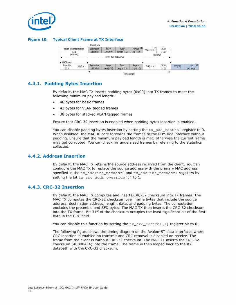
Figure 10. Typical Client Frame at TX Interface
Client - MAC Tx Interface(optional)
Client Frame
MAC Packet
Destination Addr[47:0]
Source Addr[47:0]
Type/Length[15:0]
Payload[<p-1>:0]
Destination Addr[47:0]
SFD[7:0]Preamble [55:0]
CRC32[31:0]
PAD [<s>]
Source Addr[47:0]
Client-Defined Preamble[63:0]
(optional)
Type/Length[15:0]
Payload[<p-1>:0]
PAD [<s>] CRC32[31:0]
EFD[7:0] IPG[<l-1>:0]
Frame Length
(1) (2)
(3)
4.4.1. Padding Bytes Insertion
By default, the MAC TX inserts padding bytes (0x00) into TX frames to meet thefollowing minimum payload length:
• 46 bytes for basic frames
• 42 bytes for VLAN tagged frames
• 38 bytes for stacked VLAN tagged frames
Ensure that CRC-32 insertion is enabled when padding bytes insertion is enabled.
You can disable padding bytes insertion by setting the tx_pad_control register to 0.When disabled, the MAC IP core forwards the frames to the PHY-side interface withoutpadding. Ensure that the minimum payload length is met; otherwise the current framemay get corrupted. You can check for undersized frames by referring to the statisticscollected.
4.4.2. Address Insertion
By default, the MAC TX retains the source address received from the client. You canconfigure the MAC TX to replace the source address with the primary MAC addressspecified in the tx_addrins_macaddr0 and tx_addrins_macaddr1 registers bysetting the bit tx_src_addr_override[0] to 1.
4.4.3. CRC-32 Insertion
By default, the MAC TX computes and inserts CRC-32 checksum into TX frames. TheMAC TX computes the CRC-32 checksum over frame bytes that include the sourceaddress, destination address, length, data, and padding bytes. The computationexcludes the preamble and SFD bytes. The MAC TX then inserts the CRC-32 checksuminto the TX frame. Bit 31st of the checksum occupies the least significant bit of the firstbyte in the CRC field.
You can disable this function by setting the tx_crc_control[1] register bit to 0.
The following figure shows the timing diagram on the Avalon-ST data interfaces whereCRC insertion is enabled on transmit and CRC removal is disabled on receive. Theframe from the client is without CRC-32 checksum. The MAC TX inserts the CRC-32checksum (4EB00AF4) into the frame. The frame is then looped back to the RXdatapath with the CRC-32 checksum.
4. Functional Description
UG-01144 | 2018.06.06
Low Latency Ethernet 10G MAC Intel® FPGA IP User Guide38
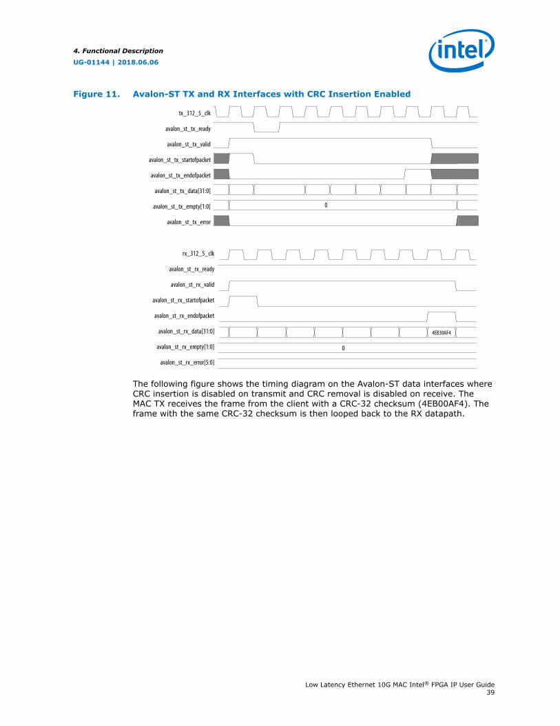
Figure 11. Avalon-ST TX and RX Interfaces with CRC Insertion Enabled
tx_312_5_clk
avalon_st_tx_ready
avalon_st_tx_valid
avalon_st_tx_startofpacket
avalon_st_tx_endofpacket
avalon_st_tx_data[31:0]
avalon_st_tx_empty[1:0]
avalon_st_tx_error
0
rx_312_5_clk
avalon_st_rx_ready
avalon_st_rx_valid
avalon_st_rx_startofpacket
avalon_st_rx_endofpacket
avalon_st_rx_data[31:0]
avalon_st_rx_empty[1:0]
avalon_st_rx_error[5:0]
4EB30AF4
0
The following figure shows the timing diagram on the Avalon-ST data interfaces whereCRC insertion is disabled on transmit and CRC removal is disabled on receive. TheMAC TX receives the frame from the client with a CRC-32 checksum (4EB00AF4). Theframe with the same CRC-32 checksum is then looped back to the RX datapath.
4. Functional Description
UG-01144 | 2018.06.06
Low Latency Ethernet 10G MAC Intel® FPGA IP User Guide39

Figure 12. Avalon-ST TX and RX Interface with CRC Insertion Disabled
tx_312_5_clk
avalon_st_tx_ready
avalon_st_tx_valid
avalon_st_tx_startofpacket
avalon_st_tx_endofpacket
avalon_st_tx_data[31:0]
avalon_st_tx_empty[1:0]
avalon_st_tx_error
0
rx_312_5_clk
avalon_st_rx_ready
avalon_st_rx_valid
avalon_st_rx_startofpacket
avalon_st_rx_endofpacket
avalon_st_rx_data[31:0]
avalon_st_rx_empty[1:0]
avalon_st_rx_error[5:0]
4EB30AF4
4EB30AF4
0
4.4.4. XGMII Encapsulation
By default, the MAC TX inserts 7-byte preamble, 1-byte SFD and 1-byte EFD (0xFD)into frames received from the client.
The MAC TX also supports custom preamble in 10G operations. To use custompreamble, set the tx_preamble_control register to 1. Behavior of the MAC TX incustom preamble mode:
• The MAC TX accepts the first eight bytes in the frame from the client as custompreamble.
• The MAC TX inserts 1-byte EFD (0xFD) into the frame.
• The MAC TX replaces the first byte of the preamble with 1-byte START (0xFB).
• The MAC TX converts the eighth byte of the preamble to a 1-byte SFD (0xD5).
An underflow could occur on the Avalon-ST TX interface. An underflow occurs whenthe avalon_st_tx_valid signal is deasserted in the middle of frame transmission.When this happens, the 10GbE MAC TX inserts an error character |E| into the frameand forwards the frame to the XGMII.
4. Functional Description
UG-01144 | 2018.06.06
Low Latency Ethernet 10G MAC Intel® FPGA IP User Guide40

4.4.5. Inter-Packet Gap Generation and Insertion
The MAC TX maintains an average IPG between TX frames as required by the IEEE802.3 Ethernet standard. The average IPG is maintained at 96 bit times (12 bytetimes) using the deficit idle count (DIC). The MAC TX inserts or deletes idle bytesdepending on the value of the DIC; the DIC must be between 9 to 15 bytes. Averagingthe IPG ensures that the MAC utilizes the maximum available bandwidth.
For 10M/100M/1G/2.5G operations, however, the MAC TX maintains a minimum IPG of12 bytes time.
4.4.6. XGMII Transmission
On the XGMII, the MAC TX performs the following:
• Aligns the first byte of the frame to lane 0 of the interface.
• Performs endian conversion. Transmit frames received from the client on theAvalon-ST interface are big endian. Frames transmitted on the XGMII are littleendian; the MAC TX therefore transmits frames on this interface from the leastsignificant byte.
The following figure shows the timing on the Avalon-ST TX data interface and XGMII.The least significant byte of the value in D5 is transmitted first on the XGMII.
4. Functional Description
UG-01144 | 2018.06.06
Low Latency Ethernet 10G MAC Intel® FPGA IP User Guide41
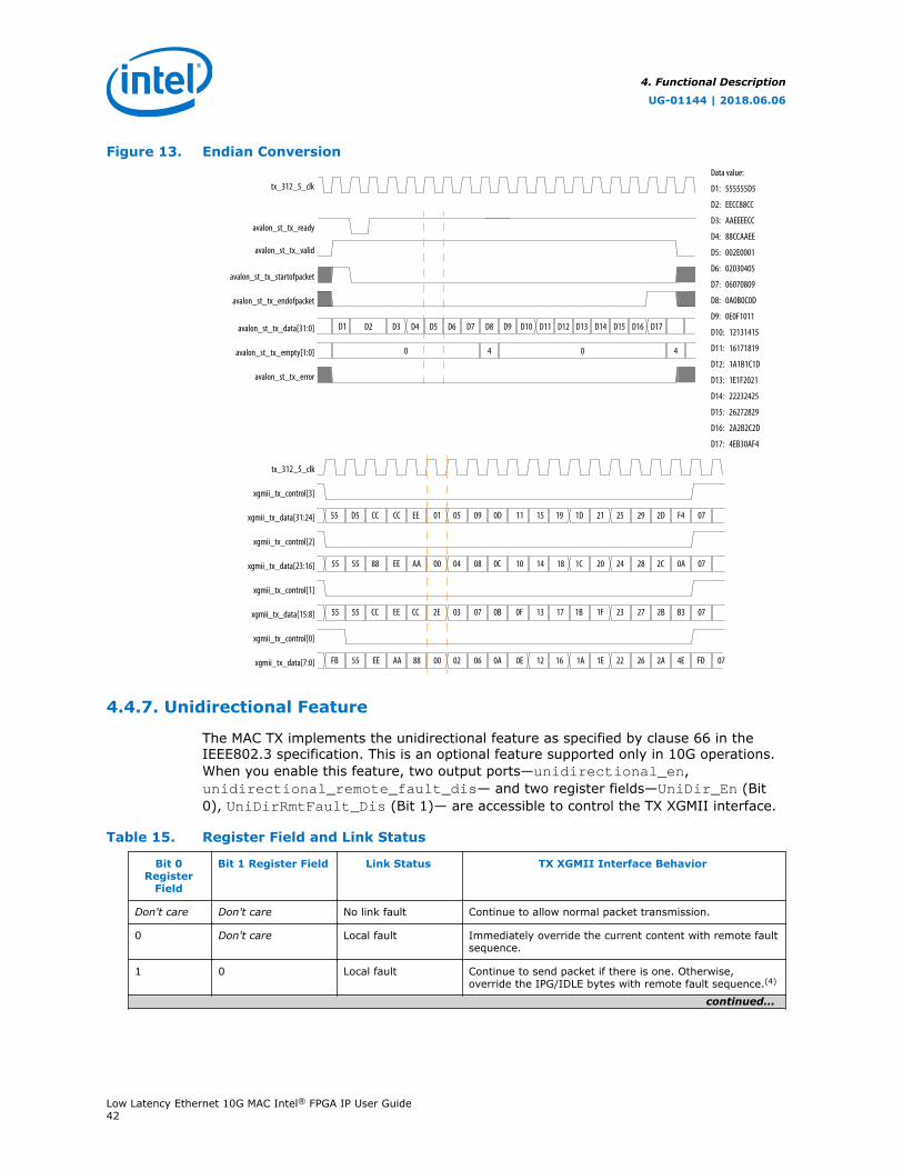
Figure 13. Endian Conversion
55 D5 CC CC EE 01 05 09 0D
55 55 88 EE AA 00 04 08 0C
55 55 EE CC 2E 03 07 0B 0F
FB 55 EE AA 88 00 02 06 0A 0E
CC
tx_312_5_clk
0 4
D1 D2 D3 D4 D5 D6 D7 D8
15 19 1D 21 25 29 2D F4 07
14 18 1C 20 24 28 2C 0A 07
13 17 1F 23 27 2B B3 07
12 16 1A 1E 22 26 2A 4E FD
1B
10
11
07
0 4
D9 D10 D11 D12 D13 D14 D15 D16 D17
D1: 555555D5
D2: EECC88CC
D3: AAEEEECC
D4: 88CCAAEE
D5: 002E0001
D6: 02030405
D7: 06070809
D8: 0A0B0C0D
D9: 0E0F1011
D10: 12131415
D11: 16171819
D12: 1A1B1C1D
D13: 1E1F2021
D14: 22232425
D15: 26272829
D16: 2A2B2C2D
D17: 4EB30AF4
avalon_st_tx_ready
avalon_st_tx_valid
avalon_st_tx_startofpacket
avalon_st_tx_endofpacket
avalon_st_tx_data[31:0]
avalon_st_tx_empty[1:0]
avalon_st_tx_error
tx_312_5_clk
xgmii_tx_control[3]
xgmii_tx_data[31:24]
xgmii_tx_control[2]
xgmii_tx_data[23:16]
xgmii_tx_control[1]
xgmii_tx_data[15:8]
xgmii_tx_control[0]
xgmii_tx_data[7:0]
Data value:
4.4.7. Unidirectional Feature
The MAC TX implements the unidirectional feature as specified by clause 66 in theIEEE802.3 specification. This is an optional feature supported only in 10G operations.When you enable this feature, two output ports—unidirectional_en,unidirectional_remote_fault_dis— and two register fields—UniDir_En (Bit0), UniDirRmtFault_Dis (Bit 1)— are accessible to control the TX XGMII interface.
Table 15. Register Field and Link Status
Bit 0Register
Field
Bit 1 Register Field Link Status TX XGMII Interface Behavior
Don't care Don't care No link fault Continue to allow normal packet transmission.
0 Don't care Local fault Immediately override the current content with remote faultsequence.
1 0 Local fault Continue to send packet if there is one. Otherwise,override the IPG/IDLE bytes with remote fault sequence.(4)
continued...
4. Functional Description
UG-01144 | 2018.06.06
Low Latency Ethernet 10G MAC Intel® FPGA IP User Guide42
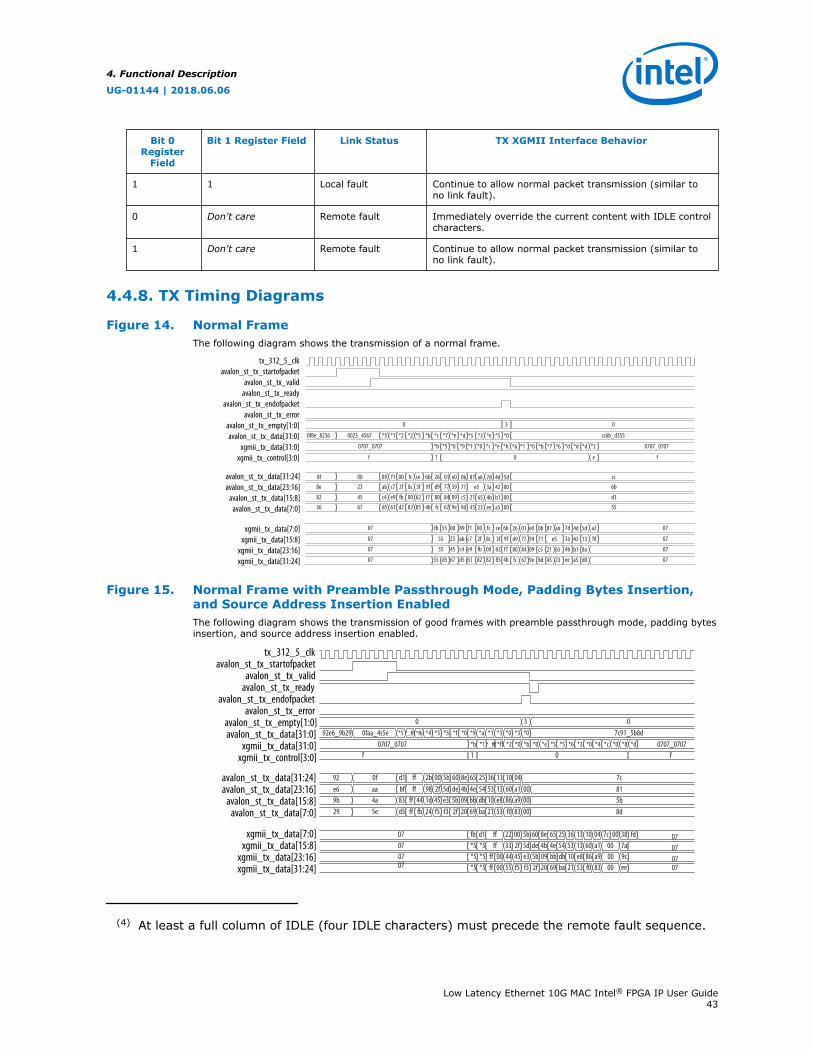
Bit 0Register
Field
Bit 1 Register Field Link Status TX XGMII Interface Behavior
1 1 Local fault Continue to allow normal packet transmission (similar tono link fault).
0 Don't care Remote fault Immediately override the current content with IDLE controlcharacters.
1 Don't care Remote fault Continue to allow normal packet transmission (similar tono link fault).
4.4.8. TX Timing Diagrams
Figure 14. Normal FrameThe following diagram shows the transmission of a normal frame.
tx_312_5_clkavalon_st_tx_startofpacket
avalon_st_tx_validavalon_st_tx_ready
avalon_st_tx_endofpacketavalon_st_tx_error
avalon_st_tx_empty[1:0]avalon_st_tx_data[31:0]
xgmii_tx_data[31:0]xgmii_tx_control[3:0]
avalon_st_tx_data[31:24]avalon_st_tx_data[23:16]
avalon_st_tx_data[15:8]avalon_st_tx_data[7:0]
xgmii_tx_data[7:0]xgmii_tx_data[15:8]
xgmii_tx_data[23:16]xgmii_tx_data[31:24]
0 3 0
0f8e_8236 0023_4567 *5 *1 *2 *2 *5 *b *c *7 *e *d *5 *3 *e *5 *0 cc6b_d355
0707_0707 *b *5 *0 *9 *1 *0 *c *e *b *6 *1 *0 *b *7 *6 *d *d *d *2 0707_0707
f 1 0 e f
0f 00 89 f1 00 fc ce 6b 26 01 e0 0b 87 a6 7d 4d 5d cc8e 23 ab c7 2f 8c 3f 9f d9 77 59 71 e5 3a 42 00 6b
82 45 c4 e9 fb 00 62 f7 80 84 09 c5 21 65 4b b1 00 d336 67 d5 61 d2 82 85 4b fc 67 9e 9d 45 23 ee a5 00 55
07 7dfb 55 00 89 f1 00 fc ce 6b 26 01 e0 0b 87 a6 07
07 3a55 23 ab c7 2f 8c 3f 9f d9 77 71 e5 07
07 4b55 45 c4 e9 fb 00 62 f7 80 84 09 c5 21 65 07
07 ee55 d5 67 d5 61 d2 82 85 4b fc 67 9e 8d 45 23 07
a24d 5d
fd42 13
b1 8a
a5 d0
59
Figure 15. Normal Frame with Preamble Passthrough Mode, Padding Bytes Insertion,and Source Address Insertion EnabledThe following diagram shows the transmission of good frames with preamble passthrough mode, padding bytesinsertion, and source address insertion enabled.
0 37c91_5b8d*5 *_fff *fb *4 *5 *3 *f *0 *9 *a *1 *3 *0 *3 *0
0707_0707*b *1 *_fff *ff *2 *0 *b *0 *e *5 *5 *6 *3 *0 *4 *c *0 *8 *d
f 1
7cd1 ff 2b 00 5b 60 8e 65 25 36 13 10 0481bf ff 0098 2f 5d de 4b 4e 54 53 13 60 a1
83 001d 45 e3 5b 09 bb db 10 e8 86 a9d5 0024 f5 f3 2f 20 69 ba 21 53 f0 83
ff 44ff fb
5b8d
fb 0422 00 5b 60 8e 65 25 36 13 10d1 ff 07fd7c 00 38*5 a133 2f 5d de 4b 4e 54 53 13 60*5 ff 0700 7a*5 a944 45 e3 5b 09 bb db 10 e8 86*5 0700 9cff 00*5 8355 f5 f3 2f 20 69 ba 21 53 f0*5 0700 eeff 00
tx_312_5_clkavalon_st_tx_startofpacket
avalon_st_tx_validavalon_st_tx_ready
avalon_st_tx_endofpacketavalon_st_tx_error
avalon_st_tx_empty[1:0]avalon_st_tx_data[31:0]
xgmii_tx_data[31:0]xgmii_tx_control[3:0]
avalon_st_tx_data[31:24]avalon_st_tx_data[23:16]
avalon_st_tx_data[15:8]avalon_st_tx_data[7:0]
xgmii_tx_data[7:0]xgmii_tx_data[15:8]
xgmii_tx_data[23:16]xgmii_tx_data[31:24]
092e6_9b29 0faa_4s5e
92 0fe6 aa9b 4a29 5e
0707_0707f0
07070707
(4) At least a full column of IDLE (four IDLE characters) must precede the remote fault sequence.
4. Functional Description
UG-01144 | 2018.06.06
Low Latency Ethernet 10G MAC Intel® FPGA IP User Guide43
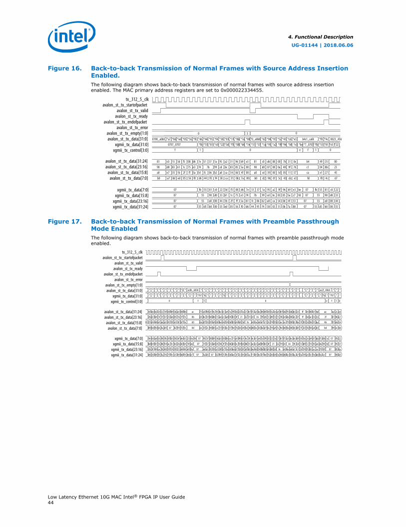
Figure 16. Back-to-back Transmission of Normal Frames with Source Address InsertionEnabled.The following diagram shows back-to-back transmission of normal frames with source address insertionenabled. The MAC primary address registers are set to 0x000022334455.
0 3 0
8190_a0b0 *a7 *8d *ed *05 *56 *f0 *d6 *44 *95 *f4 *38 *03 *31 *0b *7a *00 *0_a0b0 *d2 *96 *01 *5c *43 *cb *e3 b4c1_cafd *f0 *4c 0023_456
0707_0707 *fb *55 *81 *c0 *22 *3d *f5 *08 *d6 *7e *51 *37 *1a *95 *a2 *9f *96 *b9 *e3 *be *7_0707 *fb *55 *81 *c0 *22
f 1 0 e f 1 0
81 c0 15 3d f5 08 d6 7e 51 37 1a 95 a2 31 96 b9 e3 81 c0 d6 88 00 7b 31 0e b4 49 25 00
90 d0 83 61 1c 75 e3 f4 7b 99 cd bc 83 85 5a 00 90 d0 07 08 0a 40 9f 76 c1 04 8b 23
a0 e7 35 1b 2f ff 5a b1 fc 06 b2 a8 ca 54 0d 4f 00 a0 cd 39 00 1d 05 11 57 ca e1 27 45
b0 a7 8d ed 05 56 f0 d6 44 95 f4 38 ca 31 0b 7a 00 b0 d2 96 01 5c 43 cb e3 fd f0 4c 67
07 fb 55 81 c0 22 3d f5 08 d6 7e 51 37 1a 95 a2 9f 96 b9 e3 be 07 fb 55 81 c0 22
07 55 90 d0 33 61 1c 75 e3 f4 7b 99 cd bc 83 85 5a c7 fd 07 55 90 d0 33
07 55 a0 00 44 1b 2f ff 5a b1 fc 06 b2 a8 ca 54 0d 4f 53 07 55 a0 00 44
07 55 d5 b0 00 55 ed 05 56 f0 d6 44 95 f4 38 03 31 0b 7a 88 07 55 d5 b0 00 55
tx_312_5_clkavalon_st_tx_startofpacket
avalon_st_tx_validavalon_st_tx_ready
avalon_st_tx_endofpacketavalon_st_tx_error
avalon_st_tx_empty[1:0]avalon_st_tx_data[31:0]
xgmii_tx_data[31:0]xgmii_tx_control[3:0]
avalon_st_tx_data[31:24]avalon_st_tx_data[23:16]
avalon_st_tx_data[15:8]avalon_st_tx_data[7:0]
xgmii_tx_data[7:0]xgmii_tx_data[15:8]
xgmii_tx_data[23:16]xgmii_tx_data[31:24]
Figure 17. Back-to-back Transmission of Normal Frames with Preamble PassthroughMode EnabledThe following diagram shows back-to-back transmission of normal frames with preamble passthrough modeenabled.
tx_312_5_clkavalon_st_tx_startofpacket
avalon_st_tx_validavalon_st_tx_ready
avalon_st_tx_endofpacketavalon_st_tx_error
avalon_st_tx_empty[1:0]avalon_st_tx_data[31:0]
xgmii_tx_data[31:0]xgmii_tx_control[3:0]
avalon_st_tx_data[31:24]avalon_st_tx_data[23:16]
avalon_st_tx_data[15:8]avalon_st_tx_data[7:0]
xgmii_tx_data[7:0]xgmii_tx_data[15:8]
xgmii_tx_data[23:16]xgmii_tx_data[31:24]
* * * * * * * ** * *3 ac8b_600d* * * * * * * * ** * * * * * * * ** * * * * * * * ** ** * * * ** * aa2f_4bbd ** **
* * * * * * * ** * * * *707 *b * * * * * **0 * * * * * * * ** * * * * * * * ** ** * * * ** **707 *** * * * * **b
0 f 1 0 1f 0e
6f de b3 23 32 5f 00 3b89 a5 00 ac0b 71 a0 90 c9 4c f0 6c a461 f9 36 22 1a 21 b7 f3 bca3 69 30 fa 2e a9 87 bb dbf5 b584 22 ff 64 6700 4d aa 2cea c87a
2b d2 b4 5f 1f 37 23 05ab 1b ff 8b7e d3 bc 59 b0 db 15 ae ade2 02 0f 21 62 74 c0 36 c8 13 d9 12 15 f0 a4 00da 45f9 37 ff bd 03ac 53 2f 4b81 e704
25 d4 48 e9 ad a5 45 e3f0 8f b7 60fa da d7 38 0f a9 60 be 344d 83 d4 8c68 5d e0 c1 26 74 95 65 ac ce 0079 85e7 8a 5d f53b ba 4b eb97 240df8 eb6e ff 03
89 8d 93 66 3a d5 67 62 94 f3 0d9c ee 3f 2c 44 d5 ca 11 6c85 4e 7b 26 64 d8 e7 0a 19 a4 5c 9e b0 004a 400a d5 5b a850 83 bd ce94 4857 03bc ff 225e 48
fe 8d ad 56 98 fb 8f 50b3 6f de b3 07 fb 5f 00 89 3b a5 0b00 71 a0 90 c9 4c f0 6c a461 f9 30 22 1a 21 b7 f3 bca3 847a 69 2e 87a9 bb fb07 22ac23 4a fd 30 fa dbf5 7e
8d b9 81 16 88 54 ac b3fc 2b d2 b4 07 1f 37 23 ab 05 1b 7eff d3 bc 59 b0 db 15 ae ade2 02 0f 21 62 74 c0 36 f904 c8 12 f015 a4 4507 378b5f a6 13 d9 f4da fd
2b 0f 49 ca 38 40 9f f814 25 d4 48 07 ad a5 45 f0 e3 8f fab7 da d7 38 0f a9 60 be 344d 83 d4 68 5d 8c e0 eb6e e70d c1 95 ac65 ce 8507 8a60e9 0a 26 74 0f79
d6 38 84 f0 3a 76 7f c59c 89 8d 93 07 3a d5 67 62 94 9cf3 ee 3f 2c 44 d5 ca 11 6c85 4e 7b 26 64 d8 03bc 0a57 e7 a4 9e5c b0 4007 d50d66 e7 0a 19 ce4a5e 48
4. Functional Description
UG-01144 | 2018.06.06
Low Latency Ethernet 10G MAC Intel® FPGA IP User Guide44
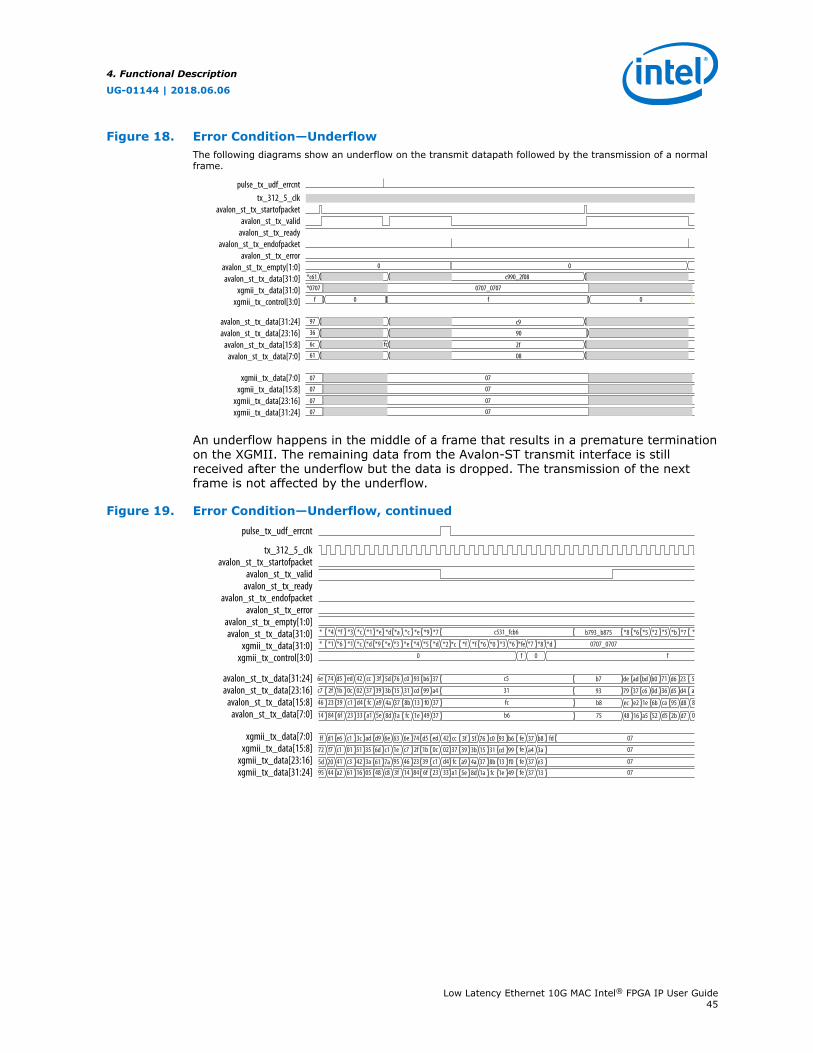
Figure 18. Error Condition—UnderflowThe following diagrams show an underflow on the transmit datapath followed by the transmission of a normalframe.
0
c990_2f08
0
0707_0707
f 00f
*c61
*0707
97
36
6c
61
c9
90
2f
08
fc
07
07
07
07
07
07
07
07
tx_312_5_clkavalon_st_tx_startofpacket
avalon_st_tx_validavalon_st_tx_ready
avalon_st_tx_endofpacketavalon_st_tx_error
avalon_st_tx_empty[1:0]avalon_st_tx_data[31:0]
xgmii_tx_data[31:0]xgmii_tx_control[3:0]
avalon_st_tx_data[31:24]avalon_st_tx_data[23:16]
avalon_st_tx_data[15:8]avalon_st_tx_data[7:0]
xgmii_tx_data[7:0]xgmii_tx_data[15:8]
xgmii_tx_data[23:16]xgmii_tx_data[31:24]
pulse_tx_udf_errcnt
An underflow happens in the middle of a frame that results in a premature terminationon the XGMII. The remaining data from the Avalon-ST transmit interface is stillreceived after the underflow but the data is dropped. The transmission of the nextframe is not affected by the underflow.
Figure 19. Error Condition—Underflow, continued
tx_312_5_clkavalon_st_tx_startofpacket
avalon_st_tx_validavalon_st_tx_ready
avalon_st_tx_endofpacketavalon_st_tx_error
avalon_st_tx_empty[1:0]avalon_st_tx_data[31:0]
xgmii_tx_data[31:0]xgmii_tx_control[3:0]
avalon_st_tx_data[31:24]avalon_st_tx_data[23:16]
avalon_st_tx_data[15:8]avalon_st_tx_data[7:0]
xgmii_tx_data[7:0]xgmii_tx_data[15:8]
xgmii_tx_data[23:16]xgmii_tx_data[31:24]
pulse_tx_udf_errcnt
* *4 *f *3 *c *1 *e *d *a *c *e *9 *7 c531_fcb6
*c *d *9 *e *3 *e *4 *5 *d *2 *c *f *f *6 *0 *3 *6 *fe *7 0707_0707
0 f 0 f
fed9 6e 63 6e 74 d5 ed 42 cc 3f 5f 76 c0 93 b6 07
fe1e c7 2f 1b 0c 02 37 39 3b 31 07
fe95 46 23 39 c1 d4 fc a9 4a 37 8b 13 f0 07fe48 c8 3f 14 84 6f 23 33 a1 5e 8d 1a fc 1e 49 07
fd37 b8
a4 3a
37 e337 13
15
* *1 *6 *1 *8 *d
*8 *6 *5 *2 *5b793_b875 *b *7 *
6e 74 d5 ed 42 cc 3f 5d 76 c0 93 b6 37 c5 de ad bd b0 71b7 d6 23 5
c7 2f 1b 0c 02 37 39 3b 15 31 cd 99 a4 31 79 37 c6 0d 3693 d5 d4 a
46 23 39 c1 d4 fc a9 4a 37 8b 13 f0 37 fc ec e2 1e 6b cab8 95 d8 8
14 84 6f 23 33 a1 5e 8d 1a fc 1e 49 37 b6 48 16 a5 52 d575 2b d7 0
c1
7a
6d
61
cd 99
ff d1 e6 c1 3c ad
c1 01 51 35
41 c3 42 3a95 44 a2 61 16 05
f7
20
72
5d
4. Functional Description
UG-01144 | 2018.06.06
Low Latency Ethernet 10G MAC Intel® FPGA IP User Guide45

Figure 20. Short Frame with Padding Bytes Insertion EnabledThe following diagram shows the transmission of a short frame with no payload data. Padding bytes insertion isenabled.
tx_312_5_clkavalon_st_tx_startofpacket
avalon_st_tx_validavalon_st_tx_ready
avalon_st_tx_endofpacketavalon_st_tx_error
avalon_st_tx_empty[1:0]avalon_st_tx_data[31:0]
xgmii_tx_data[31:0]xgmii_tx_control[3:0]
avalon_st_tx_data[31:24]avalon_st_tx_data[23:16]
avalon_st_tx_data[15:8]avalon_st_tx_data[7:0]
xgmii_tx_data[7:0]xgmii_tx_data[15:8]
xgmii_tx_data[23:16]xgmii_tx_data[31:24]
0 2
*c
0
92e6_9b29 *f *2 1626_4dfe *e *6 *5 *a *e *1 *e *f *a *b
*b0707_0707 *5 *1 0000_0000 *e *6*0 *2 *0
f 1 0
c081 4f 00 16 2f 57 ee fe 13 f0 2d d2 5c 9d
d090 e0 2e 26 a8 57 cf c3 d3 e9 87 52 ca 63
aea0 66 a0 4d d8 ea 91 b8 b5 b0 9f ad e0 d7
acb0 8f f2 fe de e6 85 3a 8e 61 be af 0a 4b
fb07 55 81 00 9f fdc0 22
07 55 90 00 ded0 33 2e
07 55 a0 00 6c00 44
07 b0 00 1500 5555 d5
4.5. RX Datapath
The MAC RX receives Ethernet frames from the XGMII and forwards the payload withrelevant frame fields to the client after performing checks and filtering invalid frames.Some frame fields are optionally removed from the frame before MAC RX forwards theframe to the client.
The following figure shows the typical flow of frame through the MAC RX.
Figure 21. Typical Client Frame at Receive Interface
Client - MAC Rx Interface(optional)
Client FrameDestination Addr[47:0]
Source Addr[47:0]
Type/Length[15:0]
Payload[<p-1>:0]
Destination Addr[47:0]
CRC32[31:0]
PAD [<s>]
Source Addr[47:0]
Client-Defined Preamble[55:0]
(optional)
Type/Length[15:0]
Payload[<p-1>:0]
PAD [<s>] CRC32[31:0]
EFD[7:0]
Start[7:0]
Frame Length
MAC Frame
SFD[7:0]Preamble [47:0]
Start[7:0]
Lorem ipsum
4.5.1. XGMII Decapsulation
The MAC RX expects the first byte of receive packets to be in lane 0,xgmii_rx_data[7:0]. If the 32-bit/64-bit adapter on the XGMII is present, the firstbyte of receive packets must be in lane 0 or lane 4, xgmii_rx_data[39:32].Receive packets must also be preceded by a column of idle bytes or an ordered setsuch as a local fault. Packets that do not satisfy these conditions are invalid and theMAC RX drops them.
4. Functional Description
UG-01144 | 2018.06.06
Low Latency Ethernet 10G MAC Intel® FPGA IP User Guide46
By default, the MAC RX only accepts packets that begin with a 1-byte START, 6-bytepreamble, and 1-byte SFD. Packets that do not satisfy this condition are invalid andthe MAC RX drops them.
When you enable the preamble passthrough mode (rx_preamble_control register= 1), the MAC RX only checks packets that begin with a 1-byte START. In this mode,the MAC RX does not remove the START and custom preamble, but passes the bytesalong with the frame to the client.
After examining the packet header bytes in the correct order, the MAC IP retrieves theframe data from the packet. If the frame data starting from the destination addressfield is less than 17 bytes, the MAC IP may or may not drop the frame. If theerroneous frame is not dropped but forwarded, an undersized error is flagged to theexternal logic to drop the frame. If the frame is more than 17 bytes, the MAC forwardsthe frame as normal and flags error whenever applicable.
4.5.2. CRC Checking
The MAC RX computes the CRC-32 checksum over frame bytes received and comparesthe computed value against the CRC field in the receive frame. If the values do notmatch, the MAC RX marks the frame invalid by setting avalon_st_rx_error[1] to1 and forwards the receive frame to the client. When the CRC error indicator isasserted, the external logic is expected to drop the frame bytes.
4.5.3. Address Checking
The MAC RX can accept frames with the following address types:
• Unicast address—bit 0 of the destination address is 0.
• Multicast address—bit 0 of the destination address is 1.
• Broadcast address—all 48 bits of the destination address are 1.
The MAC RX always accepts broadcast frames. By default, the MAC RX also receives allunicast and multicast frames unless configured otherwise in the EN_ALLUCAST andEN_ALLMCAST bits of the rx_frame_control register.
When the EN_ALLUCAST bit is set to 0, the MAC RX filters unicast frames received.The MAC RX accepts only unicast frames with a destination address that matches theprimary MAC address specified in the primary_mac_addr0 andprimary_mac_addr1 registers. If any of the supplementary address bits are set to 1(EN_SUPP0/1/2/3 in the rx_frame_control register), the MAC RX also checks thedestination address against the supplementary addresses in therx_frame_spaddr*_* registers.
When the EN_ALLMCAST bit is set to 0, the MAC RX drops all multicast frames. Thiscondition does not apply to global multicast pause frames.
4. Functional Description
UG-01144 | 2018.06.06
Low Latency Ethernet 10G MAC Intel® FPGA IP User Guide47

4.5.4. Frame Type Checking
The MAC RX checks the length/type field to determine the frame type:
• Length/type < 0x600—The field represents the payload length of a basic Ethernetframe. The MAC RX continues to check the frame and payload lengths.
• Length/type >= 0x600—The field represents the frame type.
— Length/type = 0x8100—VLAN or stacked VLAN tagged frames. The MAC RXcontinues to check the frame and payload lengths.
— Length/type = 0x8808—Control frames. The next two bytes are the Opcodefield which indicates the type of control frame. For pause frames (Opcode =0x0001) and PFC frames (Opcode = 0x0101), the MAC RX proceeds withpause frame processing. By default, the MAC RX drops all control frames. Ifconfigured otherwise (FWD_CONTROL bit in the rx_frame_control register= 1), the MAC RX forwards control frames to the client.
— For other field values, the MAC RX forwards the receive frame to the client.
Table 16. MAC Behavior for Different Frame Types
Category PacketSize
Length/Type= Payload
Length/Type> Payload
Length/Type< Payload
MAC Behavior
Frame Drop avalon_st_rx_error[]
Normal packet 65–1518
Yes No No No—
No No Yes No
No Yes No No avalon_st_rx_error[4] = 1
Undersized Packet <64
Yes No No Noavalon_st_rx_error[2] = 1
No No Yes No
No Yes No Noavalon_st_rx_error[2] = 1avalon_st_rx_error[4] = 1
Oversized1518 <
Packet <1535
Yes No No Noavalon_st_rx_error[3] = 1
No No Yes No
No Yes No Noavalon_st_rx_error[3] = 1avalon_st_rx_error[4] = 1
Related Information
Avalon-ST RX Data Interface Signals on page 102
4.5.5. Length Checking
The MAC RX checks the frame and payload lengths of basic, VLAN tagged, and stackedVLAN tagged frames. The MAC RX does not drop frames with invalid length but setsthe error bits accordingly.
4. Functional Description
UG-01144 | 2018.06.06
Low Latency Ethernet 10G MAC Intel® FPGA IP User Guide48
4.5.5.1. Frame Length
The frame length must be at least 64 (0x40) bytes and not exceed the followingmaximum value for the different frame types:
• Basic—The value in the rx_frame_maxlength register.
• VLAN tagged—The value in the rx_frame_maxlength register plus four byteswhen the rx_vlan_detection[0] register bit is 0; or the value in therx_frame_maxlength register when the rx_vlan_detection[0] register bitis set to 1.
• Stacked VLAN tagged—The value in the rx_frame_maxlength register plus eightbytes when the rx_vlan_detection[0] register bit is 0; or the value in therx_frame_maxlength register when the rx_vlan_detection[0] register bitis set to 1.
The following error bits represent frame length violations:
• avalon_st_rx_error[2]—undersized frames.
• avalon_st_rx_error[3]—oversized frames.
4.5.5.2. Payload Length
The MAC IP core checks the payload length for frames other than control frames whenthe VLAN and stacked VLAN detection is disabled. The MAC RX keeps track of theactual payload length upon receiving a frame and checks the actual payload lengthagainst the length/type or client length/type field. The payload length must bebetween 46 (0x2E) and 1500 (0x5DC). For VLAN and stacked VLAN frames, theminimum payload length is 42 (0x2A) or 38 (0x26) respectively and not exceeding themaximum value of 1500 (0x5DC).
For an invalid payload length, the MAC RX sets the avalon_st_rx_error[4] bit to1. This error occurs when the actual payload length is less than the value of thelength/type field. If the actual payload length is more than the value of the length/type field, the MAC RX assumes that the frame contains excessive padding and doesnot set this error bit to 1. If the value of the length/type field is more than the actualpayload length, the MAC RX sets the avalon_st_rx_error[4] bit to 1, and thepacket content will not be accurate.
4.5.6. CRC and Padding Bytes Removal
By default, the MAC RX forwards receive frames to the client without removing theCRC field and padding bytes from the frames. You can configure the MAC RX toremove the CRC field by setting the rx_padcrc_control register to 1. To removeboth the CRC field and padding bytes, set the rx_padcrc_control register to 3.
When enabled, the MAC RX removes padding bytes from receive frames whosepayload length is less than the following values for the different frame types:
• 46 bytes for basic frames
• 42 bytes for VLAN tagged frames
• 38 bytes for stacked VLAN tagged frames
4. Functional Description
UG-01144 | 2018.06.06
Low Latency Ethernet 10G MAC Intel® FPGA IP User Guide49

The MAC RX removes padding bytes only when the VLAN and stacked VLAN detectionis enabled (rx_vlan_detection[0] = 0). Otherwise, the MAC RX does not removepadding bytes even if padding bytes removal is enabled.
4.5.7. Overflow Handling
When an overflow occurs on the client side, the client can backpressure the Avalon-STreceive interface by deasserting the avalon_st_rx_ready signal. If an overflowoccurs, the MAC RX sets the error bit, avalon_st_rx_error[5], to 1 to indicate anoverflow. The MAC RX drops subsequent frames if the overflow condition persists. TheMAC RX then continues to receive data when the overflow condition ceases.
4.5.8. RX Timing Diagrams
Figure 22. Back-to-back Transmission of Normal Frames with CRC Removal EnabledThe following diagram shows back-to-back reception of normal frames with CRC removal enabled.
rx_312_5_clkxgmii_rx_data[31:0]
xgmii_rx_control[3:0]avalon_st_rx_startofpacket
avalon_st_rx_validavalon_st_rx_ready
avalon_st_trx_endofpacketavalon_st_rx_data[31:0]
avalon_st_rx_empty[1:0]avalon_st_rx_error[5:0]
avalon_st_rx_data[31:24]avalon_st_rx_data[23:16]
avalon_st_rx_data[15:8]avalon_st_rx_data[7:0]
xgmii_rx_data[7:0]xgmii_rx_data[15:8]
xgmii_rx_data[23:16]xgmii_rx_data[31:24]
* *fff * * * * *c 0000_0000 *0faa_4s5e * * * * * * * * * *
1 0 1f 0 1f 0
* *fff *0 * *0707_0707 * *0 0000_0000 * * * *
fb *ff cf 88 21 22 8cc 00 fd07 fb 3a 00 c0 0a 4d da * cd3a b6 fa 07 01 8187 95 46 94 f2
88 ff 58 08 d3 be 88 00 0707 88 3a 01 16 51 ae c5 * 403a df 55 80 00f3 c7 46 df f6
88 d0 d5 cd a7 ff 00 0707 88 3a 0a 50 51 2e 2b * 0a3a 62 73 c246 97 24 43 aa
88 ad 49 f5 2a 00 0707 88 d5 d9 6d 18 8d 57 * 7cd5 2b f1 003e 28 55 70 95
ff 61 68 03
5c 81ff 60
fb ff 88 b607 22 8c 00 07 3a 01 c03a cf f121 00fb
88 ff 08 df07 be 89 00 07 3a 80 163a 58 55d3 0188
88 d5 6207 a7 ff 00 07 3a c2 503a d0 73cd 0a88ff 61
88 49 2b07 2a 00 07 d5 00 6dd5 ad f1f5 d988ff 60
4. Functional Description
UG-01144 | 2018.06.06
Low Latency Ethernet 10G MAC Intel® FPGA IP User Guide50
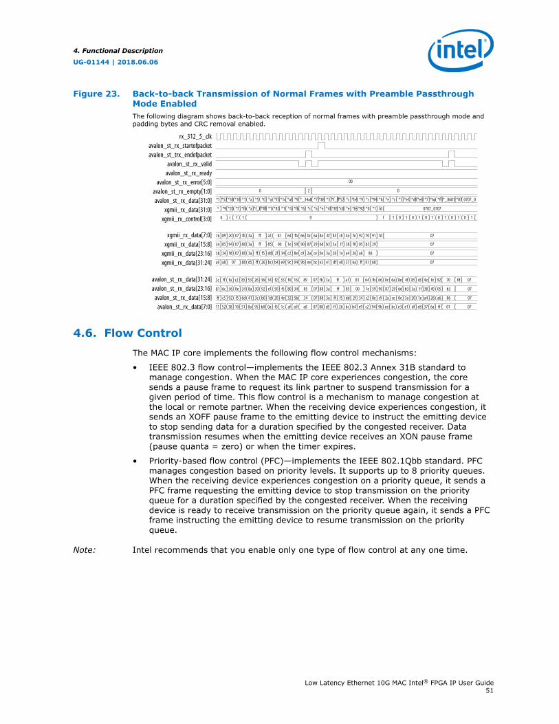
Figure 23. Back-to-back Transmission of Normal Frames with Preamble PassthroughMode EnabledThe following diagram shows back-to-back reception of normal frames with preamble passthrough mode andpadding bytes and CRC removal enabled.
rx_312_5_clkavalon_st_rx_startofpacketavalon_st_trx_endofpacket
avalon_st_rx_validavalon_st_rx_ready
avalon_st_rx_error[5:0]avalon_st_rx_empty[1:0]avalon_st_rx_data[31:0]
xgmii_rx_data[31:0]xgmii_rx_control[3:0]
avalon_st_rx_data[31:24]avalon_st_rx_data[23:16]
avalon_st_rx_data[15:8]avalon_st_rx_data[7:0]
xgmii_rx_data[7:0]xgmii_rx_data[15:8]
xgmii_rx_data[23:16]xgmii_rx_data[31:24]
*52*1 *38 *10 *1 *a *5 *0 *a *f3 *1c *af *9 *_34a8 *7 *88 *5 *f_ff*52 *c *b4 *9 *c *94 *b *e *c *3 *e1 *df *e8 *7 *6a *ff *_8601 *07 0707_0
*9* *20 *7 *fb *a *f_ff*fff *1 *81 *1 *4 *fb *a *e *4f *85 *c8 *e *fe *92 *0 *1 fd 0707_0707*6 *c
c0 f 1 0 f 1 0 1 0 1 0 1 0 1 0 1 0 1
8916 20 07 fb 3a ff a1 81 64 fb 6a 8e 4f 85 c8 4e fe 92 70 91 fd 0766 0c
345b fd 07 88 3a ff f5 dd 2f 34 c2 8e ce 0e 3a 20 1e a4 26 a6 86 07c9 2a
8534 94 07 88 3a ff 85 00 1e 59 29 6d b3 3a 1f 38 f0 05 b3 29 0790 87
a8a9 07 88 d5 ff 26 bc b4 e9 9c 94 bc e3 e1 df e8 37 6a ff 079b ee 01 68
ff3c fa c2 85 53 26 36 34 f2 35 f4 16 89 07 fb 3a ff a1 81 64 fb 66 0c 6a 8e 4f 85 c8 4e fe 92 70 fd 07
c5ff 92 f5 6d 41 3c b0 1d 20 4e 32 5b 34 07 88 3a ff f5 dd 2f 34 c2 8e c9 2a ce 0e 3a 20 1e a4 26 a6 86 07
6c81 36 0e 34 8a 30 92 c4 50 f5 80 34 85 07 88 3a ff 85 00 1e 59 90 87 29 6d b3 3a 1f 38 f0 05 b3 07
5211 38 10 51 0a 95 b0 0a f3 1c af a9 a8 07 88 d5 ff 26 bc b4 e9 c2 94 9b ee bc e3 e1 df e8 37 6a ff 01 07
0 02
00
4.6. Flow Control
The MAC IP core implements the following flow control mechanisms:
• IEEE 802.3 flow control—implements the IEEE 802.3 Annex 31B standard tomanage congestion. When the MAC IP core experiences congestion, the coresends a pause frame to request its link partner to suspend transmission for agiven period of time. This flow control is a mechanism to manage congestion atthe local or remote partner. When the receiving device experiences congestion, itsends an XOFF pause frame to the emitting device to instruct the emitting deviceto stop sending data for a duration specified by the congested receiver. Datatransmission resumes when the emitting device receives an XON pause frame(pause quanta = zero) or when the timer expires.
• Priority-based flow control (PFC)—implements the IEEE 802.1Qbb standard. PFCmanages congestion based on priority levels. It supports up to 8 priority queues.When the receiving device experiences congestion on a priority queue, it sends aPFC frame requesting the emitting device to stop transmission on the priorityqueue for a duration specified by the congested receiver. When the receivingdevice is ready to receive transmission on the priority queue again, it sends a PFCframe instructing the emitting device to resume transmission on the priorityqueue.
Note: Intel recommends that you enable only one type of flow control at any one time.
4. Functional Description
UG-01144 | 2018.06.06
Low Latency Ethernet 10G MAC Intel® FPGA IP User Guide51

4.6.1. IEEE 802.3 Flow Control
To use the IEEE 802.3 flow control, set the following registers:
• On the TX datapath:
— Set tx_pfc_priority_enable[7:0] to 0 to disable the PFC. The rest ofthe bits are unused.
— Set tx_pauseframe_enable[0] to 1 to enable the IEEE 802.3 flow control.
• On the RX datapath:
— Set rx_pfc_control[7:0] to 1 to disable the PFC. The rest of the bits aremostly unused.
— Set the IGNORE_PAUSE bit in the rx_frame_control register to 0 to enablethe IEEE 802.3 flow control.
4.6.1.1. Pause Frame Reception
When the MAC receives an XOFF pause frame, it stops transmitting frames to theremote partner for a period equal to the pause quanta field of the pause frame. If theMAC receives a pause frame in the middle of a frame transmission, the MAC finishessending the current frame and then suspends transmission for a period specified bythe pause quanta. The MAC resumes transmission when it receives an XON pauseframe or when the timer expires. The pause quanta received overrides any countercurrently stored. When the remote partner sends more than one pause quanta, theMAC sets the value of the pause to the last quanta it received from the remotepartner. You have the option to configure the MAC to ignore pause frames andcontinue transmitting frames by setting the IGNORE_PAUSE bit in therx_frame_control register to 1.
4. Functional Description
UG-01144 | 2018.06.06
Low Latency Ethernet 10G MAC Intel® FPGA IP User Guide52
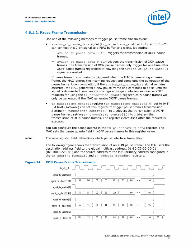
4.6.1.2. Pause Frame Transmission
Use one of the following methods to trigger pause frame transmission:
• avalon_st_pause_data signal (tx_pauseframe_enable[2:1] set to 0)—Youcan connect this 2-bit signal to a FIFO buffer or a client. Bit setting:
— avalon_st_pause_data[1]: 1—triggers the transmission of XOFF pauseframes.
— avalon_st_pause_data[0]: 1—triggers the transmission of XON pauseframes. The transmission of XON pause frames only trigger for one time afterXOFF pause frames regardless of how long the avalon_st_pause_data[0]signal is asserted.
If pause frame transmission is triggered when the MAC is generating a pauseframe, the MAC ignores the incoming request and completes the generation of thepause frame. Upon completion, if the avalon_st_pause_data signal remainsasserted, the MAC generates a new pause frame and continues to do so until thesignal is deasserted. You can also configure the gap between successive XOFFrequests for using the tx_pauseframe_quanta register. XON pause frames willonly be generated if the MAC generates XOFF pause frames.
• tx_pauseframe_control register (tx_pauseframe_enable[2:0] set to 0x1)—A host (software) can set this register to trigger pause frames transmission.Setting tx_pauseframe_control[1] to 1 triggers the transmission of XOFFpause frames; setting tx_pauseframe_control[0] to 1 triggers thetransmission of XON pause frames. The register clears itself after the request isexecuted.
You can configure the pause quanta in the tx_pauseframe_quanta register. TheMAC sets the pause quanta field in XOFF pause frames to this register value.
Note: The new register field determines which pause interface takes effect.
The following figure shows the transmission of an XON pause frame. The MAC sets thedestination address field to the global multicast address, 01-80-C2-00-00-01(0x010000c28001) and the source address to the MAC primary address configured inthe tx_addrins_macaddr0 and tx_addrins_madaddr1 registers.
Figure 24. XON Pause Frame Transmission
tx_clk_clk
FB 55 01 00 FD
xgmii_tx_control[3]
xgmii_tx_data[31:24]
xgmii_tx_control[2]
xgmii_tx_data[23:16]
xgmii_tx_control[1]
xgmii_tx_data[15:8]
xgmii_tx_control[0]
xgmii_tx_data[7:0] 00 88 88 96
55 55 80 0001 CC 08 96
55 55 C2 00EE AA 96
55 D5 00 00CC EE 01 96
4. Functional Description
UG-01144 | 2018.06.06
Low Latency Ethernet 10G MAC Intel® FPGA IP User Guide53
4.6.2. Priority-Based Flow Control
Follow these steps to use the PFC:
1. Turn on the Priority-based flow control (PFC) parameter and specify thenumber of priority levels using the Number of PFC priorities parameter. You canspecify between 2 to 8 PFC priority levels.
2. Set the following registers.
• On the TX datapath:
— Set tx_pauseframe_enable to 0 to disable the IEEE 802.3 flow control.
— Set tx_pfc_priority_enable[n] to 1 to enable the PFC for priorityqueue n.
• On the RX datapath:
— Set the IGNORE_PAUSE bit in the rx_frame_control register to 1 todisable the IEEE 802.3 flow control.
— Set the rx_pfc_control[7:0] register bits to 0 to enable the PFC. Mostof the rest of the bits are unused.
3. Connect the avalon_st_tx_pfc_gen_data signal to the corresponding RXclient logic and the avalon_st_rx_pfc_pause_data signal to thecorresponding TX client logic.
4. You have the option to configure the MAC RX to forward the PFC frame to theclient by setting the rx_pfc_control[16] register to 1. By default, the MAC RXdrops the PFC frame after processing it.
4.6.2.1. PFC Frame Reception
When the MAC RX receives a PFC frame from the remote partner, it asserts theavalon_st_rx_pfc_pause_data[n] signal if Pause Quanta n is valid (PauseQuanta Enable [n] = 1) and greater than 0. The client suspends transmission from theTX priority queue n for the period specified by Pause Quanta n. If the MAC RX assertsthe avalon_st_rx_pfc_pause_data[n] signal in the middle of a client frametransmission for the TX priority queue n, the client finishes sending the current frameand then suspends transmission for the queue.
When the MAC RX receives a PFC frame from the remote partner, it deasserts theavalon_st_rx_pfc_pause_data[n] signal if Pause Quanta n is valid (PauseQuanta Enable [n] = 1) and equal to 0. The MAC RX also deasserts this signal whenthe timer expires. The client resumes transmission for the suspended TX priorityqueue when the avalon_st_rx_pfc_pause_data[n] signal is deasserted.
When the remote partner sends more than one pause quanta for the TX priority queuen, the MAC RX sets the pause quanta n to the last pause quanta received from theremote partner.
4.6.2.2. PFC Frame Transmission
PFC frame generation is triggered through the avalon_st_tx_pfc_gen_datasignal. Set the respective bits to generate XOFF or XON requests for the priorityqueues.
4. Functional Description
UG-01144 | 2018.06.06
Low Latency Ethernet 10G MAC Intel® FPGA IP User Guide54

For XOFF requests, you can configure the pause quanta for each priority queue usingthe pfc_pause_quanta_n registers. For an XOFF request for priority queue n, theMAC TX sets bit n in the Pause Quanta Enable field to 1 and the Pause Quanta n fieldto the value of the pfc_pause_quanta_n register. You can also configure the gapbetween successive XOFF requests for a priority queue using thepfc_holdoff_quanta_n register.
For XON requests, the MAC TX sets the pause quanta to 0. You must generate a XOFFrequest before generating a XON request.
4.7. Reset Requirements
The MAC IP core consists of the following reset domains:
• CSR reset—global reset,
• MAC TX reset, and
• MAC RX reset.
These resets are asynchronous events. When the MAC or any part of it goes intoreset, the user application must manage possible asynchronous changes to the statesof the MAC interface signals. The MAC does not guarantee any reset sequence. Intelrecommends the sequence shown in the following diagram and table for CSR reset,and TX and RX datapaths reset respectively.
Figure 25. CSR Reset
csr, tx, rx clocks
csr_rst_n
tx_rst_n
rx_rst_n
When you assert csr_rst_n , you must also assert tx_rst_n and rx_rst_n . Hold the reset signals active for at least 3 clock periods of the slowest clock.
Deassert csr_rst_n no later than tx_rst_n and rx_rst_n . You can configure the registers after csr_rst_n is deasserted, but before data transfer begins.
4. Functional Description
UG-01144 | 2018.06.06
Low Latency Ethernet 10G MAC Intel® FPGA IP User Guide55
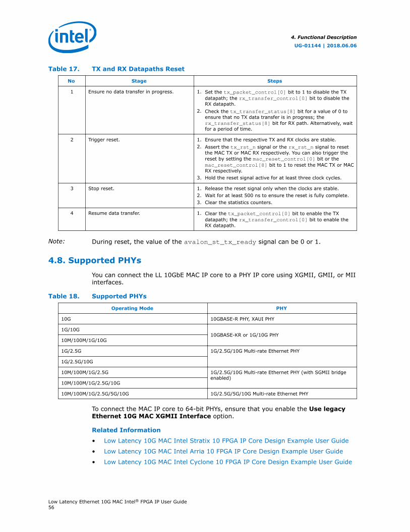
Table 17. TX and RX Datapaths Reset
No Stage Steps
1 Ensure no data transfer in progress. 1. Set the tx_packet_control[0] bit to 1 to disable the TXdatapath; the rx_transfer_control[0] bit to disable theRX datapath.
2. Check the tx_transfer_status[8] bit for a value of 0 toensure that no TX data transfer is in progress; therx_transfer_status[8] bit for RX path. Alternatively, waitfor a period of time.
2 Trigger reset. 1. Ensure that the respective TX and RX clocks are stable.2. Assert the tx_rst_n signal or the rx_rst_n signal to reset
the MAC TX or MAC RX respectively. You can also trigger thereset by setting the mac_reset_control[0] bit or themac_reset_control[8] bit to 1 to reset the MAC TX or MACRX respectively.
3. Hold the reset signal active for at least three clock cycles.
3 Stop reset. 1. Release the reset signal only when the clocks are stable.2. Wait for at least 500 ns to ensure the reset is fully complete.3. Clear the statistics counters.
4 Resume data transfer. 1. Clear the tx_packet_control[0] bit to enable the TXdatapath; the rx_transfer_control[0] bit to enable theRX datapath.
Note: During reset, the value of the avalon_st_tx_ready signal can be 0 or 1.
4.8. Supported PHYs
You can connect the LL 10GbE MAC IP core to a PHY IP core using XGMII, GMII, or MIIinterfaces.
Table 18. Supported PHYs
Operating Mode PHY
10G 10GBASE-R PHY, XAUI PHY
1G/10G10GBASE-KR or 1G/10G PHY
10M/100M/1G/10G
1G/2.5G 1G/2.5G/10G Multi-rate Ethernet PHY
1G/2.5G/10G
10M/100M/1G/2.5G 1G/2.5G/10G Multi-rate Ethernet PHY (with SGMII bridgeenabled)
10M/100M/1G/2.5G/10G
10M/100M/1G/2.5G/5G/10G 1G/2.5G/5G/10G Multi-rate Ethernet PHY
To connect the MAC IP core to 64-bit PHYs, ensure that you enable the Use legacyEthernet 10G MAC XGMII Interface option.
Related Information
• Low Latency 10G MAC Intel Stratix 10 FPGA IP Core Design Example User Guide
• Low Latency 10G MAC Intel Arria 10 FPGA IP Core Design Example User Guide
• Low Latency 10G MAC Intel Cyclone 10 FPGA IP Core Design Example User Guide
4. Functional Description
UG-01144 | 2018.06.06
Low Latency Ethernet 10G MAC Intel® FPGA IP User Guide56
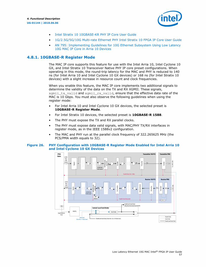
• Intel Stratix 10 10GBASE-KR PHY IP Core User Guide
• 1G/2.5G/5G/10G Multi-rate Ethernet PHY Intel Stratix 10 FPGA IP Core User Guide
• AN 795: Implementing Guidelines for 10G Ethernet Subsystem Using Low Latency10G MAC IP Core in Arria 10 Devices
4.8.1. 10GBASE-R Register Mode
The MAC IP core supports this feature for use with the Intel Arria 10, Intel Cyclone 10GX, and Intel Stratix 10 Transceiver Native PHY IP core preset configurations. Whenoperating in this mode, the round-trip latency for the MAC and PHY is reduced to 140ns (for Intel Arria 10 and Intel Cyclone 10 GX devices) or 168 ns (for Intel Stratix 10devices) with a slight increase in resource count and clock frequencies.
When you enable this feature, the MAC IP core implements two additional signals todetermine the validity of the data on the TX and RX XGMII. These signals,xgmii_tx_valid and xgmii_rx_valid, ensure that the effective data rate of theMAC is 10 Gbps. You must also observe the following guidelines when using theregister mode:
• For Intel Arria 10 and Intel Cyclone 10 GX devices, the selected preset is10GBASE-R Register Mode.
• For Intel Stratix 10 devices, the selected preset is 10GBASE-R 1588.
• The PHY must expose the TX and RX parallel clocks.
• The PHY must expose data valid signals, with MAC/PHY TX/RX interfaces inregister mode, as in the IEEE 1588v2 configuration.
• The MAC and PHY run at the parallel clock frequency of 322.265625 MHz (thePCS/PMA width equals to 32).
Figure 26. PHY Configuration with 10GBASE-R Register Mode Enabled for Intel Arria 10and Intel Cyclone 10 GX Devices
Transmitter 10G PCS
Receiver 10G PCS
Transmitter PMA
Receiver PMA
Parallel Clock (Recovered)
Parallel Clock (322+ MHz)
FPGAFabric
Regis
ter
Regis
ter
Fram
e Gen
erat
or
CRC3
2Ge
nera
tor
CRC3
2Ch
ecke
r
64B/
66B E
ncod
eran
d TX S
M
64B/
66B D
ecod
eran
d RX S
M
Scra
mble
rDe
-Scra
mble
r
Disp
arity
Chec
ker
Bloc
k Syn
chro
nizer
Fram
e Syn
chro
nizer
Disp
arity
Gene
rato
r
TX G
ear B
ox
RX G
ear B
ox
Seria
lizer
Dese
rializ
er
CDR
rx_s
erial
_dat
atx
_ser
ial_d
ata
Parallel Clock
Serial Clock
Parallel and Serial Clock
BER Monitor
Div 32
Clock Divider
Parallel and Serial Clocks (From the ×6 or ×N Clock Lines)Serial Clock
(From the ×1 Clock Lines)
Central/ Local Clock Divider
Parallel and Serial Clocks(Only from the Central Clock Divider)
CMU PLL
64-Bit Data 8-Bit Control
64-Bit Data 8-Bit Control
6666 32
3266
Input Reference Clock
64-Bit Data 8-Bit
Control
fPLL
64-Bit Data 8-Bit
Control
4. Functional Description
UG-01144 | 2018.06.06
Low Latency Ethernet 10G MAC Intel® FPGA IP User Guide57
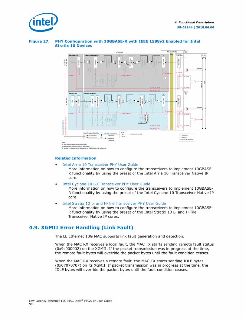
Figure 27. PHY Configuration with 10GBASE-R with IEEE 1588v2 Enabled for IntelStratix 10 Devices
Transmitter PMA Transmitter Enhanced PCS FPGA Fabric
Receiver PMA Receiver Enhanced PCS
EMIB
PCS-Core Interface
64B/
66B E
ncod
eran
d TX S
M
Inte
rlake
n CRC
32Ge
nera
tor
Inte
rlake
n Fra
me
Gene
rato
r
64B/
66B D
ecod
eran
d RX S
M
Inte
rlake
nFra
me S
ync
Inte
rlake
n Disp
arity
Chec
ker
KR FE
CSc
ram
bler
PRP
Gene
rato
r
PRBS
Gene
rato
r
KR FE
C RX
Gear
box
PRBS
Verif
ier
Trans
code
Dec
oder
KR FE
C Bloc
k Syn
c
KR FE
C Des
cram
bler
KR FE
C Dec
oder
10GB
ASE-
RBE
R Che
cker
PRP
Verif
ier
TX G
earb
ox
RX G
earb
ox
Inte
rlake
n Disp
arity
Gene
rato
r
Scra
mble
r
Bloc
k Syn
chro
nizer
Inte
rlake
nCR
C32 C
heck
er
Descr
amble
r
Trans
code
Enco
der
KR FE
C Enc
oder
KR FE
C TX G
earb
ox
Seria
l Cloc
k (51
56.25
MHz
) (1)
Para
llel C
lock (
322.2
6562
5 MHz
) (2)
32
32
322.265625 MHz (2)
322.265625 MHz (2)
5156.25 Mz = Data Rate /2ATX PLL
fPLLCMU PLL
10.31
25 G
bps
66
Self-Sync Mode
64
64
Notes:1. Value based on the clock division factor chosen.2. Value calculated as data rate/PCS-PMA interface width.3. This block is in phase measuring FIFO mode for the 10GBASE-R with 1588 configuration.
RegisterMode
RegisterMode
(3)
(3)
Row Clock
tx_clkout
tx_clkout2
tx_coreclkinPCS_clkout (tx)
PCS_clkout (rx)
Clock Divider Serial Clock
Parallel andSerial Clocks
Clock Generation Block (CGB) Input Reference Clock
Dese
rializ
erSe
rializ
er
TX PC
S FIFO
RX PC
S FIFO
TX Co
re FI
FORX
Core
FIFO
rx_s
erial
_dat
atx
_ser
ial_d
ata
Parallel ClockSerial ClockParallel and Serial Clocks
tx_pma_div_clkout
PCS_clkout_x2 (tx)
tx_clkout
Row Clock
rx_clkout
rx_clkout2
rx_coreclkin
rx_pma_div_clkout
PCS_clkout_x2 (rx)
CDR
Dedic
ated Gl
obal
Core ClockNetworks
rx_clkout
Related Information
• Intel Arria 10 Transceiver PHY User GuideMore information on how to configure the transceivers to implement 10GBASE-R functionality by using the preset of the Intel Arria 10 Transceiver Native IPcore.
• Intel Cyclone 10 GX Transceiver PHY User GuideMore information on how to configure the transceivers to implement 10GBASE-R functionality by using the preset of the Intel Cyclone 10 Transceiver Native IPcore.
• Intel Stratix 10 L- and H-Tile Transceiver PHY User GuideMore information on how to configure the transceivers to implement 10GBASE-R functionality by using the preset of the Intel Stratix 10 L- and H-TileTransceiver Native IP cores.
4.9. XGMII Error Handling (Link Fault)
The LL Ethernet 10G MAC supports link fault generation and detection.
When the MAC RX receives a local fault, the MAC TX starts sending remote fault status(0x9c000002) on the XGMII. If the packet transmission was in progress at the time,the remote fault bytes will override the packet bytes until the fault condition ceases.
When the MAC RX receives a remote fault, the MAC TX starts sending IDLE bytes(0x07070707) on its XGMII. If packet transmission was in progress at the time, theIDLE bytes will override the packet bytes until the fault condition ceases.
4. Functional Description
UG-01144 | 2018.06.06
Low Latency Ethernet 10G MAC Intel® FPGA IP User Guide58
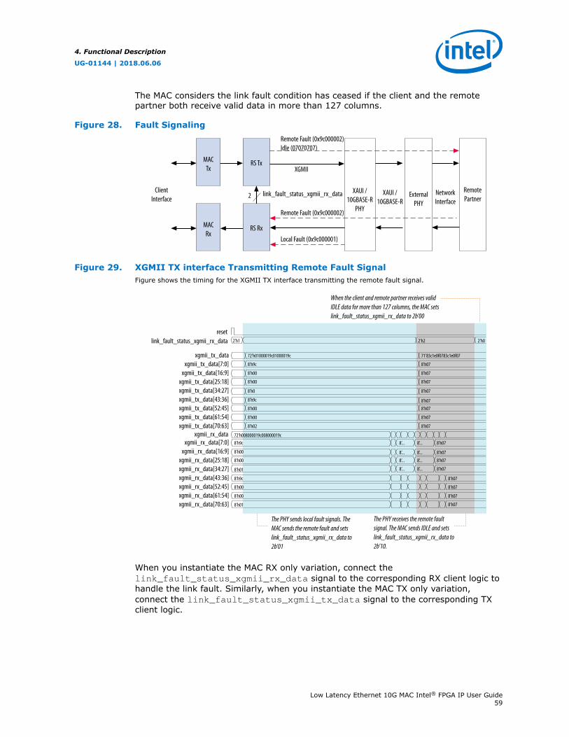
The MAC considers the link fault condition has ceased if the client and the remotepartner both receive valid data in more than 127 columns.
Figure 28. Fault SignalingRemote Fault (0x9c000002)Idle (07070707)
Remote Fault (0x9c000002)
ClientInterface
MACTx
RS Tx
MACRx
RS Rx
2 link_fault_status_xgmii_rx_data XAUI /10GBASE-R
PHY
ExternalPHY
RemotePartner
XAUI /10GBASE-R
NetworkInterface
Local Fault (0x9c000001)
XGMII
Figure 29. XGMII TX interface Transmitting Remote Fault SignalFigure shows the timing for the XGMII TX interface transmitting the remote fault signal.
2’h1
72’h01000019c01000019c
8’h9c
8’h00
8’h00
8’h0
8’h9c
8’h00
8’h00
8’h02
8’h9c
8’h00
8’h00
8’h01
8’h9c
8’h00
8’h00
8’h01
72’h008000019c008000019c
2’h2 2’h0
71’83c1e0f0783c1e0f07
8’h07
8’h07
8’h07
8’h07
8’h078’h07
8’h07
8’h07
8’h07
8’h07
8’h07
8’h07
8’h07
8’h07
8’h07
8’h07
8’...
8’...
8’...
8’...
8’...
8’...
8’...
8’...
resetlink_fault_status_xgmii_rx_data
xgmii_tx_data
xgmii_rx_data
xgmii_tx_data[7:0]xgmii_tx_data[16:9]
xgmii_tx_data[25:18]
The PHY sends local fault signals. The MAC sends the remote fault and sets link_fault_status_xgmii_rx_data to 2b’01
When the client and remote partner receives valid IDLE data for more than 127 columns, the MAC sets link_fault_status_xgmii_rx_data to 2b’00
The PHY receives the remote fault signal. The MAC sends IDLE and sets link_fault_status_xgmii_rx_data to 2b’10.
xgmii_tx_data[70:63]xgmii_tx_data[61:54]
xgmii_tx_data[34:27]xgmii_tx_data[43:36]xgmii_tx_data[52:45]
xgmii_rx_data[7:0]xgmii_rx_data[16:9]
xgmii_rx_data[25:18]
xgmii_rx_data[70:63]xgmii_rx_data[61:54]
xgmii_rx_data[34:27]xgmii_rx_data[43:36]xgmii_rx_data[52:45]
When you instantiate the MAC RX only variation, connect thelink_fault_status_xgmii_rx_data signal to the corresponding RX client logic tohandle the link fault. Similarly, when you instantiate the MAC TX only variation,connect the link_fault_status_xgmii_tx_data signal to the corresponding TXclient logic.
4. Functional Description
UG-01144 | 2018.06.06
Low Latency Ethernet 10G MAC Intel® FPGA IP User Guide59

4.10. IEEE 1588v2
The IEEE 1588v2 option provides time stamp for receive and transmit frames in the LLEthernet 10G MAC IP core designs. The feature consists of Precision Time Protocol(PTP). PTP is a protocol that accurately synchronizes all real time-of-day clocks in anetwork to a master clock.
The IEEE 1588v2 option has the following features:
• Supports 4 types of PTP clock on the transmit datapath:
— Master and slave ordinary clock
— Master and slave boundary clock
— End-to-end (E2E) transparent clock
— Peer-to-peer (P2P) transparent clock
• Supports PTP with the following message types:
— PTP event messages—Sync, Delay_Req, Pdelay_Req, and Pdelay_Resp.
— PTP general messages—Follow_Up, Delay_Resp, Pdelay_Resp_Follow_Up,Announce, Management, and Signaling.
• Supports simultaneous 1-step and 2-step clock synchronizations on the transmitdatapath.
— 1-step clock synchronization—The MAC function inserts accurate timestamp inSync PTP message or updates the correction field with residence time.
— 2-step clock synchronization—The MAC function provides accurate timestampand the related fingerprint for all PTP message.
• Supports the following PHY operating speed random error:
— 10 Gbps—Timestamp accuracy of ± 1 ns
— 5 Gbps—Timestamp accuracy of ± 2 ns
— 2.5 Gbps—Timestamp accuracy of ± 2 ns
— 1 Gbps—Timestamp accuracy of ± 2 ns
— 100 Mbps—Timestamp accuracy of ± 5 ns
• Supports static error of ± 3 ns across all speeds.
Note: The static error for Intel Stratix 10 devices is ± 4 ns.
• Supports IEEE 802.3, UDP/IPv4, and UDP/IPv6 protocol encapsulations for the PTPpackets.
• Supports untagged, VLAN tagged, and Stacked VLAN Tagged PTP packets, and anynumber of MPLS labels. The packet classifier under user control parses the packet(Ethernet packet or MPLS packet) and gives the IP core the required offset, atwhich either the Time of Day (ToD) or correction factor (CF) update can happen.
• Supports configurable register for timestamp correction on both transmit andreceive datapaths.
• Supports ToD clock that provides streams of 64-bit and 96-bit timestamps. The64-bit timestamp is for transparent clock devices and the 96-bit timestamp is forordinary clock and boundary clock devices.
4. Functional Description
UG-01144 | 2018.06.06
Low Latency Ethernet 10G MAC Intel® FPGA IP User Guide60

Related Information
Intel 1588 System SolutionDescribes the implementation of the IEEE 1588v2 feature.
4. Functional Description
UG-01144 | 2018.06.06
Low Latency Ethernet 10G MAC Intel® FPGA IP User Guide61
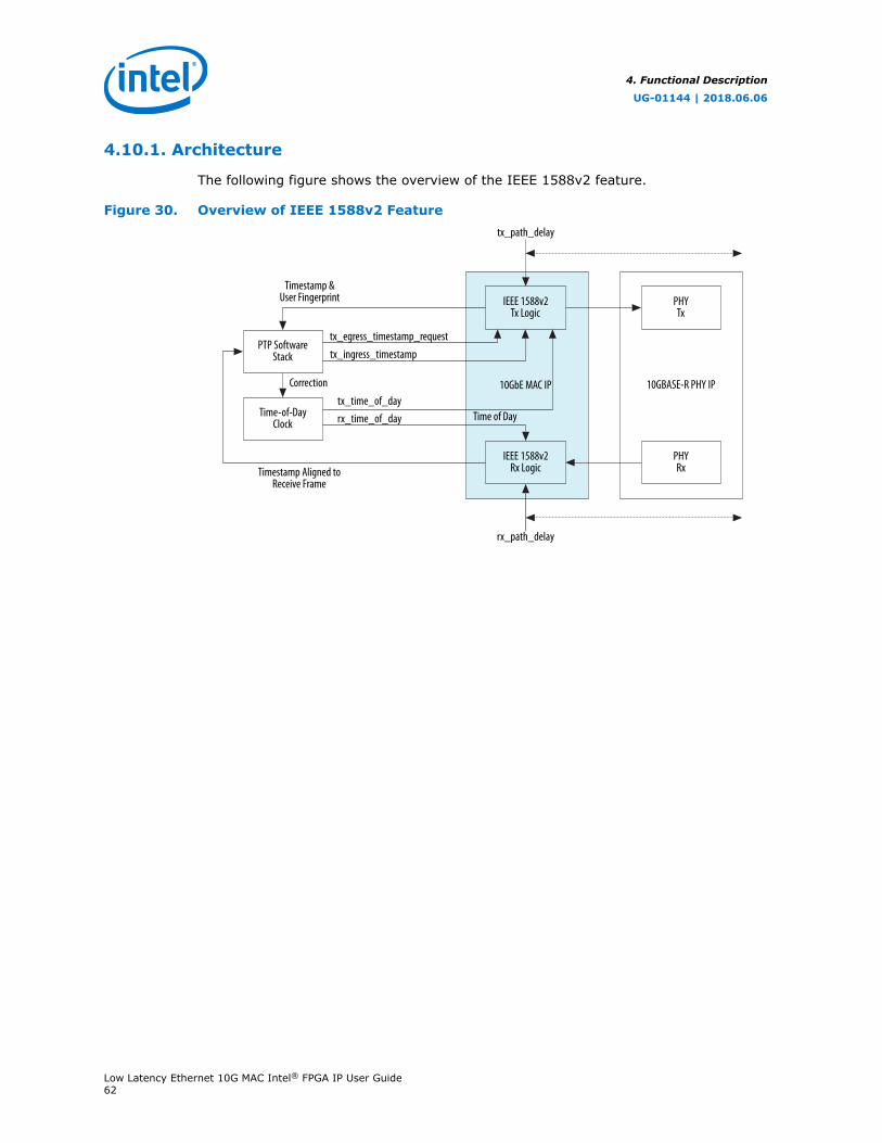
4.10.1. Architecture
The following figure shows the overview of the IEEE 1588v2 feature.
Figure 30. Overview of IEEE 1588v2 Feature
IEEE 1588v2Tx Logic
IEEE 1588v2Rx Logic
PTP SoftwareStack
Time-of-DayClock
PHYTx
PHYRx
10GbE MAC IP 10GBASE-R PHY IP
tx_path_delay
rx_path_delay
Timestamp &User Fingerprint
Correction
Time of Day
Timestamp Aligned toReceive Frame
tx_egress_timestamp_requesttx_ingress_timestamp
tx_time_of_dayrx_time_of_day
4. Functional Description
UG-01144 | 2018.06.06
Low Latency Ethernet 10G MAC Intel® FPGA IP User Guide62
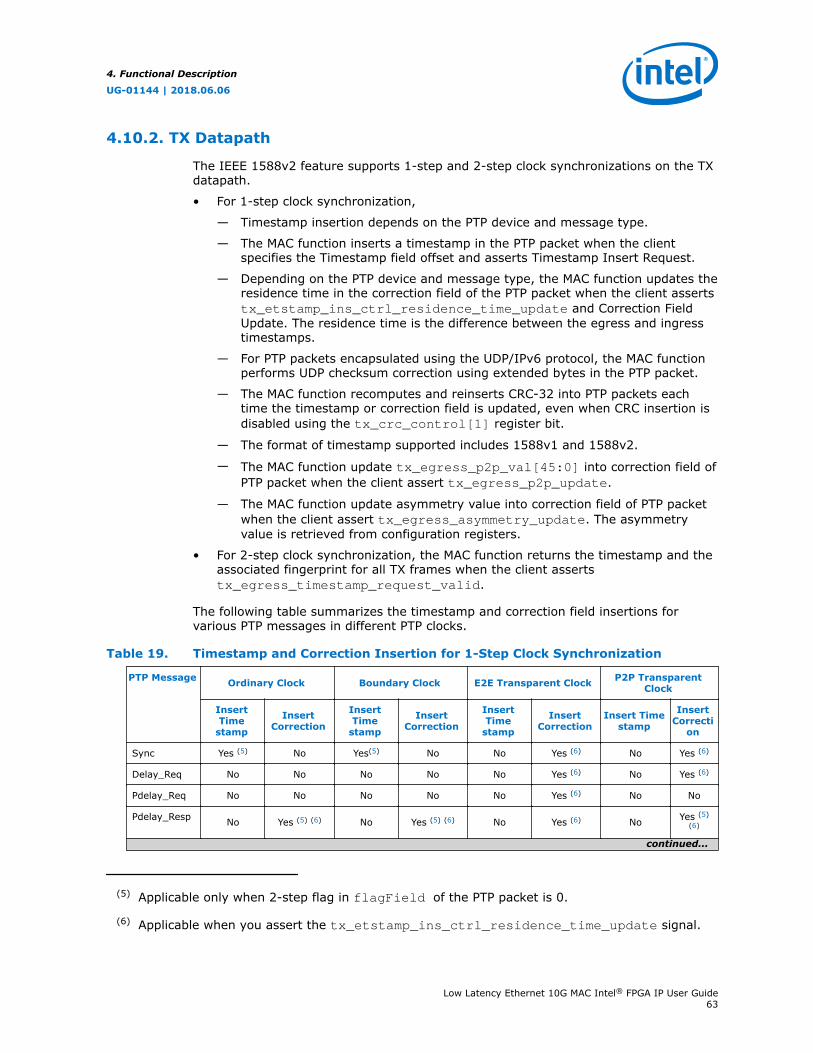
4.10.2. TX Datapath
The IEEE 1588v2 feature supports 1-step and 2-step clock synchronizations on the TXdatapath.
• For 1-step clock synchronization,
— Timestamp insertion depends on the PTP device and message type.
— The MAC function inserts a timestamp in the PTP packet when the clientspecifies the Timestamp field offset and asserts Timestamp Insert Request.
— Depending on the PTP device and message type, the MAC function updates theresidence time in the correction field of the PTP packet when the client assertstx_etstamp_ins_ctrl_residence_time_update and Correction FieldUpdate. The residence time is the difference between the egress and ingresstimestamps.
— For PTP packets encapsulated using the UDP/IPv6 protocol, the MAC functionperforms UDP checksum correction using extended bytes in the PTP packet.
— The MAC function recomputes and reinserts CRC-32 into PTP packets eachtime the timestamp or correction field is updated, even when CRC insertion isdisabled using the tx_crc_control[1] register bit.
— The format of timestamp supported includes 1588v1 and 1588v2.
— The MAC function update tx_egress_p2p_val[45:0] into correction field ofPTP packet when the client assert tx_egress_p2p_update.
— The MAC function update asymmetry value into correction field of PTP packetwhen the client assert tx_egress_asymmetry_update. The asymmetryvalue is retrieved from configuration registers.
• For 2-step clock synchronization, the MAC function returns the timestamp and theassociated fingerprint for all TX frames when the client assertstx_egress_timestamp_request_valid.
The following table summarizes the timestamp and correction field insertions forvarious PTP messages in different PTP clocks.
Table 19. Timestamp and Correction Insertion for 1-Step Clock Synchronization
PTP Message Ordinary Clock Boundary Clock E2E Transparent Clock P2P TransparentClock
InsertTime
stamp
InsertCorrection
InsertTime
stamp
InsertCorrection
InsertTime
stamp
InsertCorrection
Insert Timestamp
InsertCorrecti
on
Sync Yes (5) No Yes(5) No No Yes (6) No Yes (6)
Delay_Req No No No No No Yes (6) No Yes (6)
Pdelay_Req No No No No No Yes (6) No No
Pdelay_Resp No Yes (5) (6) No Yes (5) (6) No Yes (6) No Yes (5)(6)
continued...
(5) Applicable only when 2-step flag in flagField of the PTP packet is 0.
(6) Applicable when you assert the tx_etstamp_ins_ctrl_residence_time_update signal.
4. Functional Description
UG-01144 | 2018.06.06
Low Latency Ethernet 10G MAC Intel® FPGA IP User Guide63

PTP Message Ordinary Clock Boundary Clock E2E Transparent Clock P2P TransparentClock
InsertTime
stamp
InsertCorrection
InsertTime
stamp
InsertCorrection
InsertTime
stamp
InsertCorrection
Insert Timestamp
InsertCorrecti
on
Delay_Resp No No No No No No No No
Follow_Up No No No No No No No No
Pdelay_Resp_Follow_Up
No No No No No No No No
Announce No No No No No No No No
Signaling No No No No No No No No
Management No No No No No No No No
4.10.3. RX Datapath
In the RX datapath, the IEEE 1588v2 feature provides a timestamp for all receiveframes. The timestamp is aligned with the avalon_st_rx_startofpacket signal.
4.10.4. Frame Format
The MAC function, with the IEEE 1588v2 feature, supports PTP packet transfer for thefollowing transport protocols:
• IEEE 802.3
• UDP/IPv4
• UDP/IPv6
4.10.4.1. PTP Packet in IEEE 802.3
The following figures show the structure and format of the PTP packet encapsulated inIEEE 802.3.
Figure 31. PTP packet in IEEE 802.3 Ethernet Frame
User Data Field
PTP Packet
Ethernet Frame
Notes:FCS = Frame check sequencePTP = Precision Time Protocol
Ethernet Header Ethernet FCS
4. Functional Description
UG-01144 | 2018.06.06
Low Latency Ethernet 10G MAC Intel® FPGA IP User Guide64
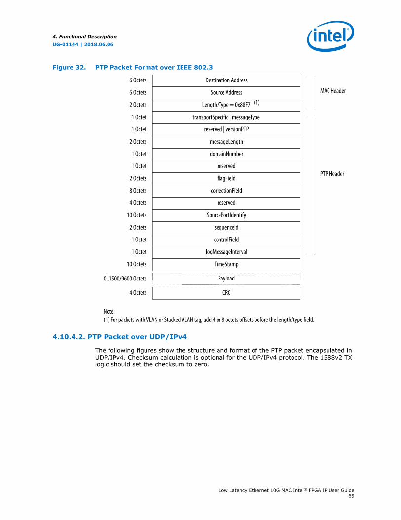
Figure 32. PTP Packet Format over IEEE 802.3
flagField
correctionField
transportSpecific | messageType
reserved | versionPTP
reserved
1 Octet
1 Octet
1 Octet
2 Octets
8 Octets
reserved4 Octets
SourcePortIdentify10 Octets
sequenceId2 Octets
controlField1 Octet
logMessageInterval1 Octet
TimeStamp
Payload
10 Octets
domainNumber
messageLength2 Octets
1 Octet
Length/Type = 0x88F7
Source Address
Destination Address
2 Octets
6 Octets
6 Octets
MAC Header
PTP Header
0..1500/9600 Octets
CRC
Note:(1) For packets with VLAN or Stacked VLAN tag, add 4 or 8 octets offsets before the length/type field.
4 Octets
(1)
4.10.4.2. PTP Packet over UDP/IPv4
The following figures show the structure and format of the PTP packet encapsulated inUDP/IPv4. Checksum calculation is optional for the UDP/IPv4 protocol. The 1588v2 TXlogic should set the checksum to zero.
4. Functional Description
UG-01144 | 2018.06.06
Low Latency Ethernet 10G MAC Intel® FPGA IP User Guide65
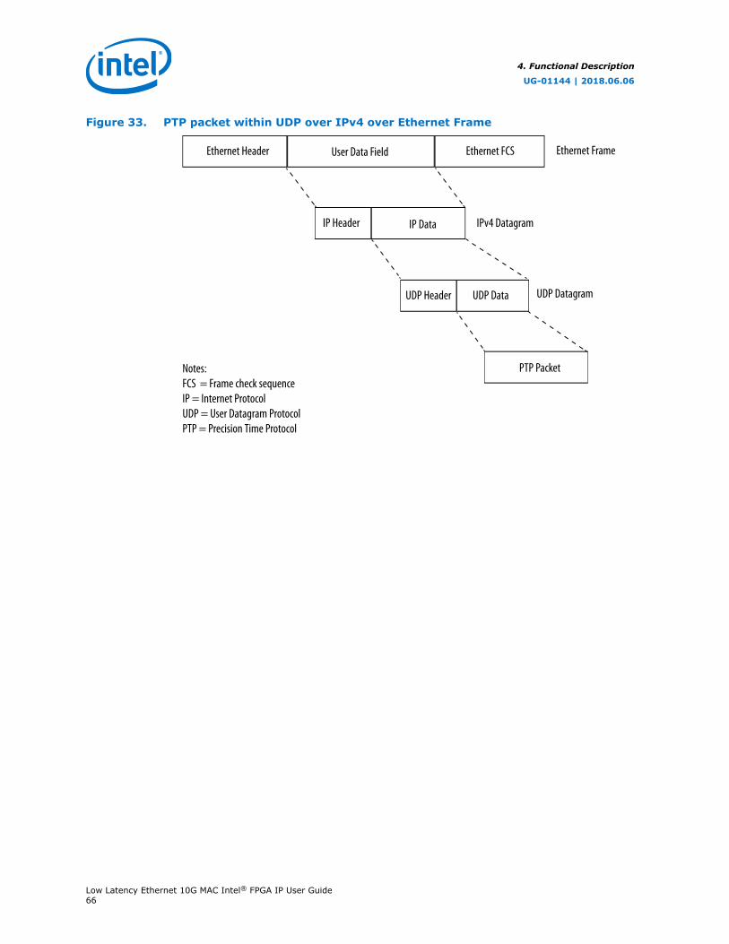
Figure 33. PTP packet within UDP over IPv4 over Ethernet Frame
User Data Field Ethernet FCS
IP Data
Ethernet Frame
IP Header
UDP Data
PTP Packet
IPv4 Datagram
UDP Datagram
Ethernet Header
Notes:FCS = Frame check sequenceIP = Internet ProtocolUDP = User Datagram ProtocolPTP = Precision Time Protocol
UDP Header
4. Functional Description
UG-01144 | 2018.06.06
Low Latency Ethernet 10G MAC Intel® FPGA IP User Guide66
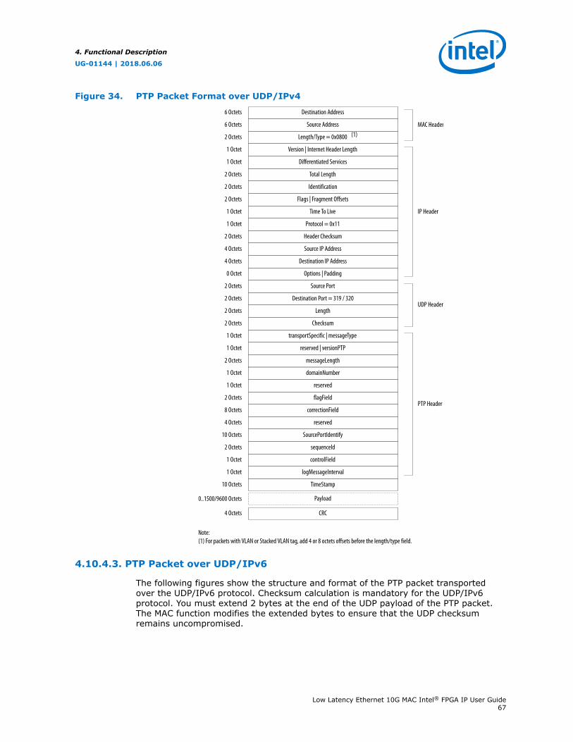
Figure 34. PTP Packet Format over UDP/IPv4
MAC Header
UDP Header
IP Header
PTP Header
Time To Live
Protocol = 0x11
Version | Internet Header Length
Differentiated Services
Flags | Fragment Offsets
1 Octet
1 Octet
2 Octets
1 Octet
1 Octet
Header Checksum2 Octets
Source IP Address4 Octets
Destination IP Address4 Octets
Options | Padding0 Octet
Source Port2 Octets
Destination Port = 319 / 3202 Octets
Identification
Total Length2 Octets
2 Octets
Length/Type = 0x0800
Source Address
Destination Address
2 Octets
6 Octets
6 Octets
Checksum
Length
2 Octets
2 Octets
flagField
correctionField
transportSpecific | messageType
reserved | versionPTP
reserved
1 Octet
1 Octet
1 Octet
2 Octets
8 Octets
reserved4 Octets
SourcePortIdentify10 Octets
sequenceId2 Octets
controlField1 Octet
logMessageInterval1 Octet
TimeStamp
Payload
10 Octets
domainNumber
messageLength2 Octets
1 Octet
0..1500/9600 Octets
CRC
Note:(1) For packets with VLAN or Stacked VLAN tag, add 4 or 8 octets offsets before the length/type field.
4 Octets
(1)
4.10.4.3. PTP Packet over UDP/IPv6
The following figures show the structure and format of the PTP packet transportedover the UDP/IPv6 protocol. Checksum calculation is mandatory for the UDP/IPv6protocol. You must extend 2 bytes at the end of the UDP payload of the PTP packet.The MAC function modifies the extended bytes to ensure that the UDP checksumremains uncompromised.
4. Functional Description
UG-01144 | 2018.06.06
Low Latency Ethernet 10G MAC Intel® FPGA IP User Guide67

Figure 35. PTP packet within UDP over IPv6 over Ethernet Frame
User Data Field Ethernet FCS
IP Data
Ethernet Frame
IP Header
UDP Data
PTP Packet
IPv6 Datagram
UDP Datagram
Ethernet Header
Notes:FCS = Frame check sequenceIP = Internet ProtocolUDP = User Datagram ProtocolPTP = Precision Time Protocol
UDP Header
4. Functional Description
UG-01144 | 2018.06.06
Low Latency Ethernet 10G MAC Intel® FPGA IP User Guide68
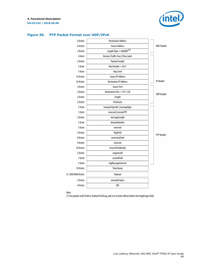
Figure 36. PTP Packet Format over UDP/IPv6
Version | Traffic Class | Flow Label
Payload Length
4 Octet
2 Octets
Source IP Address16 Octets
Destination IP Address16 Octets
Source Port2 Octets
Destination Port = 319 / 3202 Octets
Hop Limit
Next Header = 0x111 Octet
1 Octet
Length/Type = 0x86DD
Source Address
Destination Address
2 Octets
6 Octets
6 Octets
Checksum
Length
2 Octets
2 Octets
flagField
correctionField
transportSpecific | messageType
reserved | versionPTP
reserved
1 Octet
1 Octet
1 Octet
2 Octets
8 Octets
reserved4 Octets
SourcePortIdentify10 Octets
sequenceId2 Octets
controlField1 Octet
logMessageInterval1 Octet
TimeStamp
Payload
10 Octets
0..1500/9600 Octets
extended bytes2 Octets
CRC
Note:(1) For packets with VLAN or Stacked VLAN tag, add 4 or 8 octets offsets before the length/type field.
4 Octets
domainNumber
messageLength2 Octets
1 Octet
MAC Header
UDP Header
IP Header
PTP Header
(1)
4. Functional Description
UG-01144 | 2018.06.06
Low Latency Ethernet 10G MAC Intel® FPGA IP User Guide69
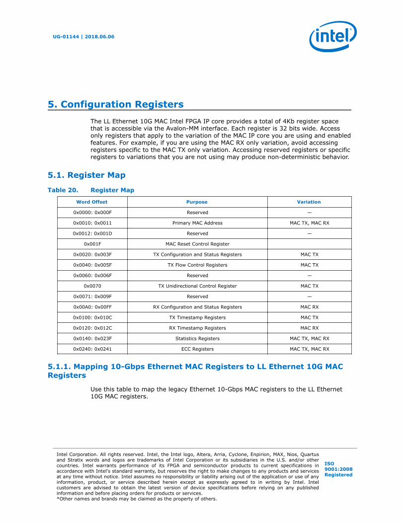
5. Configuration RegistersThe LL Ethernet 10G MAC Intel FPGA IP core provides a total of 4Kb register spacethat is accessible via the Avalon-MM interface. Each register is 32 bits wide. Accessonly registers that apply to the variation of the MAC IP core you are using and enabledfeatures. For example, if you are using the MAC RX only variation, avoid accessingregisters specific to the MAC TX only variation. Accessing reserved registers or specificregisters to variations that you are not using may produce non-deterministic behavior.
5.1. Register Map
Table 20. Register Map
Word Offset Purpose Variation
0x0000: 0x000F Reserved —
0x0010: 0x0011 Primary MAC Address MAC TX, MAC RX
0x0012: 0x001D Reserved —
0x001F MAC Reset Control Register
0x0020: 0x003F TX Configuration and Status Registers MAC TX
0x0040: 0x005F TX Flow Control Registers MAC TX
0x0060: 0x006F Reserved —
0x0070 TX Unidirectional Control Register MAC TX
0x0071: 0x009F Reserved —
0x00A0: 0x00FF RX Configuration and Status Registers MAC RX
0x0100: 0x010C TX Timestamp Registers MAC TX
0x0120: 0x012C RX Timestamp Registers MAC RX
0x0140: 0x023F Statistics Registers MAC TX, MAC RX
0x0240: 0x0241 ECC Registers MAC TX, MAC RX
5.1.1. Mapping 10-Gbps Ethernet MAC Registers to LL Ethernet 10G MACRegisters
Use this table to map the legacy Ethernet 10-Gbps MAC registers to the LL Ethernet10G MAC registers.
UG-01144 | 2018.06.06
Intel Corporation. All rights reserved. Intel, the Intel logo, Altera, Arria, Cyclone, Enpirion, MAX, Nios, Quartusand Stratix words and logos are trademarks of Intel Corporation or its subsidiaries in the U.S. and/or othercountries. Intel warrants performance of its FPGA and semiconductor products to current specifications inaccordance with Intel's standard warranty, but reserves the right to make changes to any products and servicesat any time without notice. Intel assumes no responsibility or liability arising out of the application or use of anyinformation, product, or service described herein except as expressly agreed to in writing by Intel. Intelcustomers are advised to obtain the latest version of device specifications before relying on any publishedinformation and before placing orders for products or services.*Other names and brands may be claimed as the property of others.
ISO9001:2008Registered
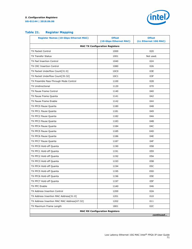
Table 21. Register Mapping
Register Names (10-Gbps Ethernet MAC) Offset(10-Gbps Ethernet MAC)
Offset(LL Ethernet 10G MAC)
MAC TX Configuration Registers
TX Packet Control 1000 020
TX Transfer Status 1001 Not used.
TX Pad Insertion Control 1040 024
TX CRC Insertion Control 1080 026
TX Packet Underflow Count[31:0] 10C0 03E
TX Packet Underflow Count[35:32] 10C1 03F
TX Preamble Pass-Through Mode Control 1100 028
TX Unidirectional 1120 070
TX Pause Frame Control 1140 040
TX Pause Frame Quanta 1141 042
TX Pause Frame Enable 1142 044
TX PFC0 Pause Quanta 1180 048
TX PFC1 Pause Quanta 1181 049
TX PFC2 Pause Quanta 1182 04A
TX PFC3 Pause Quanta 1183 04B
TX PFC4 Pause Quanta 1184 04C
TX PFC5 Pause Quanta 1185 04D
TX PFC6 Pause Quanta 1186 04E
TX PFC7 Pause Quanta 1187 04F
TX PFC0 Hold-off Quanta 1190 058
TX PFC1 Hold-off Quanta 1191 059
TX PFC2 Hold-off Quanta 1192 05A
TX PFC3 Hold-off Quanta 1193 05B
TX PFC4 Hold-off Quanta 1194 05C
TX PFC5 Hold-off Quanta 1195 05D
TX PFC6 Hold-off Quanta 1196 05E
TX PFC7 Hold-off Quanta 1197 05F
TX PFC Enable 11A0 046
TX Address Insertion Control 1200 02A
TX Address Insertion MAC Address[31:0] 1201 010
TX Address Insertion MAC MAC Address[47:32] 1202 011
TX Maximum Frame Length 1801 02C
MAC RX Configuration Registerscontinued...
5. Configuration Registers
UG-01144 | 2018.06.06
Low Latency Ethernet 10G MAC Intel® FPGA IP User Guide71
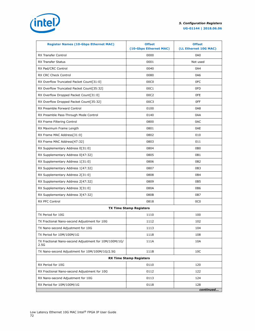
Register Names (10-Gbps Ethernet MAC) Offset(10-Gbps Ethernet MAC)
Offset(LL Ethernet 10G MAC)
RX Transfer Control 0000 0A0
RX Transfer Status 0001 Not used
RX Pad/CRC Control 0040 0A4
RX CRC Check Control 0080 0A6
RX Overflow Truncated Packet Count[31:0] 00C0 0FC
RX Overflow Truncated Packet Count[35:32] 00C1 0FD
RX Overflow Dropped Packet Count[31:0] 00C2 0FE
RX Overflow Dropped Packet Count[35:32] 00C3 0FF
RX Preamble Forward Control 0100 0A8
RX Preamble Pass-Through Mode Control 0140 0AA
RX Frame Filtering Control 0800 0AC
RX Maximum Frame Length 0801 0AE
RX Frame MAC Address[31:0] 0802 010
RX Frame MAC Address[47:32] 0803 011
RX Supplementary Address 0[31:0] 0804 0B0
RX Supplementary Address 0[47:32] 0805 0B1
RX Supplementary Address 1[31:0] 0806 0B2
RX Supplementary Address 1[47:32] 0807 0B3
RX Supplementary Address 2[31:0] 0808 0B4
RX Supplementary Address 2[47:32] 0809 0B5
RX Supplementary Address 3[31:0] 080A 0B6
RX Supplementary Address 3[47:32] 080B 0B7
RX PFC Control 0818 0C0
TX Time Stamp Registers
TX Period for 10G 1110 100
TX Fractional Nano-second Adjustment for 10G 1112 102
TX Nano-second Adjustment for 10G 1113 104
TX Period for 10M/100M/1G 1118 108
TX Fractional Nano-second Adjustment for 10M/100M/1G/2.5G
111A 10A
TX Nano-second Adjustment for 10M/100M/1G/2.5G 111B 10C
RX Time Stamp Registers
RX Period for 10G 0110 120
RX Fractional Nano-second Adjustment for 10G 0112 122
RX Nano-second Adjustment for 10G 0113 124
RX Period for 10M/100M/1G 0118 128
continued...
5. Configuration Registers
UG-01144 | 2018.06.06
Low Latency Ethernet 10G MAC Intel® FPGA IP User Guide72
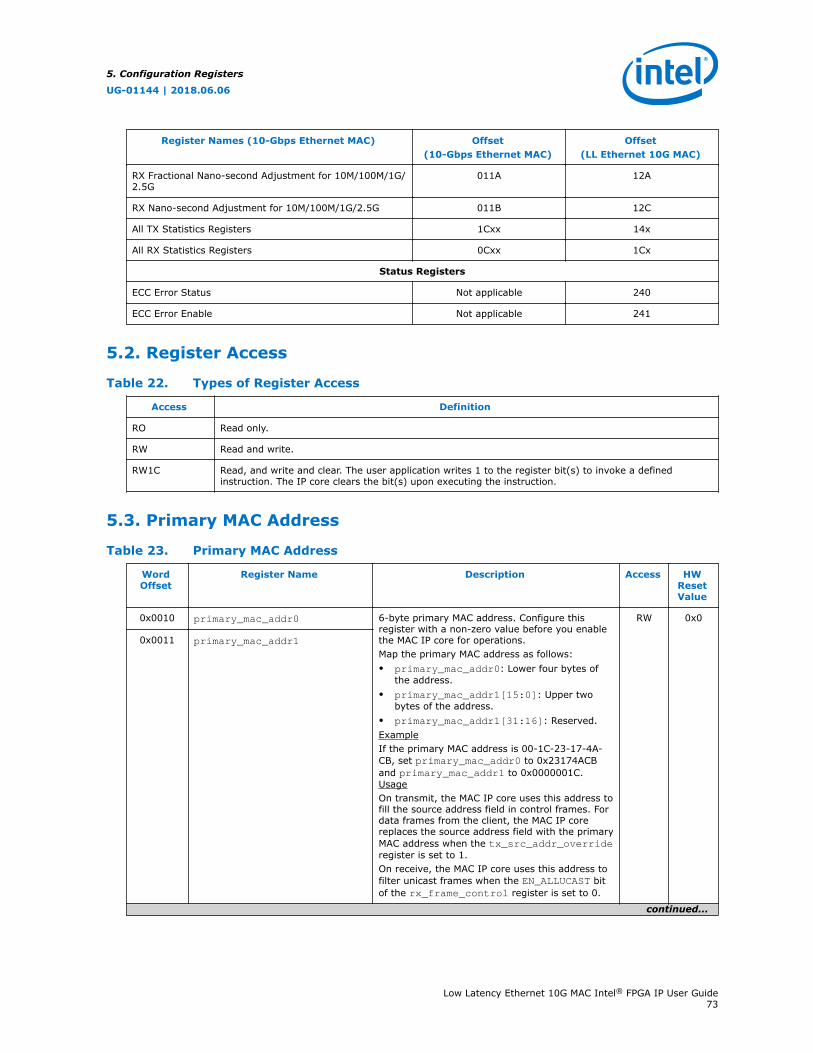
Register Names (10-Gbps Ethernet MAC) Offset(10-Gbps Ethernet MAC)
Offset(LL Ethernet 10G MAC)
RX Fractional Nano-second Adjustment for 10M/100M/1G/2.5G
011A 12A
RX Nano-second Adjustment for 10M/100M/1G/2.5G 011B 12C
All TX Statistics Registers 1Cxx 14x
All RX Statistics Registers 0Cxx 1Cx
Status Registers
ECC Error Status Not applicable 240
ECC Error Enable Not applicable 241
5.2. Register Access
Table 22. Types of Register Access
Access Definition
RO Read only.
RW Read and write.
RW1C Read, and write and clear. The user application writes 1 to the register bit(s) to invoke a definedinstruction. The IP core clears the bit(s) upon executing the instruction.
5.3. Primary MAC Address
Table 23. Primary MAC Address
WordOffset
Register Name Description Access HWResetValue
0x0010 primary_mac_addr0 6-byte primary MAC address. Configure thisregister with a non-zero value before you enablethe MAC IP core for operations.Map the primary MAC address as follows:• primary_mac_addr0: Lower four bytes of
the address.• primary_mac_addr1[15:0]: Upper two
bytes of the address.• primary_mac_addr1[31:16]: Reserved.ExampleIf the primary MAC address is 00-1C-23-17-4A-CB, set primary_mac_addr0 to 0x23174ACBand primary_mac_addr1 to 0x0000001C.UsageOn transmit, the MAC IP core uses this address tofill the source address field in control frames. Fordata frames from the client, the MAC IP corereplaces the source address field with the primaryMAC address when the tx_src_addr_overrideregister is set to 1.On receive, the MAC IP core uses this address tofilter unicast frames when the EN_ALLUCAST bitof the rx_frame_control register is set to 0.
RW 0x0
0x0011 primary_mac_addr1
continued...
5. Configuration Registers
UG-01144 | 2018.06.06
Low Latency Ethernet 10G MAC Intel® FPGA IP User Guide73

WordOffset
Register Name Description Access HWResetValue
The MAC IP core drops frames whose destinationaddress is different from the value of the primaryMAC address.
5. Configuration Registers
UG-01144 | 2018.06.06
Low Latency Ethernet 10G MAC Intel® FPGA IP User Guide74

5.4. MAC Reset Control Register
This register is used only in 10G, 1G/10G, and 10M/100M/1G/10G operating modes.
Table 24. MAC Reset Control Register
WordOffset
Register Name Description Access HWResetValue
0x001F0x08FF
mac_reset_control The user application can use the specified bits in thisregister to reset the MAC datapaths. The effect is thesame as asserting the tx_rst_n or rx_rst_nsignals.• Bit 0—TX datapath reset.
0: Stops the reset process.1: Starts the reset process.
• Bits 7:1—reserved.• Bit 8—RX datapath reset.
0: Stops the reset process.1: Starts the reset process.
• Bits 31:9—reserved.If you turn on Use legacy Ethernet 10G MACAvalon Memory-Mapped interface, the wordoffset is 0x08FF. Otherwise, the word offset is0x001F.
RW 0x0
5.5. TX_Configuration and Status Registers
Table 25. TX Configuration and Status Registers
WordOffset
Register Name Description Access HWResetValue
0x0020 tx_packet_control • Bit 0—configures the TX path.0: Enables the TX path.1: Disables the TX path. The MAC IP coreindicates a backpressure on the Avalon-STtransmit data interface by deasserting theavalon_st_tx_ready signal. When disabled,the IP core stops generating new pause andPFC frames.
• Bits 31:1—reserved.You can change the value of this register asnecessary. If the TX path is disabled while a frameis being transmitted, the MAC IP core completesthe transmission before disabling the TX path.
RW 0x0
0x0022 tx_transfer_status The MAC sets the following bits to indicate thestatus of the TX datapath.• Bits 7:0—reserved.• Bit 8: TX datapath status.
0: The TX datapath is idle.1: A TX data transfer is in progress.
• Bits 11:9—reserved.• Bit 12: TX datapath reset status.
0: The TX datapath is not in reset.1: The TX datapath is in reset.
RO 0x0
continued...
5. Configuration Registers
UG-01144 | 2018.06.06
Low Latency Ethernet 10G MAC Intel® FPGA IP User Guide75
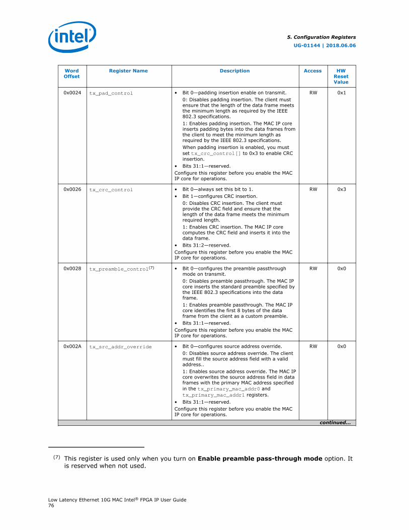
WordOffset
Register Name Description Access HWResetValue
0x0024 tx_pad_control • Bit 0—padding insertion enable on transmit.0: Disables padding insertion. The client mustensure that the length of the data frame meetsthe minimum length as required by the IEEE802.3 specifications.1: Enables padding insertion. The MAC IP coreinserts padding bytes into the data frames fromthe client to meet the minimum length asrequired by the IEEE 802.3 specifications.When padding insertion is enabled, you mustset tx_crc_control[] to 0x3 to enable CRCinsertion.
• Bits 31:1—reserved.Configure this register before you enable the MACIP core for operations.
RW 0x1
0x0026 tx_crc_control • Bit 0—always set this bit to 1.• Bit 1—configures CRC insertion.
0: Disables CRC insertion. The client mustprovide the CRC field and ensure that thelength of the data frame meets the minimumrequired length.1: Enables CRC insertion. The MAC IP corecomputes the CRC field and inserts it into thedata frame.
• Bits 31:2—reserved.Configure this register before you enable the MACIP core for operations.
RW 0x3
0x0028 tx_preamble_control(7) • Bit 0—configures the preamble passthroughmode on transmit.0: Disables preamble passthrough. The MAC IPcore inserts the standard preamble specified bythe IEEE 802.3 specifications into the dataframe.1: Enables preamble passthrough. The MAC IPcore identifies the first 8 bytes of the dataframe from the client as a custom preamble.
• Bits 31:1—reserved.Configure this register before you enable the MACIP core for operations.
RW 0x0
0x002A tx_src_addr_override • Bit 0—configures source address override.0: Disables source address override. The clientmust fill the source address field with a validaddress..1: Enables source address override. The MAC IPcore overwrites the source address field in dataframes with the primary MAC address specifiedin the tx_primary_mac_addr0 andtx_primary_mac_addr1 registers.
• Bits 31:1—reserved.Configure this register before you enable the MACIP core for operations.
RW 0x0
continued...
(7) This register is used only when you turn on Enable preamble pass-through mode option. Itis reserved when not used.
5. Configuration Registers
UG-01144 | 2018.06.06
Low Latency Ethernet 10G MAC Intel® FPGA IP User Guide76

WordOffset
Register Name Description Access HWResetValue
0x002C tx_frame_maxlength • Bits 15:0—specify the maximum allowableframe length. The MAC IP core uses thisregister only for the purpose of collectingstatistics. When the length of the data framefrom the client exceeds this value, the MAC IPcore asserts theavalon_st_txstatus_error[1] signal toflag the frame as oversized. The MAC IP corethen forwards the oversized frame through thetransmit datapath as is.
• Bits 31:16—reserved.Configure this register before you enable the MACIP core for operations.
RW 0x5EE(1518)
0x002D tx_vlan_detection • Bit 0—TX VLAN detection disable.0: The MAC detects VLAN and stacked VLANframes.1: The MAC does not detect VLAN and stackedVLAN frames. When received, the MAC treatsthem as basic frames and considers their tagsas payload bytes.
• Bits 31:1—reserved.
RW 0x0
0x002E0x081E
tx_ipg_10g • Bit 0—use this bit to specify the average IPG foroperating speed of 10 Gbps.0: Sets the average IPG to 8 bytes.1: Sets the average IPG to 12 bytes.
• Bits 31:1—reserved.The Unidirectional feature does not support anaverage IPG of 8 bytes.If you turn on Use legacy Ethernet 10G MACAvalon Memory-Mapped interface, the wordoffset is 0x081E. Otherwise, the word offset is0x002E.
RW 0x1
0x002F0x081F
tx_ipg_10M_100M_1G • Bits 3:0—use these bits to specify the averageIPG for operating speed of 10 Mbps, 100 Mbpsor 1 Gbps. Valid values are between 8 to 15bytes.
• Bits 31:4—reserved.If you turn on Use legacy Ethernet 10G MACAvalon Memory-Mapped interface, the wordoffset is 0x081F. Otherwise, the word offset is0x002F.
RW 0x0C
0x003E tx_underflow_counter0 36-bit error counter that collects the number oftruncated TX frames when TX buffer underflowpersists.• tx_underflow_counter0: Lower 32 bits of
the error counter.• tx_underflow_counter1[3:0]: Upper 4 bits
of the error counter.• tx_underflow_counter1[31:4]—reserved.To read the counter, read the lower 32 bits followedby the upper 4 bits. The IP core clears the counterafter a read.
RO 0x0
0x003F tx_underflow_counter1
5. Configuration Registers
UG-01144 | 2018.06.06
Low Latency Ethernet 10G MAC Intel® FPGA IP User Guide77

5.6. Flow Control Registers
Table 26. Flow Control Registers
WordOffset
Register Name Description Access HWResetValue
0x0040 tx_pauseframe_control • Bits 1:0—configures the transmission of pauseframes.00: No pause frame transmission.01: Trigger the transmission of an XON pauseframe (pause quanta = 0), if the transmissionis not disabled by other conditions.10: Trigger the transmission of an XOFF pauseframe (pause quanta =tx_pauseframe_quanta register), if thetransmission is not disabled by otherconditions.11: Reserved. This setting does not triggerany action.
• Bits 31:2—reserved.Changes to this self-clearing register affects thenext transmission of a pause frame.
RW 0x0
0x0042 tx_pauseframe_quanta • Bits 15:0—pause quanta in unit of quanta, 1unit = 512 bits time. The MAC IP core usesthis value when it generates XOFF pauseframes. An XOFF pause frame with a quantavalue of 0 is equivalent to an XON frame.
• Bits 31:16—reserved.Configure this register before you enable the MACIP core for operations.
RW 0x0
0x0043 tx_pauseframe_holdoff_quanta
• Bits 15:0—specifies the gap between twoconsecutive transmissions of XOFF pauseframes in unit of quanta, 1 unit = 512 bitstime. The gap prevents back-to-backtransmissions of pause frames, which mayaffect the transmission of data frames.
• Bits 31:16—reserved.Configure this register before you enable the MACIP core for operations.
RW 0x1
0x0044 tx_pauseframe_enable • Bit 0—configures the transmission of pauseframes. This bit affects pause frame requestsfrom both register and vector settings.0: Disables pause frame transmission.1: Enables pause frame transmission, if TXpath is enabled by tx_packet_control.
• Bits 2:1—specifies the trigger for pause framerequests.00: Accepts pause frame requests only fromvector setting, avalon_st_pause_data.01: Accepts pause frame requests only fromregister setting, tx_pauseframe_control.10 / 11: Reserved.
• Bits 31:3—reserved.Configure this register before you enable the MACIP core for operations.
RW 0x1
0x0046 tx_pfc_priority_enable(8) Enables priority-based flow control on the TXdatapath.
RW 0x0
continued...
5. Configuration Registers
UG-01144 | 2018.06.06
Low Latency Ethernet 10G MAC Intel® FPGA IP User Guide78
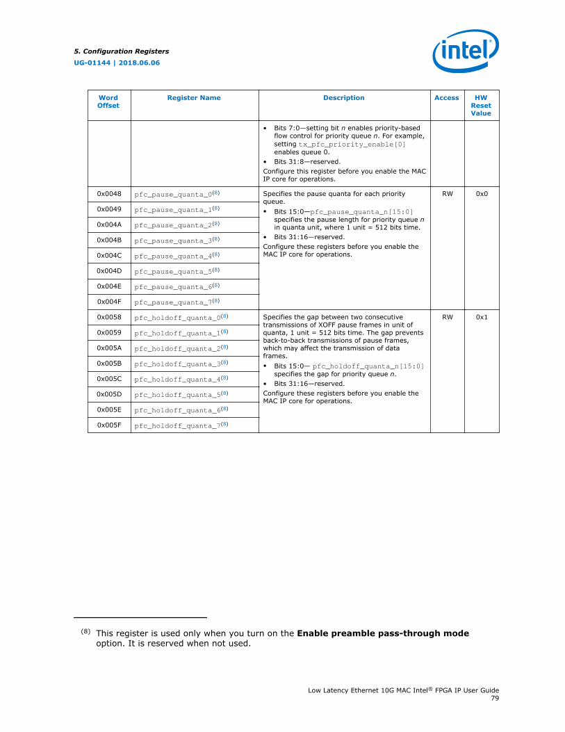
WordOffset
Register Name Description Access HWResetValue
• Bits 7:0—setting bit n enables priority-basedflow control for priority queue n. For example,setting tx_pfc_priority_enable[0]enables queue 0.
• Bits 31:8—reserved.Configure this register before you enable the MACIP core for operations.
0x0048 pfc_pause_quanta_0(8) Specifies the pause quanta for each priorityqueue.• Bits 15:0—pfc_pause_quanta_n[15:0]
specifies the pause length for priority queue nin quanta unit, where 1 unit = 512 bits time.
• Bits 31:16—reserved.Configure these registers before you enable theMAC IP core for operations.
RW 0x0
0x0049 pfc_pause_quanta_1(8)
0x004A pfc_pause_quanta_2(8)
0x004B pfc_pause_quanta_3(8)
0x004C pfc_pause_quanta_4(8)
0x004D pfc_pause_quanta_5(8)
0x004E pfc_pause_quanta_6(8)
0x004F pfc_pause_quanta_7(8)
0x0058 pfc_holdoff_quanta_0(8) Specifies the gap between two consecutivetransmissions of XOFF pause frames in unit ofquanta, 1 unit = 512 bits time. The gap preventsback-to-back transmissions of pause frames,which may affect the transmission of dataframes.• Bits 15:0— pfc_holdoff_quanta_n[15:0]
specifies the gap for priority queue n.• Bits 31:16—reserved.Configure these registers before you enable theMAC IP core for operations.
RW 0x1
0x0059 pfc_holdoff_quanta_1(8)
0x005A pfc_holdoff_quanta_2(8)
0x005B pfc_holdoff_quanta_3(8)
0x005C pfc_holdoff_quanta_4(8)
0x005D pfc_holdoff_quanta_5(8)
0x005E pfc_holdoff_quanta_6(8)
0x005F pfc_holdoff_quanta_7(8)
(8) This register is used only when you turn on the Enable preamble pass-through modeoption. It is reserved when not used.
5. Configuration Registers
UG-01144 | 2018.06.06
Low Latency Ethernet 10G MAC Intel® FPGA IP User Guide79

5.7. Unidirectional Control Registers
Table 27. Unidirectional Control Registers
WordOffset
Register Name Description Access HWResetValue
0x0070 tx_unidir_control(9) • Bit 0—configures the unidirectional feature on theTX path.0: Disables unidirectional feature.1: Enables unidirectional feature.
• Bit 1—configures remote fault sequencegeneration when the unidirectional feature isenabled on the TX path.0: Enable remote fault sequence generation ondetecting local fault.1: Disable remote fault sequence generation.
• Bit 2—configures user-triggered remote faultnotification when the unidirectional feature isenabled on the TX path.0: Default setting.1: The IP core sends remote fault notificationscontinuously until this bit is cleared.
• Bits 31:3—reserved.Configure this register before you enable the MAC IPcore for operations.
RW 0x0
5.8. RX Configuration and Status Registers
Table 28. RX Configuration and Status Registers
WordOffset
Register Name Description Access HWResetValue
0x00A0 rx_transfer_control • Bit 0—RX path enable.0: Enables the RX path.1: Disables the RX path. The MAC IP coredrops all incoming frames.
• Bits 31:1—reserved.A change of value in this register takes effect at apacket boundary. Any transfer in progress is notaffected.
RW 0x0
0x00A2 rx_transfer_status The MAC sets the following bits to indicate thestatus of the RX datapath.• Bits 7:0—reserved.• Bit 8: RX datapath status.
0: The RX datapath is idle.1: An RX data transfer is in progress.
• Bits 11:9—reserved.• Bit 12: RX datapath reset status.
0: The RX datapath is not in reset.1: The RX datapath is in reset.
RO 0x0
continued...
(9) This register is used when you turn on Enable unidirectional feature. It is reserved whennot used.
5. Configuration Registers
UG-01144 | 2018.06.06
Low Latency Ethernet 10G MAC Intel® FPGA IP User Guide80

WordOffset
Register Name Description Access HWResetValue
0x00A4 rx_padcrc_control • Bits [1:0]—Padding and CRC removal onreceive.00: Retains the padding bytes and CRC field,and forwards them to the client.01: Retains only the padding bytes. The MACIP core removes the CRC field before itforwards the RX frame to the client.11: Removes the padding bytes and CRC fieldbefore the RX frame is forwarded to the client.10: Reserved.
• Bits 31:2—reserved.Configure this register before you enable the MACIP core for operations.
RW 0x1
0x00A6 rx_crccheck_control CRC checking on receive.• Bit 0—always set this bit to 0.• Bit 1—CRC checking enable.
0: Ignores the CRC field.1: Checks the CRC field and reports the statusto avalon_st_rx_error[1] andavalon_st_rxstatus_error.
• Bits 31:2—reserved.Configure this register before you enable the MACIP core for operations.
RW 0x2
0x00A8 rx_custom_preamble_forward(10)
• Bit 0—configures the forwarding of the custompreamble to the client.0: Removes the custom preamble from the RXframe.1: Retains and forwards the custom preambleto the client.
• Bits 31:1—reserved.Configure this register before you enable the MACIP core for operations.
RW 0x0
0x00AA rx_preamble_control(10) • Bit 0—preamble passthrough enable onreceive.0: Disables preamble passthrough. The MACIP core checks for START and SFD duringpacket decapsulation process.1: Enables preamble passthrough. The MAC IPcore checks only for START during packetdecapsulation process.
• Bits 31:1—reserved.Configure this register before you enable the MACIP core for operations.
RW 0x0
0x00AC rx_frame_control Configure this register before you enable the MACIP core for operations.
RW 0x3
Bit 0—EN_ALLUCAST
0: Filters RX unicast frames using the primaryMAC address. The MAC IP core drops unicastframes with a destination address other than theprimary MAC address.1: Accepts all RX unicast frames.
continued...
(10) This register is used only when you turn on the Enable preamble pass-through modeoption. It is reserved when not used.
5. Configuration Registers
UG-01144 | 2018.06.06
Low Latency Ethernet 10G MAC Intel® FPGA IP User Guide81

WordOffset
Register Name Description Access HWResetValue
Setting this bit and the EN_ALLMCAST to 1 putsthe MAC IP core in the promiscuous mode.
Bit 1—EN_ALLMCAST
0: Drops all RX multicast frames.1: Accepts all RX multicast frames.Setting this bit and the EN_ALLUCAST bit to 1 isequivalent to setting the MAC IP core to thepromiscuous mode.
Bit 2—reserved.
Bit 3—FWD_CONTROL. When you turn on thePriority-based Flow Control parameter, this bitaffects all control frames except the IEEE 802.3pause frames and priority-based control frames.When the Priority-based Flow Controlparameter is not enabled, this bit affects allcontrol frames except the IEEE 802.3 pauseframes.0: Drops the control frames.1: Forwards the control frames to the client.
Bit 4—FWD_PAUSE
0: Drops pause frames.1: Forwards pause frames to the client.
Bit 5—IGNORE_PAUSE
0: Processes pause frames.1: Ignores pause frames.
Bits 15:6—reserved.
Bit 16—EN_SUPP0
0: Disables the use of supplementary address 0.1: Enables the use of supplementary address 0.
Bit 17—EN_SUPP1
0: Disables the use of supplementary address 1.1: Enables the use of supplementary address 1.
Bit 18—EN_SUPP2
0: Disables the use of supplementary address 2.1: Enables the use of supplementary address 2.
Bit 19—EN_SUPP3
0: Disables the use of supplementary address 3.1: Enables the use of supplementary address 3.
Bits 31:20—reserved.
0x00AE rx_frame_maxlength • Bits 15:0—specify the maximum allowableframe length. The MAC asserts theavalon_st_rx_error[3] signal when thelength of the RX frame exceeds the value ofthis register.
• Bits 16:31—reserved.Configure this register before you enable the MACIP core for operations.
RW 1518
continued...
5. Configuration Registers
UG-01144 | 2018.06.06
Low Latency Ethernet 10G MAC Intel® FPGA IP User Guide82
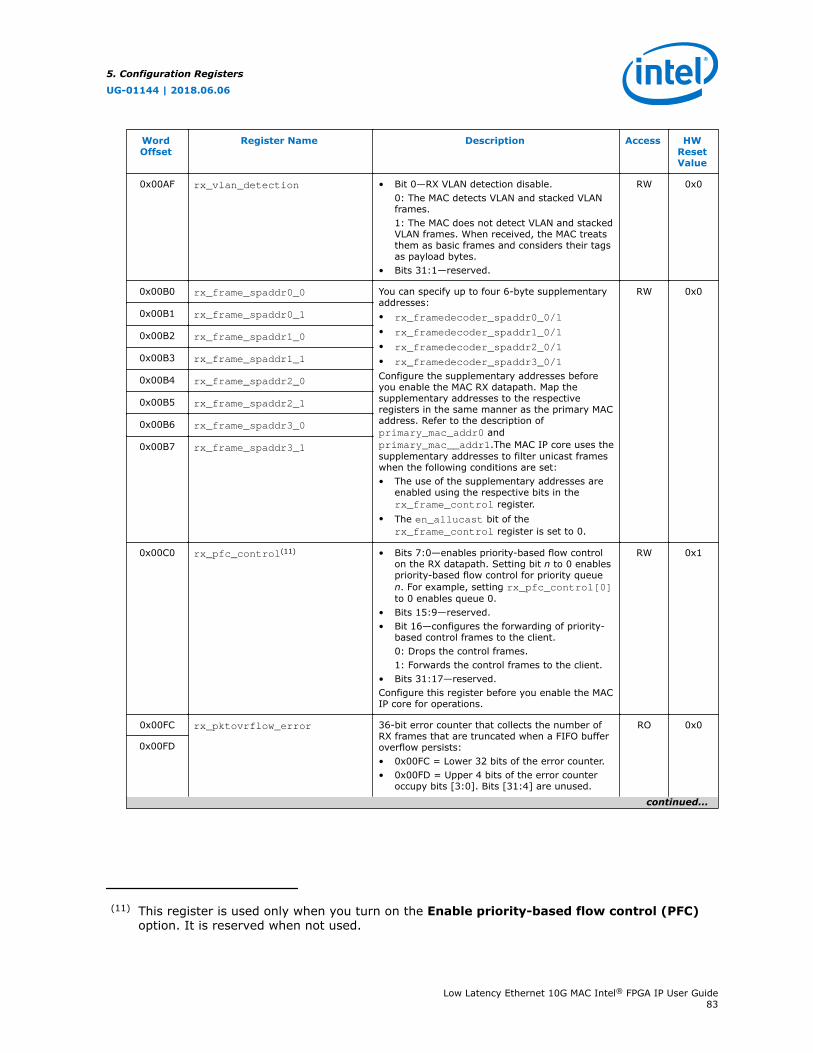
WordOffset
Register Name Description Access HWResetValue
0x00AF rx_vlan_detection • Bit 0—RX VLAN detection disable.0: The MAC detects VLAN and stacked VLANframes.1: The MAC does not detect VLAN and stackedVLAN frames. When received, the MAC treatsthem as basic frames and considers their tagsas payload bytes.
• Bits 31:1—reserved.
RW 0x0
0x00B0 rx_frame_spaddr0_0 You can specify up to four 6-byte supplementaryaddresses:• rx_framedecoder_spaddr0_0/1
• rx_framedecoder_spaddr1_0/1
• rx_framedecoder_spaddr2_0/1
• rx_framedecoder_spaddr3_0/1
Configure the supplementary addresses beforeyou enable the MAC RX datapath. Map thesupplementary addresses to the respectiveregisters in the same manner as the primary MACaddress. Refer to the description ofprimary_mac_addr0 andprimary_mac__addr1.The MAC IP core uses thesupplementary addresses to filter unicast frameswhen the following conditions are set:• The use of the supplementary addresses are
enabled using the respective bits in therx_frame_control register.
• The en_allucast bit of therx_frame_control register is set to 0.
RW 0x0
0x00B1 rx_frame_spaddr0_1
0x00B2 rx_frame_spaddr1_0
0x00B3 rx_frame_spaddr1_1
0x00B4 rx_frame_spaddr2_0
0x00B5 rx_frame_spaddr2_1
0x00B6 rx_frame_spaddr3_0
0x00B7 rx_frame_spaddr3_1
0x00C0 rx_pfc_control(11) • Bits 7:0—enables priority-based flow controlon the RX datapath. Setting bit n to 0 enablespriority-based flow control for priority queuen. For example, setting rx_pfc_control[0]to 0 enables queue 0.
• Bits 15:9—reserved.• Bit 16—configures the forwarding of priority-
based control frames to the client.0: Drops the control frames.1: Forwards the control frames to the client.
• Bits 31:17—reserved.Configure this register before you enable the MACIP core for operations.
RW 0x1
0x00FC rx_pktovrflow_error 36-bit error counter that collects the number ofRX frames that are truncated when a FIFO bufferoverflow persists:• 0x00FC = Lower 32 bits of the error counter.• 0x00FD = Upper 4 bits of the error counter
occupy bits [3:0]. Bits [31:4] are unused.
RO 0x0
0x00FD
continued...
(11) This register is used only when you turn on the Enable priority-based flow control (PFC)option. It is reserved when not used.
5. Configuration Registers
UG-01144 | 2018.06.06
Low Latency Ethernet 10G MAC Intel® FPGA IP User Guide83
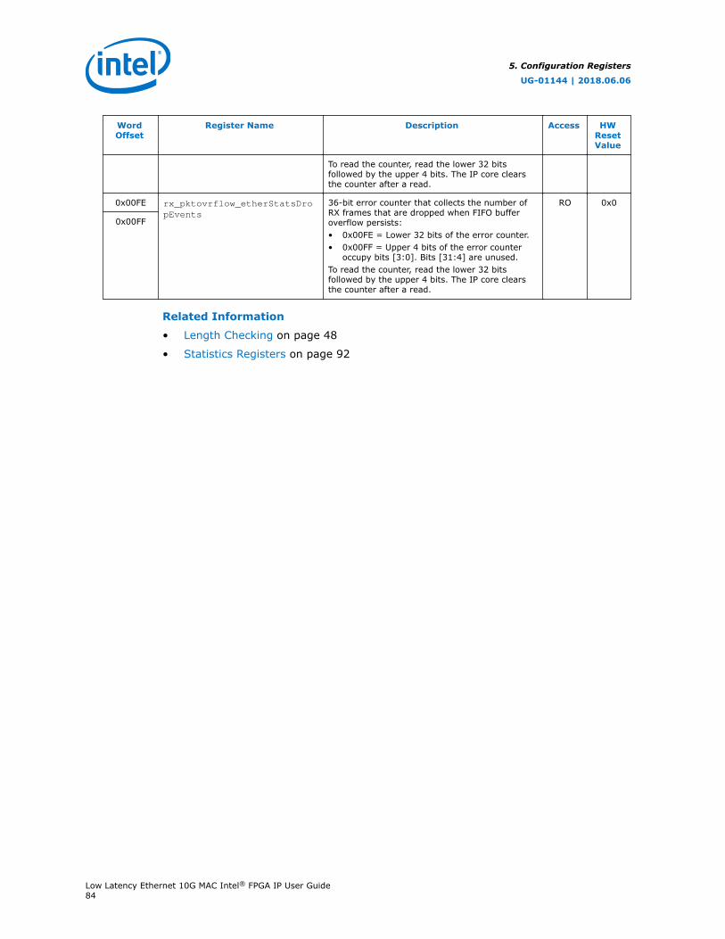
WordOffset
Register Name Description Access HWResetValue
To read the counter, read the lower 32 bitsfollowed by the upper 4 bits. The IP core clearsthe counter after a read.
0x00FE rx_pktovrflow_etherStatsDropEvents
36-bit error counter that collects the number ofRX frames that are dropped when FIFO bufferoverflow persists:• 0x00FE = Lower 32 bits of the error counter.• 0x00FF = Upper 4 bits of the error counter
occupy bits [3:0]. Bits [31:4] are unused.To read the counter, read the lower 32 bitsfollowed by the upper 4 bits. The IP core clearsthe counter after a read.
RO 0x0
0x00FF
Related Information
• Length Checking on page 48
• Statistics Registers on page 92
5. Configuration Registers
UG-01144 | 2018.06.06
Low Latency Ethernet 10G MAC Intel® FPGA IP User Guide84
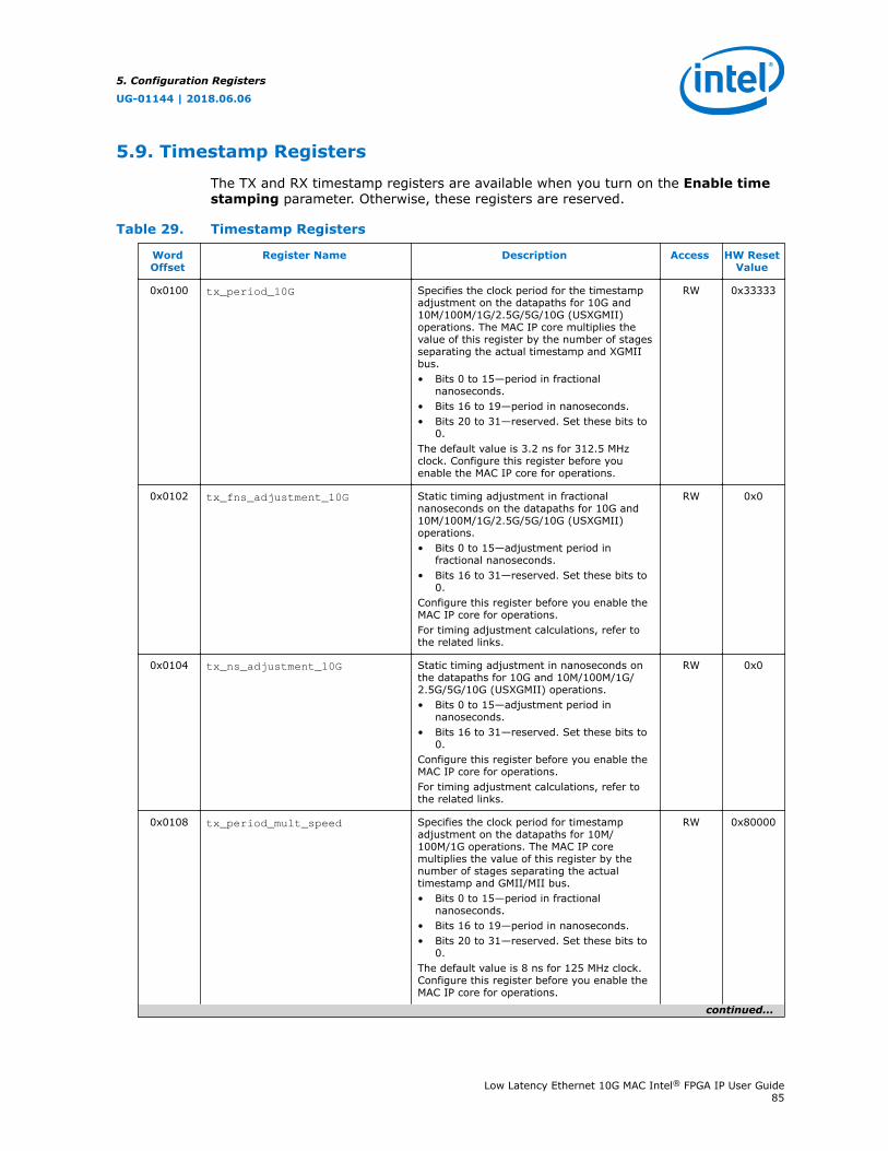
5.9. Timestamp Registers
The TX and RX timestamp registers are available when you turn on the Enable timestamping parameter. Otherwise, these registers are reserved.
Table 29. Timestamp Registers
WordOffset
Register Name Description Access HW ResetValue
0x0100 tx_period_10G Specifies the clock period for the timestampadjustment on the datapaths for 10G and10M/100M/1G/2.5G/5G/10G (USXGMII)operations. The MAC IP core multiplies thevalue of this register by the number of stagesseparating the actual timestamp and XGMIIbus.• Bits 0 to 15—period in fractional
nanoseconds.• Bits 16 to 19—period in nanoseconds.• Bits 20 to 31—reserved. Set these bits to
0.The default value is 3.2 ns for 312.5 MHzclock. Configure this register before youenable the MAC IP core for operations.
RW 0x33333
0x0102 tx_fns_adjustment_10G Static timing adjustment in fractionalnanoseconds on the datapaths for 10G and10M/100M/1G/2.5G/5G/10G (USXGMII)operations.• Bits 0 to 15—adjustment period in
fractional nanoseconds.• Bits 16 to 31—reserved. Set these bits to
0.Configure this register before you enable theMAC IP core for operations.For timing adjustment calculations, refer tothe related links.
RW 0x0
0x0104 tx_ns_adjustment_10G Static timing adjustment in nanoseconds onthe datapaths for 10G and 10M/100M/1G/2.5G/5G/10G (USXGMII) operations.• Bits 0 to 15—adjustment period in
nanoseconds.• Bits 16 to 31—reserved. Set these bits to
0.Configure this register before you enable theMAC IP core for operations.For timing adjustment calculations, refer tothe related links.
RW 0x0
0x0108 tx_period_mult_speed Specifies the clock period for timestampadjustment on the datapaths for 10M/100M/1G operations. The MAC IP coremultiplies the value of this register by thenumber of stages separating the actualtimestamp and GMII/MII bus.• Bits 0 to 15—period in fractional
nanoseconds.• Bits 16 to 19—period in nanoseconds.• Bits 20 to 31—reserved. Set these bits to
0.The default value is 8 ns for 125 MHz clock.Configure this register before you enable theMAC IP core for operations.
RW 0x80000
continued...
5. Configuration Registers
UG-01144 | 2018.06.06
Low Latency Ethernet 10G MAC Intel® FPGA IP User Guide85
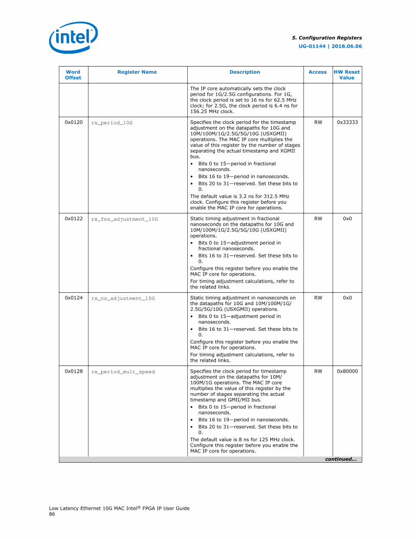
WordOffset
Register Name Description Access HW ResetValue
The IP core automatically sets the clockperiod for 1G/2.5G configurations. For 1G,the clock period is set to 16 ns for 62.5 MHzclock; for 2.5G, the clock period is 6.4 ns for156.25 MHz clock.
0x0120 rx_period_10G Specifies the clock period for the timestampadjustment on the datapaths for 10G and10M/100M/1G/2.5G/5G/10G (USXGMII)operations. The MAC IP core multiplies thevalue of this register by the number of stagesseparating the actual timestamp and XGMIIbus.• Bits 0 to 15—period in fractional
nanoseconds.• Bits 16 to 19—period in nanoseconds.• Bits 20 to 31—reserved. Set these bits to
0.The default value is 3.2 ns for 312.5 MHzclock. Configure this register before youenable the MAC IP core for operations.
RW 0x33333
0x0122 rx_fns_adjustment_10G Static timing adjustment in fractionalnanoseconds on the datapaths for 10G and10M/100M/1G/2.5G/5G/10G (USXGMII)operations.• Bits 0 to 15—adjustment period in
fractional nanoseconds.• Bits 16 to 31—reserved. Set these bits to
0.Configure this register before you enable theMAC IP core for operations.For timing adjustment calculations, refer tothe related links.
RW 0x0
0x0124 rx_ns_adjustment_10G Static timing adjustment in nanoseconds onthe datapaths for 10G and 10M/100M/1G/2.5G/5G/10G (USXGMII) operations.• Bits 0 to 15—adjustment period in
nanoseconds.• Bits 16 to 31—reserved. Set these bits to
0.Configure this register before you enable theMAC IP core for operations.For timing adjustment calculations, refer tothe related links.
RW 0x0
0x0128 rx_period_mult_speed Specifies the clock period for timestampadjustment on the datapaths for 10M/100M/1G operations. The MAC IP coremultiplies the value of this register by thenumber of stages separating the actualtimestamp and GMII/MII bus.• Bits 0 to 15—period in fractional
nanoseconds.• Bits 16 to 19—period in nanoseconds.• Bits 20 to 31—reserved. Set these bits to
0.The default value is 8 ns for 125 MHz clock.Configure this register before you enable theMAC IP core for operations.
RW 0x80000
continued...
5. Configuration Registers
UG-01144 | 2018.06.06
Low Latency Ethernet 10G MAC Intel® FPGA IP User Guide86
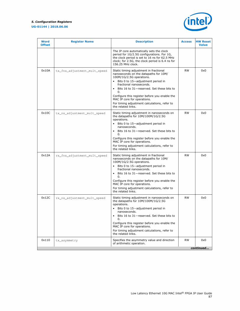
WordOffset
Register Name Description Access HW ResetValue
The IP core automatically sets the clockperiod for 1G/2.5G configurations. For 1G,the clock period is set to 16 ns for 62.5 MHzclock; for 2.5G, the clock period is 6.4 ns for156.25 MHz clock.
0x10A tx_fns_adjustment_mult_speed Static timing adjustment in fractionalnanoseconds on the datapaths for 10M/100M/1G/2.5G operations.• Bits 0 to 15—adjustment period in
fractional nanoseconds.• Bits 16 to 31—reserved. Set these bits to
0.Configure this register before you enable theMAC IP core for operations.For timing adjustment calculations, refer tothe related links.
RW 0x0
0x10C tx_ns_adjustment_mult_speed Static timing adjustment in nanoseconds onthe datapaths for 10M/100M/1G/2.5Goperations.• Bits 0 to 15—adjustment period in
nanoseconds.• Bits 16 to 31—reserved. Set these bits to
0.Configure this register before you enable theMAC IP core for operations.For timing adjustment calculations, refer tothe related links.
RW 0x0
0x12A rx_fns_adjustment_mult_speed Static timing adjustment in fractionalnanoseconds on the datapaths for 10M/100M/1G/2.5G operations.• Bits 0 to 15—adjustment period in
fractional nanoseconds.• Bits 16 to 31—reserved. Set these bits to
0.Configure this register before you enable theMAC IP core for operations.For timing adjustment calculations, refer tothe related links.
RW 0x0
0x12C rx_ns_adjustment_mult_speed Static timing adjustment in nanoseconds onthe datapaths for 10M/100M/1G/2.5Goperations.• Bits 0 to 15—adjustment period in
nanoseconds.• Bits 16 to 31—reserved. Set these bits to
0.Configure this register before you enable theMAC IP core for operations.For timing adjustment calculations, refer tothe related links.
RW 0x0
0x110 tx_asymmetry Specifies the asymmetry value and directionof arithmetic operation.
RW 0x0
continued...
5. Configuration Registers
UG-01144 | 2018.06.06
Low Latency Ethernet 10G MAC Intel® FPGA IP User Guide87
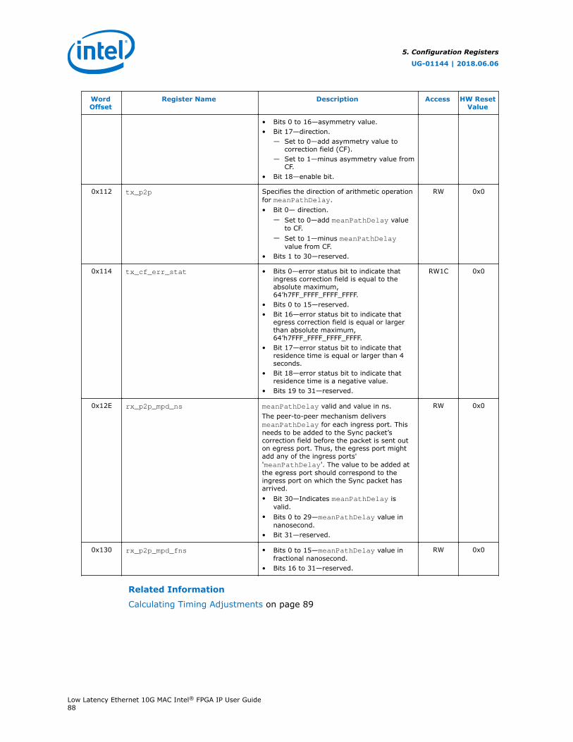
WordOffset
Register Name Description Access HW ResetValue
• Bits 0 to 16—asymmetry value.• Bit 17—direction.
— Set to 0—add asymmetry value tocorrection field (CF).
— Set to 1—minus asymmetry value fromCF.
• Bit 18—enable bit.
0x112 tx_p2p Specifies the direction of arithmetic operationfor meanPathDelay.• Bit 0— direction.
— Set to 0—add meanPathDelay valueto CF.
— Set to 1—minus meanPathDelayvalue from CF.
• Bits 1 to 30—reserved.
RW 0x0
0x114 tx_cf_err_stat • Bits 0—error status bit to indicate thatingress correction field is equal to theabsolute maximum,64’h7FF_FFFF_FFFF_FFFF.
• Bits 0 to 15—reserved.• Bit 16—error status bit to indicate that
egress correction field is equal or largerthan absolute maximum,64’h7FFF_FFFF_FFFF_FFFF.
• Bit 17—error status bit to indicate thatresidence time is equal or larger than 4seconds.
• Bit 18—error status bit to indicate thatresidence time is a negative value.
• Bits 19 to 31—reserved.
RW1C 0x0
0x12E rx_p2p_mpd_ns meanPathDelay valid and value in ns.The peer-to-peer mechanism deliversmeanPathDelay for each ingress port. Thisneeds to be added to the Sync packet’scorrection field before the packet is sent outon egress port. Thus, the egress port mightadd any of the ingress ports''meanPathDelay'. The value to be added atthe egress port should correspond to theingress port on which the Sync packet hasarrived.• Bit 30—Indicates meanPathDelay is
valid.• Bits 0 to 29—meanPathDelay value in
nanosecond.• Bit 31—reserved.
RW 0x0
0x130 rx_p2p_mpd_fns • Bits 0 to 15—meanPathDelay value infractional nanosecond.
• Bits 16 to 31—reserved.
RW 0x0
Related Information
Calculating Timing Adjustments on page 89
5. Configuration Registers
UG-01144 | 2018.06.06
Low Latency Ethernet 10G MAC Intel® FPGA IP User Guide88
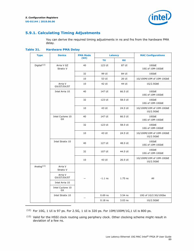
5.9.1. Calculating Timing Adjustments
You can derive the required timing adjustments in ns and fns from the hardware PMAdelay.
Table 31. Hardware PMA Delay
Type Device PMA Mode(bit)
Latency MAC Configurations
TX RX
Digital(12) Arria V GZStratix V
40 123 UI 87 UI 10GbE10G of 10M-10GbE
32 99 UI 84 UI 10GbE
10 53 UI 26 UI 1G/100M/10M of 10M-10GbE
Arria VGX/GT/SX/ST
10 42 UI 44 UI 1G/2.5GbE
Intel Arria 10 40 147 UI 66.5 UI 10GbE10G of 10M-10GbE
32 123 UI 58.5 UI 10GbE10G of 10M-10GbE
10 43 UI 24.5 UI 1G/100M/10M of 10M-10GbE1G/2.5GbE
Intel Cyclone 10GX
40 147 UI 66.5 UI 10GbE10G of 10M-10GbE
32 123 UI 58.5 UI 10GbE10G of 10M-10GbE
10 43 UI 24.5 UI 1G/100M/10M of 10M-10GbE1G/2.5GbE
Intel Stratix 1040 127 UI 48.5 UI
10GbE10G of 10M-10GbE
32 107 UI 44.5 UI10GbE
10G of 10M-10GbE
10 43 UI 26.5 UI1G/100M/10M of 10M-10GbE
1G/2.5GbE
Analog(13) Arria VStratix V
— -1.1 ns 1.75 ns AllArria V
GX/GT/SX/ST
Intel Arria 10
Intel Cyclone 10GX
Intel Stratix 10—
0.69 ns 3.54 ns 10G of 1G/2.5G/10Gbe
0.18 ns 3.03 ns 1G/2.5GbE
(12) For 10G, 1 UI is 97 ps. For 2.5G, 1 UI is 320 ps. For 10M/100M/1G,1 UI is 800 ps.
(13) Valid for the HSSI clock routing using periphery clock. Other clocking scheme might result indeviation of a few ns.
5. Configuration Registers
UG-01144 | 2018.06.06
Low Latency Ethernet 10G MAC Intel® FPGA IP User Guide89

The example below shows the required calculation for a 10M – 10GbE design targetinga Stratix V device.
Table 32. Example: Calculating RX Timing Adjustments for 10M – 10GbE Design in aStratix V Device
Step Description 10G 10M, 100M or 1G
1 Identify the digitallatency for the device.
For Stratix V using the PMA mode of 40bits, the digital latency is 87 UI.
For Stratix V using the PMA mode of 10bits, the digital latency is 26 UI.
2 Convert the digitallatency in UI to ns.
87 UI * 0.097 = 8.439 ns 26 UI * 0.8 = 20.8 ns
3 Add the analog latencyto the digital latency inns.
8.439 ns + 1.75 ns = 10.189 ns 20.8 ns + 1.75 ns = 22.55 ns
4 Add any external PHYdelay to the totalobtained in step 3. Inthis example, anexternal PHY delay of 1ns is assumed.
10.189 ns + 1 ns = 11.189 ns 22.55 ns + 1 ns = 23.55 ns
5 Convert the totallatency to ns and fns inhexadecimal.
ns: 0xBfns: 0.189 * 65536 = 0x3062
ns: 0x17fns: 0.55 * 65536 = 0x8CCC
6 Configure the respectiveregisters.
rx_ns_adjustment_10G = 0xBrx_fns_adjustment_10G = 0x3062
rx_ns_adjustment_mult_speed =0x17rx_fns_adjustment_mult_speed =0x8CCC
Related Information
Timestamp Registers on page 85
5. Configuration Registers
UG-01144 | 2018.06.06
Low Latency Ethernet 10G MAC Intel® FPGA IP User Guide90
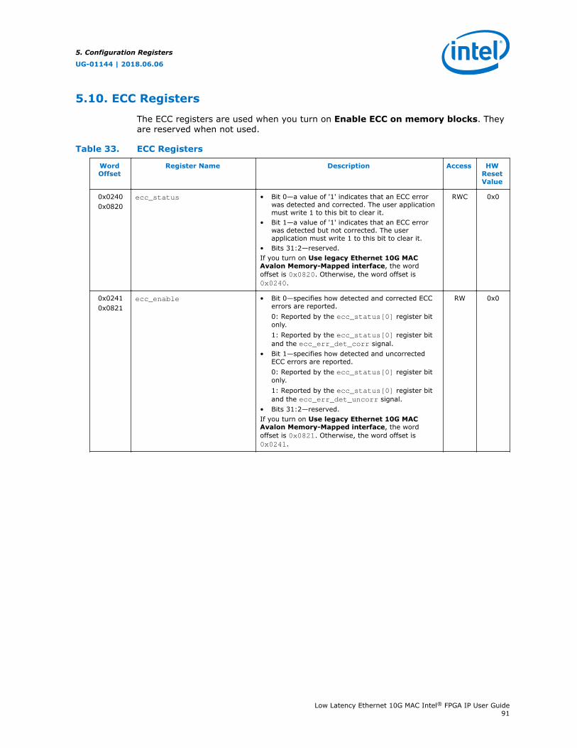
5.10. ECC Registers
The ECC registers are used when you turn on Enable ECC on memory blocks. Theyare reserved when not used.
Table 33. ECC Registers
WordOffset
Register Name Description Access HWResetValue
0x02400x0820
ecc_status • Bit 0—a value of '1' indicates that an ECC errorwas detected and corrected. The user applicationmust write 1 to this bit to clear it.
• Bit 1—a value of '1' indicates that an ECC errorwas detected but not corrected. The userapplication must write 1 to this bit to clear it.
• Bits 31:2—reserved.If you turn on Use legacy Ethernet 10G MACAvalon Memory-Mapped interface, the wordoffset is 0x0820. Otherwise, the word offset is0x0240.
RWC 0x0
0x02410x0821
ecc_enable • Bit 0—specifies how detected and corrected ECCerrors are reported.0: Reported by the ecc_status[0] register bitonly.1: Reported by the ecc_status[0] register bitand the ecc_err_det_corr signal.
• Bit 1—specifies how detected and uncorrectedECC errors are reported.0: Reported by the ecc_status[0] register bitonly.1: Reported by the ecc_status[0] register bitand the ecc_err_det_uncorr signal.
• Bits 31:2—reserved.If you turn on Use legacy Ethernet 10G MACAvalon Memory-Mapped interface, the wordoffset is 0x0821. Otherwise, the word offset is0x0241.
RW 0x0
5. Configuration Registers
UG-01144 | 2018.06.06
Low Latency Ethernet 10G MAC Intel® FPGA IP User Guide91
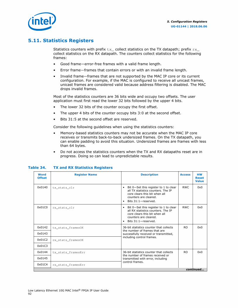
5.11. Statistics Registers
Statistics counters with prefix tx_ collect statistics on the TX datapath; prefix rx_collect statistics on the RX datapath. The counters collect statistics for the followingframes:
• Good frame—error-free frames with a valid frame length.
• Error frame—frames that contain errors or with an invalid frame length.
• Invalid frame—frames that are not supported by the MAC IP core or its currentconfiguration. For example, if the MAC is configured to receive all unicast frames,unicast frames are considered valid because address filtering is disabled. The MACdrops invalid frames.
Most of the statistics counters are 36 bits wide and occupy two offsets. The userapplication must first read the lower 32 bits followed by the upper 4 bits.
• The lower 32 bits of the counter occupy the first offset.
• The upper 4 bits of the counter occupy bits 3:0 at the second offset.
• Bits 31:5 at the second offset are reserved.
Consider the following guidelines when using the statistics counters:
• Memory-based statistics counters may not be accurate when the MAC IP corereceives or transmits back-to-back undersized frames. On the TX datapath, youcan enable padding to avoid this situation. Undersized frames are frames with lessthan 64 bytes.
• Do not access the statistics counters when the TX and RX datapaths reset are inprogress. Doing so can lead to unpredictable results.
Table 34. TX and RX Statistics Registers
WordOffset
Register Name Description Access HWResetValue
0x0140 tx_stats_clr • Bit 0—Set this register to 1 to clearall TX statistics counters. The IPcore clears this bit when allcounters are cleared.
• Bits 31:1—reserved.
RWC 0x0
0x01C0 rx_stats_clr • Bit 0—Set this register to 1 to clearall RX statistics counters. The IPcore clears this bit when allcounters are cleared.
• Bits 31:1—reserved.
RWC 0x0
0x0142 tx_stats_framesOK 36-bit statistics counter that collectsthe number of frames that aresuccessfully received or transmitted,including control frames.
RO 0x0
0x0143
0x01C2 rx_stats_framesOK
0x01C3
0x0144 tx_stats_framesErr 36-bit statistics counter that collectsthe number of frames received ortransmitted with error, includingcontrol frames.
RO 0x0
0x0145
0x01C4 rx_stats_framesErr
continued...
5. Configuration Registers
UG-01144 | 2018.06.06
Low Latency Ethernet 10G MAC Intel® FPGA IP User Guide92
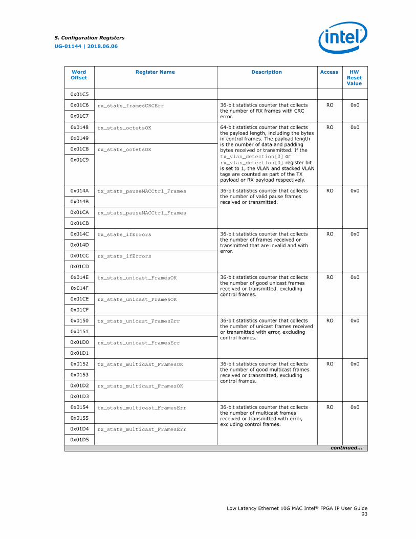
WordOffset
Register Name Description Access HWResetValue
0x01C5
0x01C6 rx_stats_framesCRCErr 36-bit statistics counter that collectsthe number of RX frames with CRCerror.
RO 0x0
0x01C7
0x0148 tx_stats_octetsOK 64-bit statistics counter that collectsthe payload length, including the bytesin control frames. The payload lengthis the number of data and paddingbytes received or transmitted. If thetx_vlan_detection[0] orrx_vlan_detection[0] register bitis set to 1, the VLAN and stacked VLANtags are counted as part of the TXpayload or RX payload respectively.
RO 0x0
0x0149
0x01C8 rx_stats_octetsOK
0x01C9
0x014A tx_stats_pauseMACCtrl_Frames 36-bit statistics counter that collectsthe number of valid pause framesreceived or transmitted.
RO 0x0
0x014B
0x01CA rx_stats_pauseMACCtrl_Frames
0x01CB
0x014C tx_stats_ifErrors 36-bit statistics counter that collectsthe number of frames received ortransmitted that are invalid and witherror.
RO 0x0
0x014D
0x01CC rx_stats_ifErrors
0x01CD
0x014E tx_stats_unicast_FramesOK 36-bit statistics counter that collectsthe number of good unicast framesreceived or transmitted, excludingcontrol frames.
RO 0x0
0x014F
0x01CE rx_stats_unicast_FramesOK
0x01CF
0x0150 tx_stats_unicast_FramesErr 36-bit statistics counter that collectsthe number of unicast frames receivedor transmitted with error, excludingcontrol frames.
RO 0x0
0x0151
0x01D0 rx_stats_unicast_FramesErr
0x01D1
0x0152 tx_stats_multicast_FramesOK 36-bit statistics counter that collectsthe number of good multicast framesreceived or transmitted, excludingcontrol frames.
RO 0x0
0x0153
0x01D2 rx_stats_multicast_FramesOK
0x01D3
0x0154 tx_stats_multicast_FramesErr 36-bit statistics counter that collectsthe number of multicast framesreceived or transmitted with error,excluding control frames.
RO 0x0
0x0155
0x01D4 rx_stats_multicast_FramesErr
0x01D5
continued...
5. Configuration Registers
UG-01144 | 2018.06.06
Low Latency Ethernet 10G MAC Intel® FPGA IP User Guide93

WordOffset
Register Name Description Access HWResetValue
0x0156 tx_stats_broadcast_FramesOK 36-bit statistics counter that collectsthe number of good broadcast framesreceived or transmitted, excludingcontrol frames.
RO 0x0
0x0157
0x01D6 rx_stats_broadcast_FramesOK
0x01D7
0x0158 tx_stats_broadcast_FramesErr 36-bit statistics counter that collectsthe number of broadcast framesreceived or transmitted with error,excluding control frames.
RO 0x0
0x0159
0x01D8 rx_stats_broadcast_FramesErr
0x01D9
0x015A tx_stats_etherStatsOctets 64-bit statistics counter that collectsthe total number of octets received ortransmitted. This count includes good,errored, and invalid frames.
RO 0x0
0x015B
0x01DA rx_stats_etherStatsOctets
0x01DB
0x015C tx_stats_etherStatsPkts 36-bit statistics counter that collectsthe total number of good, errored, andinvalid frames received or transmitted.
RO 0x0
0x015D
0x01DC rx_stats_etherStatsPkts
0x01DD
0x015E tx_stats_etherStatsUndersizePkts 36-bit statistics counter that collectsthe number of undersized TX or RXframes.
RO 0x0
0x015F
0x01DE rx_stats_etherStatsUndersizePkts
0x01DF
0x0160 tx_stats_etherStatsOversizePkts 36-bit statistics counter that collectsthe number of TX or RX frames whoselength exceeds the maximum framelength specified.
RO 0x0
0x0161
0x01E0 rx_stats_etherStatsOversizePkts
0x01E1
0x0162 tx_stats_etherStatsPkts64Octets 36-bit statistics counter that collectsthe number of 64-byteTX or RXframes, including the CRC field butexcluding the preamble and SFDbytes. This count includes good,errored, and invalid frames.
RO 0x0
0x0163
0x01E2 rx_stats_etherStatsPkts64Octets
0x01E3
0x0164 tx_stats_etherStatsPkts65to127Octets 36-bit statistics counter that collectsthe number of TX or RX framesbetween the length of 65 and 127bytes, including the CRC field butexcluding the preamble and SFDbytes. This count includes good,errored, and invalid frames.
RO 0x0
0x0165
0x01E4 rx_stats_etherStatsPkts65to127Octets
0x01E5
0x0166 tx_stats_etherStatsPkts128to255Octets
36-bit statistics counter that collectsthe number of TX or RX framesbetween the length of 128 and 255bytes, including the CRC field but
RO 0x0
0x0167
continued...
5. Configuration Registers
UG-01144 | 2018.06.06
Low Latency Ethernet 10G MAC Intel® FPGA IP User Guide94

WordOffset
Register Name Description Access HWResetValue
0x01E6 rx_stats_etherStatsPkts128to255Octets
excluding the preamble and SFDbytes. This count includes good,errored, and invalid frames.0x01E7
0x0168 tx_stats_etherStatsPkts256to511Octets
36-bit statistics counter that collectsthe number of TX or RX framesbetween the length of 256 and 511bytes, including the CRC field butexcluding the preamble and SFDbytes. This count includes good,errored, and invalid frames.
RO 0x0
0x0169
0x01E8 rx_stats_etherStatsPkts256to511Octets
0x01E9
0x016A tx_stats_etherStatsPkts512to1023Octets
36-bit statistics counter that collectsthe number of TX or RX framesbetween the length of 512 and 1,023bytes, including the CRC field butexcluding the preamble and SFDbytes. This count includes good,errored, and invalid frames.
RO 0x0
0x016B
0x01EA rx_stats_etherStatsPkts512to1023Octets
0x01EB
0x016C tx_stats_etherStatPkts1024to1518Octets
36-bit statistics counter that collectsthe number of TX or RX framesbetween the length of 1,024 and 1,518bytes, including the CRC field butexcluding the preamble and SFDbytes. This count includes good,errored, and invalid frames.
RO 0x0
0x016D
0x01EC rx_stats_etherStatPkts1024to1518Octets
0x01ED
0x016E tx_stats_etherStatsPkts1519toXOctets 36-bit statistics counter that collectsthe number of TX or RX frames equalor more than the length of 1,519bytes, including the CRC field butexcluding the preamble and SFDbytes. This count includes good,errored, and invalid frames.
RO 0x0
0x016F
0x01EE rx_stats_etherStatsPkts1519toXOctets
0x01EF
0x01F0 rx_stats_etherStatsFragments 36-bit statistics counter that collectsthe total number of RX frames withlength less than 64 bytes and CRCerror. The MAC does not drop theseframes.
RO 0x0
0x01F1
0x01F2 rx_stats_etherStatsJabbers 36-bit statistics counter that collectsthe number of oversized RX frameswith CRC error. The MAC does not dropthese frames.
RO 0x0
0x01F3
0x01F4 rx_stats_etherStatsCRCErr 36-bit statistics counter that collectsthe number of RX frames with CRCerror, whose length is between 64 andthe maximum frame length specified inthe register. The MAC does not dropthese frames.
RO 0x0
0x01F5
0x0176 tx_stats_unicastMACCtrlFrames 36-bit statistics counter that collectsthe number of valid TX or RX unicastcontrol frames.
RO 0x0
0x0177
0x01F6 rx_stats_unicastMACCtrlFrames
0x01F7
0x0178 tx_stats_multicastMACCtrlFrames 36-bit statistics counter that collectsthe number of valid TX or RX multicastcontrol frames.
RO 0x0
0x0179
0x01F8 rx_stats_multicastMACCtrlFrames
continued...
5. Configuration Registers
UG-01144 | 2018.06.06
Low Latency Ethernet 10G MAC Intel® FPGA IP User Guide95
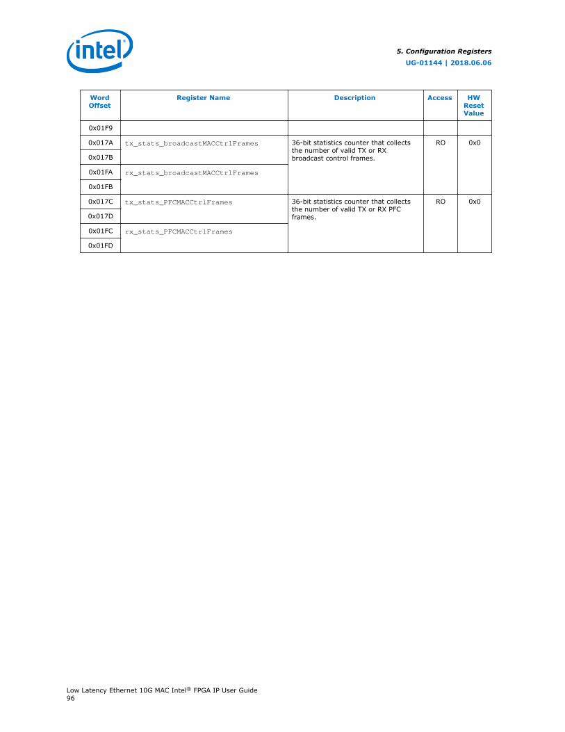
WordOffset
Register Name Description Access HWResetValue
0x01F9
0x017A tx_stats_broadcastMACCtrlFrames 36-bit statistics counter that collectsthe number of valid TX or RXbroadcast control frames.
RO 0x0
0x017B
0x01FA rx_stats_broadcastMACCtrlFrames
0x01FB
0x017C tx_stats_PFCMACCtrlFrames 36-bit statistics counter that collectsthe number of valid TX or RX PFCframes.
RO 0x0
0x017D
0x01FC rx_stats_PFCMACCtrlFrames
0x01FD
5. Configuration Registers
UG-01144 | 2018.06.06
Low Latency Ethernet 10G MAC Intel® FPGA IP User Guide96
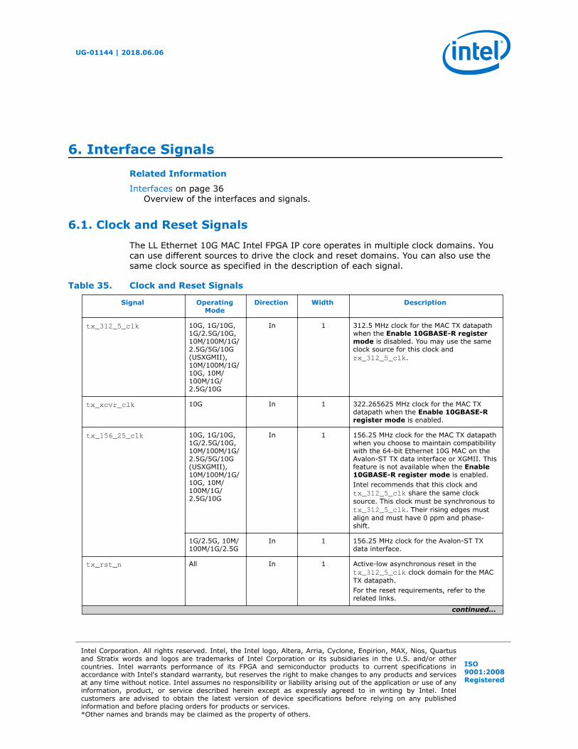
6. Interface SignalsRelated Information
Interfaces on page 36Overview of the interfaces and signals.
6.1. Clock and Reset Signals
The LL Ethernet 10G MAC Intel FPGA IP core operates in multiple clock domains. Youcan use different sources to drive the clock and reset domains. You can also use thesame clock source as specified in the description of each signal.
Table 35. Clock and Reset Signals
Signal OperatingMode
Direction Width Description
tx_312_5_clk 10G, 1G/10G,1G/2.5G/10G,10M/100M/1G/2.5G/5G/10G(USXGMII),10M/100M/1G/10G, 10M/100M/1G/2.5G/10G
In 1 312.5 MHz clock for the MAC TX datapathwhen the Enable 10GBASE-R registermode is disabled. You may use the sameclock source for this clock andrx_312_5_clk.
tx_xcvr_clk 10G In 1 322.265625 MHz clock for the MAC TXdatapath when the Enable 10GBASE-Rregister mode is enabled.
tx_156_25_clk 10G, 1G/10G,1G/2.5G/10G,10M/100M/1G/2.5G/5G/10G(USXGMII),10M/100M/1G/10G, 10M/100M/1G/2.5G/10G
In 1 156.25 MHz clock for the MAC TX datapathwhen you choose to maintain compatibilitywith the 64-bit Ethernet 10G MAC on theAvalon-ST TX data interface or XGMII. Thisfeature is not available when the Enable10GBASE-R register mode is enabled.Intel recommends that this clock andtx_312_5_clk share the same clocksource. This clock must be synchronous totx_312_5_clk. Their rising edges mustalign and must have 0 ppm and phase-shift.
1G/2.5G, 10M/100M/1G/2.5G
In 1 156.25 MHz clock for the Avalon-ST TXdata interface.
tx_rst_n All In 1 Active-low asynchronous reset in thetx_312_5_clk clock domain for the MACTX datapath.For the reset requirements, refer to therelated links.
continued...
UG-01144 | 2018.06.06
Intel Corporation. All rights reserved. Intel, the Intel logo, Altera, Arria, Cyclone, Enpirion, MAX, Nios, Quartusand Stratix words and logos are trademarks of Intel Corporation or its subsidiaries in the U.S. and/or othercountries. Intel warrants performance of its FPGA and semiconductor products to current specifications inaccordance with Intel's standard warranty, but reserves the right to make changes to any products and servicesat any time without notice. Intel assumes no responsibility or liability arising out of the application or use of anyinformation, product, or service described herein except as expressly agreed to in writing by Intel. Intelcustomers are advised to obtain the latest version of device specifications before relying on any publishedinformation and before placing orders for products or services.*Other names and brands may be claimed as the property of others.
ISO9001:2008Registered
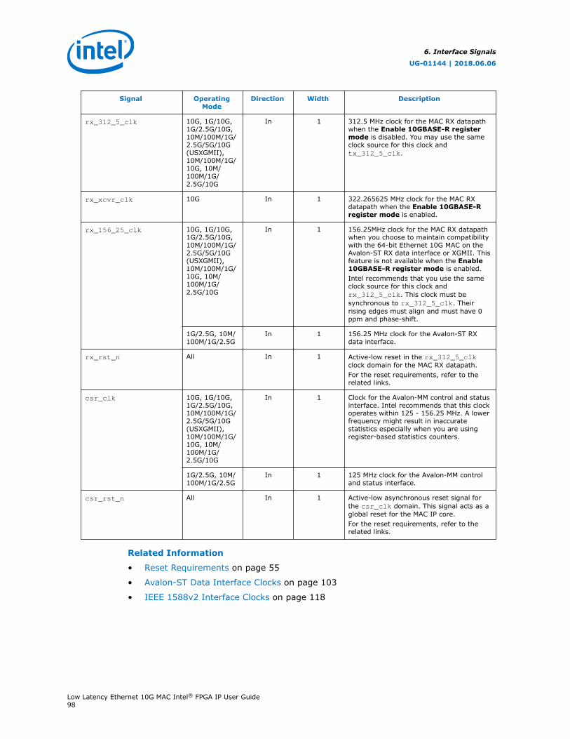
Signal OperatingMode
Direction Width Description
rx_312_5_clk 10G, 1G/10G,1G/2.5G/10G,10M/100M/1G/2.5G/5G/10G(USXGMII),10M/100M/1G/10G, 10M/100M/1G/2.5G/10G
In 1 312.5 MHz clock for the MAC RX datapathwhen the Enable 10GBASE-R registermode is disabled. You may use the sameclock source for this clock andtx_312_5_clk.
rx_xcvr_clk 10G In 1 322.265625 MHz clock for the MAC RXdatapath when the Enable 10GBASE-Rregister mode is enabled.
rx_156_25_clk 10G, 1G/10G,1G/2.5G/10G,10M/100M/1G/2.5G/5G/10G(USXGMII),10M/100M/1G/10G, 10M/100M/1G/2.5G/10G
In 1 156.25MHz clock for the MAC RX datapathwhen you choose to maintain compatibilitywith the 64-bit Ethernet 10G MAC on theAvalon-ST RX data interface or XGMII. Thisfeature is not available when the Enable10GBASE-R register mode is enabled.Intel recommends that you use the sameclock source for this clock andrx_312_5_clk. This clock must besynchronous to rx_312_5_clk. Theirrising edges must align and must have 0ppm and phase-shift.
1G/2.5G, 10M/100M/1G/2.5G
In 1 156.25 MHz clock for the Avalon-ST RXdata interface.
rx_rst_n All In 1 Active-low reset in the rx_312_5_clkclock domain for the MAC RX datapath.For the reset requirements, refer to therelated links.
csr_clk 10G, 1G/10G,1G/2.5G/10G,10M/100M/1G/2.5G/5G/10G(USXGMII),10M/100M/1G/10G, 10M/100M/1G/2.5G/10G
In 1 Clock for the Avalon-MM control and statusinterface. Intel recommends that this clockoperates within 125 - 156.25 MHz. A lowerfrequency might result in inaccuratestatistics especially when you are usingregister-based statistics counters.
1G/2.5G, 10M/100M/1G/2.5G
In 1 125 MHz clock for the Avalon-MM controland status interface.
csr_rst_n All In 1 Active-low asynchronous reset signal forthe csr_clk domain. This signal acts as aglobal reset for the MAC IP core.For the reset requirements, refer to therelated links.
Related Information
• Reset Requirements on page 55
• Avalon-ST Data Interface Clocks on page 103
• IEEE 1588v2 Interface Clocks on page 118
6. Interface Signals
UG-01144 | 2018.06.06
Low Latency Ethernet 10G MAC Intel® FPGA IP User Guide98
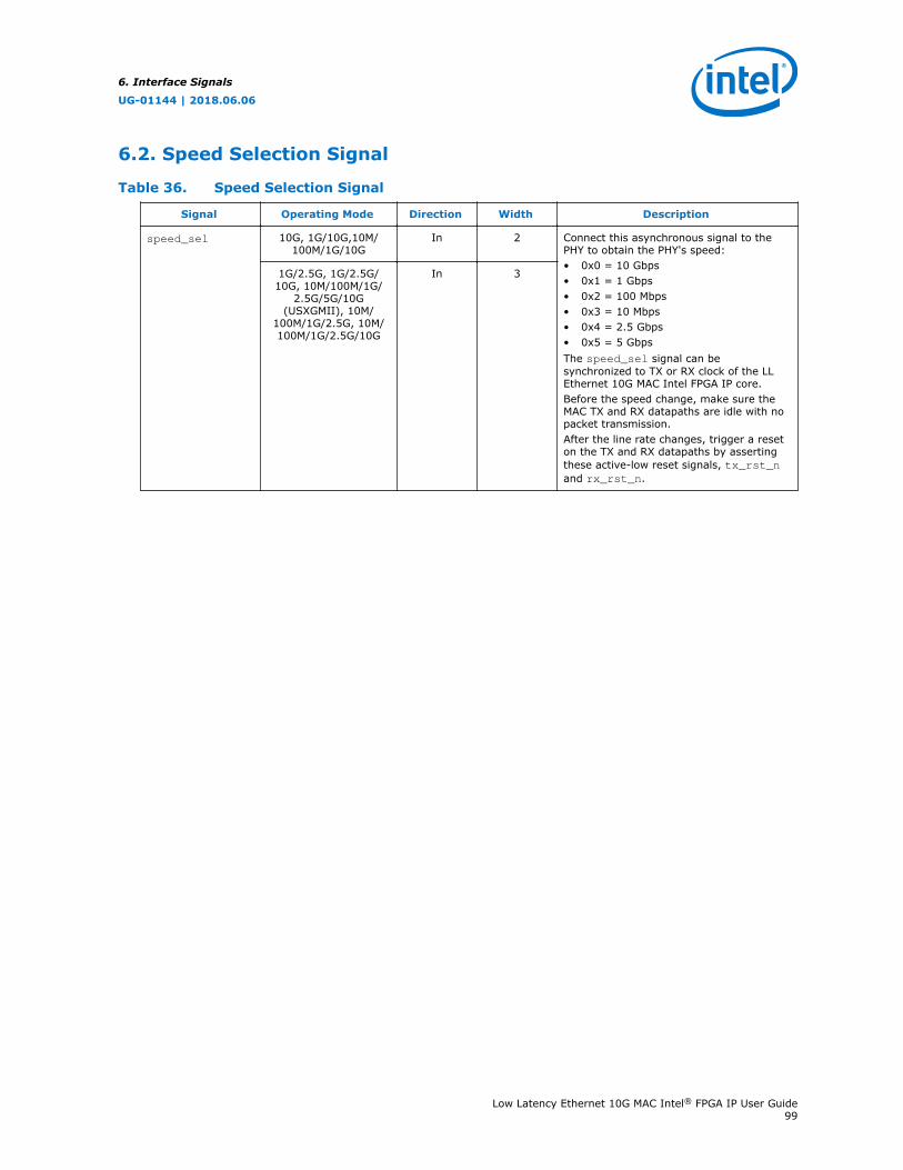
6.2. Speed Selection Signal
Table 36. Speed Selection Signal
Signal Operating Mode Direction Width Description
speed_sel 10G, 1G/10G,10M/100M/1G/10G
In 2 Connect this asynchronous signal to thePHY to obtain the PHY's speed:• 0x0 = 10 Gbps• 0x1 = 1 Gbps• 0x2 = 100 Mbps• 0x3 = 10 Mbps• 0x4 = 2.5 Gbps• 0x5 = 5 GbpsThe speed_sel signal can besynchronized to TX or RX clock of the LLEthernet 10G MAC Intel FPGA IP core.Before the speed change, make sure theMAC TX and RX datapaths are idle with nopacket transmission.After the line rate changes, trigger a reseton the TX and RX datapaths by assertingthese active-low reset signals, tx_rst_nand rx_rst_n.
1G/2.5G, 1G/2.5G/10G, 10M/100M/1G/
2.5G/5G/10G(USXGMII), 10M/
100M/1G/2.5G, 10M/100M/1G/2.5G/10G
In 3
6. Interface Signals
UG-01144 | 2018.06.06
Low Latency Ethernet 10G MAC Intel® FPGA IP User Guide99

6.3. Error Correction Signals
The error correction signals are present only when you turn on the ECC option.
Table 37. Error Correction Signals
Signal Direction Width Description
ecc_err_det_corr Out 1 The MAC IP core can indicate detected andcorrected ECC errors using the ecc_statusregister, or both the register and this signal.This signal indicates the state of theecc_status[0] register bit when theecc_enable[0] register bit is set to 1. This signalis 0 when the ecc_enable[0] register bit is set to1.
ecc_err_det_uncorr Out 1 The MAC IP core can indicate detected anduncorrected ECC errors using the ecc_statusregister, or both the register and this signal.This signal indicates the state of theecc_status[1] register bit when theecc_enable[1] register bit is set to 1. This signalis 0 when the ecc_enable[1] register bit is set to1.
6.4. Unidirectional Signals
The signals below are present when you turn on the Unidirectional feature option.This feature is available only in 10G operating mode.
Table 38. Unidirectional Signals
Signal Direction Width Description
unidirectional_en Out 1 When asserted, this signal indicates the state ofthe tx_unidir_control register bit 0.
unidirectional_remote_fault_dis
Out 1 When asserted, this signal indicates the state ofthe tx_unidir_control register bit 1.
unidirectional_force_remote_fault
Out 1 When asserted, this signal indicates the state ofthe tx_unidir_control register bit 2.
6.5. Avalon-MM Programming Signals
Table 39. Avalon-MM Programming Signals
Signal Direction Width Description
csr_address[] In 10/2 Use this bus to specify the register address to read from orwrite to.The width is 13 bits when you enable the Use LegacyEthernet 10G MAC Avalon Memory-Mapped Interfaceoption.
csr_read In 1 Assert this signal to request a read.
csr_readdata[] Out 32 Data read from the specified register. The data is valid whenthecsr_waitrequest signal is deasserted.
continued...
6. Interface Signals
UG-01144 | 2018.06.06
Low Latency Ethernet 10G MAC Intel® FPGA IP User Guide100
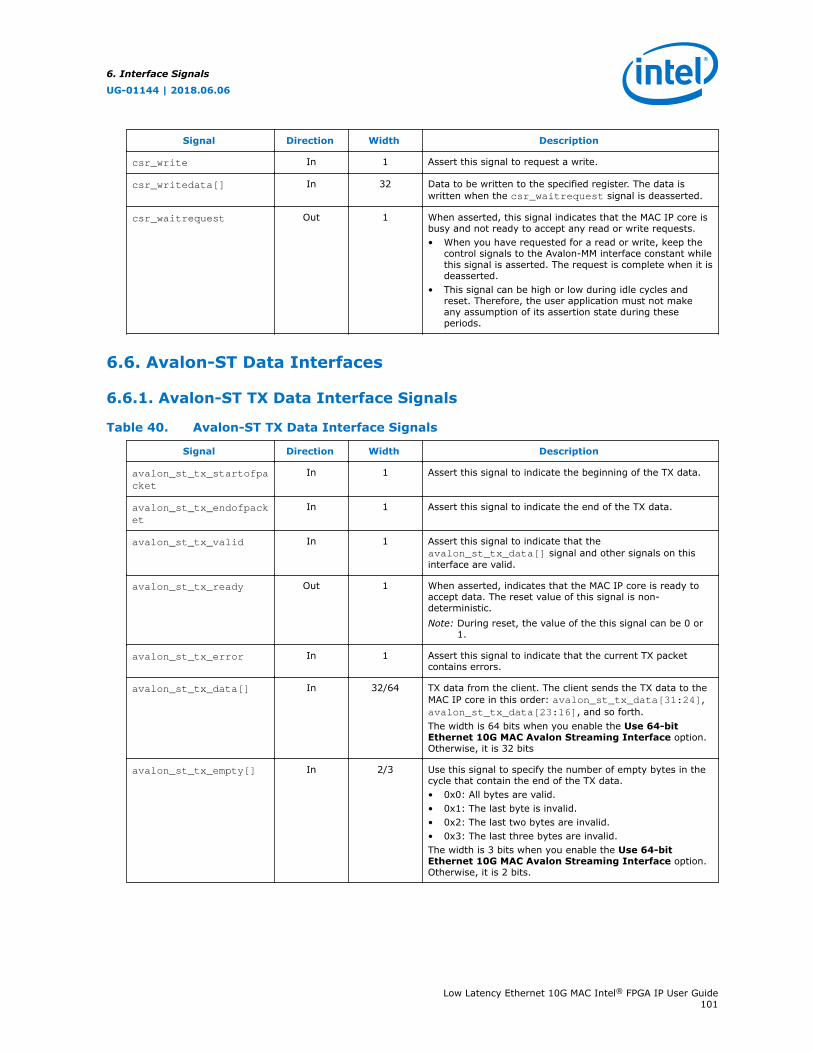
Signal Direction Width Description
csr_write In 1 Assert this signal to request a write.
csr_writedata[] In 32 Data to be written to the specified register. The data iswritten when the csr_waitrequest signal is deasserted.
csr_waitrequest Out 1 When asserted, this signal indicates that the MAC IP core isbusy and not ready to accept any read or write requests.• When you have requested for a read or write, keep the
control signals to the Avalon-MM interface constant whilethis signal is asserted. The request is complete when it isdeasserted.
• This signal can be high or low during idle cycles andreset. Therefore, the user application must not makeany assumption of its assertion state during theseperiods.
6.6. Avalon-ST Data Interfaces
6.6.1. Avalon-ST TX Data Interface Signals
Table 40. Avalon-ST TX Data Interface Signals
Signal Direction Width Description
avalon_st_tx_startofpacket
In 1 Assert this signal to indicate the beginning of the TX data.
avalon_st_tx_endofpacket
In 1 Assert this signal to indicate the end of the TX data.
avalon_st_tx_valid In 1 Assert this signal to indicate that theavalon_st_tx_data[] signal and other signals on thisinterface are valid.
avalon_st_tx_ready Out 1 When asserted, indicates that the MAC IP core is ready toaccept data. The reset value of this signal is non-deterministic.Note: During reset, the value of the this signal can be 0 or
1.
avalon_st_tx_error In 1 Assert this signal to indicate that the current TX packetcontains errors.
avalon_st_tx_data[] In 32/64 TX data from the client. The client sends the TX data to theMAC IP core in this order: avalon_st_tx_data[31:24],avalon_st_tx_data[23:16], and so forth.The width is 64 bits when you enable the Use 64-bitEthernet 10G MAC Avalon Streaming Interface option.Otherwise, it is 32 bits
avalon_st_tx_empty[] In 2/3 Use this signal to specify the number of empty bytes in thecycle that contain the end of the TX data.• 0x0: All bytes are valid.• 0x1: The last byte is invalid.• 0x2: The last two bytes are invalid.• 0x3: The last three bytes are invalid.The width is 3 bits when you enable the Use 64-bitEthernet 10G MAC Avalon Streaming Interface option.Otherwise, it is 2 bits.
6. Interface Signals
UG-01144 | 2018.06.06
Low Latency Ethernet 10G MAC Intel® FPGA IP User Guide101
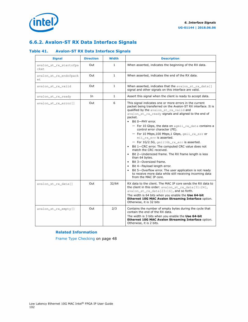
6.6.2. Avalon-ST RX Data Interface Signals
Table 41. Avalon-ST RX Data Interface Signals
Signal Direction Width Description
avalon_st_rx_startofpacket
Out 1 When asserted, indicates the beginning of the RX data.
avalon_st_rx_endofpacket
Out 1 When asserted, indicates the end of the RX data.
avalon_st_rx_valid Out 1 When asserted, indicates that the avalon_st_rx_data[]signal and other signals on this interface are valid.
avalon_st_rx_ready In 1 Assert this signal when the client is ready to accept data.
avalon_st_rx_error[] Out 6 This signal indicates one or more errors in the currentpacket being transferred on the Avalon-ST RX interface. It isqualified by the avalon_st_rx_valid andavalon_st_rx_ready signals and aligned to the end ofpacket.• Bit 0—PHY error.
— For 10 Gbps, the data on xgmii_rx_data contains acontrol error character (FE).
— For 10 Mbps,100 Mbps,1 Gbps, gmii_rx_err ormii_rx_err is asserted.
— For 1G/2.5G, gmii16b_rx_err is asserted.• Bit 1—CRC error. The computed CRC value does not
match the CRC received.• Bit 2—Undersized frame. The RX frame length is less
than 64 bytes.• Bit 3—Oversized frame.• Bit 4—Payload length error.• Bit 5—Overflow error. The user application is not ready
to receive more data while still receiving incoming datafrom the MAC IP core.
avalon_st_rx_data[] Out 32/64 RX data to the client. The MAC IP core sends the RX data tothe client in this order: avalon_st_rx_data[31:24],avalon_st_rx_data[23:16], and so forth.The width is 64 bits when you enable the Use 64-bitEthernet 10G MAC Avalon Streaming Interface option.Otherwise, it is 32 bits
avalon_st_rx_empty[] Out 2/3 Contains the number of empty bytes during the cycle thatcontain the end of the RX data.The width is 3 bits when you enable the Use 64-bitEthernet 10G MAC Avalon Streaming Interface option.Otherwise, it is 2 bits.
Related Information
Frame Type Checking on page 48
6. Interface Signals
UG-01144 | 2018.06.06
Low Latency Ethernet 10G MAC Intel® FPGA IP User Guide102
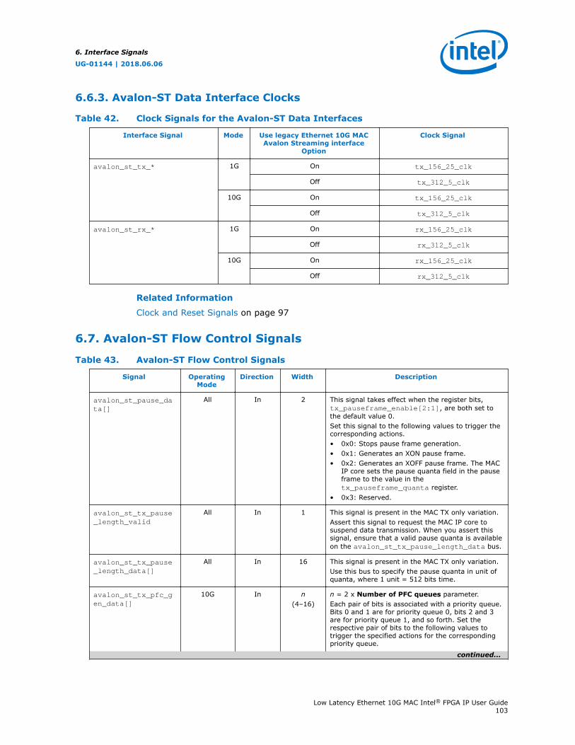
6.6.3. Avalon-ST Data Interface Clocks
Table 42. Clock Signals for the Avalon-ST Data Interfaces
Interface Signal Mode Use legacy Ethernet 10G MACAvalon Streaming interface
Option
Clock Signal
avalon_st_tx_* 1G On tx_156_25_clk
Off tx_312_5_clk
10G On tx_156_25_clk
Off tx_312_5_clk
avalon_st_rx_* 1G On rx_156_25_clk
Off rx_312_5_clk
10G On rx_156_25_clk
Off rx_312_5_clk
Related Information
Clock and Reset Signals on page 97
6.7. Avalon-ST Flow Control Signals
Table 43. Avalon-ST Flow Control Signals
Signal OperatingMode
Direction Width Description
avalon_st_pause_data[]
All In 2 This signal takes effect when the register bits,tx_pauseframe_enable[2:1], are both set tothe default value 0.Set this signal to the following values to trigger thecorresponding actions.• 0x0: Stops pause frame generation.• 0x1: Generates an XON pause frame.• 0x2: Generates an XOFF pause frame. The MAC
IP core sets the pause quanta field in the pauseframe to the value in thetx_pauseframe_quanta register.
• 0x3: Reserved.
avalon_st_tx_pause_length_valid
All In 1 This signal is present in the MAC TX only variation.Assert this signal to request the MAC IP core tosuspend data transmission. When you assert thissignal, ensure that a valid pause quanta is availableon the avalon_st_tx_pause_length_data bus.
avalon_st_tx_pause_length_data[]
All In 16 This signal is present in the MAC TX only variation.Use this bus to specify the pause quanta in unit ofquanta, where 1 unit = 512 bits time.
avalon_st_tx_pfc_gen_data[]
10G In n(4–16)
n = 2 x Number of PFC queues parameter.Each pair of bits is associated with a priority queue.Bits 0 and 1 are for priority queue 0, bits 2 and 3are for priority queue 1, and so forth. Set therespective pair of bits to the following values totrigger the specified actions for the correspondingpriority queue.
continued...
6. Interface Signals
UG-01144 | 2018.06.06
Low Latency Ethernet 10G MAC Intel® FPGA IP User Guide103
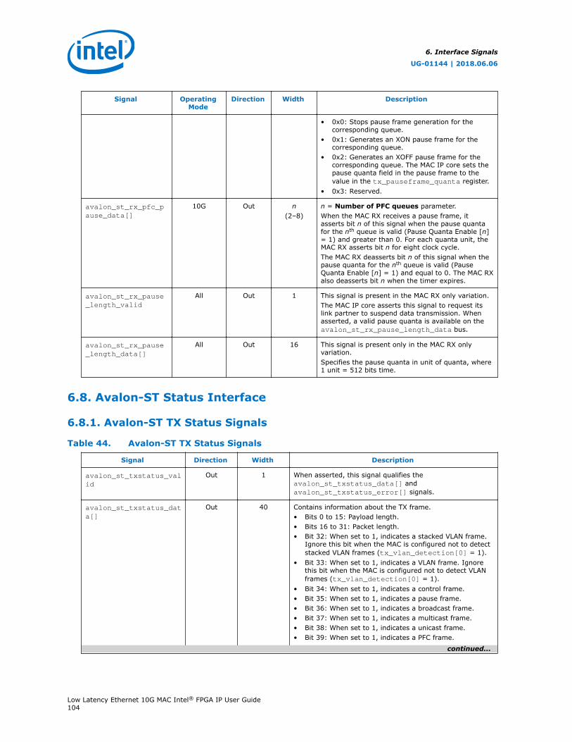
Signal OperatingMode
Direction Width Description
• 0x0: Stops pause frame generation for thecorresponding queue.
• 0x1: Generates an XON pause frame for thecorresponding queue.
• 0x2: Generates an XOFF pause frame for thecorresponding queue. The MAC IP core sets thepause quanta field in the pause frame to thevalue in the tx_pauseframe_quanta register.
• 0x3: Reserved.
avalon_st_rx_pfc_pause_data[]
10G Out n(2–8)
n = Number of PFC queues parameter.When the MAC RX receives a pause frame, itasserts bit n of this signal when the pause quantafor the nth queue is valid (Pause Quanta Enable [n]= 1) and greater than 0. For each quanta unit, theMAC RX asserts bit n for eight clock cycle.The MAC RX deasserts bit n of this signal when thepause quanta for the nth queue is valid (PauseQuanta Enable [n] = 1) and equal to 0. The MAC RXalso deasserts bit n when the timer expires.
avalon_st_rx_pause_length_valid
All Out 1 This signal is present in the MAC RX only variation.The MAC IP core asserts this signal to request itslink partner to suspend data transmission. Whenasserted, a valid pause quanta is available on theavalon_st_rx_pause_length_data bus.
avalon_st_rx_pause_length_data[]
All Out 16 This signal is present only in the MAC RX onlyvariation.Specifies the pause quanta in unit of quanta, where1 unit = 512 bits time.
6.8. Avalon-ST Status Interface
6.8.1. Avalon-ST TX Status Signals
Table 44. Avalon-ST TX Status Signals
Signal Direction Width Description
avalon_st_txstatus_valid
Out 1 When asserted, this signal qualifies theavalon_st_txstatus_data[] andavalon_st_txstatus_error[] signals.
avalon_st_txstatus_data[]
Out 40 Contains information about the TX frame.• Bits 0 to 15: Payload length.• Bits 16 to 31: Packet length.• Bit 32: When set to 1, indicates a stacked VLAN frame.
Ignore this bit when the MAC is configured not to detectstacked VLAN frames (tx_vlan_detection[0] = 1).
• Bit 33: When set to 1, indicates a VLAN frame. Ignorethis bit when the MAC is configured not to detect VLANframes (tx_vlan_detection[0] = 1).
• Bit 34: When set to 1, indicates a control frame.• Bit 35: When set to 1, indicates a pause frame.• Bit 36: When set to 1, indicates a broadcast frame.• Bit 37: When set to 1, indicates a multicast frame.• Bit 38: When set to 1, indicates a unicast frame.• Bit 39: When set to 1, indicates a PFC frame.
continued...
6. Interface Signals
UG-01144 | 2018.06.06
Low Latency Ethernet 10G MAC Intel® FPGA IP User Guide104
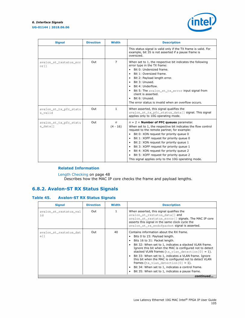
Signal Direction Width Description
This status signal is valid only if the TX frame is valid. Forexample, bit 35 is not asserted if a pause frame isoversized.
avalon_st_txstatus_error[]
Out 7 When set to 1, the respective bit indicates the followingerror type in the TX frame:• Bit 0: Undersized frame.• Bit 1: Oversized frame.• Bit 2: Payload length error.• Bit 3: Unused.• Bit 4: Underflow.• Bit 5: The avalon_st_tx_error input signal from
client is asserted.• Bit 6: Unused.The error status is invalid when an overflow occurs.
avalon_st_tx_pfc_status_valid
Out 1 When asserted, this signal qualifies theavalon_st_tx_pfc_status_data[] signal. This signalapplies only to 10G operating mode.
avalon_st_tx_pfc_status_data[]
Out n(4 - 16)
n = 2 × Number of PFC queues parameter.When set to 1, the respective bit indicates the flow controlrequest to the remote partner, for example:• Bit 0: XON request for priority queue 0• Bit 1: XOFF request for priority queue 0• Bit 2: XON request for priority queue 1• Bit 3: XOFF request for priority queue 1• Bit 4: XON request for priority queue 2• Bit 5: XOFF request for priority queue 2This signal applies only to the 10G operating mode.
Related Information
Length Checking on page 48Describes how the MAC IP core checks the frame and payload lengths.
6.8.2. Avalon-ST RX Status Signals
Table 45. Avalon-ST RX Status Signals
Signal Direction Width Description
avalon_st_rxstatus_valid
Out 1 When asserted, this signal qualifies theavalon_st_rxstatus_data[] andavalon_st_rxstatus_error[] signals. The MAC IP coreasserts this signal in the same clock cycle theavalon_st_rx_endofpacket signal is asserted.
avalon_st_rxstatus_data[]
Out 40 Contains information about the RX frame.• Bits 0 to 15: Payload length.• Bits 16 to 31: Packet length.• Bit 32: When set to 1, indicates a stacked VLAN frame.
Ignore this bit when the MAC is configured not to detectstacked VLAN frames (tx_vlan_detection[0] = 1).
• Bit 33: When set to 1, indicates a VLAN frame. Ignorethis bit when the MAC is configured not to detect VLANframes (tx_vlan_detection[0] = 1).
• Bit 34: When set to 1, indicates a control frame.• Bit 35: When set to 1, indicates a pause frame.
continued...
6. Interface Signals
UG-01144 | 2018.06.06
Low Latency Ethernet 10G MAC Intel® FPGA IP User Guide105

Signal Direction Width Description
• Bit 36: When set to 1, indicates a broadcast frame.• Bit 37: When set to 1, indicates a multicast frame.• Bit 38: When set to 1, indicates a unicast frame.• Bit 39: When set to 1, indicates a PFC frame.
avalon_st_rxstatus_error[]
Out 7 When set to 1, the respective bit indicates the followingerror type in the RX frame.• Bit 0: Undersized frame.• Bit 1: Oversized frame.• Bit 2: Payload length error.• Bit 3: CRC error.• Bit 4: Unused.• Bit 5: Unused.• Bit 6: PHY error.The IP core presents the error status on this bus in thesame clock cycle it asserts theavalon_st_rxstatus_valid signal. The error status isinvalid when an overflow occurs.
avalon_st_rx_pfc_status_valid
Out 1 When asserted, this signal qualifies theavalon_st_rx_pfc_status_data[] signal. This signalapplies only to 10G operating mode.
avalon_st_rx_pfc_status_data[]
Out n(4 - 16)
n = 2 x Number of PFC queues parameterWhen set to 1, the respective bit indicates the flow controlrequest from the remote partner, for example:• Bit 0: XON request for priority queue 0.• Bit 1: XOFF request for priority queue 0.• Bit 2: XON request for priority queue 1.• Bit 3: XOFF request for priority queue 1.• Bit 4: XON request for priority queue 2.• Bit 5: XOFF request for priority queue 2.This signal applies only to 10G operating mode.
Related Information
Length Checking on page 48Describes how the MAC IP core checks the frame and payload lengths.
6. Interface Signals
UG-01144 | 2018.06.06
Low Latency Ethernet 10G MAC Intel® FPGA IP User Guide106
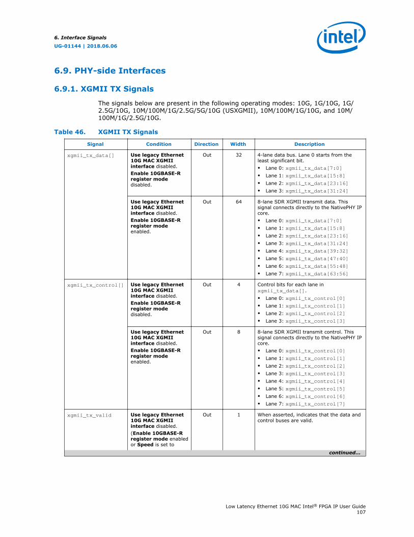
6.9. PHY-side Interfaces
6.9.1. XGMII TX Signals
The signals below are present in the following operating modes: 10G, 1G/10G, 1G/2.5G/10G, 10M/100M/1G/2.5G/5G/10G (USXGMII), 10M/100M/1G/10G, and 10M/100M/1G/2.5G/10G.
Table 46. XGMII TX Signals
Signal Condition Direction Width Description
xgmii_tx_data[] Use legacy Ethernet10G MAC XGMIIinterface disabled.Enable 10GBASE-Rregister modedisabled.
Out 32 4-lane data bus. Lane 0 starts from theleast significant bit.• Lane 0: xgmii_tx_data[7:0]• Lane 1: xgmii_tx_data[15:8]• Lane 2: xgmii_tx_data[23:16]• Lane 3: xgmii_tx_data[31:24]
Use legacy Ethernet10G MAC XGMIIinterface disabled.Enable 10GBASE-Rregister modeenabled.
Out 64 8-lane SDR XGMII transmit data. Thissignal connects directly to the NativePHY IPcore.• Lane 0: xgmii_tx_data[7:0]• Lane 1: xgmii_tx_data[15:8]• Lane 2: xgmii_tx_data[23:16]• Lane 3: xgmii_tx_data[31:24]• Lane 4: xgmii_tx_data[39:32]• Lane 5: xgmii_tx_data[47:40]• Lane 6: xgmii_tx_data[55:48]• Lane 7: xgmii_tx_data[63:56]
xgmii_tx_control[] Use legacy Ethernet10G MAC XGMIIinterface disabled.Enable 10GBASE-Rregister modedisabled.
Out 4 Control bits for each lane inxgmii_tx_data[].• Lane 0: xgmii_tx_control[0]• Lane 1: xgmii_tx_control[1]• Lane 2: xgmii_tx_control[2]• Lane 3: xgmii_tx_control[3]
Use legacy Ethernet10G MAC XGMIIinterface disabled.Enable 10GBASE-Rregister modeenabled.
Out 8 8-lane SDR XGMII transmit control. Thissignal connects directly to the NativePHY IPcore.• Lane 0: xgmii_tx_control[0]• Lane 1: xgmii_tx_control[1]• Lane 2: xgmii_tx_control[2]• Lane 3: xgmii_tx_control[3]• Lane 4: xgmii_tx_control[4]• Lane 5: xgmii_tx_control[5]• Lane 6: xgmii_tx_control[6]• Lane 7: xgmii_tx_control[7]
xgmii_tx_valid Use legacy Ethernet10G MAC XGMIIinterface disabled.(Enable 10GBASE-Rregister mode enabledor Speed is set to
Out 1 When asserted, indicates that the data andcontrol buses are valid.
continued...
6. Interface Signals
UG-01144 | 2018.06.06
Low Latency Ethernet 10G MAC Intel® FPGA IP User Guide107
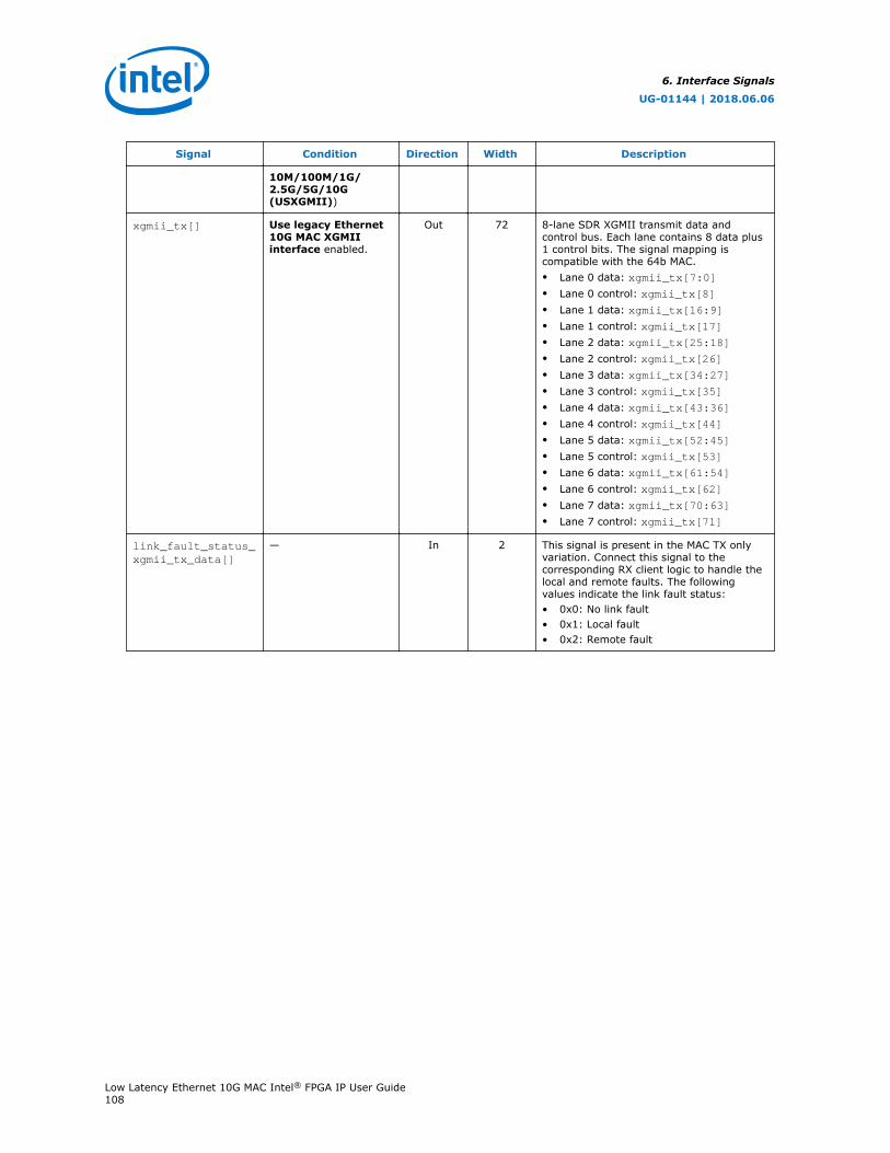
Signal Condition Direction Width Description
10M/100M/1G/2.5G/5G/10G(USXGMII))
xgmii_tx[] Use legacy Ethernet10G MAC XGMIIinterface enabled.
Out 72 8-lane SDR XGMII transmit data andcontrol bus. Each lane contains 8 data plus1 control bits. The signal mapping iscompatible with the 64b MAC.• Lane 0 data: xgmii_tx[7:0]• Lane 0 control: xgmii_tx[8]• Lane 1 data: xgmii_tx[16:9]• Lane 1 control: xgmii_tx[17]• Lane 2 data: xgmii_tx[25:18]• Lane 2 control: xgmii_tx[26]• Lane 3 data: xgmii_tx[34:27]• Lane 3 control: xgmii_tx[35]• Lane 4 data: xgmii_tx[43:36]• Lane 4 control: xgmii_tx[44]• Lane 5 data: xgmii_tx[52:45]• Lane 5 control: xgmii_tx[53]• Lane 6 data: xgmii_tx[61:54]• Lane 6 control: xgmii_tx[62]• Lane 7 data: xgmii_tx[70:63]• Lane 7 control: xgmii_tx[71]
link_fault_status_xgmii_tx_data[]
— In 2 This signal is present in the MAC TX onlyvariation. Connect this signal to thecorresponding RX client logic to handle thelocal and remote faults. The followingvalues indicate the link fault status:• 0x0: No link fault• 0x1: Local fault• 0x2: Remote fault
6. Interface Signals
UG-01144 | 2018.06.06
Low Latency Ethernet 10G MAC Intel® FPGA IP User Guide108
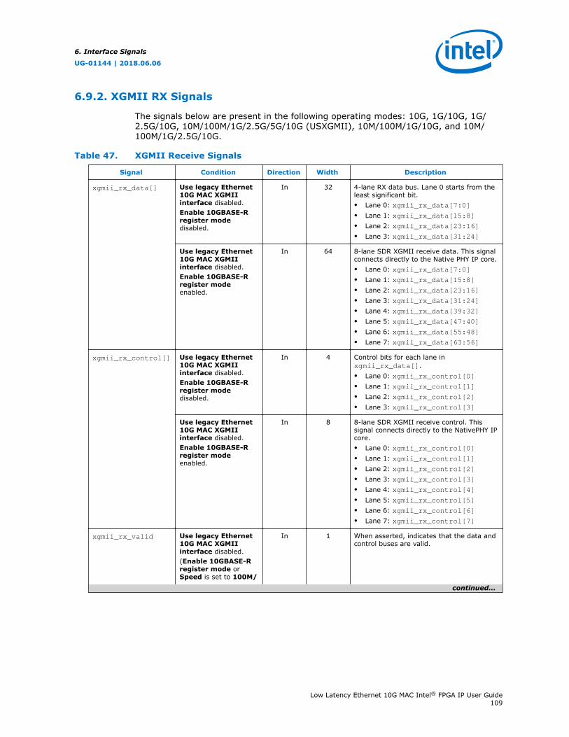
6.9.2. XGMII RX Signals
The signals below are present in the following operating modes: 10G, 1G/10G, 1G/2.5G/10G, 10M/100M/1G/2.5G/5G/10G (USXGMII), 10M/100M/1G/10G, and 10M/100M/1G/2.5G/10G.
Table 47. XGMII Receive Signals
Signal Condition Direction Width Description
xgmii_rx_data[] Use legacy Ethernet10G MAC XGMIIinterface disabled.Enable 10GBASE-Rregister modedisabled.
In 32 4-lane RX data bus. Lane 0 starts from theleast significant bit.• Lane 0: xgmii_rx_data[7:0]• Lane 1: xgmii_rx_data[15:8]• Lane 2: xgmii_rx_data[23:16]• Lane 3: xgmii_rx_data[31:24]
Use legacy Ethernet10G MAC XGMIIinterface disabled.Enable 10GBASE-Rregister modeenabled.
In 64 8-lane SDR XGMII receive data. This signalconnects directly to the Native PHY IP core.• Lane 0: xgmii_rx_data[7:0]• Lane 1: xgmii_rx_data[15:8]• Lane 2: xgmii_rx_data[23:16]• Lane 3: xgmii_rx_data[31:24]• Lane 4: xgmii_rx_data[39:32]• Lane 5: xgmii_rx_data[47:40]• Lane 6: xgmii_rx_data[55:48]• Lane 7: xgmii_rx_data[63:56]
xgmii_rx_control[] Use legacy Ethernet10G MAC XGMIIinterface disabled.Enable 10GBASE-Rregister modedisabled.
In 4 Control bits for each lane inxgmii_rx_data[].• Lane 0: xgmii_rx_control[0]• Lane 1: xgmii_rx_control[1]• Lane 2: xgmii_rx_control[2]• Lane 3: xgmii_rx_control[3]
Use legacy Ethernet10G MAC XGMIIinterface disabled.Enable 10GBASE-Rregister modeenabled.
In 8 8-lane SDR XGMII receive control. Thissignal connects directly to the NativePHY IPcore.• Lane 0: xgmii_rx_control[0]• Lane 1: xgmii_rx_control[1]• Lane 2: xgmii_rx_control[2]• Lane 3: xgmii_rx_control[3]• Lane 4: xgmii_rx_control[4]• Lane 5: xgmii_rx_control[5]• Lane 6: xgmii_rx_control[6]• Lane 7: xgmii_rx_control[7]
xgmii_rx_valid Use legacy Ethernet10G MAC XGMIIinterface disabled.(Enable 10GBASE-Rregister mode orSpeed is set to 100M/
In 1 When asserted, indicates that the data andcontrol buses are valid.
continued...
6. Interface Signals
UG-01144 | 2018.06.06
Low Latency Ethernet 10G MAC Intel® FPGA IP User Guide109
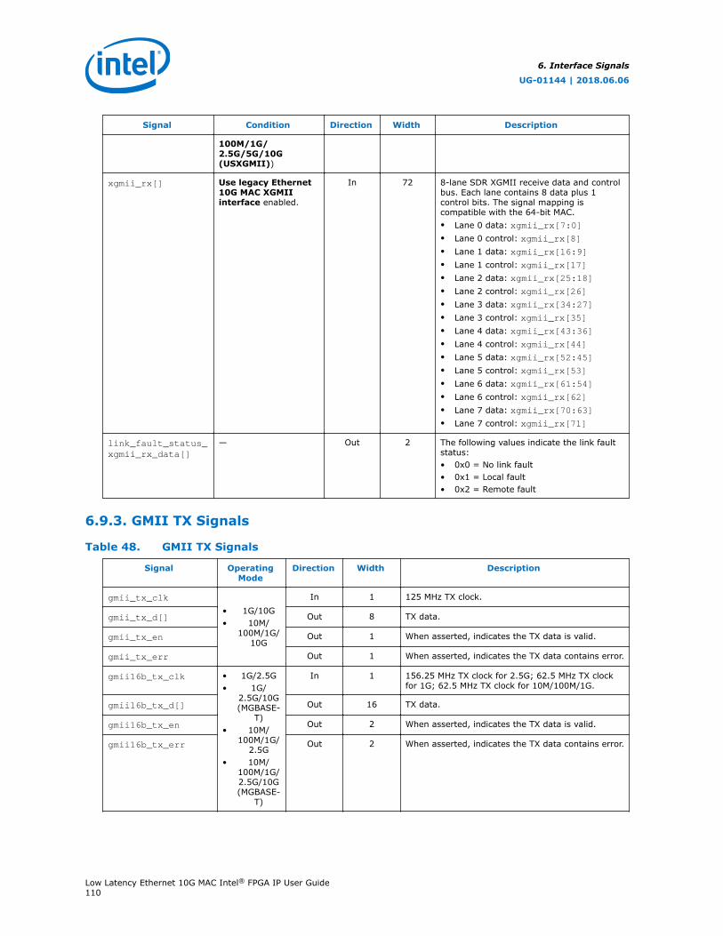
Signal Condition Direction Width Description
100M/1G/2.5G/5G/10G(USXGMII))
xgmii_rx[] Use legacy Ethernet10G MAC XGMIIinterface enabled.
In 72 8-lane SDR XGMII receive data and controlbus. Each lane contains 8 data plus 1control bits. The signal mapping iscompatible with the 64-bit MAC.• Lane 0 data: xgmii_rx[7:0]• Lane 0 control: xgmii_rx[8]• Lane 1 data: xgmii_rx[16:9]• Lane 1 control: xgmii_rx[17]• Lane 2 data: xgmii_rx[25:18]• Lane 2 control: xgmii_rx[26]• Lane 3 data: xgmii_rx[34:27]• Lane 3 control: xgmii_rx[35]• Lane 4 data: xgmii_rx[43:36]• Lane 4 control: xgmii_rx[44]• Lane 5 data: xgmii_rx[52:45]• Lane 5 control: xgmii_rx[53]• Lane 6 data: xgmii_rx[61:54]• Lane 6 control: xgmii_rx[62]• Lane 7 data: xgmii_rx[70:63]• Lane 7 control: xgmii_rx[71]
link_fault_status_xgmii_rx_data[]
— Out 2 The following values indicate the link faultstatus:• 0x0 = No link fault• 0x1 = Local fault• 0x2 = Remote fault
6.9.3. GMII TX Signals
Table 48. GMII TX Signals
Signal OperatingMode
Direction Width Description
gmii_tx_clk
• 1G/10G• 10M/
100M/1G/10G
In 1 125 MHz TX clock.
gmii_tx_d[] Out 8 TX data.
gmii_tx_en Out 1 When asserted, indicates the TX data is valid.
gmii_tx_err Out 1 When asserted, indicates the TX data contains error.
gmii16b_tx_clk • 1G/2.5G• 1G/
2.5G/10G(MGBASE-
T)• 10M/
100M/1G/2.5G
• 10M/100M/1G/2.5G/10G(MGBASE-
T)
In 1 156.25 MHz TX clock for 2.5G; 62.5 MHz TX clockfor 1G; 62.5 MHz TX clock for 10M/100M/1G.
gmii16b_tx_d[] Out 16 TX data.
gmii16b_tx_en Out 2 When asserted, indicates the TX data is valid.
gmii16b_tx_err Out 2 When asserted, indicates the TX data contains error.
6. Interface Signals
UG-01144 | 2018.06.06
Low Latency Ethernet 10G MAC Intel® FPGA IP User Guide110
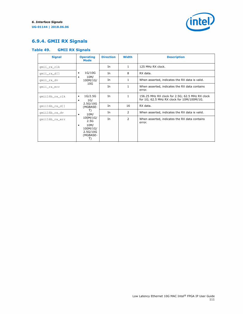
6.9.4. GMII RX Signals
Table 49. GMII RX Signals
Signal OperatingMode
Direction Width Description
gmii_rx_clk
• 1G/10G• 10M/
100M/1G/10G
In 1 125 MHz RX clock.
gmii_rx_d[] In 8 RX data.
gmii_rx_dv In 1 When asserted, indicates the RX data is valid.
gmii_rx_err In 1 When asserted, indicates the RX data containserror.
gmii16b_rx_clk • 1G/2.5G• 1G/
2.5G/10G(MGBASE-
T)• 10M/
100M/1G/2.5G
• 10M/100M/1G/2.5G/10G(MGBASE-
T)
In 1 156.25 MHz RX clock for 2.5G; 62.5 MHz RX clockfor 1G; 62.5 MHz RX clock for 10M/100M/1G.
gmii16b_rx_d[] In 16 RX data.
gmii16b_rx_dv In 2 When asserted, indicates the RX data is valid.
gmii16b_rx_err In 2 When asserted, indicates the RX data containserror.
6. Interface Signals
UG-01144 | 2018.06.06
Low Latency Ethernet 10G MAC Intel® FPGA IP User Guide111
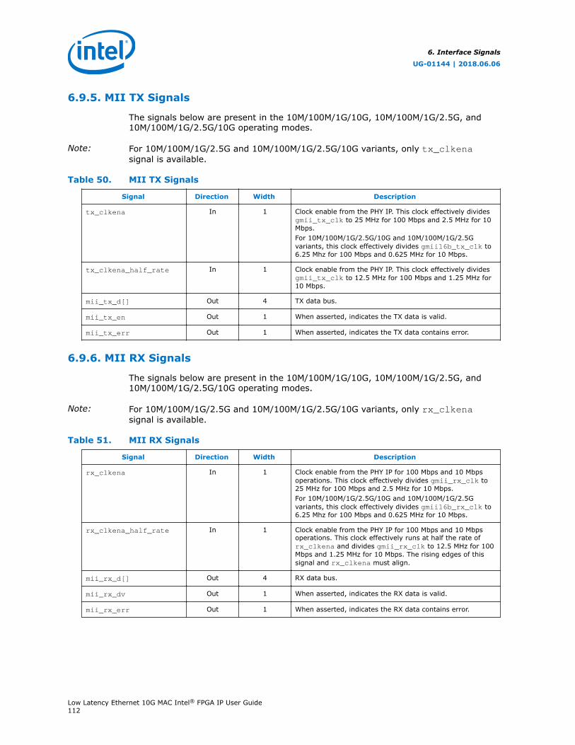
6.9.5. MII TX Signals
The signals below are present in the 10M/100M/1G/10G, 10M/100M/1G/2.5G, and10M/100M/1G/2.5G/10G operating modes.
Note: For 10M/100M/1G/2.5G and 10M/100M/1G/2.5G/10G variants, only tx_clkenasignal is available.
Table 50. MII TX Signals
Signal Direction Width Description
tx_clkena In 1 Clock enable from the PHY IP. This clock effectively dividesgmii_tx_clk to 25 MHz for 100 Mbps and 2.5 MHz for 10Mbps.For 10M/100M/1G/2.5G/10G and 10M/100M/1G/2.5Gvariants, this clock effectively divides gmii16b_tx_clk to6.25 Mhz for 100 Mbps and 0.625 MHz for 10 Mbps.
tx_clkena_half_rate In 1 Clock enable from the PHY IP. This clock effectively dividesgmii_tx_clk to 12.5 MHz for 100 Mbps and 1.25 MHz for10 Mbps.
mii_tx_d[] Out 4 TX data bus.
mii_tx_en Out 1 When asserted, indicates the TX data is valid.
mii_tx_err Out 1 When asserted, indicates the TX data contains error.
6.9.6. MII RX Signals
The signals below are present in the 10M/100M/1G/10G, 10M/100M/1G/2.5G, and10M/100M/1G/2.5G/10G operating modes.
Note: For 10M/100M/1G/2.5G and 10M/100M/1G/2.5G/10G variants, only rx_clkenasignal is available.
Table 51. MII RX Signals
Signal Direction Width Description
rx_clkena In 1 Clock enable from the PHY IP for 100 Mbps and 10 Mbpsoperations. This clock effectively divides gmii_rx_clk to25 MHz for 100 Mbps and 2.5 MHz for 10 Mbps.For 10M/100M/1G/2.5G/10G and 10M/100M/1G/2.5Gvariants, this clock effectively divides gmii16b_rx_clk to6.25 Mhz for 100 Mbps and 0.625 MHz for 10 Mbps.
rx_clkena_half_rate In 1 Clock enable from the PHY IP for 100 Mbps and 10 Mbpsoperations. This clock effectively runs at half the rate ofrx_clkena and divides gmii_rx_clk to 12.5 MHz for 100Mbps and 1.25 MHz for 10 Mbps. The rising edges of thissignal and rx_clkena must align.
mii_rx_d[] Out 4 RX data bus.
mii_rx_dv Out 1 When asserted, indicates the RX data is valid.
mii_rx_err Out 1 When asserted, indicates the RX data contains error.
6. Interface Signals
UG-01144 | 2018.06.06
Low Latency Ethernet 10G MAC Intel® FPGA IP User Guide112
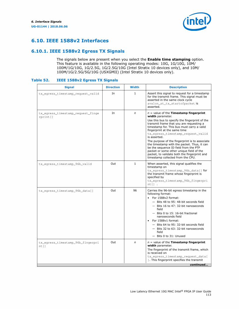
6.10. IEEE 1588v2 Interfaces
6.10.1. IEEE 1588v2 Egress TX Signals
The signals below are present when you select the Enable time stamping option.This feature is available in the following operating modes: 10G, 1G/10G, 10M/100M/1G/10G, 1G/2.5G, 1G/2.5G/10G (Intel Stratix 10 devices only), and 10M/100M/1G/2.5G/5G/10G (USXGMII) (Intel Stratix 10 devices only).
Table 52. IEEE 1588v2 Egress TX Signals
Signal Direction Width Description
tx_egress_timestamp_request_valid In 1 Assert this signal to request for a timestampfor the transmit frame. This signal must beasserted in the same clock cycleavalon_st_tx_startofpacket isasserted.
tx_egress_timestamp_request_fingerprint[]
In n n = value of the Timestamp fingerprintwidth parameter.Use this bus to specify the fingerprint of thetransmit frame that you are requesting atimestamp for. This bus must carry a validfingerprint at the same timetx_egress_timestamp_request_validis asserted.The purpose of the fingerprint is to associatethe timestamp with the packet. Thus, it canbe the sequence ID field from the PTPpacket or some other unique field of thepacket, to validate both the fingerprint andtimestamp collected from the CPU.
tx_egress_timestamp_96b_valid Out 1 When asserted, this signal qualifies thetimestamp ontx_egress_timestamp_96b_data[] forthe transmit frame whose fingerprint isspecified bytx_egress_timestamp_96b_fingerprint[] .
tx_egress_timestamp_96b_data[] Out 96 Carries the 96-bit egress timestamp in thefollowing format:• For 1588v2 format:
— Bits 48 to 95: 48-bit seconds field— Bits 16 to 47: 32-bit nanoseconds
field— Bits 0 to 15: 16-bit fractional
nanoseconds field• For 1588v1 format:
— Bits 64 to 95: 32-bit seconds field— Bits 32 to 63: 32-bit nanoseconds
field— Bits 0 to 31: Unused
tx_egress_timestamp_96b_fingerprint[]
Out n n = value of the Timestamp fingerprintwidth parameter.The fingerprint of the transmit frame, whichis received ontx_egress_timestamp_request_data[]. This fingerprint specifies the transmit
continued...
6. Interface Signals
UG-01144 | 2018.06.06
Low Latency Ethernet 10G MAC Intel® FPGA IP User Guide113
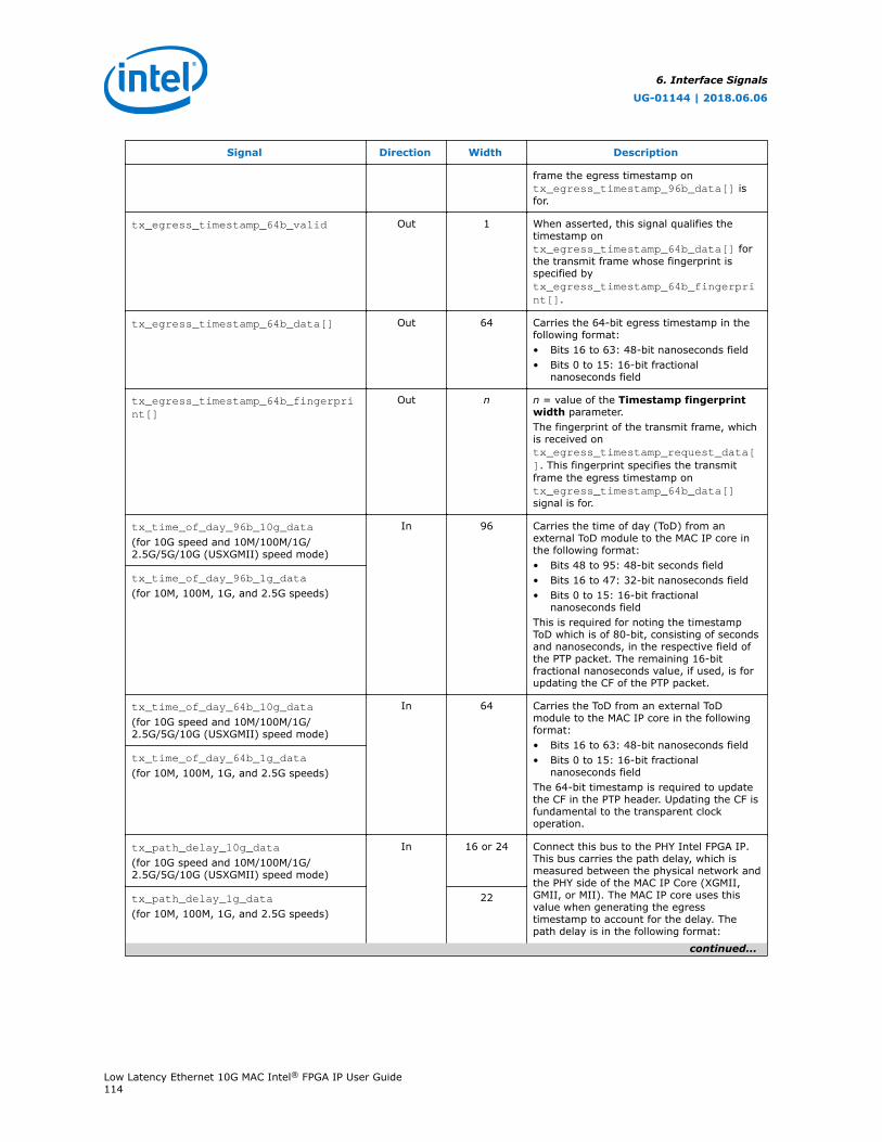
Signal Direction Width Description
frame the egress timestamp ontx_egress_timestamp_96b_data[] isfor.
tx_egress_timestamp_64b_valid Out 1 When asserted, this signal qualifies thetimestamp ontx_egress_timestamp_64b_data[] forthe transmit frame whose fingerprint isspecified bytx_egress_timestamp_64b_fingerprint[].
tx_egress_timestamp_64b_data[] Out 64 Carries the 64-bit egress timestamp in thefollowing format:• Bits 16 to 63: 48-bit nanoseconds field• Bits 0 to 15: 16-bit fractional
nanoseconds field
tx_egress_timestamp_64b_fingerprint[]
Out n n = value of the Timestamp fingerprintwidth parameter.The fingerprint of the transmit frame, whichis received ontx_egress_timestamp_request_data[]. This fingerprint specifies the transmitframe the egress timestamp ontx_egress_timestamp_64b_data[]signal is for.
tx_time_of_day_96b_10g_data
(for 10G speed and 10M/100M/1G/2.5G/5G/10G (USXGMII) speed mode)
In 96 Carries the time of day (ToD) from anexternal ToD module to the MAC IP core inthe following format:• Bits 48 to 95: 48-bit seconds field• Bits 16 to 47: 32-bit nanoseconds field• Bits 0 to 15: 16-bit fractional
nanoseconds fieldThis is required for noting the timestampToD which is of 80-bit, consisting of secondsand nanoseconds, in the respective field ofthe PTP packet. The remaining 16-bitfractional nanoseconds value, if used, is forupdating the CF of the PTP packet.
tx_time_of_day_96b_1g_data
(for 10M, 100M, 1G, and 2.5G speeds)
tx_time_of_day_64b_10g_data
(for 10G speed and 10M/100M/1G/2.5G/5G/10G (USXGMII) speed mode)
In 64 Carries the ToD from an external ToDmodule to the MAC IP core in the followingformat:• Bits 16 to 63: 48-bit nanoseconds field• Bits 0 to 15: 16-bit fractional
nanoseconds fieldThe 64-bit timestamp is required to updatethe CF in the PTP header. Updating the CF isfundamental to the transparent clockoperation.
tx_time_of_day_64b_1g_data
(for 10M, 100M, 1G, and 2.5G speeds)
tx_path_delay_10g_data
(for 10G speed and 10M/100M/1G/2.5G/5G/10G (USXGMII) speed mode)
In 16 or 24 Connect this bus to the PHY Intel FPGA IP.This bus carries the path delay, which ismeasured between the physical network andthe PHY side of the MAC IP Core (XGMII,GMII, or MII). The MAC IP core uses thisvalue when generating the egresstimestamp to account for the delay. Thepath delay is in the following format:
tx_path_delay_1g_data
(for 10M, 100M, 1G, and 2.5G speeds)22
continued...
6. Interface Signals
UG-01144 | 2018.06.06
Low Latency Ethernet 10G MAC Intel® FPGA IP User Guide114
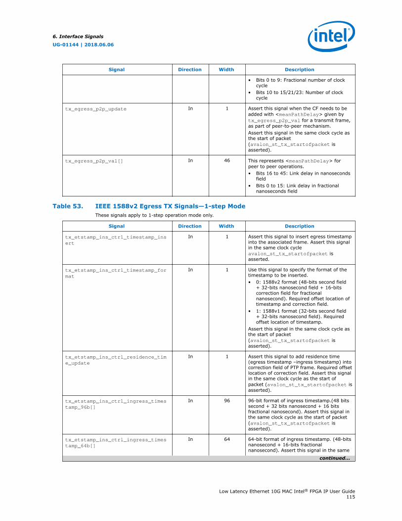
Signal Direction Width Description
• Bits 0 to 9: Fractional number of clockcycle
• Bits 10 to 15/21/23: Number of clockcycle
tx_egress_p2p_update In 1 Assert this signal when the CF needs to beadded with <meanPathDelay> given bytx_egress_p2p_val for a transmit frame,as part of peer-to-peer mechanism.Assert this signal in the same clock cycle asthe start of packet(avalon_st_tx_startofpacket isasserted).
tx_egress_p2p_val[] In 46 This represents <meanPathDelay> forpeer to peer operations.• Bits 16 to 45: Link delay in nanoseconds
field• Bits 0 to 15: Link delay in fractional
nanoseconds field
Table 53. IEEE 1588v2 Egress TX Signals—1-step ModeThese signals apply to 1-step operation mode only.
Signal Direction Width Description
tx_etstamp_ins_ctrl_timestamp_insert
In 1 Assert this signal to insert egress timestampinto the associated frame. Assert this signalin the same clock cycleavalon_st_tx_startofpacket isasserted.
tx_etstamp_ins_ctrl_timestamp_format
In 1 Use this signal to specify the format of thetimestamp to be inserted.• 0: 1588v2 format (48-bits second field
+ 32-bits nanosecond field + 16-bitscorrection field for fractionalnanosecond). Required offset location oftimestamp and correction field.
• 1: 1588v1 format (32-bits second field+ 32-bits nanosecond field). Requiredoffset location of timestamp.
Assert this signal in the same clock cycle asthe start of packet(avalon_st_tx_startofpacket isasserted).
tx_etstamp_ins_ctrl_residence_time_update
In 1 Assert this signal to add residence time(egress timestamp –ingress timestamp) intocorrection field of PTP frame. Required offsetlocation of correction field. Assert this signalin the same clock cycle as the start ofpacket (avalon_st_tx_startofpacket isasserted).
tx_etstamp_ins_ctrl_ingress_timestamp_96b[]
In 96 96-bit format of ingress timestamp.(48 bitssecond + 32 bits nanosecond + 16 bitsfractional nanosecond). Assert this signal inthe same clock cycle as the start of packet(avalon_st_tx_startofpacket isasserted).
tx_etstamp_ins_ctrl_ingress_timestamp_64b[]
In 64 64-bit format of ingress timestamp. (48-bitsnanosecond + 16-bits fractionalnanosecond). Assert this signal in the same
continued...
6. Interface Signals
UG-01144 | 2018.06.06
Low Latency Ethernet 10G MAC Intel® FPGA IP User Guide115
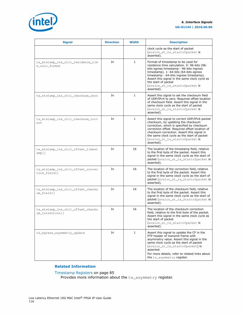
Signal Direction Width Description
clock cycle as the start of packet(avalon_st_tx_startofpacket isasserted).
tx_etstamp_ins_ctrl_residence_time_calc_format
In 1 Format of timestamp to be used forresidence time calculation. 0: 96-bits (96-bits egress timestamp - 96-bits ingresstimestamp). 1: 64-bits (64-bits egresstimestamp - 64-bits ingress timestamp).Assert this signal in the same clock cycle asthe start of packet(avalon_st_tx_startofpacket isasserted).
tx_etstamp_ins_ctrl_checksum_zero In 1 Assert this signal to set the checksum fieldof UDP/IPv4 to zero. Required offset locationof checksum field. Assert this signal in thesame clock cycle as the start of packet(avalon_st_tx_startofpacket isasserted).
tx_etstamp_ins_ctrl_checksum_correct
In 1 Assert this signal to correct UDP/IPv6 packetchecksum, by updating the checksumcorrection, which is specified by checksumcorrection offset. Required offset location ofchecksum correction. Assert this signal inthe same clock cycle as the start of packet(avalon_st_tx_startofpacket isasserted).
tx_etstamp_ins_ctrl_offset_timestamp[]
In 16 The location of the timestamp field, relativeto the first byte of the packet. Assert thissignal in the same clock cycle as the start ofpacket (avalon_st_tx_startofpacket isasserted).
tx_etstamp_ins_ctrl_offset_correction_field[]
In 16 The location of the correction field, relativeto the first byte of the packet. Assert thissignal in the same clock cycle as the start ofpacket (avalon_st_tx_startofpacket isasserted).
tx_etstamp_ins_ctrl_offset_checksum_field[]
In 16 The location of the checksum field, relativeto the first byte of the packet. Assert thissignal in the same clock cycle as the start ofpacket (avalon_st_tx_startofpacket isasserted).
tx_etstamp_ins_ctrl_offset_checksum_correction[]
In 16 The location of the checksum correctionfield, relative to the first byte of the packet.Assert this signal in the same clock cycle asthe start of packet(avalon_st_tx_startofpacket isasserted).
tx_egress_asymmetry_update In 1 Assert this signal to update the CF in thePTP header of transmit frame withasymmetry value. Assert this signal in thesame clock cycle as the start of packet(avalon_st_tx_startofpacket) isasserted.For more details, refer to related links aboutthe tx_asymmetry register.
Related Information
Timestamp Registers on page 85Provides more information about the tx_asymmetry register.
6. Interface Signals
UG-01144 | 2018.06.06
Low Latency Ethernet 10G MAC Intel® FPGA IP User Guide116

6.10.2. IEEE 1588v2 Ingress RX Signals
The signals below are present when you select the Enable time stamping option.This feature is available in the following operating modes: 10G, 1G/10G, 10M/100M/1G/10G, and 1G/2.5G, 1G/2.5G/10G (Intel Stratix 10 devices only), and 10M/100M/1G/2.5G/5G/10G (USXGMII) (Intel Stratix 10 devices only).
Table 54. IEEE 1588v2 Ingress RX Signals
Signal Direction Width Description
rx_ingress_timestamp_96b_valid Out 1 When asserted, this signal qualifies thetimestamp onrx_ingress_timestamp_96b_data[].The MAC IP core asserts this signal in thesame clock cycle it assertsavalon_st_rx_startofpacket.
rx_ingress_timestamp_96b_data[] Out 96 Carries the 96-bit ingress timestamp in thefollowing format:• Bits 48 to 95: 48-bit seconds field• Bits 16 to 47: 32-bit nanoseconds field• Bits 0 to 15: 16-bit fractional
nanoseconds fieldThe 96-bit timestamp is usually for notingthe complete ToD and is useful in ordinaryclock and boundary clock devices. Thetransparent clock typically uses 64-bittimestamp.
rx_ingress_timestamp_64b_valid Out 1 When asserted, this signal qualifies thetimestamp onrx_ingress_timestamp_64b_data[].The MAC IP core asserts this signal in thesame clock cycle it assertsavalon_st_rx_startofpacket.
rx_ingress_timestamp_64b_data[] Out 64 Carries the 64-bit ingress timestamp in thefollowing format:• Bits 16 to 63: 48-bit nanoseconds field• Bits 0 to 15: 16-bit fractional
nanoseconds fieldThis timestamp is used in transparent clockdevices.
rx_time_of_day_96b_10g_data
(for 10G speed and 10M/100M/1G/2.5G/5G/10G (USXGMII) speed mode)
In 96 Carries the time of day (ToD) from anexternal ToD module to the MAC IP core inthe following format:• Bits 48 to 95: 48-bit seconds field• Bits 16 to 47: 32-bit nanoseconds field• Bits 0 to 15: 16-bit fractional
nanoseconds field
rx_time_of_day_96b_1g_data
(for 10M, 100M, 1G, and 2.5G speeds)
rx_time_of_day_64b_10g_data
(for 10G speed and 10M/100M/1G/2.5G/5G/10G (USXGMII) speed mode)
In 64 Carries the ToD from an external ToDmodule the MAC IP core in the followingformat:• Bits 16 to 63: 48-bit nanoseconds field• Bits 0 to 15: 16-bit fractional
nanoseconds fieldrx_time_of_day_64b_1g_data
(for 10M, 100M, 1G, and 2.5G speeds)
rx_path_delay_10g_data
(for 10G speed and 10M/100M/1G/2.5G/5G/10G (USXGMII) speed mode)
In 16 or 24 Connect this bus to the PHY Intel FPGA IP.This bus carries the path delay (residencetime), measured between the physicalnetwork and the PHY side of the MAC IPCore (XGMII, GMII, or MII). The MAC IPrx_path_delay_1g_data 22
continued...
6. Interface Signals
UG-01144 | 2018.06.06
Low Latency Ethernet 10G MAC Intel® FPGA IP User Guide117
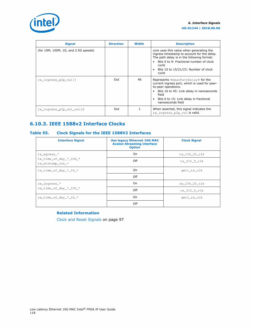
Signal Direction Width Description
(for 10M, 100M, 1G, and 2.5G speeds) core uses this value when generating theingress timestamp to account for the delay.The path delay is in the following format:• Bits 0 to 9: Fractional number of clock
cycle• Bits 10 to 15/21/23: Number of clock
cycle
rx_ingress_p2p_val[] Out 46 Represents <meanPathDelay> for thecurrent ingress port, which is used for peer-to-peer operations.• Bits 16 to 45: Link delay in nanoseconds
field• Bits 0 to 15: Link delay in fractional
nanoseconds field
rx_ingress_p2p_val_valid Out 1 When asserted, this signal indicates therx_ingress_p2p_val is valid.
6.10.3. IEEE 1588v2 Interface Clocks
Table 55. Clock Signals for the IEEE 1588V2 Interfaces
Interface Signal Use legacy Ethernet 10G MACAvalon Streaming interface
Option
Clock Signal
tx_egress_*
tx_time_of_day_*_10G_*
tx_etstamp_ins_*
On tx_156_25_clk
Off tx_312_5_clk
tx_time_of_day_*_1G_* On gmii_tx_clk
Off
rx_ingress_*
rx_time_of_day_*_10G_*
On rx_156_25_clk
Off rx_312_5_clk
rx_time_of_day_*_1G_* On gmii_rx_clk
Off
Related Information
Clock and Reset Signals on page 97
6. Interface Signals
UG-01144 | 2018.06.06
Low Latency Ethernet 10G MAC Intel® FPGA IP User Guide118
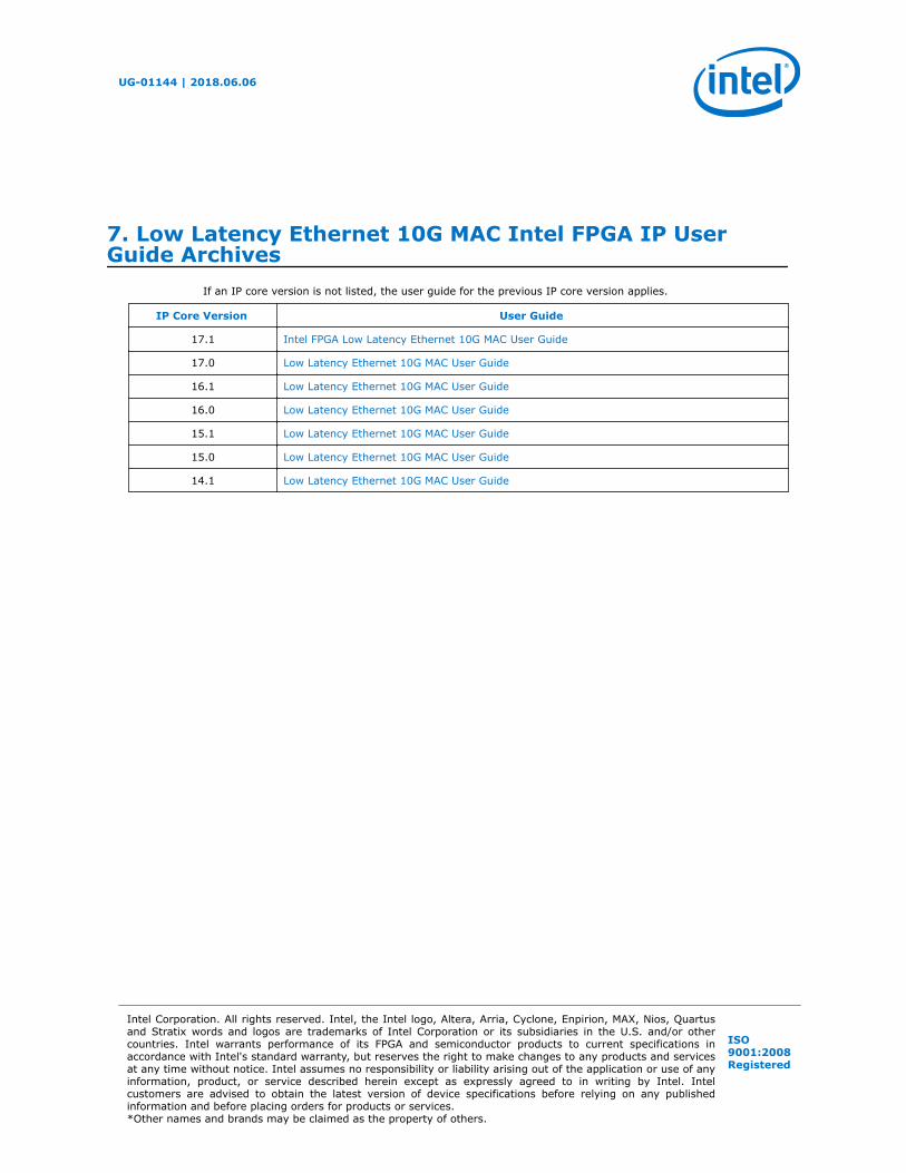
7. Low Latency Ethernet 10G MAC Intel FPGA IP UserGuide Archives
If an IP core version is not listed, the user guide for the previous IP core version applies.
IP Core Version User Guide
17.1 Intel FPGA Low Latency Ethernet 10G MAC User Guide
17.0 Low Latency Ethernet 10G MAC User Guide
16.1 Low Latency Ethernet 10G MAC User Guide
16.0 Low Latency Ethernet 10G MAC User Guide
15.1 Low Latency Ethernet 10G MAC User Guide
15.0 Low Latency Ethernet 10G MAC User Guide
14.1 Low Latency Ethernet 10G MAC User Guide
UG-01144 | 2018.06.06
Intel Corporation. All rights reserved. Intel, the Intel logo, Altera, Arria, Cyclone, Enpirion, MAX, Nios, Quartusand Stratix words and logos are trademarks of Intel Corporation or its subsidiaries in the U.S. and/or othercountries. Intel warrants performance of its FPGA and semiconductor products to current specifications inaccordance with Intel's standard warranty, but reserves the right to make changes to any products and servicesat any time without notice. Intel assumes no responsibility or liability arising out of the application or use of anyinformation, product, or service described herein except as expressly agreed to in writing by Intel. Intelcustomers are advised to obtain the latest version of device specifications before relying on any publishedinformation and before placing orders for products or services.*Other names and brands may be claimed as the property of others.
ISO9001:2008Registered
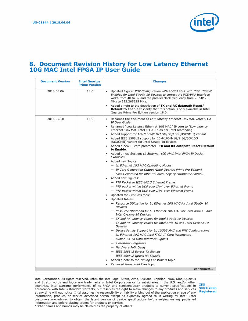
8. Document Revision History for Low Latency Ethernet10G MAC Intel FPGA IP User Guide
Document Version Intel QuartusPrime Version
Changes
2018.06.06 18.0 • Updated Figure: PHY Configuration with 10GBASE-R with IEEE 1588v2Enabled for Intel Stratix 10 Devices to correct the PCS-PMA interfacewidth from 40 to 32 and the parallel clock frequency from 257.8125MHz to 322.265625 MHz.
• Added a note to the description of TX and RX datapath Reset/Default to Enable to clarify that this option is only available in IntelQuartus Prime Pro Edition version 18.0.
2018.05.10 18.0 • Renamed the document as Low Latency Ethernet 10G MAC Intel FPGAIP User Guide.
• Renamed "Low Latency Ethernet 10G MAC" IP core to "Low LatencyEthernet 10G MAC Intel FPGA IP" as per Intel rebranding.
• Added support for 10M/100M/1G/2.5G/5G/10G (USXGMII) variant.• Added IEEE 1588v2 support for 10M/100M/1G/2.5G/5G/10G
(USXGMII) variant for Intel Stratix 10 devices.• Added a new IP core parameter—TX and RX datapath Reset/Default
to Enable.• Added a new Section: LL Ethernet 10G MAC Intel FPGA IP Design
Examples.• Added new Topics:
— LL Ethernet 10G MAC Operating Modes— IP Core Generation Output (Intel Quartus Prime Pro Edition)— Files Generated for Intel IP Cores (Legacy Parameter Editor).
• Added new Figures:— PTP Packet in IEEE 802.3 Ethernet Frame— PTP packet within UDP over IPv4 over Ethernet Frame— PTP packet within UDP over IPv6 over Ethernet Frame
• Updated the Features topic.• Updated Tables:
— Resource Utilization for LL Ethernet 10G MAC for Intel Stratix 10Devices
— Resource Utilization for LL Ethernet 10G MAC for Intel Arria 10 andIntel Cyclone 10 Devices
— TX and RX Latency Values for Intel Stratix 10 Devices— TX and RX Latency Values for Intel Arria 10 and Intel Cyclone 10
Devices— Device Family Support for LL 10GbE MAC and PHY Configurations— LL Ethernet 10G MAC Intel FPGA IP Core Parameters— Avalon-ST TX Data Interface Signals— Timestamp Registers— Hardware PMA Delay— IEEE 1588v2 Egress TX Signals— IEEE 1588v2 Igress RX Signals
• Added a note to the Timing Constraints topic.• Removed Generated Files topic.
continued...
UG-01144 | 2018.06.06
Intel Corporation. All rights reserved. Intel, the Intel logo, Altera, Arria, Cyclone, Enpirion, MAX, Nios, Quartusand Stratix words and logos are trademarks of Intel Corporation or its subsidiaries in the U.S. and/or othercountries. Intel warrants performance of its FPGA and semiconductor products to current specifications inaccordance with Intel's standard warranty, but reserves the right to make changes to any products and servicesat any time without notice. Intel assumes no responsibility or liability arising out of the application or use of anyinformation, product, or service described herein except as expressly agreed to in writing by Intel. Intelcustomers are advised to obtain the latest version of device specifications before relying on any publishedinformation and before placing orders for products or services.*Other names and brands may be claimed as the property of others.
ISO9001:2008Registered
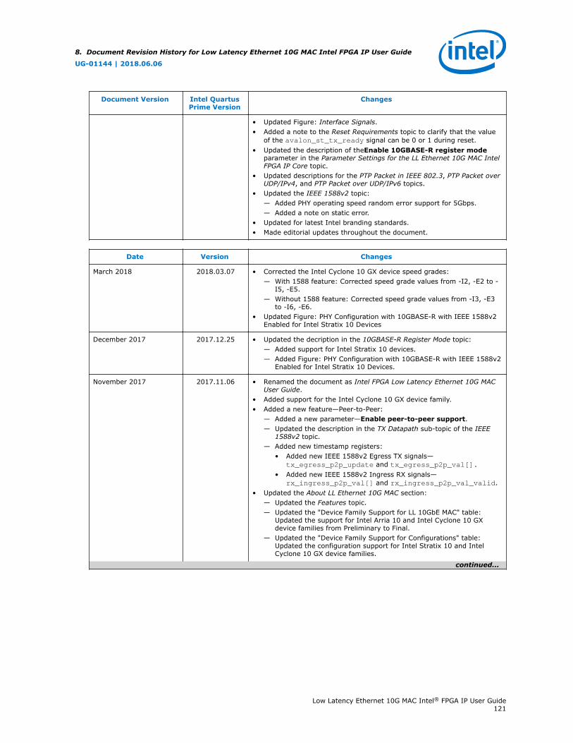
Document Version Intel QuartusPrime Version
Changes
• Updated Figure: Interface Signals.• Added a note to the Reset Requirements topic to clarify that the value
of the avalon_st_tx_ready signal can be 0 or 1 during reset.• Updated the description of theEnable 10GBASE-R register mode
parameter in the Parameter Settings for the LL Ethernet 10G MAC IntelFPGA IP Core topic.
• Updated descriptions for the PTP Packet in IEEE 802.3, PTP Packet overUDP/IPv4, and PTP Packet over UDP/IPv6 topics.
• Updated the IEEE 1588v2 topic:— Added PHY operating speed random error support for 5Gbps.— Added a note on static error.
• Updated for latest Intel branding standards.• Made editorial updates throughout the document.
Date Version Changes
March 2018 2018.03.07 • Corrected the Intel Cyclone 10 GX device speed grades:— With 1588 feature: Corrected speed grade values from -I2, -E2 to -
I5, -E5.— Without 1588 feature: Corrected speed grade values from -I3, -E3
to -I6, -E6.• Updated Figure: PHY Configuration with 10GBASE-R with IEEE 1588v2
Enabled for Intel Stratix 10 Devices
December 2017 2017.12.25 • Updated the decription in the 10GBASE-R Register Mode topic:— Added support for Intel Stratix 10 devices.— Added Figure: PHY Configuration with 10GBASE-R with IEEE 1588v2
Enabled for Intel Stratix 10 Devices.
November 2017 2017.11.06 • Renamed the document as Intel FPGA Low Latency Ethernet 10G MACUser Guide.
• Added support for the Intel Cyclone 10 GX device family.• Added a new feature—Peer-to-Peer:
— Added a new parameter—Enable peer-to-peer support.— Updated the description in the TX Datapath sub-topic of the IEEE
1588v2 topic.— Added new timestamp registers:
• Added new IEEE 1588v2 Egress TX signals—tx_egress_p2p_update and tx_egress_p2p_val[].
• Added new IEEE 1588v2 Ingress RX signals—rx_ingress_p2p_val[] and rx_ingress_p2p_val_valid.
• Updated the About LL Ethernet 10G MAC section:— Updated the Features topic.— Updated the "Device Family Support for LL 10GbE MAC" table:
Updated the support for Intel Arria 10 and Intel Cyclone 10 GXdevice families from Preliminary to Final.
— Updated the "Device Family Support for Configurations" table:Updated the configuration support for Intel Stratix 10 and IntelCyclone 10 GX device families.
continued...
8. Document Revision History for Low Latency Ethernet 10G MAC Intel FPGA IP User Guide
UG-01144 | 2018.06.06
Low Latency Ethernet 10G MAC Intel® FPGA IP User Guide121
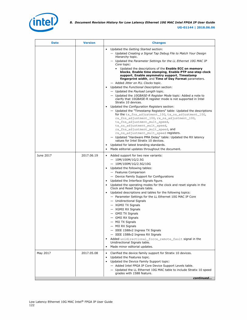
Date Version Changes
• Updated the Getting Started section:— Updated Creating a Signal Tap Debug File to Match Your Design
Hierarchy topic.— Updated the Parameter Settings for the LL Ethernet 10G MAC IP
Core topic:• Updated the descriptions of the Enable ECC on memory
blocks, Enable time stamping, Enable PTP one-step clocksupport, Enable asymmetry support, Timestampfingerprint width, and Time of Day Format parameters.
— Added Jitter on PLL Clocks topic.• Updated the Functional Description section:
— Updated the Payload Length topic.— Updated the 10GBASE-R Register Mode topic: Added a note to
clarify that 10GBASE-R register mode is not supported in IntelStratix 10 devices.
• Updated the Configuration Registers section:— Updated the "Timestamp Registers" table: Updated the descriptions
for the tx_fns_adjustment_10G, tx_ns_adjustment_10G,rx_fns_adjustment_10G, rx_ns_adjustment_10G,tx_fns_adjustment_mult_speed,tx_ns_adjustment_mult_speed,rx_fns_adjustment_mult_speed, andrx_ns_adjustment_mult_speed registers.
— Updated "Hardware PMA Delay" table: Updated the RX latencyvalues for Intel Stratix 10 devices.
• Updated for latest branding standards.• Made editorial updates throughout the document.
June 2017 2017.06.19 • Added support for two new variants:— 10M/100M/1G/2.5G— 10M/100M/1G/2.5G/10G
• Updated the following tables:— Features Comparison— Device Family Support for Configurations
• Updated the Interface Signals figure.• Updated the operating modes for the clock and reset signals in the
Clock and Reset Signals table.• Updated descriptions and tables for the following topics:
— Parameter Settings for the LL Ethernet 10G MAC IP Core— Unidirectional Signals— XGMII TX Signals— XGMII RX Signals— GMII TX Signals— GMII RX Signals— MII TX Signals— MII RX Signals— IEEE 1588v2 Ingress TX Signals— IEEE 1588v2 Ingress RX Signals
• Added unidirectional_force_remote_fault signal in theUnidirectional Signals table.
• Made minor editorial updates.
May 2017 2017.05.08 • Clarified the device family support for Stratix 10 devices.• Updated the Features topic.• Updated the Device Family Support topic:
— Added Intel FPGA IP Core Device Support Levels table.— Updated the LL Ethernet 10G MAC table to include Stratix 10 speed
grades with 1588 feature.
continued...
8. Document Revision History for Low Latency Ethernet 10G MAC Intel FPGA IP User Guide
UG-01144 | 2018.06.06
Low Latency Ethernet 10G MAC Intel® FPGA IP User Guide122

Date Version Changes
• Removed the Definition: Device Support Level topic.• Updated the Device Family Support for Configurations table to include
additional configurations that support Stratix 10 device family:— 1G/2.5G/10G MAC with 1G/2.5G/10G Multi-rate Ethernet PHY— 1G/2.5G/10G MAC with 1G/2.5G/10G Multi-rate Ethernet PHY and
IEEE 1588v2— 1G/2.5G MAC with 1G/2.5G Multi-rate Ethernet PHY— 1G/2.5G MAC with 2.5G Multi-rate Ethernet PHY— 10M/100M/1G/10G MAC with IEEE 1588v2— 1G/10G MAC with Backplane Ethernet 10GBASE-KR PHY
• Added tables listing resource utilization for Arria 10 and Stratix 10devices in the Resource Utilization topic.
• Updated the Hardware PMA Delay table to include support for Stratix 10device family.
• Updated the TX Configuration and Status Registers table:— Revised the HW Reset Value of tx_ipg_10g from 0x0 to 0x1.— Revised the HW Reset Value of tx_ipg_10M_100M_1G from 0x0 to
0x0C.• Added tables listing LX and RX latency values for Arria 10 and Stratix
10 devices in the TX and RX latency topic.• Updated the Timestamp Registers table to map registers in order of
address.• Updated the Clock and Reset Signals table.• Updated the description for speed_sel signal in the Speed Selection
table.• Updated the width and description for csr_address[] in the Avalon-
MM Programming Signals table.• Updated the width and description for avalon_st_tx_data[] signal
in both Avalon-ST TX Data Interface Signals and Avalon-ST RX DataInterface Signals tables.
• Updated Typical Client Frame at TX Interface figure, Endian Conversionfigure, and Typical Client Frame at Receive Interface figure.
October 2016 2016.10.31 • Added support for the Stratix 10 device family.• Added 1588 asymmetry support feature.• Corrected the Arria 10 device speed grades from –C2 and –C3 to –E2
and –E3.• Updated the topic about XGMII encapsulation in the TX datapath to
clarify that the MAC TX converts the eighth byte of the preamble to a1-byte SFD.
• Added a table listing the MAC behavior for different frame types in thetopic about frame type checking.
• Updated the topic listing the clock and reset signals to specify the clockdomains of the tx_rst_n and rx_rst_n signals.
• Updated the avalon_st_txstatus_data[] signal description toclarify that the status is only valid if the TX frame is valid.
• Updated the description of avalon_st_txstatus_error[5] toclarify that this bit asserts if the avalon_st_tx_error input signalfrom client is asserted.
• Added tables listing the clocks for the Avalon-ST and IEEE 1588v2interface signals.
• Added the different word offsets for the tx_ipg_10g,tx_ipg_10M_100M_1G, ecc_status, ecc_enable, andmac_reset_control registers if you turn on Use legacy Ethernet10G MAC Avalon Memory-Mapped interface.
• Updated document template.
continued...
8. Document Revision History for Low Latency Ethernet 10G MAC Intel FPGA IP User Guide
UG-01144 | 2018.06.06
Low Latency Ethernet 10G MAC Intel® FPGA IP User Guide123
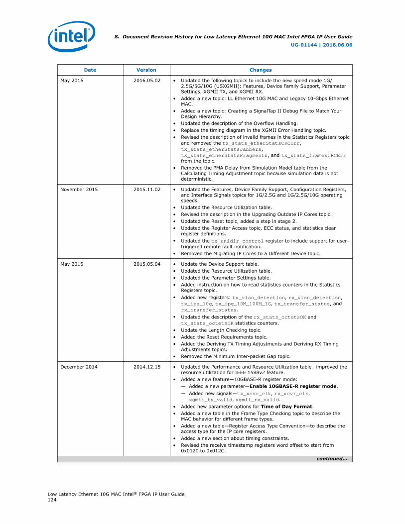
Date Version Changes
May 2016 2016.05.02 • Updated the following topics to include the new speed mode 1G/2.5G/5G/10G (USXGMII): Features, Device Family Support, ParameterSettings, XGMII TX, and XGMII RX.
• Added a new topic: LL Ethernet 10G MAC and Legacy 10-Gbps EthernetMAC.
• Added a new topic: Creating a SignalTap II Debug File to Match YourDesign Hierarchy.
• Updated the description of the Overflow Handling.• Replace the timing diagram in the XGMII Error Handling topic.• Revised the description of invalid frames in the Statistics Registers topic
and removed the tx_stats_etherStatsCRCErr,tx_stats_etherStatsJabbers,tx_stats_etherStatsFragments, and tx_stats_framesCRCErrfrom the topic.
• Removed the PMA Delay from Simulation Model table from theCalculating Timing Adjustment topic because simulation data is notdeterministic.
November 2015 2015.11.02 • Updated the Features, Device Family Support, Configuration Registers,and Interface Signals topics for 1G/2.5G and 1G/2.5G/10G operatingspeeds.
• Updated the Resource Utilization table.• Revised the description in the Upgrading Outdate IP Cores topic.• Updated the Reset topic, added a step in stage 2.• Updated the Register Access topic, ECC status, and statistics clear
register definitions.• Updated the tx_unidir_control register to include support for user-
triggered remote fault notification.• Removed the Migrating IP Cores to a Different Device topic.
May 2015 2015.05.04 • Update the Device Support table.• Updated the Resource Utilization table.• Updated the Parameter Settings table.• Added instruction on how to read statistics counters in the Statistics
Registers topic.• Added new registers: tx_vlan_detection, rx_vlan_detection,
tx_ipg_10g, tx_ipg_10M_100M_1G, tx_transfer_status, andrx_transfer_status.
• Updated the description of the rx_stats_octetsOK andtx_stats_octetsOK statistics counters.
• Update the Length Checking topic.• Added the Reset Requirements topic.• Added the Deriving TX Timing Adjustments and Deriving RX Timing
Adjustments topics.• Removed the Minimum Inter-packet Gap topic.
December 2014 2014.12.15 • Updated the Performance and Resource Utilization table—improved theresource utilization for IEEE 1588v2 feature.
• Added a new feature—10GBASE-R register mode:— Added a new parameter—Enable 10GBASE-R register mode.— Added new signals—tx_xcvr_clk, rx_xcvr_clk,
xgmii_tx_valid, xgmii_rx_valid.• Added new parameter options for Time of Day Format.• Added a new table in the Frame Type Checking topic to describe the
MAC behavior for different frame types.• Added a new table—Register Access Type Convention—to describe the
access type for the IP core registers.• Added a new section about timing constraints.• Revised the receive timestamp registers word offset to start from
0x0120 to 0x012C.
continued...
8. Document Revision History for Low Latency Ethernet 10G MAC Intel FPGA IP User Guide
UG-01144 | 2018.06.06
Low Latency Ethernet 10G MAC Intel® FPGA IP User Guide124
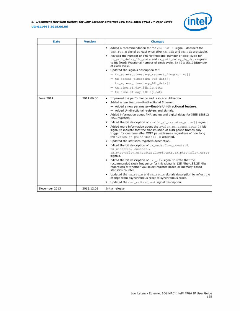
Date Version Changes
• Added a recommendation for the csr_rst_n signal—deassert thecsr_rst_n signal at least once after tx_clk and rx_clk are stable.
• Revised the number of bits for fractional number of clock cycle forrx_path_delay_10g_data and rx_path_delay_1g_data signalsto Bit [9:0]: Fractional number of clock cycle, Bit [21/15:10]:Numberof clock cycle.
• Updated the signals description for:— tx_egress_timestamp_request_fingerprint[]
— tx_egress_timestamp_96b_data[]
— tx_egress_timestamp_64b_data[]
— tx_time_of_day_96b_1g_data
— tx_time_of_day_64b_1g_data
June 2014 2014.06.30 • Improved the performance and resource utilization.• Added a new feature—Unidirectional Ethernet.
— Added a new parameter—Enable Unidirectional feature.— Added Unidirectional registers and signals.
• Added information about PMA analog and digital delay for IEEE 1588v2MAC registers.
• Edited the bit description of avalon_st_rxstatus_error[] signal.• Added more information about the avalon_st_pause_data[0] bit
signal to indicate that the transmission of XON pause frames onlytrigger for one time after XOFF pause frames regardless of how longthe avalon_st_pause_data[0] is asserted.
• Updated the statistics registers description.• Edited the bit description of tx_underflow_counter0,
tx_underflow_counter1,rx_pktovrflow_etherStatsDropEvents,rx_pktovrflow_errorsignals.
• Edited the bit description of csr_clk signal to state that therecommended clock frequency for this signal is 125 Mhz–156.25 Mhzregardless of whether you select register-based or memory-basedstatistics counter.
• Updated the tx_rst_n and rx_rst_n signals description to reflect thechange from asynchronous reset to synchronous reset.
• Updated the csr_waitrequest signal description.
December 2013 2013.12.02 Initial release
8. Document Revision History for Low Latency Ethernet 10G MAC Intel FPGA IP User Guide
UG-01144 | 2018.06.06
Low Latency Ethernet 10G MAC Intel® FPGA IP User Guide125