integration of realistic computer graphics into computer ... filening from its design through...
TRANSCRIPT

ISSN 0361-7688, Programming and Computer Software, 2018, Vol. 44, No. 4, pp. 225–232. © Pleiades Publishing, Ltd., 2018.Original Russian Text © B.Kh. Barladian, A.G. Voloboy, V.A. Galaktionov, L.Z. Shapiro, 2018, published in Programmirovanie, 2018, Vol. 44, No. 4.
Integration of Realistic Computer Graphics into Computer-Aided Design and Product Lifecycle Management Systems
B. Kh. Barladiana,*, A. G. Voloboya,**, V. A. Galaktionova,***, and L. Z. Shapiroa,****aKeldysh Institute of Applied Mathematics, Russian Academy of Sciences,
Moscow, 125047 Russia*e-mail: [email protected]
**e-mail: [email protected]***e-mail: [email protected]****e-mail: [email protected]
Received March 15, 2018
Abstract—Various approaches to the integration of realistic image rendering and lighting simulation intocomputer-aided design systems are considered. An approach that ensures the effective integration of existingrealistic image rendering systems into a CAD system is proposed. This approach makes it possible to utilizeready-to-use modules of a realistic image generation system, including the computation kernel and user inter-face modules. Synchronization of the executable modules of the basic and embedded systems is described.The proposed approaches and solutions were implemented in a project of integrating the lighting simulationand realistic image generation system Inspirer2 with the CAD CATIA.
Keywords: CAD, PLM, realistic image rendering, lighting simulation, integrated systemsDOI: 10.1134/S0361768818040047
1. INTRODUCTIONAll modern manufactures use product lifecycle
management (PLM) technologies for the design,manufacture, and maintenance of complex engineer-ing products. These technologies support the manage-ment of the whole bulk of data concerning the productand related processes during its entire lifecycle, begin-ning from its design through manufacture, mainte-nance, and removal from service. The informationabout the product is stored in a PLM system; thisinformation forms a digital model of the product. Insuch systems, the geometric model of the product istypically created using a CAD system. An importantpart of CAD is the computer-aided engineering (CAE)subsystem. In the architecture and design of variousoptical systems, the CAE system should simulate thelight propagation in various media. This allows one toobtain optical characteristics of objects and products,such as illuminance, luminance in a given direction,visibility, and legibility of devices and displays alreadyat design stage. The lighting simulation also makes itpossible to generate physically correct realistic imagesof objects, including placing them into real images forthe visual assessment of the final product (the aug-mented reality technology).
Presently, a large number of realistic graphics andoptical simulation computer programs are available;these are Maxwell renderer, V-Ray, Mental Ray,
SPEOS, ASAP, LightTools, ZEMAX, and Inspirer2.However, the independent use of such programs in themanufacturing process is limited. This is explained bytwo main factors—the need to import data concerningthe product from the CAD system (during this pro-cess, some data can be lost or corrupted), and the needto teach engineers to work with one more system.
For this reason, in order to be used effectively,lighting simulation systems should be integrated intoCAD and PLM systems. The integration shouldensure a smooth interaction with the basic CAD sys-tem in which the geometry of objects is designed andtheir characteristics are stored. Ideally, the productdesigner should be able to use the optical simulationand realistic rendering module as a part of his (her)CAD system that automatically utilizes the geometrycreated in the CAD system and the attributes that mustbe used for simulation. The lighting simulation mod-ule must automatically take into account the changesin the geometry and attributes that can be made at var-ious stages of design. Without such an effective inte-gration, the designers will not use the program, exceptfor critical cases in which the optical simulation can-not be avoided.
A widely used CAD system in aerospace and auto-motive industries is CATIA [1]. In the fields of archi-tectural and interior design the most popular CAD isAutodesk 3DS Max [2]. For this reason, we decided to
225
226 BARLADIAN et al.
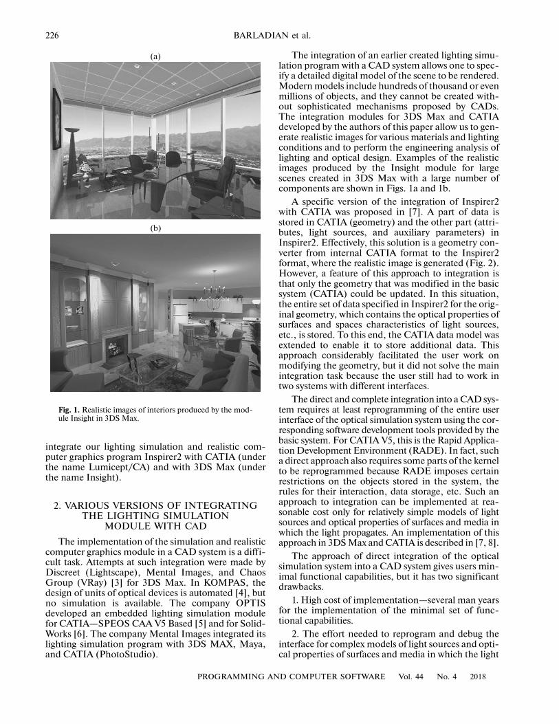
Fig. 1. Realistic images of interiors produced by the mod-ule Insight in 3DS Max.
(a)
(b)
integrate our lighting simulation and realistic com-puter graphics program Inspirer2 with CATIA (underthe name Lumicept/CA) and with 3DS Max (underthe name Insight).
2. VARIOUS VERSIONS OF INTEGRATING THE LIGHTING SIMULATION
MODULE WITH CAD
The implementation of the simulation and realisticcomputer graphics module in a CAD system is a diffi-cult task. Attempts at such integration were made byDiscreet (Lightscape), Mental Images, and ChaosGroup (VRay) [3] for 3DS Max. In KOMPAS, thedesign of units of optical devices is automated [4], butno simulation is available. The company OPTISdeveloped an embedded lighting simulation modulefor CATIA—SPEOS CAA V5 Based [5] and for Solid-Works [6]. The company Mental Images integrated itslighting simulation program with 3DS MAX, Maya,and CATIA (PhotoStudio).
PROGRAMMING A
The integration of an earlier created lighting simu-lation program with a CAD system allows one to spec-ify a detailed digital model of the scene to be rendered.Modern models include hundreds of thousand or evenmillions of objects, and they cannot be created with-out sophisticated mechanisms proposed by CADs.The integration modules for 3DS Max and CATIAdeveloped by the authors of this paper allow us to gen-erate realistic images for various materials and lightingconditions and to perform the engineering analysis oflighting and optical design. Examples of the realisticimages produced by the Insight module for largescenes created in 3DS Max with a large number ofcomponents are shown in Figs. 1a and 1b.
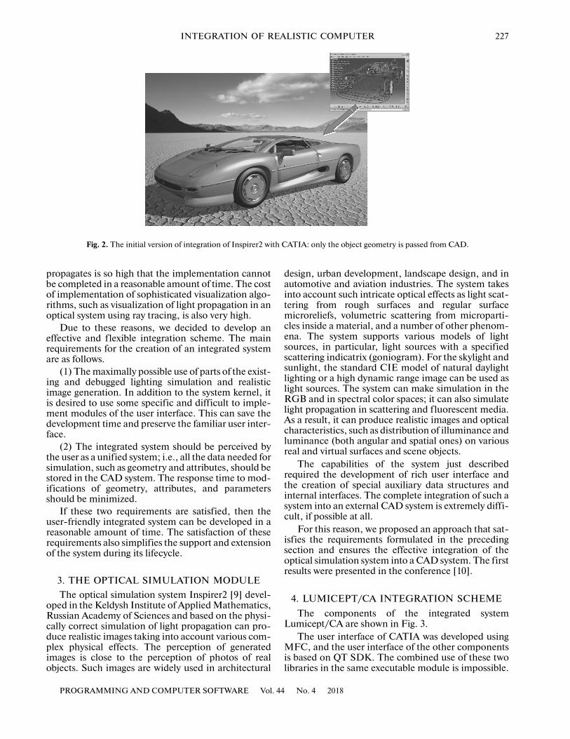
A specific version of the integration of Inspirer2with CATIA was proposed in [7]. A part of data isstored in CATIA (geometry) and the other part (attri-butes, light sources, and auxiliary parameters) inInspirer2. Effectively, this solution is a geometry con-verter from internal CATIA format to the Inspirer2format, where the realistic image is generated (Fig. 2).However, a feature of this approach to integration isthat only the geometry that was modified in the basicsystem (CATIA) could be updated. In this situation,the entire set of data specified in Inspirer2 for the orig-inal geometry, which contains the optical properties ofsurfaces and spaces characteristics of light sources,etc., is stored. To this end, the CATIA data model wasextended to enable it to store additional data. Thisapproach considerably facilitated the user work onmodifying the geometry, but it did not solve the mainintegration task because the user still had to work intwo systems with different interfaces.
The direct and complete integration into a CAD sys-tem requires at least reprogramming of the entire userinterface of the optical simulation system using the cor-responding software development tools provided by thebasic system. For CATIA V5, this is the Rapid Applica-tion Development Environment (RADE). In fact, sucha direct approach also requires some parts of the kernelto be reprogrammed because RADE imposes certainrestrictions on the objects stored in the system, therules for their interaction, data storage, etc. Such anapproach to integration can be implemented at rea-sonable cost only for relatively simple models of lightsources and optical properties of surfaces and media inwhich the light propagates. An implementation of thisapproach in 3DS Max and CATIA is described in [7, 8].
The approach of direct integration of the opticalsimulation system into a CAD system gives users min-imal functional capabilities, but it has two significantdrawbacks.
1. High cost of implementation—several man yearsfor the implementation of the minimal set of func-tional capabilities.
2. The effort needed to reprogram and debug theinterface for complex models of light sources and opti-cal properties of surfaces and media in which the light
ND COMPUTER SOFTWARE Vol. 44 No. 4 2018
INTEGRATION OF REALISTIC COMPUTER 227
Fig. 2. The initial version of integration of Inspirer2 with CATIA: only the object geometry is passed from CAD.
propagates is so high that the implementation cannotbe completed in a reasonable amount of time. The costof implementation of sophisticated visualization algo-rithms, such as visualization of light propagation in anoptical system using ray tracing, is also very high.
Due to these reasons, we decided to develop aneffective and flexible integration scheme. The mainrequirements for the creation of an integrated systemare as follows.
(1) The maximally possible use of parts of the exist-ing and debugged lighting simulation and realisticimage generation. In addition to the system kernel, itis desired to use some specific and difficult to imple-ment modules of the user interface. This can save thedevelopment time and preserve the familiar user inter-face.
(2) The integrated system should be perceived bythe user as a unified system; i.e., all the data needed forsimulation, such as geometry and attributes, should bestored in the CAD system. The response time to mod-ifications of geometry, attributes, and parametersshould be minimized.
If these two requirements are satisfied, then theuser-friendly integrated system can be developed in areasonable amount of time. The satisfaction of theserequirements also simplifies the support and extensionof the system during its lifecycle.
3. THE OPTICAL SIMULATION MODULEThe optical simulation system Inspirer2 [9] devel-
oped in the Keldysh Institute of Applied Mathematics,Russian Academy of Sciences and based on the physi-cally correct simulation of light propagation can pro-duce realistic images taking into account various com-plex physical effects. The perception of generatedimages is close to the perception of photos of realobjects. Such images are widely used in architectural
PROGRAMMING AND COMPUTER SOFTWARE Vol.
design, urban development, landscape design, and inautomotive and aviation industries. The system takesinto account such intricate optical effects as light scat-tering from rough surfaces and regular surfacemicroreliefs, volumetric scattering from microparti-cles inside a material, and a number of other phenom-ena. The system supports various models of lightsources, in particular, light sources with a specifiedscattering indicatrix (goniogram). For the skylight andsunlight, the standard CIE model of natural daylightlighting or a high dynamic range image can be used aslight sources. The system can make simulation in theRGB and in spectral color spaces; it can also simulatelight propagation in scattering and fluorescent media.As a result, it can produce realistic images and opticalcharacteristics, such as distribution of illuminance andluminance (both angular and spatial ones) on variousreal and virtual surfaces and scene objects.
The capabilities of the system just describedrequired the development of rich user interface andthe creation of special auxiliary data structures andinternal interfaces. The complete integration of such asystem into an external CAD system is extremely diffi-cult, if possible at all.
For this reason, we proposed an approach that sat-isfies the requirements formulated in the precedingsection and ensures the effective integration of theoptical simulation system into a CAD system. The firstresults were presented in the conference [10].
4. LUMICEPT/CA INTEGRATION SCHEMEThe components of the integrated system
Lumicept/CA are shown in Fig. 3.The user interface of CATIA was developed using
MFC, and the user interface of the other componentsis based on QT SDK. The combined use of these twolibraries in the same executable module is impossible.
44 No. 4 2018
228 BARLADIAN et al.
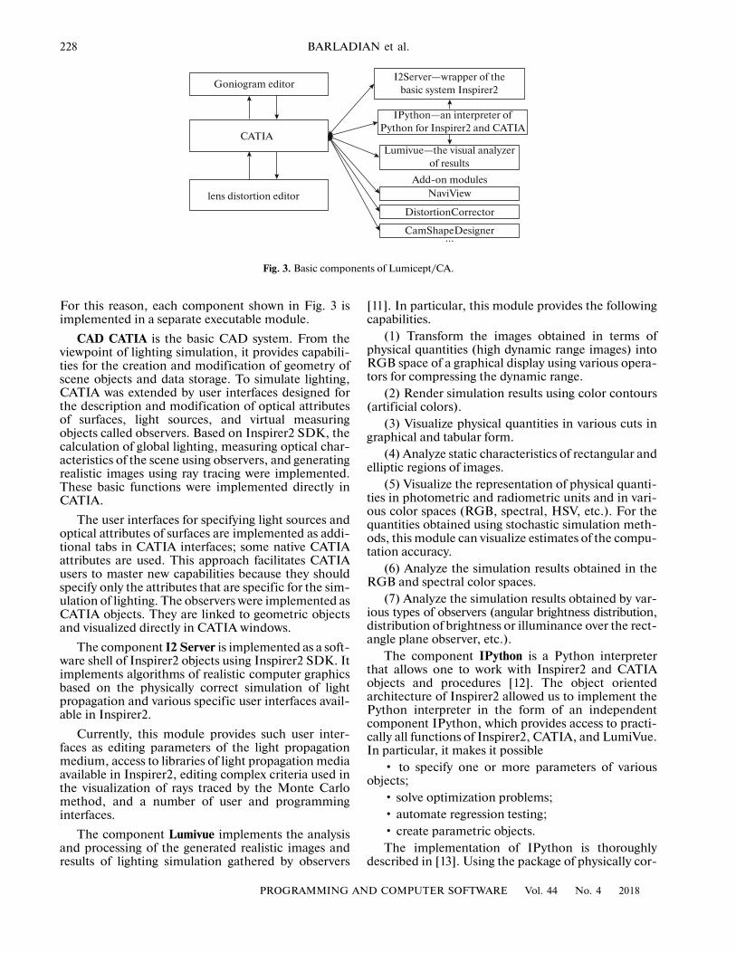
Fig. 3. Basic components of Lumicept/CA.
CATIA
lens distortion editor
Goniogram editorI2Server—wrapper of the
basic system Inspirer2
IPython—an interpreter ofPython for Inspirer2 and CATIA
Lumivue—the visual analyzerof results
Add-on modulesNaviView
DistortionCorrector
CamShapeDesigner...
For this reason, each component shown in Fig. 3 isimplemented in a separate executable module.
CAD CATIA is the basic CAD system. From theviewpoint of lighting simulation, it provides capabili-ties for the creation and modification of geometry ofscene objects and data storage. To simulate lighting,CATIA was extended by user interfaces designed forthe description and modification of optical attributesof surfaces, light sources, and virtual measuringobjects called observers. Based on Inspirer2 SDK, thecalculation of global lighting, measuring optical char-acteristics of the scene using observers, and generatingrealistic images using ray tracing were implemented.These basic functions were implemented directly inCATIA.
The user interfaces for specifying light sources andoptical attributes of surfaces are implemented as addi-tional tabs in CATIA interfaces; some native CATIAattributes are used. This approach facilitates CATIAusers to master new capabilities because they shouldspecify only the attributes that are specific for the sim-ulation of lighting. The observers were implemented asCATIA objects. They are linked to geometric objectsand visualized directly in CATIA windows.
The component I2 Server is implemented as a soft-ware shell of Inspirer2 objects using Inspirer2 SDK. Itimplements algorithms of realistic computer graphicsbased on the physically correct simulation of lightpropagation and various specific user interfaces avail-able in Inspirer2.
Currently, this module provides such user inter-faces as editing parameters of the light propagationmedium, access to libraries of light propagation mediaavailable in Inspirer2, editing complex criteria used inthe visualization of rays traced by the Monte Carlomethod, and a number of user and programminginterfaces.
The component Lumivue implements the analysisand processing of the generated realistic images andresults of lighting simulation gathered by observers
PROGRAMMING A
[11]. In particular, this module provides the followingcapabilities.
(1) Transform the images obtained in terms ofphysical quantities (high dynamic range images) intoRGB space of a graphical display using various opera-tors for compressing the dynamic range.
(2) Render simulation results using color contours(artificial colors).
(3) Visualize physical quantities in various cuts ingraphical and tabular form.
(4) Analyze static characteristics of rectangular andelliptic regions of images.
(5) Visualize the representation of physical quanti-ties in photometric and radiometric units and in vari-ous color spaces (RGB, spectral, HSV, etc.). For thequantities obtained using stochastic simulation meth-ods, this module can visualize estimates of the compu-tation accuracy.
(6) Analyze the simulation results obtained in theRGB and spectral color spaces.
(7) Analyze the simulation results obtained by var-ious types of observers (angular brightness distribution,distribution of brightness or illuminance over the rect-angle plane observer, etc.).
The component IPython is a Python interpreterthat allows one to work with Inspirer2 and CATIAobjects and procedures [12]. The object orientedarchitecture of Inspirer2 allowed us to implement thePython interpreter in the form of an independentcomponent IPython, which provides access to practi-cally all functions of Inspirer2, CATIA, and LumiVue.In particular, it makes it possible
• to specify one or more parameters of variousobjects;
• solve optimization problems;• automate regression testing;• create parametric objects.The implementation of IPython is thoroughly
described in [13]. Using the package of physically cor-
ND COMPUTER SOFTWARE Vol. 44 No. 4 2018
INTEGRATION OF REALISTIC COMPUTER 229
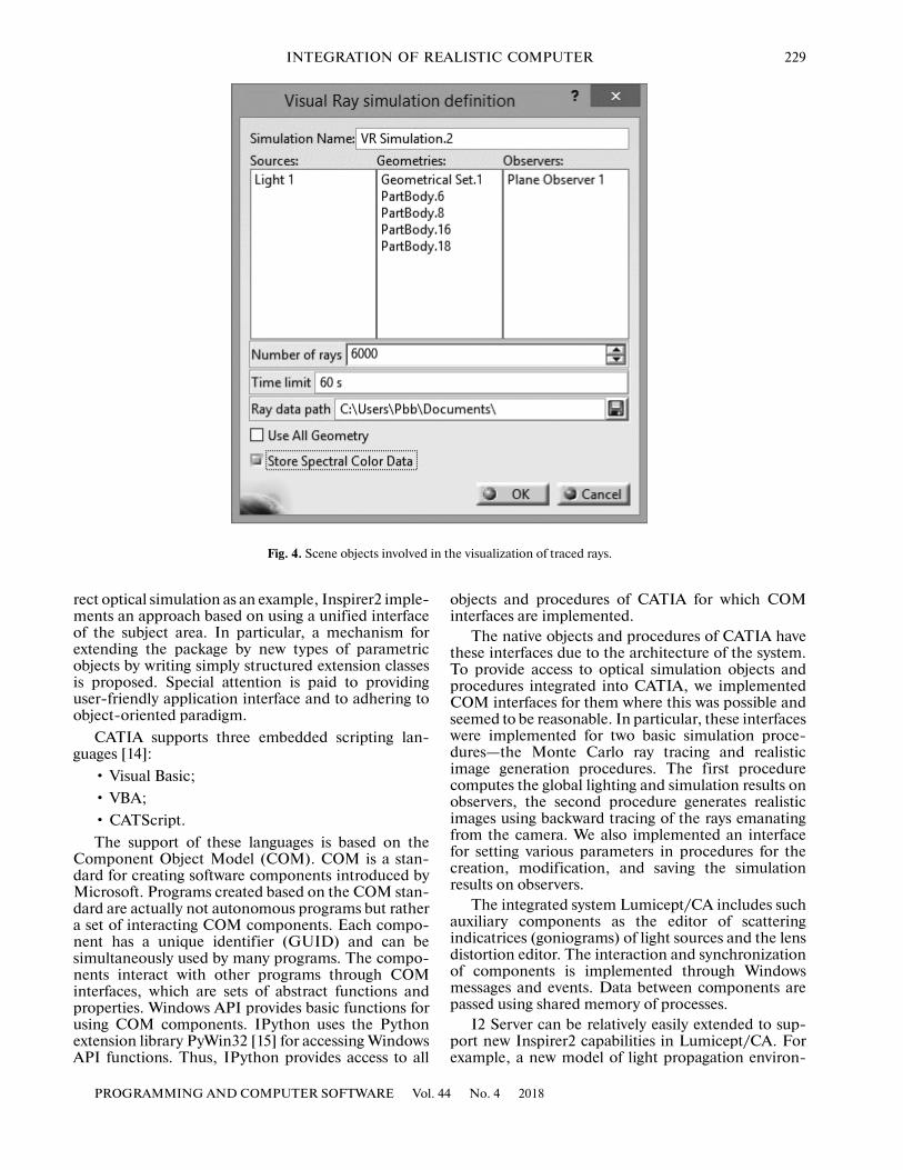
Fig. 4. Scene objects involved in the visualization of traced rays.
rect optical simulation as an example, Inspirer2 imple-ments an approach based on using a unified interfaceof the subject area. In particular, a mechanism forextending the package by new types of parametricobjects by writing simply structured extension classesis proposed. Special attention is paid to providinguser-friendly application interface and to adhering toobject-oriented paradigm.
CATIA supports three embedded scripting lan-guages [14]:
• Visual Basic;• VBA;• CATScript.The support of these languages is based on the
Component Object Model (COM). COM is a stan-dard for creating software components introduced byMicrosoft. Programs created based on the COM stan-dard are actually not autonomous programs but rathera set of interacting COM components. Each compo-nent has a unique identifier (GUID) and can besimultaneously used by many programs. The compo-nents interact with other programs through COMinterfaces, which are sets of abstract functions andproperties. Windows API provides basic functions forusing COM components. IPython uses the Pythonextension library PyWin32 [15] for accessing WindowsAPI functions. Thus, IPython provides access to all
PROGRAMMING AND COMPUTER SOFTWARE Vol.
objects and procedures of CATIA for which COMinterfaces are implemented.
The native objects and procedures of CATIA havethese interfaces due to the architecture of the system.To provide access to optical simulation objects andprocedures integrated into CATIA, we implementedCOM interfaces for them where this was possible andseemed to be reasonable. In particular, these interfaceswere implemented for two basic simulation proce-dures—the Monte Carlo ray tracing and realisticimage generation procedures. The first procedurecomputes the global lighting and simulation results onobservers, the second procedure generates realisticimages using backward tracing of the rays emanatingfrom the camera. We also implemented an interfacefor setting various parameters in procedures for thecreation, modification, and saving the simulationresults on observers.
The integrated system Lumicept/CA includes suchauxiliary components as the editor of scatteringindicatrices (goniograms) of light sources and the lensdistortion editor. The interaction and synchronizationof components is implemented through Windowsmessages and events. Data between components arepassed using shared memory of processes.
I2 Server can be relatively easily extended to sup-port new Inspirer2 capabilities in Lumicept/CA. Forexample, a new model of light propagation environ-
44 No. 4 2018

230 BARLADIAN et al.
Fig. 5. Interaction scheme of CATIA with I2 Server and LumiVue in the visualization of light rays.
CATIA
LumiVue
Reset ev1. ev2
VR SCENE LOAD
I2 Server
Monte Carlo ray tracingand ray storage
Monte Carlo ray tracingand ray storage
Construction of criterion and analysis
Reset ev1
End
Wait ev1
Wait ev1
Redraw 100 mc
Set ev2 Wait ev2
Simulation
Set ev1
Set ev1
VR_CALCULATE
Window handle
VR_RAY_CRITERIA
LUMIVUE_LOAD
LUMIVUE_HIDE
LUMIVUE_DETECTOR
VR_ANALYZE
VR_RAY_HISTORY
ment is added automatically because the correspond-ing user interface, object storing data, and the simula-tion procedure (Monte Carlo ray tracing) are imple-mented in DLLs that are common for I2 Server andInspirer2. If new functionality requires the transmis-sion of additional data between units, this is imple-mented using relatively simple add-ons in the corre-sponding units.
Note that the set of Lumicept/CA components canbe extended if new tasks emerge such that it is better toimplement them in a separate component. Figure 3shows examples of three such components.
• NaviView simulates the rear view camera in aautomobile navigation system.
• DistortionCorrector provides fish eye lens imagecorrection in a form adapted for hardware implemen-tation.
• CamShapeDesigner generates the geometryrestricting the camera field of view.
5. SYNCHRONIZATION OF COMPONENTSIN LUMICEPT/CA
When an integrated system is implemented as a setof separate units, the main problem is to efficientlysynchronize the subsystems implemented in differentexecutable modules. The interaction between subsys-tems should preferably be hidden from the user to cre-ate a comfortable work environment.
PROGRAMMING A
The interaction between components was imple-mented using special Windows messages and events.For this purpose, the main Windows procedure of I2Server and Lumiview was replaced by a special proce-dure that processes the messages sent by CATIA. Tosynchronize the other (simpler) components, a fewWindows events turned to be sufficient: to continue itsexecution, a components waits until another compo-nent throws the corresponding event. Data betweencomponents can be passed in two ways. Smallamounts of data are passed using the memory sharedby processes. Large amounts of data are passed usingthe file system in the binary format of Inspirer2.
I2 Server is implemented as an ordinary Windowsapplication, which starts simultaneously with CATIA.Its main window is invisible, and its main window pro-cedure is replaced by processing the messages sent byCATIA. Special Windows events are used to synchro-nize CATIA with I2 Server in the process of computa-tions and CATIA window repaint.
By way of example, consider in more detail the syn-chronization of the visualization component of lightpropagation in an optical system in the form of tracedrays [16]. The operation of CATIA with the compo-nent Lumivue and the goniogram and lens distortionfunction editors is synchronized similarly.
At the first step, the user selects light sources, geo-metric objects, and observers involved in the simula-tion. Actually, at this step the user specifies a new
ND COMPUTER SOFTWARE Vol. 44 No. 4 2018

INTEGRATION OF REALISTIC COMPUTER 231
Fig. 6. Examples of lighting simulation results in the inte-grated Lumicept/CA system.
(a)
(b)
scene using objects of another already existing scene.This is done directly in the CATIA interface. The userselects objects in the visualization window or in thescene tree, and the names of the selected objects areshown in a dialog. Alternatively, the user can indicatethat the entire scene will be used by selecting the cor-responding check box. In the same dialog, the path forsaving the simulation results, the number of rays to besaved, and a restriction on the simulation time are set.An example of this dialog is shown in Fig. 4. After thedialog has been closed, the specified parameters of thesimulation session are shown in the scene tree, and thesimulation can be started from the dropdown dialog bya right-click. The user may create any number of suchsimulation sessions for various needs.
The synchronization scheme of the simulation per-formed in I2 Server is illustrated in the upper part ofFig. 5. CATIA forms a scene description in the binaryformat of Inspirer2, saves it to disk, and sends the mes-sage VR_SCENE_LOAD to load the scene; next, itsends the message VR_CALCULATE (ray tracingwith storing the results in a file for future visualiza-tion). Such additional data as the path to the scene
PROGRAMMING AND COMPUTER SOFTWARE Vol.
description, simulation time restriction, and the num-ber of rays are passed through shared memory.
The execution schemes of various I2 Server com-mands are close to each other. Here we describe themost complicated execution scheme of VR_CALCU-LATE in detail.
(1) CATIA throws off the events ev1 and ev2, sendsthe message VR_CALCULATE, and waits for theoccurrence of ev1.
(2) Having received the message VR_CALCU-LATE, I2_Server retrieves the file from the sharedmemory, loads the scene from it, places its windowhandle into the shared memory, throws the event ev1,and waits for the occurrence of the event ev2.
(3) CATIA retrieves from the shared memory thewindow handle, throws off the event ev1, and throws ev2.
(4) After the occurrence of the event ev2, I2 Serverexecutes the simulation and then throws the event ev1.During the simulation, the progress bar shows theprogress of the simulation execution as the ratio of thenumber of traced rays to the total number of rays.Then, I2 Server writes the simulation results to disk.
(5) When waiting for the occurrence of the eventev1, CATIA repaints its window with an interval of 100milliseconds, makes the I2 Server window active, andplaces it on top of other windows. In response to theevent ev1, CATIA reads from the disk the updatedscene and accordingly updates the data in its docu-ment and the scene tree.
6. CONCLUSIONSThe approach proposed in this paper was used to
include the main functions of the system Inspirer2(such as computation of the direct and indirect light-ing, visualization of ray tracing, and support of com-plex optical attributes and light sources) in the CATIACAD system. As a result, the users working withCATIA can perform computational experiments withthe models they design. For example, they can test theappearance of a paint-and-lacquer coating on thebody of a car being designed under different externallighting as shown in Figs. 6a and 6b.
This approach enabled us to considerably speed upthe development of the integrated system and improveits reliability because the most complicated moduleshave already been debugged in the autonomous sys-tem. As a result, the time needed for the implementa-tion of new functions in Lumicept/CA that werealready available in Inspirer2 was drastically reduced.This is especially important because the cost of theCATIA programming environment (the license cost)is high and the development requires highly skilledexperts with good working experience in this environ-ment. The proposed approach was implemented forCAD CATIA, but it also can be applied to other CADsystems.
44 No. 4 2018
232 BARLADIAN et al.
ACKNOWLEDGMENTSThis work was supported in part by the Russian
Foundation for Basic Research, project nos. 16-01-00552 and 18-01-00569.
REFERENCES1. Dassault Systems, CATIA. http://www.3ds.com/ru/
products/catia/. Cited January 10, 2018.2. Autodesk 3DS MAX. https://www.autodesk.ru/prod-
ucts/3ds-max/overview. Cited January 10, 2018.3. Osinev, A., V-Ray: Appreciate your time, SAPR
Grafika, 2010, no. 9, pp. 88–89.4. Kolpakov, A. and Tostoba, N., Automating the design
of a unit of an optical devise, SAPR Grafika, 2012,no. 12, pp. 68–70.
5. Gol’dovskii P. and Kokova, A., Simulation of opticalphenomena and properties of various products, SAPRGrafika, 2004, no. 8, pp. 46–47.
6. Alyamovskii, SolidWorks/OptisWorks—An integratedenvironment for the analysis anb synthesis in optics:Optical analysis and software structure, SAPR Grafika,2006, no. 4, pp. 73–79.
7. Barladian, B. Kh., Voloboy, A.G., and Shapiro, L.Z.,Integration of illumination simulation by ray tracingmethod into CAD systems, in Proc. of the 23rd Int. Conf.GraphiCon’2006, Novosibirsk, Russia, 2006, pp. 275–278.
8. Barladian, B. Kh., Voloboy, A.G., Galaktionov, V.A.,and Shapiro, L.Z., Integration of illumination simula-tion software into CAD and CAM systems, Proc. of theInt. Conf. and Exhibition CAD/CAM/PDM-2006, Mos-cow, 2006, pp. 16–20.
PROGRAMMING A
9. Zhdanov, D.D., Potemin, I.S., Galaktionov, V.A., Bar-ladyan, B. Kh., Vostryakov, K.A., and Shapiro, L.Z.,Spectral Ray Tracing in Problems of PhotorealisticImagery Construction, Program. Comput. Software,2011, vol. 37, no. 5, pp. 236–244.
10. Barladian, B. Kh., Voloboy, A.G., and Shapiro, L.Z.,Generating realistic images in CAD systems, in Proc. ofthe 23rd Int. Conf. GraphiCon’2013, Vladivistok, Russia,2013, pp. 186–190.
11. Barladian, B.K., Potemin, I.S., Zhdanov, D.D., Volo-boy, A.G., Shapiro, L.S., Valiev, I.V., and Biru-kov, E.D., Visual analysis of the computer simulationfor both imaging and non-imaging optical systems, inProc. of the Society of Photographic InstrumentationEngineers 10021, Optical Design and Testing VII, 2016.
12. Deryabin, N.B., Sokolov, V.G., Zhdanov, D.D. andKopylov, M.S., Automating the generations of series ofrealistic images using Python scripting language, inProc. of the 25th Int. Conf. GraphiCon’2015, Protvino,Russia, 2015, pp. 132–136.
13. Deryabin, N.B., Zhdanov, D.D. and Sokolov, V.G.,Embedding the script language into optical simulation,Program. Comput. Software, 2017, vol. 43, no. 1, pp 13–23.
14. Introduction to CATIA V5 Automation. http://cat-iav5automation.blogspot.ru/2013/05/ introduction-to-catia-v5-automation.html. Cited February 5, 2018.
15. Python for Windows Extensions. https://sourceforge.net/projects/pywin32/. Cited February 7, 2018.
16. Barladian, B., Shapiro, L., and Voloboy, A., Ray mapstechnique for effective interrogation of results ofMCRT simulation, in Proc. of the 21th Int. Conf. onComputer Graphics and Vision GraphiCon’2011, Mos-cow, 2011, pp. 46–49.
Translated by A. Klimontovich
ND COMPUTER SOFTWARE Vol. 44 No. 4 2018