integration of cae tools for complete system prototyping …€¦ · · 2003-01-24matlab, matrixx...
TRANSCRIPT

Integration of CAE Tools for Complete System Prototyping2000 EASY5 User Conference
May, 2000
Presented by: Joel Tollefson
Integration of CAE Tools - Chart 2
EASY5
• Provide a framework to support other presentations
• define concepts• outline different methods for integrating CAE tools• survey current tools and practices
• Methods of integrating CAE tools• static data integration• co-simulation
• coupled-simulation
• EASY5’s Integration of Engineering Tools
Presentation Focus

Integration of CAE Tools - Chart 3
EASY5
• What’s driving integrated systems modeling and engineering?• need to be streamline engineering process: companies have many different
engineering tools, methods and processes • goal: reduce time to market • promise: complete system prototyping
• What is virtual system prototyping?• modeling of entire systems, from systems level down to detailed
subsystems• goal: produce a complete virtual system prototype - a computer model• use computer models to design, analyze, simulate, test entire system
before “cutting metal”• prototype: increase design iterations, validate design, reduce h/w testing
costs
• Requirements for system prototyping• ability to integrate systems modeling tools - apply broad array of computer-
aided engineering (CAE) tools• create an integrated engineering environment
Introduction

Integration of CAE Tools - Chart 4
EASY5
Overview of the Engineering Environment
Product Definition
System Req’ments
FunctionalObjectives
Avionics Hydraulics
S & C Structures ECS
ElectricalSystems
MechanicalSystems
FlightSystems
FlightControls
Loads &Flutter
SystemCertification
H/WDesign
RealTime Auto Code Simulators LRU’s
SchematicsDrawings
PropulsionSystems
Systems Engineering
Design &
Application/ ... and others ...
Func
tiona
l
multi-discipline
Level of Abstraction
higher
lowerAnalysis
Verification
Propulsion
Fidelity
lower
higher
Model

Integration of CAE Tools - Chart 5
EASY5
Selecting Design and Analysis Tools
Product Definition
System Req’ments
FunctionalObjectives
Avionics Hydraulics
S & C Structures ECS
ElectricalSystems
MechanicalSystems
FlightSystems
FlightControls
Loads &Flutter
SystemCertification
H/WDesign
RealTime Auto Code Simulators LRU’s
SchematicsDrawings
PropulsionSystems
Systems Engineering
Design &
... and others ...
multi-discipline
Application
many different engineering designand analysis tools
Analysis
can be applied to different disciplines
MATLAB, MATRIXxSABER EASY5, FlowMaster
NASTRAN EASY5 CATIARPAS
LandingGear
DADS, ADAMS
• Two opposing views:• tool-centric
• integrated tools
EASY5
EASY5

Integration of CAE Tools - Chart 6
EASY5
Partial list of simulation-based tools
Engineering Disciplines
MA
TL
AB
MA
TR
IXx
EA
SY
5
SA
BE
R
Flo
wM
aste
r
AD
AM
S, D
AD
SP
ro/M
ech
anic
a
VA
NTA
GE
STA
TE
MA
TE
Controls
Finite State StateFlow BetterState
Mechanical
Electric Circuits
Integrated Circuits
Electric Machinery
Pneumatics
Powertrain
Hydraulics
Auto-Code
Real Time
Survey of Design & Simulation Tools

Integration of CAE Tools - Chart 7
EASY5
Pro/ENGINEER
CATIA
EASY5 Chose the Integrated Tools Approach
ADAMS
DADS
Pro/MECHANICA
NASTRAN/ANSYS
STATEMATE
EASY5
MATLAB
Simulink
MATRIXx
SystemBuild
GSDS
Beacon
Vantage
(& other ViewLogic tools)
Controls
ASIC design
Finite State CAD
Structural
Auto-Code
Multi-bodyDynamics
Generatorin work
• Over 6 years of experience integrating CAE tools with EASY5.
• Tools are integrated using our “Extensions” feature.

Integration of CAE Tools - Chart 8
EASY5
EASY5‘s Extension
• What is the EASY5 “Extension” ?
– a special component that provides the “s/w hooks” for other CAE tools to integrate with EASY5
– from user’s point-of-view it provides a seamless integration of tools
• Provides an open architecture and published API for integrating other tools with EASY5.

Integration of CAE Tools - Chart 9
EASY5
Example of Extensions: Integration of EASY5 and GSDS
GSDS Auto-code modules may be added as components in EASY5
When the user “clicks” on the GSDS module the diagram for that module will “pop up” in BDED
• Presentation on EASY5 and GSDS integration to be given by Mike Bingle.
Integration of CAE Tools - Chart 10
EASY5
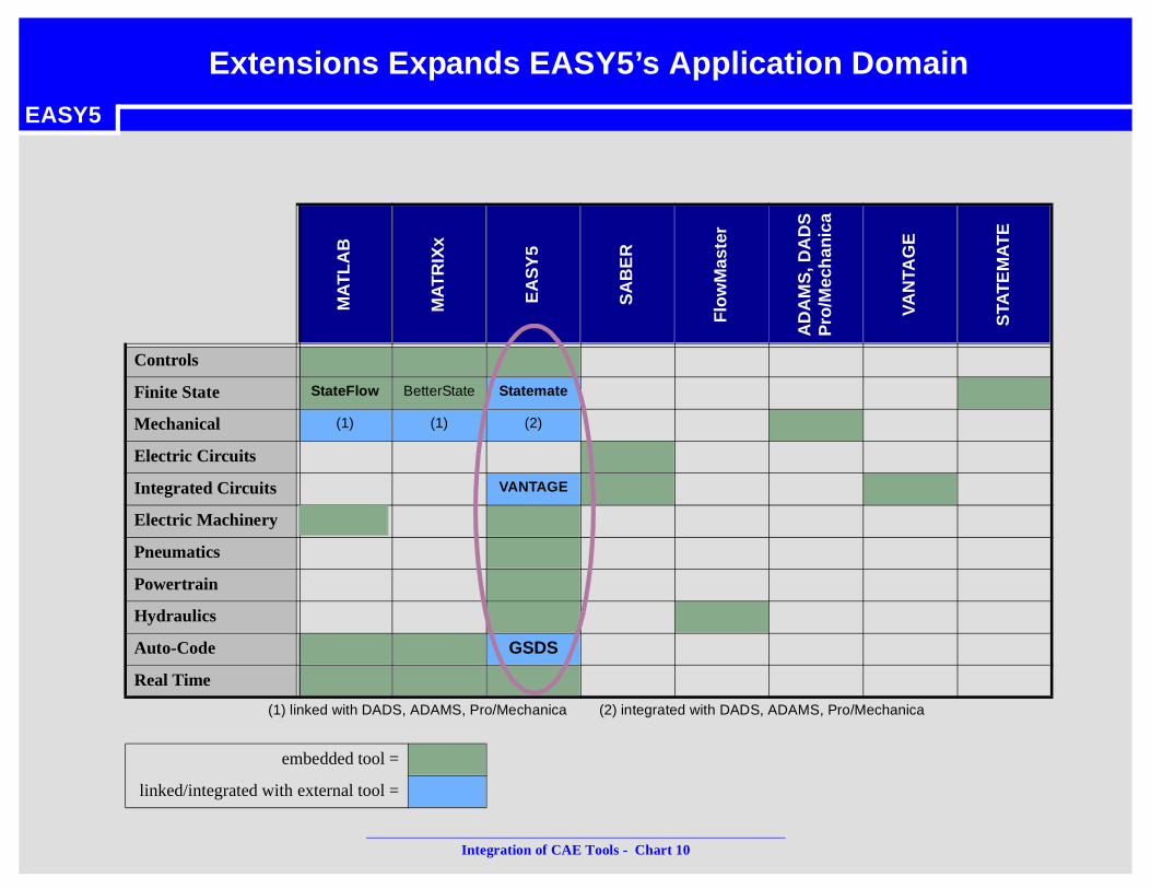
(1) linked with DADS, ADAMS, Pro/Mechanica (2) integrated with DADS, ADAMS, Pro/Mechanica
MA
TL
AB
MA
TR
IXx
EA
SY
5
SA
BE
R
Flo
wM
aste
r
AD
AM
S, D
AD
SP
ro/M
ech
anic
a
VA
NTA
GE
STA
TE
MA
TE
Controls
Finite State StateFlow BetterState Statemate
Mechanical (1) (1) (2)
Electric Circuits
Integrated Circuits VANTAGE
Electric Machinery
Pneumatics
Powertrain
Hydraulics
Auto-Code GSDS
Real Time
embedded tool =
linked/integrated with external tool =
Extensions Expands EASY5’s Application Domain

Integration of CAE Tools - Chart 11
EASY5
Cross-Functional Integration of ToolsBridging the Gap Between Systems & Design
System Req’ments
FunctionalObjectives
Avionics Hydraulics
S & C Structures ECS
ElectricalSystems
MechanicalSystems
FlightSystems
FlightControls
Loads &Flutter
SystemCertification
H/WDesign
PropulsionSystems
Syste
ms
Engin
eerin
g
Desig
n & A
nalys
is
Propulsion
• Integrate tools across functional boundaries: Systems <==> Design
• Most difficult, least understood integration process
• Different engineering environment: Behavioral Vrs. Detailed Design
• Important integration - detailed behavior can affect
high level behavior- Preliminary Design
- Trade Studies
Behavioral
Detailed Design
system requirements flows down
design capability flows up
Integration of CAE Tools - Chart 12
EASY5
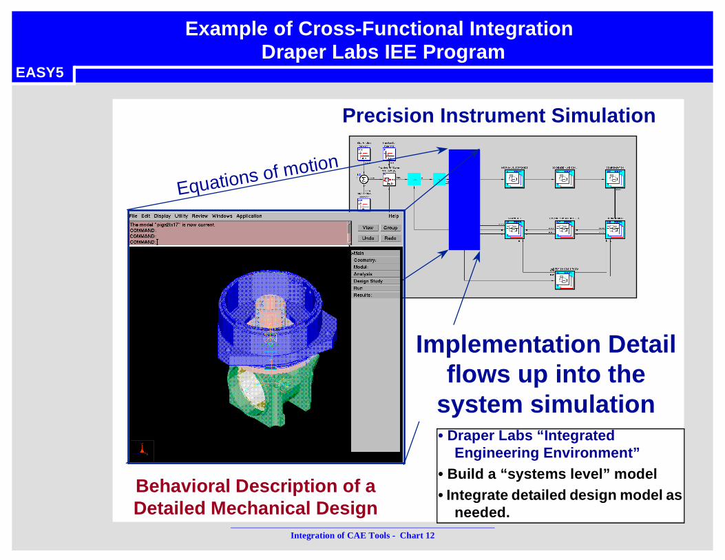
Precision Instrument Simulation
Behavioral Description of aDetailed Mechanical Design
Equations of motion
Implementation Detailflows up into the
system simulation
Example of Cross-Functional Integration
• Draper Labs “Integrated Engineering Environment”
• Build a “systems level” model • Integrate detailed design model as
needed.
Draper Labs IEE Program
Integration of CAE Tools - Chart 13
EASY5
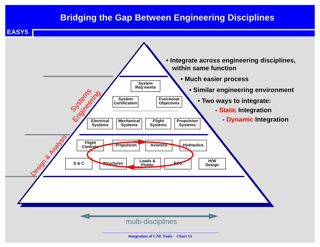
Bridging the Gap Between Engineering Disciplines
System Req’ments
FunctionalObjectives
Avionics Hydraulics
S & C Structures ECS
ElectricalSystems
MechanicalSystems
FlightSystems
FlightControls
Loads &Flutter
SystemCertification
H/WDesign
PropulsionSystems
Syste
ms
Engin
eerin
g
Desig
n & A
nalys
is
Propulsion
• Integrate across engineering disciplines, within same function
• Much easier process
• Similar engineering environment
• Two ways to integrate:- Static Integration
- Dynamic Integration
multi-disciplines

Integration of CAE Tools - Chart 14
EASY5
• “Static” Integration: geometric or parametric data is shared between programs
• simple - implementation is usually straight forward• commonly used to integrate different types of application tools;
example: geometric-based modeling with simulation-based tool• example: CATIA and DADS integration - shares geometric data• example: NASTRAN <==> EASY5 integration
• EASY5/NASTRAN integration is implemented using an “Extension” component.
EASY5
NASTRAN
EASY5/NASTRANIntegration
• extract NASTRAN modes• convert to EASY5 modal data• insert data directly into
EASY5 component
Static Integration of CAE Tools

Integration of CAE Tools - Chart 15
EASY5
• Example: Genesis/KIRTS functional integration with EASY5• Genesis/KIRTS: generates functional dynamic models from CAD
definitions of hydraulic and ECS systems • Presentation will be given by Raju.
EASY5
Parts SchematicsSolid
Model Assembly
CATIA
Genesis/KIRTS
Hydraulic Model EASY5 Genesis/KirtsFunctional Integration
Beyond Static Integration

Integration of CAE Tools - Chart 16
EASY5
• Involves “dynamic integration” of data and/or code.
• Much more complex and difficult to implement
• geared to “simulation-based” tools
• 2 methods• co-simulation integration• coupled-simulation integration
Dynamic Integration of CAE Tools

Integration of CAE Tools - Chart 17
EASY5
• Co-Simulation• two simulation programs run simultaneously • each solves its own differential equations - each controls its own Time• data is shared between programs at predetermined time intervals
• Examples of co-simulation • EASY5’s co-simulation with SystemBuild and Simulink
Simulator 1(Controls time) Simulator 2
ModelEquations
CentralIntegrator
•X X
ModelEquations
CentralIntegrator
•X X
I/O
I/O
DataBetweenModels
ExchangedAt Sample
PeriodsCentral
IntegratorCentral
Integrator
CAE Integration Using Co-Simulation

Integration of CAE Tools - Chart 18
EASY5
• Not a design and analysis tool -- only a simulation tool• not possible to generate a linear model of complete system• can not perform controls design and analysis, steady state, etc.
• Excessive run times for models with “coupled dynamics”• small data sharing time intervals may be required - constrains numerical
integration and results in unacceptable simulation run-times • MATRIXx/DADS co-simulation is a good example of this problem: f
• Co-simulation works best on systems that are not tightly coupled .
actuator modelmechanism
pressureforces
pos, vel, accel model
MULTI-BODY PROGRAMDYNAMIC SIMULATION PROGRAM
• differential equation for pressure in actuator is closely related to the mechanism velocity
• velocity is closely related to pressure force from actuator• requires small data sharing time interval (about 1E-6) to
achieve accurate results
Co-Simulation Disadvantage

Integration of CAE Tools - Chart 19
EASY5
• Purpose• To simulate any EASY5 model from
within MATRIXx (SystemBuild) or MATLAB (Simulink) models.
• Advantage• you can use EASY5 to build large,
complex highly nonlinear plant models - difficult to do with MATLAB/MATRIXx
• use EASY5 Switch states and special integrators
• use EASY5 application libraries - hc, hv, ec, pt, en, etc.
• use other tool’s strength - controller design and analysis
MATRIXxMATLAB EASY5
Co-Simulation
Controller Plant Dynamics
EASY5 Interface to MATRIXx/MATLAB

Integration of CAE Tools - Chart 20
EASY5
• Coupled-Simulation approach • equations (differential, difference, algebraic) from different CAE tools are
combined (coupled) into one set of equations, inserted into one of the CAE programs
• solved by a central numerical integrator in the simulator that controls time• required when equations in different tools are tightly coupled - such that only a
central numerical integrator can produce more accurate results within a reasonable amount of time
CentralIntegrator
•XX
ModelEquations
FromSimulation 2
ModelEquations
FromSimulator 1
Simulator 1 (Controls Time)
CentralIntegrator
CAE Integration Using Coupled-Simulation

Integration of CAE Tools - Chart 21
EASY5
• Advantages• reduced simulation time• true design and analysis tool• allows engineer to apply all analyses: simulation, steady-state, linear analysis,
control systems design• integration is more “seamless” from users point of view
• Disadvantages• much more difficult to integrate CAE tools using coupled-equations approach
• Example of coupled-simulation integration:• EASY5 integration with DADS, ADAMS, and ProE/Mechanica
• Coupled-simulation of CAE tools easily done with “Extensions”.
actuator modelmechanismpressure
forces
pos, vel, accelmodel
DADS by CADSIEASY5multibodymodel
differential equations & data
Advantages/Disadvantages of Coupled-Simulation

Integration of CAE Tools - Chart 22
EASY5
• Integration of CAE tools is necessary for complete system prototyping.
• Integration of CAE tools is central to EASY5 - being developed as a core competency
• EASY5 “Extensions” feature provides a mechanism for integrating CAE tools - makes the integration appear seamless to the user.
Summary