integration of a scada to a dms/oms/ems system for operation … · 2019-06-04 · integration of a...
TRANSCRIPT
Integration of a SCADA to a DMS/OMS/EMS system for
operation management of an energy distributor
Key-words: SCADA, DMS, EMS, OMS, GIS, distribution operation
Abstract – Spin Canada has implanted several operation centres for distribution companies, such
as the centres at CEB, CELPE, CEEE, CELPA, DME, etc. In those centres, the SCADA software makes
the supervisory control of the substations and, more recently, of the switches in the poles spread
through the medium tension and low-tension networks (13,8 kV, 220/110 V). With a partnership
with the company Energy Computer System (ECS), Spin has integrated its new SCADA to the
software OMS/DMS (Outage Management System/Distributed Management System) from this
company, creating a powerful solution to operate energy distribution centres. This solution has
both the software modules and the manuals in English and allows that a georeferenced database
of all the Utilities’ assets to be stored in a proper structure to be used in real time ambient.
Besides the operation over georeferenced screens, the system has a group of mobility equipment
that allows the technicians, using tablets and smartphones, to have access to all the screens on
the SCADA, the GIS and the DMS/OMS.
This work introduces the integration of this solution to the systems already in the distribution
company, like the GIS, the client database, etc.
1. Introduction
The SCADA system integrated to a software to estimate status and analyse contingencies
(modules of EMS: Energy Management System) enables the despatch of load in the transmission
level between the many substations in a distribution company. Before the integration described
in this paper, Spin implemented at CEB (Energy Company of Brasília) a system with those
characteristics [1] that is operational until today.
With the technological evolution came the concept of Smart Grid and begun the automation of
the distribution network, inserting hundreds of new IEDs (Intelligent Electronic Devices) in the
medium tension and low-tension networks as, for example, meters, pole switches, fault
indicators, etc. The suitability to this reality demands the use of new interface equipment with
the despatch operators, that allow the georeferenced visualization of the electrical network,
with all assets presented over a solution that integrates the electrical applications of
EMS/DMS/OMS.
This work shows a solution of this type, integrating the existing SCADA in the distribution
company of a georeferenced management of operation system (DMS/OMS/GIS). This solution
has already been implemented in many distribution companies in the three Americas [2], being
composed by, basically, three big software modules and an integration routine library:
1 – SCADA module;
2 – GIS module: software for creating and maintenance of the georeferenced asset base;
3 – OMS module: Outage Management System.
If the distribution company has a SCADA that meets their operational criteria of data acquisition
and actuation, it is enough to create an interface between this SCADA and the OMS module. If
the distribution company wants to use a last generation SCADA, it can adopt the SCADA
integrated to the solution. The use of GIS and OMS modules of the solution, however, is
mandatory, since the first generates and also keeps the proper form to real time use, the
georeferenced database with the company’s assets (pole, transformer, isolator, line, etc) and
the second, using this base, makes available its visualization in real time with many support
equipment for the operation.
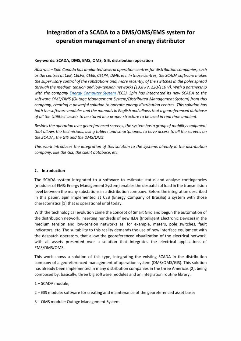
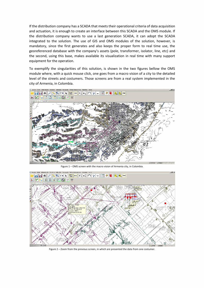
To exemplify the singularities of this solution, is shown in the two figures bellow the OMS
module where, with a quick mouse click, one goes from a macro vision of a city to the detailed
level of the streets and costumers. Those screens are from a real system implemented in the
city of Armenia, in Colombia.
Figure 1 – OMS screen with the macro vision of Armenia city, in Colombia.
Figure 2 – Zoom from the previous screen, in which are presented the data from one costumer.
2. Development
2.1. Integration of the system to the concessionary’s database
One of the most important aspects of a georeferenced system that operates in real time is its
velocity to present the data in the operation screens. The data treatment algorithms must be
oriented to this type of application, as well as the database optimization. The performance
requirement of a georeferenced system oriented to projects is quite different from the
requirement for real time applications.
The presented solution used a relational database, market standard (Oracle or SQL Server),
structured to the treatment and visualization of data in real time. The structure of the destiny
database of any application is already done, its creation, however, depends a lot on the existing
data at the distribution company and the way that data is made available (SAP2, ArcGis®, etc.).
For that, a library is available with pre-made utilities to search the data in the distribution
company files and generate the database. The necessary information is the client’s data (name,
phone, address, type of client, associated meter, measurement, transformer that feeds him,
etc.) and the network assets, such as physical node, electrical node, line stretch, transformer,
etc.
The capture of this data happens in two moments. In the beginning of the implantation, a study
of the existing information is made and of how to import them to base of the GIS module. After
the initial load, periodically, must be executed the actualization module of this base with client
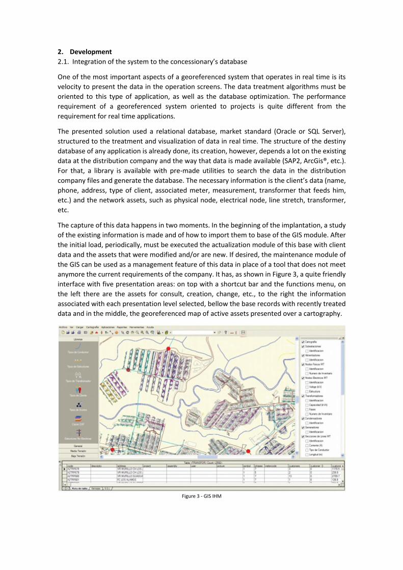
data and the assets that were modified and/or are new. If desired, the maintenance module of
the GIS can be used as a management feature of this data in place of a tool that does not meet
anymore the current requirements of the company. It has, as shown in Figure 3, a quite friendly
interface with five presentation areas: on top with a shortcut bar and the functions menu, on
the left there are the assets for consult, creation, change, etc., to the right the information
associated with each presentation level selected, bellow the base records with recently treated
data and in the middle, the georeferenced map of active assets presented over a cartography.
Figure 3 - GIS IHM
2.2. Maintenance of the database of the distribution network (GIS module)
The GIS module allows the administration and actualization of the database of the distribution
network (BDD) and is the source of data to the operation module in real time (OMS) including,
in an integrated way, the analysis and optimization functions of the distribution network.
Among the analysis applications of the electrical network of low and medium tension can be
cited the balanced or unbalanced power flow, the analysis of fault and sensibility, the
transformer load relocation, the balance of losses, power and energy, etc. Among the
optimization applications of the electrical network there is the optimal dimensioning and
location of capacitors, optimal reconfiguration of primary network, optimal calculation of
conductors, etc.
To include and/or actualize the assets base the GIS module makes available the use of mobile
technology, with tablets that can contain part or all the database of the distribution. The
technicians responsible for the maintenance can go to the field where, from the georeferenced
position identified by the tablet are searched the assets records that must be actualized. In the
event of inclusion, the georeferenced position of the tablet is used to position the asset.
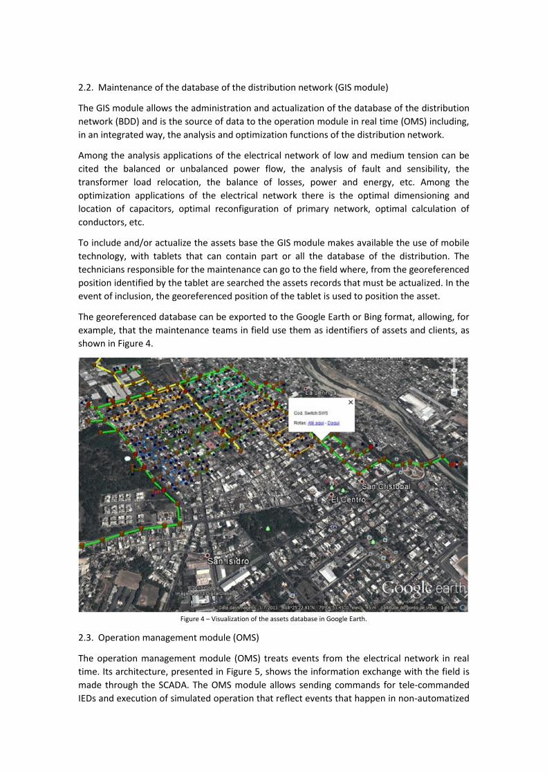
The georeferenced database can be exported to the Google Earth or Bing format, allowing, for
example, that the maintenance teams in field use them as identifiers of assets and clients, as
shown in Figure 4.
Figure 4 – Visualization of the assets database in Google Earth.
2.3. Operation management module (OMS)
The operation management module (OMS) treats events from the electrical network in real
time. Its architecture, presented in Figure 5, shows the information exchange with the field is
made through the SCADA. The OMS module allows sending commands for tele-commanded
IEDs and execution of simulated operation that reflect events that happen in non-automatized
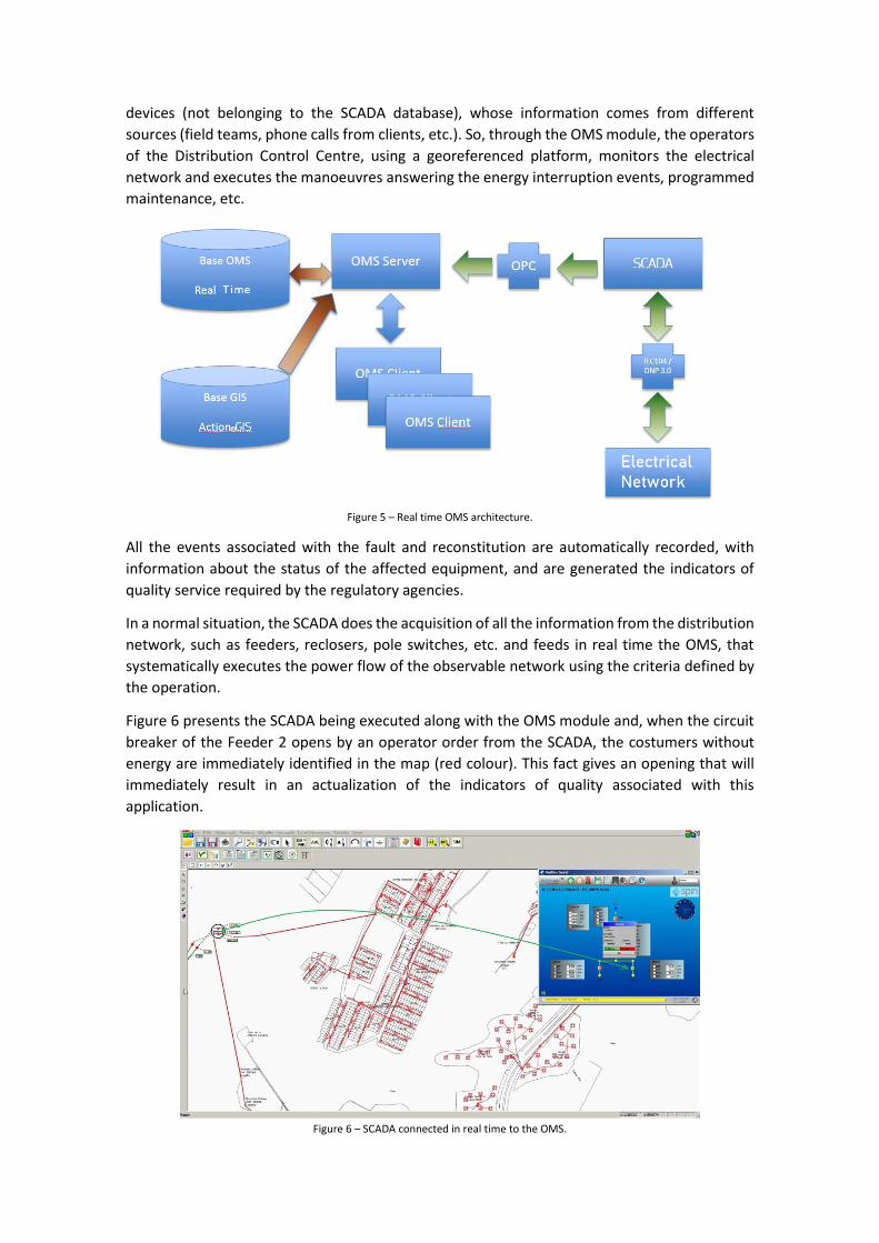
devices (not belonging to the SCADA database), whose information comes from different
sources (field teams, phone calls from clients, etc.). So, through the OMS module, the operators
of the Distribution Control Centre, using a georeferenced platform, monitors the electrical
network and executes the manoeuvres answering the energy interruption events, programmed
maintenance, etc.
Figure 5 – Real time OMS architecture.
All the events associated with the fault and reconstitution are automatically recorded, with
information about the status of the affected equipment, and are generated the indicators of
quality service required by the regulatory agencies.
In a normal situation, the SCADA does the acquisition of all the information from the distribution
network, such as feeders, reclosers, pole switches, etc. and feeds in real time the OMS, that
systematically executes the power flow of the observable network using the criteria defined by
the operation.
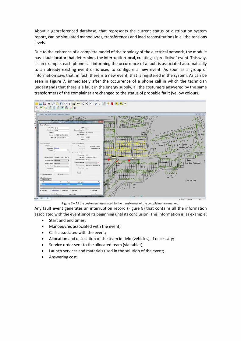
Figure 6 presents the SCADA being executed along with the OMS module and, when the circuit
breaker of the Feeder 2 opens by an operator order from the SCADA, the costumers without
energy are immediately identified in the map (red colour). This fact gives an opening that will
immediately result in an actualization of the indicators of quality associated with this
application.
Figure 6 – SCADA connected in real time to the OMS.
About a georeferenced database, that represents the current status or distribution system
report, can be simulated manoeuvres, transferences and load reconstitutions in all the tensions
levels.
Due to the existence of a complete model of the topology of the electrical network, the module
has a fault locator that determines the interruption local, creating a “predictive” event. This way,
as an example, each phone call informing the occurrence of a fault is associated automatically
to an already existing event or is used to configure a new event. As soon as a group of
information says that, in fact, there is a new event, that is registered in the system. As can be
seen in Figure 7, immediately after the occurrence of a phone call in which the technician
understands that there is a fault in the energy supply, all the costumers answered by the same
transformers of the complainer are changed to the status of probable fault (yellow colour).
Figure 7 – All the costumers associated to the transformer of the complainer are marked.
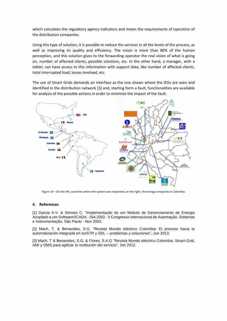
Any fault event generates an interruption record (Figure 8) that contains all the information
associated with the event since its beginning until its conclusion. This information is, as example:
Start and end times;
Manoeuvres associated with the event;
Calls associated with the event;
Allocation and dislocation of the team in field (vehicles), if necessary;
Service order sent to the allocated team (via tablet);
Launch services and materials used in the solution of the event;
Answering cost.
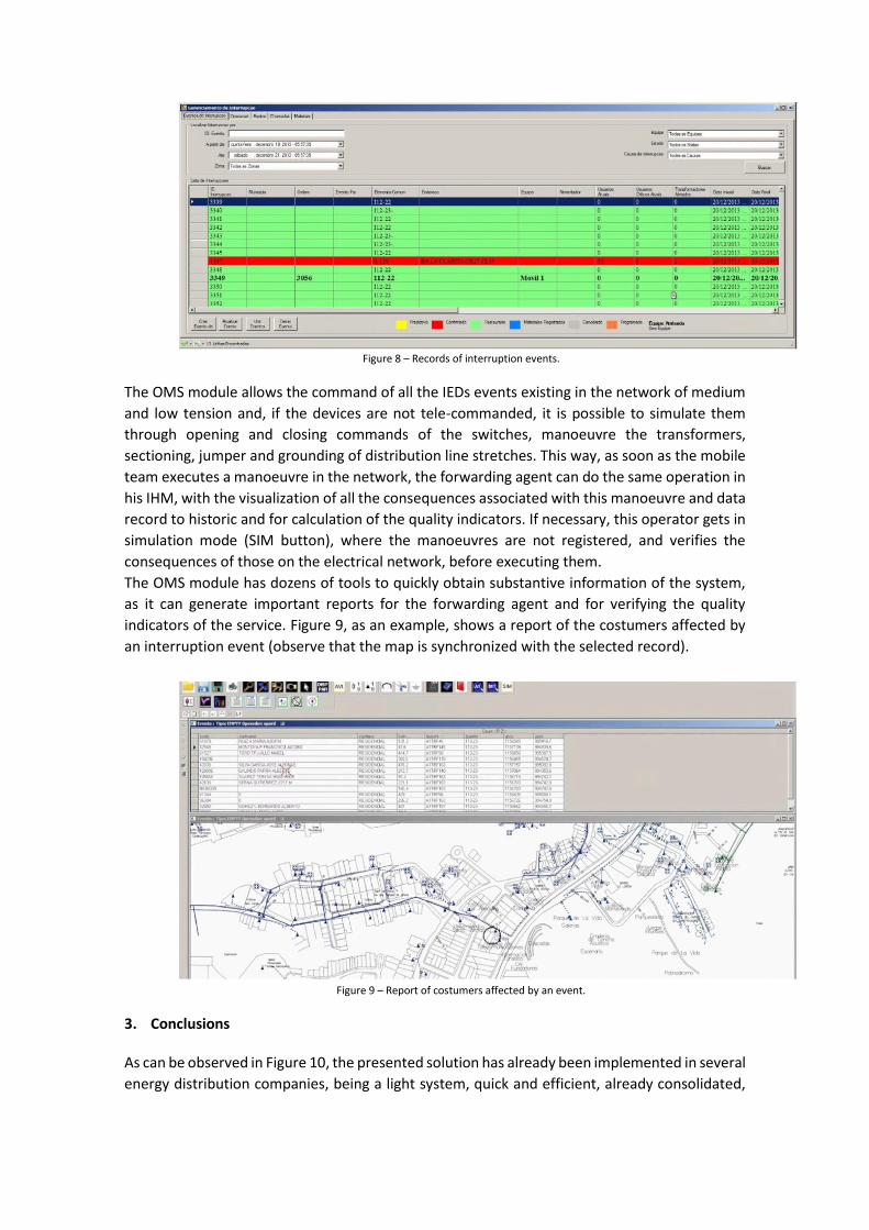
Figure 8 – Records of interruption events.
The OMS module allows the command of all the IEDs events existing in the network of medium
and low tension and, if the devices are not tele-commanded, it is possible to simulate them
through opening and closing commands of the switches, manoeuvre the transformers,
sectioning, jumper and grounding of distribution line stretches. This way, as soon as the mobile
team executes a manoeuvre in the network, the forwarding agent can do the same operation in
his IHM, with the visualization of all the consequences associated with this manoeuvre and data
record to historic and for calculation of the quality indicators. If necessary, this operator gets in
simulation mode (SIM button), where the manoeuvres are not registered, and verifies the
consequences of those on the electrical network, before executing them.
The OMS module has dozens of tools to quickly obtain substantive information of the system,
as it can generate important reports for the forwarding agent and for verifying the quality
indicators of the service. Figure 9, as an example, shows a report of the costumers affected by
an interruption event (observe that the map is synchronized with the selected record).
Figure 9 – Report of costumers affected by an event.
3. Conclusions
As can be observed in Figure 10, the presented solution has already been implemented in several
energy distribution companies, being a light system, quick and efficient, already consolidated,
which calculates the regulatory agency indicators and meets the requirements of operation of
the distribution companies.
Using this type of solution, it is possible to reduce the services in all the levels of the process, as
well as improving its quality and efficiency. The vision is more than 80% of the human
perception, and this solution gives to the forwarding operator the real vision of what is going
on, number of affected clients, possible solutions, etc. In the other hand, a manager, with a
tablet, can have access to this information with support data, like number of affected clients,
total interrupted load, losses involved, etc.
The use of Smart Grids demands an interface as the one shown where the IEDs are seen and
identified in the distribution network [3] and, starting form a fault, functionalities are available
for analysis of the possible actions in order to minimize the impact of the fault.
Figure 10 – On the left, countries where the system was implanted, on the right, the energy companies in Colombia.
4. References
[1] Garcia A.V. & Simoes C. "Implementação de um Módulo de Gerenciamento de Energia Acoplado a um SoftwareSCADA - ISA 2002 - II Congresso internacional de Automação, Sistemas e Instrumentação, São Paulo - Nov 2002.
[2] Mach, T. & Benavides, S.G. "Revista Mundo eléctrico Colombia: El proceso hacia la automatización integrada en losSTR y SDL – problemas y soluciones", Jun 2013.
[3] Mach, T & Benavides, S.G. & Flores, S.A.G "Revista Mundo eléctrico Colombia: Smart-Grid, AMI y OMS para agilizar la restitución del servicio", Set 2012.