integration of a highly bent engine inlet within an...
TRANSCRIPT
Integration of a Highly Bent Engine Inlet within an Engine
Test Facility
Rudolf P.M. Rademakers1*, Thomas Kächele1, and Reinhard Niehuis1
Abstract Bent inlet configurations find their application within the field of civil and military aviation as well as in
stationary gas turbines. The distorted flow in such ducts can have a major influence on the performance,
stability, and durability of the gas turbine. Both experimental and numerical approaches are generally
applied during the design and optimization of inlet systems. The last decade high fidelity numerical
simulations became very popular in this field of research, however, experimental investigations are
essential for the calibration, validation, and optimization of numerical simulations. Experimental data is
moreover necessary to assess the influence of combined pressure-swirl distortions on the performance of
the entire propulsion system. The Institute of Jet Propulsion made major efforts to integrate a highly
complex inlet duct in a test set-up with the state-of-the-art MexJET turbofan engine. This set-up enables
the assessment of combined pressure-swirl distortion and its influence on the engine and makes
investigations on inlet-compressor interactions possible. This paper describes the six main project phases,
which include the definition, design, development, and integration of this highly bent inlet system at the
engine test bed of the Institute of Jet Propulsion.
Keywords bent inlet duct ˗ pressure and swirl inlet distortion ˗ engine test bed 1 Institute of Jet Propulsion, Universität der Bundeswehr München
(University of the German Federal Armed Forces Munich)
* Corresponding author: [email protected]
INTRODUCTION
A bent inlet configuration is used for the air supply of e.g.:
an auxiliary power unit of a civil aircraft, a highly integrated
propulsion system of a military aircraft, or a stationary gas
turbine in container configuration. Within such inlet ducts
combined pressure-swirl distortions occur, which typically
have a negative impact on performance, stability, and
durability of the entire gas turbine. During the last decades
a lot of research was conducted regarding inlet total
pressure distortions. The Society of Automotive Engineers
(SAE) published the first edition of the Aerospace
Information Report (AIR) 1419 [1] in 1983. This document
reviews relevant contributions regarding research on inlet
pressure distortion. Nevertheless, the consideration of inlet
swirl distortion is becoming more important due to the
increasing demands on integrated inlet-compressor systems
and hence the SAE introduced the AIR 5686 [2] in 2010 to
summarize current knowledge with respect to inlet swirl
distortion. The latter document also addresses the lack of
knowledge regarding the interactions between both pressure
and swirl distortion, which consequently will be a major
subject for future research.
Research on combined pressure-swirl distortion is ideally
conducted by combining numerical and experimental
approaches. Preliminary results can rapidly be generated by
using the parallel compressor theory [3] to estimate the
global influence of a certain inlet distortion on the behavior
of the compressor system. Such models are essential in the
early design phase of an integrated inlet-propulsion system,
however, cannot be used for detailed assessment of
aerodynamic phenomena since the internal compressor flow
is not simulated. A high fidelity Computational Fluid
Dynamics (CFD) simulation of a distorted compressor (e.g.
Barthmes et al. [4] and Haug et al. [5]) enables the
assessment of internal aerodynamics, however, CFD cannot
directly predict the influence on the performance of the gas
turbine and computations are still very expensive in terms
of computation time. Moreover, in all cases the set-up of a
numerical simulation needs to be validated, which makes
experimental investigations necessary.
In the open literature two different kinds of experimental
set-ups for research on inlet distortion are often described.
First, duct configurations can be investigated in a wind
tunnel (e.g. Vakili et al. [6]). This approach is well suited
for the visualization of the internal aerodynamics within the
inlet duct, however, the upstream propagating effects from
the compressor system are neglected and the influence on
the performance, stability, and durability of the gas turbine
cannot be assessed. Second, distortion generators can be
installed upstream of the gas turbine to provoke inlet-type
distortions (e.g. Rademakers et al. [7], [8]). In this case the
engine can be included within analyses but the internal duct
flow is only simulated. Hence, CFD simulations of the inlet

duct cannot be validated and the assessment of inlet-
compressor interactions is not possible.
An experimental set-up of the entire inlet-propulsion system
has not previously been presented in the open literature by
the knowledge of the authors. The Institute of Jet Propulsion
hence made major efforts to integrate a highly bent inlet
duct within the Engine Test Facility (ETF) for experimental
investigations with the state-of-the-art MexJET turbofan
engine. This paper describes the entire integration process
of a bent inlet duct within the ETF from the first sketch until
test readiness. This process was divided in six phases, which
are nonetheless interrelated. The latter means that for each
major decision within the project all upcoming project
phases had to be taken into account. It was of particular
importance that all engineering decisions in the beginning
of the project were conceived properly. Mistakes in the
initial phases of a project usually lead to extensive
additional costs and have a negative influence on the overall
success of the project.
PHASE 1) PROJECT DEFINITION
1.1 Goals The project comprises four major goals. First, experimental
data from a full-scale inlet duct being tested at the ETF will
be used for the validation and optimization of numerical
simulations. Second, the influence of a combined pressure-
swirl distortion on the performance of both the compressor
system as well as the entire jet engine is of interest. Third,
interactions between inlet and compressor will be assessed
and finally, the experimental set-up allows the integration
of additional devices for e.g. research on flow optimization
within the bent inlet system.
1.2 General project constraints The described project is conducted in cooperation with
MTU Aero Engines AG. The MexJET turbofan engine (see
also Chapter 3.4) was hence chosen as test vehicle due to
the broad experiences of MTU Aero Engines AG with this
propulsion system. The MexJET engine is operated at the
ETF (see Fig. 1) at the Institute of Jet Propulsion and thus
the bent inlet duct was specifically designed for
experimental investigations within this engine test bed.
The design of the duct’s geometry was performed in
cooperation with MTU Aero Engines AG applying CFD
simulations. Using CFD data during the design process was
the best possible approach although the desired
experimental set-up is meant to provide data for the
validation and optimization of e.g. the same CFD
simulations. This means that all decisions within the design
process of the inlet duct had to be made with a lot of care.
In the early stages of the project a preliminary CFD set-up
was validated with data from an experimental test case
presented by Wellborn et al. [9]. This approach is very
common and was recently also presented by e.g. Brehm et
al. [10] as well as Fiola and Agarwal [11]. Details regarding
the CFD simulations are not presented here but will be
overviewed in a future paper.
PHASE 2) GEOMETRY DEFINITION OF A
HIGHLY BENT ENGINE INLET
The bent inlet duct (see Fig. 2) is the main component of the
set-up. After the definition of the project goals the inlet
geometry was designed in an iterative process while
considering a set of design restrictions. It was distinguished
between:
- pre-design-restrictions (Chapter 2.1) and
- post-simulation-limitations (Chapter 2.2).
The pre-design-restrictions were defined once and then
taken into account for every single iteration of duct design.
The post-simulation-limitations were compared with the
CFD results of each duct geometry under investigation.
2.1 Pre-design-restrictions
2.1.1 Integrability
The diameter of both the duct intake plane and the duct
outlet plane had to be equal to the fan diameter of the
MexJET engine. This makes a modular usability of existing
and new components in the same test set-up possible (see
e.g. Chapter 3). Furthermore, the available space within the
facility was determined.
2.1.2. Comparability with CFD
Three matters were considered to avoid difficulties with
CFD simulations later on.
Figure 1. Visualization of the airflow within the
Engine Test Facility (ETF) by Muth et al. [12]
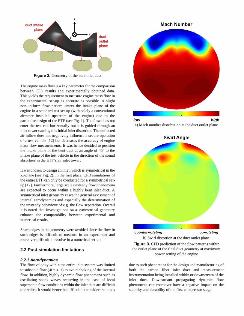
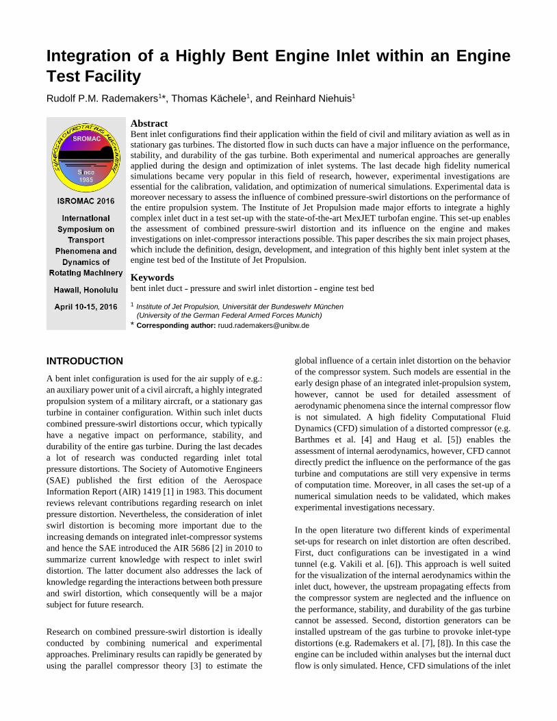
Figure 2. Geometry of the bent inlet duct
The engine mass flow is a key parameter for the comparison
between CFD results and experimentally obtained data.
This yields the requirement to measure engine mass flow in
the experimental set-up as accurate as possible. A slight
non-uniform flow pattern enters the intake plane of the
engine in a standard test set-up (with solely a conventional
airmeter installed upstream of the engine) due to the
particular design of the ETF (see Fig. 1). The flow does not
enter the test cell horizontally but it is guided through an
inlet tower causing this initial inlet distortion. The deflected
air inflow does not negatively influence a secure operation
of a test vehicle [12] but decreases the accuracy of engine
mass flow measurements. It was hence decided to position
the intake plane of the bent duct at an angle of 45° to the
intake plane of the test vehicle in the direction of the sound
absorbers in the ETF’s air inlet tower.
It was chosen to design an inlet, which is symmetrical in the
xz-plane (see Fig. 2). In the first place, CFD simulations of
the entire ETF can only be conducted for a symmetrical set-
up [12]. Furthermore, large scale unsteady flow phenomena
are expected to occur within a highly bent inlet duct. A
symmetrical inlet geometry eases the general assessment of
internal aerodynamics and especially the determination of
the unsteady behaviour of e.g. the flow separation. Overall
it is noted that investigations on a symmetrical geometry
enhance the comparability between experimental and
numerical results.
Sharp edges in the geometry were avoided since the flow in
such edges is difficult to measure in an experiment and
moreover difficult to resolve in a numerical set-up.
2.2 Post-simulation-limitations
2.2.1 Aerodynamics
The flow velocity within the entire inlet system was limited
to subsonic flow (𝑀𝑎 < 1) to avoid choking of the internal
flow. In addition, highly dynamic flow phenomena such as
oscillating shock waves occurring in the case of local
supersonic flow conditions within the inlet duct are difficult
to predict. It would hence be difficult to consider the loads
low high
a) Mach number distribution at the duct outlet plane
b) Swirl distortion at the duct outlet plane
Figure 3. CFD prediction of the flow patterns within
the outlet plane of the final duct geometry at maximum
power setting of the engine
due to such phenomena for the design and manufacturing of
both the carbon fiber inlet duct and measurement
instrumentation being installed within or downstream of the
inlet duct. Downstream propagating dynamic flow
phenomena can moreover have a negative impact on the
stability and durability of the first compressor stage.

Figure 4. Overview of the experimental set-up
Table 2. Experimental set-up
I. Airmeter V. Measurement rake
II. Decoupling element VI. Decoupling-element
III. Segment VII. MexJET test vehicle
IV. Bent Duct
During the experiments the flow pattern within the outlet
plane of the duct will be measured with five-hole probes.
The utilized probes are applicable for measuring flow with
swirl angles up to 30° and thus the expected flow angles
should not exceed this level of swirl distortion.
2.2.2 Engine limitations
The MexJET engine is based on the Eurojet EJ200 engine.
During the development of the latter turbofan engine an
extensive amount of data was gathered regarding limitations
on inlet distortion for the engine’s Low Pressure
Compressor (LPC). It could hence be assured that the inlet
distortions being provoked within the bent inlet duct are
compatible with the engine capability.
2.3 Final geometry of the bent inlet duct After an extensive iterative process the final geometry of the
duct (see Fig. 2) was defined. Figure 3 shows the predicted
aerodynamic condition of the flow within the Aerodynamic
Interface Plane (AIP) of the duct for the engine at its
maximum power setting. It is noted that the AIP is defined
by the SAE [1] as a designated measurement plane between
the inlet system and the engine face. For the described set-
up the AIP is equal to the duct outlet plane. The flow in the
AIP will be measured with five-hole probes at 120 positions
(see Chapter 4.3 for details).
The so-called Jet Engine Data Analysis Software (JEDAS)
was in-house developed for an optimal comparison between
data from numerical and experimental investigations. This
tool assesses the flow data from both CFD simulations and
experiments in the same manner. Each plot in Fig. 3 is hence
based on 120 values for the respective flow properties as
they will be determined during the experimental
investigations.
PHASE 3) INLET INTEGRATION WITHIN THE
ENGINE TEST FACILITY
The bent engine inlet duct is the main component but a set
of additional components were, however, necessary for the
integration of both the duct and extensive instrumentation.
These components (see Tab. 2) were defined in the third
phase of the project and introduced in the following
subsections. The entire experimental set-up is schematically
depicted in Fig. 4. Details regarding the instrumentation
within each of the components is illustrated in Chapter 4.
3.1 Airmeter The bellmouth airmeter (Fig. 4, Pos. I) is used to provide an
undistorted homogeneous inlet flow at the intake plane of
the bent duct. In the first place this contributes to an accurate
engine mass flow measurement (see Chapter 2.1.2). It is in
addition noted that an initial flow distortion within the
intake plane of a bent duct can be amplified throughout the
duct as it was shown by Rademakers et al. [13]. The
bellmouth is hence installed under an angle of 45° to be in
line with the flow, which enters the test section through the
sound baffles within the inlet tower of the ETF (see Fig. 1).
3.2 Decoupling elements A decoupling element is integrated at both Pos. II and Pos.
VI (see Fig. 4) to mechanically decouple the bent duct from
the test vehicle (Pos. VII) as well as the glass fiber
bellmouth airmeter (Pos. I) because of two reasons. First,
vibrations within the bent duct may not be transferred into
other components and vice versa. Secondly, both
decoupling elements simplify the boundary conditions of
the Finite Element Model (FEM) simulations on the carbon
fiber duct (see Chapter 5.2).
3.3 Exchangeable segment A module with a standardized width of 180 𝑚𝑚 can be
installed at Pos. III as well as Pos. V within the set-up. The
width of this segment is fixed at 180 𝑚𝑚 since an already
existing device for the installation of distortion screens, has
the same dimensions. Furthermore, a traversable
measurement rake was specifically designed within the
scope of this project (see Chapter 4.3) and can also be
installed at both positions.
3.4 MexJET test vehicle The MexJET turbofan engine (Fig. 4, Pos. VII) is a state-of-
the-art test vehicle based on the Eurojet EJ200, which is
generally known as the powerplant of the Eurofighter
Typhoon multirole combat aircraft. Fundamental changes
were made compared to the EJ200 turbofan engine to ensure
a safe operation within the ETF. The test vehicle had its
maiden test run at the ETF in the year 2012. For detailed
information regarding the integration of the test vehicle at
the ETF it is referred to Bindl et al. [14]. Some general
MexJET performance data is given in Tab. 3.

Figure 5. Boundary layer probe
Table 3. Engine performance data [14]
𝐹 ≈ 47𝑘𝑁 𝑑𝐹𝑎𝑛 ≈ 740 𝑚𝑚
𝑏𝑦𝑝𝑎𝑠𝑠 𝑟𝑎𝑡𝑖𝑜 (𝐵𝑃𝑅) ≈ 0.4 �̇� ≈ 70 𝑘𝑔 𝑠⁄
Π𝐿𝑃𝐶 ≈ 4.2 Π𝐻𝑃𝐶 ≈ 6.2
PHASE 4) DEFINITION OF
INSTRUMENTATION
A detailed definition of instrumentation could start with the
general set-up being defined. This was a crucial phase
within the project since this step is strongly interrelated with
other project phases and essential for a successful fulfilment
of the overall project goals (see Chapter 1.1).
4.1 Bellmouth airmeter
The design and instrumentation of the bellmouth airmeter is
according to common guidelines of the American Society
of Mechanical Engineers [15]. It is equipped for engine
mass flow measurements with eight static pressure taps,
four exchangeable total pressure probes, and one total
temperature probe. Both the static pressure taps and the total
pressure probes are equally distributed in circumferential
direction. The adapters for the total pressure probes are
standardized and can also be used for the integration of
other probes such as boundary layer probes (see Fig. 5),
which were designed within the scope of the current project.
4.2 Bent engine inlet
In total 149 adapters for wall static pressure sensors, two
adapters for mid-size probes, and one large mounting
adapter were integrated within the bent inlet duct. The
optimal positions of these adapters were determined by
means of CFD. It is referred to Chapter 5.1 for details
regarding the instrumentation itself.
4.3 Traversable measurement rake
A measurement rake (see Fig. 6), which is traversable in
circumferential direction was developed within the scope of
the current project. The rake is equipped with three different
kinds of probes. Six standard pitot probes (see Fig. 7a) are
Figure 6. Traversable measurement rake
installed within the boundary layer (three probes at the top
side and three probes at the bottom side of the rake) to
enable an estimation of the boundary layer thickness. Ten
five-hole probes (see Fig. 7b) are positioned equally spaced
along the rake. In total the flow pattern in the AIP will be
measured at 120 positions (see Fig. 8) by displacing the rake
in circumferential direction. An in-house tool presented by
Rademakers et al. [16] was used to confirm that this
approach does lead to an optimal inlet distortion assessment
by means of both total pressure and swirl distortion
coefficients. Two additional pitot probes are equipped with
a Kulite® pressure transducer (see Fig. 7c). These special
pitot probes are installed within the outer region of the AIP
where the flow unsteadiness is expected to be the most
pronounced.
Extensive numerical structural analyses (static as well as
dynamic) were conducted during the design process of the
previously described device to ensure a safe operation over
the entire operating range of the MexJET engine. A detailed
summary of respective results is nevertheless not within the
scope of this paper. It is noted that four strain gauges are
installed in the rake to monitor its state while operating the
MexJET engine.
4.4 Engine Instrumentation
The MexJET turbofan engine has a three stage LPC, which
is of primary interest while investigating engine inlet
distortions. Four rakes with both pressure and temperature
probes are installed at the exit of the LPC. It is expected that
the distortion provoked by the bent inlet duct will be mixed
out throughout the three stages of the LPC. This observation
was also made during experimental investigations by
Rademakers et al. [7] where severe inlet distortions
interacted with the two-stage LPC of the Larzac 04 jet engine.

Figure 7. Probes integrated in the measurement rake
Four rakes are hence expected to be adequate to measure the
LPC pressure ratio (Π𝐿𝑃𝐶) with sufficient accuracy. Thrust
and fuel flow are moreover measured for additional engine
performance assessment.
4.5 Instrumentation within the test bed
An upgrading of the instrumentation within the ETF was not
necessary. Pressure and temperature is measured at several
positions within the test cell and can be used to set up the
boundary conditions of CFD simulations. Data regarding
the relative humidity is obtained from a meteorological
office, which is located at the same university campus as the
Institute of Jet Propulsion.
4.6 Data acquisition
A state of the art data acquisition system based on National
Instruments (NI) PXIe hardware and NI LabVIEW software
was already available at the ETF [17]. This system can be
utilized for all four jet engines, which are operated at the
ETF. Usually this system is used solely for monitoring of
the test bed and the test vehicle.
The applicable measurement hard- and software highly
depends on the goals within a certain project. The existing
data acquisition system was hence extended with a system
based on the NI cRIO platform enabling a data acquisition
being tailored for a specific test set-up. In the case of current
investigations the high performance NI cRIO 9082 system
with multiple NI9144 extension chassis and NI LabVIEW
software is utilized for pressure (both low and high
frequency), vibration, strain gauge, and temperature
measurements. The development of this data acquisition
system is described by Rademakers et al. [18]. Furthermore,
a stepper motor is controlled by the same system to displace
the measurement rake in circumferential direction.
Figure 8. Positioning of five-hole probes within the
AIP
The vast majority of all pressure measurements will be
conducted at relative low frequencies. It was hence focused
during the establishment of the data acquisition system on
enabling a large amount of pressure measurements
simultaneously. The entire test set-up with the bent inlet
duct consists of 280 pressure probes and taps (MexJET
engine instrumentation not included). The data acquisition
system can sample up till 240 pressure values
simultaneously with a maximal sampling rate (𝑓𝑠) of 1 𝑘𝐻𝑧.
PHASE 5) DESIGN AND DEVELOPMENT OF
A BENT ENGINE INLET
5.1 Design The design of the duct did depend on the definition of
instrumentation and could hence start in the fifth phase of
the project. The duct design mainly comprised the
integration of five kinds of adapters into the carbon fiber
structure. These adapters are either used for the installation
of instrumentation (see Fig. 9; Pos. I to Pos. III and Chapter
5.1.1 to 5.1.3) or mounting of the duct in the experimental
set-up (see Fig. 9; Pos. IV and Pos. V).
All adapters were designed with a flange to securely
integrate the adapter between different layers of carbon
fiber laminate. An aluminum or a non-corrosive steal was
chosen as material depending on the respective influence on
the eigenfrequencies of the entire inlet system (see Chapter
5.2.2).
5.1.1. Sensors
In total 149 aluminum adapters (see Fig. 9; Pos. I) were
integrated for the measurement of static pressure at the
duct’s wall surface. Different sensors can be installed within
these adapters. Generally a brass sensor consisting of a drill-
hole (𝑑𝑠𝑒𝑛𝑠𝑜𝑟 = 1 𝑚𝑚) with a nipple on the outer side of
the duct will be installed during experimental investigations
a) pitot probe
b) five-hole probe
c) Kulite® pitot
probe
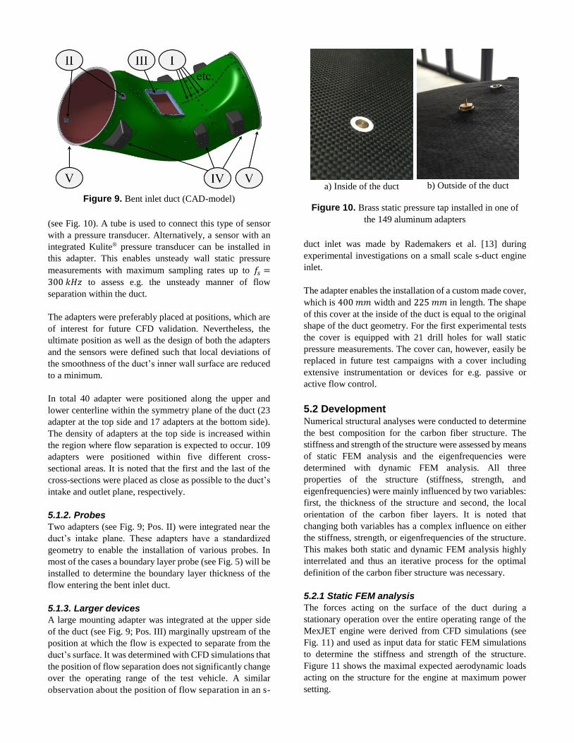
Figure 9. Bent inlet duct (CAD-model)
(see Fig. 10). A tube is used to connect this type of sensor
with a pressure transducer. Alternatively, a sensor with an
integrated Kulite® pressure transducer can be installed in
this adapter. This enables unsteady wall static pressure
measurements with maximum sampling rates up to 𝑓𝑠 =
300 𝑘𝐻𝑧 to assess e.g. the unsteady manner of flow
separation within the duct.
The adapters were preferably placed at positions, which are
of interest for future CFD validation. Nevertheless, the
ultimate position as well as the design of both the adapters
and the sensors were defined such that local deviations of
the smoothness of the duct’s inner wall surface are reduced
to a minimum.
In total 40 adapter were positioned along the upper and
lower centerline within the symmetry plane of the duct (23
adapter at the top side and 17 adapters at the bottom side).
The density of adapters at the top side is increased within
the region where flow separation is expected to occur. 109
adapters were positioned within five different cross-
sectional areas. It is noted that the first and the last of the
cross-sections were placed as close as possible to the duct’s
intake and outlet plane, respectively.
5.1.2. Probes
Two adapters (see Fig. 9; Pos. II) were integrated near the
duct’s intake plane. These adapters have a standardized
geometry to enable the installation of various probes. In
most of the cases a boundary layer probe (see Fig. 5) will be
installed to determine the boundary layer thickness of the
flow entering the bent inlet duct.
5.1.3. Larger devices
A large mounting adapter was integrated at the upper side
of the duct (see Fig. 9; Pos. III) marginally upstream of the
position at which the flow is expected to separate from the
duct’s surface. It was determined with CFD simulations that
the position of flow separation does not significantly change
over the operating range of the test vehicle. A similar
observation about the position of flow separation in an s-
a) Inside of the duct
b) Outside of the duct
Figure 10. Brass static pressure tap installed in one of
the 149 aluminum adapters
duct inlet was made by Rademakers et al. [13] during
experimental investigations on a small scale s-duct engine
inlet.
The adapter enables the installation of a custom made cover,
which is 400 𝑚𝑚 width and 225 𝑚𝑚 in length. The shape
of this cover at the inside of the duct is equal to the original
shape of the duct geometry. For the first experimental tests
the cover is equipped with 21 drill holes for wall static
pressure measurements. The cover can, however, easily be
replaced in future test campaigns with a cover including
extensive instrumentation or devices for e.g. passive or
active flow control.
5.2 Development Numerical structural analyses were conducted to determine
the best composition for the carbon fiber structure. The
stiffness and strength of the structure were assessed by means
of static FEM analysis and the eigenfrequencies were
determined with dynamic FEM analysis. All three
properties of the structure (stiffness, strength, and
eigenfrequencies) were mainly influenced by two variables:
first, the thickness of the structure and second, the local
orientation of the carbon fiber layers. It is noted that
changing both variables has a complex influence on either
the stiffness, strength, or eigenfrequencies of the structure.
This makes both static and dynamic FEM analysis highly
interrelated and thus an iterative process for the optimal
definition of the carbon fiber structure was necessary.
5.2.1 Static FEM analysis
The forces acting on the surface of the duct during a
stationary operation over the entire operating range of the
MexJET engine were derived from CFD simulations (see
Fig. 11) and used as input data for static FEM simulations
to determine the stiffness and strength of the structure.
Figure 11 shows the maximal expected aerodynamic loads
acting on the structure for the engine at maximum power
setting.
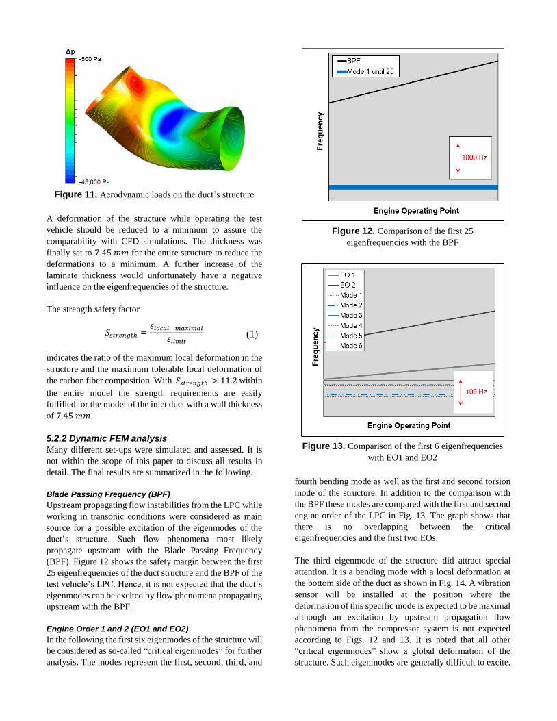
Figure 11. Aerodynamic loads on the duct’s structure
A deformation of the structure while operating the test
vehicle should be reduced to a minimum to assure the
comparability with CFD simulations. The thickness was
finally set to 7.45 𝑚𝑚 for the entire structure to reduce the
deformations to a minimum. A further increase of the
laminate thickness would unfortunately have a negative
influence on the eigenfrequencies of the structure.
The strength safety factor
𝑆𝑠𝑡𝑟𝑒𝑛𝑔𝑡ℎ =𝜀𝑙𝑜𝑐𝑎𝑙, 𝑚𝑎𝑥𝑖𝑚𝑎𝑙
𝜀𝑙𝑖𝑚𝑖𝑡
indicates the ratio of the maximum local deformation in the
structure and the maximum tolerable local deformation of
the carbon fiber composition. With 𝑆𝑠𝑡𝑟𝑒𝑛𝑔𝑡ℎ > 11.2 within
the entire model the strength requirements are easily
fulfilled for the model of the inlet duct with a wall thickness
of 7.45 𝑚𝑚.
5.2.2 Dynamic FEM analysis
Many different set-ups were simulated and assessed. It is
not within the scope of this paper to discuss all results in
detail. The final results are summarized in the following.
Blade Passing Frequency (BPF)
Upstream propagating flow instabilities from the LPC while
working in transonic conditions were considered as main
source for a possible excitation of the eigenmodes of the
duct’s structure. Such flow phenomena most likely
propagate upstream with the Blade Passing Frequency
(BPF). Figure 12 shows the safety margin between the first
25 eigenfrequencies of the duct structure and the BPF of the
test vehicle’s LPC. Hence, it is not expected that the duct´s
eigenmodes can be excited by flow phenomena propagating
upstream with the BPF.
Engine Order 1 and 2 (EO1 and EO2)
In the following the first six eigenmodes of the structure will
be considered as so-called “critical eigenmodes” for further
analysis. The modes represent the first, second, third, and
Figure 12. Comparison of the first 25
eigenfrequencies with the BPF
Figure 13. Comparison of the first 6 eigenfrequencies
with EO1 and EO2
fourth bending mode as well as the first and second torsion
mode of the structure. In addition to the comparison with
the BPF these modes are compared with the first and second
engine order of the LPC in Fig. 13. The graph shows that
there is no overlapping between the critical
eigenfrequencies and the first two EOs.
The third eigenmode of the structure did attract special
attention. It is a bending mode with a local deformation at
the bottom side of the duct as shown in Fig. 14. A vibration
sensor will be installed at the position where the
deformation of this specific mode is expected to be maximal
although an excitation by upstream propagation flow
phenomena from the compressor system is not expected
according to Figs. 12 and 13. It is noted that all other
“critical eigenmodes” show a global deformation of the
structure. Such eigenmodes are generally difficult to excite.
(1)

Figure 14. The third eigenmode of the structure
PHASE 6) COMMISSIONING OF THE SET-UP
The manufacturing of all components started after a
successful completion of the fifth project phase. The carbon
fiber bent inlet duct is shown in Fig. 15 and hence ready for
entry into service. Preliminary results will be available after
the first test run, which is planned for the year 2016.
7. SUMMARY AND OUTLOOK
During six highly interrelated project phases a novel set-up
for experimental investigations was established at the
Institute of Jet Propulsion. The geometry of a highly bent
engine inlet duct was designed (phase 2) in consideration of
four main project goals, which were defined during the
initial phase of the project. Additional components were
defined (phase 3) to enable the integration of the final inlet
duct design at the ETF. The instrumentation of the entire
set-up was then specified (phase 4) such that experimental
data can be obtained for a successful fulfillment of all
project goals. Finally, the bent inlet duct including the
integrated instrumentation was developed (phase 5) mainly
by applying numerical structural analyses to assure a safe
operation in the test environment with the MexJET turbofan
engine. The manufacturing of all components is completed
and the commissioning of the set-up (phase 6) is expected
to take place in the year 2016.
In the first place the experimentally obtained data will be
used for the calibration, validation, and optimization of
CFD simulations. The experiments will moreover
contribute to the understanding of the interdependency of
both pressure and swirl distortions within an inlet system
and an assessment of the influence of a combined pressure-
swirl distortion on the performance and stability of the
propulsion system will be possible.
A special adapter is integrated upstream of the position
where a large flow separation within the duct is expected to
occur. A part of the duct’s wall is hence exchangeable and
Figure 15. The carbon fiber bent inlet duct
and additional devices for investigations on e.g. flow
control within an engine inlet can be installed here in a future stage of the project.
ACKNOWLEDGEMENTS
The experimental set-up was realized within the scope of
the COORETEC-Turbo 2020 project no. 1.2.4a. “Stabilität
des Verdichterssystems bei Off-Design Zuström-
bedingungen”. This AG Turbo project is funded by the
German Ministry of Economy and Technology (BMWi)
and conducted in cooperation with MTU Aero Engines AG.
NOMENCLATURE
Symbols
𝑑 [𝑚𝑚] diameter
𝐹 [𝑘𝑁] thrust
𝑓𝑠 [𝐻𝑧] sampling rate
�̇� [𝑘𝑔/𝑠] engine mass flow
𝑀𝑎 [−] Mach number
𝑆𝑠𝑡𝑟𝑒𝑛𝑔𝑡ℎ [−] strength safety factor
𝜀 [−] deformation
Π [−] pressure ratio
Abbreviations
AIP Aerodynamic Interface Plane
AIR Aerospace Information Report
BPF Blade Passing Frequency
CFD Computational Fluid Dynamics
cRIO compact Reconfigurable In- Output
EO Engine Order
ETF Engine Test Facility
FEM Finite Element Method
HPC High Pressure Compressor
LPC Low Pressure Compressor
MexJET More Electric eXperimental Jet Engine Test vehicle
NI National Instruments
SAE Society of Automotive Engineers
REFERENCES
[1] Society of Automotive Engineers, “Inlet Total-Pressure
Considerations for Gas Turbine Engines”, Aerospace
Information Report 1419, Rev. B, 2013.
[2] Society of Automotive Engineers, “A Methodology for
Assessing Inlet Swirl Distortion”, Aerospace Information
Report 5686, 2010.
[3] Mazzawy, R.S., “Multiple Segment Parallel Compressor
Model for Circumferential Flow Distortion”, In J. Eng. Gas
Turbines Power 99(2), pp. 288-296, April 1977.
[4] Barthmes, S., Haug, J.P., Lesser, A., and Niehuis, R.,
“Unsteady CFD Simulation of Transonic Axial Compressor
Stages with Distorted Inflow”, In Advances in Simulation of
Wing and Nacelle Stall, Eds. Radespiel, R. et al., Vol. 131
of Notes on Numerical Fluid Mechanics and
Multidisciplinary Design, Springer, pp.303-321, doi:
10.1007/978-3-319-21127-5, 2015.
[5] Haug, J.P., Barthmes, S., and Niehuis, R.: “Full Annulus
Unsteady CFD Simulations on Effects of Inflow Distortions
in a Transonic Axial Compressor Stage”, IGTC-2015-0090,
In Proceedings of the 11th International Gas Turbine
Conference, Tokyo, Japan, November 2015.
[6] Vakili, A., Wu, J.M., Liver, P., and Bhat, M.K.,
“Measurements of Compressible Secondary Flow in a
Circular S-Duct”, AIAA-83-1739, In Proceedings of the
16th Fluid and Plasma Dynamics Conference, Danvers,
MA, USA, July 1983.
[7] Rademakers, R.P.M., Bindl, S., and Niehuis, R.,
“Effects of Flow Distortions as They Occur in S-duct Inlets
on the Performance and Stability of a Jet Engine”, In J. Eng.
Gas Turbines Power 138(2), doi: 10.1115/1.4031305,
February 2016.
[8] Rademakers, R.P.M., Bindl, S., and Niehuis, R.,
“Influence of Secondary Flow within Integrated Engine
Inlets on the Performance and Stability of a Jet Engine”,
ISABE-2015-22148, In Proceedings of the 22nd
International Symposium on Air Breathing Engines,
Phoenix, AZ, USA, October 2015.
[9] Wellborn, S.R., Okiishi, T.H., and Reichert, B.A., “A Study
of the Compressible Flow through a Diffusing S-Duct”, NASA
Technical Memorandum 106411, December 1993.
[10] Brehm, S., Kächele, T., and Niehuis, R., “CFD
Investigations on the Influence of varying Inflow
Conditions on the Aerodynamics in an S-Shaped Inlet
Duct”, AIAA-2014-3595, In Proceedings of the 50th AIAA
Joint Propulsion Conference, Cleveland, USA, June 2014.
[11] Fiola, C. and Agarwa, R.K., “Simulation of Secondary
and Separated Flow in Diffusing S Ducts”, In Journal of
Propulsion and Power, Vol. 31, No.1, pp. 180-191,
January-February 2015.
[12] Muth, B., Bindl, S., Opterwinkel, N., and Niehuis, R.,
“Numerical Investigation of the Aerodynamic Conditions
inside a Sea Level Jet Engine Test Facility Operating a
Modern Jet Engine”, In Proceedings of the 19th
International Symposium on Air Breathing Engines,
Montréal, Canada, September 2009.
[13] Rademakers, R.P.M., Bindl, S., Brehm, S., Muth, B.,
and Niehuis, R., “Investigation of Flow Distortion in an
Integrated Inlet of a Jet Engine”, DLRK2013-301349, In
Proceedings of the 20th German Aerospace, Stuttgart,
Germany, September 2013.
[14] Bindl, S., Muth, B., Niehuis, R., “Adaptation of a
Ground Test Facility to Operate a Modern Turbo Jet
Engine”, ISABE-2013-1307, In Proceedings of the 21st
International Symposium on Air Breathing Engines, Busan,
South-Korea, September 2013.
[15] American Society of Mechanical Engineers (ASME),
“Measurement of Gas Flow by Bellmouth Inlet Flowmeters”,
MFC-26-2011, ISBN: 978-07-9183-355-1, 2011.
[16] Rademakers, R.P.M., Kächele, T., Bindl, S., Niehuis,
R., “Approach for an Optimized Evaluation of Pressure and
Swirl Distortion in S-Shaped Engine Inlet Configurations”,
AIAA-2014-3594, In Proceedings of the 50th AIAA Joint
Propulsion Conference, Cleveland, USA, June 2014.
[17] Stößel, M., Niehuis, R., “Einrichtung einer Messdaten-
erfassungsanlage mit Online-Datenservereigenschaften
mittels NI PXI und LabVIEW Real-Time”, In Virtuelle
Instrumente in der Praxis 2010, Eds. Jamal, R. and Heinze,
R., VDE Verlag, ISBN 978-3-8007-3235-7, pp. 25-29, 2010.
[18] Rademakers, R.P.M., Pohl, A., Niehuis, R.,
“Hochfrequente Mehrkanal Druckmessungen an einer
Triebwerkversuchsanlage”, In Virtuelle Instrumente in der
Praxis 2015, Eds. Jamal, R. and Heinze, R., VDE Verlag,
ISBN 978-3-8007-3669-0, pp.75-78, 2015.