integrating the healthcare enterprise ihe technical … · integrating the healthcare enterprise...
TRANSCRIPT

Integrating the Healthcare Enterprise
IHE Technical Framework Volume II
Transactions
Revision 8.0 Final Text
August 30, 2007
Copyright © 2007: ACC/HIMSS/RSNA
IHE Technical Framework, vol. II: Transactions ______________________________________________________________________________
_____________________________________________________________________________
1 Rev. 8.0 Copyright © 1998-2007: ACC/HIMSS/RSNA
Contents
1 INTRODUCTION................................................................................................................. 3 1.1 OVERVIEW OF TECHNICAL FRAMEWORK ......................................................................... 3 1.2 OVERVIEW OF VOLUME II................................................................................................ 4 1.3 AUDIENCE........................................................................................................................ 4 1.4 RELATIONSHIP TO STANDARDS ........................................................................................ 5 1.5 RELATIONSHIP TO REAL-WORLD ARCHITECTURES .......................................................... 5 1.6 COMMENTS ...................................................................................................................... 6 1.7 COPYRIGHT PERMISSION.................................................................................................. 6
2 CONVENTIONS................................................................................................................... 7 2.1 THE GENERIC IHE TRANSACTION MODEL....................................................................... 7 2.2 DICOM USAGE CONVENTIONS ....................................................................................... 8 2.3 HL7 PROFILING CONVENTIONS...................................................................................... 10 2.4 HL7 IMPLEMENTATION NOTES ...................................................................................... 11 2.5 HL7 AND DICOM MAPPING CONSIDERATIONS............................................................. 14 2.6 USE OF CODED ENTITIES AND CODING SCHEMES .......................................................... 15
3 FRAMEWORK OVERVIEW ........................................................................................... 16
4 IHE TRANSACTIONS ...................................................................................................... 17 4.1 PATIENT REGISTRATION ................................................................................................ 17 4.2 PLACER ORDER MANAGEMENT ..................................................................................... 28 4.3 FILLER ORDER MANAGEMENT....................................................................................... 38 4.4 PROCEDURE SCHEDULED ............................................................................................... 49 4.5 QUERY MODALITY WORKLIST....................................................................................... 61 4.6 MODALITY PROCEDURE STEP IN PROGRESS .................................................................. 71 4.7 MODALITY PROCEDURE STEP COMPLETED/DISCONTINUED........................................... 84 4.8 MODALITY IMAGES STORED .......................................................................................... 92 4.9 MODALITY PRESENTATION STATE STORED ................................................................. 104 4.10 STORAGE COMMITMENT .............................................................................................. 106 4.11 IMAGE AVAILABILITY QUERY...................................................................................... 109 4.12 PATIENT UPDATE ......................................................................................................... 113 4.13 PROCEDURE UPDATE ................................................................................................... 128 4.14 QUERY IMAGES............................................................................................................ 132 4.15 QUERY PRESENTATION STATES ................................................................................... 138 4.16 RETRIEVE IMAGES ....................................................................................................... 141 4.17 RETRIEVE PRESENTATION STATES ............................................................................... 163 4.18 CREATOR IMAGES STORED .......................................................................................... 167 4.19 CREATOR PRESENTATION STATE STORED.................................................................... 173
2007-08-30

IHE Technical Framework, vol. II: Transactions ______________________________________________________________________________
_____________________________________________________________________________
2 Rev. 8.0 Copyright © 1998-2007: ACC/HIMSS/RSNA
4.20 CREATOR PROCEDURE STEP IN PROGRESS................................................................... 176 4.21 CREATOR PROCEDURE STEP COMPLETED .................................................................... 180 4.22 INTENTIONALLY LEFT BLANK...................................................................................... 183 4.23 PRINT REQUEST WITH PRESENTATION LUT................................................................. 184 4.24 REPORT SUBMISSION ................................................................................................... 194 4.25 REPORT ISSUING .......................................................................................................... 198 4.26 QUERY REPORTS.......................................................................................................... 205 4.27 RETRIEVE REPORTS ..................................................................................................... 209 4.28 STRUCTURED REPORT EXPORT .................................................................................... 214 4.29 KEY IMAGE NOTE STORED........................................................................................... 222 4.30 QUERY KEY IMAGE NOTES .......................................................................................... 224 4.31 RETRIEVE KEY IMAGE NOTES...................................................................................... 227
APPENDIX A: ATTRIBUTE CONSISTENCY BETWEEN MODALITY WORKLIST, COMPOSITE IODS, EVIDENCE DOCUMENTS, KIN AND MODALITY PERFORMED PROCEDURE STEP ................................................................................................................ 231
A.1: IMAGE ACQUISITION INTEGRATION-CRITICAL ATTRIBUTES......................................... 231 A.2: EVIDENCE DOCUMENTS INTEGRATION - CRITICAL ATTRIBUTES .................................. 246 A.3: CONTEXT-CRITICAL ATTRIBUTES ................................................................................ 248 A.4: CONSISTENCY DATA MODEL ....................................................................................... 249 A.5 IMPORTED OBJECT INTEGRATION – CRITICAL ATTRIBUTES .............................................. 252
APPENDIX B: HL7 ORDER MAPPING TO DICOM MWL........................................ 262
APPENDIX C: DEPARTMENTAL ACCESS TO NON-RADIOLOGY INFORMATION ..................................................................................................................... 271
C.1: SCOPE .......................................................................................................................... 271 C.2: QUERY PROTOCOL ....................................................................................................... 271 C.3: EXTERNAL REPORT CONTENT...................................................................................... 273
APPENDIX D: CLARIFICATION OF PATIENT IDENTIFIERS FOR MERGE CASES ..................................................................................................................... 275
D.1: INTRODUCTION ............................................................................................................ 275 D.2: ADMINISTRATIVE PROCESS FLOW (RAD TF-1: 3.3.1) ................................................. 276 D.3: PATIENT MERGE (RAD TF-1: 3.3.2)............................................................................ 276 D.4: TRAUMA CASES 1 AND 2 (RAD TF-1: 4.3) ................................................................. 277 D.5: TRAUMA CASE 3 (RAD TF-1: 4.3).............................................................................. 277 D.6: TRAUMA CASE 4 (RAD TF-1: 4.3).............................................................................. 278 D.7: TRAUMA CASE 5 (RAD TF-1: 4.3) .............................................................................. 279
GLOSSARY............................................................................................................................... 281
2007-08-30
IHE Technical Framework, vol. II: Transactions ______________________________________________________________________________
_____________________________________________________________________________
3 Rev. 8.0 Copyright © 1998-2007: ACC/HIMSS/RSNA
1 Introduction Integrating the Healthcare Enterprise (IHE) is an initiative designed to stimulate the integration of the information systems that support modern healthcare institutions. Its fundamental objective is to ensure that in the care of patients all required information for medical decisions is both correct and available to healthcare professionals. The IHE initiative is both a process and a forum for encouraging integration efforts. It defines a technical framework for the implementation of established messaging standards to achieve specific clinical goals. It includes a rigorous testing process for the implementation of this framework. And it organizes educational sessions and exhibits at major meetings of medical professionals to demonstrate the benefits of this framework and encourage its adoption by industry and users.
The approach employed in the IHE initiative is not to define new integration standards, but rather to support the use of existing standards⎯initially DICOM and HL7, but potentially others, as appropriate in their respective domains⎯in an integrated manner, defining configuration choices when necessary. When clarifications or extensions to existing standards are necessary, IHE refers recommendations to the relevant standards bodies.
This initiative has numerous sponsors and supporting organizations in different medical specialty domains and geographical regions. In North America the primary sponsors are the Healthcare Information and Management Systems Society (HIMSS) and the Radiological Society of North America (RSNA). The American College of Cardiology (ACC), Laboratory Healthcare Partnership (LHCP) and the American Academy of Ophthalmology (AAO) are currently supporting exploratory IHE activities in their respective domains. IHE Europe (IHE-EUR) is supported by a large coalition of organizations including the European Association of Radiology (EAR) and European Congress of Radiologists (ECR), the Coordination Committee of the Radiological and Electromedical Industries (COCIR), Deutsche Röntgengesellschaft (DRG), the EuroPACS Association, Groupement pour la Modernisation du Système d'Information Hospitalier (GMSIH), Société Francaise de Radiologie (SFR), and Società Italiana di Radiologia Medica (SIRM). In Japan IHE-J is sponsored by the Ministry of Economy, Trade, and Industry (METI); the Ministry of Health, Labor, and Welfare; and MEDIS-DC; cooperating organizations include the Japan Industries Association of Radiological Systems (JIRA), the Japan Association of Healthcare Information Systems Industry (JAHIS), Japan Radiological Society (JRS), Japan Society of Radiological Technology (JSRT), and the Japan Association of Medical Informatics (JAMI). Other organizations representing healthcare professionals are invited to join in the expansion of the IHE process across disciplinary and geographic boundaries.
1.1 Overview of Technical Framework This document, the IHE Technical Framework, defines specific implementations of established standards to achieve integration goals that promote appropriate sharing of medical information to support optimal patient care. It is expanded annually, after a period of public review, and
2007-08-30

IHE Technical Framework, vol. II: Transactions ______________________________________________________________________________
_____________________________________________________________________________
4 Rev. 8.0 Copyright © 1998-2007: ACC/HIMSS/RSNA
maintained regularly through the identification and correction of errata. The latest version of the document is always available via the Internet at www.ihe.net//Technical_Framework/.
The IHE Technical Framework defines a subset of the functional components of the healthcare enterprise, called IHE Actors, and specifies their interactions in terms of a set of coordinated, standards-based transactions. It defines this body of transactions in progressively greater depth. RAD TF-1 provides a high-level view of IHE functionality, showing the transactions organized into functional units called Integration Profiles that highlight their capacity to address specific clinical needs. The present volume provides detailed technical descriptions of IHE transactions RAD-1 to RAD-31, defined and implemented in the first three years of the IHE initiative (1999-2001). RAD TF-3 provides detailed technical descriptions of IHE transactions RAD-32 to RAD-61, defined and implemented in the 2002-2007 cycle of work. In 2005 the transactions RAD-32, RAD-33 and RAD-34 defined in TF-3 were deprecated due to the deprecation of the IHE Basic Security profile that was replaced with the “Radiology Audit Trial Option” for the ITI-Audit Trail and Node Authentication (ATNA) profile.
1.2 Overview of Volume II Section 2 presents the conventions used in this volume to define the transactions implemented under IHE.
Section 3 provides an overview of the concepts of IHE actors and transactions used in IHE to define the functional components of a distributed healthcare environment.
Section 4 defines transactions RAD-1 to RAD-31 in detail, specifying the roles for each actor, the standards employed, the information exchanged, and in some cases, implementation options for the transaction.
The appendices following the main body of this volume provide clarification of technical details of the IHE data model and transactions. The final section of the volume is a glossary of terms and acronyms used in the IHE Technical Framework, including those from relevant standards (currently HL7 and DICOM).
1.3 Audience The intended audience of this document is: • Technical staff of vendors planning to participate in the IHE initiative • IT departments of healthcare institutions • Experts involved in standards development • Anyone interested in the technical aspects of integrating healthcare information systems
2007-08-30

IHE Technical Framework, vol. II: Transactions ______________________________________________________________________________
_____________________________________________________________________________
5 Rev. 8.0 Copyright © 1998-2007: ACC/HIMSS/RSNA
1.4 Relationship to Standards The IHE Technical Framework identifies functional components of a distributed healthcare environment solely from the point of view of their interactions in the healthcare enterprise. At its current level of development, it defines a coordinated set of transactions based on the HL7 and DICOM standards. As the scope of the IHE initiative expands, transactions based on other standards will be included as required.
In some cases, IHE recommends selection of specific options supported by these standards; however, IHE does not introduce technical choices that contradict conformance to these standards. If errors in or extensions to existing standards are identified, IHE’s policy is to submit those to the appropriate standards bodies for resolution within their conformance and standards evolution strategy. IHE is therefore an implementation framework, not a standard. Referencing IHE as a standard and claiming conformance to IHE are both inappropriate. Conformance claims must be made in direct reference to specific standards. Conformance statements may, however, state that the products they describe are “implemented in accordance with the IHE Technical Framework”. See RAD TF-1: Appendix D for the suggested form of such statements.
IHE encourages implementers to ensure that products implemented in accordance with the IHE Technical Framework also meet the full requirements of the standards underlying IHE, allowing the products to interact, although possibly at a lower level of integration, with products that have been implemented in compliance with the standards but that may not meet the IHE requirements.
1.5 Relationship to Real-world Architectures The actors and transactions described in the IHE Technical Framework are abstractions of the real-world healthcare information system environment. While some of the transactions are traditionally performed by specific product categories (e.g. HIS, RIS, PACS, or modalities), the IHE Technical Framework intentionally avoids associating functions or actors with such product categories. For each actor, the IHE Technical Framework defines only those functions associated with integrating information systems. The IHE definition of an actor should therefore not be taken as the complete definition of any product that might implement it, nor should the framework itself be taken as the complete definition of a healthcare information system architecture.
The reason for defining actors and transactions is to provide a basis for defining the interactions among functional components of the healthcare information system environment. In situations where a single physical product implements multiple functions, only the interfaces between the product and external functions in the environment are considered to be significant by the IHE initiative. Therefore, the IHE initiative takes no position on the relative merits of an integrated environment based on a single, all-encompassing information system versus one based on multiple systems that together achieve the same end. To illustrate most dramatically the possibilities of the IHE Technical Framework, however, the IHE demonstrations emphasize the integration of multiple vendors’ systems based on the IHE Technical Framework.
2007-08-30

IHE Technical Framework, vol. II: Transactions ______________________________________________________________________________
_____________________________________________________________________________
6 Rev. 8.0 Copyright © 1998-2007: ACC/HIMSS/RSNA
1.6 Comments HIMSS and RSNA welcome comments on this document and the IHE initiative. They should be directed to the discussion server at http://ihe.rsna.org/ihetf/ or to:
Steve Drew/Chris Carr IHE Secretary 820 Jorie Boulevard Oak Brook, IL 60523 Email: [email protected]
1.7 Copyright Permission Health Level Seven, Inc., has granted permission to the IHE to reproduce tables from the HL7 standard. The HL7 tables in this document are copyrighted by Health Level Seven, Inc. All rights reserved.
The National Electrical Manufacturers Association (NEMA) has granted permission to the IHE to incorporate portions of the DICOM standard.
Material drawn from these documents is credited where used.
2007-08-30

IHE Technical Framework, vol. II: Transactions ______________________________________________________________________________
_____________________________________________________________________________
7 Rev. 8.0 Copyright © 1998-2007: ACC/HIMSS/RSNA
2 Conventions This document has adopted the following conventions for representing the framework concepts and specifying how the standards upon which the IHE Technical Framework is based shall be applied.
2.1 The Generic IHE Transaction Model Transaction descriptions are provided in section 4. In each transaction description, the actors, the roles they play, and the transactions between them are presented as use cases.
The generic IHE transaction description includes the following components: • Scope: a brief description of the transaction. • Use case roles: textual definitions of the actors and their roles, with a simple diagram relating
them, e.g.:
Actor Actor
Transaction
• Referenced Standards: the standards (stating the specific parts, chapters or sections thereof)
to be used for the transaction. • Interaction Diagram: a graphical depiction of the actors and transactions, with related
processing within an actor shown as a rectangle and time progressing downward, similar to:
2007-08-30

IHE Technical Framework, vol. II: Transactions ______________________________________________________________________________
_____________________________________________________________________________
8 Rev. 8.0 Copyright © 1998-2007: ACC/HIMSS/RSNA
Actor Actor Actor
MSG1
MSG2
MSG3
The interaction diagrams used in the IHE Technical Framework are modeled after those described in Grady Booch, James Rumbaugh, and Ivar Jacobson, The Unified Modeling Language User Guide, ISBN 0-201-57168-4. Simple acknowledgment messages are omitted from the diagrams for brevity.
• Message definitions: descriptions of each message involved in the transaction, the events that trigger the message, its semantics, and the actions that the message triggers in the receiver.
2.2 DICOM Usage Conventions For some DICOM transactions described in this document, IHE has strengthened the requirements on the use of selected Type 2 and Type 3 attributes. These situations are explicitly documented in section 4 and in the appendices.
IHE specifically emphasizes that DICOM Type 2 attributes (for instance, Patient Name, Patient ID) shall be transmitted with zero length if the source system does not possess valid values for such attributes; in other words, the source system shall not assign default values to such attributes. The receiving system must be able to handle zero-length values for such attributes.
IHE has defined requirements related to the support for and use of attributes in DICOM storage transactions by both Service Class Users (SCUs) and Service Class Providers (SCPs):
O The attribute or its value is optional, i.e., in DICOM it is Type 2 or 3. R The attribute is required, and is not an IHE extension of the DICOM requirements;
i.e., it is already Type 1 in DICOM, but additional constraints are placed by IHE, for example on the value set that may be used for the attribute.
R+ The Requirement is an IHE extension of the DICOM requirements, and the attribute shall be present with a value in images created by the Acquisition Modality, i.e., is Type 1, whereas the DICOM requirement may be Type 2 or 3.
2007-08-30

IHE Technical Framework, vol. II: Transactions ______________________________________________________________________________
_____________________________________________________________________________
9 Rev. 8.0 Copyright © 1998-2007: ACC/HIMSS/RSNA
RC+ The Requirement is an IHE extension of the DICOM requirements, and the attribute shall be present with a value in images created by the Acquisition Modality when the condition is satisfied, i.e., is Type 1C, whereas the DICOM requirement may be Type 2 or 3.
IHE has also defined requirements related to the support for and use of matching and return keys in DICOM queries by both Service Class Users (SCUs) and Service Class Providers (SCPs). Matching keys are used to select instances for inclusion in the response by the query SCP to the SCU, whereas return keys only return specific data and are not used for matching. • Required matching key SCU:
A key that the Query SCU shall have the ability to offer to its user as a selection criterion. The definition of the means offered to the user of the Query SCU to trigger the sending of a matching key in the Query request is beyond the scope of IHE (e.g. enter a value, select an entry).
• Required matching key SCP: An IHE required matching key is processed by the Query SCP just as if it were a DICOM-required matching key. In most cases, IHE-required matching keys are also DICOM-required matching keys.
• Required return key SCU: A key that the Query SCU requests from the Query SCP, receives in the query responses, and displays for the user, if required. The definition of the means offered to the user of the Query SCU to request a return key (e.g. by default, check a box) and to make it visible to the user is beyond the scope of IHE.
• Required return key SCP: IHE-required return keys specified within DICOM as type 1 or type 2 return keys are processed according to their DICOM type. IHE-required return keys specified within DICOM as type 3 will be processed as if they were type 2.
Query Key Requirement Tables in the framework use the following legend to specify requirements for SCUs and SCPs:
R Required O Optional
The following modifiers are also used: R+ The Requirement is an IHE extension of the DICOM requirements R* The attribute is not required to be displayed R+* The Requirement is an IHE extension of the DICOM requirements, but it is NOT
required to be displayed
Table 2.2-1 provides an example table defining matching and return keys. Note that sequence attributes are used as a structuring header in these matching and return key tables, and requirements are given for individual sequence items.
2007-08-30

IHE Technical Framework, vol. II: Transactions ______________________________________________________________________________
_____________________________________________________________________________
10 Rev. 8.0 Copyright © 1998-2007: ACC/HIMSS/RSNA
Table 2.2-1. Images Query Matching and Return Keys Query Keys Matching Query Keys Return Attributes
Name Tag
SCU SCP SCU SCP Notes
Scheduled Human Performers Sequence
(0040,4034)
>Human Performer Code Sequence
(0040,4009)
>>Code Value (0008,0100) R+ R R+* R
>>Coding Scheme Designator
(0008,0102) R+ R R+* R
>>Code Meaning (0008,0104) - - R+ R Query Keys Matching SCU or SCP do not use the Code Meaning values (“-“).
>Human Performer's Name
(0040,4037) R+ R+ R+ R+
>Human Performer's Organization
(0040,4036) O O O R+
Input Information Sequence
(0040,4021)
>Study Instance UID
(0020,000D) O O R+* R
… … … … … … …
2.3 HL7 Profiling Conventions The HL7 tables included in this document have been modified from the HL7 2.3.1 standard document. Such a modification is called a profile. Refer to the HL7 2.3.1 standard for the meanings of specific columns in the table.
The profiling tables in this document leverage the ongoing HL7 profile definition. To maintain this specification at a generic level, the following differences have been introduced: • Message specifications do not indicate the cardinality of segments within a message. • For fields composed of multiple components, there is no indication of the size of each
component.
2007-08-30

IHE Technical Framework, vol. II: Transactions ______________________________________________________________________________
_____________________________________________________________________________
11 Rev. 8.0 Copyright © 1998-2007: ACC/HIMSS/RSNA
• Where a table containing enumerated values is referenced from within a segment profile table, the enumerated values table is not always present.
• The number of times a repeating field can repeat is not indicated. • The conditions that would require inclusion of conditional fields are not defined when they
depend on functional characteristics of the system implementing the transaction and they do not affect data consistency.
The following terms refer to the OPT column, which has been profiled: R Required R2 This is an IHE extension. If the sending application has data for the field, it is
required to populate the field. If the value is not known, the field may not be sent. O Optional C Conditional
IHE requires that Z-segments be present in HL7 transactions only when defined by the IHE Technical Framework.
According to the HL7 standard, if the value of a field is not present, the receiver shall not change corresponding data in its database. However, if sender includes explicit NULL value (i.e., two double-quotes “”), it shall cause removal of any values for that field in the receiver’s database.
Table 2.3-1 provides a sample profile for an imaginary HL7 segment. Tables for real segments are copied from the HL7 2.3.1 standard with modifications made only to the OPT column.
Table 2.3-1. Sample HL7 Profile SEQ LEN DT OPT TBL# ITEM # ELEMENT NAME 1 1 ST R xx001 Element 1
2 4 ST O xx002 Element 2
3 180 HD R2 xx003 Element 3
4 180 HD C xx004 Element 4
5 180 HD O xx005 Element 5
6 180 HD R xx006 Element 6
2.4 HL7 Implementation Notes
2.4.1 Network Guidelines
The HL7 2.3.1 standard does not define a network communications protocol. The HL7 2.1 standard defines lower layer protocols in an appendix. These definitions were moved to the
2007-08-30

IHE Technical Framework, vol. II: Transactions ______________________________________________________________________________
_____________________________________________________________________________
12 Rev. 8.0 Copyright © 1998-2007: ACC/HIMSS/RSNA
Implementation Guide in 2.2 and subsequent versions, but are not HL7 requirements. The IHE Framework makes these recommendations:
1. Applications shall use the Minimal Lower Layer Protocol defined in Appendix C of the HL7 Implementation Guide.
2. An application that wants to send a message (initiate a transaction) will initiate a network connection to start the transaction. The receiver application will respond with an acknowledgement or response to query but will not initiate new transactions on this network connection.
2.4.2 Message Control
According to the HL7 standard, each message shall begin with the MSH (message header) segment. Table 2.4-1 identifies all required fields in this message. This table shall be interpreted according to the HL7 Standard unless otherwise noted in section 2.3.
Table 2.4-1. IHE Profile - MSH segment SEQ LEN DT OPT TBL# ITEM # ELEMENT NAME
1 1 ST R 00001 Field Separator
2 4 ST R 00002 Encoding Characters
3 180 HD R 00003 Sending Application
4 180 HD R 00004 Sending Facility
5 180 HD R 00005 Receiving Application
6 180 HD R 00006 Receiving Facility
7 26 TS O 00007 Date/Time Of Message
8 40 ST O 00008 Security
9 7 CM R 00009 Message Type
10 20 ST R 00010 Message Control ID
11 3 PT R 00011 Processing ID
12 60 VID R 0104 00012 Version ID
13 15 NM O 00013 Sequence Number
14 180 ST O 00014 Continuation Pointer
15 2 ID O 0155 00015 Accept Acknowledgment Type
16 2 ID O 0155 00016 Application Acknowledgment Type
17 2 ID O 00017 Country Code
18 6 ID C 0211 00692 Character Set
19 60 CE O 00693 Principal Language Of Message
20 20 ID O 0356 01317 Alternate Character Set Handling Scheme
Adapted from the HL7 Standard, version 2.3.1
2007-08-30

IHE Technical Framework, vol. II: Transactions ______________________________________________________________________________
_____________________________________________________________________________
13 Rev. 8.0 Copyright © 1998-2007: ACC/HIMSS/RSNA
The IHE Technical Framework requires that applications support HL7-recommended values for the fields MSH-1 Field Separator and MSH-2 Encoding Characters.
Field MSH-18 Character Set shall only be valued if the message utilizes character sets other than ISO IR-6, also known as ASCII.
Implementations supporting sequence number protocol (and using the field MSH-13 Sequence Number) shall be configurable to allow them to perform transactions without such protocol.
2.4.3 Acknowledgment Modes
Applications that receive HL7 messages shall send acknowledgments using the HL7 Original Mode (versus Enhanced Acknowledgment Mode).
The IHE Technical Framework provides for each HL7 message to be acknowledged by the HL7 ACK message sent by the receiver of an HL7 message to its sender. The segments of the ACK message listed below are required, and their detailed descriptions are provided in tables 2.4-1, 2.4-2 and corresponding notes. The ERR segment is optional and may be included if the MSA-1 Acknowledgement Code field identifies an error condition.
ACK Acknowledgement
Message Chapter in HL7
2.3.1 MSH Message Header 2
MSA Message Acknowledgement 2
[ERR] Error Comments 2
Table 2.4-2. IHE Profile - MSA segment
SEQ LEN DT OPT TBL# ITEM# ELEMENT NAME 1 2 ID R 0008 00018 Acknowledgment Code
2 20 ST R 00010 Message Control ID
3 80 ST O 00020 Text Message
4 15 NM O 00021 Expected Sequence Number
5 1 ID O 0102 00022 Delayed Acknowledgment Type
6 100 CE O 00023 Error Condition
Adapted from the HL7 standard, version 2.3.1
Field MSA-2 Message Control ID shall contain the Message ID from the MSH-10 Message Control ID of the incoming message for which this acknowledgement is sent.
2007-08-30

IHE Technical Framework, vol. II: Transactions ______________________________________________________________________________
_____________________________________________________________________________
14 Rev. 8.0 Copyright © 1998-2007: ACC/HIMSS/RSNA
Table 2.4-3. IHE Profile - ERR segment
SEQ LEN DT OPT TBL# ITEM# ELEMENT NAME 1 80 ID R 00024 Error code and location
Adapted from the HL7 standard, version 2.3.1
2.4.4 HL7 Versioning
The selection of a particular version of HL7 for any given HL7 based transaction within the Technical Framework is based upon a number of factors. These include:
• Whether the version of HL7 provides the functionality needed for the transaction.
• How widely the version of HL7 is supported at the time of specification
Since the transactions are self-contained communications, the implementation of each HL7 transaction may use a different version of HL7.
An application implementing an IHE transaction which uses HL7 messaging must comply with the message structure and contents defined by the specified version of HL7 and the Technical Framework. It is acceptable if the version (MSH-12) is higher than that specifed in the Framework as long as the message structure and contents meet the requirements of the specification.
2.5 HL7 and DICOM Mapping Considerations Field lengths are explicitly defined in the DICOM standard, but an HL7 element might consist of multiple components that do not have a defined maximum length. It is recognized that there are some HL7 component lengths that could be longer than the DICOM attribute lengths. Data values for mapped fields are required not to exceed the smaller of either the HL7 or the DICOM field length definitions. Systems supporting alternative character sets must take into account the number of bytes per character in such sets. All systems are required to support the DICOM Default Character Set (ISO-IR 6 or ASCII). In addition, other character sets may be supported. Maintaining consistency of data encoded using alternative character sets is outside of the scope of the IHE Technical Framework.
Value Representations are not explicitly addressed. Attention shall be given to the mapping of the HL7 representation and the DICOM representation. Examples of these include Patient Name, dates and times.
2007-08-30

IHE Technical Framework, vol. II: Transactions ______________________________________________________________________________
_____________________________________________________________________________
15 Rev. 8.0 Copyright © 1998-2007: ACC/HIMSS/RSNA
2.6 Use of Coded Entities and Coding Schemes IHE does not produce, maintain or otherwise specify a coding scheme or other resource for controlled terminology (coded entities). Where applicable, coding schemes required by the HL7 and DICOM standards take precedence. In the cases where such resources are not explicitly identified by the standards, implementations may utilize any resource (including proprietary or local) provided any licensing/copyright requirements are satisfied.
2007-08-30

IHE Technical Framework, vol. II: Transactions ______________________________________________________________________________
_____________________________________________________________________________
16 Rev. 8.0 Copyright © 1998-2007: ACC/HIMSS/RSNA
3 Framework Overview The IHE Technical Framework is based on actors that interact through transactions.
Actors are information systems or components of information systems that produce, manage, or act on information associated with operational activities in the enterprise.
Transactions are interactions between actors that transfer the required information through standards-based messages.
Specific sets of actors and transactions are specified in the Integration Profiles (see RAD TF-1: 3-16.
2007-08-30

IHE Technical Framework, vol. II: Transactions ______________________________________________________________________________
_____________________________________________________________________________
17 Rev. 8.0 Copyright © 1998-2007: ACC/HIMSS/RSNA
4 IHE Transactions This section defines each IHE transaction in detail, specifying the standards used, the information transferred, and the conditions under which the transaction is required or optional.
4.1 Patient Registration This section corresponds to Transaction RAD-1 of the IHE Technical Framework. Transaction RAD-1 is used by the actors: ADT, Order Placer and Department System Scheduler/Order Filler.
4.1.1 Scope
This transaction involves the patient information, including demographics, captured at the point of encounter. This may occur when the visit is scheduled, if that precedes patient arrival at the institution. This transaction is used for both in-patients (i.e., those who are assigned a bed at the facility) and outpatients (i.e., those who are not assigned a bed at the facility).
4.1.2 Use Case Roles
PatientRegistration
Order Placer Department System
ADT PatientRegistration
MPI
Actor: ADT
Role: Adds and modifies patient demographic and encounter information.
Actor: Order Placer
Role: Receives patient and encounter information for use in order entry.
Actor: Department System
Role: Receives and stores patient and encounter information for use in fulfilling orders by the Department System Scheduler.
Actor: MPI
Role: Receives patient and encounter information from multiple ADT systems. Maintains unique enterprise-wide identifier for a patient.
2007-08-30

IHE Technical Framework, vol. II: Transactions ______________________________________________________________________________
_____________________________________________________________________________
18 Rev. 8.0 Copyright © 1998-2007: ACC/HIMSS/RSNA
4.1.3 Referenced Standards
HL7 2.3.1 Chapters 2, 3
4.1.4 Interaction Diagram
ADT Patient Registration
Order Placer
HL7 ADT^*
HL7 ADT^*
HL7 ADT^*
Department System Scheduler / Order Filler
MPI
* - A01, A04, A05, A11, A38
Note: IHE Technical Framework currently does not support the use of a Master Patient Index, which would be required for synchronization of patient information between multiple ADT systems employed by a healthcare enterprise. It is expected the IHE initiative will include an MPI Actor in the future and that the Patient Registration Transaction between the ADT and MPI will be similar to the transaction between the ADT and Order Placer and Order Filler actors.
4.1.4.1 Patient Management – Admit/Register Patient
4.1.4.1.1 Trigger Events
The following events will trigger one of the Admit/Register messages: • A01 – Admission of an in-patient into a facility • A04 – Registration of an outpatient for a visit of the facility • A05 – Pre-admission of an in-patient (i.e., registration of patient information ahead of actual
admission).
4.1.4.1.2 Message Semantics
The Patient Registration transaction is conducted by the HL7 ADT message. The ADT Actor shall generate the message whenever a patient is admitted, pre-admitted or registered. In the event that a new patient will be seen as an outpatient at some future time, an ADT A04 message shall be used to convey patient information required by the Order Placer or Order Filler. Pre-admission of inpatients shall use the A05 message. The segments of the message listed below are required, and their detailed descriptions are provided in the following subsections.
2007-08-30

IHE Technical Framework, vol. II: Transactions ______________________________________________________________________________
_____________________________________________________________________________
19 Rev. 8.0 Copyright © 1998-2007: ACC/HIMSS/RSNA
One or more AL1 segments shall be present if any allergies are identified for the patient at the time of registration. It may be absent otherwise.
One or more OBX segments shall be present if the information about patient weight and/or height is present. They may be absent otherwise.
Note: Additional qualifications to the level of specification and HL7 profiling are stated in section 2.3.
Required segments are defined below. Other segments are optional
ADT Patient Administration Message Chapter in
HL7 2.3.1 MSH Message Header 2
EVN Event Type 3
PID Patient Identification 3
PV1 Patient Visit 3
[{OBX}] Observation/Result 7
[{AL1}] Allergy Information 3
Each message shall be acknowledged by the HL7 ACK message sent by the receiver of ADT message to its sender. See section 2.4.3 “Acknowledgement Modes” for definition and discussion of the ACK message.
4.1.4.1.2.1 MSH Segment
MSH segment shall be constructed as defined in the Section 2.4.2 “Message Control”.
Field MSH-9 Message Type shall have at least two components. The first component shall have a value of “ADT”; the second component shall have values of A01, A04 or A05 as appropriate. The third component is optional; however, if present, it shall have a value of ADT_01.
4.1.4.1.2.2 EVN Segment
Table 4.1-1 identifies required and optional fields of the EVN segment.
Table 4.1-1. IHE Profile - EVN segment
SEQ LEN DT OPT TBL# ITEM# ELEMENT NAME 1 3 ID O 0003 00099 Event Type Code
2 26 TS R 00100 Recorded Date/Time
2007-08-30
IHE Technical Framework, vol. II: Transactions ______________________________________________________________________________
_____________________________________________________________________________
20 Rev. 8.0 Copyright © 1998-2007: ACC/HIMSS/RSNA
SEQ LEN DT OPT TBL# ITEM# ELEMENT NAME 3 26 TS O 00101 Date/Time Planned Event
4 3 IS O 0062 00102 Event Reason Code
5 60 XCN O 0188 00103 Operator ID
6 26 TS R2 01278 Event Occurred
Adapted from the HL7 Standard, version 2.3.1
Field EVN-1 Event Type Code is optional; however, if present, its value shall be equal to the second component of the field MSH-9 Message Type.
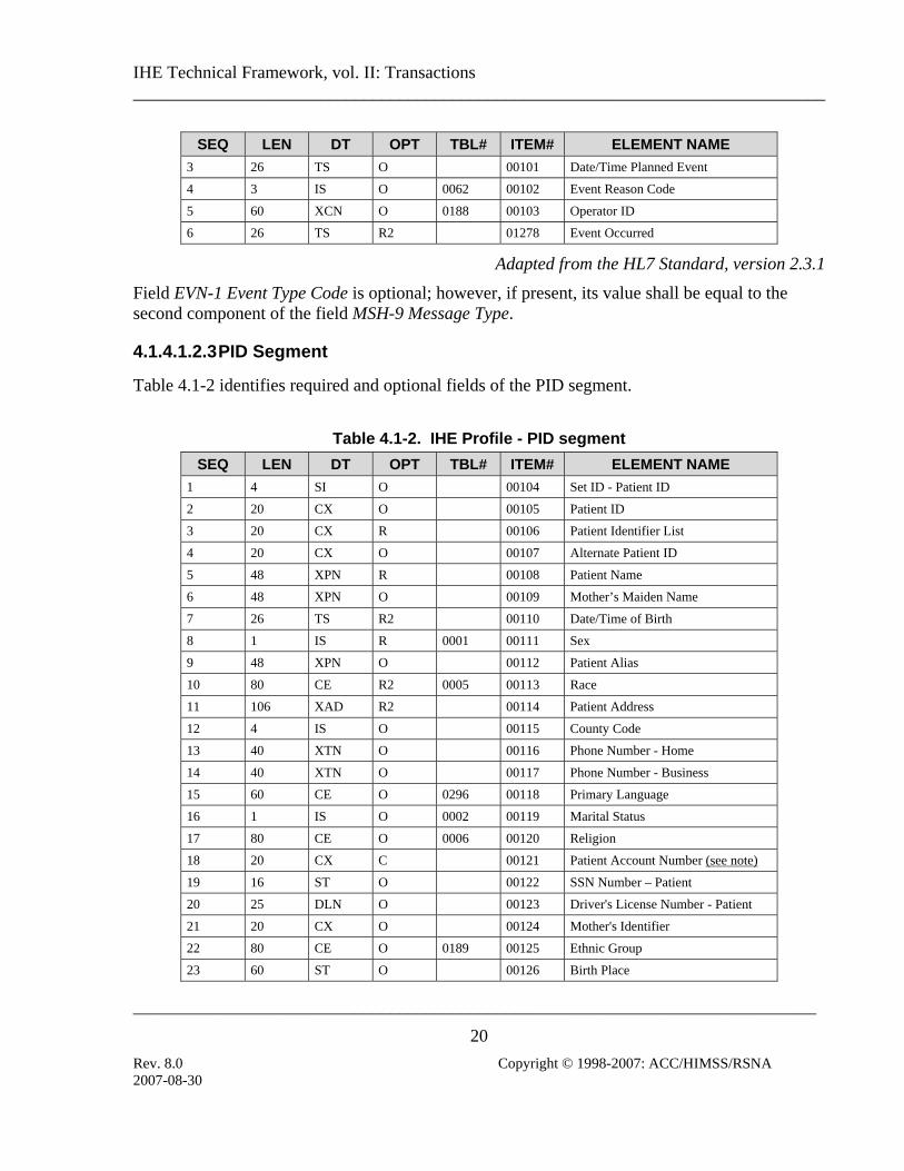
4.1.4.1.2.3 PID Segment
Table 4.1-2 identifies required and optional fields of the PID segment.
Table 4.1-2. IHE Profile - PID segment
SEQ LEN DT OPT TBL# ITEM# ELEMENT NAME 1 4 SI O 00104 Set ID - Patient ID
2 20 CX O 00105 Patient ID
3 20 CX R 00106 Patient Identifier List
4 20 CX O 00107 Alternate Patient ID
5 48 XPN R 00108 Patient Name
6 48 XPN O 00109 Mother’s Maiden Name
7 26 TS R2 00110 Date/Time of Birth
8 1 IS R 0001 00111 Sex
9 48 XPN O 00112 Patient Alias
10 80 CE R2 0005 00113 Race
11 106 XAD R2 00114 Patient Address
12 4 IS O 00115 County Code
13 40 XTN O 00116 Phone Number - Home
14 40 XTN O 00117 Phone Number - Business
15 60 CE O 0296 00118 Primary Language
16 1 IS O 0002 00119 Marital Status
17 80 CE O 0006 00120 Religion
18 20 CX C 00121 Patient Account Number (see note)
19 16 ST O 00122 SSN Number – Patient
20 25 DLN O 00123 Driver's License Number - Patient
21 20 CX O 00124 Mother's Identifier
22 80 CE O 0189 00125 Ethnic Group
23 60 ST O 00126 Birth Place
2007-08-30

IHE Technical Framework, vol. II: Transactions ______________________________________________________________________________
_____________________________________________________________________________
21 Rev. 8.0 Copyright © 1998-2007: ACC/HIMSS/RSNA
SEQ LEN DT OPT TBL# ITEM# ELEMENT NAME 24 1 ID O 0136 00127 Multiple Birth Indicator
25 2 NM O 00128 Birth Order
26 80 CE O 0171 00129 Citizenship
27 60 CE O 0172 00130 Veterans Military Status
28 80 CE O 00739 Nationality
29 26 TS O 00740 Patient Death Date and Time
30 1 ID O 0136 00741 Patient Death Indicator
Adapted from the HL7 standard, version 2.3.1
Note: At least one of the fields PID-18 Patient Account Number or PV1-19 Visit Number shall be valued. Additional requirements for the presence of value in these fields may be documented in regional or national appendixes to the IHE Technical Framework (See RAD TF-4). Every system participating in the information exchange using HL7 shall use the field PID-3 Patient Identifier List to convey the Patient ID uniquely identifying the patient, typically at the Master Patient Index. If the Master Patient Index is not available, the ID initially assigned by the ADT/Registration System may be conveyed in this field (IHE Technical Framework currently does not provide for the use of an MPI). See appendix B and appendix D for further discussion of the use of PID-3 in transactions and its mapping from HL7 messages to DICOM Patient ID (0010,0020).
Patient IDs included in the PID-3 field shall include Assigning Authority (Component 4). The first subcomponent (namespace ID) of Assigning Authority shall be populated. If the second and third subcomponents (universal ID and universal ID type) are also populated, they shall reference the same entity as is referenced in the first subcomponent.
4.1.4.1.2.4 PV1 Segment
Table 4.1-3. IHE profile - PV1 Segment
SEQ LEN DT OPT TBL# ITEM# ELEMENT NAME 1 4 SI O 00131 Set ID - PV1
2 1 IS R 0004 00132 Patient Class
3 80 PL C 00133 Assigned Patient Location
4 2 IS O 0007 00134 Admission Type
5 20 CX O 00135 Preadmit Number
6 80 PL O 00136 Prior Patient Location
7 60 XCN C 0010 00137 Attending Doctor
8 60 XCN C 0010 00138 Referring Doctor
2007-08-30

IHE Technical Framework, vol. II: Transactions ______________________________________________________________________________
_____________________________________________________________________________
22 Rev. 8.0 Copyright © 1998-2007: ACC/HIMSS/RSNA
SEQ LEN DT OPT TBL# ITEM# ELEMENT NAME 9 60 XCN R2 0010 00139 Consulting Doctor
10 3 IS C 0069 00140 Hospital Service
11 80 PL O 00141 Temporary Location
12 2 IS O 0087 00142 Preadmit Test Indicator
13 2 IS O 0092 00143 Readmission Indicator
14 3 IS O 0023 00144 Admit Source
15 2 IS C 0009 00145 Ambulatory Status
16 2 IS O 0099 00146 VIP Indicator
17 60 XCN C 0010 00147 Admitting Doctor
18 2 IS O 0018 00148 Patient Type
19 20 CX C 00149 Visit Number
20 50 FC O 0064 00150 Financial Class
21 2 IS O 0032 00151 Charge Price Indicator
22 2 IS O 0045 00152 Courtesy Code
23 2 IS O 0046 00153 Credit Rating
24 2 IS O 0044 00154 Contract Code
25 8 DT O 00155 Contract Effective Date
26 12 NM O 00156 Contract Amount
27 3 NM O 00157 Contract Period
28 2 IS O 0073 00158 Interest Code
29 1 IS O 0110 00159 Transfer to Bad Debt Code
30 8 DT O 00160 Transfer to Bad Debt Date
31 10 IS O 0021 00161 Bad Debt Agency Code
32 12 NM O 00162 Bad Debt Transfer Amount
33 12 NM O 00163 Bad Debt Recovery Amount
34 1 IS O 0111 00164 Delete Account Indicator
35 8 DT O 00165 Delete Account Date
36 3 IS O 0112 00166 Discharge Disposition
37 25 CM O 0113 00167 Discharged to Location
38 80 CE O 0114 00168 Diet Type
39 2 IS O 0115 00169 Servicing Facility
40 1 IS O 0116 00170 Bed Status
41 2 IS O 0117 00171 Account Status
42 80 PL O 00172 Pending Location
43 80 PL O 00173 Prior Temporary Location
44 26 TS O 00174 Admit Date/Time
45 26 TS O 00175 Discharge Date/Time
2007-08-30
IHE Technical Framework, vol. II: Transactions ______________________________________________________________________________
_____________________________________________________________________________
23 Rev. 8.0 Copyright © 1998-2007: ACC/HIMSS/RSNA
SEQ LEN DT OPT TBL# ITEM# ELEMENT NAME 46 12 NM O 00176 Current Patient Balance
47 12 NM O 00177 Total Charges
48 12 NM O 00178 Total Adjustments
49 12 NM O 00179 Total Payments
50 20 CX O 0192 00180 Alternate Visit ID
51 1 IS C 0326 01226 Visit Indicator
52 60 XCN O 0010 01224 Other Healthcare Provider
Adapted from the HL7 standard, version 2.3.1
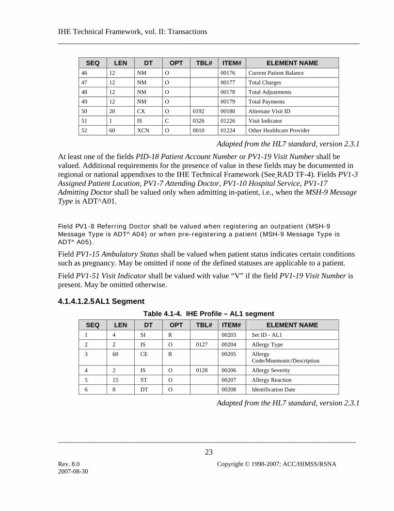
At least one of the fields PID-18 Patient Account Number or PV1-19 Visit Number shall be valued. Additional requirements for the presence of value in these fields may be documented in regional or national appendixes to the IHE Technical Framework (See RAD TF-4). Fields PV1-3 Assigned Patient Location, PV1-7 Attending Doctor, PV1-10 Hospital Service, PV1-17 Admitting Doctor shall be valued only when admitting in-patient, i.e., when the MSH-9 Message Type is ADT^A01.
Field PV1-8 Referring Doctor shall be valued when registering an outpatient (MSH-9 Message Type is ADT^A04) or when pre-registering a patient (MSH-9 Message Type is ADT^A05). Field PV1-15 Ambulatory Status shall be valued when patient status indicates certain conditions such as pregnancy. May be omitted if none of the defined statuses are applicable to a patient.
Field PV1-51 Visit Indicator shall be valued with value “V” if the field PV1-19 Visit Number is present. May be omitted otherwise.
4.1.4.1.2.5 AL1 Segment Table 4.1-4. IHE Profile – AL1 segment
SEQ LEN DT OPT TBL# ITEM# ELEMENT NAME 1 4 SI R 00203 Set ID - AL1
2 2 IS O 0127 00204 Allergy Type
3 60 CE R 00205 Allergy Code/Mnemonic/Description
4 2 IS O 0128 00206 Allergy Severity
5 15 ST O 00207 Allergy Reaction
6 8 DT O 00208 Identification Date
Adapted from the HL7 standard, version 2.3.1
2007-08-30

IHE Technical Framework, vol. II: Transactions ______________________________________________________________________________
_____________________________________________________________________________
24 Rev. 8.0 Copyright © 1998-2007: ACC/HIMSS/RSNA
4.1.4.1.2.6 OBX Segment
The IHE Technical Framework includes the OBX segment primarily for the purposes of communicating patient height and weight. In this context, the optionality of fields OBX-3 Observation Identifier has been changed to “R2” and OBX-4 Observation Result Status has been changed to “O”. Please refer to appendix B for additional details on Patient Height and Weight mapping.
Field OBX-6 Units is optional. When the OBX segments are sent to transmit the height and weight, this field shall be valued.
Table 4.1-5. IHE Profile - OBX Segment
SEQ LEN DT OPT TBL# ITEM#
ELEMENT NAME
1 4 SI O 00569 Set ID - OBX
2 3 ID C 0125 00570 Value Type
3 80 CE R 00571 Observation Identifier
4 20 ST C 00572 Observation Sub-ID
5 655361
* C 00573 Observation Value
6 60 CE O 00574 Units
7 60 ST O 00575 References Range
8 5 ID O 0078 00576 Abnormal Flags
9 5 NM O 00577 Probability
10 2 ID O 0080 00578 Nature of Abnormal Test
11 1 ID R 0085 00579 Observe Result Status
12 26 TS O 00580 Date Last Obs Normal Values
13 20 ST O 00581 User Defined Access Checks
14 26 TS O 00582 Date/Time of the Observation
15 60 CE O 00583 Producer's ID
16 80 XCN O 00584 Responsible Observer
17 60 CE O 00936 Observation Method
Adapted from the HL7 Standard, version 2.3.1
1 The length of the observation value field is variable, depending upon value type. See OBX-2-value type.
2007-08-30

IHE Technical Framework, vol. II: Transactions ______________________________________________________________________________
_____________________________________________________________________________
25 Rev. 8.0 Copyright © 1998-2007: ACC/HIMSS/RSNA
4.1.4.1.3 Expected Actions
The receiver of the ADT Patient Registration transaction message shall create a new patient record for the patient identified if there is no current record for the Patient ID (defined by the field PID-3). Interpretation of A01, A04 and A05 messages after the patient record was created is beyond the scope of the IHE Technical Framework; however, the ADT Patient Registration transaction shall not be used to update information in an existing patient record. Transaction RAD-12 Patient Update shall be used instead.
4.1.4.2 Patient Management – Cancel Admit/Register Patient
4.1.4.2.1 Trigger Events
The following events will trigger one of the Admit/Register messages: • A11 – Admission of an in-patient into a facility or registration of an outpatient for a visit of
the facility has been cancelled due to error in the information or the decision not to admit/register patient after all.
• A38 – Pre-admission of an in-patient (i.e., registration of patient information ahead of actual admission) has been cancelled due to error in the information or the decision not to admit/register patient after all.
4.1.4.2.2 Message Semantics
Patient Registration conveyed by the HL7 ADT^A01, ADT^A04 or ADT^A05 may have to be revoked due to the errors in the information or the decision of not admitting/registering patient. The cancellation transaction is conveyed by the HL7 ADT^A11 or ADT^A38 messages. ADT^A11 shall be used to revoke the transaction conveyed by the ADT^A01 or ADT^A04 message. ADT^A38 shall be used to revoke transaction conveyed by the ADT^A05 message.
Cancellation messages shall be used only if no other transactions were performed by the ADT on the patient record after the admit/registration transaction was conveyed.
The segments of the message listed below are required, and their detailed descriptions are provided in subsections below. All other segments are optional.
Note: Additional qualifications to the level of specification and HL7 profiling are stated in section 2.3.
ADT Patient Administration Message Chapter in HL7 2.3.1
MSH Message Header 2
EVN Event Type 3
PID Patient Identification 3
2007-08-30

IHE Technical Framework, vol. II: Transactions ______________________________________________________________________________
_____________________________________________________________________________
26 Rev. 8.0 Copyright © 1998-2007: ACC/HIMSS/RSNA
Chapter in ADT Patient Administration Message HL7 2.3.1
PV1 Patient Visit 3
Each message shall be acknowledged by the HL7 ACK message sent by the receiver of ADT message to its sender. See section 2.4.3 “Acknowledgement Modes” for definition and discussion of the ACK message.
4.1.4.2.2.1 MSH Segment
MSH segment shall be constructed as defined in the section 2.4.2 “Message Control”.
Field MSH-9 Message Type shall have at least two components. The first component shall have a value of “ADT”; the second component shall have values of A11 or A38 as appropriate. The third component is optional; however, if present, it shall have a value of ADT_A09 (for the A11 message) or ADT_A38 (for A38 message).
4.1.4.2.2.2 EVN Segment
See sec. 4.1.4.1.2.2 for required and optional fields of the EVN segment.
4.1.4.2.2.3 PID Segment
All of the fields in PID segment are optional, except those listed in table 4.1-6. See sec. 4.1.4.1.2.3 for the list of all fields of the PID segment.
Table 4.1-6. IHE Profile - PID segment
SEQ LEN DT OPT TBL# ITEM# ELEMENT NAME 3 20 CX R 00106 Patient Identifier List
5 48 XPN R 00108 Patient Name
18 20 CX C 00121 Patient Account Number
Adapted from the HL7 standard, version 2.3.1
4.1.4.2.2.4 PV1 Segment
All of the fields in PV1 segment are optional, except those listed in table 4.1-7. See sec. 4.1.4.1.2.4 for the list of all fields of the PV1 segment.
Table 4.1-7. IHE profile - PV1 Segment
SEQ LEN DT OPT TBL# ITEM# ELEMENT NAME
2007-08-30

IHE Technical Framework, vol. II: Transactions ______________________________________________________________________________
_____________________________________________________________________________
27 Rev. 8.0 Copyright © 1998-2007: ACC/HIMSS/RSNA
2 1 IS R 0004 00132 Patient Class
19 20 CX C 00149 Visit Number
51 1 IS C 0326 01226 Visit Indicator
Adapted from the HL7 standard, version 2.3.1
At least one of the fields PID-18 Patient Account Number or PV1-19 Visit Number shall be valued. Additional requirements for the presence of value in these fields may be documented in regional or national appendices to the IHE Technical framework (See RAD TF-4). It is required if it has been present in the registration message A01, A04 or A05 that is being cancelled by this transaction.
Field PV1-51 Visit Indicator shall be valued with value “V” if the field PV1-19 Visit Number is present. May be omitted otherwise.
4.1.4.2.3 Expected Actions
If the patient record was created as a result of a Patient Registration transaction, such record shall be discarded. If the Patient Registration transaction was sent for an existing patient record, the corresponding operations shall be “rewound” to restore the record condition existing before Patient Transaction was sent.
2007-08-30
IHE Technical Framework, vol. II: Transactions ______________________________________________________________________________
_____________________________________________________________________________
28 Rev. 8.0 Copyright © 1998-2007: ACC/HIMSS/RSNA
4.2 Placer Order Management This section corresponds to Transaction RAD-2 of the IHE Technical Framework. Transaction RAD-2 is used by the Order Placer and Department System Scheduler/Order Filler actors.
4.2.1 Scope
This transaction is used by the Order Placer to place a new order with the Order Filler. It also allows the Order Placer to cancel the order. To change order information, the Order Placer would cancel the initial order and place the new one. The Order Placer and Department System Scheduler/Order Filler must agree on the support of recurring orders and panel orders, if used.
Recurring order: An order with a performance frequency greater than one. For example, portable chest x-ray at 6:00 AM for the next seven days.
Panel order: A service item with more than one observation component. For example, a nuclear cardiac study that has a cardiology component and a radiology component that are usually reported on separately.
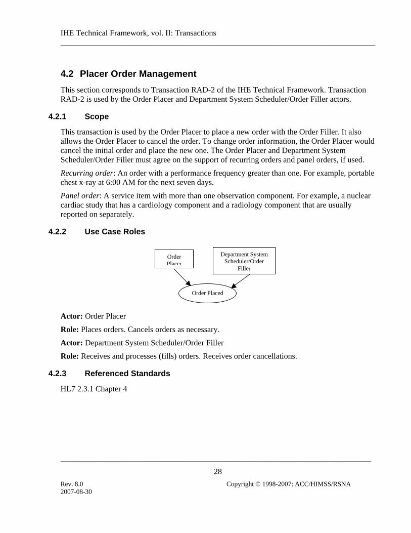
4.2.2 Use Case Roles
Order Placed
OrderPlacer
Department SystemScheduler/Order
Filler
Actor: Order Placer
Role: Places orders. Cancels orders as necessary.
Actor: Department System Scheduler/Order Filler
Role: Receives and processes (fills) orders. Receives order cancellations.
4.2.3 Referenced Standards
HL7 2.3.1 Chapter 4
2007-08-30

IHE Technical Framework, vol. II: Transactions ______________________________________________________________________________
_____________________________________________________________________________
29 Rev. 8.0 Copyright © 1998-2007: ACC/HIMSS/RSNA
4.2.4 Interaction Diagram
Order PlacerDepartment SystemScheduler/Order Filler
ORMNew Order fromOrder Placer
ORM (Cancel)Order cancelledby Order Placer
4.2.4.1 Order Management – New Order from Order Placer
4.2.4.1.1 Trigger Events
ORM – The Order Placer places a new order for the Department System Scheduler/Order Filler.
4.2.4.1.2 Message Semantics
HL7 2.3.1 Chapter 4 ORM message. Refer to HL7 Standard for general message semantics.
The order start date/time or exam date/time are required in the “Quantity/Timing” field of both the ORC and OBR segments (ORC-7.4; OBR-27.4).
Note: Additional qualifications to the level of specification and HL7 profiling are stated in section 2.3.
Required segments are listed below. Other segments are optional.
ORM General Order Message Chapter in
HL7 2.3.1 MSH Message Header 2
PID Patient Identification 3
PV1 Patient Visit 3
ORC Common Order 4
OBR Order Detail 4
Each message shall be acknowledged by the HL7 ACK message sent by the receiver of ADT message to its sender. See section 2.4.3 “Acknowledgement Modes” for definition and discussion of the ACK message.
2007-08-30

IHE Technical Framework, vol. II: Transactions ______________________________________________________________________________
_____________________________________________________________________________
30 Rev. 8.0 Copyright © 1998-2007: ACC/HIMSS/RSNA
4.2.4.1.2.1 MSH Segment
MSH segment shall be constructed as defined in the section 2.4.2 “Message Control”.
Field MSH-9 Message Type shall have at least two components. The first component shall have a value of “ORM”; the second component shall have value of O01. The third component is optional; however, if present, it shall have a value of ORM_O01.
4.2.4.1.2.2 PID Segment
All of the fields in PID segment are optional, except those listed in table 4.2-1. See sec. 4.1.4.1.2.3 for the list of all fields of the PID segment.
Table 4.2-1. IHE Profile - PID segment
SEQ LEN DT OPT TBL# ITEM# ELEMENT NAME 3 20 CX R 00106 Patient Identifier List
5 48 XPN R 00108 Patient Name
18 20 CX C 00121 Patient Account Number
Adapted from the HL7 standard, version 2.3.1
4.2.4.1.2.3 PV1 Segment
All of the fields in PV1 segment are optional, except those listed in table 4.2-2. See sec. 4.1.4.1.2.4 for the list of all fields of the PV1 segment.
Table 4.2-2. IHE profile - PV1 Segment
SEQ LEN DT OPT TBL# ITEM# ELEMENT NAME 2 1 IS R 0004 00132 Patient Class
8 60 XCN R2 0010 00138 Referring Doctor
19 20 CX C 00149 Visit Number
51 1 IS C 0326 01226 Visit Indicator
Adapted from the HL7 standard, version 2.3.1
At least one of the fields PID-18 Patient Account Number or PV1-19 Visit Number shall be valued. Additional requirements for the presence of value in these fields may be documented in regional or national appendices to the IHE Technical Framework (See RAD TF-4).
Field PV1-51 Visit Indicator shall be valued with value “V” if the field PV1-19 Visit Number is present. May be omitted otherwise.
2007-08-30
IHE Technical Framework, vol. II: Transactions ______________________________________________________________________________
_____________________________________________________________________________
31 Rev. 8.0 Copyright © 1998-2007: ACC/HIMSS/RSNA
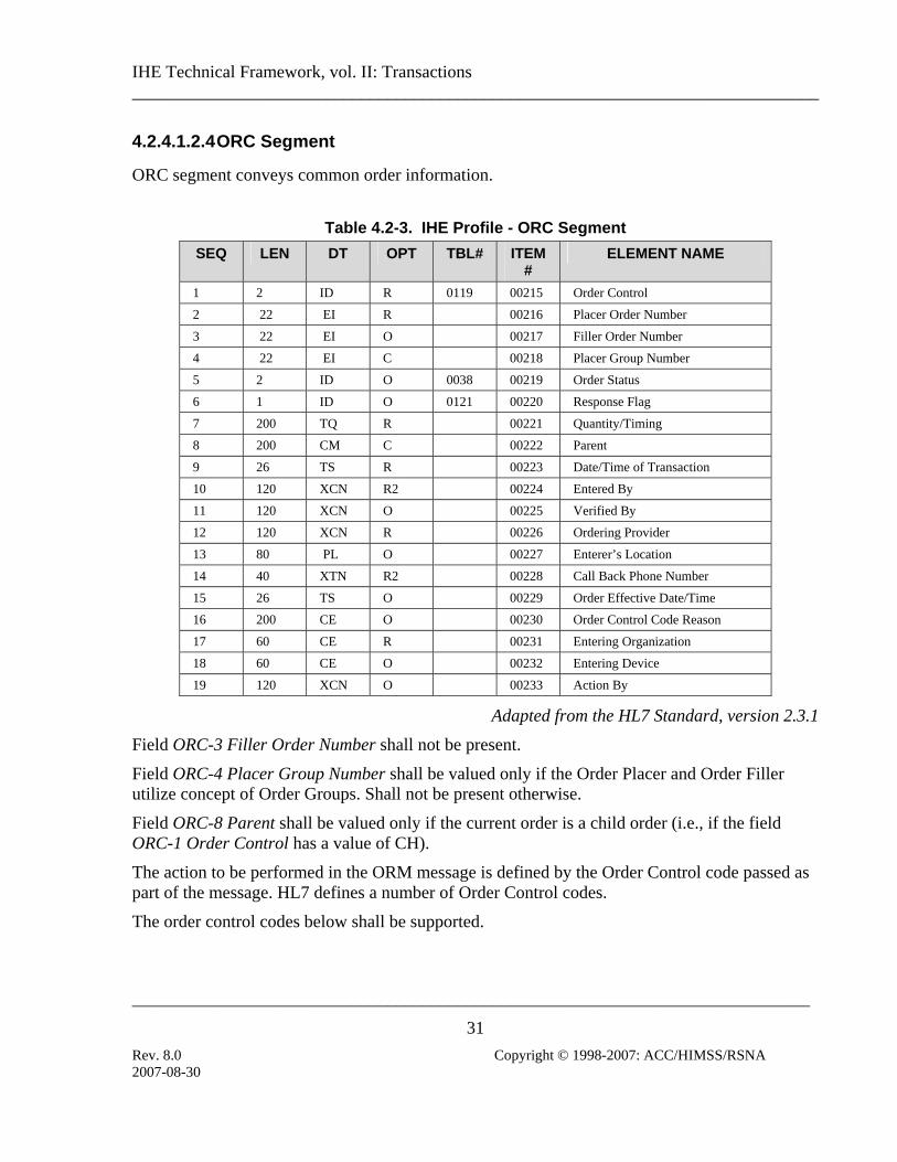
4.2.4.1.2.4 ORC Segment
ORC segment conveys common order information.
Table 4.2-3. IHE Profile - ORC Segment
SEQ LEN DT OPT TBL# ITEM#
ELEMENT NAME
1 2 ID R 0119 00215 Order Control
2 22 EI R 00216 Placer Order Number
3 22 EI O 00217 Filler Order Number
4 22 EI C 00218 Placer Group Number
5 2 ID O 0038 00219 Order Status
6 1 ID O 0121 00220 Response Flag
7 200 TQ R 00221 Quantity/Timing
8 200 CM C 00222 Parent
9 26 TS R 00223 Date/Time of Transaction
10 120 XCN R2 00224 Entered By
11 120 XCN O 00225 Verified By
12 120 XCN R 00226 Ordering Provider
13 80 PL O 00227 Enterer’s Location
14 40 XTN R2 00228 Call Back Phone Number
15 26 TS O 00229 Order Effective Date/Time
16 200 CE O 00230 Order Control Code Reason
17 60 CE R 00231 Entering Organization
18 60 CE O 00232 Entering Device
19 120 XCN O 00233 Action By
Adapted from the HL7 Standard, version 2.3.1
Field ORC-3 Filler Order Number shall not be present.
Field ORC-4 Placer Group Number shall be valued only if the Order Placer and Order Filler utilize concept of Order Groups. Shall not be present otherwise.
Field ORC-8 Parent shall be valued only if the current order is a child order (i.e., if the field ORC-1 Order Control has a value of CH).
The action to be performed in the ORM message is defined by the Order Control code passed as part of the message. HL7 defines a number of Order Control codes.
The order control codes below shall be supported.
2007-08-30

IHE Technical Framework, vol. II: Transactions ______________________________________________________________________________
_____________________________________________________________________________
32 Rev. 8.0 Copyright © 1998-2007: ACC/HIMSS/RSNA
Supported Order Control Codes
Value Description NW R New order
PA O Parent order
CH O Child order
Adapted from the HL7 Standard, version 2.3.1
R=Required; O=Optional
Note: The use of Required/Optional superscripts in the Value column is an IHE extension and is not part of the HL7 Standard.
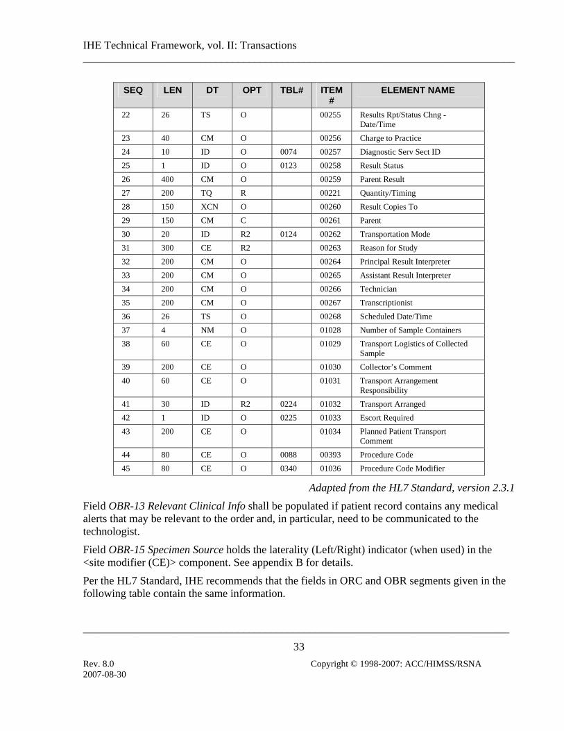
4.2.4.1.2.5 OBR Segment Table 4.2-4. IHE Profile - OBR Segment
SEQ LEN DT OPT TBL# ITEM #
ELEMENT NAME
1 4 SI O 00237 Set ID - OBR
2 75 EI R 00216 Placer Order Number
3 75 EI O 00217 Filler Order Number
4 200 CE R 00238 Universal Service ID
5 2 ID O 00239 Priority
6 26 TS O 00240 Requested Date/time
7 26 TS O 00241 Observation Date/Time
8 26 TS O 00242 Observation End Date/Time
9 20 CQ O 00243 Collection Volume
10 60 XCN O 00244 Collector Identifier
11 1 ID O 0065 00245 Specimen Action Code
12 60 CE R2 00246 Danger Code
13 300 ST C 00247 Relevant Clinical Info.
14 26 TS O 00248 Specimen Received Date/Time
15 300 CM C 0070 00249 Specimen Source
16 80 XCN R 00226 Ordering Provider
17 40 XTN O 00250 Order Callback Phone Number
18 60 ST O 00251 Placer field 1
19 60 ST O 00252 Placer field 2
20 60 ST O 00253 Filler Field 1
21 60 ST O 00254 Filler Field 2
2007-08-30
IHE Technical Framework, vol. II: Transactions ______________________________________________________________________________
_____________________________________________________________________________
33 Rev. 8.0 Copyright © 1998-2007: ACC/HIMSS/RSNA
LEN DT ITEM #
ELEMENT NAME SEQ OPT TBL#
22 26 TS O 00255 Results Rpt/Status Chng - Date/Time
23 40 CM O 00256 Charge to Practice
24 10 ID O 0074 00257 Diagnostic Serv Sect ID
25 1 ID O 0123 00258 Result Status
26 400 CM O 00259 Parent Result
27 200 TQ R 00221 Quantity/Timing
28 150 XCN O 00260 Result Copies To
29 150 CM C 00261 Parent
30 20 ID R2 0124 00262 Transportation Mode
31 300 CE R2 00263 Reason for Study
32 200 CM O 00264 Principal Result Interpreter
33 200 CM O 00265 Assistant Result Interpreter
34 200 CM O 00266 Technician
35 200 CM O 00267 Transcriptionist
36 26 TS O 00268 Scheduled Date/Time
37 4 NM O 01028 Number of Sample Containers
38 60 CE O 01029 Transport Logistics of Collected Sample
39 200 CE O 01030 Collector’s Comment
40 60 CE O 01031 Transport Arrangement Responsibility
41 30 ID R2 0224 01032 Transport Arranged
42 1 ID O 0225 01033 Escort Required
43 200 CE O 01034 Planned Patient Transport Comment
44 80 CE O 0088 00393 Procedure Code
45 80 CE O 0340 01036 Procedure Code Modifier
Adapted from the HL7 Standard, version 2.3.1
Field OBR-13 Relevant Clinical Info shall be populated if patient record contains any medical alerts that may be relevant to the order and, in particular, need to be communicated to the technologist.
Field OBR-15 Specimen Source holds the laterality (Left/Right) indicator (when used) in the <site modifier (CE)> component. See appendix B for details.
Per the HL7 Standard, IHE recommends that the fields in ORC and OBR segments given in the following table contain the same information.
2007-08-30

IHE Technical Framework, vol. II: Transactions ______________________________________________________________________________
_____________________________________________________________________________
34 Rev. 8.0 Copyright © 1998-2007: ACC/HIMSS/RSNA
Identical Element Mappings between ORC and OBR Segments Element Name ORC Segment Element OBR Segment Element
Placer Order Number ORC-2 OBR-2
Filler Order Number ORC-3 OBR-3
Quantity/Timing ORC-7 OBR-27
Parent ORC-8 OBR-29
4.2.4.1.3 Expected Actions
Department System Scheduler/Order Filler shall accept the order information for fulfillment. If error in data prevents it from fulfilling the order, it shall notify the Order Placer by returning proper information in the ACK message.
4.2.4.2 Order Management - Order Cancelled by Order Placer
4.2.4.2.1 Trigger Events
ORM – Order Placer cancels an order (control code = CA).
ORM – Order Placer discontinues (attempts to stop) an ongoing order (control code = DC).
4.2.4.2.2 Message Semantics
HL7 2.3.1 Chapter 4 ORM message. Refer to HL7 standard for general message semantics. Refer to sec. 4.2.4.1.2 above for detailed requirements of the ORM message.
Note: Additional qualifications to the level of specification and HL7 profiling are stated in section 2.3.
Required segments are listed below. Other segments are optional.
ORM General Order Message Chapter in
HL7 2.3.1 MSH Message Header 2
PID Patient Identification 3
PV1 Patient Visit 3
ORC Common Order 4
Each message shall be acknowledged by the HL7 ACK message sent by the receiver of ADT message to its sender. See section 2.4.3 “Acknowledgement Modes” for definition and discussion of the ACK message.
2007-08-30

IHE Technical Framework, vol. II: Transactions ______________________________________________________________________________
_____________________________________________________________________________
35 Rev. 8.0 Copyright © 1998-2007: ACC/HIMSS/RSNA
4.2.4.2.2.1 MSH Segment
MSH segment shall be constructed as defined in the section 2.4.2 “Message Control”.
Field MSH-9 Message Type shall have at least two components. The first component shall have a value of “ORM”; the second component shall have a value of O01. The third component is optional; however, if present, it shall have a value of ORM_O01.
4.2.4.2.2.2 PID Segment
All of the fields in PID segment are optional, except those listed in table 4.2-5. See sec. 4.1.4.1.2.3 for the list of all fields of the PID segment.
2007-08-30

IHE Technical Framework, vol. II: Transactions ______________________________________________________________________________
_____________________________________________________________________________
36 Rev. 8.0 Copyright © 1998-2007: ACC/HIMSS/RSNA
Table 4.2-5. IHE Profile - PID segment
SEQ LEN DT OPT TBL# ITEM# ELEMENT NAME 3 20 CX R 00106 Patient Identifier List
5 48 XPN R 00108 Patient Name
18 20 CX C 00121 Patient Account Number
Adapted from the HL7 standard, version 2.3.1
4.2.4.2.2.3 PV1 Segment
All of the fields in PV1 segment are optional, except those listed in table 4.2-6. See sec. 4.1.4.1.2.4 for the list of all fields of the PV1 segment.
Table 4.2-6. IHE profile - PV1 Segment
SEQ LEN DT OPT TBL# ITEM# ELEMENT NAME 2 1 IS R 0004 00132 Patient Class
19 20 CX C 00149 Visit Number
51 1 IS C 0326 01226 Visit Indicator
Adapted from the HL7 standard, version 2.3.1
At least one of the fields PID-18 Patient Account Number or PV1-19 Visit Number shall be valued. Additional requirements for the presence of value in these fields may be documented in regional or national appendices to the IHE Technical Framework (See RAD TF-4).
Field PV1-51 Visit Indicator shall be valued with value “V” if the field PV1-19 Visit Number is present. May be omitted otherwise.
4.2.4.2.2.4 ORC Segment
All of the fields in ORC segment are optional, except those listed in table 4.2-7. See sec. 4.2.4.1.2.4 for the list of all fields of the ORC segment.
Table 4.2-7. IHE Profile - ORC Segment
SEQ LEN DT OPT TBL# ITEM#
ELEMENT NAME
1 2 ID R 0119 00215 Order Control
2 22 EI R 00216 Placer Order Number
Adapted from the HL7 Standard, version 2.3.1
2007-08-30

IHE Technical Framework, vol. II: Transactions ______________________________________________________________________________
_____________________________________________________________________________
37 Rev. 8.0 Copyright © 1998-2007: ACC/HIMSS/RSNA
The action to be performed in the ORM message is defined by the Order Control code passed as part of the message. HL7 defines a number of Order Control codes.
The order control codes below shall be supported.
IHE Profile - Supported Order Control Codes Value Description
CA Cancel order request
DC Discontinue Order request
4.2.4.2.3 Expected Actions
After receiving the ORM message with the control code CA, DSS/Order Filler shall discard the record of the order and shall not attempt to schedule or otherwise to fulfill it. If the DSS/Order Filler has already scheduled the procedures corresponding to the order, it has to perform Transaction RAD-13 Procedure Update (see sec. 4.13) to notify the Image Manager of order cancellation.
Order Placer shall not cancel order that has already been started, i.e., the one for which Order Filler transmitted the “In-Progress” status (see sec. 4.3.4.2). However, if the Order Filler receives the cancellation message after it has sent the Status Update message (for example, in a case of a race condition between two messages), Order Filler shall accept order cancellation and perform Transaction RAD-13 Procedure Update to notify Image Manager.
It is expected that in most cases Order Placer will utilize the ORM message with the control code of CA. However, in some cases (such as with recurring orders – to stop the order fulfillment before all its parts were completed), Order Placer and Order Filler may agree on a use of the ORM message with the control code DC. Upon receiving such ORM message, DSS/Order Filler shall perform Transaction RAD-13 Procedure Update (see sec. 4.13) to notify the Image Manager of order discontinuation.
2007-08-30
IHE Technical Framework, vol. II: Transactions ______________________________________________________________________________
_____________________________________________________________________________
38 Rev. 8.0 Copyright © 1998-2007: ACC/HIMSS/RSNA
4.3 Filler Order Management This section corresponds to Transaction RAD-3 of the IHE Technical Framework. Transaction RAD-3 is used by the Order Placer and Department System Scheduler/Order Filler actors.
4.3.1 Scope
This transaction is used by the Order Filler to inform the Order Placer about the orders it creates and cancels, including the status of the orders it is fulfilling. If the Order Filler needs to change an order, it has to do so as a combination of Order Cancel followed by New Order.
A 1:1 relationship between Placer Order and Filler Order shall be maintained before the Order Filler creates new orders
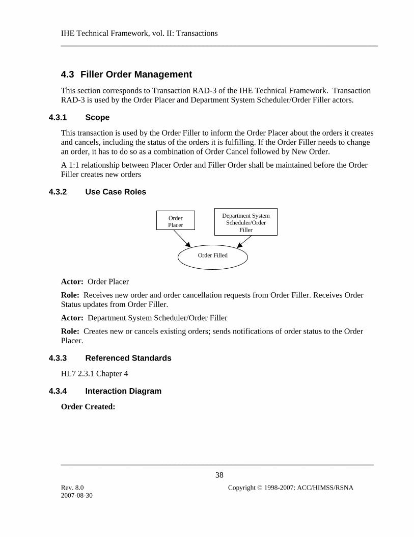
4.3.2 Use Case Roles
Order Filled
OrderPlacer
Department SystemScheduler/Order
Filler
Actor: Order Placer
Role: Receives new order and order cancellation requests from Order Filler. Receives Order Status updates from Order Filler.
Actor: Department System Scheduler/Order Filler
Role: Creates new or cancels existing orders; sends notifications of order status to the Order Placer.
4.3.3 Referenced Standards
HL7 2.3.1 Chapter 4
4.3.4 Interaction Diagram
Order Created:
2007-08-30

IHE Technical Framework, vol. II: Transactions ______________________________________________________________________________
_____________________________________________________________________________
39 Rev. 8.0 Copyright © 1998-2007: ACC/HIMSS/RSNA
Order PlacerDepartment SystemScheduler/Order Filler
ORM (Cancel)
New Order fromOrder Filler
ORM (New Order)
ORR
Order cancelled bythe Order Filler.
ORM (Status Upd) Order status updateby the Order Filler.
Note: ORR messages are sent by the Order Placer to convey the Order Placer Number in those cases where the DSS/Order Filler places the Order. ORR messages are not used as acknowledgements in other cases.
4.3.4.1 Filler Order Management – New Order from Order Filler
4.3.4.1.1 Trigger Events
ORM - Department system Scheduler/Order Filler places an order (control code = SN).
ORR – Order Placer replies (control code = NA).
4.3.4.1.2 Message Semantics
HL7 2.3.1 Chapter 4 ORM message. Refer to HL7 Standard for general message semantics. Refer to sec. 4.2.4.1.2 above for detailed requirements for the ORM message.
HL7 2.3.1 Chapter 4 ORR message. Refer to HL7 Standard for general message semantics.
See sec. 4.1 of this document for MSH and MSA segment definition.
Note: Additional qualifications to the level of specification and HL7 profiling are stated in section 2.3.
Required segments are listed below. Other segments are optional.
ORM General Order Message Chapter in
HL7 2.3.1 MSH Message Header 2
PID Patient Identification 3
PV1 Patient Visit 3
2007-08-30

IHE Technical Framework, vol. II: Transactions ______________________________________________________________________________
_____________________________________________________________________________
40 Rev. 8.0 Copyright © 1998-2007: ACC/HIMSS/RSNA
Chapter in ORM General Order Message HL7 2.3.1
ORC Common Order 4
OBR Order Detail 4
ORR
(Success) General Order Message Chapter in
HL7 2.3.1
MSH Message Header 2
MSA Message Acknowledgement 2
ORC Common Order 4
OBR Order Detail 4
ORR
(Error) General Order Message Chapter in
HL7 2.3.1 MSH Message Header 2
MSA Message Acknowledgement 2
ERR Error 2
Each message shall be acknowledged by the HL7 ACK message sent by the receiver of ADT message to its sender. See section 2.4.3 “Acknowledgement Modes” for definition and discussion of the ACK message.
4.3.4.1.2.1 MSH Segment
MSH segment shall be constructed as defined in the section 2.4.2 “Message Control”.
Field MSH-9 Message Type shall have at least two components. The first component shall have a value of “ORM” for ORM message and “ORR” for ORR message; the second component shall have value of O01 or O02, respectively. The third component is optional; however, if present, it shall have a value of ORM_O01 or ORR_O02, respectively.
4.3.4.1.2.2 MSA Segment
MSA segment in the ORR (Success) or ORR (Error) message shall be constructed as defined in the section 2.4.3 “Acknowledgement Modes”.
Field MSA-6 Error condition in ORR (Error) shall have the Error code value of 204 (Unknown Key Identifier)
2007-08-30

IHE Technical Framework, vol. II: Transactions ______________________________________________________________________________
_____________________________________________________________________________
41 Rev. 8.0 Copyright © 1998-2007: ACC/HIMSS/RSNA
4.3.4.1.2.3 PID Segment
All of the fields in PID segment are optional, except those listed in table 4.3-1. See sec. 4.1.4.1.2.3 for the list of all fields of the PID segment.
Table 4.3-1. IHE Profile - PID segment
SEQ LEN DT OPT TBL# ITEM# ELEMENT NAME 3 20 CX R 00106 Patient Identifier List
5 48 XPN R 00108 Patient Name
18 20 CX C 00121 Patient Account Number
Adapted from the HL7 standard, version 2.3.1
4.3.4.1.2.4 PV1 Segment
All of the fields in PV1 segment are optional, except those listed in table 4.3-2. See sec. 4.1.4.1.2.4 for the list of all fields of the PV1 segment.
Table 4.3-2. IHE profile - PV1 Segment
SEQ LEN DT OPT TBL# ITEM# ELEMENT NAME 2 1 IS R 0004 00132 Patient Class
19 20 CX C 00149 Visit Number
51 1 IS C 0326 01226 Visit Indicator
Adapted from the HL7 standard, version 2.3.1
At least one of the fields PID-18 Patient Account Number or PV1-19 Visit Number shall be valued. Additional requirements for the presence of value in these fields may be documented in regional or national appendices to the IHE Technical Framework (See RAD TF-4).
Field PV1-51 Visit Indicator shall be valued with value “V” if the field PV1-19 Visit Number is present. May be omitted otherwise.
4.3.4.1.2.5 ORC Segment
All of the fields in ORC segment are optional, except those listed in table 4.3-3. See sec. 4.2.4.1.2.4 for the list of all fields of the ORC segment.
Table 4.3-3. IHE Profile - ORC Segment
SEQ LEN DT OPT TBL# ITEM#
ELEMENT NAME
1 2 ID R 0119 00215 Order Control
2007-08-30

IHE Technical Framework, vol. II: Transactions ______________________________________________________________________________
_____________________________________________________________________________
42 Rev. 8.0 Copyright © 1998-2007: ACC/HIMSS/RSNA
ITEMSEQ LEN DT OPT TBL# ELEMENT NAME #
2 22 EI C 00216 Placer Order Number
3 22 EI R 00217 Filler Order Number
4 22 EI C 00218 Placer Group Number
7 200 TQ R 00221 Quantity/Timing
9 26 TS R 00223 Date/Time of Transaction
10 120 XCN R2 00224 Entered By
12 120 XCN R 00226 Ordering Provider
14 40 XTN R2 00228 Call Back Phone Number
17 60 CE R 00231 Entering Organization
Adapted from the HL7 Standard, version 2.3.1
Field ORC-1 Order Control shall have the value of SN in the ORM message and the value NA in the ORR message.
Field ORC-2 Placer Order Number shall be valued only in the ORR message and omitted in the ORM message.
Field ORC-4 Placer Group Number shall be valued only if the Order Placer and Order Filler utilize concept of Order Groups. Shall not be present otherwise.
4.3.4.1.2.6 OBR Segment
All of the fields in OBR segment are optional, except those listed in table 4.3-4. See sec. 4.2.4.1.2.5 for the list of all fields of the OBR segment.
Table 4.3-4. IHE Profile - OBR Segment SEQ LEN DT OPT TBL# ITEM
# ELEMENT NAME
2 75 EI C 00216 Placer Order Number
3 75 EI R 00217 Filler Order Number
4 200 CE R 00238 Universal Service ID
12 60 CE R2 00246 Danger Code
13 300 ST C 00247 Relevant Clinical Info.
15 300 CM C 0070 00249 Specimen Source
16 80 XCN R 00226 Ordering Provider
27 200 TQ R 00221 Quantity/Timing
30 20 ID R2 0124 00262 Transportation Mode
31 300 CE R2 00263 Reason for Study
41 30 ID R2 0224 01032 Transport Arranged
Adapted from the HL7 Standard, version 2.3.1
2007-08-30

IHE Technical Framework, vol. II: Transactions ______________________________________________________________________________
_____________________________________________________________________________
43 Rev. 8.0 Copyright © 1998-2007: ACC/HIMSS/RSNA
Field OBR-13 Relevant Clinical Info shall be populated if patient record contains any medical alerts that may be relevant to the order and, in particular, need to be communicated to the technologist. Field OBR-15 Specimen Source holds the laterality (Left/Right) indicator (when used) in the <site modifier (CE)> component. See appendix B for details. Per the HL7 Standard, IHE recommends that some fields in ORC and OBR segments contain the same information, as described in sec. 4.2.4.1.2.5. For the ORR message, all required fields in the OBR segment, except OBR-2 Placer Order Number, shall be copied by Order Placer from the ORM message received from the Order Filler. Value of the field OBR-2 Placer Order Number shall be generated by the Order Placer.
4.3.4.1.2.7 ERR Segment
ERR segment in the ORR (Error) message shall be constructed as defined in the section 2.4.3 “Acknowledgement Modes”.
Field ERR-1 Error code and location in ORR (Error) shall have the Error code value of 204 (Unknown Key Identifier).
4.3.4.1.3 Expected Actions
If the Order Placer accepts and registers order information transmitted from the Order Filler in the ORM message, it shall assign its unique number to it and convey that number to order Filler in the ORR (Success) message. In turn, the Order Filler shall register received Order Placer number and include it into the subsequent communication of order status with Order Placer, as well as procedure-related information to the Image Manager and Acquisition Modality (see sections 4.4 and 4.5).
If the Order Placer cannot accept order information transmitted from the Order Filler in the ORM message (e.g. Patient ID does not exist anymore due to a Patient Update-Cancel registration the Order Placer just received), it shall convey the rejection by returning an ORR (Error) message.
4.3.4.2 Filler Order Management - Order Status Update
The Order Status Update Message is used by the DSS/Order Filler to notify Order Placer about changes in the status of the order as it is being fulfilled by the DSS/Order Filler.
4.3.4.2.1 Trigger Events
ORM - Department System Scheduler/Order Filler updates an order status (control code = SC).
2007-08-30

IHE Technical Framework, vol. II: Transactions ______________________________________________________________________________
_____________________________________________________________________________
44 Rev. 8.0 Copyright © 1998-2007: ACC/HIMSS/RSNA
4.3.4.2.2 Message Semantics
HL7 2.3.1 Chapter 4 ORM message. Refer to HL7 Standard for general message semantics.
See sec. 4.1 of this document for MSH segment definition.
Note: Additional qualifications to the level of specification and HL7 profiling are stated in section 2.
Required segments are listed below. Other segments are optional.
ORM General Order Message Chapter in HL7 2.3.1
MSH Message Header 2
ORC Common Order 4
4.3.4.2.2.1 MSH Segment
MSH segment shall be constructed as defined in the section 2.4.2 “Message Control”.
Field MSH-9 Message Type shall have at least two components. The first component shall have a value of “ORM”; the second component shall have value of O01. The third component is optional; however, if present, it shall have a value of ORM_O01.
4.3.4.2.2.2 ORC Segment
All of the fields in ORC segment are optional, except those listed in table 4.3-5. See sec. 4.2.4.1.2.4 for the list of all fields of the ORC segment.
Table 4.3-5. IHE Profile - ORC Segment
SEQ LEN DT OPT TBL# ITEM#
ELEMENT NAME
1 2 ID R 0119 00215 Order Control
2 22 EI R 00216 Placer Order Number
3 22 EI R 00217 Filler Order Number
5 2 ID R 0038 00219 Order Status
Adapted from the HL7 Standard, version 2.3.1
When an Order Status Update (control code = SC) message is received at the Order Placer, the element ORC-5 “Order Status” will contain the reason for the status change. The reason shall be one of the following:
2007-08-30

IHE Technical Framework, vol. II: Transactions ______________________________________________________________________________
_____________________________________________________________________________
45 Rev. 8.0 Copyright © 1998-2007: ACC/HIMSS/RSNA
Order Status codes Value Description
CM Order is completed
OD Order was discontinued
IP Order is in progress
Adapted from the HL7 Standard, version 2.3.1
4.3.4.2.3 Expected Actions
DSS/Order Filler shall provide Order Placer with status updates on the order. At least the following events shall be noted: • In Progress – when the first Performed Procedure Step corresponding to the Order has been
created; • Discontinued – when a cancellation request was received from Order Placer, after an Order
has been set to “In-Progress”. A discontinuation applied instead. • Completed – when the complete, verified report is available for the given order.
Order Filler shall send at least one Order Status Update message with the Order Status code of “CM”. Determination of exact timing of such a message shall be at the discretion of the Order Filler, however, it may not occur before the final, verified report for all requested procedures within the order is available.
Order Filler shall use the Order Status Update message with the Order Status code of “IP”, to facilitate synchronization of order handling with the Order Placer, for example, to prevent cancellation/discontinuation of an order in progress. In this case, at least one message shall be sent after the Order Filler/Department System Scheduler have processed the first Modality Procedure Step In Progress transaction associated with the order. Note, that Order Placer may still issue the cancellation request, for example, because of race condition between two messages. In such case, Order Filler shall process cancellation of the order as a discontinuation and return an Order Status Update message with the Order Status Code of “OD”.
Order Status Update message cannot be used to request an action, for example, cancellation or discontinuation of an order.
If an order is being created by the Order Filler (for example, in a case of unidentified patient, see RAD TF-1:4, Order Status Update message shall not be issued until New Order message has been sent by the Order Filler.
2007-08-30

IHE Technical Framework, vol. II: Transactions ______________________________________________________________________________
_____________________________________________________________________________
46 Rev. 8.0 Copyright © 1998-2007: ACC/HIMSS/RSNA
4.3.4.3 Filler Order Management - Order Cancelled by the Order Filler
4.3.4.3.1 Trigger Events
ORM – Department System Scheduler/Order Filler cancels the order previously received from Order Placer (control code = OC).
4.3.4.3.2 Message Semantics
HL7 2.3.1 Chapter 4 ORM message. Refer to HL7 standard for general message semantics. Required segments listed below. Other segments are optional.
Note: Additional qualifications to the level of specification and HL7 profiling are stated in section 2.3.
ORM General Order Message Chapter in
HL7 2.3.1 MSH Message Header 2
PID Patient Identification 3
PV1 Patient Visit 3
ORC Common Order 4
Each message shall be acknowledged by the HL7 ACK message sent by the receiver of ADT message to its sender. See section 2.4.3 “Acknowledgement Modes” for definition and discussion of the ACK message.
4.3.4.3.2.1 MSH Segment
MSH segment shall be constructed as defined in the section 2.4.2 “Message Control”.
Field MSH-9 Message Type shall have at least two components. The first component shall have a value of “ORM”; the second component shall have value of O01. The third component is optional; however, if present, it shall have a value of ORM_O01.
4.3.4.3.2.2 PID Segment
All of the fields in PID segment are optional, except those listed in table 4.3-6. See sec. 4.1.4.1.2.3 for the list of all fields of the PID segment.
Table 4.3-6. IHE Profile - PID segment
SEQ LEN DT OPT TBL# ITEM# ELEMENT NAME 3 20 CX R 00106 Patient Identifier List
5 48 XPN R 00108 Patient Name
2007-08-30

IHE Technical Framework, vol. II: Transactions ______________________________________________________________________________
_____________________________________________________________________________
47 Rev. 8.0 Copyright © 1998-2007: ACC/HIMSS/RSNA
SEQ LEN DT OPT TBL# ITEM# ELEMENT NAME 18 20 CX C 00121 Patient Account Number
Adapted from the HL7 standard, version 2.3.1
4.3.4.3.2.3 PV1 Segment
All of the fields in PV1 segment are optional, except those listed in table 4.3-7. See sec. 4.1.4.1.2.4 for the list of all fields of the PV1 segment.
Table 4.3-7. IHE Profile - PV1 Segment
SEQ LEN DT OPT TBL# ITEM# ELEMENT NAME 2 1 IS R 0004 00132 Patient Class
19 20 CX C 00149 Visit Number
51 1 IS C 0326 01226 Visit Indicator
Adapted from the HL7 standard, version 2.3.1
At least one of the fields PID-18 Patient Account Number or PV1-19 Visit Number shall be valued. Additional requirements for the presence of value in these fields may be documented in regional or national appendices to the IHE Technical Framework (See RAD TF-4).
Field PV1-51 Visit Indicator shall be valued with value “V” if the field PV1-19 Visit Number is present. May be omitted otherwise.
4.3.4.3.2.4 ORC Segment
All of the fields in ORC segment are optional, except those listed in table 4.3-8. See sec. 4.2.4.1.2.4 for the list of all fields of the ORC segment.
Table 4.3-8. IHE Profile - ORC Segment
SEQ LEN DT OPT TBL# ITEM#
ELEMENT NAME
1 2 ID R 0119 00215 Order Control
2 22 EI R 00216 Placer Order Number
3 22 EI R 00217 Filler Order Number
Adapted from the HL7 Standard, version 2.3.1
The action to be performed in the ORM message is defined by the Order Control code passed as part of the message. The order control code below shall be supported.
2007-08-30

IHE Technical Framework, vol. II: Transactions ______________________________________________________________________________
_____________________________________________________________________________
48 Rev. 8.0 Copyright © 1998-2007: ACC/HIMSS/RSNA
Table 4.3-2. IHE Profile - Supported Order Control Codes Value Description Originator
OC Order Cancelled F
4.3.4.3.3 Expected Actions
After receiving the ORM message with the control code OC, Order Placer shall process the order the same way as if it was cancelled/discontinued by the Order Placer.
If DSS/Order Filler has already scheduled the procedures corresponding to the order, it shall perform Transaction RAD-13 Procedure Update (see sec. 4.13) to notify the Image Manager of order cancellation.
2007-08-30

IHE Technical Framework, vol. II: Transactions ______________________________________________________________________________
_____________________________________________________________________________
49 Rev. 8.0 Copyright © 1998-2007: ACC/HIMSS/RSNA
4.4 Procedure Scheduled This section corresponds to Transaction RAD-4 of the IHE Technical Framework. Transaction RAD-4 is used by the Department System Scheduler/Order Filler, Image Manager and Report Manager actors.
4.4.1 Scope
This transaction specifies a message from the Department System Scheduler/Order Filler to the Image Manager and the Report Manager notifying them that a procedure has been scheduled.
Scheduling does not necessarily mean precise time assignment for the particular procedures. For example, inpatient procedures are not necessarily scheduled for a specific time slot, but rather for “today” or “as soon as possible”. However, the Department System Scheduler/Order Filler shall handle all orders in such a way that it is capable of informing the Image Manager and the Report Manager about procedure timing and resources used to perform a procedure. It must provide the date and time when the procedure is to be performed, although precision of the time portion of that information is allowed to be implementation dependent.
This message serves as a trigger event for the Image Manager and the Report Manager, informing it to obtain necessary information and apply rules to ensure the availability of relevant information to the end user. The Image Manager and the Report Manager may need the information to create the Requested Procedure context for its purposes. The Procedure Scheduled transaction includes the initial scheduling message. The Procedure Scheduled message is also used to provide additional information from the Department System Scheduler to the Image Manager and the Report Manager for unscheduled cases. In the event that a procedure is performed prior to ordering (as in some of the use cases in RAD TF-1: 4.4), this message is used “after the fact” for the Department System Schedule to inform the Image Manager and the Report Manager of critical information such as Accession Number and Requested Procedure ID. This is described in more detail within this section.
The Department System Scheduler/Order Filler will need to communicate with multiple Image Managers. The Department System Scheduler/Order Filler shall broadcast these scheduling messages to all Image Managers and the Report Manager. An Image Manager shall be able to receive and process these messages with the understanding that the images and MPPS events for these procedures may be sent to a different Image Manager.
2007-08-30

IHE Technical Framework, vol. II: Transactions ______________________________________________________________________________
_____________________________________________________________________________
50 Rev. 8.0 Copyright © 1998-2007: ACC/HIMSS/RSNA
4.4.2 Use Case Roles
Department SystemScheduler/Order
Filler
ProcedureScheduled
Image Manager Report Manager
Actor: Department System Scheduler/Order Filler
Role: Enters, modifies and stores information about patients, receives orders, schedules Procedures (exams), modifies information about them (rescheduling, cancellations, code changes, etc.).
Actor: Image Manager
Role: Receives information about Patients, Orders, and schedules, and uses this information to assist in image management.
Actor: Report Manager
Role: Receives information about Patients, Orders, and schedules, and uses this information to assist in Report management.
4.4.3 Referenced Standards
HL7 2.3.1 Chapter 2-4
2007-08-30

IHE Technical Framework, vol. II: Transactions ______________________________________________________________________________
_____________________________________________________________________________
51 Rev. 8.0 Copyright © 1998-2007: ACC/HIMSS/RSNA
4.4.4 Interaction Diagram
Departmental System Scheduler/Order Filler
ORM (Procedure Scheduled)
Image Manager
Departmental System Scheduler/Order Filler
ORM (Procedure Scheduled)
Report Manager
4.4.4.1 Procedure Scheduled Message
4.4.4.1.1 Trigger Events
The Department System Scheduler/Order Filler determines procedures which need to be performed to fill the order, what Procedure Steps need to be performed for each Procedure, and timing and necessary resources.
Note: This transaction shall be used the first time a particular Study Instance UID is sent from the Department System Scheduler/Order Filler to the Image Manager or Report Manager. If the
2007-08-30

IHE Technical Framework, vol. II: Transactions ______________________________________________________________________________
_____________________________________________________________________________
52 Rev. 8.0 Copyright © 1998-2007: ACC/HIMSS/RSNA
Study Instance UID has been sent previously, then Procedure Updated (Transaction RAD-13) shall be used.
4.4.4.1.2 Message Semantics
The Department System Scheduler/Order Filler uses an ORM message to convey necessary procedure and scheduling information.
The Procedure Scheduled Transaction will perform the additional task of providing Patient Demographic information to the Image Manager and the Report Manager. The Image Manager and the Report Manager do not receive all Patient Registration events from the ADT System because it is not necessary for the Image Manager and Report Manager to be aware of all patients in the enterprise (since most will never have an imaging procedure). The Image Manager and the Report Manager shall obtain the Patient Demographic information from the Procedure Schedule ORM, specifically the PID and PV1 segments. For this reason, the Department System Scheduler/Order Filler must complete these segments as described in sec. 4.1, Patient Registration.
Note: Additional information regarding HL7 conventions, profiling, and implementation considerations is given in section 2.3.
The segments listed below are required. All other segments are optional.
ORM General Order Message Chapter in HL7 2.3
MSH Message Header 2
PID Patient Identification 3
PV1 Patient Visit 3
{ORC Common Order 4
OBR} Order Detail 4
ZDS Additional identification information (custom for IHE)
Each message shall be acknowledged by the HL7 ACK message sent by the receiver of the ORM message to its sender. See section 2.4.3 “Acknowledgement Modes” for definition and discussion of the ACK message.
4.4.4.1.2.1 MSH Segment
MSH segment shall be constructed as defined in the section 2.4.2 “Message Control”.
Field MSH-9 Message Type shall have at least two components. The first component shall have a value of “ORM”; the second component shall have value of O01. The third component is optional; however, if present, it shall have a value of ORM_O01.
2007-08-30

IHE Technical Framework, vol. II: Transactions ______________________________________________________________________________
_____________________________________________________________________________
53 Rev. 8.0 Copyright © 1998-2007: ACC/HIMSS/RSNA
4.4.4.1.2.2 PID Segment
All of the fields in PID segment are optional, except those listed in table 4.4-1. See sec. 4.1.4.1.2.3 for the list of all fields of the PID segment.
Table 4.4-1. IHE Profile - PID segment
SEQ LEN DT OPT TBL# ITEM# ELEMENT NAME 3 20 CX R 00106 Patient Identifier List
5 48 XPN R 00108 Patient Name
7 26 TS R2 00110 Date/Time of Birth
8 1 IS R 0001 00111 Sex
10 80 CE R2 0005 00113 Race
11 106 XAD R2 00114 Patient Address
18 20 CX C 00121 Patient Account Number
Adapted from the HL7 standard, version 2.3.1
Every system participating in the information exchange using HL7 shall use the field PID-3 Patient Identifier List to convey the Patient ID uniquely identifying the patient, typically at the Master Patient Index. If the Master Patient Index is not available, the ID initially assigned by the ADT/Registration System may be conveyed in this field (IHE Technical Framework currently does not provide for the use of an MPI). See appendix B and appendix D for further discussion of the use of PID-3 in transactions and its mapping from HL7 messages to DICOM Patient ID (0010,0020).
4.4.4.1.2.3 PV1 Segment
All of the fields in PV1 segment are optional, except those listed in table 4.4-2. See sec. 4.1.4.1.2.4 for the list of all fields of the PV1 segment.
Table 4.4-2. IHE profile - PV1 Segment
SEQ LEN DT OPT TBL# ITEM# ELEMENT NAME 2 1 IS R 0004 00132 Patient Class
3 80 PL C 00133 Assigned Patient Location
7 60 XCN C 0010 00137 Attending Doctor
8 60 XCN C 0010 00138 Referring Doctor
9 60 XCN R2 0010 00139 Consulting Doctor
10 3 IS C 0069 00140 Hospital Service
15 2 IS C 0009 00145 Ambulatory Status
17 60 XCN C 0010 00147 Admitting Doctor
2007-08-30

IHE Technical Framework, vol. II: Transactions ______________________________________________________________________________
_____________________________________________________________________________
54 Rev. 8.0 Copyright © 1998-2007: ACC/HIMSS/RSNA
19 20 CX C 00149 Visit Number
51 1 IS C 0326 01226 Visit Indicator
Adapted from the HL7 standard, version 2.3.1
At least one of the fields PID-18 Patient Account Number or PV1-19 Visit Number shall be valued. Additional requirements for the presence of value in these fields may be documented in regional or national appendices to the IHE Technical Framework (See RAD TF-4).
Fields PV1-3 Assigned Patient Location, PV1-7 Attending Doctor, PV1-10 Hospital Service, PV1-17 Admitting Doctor shall be valued only when a procedure is scheduled for the admitted in-patient.
Field PV1-8 Referring Doctor shall be valued when a procedure is scheduled for an outpatient. May be omitted otherwise.
Field PV1-15 Ambulatory Status shall be valued when patient status indicates certain conditions such as pregnancy. May be omitted if none of the defined statuses are applicable to a patient.
Field PV1-51 Visit Indicator shall be valued with value “V” if the field PV1-19 Visit Number is present. May be omitted otherwise.
4.4.4.1.2.4 ORC Segment
All of the fields in ORC segment are optional, except those listed in table 4.4-3. See sec. 4.2.4.1.2.4 for the list of all fields of the ORC segment
Table 4.4-3. IHE Profile - ORC Segment
SEQ LEN DT OPT TBL# ITEM#
ELEMENT NAME
1 2 ID R 0119 00215 Order Control
2 22 EI R2 00216 Placer Order Number
3 22 EI R 00217 Filler Order Number
5 2 ID R 0038 00219 Order Status
7 200 TQ R 00221 Quantity/Timing
10 120 XCN R2 00224 Entered By
12 120 XCN R2 00226 Ordering Provider
13 80 PL R2 00227 Enterer’s Location
14 40 XTN R2 00228 Call Back Phone Number
17 60 CE R2 00231 Entering Organization
Adapted from the HL7 Standard, version 2.3.1
2007-08-30

IHE Technical Framework, vol. II: Transactions ______________________________________________________________________________
_____________________________________________________________________________
55 Rev. 8.0 Copyright © 1998-2007: ACC/HIMSS/RSNA
The Department System Scheduler uses the ORM message in a context different from the context existing between Order Placer and Order Filler. The Department System Scheduler/Order Filler shall send as many ORM messages as there are Requested Procedures identified to fill a single order. Each ORM message shall contain as many ORC/OBR pairs as there are Protocol Codes in all Scheduled Procedure Steps for that Requested Procedure.
It is actually common for the Department System Scheduler/Order Filler to receive a single ORM from the Order Placer system, but choose to expand that order into multiple Requested Procedures, therefore sending multiple ORMs to the Image Manager or Report Manager. Taking this into account, the Department System Scheduler will consider itself an “order placer” in relation to the Image Manager or Report Manager.
Required fields in the ORC segment shall be filled by the Department System Scheduler as given in the following table.
Table 4.4-4. DSS Mappings of the ORC Segment Element Name Seq. Element Shall Contain: Notes
Order Control Code ORC-1 “NW” New order
Placer Order Number ORC-2 Placer Order Number received from Order Placer
In the event that the Order Filler places the order, the Order Filler shall not send the scheduling ORM message until it has received the Placer Order Number from the Order Placer (through an ORR message). If the Order Filler schedules a procedure for unidentified patient without an order (see case 4), this field shall be empty.
Filler Order Number ORC-3 Filler Order Number Number generated internally by the Department System Scheduler
Order Status ORC-5 “SC” Scheduled
Quantity/Timing ORC-7 Date and time of the Scheduled Procedure Step (in the fourth component)
4.4.4.1.2.5 OBR Segment
All of the fields in OBR segment are optional, except those listed in table 4.4-5. See sec. 4.2.4.1.2.5 for the list of all fields of the OBR segment.
2007-08-30

IHE Technical Framework, vol. II: Transactions ______________________________________________________________________________
_____________________________________________________________________________
56 Rev. 8.0 Copyright © 1998-2007: ACC/HIMSS/RSNA
Table 4.4-5. IHE Profile - OBR Segment SEQ LEN DT OPT TBL# ITEM
# ELEMENT NAME
1 4 SI R 00237 Set ID – OBR
2 22 EI R2 00216 Placer Order Number
3 22 EI R 00217 Filler Order Number
4 200 CE R 00238 Universal Service ID
5 2 ID R2 00239 Priority
12 60 CE R2 00246 Danger Code
13 300 ST R2 00247 Relevant Clinical Info.
15 300 CM C 0070 00249 Specimen Source
16 120 XCN R2 00226 Ordering Provider
17 40 XTN R2 00250 Order Callback Phone Number
18 60 ST R 00251 Placer field 1
19 60 ST R 00252 Placer field 2
20 60 ST R 00253 Filler Field 1
24 10 ID R 0074 00257 Diagnostic Serv Sect ID
27 200 TQ R 00221 Quantity/Timing
30 20 ID R2 0124 00262 Transportation Mode
31 300 CE R2 00263 Reason for Study
44 80 CE O 0088 00393 Procedure Code
Adapted from the HL7 Standard, version 2.3.1 Field OBR-15 Specimen Source holds the laterality (Left/Right) indicator (when used) in the <site modifier (CE)> component. See appendix B for details. Per the HL7 Standard, IHE recommends that some fields in ORC and OBR segments contain the same information, as described in sec. 4.2.4.1.2.5.
Required fields in the OBR segment that are not identical to those from the ORC segment shall be filled by the Department System Scheduler as defined in the following table.
2007-08-30

IHE Technical Framework, vol. II: Transactions ______________________________________________________________________________
_____________________________________________________________________________
57 Rev. 8.0 Copyright © 1998-2007: ACC/HIMSS/RSNA
Table 4.4-6: DSS mappings of the OBR Segment Element Name Seq. Shall Contain: Notes
Placer Field 1 OBR-18 Accession Number Length of the value in this field shall not exceed 16 characters
Placer Field 2 OBR-19 Requested Procedure ID All OBR segments within a single ORM message shall have the same value in this field.
Filler Field 1 OBR-20 Scheduled Procedure Step ID If a Scheduled Procedure Step has multiple Protocol Codes associated with it, several ORC segments within a single ORM message may have the same value in this field.
Universal Service ID OBR-4 Both the Universal Service ID of the Order and a Scheduled Protocol Code of the Scheduled Procedure Step (see OBR-20).
Components 1-3 of OBR-4 shall be copied by the Order Filler from the components 1-3 of OBR-4 it obtains from the ORM message (OBR segment) conveyed to it by the Order Placer. Components 1-3 of OBR-4 in all OBR segments of an ORM message shall have the same value. Components 4-6 shall be filled with the Scheduled Protocol Code. (See section 4.4.4.1.2.4 for multiple Scheduled Protocol Codes). The related Requested Procedure Code/ Description is sent in OBR-44.
Specimen Source OBR-15 The fifth component, Site Modifier, shall be used for the L/R indicator. The L/R value shall be appended to the Requested Procedure Description (0032,1060).
This element shall only be used if the coding scheme that is employed does not contain laterality within the coding scheme itself. If laterality is inherent in the coding scheme, this element shall not be sent.
Diagnostic Service Section ID
OBR-24 DICOM Modality The Modality attribute of DICOM consists of Defined Terms that shall be used in this element.
Procedure Code OBR-44 Requested Procedure Code and Requested Procedure Description.
Components 1-3 shall contain the Requested Procedure Code for this ORM message. Optionally, component 5 may contain the Requested Procedure Description. As the Order Filler may expand a single order into multiple Requested Procedures, multiple ORM messages may be sent for a single Order (with the same value for Components 1-3 of OBR-4).
2007-08-30

IHE Technical Framework, vol. II: Transactions ______________________________________________________________________________
_____________________________________________________________________________
58 Rev. 8.0 Copyright © 1998-2007: ACC/HIMSS/RSNA
A custom ZDS Segment is defined to convey information generated by the Order Filler and not currently defined in the HL7 standard and is given in the following table.
Table 4.4-7. IHE Profile - ZDS Segment SEQ LEN DT OPT TBL# ITEM# ELEMENT NAME 1 200 RP R Z0001 Study Instance UID
Components of the Study Instance UID field shall be encoded as given in the table 4.4-8.
Table 4.4-8. Z Segment Study Instance UID Element Components
Component Number Component Name Shall Contain: 1 Reference Pointer DICOM compliant Study Instance UID value
2 Application ID Implementation specific
3 Type of Data “Application”
4 Subtype “DICOM”
4.4.4.2 Expected Actions
4.4.4.2.1 Use Cases
The intent of this section is to illustrate through use cases how key information is used in a Procedure Scheduled transaction.
See RAD TF-1: 3.3 (Typical Process Flow) for illustrations of the following discussions:
• RAD TF-1: 3.3.2.1: In the case where the patient demographics are updated or patients are merged prior to placer order creation, this transaction occurs normally using the updated patient and visit information.
• RAD TF-1: 3.3.2.2: In the case where the patient demographics are updated or patients are merged after a procedure has been scheduled, only a Patient Update transaction is required, and this transaction is not used.
• RAD TF-1: 3.3.3: In the case where an order is cancelled at the Order Placer or Order Filler and a new order is generated, the previously scheduled order (ORM) sent to the Image Manager or Report Manager shall be cancelled (sec. 4.13) and a new Procedure Scheduled transaction shall be initiated for the “new” order.
See RAD TF-1: 4.3 (Unidentified Patient Image Acquisition) for illustrations of the following discussions:
• Case 1: In the case where a Temporary Patient Name and ID are assigned by an ADT system and an order is placed at the Order Placer, a Procedure Update transaction is not necessary (only a Patient Update transaction is necessary).
2007-08-30

IHE Technical Framework, vol. II: Transactions ______________________________________________________________________________
_____________________________________________________________________________
59 Rev. 8.0 Copyright © 1998-2007: ACC/HIMSS/RSNA
• Case 2: In the case where a Temporary Patient Name and ID are assigned by an ADT system but the order is placed at the Department System Scheduler, a Procedure Update transaction is not necessary (only a Patient Update transaction is necessary).
In both cases 1 and 2, the DICOM attribute information mapping given in the Procedure Scheduled Transaction remains the same. That is, the Study Instance UID, Requested Procedure ID, Accession Number, etc., are supplied by the Department System Scheduler, are used by the modality and Image Manager or Report Manager, and are not changed.
• Case 3: In this case a Temporary Patient Name and ID are assigned by an ADT system, no order is placed prior to image acquisition, but rather an order is placed after the exam is completed, the Study Instance UID is generated by the acquisition modality, and a Modality Performed Procedure Step is sent to the Image Manager, Report Manager and Department System Scheduler (containing the modality generated Study Instance UID). As always, the Study Instance UID contained within an object set remains the “master” key.
At this point, a Procedure Scheduled transaction (Control Code = NW) must be sent to the Image Manager and Report Manager using the Study Instance UID contained in the MPPS message from the acquisition device. In this case, the information given in table 4.4-11 must be altered by the Image Manager, Report Manager using the information received in the Procedure Update ORM by changing the DICOM objects.
Table 4.4-11. Data Mapping from ORM by Image Manager and Report Manager after Procedure Scheduled
Attributes Overwritten in DICOM Instances Based on Procedure Scheduled
information Placer Order Number + Issuer
Filler Order Number + Issuer
Accession Number
Requested Procedure ID
Note: In case 3, the reconciliation of Scheduled Procedure Steps which are identified by the Department System Scheduler and contained in the Procedure Scheduled message with the Performed Procedure Steps that are actually contained in the DICOM objects (MPPS object) may not be consistent and do not need to be coerced. At this point, the number and identification of the Scheduled Procedure Steps is irrelevant because the procedure has already been performed.
If a race condition should occur such that the Department System Scheduler has just created a Procedure Scheduled Transaction (and generated a Study Instance UID) and the Modality has
2007-08-30

IHE Technical Framework, vol. II: Transactions ______________________________________________________________________________
_____________________________________________________________________________
60 Rev. 8.0 Copyright © 1998-2007: ACC/HIMSS/RSNA
generated DICOM objects (and generated a different Study Instance UID) it is the responsibility of the Department System Scheduler to reconcile these transactions by canceling the order (and Study Instance UID) that it generated internally and create a new Procedure Scheduled transaction using the Study Instance UID generated by the modality and provided in the Modality Performed Procedure Step transaction. In cases where this is a multi-modality study with multiple Study Instance UIDs, multiple Procedure Scheduled transactions must be generated by the Department System Scheduler. The studies may still be reported as one Requested Procedure (see sections 4.24-6.27).
In case 3, a Patient Update Transaction(s) must still be sent to the Image Manager and Report Manager to update the patient demographic, visit information, and ID.
• Case 4: In the case where the Departmental System Scheduler assigns a Department Temporary Patient Name and ID and the procedure is scheduled, a Procedure Scheduled transaction is necessary and adequately provides the Study Instance UID and other information given in table 4.4-11. Subsequently, a Patient Update transaction(s) is necessary.
• Case 5: In the case where no Temporary Patient Name nor ID are assigned by an ADT system, no order is placed in advance, but rather the patient is registered at the Department System Scheduler and the order is placed after the exam is complete a Procedure Scheduled transaction (Control Code = NW) must be sent to the Image Manager and the Report Manager. Similar to case 3, the Study Instance UID obtained in the Modality Performed Procedure Step message shall be used as the key by both the Department System Scheduler the Image Manager and the Report Manager. The Image Manager and the Report Manager must alter the information given in table 4.4-11 using the information received in the Procedure Scheduled ORM.
In case 5, a Patient Update Transaction(s) must still be sent to the Image Manager and Report Manager to update the patient demographic, visit information and ID.
2007-08-30

IHE Technical Framework, vol. II: Transactions ______________________________________________________________________________
_____________________________________________________________________________
61 Rev. 8.0 Copyright © 1998-2007: ACC/HIMSS/RSNA
4.5 Query Modality Worklist This section corresponds to Transaction RAD-5 of the IHE Technical Framework. Transaction RAD-5 is used by the Department System Scheduler/Order Filler and worklist clients such as Acquisition Modalities and Importers.
4.5.1 Scope
This transaction takes place under two circumstances. The first is for the scheduling of an acquistion, the second is for the scheduling of an importation of existing Evidence Objects or Hardcopy. This transaction takes place at the Acquisition Modality at the point of scan/acquisition by a technologist. When a patient arrives for the scheduled procedure, the technologist performing the procedure must examine key information elements as they relate to the procedure, the correctness of the procedure that has been ordered, and comments that may have been entered by the referring physician and/or radiologist, among others. The technologist at the Acquisition Modality uses the DICOM Modality Worklist to query the Department System Scheduler/Order Filler for Scheduled Procedure Steps. The list is downloaded to the Acquisition Modality and the technologist verifies the information on the Acquisition Modality console. In the Modality Images Stored transaction this information will be included in the header of the generated images (See sec. 4.8 and Appendix A).
At the point of scheduled DICOM data importation by a User. An importation may occur with existing DICOM Objects or the creation of DICOM Objects as part of the importation (e.g. the digitization of films into DICOM Objects). The actual scheduling of the importation may vary. For example, the importation may be scheduled as part of an externally referred acquisition, or upon the receipt of a physical PDI media containing patient images required for an upcoming consultation. The User at the Importer uses the DICOM Modality Worklist to query the Department System Scheduler/Order Filler for Scheduled Procedure Steps. The User must be able to verifies that Evidence Objects or the Hardcopy data to be imported as DICOM Composite Objects, are for the correct Patient and Scheduled Procedure Step. In the Imported Objects Stored transaction this information will be included in the header of the imported Evidence Documents (See Rad TF-3: 4.61. and Appendix A.5).
2007-08-30

IHE Technical Framework, vol. II: Transactions ______________________________________________________________________________
_____________________________________________________________________________
62 Rev. 8.0 Copyright © 1998-2007: ACC/HIMSS/RSNA
4.5.2 Use Case Roles
Department System Scheduler/Order Filler
Acquisition Modality
Query Modality Worklist
Importer
Actor: Acquisition Modality
Role: Responsible for requesting and receiving data from the Department System Scheduler/Order Filler.
Actor: Importer
Role: Responsible for requesting and receiving data from the Department System Scheduler/Order Filler.
Actor: Department System Scheduler/Order Filler
Role: Responsible for accepting requests for MWL from an acquisition modality, performing the query, and sending the response back.
4.5.3 Referenced Standards
DICOM 2007 PS 3.4: Modality Worklist SOP Class
4.5.4 Interaction Diagram
AcquisitionModality
Department SystemScheduler/Order Filler
Query Scheduled MWL
Receive Scheduled MWL
2007-08-30

IHE Technical Framework, vol. II: Transactions ______________________________________________________________________________
_____________________________________________________________________________
63 Rev. 8.0 Copyright © 1998-2007: ACC/HIMSS/RSNA
Importer Department System Scheduler/Order Filler
Query Scheduled MWL
Receive Scheduled MWL
4.5.4.1 Query Scheduled MWL Message
This is the worklist query message sent to the Department System Scheduler/Order Filler.
4.5.4.1.1 Trigger Events
The patient arrives at the Acquisition Modality for a procedure (scan/acquisition).
The trigger event for an importation is a User that wants to perform a scheduled importation. The actual trigger for scheduling the importation is site specific, but may be triggered by such events as:
• Arrival of films as a result of a request for a scheduled consult. • Patient with a scheduled procedure brings prior Evidence Objects on a PDI Media. • Other communications not specified further by the IHE Technical Framework which
result in the scheduling of a import.
4.5.4.1.2 Message Semantics
The Acquisition Modality or Importer uses the C-FIND Request of the DICOM Modality Worklist SOP Class to query for the worklist from the DSS/Order Filler. The Acquisition Modality or Importer performs the SCU role, and the DSS/Order Filler the SCP role.
Acquisition Modalities and Importers shall support individually each one of the required query keys listed in Table 4.5-3 - Matching and Return Keys For Modality Worklist. For Importers, Patient Based Query shall be supported. For Acquisition Modalities, at least one of the following two combinations of keys shall be supported by the Acquisition Modality:
1. The Patient Based Query: Query for a worklist specific for a particular patient. The SCU shall support all (15) combinations of the matching key attributes listed in table 4.5-1 by
2007-08-30

IHE Technical Framework, vol. II: Transactions ______________________________________________________________________________
_____________________________________________________________________________
64 Rev. 8.0 Copyright © 1998-2007: ACC/HIMSS/RSNA
including 1 or more keys.
Table 4.5-1. MWL Keys for Query by Patient Matching Key Attributes Tag
Patient's Name (0010,0010)
Patient ID (0010,0020)
Accession Number (0008,0050)
Requested Procedure ID (0040,1001)
2. The Broad Query: Query for a broad worklist. The SCU shall support all (7) combinations of the matching key attributes listed in table 4.5-2 by including 1 or more keys.
Table 4.5-2. MWL Keys for Broad Worklist Queries Matching Key Attributes Tag
Scheduled Procedure Step Start Date (0040,0002)
Modality (0008,0060)
Scheduled Station AE-Title (0040,0001)
4.5.4.1.2.1 Examples for the Use of Matching Key Attributes • Using the Scheduled Procedure Step Start Date: query for all the procedures in my
department that are scheduled for the start date specified. • Using the Modality key: query for all the procedures that are scheduled on this type of
modality (e.g., all CT exams). • Using AE Title key: query for all the procedures that are scheduled on the modality with the
specified AE Title. • Using the Scheduled Procedure Step Start Date and Modality keys: query for all the CT
procedures that are scheduled for today. • Using the Patient Name, Patient Birth Date and Patient Sex query for all the procedures that
are scheduled for a patient. • Using the Patient Name and AE Title query for all procedures to be imported for a Patient.
Note: DICOM defines that dates and times are matched by their meaning, not as literal strings. If an application is concerned about how a single value matching of dates and times is performed by another application, it may consider using range matching instead (e.g. "<today>-<today>"), which is always performed by meaning.
Note: Applications are recommended to append a wildcard "*", if one was not previously entered by the user, at the end of each component of the structured Patient Name.
2007-08-30

IHE Technical Framework, vol. II: Transactions ______________________________________________________________________________
_____________________________________________________________________________
65 Rev. 8.0 Copyright © 1998-2007: ACC/HIMSS/RSNA
4.5.4.1.2.2 Matching Keys and Return Keys for Display
The Modality is required to query for specific attributes (return keys) that will be inserted into the image objects. The requirements for the attributes in the stored images are defined in sec. 4.8 and Appendix A. There are additional attributes that may be queried for use on the Acquisition Modality but might not be inserted into the composite image object.
Table 4.5-3 summarizes the matching key requirements and lists the optional and required attributes that may be requested and is expected to be returned in order to make these available to the user at the Acquisition Modality. See section 2.2 for more information on the requirements expressed in this table. All display requirements are an addition to the DICOM Standard requirements for the Modality Worklist SOP Class.
The Importer is required to query for specified attributes (return keys) that will be used to modify the imported objects. The attribute modification requirements are defined in RAD TF-3: 4.61. and Appendix A.5.
Table 4.5-3. Return and Matching Keys For Modality Worklist Query Keys Matching Query Keys Return Attribute Name Tag
SCU SCP SCU SCP Scheduled Procedure Step Scheduled Procedure Step Sequence
(0040,0100) [IHE-1] [IHE-2]
>Scheduled Station AE Title (0040,0001) R+ R R+* R
>Scheduled Procedure Step Start Date
(0040,0002) R+ R R+ R
>Scheduled Procedure Step Start Time
(0040,0003) O R R+ R
> Scheduled Procedure Step Location
(0040,0011) O O O O
>Modality (0008,0060) R+ R R+ R >Scheduled Performing Physician's Name
(0040,0006) O R O R
>Scheduled Procedure Step ID (0040,0009) O O R+* R
>Scheduled Protocol Code Sequence
(0040,0008)
>>Code Value (0008,0100) O O R+* R
>>Coding Scheme Version (0008,0103) O O O O
>>Coding Scheme Designator (0008,0102) O O R+* R
>>Code Meaning (0008,0104) O O R+ R+ >Scheduled Procedure Step Description
(0040,0007) O O R+ R
Requested Procedure
2007-08-30

IHE Technical Framework, vol. II: Transactions ______________________________________________________________________________
_____________________________________________________________________________
66 Rev. 8.0 Copyright © 1998-2007: ACC/HIMSS/RSNA
Query Keys Matching Query Keys Return Attribute Name Tag SCU SCP SCU SCP
Requested Procedure Comments (0040,1400) O O O O
Requested Procedure Description
(0032,1060) O O R+ R
Requested Procedure Code Sequence
(0032,1064)
>Code Value (0008,0100) O O R+* R
>Coding Scheme Version (0008,0103) O O O O
>Coding Scheme Designator (0008,0102) O O R+* R
>Code Meaning (0008,0104) O O R+ R+
Requested Procedure ID (0040,1001) R+ (Note 1) R+ (Note 1) R+ R Names of Intended recipients of results
(0040,1010) O O O O
Study Instance UID (0020,000D) O O R+* R
Referenced Study Sequence [IHE-3]
(0008,1110)
>Referenced SOP Class UID (0008,1150) O O R+* R
>Referenced SOP Instance UID (0008,1155) O O R+* R
Imaging Service Request Imaging Service Request Comments
(0040,2400) O O O O
Accession Number (0008,0050) R+ (Note 1) R+ (Note 1) R+ R+ [IHE-3]
Requesting Physician (0032,1032) O O O R
Requesting Service (0032,1033) O O O O
Referring Physician's Name (0008,0090) O O R+ R
Visit Identification Admission ID (0038,00100 O O O R
Visit Status Current Patient Location (0038,0300) O O O R
Visit Relationship Referenced Patient Sequence (0008,1120)
>Referenced SOP Class UID (0008,1150) O O O R
>Referenced SOP Instance UID (0008,1155) O O O R
Patient Identification Patient's Name (0010,0010) R+ R R+ R
Patient ID (0010,0020) R+ R R+ R
Other Patient ID’s (0010,1000) O O O O
Patient Demographic Patients Birth Date (0010,0030) O O R+ R
2007-08-30

IHE Technical Framework, vol. II: Transactions ______________________________________________________________________________
_____________________________________________________________________________
67 Rev. 8.0 Copyright © 1998-2007: ACC/HIMSS/RSNA
Query Keys Matching Query Keys Return Attribute Name Tag SCU SCP SCU SCP
Patient's Sex (0010,0040) O O R+ R
Confidentiality constraint on patient data
(0040,3001) O O O R
Ethnic Group (0010,2160) O O O O
Patient Comment (0010,4000) O O O O
Patient Medical Patient State (0038,0500) O O O R
Pregnancy Status (0010,21C0) O O O R
Medical Alerts (0010,2000) O O O R
Additional Patient History (0010,21B0) O O O O
Contrast Allergies (0010,2110) O O O R
Patient Weight (0010,1030) O O O R
Special Needs (0038,0050) O O O R
Note1: The matching performed by the SCP for the Requested Procedure ID and Accession Number attributes
shall be single value (SV) matching.
(IHE-1): SCU implementations may choose to obtain the values contained in attributes that are part of the Scheduled Procedure Step sequence in either one of three ways. The first one is to request a universal match on the sequence attribute (zero length attribute). The second one is a universal sequence match (zero length item) for all attributes of the Scheduled Procedure Step sequence. The third one is to request a universal attribute match for selected attributes contained in the Scheduled Procedure Step sequence.
(IHE-2): SCP implementations shall support, per the DICOM Standard, three ways to let the Query SCU obtain the values contained in attributes that are part of the Scheduled Procedure Step sequence. The first one is to support a universal match on the sequence attribute (zero length attribute), and all managed attributes will be returned. The second one is to support a universal sequence match (zero length item) for all attributes of the Scheduled Procedure Step sequence, and all managed attributes will be returned. The third one is to support a universal attribute match for selected attributes contained in the Scheduled Procedure Step sequence, and the managed attributes that were selected will be returned.
(IHE-3): A value (Non empty field) shall be returned in the Accession Number attribute if the field was requested by the MWL SCU.
2007-08-30

IHE Technical Framework, vol. II: Transactions ______________________________________________________________________________
_____________________________________________________________________________
68 Rev. 8.0 Copyright © 1998-2007: ACC/HIMSS/RSNA
4.5.4.1.3 Expected Actions
The Departmental System Schedule/Order Filler performs the query and sends the DICOM Modality Worklist to the Acquisition Modality or Importer.
The Importer shall make available to the Operator the information in the Scheduled Procedure Step Description (See Table 4.5-3). This information may include:
• A description of specific Evidence Objects to import (e.g. Only a particular study, series or image should be imported).
.
4.5.4.2 Receive Scheduled MWL Message
This is the message that the Department System Scheduler sends to the modality as a reply containing DICOM Modality Worklist information.
4.5.4.2.1 Trigger Events
The Departmental System Scheduler/Order Filler had received a query for a MWL.
4.5.4.2.2 Message Semantics
C-FIND Response from the DICOM Modality Worklist SOP Class will be used for this message. Some of the attributes queried through the MWL SOP class originate with the Order Placer and ADT, while other attributes are managed internally by the Department System Scheduler/Order Filler. The DSS/Order Filler will determine the Requested Procedures needed to fulfill the Order, and decompose the Requested Procedures in Scheduled Procedure Steps, assigning proper Protocol Codes. The DSS/Order Filler shall support the definition of multiple Protocol Codes in a Scheduled Protocol Code Sequence contained in the Scheduled Procedure Steps for any Requested Procedure. Coded Values shall be used to specify exactly what actions are to be performed at the Acquisition Modality. In addition to these Coded Values additional instructions for the technologist may be specified. It is recommended to use the Scheduled Procedure Step Description and the Requested Procedure Description attributes for these additional specific instructions.
Appendix B defines the origin and mappings of the attributes returned in a MWL query.
The details of the C-FIND Response from the DICOM MWL SOP Class are depicted in table 4.5-3 and appendix A. At the time images are being created/generated, these attributes will be stored into the DICOM image instance headers. The Acquisition Modality or Importer may need additional information; however this is beyond the scope of this document. Refer to RAD TF-1, Appendix A for a discussion of Accession Number and Procedure ID.
An Order may be cancelled after the corresponding Requested Procedure(s) and Scheduled Procedure Steps have been scheduled, and possibly even after a Performed Procedure Step has
2007-08-30

IHE Technical Framework, vol. II: Transactions ______________________________________________________________________________
_____________________________________________________________________________
69 Rev. 8.0 Copyright © 1998-2007: ACC/HIMSS/RSNA
been started. In this case the Department System Scheduler/Order Filler shall remove the Scheduled Procedure Steps of the Order from its worklist, and the absence of these Scheduled Procedure Steps in the next C-FIND response to the Acquisition Modality or Importer will indicate that the procedure has been cancelled. In this way the technologist recognizes that the previously scheduled steps no longer need to be performed.
It is the responsibility of the Department System Scheduler/Order Filler to ensure that the patient and procedure information is current in the Modality Worklist response. The Department System Scheduler/Order Filler receives patient and procedure updates through Transactions RAD-2, RAD-3 and RAD-12.
4.5.4.2.2.1 Scheduled Protocol Sequence for Import
The Department System Scheduler/Order Filler has the ability to provide instructions to the Importer on what should be done with the imported Evidence Objects after they are imported through the use of the Scheduled Protocol Sequence (0040,0008). Zero or more items may be present. Table 4.5-4 provides a list of the valid codes that may be used.
If present the codes are intended to be made available for copying into the Performed Protocol Sequence (0040.0260) in order to convey the subsequent use of the instances.
Table 4.5-4: Import Instruction Codes
Coding Scheme Designator (0008,0102)
Code Value (0008,0100)
Code Meaning (0008,0104)
IHERADTF IRWF001 Import
IHERADTF IRWF002 To be interpreted
IHERADTF IRWF003 To be archived
IHERADTF IRWF004 To be over read
IHERADTF IRWF005 To be post-processed
IHERADTF IRWF006 To be printed
IHERADTF IRWF007 To be provided as a prior
IHERADTF IRWF008 Destroy original media
IHERADTF IRWF009 Return original media to patient
IHERADTF IRWF010 Return original media to sender
IHERADTF IRWF011 Archive original media
4.5.4.2.3 Expected Actions
The technologist checks for the existence of the Scheduled Procedure Steps, validates the displayed patient and procedure information, and checks the given instructions.
2007-08-30
IHE Technical Framework, vol. II: Transactions ______________________________________________________________________________
_____________________________________________________________________________
70 Rev. 8.0 Copyright © 1998-2007: ACC/HIMSS/RSNA
When an Acquisition Modality supports the ASSISTED ACQUISITION PROTOCOL SETTING option, it shall provide the means to use the protocol codes specified in the Scheduled Procedure Steps selected from the Modality Worklist (See sec. 4.6.4.1.2.4.2 Assisted Acquisition Protocols Setting Option).
For imports, the User checks for the existence of the Scheduled Procedure Steps, validates the selected Patient Demographics with the Patient demographics of the existing Evidence Objects or the hardcopy, and checks for special instructions given in the Scheduled Procedure Step Description on what Evidence Objects are to be imported (e.g. how many PDI Media or films are associated with the Scheduled Procedure Step). In addition, the Importer shall provide the means to use the protocol codes specified in the Scheduled Procedure Step selected from the Modality Worklist (See RAD TF-3: 4.59.4.1.2.3.3) Import Instruction Codes).
2007-08-30
IHE Technical Framework, vol. II: Transactions ______________________________________________________________________________
_____________________________________________________________________________
71 Rev. 8.0 Copyright © 1998-2007: ACC/HIMSS/RSNA
4.6 Modality Procedure Step In Progress This section corresponds to Transaction RAD-6 of the IHE Technical Framework. Transaction RAD-6 is used by the Department System Scheduler/Order Filler, Image Manager, Performed Procedure Step Manager, Report Manager and Acquisition Modality actors.
4.6.1 Scope
This transaction includes a message from the Acquisition Modality to the Performed Procedure Step Manager, which in turn issues the message to the Department System Scheduler/Order Filler, the Image Manager and the Report Manager that the Performed Procedure Step is in progress. This may be an unscheduled procedure step. The receiving Performed Procedure Step Manager is grouped with the Image Manager or the Department System Scheduler/Order Filler, and shall support forwarding messages to two other destinations besides the Actor it is grouped with. It shall start issuing messages to the configured destinations immediately after it accepts the corresponding messages from the Acquisition Modality.
To allow for proper integration, the following considerations must be taken into account: • The Performed Procedure Step Manager must maintain proper PPS objects and then store
them until corresponding N-CREATE and N-SET messages are transmitted to the Actor it is grouped with, and the two other Actors. If transmission to a destination fails, the Performed Procedure Step Manager shall try to repeat transmission periodically until it succeeds. The Performed Procedure Step Manager must not use failure of one or more of these transmissions as a reason for rejecting the initial transmission from the Acquisition Modality;
• Because both the Image Manager and the Department System Scheduler/Order Filler incorporate the Performed Procedure Step Manager function, an infinite redistribution of PPS messages is possible. The Image Manager and the Department System Scheduler/Order Filler systems that provide the Performed Procedure Step Manager function shall be configurable to disable this function; Transfer of the information to the system that the receiving Performed Procedure Step Manager is integrated with is outside the scope of the IHE Technical Framework (i.e., internal to an implementation).
2007-08-30

IHE Technical Framework, vol. II: Transactions ______________________________________________________________________________
_____________________________________________________________________________
72 Rev. 8.0 Copyright © 1998-2007: ACC/HIMSS/RSNA
4.6.2 Use Case Roles
Department SystemScheduler/Order Filler
Image ManagerPerformedProcedure Step
Manager
Modality ProcedureStep In Progress
AcquisitionModality
Report Manager
Actor: Department System Scheduler/Order Filler.
Role: Receives the PPS information forwarded by the PPS Manager.
Actor: Image Manager.
Role: Receives the PPS information forwarded by the PPS Manager.
Actor: Report Manager.
Role: Receives the PPS information forwarded by the PPS Manager.
Actor: Acquisition Modality.
Role: Informs the Performed Procedure Step Manager that a particular Performed Procedure Step has started.
Actor: Performed Procedure Step Manager.
Role: Accepts Performed Procedure Step information from an Acquisition Modality and transmits it to the Department System Scheduler/Order Filler, Image Manager and Report Manager.
4.6.3 Referenced Standards
DICOM 2007 PS 3.4: Modality Performed Procedure Step SOP Class.
2007-08-30

IHE Technical Framework, vol. II: Transactions ______________________________________________________________________________
_____________________________________________________________________________
73 Rev. 8.0 Copyright © 1998-2007: ACC/HIMSS/RSNA
4.6.4 Interaction Diagram
Department SystemScheduler/Order
FillerAcquisition
ModalityReport Manager
MPPS N-CREATEMPPS N-CREATE
Performed Procedure StepManager/
Image Manager
MPPS N-CREATE
Image Manager
AcquisitionModality
Report Manager
MPPS N-CREATEMPPS N-CREATE
Performed Procedure Step Manager/Department System Scheduler/Order
Filler
MPPS N-CREATE
4.6.4.1 Procedure Step In Progress Message
4.6.4.1.1 Trigger Event
Technologist begins procedure step from the Acquisition Modality console.
4.6.4.1.2 Message Semantics
The Acquisition Modality uses the Modality Performed Procedure Step SOP Class (N-CREATE Service) to inform the Performed Procedure Step Manager that a specific Procedure Step has been started and is in progress. In turn, the Performed Procedure Step Manager uses the N-
2007-08-30

IHE Technical Framework, vol. II: Transactions ______________________________________________________________________________
_____________________________________________________________________________
74 Rev. 8.0 Copyright © 1998-2007: ACC/HIMSS/RSNA
CREATE service to forward the information to the Department System Scheduler/Order Filler Image Manager and Report Manager. The Performed Procedure Step Manager shall use the same Performed Procedure Step SOP Instance UID during this interchange. The following aspects shall be taken into account during implementation of this step:
4.6.4.1.2.1 Patient/Procedure/Scheduled Procedure Step Information
The Acquisition Modality shall ensure that the Patient/Procedure/Scheduled Procedure Step information it has is valid and current.
4.6.4.1.2.2 Required Attributes
Appendix A lists a number of attributes that have to be properly handled by the Acquisition Modality to ensure consistency between the Performed Procedure Step object attributes, Scheduled Step information in the Modality Worklist, and the information included in the generated SOP instances.
4.6.4.1.2.3 Relationship between Scheduled and Performed Procedure Steps
The relationship between Scheduled and Performed Procedure Step information is shown in the following 6 cases. Refer to appendix A for details of forming attributes (Study Instance UID, Procedure ID, Accession Number, etc.) in each of these cases.
4.6.4.1.2.3.1 Simple Case
SPS results in
PPS 1 1
This case indicates a 1-to-1 relationship between SPS and PPS. Information about the Scheduled Procedure Step and Requested Procedure shall be copied from the Scheduled Procedure Step object to the Performed Procedure Step Relationship Module (see appendix A).
Examples: A Procedure Step was performed exactly as scheduled. It could also be that a Procedure Step was not exactly performed as scheduled, but without being rescheduled, e.g. due to a patient’s allergic reaction to contrast media.
2007-08-30
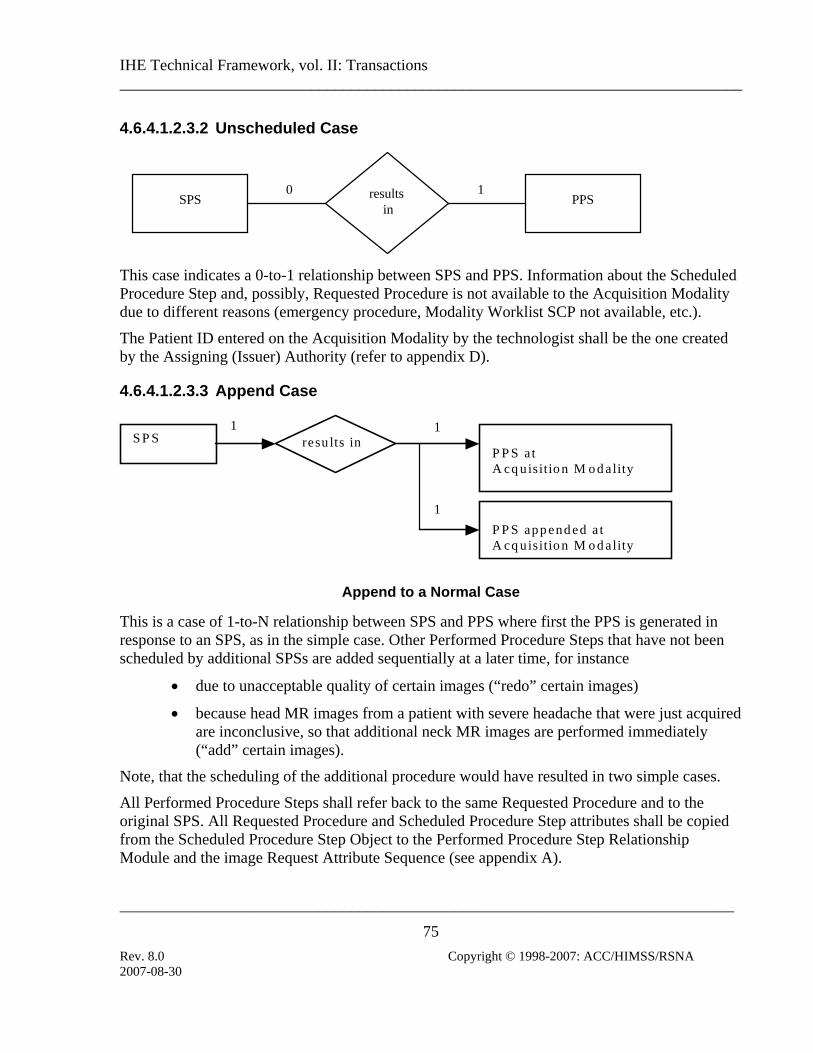
IHE Technical Framework, vol. II: Transactions ______________________________________________________________________________
_____________________________________________________________________________
75 Rev. 8.0 Copyright © 1998-2007: ACC/HIMSS/RSNA
4.6.4.1.2.3.2 Unscheduled Case
SPS results in
PPS0 1
This case indicates a 0-to-1 relationship between SPS and PPS. Information about the Scheduled Procedure Step and, possibly, Requested Procedure is not available to the Acquisition Modality due to different reasons (emergency procedure, Modality Worklist SCP not available, etc.).
The Patient ID entered on the Acquisition Modality by the technologist shall be the one created by the Assigning (Issuer) Authority (refer to appendix D).
4.6.4.1.2.3.3 Append Case
S P S resu lts in P P S a t A cq uisitio n M o d ality
1
1
1
P P S app end ed a t A cq uisitio n M o d ality
Append to a Normal Case
This is a case of 1-to-N relationship between SPS and PPS where first the PPS is generated in response to an SPS, as in the simple case. Other Performed Procedure Steps that have not been scheduled by additional SPSs are added sequentially at a later time, for instance
• due to unacceptable quality of certain images (“redo” certain images)
• because head MR images from a patient with severe headache that were just acquired are inconclusive, so that additional neck MR images are performed immediately (“add” certain images).
Note, that the scheduling of the additional procedure would have resulted in two simple cases.
All Performed Procedure Steps shall refer back to the same Requested Procedure and to the original SPS. All Requested Procedure and Scheduled Procedure Step attributes shall be copied from the Scheduled Procedure Step Object to the Performed Procedure Step Relationship Module and the image Request Attribute Sequence (see appendix A).
2007-08-30

IHE Technical Framework, vol. II: Transactions ______________________________________________________________________________
_____________________________________________________________________________
76 Rev. 8.0 Copyright © 1998-2007: ACC/HIMSS/RSNA
S P S resu lts in P P S a t A cq uisitio n M o d ality
1
1
1
P P S app end ed a t A cq uisitio n M o d ality
S P S 1
Append to a Group Case
When the first PPS generated at the Acquisition Modality results from a Group Case (See sec. 4.6.4.1.2.3.4 or 4.6.4.1.2.3.6), the Performed procedure Step appended by the Acquisition Modality may refer back to any one or all of the original SPSes and related Requested Procedure(s), using information from the Request Attribute Sequence in the original images. The corresponding attributes shall be copied to the Performed procedure Step Relationship Module and the image Request Attribute Sequence (see Appendix A).
Note: For example, following a PPS performed on an MR Modality in response to the grouping of a "neck" SPS and a "head" SPS, a 3D analysis on the MR head images is performed on the modality. This modality application may choose to link the appended PPS associated with the 3D secondary captures images resulting from the 3D analysis with both the head and the neck SPS.
4.6.4.1.2.3.4 Group Case
Requested Procedure 1
Requested Procedure 2
SPS
SPS
SPS
results in PPS
1
1
1
1
This case indicates an N-to-1 relationship between SPS and PPS. The following sub-cases shall be supported and fulfilled by a single Performed Procedure Step:
2007-08-30

IHE Technical Framework, vol. II: Transactions ______________________________________________________________________________
_____________________________________________________________________________
77 Rev. 8.0 Copyright © 1998-2007: ACC/HIMSS/RSNA
a) Grouped SPSes belonging to a single Requested procedure
b) Grouped SPSes belonging to multiple Requested Procedures
c) A combination of Grouped SPSes belonging to multiple Requested procedures and Grouped SPSes belonging to a single Requested Procedure.
If all grouped SPSs belong to the same Requested Procedure, then the Study Instance UID and Accession Number from the MWL shall be copied to the corresponding attributes of the grouped images and in the grouped PPS. If the grouped SPSs belong to different Requested Procedures sharing the same Accession Number (i.e. same Order), the Modality shall generate a new Study Instance UID and the Accession Number from the MWL shall be copied to the corresponding attributes of the grouped images and the grouped PPS (see Appendix A.1-4 for mapping details). If the grouped SPSs belong to different Requested Procedures with different Accession Numbers (i.e. different Orders), the Modality shall generate a new Study Instance UID, leave the Accession Number empty in grouped Images and copy the Accession Number from the MWL to the corresponding attributes in grouped PPS (see Appendix A.1-4 for mapping details).
All Requested Procedure and Scheduled Procedure Step attributes shall be copied from the multiple Scheduled Procedure Step Objects (and associated Requested Procedures) to the Performed Procedure Step Relationship Module in the single Performed Procedure Step and to the Request Attribute Sequence in Images (See Appendix A for proper mappings to MPPS and Images).
Support for the group case by the Acquisition Modality actor is required in the Presentation of Grouped Procedures Integration Profile. In the Scheduled Workflow Integration Profile a Modality may clain the support of the MODALITY GROUP CASE Option. When supported this option implies that sub-cases a), b), and c) above shall be supported..
The DSS/Order Filler, Image Manager Report Manager and Performed Procedure Step Manager are always required to accept Performed Procedure Steps containing attributes from multiple Scheduled Procedure Steps and Requested Procedures in Integration Profiles where those actors accept Modality Performed Procedure Step Transactions.
4.6.4.1.2.3.5 Abandoned Case
SPS results in
PPS 1 1
2007-08-30
IHE Technical Framework, vol. II: Transactions ______________________________________________________________________________
_____________________________________________________________________________
78 Rev. 8.0 Copyright © 1998-2007: ACC/HIMSS/RSNA
This case indicates a 1-to-1 relationship between SPS and PPS, even though the PPS may or may not create images. A procedure step may have to be abandoned for clinical reasons before it is complete. If SOP instances are sent by the Acquisition Modality to the Image Archive, then they shall be identified in the PPS N-SET. This is a means to explicitly communicate this information to the Image Manager or Department System Scheduler/Order Filler. In addition, one may choose to use this abandoned case to remove Scheduled Procedure Steps from the worklist, by starting the corresponding Performed Procedure Step and immediately discontinuing it using the N-SET service with the status value DISCONTINUED. All Requested Procedure and Scheduled Procedure Step attributes shall be copied from the Scheduled Procedure Step Object to the Performed Procedure Step Relationship Module (see appendix A).
4.6.4.1.2.3.6 Group Case with Presentation of Grouped Procedures
This case applies only in the context of the Presentation of Grouped Procedures Integration Profile. It applies to the subcases b) and c) of the Group Case ( sec. 4.6.4.1.2.3.4) and to the Append Case ( sec. 4.6.4.1.2.3.3) along with the rules specified in this section. Refer to RAD TF-1:6 for the use cases associated with the Presentation of Grouped Procedures. Presentation of Grouped Procedures in the a) subcase is equivalent to the use of the CPI Integration Profile. It is therefore out of scope for this section.
First, this case indicates an N-to-1 relationship between SPS and a first PPS. SPSs belong to two or more different Requested Procedures, and are fulfilled by a single Performed Procedure Step. This Performed Procedure Step is related to the images, (and possibly presentation states, key image notes, etc.). acquired in a single acquisition. All Requested Procedure and Scheduled Procedure Step attributes shall be copied from the multiple Scheduled Procedure Step Objects to the Performed Procedure Step Relationship Module in the single Performed Procedure Step (see appendix A) and to the Request Attribute Sequence in Images (See Appendix A). This is a proper subset of the Group Case specified in sec. 4.6.4.1.2.3.4.
Second, this case indicates a 1-to-1 relationship between the SPSs of each Requested Procedure and an additional corresponding PPS. All SPSs belonging to the same Requested Procedure, are fulfilled by a corresponding Performed Procedure Step. The Requested Procedure and Scheduled Procedure Step attributes shall only be copied from the related Scheduled Procedure Step Object(s) to the Performed Procedure Step Relationship Module in the Performed Procedure Step (see appendix A) related to the specific Presentation State(s) intended to present the corresponding subset of images for the Requested Procedure. This is a proper subset of the Append Case specified in sec. 4.6.4.1.2.3.3, with the exception that the Study Instance UID used for the Presentation States shall be the same as the one created for the image set acquired as part of the first PPS (See Appendix A, Table A.1-4).
The Presentation of Grouped Procedure operates at the Requested Procedure level whereas grouping operates at the level of Scheduled Procedure Steps.
2007-08-30

IHE Technical Framework, vol. II: Transactions ______________________________________________________________________________
_____________________________________________________________________________
79 Rev. 8.0 Copyright © 1998-2007: ACC/HIMSS/RSNA
Requested Procedure 1 SPS
SPS
SPS
results in
1
1
1
1
results in 1
results in 1 PPS
PPS
PPS
Presentation State(s) for Requested Procedure 1
Presentation State(s) for Requested Procedure 2
Image Set for Requested Procedures 1 & 2
Study Instance UID(Created per the
Group Case rules)
Requested Procedure 2
4.6.4.1.2.4 Protocol Handling
The protocol (a specific combination of modality settings or a method) used in performing a procedure step shall be determined on the Acquisition Modality at this time. Two cases/options are defined: Manual Modality Setting and Assisted Modality Setting. The first case is the one that is currently most commonly used while the second case introduces new functionality and is optional for the IHE Technical Framework.
The Acquisition Modality shall not change the Requested Procedure Code it obtains through the MWL. If the Requested Procedure Code is not correct or needs to be changed at the time the procedure is being performed, one of the following two methods shall be used: • Department System Scheduler Method: The Procedure Information shall be corrected on the
Department System Scheduler/Order Filler, and updated information shall be downloaded to the Acquisition Modality, OR
• Acquisition Modality Method: The Acquisition Modality redefines Protocol Code(s) for the Procedure Steps it actually performs and sets the Procedure Code Sequence (0008,1032) to zero length.
The specification for which methods are required or optional is found in the Scheduled Workflow Integration Profile (RAD TF-1: 3.3.4).
2007-08-30

IHE Technical Framework, vol. II: Transactions ______________________________________________________________________________
_____________________________________________________________________________
80 Rev. 8.0 Copyright © 1998-2007: ACC/HIMSS/RSNA
4.6.4.1.2.4.1 Manual Modality Setting
The following illustration is a Scheduled Procedure Step (SPS) being returned to an Acquisition Modality as part of a Modality Worklist (MWL) and protocol information being returned in the Performed Procedure Step (PPS). In this case an operator selects and sets a protocol based on manual interpretation/evaluation of the Requested Procedure (RP) code and/or the Scheduled Procedure Step description and content of the Scheduled Protocol Code Sequence (SPCS). Note that the Scheduled Protocol Code Sequence, if present, may contain multiple items, however, they describe a single Protocol.
Note: Scheduled Action Item Code Sequence has been redefined in 2001 by the DICOM standard as Scheduled Protocol Code Sequence.
This approach may also be used in cases when the protocol identifies more of a method used in performing the acquisition (such as in ultrasound), rather then a set of fixed modality settings (such as in CT/MR).
SPS
RP ⎯ Code & Desc.
SPS ⎯ SPCS & Desc.
MWL
OperatorSelects
Protocol Name
PPS
In this Manual Modality Setting, the Scheduled Protocol Code Sequence is analyzed by the Operator. The Acquisition Modality Actor is not required to provide a value for the Performed Protocol Code Sequence. (Only the Protocol Name is required to be sent).
4.6.4.1.2.4.2 Assisted Acquisition Protocol Setting Option
When an Acquisition Modality Actor supports the ASSISTED ACQUISITION PROTOCOL SETTING option, it shall provide the means to use the protocol codes specified in the Scheduled Procedure Steps selected from the Modality Worklist.
According to the DICOM standard (PS 3.3): "A Protocol is a specification of actions prescribed by a Procedure Plan to perform a specific Procedure Step. A Scheduled Procedure Step contains only one Protocol that may be conveyed with one or more Protocol Codes. So, each Scheduled Procedure Step is performed according to a single Protocol which may be identified by one or more Protocol Codes." This option refines the semantics of the interpretation of Protocol Codes specifically in the case where more than one Protocol Code is present.
2007-08-30

IHE Technical Framework, vol. II: Transactions ______________________________________________________________________________
_____________________________________________________________________________
81 Rev. 8.0 Copyright © 1998-2007: ACC/HIMSS/RSNA
A Scheduled Procedure Step may contain a single Protocol Code, for example: • A “Standard Chest X-ray” Protocol Code. This implies PA and Lateral views. • A “Screening Mamography” Protocol Code. This implies RMLO and LMLO, RCC and
LCC views.
A Scheduled Procedure Step may also contain multiple Protocol Codes in cases where more complex SPS requires several acquisition or image processing tasks be performed in a sequencial manner, for example: • An “MRI Acquisition” Protocol Code followed by an “MRA Acquisition” Protocol Code. • A “CT Head without contrast” Protocol Code followed by a “CT with contrast” Protocol
Code. • A “CT Lumbar Spine” Protocol Code followed by a “Reformation of the discs” Protocol
Code. • A “CT Thorax” protocol Code followed by a “Recon with lung kernel” Protocol Code.
In this option, an Acquisition Modality shall process the protocol code sequence in each Scheduled Procedure Step (SPS) selected from the Modality Worklist and return the Performed Protocol Codes in the Performed Procedure Step (PPS). Department System Schedulers and Image Managers shall support the use of more than one Protocol Code in the Scheduled Protocol Code (SPC) Sequence. Modalities shall support either a single code or multiple codes in the SPC sequence. If a Department System Scheduler/Order Filler communicates with modalities that support only a single Protocol Code in the Scheduled Protocol Code Sequence, the procedure plan (mapping of order into requested procedures, scheduled procedure steps, and protocol codes) shall only use single protocol codes per SPS. The institution may decide to configure its Department System Scheduler to either schedule all Scheduled Procedure Step with a single code or to schedule Steps on modalities based on their capabilities and handling of multiple Procedure Codes.
The modality operator shall either accept the protocol proposed by the set of Protocol Codes or select one or more alternative protocol defined on the Modality. The operator shall not manually enter the attributes of the acquisition protocol as in the Manual Modality Setting. The Assisted Acquisition Protocol Setting Option simplifies the operator’s work on the modality and enables a better management of the protocols used in an imaging department. This option may provide benefits for charge posting.
When multiple Scheduled Protocol Codes are present in the SPC Sequence, each Scheduled Protocol Code shall be analyzed independently (i.e., not as a compound code). It follows that: • The modality settings resulting from the simultaneous processing of the ordered set of
Protocol Codes is semantically equivalent to the sequential processing of each Protocol Code independently. In other words, no additional semantics may be inferred from the simultaneous processing of multiple Protocol Codes in the sequence, and
2007-08-30

IHE Technical Framework, vol. II: Transactions ______________________________________________________________________________
_____________________________________________________________________________
82 Rev. 8.0 Copyright © 1998-2007: ACC/HIMSS/RSNA
• Protocol Codes shall be proposed to the operator in the order defined in the sequence. The Operator may choose to perform this sequence of Protocol Codes in a different order than scheduled, omit performing some of the protocol codes or include others.
Whether the Scheduled Procedure Step includes one or several Protocol Codes, each Protocol Code shall be processed according to the Protocol Codes defined in the Modality Protocol Code Table. • If a match is found, the modality settings defined in the Modality Protocol Code Table, shall
be proposed to the operator. The operator may then choose to: • Accept the settings (i.e. modality acquisition parameters) proposed. In this case the
Performed Protocol Code will take the value of the Scheduled Protocol Code. • Accept the settings (modality acquisition parameters) and refine them. (Local policy
will determine what refinements are acceptable within a specific protocol code). In this case the Performed Protocol Code will take the value of the Scheduled Protocol Code.
• Reject the settings proposed and manually select another protocol defined in the Modality Protocol Table. In this case the Performed Protocol Code will take the value of the manually selected Protocol Code (see recommendations in Tables A.1-1 to A.1-5 in Appendix A)..
• If there is no identical Protocol Code defined in the Modality Protocol Table, the Acquisition Modality must alert the operator.
A Modality Protocol Table shall be configured on the Acquisition Modality. This table shall be synchronized with the Image Manager and the Department System Scheduler/Order Filler. A simple approach may be used to achieve such synchronization: if a requested Protocol Code is received, but not yet defined, the Acquisition Modality may provide a means to notify the operator that the Modality Protocol Table needs to be updated by creating the detailed acquisition settings corresponding to the new protocol Code.
SPS
RP ⎯ Code & Desc. SPS ⎯ Sch. Pr. Code Seq SPS⎯ Description
MWL
Performed Protocol Name; Performed Protocol Code(s)
PPS
Code Protocol Desc. A Head without
contrast …. …. X Lumbar spine.
Modality Protocol Code Table
Operator accepts suggested protocol or selects protocol from table
When the ASSISTED ACQUISITION PROTOCOL SETTING option is supported by the Acquisition Modality actor, a value for the Performed Protocol Code Sequence shall be provided
2007-08-30

IHE Technical Framework, vol. II: Transactions ______________________________________________________________________________
_____________________________________________________________________________
83 Rev. 8.0 Copyright © 1998-2007: ACC/HIMSS/RSNA
in addition to the Protocol Name. If multiple Protocol Codes have been selected and the corresponding acquisitions performed, the order of the Protocol Codes in the sequence shall reflect the order in which they were performed. This order may differ from the order in which they appeared in the Scheduled Protocol Code Sequence.
The ASSISTED ACQUISITION PROTOCOL SETTING option does not define a specific codification of acquisition protocols. The involved actors, Department System Scheduler, Acquisition Modality, Image Manager/Archive and Report Manager shall be configurable in order to support the codification scheme selected or defined by the healthcare enterprise.
4.6.4.1.3 Expected Actions
The Department System Scheduler/Order Filler, Report Manager and the Image Manager/Image Archive receive information from the Performed Procedure Step Manager and link it with the Requested Procedure and Scheduled Procedure Step. If the Requested Procedure ID is transmitted empty (Unscheduled Performed Procedure Step case), the Department System Scheduler/Order Filler and the Image Manager shall create an exception that must be manually resolved to link the Performed Procedure Step to the appropriate procedure.
2007-08-30

IHE Technical Framework, vol. II: Transactions ______________________________________________________________________________
_____________________________________________________________________________
84 Rev. 8.0 Copyright © 1998-2007: ACC/HIMSS/RSNA
4.7 Modality Procedure Step Completed/Discontinued This section corresponds to Transaction RAD-7 of the IHE Technical Framework. Transaction RAD-7 is used by the Department System Scheduler/Order Filler, Image Manager, Report Manager, Performed Procedure Step Manager and Acquisition Modality actors.
4.7.1 Scope
This transaction includes a message from the Acquisition Modality to the Performed Procedure Step Manager, which in turn issues messages to the DSS/Order Filler, the Report Manager and the Image Manager that the Performed Procedure Step has been completed. Information is not being released for billing at this point but a code may be assigned. The Image Manager may need the information to co-locate images of the same study. The Modality Procedure Step Completed message does not necessarily mean that the set of images is complete or available for retrieval.
4.7.2 Use Case Roles
Department SystemScheduler/Order Filler
Image ManagerPerformed
Procedure StepManager
Modality ProcedureStep Completed
AcquisitionModality
Report Manager
Actor: Department System Scheduler/Order Filler.
Role: Receives the PPS information forwarded by the PPS Manager.
Actor: Image Manager.
Role: Receives the PPS information forwarded by the PPS Manager.
Actor: Report Manager.
Role: Receives the PPS information forwarded by the PPS Manager.
Actor: Acquisition Modality.
Role: Informs the Performed Procedure Step Manager that a particular Performed Procedure Step is completed.
Actor: Performed Procedure Step Manager.
2007-08-30

IHE Technical Framework, vol. II: Transactions ______________________________________________________________________________
_____________________________________________________________________________
85 Rev. 8.0 Copyright © 1998-2007: ACC/HIMSS/RSNA
Role: Accepts Performed Procedure Step information from an Acquisition Modality and transmits it to the Department System Scheduler/Order Filler, Image Manager and Report Manager.
4.7.3 Referenced Standards
DICOM 2007 PS 3.4: Modality Performed Procedure Step SOP Class.
DICOM 2007 PS 3.16: DCMR Context Groups (Normative)
4.7.4 Interaction Diagram
Department SystemScheduler/Order
FillerAcquisition
ModalityReport Manager
MPPS N-SETMPPS N-SET
Performed Procedure StepManager/
Image Manager
MPPS N-SET
2007-08-30

IHE Technical Framework, vol. II: Transactions ______________________________________________________________________________
_____________________________________________________________________________
86 Rev. 8.0 Copyright © 1998-2007: ACC/HIMSS/RSNA
Image ManagerAcquisition
Modality
Report Manager
MPPS N-SETMPPS N-SET
Performed Procedure Step Manager/Department System Scheduler/Order
Filler
MPPS N-SET
Note: The diagram above shows the sequencing of messages for the Modality Performed Procedure Step SOP Class. Acquisition Modalities will also implement the Storage and Storage Commitment classes. The timing relationship between PPS messages and Storage and Storage Commitment messages is not specified. That is, PPS messages may occur before or after storage requests. .
4.7.4.1 Procedure Step Completed/Discontinued
4.7.4.1.1 Trigger Event
Technologist completes procedure step from the Acquisition Modality console.
4.7.4.1.2 Message Semantics
The Acquisition Modality uses the Modality Performed Procedure Step SOP Class (N-SET service) to inform the Performed Procedure Step Manager that a specific Performed Procedure Step has been completed or discontinued. The Acquisition Modality may use the MPPS N-SET service to send intermediate updates of the Performed Procedure Step information.
The final N-SET has either the MPPS status of "COMPLETED" or "DISCONTINUED". The Performed Procedure Step Manager sends corresponding N-SETs to the Department System Scheduler/Order Filler, Image Manager and Report Manager.
When an N-SET is issued with a “DISCONTINUED” status, one or more Series of Instances may be referenced, if images were created and sent. Those Instances shall be Stored and Storage Committed
2007-08-30

IHE Technical Framework, vol. II: Transactions ______________________________________________________________________________
_____________________________________________________________________________
87 Rev. 8.0 Copyright © 1998-2007: ACC/HIMSS/RSNA
Along with other information, the Acquisition Modality shall transmit information about the protocol it used to produce the SOP instances to the recipients. See Protocol Handling in sec. 4.6.4.1.2.4 for detailed discussion of this issue.
Note: DICOM specifies that when attributes are allowed to be be set by an N-SET, the value provided by the last N-SET overrides any value set by an earlier N-CREATE or N-SET.
4.7.4.1.2.1 Retrieve AE Title
According to the DICOM Standard, the Acquisition Modality has the ability to include the Retrieve AE Title attribute (0008,0054) in the Performed Series Sequence (0040,0340). This is an AE Title where the referenced SOP instances for the series may be retrieved. This Retrieve AE Title will often be of zero length or be of short-term validity, due to the following situations: • If an Acquisition Modality supports a Retrieve SOP Class in an SCP Role, the modality
Retrieve AE Title may be included; however, the modality does not guarantee long-term availability.
• A Retrieve AE Title of the Image Manager can be configured on the Acquisition Modality. Otherwise, this field shall be sent zero length. Acquisition Modality implementers shall not assume that the destination AE Title used for the Storage SCP or Storage Commitment SCP is the same as that for Image Retrieval.
• An Acquisition Modality may receive the Retrieve AE Title in a Storage Commitment Message (N-EVENT REPORT). However, this information may be received well after the MPPS N-SET (Complete) was performed.
4.7.4.1.2.2 PPS Exception Management Option
When an Acquisition Modality Actor supports the PPS EXCEPTION MANAGEMENT option, it shall provide the appropriate reason codes (often selected by the operator) in the final N-SET sent with the status of DISCONTINUED.
When the Modality Procedure Step is sent with the Status DISCONTINUED, the Modality Procedure Step Discontinuation Reason Code Sequence (0040,0281) shall be sent with one of the values defined in DICOM 2007 PS 3.16 Annex B.
Table 4.7-1 Context ID 9300 – Procedure Discontinuation Reasons
Most Restrictive Use: Defined Coding Scheme
Designator (0008,0102)
Code Value (0008,0100)
Code Meaning (0008,0104)
DCM 110500 Doctor cancelled procedure
DCM 110501 Equipment failure
2007-08-30

IHE Technical Framework, vol. II: Transactions ______________________________________________________________________________
_____________________________________________________________________________
88 Rev. 8.0 Copyright © 1998-2007: ACC/HIMSS/RSNA
DCM 110502 Incorrect procedure ordered
DCM 110503 Patient allergic to media/contrast
DCM 110504 Patient died
DCM 110505 Patient refused to continue procedure
DCM 110506 Patient taken for treatment or surgery
DCM 110507 Patient did not arrive
DCM 110508 Patient pregnant
DCM 110509 Change of procedure for correct charging
DCM 110510 Duplicate order
DCM 110511 Nursing unit cancel
DCM 110512 Incorrect side ordered
DCM 110513 Discontinued for unspecified reason
DCM 110514 Incorrect worklist entry selected
DCM 110515 Patient condition prevented continuing
The Reason Code when communicated to the DSS/Order Filler and Image Manager/Archive may imply canceling an order. It may also facilitate more accurate charge posting.
The Reason Code: “Incorrect Worklist Entry Selected’ is used by the Acquisition Modality Actor to convey that the wrong SPS has been selected (incorrect patient or incorrect Requested procedure/order for the same patient). In this case some or all of the incorrectly acquired images (for example the ones assigned to the wrong patient) may already have been stored to the image manager. (See sec 4.7.4.1.3.1). Modality implementers are left free to decide how to correct the incorrectly acquired images. The Acquisition Modality shall include within the MPPS the list of images that are or will be included in the Images Stored Transaction(s).
Note: When a PPS DISCONTINUED is sent with the reason code "incorrect worklist entry selected", images referenced in this PPS DISCONTINUED are images that may have been sent to the Image Manager/Archive. The IHE Technical Framework does not specify whether or not the Acquisition Modality Actor needs to perform a Storage Commitment for these instances.
4.7.4.1.2.3 Billing and Material Management Option
The message semantics are defined in the DICOM Service Class section of the DICOM 2007 Modality Performed Procedure Step SOP Class. It is the responsibility of the Acquisition Modality to ensure that the patient and procedure information is sent to the Department System Scheduler/Order Filler.
The Attributes defined in Table 4.7-2 provide a means to transmit procedure and material management codes from the acquisition modality to the DSS/Order Filler that uses them for calculation of charges to be posted to Charge Processor.
2007-08-30

IHE Technical Framework, vol. II: Transactions ______________________________________________________________________________
_____________________________________________________________________________
89 Rev. 8.0 Copyright © 1998-2007: ACC/HIMSS/RSNA
A modality that supports the BILLING AND MATERIAL MANAGEMENT option shall be able to provide content within at least one of the Billing Procedure Step Sequence, Film Consumption Sequence and Billing Supplies and Devices Sequence.
Table 4.7-2 Billing and Material Management Code Module Attributes
Attribute name Tag Attribute Description Billing Procedure Step Sequence (0040,0320) Contains billing codes for the Procedure Type performed
within the Procedure Step. The sequence may have zero or more Items See note IHE-1, IHE-2
> Code Value (0008,0100)
> Coding Scheme Designator (0008,0102)
> Code Meaning (0008,0104)
Film Consumption Sequence (0040,0321) Information about the film consumption for this Performed Procedure Step. The sequence may have zero or more Items. Note: This is only for films printed from this device. See note IHE-3
>Number of Films (2100,0170) Number of films actually printed.
>Medium Type (2000,0030) Type(s) of medium on which images were printed.
>Film Size ID (2010,0050) Size(s) of film on which images were printed.
Billing Supplies and Devices Sequence (0040,0324) Contains billing codes for chemicals, supplies and devices for billing used in the Performed Procedure Step. The sequence may have one or more Items.
>Billing Item Sequence (0040,0296) Codes values of chemicals, supplies or devices required for billing. The sequence may have zero or one Items. See note IHE-4
>> Code Value (0008,0100)
>> Coding Scheme Designator (0008,0102)
>> Code Meaning (0008,0104)
>Quantity Sequence (0040,0293) Sequence containing the quantity of used chemicals or devices. The sequence may have zero or one Items.
>>Quantity (0040,0294) Numerical quantity value.
>>Measuring Units Sequence (0040,0295) Unit of measurement. The sequence may have zero or one Items. Baseline CID 82
>>> Code Value (0008,0100)
>>> Coding Scheme Designator (0008,0102)
>>> Code Meaning (0008,0104)
(IHE-1) Billing Procedure Step Sequence Attribute shall be present if Modality supports the BILLING AND MATERIAL MANAGEMENT option. It may be sent zero-
2007-08-30

IHE Technical Framework, vol. II: Transactions ______________________________________________________________________________
_____________________________________________________________________________
90 Rev. 8.0 Copyright © 1998-2007: ACC/HIMSS/RSNA
length if one of Film Consumption Sequence or Billing Supplies and Devices Sequence is also populated.
(IHE-2) A Modality Billing Code Table shall be configured on the Acquisition Modality. This table shall be synchronized with the Department System Scheduler/Order Filler. The codes provided by the Acquisition Modality might not be the same as the code the Department System Scheduler/Order Filler is required to use when posting Charges to the Charge Processor.
(IHE-3) Film Consumption Sequence shall be present if films have been printed during this Performed Procedure Step. Information provided in Film Consumption Sequence may not be sufficient to properly calculate charges. For example, to take into account quality and sensitivity of film, Department System Scheduler/Order Filler shall obtain additional information before calculating and posting charges to the Charge Processor.
(IHE-4) Different coding schemes may be used for codes of Billing Items, for example, DCMR Context ID 12 - Radiographic Contrast Agent may be used to record quantity of contrast used.
4.7.4.1.2.4 Protocol Handling
See section 4.6.4.1.2.4 for a description of protocol handling.
4.7.4.1.3 Expected Actions
The Image Manager, Report Manager and Department System Scheduler/Order Filler receive information about the Performed Procedure Step being complete or discontinued. The Image Manager, Report Manager and Department System Scheduler are not required to act on intermediate N-SET messages with the MPPS Status "IN PROGRESS".
The Requested Procedure may be considered complete if all Performed Procedure Steps related to all Scheduled Procedure Steps have been completed (or properly discontinued). Additional new (unscheduled) Performed Steps may be performed at any time, even after the Requested Procedure has been assigned complete scanning status. See relationship between Scheduled and Performed Procedure Steps in sec. 4.6.4.1.2.3 for detailed discussion of this issue.
4.7.4.1.3.1 PPS Exception Management Option
When a DSS/Order Filler or Image Manager/Archive supports the PPS EXCEPTION MANAGEMENT option, it shall use the reason codes in the final N-SET sent with the status of DISCONTINUED.
2007-08-30

IHE Technical Framework, vol. II: Transactions ______________________________________________________________________________
_____________________________________________________________________________
91 Rev. 8.0 Copyright © 1998-2007: ACC/HIMSS/RSNA
When the Modality Procedure Step is received with the Status DISCONTINUED, the receiver shall interpret the Performed Procedure Step Discontinuation Reason Code Sequence (0040,0281) values as defined in DICOM (See Table 4.7-1). When received by the Department System Scheduler/Order Filler and the Image Manager/Archive, the Reason Code may indicate the necessity for modification or canceling of an order). With the Reason Code: “Incorrect Worklist Entry Selected”, the Acquisition Modality Actor conveys that the wrong SPS has been selected (e.g. incorrect patient or incorrect Requested procedure/order for the same patient). In this case the Image Manager and Department System Scheduler shall take the appropriate action to ensure that already received incorrect instances (i.e. SOP Instances referenced by this Discontinued PPS) are not mistakenly used. If the images, presentation states, or key image notes are not actually deleted, the Image Manager shall: • not return SOP Instance UIDs for the images in query responses, • not return such images in Patient, Study, Series, or Instance level retrievals,
On the DSS and Image Manager, the Order/Requested Procedure status shall be corrected to indicate that the discontinued PPS (with wrong worklist entry selected) is not valid. Therefore the Order Filler/Department System Scheduler shall not query for those instances with an Image Availability transaction.
4.7.4.1.3.2 Billing and Material Management Option
When a DSS/Order Filler supports the BILLING AND MATERIAL MANAGEMENT option, it shall use the billing codes and material usage information provided in the final N-SET for calculation of charges that it will eventually post to the Charge Processor. It is recommended that DSS/Order Filler verifies the consistency of provided billing codes with Requested Procedure Code and Performed Procedure Step Protocol codes supplied in the same N-SET.
2007-08-30

IHE Technical Framework, vol. II: Transactions ______________________________________________________________________________
_____________________________________________________________________________
92 Rev. 8.0 Copyright © 1998-2007: ACC/HIMSS/RSNA
4.8 Modality Images Stored This section corresponds to Transaction RAD-8 of the IHE Technical Framework. Transaction RAD-8 is used by the Image Archive and Acquisition Modality actors.
4.8.1 Scope
In the Modality Images Stored transaction, the Acquisition Modality sends the acquired images to the Image Archive. The information provided from the Modality Worklist transaction (see sec. 4.5) shall be included in the headers of the generated images.
4.8.2 Use Case Roles
ModalityImages Stored
AcquisitionModality
ImageArchive
Actor: Acquisition Modality
Role: Transmit acquired image data to Image Archive.
Actor: Image Archive
Role: Accept and store images from Acquisition Modalities.
4.8.3 Referenced Standards
DICOM 2007 PS 3.4: Storage Service Class.
2007-08-30

IHE Technical Framework, vol. II: Transactions ______________________________________________________________________________
_____________________________________________________________________________
93 Rev. 8.0 Copyright © 1998-2007: ACC/HIMSS/RSNA
4.8.4 Interaction Diagram
AcquisitionModality
ImageArchive
C-STORE (Images Stored)
4.8.4.1 Images Stored
4.8.4.1.1 Trigger Events
The Acquisition Modality can transfer images to the Image Archive sequentially within one or more DICOM associations, as the images become available or collectively.
4.8.4.1.1.1 Study UIDs and Series UIDs
Study UID creation details and timing are clearly defined by the IHE. The Scheduled Workflow and Patient Reconciliation Profiles explain how the Study information and identifiers such as the Study Instance UID are generated by the Order Filler and made available to the modality through the Modality Worklist. Generation of these items by the modality or workstation are restricted in general and are only permitted in specifically outlined exception cases, when a PPS is unscheduled (Appendix A, Table A.1-2) or when several SPS belonging to different Requested Procedures are satisfied by a single PPS (Appendix A, Table A.1-5).
Series UID creation must be compatible with a number of DICOM rules.
Multiple performed procedure steps are not permitted to reference the same series. So conversely, one series cannot contain the output of different performed procedure steps. Therefore, adding images to a series in a procedure step which has been completed is not permitted since a procedure step cannot be modified.
Note that a series may fulfill more than one scheduled procedure step. This is referred to in IHE as the group case.
Adding images after completion of a procedure step shall trigger the creation of a new series.
2007-08-30

IHE Technical Framework, vol. II: Transactions ______________________________________________________________________________
_____________________________________________________________________________
94 Rev. 8.0 Copyright © 1998-2007: ACC/HIMSS/RSNA
One series cannot contain the output of different equipment (in part because a series must have a single Frame Of Reference). Creating images on different equipment shall trigger the creation of a new series.
All images in a series must share the same Frame Of Reference. Generally this means creating images with different patient positioning shall trigger the creation of a new series. Note that if the Frame Of Reference is not present (at the Series level), this requirement is avoided.
Images reconstructed on a different piece of equipment are required to be in a separate Series.
For consistency, IHE specifies that reconstructed images shall be stored in a separate series from the acquired tomographic images from which they were reconstructed regardless of whether they are reconstructed on the Acquisition Modality or an Evidence Creator.
4.8.4.1.2 Message Semantics
The Acquisition Modality uses the DICOM C-STORE message to transfer the images. The Acquisition Modality is the DICOM Storage SCU and the Image Archive is the DICOM Storage SCP.
The technologist validates the available information for the patient and the Scheduled Procedure Step/Requested Procedure. It is a requirement that certain information be recorded in the image header. The details of the mapping to DICOM image instances are specified in appendix A. Effectively, this appendix strengthens the type definition of some DICOM attributes for the IHE Technical Framework.
4.8.4.1.2.1 Storage of Localizer Images (MR and CT)
In addition to these general mapping requirements, in MR and CT images the relationship between localizer or plan images and related slice images shall be recorded when such slice images were planned or prescribed from the localizer or plan images. In this case, the attribute Referenced Image Sequence (0008,1140) of the slice image shall refer to the related localizer or plan image(s). The coordinate space for this set of related images shall be the same, which is indicated by having a single value for the attribute Frame of Reference UID (0020,0052). For CT images the slice images shall have the value AXIAL in the attribute Image Type, and the localizer image the value LOCALIZER. For MR images no specific value for image type is used to further qualify the relationship between plan and related slice images. The Acquisition Modality actor shall not use the method of burning-in localizer lines in the pixel sample values (pixel sample value is the "bits stored" part of the pixel data) of the localizer or plan image(s).
2007-08-30

IHE Technical Framework, vol. II: Transactions ______________________________________________________________________________
_____________________________________________________________________________
95 Rev. 8.0 Copyright © 1998-2007: ACC/HIMSS/RSNA
Image Display actors that want to show the localizer lines will be able to calculate the position of these lines of intersection (if visible) based on the information recorded in the images by the Acquisition Modality actor.
4.8.4.1.2.2 Storage of NM Images (NM)
Systems supporting the NM Image Profile are required to support a number of attributes as described in the following tables and text. Many of these requirements build on attributes which are Type 2 or Type 3 in DICOM (such attributes are indicated with R+).
Note that the NM Image profile is undergoing revision, and vendors considering implementation are advised to include the modifications contained in the trial implementation version “NM Image Profile with Cardiac Option”. For additional information please contact the IHE Radiology Technical Committee at [email protected].
This section is referred to in the Creator Images Stored transaction (Section 4.18) and so the Evidence Creator actor may also be referred to in the text here.
Table 4.8-2. Required Attributes in Nuclear Medicine Images Image Type
General Cardiac Attribute Tag
S T AT I C
DY NAMI C
WH O L E B O D Y
GATED
T O M O
R E C O N
T O M O
T O M O
R E C O N
T O M O
G A T E D
T O M O
R E C O N
G A T E D
T O M O
Detector Information Sequence
(0054,0022)
> Image Position (0020,0032) R+ R+ R+
> Image Orientation (0020,0037) R+ R+ R+ R+ R+ R+ > View Code Sequence
(0054,0220)
>> Code Value (0008,0100) R+1R+ R+1
>> Coding Scheme Designator
(0008,0102) R+ R+1 R+1
2007-08-30

IHE Technical Framework, vol. II: Transactions ______________________________________________________________________________
_____________________________________________________________________________
96 Rev. 8.0 Copyright © 1998-2007: ACC/HIMSS/RSNA
Image Type Slice Progression Direction
(0054,0500) R+2 R+2
Spacing Between Slices
(0018,0088) R+4 R+4 R+4
Acquisition Context Sequence
(0040,0555)
> Concept-Name Code Sequence
(0040,A043) R+3 R+3 R+3 R+3
> Concept Code Sequence
(0040,A168) R+3 R+3 R+3 R+3
Note 1: Required for images from one of the standard cardiac views: Short Axis, Vertical Long Axis, or Horizontal Long Axis. For a definition of these terms and the implied orientation of the heart in the frame (refer to Nuclear Cardiology Nomenclature, Cequeria MD, et al, Journal of Nuclear Cardiology, 2002, 9:240-245). The Code Values shall be taken from Context ID 26 (relevant codes are shown here):
Coding SchemeDesignator
Code Value Code Meaning
SNM3 G-A186 Short Axis
SNM3 G-A18A Vertical Long Axis
SNM3 G-A18B Horizontal Long Axis
Note 2: Slice Progression Direction is required for Images in which the View Code Sequence indicates Short Axis views. The DICOM defined values are APEX_TO_BASE and BASE_TO_APEX.
Note 3: The Acquisition Context Module and the Acquisition Context Sequence (0040,0555) contained within it are required for cardiac stress/rest images. As defined in the Standard, the Concept Name Code Sequence (0040,A043) shall contain (DCM, 109054, “Patient State”) and the Concept Code Sequence (0040,A168) shall use values from the following list:
Coding SchemeDesignator
Code Value Code Meaning
SRT F-01604 Resting State
DCM 109091 Cardiac Stress State
DCM 109092 Reinjection State
DCM 109093 Redistribution State
DCM 109094 Delayed Redistribution State
Note 4: The ‘Spacing Between Slices’ attribute is required by IHE to contain a valid value for the RECON image types.
2007-08-30

IHE Technical Framework, vol. II: Transactions ______________________________________________________________________________
_____________________________________________________________________________
97 Rev. 8.0 Copyright © 1998-2007: ACC/HIMSS/RSNA
It is recommended that when multiple energy windows are present that descriptive values be provided for the following attributes: Energy Window Name (0054,0018), Energy Window Lower Limit (0054,0014) and Energy Window Upper Limit (0054,0015).
It is recommended that when multiple detectors are present that descriptive values be provided in the codes contained in the View Code Sequence (0054,0220).
It is recommended that when multiple phases are present that descriptive values be provided for the Phase Description (0054,0039).
The Acquisition Modality or Evidence Creator shall be capable of encoding the data for NM images with Image Type (0008,0008) equal to TOMO or GATED TOMO as if it were created on a single detector system. This means setting the Number of Detectors (0054,0021) to 1 and reordering the frame data to be consistent with acquisition by a single detector system regardless of the number of actual detectors used to acquire the image data. The system may additionally support encoding the data with the actual detector configuration.
When the Image Type (0008,0008) is RECON TOMO or RECON GATED TOMO, the Image Position (0020,0032), Image Orientation (0020,0037), and the View Code Sequence (0054,0220) shall describe the orientation of the reconstructed frames within the Image.
When the Image Type (0008,0008) is WHOLEBODY, the useful image data is generally rectangular in shape (e.g. 256x1024). Acquisition Modalities and Evidence Creators shall be capable of creating these images without padding to create square frames.
Although the DICOM standard does not rigorously specify the order of frames in the image object, the following practice is commonly used and is required by the NM Image Profile:
Images shall be stored with the frames sorted into “vector sorted order”. That is, the frames shall be ordered such that the frames are sorted first by the values of the first vector, then within a value for the first vector, the frames are sorted by the values of the second vector, etc.. This order is referred to in this document as “vector sorted order”.
For details on vectors and examples of “vector sorted order”, refer to RAD TF-1, Appendix E.4.2 NM Image IOD: Multi-Frames & Vectors.
4.8.4.1.2.3 Storage of Full Field Digital Mammography Images
When participating in the Modality Images Stored transaction and the Mammography Image Integration Profile, the Acquisition Modality actor that creates in vivo clinical full field digital mammography images, whether using a digital detector, by computed radiography, or by digitizing film, shall use the DICOM Digital Mammography X-Ray Image IOD, and shall supply the attributes with the additional requirements presented in Table 4.8.4.1.2.3-1.
The less stringent requirements for Attributes for digitized film in Table 4.8.4.1.2.3-1 apply only if the intent of digitization is not for primary diagnosis, but for other purposes such as CAD and
2007-08-30

IHE Technical Framework, vol. II: Transactions ______________________________________________________________________________
_____________________________________________________________________________
98 Rev. 8.0 Copyright © 1998-2007: ACC/HIMSS/RSNA
use as priors for comparison, since additional information otherwise required may not obtainable at the time of digitization.
Table 4.8.4.1.2.3-1. Required Additional Attributes in Mammography Images Attribute Tag DX,
CR Film Rationale
Patient’s Name (0010,0010) R+ R+ Used for identification during display
Patient ID (0010,0020) R+ R+ Used for identification during display
Patient’s Birth Date (0010,0030) R+ O Used for identification during display
Patient’s Age (0010,1010) R+ O Used for identification during display
Acquisition Date (0008,0022) R+ R+ Used for identification during display
Acquisition Time (0008,0032) R+ O Used for identification during display
Operator’s Name (0008,1070) R+ O Used for identification during display
Manufacturer (0008,0070) R+ O Used for quality control display
Institution Name (0008,0080) R+ O Used for identification during display
Institution Address (0008,0081) R+ O Used for quality control display
Manufacturer’s Model Name
(0008,1090) R+ O Used for quality control display
Device Serial Number
(0018,1000) R+ O Used for quality control display
Detector ID (0018,700A) R+ O Used for quality control display; this attribute in the Mammography IOD replaces the function in the CR IOD of Plate or Cassette ID for a CR mammography system
Software Versions (0018,1020) R+ O Used for CAD systems to be sure that processing is appropriate to the software version that created the images.
Station Name (0008,1010) R+ O Used for identification of the system that acquired the images during display.
Gantry ID (0018,1008) RC+ O Used for identification of the system that acquired the images during display. Required for images acquired by CR, since the Station Name (0008,1010) will normally identify the plate reader, not the acquisition device.
Source Image Sequence
(0008,2112) R+ O Neededto allow Image Displays to apply CAD marks to for presentation images when CAD was performed on for processing images
>Spatial Locations Preserved
(0028,135A) R+ O Neededto allow Image Displays to apply CAD marks to for presentation images when CAD was performed on for processing images; see also DICOM CP 564. Shall be YES if only a flip or rotation of the image pixel data has been performed.
KVP (0018,0060) R+ O Used for display of the kVP technical factor
Exposure (0018,1152) R+ O Used for display of the mAs technical factor
2007-08-30

IHE Technical Framework, vol. II: Transactions ______________________________________________________________________________
_____________________________________________________________________________
99 Rev. 8.0 Copyright © 1998-2007: ACC/HIMSS/RSNA
DX, Attribute Tag Film Rationale CR
Exposure Time (0018,1150) R+ O Used for display of the exposure time technical factor
Filter Material (0018,7050) R+ O Used for display of the filter technical factor
Anode Target Material
(0018,1191) R+ O Used for display of the target technical factor
Compression Force (0018,11A2) R+ O Used for display of the compression force technical factor
Body Part Thickness
(0018,11A0) R+ O Used for display of the compressed breast thickness technical factor
Positioner Primary Angle
(0018,1510) R+ O Used for display of the degree of obliquity technical factor
Relative X-ray Exposure
(0018,1405) R+ O Used for the display of the relative exposure technical factor. Note that Sensitivity (0018,6000) is NOT used for this purpose.
Entrance Dose in mGy
(0040,8302) R+ O Used for display of the estimated skin dose technical factor. Note that this attribute is used instead of the less precise (0040,0302) whose integer value is in dGy units.
Organ Dose (0040,0316) R+ O Used for the display of the estimated mean glandular dose technical factor
VOI LUT Sequence (0028,3010) C C Required if Window Center and Width not present
>LUT Explanation (0028,3003) RC+ RC+ Required if more than one sequence item or at least one sequence item and window center/width pair is present in order to allow Image Display to present to the user a selection of LUTs or windows described by the explanation.
Window Center and Width Explanation
(0028,1055) RC+ RC+ Required if more than one VOI LUT Sequence item or window center/width pair and at least one VOI LUT Sequence item is present in order to allow Image Display to present to the user a selection of LUTs or windows described by the explanation.
VOI LUT Function (0028,1056) RC+ RC+ Required if Window Center and Width are not intended to be interpreted as parameters of a linear function in order to allow Image Display to perform appropriate contrast transformation. Enumerated Values LINEAR or SIGMOID. See DICOM CP 467.
Burned In Annotation
(0028,0301) R R Shall have the enumerated value of “NO”, unless the image was obtained by film digitization.
Implant Present (0028,1300) R+ O Used to control hanging and processing (including CAD); not identical to Implant Displaced value for View Modifier Code Sequence, since an implant may be present but not displaced.
Pixel Padding Value (0028,0120) RC+ RC+ Required if background air supression has been performed by replacing the pixels with a value not used within the breast tissue, so that pixels with this value can be excluded from contrast
2007-08-30

IHE Technical Framework, vol. II: Transactions ______________________________________________________________________________
_____________________________________________________________________________
100 Rev. 8.0 Copyright © 1998-2007: ACC/HIMSS/RSNA
DX, Attribute Tag Film Rationale CR
transformations,. May be present otherwise. See 4.8.4.1.2.3.2.
Pixel Padding Range Limit
(0028,0121) RC+ RC+ Required if Pixel Padding Value (0028,0120) is present and the padding values are a range rather than a single value. See 4.8.4.1.2.3.2.
Estimated Radiographic Magnification Factor
(0018,1114) R+ O Used to adjust Imager Pixel Spacing (0018,1164) to account for geometric magnification for normal and magnified views when making distance measurements and displaying or printing calipers.
Date of Last Detector Calibration
(0018,700C) RC+ O Used for quality control display. Required if detector undergoes periodic calibration (e.g., may not be applicable for CR).
See Section 2.2 DICOM Usage Conventions.
4.8.4.1.2.3.1 Partial View Option
The Partial View Option requires that the Acquisition Modality always send a flag indicating whether or not the image is part of a set of images (a mosaic) used to cover the area of a breast that is larger than the detector, and which part of the set the image represents.
The Partial View (0028,1350) Attribute shall be sent and have a value of NO for magnification and spot compression images.
Table 4.8.4.1.2.3.1-1. Required Additional Attributes in Mammography Images
for the Partial View Option Attribute Tag IHE Rationale
Partial View (0028,1350) R+ Required to control hanging of mosaics. Partial View Code Sequence
(0028,1352) RC+ Required if Partial View (0028,1350) has a value of YES, to control hanging of mosaics.
4.8.4.1.2.3.2 Background Air Supression
For full field images (but not magnification or specimen images), the Acquisition Modality shall detect air outside the breast or the skin line, so as to provide for image contrast adjustment of the breast without adjusting the contrast of the background, and shall encode the region of the background to be excluded in “For Presentation” images by one of two means:
• a single Pixel Padding Value (0028,0120) that is used to indicate a value in the pixel data that is outside the breast
2007-08-30

IHE Technical Framework, vol. II: Transactions ______________________________________________________________________________
_____________________________________________________________________________
101 Rev. 8.0 Copyright © 1998-2007: ACC/HIMSS/RSNA
• a range of pixel values between Pixel Padding Value (0028,0120) and Pixel Padding Range Limit (0028,0121) inclusive that is used to indicate values in the pixel data that are outside the breast
The air supression mechanism used shall not obscure any burned in lead markers present in the image.
4.8.4.1.2.3.3 Cleavage Views
In a cleavage view that is not centered between both breasts or for which the operator designates one breast as primary, then the value of Image Laterality (0020,0062) shall be “L” or “R”, rather than “B”.
4.8.4.1.2.3.4 Digitized Film
The Digital Mammography X-Ray Image IOD, not the Secondary Capture Image IOD, shall be used for digitized film. Presentation Intent Type (0008,0068) shall be FOR PRESENTATION.
The values of the pixel size encoded in Imager Pixel Spacing (0018,1164) shall be the physical distance on the film being digitized or scanned between the center of each pixel.
The Study Date (0008,0020), Study Time (0008,0030), Acquisition Date (0008,0022) and Acquisition Time (0008,0022) shall be the date and time of acquisition of the film-screen exposure, not when the film was digitized.
Burned In Annotation (0028,0301) shall be present and may have a value of YES if the digitized image contains patient identification information.
There are no specific requirements in this transaction for the reconciliation of identifiers during digitization. However, the Acquisition Modality may be grouped with an Importer Actor in the Import Reconciliation Workflow integration profile.
The output of the grayscale pipeline in a Digital Mammography X-Ray Image IOD FOR PRESENTATION image is always in P-Values, therefore the optical density values obtained during film digitization shall be converted to P-Values, using appropriate assumed viewing conditions for the original film.
4.8.4.1.3 Expected Actions
The Image Archive will store the received DICOM objects.
The DICOM objects shall be stored such that they can be later retrieved (See 4.16 Retrieve Images) in a fashion meeting the requirements defined for a DICOM Level 2 Storage SCP (Refer to DICOM PS 3.4 B.4.1).
2007-08-30

IHE Technical Framework, vol. II: Transactions ______________________________________________________________________________
_____________________________________________________________________________
102 Rev. 8.0 Copyright © 1998-2007: ACC/HIMSS/RSNA
4.8.4.1.3.1 DICOM Image Storage SOP Classes
The DICOM Standard (2007) defines a number of image specific storage SOP classes. It is expected that Image Archive will support multiple storage SOP classes as defined in table 4.8-1 below.
Table 4.8-1. Suggested Image SOP Classes SOP Class UID SOP Class Name
1.2.840.10008.5.1.4.1.1.1 Computed Radiography Image Storage
1.2.840.10008.5.1.4.1.1.2 CT Image Storage
1.2.840.10008.5.1.4.1.1.4 MR Image Storage
1.2.840.10008.5.1.4.1.1.20 Nuclear Medicine Image Storage
1.2.840.10008.5.1.4.1.1.128 Positron Emission Tomography Image Storage
1.2.840.10008.5.1.4.1.1.481.1 RT Image Storage
1.2.840.10008.5.1.4.1.1.7 Secondary Capture Image Storage
1.2.840.10008.5.1.4.1.1.6.1 Ultrasound Image Storage
1.2.840.10008.5.1.4.1.1.3.1 Ultrasound Multi-frame Image Storage
1.2.840.10008.5.1.4.1.1.12.1 X-Ray Angiographic Image Storage
1.2.840.10008.5.1.4.1.1.12.2 X-Ray Radiofluoroscopic Image Storage
1.2.840.10008.5.1.4.1.1.1.1 Digital X-Ray Image Storage – For Presentation
1.2.840.10008.5.1.4.1.1.1.1.1 Digital X-Ray Image Storage – For Processing
1.2.840.10008.5.1.4.1.1.1.2 Digital Mammography Image Storage – For Presentation
1.2.840.10008.5.1.4.1.1.1.2.1 Digital Mammography Image Storage – For Processing
1.2.840.10008.5.1.4.1.1.1.3 Digital Intra-oral X-Ray Image Storage – For Presentation
1.2.840.10008.5.1.4.1.1.1.3.1 Digital Intra-oral X-Ray Image Storage – For Processing
1.2.840.10008.5.1.4.1.1.77.1.1 VL Endoscopic Image Storage
1.2.840.10008.5.1.4.1.1.77.1.2 VL Microscopic Image Storage
1.2.840.10008.5.1.4.1.1.77.1.3 VL Slide-Coordinates Microscopic Image Storage
1.2.840.10008.5.1.4.1.1.77.1.4 VL Photographic Image Storage
Image Manager/Image Archives claiming the NM Image Profile are required to support all of the SOP classes listed in Table 4.8-3 below. Acquisition Modalities claiming the NM Image Profile are required to support Nuclear Medicine Image Storage.
Table 4.8-3. Nuclear Medicine SOP Classes
SOP Class UID SOP Class Name 1.2.840.10008.5.1.4.1.1.20 Nuclear Medicine Image Storage
1.2.840.10008.5.1.4.1.1.7 Secondary Capture Image Storage
1.2.840.10008.5.1.4.1.1.7.2 Multi-frame Grayscale Byte Secondary Capture Image Storage
1.2.840.10008.5.1.4.1.1.7.4 Multi-frame True Color Secondary Capture Image Storage
2007-08-30

IHE Technical Framework, vol. II: Transactions ______________________________________________________________________________
_____________________________________________________________________________
103 Rev. 8.0 Copyright © 1998-2007: ACC/HIMSS/RSNA
Acquisition Modalities shall be capable of providing all created Nuclear Medicine image types using the Nuclear Medicine Image SOP class.
Acquisition Modalities and Image Manager/Image Archives claiming the Mammography Image Profile are required to support all of the SOP classes listed in Table 4.8-4 below.
Table 4.8-4. Mammography SOP Classes for Acquisition and Archival
SOP Class UID SOP Class Name 1.2.840.10008.5.1.4.1.1.1.2 Digital Mammography Image Storage – For Presentation
1.2.840.10008.5.1.4.1.1.1.2.1 Digital Mammography Image Storage – For Processing
Film digitizers are only required to create “For Presentation” images. All other Acquisition Modalities claiming the Mammography Image Profile shall be capable of sending both “For Presentation” and “For Processing” images for every image stored, though not necessarily to the same target. E.g. “For Processing” images may be sent to the actor corresponding to the CAD device and “For Presentation” images or both to the Image Manager/Archive).
The “For Presentation” images shall contain a reference to the SOP Instance UID of the corresponding “For Processing” image in Source Image Sequence (0008,2112).
The Image Manager/ Image Archive actor shall be able to accept both “For Processing” and “For Presentation” images from the Acquisition Modality, and make both available for retrieval, but is not required to be able to make “For Processing” images “presentable”.
2007-08-30

IHE Technical Framework, vol. II: Transactions ______________________________________________________________________________
_____________________________________________________________________________
104 Rev. 8.0 Copyright © 1998-2007: ACC/HIMSS/RSNA
4.9 Modality Presentation State Stored This section corresponds to Transaction RAD-9 of the IHE Technical Framework. Transaction RAD-9 is used by the Image Archive and Acquisition Modality actors.
4.9.1 Scope
This section describes DICOM Storage requests of Grayscale Softcopy Presentation States issued by the Acquisition Modality to the Image Archive. The Acquisition Modality sends Presentation States for storage along with the images so they can be later used for support of consistent display of imaging data
4.9.2 Use Case Roles
AcquisitionModality
ImageArchive
ModalityPresentation State
Stored
Actor: Acquisition Modality
Role: Generate Grayscale Softcopy Presentation States to be applied to image data. This actor will support the ability to send Presentation State data to an Image Archive. This actor must support pixel rendering according to the Grayscale Standard Display Function (GSDF) as defined in DICOM 2007 PS 3.14.
Actor: Image Archive
Role: Accept and store Grayscale Softcopy Presentation State SOP Instances received from the Acquisition Modality.
4.9.3 Referenced Standards
DICOM 2007 PS 3.4: Storage Service Class
2007-08-30

IHE Technical Framework, vol. II: Transactions ______________________________________________________________________________
_____________________________________________________________________________
105 Rev. 8.0 Copyright © 1998-2007: ACC/HIMSS/RSNA
DICOM 2007 PS 3.4: Grayscale Softcopy Presentation State Storage
DICOM 2007 PS 3.14: Grayscale Standard Display Function
4.9.4 Interaction Diagram
Acquisition Modality
Image Archive
C-STORE (Presentation State Stored)
4.9.4.1 Modality Presentation State Stored
4.9.4.1.1 Trigger Events The Acquisition Modality generates a Grayscale Softcopy Presentation State and sends it to the Image Archive for storage. A Presentation State shall be generated as part of a Performed Procedure Step (see sec. 4.6.4). It can be either as part of a Simple, Unscheduled, Append, Discontinue or Grouped Cases for which the same requirements as images apply. When generated as part of a Presentation of Grouped Procedure Case it shall follow the specific requirements defined in sec. 4.6.4.1.2.3.6.
4.9.4.1.2 Message Semantics
The Acquisition Modality uses the DICOM C-STORE message to store Grayscale Softcopy Presentation States. All grayscale processing operations, and all spatial and graphical operations, that are relevant to the resulting presentation of the referenced image have to be recorded in the presentation state. This will preserve the "as-last-seen" view of the image, with for example the contrast setting, rotation, flip and text annotation. The image operations in the presentation state override whatever is recorded in the image itself, even in the case that no attributes for a specific operation ( e.g. Window Width/Window Level operation) are present in the presentation state. The latter case by definition specifies an identity operation. The full message semantics are defined in the Grayscale Softcopy Presentation State Storage SOP Class Behavior section of DICOM 2007 PS 3.4. The Acquisition Modality will be the DICOM Storage SCU and the Image Archive will be the DICOM Storage SCP.
2007-08-30

IHE Technical Framework, vol. II: Transactions ______________________________________________________________________________
_____________________________________________________________________________
106 Rev. 8.0 Copyright © 1998-2007: ACC/HIMSS/RSNA
4.9.4.1.3 Expected Actions
The Image Archive will store the received Grayscale Softcopy Presentation State objects.
4.10 Storage Commitment This section corresponds to Transaction RAD-10 of the IHE Technical Framework. Transaction RAD-10 is used by the Image Manager and Acquisition Modality actors.
4.10.1 Scope
After the Acquisition Modality or Evidence Creator has sent images, Presentation States, or Key Image Notes to the Image Archive, it requests that the Image Manager/Image Archive accept responsibility for them. The objective of this transaction is to provide a formal release of storage responsibility to the Acquisition Modality or Evidence Creator, allowing it to reuse its internal resources allocated to the study.
4.10.2 Use Case Roles
Storage Commitment
Acquisition Modality
Evidence Creator
Image Manager
Actor: Acquisition Modality
Role: Make requests for storage commitment to the Image Manager for the images, Presentation States, Key Image Notes, and Evidence Documents previously transmitted.
Actor: Evidence Creator
Role: Make requests for storage commitment to the Image Manager for the images, Presentation States, Key Image Notes, and Evidence Documents previously transmitted.
Actor: Image Manager.
Role: Assume responsibility for reliable storage, retrieval, and validity of images, Presentation States, Key Image Notes, and Evidence Documents.
4.10.3 Referenced Standards
DICOM 2007 PS 3.4: Storage Commitment Push Model SOP Class.
2007-08-30

IHE Technical Framework, vol. II: Transactions ______________________________________________________________________________
_____________________________________________________________________________
107 Rev. 8.0 Copyright © 1998-2007: ACC/HIMSS/RSNA
4.10.4 Interaction Diagram
Acquisition Modality
ImageManager
Storage Commitment N-ACTION
Storage Commitment N-EVENT-REPORT
Evidence Creator
Storage Commitment N-ACTION
Storage Commitment N-EVENT-REPORT
4.10.4.1 Images Committed
The Storage Commitment Push Model SOP Class shall be used as reflected in the interaction diagram. The Storage Commitment Pull Model SOP Class will not be supported. Refer to the DICOM 2007 PS 3.4 for detailed descriptive semantics.
4.10.4.1.1 Trigger Events
The Acquisition Modality and Evidence Creator act as the Storage Commitment SCUs and can issue a commitment request at any time after the successful transfer of one or more SOP Instances to the Image Manager/Archive, which is the Storage Commitment SCP.
4.10.4.1.2 Message Semantics
The Acquisition Modality and Evidence Creator use the DICOM Storage Commitment SOP Class to communicate with the Image Manager. The Acquisition Modality and Evidence Creator shall convey the reference to SOP Class and Instance by using the Modality Performed Procedure Step (see TF-2, A.1) instead of using the Referenced Performed Procedure Step Sequence (0008,1111). The Storage Commitment AE Title used by the Image Manager may or may not be the same AE Tile as the one used for the Images Stored (C-STORE) service. The Acquisition Modality and Evidence Creator shall support this flexibility with respect to the AE Title. The N-EVENT-REPORT sent by the Image Manager to communicate its storage commitment may or may not occur on the same association as the N-ACTION.
2007-08-30

IHE Technical Framework, vol. II: Transactions ______________________________________________________________________________
_____________________________________________________________________________
108 Rev. 8.0 Copyright © 1998-2007: ACC/HIMSS/RSNA
An Acquisition Modality and Evidence Creator may receive the Retrieve AE Title in a Storage Commitment Message (N-EVENT REPORT). However, this N-EVENT REPORT may happen well after the Modality Performed Procedure Step N-SET (Complete) was performed. For this reason, the IHE Technical Framework does not require that the Acquisition Modality and Evidence Creator send the Retrieve AE Title Attribute (0008,0054) in the Modality and Creator Performed Procedure Step N-SET (See sections 4.7 and 4.21).
Under normal circumstances, in the event that the Image Manager cannot service the storage commitment request, which can be determined by the "Failure Reason Attribute," the Acquisition Modality and Evidence Creator shall not delete nor modify the respective SOP instance(s).
4.10.4.1.3 Expected Actions
The Image Manager in coordination with the Image Archive accepts responsibility for the safe storage of the transferred image data or Presentation States. (The form of the cooperation is beyond the scope of the IHE Technical Framework.) Ownership of data transfers from the Acquisition Modality to the Image Manager. The Acquisition Modality is then free to manage its own internal resources accordingly.
2007-08-30

IHE Technical Framework, vol. II: Transactions ______________________________________________________________________________
_____________________________________________________________________________
109 Rev. 8.0 Copyright © 1998-2007: ACC/HIMSS/RSNA
4.11 Image Availability Query This section corresponds to Transaction RAD-11 of the IHE Technical Framework. Transaction RAD-11 is used by the Department System Scheduler, Report Manager and Image Manager actors.
4.11.1 Scope
The purpose of this transaction is for the Department System Scheduler/Order Filler and Report Manager to determine whether SOP instances associated with a particular performed procedure step have been stored and are available for use in subsequent workflow steps as well as the storage location for retrieval of these SOP instances. The Image Manager is assumed to possess image availability information. The following examples show possible uses of the Image Availability Query: • The Department System Scheduler/Order Filler queries the Image Manager after receiving
notification, that images have been acquired (by MPPS N-SET message with PPS status of “COMPLETED” – see Transaction RAD-7) until it receives a list of all images listed in the PPS.
• The Department System Scheduler/Order Filler needs to verify the availability of prior images pre-fetched according to workflow rules. In this case the availability of a single image may have to be verified.
• The Report Manager queries the Image Manager after receiving notification, that images have been acquired (by MPPS N-SET message with PPS status of “COMPLETED” – see Transaction RAD-7) until it receives a list of all images listed in the PPS. At this time the Report Manager may schedule the appropriate task so that the reporting process can commence.
• The Report Manager needs to verify the availability of prior images pre-fetched according to workflow rules. In this case the availability of a single image may have to be verified.
Image availability is determined by the fact that the Image Instance UID in question is returned in response to the query. However, for the purposes of workflow management, image availability is generally qualified with additional parameters, such as:
Storage Location describes a system or system component (for instance, an Image Archive) that can be identified as a holder of images at a particular period in time.
Access Time is a period of time that is required for images to be moved from a storage location to be ready for distribution; i.e., this does not take into consideration the outbound network transfer time or the performance of the receiver application to display the images. The exact access time is difficult to determine and is highly implementation-dependent. Nevertheless, it is possible to approximate access time by using a degree or level of image availability.
2007-08-30

IHE Technical Framework, vol. II: Transactions ______________________________________________________________________________
_____________________________________________________________________________
110 Rev. 8.0 Copyright © 1998-2007: ACC/HIMSS/RSNA
4.11.2 Use Case Roles
Department System Scheduler/Order Filler
Image Manager
Image Availability Query
Report Manager
Actor: Department System Scheduler/Order Filler
Role: Queries Image Manager to determine availability of images for use in the processes according to department workflow (for example, interpretation)
Actor: Report Manager
Role: Queries Image Manager to determine availability of images for use in the processes according to department workflow (for example, interpretation)
Actor: Image Manager
Role: Supplies image availability information to Department System Scheduler/Order Filler
4.11.3 Referenced Standards
DICOM 2007 PS 3.4: Query/Retrieve Service Class.
4.11.4 Interaction Diagram
Department System Scheduler/Order Filler
Image Manager
Image Availability query (DICOM C-FIND)
DICOM C-FIND Response
2007-08-30

IHE Technical Framework, vol. II: Transactions ______________________________________________________________________________
_____________________________________________________________________________
111 Rev. 8.0 Copyright © 1998-2007: ACC/HIMSS/RSNA
Report Manager
Image Manager
Image Availability query (DICOM C-FIND)
DICOM C-FIND Response
4.11.4.1 Query Image Availability
4.11.4.1.1 Trigger Events
After receiving MPPS N-SET message with PPS status of “COMPLETED” or at a later time, the Department System Scheduler/Order Filler or Report Manager needs to verify image availability.
4.11.4.1.2 Message Semantics
The Department System Scheduler/Order Filler or Report Manager issues a C-FIND request as specified in the DICOM Standard for the Study Root Query/Retrieve Information Model – FIND SOP Class. The Department System Scheduler/Order Filler and Report Manager must be configured with the AE information of the Image Managers to be queried. To obtain the list of images in question, the Department System Scheduler/Order Filler and Report Manager shall perform a query on the Image Level based on the specification in DICOM. The Hierarchical Search Method shall be supported. The following table highlights important attributes of the query. It is not the intent of this transaction to provide a mechanism for polling. The Department System Scheduler/Order Filler and Report Manager shall query the Image Manager with the minimal number of queries necessary. For example, if the purpose is to verify availability of all images in a series, DSS/OF shall not send queries on an image-by-image basis. In this case, a single, zero length value for the SOP Instance UID could be sent, then all matched images information will be returned.
Table 4.11-1. Images Availability Query Keys Attribute Tag Query Key value
Query/Retrieve Level (0008,0052) IMAGE
Study Instance UID (0020,000D) Unique value for single-value match
Series Instance UID (0020,000E) Unique value for single-value match
SOP Instance UID (0008,0018) Single value, zero length value or list of UIDs
2007-08-30

IHE Technical Framework, vol. II: Transactions ______________________________________________________________________________
_____________________________________________________________________________
112 Rev. 8.0 Copyright © 1998-2007: ACC/HIMSS/RSNA
Per the DICOM standard, Retrieve AE Title (0008,0054) shall be supported and returned by the Image Manager as part of the response.
To better quantify Access Time, the optional attribute Instance Availability (0008,0056) with enumerated values of “ONLINE”, “NEARLINE” and “OFFLINE” may be used. In terms of access times and results of subsequent Retrieve (C-MOVE) request, the Image Availability values shall be interpreted as follows:
Table 4.11-2. Image Access Time Level Description Access time
ONLINE Images can be retrieved from storage location and be ready for distribution within a reasonable period of time (what time is reasonable is implementation-specific)
Typically, seconds to a few minutes
NEARLINE Before distribution, images has to be processed at a storage location; total retrieval time is longer than “reasonable”
Typically, minutes to an hour
OFFLINE Image cannot be distributed without human user intervention Typically, minutes to hours to days
4.11.4.1.3 Expected Actions
The Image Manager shall respond to the C-FIND as specified in the DICOM standard, including returning the SOP Instance UIDs (0008,0018) and corresponding Retrieve AE title (0008, 0054) when the match is successful.
2007-08-30

IHE Technical Framework, vol. II: Transactions ______________________________________________________________________________
_____________________________________________________________________________
113 Rev. 8.0 Copyright © 1998-2007: ACC/HIMSS/RSNA
4.12 Patient Update This section corresponds to Transaction RAD-12 of the Technical Framework. Transaction RAD-12 is used by the ADT, Order Placer, Department System Scheduler, Report Manager and Image Manager actors.
4.12.1 Scope
This transaction involves changes to patient information, including demographics, patient identification, patient location/class changes, and patient merges. These changes may occur at any time for a patient record. This transaction is used for both inpatients (i.e., those who are assigned a bed at the facility) and outpatients (i.e., those who are not assigned a bed at the facility) if the patient has been previously registered.
4.12.2 Use Case Roles
Patient Update
Order Placer
Department SystemScheduler
ADT ImageManager
MPIReport Manager
Actor: ADT
Role: Adds and modifies patient demographic and encounter information.
Actor: Order Placer
Role: Receives patient and encounter information for use in order entry.
Actor: Department System Scheduler
Role: Receives and updates patient and encounter information to maintain consistency with ADT and MPI systems. Shall provide the updated patient and encounter information to the Image Manager.
Actor: MPI
Role: Receives patient and encounter information from multiple ADT systems. Maintains unique enterprise-wide identifier for a patient.
Actor: Image Manager
2007-08-30

IHE Technical Framework, vol. II: Transactions ______________________________________________________________________________
_____________________________________________________________________________
114 Rev. 8.0 Copyright © 1998-2007: ACC/HIMSS/RSNA
Role: Receives patient and encounter information for use in maintaining its database of images and other evidence documents and, possibly, for management such as auto-routing evidence objects to a specific in-patient floor.
Actor: Report Manager
Role: Receives patient and encounter information for use in maintaining its report database.
Note: The IHE Technical Framework currently does not support the use of a Master Patient Index, which is required for synchronization of patient information between multiple ADT systems employed by a healthcare enterprise. It is expected that the IHE initiative will include an MPI Actor in the future and that the Patient Update/Merge Transaction between the ADT and MPI will be similar to the transaction between the ADT and Order Placer and Order Filler actors.
4.12.3 Referenced Standards
HL7 2.3.1 Chapters 2, 3
4.12.4 Interaction Diagram
HL7 ADT^*
HL7 ADT^*
ADT Order Placer
HL7 ADT^*
HL7 ADT^*
Department SystemScheduler
* A02, A03, A06, A07, A08, A40
Image Manager
MPI
2007-08-30

IHE Technical Framework, vol. II: Transactions ______________________________________________________________________________
_____________________________________________________________________________
115 Rev. 8.0 Copyright © 1998-2007: ACC/HIMSS/RSNA
HL7 ADT^*
HL7 ADT^*
ADT Order Placer
HL7 ADT^*
HL7 ADT^*
Department SystemScheduler
* A02, A03, A06, A07, A08, A40
Report Manager
MPI
4.12.4.1 Patient Management – Patient Transfer
4.12.4.1.1 Trigger Events
Changes in patient location result in the following Update Patient message:
A02 – Patient Transfer
An A02 event is issued as a result of the patient changing his or her assigned physical location.
4.12.4.1.2 Message Semantics
The Update Patient transaction is an HL7 ADT message. The message shall be generated by the system that performs the update whenever an error is resolved or a change occurs in patient location.
The segments of the Patient Transfer message listed below are required, and the detailed description of messages is provided in the following subsections.
ADT A02 Patient Administration Message Chapter in HL7 v2.3.1
MSH Message Header 2
EVN Event Type 3
PID Patient Identification 3
PV1 Patient Visit 3
Each message shall be acknowledged by the HL7 ACK message sent by the receiver of ADT message to its sender. See section 2.4.3 “Acknowledgement Modes” for definition and discussion of the ACK message.
4.12.4.1.2.1 MSH Segment
MSH segment shall be constructed as defined in the section 2.4.2 “Message Control”.
2007-08-30

IHE Technical Framework, vol. II: Transactions ______________________________________________________________________________
_____________________________________________________________________________
116 Rev. 8.0 Copyright © 1998-2007: ACC/HIMSS/RSNA
Field MSH-9 Message Type shall have at least two components. The first component shall have a value of “ADT”; the second component shall have value of A02. The third component is optional; however, if present, it shall have a value of ADT_A02.
4.12.4.1.2.2 EVN Segment
See sec. 4.1.4.1.2.2 for required and optional fields of the EVN segment.
4.12.4.1.2.3 PID Segment
Most of the fields in PID segment are optional, except those listed in table 4.12-1. See sec. 4.1.4.1.2.3 for the list of all fields of the PID segment.
Table 4.12-1. IHE Profile - PID segment
SEQ LEN DT OPT TBL# ITEM# ELEMENT NAME 3 20 CX R 00106 Patient Identifier List
5 48 XPN R 00108 Patient Name
18 20 CX C 00121 Patient Account Number
Adapted from the HL7 standard, version 2.3.1
4.12.4.1.2.4 PV1 Segment
Most of the fields in PV1 segment are optional, except those listed in table 4.12-2. See sec. 4.1.4.1.2.4 for the list of all fields of the PV1 segment.
Table 4.12-2. IHE profile - PV1 Segment
SEQ LEN DT OPT TBL# ITEM# ELEMENT NAME 2 1 IS R 0004 00132 Patient Class
3 80 PL C 00133 Assigned Patient Location
6 80 PL C 00136 Prior Patient Location
10 3 IS R 0069 00140 Hospital Service
11 80 PL C 00141 Temporary Location
19 20 CX C 00149 Visit Number
43 80 PL C 00173 Prior Temporary Location
51 1 IS C 0326 01226 Visit Indicator
Adapted from the HL7 standard, version 2.3.1
At least one of the fields PID-18 Patient Account Number or PV1-19 Visit Number shall be valued. Additional requirements for the presence of value in these fields may be documented in regional or national appendices to the IHE Technical Framework (See RAD TF-4).
2007-08-30

IHE Technical Framework, vol. II: Transactions ______________________________________________________________________________
_____________________________________________________________________________
117 Rev. 8.0 Copyright © 1998-2007: ACC/HIMSS/RSNA
Field PV1-51 Visit Indicator shall be valued with value “V” if the field PV1-19 Visit Number is present. May be omitted otherwise.
The new patient location shall appear either in the field PV1-3 Assigned Patient Location or PV1-11 Temporary Location (if the transfer is to a temporary location). The old patient location shall appear in the field PV1-6 Prior Patient Location or PV1-43 Prior Temporary Location (if the transfer is from a temporary location).
4.12.4.1.3 Expected Actions
It is expected that after receiving Patient Transfer message (A02) the receiving system will change its records about patient location.
It is the responsibility of the Image Manager and the Report Manager to ensure that the patient information (including the patient location) has been updated in the diagnostic reports and any relevant objects they manage when they are retrieved.
4.12.4.2 Patient Management – Update Patient Class
4.12.4.2.1 Trigger Events
Changes “in patient” class (that is from an inpatient status to outpatient, from an outpatient status to inpatient, from “admitted” or “non-admitted” status to discharged) result in one of the following Update Patient messages: • A03 – Patient Discharge • A06 – Change an Outpatient to an Inpatient • A07 – Change an Inpatient to an Outpatient
An A03 event signals the end of a patient’s stay in a healthcare facility. For in-patient, it signals that the patient’s status has changed to “discharged” and the patient is no longer in the facility. For outpatient, it signals the end of current visit of a patient to the facility. An A06 event is sent when a patient who was present for a non-admitted visit is being admitted. This event changes a patient’s status from non-admitted to “admitted”. An A07 event is sent when a patient who was admitted changes his/her status to “no longer admitted” but is still being seen for this episode of care. This event changes a patient from an “admitted” to a “non-admitted” status.
4.12.4.2.2 Message Semantics
The Update Patient transaction is an HL7 ADT message. The message shall be generated by the system that performs the update whenever patient class changes.
The segments of the Update Patient Class messages listed below are required, and the detailed description of messages is provided in sections 4.12.4.1.2.1 through 4.12.4.1.2.3.
2007-08-30

IHE Technical Framework, vol. II: Transactions ______________________________________________________________________________
_____________________________________________________________________________
118 Rev. 8.0 Copyright © 1998-2007: ACC/HIMSS/RSNA
ADT A03/A06/A07
Patient Administration Message Chapter in HL7 v2.3.1
MSH Message Header 2
EVN Event Type 3
PID Patient Identification 3
PV1 Patient Visit 3
Each message shall be acknowledged by the HL7 ACK message sent by the receiver of ADT message to its sender. See section 2.4.3 “Acknowledgement Modes” for definition and discussion of the ACK message.
4.12.4.2.2.1 MSH Segment
MSH segment shall be constructed as defined in the section 2.4.2 “Message Control”.
Field MSH-9 Message Type shall have at least two components. The first component shall have a value of “ADT”; the second component shall have value of A03, A06 or A07, as appropriate. The third component is optional; however, if present, it shall have a value of ADT_A03 (for A03 message) or ADT_A06 (for A06 and A07 messages).
4.12.4.2.2.2 EVN Segment
See sec. 4.1.4.1.2.2 for required and optional fields of the EVN segment.
4.12.4.2.2.3 PID Segment
Most of the fields in PID segment are optional, except those listed in table 4.12-3. See sec. 4.1.4.1.2.3 for the list of all fields of the PID segment.
Table 4.12-3. IHE Profile - PID segment
SEQ LEN DT OPT TBL# ITEM# ELEMENT NAME 3 20 CX R 00106 Patient Identifier List
5 48 XPN R 00108 Patient Name
18 20 CX C 00121 Patient Account Number
Adapted from the HL7 standard, version 2.3.1
4.12.4.2.2.4 PV1 Segment
Most of the fields in PV1 segment are optional, except those listed in table 4.12-4. See sec. 4.1.4.1.2.4 for the list of all fields of the PV1 segment.
2007-08-30

IHE Technical Framework, vol. II: Transactions ______________________________________________________________________________
_____________________________________________________________________________
119 Rev. 8.0 Copyright © 1998-2007: ACC/HIMSS/RSNA
Table 4.12-4. IHE profile - PV1 Segment SEQ LEN DT OPT TBL# ITEM# ELEMENT NAME
2 1 IS R 0004 00132 Patient Class
3 80 PL R 00133 Assigned Patient Location
6 80 PL C 00136 Prior Patient Location
7 60 XCN C 0010 00137 Attending Doctor
8 60 XCN C 0010 00138 Referring Doctor
9 60 XCN R2 0010 00139 Consulting Doctor
17 60 XCN C 0010 00147 Admitting Doctor
19 20 CX C 00149 Visit Number
43 80 PL C 00173 Prior Temporary Location
51 1 IS C 0326 01226 Visit Indicator
Adapted from the HL7 standard, version 2.3.1
At least one of the fields PID-18 Patient Account Number or PV1-19 Visit Number shall be valued. Additional requirements for the presence of value in these fields may be documented in regional or national appendices to the IHE Technical Framework (See RAD TF-4).
Field PV1-51 Visit Indicator shall be valued with value “V” if the field PV1-19 Visit Number is present. May be omitted otherwise.
For “Discharge Patient” (A03) message: • The field PV1-3 Assigned Patient Location shall contain the patient’s location prior to
discharge. • The field PV1-45 Discharge Date/Time does not have to be present in A03. If PV1-45 is not
present then the timestamp in the EVN segment (EVN-2 Recorded Date/Time) signifies date and time of discharge.
For “Change an Outpatient to an Inpatient” (A06) message: • The new patient class shall appear in PV1-2-patient class. • The new patient location shall appear in PV1-3-assigned patient location. • The old patient location (if relevant) shall appear in PV1-6-prior patient location. • The current active account number shall appear in PID-18-patient account number. • The Attending Doctor in PV1-7, the Referring Doctor in PV1-8, and the Consulting Doctor
in PV1-9, may be different, if there are changes to those values.
For “Change an Inpatient to an Outpatient” (A07) message: • The new patient class shall appear in PV1-2-patient class. • The old patient location shall appear in PV1-6-prior patient location or PV1-43 Prior
Temporary Location.
2007-08-30

IHE Technical Framework, vol. II: Transactions ______________________________________________________________________________
_____________________________________________________________________________
120 Rev. 8.0 Copyright © 1998-2007: ACC/HIMSS/RSNA
• The current active account number shall appear in field PID-18-patient account number. • The Attending Doctor in PV1-7, the Referring Doctor in PV1-8, and the Consulting Doctor
in PV1-9, may be different, if there are changes to those values.
A06 and A07 messages shall be used exclusively to send fields pertinent to the change in patient class between inpatient and outpatient.
Modification of any patient demographic information or non patient-class visit information must be done by in addition sending an Update Patient Information (A08) message.
4.12.4.2.3 Expected Actions
It is expected that after receiving Patient Class Change message (A03/A06/A07) it is expected that the receiving system will change its local patient visit information.
It is the responsibility of the Image Manager and the Report Manager to ensure that the patient information (including the patient location) has been updated in the diagnostic reports and any relevant objects they manage when they are retrieved.
4.12.4.3 Patient Management – Patient Information Update
4.12.4.3.1 Trigger Events
Changes to patient demographics and account information (e.g., change in patient name, patient address, etc.) shall trigger the following Update Patient message: • A08 – Update Patient Information
4.12.4.3.2 Message Semantics
The Update Patient transaction is an HL7 ADT message. The message shall be generated by the system that performs the update whenever an error is resolved or a change occurs in patient demographics.
All of the required (R and R2) information for a patient record shall be re-sent in an A08 message. Any information received as NULL (i.e. transmitted as two double quote marks "“) in the A08 message shall be removed from the receiving system's database for that patient record. If no value is sent (i.e. omitted) in the A08 message, the old value shall remain unchanged in the receiving system's database for that patient record.
An A08 message is the only method that may be used to update patient demographic and visit information. However Patient ID cannot be updated with an A08 message. An A40 message shall be used for this purpose (see sec. 4.12.4.1.2.5).
2007-08-30

IHE Technical Framework, vol. II: Transactions ______________________________________________________________________________
_____________________________________________________________________________
121 Rev. 8.0 Copyright © 1998-2007: ACC/HIMSS/RSNA
The segments of the Update Patient Information message listed below are required, and the detailed description of the message is provided in sec. 4.12.4.1.2.4. The allergy segment AL1 shall be present if allergy information is added/updated. OBX segment(s) shall be present if patient weight and/or height is updated.
ADT A08 Patient Administration Message Chapter in HL7 v2.3.1
MSH Message Header 2
EVN Event Type 3
PID Patient Identification 3
PV1 Patient Visit 3
[{OBX}] Observation/results 7
[{AL1}] Allergy 3
Each message shall be acknowledged by the HL7 ACK message sent by the receiver of ADT message to its sender. See section 2.4.3 “Acknowledgement Modes” for definition and discussion of the ACK message.
4.12.4.3.2.1 MSH Segment
MSH segment shall be constructed as defined in the section 2.4.2 “Message Control”.
Field MSH-9 Message Type shall have at least two components. The first component shall have a value of “ADT”; the second component shall have value of A08. The third component is optional; however, if present, it shall have a value of ADT_A08.
4.12.4.3.2.2 EVN Segment
See sec. 4.1.4.1.2.2 for required and optional fields of the EVN segment.
4.12.4.3.2.3 PID Segment
The required fields of the PID segment are listed in table 4.12-5. All other fields are conditional and shall be present if the value of the field has been changed by the ADT. See sec. 4.1.4.1.2.3 for the list of all fields of the PID segment.
Note that certain visit information, such as patient location and class may not be changed with this message. In these cases Patient Transfer and Change Patient Class messages shall be used.
Table 4.12-5. IHE Profile - PID segment
SEQ LEN DT OPT TBL# ITEM# ELEMENT NAME 3 20 CX R 00106 Patient Identifier List
2007-08-30

IHE Technical Framework, vol. II: Transactions ______________________________________________________________________________
_____________________________________________________________________________
122 Rev. 8.0 Copyright © 1998-2007: ACC/HIMSS/RSNA
5 48 XPN R 00108 Patient Name
18 20 CX C 00121 Patient Account Number
Adapted from the HL7 standard, version 2.3.1
4.12.4.3.2.4 PV1 Segment
Most of the fields in PV1 segment are optional, except those listed in table 4.12-6. See sec. 4.1.4.1.2.4 for the list of all fields of the PV1 segment.
Table 4.12-6. IHE profile - PV1 Segment
SEQ LEN DT OPT TBL# ITEM# ELEMENT NAME 2 1 IS R 0004 00132 Patient Class
19 20 CX C 00149 Visit Number
51 1 IS C 0326 01226 Visit Indicator
Adapted from the HL7 standard, version 2.3.1
At least one of the fields PID-18 Patient Account Number or PV1-19 Visit Number shall be valued. Additional requirements for the presence of value in these fields may be documented in regional or national appendices to the IHE Technical Framework (See RAD TF- 4).
Field PV1-51 Visit Indicator shall be valued with value “V” if the field PV1-19 Visit Number is present. May be omitted otherwise.
4.12.4.3.2.5 AL1 Segment
See sec. 4.1.4.1.2.5 for required and optional fields of the AL1 segment.
4.12.4.3.2.6 OBX Segment
See sec. 4.1.4.1.2.6 for required and optional fields of the OBX segment.
4.12.4.3.3 Expected Actions
It is expected that after receiving Patient Information message (A08) the receiving system will update its local patient demographic, visit, allergy, and/or insurance information. Any information received as null in the new A08 message shall be removed locally.
It is the responsibility of the Image Manager and the Report Manager to ensure that the patient information has been updated in the diagnostic reports and evidence objects (e.g. images, Key Image Notes, Grayscale Softcopy Presentation States, Evidence Documents, etc.) they manage when they are retrieved from.
2007-08-30

IHE Technical Framework, vol. II: Transactions ______________________________________________________________________________
_____________________________________________________________________________
123 Rev. 8.0 Copyright © 1998-2007: ACC/HIMSS/RSNA
4.12.4.4 Patient Management – Patient Merge
4.12.4.4.1 Trigger Events
When two patients records are found to identify the same patient and are merged, the following message shall be triggered: • A40 – Merge Patient – Internal ID
An A40 message indicates that a merge has been done at the internal identifier level. That is, PID-3-patient ID identifier has been merged with MRG-1 Patient ID. This message is initiated by the system that performs the merge.
4.12.4.4.2 Message Semantics
The Update Patient transaction is an HL7 ADT message. The message shall be generated by the system that performs the update whenever Patient ID changes or two records are found to reference the same person.
The segments of the Merge Patient message listed below are required, and the detailed description of the message is provided in sec. 4.12.4.1.2.5. The PV1 segment is optional.
ADT A40 Patient Administration Message Chapter in HL7 v2.3.1
MSH Message Header 2
EVN Event Type 3
PID Patient Identification 3
MRG Merge Information 3
[PV1] Patient Visit 3
Each message shall be acknowledged by the HL7 ACK message sent by the receiver of ADT message to its sender. See section 2.4.3 “Acknowledgement Modes” for definition and discussion of the ACK message.
4.12.4.4.2.1 MSH Segment
MSH segment shall be constructed as defined in the section 2.4.2 “Message Control”.
Field MSH-9 Message Type shall have at least two components. The first component shall have a value of “ADT”; the second component shall have value of A40. The third component is optional; however, if present, it shall have a value of ADT_A39.
4.12.4.4.2.2 EVN Segment
See sec. 4.1.4.1.2.2 for required and optional fields of the EVN segment.
2007-08-30

IHE Technical Framework, vol. II: Transactions ______________________________________________________________________________
_____________________________________________________________________________
124 Rev. 8.0 Copyright © 1998-2007: ACC/HIMSS/RSNA
4.12.4.4.2.3 PID Segment
Most of the fields in PID segment are optional, except those listed in table 4.12-7. See sec. 4.1.4.1.2.3 for the list of all fields of the PID segment.
Table 4.12-7. IHE Profile - PID segment
SEQ LEN DT OPT TBL# ITEM# ELEMENT NAME 3 20 CX R 00106 Patient Identifier List
5 48 XPN R 00108 Patient Name
Adapted from the HL7 standard, version 2.3.1
4.12.4.4.2.4 PV1 Segment
Most of the fields in PV1 segment are optional, except those listed in table 4.12-8. See sec. 4.1.4.1.2.4 for the list of all fields of the PV1 segment.
Table 4.12-8. IHE profile - PV1 Segment SEQ LEN DT OPT TBL# ITEM# ELEMENT NAME
2 1 IS R 0004 00132 Patient Class
11 80 PL O 00141 Temporary Location
Adapted from the HL7 standard, version 2.3.1
4.12.4.4.2.5 MRG Segment
The PID segment contains the dominant patient information, including Patient ID (and Issuer of Patient ID). The MRG segment identifies the “old” or secondary patient records to be de-referenced. HL7 does not require that the 'old' record be deleted; it does require that the "incorrect" identifier not be referenced in future transactions following the merge.
Table 4.12-9. IHE Profile - MRG segment
SEQ LEN DT OPT TBL# ITEM# ELEMENT NAME 1 20 CX R 00211 Prior Patient Identifier List
2 20 CX O 00212 Prior Alternate Patient ID
3 20 CX O 00213 Prior Patient Account Number
4 20 CX R2 00214 Prior Patient ID
5 20 CX O 01279 Prior Visit Number
6 20 CX O 01280 Prior Alternate Visit ID
2007-08-30

IHE Technical Framework, vol. II: Transactions ______________________________________________________________________________
_____________________________________________________________________________
125 Rev. 8.0 Copyright © 1998-2007: ACC/HIMSS/RSNA
7 48 XPN R2 01281 Prior Patient Name
Adapted from the HL7 Standard, version 2.3.1
A separate merge message shall be sent for each patient record to be merged. For example, if Patients A, B, and C are all to be merged into Patient B, two MRG messages would be sent. In the first MRG message patient B would be identified in the PID segment, and Patient A would be identified in the MRG segment. In the second MRG message, patient B would be identified in the PID segment, and Patient C would be identified in the MRG segment. The visits and accounts of patients A and C will now belong to patient B’s record along with B’s original visits and accounts.
Modification of any patient demographic information shall be done by sending a separate Update Patient Information (A08) message for the current Patient ID. An A40 message is the only method that may be used to update a Patient ID.
A new Patient shall be created in the Image Manager and the Report Manager using the demographics contained in the Patient Merge (A40) message when the prior Patient to be merged does not exist on the Image Manager. This shall be followed by a Patient Update (A08) Message to update any of the demographics missing in the Patient Merge (A40) message.
4.12.4.4.3 Expected Actions
It is expected that after receiving a Patient Merge message (A40) the receiving system will perform updates to reflect the fact that two patient records have been merged into a single record. If the correct target patient was not known to the receiving system, it is expected that the receiving system will create a patient record using the patient identifiers and demographics from the available PID segment data.
It is the responsibility of the Image Manager and the Report Manager to ensure that the patient information has been updated in the diagnostic reports and evidence objects (e.g. images, Key Image Notes, Grayscale Softcopy Presentation States, Evidence Documents, etc.) they manage when they are retrieved.
4.12.4.5 Patient Management – Cancel Patient Transfer/Discharge
4.12.4.5.1 Trigger Events
The following events will trigger one of the Cancel messages: • A12 – Transfer of a patient from one location to another has been cancelled due to error in
the information or the decision not to transfer the patient. • A13 – Discharge of a patient has been cancelled due to error in the information or the
decision not to discharge the patient.
2007-08-30

IHE Technical Framework, vol. II: Transactions ______________________________________________________________________________
_____________________________________________________________________________
126 Rev. 8.0 Copyright © 1998-2007: ACC/HIMSS/RSNA
4.12.4.5.2 Message Semantics
Patient Transfer/Discharge conveyed by the HL7 ADT^A02 or ADT^A03 messages may have to be revoked due to the errors in the information or the decision of not transferring/discharging patient. Cancellation transaction is conveyed by the HL7 ADT^A12 or ADT^A13 messages. ADT^A12 shall be used to revoke transaction conveyed by the ADT^A02 message. ADT^A13 shall be used to revoke the transaction conveyed by the ADT^A03 message.
Cancellation messages shall only be used if no other transactions were performed by the ADT on the patient record after the Patient Transfer/Discharge transaction was conveyed.
The segments of the message listed below are required, and their detailed descriptions are provided in subsections below. All other segments are optional.
Note: Additional qualifications to the level of specification and HL7 profiling are stated in section 2.3.
ADT Patient Administration Message Chapter in HL7 2.3.1
MSH Message Header 2
EVN Event Type 3
PID Patient Identification 3
PV1 Patient Visit 3
Each message shall be acknowledged by the HL7 ACK message sent by the receiver of ADT message to its sender. See section 2.4.3 “Acknowledgement Modes” for definition and discussion of the ACK message.
4.12.4.5.2.1 MSH Segment
MSH segment shall be constructed as defined in the section 2.4.2 “Message Control”.
Field MSH-9 Message Type shall have at least two components. The first component shall have a value of “ADT”; the second component shall have values of A12 or A13 as appropriate. The third component is optional; however, if present, it shall have a value of ADT_A12 (for the A12 message) or ADT_A01 (for A13 message).
4.12.4.5.2.2 EVN Segment
See sec. 4.1.4.1.2.2 for required and optional fields of the EVN segment.
2007-08-30

IHE Technical Framework, vol. II: Transactions ______________________________________________________________________________
_____________________________________________________________________________
127 Rev. 8.0 Copyright © 1998-2007: ACC/HIMSS/RSNA
4.12.4.5.2.3 PID Segment
All of the fields in PID segment are optional, except those listed in table 4.12-10. See sec. 4.1.4.1.2.3 for the list of all fields of the PID segment.
Table 4.12-10. IHE Profile - PID segment
SEQ LEN DT OPT TBL# ITEM# ELEMENT NAME 3 20 CX R 00106 Patient Identifier List
5 48 XPN R 00108 Patient Name
18 20 CX C 00121 Patient Account Number
Adapted from the HL7 standard, version 2.3.1
4.12.4.5.2.4 PV1 Segment
All of the fields in PV1 segment are optional, except those listed in table 4.12-11. See sec. 4.1.4.1.2.4 for the list of all fields of the PV1segment.
Table 4.12-11. IHE profile - PV1 Segment
SEQ LEN DT OPT TBL# ITEM# ELEMENT NAME 2 1 IS R 0004 00132 Patient Class
19 20 CX C 00149 Visit Number
51 1 IS C 0326 01226 Visit Indicator
Adapted from the HL7 standard, version 2.3.1
At least one of the fields PID-18 Patient Account Number or PV1-19 Visit Number shall be valued. Additional requirements for the presence of value in these fields may be documented in regional or national appendices to the IHE Technical framework (See RAD TF- 4).
Field PV1-51 Visit Indicator shall be valued with value “V” if the field PV1-19 Visit Number is present. May be omitted otherwise.
4.12.4.5.3 Expected Actions
If the patient record was modified as a result of Patient Transfer/Discharge transaction, it shall be reverted.
2007-08-30

IHE Technical Framework, vol. II: Transactions ______________________________________________________________________________
_____________________________________________________________________________
128 Rev. 8.0 Copyright © 1998-2007: ACC/HIMSS/RSNA
4.13 Procedure Update This section corresponds to Transaction RAD-13 of the IHE Technical Framework. Transaction RAD-13 is used by the Department System Scheduler/Order Filler, Report Manager and Image Manager actors.
4.13.1 Scope
This transaction involves changes to procedure information communicated from the Department System Scheduler to the Image Manager and Report Manager. Unlike the order ORM message sent between the Order Placer and Order Filler (where only the order status can be updated without requiring a Cancel/New Order to change an order), the ORM message from the Department System Scheduler/Order Filler and Image Manager may reference a previously scheduled Requested Procedure identified by a Study Instance UID.
4.13.2 Use Case Roles
Procedure Update
Department SystemScheduler/Order Filler
ImageManager
ReportManager
Actor: Department System Scheduler/Order Filler
Role: Responsible for scheduling placed orders and sending the timing, resource, procedure and other information to the Image Manager.
Actor: Image Manager
Role: May use the scheduling, resource, procedure, and other information to perform image management tasks such as auto routing or pre fetching of images.
Actor: Report Manager
Role: May use the scheduling, resource, procedure, and other information to perform detailed report scheduling tasks.
4.13.3 Referenced Standards
HL7 2.3.1 Chapters 2, 4
2007-08-30

IHE Technical Framework, vol. II: Transactions ______________________________________________________________________________
_____________________________________________________________________________
129 Rev. 8.0 Copyright © 1998-2007: ACC/HIMSS/RSNA
4.13.4 Interaction Diagram Department System
Scheduler/Order Filler Image Manager
ORM (Procedure Updated)
Department System
Scheduler/Order Filler Report Manager
ORM (Procedure Updated)
4.13.4.1 Trigger Events A Procedure Update transaction is triggered in the case when the Department System Scheduler cancels, re-schedules or modifies characteristics of the procedure it previously scheduled and transmitted to the Image Manager and Report Manager via a Procedure Scheduled transaction (Transaction RAD-4).
4.13.4.2 Message Semantics
The Procedure Update transaction is conveyed by the HL7 ORM message formatted according to the rules described in sec. 4.4.
The following Order Control Codes and Order Statuses are applicable for use in the ORC-1 and ORC-5 fields respectively.
Table 4.13-1. IHE Profile - Required Order Control Codes and Order Statuses ORC-1 Value
ORC-1 Description Originator ORC-5 Value
2007-08-30

IHE Technical Framework, vol. II: Transactions ______________________________________________________________________________
_____________________________________________________________________________
130 Rev. 8.0 Copyright © 1998-2007: ACC/HIMSS/RSNA
ORC-1 ORC-1 Description Originator ORC-5 Value Value
CA Cancel order request DSS CA
DC Discontinue order request DSS CA XO Change order request, order is still
scheduled or in progress DSS SC
XO Change order request, order has been completed
DSS CM
Adapted from the HL7 Standard, version 2.3.1
The value of the field ORC-5 Order Status shall reflect status of the underlying order. If the order has been cancelled by either the Order Placer or the Order Filler, the value in the field ORC-5 shall be set to ‘CA’. In particular, if the field ORC-1 is sent with the values of ‘CA’ or ‘DC’, the field ORC-5 will be valued as ‘CA’. If the order is changed and is still scheduled or in progress, ORC-1 is set to ‘XO’ and ORC-5 will be valued as ‘SC’.
If the order is changed and has been completed, ORC-1 is set to ‘XO’ and ORC-5 will be valued as ‘CM’. (This is done by the DSS/OF to update or synchronize procedure information with the IM/IA in the case the modality performed a procedure other than what was originally requested).
Only procedural information that is conveyed in the OBR and ORC segments of the message may be changed. Any updates of patient or visit information shall be performed by Transaction RAD-12, Patient Update (see sections 4.1 and 4.12 for PID and PV1 information and updates).
All (ORC, OBR) segment pairs sent in the Procedure Scheduled message shall be present in the Procedure Update message, not only the pairs introducing a change.
The ORC and OBR elements given in table 4.13-2 shall not be altered after the initial Procedure Scheduled (sec. 4.4), regardless of the type of control code.
2007-08-30

IHE Technical Framework, vol. II: Transactions ______________________________________________________________________________
_____________________________________________________________________________
131 Rev. 8.0 Copyright © 1998-2007: ACC/HIMSS/RSNA
Table 4.13-2. Procedure Update Elements that shall not be changed Element Name Element Number(s)
Placer Order Number OBR-2, ORC-2
Filler Order Number OBR-3, ORC-3
Placer Group Number ORC-4
Study Instance UID ZDS-1
Any other elements in the OBR or ORC segments may be changed when the Order Control Code = XO.
Note: Additional information regarding HL7 conventions, profiling, and implementation considerations are given in section 2.3.
4.13.4.3 Expected Actions
The Image Manager and Report Manager are expected to perform the following actions based on the value of the field ORC-1 Order Control Code:
CA – Procedure has been cancelled, usually due to the cancellation of the underlying order; the Image Manager and the Report Manager shall inactivate corresponding procedure information using Study Instance UID as a unique key of the Requested Procedure in question. Information from PID and PV1 segments shall not be used to update patient or visit information. If the Department System Scheduler/Order Filler has been notified that a Performed Procedure Step is in progress for a Requested Procedure, the order control code DC shall be used.
XO – Procedure-related information (including scheduled date/time and/or resource) has been changed. The Image Manager and Report Manager shall modify corresponding procedure information using the Study Instance UID as a unique key of the procedure in question. Information from PID and PV1 segments shall not be used to update patient or visit information.
DC – Order to which the particular procedure is related, has been discontinued after at least one Performed Procedure Step for this procedure has started. The Image Manager and the Report Manager shall consider all remaining SPS known for that procedure (if any) cancelled. The Image Manager shall use the Study Instance UID as a unique key of the procedure in question. Information from PID and PV1 segments shall not be used to update patient information.
2007-08-30
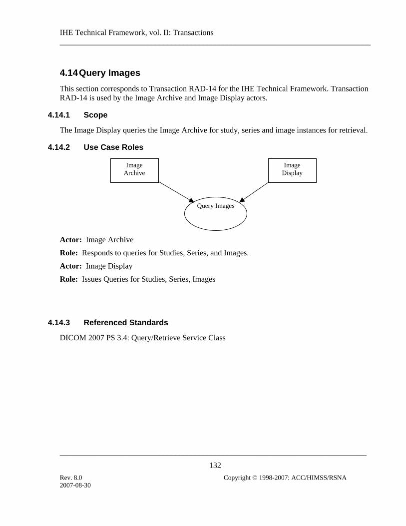
IHE Technical Framework, vol. II: Transactions ______________________________________________________________________________
_____________________________________________________________________________
132 Rev. 8.0 Copyright © 1998-2007: ACC/HIMSS/RSNA
4.14 Query Images This section corresponds to Transaction RAD-14 for the IHE Technical Framework. Transaction RAD-14 is used by the Image Archive and Image Display actors.
4.14.1 Scope
The Image Display queries the Image Archive for study, series and image instances for retrieval.
4.14.2 Use Case Roles
Query Images
ImageDisplay
ImageArchive
Actor: Image Archive
Role: Responds to queries for Studies, Series, and Images.
Actor: Image Display
Role: Issues Queries for Studies, Series, Images
4.14.3 Referenced Standards
DICOM 2007 PS 3.4: Query/Retrieve Service Class
2007-08-30

IHE Technical Framework, vol. II: Transactions ______________________________________________________________________________
_____________________________________________________________________________
133 Rev. 8.0 Copyright © 1998-2007: ACC/HIMSS/RSNA
4.14.4 Interaction Diagram
Query Images (C-FIND)
Image Display
Image Archive
Responses (C-FIND)
4.14.4.1 Query Images
The Query (Study Root – FIND and optionally Patient Root – FIND) SOP Classes shall be supported. Refer to DICOM 2007 PS 3.4 for detailed descriptive semantics.
4.14.4.1.1 Trigger Events
The user at the Image Display wishes to view selected images.
4.14.4.1.2 Message Semantics
The message semantics are defined by the DICOM Query/Retrieve SOP Classes.
A C-FIND Request from the DICOM Study Root Query/Retrieve Information Model – FIND SOP Class or optionally the DICOM Patient Root Query/Retrieve Information Model – FIND SOP Class shall be sent from the Image Display to the Image Archive. Hierarchical Search Method shall be supported.
The Image Display uses one or more matching keys as search criteria to obtain the list of matching entries in the Image Archive at the selected level (Patient & Study/Series/Image). Based on this list of entries, the Image Display may select relevant entries to be retrieved.
The matching keys and return keys to be supported by the Image Display (SCU) and the Image Manager (SCP) are defined in the table below. The table specifies for both the Query SCU (Image Display) and the Query SCP (Image Archive) if Matching Keys (keys used as matching criteria in the Query request) and Returned Keys (Keys used to request attributes to be returned in the query responses) are Required (R) or Optional (O). See section 2.2 for more information.
2007-08-30

IHE Technical Framework, vol. II: Transactions ______________________________________________________________________________
_____________________________________________________________________________
134 Rev. 8.0 Copyright © 1998-2007: ACC/HIMSS/RSNA
Table 4.14-1 below includes the definition of return and matching keys specified by DICOM. Requirements indicated with R+ highlight the requirements added by the IHE Technical Framework.
Table 4.14-1. Images Query Matching and Return Keys Query Keys Matching Query Keys Return Attributes Name Tag
SCU SCP SCU SCP Notes
Study Level Study Date (0008,0020) R+ R R+ R
Study Time (0008,0030) R+ R R+ R
Accession Number (0008,0050) R+ R R+ R
Patient Name (0010,0010) R+ R R+ R IHE-1, IHE-2
Patient ID (0010,0020) R+ R R+ R
Study ID (0020,0010) R+ R R+ R
Study Instance UID (0020,000D) R+ R R+* R
Modalities in Study (0008,0061) R+ R+ R+ R+ Referring Physician’s Name
(0008,0090) R+ R+ R+ R+ IHE-1, IHE-2
Study Description (0008,1030) O O O O
Procedure Code Sequence
(0008,1032)
>Code Value (0008,0100) O O O O >Coding Scheme Designator
(0008,0102) O O O O
>Coding Scheme Version
(0008,0103) O O O O
>Code Meaning (0008,0104) O O O O
Name of Physician(s) Reading Study
(0008,1060) O O O O IHE-1, IHE-2
Admitting Diagnoses Description
(0008,1080) O O O O
Referenced Study Sequence
(0008,1110)
>Referenced SOP Class UID
(0008,1150) O O O O
>Referenced SOP Instance UID
(0008,1155) O O O O
Referenced Patient Sequence
(0008,1120)
>Referenced SOP Class UID
(0008,1150) O O O O
2007-08-30

IHE Technical Framework, vol. II: Transactions ______________________________________________________________________________
_____________________________________________________________________________
135 Rev. 8.0 Copyright © 1998-2007: ACC/HIMSS/RSNA
Query Keys Matching Query Keys Return Attributes Name Tag SCU SCP SCU
Notes SCP
>Referenced SOP Instance UID
(0008,1155) O O O O
Patient’s Birth Date (0010,0030) O O R+ R+
Patient's Birth Time (0010,0032) O O O O
Patient’s Sex (0010,0040) O O R+ R+
Other Patient IDs (0010,1000) O O O O
Other Patient Names (0010,1001) O O O O IHE-1, IHE-2
Patient’s Age (0010,1010) O O O O
Patient’s Size (0010,1020) O O O O
Patient’s Weight (0010,1030) O O O O
Ethnic Group (0010,2160) O O O O
Occupation (0010,2180) O O O O Additional Patient History
(0010,21B0) O O O O
Patient Comments (0010,4000) O O O O
Other Study Numbers
(0020,1070) O O O O
Number of Patient Related Studies
(0020,1200) N/A N/A O O
Number of Patient Related Series
(0020,1202) N/A N/A O O
Number of Patient Related Instances
(0020,1204) N/A N/A O O
Number of Study Related Series
(0020,1206) N/A N/A O R+
Number of Study Related Instances
(0020,1208) N/A N/A O R+
Interpretation Author (4008,010C) O O O O IHE-1, IHE-2
Series Level Modality (0008,0060) R+ R R+ R
Series Number (0020,0011) R+ R R+ R
Series Instance UID (0020,000E) R+ R R+* R
Number of Series Related Instances
(0020,1209) N/A N/A O R+
Series Description (0008,103E) O O R+ R+ Performed Procedure Step ID
(0040, 0253) O O O O
Referenced Performed Procedure Step Sequence
(0008,1111)
2007-08-30

IHE Technical Framework, vol. II: Transactions ______________________________________________________________________________
_____________________________________________________________________________
136 Rev. 8.0 Copyright © 1998-2007: ACC/HIMSS/RSNA
Query Keys Matching Query Keys Return Attributes Name Tag SCU SCP SCU
Notes SCP
>Referenced SOP Class UID
(0008,1150) O O O O
>Referenced SOP Instance UID
(0008,1155) O O O O
Request Attribute Sequence
(0040, 0275) IHE-3
>Requested Procedure ID
(0040,1001) R+ R+ R+ R+
>Scheduled Procedure Step ID
(0040,0009) R+ R+ R+ R+
Performed Procedure Step Start Date
(0040,0244) R + R+ R+ R+
Performed Procedure Step Start Time
(0040,0245) R + R+ R+ R+
Composite Object Instance Level Instance Number (0020,0013) R+ R R+* R
Overlay Number (0020,0022) O O O O
Curve Number (0020,0024) O O O O
LUT Number (0020,0026) O O O O
SOP Instance UID (0008,0018) R+ R R+* R
SOP Class UID (0008,0016) O R+ O R+ IHE-4
Note: For a description of the notation/ modifiers used in the above table, see RAD TF-2: 2.2.
The table below extends the table above with image-specific keys.
Table 4.14-2. Image Specific Query Matching and Return Keys Query Keys Matching Query Keys Return Attribute Name Tag
SCU SCP SCU SCP Notes
Image Specific Level Rows (0028,0010) O O O R+
Columns (0028,0011) O O O R+
Bits Allocated (0028,0100) O O O R+
Number of Frames (0028,0008) O O O R+
The SCP is required (R+) to support the query return key elements: Rows, Columns, Bits Allocated and Number of Frames for calculating the storage size needed for retrieving (storing) the images. Furthermore, the image Bits Allocated is used in matching the image pixel bit depth to the Hard Copy Device (Printer) pixel bit depth.
2007-08-30

IHE Technical Framework, vol. II: Transactions ______________________________________________________________________________
_____________________________________________________________________________
137 Rev. 8.0 Copyright © 1998-2007: ACC/HIMSS/RSNA
IHE-1: Case insensitive matching is allowed for attributes of VR PN per the approved DICOM Change Proposal (CP 190).
IHE-2: SCUs are recommended to append wildcard “*” at the end of each component of any structured name to facilitate matching (i.e., PN attributes).
IHE-3: Universal Matching (selecting return keys) against an Attribute of VR SQ, may be requested by the Query SCU using a Zero Length Sequence Attribute. Query SCPs shall accept such Universal Match Requests. In addition, Query SCPs are required by the DICOM Standard to support requests for a Universal Match for an SQ attribute encoded as a zero length item.
IHE-4: A SOP Class UID is a non-ambiguous key to identify a specific type of image (Modality is not).
4.14.4.1.3 Expected Actions
The Image Archive receives the C-FIND request, performs the matching on the provided keys and sends the list of matching records back to the Image Display via C-FIND responses. It is the responsibility of the Image Manager to ensure that the patient and procedure information is current in the images when they are retrieved from the Image Archive. The patient and procedure information is updated through Transactions RAD-12 and RAD-13.
This means the Image Display may receive patient data inconsistent with those received from a previously issued query or retrieve operation. For example, in the event that a patient has been renamed, the Image Display will receive images with the same Study Instance UID, Series Instance UID and SOP Instance UIDs, but with a different patient name. The Image Display shall use the just queried information or the most recently received instances to ensure that the most recent patient data from the Image Manager/Archive is displayed.
2007-08-30

IHE Technical Framework, vol. II: Transactions ______________________________________________________________________________
_____________________________________________________________________________
138 Rev. 8.0 Copyright © 1998-2007: ACC/HIMSS/RSNA
4.15 Query Presentation States This section corresponds to Transaction RAD-15 of the IHE Technical Framework. Transaction RAD-15 is used by the Image Archive and Image Display actors.
4.15.1 Scope
This section describes the sequence of messages required for the Image Display to query the Image Archive for instances of Grayscale Softcopy Presentation States. The Image Display will query and then retrieve Presentation State objects together with the image data referenced in the return keys supplied in the response from the Image Archive or referenced in the Presentation State object. The transformations will be applied by the Image Display to the image data to assure the image display is consistent with the device that originally created and stored the Presentation State. The Image Display will be required to support all transformations defined in DICOM 2007 PS 3.4: Grayscale Softcopy Presentation State Storage. In addition, multiple Presentation States may exist that reference the same image data.
4.15.2 Use Case Roles
Image Display
Image Archive
Query Presentation
States
Actor: Image Display
Role: Query for Grayscale Softcopy Presentation State objects together with the referenced image data and apply the transformations specified by the Presentation State. This actor must support pixel rendering according to the Grayscale Standard Display Function (GSDF) defined in DICOM 2007 PS 3.14. This device will implement the Query/Retrieve SOP Classes in the role of SCU.
Actor: Image Archive
Role: Respond to queries from the Image Display for Grayscale Softcopy Presentation States objects. This device will implement the Query/Retrieve SOP Classes in the role of SCP.
2007-08-30

IHE Technical Framework, vol. II: Transactions ______________________________________________________________________________
_____________________________________________________________________________
139 Rev. 8.0 Copyright © 1998-2007: ACC/HIMSS/RSNA
4.15.3 Referenced Standards
DICOM 2007 PS 3.4: Query/Retrieve Service Class
DICOM 2007 PS 3.14: Grayscale Standard Display Function
4.15.4 Interaction Diagram
ImageDisplay
ImageArchive
Query Presentation States (C-FIND)
Available Presentation States (C-FIND)
4.15.4.1 Query for Grayscale Softcopy Presentation States
The Query (Study Root – FIND and optionally Patient Root – FIND) SOP Classes will be supported. Refer to DICOM 2007 PS 3.4: Query/Retrieve Service Class for detailed descriptive semantics.
4.15.4.1.1 Trigger Events
The user of the Image Display wishes to query instances of Grayscale Softcopy Presentation States.
4.15.4.1.2 Message Semantics
The message semantics are defined by the DICOM Query/Retrieve SOP Classes: A C-FIND Request from the DICOM Study Root Query/Retrieve Information Model – FIND SOP Class or the optional DICOM Patient Root Query/Retrieve Information Model – FIND SOP Class. The C-FIND request shall be sent from the Image Display to the Image Archive.
The matching keys and return keys to be supported by the Image Display (SCU) and the Image Archive (SCP) at the Study and Series level are defined in table 4.14-1.
Table 4.15-1 below specifies for both the Query SCU (Image Display) and the Query SCP (Image Archive), additional Matching Keys (keys used as matching criteria in the Query request)
2007-08-30

IHE Technical Framework, vol. II: Transactions ______________________________________________________________________________
_____________________________________________________________________________
140 Rev. 8.0 Copyright © 1998-2007: ACC/HIMSS/RSNA
and Return Keys (keys used to request attributes to be returned in the query responses) that are Required (“R”) or Optional (“O”), specific (or pertaining) to Presentation State. See section 2.2 for more information.
Table 4.15-1. Presentation State Specific Query Matching and Return Keys Query Keys Matching Query Keys Return Attribute Name Tag
SCU SCP SCU SCP Presentation Label (0070,0080) O O R+ R+
Presentation Description (0070,0081) O O O R+
Presentation Creation Date (0070,0082) O O R+ R+
Presentation Creation Time (0070,0083) O O R+ R+
Presentation Creator’s Name (0070,0084) O O R+ R+
Referenced Series Sequence (0008,1115)
>Series Instance UID (0020,000E) O O O R+
>Referenced Image Sequence (0008,1140)
>>Referenced SOP Class UID (0008,1150) O O O R+
>>Referenced SOP Instance UID (0008,1155) O O O R+
4.15.4.1.3 Expected Actions
The Image Archive receives the C-FIND request, matches on the provided keys and sends the list of matching records back to the Image Display via C-FIND responses. It is the responsibility of the Image Manager to ensure that the patient and procedure information is current in the images and Softcopy Presentation State objects when they are retrieved from the Image Archive. The patient and procedure information is updated through transactions RAD-12 and RAD-13.
This means the Image Display may receive patient data inconsistent with those received from a previously issued query or retrieve operation. For example, in the event that a patient has been renamed, the Image Display will receive Softcopy Presentation State objects with the same Study Instance UID, Series Instance UID and SOP Instance UIDs, but with a different patient name. The Image Display shall use the just queried information or the most recently received instances to ensure that the most recent patient data from the Image Manger/Archive is displayed.
2007-08-30

IHE Technical Framework, vol. II: Transactions ______________________________________________________________________________
_____________________________________________________________________________
141 Rev. 8.0 Copyright © 1998-2007: ACC/HIMSS/RSNA
4.16 Retrieve Images This section corresponds to Transaction RAD-16 of the IHE Technical Framework. Transaction RAD-16 is used by an Image Display actor to request and retrieve images from an Image Archive and the Imaging Document Consumer to request and retrieve documents from an Imaging Document Source actor.
4.16.1 Scope
After the Image Display or Imaging Document Consumer request for image retrieval, the requested DICOM Images are transferred from the Image Archive to the Image Display or from the Imaging Document Source to the Imaging Document Consumer for viewing.
4.16.2 Use Case Roles
Retrieve Images
Image Display
Image Archive
Imaging Document
Source
Imaging Document Consumer
Actor: Image Archive:
Role: Sends requested images to the Image Display Actor.
Actor: Imaging Document Source:
Role: Sends requested images to the Imaging Document Consumer Actor.
Actor: Image Display
Role: Receives requested images from the Image Archive Actor.
Actor: Imaging Document Consumer
Role: Receives requested images from the Imaging Document Source Actor.
4.16.3 Referenced Standards
DICOM 2007 PS 3.4: Storage Service Class
DICOM 2007 PS 3.4: Query/Retrieve Service Class
2007-08-30

IHE Technical Framework, vol. II: Transactions ______________________________________________________________________________
_____________________________________________________________________________
142 Rev. 8.0 Copyright © 1998-2007: ACC/HIMSS/RSNA
4.16.4 Interaction Diagram
Retrieve Images (C-MOVE)
Image Display
View Images
Image Archive
Store Images (C-STORE)
Retrieve Images (C-MOVE)
Imaging Document Consumer
View Images
Imagig Document
Source
Store Images (C-STORE)
4.16.4.1 Retrieve Images
The Retrieve (Study Root – MOVE and optionally Patient Root – MOVE) SOP Classes shall be supported. The DICOM Image Storage SOP Classes will be supported by the Image Archive or Imaging Document Source as an SCU. Refer to DICOM 2007 PS 3.4, Annex C, for detailed descriptive semantics.
In the case of retrieving images in a Cross-Enterprise, imaging document sharing (XDS-I) network environment, a configuration of mapping the AE Titles to DICOM AE Network Addresses (IP Address and Port number) are needed to be exchanged between the Imaging
2007-08-30

IHE Technical Framework, vol. II: Transactions ______________________________________________________________________________
_____________________________________________________________________________
143 Rev. 8.0 Copyright © 1998-2007: ACC/HIMSS/RSNA
Document Source and the Imaging Document Consumer. RAD TF-3: Appendix G describes in details the AE Title mapping to the DICOM AE Network Addresses.
4.16.4.1.1 Trigger Events
Images are selected for viewing at the Image Display or Imaging Document Consumer.
4.16.4.1.2 Message Semantics
The message semantics are defined by the DICOM Query/Retrieve SOP Classes and the DICOM Image Storage SOP Classes.
A C-MOVE Request from the DICOM Study Root Query/Retrieve Information Model – MOVE SOP Class or the DICOM Patient Root Query/Retrieve Information Model – MOVE SOP Class shall be sent from the Image Display to the Image Archive or from the Imaging Document Consumer to the Imaging Document Source.
.
4.16.4.1.3 Expected Actions
The Image Archive or Imaging Document Source receives the C-MOVE request, establishes a DICOM association with the Image Display or Imaging Document Consumer, respectively, and uses the appropriate DICOM Image Storage SOP Classes to transfer the requested images. The Image Display or Imaging Document Consumer is expected to support at least one of the SOP Classes specified in table 4.8-1. It is assumed that support of retrieval for a SOP Class also means support for display.
4.16.4.1.3.1 NM Image Profile
Image Manager/Image Archive, Imaging Document Source, Image Displays and Imaging Document Consumer actors that claim the NM Image Profile shall support all the SOP Classes specified in Table 4.8-3 in section 4.8.
4.16.4.1.3.2 Mammography Image Profile
Image Manager/Image Archive actors supporting the Mammography Image Profile shall support all the SOP Classes specified in Table 4.16.4.1.3.2-1.
Image Display actor supporting the Mammography Image Profile shall support all the SOP Classes specified in Table 4.16.4.1.3.2-1.
Table 4.16.4.1.3.2-1. Mammography SOP Classes for Display
SOP Class UID SOP Class Name
2007-08-30

IHE Technical Framework, vol. II: Transactions ______________________________________________________________________________
_____________________________________________________________________________
144 Rev. 8.0 Copyright © 1998-2007: ACC/HIMSS/RSNA
1.2.840.10008.5.1.4.1.1.1.2 Digital Mammography Image Storage – For Presentation
Note that Image Displays are not required to support “For Processing” images.
4.16.4.2 View Images
This transaction relates to the “View Images” event of the above interaction diagram.
4.16.4.2.1 Trigger Events
The Image Display or Imaging Document Consumer is requested to be capable to display the images.
4.16.4.2.2 Invocation Semantics
This is a local invocation of functions at the Image Display or Imaging Document Consumer.
4.16.4.2.2.1 Display of Digital X-Ray, Mammo and Intra-Oral Images
For the “For Presentation” variant of the Digital X-Ray Image, the Digital Mammography Image, and the Digital Intra-oral X-Ray Image, the Image Display or Imaging Document Consumer actor shall have both the capability to apply all the transformations specified by the VOI LUT Sequence (0028,3010) and the capability to apply all the transformations specified by the Window Width (0028,1051)/Window Center (0028,1050)/VOI LUT Function (0028,1056) attributes in the DX Image Module as selected by the user from the choices available (e.g., guided by Window Center/Width Explanation (0028,1055) or LUT Explanation(0028,3003).
If VOI LUT Function (0028,1056) is absent, then Window Width (0028,1051)/Window Center (0028,1050) shall be assumed to be the parameters of a linear window operation. VOI LUT Function (0028,1056) values of “SIGMOID” and “LINEAR” shall be supported.
The Image Display or Imaging Document Consumer shall support the application of LUT Data (0028,3006) in items of the VOI LUT Sequence (0028,3010) regardless of the Value Representation (i.e., the DICOM standard allows either OW or US Value Representation).
The Image Display or Imaging Document Consumer actor must also support pixel rendering according to the Grayscale Standard Display Function (GSDF) defined in DICOM 2007 PS 3.14, because the output values of these images are always P-Values.
If the DICOM image is referenced by other DICOM composite objects, such as Grayscale Softcopy Presentation States, it is optional for the Image Display or Imaging Document Consumer to actually retrieve and display/apply these objects.
2007-08-30

IHE Technical Framework, vol. II: Transactions ______________________________________________________________________________
_____________________________________________________________________________
145 Rev. 8.0 Copyright © 1998-2007: ACC/HIMSS/RSNA
4.16.4.2.2.1.1 Display of Digital Mammography Images
The contents of this section are required for Image Display claiming the Mammography Image Profile.
The following requirements are intended to establish a baseline level of capabilities. Providing more intelligent and advanced capabilities is both allowed and encouraged and the profile is not intended to be limiting in any way with respect to capabilities. The intention is not to dictate implementation details.
All mammography Image Display actors shall support the Retrieve Images transaction for “For Presentation” images.
The Image Display shall be capable of displaying simultaneously a set of current and prior conventional four view screening mammogram images (left and right CC and MLO views), regardless of whether these images are in one or multiple DICOM Series.
4.16.4.2.2.1.1.1 Background Air Suppression
Image Display actors shall be capable of recognizing pixels that have the value specified in Pixel Padding Value (0028,0120) when present alone, and between Pixel Padding Value (0028,0120) and Pixel Padding Range Limit (0028,0121) inclusive when both elements are present, and setting them to a minimum display value that is not affected by image contrast adjustments, including inversion of the image contrast.
4.16.4.2.2.1.1.2 Image Orientation and Justification
Image Display actors shall not assume that the pixel data is encoded with an orientation that is suitable for direct display to the user without flipping or rotating into the correct orientation.
The Image Display actor shall use the values of Image Laterality (0020,0062), View Code Sequence (0054,0220), View Modifier Code Sequence (0054,0222) and Patient Orientation (0020,0020) to display images according to the preferred hanging protocol of the current user, rather than depend on descriptive attributes such as Series Description (0008,103E).
The Image Display shall allow the user to select or configure hanging protocols such that given a set of images containing these attributes, the placement of images relative to one another, the required orientation of the images, the display of current and prior images, and the sequence of layouts displayed can be defined.
Note that images are normally displayed such that the axilla is towards the top of the viewport, except for cleavage views (which contain two axillas). The location of the axilla can be determined from the direction of the head encoded in Patient Orientation (0020,0020) in the case of lateral and oblique views, and the Image Laterality (0020,0062) in the case of cranio-caudal or caudo-cranial views. For cleavage views, indicated by the presence of a View Modifier Code
2007-08-30

IHE Technical Framework, vol. II: Transactions ______________________________________________________________________________
_____________________________________________________________________________
146 Rev. 8.0 Copyright © 1998-2007: ACC/HIMSS/RSNA
Sequence (0054,0222) Item containing (R-102D2, SNM3, “Cleavage”), either axilla may be at the top of the view port.
The Image Display shall be able to distinguish and display separately images with one or more Items in a View Modifier Code Sequence (0054,0222) from each other and those without a View Modifier Code Sequence (0054,0222) Item.
The Image Display shall be capable of horizontally justifying the image to the left or right side of the viewport rather than centering it, when the aspect ratio (ratio of the number of rows and columns) of the viewport does not match aspect ratio of the image, in order to avoid displaying any unnecessary padding between the adjacent chest walls of back to back images; excessive window decoration (such as scroll bars) shall not be displayed between back to back viewports.
4.16.4.2.2.1.1.3 Image Size
The physical size of the pixels in an image for the purposes of the display modes defined in this section shall be approximated by using the values of Imager Pixel Spacing (0018,1164).
The physical size of the pixels in an image for the purposes of distance measurements and the display of a distance caliper shall be approximated by using the values of Imager Pixel Spacing (0018,1164) divided by Estimated Radiographic Magnification Factor (0018,1114).
For contact (unmagnified) views, the value of Estimated Radiographic Magnification Factor (0018,1114) is typically 1, or close to 1, depending on the distance between the detector side of the compressed breast and the front of the detector housing (the latter being the plane in which Imager Pixel Spacing (0018,1164) is defined), and what depth the nominal location of the object plane is within the compressed breast.
For magnification views, the spacing between the detector side of the compressed breast and the detector is increased substantially relative to the distance to the x-ray source to obtain geometric magnification, and Estimated Radiographic Magnification Factor (0018,1114) will have a value substantially greater than 1.
Pixel Spacing (0028,0030) shall not be used to determine size for the purpose of sizing for display or distance measurements. DICOM CP 586, which clarifies the meaning of Pixel Spacing (0028,0030) values that differ from Imager Pixel Spacing (0018,1164) values when an image has been calibrated by use of a fiducial of known size within the image, is not relevant to mammography applications.
Note that the use of Imager Pixel Spacing (0018,1164) is sufficient regardless of the physical size of the detector used.
2007-08-30

IHE Technical Framework, vol. II: Transactions ______________________________________________________________________________
_____________________________________________________________________________
147 Rev. 8.0 Copyright © 1998-2007: ACC/HIMSS/RSNA
4.16.4.2.2.1.1.3.1 Same Size
The Image Display shall be capable of displaying multiple images such that all images are at the same relative physical size, regardless of whether they have the same values of Imager Pixel Spacing (0018,1164) or not.
For example, a user reviewing a four-view screening mammogram together with a four-view prior mammogram might want to display eight viewports, each showing one view, such that the each view is at the same relative physical size, even if the images were obtained on detectors with different sized pixels. This allows the user to compare features in the prior and current images to visually assess whether or not they have changed in size.
Note that it is not expected that the Image Display attempt to compensate for the location of the object within the compressed breast of finite thickness along the x-ray beam, since the convention for measurement from film-screen practice assumes that all objects are located at the cassette (detector) side of the breast.
This mode of display is not intended for comparison of geometrically magnified views at the same time as non-magnified views, since the geometrically magnified view would then be displayed too small.
4.16.4.2.2.1.1.3.2 True Size
The Image Display shall be capable of displaying multiple images such that all images are true size, regardless of whether they have the same values of Imager Pixel Spacing (0018,1164) or not.
True size is defined as the display of an image such that an object in the image when measured with a hand-held ruler on the surface of the display measures as closely as possible to the true physical size of the object if located on the front face of the detector housing.
This mode of display is not intended for geometrically magnified views, since the geometrically magnified view would then be displayed too small.
4.16.4.2.2.1.1.3.3 View Actual Pixels
The Image Display shall be capable of displaying multiple images such that each encoded pixel occupies one display pixel in the viewport.
If the size of the pixel data exceeds the size of the viewport, it may not be possible to display all of the encoded pixels at once, in which case some form of pan or quadrant navigation functionality shall be provided.
Since there is no minification or magnification, images with different pixel physical size will be displayed in this mode such that the physical size in the patient will appear different.
2007-08-30

IHE Technical Framework, vol. II: Transactions ______________________________________________________________________________
_____________________________________________________________________________
148 Rev. 8.0 Copyright © 1998-2007: ACC/HIMSS/RSNA
4.16.4.2.2.1.1.4 Image Contrast Adjustment
As described in 4.16.4.2.2.1 Display of Digital X-Ray, Mammography and Intra-Oral Images, the Image Display shall provide the user with the ability to select amongst the available window and VOI LUT choices available in the image object.
Subsequent to the initial application of the chosen contrast transformation, the Image Display actor shall allow the user to adjust the contrast without reverting to a purely linear transformation:
• If the chosen contrast transformation is a lookup table, then the Image Display shall allow the input value of the lookup table to be stretched and translated so as to give the affect of adjusting contrast and brightness whilst applying the same general shape as the curve encoded in the lookup table. To provide feedback to the user, the “window width” can be reported as the adjusted range of input values to the LUT, and the “window center” can be reported as the center value of that range.
• If the chosen contrast transformation is a sigmoid shaped VOI LUT Function parameterized by the window center and width, then the Image Display shall allow the window center and width values to be adjusted and a sigmoid function reapplied.
If a Pixel Padding Value (0028,0120) only is present in the image then image contrast manipulations shall be not be applied to those pixels with the value specified in Pixel Padding Value (0028,0120).
If both Pixel Padding Value (0028,0120) and Pixel Padding Range Limit (0028,0121) are present in the image then image contrast manipulations shall not be applied to those pixels with values in the range between the values of Pixel Padding Value (0028,0120) and Pixel Padding Range Limit (0028,0121), inclusive.
4.16.4.2.2.1.1.5 Annotation of Image Information
Quite apart from good practice, there are nationally-specific requirements for information to be displayed (or displayable) to the user in order to ensure correct identification of the patient and study during reporting and review as well as the resolution of quality issues.
This profile defines the union of currently known and anticipated nationally-specific requirements with respect to annotation.
It is desirable that the subset of attributes displayed be configurable by the user or the site.
If annotations are overlayed on the displayed image, the Image Display shall not annotate the edge that contains the chest wall, as determined from (0020,0020) Patient Orientation, so as to avoid covering breast tissue.
2007-08-30

IHE Technical Framework, vol. II: Transactions ______________________________________________________________________________
_____________________________________________________________________________
149 Rev. 8.0 Copyright © 1998-2007: ACC/HIMSS/RSNA
4.16.4.2.2.1.1.5.1 Annotation of Identification Information
The Image Display shall be capable of displaying the information contained in the attributes listed in Table 4.16.4.2.2.1.1.5.1-1. The required information is defined in two categories:
• Clinical - Those attributes that are useful during interpretation and review of the images for clinical purposes, and which under normal circumstances should be displayed
• Investigative - Those attributes that are useful for investigative purposes, such as to trace a quality problem, and which under normal circumstances are a distraction and should not be displayed until requested by the user
Table 4.16.4.2.2.1.1.5.1-1. Identification Attributes for Display
Attribute Tag Requirement Patient’s Name (0010,0010) Clinical
Patient ID (0010,0020) Clinical
Patient’s Birth Date (0010,0030) Clinical
Patient’s Age (0010,1010) Clinical
Acquisition Date (0008,0022) Clinical
Acquisition Time (0008,0032) Clinical
Operator’s Name (0008,1070) Clinical
Manufacturer (0008,0070) Investigative
Institution Name (0008,0080) Clinical
Institution Address (0008,0081) Investigative
Manufacturer’s Model Name
(0008,1090) Investigative
Device Serial Number (0018,1000) Investigative
Detector ID (0018,700A) Investigative
Software Versions (0018,1020) Investigative
Station Name (0008,1010) Clinical
Gantry ID (0018,1008) Clinical (for CR overrides Station Name, which is
plate reader)
Date of Last Detector Calibration
(0018,700C) Investigative
Note that it is common practice to use the Operator’s Name (0008,1070) to encode the initials rather than the full name of the operator, and this is sufficient to meet known regulatory requirements.
2007-08-30

IHE Technical Framework, vol. II: Transactions ______________________________________________________________________________
_____________________________________________________________________________
150 Rev. 8.0 Copyright © 1998-2007: ACC/HIMSS/RSNA
Note also that Station Name (0008,1010) (or Gantry ID (0018,1008) for CR) are typically short, human-recognizable strings meaningful to the users, and are preferred for satisfying any regulatory requirement for “mammography unit identification” over the more cryptic but precise attributes like Device Serial Number (0018,1000).
The Image Display shall make the investigative set of values available to the ordinary user, but these need not necessarily be annotated directly on the image, e.g., they might be displayed in a separate pop-up window.
It shall be possible to turn on or off either set of annotations at the user’s discretion.
4.16.4.2.2.1.1.5.2 Annotation of Technical Factor Information
Good practice dictates that certain technical factors be displayed (or displayable) to the user in order to detect and resolve quality issues.
In addition, there are technical factors that are unique to the digital realm. One such factor is related to the adjustment of the sensitivity and/or dynamic range of the sensor or processing, corresponding to the amount of radiation reaching the detector. These are variously referred to by manufacturers as ADU, exposure index, or sensitivity. Note that interpretation of this value is vendor-specific, though may be standardized in the future by AAPM.
The Image Display shall be capable of displaying the information contained in the attributes listed in Table 4.16.4.2.2.1.1.5.2-1.
Table 4.16.4.2.2.1.1.5.2-1. Technique Attributes for Display
Attribute Tag KVP (0018,0060)
Exposure (0018,1152)
Exposure Time (0018,1150)
Filter Material (0018,7050)
Anode Target Material (0018,1191)
Compression Force (0018,11A2)
Body Part Thickness (0018,11A0)
Positioner Primary Angle (0018,1510)
Relative X-ray Exposure (0018,1405)
Entrance Dose in mGy (0040,8302)
Organ Dose (0040,0316)
It shall be possible to turn on or off the annotations at the user’s discretion.
2007-08-30

IHE Technical Framework, vol. II: Transactions ______________________________________________________________________________
_____________________________________________________________________________
151 Rev. 8.0 Copyright © 1998-2007: ACC/HIMSS/RSNA
4.16.4.2.2.1.1.5.3 Annotation of View Information
Traditional film-screen practice requires the use of lead markers consisting of letters encoding the type of view, located in the corner of the film that is opposite the chest wall and towards the axilla.
Image Displays shall mimic this practice by annotating the viewport with abbreviations derived from the value of Image Laterality (0020,0062), View Code Sequence (0054,0220) and any values of View Modifier Code Sequence (0054,0222) Items that are present.
Unless otherwise overridden by nationally specific extensions, the specific abbreviations to be displayed are as defined in the View Modifier Abbreviations Column of CID 4014 and CID 4015 of DICOM PS 3.16, which is derived from ACR MQCM 1999, with the following clarifications:
• The Image Laterality shall be prepended to the abbreviation, e.g., a right CC view shall be displayed as “RCC”
• A CC view with a cleavage modifier shall be annotated as only “CV” if Image Laterality has a value of “B”, i.e., the “CC” shall not be displayed, and the laterality shall be omitted (in which case the left and right breast can be determined from the value of Patient Orientation (0020,0020)); otherwise “LCV” or “RCV” shall be used
• A right MLO view with the axillary tail modifier shall be annotated only as “RAT”, i.e., the “MLO” shall not be displayed
• The implant displaced modifier shall be appended as a suffix to the view, as if it were defined as “…ID”, e.g., a right implant displaced CC view would be annotated as “RCCID”
• A spot compression modifer shall be prepended as a prefix to the view, as if it were defined as “S…”, e.g., a left spot compression CC view would be annotated as “LSCC”
• A tangential modifier shall be annotated as only “TAN”, i.e., the “CC” or whatever else is encoded as the view, shall not be displayed
• When multiple prefix or suffix modifiers are present, they shall be sorted alphabetically, e.g. a right magnified, spot compression, implant displaced, rolled lateral CC view would be annotated as “RMSCCIDRL”
Spaces and other delimiters are permitted between components of the abbreviations.
Prior to any flip or rotation for display, the location of the corner opposite the chest wall and towards the axilla can be determined from the direction of the chest wall encoding in Patient Orientation (0020,0020), regardless of view, and the direction of the head encoded in Patient Orientation (0020,0020) in the case of lateral and oblique views, and the Image Laterality (0020,0062) in the case of cranio-caudal or caudo-cranial views. For cleavage views, the axilla at the top of the viewport shall be annotated. See also 4.16.4.2.2.1.1.2 Image Orientation and Justification.
2007-08-30

IHE Technical Framework, vol. II: Transactions ______________________________________________________________________________
_____________________________________________________________________________
152 Rev. 8.0 Copyright © 1998-2007: ACC/HIMSS/RSNA
It shall be possible to turn on or off the annotations at the user’s discretion.
4.16.4.2.2.1.1.6 Annotation of Size Information
For the purpose of this section, physical pixel size is as defined in Section 4.16.4.2.2.1.1.3 Image Size.
The user needs to be aware when the displayed image does not reflect a 1:1 rendition of an encoded image pixel to a displayed pixel, i.e., that some magnification or minification has taken place. Anything other than 1:1 rendition may result in loss or distortion of information.
Further, the user needs to be aware of whether or not the image is displayed at true size, and whether or not different images are at the same relative physical size.
Therefore, the Image Display shall be capable of annotating the displayed images with the following:
• Number of displayed pixels relative to the number of encoded image pixels, such that a factor of 1.0 (or 100%) means 1:1 rendition, a factor of less than 1.0 means that one pixel on the display represents more than one pixel in the encoded image (minification), and a factor of greater than 1.0 means that pixels in the encoded image have been replicated or interpolated to span multiple displayed pixels (magnification)
• Size of the displayed pixels relative to true size, such that a factor of 1.0 (or 100%) means true size, a factor of less than 1.0 means smaller than true size, and a factor of greater than 1.0 means larger than true size
The exact form and description of these two relative pixel size indications is left to the discretion of the implementor.
The Image Display shall be capable of displaying a ruler or caliper indicating the physical size of the displayed image, for the purpose of providing a visual cue to the user of the general size of the features in the image. It shall be possible to turn on or off the ruler at the user’s discretion.
The Image Display shall provide a means of accurately measuring distance between two points based on the physical size of the image pixels.
4.16.4.2.2.1.1.7 Partial View Option
If the Image Display supports the Partial View Option, it shall additionally annotate the displayed image in the view port to indicate:
• when the image is a partial view, as defined by the presence of Attribute Partial View (0028,1350) with a value of YES
• which region of the mosaic the image represents, as encoded in Partial View Code Sequence (0028,1352), if present
2007-08-30

IHE Technical Framework, vol. II: Transactions ______________________________________________________________________________
_____________________________________________________________________________
153 Rev. 8.0 Copyright © 1998-2007: ACC/HIMSS/RSNA
Whether or not this annotation is textual or in the form of some iconic graphic representation, and whether or not any navigational or layout assistance is provided for the entire mosaic is at the discretion of the implementor.
4.16.4.2.2.1.1.8 Display of CAD Marks
Image Displays shall be able to apply marks on the displayed image corresponding to all findings encoded in Mammography CAD SR objects with a (111056, DCM, “Rendering Intent”) value of (111150, DCM, “Presentation Required”). They may be able to display additional findings that have a with a (111056, DCM, “Rendering Intent”) value of (111151, DCM, “Presentation Optional”).
The Image Display shall make the user aware that CAD marks are available for display, and indicate whether or not CAD marks are currently activated. If more than one set of CAD objects are available that are applicable to the same image (e.g. CAD was run more than once on the same images), then all shall be made available for display at the user’s discretion.
The Image Display shall be able to apply the marks to “For Presentation” images that are referenced by the Mammography CAD SR SOP Instance.
The Image Display shall also be able to apply the marks to “For Presentation” images whose Source Image Sequence references the SOP Instance UID of the “For Processing” images that are referenced by the Mammography CAD SR SOP Instance, unless the Spatial Locations Preserved (0028,135A) is present in the Source Image Sequence Item and has a value of NO.
The Patient Orientation of the images referenced in the Source Image Sequence encoded in (111044, DCM, “Patient Orientation Row”) and (111043, DCM, “Patient Orientation Column”) of the Mammography CAD SR SOP Instance shall be used to transform (flip or rotate) the coordinates of the CAD marks if it differs from the Patient Orientation (0020,0020) of the corresponding “For Presentation” image.
The form in which the CAD marks are displayed may influence observer performance, and hence it may be necessary to display them in a manner prescribed by the CAD device vendor, which is not encoded in the DICOM object. The form of the CAD mark rendering is out of the scope of this profile to define.
The Image Display shall make available for display the following information about each CAD finding, if encoded in the CAD object:
• Manufacturer (0008,0070)
• Algorithm as defined in (111001, DCM, “Algorithm Name”) and (111003, DCM, “Algorithm Version”)
• Operating point as defined in (111071, DCM, “CAD Operating Point”)
2007-08-30

IHE Technical Framework, vol. II: Transactions ______________________________________________________________________________
_____________________________________________________________________________
154 Rev. 8.0 Copyright © 1998-2007: ACC/HIMSS/RSNA
• Content Date (0008,0023) and Content Time (0008,0033) of the CAD SR instance, if more than one exists and applies to the displayed image
The Image Display shall indicate when CAD was not attempted or has failed, either entirely, or if some algorithms have succeeded and others failed, as distinct from when CAD has succeeded but there are no findings. This information shall be obtained from the status values of (111064, DCM, “Summary of Detections”) and (111065, DCM, “Summary of Analyses”).
4.16.4.2.2.1.1.9 Post-Processing of For Presentation Images
This profile does not constrain the ability of the Image Display to further post-process “For Presentation” images, for example with edge enhancement or noise reduction.
However, there shall be a mode in which actual pixels of “For Presentation” images are displayed not only with 1:1 display to encoded pixel size, but with no further processing or interpolation other than application of point grayscale transformations.
4.16.4.2.2.1.1.10 Accidental reading of prior studies
There is a significant risk that during primary interpretation the most recently available prior study on the Image Display will be interpreted by the user as the current study, if for some reason the current study is not available.
Accordingly, it is required that an Image Display explicitly warn the user if none of the studies being displayed are within a user configurable period from the current real time, as determined by Acquisition Date (0008,0022).
4.16.4.2.2.2 Display of Localizer Lines
Image Display or Imaging Document Consumer actors that want to show the localizer lines, if visible, will be able to calculate the position of these lines of intersection based on the information recorded in the images by the Acquisition Modality actor (See 4.8.4.1.2.1).
4.16.4.2.2.3 Display of NM Images
The contents of this section are required for Image Displays claiming the NM Image Profile.
The following requirements are intended to establish a baseline level of capabilities. Providing more intelligent and advanced capabilities is both allowed and encouraged. The intention is to focus on display capabilities, not to dictate implementation details.
Note that the NM Image profile is undergoing revision, and vendors considering implementation are advised to include the modifications contained in the trial implementation version “NM Image Profile with Cardiac Option”. For additional information please contact the IHE Radiology Technical Committee at [email protected].
2007-08-30

IHE Technical Framework, vol. II: Transactions ______________________________________________________________________________
_____________________________________________________________________________
155 Rev. 8.0 Copyright © 1998-2007: ACC/HIMSS/RSNA
Some examples of display behaviours typical to NM are described in RAD TF-1, Appendix E.5.3.
The NM Image IOD is a multi-frame image indexed by vectors as described in Section 4.8.4.1.2.2.1. “Image” will be used here to strictly refer to the IOD, while frame will be used to refer to the usual two-dimensional array of pixels.
The Image Display shall be able to display the frames in the order they are stored in the image.
The Image Display shall be able to perform the frame selections shown for each Image Type in the Table 4.16-1 and as described below in 4.16.4.2.2.3.1 Frame Selection Support. The result of a frame selection will be referred to as a “frameset” in this document. Note that a frameset only references frames from a single Image.
The Image Display shall be able to display simultaneously multiple framesets. These may be from the same Image, different Images, different Series, or different Studies.
The Image Display is not required to display simultaneously multiple framesets with different Image Types. (Note that two exceptions to this are identified in 4.16.4.2.2.3.5 Review Option).
The Image Display shall be able to display simultaneously at least the number of framesets indicated in table 4.16-1.
All frames in the displayed frameset(s) are not required to be on the screen at once; if there are more frames than fit on the screen based on the current frame display size (see Section 4.16.4.2.2.3.4 Image Zoom), the ability to scroll through the frames is required.
The Image Display shall be able to display, if present, the View Code Sequence (0054,0220), Acquisition Context Sequence (0040,0555), Series Description (0008,103E) and Acquisition Time (0008,0032) values for a given frameset.
The Image Display is required to support the display capabilities for each Image Type shown in table 4.16-1.
Table 4.16-1. Selection, Sorting and Viewing Requirements for NM Images # of
Simultaneous Framesets
Image Type (0008,0008)
Value 3
Frame Increment Pointer
(0028,0009) [i.e. vectors]
Required Frame Selection1
E = single E = all
Display Capabilities
(See 4.16.4.2.2.3.2) Basic
Review Option
Grid Display 1 1
Fit Display 12 12
STATIC
Energy Window (0054,0010) Detector (0054,0020)
E D E D E D * Cine - 1
(optional))
WHOLEBODY Energy Window(0054,0010) Detector(0054,0020)
E D E D E D *
Wholebody Display 2 4 2
2007-08-30

IHE Technical Framework, vol. II: Transactions ______________________________________________________________________________
_____________________________________________________________________________
156 Rev. 8.0 Copyright © 1998-2007: ACC/HIMSS/RSNA
# of Simultaneous
Framesets Grid Display 1 1
Comparison Display 1 2
DYNAMIC Energy Window (0054,0010) Detector (0054,0020) Phase (0054,0100) Time Slice (0054,0030)
E D P T E D P T E D P T Cine 1 2
Grid Display 1 1
Comparison Display 3 6
GATED Energy Window (0054,0010) Detector (0054,0020) R-R Interval (0054,0060) Time Slot(0054,0070)
E D I T
Cine 3 6
Grid Display 1 1
Comparison Display 3 3
TOMO Energy Window (0054,0010) Detector (0054,0020) Rotation (0054,0050) Angular View (0054,0090)
E D R A
Cine 3 3
Grid Display 1 1
Cine 1 1
GATED TOMO Energy Window(0054,0010) Detector (0054,0020) Rotation (0054,0050) R-R Interval (0054,0060) Time Slot (0054,0070) Angular View (0054,0090)
E D R I T A E D R I T A E D R I T A - any one of above three
Grid Display 1 1
Comparison Display 3 6
Cine 3 3
RECON TOMO Slice(0054,0080) S
MPR Display - 1
Grid Display 1 1
Comparison Display 1 2
Cine - 2
GATED RECON TOMO
R-R Interval (0054,0060) Time Slot(0054,0070) Slice (0054,0080)
I T S I T S I T S *
MPR Display - 1
Note 1: The Frame Selection column refers to the Frame Increment Pointer vectors by their first letter (except for R-R Interval which uses “I” for Interval). A letter shown underlined and bold (e.g. E ) indicates that all values for that vector are selected. A letter shown in plain text (e.g. E ) indicates that a single value for that vector has been selected. So in the case of the TOMO Image Type, E R D A means that all frames of the image are selected; while E R D A means that the selected frames represent all Angular Views for a specific Energy Window, a specific Detector and a specific Rotation. An asterisk (*) indicates that it is required under the review option only, and not required under the basic NM Image profile.
Note 2: The requirement for 4 framesets is to handle the case where the 4 frames are in separate framesets due to the anterior and posterior views being in separate images. It is not required to support 4 framesets with 2 frames each.
2007-08-30

IHE Technical Framework, vol. II: Transactions ______________________________________________________________________________
_____________________________________________________________________________
157 Rev. 8.0 Copyright © 1998-2007: ACC/HIMSS/RSNA
4.16.4.2.2.3.1 Frame Selection Support
A Frame Selection consists of either a single value, or “all values” being identified for each vector in the Image. In fact (except for the case of selecting “all frames” and and the case of selecting all phases and time slices in a Dynamic Image) a single value will be identified for all but one of the available vectors.
It is not necessary to require the user to specify a value for single valued vectors, such as when, for example, only a single detector value is present. It is desirable for the application to provide a way to make a selection when a vector that is typically single valued unexpectedly has additional values.
When selecting values for certain vectors, the user shall be presented with meaningful terms, if available, rather than the underlying integer values from the DICOM vector. For example, in the case of the detector vector, if the View Code Sequence it present, the terms contained there (e.g. “Anterior”, “Posterior”) shall be used instead of the Detector Number from the vector.
The sources of selection terms in priority order (i.e. the first, if present shall be used, otherwise consider the next) are shown in the following table:
Table 4.16-2 Sources of Value Selection Terms for Vectors Vector Source of Selection Terms
Energy Window 1. Energy Window Name (0054,0018) 2. Energy Window Lower Limit (0054,0014) & Energy Window Upper Limit (0054,0015) 3. Energy Window Number
Detector 1. View Code Sequence (0054,0220) 2. Detector Number
Phase 1. Phase Description (0054,0039) 2. Phase Number
Rotation 1. Rotation Number
R-R Interval 1. R-R Interval Number
Time Slot 1. Time Slot Number
Angular View 1. Angular View Number
Slice 1. Slice Number
One method of allowing the user to select a frameset by vectors might be to display a multi-vectored image to the user as if it were broken down into its components by vector. For example, a 2-phase dual-dectector GI bleed study might be shown to the user as
GI-bleed Phase-1 Anterior
GI-bleed Phase-1 Posterior
GI-bleed Phase-2 Anterior
2007-08-30

IHE Technical Framework, vol. II: Transactions ______________________________________________________________________________
_____________________________________________________________________________
158 Rev. 8.0 Copyright © 1998-2007: ACC/HIMSS/RSNA
GI-bleed Phase-2 Posterior
This is acceptable as a means of frame selection support, provided the user has the option of selecting all the parts of the image for display as at the same time, should the user desire to do so, and provided that the multi-vectored image remains as a single image if it is sent via DICOM to another system.
4.16.4.2.2.3.2 Display Capabilities
Image Displays are required to support the following display formats as indicated above in Table 4.16-1
Practical examples of the usage and appearance of these display capabilities can be found in RAD TF-1 Appendix E.5 NM Display and in particular in RAD TF-1, Appendix E.5.3 NM Display Examples.
Grid Display For Grid Display, the Image Display shall display a single frameset arranged in a 2D grid of frames.
Fit Display For Fit Display, the Image Display shall display several framesets simultaneously. Efficient use of screen space is encouraged. The Image Display is free to organize the frames any way that seems sensible. In the absence of other useful information, it is common to display them in order of acquisition time.
Comparison Display For Comparison Display, the Image Display shall display several framesets simultaneously in a fashion such that frames in the two framesets can be compared. For example, each frameset could be placed on an adjacent row.
Display of each frameset in a single row (i.e. the number of rows equals the number of framesets) is required. Support for more than one row per frameset is optional.
Comparison requires that the relationship between frames in the two framesets be maintained when navigating, and to be adjusted separately/established.
Wholebody Display For Wholebody Display, the Image Display shall simultaneously display of both the anterior and posterior frames of an NM whole body image.
2007-08-30

IHE Technical Framework, vol. II: Transactions ______________________________________________________________________________
_____________________________________________________________________________
159 Rev. 8.0 Copyright © 1998-2007: ACC/HIMSS/RSNA
These images will typically be rectangular in shape (taller than wide) and are typically 256 x 1024 or 512 x 1024 in size. The display system should display them as rectangular frames (and not pad them to make them square).
MPR (Multi-Planar Reconstruction) Display For MPR Display, the Image Display shall provide MPR capabilities for slice stack data. Typically, MPR involves displaying three orthogonal plane views at the same time along with a method of navigating the volume (i.e. controlling the specific saggital, coronal and transaxial images shown).
The Image Display is not required to generate oblique slices from slice data, but is required to generate orthogonal slices even if the slice data is obliquely oriented.
In the NM Image Profile, MPR Display shall be supported when claiming the Review Option (See section 4.16.4.2.2.3.5). When displaying NM Data, the Image Display shall be specifically capable of taking a frameset of slice data from a RECON TOMO or GATED RECON TOMO image and displaying all three orthogonal plane views (transaxial, saggital and coronal). PET transaxial data in the MPR display is strongly encouraged, but not required under the NM Profile.
Refer to DICOM documentation for details on how orientation and spatial information is encoded in the NM Image IOD.
Cine Display The Image Display shall be able to display a cine of the selected frames as indicated by the order they are stored in the Image.
The Image Display shall be capable of displaying cines of multiple framesets simultaneously as indicated above in Table 4.16-1.
When the framesets have the same number of frames, the Image Display shall be capable of displaying the cines in synchronization (i.e. the first frame of each frameset should display simultaneously, the second frame of each frameset should display simultaneously, etc.).
The Image Display shall provide the ability to adjust intensity (as described below in Section 4.16.4.2.2.3.3) for each frameset independently. The ability to adjust intensity while a cine is running is useful but not required.
4.16.4.2.2.3.3 Intensity and Color
NM clinical practice requires the ability to adjust the Upper and Lower Window Levels rather than the Window Center and Window Width. Refer to RAD TF-1, Appendix E.5.1 for details on NM usage of intensity and color attributes.
2007-08-30

IHE Technical Framework, vol. II: Transactions ______________________________________________________________________________
_____________________________________________________________________________
160 Rev. 8.0 Copyright © 1998-2007: ACC/HIMSS/RSNA
For all images with a modality type of NM, the Image Display shall provide direct control over the Upper Window Level and the Lower Window Level display parameters independently from each other for both grayscale and pseudocolor display.
This control shall be available for all frames as a group and for each frameset individually. Optionally is it also useful to support adjustment of individual frames.
Window Level values shall be translated into equivalent Window Width and Center values when stored in the image attributes.
The Image Display shall be capable of effectively “inverting” the image (in the sense of switching between a MONOCHROME1 and MONOCHROME2 interpretation). The method is undefined. This requirement applies to grayscale image display only; it is not required for pseudo-color lookup tables.
If the Image Display supports a color screen, the following shall be supported:
The Image Display shall support display of frames of grayscale Images using a pseudo-color lookup table.
The Image Display shall allow the user to select from a configured set of pseudo-color lookup tables.Simultaneous display of both grayscale and pseudo-color presentations is not required. Thus, selecting a color lookup table may change all displayed frames on the screen.
The Image Display shall provide a method of adding new pseudo-color lookup tables. It is acceptable if this is only available to service engineers.
4.16.4.2.2.3.4 Image Zoom
The Image Display shall be capable of “zooming” the frames where zooming consists of resampling and displaying the frame at a larger or smaller matrix size. For example re-sampling a 128x128 frame to create a 256x256 frame is referred to as a 2X zoom in this document.
All zooming of NM images shall preserve the aspect ratio (that is, the same zoom factor shall be applied in both the x and y dimensions). The Image Display is free to use pixel replication or interpolation to perform image zooming.
Some guidelines on appropriate default display sizes and desirable zoom behaviors are provided in RAD TF-1, Appendix E.5.2 NM Image Resizing.
4.16.4.2.2.3.5 Review Option
Image Displays claiming the Review Option shall support the following display capabilities and those indicated in Table 4.16-1.
The Image Display shall be capable of displaying both a Dynamic Image frameset and Static Image frameset(s) at the same time.
2007-08-30

IHE Technical Framework, vol. II: Transactions ______________________________________________________________________________
_____________________________________________________________________________
161 Rev. 8.0 Copyright © 1998-2007: ACC/HIMSS/RSNA
The Image Display shall be capable of displaying both a Wholebody Image frameset and a Static Image frameset at the same time (i.e. anterior & posterior wholebody and several static spot images).
The Image Display shall be capable of displaying the pixel value of a selected pixel.
4.16.4.2.2.4 Display of Result Screens
The contents of this section are required for Image Displays claiming the NM Image Profile.Refer to Table 4.18-2 for the specific SOP Class UIDs of the IODs referenced here for use as Result Screens.
The Image Display shall be able to display DICOM Secondary Capture images (including specifically 8 and 16 bit monochrome and 24 bit RGB).
The Image Display shall be able to display DICOM Multi-Frame Secondary Capture images (including specifically 8-bit monochrome and 24-bit True Color)
The Image Display shall be able to display result screens at their original pixel resolution. If the display size is equal to or greater than the size of the result screen, this should be done as the default. If the display size is less than the size of the result screen, this will require some sort of panning capability.
The Image Display shall be able to scale result screens using a fixed aspect ratio. If the display size is smaller than the size of the result screen, this should be done to fit the result screen onto the display as the default.
For Multi-Frame Secondary Capture images which contain a Cine module, the Image Display shall be able to cine the frames. The default cine rate shall be the value in the Cine module, or the maximum rate of the Image Display, whichever is slower.
4.16.4.2.3 Expected Actions
The Image Display or Imaging Document Consumer presents to the user a DICOM Image.
The Image Display or Imaging Document Consumer may receive patient data inconsistent with those received from a previously issued query or retrieve operation. For example, in the event that a patient has been renamed, the Image Display or Imaging Document Consumer will receive images with the same Study Instance UID, Series Instance UID and SOP Instance UIDs, but with a different patient name. The Image Display or Imaging Document Consumer shall use the just queried information or the most recently received instances to ensure that the most recent patient data from the Image Manger/Archive or Imaging Document Source is displayed.
The Image Display or Imaging Document Consumer shall be able to display the Series Description for each series displayed.
2007-08-30

IHE Technical Framework, vol. II: Transactions ______________________________________________________________________________
_____________________________________________________________________________
162 Rev. 8.0 Copyright © 1998-2007: ACC/HIMSS/RSNA
4.16.4.2.3.1 NM Image Specifics
Actors claiming the NM Image Profile which have applications that accept re-sliced (reconstructed tomographic) cardiac data for viewing or further processing shall make use of the View Code Sequence (0054,0220), Slice Progression Direction (0054,0500) and Acquisition Context Sequence (0040,0555) attributes to aid in the selection of input data. However, the means by which these attributes are used to identify and/or process the data is unspecified.
Note: a means for identifying and processing cardiac input data that does not include the above mentioned attributes will likely be useful due to the existence of Images without those attributes. Series Description may be useful in such cases.
Matching related studies or series (such as stress and rest images) is an important part of NM processing and display. When Image Displays are trying to do this they shall look for the Patient State (0038,0500) to identify such things as stress and rest images and in the NM Acquisition Context Module, the Image Orientation in the Detector Sequence, and the View Code Sequence (0054,0220) to identify images with desired orientations. Since images may exist without those fields present, the Series Description may also be examined for relevant details by the software.
2007-08-30

IHE Technical Framework, vol. II: Transactions ______________________________________________________________________________
_____________________________________________________________________________
163 Rev. 8.0 Copyright © 1998-2007: ACC/HIMSS/RSNA
4.17 Retrieve Presentation States This section corresponds to Transaction RAD-17 of the IHE Technical Framework. Transaction RAD-17 is used by the Image Display or Imaging Document Consumer to request and retrieve Presenttaion State from the Image Archive or Imaging Document Source actor.
4.17.1 Scope
This section describes the sequence of messages required for the Image Display or Imaging Document Consumer to retrieve Grayscale Softcopy Presentation State Instances from the Image Archive or Imaging Document Source. The Image Display or Imaging Document Consumer will query and then retrieve Presentation State objects. The transformations will be applied by the Image Display or Imaging Document Consumer to the image data to assure the image display is consistent with the device that originally created and stored the Presentation State. The Image Display or Imaging Document Consumer will be required to support all transformations defined in DICOM 2007 PS 3.4: Grayscale Softcopy Presentation State Storage. In addition, multiple Presentation States may exist that reference the same image data.
4.17.2 Use Case Roles
Retrieve Presentation
States
Image Display
Image Archive
Imaging Document
Source
Imaging Document Consumer
Actor: Image Display
Role: Retrieve Grayscale Softcopy Presentation State objects together with the referenced image data and apply the transformations specified by the Presentation State. This actor must support pixel rendering according to the Grayscale Standard Display Function (GSDF) defined in DICOM 2007 PS 3.14. This device will implement the Query/Retrieve SOP Classes in the role of an SCU.
Actor: Imaging Document Consumer
Role: Retrieve Grayscale Softcopy Presentation State objects together with the referenced image data and apply the transformations specified by the Presentation State. This actor must support pixel rendering according to the Grayscale Standard Display Function (GSDF) defined in DICOM 2007 PS 3.14. This device will implement the Query/Retrieve SOP Classes in the role of an SCU.
2007-08-30

IHE Technical Framework, vol. II: Transactions ______________________________________________________________________________
_____________________________________________________________________________
164 Rev. 8.0 Copyright © 1998-2007: ACC/HIMSS/RSNA
Actor: Image Archive
Role: Respond to retrieve requests from the Image Display for Grayscale Softcopy Presentation States objects. Transmit requested Grayscale Softcopy Presentation State object(s) to the Image Display. This device will implement the Query/Retrieve SOP Classes in the role of an SCP.
Actor: Imaging Document Source
Role: Respond to retrieve requests from the Imaging Document Consumer for Grayscale Softcopy Presentation States objects. Transmit requested Grayscale Softcopy Presentation State object(s) to the Imaging Document Consumer. This device will implement the Query/Retrieve SOP Classes in the role of an SCP.
4.17.3 Referenced Standards
DICOM 2007 PS 3.4: Query/Retrieve Service Class
DICOM 2007 PS 3.14: Grayscale Standard Display Function
DICOM 2007 PS 3.4: Grayscale Softcopy Presentation State Storage
4.17.4 Interaction Diagram
ImageDisplay
ImageArchive
Select Presentation States (C-MOVE)
Store Presentation States (C-STORE)
View Presentation States
2007-08-30

IHE Technical Framework, vol. II: Transactions ______________________________________________________________________________
_____________________________________________________________________________
165 Rev. 8.0 Copyright © 1998-2007: ACC/HIMSS/RSNA
Imaging
Document Consumer
Imaging Document
Source
Select Presentation States (C-MOVE)
Store Presentation States (C-STORE)
View Presentation States
4.17.4.1 Retrieve Grayscale Softcopy Presentation State
This transaction refers to the “C-MOVE” and “C-STORE” messages between the Image Display and Image Archive or Imaging Document Consumer and Imaging Document Source actor in the above interaction diagram. The Retrieve (Study Root – MOVE and optionally Patient Root – MOVE) SOP Classes are supported. Refer to the DICOM 2007 PS 3.4 for detailed descriptive semantics.
In the case of retrieving Grayscale Softcopy Presentation State in a Cross-Enterprise, imaging document sharing (XDS-I) network environment, a configuration of mapping the AE Titles to DICOM AE Network Addresses (IP Address and Port number) are needed to be exchanged between the Imaging Document Source and the Imaging Document Consumer. RAD TF-3: Appendix G describes in details the AE Title mapping to the DICOM AE Network Addresses.
4.17.4.1.1 Trigger Events
The Image Display or Imaging Document Consumer selects specific Grayscale Softcopy Presentation State objects to retrieve from the Image Archive.
4.17.4.1.2 Message Semantics
The message semantics are defined in the DICOM Query/Retrieve Service Class section of the DICOM 2007 PS 3.4: Query/Retrieve Service Class. It is the responsibility of the Image Manager or Imaging Document Source to assure that the patient and procedure information is
2007-08-30

IHE Technical Framework, vol. II: Transactions ______________________________________________________________________________
_____________________________________________________________________________
166 Rev. 8.0 Copyright © 1998-2007: ACC/HIMSS/RSNA
current in the images and Softcopy Presentation State objects when they are retrieved from the Image Archive or Imaging Document Source.
4.17.4.1.3 Expected Actions
The Image Archive or Imaging Document Source receives the C-MOVE request, establishes a DICOM association with the Image Display or Imaging Document Consumer actor, respectively, and uses the DICOM Grayscale Softcopy Presentation State Storage SOP Class to transfer the requested Presentation State objects.
4.17.4.2 View Presentation States
This transaction relates to the “View Presentation States” event in the above interaction diagram. Presentation States cannot be viewed separately, but must be applied to an image. Refer to sec. 4.16 for a description of the transaction used to retrieve images to which Presentation States may be applied.
4.17.4.2.1 Trigger Events
The Image Display or Imaging Document Consumer receives Presentation State instances from the Image Archive or Imaging Document Source respectively.
4.17.4.2.2 Invocation Semantics
This is a local invocation of functions resident within the Image Display or Imaging Document Consumer. The method used by the Image Display or Imaging Document Consumer to present images for viewing by the user after the Presentation State transformations have been applied is outside the scope of the IHE Technical Framework.
4.17.4.2.3 Expected Actions The Image Display or Imaging Document Consumer applies the transferred Grayscale Softcopy Presentation State to image data and renders it for viewing. The Image Display or Imaging Document Consumer may receive patient data inconsistent with those received from a previously issued query or retrieve operation. For example, in the event that a patient has been renamed, the Image Display or Imaging Document Consumer will receive Softcopy Presentation State objects with the same Study Instance UID, Series Instance UID and SOP Instance UIDs, but with a different patient name. The Image Display or Imaging Document Consumer shall use the just queried information or the most recently received instances to ensure that the most recent patient data from the Image Manger/Archive or Imaging Document Source is displayed. If the number of frames (0028,0008) attribute is set to 1, then the Reference Frame Number (0008,1160) shall be ignored.
2007-08-30

IHE Technical Framework, vol. II: Transactions ______________________________________________________________________________
_____________________________________________________________________________
167 Rev. 8.0 Copyright © 1998-2007: ACC/HIMSS/RSNA
4.18 Creator Images Stored This section corresponds to Transaction RAD-18 of the IHE Technical Framework. Transaction RAD-18 is used by the Image Archive and Evidence Creator actors.
4.18.1 Scope
In the Creator Images Stored transaction, the Evidence Creator sends the newly generated images for a study to the Image Archive.
4.18.2 Use Case Roles
Creator Images Stored
Evidence Creator
ImageArchive
Actor: Evidence Creator
Role: Transmit generated image data to Image Archive.
Actor: Image Archive
Role: Accept and store images from Evidence Creators.
4.18.3 Referenced Standards
DICOM 2007 PS 3.4: Storage Service Class.
2007-08-30

IHE Technical Framework, vol. II: Transactions ______________________________________________________________________________
_____________________________________________________________________________
168 Rev. 8.0 Copyright © 1998-2007: ACC/HIMSS/RSNA
4.18.4 Interaction Diagram
Evidence Creator
ImageArchive
C-STORE (Images Stored)
4.18.4.1 Images Stored
4.18.4.1.1 Trigger Events
The Evidence Creator transfers images to the Image Archive sequentially within one or more DICOM associations, as the images become available or collectively.
Details about when it is appropriate to trigger the creation of a new Study/Series/Image Instance are described in section 4.8.4.1.1.1 “Study UIDs and Series UIDs”.
4.18.4.1.2 Message Semantics
The Evidence Creator uses the DICOM C-STORE message to transfer the images. The Evidence Creator is the DICOM Storage SCU and the Image Archive is the DICOM Storage SCP.
Per the DICOM Standard, the Evidence Creator shall create a new series for its created images and not extend series containing source images.
The Evidence Creator derives images from source images, and the derived images may or may not have the same Image SOP Class as the source images.
The source images may include Performed Procedure Step relationship information. This information will include Scheduled Procedure Step information for the procedure performed at an Acquisition Modality. When present in the source images, the Evidence Creator shall extract appropriate Scheduled Procedure Step information and include it with PPS information produced by the Evidence Creator.
See Appendix A for rules on how to use the source image information in the derived image objects.
2007-08-30

IHE Technical Framework, vol. II: Transactions ______________________________________________________________________________
_____________________________________________________________________________
169 Rev. 8.0 Copyright © 1998-2007: ACC/HIMSS/RSNA
4.18.4.1.2.1 Storage of Localizer Images (MR and CT)
In addition to these general mapping requirements, in MR and CT images, the relationship between localizer or plan images and axial images shall be recorded when such a relationship exists. In such a case the attribute Referenced Image Sequence (0008,1140) of the axial image shall refer to the related localizer or plan image(s). The coordinate space for the set of related images shall be the same, which is indicated by having a single value for the attribute Frame of Reference UID (0020,0052). For CT images the axial images shall have the value AXIAL in the attribute Image Type, and the localizer image the value LOCALIZER. For MR images no specific value for image type is used to further qualify the relationship between plan and axial images. If the Evidence Creator actor wants to show the location of the axial images on the localizer or plan image, a Presentation State object may be created for this purpose.
4.18.4.1.2.2 Storage of NM Images (NM)
Systems supporting the NM Image Profile must support the requirements described in the Modality Images Stored transaction section 4.8.4.1.2.2 Storage of NM Images and section 4.8.4.1.2.2.1 NM Image IOD: Multi-Frames & Vectors.
An Image Creator that processes cardiac tomographic images (Image Type RECON TOMO or RECON GATED TOMO) and creates new cardiac tomographic images shall copy the Acquisition Context Sequence (0040,0555) and its contents into the created images.
4.18.4.1.2.3 Storage of Cardiac Images (NM)
Evidence Creators, Acquisition Modalities or Image Displays creating reconstructed tomographic datasets shall incorporate Image Orientation [Patient] (0020,0037) (inside the Detector Information Sequence (0054,0022)), and Spacing Between Slices (0018,0088).
In addition, Evidence Creators creating a reconstructed tomographic dataset representing standard cardiac views (e.g. Short Axis) shall include the View Code Sequence (0054,0220), Slice Progression Direction (0054,0500), and Acquisition Context Sequence (0040,0555) attributes, as appropriate.
These requirements are defined in section 4.8.4.1.2.2 Storage of NM Images (NM), Table 4.8-2.
4.18.4.1.2.4 Result Screen Export Option
Evidence Creators claiming support of the Result Screen Export Option shall be capable of storing Result Screens as described in this section.
Result Screens refer to a presentation of result elements on the display, potentially including graphics, images and text, typically found on clinical analysis software such as NM cardiac packages.
2007-08-30

IHE Technical Framework, vol. II: Transactions ______________________________________________________________________________
_____________________________________________________________________________
170 Rev. 8.0 Copyright © 1998-2007: ACC/HIMSS/RSNA
This option is intended to provide a way of exporting snapshots of Result Screens as DICOM objects so they can be viewed elsewhere on generic DICOM display systems. As things like DICOM SR Templates for various clinical results become available, such coded data formats provide a more robust solution and should be used in preference to the Result Screen Export Option. This Option is not intended to be used for transferring the clinical data for processing or database purposes.
This option will refer to result screens which include moving images or graphics, such as a beating heart or rotating image, as Dynamic Result Screens. Result screens which do not include moving components will be referred to as Static Result Screens.
Result screens which are completely presented in shades of grey will be referred to as Greyscale Result Screens. Result screens which use color presentation will be referred to as Color Result Screens. Result screens which present images in greyscale and only use small amounts of color for the graphics may optionally be considered Greyscale Result Screens.
The Evidence Creator shall be capable of storing result screens it presents as described in this section. Note that if an Evidence Creator does not present Dynamic Result Screens, it is not
required to implement the dynamic features described, and if an Evidence Creator does not present Color Result Screens, it is not required to implement the color features described.
The Evidence Creator shall use DICOM Secondary Capture (SC) IODs or Multi-Frame Secondary Capture (MFSC) IODs for storing Static Result Screens. The use of MFSC IODs is preferred over the use of simple SC IODs due to the lack of attributes to indicate the content of the image, derivation and source of inputs, and other ambiguities in the SC IODs.
Static Result Screens may be stored using the DICOM SC Image and a set of Static Result Screens may be stored one at a time in DICOM SC Images, however it is strongly recommended that the DICOM MFSC Image IODs be used both for sets of Static Result Screens and individual Static Result Screens.
When multiple Static Result Screens are stored in a DICOM MFSC object, the Cine module shall not be included. The order of the Static frames in the MFSC shall represent the intended display order of the result screens.
The Evidence Creator shall use DICOM MFSC IODs for storing Dynamic Result Screens. The cine module shall be included as described in Table 4.18-1. The frames shall be ordered to present a cine of the Dynamic Result Screen. The number of frames is not specified here. If there are several cine regions in the result screen and the length of their cine “cycle” is not the same, it is acceptable if there is a “jump” in the playback when the MFSC cycle loops back to the beginning.
The Evidence Creator shall support export of Color Result Screens as 24-bit RGB. Dynamic Color Result Screens shall be stored using Multi-frame True Color Secondary Capture Image Storage.
2007-08-30

IHE Technical Framework, vol. II: Transactions ______________________________________________________________________________
_____________________________________________________________________________
171 Rev. 8.0 Copyright © 1998-2007: ACC/HIMSS/RSNA
The system shall also support export of result screens as 8-bit grayscale. It will sometimes be useful to export a given result screen in both color and greyscale formats. Evidence Creators that only present grayscale results are not required to export them as 24-bit RGB.
Multiple SC and/or MFSC objects may be created in the same series to collect result screens which are associated by processing run as long as doing so doesn’t violate the Series rules outlined in RAD TF-1, Appendix E.4.1 Study UIDs and Series UIDs.
The image Instance Numbers shall be set/incremented to reflect the intended display order.
Each time processing is repeated to create new Result Screens, it shall generate a new series.
Conversion Type (0008,0064) in the SC Equipment module shall have a value of “WSD” (indicating images generated by a Workstation).
Series Description (0008,103E) in the General Series module shall include an indication that these are result screens.
Derivation Description (0008,2111) shall contain a description of the nature of the results and/or the processing that generated them.
Modality (0008,0060) shall reflect the modality of the data used to generate the Result Screens.
To ensure maximum compatibility with a variety of display systems, the Frame Time, Recommended Display Frame rate, and Cine Rate attributes in the Cine Module shall all be set to reflect the same frame rate.
These values reflect the display rate of the stored result cine. It is not necessary to set the value to reflect “real world values” such as the actual patient heart rate.
Table 4.18-1. Required Attributes for Multiframe Secondary Capture Cine Module Attribute Tag Type Attribute Description
Preferred Playback Sequencing (0018,1244) R+ Describes the preferred playback sequencing for a multi-frame image. Shall have a value of 0 (which indicates Looping (1,2,..n,1,2,..n) )
Cine Rate (0018,0040) R+ Number of frames per second at which the Evidence Creator intends the results to be presented.
Frame Time (0018,1063) R Nominal time (in msec) per individual frame.Equals 1000/CineRate
Recommended Display Frame Rate (0008,2144) R+ Same as Cine Rate
4.18.4.1.3 Expected Actions
The Image Archive will store the received DICOM objects.
2007-08-30

IHE Technical Framework, vol. II: Transactions ______________________________________________________________________________
_____________________________________________________________________________
172 Rev. 8.0 Copyright © 1998-2007: ACC/HIMSS/RSNA
The DICOM objects shall be stored such that they can be later retrieved (See 4.16 Retrieve Images) in a fashion meeting the requirements defined for a DICOM Level 2 Storage SCP (Refer to DICOM PS 3.4 B.4.1).
4.18.4.1.3.1 DICOM Image Storage SOP Classes
Image Archives claiming the NM Image Profile are required to support all of the SOP classes listed in Table 4.8-3. Evidence Creators claiming the NM Image Profile are required to support at least one of the SOP classes listed in Table 4.8-3.
Evidence Creators shall be capable of providing all created Nuclear Medicine image types using the Nuclear Medicine Image SOP class.
Evidence Creators claiming the Result Screen Export Option are required to support all the SOP classes listed in Table 4.18-2 that are dictated by the Evidence Creators result presentation capabilities, as described in section 4.18.4.1.2.4.
Table 4.18-2. Result Screen Export SOP Classes SOP Class UID SOP Class Name
1.2.840.10008.5.1.4.1.1.7 Secondary Capture Image Storage
1.2.840.10008.5.1.4.1.1.7.2 Multi-frame Grayscale Byte Secondary Capture Image Storage
1.2.840.10008.5.1.4.1.1.7.4 Multi-frame True Color Secondary Capture Image Storage
2007-08-30

IHE Technical Framework, vol. II: Transactions ______________________________________________________________________________
_____________________________________________________________________________
173 Rev. 8.0 Copyright © 1998-2007: ACC/HIMSS/RSNA
4.19 Creator Presentation State Stored This section corresponds to Transaction RAD-19 of the IHE Technical Framework. Transaction RAD-19 is used by the Image Archive and Evidence Creator actors.
4.19.1 Scope
This section describes DICOM Grayscale Softcopy Presentation States Storage requests issued by the Evidence Creator to the Image Archive. The Evidence Creator sends Presentation States for storage along with the images so they could be later used for support of consistent display of imaging data. The Evidence Creator is the DICOM Store SCU and the Image Archive is the DICOM Store SCP. DICOM 2007 PS 3.4: Grayscale Softcopy Presentation State Storage defines the transformations supported by this transaction.
4.19.2 Use Case Roles
Evidence Creator
Image Archive
Creator Presentation State Stored
Actor: Evidence Creator
Role: Generate Grayscale Softcopy Presentation States to be applied to image data. This actor will support the ability to send Presentation State data to an Image Archive. This actor must support pixel rendering according to the Grayscale Standard Display Function (GSDF) as defined in DICOM 2007 PS 3.14.
Actor: Image Archive
Role: Accept and store Grayscale Softcopy Presentation State Instances received from the Evidence Creator. This transaction describes the role related only to storage of the Presentation State information.
2007-08-30

IHE Technical Framework, vol. II: Transactions ______________________________________________________________________________
_____________________________________________________________________________
174 Rev. 8.0 Copyright © 1998-2007: ACC/HIMSS/RSNA
4.19.3 Referenced Standards
DICOM 2007 PS 3.4: Storage Service Class
DICOM 2007 PS 3.4: Grayscale Softcopy Presentation State Storage
DICOM 2007 PS 3.14: Grayscale Standard Display Function
4.19.4 Interaction Diagram Evidence
Creator Image
Archive
C-STORE (Presentation State Stored)
4.19.4.1 Creator Presentation State Stored
4.19.4.1.1 Trigger Events
The Evidence Creator generates a Grayscale Softcopy Presentation State Instance and sends it to the Image Archive for storage.
4.19.4.1.2 Message Semantics
The Evidence Creator uses the DICOM C-STORE message to store Grayscale Softcopy Presentation States. All grayscale processing operations, and all spatial and graphical operations, that are relevant to the resulting presentation of the referenced image have to be recorded in the presentation state. This will preserve the "as-last-seen" view of the image, with for example the contrast setting, rotation, flip and text annotation. The image operations in the presentation state override whatever is recorded in the image itself, even in the case that no attributes for a specific operation (e.g. Window Width/Window Level operation) are present in the presentation state. The latter case by definition specifies an identity operation. The full message semantics are defined in the Grayscale Softcopy Presentation State Storage SOP Class behavior section of DICOM 2007 PS 3.4.
The Evidence Creator derives images and Grayscale Softcopy Presentation State objects from source images that may include Modality Performed Procedure Step relationship information.
2007-08-30

IHE Technical Framework, vol. II: Transactions ______________________________________________________________________________
_____________________________________________________________________________
175 Rev. 8.0 Copyright © 1998-2007: ACC/HIMSS/RSNA
This information will include Scheduled Procedure Step information for the procedure performed at an Acquisition Modality. When present in the source images, the Evidence Creator shall extract appropriate Scheduled Procedure Step information and include it with PPS information produced by the Evidence Creator.
4.19.4.1.3 Expected Actions
The Image Archive will store the received Grayscale Softcopy Presentation State objects.
2007-08-30

IHE Technical Framework, vol. II: Transactions ______________________________________________________________________________
_____________________________________________________________________________
176 Rev. 8.0 Copyright © 1998-2007: ACC/HIMSS/RSNA
4.20 Creator Procedure Step In Progress This section corresponds to Transaction RAD-20 of the IHE Technical Framework. Transaction RAD-20 is used by the Department System Scheduler/Order Filler, Image Manager, Performed Procedure Step Manager and Evidence Creator actors.
4.20.1 Scope
This Performed Procedure Step of the Evidence Creator will be appended to the Modality Performed Procedure Steps done at the Acquisition Modality for the same Scheduled Procedure Step. It includes a message from the Evidence Creator to the Performed Procedure Step Manager, which in turn issues the messages to the Department System Scheduler/Order Filler and the Image Manager. The Performed Procedure Step Manager must support forwarding messages to two different destinations. It shall start issuing messages to the configured destinations immediately after it accepts the corresponding messages from the Evidence Creator.
For the details on the Performed Procedure Step Manager refer to sec. 4.6.1.
4.20.2 Use Case Roles
Department System Scheduler/Order Filler
Image ManagerPerformed
Procedure Step Manager
Creator Procedure Step In Progress
Evidence Creator
Actor: Department System Scheduler/Order Filler.
Role: Receives the PPS information forwarded by the Performed Procedure Step Manager.
Actor: Image Manager.
Role: Receives the PPS information forwarded by the Performed Procedure Step Manager.
Actor: Evidence Creator.
Role: Informs the Performed Procedure Step Manager that a particular Performed Procedure Step has started.
Actor: Performed Procedure Step Manager.
2007-08-30

IHE Technical Framework, vol. II: Transactions ______________________________________________________________________________
_____________________________________________________________________________
177 Rev. 8.0 Copyright © 1998-2007: ACC/HIMSS/RSNA
Role: Accepts Performed Procedure Step information from an Evidence Creator and transmits it to the Department System Scheduler/Order Filler and Image manager.
4.20.3 Referenced Standards
DICOM 2007 PS 3.4: Modality Performed Procedure Step SOP Class.
4.20.4 Interaction Diagram Department System
Scheduler/Order Filler
Evidence Creator
Image Manager
MPPS N-CREATE MPPS N-CREATE
Performed Procedure Step
Manager
MPPS N-CREATE
4.20.4.1 Procedure Step Started Message
4.20.4.1.1 Trigger Event
Technologist begins with the generation of images or Presentation State objects at the Evidence Creator station.
4.20.4.1.2 Message Semantics
The Evidence Creator uses the Modality Performed Procedure Step SOP Class (N-CREATE Service) to inform the Performed Procedure Step Manager that a specific image generation Procedure Step has been started and is in progress. In turn, the Performed Procedure Step Manager uses the N-CREATE Service to forward the information to the Department System Scheduler/Order Filler and Image Manager. The Performed Procedure Step Manager shall use the same Performed Procedure Step SOP Instance UID during this interchange. The following aspects shall be taken into the account during implementation of this step.
4.20.4.1.2.1 Patient/Procedure/Procedure Step Information
The Evidence Creator shall ensure that the Patient/Procedure/Procedure Step information it has is valid and current. In this case a Modality Worklist does not provide the identification and relationship information, but the Evidence Creator extracts the Scheduled Procedure Step information from the images it uses as originals. If those images satisfied several Scheduled
2007-08-30

IHE Technical Framework, vol. II: Transactions ______________________________________________________________________________
_____________________________________________________________________________
178 Rev. 8.0 Copyright © 1998-2007: ACC/HIMSS/RSNA
Procedure Steps, information about all of them may be recorded in the resulting PPS messages and image headers.
4.20.4.1.2.2 Required Attributes
Appendix A lists a number of attributes that have to be properly handled by the Evidence Creator to ensure consistency between Performed Procedure Step object attributes and information included into the generated images.
4.20.4.1.2.3 Relationship between Scheduled and Performed Procedure Steps
In this case the Scheduled Procedure Step is specified in the relationship part of the MPPS information in the source images. Therefore we have the Append Case relationship between Scheduled and Performed Steps. Refer to appendix A for details of forming attributes (Study Instance UID, Procedure ID, Accession Number, etc.) in this case.
4.20.4.1.2.3.1 Append Case
S P S resu lts inP P S a tA cq uisitio n M o d ality
1
1
1
P P S a tIm age C rea to r
Append to a Normal Case
This is a special case of 1-to-N relationship between SPS and PPS where the first PPS is generated at the Acquisition Modality in response to an SPS. The new Performed Procedure Step is added at the Evidence Creator at a later time. The Performed Procedure Step will refer back to the same Requested Procedure and to the original SPS. All Requested Procedure and Scheduled Procedure Step attributes contained in the source images shall be copied to the Performed Procedure Step Relationship Module and the image Request Attribute Sequence (see appendix A).
2007-08-30

IHE Technical Framework, vol. II: Transactions ______________________________________________________________________________
_____________________________________________________________________________
179 Rev. 8.0 Copyright © 1998-2007: ACC/HIMSS/RSNA
S P S resu lts in P P S a t A cq uisitio n M o d ality
1
1
1
P P S a t Im age C rea to r
S P S 1
Append to a Group Case
When the first PPS generated at the Acquisition Modality results from a Group Case (See sec. 4.6.4.1.2.3.4 or 4.6.4.1.2.3.6), the Performed Procedure Step appended by the Evidence Creator may refer back to any one or more of the original SPSs and related Requested Procedure(s) which were grouped, using information from the Request Attribute Sequence in the original images. The corresponding attributes shall be copied from the images to the Performed Procedure Step Relationship Module and the image Request Attribute Sequence (see Appendix A).
Note: For example, following a PPS performed on an MR Modality in response to the grouping of a "neck" SPS and a "head" SPS, a 3D analysis on the MR head images is performed on the image display/creator actor. This display/creator actor application may choose to link the appended PPS associated with the 3D secondary captures images resulting from the 3D analysis with both the head and the neck SPSes.
4.20.4.1.3 Expected Actions
The DSS/Order filler receives information from the Performed Procedure Step Manager and links it with the Requested Procedure. If the Requested Procedure ID is transmitted empty, the Department System Scheduler/Order Filler and the Image Manager will create an exception that must be manually resolved to link the Performed Procedure Step to the appropriate procedure.
2007-08-30

IHE Technical Framework, vol. II: Transactions ______________________________________________________________________________
_____________________________________________________________________________
180 Rev. 8.0 Copyright © 1998-2007: ACC/HIMSS/RSNA
4.21 Creator Procedure Step Completed This section corresponds to Transaction RAD-21 of the IHE Technical Framework. Transaction RAD-21 is used by the Department System Scheduler/Order Filler, Image Manager, Performed Procedure Step Manager and Evidence Creator actors.
4.21.1 Scope
This transaction includes a message from the Evidence Creator to the Performed Procedure Step Manager, which in turn issues the messages to the DSS/Order Filler and the Image Manager that the Performed Procedure Step has been completed. Information is not being released for billing at this point but a code may be assigned. The Image Manager may need the information to co-locate SOP instances of the same study. The Performed Procedure Step Completed message does not necessarily mean that the set of images is complete or available for retrieval.
4.21.2 Use Case Roles
Department System Scheduler/Order Filler
Image ManagerPerformed
Procedure Step Manager
Creator Procedure Step Completed
Evidence Creator
Actor: Departmental System Scheduler/Order Filler.
Role: Receives the PPS information forwarded by the Performed Procedure Step Manager.
Actor: Image Manager.
Role: Receives the PPS information forwarded by the Performed Procedure Step Manager.
Actor: Evidence Creator.
Role: Informs the Performed Procedure Step Manager that a particular Performed Procedure Step is completed.
Actor: Performed Procedure Step Manager.
Role: Accepts Performed Procedure Step information from an Evidence Creator and transmits it to the Department System Scheduler/Order Filler and the Image Manager.
2007-08-30

IHE Technical Framework, vol. II: Transactions ______________________________________________________________________________
_____________________________________________________________________________
181 Rev. 8.0 Copyright © 1998-2007: ACC/HIMSS/RSNA
4.21.3 Referenced Standards
DICOM 2007 PS 3.4: Modality Performed Procedure Step SOP Class.
4.21.4 Interaction Diagram Department System
Scheduler/Order Filler
Evidence Creator
Image Manager
MPPS N-SET MPPS N-SET
Performed Procedure Step
Manager
MPPS N-SET
Note: The diagram above shows the sequencing of messages for the Performed Procedure Step SOP Class. Evidence Creators will also implement the Storage and Storage Commitment classes. The timing relationship between MPPS messages and Storage and Storage Commitment messages is not specified. That is, MPPS messages may occur before or after storage requests.
4.21.4.1 Procedure Step Completed/Discontinued
4.21.4.1.1 Trigger Event
Technologist completes the procedure step from the Evidence Creator station.
4.21.4.1.2 Message Semantics
The Evidence Creator uses the Modality Performed Procedure Step SOP Class (N-SET Service) to inform the Performed Procedure Step Manager that a specific Procedure Step has been completed or discontinued. For further details on the message semantics refer to sec. 4.7.4.1.2.
The Evidence Creator derives images and Grayscale Softcopy Presentation State objects from source images that include Performed Procedure Step information. This information will include scheduled step information for the procedure performed at an Acquisition Modality. When present in the source images, the Evidence Creator shall extract appropriate PPS information and include it with the PPS messages and the images produced by the Evidence Creator.
Note: DICOM specifies that when attributes are allowed to be be set by an N-SET, the value provided by the last N-SET overrides any value set by an earlier N-CREATE or N-SET.
2007-08-30

IHE Technical Framework, vol. II: Transactions ______________________________________________________________________________
_____________________________________________________________________________
182 Rev. 8.0 Copyright © 1998-2007: ACC/HIMSS/RSNA
4.21.4.1.2.1 PPS Exception Management Option
When an Evidence Creator Actor supports the PPS EXCEPTION MANAGEMENT option, it shall provide the appropriate reason codes (often selected by the operator) in the final N-SET sent with the status of DISCONTINUED.
When the Modality Procedure Step is sent with the Status DISCONTINUED, the Modality Procedure Step Discontinuation Reason Code Sequence (0040,0281) shall be sent with one of the values defined in Table 4.7-1 Context ID 9300 – Procedure Discontinuation Reasons
The Reason Code when communicated to the DSS/Order Filler and Image Manager/Archive may imply canceling an order. It may also facilitate more accurate charge posting.
2007-08-30

IHE Technical Framework, vol. II: Transactions ______________________________________________________________________________
_____________________________________________________________________________
183 Rev. 8.0 Copyright © 1998-2007: ACC/HIMSS/RSNA
4.22 Intentionally Left Blank This transaction was defined in earlier versions of the Technical Framework. It is now combined with Modality Storage Commitment in Transaction RAD-10.
2007-08-30

IHE Technical Framework, vol. II: Transactions ______________________________________________________________________________
_____________________________________________________________________________
184 Rev. 8.0 Copyright © 1998-2007: ACC/HIMSS/RSNA
4.23 Print Request with Presentation LUT This section corresponds to Transaction RAD-23 of the IHE Technical Framework. Transaction RAD-23 is used by the Print Composer and Print Server actors.
4.23.1 Scope
This transaction supports the capability of the Print Composer to ensure display consistency for images rendered by the Print Server. The Print Composer sends a DICOM Print Request to the Print Server. The request includes the specification of a Presentation Look Up Table (LUT) to be applied to the image data at the Film Box level. The Print Composer will be the DICOM Print SCU and the Print Server will be the DICOM Print SCP.
4.23.2 Use Case Roles
Actor: Print Composer
Role: Generate DICOM Print Requests as a DICOM Print SCU. Systems which include display capability must support pixel rendering according to the DICOM Grayscale Standard Display Function (GSDF) as defined in DICOM 2007 PS 3.14. The Print Requests must specify and reference Presentation LUTs to be applied by the SCP to the image data to maintain desired image perception.
Actor: Print Server
Role: Process DICOM Print Requests as a DICOM Print SCP. The system must support pixel rendering according to the DICOM Grayscale Standard Display Function (GSDF) as defined in
Print Composer Print Server
Print Request withPresentation LUT
2007-08-30

IHE Technical Framework, vol. II: Transactions ______________________________________________________________________________
_____________________________________________________________________________
185 Rev. 8.0 Copyright © 1998-2007: ACC/HIMSS/RSNA
DICOM 2007 PS 3.14 and be able to transform the image data using the specified Presentation LUT to produce the desired image perception.
4.23.3 Referenced Standards
DICOM 2007 PS 3.4: Print Management Service Class
DICOM 2007 PS 3.4: Presentation LUT SOP Class
DICOM 2007 PS 3.14: Grayscale Standard Display Function
2007-08-30

IHE Technical Framework, vol. II: Transactions ______________________________________________________________________________
_____________________________________________________________________________
186 Rev. 8.0 Copyright © 1998-2007: ACC/HIMSS/RSNA
4.23.4 Interaction Diagram
PrintComposer
PrintServer
DICOM Film Session N-CREATE
DICOM Presentation LUT N-CREATE
DICOM Film Box N-CREATE
DICOM Image Box N-SET
DICOM Film Box N-ACTION
DICOM Film Session N-ACTION
Print Status (N-EVENT-REPORT)
Note: The diagram above shows thesequencing of messages for printingrequests. Timing of the Print Status N-EVENT-REPORT message is not specified.It may occur at any time when Print Serverneeds to report its status to Print Composer
4.23.4.1 DICOM Film Session N-CREATE
Support of this message is required for the Print Composer and Print Server in the IHE Technical Framework. The Film Session N-CREATE message describes the presentation parameters common to all sheets of film in a film session. Implementation of this message will be according to the DICOM Basic Print Management Meta SOP Class.
2007-08-30

IHE Technical Framework, vol. II: Transactions ______________________________________________________________________________
_____________________________________________________________________________
187 Rev. 8.0 Copyright © 1998-2007: ACC/HIMSS/RSNA
4.23.4.1.1 Trigger Events
The Print Composer initiates a Print Request to the Print Server.
4.23.4.1.2 Message Semantics
The DICOM Print Management Service Class Behavior defines the message semantics for the Basic Film Session SOP Class.
4.23.4.1.3 Expected Actions
The Print Server shall create the Film Session SOP Instance and initialize attributes as specified in the N-CREATE. The Print Server shall return the status code of the requested SOP Instance creation as defined for the Basic Film Session SOP Class.
4.23.4.2 DICOM Presentation LUT N-CREATE
The Presentation LUT data specified by this N-CREATE will be used to transform the image data at the film box level to realize specific image display characteristics suitable to the Print Composer. In addition, this message can use the Presentation LUT Shape Attribute to specify a pre-defined Presentation LUT Shape (The Presentation LUT Shape value of “LIN OD” will not be supported for the IHE Technical Framework, except for the Mammography Image Profile (see 4.23.4.8)). Presentation LUT information will only be specified and applied at the Film Box level.
Note: In the event a Print Composer chooses to specify a Presentation LUT Shape of IDENTITY instead of a Presentation LUT then the image data will be sent to the Print Server in the form of P-values for interpretation by the Print Server according to the GSDF.
Note: Print composers are encouraged to use the procedures defined in Appendix B of DICOM Part 14 or other equivalent procedures to make calibration measurements. Where these data are not available, Print Composers may use the suggested default values specified in Part 14 of the DICOM standard for the attributes of Illumination (2010,015E) and Reflected Ambient Light (2010,0160). For transmissive hardcopy printers the standard recommends 2000 cd/m² for Illumination and 10 cd/m² for reflected ambient light. For reflective hardcopy printers the standard recommends 150 cd/m² for Illumination (maximum luminance obtainable from diffuse reflection of the illumination present.) These values are also consistent with those used in the illustrative examples in Annex D of Part 14 of the standard.
4.23.4.2.1 Trigger Events
This message will be triggered when the Print Composer receives a successful status response from the Print Server following transmission of the Film Session N-CREATE message.
2007-08-30

IHE Technical Framework, vol. II: Transactions ______________________________________________________________________________
_____________________________________________________________________________
188 Rev. 8.0 Copyright © 1998-2007: ACC/HIMSS/RSNA
4.23.4.2.2 Message Semantics
The DICOM Print Management Service Class Behavior defines the message semantics for the Presentation LUT SOP Class. Presentation LUTs supplied by the Print Composer will be required to have a number of entries corresponding to the bit depth of the image data (e.g. 256 entries for 8 bit image data, 4096 entries for 12 bit image data).
4.23.4.2.3 Expected Actions
The Print Server shall create a Presentation LUT SOP Instance and initialize attributes as specified in the N-CREATE. The Print Server shall return the status code of the requested SOP Instance creation as defined for the Presentation LUT SOP Class.
4.23.4.3 DICOM Film Box N-CREATE
Per the DICOM standard support of this message is required by the Print Composer and Print Server in the IHE Technical Framework. The Film Box N-CREATE message describes the presentation parameters common to a single sheet of film in a film session.
4.23.4.3.1 Trigger Events
This message will be triggered when the Print Composer receives a successful status response from the Print Server following transmission of the Presentation LUT N-CREATE message.
4.23.4.3.2 Message Semantics
The DICOM Print Management Service Class Behavior defines the message semantics for the Basic Film Box SOP Class. A Film Box N-CREATE will be issued for each sheet of film in a multi-film session. The Print Composer, behaving as a DICOM Print SCU, may use default values for Illumination (2010,015E), Reflective Ambient Light (2010,0160), Min Density (2010,0120), and Max Density (2010,0130) as specified in DICOM 2007 PS 3.14. In addition, the Film Box N-CREATE message will reference Presentation LUT SOP instances created by the Presentation LUT N-CREATE message. Table 4.23-1 below specifies the Basic Film Box Attribute values required to be supported by the SCU.
2007-08-30

IHE Technical Framework, vol. II: Transactions ______________________________________________________________________________
_____________________________________________________________________________
189 Rev. 8.0 Copyright © 1998-2007: ACC/HIMSS/RSNA
Table 4.23-1. Film Box Module Attributes Supported by the Print Composer Tag Attribute Name Supported Values
(2010,0010) Image Display Format STANDARD\C, R (C = columns, R = rows)
(2010,0040) Film Orientation PORTRAIT LANDSCAPE
(2010,0050) Film Size ID 8INX10IN 11INX14IN 14INX17IN
(2010,0060) Magnification Type REPLICATE BILINEAR CUBIC NONE
4.23.4.3.3 Expected Actions
The Print Server shall create the Film Box SOP Instance and initialize attributes as specified in the N-CREATE. The Print Server will create an Image Box SOP Instance for each image box defined by the Image Display Format attribute (2010,0010) at the time the Basic Film Box SOP Instance is created. The Print Server shall return the status code of the requested SOP Instance creation as defined for the Basic Film Box SOP Class. Additional behavior is defined in the description of the Basic Film Box SOP Class for the DICOM Print Management Service Class within the DICOM Standard.
4.23.4.4 DICOM Image Box N-SET
Per the DICOM standard support of this message is required by Print Composer and Print Server in the IHE Technical Framework. The Image Box N-SET message describes the presentation parameters and image pixel data specific to a single image box on a single sheet of film within a film session.
4.23.4.4.1 Trigger Events
This message will be triggered when the Print Composer receives a successful status response from the Print Server following transmission of the Film Box N-CREATE message.
4.23.4.4.2 Message Semantics
The DICOM Print Management Service Class Behavior defines the message semantics for the Image Box SOP Classes. An Image Box N-SET will be issued for each Image Box defined by the Display Format attribute (2010,0010) of the Film Box N-CREATE message.
2007-08-30

IHE Technical Framework, vol. II: Transactions ______________________________________________________________________________
_____________________________________________________________________________
190 Rev. 8.0 Copyright © 1998-2007: ACC/HIMSS/RSNA
4.23.4.4.3 Expected Actions
The Print Server will apply the specified image box attributes to the Image Box SOP Instance. The Print Server shall return the status code of the requested SOP Instance update as defined for the Image Box SOP Class.
4.23.4.5 DICOM Film Box N-ACTION
Support of this message is required by the Print Composer and Print Server in the IHE Technical Framework. The Film Box N-ACTION message is used to print a single sheet of film in the film session.
4.23.4.5.1 Trigger Events
This message will be triggered when the Print Composer receives a successful status response from the Print Server following transmission of the last Image Box N-SET message for the specified Film Box.
4.23.4.5.2 Message Semantics
The DICOM Print Management Service Class Behavior defines the message semantics for the Film Box SOP Classes.
4.23.4.5.3 Expected Actions
The Print Server prints the sheet of film described by the film box. Presentation LUT SOP Instances referenced at the Film Box or Image Box levels will be applied to the image data. The Print Server shall return the appropriate status code as defined for the Film Box N-ACTION DIMSE Service of the DICOM Print Management Service Class.
4.23.4.6 DICOM Film Session N-ACTION
Support of this message is optional by the Print Composer and Print Server in the IHE Technical Framework. The Film Session N-ACTION message is used to print all sheets of film in the film session.
4.23.4.6.1 Trigger Events
This message will be triggered when the Print Composer receives a successful status response from the Print Server following transmission of the last Image Box N-SET message for the specified Film Session.
2007-08-30

IHE Technical Framework, vol. II: Transactions ______________________________________________________________________________
_____________________________________________________________________________
191 Rev. 8.0 Copyright © 1998-2007: ACC/HIMSS/RSNA
4.23.4.6.2 Message Semantics
The DICOM Print Management Service Class Behavior defines the message semantics for the Film Session SOP Classes.
4.23.4.6.3 Expected Actions
The Print Server prints the film session. Presentation LUT SOP Instances referenced at the Film Box or Image Box levels will be applied to the image data. The Print Server shall return the appropriate status code as defined for the Film Session N-ACTION Service of the DICOM Print Management Service Class.
4.23.4.7 Print Status (N-EVENT-REPORT)
Per the DICOM standard, support of this message is required by the Print Composer and Print Server in the IHE Technical Framework. The N-EVENT-REPORT is used to report Print Server status to the Print Composer in an asynchronous manner. That is, a print SCP may send an N-EVENT-REPORT message while the SCU is transmitting additional print commands. The SCU and SCP are required to accommodate these asynchronous messages.
4.23.4.7.1 Trigger Events
This message will be triggered when the Print Server senses a change in the status related to the Print Request that is worthy of notification to the Print Composer.
4.23.4.7.2 Message Semantics
The DICOM Print Management Service Class Behavior defines the message semantics for the Printer SOP Class.
4.23.4.7.3 Expected Actions
The Print Composer will return the confirmation of the N-EVENT-REPORT operation to the Print Server.
4.23.4.8 Mammography Image Profile
Requirements specific to print are specified for mammography since there are regulatory requirements in many jurisdictions with respect to the need to provide the patient with images of primary diagnostic quality that are appropriately annotated.
Print Composers participating in the Mammography Image Profile shall:
• Be capable of true size printing of all the pixels of a single view per sheet of film based on the value stored in Imager Pixel Spacing (0018, 1164) in the Mammography Image SOP Instances being printed, so that distance measurements made optically on the printed
2007-08-30

IHE Technical Framework, vol. II: Transactions ______________________________________________________________________________
_____________________________________________________________________________
192 Rev. 8.0 Copyright © 1998-2007: ACC/HIMSS/RSNA
film will be approximately equivalent to those made on a film-screen mammography exposure, and shall use Requested Image Size (2020,0030) to command the Print Server to use the correct image size. Note that the Imager Pixel Spacing (0018, 1164) should not be corrected by Estimated Radiographic Magnification Factor (0018,1114), since doing so for magnified views would not only exceed the size of the available print area, but would deviate from the accepted film-screen practice.
• Be capable of justifying the images in the print request such that the chest wall will be printed as close to the edge of the film as the Print Server is capable.
• Be capable of sending the Maximum Density attribute (2010,0130)
• Be capable of burning into the pixel data sent to the Print Server all the annotations defined in the clinical set for Image Displays in 4.16.4.2.2.1.1.5.1 Annotation of Identification Information, and additionally Institution Address (0008,0081), 4.16.4.2.2.1.1.5.2 Annotation of Technical Factor Information and 4.16.4.2.2.1.1.5.3 Annotation of View Information
• Be capable of burning a ruler, caliper or other form of distance scale into the pixel data sent to the Print Server
• Be capable of transmitting a pixel data bit depth of 12 bits to the Print Server (i.e., an 8 bit path is not sufficient for mammography)
• Be capable of burning into the pixel data sent to the Print Server a VOI LUT transformation (linear, sigmoid or tabular) as selected by the user from those available in the original image or as otherwise provided by the user
Print Servers participating in the Mammography Image Profile shall:
• Print on transmissive media
• Be capable of true size printing based on the Requested Image Size (2020,0030) and shall attain the requested size with a precision of a maximum 2% error in linear distance (this precision requirement is chosen based not any implied or required accuracy of measurements from film or projection radiography, but rather because current electrical, mechanical and optical technology readily allows for this precision, and deviation beyond this value indicates a fundamental flaw in the implementation of the protocol or logic)
• Be capable of printing with a border between the chest wall edge of the digital mammography image and the physical edge of the film no greater than 5mm, so that the printed films can be hung on a light box with the chest wall edges of corresponding views directly abutted.
• Be capable of applying the Maximum Density attribute (2010,0130) in the request, and printing with a maximum optical density no less than 3.5
2007-08-30

IHE Technical Framework, vol. II: Transactions ______________________________________________________________________________
_____________________________________________________________________________
193 Rev. 8.0 Copyright © 1998-2007: ACC/HIMSS/RSNA
• Be capable of receiving a pixel data bit depth of 12 bits from the Print Composer (i.e., an 8 bit path is not sufficient for mammography).
• Be capable of using a Presentation LUT Shape value of “IDENTITY” and “LIN OD” and the Presentation LUT Sequence (2050,0010)
Note that support for a Presentation LUT Shape value of “LIN OD” by Print Servers is specified for Mammography since the expected transmitted illumination of mammography view boxes on which printed film may be hung exceeds the range of illumination for which the Barten model is defined, and hence it may be difficult to achieve consistency between prints, and between prints and displays. It allows the Print Composer to use “LIN OD” to have greater control over the optical density of the printed film, and to take what action is necessary to result in consistency of appearance for the anticipated viewing conditions.
2007-08-30

IHE Technical Framework, vol. II: Transactions ______________________________________________________________________________
_____________________________________________________________________________
194 Rev. 8.0 Copyright © 1998-2007: ACC/HIMSS/RSNA
4.24 Report Submission This section corresponds to Transaction RAD-24 of the IHE Technical Framework. Transaction RAD-24 is used by the Report Creator and Report Manager actors.
4.24.1 Scope
In the Report Submission transaction, the Report Creator transmits a DICOM Structured Report (SR) object in an initial draft or final state to the Report Manager. The Structured Report object is required minimally to conform to the template TID 2000. Creators may introduce increased complexity as long as it conforms to the SOP class.
A final report is defined as one where the Completion Flag (0040,A491) attribute is set to “COMPLETE” and the Verified Flag (0040,A493) attribute is set to “VERIFIED”. Reports with any other values for the Completion Flag (0040,A491) or the Verified Flag (0040,A493) attributes are considered draft reports.
4.24.2 Use Case Roles
ReportSubmission
ReportCreator
ReportManager
Actor: Report Creator
Role: Transmit draft or final DICOM Structured Reports to Report Manager.
Actor: Report Manager
Role: Accept draft and final DICOM Structured Reports for management.
4.24.3 Referenced Standards
DICOM 2007 PS 3.4: Storage SOP Class
DICOM 2007 PS 3.16: Content Mapping Resource
2007-08-30

IHE Technical Framework, vol. II: Transactions ______________________________________________________________________________
_____________________________________________________________________________
195 Rev. 8.0 Copyright © 1998-2007: ACC/HIMSS/RSNA
4.24.4 Interaction Diagram
ReportCreator
ReportManager
Report Submission(C-STORE)
Report Creation
4.24.4.1 Report Creation
This transaction relates to the “Report Creation” event in the above interaction diagram.
4.24.4.1.1 Trigger Events
The user at the Report Creator wishes to create a DICOM Structured Report.
4.24.4.1.2 Invocation Semantics
This is a local invocation of functions at the Report Creator, and the method used by the Report Creator to obtain report data and create a DICOM Structured Report object is outside the scope of the IHE Technical Framework. The Report Creator shall create a report that conforms to the DICOM Basic Text SR Information Object Definition (IOD). If numeric values are required in the report, then the Report Creator shall create a report that conforms to the DICOM Enhanced SR IOD. A single Report Creator may support both SR IODs if this is deemed desirable by the implementers, but must at least support the Basic Text SR IOD. Reports created by the Report Creator shall also conform to the DCMR template TID 2000.
4.24.4.1.2.1 Coded Entries
All Reporting actors (Report Creator, Report Manager, Report Repository, and External Report Repository Access) must be able to load configurable code tables. The DICOM Structured Report objects are dependent on coded entries to define the concepts being conveyed. Codes specified in DCMR (DICOM PS 3.16) shall be. In the absence of standard codes, the IHE Committee may define necessary codes for use in demonstrations.
The types of reports created by the Report Creator are defined in RAD TF-1: 9.4. At a minimum, the Report Creator shall be able to generate reports based on the Simple Image Report (RAD TF-
2007-08-30

IHE Technical Framework, vol. II: Transactions ______________________________________________________________________________
_____________________________________________________________________________
196 Rev. 8.0 Copyright © 1998-2007: ACC/HIMSS/RSNA
1: 9.4.1). If the Report Creator supports the Enhanced SR Information Object Definition then it shall also support the creation of Simple Image and Numeric Reports (RAD TF-1: 9.4.2).
4.24.4.1.2.2 Retrieve AE Title
Whenever references to DICOM Composite objects are made within a DICOM Structured Report, it is possible to include the Retrieve AE Title attribute (0008,0054). In the case of the Report Creator, these references shall be contained in the Current Requested Procedure Evidence Sequence attribute (0040,A375), or the Pertinent Other Evidence Sequence attribute (0040,A385). If the Report Creator is a standalone actor it is optional for the Retrieve AE Title attribute (0008,0054) to be sent and it is up to the implementation to determine what value to send. If the Report Creator is combined with an Image Display, then it is recommended that the Retrieve AE Title attribute (0008,0054) be set to the AE Title of the device from which the Image Display retrieved the referenced DICOM Composite objects.
4.24.4.1.2.3 Study Identification and Identical Documents Sequence
A Study Instance UID is required to identify the study to which the report belongs. It is recommended to use the Study Instance UID of the images reported on as the Study Instance UID of the created Structured Report. The mechanism by which the Report Creator actor will receive this information is defined in the IHE Technical Framework. Sometimes a single report refers to multiple studies. For example, a trauma patient may require X-rays of both the wrist and leg. These may be ordered as separate studies, but the Radiologist may report on both studies at the same time. To handle this situation in the DICOM Hierarchical Model, it is necessary to duplicate the report within each study. If a Report Creator is generating a single report for multiple studies, it shall create multiple copies of the report, with different SOP Instance UIDs for each study and use the Identical Documents Sequence attribute (0040,A525) in each report. The Identical Documents Sequence attribute (0040,A525) in each report shall reference each of the other identical reports in the other studies. The actual content of the report, that is, the SR Document General Module attributes (except the Identical Documents Sequence attribute) and the SR Document Content Module attributes shall be the same in each report instance.
The Retrieve AE Title attribute (0008,0054) in the Identical Documents Sequence Items shall not be sent.
4.24.4.1.3 Expected Actions
Creation of DICOM Structured Report objects ready for storage to the Report Manager.
4.24.4.2 Report Submission
This transaction relates to the “DICOM C-STORE” event between the Report Creator and Report Manager in the above interaction diagram.
2007-08-30

IHE Technical Framework, vol. II: Transactions ______________________________________________________________________________
_____________________________________________________________________________
197 Rev. 8.0 Copyright © 1998-2007: ACC/HIMSS/RSNA
4.24.4.2.1 Trigger Events
When report authoring is completed and the Report Creator creates new DICOM Structured Reports, the Report Creator shall transfer DICOM Structured Reports to the Report Manager within one or more DICOM associations.
4.24.4.2.2 Message Semantics
The Report Creator uses the DICOM C-STORE message to transfer DICOM Structured Reports. The Report Creator is the DICOM Storage SCU of the Basic Text SR Storage SOP Class or the Enhanced SR Storage SOP Class or both. The Report Manager is the DICOM Storage SCP of at least the Basic Text SR Storage SOP Class and optionally the Enhanced SR Storage SOP Class. In accordance with the DICOM Standard for SR the Report Manager must support Level 2 (Full) storage, which means all DICOM Type 1, 2 and 3 attributes are stored.
4.24.4.2.3 Expected Actions
The Report Manager will store the received DICOM Structured Report objects. At this point the Report Creator relinquishes any responsibility for the report objects and may not change them in any way without creating a new object with a new SOP Instance UID.
2007-08-30

IHE Technical Framework, vol. II: Transactions ______________________________________________________________________________
_____________________________________________________________________________
198 Rev. 8.0 Copyright © 1998-2007: ACC/HIMSS/RSNA
4.25 Report Issuing This section corresponds to Transaction RAD-25 of the IHE Technical Framework. Transaction RAD-25 is used by the Report Manager and Report Repository actors.
4.25.1 Scope
In the Report Issuing transaction, the Report Manager transmits either an unchanged draft DICOM Structured Report (created by a Report Creator) or a new modified DICOM Structured Report to the Report Repository or both. The Report Manager handles all state and content changes to DICOM Structured Reports, and with each change new DICOM Structured Report objects are created and may be stored in the Report Repository.
4.25.2 Use Case Roles
ReportIssuing
ReportManager
ReportRepository
Actor: Report Manager
Role: Process report changes and transmit reports to Report Repository. This involves the ability to handle content and state changes to DICOM Structured Reports and create new DICOM Structured Reports based on these changes. Examples of the types of changes the Report Manager needs to process are as follows: • Verifying a draft report and setting the verification attributes in the newly created verified
report; • Creating a new unverified report based on one or more previous draft or verified reports; • Creating a new verified report based on one or more previous draft or verified reports; and • Creating a new report that is the result of merging multiple previous reports. • Generating a new version of an existing report with updated patient demographics based on
receiving a Patient Update transaction.
Actor: Report Repository
Role: Accept and store DICOM Structured Reports from Report Managers.
2007-08-30

IHE Technical Framework, vol. II: Transactions ______________________________________________________________________________
_____________________________________________________________________________
199 Rev. 8.0 Copyright © 1998-2007: ACC/HIMSS/RSNA
4.25.3 Referenced Standards
DICOM 2007 PS 3.4: Storage SOP Class DICOM 2007 PS 3.16: Content Mapping Resource
4.25.4 Interaction Diagram
Report Issuing (C-STORE)
Report Issuing (C-STORE)
Report Manager
Report Repository
Report Modification or Verification
4.25.4.1 Report Issuing (Step 1)
This transaction relates to the top “DICOM C-STORE” event between the Report Manager and Report Repository in the above interaction diagram.
4.25.4.1.1 Trigger Events
When DICOM Structured Reports are received from the Report Creator, the Report Manager can transfer the DICOM Structured Reports to the Report Repository within one or more DICOM associations. This capability may be configurable as it may enable access to reports before they are verified and finalized. Some sites may require this feature, while others may find it undesirable.
4.25.4.1.2 Message Semantics
The Report Manager uses the DICOM C-STORE message to transfer DICOM Structured Reports. The Report Manager is the DICOM Storage SCU of at least the Basic Text SR Storage
2007-08-30

IHE Technical Framework, vol. II: Transactions ______________________________________________________________________________
_____________________________________________________________________________
200 Rev. 8.0 Copyright © 1998-2007: ACC/HIMSS/RSNA
SOP Class and optionally the Enhanced SR Storage SOP Class. It is required that if a Report Manager is an SCP of the Enhanced SR Storage SOP Class (see sec. 4.24) then it shall also be an SCU of the Enhanced SR Storage SOP Class. The Report Repository is the DICOM Storage SCP of both the Basic Text SR Storage SOP Class and the Enhanced SR Storage SOP Class. In accordance with the DICOM Standard for SR, the Report Repository must support Level 2 (Full) storage, which means all DICOM Type 1, 2 and 3 attributes are stored.
4.25.4.1.3 Expected Actions
The Report Repository will store the received DICOM Structured Report objects.
4.25.4.2 Report Modification
This transaction relates to the “Report Modification or Verification” event in the above interaction diagram.
4.25.4.2.1 Trigger Events
The user at the Report Manager selects an existing report and decides to make some modification to this report.
4.25.4.2.2 Invocation Semantics
This is a local invocation of functions at the Report Manager, and the method used by the Report Manager to specify report state transitions or obtain modified report data and create a new DICOM Structured Report object is outside the scope of the IHE Technical Framework. The Report Manager shall create a report that conforms to the DICOM Basic Text SR Information Object Definition or the DICOM Enhanced SR Information Object Definition if numeric values are to be included in the report either by their addition by the Report Manager or numeric values appeared in the original report received from the Report Creator. It is required that if a Report Manager can receive Enhanced SR objects, that it can also manage such objects and generate new Enhanced SR objects. If the Report Manager removes numeric values from a report it may convert an Enhanced SR object into a Basic Text SR object. When the Report Manager creates a new modified report it must be in a different series to the original report, unless the Report Manager and Report Creator are the same device. This is because the DICOM Standard requires that objects created by different devices must be in different series (i.e., different DICOM General Equipment Module attributes). In order to reference the original report, the new modified report must correctly contain the Predecessor Documents Sequence attribute (0040,A360).
The types of external state changes the Report Manager shall handle are: • Completing a partial report; and • Verifying a report.
2007-08-30
IHE Technical Framework, vol. II: Transactions ______________________________________________________________________________
_____________________________________________________________________________
201 Rev. 8.0 Copyright © 1998-2007: ACC/HIMSS/RSNA
To complete a partial report, additional content may be added to the original report and the Completion Flag attribute (0040,A491) shall be set to “COMPLETE”. To verify a report, the content of the original report is checked for correctness, and the Verification Flag attribute (0040,A493) shall be set to “VERIFIED”. This also requires that the Verifying Observer Sequence attribute (0040,A073) be completed appropriately.
The types of reports that at a minimum shall be handled by the Report Manager are defined in RAD TF-1: 9.4. The Report Manager shall be able to manipulate reports based on the Simple Image Report (RAD TF-1: 9.4.1). If the Report Manager supports the Enhanced SR Information Object Definition then it shall also support manipulation of Simple Image and Numeric Reports (RAD TF-1: 9.4.2). Even though the IHE Technical Framework sets boundaries on the complexity of SR objects, the Report Manager must still be able to receive and store any Basic Text SR object and optionally any Enhanced SR object in order to conform to the DICOM Standard. An implementation may restrict the modification capabilities for reports more complex than those specified in RAD TF-1: 9.4. When creating a new report, the Report Manager shall also conform to the DCMR template TID 2000.
There are many reasons and methods for the Report Manager to modify the content of a report and these are outside the scope of the IHE Technical Framework. Examples of the types of changes, in addition to the state changes above, the Report Manager needs to be able to process are as follows: • Creating a new report based on one or more previous draft or verified reports where data is
changed or added; • Creating a new report that is the result of merging multiple previous reports. This can also
involve changing or adding report data; and • Converting a Basic Text SR into an Enhanced SR if the Report Manager adds measurements.
This also means that if a Basic Text SR is merged with an Enhanced SR then the resulting object will be an Enhanced SR.
It is recommended that amendments to DICOM Structured Reports are made by creating a new DICOM Structured Report object containing the original content as well as any amendments or additions. References to the original report are made by the Predecessor Document Sequence attribute (0040,A360).
In general report issuing requires that a new SR instance UID will be created as a result of the rules defined by the DICOM standard (see PS 3.4 – Section O.3 - Modification of SR DOCUMENT CONTENT.
4.25.4.2.2.1 Retrieve AE Title
Whenever references to DICOM Composite objects are made within a DICOM Structured Report, it is possible to include the Retrieve AE Title attribute (0008,0054). In the case of the
2007-08-30

IHE Technical Framework, vol. II: Transactions ______________________________________________________________________________
_____________________________________________________________________________
202 Rev. 8.0 Copyright © 1998-2007: ACC/HIMSS/RSNA
Report Manager, these references will be contained in the Predecessor Documents Sequence attribute (0040,A360), as well as the Current Requested Procedure Evidence Sequence attribute (0040,A375) and the Pertinent Other Evidence Sequence attribute (0040,A385) if the Report Creator uses these evidence sequence attributes.
The Report Creator may send reports to the Report Manager where the Retrieve AE Title attribute (0008,0054) in the Current Requested Procedure Evidence Sequence Items (0040,A375), or the Pertinent Other Evidence Sequence Items (0040,A385) is empty or not sent. In these cases the Report Manager may add the AE Title of a configured Image Manager in the Retrieve AE Title attribute (0008,0054) of these sequence items.
When the Report Manager creates a new report based on one or more previous reports that it has already stored in the Report Repository, then the AE Title of the Report Repository shall be used as the Retrieve AE Title attribute (0008,0054) in the Predecessor Documents Sequence Items (0040,A360). If the prior reports have not been stored in the Report Repository then the Retrieve AE Title attribute (0008,0054) shall not be sent.
4.25.4.2.2.2 Study Identification and Identical Documents Sequence
A Study Instance UID is required to identify the study to which the report belongs. It is recommended to use the Study Instance UID of the images reported on as the Study Instance UID of the created Structured Report. The mechanism by which the Report Creator will receive this information is currently undefined in the IHE Technical Framework. The expectation is that the DICOM General Purpose Worklist service will be used for this function when this service is finalized in DICOM and incorporated in the IHE Technical Framework.
When the Report Manager is modifying a report that contains items in the Identical Documents Sequence attribute (0040,A525) then a decision is needed as to the actions to occur upon the other identical documents. The user modifying the report may be asked as to whether the changes may only apply to the current report or to the other identical documents as well. If the changes are limited to one report, then no Identical Documents Sequence attribute (0040,A525) shall be included in the new report as it is no longer the same as the other documents. If the changes are to apply to multiple reports, then multiple new reports with new SOP Instance UIDs shall be created with the new report data and their Identical Documents Sequence attribute (0040,A525) shall refer to the appropriate new report objects. Also in this case each Predecessor Documents Sequence attribute (0040,A360) shall refer to all the original identical documents. This is shown in figure 4.25-1.
2007-08-30

IHE Technical Framework, vol. II: Transactions ______________________________________________________________________________
_____________________________________________________________________________
203 Rev. 8.0 Copyright © 1998-2007: ACC/HIMSS/RSNA
OriginalDocument 1
IdenticalDocumentsSequence
IdenticalDocumentsSequence
PredecessorDocumentsSequence
OriginalDocument 2
OriginalDocument 3
ModifiedDocument 1
ModifiedDocument 2
ModifiedDocument 3
Figure 4.25-1. Identical and Predecessor Document Sequences
4.25.4.2.3 Expected Actions
Creation of a new modified DICOM Structured Report object ready for storage to the Report Repository.
4.25.4.3 Report Issuing (Step 2)
This transaction relates to the bottom “DICOM C-STORE” event between the Report Manager and Report Repository in the above interaction diagram.
4.25.4.3.1 Trigger Events
When reports are finalized (complete and verified) they shall be stored in the Report Repository. The Report Manager can transfer DICOM Structured Reports to the Report Repository within one or more DICOM associations. Internal reports shall be temporarily stored in the Report Manager until they are finalized, but may also be stored permanently in the Report Repository if the Report Manager decides to transfer them. The technique used by the Report Manager to finalize a report is outside the scope of the IHE Technical Framework.
2007-08-30
IHE Technical Framework, vol. II: Transactions ______________________________________________________________________________
_____________________________________________________________________________
204 Rev. 8.0 Copyright © 1998-2007: ACC/HIMSS/RSNA
4.25.4.3.2 Message Semantics
The Report Manager uses the DICOM C-STORE message to transfer DICOM Structured Reports. The Report Manager is the DICOM Storage SCU of at least the Basic Text SR Storage SOP Class and optionally the Enhanced SR Storage SOP Class. It is required that if a Report Manager is an SCP of the Enhanced SR Storage SOP Class (see sec. 4.24) then it shall also be an SCU of the Enhanced SR Storage SOP Class. The Report Repository is the DICOM Storage SCP of both the Basic Text SR Storage SOP Class and the Enhanced SR Storage SOP Class. In accordance with the DICOM Standard for SR the Report Repository must support Level 2 (Full) storage, which means all DICOM Type 1, 2 and 3 attributes are stored.
4.25.4.3.3 Expected Actions
The Report Repository will store the received DICOM Structured Report objects.
2007-08-30

IHE Technical Framework, vol. II: Transactions ______________________________________________________________________________
_____________________________________________________________________________
205 Rev. 8.0 Copyright © 1998-2007: ACC/HIMSS/RSNA
4.26 Query Reports This section corresponds to Transaction RAD-26 of the IHE Technical Framework. Transaction RAD-26 is used by the Report Manager, Report Repository, Report Reader, and External Report Repository Access actors.
4.26.1 Scope
In the Query Reports Transaction, the Report Reader queries the Report Manager, Report Repository or External Report Repository Access for draft or final DICOM Structured Reports.
4.26.2 Use Case Roles
Q uery Reports
Report Reader
Report R epository
External R eport R epository
A ccess
Report M anager
Actor: Report Repository
Role: Responds to queries for DICOM Structured Reports.
Actor: External Report Repository Access
Role: Responds to queries for DICOM Structured Reports. This system provides storage of DICOM Structured Reports obtained from outside the Radiology department. Such a system may be required to convert reports of different formats (HL7) into DICOM Structured Reports (see appendix C).
Actor: Report Reader
Role: Queries Report Repository or External Report Repository Access for DICOM Structured Reports and makes them available for selection.
Actor: Report Manager
Role: Responds to queries for DICOM Structured Reports.
4.26.3 Referenced Standards
DICOM 2007 PS 3.4: Query/Retrieve Service Class
2007-08-30

IHE Technical Framework, vol. II: Transactions ______________________________________________________________________________
_____________________________________________________________________________
206 Rev. 8.0 Copyright © 1998-2007: ACC/HIMSS/RSNA
DICOM 2007 PS 3.16: Content Mapping Resource
4.26.4 Interaction Diagram
Query Responses (C-FIND)
ReportReader
External ReportRepository
Access
Query Reports (C-FIND)
Query Responses (C-FIND)
ReportRepository
Query Reports (C-FIND)
Query Responses (C-FIND)
Report Reader
Report Manager
Query Reports (C-FIND)
4.26.4.1 Query Reports
This transaction relates to the query section of the above interaction diagram. The Query (Study Root – FIND and optionally Patient Root – FIND) SOP Classes will be supported. Refer to DICOM 2007 PS 3.4: Query/Retrieve Service Class for detailed descriptive semantics.
2007-08-30

IHE Technical Framework, vol. II: Transactions ______________________________________________________________________________
_____________________________________________________________________________
207 Rev. 8.0 Copyright © 1998-2007: ACC/HIMSS/RSNA
4.26.4.1.1 Trigger Events
The user at the Report Reader wishes to view selected reports.
4.26.4.1.2 Message Semantics
The message semantics are defined by the DICOM Query/Retrieve SOP Classes.
A C-FIND Request from the DICOM Study Root Query/Retrieve Information Model – FIND SOP Class or the DICOM Patient Root Query/Retrieve Information Model – FIND SOP Class shall be sent from the Report Reader to the Report Manager, Report Repository or External Report Repository Access.
The Report Reader uses one or more matching keys as search criteria to obtain the list of matching entries in the Report Manager, Report Repository or External Report Repository Access at the selected level (Patient & Study/Series/Instance).
In addition to the required and unique keys defined by the DICOM Standard, the IHE Technical Framework has defined matching and return keys to be supported by query SCUs and SCPs. The keys are defined in sec. 4.14.4.1.2 and table 4.14-1, except that Report Manager and Report Repositories are not required to support PPS Start Date and PPS Start Time. The conventions for key usage are defined in section 2.2. For the Report Reader (SCU) and the Report Manager, Report Repository and External Report Repository Access (SCP) the additional SR Instance specific keys are defined in table 4.26-1.
Table 4.26-1. SR Instance Specific Query Matching and Return Keys
Query Keys Matching Query Keys Return Attribute Name Tag SCU SCP SCU SCP
SR Instance Specific Level Completion Flag (0040,A491) R+ R+ R+ R+
Verification Flag (0040,A493) R+ R+ R+ R+
Content Date (0008,0023) O O O R+
Content Time (0008,0033) O O O R+
Observation DateTime (0040,A032) O O O R+
Verifying Observer Sequence (0040,A073)
>Verifying Organization (0040,A027) O O R+ R+
>Verification DateTime (0040,A030) R+ R+ R+ R+
>Verifying Observer Name (0040,A075) R+ R+ R+ R+
>Verifying Observer Identification Code Sequence
(0040,A088)
>> Code Value (0008,0100) O O R+ R+
>> Coding Scheme Designator (0008,0102) O O R+ R+
2007-08-30

IHE Technical Framework, vol. II: Transactions ______________________________________________________________________________
_____________________________________________________________________________
208 Rev. 8.0 Copyright © 1998-2007: ACC/HIMSS/RSNA
Query Keys Matching Query Keys Return Attribute Name Tag SCU SCP SCU SCP
>> Coding Scheme Version (0008,0103) O O R+ R+
>> Code Meaning (0008,0104) O O R+ R+
Referenced Request Sequence (0040,A370)
>Study Instance UID (0020,000D) O O R+* R+
>Accession Number (0008,0050) O O R+ R+
>Requested Procedure ID (0040,1000) O O R+ R+ >Requested Procedure Code Sequence
(0032,1064)
>>Code Value (0008,0100) O O O R+
>>Coding Scheme Designator (0008,0102) O O O R+
>>Coding Scheme Version (0008,0103) O O O R+
>>Code Meaning (0008,0104) O O O R+
Concept Name Code Sequence (0040,A043)
>Code Value (0008,0100) R+ R+ R+ R+
>Coding Scheme Designator (0008,0102) R+ R+ R+ R+
>Coding Scheme Version (0008,0103) O O O R+
>Code Meaning (0008,0104) O O R+ R+
4.26.4.1.3 Expected Actions
The Report Manager, Report Repository or External Report Repository Access receives the C-FIND request, performs the matching on the provided keys and sends the list of matching records back to the Report Reader via C-FIND responses.
2007-08-30

IHE Technical Framework, vol. II: Transactions ______________________________________________________________________________
_____________________________________________________________________________
209 Rev. 8.0 Copyright © 1998-2007: ACC/HIMSS/RSNA
4.27 Retrieve Reports This section corresponds to Transaction RAD-27 of the IHE Technical Framework. Transaction RAD-27 is used by the Report Manager, Report Repository, Imaging Document Source, Report Reader, Imaging Document Consumer and External Report Repository Access actors.
4.27.1 Scope
In the Retrieve Reports Transaction, the requested DICOM Structured Reports are transferred from the Report Manager, Report Repository, Imaging Document Source, or External Report Repository Access to the Report Reader or Imaging Document Consumer for viewing.
4.27.2 Use Case Roles
R etrieve Reports
Report Reader
External R eport R epository
A ccess
Report M anager
Im aging D ocum ent
Source
Im aging D ocum ent Consum er
Report Repository
Actor: Report Repository
Role: Sends requested DICOM Structured Reports to Report Reader.
Actor: Imaging Document Source
Role: Sends requested DICOM Structured Reports to the Imaging Document Consumer Actor.
Actor: External Report Repository Access
Role: Sends requested DICOM Structured Reports to Report Reader. Such a system may be required to convert reports of different formats (HL7) into DICOM Structured Reports (see appendix C).
Actor: Report Reader
Role: Retrieves DICOM Structured Reports from Report Repository or External Report Repository Access and makes them available for viewing.
Actor: Imaging Document Consumer
2007-08-30

IHE Technical Framework, vol. II: Transactions ______________________________________________________________________________
_____________________________________________________________________________
210 Rev. 8.0 Copyright © 1998-2007: ACC/HIMSS/RSNA
Role: Retrieves DICOM Structured Reports from the Imaging Document Source Actor and makes them available for viewing.
Actor: Report Manager
Role: Sends requested DICOM Structured Reports to Report Reader.
4.27.3 Referenced Standards
DICOM 2007 PS 3.4: Query/Retrieve Service Class
DICOM 2007 PS 3.4: Storage SOP Class
DICOM 2007 PS 3.16: Content Mapping Resource
4.27.4 Interaction Diagram
Retrieve Reports (C-MOVE)
Retrieve Reports (C-MOVE)
ReportReader
External ReportRepository
Access
Store Reports (C-STORE)
View Reports
ReportRepository
Store Reports (C-STORE)
View Reports
2007-08-30

IHE Technical Framework, vol. II: Transactions ______________________________________________________________________________
_____________________________________________________________________________
211 Rev. 8.0 Copyright © 1998-2007: ACC/HIMSS/RSNA
Store Reports (C-STORE)
Report Reader
Report Manager
Retrieve Reports (C-MOVE)
Retrieve Reports (C-MOVE)
Imaging Document Consumer
View Reports
Imaging Document
Source
Store Reports (C-STORE)
4.27.4.1 Retrieve Reports
This transaction relates to the retrieve section of the above interaction diagram. The Retrieve (Study Root – MOVE and optionally Patient Root – MOVE) SOP Classes shall be supported. The Report Reader and Imaging Document Consumer as an SCP shall support the DICOM Basic Text SR Storage SOP Class and optionally the DICOM Enhanced SR Storage SOP Class. The Report Manager, Imaging Document Source and the Report Repository as an SCU shall support both the DICOM Basic Text SR Storage SOP Class and the DICOM Enhanced SR Storage SOP Class. The External Report Repository Access as an SCU shall support the DICOM Basic Text SR Storage SOP Class and optionally the DICOM Enhanced SR Storage SOP Class. Refer to DICOM PS 3.4, Annex C, for detailed descriptive semantics.
2007-08-30

IHE Technical Framework, vol. II: Transactions ______________________________________________________________________________
_____________________________________________________________________________
212 Rev. 8.0 Copyright © 1998-2007: ACC/HIMSS/RSNA
4.27.4.1.1 Trigger Events
The user at the Report Reader or Imaging Document Consumer selects specific reports to view.
4.27.4.1.2 Message Semantics
The DICOM Query/Retrieve SOP Classes and the DICOM Structured Report Storage SOP Classes define the message semantics.
A C-MOVE Request from the DICOM Study Root Query/Retrieve Information Model – MOVE SOP Class or the DICOM Patient Root Query/Retrieve Information Model – MOVE SOP Class shall be sent from the Report Reader to the Report Manager, Report Repository or External Report Repository Access, or from the Imaging Document Consumer to the Imaging Document Source.
4.27.4.1.3 Expected Actions
The Report Manager, Report Repository, Imaging Document Source or External Report Repository Access receives the C-MOVE request, establishes a DICOM association with the Report Reader or Imaging Document Consumer and uses the appropriate DICOM Structured Report Storage SOP Classes (Basic Text SR Storage SOP Class and/or Enhanced SR Storage SOP Class) to transfer the requested reports.
Report Repository responds to the queries with the information from the DICOM instances it received from the Report Manager. Typically, Report Manager will apply information updates to the instances of reports it holds and re-issue the reports to the Report Repository. To properly update the content of instances that are no longer present on the Report Manager, the update shall be performed by retrieval and re-submission of the report through the Report Manager. It may also be done by grouping the Report Repository and Report Manager.
4.27.4.2 View Reports
This transaction relates to the “View Reports” event of the above interaction diagram.
4.27.4.2.1 Trigger Events
The Report Reader or Imaging Document Consumer receives reports from the Report Repository, Imaging Document Source or External Report Repository Access.
4.27.4.2.2 Invocation Semantics
This is a local invocation of functions at the Report Reader or Imaging Document Consumer, and the method used by the Report Reader or Imaging Document Consumer to interpret and display the report data in a meaningful way is outside the scope of the IHE Technical Framework. At a minimum the Report Reader or Imaging Document Consumer shall be able to correctly display
2007-08-30

IHE Technical Framework, vol. II: Transactions ______________________________________________________________________________
_____________________________________________________________________________
213 Rev. 8.0 Copyright © 1998-2007: ACC/HIMSS/RSNA
reports defined in RAD TF-1: 9.4. The Report Reader or Imaging Document Consumer shall be able to display reports based on the Simple Image Report (RAD TF-1: 9.4.1). If the Report Reader or Imaging Document Consumer supports the Enhanced SR Information Object Definition then it shall also support display of Simple Image and Numeric Reports (RAD TF-1: 9.4.2). Even though the IHE Technical Framework sets boundaries on the complexity of SR objects, the Report Reader or Imaging Document Consumer must still be able to receive, store and view any Basic Text SR object and optionally any Enhanced SR object in order to conform to the DICOM Standard. An implementation may not be able to render, in a meaningful way, reports more complex than those specified in RAD TF-1: 9.4.
If a DICOM Structured Report references other DICOM composite objects, such as images, and softcopy presentation states, it is optional for the Report Reader or Imaging Document Consumer to actually retrieve and display/apply these objects, but the Report Reader or Imaging Document Consumer must convey to the user that such references exist in the report.
4.27.4.2.2.1 Retrieve AE Title
If the Report Reader is grouped with an Image Display and capable of retrieving objects referenced in a DICOM Structured Report then the Report Reader shall retrieve these objects from the device matching the appropriate Retrieve AE Title attribute (0008,0054) included in the DICOM Structured Report. If the Retrieve AE Title attribute is not specified or configured, then the Report Reader may use some other configurable Retrieve AE Title.
In the case of retrieving reports in a Cross-Enterprise, imaging document sharing (XDS-I) network environment, a configuration of mapping the AE Titles to DICOM AE Network Addresses (IP Address and Port number) are needed to be exchanged between the Imaging Document Source and the Imaging Document Consumer. RAD TF-3: Appendix G describes in details the AE Title mapping to the DICOM AE Network Addresses.
4.27.4.2.3 Expected Actions
The Report Reader or Imaging Document Consumer presents to the user a DICOM Structured Report.
2007-08-30

IHE Technical Framework, vol. II: Transactions ______________________________________________________________________________
_____________________________________________________________________________
214 Rev. 8.0 Copyright © 1998-2007: ACC/HIMSS/RSNA
4.28 Structured Report Export This section corresponds to Transaction RAD-28 of the IHE Technical Framework. Transaction RAD-28 is used by the Report Manager and Enterprise Report Repository actors.
4.28.1 Scope
In the Structured Report Export transaction, the Report Manager transmits verified Structured Reports as unsolicited HL7 observations to the Enterprise Report Repository. The Report Manager is responsible for mapping DICOM SR to HL7. The Structured Report mapping to the Structured Report Export is defined later in this section.
The report data transmitted in the HL7 message shall be simple ASCII text. The Report Manager shall provide a presentation of the Structured Report consistent with the semantics of the content of the Structured Report and the limitations of ASCII-based rendering.
Due to a wide variety of output devices at the final destination of the HL7 message, special formatting characters shall be avoided. For proper column alignment, the Report Manager shall use space characters as appropriate, since “tab” and other special characters may not be valid, or have inconsistent meaning on the eventual display device.
4.28.2 Use Case Roles
StructuredReportExport
ReportManager
EnterpriseReport
Repository
Actor: Report Manager
Role: Export verified text results to Enterprise Report Repository. This involves mapping DICOM SR terminology to HL7 terminology.
Actor: Enterprise Report Repository
Role: Accept and store HL7 results transmitted by the Report Manager.
2007-08-30

IHE Technical Framework, vol. II: Transactions ______________________________________________________________________________
_____________________________________________________________________________
215 Rev. 8.0 Copyright © 1998-2007: ACC/HIMSS/RSNA
4.28.3 Interaction Diagram
ORU^R01
ReportManager
Enterprise ReportRepository
4.28.3.1 Structured Report Export
This transaction relates to the ORU event between the Report Manager and the Enterprise Report Repository in the above interaction diagram.
4.28.3.1.1 Trigger Events
When DICOM Structured Reports are verified and finalized by the Report Manager, the Report Manager sends unsolicited ORU transactions to the Enterprise Report Repository.
4.28.3.1.2 Message Semantics
Refer to the HL7 2.3.1 Standard, Chapter 7 ORU message, for general message semantics. Refer to sec. 4.28.6.1 through 4.28.6.4 below for detailed requirements of the ORU message.
ORU Structured Report Export Chapter in
HL7 2.3.1 MSH Message Header 2
PID Patient Identification 3
[PV1] Patient Visit 3 (see note)
OBR Order detail 7
{OBX} Observation Results 7 Note: PV1 is required if use of PV1-19 Visit Number is required per the applicable regional or national appendices
to the IHE Technical Framework (See RAD TF-4)
The following tables provide field-by-field definitions of the required segments of the ORU message of the Structured Report Export transaction. These tables shall be interpreted according to the HL7 Standard unless otherwise specified in notes beneath the tables.
2007-08-30

IHE Technical Framework, vol. II: Transactions ______________________________________________________________________________
_____________________________________________________________________________
216 Rev. 8.0 Copyright © 1998-2007: ACC/HIMSS/RSNA
Table 4.28-1 IHE Profile - MSH segment
SEQ LEN DT OPT TBL# ITEM # ELEMENT NAME 1 1 ST R 00001 Field Separator
2 4 ST R 00002 Encoding Characters
3 180 HD R 00003 Sending Application
4 180 HD R 00004 Sending Facility
5 180 HD R 00005 Receiving Application
6 180 HD R 00006 Receiving Facility
9 7 CM R 00009 Message Type
10 20 ST R 00010 Message Control ID
11 3 PT R 00011 Processing ID
12 60 VID R 0104 00012 Version ID
18 6 ID C 0211 00692 Character Set
Adapted from the HL7 Standard, version 2.3.1
The IHE Technical Framework requires that applications support HL7-recommended values for the fields MSH-1 Field Separator and MSH-2 Encoding Characters.
Field MSH-9 Message Type shall have at least two components. The first component shall have a value of “ORU”; the second component shall have the value of “R01”. Implementations supporting sequence number protocol shall be configurable to allow them to perform this transaction without such protocol.
Table 4.28-2 IHE Profile - PID segment SEQ LEN DT OPT TBL# ITEM# ELEMENT NAME
3 20 CX R 00106 Patient Identifier List
5 48 XPN R 00108 Patient Name
7 26 TS R2 00110 Date/Time of Birth
8 1 IS R2 0001 00111 Sex
10 80 CE R2 0005 00113 Race
11 106 XAD R2 00114 Patient Address
18 20 CX C 00121 Patient Account Number
Adapted from the HL7 standard, version 2.3.1
Table 4.28-3 IHE Profile – PV1 segment
SEQ LEN DT OPT TBL# ITEM# ELEMENT NAME 2 1 IS R 0004 00132 Patient Class
2007-08-30

IHE Technical Framework, vol. II: Transactions ______________________________________________________________________________
_____________________________________________________________________________
217 Rev. 8.0 Copyright © 1998-2007: ACC/HIMSS/RSNA
19 20 CX C 00149 Visit Number
51 1 IS C 0326 01226 Visit Indicator
Adapted from the HL7 standard, version 2.3.1
At least one of the fields PID-18 Patient Account Number or PV1-19 Visit Number shall be valued. Additional requirements for the presence of value in these fields may be documented in regional or national appendices to the IHE Technical framework (See RAD TF- 4).
Field PV1-51 Visit Indicator shall be valued with value “V” if the field PV1-19 Visit Number is present. May be omitted otherwise.
Table 4.28-4 IHE Profile - OBR Segment
SEQ LEN DT OPT TBL# ITEM #
ELEMENT NAME
1 4 SI R 00237 Set ID - OBR
2 22 EI R 00216 Placer Order Number
3 22 EI R 00217 Filler Order Number
4 200 CE R 00238 Universal Service ID
7 26 TS R 00241 Observation Date/Time
25 1 ID R 0123 00258 Result Status
Adapted from the HL7 Standard, version 2.3.1
Table 4.28-5 IHE Profile - OBX Segment
SEQ LEN DT OPT TBL# ITEM# ELEMENT NAME 1 4 SI R 00569 Set ID - OBX
2 3 ID R 0125 00570 Value Type
3 80 CE R 00571 Observation Identifier
4 20 ST C 00572 Observation Sub-ID, See Note.
5 655362 * R 00573 Observation Value – may be image directory reference
11 1 ID R 0085 00579 Observe Result Status
Adapted from the HL7 Standard, version 2.3.1 Note: OBX-4 is conditional based on the OBX segment being populated. See Table 4.28-8 for conditions on the OBX-4 field.
2 The length of the observation value field is variable, depending upon value type. See OBX-2-value type.
2007-08-30
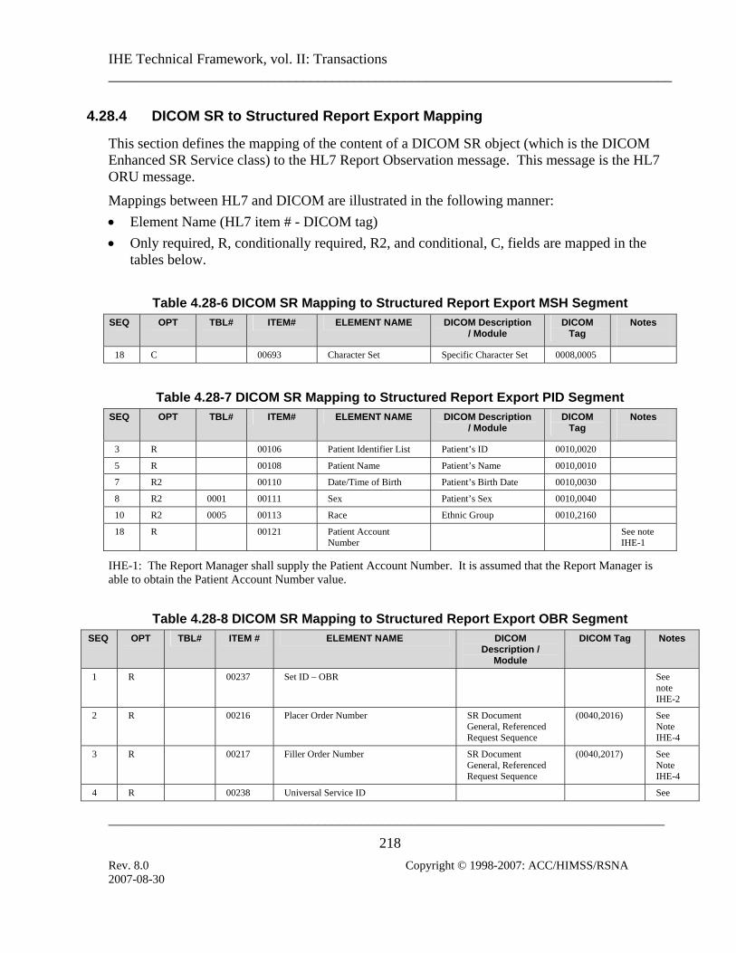
IHE Technical Framework, vol. II: Transactions ______________________________________________________________________________
_____________________________________________________________________________
218 Rev. 8.0 Copyright © 1998-2007: ACC/HIMSS/RSNA
4.28.4 DICOM SR to Structured Report Export Mapping
This section defines the mapping of the content of a DICOM SR object (which is the DICOM Enhanced SR Service class) to the HL7 Report Observation message. This message is the HL7 ORU message.
Mappings between HL7 and DICOM are illustrated in the following manner: • Element Name (HL7 item # - DICOM tag) • Only required, R, conditionally required, R2, and conditional, C, fields are mapped in the
tables below.
Table 4.28-6 DICOM SR Mapping to Structured Report Export MSH Segment
SEQ OPT TBL# ITEM# ELEMENT NAME DICOM Description / Module
DICOM Tag
Notes
18 C 00693 Character Set Specific Character Set 0008,0005
Table 4.28-7 DICOM SR Mapping to Structured Report Export PID Segment
SEQ OPT TBL# ITEM# ELEMENT NAME DICOM Description / Module
DICOM Tag
Notes
3 R 00106 Patient Identifier List Patient’s ID 0010,0020
5 R 00108 Patient Name Patient’s Name 0010,0010
7 R2 00110 Date/Time of Birth Patient’s Birth Date 0010,0030
8 R2 0001 00111 Sex Patient’s Sex 0010,0040
10 R2 0005 00113 Race Ethnic Group 0010,2160
18 R 00121 Patient Account Number
See note IHE-1
IHE-1: The Report Manager shall supply the Patient Account Number. It is assumed that the Report Manager is able to obtain the Patient Account Number value.
Table 4.28-8 DICOM SR Mapping to Structured Report Export OBR Segment
SEQ OPT TBL# ITEM # ELEMENT NAME DICOM Description /
Module
DICOM Tag Notes
1 R 00237 Set ID – OBR See note IHE-2
2 R 00216 Placer Order Number SR Document General, Referenced Request Sequence
(0040,2016) See Note IHE-4
3 R 00217 Filler Order Number SR Document General, Referenced Request Sequence
(0040,2017) See Note IHE-4
4 R 00238 Universal Service ID See
2007-08-30

IHE Technical Framework, vol. II: Transactions ______________________________________________________________________________
_____________________________________________________________________________
219 Rev. 8.0 Copyright © 1998-2007: ACC/HIMSS/RSNA
SEQ OPT TBL# ITEM # ELEMENT NAME DICOM DICOM Tag Notes Description / Module
Note IHE-3
7 R 00241 Observation DateTime SR Content Observation DateTime if present, otherwise use the SR Document General, Content Date, Content Time
(0040,A032)
or
(0008,0023)
(0008,0033)
25 R 00258 Result Status = F
32 O 00264 Principal Results Interpreter Person Name value of the Content item that is related to the root of the SR document with the relation ship HAS OBS CONTEXT and whose Concept Name Code is (121008,DCM, “Person Observer Name”)
(0040,A123)
IHE-2: If the SR has multiple items in the Referenced Request sequence, the Report Manager will generate separate ORU messages for each item.
IHE-3: The Report Manager shall supply the Universal Service ID from the original order (Placer). It is assumed that the Report Manager is able to obtain the Universal Service ID value.
IHE-4: If the Placer and/or Filler order number are not provided by the Referenced Request Sequence, it is assumed that the Report Manager is able to obtain values.
Table 4.28-9 DICOM SR Mapping to Structured Report Export OBX Segments
SEQ OPT TBL# ITEM# ELEMENT NAME DICOM Description
/ Module DICOM
Tag Notes
The first OBX segment carries the Structured Report Instance UID
1 R Set-ID-OBX = 1
2 R 0125 00070 Value Type = HD
3 R 00571 Observation Identifier = ^SR Instance UID
5 R 00573 Observation Value SR Instance UID 0008,0018
11 R 0085 Observe Result Status=F
2007-08-30

IHE Technical Framework, vol. II: Transactions ______________________________________________________________________________
_____________________________________________________________________________
220 Rev. 8.0 Copyright © 1998-2007: ACC/HIMSS/RSNA
SEQ OPT TBL# ITEM# ELEMENT NAME DICOM Description DICOM Notes / Module Tag
The next set of four OBX segments repeats for each IMAGE type Content Item present in the SR content. Each OBX set provides the external report repository the ability to lookup the relevant image references.
The Content Items only provide the Referenced SOP Class UID (0008,1150) and Referenced SOP Instance UID (0008,1155). The Study Instance UID (0020,000D) and Series Instance UID (0020,000E) are found in the corresponding item in the Current Requested Procedure Evidence Sequence (0040,A375) or the Pertinent Other Evidence Sequence (0040,A385). Use the SOP Instance UID to find the correct sequence item. For further details, see Table C.17-2 (SR Document General Module Attributes) and Table C.17-3 (SOP Instance Reference Macro Attributes) in Part 3 of the DICOM 2007 Standard.
Each set of four OBX segments that make up an UID reference will have the same unique Observation Sub-ID (OBX 4). The Sub-ID for the first set shall have a value of 1. The Sub-ID shall increment for each subsequent OBX set in the message.
1 R Set-ID-OBX
2 R 0125 00070 Value Type = HD
3 R 00571 Observation Identifier = ^Study Instance UID
5 R 00573 Observation Value Current/Pertinent Evidence Sequence, matching item’s Study Instance UID
0020,000D
11 R 0085 Observe Result Status=F
1 R Set-ID-OBX
2 R 0125 00070 Value Type = HD
3 R 00571 Observation Identifier = ^Series Instance UID
5 R 00573 Observation Value Current/Pertinent Evidence Sequence, matching item’s Series Instance UID
0020,000E
11 R 0085 Observe Result Status=F
1 R Set-ID-OBX
2 R 0125 00070 Value Type
3 R 00571 Observation Identifier = ^SOP Instance UID
5 R 00573 Observation Value IMAGE Content Item, Referenced SOP Instance UID
0008,1155
11 R 0085 Observe Result Status=F
1 R Set-ID-OBX
2 R 0125 00070 Value Type = HD
3 R 00571 Observation Identifier = ^SOP Class ID
5 R 00573 Observation Value Image Content Item, Referenced SOP Class UID
0008,1150
11 R 0085 Observe Result Status=F
2007-08-30

IHE Technical Framework, vol. II: Transactions ______________________________________________________________________________
_____________________________________________________________________________
221 Rev. 8.0 Copyright © 1998-2007: ACC/HIMSS/RSNA
SEQ OPT TBL# ITEM# ELEMENT NAME DICOM Description DICOM Notes / Module Tag
The report text generated by the Report manager is sent in the next OBX segment(s). No contextual information shall be assumed if multiple OBX segements are used. 1 R Set-ID-OBX
2 R 0125 00070 Value Type = TX
3 R 00571 Observation Identifier = ^SR Text
5 R 00573 Observation Value Report Text from SR Object
11 R 0085 Observe Result Status=F
4.28.5 Expected Actions
The Enterprise Report Repository accepts the message. The usage of the result by the Enterprise Report Repository is beyond the scope of the IHE Technical Framework
2007-08-30

IHE Technical Framework, vol. II: Transactions ______________________________________________________________________________
_____________________________________________________________________________
222 Rev. 8.0 Copyright © 1998-2007: ACC/HIMSS/RSNA
4.29 Key Image Note Stored This section corresponds to Transaction RAD-29 of the IHE Technical Framework. Transaction RAD-29 is used by the Acquisition Modality and Evidence Creator actors.
4.29.1 Scope
In the Key Image Note Stored transaction, the Acquisition Modality or the Evidence Creator transmits a DICOM Key Image Note, which is stored in the Image Archive.
4.29.2 Use Case Roles
Key Image Note Stored
Acquisition Modality
Evidence Creator
Image Archive
Actor: Acquisition Modality
Role: Flag significant images by creating Key Image Notes and issuing Key Image Note Stored Transactions to the Image Archive.
Actor: Evidence Creator
Role: Flag significant images by creating Key Image Notes and issuing Key Image Note Stored Transactions to the Image Archive.
Actor: Image Archive
Role: Accepts and Stores Key Image Note Instances received from the Acquisition Modality or Evidence Creator. This transaction describes the role related only to storage of the Key Image Note.
4.29.3 Referenced Standards
DICOM 2007 PS 3.4: Key Object Selection Document Storage SOP Class
DICOM 2007 PS 3.4: Storage SOP Class
2007-08-30

IHE Technical Framework, vol. II: Transactions ______________________________________________________________________________
_____________________________________________________________________________
223 Rev. 8.0 Copyright © 1998-2007: ACC/HIMSS/RSNA
4.29.4 Interaction Diagram
Key Image Note Stored
Acquisition Modality
Image Archive Evidence
Creator
Key Image Note Stored
(C-STORE) (C-STORE)
4.29.4.1 Key Image Note Stored
This transaction relates to the “DICOM C-STORE” event between the Acquisition modality or the Evidence Creator and the Image Archive in the above interaction diagram.
4.29.4.1.1 Trigger Events
The Acquisition Modality or the Evidence Creator generates a Key Image Note and sends it to the Image Archive for storage.
4.29.4.1.2 Message Semantics
The Acquisition Modality or the Evidence Creator uses the DICOM C-STORE message to store Key Image Notes. Message semantics are defined in the Key Object Selection Storage SOP Class definition and Behavior section of DICOM PS3.3 and PS3.4.
4.29.4.1.3 Expected Actions
The Image Archive will store the received Key Image Note objects.
2007-08-30

IHE Technical Framework, vol. II: Transactions ______________________________________________________________________________
_____________________________________________________________________________
224 Rev. 8.0 Copyright © 1998-2007: ACC/HIMSS/RSNA
4.30 Query Key Image Notes This section corresponds to Transaction RAD-30 of the IHE Technical Framework. Transaction RAD-30 is used by the Image Archive and Image Display actors.
4.30.1 Scope
This section describes the sequence of Transactions required for the Image Display to query the Image Archive for instances of Key Image Notes. The Image Display will query (in order to later retrieve) for Key Image Note objects together with the image objects referenced in the return keys supplied in the response from the Image Archive.
Multiple Key Image Notes may exist that reference the same image data.
4.30.2 Use Case Roles
Query Key Image Notes
Image Display
Image Archive
Actor: Image Display
Role: Query for Key Image Notes objects together with the referenced image data and provides a means to indicate that images are flagged as significant. This device will implement the Query/Retrieve SOP Classes in the role of SCU.
Actor: Image Archive
Role: Respond to queries from the Image Display for Key Image Notes objects. This device will implement the Query/Retrieve SOP Classes in the role of SCP.
4.30.3 Referenced Standards
DICOM 2007 PS 3.4: Query/Retrieve Service Class
DICOM 2007 PS 3.4: Key Image Note Storage SOP Class
2007-08-30

IHE Technical Framework, vol. II: Transactions ______________________________________________________________________________
_____________________________________________________________________________
225 Rev. 8.0 Copyright © 1998-2007: ACC/HIMSS/RSNA
4.30.4 Interaction Diagram
Query Responses (C-FIND)
Image Display
Image Archive
Query Key Image Notes (C-FIND)
4.30.4.1 Query Key Image Notes
This transaction relates to the query section of the above interaction diagram. The Query (Study Root – FIND and optionally Patient Root – FIND) SOP Classes shall be supported. Refer to DICOM 2007 PS 3.4: Query/Retrieve Service Class for detailed descriptive semantics.
4.30.4.1.1 Trigger Events
The user at the Image Display wishes to view Key Image Notes to use as a guide to find significant images.
4.30.4.1.2 Message Semantics
The message semantics are defined by the DICOM Query/Retrieve SOP Classes.
A C-FIND Request from the DICOM Study Root Query/Retrieve Information Model – FIND SOP Class or the DICOM Patient Root Query/Retrieve Information Model – FIND SOP Class shall be sent from the Image Display to the Image Archive.
The Image Display uses one or more matching keys as search criteria to obtain the list of matching entries in the Image Archive at the selected level (Patient & Study/Series/Instance).
In addition to the required and unique keys defined by the DICOM Standard, the IHE Technical Framework has defined matching and return keys to be supported by query SCUs and SCPs. The keys are defined in sec. 4.14.4.1.2 and table 4.14-1. The conventions for key usage are defined in section 2.2. For the Image Display (SCU) and the Image Archive (SCP) the additional Key Image Note Instances specific keys are defined in table 4.30-1.
2007-08-30

IHE Technical Framework, vol. II: Transactions ______________________________________________________________________________
_____________________________________________________________________________
226 Rev. 8.0 Copyright © 1998-2007: ACC/HIMSS/RSNA
Table 4.30-1. Key Image Note Instance Specific Query Matching and Return Keys Query Keys Matching Query Keys Return Attribute Name Tag SCU SCP SCU SCP
Key Instance Note Instance Specific Level Content Date (0008,0023) O O O R+
Content Time (0008,0033) O O O R+
Observation DateTime (0040,A032) O O O R+
Referenced Request Sequence (0040,A370)
>Study Instance UID (0020,000D) O O R+* R+
>Accession Number (0008,0050) O O R+ R+
>Requested Procedure ID (0040,1000) O O R+ R+
>Requested Procedure Code Sequence
(0032,1064)
>>Code Value (0008,0100) O O O R+
>>Coding Scheme Designator (0008,0102) O O O R+
>>Coding Scheme Version (0008,0103) O O O R+
>>Code Meaning (0008,0104) O O O R+
Concept Name Code Sequence (Note 1)
(0040,A043)
>Code Value (0008,0100) R+ R+ R+ R+
>Coding Scheme Designator (0008,0102) R+ R+ R+ R+
>Coding Scheme Version (0008,0103) O O O R+
>Code Meaning (0008,0104) O O R+ R+
Note1: The Concept Name Code Sequence of the root content item conveys the Key Image Note Title. The list of applicable codes can be found in CID 7010 (Key Object Selection Document Title) in DICOM PS 3.16.
4.30.4.1.3 Expected Actions
The Image Archive receives the C-FIND request, performs the matching on the provided keys and sends the list of matching records back to the Image Display via C-FIND responses.
2007-08-30

IHE Technical Framework, vol. II: Transactions ______________________________________________________________________________
_____________________________________________________________________________
227 Rev. 8.0 Copyright © 1998-2007: ACC/HIMSS/RSNA
4.31 Retrieve Key Image Notes This section corresponds to Transaction RAD-31 of the IHE Technical Framework. Transaction RAD-31 is used by the Image Display and Image Archive actors or Imaging Document Consumer and Imaging Document Source.
4.31.1 Scope
In the Retrieve Key Image Notes Transaction, the requested DICOM Key Image Notes are transferred from the Image Manager or Imaging Document Source to the Image Display or Imaging Document Consumer for viewing along with the images flagged by the Key Image Note.
4.31.2 Use Case Roles
Retrieve Key Image Notes
Image Display
Image Archive Imaging Document
Source
Imaging Document Consumer
Actor: Image Archive:
Role: Sends requested Key Image Notes to the Image Display Actor.
Actor: Imaging Document Source
Role: Sends requested Key Image Notes to the Imaging Document Consumer Actor.
Actor: Image Display
Role: Receives requested Key Image Notes from the Image Archive Actor.
Actor: Imaging Document Consumer
Role: Receives requested Key Images Notes from the Imaging Document Source Actor.
2007-08-30

IHE Technical Framework, vol. II: Transactions ______________________________________________________________________________
_____________________________________________________________________________
228 Rev. 8.0 Copyright © 1998-2007: ACC/HIMSS/RSNA
4.31.3 Referenced Standards
DICOM 2007 PS 3.4: Query/Retrieve Service Class
DICOM 2007 PS 3.4: Key Object Selection Document Storage SOP Class
4.31.4 Interaction Diagram
Retrieve Key Image Notes (C-MOVE)
Image Display
Render Key Image Notes
Image Archive
Store Key Image Notes (C-STORE)
Retrieve Key Image Notes (C-MOVE)
Imaging Document Consumer
Render Key Image Notes
Imaging Document
Source
Store Key Image Notes (C-STORE)
4.31.4.1 Retrieve Key Image Notes
The Retrieve (Study Root – MOVE and optionally Patient Root – MOVE) SOP Classes will be supported. The Image Archive and Imaging Document Source as an SCU shall support DICOM Image Storage SOP Classes. Refer to DICOM 2007 PS 3.4, Annex C, for detailed descriptive semantics.
2007-08-30

IHE Technical Framework, vol. II: Transactions ______________________________________________________________________________
_____________________________________________________________________________
229 Rev. 8.0 Copyright © 1998-2007: ACC/HIMSS/RSNA
4.31.4.1.1 Trigger Events
The Image Display or Imaging Document Consumer selects specific Key Image Note objects to retrieve from the Image Archive or Imaging Document Source.
4.31.4.1.2 Message Semantics
The message semantics are defined in the DICOM Query/Retrieve Service Class section of the DICOM 2007 PS 3.4: Query/Retrieve Service Class. It is the responsibility of the Image Manager to assure that the patient and procedure information is current in the images and Key Image Note objects when they are retrieved from the Image Archive. It is the responsibility of the Imaging Document Source to assure that the patient and procedure information is current in the Key Image Note objects when they are retrieved from this Actor.
4.31.4.1.3 Expected Actions
The Image Archive or Imaging Document Source receives the C-MOVE request, establishes a DICOM association with the Image Display or Imaging Document Consumer, and uses the DICOM Key Image Note Storage SOP Class to transfer the requested Key Image Note objects.
4.31.4.2 Render Key Image Notes
This transaction relates to the “Render Key Image Notes” event of the above interaction diagram. Key Image Notes cannot be rendered separately, but must be applied to images. Refer to sec. 4.16 for a description of the transaction used to retrieve images to which Key Image Notes may be applied.
The Image Display or Imaging Document Consumer is not required to, but may choose to, support retrieval and display of images from other studies than the one to which the Key Image Note belongs
4.31.4.2.1 Trigger Events
The Image Display or Imaging Document Consumer receives Key Image Note instances from the Image Archive or Imaging Document Source.
4.31.4.2.2 Invocation Semantics
This is a local invocation of functions resident within the Image Display or Imaging Document Consumer. The method used by the Image Display or Imaging Document Consumer to present images for viewing by the user flagged by the Key Image Notes is outside the scope of the IHE Technical Framework.
2007-08-30

IHE Technical Framework, vol. II: Transactions ______________________________________________________________________________
_____________________________________________________________________________
230 Rev. 8.0 Copyright © 1998-2007: ACC/HIMSS/RSNA
4.31.4.2.2.1 Retrieve AE Title
If the Image Display is capable of retrieving objects referenced in a DICOM Key Image Note then it shall retrieve these objects from the device matching the appropriate Retrieve AE Title attribute (0008,0054) included in the DICOM Key Image Note. If the Retrieve AE Title attribute is not specified or configured, then the Image Display shall use some other configurable Retrieve AE Title.
In the case of retrieving DICOM Key Image Notes in a Cross-Enterprise, imaging document sharing (XDS-I) network environment, a configuration of mapping the AE Titles to DICOM AE Network Addresses (IP Address and Port number) are needed to be exchanged between the Imaging Document Source and the Imaging Document Consumer. RAD TF-3: Appendix G describes in details the AE Title mapping to the DICOM AE Network Addresses.
4.31.4.2.3 Expected Actions
The Image Display or Imaging Document Consumer flags the images and renders the Key Image Note.
Note: It is recommended to use the just retrieved instance of the Key Image Note to ensure that the most recent
patient data be displayed to reflect possible patient merge and patient update in the Image Manager/Image Archive or Imaging Document Source. This patient data may be inconsistent with patient data contained in a previously retrieved copy of the same Key Image Note instance.
2007-08-30

IHE Technical Framework, vol. II: Transactions ______________________________________________________________________________
_____________________________________________________________________________
231 Rev. 8.0 Copyright © 1998-2007: ACC/HIMSS/RSNA
Appendix A: Attribute Consistency between Modality Worklist, Composite IODs, Evidence Documents, KIN and Modality Performed Procedure Step
This appendix is an integral part of the IHE Technical Framework. It reflects IHE’s adoption of DICOM-defined attribute consistency (Annex J, PS.3.17, since DICOM 2006; before: Annex M, PS3.4). It includes four sections: • The first section contains the IHE clarifications, additions and a summary of DICOM,
PS.3.17, Annex J that relate to image acquisition. IHE requires that Modality Actors support the Attribute mapping defined in this table as they implement MWL, various IOD Storage and PPS SOP Classes for Transactions RAD-6, RAD-7, RAD-20 and RAD-21. IHE restates or extends some of the DICOM requirements as well as select some of the choices offered or enforce some of the recommendations of DICOM. A few additional IHE recommendations are also specified.
• The second section defines attribute mappings for consistency in DICOM SR-based evidence objects generated by the Evidence Creator and Acquisition Modality. The DICOM SR objects are created based on existing images that provide values to be filled into the new evidence documents.
• The third section defines additional IHE requirements for consistency of DICOM C-FIND Return Key Attributes.
• The fourth section introduces a real-world data model of the entities and their Attributes related to consistency. Readers are advised to use this data model along with the information presented in RAD TF-1: 3.4. This data model is provided only for ease of understanding and does not introduce any additional IHE requirements.
A.1: Image Acquisition Integration-critical Attributes The tables below describe requirements, recommendations or explanations on integration-critical attributes for image acquisition cases. They define which integration-critical attributes need to be equal (copied or generated locally), in order to correctly relate scheduled and performed procedure steps for the PPS cases described in 4.6.4.1.2.3.
General table structure: • The 1st column denotes the DICOM attributes whose values shall be mapped between the
DICOM objects (equal values in the same table row). The DICOM attribute tag is indicated for clarity.
• The 2nd to 4th columns define where attribute values come from: all defined attribute values of one table row are equal.
2007-08-30

IHE Technical Framework, vol. II: Transactions ______________________________________________________________________________
_____________________________________________________________________________
232 Rev. 8.0 Copyright © 1998-2007: ACC/HIMSS/RSNA
These columns read left to right: MWL return values (2nd column), if existing, shall be used as the source for copies to Image/ Standalone or MPPS IODs.
• The MWL column is omitted if the described case does not include any MWL return values, or to simplify the table (as in the Append Case in table A.1-3 or the PGP with Group Case in table A.1-5).
Cell content conventions: • “Source” in a table cell means that the DICOM object defined in the table column (e.g.
MWL) and created by one actor shall be the source of this value for the DICOM attribute for another actor to fill in this value for their own objects (e.g. Image or MPPS).
• “Copy” in a table cell means that the value shall be copied from a corresponding source attribute of another DICOM object, as defined by the table column.
• ”Copy from: <DICOM attribute>” means that, instead of using the DICOM attribute of the same row as the source, the source as specified in the referenced DICOM attribute shall be used.
• “Equal” in a table cell means that an actor already knows the value, e.g. from some previously performed action. Thus, the circumstances of value generation do not matter.
• “Equal (internally generated)” in a table cell means that an actor has internally generated a value that may be used in more than one DICOM object, without having obtained this value from another actor (i.e. no copy).
• “Equal (copied from MWL)” in a table cell means that the actor shall use a value that it already knows from an MWL query result obtained for the same SPS in the append case.
• ”Source-1”, “Copy-1” or “Equal-1” etc. are corresponding mapping attribute values, if several sources appear in one table row.
• “See (IHE-X)” in a table cell denotes additional requirements, recommendations or explanations for the attribute value, as described in the table’s note “(IHE-X)”. Otherwise, brief text that fits into a table cell is presented in the cell.
• “n.a.” in a table cell means that such an attribute or value shall not exist. Either the attribute is not defined by the DICOM standard for this object, or the particular sequence attribute is a DICOM type 3 attribute, and DICOM requires at least one sequence item to be present.
Actor behavior: • An attribute from the column “Modality Worklist” shall be requested by a MWL SCU
(Acquisition Modality) as a return key in its C-FIND Requests. The Department System Scheduler shall return attribute values in the Modality Worklist C-FIND response (for a complete description, see Table 4.5-3).
2007-08-30

IHE Technical Framework, vol. II: Transactions ______________________________________________________________________________
_____________________________________________________________________________
233 Rev. 8.0 Copyright © 1998-2007: ACC/HIMSS/RSNA
• The MWL return attribute values, if available as a source, shall be used by the Acquisition Modality in filling the attribute shown on the corresponding rows both for Composite Instances and MPPS Instances.
• If the MWL value is not existing (“n.a.”), then the Modality shall generate certain values internally.
• The PPS Manager, Image Manager and Department System Scheduler roles shall be capable of handling the attributes shown in the corresponding row of the column titled “MPPS IOD” as defined by the SCP Type and the additional notes.
Table A.1-1: Simple Case - required mapping of corresponding attributes
In the simple normal case, a Procedure Step is performed
• exactly as scheduled, or
• different than scheduled, but without being rescheduled, e.g. due to a patient’s allergic reaction to contrast media.
Modality Worklist Filling values for:
DICOM attribute
(return attribute values)
Image/ Standalone IOD MPPS IOD
Study Instance UID (0020,000D)
Source Copy Copy
Referenced Study Sequence (0008,1110)
Source Copy Copy
Accession number (0008,0050)
Source Copy See (IHE-A.1.1)
Copy See (IHE-A.1.1)
Requested Procedure ID (0040,1001)
Source Copy Copy
Requested Procedure Description (0032,1060)
Source Copy Note: extended attribute
Copy
Scheduled Procedure Step ID (0040,0009)
Source Copy Copy
Scheduled Procedure Step Description (0040,0007)
Source Copy Copy
Scheduled Protocol Code Sequence (0040,0008)
Source Req
uest
Att
ribu
tes S
eque
nce
(0
040,
0275
)
Copy
Sche
dule
d St
ep A
ttri
bute
s Seq
uenc
e
(004
0,02
70)
Copy
Performed Protocol Code Sequence (0040,0260)
n.a. Equal (internally generated). Recommendation: Absent if the value is not known. Is non-empty if Assisted Protocol Setting option is supported (see 4.6.4.1.2.4).
Equal (internally generated). Shall be zero length if the value is not known, e.g. Assisted Protocol Setting not supported.
2007-08-30

IHE Technical Framework, vol. II: Transactions ______________________________________________________________________________
_____________________________________________________________________________
234 Rev. 8.0 Copyright © 1998-2007: ACC/HIMSS/RSNA
Modality Worklist Filling values for:
DICOM attribute
(return attribute Image/ Standalone IOD MPPS IOD values)
Study ID (0020,0010) n.a. Equal (internally generated). Recommendation: use Requested Procedure ID.
Equal (internally generated). Recommendation: use Requested Procedure ID.
Performed Procedure Step ID (0040,0253)
n.a. Equal (internally generated). See (IHE-A.1.2)
Equal (internally generated).
Performed Procedure Step Start Date (0040,0244)
n.a. Equal (internally generated). Recommendation: use the same value for Study Date.
Equal (internally generated).
Performed Procedure Step Start Time (0040,0245)
n.a. Equal (internally generated). Recommendation: use the same value for Study Time.
Equal (internally generated).
Performed Procedure Step Description (0040,0254)
n.a. Equal (internally generated). Recommendation: use the same value for Study Description.
Equal (internally generated).
Requested Procedure Code Sequence (0032,1064)
Value shall be used for Procedure Code Sequence as specified below.
n.a. n.a.
Procedure Code Sequence (0008,1032)
n.a. Copy from: Requested Procedure Code Sequence (0032,1064). Recommendation: absent, if empty in MWL or perfor-med acquisition is different to what was scheduled.
Copy from: Requested Procedure Code Sequence (0032,1064). Recommendation: empty, if empty in MWL or perfor-med acquisition is different to what was scheduled.
Referenced SOP Class UID (0008,1150)
n.a. 1.2.840.10008.3.1.2.3.3
Equal (internally generated). See (IHE-A.1.4)
Referenced SOP Instance UID (0008,1155)
n.a.
Ref
eren
ced
PPS
Sequ
ence
(I
HE-
A.1
.3)
Equal to SOP Instance of the associated MPPS (IHE-A.1.5).
Equal (internally generated). See (IHE-A.1.5)
Protocol Name (0018,1030) n.a. Recommendation: equal (internally generated)
Perf
orm
ed
Seri
es
Sequ
ence
(0
040,
0340
) Equal (internally generated)
(IHE-A.1.1) A Zero Length Accession Number (One of the options proposed by DICOM PS3.4 Annex M) shall be created when no reliable value for this attribute is available. Reliable values are those that can be conveyed by means other than manual data entry such as a value received from the Order Filler via a Modality Worklist including an Accession Number or received through a bar code reader.
2007-08-30

IHE Technical Framework, vol. II: Transactions ______________________________________________________________________________
_____________________________________________________________________________
235 Rev. 8.0 Copyright © 1998-2007: ACC/HIMSS/RSNA
(IHE-A.1.2) Performed Procedure Step ID is generated by the modality arbitrarily and is not necessarily unique: Two different Performed Procedure Steps may share the same ID (e.g. may have been generated by different modalities). This ID may not enable a receiving system to reliably relate the PPS to the associated Requested Procedure and SPS. It is not reliable to assume that two PPSs with the same PPS ID value fulfill the same SPS/Requested Procedure, without checking the content of Scheduled Attributes Step Sequence.
(IHE-A.1.3) The Referenced Performed Procedure Step Sequence (0008,1111) that contains the PPS SOP Instance UID shall be included (per DICOM PS3.3 section C.7.3 strong recommendation, General Series Module Table, Note 1) when Acquisition Modality Actors support MPPS.
(IHE-A.1.4) In MPPS, SOP Class UID is sent in the Affected SOP Class UID (0000,0002) for the PPS N-Create message and in Requested SOP Class UID (0000,0003) for the PPS N-Set message. SOP Class UID (0008,0016) shall not be used.
(IHE-A.1.5) In MPPS, SOP Instance UID is sent in the Affected SOP Instance UID (0000,1000) of the PPS N-Create message and in Requested SOP Instance UID (0000,1001) for the PPS N-Set message. SOP Instance UID (0008,0018) shall not be used.
Table A.1-2: Unscheduled Case - required mapping of corresponding attributes
Filling values for: DICOM attribute Image/ Standalone IOD MPPS IOD
Study Instance UID (0020,000D)
Equal (internally generated). Equal (internally generated).
Referenced Study Sequence (0008,1110)
n.a. Shall be empty.
Accession number (0008,0050)
Shall be empty (zero length). Shall be empty.
Requested Procedure ID (0040,1001)
Shall be empty.
Requested Procedure Description (0032,1060)
Shall be empty.
Scheduled Procedure Step ID (0040,0009)
Shall be empty.
Scheduled Procedure Step Description (0040,0007)
Shall be empty.
Scheduled Protocol Code Sequence (0040,0008)
Req
uest
Att
ribu
tes S
eque
nce
(0
040,
0275
)
n.a.
Sche
dule
d St
ep A
ttri
bute
s Seq
uenc
e
(004
0,02
70)
Shall be empty.
Performed Protocol Code Sequence (0040,0260)
Equal (internally generated). Recommendation: Absent if the value is not known. Is non-empty if Assisted
Equal (internally generated). Shall be zero length if the value is not known, e.g. Assisted Protocol
2007-08-30

IHE Technical Framework, vol. II: Transactions ______________________________________________________________________________
_____________________________________________________________________________
236 Rev. 8.0 Copyright © 1998-2007: ACC/HIMSS/RSNA
Filling values for: DICOM attribute Image/ Standalone IOD MPPS IOD
Protocol Setting option is supported (see 4.6.4.1.2.4).
Setting not supported.
Study ID (0020,0010) Equal (internally generated) Equal (internally generated)
Performed Procedure Step ID (0040,0253)
Equal (internally generated). See (IHE-A.2.1)
Equal (internally generated).
Performed Procedure Step Start Date (0040,0244)
Equal (internally generated). Recommendation: use the same value for Study Date.
Equal (internally generated).
Performed Procedure Step Start Time (0040,0245)
Equal (internally generated). Recommendation: use the same value for Study Time.
Equal (internally generated).
Performed Procedure Step Description (0040,0254)
Equal (internally generated). Recommendation: use the same value for Study Description.
Equal (internally generated).
Requested Procedure Code Sequence (0032,1064)
n.a. n.a.
Procedure Code Sequence (0008,1032)
n.a. Shall be empty.
Referenced SOP Class UID (0008,1150)
1.2.840.10008.3.1.2.3.3 Equal (internally generated). See (IHE-A.2.3)
Referenced SOP Instance UID (0008,1155)
Ref
eren
ced
PPS
Se-
quen
ce (
0008
,111
1)
(IH
E-A
.2.2
)
Equal to SOP Instance of the associated MPPS (IHE-A.2.4).
Equal (internally generated). See (IHE-A.2.4)
Protocol Name (0018,1030) Recommendation: equal (internally generated).
Perf
orm
ed
Seri
es
Sequ
ence
(0
040,
0340
) Equal (internally generated)
(IHE-A.2.1) Performed Procedure Step ID is generated by the modality arbitrarily and is not necessarily unique: Two different Performed Procedure Steps may share the same ID (e.g. may have been generated by different modalities).
(IHE-A.2.2) The Referenced Performed Procedure Step Sequence (0008,1111) that contains the PPS SOP Instance UID shall be included (per DICOM PS3.3 section C.7.3 strong recommendation, General Series Module Table, Note 1) when Acquisition Modality Actors support MPPS.
(IHE-A.2.3) In MPPS, SOP Class UID is sent in the Affected SOP Class UID (0000,0002) for the PPS N-Create message and in Requested SOP Class UID (0000,0003) for the PPS N-Set message. SOP Class UID (0008,0016) shall not be used.
(IHE-A.2.4) In MPPS, SOP Instance UID is sent in the Affected SOP Instance UID (0000,1000) of the PPS N-Create message and in Requested SOP Instance UID
2007-08-30

IHE Technical Framework, vol. II: Transactions ______________________________________________________________________________
_____________________________________________________________________________
237 Rev. 8.0 Copyright © 1998-2007: ACC/HIMSS/RSNA
(0000,1001) for the PPS N-Set message. SOP Instance UID (0008,0018) shall not be used.
2007-08-30

IHE Technical Framework, vol. II: Transactions ______________________________________________________________________________
_____________________________________________________________________________
238 Rev. 8.0 Copyright © 1998-2007: ACC/HIMSS/RSNA
Table A.1-3: Append to a Simple/ Normal Case - required mapping of corresponding attributes
Similar to the simple case, the first PPS is generated in response to an SPS. Other PPSes are added at a later time, for instance due to unacceptable quality of certain images.
Filling values for: DICOM attribute Original Image/ Standalone IOD
Append Image/ Standalone IOD
Append MPPS IOD
Study Instance UID (0020,000D)
Equal (copied from MWL) Equal (copied from MWL) Equal (copied from MWL)
Referenced Study Sequence (0008,1110)
Equal (copied from MWL)
Equal (copied from MWL) Equal (copied from MWL)
Accession number (0008,0050)
Equal (copied from MWL). See (IHE-A.3.1).
Equal (copied from MWL). See (IHE-A.3.1).
Equal (copied from MWL). See (IHE-A.3.1).
Requested Procedure ID (0040,1001)
Equal (copied from MWL)
Equal (copied from MWL)
Equal (copied from MWL)
Requested Procedure Description (0032,1060)
Equal (copied from MWL)
Equal (copied from MWL)
Equal (copied from MWL)
Scheduled Procedure Step ID (0040,0009)
Equal (copied from MWL)
Equal (copied from MWL)
Equal (copied from MWL)
Scheduled Procedure Step Description (0040,0007)
Equal (copied from MWL)
Equal (copied from MWL)
Equal (copied from MWL)
Scheduled Protocol Code Sequence (0040,0008)
Sche
dule
d St
ep A
ttri
bute
s Seq
uenc
e
(004
0,02
70)
Req
uest
Att
ribu
tes S
eque
nce
(0
040,
0275
)
Req
uest
Att
ribu
tes S
eque
nce
(0
040,
0275
)
Equal (copied from MWL)
Equal (copied from MWL)
Equal (copied from MWL)
Performed Protocol Code Sequence (0040,0260)
Note: Values may not be relevant for the appended image and associated MPPS, e.g. due to adding images from an adjacent body region or from doing measurements.
Equal (internally generated). Recommendation: Absent if the value is not known. Is non-empty if Assisted Protocol Setting option is supported (see 4.6.4.1.2.4).
Equal (internally generated). Shall be zero length if the value is not known, e.g. Assisted Protocol Setting not supported.
Study ID (0020,0010) Equal (internally generated) Recommendation: use Requested Procedure ID.
Equal (internally generated) Recommendation: use Requested Procedure ID.
Equal (internally generated) Recommendation: use Requested Procedure ID.
Performed Procedure Step ID (0040,0253)
Note: Values not relevant for the appended image and associated MPPS.
Equal (internally generated). See (IHE-A.3.2)
Equal (internally generated).
Performed Procedure Step Start Date (0040,0244)
Note: Values not relevant for the appended image and associated MPPS.
Equal (internally generated). See (IHE-A.3.3)
Equal (internally generated).
Performed Procedure Step Start Time (0040,0245)
Note: Values not relevant for the appended image
Equal (internally generated).
Equal (internally generated).
2007-08-30

IHE Technical Framework, vol. II: Transactions ______________________________________________________________________________
_____________________________________________________________________________
239 Rev. 8.0 Copyright © 1998-2007: ACC/HIMSS/RSNA
Filling values for: DICOM attribute Original Image/ Standalone IOD
Append Image/ Standalone IOD
Append MPPS IOD
and associated MPPS. See (IHE-A.3.3)
Performed Procedure Step Description (0040,0254)
Note: Values not relevant for the appended image and associated MPPS.
Equal (internally generated). See (IHE-A.3.3)
Equal (internally generated).
Requested Procedure Code Sequence (0032,1064)
n.a. n.a. n.a.
Procedure Code Sequence (0008,1032)
Equal.
Note: May be absent (see Table A.1-1)
Equal. If absent in original image, shall be absent here. Recommendation: absent, if performed acquisition is different from the original image’s procedure.
Equal. If absent in original image, shall be empty. Recommendation: empty, if absent in the original/ appended image.
Referenced SOP Class UID (0008,1150)
1.2.840.10008.3.1.2.3.3
Equal (internally generated). See (IHE-A.3.5)
Referenced SOP Instance UID (0008,1155)
Ref
eren
ced
PPS
Se-
quen
ce (
0008
,111
1)
(IH
E-A
.3.4
)
Note: Values not relevant for the appen-ded image and associated MPPS.
Ref
eren
ced
PPS
Se-
quen
ce (0
008,
1111
) (I
HE-
A.3
.4)
Equal to SOP Instance of the associated MPPS (IHE-A.3.6).
Equal (internally generated). See (IHE-A.3.6)
Protocol Name (0018,1030) Note: Values not relevant for the appended image and associated MPPS.
Recommendation: equal (internally generated).
Perf
orm
ed
Seri
es
Sequ
ence
(0
040,
0340
) Equal (equally generated)
(IHE-A.3.1) A Zero Length Accession Number (One of the options proposed by DICOM PS3.4 Annex M) needs to be created when no reliable value for this attribute is available. Reliable values are those that can be conveyed by means other than manual data entry such as a value received from the Order Filler via a Modality Worklist including an Accession Number or received through a bar code reader.
(IHE-A.3.2) Performed Procedure Step ID is generated by the modality arbitrarily and is not necessarily unique: Two different Performed Procedure Steps may share the same ID (e.g. may have been generated by different modalities). This ID may not enable a receiving system to reliably relate the PPS to the associated Requested Procedure and SPS. It is not reliable to assume that two PPSs with the same PPS ID value fulfill the same SPS/Requested Procedure, without checking the content of Scheduled Attributes Step Sequence.
(IHE-A.3.3) In the Image IODs created in Append Case, the Study Date, Study Time and Study Description shall re-use the corresponding values from the original images to which they are appended.
2007-08-30

IHE Technical Framework, vol. II: Transactions ______________________________________________________________________________
_____________________________________________________________________________
240 Rev. 8.0 Copyright © 1998-2007: ACC/HIMSS/RSNA
(IHE-A.3.4) The Referenced Performed Procedure Step Sequence (0008,1111) that contains the PPS SOP Instance UID shall be included (per DICOM PS3.3 section C.7.3 strong recommendation, General Series Module Table, Note 1) when Acquisition Modality Actors support MPPS.
(IHE-A.3.5) In MPPS, SOP Class UID is sent in the Affected SOP Class UID (0000,0002) for the PPS N-Create message and in Requested SOP Class UID (0000,0003) for the PPS N-Set message. SOP Class UID (0008,0016) shall not be used.
(IHE-A.3.6) In MPPS, SOP Instance UID is sent in the Affected SOP Instance UID (0000,1000) of the PPS N-Create message and in Requested SOP Instance UID (0000,1001) for the PPS N-Set message. SOP Instance UID (0008,0018) shall not be used.
If a PPS and related images is appended to a group case (see Rad TF-2, 4.6.4.1.2.3.3), e.g. for adding 3D post-processing evidence to a grouped MR head and neck exam, then the following conditions need to be considered for the appended images and MPPs, especially as compared to appending to a simple case:
• The Study Instance UID (0020,000D) in appended images and PPS shall have the same value as the Study Instance UID generated for the original grouped images.
• The Accession Number (0008,0050) shall be empty if the grouped SPS do not have the same Accession Number.
• The Referenced Study Sequence (0008,1110) in appended images shall have as many sequence items as there are different grouped Requested Procedures.
• The Request Attributes Sequence (0040,0275) in appended images shall have as many sequence items as there are grouped SPSes.
• The Scheduled Step Attributes Sequence (0040,0270) associated with the appended images shall have as many sequence items as there are grouped SPSes.
• Performed Protocol Code Sequence (0040,0260) will probably have different values than for the original grouped images.
• The Procedure Code Sequence (0008,1032) in appended images and the associated MPPS is recommended to contain as many items as there are different Procedure Codes in Requested Procedures if the system is able to ensure that what is acquired is what has been scheduled. It is recommended to be absent if the Procedure Code Sequence is absent in MWL or the performed acquisition is different from what has been scheduled.
2007-08-30

IHE Technical Framework, vol. II: Transactions ______________________________________________________________________________
_____________________________________________________________________________
241 Rev. 8.0 Copyright © 1998-2007: ACC/HIMSS/RSNA
Table A.1-4: Group Case (3 SPSs belonging to 2 Requested Procedures) - required
mapping of corresponding attributes
This scenario describes the case where the first Requested Procedure has 1 SPS, and the 2nd Requested Procedure contains 2 SPSes (grouping as in the diagram in section 4.6.4.1.2.3.6). Note: For generating the append PPS to a group case, the Modality actor needs to fill in additional attributes currently not defined in DICOM, which relate to requested or scheduled information. A Correction Proposal to DICOM requests to resolve these issues by adding optional attributes to the Request Attributes Sequence in Image IODs and to the Scheduled Step Attribute Sequence in MPPS (for details see Rad TF-1, B.2.2).
Modality Worklist
(return attribute values) Filling values for:
DICOM attribute
Item 1 Item 2 Item 3 Image IOD MPPS IOD
Item 1 Item 2 Item 3 Study Instance UID (0020,000D) Source-1 Source-2 Source-2 Equal (internally generated) Equal Equal Equal
Accession number (0008,0050)
Source-1 Source-2 Source-2 Copy (if same Accession Number in Source-1 and Source-2). Shall be empty if the grouped SPSes do not have the same Accession Number.
Copy-1 Copy-2 Copy-2
Item 1 Item 2 Referenced Study Sequence (0008,1110) Source-1 Source-2 Source-2 Copy-1 Copy-2 Copy-1 Copy-2 Copy-2
Item 1 Item 2 Item 3 Requested Procedure ID (0040,1001)
Source-1 Source-2 Source-2 Copy-1 Copy-2 Copy-2 Copy-1 Copy-2 Copy-2
Requested Procedure Description (0032,1060)
Source-1 Source-2 Source-2 Copy-1 Copy-2 Copy-2 Copy-1
Copy-2 Copy-2
Scheduled Procedure Step ID (0040,0009)
Source-1 Source-2 Source-3 Copy-1 Copy-2 Copy-3 Copy-1
Copy-2 Copy-3
Scheduled Procedure Step Description (0040,0007)
Source-1 Source-2 Source-3 Copy-1 Copy-2 Copy-3 Copy-1
Copy-2 Copy-3
Scheduled Protocol Code Sequence (0040,0008)
Source-1 Source-2 Source-3 Req
uest
Att
ribu
tes S
eque
nce
(0
040,
0275
)
Copy-1 Copy-2 Copy-3
Sche
dule
d St
ep A
ttri
bute
s Seq
uenc
e
(004
0,02
70)
Copy-1
Copy-2 Copy-3
Performed Protocol Code Sequence (0040,0260)
n.a Equal (internally generated). Recommendation: Absent if the value is not known. Is non-empty if Assisted Protocol Setting option is supported (see 4.6.4.1.2.4).
Equal (internally generated). Shall be zero length if the value is not known, e.g. Assisted Protocol Setting not supported.
2007-08-30

IHE Technical Framework, vol. II: Transactions ______________________________________________________________________________
_____________________________________________________________________________
242 Rev. 8.0 Copyright © 1998-2007: ACC/HIMSS/RSNA
Modality Worklist
(return attribute values) Filling values for:
DICOM attribute
Item 1 Item 2 Item 3 Image IOD MPPS IOD
Study ID (0020,0010) n.a Equal (internally generated) Equal (internally generated)
Performed Procedure Step ID (0040,0253)
n.a Equal (internally generated). See (IHE-A.4.1)
Equal (internally generated). See (IHE-A.4.1)
Performed Procedure Step Start Date (0040,0244)
n.a Equal (internally generated). Recommendation: Use the same value for Study Date
Equal (internally generated)
Performed Procedure Step Start Time (0040,0245)
n.a Equal (internally generated). Recommendation: Use the same value for Study Time
Equal (internally generated)
Performed Procedure Step Description (0040,0254)
n.a Equal (internally generated). Recommendation: Use the same value for Study Description
Equal (internally generated)
Requested Procedure Code Sequence (0032,1064)
Values (Source-1, Source-2) shall be used for Procedure Code Sequence as specified below.
n.a. n.a.
Procedure Code Sequence (0008,1032)
n.a Equal (internally generated). Recommendation: Contains as many items as there are different Procedure Codes in Requested Procedures if the system is able to ensure that what is acquired is what has been scheduled. Is absent if absent in MWL or performed acquisition is different from what has been scheduled.
Equal (internally generated). Recommendation: Contains as many items as there are different Procedure Codes in Requested Procedures if the system is able to ensure that what is acquired is what has been scheduled. Is empty if absent in MWL or performed acquisition is different from what has been scheduled.
Referenced SOP Class UID (0008,1050)
n.a 1.2.840.10008.3.1.2.3.3 Equal (internally generated). See (IHE-A.4.3)
Referenced SOP Instance UID (0008,1155)
n.a
Ref
eren
ced
PPS
Se-
quen
ce (0
008,
1111
) (I
HE-
A.4
.2)
Equal to SOP Instance UID of associated PPS (IHE-A.4.4).
Equal (internally generated). See (IHE-A.4.4)
Protocol Name (0018,1030)
n.a Recommendation: Equal (internally generated)
Perf
orm
ed
Seri
es S
eque
nce
(004
0,03
40) Equal (internally
generated)
(IHE-A.4.1): Performed Procedure Step ID is generated by the modality arbitrarily and is not necessarily unique: Two different Performed Procedure Steps may share the same ID (e.g. may have been generated by different modalities). This ID may not enable a receiving system to reliably relate the PPS to the associated Requested Procedure and
2007-08-30

IHE Technical Framework, vol. II: Transactions ______________________________________________________________________________
_____________________________________________________________________________
243 Rev. 8.0 Copyright © 1998-2007: ACC/HIMSS/RSNA
SPSes. It is not reliable to assume that two PPSs with the same PPS ID value fulfill the same set of SPSs/Requested Procedures, without checking the content of Scheduled Attributes Step Sequence.
(IHE-A.4.2) The Referenced Performed Procedure Step Sequence (0008,1111) that contains the PPS SOP Instance UID shall be included (per DICOM PS3.3 section C.7.3 strong recommendation, General Series Module Table, Note 1) when Acquisition Modality Actors support MPPS.
(IHE-A.4.3) In MPPS, SOP Class UID is sent in the Affected SOP Class UID (0000,0002) for the PPS N-Create message and in Requested SOP Class UID (0000,0003) for the PPS N-Set message. SOP Class UID (0008,0016) shall not be used.
(IHE-A.4.4) In MPPS, SOP Instance UID is sent in the Affected SOP Instance UID (0000,1000) of the PPS N-Create message and in Requested SOP Instance UID (0000,1001) for the PPS N-Set message. SOP Instance UID (0008,0018) shall not be used.
Table A.1-5: Group Case with PGP (3 SPS belonging to 2 Requested Procedures) -
required mapping of corresponding attributes
As an extension to Table A.1-4, this scenario is based on the same grouping: the first Requested Procedure has 1 SPS, and the 2nd Requested Procedure contains 2 SPSes (grouping as in the diagram in section 4.6.4.1.2.3.6).
This table assumes that a Group Case acquisition has already been performed as part of the IHE Scheduled Workflow profile option. It describes the mapping on any Actor (e.g. Acquition Modality) that creates the GSPS and the PPS generated during the presentation step (i.e. split step) of the workflow. Therefore, the input of the mapping comes from Image IODs resulting from that previous Group Case acquisition (see Table A.1-4). Note: For generating the append PPS to a group case, the Modality actor needs to fill in additional attributes currently not defined in DICOM, which relate to requested or scheduled information. A Correction Proposal to DICOM requests to resolve these issues by adding optional attributes to the Request Attributes Sequence in Image IODs and to the Scheduled Step Attribute Sequence in MPPS (for details see Rad TF-1, B.2.2).
Filling values for:
Presentation Group 1 Presentation Group 2
DICOM attribute
Image IOD from Group Case Acquisition GSPS IOD MPPS IOD GSPS IOD MPPS IOD
Item 1 Item 1 Item 2 Study Instance UID (0020,000D) Equal Equal A
ttri
bute
s Se
quen
Equal Equal Att
ribu
tes
Sequ
en
Equal Equal
2007-08-30

IHE Technical Framework, vol. II: Transactions ______________________________________________________________________________
_____________________________________________________________________________
244 Rev. 8.0 Copyright © 1998-2007: ACC/HIMSS/RSNA
Filling values for:
Presentation Group 1 Presentation Group 2
DICOM attribute
Image IOD from Group Case Acquisition GSPS IOD MPPS IOD GSPS IOD MPPS IOD
Accession number (0008,0050)
Equal. See (IHE-A.5.1)
Equal. See (IHE-A.5.1)
Equal. See (IHE-A.5.2)
Equal. See (IHE-A.5.1)
Equal See (IHE-A.5.2)
Equal See (IHE-A.5.2)
Item 1 Item 2 Referenced Study Sequence (0008,1110) Equal-1 Equal-2 Equal-1 Equal-1 Equal-2
Equal-2
Equal-2
Item 1 Item 2 Item 3 Item 1 Item 1 Item 2Requested Procedure ID (0040,1001)
Equal-1 Equal-2 Equal-2 Equal-1 Equal-1 Equal-2 Equal-2Equal-2
Equal-2
Requested Procedure Description (0032,1060)
Equal-1 Equal-2 Equal-2 Equal-1 Equal-1 Equal-2 Equal-2 Equal-2 Equal-2
Scheduled Procedure Step ID (0040,0009)
Equal-1 Equal-2 Equal-3 Equal-1 Equal-1 Equal-2 Equal-3 Equal-2 Equal-3
Scheduled Procedure Step Description (0040,0007)
Equal-1 Equal-2 Equal-3 Equal-1 Equal-1 Equal-2 Equal-3 Equal-2 Equal-3
Scheduled Protocol Code Sequence (0040,0008)
Req
uest
Att
ribu
tes S
eque
nce
(004
0,02
75)
Equal-1 Equal-2 Equal-3
Req
uest
Att
ribu
tes S
eque
nce
(004
0,02
75)
Equal-1 Equal-1
Req
uest
Att
ribu
tes S
eque
nce
(004
0,02
75)
Equal-2 Equal-3 Equal-2 Equal-3
Performed Protocol Code Sequence (0040,0260)
Note: Values shall not be used for the GSPS and associated MPPS.
Equal-1 (internally generated). See (IHE-A.5.3)
Equal-1 (internally generated). See (IHE-A.5.4)
Equal-2 (internally generated). See (IHE-A.5.3)
Equal-2 (internally generated). See (IHE-A.5.4)
Study ID (0020,0010) Equal Equal Equal Equal Equal
Performed Procedure Step ID (0040,0253)
Note: Value shall not be used for the GSPS and associated MPPS.
Equal-1 (internally generated). See (IHE-A.5.5)
Equal-1 (internally generated). See (IHE-A.5.5)
Equal-2 (internally generated). See (IHE-A.5.5)
Equal-2 (internally generated). See (IHE-A.5.5)
Performed Procedure Step Start Date (0040,0244)
Note: Value shall not be used for the GSPS and associated MPPS.
Equal-1 (internally generated). See (IHE-A.5.6)
Equal-1 (internally generated)
Equal-2 (internally generated). See (IHE-A.5.6)
Equal-2 (internally generated)
Performed Procedure Step Start Time (0040,0245)
Note: Value shall not be used for the GSPS and associated MPPS.
Equal-1 (internally generated). See (IHE-A.5.6)
Equal-1 (internally generated)
Equal-2 (internally generated). See (IHE-A.5.6)
Equal-2 (internally generated)
Performed Procedure Step Description (0040,0254)
Note: Value shall not be used for the GSPS and associated MPPS.
Equal-1 (internally generated). See (IHE-A.5.6)
Equal-1 (internally generated)
Equal-2 (internally generated). See (IHE-A.5.6)
Equal-2 (internally generated)
Requested Procedure Code Sequence (0032,1064)
n.a. n.a. n.a. n.a. n.a.
2007-08-30

IHE Technical Framework, vol. II: Transactions ______________________________________________________________________________
_____________________________________________________________________________
245 Rev. 8.0 Copyright © 1998-2007: ACC/HIMSS/RSNA
Filling values for:
Presentation Group 1 Presentation Group 2
DICOM attribute
Image IOD from Group Case Acquisition GSPS IOD MPPS IOD GSPS IOD MPPS IOD
Procedure Code Sequence (0008,1032)
Equal.
Note: This information is not alwayssufficient for linking each SPS to the proper Requested Procedure.
If present in images, then it shall contain a single item (code of the associated Re-quested Procedure).
Equal. Equal.
If present in ima-ges, then it shall contain a single item (code of the associated Reques-ted Procedure).
Equal.
If present in images, then it shall contain a single item (code of the associated Requested Procedure).
Equal.
If present in images, then it shall contain a single item (code of the asso-ciated Requested Procedure).
Referenced SOP Class UID (0008,1050)
1.2.840.10008.3.1.2.3.3
Equal (internally generated). See (IHE-A.5.7)
1.2.840.10008. 3.1.2.3.3
Equal (internally generated). See (IHE-A.5.7)
Referenced SOP Instance UID (0008,1155)
Ref
eren
ced
PPS
Sequ
ence
(0
008,
1111
)
Note: Value shall not be used for the GSPS and associated MPPS.
Ref
eren
ced
PPS
Sequ
ence
(0
008,
1111
) (IH
E-A
.5.8
)
Equal to SOP Instance UID of associated PPS
Equal (internally generated). See (IHE-A.5.8)
Ref
eren
ced
PPS
Sequ
ence
(0
008,
1111
) (IH
E-A
.5.8
)
Equal to SOP Instance UID of associated PPS
Equal (internally generated). See (IHE-A.5.8)
Protocol Name (0018,1030)
Note: Value shall not be used for the GSPS and associated MPPS.
Recommendation: Equal-1 (internally generated)
Perf
orm
ed S
erie
s Se
quen
ce
(004
0,03
40) Equal-1
(inter-nally ge-nerated)
Recommendation: Equal-2 (internally generated)
Perf
orm
ed S
erie
s Se
quen
ce
(004
0,03
40) Equal-2
(internally generated)
(IHE-A.5.1) When several SPSs belonging to Requested Procedures attached to the same Imaging Service Request have been grouped together, the original value of Accession Number (0008,0050) shall be copied in the Accession Number field in GSPSs. When the grouped SPSs belong to Requested Procedures attached to different Imaging Service Request, the Accession Number (0008, 0050) in the original images is expected to be empty per the group case specified by IHE. Therefore, it shall also be empty in generated GSPS (as they belong to the same Study as the original images).
(IHE-A.5.2) The Accession Number in MPPS objects shall be equal to the MWL Accession Number return value, irrespective of the Accession Number value (including zero length) in Image and Standalone IODs and GSPSs.
(IHE-A.5.3) Recommendation: Absent if the value is not known. If Assisted Protocol Setting option is supported (see 4.6.4.1.2.4), the value is recommended to be non-empty and contain a specific code that indicates the splitting of grouped images.
(IHE-A.5.4) Shall be zero length if the value is not known, e.g. Assisted Protocol Setting is not supported. If Assisted Protocol Setting option is supported (see 4.6.4.1.2.4), the value is recommended to be non-empty and contain a specific code that indicates the splitting of grouped images.
2007-08-30

IHE Technical Framework, vol. II: Transactions ______________________________________________________________________________
_____________________________________________________________________________
246 Rev. 8.0 Copyright © 1998-2007: ACC/HIMSS/RSNA
(IHE-A.5.5) Performed Procedure Step ID is generated by the modality arbitrarily and is not necessarily unique: Two different Performed Procedure Steps may share the same ID (e.g. may have been generated by different modalities). This ID may not enable a receiving system to reliably relate the PPS to the associated Requested Procedure and SPSes. It is not reliable to assume that two PPSs with the same PPS ID value fulfill the same set of SPSs/Requested Procedures, without checking the content of Scheduled Attributes Step Sequence.
(IHE-A.5.6) In the GSPS IODs created during the “splitting” step of PGP, the Study Date, Study Time and Study Description shall re-use the corresponding values from the source image to which they are appended.
(IHE-A.5.7) In MPPS, SOP Class UID is sent in the Affected SOP Class UID (0000,0002) for the PPS N-Create message and in Requested SOP Class UID (0000,0003) for the PPS N-Set message. SOP Class UID (0008,0016) shall not be used.
(IHE-A.5.8) In MPPS, SOP Instance UID is sent in the Affected SOP Instance UID (0000,1000) of the PPS N-Create message and in Requested SOP Instance UID (0000,1001) for the PPS N-Set message. SOP Instance UID (0008,0018) shall not be used.
(IHE-A.5.9) The Referenced Performed Procedure Step Sequence (0008,1111) that contains the PPS SOP Instance UID shall be included (per DICOM PS3.3 section C.7.3 strong recommendation, General Series Module Table, Note 1) when Acquisition Modality Actors support MPPS.
A.2: Evidence Documents Integration - critical Attributes The table in this section is analogous to the tables in the previous section, where the Acquisition Modality uses certain attributes from the Modality Worklist in order to fill in related image values in a consistent manner. Similarly, the Evidence Creator or Acquisition Modality in the Evidence Documents Integration Profile, which do not get a Modality Worklist, use relevant data from images that originate from a scheduled acquisition as input for consistently filling in corresponding values in DICOM SR Evidence Documents.
Note: In the Scheduled Workflow Integration Profile, the Evidence Creator creates images. This case can be considered an image acquisition append case (see table A.1-2).
General table structure:
2007-08-30

IHE Technical Framework, vol. II: Transactions ______________________________________________________________________________
_____________________________________________________________________________
247 Rev. 8.0 Copyright © 1998-2007: ACC/HIMSS/RSNA
• The 1st column denotes the DICOM attributes whose values shall be mapped between the DICOM objects (equal values in the same table row). The DICOM attribute tag is indicated for clarity.
• The 2nd and 3rd columns define for each attribute how the attribute values are filled for the different IODs. These columns read left to right within the same row: Image/ Standalone IOD (2nd column) shall be used as the source for copies to Evidence Documents (DICOM SR IOD).
Cell content conventions:
• These are the same as defined in the corresponding paragraph of A.1.
Actor behavior:
• The values from the Image/ Standalone IOD, if available as a source, shall be used by the Evidence Creator or Acquisition Modality to fill in the attribute shown on the corresponding rows for Evidence Document instances.
Table A.2-1: Evidence Document Attribute Mapping
This table defines how to use values from Image or Standalone IODs that were previously generated by a different actor in order to fill in values into newly generated Evidence Documents created by an Evidence Creator or Acquisition Modality in the Evidence Documents Integration Profile. Note that this mapping table is most relevant for cases where evidence is created based on images that originate from a scheduled acquisition, otherwise most of the workflow integration-critical attributes will be absent or empty in the originating Image/ Standalone IODs. This table does not take into account cases where Evidence Documents are generated as a result of Post-Processing Workflow.
Image/ Standalone IOD DICOM attribute
Filling values for Evidence Documents
Study Instance UID (0020,000D)
Source Copy (IHE-A.2-1.1)
Referenced Study Sequence (0008,1110)
Source. (IHE-A.2-1.2)
Copy, if not absent in Image/ Standalone IOD. (IHE-A.2-1.1)
Accession number (0008,0050)
Source Copy (IHE-A.2-1.1)
Requested Procedure ID (0040,1001)
Source (IHE-A.2-1.2)
Copy, if not absent in Image/ Standalone IOD.
Requested Procedure Description (0032,1060)
Source (IHE-A.2-1.2)
Copy, if not absent in Image/ Standalone IOD.
Requested Procedure Code Sequence (0032,1064)
Req
uest
A
ttri
bute
s Se
quen
ce
(004
0,02
75)
Source (IHE-A.2-1.2)
Ref
eren
ced
Req
uest
Se
quen
ce
(004
0,A
370)
Copy, if not absent in Image/ Standalone IOD.
Procedure Code Sequence Source. Recommendation:
2007-08-30

IHE Technical Framework, vol. II: Transactions ______________________________________________________________________________
_____________________________________________________________________________
248 Rev. 8.0 Copyright © 1998-2007: ACC/HIMSS/RSNA
Image/ Standalone IOD DICOM attribute Filling values for Evidence Documents
(0008,1032) Note: May be absent. Copy, if not absent in Image/ Standalone IOD.
(IHE-A.2-1.1) If the creation of evidence relates to a Requested Procedure, it is required per DICOM to also fill this information in the Referenced Request Sequence (0040,A370).
(IHE-A.2-1.2) May be absent in case of an unscheduled image acquisition.
IMPORTANT:
For IRWF Annex table note numbering, use the same notation as used in A.2 for numbering table notes (IHE-A.1-x.y). Otherwise, the numbering can get repeated and ambiguous.
A.3: Context-critical Attributes This section extends the above table with additional IHE Requirements based on a number of context-critical attributes (Type 2 in DICOM) common to most images and standalone IODs when provided in response to a C-FIND Request in Return Key Attributes. The content of this table is strictly consistent with PS 3.4 Annex M of DICOM.
Modality Worklist Images and Standalone IOD MPPS IOD
Patient Name Patient Name (note 1) Patient Name (note 1)
Patient ID Patient ID (note 1) Patient ID (note 1)
Patient’s Birth Date Patient’s Birth Date (note 2) Patient’s Birth Date (note 2)
Patient‘s Sex Patient‘s Sex (note 2) Patient‘s Sex (note 2)
Referring Physician's Name Referring Physician's Name (note 2) ----
Notes: 1. This Attribute may be zero length when the Department System Scheduler/Order
Filler providing the Modality Worklist service is not accessible. Pre-registered values
2007-08-30

IHE Technical Framework, vol. II: Transactions ______________________________________________________________________________
_____________________________________________________________________________
249 Rev. 8.0 Copyright © 1998-2007: ACC/HIMSS/RSNA
for Patient ID and Patient Name will be used in the Unidentified Patient cases defined in the IHE Technical Framework.
2. This Attribute may be zero length when the Department System Scheduler/Order Filler providing Modality Worklist service is not accessible or the Attributes returned by MWL are zero length.
A.4: Consistency Data Model The section introduces a data model of the entities and their Attributes related to Consistency. Readers are advised to use this data model along with the table presented in section 1 of this appendix. This data model is provided only for ease of understanding and does not introduce any additional IHE requirements than those specified in section C.2.
Entities are shown by solid line rectangular boxes.
A relationship between two entities is shown by an arrow or a straight line. In the case of straight lines the Attributes used to define this relationship are not described by this model (they are generally well understood). In the case an arrow is used: • The attribute in the referencing entity used to define this relationship is shown within the
entity in a box next to the origin of the arrow (e.g. Ref. St. Seq. in the Requested Procedure Entity is used to link this entity with the Conceptual Study Management entity).
• The referenced attribute is shown at the tip of the arrow also in a rectangular box but with curly brackets (e.g. {Study Instance UID} ). In some cases the referencing Attribute has a different name than this referenced Attribute. This reflects the way DICOM has elected to name and or encode those Attributes. The number shown between square brackets is the Data Type as defined by DICOM.
The cardinality of relationship is defined both along straight lines and arrows: • Cardinality of the relationship between the entities is shown along the arrow/lines. The
direction of the arrow has no influence on the cardinality definition. This cardinality reflects the cardinality between entities in a real-world data model (used as defined by DICOM). This cardinality may be slightly different in the DICOM Information Object Definition data models as this data-model reflects entity relationship supported in the context of information communication. For example “I-Series to I-Composite” has a 1 to 0-n relationship to reflect that a PPS may contain a series with no Composite Instances (e.g. images, GSPS). However in the context of the DICOM Storage Service Class, a Series must contain at least one Composite Instance (e.g. image, GSPS). In other terms series with no images cannot be stored but can be defined by DICOM Performed Procedure Steps.
Arrows with thick lines reflect the fact that the referencing Attributes are UID (broad uniqueness), as opposed to simple IDs, which are shown by thin line arrows.
In this Data Model, two dotted-line boxes are shown:
2007-08-30

IHE Technical Framework, vol. II: Transactions ______________________________________________________________________________
_____________________________________________________________________________
250 Rev. 8.0 Copyright © 1998-2007: ACC/HIMSS/RSNA
• The first one groups 4 entities: I-Patient, I-Study, I-Series, and I-Composite. This is intended to reflect the fact that Composite Instances are transferred (Storage Service Class) by grouping these four entities. These 4 entities are those defined by DICOM Composite Image Information Model (See PS 3.3, section A.1.2)
• The second one groups 2 entities: Requested Procedure and Conceptual Study Management. This reflects that those two entities are always in a one-to-one relationship. The Requested Procedure entity as well as those associated with it (Patient, Imaging Service Request, Schedule Procedure Step and Performed Procedure Step) are defined by the DICOM Model of the Real World for the purpose of the Modality-IS Interface (See PS3.3, section 7.3). The “Conceptual Study Management” entity is special in that its only attribute in the context of this version of the IHE Technical Framework is the Referenced SOP Instance UID (found in Reference Study Sequence). This Conceptual Study Detached Study entity (without the Detached Management Study SOP Class being used) is defined by DICOM in PS3.4 section M.2.
2007-08-30

IHE Technical Framework, vol. II: Transactions ______________________________________________________________________________
_____________________________________________________________________________
251 Rev. 8.0 Copyright © 1998-2007: ACC/HIMSS/RSNA
Imaging ServiceRequest/
Filler Order
Patient0-n
1
RequestedProcedure Ref. St. Seq. [2]
{Req. Pr. ID}
{Study Instance UID}
1
1-n Conceptual Study Mgt.
11
1
1-n
ScheduledProcedure Step
{Sch. Pr. ID}
***
Composite (e.g. Images,GSPS) SOP Instance
PerformedProc. Step
St. Inst. UID [1] Ref. St. Seq.
{Perf. Proc. Step SOP Instance UID}
Series Inst.UID [1]
Image. Inst. UID [1]
0-n
0-m1-n
I-Patient
1
1-n
I-Study
Ref. St. Seq. [3]
St. Inst. UID [1]
0-n
0-m
1 1
1-n
I-Series
Ref. St. Comp. Seq. [3]{Series Inst. UID [1]}
Req. Pr. ID (2/3)Sch. Pr. St. ID [2/3]
I-Composite
0-n
1
{SOP Instance UID [1]}
0-11-n
1
0-n
1
*** This relationship may not exist “0-1 to n” but “0-n tom” when multiple Scheduled Procedure Steps are satisfiedby one Performed Procedure Step.
Legend:{xxx} : An Attribute which is a unique identifier (DICOM UID) or an identifier (DICOM ID) or for the entityyyy : An Attribute which is used in the entity to reference another entity as show by the associated arrow.[n] : The Attribute Type as defined by DICOM for this entity (IHE may strengthen this requirement)
: A relationship between two entities using a unique identifier (DICOM UID): A bidirectional relationship between two entities using a pair of unique identifiers (DICOM UID): A relationship between two entities using a simple identifier (DICOM ID)
n-m : Cardinality of the relationship between the entitties, not the identifiers. (Direction of the arrow is irrelevant to cardinality.)
Sch. Pr. ID0-n 0-m
0-m0-n
0-n
0-n
{Referenced Study SOPInstance UID}
Figure A-1. Data Consistency Model: Modality Worklist Information Model, Composite
IODs and Modality Performed Procedure Step IOD
2007-08-30

IHE Technical Framework, vol. II: Transactions ______________________________________________________________________________
_____________________________________________________________________________
252 Rev. 8.0 Copyright © 1998-2007: ACC/HIMSS/RSNA
A.5 Imported Object Integration – Critical Attributes The Importer shall modify each DICOM object to ensure that critical attributes from the local Enterprise are incorporated.
The tables below describe requirements, recommendations or explanations on integration-critical attributes for cases covering import of digital media and creation of digitized objects into the local environment.
Until such time that Code Sets are consistent among Enterprises, the Protocol Code Sets used within one Enterprise will most likely not be valid in another Enterprise. Coercion rules or mechanisms for Code Sets is out of scope for the Radiology Technical Framework.
General table structure: • The 1st column denotes the DICOM attributes whose values shall be mapped between the
DICOM objects (equal values in the same table row). The DICOM attribute tag is indicated for clarity.
• The 2nd to 5th columns define where attribute values come from: all defined attribute values of one table row are equal. These columns read left to right.
• The column labeled ‘Objects for Import’ refers to attributes and values included in, or “extracted” from the objects to be imported. In the case of hardcopy import (i.e., digitization), this extraction can be done via OCR or manual entry, extracted from the paperwork accompanying the media, or via some other mechanism. It is likely that values will not be available for some of the attributes in that column.
• The column labeled ‘Resultant IOD’ signifies the attributes and values included in the objects resulting from the Import action (regardless of the source of the import).
• The MWL column is replaced by a column entitled ‘Demographic Query Information’ for unscheduled cases where the Importer receives information via an HL7 query message rather than via a DICOM MWL response.
Cell content conventions: • “Source” in a table cell means that the DICOM object defined in the table column (e.g.
MWL) and created by one actor shall be the source of this value for the DICOM attribute for another actor to fill in this value for their own objects (e.g. Image or MPPS).
• “Copy” in a table cell means that the value shall be copied from a corresponding source attribute of another DICOM object, as defined by the table column.
2007-08-30

IHE Technical Framework, vol. II: Transactions ______________________________________________________________________________
_____________________________________________________________________________
253 Rev. 8.0 Copyright © 1998-2007: ACC/HIMSS/RSNA
• ”Copy from: <DICOM attribute>” means that, instead of using the DICOM attribute of the same row as the source, the source as specified in the referenced DICOM attribute shall be used.
• “Equal” in a table cell means that an actor already knows the value, e.g. from some previously performed action. Thus, the circumstances of value generation do not matter.
• “Equal (internally generated)” in a table cell means that an actor has internally generated a value that may be used in more than one DICOM object, without having obtained this value from another actor (i.e. no copy).
• ”Source-1”, “Copy-1” or “Equal-1” etc. are corresponding mapping attribute values, if several sources appear in one table row.
• “Copy-2 [Copy-1]” in a table cell means Copy the value from Source-2 (Copy-2) if present, otherwise Copy from Source-1 (Copy-1).
• “Merge Copy-1, Copy-2” in a table cell means that the values copied from multiple sources are all to be included in the resulting attribute. Note: this is done only for some multi-valued or sequence attributes.
• “See (IHE-X)” in a table cell denotes additional requirements, recommendations or explanations for the attribute value, as described in the table’s note “(IHE-X)”. Otherwise, brief text that fits into a table cell is presented in the cell.
• “n.a.” in a table cell means that such an attribute or value shall not exist. Either the attribute is not defined by the DICOM standard for this object, or the particular sequence attribute is a DICOM type 3 attribute, and DICOM requires at least one sequence item to be present.
Actor behavior: • The general goal for the ‘importing’ actor (Importer) is to minimally change the original
Objects. Only attributes that are critical to ensure identification consistency in the receiving environment are coerced.
• The ‘importing’ actor (Importer) shall use the values in the second and third columns (‘Objects for Import’ and ‘MWL return values’ or ‘Demographic Query Information’) as the source for copying into the Image/ Standalone or MPPS IODs according to the rules defined within the tables.
• The ‘importing’ actor (Importer) shall not assume that instances on the media are from the same Series, Study, Patient, etc. There are cases where the media may contain multiple patients.
• Any attribute value in the original Objects for Import that is replaced by the importing actor shall be recorded in the ‘Original Attributes Sequence’ contained in the Objects resulting from the import activity.
2007-08-30

IHE Technical Framework, vol. II: Transactions ______________________________________________________________________________
_____________________________________________________________________________
254 Rev. 8.0 Copyright © 1998-2007: ACC/HIMSS/RSNA
• Attributes from the column “Modality Worklist” shall be requested by a MWL SCU (Importer) as a return key in its C-FIND Requests. The Department System Scheduler shall return attribute values in the Modality Worklist C-FIND response (for a complete description, see Table 4.5-3).
• The PPS Manager, Image Manager and Department System Scheduler actors shall be capable of handling the attributes shown in the column titled “MPPS IOD” as defined by the SCP Type and the additional notes. The general goal is to use the PPS information presenting for the imported instances for use in the resulting PPS.
2007-08-30

IHE Technical Framework, vol. II: Transactions ______________________________________________________________________________
_____________________________________________________________________________
255 Rev. 8.0 Copyright © 1998-2007: ACC/HIMSS/RSNA
Table A.5-1: Scheduled Import - required mapping of corresponding attributes
Modality Worklist
Filling values for:
DICOM attribute Objects for Import
(return attribute values)
Resultant IOD MPPS IOD
Patient Name (0010,0010)
Source-1 Source-2 Copy-2 [Copy-1] Copy-2 [Copy-1]
Patient ID (0010,0020) Source-1 Source-2 Copy-2 [Copy-1] Copy-2 [Copy-1]
Other Patient Ids (0010,1000)
Source-1 Source-2 Merge Copy-1,Copy-2
n.a
Patient’s Birth Date (0010,0030)
Source-1 Source-2 Copy-2 [Copy-1] Copy-2 [Copy-1]
Patient‘s Sex (0010,0040)
Source-1 Source-2 Copy-2 [Copy-1] Copy-2 [Copy-1]
Study Instance UID (0020,000D)
Source-1 (See IHE-A.5.1.2)
Source-2 Copy-1 [Copy-2] (See IHE-A.5.1.2)
Copy-1 [Copy-2] (See IHE-A.5.1.2)
Referenced Study Sequence (0008,1110)
Source-1 See (IHE-A.5.1.8)
Source-2 See (IHE- A.5.1.6)
Copy-1 [Copy-2]
Copy-1 [Copy-2]
Accession number (0008,0050)
Source-1 Source-2 Copy-2 See (IHE- A.5.1.3)
Copy-2 See (IHE- A.5.1.3)
Requested Procedure ID (0040,1001)
Source-1 Source-2 Copy-2 [Copy-1]
Copy-2 [Copy-1]
Requested Procedure Description (0032,1060)
Source-1 Source-2 Copy-2 [Copy-1] See (IHE-A.5.1.7)
Copy-2 [Copy-1] See (IHE-A.5.1.7)
Scheduled Procedure Step ID (0040,0009)
Source-1 Source-2 Copy-2 [Copy-1]
Copy-2 [Copy-1]
Scheduled Procedure Step Description (0040,0007)
Source-1 Source-2 Copy-1 Copy-2
Scheduled Protocol Code Sequence (0040,0008)
Source-1 Source-2
Req
uest
Attr
ibut
es S
eque
nce
(0
040,
0275
)
Copy-1 See (IHE-A.5.1.7)
Sche
dule
d St
ep A
ttrib
utes
Seq
uenc
e
(004
0,02
70)
Copy-2
Performed Protocol Code Sequence
Source-1 n.a. Copy-1 See (IHE-A.5.1.9)
See (IHE-A.5.1.10)
2007-08-30

IHE Technical Framework, vol. II: Transactions ______________________________________________________________________________
_____________________________________________________________________________
256 Rev. 8.0 Copyright © 1998-2007: ACC/HIMSS/RSNA
Modality Worklist
Filling values for:
Objects for DICOM attribute Import
(return Resultant IOD MPPS IOD attribute values)
(0040,0260)
Study ID (0020,0010) Source n.a. Copy [Equal (Internally Generated Recommendation: Use Requested Procedure ID from MWL)]
Copy [Equal (Internally Generated Recommendation: Use Requested Procedure ID from MWL)]
Performed Procedure Step ID (0040,0253)
Source See (IHE-A.5.1.1)
n.a. Copy See (IHE-A.5.1.1)
Copy [Equal (Internally Generated)] See (IHE-A.5.1.1)
Performed Procedure Step Description (0040,0254)
Source n.a. Copy See (IHE-A.5.1.7)
Copy See (IHE-A.5.1.7)
Performed Procedure Step Start Date (0040,0244)
Source n.a Copy Equal (internally generated).
Performed Procedure Step Start Time (0040,0245)
Source n.a Copy Equal (internally generated).
Requested Procedure Code Sequence (0032,1064)
n.a Value shall be used for Procedure Code Sequence as specified below.
n.a n.a.
Procedure Code Sequence (0008,1032)
n.a n.a. Copy from: Requested Procedure Code Sequence (0032,1064). See (IHE-A.5.1.7)
Copy from: Requested Procedure Code Sequence (0032,1064) See (IHE-A.5.1.7)
Referenced SOP Class UID (0008,1150)
n.a. n.a. 1.2.840.10008.3.1.2.3.3
1.2.840.10008.3.1.2.3.3 See (IHE-A.5.1.4)
Referenced SOP Instance UID (0008,1155)
n.a. n.a.
Ref
eren
ced
PPS
Sequ
ence
(I
HE-
A.1
.3) Equal to
SOP Instance UID of the associated MPPS See (IHE-A.5.1.5)
Equal (internally generated) See (IHE-A.5.1.5)
2007-08-30

IHE Technical Framework, vol. II: Transactions ______________________________________________________________________________
_____________________________________________________________________________
257 Rev. 8.0 Copyright © 1998-2007: ACC/HIMSS/RSNA
(IHE-A.5.1.1) Performed Procedure Step ID may be generated by the Importer arbitrarily and
is not necessarily unique: Two different Performed Procedure Steps may share the same ID (e.g. may have been generated by different importers). The Performed Procedure Step ID (0040,0253) will not be available when data is imported from non-digital media (e.g., digitized hardcopy objects)
(IHE-A.5.1.2) Valid DICOM UIDs are universally unique, so there should be no risk of collision with local UIDs. When a valid set of DICOM UIDs is present the importer shall use this set and not change them. If the importer detects incorrect UIDs or an inconsistent set of UIDs, then it may correct or re-generate UIDs. The UIDs are used as references between objects, and if they are altered, the Importer shall maintain referential integrity.
(IHE-A.5.1.3) A Zero Length Accession Number shall be created when no reliable value for this attribute is available. Reliable values are those that can be conveyed by means other than manual data entry such as a value received from the Order Filler via a Modality Worklist including an Accession Number or received through a bar code reader.
(IHE-A.5.1.4) In MPPS, SOP Class UID is sent in the Affected SOP Class UID (0000,0002) for the PPS N-Create message and in Requested SOP Class UID (0000,0003) for the PPS N-Set message. SOP Class UID (0008,0016) shall not be used.
(IHE-A.5.1.5) In MPPS, SOP Instance UID is sent in the Affected SOP Instance UID (0000,1000) of the PPS N-Create message and in Requested SOP Instance UID (0000,1001) for the PPS N-Set message. SOP Instance UID (0008,0018) shall not be used.
(IHE-A.5.1.6) According to the Query Modality Worklist transaction (RAD TF-2: 4.5.4.1.2.2), the DSS/ Order Filler is required to replicate the Study Instance UID value in both the Study Instance UID attribute (0020,000D) and within the Referenced Study Sequence (0008,1110).
(IHE-A.5.1.7) Descriptions and Codes used in the Enterprise may not match those used in the Evidence Objects. The method used to coerce the Descriptions or Codes is out of scope of the Technical Framework. Note that the Descriptions and Codes from the Evidence Objects may be useful.
(IHE-A.5.1.8) The Referenced Study Sequence (0008,1110) will not be available when data is imported from non-digital media (e.g., digitized hardcopy objects)
(IHE-A.5.1.9) Performed Protocol Codes used in the Enterprise may not match those used in the Evidence Objects. Determination of whether to copy, coerce or remove the Codes is out of scope of the Technical Framework. Note that the Codes from the Evidence Objects may be useful.
2007-08-30

IHE Technical Framework, vol. II: Transactions ______________________________________________________________________________
_____________________________________________________________________________
258 Rev. 8.0 Copyright © 1998-2007: ACC/HIMSS/RSNA
(IHE-A.5.1.10) See Section RAD TF-4.59.4.1.2.3. If no information about the Scheduled Import exists, this shall be internally generated and included as one of the items in the Performed Protocol Sequence. The Performed Protocol Codes present in the Objects for Import may not match those used in the Evidence Objects. Determination of whether to merge, coerce and merge or disgard the Codes is out of scope of the Technical Framework. Note that the Codes from the Evidence Objects may be useful.
2007-08-30

IHE Technical Framework, vol. II: Transactions ______________________________________________________________________________
_____________________________________________________________________________
259 Rev. 8.0 Copyright © 1998-2007: ACC/HIMSS/RSNA
Table A.5-2: Unscheduled Import - required mapping of corresponding attributes
Filling values for: DICOM attribute Objects for
Import Demographic
Query Information
(return attribute values)
Resultant IOD MPPS IOD
Patient Name (0010,0010)
Source-1 Source-2 PID:5
Copy-2 [Copy-1] Copy-2 [Copy-1]
Patient ID (0010,0020) Source-1 Source-2 PID:3
Copy-2 [Copy-1] Copy-2 [Copy-1]
Other Patient Ids (0010,1000)
Source-1 Source-2 PID:4
Merge Copy-1,Copy-2
n.a
Patient’s Birth Date (0010,0030)
Source-1 Source-2 PID:7
Copy-2 [Copy-1] Copy-2 [Copy-1]
Patient‘s Sex (0010,0040)
Source-1 Source-2 PID:8
Copy-2 [Copy-1] Copy-2 [Copy-1]
Study Instance UID (0020,000D)
Source (See IHE-A.5.2.6)
n.a Copy or Equal (internally generated) (See IHE-A.5.2.6)
Copy or Equal (internally generated) (See IHE-A.5.2.6)
Accession number (0008,0050)
Source n.a Shall be empty (zero length).
Shall be empty.
Requested Procedure ID (0040,1001)
Source n.a Equal (internally generated)
Equal (internally generated)
Scheduled Procedure Step ID (0040,0009)
Source n.a Copy Copy [Equal (internally generated)]
Scheduled Protocol Code Sequence (0040,0008)
Source n.a
Req
uest
Attr
ibut
es S
eque
nce
(0
040,
0275
)
Copy
Sche
dule
d St
ep A
ttrib
utes
Seq
uenc
e
(004
0,02
70)
Copy
Performed Protocol Code Sequence (0040,0260)
Source n.a Copy See (IHE-A.5.2.7)
Merge Copy (internally generated). Shall contain a code indicating that an import was performed See (IHE A.5.2.8)
Study ID (0020,0010) Source n.a. Copy [Equal (Internally Generated)]
Copy [Equal (Internally Generated)]
2007-08-30

IHE Technical Framework, vol. II: Transactions ______________________________________________________________________________
_____________________________________________________________________________
260 Rev. 8.0 Copyright © 1998-2007: ACC/HIMSS/RSNA
Filling values for:
Objects for Demographic DICOM attribute Import Query
Information Resultant IOD MPPS IOD (return attribute
values)
Performed Procedure Step ID (0040,0253)
Source n.a. Copy See (IHE-A.5.2.1)
Copy [Equal (Internally Generated)] See (IHE-A.5.2.1)
Performed Procedure Step Description (0040,0254)
Source n.a. Copy See (IHE-A.5.2.5)
Copy See (IHE-A.5.2.5)
Performed Procedure Step Start Date (0040,0244)
Source n.a Copy Equal (internally generated).
Performed Procedure Step Start Time (0040,0245)
Source n.a Copy Equal (internally generated).
Requested Procedure Code Sequence (0032,1064)
n.a Value shall be used for Procedure Code Sequence as specified below.
n.a n.a.
Procedure Code Sequence (0008,1032)
n.a n.a. Copy from: Requested Procedure Code Sequence (0032,1064). See (IHE-A.5.2.5)
Copy from: Requested Procedure Code Sequence (0032,1064) See (IHE-A.5.2.5)
Referenced SOP Class UID (0008,1150)
n.a. n.a. 1.2.840.10008.3.1.2.3.3
1.2.840.10008.3.1.2.3.3 See (IHE-A.5.2.3)
Referenced SOP Instance UID (0008,1155)
n.a. n.a.
Ref
eren
ced
PPS
Sequ
ence
(I
HE-
A.2
.2.2
) Equal to SOP Instance UID of the associated MPPS See (IHE-A.5.2.4)
Equal (internally generated) See (IHE-A.5.2.4)
(IHE-A.5.2.1) Performed Procedure Step ID is generated by the importer arbitrarily and is
not necessarily unique: Two different Performed Procedure Steps may share the same ID (e.g. may have been generated by different importers).
(IHE-A.5.2.2) The Referenced Performed Procedure Step Sequence (0008,1111) that contains the PPS SOP Instance UID shall be included (per DICOM PS3.3 section C.7.3 strong recommendation, General Series Module Table, Note 1).
2007-08-30

IHE Technical Framework, vol. II: Transactions ______________________________________________________________________________
_____________________________________________________________________________
261 Rev. 8.0 Copyright © 1998-2007: ACC/HIMSS/RSNA
(IHE-A.5.2.3) In MPPS, SOP Class UID is sent in the Affected SOP Class UID (0000,0002) for the PPS N-Create message and in Requested SOP Class UID (0000,0003) for the PPS N-Set message. SOP Class UID (0008,0016) shall not be used.
(IHE-A.5.2.4) In MPPS, SOP Instance UID is sent in the Affected SOP Instance UID (0000,1000) of the PPS N-Create message and in Requested SOP Instance UID (0000,1001) for the PPS N-Set message. SOP Instance UID (0008,0018) shall not be used.
(IHE-A.5.2.5) Descriptions and Codes used in the Enterprise may not match those used in the Evidence Objects for Import. The method used to coerce the Descriptions or Codes is out of scope of the Technical Framework. Note that the Descriptions and Codes from the Evidence Objects may be useful.
(IHE-A.5.2.6) Ideally, UIDs are universally unique, so there should be no risk of collision with local UIDs, and hence there should be no reason to change them. However, since the integrity of externally generated data cannot be ensured, it may be necessary to correct or re-generate UIDs. The UIDs are used as references between objects, and if they are altered, the Importer shall maintain referential integrity.
(IHE-A.5.2.7) Performed Protocol Codes used in the Enterprise may not match those used in the Evidence Objects. Determination of whether to copy, coerce or remove the Codes is out of scope of the Technical Framework. Note that the Codes from the Evidence Objects may be useful.
(IHE-A.5.2.8) See Section RAD TF-4.59.4.1.2.3. The Performed Protocol Codes present in the Objects for Import may not match those used in the Evidence Objects. Determination of whether to merge, coerce and merge or disgard the Codes is out of scope of the Technical Framework. Note that the Codes from the Evidence Objects may be useful.
2007-08-30

IHE Technical Framework, vol. II: Transactions ______________________________________________________________________________
_____________________________________________________________________________
262 Rev. 8.0 Copyright © 1998-2007: ACC/HIMSS/RSNA
Appendix B: HL7 Order Mapping to DICOM MWL This appendix defines the mapping of the HL7 ADT and ORM messages to the DICOM Modality Worklist. Note that the HL7 messages address information regarding the order, not scheduling or resource management information. The scheduling and resource management is internal to the Department System Scheduler.
Note also that this mapping does not apply to Procedure Scheduled Transaction (message from Department System Scheduler to Image Manager). Also see the IHE ER Model and the HL7 Implementation Notes in section 2 for a more thorough definition of field lengths, value representations, and attribute types. See sec. 4.4 for the Procedure Scheduled Transaction description.
Mappings between HL7 and DICOM are illustrated in the following manner: • Element Name (HL7 item_number.component #/ DICOM (group, element)) • The component value is not listed if the HL7 element does not contain multiple components.
Table B-1. HL7 Order Mapping to DICOM MWL
DICOM Description / Module
DICOM Tag DICOM SCP Matching Key Type
DICOM SCP Return Key Type
HL7 Description
HL7 Item #
HL7 Segment
Notes
SOP Common Specific Character Set (0008,0005) O 1C Principal
Language of Message
00693 ORM MSH:18
Scheduled Procedure Step Scheduled Procedure Step Sequence
(0040,0100) R 1
>Scheduled station AE title
(0040,0001) R 1 Generated by the department system scheduler
>Scheduled Procedure Step Start Date
(0040,0002) R 1 Generated by the department system scheduler
>Scheduled Procedure Step Start Time
(0040,0003) R 1 Generated by the department system scheduler
>Modality (0008,0060) R 1 Generated by the department
2007-08-30

IHE Technical Framework, vol. II: Transactions ______________________________________________________________________________
_____________________________________________________________________________
263 Rev. 8.0 Copyright © 1998-2007: ACC/HIMSS/RSNA
DICOM Description / DICOM DICOM HL7 HL7 Item HL7 DICOM Tag Notes Module SCP
Matching Key Type
SCP Return Key Type
Description # Segment
system scheduler (note 3)
>Scheduled Performing Physician's Name
(0040,0006) R 2 Technician 00266 ORM OBR:34
See note 9
>Scheduled Procedure Step Description
(0040,0007) O 1C Generated by the department system scheduler
>Scheduled Station Name
(0040,0010) O 2 Generated by the department system scheduler
>Scheduled Procedure Step Location
(0040,0011) O 2 Generated by the department system scheduler
>Scheduled Protocol Code Sequence
(0040,0008) O 1C
>>Code Value (0008,0100) O 1C Generated by the department system scheduler
>>Coding Scheme Designator
(0008,0102) O 1C Generated by the department system scheduler
>>Code Meaning (0008,0104) O 3 Generated by the department system scheduler
>Pre-Medication (0040,0012) O 2C
>Scheduled Procedure Step ID
(0040,0009) O 1 N/A Generated by the department system scheduler
>Requested Contrast Agent
(0032,1070) O 2C N/A Generated by the department system scheduler
>Scheduled Procedure Step Status
(0040,0020) O 3 N/A Generated by the department system scheduler
2007-08-30

IHE Technical Framework, vol. II: Transactions ______________________________________________________________________________
_____________________________________________________________________________
264 Rev. 8.0 Copyright © 1998-2007: ACC/HIMSS/RSNA
DICOM Description / DICOM DICOM HL7 HL7 Item HL7 DICOM Tag Notes Module SCP
Matching Key Type
SCP Return Key Type
Description # Segment
>All other Attributes from the Scheduled Procedure Step Module
O 3
Requested Procedure Requested Procedure ID (0040,1001) O 1 Generated by
the department system scheduler
Requested Procedure Description
(0032,1060) O 1C Generated by the department system scheduler. See note 1
Requested Procedure Code Sequence
(0032,1064) O 1C
>Code Value (0008,0100) O 1C Generated by the department system scheduler. See note 1
>Coding Scheme Designator
(0008,0102) O 1C Generated by the department system scheduler. See note 1
>Code Meaning (0008,0104) O 3 Generated by the department system scheduler. See note 1
Study Instance UID (0020,000D) O 1 Generated by the department system scheduler
Referenced Study Sequence
(0008,1110) O 2
>Referenced SOP Class UID
(0008,1150) O 1C
>Referenced SOP Instance UID
(0008,1155) O 1C
Requested Procedure Priority
(0040,1003) O 2 Quantity/ Timing
00221.6 ORM ORC:7
See note 2
Patient Transport Arrangements
(0040,1004) O 2 Transport Arrangeme
01031.1-3
ORM OBR:30
2007-08-30

IHE Technical Framework, vol. II: Transactions ______________________________________________________________________________
_____________________________________________________________________________
265 Rev. 8.0 Copyright © 1998-2007: ACC/HIMSS/RSNA
DICOM Description / DICOM DICOM HL7 HL7 Item HL7 DICOM Tag Notes Module SCP
Matching Key Type
SCP Return Key Type
Description # Segment
nt Response.
All other Attributes from the Requested Procedure Module
O 3
Imaging Service Request Accession Number (0008,0050) O 2 Generated by
the department system scheduler
Requesting Physician (0032,1032) O 2 Ordering Provider
00226.1-7
ORM OBR:16
Referring Physician's Name
(0008,0090) O 2 Referring Doctor
00138.1-7
ORM PV1:8
Placer Issuer and Number
(0040,2016) O 2 Placer Order #
00216.1-2
ORM ORC:2
See note 4
Filler Issuer and Number
(0040,2017) O 2 Filler Order #
00217.1-2
ORM ORC:3
See note 4
Reason for Imaging Service Request
(0040,2001) O 2 Reason for Study
00263 ORM OBR:31
Entered by…. (0040,2008) O 3 Entered by….
00224.2-6
ORM ORC:10
Order Entering Location (0040,2009) O 3 Entering Organization
00231.2 ORM ORC:17
Order Callback Phone Number
(0040,2010) O 3 Order Callback Phone Number
00228 ORM ORC:14
All other Attributes from the Scheduled Procedure Step Module
O 3
Visit Identification Admission ID (0038,0010) O 2 Patient
Account Number or Visit Number
00121.1 or 00149.1
ORM PID: 18 or PV1:19
See note 6
Issuer of Admission ID (0038,0011) O 2 Patient Account Number or Visit Number
00121.4 or 00149.4
ORM PID:18 or PV1-19
See note 6
2007-08-30

IHE Technical Framework, vol. II: Transactions ______________________________________________________________________________
_____________________________________________________________________________
266 Rev. 8.0 Copyright © 1998-2007: ACC/HIMSS/RSNA
DICOM Description / DICOM DICOM HL7 HL7 Item HL7 DICOM Tag Notes Module SCP
Matching Key Type
SCP Return Key Type
Description # Segment
All other Attributes from the Visit Identification Module
O 3
Visit Status Current Patient Location (0038,0300) O 2 Assigned
Pat. Loc. 00133 ORM
PV1:3
All other Attributes from the Visit Status Module
O 3
Visit Relationship Referenced Patient Sequence
(0008,1120) O 2
>Referenced SOP Class UID
(0008,1150) O 2
>Referenced SOP Instance UID
(0008,1155) O 2
All other Attributes from the Visit Relationship Module
O 3
Visit Admission All Attributes from the Visit Admission Module
O 3
Patient Relationship All Attributes from the Patient Relationship Module
O 3
Patient Identification Patient's Name (0010,0010) R 1 Patient
Name 00108 ORM
PID:5 See note 10
Patient ID (0010,0020) R 1 External Patient ID
00105.1 ORM PID:2
See note 5
Issuer of Patient ID (0010,0021) O 3 External Patient ID
00105.4 ORM PID:2
See note 5
Ethnic Group (0010,2160) O 3 Ethnic Group
00125 ORM PID:22
All other Attributes from the Patient Identification Module
O 3
Patient Demographic Patients Birth Date (0010,0030) O 2 Date/ Time 00110.1 ORM
2007-08-30

IHE Technical Framework, vol. II: Transactions ______________________________________________________________________________
_____________________________________________________________________________
267 Rev. 8.0 Copyright © 1998-2007: ACC/HIMSS/RSNA
DICOM Description / DICOM DICOM HL7 HL7 Item HL7 DICOM Tag Notes Module SCP
Matching Key Type
SCP Return Key Type
Description # Segment
of Birth PID:7
Patient's Sex (0010,0040) O 2 Sex 00111 ORM PID:8
See Note 11
Patient's Weight (0010,1030) O 2 Observation Value
00573 when 00571.2 = "Body Weight" and 00574.1 = "kg"
ADT OBX:5
See note 7
Patient's Size (0010,1020) O 2 Observation Value
00573 when 00571.2 = "Body Height" and 00574.1 = "m"
ADT OBX:5
See note 7
Confidentiality constraint on patient data
(0040,3001) O 2 VIP Indicator
146 ORM PV1:16
Region of Residence (0010,2152) O 3 Citizenship 00129 ORM PID:26
Military Rank (0010,1080) O 3 Veterans Military Status
00130 ORM PID:27
All other Attributes from the Patient Demographic Module
O 3
Patient Medical Patient State (0038,0500) O 2 Danger
Code 00246 ORM
OBR:12
Pregnancy Status (0010,21C0) O 2 Ambulatory Status
00145 ORM PV1:15
"B6" must be mapped to DICOM enumerated value "3" (definitely pregnant).
Medical Alerts (0010,2000) O 2 Relevant Clinical Info
00247 ORM OBR:13
Contrast Allergies (0010,2110) O 2 Allergy 00205 ADT
2007-08-30

IHE Technical Framework, vol. II: Transactions ______________________________________________________________________________
_____________________________________________________________________________
268 Rev. 8.0 Copyright © 1998-2007: ACC/HIMSS/RSNA
DICOM Description / DICOM DICOM HL7 HL7 Item HL7 DICOM Tag Notes Module SCP
Matching Key Type
SCP Return Key Type
Description # Segment
Code AL1:3
Special Needs (0038,0050) O 2 All other Attributes from the Patient Medical Module
O 3
Adapted from DICOM PS 3.4
Notes from table D-1: Note 1: Universal Service ID and Specimen Source decoding:
In order to fulfill an accepted order, the Department System Scheduler generates one or more Requested procedures, to which it assigns IDs and proper codes, taken from either local or universal coding scheme (such as CPT-4 or LOINC)". If laterality is not specified in the Universal Service ID then it is recommended to use Specimen Source (00249) to further clarify the free format text descriptions of the Order.
Note 2: Only the suggested values of the HL7 Priority component of Quantity/Timing shall be used for IHE. These values shall be mapped to the DICOM enumerated fields for Priority as:
HL7 Status DICOM Status S - STAT STAT
A - ASAP HIGH
R - Routine ROUTINE
P - Pre-op HIGH
C - Callback HIGH
T - Timing MEDIUM
Note 3: Department System Scheduler/Order Filler shall determine the value of DICOM
Modality (0008,0060) attribute based on the content of the order. The DICOM defined terms must be used for the MWL response as listed in DICOM PS 3.3.
Note 4: Attributes (0040,2016) and (0040, 2017) are designed to incorporate the HL7 components of Placer Issuer and Number, and Filler Issuer and Number. In a healthcare enterprise with multiple issuers of patient identifiers, both the issuer name and number are required to guarantee uniqueness.
2007-08-30
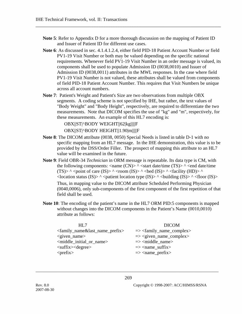
IHE Technical Framework, vol. II: Transactions ______________________________________________________________________________
_____________________________________________________________________________
269 Rev. 8.0 Copyright © 1998-2007: ACC/HIMSS/RSNA
Note 5: Refer to Appendix D for a more thorough discussion on the mapping of Patient ID and Issuer of Patient ID for different use cases.
Note 6: As discussed in sec. 4.1.4.1.2.4, either field PID-18 Patient Account Number or field PV1-19 Visit Number or both may be valued depending on the specific national requirements. Whenever field PV1-19 Visit Number in an order message is valued, its components shall be used to populate Admission ID (0038,0010) and Issuer of Admission ID (0038,0011) attributes in the MWL responses. In the case where field PV1-19 Visit Number is not valued, these attributes shall be valued from components of field PID-18 Patient Account Number. This requires that Visit Numbers be unique across all account numbers.
Note 7: Patient's Weight and Patient's Size are two observations from multiple OBX segments. A coding scheme is not specified by IHE, but rather, the text values of "Body Weight" and "Body Height", respectively, are required to differentiate the two measurements. Note that DICOM specifies the use of "kg" and "m", respectively, for these measurements. An example of this HL7 encoding is:
OBX||ST|^BODY WEIGHT||62|kg|||||F OBX||ST|^BODY HEIGHT||1.90|m|||||F
Note 8: The DICOM attribute (0038, 0050) Special Needs is listed in table D-1 with no specific mapping from an HL7 message. In the IHE demonstration, this value is to be provided by the DSS/Order Filler. The prospect of mapping this attribute to an HL7 value will be examined in the future.
Note 9: Field OBR-34 Technician in ORM message is repeatable. Its data type is CM, with the following components: <name (CN)> ^ <start date/time (TS)> ^ <end date/time (TS)> ^ <point of care (IS)> ^ <room (IS)> ^ <bed (IS)> ^ <facility (HD)> ^ <location status (IS)> ^ <patient location type (IS)> ^ <building (IS)> ^ <floor (IS)> Thus, in mapping value to the DICOM attribute Scheduled Performing Physician (0040,0006), only sub-components of the first component of the first repetition of that field shall be used.
Note 10: The encoding of the patient’s name in the HL7 ORM PID:5 components is mapped without changes into the DICOM components in the Patient’s Name (0010,0010) attribute as follows: HL7 DICOM <family_name&last_name_prefix> => <family_name_complex> <given_name> => <given_name_complex> <middle_initial_or_name> => <middle_name> <suffix><degree> => <name_suffix> <prefix> => <name_prefix>
2007-08-30

IHE Technical Framework, vol. II: Transactions ______________________________________________________________________________
_____________________________________________________________________________
270 Rev. 8.0 Copyright © 1998-2007: ACC/HIMSS/RSNA
Note: The HL7 “degree” component is absorbed as a second element in the “name_suffix” component in DICOM.
Note 11: The DICOM Patient’s Sex (0010,0040) attribute can have only the values M, F or O
(for other), or be zero length if unknown. These are enumerated values and hence any other values would be illegal. The HL7 V2.3.1 description also uses M, F and O, but suggests a value of U for unknown, which needs to be mapped to zero length. In HL7 these are only suggested values however, and care should be taken to map any other values encountered to valid DICOM values. Note also that in HL7 V2.5.1, the additional suggested values of A meaning Ambiguous and N meaning Not applicable, are present, and again, these would be illegal in DICOM and need to be mapped to O.
2007-08-30

IHE Technical Framework, vol. II: Transactions ______________________________________________________________________________
_____________________________________________________________________________
271 Rev. 8.0 Copyright © 1998-2007: ACC/HIMSS/RSNA
Appendix C: Departmental Access to Non-Radiology Information
C.1: Scope The access to non-radiology reports external to the imaging department is supported in the IHE Technical Framework by leveraging the Query Reports and Retrieve Reports Transactions also used to access imaging department Structured Reports (see sections 4.26 and 4.27). The External Report Repository Access provides a method to retrieve from the other department’s reports (e.g. Laboratory).
The IHE Technical Framework does not restrict the manner in which this External Report Repository Access is implemented. It may, for example: • Be a Laboratory Repository System that directly supports this actor and the associated Query
Reports and Retrieve Reports Transactions; • Accept the Query Reports and Retrieve Reports Transactions on one side and translate them
into another query transaction supported by a specific laboratory report repository.
This appendix discusses the constraints that this External Report Repository Access needs to support for its proper integration.
C.2: Query Protocol The assumptions under which the External Report Repository Access operates are:
1. The External Report Repository Access is responsible for formatting other department reports (e.g. laboratory report) into a DICOM Structured Report object (for content constraints see section C.3). The prime focus for the IHE Technical Framework will be laboratory reports, although other department’s reports may be supported.
2. Consistent Patient IDs will be used in the laboratory (or other) department reports and in the imaging department. This will ensure that a Patient ID of an image displayed by an Image Display, can be used as a key to retrieve recent laboratory reports for the same patient. This implies that the laboratory information system is integrated with the same ADT Patient Registration (although this integration is not within the scope of the IHE Technical Framework).
3. The Study and Series groupings are not specified by the IHE Technical Framework and may be arbitrarily used by the External Report Repository Access. For example, a DICOM Study may be created for each order (Accession Number) that contains one or more laboratory reports, a Series may be created for each laboratory request and so may contain mostly one report, unless amended. Alternatively, a single Series may be
2007-08-30

IHE Technical Framework, vol. II: Transactions ______________________________________________________________________________
_____________________________________________________________________________
272 Rev. 8.0 Copyright © 1998-2007: ACC/HIMSS/RSNA
created and contain multiple reports if different laboratory exams were requested in the same order.
4. Study Instance UIDs, Series Instance UIDs and SOP Instance UIDs may be created by the External Report Repository Access to group one or more of its Reports. Those UIDs need to be properly formed DICOM UIDs, i.e. use a registered root.
5. If the same Report is being queried and retrieved several times, the same set of Study, Series and SOP Instance UIDs shall be provided by the External Report Repository Access. This ensures that two separate queries selecting the same report will identify the same instance and retrieve an identical copy. This is important to avoid multiple copies with the same content confusing the clinician.
6. Table C.2-1 shows the minimal set of matching and return keys that shall be supported by the External Report Repository Access as an SCP at the different DICOM Hierarchical Levels. It is a reduced set from the radiology department keys (see sections 4.14.4.1.2). Additional SR Instance specific keys that shall be supported by the External Report Repository Access as an SCP are defined in sec. 4.26.4.1.2 and table 4.26-1. Minimum DICOM conformance is still required. Conventions for table C.2-1 may be found in section 2.2.
Note: The use of N/A (Not Applicable) in the SCU columns is because the External Report Repository Access is only an SCP of the query request.
Table C.2-1. Query Matching and Return Keys
Query Keys Matching Query Keys Return Attributes Name Tag SCU SCP SCU SCP
Notes
Study Level Study Date (0008,0020) N/A R N/A R
Study Time (0008,0030) N/A R N/A R
Accession Number (0008,0050) N/A R N/A R
Patient Name (0010,0010) N/A R N/A R IHE-1, IHE-2
Patient ID (0010,0020) N/A R N/A R
Study ID (0020,0010) N/A R N/A R
Study Instance UID (0020,000D) N/A R N/A R
Referring Physician’s Name
(0008,0090) N/A R+ N/A R+ IHE-1, IHE-2
Study Description (0008,1030) N/A O N/A O Procedure Code Sequence
(0008,1032) N/A O N/A O IHE-3
Patient’s Birth Date (0010,0030) N/A O N/A R+
Patient’s Sex (0010,0040) N/A O N/A R+
2007-08-30

IHE Technical Framework, vol. II: Transactions ______________________________________________________________________________
_____________________________________________________________________________
273 Rev. 8.0 Copyright © 1998-2007: ACC/HIMSS/RSNA
Query Keys Matching Query Keys Return Attributes Name Tag SCU SCP SCU
Notes SCP
Series Level Modality (0008,0060) N/A R N/A R IHE-5
Series Number (0020,0011) N/A R N/A R
Series Instance UID (0020,000E) N/A R N/A R
Composite Object Instance Level Instance Number (0020,0013) N/A R N/A R
SOP Instance UID (0008,0018) N/A R N/A R
SOP Class UID (0008,0016) N/A R+ N/A R+ IHE-4
IHE-1: Case insensitive matching is allowed in the IHE Technical Framework, for
attributes of VR PN. A DICOM Change Proposal (CP 190) to allow case insensitivity on PN attributes was balloted in DICOM 2001
IHE-2: SCUs are recommended to append wildcard “*” at the end of each component of any structured name to facilitate matching (i.e., PN attributes).
IHE-3: Universal Matching (selecting return keys) against an Attribute of VR SQ may be requested by the Query SCU using a Zero Length Sequence Attribute. Query SCPs shall accept such Universal Match Requests. In addition, Query SCPs are required by the DICOM Standard to support requests for a Universal Match for an SQ attribute encoded as a zero length item.
IHE-4: A SOP Class UID is a non-ambiguous key to identify a specific type of image (Modality is not).
IHE-5: The Modality Matching Key will always be set to “SR”
C.3: External Report Content The requirements for coded entries and report structure for reports handled by the External Report Repository via the Query Reports and Retrieve Reports Transactions shall be similar to the Report Creator (see sec. 4.24.4.1.2.1): • The types of reports generated by the External Report Repository are defined in RAD TF-
1:9.4. The External Report Repository shall be able to generate reports based on the Simple Image Report (RAD TF-1: 9.4.1) with optional image references. If the External Report Repository supports the Enhanced SR Information Object Definition then it shall also support the generation of Simple Image and Numeric Reports (RAD TF-1: 9.4.2).
• A specialized set of Report Titles, Report Section Headings, Concept Name Codes, Observation Context Codes, Measurement Codes and Disposition or Conclusion Codes will be defined for each type of department repository accessed (e.g. laboratory codes for laboratory departments)
2007-08-30

IHE Technical Framework, vol. II: Transactions ______________________________________________________________________________
_____________________________________________________________________________
274 Rev. 8.0 Copyright © 1998-2007: ACC/HIMSS/RSNA
2007-08-30

IHE Technical Framework, vol. II: Transactions ______________________________________________________________________________
_____________________________________________________________________________
275 Rev. 8.0 Copyright © 1998-2007: ACC/HIMSS/RSNA
Appendix D: Clarification of Patient Identifiers for Merge Cases
D.1: Introduction IHE Technical Framework has adopted the changes in HL7 2.3.1 Patient Identifiers. This includes: • HL7 v2.3 External Patient ID (PID –2) has been retained for backward compatibility. • Alternate Patient ID (PID-4) has been retained for backward compatibility. • Internal Patient ID (PID-3) has been renamed “Patient Identifier List” and is now allowed to
repeat.
Due to the adoption of these HL7 2.3.1 changes, IHE mandates the use of assigning authority (issuer) in PID-3 component 4 and identifier in PID-3 component 1.
Since the DICOM Patient ID attribute (0010,0020) does not convey assigning authority and the Issuer of Patient ID (0010,0021) is an optional attribute in DICOM, both the Image Manager Actor and the Department System Scheduler/Order Filler Actor shall be prepared to make assumptions regarding the assigning authority for Patient IDs transmitted from a Modality via DICOM Modality PPS. It is assumed that it is possible to recognize a valid range of patient identifiers assigned by a single ADT Actor or single issuer of identifiers within an enterprise.
The identifier in PID-3 in all HL7 transactions specified by the IHE shall be single valued and used by the ADT/Patient Registration actor, except for Transaction RAD-4 which may use an identifier assigned by the DSS/Order Filler.
In future years of IHE with the introduction of an MPI, it is assumed that the MPI identifier will be used in PID-3 for all HL7 transactions.
It is required that the healthcare institution configure the issuer of temporary patient identifiers to be either the ADT Issuer or the Departmental Issuer in both the Image Manager and the DSS/Order Filler. This will ensure that Patient ID in DICOM (0010,0020) is associated with the same assigning authority when mapped into a PID-3 in HL7 messages.
Although, an organization may operate with temporary patient identifiers issued by the ADT and used primarily in Cases 1,2 and 3, Case 5 may occur. This may happen due to Modality operator errors when manually entering patient identifier in Case 3. In this situation, DSS/Order Filler and Image Manager shall recognize the error and associate the erroneous identifier to the same issuer. The reconciliation will happen on the DSS/Order Filler and it will send the Patient Merge message to the Image Manager where both “new” and “old” patient identifiers are associated with the same issuer.
The use of PID-3 is illustrated in the following sections using the use cases from RAD TF-1: 3.3, 4.3. In the examples given below time flows from the top row of the table to the bottom.
2007-08-30

IHE Technical Framework, vol. II: Transactions ______________________________________________________________________________
_____________________________________________________________________________
276 Rev. 8.0 Copyright © 1998-2007: ACC/HIMSS/RSNA
Table Acronyms
Description
IM Image Manager
OF Order Filler / Departmental System Scheduler
OP Order Placer
PPSM Performed Procedure Step Manager
D.2: Administrative Process Flow (RAD TF-1: 3.3.1) The illustration includes A01, A04, A05, A11, and A30 although only an A01 is included in this example. The ADT identifier number used in the example below is “123”, the assigning authority is “ADT_Issuer”.
Transaction PID-3 (Patient Identifier List)
DICOM (0010,0020)
MRG-1 (Prior Patient Identifier List)
A01 (ADT -> OF) 123^^^ADT_Issuer N/A N/A
A01 (ADT -> OP) 123^^^ADT_Issuer N/A N/A
ORM (OP->OF) 123^^^ADT_Issuer N/A N/A
ORM (OF->IM) 123^^^ADT_Issuer N/A N/A
DICOM MWL (OF -> Modality)
N/A 123 N/A
PPS (Modality -> PPSM) N/A 123 N/A
PPS (PPSM -> IM) N/A 123 N/A
PPS (PPSM -> OF) N/A 123 N/A
D.3: Patient Merge (RAD TF-1: 3.3.2) This specifically looks at the Patient merge scenario in RAD TF-1: 3.3.2.2. The “old” ADT identifier number used in the example below is “123”, the assigning authority is “ADT_Issuer”. The “new” ADT identifier number used in the example below is “456”, the assigning authority is “ADT_Issuer”.
Transaction PID-3 (Patient Identifier List)
DICOM (0010,0020)
MRG-1 (Prior Patient Identifier List)
A01 (ADT -> OF) 123^^^ADT_Issuer N/A N/A
A01 (ADT -> OP) 123^^^ADT_Issuer N/A N/A
ORM (OP->OF) 123^^^ADT_Issuer N/A N/A
ORM (OF->IM) 123^^^ADT_Issuer N/A N/A
DICOM MWL (OF -> Modality)
N/A 123 N/A
2007-08-30

IHE Technical Framework, vol. II: Transactions ______________________________________________________________________________
_____________________________________________________________________________
277 Rev. 8.0 Copyright © 1998-2007: ACC/HIMSS/RSNA
A40 (ADT -> OF) 456^^^ADT_Issuer N/A 123^^^ADT_Issuer
A40 (OF->IM) 456^^^ADT_Issuer N/A 123^^^ADT_Issuer
A40 (ADT -> OP) 456^^^ADT_Issuer N/A 123^^^ADT_Issuer
D.4: Trauma Cases 1 and 2 (RAD TF-1: 4.3) The ADT temporary identifier for “John Doe” used in the example below is “Temp_123”, the assigning authority is “ADT_Issuer”.
Transaction PID-3
(Patient Identifier List) DICOM
(0010,0020) MRG-1
(Prior Patient Identifier List) A01 (ADT -> OF) Temp_123^^^ADT_Issuer N/A N/A
A01 (ADT -> OP) Temp_123^^^ADT_Issuer N/A N/A
ORM (OP->OF) Temp_123^^^ADT_Issuer N/A N/A
ORM (OF->IM) Temp_123^^^ADT_Issuer N/A N/A
DICOM MWL (OF -> Modality)
N/A Temp_123 N/A
PPS (Modality -> PPSM) N/A Temp_123 N/A
PPS (PPSM -> IM) N/A Temp_123 N/A
PPS (PPSM -> OF) N/A Temp_123 N/A
A40 (ADT -> OF) 456^^^ADT_Issuer N/A Temp_123^^^ADT_Issuer
A40 (OF->IM) 456^^^ADT_Issuer N/A Temp_123^^^ADT_Issuer
A40 (ADT -> OP) 456^^^ADT_Issuer N/A Temp_123^^^ADT_Issuer
D.5: Trauma Case 3 (RAD TF-1: 4.3) The ADT temporary identifier number for “John Doe” used in the example below is “Temp_123”. The patient will later be assigned a permanent identifier of “Real_456”, the assigning authority is “ADT_Issuer”.
Transaction PID-3
(Patient Identifier List) DICOM
(0010,0020) MRG-1
(Prior Patient Identifier List) A01 (ADT -> OF) Temp_123^^^ADT_Issuer N/A N/A
A01 (ADT -> OP) Temp_123^^^ADT_Issuer N/A N/A (Note: Temporary Patient ID “Temp_123” is manually entered at the modality.)
N/A N/A N/A
2007-08-30

IHE Technical Framework, vol. II: Transactions ______________________________________________________________________________
_____________________________________________________________________________
278 Rev. 8.0 Copyright © 1998-2007: ACC/HIMSS/RSNA
DICOM Transaction PID-3 MRG-1 (0010,0020) (Patient Identifier List) (Prior Patient Identifier List)
PPS (Modality -> PPSM) N/A Temp_123 N/A
PPS (PPSM -> IM) N/A Temp_123 N/A
(Note: The IM recognizes an unscheduled PPS and assumes a site configured assigning authority of “ADT_Issuer”.)
N/A N/A N/A
PPS (PPSM -> OF) N/A Temp_123 N/A
(Note: The OF recognizes an unscheduled PPS with a valid ADT Patient ID – with a site configured assigning authority of “ADT_Issuer”.)
N/A N/A N/A
ORM (OF-> OP) Temp_123^^^ADT_Issuer N/A N/A
ORR (OP->OF) Temp_123^^^ADT_Issuer N/A N/A
ORM (OF-> IM) Temp_123^^^ADT_Issuer N/A N/A
(Note: Patient Reconciliation occurs on the ADT system.)
N/A N/A N/A
A40 (ADT -> OF) Real_456^^^ADT_Issuer N/A Temp_123^^^ADT_Issuer
A40 (ADT -> OP) Real_456^^^ADT_Issuer N/A Temp_123^^^ADT_Issuer
A40 (OF-> IM) Real_456^^^ADT_Issuer N/A Temp_123^^^ADT_Issuer
D.6: Trauma Case 4 (RAD TF-1: 4.3) The OF temporary identifier number for “John Doe” used in the example below is “Dept_789”. The Patient will later be assigned a permanent identifier of “123”, the assigning authority is “OF_Issuer”.
Transaction PID-3
(Patient Identifier List) DICOM
(0010,0020) MRG-1
(Prior Patient Identifier List) ORM (OF->IM) Dept_789^^^OF_Issuer N/A N/A DICOM MWL (OF->Modality)
N/A Dept_789 N/A
PPS (Modality -> PPSM) N/A Dept_789 N/A
PPS (PPSM -> IM) N/A Dept_789 N/A (Note: The IM recognizes a scheduled PPS with a Patient ID - with a site configured assigning authority of “OF_Issuer”.)
N/A N/A N/A
PPS (PPSM -> OF) N/A Dept_789 N/A
2007-08-30

IHE Technical Framework, vol. II: Transactions ______________________________________________________________________________
_____________________________________________________________________________
279 Rev. 8.0 Copyright © 1998-2007: ACC/HIMSS/RSNA
(Note: The OF recognizes a scheduled PPS with a Patient ID issued by the OF.)
N/A N/A N/A
A01 (ADT -> OP) 123^^^ADT_Issuer N/A N/A
A01 (ADT -> OF) 123^^^ADT_Issuer N/A N/A (Note: The patient Dept_789^^^OF_Issuer is manually reconciled with 123^^^ADT_Issuer.)
N/A N/A N/A
A40 (OF-> IM) 123^^^ADT_Issuer N/A Dept_789^^^OF_Issuer
ORM (OF-> IM) 123^^^ADT_Issuer N/A N/A
ORM (OF-> OP) 123^^^ADT_Issuer N/A N/A
ORR (OP->OF) 123^^^ADT_Issuer N/A N/A
D.7: Trauma Case 5 (RAD TF-1: 4.3) The temporary identifier number for “John Doe” used in the example below is “Dept_123” and is manually entered on the Modality. The patient will later be assigned a permanent identifier of “Real_456”, the assigning authority is “OF_Issuer”.
Transaction PID-3 (Patient Identifier List)
DICOM (0010,0020)
MRG-1 (Prior Patient Identifier List)
PPS (Modality -> PPSM)
N/A Dept_123
PPS (PPSM->IM) N/A Dept_123 N/A
(Note: The IM recognizes an unscheduled PPS and assumes a site configured assigning authority)
N/A N/A N/A
PPS (PPSM->OF) N/A Dept_123 N/A
(Note: The OF recognizes an unscheduled PPS and assumes a site configured assigning authority; recognizes that Patient ID is invalid.)
N/A N/A N/A
A01 (ADT->OF) Real_456^^^ADT_Issuer N/A N/A
2007-08-30

IHE Technical Framework, vol. II: Transactions ______________________________________________________________________________
_____________________________________________________________________________
280 Rev. 8.0 Copyright © 1998-2007: ACC/HIMSS/RSNA
A01 (ADT->OP) Real_456^^^ADT_Issuer N/A N/A
(Note: Manual patient reconciliation occurs on the OF system.)
N/A N/A N/A
A40 (OF-> IM) Real_456^^^ADT_Issuer N/A Dept_123^^^Configured_Issuer
ORM (OF-> OP) Real_456^^^ADT_Issuer N/A N/A
ORR (OP->OF) Real_456^^^ADT_Issuer N/A N/A
ORM (OF-> IM) Real_456^^^ADT_Issuer N/A N/A
2007-08-30

IHE Technical Framework, vol. II: Transactions ______________________________________________________________________________
_____________________________________________________________________________
281 Rev. 8.0 Copyright © 1998-2007: ACC/HIMSS/RSNA
GLOSSARY See RAD TF-1: Appendix E, which contains a comprehensive glossary for this document.
2007-08-30