integrating refinement into software development tools
TRANSCRIPT

Integrating Refinement into Software
Development Tools
Lu Yang1
State Key Laboratory of Novel Software TechnologyDepartment of Computer Science and Technology, Nanjing University
Nanjing, Jiangsu, P.R.China 210092
Volker Stolz2
International Institute for Software TechnologyUnited Nations University, Macao SAR
Abstract
It is a challenge for automatic tool support to formal design by refinement transformations. In this paper,we bring this matter to the attention of the research community and discuss a component-based modeltransformational approach for integrating refinement into software development tools. Models, their con-sistency and correctness, in an object-oriented and component-based development process are defined inrCOS, that is a refinement calculus recently developed at UNU-IIST. Correctness preserving transforma-tions between models are formalized and proved as refinement rules in rCOS. In this paper, we will discusson how these transformations can be implemented in the relations language of Query/View/Transformation(QVT) standardized by OMG.
Keywords: Model transformations, MDA, QVT, rCOS.
1 Introduction
In model based development, transformations are used in the development of an
application from the earliest models of requirements to the final deployed code.
It is a challenge to develop automatic transformations that preserves correctness
with respect to specified properties. All application of these tools is based on the
construction of a correct model of the system to be verified or validated. Building
such a model requires high technical skills and theoretical wisdom, and there is little
satisfactory tool support to it.
1 Email:[email protected] Email:[email protected]
Electronic Notes in Theoretical Computer Science 207 (2008) 69–88
1571-0661/$ – see front matter © 2008 Elsevier B.V. All rights reserved.
www.elsevier.com/locate/entcs
doi:10.1016/j.entcs.2008.03.086

In our approach, we take a view that the process of developing a software system
is a process of working out a proof of the final software product, with a sequence of
step of constructing models with annotated properties that are verified. For this,
we use the relational calculus, called rCOS [16,4], to define the models that are to
be produced in a development process.
Like UML but with a formal definition, rCOS provides a method of two dimen-
sional multi-view modelling. It also combines component-based and object-oriented
modelling and design. In the horizontal dimension, rCOS allows to define a compo-
nent in terms of its provided interface for syntactic type checking, the specification
of the static functionality of the interface methods by the notation of design in UTP
[17], the interaction protocol for the order of the methods in which the clients (en-
vironment) can interact with the component, and the dynamic execution behavior.
Further features, such as constraints on timing and memory can also be included in
the model. The nice feature of this modelling techniques is that models of different
views can be introduced incrementally. In the vertical dimension, models of differ-
ent views can be refined by correctness preserving transformations. The model of a
whole system consists of its structural view defined by the set of components, their
relations modelled by the provided and required interfaces, the interactions among
components and dynamic execution of the components.
The UML graphic modelling language can be used to illustrate the models of
the different views: the data structure of an interface is given by a class diagram,
the protocol is shown by a sequence diagram, and the dynamic execution model is
given by a state diagram.Increasin g
Details
(Vertical
Transfo rm
ation)I n c r e a s i n g V i e w s ( H o r i z o n t a l T r a n s f o r m a t i o n )
M o d e l o f R e q u i r e m e n t s :
M o d e l o f D e s i g n :
M o d e l o f C o m p o n e n t A r c h i t e c t u r e :
C o n c e p t u a l C l a s s D i a g r a m
U s e C a s e S e q u e n c e D i a g r a m
F u n c t i o n a l i t y S p e c i f i c a t i o n /
D e s i g n C l a s s D i a g r a m
O b j e c t S e q u e n c e D i a g r a m
C o m p o n e n t D i a g r a m
C o m p o n e n t I n t e r a c t i o n D i a g r a m
F u n c t i o n a l i t y S p e c i f i c a t i o n /
S t r u c t u r e B e h a v i o r
. . .
. . .
. . .
. . .
S t a t e D i a g r a m
/
S t a t e D i a g r a m //
/
/
Fig. 1. Models with views and refinements
The feature of multi-view supports separation of concerns and incremental mod-
eling, the multi-level of abstraction supports stepwise development processes by
correctness preserving transformations [5].
The development process of a system is a stepwise, incremental, and iterative
process and can follow the V-Model , which is a generalized version of the Waterfall
Model, as shown in Fig. 1. Each subsequent model should be produced from its
preceding version by applying a transformation that preserves specified properties.
The theoretical frameworks supporting such a development process are usually re-
ferred to as correctness by design. In rCOS, correctness preserving transformations
are characterized by refinement rules.
L. Yang, V. Stolz / Electronic Notes in Theoretical Computer Science 207 (2008) 69–8870

T r a n s f o r m a t i o n
T r a n s f o r m a t i o n L a n g u a g e - Q V T
s a t i s f i e s
T r a n s f o r m a t i o n D e f i n i t i o n
T a r g e t M e t a m o d e l ( U M L )
S o u r c e M e t a m o d e l ( U M L )
S o u r c e M o d e l ( U M L )
T a r g e t M o d e l ( U M L )
P r o p e r t i e s t o b e c h e c k e d
s a t i s f i e s
i n s t a n c e O f i n s t a n c e O f w r i t t e n I n
i n p u t o u t p u t e x e c u t e s
M O F
c o n f o r m s T o c o n f o r m s T o
c o n f o r m s T o
b a s e d O n b a s e d O n
M 3 ( m e t a m e t a - m o d e l )
M 1 ( i n s t a n c e - m o d e l )
M 2 ( m e t a - m o d e l )
Fig. 2. Model transformation
Fig. 2 is a sketch for a model-to-model transformation. Such a transformation
definition is given and realized by a transformation language such as QVT [12] which
is compatible with MDA [10] standard suite: UML [13], MOF [14], OCL [15], etc.,
and it is used to generate a target model from a source model.
In parallel with QVT, many research groups and companies have been working
on their own model transformation approaches and tools, e.g. GreAT [2], UMLX
[28], AToM3 [8], VIATRA [27], BOTL [20], ATL [3] and YATL [21]. These model
transformation languages all have a similar operational context. They provide their
own metamodels to define concrete syntaxes. Most of them are based on MOF. In
[7], these model transformation approaches are classified as four categories.
• Declarative approaches focus on what is to be transformed into what instead of
how the transformation is done.
• Imperative approaches focus on how the transformation are performed.
• Hybrid approaches are combination of the imperative and declarative approaches.
These approaches allow the user to mix and match different concepts and
paradigms depending on the application. Examples of the hybrid approaches
include ATL [3] and QVT [12].
• Graph-Transformation approaches are inspired by theoretical work in graph
transformations and specifically designed to represent UML-like models. These
approaches are visual notations and formally founded. Examples of graph-
transformation approaches include VIATRA [27], AToM3 [8], GreAT [2], UMLX
[28], and BOTL [20].
Several tools and development approaches of these transformation languages are
used to help the software development [26,1,9]. Also an attempt of studying the
correctness and completeness of transformations in VIATRA was made in [27]. This
shows a direction to introduce formal methods into model transformation languages
and to help software development.
In [27], some requirements for model transformation approaches are identified,
and we hope to develop tool that satisfy these requirements:
L. Yang, V. Stolz / Electronic Notes in Theoretical Computer Science 207 (2008) 69–88 71

• formal, complete and minimum metamodels.
• mathematically precise description of transformation rules.
• automatic model generation from the transformation rules.
• tool for proving semantic correctness and completeness of the transformations.
We plan to use the relations language of QVT to implement the transformation,
since the refinement rules in rCOS are relations between models and these refine-
ment rules can be implemented as a relation of the transformation directly using the
declarative approach, instead of being implemented as steps to be executed using
the imperative approach. The transformations that implement the refinement rules
are already correctness preserving transformations. As requirement of the transfor-
mation language, we need to define the metamodels and instances models that we
want to transform.
Overview
We will start with an introduction to the rCOS development process in Section 2.
In Section 3 we will define the metamodels that we are going to manipulate. After
that, we will discuss the implementation in QVT of our ongoing research in Section
4. Finally Section 5 concludes and discusses the further work.
2 rCOS Development Process
To support the correctness preserving transformation, we introduce the normal
models of object-oriented and component-based design that can be formalized and
refined in rCOS.
2.1 Model of requirements
The development starts from the construction and analysis of a model of require-
ments for a number of use cases (business processes). In such a model of require-
ments, each use case is specified as an rCOS contract of the interface [4]:
• The methods of the interface in the contract are the operations that the actors
call for execution in the use case.
• The fields of the interface in the contract represent the data and objects needed
in realizing the use case, and form a conceptual class diagram.
• The functionality of the methods is specified by pre- and post-conditions.
• The protocol of the contract describes the pattern in which the actors and the
system interact in the use case and can be illustrated by a use case sequence
diagram.
Example 2.1 We used the example of Point-Of-Sale (POS) system originally pro-
posed by Larman [18] for the implementation of the transformation. For the use
case Process Sale (Cash Desk), we quote the problem description used in [6]:
L. Yang, V. Stolz / Electronic Notes in Theoretical Computer Science 207 (2008) 69–8872

Fig. 3. Conceptual Class Diagram and Use Case Sequence Diagram
A Customer arrives at a checkout with items to purchase. The Cashier records
the purchase items and handle either a cash or a card payment. On completion,
the sale is logged and the inventory is updated, and the Customer leaves with the
items.
Fig. 3 shows the conceptual class diagram and the use case sequence diagram of
the use case Process Sale. The pre- and post-conditions of the methods are specified
in [6].
2.2 Model of logical design
From the model of requirements, a model of the logical design is produced by first
applying object-oriented refinement to the methods of the use cases. This is mainly
to decompose the classes in the conceptual class diagrams and to decompose the
functionality of the methods by delegating responsibilities to the auxiliary classes
by using the expert pattern. This step designs the interactions among the objects
and thus produces a model of logical design that consists of:
• A design class diagram, that refines the conceptual class diagram in the model of
requirements.
• A refinement of each use case sequence diagram, that decompose the use case
methods and delegates the partial functionalities to appropriate objects (called
expert objects).
Example 2.2 The designer applies the refinement rules of rCOS to the methods
that we specified for the use cases. Fig. 4 show the design class diagram and the
object sequence diagram that are refined from the precious diagrams in the model
of requirements.
2.3 Model of component architecture
A further step of design is component architectural design in which some components
are combined into larger components, and some components are decomposed into
interconnected subcomponents. This produces a model of component architecture
that includes:
L. Yang, V. Stolz / Electronic Notes in Theoretical Computer Science 207 (2008) 69–88 73

Fig. 4. Design Class Diagram and Object Sequence Diagram
• A family of components, specified with their provided and required interfaces,
and this can be described as a component diagram.
• A set of component interaction diagrams that is an abstraction and composition
of the object sequence diagrams.
Detailed design can be carried out on the component architecture so that each
method in each component is designed. The components can the be verified, tested
and checked by various tools such as a model checker or a runtime checking tool
(e.g. JML [19]).
The final step of the development is to integrate the components implement-
ing the interfaces among components with appropriate interaction mechanisms and
middlewares, such as RMI and CORBA.
Fig. 5. Component Diagram and Component Interaction Diagram
Example 2.3 The designer decided to partition the functions that are handled by
the CashDesk, the Inventory, the Clock and the Bank considering deployment of
these four parts. So the use case is partitioned to four components: SalesHandler,
L. Yang, V. Stolz / Electronic Notes in Theoretical Computer Science 207 (2008) 69–8874

Inventory, Clock and Bank. Fig. 5 shows the component diagram and the compo-
nent interaction diagram. Then the interface of the components are specified easily
in [6].
2.4 Tool support of the development process
These models can be used in different stages of the software development process by
different roles. For example, in the MDA tool MasterCraft [24] by Tata Research
Development & Design Center (TRDDC), the Analysis Modeler produces the model
of requirements that implements the use case. Then the Design Modeler takes the
model of requirements as input, and increases design details to produce the model
of logical design that is ready for code generation. Finally, the Architecture Modeler
may produce the model of component architecture based on the model of logical
design and consider the deployment.
3 QVT Metamodels
E n t i t y
o r d e r : I n t e g e r
U C S e q u e n c e D i a g r a m
A g e n t
L i f e L i n e C l a s s A c t o r
1
**
1
**
1
1 1
a c t o r o w n e r
r e c e i v e r s e n d e r
i n t e r f a c e
A t t r i b u t e
M e t h o d 1
1 *
*
a t t r i b u t e
i n _ p a r a m e t e r D a t a T y p e
*
M e s s a g e E v e n t
1
1e v e n t
*
1
o p e r a t i o n c a l l e d
11p r e c o n d i t i o n p o s t c o n d i t i o n 11
C o n c e p t u a l C l a s s D i a g r a m
1
* * 0 . . 1
s p e c i a l i z a t i o n s
1
*s o u r c e d e s t i n a t i o n
1
*
A s s o c i a t i o n
R e q u i r e m e n t M o d e l
P r i m i t i v e D a t a T y p e
1*
1
c l a s s
c d s d
P a r a m e t e r 1*
p t y p e o u t _ p a r a m e t e r
*
1
C o n s t r a i n t
c o n d i t i o n : S t r i n g
A l t L o o p M e s s a g e
1
11
*
l o o p
a l t
U C I n t e r f a c e
*
1
m e t h o d
a t y p e
1
C o n d i t i o n
a _ g u a r d l _ g u a r d **
11
Fig. 6. Metamodel for the model of requirements
E n t i t y
o r d e r : I n t e g e r
S e q u e n c e D i a g r a m
A g e n t
L i f e L i n e C l a s s A c t o r
1
* *
1
**
*
1 1
a c t o r o w n e r
r e c e i v e r s e n d e r
c l a s s _ s d
A t t r i b u t e
M e t h o d 1
1
*
*
*
a t t r i b u t e
m e t h o d i n _ p a r a m e t e r D a t a T y p e
1*
a t y p e
M e s s a g e E v e n t
11 e v e n t
*
1
o p e r a t i o n c a l l e d
11
p r e c o n d i t i o n p o s t c o n d i t i o n 11
D e s i g n C l a s s D i a g r a m
1
* * 0 . . 1
s p e c i a l i z a t i o n s
1
*s o u r c e d e s t i n a t i o n
1
*
A s s o c i a t i o n
D e s i g n M o d e l
P r i m i t i v e D a t a T y p e
1*
1
c l a s s _ o d
o d s d
P a r a m e t e r
1
*
p t y p e
o u t _ p a r a m e t e r
*
1
C o n s t r a i n t
c o n d i t i o n : S t r i n g
1 . . * *u s e s
A l t L o o p M e s s a g e
1
11
*
l o o p
a l t
C o n d i t i o n
11** l _ g u a r d a _ g u a r d
Fig. 7. Metamodel for the model of logical design
As required for the transformation language QVT, we define the QVT meta-
models for the model of requirements, the model of logical design and the model of
component architecture, as show in Fig. 6 - Fig. 8. In this section we will focus on
the relationship among these diagrams.
L. Yang, V. Stolz / Electronic Notes in Theoretical Computer Science 207 (2008) 69–88 75

E n t i t y
o r d e r : I n t e g e r
C o m p o n e n t I n t e r a c t i o n D i a g r a m
s e n d e r
A g e n t
L i f e L i n e C o m p o n e n t A c t o r
1
**
**
*
1 1 r e c e i v e r
a c t o r
C l a s s
1
*
c o m p o n e n t _ c i d
o w n e r
c l a s s
M e t h o d
A t t r i b u t e
I n t e r f a c e
1
1
1
1
*
*
m e t h o d
a t t r i b u t e
i n _ p a r a m e t e r
p r o v i d e d
*
M e s s a g e E v e n t
1
1
e v e n t
F i e l d
O p e r a t i o n 1
*
*
o p e r a t i o n
o u t _ p a r a m e t e r
D a t a T y p e
1
* c o _ f t y p e
1o p e r a t i o n c a l l e d 11
c o _ p r e c o n d i t i o n c o _ p o s t c o n d i t i o n
1
*
1
1 1
1
*
i n _ p a r a m e t e r
*
1
c a _ a t y p e
P r i m i t i v e D a t a T y p e
1
11
1c a _ p r e c o n d i t i o n c a _ p o s t c o n d i t i o n
C o m p o n e n t D i a g r a m
1
*
C o m p o n e n t - B a s e d A r c h i t e c t u r e
1
1*
c o m p o n e n t _ c d
c i d c d
1
*s o u r c e
1
*
A s s o c i a t i o n
d e s t i n a t i o n
M _ P a r a m e t e r
1
*
c a _ p t y p e
o u t _ p a r a m e t e r
*
1
* 0 . . 1
s p e c i a l i z a t i o n s
O _ C o n s t r a i n t
o _ c o n d i t i o n : S t r i n g
M _ C o n s t r a i n t
m _ c o n d i t i o n : S t r i n g O _ P a r a m e t e r
c o _ p t y p e
1
*
*f i e l d
u s e s 1 . . *
*u s e s 1 . . *
*A l t L o o p M e s s a g e
*
11
1
a l t
l o o p
C l a s s D i a g r a m
c a d *
1
*c l a s s _ c a d 1
1r e q u i r e d
C o n d i t i o n
11
**l _ g u a r d a _ g u a r d
Fig. 8. Metamodel for the model of component architecture
3.1 QVT metamodel for the model of requirements
A conceptual class diagram contains class declarations:
• A class is declared with its attributes.
• An association is declared as class with roles of the association with the attributes
and the role classes as their types.
• A generalization-specialization relation between two classes Ci and Cj is specified
by Cj extends Ci.
• A constraint is recorded as an uninterpreted text string. It is future work to select
an expression syntax that can be used in checking refinement of operations.
Most of the model elements are the same as those in the UML model, except
the usage of a set of output parameters which is replaced by a return type in UML.
A use case sequence diagram represents the interactions among the actors and
the use case, which consists of:
• A sequence of entities with the lifelines that send or receive the entities. The
entity may be a message, loop or alternative.
• A source and a target of the entity. The source of the entity should be an actor
and the target of the entity should be the use case interface with methods.
• An order number of the entity. The order number is given according to its position
in a structure tree. The root node of the tree is corresponding to the starting
actor of the sequence diagram. Then the first layer branches with order number
is 1, 2, 3, · · · , n. From the u-th node of first layer, there may be m nodes, and the
corresponding order numbers of branches are u.1, u.2, · · · , u.m. u.v is the v-th branch
from that node.
• A message event which is either a method call or a command without method
calls (an internal action). For simplicity, we only consider the call event (method
call), not the signal event.
L. Yang, V. Stolz / Electronic Notes in Theoretical Computer Science 207 (2008) 69–8876

3.2 QVT metamodel for the model of logical design
The metamodel for the design class diagram is quite like the metamodel for the
conceptual class diagram except adding the declaration of the methods of the class.
An object sequence diagram represents the pattern of interactions among the
objects. The differences between the metamodel of the use case sequence diagram
and the metamodel of the object sequence diagram are:
• The source and the target of the entity should be classes. Of course the source
of the entity can also be an actor.
• The message events are not invocations of the methods of the use case interface,
but the methods of the classes.
3.3 QVT metamodel for the model of component architecture
In a component architecture, an interface declares a set of fields and a set of oper-
ation signatures without providing any semantic information of their designs and
implementations. A component diagram is specified as follows:
• A field is a variable with its type.
• An operation declares a name for the operation and its input parameters and
output parameters with their types.
• A static functionality specification assigned to each operation as constraints in
terms of pre- and post-conditions.
The metamodel for the class diagram is also a part of the component-based
architecture.
The semantics of the component interaction diagram is the protocol of the oper-
ation invocations of the component interfaces. The metamodel for the component
interaction diagram is quite like the metamodel for the sequence diagram except
the agent of the lifelines should be components.
Some parts of the metamodels are shared, but have to be replicated in the
metamodels, e.g. the Lifeline business, as shown in the boxes in Fig. 6 - Fig. 8
4 Implementation of the Transformations
4.1 QVT relations language
To implement the transformations from model of requirements to model of compo-
nent architecture based on the POS case study, we choose the relations language of
MOF 2.0 QVT [12] which is a standard by OMG. QVT supports queries, views and
transformations of models, and MOF [14] allows the development of interoperable
tools for manipulating both data and metadata in a platform independent manner.
Within the QVT specification, there exist provisions for a declarative and an im-
perative transformation language. The relations language, which borrows from logic
programming, allows structural matching on classes and navigating associations.
L. Yang, V. Stolz / Electronic Notes in Theoretical Computer Science 207 (2008) 69–88 77

In the relations language, a transformation between models is specified as a set
of relations that must hold. A relation is defined by two or more domains and a
pair of when and where predicates.
• A domain is a distinguished typed variable that can be matched in a model of a
given type. A domain pattern can be viewed as a set of variables, and a set of
constraints.
• A relation can also be constrained by two sets of predicates: the when clause
specifies the condition under which the relation needs to hold, and the where
clause specifies the condition that must be satisfied by all model elements in the
relation.
A transformation can be invoked to check two models for consistency (no side
effect), or to modify one model to enforce consistency. Whether or not the relation
maybe enforced is determined by the target domain, which may be marked as
checkonly or enforce. When a transformation executes in the direction of the model
of a checkonly domain, it is simply checked to see if there exists a valid match
that satisfies the relation. When a transformation executes in the direction of the
model of an enforce domain, if the checking fails, the target model is modified so
as to satisfy the relation, it is a check-before-enforce semantics. The more detailed
semantics of the checking and enforcement can be found in [12].
For the tool support of automatic transformation, ModelMorf [25], a QVT engine
developed by TRDDC, supports the QVT relations language. The metamodels and
instance models are constructed by the MetaModeler, which is also developed by
TRDDC, and exported in the interchange format XMI [11]. The left of the Fig. 9
shows how to produce an instance model based on the source metamodel in the
POS example using the MetaModeler. The source and target metamodels and the
instance model will be exported as XMI files and taken as input of the QVT engine
ModelMorf. The transformation execution of the POS example in enforce mode is
shown on the right of the Fig. 9.
Fig. 9. (a) Model Construction and (b) Transformation Execution
L. Yang, V. Stolz / Electronic Notes in Theoretical Computer Science 207 (2008) 69–8878

4.2 Implementation of the transformation for refinement rules
After the requirement capture and analysis, the logical design is needed by applying
object-oriented refinement to the requirement model, e.g. decomposing the classes
in the conceptual class diagrams. We have carried out the implementation of the
refinement rule class decomposition pattern in QVT [29] and improve it in this
paper, and we will implement other important refinement rules, especially the expert
pattern that are use to decompose the functionality of the methods by delegating
responsibilities to the inner classes. The design decisions are needed for the class
decomposition pattern and the expert pattern, and this kind of patterns can be
implemented as semi-automatic QVT transformations. These design decisions are
made by the designer. More simple transformations, e.g. the attribute encapsulation
pattern, can be executed automatically without too many design decisions.
Example 4.1 During an object-oriented design, we often need to decompose a
class into a number of classes. For example, consider classes C1 :: D a1, C2 :: D a2,
and D :: T1 x,T2 y. If methods of C1 only call a method D :: m(){...} that only involves
x, and methods of C2 only call a method D :: n(){...} that only involves y, we can
decompose D into two D1 :: T1 x; m(){...} and D2 :: T2 y; n(){...}, and change the type
of a1 in C1 to D1 and the type of a2 in C2 to D2. There are other rules for class
decomposition in [16].
We first introduce some notations in rCOS. We use N [supclass, pri, prot, pub, op] to
denote a well-formed class declaration that declares the class N that has supclass
as its direct superclass; pri, prot and pub as its sets of private, protected and public
attributes; and op as its set of methods.
Theorem 4.2 (Class decomposition Pattern) Assume M [pri, op] is a well-
formed class declaration, pri = {x, y} are (or are lists of) attributes of M, m1(){c1(x)} ∈ op
only accesses attribute x, method m2(){c2[m1]} ∈ op can only change x by calling m1 (or
it does not have to change it at all). Then
M [pri0, op0]; Cdecls � M [prinew, opnew]; M1[pri1, op1]; M2[pri2, op2]; Cdecls
pri0 = {x, y} prinew = {M2 o2}
op0 = {m1(){c1(x)}, opnew = {m1(){o2.m1()},
m2(){c2[m1()]}} m2(){o2.m2()}}
pri1 = {x}
op1 = {m1(){c1(x)}}
pri2 = {y, M1 o1}
op2 = {m1(){o1.m1()},
m2(){c2[o1.m1()]}}
This class decomposition pattern is illustrated in Fig. 10. The class M in the
target model is a part of a more complex model, where M is connected via interfaces
to some class C. The QVT implementation of this pattern is shown in A.
L. Yang, V. Stolz / Electronic Notes in Theoretical Computer Science 207 (2008) 69–88 79

M
x y
m 1 { c 1( x ) }
m 2 { c 2[ m 1] }
M
M 2 o 2
m 1 { o 2. m 1 }
m 2 { o 2. m 2 }
M2
y M 1 o 1
m 1 { o 1. m 1 }
m 2 { c 2[ o 1. m 1] }
M1
x
m 1 { c 1( x ) }
C
M k
n 1 { k . m 1 }
n 2 { k . m 2 }
C
M k
n 1 { k . m 1 }
n 2 { k . m 2 }
Fig. 10. Class Decomposition Pattern
4.3 Implementation of the transformation for component architecture
We have carried out the transformations from the model of logical design to the
model of component architecture. For correct construction of the software, such a
transformation has to be proved to be a refinement.
In the transformation from the object-oriented model to the component-based
architecture, the functionality of the use case will be handled by several components.
The decision of functionality decomposition of the use case should be made by
the designer. The strategy is mapping Classes into Components and assigning
Methods to Component or hide them based on the above mapping. The detailed
transformation rules are defined in the following.
For the model elements in the sequence diagram, we need to consider the trans-
formation of different kinds of entities (messages, loops, alternatives) in different
situations:
(i) The message event is a method invocation between classes that belong to the
same component:
This kind of messages in the source domain will not be shown in the component
interaction diagram in the target domain.
(ii) The message event is a method invocation between classes that belong to
different components: (cf. the four relations Message to Message)
(a) While transforming the Message in the source domain to the target domain,
the Order Number of the Message is kept. The agents of the lifelines
that send and receive the message will be transformed from the classes
to the corresponding components. If class Ca1 is in component Co1 and
class Ca2 is in component Co2, Co1 calls Co2 only when Ca1 calls Ca2. The
interface of the component which is the agent of the lifeline will be cre-
ated.
(b) The method invoked in the source domain will be transformed to the
operation of the interface (in rule a) in the target domain.
(c) The attributes which are used by the method (in rule b) should be known
by the external environment of the component and will be transformed to
the fields of the interface (in rule a). There fields should be attached
to the corresponding operation (in rule b).
L. Yang, V. Stolz / Electronic Notes in Theoretical Computer Science 207 (2008) 69–8880

(d) The (input and output) parameters and the constraints of the method
(in rule b) will also be transformed to the parameters and the constraints
of the operation (in rule b).
In the situation we separate this step into four QVT relations to satisfy dif-
ferent conditions: the method with input parameters, the method with output
parameters, the method with attributes or the method with none of them, to
support more complex situations which are combined by the four.
(iii) The message event is a method invocation from actor to class: (cf. the four
relations Message to Message2)
The transformation rules are similar to these in rule 2 (b - d).
(a) The sender of the lifelines will be transformed from actors in the source
domain to the target domain, and the receiver of the lifelines will be
transformed from the classes to the corresponding components. The
interface of the component will be created.
Quite like the messages in situation i-iii, the loop and alternative in these
different situations have similar transformation rules: the sender and receiver of the
loop (or alternative) are transformed, together with a lifeline (or a set of lifelines)
that the loop (or alternative) contains (cf. the two relations Loop to Loop and the
two relations Alternative to Alternative).
For the model elements in the class diagram in the source domain, they will be
transformed to the corresponding elements in the target domain:
• The classes and their attributes and methods (with the parameters and
constraints) are transformed to the corresponding elements in the target do-
main directly (cf. the relations Class to Class and Component,
Attribute to Attribute, InputParameter to InputParameter,
Method to Method and OutputParameter to OutPutParameter).
• The specializations associations between classes will be kept in the target
domain (cf. the relation SuperClass to SuperClass).
• The associations between classes in the same component will be transformed to
the corresponding elements in the target domain, and the associations between
classes in different components will not be shown in the target domain. (cf. the
relation Association to Association)
Two relations of the transformation from model of logical design to Model of
component architecture are shown in B.
4.3.1 Discussion
For the tool support of this correctness preserving transformations, at first we choose
one of the transformations which is proved to be correct using rCOS and imple-
mented using QVT. Then we import a source model which will be transformed
and parameterize the transformation based on the design decisions. Finally this
transformation will be executed.
(i) While creating model elements, we want to ensure that duplicate instances are
L. Yang, V. Stolz / Electronic Notes in Theoretical Computer Science 207 (2008) 69–88 81

not created when the required elements already exist. In such case we just
want to update the existing ones. The concept of Key in QVT, that defines
a set of properties of a class that uniquely identify an instance of the class
in a model, is used in the transformation. A class may have multiple keys.
For example, the key of method should be the name of the method, the class
that it belongs to and the input parameters. But the multiple keys are not
supported by the QVT engine we use now, we only use name of the method as
the key, so do other model elements.
(ii) Transformations may be unidirectional or bidirectional. In a unidirectional
transformation, changes must be propagated from the source model to the
target model. In a bidirectional transformation, changes must be propagated
in either direction. In some cases, changes may be made to both models.
Our implementation is a unidirectional transformation which does not work
backwards.
(iii) For some transformations, such as class decomposition pattern, the design de-
cisions are needed and the transformation will not be a fully automatic process.
If the interaction between the designer and the QVT tool is possible, the de-
signer can provide design decisions for the transformation. There are two parts
of the QVT transformation, one containing the transformation rules executed
automatically, another introducing the design decisions made by the designer
(cf. the query QClassToComponent).
(iv) Quite often, the functionality of a use case is handled by a number of compo-
nents. The component decomposition task is needed in this situation, e.g. the
use case Process Sale is partitioned to four components. But there are also
situations that we need to combine the functionality of several use cases for
a component. The component composition task is needed here, e.g. some of
the functions of the use cases Process Sale, Order Products, Change Price and
Show Report are used to complete the interfaces of the component Inventory.
These different situations make the transformation more complex.
(v) The proof of the correctness of the transformation is missing now. For ex-
ample, the semantics of the sequence diagram and the component interaction
diagram are protocol in terms of a set of traces. We can use verification tools
such as FDR [22] to check the consistency of the traces before and after the
transformation, or we can prove the consistency (correctness property of the
transformation) directly.
5 Conclusion and Future Work
This article discusses the practical aspects of transformation from the object-
oriented design to the component-based design. By using MOF/QVT framework
for implementing model transformations, we hope to be able to tie the knot between
formal methods and tool support in the long term. We plan to use formal reason-
ing to prove the correctness of transformations that are implemented in QVT, that
L. Yang, V. Stolz / Electronic Notes in Theoretical Computer Science 207 (2008) 69–8882

is, investigate how sequences of atomic transformations modify or preserve already
proved properties on a more abstract level.
We have done the experiment using QVT/MOF framework to develop a semi-
automatic correctness preserving transformation tool in the whole software devel-
opment process. We believe this correctness preserving transformation approach
would be applicable to a wide range of models. Therefore, we would like to embed
them in an existing successful transformation tool, such as MasterCraft [24], to have
extensive coverage of the whole software development life-cycle following the idea
of Rushby’s toolbus [23].
There is indeed room for further work. We have found the following main areas:
(i) We propose to implement the OVT transformation for all the rCOS refinement
rules, especially the expert pattern which is quite often used in the object-
oriented design. If we implement a group of automatic transformations, the
work will be more useful. This makes it possible to reuse the transformation
with only proving its correctness once.
Theorem 5.1 (Expert Pattern) Given a list of class declarations Classes
and its navigation paths r1. . . . .rf .x(denoted by le), {a11. . . . .a1k1.x1, . . . , a�1. . . . .a�k�
.x�},
and {b11. . . . .b1j1 .y1, . . . , bt1. . . . .atjt .yt} starting from class C, let m() be a
method of C specified as
C :: m(){ c(a11. . . . .a1k1.x1, . . . , a�1. . . . .a�k�
.x�)
∧ le′ = e(b11. . . . .b1s1.y1, . . . , bts1. . . . .btst .yt) }
Then Classes can be refined by redefining m() in C and defining the following
fresh methods in the corresponding classes:
C :: check(){return′=c(a11.getπa11x1
(), . . . , a�1.getπa�1x�
())}
m(){if check() then r1.do-mπr1(b11.getπb11
y1(), . . . , bs1.getπbs1
ys())}
T(aij ) :: getπaijxi
(){return′=aij+1.getπaij+1xi
()} (i : 1..�, j : 1..ki − 1)
T(aiki) :: getπaiki
xi(){return′=xi} (i : 1..�)
T(ri) :: do-mπri(d11, . . . , ds1){ri+1.do-mπri+1
(d11, . . . , ds1)} i : 1..f − 1
T(rf ) :: do-mπrf(d11, . . . , ds1){x′ = e(d11, . . . , ds1)}
T(bij ) :: getπbijyi
(){return′=bij+1.getπbij+1yi
()} (i : 1..t, j : 1..si − 1)
T(bisi) :: getπbisi
yi(){return′=yi} (i : 1..t)
where T(a) is the type name of attribute a and πvidenotes the remainder of the
corresponding navigation path v starting at position j.
If the paths {a11. . . . .a1k1.x1, . . . , a�1. . . . .a�k�
.x�} have a common prefix, say up
to a1j , then class C can directly delegate the responsibility of getting the x-
attributes and checking the condition to T(aij ) via the path a11. . . . , aij and then
follow the above rule from T(aij ). The same rule can be applied to the b-
navigation paths.
(ii) We propose to model the expressions in command, pre- and post-conditions in
metamodel based on the syntax of rCOS:
(iii) State diagram is also an important view of the system and we will model the
metamodel of the state diagram, as shown in Fig. 11.
L. Yang, V. Stolz / Electronic Notes in Theoretical Computer Science 207 (2008) 69–88 83

T ::= M | int | bool | double | ... type
V ::= x | V ′ | this | null | n | true | false | ... variable
E ::= V | E.m | E.f(E) | ((M)E) | M.new(E) | B expression
| (E1 + E2) | (E1 − E2) | (E1 ∗ E2) | (E1/E2) | ...
B ::= (E1 == E2) | (E1 < E2) | ¬B | (B1 ∧ B2) boolean expression
| (∀ V • B) | (E is M)
C ::= var T x [= E] | end x | skip | chaos command
| (V := E) | (E1.m := E2) | E.f(E ; V )
| (C1; C2) | C1 � B � C2 | B ∗ C
| (C1 � C2) | (C1 ∧ C2)
...
S t a t e M a c h i n e
S t a t e
*
1
s t a t e
T r a n s i t i o n
* t r a n s i t i o n
1
1
*
*e x i t
F i n a l S t a t e
A c t i o n C o n s t r a i n t
0 . . 1 1
1
*
d e f i n e e v e n t
t r i g g e r
1
1
g u a r d e n t r y
E v e n t
a c t i o n 1
1
Fig. 11. Metamodel for the state diagram
A state diagram specifies the behavioral patterns of the classes and the func-
tionalities of method invocations. A state diagram consists of states and tran-
sitions. A transition from a state is either one of the methods of classes or
triggered by external invocations. A transition may have a trigger event and
an action with the guard:• A trigger event is a method signature.• An action is a rCOS command.• A guard is a predicate about the attributes of the class and local variables in
action.
Acknowledgement
I would like to thank Zhiming Liu and Volker Stolz from UNU-IIST for their dis-
cussions and useful comments for the paper. This work is partially supported by
the project HighQSoftD funded by Macao Science and Technology Development
Fund and the National Grand Fundamental Research 973 Program of China (No.
2002CB312001).
References
[1] Kent Modelling Framework. http://www.cs.kent.ac.uk/projects/kmf/ , 2004.
[2] A. Agrawal. Graph Rewriting And Transformation (GReAT): A Solution For The Model IntegratedComputing (MIC) Bottleneck. In ASE, pages 364–368, 2003.
[3] J. Bezivin, G. Dupe, F. Jouault, and J. E. Rougui. First experiments with the ATL modeltransformation language: Transforming XSLT into XQuery. In Online Proceedings of the OOPSLA’03Workshop on Generative Techniques in the Context of the MDA, 2003.
L. Yang, V. Stolz / Electronic Notes in Theoretical Computer Science 207 (2008) 69–8884

[4] X. Chen, J. He, Z. Liu, and N. Zhan. A Model of Component-Based Programing. In InternationalSymposium on Fundamentals of Software Engineering, to appear in LNCS. Springer, 2007.
[5] X. Chen, Z. Liu, and V. Mencl. Separation of Concerns and Consistent Integration in RequirementsModelling. In Proceedings of 33rd International Conference on Current Trends in Theory and Practiceof Computer Science (SOFSEM 07), LNCS 4362. Springer, 2007.
[6] Z. Chen, A.H. Hannousse, D. Van Hung, I. Knoll, X. Li, Y. Liu, Z. Liu, Q. Nan, J. Okika, A.P. Ravn,V. Stolz, L. Yang, and N. Zhan. The Common Component Modelling Example in rCOS. In TheCommon Component Modeling Example: Comparing Software Component Models. Springer, 2007. Tobe published as LCNS.
[7] K. Czarnecki and S. Helsen. Classification of Model Transformation Approaches. In Proceedings ofOOPSLA 2003 Workshop: Generative techniques in the context of MDA, 2003.
[8] J. de Lara and H. Vangheluwe. AToM3: A Tool for Multi-formalism and Meta-modelling. In Proceedingsof FASE 2002, pages 174–188, 2002.
[9] J. de Lara and H. Vangheluwe. Using AToM3 as a Meta-Case Tool. In Proceedings of ICEIS 2002,pages 642–649, 2002.
[10] Object Management Group. Technical Guide to Model Driven Architecture: The MDA Guide, version1.0.1. http://www.omg.org/cgi-bin/doc?omg/03-06-01 , OMG Document: omg/2003-06-01, 2003.
[11] Object Management Group. Meta Object Facility (MOF) 2.0 XMI Mapping Specification, version 2.1.http://www.omg.org/uml/ , OMG document: formal/05-09-01, 2005.
[12] Object Management Group. MOF QVT finaladopted specification. http://www.omg.org/docs/ptc/05-11-01.pdf , OMG Document:ptc/05-11-01,2005.
[13] Object Management Group. Unified Modeling Language: Superstructure, version 2.0, final adoptedspecification. http://www.omg.org/uml/ , OMG Document: formal/05-07-04, 2005.
[14] Object Management Group. Meta Object Facility, version 2.0.http://www.omg.org/cgi-bin/doc?formal/2006-01-01 , OMG document: formal/2006-01-01, 2006.
[15] Object Management Group. Object Constraint Language Specification, version 2.0. OMG document:formal/06-05-01, 2006.
[16] J. He, X. Li, and Z. Liu. rCOS: A refinement calculus for object systems. Theoretical ComputerScience, 365(1-2):109–142, 2006.
[17] C.A.R. Hoare and J. He. Unifying Theories of Programming. Prentice-Hall, 1998.
[18] C. Larman. Applying UML and Patterns. Prentice-Hall Intl., 3rd edition, 2005.
[19] G.T. Leavens, A.L. Baker, and C. Ruby. Preliminary Design of JML: A Behavioral InterfaceSpecification Language for Java. Technical Report 98-06-rev29, Department of Computer Science,Iowa State University, USA., January 2006.
[20] F. Marschall and P. Braun. Model Transformations for the MDA with BOTL. In A. Rensink, editor,Proceedings of the Workshop on Model Driven Architecture: Foundations and Applications, pages 25–36, 2003.
[21] O. Patrascoiu. YATL:Yet Another Transformation Language. In Proceedings of First EuropeanWorkshop MDA-IA, 2004.
[22] A.W. Roscoe. The Theory and Practice of Concurrency. Prentice Hall, 1997.
[23] J.M. Rushby. An Evidential Tool Bus. In Proceedings of ICFEM 2005, pages 36–36, 2005.
[24] Tata Consultancy Services. MasterCraft. http://www.tata-mastercraft.com/ .
[25] Tata Consultancy Services. ModelMorf. http://www.tcs-trddc.com/modelmorf/ .
[26] INRIA Atlas team. ATL engine. http://modelware.inria.fr/rubrique12.html , 2003.
[27] D. Varro, G. Varro, and A. Pataricza. Designing the Automatic Transformation of Visual Languages.Science of Computer Programming, 44(2):205–227, 2002.
[28] E. D. Willink. UMLX: A graphical transformation language for MDA. In A. Rensink, editor,Proceedings of the Workshop on Model Driven Architecture: Foundations and Applications, pages 13–24, 2003.
[29] L. Yang, V. Mencl, V. Stolz, and Z. Liu. Automating Correctness Preserving Model-to-ModelTransformation in MDA. In Draft Proceedings of the 1st Asian Working Conference on VerifiedSoftware, AWCVS’06, UNU-IIST Report No. 348, 2006. http://www.iist.unu.edu .
L. Yang, V. Stolz / Electronic Notes in Theoretical Computer Science 207 (2008) 69–88 85

A Appendix: The QVT Implementation of the Class
Decomposition Pattern
In the following we give the working source code of the Class Decomposition Pattern
we used to implement the transformation in the ModelMorf QVT tool.
transformation ClassDecomposition(N1:ObjectUML;N2:ObjectUML){
key ObjectUML::Class{name};key ObjectUML::Attribute{name};key ObjectUML::Operation{name};key ObjectUML::DataType{name};key ObjectUML::PrimitiveDataType{name};
top relation ClassDecomp{x,c1:String;
checkonly domain N1c:Class{
name = ’M’,attributerev = att:Attribute{
name = x,isPrimitive = true
},operationrev = o 1:Operation{
name = ’m1’,commandrev = cmd 1:Command{
cmd = c1,parameterrev = att
}},operationrev = o 2:Operation{
name = ’m2’,commandrev = cmd 2:Command{ cmd = ’m1’ }
}};
enforce domain N2c 0:Class{
name = ’M’,
sourcefwd = asso 2:Association{directionrev = c 2:Class{
name = ’M2’,
sourcefwd = asso 1:Association{directionrev = c 1:Class {
name = ’M1’,attributerev = att 1:Attribute{
name = x,isPrimitive = true
},operationrev = oper 1:Operation{
name = ’m1 1’,ovisibility = ’public ’,
commandrev = cmd 1 1:Command{cmd = c1,parameterrev = att 1
}}}},
attributerev = attr 2:Attribute{name = ’o1’,isPrimitive = false ,atypefwd = c 1
},operationrev = o 2 1:Operation{
name = ’m1 2’,
L. Yang, V. Stolz / Electronic Notes in Theoretical Computer Science 207 (2008) 69–8886

commandrev = cmd 2 1:Command{ cmd = ’o1.m1 1’ }},operationrev = o 2 2:Operation {
name = ’m2 2’,commandrev = cmd 2 2:Command{ cmd = ’o1.m1 1’ }
}}},
attributerev = attr 0:Attribute{name = ’o2’,isPrimitive = false ,atypefwd = c 2
},operationrev = o 0 1:Operation{
name = ’m1’,commandrev = cmd 0 1:Command{ cmd = ’o2.m1 1’ }
},operationrev = o 0 2:Operation {
name = ’m2’,commandrev = cmd 0 2:Command{ cmd = ’o2.m2 2’ }
}};}
}
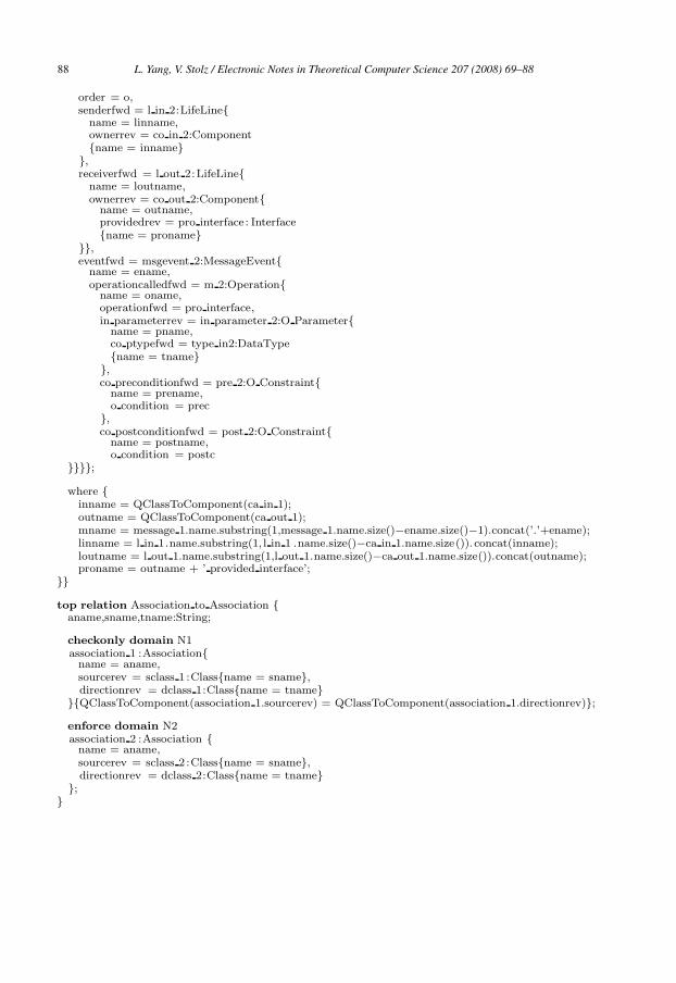
B Appendix: The QVT Implementation of the Rela-
tions in OOtoCB
In the following we give part of the working source code of the OOtoCB transform-
tion: relations Message to Message and Association to Association.
top relation Message to Message with Input Parameter {mname,inname,outname,ename,oname,linname,loutname,proname,prename,postname,pname,tname,prec,postc:String;o: Integer ;
checkonly domain N1message 1:Message{
order = o,senderfwd = l in 1:LifeLine{
ownerrev = ca in 1:Class{}},receiverfwd = l out 1:LifeLine{
ownerrev = ca out 1:Class{}},eventfwd = msgevent 1:MessageEvent{
name = ename,operationcalledfwd = m 1:Method{
name = oname,in parameterrev = in parameter 1:Parameter{
name = pname,ptypefwd = type in1:DataType{name = tname}
},preconditionfwd = pre 1:Constraint{
name = prename,condition = prec
},postconditionfwd = post 1:Constraint{
name = postname,condition = postc
}}}}{QClassToComponent(ca in 1) <> QClassToComponent(ca out 1)};
enforce domain N2message 2:Message {
name = mname,
L. Yang, V. Stolz / Electronic Notes in Theoretical Computer Science 207 (2008) 69–88 87
order = o,senderfwd = l in 2:LifeLine{
name = linname,ownerrev = co in 2:Component{name = inname}
},receiverfwd = l out 2:LifeLine{
name = loutname,ownerrev = co out 2:Component{
name = outname,providedrev = pro interface: Interface{name = proname}
}},eventfwd = msgevent 2:MessageEvent{
name = ename,operationcalledfwd = m 2:Operation{
name = oname,operationfwd = pro interface,in parameterrev = in parameter 2:O Parameter{
name = pname,co ptypefwd = type in2:DataType{name = tname}
},co preconditionfwd = pre 2:O Constraint{
name = prename,o condition = prec
},co postconditionfwd = post 2:O Constraint{
name = postname,o condition = postc
}}}};
where {inname = QClassToComponent(ca in 1);outname = QClassToComponent(ca out 1);mname = message 1.name.substring(1,message 1.name.size()−ename.size()−1).concat(’.’+ename);linname = l in 1.name.substring(1, l in 1 .name.size()−ca in 1.name.size()). concat(inname);loutname = l out 1.name.substring(1,l out 1.name.size()−ca out 1.name.size()).concat(outname);proname = outname + ’ provided interface’;
}}
top relation Association to Association {aname,sname,tname:String;
checkonly domain N1association 1 :Association{
name = aname,sourcerev = sclass 1 :Class{name = sname},directionrev = dclass 1:Class{name = tname}
}{QClassToComponent(association 1.sourcerev) = QClassToComponent(association 1.directionrev)};
enforce domain N2association 2 :Association {
name = aname,sourcerev = sclass 2 :Class{name = sname},directionrev = dclass 2:Class{name = tname}
};}
L. Yang, V. Stolz / Electronic Notes in Theoretical Computer Science 207 (2008) 69–8888