integrated vehicle health management of a transport aircraft · pdf filewhite paper integrated...
TRANSCRIPT
WHITE PAPER
Integrated Vehicle Health Management of a Transport Aircraft Landing Gear System
AbstractIntegrated Vehicle Health Management (IVHM) is one of the few technologies that will help in reducing both maintenance and operational costs, while improving the overall safety of an aircraft. It also helps in moving away from conservative design philosophies. Hence IVHM is increasingly being adopted in various aircraft programs. IVHM requires a multi-disciplinary approach bringing together the best of mechanical engineering, sensor technologies, communication and data analytics.
Aircraft landing gear (LG) is one of the most critical systems in an aircraft which requires the maximum maintenance effort, next only to the propulsion system. In this paper a solution approach for IVHM of the landing gear system for a typical transport aircraft is presented. Application is demonstrated through a typical use case of the landing gear retraction mechanism.

External Document © 2017 Infosys Limited External Document © 2017 Infosys Limited
Introduction
Aircraft health monitoring system as a
concept stems from challenges to enhance
flight safety and at the same time to
reduce operational and maintenance
costs. A system that enables automatic
detection, diagnosis, prognosis and
mitigation of adverse events arising from
component failures, is conceptualized in
an Integrated Vehicle Health Management
(IVHM) system. The current practice of
scheduled maintenance increases the
cost of maintenance steeply, especially in
the case of an aircraft operating beyond
its designed service life. So a need exists
to adopt condition based maintenance
(CBM) which is possible only with an
effective health monitoring system. CBM
enables increased asset availability and
hence a higher return on investment while
ensuring safety.
The aim of a Health Monitoring system is to detect and diagnose initiation of any defect, to analyze its effects and to trigger maintenance workflows in order to maintain safety of the aircraft. This is done by capturing data by a network of sensors and analyzing the data using life prediction algorithms implemented on highly evolved software systems.
Health monitoring systems are employed on both structures and systems. Structural health monitoring essentially looks after structural integrity by online monitoring of damage growth and assessing remaining usable life (RUL). System health monitoring looks after functional aspects and any degradation in performance triggering maintenance tasks or replacement of affected Line replacement units (LRU). In recent times IVHM systems have been developed that take care of both structural and systems health management in aircrafts. In this paper, a study performed on the Health Monitoring system for a retractable landing gear of a transport aircraft is presented.
External Document © 2017 Infosys Limited External Document © 2017 Infosys Limited
Landing Gear system and its Failures
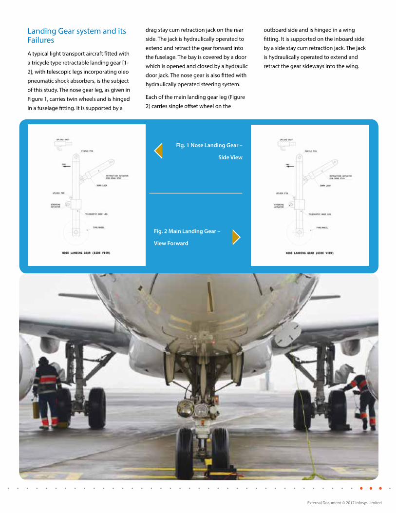
A typical light transport aircraft fitted with
a tricycle type retractable landing gear [1-
2], with telescopic legs incorporating oleo
pneumatic shock absorbers, is the subject
of this study. The nose gear leg, as given in
Figure 1, carries twin wheels and is hinged
in a fuselage fitting. It is supported by a
drag stay cum retraction jack on the rear
side. The jack is hydraulically operated to
extend and retract the gear forward into
the fuselage. The bay is covered by a door
which is opened and closed by a hydraulic
door jack. The nose gear is also fitted with
hydraulically operated steering system.
Each of the main landing gear leg (Figure
2) carries single offset wheel on the
outboard side and is hinged in a wing
fitting. It is supported on the inboard side
by a side stay cum retraction jack. The jack
is hydraulically operated to extend and
retract the gear sideways into the wing.
Fig. 1 Nose Landing Gear –
Side View
Fig. 2 Main Landing Gear –
View Forward
External Document © 2017 Infosys Limited External Document © 2017 Infosys Limited
In order to validate the IVHM system
functionality the complete landing gear
operating system can be rigged up in a
ground test rig with all LRU’s located as in
the aircraft. This test rig should facilitate
extension and retraction and locking of
the landing gears, actuation of nose door
and nose wheel steering system. Proper
installation and rigging is also important
for correct functioning of the LG system.
The health of a system depends on the
proper functionality of each LRU in the
system. An LRU can have many failure
modes and potential failure can be
detected through symptoms. While some
failure modes can be critical, others may
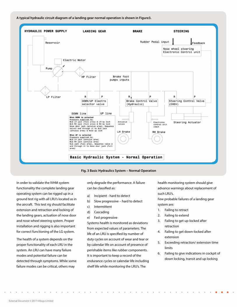
A typical hydraulic circuit diagram of a landing gear normal operation is shown in Figure3.
Fig. 3 Basic Hydraulics System – Normal Operation
only degrade the performance. A failure
can be classified as:
a) Incipient - hard to detect
b) Slow progressive – hard to detect
c) Intermittent
d) Cascading
e) Fast progressive
Systems health is monitored as deviations
from expected values of parameters. The
life of an LRU is specified by number of
duty cycles on account of wear and tear or
by calendar life on account of presence of
perishable items like rubber components.
It is important to keep a record of the
endurance cycles or calendar life including
shelf life while monitoring the LRU’s. The
health monitoring system should give
advance warnings about replacement of
such LRU’s.
Few probable failures of a landing gear
system are:
1. Failing to retract
2. Failing to extend
3. Failing to get up-locked after
retraction
4. Failing to get down-locked after
extension
5. Exceeding retraction/ extension time
limits
6. Failing to give indications in cockpit of
down locking, transit and up locking

External Document © 2017 Infosys Limited External Document © 2017 Infosys Limited
IVHM System Architecture
The key objective of a robust IVHM system
is to continuously monitor all components
and the system as a whole, acquire data,
collate component states with other
relevant aircraft parameters and report
threshold-exceeds to trigger maintenance
and other operational workflows.
The key criteria that an IVHM system needs
to satisfy are:
1. Interoperability with existing avionics,
Electronic Log Books
2. Pluggable System, easy to deploy
3. Less hindrance to existing aircraft
structures
4. Optimal weight and shape of extra
sensors and hardware
5. Aviation grade hardware and software
components
6. Compliance
7. Modularity and Scalability
8. Reliability
9. Security
10. Certification
An IVHM system can be designed to
trace, track and monitor each individual
component or an LRU of a Landing
Gear Unit, through the various stages
of the product life cycle namely Design,
Manufacturing, Distribution, In Service, and
End of Life. The current design approach
discusses IVHM, restricted to the phases
of Aircraft Assembly, in-service operations
through End of Life, as the aircraft
design and manufacturing house in the
current context, is presumed to procure
components and LRUs from different
suppliers.
Each LRU or component should be given
a unique identity throughout its lifecycle.
The identification can be done by RFID
tagging of the LRU or component, or
by physical attachment [3]. As we see
in a subsequent section, an LG attains
different health characteristics with the
replacement of an LRU or a component
and hence the constitution and hierarchy
of all LRUs and components at a given time
in the LG needs to be recorded. Ideally,
an IVHM system should treat a LG as a
different instance even if one component
or LRU gets replaced due to maintenance
activities. Hence the state and health
condition of an LG is always a function of
the collection of all LRU and components.
All such Components and LRU identities
will be tracked in the ground based
Serialization ERP systems.
Landing Gear
IVHM Processing Unit
Remote Data Concentrators
Dat
abus
Exte
rnal
Dat
a in
terf
aces
Sensors
Data Base
Fig. 4 On Board IVHM System
External Data Interfaces
Serialization, Supply Chain Systems (ERP)
Portals Applications
Data Warehouse
Prognostics, Diagnostics, Analytics
Fig. 5 Enterprise IVHM System

External Document © 2017 Infosys Limited External Document © 2017 Infosys Limited
The diagram shown in Figure 4 depicts a
suggested IVHM architecture segregating
ground and onboard systems. This IVHM
system is a combination of a near real
time system on board and a highly scaled
Enterprise IT system on the ground. In the
current approach, the on board system is
recommended to be implemented as a
separate pluggable system on dedicated
hardware, with minimal, need based
interoperability with the main avionics
of the aircraft. The IVHM is designed for
condition monitoring, limited to aiding
Operations & Maintenance (O&M). IVHM
requirements may scale up and may
mandate collection of data at frequencies
more than 1 KHz. The power source for
such a unit may have to be tapped from
existing power modules or the power
modules may have to be redesigned to
support the additional loads that the IVHM
system would introduce.
At the minimum, the on board IVHM
system is visualized as containing the
following components:
1. A collage of sensors carefully selected
and strategically placed on the LG
system.
2. One or more Remote Data Concentrator
that aggregates all sensor data through
the required interfaces
3. A central computer of the onboard
IVHM (IVHM PU) with nonvolatile
memory in it
4. A relational database running on
possibly an NVRAM
5. A data bus local to the IVHM system
6. An external interface for data collection
by ground systems (Wired, Wireless,
Serial etc.)
The onboard IVHM system will interact
minimally with other avionics systems, for
example, to fetch complementary data and
parameters for e.g., the CG location of the
aircraft.
The ground systems would comprise many
robust Enterprise modules (Figure 5) based
on processing required to be performed on
the aircraft data.
1. Prognostics and Advice Generation
2. Trace and Track LG and its LRUs,
components, parts
3. Integration with O&M ERP systems
a. Schedule maintenance based on the
condition, raise tickets etc.
b. Supply chain availability, Integration
with Order Management System to to
ensure scheduled maintenance
4. Portal and Interfaces for data
presentation to the Airline and the OEM.
Structural Architecture
Introduction of IVHM into an aircraft
may require structural modification to
accommodate new sensors, hardware,
communication buses etc. The following
key criteria have to be borne in mind while
introducing a “foreign component” into the
aircraft to enable a new IVHM system.
1. Sensor type and range
2. Installation aspects / orientation
3. Interference/Coupling effects with
structure and other systems
4. Effect of failure of sensor/ false outputs
The sensor type and range is decided
based on the parameters to be monitored.
The installation may call for some
modification to the LRU and is ensured
that it does not affect its functioning.
Coupling effects and interference to
output is minimized by suitable choice of
location of the sensor. It should be ensured
that sensors are of high reliability and any
failure or false outputs should be easily
recognizable by the system software by
comparison of data.
Logical Architecture
There are different objectives to
implementing an IVHM system in an
aircraft (and its Landing Gear), main ones
being
1. Increased safety,
2. Usage monitoring,
3. Monitoring Component, LRU and
System conditions,
4. Estimation of RUL,
5. Aiding Built in test equipment (BITE),
6. Running diagnostics and prognostics
While the above objectives are operational,
the ultimate business objective is to
reduce manual inspections and periodic
maintenance schedules. This introduces
a paradigm shift towards introducing
Condition Based Maintenance (CBM) in
lieu of periodic maintenance and IVHM is
built to cater to this important business
objective of the aviation industry.
It is increasingly seen that the OSA-CBM
standard [4] (www.mimosa.org) is receiving
support from the aviation industry and is
being adopted for both onboard electronic
systems and ground based Decision
support Systems. OSA-EAI standard is
being leveraged to integrate with ground
based Enterprise systems that run the
O&M critical Supply Chain, Serialization (for
tracking, tracing) modules. Figure 6 depicts
the OSA-CBM stack.
While OSA-CBM provides a standard and
a well-defined stack for CBM, it also faces
certain implementation challenges for
onboard systems. The OSA CBM defines the
data definitions, communication interfaces
and functional aspects in a layered
architecture. OSA CBM provides quite an
exhaustive collection of XML messages
to be exchanged between the functional
layers. While it perfectly fits into the ground
based systems, XML messages adds to
huge overhead of XML tag bytes in on
board systems [5]. Hence it may be prudent
to design non-XML binary implementation
of the messages of all realized layers in
onboard systems. Moreover the stack
would have to run on Real Time Operating
Systems, with the stack completely
implemented in the C language, adhering
to typical aviation standards of coding
guidelines, such as DO-178B/EUROCAE
ED-12B.

External Document © 2017 Infosys Limited External Document © 2017 Infosys Limited
The OSA CBM functional layers data
acquisition to state detection are good
to be fully implemented on on-board
systems and Prognostics Assessment,
Advisory Generation to be implemented
on ground based IT systems. There may
be an overlap of Health Assessment being
implemented partially in onboard systems
and majorly on the ground based systems.
Critical Health factors that need immediate
attention should be assessed onboard,
while the rest can be processed on ground
systems.
Advisory Generation (AG)
Prognostics Assessment (PA)
Health Assessment (HA)
State Detection (SD)
Data Manipulation (DM)
Data Acquisition (DA)
Fig 6. OSA-CBM Stack
Data Acquisition (DA)
Data for LG IVHM comes from various
sensors mounted on the LG assembly and
LRUs. Complementary data may have to
be sourced from other onboard avionic
systems, for e.g., the Center of Gravity
of the aircraft, Cross wind, Acceleration,
Speed, Electrical System Parameters
etc. amongst others. A few important
parameters to be monitored for health
monitoring of landing gear retraction
system through the added sensors would
be as follows.
Hydraulic pressure in DOWN line
• Hydraulic pressure in UP line
• Electrical signals from Weight-on-wheel
switches
• Electrical signals from Up-locks
• Electrical signals from Down-locks
• Pump output pressure
• Retraction and Extension timings
• Oleo gas pressures
• Oleo fescule lengths when aircraft in on
ground
Locations and type of sensors will be
indicated in the Structural/Physical
architecture.
Sensors
The sensors chosen for health monitoring
system in aircraft should work well in
the aircraft environment and range of
temperature, altitude, acceleration, shock,
vibration, salt fog, humidity, sand and
dust etc. They should be small in size
and weight, should be energy efficient.
Sensor systems on board an aircraft
provide outputs (signals) to intelligent
software systems to automatically
interpret the sensor outputs. Based on
the specific requirements, the most widely
used sensors are the fiber optic sensors,
ultrasonic sensors,
wireless sensors, non-contact type sensors,
Micro electromechanical system (MEMS)
and Nano-technology based sensors.
Data Manipulation (DM)
Sensor fusion, Signal processing and other
conditioning and marshaling/muddling
happen at this layer. This layer will be
the primary layer of the OSA CBM stack,
where a binary implementation of the
message exchange formats and the data
structures would be implemented. Feature
extractions and corresponding algorithms
can also happen at this layer.
State Detection (SD)
A LG state model and state machine as
per OSA CBM specification should be
implemented in this layer. Fault model
implementation also falls into this layer.
Any critical change in the profile of the
fault data from the collection instances
would trigger alerts for cockpit or ground
consumption.
The LG state model should be in sync with
the Trace/Track serialization component
hierarchy of the LG components and the LG
system as a whole. Even a single change in
the LRU or a LG component would treat the
state model instance as a different state for
health and condition monitoring aspects.
This is due to the fact that certain faults
would have cascading effects and faults
in the replaced LRU would not be similar
to its predecessor. Hence the uniqueness
of the constitution of the LG state has to
be preserved and recorded.Typically the
binary implementation of the DM and SD
layers would end here and spew data onto
the common bus (may be MIL-1553 kind)
and may be stored in a persistent database
built on NVRAM modules.
The persistent data is available for
download through the external data
interface. The external data interfaces
could be USB, Ethernet, Wireless or Serial.
The data that is exchanged or stored
here could be encrypted using different
mechanisms.When the data download
happens and gets transferred to the
ground systems, the binary formats have
to be converted to OSA CBM defined
XML formats. The data thus collected
would go into the DataWarehouse of the
ground system which houses the Common
Relational Information Schema (CRIS) of
the OSA EAI specification.
Health Assessment
A majority of Health Assessment (HA) will
happen on the ground systems. Minimal
to no HA should happen onboard as this
is a computationally intensive operation.
Any critical events detected by the IVHM
system and not available in standard
avionics should only be considered to
be detected on board and informed to
the main Avionics through the databus
interfaces. The Health Assessment module
sitting on top of the Datawarehouse would
consist of a set of Diagnostics algorithms
and processes.
External Document © 2017 Infosys Limited External Document © 2017 Infosys Limited
The HA module should be highly customizable and highly extensible as the prognostics and diagnostics algorithms are ever evolving and new ones are innovated continuously.
The workflow of the HA should also be made graphically available to the IVHM users, so that they can introduce new tests, modify the sequence of tests, parallelize, serialize, introduce logical gates etc. Reuse of Diagnostics and Prognostics algorithms in different HA tests can be made possible.
The diagnostics would determine any exceedances in the values collected, observe the data collected over the flight duration, efficiencies of the LG functions and track any performance degradation against the previous data recorded for the flight, even if threshold breakages are absent.
Any threshold violation and periodic degradation with respect to previous
dataset collected is the key output of this module.
Prognostics AssessmentThe main responsibility of the Prognostic Assessment (PA) module is to calculate the Remaining Usable Life (RUL) of a component or LRU where defects or degradation has been reported by the HA module.
PA is a sophisticated, complex and most sought after area of research. Established algorithms by using Predictive Modeling, Principal Component Analysis and other techniques should be constantly updated in this system.
Hence the PA module should be highly flexible and should be ready to import new algorithms, schedule PA workflows. The Software architecture should support patching and upgrading this module
frequently and let IVHM administrators to dynamically create work flows and schedule PA tests as per the need.
Advisory Generation The Advisory Generation (AG) Layer is the main Decision Support System (DSS) for the IVHM solution. It accrues the HA and PA findings and generates Health Reports and rosters maintenance activities if integrated with the Enterprise Systems automatically.
Web portals on top of this layer would help both the OEM and Operator to access the IVHM data and results for the flights of interest. The portals would also help an OEM to offer or sell IVHM services to different Airlines to which the aircrafts have been sold or leased.
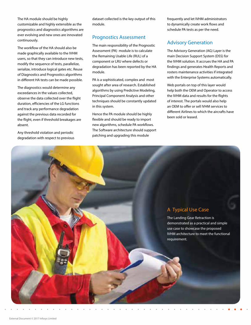
A Typical Use CaseThe Landing Gear Retraction is demonstrated as a practical and simple use case to showcase the proposed IVHM architecture to meet the functional requirement.

External Document © 2017 Infosys Limited External Document © 2017 Infosys Limited
A LG retraction activity is possible only when the following conditions are met:
1. Aircraft hydraulics power and electrical power are ‘ON’
2. All Weight-On-Wheel switches are ‘OFF’. (When aircraft is standing on the landing gear the oleo will be compressed to that extent. Weight-on-wheel micro-switches are installed in each gear to sense the oleo closure. The switches are ‘ON’ when the weight is on the landing gear. When any one or more switches are ‘ON” the Selector switch lever is
LOCKED by a solenoid operated plunger preventing operation of the Selector to UP position.)
3. Select landing gear ‘UP’ on the landing gear selector switch to energize the electro-selector spool valve to move to ‘UP’ position.
4. Hydraulic pressure flows to ‘UP’ lines of actuators.
5. All Down locks are unlocked
6. Actuator stroke retract the landing gears individually.
Thus a failure of retraction can be due to any of the reasons mentioned in Table 1. The main objective of the IVHM system is not to report a failure at the time of failure, but also to give a near practical prognosis of a failure event and estimate RUL or Time to Failure (TTF). Hence the current IVHM solution should present the degradation graph for the eight failures mentioned in Table 1.
No Hydraulic Power
No Electric power
Weight on wheel signal failure
Failure Detection Mechanism
Electro-selector switch failure
Electro-selector valve failure
Hardware Availability
Sensed by a pressure transducer in the system
Already available in the current
Already available in the current system
Comments
Need to get the information from existing avionics sytem
Sensed by system voltage sensor
Sensed through electrical signal which needs to be tapped
Failure of Down locksSense the signals from Down locks
Gear unlocked, but not going up to up lock
Sense signal from Up lock
Retraction failure
Time intervals between selector switch operation, down lock release and up locking for each gear is beyond limits
Identify through solenoid voltage
Identify through pressure in ‘UP’ line
New sensor need to be deployed New data to be captured
Table 1 Landing Gear Failure Modes and detection mechanism
The state detection layer (SD) will implement the whole state model containing all the pressure and electrical parameters and establish correlation relationships between them. For example, a drop in hydraulic pressure or a low voltage may cause the unlocked LG not to reach the uplock position or a delayed retraction. The effects of combination of both conditions under various amplitudes would be different. The algorithms will have to learn the inter dependency of such
parameters accurately to help the next layer while performing HA.
Health Assessment onboard will be simple and the algorithms are based on threshold exceedances during service. The HA algorithms on ground based systems would be more complex combining Information gain and decision making modules. On the domain side the HA would also have a database of material behaviour, historical data and built in self learningcapabilities.
The Advisory Generation module will implement probability calculation algorithms and when the probability of a functionality reduces below 100%, on a time scale, maintenance advisories are generated, for example, when the probability of the uplock functionality based on the historical and current data sensed is about to drop or drops to less than 100%, a maintenance need is triggered.

External Document © 2017 Infosys Limited External Document © 2017 Infosys Limited
Conclusion
Integrated Vehicle Health Management (IVHM) is increasingly being adopted in various aircrafts encompassing both systems and structures. Aircraft landing gear system is taken for the current study due to its criticality next only to a propulsion system. A solution approach for Integrated Vehicle Health Management (IVHM) for landing gear system of a typical transport aircraft is presented. This end to end solution approach considers both aircraft OEMs and airliners. The system architecture details out various components like track and trace, structural architecture, logical architecture, data acquisition, sensors, data processing, state detection, assessment of health and prognostics. The solution approach is demonstrated through a typical use case of the landing gear retraction mechanism. Infosys has been working actively in this area bringing together best of its capabilities in mechanical product development, sensor technologies, communication, data analytics and software systems engineering. Many advanced technologies are continuously being developed in health monitoring which is making it relevant to multiple industry domains.
External Document © 2017 Infosys Limited External Document © 2017 Infosys Limited
References 1. Jan Roskam, Airplane Design Part IV – Landing gear design, 1986
2. Norman S. Curry, Aircraft Landing Gear Design: Principles and Practices, 1988
3. Patkai, B., Theodorou, L., McFarlane, D. and Schmidt, K., Requirements for RFID based Sensor integration in Landing Gear IVHM, AUTO-ID LABS AEROID-CAM-016, 2007,http://www.aero-id.org/research_reports/AEROID-CAM-016-MessierDowty.pdf [Accessed on Aug 25, 2012]
4. Operations and Maintenance Information Open Systems Alliance, http://mimosa.org/ [Accessed on Aug 25, 2012]
5. Andreas L., Conor H. and Matthias B., Data Management backbone for embedded and pc based systems using OSA CBM and OSA EAI, European Conference of Prognostics and Health Management Society, 2012.http://www.phmsociety.org/sites/phmsociety.org/files/phm_submission/2012/phmc_12_015.pdf [Accessed on Aug 25, 2012]
Acknowledgements The authors would like to thank Prof. K. P. Rao, Mr. T G A Simha and Mr. Jagadish V. P. for their critical review of this document and valuable feedback. Mr. Thirunavukkarasu K.S. help in creating the figures is appreciated. The authors also would like to thank senior management of engineering services practice of Infosys Mr. Srinivasa Rao P and Mr. Abhishek for their continuous support and encouragement.
© 2017 Infosys Limited, Bengaluru, India. All Rights Reserved. Infosys believes the information in this document is accurate as of its publication date; such information is subject to change without notice. Infosys acknowledges the proprietary rights of other companies to the trademarks, product names and such other intellectual property rights mentioned in this document. Except as expressly permitted, neither this documentation nor any part of it may be reproduced, stored in a retrieval system, or transmitted in any form or by any means, electronic, mechanical, printing, photocopying, recording or otherwise, without the prior permission of Infosys Limited and/ or any named intellectual property rights holders under this document.
For more information, contact [email protected]
Infosys.com | NYSE: INFY Stay Connected
About the Authors
Divakaran V. N. is a Consultant with Infosys since December, 2006. Prior to this, he was with Hindustan aeronautics Ltd at its Aircraft Research and Design Centre as Head of Design (Mechanical systems). He has over 35 years of experience in design and development of landing gears and other mechanical systems, working in military aircraft programs like Light Combat Aircraft, Advanced Light Helicopter, Intermediate Jet Trainer and civil Light Transport Aircraft. He has two patents in design. He took his degree in mechanical engineering from NIT, Calicut and underwent 9 months of institutional training in Aeronautics at Indian Institute of Science, Bangalore.
Subrahmanya R. M. is a Senior Architect with Infosys. He has led large programs in the Remote Management, M2M, Service Management, Network Fault Management areas for different industry verticals. He has more than 15 years of experience in engineering software products, from concept to realization. He has filed six patents on the above areas. He is an Electronics and Communication Engineer from PESIT, Bangalore. He has undergone a 1 year training at SERC, IISc, Bangalore prior to joining Infosys.
Dr Ravikumar, G.V.V. is Senior Principal and Head Advanced Engineering Group (AEG)brings together 20 years of research and industrial experience in Aircraft Industry. His areas of interest include Aircraft Structures, Knowledge Based Engineering, Composites and Structural Health Monitoring. He authored more than 30 technical papers in various journals/conferences/white papers and filed a patent. He worked on various prestigious engineering design and development, KBE tool development projects for both military and commercial aircraft programs including Indian light combat aircraft (LCA). He obtained his doctoral degree in Applied Mechanics from IIT Delhi. He worked in Tata Research Design and Development Center (TRDDC), Pune and Aeronautical Development Agency (ADA) Bangalore prior to joining Infosys.