integrated pollution prevention and control (ippc ... · part a: hot and cold forming the hot and...
TRANSCRIPT

EUROPEAN COMMISSION
Integrated Pollution Prevention and Control (IPPC)
Reference Document onBest Available Techniques in the Ferrous Metals Processing
Industry
December 2001


Executive Summary
Ferrous Metals Processing Industry i
EXECUTIVE SUMMARY
This Reference Document on best available techniques in ferrous metals processing reflects aninformation exchange carried out according to Article 16(2) of Council Directive 96/61/EC. Thedocument has to be seen in the light of the preface which describes the objectives of thedocument and its use.
This BREF document consists of 4 Parts (A – D). Parts A to C cover the different industrialsub-sectors of the Ferrous Metals Processing sector: A, Hot and Cold Forming; B, ContinuousCoating; C, Batch Galvanizing. This structure was chosen because of the differences in natureand scale of the activities covered by the term FMP.
Part D does not cover an industrial sub-sector. It comprises the technical descriptions of anumber of environmental measures which are techniques to be considered in the determinationof BAT in more than one sub-sector. This was done to avoid repetition of technical descriptionsin the three Chapters 4. These descriptions have to be viewed always in connection with themore specific information, referring to the application in individual sub-sectors, which is givenin the relevant Chapter 4.
Part A: Hot and Cold Forming
The hot and cold forming part of the ferrous metal processing sector comprises differentmanufacturing methods, such as hot rolling, cold rolling and drawing of steel. A great variety ofsemi-finished and finished products with different lines of production is manufactured. Productsare: hot and cold rolled flats, hot rolled long products, drawn long products, tubes and wire.
Hot Rolling
In hot rolling the size, shape and metallurgical properties of steel are changed by repeatedlycompressing the hot metal (temperature ranging from 1050 to 1300 Co) between electricallypowered rollers. The steel input for hot rolling varies in form and shape - cast ingots, slabs,blooms, billets, beam blanks - depending on the product to be manufactured. Products obtainedfrom hot rolling are usually classified in two basic types according to their shape: flat and longproducts.
Total EU production in 1996 of hot rolled (HR) products was 127.8 million tonnes of whichflats accounted for 79.2 million tonnes (ca. 62%) [Stat97]. Germany is the largest manufacturerof the flats, with 22.6 million tonnes followed by France with 10.7 million tonnes, Belgium 9.9million tonnes, Italy 9.7 million tonnes and UK 8.6 million tonnes. The vast majority of HR flatproducts is wide strip.
The remaining 38 % of HR products are long products with about 48.5 million tonnes in 1996.The two major manufacturing countries are Italy with about 11.5 million tonnes and Germanywith 10.3 million tonnes; followed by UK (7 million tonnes) and Spain (6.8 million tonnes).The largest part of the long products sector in tonnage terms is the production of wire rod whichstands for roughly a third of the total production followed by reinforcing bars and merchant barswith an approximate share of one quarter of the production each.
In steel tube manufacture, the EU, which produced 11.8 million tonnes in 1996, (20.9 % of totalworld production) is the largest producer followed by Japan and the U.S. The European steeltube industry has a highly concentrated structure. Five countries – Germany (3.2 milliontonnes), Italy (3.2 million tonnes), France (1.4 million tonnes), United Kingdom (1.3 milliontonnes) and Spain (0.9 million tonnes) - account for roughly 90 % of total EU production. In

Executive Summary
ii Ferrous Metals Processing Industry
some countries, a single company can account for 50 % or more of the national output. Inaddition to the major integrated steel tube manufacturers (mainly producing welded tubes),there are a relatively large number of small and medium-sized firms that are independent. Somemanufacturers, often small in tonnage terms, operating in high value-added markets, concentrateon the manufacture of special dimensions and grades of tubes according to particular customerspecifications.
Hot rolling mills usually comprise the following process steps: conditioning of the input(scarfing, grinding); heating to rolling temperature; descaling; rolling (roughing including widthreduction, rolling to final dimension and properties) and finishing (trimming, slitting, cutting).They are classified by the type of product that they produce and by their design features:blooming and slabbing mills, hot strip mills, plate mills, bar and rod mills, structural and sectionmills and tube mills.
The main environmental issues of hot rolling are emissions to air, especially NOx and SOx; theenergy consumption of furnaces; (fugitive) dust emissions from product handling, rolling ormechanical surface treatment; oil- and solid-containing effluents and oil-containing wastes.
For NOx emissions of reheating and heat treatment furnaces, industry reported concentrationsof 200 – 700 mg/Nm³ and specific emissions of 80 – 360 g/t; while other sources reported up to900 mg/Nm3 and – with combustion air preheating of up to 1000 oC – of up to more than5000 mg/Nm³. SO2 emissions from furnaces depend on the fuel used; ranges were reportedfrom 0.6 – 1700 mg/Nm³ and 0.3 – 600 g/t. The scattering of energy consumption for thesefurnaces was 0.7 to 6.5 GJ/t; with a typical range being 1 – 3 GJ/t.
As for dust emissions from product handling, rolling or mechanical surface treatment, very fewdata were submitted referring to the individual processes. The concentration ranges reportedwere:
• Scarfing: 5 – 115 mg/Nm³• Grinding: < 30 – 100 mg/Nm³• Mill stands: 2 – 50 mg/Nm³ and• Coil handling: approximately 50 mg/Nm³ .
Emissions to water from hot rolling basically comprise oil- and solid-containing effluents in therange of 5 to 200 mg/l total suspended solids and 0.2 – 10 mg/l hydrocarbons. Oil-containingwastes from waste water treatment were reported ranging from 0.4 – 36 kg/t depending on themill type.
For more details and for emission and consumption data for other process steps of hot rolling,refer to Chapter A.3 where the available data are presented with qualifying information.
The key findings regarding BAT for individual process steps and different environmental issuesof hot rolling are summarized in Table 1. All emission figures are expressed as daily meanvalues. Emissions to air are based on standard conditions of 273 K, 101.3 kPa and dry gas.Discharges to water are indicated as daily mean value of a flow-rate-related 24-hour compositesample or a flow-rate-related composite sample over the actual operating time (for plants notoperated in three shifts).
There was consensus in the TWG on the best available techniques and associatedemission/consumption levels presented in the table, except where a ‘split view’ is explicitlyrecorded.

Executive Summary
Ferrous Metals Processing Industry iii
Best Available Techniques / Split views on BAT BAT-associated emission andconsumption levels /
Split views on associated levelsStoring and handling of raw materials and auxiliaries
• Collection of spillages and leakages by suitable measures,e.g. safety pits and drainage.
• Separation of oil from the contaminated drainage waterand reuse of recovered oil.
• Treatment of separated water in the water treatment plant.Machine scarfing
• Enclosures for machine scarfing and dust abatement withfabric filters.
split view on dust level:< 5 mg/Nm³< 20 mg/Nm³
• Electrostatic precipitator, where fabric filters cannot beoperated because of very wet fume.
split view on dust level:< 10 mg/Nm³20 - 50 mg/Nm³
• Separate collection of scale/swarf from scarfing.Grinding
• Enclosures for machine grinding and dedicated booths,equipped with collection hoods for manual grinding anddust abatement by fabric filters.
split view on dust level:< 5 mg/Nm³< 20 mg/Nm³
All surface rectification processes• Treatment and reuse of water from all surface rectification
processes (separation of solids).• Internal recycling or sale for recycling of scale, swarf and
dust.
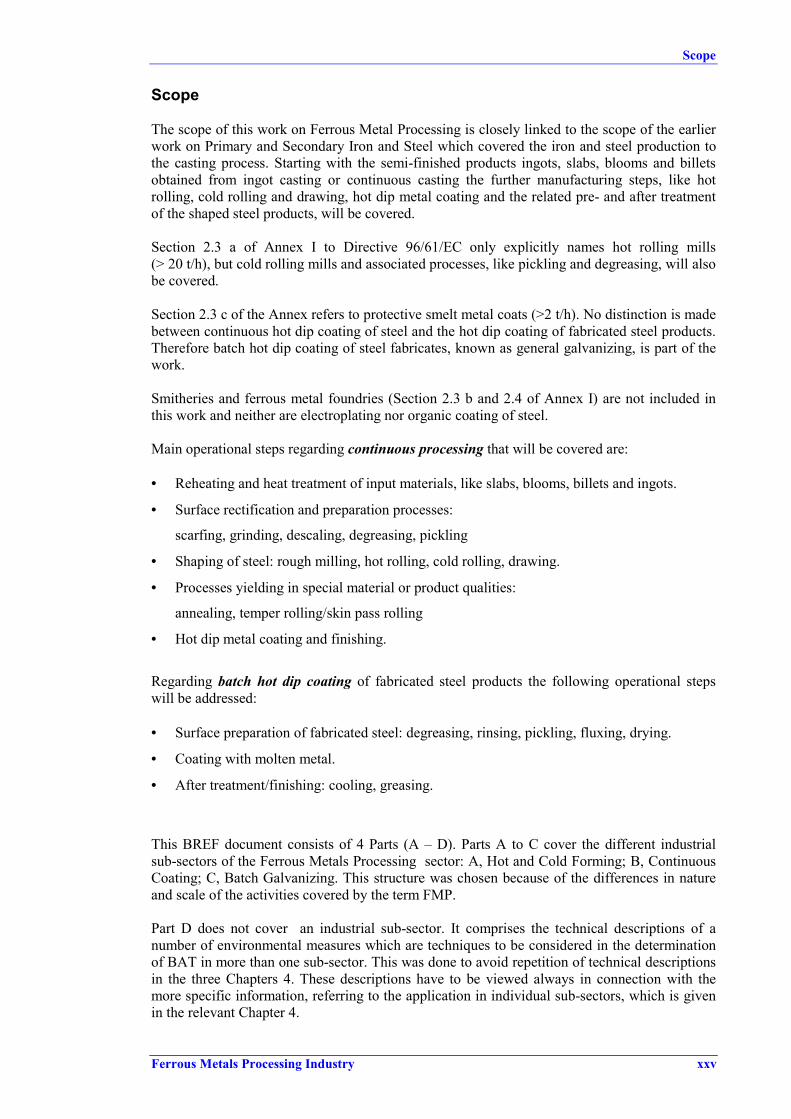
Table 1: Key findings regarding BAT and associated emission/consumption levels for hot rolling

Executive Summary
iv Ferrous Metals Processing Industry
Best Available Techniques / Split views on BAT BAT-associated emission andconsumption levels /
Split views on associated levelsRe-heating and heat treatment furnaces
• General measures, e.g. regarding furnace design oroperation & maintenance, as described in chapter A.4.1.3.1.
• Avoiding excess air and heat loss during charging byoperational measures (minimum door opening necessaryfor charging) or structural means (installation of multi-segmented doors for tighter closure).
• Careful choice of fuel and implementation of furnaceautomation/control to optimise the firing conditions.- for natural gas- for all other gases and gas mixtures- for fuel oil (< 1 % S)
SO2 levels:< 100 mg/Nm3
< 400 mg/Nm3
up to 1700 mg/Nm³Split view:• limitation of sulphur content in fuel to < 1 % is BAT• lower S limit or additional SO2 reduction measures is BAT• Recovery of heat in the waste gas by feedstock pre-heating• Recovery of heat in the waste gas by regenerative or
recuperative burner systemsEnergy savings 25 - 50 % andNOx reductions potentials of upto 50 % (depending on system).
• Recovery of heat in the waste gas by waste heat boiler orevaporative skid cooling (where there is a need for steam)
• Second generation low-NOx burners NOx 250 - 400 mg/Nm³ (3% O2)without air pre-heating reportedNOx reduction potential of about65 % compared to conventional.
• Limiting the air pre-heating temperature.Trade-off energy saving vs. NOx emission:Advantages of reduced energy consumption and reductionsin SO2, CO2 and CO have to be weighed against thedisadvantage of potentially increased emissions of NOx
Split view:• SCR and SNCR are BAT
• Not enough information to decide whether or notSCR/SNCR are BAT
achieved levels 1:SCR: NOx < 320 mg/Nm3
SNCR: NOx < 205 mg/Nm³ , ammonia slip 5 mg/Nm3
• Reduction of heat loss in intermediate products; byminimizing the storage time and by insulating theslabs/blooms (heat conservation box or thermal covers)depending on production layout.
• Change of logistic and intermediate storage to allow for amaximum rate of hot charging, direct charging or directrolling (the maximum rate depends on production schemesand product quality).
• For new plants, near-net-shape casting and thin slabcasting, as far as the product to be rolled can be producedby this technique.
1 These are emission levels reported for the one existing SCR plant (walking beam furnace) and the one existing SNCRplant (walking beam furnace).
Table 1 continued: Key findings regarding BAT and associated emission/consumption levels forhot rolling

Executive Summary
Ferrous Metals Processing Industry v
Best Available Techniques / Split views on BAT BAT-associated emission andconsumption levels /
Split views on associated levelsDescaling
• Material tracking to reduce water and energyconsumption.
Transport of rolled stock• Reduce unwanted energy loss by coil boxes or coil
recovery furnaces and heat shields for transfer barsFinishing train
• Water sprays followed by waste water treatment in whichthe solids (iron oxides) are separated and collected forreuse of iron content.
• Exhaust systems with treatment of extracted air by fabricfilters and recycling of collected dust.
split view on dust level:< 5 mg/Nm³< 20 mg/Nm³
Levelling and welding• Suction hoods and subsequent abatement by fabric filters split view on dust level:
< 5 mg/Nm³< 20 mg/Nm³
Cooling (machines etc.)• Separate cooling water systems operating in closed loops
Waste water treatment/ scale- and oil-containing process water• Operating closed loops with recirculating rates of > 95 %• Reduction of emissions by using a suitable combination of
treatment techniques (described in detail in ChaptersA.4.1.12.2 and D.10.1).
SS: < 20 mg/l Oil: < 5 mg/l (1)
Fe: < 10 mg/lCrtot: < 0.2 mg/l (2)
Ni: < 0.2 mg/l (2)
Zn: < 2 mg/l• Recirculation of mill scale collected in water treatment to
the metallurgical process• Oily waste/sludge collected should be de-watered to allow
for thermal utilisation or safe disposal.Prevention of hydrocarbon contamination
• Preventive periodic checks and preventive maintenance ofseals, gaskets, pumps and pipelines.
• Use of bearings and bearing seals of modern design forwork- and back-up rolls, installation of leakage indicatorsin the lubricant lines (e.g. at hydrostatic bearings).
• Collection and treatment of contaminated drainage waterat the various consumers (hydraulic aggregates), separationand use of oil fraction, e.g. thermal utilisation by blastfurnace injection. Further processing of the separated watereither in the water treatment plant or in dressing plants withultra filtration or vacuum evaporator.
Reduction in oil consumption by50-70 %.
1 oil based on random measurements2 0.5 mg/l for plants using stainless steel
Table 1 continued: Key findings regarding BAT and associated emission/consumption levels forhot rolling

Executive Summary
vi Ferrous Metals Processing Industry
Best Available Techniques / Split views on BAT BAT-associated emission andconsumption levels /
Split views on associated levelsRoll shops
• Use of water-based degreasing as far as technicallyacceptable for the degree of cleanliness required.
• If organic solvents have to be used, preference is to begiven to non-chlorinated solvents.
• Collection of grease removed from roll trunnions andproper disposal, such as by incineration.
• Treatment of grinding sludge by magnetic separation forrecovery of metal particles and recirculation into thesteelmaking process.
• Disposal of oil- and grease-containing residues fromgrinding wheels, e.g. by incineration.
• Deposition of mineral residues from grinding wheels and ofworn grinding wheels in landfills.
• Treatment of cooling liquids and cutting emulsions foroil/water separation. Proper disposal of oily residues, e.g.by incineration.
• Treatment of waste water effluents from cooling anddegreasing as well as from emulsion separation in the hotrolling mill water treatment plant.
• Recycling of steel and iron turnings into the steelmakingprocess.
Table 1 continued: Key findings regarding BAT and associated emission/consumption levels for hot rolling
Cold Rolling
In cold rolling, the properties of hot rolled strip products, e.g. thickness, mechanical andtechnological characteristics, are changed by compression between rollers without previousheating of the input. The input is obtained in the form of coils from hot rolling mills. Theprocessing steps and the sequence of processing in a cold rolling mill depend on the quality ofthe steel treated. The following process steps are used for low alloy and alloy steel (carbonsteel): pickling; rolling for reduction in thickness; annealing or heat treatment to regenerate thecrystalline structure; temper rolling or skin pass rolling of annealed strip to give desiredmechanical properties, shape and surface roughness, and finishing.
The process route for high alloy steel (stainless steel) involves additional steps to that forcarbon steels. The main stages are: hot band annealing and pickling; cold rolling; finalannealing and pickling (or bright annealing); skin pass rolling and finishing.
Cold rolled products are mainly strips and sheets (thickness typically 0.16 - 3 mm) with highquality surface finish and precise metallurgical properties for use in high specification products.
Cold rolled wide strip production (sheets and plates) was about 39.6 million tonnes in 1996.[EUROFER CR]. The main producing countries were Germany with about 10.6 million tonnes,France with 6.3 million tonnes, Italy with 4.3, UK with 4.0 million tonnes and Belgium with 3.8million tonnes.

Executive Summary
Ferrous Metals Processing Industry vii
Cold rolled narrow strip, obtained from cold rolling narrow hot strip or from slitting and coldrolling hot rolled sheet, amounted to about 8.3 millions tonnes in 1994 (2.7 million tonnes ofcold rolled and 5.5 million tonnes of slit strip)The cold rolled strip industry in the EU is both concentrated and fragmented. The largest 10companies account for 50 % of the production while another 140 companies account for theremaining 50 %. The structure of the sector is marked by national differences in company sizeand industry concentration. Most of the largest companies are situated in Germany, whichdominate the market with about 57 % of EU production (1.57 million tonnes in 1994). Themajority of companies, however, can be classified as small or medium-sized enterprises.[Bed95]
In 1994, Germany produced about 35 % of the slit strip, with 1.9 million tonnes, followed byItaly and France each with a production of 0.9 million tonnes.
The main environmental issues of cold rolling are: acidic wastes and waste water; degreaserfume, acidic and oil mist emissions to air; oil-containing wastes and waste water; dust, e.g. fromdescaling and decoiling; NOx from mixed acid pickling and combustion gases from furnacefiring.
As for acid emissions to air from cold rolling, these may arise from pickling and acidregeneration processes. Emissions differ, depending on the pickling process used – basically theacid used. For hydrochloric acid pickling, HCl emissions of 1 – 145 mg/Nm³ maximum (up to16 g/t) were reported; with the range reported by industry being 10 – < 30 mg/Nm³ (~ 0.26 g/t).For sulphuric acid pickling, H2SO4 emissions of 1 –2 mg/Nm³ and 0.05 – 0.1 g/t were reported.
For mixed acid pickling of stainless steel, HF emissions were reported in the range of 0.2 – 17mg/m3 (0.2 – 3.4 g/t). Additionally to acidic air emissions, NOx is generated. The scatteringrang was reported to be 3 - ~ 1000 mg/Nm3 (3 – 4000 g/t specific emission) with doubts beingraised on the lower end levels.
Only little data was available for dust emissions from steel handling and descaling operations.Reported ranges for mechanical descaling are 10 – 20 g/t for specific emissions andconcentration ranging from < 1 – 25 mg/m3.
For more details and for emission and consumption data for other process steps of cold rolling,refer to Chapter A.3 where the available data are presented with qualifying information.
The key findings regarding BAT for individual process steps and different environmental issuesof cold rolling are summarized in Table 2. All emission figures are expressed as daily meanvalues. Emissions to air are based on standard conditions of 273 K, 101.3 kPa and dry gas.Discharges to water are indicated as daily mean value of a flow-rate-related 24-hour compositesample or a flow-rate-related composite sample over the actual operating time (for plants notoperated in three shifts).
There was consensus in the TWG on the best available techniques and associatedemission/consumption levels presented in the table, except where a ‘split view’ is explicitlyrecorded.

Executive Summary
viii Ferrous Metals Processing Industry
Best Available Techniques / Split views on BAT BAT-associated emission andconsumption levels /
Split views on associated levelsDecoiling
• Water curtains followed by waste water treatment in whichthe solids are separated and collected for reuse of ironcontent.
• Exhaust systems with treatment of extracted air by fabricfilters and recycling of collected dust.
split view on dust level:< 5 mg/Nm³< 20 mg/Nm³
PicklingGeneral measures to reduce acid consumption and waste acidgeneration as described in Chapter A.4.2.2.1. should beapplied as far as possible, especially the following techniques:
• Prevention of steel corrosion by appropriate storage andhandling, cooling etc.
• Reduction of load on pickling step by mechanical pre-descaling in a closed unit, with an extraction system andfabric filters.
• Use of electrolytic pre-pickling.• Use of modern, optimised pickling facilities (spray or
turbulence pickling instead of dip pickling).• Mechanical filtration and recirculation for lifetime
extension of pickling baths.• Side-stream ion-exchange or electro-dialysis (for mixed
acid) or other method for free acid reclamation (describedin Chapter D.6.9) for bath regeneration.
HCl pickling• Reuse of spent HCl.
• or Regeneration of the acid by spray roasting or fluidisedbed (or equivalent process) with recirculation of theregenerate; air scrubbing system as described in Chapter 4for the regeneration plant; reuse of Fe2O3 by-product.
Dust 20 -50 mg/Nm³HCl 2 – 30 mg/Nm³SO2 50 - 100 mg/Nm³CO 150 mg/Nm³CO2 180000 mg/Nm³NO2 300 – 370 mg/Nm³
• Totally enclosed equipment or equipment fitted withhoods and scrubbing of extracted air.
Dust 10 - 20 mg/Nm³HCl 2 – 30 mg/Nm³
H2SO4 Pickling• Recovery of the free acid by crystallisation; air scrubbing
devices for recovery plant.H2SO4 5 - 10 mg/Nm³SO2 8 – 20 mg/Nm³
• Totally enclosed equipment or equipment fitted withhoods and scrubbing of extracted air.
H2SO4 1 - 2 mg/Nm³SO2 8 - 20 mg/Nm³
Table 2: Key findings regarding BAT and associated emission/consumption levels for cold rolling
Executive Summary
Ferrous Metals Processing Industry ix
Best Available Techniques / Split views on BAT BAT-associated emission andconsumption levels /
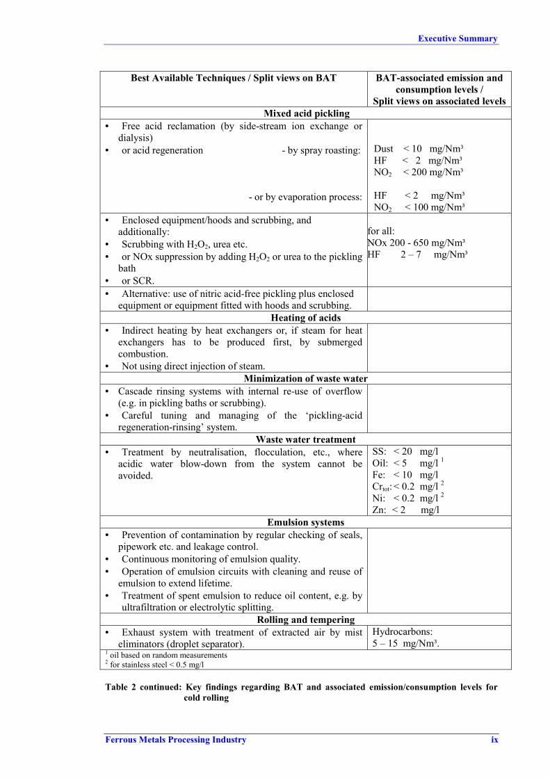
Split views on associated levelsMixed acid pickling
• Free acid reclamation (by side-stream ion exchange ordialysis)
• or acid regeneration - by spray roasting:
- or by evaporation process:
Dust < 10 mg/Nm³HF < 2 mg/Nm³NO2 < 200 mg/Nm³
HF < 2 mg/Nm³NO2 < 100 mg/Nm³
• Enclosed equipment/hoods and scrubbing, andadditionally:
• Scrubbing with H2O2, urea etc.• or NOx suppression by adding H2O2 or urea to the pickling
bath• or SCR.
for all:NOx 200 - 650 mg/Nm³HF 2 – 7 mg/Nm³
• Alternative: use of nitric acid-free pickling plus enclosedequipment or equipment fitted with hoods and scrubbing.
Heating of acids• Indirect heating by heat exchangers or, if steam for heat
exchangers has to be produced first, by submergedcombustion.
• Not using direct injection of steam.Minimization of waste water
• Cascade rinsing systems with internal re-use of overflow(e.g. in pickling baths or scrubbing).
• Careful tuning and managing of the ‘pickling-acidregeneration-rinsing’ system.
Waste water treatment• Treatment by neutralisation, flocculation, etc., where
acidic water blow-down from the system cannot beavoided.
SS: < 20 mg/lOil: < 5 mg/l 1Fe: < 10 mg/lCrtot: < 0.2 mg/l 2Ni: < 0.2 mg/l 2Zn: < 2 mg/l
Emulsion systems• Prevention of contamination by regular checking of seals,
pipework etc. and leakage control.• Continuous monitoring of emulsion quality.• Operation of emulsion circuits with cleaning and reuse of
emulsion to extend lifetime.• Treatment of spent emulsion to reduce oil content, e.g. by
ultrafiltration or electrolytic splitting.Rolling and tempering
• Exhaust system with treatment of extracted air by misteliminators (droplet separator).
Hydrocarbons:5 – 15 mg/Nm³.
1 oil based on random measurements2 for stainless steel < 0.5 mg/l
Table 2 continued: Key findings regarding BAT and associated emission/consumption levels forcold rolling

Executive Summary
x Ferrous Metals Processing Industry
Best Available Techniques / Split views on BAT BAT-associated emission andconsumption levels /
Split views on associated levelsDegreasing
• Degreasing circuit with cleaning and reuse of the degreasersolution. Appropriate measures for cleaning are mechanicalmethods and membrane filtration as described in chapterA.4.
• Treatment of spent degreasing solution by electrolyticemulsion splitting or ultrafiltration to reduce the oilcontent; reuse of separated oil fraction; treatment(neutralisation etc.) of separated water fraction prior todischarge.
• Extraction system for degreasing fume and scrubbing.Annealing furnaces
• For continuous furnaces, low NOx burners. NOx 250–400 mg/Nm³ withoutair pre-heating, 3 % O2.Reduction rates of 60 % forNOx (and 87 % for CO)
• Combustion air pre-heating by regenerative orrecuperative burners or
• Pre-heating of stock by waste gas.Finishing/Oiling
• Extraction hoods followed by mist eliminators and/orelectrostatic precipitators or
• Electrostatic oiling.Levelling and welding
• Extraction hoods with dust abatement by fabric filters. split view on dust level:< 5 mg/Nm³< 20 mg/Nm³
Cooling (machines etc.),• Separate cooling water systems operating in closed loops.
Roll shopsRefer to BATs listed for roll shops in hot rolling.
Metallic by-products• Collection of scrap from cutting, heads and tails and
recirculation into the metallurgical process.
Table 2 continued: Key findings regarding BAT and associated emission/consumption levels forcold rolling
Executive Summary
Ferrous Metals Processing Industry xi
Wire Drawing
Wire drawing is a process in which wire rods/wires are reduced in size by drawing themthrough cone-shaped openings of a smaller cross section, called dies. The input is usually wirerod of diameters raging from 5.5 to 16 mm obtained from hot rolling mills in the form of coils.A typical wire drawing plant comprises the following process lines:
• Pre-treatment of the wire rod (mechanical descaling, pickling)• Dry or wet drawing (usually several drafts with decreasing die sizes)● Heat treatment (continuous-/discontinuous annealing, patenting, oil hardening)• Finishing
The European Union has the world largest wire drawing industry, followed by Japan and NorthAmerica. It produces about 6 million tonnes of wire per year. Including the various wireproducts, such as barbed wire, grill, fencing, netting, nails etc, the production of the sectorreaches more than 7 million tonnes per year. The European wire drawing industry ischaracterised by a large number of medium sized, specialised companies. The industry’s output,however, is dominated by a few large producers. It is estimated that about 5 % of the companiesaccount for 70 % of the industry’s output (25 % of the companies for 90 %).
Over the past 10 years, independent wire drawing companies have become increasinglyvertically integrated. Approximately 6 % of the wire drawers in Europe are integrated producersrepresenting about 75 % of the total production of steel wire [C.E.T].
The largest producer of steel wire is Germany with 32 % (about 1.09 million tonnes) of EU wireproduction, followed by Italy (approx. 22 %, 1.2 million tonnes), UK, Benelux (mainlyBelgium), France and Spain.
The main environmental aspects of wire drawing are: air emissions from pickling, acidic wastesand waste water; fugitive soap dust (dry drawing), spent lubricant and effluents (wet drawing),combustion gas from furnaces and emissions and lead-containing wastes from lead baths.
For air emissions from pickling, HCl concentrations of 0 - 30 mg/Nm³ were reported. Incontinuous annealing and patenting lead baths are used. Generating lead containing wastes,1 - 15 kg/t for continuous annealing and 1 –10 kg/t for patenting. Reported Pb air emissions forpatenting are < 0.02 – 1 mg/Nm³ and Pb concentrations in quench water overflow 2 – 20 mg/l.
For more details and for emission and consumption data for other process steps of wiredrawing, refer to Chapter A.3 where the available data are presented with qualifyinginformation.
The key findings regarding BAT for individual process steps and different environmental issuesof wire drawing are summarized in Table 3. All emission figures are expressed as daily meanvalues. Emissions to air are based on standard conditions of 273 K, 101.3 kPa and dry gas.Discharges to water are indicated as daily mean value of a flow-rate-related 24-hour compositesample or a flow-rate-related composite sample over the actual operating time (for plants notoperated in three shifts).
There was consensus in the TWG on the best available techniques and associatedemission/consumption levels presented in the table.
Executive Summary
xii Ferrous Metals Processing Industry
Best Available Techniques BAT-associated emissionand consumption levels
Batch pickling• Close monitoring of bath parameters: temperature and
concentration.• Operating within the limits given in Part D/Chapter D.6.1 ‘Open
Pickling Bath Operation’.• For of pickling baths with high vapour emission, e.g. heated or
concentrated HCl-bath: installation of lateral extraction andpossibly treating of the extraction air for both new and existinginstallations.
HCl 2 – 30 mg/Nm³.
Pickling• Cascade Pickling (capacity >15 000 tonne wire rod per year) or• Reclamation of free acid fraction and reuse in pickling plant.• External regeneration of spent acid.• Recycling of spent acid as secondary raw material.• Non-acid descaling, e.g shot blasting, if quality requirements
allow it.• Counter current cascade rinsing.
Dry drawing• Enclosing the drawing machine (and connecting to a filter or
similar device when necessary), for all new machines withdrawing speed ≥ 4 m/s.
Wet drawing• Cleaning and reuse of drawing lubricant.• Treatment of spent lubricant to reduce oil content in the
discharge and/or to reduce waste volume, e.g. by chemicalbreaking, electrolytic emulsion splitting or ultrafiltration.
• Treatment of discharge water fraction.Dry and wet drawing
• Closed cooling-water loops.• Not using once-through cooling water systems.
Batch annealing furnaces, continuous annealing furnaces for stainless steel and furnacesused in oil hardening and tempering
• Burning of the protective gas purge.Continuous annealing of low carbon wire and patenting,
• Good housekeeping measures, as described in chapter A.4.3.7for the lead bath.
• Separate storage of Pb-containing wastes, protected from rainand wind.
• Recycling of Pb-containing wastes in non-ferrous metalsindustry
• Closed loop operation of quench bath.
Pb < 5 mg/Nm³,CO < 100 mg/Nm³TOC < 50 mg/Nm³.
Oil-hardening lines• Evacuation of the oil mist from quench baths and removal of
the oil mists, when appropriate.
Table 3: Key findings regarding BAT and associated emission/consumption levels for wire drawing

Executive Summary
Ferrous Metals Processing Industry xiii
Part B: Continuous Hot Dip Coating
In the hot dip coating process, steel sheet or wire is continuously passed through molten metal.An alloying reaction between the two metals takes place, leading to a good bond betweencoating and substrate.
Metals suitable for the use in hot dip coating are those which have a melting point low enoughto avoid any thermal changes in the steel product; for example, aluminium, lead, tin and zinc.
The production of continuous hot dip coating lines in the EU was about 15 Mt in1997. The vastmajority of coatings applied in continuous hot dip coating is zinc. Aluminium coatings and,especially, terne coatings played only a minor role.
Galvanized steel 81 %Galvannealed steel 4 %Galfan 4 %Aluminized steel 5%Aluzinc 5%Ternex 1 %
In general, continuous coating lines for sheet comprise the following steps:• Surface cleaning by means of chemical and/or thermal treatment• Heat treatment• Immersion in a bath of molten metal• Finishing treatment
Continuous wire galvanizing plants involve the following steps:• Pickling• Fluxing• Galvanizing• Finishing
Main environmental issues concerning this sub-sector are acidic air emissions, wastes and wastewater; air emissions and energy consumption of furnaces, Zinc-containing residues, oil- andchrome-containing waste waters.
For detailed emission and consumption data, refer to Chapter B.3 where the available data arepresented with qualifying information.
The key findings regarding BAT for individual process steps and different environmental issuesof continuous hot dip galvanizing are summarized in Table 4. All emission figures areexpressed as daily mean values. Emissions to air are based on standard conditions of 273 K,101.3 kPa and dry gas. Discharges to water are indicated as daily mean value of a flow-rate-related 24-hour composite sample or a flow-rate-related composite sample over the actualoperating time (for plants not operated in three shifts).
There was consensus in the TWG on the best available techniques and associatedemission/consumption levels presented in the table.
Executive Summary
xiv Ferrous Metals Processing Industry
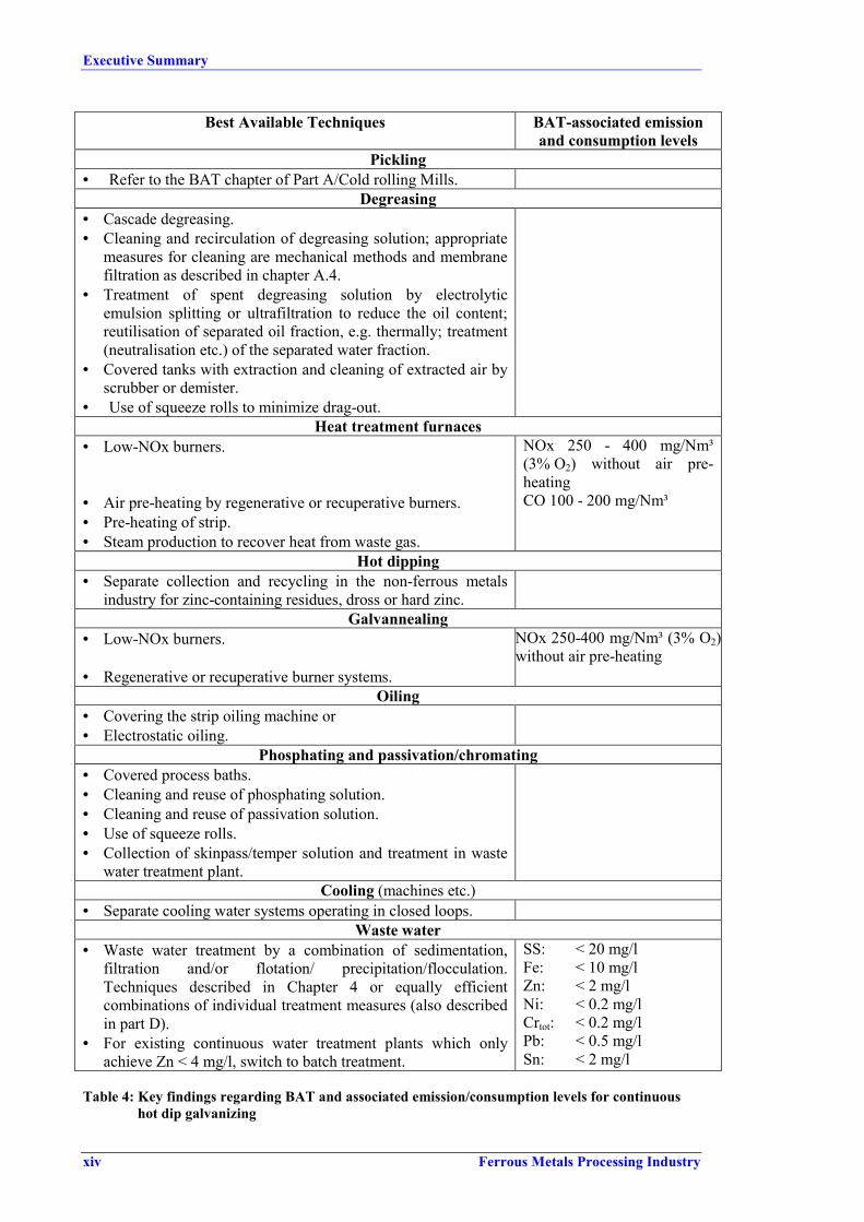
Best Available Techniques BAT-associated emissionand consumption levels
Pickling• Refer to the BAT chapter of Part A/Cold rolling Mills.
Degreasing• Cascade degreasing.• Cleaning and recirculation of degreasing solution; appropriate
measures for cleaning are mechanical methods and membranefiltration as described in chapter A.4.
• Treatment of spent degreasing solution by electrolyticemulsion splitting or ultrafiltration to reduce the oil content;reutilisation of separated oil fraction, e.g. thermally; treatment(neutralisation etc.) of the separated water fraction.
• Covered tanks with extraction and cleaning of extracted air byscrubber or demister.
• Use of squeeze rolls to minimize drag-out.Heat treatment furnaces
• Low-NOx burners.
• Air pre-heating by regenerative or recuperative burners.• Pre-heating of strip.• Steam production to recover heat from waste gas.
NOx 250 - 400 mg/Nm³(3% O2) without air pre-heatingCO 100 - 200 mg/Nm³
Hot dipping• Separate collection and recycling in the non-ferrous metals
industry for zinc-containing residues, dross or hard zinc.Galvannealing
• Low-NOx burners.
• Regenerative or recuperative burner systems.
NOx 250-400 mg/Nm³ (3% O2)without air pre-heating
Oiling• Covering the strip oiling machine or• Electrostatic oiling.
Phosphating and passivation/chromating• Covered process baths.• Cleaning and reuse of phosphating solution.• Cleaning and reuse of passivation solution.• Use of squeeze rolls.• Collection of skinpass/temper solution and treatment in waste
water treatment plant.Cooling (machines etc.)
• Separate cooling water systems operating in closed loops.Waste water
• Waste water treatment by a combination of sedimentation,filtration and/or flotation/ precipitation/flocculation.Techniques described in Chapter 4 or equally efficientcombinations of individual treatment measures (also describedin part D).
• For existing continuous water treatment plants which onlyachieve Zn < 4 mg/l, switch to batch treatment.
SS: < 20 mg/lFe: < 10 mg/lZn: < 2 mg/lNi: < 0.2 mg/l Crtot: < 0.2 mg/l Pb: < 0.5 mg/lSn: < 2 mg/l
Table 4: Key findings regarding BAT and associated emission/consumption levels for continuous hot dip galvanizing

Executive Summary
Ferrous Metals Processing Industry xv
Aluminizing of Sheet
Most BAT are the same as for hot dip galvanising. However, there is no need for a waste watertreatment plant as only cooling water is discharged.
BAT for heating:Gas firing. Combustion control system
Lead-Tin Coating of Sheet
Best Available Techniques BAT-associated emissionand consumption levels
PicklingEnclosed tanks and venting to a wet scrubber, treatment of waste
water from the scrubber and pickling tank.HCl < 30 mg/Nm³ (1)
Nickel plating• Enclosed process, ventilated to a wet scrubber.
Hot dipping• Air knives to control coating thickness.
Passivation• A no-rinse system and hence no rinse waters.
Oiling• Electrostatic oiling machine.
Waste water• Waste water treatment by neutralising with sodium hydroxide
solution, flocculation/precipitation.• Filter cake de-watering and disposed to landfill.1 daily mean values, standard conditions of 273 K, 101.3 Pa and dry gas
Table 5: Key findings regarding BAT and associated emission/consumption levels for continuous lead-tin coating of sheet

Executive Summary
xvi Ferrous Metals Processing Industry
Coating of Wire
The key findings regarding BAT for individual process steps and different environmental issuesof wire coating are summarized in Table 6. All emission figures are expressed as daily meanvalues. Emissions to air are based on standard conditions of 273 K, 101.3 kPa and dry gas.Discharges to water are indicated as daily mean value of a flow-rate-related 24-hour compositesample or a flow-rate-related composite sample over the actual operating time (for plants notoperated in three shifts).
There was consensus in the TWG on the best available techniques and associatedemission/consumption levels presented in the table.
Best Available Techniques BAT-associated emissionand consumption levels
Pickling• Enclosed equipment or equipment fitted with hoods and
scrubbing of extracted air.• Cascade pickling for new installations above a capacity of
15 000 tonne/year per line.• Recovery of free acid fraction.• External regeneration of spent acid for all installations.• Reuse of spent acid as secondary raw material.
HCl 2 - 30 mg/Nm³.
Water consumptionCascaded rinsing, possibly in combination with other methods
to minimize water consumption, for all new and all largeinstallations (> 15 000 tonne/year).
Waste water• Waste water treatment by physico-chemical treatment
(neutralisation, flocculation, etc.).SS: < 20 mg/lFe: < 10 mg/lZn: < 2 mg/lNi: < 0.2 mg/lCrtot: < 0.2 mg/lPb: < 0.5 mg/lSn: < 2 mg/l
Fluxing• Good housekeeping with special focus on reducing iron
carry-over and bath maintenance.• Regeneration of flux baths on site (side-stream iron
removal).• External reutilisation of spent flux solution.
Hot dipping• Good housekeeping measures as described in Chapter B.4 Dust < 10 mg/Nm³
Zinc < 5 mg/Nm³Zn-containing wastes
• Separate storage and protection form rain and wind, andreuse in the non-ferrous metals industry.
Cooling water (after the zinc bath)• Closed loop or reuse of this relatively pure water as make-
up water for other applications.
Table 6: Key findings regarding BAT and associated emission/consumption levels for wire coating

Executive Summary
Ferrous Metals Processing Industry xvii
Part C: Batch Galvanizing
Hot dip galvanizing is a corrosion protection process in which iron and steel fabrications areprotected from corrosion by coating them with zinc. Prevalent in batch hot dip galvanizing isjob galvanizing - also referred to as general galvanizing - in which a great variety of inputmaterials are treated for different customers. The size, amount and nature of the inputs candiffer significantly. Galvanizing of pipes or tubes which is carried out in semi- or fully-automatic special galvanizing plants is usually not covered by the term job galvanizing.
The items to be coated in batch galvanizing plants are steel fabrications, such as nails, screwsand other very small items; lattice grates, construction parts, structural components, light polesand many more. In some cases tubes are also galvanized in conventional batch coating plants.Galvanized steel is used in construction, transport, agriculture, power transmission andeverywhere that good corrosion protection and long life are essential.
The sector operates with short lead times and short order books to give enhanced service tocustomers. Distribution issues are important, and so plants are located close to marketconcentrations. Consequently, the industry consists of a relatively large number of plants (about600 all over Europe), servicing regional markets in order to minimize distribution costs andincrease economic efficiency. Only a few ‘niche’ operators are prepared to transport certainclasses of fabrication for longer distances in order to exploit their special expertise or plantcapability. Opportunities for these specialist operators are limited.
In 1997 the tonnage of galvanized steel was about 5 million. The largest share was produced byGermany with 1.4 million tonnes and 185 galvanizing plants (in 1997). Second largest producerwas Italy with 0.8 million tonnes (74 plants), followed by UK and Ireland with 0.7 milliontonnes (88 plants) and France 0.7 million tonnes (69 plants).
Batch galvanizing usually comprises the following process steps:
• Degreasing• Pickling• Fluxing• Galvanizing (melt metal coating)• Finishing
A galvanizing plant, essentially, consists of a series of treatment or process baths. The steel ismoved between tanks and dipped into the baths by overhead cranes.
The main environmental issues for batch galvanizing are emissions to air (HCl from pickling,and dust and gaseous compounds from the kettle); spent process solutions (degreasing solutions,pickling baths and flux baths), oily wastes (e.g. from cleaning of degreasing baths) and zinc-containing residues (filter dust, zinc ash, hard zinc).
For detailed emission and consumption data, refer to Chapter .3 where the available data arepresented with qualifying information.
The key findings regarding BAT for individual process steps and different environmental issuesof batch galvanising are summarized in Table 7. All emission figures are expressed as dailymean values. Emissions to air are based on standard conditions of 273 K, 101.3 kPa and drygas. Discharges to water are indicated as daily mean value of a flow-rate-related 24-hourcomposite sample or a flow-rate-related composite sample over the actual operating time (forplants not operated in three shifts).
There was consensus in the TWG on the best available techniques and associatedemission/consumption levels presented in the table.

Executive Summary
xviii Ferrous Metals Processing Industry
Best Available Techniques BAT-associated emissionand consumption
Degreasing• Installation of a degreasing step, unless items are totally grease
free.• Optimum bath operation to enhance efficiency, e.g. by
agitation.• Cleaning degreasing solutions to extend lifespan (by
skimming, centrifuge, etc.) and recirculation, reutilization ofoily sludge or
• 'Biological degreasing' with in situ cleaning (grease and oilremoval from degreaser solution) by bacteria.
Pickling + stripping:• Separate pickling and stripping unless a downstream process
for the recovery of values from “mixed” liquors is installed onsite or is available through a specialist external contractor.
• Reuse of spent stripping liquor (external or internal e.g. torecover fluxing agent).
In case of combined pickling and stripping:• Recovery of values from “mixed” liquors, e.g. use for flux
production, recovery of acid for re-use in the galvanizingindustry or for other inorganic chemicals
HCl pickling• Close monitoring of baths parameters: temperature and
concentration.• Operating within the limits given in Part D/Chapter D.6.1
‘Open Pickling Bath Operation’.• If heated or higher concentrated HCl-baths are used:
installation of extraction unit and treatment of extracted air(e.g. by scrubbing).
• Special attention to actual pickling effect of bath and use ofpickling inhibitors to avoid over-pickling.
• Recovery of free acid fraction from spent pickle liquor orexternal regeneration of pickling liquor.
• Zn removal from acid.• Use of spent pickle liquor for flux production.• Not using spent pickle liquor for neutralisation• Not using spent pickling liquor for emulsion splitting
HCl 2 – 30 mg/Nm³
Rinsing• Good drainage between pre-treatment tanks.• Implementation of rinsing after degreasing and after pickling.• Static rinsing or rinsing cascades.• Reuse of rinse water to replenish preceding process baths.
Waste water-free operation (in exceptional cases where wastewater is generated, waste water treatment is required).
Table 7: Key findings regarding BAT and associated emission/consumption levels for batch galvanizing

Executive Summary
Ferrous Metals Processing Industry xix
Best Available Techniques BAT-associated emissionand consumption
Fluxing• Control of bath parameters and the optimised amount of flux
used are also important to reduce emission further down theprocess line.
• For flux baths: internal and external flux bath regeneration.Hot dipping
• Capture of emissions from dipping by enclosure of the pot orby lip extraction and dust abatement by fabric filters or wetscrubbers.
• Internal or external reuse of dust, e.g. for flux production. Therecovery system should ensure that dioxins, which mayoccasionally be present at low concentration due to upsetconditions in the plant, do not build up as the dusts arerecycled.
Dust < 5 mg/Nm³
Zn-containing wastes• Separate storage and protection form rain and wind, and reuse
of contained values in the non-ferrous or other sectors.
Table 7 continued: Key findings regarding BAT and associated emission/consumption levels for batch galvanizing


Preface
Ferrous Metals Processing Industry xxi
PREFACE
1. Status of this document
Unless otherwise stated, references to “the Directive” in this document means the CouncilDirective 96/61/EC on integrated pollution prevention and control.This document forms part of a series presenting the results of an exchange of informationbetween EU Member States and industries concerned on best available techniques (BAT),associated monitoring, and developments in them. It is published by the European Commissionpursuant to Article 16(2) of the Directive, and must therefore be taken into account inaccordance with Annex IV of the Directive when determining “best available techniques”.
2. Relevant legal obligations of the IPPC Directive and the definition of BAT
In order to help the reader understand the legal context in which this document has been drafted,some of the most relevant provisions of the IPPC Directive, including the definition of the term“best available techniques”, are described in this preface. This description is inevitablyincomplete and is given for information only. It has no legal value and does not in any way alteror prejudice the actual provisions of the Directive.
The purpose of the Directive is to achieve integrated prevention and control of pollution arisingfrom the activities listed in its Annex I, leading to a high level of protection of the environmentas a whole. The legal basis of the Directive relates to environmental protection. Itsimplementation should also take account of other Community objectives such as thecompetitiveness of the Community’s industry thereby contributing to sustainable development.
More specifically, it provides for a permitting system for certain categories of industrialinstallations requiring both operators and regulators to take an integrated, overall look at thepolluting and consuming potential of the installation. The overall aim of such an integratedapproach must be to improve the management and control of industrial processes so as to ensurea high level of protection for the environment as a whole. Central to this approach is the generalprinciple given in Article 3 that operators should take all appropriate preventative measuresagainst pollution, in particular through the application of best available techniques enablingthem to improve their environmental performance.
The term “best available techniques” is defined in Article 2(11) of the Directive as “the mosteffective and advanced stage in the development of activities and their methods of operationwhich indicate the practical suitability of particular techniques for providing in principle thebasis for emission limit values designed to prevent and, where that is not practicable, generallyto reduce emissions and the impact on the environment as a whole.” Article 2(11) goes on toclarify further this definition as follows:
“techniques” includes both the technology used and the way in which the installation isdesigned, built, maintained, operated and decommissioned;
“available” techniques are those developed on a scale which allows implementation in therelevant industrial sector, under economically and technically viable conditions, taking intoconsideration the costs and advantages, whether or not the techniques are used or producedinside the Member State in question, as long as they are reasonably accessible to the operator;
“best” means most effective in achieving a high general level of protection of the environmentas a whole.

Preface
xxii Ferrous Metals Processing Industry
Furthermore, Annex IV of the Directive contains a list of “considerations to be taken intoaccount generally or in specific cases when determining best available techniques ... bearing inmind the likely costs and benefits of a measure and the principles of precaution and prevention”.These considerations include the information published by the Commission pursuant toArticle 16(2).
Competent authorities responsible for issuing permits are required to take account of the generalprinciples set out in Article 3 when determining the conditions of the permit. These conditionsmust include emission limit values, supplemented or replaced where appropriate by equivalentparameters or technical measures. According to Article 9(4) of the Directive, these emissionlimit values, equivalent parameters and technical measures must, without prejudice tocompliance with environmental quality standards, be based on the best available techniques,without prescribing the use of any technique or specific technology, but taking into account thetechnical characteristics of the installation concerned, its geographical location and the localenvironmental conditions. In all circumstances, the conditions of the permit must includeprovisions on the minimization of long-distance or transboundary pollution and must ensure ahigh level of protection for the environment as a whole.
Member States have the obligation, according to Article 11 of the Directive, to ensure thatcompetent authorities follow or are informed of developments in best available techniques.
3. Objective of this Document
Article 16(2) of the Directive requires the Commission to organise “an exchange of informationbetween Member States and the industries concerned on best available techniques, associatedmonitoring and developments in them”, and to publish the results of the exchange.
The purpose of the information exchange is given in recital 25 of the Directive, which statesthat “the development and exchange of information at Community level about best availabletechniques will help to redress the technological imbalances in the Community, will promotethe world-wide dissemination of limit values and techniques used in the Community and willhelp the Member States in the efficient implementation of this Directive.”
The Commission (Environment DG) established an information exchange forum (IEF) to assistthe work under Article 16(2) and a number of technical working groups have been establishedunder the umbrella of the IEF. Both IEF and the technical working groups includerepresentation from Member States and industry as required in Article 16(2).
The aim of this series of documents is to reflect accurately the exchange of information whichhas taken place as required by Article 16(2) and to provide reference information for thepermitting authority to take into account when determining permit conditions. By providingrelevant information concerning best available techniques, these documents should act asvaluable tools to drive environmental performance.
4. Information Sources
This document represents a summary of information collected from a number of sources,including in particular the expertise of the groups established to assist the Commission in itswork, and verified by the Commission services. All contributions are gratefully acknowledged.
5. How to understand and use this document
The information provided in this document is intended to be used as an input to thedetermination of BAT in specific cases. When determining BAT and setting BAT-based permitconditions, account should always be taken of the overall goal to achieve a high level ofprotection for the environment as a whole.

Preface
Ferrous Metals Processing Industry xxiii
The rest of this section describes the type of information that is provided in each section of thedocument.In each of the sections A, B and C, Sub-chapters 1 and 2 provide general information on theindustrial sector concerned and on the industrial processes used within the sector.Sub-chapters 3 provides data and information concerning current emission and consumptionlevels reflecting the situation in existing installations at the time of writing.
Sub-chapters 4 describe in more detail the emission reduction and other techniques that areconsidered to be most relevant for determining BAT and BAT-based permit conditions. Thisinformation includes the consumption and emission levels considered achievable by using thetechnique, some idea of the costs and the cross-media issues associated with the technique, andthe extent to which the technique is applicable to the range of installations requiring IPPCpermits, for example new, existing, large or small installations. Techniques that are generallyseen as obsolete are not included.
Sub-chapters 5 present the techniques and the emission and consumption levels that areconsidered to be compatible with BAT in a general sense. The purpose is thus to providegeneral indications regarding the emission and consumption levels that can be considered as anappropriate reference point to assist in the determination of BAT-based permit conditions or forthe establishment of general binding rules under Article 9(8). It should be stressed, however,that this document does not propose emission limit values. The determination of appropriatepermit conditions will involve taking account of local, site-specific factors such as the technicalcharacteristics of the installation concerned, its geographical location and the localenvironmental conditions. In the case of existing installations, the economical and technicalviability of upgrading them also needs to be taken into account. Even the single objective ofensuring a high level of protection for the environment as a whole will often involve makingtrade-off judgements between different types of environmental impact, and these judgementswill often be influenced by local considerations.
Although an attempt is made to address some of these issues, it is not possible for them to beconsidered fully in this document. The techniques and levels presented in sub-chapters 5 willtherefore not necessarily be appropriate for all installations. On the other hand, the obligation toensure a high level of environmental protection including the minimization of long-distance ortransboundary pollution implies that permit conditions cannot be set on the basis of purely localconsiderations. It is therefore of the utmost importance that the information contained in thisdocument is fully taken into account by permitting authorities.
Since the best available techniques change over time, this document will be reviewed andupdated as appropriate. All comments and suggestions should be made to the European IPPCBureau at the Institute for Prospective Technological Studies at the following address:
Edificio Expo-WTC, C/Inca Garcilaso, s/n, E-41092 Seville – SpainTelephone: +34 95 4488 284 Fax: +34 95 4488 426e-mail [email protected]: http://eippcb.jrc.es

Scope
Ferrous Metals Processing Industry xxv
Scope
The scope of this work on Ferrous Metal Processing is closely linked to the scope of the earlierwork on Primary and Secondary Iron and Steel which covered the iron and steel production tothe casting process. Starting with the semi-finished products ingots, slabs, blooms and billetsobtained from ingot casting or continuous casting the further manufacturing steps, like hotrolling, cold rolling and drawing, hot dip metal coating and the related pre- and after treatmentof the shaped steel products, will be covered.
Section 2.3 a of Annex I to Directive 96/61/EC only explicitly names hot rolling mills(> 20 t/h), but cold rolling mills and associated processes, like pickling and degreasing, will alsobe covered.
Section 2.3 c of the Annex refers to protective smelt metal coats (>2 t/h). No distinction is madebetween continuous hot dip coating of steel and the hot dip coating of fabricated steel products.Therefore batch hot dip coating of steel fabricates, known as general galvanizing, is part of thework.
Smitheries and ferrous metal foundries (Section 2.3 b and 2.4 of Annex I) are not included inthis work and neither are electroplating nor organic coating of steel.
Main operational steps regarding continuous processing that will be covered are:
• Reheating and heat treatment of input materials, like slabs, blooms, billets and ingots.
• Surface rectification and preparation processes:
scarfing, grinding, descaling, degreasing, pickling
• Shaping of steel: rough milling, hot rolling, cold rolling, drawing.
• Processes yielding in special material or product qualities:
annealing, temper rolling/skin pass rolling
• Hot dip metal coating and finishing.
Regarding batch hot dip coating of fabricated steel products the following operational stepswill be addressed:
• Surface preparation of fabricated steel: degreasing, rinsing, pickling, fluxing, drying.
• Coating with molten metal.
• After treatment/finishing: cooling, greasing.
This BREF document consists of 4 Parts (A – D). Parts A to C cover the different industrialsub-sectors of the Ferrous Metals Processing sector: A, Hot and Cold Forming; B, ContinuousCoating; C, Batch Galvanizing. This structure was chosen because of the differences in natureand scale of the activities covered by the term FMP.
Part D does not cover an industrial sub-sector. It comprises the technical descriptions of anumber of environmental measures which are techniques to be considered in the determinationof BAT in more than one sub-sector. This was done to avoid repetition of technical descriptionsin the three Chapters 4. These descriptions have to be viewed always in connection with themore specific information, referring to the application in individual sub-sectors, which is givenin the relevant Chapter 4.


Ferrous Metals Processing Industry xxvii
Best Available Technique Reference Document onFerrous Metals Processing
Executive Summary...................................................................................................................................... iPreface ...............................................................................................................................................xxi
A.1 General Information on Hot and Cold Forming ..........................................................................1A.1.1 Hot Rolled Flat Products........................................................................................................2A.1.2 Hot Rolled Long Products......................................................................................................3A.1.3 Tubes......................................................................................................................................4A.1.4 Cold Rolled Flat Products ......................................................................................................5A.1.5 Cold Drawn Long Products/ Bright Steel Bars ......................................................................8A.1.6 Wire .......................................................................................................................................8
A.2 Applied Processes and Techniques in Hot and Cold Forming...................................................11A.2.1 Hot Rolling Mills .................................................................................................................11
A.2.1.1 Process Overview...........................................................................................................11A.2.1.1.1 Blooming/Slabbing Mills.......................................................................................13A.2.1.1.2 Hot Strip Mills .......................................................................................................13A.2.1.1.3 Plate Mills ..............................................................................................................16A.2.1.1.4 Bar and Rod Mills..................................................................................................17A.2.1.1.5 Structural/Section Mills .........................................................................................19A.2.1.1.6 Tube Mill ...............................................................................................................22
A.2.1.2 Surface Rectification and Conditioning of Input............................................................25A.2.1.3 Reheating- and Heat Treatment Furnaces ......................................................................26
A.2.1.3.1 Batch Furnaces.......................................................................................................26A.2.1.3.2 Continuous Furnaces..............................................................................................27
A.2.1.4 Descaling........................................................................................................................29A.2.1.5 Edging ............................................................................................................................30A.2.1.6 Roughing ........................................................................................................................30A.2.1.7 Strip Rolling/Finishing Train .........................................................................................30A.2.1.8 Rod Rolling/Finishing Train ..........................................................................................30A.2.1.9 Plate Rolling...................................................................................................................31A.2.1.10 Transport of Roll Stock between Rolling Stands ...........................................................31A.2.1.11 Cooling Lines .................................................................................................................31A.2.1.12 Sheet and Plate Production.............................................................................................32A.2.1.13 Plate Heat Treatment ......................................................................................................32A.2.1.14 Roll Shop........................................................................................................................33A.2.1.15 Water Circuits / Water Management in Hot Rolling Mills.............................................33A.2.1.16 Waste and By-product Management in Hot Rolling Mills .............................................36
A.2.2 Cold Rolling Mills ...............................................................................................................38A.2.2.1 Process Overview...........................................................................................................38A.2.2.2 Pickling of Low Alloy and Alloy HR Steel....................................................................40A.2.2.3 Annealing (I) and Pickling (I) of High Alloy HR Steel..................................................41A.2.2.4 Cold Rolling of the Pickled Hot Rolled Strip.................................................................43
A.2.2.4.1 Low Alloy and Alloy Steel ....................................................................................43A.2.2.4.2 High Alloy Steel ....................................................................................................44
A.2.2.5 Annealing of Low Alloy and Alloy Steel .......................................................................45A.2.2.5.1 Batch Annealing.....................................................................................................45A.2.2.5.2 Continuous Annealing ...........................................................................................46
A.2.2.6 Annealing (II) and Pickling (II) of High Alloy Steel .....................................................47A.2.2.7 Tempering of Cold Rolled Strip .....................................................................................48
A.2.2.7.1 Low Alloy and Alloy Steel ....................................................................................48A.2.2.7.2 High Alloy Steel ....................................................................................................48
A.2.2.8 Finishing.........................................................................................................................49A.2.2.9 Roll Shop........................................................................................................................49A.2.2.10 Water and Process Baths Management in Cold Rolling Mills .......................................50
A.2.2.10.1 Emulsion System ...................................................................................................50A.2.2.10.2 Degreasing Solution System ..................................................................................51A.2.2.10.3 Cooling Water Systems..........................................................................................51A.2.2.10.4 Waste Water Treatment .........................................................................................53
A.2.2.11 Waste and By-product Management in Cold Rolling Mills ...........................................53A.2.3 WIRE PLANTS ...................................................................................................................54

xxviii Ferrous Metals Processing Industry
A.2.3.1 Wire Drawing Process Overview................................................................................... 54A.2.3.2 Wire Rod Preparation .................................................................................................... 55
A.2.3.2.1 Mechanical Descaling of Wire Rod....................................................................... 56A.2.3.2.2 Chemical Descaling (Pickling) of Wire Rod ......................................................... 56A.2.3.2.3 Application of Soap (Lubricant) Carrier ............................................................... 56
A.2.3.3 Drawing ......................................................................................................................... 57A.2.3.3.1 Dry Drawing of Wire ............................................................................................ 57
A.2.3.4 Heat Treatment of Wire ................................................................................................. 57A.2.3.4.1 Batch Annealing of Low Carbon Steel Wire......................................................... 57A.2.3.4.2 Continuous (In-Line) Annealing of Low Carbon Steel Wire ................................ 58A.2.3.4.3 Continuous (In-Line) Annealing of Stainless Steel Wire ...................................... 58A.2.3.4.4 Patenting................................................................................................................ 58A.2.3.4.5 Oil Hardening and Tempering (Oil Tempering).................................................... 59A.2.3.4.6 Stress-relieving...................................................................................................... 59
A.2.3.5 In-line Pickling .............................................................................................................. 60A.3 Present Consumption and Emission Levels for Hot and Cold Forming.................................... 61
A.3.1 Hot Rolling Mills................................................................................................................. 61A.3.1.1 Mass Stream Overview.................................................................................................. 61A.3.1.2 Surface Rectification and Conditioning of Input ........................................................... 62A.3.1.3 Reheating and Heat Treatment Furnaces ....................................................................... 63A.3.1.4 Descaling ....................................................................................................................... 65A.3.1.5 Hot Rolling .................................................................................................................... 67A.3.1.6 Roll Shop ....................................................................................................................... 67A.3.1.7 Oil, Grease and Hydraulic Oil Flow .............................................................................. 67A.3.1.8 Hot Rolling Mill Waste Water Treatment Plant ............................................................ 69A.3.1.9 Waste and Recycling ..................................................................................................... 70A.3.1.10 Noise Issues in Hot Rolling ........................................................................................... 71A.3.1.11 Commissioning and Decommissioning ......................................................................... 71
A.3.2 Cold Rolling Mills............................................................................................................... 73A.3.2.1 Mass Stream Overview.................................................................................................. 73A.3.2.2 Pickling of Low Alloy, Alloy and High Alloy Steel...................................................... 74
A.3.2.2.1 Hydrochloric Acid Pickling Line and Regeneration Plant .................................... 75A.3.2.2.2 Sulphuric Acid Pickling Line and Regeneration Plant .......................................... 77A.3.2.2.3 Mixed (HNO3-HF) Acid Pickling Line and Acid Recovery.................................. 79
A.3.2.3 Cold Rolling................................................................................................................... 80A.3.2.3.1 Low Alloy ............................................................................................................. 80A.3.2.3.2 High Alloy/Reversing Mill.................................................................................... 82
A.3.2.4 Annealing of Low Alloy and Alloy Steel ...................................................................... 83A.3.2.4.1 Batch Annealing .................................................................................................... 83A.3.2.4.2 Continuous Annealing........................................................................................... 84
A.3.2.5 Annealing and Pickling of High Alloy Steel.................................................................. 85A.3.2.6 Tempering (Low alloy/High Alloy)............................................................................... 87A.3.2.7 Finishing (Cutting, Inspection, Packing) ....................................................................... 87A.3.2.8 Roll Shop ....................................................................................................................... 88A.3.2.9 Hydraulic Fluids and Lubricants Management .............................................................. 88A.3.2.10 Cold Rolling Mill Waste Water Treatment Plant........................................................... 89A.3.2.11 Waste and Recycling ..................................................................................................... 91A.3.2.12 Noise Issues in Cold Rolling.......................................................................................... 91
A.3.3 Wire Plant............................................................................................................................ 93A.3.3.1 Mass Stream Overview.................................................................................................. 93A.3.3.2 Wire Rod Preparation .................................................................................................... 94
A.3.3.2.1 Mechanical Descaling of Wire Rod....................................................................... 94A.3.3.2.2 Chemical Descaling/Pickling of Wire Rod ........................................................... 94A.3.3.2.3 Application of Soap Carrier................................................................................... 95
A.3.3.3 Drawing of Wire ............................................................................................................ 96A.3.3.3.1 Dry Drawing.......................................................................................................... 96A.3.3.3.2 Wet Drawing ......................................................................................................... 97
A.3.3.4 Heat Treatment of Wire ................................................................................................. 99A.3.3.4.1 Batch Annealing/Bell and Pot Furnaces ................................................................ 99A.3.3.4.2 Continuous Annealing/Molten Lead Bath............................................................. 99A.3.3.4.3 Patenting.............................................................................................................. 100A.3.3.4.4 Oil Hardening & Tempering ............................................................................... 101

Ferrous Metals Processing Industry xxix
A.3.3.4.5 Annealing of Stainless Steel Wire .......................................................................102A.3.3.4.6 Stress Relieving ...................................................................................................102
A.3.3.5 Noise Issues in a Wire Plant.........................................................................................102A.4 Techniques to Consider in the Determination of BAT for Hot and Cold Forming..................105
A.4.1 HOT ROLLING MILL ......................................................................................................105A.4.1.1 Storage and Handling of Raw Materials and Auxiliaries .............................................105A.4.1.2 Surface Rectification and Conditioning of Input..........................................................105
A.4.1.2.1 Enclosed Scarfing Operation with Wastegas Cleaning........................................105A.4.1.2.2 Enclosed Grinding Operation with Waste Gas Cleaning .....................................107A.4.1.2.3 CAQC - Computer Aided Quality Control ..........................................................109A.4.1.2.4 Rolling of Wedge-type Slabs ...............................................................................110A.4.1.2.5 Slab Slitting..........................................................................................................110
A.4.1.3 Reheating and Heat Treatment Furnaces......................................................................111A.4.1.3.1 General Measures for Energy Efficiency and Low Emission Operation .............111A.4.1.3.2 Furnace Automation / Furnace Control................................................................113A.4.1.3.3 Optimised Furnace Door Design..........................................................................114A.4.1.3.4 Regenerative Burner System................................................................................115A.4.1.3.5 Recuperator and Recuperative Burners................................................................117A.4.1.3.6 Oxy-fuel Technology ...........................................................................................117A.4.1.3.7 Low-NOx Burners ...............................................................................................118A.4.1.3.8 Selective Catalytic Reduction (SCR) ...................................................................119A.4.1.3.9 Selective Non-Catalytic Reduction (SNCR) ........................................................121A.4.1.3.10 External Flue Gas Recirculation (FGR)...............................................................123A.4.1.3.11 Waste Heat Boiler ................................................................................................123A.4.1.3.12 Optimised Skid Design to Reduce Skid Marks....................................................125A.4.1.3.13 Reduction of Energy Loss through Stock Transportation Device........................126A.4.1.3.14 Evaporative Furnace Skid Cooling ......................................................................126A.4.1.3.15 Feedstock Preheating ...........................................................................................128A.4.1.3.16 Heat Conservation Box / Thermal Covers ...........................................................129A.4.1.3.17 Hot Charging / Direct Rolling..............................................................................131A.4.1.3.18 Near Net Shape Casting / Thin Slab Casting .......................................................133A.4.1.3.19 Near Net Shape Casting/ Beam Blank Casting ....................................................138
A.4.1.4 Descaling......................................................................................................................138A.4.1.4.1 Material Tracking.................................................................................................138A.4.1.4.2 Use of High-pressure Storage Equipment............................................................139
A.4.1.5 Edging ..........................................................................................................................139A.4.1.5.1 Automatic Width Control Comprising Short Stroke Control...............................140
A.4.1.6 Roughing ......................................................................................................................141A.4.1.6.1 Process Automation .............................................................................................141
A.4.1.7 Transport of Rolled Stock from Roughing Mill to Finishing Train..............................141A.4.1.7.1 Coil Box...............................................................................................................141A.4.1.7.2 Coil Recovery Furnace ........................................................................................142A.4.1.7.3 Heat Shields on Transfer Tables ..........................................................................143A.4.1.7.4 Strip Edge Heating...............................................................................................143
A.4.1.8 Rolling..........................................................................................................................144A.4.1.8.1 Crop Optimisation System...................................................................................144A.4.1.8.2 Work Roll Lubrication System ............................................................................145A.4.1.8.3 Forced Interstand Strip Cooling...........................................................................145A.4.1.8.4 Interstand Strip Tension Control..........................................................................145A.4.1.8.5 Strip Profile and Flatness Control ........................................................................146A.4.1.8.6 Work Roll Cooling...............................................................................................147A.4.1.8.7 Finishing Train Automation - Process- and Basic Automation............................148A.4.1.8.8 Reduction of Fugitive Emissions / Oxide Removal System ................................148A.4.1.8.9 Prevention of Hydrocarbon Contamination .........................................................149A.4.1.8.10 Hydraulic Coilers Comprising Step Control ........................................................150A.4.1.8.11 Shape Rolling / Plan View Control......................................................................150A.4.1.8.12 On Line Heat Treatment (Accelerated Cooling) ..................................................151A.4.1.8.13 Thermo Mechanical Rolling Operation ...............................................................151
A.4.1.9 Cooling Lines ...............................................................................................................152A.4.1.9.1 Optimized Water Pumps for Laminar Flows .......................................................152
A.4.1.10 Subsequent Sheet Production .......................................................................................152A.4.1.10.1 Leveller Dust Removal ........................................................................................152

xxx Ferrous Metals Processing Industry
A.4.1.11 Roll Shop ..................................................................................................................... 153A.4.1.11.1 Good Operational Practice for Roll Shops .......................................................... 153
A.4.1.12 Water Treatment .......................................................................................................... 153A.4.1.12.1 Reduction of Water Consumption and Discharge ............................................... 153A.4.1.12.2 Treatment of Scale and Oil Bearing Process Water ............................................ 155A.4.1.12.3 Cooling Water Treatment .................................................................................... 159
A.4.1.13 Waste/By-product Treatment and Recycling ............................................................... 160A.4.1.13.1 Internal Recycling of Dry or Drained Oxides...................................................... 160A.4.1.13.2 Recycling Technologies for Oily Mill Scale ....................................................... 161
A.4.2 COLD ROLLING Mill...................................................................................................... 163A.4.2.1 Storage and Handling of Raw Materials and Auxiliaries............................................. 163A.4.2.2 Pickling........................................................................................................................ 163
A.4.2.2.1 Reduction of Waste Water Volume Contaminant Loading ................................. 163A.4.2.2.2 Reduction of Dust Emission at the Decoilers ...................................................... 164A.4.2.2.3 Mechanical Pre-descaling.................................................................................... 164A.4.2.2.4 Optimised Rinsing Procedure/ Cascade Rinsing ................................................. 166A.4.2.2.5 Turbulence Pickling ............................................................................................ 166A.4.2.2.6 Cleaning and Reuse of Acid Pickle Liquor ......................................................... 167A.4.2.2.7 Hydrochloric Acid Regeneration by Spray Roasting .......................................... 168A.4.2.2.8 Hydrochloric Acid Regeneration by Fluidised Bed............................................. 170A.4.2.2.9 Effluent-free HCl Strip Pickling Plant................................................................. 170A.4.2.2.10 Sulphuric Acid Recovery by Crystallization ....................................................... 172A.4.2.2.11 Mixed Acid Regeneration by Spray Roasting ..................................................... 173A.4.2.2.12 Mixed Acid (HNO3 and HF) Recovery by Ion Exchange ................................... 175A.4.2.2.13 Mixed Acid (HNO3 and HF) Recovery by Diffusiondialysis .............................. 175A.4.2.2.14 Mixed Acid Recovery by Evaporation ................................................................ 176A.4.2.2.15 Electrolytic Pre-pickling for High Alloy Steel .................................................... 177A.4.2.2.16 Cleaning and Reuse of Electrolytic Pickle Liquor .............................................. 178A.4.2.2.17 External Use of Spent Acid Pickle liquor............................................................ 178A.4.2.2.18 Reduction of Emissions from Pickling/Closed HCl and H2SO4 Pickling Tanks with
Exhaust Gas Scrubbing........................................................................................ 179A.4.2.2.19 Reduction of Emissions from Pickling/Closed Mixed Acid Pickling Tanks with
Exhaust Gas Scrubbing........................................................................................ 180A.4.2.2.20 Suppresion of NOx from Mixed Acid Pickling by Addition of H2O2 (or Urea) to
Pickling Bath ....................................................................................................... 181A.4.2.2.21 NOx Reduction from Pickling by Selective Catalytic Reduction........................ 182A.4.2.2.22 NOx Reduction from Pickling by Non-Selective Catalytic Reduction................ 182A.4.2.2.23 Nitric Acid Free Pickling of Stainless Steel ........................................................ 183A.4.2.2.24 Optimized Oil Use for Low Alloy and Alloy Steel ............................................. 183A.4.2.2.25 Magnetic Pumps (Low Alloy and Alloy Steel) ................................................... 184A.4.2.2.26 Acid Heating by Heat Exchangers....................................................................... 184A.4.2.2.27 Acid Heating by Submerged Combustion ........................................................... 184A.4.2.2.28 Treatment of Acidic Waste Water ....................................................................... 185
A.4.2.3 Rolling ......................................................................................................................... 186A.4.2.3.1 Continuous instead of Conventional Discontinuous Rolling for Low Alloy and
Alloy Steel........................................................................................................... 186A.4.2.3.2 Pickling Plant Coupled with the Tandem Mill .................................................... 187A.4.2.3.3 Optimal Choice of Rolling Oil and Emulsion System......................................... 187A.4.2.3.4 Continuous Monitoring of Emulsion Quality ...................................................... 188A.4.2.3.5 Prevention of Contamination............................................................................... 188A.4.2.3.6 Optimized Emulsion/Oil Use .............................................................................. 189A.4.2.3.7 Cleaning and Reuse of Emulsion......................................................................... 189A.4.2.3.8 Treatment of Spent Emulsion.............................................................................. 190A.4.2.3.9 Extraction of Oil Mist Emissions and Oil Separation.......................................... 193A.4.2.3.10 Cooling Water Cycles/Special Cooling Water systems....................................... 193
A.4.2.4 Annealing..................................................................................................................... 195A.4.2.4.1 Implementation of Degreasing Bath Cascades .................................................... 195A.4.2.4.2 Hot Water Pre-degreasing ................................................................................... 195A.4.2.4.3 Cleaning and Reuse of Degreasing Solution ....................................................... 195A.4.2.4.4 Treatment of Spent Degreasing Bath and Alkaline Waste Water........................ 196A.4.2.4.5 Extraction System for Degreasing Facilities ....................................................... 197A.4.2.4.6 Special Cooling Water Systems and Water Reuse .............................................. 198

Ferrous Metals Processing Industry xxxi
A.4.2.4.7 Batch Annealing with 100 % Hydrogen ..............................................................198A.4.2.4.8 Continuous Instead of Batch Annealing ..............................................................198A.4.2.4.9 Preheating Combustion Air/Use of Regenerative or Recuperative Burners for
Annealing Furnace ...............................................................................................198A.4.2.4.10 Reduction in NOx Emission by Low-NOx burner...............................................199A.4.2.4.11 Preheating the Feedstock .....................................................................................200A.4.2.4.12 Heat Utilisation for Heating Degreasing Bath .....................................................201
A.4.2.5 Tempering ....................................................................................................................201A.4.2.5.1 Optimisation of Emulsion System .......................................................................201A.4.2.5.2 Change to Dry Temper Process ...........................................................................201A.4.2.5.3 Cleaning of Temper Mill Emulsion .....................................................................202A.4.2.5.4 Reduction of Oil Mist and Dust ...........................................................................202
A.4.2.6 Finishing.......................................................................................................................203A.4.2.6.1 Capture and Abatement of Oil Mists from Oiling Operation...............................203A.4.2.6.2 Electrostatic Oiling ..............................................................................................203A.4.2.6.3 Optimization of Oil Spray....................................................................................203A.4.2.6.4 Dust Reduction from Levelling and Welding ......................................................204A.4.2.6.5 Optimised Finishing Operation............................................................................205
A.4.2.7 Roll Shop......................................................................................................................205A.4.2.7.1 Cleaning and Reuse of Grinding Emulsion..........................................................205A.4.2.7.2 Exhaust System (PRETEX/SBT).........................................................................205A.4.2.7.3 Reduction and Recycling of Scrap.......................................................................205
A.4.3 Wire Mill............................................................................................................................206A.4.3.1 Storage and Handling of Raw Materials and Auxiliaries .............................................206A.4.3.2 Mechanical Descaling ..................................................................................................206
A.4.3.2.1 External Recycling of Scale.................................................................................206A.4.3.3 Chemical Descaling / Pickling of Wire Rod ................................................................207
A.4.3.3.1 Optimum Range of Operation for HCl Pickling Baths ........................................207A.4.3.3.2 Pickling Tank Fume Control................................................................................207A.4.3.3.3 Treatment of Extracted Air from Pickling Tank Fume Control ...........................208A.4.3.3.4 Cascade Pickling..................................................................................................209A.4.3.3.5 Minimizing Carry-out from Pickling ...................................................................209A.4.3.3.6 Separation and Reuse of Free Acid Fraction........................................................210A.4.3.3.7 Regeneration of Spent Acid .................................................................................210A.4.3.3.8 Reuse of Spent Acid as Secondary Raw material ................................................211A.4.3.3.9 Minimize Rinsing Water Consumption by Cascade Rinsing...............................211
A.4.3.4 Shot Blast Descaling: Separation of Scale and Blast media.........................................212A.4.3.5 Dry Drawing.................................................................................................................213
A.4.3.5.1 Control of Air Emissions from Drawing Machines / Treatment of Extracted Air.............................................................................................................................213
A.4.3.5.2 Closed Loop for Cooling Water...........................................................................213A.4.3.6 Wet Drawing ................................................................................................................214
A.4.3.6.1 Closed Loop for Cooling Water...........................................................................214A.4.3.6.2 Cleaning of Drawing Lubricant / Coolant............................................................214A.4.3.6.3 Treatment of Waste Drawing Lubricant: Oil and Oil emulsions .........................215A.4.3.6.4 Treatment and Disposal of Waste Drawing Lubricant: Soap Emulsions .............215
A.4.3.7 Batch Annealing of Wire..............................................................................................216A.4.3.7.1 Burn Purge of Protective Gas...............................................................................216
A.4.3.8 Continuous (In-line) Annealing of Low Carbon Wire .................................................216A.4.3.8.1 Lead-bath: Good Housekeeping...........................................................................216A.4.3.8.2 Recycling of Pb-containing Residues ..................................................................217A.4.3.8.3 Operation of Quench Bath and Treatment of Waste Water from Quench baths
from In-Line Annealing .......................................................................................218A.4.3.9 Continuous (In-line) Annealing of Stainless Steel Wire ..............................................218
A.4.3.9.1 Burn Purge of Protective Gas...............................................................................218A.4.3.10 Patenting.......................................................................................................................218
A.4.3.10.1 Optimised Operation of the Oven ........................................................................218A.4.3.10.2 Lead-bath: Good Housekeeping...........................................................................219A.4.3.10.3 Recycling of Pb-containing Residues ..................................................................219A.4.3.10.4 Operation of Quench Bath and Treatment of Waste Water from Quench Baths of
Patenting Line ......................................................................................................219A.4.3.11 Oil Hardening and Tempering......................................................................................219

xxxii Ferrous Metals Processing Industry
A.4.3.11.1 Burn Purge of Protective Gas .............................................................................. 219A.4.3.11.2 Extraction of Oil Mists from Quench Baths and Abatement............................... 219
A.4.3.12 Heat Treatment of wire (different processes)............................................................... 220A.4.3.12.1 Inductive Heating of Wire ................................................................................... 220
A.4.3.13 In-line Pickling ............................................................................................................ 221A.5 Best Available Techniques for Hot and Cold Forming ........................................................... 223
A.5.1 Hot Rolling Mill ................................................................................................................ 224A.5.2 Cold Rolling Mill .............................................................................................................. 229A.5.3 Wire plant .......................................................................................................................... 234
A.6 Emerging Techniques for Hot and Cold Forming................................................................... 237A.6.1 Hot Rolling Mill ................................................................................................................ 237
A.6.1.1 Scarfing and Grinding.................................................................................................. 237A.6.1.2 Reheating Furnace ....................................................................................................... 237
A.6.1.2.1 Flameless Burner................................................................................................. 237A.6.1.2.2 Ultra Low-NOx Burner ....................................................................................... 237A.6.1.2.3 Water Injection.................................................................................................... 237A.6.1.2.4 Shell de-NOx Process.......................................................................................... 238A.6.1.2.5 Regenerative Active Coal Process....................................................................... 238A.6.1.2.6 Degussa H2O2 Process......................................................................................... 238A.6.1.2.7 Bio–de-NOx Process ........................................................................................... 238
A.6.1.3 Descaling ..................................................................................................................... 238A.6.1.3.1 Rotor Descaling................................................................................................... 238
A.6.1.4 Hot Rolling and Water Treatment................................................................................ 239A.6.1.4.1 Endless Rolling.................................................................................................... 239A.6.1.4.2 Strip Casting Procedure....................................................................................... 240A.6.1.4.3 By-product Recycling.......................................................................................... 243
A.6.2 Cold Rolling Mill .............................................................................................................. 245A.6.2.1 Pickling........................................................................................................................ 245
A.6.2.1.1 Hydro-abrasive Pre-descaling (Ishi Clean).......................................................... 245A.6.2.1.2 Pre-descaling by Ferromagnetic Abrasive........................................................... 245
A.6.3 Wire Plant.......................................................................................................................... 246A.7 Concluding remarks ................................................................................................................ 247

Ferrous Metals Processing Industry xxxiii
List of figures
Figure A.1-1: Hot and Cold Formed Products covered by this BREF .........................................................1Figure A.1-2: CR Strip production in 1994 ..................................................................................................7Figure A.1-3: Slit strip production................................................................................................................8Figure A.2-1: Overview of Hot Rolled Products........................................................................................12Figure A.2-2: Typical designs for Hot Strip Mills......................................................................................14Figure A.2-3: Typical STECKEL Mill configuration.................................................................................15Figure A.2-4: STECKEL Mill with coiling furnaces..................................................................................15Figure A.2-5: Planetary Mill (SENDZIMIR) .............................................................................................16Figure A.2-6: Typical Plate Mill configuration ..........................................................................................17Figure A.2-7: Typical layout of a Wire Rod Mill.......................................................................................18Figure A.2-8: Profiled rolls for sheet piling sections..................................................................................19Figure A.2-9: Universal stands for parallel flanged products.....................................................................20Figure A.2-10: Plant layout of a Heavy Section Mill .................................................................................20Figure A.2-11: Plant layout of a Heavy/Medium Section Mill for sheet piling..........................................21Figure A.2-12: Examples of beam blanks cross sections ...........................................................................21Figure A.2-13: Mandrel mill ......................................................................................................................22Figure A.2-14: Plug mill.............................................................................................................................23Figure A.2-15: Flow sheet for continuous tube production........................................................................24Figure A.2-16: Tube welding processes .....................................................................................................25Figure A.2-17: Pit furnace ..........................................................................................................................27Figure A.2-18: Pusher type furnace............................................................................................................28Figure A.2-19: Walking beam furnace .......................................................................................................28Figure A.2-20: Typical design of rotary hearth furnace .............................................................................29Figure A.2-21: Roller arrangement of wire rod finishing section...............................................................31Figure A.2-22: Different types of water cooling ........................................................................................32Figure A.2-23: Example of a once through water system...........................................................................33Figure A.2-24: Example of semi-closed water circuit ................................................................................34Figure A.2-25: Example of closed circuit water system.............................................................................35Figure A.2-26: Water loops for hot strip rolling mill .................................................................................35Figure A.2-27: Use of water loops in a hot rolling mill..............................................................................36Figure A.2-28: Typical configurations of cold rolled strip mills ................................................................39Figure A.2-29: Cold rolling process line with continuous annealing .........................................................40Figure A.2-30: Schematic of a continuous pickling line ............................................................................41Figure A.2-31: Schematic of a hood-type annealing furnace .....................................................................46Figure A.2-32: Example of a continuous annealing furnace ......................................................................47Figure A.2-33: General emulsion flow.......................................................................................................50Figure A.2-34: Degreasing solution flow (continuous annealing line).......................................................51Figure A.2-35: Cooling water system for a cold mill .................................................................................52Figure A.2-36: Cooling water system for HCl-pickling and batch annealing ............................................52Figure A.2-37: Cooling water system for a continuous annealing line.......................................................52Figure A.2-38: Production of low carbon galvanized wire.........................................................................54Figure A.2-39: Production of high carbon galvanized wire .......................................................................55Figure A.3-1: Input/output overview for hot rolling mills..........................................................................61Figure A.3-2: Sankey diagram for a typical reheat furnace as reported in [StTimes 6/93] ........................64Figure A.3-3: Oily material balance of a typical steel mill as repoted in [DFIU 96] .................................68Figure A.3-4: Input/output overview for cold rolling mills ........................................................................73Figure A.3-5: Flow sheet for HCl pickling and acid regeneration..............................................................75Figure A.3-6: Flow sheet for H2SO4 pickling and regeneration .................................................................77Figure A.3-7: Flow sheet for stainless steel pickling with HNO3-HF acid (incl. recovery) .......................79Figure A.4-1: Scarfing abatement flowsheet (example with wet EP).......................................................106Figure A.4-2: Grinding abatement flowsheet ...........................................................................................108Figure A.4-3: Schematic of waste heat boiler...........................................................................................124Figure A.4-4: Typical schematic of evaporative furnace skid cooling .....................................................127Figure A.4-5: Principle of slab preheating by waste gas ..........................................................................128Figure A.4-6: Modified storage to increase charge temperature ..............................................................130Figure A.4-7: Material flow: cold versus hot charging.............................................................................131Figure A.4-8: Schematic of the CSP process............................................................................................134Figure A.4-9: Schematic of the ISP process.............................................................................................135Figure A.4-10: AWC-operation................................................................................................................140

xxxiv Ferrous Metals Processing Industry
Figure A.4-11: Coil box arrangement ...................................................................................................... 142Figure A.4-12: Crop optimisation system................................................................................................ 144Figure A.4-13: Example of a water recirculation system for a hot rolling mill ....................................... 157Figure A.4-14: Treatment of back-washing water ................................................................................... 158Figure A.4-15: Different type of pickling tanks....................................................................................... 166Figure A.4-16: Dependence of rinse water utilisation on iron content .................................................... 171Figure A.4-17: Example of effluent-free HCl pickling and acid regeneration......................................... 172Figure A.4-18: Spent emulsion splitting system ...................................................................................... 191Figure A.4-19: Spent degreasing solution flow (example of a continuous annealing line)...................... 196Figure A.6-1: Diagrammatic view of the endless hot strip rolling process.............................................. 239Figure A.6-2: Double-roller pilot plant .................................................................................................... 240Figure A.6-3: Casting Pressing Rolling (CPR) pilot plant ....................................................................... 241

Ferrous Metals Processing Industry xxxv
List of tables
Table A.1-1: Production of Flat Products in EU 15 in 1996 ........................................................................2Table A.1-2: Size distribution of Flat Product manufacturing facilities.......................................................2Table A.1-3: Production of Long Products in EU 15 in 1996 ......................................................................3Table A.1-4: Size distribution of Long Product manufacturing facilities.....................................................3Table A.1-5: Steel Tube production, number of plants and employees........................................................4Table A.1-6: Number and size of tube plants in 1994 ..................................................................................5Table A.1-7: CR Sheet and Strip production in 1996...................................................................................5Table A.1-8: Number and nominal capacity of CR Mills.............................................................................6Table A.1-9: Distribution and average company size of Cold Rolling Strip plants......................................6Table A.1-10: Production of CR strip and slit strip ......................................................................................7Table A.1-11: Wire drawing industry in the EU ..........................................................................................9Table A.2-1: Semi-finished product mills ..................................................................................................13Table A.3-1: Consumption and emission levels for surface preparation....................................................62Table A.3-2: Consumption and emission levels for reheating/heat treatment furnaces..............................65Table A.3-3: Consumption and emission levels for descaling....................................................................66Table A.3-4: Consumption and emission levels for hot rolling..................................................................67Table A.3-5: Consumption and emission levels of the water treatment plant ............................................69Table A.3-6: Waste generated in hot rolling mills and utilisation rates......................................................70Table A.3-7: Consumption and emission levels for HCl pickling plants (incl. regeneration) ....................76Table A.3-8: Consumption and emission levels for waste water treatment in HCl-pickling plants ...........77Table A.3-9: Consumption and emission levels for H2SO4 pickling plants (incl. regeneration) ................78Table A.3-10: Consumption and emission levels for waste water treatment in H2SO4 pickling plants......78Table A.3-11: Consumption and emission levels for mixed acid pickling and recovery ...........................80Table A.3-12: Consumption and emission levels from tandem mills with emulsion system .....................81Table A.3-13: Consumption and emission levels from reversing mills......................................................82Table A.3-14: Consumption and emission levels from reversing mills......................................................82Table A.3-15: Consumption and emission levels from degreasing ............................................................83Table A.3-16: Consumption and emission levels from batch annealing ....................................................83Table A.3-17: Consumption and emission levels from continuous annealing............................................84Table A.3-18: Consumption and emission levels of continuous annealing furnaces..................................85Table A.3-19: Consumption and emission levels from Pickling and annealing of high alloy steel............86Table A.3-20: Consumption and emission levels from tempering .............................................................87Table A.3-21: Consumption and emission levels from finishing ...............................................................87Table A.3-22: Consumption and emission levels from the roll shop..........................................................88Table A.3-23: Consumption and emission levels from hydraulic fluid and lubricant systems...................88Table A.3-24: Waste water discharge from cold rolling mills....................................................................89Table A.3-25: Waste generated in cold rolling mills and utilisation rates..................................................91Table A.3-26: Input/Output balance for a wire mill ...................................................................................93Table A.3-27: Consumption and emission levels for mechanical descaling ..............................................94Table A.3-28: Consumption and emission levels for chemical descaling ..................................................95Table A.3-29: Consumption and emission levels for the application of soap carrier .................................96Table A.3-30: Consumption and emission levels for dry drawing .............................................................96Table A.3-31: Consumption and emission levels for wet drawing.............................................................97Table A.3-32: Consumption and emission levels for bell and pot furnaces ...............................................99Table A.3-33: Consumption and emission levels for lead baths...............................................................100Table A.3-34: Consumption and emission levels for in-line HCl pickling...............................................100Table A.3-35: Consumption and emission levels for patenting................................................................101Table A.3-36: Qualitative input / output balance for oil hardening..........................................................101Table A.3-37: Qualitative input / output balance for annealing of stainless steel ....................................102Table A.3-38: Qualitative input / output balance for stress relieving.......................................................102Table A.4-1: Operational data and achievable emission levels for dust from scarfing operation.............107Table A.4-2: Operational data and achievable emissions for dust reduction from grinding.....................108Table A.4-3: Comparison of amount of scarfing with/without CAQC.....................................................109Table A.4-4: Typically achievable reductions and cost data for furnace automation...............................114Table A.4-5: Typically achievable reductions and cost data for regenerative systems ............................116Table A.4-6: Typically achievable reductions and cost data for recuperators and recuperative burners..117Table A.4-7: Typically achievable reductions and cost data for low-NOx burners..................................119Table A.4-8: Typically achievable reductions and cost data for waste heat boilers .................................125Table A.4-9: Typically achievable reductions and cost data for evaporative furnace skid cooling..........127

xxxvi Ferrous Metals Processing Industry
Table A.4-10: Effect of hot charging on fuel consumption and residence time....................................... 132Table A.4-11: Investment costs for for hot charging ............................................................................... 133Table A.4-12: Thin slab casting plants (by July 1995) ............................................................................ 136Table A.4-13: Comparison of consumption figures for conventional and thin slab production route ..... 137Table A.4-14: Achieved emission levels and operational data for oxide removal systems ..................... 149Table A.4-15: Typical reduction of fugitive emissions by water spraying .............................................. 149Table A.4-16: Typically achieved effluent levels for different water treatment systems......................... 154Table A.4-17: Estimated costs for different water treatment plants......................................................... 154Table A.4-18: Pollutant concentration in the water circuit ...................................................................... 156Table A.4-19: Concentration of effluents from treatment of back-washing water................................... 158Table A.4-20: Pollutant reduction for several waste water treatments..................................................... 159Table A.4-21: Dust emission levels achieved at shot blasting unit using fabric filters............................ 165Table A.4-22: Consumption and emission levels for HCl spray roasting ................................................ 169Table A.4-23: Emissions to air from HCl spray roasting......................................................................... 169Table A.4-24: Consumption and emission levels for H2SO4 vacuum crystallisation............................... 173Table A.4-25: Emissions to air from H2SO4 vacuum crystallisation ....................................................... 173Table A.4-26: Consumption and emissions of mixed acid regeneration by spray roasting ..................... 174Table A.4-27: Consumption and emission levels for mixed acid recovery by ion exchange................... 175Table A.4-28: Consumption and emission levels for mixed acid recovery by evaporation..................... 177Table A.4-29: Emission levels achieved for HCl pickling by absorption towers .................................... 179Table A.4-30: Emission levels achieved for HCl pickling by absorption towers .................................... 180Table A.4-31: Estimated costs for counter-current water scrubbing in packed columns ......................... 180Table A.4-32: Achievable emission levels by H2O2 injection ................................................................. 181Table A.4-33: Pollutant concentration in water discharge of HCl pickling and regeneration plants ....... 185Table A.4-34: Pollutant concentration in water discharge of HCl pickling and regeneration plants ....... 186Table A.4-35: Pollutant concentration in water discharge of H2SO4 pickling and regeneration plants ... 186Table A.4-36: Operational data for electrolytic emulsion splitting.......................................................... 192Table A.4-37: Achievable emission levels for emulsion fume separation at rolling mills....................... 193Table A.4-38: Consumption and emission levels for the cooling water system of a tandem mill ........... 194Table A.4-39: Operational and effluent data for degreasing bath cleaning by ultrafiltration................... 196Table A.4-40: Operational and effluent data for alkaline waste water treatment..................................... 197Table A.4-41: Achievable emission levels with low-NOx burners on batch anealing furnaces .............. 200Table A.4-42: Achievable emission levels with low-NOx burners on continuous annealing furnaces.... 200Table A.4-43: Achievable emission levels for fabric droplet separators ................................................. 202Table A.6-1: Comparison of selected parameters of different casting technologies ................................ 240Table A.6-2: Development projects in strip casting................................................................................. 241

PART AHot and Cold Forming
(Rolling and Drawing of Steel)


Part A/Chapter 1
Ferrous Metals Processing Industry 1
A.1 GENERAL INFORMATION ON HOT AND COLDFORMING
The hot and cold forming part of the ferrous metal processing sector comprises differentmanufacturing methods, like hot rolling, cold rolling and drawing of steel. A great variety ofsemi-finished and finished products with different lines of production is manufactured.
Literature dealing with the ferrous metals sector uses different ways of splitting and structuringthe sector and for delivering data. Some reports distinguish with regard to the forming process:hot - cold; or with regard to the shape of the final product: flat - long.
Others (e.g. NACE 1) separate in groups: iron and steel production (including most of the hotand cold rolled products as well as continuous coated strip), manufacture of steel tubes and'other first processing of steel' (cold drawing, cold rolling of narrow strip, wire drawing etc.).
To put together general information on the sector, statistical data (productivity, number/ size ofplants, distribution etc.) and economic information is difficult as most of the available sourcesfor data use different basis and different splitting of the sector, thus making it impossible tocompare the given data.
To present the general information on the hot and cold forming sector in this BREF, an outlinein accordance with the manufactured products; as is shown in Figure A.1-1, was chosen.
Hot Rolled Flat Products
Hot Rolled Long Products
Cold Rolled Flat Products
Cold DrawnLong Products
Wire
Hot and Cold Formingof Ferrous Metals
Tubes
Figure A.1-1: Hot and Cold Formed Products covered by this BREF
1 General industrial classification of economic activities within the European Community

Part A/Chapter 1
2 Ferrous Metals Processing Industry
A.1.1 Hot Rolled Flat Products
The total production of hot rolled (HR) products in the EU decreased from 131.7 million tonnesin 1994 [EGKS95] to 127.8 million tonnes in 1996 [Stat97]. Roughly, 62 % of these HRproducts fall into the category: flats with an annual production of 79.2 million tonnes. TableA.1-1 presents production data for individual flat products for each Member State in 1996.
HR Wide Flats
[1000 t]
HR NarrowStrip
[1000 t]
HR WideStrip
[1000 t]
HR Plate
[1000 t]
Total HR FlatProducts[1000 t]
Austria 0 0 2621 340 2961Belgium 0 0 9350 566 9916
Denmark 0 0 0 388 388Finland 0 0 1670 576 2246France 1 0 9871 845 10717
Germany 103 623 19138 2748 22612Greece 0 9 346 4 359Ireland 0 0 0 0 0
Italy 185 48 8061 1385 9679Luxembourg 0 0 0 0 0Netherlands 0 0 4136 15 4151
Portugal 0 0 0 0 0Sweden 46 32 2832 569 3479
Spain 0 190 3385 575 4150UK 88 145 7396 958 8587
Total 423 1047 68806 8969 79245Reference year 1996
Table A.1-1: Production of Flat Products in EU 15 in 1996[Stat97]
Regarding the total production of HR flats, Germany is the largest manufacturer with more thandouble the production of the follow-up producers (France, Belgium, Italy and UK). The vastmajority of HR flat products is wide strip.
Beginning of 1993 74 production units for flats were in operation in EU 12. Number and size ofthese plants are given in Table A.1-2.
Total numberof plants
Total average hourlytechnical capacity
[t/h]
Number of plants withan average hourlytechnical capacity
over 20t/hNarrow Strip Mills 17 45 15Wide Strip Mills 25 474 25Heavy and MediumPlate Mills
32 109 23
Sheet Mills 7 12Universal Flat Mill 2 31Re-rolling Mills forHot Wide Strip
8 677
Table A.1-2: Size distribution of Flat Product manufacturing facilities[EUROSTAT]

Part A/Chapter 1
Ferrous Metals Processing Industry 3
A.1.2 Hot Rolled Long Products
The remaining 38 % of HR products are categorized as long products. Production figures for allMembers States are given in Table A.1-3.
TrackMaterial[1000 t]
Heavy sections/profiles[1000 t]
ReinforcingSteel Bars
[1000 t]
MerchantBars
[1000 t]
Wire rod
[1000 t]
HR LongProducts[1000 t]
Austria 238 0 159 90 389 876Belgium 0 61 8 174 805 1048
Denmark 0 0 58 158 0 216Finland 1 0 91 210 294 596France 255 303 923 1215 1766 4462
Germany 243 1914 1566 1287 5268 10278Greece 0 0 635 56 197 888Ireland 0 311 0 0 0 311
Italy 106 927 3725 3538 3270 11566Luxembourg 55 1255 282 260 463 2315Netherlands 0 0 453 0 152 605
Portugal 0 0 523 0 138 661Sweden 48 17 128 587 107 887
Spain 64 1180 2315 1381 1883 6823UK 211 1951 650 2071 2147 7030
Total 1221 7919 11516 11027 16879 48562
Table A.1-3: Production of Long Products in EU 15 in 1996[Stat97]
The two major manufacturing countries are Italy and Germany followed by UK and Spain. Thelargest part of the long products sector in tonnage terms is the production of wire rod whichstands for roughly a third of the total production followed by reinforcing bars and merchant barswith an approximate share of one quarter of the production each.
Table A.1-4 compiles the size distribution for the long product manufacturing facilities. In 1993a total of 306 units were in operation.
Hourly technicalcapacity (HTC) [t/h]
< 20 20 - 39 40 - 59 60 - 79 80 - 99 100 - 119 120 – 139 >=140 Total
Long Products* 89 56 53 44 28 14 10 12 306Heavy Sections only 3 2 5 4 3 6 1 3 27Wire Rod only 4 7 7 8 5 3 2 3 39Wire rod + reinforcingbars in coils
0 3 3 2 4 0 4 3 19
HTC [t/h] < 30 30 - 49 50 - 69 70 - 89 >=90 TotalHeavy Sections +Merchant Bars
3 2 4 3 1 13
HTC [t/h] < 20 20 - 39 40 - 59 60 - 79 80 - 89 >=90 TotalMerchant Bars only 55 12 12 7 2 1 89HTC [t/h] < 20 20-39 40 - 59 60 - 79 80 - 99 100 - 149 TotalMerchant Bars +Reinforcing Bars inlength
3 5 4 2 7 2 23
*except extrusion presses, forging machinery and sheet piling profiling lines.
Table A.1-4: Size distribution of Long Product manufacturing facilities[EUROSTAT]

Part A/Chapter 1
4 Ferrous Metals Processing Industry
A.1.3 Tubes
With a production accounting for 20.9 % of the world's total production, the EU is the largestmanufacturer of steel tubes followed by Japan and the U.S. The European steel tube industryhas a highly concentrated structure. Five countries - Germany, Italy, France, United Kingdomand Spain - account for roughly 90 % of the total EU production. In some countries, a singlecompany can account for 50 % or more of the national output. In addition to the majorintegrated steel tube manufacturers (mainly producing welded tubes), there are a relatively largenumber of small and medium-sized firms that are independent. Some manufacturers, often smallin tonnage terms, operating in high value added markets, concentrate on the manufacture ofspecial dimensions and grades of tubes according to particular customer specifications. At theend of 1994, there were 280 production units in the EU belonging to an estimated 245enterprises. Of these, 67 were specialised in cold drawing of seamless or welded tubes. [Pan97]
Statistical information from the European Steel Tube Association -for 1994 and the EU 12 -refer to 252 production sites belonging to estimated 193 companies. [CEAM]
Steel tubes cover three product categories, which differ considerably in manufacturing process,raw materials, and investment requirements. These categories are classified as:• Seamless tubes.• Welded steel tubes of circular cross-section over 406.4 mm in outside diameter.• Welded steel tubes of circular cross -section up to and including 406.4 mm in outside
diameter together with welded steel tubes of non-circular cross-section of any perimeter.
It should be noted that sometimes tubes of different categories (e.g. seamless and welded tubes)and of different grade (e.g. commercial grade, high quality) are manufactured in the same mill.
About 26.4 % of the tubes produced are seamless tubes, of the remaining 73.6 % welded tubesabout 18.9 % are of large diameter. The major part of the total steel tube sector is smalldiameter tubes with a share of 54.7 %. [CEAM]
Table A.1-5 shows the steel tube production and number of sites and number of employees forindividual Member States.
SeamlessSteel Tubes
[1000 t]1
Welded SteelTubes
[1000 t]1
Total SteelTubes
[1000 t]1
Number ofProduction
sites2
Number ofEmployees
2
Austria 234 255 489 N/A N/ABelgium --- 118 118 3 554
Denmark --- 60 60 4 1100Finland --- 330 330 N/A N/AFrance 566 834 1400 32 8785
Germany 1295 1991 3286 65 22774Greece N/A N/A N/A 26 840Ireland N/A N/A N/A 1 45
Italy 711 2508 3219 49 9050Luxembourg --- 95 95 N/A N/ANetherlands --- 393 393 5 775
Portugal --- --- ---- 2 380Sweden 131 90 221 N/A N/A
Spain 242 662 904 29 4200UK 73 1215 1288 36 6325
Total 3252 8551 11803 252 548281 reference year 19962 reference year 1994
Table A.1-5: Steel Tube production, number of plants and employees[CEAM]

Part A/Chapter 1
Ferrous Metals Processing Industry 5
As can be seen in Table A.1-6, welded steel tube producing plants are predominantly small andmedium sized plants with only 22 out of 161 plants having more than 500 employees. Withseamless tube producing plants this effect is not as obvious, as 13 out of 32 plants can becharacterized as large plants.
Number of Companies Large TotalSmall Plants
(< 100 *)Medium
(100 - 499*) (500 - 999*) (>1000*)Seamless tubes 5 14 6 7 32Welded SteelTubes:
78 61 14 8 161
Welded TubesOD> 406.6mm 6 17 2 2 27Welded TubesOD≤≤≤≤ 406.4mm 72 44 12 6 134
Total 83 75 20 15 193*Number of Employees
Table A.1-6: Number and size of tube plants in 1994[CEAM]
A.1.4 Cold Rolled Flat Products
The total production of cold rolled products in 1994 was 39.7 million tonnes in EU 15.Production of stainless and electrical sheet stood at 2.3 and 1.14 million tonnes respectively,representing 6.4 % and 3.2 % of the total. [EGKS95]
Cold rolled wide stripCold rolled sheets and plates production was 39.6 millions tonnes in 1996. [EUROFER CR]Table A.1-7 gives the production of cold rolled sheet and strip for individual Member States.The number and production capacity for different cold rolling mills in the EU is shown in.Table A.1-8.
Production of Cold Rolled Sheet and Strip[1000 t]
Austria 1289Belgium 3852
Denmark 0Finland 890France 6296
Germany 10615Greece 380Ireland 0
Italy 4271Luxembourg 336Netherlands 2088
Portugal 202Sweden 1174
Spain 3093UK 4026
Total 38512Table A.1-7: CR Sheet and Strip production in 1996[Stat97]
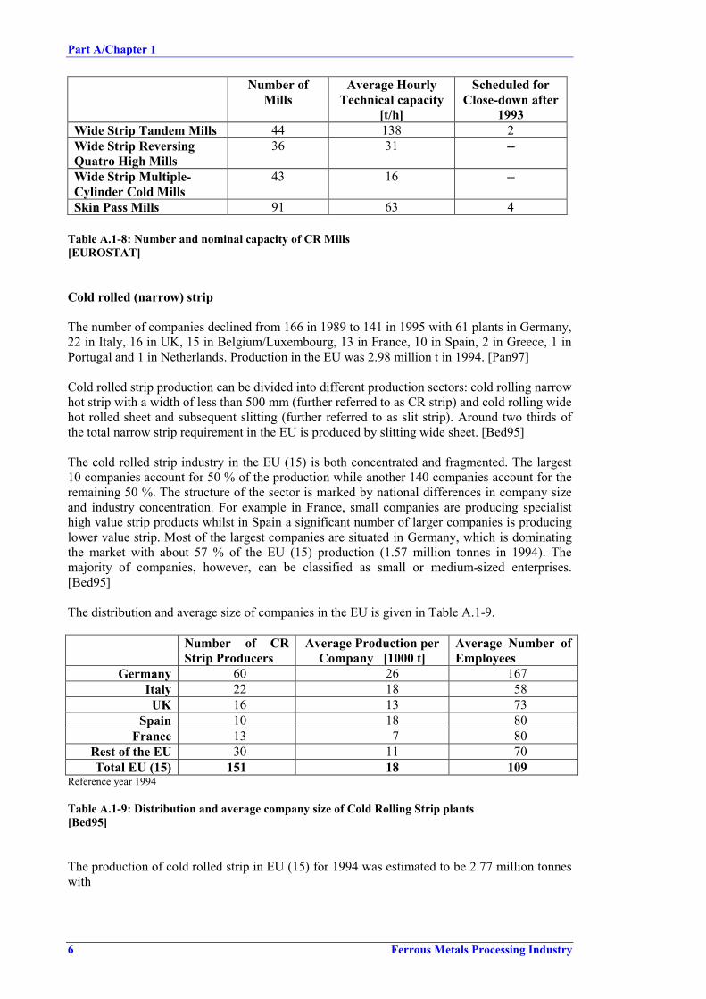
Part A/Chapter 1
6 Ferrous Metals Processing Industry
Number ofMills
Average HourlyTechnical capacity
[t/h]
Scheduled forClose-down after
1993Wide Strip Tandem Mills 44 138 2Wide Strip ReversingQuatro High Mills
36 31 --
Wide Strip Multiple-Cylinder Cold Mills
43 16 --
Skin Pass Mills 91 63 4
Table A.1-8: Number and nominal capacity of CR Mills[EUROSTAT]
Cold rolled (narrow) strip
The number of companies declined from 166 in 1989 to 141 in 1995 with 61 plants in Germany,22 in Italy, 16 in UK, 15 in Belgium/Luxembourg, 13 in France, 10 in Spain, 2 in Greece, 1 inPortugal and 1 in Netherlands. Production in the EU was 2.98 million t in 1994. [Pan97]
Cold rolled strip production can be divided into different production sectors: cold rolling narrowhot strip with a width of less than 500 mm (further referred to as CR strip) and cold rolling widehot rolled sheet and subsequent slitting (further referred to as slit strip). Around two thirds ofthe total narrow strip requirement in the EU is produced by slitting wide sheet. [Bed95]
The cold rolled strip industry in the EU (15) is both concentrated and fragmented. The largest10 companies account for 50 % of the production while another 140 companies account for theremaining 50 %. The structure of the sector is marked by national differences in company sizeand industry concentration. For example in France, small companies are producing specialisthigh value strip products whilst in Spain a significant number of larger companies is producinglower value strip. Most of the largest companies are situated in Germany, which is dominatingthe market with about 57 % of the EU (15) production (1.57 million tonnes in 1994). Themajority of companies, however, can be classified as small or medium-sized enterprises.[Bed95]
The distribution and average size of companies in the EU is given in Table A.1-9.
Number of CRStrip Producers
Average Production perCompany [1000 t]
Average Number ofEmployees
Germany 60 26 167Italy 22 18 58UK 16 13 73
Spain 10 18 80France 13 7 80
Rest of the EU 30 11 70Total EU (15) 151 18 109
Reference year 1994
Table A.1-9: Distribution and average company size of Cold Rolling Strip plants[Bed95]
The production of cold rolled strip in EU (15) for 1994 was estimated to be 2.77 million tonneswith

Part A/Chapter 1
Ferrous Metals Processing Industry 7
• 2.09 million tonne of non-alloy steel strips (C-content < 0.25 %)• 0.46 million tonne of non-alloy steel strips (C-content > 0.25 %)• 0.12 million tonnes of coated steel strip.• 0.10 million tonnes of HSS and other alloy strips.
A breakdown of the total strip production (CR rolled strip and slit strip) by countries is given inTable A.1-10, Figure A.1-2 and Figure A.1-3.
CR Strip Production[1000 t]
Slit Strip Production[1000 t]
Total Strip production[1000 t]
Germany 1570 1950 3520Italy 390 900 1290
UK 210 500 710Spain 180 330 510
France 90 900 990Rest of EU: 320 970 1290
Sweden 140Benelux 100Greece 30
Portugal 30Finland 10Austria 10
Total 2760 5550 8310Reference year 1994
Table A.1-10: Production of CR strip and slit strip[Bed95]
CR Strip Production [million tonnes]
Germany56%
Italy14%
United Kingdom8%
Spain7%
France3%
Rest of EU:12%
GermanyItalyUnited KingdomSpainFranceRest of EU:
Figure A.1-2: CR Strip production in 1994[Bed95]

Part A/Chapter 1
8 Ferrous Metals Processing Industry
Slit Strip Production [million tonnes]
Germany36%
Italy16%
United Kingdom9%
Spain6%
France16%
Rest of EU:17%
GermanyItalyUnited KingdomSpainFranceRest of EU:
Figure A.1-3: Slit strip production[Bed95]
A.1.5 Cold Drawn Long Products/ Bright Steel Bars
The production of bright steel bars in the EU was about 2.4 million tonnes in 1994. The numberof companies declined from 154 in 1988 to 130 in 1995 with a number of 46 companies inGermany, 26 in Spain, 25 in Italy, 15 in United Kingdom, 14 in France, 2 in Portugal, 1 inDenmark and 1 in Belgium. Bright steel bars are used by industries such as the manufacture ofmotor vehicles, machinery, electrical goods and other industries, where high quality basicmaterial is compulsory. [Pan97]
A.1.6 Wire
The European Union has the world largest wire drawing industry, followed by Japan and NorthAmerica. It produces about 6 million tonnes of wire per year. Including the various wireproducts, like barbed wire, grill, fencing, netting, nails etc, the production of the sector reachesmore than 7 million tonnes per year. The European wire drawing industry is characterised by alarge number of medium sized, specialised companies with an average of 121 employees and anannual turnover of ECU 13.7 million per company. The industry’s output, however, isdominated by a few large producers. It is estimated that about 5 % of the companies account for70 % of the industry’s output (25 % of the companies for 90 %).
Over the past 10 years, independent wire drawing companies have become increasinglyvertically integrated. Downstream wire drawing and producing finished wire products haveshown a high degree of integration, but also upstream there has been some integration betweensteel making and wire rod producing industries and wire drawing. Approximately 6 % of thewire drawers in Europe are integrated producers representing about 75 % of the total productionof steel wire [C.E.T].
The largest producer of steel wire is Germany with 32 % of the wire production followed byItaly (approx. 22 %), UK, Benelux (mainly Belgium), France and Spain. Other Member Stateswhich have a small wire drawing industry are Sweden, Austria, Greece and Portugal. The

Part A/Chapter 1
Ferrous Metals Processing Industry 9
distribution of wire drawing installations in EU, size and number of plants for individualMember States is given in Table A.1-11.
Wire Production[1000 t]1
Wire Products[1000 t]1
Number ofplants2
Average number ofemployees per plant2
Austria 120 115 2 N/A.Benelux 619 246 20 325
Denmark N/A. N/A. N/A. N/A.Finland N/A. N/A. N/A. N/A.France 406 102 36 136
Germany 1908 89 85 125Greece 140 60 2 N/A.Ireland N/A. N/A. N/A. N/A.
Italy 1250 300 74 58Portugal 82 30 2 N/A.Sweden 135 63 11 85
Spain 463 138 26 N/A.UK 735 105 25 110
Total 5858 1248 283 1211 reference year 19962 reference year 1994
Table A.1-11: Wire drawing industry in the EU[C.E.T.] [Euro-Strategy]


Part A/Chapter 2
Ferrous Metals Processing Industry 11
A.2 APPLIED PROCESSES AND TECHNIQUES IN HOT ANDCOLD FORMING
Hot and cold forming activities covered in this BREF are hot rolling, cold rolling and drawingof steel.
A.2.1 Hot Rolling Mills
A.2.1.1 Process Overview
In hot rolling the size, shape and metallurgical properties of the steel slabs, blooms, billets oringots are changed by repeatedly compressing the hot metal (temperature ranging from 1050 to1300 Co) between electrically powered rollers. The steel input for hot rolling differs in formand shape, depending on the process route and on the product to be manufactured:
Cast ingots, predominantly with square cross section, are used for the manufacture of slabs andblooms on slabbing-/ blooming mills. Slabs and blooms are further processed to plates or stripson other rolling mills. Nowadays, the use of cast ingots and slabbing/blooming is decreasing ascontinuous casting has made this step obsolete. Approximately 93.7 percent (1995) of the crudesteel produced in Europe is cast continuously into semi-finished products such as slabs, bloomsor billets. Only a minor part is cast into discrete moulds to produce ingots for some specialproducts (e.g. heavy plates).
Slabs (400 up to 2500 mm wide and 40 to 500 mm thick) are semi-finished, continuous castproducts for the rolling of flat products.
Billets (of square or rectangular shape with cross sections of 2500 mm2 to 14400 mm² (50 x 50mm to 120 x 120 mm)) and blooms (of square or rectangular shape with cross sections of 14000mm² up to approx. 100000 mm² (120 x 120 mm up to 250 x 400 mm)) are semi-finishedcontinuous cast products used for the rolling of long products.
Beam blanks (with dimensions of 170 x 240 mm up to 500 x 1120 mm) are continuously castto near net shape. Beam blanks are used for rolling of long products. [EUROFER HR]
Hot rolling mills usually comprise the following process steps:
• Conditioning of the input (scarfing, grinding).• Heating to rolling temperature.• Descaling.• Rolling (roughing including width reduction, rolling to final dimension and properties).• Finishing (trimming, slitting, cutting).
Products obtained from hot rolling are usually classified in two basic types according to theirshape: flat and long products. Tubes, are also covered by the term 'long product' in thisdocument.
Figure A.2-1 shows an overview of products manufactured for various purposes andapplications.

Part A/Chapter 2
12 Ferrous Metals Processing Industry
(Narrow) Steel Stripwidth < 600 mm
Hot Wide Stripwidth > 600 mm
Heavy Platethickness > 3 mm
Black Plate/Tinplatethickness < 0.5 mm
Metal Sheetthickness 0.5 … 3
Strip
Wide Flats
Plates/SheetsFlat Products
Special Profiles/Sectionheight > 80
Flat Barsthick > 5 mm, width < 150
Profiles/Sectionsheight > 80
Railsheight > 80
Profilesheight < 80
Square-/Rectangular Bars/ Bars div. Cross sections
Round Bars
Sheet Piling
Structural Steel
Bars/MerchantBarsLong Products
Wire Rod
Welded TubesTubes
Seamless Tubes
Figure A.2-1: Overview of Hot Rolled Products

Part A/Chapter 2
Ferrous Metals Processing Industry 13
Hot rolling mills are classified by the type of product that they produce and by their designfeatures. The following chapters give an inside on the different mill layouts and manufacturingsequences. More detailed information on the individual processing steps, which are oftensimilar in different mills, is given thereafter.
A.2.1.1.1 Blooming/Slabbing Mills
Blooming and slabbing mills are used to roll cast ingots into semi-finished products, likeblooms and slabs, for further processing on other mills. The raw material is heated in soakingpits to ca. 1300 o C and subsequent formed on heavy two-high reversing stands in 15 - 30 rollingpasses.
The material to be rolled is moved along roller tables, positioned with the aid of manipulators,and fed into the roll gap. The material is rotated repeatedly by 90 o about its long axis during theseries of passes.
The main difference between blooming and slabbing stands is the greater height of the standsused for rolling slabs. This is associated with the product characteristics, as slabbing mills aremainly used to roll flat semi-finished products they require a bigger lift height of the upper rolls.
Another rolling system is the universal slabbing stand. Working pairs of rolls are arrangedhorizontally and vertically in succession. The vertical rolls form the narrow sides.
The rolled semi-finished products are cropped with shears at both ends, and divided intoordered lengths. Surface defects of the product maybe removed by flame deseaming (scarfing).[Ullmann’s]
With the growth of continuously cast products, the number and importance of slabbing andblooming mills has decreased. From 1988 the number dropped by 18 to a total of 67 in 1993(see Table A.2-1)
Number of Plants Average capacity [t/h]Blooming Mills 13 85
Blooming and billeting 8 84Blooming and slabbing 13 187
Blooming, slabbing, billeting 6 109Slabbing (only) mills 5 284Billeting (only) mills 20 83
Billeting and slabbing mills 2 122Total 67 122
Table A.2-1: Semi-finished product mills[EUROSTAT]
A.2.1.1.2 Hot Strip Mills
For the production of hot strip, the heated slab - after descaling - passes the roughing mill,where it is reduced from a thickness of approx. 120 - 300 (500) mm to approx. 20 - 50 mm(transfer bar). Roughing can also include a reduction in width.
This roughing is done either in several passages through an individual rolling stand by repeatedreversing, or in a continuous passage through several roughing stands. The designations of strip

Part A/Chapter 2
14 Ferrous Metals Processing Industry
mills (semi-continuous hot strip mill, 3/4 continuous hot strip mill and continuous hot strip mill,see Figure A.2-2) originate from this plant configuration.
Furnaces R F1 F2 F3 F4 F5 F6F0E1E2
Typical configuration of semi-continuous hot strip mill
Furnaces R3 F1 F2 F3 F4 F5 F6F0E1E4
R1E2
R2E3
Typical configuration of 3/4 continuous hot strip mill
Furnaces R4 F1 F2 F3 F4 F5 F6F0E1E5
R1E2
R3E4
R2E3
Typical configuration of fully continuous hot strip mill
E= Edger R= Roughing stand F= Finishing stand
Figure A.2-2: Typical designs for Hot Strip Mills[EUROFER HR]
The material reduced to a transfer bar is directed to the finishing train via an intermediate rollertable, which in some cases is combined with a so-called coil box. Before entering a train ofrolling stands for thickness reduction to the final size (between 1.2 and approx. 20 mm) thetransfer bar is cropped. Temperature controlled rolling in the finishing train, involvingcontrolled strip cooling installed at the delivery roller table, provides the requestedtechnological parameters (strength, toughness, etc.) of the hot strip. At the end of the rollingmill the finished product is wound up in a coil.
Hot strip, which is not foreseen for further processing in the cold mills is partly sold with rolledstrip edges, but depending on the planned external use the strip has to be conditioned. This coilfinishing includes side trimming, cutting to small bands on slitting lines and cutting into sheets.[EUROFER HR]

Part A/Chapter 2
Ferrous Metals Processing Industry 15
Steckel Mill
A special method of hot strip production is rolling in so-called STECKEL mills. Here theprematerial is usually processed into strip by reversing through a roughing stand and a finishingstand, in some cases even by reversing through one stand only.
Furnaces R F1Steckel Mill
E1E2
E= Edger R= Roughing stand F= Finishing stand
Figure A.2-3: Typical STECKEL Mill configuration[EUROFER HR]
To keep the heat losses during the rather long forming process within reasonable limits and tohandle the relatively long strip more easily, heated coiling devices referred to as STECKELcoilers are attached on both sides of the rolling stand (finishing stand), where the rolled stock istemporarily stored.
Figure A.2-4: STECKEL Mill with coiling furnaces[EUROFER HR]

Part A/Chapter 2
16 Ferrous Metals Processing Industry
Sendzimir Planetary mill
Mills of this type are characterised by the use of rotating backup rolls which drive the work rollsso that the surface of the latter move in a direction opposite to that of the workpiece. The workrolls are held in cages, which rotate around the backup rolls in a synchronised manner. Tofacilitate the use of thicker ingoing material (slabs) planetary mills may be assisted by attachedeccentric presses.
Special kinds of planetary mills are the single planetary mill - only the bottom roll set isdesigned as planetary type and either a rotating top roll or fixed die is arranged above passline -and the ‘Krupp-Platzer’ planetary mill where intermediate rolls are arranged between the workrolls and backup roll. [EUROFER HR]
Workrolls
Material travel
Strip
Backup roll Cage
Slab
Normal flow of material
Descaler
Gas fired furnace
Planetary mill
Feed rolls
Tension roll
Runout table
Planishing mill Upcoiler
Figure A.2-5: Planetary Mill (SENDZIMIR)[EUROFER HR]
A.2.1.1.3 Plate Mills
Production of heavy plates (thickness between 5.0 and 380 mm, width up to 5.2 m) is done byreversing operation at one mill stand or in tandem operation.
After rolling, the plates are placed on a cooling bed (cross transfer) and cooled to roomtemperature and/or temperatures down to max. 500°C for further processing. [EUROFER HR]

Part A/Chapter 2
Ferrous Metals Processing Industry 17
Furnaces Plate Mill
Stand
EdgerHot
LevellerCooling-
bed
Shearing lineSide trimming &cutting to length
Storageyard
subsequenttreatment
turning
turning
Figure A.2-6: Typical Plate Mill configuration[EUROFER HR]
In special cases the rolled product is heat treated by water cooling systems (e.g. water curtains)immediately after hot rolling. Hot and/or cold levellers are arranged in front or behind thecooling bed to straighten the plates.
After the cooling process on the cooling bed, secondary treatment of the sheets is performed inthe finishing shops (shearing, side trimming cutting to length). A part of the production issubjected to a subsequent heat treatment prior to shipment. Such treatments include annealing,spherodise annealing, stress relieving, normalising, quenching and tempering.
Clads
Special products such as multi-layer plates (clads) require a separate preparation and rollingtechnique (mainly a two-heat rolling operation). In such products, a corrosion-resistant surfacematerial is permanently bonded to lower-cost, possibly stronger, carbon steel.
The first step involves the fabrication of ‘sandwiches’ which consist of plates of the claddingand the backing materials with thickness in the exact proportion to produce the required platesize with the percentage of metals ordered. The assembly is then rolled to the desired gauge,width and length, with the two materials becoming permanently bonded because of the highrolling pressure.
In the rolling operation, drafts are usually limited and the finishing temperatures are carefullycontrolled. In some cases the sandwiches are rolled in a first stage into slabs, cut to requiredsizes and in a second heat, final rolled either on hot strip mills or on the plate mill. Sometimesheat treatments are required to produce the desired corrosion resistance and physical properties,the resultant scale being removed by sand- or shot blasting. [EUROFER HR]
A.2.1.1.4 Bar and Rod Mills
Bars and rods (wire rods) constitute hot rolled products of relatively small cross sectionsproduced in coiled or straight form. For the rolling operation profiled rolls are in use to give thesteel its desired final shape.
Wire rods
Wire rods generally have circular cross sections with a diameter of 5 to 14 mm. Larger crosssections and different section shapes such as oval, square, hexagonal, octagonal etc. Can also berolled on wire rod mills with adequately shaped rollers. Hot rolled wire rod is mainly used forfurther processing by cold drawing or cold rolling.

Part A/Chapter 2
18 Ferrous Metals Processing Industry
FurnaceRoughing mill6 + 3 stands
Finishing blocks10 stands
Intermediate mill6 + 4 stands Cooling line Coil conveyor /
Retarded cooling
Coilers
Coil collectors
Note: Example of a 2 strand, 30 stand wire rod mill with Stelmor controlled cooling
Figure A.2-7: Typical layout of a Wire Rod Mill[EUROFER HR]
The billets fed into rod mills are heated to hot rolling temperature in pusher or walking beamfurnaces. A descaling system is installed between the furnace exit and the first rolling stand.
Rod mills are continuous mills with roughing, intermediate and finishing sections. The rollingstands are 2-high and their number is generally in excess of 25, depending on the cross sectionof the billets feeding the mill (80 to 155 mm). Roughing and intermediate sections may bemulti-strand (up to 4 strands), while finishing sections are always single stranded.
Crop shears are installed between the different sections of the mill and are used to provide aclean cut for improved introduction into the following roll stand. Crop shears are also used tocut the bar engaged into the rolling process in case of an incident downstream in the mill.
In-line heat treatment of the wire rod is performed with water cooling ramps located betweenthe final rolling stands and the coilers, followed by air cooling of the coils laid on conveyorbelts. Controlled air-flow gives the wire rod the desired micro-structure for further processing(STELMOR® cooling). [EUROFER HR]
Bars
Hot rolled bars include basically two types of steel products, merchant steels or engineeringsteels with round, square, rectangular, hexagonal, octagonal, L-shaped, [-shaped, I-shapedcross sections smaller than 1600 mm2 and concrete reinforcing bars (re-bars) with round crosssections, 6 to 40 mm diameter, mostly with ribs on their surface.
Bar rolling mills are similar to the first sections of wire rod rolling mills. They have generallysingle strand 2-high mills with roughing, intermediate and finishing groups followed by shearsthat cut the hot rolled product to long bars, which are then conveyed to a cooling bed. Highcapacity mills are all continuous with alternating horizontal and vertical stands, while the frontgroups of lower capacity mills are of the ‘open’ type.
After cooling the bars are cut to commercial lengths and may be straightened at a coldstraightening machine.
Re-bars are often heat-treated in-line by intensive water-cooling to obtain high tensile strength(TEMPCORE® process). A different way for increasing the tensile strength of re-bars is amechanical treatment after cooling: The bars are deformed by torsion beyond their yieldstrength until the desired tensile strength is obtained. [EUROFER HR]

Part A/Chapter 2
Ferrous Metals Processing Industry 19
Cold Drawing of Steel Bars
Cold drawing concerns the manufacture of steel bars or sections by cold drawing, grinding orpeeling of hot rolled steel bars into so called 'bright steel bars', having form and characteristicsrequired by the users. Cold finishing during cold drawing operations hardens and increases thetensile strength of the steel, while at the same time reducing the ductility, which may require anannealing treatment of the product after drawing. Bright steel bars are mainly of circular,square, rectangular or hexagonal cross-section, but all kinds of cross-sections can be producedaccording to demand. Products are non-alloy steel bars, alloy steel bars of different gradesincluding high-speed steel and other tool steel and shapes and sections of different steel grades.[Pan97]
Bright steel bars are used by industries such as the manufacture of motor vehicles, machinery,electrical goods and other industries, where high quality basic material is compulsory.
A.2.1.1.5 Structural/Section Mills
As most other types of mills, section rolling mills are divided into roughing, intermediate andfinishing stands, preceded by a descaling machine installed between the reheating furnace andthe roughing mill.
Roughing stands are generally reversing, 2-high stands. The rolls have several sets of profiles,which are used in sequence. The upper roll can be moved vertically in order to progressivelyreduce the gap between the rolls and thus to reduce the passing section.
Cropping shears or hot saws are generally installed between the different sections of the millsand are used to provide a clean cut bar end to facilitate the introduction into the followingrolling stand.
On leaving the finishing stand or train, the bars are divided to cooling bed length or tocommercial length by saws. After cooling on the cooling bed, the bars are straightened onmechanical or hydraulic straightening machines and cut to length by saws as required.[EUROFER HR]
To yield the different profile shapes required for sections/structurals, either duo-stands with 2grooved rolls or ‘universal’ stands with 2 horizontal and 2 vertical rolls are used as shown inFigure A.2-8 and Figure A.2-9.
Figure A.2-8: Profiled rolls for sheet piling sections[EUROFER HR]

Part A/Chapter 2
20 Ferrous Metals Processing Industry
Vertical roll
Horizontal roll
Arrangement of working rolls in a"Universal" rolling stand
Figure A.2-9: Universal stands for parallel flanged products[EUROFER HR]
Geometry control is of utmost importance in section rolling since rather tight tolerances arecommon for hot rolled sections. Measuring devices applying sophisticated techniques includinglaser beam technology and radioactive sources are of common use.
The designs of section mills vary greatly according to the manufacturing programme.Figure A.2-10 shows the layout of a heavy section mill with universal stands, specialised inparallel flange H and I beams. It includes in-line heat treatment (QST - Quenching and Self-Tempering) to obtain an optimal micro-structure for high strength and high ductilityapplications.
Walking beamfurnace
QSTFinishing stand
Roughing stand
Intermediate stands
Hot saws
Heavy section rolling mill (Grey mill) with one 2-high reversing roughing stand, tworeversing universal intermediate stands and one universal finishing stand.
Figure A.2-10: Plant layout of a Heavy Section Mill[EUROFER HR]

Part A/Chapter 2
Ferrous Metals Processing Industry 21
Figure A.2-11 shows the layout of a heavy/medium section mill specialised in the rolling ofsheet piling sections. The intermediate stands are of the ‘open’ type with one common drive.The 2-high finishing stand can be exchanged by a universal stand for the production of parallelflanged products.
3 intermediate stands
Finishing stand
Straightening machine
12
34
5
Hot circular saws
Roughing stand (blooming mill)
FINISHING SHOP
Cooling beds
Heavy/medium section mill with one reversing 2-high roughing stand, three reversing2-high intermediate stands with a common drive and one reversing finishing stand
Figure A.2-11: Plant layout of a Heavy/Medium Section Mill for sheet piling[EUROFER HR]
Section mills increasingly use near-net-shape, continuously cast semis called beam blanks (seeFigure A.2-12) to increase productivity and decrease energy input.
Beam blanks for different beam sections
Figure A.2-12: Examples of beam blanks cross sections[EUROFER HR]
If the production rhythm and the manufacturing programme allow, hot charging of continuouslycast semis - from the casting machine run-out area to the reheating furnace of the rolling mill -is more and more applied. Considerable savings in energy consumption may be achieved, butthis depends on the proximity of the rolling mill to the continuous casting plant.

Part A/Chapter 2
22 Ferrous Metals Processing Industry
A.2.1.1.6 Tube Mill
Seamless tube
Seamless tube production consists basically of the following manufacturing steps:• Heating of the input.• Piercing (press-piercing or oblique rolling).• Elongation/Stretching.• Final Rolling.• Heat Treatment.
The most important types of plants used today are mandrel mills, plug mills, push bench millsand pilger mills. Figure A.2-13 and Figure A.2-14 show some typical tube mill designs.
Raw material for the production of unalloyed and medium-alloy steel tubes are continuouslycast round billets or blooms, although sometimes billets with square cross sections are used.The raw material for high-chrome steel tubes are mainly round bars, rolled from cast billets.The input is heated to rolling temperature in rotary hearth furnaces fired with natural gas or oil.Then a hollow billet (ingot) is produced by piercing. The most important hole-piercing processuses inclined rollers. The hole is produced by two inclined rolls rotating in the same direction,so that the ingot is rolled with a screw motion over a piercer plug to form a hollow bloom. Thepiercer plug is fixed to a freely rotating rod supported by a thrust bearing on the exit side.
1 Rotary hearth furnace 5 Re-heating furnace2 Cross-rolling piercer 6 Stretch-reducing mill (off-set 60 o)3 Mandrel mill (offset 45o) 7 To cooling bed and finishing lines4 Stripper
Figure A.2-13: Mandrel mill[Tech Metal]

Part A/Chapter 2
Ferrous Metals Processing Industry 23
1 Rotary hearth furnace 5 Reeler2 Cross rolling piercer 6 Sizing mill3 Cross-rolling elongator 7 Cooling bed4 Plug mill 8 To finishing shop
Figure A.2-14: Plug mill[Tech Metal]
Longitudinal rolling, transverse rolling, or presses are used for the elongating stage. The mostimportant one is the continuous tube rolling process, as it is one of the most efficient andproductive processes.
Several rolling stands are used simultaneously, usually 6 -8 two-high stands per group, at anangle of 90 o to each other. The reduction of the wall thickness takes place between the rolls anda cylindrical lubricated mandrel.
Rolling to the finished size is carried out without an inner mandrel in sizing mills or stretch-reducing mills. Sizing mills have 2 - 10 stands, and can have two or three rolls per stand. As thecircumference is reduced, the wall thickness is increased. In stretch reducing mills, whichnormally have three rolls per stand, and up to 30 stands, an increase of wall thickness isavoided, as tensile forces are applied between the stands during the process.
Tubes for undemanding applications can be shipped immediately after rolling. For moreexacting quality requirements, especially good toughness properties, separate heat treatment isusually carried out after rolling. This can include normalising and tempering.

Part A/Chapter 2
24 Ferrous Metals Processing Industry
Welded tubes
Welded tubes are produced from cold rolled or hot rolled steel strip; hot rolled wide strip; orthick plate. In principal the production sequence comprises bending of the strip or plate to anopen tube and closing the gap by welding. Figure A.1-1 shows a schematic of continuous tubeproduction (Fretz-Moon process).
Figure A.2-15: Flow sheet for continuous tube production[HMIP]
In the Fretz-Moon process (pressure welding) coils of hot-rolled strip are heated to a hightemperature in a tunnel furnace. The edges of the strip are heated to welding temperature byadditional burners. The strip is formed into a tube with a longitudinal gap. A two-rollcompression device at 90 o then reduces the gap and presses the edges together so they becomewelded.
The semi-finished tube passes without further heating through a stretching mill, where thedimensions are reduced as required. A flying saw cuts the continuous tube into lengths, whichare then cooled on a cooling bed.
Alternative welding processes are resistance pressure welding, in which the required weldingheat is generated by high-frequency alternating current, conduction or induction. The propertiesof the welded seams can be improved, either by continuous heat treatment or by separate heattreatment of the individual tube. Fusion Welding is mainly used to produce steel pipes withlarge diameters (> 457.2 mm). Figure A.2-16 shows the main tube welding processes.

Part A/Chapter 2
Ferrous Metals Processing Industry 25
a Fretz-Moon welding processb High-frequency conductive weldingc High-frequency inductive welding
Figure A.2-16: Tube welding processes[EUROFER HR]
A.2.1.2 Surface Rectification and Conditioning of Input
Slabs, blooms and billets can have surface defects, like cracks, folds or seams. Surfacepreparation of rolling stock is necessary to ensure flawless surfaces of the rolled product.Surface defects of semi-finished products, can also be removed by the following processes.
ScarfingScarfing removes surface defects of carbon steel grades by an oxy-fuel flame. The flame is usedto rapidly melt and oxidise the steel surface while a separate supply of high pressure oxygen tothe cutter propels the slag product from the surface. Scarfing is either done by hand (for smalllot sizes) or by machine.
The scale from machine scarfing is washed from the steel surface by high pressure water andled to a water pit where the scale is removed by crane. The water is treated and recirculated.From manual scarfing operation scrap collection is carried out by means of magnets.
Dust emissions from scarfing operation are collected and, usually, abated by electrostaticprecipitators (wet or dry).
GrindingFor stainless steels and special steel grades, thermal removal of the surface defects is notpossible. Therefore defects have to be eliminated by grinding. The grinding process is either

Part A/Chapter 2
26 Ferrous Metals Processing Industry
carried out manually or by machines. Manual grinding is performed by use of hand held powertools, in some cases booths equipped with fume extraction to bag filter units. Grindingmachines are equipped with a roller table on which the work piece is supported and on which itcan be moved. The grinding wheel is mounted on a carriage that permits it to be moved backand forth over the work piece. The unit is positioned in an enclosure, which collects the dustgenerated during grinding and ducts it to a bag filter before discharge to atmosphere.
Cutting to-size slabsIn some cases the slabs have to be cut to the appropriate size. Wedge-type slabs, which resultfrom adjustment of the width in the continuous casting plant (mould adjustment) and fromchange of the lot size, have to be conditioned by torch cutting to obtain the desired geometricalshape.
A.2.1.3 Reheating- and Heat Treatment Furnaces
For hot rolling the steel input has to be heated to appropriate rolling temperature between 1050and 1300 °C and a uniform temperature distribution has to be ensured.
Depending on the charge material and the hot rolling process, reheating is done in differenttypes of furnaces such as pit furnaces, pusher type furnaces, walking beam furnaces, rotaryhearth furnaces or others. These furnaces are fired directly, usually by oil, natural gas or plantgases such as COG and BFG. Depending on the heating media, different waste gas emissionswill occur (mainly SO2 and NOx).
A.2.1.3.1 Batch Furnaces
Batch type furnaces are often used for speciality steels and forgings. A typical example of thebatch type furnace is the soaking pit, used to reheat ingots, slabs and other feedstock. It consistsof refractory lined chambers in which the input is placed vertically (ingots) or horizontally(slabs). A moveable cover allows the input to be charged and removed for rolling. Cast ingotscan be charged immediately after stripping to conserve energy. The typical soaking pit capacityis 50 to 170 tonnes with a thermal input of 9.5 MW (Th) and a heating rate of 10.7 t/h.
Soaking pits are no longer in widespread use as more and more steel is continuously cast, aprocess, which often bypasses the soaking pits. An example of the soaking pit furnace is shownin Figure A.2-17. [EUROFER HR]

Part A/Chapter 2
Ferrous Metals Processing Industry 27
Figure A.2-17: Pit furnace[ETSU-NP-54]
Another type of the batch furnace is the bogie hearth furnace. The stock is carried into thefurnace chamber on a bogie. The furnace chamber is closed by means of a door and the stock isheated. When the targeted temperature is reached, the door is opened, the bogie with the stock isremoved and the slab or casting is taken away for further use. [EUROFER HR]
A.2.1.3.2 Continuous Furnaces
Larger furnaces are usually fed continuously. The stock is pushed through the furnace by thefollowing stock (pusher type furnace) or is moved through by walking beams (walking beamfurnaces), a walking hearth or on/between rollers.
Examples of the larger size (> 20 MWTh) furnaces - the pusher and walking beam furnaces –are shown in Figure A.2-18 and Figure A.2-19. The largest currently in operation are walkingbeam furnaces of approx. 125 MW (Th) and pusher furnaces of 200 MW (Th). [EUROFER HR]

Part A/Chapter 2
28 Ferrous Metals Processing Industry
Recuperator
Heating zonePreheating zone Soaking zone
Pushing direction
Entry furnacedoor
Exit doorBurner
Workpiece(Slabs)
Skid rails
End burner
Figure A.2-18: Pusher type furnace[DFIU98]
Figure A.2-19: Walking beam furnace[ETSU-G77]
In a rotary hearth furnace (see Figure A.2-20) the charge material is placed onto a rotaryhearth. During the furnace campaign (hearth is rotating) the material is heated and, aftercompletion of a rotation, discharged.

Part A/Chapter 2
Ferrous Metals Processing Industry 29
Hearth rotation
Con
vect
ion
zone
zone 1
zone 2
zone 3
Discharging
Charging
Figure A.2-20: Typical design of rotary hearth furnace[EUROFER HR]
A.2.1.4 Descaling
Prior to rolling adherent scale, which forms during reheating must be removed, in order to avoida contamination of the stock surface by scale impressed by the rolls (so-called 'rolled in matter').
Mechanical descaling, where the adherent scale is mechanically broken in a light pass (mostlyin two-high stands) and then sprayed off or mechanically removed (brushing), is rarely appliedany more. Today, a common method of descaling is breaking and spraying off the scale bymeans of high-pressure water. Power water with pressures of 120 to 250 bar (exeptionally 600bar) is applied via flat jet nozzles onto the material surface. For the cleaning effect, the impactpressure (i.e. the pressure determined by the distance of the descaling nozzles to the rollingstock) is more important than the system pressure. The following techniques are appliedthroughout the whole rolling process:
• Primary descaling in so-called high pressure descalers installed before the entry into theroughing train and equipped with 1 or 2 pairs, some times adjustable, descaling headers.
• Mill stand descaling by means of descaling headers arranged above and below the platepassage on both sides of reversing stand and on the entry side in case of continuous stands.
• Descaler at entry of the finishing train for removing secondary scale, i.e. the scale formedon the rough strip at the conveying roller table of the roughing train and finishing train.
• Pairs of mill stand descaling sprays at the entry of the first stand of the finishing train.[EUROFER HR].
In case of production lines for long products the descaling headers are either designed as sprayrings or as combination of vertical and horizontal headers, sometimes adjustable to materialcross section, for proper descaling of all material surfaces. [EUROFER HR]

Part A/Chapter 2
30 Ferrous Metals Processing Industry
A.2.1.5 Edging
Edging is usually applied in the manufacture of strip and plate. The slabs produced in thecontinuous casting plant are supplied in certain defined, stepped dimensions of widths. Thewidth has to be reduced to the specified dimension of the rolled strip, with a trimmingallowance as narrow as possible (scrap minimization and yield improvement). In most cases,this width reduction is performed on so-called edgers (vertical rolling stands) - recently even inslab presses - which are installed in front of the roughing unit. The accuracy of the widthreduction and optimum adherence to the rectangular shape effect the amount of scrap arisingfrom cropping (head and tail end) in the rolling mill and in the finishing shops (trimming).
A.2.1.6 Roughing
Roughing depicts the first bulk reduction done on the incoming hot roll stock for the productionof strip, rod and sections. Generally, the roughing train consists of one or more horizontalstands for thickness reduction, including edgers (vertical stands) situated in front of the standfor width adjustment. Reversing roughing mills are sometimes equipped with edgers on bothends of the mill stand [EUROFER HR]
A.2.1.7 Strip Rolling/Finishing Train
In general, the finishing mill consists of a number of rolling stands positioned after one another.The stands have staggered roll gaps so that the thickness reduction to the requested finalthickness is done in one pass of the transfer bar. The number of stands depends on the grade andmaterial thickness of the input (slabs) as well as on the thickness range of the finished strip.
Crop shears arranged in front of the finishing stands serve to cut the ends of the rough strip,which may have the form of a tongue or fishtail. This ensures safe entry into the finishing trainand avoids damage to the rolls as well as generation of scrap.
In most cases, an additional descaling device (descaling sprays) as described above is installedbetween crop shears and finishing train. Sometimes there is also an additional vertical stand,which is mainly used for strip guidance, but occasionally for minor width adjustments as well.
Coilers
Hot strips with length up to 2 km and even more are wound up on so named down (sometimesup-) coilers at the end of the rolling mill by speeds up to 20 m/s and more. The hot band isguided around an expandable mandrel by special arranged wrapper rollers. After approx. 3 - 4windings the wrapper rollers are lifted and the band is coiled onto the expanded mandrel. Afterthe coiling operation is finished, the mandrel is collapsed and the hot coil is transported to astrapping station by means of a coil car. [EUROFER HR]
A.2.1.8 Rod Rolling/Finishing Train
The finishing train of rod mills usually consists of rolling blocks with up to 10 sets ofalternating horizontal and vertical roller pairs as shown in Figure A.2-21.
Rolling speeds of more than 100 m/s are achieved at the final stages. The material used for theroughing and intermediate rolls is generally hardened steel or cast iron while the finishing rollsare made of carbide, a particularly wear resistant material. The typical calibration used for wirerod mills is a sequence of alternating round and oval calibres.

Part A/Chapter 2
Ferrous Metals Processing Industry 31
6 stand finishing block with 3 vertical and 3 horizontalpairs of rolls
Figure A.2-21: Roller arrangement of wire rod finishing section[EUROFER HR]
A.2.1.9 Plate Rolling
Plate rolling by reversing operation is similar to roughing in strip production. The slabs areformed into plates in the so-called multi-stage rolling operations, where the slabs are stretched,turned by 90° by means of conical rollers on a special roller table, spread, turned again androlled to the requested thickness.
A.2.1.10 Transport of Roll Stock between Rolling Stands
Usually, roller tables arranged along the entire strip rolling train are used as a means oftransport for the rolling stock. These roller tables consist of individual metallic hollow and/orsolid rollers with single drive or group drive by means of an electromotor and gear, if necessary.
In special cases, for example later modernisation of a rolling mill including increase of theweight of single products or installation of additional equipment, the distance between roughingstand and finishing stand is no longer sufficient to de-couple the two processes. So-called coilboxes - developed by STELCO, Steel Company of Canada Ltd. - are then inserted asintermediate storing devices. [EUROFER HR]
A.2.1.11 Cooling Lines
In connection with an appropriate temperature control within the finishing trains, the coolingline provides the desired mechano-technological parameters to the material. The steel is rapidlycooled using either water sprays, water walls or laminar flows (see Figure A.2-22).

Part A/Chapter 2
32 Ferrous Metals Processing Industry
a Laminar flows b Water wall c Water sprays
Figure A.2-22: Different types of water cooling[Tech Metal]
Widest spread nowadays is the use of laminar flow cooling on run out tables. Usually, the sprayheaders (arranged on top and bottom of the passline) are grouped into sections, sometimes ofdifferent water flow volume. Each section and/or each header is individually controllable so thatdesired cooling temperature may be realised. Cooling lines and the individual sprays arecomputer controlled, whereas the spray headers are switched on and off in accordance tocomplex mathematical-empirical models, supported by peripheral temperature measurements.[EUROFER HR]
A.2.1.12 Sheet and Plate Production
For sheet production the hot produced coils are decoiled by means of uncoiling reels andsupplied to a shearing line which is equipped with levellers to straighten the strip. The rolledsheets with desired length are piled and stored in the storage yard. [EUROFER HR]
Plate production is carried out on shearing lines following the rolling process. The plates aretrimmed on both sides, cropped and cut to desired length. Cutting to size for special blanks isdone by CNC-cutting equipment (torch-, plasma- or laser beam-cutting units). The internalquality of plates may be determined by ultrasonic techniques. Automatically working devicesmay be installed on the shearing line run out table.
Finishing operations are computer controlled in the most installations. Consideration is alsobeing given to the in-line quenching and heat-treatment of plates following the last rolling passas a means of conserving energy. [EUROFER HR]
A.2.1.13 Plate Heat Treatment
Finished plates are partly subject to heat treatment. In annealing steel is heated to a subcriticaltemperature to relieve stresses. For normalising steel is heated above its critical temperatureand air-cooled. The purpose is to refine grain sizes and to obtain a carbide distribution, whichwill dissolve more readily, austenite. Quenching, tempering and other methods may also beapplied.
Several different types of furnaces are used for these purposes, such as walking beam type,roller hearth or car bottom furnaces. The heating and combustion system of such furnaces are

Part A/Chapter 2
Ferrous Metals Processing Industry 33
comparable with the systems related to stock re-heating. All usually available heating mediamay be used for firing the treatment furnaces. [EUROFER HR]
A.2.1.14 Roll Shop
The workrolls as well as the back-up rolls for both finishing and roughing mills are conditionedaccording to well-defined specifications, depending on the product to be rolled. Conditioning ofthe rolls is performed at the roll shop where typical machine shop techniques are applied, suchas machining and grinding. [EUROFER HR]
A roll shop generally includes the following:
• Cooling area where work rolls are cooled either in open air or by water sprinkling.• Preparation area where the shocks are dismantled and set-up (In some cases the roll shop
machines allow reconditioning of rolls without prior dismantling).• Cleaning area where the rolls to be reconditioned are cleaned from deposits and lubricants,
(The cleaning techniques include steam cleaning, application of alkali degreasing solutions,application of organic solvents).
• Typical machine shop equipment including lathes and grinding machines which haveindividual cooling system where the cooling liquid is continuously processed in order toseparate turnings and grinding sludge [EUROFER HR].
A.2.1.15 Water Circuits / Water Management in Hot Rolling Mills
Throughout the hot rolling process and linked process steps water is used for cooling and fortechnological reasons. Electric motors, re-heating furnaces, control rooms and power systems,instruments and process control are usually cooled indirectly. The steel, rolls, saws, croppedends, coilers and hot run out tables are cooled directly. Water is also used for scale breaking,flushing scale and for scale transport. Wherever the water is in contact with the rolled material(process water) and rolling equipment it will be contaminated with scale and oil.
The simplest water feeding system applied is an open system (once-through system) as shownin Figure A.2-23. The water is taken from natural resources (river, lake or ground water), flowsthrough the various consumers of the hot mill and is released again to the watercourse.
outlet to sewerand / or watercourse
OilScale
gravelfilter thickener
Various consumersthroughout hot
rolling mill
Disposal to waste storage or recyclingby steel pro-duction
water inlet
Sludge
Figure A.2-23: Example of a once through water system[EUROFER HR]
The polluted cooling and process waters are collected and treated prior to discharge. Firsttreatment stage is a sedimentation basin in which solids, mainly iron oxides, are allowed tosettle at the bottom of the basin.

Part A/Chapter 2
34 Ferrous Metals Processing Industry
The sedimented solids are discharged via appropriate devices (scraper, screw, etc.) and, in thecase of integrated steel plants, returned to the production process via the hot metal route. The oilpollutants floating on the surface are removed by means of suitable skimming devices and aredischarged to the respective collecting basins.
The pre-cleaned overflow is supplied via pipes to the filter batteries whose number, size andcapacity are designed in conformity with the water volume. In most cases these filters are gravelfilters, i.e. the overflowing water is cleaned by passing through gravel beds.
The pollutants in the gravel filters must be removed by back-washing in order to maintain thefunction and separation efficiency of the filters. The purified waste water from the filters isdischarged into the sewage system and/or lakes and rivers.
The sludge-bearing waters (mostly containing iron oxide) from the filter batteries are separatedin a thickener. The overflow is recirculated to the cleaning circuit system. The high-quality feedmaterial contained in the sludge is further dewatered and disposed off or returned to the steelproduction process, provided the appropriate technical equipment is available.
In order to reduce or avoid waste water discharge from hot rolling operations semi-closed - andclosed circuits are implemented.
In semi-closed circuits, as shown in Figure A.2-24, the water is treated and partly reuseddepending on the temperature. The water treatment devices are the same as for open systems,but the filtered waste water is not directly disposed off. Instead it is conveyed into a filter waterbasin and mixed with cold fresh water, if necessary. Depending on the temperature of the mixedwater, the filtered water is returned to the different consumers in the hot rolling mill and onlythe overflow is discharged. Accordingly, the volume of the circulating water depends on theseasons and the geographical situation.
filter watertank
ground waterwater outlet to sewer / watercourse
Various consumersthroughout hot
rolling mill
OilScale
gravelfilter thickener
water inlet
Disposal to waste storage or recyclingby steel pro-ductionSludge
Figure A.2-24: Example of semi-closed water circuit[EUROFER HR]
With application of closed water circuits (see Figure A.2-25) the purified water is notdischarged, but re-cooled in cooling towers or heat exchangers to required temperature and isreused in the rolling process. For plants using cooling towers, water consumption is restricted toadditional water (approx. 3 - 5 %) needed to make up for evaporation and for blow down losses.When heat exchangers are used, large re-circulating volumes of re-cooling water are required.

Part A/Chapter 2
Ferrous Metals Processing Industry 35
OilScalegravelfilter
thickener
Various consumersthroughout hot
rolling mill
make up water
Deflocculation agent
spray- lossesHCl or NaOH
evapourationbiocides(NaOCl)
Settling basin
Sludge
Disposal to waste storage or recyclingby steel pro-duction
waste water to sewer and/or watercourse
coolingtower
Figure A.2-25: Example of closed circuit water system[EUROFER HR]
Water feeding- and treatment systems in hot rolling mills are usually very complex, withseveral, partly interconnected water loops and multiple-stage use of water. In some cases the hotrolling mill water circuit is coupled with water feeding systems of other iron and steelproduction units, as for example continuous casting. Reasons for this connection are thesimilarity of the waste water contents and the proximity of the installations.
Notes: 1) Figures given represent water flow in m3/h 2) Mill capacity: 270000 t per month
Figure A.2-26: Water loops for hot strip rolling mill[StuE-96-7]

Part A/Chapter 2
36 Ferrous Metals Processing Industry
Figure A.2-26 shows the water circuit of a hot wide strip mill where 3 water loops areestablished. Loop 1, with 8030 m3/h, comprises the cogging stand, finishing train and re-heatingfurnace; loop 2 (8000 m3/h) delivery roller table and loop 3 (2200 m3/h) mainly the electricalequipment. The Loops are connected in a way that water input for loop 2 and 3 is supplied bythe clean waterside of loop 1. Process water of loop 2 and 3 is sent to the treatment facilities ofloop 1 and also blow-down water can be discharged to loop 1.
Figure A.2-27 shows another example of a water management system for hot wide strip mill.The loops established in this case are for furnace- and engine cooling, for roller stands and forlaminar strip- and roller table cooling.
Furnace coolingEngine-
andoil cooling
Cooling towers Sandfilter
Horizontal settling tank
Thickener Buffer Filterpress
Sandfilter Coolingtower
Horizontalsettling tank
Laminarstrip
cooling
Roller tablecooling RinsingHorizontal settling
tank Sand filter Coolingtower
Scale-pit
Intermediatestand strip
cooling
Otherconsumers
Roughingmill
cooling
Coolingrolls
Highpressuredescaling
Roller tablecooling
loop.ds4
Figure A.2-27: Use of water loops in a hot rolling mill[DFIU98]
The prevention of effluents by using water in loops or in multiple stages is a well-known andwide spread practice within the steel industry. Hot rolling mills offer a high potential forreduction in water consumption and waste water discharge, because of the large quantities ofwater needed.
A.2.1.16 Waste and By-product Management in Hot Rolling Mills
Apart from waste water, hot rolling operations generate different kinds of solid and liquid by-products and waste.
• Metallic waste and by-products.• Scarfing scale/swarf.• Dusts from scarfing and rolling.• Mill scale (oil free and oily).• Water treatment and mill scale sludge.• Grinding sludge (roll shop).• Oil and greases.

Part A/Chapter 2
Ferrous Metals Processing Industry 37
Metallic by-products/waste, like scrap, downgrades, crop ends, etc. arising from hot rolling, isusually rather clean and is easily recycled into metallurgical processes (e.g. BOF).
Oilfree scale and low oil-content (< 1 %) scale, is fed back directly to the metallurgical process,usually via the sinter plant. Oily, ferrous sludges with up to 80 % FeOn content, like oily millscale and grinding sludges, obtained from water treatment plants have to be conditioned beforeinternal recycling.
Scale is also sold for external use (e.g. to cement manufacturers) or it is supplied to an externalcompany for treatment (usually thermal treatment to burn the oil content). Thermal treatmentplants can yield a product with an iron-content of about 60 - 70 %. If the thermal treatment plantis fed with oily mill-scale of about 4.5 % no additional energy supply is required.
Oxide dusts from air cleaning devices, for example from bag filters for oxide removal at themill stands, are recyclable to the steel production (e.g. sinter plant) without risks.
Oil and grease, separated and collected at various stages, are energy sources and can be utilizedas secondary fuels, for example by injection into the blast furnace or in the coke makingprocess. Dewatering might be a precondition. Alternatively, these materials can be used at thecoke ovens to increase coal bulk density prior to carbonisation. [EUROFER HR], [Com2 HR]
Spent emulsion from the roll shop or other consumers can be split into components: oil andwater. The separated oil can be thermally utilized or recycled externally. [Com2 HR]

Part A/Chapter 2
38 Ferrous Metals Processing Industry
A.2.2 Cold Rolling Mills
A.2.2.1 Process Overview
In cold rolling the properties of hot rolled strip products, e.g. thickness, mechanical andtechnological characteristics, are changed by compression between rollers without previousheating of the input. The input is obtained in form of coils from hot rolling mills.
The processing steps and the sequence of processing in a cold rolling mill depends on thequality of the steel treated. Low alloy and alloy steel (carbon steels) processing usuallyfollows the order: pickling, rolling, annealing, temper rolling/skin pass rolling and finishing.
The process route for high alloy steel (stainless steel) requires an initial annealing step prior topickling due to the hardness of the steel quality and, further more, several additional annealingand/or pickling steps during rolling may be necessary.
Cold rolled products are mainly strips and sheets (thickness typically 0.16 - 3 mm) with highquality surface finish and precise metallurgical properties for use in high specification products.
Cold Rolling Mills (CR Strip Mills)
Typical layouts for cold rolling mills are shown in (Figure A.2-28), the plants usually comprise:
• Continuous pickling line, where the oxide layer formed during the hot rolling is removedby pickling with sulphuric, hydrochloric or a mixture of nitric and hydrofluoric acid. Astretcher leveller or an in-line skin-pass may be used to improve the shape of the strip andprovide mechanical breaking of the oxide layer.
• Cold rolling mill generally consisting of a 4-stand or a 5-stand four-high tandem mill or ofa four-high reversing mill. Cold rolling reduces the initial thickness of the hot rolled strip bytypically 50 to 80 %.
• Annealing facilities to restore the ductility of the steel strip that is lost as the result of workhardening during the cold rolling.
• Temper mills to give the annealed material the required mechanical properties (preventsthe formation of Lüders lines during drawing). The material is subject to a slight skin passrolling typically on a four-high skin pass mill. The roughness of the work rolls of the mill istransferred to the strip by the roll pressure.
• Inspection and finishing lines, here coils with different length may be welded together tomeet the required weight or may be slit to required width. Also coils are cut into sheets withrequired length and width. At the same time defective sections of strip can be discarded.
• Packaging lines for coils or sheets according to the destination and/or the means oftransport.
• Roll shop, where the work rolls and the backup rolls for the cold rolling mill and the tempermill are prepared.

Part A/Chapter 2
Ferrous Metals Processing Industry 39
A) Reversing Mill
B) Tandem Mill
Figure A.2-28: Typical configurations of cold rolled strip mills[EUROFER CR]

Part A/Chapter 2
40 Ferrous Metals Processing Industry
For electrical steel sheet production the mill design is quite similar to those described above.The rolling mill usually comprises a four-high reversing mill stand, which is enlarged to rollingand alternative skin pass rolling operation (rough pass up to 7 % deformation). For higherSi-contents, flash butt welding of head and tail of the coils to an endless strip has to be replacedby ‘agraphing’ the ends of the coils.
Technical trends and developments in cold rolled strip production, driven by increasing marketdemands and competition from alternative materials, aim at increasing the efficiency and theoutput of plants by minimizing the processing time and the consumption of materials andenergy. Simultaneously the environmental impacts of the facilities are reduced. Figure A.2-29shows as an example a modified plant concept which shortens the process time for annealingand the following operations from 3- 7 days (2 –3 days when hydrogen is used) toapproximately 10 minutes. [EUROFER CR], [Com VDMA]
Figure A.2-29: Cold rolling process line with continuous annealing[EUROFER CR]
A.2.2.2 Pickling of Low Alloy and Alloy HR Steel
The entire surface of the hot rolled coil is covered with a thin layer of scale containing oxides,which must be removed prior to cold rolling. This is done by pickling with hydrochloric acid orsulphuric acid, at temperatures typically ranging from 75 °C to 95 °C.
Once the strip or sheet is pickled, it must be thoroughly rinsed with de-mineralised (or equalquality) water and subsequently dried. Oiling is done either with rolling oil or anticorrosive oil.[EUROFER CR]
Pickling lines
Pickling can be done as a batch (usually for bars, rods or tubes), semi-batch or as a continuousprocess and can also involve a number of stages using several acid baths. The following processdescription refers to continuous pickling lines on which steel is pickled in coiled shape. Each ofthe pickling steps described below can also be performed as an individual batch process.
A typical pickling plant may incorporate:
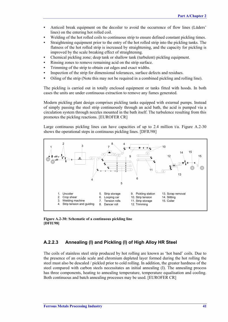
Part A/Chapter 2
Ferrous Metals Processing Industry 41
• Anticoil break equipment on the decoiler to avoid the occurrence of flow lines (Lüders’lines) on the entering hot rolled coil.
• Welding of the hot rolled coils to continuous strip to ensure defined constant pickling times.• Straightening equipment prior to the entry of the hot rolled strip into the pickling tanks. The
flatness of the hot rolled strip is increased by straightening, and the capacity for pickling isimproved by the scale breaking effect of straightening.
• Chemical pickling zone; deep tank or shallow tank (turbulent) pickling equipment.• Rinsing zones to remove remaining acid on the strip surface.• Trimming of the strip to obtain cut edges and exact widths.• Inspection of the strip for dimensional tolerances, surface defects and residues.• Oiling of the strip (Note this may not be required in a combined pickling and rolling line).
The pickling is carried out in totally enclosed equipment or tanks fitted with hoods. In bothcases the units are under continuous extraction to remove any fumes generated.
Modern pickling plant design comprises pickling tanks equipped with external pumps. Insteadof simply passing the steel strip continuously through an acid bath, the acid is pumped via acirculation system through nozzles mounted in the bath itself. The turbulence resulting from thispromotes the pickling reactions. [EUROFER CR]
Large continuous pickling lines can have capacities of up to 2.4 million t/a. Figure A.2-30shows the operational steps in continuous pickling lines. [DFIU98]
12
3
4
78 4
56
11
9
10
12
13
14 1515
1. Uncoiler2. Crop shear3. Welding machine4. Strip tension and guiding
5. Strip storage6. Looping car7. Tension rolls8. Dancer roll
9. Pickling station10. Strip tension11. Strip storage12. Trimming
13. Scrap removal14. Slitting15. Coiler
Figure A.2-30: Schematic of a continuous pickling line[DFIU98]
A.2.2.3 Annealing (I) and Pickling (I) of High Alloy HR Steel
The coils of stainless steel strip produced by hot rolling are known as ‘hot band’ coils. Due tothe presence of an oxide scale and chromium depleted layer formed during the hot rolling thesteel must also be descaled / pickled prior to cold rolling. In addition, the greater hardness of thesteel compared with carbon steels necessitates an initial annealing (I). The annealing processhas three components, heating to annealing temperature, temperature equalisation and cooling.Both continuous and batch annealing processes may be used. [EUROFER CR]

Part A/Chapter 2
42 Ferrous Metals Processing Industry
Annealing
Ferritic grades are generally annealed as tightly wound coils in a batch heat treatmentfacility. Such installations may be used for the full heating, temperature equalisation andcooling cycles. One or more coils are placed on the furnace base and covered to form a closedfurnace chamber. Heating may be achieved via gas firing or electrical heating. An inertprotective atmosphere (nitrogen/hydrogen) is required for metallurgical reasons. Ferritic steelsare generally annealed at steel temperatures of up to 800oC. [EUROFER CR]
For continuous annealing of austenitic steels the steel coil is unwound and passed through oneor more heat treatment furnaces. These furnaces typically consist of a refractory (or other formof insulation) lined steel structure and are usually directly fired by gaseous fuels. An oxidizingatmosphere is needed to form a scale, which is rich in oxygen to allow a better pickling. Thewaste gases are exhausted via flues under natural or forced draft. Strip temperatures typically upto 1100oC are necessary for annealing austenitic steels. The steel strip then passes through thecooling section and may be cooled using gas jets, air, water sprays or water quenching.Continuous annealing is generally combined with a descaling/pickling plant as described aboveto form a continuous annealing and pickling line. [EUROFER CR]
Descaling and Pickling
After annealing the steel is descaled to produce a steel surface suitable for cold rolling.Mechanical descaling such as shot blasting or scale breaking may be used prior to chemicalpickling to remove the heavy scale burden. However, careful control of such mechanicalprocesses is necessary to minimize damage to the strip surface, which could affect the finalproduct quality.
Final scale removal including the removal of the chromium depleted layer beneath the scale isgenerally done by pickling in a mixture of nitric and hydrofluoric acids at temperatures of up to70oC. The acid concentrations employed depend on the material being processed but arenormally in the range 10 - 18 % nitric acid and 1 - 5 % hydrofluoric acid.
The chemical reactions that take place during the pickling of stainless steels are complex andinvolve the removal of the adherent scale layer by the combined action of the acids used. Thedominating chemical reaction during pickling is the dissolution of metals by the nitric acid. As aby-product of these reactions both nitrogen monoxide and nitrogen dioxide are formed. Thereactions shown below are for the dominant metal iron but similar reactions also occur for thealloy elements present in the stainless steel such as nickel and chromium.
Fe + 4H+ + NO3- = Fe3+ + NO + 2H2O
Fe + 6H+ + 3NO3- = Fe3+ + 3NO2 + 3H2O
The NOx generated is partially soluble in the acid but once the limit of solubility is reached theNOx fumes transfer to the gaseous phase and are released from the pickling tanks. The rate offormation of NOx increases with increasing temperature.
The metal ions formed in the dissolution reactions then react with the hydrofluoric acid leadingto the formation of metal complexes.
2HF + Fe3+ = FeF2+ + 2H+
3HF + Fe3+ = FeF3 + 3H+
The combination of these two sets of reactions results in the consumption of both nitric andhydrofluoric acids. To maintain the optimum conditions for descaling regular additions of fresh

Part A/Chapter 2
Ferrous Metals Processing Industry 43
acid are made as required. The iron fluoride complexes produced in the dissolution reactionshave a limited solubility and if the concentration of iron is allowed to reach 5 % (40 g/l) thenprecipitation of iron fluoride will commence. This precipitation causes the formation of largequantities of a hard crystalline sludge.
Pickling line design is usually the same as for pickling of low alloy steels. Except, that on exitfrom the last pickling tank the steel strip is rinsed with water to remove traces of acid, dried, butno application of oil is necessary because of the corrosion resistance of the steel.[EUROFER CR]
A.2.2.4 Cold Rolling of the Pickled Hot Rolled Strip
A.2.2.4.1 Low Alloy and Alloy Steel
In cold rolling the pickled hot rolled bars, sheets or strips are passed through sets of rolls onreversing mills or on continuous in-line mills. Low carbon steels which are less hard, aregenerally rolled in multi-stand tandem mills due to a higher capacity of these mills. Theyconsist of a series of four or six-high stands. The strip enters the first stand and undergoes aninitial thickness reduction, further reductions are achieved in each subsequent stand until thefinal gauge is attained.
For low carbon strip generally an emulsion of 0.5 to 4 % (10 – 20 % for direct application) ofoil in water is necessary for
• Lubrication.• Cooling of the strip, work and back-up rolls.• Removal of Fe-particles.
In the rolling process the wide strip is mainly deformed in a longitudinal direction, withtransverse deformation being practically negligible. The thickness reduction of the material isobtained by the influence of the rolling forces and the strip tensions (forward and back) applied.The cold forming process leads to a corresponding hardening of the material. Exact mass flowcontrol (control of rolling force and/or position), assisted by laser control of the strip speed andtension, may be used. Additional automatic control loops for flatness (roll bending, zonecooling, etc.) are used to obtain the required flatness of the strip. The roughness texture of thestrip surface is applied in the last stand of the tandem mill.
For optimum strip surface cleanliness it is important to avoid contamination of the tandememulsion by the hydraulic oil, by the Morgoil oil, by grease or by the cooling water (used tocool the emulsion). Precautions taken to avoid any contamination may include:
• Continuous monitoring of oil levels.• Monitoring of the oil concentration.• Regular control of hydraulic equipment and bearings.• Monitoring of emulsion parameters such as temperature, pH value, saponification index,
acid value, conductivity.• Filtering of the tandem emulsion (using techniques such as magnetic filters, paper filters,
precoat filters).
To clean the strip and remove any remaining soap or oil, it may be subjected to chemical and/orelectrochemical degreasing. For this purpose, cleaning zones are installed on the entry side ofthe downstream processing plants such as hot dip galvanising plants or continuous annealingplants. [EUROFER CR]

Part A/Chapter 2
44 Ferrous Metals Processing Industry
Conventional discontinuous rolling
The pickled hot rolled strip is fed into the cold rolling mill coil by coil. This results in avariation in the strip thickness corresponding to the geometrical conditions of the line at thestrip ends during threading and at the exit of the coil end.
To produce ‘mill clean sheet’, often a thin emulsion with a maximum concentration of 1 % canbe used on the last stands of the tandem mill. The emulsion is usually applied via spray nozzlesonto the rolls and the strip. Sometimes higher concentrations are used in direct applicationsystems.
Discontinuous rolling offers a high degree of process flexibility to account for variations inproduct mix. The technique is preferable for certain steel qualities. [EUROFER CR]
Continuous Rolling
To achieve the narrowest possible thickness tolerances, maximum output and optimumproductivity figures, a shallow tank turbulence pickling plant can be coupled with a tandemmill, which is enlarged by one stand. Usually an accumulator and a welding machine before atandem has the same good results and a bigger increased capacity. The use of a weldingmachine and the accumulator allows coils to be joint and the strip to be fed to the millcontinuously.
On a tandem line, the entering pickled hot rolled strip is reduced to the desired final thicknesson a single pass through the line. Owing to the installation of several separate emulsion systems,a special emulsion can be applied in the last stand to increase the cleaning effect. For thispurpose, either a detergent or a thin emulsion (1 % oil content) can be used.
Continuous rolling can allow good control of the strip thickness for coil ends and of surfacequality. This can have a beneficial effect on material yield. In addition it allows oil consumptionto be optimised. [EUROFER CR]
A.2.2.4.2 High Alloy Steel
After the initial annealing and pickling the steel is generally rolled to the required thickness onreversing cluster mills for a number of passes until the desired dimensions are achieved or untilwork hardening necessitates further annealing.
The process of cold reduction generates heat, part of which is transferred to the rolling oil whichis sprayed onto the steel and rolls for cooling as well as lubrication. This heat is subsequentlydissipated through heat exchangers to cooling water systems.
Mineral oils are generally used as rolling oil and close control of the oil cleanliness is necessaryfor optimum performance. This may be achieved using oil filtration circuits, which incorporatemedia element filters or powder pre-coat filter systems. Although the use of mineral oilspredominates, emulsion cooling systems similar to those used for carbon steels may beemployed. In such cases additional precautions must be taken to control oil cleanliness in orderto avoid strip marking.
Collection hoods are fitted to the mill and operate under continuous extraction to remove oilmist that is generated. [EUROFER CR]

Part A/Chapter 2
Ferrous Metals Processing Industry 45
A.2.2.5 Annealing of Low Alloy and Alloy Steel
The basic stages of the annealing process comprise:
• Heating to annealing temperature (above 650 °C).• Holding at annealing temperature.• Cooling.
This annealing process may be carried out in batch furnaces or continuous furnaces. Theannealing cycle has a significant influence on the mechanical properties and, consequently, onthe formability of the steel strip. The main parameter controlling the annealing cycle is thetemperature profile. It varies, depending on whether the annealing is carried out in a continuousor batch furnace, and depending on the required strength or hardness of the product. Theannealing cycle depends on a number of parameters including the actual material analysis, thereduction realised during cold rolling, the required mechanical properties and the requiredsurface cleanliness, the type of protective gas, etc.
Continuous annealing and batch annealing are considered to be complementary processes andnot fully interchangeable. Production related issues are integral to the selection of the annealingtechnique.
A.2.2.5.1 Batch Annealing
Degreasing /Cleaning by means of alkaliPrior to the annealing process the strip may be cleaned (degreased) to produce a cleaner surface.The cleaning serves to remove oil residues from the steel surface. The process is similar to thatused for acid pickling except for the chemicals that are used. The most frequently used cleaningagents are phosphates, alkaline silicates, caustic soda and soda ash. Electrolytic cleaning andbrushes are also used in some cases to remove iron fines from the strip surface.
The steel sheet is unwound from the coil and passed through cleaning tanks, which may bestirred to improve the cleaning effect. Subsequently, the steel is rinsed with water and recoiled.The degreasing solution can be regenerated and recycled.
AnnealingThe cold rolled coiled strip is stacked in a hood furnace for annealing (see Figure A.2-31). Thecombustion chamber (space between heating and protecting hood) is heated by oil or gasburners. Heat passes through the protective hood into where the steel coils are stacked. Acirculating fan provides as uniform temperature distribution as possible. The atmosphere inconventional plants is usually HNX gas (a nitrogen-hydrogen mixture with a hydrogen contentclose to the flammability limit). The atmosphere can also be 100 % H2 as in parts of theworking cycle of high convection furnaces.

Part A/Chapter 2
46 Ferrous Metals Processing Industry
Off gas
Heating space Circulating fan
Circulatedinert gas
Coils
Protecting hoodHeating hood
Burner
ann_hood.ds4
Figure A.2-31: Schematic of a hood-type annealing furnace[DFIU98]
The heat passes into the coils through their outer edges, so that these areas are always hotterthan the inner windings, especially during heating up. The heat treatment causes the organicresidues of the emulsion to partly burn off; partly a distillation process takes place. Products ofthe reactions taking place are CO/CO2, H2, FeOx and CH4. The strip is heated to re-crystallisation temperature, and annealed at about 700 o C resulting in complete re-crystallisation of the cold rolled steel. For cooling the coils, the heating hood is removed. Thecooling effect can be enhanced by spraying water on the protecting hood; by covering it with acooling bell and blowing air on it or by using a cooling by-pass system which cools theprotective atmosphere under the protective hood. The time necessary for annealing depends onthe annealing temperature and the weight of the charge and can take 2 to 7 days.
Annealing in this type of furnace is very slow and also the cooling rate is not suitable for certainsteel grades. Therefore an annealing process in a 100 % hydrogen atmosphere was developedyielding in shorter annealing times and more rapid cooling.
A.2.2.5.2 Continuous Annealing
For continuous annealing the coils are welded together on the entry side of the plant andsubjected to the following process steps:
• Alkaline/electrolytic cleaning of the strips.• Heating and holding at the required annealing temperature.• Cooling (slow jet cooling, high gas jet cooling (using cooling rates up to 150 °C/s, hot water
quench (HOWAQ), overaging, roll cooling, final cooling, misting jet cooling).
The continuous annealing is carried out by passing the steel strip through a multi-zone heatingfurnace with heating chamber, annealing chamber, cooling zone, tempering zone and a secondcooling zone. The steel is heated to a range between 650 °C and 830 °C and then cooled by gasjets, gas-water sprays, contact rolls or water quenching, depending on the desired metallurgical

Part A/Chapter 2
Ferrous Metals Processing Industry 47
properties. These furnaces are usually fired by gas (direct or indirect) or electrically heated. Thesteel can be protected by an inert gas atmosphere or a reducing gas atmosphere in parts of thefurnace. The principle operational steps for continuous annealing are shown in Figure A.2-32.
12 3
4
5
6
7 8
9
1011
12
1314
15
1. Uncoiler2. Crop shears3. Welding machine4. Strip cleaning5. Looping tower
6. Entry looping car7. Entry section8. Dancer roll9. Furnace10.Cooling section
11. Upper top roll12. Strip exit13. Exit looping car14. Crop shears15. Coiler
Figure A.2-32: Example of a continuous annealing furnace[DFIU98]
Continuous annealing gives a shorter processing time (about 10 minutes), less intermediatestorage, uniform mechanical properties and a superior surface cleanliness. Continuous annealingis more appropriate for the production of higher strength steels. The layout of the furnacefacilitates energy recovery from the exhaust gas.
A.2.2.6 Annealing (II) and Pickling (II) of High Alloy Steel
DegreasingPrior to the final annealing process, degreasing of the strip may be required to remove anycontaminants from the steel surface. This can be achieved using an alkali based cleaningsystems, which may be incorporated in the entry section of continuous annealing lines.
The steel coil is unwound and passed through a series of tanks containing the cleaningsolutions. Agitation of the solution is usually incorporated to enhance the cleaning. Afterwardsthe strip is rinsed with water. De-mineralised water can be used for the final rinsing step.[EUROFER CR]
AnnealingThe process route for final annealing and pickling is dictated by the surface finish required.Examples of this are EN standard finish ‘2R’ which requires a bright annealing treatment andsurface finish ‘2B’ which requires annealing and pickling.
Bright annealing is generally conducted in an electrically heated or gas fired furnace with aprotective inert atmosphere of nitrogen and/or hydrogen. Both batch annealing and continuous

Part A/Chapter 2
48 Ferrous Metals Processing Industry
annealing may be used. Degreasing of the steel surface is required to prevent surfacediscolouration.
Material with a ‘2B’ surface finish is generally processed on continuous annealing and picklinglines. The furnace design and operation is generally similar to that for the annealing of hot bandmaterial described above. The steel is unwound and passed through one or more furnaces,which are usually gas fired. Annealing takes place in an oxygen rich atmosphere. This isnecessary to ensure that the scale generated in the furnace is of a composition that is readilyremovable by the downstream chemical pickling processes.
PicklingUnlike the descaling of hot band material described above, mechanical descaling techniquescannot be employed to assist in the removal of this scale due to the surface damage whichwould result for the final cold rolled strip. Therefore only chemical pickling is applied. This isdone in the same manner as described above for hot band pickling.
Scale of high alloy steel, due to the presence of oxides of alloying elements, cannot always beremoved in just a single acid descaling step. Additional treatment or pre-treatment processesmay be necessary. These may include scale removal by an initial electrolytic descaling process(using e.g. sodium sulfate) installed prior to the mixed acid section. Generally these facilitiesoperate with neutral salts or acids as the electrolyte. It is appropriate to consider the electrolyticprocess as a pre-pickling system as satisfactory descaling cannot be achieved with this sectionalone. However the length of mixed acid section required (and hence the acid consumption andenvironmental impacts) is considerably reduced. Furthermore the combination of electrolyticand mixed acid can provide an improved surface finish. [EUROFER CR], [Com2 CR]
A.2.2.7 Tempering of Cold Rolled Strip
A.2.2.7.1 Low Alloy and Alloy Steel
After annealing the surface finish and mechanical properties of the steel are modified in linewith the customer requirements. This is done by temper rolling which consists of subjecting thestrip to a light rolling pass with a thickness reduction between 0.3 and 2 %. Before temperingthe strip temperature must be less than 50 °C.
Temper rolling is carried out in the temper mill which comprises typically one or two four-highstands, although two-high or six-high stands are also possible. For tin plate production two fourhigh stands is common. The rolls for these stands have an extremely precise surface finish inorder to control the final roughness of the strip in line with the end use of the finished product.Tempering also improves strip flatness.
To avoid residues from the rolling process remaining on the strip cleaning agents, (a wet temperrolling agent), can be used during tempering. The rolls may also be brushed with mechanicalpolishing equipment and an associated extraction system. [EUROFER CR]
A.2.2.7.2 High Alloy Steel
Similar to the process route for carbon steels temper rolling or skin pass rolling is completed inorder to attain the desired surface finish on the steel. This cold rolling treatment, comprising aminimal reduction in gauge (up to 2 %) is generally performed dry without application of oil forcooling. The temper mill usually comprises a single two or four high stand with precisionground rolls.

Part A/Chapter 2
Ferrous Metals Processing Industry 49
A.2.2.8 Finishing
Finishing comprises slitting into coils of different width strip and transversal shearing to obtainsheet. Additional steps such as straightening, sampling, oiling and marking are also completed.In general the techniques used are similar for both low alloy and high alloy steels, howeveroiling is not required for stainless steels.
The finishing process comprises the following operations:
• Dimensional control (width, thickness and length).• Inspection for surface defects and their removal.• Sampling to determine the mechanical and technological properties, the strip roughness
structure and the content of residue of particles from roll wear and carbon on the stripsurface (statistical sampling).
• Trimming the coils to exact width.• Straightening the strips to optimum flatness.• Oiling the strips with electrostatic oiling machines or with oiling machines equipped with
sprays or rolls oiling machines (anticorrosive oils or prelubes).• Marking the finished products with coil number, production date, etc.• Welding of different smaller coils to bigger coils.
In the finishing shops the coil weights used for maximising productivity are cut into the coilweights ordered by the customers. Defective coil parts are eliminated or if necessary, thematerial is subjected to additional treatment for removal of the defects. This can includeadditional annealing, temper rolling or straightening. [EUROFER CR] Strip grinding Grinding of the steel surface may be used to generate a uniform surface quality as well asrectifying defects. The strip is usually decoiled on dedicated process lines, sprayed with oil andground with belts of varying surface roughness. Mineral oil is generally used for this processand filtration circuits employed to separate the swarf generated during grinding.[EUROFER CR]
PackingThe material, now in its final form, is usually packed ready for despatch to the customer. Thepackaging is designed to ensure that no damage occurs either during storage or transport to theend user. Control measures also have to be taken to prevent damage from mechanical andclimatic sources. In addition the lifting and transport equipment in the production plant shouldalso be designed and operated to minimize damage to the steel. After finishing, packing of theindividual items ordered by the customers is done. The packing materials used includes: steelbands, paper, plastic, wood, seaworthy packing, special packing. [EUROFER CR]
A.2.2.9 Roll Shop
The activities generally consist of the dismantling of the chocks, the grinding of the rolls, thetexturing of the work rolls and the reassembling of the rolls.
To satisfy the required strip tolerances and surface standards the rolls must be regularlyreground. During this grinding operation the rolls are usually cooled and lubricated with agrinding emulsion. The spent emulsion can be recirculated and filtered, but partial replacementis required periodically. In addition, used oil and grinding sludge are produced which requiredisposal.

Part A/Chapter 2
50 Ferrous Metals Processing Industry
The principal roll texturing systems used include:• SBT (Shot Blast Texturing): This is a mechanical application of the texture onto the roll
using grit blasting.• EDT (Electron Discharge Texturing): The work rolls are textured by spark generation in an
oil bath.• EBT (Electron Beam Texturing): In this system the roll is placed in a vacuum chamber and
the texture is applied by means of an electron beam gun.• Laser Tex (Laser Texturing): The roll is textured to predetermined roughness by Laser gun.• Pretex (Premium Texturing): The roll is textured by a rough electrolytical chromium
plating. The chromium plating process is fully enclosed and fitted with an exhaust gassystem using a wet scrubber. The whole process operates without an effluent discharge,because of the evaporative losses [EUROFER CR].
A.2.2.10 Water and Process Baths Management in Cold Rolling Mills
Water is used in cold rolling mills to clean the surface of rolling stock, for preparation ofpickling and degreasing baths, for rinsing and for cooling. Pickling and related processes(rinsing, gas cleaning operations, acid regeneration) cause acidic waste water streams. In casethat degreasing is part of the processing also alkaline waste water arises.
For cooling and lubrication water/oil emulsions are used in the rolling sections, which gives riseto oil and suspended solid loaded waste water streams. Generally, emulsion and degreasingsolutions are recycled to the process in closed loops. Water used for indirect cooling is alsooperated in closed loop circuits. (Classifications and definitions for water circuits are in analogyto those used in hot rolling, refer to Chapter A.2.1.15)
A.2.2.10.1 Emulsion System
In cold rolling mills normally emulsion cycles, as shown in Figure A.2-33 are installed. Tomaintain these loops the circulated liquids have to be treated and conditioned by emulsionsettling and cooling. Measures to maintain the quality of the emulsion and to extend the lifetimeare described in Chapter 4.
Electrical EnergyRolling Oil Acid, Alkali, Salt, Polyelectrolyte
Fresh CleanedWater Water
Cooling WaterOil Sludge
COLD ROLLING STANDS
EMULSION SETTLING, COOLING &
RECIRCULATION+DIRECT
APPLICATIONFRESH EMULSION
PREPARATIONUSED EMULSION
SPLITTING
Figure A.2-33: General emulsion flow[EUROFER CR]
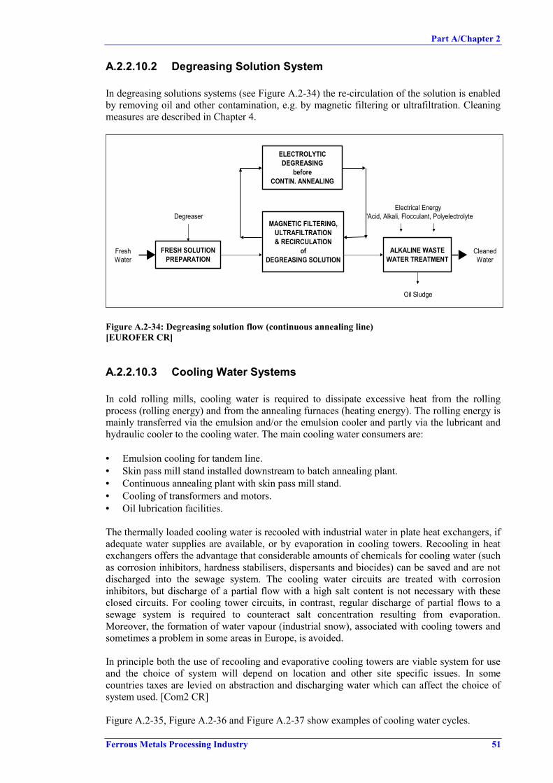
Part A/Chapter 2
Ferrous Metals Processing Industry 51
A.2.2.10.2 Degreasing Solution System
In degreasing solutions systems (see Figure A.2-34) the re-circulation of the solution is enabledby removing oil and other contamination, e.g. by magnetic filtering or ultrafiltration. Cleaningmeasures are described in Chapter 4.
Electrical EnergyDegreaser 'Acid, Alkali, Flocculant, Polyelectrolyte
Fresh CleanedWater Water
Oil Sludge
ELECTROLYTIC DEGREASING
beforeCONTIN. ANNEALING
MAGNETIC FILTERING, ULTRAFILTRATION & RECIRCULATION
ofDEGREASING SOLUTION
FRESH SOLUTION PREPARATION
ALKALINE WASTE WATER TREATMENT
Figure A.2-34: Degreasing solution flow (continuous annealing line)[EUROFER CR]
A.2.2.10.3 Cooling Water Systems
In cold rolling mills, cooling water is required to dissipate excessive heat from the rollingprocess (rolling energy) and from the annealing furnaces (heating energy). The rolling energy ismainly transferred via the emulsion and/or the emulsion cooler and partly via the lubricant andhydraulic cooler to the cooling water. The main cooling water consumers are:
• Emulsion cooling for tandem line.• Skin pass mill stand installed downstream to batch annealing plant.• Continuous annealing plant with skin pass mill stand.• Cooling of transformers and motors.• Oil lubrication facilities.
The thermally loaded cooling water is recooled with industrial water in plate heat exchangers, ifadequate water supplies are available, or by evaporation in cooling towers. Recooling in heatexchangers offers the advantage that considerable amounts of chemicals for cooling water (suchas corrosion inhibitors, hardness stabilisers, dispersants and biocides) can be saved and are notdischarged into the sewage system. The cooling water circuits are treated with corrosioninhibitors, but discharge of a partial flow with a high salt content is not necessary with theseclosed circuits. For cooling tower circuits, in contrast, regular discharge of partial flows to asewage system is required to counteract salt concentration resulting from evaporation.Moreover, the formation of water vapour (industrial snow), associated with cooling towers andsometimes a problem in some areas in Europe, is avoided.
In principle both the use of recooling and evaporative cooling towers are viable system for useand the choice of system will depend on location and other site specific issues. In somecountries taxes are levied on abstraction and discharging water which can affect the choice ofsystem used. [Com2 CR]
Figure A.2-35, Figure A.2-36 and Figure A.2-37 show examples of cooling water cycles.
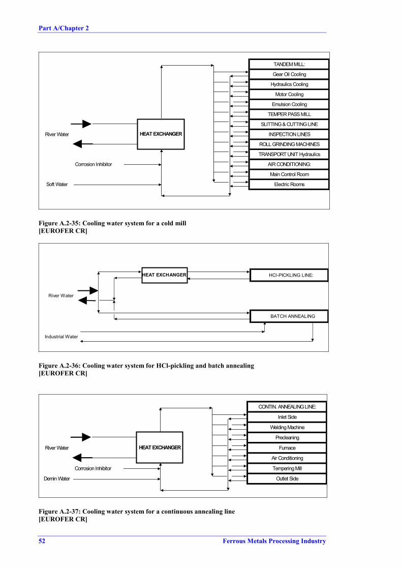
Part A/Chapter 2
52 Ferrous Metals Processing Industry
TANDEM MILL:
Gear Oil Cooling
Hydraulics Cooling
Motor Cooling
Emulsion Cooling
TEMPER PASS MILL
SLITTING & CUTTING LINE
River Water INSPECTION LINES
ROLL GRINDING MACHINES
TRANSPORT UNIT Hydraulics
Corrosion Inhibitor AIR CONDITIONING:
Main Control Room
Soft Water Electric Rooms
HEAT EXCHANGER
Figure A.2-35: Cooling water system for a cold mill[EUROFER CR]
HCl-PICKLING LINE:
River Water
BATCH ANNEALING
Industrial Water
HEAT EXCHANGER
Figure A.2-36: Cooling water system for HCl-pickling and batch annealing[EUROFER CR]
CONTIN. ANNEALING LINE:
Inlet Side
Welding Machine
Precleaning
River Water Furnace
Air Conditioning
Corrosion Inhibitor Tempering Mill
Demin Water Outlet Side
HEAT EXCHANGER
Figure A.2-37: Cooling water system for a continuous annealing line[EUROFER CR]

Part A/Chapter 2
Ferrous Metals Processing Industry 53
A.2.2.10.4 Waste Water Treatment
Waste water from cold rolling operations, which cannot be regenerated or used elsewhere in theproduction line, has to be treated prior to discharge. Acidic waste water from rinsing or acid regeneration is usually treated by neutralisation withagents, such as calcium hydroxide or sodium hydroxide. The dissolved metal ions areprecipitated as hydroxides and then separated by sedimentation techniques includingclarification or filtration. Flocculants are sometimes used to assist the process. The sludge is de-watered, e.g. by filter presses, to reduce the final volume of sludge. Where electrolytic chemical pre-pickling processes are used additional effluent treatment stepsmay be required. Typically these can incorporate chromium (VI) reduction processes usingsodium bisulphite or iron (II) compounds.
Alkaline waste water streams may be neutralised using HCl, filtered and then discharged.
Spent coolants/lubricants (emulsions) are treated by emulsion breaking, either done thermal,chemical, mechanical or physical, followed by a separation of water and oily phase
A.2.2.11 Waste and By-product Management in Cold Rolling Mills
Cold rolling gives rise to solid residues, such as scrap (cleaning rags, cleaning paper), sludgesfrom the waste water treatment plants, remainder of packing material and dust.
Scrap is recycled in the works for steel production. The oil-containing sludges from the wastewater treatment plants may be used in blast furnaces.
Acid regeneration sludges can be recycled in steel plants (EAF and blast furnace) or given toexternal recycling firms for the production of iron oxides.
The iron sulphate-heptahydrate from the sulphuric acid regeneration plant can be used:- For the production of complex iron-cyan salts.- As flocculation agents in waste water treatment plants.- For the production of gas adsorption mass.- As chemical amelioration agent.- For the production of iron oxide pigments, and- For the production of sulphuric acid [Com D].The iron oxide from the hydrochloride acid regeneration can be used in several industries ashigh quality input, e.g.:
- As input for the production of ferromagnetic materials.- As input for the production of iron powder, or- As input for the production of construction material, pigments, glass and ceramics [Com D].
Sludges from oil recovery are externally used, either by incineration or for oil recuperation inspecially dedicated plants.
Only a small part of the sludges from waste water treatment is internally recycled, the vastmajority of is landfilled.
Oily wastes (oil, emulsion, greases) arising are internally or externally used by incineration.

Part A/Chapter 2
54 Ferrous Metals Processing Industry
A.2.3 WIRE PLANTS
A.2.3.1 Wire Drawing Process Overview
Wire drawing is a process in which wire rods/wires are reduced in size by drawing themthrough cone-shaped openings of a smaller cross section, so called dies. The input usually iswire rod of diameters raging from 5.5 to 16 mm obtained from hot rolling mills in form of coils.A typical wire drawing process line comprises the following steps:
• Pre-treatment of the wire rod (mechanical descaling, pickling).• Dry or wet drawing (usually several drafts with decreasing die sizes).● Heat treatment (continuous-/discontinuos annealing, patenting, oil hardening).• Finishing.
Wire is manufactured in different grades of steel: low carbon steel with carbon content of up to0.25 %, high carbon steel with a carbon content of over 0.25 %, stainless and other alloy steel.Non-alloy steel wire can be uncoated or coated with zinc, copper, brass, tin, nickel, chrome,plastic or varnish. Wire is send in coil form to further processing, like coating andmanufacturing of finished products (e.g. cable, mesh, barbed wire, wire fencing, grill, springs,nails). [Bekaert94], [Pan97]
raw material
wire rod preparation
dry drawing
recristallisationor annealing, dependingon mechanical properties
galvanization *
further internal or external processing
chemical pickling
rinsing
put soap carrier
mechanical descaling
heat treat in lead bath
drawing machine
wire rod storage
water quench bath
pickling in line
rinsing
flux bath
zinc bath cooling
pot or bell annealing
evt. waxing
* galvanization is dealt with in Part B of this BREF
Figure A.2-38: Production of low carbon galvanized wire[Bekaert98]

Part A/Chapter 2
Ferrous Metals Processing Industry 55
raw material
wire rod preparation
dry drawing
patenting
galvanization *
further internal or external processing
chemical pickling
rinsing
put soap carrier
mechanical descaling
heat treat in oven
drawing machine
wire rod storage
heat treat in lead bath
pickling in line
rinsing
flux bath
zinc bath
cooling
water quench bath
* galvanization is dealt with in Part B of this BREF
Figure A.2-39: Production of high carbon galvanized wire[Bekaert98]
Because of the huge variety of wire products, many different processing schemes exist, dictatedby wire diameter and required mechanical and other quality specifications. The process schemesshown in Figure A.2-38 and Figure A.2-39 cover the majority of galvanized wire that isproduced in Europe (and worldwide). A fraction is sold as such; a fraction is processed furtherby wet drawing or by processes that fall out of the scope of the BREF, such as welding,electroplating, weaving, cabling, bunching, painting, plastic coating, cutting to length, etc.
A.2.3.2 Wire Rod Preparation
Air-cooling after rolling produces an iron oxide-layer (scale) on the wire rod surface. This layeris very hard, brittle and not deformable and must therefore be removed before any furtherprocessing can take place. In most cases, this is done by the wire industry. For stainless steelhowever, this is typically done by the steel mill.
Two techniques for descaling wire rods are applied: mechanical descaling and chemicalpickling. Some categories of end products can only be produced from mechanically descaledwire at a reduced drawing speed (needing more drawing machine capacity, meaning higherinvestment costs). The decision on the descaling technique is therefore done by each individualplant, based on product qualities and economical considerations.

Part A/Chapter 2
56 Ferrous Metals Processing Industry
A.2.3.2.1 Mechanical Descaling of Wire Rod
In the most common mechanical descaling method applied: wire bending, the wire is bend tocause the brittle scale to peel off. Other descaling techniques, like sanding, brushing or shotblasting, are used as a finishing step after wire bending to remove loose scale or are used asstand-alone techniques.
Batch shot blasting is a common technique for mechanical descaling of heavy diameter wire rod(e.g. used for cold heading applications). However mechanical descaling is generally done in acontinuous way.
Depending on the finish of the wire rod and the quality requirements of the product, descalingby reverse bending is completed or possibly replaced by an abrasive method such as sanding,brushing, shot blasting or stream descaling. By combining reverse bending with one of theseauxiliary methods, complete removal of the oxide layer can be achieved, reaching a similarsurface cleanliness as with chemical pickling. [Com2 BG]
Compared to chemical pickling of wire rod, mechanical descaling has the advantage that oneproduction step is eliminated as the descaling unit is normally coupled directly to the drawingmachine. On the other hand, it is difficult to obtain the same level of drawability withmechanical descaling. [CET-BAT]
A.2.3.2.2 Chemical Descaling (Pickling) of Wire Rod
In chemical descaling the mill scale is removed by dissolving in acid. Acids used are:
• Sulphuric or hydrochloric acid for low carbon wire.• Hydrochloric acid for high carbon wire.
Pickling is mostly done in a batch process. Each roll of wire rod is immersed in the acid bath.The acid slowly dissolves the oxide layer by transforming it into iron chlorides or sulphates.When pickling in HCl an H2-inhibitor is used to suppress the reaction: 2 HCl + Fe -> FeCl2 + H2and reduce the unwanted loss of iron.
After pickling the wire rod coils are rinsed in water. This is usually done in cascade rinsing (e.g.rinsing 3 times) to yield maximum rinsing efficiency and minimum water consumption.[Bekaert94], [Bekaert98]
A.2.3.2.3 Application of Soap (Lubricant) Carrier
In some cases, soap carrier is applied to enhance the adhesion of the lubricant to the wire. Awide range of soap carriers is available. Selection is made on economical basis and on requiredproperties in downstream processes. Traditional soap carriers include lime, borax and Zn-phosphate. Modern soap carriers are typically mixtures of soluble salts, e.g. sodium andpotassium sulphate, chloride, borax, phosphate or silicate. They are adapted to a particular soapand a particular drawing situation.
Soap carrier is applied before drawing by dipping the wire in a watery soap carrier solution.This can be done in a batch process, usually associated with chemical descaling, or continuousin association with mechanical descaling.

Part A/Chapter 2
Ferrous Metals Processing Industry 57
A.2.3.3 Drawing
A.2.3.3.1 Dry Drawing of Wire
Dry drawing is typically used to draw wire rod (> 5.5 mm) to a product diameter of 1 - 2 mmand some times even lower. The diameter of wire is reduced by passing it through a series ofdies with diminishing diameter. Before entering the dies, the wire is passed through a drylubricant. In most cases, soap-based lubricants are used with the soap formulation depending onchoice of fats from which the soap is produced, choice of fillers or choice of additives. Inexceptional cases (e.g. special steels, wire with special metal coatings) other lubricants likepastes or oils can be used.
The drawing operation heats both (wire and drawing die) through friction of the wire. Coolingis done indirectly, by cooling the capstans in contact with the wire with water.
Wet Drawing of Wire
Wet drawing is typically used to draw wire with an intermediate product diameter of 1 - 2 mmto final diameter. The wire is also passed through a series of dies with diminishing diameter, butwire, dies and capstans are immersed in a lubricant liquid that provides lubrication and cooling.Typically, soap or oil emulsions (for some applications plain oil) are used. The heat resultingfrom drawing operation is taken up by the lubricant, which is cooled indirectly with water.
A.2.3.4 Heat Treatment of Wire
Heat treatment of wire has different goals. Therefore different types of heat treatment areavailable depending on the type of steel (low carbon / high carbon / stainless) and the final use(desired ductility and strength). Heat treatment also thermally removes soap and lubricantresidues.
A considerable percentage of the output of the wire industry does not need any heat-treatment.The heavy deformation of the metal crystal structure caused by drawing is mostly a positiveproperty, as it increases the hardness and the strength of the wire in the axial direction.
A.2.3.4.1 Batch Annealing of Low Carbon Steel Wire
Drawing profoundly deforms the shape of the metal crystals of the wire. Annealing is one of thedifferent methods to re-obtain a suited crystal shape. Batch annealing, typically used for lowcarbon steel wire to obtain a very soft and ductile end product, is done in bell or pot furnaces.
Batch annealing is done by putting coils of drawn wire in chambers (called "pots" or "bells"),filled with a protective gas. The protective gas is either neutral or reducing. The most commonprotective gasses are nitrogen, hydrogen, nitrogen/hydrogen mixtures and partly oxidizednatural gas (or similar fuel). The chambers are heated from outside, typically by gas or fuel.The warming up from room to peak temperature (roughly 700 °C) takes several hours; alsocooling down again takes several hours. In order to keep an over-pressure in the "pots" or"bells", a fraction of the protective gas is continuously purged.
In some cases, the wire is oiled immediately after annealing.

Part A/Chapter 2
58 Ferrous Metals Processing Industry
A.2.3.4.2 Continuous (In-Line) Annealing of Low Carbon Steel Wire
Continuous annealing or strand-annealing has a similar goal as batch annealing: restore a suitedcrystal texture to the steel in the wire after drawing. But the desired crystal shape and metalproperties are different from those that are desired when batch-annealing is applied. Continuousannealing is a typical heat treatment method for low carbon products.
Strand-annealing is a fast continuous process. The wire is heated up to the recrystallisationtemperature (500 - 700 °C), is kept at this temperature for a few seconds, and is cooled downagain by quenching in a water bath.
A typical line is equipped for 15 - 50 wires and is characterised by a particular v x d (wire speedx wire diameter). This means that wires of different diameters can be processed together at thesame line, but the higher the diameter of a wire, the lower its speed. Modern lines have a v x dof 100 - 200 m/min x mm (in other words, a 1 mm wire is processed at speeds of 100 - 200m/min). For specialities, lines with a few or only one wire and/or operating at a lower v x d, areused. Strand-annealing is often combined in one production line with other unit processes e.g.with hot-dip coating.
Commonly the wire is heated by passing through a molten lead bath. A fast heat-up is essentialfor strand–annealing. Due to a very high heat transfer coefficient of lead (3000 W/m2.K)equilibrium between wire and lead-bath temperature is reached after a few seconds. Othermethods such as an oven or inductive heating are alternatives, only in some niches e.g. one-wirelines, lines operating at low speed or lines designed to run with only one diameter at a time.
After the heat-treatment, the wire is generally quenched in water. This can be followed by in-line pickling with warm or cold HCl to remove oxides which also partly dissolves thepotentially dragged lead. Other acids or electrolytically assisted pickling can be used as well.Pickling is followed by a rinsing cascade. At some plants, pickling is done as the first operationof the next process step. Often pickling is omitted after heat treatment under protectiveatmosphere.
A.2.3.4.3 Continuous (In-Line) Annealing of Stainless Steel Wire
Stainless and high alloyed steel wire is continuously annealed to obtain suited metal crystalproperties for (further) drawing operations. For stainless steel, the heat-treatment is done undera protective gas atmosphere. If no protective atmosphere would be used, the stainless steel wirewould be oxidized; removal of these oxides would require pickling with special acids such asHNO3, HNO3/HF,... (cfr. production of stainless steel strip). The temperature profile used,varies with the type -content of Ni, Cr or other alloying elements- of stainless steel that isprocessed (700 – 1100 oC).
The wire is passed through tubes or a muffle, under a protective gas. The purge of protectivegas is similar to what is described for batch-annealing. The first part of the tubes or muffle isplaced in an oven (indirect heating of the wire); the second part is cooled indirectly, e.g. bycooling with water. The heating can be done by electricity (resistance heating, inductiveheating) or by combustion. [CET-BAT]
A.2.3.4.4 Patenting
Patenting is a heat-treatment method typically used for high-carbon and alloyed steel productsto create a special crystal structure, which allows easy further deformation. In contrast to

Part A/Chapter 2
Ferrous Metals Processing Industry 59
annealing where iron and iron/carbon compounds tend to be separated, patenting yields astructure where the carbon is homogeneously distributed in the iron.
Patenting is done by heating the wire to 850 - 1000 °C, then cooling fast to 450 - 600 °C andkeeping the wire for a while a this temperature, and finally quenching in water. Patenting isusually done continuously and often combined with other unit processes, e.g. hot dip coating.
Heating to 850 - 1000 °C is done in an oven where the wire is in contact with the combustiongasses. Intermediate cooling and keeping at 450 - 600 °C is done in a lead bath. For small linesdesigned for specialities (e.g. fine diameters or mono-wire lines) other heating methods such asheating under protective gas atmosphere and electric ovens can be used. For the patenting ofthick diameters, sometimes a molten salt bath is used.
In the fuel fired oven, a slight substoichiometric mixture is used in the burners. In this way, allO2 is excluded from the oven atmosphere, in order to minimize the formation of iron oxides atthe wire surface. Excessive formation of iron oxide leads to high losses of wire material and toexcessive consumption of pickling acid, and leads to excessive dragout of lead.
Final cooling is done by quenching in a water bath followed by the same procedure as incontinuous annealing.
A.2.3.4.5 Oil Hardening and Tempering (Oil Tempering)
Oil hardening and tempering creates a special crystal structure in the steel with a highpercentage of martensite, resulting in increased hardness and wear resistance combined withgood thoughness. First, the wire is heated to 850 – 1000 oC, followed by rapid cooling.
Heating is typically done under protective atmosphere using electricity (radiation, inductiveheating) or combustion. The purge of protective gas is similar to what is described for batch-annealing. Quenching is traditionally done in oil, but also other quenching media can be usedsuch as water or water with additions. (Note: although it is not unusual to quench in othermedia than oil, the normal way of referring to this process step is still oil-hardening).
Oil-hardening is always followed by a tempering or stress-relieving step, in order to remove thestresses caused by the extremely fast cooling. This is done by heating the wire again to 300 -500 °C. Typically a normal oven is used, with electrical heating or direct heating with a typicalcombustion gas, but also inductive heating can be used.
A.2.3.4.6 Stress-relieving
The goal of stress-relieving is to remove internal stresses in the wire caused by a previousprocessing steps, without changing the shape and structure of the steel crystal. The internalstresses can be caused by deformation (mechanical stresses) or by fast cooling (thermalstresses). Stress-relieving as a stand-alone heat-treatment step is a typical process step for theproduction of PC-strand (wire for prestressed concrete).
Stress-relieving can be done at various temperatures (200 - 500 °C), dependent on the desiredcharacteristics of the final product. Typically a normal oven is used, with electrical heating ordirect heating with a typical combustion gas, but also inductive heating can be used. Afterstress-relieving, the wire is cooled relatively slowly in air or water. [CET-BAT]

Part A/Chapter 2
60 Ferrous Metals Processing Industry
A.2.3.5 In-line Pickling
In-line pickling is a typical operation after heat-treatment and/or before hot-dip coating of wire.It is used to clean the wire and to remove metal oxides. The wire is passed continuously throughone or more acid baths. The most common acid is HCl, but other acids can be used. Thepickling takes place in a very short time (a few seconds), therefore the acid is often heatedand/or used in concentrated form. After pickling the wire is rinsed in water.
Finishing of wire includes the application of metallic or non-metallic coatings. Galvanizing ofwire is covered in Part B of this BREF. In-line pickling will also be dealt with in detail in Part Bof the BREF.

Part A/Chapter 3
Ferrous Metals Processing Industry 61
A.3 PRESENT CONSUMPTION AND EMISSION LEVELSFOR HOT AND COLD FORMING
A.3.1 Hot Rolling Mills
A.3.1.1 Mass Stream Overview
By-products andWaste
Air Emissions
Oil
Slabs/BloomsBillets/Ingots
Waste Water
Hot Rolling MillSurface rectification Re-heating RollingFinishing Wastewater Treatment Roll Shop
Miscellaneous
Hot RolledProduct
Water
Energy
Particulates
NOx
SO2
CO/CO2
VOC
Suspended Solids
Oil, Grease
Water Treatment Sludge
Oxycutting & scarfing slags
Filter Dust
Furnace Scale
Mill Scale/Mill Scale Sludge
Steel Scrap
Refractory
Miscellaneous Waste Heat (steam, hot water)
Noise
Detergents
Flocculating Agents
Biocides
Corrosion Inhibitors
Refractories
Grease/Oil
Rolling Oil
Natural or Plant Gas (BOF,BF, COG)
Fuel Oil
Electricity
Steam
Oxygen
Cooling Water
Process Water
Figure A.3-1: Input/output overview for hot rolling mills
The subsequent chapters present specific input and consumption data, as well as specific outputand emission data for individual operational steps associated with the manufacture of hot rolledproducts.

Part A/Chapter 3
62 Ferrous Metals Processing Industry
A.3.1.2 Surface Rectification and Conditioning of Input
The consumption of fuel (natural gas, liquefied petroleum or plant gases) and oxygen forscarfing depends on the dimensions of the rolling stock. Variations of 20 % in consumption andemissions are possible when the e.g. thickness of a slab is increased from 200 mm to 250 mm.Typical consumption for automatic scarfing of billets was reported as 5 m3 oxygen/t and 25 MJ(propane)/t steel processed. No data available on water consumption for scarfing or on theamount of waste water, which is generally discharged to the rolling mill or continuous castingwater treatment plant and is reused in the mill water system. [EUROFER HR]
During scarfing wet, corrosive fumes with high proportions of sub-micron particles (size rangefrom 0.5 to 250 microns) are generated. Samples of this fume, taken at the electrostaticprecipitator inlet, showed concentrations of 60 mg /m3 for CO, 35 mg /m3 for NOx and a rangeof 230 - 3000 mg /m3 for dust. [HMIP]
Scarfing:Input / Consumption Level
Energy n.a.Oxygen n.a.Water n.a.
Output / Emission LevelSpecific Emission Concentration
Dust 1 1 - 80 2 g/t 5 – 115 3 mg/m3
Filter dust 1.5 - 3.25 2 kg/tNOx 7
CO 7n.a.n.a.
approx. 35approx. 60
mg/m3
mg/m3
Scale n.a.Waste water no discharge, reused in
mill water systemGrinding:
Input / Consumption LevelEnergy no representative data availableWater no representative data available
Output / Emission LevelSpecific Emission Concentration
Dust: 4mild steel < 30 - 100 5, 6 mg/m3
stainless steel n.a. < 50 5 mg/m3
Swarf n.a.Noise n.a.Scarfing, grinding and shot blasting:
Scale (dry material) < 0.2 - 35 2 kg/t1 Dust emitted in cleaned waste gas2 Source of data: [EC Study]3 Resulting range from the sources [SIDMAR], [CITEPA] and [EUROFER HR]4 [CITEPA] reports 1 - 10 mg/m3 without distinction of mild and stainless steel5 Source of data [EUROFER HR]6 Examples, abatement: fabric filter, V= 2.5 and 7 Nm3/s7 [Com HR]
Table A.3-1: Consumption and emission levels for surface preparation

Part A/Chapter 3
Ferrous Metals Processing Industry 63
The dust generated by scarfing contains mainly iron oxides with some trace alloying elementspresent in steel. Dust emission factors vary significantly, depending on whether scarfing is doneautomatic (30 - 60 g/t) or manual (3 g/t). [CITEPA]
Samples of the composition of emitted dust from scarfing show the following metal contents:Cr 0.5 - 10 g/kg, Ni 1 - 5 g/kg, Mn 5 - 20 g/kg, Pb 1.7 - 2.3 g/kg, Cu 7.5 - 8.6 g/kg. [EC Study]
For dust collected from grinding and shot blasting of stainless steel following contents werefound: Cr 3 - 100 g/kg, Ni 6 - 20 g/kg, Mn 4 - 10 g/kg. [EC Study]
A.3.1.3 Reheating and Heat Treatment Furnaces
Energy consumptionIntegrated steel plants try to valorise as much as possible the gases arising within the works forinternal use. Hence blast furnace gas, coke oven gas, BOF gas, natural gas and a lot of differentcombinations of these gases (so-called mixed gases) are used in continuous furnaces. Theenergy consumption of the furnaces depends on several parameters such as:
• The furnace design (pusher-type, walking beam, etc.).• Throughput and shift patterns (operating time) [Com UK].• The designed length of the recuperation zone in the furnace.• The burner design.• The use of recuperators or of a regenerating system.• The production capacity of the furnace.• The heating zone arrangement.• The charging temperature of the stock.• The heating and discharging temperature.• The accuracy of the thermal regulation, and.• The degree of insulation of the furnace [EUROFER HR].
Figure A.3-2 shows the energy balance of a typical reheating furnace in form of a sankeydiagram, only half of the energy input is heat to reheat the steel.
Dust (particulates)Because of the nature of the fuel used (BFG previously dedusted, NG no dust) dust emissionsare low. Some data reported show an average of 13 g dust/ tonne rolled steel and a median of8 g/t. The highest emission values correspond to the use of fuel oil. [EUROFER HR], [ECStudy]
NOxThe NOx emission level depends mostly on the type of the fuel and on the burner type anddesign, e.g. ceiling burners emit less NOx than front or lateral burners. The use of recuperatorsor of a regenerative system increases the thermal efficiency of the furnace, but can lead also to ahigher NOx concentration (up to 3500 mg/Nm3). In some countries a higher NOx level isallowed for higher air preheat temperatures. In conventional burners, high flame temperaturesresult in high NOx emission levels. Typical value for the NOx level is 500 mg/Nm³ (natural gas,3 % O2, combustion air at ambient temperature). The preheating of the combustion air (withrecuperative or regenerative systems) can increase the NOx level exponentially. [EUROFERHR]
SO2The SO2 emission level depends on the S-content in the available fuel. Reported SO2 emissionsin dependence on fuel type show a difference in the SO2 emission levels between natural gas,works arising gas and fuel oil. Average values are 9.7 g SO2/t for natural gas, 452 g SO2/t for
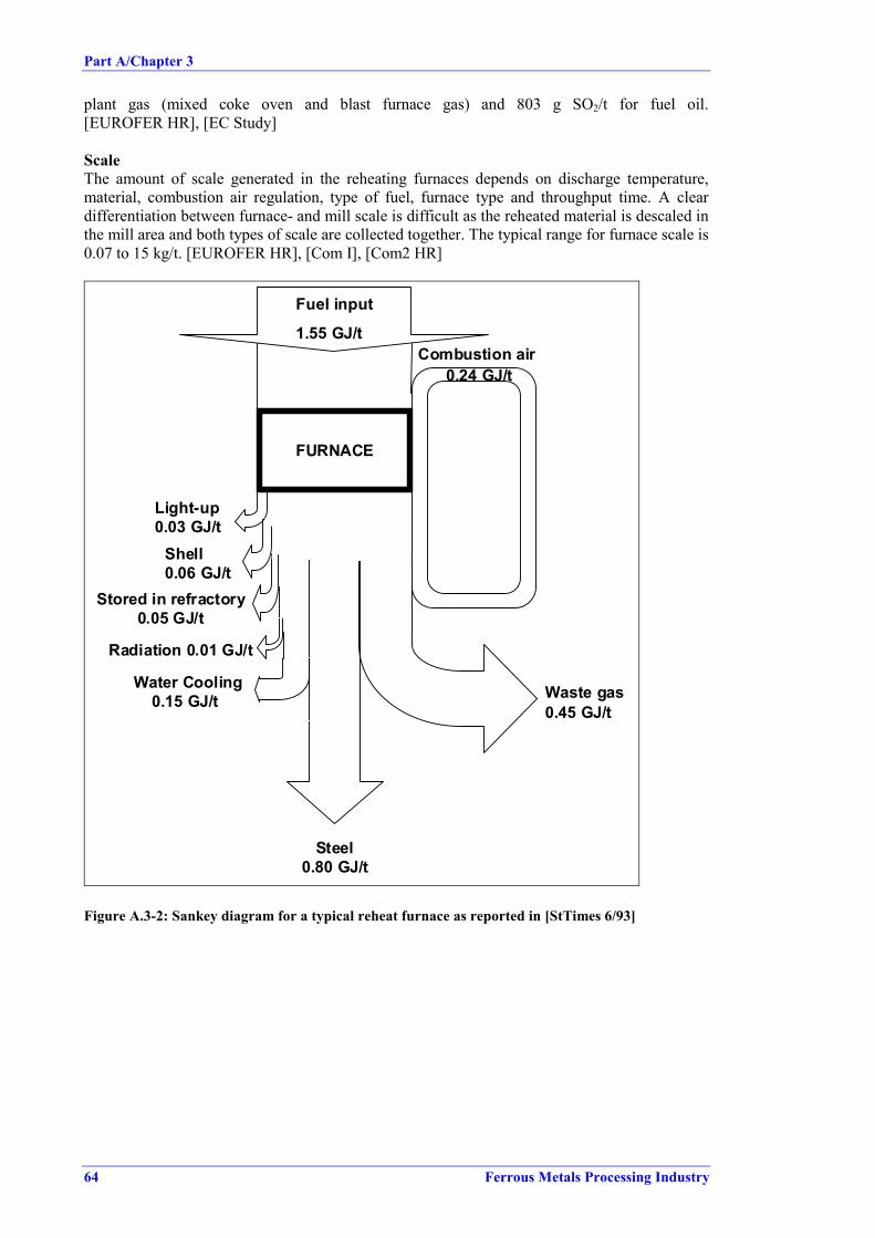
Part A/Chapter 3
64 Ferrous Metals Processing Industry
plant gas (mixed coke oven and blast furnace gas) and 803 g SO2/t for fuel oil.[EUROFER HR], [EC Study]
ScaleThe amount of scale generated in the reheating furnaces depends on discharge temperature,material, combustion air regulation, type of fuel, furnace type and throughput time. A cleardifferentiation between furnace- and mill scale is difficult as the reheated material is descaled inthe mill area and both types of scale are collected together. The typical range for furnace scale is0.07 to 15 kg/t. [EUROFER HR], [Com I], [Com2 HR]
FURNACE
Combustion air
Fuel input
1.55 GJ/t
Waste gas0.45 GJ/t
Steel0.80 GJ/t
Light-up0.03 GJ/t
Shell0.06 GJ/t
Stored in refractory 0.05 GJ/t
Radiation 0.01 GJ/t
Water Cooling 0.15 GJ/t
0.24 GJ/t
Figure A.3-2: Sankey diagram for a typical reheat furnace as reported in [StTimes 6/93]

Part A/Chapter 3
Ferrous Metals Processing Industry 65
Input / Consumption LevelEnergy: 1.1 - 2.2 6,10 GJ/tCooling water(for components of the re-heating furnace)
closed looprecycled completely
Output / Emission LevelSpecific Emission Concentration
Dust 1 1 - 10 6, 8 g/t 4 - 20 6 mg/Nm3
NOx 2,3 80 - 360 6 g/t 200 - 700 6 mg/Nm3
Conventional burners 2 - 600 4 g/tLow-NOx burner 150 - 500 4 g/t 25011 - 900 5 mg/Nm3
Regenerative burner 1000 - 4000 4 g/t
SO2 3 0.3 - 600 6, 9 g/t 0.6 - 1300 6 mg/Nm3
400 - 800 5 mg/Nm3
CO 5 - 850 5, 7 g/t 100 - 170 5 mg/Nm3
Hydrocarbon ( for BFG + NG firing) 0 - 5 5, 7 g/t
Furnace scaleReversing, 4-high-MillsHot Strip MillsBlooming/Billet/ Heavy Section MillsLight/Medium Bar and Section MillsWire Rod Mills
0.5 - 18 40.1 - 11 40.5 - 47 4
1 - 30 40.3 - 20 4
kg/tkg/tkg/tkg/tkg/t
Waste refractory1 [CITEPA] reports 200 - 1400 g of dust/t for continuous and 100 g/t for soaking pits with fuel oil firing, cautionary
note: may not be representative.2 [EC Study] reports an average of 383 g/t for low-NOx burners, 1690 g/t for regenerative burners and 228 g/t for
conventional burners.3 [CITEPA] reports 5 - 10 g/t for a mixture of blast furnace gas and natural gas, cautionary note: may not be
representative.4 Source of data [EC Study]5 Reference [CITEPA]6 Source of data [EUROFER HR]7 Cautionary note: may not be representative8 [DFIU98] reports 0.2 - 30 g/t9 [DFIU98] reports 0.02 - 900 g/t10 [ETSU-G76] reports typical energy consumption 2.0 – 3.0 GJ/t, scattering from 0.7 – 6.5 GJ/t11 [Input-HR-1]12 [Vercaemst 30.3] reported 2.2 – 63 mg/Nm3
Table A.3-2: Consumption and emission levels for reheating/heat treatment furnaces
A.3.1.4 Descaling
WasteMill scale from descaling operations, after the reheating furnace and in-between rolling passes,consists mainly of iron oxides, like FeO and Fe3O4. The exact composition varies, depending onthe steel grade rolled and the rolling process, but the iron content is usually about 70 % (on an

Part A/Chapter 3
66 Ferrous Metals Processing Industry
oil and moisture free basis). Chemical analysis of mill scales show an average hydrocarboncontent of 4.6 % with a scattering range of 0.5 - 8.7 %. High hydrocarbon content may limitrecycling. [EC Study] Reported compositions of mill scale sludge show ranges of 25 – 65 % forsolids, 30 – 60 % water and 2 – 15 % for oil. [STuE-114-1]
Due to the use of lubrication oil and grease during rolling, mill scale is contaminated. Oilcontents depend on process operation, technical equipment and, especially, on the quality ofmaintenance. Another factor influencing the oil content of mill scale is particle size. The veryfine particle portion of mill scale (referred to as mill scale sludge) consists of particles smallerthan 63 µm, which tend to adsorb oil. [DFIU98]
The typical range of scale generated is reported as 12.7 - 16 kg/t for oil-free scale and 1.9 - 3.5kg/t for oily scale. [EUROFER HR]
Waste waterThe process water used for descaling directly after the furnace is usually oil-free. The processwater used for descaling within the hot rolling section mostly contains oil due to losses and dueto the contact with the rolling equipment. The two waste water streams are usually mixed,resulting in one oil containing, scale loaded waste water stream. The coarse share of the scaleload can be removed in settling tanks and, due to relatively low oil contents, be recycled to themetallurgical process.
Input / Consumption LevelWater:
Cogging trainbefore finishing trainafter finishing train
n.a.n.a.n.a.
m3/tm3/tm3/t
0.1 - 0.12 10.05 - 0.06 10.03 - 0.04 1
m3/sm3/sm3/s
Energy n.a.Output / Emission Level
Specific Emission ConcentrationWaste water n.a. m3/t
Containing scale and oil n.a.Oil free scale3:
Reversing, 4-high-Mills 1.6 - 23 2 kg/tHot Strip Mills 10 -20 2 kg/tBlooming/Billet/Heavy Profile Mills 9 - 38 2 kg/tLight/Medium Bar and Section Mills 3 - 60 2 kg/tWire Rod Mills 5 - 20 2 kg/t
Oily scale3:Reversing, 4-high-Mills 1 - 36 2 kg/tHot Strip Mills 2.7 - 30 2 kg/tBlooming/Billet Mills 0.4 - 28 2 kg/tLight/Medium Bar and Section Mills 0.5 - 20 2 kg/tWire Rod Mills 0 - 20 2 kg/t
1 Source [DFIU98]2 Source [EC Study]3 Austria reported: Coarse scale 20 – 30 kg/t for flat products, 5 – 10 kg/t for long products, scale sludge (fine scale) from finishing group 3 – 15 kg/t [Com A]
Table A.3-3: Consumption and emission levels for descaling

Part A/Chapter 3
Ferrous Metals Processing Industry 67
A.3.1.5 Hot Rolling
The energy demand for the motor-driven rolls depends on the degree of deformation,temperature of the work piece and material hardness. Energy is used in form of electricity.
Water consumption and water discharge depend on how the water flow is designed (watermanagement). Water discharge close to 0 m3/t can be achieved by closed circuits. Semi-closedcircuits have discharge rates of typically up to 11 m3/t maximum, whereas open systems (once-through) will lead typically to 11 - 22 m3/t.
Emissions to air are dust, originating from the mill stands and for strip products from coilhandling lines. Fugitive oil emissions originate from the mill stands (work roll lubrication). Thequantity of dust emissions from hot rolling depends largely on the rolling speed and the productsurface area.
Input / Consumption LevelRolling and lubrication oilWater 1 - 15.5 2, 3 m3/tEnergy:
Deformation energy 72 – 140 2, 4 kWh/tOutput / Emission Level
Specific Emission ConcentrationParticulates (oxides, dust)
Mill stands: 2 - 40 1 g/t 2 - 50 2 mg/m3
Coil handling lines ≈ 50 2 mg/m3
Filter dust (collected from rolling stands) 100 – 7 600 1 g/tFugitive oil emissions 5 negligibleWaste water: (containing suspended solids,oil…)
0.8 -15.3 2 m3/t
Sludge from waste water treatmentMetallic by-products: Crops, rolling rejections,cuttings, etc.
70 – 150 6 kg/t
1 Source of data [EC Study]2 Source of data [EUROFER HR]3 [EC Study] reports up to 22 m3/t4 Upper end of range reported by [Com I]5 Generated inside the mill bay, remarkable in near vicinity of emission source only and from that not significant for
releases to air [EUROFER HR]6 Source [Com A]
Table A.3-4: Consumption and emission levels for hot rolling
A.3.1.6 Roll Shop�No data available.
A.3.1.7 Oil, Grease and Hydraulic Oil Flow
Oil and greases used for lubrication and hydraulic oil result in oil-bearing waste water andwaste. Large parts of the oil/grease input are carried out of the system by the product, by millscale, by the waste water or by emission to air. An estimated 300 g/t flat products and anestimated 100 - 800 g/t long products is emitted as hydrocarbon to air due to evaporation, e.g.

Part A/Chapter 3
68 Ferrous Metals Processing Industry
when in contact with the hot metal surface. Figure A.3-3 shows an example of oil and greaseflow in a steel mill. [DFIU 96]
on product
in wastewater
on mill scale
losses due to evaporation,burn-off
leackage losses,piping, filling cleaning
intermediate storage
disposalin waste and sludge
sinter plant
losses during transportand storage
collected or skimmed
Miscellanious
Input (100 %):OilGreaseHydraulic oil
6 %
6 %
5 %
3 %
39 %
6 %
12 %
5 %
7 %
2 %
wastewatertreatment
used-oiltreatment
discharge
sludgetreatment
fuel
1 %
18 %
8 %
(treated lubricants)
Figure A.3-3: Oily material balance of a typical steel mill as repoted in [DFIU 96]

Part A/Chapter 3
Ferrous Metals Processing Industry 69
A.3.1.8 Hot Rolling Mill Waste Water Treatment Plant
Kind and amount of input depends mainly on the design of the water treatment plant and watertreatment measures applied, e.g. application of flocculate agents or acids. Quality of water inputand the specific water consumption also have an influence.
Waste water from scale removal and flume flushing contains, apart form coarse scale,suspended solids and emulsified oil. Large amounts of water are used for roll and materialcooling, which also contain oil and suspended solids. The solid concentrations range from 120to 2000 mg/l (others report 50 to 1000 mg/l [DFIU98]); oil contents from 10 to 200 mg/ldepending on the mill type. [EC Haskoning]
The amount of water discharged from hot rolling mills is reported to range from 0 to 22 m3/tincluding once-through cooling units. When once-through cooling units are excluded, themaximum specific water discharge is up to 11 m3/t. Once-through cooling systems do notcorrespond with 'state of the art'.
Input / Consumption LevelProcesswaterFlocculating agentsOthers
Output / Emission LevelSpecific Emission Concentration
Discharged water:Total suspended solids (TSS) 20 - 1065 1 g/t 5 - 100 1, 3 mg/l
Chemical oxygen demand (COD) 22 - 65 1, 5 g/t 18 - 43 1, 4 mg/l
Hydrocarbon content 1 - 3 1 g/t 0.2 - 10 1 mg/l
Cu 0.009 - 0.26 2, 6 mg/lZn 0.004 - 0.35 2 mg/lCd < 0.05 6 mg/lAl 0.04 - 0.14 2 mg/lPb < 0.1 2, 6 mg/lCr < 0.18 6 mg/Cr6+ 0.01 mg/lMn 0.04 - 0.26 2 mg/lFe 0.3 - 2.0 2 mg/lNi 0.01 - 2.0 2, 6 mg/lHg < 0.01 mg/lFree chlorine 0.1 - 0.5 2 mg/l
Other parameters:pH-value 7 -8.5 1Temperature 11 - 30 oC 1
Water treatment sludge1 Source of data [EUROFER HR]2 Source of data [HMIP]3 [EC Study] reports an extreme of figure of 200 mg/l4 [EC Study] reports normal range up to 80 mg/l, with two extreme figures: 200 and 450 mg/l5 [EC Study] reported data are as high as 300, 800 g/t and more6 Source of data [EC Study]
Table A.3-5: Consumption and emission levels of the water treatment plant

Part A/Chapter 3
70 Ferrous Metals Processing Industry
A.3.1.9 Waste and Recycling
In addition to the information on waste generation for the individual sub-process, Table A.3-6presents an overview of the waste generated in total by hot rolling operations and of theutilisation potentials. The reference base of the hot rolling mill as a whole was chosen, becausea clear distinction of waste sources and attribution of waste amounts to individual processingsteps is impossible in a number of cases.
Kind of waste orby-product/Source
AverageSpecific Mass
[kg/t]
Reported Waste1
[t](steel production)2
Utilization Percentage2
Recycle in-plant 95.9Externally used 4 3.4
Scale(from scarfing, grinding,shot blasting)
3.5 77900(22 Mt) Landfill 0.7
Recycle in-plant 37.6Externally used 4 13.4Externally used 5 9.7Sold5 29.0
Re-heating furnacescale
4 128000(44.7 Mt)
Landfill 10.3Recycle in-plant 74.8Externally used 4 3.6Externally used 5 15.1Sold 5 2.9
Oil-free millscale 14.1 517000(36.8 Mt)
Landfill 3.6Recycle in-plant 81.6Externally used 4 1.6Externally used 5 1.5Sold 5 9.7
Oily millscale 11.2 692800(61.7 Mt)
Landfill 5.6Recycle in-plant 94.8Externally used 5 0.8
Dust and sludges from aircleaning devices,Flat products
0.23 2363(10.2 Mt) Landfill 4.4
Recycle in-plant 16.8Externally used 4 24.5
Dust and sludges from aircleaning devices,Long products
0.71 2492(3.5 Mt) Landfill 58.7
Recycle in-plant 7.7Externally used 6 25.3Sold 5 7.6
Waste water treatmentsludges
3.4 161000(11 Mt)
Landfill 59.4Recycle 6.0Externally used 7 7.7Sold 5 13.8
Dismantled refractories 0.5 21900(46 Mt)
Landfill 72.5Note: data based on [EC Study]; figures given on dry weight-basis1 Submitted as an answer to a questionnaire activity of the EU.2 Steel production of the companies that provided information on utilisation.3 Percentage refers to reported mass/ answered questionnaires.4 Reported by non-integrated plants, recycling in other steel making plants5 No indication on further use6 About a quarter is being recycled in other steel plants7 Principally in refractory plants
Table A.3-6: Waste generated in hot rolling mills and utilisation rates

Part A/Chapter 3
Ferrous Metals Processing Industry 71
A.3.1.10 Noise Issues in Hot Rolling
Excessive noise from hot rolling is primarily an internal occupational health issue, withprecautions normally taken to protect employees where it is not practicable to prevent or reducethe noise at source. In some instances, depending on the location of the process (for exampleclose to a residential area) and the noise characteristics (intermittent, impact and/or highfrequency noise is more often a source of complaint than continuous low frequency noise) therecan be cause for concern off-site, although this depends on the background noise level and othernoise sources nearby.
The most significant sources of noise in the hot rolling process are associated with producthandling. Other sources, such as high pressure descaling, reheat furnace induced draft fans andhot/cold sawing can also be significant. The main issues with product handling are associatedwith impact noise from large diameter pipes and movement of heavy plates, for example.Section mill cooling banks can also be a source of high levels of noise as products are movedduring cooling. High pressure descaling (in some cases greater than 250 bar) is anotherintermittent noise source. Reheat furnace induced draught fans operate continuously but can bevariable speed and therefore will cause noise of varying frequency and noise level. Longproducts, such as sections or rail, are cut to length, on or off line, by either hot or cold saws.High frequency noise is generated by the cutting action/friction. This can be both intermittentand high frequency. The absolute noise levels (in decibel) are equipment/plant specific but canbe in excess of 85 dBA.
In terms of product handling, the main method for reducing noise is to devise operatingprocedures to minimize the amount of contact between products and material handlingequipment such as cooling bank skids. Most other sources of noise are normally withinbuildings and the noise level is moderated to an acceptable level. In the event of specific localproblems, additional measures such as local enclosure and/or building insulation may berequired, but these can be extremely expensive and are not normally considered to be necessary.
A.3.1.11 Commissioning and Decommissioning
The environmental effects of commissioning or the decommissioning in hot rolling mills aregenerally not important. Some facilities are available (e.g. N2 purge in reheat furnaces) to assuresafety during commissioning or decommissioning or to permit the installations to bemaintained.


Part A/Chapter 3
Ferrous Metals Processing Industry 73
A.3.2 Cold Rolling Mills
A.3.2.1 Mass Stream Overview
By-productsand Waste
Air Emissions
Oil
Hot RolledCoil/Bars
Waste Water
Cold Rolling MillPickling Rolling Annealing Tempering Finishing
Acid Regeneration Wastewater Treatment Roll Shop
Miscellaneous
Cold RolledProduct
Water
Energy
Particulates
NOx
SO2
CO/CO2
VOC
Acid Aerosol
HF
Alkaline Aerosols
Oil Mist
Suspended Solids
Oil, Grease
Filter Dust
Scrap
Scale/Scale Dust
Packaging materialMiscellaneous Noise
Waste heat
Degreasing Agents
Inert Gas (H2, N2)
Lime, NaOH,Ammonia, Urea
Hydrogen Peroxide
Flocculating Agents
Biocides
Corrosion Inhibitors
Oil/Grease
Rolling Oil
Natural Gas
Plant Gas
Electrical
Steam
Cooling Water
Process Water
Acid Hydrochloric acid
Sulphuric Acid
Mixed Acid
LiquidWaste
Spent Pickle Bath
Acidic Rinse Water
Spent Degreasing Bath
Spent EmulsionSludgesPickle Tank Sludge
Emulsion Treatment Sludge
Water Treatment Sludge
Scale Sludge
By-products fromRegeneration
( Iron oxide, iron sulphate)
Figure A.3-4: Input/output overview for cold rolling mills
The subsequent chapters present specific input and consumption data, as well as specific outputand emission data for individual operational steps associated with cold rolling activities.

Part A/Chapter 3
74 Ferrous Metals Processing Industry
A.3.2.2 Pickling of Low Alloy, Alloy and High Alloy Steel
Hydrochloric, sulphuric and, for stainless steel, a mixture of nitric and hydrofluoric acid areused as pickling agents. Acid consumption varies obviously depending on whether acid isregenerated or not. It also depends on the specific surface area pickled and the thickness of theoxide layer. [EUROFER CR]
Consumption of anticorrosive oil depends on the percentage of oiled products, on the type ofoiling machine used (electrostatic oiling or spraying nozzles) and on the oil weight required bythe customer. [EUROFER CR]
Energy is required in form of steam for heating the pickling bath, as electrical energy for drives,pumps etc. and as caloric energy (natural gas or LPG) for the regeneration process (HCl). Someplants do not regenerate the acid or subcontract the regeneration, which in both cases can resultin lower energy consumption. However for these plants all the fresh acid has to be heated toworking temperature. [EUROFER CR]
Additionally, for high alloy steel processing, shot (for the shot blast machine) is needed for hotband mechanical descaling. For NOx reduction measures either hydrogen peroxide is needed tobe added to the pickling bath to suppress the formation of NOx during pickling or ammonia orurea is required for SCR installations. [EUROFER CR]
Water is used for rinsing after pickling and to prepare the pickling baths. Three kinds of processwater are created during pickling. These comprise water used for rinsing, spent pickle baths andothers (like water from the fume absorbers of the pickling tank exhaust system and flushingwater from plant cleaning). The main volume of waste water derives from rinsing, whereas themain load of contamination comes from the continuous or batch exchange of pickle baths.[EUROFER CR]
A primary aim should be to reduce waste water volume and minimize contaminant loading ofthe waste streams by optimisation of the pickling process. The waste water volume can bereduced by acid regeneration and recycling. Some plants sell spent pickle acid for external use,e.g. in water treatment. Acidic waste water, e.g. from the rinsing section or the fume scrubbers,which cannot be used in other processes of the installation have to be treated/neutralised prior torelease. Neutralisation, however, requires the use of additional chemicals, like lime, NaOH orpolyelectrolyte.
Scrap, scale dusts and pickle tank sludge arise during pickling operations. From acidregeneration 0.05 to 15 kg sludges (ref. dry material) per tonne of steel arise, with an average of4.2 kg/t. The sludges have an iron content of 55 - 66 % and, in case of stainless steel processing,5 - 10 % Cr and 3 - 5 % Ni. [EC Study]
By-products generated by acid regeneration are iron oxides or iron sulphate. The average ironoxide yield from regeneration is 5.5 kg/t. The Fe2O3 content of the by-products is usually> 99 % with low concentrations of other metals, such as Al < 0.1 %; Pb, Cu < 0.03 %; Cr,Ni < 0.02 % and Zn < 0.01 %. Chloride contents range from 0.1 to 0.2 %.
Iron sulphate production ranges from 2.5 to 25 kg/t with an average of 17 kg/t. Less than 0.1 %of the production is reported to be landfilled as the product can be sold to external usage,including water treatment and chemical industries. [EC Study]
Emissions to air generated by pickling depend partly on the acid used for pickling. They are:• Acid-fumes from the pickling tanks (HCl, H2SO4), emitted from the outlet chimney of the
pickling tank fume exhaust absorber and from the exhaust gas chimney of the acidregeneration plant.
• In case of mixed acid pickling: NOx, HF.

Part A/Chapter 3
Ferrous Metals Processing Industry 75
• Dust, NOx, SOx, H2SO4, HCl from the regeneration plant.• Gaseous emissions from storage facilities [EUROFER CR].
When pre-descaling is applied for stainless steel grades is carried out by electrolytic picklingwith sodium sulfate, chromium containing waste waters and wastes (sludges) may arise.
Many modern pickling lines are operated in association with regeneration plants. Thereforesome of the consumption and emission data presented for the individual pickling processes inthe following chapters include the regeneration process. A distinction was made where possible.Detailed consumption and emission data for the regeneration plant and the exhaust gas cleaningfrom pickling tanks are given in the corresponding chapters for techniques to be considered indetermination of Best Available Techniques.
A.3.2.2.1 Hydrochloric Acid Pickling Line and Regeneration Plant
Regeneration of the pickle liquor is done on- or off site. Figure A.3-5 shows the material flowfor a HCl pickling line in conjunction with acid regeneration.
Exhaust Gas
Fume ExhaustAbsorber
Pickling Loss Drag Out Drag OutIron Scale Fe2O3 + Fe
Pickling Section Fresh Acid Rinsing Section
Fresh WaterFeCl2 + HCl + H2O Rinsing
Waste Acid HCl + H2O WastewaterRegen. Acid
Fe (Scrap) Precipitation
Waste GasLime Neutralisation
Ca(OH)2
Regeneration 2 HCl + FeCl2 + 2 Ca(OH)2 ->Iron Oxide Gas, Air Fe(OH)2 + 2 CaCl2 + 2 H2O
External or internal operations SludgeAir Fe(OH)3
½ O2 + H2O Oxidation
Precipitation
Chemical Reactions during HCl-PicklingPickling Ca2+, Cl- , H2OPicklingPickling Cleaned WaterPickling
Pickling Permanent T°C Pickling automatic control Flow Acidity pH.Regeneration Turbidity
Neutralisation Point of regulatory Neutralisation control by the nationalOxidation and regional authorities
Fe2O3 + 6 HCl -> 2 FeCl3 + 3 H2OFeO + 2 HCl -> FeCl2 + H2O
Fe3O4 + 8 HCl -> 2 FeCl3 + FeCl2 + 4 H2OFe + 2 HCl -> FeCl2 + H2
FeCl3 + ½ H2 -> FeCl2 + HClFe2O3 + Fe + 6 HCl -> 3 FeCl2 + 3 H2O
2 FeCl2 + 2 H2O + ½ O2 -> Fe2O3 + 4 HClHCl + NaOH -> NaCl + H2OFeCl2 + 2 NaOH -> 2 NaCl + Fe(OH)2
2Fe(OH)2 + ½ O2 + H2O -> 2 Fe(OH)3
Figure A.3-5: Flow sheet for HCl pickling and acid regeneration[EUROFER CR]

Part A/Chapter 3
76 Ferrous Metals Processing Industry
Input / Consumption LevelHot rolled strip 1.01 - 1.05 t/tPickling agent:
HCl (33 %) with regeneration 0.7 - 0.9 1 kg/tHCl (33 %) without regeneration 12 - 17.5 kg/t
Anticorrosive oils 0.1 - 0.2 kg/tEnergy: Steam for bath heating 0.03 - 0.07 GJ/t
Electrical energy 0.015 - 0.08 GJ/tCaloric energy 0.04 - 0.1 GJ/t
Industrial + demineralised water 0.02 - 0.13 m3/tCooling water 0.5 - 0.8 m3/t
Output / Emission LevelSpecific Emission Concentration
Waste gas 35 - 100 m3/tWaste air 50 - 400 m3/tExhaust gas from acid regeneration(Dust, SO2, NOx, CO/CO2, HCl, Cl)
24 - 38 m3/t
Exhaust gas from pickling tanksDust2
HCl 3
25 - 400n.a.
0.258
m3/t
g/t< 5 - 20
1 - 30mg/m3
mg/m3
HCl (20 %) recycled 23 - 40 kg/tWaste water 4Spent pickle liquor
0.025 - 0.07 m3/t
Sludge cake 0.043 - 1.2 kg/tPickling tank sludgeOil contaminated wasteIron oxide (Fe2O3) 4 - 12 5 kg/tScale dust( collected by dedusting system)Strip head/tail scrap 30 kg/tNotes: Source of data [EUROFER CR]; Production: 300000 - 2500000 t/a1 Germany reported fresh HCl consumption as low as 0.01 kg/t for closed circuit pickling line [Com D]2 [EUROFER CR] reports 10 – 20 mg/Nm³ , [Corus 31.8] reports < 5 mg/Nm³ .3 [EUROFER CR] reports emission levels of 10 – 20 mg/m3, [EC Study] 1 - 145 mg/m3 and 2 - 16 g/t and [EPA-
453] achieved levels of 2.7 – 3.5 mg/m3., [EUROFER 6.9] reports upper level of 30 mg/Nm³ when includingcontinuous measurements.
4 In some cases no acid regeneration, but free acid reduction with scrap, FeCl2 (used bath): 19.4 kg/t is sold forexternal use
5 Source: [EC Study]
Table A.3-7: Consumption and emission levels for HCl pickling plants (incl. regeneration)
The acid rinsing water from the pickling plant can be used as wash water for gas scrubbers andas process water in the regeneration plant. In case acidic water is not or partially not reused asprocess water, it is neutralised with lime or NaOH in the neutralisation plant prior to discharge.The sludge is de-watered in filter presses and then disposed of. Input and output ofneutralisation, sedimentation and filtration, as well as the concentration of pollutants dischargedare given in Table A.3-8.
Although acidic waste water from gas scrubbing and other acidic waste water are oftenneutralised and the sludge is being disposed of, there are processes which allow a recycling ofthese waste water streams. For hydrochloric acid pickling the possibility of a virtually wastewater free operation was reported. [Com D]

Part A/Chapter 3
Ferrous Metals Processing Industry 77
Input / Consumption LevelRaw Waste water 0.025 - 0.07 m3/tCa(OH)2 (95 %) 0.272 - 0.525 kg/tPolyelectrolyte 0.22 g/tAir 0.259 kg/tEnergy (electrical) 1 MJ/t
Output / Emission LevelSpecific Emission
Sludge Cake 0.043 - 1.2 kg/tWaste water
Suspended solidsFe total
0.025 - 0.072.86
0.114
m3/tg/tg/t
Note: source of data [EUROFER CR]1 Reduction rate based on mass flow of constituent
Table A.3-8: Consumption and emission levels for waste water treatment in HCl-pickling plants
A.3.2.2.2 Sulphuric Acid Pickling Line and Regeneration Plant
Exhaust GasPickling LossIron Scale Drag Out Drag Out
Fe2O3 + Fe Pickling Fresh Acid Rinsing
Section Section Fresh Water
FeSO4 + H2SO4 + H2O H2SO4 + H2O Rinsing Waste WaterWaste Acid Regen. Acid
Regeneration VacuumIron Sulphate
Exhaust Gas Lime NeutralisationCa(OH)2
Cooling WaterCondenser H2SO4 + FeSO4 + 2 Ca(OH)2 ->
Fe(OH)2 + 2 CaSO4 + 4 H2O
SludgeCooling Water Air Fe(OH)3 + CaSO4solid
O2 + H2O OxidationPrecipitation
Chemical Reactions during H2SO4-PicklingFeO + H2SO4 -> FeSO4 + H2OFe2O3 + 6 H2SO4 -> 2 Fe(SO4)3 + 3 H2O Ca2+, SO4
2- , H2OFe3O4 + 4 H2SO4 -> 2 Fe(SO4)3 + FeSO4 + 4 H2OFe + H2SO4 -> FeSO4 + H2
Fe(SO4)3 + 2 H2 -> FeSO4 + 2 H2SO4 Cleaned WaterFe2O3 + Fe + 3 H2SO4 -> 3 FeSO4 + 3 H2O
H2SO4 + Ca(OH)2 -> CaSO4 + 2 H2OFeSO4 + Ca(OH)2 -> CaSO4 + Fe(OH)2
2Fe(OH)2 + ½ O2 + H2O -> 2 Fe(OH)3
Figure A.3-6: Flow sheet for H2SO4 pickling and regeneration[EUROFER CR]

Part A/Chapter 3
78 Ferrous Metals Processing Industry
Regeneration of the pickle liquor is done on- or off site. Figure A.3-6 shows the material flowfor a H2SO4 pickling line with acid regeneration.
Input / Consumption LevelHot rolled strip 1.03 - 1.06 t/tPickling agent: 96 % sulphuric acid 7 - 10 kg/tCooling water 3.84 m3/tAnticorrosive oils1 0.15 - 0.3 kg/tEnergy:
caloric/steam for bath heating 0.05 - 0.1 GJ/telectrical energy for drives 0.02 - 0.05 GJ/t
Output / Emission LevelSpecific Emission Concentration
FeSO4-heptahydrate (from regeneration) 26 - 30 kg/tRecycled acid (H2SO4 20 %) 0 - 10 kg/tWaste gas 100 - 150 m3/tExhaust gas from pickling tanks
H2SO4SO2
50 - 1100.05 - 0.1
0.4 - 1
m3/tg/tg/t
1- 28 - 20
mg/m3
mg/m3
Exhaust gas from acid regeneration (SO2, H2SO4) 70 - 90 m3/tWaste water 0.2 - 0.5 m3/tOil contaminated waste 4 - 8 E - 5 m3/tSludge cake 3 0.06 - 0.2 kg/tScale dust (collected by dedusting system)Scrap (from trimming and head/tail ends of coil) 37 - 45 kg/tNote: Source of data [EUROFER CR]; Production: 900000 - 1500000 t/a1 sometimes rolling oil2 waste = dust + sludge
Table A.3-9: Consumption and emission levels for H2SO4 pickling plants (incl. regeneration)
In case that cooling water from the condenser (acid regeneration) and acidic rinsing water fromthe pickling plant have to be discharged, they are generally neutralised with lime or NaOH. Thesludge is dewatered in filter presses and disposed of. Input and output of neutralisation,sedimentation and filtration, as well as the concentration of pollutants discharged are given inTable A.3-10.
Input / Consumption LevelRaw Waste water 0.315 m3/tCa(OH)2 kg/tPolyelectrolyte g/tAir kg/tEnergy (electrical) 1 MJ/t
Output / Emission LevelSpecific Emission
Sludge cake kg/tWaste water:
Suspended solidsFe total
0.31516 - 20
0.3 - 0.5
m3/tg/tg/t
Note: Source of data [EUROFER CR]1 Reduction rate based on mass flow of constituent
Table A.3-10: Consumption and emission levels for waste water treatment in H2SO4 pickling plants

Part A/Chapter 3
Ferrous Metals Processing Industry 79
A.3.2.2.3 Mixed (HNO3-HF) Acid Pickling Line and Acid Recovery
Figure A.3-7 shows the material flow for a mixed acid pickling in conjunction with acidrecovery.
Figure A.3-7: Flow sheet for stainless steel pickling with HNO3-HF acid (incl. recovery)[DFIU98]
Neutral salt, electrolytic Rinsing HNO3 / HF Rinsing Drying
Regeneration
ClarificationChromate
detoxification Neutralisation Continuousneutralisation
Absorption
Nitritedetoxification
Ca(OH)2 Ca(OH)2
H2O H2O
Evacuation
NaOH
NaOClNaHSO3 H2SO4
Strip
H2SO4
ClarificationNaHSO3
NeutralisationCa(OH)2
Filtration Thickening
Clear water
Chromate detoxification
Clear water
flowstai.ds4

Part A/Chapter 3
80 Ferrous Metals Processing Industry
Input / Consumption LevelAnnealed stripShot 1 1.5 - 3 kg/tNitric acid (HNO3 70 %) 3 - 10 kg/tHydrofluoric acid (HF 70 %) 2.5 - 7.5 kg/tHydrogen peroxide (H2O2 35 %) 3 -10 kg/tWaterEnergy: steam (acid heating) 0.1 - 0.3 GJ/t
Output / Emission LevelSpecific Emission Concentration
Metal oxide and /or scale particles, shotfragmentsExhaust gas from mechanical descaling
Dust350 - 450
10 - 20m3/tg/t < 1 – 25 2 mg/Nm³
ScaleSpent pickle bath/ mixed acidSludgeAcid treatment sludgeExhaust gas from pickle plant: a
HFNOx,SO2
0.2 - 3.43 - 4000
1
g/tg/tg/t
0.2 – 17 3
3 - (∼ 1000)1 - 10
mg/m3
mg/m3
mg/m3
Waste water 4 1.0 - 9.0 m3/tWater from neutralisation(metals, suspended solids)Gaseous emissions from storageNote: source of data [EUROFER CR], except a: [EC Study]1 Shot blasting is only used for hot band (pickling I)2 15 – 25 mg/Nm³ source [EUROFER CR]; < 1 – 4.5 mg/Nm³ source [FIN 28.3]3 reported range from [EUROFER CR] 350 – 600 mg/Nm3 with application of hydrogen peroxide injection and
pickling tank fume exhaust absorber4 Discharged to effluent treatment
Table A.3-11: Consumption and emission levels for mixed acid pickling and recovery
A.3.2.3 Cold Rolling
A.3.2.3.1 Low Alloy
Tandem Mill
Rolling oil (including additives as required) and demineralised water or equivalent water areused to prepare the rolling emulsion. Basic oils are usually naphthenic and paraffinic mineral oilfractions or vegetable fatty oils. To create a oil-in-water emulsion, anionic and nonionicemulsifier are added. The oil concentration in the emulsion can range from 1 to 25 %. To reducefriction and wear mineral oils are substituted by synthetic products, containing additionalcorrosion inhibitors, anti-foam agents and agents to prevent biological degradation Usualcooling/lubricant consumption is between 1800 and 3000 m3/h.
Energy is required in mill stands, emulsion-, hydraulics- and oil management for drives, fans,pumps etc.. The consumption of electrical energy is related to the steel grade rolled, the totalreduction and the final gauge of the cold rolled product. Additionally, energy in form of steam

Part A/Chapter 3
Ferrous Metals Processing Industry 81
maybe needed for heating of the emulsion (if required). Oil consumption depends on theaverage final gauge of the cold rolled product.
Cold rolling activities result in the generation waste water which is treated in emulsion splittingplants. Effluents may contain oil and suspended solids. Oil and oil sludge from emulsionsplitting plants or exhaust air absorber from mill stand are generated. Also particulate emissionscan occur (roll wear or iron dust), which are collected by de-dusting systems.
Input / Consumption LevelPickled steel strip 1.002 - 1.032 t/tCooling water 5 - 6.5
(0.5)2m3/tm3/t
(River water, soft water, NaOH, inhibitor)for cooling water systemIndustrial + demineralised water 0.014 - 0.04 m3/tRolling oil1 0.3 - 2.0 kg/tOther oils (hydaulic, Morgoil…)Energy:
Steam 0.01 - 0.03 GJ/tElectrical 0.2 - 0.3 GJ/tCaloric 0.001 - 0.036 GJ/t
Output / Emission LevelSpecific Emission Concentration
Cooling water 5 - 6.5(0.5)2
m3/tm3/t
Waste water 0.003 - 0.015 m3/tWaste air 1800 - 2000 m3/tEmissions to air: Dust
Hydrocarbons
Oila
967
0.6 - (∼ 150)3
∅ 19.7
g/tg/t
g/tg/t
10 - 505 - 20
0.1 - 15 (34)4
mg/m3
mg/m3
mg/m3
Oil contaminated waste (disposed) 0.2 g/tEmulsion (internally recycled) 5000 - 13200 kg/tSludge cake 0.9 -1.5 kg/tNote: Source of data [EUROFER CR], except: a [EC Study]; Production: 1600000 - 3100000 t/a1 Consumption of rolling oil in the pickling line is also considered2 Circulating water3 from diagram [EC Study]4 one extreme figure
Table A.3-12: Consumption and emission levels from tandem mills with emulsion system

Part A/Chapter 3
82 Ferrous Metals Processing Industry
Reversing Mill
Input / Consumption LevelPickled steel strip 1.002 t/tCooling water 3.2 - 3.5 m3/tIndustrial + demineralised water 0.02 - 0.06 m3/tRolling Oil 0.1 - 0.11 kg/tEnergy:
Electrical 240 - 245 MJ/tCaloric 0.023 - 0.024 MJ/t
Output / Emission LevelSpecific Emission Concentration
Waste air 180 - 850 m3/tEmisions to air HC
Oila8.4 - 10.1
0.4 - (∼ 150)1
∅ 10.8
g/tg/tg/t
10 - 120.1 - (∼ 6)1
mg/m3
mg/m3
Waste water 0.06 - 0.07 m3/tSludge cake (disposed) 1.9 -2.0 kg/tEmulsion (internal recycling) 8.5 - 9.0 m3/tScrap, off-cuts, etcNote: Source of data [EUROFER CR], except a [EC Study]; Production: 250000 - 550000 t/a1 from diagram [EC Study]
Table A.3-13: Consumption and emission levels from reversing mills
A.3.2.3.2 High Alloy/Reversing Mill
As rolling oil usually mineral oil including additives is used. Energy is used on mill stands andoil circuits for drives, fans, pumps etc. From cleaning operations oil contaminated filter media(debris from roll wear, dust and steel strip) is generated. The oil from exhaust filtration systemis recovered. [EUROFER CR]
Input / Consumption LevelStainless annealed strip 1.01 - 1.03 t/tCooling water (recirculating) 20 -35 m3/tOil (mineral) 1.5 - 6.0 l/tOil filtration media 1 - 2 kg/tEnergy: electrical 0.6 - 0.8 GJ/t
Output / Emission LevelSpecific Emission Concentration
Waste air (mill stand exhaust air absorber)Oil
Oil a
3000 - 1200050 - 80
3 - (∼ 150)1
∅ 91.7
m3/tg/tg/tg/t
10 - 200.1 - 16
mg/m3
mg/m3
Oil contaminated waste filter media 1.8 - 2.8 kg/tWaste water (suspended solids, salts of ironand alloy metals, traces of oil)Scrap, off-cuts, etcNote: Source of data [EUROFER CR], except a [EC Study]; Production: 40000 - 150000 t/a1 from diagram [EC Study]
Table A.3-14: Consumption and emission levels from reversing mills
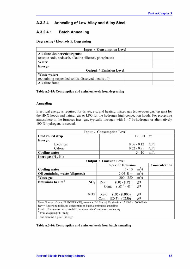
Part A/Chapter 3
Ferrous Metals Processing Industry 83
A.3.2.4 Annealing of Low Alloy and Alloy Steel
A.3.2.4.1 Batch Annealing
Degreasing / Electrolytic Degreasing
Input / Consumption LevelAlkaline cleaners/detergents:(caustic soda, soda ash, alkaline silicates, phosphates)WaterEnergy
Output / Emission LevelWaste water:(containing suspended solids, dissolved metals oil)Alkaline fume
Table A.3-15: Consumption and emission levels from degreasing
Annealing
Electrical energy is required for drives, etc. and heating; mixed gas (coke-oven gas/top gas) forthe HNX-hoods and natural gas or LPG for the hydrogen-high convection hoods. For protectiveatmosphere in the furnaces inert gas, typically nitrogen with 3 - 7 %-hydrogen or alternatively100 %-hydrogen, is needed.
Input / Consumption LevelCold rolled strip 1 - 1.01 t/tEnergy:
Electrical 0.06 - 0.12 GJ/tCaloric 0.62 - 0.75 GJ/t
Cooling water 5 - 10 m3/tInert gas (H2, N2)
Output / Emission LevelSpecific Emission Concentration
Cooling water 5 - 10 m3/tOil containing waste (disposed) 2.04 E -4 m3/tWaste gas 200 - 250 m3/tEmissions to air: a SO2 Rev: (∼ 0) - (∼ 2) 1
Cont: (∼ 0) 1 - 41 2g/tg/t
NOx Rev: (∼ 9) - (∼ 900) 1
Cont: (∼ 0.5) - (∼ 250) 1g/tg/t
Note: Source of data [EUROFER CR], except a [EC Study]; Production: 175000 - 1500000 t/aRev = Reversing mills, no differentiation batch/continuous annealingCont = Continuous mills, no differentiation batch/continuous annealing1 from diagram [EC Study]2 one extreme figure: 194.4 g/t
Table A.3-16: Consumption and emission levels from batch annealing

Part A/Chapter 3
84 Ferrous Metals Processing Industry
A.3.2.4.2 Continuous Annealing
Chemicals for alkaline and electrolytic pre-cleaning are needed. Furthermore, wet temperrolling agents for rough passes and anticorrosive oils are consumed. Usually, natural gas, other(plant) gases or LPG are used for heating the strip. Electrical energy is used for drives, booster,overaging zone and finishing). Inert gas (nitrogen with typically about 5 %-hydrogen oralternatively 100 %-hydrogen) is used for protection of surface oxidation.
Continuous annealing mainly produces waste water (oil, suspended solids, COD) and exhaustgas from annealing furnaces (NOx, SO2, CO, CO2).
Input / Consumption LevelCold rolled strip 1.007 - 1.030 t/tChemicals for alkaline/electrolytic pre-cleaningEnergy:
Electrical 0.173 - 0.239 GJ/tCaloric 0.775 - 1.483 GJ/tSteam 0.119 GJ/t
Cooling water 23.529 m3/tInert gas (nitrogen/hydrogen)Wet temper rolling agent(for rough pass, electrical sheet)Anticorrosive oils,
Output / Emission LevelSpecific Emission Concentration
Waste gas from annealing furnace: 350 - 400 m3/tEmissions to air: a SO2
Rev: ∼ 0) - (∼ 2) 1
Cont: (∼ 0) 1 - 41 2g/tg/t
NOx Rev: (∼ 9) - (∼ 900) 1
Cont: (∼ 0.5) - (∼ 250) 1g/tg/t
Waste heat (steam, can be recovered) 0.037 - 0.078 GJ/tWaste water (oil, suspended solids…) 0.118Cooling waterSludge cake (disposed) 0.018 - 0.47 kg/tScale dustOil sludge from pre-cleaningNote: source of data [EUROFER CR], except a [EC Study]; Production: 600000 t/aRev = Reversing mills, no differentiation batch/continuous annealingCont = Continuous mills, no differentiation batch/continuous annealing1 from diagram [EC Study]2 one extreme figure: 194.4 g/t
Table A.3-17: Consumption and emission levels from continuous annealing

Part A/Chapter 3
Ferrous Metals Processing Industry 85
A.3.2.5 Annealing and Pickling of High Alloy Steel
Table A.3-18 presents consumption and emission data of continuous furnaces for annealing hotrolled strip.
Input / Consumption LevelHot rolled strip 1.01 - 1.02 t/tIndustrial + demineralised water 0.015 – 0.55 m3/tCooling water 0.15 - 1.1 m3/tEnergy:
Electrical 0.3 - 0.4 GJ/tCaloric (Gas) 1.0 - 1.5 GJ/tSteam 0.06 - 0.13 MJ/t
Output / Emission LevelSpecific Emission Concentration
Waste gas 550 - 1000 m3/tEmissions to air: a SO2 0 - (∼ 30) 1 g/t
NOx 0.1 - (∼ 1500) 1, 2 g/tWaste water 0.4 - 0.5 m3/tSludge cake 2.0 - 15.0 kg/tNote: source of data [EUROFER CR], except a [EC Study]; Production: 56000 - 550000 t/a1 from diagram [EC Study]2 one extreme figure: 3820 g/t
Table A.3-18: Consumption and emission levels of continuous annealing furnaces
High alloy steels are mostly treated in combined annealing and pickling lines. The amount ofpickling acid required depends on the strip size (surface, volume) and the thickness of scalelayer. Acid consumption depends also on whether hot band or cold rolled material is processed.
Energy requirements are: natural gas and LPG for annealing furnaces, steam for acid bathheating and electrical energy for drives, fans, pumps etc
Emissions mainly refer to waste water from neutralisation plants (metals, suspended solids),exhaust gas from furnaces (combustion products: CO, CO2 NOx), exhaust gas from picklingplant fume scrubbers (containing NOx HF) and exhaust gas from mechanical descalingextraction system (dust). [EUROFER CR]
Table A.3-19 gives the consumption and emission from combined pickling and annealing lines.

Part A/Chapter 3
86 Ferrous Metals Processing Industry
Input / Consumption LevelStainless steel strip (hot band or cold rolled) 1.03 - 1.08 t/tShot1 1.5 - 3 kg/tCooling water (recirculated) 10 -20 m3/tNitric acid (HNO3 70 %) 3 - 10 kg/tHydrofluoric acid (HF 70 %) 2.5 - 7.5 kg/tHydrogen peroxide (H2O2 35 %) 3 -10 kg/tCompressed airEnergy1: Electrical 0.15 - 0.30 GJ/t
Caloric (NG) 0.7 - 1.8 GJ/tSteam (acid heating) 0.1 - 0.3 GJ/t
Output / Emission LevelSpecific Emission Concentration
Scale/shot dustExhaust gas from mechanical descaling/dust 350 - 450 m3/tWaste water discharged to effluent treatment 1.0 - 9.0 m3/tSpent pickle bath/ mixed acidExhaust gas from pickle plant fume scrubbersExhaust gas:Emissions to air from furnace: a SO2 0 - (∼ 30) 2 g/t
NOx 0.1 - (∼ 1500) 2, 3 g/tNote: Source of data [EUROFER CR]; Production: 30000 - 300000 t/a)1 Shot blasting is only done on hot band (pickling I)2 from diagram [EC Study]3 one extreme figure: 3820 g/t
Table A.3-19: Consumption and emission levels from Pickling and annealing of high alloy steel

Part A/Chapter 3
Ferrous Metals Processing Industry 87
A.3.2.6 Tempering (Low alloy/High Alloy)
During rolling operation typically a 5 % -solutions of wet temper rolling agents, which may benitrite based, are applied. Energy is required in form of hot water and electrical energy for millstand, hydraulics, etc.
Input / Consumption LevelAnnealed strip 1.01 - 1.03 t/tIndustrial and demineralised water 0.002 - 0.004 m3/tCooling water 1.0 - 4.0 m3/tElectrical energy 0.02 - 0.15 GJ/tTempering fluid concentrate 0.11- 3 kg/tAnticorrosive oil 0.04 - 0.05 kg/t
Output / Emission LevelSpecific Emission Concentration
Waste air 1 - 100 m3/tWaste water 0.002 - 0.004 m3/tOil contaminated waste1 6 - 7.5 E -5 m3/tTempering2/cooling fluidSludge cake2 2.0 - 4.0 kg/tLeakage oil 4 - 5 E -5 m3/tNote: source of data [EUROFER CR]; Production: 300000 - 1000000 t/a1 externally disposed2 internally recycled
Table A.3-20: Consumption and emission levels from tempering
A.3.2.7 Finishing (Cutting, Inspection, Packing)
Input / Consumption LevelCooling water 0.5 - 0.7 m3/tAnticorrosive oil 0.2 - 0.4 kg/tSigning ink 0.5 - 80 g/tFilm (clear) 80 -90 g/tPaper (blue) 9 - 80 g/tVCI paper 1.5 - 1.7 g/tFLEX-Stripes 0.05 - 0.06 m2/tWood 950 - 1050 g/tElectrical energy 0.02 - 0.04 GJ/t
Waste gas Output / Emission LevelSpecific Emission Concentration
Oil contaminated waste 1.4 - 1.6 E -4 m3/tScrap 25 - 40 kg/tNote: source of data [EUROFER CR]
Table A.3-21: Consumption and emission levels from finishing

Part A/Chapter 3
88 Ferrous Metals Processing Industry
A.3.2.8 Roll Shop
Main input for the roll shop is water and grinding fluid to prepare fresh emulsions. Outputresulting from grinding: spent grinding emulsions and grinding sludge. [EUROFER CR]
Input / Consumption LevelCooling water (circulating water) m3/tGrinding emulsion (fresh) 0.4 -80 g/tShot grain (SBT) 40 - 50 g/tSoluble oil concentrate 5 - 6 g/tChromium salt (PRETEX) 2 - 3 g/tCondensate for chromium acid (PRETEX) 140 - 160 g/t
Waste gas Output / Emission LevelSpecific Emission Concentration
Waste gas1
DustCr
25 - 70 m3/t< 1
< 0.1mg/m3
mg/m3
Grinding sludge 0.1 - 0.2 kg/tGrinding wheel 0.9 - 1.0 g/tWaste emulsion 0.035 - 0.08 kg/tOil contaminated waste 1.5 - 2.0 E -4 m3/tSBT-dust 40 - 50 g/tNote: source of data [EUROFER CR]1 Chroming installation2 Cold rolled strip is used as reference value for specific consumption figures
Table A.3-22: Consumption and emission levels from the roll shop
A.3.2.9 Hydraulic Fluids and Lubricants Management
On several places of the cold rolling mill, hydraulic systems or oiled and greased componentsare in operation. These systems are generally placed in oil-tight bunds or pits to prevent the oilfrom penetrating into water or soil in case of leakage.
Input / Consumption LevelCooling water 9.0 - 10 m3/tDemineralized water 0.05 - 0.12 m3/tGrease, oil, hydraulic oil 1.5 - 1.8 kg/tRolling oil 0.45 - 2.2 kg/tHydraulic + lubrication oils 0.2 - 0.9 kg/tEnergy:
ElectricalSteam
0.2 - 0.450.04 - 0.05
GJ/tGJ/t
Waste gas Output / Emission LevelSpecific Emission
Waste (disposed)Used oil + water + rejectsUsed oil + water
3.0 - 503.2 - 3.5
kg/tkg/t
Waste water 0.05 - 0.12 m3/tNote: source of data [EUROFER CR]
Table A.3-23: Consumption and emission levels from hydraulic fluid and lubricant systems

Part A/Chapter 3
Ferrous Metals Processing Industry 89
A.3.2.10 Cold Rolling Mill Waste Water Treatment Plant
The following data refer to water discharge from the cold rolling mill as a whole as availabledata often does not distinguish the different sources of waste water.
Continuous C-Steel
Reversing C-Steel ReversingStainless Steel
Specific Waste waterdischarge 0 - 40 m3/t 0 - 6 m3/t (∼ 0) - 35 m3/tWaste water dischargefrom WW-Treatment(excl. once -through cooling)
0 - 12 m3/t
Total Suspended Solids 1 7 - 1202.7 - 520
mg/lg/t
(∼ 0) - 2210(∼ 0) - (∼ 160)
mg/lg/t
0 - 600 - (∼ 180)
mg/lg/t
COD 1 19 - 53005 - 220
mg/lg/t
15 - 10010 - 80
mg/lg/t
10 - 200010 - 275
mg/lg/t
Note: Source of data [EC Study]1 Unit changed from mg/m3 to mg/l
Table A.3-24: Waste water discharge from cold rolling mills


Part A/Chapter 3
Ferrous Metals Processing Industry 91
A.3.2.11 Waste and Recycling
In addition to the information on waste generation for the individual sub-process, Table A.3-25presents an overview of the waste generated in total by cold rolling operations and of theutilisation potentials. The reference base of the hot rolling mill as a whole was chosen, becausea clear distinction of waste sources and attribution of waste amounts to individual processingsteps is impossible in a number of cases.
Kind of waste/Source AverageSpecific Mass
[kg/t]
Reported Waste1
[t](steel production)2
Utilization Percentage3
Recycle in-plant 50.3Externally used 4 33.7Sold 5 3.6
Oil recovery sludges1 13150
(14 Mt)Landfill 12.4Recycle in-plant6
9.8
Externally used 7 9.4Sold5 46.0
Acid regenerationsludges 4.2 36200
(8.5 Mt)
Landfill 35.0Recycle in-plant 32.5Externally usedor sold5
1Waste watertreatment sludges 3.3 114000
(19.9 Mt)Landfill 66.5Recycle in-plant 38.5Externally used 5 42
Dry dust from aircleaning devicesStainless steel rolling
5.4 8200(1.5 Mt) Landfill 19.5
Recycle 42.8Externallyincineration
34.4Oil, emulsion, grease
1.3 17700(8.7 Mt)
Landfill 22.8Externally used 5 66Dismantled
refractories 60 Landfill 34Note: data based on [EC Study]; figures given refer to dry material1 Submitted as an answer to a questionnaire activity of the EU.2 Steel production of the companies that provided information on utilisation.3 Percentage refers to reported mass/ answered questionnaires.4 56 % incinerated, 44 % oil recuperation in dedicated plant5 No indication on further use6 EAF or blast furnace7 For the production of iron oxides
Table A.3-25: Waste generated in cold rolling mills and utilisation rates
A.3.2.12 Noise Issues in Cold Rolling�No specific information for cold rolling submitted.


Part A/Chapter 3
Ferrous Metals Processing Industry 93
A.3.3 Wire Plant
A.3.3.1 Mass Stream Overview
Lubricant
Rod Wire Mill
Miscellaneous
Wire
Water
Energy
H2 Inhibitors
Soap Carrier
Oil
Protective Gas (H2, N2)
Additives for Cooling Water Circuit
Ca(OH)2 or NaOH (Wastewater Treatment)
Soap + Additives
Soap Emulsions
Oil Emulsions or Plain Oil
Natural Gas or LPG
Electricity
Steam
Process Water
Cooling Water
Acid Hydrochloric Acid
Sulfuric Acid
Mixed Acid
Solid Waste
Air Emissions
Waste Water
Particulates
NOx, CO/CO2
Acid Aerosols
Oil Mist
Suspended Solids
Dissolved Fe
Traces of Other Metals
Soaps
Filter Dust
Scrap
Scale/Scale Dust
Lead Waste
Spent Dry Drawing Lubricant
Miscellaneous
Liquid Waste Spent Pickle Bath
Spent Soap Carrier Bath
Spent Wet Drawing Lubricant
Sludges Water Treatment Sludge
FePO4 Sludge
Lead
Descaling Pickling Drawing Heat Treatment
Table A.3-26: Input/Output balance for a wire mill

Part A/Chapter 3
94 Ferrous Metals Processing Industry
The subsequent chapters present input and consumption data, as well as output and emissiondata for individual operational steps associated with wire production (wire rod preparation,drawing, heat treatment process steps). It should be noted that specific consumption andemission data (expressed per tonne of product) can show huge variations with the wire diameterproduced.
A.3.3.2 Wire Rod Preparation
A.3.3.2.1 Mechanical Descaling of Wire Rod
Mechanical descaling brings about solid waste: scale, mainly consisting of iron oxide (FeO andFe3O4) plus traces of other metal oxides, depending on the alloy elements and impurities in thewire rod. The most common wire descaling technique, wire bending, generates a relativelycoarse scale, which generates only negligible amounts of dust.
Sanding, brushing and shot blasting generate a relatively fine scale and are equipped with afilter system to capture scale dust. When shot blasting is used, the scale is mixed with thefraction of the shot blasting media that is not recovered.
Scale is not contaminated with oil or water, in contrast to what is generally the case in the stripindustry. Very fine scale (e.g. filter dust) represents a fire or explosion hazard.
Abrasive methods:Input / Consumption Level
Abrading materialOutput / Emission Level
Specific Emission ConcentrationScale (iron oxide)Scale dust
Wire bending:Output / Emission Level
Specific Emission ConcentrationScale 2 - 5 1 kg/tNote: Source od data [Com BG]1 depending on wire rod diameter and quality
Table A.3-27: Consumption and emission levels for mechanical descaling
A.3.3.2.2 Chemical Descaling/Pickling of Wire Rod
In chemical descaling liquid waste is generated in form of spent HCl or H2SO4 acid, largelyconverted to metal salts. Aerosols (small HCl or H2SO4 particles) can from mechanically whenthe wire rod is allowed to drip off. Furthermore, fumes evaporate from the HCl bath and H2 canform unless suppressed by an inhibitor. Acid fumes from the baths are evacuated. Sometimesscrubbing is needed, depending on type of acid and concentration. [Bekaert98]

Part A/Chapter 3
Ferrous Metals Processing Industry 95
Input / Consumption LevelAcid:
HCl (32 %) (no recovery)HCl (32 %) (with recovery)H2SO4 (98 %) (no recovery)H2SO4 (98 %) (with recovery)
15 – 25n.a.
10 – 202.5 – 5
kg/t
kg/tkg/t
H2 inhibitor 0.01 – 0.1 kg/tEnergy (mainly electricity):
Pumps, ventilation, lifting equipment etc.Heating of acid (only H2SO4)
n.a.n.a.
Rinsing water 1 n.a.Output / Emission Level
Specific Emission ConcentrationEmissions to air from
HCl pickling (acid vapour, droplets) 6H2SO4 pickling (aerosols, droplets of acid) 6
n.a.n.a.
Spent acid:HCl
total ClFe
H2SO4 3
80 – 90 % 2200 - 275100 - 160
g/lg/l
Rinsing water 10 – 20 % 2
FeSO4 x 7 H2O 4 20 – 35 kg/tH2
5
Note: Source of data [Com BG]1 large variations from plant to plant depending on number of rinsing cascades, wire rod diameter and quality requirements2 of consumed acid3 No figures available for spent H2SO4 if recovery by FeSO4-crystallisation is not used4 from regeneration, 96 – 98 % pure; imureties: H2O, H2SO4 and traces of metals depending on alloy elements in wire rod5 Emission of H2 is negligible if a correct H2-inhibitor is used. The use of inhibitors is normally limited to batch pickling.6 Source [Stone]
Table A.3-28: Consumption and emission levels for chemical descaling
A.3.3.2.3 Application of Soap Carrier
Consumption and emissions associated with the application of soap carrier vary in dependenceof the type of soap carrier, thickness applied and the wire rod diameter. No quantitative data isavailable at the moment.
When Zn-PO4 coating is used, a thick FePO4 sludge or cake is formed containing traces of zinc,soluble phosphates and chlorate or nitrite coming from the Zn-PO4 bath. Also spent soap carrierbath may arise as liquid waste. If drying is done in gas - or fuel fired ovens, the usualcombustion products are emitted. [Bekaert98]

Part A/Chapter 3
96 Ferrous Metals Processing Industry
Lime and equivalent products:Consumption Emissions
− lime milk (made from lime and processwater)
− steam or natural gas− water for compensation of heat losses
− spent lime milk baths (accumulation ofimpurities by dragin)
− possible emmisions from heating.
Alkali-salts and mixtures of alkali saltsConsumption Emissions
− alkali salt (mixture)− water/water for compensation of heat
losses− possibly steam
− spent soap carrier baths (accumulation ofimpurities by dragin)
− possibly emissions from heating
ZnPO4 and equivalent productsConsumption Emissions
− concentrated mixture of Zn, H3PO4 andadditive
− water/water for compensation of heatlosses
steam for heating
− FePO4 sludge− rinsing water− Bath liquid is normally never discharged.
Table A.3-29: Consumption and emission levels for the application of soap carrier[Com BG]
A.3.3.3 Drawing of Wire
A.3.3.3.1 Dry Drawing
Dry drawing activities leave spent lubricant, mainly consisting of the drawing soap itself(typically alkali-salt of natural fatty acid + additives) contaminated by degradation products,caused by heating of lubrication in the dies, soap carrier and metal particles, like Fe or Zndepending on the surfaces of the wire). From the drawing activity also soap dust arises, whichcan be controlled by proper encapsulation and filtering of the extracted air. Traces of soap mayalso contaminate the cooling tower blow down, if the drawing machine is not well maintained.Furthermore, waste arises in from broken dies. [Bekaert98]
Input / Consumption LevelDry drawing lubricant(preformulated alkali soap + additives)
1 - 4 kg/t
Electric energy for drawing machine...1 n.a.Cooling water n.a.
(huge variation)Output / Emission Level
Specific Emission ConcentrationSpent soap + evt. filter dust of soap filter system 1 - 4 kg/tSoap dust emission n.a.Cooling water n.a.Broken dies not significantNote: Source of data [Com BG], data per tonne of drawn wire1 no figure available, huge variation, dependent on diameter, ratio initial / final diameter and type of steel.
Table A.3-30: Consumption and emission levels for dry drawing

Part A/Chapter 3
Ferrous Metals Processing Industry 97
A.3.3.3.2 Wet Drawing
Wet drawing is done in a watery emulsion of soap or oil. This emulsion is graduallycontaminated by dragin of various products from previous process steps, by dissolution orabrasion of metal from the wire surface (Fe or other metals if the wire is coated in a previousstep), and by thermal or biological degradation. The result is that the wet drawing lubricantneeds to be replaced from time to time; the replacement frequency can be lowered bycontinuous removal of some of the contaminants by decantation or filtration.
Other waste streams are broken dies and cooling tower blowdown, which could becontaminated by traces of emulsion if the heat exchanger is not properly maintained.
Cooling water contamination occurs much less frequent with wet drawing machines than withdry drawing machines.
No figures are available for wet drawing in plain oil; the percentage of wire tonnage which isdrawn in oil, is rather small. If wire is drawn in plain oil, oil aerosols do not occur. All movingparts are submersed in oil; the wire is wiped at the exit of the drawing machine. [Com BG]
Input / Consumption LevelPreformulated concentrated soap emulsion or oilemulsion
1 - 10 kg/t
Dillution water for wet drawing lubricant 20 - 250 l/tElectric energy for drawing machine... n.a.Cooling water n.a.
(huge variation)Output / Emission Level
SpecificEmission
Concentration
Spent Wet Drawing Emulsion(including sludge removed by filtration / decantation)
Suspended SolidsCOD (fatty acid soap or oil, surfactants, other additives)Metals (Fe for wet drawing of bright wire, other metals
for wet drawing of coated wire)
20 - 250 l/t
20 - 800.2 - 1
g/l g/l
Cooling water 2 n.a.Broken dies n.a.Note: Source of data [Com BG], data per tonne of drawn wire1 no figure available, huge variation, dependent on diameter, ratio initial / final diameter and type of steel.2 Note: Cooling water contamination occurs much less frequent with wet drawing machines than with dry drawing
machines.
Table A.3-31: Consumption and emission levels for wet drawing


Part A/Chapter 3
Ferrous Metals Processing Industry 99
A.3.3.4 Heat Treatment of Wire
A.3.3.4.1 Batch Annealing/Bell and Pot Furnaces
Emissions from batch annealing furnaces comprises the combustion products from the firingand a small flow of the protective atmosphere (purge) containing decomposition products of thelubricant. These are formed by pyrolisis/cracking of the lubricant molecules; typicaldecomposition products are low molecular weight olefins and alkanes.
The cooling water is not contaminated and can be used for cooling of some parts of the furnace.[Bekaert98], [CET-BAT]
Input / Consumption LevelEnergy (gas, fuel, electricity) n.a.Inert gas(H2, N2, H2/N2-mixture, partially oxidized gas)
n.a.
Cooling water n.a.Oil (if applied) n.a.
Output / Emission LevelSpecific Emission Concentration
Combustion products n.a.Cooling water n.a.Spent inert gas 1Note: No figures are available for annealing of wire, but they are assumed to be similar to those for annealling in a
hood-type furnace used for strip, although the unit size is much smaller in the wire business. [Com BG]1 Normally all spent protective gas is burnt.
Table A.3-32: Consumption and emission levels for bell and pot furnaces
A.3.3.4.2 Continuous Annealing/Molten Lead Bath
Continuous annealing in a lead bath is composed of a lead bath followed by quenching in water.This process leads to solid wastes in the form of lead oxides and lead contaminated bath covermaterial. Waste water is formed as overflow of the quench bath; this stream contains some ofPb. Emissions to air occur in form of dust (bath cover material, including small amounts of Pb)and soap pyrolysis products (VOC, CO, etc.). [Com BG]
Often, this heat-treatment step is followed by continuous pickling in a HCl bath. Due to theshort residence time, heated and concentrated HCl is used. HCl-fumes are removed byscrubbing from the gaseous outlet streams of the HCl-bath. Liquid waste generated are spentacids, partially converted to metal salts and contaminated by iron, lead, traces of other metalsand inorganic suspended solids; quench water also contaminated by lead (magnitude mg/l).Waste waters occur as rinsing water from the rinsing cascade after the HCl-bath and from thescrubber. [Bekaert98], [Com BG]

Part A/Chapter 3
100 Ferrous Metals Processing Industry
Input / Consumption LevelLead 1 – 15 1 kg/tEnergy for heating the lead bath (gas, fuel) n.a.Quench water 1 - 3 m3/t
Output / Emission LevelSpecific Emission Concentration
Lead waste (lead oxides + spent bath cover) 1 –15 1 kg/tQuench water overflow(containing Pb and suspended solids) SS
Pb
0.5 – 2.5 m3/tn.a.
2 - 20 mg/lEmissions of lead bath: Pb
DustTOC
0.02 - 51 – 301 - 50
mg/m3
mg/m3
mg/m3
Emissions from heating the lead baths(typical emissions of standard heating process)Note: Source of data [Com BG], data per tonne of wire1 extreme figures apply to fine wire
Table A.3-33: Consumption and emission levels for lead baths
Input / Consumption LevelHCl (expressed as 32 % HCl) 10 - 100 kg/tEnergy for heating the HCl-bath 1 n.a.Scrubber / rinsing water 0.5 - 5 m3/t
Output / Emission LevelSpecific Emission Concentration
Spent HCl 2 5 - 100 l/tTotal Cl
Fe150 – 275
60 - 125g/lg/l
Scrubber/rinsing waste water 0.5 - 5 mg/m3
HCl (emissions from scrubber) 0 – 30 3 mg/m3
Lubricant burn-offWaste waterDustNote: Source of data [Com BG], data per tonne of pickled wire; the figures for HCl-pickling are also -/+representative for other continuous HCl pickling process steps.1 often the bath is heated by residual heat in the wire2 spent acid contains Cl, Fe and other contaminants depending on previous processing steps, e.g. soap residues,
pickled soap carrier, Pb…3 small sources (< 300 g/h) can have higher concentrations, as in most countries, small sources only have to comply
with a limit for mass flow
Table A.3-34: Consumption and emission levels for in-line HCl pickling
A.3.3.4.3 Patenting
For a patenting line consisting of a furnace with direct contact between wire and combustiongases, a lead bath and a quench bath, wastes and emissions are as follows:
Air emissions arise from the furnace. The furnace is heated to 850 - 1000 °C using natural gas(or a similar sulphur-free fuel) and with a slight O2-shortage. Fresh air is mixed with the hotexhaust gas of the oven in order to convert the CO to CO2, prior to emission into the

Part A/Chapter 3
Ferrous Metals Processing Industry 101
atmosphere. NOx and SO2 are negligible in this stream: reducing atmosphere/fuel is free ofsulphur.The lead bath is used for cooling; in contrast to a lead bath used for annealing, there is noburning of residual lubricant, so the emissions to air are limited to dust (bath cover material,containing traces of Pb).
Solid waste is generated by the lead bath as lead oxides and spent bath cover material. Wastewater is formed in the quench bath. Some installations need cooling water for cooling ofmoving parts that are in contact with the hot wire. [Com BG]
Input / Consumption LevelLead 1 - 10 kg/tEnergy (for heating the furnace and for heatingthe lead bath during start-up and stand-by periods)
n.a.
Quench water 1 - 3 m3/tCooling water 0 – n.a.
Output / Emission LevelSpecific Emission Concentration
Lead waste (lead oxides + spent bath cover) 1 - 10 kg/tQuench water overflow(containing Pb and suspended solids) SS
Pb
0.5 – 2.5 m3/tn.a.
2 - 20 mg/lStack emissions from lead bath: Pb
Dust< 0.02 – 1
1 - 30mg/m3
mg/m3
Stack emissions from the furnace: CONOx, SO2
50 - 300negligible
mg/m3
Note: Source of data [Com BG], data per tonne of wire
Table A.3-35: Consumption and emission levels for patenting[Bekaert98]
A.3.3.4.4 Oil Hardening & Tempering
An oil hardening and tempering line consists of a heating step under protective gas, quenchingin oil or water, and reheating in a temper oven. Waste and emissions are dependent on themethod of heating, the quench medium and the reheating method. This, in combination withthe broad diameter range of products, makes it impossible to present general figures for an oilhardening and tempering line. [Com BG]
Input / Consumption LevelEnergy for heating (electricity, and/or natural gas)Protective gasQuenching medium (oil, water, additives)Lead (if applied)Cooling water
Output / Emission LevelUsing a lead bath: lead wasteQuenching with water: waste waterQuenching with oil: waste quench oil
emission to air of oil aerosolsHeating with natural gas: exhaust gas of normal combustion process
Burnt protective gas stream
Table A.3-36: Qualitative input / output balance for oil hardening

Part A/Chapter 3
102 Ferrous Metals Processing Industry
A.3.3.4.5 Annealing of Stainless Steel Wire
A quantitative mass balance cannot be given (lack of data / small tonnage when compared toplain steel/high variation due to variation in diameter and stainless steel composition).
Input / Consumption LevelEnergy: gas (fuel), electricityInert gas: H2, N2, H2/N2-mixtureCooling water
Output / Emission LevelCombustion productsCooling waterSource [Com BG]Note: normally all spent protective gas is burnt
Table A.3-37: Qualitative input / output balance for annealing of stainless steel
A.3.3.4.6 Stress Relieving
The most important application is stress relieving of PC-strand: reinforcement wire that will beused in prestressed concrete. Normally inductive heating is used as heating technique.
Input / Consumption LevelElectric energy for the inductive heating coil and possibly for a soaking zoneCooling water for equipment and wire
Output / Emission LevelCooling waterSource [Com BG]
Table A.3-38: Qualitative input / output balance for stress relieving
A.3.3.5 Noise Issues in a Wire Plant
Excessive noise is primarily an internal occupational health issue, with precautions normallytaken to protect employees where it is not practical to prevent or reduce noise at the source. Insome instances, depending on the location of the process and noise characteristics, dependingon local off-site aspects (other noise sources, nearby residential area,...), and depending on localplant aspects (noise reduction by the building structure), there can be a concern for noise off-site.
The main sources of noise in wire processes are:• Rotating equipment, e.g. wet drawing machines; dry drawing machines; take-up units and
pull-through units on coating lines.• Air-wipes or air-brushes which clean the wire using compressed air can have a high
frequency noise.• Pay-off units of wire rod have a particular repetitive noise.• Burners of ovens.
These operations are typically continuous operations and are operated inside a building. In thisway, the impact outside the building is minimized to such an extent, that noise generated bythese operations rarely is an issue when concerning noise off-site.

Part A/Chapter 3
Ferrous Metals Processing Industry 103
Case studies show that non-process sources outside the building, such as ventilation or plantutilities, are the main concern in wire plants located close to e.g. a residential area. Measuressuch as relocation, insulation or local enclosure can be considered for this last category ofsources.


Part A/Chapter 4
Ferrous Metals Processing Industry 105
A.4 TECHNIQUES TO CONSIDER IN THE DETERMINATIONOF BAT FOR HOT AND COLD FORMING
In this section techniques for environmental protection and energy saving measures are givenfor the individual processing steps. A description of each technique, the main achieved emissionlevels, the applicability, the monitoring of emissions, cross-media effects, reference plants,operational data, economics and driving force for the implementation are given where these dataare available and pertinent.
Some of the techniques listed here aim predominantly at improving product quality andincreasing yield. As these measures also have an environmental impact (reduced scrap, reducedenergy consumption, less emissions) they are covered here as well, although their reductionpotential may only be limited.
A.4.1 HOT ROLLING MILL
A.4.1.1 Storage and Handling of Raw Materials and Auxiliaries
Description:Oil: Spillages of oil may occur at storage tanks and from pipelines. Such spillages are drainedto pump sumps, from where the oil, grease water mixture may be fed to intermediate waste oilstorage tanks. Discharge of filled tanks may be carried out via authorised external companies or,in the case of integrated plant sites, by internal thermal treatment plants or via the blast furnaceor coke ovens.
Accidental releases of hydrocarbons are prevented by periodic checks and preventivemaintenance of seals, gaskets, pumps and pipelines.
Contaminated drainage water at the various consumers (hydraulic aggregates) should becollected and may be pumped into intermediate storage tanks. The waste oil, after separationfrom water, should be reused or utilized, e.g. by injection into the blast furnace or by externalrecycling. To allow for reuse, the separated oil has to be recovered in sufficient quantities and ina form suitable for reuse; the chemical composition and the physical properties (e.g. viscosity)of the recovered (used) oil have to be the same as of the new oil. The separated water may befurther processed in a water treatment plant, e.g. with ultra filtration or vacuum evaporator (e.g.of industrial washing machines).
Complete prevention of water and scale contamination by hydrocarbons (oils and grease) is,even by applying precautionary measures, almost impossible.
A.4.1.2 Surface Rectification and Conditioning of Input
A.4.1.2.1 Enclosed Scarfing Operation with Wastegas Cleaning
Description:As shown in Figure A.4-1, scarfing takes place in a tightly closed hood, which captures thefume and dust generated by the oxy-fuel flame. The waste air is cleaned by dry or wetelectrostatic precipitators or fabric filters. The collected dust is internally recycled withinintegrated steel works or disposed of by authorised companies.

Part A/Chapter 4
106 Ferrous Metals Processing Industry
Water jets are used to remove the slag from the conditioned surface. Spent water and slag arecollected in a flume beneath the roller table and transferred to water treatment.
Figure A.4-1: Scarfing abatement flowsheet (example with wet EP)[HMIP]
Main achieved environmental benefits:• Reduced fugitive air emissions/dust.
Applicability:• New plants (difficult to implement in existing plants due to problems with structures of
buildings).• Not applicable for manual scarfing.
Cross-media effects:• Increased energy consumption.• Generation of waste / filter dust or sludge which is collected.• Waste can be reduced by internal recycling.
Reference plants:SIDMAR, Aceralia (Avilés)
Operational data and economics:
Example SIDMAR:The scarfing machine is located in a special building (dimensions 32 m x 18 m x 9 m) withacoustic insulated sidewalls leading to a maximum noise level of 85 dBA at 1 m. The fume iscaptured at the 4 corners of the roof. The complete installation is operated under suction with anaspiration flow of 200000 m3/h. The aspiration is controlled automatically as a function of theplace where the scarfing takes place (2/3 of fumes are aspired above the work area). Theexhaust air is cleaned by fabric filters with filter area of 3576 m2 leading to an exit dustconcentration of 5 – 10 mg/Nm3 (continuous optical measurement in stack).

Part A/Chapter 4
Ferrous Metals Processing Industry 107
Year ofInstallation
Waste GasVolume[m3/s]
ParticulateEmission[mg/m3]
EnergyConsumption 1[kWh/1000m2]
CostsEURO
‘000a Wet EP
(Billet Scarfer)1973 32 20 - 115
b Wet EP < 20c Wet EP 1988 approx. 60 30 - 80 n.a.a Dry EP
(Slab Scarfer)1986 30 20 - 115
b Dry EP < 50 420d Bag filter data: 1998 30 < 10b Bag filter ∅ 42
max. 55< 20 155 I 2: 2200
O 1,3 0.058e Bag filter 55.6 5 - 10Note: ESP = Electrostatic Precipitator; I = Investment costs; O = Operational costsa: [EUROFER HR]b: [CITEPA], levels were reported BAT levels of the air-BAT-notec: [Input-HR-1]d: [DFIU98]e: Company information SIDMAR1 Reference base 1000 m2-scarfed2 Investment costs given for complete installation, incl. civil engineering, filter (filter area: 3200 m2), hood,
ventilators, motors, pipes, control measurement devices etc.3 Operational costs for full capacity, 60 % manpower
Table A.4-1: Operational data and achievable emission levels for dust from scarfing operation
As the fume generated by scarfing is very corrosive, maintenance is an important issue for goodperformance of the abatement units. Regular inspection of precipitator electrodes, associatedinternals etc. is recommended to survey corrosion.
If the fume is very wet, bag filters might be problematic. [Com HR]
Driving force for implementation: prevention of fugitive emissions. [Com HR]Reference literature:
A.4.1.2.2 Enclosed Grinding Operation with Waste Gas Cleaning
Description:The dust created by grinding operations is collected and precipitated in bag filters. Manualgrinding is carried out in dedicated booths, equipped with collection hoods. Machine grinding iscarried out in soundproofed, complete enclosures. The abatement unit, in both cases, is eitherstand-alone or shop based.
The collected dust is internally recycled within integrated steelworks or disposed of byauthorised companies.

Part A/Chapter 4
108 Ferrous Metals Processing Industry
Figure A.4-2: Grinding abatement flowsheet[HMIP]
Main achieved environmental benefits:• Reduced fugitive air emissions/dust.• Noise is reduced.
Applicability:• New Plants.
Cross-media effects:• Increased energy consumption.• Generation of waste / filter dust which is collected.• Waste can be reduced by internal recycling.
Reference plants:
Operational data:
Year ofInstallation
Waste GasVolume[m3/s]
ParticulateEmission[mg/m3]
EnergyConsumption 1[kWh/1000m2]
CostsEURO
‘000a Compact
Cell Filter 21980 - 1989 2.5 20 - 100
a Pulse JetFilter 3
1995 7 < 30
a: [EUROFER HR], reported typical operational data and emission levels [Com2 HR]1 Reference base 1000 m2-ground2 Bag area 120 m2
3 Bag area 234 m2
Table A.4-2: Operational data and achievable emissions for dust reduction from grinding
Economics:Driving force for implementation: Prevention of fugitive emissions. [Com HR]Reference literature:

Part A/Chapter 4
Ferrous Metals Processing Industry 109
A.4.1.2.3 CAQC - Computer Aided Quality Control
Description:Computer aided quality control is applied to enhance the quality of the continuous castingoutput, thus reducing surface defects in the rolled product. A computer model observes andcontrols the casting conditions based on various peripheral measurements. Each change in theoperation parameters leads to a new pre-setting of the machine for an optimised casting process.Changes in the casting conditions, which cannot be corrected by the control loop and may leadto surface defects, are recognised and visualised by the system so that the location of a possiblefault is well known. Subsequently, selective (manual) scarfing of the damaged areas is possibleinstead of automatically scarfing the total slab.
Main achieved environmental benefits:• Reduction of air emissions and waste from scarfing, because selected scarfing is possible.• Energy consumption for scarfing process is reduced.• Enhanced surface quality, reduction of scrap.
Without CAQC With CAQCMachine scarfed 32 % 9 %Inspection and selective scarfing 68 % 8 %No inspection no scarfing 83 %
Table A.4-3: Comparison of amount of scarfing with/without CAQC[DFIU98]
Applicability:• New and existing plants with continuous casting [Com HR].
Cross-media effects:Reference plants:• VA Stahl Linz, Austria.• EKO Stahl, Germany [Com A].
Operational data:
Economics:Only very limited data on economics were reported.One source reported investment costs of EUR 4 m, Voest [Input-HR-1]; while another reportedsavings of 5 $ per tonne of steel [Com A] in connection with implementationof CAQC.
Driving force for implementation:• Improved quality of hot rolled product, increased yield.• Reduction of slab conditioning costs [Com A].
Reference literature:Aspects of modern quality control for continuous casting, 3rd European Conference onContinuous Casting, Oct. 20 – 23, 1998 [Com A]

Part A/Chapter 4
110 Ferrous Metals Processing Industry
A.4.1.2.4 Rolling of Wedge-type Slabs
Description:Instead of flame cutting, wedge-type slabs are rolled under special settings of the hot rollingmill. The wedge is either eliminated by edging technology (automatic width control or sizingpress) or by trimming during the subsequent shearing of hot strips.
Main achieved environmental benefits:• Emissions and wastes normally generated by flame cutting are avoided.
Applicability: new plants and existing plants in case of major revamping [ComHR]Cross-media effects:Reference plants:Operational data:Economics:Driving force for implementation:Reference literature:
A.4.1.2.5 Slab Slitting
Description:In order to improve caster productivity, the slabs are often cast in multiple widths. The slabs areslit before hot rolling by means of slitting devices, slit rolling or torches either manuallyoperated or mounted on a machine. In that way, wedge-type slabs are prevented.
Main achieved environmental benefits:• Emissions and waste arising from wedge correction are prevented.
Applicability:
Cross-media effects:• Additional energy consumption [Com A].
Reference plants:• Krakatau Steel [Com A].
Operational data:This technique requires an improved quality of centre segregation.
Gas consumption 1.6 Nm3/t slabOxygen consumption 2.7 Nm3/t slabYield loss 1.4 0 3.0 % of slab weight, depending on slab dimensions [Com A]
Economics:
Driving force for implementation:Higher caster capacity as twin or triple casting [Com A]
Reference literature:

Part A/Chapter 4
Ferrous Metals Processing Industry 111
A.4.1.3 Reheating and Heat Treatment Furnaces
A.4.1.3.1 General Measures for Energy Efficiency and Low EmissionOperation
Furnace designThe design of the furnace and the degree of insulation have a significant effect on the thermalefficiency. The furnace as a whole, the number and the installed capacity of the burners shouldbe carefully calculated starting from several realistic production scenarios. Different heatingtemperatures of the stock, differences in production rhythm caused by changes in thedimensions of the stock or as a result of changes in the production rhythm of the hot mill as wellas periods where hot or direct charging is applied have to be taken into account.[EUROFER HR]
The appropriate equipment should be available to limit the emissions and the energyconsumption in case of a sudden line stop. This means that temperature can easily be turneddown or burners switched off in certain furnace sections. In the latter case, a N2-purge might benecessary for safety reasons. [EUROFER HR], [Com HR]
Generally, the following recommendations should be considered, preferably in the designprocess:
• Incorporation of a stock recuperation zone in the furnace, with the unfired preheatingsection being large enough to ensure a maximum recovery of the heat of the flue gases.
• Radiant burners in the roof of the furnace, due to quick dissipation of energy, produce lowerNOx levels.
• Return of the flue gases into the burners influences the NOx emission level.• Insulation properties of the refractory material are important, therefore constructional
measures should be taken to increase the life of the refractory material, as damage in therefractory material cannot be repaired immediately.
• Use of low thermal mass refractory material can reduce stored energy losses and reducelight-up energy and time [ETSU-G76]. Ceramic fibres are generally cheaper than pre-castconcrete modules and have good insulating properties. However, following a EuropeanDirective, their use is or will be limited because they may cause cancer by inhalation. Innew condition the fibres are dust-producing when being manipulated and may cause someskin irritation. After heating, cristoballite is formed which is suspected to cause cancer.Nevertheless, new ceramic fibres are also considered suspect [Com2 HR].
• Improved air-tightness of furnaces and installation of specially designed doors, to reducetramp air [ETSU-G76].
• Door areas and/or charge and discharge door gaps should be minimized, use of insulatingrefractory curtains for times when doors are necessarily open (provided that excessivemechanical damage to stock can be avoided) [ETSU-G76].
• Measures such as skid mark compensation or skid shifting, avoid skid marks and allowlower heating temperature [EUROFER HR].
Waste Heat RecoveryThe heat contained in the gases leaving the reheating furnace normally constitutes the mainenergy loss. Three basic principles of heat recovery options should be considered:
(a) Minimizing energy lost in the exhaust gases.(b) Recycling the exhaust gas energy back to the furnace.(c) Using the exhaust gas energy for other purposes ('external').
As mentioned under furnace design, energy loss in exhaust gases can be minimized by creatinga large temperature gradient along the length of the furnaces, removing the exhaust gas at the

Part A/Chapter 4
112 Ferrous Metals Processing Industry
cold (discharge) end and using the heat for stock recuperation. Using exhaust gas energy outsidethe furnace usually implies the generation of steam, which might be used elsewhere in the plant.Utilising the exhaust gas energy within the furnace comprises basically three heat recoverysystems: regenerative burners, self-recuperative burners and recuperators, which are presentedin more detail later on. [ETSU-G76]
Operation & MaintenanceThe furnace should be run with 'good craftsmanship'. Even sophisticated installations can givepoor results in emission and thermal efficiency if the process is not properly operated and if theinstallations are not maintained on a regular basis. Experience has shown that goodhousekeeping can lead to fuel savings of up to 10 %. [ETSU-G76]
Turbulence in the flame of the burners should be avoided. Investigations showed a markedincrease of the NOx production by temperature fluctuations compared to the NOx valuesproduced by a steady flame operating at the same mean temperature. The control system shouldtherefore be appropriate.
Air excess is also an important factor for the control of the NOx emission level, the energyconsumption and the formation of scale. The air excess should be minimized without excessiveCO emission. Special care should be taken to avoid the presence of tramp air, which increasesthe energy consumption as well as the NOx emission. A mass spectrometer is useful in keepingthe air/gas ratio at an optimal level for fuels with variable or unknown composition.[EUROFER HR]
Heat stored in the refractories is supplied during light-up period and the first production shift.During continuous operation this stored heat is usually regarded as negligible. When down-shiftpractices are employed (e.g. at weekends) or when furnaces are deliberately cooled formaintenance reasons, these energy losses can become an important factor as this energy has tobe put in during furnace heat-up for the next production period. For two cases, stored energylosses during weekend plant shut-down were reported: 0.409 GJ/m2 and 0.243 GJ/m2. Duringproduction stoppages and weekends, doors should be closed and sealed to retain the heat. Theuse of low thermal mass refractories can reduce light-up time, energy consumption andoperating costs. [ETSU-G76]
Choice of fuelIntegrated steel works normally utilise gases from the coke oven plant, the blast furnace or thebasic oxygen furnace, sometimes in mixture with natural gas. Non-desulphurised coke oven gasand S-containing liquid fuel (including liquefied petroleum gas (LPG) and all types of oil(distillate and residual) and emulsion) are the major sources of SO2 emission from re-heatingfurnaces. If required, desulphurisation ought to be performed at the gas producing and providingplants (e.g. coke oven battery). The use of liquid fuel is sometimes necessary to continueoperations during a temporary stop in the supply of gaseous fuels, which can result in elevatedsulphur oxide emission. Limiting the sulphur content in fuel oil is one measure to reduce SO2emissions. Where possible, the use of plant gases should be maximised, which minimizes theuse of valuable natural resources and the need to flare the plant gases.
SO2 emission is directly related to the S-content of the fuel. Due to the different ratios of thevolume of the flue gases to the volume of the fuel gas for different fuels, a comparable S-content in 2 different fuels can result in marked differences in the SO2 content in the flue gases.
Depending on the fuel used the following SO2 levels are achieved:− natural gas < 100 mg/Nm3
− all other gases and gas mixtures < 400 mg/Nm3
− fuel oil (< 1 % S) up to 1700 mg/Nm³

Part A/Chapter 4
Ferrous Metals Processing Industry 113
Techniques for efficient combustion are based on burner design, the method of atomisation andcontrol of air supply. A control system is required to govern the fuel and air supplies and isimportant in air pollution control. It is important that the atomisation of oil fuels is efficient, andthe primary consideration will be the viscosity of the fuel fed to the burners. [EUROFER HR]
With regard to NOx formation, the individual combustion gases also show a differentbehaviour. For instance, waste gas from coke-oven gas firing contains 50 to 100 % more NOxthan the waste gas from natural gas firing.
The composition of the fuel is related to the flame temperature. Methane (natural gas) burnsrelatively slowly compared to fuels with a high H2 - content (e.g. coke oven gas) that tends toburn more quickly with a higher NOx emission level (up to 70 % higher). The type of burnershould be appropriate for the available fuel(s). [EUROFER HR]
A.4.1.3.2 Furnace Automation / Furnace Control
Description:With the help of a process computer the heating process can be optimised (e.g. no unnecessaryoverheating of slabs during interruptions, more accurate temperature control) in accordancewith material quality and dimensions. At the same time, parameters such as the proportion ofcombustion air, are controlled more exactly. [EUROFER HR]
Furnace pressure control: If the furnace pressure is below atmospheric pressure, cold air willbe drawn into the chamber through doors and openings. Conversely, if it is above atmosphericpressure, hot gases will be forced out through the same openings. For reasons of energyefficiency, consistency of operation and product quality furnaces, are usually operated at aslight positive pressure compared with the outside air. [ETSU-G76] Another reason to maintaina slightly positive furnace pressure is for safety; to prevent air ingress which might provide anexplosive mixture if fuel/gas were ignited, especially on start-up. [Com HR]
Air/fuel ratio control: Control of the air/fuel ratio is necessary to regulate the quality of thecombustion, as it secures flame stability and complete combustion. Adjusting the air/fuel ratioas close as possible to stoichiometric conditions results in higher fuel efficiency and reducedexhaust gas energy losses. Measurements of the oxygen concentration in the combustionproducts in the furnace can be used to provide a signal to trim air/fuel ratio control systems(Oxygen Trim Control). [ETSU-G76]
Main achieved environmental benefits:• Reduced energy consumption.• NOx reduction.
Applicability:• New and existing continuous reheating furnaces.
Cross-media effects: - no negative effects on other media are known.
Reference plants:Roundwood Coil Bar Mill, Rotherham Engineering Steels Ltd, UKBritish Steel, Teesside, UKBenteler AG, Dinslaken, Germany [StuE-116-11]

Part A/Chapter 4
114 Ferrous Metals Processing Industry
Operational data and economics:
Example Oxygen Trim Control
A system using zirconia-based oxygen measuring cells has been installed at RotherhamEngineering Steels' walking beam furnace which is used for reheating square billets from coldto 1200 oC. The 110 t/h capacity furnace operates 6 independently controlled temperature zones.It is usually fired by natural gas, but with heavy fuel as an alternative during interruptions in gassupplies. The oxygen trim resulted in a lower average oxygen concentration in the furnace thanwith conventional air/fuel ratio control. Energy savings of about 2 % were achieved: althoughthe reduction in oxygen content suggests that savings of around 4.7 % could realistically beachieved, this potential has been reduced by an increase of temperature in the heating zones.Additional benefits included improved product quality and reduced maintenance costs. [ETSU-FP15], [ETSU-G77]
Energy reductions of 2 % were equivalent to an approximate fuel cost saving of ₤ 26000/y,giving a simple payback time of 1 year on the initial investment of ₤ 26572 (reference year1989). [ETSU-FP15]
Example Computer-Controlled Furnace ManagementComputer-controlled furnace management installed at two pusher-type furnaces used to re-heatcold charged slabs at BS, Teeside, resulted in energy savings of 15 % for both furnaces. Theformer manually adjusted temperature zones switched to computer controlled (using on-linemathematical models) to provide optimal heating profiles.
Implementation of computerised furnace control at a German pipe production site, led to energysavings of 5 % and a reduction of scale generation during reheating of up to 30 %. [StuE-116-11]
Reduction [%] Investment cost [M ECU]NOx Energy 1 New facilities Existing facilities
Furnace automation 2 10 10 2.0 2.0Note: Source of data [EUROFER HR]. Basis is a furnace with a yearly capacity of 1.5 Mt fired with natural gas with
standard burners and without air preheat. Investment costs can be site specific (available room, layout of theexisting furnace, number of side and bottom burners)
1 In percentage terms, the energy reduction is matched by the reduction in SO2, CO and CO2 emissions2 With furnace automation is meant all measures that allow a quick adaptation of the furnace parameters to changes
in the production and a tight control of the air excess
Table A.4-4: Typically achievable reductions and cost data for furnace automation
Driving force for implementation:Reference literature: [ETSU-FP15], [ETSU-G77], [ETSU-G76]
A.4.1.3.3 Optimised Furnace Door Design
Description:Conventional (one-segment) furnace doors leave gaps beside the feedstock through whichfurnace gases escape (or tramp air may be sucked into the furnace; see negative impact ofexcess air). In case of escaping furnace gases, this results not only in uncontrolled (fugitive)emission, but also in a loss of waste gas which might otherwise be used for combustion airpreheating. The recuperation efficiency is thus reduced.

Part A/Chapter 4
Ferrous Metals Processing Industry 115
The modern furnace door design comprises a vast number of single doors (e.g. 64 doors on awidth of 15.6 m) which can be lowered down on the refractory to the left and right of thefeedstock. [STuE-117-5]
Main achieved environmental benefits:
Applicability:• New and existing continuous reheating furnaces.
Cross-media effects: - no negative effects on other media are known.Reference plants: Stahlwerke Bremen
Operational data:The change of the furnace door design (of a walking beam furnace) resulted in an increase ofthe air preheat temperature (recuperation) of 60 ° with a reduction in energy consumption of0.05 GJ/t. [STuE-117-5]
Economics:With the given reduction of energy consumption of 0.05 GJ/T and an investment cost of DEM1 m (reference year 97) for 2 doors and a production of about 3.5 Mt, the return on investmentwas about 1 year. [STuE-117-5]
Driving force for implementation:Reference literature:
A.4.1.3.4 Regenerative Burner System
Description: see Chapter D.2.1
Main achieved environmental benefits:• Reduced energy consumption.• Reduction of the total volume of flue gases.
Applicability:• New plants.• Existing plants, provided that space is available.
Cross-media effects:• Higher NOx emission levels may occur. [EUROFER HR]• Reduced energy consumption has a positive effect on SO2 and CO2.
Reference plants: small part of reheating furnaces.
Operational information and economics:
Example A:A UK plant operating a walking beam furnace to heat various sizes of mild steel tube (up to200 mm diameter and 15 m long) from cold to 1050 oC, changed their firing to regenerativeburners. The old 44 nozzle mix, NG fired burners were replaced by 12 pairs of regenerativeburners. At the same time, the roof profile was modified to improve zone control and hot gascirculation. As a result of the plant modification the specific energy consumption was reducedfrom typically 3.55 GJ/t to 1.7 GJt, giving a 52 % saving in fuel use. Productivity potential wasimproved by 14 %. The payback period was less than three years. [ETSU-G77]

Part A/Chapter 4
116 Ferrous Metals Processing Industry
Example B:Rotherham Engineering Steels revamped one of their soaking pit re-heating units in 1987 withdual-fuel, regenerative low-NOx burners. The original pit was feeding a billet mill with ingots;a nominal charge being about 100 t heated to about 1300 °C. About 80 % of the chargedmaterial was hot charged at about 750 °C, 20 % was charged cold coming from stock (no mixedcharges of hot and cold material). The pit was dual-fuel fired by NG or heavy fuel oil by a main6.5 MW burner in the upper part of one of the end-walls and by a 750 kW supplementary unitdirectly beneath. A concentric-tube recuperator provided preheated air to the main burner only.Compared with the original plant only the combustion system was changed; the structure, stocktonnage, and the thermal objectives remained essentially the same. An assembly of tworegenerative burners was installed at each end of the pit. Long-term monitoring showed energysavings of 40 % for oil-firing mode. Short-term monitoring for oil-firing confirmed the samesavings. Cost of the modification was ₤ 170000 (including ₤ 21500 on-site burner development)resulting in a payback period of 2.4 years (2.1 without the burner development). [ETSU-NP-54]
Advantages and disadvantages:Higher NOx emissions may occur (typical value is 350 mg/Nm³), but combined with lowerenergy consumption and waste gas flow reduction, specific NOx emission (in g/tonne steel) iscomparable with the specific NOx emission level reached with other systems. [EUROFER HR]
A drawback of regenerative systems is their sensitivity to dust. If the heating process generatessubstantial amounts of dust the permeability of the ceramic fillings in the regenerator drops veryfast and the fillings have to be replaced consequently. This item appears to be a minor problemin re-heating furnaces in steel plants. [EUROFER HR]
Regenerative burners are usually bigger than conventional burners. Thus limited space can bean obstacle for installing regenerative burners in existing plants. To date, it has not beenpossible to use regenerative systems cannot be used for roof burners. [EUROFER HR]
A regenerative system might be considered for the construction of new re-heating furnaces inthose cases where, due to the plant layout, the length of the re-heating furnace has to be limited.In the same way, an increase in the production capacity of an existing furnace is possible byinstalling a regenerative system without increasing the length of the furnace (which in mostcases is a fixed specification). [EUROFER HR]
This system is particularly interesting for batch processes because batch processes generally donot contain a preheat zone. In continuous furnaces equipped with a central recuperator system, asimilar thermal efficiency is reached by means of a long unheated (preheat) zone, where theheat of the flue gases is transmitted by convection to the cold stock. A thermal efficiency of thefurnace of 80 % can be achieved. [EUROFER HR]
The higher investment costs (regenerative system, more expensive burners) may becompensated by the benefits of shortening the length of the furnace (new plant) and increasedfuel efficiency. [EUROFER HR]
Reduction [%] Investment cost [M ECU]NOx Energy 1 New facilities Existing facilities
Regenerative systems 50 40 4.0 4.5Notes: Source of data [EUROFER HR]. Basis is a furnace with a yearly capacity of 1.5 Mt fired with natural gas
with standard burners and without air preheat. Investment costs can be site specific (available room, layoutof the existing furnace, number of side and bottom burners)
1 In percentage terms, the energy reduction is matched by the reduction in SO2, CO and CO2 emissions
Table A.4-5: Typically achievable reductions and cost data for regenerative systems
Driving force for implementation: improved energy efficiency and monetary advantage.Reference literature: [ETSU-G76], [ETSU-G77]
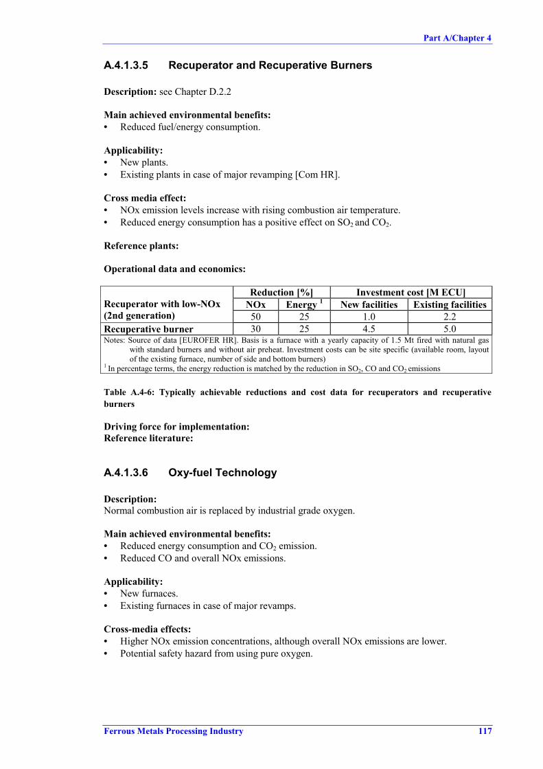
Part A/Chapter 4
Ferrous Metals Processing Industry 117
A.4.1.3.5 Recuperator and Recuperative Burners
Description: see Chapter D.2.2
Main achieved environmental benefits:• Reduced fuel/energy consumption.
Applicability:• New plants.• Existing plants in case of major revamping [Com HR].
Cross media effect:• NOx emission levels increase with rising combustion air temperature.• Reduced energy consumption has a positive effect on SO2 and CO2.
Reference plants:
Operational data and economics:
Reduction [%] Investment cost [M ECU]NOx Energy 1 New facilities Existing facilitiesRecuperator with low-NOx
(2nd generation) 50 25 1.0 2.2Recuperative burner 30 25 4.5 5.0Notes: Source of data [EUROFER HR]. Basis is a furnace with a yearly capacity of 1.5 Mt fired with natural gas
with standard burners and without air preheat. Investment costs can be site specific (available room, layoutof the existing furnace, number of side and bottom burners)
1 In percentage terms, the energy reduction is matched by the reduction in SO2, CO and CO2 emissions
Table A.4-6: Typically achievable reductions and cost data for recuperators and recuperativeburners
Driving force for implementation:Reference literature:
A.4.1.3.6 Oxy-fuel Technology
Description:Normal combustion air is replaced by industrial grade oxygen.
Main achieved environmental benefits:• Reduced energy consumption and CO2 emission.• Reduced CO and overall NOx emissions.
Applicability:• New furnaces.• Existing furnaces in case of major revamps.
Cross-media effects:• Higher NOx emission concentrations, although overall NOx emissions are lower.• Potential safety hazard from using pure oxygen.

Part A/Chapter 4
118 Ferrous Metals Processing Industry
Reference plants: several case studies (mostly for stainless steel)At least 50 units in normal daily steel heating operation; soaking pits, car bottom furnaces, boxfurnaces, caternary furnaces, rotary hearth furnaces, roller hearth furnaces etc. At least 6 newfurnaces operating in Sweden.
Operational data:
Economics:• Low investment costs.• High running cost if no increase in production is realized.
Driving force for implementation:• Increased productivity.• Fuel savings.• Lower overall NOx emissions.
Reference literature:"All Oxy-Fuel in heating furnaces", Dr. Joachim von Schéele and Dipl. Ing. Tomas Ekman,"Nordic Steel and Mining Review 2000", page 100.
A.4.1.3.7 Low-NOx Burners
Description: see Chapter D.2.1Nowadays burners combining low-NOx design features and air preheating are available, e.g.regenerative low-NOx burners.
Main achieved environmental benefits:• Reduction in NOx emission.
Applicability:• New furnaces.• Existing plants in case of major revamping (limitation for the replacement of existing
burners may be given with respect to the size). [Com HR] Existing conventional burnerscan generally be converted into first generation low-NOx burners by changing burner baffleand port block. A conversion to second generation low-NOx burners is more difficult andrequires a modification of the furnace lining. [EUROFER HR]
Cross-media effects:• The internal flue gas re-circulation, a design feature of low-NOx burners, reduces the NOx
level, but may increases energy consumption.
Reference plants:EKO Stahl, Aceralia, Voest Alpine, Preussag, etc.
Operational data and economics:For low-NOx burners the NOx level is less dependent on the air preheat temperature.Sometimes in industrial practice, low-NOx burners do not show best performance in NOxemission. This shows that the total NOx output is influenced by a lot of other parameters suchas furnace design, type of fuel, heating temperature, operation and maintenance. [EUROFERHR] Special care is therefore necessary regarding operating conditions and control of operation.
Compared to conventional burners a reduction in the NOx emission level of approximately 30% can be obtained. A typical value for natural gas is 300 mg NOx /Nm³.

Part A/Chapter 4
Ferrous Metals Processing Industry 119
In two cases, using COG and heavy oil, guaranteed emission levels of 330 mg NOx/m3 (drywaste gas at 5 % O2) were reported. [DFIU]
ExamplesVoest Alpine is operating 2 pusher–type (350 t/h) and 2 heat treatment furnaces. The reductionof the NOx level can only be obtained, when the burner capacity is higher than 20 %. During anunscheduled or scheduled delay time (burner capacity < 20 %) the NOx level can be double ormore. Investment costs were reported to be EUR 1 m/furnace (350 t/h). [Input-HR-1]
EKO Stahl operates a walking-beam furnace with a capacity of 200 t/h. The furnace isequipped with low-NOx burners and is operated with natural gas and an air preheatingtemperature of 450° C (waste gas volume 140000 m3/h). Levels of 400 mg/m3 for NOx and<100 mg/m for CO (reference 5 % O2) are achieved as daily averages in the case of coldcharging.
NOx emissions of 250 mg/m3 (reference 3 % O2) with Low-NOx burners were also reported,compared to conventional burners with 300 – 500 mg/m3 ACB
Reduction [%] Investment cost [M ECU]NOx Energy New
facilitiesExistingfacilities
Low-NOx burners with internal flue gasrecirculation (1st generation)
40 0 0 0.8
Low-NOx burners with internal flue gasrecirculation and air staging (2ndgeneration)
65 0 0.2 1.2
Notes: Source of data [EUROFER HR]. Basis is a furnace with a yearly capacity of 1.5 Mt fired with natural gaswith standard burners and without air preheat. Investment costs can be site specific (available room, layoutof the existing furnace, number of side and bottom burners)
Table A.4-7: Typically achievable reductions and cost data for low-NOx burners
Driving force for implementation:Reference literature:
A.4.1.3.8 Selective Catalytic Reduction (SCR)
Description:A secondary measure to reduce the NOx emissions is selective catalytic reduction. The generaltechnical description of SCR is given in Chapter D.2.4.
Main achieved environmental benefits:• Reduction in NOx emission.
Applicability:• New and existing plants.
Cross-media effects:• Use of ammonia gas (transport and storage can be hazardous and subject to stringent safety
regulations).• Risk of air pollution due to ammonia slip.• Possible increase in energy consumption [Vercaemst 27.7].• Possible increase in waste; de-activated catalyst, which can be reprocessed by the
manufacturer. This waste stream probably will be minimal.[Vercaemst 27.7], [Oekopol 7.9]

Part A/Chapter 4
120 Ferrous Metals Processing Industry
Reference plants:Hoogovens Steel, walking beam furnace [Com NL]
Operational data:
Example Corus/Hoogovens Hot Rolling Mill No 2 in IJmuiden:In IJmuiden the SCR technique is applied at the walking beam furnaces which produce about2.3 million tonnes of hot rolled steel annually. Due to the specific construction of the flue gaschannel, it was possible to build the ordinary SCR catalyst into the existing channel. The type ofcatalyst used is suitable to operate within the temperature range 270 - 450 °C. Short periods oftemperatures up to 500 °C do not harm the catalyst. With this type of installation it is possible toget an overall reduction rate of more than 80 %. The permit of the plant describes a reductionfrom 800 mg/Nm3 to 320 mg/Nm3 and a demand to achieve more than 85 % reduction, whichcan probably be done. The cost efficiency of the SCR at the walking beam furnace atCorus/Hoogovens is NLG 4.20 per kg NOx reduced. [EUROFER 31.3] [EUROFER 3.4]
In IJmuiden no SCR behind a pusher type furnace is installed yet, but one is under construction.Start of operation is scheduled for June 2000. For the second pusher furnace, installation of anSCR is planned for early next year. The performance will probably be much worse than in thecase of the walking beam furnace. Due to the very high temperatures of the flue gas (75 %above 520°C) an experimental type of catalyst has to be used. This type only functions properlywithin a temperature range of 300 - 520°C. At temperatures above 520° no ammonia can beinjected any more because of potential damage to the catalyst. Unless the high temperatures aredealt with (i.e. technical solutions for this problem are found or additional measures are taken),it is estimated that the overall reduction of NOx will not be more than 30 %. [EUROFER 31.3]
Some doubts were expressed regarding the technical feasibility of SCR which may limit theapplicability to reheating furnaces:• Some practical problems are likely to be encountered in application of SCR on steel
reheating/heat treatment furnaces as production rate (and therefore thermal input) andtemperature profiles are not steady state. To avoid either excessive NH3 slip or excess NOxin the stack, the ammonia injection rate would need to be controlled to match rapidlychanging exhaust flow rates and NOx concentrations. [ETSU-GIR-45].
• SCR technology requires certain limits of temperature and volume flow, which might not beachieved by some plants [DK 30.6].
• The required flue gas temperature suitable for SCR may not be readily available. If thetemperatures are too high, dilution air could be used, although furnace draughting may thennot be acceptable. [ETSU-GIR-45].
• In the case of regenerative burners, the efficiency of flue gas heat recovery would beaffected, unless the SCR could be incorporated midway in a regenerator bed (e.g. the bedwould need to be split). [ETSU-GIR-45].
• Many plants recover the waste heat of the exhaust gases for reasons of energy efficiency.The resulting temperature of the waste gas is in the range 150 – 210 °C and needs to bereheated for the SCR catalyst to work properly. Consequently, additional energy inputwould be necessary [EUROFER 2.7].
• As there is only very limited experience with the application of SCR at reheating furnaces(only one plant and only for walking beam furnaces), it not verified whether the techniquewill work under all temperature conditions and air ratios, [EUROFER 30.6].
• With higher dust concentrations in the waste gas (e.g. if fuel oil is used as energy source)de-dusting measures would be required to protect the catalyst [EUROFER 2.7].
• In integrated steel plants, plant gases (blast furnace top gas, BOF converter gas or cokeoven gas) are used as fuel. They contain usually only negligible traces of zinc or othermetals, but these could still contaminate the surface of the catalyst and gradually reduce itsefficiency and lifetime [EUROFER 2.7].

Part A/Chapter 4
Ferrous Metals Processing Industry 121
• A problem which can arise is the formation of acidic ammonium sulphate (NH4)2SO4 orbisulphate (NH4) HSO4 particles by the reaction of excess ammonia carried over from theSCR reactor with SO2 and SO3 in the cooler flue gases downstream. Deposition of theseparticles can cause fouling, erosion and corrosion of downstream equipment surfaces. Theformation of ammonium sulphate is minimized by use of slightly sub-stoichiometricamounts of NH3 (0.9 – 1.0 mole per mole of NOx) to suppress carry over. [HMIP-95-003],[ETSU-GIR-45].
Economics: NLG 4.20 per kg NOx reduced [EUROFER 3.4]Driving force for implementation:Reference literature: [HMIP-95-003], [ETSU-GIR-45], [EUROFER 31.3]
A.4.1.3.9 Selective Non-Catalytic Reduction (SNCR)
Description:The general description of SNCR is given in Chapter D.2.5
Main achieved environmental benefits:• Reduction in NOx emission.
Applicability:• New and existing plants.
Cross-media effects:• Use of ammonia gas (transport and storage can be hazardous and subject to stringent safety
regulations).• Risk of air pollution due to ammonia slip.
Reference plants:Avesta Sheffield, walking beam furnaces
Operational data:
Example Avesta Sheffield:At the hot strip mill for rolling stainless steel slabs to strip, there are two reheating furnaces(walking beam furnaces), each with a capacity of 100 t/h and using propane/butane gas as fuel.Furnace A, supplied by Stein Heurty, became operative operation in 1992, and furnace B,supplied by Italimpianti, in 1996.
Because this is the plant’s largest point source of NOx, action has been taken to reduce theseemissions through the introduction of an SNCR installation. The installation comprises mainly astorage tank for ammonia (25 % water solution), pumps, pipes, injection lances, and acomputerised measurement and control system, where ammonia is added to the exhaust gas ofeach furnace on the basis of continuous NOx measurement.
The installation was put into in continuous operation in October 1999 and was regulated duringthe autumn. Measurements in January 2000 gave the following results (NOx measured as NO2):
NOx content (mg/MJ fuel) Reduction (%) NOx [mg/Nm3]Furnace A 74 70 205Furnace B 62 30 172 (ammonia slip 5 mg/Nm3)
The measurement results are averages of continuous measurements made during 32 hours atFurnace A and 42 hours at Furnace B. They are considered normal and expected to remain atthese levels in continuous operations.

Part A/Chapter 4
122 Ferrous Metals Processing Industry
The reason why the reduction is lower at Furnace B is that the nitrogen oxide content withoutammonia is lower than in Furnace A.
The following cost information was given to the Swedish Environment Court in December 1999in a report on the possibilities of reducing the emissions of nitrogen oxides from these furnaces:
The capital investment (including installation and running-in costs as well as the cost of allequipment): SEK 6.3 m (EUR 0.76 m)2
Operating costs (mainly ammonia and maintenance): SEK 1.4 m per year (EUR 0.169 m peryear)Total capital and operating costs: SEK 3.3 m per year (EUR 0.40 m per year)
With the NOx reduction mentioned above, the emissions of nitrogen oxides can be reduced by60 tonnes per year, corresponding to a specific cost of SEK 55 (EUR 6.63) per kg NOx reduced(measured as NO2). [EUROFER 17.4]
Other sources report efficiency of NOx removal by SNCR of typically 50 – 60 % with 20- 30ppm NH3 slip [ETSU-GIR-45], but even higher reductions of up to 85 % are reported inconnection with ammonia injection on a natural gas-fired regenerative burner. Others reportedon the use of ammonia and urea injected into the flue of a burner (operating at 900 ºC airpreheat) burning a mixture of blast furnace and coke oven gases. For both reagents, themaximum reduction was of the order of 80 %. These data derive from test furnaces notexceeding 600 kWth, which in this case was a 1/3 scale version of a soaking pit furnace.[HMIP-95-003]
Some doubts were expressed regarding the technical feasibility of SNCR which may limit theapplicability to reheating furnaces. Problems in applying SNCR to reheating furnaces due tolarge variations in process conditions (waste gas temperature, volume flow etc.) and or non-availability of a suitable temperature window are probably the same as for the application ofSCR (see above):
• The temperature window for SNCR is about 850 – 1100 ºC (depending on the reagent). Forthose regenerative systems which have furnace temperatures well in excess of 1000 ºC, theappropriate SNCR temperature range is liable to be found within the regenerator bed, whichmay militate against the use of the method. Control systems would be complicated if therewere a need to 'follow' a temperature window which can change its location within thefurnace/burner as thermal inputs and production rates are altered. [HMIP-95-003],[EUROFER HR]
• A potential drawback of the SNCR technique is the formation of ammonium sulphate by thecarry over of excess NH3. The use of clean gaseous fuels such as natural gas in conjunctionwith SNCR should avoid the reported problems of adhesive and corrosive compounds thatcan otherwise occur. This may not be the case with sulphur-containing steelwork gases.[HMIP-95-003]
Economics: The economic data of the Swedish plants shows that the cost of 6.63 euro per kg ofNOx reduced gives rise to additional costs of 0.33 euro in the manufacture of 1 tonne of rolledsteel. Based on a price of about 400 euro per tonne of hot wide strip, the relative expenditurecomes to 0.08 %. Annual production of the two plants was estimated to be 1.2 million tonnes ofrolled steel. [Germany 7.4]
2 The costs in EUR were calculated using an exchange rate of EUR 0.12 for 1 SEK.

Part A/Chapter 4
Ferrous Metals Processing Industry 123
Driving force for implementation:The SNCR units were fitted as a result of local regulatory issues. The site has a total annualmass emission limit for NOx and there was a desire to increase production. The increasedthroughput could not be realised unless some emission reductions were achieved and the SNCRinstallation was then found to be the best solution.
Reference literature: [HMIP-95-003], [ETSU-GIR-45], [EUROFER 17.4]
A.4.1.3.10 External Flue Gas Recirculation (FGR)
Description: see Chapter D.2.3
Main achieved environmental benefits:• Reduction in NOx emission.
Applicability:
• New and existing furnaces.• In practice, for retrofitting, there may be physical difficulties in installing ductwork and
problems of accessibility.• Potentially difficult to control in cases where composition and hence waste gas volumes are
variable (e.g. on integrated sites where mixed plant gases are used).
Cross-media effects:• Potential increase in fuel consumption (as long as waste gas flow and temperature are not
affected by FGR, combustion efficiency and fuel consumption will remain the same, butthis implies an increase in air-preheat temperature).
Reference plants:
Operational data:For a COG fired steel slab reheater with a capacity of at least 140 t/h NOx reductions of 51.4 %,69.4 % and 79.8 % (from a base level of 657 mg/m3) for 10 %, 20 %, and 30 % FGRrespectively, are reported. [ETSU-GIR-45]
Data given for increases in fuel consumption (and hence for CO2 emission) for different burnerdesigns range from 1.1 to 9.9 % (FGR ranging from 10 – 50 %). [ETSU-GIR-45]
Economics:Driving force for implementation:Reference literature:
A.4.1.3.11 Waste Heat Boiler
Description:A waste heat boiler can be installed between furnace exit and chimney (decreasing theeffectiveness of a recuperating system) or between the recuperator and the stack. In the wasteheat boiler, the heat content of the waste gas is used to generate steam. The waste gastemperature after the waste heat boiler is lowered to about 200 °C. The generation of steam bythis method at this point saves generating this energy elsewhere (e.g. in the power plant orheating station). As a result, considerable energy and emission reductions can be achieved.
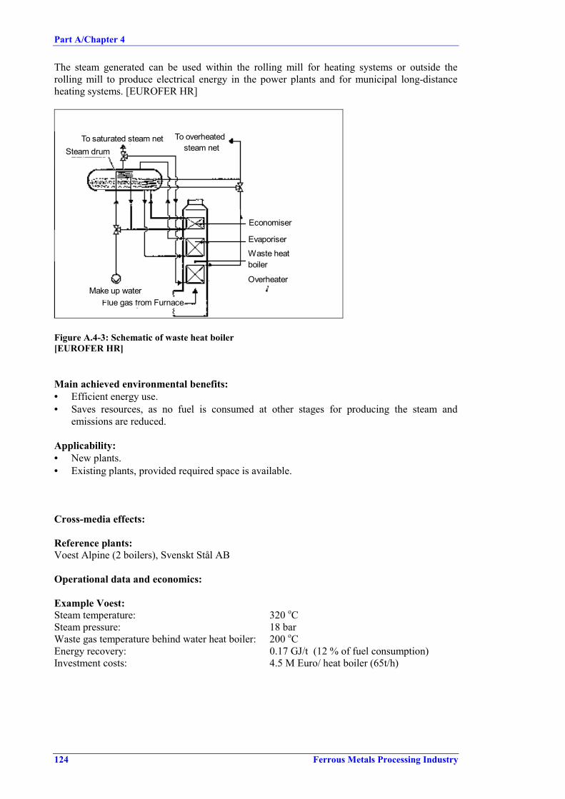
Part A/Chapter 4
124 Ferrous Metals Processing Industry
The steam generated can be used within the rolling mill for heating systems or outside therolling mill to produce electrical energy in the power plants and for municipal long-distanceheating systems. [EUROFER HR]
Steam drum
Flue gas from FurnaceMake up water
To saturated steam net To overheated steam net
Economiser
EvaporiserWaste heat boiler
Overheater
Figure A.4-3: Schematic of waste heat boiler[EUROFER HR]
Main achieved environmental benefits:• Efficient energy use.• Saves resources, as no fuel is consumed at other stages for producing the steam and
emissions are reduced.
Applicability:• New plants.• Existing plants, provided required space is available.
Cross-media effects:
Reference plants:Voest Alpine (2 boilers), Svenskt Stål AB
Operational data and economics:
Example Voest:Steam temperature: 320 oCSteam pressure: 18 barWaste gas temperature behind water heat boiler: 200 oCEnergy recovery: 0.17 GJ/t (12 % of fuel consumption)Investment costs: 4.5 M Euro/ heat boiler (65t/h)

Part A/Chapter 4
Ferrous Metals Processing Industry 125
Reduction 1 [%] Investment cost [M ECU]NOx Energy 2 New facilities Existing facilities
Waste heat boiler 15 15 4.0 4.0Notes: Source of data [EUROFER HR]. Basis is a furnace with a yearly capacity of 1.5 Mt fired with natural gas
with standard burners and without air preheat. Investment costs can be site specific (available room, layoutof the existing furnace, number of side and bottom burners)
1 Waste heat boilers have a negligible effect when combined with recuperators or with regenerative systems2 The energy reduction in terms of percentage has an equal effect on the reduction in SO2, CO- and CO2 emissions
Table A.4-8: Typically achievable reductions and cost data for waste heat boilers
Installation of a waste heat boiler is only sensible when there is a special requirement for steam,i.e. some users. Only a marginal effect can be expected from the installation of a waste heatboiler when it is combined with effective recovery of the waste heat by the use of recuperatorsor of a regenerative system and with the proper furnace design. [EUROFER HR]
Driving force for implementation: - reduced energy consumption, monetary advantage.Reference literature:
A.4.1.3.12 Optimised Skid Design to Reduce Skid Marks
Description:SMC - Skid Mark Compensation DeviceThe slabs heated in the pusher-type furnace lean on water-cooled supporting pipes whichcause local undercooling (skid marks) on the bottom side of the slabs and must be compensatedfor during the residence time in the soaking hearth to avoid thickness variations of the finishedproduct.
The soaking time can be reduced if the skid marks are reheated by application of suitablemethods, e.g. local inductive heating (skid mark compensation device). Losses due to thecooling system and the hearth wall are almost constant over time, regardless of whether thefurnace is operated under full load or partial load.
Main achieved environmental benefits: The reduction of the residence time on the hearth and,consequently, of the throughput time, results in energy savings. But it was also reported thatSMC requires high energy input for inductive heating. [Com2 HR]
Furnace Skid RidersAn additional measure to reduce the formation of skid marks is the use of so-called skid riders.These are fixtures for the water-cooled furnace rails made from special material (metal alloy orceramics), which reduce temperature dissipation.
Main achieved environmental benefits: - As in SMC, a reduction of the temperaturecompensation, combined with an increased throughput and reduced energy consumption, ispossible.
Skid ShiftingIn modern walking beam furnaces, the material supporting skids are not straight all along thefurnace. Mainly the last section of skids, near the furnace exit side, is shifted with an offsetdesigned to distribute and therefore to decrease the skidmarks.
Main achieved environmental benefits: - Quality is enhanced and waste output reduced.
Applicability:• Furnace skid riders and skid shifting: only applicable to new installations as they have to be
considered at design stage.• Skid mark compensation device: new and existing installations.

Part A/Chapter 4
126 Ferrous Metals Processing Industry
Cross-media effects:Reference plants:
Operational data:Reported reduction for skid shifting, skidmark compensation or furnace skid riders was 1 % forenergy consumption and 1 % NOx emission. [EUROFER HR]
Economics:Driving force for implementation:Reference literature:
A.4.1.3.13 Reduction of Energy Loss through Stock TransportationDevice
Description:In re-heating furnaces water cooling is used to protect some components and maintain theirphysical strength; examples include doors, lintels and the stock transport mechanism or supportsystem. Water-cooled components represent a significant source of energy loss. In particular,the loss through stock transport systems in continuous (walking beam) furnaces, can account for6 to 12 % of the fuel input under typical operating conditions. Close to the end of a furnaceoperating campaign, when insulation of the cooled components begins to degrade, the loss canbe as high as 20 to 25 %. [ETSU-G76], [Com2 HR]
Losses from stock supporting structures can be minimized at the design stage byoptimizing/reducing the number of cooled beams and supports and by using suitableinsulation. [ETSU-G76]
Main achieved environmental benefits:• Reduction in water cooling losses of 26.7 GJ/h (equivalent to a fuel saving of 44.5 GJ/h)
were reported [ETSU-G76].
Applicability:• New furnaces and existing furnaces.• For existing furnaces, optimisation can be done during refractory maintenance [Com2 HR].
Cross-media effects:• 46 % reduction in water use [ETSU-G76].• Reduced energy consumption of pusher mechanism [ETSU-G76].• Reduced skid marks, improved quality [ETSU-G76].
Reference plants:Operational data:Economics:Driving force for implementation:Reference literature:
A.4.1.3.14 Evaporative Furnace Skid Cooling
Description:Skid cooling energy losses can be used to generate steam. A closed, forced cooling circuit,which circulates a mixture of approx. 95 % water and 5 % saturated steam can be installed in re-
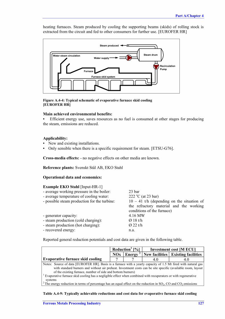
Part A/Chapter 4
Ferrous Metals Processing Industry 127
heating furnaces. Steam produced by cooling the supporting beams (skids) of rolling stock isextracted from the circuit and fed to other consumers for further use. [EUROFER HR]
Steam drum
Steam produced
Water supply
RecirculationPump
Water steam circulation
Furnace
Furnace skid system
Figure A.4-4: Typical schematic of evaporative furnace skid cooling[EUROFER HR]
Main achieved environmental benefits:• Efficient energy use, saves resources as no fuel is consumed at other stages for producingthe steam, emissions are reduced.
Applicability:• New and existing installations.• Only sensible when there is a specific requirement for steam. [ETSU-G76].
Cross-media effects: - no negative effects on other media are known.
Reference plants: Svenskt Stål AB, EKO Stahl
Operational data and economics:
Example EKO Stahl [Input-HR-1]- average working pressure in the boiler: 23 bar- average temperature of cooling water: 222 oC (at 23 bar)- possible steam production for the turbine: 10 – 41 t/h (depending on the situation of
the refractory material and the workingconditions of the furnace)
- generator capacity: 4.16 MW- steam production (cold charging): Ø 18 t/h- steam production (hot charging): Ø 22 t/h- recovered energy: n.a.
Reported general reduction potentials and cost data are given in the following table.
Reduction1 [%] Investment cost [M ECU]NOx Energy 2 New facilities Existing facilities
Evaporative furnace skid cooling 7 7 4.0 4.0Notes: Source of data [EUROFER HR]. Basis is a furnace with a yearly capacity of 1.5 Mt fired with natural gas
with standard burners and without air preheat. Investment costs can be site specific (available room, layoutof the existing furnace, number of side and bottom burners)
1 Evaporative furnace skid cooling has a negligible effect when combined with recuperators or with regenerativesystems
2 The energy reduction in terms of percentage has an equal effect on the reduction in SO2, CO and CO2 emissions
Table A.4-9: Typically achievable reductions and cost data for evaporative furnace skid cooling

Part A/Chapter 4
128 Ferrous Metals Processing Industry
Only a marginal effect can be expected from evaporative furnace skid cooling when it iscombined with good insulation of the skids.
Driving force for implementation:Reference literature:
A.4.1.3.15 Feedstock Preheating
Description:The heat in the waste gas of heating furnaces can be used to preheat the feedstock by blowingthe hot waste gas from top and bottom onto the slab. Even after regenerative burners and awaste heat boiler, the waste gas can have enough energy to heat the slabs up to 400 °C. FigureA.4-5 shows the example of a slab preheater installed upstream of a pusher-type heatingfurnace.
Figure A.4-5: Principle of slab preheating by waste gas[StuE-113-10]
Main achieved environmental benefits:• Reduced energy consumption in the heating furnace (20 %).
Applicability:• New and existing continuous reheating furnaces (for cases where stock recuperation is not
already incorporated in the furnace).
Cross-media effects: - no negative effects on other media are known.
Reference plants: Preussag Stahl, Salzgitter

Part A/Chapter 4
Ferrous Metals Processing Industry 129
Operational data:Example:The preheater shown in Figure A.4-5 is installed up-stream of 2 pusher-type furnaces. Thefurnaces have capacities of 300 t/h and are fired by regenerative burners. The heat from thewaste gas of the furnace is first used for heat recovery in a waste heat boiler. After that it stillhas a temperature of 500 – 600 °C and is used in the preheater to heat the slabs to up to 400 °C.The waste gas leaving the preheater still has a temperature of 300 °C and is used to preheat thecombustion air for the regenerative burners of the heating furnace to about 150 °C (by means ofa oil heat exchangers). The waste gas is discharged at a temperature of 200 °C. [StuE-113-10]
As an alternative to preheaters, the heat of waste gas can be used in very long walking beamfurnaces in the un-fired long preheating zone. [StuE-113-10]
Economics:Driving force for implementation:Reference literature:
A.4.1.3.16 Heat Conservation Box / Thermal Covers
Description:Hot boxes or insulated chambers are used to promote heat retention in the steel and to provide alink between the source of hot stock and the furnace. Semi-finished products, which cannot becharged immediately (because of programme co-ordination and for bridging gaps caused byinterruptions) are stored in this unheated, heat-insulated box instead of being stored in openstockyards. Heat losses of the slabs are reduced and the charge temperature is maintained at ahigh level. On average, the storing time for slabs is 8 hours. The temperature of insulated storedslab is approximately 220 °C higher than that of open stored slabs. [EUROFER HR], [ETSU-G76].
Another method for reducing the furnace operating temperature and preventing heat lossbetween the furnace and the rolling mill is insulated shields (heat retaining covers) installedbetween the furnace discharge and the rolling stands. Heat losses during transport from thecasting machine to the re-heating furnace can be prevented by the same kind of measures.[DFIU98], [ETSU-G76]
Main achieved environmental benefits:• Reduced energy consumption in re-heating.• Thermal covers for the transport of slabs between a continuous caster and a re-heatingfurnace can save about 0.33GJ/t [DFIU98].
Applicability:• New and existing installations.• All continuous casting plants with adjacent rolling mill [Com A].• same limitations may apply as for hot charging [Input-HR-1].
Cross-media effects: - no negative effects on other media are known.
Reference plants:• VA Stahl Linz, (max. 5000 t), Austria [Input-HR-1].• HADEED, Saudi Arabia [Com A].• Stahlwerke Bremen [STuE-117-5].

Part A/Chapter 4
130 Ferrous Metals Processing Industry
Operational data:ExampleAn investigation on potential measures to increase the charging temperature of continuous castslabs to a heating furnace was done at Stahlwerke Bremen using numerical modelling. Theresults based on computer simulation and measurements for that installation showed that thecore temperature of slab immediately after casting was about 950 °C. On the way to thestockyard of the hot rolling mill the slabs cooled down by 200 ° to 750 °C: during the storagetime of 24 h the temperature of the slabs dropped further, leaving a remaining chargingtemperature to the heating furnace of about 350 °C. By optimizing the synchronisation of thecontinuous caster and the rolling schedule, the storage time could be reduced to a third.Additionally, the slabs were covered with thermal covers with a 50 mm mineral wool lining. Itwas proven that during an 8 hour storage, starting from 750 °C, a charging temperature of700 °C could be maintained. Compared to the old charging practice (350 °C) this represented anadditional energy input to the furnace of 0.26 GJ/t resulting half from the shorter storage timeand half from the thermal insulation. [StuE-117-5]
Figure A.4-6: Modified storage to increase charge temperature[StuE-117-5]
Economics:Return on investment in 1 year at VA Stahl Linz [ComA].Investment costs 2 M Euro, Voest [Input-HR-1].
Driving force for implementation:• Increased furnace- and rolling mill capacity.• Increased hot charging rate in connection with CAQC. [Com A].
Reference literature:Ideas and Concepts for Hot or Direct Charging, Paper No. 50, 7th International ContinuousCasting Conference, May 20 – 22, 1996 [Com A].

Part A/Chapter 4
Ferrous Metals Processing Industry 131
A.4.1.3.17 Hot Charging / Direct Rolling
Description:Contrary to the conventional process (storage and cooling of the material), the residual heatfrom the continuous-cast slabs, blooms, beam blanks or billets is utilized by charging themdirectly (with their residual heat content) into the heating furnaces. Hot charging refers tocharging temperatures of 300 to 600 oC; direct rolling to charging temperatures of 900 to1000oC. These technique, can only be applied if the surface quality is good enough so thatcooling and scarfing is not required and if the manufacturing programs of the steel making plantand the hot rolling mill can be adequately tuned. Control computers are used to co-ordinate theproduction of both departments according to customers' orders and to prepare the rollingschedules.
Figure A.4-7 presents a possible material flow in a plant allowing both cold charging and warmor hot charging. An optimised production planning and control system to synchronise theproduction schedules of a steelworks and a rolling mill can achieve a hot charging share of over60 % at about 800°C. A soaking furnace placed before the rolling mill may be required.
1312
6
5
11
10
3
4
12
7
98
Material flow with hot and cold charging
1. Flame-cutting machine2. Roller table3. Cross transport4. Distributing roller table
Cold charging
10. Ingot pusher11. Bearing grid12. Cold stock13. Feeding grid 6. Roller table
Hot charging
5. Bloom transfer
6. Roller table
7. Walking beam furnace8. Bloom transfer9. Roughing stand
6
Figure A.4-7: Material flow: cold versus hot charging[DFIU98]
Main achieved environmental benefits:• Reduction in energy consumption (fuel savings).• Reduction in SO2, CO and CO2 emissions.
Applicability:• New and existing installations.• Application may be limited at some existing plants because of plant layout and operational
logistics. Important technological parameters are mill type and configuration, proximity ofthe caster to furnace and rolling mill (time required for the transfer of the stock from thesteel plant to the reheating furnace) as well as steel specifications. Sometimes application tofurnaces with unfired preheating zones is not possible. The implementation of hot charging

Part A/Chapter 4
132 Ferrous Metals Processing Industry
or direct rolling depends furthermore on the installation of equipment to allow a higherfurnace throughput, temperature normalisation (e.g. edge heaters), schedule free rolling,potential to aligne the production schedule of the steel plant (caster) and the productionschedule of the rolling mill, high quality slabs (surface quality) etc. [DFIU98], [ETSU-G77].
Cross-media effects:• Reduced stock residence time in the furnace.• Higher production rates (e.g. 10 - 25 %).• Improved yields and product quality due to reduced scaling and decarburisation.• Waste reduction in following processes, e.g. descaling.• Temperature of exhaust gas may increase [ETSU-G77].
Reference plants:EKO Stahl, [Input-HR-1]Rotherham Engineering Steels, [ETSU-CS-263]Stahlwerke Thueringen [StuE-118-2]
Operational data:Table A.4-10 illustrates the influence of hot charging on energy consumption and productiontime for hot charging. In the examples shown, production potential was increased by 10 % for ahot charging temperature of 400 °C and by 25 % for a charging temperature of 700 °C.
Charging Temperature20 oC 400 oC 700 oC
Specific energyconsumption (fuel)
1.55 GJ/t 1.25 GJ/t 0.94 GJ/t
Percentage Reduction 0 % 19 % 39 %Heat to steel 0.80 GJ/t 0.56 GJ/t 0.37 GJ/tResidence time infurnace1
100 min 90 min 75 min
1 Example based on: billets, mild steel, top-fired pusher furnace, discharge temperature 1200 oC
Table A.4-10: Effect of hot charging on fuel consumption and residence time[ETSU-G77]
ExamplesEKO Stahl hot charging of slabs [Input-HR-1]- percentage of hot charging: 4.63 – 31.65 %, Ø in 1998 14.64 %- average charging temperature of slabs: 700 – 900 oC- fuel consumption (natural gas): 17 Nm3/t- energy saving: 0.6 GJ/t
Rotherham Engineering Steels hot charging of blooms [ETSU-CS-263]- percentage of hot charging: 66.4 %- charging temperature of blooms: ~ 700 oC- specific energy consumption (SEC): 1.1 GJ/t during productive periods
1.23 GJ/t including light-up energyenergy saving: ~ 0.67 GJ/t (compared with awalking-beam type furnace with similar structuralenergy loss, efficiency of 67 % and SEC 1.9 GJ/t)
Stahlwerke Thueringen hot charging beam blanks [StuE-118-2]- percentage of hot charging: > 60 %

Part A/Chapter 4
Ferrous Metals Processing Industry 133
British Steel, Scunthorpe hot charging concast blooms [Input-HR-1]- charging temperature of blooms: ambient up to concast exit temperature ~ 1300 oC- energy savings of about 33 %- specific energy consumption (SEC): 1.35 GJ/t (2.1 GJ/t without hot charging)
Energy savings for hot charging at 300 °C of 15 % were reported in [EUROFER HR].
Imatra Steel, Imatra Hot charging of blooms
- engineering steel grades, billets / heavy bars 74 / 26 %- percentage of charging via hot route 91 – 93 %- direct hot charging 700 – 900 °C- charging via hot buffer (natural gas fired) 700 °C- soaking temperature 1250 - 1290 °C- specific energy consumption 0.87 GJ/t (average for production 1998 (98 %natural gas + 2 % electricity) including hot buffer, cold charging, weekends
and light-up energy).
Hot buffer is used:- to eliminate effects of short stoppages in rolling mill- to balance the production speed difference when rolling bars (the casting
speed cannot be lowered to match the speed of the old rolling mill)- for slow preheating of cold blooms at weekends.
Economics:
Type of investment Investment costNew facilities
(M ECU)Existing facilities
(M ECU)Hot charging (at 300 °C) 1.5 2.0Notes: Source of data [EUROFER HR]. Basis is a furnace with a yearly capacity of 1.5 Mt fired with natural gas with standard
burners and without air preheat. Investment costs can be site specific (available room, layout of the existing furnace, numberof side and bottom burners)
Table A.4-11: Investment costs for for hot charging[EUROFER HR]
Driving force for implementation: - reduced energy consumption.Reference literature:
A.4.1.3.18 Near Net Shape Casting / Thin Slab Casting
Description:'Near net shape casting' or thin slab casting comprises an improved continuous castingtechnology in which the thickness of the produced slab is reduced as far as possible to therequired end-product shape.
The technical solutions available differ mainly in the thickness of the slabs, ranging from 15 upto 80 mm (conventional thickness ranges 150 - 300 mm), in the reheat technique and the linkagebetween caster and hot rolling mill. Available thin slab casting techniques include:
• Compact Strip Production (CSP): using funnel type moulds with a casting thickness ofapprox. 50 mm.

Part A/Chapter 4
134 Ferrous Metals Processing Industry
• Inline Strip Production (ISP): the cast strand of about 60 mm thickness undergoes a softreduction (on liquid core) with rolls below the mould, followed by a shaping of thesolidified strand creating slab thickness of about 15 mm.
• Continuous Thin Slab Casting and Rolling (CONROLL): using straight parallel mouldswith casting thickness of 70 - 80 mm.
• Direct Strip Production (DSP): 90 mm caster mould and soft-reduction to 70 mm.
The casting machines may be linked to all main configurations of hot rolling finishing mills,e.g. finishing train, planetary mills, Steckel mills etc.
Figure A.4-8 and Figure A.4-9 show as examples the schematics of the CSP and the ISPprocess.
Furnaces of different design – chieving uniforme incoming slab temperature - are the linkagesbetween the caster and the hot rolling mill. Depending on the type of thin slab production plant,tunnel furnaces or 'cremona boxes' are used. The main target of these facilities is to equalise andhomogenise the temperature of the continuous cast slabs of different cross sections and lengthof around 50 m up to 300 m nowadays [Com2 HR] and to regulate the feed to the finishingrolling mill. Dependent on the casting strands, 1 or 2 furnaces are installed, connected by ashuttle device.Firing of continuous furnaces and combustion systems is in general comparable with thecommon systems of reheat furnaces.
Coiler
Cooling line
Rolling millSoaking furnace
Mould
Ladle
Tundish
CSP.ds4
Figure A.4-8: Schematic of the CSP process[DFIU98]

Part A/Chapter 4
Ferrous Metals Processing Industry 135
Mould
Ladle
Tundish
CoilerCooling lineRolling mill
Coilbox
Furnace
HRM (hot reductionmill)
ISP.ds4
Figure A.4-9: Schematic of the ISP process[DFIU-99]
Main achieved environmental benefits:• Reduced energy consumption.
Applicability:• Applicable for new plants.• For the production of low carbon steel, higher strength unalloyed and micro-alloyed
structural steel and C-steel > 0.22 % [STuE-118-5].• For production of high quality stainless steel (austenitic, gradres, ferritic grades as well as
martensitic grades (BHM, 142Jg. 1997, Heft 5, 210 – 214)) [Com A].
Cross-media effects: - no negative effects on other media are known.Reference plants:

Part A/Chapter 4
136 Ferrous Metals Processing Industry
Slab dimensions[mm]
Capacity[Mt/a]
Rolled Thickness[mm]
Start Date
Compact Strip ProductionNucorCrawfordsville, USA
50 x 900 - 135050 x.500 - 1350
0.81
1.61.6
7/894/94
NucorHickman, USA
50(75) x 1220 - 156050(75) x 1220 - 1560
11
1.51.5
8/925/94
Nucor, Berkeley County, USA 50 x 1680 1.5 1.2 3/97Geneva SteelProvo, USA
150-250 x 3200 maxor 50 x 1880 max
1.9 plate 7/94 - 95
AST, Terni, Italy 50 x 1000 - 1560 - - 12/92Hylba SA, Monterrey, Mexico 50 x 790 - 1350 0.75 1.2 11/94Hanbo SteelAsan Bay, Korea
50 x 900 - 156050 x 900 - 1560
11
1.51.5
6/9512/95
Gailatin Steel, Warsaw, USA 50 x 1000 - 1560 1 2.1 2/95Steel Dynamics, Butler, USA 40-70 x 990 - 1560 1.2 1.2 1/96Nippon Denro lspalCalcutta, India
50 x 900 - 1560 1.2 1.2 8/96
Amalgamated Steel MillsMalaysia
50 x 900 - 1560 2 1.2 10/96
Ac. Compacta BizkayaBilbao, Spain
53 x 790 - 1560 0.91 1.3 7/96
Acme MetalsRiverdale, USA
50 x 900 - 1560 0.9/1.8 1.25 10/96
Inine Strip ProductionArvedi ISP WorksCremona, Italy
60* x 1070 - 1250*(red. to 40 duringsolidification)
0.5 1.2 1/92
Posco, Kwangyang, Korea 75* x 900 - 1350*(red. to 60 duringsolidification)
10.8
1.01.0
19961996
Nusantara Steel CorpMalaysia
?
Saldanha, South Africa (1.4)1 ?Ipsco, USA (1)1 ?Pohang Iron and SteelSouth Korea
(2)1
Hoogovens Staal 2Ijmuiden, NL
70 – 90 x ?? (1.3) 1 – 2.5
CONROLLAvesta, Sweden 80-200 x 660–2100 - - 12/88Armco, Mansfield, USA 75-125 x 635-1283 0.7/1.1 1.7 4/95Voest Alpine, Linz, Austria ?
Direct Strip ProductionAlgoma, CAN3 90* x 200
*(red. to 60 duringsolidification)
1 11/97
Note: Source of data [Jahrbuch Stahl 1996], reference year of information 19951 Source [StuE-116-11], ordered plants, reference year of information 19962 Source [Steel News, march 1998]3 Source [algoma.com]
Table A.4-12: Thin slab casting plants (by July 1995)

Part A/Chapter 4
Ferrous Metals Processing Industry 137
Operational data:The production of 1 to 3 mm thick strip by conventional slab casting - with a chargingtemperature for the furnace of 20 ºC and discharge at 1200 oC - requires a specific energy of1.67 GJ/t. A thin slab casting line - with a charging temperature for the furnace of 960 ºC anddischarge at 1150 oC - has a specific energy consumption of 0.50 GJ/t.
Grades cast by thin slab casting (commercial production):- Plain carbon steels outside peritedic range (CSP).
(0.065 - 0.15 %C) (CSP).- High alloyed and stainless (CSP).- Unalloyed structural steels (ISP).- Alloyed structural steels (ISP).- Line pipe steels (HSLA) (ISP).- Oil field pipe steels (ISP).- High alloyed austenitic and ferritic steels (ISP)- Stainless steels CONROLL [Near-Net-Shape].- Low and ultra-low carbon steel (CSP) [StuE-118-5], [AC-Kolloq].- C-steel grades with > 0.22 %.- High strength (micro- and unalloyed) structural steel.- Deep steel drawing grades.- Microalloyed Nb steels.- Cu alloyed structural steels [Near-Net-Shape].
Conventional production routeTypical Consumption
Thin slab production routeTypical Consumption
Electrical energy 1(deformation energy)
72 - 115 kWh/t
average 94 kWh/t (reported bymembers of shadow group)
approx. 70 kWh/t (deformation only)approx. 77 kWh/t (incl. Coil box)
Reheating energy(fuel consumption) 2 approx. 1300 - 1900 MJ/t approx. 300 - 650 MJ/t
Note: source of data [EUROFER HR]1 Depends on the degree of deformation; temp. of intermediate strip; material hardness2 fuel consumption depends on the furnace design and thickness of ingoing slab
Table A.4-13: Comparison of consumption figures for conventional and thin slab production route
Economics:Thin slab casting technique effectively opened the flat rolled market to mini mills, which up tothat time had been bound more or less to the production of long products. Implementation ofthis technology shrinks the size of the caster and eliminates the roughing mill, resulting incapital cost saving. Hot band, in the non-critical surface segment, can now be economicallyproduced with capacities of 0.8 - 1.0 Mt/year (with one-strand casters).
Driving force for implementation:- Due to reduction in energy consumption and processing time, economic/monetary advantage.
Reference literature:

Part A/Chapter 4
138 Ferrous Metals Processing Industry
A.4.1.3.19 Near Net Shape Casting/ Beam Blank Casting
Description:Another – more common - form of 'near net shape casting' is applied in the field of long productrolling of structural steel. Instead of the traditional bloom with a rectangular or square crosssection the continuous caster produces an H, I or double T shaped beam blank.
Main achieved environmental benefits:• Reduced energy input in reheating and rolling.
Applicability:• New plants or existing plants in case of a major revamp.
Cross-media effects: - no negative effects on other media are known.
Reference plants:Northwestern Steel & Wire, USA [StuE-114-8]Chaparral Steel, USA [StuE-114-8]Kawasaki Steel, Nucor-Yamato, Yamato Steel Tung Ho Steel [StuE-114-9]Stahlwerke Thueringen [StuE-118-2]
Operational data:Economics:Driving force for implementation:• Increased yield in the continuous caster due to reduced material to be cropped.• Increased specific heat transfer in the reheating furnace.• Reduced time in the rolling process, increase in productivity [Com HR].
Reference literature:
A.4.1.4 Descaling
A.4.1.4.1 Material Tracking
Description:Automation of the respective train areas and peripheral sensors allow exact determination of theentry into and the delivery of the materials from the descaling equipment and allow the operatorto open the valves of the pressure-water pipes accordingly. As a result, the water volume can becontinuously adjusted to the requirement.
Main achieved environmental benefits:• Reduced water consumption.• Reduced energy consumption.
Applicability:• Roughing, finishing and plate mills.• New and existing hot rolling mills for flat products.
Cross-media effects:Reference plants:Operational data:Economics:Driving force for implementation:Reference literature:

Part A/Chapter 4
Ferrous Metals Processing Industry 139
A.4.1.4.2 Use of High-pressure Storage Equipment
Description:Appropriately sized high-pressure storage vessels are used to temporarily store the high-pressure water and to reduce the starting phase of the high-powered pumps. In addition, it ispossible to keep the pressure at a constant level when several simultaneous descaling processesare performed. This method helps to keep the energy consumption within reasonable limits and,in the case of several descaling processes at the same time, helps to ensure optimum cleaningand high-quality products due to the constant system pressure.
Main achieved environmental benefits:• Reduced energy consumption.
Applicability:• Roughing, finishing and plate mills’ descaling systems.• New and existing hot rolling mills for flat products.
Cross-media effects:Reference plants:Operational data:Economics:Driving force for implementation:Reference literature:
A.4.1.5 Edging
Sizing Press
Description:In conventional vertical rolling, width reduction is limited to the slab edges with only littleeffect on the centre part of the slabs. Material thickness increases at the edges, forming dog-bone shaped cross sections. In the following horizontal rolling a significant return in width -side spreading - takes place, resulting in low width reduction efficiency.
In-line size presses, due to the forging effect on the slab, increase also the material thickness inthe middle of the slab. The shape of the cross section is nearly rectangular and side spreadingduring horizontal rolling passes is reduced.With the introduction of a sizing press prior to the rougher the width intervals of the caster andthe number of wedge type slabs are reduced. Caster productivity and hot charging rate maytherefore be increased. [EUROFER HR]
Main achieved environmental benefits:• Reduced energy consumption.• Reduced trimming and cropping scrap.
Applicability:• Roughing and plate mills.• New hot rolling mills for flat products.• With limitations for existing mills.
Cross-media effects:Reference plants: Sollac Fos, Thyssen Bruckhausen

Part A/Chapter 4
140 Ferrous Metals Processing Industry
Operational data:Economics:Driving force for implementation: - Improved yield.Reference literature:
A.4.1.5.1 Automatic Width Control Comprising Short Stroke Control
Description:In conventional edging the width of the slab is reduced independently of the actual width andtemperature of the material, therefore generating width variations along the transfer bar,especially under high width reductions. With the aid of an AWC system the edging process isperformed via computer models. For the strip ends (head and tail) the edging values are reducedacross a defined length and thus the formation of so-called tongues at the strip head and/or fishtails occurring in conventional rolling are avoided.
Skid marks
Constant position
Dog boneBad shape
a) W ithout AWC- and short stroke function
Skid marks Dog boneImproved shape (rectangularity)
Position control
b) With AW C- and short stroke function
Figure A.4-10: AWC-operation
Main achieved environmental benefits:• Reduced trimming, head and tail scrap.
Applicability:• Roughing, finishing and plate mills.• New and existing hot rolling mills for flat products.
Cross-media effects:• Increased product quality, improved yield, therefore less material has to be recycled; energy
consumption and emissions are reduced.
Reference plants:Operational data:Economics:Driving force for implementation: - Improved yield.Reference literature:

Part A/Chapter 4
Ferrous Metals Processing Industry 141
A.4.1.6 Roughing
A.4.1.6.1 Process Automation
Description:The use of computers allows the adjustment of the thickness reduction per pass. In other words,slabs and blooms are reduced to a rough strip by applying the lowest possible number of passes,even in the case of short interruptions resulting in temperature losses of the material.
Main achieved environmental benefits:• Reduced energy consumption.• Furnace discharge temperature can be decreased.• Number of roll passes is optimised.
Applicability:• Roughing and plate mills.• New and existing hot rolling mills for flat products.
Cross-media effects:Reference plants:Operational data:Economics:Driving force for implementation:Reference literature:
A.4.1.7 Transport of Rolled Stock from Roughing Mill to Finishing Train
A.4.1.7.1 Coil Box
Description:The intermediate product produced in the roughing train (transfer bar) is wound up to a coilwithout a mandrel by means of appropriately arranged, electrically driven pinch/bending rollsand cradle rolls. After completion of coiling, the coil is placed on an uncoiling device, decoiled,and passed to the finishing stand. During the uncoiling process and finishing rolling the coiler isfree to receive the next rough strip. In this way, bottlenecks in the production flow can beavoided.
This equipment has the advantage that the temperature distribution across the length of thetransfer bar remains constant and the loads during finishing rolling are reduced. On the otherhand, the additional energy requirement for the coiling operations must be considered. Whenmodernising existing mills, product range may be increased.
In the event of a cobble downstream, the coiled bar may be held for a longer period than wouldotherwise be possible. For longer mill break-downs the coiled transfer bar might be stored in socalled heat recovery furnaces. Both measures thereby improve the yield.

Part A/Chapter 4
142 Ferrous Metals Processing Industry
Figure A.4-11: Coil box arrangement[EUROFER HR]
Main achieved environmental benefits:• Reduced energy consumption.• Less rolling force required (temperature in stock is higher and more uniform).
Applicability:• Run-out table of roughing mills.• New and existing hot rolling mills for flat products.
Cross-media effects:Reference plants:Operational data:In some cases a coil box can limit the maximum mill production. [Com HR]Economics:Driving force for implementation:Reference literature:
A.4.1.7.2 Coil Recovery Furnace
Description:Coil recovery furnaces were developed as an addition to coil box installations, so that in case oflonger rolling interruptions the coils could be restored to rolling temperature and returned to therolling sequence, which results in a yield improvement. Temperature losses are minimized andeven rolling breaks of up to 2 hours can be covered.
Heating and cooling temperature models determine the correct heating cycle for each coil,taking into account the temperature profile of the coil at the start of heating. This profile isdetermined from data from the mill computer on the temperature at the roughing pass, theelapsed time before and after coiling, as well as bar size and grade. Coils saved using therecovery furnace are rolled into prime hot band, providing they are rolled within 2h. Coils heldfor longer periods are processed to ‘non-surface critical’ products. (The furnace can be builtwith an inert gas system.)
Main achieved environmental benefits:• Reduced energy consumption.
Applicability:• In combination with coil boxes at roughing stands.• New and existing hot rolling mills for flat products.

Part A/Chapter 4
Ferrous Metals Processing Industry 143
Cross-media effects:Reference plants:Operational data:Economics:Driving force for implementation: - Improved yield.Reference literature:
A.4.1.7.3 Heat Shields on Transfer Tables
Description:To minimize temperature loss in a bar while it is conveyed from rougher to finishing mill and todecrease the temperature difference of head and tail end on entering the finishing train, thetransfer roller table can be equipped with heat shields. These are insulated covers applied to theconveyor. For those sizes where the rolled products reach the limit of capacity of the rollingtrain, this equipment achieves lower rolling loads.
Main achieved environmental benefits:• Reduced energy consumption.• Reduced temperature loss.
Applicability:• Transport roller table between roughing and finishing mills.• New and existing hot rolling mills for flat products.
Cross-media effects:Reference plants:Operational data: Heat shields on transfer tables involve high maintenance costs as the shieldsare easily damaged by cobbles. [Com2 HR]
Economics:Driving force for implementation: -Improved yieldReference literature:
A.4.1.7.4 Strip Edge Heating
Description:In order to raise the temperature of the cooler strip edges to the overall temperature level andachieve a constant temperature profile across the strip width, the transfer roller table is equippedwith additional gas or inductive heating devices.
Main achieved environmental benefits:• Reduced energy consumption in finishing rolling.• Reduced wear occurring on the work rolls (less grinding sludge).
Applicability:• Transport roller table between roughing and finishing mills.• New and existing hot rolling mills for flat products.
Cross-media effects:• Energy used for edge heating.

Part A/Chapter 4
144 Ferrous Metals Processing Industry
Reference plants:Operational data:Economics:Driving force for implementation: -Improved yield.Reference literature:
A.4.1.8 Rolling
A.4.1.8.1 Crop Optimisation System
Description:By the use of CCD-cameras, combined with a width measurement subsequent to the roughingtrain, the real crop shape of the ingoing rough strip is identified. An automatic system ensuresthat the cutting action of the shears is limited to cut off materials outside of the rectangular areaof the transfer bar.
cutting line
Shape measurement
Crop shear
Figure A.4-12: Crop optimisation system[EUROFER HR]
Main achieved environmental benefits:• Scrap (head and tail) reduction.
Applicability:• At entry of finishing trains.• New and existing hot rolling mills for flat products.
Cross-media effects:Reference plants: SidmarOperational data:Economics:Driving force for implementation: - Improved yield.Reference literature:

Part A/Chapter 4
Ferrous Metals Processing Industry 145
A.4.1.8.2 Work Roll Lubrication System
Description:Rolling oils are supplied to the roll gap via nozzles in order to reduce the friction betweenmaterial and roll, to lower the drive power requirements, to decrease rolling forces and toimprove the surface quality of rolled material.
Main achieved environmental benefits:• Reduced energy consumption by reduced rolling load.• Reduced roll wear (especially at the strip edge areas) resulting in a longer lifetime of work
rolls and reduction of grinding sludge.
Applicability:• Finishing stands.• New and existing hot rolling mills for flat products.
Cross-media effects:• Contamination of water system with rolling oils.
Reference plants: large number of plants.Operational data:Economics:Driving force for implementation: - Higher mill productivity and increased pickling rate.Reference literature:
A.4.1.8.3 Forced Interstand Strip Cooling
Description:To permit acceleration of the finishing train and still attain a constant finishing temperature,forced interstand cooling of the strip by water sprays or water curtains is employed.
Main achieved environmental benefits:• The formation of scale and oxide fumes is suppressed.• Decreased wear rate of the work rolls in succeeding stands and reduced grinding sludge.
Applicability:• Between finishing stands.• New and existing hot rolling mills for flat products.
Cross-media effects:• Generation of waste water.
Reference plants:Operational data:Economics:Driving force for implementation:Reference literature:
A.4.1.8.4 Interstand Strip Tension Control
Description:Normally loopers are used for controlling strip tension between finishing stands. Various looperdesigns (hydraulic, low inertia, and tension measuring devices) are available. Additionally, so-

Part A/Chapter 4
146 Ferrous Metals Processing Industry
called looper-less techniques have been developed but their successful operation dependslargely on the measurement accuracy of processing parameters. Improved looper systemscombined with computer models for calculating the strip tension and appropriate electronicscontroller facilitates the independent control of both tension and looper height. This mainlyavoids necking of the strip after threading and unstable operation.
Automatic systems for controlling the strip width when leaving the finishing mill train and/orapproaching the coilers (with feedback to the computer models of the finishing train) supportsthe tension control system.
Main achieved environmental benefits:• Trimming scrap is reduced by avoiding ‘necking’ during threading and unstable operation.
Applicability:• Finishing trains.• New and existing hot rolling mills for flat products (part of mill automation systems).
Cross-media effects:Reference plants:Operational data:Economics:Driving force for implementation: - Improved yield.Reference literature:
A.4.1.8.5 Strip Profile and Flatness Control
Description:The cross sectional profile and flatness of the hot band is of importance for subsequentprocessing and is dependent on a number of operating conditions including the pass schedulepractice.
The principle purpose of strip profile and flatness control in rolling mills is to achieve thedesired strip profile without exceeding the required flatness tolerances. In application to hotrolling mills, strip profile and flatness control systems are commonly designed to achieve thefollowing targets:
• Strip crown control range from approx. 0 - 75 µm.• Strip crown tolerances.• Strip flatness of approx. 10 I-Units (I-Unit: ∆L/L= 10-5 m).• Reduction in edge drop.
To maintain good strip flatness in hot strip mills, there are only certain maximum changes in thestrip crown to thickness ratio that are possible in one rolling pass without introducingundesirable disturbances to strip flatness, known as 'flatness deadband'. Different actuators aredeveloped for an objective selection of strip profile and flatness:
• Work roll and backup roll bending systems.• Flexible body adjustable crown rolls.• Flexible edge adjustable crown rolls.• Roll crossing systems.• Axially shifting systems with non cylindrical rolls.• Axially shifted cylindrical rolls.• Automatic gauge control.

Part A/Chapter 4
Ferrous Metals Processing Industry 147
In hot strip mills each stand is usually equipped with a roll bending system that can be eithercrown in, crown out or both. If that is not sufficient to reach the crown requirements the standscan be equipped with additional actuators such as CVC-rolls, UPS-rolls, roll crossing systemsor others. A computer mill set up model, sometimes comprising neural networks, calculates therequired settings of profile and flatness actuators under consideration of thermal crown of theroll body to obtain desired strip crown and flatness.
Downstream of the mill stands, profile measuring devices (sensors) are installed to monitor theactual crown. The actual crown is compared to the target and the difference is used to producechanges mainly in the roll bending forces. Flatness control loops lead to nearly constantstripcrown-to-thickness ratio. Shapemeter devices are installed either at the end of the finishingtrain or between mill stands to monitor the actual flatness. Detected flatness errors are againused to adjust roll bending forces.
Main achieved environmental benefits:• Reduced scrap.
Applicability:• Finishing and plate mills.• New and existing hot rolling mills for flat products (part of automatic process control).
Cross-media effects:Reference plants:Operational data:Economics:Driving force for implementation: - Improved yield.Reference literature:
A.4.1.8.6 Work Roll Cooling
Description:In the mill stands a wide variety of water spray nozzle types and spray header configurations areused to cool the work rolls. This is important to avoid damage and cracks of the rolls (whichmeans less grinding operations and waste generation) and reduces the formation of scale.
Main achieved environmental benefits:• Reduced scale formation.• Reduced roll wear and reduced grinding sludge.
Applicability:• Roughing, finishing and plate mills.• New and existing hot rolling mills for flat products.
Cross-media effects:Reference plants:Operational data:Economics:Driving force for implementation:Reference literature:

Part A/Chapter 4
148 Ferrous Metals Processing Industry
A.4.1.8.7 Finishing Train Automation - Process- and Basic Automation
Description:High quality materials can be produced by using process computers supported by appropriatecontrol loops (basic automation - level I) for production planning and control of furnaces androughing mills. In the event of short rolling interruptions the implemented flexible softwaremodels allow pass schedule changes up to the last moment (just before grabbing in the firststand).
Main achieved environmental benefits:• Reduced scrap from short mill breakdowns.
Applicability:• Finishing mill.• New and existing hot rolling mills for flat products.
Cross-media effects:Reference plants:Operational data:Economics:Driving force for implementation: - Increased yield.Reference literature:
A.4.1.8.8 Reduction of Fugitive Emissions / Oxide Removal System
Description:Oxide particles are released due to the rolling operation. The air borne particles are released asfugitive emissions, mainly at the exit side of mill stands (where the speed of the mill stands isthe highest). They may be suppressed by water sprays or removed by exhaust systems(suction hoods, dust hoods or suction lines).
Water spraysWith the spray water, the suppressed oxides are led to the roller table flumes and further to thewater treatment, where they are recovered in settling basins and filters.
Exhaust systemAnother option is to install an exhaust system, where dust hoods are installed between the millstands (mainly behind the last 3 finishing stands) to collect the dust and oxides. Via suctionpipes at the mill drive side the oxide-dust mixture is drawn off and routed to pulse jet filters(dry type, bag filter) or wet type filters. The separated dust and oxides are transported intobuckets via screw conveyors and are recycled in integrated steel plants.
Main achieved environmental benefits:• Fugitive emissions of particles are reduced.
Applicability:• Finishing mills.• New and existing hot rolling mills for flat products.
Cross-media effects:• Water sprays result in waste water, oxides have to be recovered from the waste water.• Dry systems consume energy but, like exhaust/bag filters, have the advantage that they
avoid the need to recover the oxides from waste water and the collected dust can berecycled internally. [Com2 HR].

Part A/Chapter 4
Ferrous Metals Processing Industry 149
Reference plants:Water sprays WSM Avilés, Aceralia; Sidmar, HoogovensExhaust System Voest Alpine
Operational data and economics:
Particulate Emission[mg/m3]
Capacity[Mt/a]
CostsEURO ‘000
a Water sprays IC: 50a Hood and Bag filter 1 < 50 3 IC: 280
a: [CITEPA], level was reported BAT level of the air-BAT-noteIC: Investment costs
Table A.4-14: Achieved emission levels and operational data for oxide removal systems
Examples Water sprays:Water sprays are installed in the last finishing stand. The equipment comprises 6 nozzles in theupper part and 8 nozzles in the lower part at each stand. The water is sprayed at a flow-rate of22 l/min and a pressure of 8 bar. The total water flow of the spraying system is 35 m3/h. Costsgiven for 1994: 50000 ECU.
Concentration of particulate matterSampling locationSampling Duration: 3 h without spraying with sprayingAbove the finishing mill 6.02 mg/Nm3 2.35 mg/Nm3
Roof 2.77 mg/Nm3 0.63 mg/Nm3
Table A.4-15: Typical reduction of fugitive emissions by water spraying[Input-HR-1]
The measuring system does not correspond to any standard, because the emissions are more orless diffuse. The sampling points were chosen valuing from where the emissions came due toaspiration in the workshop because there were no well defined flows.
Example Exhaust System:Investment costs of 1 M Euro (Voest) were reported in [Input-HR-1]. Another source[EUROFRER HR] reports approx. investment costs of 1.45 M ECU and operating cost of 0.15M ECU/t (sludge and dust removal /disposal not included) for suction plants for finishing train.
Driving force for implementation: - reduction of emissions of ferrous oxides. [Input-HR-1]Reference literature:
A.4.1.8.9 Prevention of Hydrocarbon Contamination
Description: Reduction of oil and lubricant losses is a preventive measure against the contamination ofprocess waters and the included scale. The use of modern design bearings and bearing sealsfor work-up and back-up rolls and the installation of leakage indicators in the lubricant lines(pressure monitoring equipment e.g. at hydrostatic bearings) can reduce the hydrocarboncontent (oil) of scale and waste water and reduces the oil consumption by 50 to 70 %.[EUROFER HR] Contaminated drainage water at the various consumers (hydraulic aggregates) should becollected and can be pumped into intermediate storage tanks. The waste oil, after separationfrom water, can be used as a reducing agent in the blast furnace or can be recycled off-site. The

Part A/Chapter 4
150 Ferrous Metals Processing Industry
separated water may be further processed either in the water treatment plant or in dressingplants with ultra filtration or vacuum evaporator. [Com2 HR] Main achieved environmental benefits:• Prevention of oil (hydrocarbon) contamination of water and scale.• Reduced amount of oily scale.
Applicability:• New plants and existing plants in case of major revamps (less applicable to older plants).
Cross-media effects:Reference plants:Operational data:Economics:Driving force for implementation:Reference literature:
A.4.1.8.10 Hydraulic Coilers Comprising Step Control
Description:In conventional coiling the strip is in contact with the wrapper rollers during at least 3 turns ofthe mandrel and penetrates the overlaying winding. These parts of the hot band have to beremoved for subsequent processing in the cold rolling mill.
Hydraulically operated coilers comprising step control systems lift the wrapper rollersautomatically, commanded by sensors, when the strip head passes the individual roller.
Main achieved environmental benefits:• Amount of crop scrap in the subsequent processes is reduced.
Applicability:• Hot strip mills.• New and existing hot rolling mills for flat products.
Cross-media effects:Reference plants:Operational data:Economics:Driving force for implementation: - Increased yield.Reference literature:
A.4.1.8.11 Shape Rolling / Plan View Control
Description:During conventional plate rolling by maintaining a constant plate thickness during each rollingpass, a distinct distortion of the plate plan view from true rectangular shape takes place.
Employing shape controlled rolling, tapered thickness profiles or dog bones will be producedduring rolling. Supported by measurements (load or shape) the amount of dog bone formationor tapering is computed and the correction signals are sent to the roll adjusting system. The planview control is mainly employed as an addition to the automatic gauge system. The term 'shaperolling or plan view control' is applied to various techniques developed in recent years. All ofthem are based on the same principle that employs rolling a plate of variable thickness during

Part A/Chapter 4
Ferrous Metals Processing Industry 151
the intermediate passes, which results in closely rectangular final plate shape and a reduction intrimming scrap.
Main achieved environmental benefits:• Reduced scrap.
Applicability:• Plate mills.• New plants and, with limitations, existing plants.
Cross-media effects:Reference plants:Operational data:Economics:Driving force for implementation: - Increased yield.Reference literature:
A.4.1.8.12 On Line Heat Treatment (Accelerated Cooling)
Description:Cooling devices of various design (e.g. water curtains, water pillows, etc.) are arranged behindthe rolling mill stand. By controlling the cooling water volume under consideration of sheettemperatures, in-line treatment, such as normalising or quenching, can be applied.
Main achieved environmental benefits:• Reduced energy consumption and emissions from subsequent heat treatment furnaces.
Applicability:• Plate mills.• New plants and with limitations for existing plants.
Cross-media effects:Reference plants:Operational data:Economics:Driving force for implementation:Reference literature:
A.4.1.8.13 Thermo Mechanical Rolling Operation
Description:In a 'thermo-mechanical rolling operation', the properties of hot rolled plates or sections areinfluenced to reduce the need for subsequent heat treatment. Slabs or blooms/beam blanks fromthe re-heating furnace are rolled to an intermediate thickness, followed by a holding period(during which water sprays may be applied) to cool down to a desired temperature and are thenfinally rolled. Thermo-mechanical rolling achieves a technological parameter, usually attributedto smaller grain size, using less alloying additives and without or with reduced need forsubsequent heat treatments, such as normalising.
Main achieved environmental benefits:• Reduced of energy consumption.• Reduction of emissions from heat treatment.

Part A/Chapter 4
152 Ferrous Metals Processing Industry
Applicability:• Plate and section mills.• New and existing plants, provided sufficient rolling power is available [Com HR].
Cross-media effects:Reference plants:Operational data:Economics:Driving force for implementation:Reference literature:
A.4.1.9 Cooling Lines
A.4.1.9.1 Optimized Water Pumps for Laminar Flows
Description:� No description and technical information submitted..
A.4.1.10 Subsequent Sheet Production
A.4.1.10.1 Leveller Dust Removal
Description:By the strip bending effect of levelling rollers, scale is broken from the strip surface andfugitive dust is generated. Suction hoods can be installed which collect the air born particlesnear the leveller and lead them via suction pipes to a filter plant, usually equipped with fabricfilters. [Com HR]
Main achieved environmental benefits:• Reduction of fugitive particle emissions.
Applicability:• Shearing and rewinding lines.• New installations for subsequent treatment equipment for flat products.
Cross-media effects:• Waste generation.• Collected dust particles are recycled into the steel production.• Increased energy consumption [Com2 HR].
Reference plants:Operational data:Economics:Driving force for implementation:Reference literature:

Part A/Chapter 4
Ferrous Metals Processing Industry 153
A.4.1.11 Roll Shop
A.4.1.11.1 Good Operational Practice for Roll ShopsDescription:Use of solvents• As far as technically acceptable for the degree of cleanliness required, water baseddegreasing should be applied.• If organic solvents are used, preference should be given to non-chlorinated solvents.
Wastes• Grease removed from roll trunnions is collected and disposed of properly (e.g. by
incineration).• Grinding sludge is treated by magnetic separation for recovery of metal particles which are
recycled into the steelmaking process.• Mineral residues from grinding wheels are deposited in landfills.• Steel and iron turnings are recycled into the steelmaking process.• Worn grinding wheels are deposited in landfills.• Worn rolls which are unsuitable for further reconditioning are recycled into the steelmaking
process or returned to the manufacturer.• Cooling liquids and cutting emulsions are treated for oil/water separation. Oily residues are
disposed of properly (e.g. by incineration).• Waste water effluents from cooling and degreasing as well as from emulsion separation are
recovered by the hot rolling mill water treatment plant.
Main achieved environmental benefits:• Reduction of overall environmental impact.
Applicability:• New and existing roll shops.
Cross-media effects:Reference plants:Operational data:Economics:Driving force for implementation:Reference literature:
A.4.1.12 Water Treatment
A.4.1.12.1 Reduction of Water Consumption and Discharge
Description:Implementation of semi-closed and closed loop water systems, with discharge as low aspossible. For further description refer to Chapter A.2.1.15
Main achieved environmental benefits:• Reduction of waste water and pollutant discharge.
Applicability:• In some cases upgrading existing plants from ‘wet mills’ (once-through) to mills with semi-
or closed circuits, may not be possible due to insufficient space being available toaccommodate a fully equipped water treatment plant at economically justifiable investmentcosts.

Part A/Chapter 4
154 Ferrous Metals Processing Industry
Cross-media effects:• Increased energy consumption and consumption of chemicals.• Waste (sludge) generation.
Reference plants:Semi-closed: …..Closed: Stahlwerke Bremen, …
Operational data:Table A.4-16 shows the emission levels achieved with semi-closed and closed water circuits.For comparison the levels achieved by an open system are also given.
Parameter Open circuit Semi closed circuit Closed circuitSuspended solids (SS) ≤ 40 mg/l ≤ 40 mg/l ≤ 40 mg/lSpecific emission of SS approx. 800 g/t approx. 480 g/t 0 - 40 g/tWater consumption 100 % approx. 60 % 1 approx. 5 % 1
COD (O2) ≤40 mg/l ≤ 40 mg/ ≤ 40 mg/lSpecific emission of COD approx. 800 g/t approx. 480 g/t approx. 38 g/tHydrocarbons (HC)(related to mineral oil)
≤ 5 mg/l ≤ 5 mg/l ≤ 5 mg/l
Specific emission of HC approx. 100 g/t approx. 60 g/t approx. 5 g/tNotes: Source of data [EUROFER HR]. Based on a production of approx. 3.0 Mt. Waste water treatment consistingof a combination of individual measures as described in the following chapter (no detailed information available)1 Compared with open-circuit, absolute values for water consumption depends on the individual plant situation.
Table A.4-16: Typically achieved effluent levels for different water treatment systems
Economics:
Process Investment costs Operating costs Water volumeflow/consumption
Open circuittreatment plant
ECU 9.4 - 14.4 million ECU 0.5 - 0.65 / t 4000 m³/h
Semiclosed circuittreatment plant
ECU 13.0 - 14.5 million ECU 0.6 - 1.15 / t 2500 m³/h
Closed circuittreatment plant
• with cooling tower • with heat exchanger
ECU 25.0 up to 40.0 million
ECU 43.2 million
ECU 1.45 / t
ECU 1.6 - 1.75 / t
m³/hadditional waterconsumption(cooling tower)and/or cooling waterin large quantitiesfor heat exchangers
Notes: Source of data [HR]. Basis is a production of about 3.0 Mt/year hot rolled products. Investment costsexclude costs for building ground and shops, but include the necessary infrastructure. Operating costs are typicalexamples only; sludge and dust removal (disposal) is not considered).
Table A.4-17: Estimated costs for different water treatment plants
Driving force for implementation:Reference literature:

Part A/Chapter 4
Ferrous Metals Processing Industry 155
A.4.1.12.2 Treatment of Scale and Oil Bearing Process Water
Description:Scale and oil bearing waste water from hot rolling (and often from continuous casting) is treatedby a sequence of cleaning steps, for example scale pits, settling tanks, cyclones, filtration etc.creating quite complex waste water treatment systems. The first step, usually, is a scale pit toremove the coarse scale by sedimentation. This is followed by several secondary or finecleaning steps aiming at separating and abating oil and the remaining scale.
For a detailed description of the individual treatment devices refer to Chapter D.9.1.
As there are numerous options for combining the individual cleaning steps, the treatment ofscale and oil bearing process waters and the achievable emission levels are described by meansof examples of water treatment systems implemented in hot rolling mills.
Main achieved environmental benefits:• Reduction of pollutant discharge to water, especially suspended solids, oil, grease etc.
Applicability:• New and existing plants.
Cross-media effects:• Oil and sludge arise as waste in waste water treatment. [Com D].
Reference plants:Stahlwerke Bremen (D), SSAB (S), BSW (D).
Operational data:
Example A: SSABThe major portion of scale and oil is separated in two scale pits near the rolling mill. The watertreatment plant has three basins for gravimetric separation of scale and surface separation of oiland grease. The final cleaning is done in ten sand filters. The rate of water circulation hasgradually been increased over the past years to reduce water discharge to river to below200 m3/h (former: 3500 m3/h, recirculation rate approx. >95 %). Additionally, primary measureshave been taken to reduce leakage of e.g. grease, lubricants and hydraulic oils from machineequipment. Hoses have been changed, better couplings have been installed and routineinspections are carried out. [SSAB]
Achieved discharge values are 0.4 mg/l for oil (0.7 t/a) and 3.8 mg/l for suspended solids (6t/a)(reference year 1994, monthly mean value?) [SSAB]
Example B: Stahlwerke BremenFigure A.4-13 shows the water circuit and the water treatment system installed at StahlwerkeBremen. The system treats an average water flow of 18000 m3/h; about 3500 m3/h of which isfrom the roughing mill and about 14500 m3/h from the finishing train including water from thedelivery roller table, the coiler and the mist extraction system. The coarse scale is removedfrom the roughing mill process water in scale pits before it is treated together with the streamfrom the finishing train in aerated fine scale traps followed by settling tanks. Before the water isrecirculated and split into different quality streams, it is cleaned in sand filters. These consist of3 groups of pressure filters; operating at full production capacity, the filtering speed is 21.4 m/h.The reduced concentration of suspended solids, iron and hydrocarbons is shown in TableA.4-18. [Dammann], [UBA-Kloeckner-82]

Part A/Chapter 4
156 Ferrous Metals Processing Industry
Scale pits, aerated fine scale trap,settling tank
Sand/Gravelfilter
Outlet Inlet1 Outlet ReductionSubstance [mg/l] [mg/l] [mg/l] [%]Suspended solids 40 – 70 36 3.5 ~ 3.8 90Iron 10 – 20 7.7 0.85 90Hydrocarbons 1 - 2 1.7 0.5 ~ 0.6 65Note: Source of data [UBA-Kloechner-82]1 average inlet concentration
Table A.4-18: Pollutant concentration in the water circuit

Part A/Chapter 4
Ferrous Metals Processing Industry 157
Stream I: 4600 m3/h for machine cooling (highest quality, oil < 10 mg/l)Stream II: 7400 m3/h roughing mill and finishing train (medium quality, oil ~15 mg/l)Stream III: 6000 m3/h delivery roller table (lowest quality, oil < 20 mg/l)
Figure A.4-13: Example of a water recirculation system for a hot rolling mill[UBA-CS-8007]
To make–up for evaporation losses and elutriation water, water from the LD steel plant or – incase of production stop - roughly filtered water from a river is added to the system. The amountof elutriation water, which needs to be withdrawn from the system to avoid salt built-up, is

Part A/Chapter 4
158 Ferrous Metals Processing Industry
mimimised by reuse for back-washing sand filters and by partial reuse in slag processing.[Dammann], [UBA-Kloeckner-82]
From filter back-washing about 750 m3/h arise which are treated as shown is in Figure A.4-14.About 92 % of the solids settle in the sedimentation step; the remaining suspended solids(approx. 50 mg/l) and the hydrocarbons (average 1.5 mg/l) are treated by flocculation andflotation. The water is then recirculated to the water system. The partial stream which has to bediscarded is treated in two-layer filters. The concentration of suspended solids andhydrocarbons are well below the emission limit values set by authorities (10 mg/l SS and 1 mg/lHC). Achieved emission levels are shown in Table A.4-19.
For maintaining the water circuit, biocides, corrosion inhibitors and dispersing agents are added.When needed (e.g. once a day) flash chlorination is done.
FA = flocculation agent FAA = filtration aiding agent
Figure A.4-14: Treatment of back-washing water[UBA-CS-8007]
Substance Concentrationin mg/l
Type of sampling Measurements in 1998Operator/Comp. authority
Fe 0.13 Qualified random sample 12/6Oil < 0.1 Qualified random sample 12/6Suspendedsolids
< 3 Qualified random sample 12/6
Cr < 0.01 Qualified random sample 12/6Ni 0.02 Qualified random sample 12/6Zn 0.03 Qualified random sample 12/6Note: Source of data: Senator für Bau und Umwelt Bremen. Plant: Stahlwerke Bremen.Mean values of the qualified random samples from 1998. Waste water volume: 1620404 m3
Table A.4-19: Concentration of effluents from treatment of back-washing water[Com2 D]
Example C: SIDMARThe water circuit installed at Sidmar consists basically of 3 systems: the 3 bar-system forcooling the supporting rolls, the roll table and the motors; the 12 bar-system for cooling of the

Part A/Chapter 4
Ferrous Metals Processing Industry 159
work rolls and for feeding of the discaling pump system and the 150 bar-system for descaling atthe furnace exits and in the roughing and finishing mill. The total flow is up to 13000 m3/h.
Oil and scale bearing water from the 150 bar-system is cleaned in a first step by scale pitsfollowed by gravity sand filters. The process water from the roughing mill contains mainly largescale, less than 20 % of the oil and grease consumption, does not require colling and can bereused in the 3 bar-system without further treatment. Water from the finishing mill contains finescales and over 80 % of the oil and grease consumption. Following the decanters and the sandfilters this water needs to be cooled before it is reused in the 3 bar-system. The reused channelwater contains less than 5 mg/l suspended solids and less than 0.2 mg/l hydrocarbons.
Due to evaporation losses and high contents of Na, Cl, etc., about 500 m3/h of refreshing wateris needed, which is taken from the cold rolling mill. The elutriated water exits to the steel mill.
The reutilisation rate of the described system is over 95 %.
Efficiency of the waste water treatment and thus the pollutant concentration discharged dependsamong others on the combination of individual cleaning operations. Table A.4-20 lists moreexample water treatment sequences and achieved emission levels.
Results of waste water treatmentBefore Treatment Treatment After treatment [mg/l]
Example ESedimentation + flocculation,flotation + sand filter
Oil: 50SS: 50
Example FSedimentation + flocculation +cooling + sand filter
SS: < 10Oil: <5Fe: 12Ni, Cr, Cu, Zn, Pb, Cd: < 0.1
Example GSedimentation + flocculation +cooling + magnetic filtration 1
Reduction:SS: 90 % (down to 3 - 9 mg/l)Oil: 50 - 90 %
Example B’Sedimentation + aerated sinterremoval + flotation + sand filter,blow down: biological polishing
Reduction:SS (>63 µm): > 99 %31 < SS <63 µm): 20 - 80 %:
Oil/Grease:10 -200 mg/l0.7 - 2.73 kg/t
Suspended solids (SS):120 – 2000 mg/l0.13 - 4.57 kg/t
Example HCyclones, settling basin, sand filter,cooling towers
Oil: 50 (= 20 g/t)SS: 50 (= 20 g/t)COD: 100
Note: Source of data [EC Haskoning]1 Concentration before treatment: 30 - 100 mg suspended solids/l
Table A.4-20: Pollutant reduction for several waste water treatments
Economics:Driving force for implementation:Reference literature:
A.4.1.12.3 Cooling Water Treatment
Description:In order to operate closed cooling water cycles the cooling water has to be re-cooled andtreated.

Part A/Chapter 4
160 Ferrous Metals Processing Industry
Cooling is carried out either by evaporation in cooling towers or by heat exchangers. Inpressure-cooled counterflow cooling towers the water to be cooled is sprayed on grids in thecooling tower cells and flows over blocks into the cooling tower tray. Fans arranged laterally oron top draw off ambient air which passes the water in counterflow. Thus cooling is achieved byevaporation of water. The cooling efficiency is controlled by means of the air volume. Desaltingis controlled via a measurement of the electrical conductivity. If required, the necessary amountof dispersants, sodium hypochlorite and biocide (prevention of growth of bacteria and fungi)and acid or alkali (pH-value) is added.
In plate heat exchangers plates with flow-through channels are screwed to a package. Fromeach plate, alternatively hot waste water and cold cooling water is pumped through thesechannels. The heat is transferred via the plate wall.
In hybrid cooling towers, a plate heat exchanger is installed in the upper part of the tower. Inthe lower part, the water is cooled by evaporation. Due to the heat exchanger, the air with100 % moisture is heated and condenses as fog some time later and with less intensity.
Main achieved environmental benefits:• Reduced water consumption as water can be re-used in the process.
Applicability:
Cross-media effects:• Addition of dispersants and of biocides [Com HR].• Increased energy consumption as a result of recirculation pumping requirements.
[Com2 HR].
In the planning and installation of circuit-type water treatment plants with cooling towers thegeographical situation of the respective mill has to be taken into consideration. Due to the waterevaporation in the recooling process the climatic conditions can be affected by the constantformation of fog and by the so-called industrial snow, especially in central Europe.
Reference plants:Operational data: refer to Table A.4-16 [Com2 HR]Economics:Driving force for implementation:Reference literature:
A.4.1.13 Waste/By-product Treatment and Recycling
A.4.1.13.1 Internal Recycling of Dry or Drained Oxides
Description:Dry or drained oxides, which mostly consist of the coarse fraction - also resulting from thegrinding or scarfing operations -, can be selectively recycled by magnetic and mechanicalseparation (sieves). Thus part of the oxide can be directly reused in the sinter plant, in the blastfurnace or in the steel plant.
Main achieved environmental benefits:• Reduced waste.• Use of iron content.
Applicability:• Certain recycling options require pretreatment by briquetting [Com D].

Part A/Chapter 4
Ferrous Metals Processing Industry 161
Cross-media effects:Reference plants:Operational data:Economics:Driving force for implementation:Reference literature:
A.4.1.13.2 Recycling Technologies for Oily Mill Scale
Description:The direct utilisation of oily mill scale in metallurgical processes is restricted depending on theoil content. Coarse scale with a particle size of 0.5 – 5 mm and a oil content below 1 % can bereturned to the sinter strand without any pre-treatment. High oil contents (> 3 %) result inincreased emissions of VOC and potentially dioxins and can lead to problems the waste gaspurification systems (e.g. glowfires in the electrostatic precipitators). Because of that theresidues and waste have to be pre-treated before reuse. Fine scale sludge consists mainly of verysmall scale particles (< 0.1 mm). Because the fine particles absorb oil to a very high degree (5 –20 %) this scale normally cannot be returned to the sinter strand without any pre treatment. Thehigh oil content of the sludge combined with incomplete burning can result in oil vapourformation which can lead to fire in the following waste gas treatment systems. [Com A]
Examples for treating oily mill scale are:
Briquetting and Converter chargingThe scale containing sludge is formed to briquettes under addition of binders. The produced,moulded bodies are of adequate consistency to be charged in the converter. Briquettes coolingeffect is sufficient for converter charging. Additives such as anthracite can be included to makethe briquettes thermally neutral.
CARBOFEROily mill scale sludge is mixed with lime and coal dust and, optionally, iron or carbon bearingflue dust to obtain a dry mixture that is suitable for pneumatic injection into a reactor of the ironand steel making process, such as the blast furnace or the electric arc furnace. A fully recoveryof the injected materials can be expected. [Com HR]
Washing (PREUSSAG method/de-oiling)A stirring device is charged with preconditioned sludge (scale, oil, water) under addition ofwashing water reagents. After rinsing the created suspension, solids, water and oil is separated.Result is oil free (≤ 0.2 %) ferrous material.
Flotation (THYSSEN method/de-oiling)Scale containing sludge is conditioned with reagents and deoiled in a 3-stage flotation process.The result is a Fe-product, an oily-product and a mixture of these.
Revolving tubular furnace (de-oiling)Scale, containing oil and water, is dewatered and deoiled by temperatures of approx. 450 - 470°C. The furnace may be heated directly or indirectly. The result is an oil free ferrous product (~0.1 %) plus emissions to air by additional usage of energy.
2-layer sintering technologyProcess steps:Prestraining of the charge (mill scale, flue dust, etc.)Premixing the charge in the bunker followed by an intensive mixing procedurecharging the waste mixture - approx. 10 m behind ignition - onto the already sintered primarycharge, resulting in secondary ignition.

Part A/Chapter 4
162 Ferrous Metals Processing Industry
Direct utilization in the blast furnace (VOEST-ALPINE STAHL method)Scale is shot into the bottom of the blast furnace via a sludge burning lance. This is a veryeconomic way to utilize the energy of the hydrocarbons and to reduce the iron oxide (scale)without needing an extra furnace and without producing extra environmental pollution, but it isonly possible for blast furnaces equipped with a sludge or waste oil burning lance. It isimportant to inject the sludge at the bottom and not at the top of blast furnace to ensure that thehydrocarbons are burnt and not only evaporated. Special attention has to be taken on theemissions, to control, that really all hydrocarbons are burnt and to ensure, that thecoincineration of these wastes in the blast furnace will not result in higher emissions.
Main achieved environmental benefits:• Reduced waste.• Using iron contents as raw material.
Applicability:• New and existing plants.
Cross-media effects:• De-oiling methods consume washing agents or flocculating agents and result in oily waste
water or residues from flotation.• Thermal treatments result in emissions to air and increased energy consumption.
Reference plants:Operational data:Economics:Driving force for implementation:Reference literature:

Part A/Chapter 4
Ferrous Metals Processing Industry 163
A.4.2 COLD ROLLING Mill
A.4.2.1 Storage and Handling of Raw Materials and Auxiliaries
A.4.2.2 Pickling
A.4.2.2.1 Reduction of Waste Water Volume Contaminant Loading
Description:General techniques for the reduction of waste water volume and contaminant loading include:
• Reduction of iron oxide formation during hot rolling and steel handling (e.g. by highpressure descaling, fast cooling, short storage time, corrosion free storage and transport).The acid consumption during pickling is proportional to the amount of iron oxide removedfrom the steel surface. Although the potential for a reduction in oxide formation is limited,control of the cooling rate can modify the structure of the scale. This can influence thepickling speed and thus reduce energy consumption for the process. Fast cooling of the hotrolled strip may be limited however for quality reasons.
• Partial or full replacement of wet pickling processes by waste water free mechanicaltreatment (mechanical descaling). For stainless steel mechanical descaling can only beapplied at one part of the process and only partial replacement is viable. [Com2 CR]However, it should be recognised that there is an energy penalty associated with the use ofmechanical descaling equipment.
• Reduction of acid consumption and regeneration costs by adding adequate chemicals(inhibitors) for pickling of low alloy and alloy steel (not applicable to stainless steel).However, inhibitors can have a detrimental effect on surface quality (due to the formationof rust).
• Reduction of acid concentration by using high pickling temperatures. Although a balancehas to be reached between acid concentration and pickling temperature. The optimum is afunction of acid losses, pickling efficiency and energy consumption. Increasing the picklingtemperature leads to a rise in NOx generation for stainless steel pickling and thereforeavoiding excessive NOx formation needs to be considered in the balance.
• Reduction of acid concentration by using electrical processes.
• Minimization of waste water volume by use of cascading flow.
• Minimization of waste water volume by using improved pickling and rinsing equipment(mechanical pre-treatment, closed tanks to reduce gas scrubber effluents, spray typetreatment instead of dip treatment, squeegee rolls for removal of adhering bath liquor toreduce carry-over of pickle liquor and rinsing water, etc.).
• Internal recycling and mechanical filtering of pickle liquor and rinsing water for lifetimeextension.
• Regeneration of pickling acid. Regeneration of waste acids reduces the volume of wasterequiring neutralisation. However, the concentration and the volume of waste acid has toreach a certain level to be suitable for regeneration processes.
• Side-stream ion exchange or electrodialysis for bath regeneration.

Part A/Chapter 4
164 Ferrous Metals Processing Industry
• Careful selection of raw materials to minimize contamination of waste streams.
• Reduction of the formation of oxide dust (during de-coiling, levelling or in the entryaccumulator) by the use of adequate suction heads.
• Indirect heating of acid. The most common way to heat the acid is the use of heatexchangers. Direct heating by steam injection dilutes the waste acid, which therefore cannotbe regenerated.
A.4.2.2.2 Reduction of Dust Emission at the Decoilers
Description:Iron oxide dust is formed by stretching the strip during the decoiling operation. The formationof dust can be prevented by the use of water curtains. This wet method requires a separatorsystem to remove the iron oxide from the spraying water. This can either be a stand-alonesystem or it is integrated in the global water treatment system of the plant.
In some cases the water spray method leads to an undesired build-up of iron oxide particles onthe rolls in the pickling line and hence to roll marks on the strip. In these cases an exhaustsystem, usually equipped with fabric filters, is used as an alternative to prevent the dispersionof the dust.
Main achieved environmental benefits:• Prevention of fugitive dust emissions.• Reduction of air emissions.
Applicability:• New and existing plants.
Cross-media effects:• Consumption of energy.• Generation of waste water or waste (filter dust).
Reference plants:
Operational data and economics:
Investment costs were reported to be 50000 euro for water sprays and 280000 euro for exhaustsystem with fabric filter (for a 3 Mt/a plat). [CITEPA]
Driving force for implementation:Reference literature:
A.4.2.2.3 Mechanical Pre-descaling
Description: Mechanical descaling techniques, like shot blasting, stretcher leveller, temper mill orleveller, are used to break and remove the major portion of the hot rolling scale. As the amountof iron oxide that has to be removed from the steel surface in the chemical pickling section isreduced, the acid consumption is reduced.

Part A/Chapter 4
Ferrous Metals Processing Industry 165
Mechanical descaling facilities are equipped with extraction systems and abatement devices(generally fabric filters) to control the release of particulate material.
Main achieved environmental benefits:• Reduction of acid consumption.• Increased effectiveness of the pickling process.
Applicability:• New plants and with limitations –due to available space- for existing plants.• Mechanical descaling for stainless steel grades can only be applied prior the initial pickling
step. In later pickling steps this would influence the surface quality of the finished product.
Cross-media effects:• Increased energy consumption.• Generation of particulate emissions, which have to be captured and abated.• Generation of waste (filter dust).• Due to increased effectiveness of the pickling operations, pickling bath temperatures can be
lowered, resulting in lower evaporation losses. Reducing the loading on the acid picklingand hence the consumption of acids decreases the generation of acidic wastes.
Reference plants:Thyssen Stahl, Krefeld, Germany (horizontal shot blasting for hot and cold strip, fabric filter)[Met-Plant-Int-1-94]
Operational data:
Concentration[mg/Nm3]
Specific Emission[kg/t product]
Reduction rate1
[%]Waste Gas Volume Method of
analysis
Example A: shot blasting unit of stainless steel plantDust 15 – 25
10.01 - 0.02 > 95 350 – 450 m3/t BS 3405
Cr,Mn,Ni
reliably belowthe limit of5 mg/m3 2
Example B: shot blasting unit of the annealing and pickling line for hot rolled steelbands4.5/< 1/2.6 13800/15200/18200
Nm3/hNote: Source of data for example A [EUROFER CR]; example B [FIN 28.3]1 [CITEPA] reports below 20 mg/m3 for V=135000 m3/h and max capacity of 225 t/h.2 Source of data [Met-Plant-Int-1-94]
Table A.4-21: Dust emission levels achieved at shot blasting unit using fabric filters
Economics:Driving force for implementation:Reference literature:

Part A/Chapter 4
166 Ferrous Metals Processing Industry
A.4.2.2.4 Optimised Rinsing Procedure/ Cascade Rinsing
Description: see also Chapter D.8An optimised rinsing operation aims at reducing the waste water generated and at minimizingcontamination of the rinsing water. A common method to reduce the volume of waste water andsludge from waste water treatment is to install a (counter-current) cascading flow system incombination with squeegee rolls in the rinsing plant. Furthermore, spent rinsing water can bereused in the plant, e.g. for make-up water in pickling baths. Squeeze rolls and wiper rolls areinstalled behind the pickling baths, as well as before and behind the rinsing baths. Adheringbath liquor from the strip surface is removed to reduce carry-over of pickle liquor from thepickling bath and of concentrated rinsing water from one cascading flow step to the next.
A typical cascade rinse system utilizes some three to six compartments with wringer rolls toreduce carry-over between compartments. Fresh or condensate water to be added to the lastcompartment is allowed to cascade counter-currently over a weir to the preceding compartment.The excess, i.e. dragout, overflows from the first compartment to a storage tank from where it isusually passed to the regeneration plant. Portions from the intermediate tanks are taken for acidvapour absorption in the absorption columns of the regeneration plant or for fresh acid dilutionin the pickling tanks.
Main achieved environmental benefits:• Reduced water consumption.• Reduction of waste water volume and sludge from waste water treatment.• Reduction of acid consumption.
Applicability:• New and existing plants.
Cross-media effects:Reference plants: Jenn An, TaiwanOperational data:Economics:Driving force for implementation:Reference literature:
A.4.2.2.5 Turbulence Pickling
Description: Recent developments in pickling techniques aim mainly at improving the process itself;inhancing efficiency, pickling speed and quality and making the process easier to control.Figure A.4-15 shows the development from deep pickling tanks via shallow tanks to turbulentpickling where the acid is sprayed onto the strip at the narrow gap between the pickling tanks.
Figure A.4-15: Different type of pickling tanks

Part A/Chapter 4
Ferrous Metals Processing Industry 167
Main achieved environmental benefits:• Increased efficiency.• Reduction energy consumption, reduction in acid consumption.
Applicability:• New pickling plants and existing in connection with major revamping.
Cross-media effects:• As the process is more efficient, lower temperatures are possible for the acid bath, leading
to a reduction in acid consumption [Metall94].• As turbulence pickling is easier to control ( and may be equipped with additional process
models) a more effective control of the pickling effect is possible, leading to less over-pickling and thus reduction in pickling loss (20 – 30 %, 0.8 – 1.2 kg/t respectively)[Metall94].
• New acid consumption and/or regeneration capacities for spent acid are reduced [Metall94].
Reference plants:Stahlwerke Bochum AG (Germany); BHP (Australia); Sumitomo Metals (Japan); Sidmar(Belgium); Thyssen Stahl (Germany); ILVA (Italy); ALZ (Belgium), Avesta (Sweden);Allegheny Ludlum (USA) [Metall94]
Operational data:Economics: reduced investment and operational costsDriving force for implementation: improvement of pickling process efficiency, improvedquality, monetary advantageReference literature:
A.4.2.2.6 Cleaning and Reuse of Acid Pickle Liquor
Description:Side-stream mechanical filtering, acid recovery and internal recycling can be used for cleaningand extending the lifetime of the pickling liquor. The liquor is filtered, e.g. in deep bed mediafilters, to remove particulates. Cooling of the acid by means of heat exchangers might benecessary prior to the adsorption unit in which a physio-chemical adsorbent (like a resin)removes free acid from the waste stream. Once the unit is saturated the free acid is desorbed bya fresh water stream and recycled to the pickling process.
Main achieved environmental benefits:• Reduced acid consumption (waste water volume and sludge).
Applicability:• New and existing plants.
Cross-media effects:• Increased energy consumption.
Reference plants:Allegheny Ludlum, USA
Operational data:Economics:Driving force for implementation:Reference literature:

Part A/Chapter 4
168 Ferrous Metals Processing Industry
A.4.2.2.7 Hydrochloric Acid Regeneration by Spray Roasting
Description:See Chapter D.6.10.1.2 for regeneration process description and chapter D.6.3 for emissionabatement.
Main achieved environmental benefits:• Reduced consumption of fresh acid (from 12 - 17.5 kg/t to 0.7 - 0.9 kg/t; HCl conc. 33 %).• Reduced waste water volume and sludge.
Applicability:• New plants and existing plants depending on size.
Cross-media effects:• Consumption of energy and water.• Generation of air emissions (combustion product and acid), which have to be reduced by
e.g. wet scrubbers.• Generation of waste water, which has to be treated (see A.4.2.2.28).• Specific emission of suspended solids of 2.86 g/t product (in treated waste water).• Reduction of new acid to be produced (supplier).• Generates a sellable solid by-product: iron oxide, which can be reused in the ferrite industry
or in color- and glass production.
Reference plants: [Karner-1]
Company Year ofcontract
Capacity[l/h]
Remarks
Hoesch Stahl AG; Dortmund, FRG 1989 9000Ornatube Enterprise; Kaohsiung; Taiwan 1989 900Shanghai Cold Strip; China 1989 2900China Steel; Kaohsiung, Taiwan 1989 1900Sidmar S.A.; Gent, Belgium 1990 11000Anshan Iron & Steel; China 1991 2 x 6000 high-purity oxideBenxi Iron & Steel; China 1992 5000Karaganda Met. Komb.; Kazakhstan 1992 2 x 10000MMK; Magnitogorsk, Russia 1993 11000Baoshan Iron & Steel; China 1994 2 x 2900 high-purity oxideHanbo Steel; Korea 1994 11000
Operational data:Table A.4-22 and Table A.4-23 present data on consumption and emissions associated with HClspray roasting.

Part A/Chapter 4
Ferrous Metals Processing Industry 169
Input / Consumption LevelSpent acid 0.7 - 0.9 kg/tCooling water (in) 0.07 - 0.09 m3/tIndustrial + demineralised water 0.09 - 0.15 m3/tEnergy:
Electrical energy 4 - 15 MJ/tCaloric energy (natural gas) 102 - 119 MJ/t
Output / Emission LevelSpecific Emission
Solid by-product: Fe2O3 5.1 - 5.4 (5.6 Sidmar) kg/tRecycled acid (20 %) 23 - 40 kg/tCooling water (out) 0.07 - 0.09 m3/tWaste gas 24 -38 m3/tWaste water (discharge) 0.04 - 0.07 m3/t
Note: Source of data [EUROFER CR]
Table A.4-22: Consumption and emission levels for HCl spray roasting
Concentration[mg/Nm3]
Specific Emission[kg/t product]
Reduction rate1
[%]Method of analysis
Dust 20 - 50 n.a. n.a. EPASO2 50 - 100 n.a. n.a. SO4 detection by Ion Chromato-
graphy (NBN T95-202)NO2 2 300 - 370 0.014 > 90 NO3 detection by Ion Chromato-
graphy (NBN T95-301),Luminiscence
CO 150 0.006 > 90 Umwelt-BA EM-K1CO2 180000 6855 > 90 InfraredHCl 8 - 30 3.05 E-4 > 98 Ion chromotography
(ASTM D 4327-84),Potentiometric titration(NEN 6476)
Note: Source of data [EUROFER CR]1 Reduction rate based on mass flow of constituent before/after abatement measure2 (3 % O2)
Table A.4-23: Emissions to air from HCl spray roasting
Plant supplier claim pollutant concentrations of less than 2 mg/m3 of HCl and free Cl2.[Karner-1]
For a countercurrent packed water scrubber with final alkaline scrubbing HCl emission levels of<15 mg/m3 with investment cost of 1175 kECU and operating costs of 6 kECU/a (electricity300 kWh, V=10000 m3/h) were reported by [CITEPA].
Economics:Driving force for implementation:Reference literature:

Part A/Chapter 4
170 Ferrous Metals Processing Industry
A.4.2.2.8 Hydrochloric Acid Regeneration by Fluidised Bed
Description:See Chapter D.5.10.1.1 for regeneration process description and Chapter D.5.3 for emissionabatement.
Main achieved environmental benefits:• Reduced consumption of fresh acid.• Reduced waste water volume and sludge.
Applicability:• New plants and existing plants depending on size.
Cross-media effects:Reference plants:Operational data:
Economics:The economics of a modern pickling plant, including the fluidized bed process, involve thefollowing factors:• Raw acid consumption.• Utilisation of rinse and scrubber water.• Production of clear, iron-free hydrochloric acid.• Production of iron oxidem which can be used in different industries.
Generally, the capital costs of a pickling plant, including fluidised bed process, are favorablecompared with the operation costs and resulting benefits. Overall economics will vary from oneinstallation to another, due to local differences in acid cost, waste pickle liquor regeneration costand the cost involved in modernizing existing facilities or constructing new facilities.[Rituper-1]
Driving force for implementation:Reference literature:
A.4.2.2.9 Effluent-free HCl Strip Pickling Plant
Description:In determining the waste water from pickling operation: spent pickle liquor; rinse waste water;and scrubber water have to be taken into account. Using the fluidized bed process, the pickleliquor recycled between the pickling tanks and regeneration unit, results in a nearly zeroconsumption of raw acid apart from some small amount of evaporation loss. [Rituper-1]
Since the fluidized bed process operates at approximately 850 ºC, additional rinse and scrubberwater from the pickle line can be utilized in the regeneration plant. In accordance with theenergy balance of the venturi scrubber, a certain amount of water is necessary for cooling thereactor off-gas by evaporation. [Rituper-1]
The quantity of rinse and scrubber water, which can be utilized in the fluidized bed process,depends on the iron content of pickle liquor. An example of rinse water utilization is shown inFigure A.4-16 A portion of the rinse water is used for absorption, with the remainder directlyadded to the venturi scrubber. [Rituper-1]
In the example shown in Figure A.4-16, a total of 5943 l/h of rinse water can be used for theabsorption of HCI. Depending on the iron content of the pickle liquor, approximately 500 l/h of

Part A/Chapter 4
Ferrous Metals Processing Industry 171
rinse water at 105 g/l Fe++ and approximately 1750 l/h of rinse water at 130 g/l Fe++ can be usedin addition.
5000
5500
6000
6500
7000
4500
Spent pickle liquor
Additional rinse water
Constant rinse water
110100 140120 130
Figure A.4-16: Dependence of rinse water utilisation on iron content[Rituper-1]
This example shows that an economical effluent-free pickling line operation can be achievedconsidering spent pickling liquor as well as rinse water quantities and concentrations.
This process is capable of operating a completely closed, effluent-free pickling, plant and hasalready been installed in several modern facilities. These facilities are operating withhydrochloric acid consumption of less than 0.2 kg acid/tonne of pickled material. One exampleof effluent-free strip pickling line in operation is illustrated in Figure A.4-17. [Rituper-1]
Main achieved environmental benefits:• No water discharge/pollution.
Applicability:• New plants and existing plants depending on size.
Cross-media effects:Reference plants:Operational data:Economics:Driving force for implementation:Reference literature:

Part A/Chapter 4
172 Ferrous Metals Processing Industry
Scrubber
Pickling line
Tank farm
Fluidized bed process
Regeneratingacid
7730 l/h190 g/l HCl
2 g/l Fe
Regeneratingacid
7730 l/h190 g/l HCl
2 g/l Fe
Waste acid
7345 l/h200 g/l HCl100 g/l Fe
Waste acid
7345 l/h200 g/l HCl100 g/l Fe
Rinse acid
6900 l/h16 g/l HCl0.4 g/l Fe
Rinse acid
6900 l/h16 g/l HCl0.4 g/l Fe
Waste gas
39800 m3/h< 30 mg HCl/m3
< 50 mg dust/m3
Water
7400 l/h
Natural gas
645 m3/h
Iron oxide
1050 kg/h
Fresh acid
< 0.2 kg/t
Water
3.550 l/h
Exhaust air
15000 m3/h< 10 mg HCl/m3
890 l water/h
Pickledsteel
Steel tobe pickled
Figure A.4-17: Example of effluent-free HCl pickling and acid regeneration[Rituper-1]
A.4.2.2.10 Sulphuric Acid Recovery by Crystallization
Description: see Chapter D.6.9.1 and D.6.3 for reduction of air emissions (scrubbing).
Main achieved environmental benefits:• Reduced consumption of fresh acid.• Reduced waste water volume and sludge.

Part A/Chapter 4
Ferrous Metals Processing Industry 173
Applicability:• New plants and existing plants depending on size.
Cross-media effects:• Increased energy consumption.• Emissions to air from recovery.
Reference plants:
Operational data:
Table A.4-35 presents data on consumption and emissions associated with H2SO4 vacuumcrystallisation.
Input / Consumption LevelSpent acid 7 - 10 kg/tCooling water (in) 2 - 3.5 m3/tIndustrial + demineralised water 0.2 - 0.4 m3/tEnergy:
Electrical energy 1 - 20 MJ/tCaloric energy 100 - 200 MJ/t
Output / Emission LevelSpecific Emission
Solid by-product: Fe-sulphate 26 - 30 kg/tRecycled acid (20 %) 0 -10 kg/tCooling water (out) 2 - 3.5 m3/tWaste gas 70 - 90 m3/tWaste water (discharge) 0.2 - 0.4 m3/tNote: Source of data [EUROFER CR]
Table A.4-24: Consumption and emission levels for H2SO4 vacuum crystallisation
Concentration[mg/Nm3]
Specific Emission[g/t product]
Reduction rate1
[%]Method of analysis
SO2 8 - 20 0.5 - 1.5 > 95 InfraredH2SO4 5 - 10 0.3 - 0.6 > 95 TitrationNote: Source of data [EUROFER CR]1 Reduction rate based on mass flow of constituent before/after abatement measure
Table A.4-25: Emissions to air from H2SO4 vacuum crystallisation
Economics:Driving force for implementation:Reference literature:
A.4.2.2.11 Mixed Acid Regeneration by Spray Roasting
Description: see Chapter D.5.10.1.2 and D.5.3
Main achieved environmental benefits:• Reduction in fresh acid consumption (from 2.5 -7. kg/t HF and 3 - 10 kg/t HNO3 down to
0.8 - 1.2 kg/t HF), reduction of new acid to be produced (supplier) [Com Karner].• Reduction of neutralisation sludge [Com Karner].

Part A/Chapter 4
174 Ferrous Metals Processing Industry
Applicability:• New and existing plants [Com Karner].
Cross –media effects:• Consumption of energy and chemicals.• Generation of air emissions, which have to be reduced/controlled.• Generation of waste water, which has to be treated.• Generation of usable by-product mixed oxide [Com Karner].
Reference plants: [Com Karner]
Company Capacity [l/h] Year of StartAcerinox, Spain 3000 1992Yieh United, Taiwan 4500 1994Posco, Korea 4500 1994Columbus, South Africa 4500 1995
Operational data:
Table A.4-26 presents data on consumption and emissions of mixed acid regeneration by sprayroasting.
Input/Consumption LevelSpent acid 25 - 100 kg/tCooling water (in) 1.5 - 9 m3/tUrea (for Denox) 0.4 - 1 kg/tCaustic sodaEnergy:
Electrical energy 5 - 20 MJ/tCaloric energy (natural gas) 60 - 230 MJ/t
Output/Emission LevelSolid by-product: mixed oxide 1.7 - 5 kg/tRecycled acid (HF 6 %, HNO3 10 %) 26 - 108 kg/tCooling water (out) 1.5 - 9 m3/tWaste gas: 25 - 100 m3/t
NOx < 100 (= 200
ppmmg/m3 calc. NO2)
HF < 2 mg/Nm3
Dust < 10 mg/Nm3
Waste water 0.003 - 0.01 m3/tNote: Source of data [Com-Karner], example Pyromars
Table A.4-26: Consumption and emissions of mixed acid regeneration by spray roasting
Economics: savings due to reduced acid consumption and sellable by-productDriving force for implementation:Reference Literature:W. Karner, W.Hofkirchner, Modern pickling and acid regeneration technology, MPT-Metallurgical Plant and Technology No.2, 1996, 92 -100

Part A/Chapter 4
Ferrous Metals Processing Industry 175
A.4.2.2.12 Mixed Acid (HNO3 and HF) Recovery by Ion Exchange
Description: see Chapter D.5.9.3
Main achieved environmental benefits:• Reduction of waste and fresh acid consumption.
Applicability:• New and existing plants.
Cross-media effects:Reference plants:
Operational data:
Input / Consumption LevelSpent mixed acid 0.05 - 0.2 m3/tWater 0.05 - 0.2 m3/tEnergy:
Electrical energy 2 - 5 MJ/tOutput / Emission Level
Specific EmissionRecovered mixed acid 0.05 - 0.2 m3/t
Free HF recovery rate: 75 - 85 %Free HNO3 recovery rate: 80 - 85 %
Metals removal rate: 50 - 55 %Metal containing weak acid solution 0.05 - 0.2 m3/t
Note: Source of data [EUROFER CR]Table A.4-27: Consumption and emission levels for mixed acid recovery by ion exchange
Economics:Driving force for implementation:Reference literature:
A.4.2.2.13 Mixed Acid (HNO3 and HF) Recovery by Diffusiondialysis
Description: see D.5.9.4
Main achieved environmental benefits:• Reduction of waste and fresh acid consumption.
Applicability:• New and existing plants.
Cross-media effects:
Reference plants: Swedish plant.
Operational data:ExampleThanks to the filtration of the used acids, a membrane cleaning does become necessary veryseldom. By means of a corresponding pretreatment of the process solution it was reached, that adiffusion dialysis plant, installed in Sweden in 1989, for regeneration of stainless steel pickling

Part A/Chapter 4
176 Ferrous Metals Processing Industry
acid (HF/HNO3, 300 l/h) has been operating until today (1993) without any membrane cleaningwith perfect results. [OSMOTA]
Economics:
Driving force for implementation:
Reference literature:
A.4.2.2.14 Mixed Acid Recovery by Evaporation
Description: See Chapter D.5.10.4 and D.5.10.5.
Main achieved environmental benefits:• Reduction of fresh acid consumption by recycling both free and bounded HNO3 and HF.• No nitrates in waste waters.• No dust emissions [Com2 FIN].
Applicability:• New and existing plants.
Cross-Media effects:• Consumption of energy and H2SO4.• Generation of metal sulfates, which can neutralised to metal hydroxides [Com2 FIN].
Reference plants:
Company Capacity (l/h) Year of StartOutokumpu, Finland 1500 1984Outokumpu, Finland 3000 1997

Part A/Chapter 4
Ferrous Metals Processing Industry 177
Operational data:
Input/Consumption LevelSpent acid 15 – 30 litres / tH2SO4 (95 %) 4.0 – 6.0 kg / tCooling water 3.8 – 5.8 kg / tEnergy: Electricity 2.3 – 3.5 MJ / t Steam 16 – 24 kg / t Propan 3.2 – 4.8 MJ / t
Output/Emission LevelCooling water 3.8 – 5.8 kg / tRecycled acid: 14 – 20 litres / t 130 g/l HNO3 55 g/l HFMetal sulphate: 5.0 – 7.6 kg / t Fe 0.6 – 0.8 kg / t Cr 0.09 – 0.13 kg / t Ni 0.08 – 0.12 kg / t SO4 1.9 – 2.9 kg / t H2SO4 1.7 – 2.5 kg / tWaste gas: Dust None HF < 2 mg / l NO2 < 100 mg / lThe data above is based on measurements during plant operation.
Table A.4-28: Consumption and emission levels for mixed acid recovery by evaporation[Com2 FIN]
Economics:• Savings due to reduced consumption of acids.• Easy to maintain constant composition of pickling acids.• No need to acid neutralization [Com2 FIN].
Diving force for implementation:• Total regeneration of acids [Com2 FIN].
Reference literature:B.Nyman, T.Koivunen, The Outokumpu process for pickling acid recovery, Iron Control inHydrometallurgy, Toronto, 19 - 22 Oct 1986, p 519-536, John Wiley &Sons.
A.4.2.2.15 Electrolytic Pre-pickling for High Alloy Steel
Description: Pre-pickling is done in an initial neutral electrolyse tank using an aqueous solution of sodiumsulfate (Na2SO4) at a processing temperature (max. 80 ºC) prior to the mixed acid baths.Electrolytic pre-pickling facilities are fully sealed; fumes are extracted and led to a scrubber unitbefore release. Recent developments include also alkaline electrolytic pre-pickling in combination with neutralpre-pickling and acidic pickling /acidic electrolysis. [Hitachi]

Part A/Chapter 4
178 Ferrous Metals Processing Industry
Main achieved environmental benefits:• Reduction of the load on the mixed acid and hence a reduction in NOx and nitrate releases.• Wet scrubbing techniques using packed towers are generally employed to reduce the
emissions to air from pre-pickling facilities.
Applicability:• New pickling lines and existing in case of major revamps provided sufficient space is
available.
Cross-media effects:
Reference plants:Allegheny Ludlum, USA
Operational data:Economics:Driving force for implementation:Reference literature:
A.4.2.2.16 Cleaning and Reuse of Electrolytic Pickle Liquor
Description:During the pickling process non soluble salts and metallics are formed and must be removedfrom the electrolytic sodium sulfate solution to maintain proper operation.
Therefore, a small side stream of the electrolyte is cleaned. Particulates in the solution areremoved in inclined plate clarifiers by gravity settling. The clarified solution is returned to theelectrolysis; while the sludge stream is sent to a chromium reduction unit.
Main achieved environmental benefits:• Reduced electrolyte lifetime, reduced waste.
Applicability:• New and existing plants.
Cross-media effects:
Reference plants:Allegheny Ludlum, USA
Operational data:Economics:Driving force for implementation:Reference literature:
A.4.2.2.17 External Use of Spent Acid Pickle liquor
Description: sell for external regeneration / sell for external use in water treatment� no information submitted.
Main achieved environmental benefits:Applicability:Cross-media effects:
Part A/Chapter 4
Ferrous Metals Processing Industry 179
Reference plants:Operational data:Economics:Driving force for implementation:Reference literature:
A.4.2.2.18 Reduction of Emissions from Pickling/Closed HCl and H2SO4Pickling Tanks with Exhaust Gas Scrubbing
Description: see Chapter D.5.2 and D.5.3 ffThe various working steps of the pickling process are carried out in totally enclosed equipmentor in equipment fitted with hoods. The acid fumes generated are extracted and passed throughgas scrubbers (absorption towers) for cleaning. Recycling water, e.g. from rinsing, is used asabsorbent. Partial flow of the scrubbing water has to be discharged via the neutralisation plant.
Main achieved environmental benefits:• Reduction of emissions to air, especially of fugitive acid fumes.
Applicability:• New plants and existing plants.
Cross-media effects:• Increased energy consumption.• Generation of acidic waste water, which can be used in the process, e.g. as rinse water for
HCl regeneration, or require neutralisation followed by water treatment (associated withconsumption of chemicals and generation of water treatment sludges).
Reference plants: Jenn An, Taiwan [Danieli].Operational data:
HCl Pickling
HCl PicklingDust HCl
Specific Waste Gas Volume [m3/t] 25 - 400Energy Consumption [MJ/t] 0.5 - 1.5
Concentration [mg/Nm³] 10 - 20 10 - 30 1
Specific Emission [g/t] 0.258Reduction rate 2 > 98 %
Method of analysis EPA Ion chromotography (ASTM D 4327-84)Potentiometric titration (NEN 6476)
Note: Source of data [EUROFER CR]1 [EUROFER 6.9] reports upper level of 30 mg/Nm³ when including continuous measurements.2 Reduction rate based on mass flow of constituent before/after abatement measure
Table A.4-29: Emission levels achieved for HCl pickling by absorption towers
Other sources reported the following achieved emission levels:USA [EPA-453]Packed scrubber + mesh demister:HCl emission values: 2.7 / 2.8 / 21.2 mg/m3, respectively 99.5 / 97.8 / 97.0 % efficiency.
Plate scrubber + mesh demister:HCl emission values: 3.5 mg/m3, respectively 99.96 % efficiency.

Part A/Chapter 4
180 Ferrous Metals Processing Industry
Plate scrubber + chevron demister:HCl emission values: 12.9 / 13.4 mg/m3, respectively 99.0 % efficiency.[Co-or] reported HCl emission values as low as 1 mg/m3, with an average of 15.4 and amaximum of 30 mg/m3
[CITEPA]:water wall + mist arrestor:HCl emissions 10 – 15 mg/m3, investment costs: 450 kECU, operating costs: 14 kECU/a,electricity hourly consumption: 100 kWh.
Counter current water packed scrubbing: HCl emissions 10 – 15 mg/m3, investment costs:625 kECU, operating costs: 14 kECU/a, electricity 80 kWh.
[Rituper] reported emission levels < 10 mg/m3.
H2SO4 Pickling
H2SO4 PicklingSO2 H2SO4
Specific Waste Gas Volume [m3/t] 50 - 110Energy Consumption [MJ/t] 1 -2
Concentration [mg/Nm³] 8 - 20 1 - 2Specific Emission [g/t] 0.4 0.05
Reduction rate1 > 95 % > 95 %Method of analysis Infrared Titration
Note: Source of data [EUROFER CR]
Table A.4-30: Emission levels achieved for HCl pickling by absorption towersEconomics:
Counter-current water scrubbing in packed columnsProduction capacity 900000 t/aEnergy consumption (electrical) 0.68 kWh/tVolume flow 10.6 Nm3/sInvestment cost 625 EUR ‘000Operating costs 14 EUR ‘000
Table A.4-31: Estimated costs for counter-current water scrubbing in packed columns[CITEPA]
Driving force for implementation:Reference literature:
A.4.2.2.19 Reduction of Emissions from Pickling/Closed Mixed AcidPickling Tanks with Exhaust Gas Scrubbing
Description: see Chapter D.5.2, D.5.3 (fabric filter) and D.5.8.3. scrubbing with H2O2, NaOH, urea … Main achieved environmental benefits:• Reduction of emissions to air, especially of fugitive acid fumes (HF and NOx).

Part A/Chapter 4
Ferrous Metals Processing Industry 181
Applicability:• New plants and existing plants.
Cross-media effects:• Scrubbing with H2O2 results in a nitric acid by-product with a concentration that allows
recycling to the pickling process.• Reduction of nitric acid consumption.• Reduced waste water volume and waste water treatment sludge.• In case of H2O2 or urea injection in the pickling bath, scrubbing water can be reused as
make up water in the pickling tanks.• Scrubbing with sodium hydroxate results in a sodium nitrate waste which is disposed of.
Reference plants:Thyssen Stahl, Krefeld, Germany [Met-Plant-Int-1-94]Allegheny Ludlum, USA
Operational data:[CITEPA] reported emission figures of 0.2 – 2 mg/m3 (max 17 mg/m3) for HF and5 - 1000 mg/m3 for NOx.Industry reported the lower end of the emission range to be 350 mg/Nm3 for NOx. [Com2 CR]
Economics:Driving force for implementation:Reference literature:
A.4.2.2.20 Suppresion of NOx from Mixed Acid Pickling by Addition ofH2O2 (or Urea) to Pickling Bath
Description: see Chapter D.5.8.1
Main achieved environmental benefits:• Reduction of NOx emission.
Applicability:• New and existing plants.
Cross-media effects:• Reduction in acid consumption.• Consumption of hydrogen peroxide (3 to 10 kg/t).
Reference plants:Thyssen Stahl, Krefeld, Germany (urea addition) [Met-Plant-Int-1-94]
Operational data:Addition of hydrogen peroxide suppresses the formation of gaseous NOx emissions byreforming HNO3 in the pickle tank. Thus it is possible to reuse the acid part leading to areduction of acid consumption of up to 25 %.
Concentration[mg/Nm3]
Specific Emission[g/t product]
Reduction rate1
[%]Method of analysis
NOx 350 - 600 80 - 300 75 - 85 ChemiluminescenceHF 2 - 7 1 - 1.5 70 - 80 TitrationNote: Source of data [EUROFER CR]1 Reduction rate is a combination of H2O2 injection and exhaust absorber system.
Table A.4-32: Achievable emission levels by H2O2 injection
Part A/Chapter 4
182 Ferrous Metals Processing Industry
For NOx suppression using urea addition to the pickling bath (plus gas washer), it was reportedthat emissions were reliably below the NOx limit value of 850 mg/m3. Higher ammoniacontents in the waste water were reduced by aeration. [Met-Plant-Int-1-94]
Economics:For a 70 % reduction of NOx, hydrogen peroxide addition cost of 4 kECU/kg NOx werereported. [CITEPA]
For shallow bath turbulent pickling, the required dose rate of hydrogen peroxide may increasesdramatically. [Com2 CR] Hence for large pickling installations where the dose rate forhydrogen peroxide would be excessive, other NOx reduction measrues, e.g. SCR system, can bemore appropriate.
Driving force for implementation:Reference literature:
A.4.2.2.21 NOx Reduction from Pickling by Selective CatalyticReduction
Description: for more detailed description see Chapter D.2.4 The technique of Selective Catalytic Reduction (SCR) can be applied to the emissions frommixed acid pickling. This comprises heating the NOx laden exhaust gas from the pickling tanksto 280 - 450oC and injecting ammonia or urea. The gas stream is then passed over a catalyst andthe NOx reacts with the ammonia to form nitrogen and water. SCR can be coupled with an additional HF reduction step which is either wet absorption or limetreatment. [Com CR] In the latter, the waste gas is treated with lime prior to the SCR. HF reactswith the lime to form fluor-spar, which, because of its high degree of purity, can be used assecondary raw material. [CITEPA]
Main achieved environmental benefits:• Reduction of NOx (reduction efficency of up to 95 % with a typical range of 70 – 90 %.
The achieved NOx level depends on the initial concentration).• If coupled with lime treatment, reduction of HF emissions.
Applicability:• New plants and mayor modernisation of existing plants.
Cross-media effects:
Reference plants: 3 units in Outokumpu Tornio Plant, Finland [Com2 FIN]Operational data:Economics: High capital cost, therefore only for large installations [Com CR]Driving force for implementation:Reference literature:
A.4.2.2.22 NOx Reduction from Pickling by Non-Selective CatalyticReduction
Description: for more detailed description see Chapter D.2.5 Main achieved environmental benefits:• Reduction of NOx.

Part A/Chapter 4
Ferrous Metals Processing Industry 183
Applicability:• New plants and mayor modernisation of existing plants.
Cross-media effects:• Energy consumption to heat exhaust gas to operating temperature for SNCR
Reference plants: not applied for mixed acid pickling.
Operational data and Economics:To heat the exhaust gases from a process operating at ambient temperature up to thetemperature required for SNCR to operate (in the range of 900 - 1000oC) means, that therunning costs would be very high. Furthermore, the removal efficiency is lower than can beachieved by the SCR technique, which requires a temperature of some 500 -600oC less thanSNCR for effective operation. [Com3 EUROFER] As there are other, NOx reduction measuresreadily available, which are more suitable and more efficient, SNCR was not selected as BATfor NOx reduction from mixed acid pickling.
Driving force for implementation:Reference literature:
A.4.2.2.23 Nitric Acid Free Pickling of Stainless Steel
Description: for more detailed description see Chapter D.5.8.2 Main achieved environmental benefits:• Reduction of NOx.
Applicability:• New plants and mayor modernisation of existing plants.
Cross-media effects:Reference plants: not applied for pickling of strip [Com2 CR]Operational data:Economics:Driving force for implementation:Reference literature:
A.4.2.2.24 Optimized Oil Use for Low Alloy and Alloy Steel
Description:When oiling the sheet (with rolling oil or anticorrosive oil), optimisation of the oil spraychambers or the oiling machines leads to a reduction in oil consumption. An electrostatic oilingmachine has the advantage that the oil flow can continuously be adapted to the required oil filmthickness at the actual line speed.
If the pickled sheet (product) is to be used for cold rolling, oiling with rolling oil may not berequired at the pickling line. On the other hand oiling with anticorrosive oil is not necessary ifthe next process step follows immediately.
Main achieved environmental benefits:Applicability:Cross-media effects:Reference plants:

Part A/Chapter 4
184 Ferrous Metals Processing Industry
Operational data:Economics:Driving force for implementation:Reference literature:
A.4.2.2.25 Magnetic Pumps (Low Alloy and Alloy Steel)
Description:Mechanical pumps need a constant gland water flow on the mechanical seals. Substitution ofmechanical by magnetic pumps reduces the water needs.
Main achieved environmental benefits:• Reduction of water consumption.
Applicability:• New and existing plants.
Cross-media effects:Reference plants:Operational data:Economics:Driving force for implementation:Reference literature:
A.4.2.2.26 Acid Heating by Heat Exchangers
Description: see Chapter D.6The use of heat exchangers avoids the dilution of the pickling acid that can occur with directsteam injection.
Main achieved environmental benefits:
Applicability:• New and existing plants.
Cross-media effects:Reference plants:Operational data:Economics:Driving force for implementation:Reference literature:
A.4.2.2.27 Acid Heating by Submerged Combustion
Description: see Chapter D.6
Main achieved environmental benefits:
Applicability:• New and existing plants.

Part A/Chapter 4
Ferrous Metals Processing Industry 185
Cross-media effects:Reference plants:Operational data:Economics:Driving force for implementation:Reference literature:
A.4.2.2.28 Treatment of Acidic Waste Water
Description:Acidic waste water from rinsing and from fume absorbers of the pickling tank exhaust system,if it cannot be used in the pickling tanks, and the waste water from flushing (plant cleaning)require treatment prior to discharge. The waste water is neutralised (e.g. with alkaline wastewaters from other plant operations), dissolved metal ions are transformed into hydroxides orsparingly soluble salts and subsequently eliminated by sedimentation, in many cases by addingflocculants. The precipitated metal sludge is de-watered in filter presses and disposed of. Main achieved environmental benefits:• Reduction of volume and contaminant load to water.
Applicability:• New and existing plants.
Cross-media effects:• Generation of a large quantity of sludge.• The sludge, mainly consisting of iron hydroxide and water, can be recycled for iron
production as long as it is not contaminated by unacceptable metals (e.g. zinc) or by otherconstituents. Care should be taken to avoid mixing of waste water streams or sludges whichcan make recycling difficult.
• Neutralisation can also create large amounts of neutral salts (e.g. NaCl, CaCl2, Na2SO4,CaSO4), most of which are very soluble in water and are discharged with the treated water.Removal is only possible by very special, and in most cases uneconomical, treatment(reverse osmosis, electrodialysis or evaporation followed by ion exchange and concentrateevaporation with salt drying). Even if these salts are removed, their mixed compositionlimits re-use and disposal to landfill may be restricted by their solubility.
Reference plants:
Operational data:
Concentration[mg/l]
Specific Emission[g/t product]
Reduction rate1
[%]Method of
analysisSuspended solids 50 2.86 > 90 DIN 38409-H2Fe total 2 0.114 > 90 DIN 38406Zn total 0.06 - 1 "Ni total 0.1 - 0.5 "Cr total 0.02 - 0.5 "Cr VI 0.01 - 0.1 "Temperature < 30 oC ThermometerpH 6.5 - 9.5 DIN38404-C5Note: Source of data [EUROFER CR]. Data based on weekly, volume proportional 24-h sampling
1 Reduction rate based on mass flow of constituent before/after abatement measure
Table A.4-33: Pollutant concentration in water discharge of HCl pickling and regeneration plants[EUROFER CR]

Part A/Chapter 4
186 Ferrous Metals Processing Industry
Substance Concentrationin mg/l1)
Type of sampling Measurements in 1998Operator/Comp.
authorityFe 0.41 Qualified random sample 12/6Oil < 0.28 Qualified random sample 12/6Suspended solids < 10 Qualified random sample 12/6Cr < 0.01 Qualified random sample 12/6Ni 0.03 Qualified random sample 12/6Zn 0.02 Qualified random sample 12/6Note: Source of data: Senator für Bau und Umwelt Bremen. Plant: Stahlwerke Bremen.1) Mean values of the qualified random samples from 1998. Waste water volume: 264528 m3
Table A.4-34: Pollutant concentration in water discharge of HCl pickling and regeneration plants[Com2 D]
Concentration[mg/l]
Specific Emission[g/t product]
Reduction rate1
[%]Method of
analysisSuspended solids 40 - 50 16 - 20 > 90 DIN 38409-H2Fe total 1.4 - 2 0.3 - 0.5 > 95 DIN 38406Zn total 0.15 - 1 "Ni total 0.1 - 0.5 "Cr total 0.5 "Cr VI 0.01 - 0.1 "Temperature < 30 oC ThermometerpH 6.5 - 9.5 DIN38404-C5Note: Source of data [EUROFER CR]. Data based on weekly, volume proportional 24-h sampling
1 Reduction rate based on mass flow of constituent before/after abatement measure
Table A.4-35: Pollutant concentration in water discharge of H2SO4 pickling and regenerationplants
Economics:Driving force for implementation:Reference literature:
A.4.2.3 Rolling
A.4.2.3.1 Continuous instead of Conventional Discontinuous Rollingfor Low Alloy and Alloy Steel
Description: see Chapter A.2 Continuous Rolling
Main achieved environmental benefits:• Reduction in oil consumption.• Reduction of electricity consumption.
Applicability:• Applicable for installations with a high production capacity and the same kind of products.• New installations or major modernisation of existing installations.
Cross-media effects:Reference plants:
Part A/Chapter 4
Ferrous Metals Processing Industry 187
Operational data:• Continuous rolling coupled or full continuous can have a lot of advantages compared to
discontinuous rolling.• Improvement of the material yield due to the better control of gauge for coil ends.• Improvement on quality yield.• Reduction in roll change frequencies.
Economics:
Driving force for implementation:• Improved quality and increased yield.
Reference literature:
A.4.2.3.2 Pickling Plant Coupled with the Tandem Mill
Description:The coupling of an existing pickling line with an existing tandem mill is only beneficial whenthe capacities of the two individual installations are well balanced.
Main achieved environmental benefits:• Reduced scrap (minimization of defects).
Applicability:• For new installations or major modernisation of existing plants.
Cross-media effects:Reference plants:Operational data:Economics:
Driving force for implementation:• Reduced processing time, minimization of defects, increased yield.
Reference literature:
A.4.2.3.3 Optimal Choice of Rolling Oil and Emulsion System
Description:The proper choice of a tandem mill oil is important for quality reasons (good distillationproperties, easy removal in degreasing lines). Besides that, to limit the oil consumption, atandem mill oil must satisfy a number of performance criteria:- Good lubrication characteristics allow a decrease in the oil consumption.- An easy separation caused by accidental leakages from the hydraulic system or from the
Morgoil bearings is necessary. If separation is not possible, a partial or a complete renewalof the emulsion is necessary.
- The actual process parameters (cold reduction, gauge, rolling forces, speed, roughness) andthe available emulsion preparation station determine the requirements on the stability of theemulsion and on the dispersion of the oil in the emulsion.
- The quality of the oil has to remain unaffected by longer periods of line stop conditions(stability of the emulsion, formation of bacteria) in order to avoid a need for the prematuredisposal of the emulsion.

Part A/Chapter 4
188 Ferrous Metals Processing Industry
Main achieved environmental benefits:• Reduction in oil consumption.• Reduced disposal of waste emulsion.
Applicability:• New plants and existing plants.
Cross-media effects:Reference plants:Operational data:Economics:Driving force for implementation:Reference literature:
A.4.2.3.4 Continuous Monitoring of Emulsion Quality
Description:The quality of the emulsion can be downgraded by a lot of accidents, which are difficult tomonitor: carry-over of acid from the pickling line, contamination from the emulsion coolingwater, contamination with hydraulic or Morgoil oil, destruction of the emulsion properties bybacteria, or concentration of iron fines. These accidents very often result in a partial or acomplete renewal of the tandem emulsion. A regular or, if possible, a continuous measurementof the important emulsion characteristics (oil concentration, pH, saponification index, acidconcentration, concentration of possible pollutants, concentration of iron fines etc.) offers thepossibility to detect and to cure anomalies in the emulsion quality.
Main achieved environmental benefits:• Reduction in oil/emulsion consumption.• Reduction of waste emulsion to be treated and disposed of.
Applicability:• New plants and existing plants.
Cross-media effects:Reference plants:Operational data:Economics:Driving force for implementation:Reference literature:
A.4.2.3.5 Prevention of Contamination
Description:A regular control of the seals and of the pipings helps to prevent leakage and thuscontamination of the rolling emulsion with hydraulic oil or Morgoil oil.
Main achieved environmental benefits:• Reduced emulsion consumption.• Reduced waste water treatment and discharge.
Applicability:• New plants and existing plants.

Part A/Chapter 4
Ferrous Metals Processing Industry 189
Cross-media effects:Reference plants:Operational data:Economics:Driving force for implementation:Reference literature:
A.4.2.3.6 Optimized Emulsion/Oil Use
The residual oil concentration left on the strip leaving the mill, which is responsible for themajor part of the oil consumption, is a function of the oil concentration in the last stand.Therefore oil concentration in the last stand should be limited to the minimum required forlubrication and the carry-over of emulsion from the previous stands, where the oil concentrationis higher, should be lower than the minimal working concentration. The possible measures(separating the emulsion cellars, shielding of the mill stands) are specific for each installation.
Main achieved environmental benefits:• Reduction of oil consumption.
Applicability:• New and existing plants.
Cross-media effects:Reference plants:Operational data:Economics:Driving force for implementation:Reference literature:
A.4.2.3.7 Cleaning and Reuse of Emulsion
Description: see Chapter D.3.1 Rolling emulsions from the mill stands are sprayed onto the rolls for cooling, lubrication andcleaning. Contamination of the rolling emulsion occurs due to the pick up of particulate matter,steel slivers, scale and dust. Nowadays emulsions systems are operated as circulation systems,in which cleaning devices are integrated to maintain emulsion quality and thus minimizedamage to the surface finish of the strip.
Settling tanks, separators, mesh filters, magnetic filters etc. are used to remove impurities fromthe emulsion. Only a partial flow needs to be discarded from the circuit and is treated inemulsion splitting plants and finally discharged.
Main achieved environmental benefits:• Reduced consumption of new cold rolling emulsion.• Reduced waste water volume.
Applicability:• New and existing plants.
Cross-media effects:Reference plants:Operational data:Economics:
Part A/Chapter 4
190 Ferrous Metals Processing Industry
Driving force for implementation:Reference literature:
A.4.2.3.8 Treatment of Spent Emulsion
Description: see Chapter D.3.2The partial flow of the emulsion circuit cleaning system that is discarded, is de-oiled in anemulsion splitting plant and/or split into oil sludge and water, and the purified water is thendischarged. The separated, oil-containing sludge may be e.g. used in the blast furnaces in anintegrated steel work.
Figure A.4-18 shows an example of an emulsion splitting system using electrolytic splitting. Main achieved environmental benefits:• Reduced emissions to water.
Applicability:• New plants and existing plants.
Thermal Treatment:
Cross-media effects:• High energy consumption.• Waste gas treatment required.• Little COD in effluent [Woll].
Reference plants:Operational data:Economics:Driving force for implementation:Reference literature:
Chemical Treatment:
Cross-media effects:• Generation of additional oil-containing neutralisation sludges [Com D].• Consumption of chemicals [Woll].• COD in effluent [Woll].
Reference plants:Operational data:Economics:Driving force for implementation:Reference literature:
Electrolytical Treatment:
Cross-media effects:Reference plants:Operational data:

Part A/Chapter 4
Ferrous Metals Processing Industry 191
Fresh Water
Electrical Energy
Electrical EnergyOily Residues Polyelectrolyte
Electrical EnergySalt, Acid Alkali, Polyelectrolyte
Used CleanedEmulsion Water
Oil Sludge
Oil Sludge
Return Water
Oil Sludge
SPLITTING & SETTLING
SPLITTING & SETTLING
MIXING TANKUSED EMULSION
STORAGESKIMMING
SPLITTING & SETTLING
SLUDGE SETTLINGTANK
CENTRIFUGATION Separated Oilrecycled on the millin blast furnaces or external
Sepa
rate
d O
il
Figure A.4-18: Spent emulsion splitting system[EUROFER CR]

Part A/Chapter 4
192 Ferrous Metals Processing Industry
Input / Consumption LevelTandem Mill Reversing Mill
Spent emulsion 5 -13 kg/t 0.06 m3/tIndustrial water 0.5 - 1 kg/t kg/tSalt 0.025 - 0.05 kg/t 0.125 (NaCl) kg/tPolyelectrolyte 0.003 - 0.005 kg/t 0.012 kg/tAl-Anodes 0.003 - 0.006 kg/t 0.012 kg/tElectrical energy 5 - 10 MJ/t 3 - 3.5 MJ/t
Output / Emission LevelPurified waste water 5 - 13 kg/t 0.06 m3/tWater (-> coke plant)Oily sludge (disposal) 0.1 - 0.3 kg/t 1.9 kg/tOily sludge (internal recycling) 2.5 - 3.5 kg/tOil (+/- 20 % water,� blast furnace)
1.3 - 2 kg/t
Concentration[mg/l]
Specific Emission[kg/t product]
Reduction rate1
[%]Method of
analysisSettleable solids 7 - 10 5.8 - 8 E -5 > 90 DIN 38409-H9Σ Hydrocarbons 6 - 18 5.2 - 18 E -5 > 90 DIN 38409-H18Chlorides 800 -1400 6.7 - 10 E -3 DIN 38405-D1Sulfide 0.004 - 0.4 3.3 - 330 E -8 DIN 38405-D26NO2
- 8 -10 8 - 9 E -5 DIN 38405-D19Pb total 0.03 - 0.3 2.65 - 27 E -7 > 90 DIN 38406As total 0.075 - 0.1 6.2 - 7.5 E -7 > 90 DIN 38406Zn total 0.08 - 1.6 6.6 - 132 E -7 > 90 DIN 38406Ni total 0.4 - 0.5 3.3 - 4 E -6 > 90 DIN 38406Cr total 0.008 - 0.4 6.6 - 2500 E -8 > 90 DIN 38406Cu total 0.06 - 0.4 5 - 33 E -7 > 90 DIN 38406AOX 0.1 - 0.4 8.3 - 32 E -7 DIN 38409-H14BTX 0.02 - 0.08 1.7 - 6.6 E -7 DIN 38407-F9Temperature 28 oC ThermometerpH 7.6 DIN 38405-C5Notes:- Source of data [EUROFER CR]- Data based on weekly, volume proportional 24-h sampling
Table A.4-36: Operational data for electrolytic emulsion splitting
Economics:Driving force for implementation:Reference literature:
Ultrafiltration:
Cross-media effects:• No chemical addition required [SIDMAR].• No oily sludge is generated [SIDMAR].• Nearly 100 % oil removal efficiency, independent of influent oil content [SIDMAR].
Reference plants: SIDMAROperational data:Economics: saves costsDriving force for implementation:Reference literature:
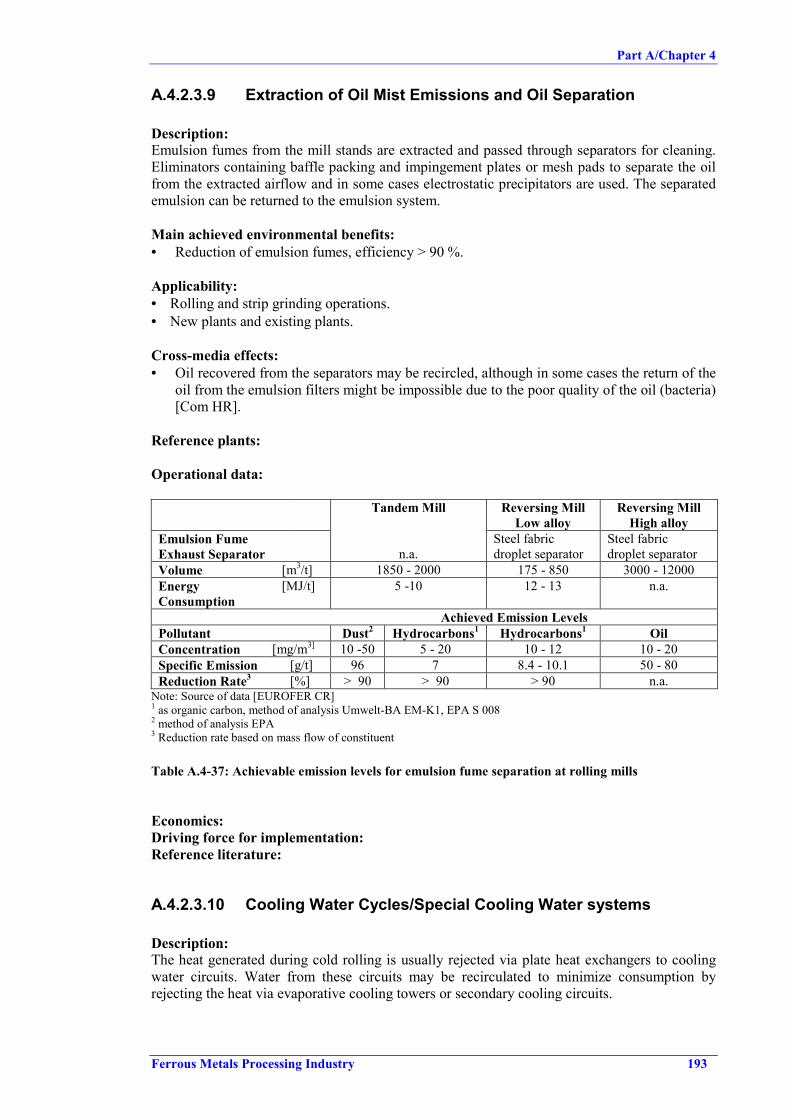
Part A/Chapter 4
Ferrous Metals Processing Industry 193
A.4.2.3.9 Extraction of Oil Mist Emissions and Oil Separation Description:Emulsion fumes from the mill stands are extracted and passed through separators for cleaning.Eliminators containing baffle packing and impingement plates or mesh pads to separate the oilfrom the extracted airflow and in some cases electrostatic precipitators are used. The separatedemulsion can be returned to the emulsion system.
Main achieved environmental benefits:• Reduction of emulsion fumes, efficiency > 90 %.
Applicability:• Rolling and strip grinding operations.• New plants and existing plants.
Cross-media effects:• Oil recovered from the separators may be recircled, although in some cases the return of the
oil from the emulsion filters might be impossible due to the poor quality of the oil (bacteria)[Com HR].
Reference plants:
Operational data:
Tandem Mill Reversing MillLow alloy
Reversing MillHigh alloy
Emulsion FumeExhaust Separator n.a.
Steel fabricdroplet separator
Steel fabricdroplet separator
Volume [m3/t] 1850 - 2000 175 - 850 3000 - 12000EnergyConsumption
[MJ/t] 5 -10 12 - 13 n.a.
Achieved Emission LevelsPollutant Dust2 Hydrocarbons1 Hydrocarbons1 OilConcentration [mg/m3] 10 -50 5 - 20 10 - 12 10 - 20Specific Emission [g/t] 96 7 8.4 - 10.1 50 - 80Reduction Rate3 [%] > 90 > 90 > 90 n.a.
Note: Source of data [EUROFER CR]1 as organic carbon, method of analysis Umwelt-BA EM-K1, EPA S 0082 method of analysis EPA3 Reduction rate based on mass flow of constituent
Table A.4-37: Achievable emission levels for emulsion fume separation at rolling mills
Economics:Driving force for implementation:Reference literature:
A.4.2.3.10 Cooling Water Cycles/Special Cooling Water systems Description: The heat generated during cold rolling is usually rejected via plate heat exchangers to coolingwater circuits. Water from these circuits may be recirculated to minimize consumption byrejecting the heat via evaporative cooling towers or secondary cooling circuits.

Part A/Chapter 4
194 Ferrous Metals Processing Industry
Special cooling water system:The risk of contaminating the cooling water with oils can be minimized.
Reuse of cooling water:Saving natural resources and energy in the cooling water cleaning system.
Main achieved environmental benefits:Applicability:Cross-media effects:Reference plants:
Operational data:
Cooling Water System
Input / Consumption LevelCooling water (re-circulating) 8400 m3/tRiver water 7000 m3/tSoft water 1 2.5 E -4 m3/tNaOH 1.25 E -8 m3/tInhibitor 2.5 E -7 m3/tEnergy:
Electrical 0.004 GJ/tCaloric 2 0.282 GJ/t
Output / Emission LevelSpecific Emission Concentration
Cooling water (re-circulating) 8400 m3/t
Waste water (system drain water) 2.5 E -4 m3/tSettleable solids (volume) 2 - 5 ml/lHydrocarbons (oil, grease) 2 - 5 mg/l 0.5 - 1.25 mg/tChlorides 50 mg/l 12.5 mg/tFe total 2 mg/l 0.5 mg/tTemperature 35 oCpH 6.5 - 9.5Electric conductivity 1.1 mS/cm
Notes: Source of data [EUROFER CR] Data based on weekly, volume proportional 24-h sampling
1 only in case of system drainage2 energy removed from tandem mill by cooling water
Table A.4-38: Consumption and emission levels for the cooling water system of a tandem mill
Economics:Driving force for implementation:Reference literature:
Part A/Chapter 4
Ferrous Metals Processing Industry 195
A.4.2.4 Annealing
A.4.2.4.1 Implementation of Degreasing Bath Cascades�No description and technical information submitted
A.4.2.4.2 Hot Water Pre-degreasing�No description and technical information submitted
A.4.2.4.3 Cleaning and Reuse of Degreasing Solution
Description: see Chapter D.4.3High oil contents make the degreasing solution unusable and cleaning measures are applied toextent the life span of the bath. Measures to clean the degreasing bath and to extend the lifetimeare:
Magnetic separators to remove the mixture of iron fines and oil.
Mechanical cleaningUsually the emulsions of degreasing agents and oil/grease from the metal surface are unstableand after some time they float on the surface of the bath. They can be removed by skimmers.Suspended particles are removed by sedimentation in gravity separators. Mechanical cleaningcan extend the lifetime of degreasing baths 2 – 4 times.
Adsorption of surfactants and oil (precipitation followed by filtration).
Ultrafiltration
Main achieved environmental benefits:• Consumption of chemicals for new alkaline baths can be drastically reduced.• Reduction of waste water treatment and discharge.
Applicability:• New plants and existing plants.
Cross-media effects:• Oil and grease arise as waste in the cleaning of degreasing solutions. This waste may be
used for energy recovery or has to be disposed of by incineration.
Reference plants:
Operational data:
Table A.4-39 presents input/output data and effluent data for degreasing solution cycle of acontinuous annealing line, which is maintained by cleaning via ultrafiltration.

Part A/Chapter 4
196 Ferrous Metals Processing Industry
Input / Consumption LevelDegreasing solution 50 - 60 kg/tDemineralised water 0.3 - 0.4 kg/tDegreaser 0.04 - 0.05 kg/tTempering fluid concentrate 0.15 - 0.2 kg/tElectrical energy 4 -5 MJ/t
Output / Emission LevelCleaned degreasing solution 40 - 50 kg/tSludge 0.4 - 0.5 kg/t
Concentration[mg/l]
Specific Emission[g/t product]
Reduction rate1
[%]Method of
analysisSuspended solids(filterable)
20 - 40 2.35 - 4.7 E -4 > 90 DIN 38409-H2
ΣΣΣΣ Hydrocarbons(oil, grease)
5 - 8 5.9 - 9.4 E -5 > 90 DIN 38409-H18
Fe total 1 -2 1.2 - 2.4 E -5 > 90 DIN 38406Temperature 30 oC ThermometerpH 6.5 - 9.5Note: Source of data [EUROFER CR]. Data based on weekly, volume proportional 24-h sampling
1 Based on mass flow of constituent
Table A.4-39: Operational and effluent data for degreasing bath cleaning by ultrafiltration
Economics:Driving force for implementation:Reference literature:
A.4.2.4.4 Treatment of Spent Degreasing Bath and Alkaline WasteWater
Description: see also Chapter D.4.4 and D.4.5Partial flows from the degreasing solution cleaning circuit, rinsing water from the electrolyticdegreasing and waste water from the skin pass mill stand, which cannot be reused in the mills,have to be treated prior to discharge. Prior to treatment of the waste water withflocculants, theoil contend has to be removed, e.g. by ultrafiltration. [Com2 D] Then the waste water is usuallyneutralised with lime or HCl in a neutralisation plant, passed through filters and finallydischarged. The sludge is dewatered in filter presses and discharged for landfill deposit. The oilsludge from the ultrafiltration plants can be used in the blast furnaces. [EUROFER CR]
Rinsing Water fromDegreasing &Water fromTempering Stand Pump Energy
Acid, Lime, Coagulant, Polyelectrolyte
Degreasing Filtrate CleanedSolution Water
Sludge
Return Concentrate Water (Oily Waste)
Sludge Cake
ULTRAFILTRATION
RECIRCULATIONTANK
WASTEDEGREASING
SOLUTIONSTORAGE
SLUDGEDEWATERING
WATER STORAGE,NEUTRALISATION,SEDIMENTATION,
FILTRATION
Figure A.4-19: Spent degreasing solution flow (example of a continuous annealing line)[EUROFER CR]

Part A/Chapter 4
Ferrous Metals Processing Industry 197
Main achieved environmental benefits:• Reduced emissions, especially oil, to water.
Applicability:• New and existing plants.
Cross-media effects:• Energy and raw material consumption.
Reference plants:
Operational data:Table A.4-40 presents input/output data and effluent data for alkaline (degreasing) waste watertreatment by ultrafiltration (continuous annealing line).
Input / Consumption LevelRaw waste water 12 - 15 kg/tCitric acid occasionally kg/tElectrical energy 1 - 1.5 MJ/t
Output / Emission LevelPurified waste water 12 - 15 kg/tSludge kg/t
Concentration[mg/l]
Specific Emission[g/t product]
Reduction rate1
[%]Method of
analysisSuspended solids(filterable)
20 - 40 2.35 - 4.7 E -4 > 90 DIN 38409-H2
ΣΣΣΣ Hydrocarbons(oil, grease)
5 - 8 5.9 - 9.4 E -5 > 90 DIN 38409-H18
COD 5000 - 6000 5.9 - 7.1 E -5 > 50 DIN 38409-H44Temperature 30 oC ThermometerpH 6.5 - 9.5Note: Source of data [EUROFER CR]. Data based on weekly, volume proportional 24-h sampling
1 Reduction rate based on mass flow of constituent
Table A.4-40: Operational and effluent data for alkaline waste water treatment
Economics:Driving force for implementation:Reference literature:
A.4.2.4.5 Extraction System for Degreasing Facilities
Description:Fumes from degreasing baths and the pre-cleaning section of continuous annealing lines areextracted by an exhaust system and passed through gas scrubbers for cleaning. Recycled wateris used as an absorbent. Partial flow of the scrubbing water has to be discharged via the watertreatment facilities of the degreasing line or, respectively, the continuous annealing plant.
Main achieved environmental benefits:• Reduced fugitive emissions of degreasing fumes.
Applicability:Cross-media effects:Reference plants:

Part A/Chapter 4
198 Ferrous Metals Processing Industry
Operational data:Economics:Driving force for implementation:Reference literature:
A.4.2.4.6 Special Cooling Water Systems and Water Reuse�No description and technical information submitted
A.4.2.4.7 Batch Annealing with 100 % Hydrogen
Description:Batch annealing 100 % hydrogen may be used instead of hydrogen/nitrogen.
Main achieved environmental benefits:• Reduction in specific energy consumption (reduced from 700 MJ/t when annealing under
H2N2 to 422 MJ/t under 100 % hydrogen atmosphere) [EUROFER CR].
Applicability:Cross-media effects:Reference plants:Operational data:Economics:Driving force for implementation:Reference literature:
A.4.2.4.8 Continuous Instead of Batch Annealing
Description: Continuous annealing instead of conventional batch annealing can be used forsome parts of the product range.
Main achieved environmental benefits:
Applicability: For new installations or major modernisation of existing plants.
Cross-media effects:Reference plants:Operational data:Economics:Driving force for implementation:Reference literature:
A.4.2.4.9 Preheating Combustion Air/Use of Regenerative orRecuperative Burners for Annealing Furnace
Description: see Chapters D.1.1 and D.1.2 Main achieved environmental benefits:• Reduction in energy consumption.
Applicability:• New and existing furnaces.

Part A/Chapter 4
Ferrous Metals Processing Industry 199
Cross-media effects:• Potential increased NOx emission level (concentration).
Reference plants: - British Steel Stainless, Sheffield.
Operational data:ExampleThe 'old' annealing furnace for stainless strip was operated with 3 individually controlled zones,but at the same temperature of about 1100 °C, heated by electric elements mounted in thesidewalls. Maximum throughput was 1 t/h. In 1989 structural modification were done toincrease capacity and to improve circulation of furnace gas. The 3 zones remained, but the firsttwo were equipped with two pairs of 5.5 therm/h integral bed burners (IBB), in the third zone aself-recuperative burner was installed.
NOx emissions were measured at burner firing rates of 21 – 84 % of maximum and ranged from225 – 317 ppm corrected to 3 % oxygen (460 – 650 mg/m3).
Assuming a mean throughput of 100 t/week and 46 production weeks per year, the primaryenergy consumption was reduced by 50.6 % (taking into account the primary energyconsumption at power station for the former electrical heating system). Payback period in thatcase study was 5.5 years, but payback time depends to large extend on the energy costs (fuel,gas, electricity etc.). Calculated payback periods for other scenarios were reported: 2.5 years for₤2.93/GJ gas and ₤ 11.77/GJ electricity. [ETSU-FP-64]
Economics:Driving force for implementation:Reference literature:
A.4.2.4.10 Reduction in NOx Emission by Low-NOx burner Description: see Chapter D.2.1 The generation of NOx resultant from the combustion processes can be reduced by selection oflow-NOx burners. Main achieved environmental benefits:• Reduced NOx emissions.
Applicability:• New and existing furnaces.
Cross-media effects:Reference plants:Operational data:

Part A/Chapter 4
200 Ferrous Metals Processing Industry
Concentration[mg/m³]
Emission[kg/t product]
Reduction1
[%]Methode of analysis
Dust 5 - 10 EPASO2 60 - 100 9 - 14 E -03 Infrared, UV-fluorescenceNO2 2 150 - 380 25 - 110 E -02 60 Chemiluminescence
(NBN T94-303)CO 40 - 100 15 - 40 E -03 87 Umweltbundesamt-EM-K1,
IR-spectrometryCO2 200000 - 220000 31200 0 IR-absorptions-spectrometryNotes: Source of data [EUROFER CR] m³ are based on standard conditions; (waste gas 10000 – 16000 m3/h, 200 - 250 m3/t)1 reduction rate based on mass flow of constituent2 reference 3 % O2, mg/m³ dry
Table A.4-41: Achievable emission levels with low-NOx burners on batch anealing furnaces
Concentration[mg/m³]
Emission[kg/t product]
Reduction1
[%]Methode of analysis
Dust 10 - 20 0.16 – 0.32 EPASO2 50 - 100 0.08 – 1.6 Infrared, UV-fluorescenceNO2 2 400 - 650 0.14 - 0.22 60 Chemiluminescence
(NBN T94-303)CO 50 - 120 0.08 - 0.2 87 Umweltbundesamt-EM-K1,
IR-spectrometryCO2 180000 - 250000 62.5 - 86.8 0 IR-absorptions-spectrometryNotes: Source of data [EUROFER CR] m³ are based on standard conditions; (waste gas 350 – 400 m3/t)1 reduction rate based on mass flow of constituent2 reference 3 % O2, mg/m³ dry
Table A.4-42: Achievable emission levels with low-NOx burners on continuous annealing furnaces
Economics:Investment costs of 100 kECU (for continuous annealing furnace, capacity: 540000 t/a) werereported. [CITEPA]
Driving force for implementation:Reference literature:
A.4.2.4.11 Preheating the Feedstock
Description:Preheating the material in the continuous annealing line with waste gas:This can either be done by a direct contact between the strip and the flue gases or the heat canbe transferred to the strip by the protective gas heated by the waste gas in heat exchangers.A direct contact is only possible in controlled circumstances (depending on temperature of thegas and of the strip, oxidation potential of the gas, moisture, contamination of the gas withparticles). The result is a reduction of energy consumption.
Main achieved environmental benefits:• Reduced energy consumption.

Part A/Chapter 4
Ferrous Metals Processing Industry 201
Applicability:Cross-media effects:Reference plants:Operational data:Economics:Driving force for implementation:Reference literature:
A.4.2.4.12 Heat Utilisation for Heating Degreasing Bath�No description and technical information submitted
A.4.2.5 Tempering
A.4.2.5.1 Optimisation of Emulsion System
Description:a) Use of low pressure sprays for the emulsionAtomisation of the temper rolling emulsion has to be minimized by the use of the appropriatetype of spray nozzles at the appropriate pressure.b) Adapt the number of emulsion jets to the width of the stripSince the temper rolling emulsion is not recycled, optimisation of the spray patterns reducesemulsion consumption.
Main achieved environmental benefits:• a) Reduced oil emissions.• b) Reduced oil consumption.
Applicability:• New plants and existing plants.
Cross-media effects:Reference plants:Operational data:Economics:Driving force for implementation:Reference literature:
A.4.2.5.2 Change to Dry Temper Process
Description:
Main achieved environmental benefits:• No oil consumption.
Applicability:• New plants and existing plants.
Cross-media effects:• Generates emissions to air.• Requires an exhaust system and generates waste (filter dust).

Part A/Chapter 4
202 Ferrous Metals Processing Industry
Reference plants:Operational data:Economics:Driving force for implementation:Reference literature:
A.4.2.5.3 Cleaning of Temper Mill Emulsion
Description:The used temper mill emulsion has to be cleaned before disposal. This emulsion is generallytreated together with the tandem mill emulsion and the other oily residues in the emulsiontreatment system.
Main achieved environmental benefits:• Reduced emissions to water.
Applicability:• New plants and existing plants.
Cross-media effects:• Energy and raw material consumption.
Reference plants:Operational data:Economics:Driving force for implementation:Reference literature:
A.4.2.5.4 Reduction of Oil Mist and DustDescription:Oil mist and dust are extracted via an exhaust system, equipped with wet or dry filters. Also oilmist eliminators (mechanical) and cyclones may be applied.
Main achieved environmental benefits:• Reduced oil emissions.
Applicability:• New plants and existing plants.
Cross-media effects:Reference plants:
Operational data:
Concentration[mg/Nm3]
SpecificEmission
[g/t product]
Reduction rate1
[%]SpecificVolume[m3/t]
Method of analysis
Example: Steel fabric droplet separatorHydrocarbon 5 - 15 0.273 > 90 90 - 110 Umwelt-BA EM-K1Note: Source of data [EUROFER CR]
Table A.4-43: Achievable emission levels for fabric droplet separators

Part A/Chapter 4
Ferrous Metals Processing Industry 203
Oil mist emissions reported by [CITEPA]: ~ 10 mg/m3
Economics:Oil mist eliminator: investment costs: 375 kECU (125 for oil abatement, 250 for dust),operating costs: 6 kECU/a, electricity: 70 kWh [CITEPA]
Cyclone: investment costs: 25 kECU, operating costs: 2.5 kECU/a electricity 45 kWh[CITEPA]
Driving force for implementation:Reference literature:
A.4.2.6 Finishing
A.4.2.6.1 Capture and Abatement of Oil Mists from Oiling Operation
Description:Oil emissions that arise from spraying oil mist on strips for conservation reasons, can bereduced by extraction hoods, followed by mist eliminator (baffle-type) and electrostaticprecipitator. The oil captured in the mist eliminator can be recircled into the oiling process.
Main achieved environmental benefits:• Reduction of fugitive oil mist emissions.• Reduced oil consumption.
Applicability:• New and existing plants.
Cross-media effects:
Reference plants: Stahlwerke Bremen.
Operational data:ExampleBy the described measure it is possible to capture the mist arising from oiling almost completely(visual judgement: all visible emissions are captured). The mist eliminator efficiency wasreported to be 72 %. Measurements of the waste gas showed concentrations of oil droplets afterthe mist eliminator, but before the EP, of up to 296 mg/m3 (average 104 mg/m3). The maximumconcentration measured after EP was 6.3 mg/m3 with an average emission of 3.0 mg/m3. Theefficiency of the EP was between 97 and 98 %. The carbon contents of the unabated waste gaswas measured 17.5 to 21.3 mg/m3; behind the EP around 10.6 to 11.9 mg/m3.[UBA-Kloeckner-82]
Economics:Driving force for implementation:Reference literature:
A.4.2.6.2 Electrostatic Oiling�No description and technical information submitted
A.4.2.6.3 Optimization of Oil Spray�No description and technical information submitted

Part A/Chapter 4
204 Ferrous Metals Processing Industry
Main achieved environmental benefits:• Reduced oil consumption.
Applicability:• New plants and existing plants.
Cross-media effects:Reference plants:Operational data:Economics:Driving force for implementation:Reference literature:
A.4.2.6.4 Dust Reduction from Levelling and Welding
Description:Particulate emissions from welding and levelling are captured by hoods and abated by fabricfilters. [CITEPA]
Main achieved environmental benefits:• Reduction of emissions to air, especially fugitive dust.
Applicability:• New and existing plants.
Cross-media effects:• Increased energy consumption.• Generation of waste (filter dust).
Reference plants:
Operational data and economics::Dust emission 5 – 30 mg/m3 were reported in [CITEPA] for an installation operated 5 % of thetime to reduce emissions from welding (discontinuously) and continuously for dust reductionfrom levelling. The hourly electricity demand was 110 kWh (0.64 kWh/t). [CITEPA]Investment costs of 625 kECU (for collection devices, pipes, filters, fans, electrical equipment,motors hood) and operating costs of 10 kECU were reported. [CITEPA]
Other sources [Vanroosb 3.4] reported for an installation that is filtering the exhaust gases fromthe stretcher leveller, the welding machine and the leveller the decoiler dust emission values of:16 - 7 - 39 - 22 - (change of bags) - 24 - 29 - 35 - 39 mg/Nm³.
Each emission value is the result of 6 isokinetically taken samples on 6 different places in thecross section of the chimney. There are therefore 2 sampling points at 90 ° of each other. Eachsampling campaign takes about 6 hours. Sampling frequency is about 6 times per year.
Installation data: Filter area 687 m² Number of filter bags 441 Dimensions filter bags Dia 120 mm x length 4030 mm Type of filter bags PE/PE - weight 550 g/m² - thickness 1.9 mm - density 0.29 g/cm³ - air permeability 150 l/dm²; min at 196 Pa (20 mm water column) Number of exhaust fans 3 x 55 kW - 1470 rev/min Gas flow (design) 90000 m³/h Pressure drop (design 120 daPa Cleaning cycle 50 msec at a pressure of 4 - 6 bar [Vanroosb 3.4]

Part A/Chapter 4
Ferrous Metals Processing Industry 205
Bags are changed when it is observed that the bags present cracks. This change takes about 50manhours and requires a stop of the pickling line of at least 2 shifts - the cost is about 400000BEF (10000 EUR). [Vanroosb 3.4]
Driving force for implementation:Reference literature:
A.4.2.6.5 Optimised Finishing Operation�No description and technical information submitted
Main achieved environmental benefits:• Scrap reduction.
Applicability:Cross-media effects:Reference plants:Operational data:Economics:Driving force for implementation:Reference literature:
A.4.2.7 Roll Shop
A.4.2.7.1 Cleaning and Reuse of Grinding Emulsion�No description and technical information submitted
A.4.2.7.2 Exhaust System (PRETEX/SBT)�No description and technical information submitted
A.4.2.7.3 Reduction and Recycling of Scrap�No description and technical information submitted
Description:Internal recycling options for scrap (from trimming, finishing, etc.).Good process control helps to reduce material losses [Com D].
Main achieved environmental benefits:
Applicability:Cross-media effects:Reference plants:Operational data:Economics:Driving force for implementation:Reference literature:

Part A/Chapter 4
206 Ferrous Metals Processing Industry
A.4.3 Wire Mill
A.4.3.1 Storage and Handling of Raw Materials and AuxiliariesDescription:All storage tanks for both fresh and spent acid must be equipped with an efficient and sealedsecondary containment and if required also with protective shields. This secondary containmentmust be completely protected with an acid-resistant coating which must be regularly controlledon potential damage and cracks.Furthermore the loading and unloading area for the acids must be designed in such a way thatany potential leak is directly discharged to the waste water treatment plant or can be collectedseparately.
Main achieved environmental benefits:Applicability:Cross-media effects:Reference plants:Operational data:Economics:Driving force for implementation:Reference literature:
A.4.3.2 Mechanical Descaling
A.4.3.2.1 External Recycling of ScaleDescription:The bulk of descaling in wire industry is done by reverse bending, leading to a scale whichconsists mainly of metal oxides and which is oil- and water-free. Due to bending and torsion ofthe wire, the scale breaks and drops into collection containers. All wire companies can keepscale separated from other waste streams to allow recovery of the iron content by recycling tothe primary iron and steel industry. Whether recycling is done or not, depends to a large extendon the interest of the local steel industry, that has not much to win by the recycling of this smallamount of rather difficult to handle secondary raw material. [CET-BAT]
In some exceptional cases where abrasives are used (e.g. shot-blasting, sanding etc.), scale getsmixed with other products. Recovery of shot-blasting media from scale is a common practicewith both economical (less consumption) and environmental (less waste) benefits. Infiniterecovery is not possible and not desired (quality loss, higher degree of dust formation).[CET-BAT]
Main achieved environmental benefits:● Reduction of waste [CET-BAT].
Applicability:● New and existing plants.● Technically possible for all scale from mechanical descaling of wire (rod).● Limitation of recycling not due to technical factors, but due to acceptance by the potential
recycler [CET-BAT].
Cross-media effects:Reference plants:Operational data:Economics:Driving force for implementation:Reference literature:

Part A/Chapter 4
Ferrous Metals Processing Industry 207
A.4.3.3 Chemical Descaling / Pickling of Wire Rod
A.4.3.3.1 Optimum Range of Operation for HCl Pickling Baths
Description: see Chapter D.5.1As chemical pickling of wire rod is mostly done in batch operation as pickling is done in jobgalvanizing, in principle the same good operational practice and reduction measures can beapplied.
Main achieved environmental benefits:• Reduction of acid emissions to air.
Applicability:• New and existing plants.
Cross-media effects:The acid concentration chosen according to the VDI-guideline is lower than typically used forwire rod pickling (see A.3.3.2.2. for typical process conditions). This results in:• Lower conversion of the acid from HCl to FeCl2, which implies a higher consumption of
fresh HCl [Com2 BG].• Reuse of spent acid as secondary raw material becomes very difficult; for reuse for the
production of FeCl3, a minimum concentration of 10 % Fe is requested; this high Fe-concentration can only be achieved with a high conversion of HCl and with a high initialconcentration of HCl [Com2 BG].
• Increased pickling time, which implies investment in more and/or bigger pickling tanks.Increased bath surface leads to more g/h HCl-evaporation. [Com2 BG].
Reference plants:Operational data:Economics: Due to increased pickling time, investment in more and/or bigger pickling tanksmab be necessary. [Com2 BG]Driving force for implementation:Reference literature:
A.4.3.3.2 Pickling Tank Fume Control
Description: see Chapter D.5.2Vapour and aerosols coming off pickling tanks can be controlled by a variety of collectionsystem designs, e.g lateral extractors or hoods and covers installed above or around a singlepickling bath or a group of pickling baths. The air above the baths is extracted and send to astack. In case of continuous, in-line pickling the same measures as for pickling in cold rollingmills can be applied.
Main achieved environmental benefits:● Reduction of fugitive emissions from pickling (acid vapour and aerosols).
Applicability:
Hoods● New pickling lines or in case of major revamps of existing plants.● Retrofitting of existing open baths by adding a cover or a hood over a pickling bath or a
group of pickling baths, is only possible at extremely high costs. It requires a completelynew internal transport system, requires to change the way the pickling process is controlled,(as the operator has no visual control anymore, a switch to an automated system isimposed), and generally requires some changes to building and infrastructure.

Part A/Chapter 4
208 Ferrous Metals Processing Industry
Lateral Extraction● New and existing plants.
Cross-media effects:● Extraction (large volumes) may course more emission as, due to vapour pressure, the
extracted vapour over the bath is replaced to yield equilibrium.
Reference plants:Operational data:Economics:Driving force for implementation:Improvement of working environment, protection of installation and equipment
Reference literature:
A.4.3.3.3 Treatment of Extracted Air from Pickling Tank Fume Control
Description:The type of treatment and the necessity depend largely on the type of acid (HCl, H2SO4,others,…) and the way the pickling bath is operated (heated or not, use of inhibitors orsurfactants, degree of agitation). Available abatement techniques are packed or plate scrubbersand entrainment separators (demisters).
For H2SO4 or H3PO4 baths, even when heated, the acid vapour pressure is very low, sotreatment of the extracted air is not needed unless droplets are emitted. In this case the entrainedacid droplets can be removed from the exhaust gas by dry fume filters. The removed acid canbe returned into the pickling tank. Only little water is needed to, occasionally, wash the filtermedium. [CET-BAT]
For HCl pickling baths, depending on the concentration of the HCl, the bath temperature, thenumber of wire rod coils treated per time unit or the presence of additives, wet scrubbers. areused to reduce the emission of HCl vapour and aerosols. Plate scrubbers can operate on smallamounts of scrubbing water compared to packed scrubber, resulting in a small volume of quitestrong acid effluent. This effluent can be recirculated into the pickling tank. [CET-BAT],[N.Stone 2]
Main achieved environmental benefits:● Reduction of acid vapour, droplets and aerosol emissions.
Applicability:● New and existing plants with pickling tank fume extraction.
Cross-media effects:Reference plants:Most installations for pickling of wire rod, built in the last -/+ 10 years, have scrubbers on theexhaust from the HCl baths. [CET-BAT]
Operational data:Typical emission limits are: < 20 to < 30 mg/Nm3. This can be reached without significantproblems with a demister (for H2SO4) or with a scrubber (for HCl). [CET-BAT]
Economics:Driving force for implementation:Reference literature:

Part A/Chapter 4
Ferrous Metals Processing Industry 209
A.4.3.3.4 Cascade Pickling
Description:Cascade pickling is performed in two or more baths in series. The acid flows (continuously ordiscontinuously) in counter flow from one bath to the next. This allows to achieve a veryefficient use of the acid while still reaching good pickling quality. [CET-BAT]
Main achieved environmental benefits:● Reduced consumption of fresh acid.● Reduced spent acid (waste).
Applicability:● New and existing plants.● Existing plants available space might be a limiting factor.
Cross-media effects:Reference plants:Operational data:
Economics:Costs include:- larger building, including larger acid proof floor surface and larger secondary containment- extra tank, circulation pump, possibly extra exhaust system- more complex process control software for follow-up of pickling bath composition and level- often, different types of wire rod require different contact times. If this is the case, also
specific process control software for scheduling and follow-up of the movements of thedifferent rolls is required.
Estimation: 0.2 - 0.4 M Euro depending on capacity.
Driving force for implementation:Reference literature:
A.4.3.3.5 Minimizing Carry-out from Pickling
Description:Minimizing carry-out requires sufficient time for the acid to drip of the wire rod coils. This canbe done by lifting the wire rod coil slowly from the last acid-bath of the cascade and thenallowing several seconds of dripping time above the acid bath before moving the wire rod coilto the first bath of the rinsing cascade. Dripping off can be enhanced e.g. by vibrating the wirerod coil.
Main achieved environmental benefits:● Reduced carry-out of acid, reduced consumption of fresh acid.● Reduced spent acid (waste).● Reduced pickling loss.
Applicability:● New and existing plants.
Cross-media effects:Reference plants:Operational data:

Part A/Chapter 4
210 Ferrous Metals Processing Industry
Economics:Driving force for implementation:Reference literature:
A.4.3.3.6 Separation and Reuse of Free Acid FractionDescription: see also Chapter D.5.9Various methods are available to separate free acid from bounded acid. The free acid outputstream is reused in the pickling process. This technique has no added value when cascadepickling of wire rod is applied, as cascade pickling allows to convert nearly all acid to metalsalts (no or only little free acid). In other words, separation and reuse of the free acid fraction isan alternative to cascade pickling (see A.4.3.2.2).
For H2SO4, crystallisation of FeSO4.7H2O and reuse of the liquid phase (containing H2SO4) is acommon technology that is economically viable if FeSO4.7H2O can be marketed as a by-product.
For HCl, evaporation of HCl is a technically available but rarely used because of the importantinvestment and energy costs.
Other methods described in literature, such as acid retardation or membrane processes, aregenerally not feasible (short lifetime of membranes in the presence of additives to the acid andimpurities in technical acid as well as blocking of membrane pores by FeCl2).
Solvent extraction is not considered as separation method because of the use of dangerouschemical products in the extraction process. Any malfunctioning of the recovery unit bringssolvent where it is not supposed to be, resulting in hazwaste or spills to the waste water that arenot removed in a typical waste water treatment station. [CET-BAT]
Main achieved environmental benefits:● Reduced consumption of fresh acid.● Reduced spent acid (waste).
Applicability:● New and existing plants.
Cross-media effects:Reference plants:Operational data:Economics:Driving force for implementation:Reference literature:
A.4.3.3.7 Regeneration of Spent AcidDescription: see also D.5.10Roasting of hydrochloric acid: heating of spent acid in presence of oxygen; vapour phaseprocess at elevated temperature. All acid is converted to free acid; metals are converted tometal oxides. Oxidation chamber and acid recovery unit have to be made from extremelycorrosion resistant materials. HCl can be upgraded to a quality suited for chemical pickling;metal oxides are either dumped or used as secondary raw material. [CET-BAT]
A viable roasting plant has a capacity of an order of magnitude higher than the output of spentacid of a typical wire plant. [CET-BAT]

Part A/Chapter 4
Ferrous Metals Processing Industry 211
Main achieved environmental benefits:● Reduction of acidic waste.
Applicability:● Regeneration plants require a minimum capacity, a minimum amount of spent acid to be
treated which is far beyond the spent acid generated at a single wire plant.● Wire industry depends on outside contractors for the recycling of spent acid.
Cross-media effects:Reference plants:Operational data:Economics:Driving force for implementation:Reference literature:
A.4.3.3.8 Reuse of Spent Acid as Secondary Raw material
Description:The chemical industry uses spent acid as a secondary raw material for the production of FeCl3and, to a minor extent, for pigments. The possibility to recycle spent acid for the production ofvaluable chemicals is available in many regions in Europe. Some contractors impose or have toimpose strict limits for some metal impurities in the spent acids. A few contractors haverecently developed and patented special processes to remove e.g. Zn or Pb from some types ofspent acid. [CET-BAT]
Main achieved environmental benefits:● Reduction of acidic waste.
Applicability:● New and existing plants.
Cross-media effects:Reference plants:Operational data:Economics:Driving force for implementation:Reference literature:
A.4.3.3.9 Minimize Rinsing Water Consumption by Cascade Rinsing
Description: see Chapter D.8The wire rod coil is rinsed several times in separate tanks, each time in cleaner water. Only tothe last bath, fresh rinsing water is supplied. Each bath flows over to the previous one.
Main achieved environmental benefits:● Reduction of water consumption (by an order of magnitude less than single step rinsing)
[CET-BAT].
Applicability:● New and existing plants.
Cross-media effects:Reference plants:Operational data:

Part A/Chapter 4
212 Ferrous Metals Processing Industry
Economics:Driving force for implementation:Reference literature:
A.4.3.4 Shot Blast Descaling: Separation of Scale and Blast mediaDescription:Shot blasting is possible as in-line or bulk processing. It involves the propulsion of thousands ofsteel shot particles per second, towards the surface of the material. This causes the scale tobreak and fall off the base metal. The shot blast or blast cleaning system consists of:
1. A cabinet to house and contain the descaling operation.2. A series of blast wheels of varying power depending on required line speeds, production
requirements, etc.3. A reclaim system to return used shot or media to a recycling system.4. A recycling system where media is cleaned and small particles of dust and scale are
removed.5. A storage area within the system where shot is stored before being distributed once again to
the blast wheels.6. A dust collection system.
The blast cabinet is a confined enclosure where the blast descaling operation takes place. Aseries of blast wheels are mounted to the cabinet and propel the media, usually steel shot, bycentrifugal force towards the wire.
The reclaim system provides a means to retrieve the used shot and dust from the descalingoperation and brings it to the recycling system.
Recycling of the shot media involves separating the good reusable media from the contaminantsand dust gathered in the mix. By passing the collected media through an air wash separator, thefine dusts and smaller contaminants are drawn from the system by a vacuum effect leaving thecleaned shot particles to be returned to a storage system. From this storage system, the mediawill be distributed through a series of controls or valves back to the blast wheels. Bysynchronizing the entire system, a continuous flow of media is directed toward the work toachieve the desired results in the fastest and most expedient manner.
Stream descalingThis method involves pre-descaling of wire rod by bending and torsion and fluidization of thescale obtained in this descaling. In a special chamber the fluidized scale is then blown onto thewire rod surface by means of jet pumps and compressed air. The rod is descaled to its metallicsurface. The scale is transported to a dust collection system (cyclone, cloth filter) by thecompressed air. Coarse scale is returned to the jet pumps and used again. The fine scale isutilized as a component in the production of paints.
This method is reported to be applicable to low carbon steel wire rod and high carbon steels.Initial investment costs and space requirements are reported to be very low. Another advantageis that no other media as shot or grit is needed.
Main achieved environmental benefits:• Scale is collected separately and can be reused.• Consumption of shot-blasting media is reduced.
Applicability:• New and existing plants.
Cross-media effects:

Part A/Chapter 4
Ferrous Metals Processing Industry 213
Reference plants:Stream descaling: Wire Factory in Gliwice, Poland application low carbon wire, reducedproduction costs (planned or implemented?)
Operational data:Economics:Driving force for implementation:
Reference literature:Stream descaling:'A new Method of mechanical Descaling of Carbon Steel Wire Rods', Conference Proceedings –Wire association International Incororated, 65th Annual Convention Atlanta, 1995.
A.4.3.5 Dry Drawing
A.4.3.5.1 Control of Air Emissions from Drawing Machines / Treatmentof Extracted Air
Description: A hood or cover is installed above parts of the drawing machine that are in contact with thewire. The cover needs to be designed in a way that it can be removed easily for frequent tasks,such as threading a wire through the machine, fixing a broken wire, adjusting or replacing a dieor adding soap. The air within the cover is extracted. The extracted air can be treated by a filter or similar device to capture soap dust. Main achieved environmental benefits:● Reduction of emissions to air, especially of fugitive soap dust [CET-BAT].
Applicability:● New plants.● Technical problems expected in existing plant due to design reasons.
Cross-media effects: Reference plants: All recent dry drawing machines are for a large extend enclosed [CET-BAT].
Operational data:Economics: Driving force for implementation: The goal is to limit the spread of lubricant-dust over the area around the drawing machine.100 % elimination of soap dust is impossible (e.g. soap dust leaving the drawing machine withthe drawn wire). This is mainly done to improve the working environment. [CET-BAT]
Reference literature:
A.4.3.5.2 Closed Loop for Cooling Water Description: The drawing operation heats both wire and drawing die through friction of the wire. So boththe dies and the wire (indirectly, through cooling of the capstans in contact with the wire) arewater cooled. In order to reuse the cooling water, the water circuit is equipped with a wetcooling tower, an air cooler or similar device. [CET-BAT]

Part A/Chapter 4
214 Ferrous Metals Processing Industry
Main achieved environmental benefits:• Reduced water consumption.
Applicability:• New and existing plants.
Cross-media effects:Reference plants:Operational data:Economics:Driving force for implementation:Reference literature:
A.4.3.6 Wet Drawing
A.4.3.6.1 Closed Loop for Cooling Water Description: The drawing operation heats both wire and drawing die through friction of the wire. This heatis taken up by the lubricant. The lubricant on its turn is cooled, often this is done indirectly withcooling water. [CET-BAT] Main achieved environmental benefits:• Reduced water consumption.
Applicability:• New and existing plants.
Cross-media effects:Reference plants:Operational data:Economics:Driving force for implementation:Reference literature:
A.4.3.6.2 Cleaning of Drawing Lubricant / Coolant
Description: see also Chapter D.3.1Wire drawing lubricants, water-miscible oil emulsions or straight oils, accumulate metal finesduring operation. As the contents of fines increases, operational problems develope, such aswire-drawing breaks, capstan wear and poor quality of wire, requiring replacement of thelubricant. Media filtration and/or centrifuges are used to clean the lubricant and to prolong thelife-cycle. [El-Hindi]
Main achieved environmental benefits:• Reduction of waste drawing lubricant [El-Hindi].
Applicability:• New and existing plants.
Cross-media effects:• Generation of waste filter media [El-Hindi].
Part A/Chapter 4
Ferrous Metals Processing Industry 215
Reference plants:Operational data:Cleaning of drawing lubricant, can improve the operational behavior as it reduces wire-drawingbreaks and improves the wire quality (thus reducing also operational problems downstream).[El-Hindi]
Economics:Driving force for implementation:Reference literature: [El-Hindi]
A.4.3.6.3 Treatment of Waste Drawing Lubricant: Oil and Oil emulsions Description: see Chapter D.3.2 Main achieved environmental benefits:• Reduced disposal volume.• In case of incineration, thermal utilisation of waste.
Applicability:• New and existing plants.
Cross-media effects:
Reference plants:
Operational data:• Reduced waste disposal costs.
Economics:Driving force for implementation:Reference literature:
A.4.3.6.4 Treatment and Disposal of Waste Drawing Lubricant: SoapEmulsions
Description:For soap emulsions based on a fatty acid alkali soap the treatment depends on the amount ofwaste lubricant. In case the quantities are small compared to other waste waters of the plant, thespent lubricant is mixed with other waste waters. The soaps are bounded in the filter cakeduring almost all existing water treatment methods for acidic waste waters. If a biologicaltreatment is used, the fatty acid soaps are well biodegradable. [CET-BAT]
If the quantities are comparably big, the spent lubricants are treated separately by coagulationand precipitation, coagulation and flotation, membrane filtration, evaporation or other suitedmethods. [CET-BAT]
Main achieved environmental benefits:• Reduced emissions to water.
Applicability:• New and existing plants.

Part A/Chapter 4
216 Ferrous Metals Processing Industry
Cross-media effects:• Generation of sludge and filter cake from water treatment.
Reference plants:Operational data:Economics:Driving force for implementation:Reference literature:
A.4.3.7 Batch Annealing of Wire
A.4.3.7.1 Burn Purge of Protective Gas
Description: In order to keep an over-pressure in the "pots" or "bells", a fraction of the protective gas iscontinuously purged. This gas stream contains - apart from the components of the actual protective gas, decompo-sition products of the lubricant. These are formed by pyrolisis / cracking of the lubricantmolecules; typical decomposition products are low molecular weight olefins and alkanes. These volatile organic components and the combustible components in some types of protectivegasses (CO, H2), should be converted to harmless products. As the purge is a very small flow ofcombustible gas, this is simply done in an open flame. [CET-BAT]
Main achieved environmental benefits:• Reduced emissions to air.
Applicability:• New and existing plants.
Cross-media effects:Reference plants:Operational data:Economics:Driving force for implementation:Reference literature:
A.4.3.8 Continuous (In-line) Annealing of Low Carbon Wire
A.4.3.8.1 Lead-bath: Good Housekeeping
Description:The most important house-keeping methods are:− Maintain a protective layer (particulate material) or cover on the lead-bath to minimize loss
of lead by oxidation and drastically reduce energy losses of the lead bath.− Prevent formation of dust while removing impurities from the lead-bath.− Keep containers with lead contaminated waste in a separate area, protect this waste from
any contact with wind or rain.− Minimize drag-out of lead with the wire by maintaining a suited surface condition on the
half-product (both economically and environmentally attractive).

Part A/Chapter 4
Ferrous Metals Processing Industry 217
− Minimize drag-out of lead with the wire by using an anthracite gravel wipe or similarimmediately after the lead bath.
− Apply a method that minimizes / eliminates the spread of lead dust that is possibly draggedout with the wire. In many production lines, this is done by coupling the in-line heat-treatment to in-line pickling. Other methods are: coating of the wire with a suitable productor adapted packaging of the wire. [CET-BAT]
Main achieved environmental benefits:• Reduce emissions from lead bath (Pb from bath itself, CO and TOC from incomplete
burning of residues on the wire [CET-BAT].
Applicability:• New and existing plants.
Cross-media effects:Reference plants:
Operational data:By good house-keeping methods, it is perfectly possible to run a lead-bath at very lowemissions of below 5 mg Pb/Nm3, 100 mg CO /Nm3 and 50 mg TOC /Nm3. [CET-BAT]
Economics:Driving force for implementation:Reference literature:
A.4.3.8.2 Recycling of Pb-containing Residues
Description:Some Pb-containing residues originate from the Pb-bath (waste bath cover material, leadoxides). These residues should be stored separately and protected from rain and wind. Thewire industry depends on subcontractors for the final disposal or recycling of these residues.Normally Pb-containing waste is recycled by the non-ferro industry (Pb-smelters). [CET-BAT]
Main achieved environmental benefits:• Reduced waste disposal.
Applicability:• New and existing plants.
Cross-media effects:Reference plants:Operational data:Economics:Driving force for implementation:Reference literature:

Part A/Chapter 4
218 Ferrous Metals Processing Industry
A.4.3.8.3 Operation of Quench Bath and Treatment of Waste Waterfrom Quench baths from In-Line Annealing
Description: As the water quality requirements for this bath are generally low, it is advised to userecuperated water for this purpose or to operate the quench bath in closed loop. [CET-BAT]
Waste water from a quench bath should be treated in such a way that contamination (mainlycontamination with insoluble Pb(OH)2 and PbCO3) is removed in a satisfactory way prior todischarge. [CET-BAT]
Remark:1) Each site has to determine its own waste water treatment facility in such a way that it canhandle the mix of waste waters that originates at that site. This mix is different for each site,and is highly dependent on the product range of that site (use of acid or not, availability ofrecycling services for spent acid or not, use of wet drawing emulsions or not, use of platingbaths or not + type of plating baths,...) and on the local environmental requirements.2) If a heat treatment without protective atmosphere is used (e.g. a heat treatment involving theuse of a molten Pb-bath), then also acid pickling is used � at least spent rinsing watercontaining acid and iron has to be treated. In this case, most wire plants use a traditionalphysico-chemical waste water treatment, in other words neutralisation with lime milk followedby precipitation of Fe and Pb + other heavy metals, followed by decantation and filter-pressingof the cake. [Com BG2]
Main achieved environmental benefits:• Reduced emissions to water.
Applicability:• New and existing plants.
Cross-media effects:• Generation of waste/sludges from waste water treatment.
Reference plants:Operational data:Economics:Driving force for implementation:Reference literature:
A.4.3.9 Continuous (In-line) Annealing of Stainless Steel Wire
A.4.3.9.1 Burn Purge of Protective GasRefer to A.4.3.5.1
A.4.3.10 Patenting
A.4.3.10.1 Optimised Operation of the Oven
Description: A slightly substochiometric mixture is used in the burners. In this way, all O2 is excluded fromthe oven atmosphere, in order to minimize the formation of iron oxides at the wire surface.
Part A/Chapter 4
Ferrous Metals Processing Industry 219
Excessive formation of iron oxide leads to high losses of wire material and to excessiveconsumption of pickling acid, and leads to excessive dragout of lead. [CET-BAT] Excess CO must be converted to CO2 by adding air in a controlled way to the hot exhaust of theoven. The CO-content of the oven atmosphere and the exhaust gas must be controlled regularly,e.g. after every major change in the product mix or at least every month. [CET-BAT] Because of the heating method, NOx formation is not an issue. [CET-BAT]
Main achieved environmental benefits:• Reduced consumption in following process steps (e.g. acid).• Reduced CO-content.
Applicability:• New and existing plants.
Cross-media effects:Reference plants:Operational data:Economics:Driving force for implementation:Reference literature:
A.4.3.10.2 Lead-bath: Good HousekeepingRefer to A4.3.6.1
A.4.3.10.3 Recycling of Pb-containing ResiduesRefer to A.4.3.6.2
A.4.3.10.4 Operation of Quench Bath and Treatment of Waste Waterfrom Quench Baths of Patenting Line
Refer to A.4.3.6.3
A.4.3.11 Oil Hardening and Tempering
A.4.3.11.1 Burn Purge of Protective GasRefer to A.4.3.5.1
A.4.3.11.2 Extraction of Oil Mists from Quench Baths and Abatement
Description:Evacuation of the oil mist and removal of the oil mist from the extracted air.
Main achieved environmental benefits:• Reduction of fugitive air emissions, especially oil emissions.
Applicability:Cross-media effects:Reference plants:Operational data:

Part A/Chapter 4
220 Ferrous Metals Processing Industry
Economics:Driving force for implementation:Reference literature:
A.4.3.12 Heat Treatment of wire (different processes)
A.4.3.12.1 Inductive Heating of Wire
Description:The wire to be heated is guided through a coil; in this coil a magnetic field is generated.Typically, applied frequencies are 5 - 50 kHz (mid-frequent heating). Exceptionally, high-frequent heating (well above 50 kHz) is used. This magnetic field induces an electric current inthe wire; the wire is heated through the Joule effect of the induced current. The induced currentis mainly in a small layer towards the outside of the wire section; this phenomenon is called the"skin-effect".
The applicability of inductive heating is highly dependent on wire material, wire diameter andrequired temperature increase:• Material is preferably magnetic.
Steel and certain steel alloys are magnetic. Most types of stainless steel are non-magnetic.Most metal coatings are non-magnetic.
• Wire diameter is preferably high, e.g. above 2 - 3 mm.The smaller the diameter, the higher the frequency should be in order to maintain asufficient skin-effect.
• Above the "Curie-temperature", a magnetic material looses its magnetic properties. Steellooses its magnetic properties at approx. 760 °C.
Applications outside this range are available. However, expensive high-frequency equipmenthas to be used and energetic efficiency is on average lower.
The vast majority of the applications of inductive heating are found in single wire lines.Induction heating in a single wire line concept can be used for austenitising and tempering.Austenitising is the first step of several thermal treatment operations: patenting (see A.2.3.4.4),oil hardening (see A.2.3.4.5) and tempering (described in A.2.3.4.5. and A.2.3.4.6).
An exact control of the wire temperature is a necessity for these thermal treatments.Induction heating in a multi-wire line concept can be used for preheating of the wires (e.g. tothe Curie-temperature). Another application is diffusion of Cu and Zn coatings on a steel wirein order to obtain a brass coated wire.
Main achieved environmental benefits:Air emissions from combustion are avoided in the plant.
Applicability:The applicability of inductive heating in a single wire line concept is quite wide and includesapplications where exact temperature control is required.Use of inductive heating in a multi-wire line concept is limited to applications where exacttemperature control is not an issue, e.g. preheating.Applicability is dependent on wire properties. See above.

Part A/Chapter 4
Ferrous Metals Processing Industry 221
Cross-media effects:Consumption of fuel (typically NG or LPG) is replaced by consumption of electricity. Whentaking into account the fuel consumption of electricity generation, this cross-media effect isnegligible.Typical electrical energy efficiencies of mid-frequent inductive heating are in the range60 - 85 %. Typical energy efficiency of a NG-based heating method for similar applications is25 - 45 %. Taking into account the efficiency of NG-based electricity generation, e.g. a STAGreaching 50 – 55 %, one can conclude that there is hardly any difference in primary fuelconsumption.Cooling water is needed to cool the induction coil.
Reference plants:Operational data:Economics:Driving force for implementation:Reference literature:not enough information to make BAT decision?
A.4.3.13 In-line PicklingSee Part B


Part A/Chapter 5
Ferrous Metals Processing Industry 223
A.5 BEST AVAILABLE TECHNIQUES FOR HOT AND COLDFORMING
In understanding this chapter and its contents, the attention of the reader is drawn back to thepreface of this document and in particular the fifth section of the preface: “How to understandand use this document”. The techniques and associated emission and/or consumption levels, orranges of levels, presented in this chapter have been assessed through an iterative processinvolving the following steps:
• Identification of the key environmental issues of hot and cold forming. The diversity of theprocessing steps in this part of the ferrous metal processing sector means that all media areaffected. Among the most important issues are air emissions (especially NOx) fromfurnaces; energy consumption of furnaces, effluents containing oil and solids, acidic wastesand waste water; acidic and oil mist emissions to air and oil-containing wastes.
• Examination of the techniques most relevant to address those key issues.• Identification of the best environmental performance levels, on the basis of the available
data in the European Union and world-wide.• Examination of the conditions under which these performance levels were achieved; such as
costs, cross-media effects, main driving forces involved in implementation of thistechniques.
• Selection of the best available techniques (BAT) and the associated emission and/orconsumption levels for this sector in a general sense all according to Article 2(11) andAnnex IV of the Directive.
Expert judgement by the European IPPC Bureau and the relevant Technical Working Group(TWG) has played a key role in each of these steps and in the way in which the information ispresented here.
On the basis of this assessment, techniques, and as far as possible emission and consumptionlevels associated with the use of BAT, are presented in this chapter that are considered to beappropriate to the sector as a whole and in many cases reflect current performance of someinstallations within the sector. Where emission or consumption levels “associated with bestavailable techniques” are presented, this is to be understood as meaning that those levelsrepresent the environmental performance that could be anticipated as a result of the application,in this sector, of the techniques described, bearing in mind the balance of costs and advantagesinherent within the definition of BAT. However, they are neither emission nor consumptionlimit values and should not be understood as such. In some cases it may be technically possibleto achieve better emission or consumption levels but due to the costs involved or cross mediaconsiderations, they are not considered to be appropriate as BAT for the sector as a whole.However, such levels may be considered to be justified in more specific cases where there arespecial driving forces.
The emission and consumption levels associated with the use of BAT have to be seen togetherwith any specified reference conditions (e.g. averaging periods).
The concept of “levels associated with BAT” described above is to be distinguished from theterm “achievable level” used elsewhere in this document. Where a level is described as“achievable” using a particular technique or combination of techniques, this should beunderstood to mean that the level may be expected to be achieved over a substantial period oftime in a well maintained and operated installation or process using those techniques.
Where available, data concerning costs have been given together with the description of thetechniques presented in the previous chapter. These give a rough indication about the

Part A/Chapter 5
224 Ferrous Metals Processing Industry
magnitude of costs involved. However, the actual cost of applying a technique will dependstrongly on the specific situation regarding, for example, taxes, fees, and the technicalcharacteristics of the installation concerned. It is not possible to evaluate such site-specificfactors fully in this document. In the absence of data concerning costs, conclusions oneconomic viability of techniques are drawn from observations on existing installations.
It is intended that the general BAT in this chapter are a reference point against which to judgethe current performance of an existing installation or to judge a proposal for a new installation.In this way they will assist in the determination of appropriate "BAT-based" conditions for theinstallation or in the establishment of general binding rules under Article 9(8). It is foreseenthat new installations can be designed to perform at or even better than the general BAT levelspresented here. It is also considered that existing installations could move towards the generalBAT levels or do better, subject to the technical and economic applicability of the techniques ineach case.
While the BREFs do not set legally binding standards, they are meant to give information forthe guidance of industry, Member States and the public on achievable emission andconsumption levels when using specified techniques. The appropriate limit values for anyspecific case will need to be determined taking into account the objectives of the IPPC Directiveand the local considerations.
This chapter discusses the best available techniques for reducing the environmental impactsfrom hot and cold forming. Where possible, the structure follows the logic of the productionline and identifies BAT for individual processing stages. However, some measures, especiallyprimary or preventive measures, cannot be assigned to one single process step and have to beallocated to the plant as a whole. As far as possible and wherever the data available allowed,emission levels, efficiencies or recirculation rates are given as an indication of the improvementthat can be expected by implementation of the techniques. For a number of techniques theobvious positive effect cannot be described by an exact number, but some of these techniquesare nevertheless considered as BAT.
Unless stated otherwise the emission figures presented in the following BAT chapters are dailymean values. For emissions to air they are based on standard conditions of 273 K, 101.3 kPaand dry gas.
Discharges to water are indicated as daily mean value of a flow-rate-related 24-hours compositesample or a flow-rate-related composite sample over the actual operating time (for plants notoperated in three shifts).
A.5.1 Hot Rolling Mill
For storing and handling of raw materials and auxiliaries the following techniques areconsidered to be BAT:
• Collection of spillages and leakages by suitable measures, e.g. safety pits and drainage.• Separation of oil from the contaminated drainage water and reuse of recovered oil.• Treatment of separated water in the water treatment plant.
In general, the best way to reduce the environmental impact from surface rectification andconditioning of input is to avoid the need for rectification. The improvement of surface qualityof cast products to reduce the need for surface rectification is therefore considered BAT.
Furthermore, the following measures were identified as BAT for surface rectification andconditioning of input:

Part A/Chapter 5
Ferrous Metals Processing Industry 225
For machine scarfing:• Enclosures for machine scarfing and dust abatement with fabric filters.
There was agreement that this technique constitutes BAT, but there were different opinionson the associated emission level and the TWG recorded a split view. One plant reportedachieved dust emission levels of 5 - 10 mg/m³. Some Member States argued (withoutsupporting data for this type of installation) that fabric filters in general can achieve below5 mg/Nm³ and that this is the level that should be associated with BAT. Others pointed outthat < 20 mg/Nm³ is the appropriate level.
• The use of an electrostatic precipitator, where fabric filters cannot be operated because ofvery wet fume. There were no dust emission data available for individual plants, butreported current emission levels ranged from < 20 mg/Nm³ to 20 - 115 mg/m³. Based oninformation submitted by TWG members on generally achievable dust levels forelectrostatic precipitators3 in the application of oxide and dust removal in the FMP sector,an associated dust level of 15 – 20 mg/Nm³ was proposed by the EIPPCB. Interventionswere made by an industrial NGO that the BAT-associated level was 20 - 50 mg/m³; whileMember States claimed that generally achievable levels of electrostatic precipitators are <10 mg/Nm³ and that this should be the BAT-associated emission level. The TWG wasunable to reach agreement on the BAT-associated level and a split view was recorded.
• Separate collection of scale/swarf from scarfing. The oil-free scale should be kept apartfrom oily millscale for easier reuse in metallurgical processes.
For grinding:• Enclosures for machine grinding and dedicated booths, equipped with collection hoods for
manual grinding and dust abatement for the extracted air by fabric filters.There was consensus among TWG members that these techniques constitute BAT, but noagreement was reached as to what the associated emission level is. Emission data takenfrom various sources lead to a reported current dust emission range for grinding of 1 – 100mg/m³. Industry reported data for the application of fabric filters with resulting dust levelsof < 30 mg/Nm³ and 20 – 100 mg/Nm³ (for different filter types). Taking into account thebetter range of the reported emisson levels and the information submitted by TWGmembers on generally achievable dust levels for fabric filters4 in the application of oxideand dust removal in the FMP sector, a BAT-associated level of < 20 mg/Nm³ was proposed.Some Member States opposed, saying (based on very limited data) that fabric filters ingeneral can achieve below 5 mg/Nm³ and that this should be the BAT-associated level.
Aditionally, for all surface rectification processes:• Treatment and reuse of water from all surface rectification processes (separation of solids).• Internal recycling or sale for recycling of scale, swarf and dust.
Air emissions from reheating and heat treatment furnaces basically comprise NOx, SO2 anddust. For dust, no specific abatement measures are applied. Generally, dust emissions are in therange of 4 – 20 mg/m³, but figures as low as 2.2 mg/Nm³ have been reported.
For reducing air emissions, especially NOx, from reheating and heat treatment furnaces and toreduce the energy consumption, the general measures described in Chapter A.4.1.3.1 should betaken into account at the design stage. Special attention should be paid to energy efficiency andwaste heat recovery, e.g by adequate furnace insulation, insulation of skids, adequate stock 3 Reduction efficiency 95 – 99 %, grain size > 0.1 µm and input dust content up to 100 mg/m³, dust output levels for EP 15 – 20
mg/Nm³ reference [EUROFER HR]4 Reduction efficiency 95 – 99 %, grain size (> 0.1 µm) > 0.5 µm and input dust content up to 500 mg/Nm³; dust output levels for
FF 1 – 20 mg/Nm³ [EUROFER HR].

Part A/Chapter 5
226 Ferrous Metals Processing Industry
recuperation zone etc, and to air emission reduction, e.g. by choice of burners and placement ofburners.
Additionally, the following measures, which can also be applied to existing furnaces, areconsidered BAT for reheating and heat treatment furnaces:
• Avoiding excess air and heat loss during charging by operational measures (minimum dooropening necessary for charging) or structural means (installation of multi-segmented doorsfor tighter closure).
• Careful choice of fuel (in some cases, e.g. coke oven gas, desulphurisation maybe necessary)and implementation of furnace automation and control to optimise the firing conditions inthe furnace. Depending on the fuel used, the following SO2 levels are associated with BAT:
− for natural gas < 100 mg/Nm3
− for all other gases and gas mixtures < 400 mg/Nm3
− for fuel oil (< 1 % S) up to 1700 mg/Nm³
There was a split view in the TWG on whether the limitation of < 1 % sulphur content infuel oil can be considered as BAT. Some experts considered this limit enough to be BAT,whilst others expressed the view that the resulting emissions of up to 1700 mg SO2/Nm³cannot be regarded as such. They considered a lower S content or the application ofadditional SO2 reduction measures to be BAT.
• Recovery of heat in the waste gas- by feedstock preheating- by regenerative or recuperative burner systems- by waste heat boiler or evaporative skid cooling (where there is a need for steam)
Energy savings of 40 - 50 % can be achieved by regenerative burners, with reported NOxreductions potentials of up to 50 %. Energy savings associated with recuperators orrecuperative burners are about 25 %, with reported achievable NOx reductions of about30 % (50 % in combination with low-NOx burners).
• Second generation low-NOx burners with associated NOx emission levels of250 - 400 mg/Nm³ (3 % O2) without air preheating and reported NOx reduction potential ofabout 65 % compared to conventional burners. It should be noted that in evaluating theefficiency of NOx reduction measures it is important to also pay attention to specificemission levels, not only to the achieved concentration. In some cases, NOx concentrationsmay be higher, but the NOx mass emitted may be equal or even lower. Unfortunately, thefigures available at present for NOx concentrations and specific NOx emissions are verylimited.Reheating furnaces do not operate in stable conditions during start-up and shut-down; duringthese phases the emission levels may increase.
• Limiting the air preheating temperature.Higher NOx concentrations may arise in the case of reheating furnaces operating withcombustion air preheating. Only very limited data were submitted on NOx concentrations inconnection with air preheating. The following data, taken from available UK reports5, givean indication of the NOx emission levels that may be expected with increasing airpreheating temperature (refer also to Part D.2.2):
5 See also Part D.3.2, for more detailed information see references [HMIP-95-003] [ETSU-GIR-45]

Part A/Chapter 5
Ferrous Metals Processing Industry 227
Air preheating Temperature [oC] NOx [mg/Nm³]6
100 - 200 < 400300 up to 450400 up to 600500 up to 800700 up to 1500800 up to 2300900 up to 3500
1000 up to 5300
With increasing air preheating temperature, a significant rise in NOx concentrations isinevitable. Thus, limiting the preheating temperature may be seen as a NOx reductionmeasure. However, the advantages of reduced energy consumption and reductions in SO2,CO2 and CO have to be weighed against the disadvantage of potentially increased emissionsof NOx.
Regarding further NOx reduction measures, information on actual application of SCR andSNCR at reheating furnaces was received at a very late stage of the work. It was confirmed thatone plant is applying SCR at its walking beam furnaces, achieving below 320 mg/Nm3 with areduction rate of about 80 % and that another plant has installed SNCR after its walking beamfurnaces achieving NOx levels of 205 mg/Nm3 (~ 70 % reduction rate) and 172 mg/Nm3 (~30 %reduction rate) with an ammonia slip of 5 mg/Nm3.
Based on this information, some members of the TWG stated that these techniques are BAT forthe sector as a whole; while other members thought the available information on technicaldetails and on economics was not sufficient enough to allow for a final decision on whetherSCR and SNCR are BAT or not and therefore a split view was recorded.
Furthermore, the following measures to minimize the energy requirements are considered to beBAT:
• Reduction of heat loss in intermediate products; by minimizing the storage time and byinsulating the slabs/blooms (heat conservation box or thermal covers) depending onproduction layout.
• Change of logistic and intermediate storage to allow for a maximum rate of hot charging,direct charging or direct rolling (the maximum rate depends on production schemes andproduct quality).
For new plants, near-net-shape casting and thin slab casting are considered BAT, to the extentthat the product to be rolled can be produced by this technique. A great variety of qualities isalready produced by these techniques and rapid developments are taking place. The list given inChapter A.4.1.3.16 should therefore not be seen as final.
In reducing water and energy consumption, material tracking is considered BAT for descaling.
Large amounts of heat contained in continuous cast products or in intermediate products are lostduring handling and storage. To reduce unwanted energy loss during transport of rolled stockfrom roughing mill to finishing train, coil boxes or coil recovery furnaces and heat shields for 6 Rough estimate as taken from diagram; 3 % oxygen, dry gas, standard conditions

Part A/Chapter 5
228 Ferrous Metals Processing Industry
transfer bars are considered to be the best available techniques, although a potentially higherrisk of surface defects (rolled-in scale) and potential damages caused by curled transfer bars wasreported for heat retention shields. Coil boxes may also result in increased surface defects.
During rolling in the finishing train fugitive emissions of dust occur. Two techniques havebeen identified as BAT for the reduction of these emissions:
• water sprays followed by waste water treatment in which the solids (iron oxides) areseparated and collected for reuse of iron content.
• Exhaust systems with treatment of extracted air by fabric filters and recycling of collecteddust. The reported current dust emission level ranged from 2 – 50 mg/Nm3. Taking intoaccount the better range of the reported emisson levels and the information submitted byTWG members on generally achievable dust levels for fabric filters7 in the application ofoxide and dust removal in the FMP sector, a BAT associated level of < 20 mg/Nm³ wasproposed. Some Member States opposed, saying (not supported by data) that fabric filters ingeneral can achieve below 5 mg/Nm³ and that this should be the BAT-associated level. TheTWG was unable to reach agreement on the BAT associated level and a split view wasrecorded.
For tube mills, collection hoods and fabric filters for fugitive emissions from rolling stands arenot considered BAT, due to low rolling speeds and resulting lower emissions.
For reducing fugitive dust emissions from levelling and welding, suction hoods and subsequentabatement by fabric filters was identified as BAT. There were no emission data available forlevelling and welding, but following the general approach on what is achievable by fabric filters(see above) a BAT-associated dust level of < 20 mg/Nm³ was proposed. Some Member Statesexpressed the view (without supporting data) that fabric filters in general can achieve below 5mg/Nm³ and that this should be the BAT-associated level. The TWG was unable to reachagreement on the BAT associated level and a split view was recorded.
Best available operational and maintenance techniques for roll shops are:
• Use of water-based degreasing as far as technically acceptable for the degree of cleanlinessrequired.
• If organic solvents have to be used, preference is to be given to non-chlorinated solvents.• Collection of grease removed from roll trunnions and proper disposal, such as by
incineration.• Treatment of grinding sludge by magnetic separation for recovery of metal particles and
recirculation into the steelmaking process.• Disposal by incineration of oil- and grease-containing residues from grindingwheels
[Com D]• Deposition of mineral residues from grinding wheels and worn grinding wheels in landfills.• Treatment of cooling liquids and cutting emulsions for oil/water separation. Proper disposal
of oily residues, e.g. by incineration.• Treatment of waste water effluents from cooling and degreasing as well as from emulsion
separation in the hot rolling mill water treatment plant.• Recycling of steel and iron turnings into the steelmaking process.• Recycling of worn rolls which are unsuitable for further reconditioning, into the steelmaking
process or returned to the manufacturer. 7 Reduction efficiency 95 – 99 %, grain size (> 0.1 µm) > 0.5 µm and input dust content up to 500 mg/Nm³; dust output levels for
FF 1 – 20 mg/Nm³ [EUROFER HR].

Part A/Chapter 5
Ferrous Metals Processing Industry 229
For cooling (machines etc.) separate cooling water systems operating in closed loops areconsidered BAT.
Hot rolling leads to a large amount of scale- and oil-containing process water. Theminimization of consumption and discharge by operating closed loops with recirculating ratesof > 95 % is considered BAT.
Treatment of this process water and pollution reduction in the effluent from these systems asdescribed by examples in Chapter A.4.1.12.2 or by other combinations of the individualtreatment units (as in D.10.1) are considered BAT. The following release levels from the wastewater treatment are associated with BAT:
SS: < 20 mg/l Oil: < 5 mg/l (oil based on random measurements)Fe: < 10 mg/lCrtot: < 0.2 mg/l (for stainless steel < 0.5 mg/l)Ni: < 0.2 mg/l (for stainless steel < 0.5 mg/l)Zn: < 2 mg/l
As the volume and contamination of waste water from tube mills are quite similar to other hotrolling operations, it was noted that the same techniques and the same associated BAT levelsapply for tube mills.
Recirculation to the metallurgical process of mill scale collected in water treatment is BAT.Techniques are described in Chapter A.4.1.13.2.. Depending on oil content, additional treatmentmay be required. All oily waste/sludge collected should be de-watered to allow for thermalutilisation or safe disposal.
Throughout the plant the following techniques for prevention of hydrocarbon contaminationof water have been identified and are considered to be BAT:
• Preventive periodic checks and preventive maintenance of seals, gaskets, pumps andpipelines.
• Use of bearings and bearing seals of modern design for work- and back-up rolls as well asthe installation of leakage indicators in the lubricant lines (e.g. at hydrostatic bearings). Thisreduces the oil consumption by 50 - 70 %.
• Collection and treatment of contaminated drainage water at the various consumers (hydraulicaggregates), separation and use of oil fraction, e.g. thermally utilized by blast furnaceinjection. Further processing of the separated water either in the water treatment plant or indressing plants with ultra filtration or vacuum evaporator.
A.5.2 Cold Rolling Mill
At the entry side of pickling lines, decoiling of the hot rolled strip leads to fugitive dustemissions. For the reduction of these emissions two techniques have been identified as BAT:
• Water curtains followed by waste water treatment in which the solids are separated andcollected for reuse of iron content.
• Exhaust systems with treatment of extracted air by fabric filters and recycling of collecteddust.

Part A/Chapter 5
230 Ferrous Metals Processing Industry
There were no emission data available for decoiling, but following the general approach onwhat is achievable by fabric filters (see above), a BAT-associated dust level of < 20 mg/Nm³was proposed. Some Member States expressed the view (without supporting data) that fabricfilters in general can achieve below 5 mg/Nm³ and that this should be the BAT-associatedlevel. The TWG was unable to reach agreement on the BAT associated level and a split viewwas recorded.
To reduce the environmental impact from pickling, general measures to reduce acidconsumption and waste acid generation as described in chapter A.4.2.2.1. should be applied asfar as possible and be considered preferably already at design stage, especially the followingtechniques that are considered BAT:• Prevention of steel corrosion by appropriate storage and handling, cooling etc.• Mechanical pre-descaling to reduce the load on the pickling step. If mechanical descaling is
applied, BAT is a closed unit, equipped with an extraction system and fabric filters.For shot blasting, dust emission levels of < 1 mg/Nm³, 2.6 mg/Nm³ and 4.5 mg/Nm³ havebeen achieved [FIN 28.3].
• Use of electrolytic pre-pickling.• Use of modern, optimised pickling facilities (spray or turbulence pickling instead of dip
pickling).• Mechanical filtration and recirculation for lifetime extension of pickling baths.• Side-stream ion-exchange or electro-dialysis (for mixed acid) or other method for free acid
reclamation (described in chapter D.6.9) for bath regeneration.
For HCl pickling, BAT is considered to be:• The reuse of spent HCl
or• The regeneration of the acid by spray roasting or fluidised bed (or equivalent process) with
recirculation of the regenerate to the pickling process is considered BAT. Depending onsite circumstances, the high acid consumption and amounts of waste acid generated and thesavings generally obtained from regeneration may justify the investment in a regenerationplant. The acid regeneration plant needs to be equipped with an air scrubbing system asdescribed in Chapter 4, to reduce emissions, especially acid emissions. Achievablereduction efficiencies of > 98 % were reported. Some sources report achieved HClconcentrations by applying caustic scrubbing of < 2 mg/Nm³. The TWG agreed that thefollowing emission levels are associated with acid regeneration (waste gas treatment byscrubbers or adsorption towers):Dust 20 -50 mg/Nm³HCl 2 – 30 mg/Nm³SO2 50 - 100 mg/Nm³CO 150 mg/Nm³CO2 180000 mg/Nm³NO2 300 - 370 mg/Nm³
The recovered solid by-product Fe2O3 is a saleable product and is externally reused.
For H2SO4 pickling processes, recovery of the free acid by crystallisation is considered BAT.The recovery plant needs to be equipped with air scrubbing devices; emission levels associatedwith this process are:H2SO4 5 - 10 mg/Nm³SO2 8 - 20 mg/Nm³.

Part A/Chapter 5
Ferrous Metals Processing Industry 231
For mixed acid pickling, free acid reclamation (e.g. by side-stream ion exchange or dialysis) oracid regeneration (e.g. by spray roasting or evaporation process) is considered BAT.While free acid reclamation is applicable to virtually all plants, the applicability of regenerationprocesses may be limited for site-specific reasons. The emissions associated with BAT are:
Spray Roasting Evaporation Process Free Acid ReclamationDust < 10 mg/Nm³ noneHF <2 mg/Nm³ <2 mg/Nm³NO2 < 200 mg/Nm³ < 100 mg/Nm³
none
Waste water 0.003 – 0.01m3/t
not available 0.05 – 0.02 m3/t (metal-containing weak acid solution)
Other output mixed oxide metal sulphate filter cake
All three processes are equally considered BAT. Despite the disadvantage of higher airemissions and energy consumption, spray roasting was selected because of its high acidrecovery rate and associated low fresh acid consumption. Furthermore the waste water is only afraction of that produced by reclamation processes. Metals are basically bound in a solid by-product. This mixed iron-chromium- nickel oxide can be reused in metal production.
The evaporation process also provides a very high acid recovery rate and thus low fresh acidconsumption, but with much lower energy consumption than spray roasting. The metal sulphatefilter cake, however, needs to be disposed of.
For the reduction of air emissions from the pickling tanks, totally enclosed equipment orequipment fitted with hoods and scrubbing of extracted air are considered BAT with associatedemission levels:
HCl pickling: Dust 10 - 20 mg/Nm³HCl 2 – 30 mg/Nm³ (reduction efficiency > 98 %)
H2SO4 pickling: H2SO4 1- 2 mg/Nm³SO2 8 - 20 mg/Nm³ (reduction efficiency > 95 %)
For mixed acid pickling of stainless steel, in addition to enclosed equipment/hoods andscrubbing, further NOx reduction measures are required. The following techniques areconsidered to be BAT:• Scrubbing with H2O2, urea etc.;or• NOx suppression by adding H2O2 or urea to the pickling bath;or• SCR.
Emission levels of 200 - 650 mg/Nm³ for NOx (reduction 75 - 85 %) and 2 – 7 mg/Nm³ for HF(reduction 70 - 80 %) are associated with these techniques. Some sources reported achievableemission levels for HF of < 2 mg/Nm³, but as there was some recognition of difficulties inmeasuring HF, especially at low levels, it was concluded that the BAT-associated level is therange given above.
As an alternative, implementation of nitric acid-free pickling (e.g. H2O2 based) with enclosedequipment or equipment fitted with hoods and scrubbing is considered BAT. However, thistechnique is not applicable to all applications.

Part A/Chapter 5
232 Ferrous Metals Processing Industry
For heating of acids the direct injection of steam is not considered BAT as it leads tounnecessary dilution of the acid. BAT is indirect heating by heat exchangers or, if steam forheat exchangers has to be produced first, by submerged combustion.
The following measures have been identified as BAT for the minimization of acidic wastewater:• Cascade rinsing systems with internal re-use of overflow (e.g. in pickling baths or
scrubbing).
• Careful tuning and managing of the ‘pickling-acid regeneration-rinsing’ system. Somesources report a possible waste water-free operation.
• in any case where acidic water blow-down from the system cannot be avoided, waste watertreatment is required (neutralisation, flocculation, etc.). Associated release levels of thewaste water treatment are:SS: < 20 mg/lOil: < 5 mg/l (oil based on random measurements)Fe: < 10 mg/lCrtot:< 0.2 mg/l (for stainless steel < 0.5 mg/l)Ni: < 0.2 mg/l (for stainless steel < 0.5 mg/l)Zn: < 2 mg/l
There was agreemant in the TWG that there are exceptional cases for stainless steel wherethe levels of Crtot and Ni cannot be kept below 0.5 mg/l.
For emulsion systems the following techniques are considered to be BAT:
• Prevention of contamination by regular checking of seals, pipework etc. and leakage control.• Continuous monitoring of emulsion quality.• Operation of emulsion circuits with cleaning and reuse of emulsion to extend lifetime.• Treatment of spent emulsion to reduce oil content, e.g. by ultrafiltration or electrolytic
splitting.
During rolling and tempering, fugitive emissions of emulsion fumes occur. To capture andreduce these emissions the best technique available is the installation of an exhaust system withtreatment of extracted air by mist eliminators (droplet separator). Reduction efficienciesachieved are > 90 % and associated emission levels of hydrocarbons 5 - 15 mg/Nm³.
For installations operating with a degreasing step, the following techniques are consideredBAT:
• Implementation of a degreasing circuit with cleaning and reuse of the degreaser solution.Appropriate measures for cleaning are mechanical methods and membrane filtration asdescribed in Chapter A.4.
• Treatment of spent degreasing solution by electrolytic emulsion splitting or ultrafiltration toreduce the oil content. The separated oil fraction should be reused, e.g. thermally; theseparated water fraction requires treatment (neutralisation etc.) prior to discharge.
• Extraction system to capture degreaser fume and scrubbing of extracted air.

Part A/Chapter 5
Ferrous Metals Processing Industry 233
The main environmental issues for annealing furnaces are air emissions from combustionprocesses and efficient energy use. The best available techniques to reduce emissions atcontinuous annealing furnaces are low-NOx burners with reduction rates of 60 % for NOx (and87 % for CO) and with an associated emission level of 250 – 400 mg/Nm³ (without airpreheating, 3 % O2). The NOx emission level for batch annealing furnaces without theapplication of low-NOx burners and without air preheating is in the range of 150 – 380 mg/Nm³(without air preheating, 3 % O2). Generally the emissions levels to expect from annealingfurnaces are:
Batch Furnaces Continuous FurnacesDust 5 - 10 10 - 20 mg/Nm³.SO2 60 - 100 50 - 100 mg/Nm³.NOx 150 - 380 250 - 400 mg/Nm³.CO 40 - 100 50 - 120 mg/Nm³.CO2 200000 - 220000 180000 - 250000 mg/Nm³.
Oxygen reference level 3 %
The best available measures to increase the energy efficiency are:
• Combustion air preheating by regenerative or recuperative burners.Higher NOx concentrations may arise in the case of annealing furnaces operating withcombustion air preheating. No data was submitted on NOx concentrations in connection withair preheating, but the figures given for reheating furnaces may serve as an indication.Limiting the preheating temperature may be seen as a NOx reduction measure. However, theadvantages of reduced energy consumption and reductions in SO2, CO2 and CO have to beweighed against the disadvantage of possible increased emissions of NOx.
or• Preheating of stock by waste gas.
For finishing, the steel strip may be oiled for protection; this can lead to oil mist emissions. Thebest techniques to reduce these emissions are:
• Extraction hoods followed by mist eliminators and/or electrostatic precipitators. Datasubmitted for one plant showed an achieved average oil droplet concentration of 3.0 mg/Nm3
applying mist eliminator and electrostatic precipitator.or• Electrostatic oiling.
Further finishing operations, levelling and welding, generate fugitive dust emissions. BAT toreduce these emissions are extraction hoods with dust abatement by fabric filters. Emission dataavailable from one plant range from 7 – 39 mg/Nm³; data from another plant (part timeoperation) from 5 – 30 mg/Nm³. Taking into account the better range of the reported emissionlevels and the information submitted by TWG members on generally achievable dust levels forfabric filters8 in the application of oxide and dust removal in the FMP sector, a BAT-associatedlevel of < 20 mg/Nm³ was proposed. Some Member States opposed, saying (not supported bydata) that fabric filters in general can achieve below 5 mg/Nm³ and that this should be the BAT-associated level. The TWG was unable to reach agreement on the BAT associated level and asplit view was recorded.
8 Reduction efficiency 95 – 99 %, grain size (> 0.1 µm) > 0.5 µm and input dust content up to 500 mg/Nm³; dust output levels for
FF 1 – 20 mg/Nm³ [EUROFER HR].

Part A/Chapter 5
234 Ferrous Metals Processing Industry
For cooling (machines etc.), separate cooling water systems operating in closed loops areconsidered BAT.
For the roll shops of cold rolling mills the same principles as for roll shops in hot rolling millsare applicable.
Metallic by-products, scrap from cutting, heads and tails are collected at different stages in therolling mill. Collection and recirculation into the metallurgical process is BAT.
A.5.3 Wire plant
Pickling operations, especially when concentrated or heated acid is used, lead to emissions ofacidic vapors. Techniques to reduce the emissions depend on the acid used and on the waypickling is done (batch or continuously). Batch (discontinuous) pickling, used for preparation ofwire rod, is described below. Continuous pickling of wire is typically used in combination withother operations such as hot dip coating of wire. See B.5.4.
For batch pickling, the following techniques are considered to be BAT:
• HCl pickling: close monitoring of bath parameters: temperature and concentration andoperating within the limits given in Part D/Chapter D.6.1 ‘Open Pickling Bath Operation’.Where operation in compliance with the conditions described in D.6.1 is not possible,extraction and scrubbing is considered BAT.
• In the case of pickling baths with high vapour emission, e.g. heated or concentrated HCl-bath: installation of lateral extraction and possibly treating of the extraction air for both newand existing installations. The BAT-associated level for HCl emission is 2 – 30 mg/Nm³.
To reduce acid consumption, amounts of acidic wastes and waste water, the followingtechniques are considered to be BAT:
• Cascade Pickling (for installations above a capacity of 15 000 tonne wire rod per year. Forsmall scale applications, the investment in a second tank, piping and process controlequipment is not justified.)
or• Reclamation of free acid fraction and reuse in pickling plant.
• External regeneration of spent acid. (On-site regeneration of spent acid, which is describedas BAT for hot/cold rolling (see section A.5.2), is not feasible for wire pickling plants.These regeneration plants require a certain waste acid throughput for economic operation.The volumes of waste acid available in a wire plant are far below this threshold foreconomic operation).
• Recycling of spent acid as secondary raw material.• Non-acid descaling, e.g shot blasting, if quality requirements allow.• Countercurrent cascade rinsing [CET-BAT]
To reduce fugitive soap dust emissions from dry drawing, enclosing the drawing machine (andconnecting to a filter or similar device when necessary), is considered to be BAT for all newmachines with drawing speed ≥ 4 m/s.
In some categories of wire drawing machines where the drawing speed is limited (< 4 m/s), thespread of lubricant-dust is limited, even without a cover. In these cases, the added

Part A/Chapter 5
Ferrous Metals Processing Industry 235
environmental value of a hood or cover is very limited. Examples of such drawing machinesare mono-blocs (machines with only 1 die) and multi-wire drawing machines that are coupled toanother operation.
Equipping existing drawing machines with a cover with acceptable dust capture efficiency thatwould still allow efficient operation and maintenance of the machine is technically impossiblefor design reasons.
For wet drawing lubricants, the following measures are considered to be BAT:• Cleaning and reuse of drawing lubricant.• Treatment of spent lubricant to reduce oil content in the discharge and/or to reduce waste
volume, e.g. by chemical breaking, electrolytic emulsion splitting or ultrafiltration.• Treatment of discharge water fraction.
Not to use once-through cooling water systems is considered BAT. The best availabletechniques to reduce cooling water consumption are closed cooling-water loops for dry andwet drawing.
Burning of the protective gas purge is considered to be BAT for all batch annealing furnaces,continuous annealing furnaces for stainless steel and furnaces used in oil hardening andtempering.
For continuous annealing of low carbon wire and patenting, the following measures areconsidered to be BAT:
• Good housekeeping measures, as described in chapter A.4.3.7 for the lead bath withassociated emission levels of Pb < 5 mg/Nm³, CO < 100 mg/Nm³ and TOC < 50 mg/Nm³
• Separate storage of Pb-containing wastes, protected from rain and wind• Recycling of Pb-containing wastes in non-ferrous metals industry• Closed loop operation of quench bath.
For quench baths in oil-hardening lines, evacuation of the oil mist and removal of the oil mists,when appropriate, are considered BAT.


Part A/Chapter 6
Ferrous Metals Processing Industry 237
A.6 EMERGING TECHNIQUES FOR HOT AND COLDFORMING
A.6.1 Hot Rolling Mill
A.6.1.1 Scarfing and Grinding
Stainless Steel
• Increased power for grinding machines (speeding up the process and therefore reducingemission/t steel processed).
• In line installations within the casting plant to reduce energy consumption by grinding whenhot charging [HR].
A.6.1.2 Reheating Furnace
A.6.1.2.1 Flameless Burner
The “flameless burner” or “diffused flame” is the most recent development. In this burnertype the burner only provides the air supply. The gas is supplied via separate inlets in thefurnace. Maximum recirculation of the flue gases is achieved.
A NOx emission level of approximately 100 mg/Nm³ could be realised. Until now no industrialrealisation of the flameless burner exists in a reheating furnace. Combustion control may be aproblem. [HR]
A.6.1.2.2 Ultra Low-NOx Burner
In the ultra low-NOx burners a high gas flow is achieved. The complete mixing of the fuel andthe combustion air (and the flue gases) takes place in the furnace, which has the effect that thereis no anchoring of the flame to the burner. As a result this type of burners can only be used atfurnace temperatures beyond the spontaneous ignition temperature of the fuel/air mixture.NOx levels of 100 - 200 mg/Nm³ can be achieved. The NOx levels are less dependent of the airpreheat temperature. [HR]
A.6.1.2.3 Water Injection
The objective of diluent addition as a means of NOx control is to ensure that temperatures arereduced significantly in the pollutant forming regions so as to lmit formation by the thermalmechanism. In principle, various species can be employed as diluents depending on theiravailability. In practice, water injection is the most viable diluent for reheating and heattreatment furnaces. The quality of water required for use on reheating furnaces is very muchlower than that needed for NOx reduction on gas turbines. Steam or nitrogen may be availableat some sites but these are likely to be more expensive than water in terms of additional capitalcosts and less effective in terms of the required diluent/fuel mass ratio.
Part A/Chapter 6
238 Ferrous Metals Processing Industry
The most effective method of water injection is usually one in which the water is mixed withthe fuel immediately prior to combustion; this being more easily engineered and better able toachieve uniform flame temperatures than methods which seek to dilute the air supply.
A system which limits NOx formation by using water injection to limit peak flame temperaturesin regenerative burners has been described by Wills and Volgt (1993). In this arrangement,water and air are supplied through the centre of the fuel gas inlet pipe, which is concentric withthe hot combustion air supply from the regenerator. A 'two fluid' atomiser sprays fine waterdroplets into the gas before the end of the supply pipe, and shortly after the combustion of thegas/water mist/hot air mixture is initiated and then stabilised.
At least one burner manufacturer (Stordy Combustion Engineering, 1994) would offer waterinjection as a NOx control technique, and there may well be other suppliers.
Data on the performance of water injection systems on laboratory test rigs for natural gas andBFG/COG showed reductions up to 60 – 80 %.
In principle, diluent injection could be widely applicable as a retrofit method provided intimatemixing of diluent and either fuel or combustion air is possible. At present, information on theapplication of diluent injection seems confined to short duration experiments on test rigs.
It is possible that flame stability win be reduced, as will flame thrust. The increase in watervapour content of the combustion products could affect scaling of steel being heated.
There will be additional capital costs over and above those of the basic burner. These willcertainly include pipework, pumps, injectors and a Water injection control system. Dependingon the source of water, there may be a requirement for treatment plant and storage. For otherdiluents there will be similar requirements for pipework and controls.
A.6.1.2.4 Shell de-NOx Process
Description: SCR with catalyst operation at lower temperatures 120 ºC [Com NL].
A.6.1.2.5 Regenerative Active Coal ProcessNo information submitted.
A.6.1.2.6 Degussa H2O2 ProcessNo information submitted.
A.6.1.2.7 Bio–de-NOx ProcessNo information submitted.
A.6.1.3 Descaling
A.6.1.3.1 Rotor Descaling
Instead of descaling headers (rings) equipped with nozzles, rotary heads equipped with 1 to 2nozzles are used. Due to the rotation of the head, combined with the advance movement of therolling stock, a good cleaning effect is achieved with low water volumes. However, this methodis up to now more or less only as test installation available and not really proved in practicaloperation.

Part A/Chapter 6
Ferrous Metals Processing Industry 239
Main achieved environmental benefits:• Reduced water consumption.• Reduced energy consumption.
Applicability:• Roughing, finishing and plate mills.• New and existing hot rolling mills for flat products.
Installations:Boehler Edelstahl (97?)Huta Bailden, Polen (98?)
A.6.1.4 Hot Rolling and Water Treatment
A.6.1.4.1 Endless Rolling
The hot strip production of gauges ≤ 1.0 mm by means of the conventional rolling mill conceptswill be difficult. The final rolling speeds which are necessary to ensure the desired final rollingtemperature increases by the decrease of final strip thickness and that by a decrease of theallowable transport speed on the run out table.
One procedure to overcome these problems is the so called „endless rolling“ where the transferbars are welded together before they enter the finishing train in order to form an endless stripand divided to desired specific coil weight after the finishing mill. [HR]
This process has been implemented in one plant in Japan. It has the potential to increase theoverall productivity of the mill, to reduce yield losses and improve the steel quality leading toan overall reduction in specific energy use. The implementation of endless rolling requiresparticular care in order to join the bars properly in an economic manner. Also the controlsystems need to be adapted to new tasks, as mill idle times for pre-setting are no longerprovided. Figure A.6-1 shows a diagrammatic view of the endless hot rolling process atKawasaki Steel Chiba Works. [DFIU-99]
R1R2 R3 F1 F2 F3 F4 F5 F6 F7
High speed furnaceCarriage speed: 2 m/minExtractor: 40 sec/cycle
Fine control mill placingRougher rolling harmonizedwith finisher rolling time
Coil boxContinuous bar supplyRecoiling min. pitch: 40 sec.
Sheet bar joining machineInduction heating and upset joiningSelf driving with sheet bar carriage
Deburring machineRotary cutter type
High speed strip shearFlying type shearCut speed: max. 1150 m/min
High speed down coilerHigh speed windingHigh speed coiler changing
Endless.ds4
Figure A.6-1: Diagrammatic view of the endless hot strip rolling process
Reported benefits at the plant mentioned have been an increase in strip quality (slight thicknesschange over the entire length of strip, a slight width change over the entire length of strip:± 3 - 6 mm, little coiling temperature fluctuation over the entire length of strip: deviation± 15 - 30 °C), an increase in productivity (increase 20 %, decrease in unexpected roll change
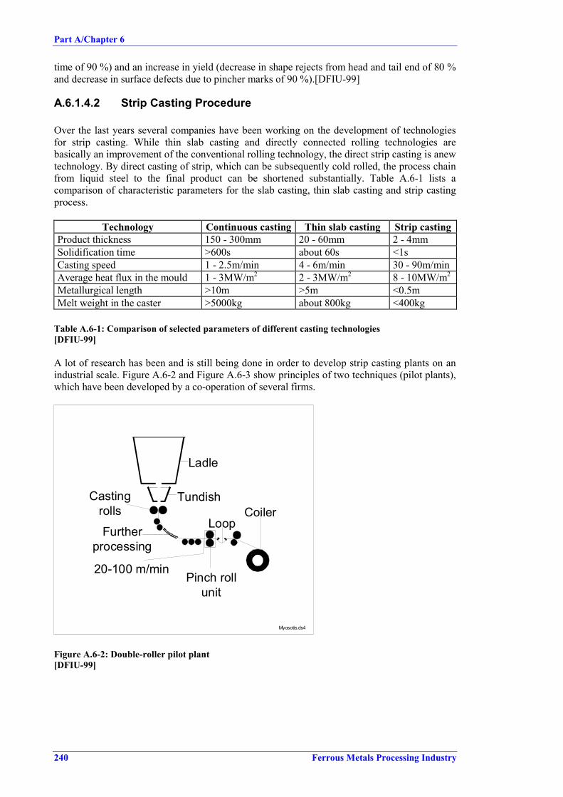
Part A/Chapter 6
240 Ferrous Metals Processing Industry
time of 90 %) and an increase in yield (decrease in shape rejects from head and tail end of 80 %and decrease in surface defects due to pincher marks of 90 %).[DFIU-99]
A.6.1.4.2 Strip Casting Procedure
Over the last years several companies have been working on the development of technologiesfor strip casting. While thin slab casting and directly connected rolling technologies arebasically an improvement of the conventional rolling technology, the direct strip casting is anewtechnology. By direct casting of strip, which can be subsequently cold rolled, the process chainfrom liquid steel to the final product can be shortened substantially. Table A.6-1 lists acomparison of characteristic parameters for the slab casting, thin slab casting and strip castingprocess.
Technology Continuous casting Thin slab casting Strip castingProduct thickness 150 - 300mm 20 - 60mm 2 - 4mmSolidification time >600s about 60s <1sCasting speed 1 - 2.5m/min 4 - 6m/min 30 - 90m/minAverage heat flux in the mould 1 - 3MW/m2 2 - 3MW/m2 8 - 10MW/m2
Metallurgical length >10m >5m <0.5mMelt weight in the caster >5000kg about 800kg <400kg
Table A.6-1: Comparison of selected parameters of different casting technologies[DFIU-99]
A lot of research has been and is still being done in order to develop strip casting plants on anindustrial scale. Figure A.6-2 and Figure A.6-3 show principles of two techniques (pilot plants),which have been developed by a co-operation of several firms.
Ladle
TundishCoiler
Loop
Pinch rollunit
Furtherprocessing
Castingrolls
20-100 m/min
Myosotis.ds4
Figure A.6-2: Double-roller pilot plant[DFIU-99]

Part A/Chapter 6
Ferrous Metals Processing Industry 241
CoilerCooling line
Mould
Squeezing
Pressing Induction furnace
Descaling
Mill stand5,5 m/min
8,3 m/min
20,5 m/min CPRplant.ds4
Figure A.6-3: Casting Pressing Rolling (CPR) pilot plant[DFIU-99]
Typ1 Stand2 Thickness[mm]
Width[mm]
Year ofStart
Remarks
BHP, Mulgrave, AusBHP, IHI, Port Kembla, AUS
R/B2-R
HMPilot
1 - 22
1601900
1995
Voest Alpine, Linz, A 1½-R HM 1.15 330 1986 slanted &vertical
CRNC-IMI, Boucherville, CANCRNC-Projet Bessemer,Boucherville, CAN
2-22-R
HMHM
32-5
100200
1990(steel)1992
horizontalfeedingverticalfeeding
Shanghai MetalResearch Inst. Shanghai, CHN
2-R HM
Clecim, Le Creusol, FIRSID, Maizières, FIRSID, Maizières, F
Myosotis, lsbergues, F
1½-R2-R1-R
HMHMHM
122-50.22.52-6
200200200
865
1968-1974 stopped
ZFW, Dresden, DThyssen, Oberhausen, DRWTH/Thyssen, Aachen, DMax Planck, Düsseldorf, DKrupp Stahl, Siegen, DKrupp Stahl, Unna, D
Clausthal Uni. Clausthal, D
2-R1-R2-R2-R1½-R1½-R
B
HMHMHMHMHMIn-pilot
HM
0.15-20.10-0.300.3-2.513
1.5-4.5
5-10
30-110270150110
700-1050
150-300 1989-1995
stopped
stoppedstopped
CSM, Rome, ICSM, Terni, I
2-R2-R
HMPilot
3-252-5
150400750-800
Table A.6-2: Development projects in strip casting[Jahrbuch Stahl 1996]

Part A/Chapter 6
242 Ferrous Metals Processing Industry
NSC/MHI, Kawasaki, JAPNSC/MHI, Hikari, JAP
Kawasaki, Chiba, JAP
Kawasaki, Chiba, JAPKobe, Kakogawa, JAP
Nippon Metal, Sagamihara, JAP
2-R2-R
2-R
2-R2-R
1½-R
HMIn-PilotHM
PilotHM
HM
0.5-31.5-6
0.2/0.8
1-31.5/5
1-4
1001330
250-500
100300
650
stopped
stoppedstopped
stoppedNippon, Naoetsu, JAPStainless Nippon Yakin,Kawasaki, JAP
Nisshin + Hitachi, Yamaguchi,JAPNisshin + Hitachi, Hitachi, JAPNisshin + Hitachi, Hitachi, JAPPacific Metals, Hachinoe, JAPPacific Metals, Hachinoe, JAPWaseda Uni.,Tokyo, JAP
1-R
2-R
2-R2-R2-R2-R2-R2-R
HM
Pilot
HMHMHM
PilotHM
1-2.5
0.8/52.12.3
2-7
600
300600802001050
POSCO RIST Davy, Pohang,KORPOSCO RIST, Davy, Pohang,KORInst. of Ind. Sc. & Techn.Pohang, KOR
2-R
2-R
2-R
HM
Pilot
HM
2-6
3
1-5
350
1050-1300
250-350
1994
statusunknown
VNIIMETMACH, Moscow,RUS
2-R 0.1-0.35 150
MEFOS, Lulea, SASEA-Royal Institute,Stockholm, S
62-R
PilotHM
5-10 450(900)
1991
British Steel, Teesside, UK
BS-Avesta, Sheffield, Teesside,UKBritish Steel, Teesside, UK
2 R
2 R
2 R
HM
Pilot
Indust.pilot
1-3
2.3-5.5
2-7
76
400
1550
1986
1990
understudy
Consortium 3), Bethelehem,USAARMCO-Westinghouse,Middletown, USA
National-Batelle, Columbus,USA
Allegheny/VA, Breckenridge,Lockport, USA
2-R1-R
1-R
1-R
HMHM
HM
Pilot
0.5-20.5-0.8
1.25-1.75
1-3
30075
(25 µm)-1.75
660-1220
1982<1988
stoppedstopped
stopped
1220 mmnotyet tried
Table A.6-2 cont.: Development projects in strip casting[Jahrbuch Stahl 1996]

Part A/Chapter 6
Ferrous Metals Processing Industry 243
A.6.1.4.3 By-product Recycling
Technologies for Recycling without Deoiling
Blast furnace injection Process steps: Sludge and scale dewatering (drying) at low temperatures, thus the hydrocarbons remain in thedried substance. Adding of granulators to bring the mixture into a friable condition. BF injection via special designed equipment. Oily sludges can also be injected in liquid form.
Deoiling Techniques
Thermocon process (Thermal physical Process for deoiling *) Oily sludges are batchwise (40 - 45 t/charge) processed. The materials are charged into a special container and heated up to approx. 130 °C. The actually chemical-physical effect utilized, is steam distillation. Steam including water and hydrocarbons sucked from the container is heated up to approx.500 °C and afterwards burned by approx. 1000 °C. CED - process (Chemnitzer Entsorgungsdienst) (*) The process is based on the thermal deoiling principle. Contrary to the thermocon method, CED is a continuous process. The scale is transported through heated pipes by means of screws. Moistness with oil is distilled and afterwards condensed.
DCR - process (Dispersion by Chemical Reaction) (*) Scale with liquid additive and the DCR reagent (e.g. quicklime) is homogenised within amixing apparatus. The hydrocarbons are bounded by the generated Ca(OH)2. Pulverised oil isseparated from the ferrous material via combined sieving and sorting device.
TRF process (Tubular-Rotor Filter) (*) Cleaning of the oily scale in a washing device by a water-tenside-emulsion. The waste washing water is cleaned from tenside- / oilmixture by using the so called Tubular-Rotorfilter. The fractionated oil is thermal utilized.
HD - process (High pressure method) (*)Scale is cleaned from oil by shooting a water scale mixture under high pressure (approx.150 - 180 bar) and from a short distance (200 - 400 mm) onto a baffle plate.

Part A/Chapter 6
Ferrous Metals Processing Industry 245
A.6.2 Cold Rolling Mill
A.6.2.1 Pickling
A.6.2.1.1 Hydro-abrasive Pre-descaling (Ishi Clean)
Iron containing sludge is mixed with a circulating high pressure water jet and is sprayed ontothe strip surface to remove the scale.
A.6.2.1.2 Pre-descaling by Ferromagnetic Abrasive
Splintered, ferromagnetic abrasive material is aligned by a magnetic field and is mechanicallypressed onto the strip surface.

Part A/Chapter 6
246 Ferrous Metals Processing Industry
A.6.3 Wire Plant
Acid regeneration process such as electrodialysis / bipolar membrane technology are underdevelopment or being tested. This technology which converts all acid again to free acid andmetals to hydroxides is much too young / not proven / too expensive
From analogy with more traditional membrane processes, a short membrane life is expected.
Part A/Chapter 7
Ferrous Metals Processing Industry 247
A.7 CONCLUDING REMARKS
The following conclusions and recommendations concern timing of the work, sources ofinformation, availability and quality of data, consensus amongst experts of the TWG andrecommendations for future work.
Timing of workThe drawing up of this BREF took about 2 ½ years. The major steps have been:
• First TWG meeting (kick-off meeting) 11 – 12.12.97• Submission of relevant information and data by TWG:
for Chapters 2 February – October ’98for Chapters 3 April – October ’98for Chapters 4 July – October ’98
• First draft December 1998• First consultation round 16.12.98 – 12.2.99• Evaluation of comments and redrafting: May – July ‘99
(response to comments, clarification andrequest for additional information)
• Submission of missing information/data: September – November ’99• Second draft December 1999• Second consultation 17.12.99 - 17.02.00• Second TWG meeting 22 – 24.03.00• Submissions on controversial issues that came up
during the 2nd TWG meeting: 28.03.00 – 19.07.00• Consultation on ‘new’ chapters (revised Chapters 5, 21.07.00 – 18.08.00
Chapter 7 Conclusions & Recommendations,Executive Summary, Chapter 4: SCR and SNCR)
• Final draft
Sources of information65 reports dealing with the various aspects of the ferrous metals processing sector weresubmitted. These reports contain very different kinds of information (statistical data, descriptionof production technologies, information on certain environmental measures including casestudies and emission/consumption data). They have been prepared from different points ofview; most of them only focusing on single aspects or media, only very few covering allenvironmental aspects.
During the period of work on the Ferrous Metals Processing BREF, industry shadow groups onhot rolling, cold rolling and continuous coating and the European General GalvanizersAssociation (EGGA) provided reports and papers on their sectors regarding the appliedproduction techniques and some environmental measures. Germany submitted a report on ‘BATin the German Ferrous Metals Processing Industry’.
The availability of such documents is essential for the quality of the document, but theirusefulness is potentially compromised if they are not sent in early in the process. Delays insubmitting crucial information, especially on the techniques to be considered in thedetermination of BAT, have led to delays in issuing drafts of this BREF.
Best available techniquesBAT have been identified for all three sub-sectors of ferrous metals processing and for theindividual production steps. They are described in detail in the three Chapters 5 providingbackground and, where necessary, justification for selection as BAT and for the reported BAT-associated emission levels. The executive summary includes all these BAT conclusions.

Part A/Chapter 7
248 Ferrous Metals Processing Industry
Level of consensusPart A of this BREF contains several split views. There were three areas in which the TWG
could not reach an agreement:• BAT-associated dust levels for application of fabric filters/electrostatic precipitators• SCR and SNCR NOx reduction measures for reheating furnaces• S-content in fuel oil
On dust emissions, the TWG agreed that capturing and fabric filters are BAT, but there weretwo general points of view on what is achievable with fabric filters. Industry proposed, based ontheir experience and knowledge of achieved dust levels, the higher level of 20 mg/Nm³. SomeMember States and environmental NGOs considered below 5 mg/Nm³ to be the appropriateassociated level for fabric filters, but there were only very few figures and for most applicationsno data presented to support this view (see also recommendations for future work).
Information and data on SCR and SNCR in reheating furnaces was received at a very late stageof the work; during and after the second TWG meeting. Some TWG members considered thesetechniques to be BAT, while others thought the available information on technical details andon economics was not sufficient to allow a final decision to be made on whether or not SCR andSNCR are BAT. As this controversy was raised almost at the end of this exercise, there was notime to resolve the outstanding issues (see also recommendations for future work).
Another point of dissent was the issue of limiting S-content in fuel oil. Although a level ofS < 1% can lead to emissions as high as 1700 mg SO2 /Nm3, some TWG members thought thatthis should be BAT. Others regarded a lower S-limit in the fuel oil or additional SO2 reductionmeasures as BAT.
Parts B and C of this BREF enjoy a high level of consensus. No split views had to be noted. Allparties in the information exchange process consider them an acceptable result.
Recommendations for future workA lack of data and information on the performance of techniques to be considered in thedetermination of BAT, especially on achieved emission and consumption levels and oneconomics, was noted as a flaw of this BREF document. For future BREF reviews, all TWGmembers and interested parties should continue to collect these data and information and shouldmake them available earlier rather than later in the process.
For quite a number of the techniques to be considered in the determination of BAT, noinformation or only a technical description is available. Information on reference plants andactual performance data are scarce. For the revision of this document the missing informationshould be provided. Some of the techniques concerned are the following:Part A:− Optimized water pumps for laminar flows− Implementation of degreasing bath cascades− Hot water pre-degreasing− Heat utilisation for heating degreasing bath− Electrostatic oiling− Optimization of oil spray− Optimized finishing operation− Cleaning and reuse of grinding emulsion− Exhaust system (PRETEX/SBT)− External use of spent acid pickle liquor

Part A/Chapter 7
Ferrous Metals Processing Industry 249
Part C:− Storage and handling of raw materials and auxiliaries− Capture/treatment of emissions from tube finishing operations
Part D:− Implementation of degreasing bath cascades− Hot water pre-degreasing− Adsorption of surfactants and oil (precipitation followed by filtration)− Electrolytic pickling− Treatment of rinsing water using ion exchange, electrolytic iron removal, reverse osmosis,
oxidizing iron removal
Several techniques are presented in the Chapters 6 ‘Emerging Techniques’. The progress indevelopment and the suitability for application in the FMP sector should be checked for apotential move of these techniques to Chapter 4 ‘Techniques to be considered in thedetermination of BAT’ and/or to Chapter 5 ‘Best Available Techniques’.
The criticism was made that the presentation of some techniques was too positive, having beenderived mainly from suppliers’ information, and that only the advantages were presented. Thismainly concerns reclamation and regeneration processes for spent treatment baths, e.g. for spentpickling liquors or spent degreasing or flux baths. Here industry is requested to provide theinformation and results they have achieved with certain techniques, together with descriptionsof any problems they have experienced.
There is a need for more emission and consumption data generally, but of particular interest arefigures on NOx emissions (concentrations and specific emissions) both for furnaces that use airpreheating and those that do not. Such data would make possible both a more thoroughevaluation of the efficiency of reduction measures and a comparison of the advantages anddisadvantages of energy savings vs. NOx emissions.
More data are required on achieved dust emission levels for the various production steps of hotand cold rolling (Part A), where a split view on the BAT-associated dust level had to be statedin the BREF. Especially, those parties advocating the lower level of 5 mg/Nm³ should seek toprovide data to substantiate their view.
It was reported that the number of installations applying SCR (pusher type furnaces) is likely toincrease. When this BREF is reviewed, there should be more information available on theperformance and applicability of SCR and SNCR for reheating furnaces. Existing SCR andSNCR installations will have a longer operating history to draw on, which should help toanswer the criticism that the information available was based on too short an operating period.Possibly the disagreement on whether these techniques constitute BAT can be resolved then.
During the 2nd TWG meeting the point was raised that inductive heating was BAT for severalapplications in furnaces. In this BREF, inductive heating is included as a technique to beconsidered, but it was stated that the information available was not sufficient to decide whetherthe technique is BAT. More information and data should be collected to enable this decision tobe made.
Another issue raised was the dioxin content of dust from batch galvanizing and potential risksof dioxin build-up when these dusts are recycled. Efforts should continue to compileinformation and data of actual dioxin contents in dusts for normal plant operation. Availabledata should be provided to the IPPCB and the TWG to allow a judgement on this problem andenable an evaluation of the potential risk.
A revision of this BREF document is recommended for the year 2005.


PART B
Continuous Hot Dip Coating Lines


Ferrous Metals Processing Industry 253
Best Available Technique Reference Document onFerrous Metals Processing
B.1 General Information on Continuous Hot Dip Coating Lines ...................................................257B.2 Applied Processes and Techniques in Continuous Hot Dip Coating Lines .............................259
B.2.1 Continuous Hot Dip Coating Process Overview................................................................259B.2.2 Galvanizing of Sheet (Zinc and Zinc Alloy Coating) ........................................................260B.2.3 Aluminizing of Sheet .........................................................................................................269B.2.4 Lead-Tin Coating of Sheet .................................................................................................270B.2.5 Wire Hot Dip Coating ........................................................................................................273
B.3 Present Consumption and Emission Levels for Continuous Coating Lines.............................275B.3.1 Continuous Coating Mass Stream Overview .....................................................................275B.3.2 Galvanizing of Steel...........................................................................................................277B.3.3 Aluminizing of Sheet .........................................................................................................281B.3.4 Lead-Tin Coating of Sheet .................................................................................................282B.3.5 Wire Hot Dip Coating (Galvanizing) .................................................................................285
B.4 Techniques to Consider in the Determination of BAT for Continuous Coating Lines ............287B.4.1 Galvanizing of Sheet..........................................................................................................287B.4.2 Aluminizing and Lead-Tin (Terne) Coating ......................................................................303B.4.3 Wire Hot Dip Coating (Galvanizing) .................................................................................305
B.5 Best Available Techniques for Continuous Coating Lines......................................................313B.5.1 Galvanizing of Sheet..........................................................................................................314B.5.2 Aluminizing of Sheet .........................................................................................................316B.5.3 Lead-Tin Coating of Sheet .................................................................................................316B.5.4 Coating of Wire..................................................................................................................317
B.6 Emerging Techniques for Continuous Coating Lines..............................................................319B.6.1 Coating of Sheet.................................................................................................................319B.6.2 Coating of Wire..................................................................................................................321
B.7 Concluding remarks.................................................................................................................323

254 Ferrous Metals Processing Industry
List of figures
Figure B.1-1: Production share for different hot dip coatings.................................................................. 257Figure B.2-1: Degreasing line layouts ..................................................................................................... 260Figure B.2-2: Typical layout for a hot dip zinc coating line .................................................................... 261Figure B.2-3: Schematic Coating Section of a Galvannealing Line......................................................... 264Figure B.2-4: Typical configuration of a cooling loop with cooling towers ............................................ 267Figure B.2-5: Cooling water system with heat exchangers...................................................................... 268Figure B.2-6: Aluminium coating process ............................................................................................... 270Figure B.2-7: Ternex process................................................................................................................... 272Figure B.3-1: Input/Output balance for continuous hot dip (sheet)coating lines ..................................... 275Figure B.3-2: Consumption and emission levels for lead-tin coating ...................................................... 282Figure B.4-1: Example of a degreasing solution recycling system .......................................................... 289Figure B.4-2: Chemical pre-treatment section for a sheet hot dip coating line (example)....................... 292Figure B.4-3: Diagrammatic view of a recovery system for zinc from dross .......................................... 295

Ferrous Metals Processing Industry 255
List of tables
Table B.1-1: Number of continuous coating lines in EU 15.....................................................................257Table B.1-2: Hot-dip galvanizing companies and their production..........................................................258Table B.1-3: Main consuming industries for galvanized products ...........................................................258Table B.2-1: Main hot dip coatings for steel sheet ...................................................................................259Table B.3-1: Consumption and emission levels for the total coating line ................................................276Table B.3-2: Consumption and emission levels for pickling....................................................................277Table B.3-3: Consumption and emission levels for degreasing................................................................277Table B.3-4: Consumption and emission levels for heat treatment ..........................................................278Table B.3-5: Consumption and emission levels for galvanizing ..............................................................279Table B.3-6: Consumption and emission levels for galvannealing ..........................................................279Table B.3-7: Consumption and emission levels for finishing...................................................................280Table B.3-8: Consumption and emission levels for waste water treatment..............................................281Table B.3-9: Consumption and emission levels for pickling of wire .......................................................285Table B.3-10: Consumption and emission levels for fluxing of wire .......................................................285Table B.3-11: Consumption and emission levels for hot dipping of wire ................................................286Table B.4-1: Pollutant concentrations in water discharge from treatment of waste water fromgalvanization [Com2 D] ...........................................................................................................................302


Part B/Chapter 1
Ferrous Metals Processing Industry 257
B.1 GENERAL INFORMATION ON CONTINUOUS HOT DIPCOATING LINES
The production of continuous hot dip coating lines in EU 15 was 15 Mt in 1997. The number ofcontinuous plants in EU Member States - operating, under construction and planned - is shownin Table B.1-1.
Number of Continuous Coating LinesAustria 4
Belgium 6Denmark -
Finland 2 (+ 1 under construction)France 14
Germany 10Greece 1Ireland -
Italy 8Luxembourg 3Netherlands 1 (+1 projected)
Portugal 1Sweden 2
Spain 4 (2 under construction)United Kingdom 7
Total 63Note: Source of data [EUROFER CC]
Table B.1-1: Number of continuous coating lines in EU 15
The vast majority of coatings applied, as shown in Figure B.1-1, was zinc. Aluminium coatingsand, especially terne coatings, played only a minor role.
Galvanized steel81%
Galvannealed steel4%
Aluminized steel5%
Aluzinc5%
Ternex1%
Galfan4%
Note: Source of data [EUROFER CC]
Figure B.1-1: Production share for different hot dip coatings

Part B/Chapter 1
258 Ferrous Metals Processing Industry
The hot dip galvanizing production for western European companies in 1997 is shown inTable B.1-2.
Company Production[1000 t]
Usinor 2124.7Cockerill Sambre 1917.1Thyssen 1661.2British Steel S.P. 1568.0Krupp-Hoesch 1310.0Riva 1024.0Aceralia 722.5Arbed 680.8Hoogovens Ijmuiden 375.0Lucchini 600.0Rautaruukki 572.5Voest-Alpine 520.0Preussag 520.0SSAB 505.0Others 595.5
TOTAL 14696.3Note: Source of data [EUROFER CC]
Table B.1-2: Hot-dip galvanizing companies and their production
Table B.1-3 shows the shares of galvanised products consuming industries in EU.
Sector Consumption[1000 t]
Transport 2570Construction 4759White Lines 364
Others 4547Total 12231
Note: Source of data [EUROFER CC]
Table B.1-3: Main consuming industries for galvanized products

Part B/Chapter 2
Ferrous Metals Processing Industry 259
B.2 APPLIED PROCESSES AND TECHNIQUES INCONTINUOUS HOT DIP COATING LINES
B.2.1 Continuous Hot Dip Coating Process Overview
In the hot dip coating process, the steel is continuously passed through molten metal. Analloying reaction between the two metals takes place, leading to a good bond between coatingand substrate.
Metals suitable for the use in hot dip coating are those, which have a melting point low enoughto avoid any thermal changes in the steel product, like for example aluminium, lead, tin, andzinc.
The principal hot dip coatings for steel sheet are shown in Table B.2-1. Wire is hot dip coatedwith zinc (galvanized) or tin. Zinc coating is mainly applied as corrosion protection. Tin givesthe wire a shine appearance and also provides a solder adhesive layer.
Coating Base Bath Coating
Type NameZinc base Zn
ZnZn
ZnZn-FeLead free
GalvanisedGalvannealed
Zn-AlZn-Al
99 %Zn, 1 %Al95 %Zn, 5 %Al
CrackfreeGalfan
AluminiumBase
Al-ZnAlAl-Si
55 %Al, 43.5 %Zn, 1.5 % SiAlAl 87 %, Si 13 %
GalvalumeType IType II
Lead base Pb-Sn 8.25 % Sn75 - 92 % Pb
Terne
Note: Source of data [EUROFER CC], [Com-CC-2]
Table B.2-1: Main hot dip coatings for steel sheet
In general continuous coating lines for sheet comprise the following steps:
• Surface cleaning by means of chemical and/or thermal treatment.• Heat treatment.• Immersion in a bath of molten metal.• Finishing treatment.
Continuous wire galvanizing plants involve the following steps:
• Pickling.• Fluxing.• Galvanizing.• Finishing.

Part B/Chapter 2
260 Ferrous Metals Processing Industry
B.2.2 Galvanizing of Sheet (Zinc and Zinc Alloy Coating)
In continuous hot dip galvanizing steel strip is coated with a zinc or zinc alloy layer as corrosionprotection. Figure B.2-2 shows the layout of a continuous galvanizing line (without pickling).Plant layouts may vary in the design of the entry section (with/without pickling or alkalinedegreasing), in the design of the annealing furnaces (vertical or horizontal) or the post-dippingtreatment (galvannealing etc.)
Hot dip galvanizing of cold rolled strip is more common than galvanizing hot rolled strip. Theprocessing is similar, except that for hot rolled products additional descaling (pickling) isnecessary.
B.2.2.1 Pickling
Pickling operation for descaling is only necessary for galvanizing hot rolled products to removehot mill scale. Pickling of unannealed cold rolled coil is done for activation. Both processes aredone in hydrochloric acid, followed by rinsing. The technology is the same as the picklingprocess described in the cold rolling section of this BREF.
B.2.2.2 Degreasing
It is essential that the surface of the steel coil is free of impurities such as grease, oil or abradediron fines to ensure the entire surface is exposed to the coating product and strong adherence isachieved. Although degreasing is not necessary when the strip is subsequently heat treated, it isoften applied in any case. The cleaning process involves several or all of the following steps:• Alkaline degreasing via immersion or by spraying; maybe coupled with brushing.• Alkaline degreasing by an electrolytic system; maybe coupled with brushing.• Rinsing with water with intermediate brushing between rinsing tanks.• Drying.
Figure B.2-1 show two possible layouts for modern degreasing lines.
Cleaning section Rinsing section
Cleaning section Rinsing section
Spray cleaning Brushing machine Spray cleaning Brushing machine Cascade rinsing
Spray cleaning(Dip cleaning) Brushing machine Elektrolytic cleaning
cell Brushing maschine Cascade rinsing
R-Linie.dsf
Figure B.2-1: Degreasing line layouts[DFIU]

Part B/Chapter 2
Ferrous Metals Processing Industry 261
Figure B.2-2: Typical layout for a hot dip zinc coating line[Com-CC-2]

Part B/Chapter 2
262 Ferrous Metals Processing Industry
The degreasing agent is usually a non-siliceous alkaline solution with a concentration of 25 g/land a temperature between 70 and 95 oC. Aqueous systems are now standard and solventdegreasing is obsolete. [ERM95], [Com-CC-2]
The same aqueous solution containing mainly sodium hydroxides, orthophosphates andsurfactant compounds is used in spray degreasing and in electrolytic degreasing. Once thesolution in the electrolytic degreasing section has reached a certain oil level, it is re-used on thespraying section (cascade use). It is also possible that the solution is treated in an emulsionseparation centre and then biological treated [Com-CC-2] When the solution has reached themaximum oil content it is regenerated, usually off-site. [EUROFER CC]
Fumes generated in degreasing and brushing are collected and scrubbed prior to release, usingwater or caustic soda solution and/or led through a demister for cleaning. [Com-CC-2] Spentdegreasing agent and waste water from the rinsing and brushing operations are sent to wastewater treatment before release. [EUROFER CC]
B.2.2.3 Heat Treatment
Hot and cold rolled steel coil are passed through a furnace with controlled atmosphere prior togalvanization to degrease and dry the surface, to improve the adhesive properties of the surface,to obtain the required mechanical properties of the steel and to allow the steel to reach therequired temperature before dipping. The following types of furnaces are used:
Sendzimir Furnace
This type of furnace is no longer used in modern coating lines, but some older plants might stilloperate this horizontal continuous furnace, which comprises a directly heated preheatingfurnace (oxidizing zone) and indirectly heated reduction and holding zones with reducing H2/N2atmospheres, followed by cooling zones. In the preheating part of the furnace, the temperatureis 450 - 550 oC. The strip is cleaned by burning off the oil the oil emulsion residues. In thereduction zone, at a temperature of 980 oC and in an inert atmosphere the oxides are reduced.The holding zone allows for recrystallisation and normalisation. The strip is then cooled to atemperature slightly above that of the molten metal (ca. 500 oC) and is fed into the zinc bath,under protective gas, by means of a so-called snout.
Direct Flame Furnace (D.F.F)
The direct flame furnace (Non Oxidizing Type) can be divided into different sections:
− A warming-up section where the strip is preheated using the gas flow coming from thefurnace, temperature raises from 20 oC to approximately 250 oC).
− The furnace itself, where the coil is heated directly by means of a naked flame, reaching atemperature between 560º- 750 ºC.
− The annealing zone where electric or radiant elements heat the strip up to 830 ºC andmaintain this temperature under reducing atmosphere (HNx atmosphere, 3 –20 % hydrogen).
− Two cooling areas, with different cooling rates, where the temperature of the steel is reducedby jet cooling down to 450º- 480 ºC.
− The exit area where the steel goes towards the galvanising bath.
This type of furnace cleans the coil surface and does not require any prior degreasing of the metal,but air emissions are generated as the remaining oil from the surface is burnt. Furthermorecombustion products, H2 and N2 arise from the furnace (fired by natural gas or desulphurised cokegas). [EUROFER CC], [Com-CC-2]

Part B/Chapter 2
Ferrous Metals Processing Industry 263
Radiant Tube Furnace (R.T.F.)
The radiant tube furnace is a variation with indirect heating. The combustion gases circulatethrough radiant tubes and do not get in contact with the strip. The soaking zone can be fittedwith radiant tubes or electric heating. Alkaline degreasing and radiant tubes or electric heatingare required for very high quality standards and for improving the adherence of the followingmetallic coating. The fast cooling areas are similar to those of a D.F.F. The annealing furnace iscombined with an alkaline degreasing equipment. [EUROFER CC], [Com-CC-2], [Com2 CC]
Fuels used are desulphured coke oven gas and natural gas. Energy conservation is a primaryconsideration in modern furnace designs. Recuperative features, such as infrared waste gaspreheaters, preheating of combustion air in direct fired and radiant tube furnace burners,preheating of furnace atmosphere gas and installation of waste heat boilers are generallyincorporated when feasible.
B.2.2.4 Hot Dipping (Galvanizing)
The galvanizing bath consists of one or more tanks, usually made of ceramic material. Thesepots, which can be either fixed or mobile, contain the molten metal at a temperature of 440º -490 ºC, through which the strip is passed. The bath contains zinc and any other requiredadditive (i.e. antimony, lead or aluminium). The bath contains a sufficient amount of moltenzinc in order to prevent the wide fluctuations in the operating temperature that may appearunder maximum operating conditions. Most pots are nowadays heated by electrical inductionsystems. However, natural gas as fuel for heating the pots is an alternative when considering theenvironment as a whole and taking environmental aspects of power generation into account.[EUROFER CC], [Com-CC-2]
As the steel passes through the molten zinc bath the surface is coated, to some extent with layersof different iron-zinc alloys, but due to the high speed of the steel strip (max. 180 m/min) andthe short exposure time, the coating mainly consist of zinc.
Temperature control of the bath is essential, as a high temperature will increase the rate ofoxidation at the surface of the molten bath, resulting in increased ash generation. A low bathtemperature will increase the viscosity of the molten coating metal, thus inhibiting the formationof a thin coating layer. The bath temperature is therefore optimized to meet the individualquality requirements of the final coated product.
The strip leaves the bath with some amount of liquid zinc on the surface. In order to achieve theexact thickness of coating required, the strip passes through a series of jets placed above thesurface of the bath. By blowing air or nitrogen the excess of zinc is removed from the steel. Thesystem is usually controlled by an automatic gauge, which measures the thickness of the coatingusing X-ray measurement technology or a similar technique.
Special galvanising processes to produce one-sided coatings are also applied. Examples are theMonogal process in which the zinc coating after normal galvanising is brushed off by rotatingmetal brushes and processes in which the zinc is applied by carrier rolls.
On leaving the bath, the strip is gradually cooled by air coolers, followed by a water quenchtank and a drier.

Part B/Chapter 2
264 Ferrous Metals Processing Industry
B.2.2.5 Galvannealing
Galvannealing is a special post-treatment applied in some installations in which the strip, aftergalvanizing, is heated to a temperature that allows the formation of a zinc-iron alloy (10 %iron). Galvannealing yields in a particularly smooth appearance of the product.
Galvannealing is the alloying of the zinc layer by the diffusion of iron (Fe) from the steelsubstrate. The Fe diffusion is obtained by maintaining the steel at a temperature of about500 °C, for low carbon steel, to a temperature of about 540°C, for new generation High StrengthSteel, during a sufficient time. Such furnaces are divided in two zones: a heating zone and asoaking zone. The available space for the furnace is limited. For a same available surface, avery quick heating from the zinc bath temperature (460°C) to the soaking temperature allows toapply a longer soaking time. Some furnaces are equipped with induction heating system in theheating zone and electrical elements or radiant tubes in the soaking zone. Induction heatingtechnique is characterised by a short heating time, a short reaction time, and an accurateregulation of the temperature and no emissions on the site. The alloying and surface qualitiesare improved.
Other galvannealing furnaces are equipped in the heating zone and in the soaking zone withradiant tubes characterised by a longer heating time. In that case the site emissions and theenergy consumption are improved by the use of low-NOx burners and regenerative orrecuperative burner systems. [Com2 CC]
Figure B.2-3 shows the schematic of view of the coating section and the galvannealing furnace.
Annealing furnace
Cooling zone
Soaking zone
Heating zone
Galvannealing-furnace
Hot dip galvanising
Zincbath
Jet (air-knives)
Figure B.2-3: Schematic Coating Section of a Galvannealing Line[DFIU 99]

Part B/Chapter 2
Ferrous Metals Processing Industry 265
B.2.2.6 Post Treatments
Following the coating, the steel strips are usually subjected to post-treatment in order to preventsurface damages and flaws, like white rust caused by water condensation in case of insufficientair access. Voluminous corrosion products as zinc hydroxides (white rust) affect furtherprocessing, such as e.g. painting. The formation of condensate during transportation and storageis to be generally prevented. [Com-CC-2]
The resistance against white rust is considerably increased by the application of post treatment,like oiling, passivation, phosphating, organic coating or a combination of such treatment. Inaddition, the processing properties are significantly improved depending on application (e.g.oiling: deformation aid, phosphating: direct painting ensured, in combination with oiling:deformation aid). [Com-CC-2]
OilingTo apply a wet film of oil on the surface of the strip dip spray, wingrolls or electrostatic oilingmachines are used. The oiling coat is between 0.25 - 3 g/m2/side [Com-CC-2]
PassivationPassivation is a treatment with solvents containing chromic acids, applied by spraying orapplicator-rolls. For hot dip metal-coated strip, a coat of 10 - 35 mg/m² per side is applied. Coatthickness is therefore extremely thin (few nanometer only). During passivation, Cr6+ is mainlyconversed to Cr3+. Almost all of the installations have a little heater after the treatment to makesure that the temperature rise over 120 ºC which is necessary for a chemical reaction of excessCr6+ with the additives of the passiving solution and become into Cr3+. The strip is treated withsolutions between 0.5 – 2 % of Cr6+ and temperatures between 70-120 ºC. [Com-CC-2],[Com2 D]
PhosphatingIn phosphating a phosphate coat of approx. 1 - 1.8 g/m² is applied. The phosphating procedureis more or less a precipitation reaction of zinc phosphate crystals at the surface of the metal coatcaused by an increase in pH-value at the metal surface due to a pickling reaction. Tri-cationphosphation process could be used (the hopeite crystal Zn3(PO4)2 ⋅ 4 H2O incorporates approx.1 % Ni and 5 % Mn). Thus, this process forms the same chemical structure of the phosphatecoat as the high-quality phosphating processes for cars and household appliances do.[Com-CC-2]
B.2.2.7 Finishing
To give the steel a special surface appearance, smoothness etc. as required by the customers orto meet width tolerances, the following operations may be applied:
Mini or No Spangle TreatmentIf the cooling rate of the top layer of pure zinc is sufficiently low, large crystals will formresulting in a ‘spangled’ appearance. Sometimes smaller zinc spangles or even no-spangle effectis requested. In that case the strip is either cooled more rapidly or the number of points ofspangling are increased by steam spraying, steam spraying with a chemical additive (usuallyphosphate based) or spraying with zinc powder. [ERM95]
Mat MillThe strip is skin-passed to obtain a mat finish surface.Skin pass treatment can be done in three different ways: dry, wet (only water) or wet (withwater and detergent). The 'temper mill' solution generated in the later process must be collectedand sent to a waste water treatment plant when it is spent.

Part B/Chapter 2
266 Ferrous Metals Processing Industry
Edge cuttingFor certain applications, an edge cutting must be done in order to obtain the width toleranceneeded and to avoid little dog bone defects. There are two places to realise this process:
In the pickling line before cold rolling.In the hot dip coating process.
A perfect product schedule tries to reduce this process to the minimum to increase the line yield.[Com-CC-2]
B.2.2.8 Cooling Water Circuits
In coating plants, cooling water is required to discharge excessive heat from furnaces. Part ofthe heat energy is emitted directly to the air (with the waste gases), via the coated strip or theshop air. The rest is transferred to the cooling water. The main cooling water consumers are thefurnace (roll bearings) and final cooling of the strip.
A coating plant is supplied with cooling water re-circulated from central cooling water systems.In these systems, pumps convey the cooling water to the consumers; the heated water isreturned and re-cooled again in plate heat exchangers with industrial water (e.g. from the river).
Due to the insertion of the closed re-cooling water circuits, the industrial water, even in case ofleakage of a cooler, does not get into touch with the equipment of the consumers; so that,penetration of chemicals or oil into the industrial water and pollution of the sewage system isprevented.
There are several variants of re-cooling, two of them are:− re-cooling with industrial water in heat exchangers and− re-cooling by evaporation in cooling towers.
Compared to re-cooling in towers, re-cooling in plate exchangers offers the advantage thatconsiderable amounts of chemicals for cooling water treatment (such as corrosion inhibitors,hardness stabilisers, dispersants and biocides) can be saved, and are not discharged into thesewage system. Another advantageous feature is that it is not necessary to do discharges ofpartial flow with a high salt content caused by the evaporation, as it happened in the case ofcooling towers. [EUROFER CC]
Typical configuration of a cooling loop with cooling towersThe little discharge that is necessary for keeping low salt concentration of water to the sewersystem is mostly made continuously. Algaecide (for avoiding the saturation of the contact zonebetween the water and the air) is dosed. The frequency is variable depending on the weather(between 1 and 3 times per week).
Other chemicals could be necessaries depending on the composition of the water used in thecircuit (hardness, etc).

Part B/Chapter 2
Ferrous Metals Processing Industry 267
evaporation
Suppletion of river water
conditioning withhypochlorite
Discharge to sewer system
cooling tower
pumpsIndirect furnaces
Indirect zinc pot
Airco computer room
Airco zinc pot cellar
Hydraulic units
N2 + H2 heatexchangers
conditioningIndirect quench tank
Figure B.2-4: Typical configuration of a cooling loop with cooling towers[CC 11/99]
Configuration for recycling water using plate heat exchanger:Cooling water is recirculated in several closed cooling systems and heated by the heat expelledfrom the process (machine cooling, gas cooling, etc.). The cooling water is recooled by riverwater in heat exchangers. The river water on the secondary side of the heat exchanger is neverin contact with the strip or harmful media and is therefore not contaminated. The water becomesonly heat loaded and can be drained back to the river. The main cooling water consumers arethe preheating and annealing furnaces, the zinc pots, several roll coolings, the immersed watercoolers, the activation section, the electrical equipment, the hydraulics and air conditioning.All heat which is not removed by the cooling water has to be discharged either by waste gas orto the ambient air.

Part B/Chapter 2
268 Ferrous Metals Processing Industry
With this system, addition of algaecide and scale-prevender is avoided. The outlet water is onlythermal loaded. This could be advantageous if the water of the system has no contact withpollution. There are discharges in case of system drain only.
HOT DIP GALVANIZING LINE
Inlet SideWelding Machine
FurnacesStrip Cooling
River Water Zinc PotWater Cooler
ActivationOutlet Side
Corrosion Inhibitor Hydraulics CoolingAir Conditioning
Make-up Water Electrics
HEATEXCHANGERS
Figure B.2-5: Cooling water system with heat exchangers[CC 11/99]
B.2.2.9 Water Circuits/Water Management
Process water is water which is used for make-up of chemical solutions or which is in directcontact with the strip (e.g. water for direct strip cooling). It may be contaminated by the processand has then to be treated as waste water. The following process water streams are used atgalvanizing lines and are finally discharged as waste water:− Make-up water (usually deionized water) for concentrate preparation of the chemical strip
treatment sections (pre-treatment, electrolytic treatment, post treatment). The differentconcentrates are sprayed onto strip or the strip is running through the concentrate bath. Theconcentrates are usually recirculated by pumps. They are clarified or filtered in recyclingplants during recirculation. Only a small flow is discharged as high concentrated waste waterto the water treatment plant.
− Rinsing water (usually deionized water) for chemical treatment sections (pretreatment,electrolytic treatment, post treatment). The rinsing water is used for removing of remainingconcentrate from the strip. The water sprayed onto strip in a cascade of rinsing sections, withthe water flowing countercurrently to the strip. It is finally discharged as low concentratedwaste water to the water treatment plant.
− Make-up water for the water cooler. In the water cooler the strip is cooled first byrecirculated spray water and finally by running through a water bath with an immersed turnback roll. The water will be contaminated by abrasion dust and has to be discharged fromtime to time to the skin pass mill water treatment plant.
− Spray water for the skin pass mill. The water is used for keeping the working rolls clean. It issprayed onto the rolls and contaminated by Zn-containing abrasion dust and lubricating oiland is discharged to the skin pass mill water treatment plant.

Part B/Chapter 2
Ferrous Metals Processing Industry 269
B.2.3 Aluminizing of Sheet
Most aluminium coated steel coil is produced by some variation on the hot dip galvanizingprocess. Figure B.2-6 shows the schematic line of production for applying aluminium coatings.The production line usually includes a passivation section, which is either in-line or is off line ina separate process unit.
Due to affinity of aluminium for oxygen it is extremely important to ensure against theformation of an oxide layer which would prevent diffusion of the aluminium into the steelsubstrate. The steel is sometimes spray or chloride gas pickled prior to annealing [ERM95]. Theformation of an oxide layer can then be prevented by using a number of methods, like:
− Passing the washed and pickled steel through a furnace with a hydrogen atmosphere toeliminate oxygen (the absorbed hydrogen further protects the substrate as it passes into themolten aluminium bath).
− Dipping the pickled steel in a molten aluminium bath that is kept saturated with hydrogeninjected by submerged jets.
The aluminium bath is generally maintained at temperatures of about 690 oC. The coated coilcan then be further heat treated at 820 - 930 ºC, which converts the aluminium coatingcompletely to steel-aluminium alloy if required. [ERM95]
Following the coating the strips may be subjected to post-treatment in order to prevent surfacedamages and flaws, as white rust caused by condensation in case of insufficient air access.
Passivation: spray treatment with solvents containing chromic acids. For hot dip metal-coatedstrip, a coat of 10 - 35 mg/m² per side is applied. Coat thickness is therefore extremely thin (fewnanometer only). During passivation Cr6+ is partly conversed to Cr3+. The strip is treated withsolutions between 0.5 – 2 % of Cr6+ and temperatures between 50 -120 ºC.
Anti-finger print: wringer rolls treatment of a polymer base coating on the strip surface. A coatweight (after drying) of < 1.5 g / m² per side is applied.

Part B/Chapter 2
270 Ferrous Metals Processing Industry
Figure B.2-6: Aluminium coating process[EUROFER CC]
B.2.4 Lead-Tin Coating of Sheet
Pure lead is never used as coating material for steel due to the fact that it is not possible toproduce a lead-steel alloy and obtain an adhesive coating. However, steel coils are coated with alead-tin alloy containing 8 - 25 % tin, called 'terne' metal. The terne metal can also contain up to3 % antimony. Tin and antimony first form alloys with the steel substrate, which provides theadhesion for the lead/tin surface coating.
Terne coating provides a high degree of external corrosion resistance. The coating keeps itsintegrity during deep drawing and forming, and it also acts as lubricant during same operations.Terne coatings have excellent solderability and are usually welded. It is widely used in theautomotive industry for the manufacture of petrol tanks and for different applications such asgas meters.

Part B/Chapter 2
Ferrous Metals Processing Industry 271
A flow sheet for lead-tin coating (ternex process) is shown in Figure B.2-7. First, the coldreduced substrate is cleaned by (electrolytical) degreasing and pickled, usually in warm, dilutedhydrochloric or nitric acid. Then, in cases of nickel flash terne coating, a thin nickel coating isapplied electrolytically. This improves wetting of the substrate by the alloy in the following hotdip stage and yields continuous and uniform coatings. [ERM95]
The continuous film of nickel on both surfaces of the steel strip will readily alloy with tin toform the basis for a discontinuity free layer of terne metal. The strip is passed through platingcells, containing titanium baskets filled with nickel pellets. An electrolyte consisting of Wattssolution (nickel sulphate/ chloride) is heated and recirculated through the plating cell and ismaintained at 65 ºC with a pH of 2.5 - 5.0. [Com-CC-2]
In the following step, the steel enters the molten terne bath at a temperature of 310 ºC through azinc ammonium chloride flux. To control coating thickness air knives are used nowadays. Theseprovide a wiping action to remove surplus lead from the strips surface. Oil baths, which havebeen used before in coating thickness control, have been replaced due to bad environmentalperformance. After cooling, the coil can be post-treated for protection either by oiling orpassivation.
PassivationTo seal the surface of the strip and passivate any pores or exposed areas of substrate againstoxidation, the strip is led through a dip tank with the passivation agent, usually chromic acidbased. A squeegee roll system on the exit of the tank stops any carry over from the tank andcontrols the film thickness. If required a drier can be used to raise the temperature of the stripand cure the chromate film on the surface of the strip.
OilingTo apply a wet film of oil on the surface of the strip roller coater systems, spray systems orelectrostatic oiling machines can be used

Part B/Chapter 2
272 Ferrous Metals Processing Industry
Figure B.2-7: Ternex process[EUROFER CC]

Part B/Chapter 2
Ferrous Metals Processing Industry 273
B.2.5 Wire Hot Dip Coating
Wire is hot dip coated mainly with zinc and zinc alloys (e.g. Galfan 95 % Zn, 5 % Al); the mainfunction of these types of coating is corrosion protection. Other coatings that are applied by hotdipping are tin and aluminium. Aluminium is used for some corrosion protection on nicheproducts. Tin gives a shiny appearance and also provides a solder adhesive layer. Theapplication processes for these hot dip coatings are basicily the same.
A continuous hot-dip coating line for wire consists of following production steps: the wire ispickled, rinsed, dipped in a flux-bath, dried, passed through the molten metal bath and cooledagain. Eventually a water based protective coating (so-called wax) can be applied after the hotdip coating step. [Com BG]
B.2.5.1 Continuous Pickling of Wire
Following heat treatment (see also Chapter A.2.3.5) or as a starting step for hot dip coating, thewire is pickled to remove surface debris to improve its appearance or to prepare the surface forthe application of coatings. This is usually done in-line either by immersing the wire in an acidbath or by subjecting it to a neutral salt bipolar electrolysis cell.
In acid pickling the wire is cleaned by passing it continuously through one or more hydrochloricacid baths; sometimes H2SO4 is used. Due to the short residence times, the HCl acid is oftenheated (up to 60 °C) or is used in concentrated form.. The type of impurities that are removedin this bath depend on the previous process step:
− For heat treated wire: metal oxides, residues of soap carrier, possibly traces of lead.− For drawn wire: residues of soap, oil or other lubricant and traces of rust. Sometimes a
degreasing agent is added to the HCl-bath to enhance removal of these substances.[Com BG].
Faster pickling and higher wire speeds are realised by increasing the length of the bath, byincreasing temperature of HCl, by increasing the concentration of the bath or by applyingelectrolytic assisted pickling. HCl-fumes from the pickling baths are collected and removed byscrubbing.
After pickling, the wire is passed through a rinsing cascade. [Com BG]
B.2.5.2 Fluxing
For good adhesion of the zinc coating, the wire is passed through a flux bath, a heated waterysolution of ZnCl2 and NH4Cl. (pure ZnCl2 is used for tin coating). Excess flux is removed fromthe wire by wiping. Prior to coating, the wire is dried; this can be done in a furnace or with theinternal heat of the wire. With high wire diameters and/or efficient wipers, the internal heat ofthe wire (due to the heating in the flux bath) is sufficient to secure a dry wire. The wire must bedry before entering the flux bath to prevent squirting at the inlet of the zinc bath.
The same flux media are used as for batch galvanizing, however the concentration is generallymuch lower. For zinc coatings usually a ZnCl2/NH4Cl mixture is used (pure ZnCl2 is used fortin coating). [Com BG]

Part B/Chapter 2
274 Ferrous Metals Processing Industry
B.2.5.3 Hot Dipping (Galvanizing)
The wire is passed through a molten zinc bath (430 - 470 °C). In the zinc bath, an iron - zincdiffusion layer is formed, consisting of sublayers of several Fe-Zn alloys. A zinc layer isformed on top of this, at the moment the wire leaves the zinc bath. Galvanizing can be dividedin heavy (vertical) galvanizing (high coating thickness; coating mainly consists of thewithdrawn zinc) and regular (horizontal) galvanizing (low coating thickness; the coating ismainly iron-zinc alloy layer). [Com2 BG]
Most zinc baths are heated through the bottom and the side walls with natural gas or other fuel.Exceptionally electric heating is used and/or heating is done from above the zinc bath.
A protective layer of particulate material or a bath cover can be applied on (a part of) the zincbath, in order to minimize formation of zinc oxides and energy losses.
After the zinc bath, the wire is cooled to near ambient temperature using air and cooling water.
Hot dipping in other metals or alloys is done in the same way. [Com BG]
B.2.5.4 Finishing
Eventually, a wax layer is applied for protection against formation of so-called white rust(superficial corrosion of the zinc layer).

Part B/Chapter 3
Ferrous Metals Processing Industry 275
B.3 PRESENT CONSUMPTION AND EMISSION LEVELSFOR CONTINUOUS COATING LINES
B.3.1 Continuous Coating Mass Stream Overview
By-Productsand Waste
Air Emissions
Acid
CR / HR Strip
Cold Drawn Wire
Waste Water
Continuous Coating LinePickling Fluxing Degreasing Heat Treatment
Dipping Galvannealing Finishing
Miscellaneous
Coated Strip
Coated Wire
Water
Energy
Particles
Combustion Products
Oil Burn-off
Oil Mist
Acid Aerosols
Chrome
Cooling Tower Emissions
Suspended Solids
Oil, Grease
Scrap
Dross
Oily sludge
Water Treatment Sludge
Furnace Scale
Refractory Material
Miscellaneous
Oil/Grease
Rolling Emulsion
Alkaline Degreasing Agents
Corrosion inhibitors,Biocides, Flocculating agents
Inert Gas, Compressed Air
Ni-electrolyte
Flux
Zinc Powder, Zn-chloride
Soap Carrier
Hydrochloric Acid
Nitric Acid
Electrical
Natural Gas
Desulphurised Coke gas
Cooling
Rinsing
Scrubbers
Coating Metal Zinc
Aluminium
Zn-Al-Alloy
Lead-Tin
Liquid Waste Spent Flux
Spent Pickle Liquor
Spent Degreasing Agent
Chromate Wastes
NoiseVisual Amenity
Note: Pickling only for HR band and wire coating; Fluxing for wire coatingFigure B.3-1: Input/Output balance for continuous hot dip (sheet)coating lines

Part B/Chapter 3
276 Ferrous Metals Processing Industry
Input / Consumption LevelZinc (coating metal)1 25 – 48 kg/tEnergy:
natural gas 800 - 1300 MJ/telectrical 44 - 140 MJ/thot water 20 - 44 MJ/t
Hydrogen 0.75 – 2.5 Nm3/tNitrogen 13 - 80 Nm3/tWater2
entry section: 8 -10 m3/hcoating section: 0.5 - 10.5 m3/hexit section: 0.5 - 6 m3/h
Water total (added to the system) 0.167 – 0.4 Nm3/tOutput / Emission Level
Specific Emission ConcentrationWaste air from combustion heating
SO2 4
NOx 4
0 - 1000 - 100
g/tg/t
0 - 800.5 - 700
mg/m3
mg/m3
Chromium 4(from chemical treatment zone) 0.001 - 0.360 g/t < 0.08 - 1.7 mg/m3
Acid aerosolsWaste water 4
Total Suspended SolidsCOD
(∼ 0.002) - (∼ 5)0.04 - 11
5 - 150 g/t
m3/tg/t 0.2 - 25
23 - 750mg/l 5
mg/lWaste3:
Oily sludge 0.004 –0.36 kg/tSludge from waste watertreatment
0.1 - 1.5 kg/t
Plate scrap1 1.5 - 36 kg/tZn containing material 4(scum, surfaces mattes, slags, dust )
0 - 4.5 kg/t
Dross1 Source of data [Com-CC-2]2 Source [EUROFER CC]3 Single plant data, [EUROFER CC]4 Source of [EC Study], including untreated discharge, lower end of scattering range from [Com-CC-2]5 Unit changed from mg/m3 to mg/l6 data from 3 plants, included are spills of lubricants and hydraulic, for disposal or internal recycling
Table B.3-1: Consumption and emission levels for the total coating line

Part B/Chapter 3
Ferrous Metals Processing Industry 277
B.3.2 Galvanizing of Steel
B.3.2.1 Pickling of Steel Sheet
Data from pickling in cold rolling mills also apply for this sector.
Input / Consumption LevelHCl kg/t
Output / Emission LevelSpecific Emission Concentration
Waste gas1:HCl 0.12 g/t
Note: Source of data [EUROFER CC]1 Single plant data
Table B.3-2: Consumption and emission levels for pickling
B.3.2.2 Degreasing
Fumes generated in degreasing and brushing are collected and scrubbed, using water or causticsoda solution or led via a demister without scrubbing.
Spent degreasing agent and waste water from the rinsing and brushing operations are sent towaste water treatment before release. Degreasing solution is generally regenerated and re-circulated to the degreasing baths. Oils are separated from the baths and the composition of thealkali solution is re-adjusted.
Sometimes the solution is treated in an emulsion separation centre and then biologically treated.[Com-CC-2]
Oil separated from the alkali solution is used as fuel for the production of heat.
Input / Consumption LevelWater 0.063 – 0.25 m3/tDetergents < 0.45 kg/t
Output / Emission LevelSpecific Emission Concentration
Air:NaOH,(PO4)2-
0.05 g/t
Waste water:NaOH,(PO4)2-
0.45 kg/t
OilWaste:
Oily sludge 0.18 kg/tFe2O3, Fe SO4
Source of data [Com-CC-2], single plant data
Table B.3-3: Consumption and emission levels for degreasing

Part B/Chapter 3
278 Ferrous Metals Processing Industry
B.3.2.3 Heat Treatment
Non-oxidizing type (D.F.F.):Natural gas and coke gas, previously in some cases desulphurised, are used for firing. The nakedflame in this type of furnace is directly heating the strip surface. No degreasing of the strip isnecessary, as the oil is burnt in the furnace. However, additional air emissions, apart from the fuelcombustion products, are generated by the combustion of the oil. The pollutants released are: CO2,CO and NOx. As the furnace is operated under reducing conditions by use of inert gases the wastegas also contains H2, and N2.
If coke gas is used as fuel, SO2 will also be generated, with a concentration depending on thesulphur content in the fuel.
Radiant type (R.T.F.):Since there is no contact between the flame and the surface of the strip, air emissions are onlygenerated by gas combustion, consisting mainly of CO2/CO, NOx and SO2, if coke gas is used asfuel.
Input / Consumption LevelHydrogen 0.75 – 2.5 Nm3/tNitrogen 13 - 80 Nm3/tNH3 (dissociated)1 0.7 Nm3/tEnergy
Output / Emission LevelSpecific Emission Concentration
Waste gas:Heat Treatment Furnace(R.T.F) 1
Carbon monoxide (CO) 1.21 – 23.3 g/tNitrogen oxides (NOx) 55.4 - 105 g/t
Note: Source of data [EUROFER CC], [Com-CC-2]1 Data from 3 plants
Table B.3-4: Consumption and emission levels for heat treatment
B.3.2.4 Hot Dipping (Galvanizing)
In modern facilities, the molten bath is heated by means of an electric induction systems. Olderfacilities using fuel-oil or gas produce the typical emissions (fumes corresponding to eachdifferent type of fuel). CO2, CO, NOx,; if fuel-oil or coke gas is burnt, also SO2 are emitted.Waste generated by galvanizing are bath splashes and dross formed in the bath.

Part B/Chapter 3
Ferrous Metals Processing Industry 279
Input / Consumption LevelZinc (coating metal)a 25 – 48 kg/tEnergy:
Output / Emission LevelSpecific Emission Concentration
Waste gas from heating the zinc bath1:CO 5 - 10 g/tNOx
2 20 - 40 g/tSO2
2 0.2 - 0.5 g/tHydrocarbons 0.1 - 0.2 g/tSoot 0.1 – 0.2 g/t
Plate scrapa 1.5 - 36 kg/tZn containing materiala 0 - 4.5 kg/t
Note: source of data [ERM95]; a: Source of data [Com-CC-2]1 Does not apply when electrically heated.2 when using 0.3 % sulphur fuel oil: 110 g NOx /t and 36 gSO2/t [ERM95]
Table B.3-5: Consumption and emission levels for galvanizing
B.3.2.5 Galvannealing
In modern facilities, the strip is reheated in an induction furnace. When reheating is done inconventional gas-fired furnaces, waste gas with a composition that depends on the type of gas usedis generated.
Input / Consumption LevelEnergy
Output / Emission LevelSpecific Emission Concentration
Waste gas1:Carbon monoxide (CO) 0.84 g/tNitrogen oxides (NOx) 0.93 g/t
Note: Source of data [Com-CC-2]1 when oil-fired, single plant data
Table B.3-6: Consumption and emission levels for galvannealing
B.3.2.6 Post Treatments
OilingNowadays, the oily protection is mainly applied by electrostatic oily machines, which producenegligible emission levels.
PassivationCr emission data are already enclosed in the table B.3-1 on the page 254.
Phosphating� No information submitted.

Part B/Chapter 3
280 Ferrous Metals Processing Industry
B.3.2.7 Finishing
The water + detergent method produces a temper mill emulsion that, when spent, must be collectedand sent to the waste water treatment plant. Not all installations use emulsions, some use solutionor nothing. [Com-CC-2]
Input / Consumption LevelEmulsionEnergy
Output / Emission LevelSpecific Emission Concentration
Effluent from skin pass mill1:(previous to the treatment)
SS (filterable)CODSum of hydrocarbons(oil + grease)Zn total
3060
8.0
1
mg/lmg/lmg/l
mg/lNote: Source of data [Com-CC-2]1 single plant data
Table B.3-7: Consumption and emission levels for finishing
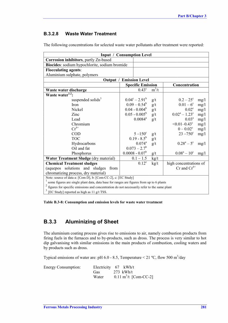
Part B/Chapter 3
Ferrous Metals Processing Industry 281
B.3.2.8 Waste Water Treatment
The following concentrations for selected waste water pollutants after treatment were reported:
Input / Consumption LevelCorrosion inhibitors, partly Zn-basedBiocides: sodium hypochlorite, sodium bromideFlocculating agents:Aluminium sulphate, polymers
Output / Emission LevelSpecific Emission Concentration
Waste water discharge 0.43c m3/tWaste water1,2:
suspended solids3 0.04c – 2.91b g/t 0.2 – 25c mg/lIron 0.09 – 0.54b g/t 0.01 – 6c mg/lNickel 0.04 - 0.004b g/t 0.02c mg/lZinc 0.05 - 0.005b g/t 0.02a – 1.23c mg/lLead 0.0084a g/t 0.03a mg/lChromiumCr6+
<0.01–0.43c
0 – 0.02cmg/lmg/l
COD 5 –150c g/t 23 –750c mg/lTOC 0.19 - 8.5b g/tHydrocarbons 0.074a g/t 0.28a – 5c mg/lOil and fat 0.073 – 2.7b
Phosphorus 0.0008 - 0.07b g/t 0.08a – 10c mg/lWater Treatment Sludge (dry material) 0.1 – 1.5 kg/tChemical Treatment sludges(aquepos solutions and sludges fromchromatizing process, dry material)
0.12c kg/t high concentrations ofCr and Cr6+
Note: source of data a: [Com D], b: [Com-CC-2], c: [EC Study]1 some figures are single plant data, data base for ranges are figures from up to 6 plants2 figures for specific emissions and concentration do not necessarily refer to the same plant3 [EC Study] reported as high as 11 g/t TSS.
Table B.3-8: Consumption and emission levels for waste water treatment
B.3.3 Aluminizing of Sheet
The aluminium coating process gives rise to emissions to air, namely combustion products fromfiring fuels in the furnaces and to by-products, such as dross. The process is very similar to hotdip galvanising with similar emissions in the main products of combustion, cooling waters andby products such as dross.
Typical emissions of water are: pH 6.0 - 8.5, Temperature < 21 ºC, flow 500 m3/day
Energy Consumption: Electricity 67 kWh/t Gas 273 kWh/t Water 0.11 m3/t [Com-CC-2]

Part B/Chapter 3
282 Ferrous Metals Processing Industry
B.3.4 Lead-Tin Coating of Sheet
There are no emissions of lead from the terne bath (380 - 450 ºC working temperature) as it hasbeen proved by extensive surveys on the environment in working places. [EUROFER CC]
From heating the terne metal and maybe the treatment baths, emissions to air (combustionproducts) arise.
Emissions from the oil bath and extractors on the exit of the terne pot are extracted and passedthrough a catalytic oxidizer. This oxidizes a range of hydrocarbons with molecular weights varyingfrom 50 to over 250 and also removes odour from the fume. Fumes from cleaners, pickling, nickelplating and fluxing sections are passed through a water scrubber prior to emission. [ERM95]
There has been some information that oil baths (and also catalytic oxidizers) are no longer usedand that nowadays air knives are used to control coating thickness. [Com-CC-2]
Other outputs to be expected from the process are solid wastes and by-products, like spent fluxor dross, and waste water. [EUROFER CC]
Input / Consumption LevelEnergy: Electricity
Gas2.43
1490kWh/tMJ/t
Water 3.0 m3/tOutput / Emission Level
Specific Emission ConcentrationWaste water discharge:(after effluent treatment)
Suspended solids 30.0 g/t mg/lCOD 90.0 g/t mg/lChromiumCr6+
0.028n.a.
g/t mg/lmg/l
Copper 0.014Lead 0.155 g/t mg/lNickel 0.565 g/t mg/lZinc 0.266 g/t mg/lIron 9.86 g/t
Emissions to Air:NO2 27.58 g/tHCl 10.38 g/tSOx negligible when gas firedParticulate negligible when gas firedCO2 42.0 kg/t
Waste:Filter Cake (effluent treatment) 7.52 kg/tCaustic Waste 1.47 kg/tZinc Chloride 1.96 kg/tChromate 0.73 kgtOil 0.49 kg/tWaste Sludge 10.5 kg/t
Note: source of data [Com-CC-2], single plant data
Figure B.3-2: Consumption and emission levels for lead-tin coating

Part B/Chapter 3
Ferrous Metals Processing Industry 283
Data available for one plant [UK-5/98]:
With air knife / wetscrubber
(after revamp)
Cooling and gauge controlusing oil / catalytic oxidizer('Old system')
Emissions to air: particulatesVOC
all metallsacid gases
< 1 mg/m3
< 1 mg/m3
< 1 mg/m3
30 mg/m3
150 mg/m3
100 mg/m3
Waste water: SSCOD
FeCrCuNiPbZnpH
400 mg/l600 mg/l250 mg/l 5 mg/l 2 mg/l 5 mg/l 2 mg/l 5 mg/l6 - 11
Waste: iron-rich filter cake from effluent treatment,with high chlorine content


Part B/Chapter 3
Ferrous Metals Processing Industry 285
B.3.5 Wire Hot Dip Coating (Galvanizing)
B.3.5.1 Continuous Pickling of Wire
Pickling is done in partially diluted HCl. The HCl bath is heated with a steam- or hot-watercoil. Water is consumed in the form of rinsing water and scrubbing water and leaves theinstallation ultimately as waste water. [Com BG]
Input / Consumption LevelHCl (expressed as 32 % HCl) 10 - 100 kg/tEnergy for heating the HCl-bath 1 no figure availableScrubber / rinsing water 0.5 - 5 m3/t
Output / Emission LevelSpecific Emission Concentration
Spent HCl containing 2:Total Cl
Fe
5 - 100 l/t150 – 275
60 - 125g/lg/l
Waste water from scrubber / rinsing 0.5 - 5 m3/t no representativefigure available 3
Emissions from scrubber:HCl 0 – 30 mg/m3
Note: source of data [Com BG], reference is tonnage of pickled wire1 often the bath is heated by residual heat in the wire2 other contaminants depending on previous steps, e.g. soap residues, pickled soap carrier, Pb...3 huge variations
Table B.3-9: Consumption and emission levels for pickling of wire
B.3.5.2 Fluxing
The flux bath is heated with a steam- or hot water coil. Drying of the wire after the flux bathcan be done in an oven or through the residual heat in the wire. Often, the oven is heated withthe residual heat of the exhaust gas of the zinc bath heating. [Com BG]
Input / Consumption LevelFlux salt 0.2 - 2.5 kg/tEnergy for heating the flux-bath n.a.Water (make-up/replace evaporation losses)1
Output / Emission LevelSpecific Emission Concentration
Spent flux negligibleNote: source of data [Com BG], reference is tonnage of fluxed wire1 negligible to rinsing and cooling water consumption
Table B.3-10: Consumption and emission levels for fluxing of wire
B.3.5.3 Hot Dipping (Galvanizing)
The zinc bath is heated through the walls and bottom using natural gas or other fuel. Tiles ofzinc are added to the zinc bath. Through drag-in of traces of Fe, and through oxidation, dross isformed, which has to be removed.

Part B/Chapter 3
286 Ferrous Metals Processing Industry
Following the zinc bath, the wire is cooled with water. [Com BG]
Input / Consumption LevelZinc 15 - 150 kg/tEnergy for heating of the zinc-bath n.a.Cooling water 0.2 - 1 m3/tBath cover material n.a.
Output / Emission LevelSpecific Emission Concentration
Zinc-containing residues (top-dross,bottom dross, waste bath cover material)
5 - 25 kg/t
Exhaust gas of zinc bath heating 1Emissions of zinc bath:
Zn 2Dust 2
0 – 10 – 15
mg/m3
mg/m3
Note: source of data [Com BG]1 typical emissions of natural gas fired furnace (unless other energy carrier is used2 small sources can have higher concentrations, as in most countries, small sources only have to comply with a limit
for mass flow
Table B.3-11: Consumption and emission levels for hot dipping of wire
B.3.5.4 Noise Issues in a Wire Plant
Excessive noise is primarily an internal occupational health issue, with precautions normallytaken to protect employees where it is not practical to prevent or reduce noise at the source. Insome instances, depending on the location of the process and noise characteristics, dependingon local off-site aspects (other noise sources, nearby residential area,...), and depending on localplant aspects (noise reduction by the building structure), there can be a concern for noise off-site.
The main sources of noise in wire processes are:• Rotating equipment, e.g. wet drawing machines; dry drawing machines; take-up units and
pull-through units on coating lines.• Air-wipes or air-brushes which clean the wire using compressed air can have a high
frequency noise.• Pay-off units of wire rod have a particular repetitive noise.• Burners of ovens.
These operations are typically continuous operations and are operated inside a building. In thisway, the impact outside the building is minimized to such an extent, that noise generated bythese operations rarely is an issue when concerning noise off-site.Case studies show that non-process sources outside the building, such as ventilation or plantutilities, are the main concern in wire plants located close to e.g. a residential area. Measuressuch as relocation, insulation or local enclosure can be considered for this last category ofsources.

Part B/Chapter 4
Ferrous Metals Processing Industry 287
B.4 TECHNIQUES TO CONSIDER IN THE DETERMINATIONOF BAT FOR CONTINUOUS COATING LINES
B.4.1 Galvanizing of Sheet
B.4.1.1 General Advice /Whole Plant
B.4.1.1.1 Oil-tight Trays or Cellars
Description:Several hydraulic stations and oil- or grease-lubricated equipment are required for galvanisinglines. These units are usually situated in oil-tight trays or cellars to avoid penetration of oil intoground in case of leakage. [Com-CC-2]
Main environmental benefits:• The risk to contaminate the soil is minimized. [Com-CC-2].
Applicability:• New and existing plants [Com-CC-2].
Cross media effects: No [Com-CC-2]Operational data:Economics: IC and OC are both lows. [Com-CC-2]Driving force for implementation: environment requirements [Com-CC-2]Reference literature:
B.4.1.1.2 Recycling of Oil Containing Waste
Description:Oil containing waste, such as the waste oil collected in the trays and sumps and the sludge fromthe oil separator of the water treatment plants, should be collected and stored separately fromother waste. The collected oily waste can be used as fuel for blast furnace (in an integratedprocess) instead of landfilling. [Com-CC-2]
Main environmental benefits:• Reduction in waste [Com-CC-2].• Increase of the waste recycling rate [Com-CC-2].
Applicability: New and existing plants [Com-CC-2]
Reference plant: Many plants [Com-CC-2]Cross media effects: No [Com-CC-2]Operational data:Economics: IC and OC are both medium [Com-CC-2]Driving force for implementation: Environments requirements [Com-CC-2]Reference literature:

Part B/Chapter 4
288 Ferrous Metals Processing Industry
B.4.1.2 Pickling of Steel Sheet
The techniques to consider in the determination of BAT for pickling in sheet galvanizing plantsare same as for pickling operations in cold rolling. For descriptions and comments on thesetechniques refer to Part A, chapters A.4.2.1.1, A.4.2.1.4, A.4.2.1.5 to A.4.2.1.10, A.4.2.1.16,A.4.2.1.17, A.4.2.1.22 to A.4.2.1.25.
B.4.1.3 Degreasing
B.4.1.3.1 Cascade (multiple) Use of Degreasing Solutions
Description:The solution from the electrolytic degreasing section is reused in the spray section, once a certainoil level is reached. The spent degreasing solution of the spray section is sent away to beregenerated. The oil residues out of the regeneration devices are incinerated out of the site, and therinse waters are treated in the main water treatment plant. Leakages and splashes are collected andtreated.
Main achieved environmental benefits:• Reduced degreasing solution consumption (fresh water consumption).• Reduction of waste water and sludge in the water treatment plant [Com-CC-2].
Applicability:• New and existing lines, provided space is available. [Com-CC-2].
Cross-media effects:• Increased energy consumption [Com-CC-2].
Reference plants: - several plants [Com-CC-2].
Operational data:15 m3/h of demineralized water is needed. (For the material that need this quality with aproduction yield of 68 t/h) [Com-CC-2]
Economics: Investments costs are medium and operative costs are low. [Com-CC-2]
Driving force for implementation:Reference literature:
B.4.1.3.2 Cleaning and Recirculation of Degreasing Baths
Description: More detailed information see Chapter D.4.3Spent degreasing solution is cleaned, e.g. in an ultrafiltration device or a magnetic filter. Theoily sludge may be used as reductor in the blast furnace; the treated degreasing bath is recycled.Fig shows an example of a degreasing solution circuit.

Part B/Chapter 4
Ferrous Metals Processing Industry 289
Steel SteelStrip Strip
Degreaser
FreshWater
Outlet Waterto Central
WaterBackwash Waste Water Treatment Plant
ALKALINE & ELECTROLYTICDEGREASING
MAGNETICFILTER
FRESH SOLUTIONPREPARATION
RECIRCULATIONof
DEGREASING SOLUTION
SEPARATOR
Figure B.4-1: Example of a degreasing solution recycling system[CC 11/99]
Main achieved environmental benefits:• Reduction of alkaline chemical consumption, [Com-CC-2].• Reduction of water volume and sludge volume in the water treatment plant. [Com-CC-2].
Applicability:• New and existing plants with no space problems for pumps, pipes tanks etc. [Com-CC-2].
Cross-media effects:• Increased energy consumption [Com-CC-2].• Reference plants: Voest-Alpine line 1 and 2, Aceralia line 2, Galtec 1 and others [Com-CC-2]
Operational data: Water consumption of 5 m3/h with the same consideration than before.[Com-CC-2]
Economics: high investment and high operational costs. [Com-CC-2]
Driving force for implementation: Environmental requirements [Com-CC-2]Reference literature:
B.4.1.3.3 Degreasing by Burning Oil in the Heat Treatment Furnace
Description:Oil on the steel surface is burnt in the heat treatment furnaces. Alkaline degreasing is omitted.
Main achieved environmental benefits:• No emissions to water [Com-CC-2].• No generation of waste [Com-CC-2].• Emissions to the atmosphere are lower than those generated in alkaline liquid degreasing.
[EUROFER CC].

Part B/Chapter 4
290 Ferrous Metals Processing Industry
Applicability:• New and existing installations.• When requirements for surface cleanliness and zinc adhesion are not very high. [Com-CC-2]
Cross-media effects: Air emission through burning of oil rest [Com-CC-2].
Reference plants: Galtec 1 [Com-CC-2]
Operational data:In some cases it might still be necessary to have a degreasing section before the furnace forsome high quality appliances. The furnace is not so easy to control as a radiant tubes furnace.Fumes from the furnace. [Com-CC-2]
Economics:Investment and operative costs are reduced because no need for preceding sections. [Com E]It is cheap on operation and installation. [Com-CC-2]
Driving force for implementation:Reference literature:
B.4.1.3.4 Treatment of Spent Degreasing Baths
Description: see Chapter D.4.4
Main achieved environmental benefits:• Reduction of waste.
Applicability:• New and existing plants.
Cross-media effects:Reference plants:Operational data:Economics:Driving force for implementation:Reference literature:
B.4.1.3.5 Treatment of Alkaline Waste water
Description: see Chapter D.4.5
Main achieved environmental benefits:• Reduced emissions to water.• Applicability:• New and existing plants.
Cross-media effects:Reference plants:Operational data:Economics:Driving force for implementation:Reference literature:

Part B/Chapter 4
Ferrous Metals Processing Industry 291
B.4.1.3.6 Degreasing Vapour Collection and Treatment
Description:Vapours generated by degreasing are collected by means of an exhaust device and subject to ascrubber or demister for abatement. Waste water originating from scrubbing are subject to watertreatment.
Main achieved environmental benefits:• Reduction of fugitive emission.• Reduction in degreasing fume emission.
Applicability:• New and existing plants with degreasing devices [Com-CC-2].• Existing plants with no space problems [Com-CC-2].
Cross-media effects:• Scrubber: water consumption (evaporation) and sludge generation in water treatment plant
[Com-CC-2].• Demister: depending on the cleaning technique used, treatment of spraying water or
solvents [Com-CC-2].
Reference plants: - Several [Com-CC-2], Jenn An, Taiwan [Danieli]Operational data: 5 m3/h of recirculate water (evaporate) for a production yield of 66 t/h[Com-CC-2]
Economics: medium [Com-CC-2]Driving force for implementation: Local conditions or requirements from local authoritiesthat lead to implementation. [Com-CC-2]Reference literature:
B.4.1.3.7 Using Squeeze Rolls
Description:The remaining degreasing solution or rinse water on the steel strip is removed from the strip bysqueeze rolls before leaving each treating section. This will assure that dragout of solution intonext section is minimized and loss of chemicals and contamination of rinse water is alsominimized. [Com-CC-2]
Fig shows an example of a chemical pre-treatment section of a hot dip galvanizing line for sheetusing squeeze rolls and cascade rinsing (for efficient rinse water use).

Part B/Chapter 4
292 Ferrous Metals Processing Industry
Squeeze RollsAlkaline Cleaning Electrolytic Cleaning Brushing Rinsing
Strip
Strip
1 Alkaline Cleaning2 Electrolytic Cleaning3 Brushing4 Rinse 15 Rinse 26 Rinse 3
1 2
RecyclingUnit
3
Wa ste Water,Sludge
Fresh Soluti on
4
Wa ste WaterFresh Water
5 6
Figure B.4-2: Chemical pre-treatment section for a sheet hot dip coating line (example)[CC 11/99]
Main environmental benefits:• Reduction of raw materials consumption, [Com-CC-2].• Reduction of waste water volume and of sludge in the waste water treatment plant [Com-
CC-2].
Applicability:• New and existing plants with degreasing and rinsing sections. [Com-CC-2].
Cross media effects: No [Com-CC-2]Reference plants: many plants. [Com-CC-2]Operational data:Economics: The initial investment in not so high and the operating cost is cheap. [Com-CC-2]Driving force for implementation:Reference literature:
B.4.1.4 Heat Treatment
B.4.1.4.1 Low-NOx Burner
Description: see Chapter D.2.1
Main achieved environmental benefits:• Lower CO and NOx emissions [Com-CC-2].
Applicability:• New and existing plants, sometimes when the gas is preheated with gas is not possible.
[Com-CC-2].
Cross-media effects:• Higher energy consumption.

Part B/Chapter 4
Ferrous Metals Processing Industry 293
Reference plants: Voest- Alpine HDG lines 1- 2, Aceralia line 2, Galtec 1 and many others.[Com-CC-2]
Operational data:Concentration of NOx between 300 - 500 mg/Nm3 and CO between 10 - 20 mg/m3 [Com-CC-2]; other sources reported 250 – 400 mg/Nm3 [Com2 A].Economics: Expensive technique on operation (through higher consumption) and investment[Com-CC-2]
Driving force for implementation:Reference literature:
B.4.1.4.2 Preheating of Combustion Air with Recovery Heat
Description: see Chapters D.1.1 and D.1.2The heat of the exhaust gases is recovery by a heat exchanger (regenerative burner, recuperativeburners or external recuperators, (see Part D) and transferred partially to the combustion air.[Com-CC-2]
Main environmental benefits:• Reduction of energy consumption [Com-CC-2].
Applicability:• New plants and existing plants in case of major modernisation [Com-CC-2].
Cross-media effects:• Increase in NOx emissions [Com-CC-2]
Reference plants:Operational data:Economics: IC=medium, OC is cheap [Com-CC-2]riving force for implementation:Reference literature:
B.4.1.4.3 Preheating the Strip with Recovery Heat
Description:Downstream of the entry looper, bridging the period of strip welding, the strip passes through apreheating zone where the residual heat of the waste gas is utilized. [Com-CC-2]
Main achieved environmental benefits:• Reduction of energy consumption [Com-CC-2].Applicability:• New and existing plants on major modernisation. Depending on the available heat on the
fumes. [Com-CC-2]
Cross-media effects:Reference plants:Operational data:Economics: IC=medium, OC is cheap [Com-CC-2]Driving force for implementation:Reference literature:

Part B/Chapter 4
294 Ferrous Metals Processing Industry
B.4.1.4.4 Steam Production with Recovery Heat
Description: No description and technical information submitted.
Main achieved environmental benefits:• Reduction of energy consumption.
Applicability:• New and existing plants on major modernisation. Depending of the available heat on the
fumes [Com-CC-2].
Cross-media effects:Reference plants:
Operational data: Increase of the risk of corrosion by a possible condensation of water. It isimportant for this technique the existence near this installation of a steam consumer.
Economics: IC: high, OC: medium [Com-CC-2]Driving force for implementation:Reference literature:
B.4.1.4.5 Inductive Heating System
Description: No description and technical information submitted.Main achieved environmental benefits:Applicability:Cross-media effects:Reference plants:Operational data:Economics:Driving force for implementation:Reference literature:
B.4.1.5 Hot Dipping (Galvanizing)
B.4.1.5.1 Dross TreatmentDescription:On hot dip galvanising lines, more than 10 % of the metallic zinc consumed appears as dross,mainly Zn and ZnO, on top of the molten zinc bath. Because of likely adverse effect on thegalvanised steel sheet, it is manually removed. The arising residual product can be sold to zincsmelters or being treated directly on-site to receive a zinc ash, which has only 20 % of theformer volume and can then be sold to the zinc producing industry for a higher price.Figure B.4-3 shows a diagrammatic view of a zinc recovery plant. [DFIU]
Main achieved environmental benefits:• Reduction of waste.
Applicability:Cross-media effects:Reference plants:Operational data: Economics:Driving force for implementation:Reference literature:

Part B/Chapter 4
Ferrous Metals Processing Industry 295
Reactor
Flux inlet
Recovered zincoxides
Fume(Scrubber)
Dross inlet
Potwall
Recovery.dsf
Figure B.4-3: Diagrammatic view of a recovery system for zinc from dross[DFIU-99]
Main achieved environmental benefits:• Reduction of waste.
Applicability:Cross-media effects:Reference plants:Operational data: Economics:Driving force for implementation:Reference literature:
B.4.1.5.2 External Recycling of Coating Material Slag
Description:Zinc slag is collected and returned to the zinc supplier for recycling of zinc. [Com-CC-2]
Main environmental benefits:• Reduction of waste [Com-CC-2].• Saving natural sources.
Applicability:• New and existing plants. [Com-CC-2].
Cross media effects: No [Com-CC-2]Operational data:Economics: IC and OC are both low [Com-CC-2]Driving force for implementation: Environmental and economics [Com-CC-2]Reference literature:

Part B/Chapter 4
296 Ferrous Metals Processing Industry
B.4.1.6 Galvannealing
B.4.1.6.1 Induction Electrical Furnace
Description:An induction electrical furnace is a relatively new technique, which is applied in the Hot DipCoating process. It is possible to use it to galvanneal the coated strip, as well as in the drierstage of the organic coating (if there were any) in the final finishing phase. Strictly speaking,this technique is not new (it appeared about five years ago). However, it undergoes a continuousinnovation, such as frequency variations and others.
This application could improve the environmental performance of the conventional furnaceswhen dealing with a hot dip process context, since there is not gas emissions from this stage.The price of the electrical power is not necessary acceptable. [Com-CC-2]
Main achieved environmental benefits:• Reduced air emissions.
Applicability:Cross-media effects:Reference plants:Operational data:Economics:Driving force for implementation:Reference literature:.
B.4.1.7 Post Treatments
B.4.1.7.1 Covering the Strip Oiling Machine
Description: No description and technical information submitted.
Main environmental benefits:• Reduction of oil fumes emissions in the atmosphere. [Com-CC-2].
Applicability:• New and existing plants with this strip oiling device. [Com-CC-2].
Cross media effects:Operational data:Economics: IC is medium and OC is low. [Com-CC-2]Driving force for implementation:Reference literature:
B.4.1.7.2 Electrostatic Oiling
Description:Light heated oil (anticorrosion or deepdrawing oil) is electrostatically settled on the zincsurface. The machine is covered and the splashed oil is collected and reinjected. [Com-CC-2]

Part B/Chapter 4
Ferrous Metals Processing Industry 297
Main achieved environmental benefits:• Reduced oil consumption.• Reduced oil emissions [Com-CC-2].
Applicability:• New and existing plants [Com-CC-2].
Cross-media effects: No [Com-CC-2]Reference plants: all the SIDMAR lines. [Com-CC-2]Operational data: It is not able to make the dry lubricant protection. [Com-CC-2]Economics: Invest costs are high, operational costs are medium. [Com-CC-2]Driving force for implementation:Reference literature:
B.4.1.7.3 Cleaning and Reuse of Phosphating Solution
Description:The phosphate solution is filtered through filters while recirculated. Only a small amount ofexhausted solution is discharged from time to time and treated externally. The waste water fromthe rinsing section is also treated externally in the water treatment plant. This treatment mayalso be carried out off site. [Com-CC-2]
Main achieved environmental benefits:• Reduction of phosphating chemical consumption, [Com-CC-2].• Reduction of water outlets and volume of sludge in the water treatment plant. [Com-CC-2].
Applicability:• New installations and existing if space is not a problem in revamping [Com-CC-2].
Cross-media effects:• Energy consumption [Com-CC-2].
Reference plants: Voest-Alpine [Com-CC-2]Operational data:Economics: IC=medium, OC=medium [Com-CC-2]Driving force for implementation:Reference literature: Voest Alpine, internal document. [Com-CC-2]
B.4.1.7.4 Cleaning and Reuse of Chromating Solution
Description:The chromium solution is filtered through filters while recirculated. Exhausted solution isdischarged from time to time and treated externally in the water treatment plant. This treatmentmay also be carried out off site. [Com-CC-2]
Main achieved environmental benefits:• Reduction of chromium chemical consumption, [Com-CC-2].• Reduction of water outlets and volume of sludge in the water treatment plant. [Com-CC-2].
Applicability:• New and revamped lines if no space problems [Com-CC-2].

Part B/Chapter 4
298 Ferrous Metals Processing Industry
Cross-media effects:• Energy consumption [Com-CC-2].
Reference plants: Voest Alpine [Com-CC-2]Operational data:Economics: IC=medium, OC=medium [Com-CC-2]Driving force for implementation:Reference literature: Voest Alpine, internal document. [Com-CC-2]
B.4.1.7.5 Covered Process Baths and Storage Tanks
Description:Storage tanks and chemical treating bathes are covered (extraction system) to collect emissionsof fumes and aggressive waste air. Com-CC-2]
Main environmental benefits:• Prevention of fugitive releases of chemical fumes. Com-CC-2].• Reduction in exhaust air volumes. Com-CC-2].
Applicability:• New and existing plants Com-CC-2].
Cross media effects:
Reference plants: Voest-Alpine line 1 and 2, Aceralia line 2 Com-CC-2]
Operational data:Economics: IC= medium, and OC are low. Com-CC-2]Driving force for implementation:Reference literature:
B.4.1.7.6 Using Squeeze Rolls
Description:The remaining solution on the steel strip is removed from the strip by squeeze rolls beforeleaving each treating section. This will assure that dragout of solution into next section isminimized and loss of chemicals. [Com-CC-2]
Main environmental benefits:• Reduction of raw materials consumption, [Com-CC-2].
Applicability:• New and existing plants with passivation process. [Com-CC-2].
Cross media effects: No [Com-CC-2]Reference plants: many plants. [Com-CC-2]Operational data:Economics: The initial investment in not so high and the operating cost is cheap. [Com-CC-2]Driving force for implementation:Reference literature:

Part B/Chapter 4
Ferrous Metals Processing Industry 299
B.4.1.7.7 Using Reverse Osmosis to Produce Deionized Water
Description:For preparation of chemical treating solutions and for rinsing water deionised water is required.This was produced in former times by desalination through ion exchange filters. As these filtersneed chemicals and water for regeneration as well as they produce regeneration brine,…
Main environmental benefits:• Reduction of chemicals consumption and avoidance of higher emissions in the natural
waters.
Applicability:• New and existing installations if is needed to change the deionised unit.
Reference plant: Voest- Alpine line 1 and 2Cross media effects: NoOperational data:Economics: Investments cost are high but operational costs are mediumDriving force for implementation: Environment and savings.Reference literature:
B.4.1.8 Finishing
B.4.1.8.1 Collection and Treatment of Skin Pass/Temper Solution
Description:Used solution, containing zinc particles and anticorrosion compounds, is send to the watertreatment section. The water could be recycled for the same or other purposes. Spent emulsiongenerated from tempering should be collected and send for water treatment. [EUROFER CC]
Main achieved environmental benefits:• Reduced water pollutant load (95 %) [Com-CC-2].
Applicability:• New and existing plants that use skin pass. [Com-CC-2].
Cross-media effects: - noReference plants: Galtec, Aceralia line 2, Voest-Alpine HDG 1 and 2 [Com-CC-2]Operational data:Economics: - High investment costs and medium operation costs. [Com-CC-2]
Driving force for implementation:Environmental requirements, cost requirements, Yield increase and Quality requirements[Com-CC-2]Reference literature:
B.4.1.9 Waste Water Treatment
Generally, the waste water treatment plants treat not only the water from coating plants but alsoall the effluents generated in the rolling facilities. Normally, these plants consist of threedifferent circuits: chromic water line, oily water line and the general waste water line.

Part B/Chapter 4
300 Ferrous Metals Processing Industry
B.4.1.9.1 Chromic Water Line
Description:The function of this circuit is to remove the chrome ions existing in the water, mainly, theCr(VI), due to its higher toxicity, and the Cr(III). In the treatment plant the Cr(VI) is reduced toCr(III) with sodium bisulphite or ferric chloride; the latter is preferable due to the muchsmoother reaction conditions obtained regarding pH, as the bisulphite reaction requires a muchlower pH, thus entailing a higher acid consumption. [EUROFER CC]
The following reaction takes place: Cr6 + 3 Fe2+ ----------> Cr3 + 3 Fe3+
In the following stage the Cr3+ precipitates due to a pH increase obtained by addition ofhydrated lime. Cr3+ + 3 OH- ----------> 3 Cr(OH)3
The ferric hydroxide precipitates simultaneously with the chromic hydroxide. The slurryobtained is treated in a decanter, inerted with milk of lime and subsequently passed through apress filter. Treatment with a polymer to achieve flocculation is also possible. [EUROFER CC],[Com-CC-2]
Main achieved environmental benefits:• Reduction of chromium emission with effluent.
Applicability:• New and existing plants.
Cross-media effects:Reference plants:Operational data:Economics:Driving force for implementation:Reference literature:
B.4.1.9.2 Oily Water Circuit
Description:The aqueous effluents from those facilities where the strip is degreased prior to the coatingprocesses are transferred to a neutralisation tank; neutralisation is achieved through the additionof hydrochloric acid. In case that acidic waste water from other processing steps (e.g. acidicrinse water) that cannot be recirculated is available, this may be used for neutralisation.[Weigel] After this step, the effluents enter a homogenisation tank and, subsequently, acoagulation and flocculation section. [EUROFER CC]
Coagulation is achieved through the addition of ferric chloride and hydrochloric acid andflocculation by means of a treatment with polymers such as aluminium polychlorid and othertypes of polyelectrolyte. [EUROFER CC]
From the flocculation tank, the effluent goes to a flotation tank where three phases areseparated:
a) Flocculated oily slurriesb) Sediment slurriesc) Water, to recycle

Part B/Chapter 4
Ferrous Metals Processing Industry 301
The flocculated oily slurries float as foam, by the injection of pressurised water through thebottom of the aero-floater. The air absorbed by the water is released with depressurisation,forming small bubbles that adhere to the flocculated oily slurries making them float as a foam,subsequently removed by means of a suitable mechanism. [EUROFER CC]
Other Option/Treatment of Spent Degreasing SolutionThe basic emulsion could also be treated in a central plant. First, there is a separation in threephases by means of gravity. The upper phase is treated in an oil centre. The middle phase istreated in an emulsion centre. The bottom phase consists of sludge and is treated separately. Bymeans of ultrafiltration, emulsions are separated in water and oil. The water part is treated in aconventional biological plant to reduce COD. [Com-CC-2]
Main achieved environmental benefits:• Reduction of oil emission with effluent.
Applicability:• New and existing plants.
Cross-media effects:Reference plants:Operational data:Economics: Investment cost is very high, operatives ones are high, but its environmentalperformance are also very high. [Com-CC-2]Driving force for implementation: environmental requirements. [Com-CC-2]Reference literature:
B.4.1.9.3 General Waste Water Circuit
Description:The treatment process of the waste water consists in a flocculation with subsequent filtering andcooling. In order to improve the removal of oil and solid particles, a small amount ofcoagulating agent and polyelectrolyte is added to produce a microflocculation.
The water and the flocculi are sent to a battery of two-layer sand and anthracite filters that retainthe particles formed. The filtrated water is transferred to cooling towers and the slurries retainedin the filters are removed and passed through a press filter for subsequent recycling.[EUROFER CC]
Main achieved environmental benefits:• Reduction of pollutants in effluent.
Applicability:• New and existing plants.
Cross-media effects:Reference plants:

Part B/Chapter 4
302 Ferrous Metals Processing Industry
Operational data:
Substance Concentration inmg/l 1)
Type of sampling Measurements in 1998Operator/Comp. authority
Fe 1.5 Qualified random sample 28/5Oil 0.2 Qualified random sample 28/5Suspendedsolids
10 Qualified random sample 28/5
Cr < 0.006 Qualified random sample 28/5Ni 0.01 Qualified random sample 28/5Zn 0.04 Qualified random sample 28/5Note: Source of data: Senator für Bau und Umwelt, Bremen. Plant: BREGAL, in Bremen.1) Mean values of the qualified random samples from 1998. Waste water volume: 135549 m3
Table B.4-1: Pollutant concentrations in water discharge from treatment of waste water fromgalvanization [Com2 D]
Economics:Driving force for implementation:Reference literature:
B.4.1.10 Cooling Water Systems
B.4.1.10.1 Closed Cooling Water Loop
Description: see Chapters D.9.2Separate and closed cooling water systems with recooling of the water by evaporative towers orplate heat exchangers.
Main achieved environmental benefits:• Saving natural resources [Com-CC-2].• Reduction of energy consumption. [Com-CC-2].
Applicability:• New Installations and existing installation in case of major modernisation [Com-CC-2].
Cross-media effects:Reference plants:Operational data:Economics: IC=high, OC=low [Com-CC-2]Driving force for implementation: Site specific issues will govern the choice of coolingsystem and applicability on existing plants. [Com-CC-2]Reference literature:
B.4.1.10.2 Reuse of Cooling Water
Description:Design a water circuit to reintroduce the cooling waters to this process or for another purpose.[Com-CC-2]
Main environmental benefits:• Saving natural resources, [Com-CC-2].• Reduction of energy consumption [Com-CC-2].

Part B/Chapter 4
Ferrous Metals Processing Industry 303
Applicability:• New and existing plants. [Com-CC-2].
Cross media effects:Reference plants: Many plants. [Com-CC-2]Operational data:The recycling ratio of the cooling water can surpass easily 90 %. [Com-CC-2]Economics: IC=high, OC=medium [Com-CC-2]Driving force for implementation:Reference literature:
B.4.2 Aluminizing and Lead-Tin (Terne) Coating
Techniques to be considered in the determination of BAT, are basically the same as forGalvanizing, when the same processing steps are applied (e.g. pickling, passivation, etc.). Someadditional measures for Lead-Tin (Terne) Coating are listed below:
B.4.2.1 Nickel Plating
Description:The electrolytic nickel plating facility is in enclosed and the exhaust air is ventilated to a wetscrubber. [Com-CC-2]
Main achieved environmental benefits:• Reduction of emissions to air, especially of fugitive emissions.
Applicability:Cross-media effects:Reference plants:Operational data:Economics:Driving force for implementation:Reference literature:
B.4.2.2 Hot Dipping
B.4.2.2.1 Air Knives for Thickness Control
Description:To control coating thickness air knives are used which provide a wiping action to removesurplus lead from the strips surface. [Com-CC-2]
Main achieved environmental benefits:• No emission of VOC and hydrocarbons to air (as with oil bath) [Com-CC-2].• No generation of waste oil [Com-CC-2].
Applicability:• New and existing plants.
Cross-media effects:Reference plants: British Steel, Brierley Hill, UK

Part B/Chapter 4
304 Ferrous Metals Processing Industry
Operational data:Reduction of VOC from 150 mg/m3 to < 1 mg/m3 [UK 5/98]No requirement for an incinerator to destroy emissions. [Com-CC-2]
Economics:Driving force for implementation:Reference literature:

Part B/Chapter 4
Ferrous Metals Processing Industry 305
B.4.3 Wire Hot Dip Coating (Galvanizing)
B.4.3.1 Continuous Pickling of Wire
B.4.3.1.1 Enclosing Pickling Baths / Treatment of Extracted Air
Description: The acid-bath must be equipped with a hood or cover, kept under slight underpressure, orcomparable enclosing. The extracted air can be treated by scrubbing with water using packed orplate scrubbers. [CET-BAT]
Main achieved environmental benefits:● Reduction of fugitive emissions from pickling (acid vapour and aerosols).● Reduction of acid vapour and aerosols by scrubbing.
Applicability:• New and existing plants, especially as heated and concentrated HCl is used.• Also applicable at continuous annealing and patenting lines with HCl in-line cleaning.
Cross-media effects:
Reference plants:Most installations with continuous pickling that operate either at high HCl or increasedtemperature, are equipped with a scrubber. [CET-BAT]
Operational data:Typical emission limits (concentration) are: < 20 to < 30 mg HCl per Nm3. This can be reachedwith a scrubber operated with water (no addition of NaOH needed). [CET-BAT]
Plate scrubbers achieve < 30 mg HCl/Nm3. They have a low water consumption and thereforelimited amount of waste water. In some applications (e.g. high acid consumption, high acidtemperature) complete reuse of scrubber waste water for dilution of fresh acid is possible.[Com BG2]
Packed media scrubber achieve < 20 mg/Nm3 but with a higher water consumption as platescrubbers, resulting in a higher amount of waste water. [Com BG2]
Economics:Driving force for implementation:Reference literature:
B.4.3.1.2 Cascade Pickling
Description:Cascade pickling is performed in two or more baths in series. The acid flows (continuously ordiscontinuously) in counter flow from one bath to the next. This allows to achieve a veryefficient use of the acid while still reaching good pickling quality. In this way, a higherconversion of the acid to metal salts can be reached, leading to a lower acid consumption.[CET-BAT]
Main achieved environmental benefits:● Reduced consumption of fresh acid.● Reduced spent acid (waste).
Part B/Chapter 4
306 Ferrous Metals Processing Industry
Applicability:● New and existing plants.● For existing plants available space might be a limiting factor.
Cross-media effects:Reference plants:Operational data:
Economics:For cascade pickling an extra pickling tank is necessary, it is not sufficient to split an existingpickling tank into 2 sections. It requires a big enough building (extra building), with acid prooffloor surface, secondary containment and an extra pump system. Depending on the applicationalso additional cover, exhaust system and scrubber for the extra cascade are necessary.[Com BG2]
Extra cost is highly dependent on the capacity of the line. Estimate: euro 0.2 - 0.5 million.[Com BG2]
Driving force for implementation:Reference literature:
B.4.3.1.3 Evaporative Recovery of Hydrochloric Acid
Description: see Chapter D.5.9.2
Main achieved environmental benefits:• Reduction in fresh acid consumption, reduction in fresh acid production (resources, energy).
Applicability:• New and existing plants.
Cross-media effects:For HCl, evaporation of HCl is a technically available but rarely used because of the importantinvestment and energy costs.
Reference plants:Operational data:
B.4.3.1.4 Recovery of Free Acid Fraction
Description: see Chapter D.5.9.1
Main achieved environmental benefits:● Reduced consumption of fresh acid.● Reduced spent acid (waste).
Applicability:● New and existing plants.
Cross-media effects:Reference plants:Operational data:Economics:Driving force for implementation:Reference literature:

Part B/Chapter 4
Ferrous Metals Processing Industry 307
B.4.3.1.5 (External) Regeneration of Spent Acid
Description: see Chapter D.5.10
Main achieved environmental benefits:● Reduction of acidic waste.
Applicability:● Regeneration plants require a minimum capacity, a minimum amount of spent acid to be
treated which is far beyond the spent acid generated at a single wire plant.● Wire industry depends on outside contractors for the recycling of spent acid.
Cross-media effects:Reference plants:Operational data:Economics:Driving force for implementation:Reference literature:
B.4.3.1.6 Reuse of Spent Acid as Secondary Raw Material
Description:The chemical industry uses spent acid as a secondary raw material for the production of FeCl3and, to a minor extend, for pigments. The possibility to recycle spent acid for the production ofvaluable chemicals is available in many regions in Europe. Some contractors impose or have toimpose strict limits for some metal impurities in the spent acids. A few contractors haverecently developed and patented special processes to remove e.g. Zn or Pb from some types ofspent acid. [CET-BAT]
Main achieved environmental benefits:● Reduction of acidic waste.
Applicability:● New and existing plants.
Cross-media effects:Reference plants:Operational data:Economics:Driving force for implementation:Reference literature:
B.4.3.1.7 Optimized Rinsing Procedure and Cascade Rinsing
Description:Counter-current cascade rinsing in combination with measures like to minimize dragout byinstalling suited wiping device (air-knife, pad, drip-bar etc.), continuously monitor rinsing waterquality, use of recuperated water / reuse rinsing water in other application.
Main achieved environmental benefits:• Reduced water consumption, lower water treatment costs [Com BG2].• Reduces carry-over of Fe-ions into the flux bath (increases life span of flux baths, reduces
carry-over of Fe into zinc bath).

Part B/Chapter 4
308 Ferrous Metals Processing Industry
Applicability:● New and existing plants.● For existing plants available space might be a limiting factor.
Cross-media effects:Reference plants:Operational data:Economics:Driving force for implementation:Reference literature:
B.4.3.2 Fluxing
B.4.3.2.1 Good Housekeeping and Bath Maintenance
Description:An excessive Fe-concentration in the flux bath causes drag-in of Fe into the zinc bath. Each kgof Fe entering the zinc bath causes the loss of 25 - 30 kg Zn by formation of dross. Thereforeiron content should be kept at a low level (e.g. by sufficient rinsing and wiping in the rinsingstep) and be controlled carefully. [CET-BAT]
A flux-bath should not have an over-flow; waste water from flux-baths should be limited toonce or a few times per year for reasons of maintenance and cleaning. This can be reachedeasily by minimizing drag-in of rinsing water. In this way, overflow of ammonia to the wastewater treatment is avoided. (Note: ammonia is not removed by the typical physicochemicalwaste water treatment at a wire plant.) [CET-BAT]
The flux consumption can be optimized by correct wire preparation, by frequent control of flux-salt concentration in the flux bath, etc. As it is much easier to put continuously just the rightamount of flux on a wire than on a complex piece, flux concentration and consumption aremuch lower in wire galvanizing than it is in batch galvanizing. As a result, excessive formationof dust and flux fumes can be avoided on a well maintained wire galvanising line and it ispossible to achieve low dust and metal emissions without the use of a filter. [CET-BAT]
Main achieved environmental benefits:• Increased lifespan of flux bath.• Reduced waste (dross) and emissions in the following galvanizing step.
Applicability:• New and existing plants.
Cross-media effects:Reference plants:Operational data:Economics:Driving force for implementation:Reference literature:

Part B/Chapter 4
Ferrous Metals Processing Industry 309
B.4.3.2.2 Regeneration of Flux Baths (on-site)
Description:Through dragin of rinsing water into the flux bath and through corrosion of the wire, Fe(II) isbrought into the flux bath. Fe(II) is converted to Fe(III) through oxidation by oxygen absorbedfrom the ambient air. Fe(III) precipitates as Fe(OH)3. After several weeks or months, the line isstopped and Fe(OH)3 is allowed to settle. The resulting sludge is disposed off ; the liquid phaseis returned to the flux bath.
If oxidation by ambient air is insufficient, then either the dragin of Fe(II) can be reduced (seeB.4.3.1.7) or other oxidation methods can be used (H2O2 see D.7.1.1 or electrolytic oxidationsee D.7.1.2).
If build-up of Fe(OH)3 is too fast to be handled by occasionally stopping of the line, the sludgecan be separated continuously in a settler.
Main achieved environmental benefits:• Reduced amount of spent flux bath.
Applicability:• New and existing plants.
Cross-media effects:Reference plants:Operational data and Economics:The goal is bringing the amount of spent flux to a very low level or possibly eliminating anyproduction of spent flux. Many wire plants achieve this by prevention (minimizing dragin ofFe(II)) rather than by investing in regeneration technology. A comparison between flux baths ina typical batch galvanizing plant and in a wire galvanizing plant learns that dragin of Fe(II) perm2 surface to be galvanized in a wire plant is roughly 2 - 5 % of the value in a batch galvanizingplant. In cases where the amount of spent flux can be kept very low by minimizing dragin,investment in a regeneration unit may not be justified.
Driving force for implementation:Reference literature:
B.4.3.2.3 Re-utilization of Spent Flux Baths (off-site)
Description:Spent flux baths are sent off-site, usually to flux agent producers, for re-cycling. The salts in thespent flux solution can be re-used for flux agent production.
Main achieved environmental benefits:Applicability:Cross-media effects:Reference plants: Th. Goldschmidt, GermanyOperational data:Economics:Driving force for implementation:Reference literature:

Part B/Chapter 4
310 Ferrous Metals Processing Industry
B.4.3.2.4 Enclose Flux Bath A flux solution (a heated watery solution of a mixture of ZnCl2, NH4Cl and possibly other salts)emits only water vapour. The flux bath could be covered with a hood or bath cover - This can have an advantage in termsof minimization of heat losses, when the flux bath is heated. [CET-BAT]Enclosed flux bayhs were not considered BAT because the vapour escaping from the baths isnot really dangerous and the advantage for the environment is too small compared to the costs.[Com2 B]
B.4.3.3 Hot Dipping (Galvanizing)
B.4.3.3.1 Zinc Bath: Good Housekeeping
Description:The most important house-keeping methods are:• Maintain a protective layer (particulate material) or a cover on the zinc bath. This
minimizes loss of zinc by oxidation, minimizes the formation of flux fumes and drasticallyreduces energy losses of the zinc bath.
• Any moisture dragged into the zinc bath evaporates explosively. This cause of zinc dustcan be eliminated by having a dry wire at the inlet of the zinc bath. [CET-BAT].
Main achieved environmental benefits:Applicability:Cross-media effects:Reference plants:
Operational data: By good house-keeping methods, it is perfectly possible to run a hot dip galvanising bath atvery low emissions of Zn and dust (below 5 mg/Nm3 Zn, below 10 mg/Nm3 dust). [CET-BAT]Economics:Driving force for implementation:Reference literature:
B.4.3.3.2 Emission Capture and Treatment of Extracted Air
Description:When for one reason or another, good house-keeping would is not sufficient to reach low Znand dust emissions, a hood or cover above the Zn-bath, extraction of air and installation of afilter can be installed. [CET-BAT]
Main achieved environmental benefits:Applicability:Cross-media effects:Reference plants:Operational data:Economics:Driving force for implementation:Reference literature:

Part B/Chapter 4
Ferrous Metals Processing Industry 311
B.4.3.3.3 Smoke-reduced Flux Agent
Description:In smoke-reduced flux agents ammonia chloride is partly substituted by other alkali chlorides(e.g. potassium chloride).
Main achieved environmental benefits:• Reduced air emissions.• Reduced hard zinc.
Applicability:Cross-media effects:Reference plants:Operational data:Economics:Driving force for implementation:Reference literature:
B.4.3.3.4 Storage of Zinc-containing Residues
Description:Zn-residues originate from the Zn-bath (top-dross, bottom dross, waste bath cover). Theseresidues should be stored separately and protected from rain and wind. The wire industrydepends on subcontractors for the final disposal and recycling of these residues. Normally Zn-containing waste is recycled by the non-ferro industry (Zn-smelters). [CET-BAT]
Main achieved environmental benefits:Applicability:Cross-media effects:Reference plants:Operational data:Economics:Driving force for implementation:Reference literature:
B.4.3.3.5 Cooling Water after Zn-bath
Description:The cooling water can be operated in closed circuit, using a wet cooling tower, air cooler orsimilar device. As the quality of this water is quite high, one could consider to give a secondfunction to any stream leaving this circuit.
Any waste water of this cooling water circuit should be treated in such a way that contamination(mainly dissolved Zn) is removed in a satisfactory way prior to discharge. [CET-BAT]
Main achieved environmental benefits:Applicability:Cross-media effects:Reference plants:Operational data:Economics:Driving force for implementation:Reference literature:


Part B/Chapter 5
Ferrous Metals Processing Industry 313
B.5 BEST AVAILABLE TECHNIQUES FOR CONTINUOUSCOATING LINES
In understanding this chapter and its contents, the attention of the reader is drawn back to thepreface of this document and in particular the fifth section of the preface: “How to understandand use this document”. The techniques and associated emission and/or consumption levels, orranges of levels, presented in this chapter have been assessed through an iterative processinvolving the following steps:
• Identification of the key environmental issues of continuous coating lines. Among theimportant issues are: acidic air emissions, wastes and waste water; air emissions fromfurnaces; energy consumption of furnaces; Zn-containing residues and oil- and chrome-containing waste waters.
• Examination of the techniques most relevant to address those key issues.• Identification of the best environmental performance levels, on the basis of the available
data in the European Union and world-wide.• Examination of the conditions under which these performance levels were achieved; such as
costs, cross-media effects, main driving forces involved in implementation of thistechniques.
• Selection of the best available techniques (BAT) and the associated emission and/orconsumption levels for this sector in a general sense all according to Article 2(11) andAnnex IV of the Directive.
Expert judgement by the European IPPC Bureau and the relevant Technical Working Group(TWG) has played a key role in each of these steps and in the way in which the information ispresented here.
On the basis of this assessment, techniques, and as far as possible emission and consumptionlevels associated with the use of BAT, are presented in this chapter that are considered to beappropriate to the sector as a whole and in many cases reflect current performance of someinstallations within the sector. Where emission or consumption levels “associated with bestavailable techniques” are presented, this is to be understood as meaning that those levelsrepresent the environmental performance that could be anticipated as a result of the application,in this sector, of the techniques described, bearing in mind the balance of costs and advantagesinherent within the definition of BAT. However, they are neither emission nor consumptionlimit values and should not be understood as such. In some cases it may be technically possibleto achieve better emission or consumption levels but due to the costs involved or cross mediaconsiderations, they are not considered to be appropriate as BAT for the sector as a whole.However, such levels may be considered to be justified in more specific cases where there arespecial driving forces.
The emission and consumption levels associated with the use of BAT have to be seen togetherwith any specified reference conditions (e.g. averaging periods).
The concept of “levels associated with BAT” described above is to be distinguished from theterm “achievable level” used elsewhere in this document. Where a level is described as“achievable” using a particular technique or combination of techniques, this should beunderstood to mean that the level may be expected to be achieved over a substantial period oftime in a well maintained and operated installation or process using those techniques.
Where available, data concerning costs have been given together with the description of thetechniques presented in the previous chapter. These give a rough indication about themagnitude of costs involved. However, the actual cost of applying a technique will dependstrongly on the specific situation regarding, for example, taxes, fees, and the technical

Part B/Chapter 5
314 Ferrous Metals Processing Industry
characteristics of the installation concerned. It is not possible to evaluate such site-specificfactors fully in this document. In the absence of data concerning costs, conclusions oneconomic viability of techniques are drawn from observations on existing installations.
It is intended that the general BAT in this chapter are a reference point against which to judgethe current performance of an existing installation or to judge a proposal for a new installation.In this way they will assist in the determination of appropriate "BAT-based" conditions for theinstallation or in the establishment of general binding rules under Article 9(8). It is foreseenthat new installations can be designed to perform at or even better than the general BAT levelspresented here. It is also considered that existing installations could move towards the generalBAT levels or do better, subject to the technical and economic applicability of the techniques ineach case.
While the BREFs do not set legally binding standards, they are meant to give information forthe guidance of industry, Member States and the public on achievable emission andconsumption levels when using specified techniques. The appropriate limit values for anyspecific case will need to be determined taking into account the objectives of the IPPC Directiveand the local considerations.
This chapter discusses the best available techniques for reducing the environmental impactsfrom continuous coating lines. Where possible, the structure follows the logic of the productionline and identifies BAT for individual processing stages. However, some measures, especiallyprimary or preventive measures, cannot be assigned to one single process step and have to beallocated to the plant as a whole. As far as possible and wherever the data available allowed,emission levels, efficiencies or recirculation rates are given as an indication of the improvementthat can be expected by implementation of the techniques. For a number of techniques theobvious positive effect cannot be described by an exact number, but some of these techniquesare nevertheless considered as BAT.
Unless stated otherwise the emission figures presented in the following BAT chapters are dailymean values. For emissions to air they are based on standard conditions of 273 K, 101.3 kPaand dry gas.
Discharges to water are indicated as daily mean value of a flow-rate-related 24-hour compositesample or a flow-rate-related composite sample over the actual operating time (for plants notoperated in three shifts).
B.5.1 Galvanizing of Sheet
For the best available techniques in pickling, refer to the BAT chapter of Part A/Cold RollingMills.
For degreasing operations in continuous galvanising plants, the following techniques areconsidered to be BAT:
• Cascade degreasing.• Cleaning and recirculation of degreasing solution; appropriate measures for cleaning are
mechanical methods and membrane filtration as described in Chapter A.4.• Treatment of spent degreasing solution by electrolytic emulsion splitting or ultrafiltration to
reduce the oil content; separated oil fraction should be reutilized, e.g. thermally; theseparated water fraction requires treatment (neutralisation etc.).
• Covered tanks with extraction and cleaning of extracted air by scrubber or demister.• Use of squeeze rolls to minimize drag-out.

Part B/Chapter 5
Ferrous Metals Processing Industry 315
The best available techniques for the reduction of emissions and energy consumption of heattreatment furnaces are considered to be:
• Low-NOx burners with associated emission levels of 250 - 400 mg/Nm³ for NOx (3 % O2)without air preheating and 100 - 200 mg/Nm³ for CO.
• Combustion air preheating by regenerative or recuperative burners.No data were submitted on NOx concentrations in connection with air preheating, but thefigures given for reheating furnaces may serve as an indication. Limiting the preheatingtemperature may be seen as a NOx reduction measure. However, the advantages of reducedenergy consumption and reductions in SO2, CO2 and CO have to be weighed against thedisadvantage of possible increased emissions of NOx.
or• Preheating of strip.• Steam production to recover heat from waste gas.
The hot dipping zinc bath is a source of zinc-containing residues, dross or hard zinc. BAT forthese residues is separate collection and external recycling in the non-ferrous metals industry.
In installations where galvannealing is done, BAT to reduce emissions and energyconsumption are:
• Low-NOx burners with associated emission levels of 250 - 400 mg/Nm³ for NOx (3 % O2)without air preheating.
• Regenerative or recuperative burner systems.• No data were submitted on NOx concentrations in connection with air preheating, but the
figures given for reheating furnaces may serve as an indication. Limiting the preheatingtemperature may be seen as a NOx reduction measure. However, the advantages of reducedenergy consumption and reductions in SO2, CO2 and CO have to be weighed against thedisadvantage of possible increased emissions of NOx.
Post-treatments of steel, such as oiling, phosphating and chromating, are done for protection. Inoiling, oil fumes are generated, which are best reduced by:
• Covering the strip oiling machine.or• Electrostatic oiling.
The environmental impact from phosphating and passivation/chromating can be reduced bythe following BAT:
• Covered process baths.• Cleaning and reuse of phosphating solution.• Cleaning and reuse of passivation solution.• Use of squeeze rolls.• Collection of skinpass/temper solution and treatment in waste water treatment plant.
For cooling (machines etc.), separate cooling water systems operating in closed loops areconsidered BAT.
Waste water arises in sheet galvanising from the chemical treatment sections and from rinsingoperations. Waste water also arises from strip cooling, contaminated by abrasion dust, and from

Part B/Chapter 5
316 Ferrous Metals Processing Industry
the water sprays which are used to keep working rolls in the skin pass mill clean and which iscontaminated by Zn-containing abrasion dust and lubricating oil. These waste water streamsrequire treatment by a combination of sedimentation, filtration and/orflotation/precipitation/flocculation. The techniques described in Chapter 4 or equally efficientcombinations of individual treatment measures (also described in part D) are considered BAT.The associated pollutant concentrations in the effluent are:
SS: < 20 mg/lFe: < 10 mg/lZn: < 2 mg/lNi: < 0.2 mg/l Crtot: < 0.2 mg/lPb: < 0.5 mg/lSn: < 2 mg/l
With some of the existing continuous water treatment plants, a zinc level of < 4 mg/l is all thatcan be achieved. In these cases the best option is to switch to batch treatment.
B.5.2 Aluminizing of Sheet
Most BAT are the same as for hot dip galvanising. However, there is no need for a waste watertreatment plant as only cooling water is discharged.
BAT for heating:Gas firing. Combustion control system
B.5.3 Lead-Tin Coating of Sheet
Best available techniques for lead-tin coating are:
• Pickling tanks are to be enclosed and vented to a wet scrubber packed tower, with pHcontrol. Achieved HCl emission levels are well below 30 mg/Nm³. Waste water from thetower and tank must then pass through a waste water treatment plant.
• Enclosed nickel plating process, ventilated to a wet scrubber.
• For hot dipping, air knives to control coating thickness are considered to be BAT; theyresult in no emissions
• For passivation, BAT is a no rinse system and hence no rinse waters from the systemrequire treatment. If a drier is required, this should be a gas-fired oven. No effluentproduced.
• Oiling by an electrostatic oiling machine.
• To treat process effluents e.g. acids from pickling or waste waters from scrubber, a wastewater treatment plant is required.. BAT for this type of process is sodium hydroxidesolution, added in a two stage neutralising process with automatic pH control of the dosingrate. A flocculent is then added to assist settlement of the precipitated solids in a settlementtank. Clean liquor then flows from the tank to sewer, river etc. The filter cake is then passedthrough a filter press and disposed to landfill. Establishing a route for recycling would be aBAT but, to date, no route has been found for this material.
Part B/Chapter 5
Ferrous Metals Processing Industry 317
B.5.4 Coating of Wire
For the reduction of air emissions from in-line pickling, enclosed equipment or equipmentfitted with hoods and scrubbing of extracted air is considered BAT. The BAT-associatedemission level is 2 - 30 mg/Nm³.
For the reduction of acid consumption in pickling lines, the following techniques are consideredto be BAT:
• Cascade pickling for new installations above a certain capacity. For small lines, the extrainvestment in a second tank, piping and process control equipment is not justified. Athreshold-capacity of 15 000 tonnes/year per line is proposed.Conversion of existing one-bath lines to cascade pickling is expensive. The cost is probablytoo high, when compared to the advantages.
• Recovery of free-acid fraction.• External regeneration of spent acid for all installations.• Reuse of spent acid as secondary raw material.
To reduce water consumption the following techniques are considered BAT:• Cascaded rinsing, in combination with other methods to minimize water consumption, for all
new and for all large installations (> 15 000 tonnes/y).
For smaller lines, most new installations include cascade rinsing, possibly in combinationwith other methods to minimize rinsing water consumption. At smaller existing lines, thechoices are often limited, e.g. adding extra rinsing cascades could be impossible because ofspace constraints.
For the remaining waste water, waste water treatment is required. The BAT for waste watertreatment of a wire plant consisting of a hot dip coating line and associated processes, isphysico-chemical treatment (neutralisation, flocculation, etc.). Associated pollutantconcentrations in the effluent are:
SS: < 20 mg/lFe: < 10 mg/lZn: < 2 mg/lNi: < 0.2 mg/l Crtot:< 0.2 mg/lPb: < 0.5 mg/lSn: < 2 mg/l [Com BG3]
To reduce waste and waste flux solution, the following techniques are considered BAT forfluxing operations:
• Good housekeeping with special focus on reducing iron carry-over and bath maintenance.• Regeneration of flux baths on site (side-stream iron removal).• External reutilization of spent flux solution.
Basically, good housekeeping measures as described in Chapter B.4 are also considered BATfor hot dipping. Emission levels that are associated with these BAT are dust < 10 mg/Nm³ andZn < 5 mg/Nm³. Additionally, collection of all Zn-containing wastes, separate storage and

Part B/Chapter 5
318 Ferrous Metals Processing Industry
protection form rain and wind, and reuse in the non-ferrous metals industry are consideredBAT.
If cooling water is needed after the zinc bath, closed loop or reuse of this quite pure water asmake-up water for other applications is considered to be BAT.
Part B/Chapter 6
Ferrous Metals Processing Industry 319
B.6 EMERGING TECHNIQUES FOR CONTINUOUS COATINGLINES
B.6.1 Coating of Sheet
B.6.1.1 Roll Coaters
These are rolls for applying organic coatings or paintings that are nowadays replacing to thechromating surface treatment. If compatible with the high speed in galvanising, this applicationimproves notably the environmental performance in the finish stage, because there are not effluentswith chromic products. [Com-CC-2]
B.6.1.2 Vacuum Vapour Deposition
This coating method is a physical process to deposit evaporated metal on base metal in avacuum (< 50 Pa). Metallic vapour is produced, mainly, by one of two processes: resistantheating and electron-beam bombardment.
A production line with zinc vapour deposition was developed by Nisshing Steel Company andMitsubishi Heavey Industry Company in Japan, and commercial products have been producedsince 1987. This production line works with a resistence heating system.The production process is as follows: pre-treatment furnace, seal roll, coating chamber andevaporation bath. In the production line, the reducing furnace system of the galvanising line isadopted as a pretreatment process. [Com-CC-2]
Physical Vapour Deposition (PVD)Strictly speaking the above process belong to this one. But nowadays several different processescoming from PVD are being investigated.
The PVD process can be used for the deposition of pure ceramic coatings (as well as metals andalloys). At least one of the constituents is physically evaporated from solid within the vacuumchamber. In the most advanced processes the sample to be coated is made the cathode in a glowdischarge of the evaporated metal and gas atomic species. Thus, for example, titanium can beevaporated in nitrogen to produce titanium nitride. The benefit of the ionisation which results inthe glow discharge is that the positively charged depositing species are accelerated to thesample surface and arrive with high energy, producing a dense, well adhered deposit. Also,since the energy is imparted at the surface, where it is needed, the process can be carried out atcomparatively low bulk substrate temperatures (<500 ºC). Thus, materials such as hardenedhigh speed steel and hot working tool steels can be coated with pure ceramic films withoutbeing softened. There are various ways of producing the metal evaporant, such as electron beamguns, 'sputter' sources, and arc sources. The PVD process is highly flexible, permitting thedeposition of virtually any material onto any other.
This method has become a lot of another evolution depending on the process to produce thevapour, but almost of them are only in experimentation field. [Com-CC-2]
B.6.1.3 Passivation with Cr-free Products
Cr-free passivation products are been studied in order to change the composition of those. Theresults of these studies have opened the possibility to a future change in the composition of
Part B/Chapter 6
320 Ferrous Metals Processing Industry
passiving solutions. The behaviour of alternatives has been good as primer (previous to anorganic coating), but not so good as definitive protection. [Com-CC-2]
B.6.1.4 Air-knives with Variable Profile
This technique consists on a device with several metallic lamellas with an independent heatingsystem. These can change the gap of the air-knives by means of a differential temperature ineach part of the air-knives thus the coating profile is better controlled. This technique wouldproduce a reduction of the consumption of the coating material, and improving of the quality inthe thickness of the metallic layer and, then, and increase of the yield. [Com-CC-2]
B.6.1.5 Application of the Fuzzy-logic for the Controlling of the Air-knives
With an Artificial Neural Networks (ANN) software, the thickness gage would feedback the gapof the air-knives to optimize the coating. The system is designed as knowledge based system tolearn from its previous experience. This technique would produce a reduction of theconsumption of the coating material, and improving of the quality in the thickness of themetallic layer and, then, and increase of the yield. This is equivalent to a better energyefficiency. [Com-CC-2]
B.6.1.6 Removing the Pot-roll (Catenary)
When the strip leaves the snout, if it would be possible a strict control of the catenary traced bythe strip, the pot-roll could be avoided.Removing the top-roll (air-cushion)After the bath, the strip go up to the cooling zone. In the first stage is advisable to avoid thecontact of the strip anywhere whit other devices, because the coating temperature is still toohigh and could be marked the surface easily. This system consists on an air cushion on the topat the beginning of the cooling zone for this purpose. Thus, there are an increase of the qualityand yield of the line. [Com-CC-2]
B.6.1.7 Core-less Pot
This pot is an induction system itself.
B.6.1.8 Cooling by Micro Water Sprayed at the Cooling Tower
With this device we can reduce the size of the cooling tower. This implies a reduction of themechanical parts, rolls, etc. In the same way, there are a reduction of the probabilities of marks,oil-leaks, etc.

Part B/Chapter 6
Ferrous Metals Processing Industry 321
B.6.2 Coating of Wire
B.6.2.1.1 Ultrasound Cleaning
For removing smut from over-etched high carbon steel wire, smut = fine particle carboncompounds layer on surface, leading to rejection of the wire --- waste
B.6.2.1.2 Combined Electrolytic and Ultrasound Cleaning for ScaleRemoval
Emerging:as alternative to acid picklingusing neutral aqueous solutions of sodium sulphate, sodium chloride and sodiumtripolyphosphate, with Anodic or cathodic D.C. electrolysis or P.R. (periodic current reversal)


Part B/Chapter 7
Ferrous Metals Processing Industry 323
B.7 CONCLUDING REMARKS
The following conclusions and recommendations concern timing of the work, sources ofinformation, availability and quality of data, consensus amongst experts of the TWG andrecommendations for future work.
Timing of workThe drawing up of this BREF took about 2 ½ years. The major steps have been:
• First TWG meeting (kick-off meeting) 11 – 12.12.97• Submission of relevant information and data by TWG:
for Chapters 2 February – October ’98for Chapters 3 April – October ’98for Chapters 4 July – October ’98
• First draft December 1998• First consultation round 16.12.98 – 12.2.99• Evaluation of comments and redrafting: May – July ‘99
(response to comments, clarification andrequest for additional information)
• Submission of missing information/data: September – November ’99• Second draft December 1999• Second consultation 17.12.99 - 17.02.00• Second TWG meeting 22 – 24.03.00• Submissions on controversial issues that came up
during the 2nd TWG meeting: 28.03.00 – 19.07.00• Consultation on ‘new’ chapters (revised Chapters 5, 21.07.00 – 18.08.00
Chapter 7 Conclusions & Recommendations,Executive Summary, Chapter 4: SCR and SNCR)
• Final draft
Sources of information65 reports dealing with the various aspects of the ferrous metals processing sector weresubmitted. These reports contain very different kinds of information (statistical data, descriptionof production technologies, information on certain environmental measures including casestudies and emission/consumption data). They have been prepared from different points ofview; most of them only focusing on single aspects or media, only very few covering allenvironmental aspects.
During the period of work on the Ferrous Metals Processing BREF, industry shadow groups onhot rolling, cold rolling and continuous coating and the European General GalvanizersAssociation (EGGA) provided reports and papers on their sectors regarding the appliedproduction techniques and some environmental measures. Germany submitted a report on ‘BATin the German Ferrous Metals Processing Industry’.
The availability of such documents is essential for the quality of the document, but theirusefulness is potentially compromised if they are not sent in early in the process. Delays insubmitting crucial information, especially on the techniques to be considered in thedetermination of BAT, have led to delays in issuing drafts of this BREF.
Best available techniquesBAT have been identified for all three sub-sectors of ferrous metals processing and for theindividual production steps. They are described in detail in the three Chapters 5 providingbackground and, where necessary, justification for selection as BAT and for the reported BAT-associated emission levels. The executive summary includes all these BAT conclusions.

Part B/Chapter 7
324 Ferrous Metals Processing Industry
Level of consensusPart A of this BREF contains several split views. There were three areas in which the TWG
could not reach an agreement:• BAT-associated dust levels for application of fabric filters/electrostatic precipitators• SCR and SNCR NOx reduction measures for reheating furnaces• S-content in fuel oil
On dust emissions, the TWG agreed that capturing and fabric filters are BAT, but there weretwo general points of view on what is achievable with fabric filters. Industry proposed, based ontheir experience and knowledge of achieved dust levels, the higher level of 20 mg/Nm³. SomeMember States and environmental NGOs considered below 5 mg/Nm³ to be the appropriateassociated level for fabric filters, but there were only very few figures and for most applicationsno data presented to support this view (see also recommendations for future work).
Information and data on SCR and SNCR in reheating furnaces was received at a very late stageof the work; during and after the second TWG meeting. Some TWG members considered thesetechniques to be BAT, while others thought the available information on technical details andon economics was not sufficient to allow a final decision to be made on whether or not SCR andSNCR are BAT. As this controversy was raised almost at the end of this exercise, there was notime to resolve the outstanding issues (see also recommendations for future work).
Another point of dissent was the issue of limiting S-content in fuel oil. Although a level ofS < 1% can lead to emissions as high as 1700 mg SO2 /Nm3, some TWG members thought thatthis should be BAT. Others regarded a lower S-limit in the fuel oil or additional SO2 reductionmeasures as BAT.
Parts B and C of this BREF enjoy a high level of consensus. No split views had to be noted. Allparties in the information exchange process consider them an acceptable result.
Recommendations for future workA lack of data and information on the performance of techniques to be considered in thedetermination of BAT, especially on achieved emission and consumption levels and oneconomics, was noted as a flaw of this BREF document. For future BREF reviews, all TWGmembers and interested parties should continue to collect these data and information and shouldmake them available earlier rather than later in the process.
For quite a number of the techniques to be considered in the determination of BAT, noinformation or only a technical description is available. Information on reference plants andactual performance data are scarce. For the revision of this document the missing informationshould be provided . Some of the techniques concerned are the following:Part A:− Optimized water pumps for laminar flows− Implementation of degreasing bath cascades− Hot water pre-degreasing− Heat utilisation for heating degreasing bath− Electrostatic oiling− Optimization of oil spray− Optimized finishing operation− Cleaning and reuse of grinding emulsion− Exhaust system (PRETEX/SBT)− External use of spent acid pickle liquor

Part B/Chapter 7
Ferrous Metals Processing Industry 325
Part C:− Storage and handling of raw materials and auxiliaries− Capture/treatment of emissions from tube finishing operations
Part D:− Implementation of degreasing bath cascades− Hot water pre-degreasing− Adsorption of surfactants and oil (precipitation followed by filtration)− Electrolytic pickling− Treatment of rinsing water using ion exchange, electrolytic iron removal, reverse osmosis,
oxidizing iron removal
Several techniques are presented in the Chapters 6 ‘Emerging Techniques’. The progress indevelopment and the suitability for application in the FMP sector should be checked for apotential move of these techniques to Chapter 4 ‘Techniques to be considered in thedetermination of BAT’ and/or to Chapter 5 ‘Best Available Techniques’.
The criticism was made that the presentation of some techniques was too positive, having beenderived mainly from suppliers’ information, and that only the advantages were presented. Thismainly concerns reclamation and regeneration processes for spent treatment baths, e.g. for spentpickling liquors or spent degreasing or flux baths. Here industry is requested to provide theinformation and results they have achieved with certain techniques, together with descriptionsof any problems they have experienced.
There is a need for more emission and consumption data generally, but of particular interest arefigures on NOx emissions (concentrations and specific emissions) both for furnaces that use airpreheating and those that do not. Such data would make possible both a more thoroughevaluation of the efficiency of reduction measures and a comparison of the advantages anddisadvantages of energy savings vs. NOx emissions.
More data are required on achieved dust emission levels for the various production steps of hotand cold rolling (Part A), where a split view on the BAT-associated dust level had to be statedin the BREF. Especially, those parties advocatingthe lower level of 5 mg/Nm³ should seek toprovide data to substantiate their view.
It was reported that the number of installations applying SCR (pusher type furnaces) is likely toincrease. When this BREF is reviewed, there should be more information available on theperformance and applicability of SCR and SNCR for reheating furnaces. Existing SCR andSNCR installations will have a longer operating history to draw on, which should help toanswer the criticism that the information available was based on too short an operating period.Possibly the disagreement on whether these techniques constitute BAT can be resolved then.
During the 2nd TWG meeting the point was raised that inductive heating was BAT for severalapplications in furnaces. In this BREF, inductive heating is included as a technique to beconsidered, but it was stated that the information available was not sufficient to decide whetherthe technique is BAT. More information and data should be collected to enable this decision tobe made.
Another issue raised was the dioxin content of dust from batch galvanizing and potential risksof dioxin build-up when these dusts are recycled. Efforts should continue to compileinformation and data of actual dioxin contents in dusts for normal plant operation. Availabledata should be provided to the IPPCB and the TWG to allow a judgement on this problem andenable an evaluation of the potential risk.
A revision of this BREF document is recommended for the year 2005.


PART C
Batch Galvanizing


Ferrous Metals Processing Industry 329
Best Available Technique Reference Document onFerrous Metals Processing
C.1. General Information on Batch Galvanizing.............................................................................333C.2. Applied Processes and Techniques in Batch Galvanizing .......................................................335
C.2.1 Batch Hot Dip Coating Overview......................................................................................335C.2.2 Raw Material Handling......................................................................................................337C.2.3 Preparation of the Input......................................................................................................337C.2.4 Degreasing .........................................................................................................................337C.2.5 Pickling ..............................................................................................................................338C.2.6 Stripping.............................................................................................................................338C.2.7 Rinsing ...............................................................................................................................338C.2.8 Fluxing ...............................................................................................................................339C.2.9 Hot Dipping .......................................................................................................................340C.2.10 Finishing ............................................................................................................................341
C.3. Present Emission and Consumption Levels in Batch Galvanizing ..........................................343C.3.1 Degreasing .........................................................................................................................344C.3.2 Pickling ..............................................................................................................................345C.3.3 Stripping.............................................................................................................................346C.3.4 Fluxing ...............................................................................................................................347C.3.5 Rinsing I + II......................................................................................................................348C.3.6 Hot Dipping .......................................................................................................................348C.3.7 Finishing ............................................................................................................................350
C.4. Techniques to Consider in the Determination of BAT for Batch Galvanizing ........................351C.4.1 Storage and Handling of Raw Materials and Auxiliaries...................................................351C.4.2 Degreasing .........................................................................................................................351C.4.3 Pickling and Stripping........................................................................................................356C.4.4 Rinsing ...............................................................................................................................368C.4.5 Fluxing ...............................................................................................................................371C.4.6 Hot Dipping .......................................................................................................................377
C.5. Best Available Techniques for Batch Galvanizing..................................................................387C.6. Emerging Techniques for Batch Galvanizing..........................................................................391C.7. Concluding remarks.................................................................................................................393

330 Ferrous Metals Processing Industry
List of figures
Figure C.2-1: Typical process flow for a general galvanizing plant ........................................................ 335Figure C.2-2: Principle of tube galvanizing ............................................................................................. 336Figure C.3-1: Material flow sheet for general galvanizing plants............................................................ 343Figure C.4-1: Flow sheet for biological degreasing (example CAMEX)................................................. 354Figure C.4-2: Flowsheet for activated pickling........................................................................................ 358Figure C.4-3: Example flowsheet for evaporative HCl recovery in a galvanising plant.......................... 360Figure C.4-4: Mass balance for evaporation recovery (example) ............................................................ 360Figure C.4-5: Schematic of the solvent extraction process ...................................................................... 363Figure C.4-6: Flow chart for removal of zinc from pickling baths .......................................................... 366Figure C.4-7: Cascade rinsing installed in galvanizing plant................................................................... 370Figure C.4-8: Stationary enclosure .......................................................................................................... 377Figure C.4-9: Moveable enclosure with vertical moving side walls ........................................................ 378Figure C.4-10: Bilateral peripheral exhaust with auxiliaries.................................................................... 380

Ferrous Metals Processing Industry 331
List of tables
Table C.1-1: Distribution of galvanizing plants in the EU .......................................................................333Table C.1-2: Market segmentation for Galvanized Steel..........................................................................333Table C.3-1: Consumption and emissions from degreasing activities......................................................345Table C.3-2: Composition ranges of spent pickle baths ...........................................................................346Table C.3-3: Consumption and emissions from pickling .........................................................................346Table C.3-4: Composition range of spent stripping baths ........................................................................347Table C.3-5: Consumption and emissions from stripping ........................................................................347Table C.3-6: Consumption and emissions from fluxing...........................................................................348Table C.3-7: Consumption and emissions from the zinc kettle ................................................................350Table C.4-1: Typical specific consumption/production and cost/saving for a flux regeneration .............374Table C.4-2: Summary of savings and costs.............................................................................................375Table C.4-3: Concentrations in emissions from galvanizing kettles ........................................................379Table C.4-4: Concentrations in emissions from galvanizing kettles ........................................................379Table C.4-5: Examples for emissions from a galvanizing kettle ..............................................................380Table C.4-6: Emission comparison of normal and smoke-reduced flux agents........................................381


Part C/Chapter 1
Ferrous Metals Processing Industry 333
C.1. GENERAL INFORMATION ON BATCH GALVANIZING
General galvanizing is a service industry, offering the application of zinc coating corrosionprotection to steel fabricators or the users of fabricated steel products. The sector operates withshort lead times and short order books to give enhanced service to customers. Distributionissues are important, and so plants are located close to market concentrations. Consequently, theindustry consists of a relatively large number of plants, servicing regional markets in order tominimize distribution costs and increase economic efficiency. Only a few ‘niche’ operators areprepared to transport certain classes of fabrication for longer distances in order to exploit theirspecial expertise or plant capability. Opportunities for these specialist operators are limited.
About 600 galvanizing plants with more than 30000 employees are distributed throughout theEU, as shown in Table C.1-1.
Member State Number of plantsin 1997
Steel Galvanized[t/a]
Austria 17 132916Belgium 22 263268
Denmark 17 122500Finland 19 73360France 69 690105
Germany 185 1428610Greece 4 n.a
Italy 74 810716Luxembourg 1 n.a.Netherlands 21 242717
Portugal 9 42368Spain 35 314509
Sweden 34 120000United Kingdom (+ Ireland) 88 738928
Total: 595 4979997Note: Source of data [EGGA5/98], [EGGA/99]
Table C.1-1: Distribution of galvanizing plants in the EU
The zinc consumption of the EU galvanizing industry (excluding Greece and Luxembourg) in1997 was 381188 t. The main galvanizing countries are Germany with of 27.5 % of theproduction, Italy with 15.6 %, UK/Ireland with 14.2 % and France with 13.3 %. [EGGA/99]
In recent years the markets for galvanized steel have grown more rapidly than previously. Theshare of total market accounted for by various market sectors is shown in Table C.1-2.
Market Tonnage [t] Percentage [%]Construction 2022886 39.0Infrastructure and highways 832634 16.1Power transmission 531042 10.2Agriculture 524586 10.1Transport 308786 6.0Fasteners 254056 4.9Other 712264 13.7Total 5186254 100.0
Note: Source of data [EGGA/99];Table C.1-2: Market segmentation for Galvanized Steel

Part C/Chapter 1
334 Ferrous Metals Processing Industry
Industry turnover is estimated at EUR 1800 million per year. The capacities of the mosteconomic operating units are related to the size of the steel fabrications to be treated and to thedemand in the accessible market. Most companies in the sector are small or medium sizedenterprises financed by private capital. Integration into the zinc production or steel fabricationindustry is very unlikely. About half of the European capacity is in the hands of businesses thatown one or two plants. Larger companies, owing up to 20 plants, have emerged in someMember States. Even so, the assets of these groups are widely distributed in order to serviceregional markets and the opportunity for concentration of productive capacity is limited.[EGGA5/98]
In recent years the cost of entry has risen, reflecting greater capital intensity arising from use ofimproved technology and increased environmental control. This has discouraged the entry ofpoor quality, short life operators. On the other hand, the sector is highly competitive as to priceand quality of service. [EGGA5/98]
In general, the sector enjoys reasonable economic success but it is occasionally subject to pricepressures because of over-capacities in some markets and variations in the price of zinc.
A significant part of recent investment has been spent on emission control measures. The hotdip galvanizing process gives rise to zinc-containing waste/by-products such as zinc skimmingsand dross. These are recycled as raw material to the secondary zinc industry for the recovery ofthe valuable zinc. Aqueous process streams which contain zinc are either treated on-site for theextraction of metals before the aqueous stream is discarded, or aqueous blow down is removedfrom site by specialist contractors for further recovery treatment. [EGGA5/98]

Part C/Chapter 2
Ferrous Metals Processing Industry 335
C.2. APPLIED PROCESSES AND TECHNIQUES IN BATCHGALVANIZING
C.2.1 Batch Hot Dip Coating Overview
Hot dip galvanizing is a corrosion protection process in which iron and steel fabrications areprotected from corrosion by coating them with zinc. Prevalent in batch hot dip galvanizing isjob galvanizing - also referred to as general galvanizing - in which a great variety of inputmaterials is treated for different customers. Size, amount and nature of the inputs can differsignificantly. The galvanizing of pipes or tubes, which is carried out in semi- or fully-automaticspecial galvanizing plants, is usually not covered by the term job galvanizing.
The items to be coated in batch galvanizing plants are steel fabrications, such as nails, screwsand other very small items; lattice grates, construction parts, structural components, light polesand many more. Tubes are sometimes also galvanized in conventional batch coating plants.Galvanized steel is used in construction, transport, agriculture, power transmission andeverywhere that good corrosion protection and long life are essential. [EGGA5/98]Figure C.2-1 shows the sequence of operations in a batch galvanizing, which usually comprisesthe following process steps:
• Degreasing.• Pickling.• Fluxing.• Galvanizing (melt metal coating).• Finishing.
A galvanizing plant essentially consists of a series of treatment or process baths. The steel ismoved between tanks and dipped into the baths by overhead cranes.
Figure C.2-1: Typical process flow for a general galvanizing plant[Galva94-1]

Part C/Chapter 2
336 Ferrous Metals Processing Industry
There are two basic plant layouts, distinguished by the design of the pre-treatment section:open- and closed pre-treatment.
Galvanizing plants with open pre-treatment locate pre-treatment vats and the other processoperations in one bay. In these cases pickling baths are operated at room temperature to avoidair emissions (acid fume) and the associated corrosion of installations.
Galvanizing plants with dedicated, tightly enclosed pre-treatment sections are designed tooperate pickling baths at elevated temperatures and thus reduce the number of pickling vats andthe pickling time. Fume generated from the acid vats is collected and, in some cases, cleaned bysuitable abatement devices.
For some special applications the galvanizing bath can be operated at elevated temperatureusing ceramic lined kettles instead of steel kettles; this process variation is referred to as 'hightemperature galvanizing'.
Installations for tube galvanizing represent a special type of galvanizing plant, in which tubesare quasi-continuously coated. The handling of tubes in these plants is partly or fully automated.Figure C.2-2 shows the dipping principle of such plants.
Figure C.2-2: Principle of tube galvanizing[Welzel]
The principal pre-treatment steps are the same as for general gavanizing, but following thecoating the excess zinc is removed from the outside of the tubes by blowing with compressedair. The excess zinc on the inside is removed by watersteam pressure pulse.
Although the basic technological principles have remained unchanged over the past 150 years,some developments have taken place mainly to improve the coating quality of reactive steels orsmall parts. Research has been done on adding V and Ti to the molten zinc bath and ondeveloping a zinc-tin coating. Technigalva, with the addition of approximately 0.03 to 0.08 %Ni to the zinc bath, has been applied for some time now at full industrial scale. Zinkopal, inwhich a zinc-aluminium coating for small parts is used, was developed in Germany, where oneplant is in operation. [Galva-97-1], [Com EGGA]

Part C/Chapter 2
Ferrous Metals Processing Industry 337
C.2.2 Raw Material Handling
Zinc is received in bulk form and stored close to the galvanizing process. Chemicals, principally28 % HCl, an input to the pickling process, are received in plastic or glass containers or by roadtanker, and are stored according to manufacturers' directions. Other agents, such as mistsuppressants and degreasing fluids, are similarly received in drums and stored according tomanufacturers' directions. Materials for processing, consisting of a wide variety of steelfabrications, are received on site, usually by road haulage, and are unloaded by forklift truck orcrane. [EGGA5/98]
C.2.3 Preparation of the Input
Steel fabrications are inspected to ensure they are suitable for galvanizing. Iron and steelcastings and some threaded components are abrasive blast cleaned before pickling. To handlefabrications throughout the galvanizing process they are attached to jigs or strongbacks bymeans of hooks or steel wire. Fasteners and other small components are loaded into perforatedbaskets, which are attached to the jigs. [EGGA5/98]
C.2.4 Degreasing
To guarantee satisfactory galvanizing and to enhance the performance of filtering separators, adegreasing step is used to remove traces of coolants and lubricants from the fabricated steel.This is commonly done using alkaline degreasing baths. These baths contain surfactants,which remove oil and grease from the metal surface by emulsifying. The resulting unstableemulsions float on the surface of the bath and can be removed by gravitational separators,skimmers, micro- or ultrafiltration etc.
Concentration, bath temperature and immersion time of the work-pieces determine theefficiency of the degreasing baths. The normal temperature range for indirectly heateddegreasing baths is 30 - 70 oC, although in some cases hot degreasing is applied at a temperatureof about 85 o C. The baths consists of a sodium-hydroxide solution (1 - 10 %) plus otheralkaline reagents, such as soda, sodium silicate, condensed alkaline phosphates and borax, andspecific surfactants, emulsifying agents and dispersion agents.
An alternative method is acidic degreasing. Degreasing baths consist of diluted, stronginorganic acids, like hydrochloric acid and/or phosphoric acid with additives. Acidic degreasingagents usually form stable oil emulsions which obstruct bath maintenance measures such asskimming, separating, centrifuging or ultrafiltration. [ABAG]
When degreasing is skipped or when insufficiently degreased work-pieces enter the processflow, there is a risk of organic pollutants being carried over to subsequent process steps,possibly leading to organic pollution in the flux fume arising from the galvanizing kettle duringdipping. Organic pollutants in the waste gas lead to operational problems with filteringprecipitators (clogging etc.) and make the recycling of precipitated dusts difficult or evenimpossible. [EGGA5/98], [ABAG]
Degreasing may only be omitted if the input material is oil-free, which is the exception ratherthan the rule in batch galvanizing.
After degreasing, rinsing is necessary to prevent carry-over of degreasing agents which wouldshorten the life of pickling baths and reduce the re-usability of the bath.

Part C/Chapter 2
338 Ferrous Metals Processing Industry
C.2.5 Pickling
To remove casting skin, roll skin, grid or scale the items are pickled in diluted hydrochloricacid. Therefore a galvanizing plant usually comprises a series of pickling baths with differentacid concentrations ranging from 2 - 16 %, normally 12 – 16 % when freshly prepared. Toprevent excessive pickling of steel items, especially in pickling high tensile steels, and toprotect the steel pickling vats, pickling inhibitors (e.g. hexamethylenetetramine) are added tothe bath. [EGGA5/98], [ABAG], [Com EGGA]
During operation the iron content of the pickling bath increases, while the amount of free aciddecreases, making it necessary to top up the bath occasionally by adding fresh acid. Iron-(II)-chloride has a limited solubility in HCl. When this maximum is reached, pickling becomesimpossible, but usually the pickling bath has to be replaced even sooner at lower FeCl2concentrations. Discarding concentrations of 170 g FeCl2/l (=75 g Fe2+/l) and 100 to 120 g Fe/lhave been reported. [EGGA5/98], [ABAG], [Com EGGA], [Com DK]Raising the temperature of the pickling bath can enable its use at relatively high concentrationsof FeCl2, e.g. 175 to 200 g/l with the bath at 35o C, with some increase in emissions. [Com2EGGA]
Operators sometimes degrease articles with less heavy deposits of oil in the pickle tank. Thispractice may lead to an increased pickling time, greater volumes in discarded pickling bath pertonne of product and increased consumption of zinc. This practice cannot be considered asenvironmentally friendly.
Pickling in plants with open pre-treatment is usually done at ambient air temperature; plantswith an enclosed pre-treatment sometimes operate with higher acid temperatures. Gaseousemissions of the pickling agent can arise from the pickling baths, depending on concentrationand temperature of the bath, and from the pickled items. Hydrogen vesicles formed during thepickling process can also contain acid droplets. [EGGA5/98], [VDI-RL 2579]
C.2.6 Stripping
Sometimes it is necessary to clean the suspension devices of zinc coatings, to remove faultycoatings from steel fabrications or to de-zinc fabrications whose coatings have to be renewed.This is commonly done by dipping in diluted pickle acid.
When pickling and stripping are carried out in the same treatment vat, pickle liquors are createdwhich contain iron- and zinc chloride. Some galvanizers operate separate pickling and strippingbaths because in their technical and economic environment, this favours recycling of the zinccontained in them. Spent stripping liquor can be either treated on site for zinc recovery or sentoff-site to a contractor for zinc recovery.
In some cases spent stripping liquor is send for neutralisation and disposal by externalcontractors. [Com2 Wedge]
C.2.7 Rinsing
Rinsing is a very important step in the galvanizing process as it prolongs the life of subsequenttreatment baths, reduces the generation of waste and increases the re-usability of by-products.After degreasing and pickling the fabricated steel is therefore rinsed/dipped in water baths,which are sometimes heated.

Part C/Chapter 2
Ferrous Metals Processing Industry 339
Carry-over of solution between baths depends on the type of work (i.e. its capacity for fluidretention) and the way in which it is handled, especially the drainage time permitted above abath before the work is moved. The quantity of liquid carried-over can vary between 5 and 20 l/tblack steel. Carry-over of degreasing solution into the pickling baths eventually leads toneutralisation of the bath; carry-over of acids and iron salts from pickling into the flux baths andfurther to the galvanizing pot would increase both the generation of hard zinc (dross) and theconsumption of zinc. A carry-over of 1 g of iron results in about 25 g of hard zinc. [ComEGGA], [ABAG], [Com2 EGGA]
Water from rinsing can be used to prepare fresh pickling or degreasing baths as a way ofrecycling water and minimising aqueous blowdown.
C.2.8 Fluxing
The purpose of fluxing is to enable liquid zinc to wet the surface of the steel, a necessaryprerequisite for the galvanizing reaction, and with ammonium chloride-containing fluxes, toprovide additional pickling (cleaning of the surface) during hot dipping. At temperatures ofabove 200 oC the ammonium chloride in the flux decomposes into NH3 and HCl, which resultsin an additional pickling effect. [EGGA5/98], [ABAG]
Fluxing is carried out in two different ways: dry and wet.
In dry fluxing, the steel is immersed in a fluxing bath, usually an aqueous solution of zincchloride and ammonium chloride, typically maintained at 40 - 80 oC. Cold fluxing is possiblebut reduces the potential for air-drying of the work after removal from the flux bath. Typicalbath characteristics are: ZnCl2 150 - 300 g/l
NH4Cl 150 - 300 g/lDensity: 1.15 – 1.30 g/mlDissolved iron: < 2 g/l
The pH-value of flux baths is normally adjusted to approximately 4.5 to secure precipitation ofiron ions as iron(III)-hydroxide; but the pH of flux baths may be in the range of 1 to 5.0.
The total concentration of flux salt (sum of zinc chloride and ammonium chloride) and the ratioof the zinc chloride to ammonium chloride are both very important. Ammonium chloride in atypical good flux often accounts for 40 – 60 % of the total flux salt. [Com DK]
Ammonium chloride provides quick drying and better removal of iron oxides from the surfacesof the items, but also causes more fume, ash and dross formation during the coating process.When the pre-treatment of the workpieces is insufficient, more ammonium chloride is required.Zinc chloride prevents oxidation of the work-piece surfaces. This is particularly important whenthe drying time is long. Altogether, the optimum flux concentration and composition must beadjusted to the particular circumstances. [Com DK]
The iron content of the flux bath is extremely important for process control, economy andenvironment. A high concentration of iron in the flux (originating from drag-out from thepickling bath) will also influence the quality of the zinc coating. Iron carry-over from the fluxbath to the zinc kettle will generate dross and may also increase the final thickness of the zinclayer for many steel grades. [Com DK]
To reduce the environmental impact of ammonium chloride during dipping, some galvanizershave changed to 'smoke-reduced' fluxes in which ammonium chloride has partly or completelybeen substituted by potassium chloride. [ABAG]

Part C/Chapter 2
340 Ferrous Metals Processing Industry
After withdrawing the work-pieces from the flux bath, some of the water from the adheringfluxing fluid evaporates. The extent of evaporation depends on the temperature of the flux bathand, if the bath is hot, the rate of removal of work from the bath (slower removal gives moreevaporation). Further drying is sometimes achieved in dedicated drying. Exhaust gases from thegalvanizing kettle can sometimes be a useful indirect source of heat to such a drying unit,although ancillary burners are often also used. Drying of the work helps reduce splashing andejection of metal from the zinc bath as the work is dipped, a benefit which is increased if thework retains heat after leaving the dryer, i.e. if preheat is applied. [Com2 EGGA]A small number of galvanizing works, especially those with exceptionally demanding fluxingrequirements for intricate parts, operate an alternative process, called wet fluxing. In thisprocess the fluxing agents flow as a layer of molten salt on the surface of the galvanizing bath.Steel parts to be galvanized are passed through the flux layer into the zinc bath. Then the moltensalt layer is drawn back from the surface by means of a rake to allow the steel parts to bewithdrawn from the galvanizing bath without further contact with the flux. [EGGA5/98]
C.2.9 Hot Dipping
The fluxed steel fabrications are slowly lowered into a bath of molten zinc. With very longitems, which do not fit in the kettle, double dipping has to be applied to cover the whole surface.The steel reacts with the zinc to form a coating consisting of a series of zinc-iron alloy layerstopped by a layer of pure zinc when the parts are withdrawn from the bath. The period ofimmersion varies from several minutes for relatively light steelwork up to 30 minutes for theheaviest structural parts. [EGGA5/98]
The molten zinc has a temperature of 440 - 475 oC. Kettle dimensions vary greatly, dependingon the market served and the type of fabrication treated. Typical dimensions are 7 m long by 1.4m wide by 2.6 m deep, but kettles as long as 20m and as deep as 4 m are in use. The kettle,enclosed by the furnace casing, is installed in a pit or at floor level with access platforms. Thekettle is normally heated externally, commonly by gas or oil-fired burners. Heating byimmersion burners or by canopy heaters is used when the zinc temperature is above about460oC (and a steel kettle cannot be used) or where there is insufficient kettle wall surface totransfer heat into the melt. Where economically viable, electrical heating is used, usually viaradiation from the sides or top, occasionally also by induction or resistance. [EGGA5/98],[Com2 EGGA], [Com2 Fin]
The zinc bath usually also contains very small amounts of other metals, which either areimpurities of the zinc input or are added as alloying elements. A typical bath composition is:
• Zinc 98.9 wt-%• Lead 1.0 wt-%• Iron 0.03 wt-%• Aluminium 0.002 wt-%• Cadmium 0.02 wt-%• Traces of other metals (e.g. tin, copper)
Aluminium and lead are added because of their influence on the thickness and the appearance ofthe coating. The addition of lead (from 0.1 to 0.15 per cent) has an influence on the physicalproperties of zinc, especially viscosity and surface tension. It helps to wet the steel beforegalvanizing and the zinc to flow from the surface after galvanizing. Lead can also be used toprotect the kettle. In this case the molten zinc floats on a layer of molten lead on the bottom ofthe kettle. The thickness of the kettle's steel walls is measured on a regular basis to preventbreaking. [ABAG], [Com2 EGGA]

Part C/Chapter 2
Ferrous Metals Processing Industry 341
Where steel kettles are used, it is important that the kettle material (typically low-carbon steelwith minimal additions of reactive elements such as silicon) is correctly chosen so as to reducethe effect of zinc attack, and that it is manufactured to withstand the high hydrostatic loads andthermal stresses generated during heat-up to operating temperature. Steel kettles internally cladto resist zinc attack can be obtained, but are significantly more expensive. [Com2 EGGA]
A small number of plants carry out 'high temperature galvanizing' using refractory lined vessels,which allow the zinc bath to be operated at higher temperatures, usually about 530 oC. Thisprocess is required to treat certain classes of steel (steel grades) and specific types ofcomponents. [EGGA5/98]
Ammonium chloride, a component of the flux agent, has a sublimation temperature below thezinc bath temperature, and this, together with the other reactions taking place, cause fumes to begenerated during hot dipping. Galvanizing kettles are generally contained in a vented enclosureor ventilated by a lip extraction system. Commonly, the ventilation air is cleaned in bag filtersand the precipitated dust is shipped off-site for recovery of valuable substances, namely fluxagent. In some cases the precipitated dust is sent for landfill [Com2 Wedge] Some operatorsapply venturi scrubbers and use the scrubber blowdown for flux solution make-up.[EGGA5/98], [Com2 EGGA]
Reactions of zinc with steel, either from the fabrications that are being galvanized or from thekettle itself, lead to a build-up of zinc-iron alloy in the bath, which is known as hard zinc ordross. Dross can adhere to the walls of the bath, but mostly accumulates at the bottom where itis periodically removed using a submerged scoop or grab. Excess dross may interfere withgalvanizing and may cause over-heating of an externally-heated kettle. The material removed isreturned to the secondary zinc industry for recovery of the zinc content or to the zinc chemicalsindustry for the manufacture of zinc oxide. [EGGA5/98], [Com EGGA], [Com2 EGGA]
Zinc ash is formed at the surface of the zinc bath due to the reaction of zinc with oxygen in theair and with the flux. The oxidized material is removed and is reused directly in the plant orreturned to the secondary zinc industry for recovery. [EGGA5/98], [GE6], [Com2 FIN]
C.2.10 Finishing
Steel fabrications are withdrawn from the zinc bath; excessive zinc is removed by wiping or, insome cases, by rattling. The fabrications are then cooled and inspected. Small surfaceimperfections are repaired and the fabrications are removed from the jigs and made ready fordispatch. After hot dip coating some steel products are quenched in water to give them specialproperties. As protection against white rust, the products may be covered with oil emulsions ormay be chromated.
In galvanizing fasteners and small components, a perforated steel basket containing thecomponents is immersed in liquid zinc in the usual way. When the basket is withdrawn from theliquid zinc it is placed into a centrifuge system. Excess zinc coating is removed by centrifugalforce. The galvanized components are ejected from the basket and cooled, while the basket isreturned to the process. Proprietary and custom built systems are known. [Com2 EGGA]
When galvanizing tubes and pipes, the outside is blown-off with compressed air, the inside withsteam to remove excess zinc after withdrawal from the zinc bath. During removal of excess zincwith steam, zinc dust is emitted, but the zinc particles can be collected and returned to the zincbaths or be utilized in the secondary zinc industry for zinc recovery. [EGGA5/98], [GE6]


Part C/Chapter 3
Ferrous Metals Processing Industry 343
C.3. PRESENT EMISSION AND CONSUMPTION LEVELS INBATCH GALVANIZING
DEGREASE
PREFLUX
DRYING
RECEIPT
RINSE
PICKLEroom temp.
RINSE
STRIP
FUMETREATMENT
STEEL ITEMS FORPROCESSING
WIRES &TAGS WATER
VAPOUR
WATERVAPOUR
GALVANIZED PRODUCT
HOT DIPGALVANIZING
QUENCH
INSPECTION
DEPOSITS (L)FOR REMOVAL
ACID WASTE (L)FOR REMOVAL
DEPOSITS (L)FOR REMOVAL
BLACK WORK
MOISTAIR (G)
ASH TO RECYCLEPLANT (S)
FILTEREDAIR (G)
FUME DEPOSITSFOR REMOVAL (S)
FUME
DROSS TO RECYCLEPLANT (S)
WHITE WORK WATERVAPOUR
DEPOSITS (L.S)FOR REMOVAL
USED WIRE& TAGS
ZINCINGOTS
DRYAIR
ZnCl2NH4Cl
CONC.HCl.
RINSEWATER
RINSEWATER
CONC. DEGREASE(ALK. OR ACID)
WATER
REJECTS FOR RE-PROCESSING& EMPTY JIGS FOR CLEANING
ZnCl2 solution recycled topreflux
Water vapour
1) Waste streams denoted: S: solid, L: liquid, G: gas or vapour2) Inflow to degrease, pickle and preflux include small quantities of inhibitors, surfactants, etc.
Figure C.3-1: Material flow sheet for general galvanizing plants

Part C/Chapter 3
344 Ferrous Metals Processing Industry
Many different factors influence the consumption of resources and the emission of pollutantsand wastes for general galvanizing plants. Variations between plants are caused by: variations inthe nature of the steel inputs such as size, shape and most of all, cleanness; the type of kettleused; the heating devices; the process flow and the degree of regeneration and reuse of materialsin the process.
Environmental impacts to be expected from general galvanizing are emissions to air and thegeneration of waste, in most cases classified as hazardous. Waste water and emissions to waterare a declining problem, as it is possible nowadays to run general galvanizing plants almostwaste water free. [DK-EPA-93] Finland reported waste water discharge from water baths andfloor washing with zinc contents of 5 – 25 mg/l and pH-value of 6 – 10. [Com FIN] Althoughwaste water discharge is only a minor issue, zinc in surface water run off might have to beconsidered.
Sources of emissions to air are: the pre-treatment section, mainly from pickling operations; themolten zinc surface, especially during the dipping process, and the firing/combustion systemsfor heating of the zinc kettle or other treatment vats.
Wastes and by-products arising from batch galvanizing are zinc-containing dross and ash aswell as spent treatment liquors and sludges from the maintenance of the baths. [DK-EPA-93]During transportation of the fabrications from one treatment bath to the other, fluids (acid, fluxetc.) may drop from the work-pieces. This spillage is usually caught by drip pans and can eitherbe recycled or collected as chemical waste.
The overall energy consumption for galvanizing fabricated steel is 300 - 900 kWh per tonne ofproduct with the major part being spent on heating the zinc melt. [DK-EPA-93] The followingchapters give more detailed information on consumption of resources and emissions from thecharacteristic processing steps of general galvanizing.
C.3.1 Degreasing
Degreasing baths are made up of degreasing agents and water. The energy needed for heatingthe baths to operating temperature is supplied by oil or gas or as electrical energy, depending onlocal conditions for each individual plant. In many cases the degreasing systems are heated bywaste heat recovery and heat exchange.
Degreasing results in chemical waste in the form of discarded baths and sludge. The amount ofspent degreasing liquor to be discarded depends on the quantity of steel degreased and thedegree of pollution. It correlates with the maximum working lifetime of the degreasing solution,which is usually 1 - 2 years. [ABAG] Other sources report a maximum lifetime of degreasingbaths of up to 7 years. [Com EGGA], [Com2 EGGA]
Used alkaline degreasing baths contain sodium hydroxide, carbonates, phosphates, silicates,surfactants and free and emulsified oil and grease. Used acidic degreasing baths contain, apartfrom free and emulsified oil and grease, diluted hydrochloric and/or phosphoric acid,emulsifiers and corrosion protection inhibitors.
Spent degreasing baths are usually chemically and physically treated by special contractors(disposal companies). The emulsion is split into an oil-rich and an oil-poor phase. The aqueous,low-oil part is further treated, while the oil-rich part has to be disposed according to wasteregulations. [ABAG]

Part C/Chapter 3
Ferrous Metals Processing Industry 345
Input / Consumption LevelDegreasing agent 0 - 4 kg/tWater 0 - 20 l/tEnergy 0 - 44.6 kWh/t
Output / Emission LevelSpecific Emission Concentration
Liquor and sludge1,2 0 - 5.4 kg/tOily sludge3 0.16 kg/tDiscarded degreasing bath 1 - 2 kg/tNote: Source of data [EGGA5/98], [DK-EPA-93]1 Contains discarded degreasing bath.2 Typically 30 - 40 % solids.3 Sludge periodically withdrawn from degreasing bath, single plant data [ABAG]
Table C.3-1: Consumption and emissions from degreasing activities
C.3.2 Pickling
Pickling baths are set up by diluting HCl, which is usually delivered at a concentration of28 - 32 % w/w (or approx. 320 – 425 g/l HCl) to working concentration, typically 15 % w/w (orapprox. 160 g/l HCl). In some cases pickling inhibitors are added. Average consumption of acidis about 20 kg per tonne product, but it is affected by the quality of the steel input: very lowconsumption rates (e.g. less than 10 kg/t) can be achieved for clean fabrications as against highconsumption rates (up to 40 kg/t) for rusty parts. Pickling baths are usually operated at ambientair temperatures, so no energy is needed for heating. In the case of enclosed pre-treatmentpickling, the solution temperature may be up to approximately 40o C. In this case the baths mustbe heated. Other energy consumptions in the pickling process result from the operation ofauxiliary equipment such as pumps and cranes, although this may be considered negligible.[EGGA5/98], [Com2 EGGA]
Hydrogen chloride emissions arise from the pickling baths in different quantities, depending onthe temperature and the concentration of the bath. These acid fumes are usually diffuseemissions. Extraction measures (e.g. lip extraction) or flue scrubbing are generally not applied,as general plant ventilation keeps the concentration of HCl in the workplace air below permittedlimits [ABAG]. Special cases are plants operating enclosed pre-treatment sections, whichsometimes operate with higher acid temperatures. Here the enclosure is extracted and the wastegas is usually scrubbed.
Wastes generated in pickling are spent pickle liquor and sludge. Spent pickle liquor consists offree acid, iron chloride (up to 140 - 170 g Fe/t), zinc chloride, alloying elements of the pickledsteel and, sometimes, pickling inhibitors. Where stripping and pickling are done in the samebath, mixed pickle liquor is generated, with high zinc and iron contents. If degreasing is done inthe pickling bath, free and emulsified oil and grease are present as well. The averagecomposition of spent pickling baths are given in Table C.3-2.

Part C/Chapter 3
346 Ferrous Metals Processing Industry
Pickling Pickling (including stripping)Iron (as FeCl2) 1 < 140 g/l < 140 g/lZinc 5 - 10 g/l 2 20 - 40 g/lHCl (free acid) 30 - 50 g/l 30 - 50 g/lPickle inhibitor approx. 50 ppm (1 l inhibitor per 20 m3 pickle liquor)Oil, grease, surfactants n.a. (carry-over from degreasing baths)Note: Source of data [ABAG]1 Ratio of FeCl3: FeCl2 is about 1:50 according to [ABAG], while [Com DK] reports the ratio of FeCl3: FeCl2 is <
1:1000.2 Requirements set by recycling companies are usually more stringent.
Table C.3-2: Composition ranges of spent pickle baths
Input / Consumption LevelHydrochloric acid1 9.2 – 40 2 kg/tInhibitor 0 - 0.2 kg/tWater3 0 - 35 l/tEnergy4 0 - 25 kWh/t
Output / Emission LevelSpecific Emission Concentration
Emissions to air: aHydrogen chloride
Dust0.1 – 5
1mg/m3
mg/m3
Waste acid and sludge5,6,7 10 - 40 l/tDiscarded pickle liquorNote: Source of data [EGGA5/98], except a: [DK-EPA-93]1 Consumption refers to 30 % HCl2 [Flem BAT] reports up to 70 kg/t without reference to acid concentration3 Lower end of the range represents cases in which the acid is delivered in lower concentrations or in end concentration (~ 16 %)4 Energy needed for acid heating in enclosed pre-treatment plants.5 Includes discarded spent pickle bath6 Containing about 140 g Fe/l-spent bath as FeCl27 Acid waste reported by DK: 15 – 50 kg/t.[DK-EPA-93]
Table C.3-3: Consumption and emissions from pickling
C.3.3 Stripping
The amount of items to be stripped, rejected galvanized items, suspension devices andfabrications whose coatings need to be renewed, ranges 1 -15 kg/t.
Stripping of workpieces is done using hydrochloric acid baths usually with lower concentrationsand reactivity similar to those required for pickling. Some operators use partly spent pickleliquors or use the pickling bath for stripping but, as described later on, this leads to a number ofenvironmental disadvantages.
Stripping operation using hydrochloric acid also generates waste acids, but with a differentcomposition from those originating from pickling. If stripping is carried out in an acidic bathseparate from the pickling baths then zinc chloride relatively uncontaminated by iron chloride isgenerated in the stripping bath. This solution can be recycled to the preflux (zinc ammoniumchloride) bath. [Com FIN], [Com2 EGGA]
Iron chloride- and zinc chloride-containing solutions from combined pickling and stripping canbe used in the fertilizer industry. Although attention has to be payed to zinc addition to

Part C/Chapter 3
Ferrous Metals Processing Industry 347
agricultural soils and the fact that statutory limits are not exceeded. [Com FIN], [Com2 UKGalv]
StrippingIron (as FeCl2) < 10 % of zinc content1
Zinc (as ZnCl2) 160 - 200 g/lHCl (free acid) < 10 g/lPickle inhibitor approx. 50 ppm (1 l inhibitor per 20 m3 pickle liquor)Oil, grease, surfactants n.a. (carry-over from degreasing baths)Note: Source of data [ABAG]1 Required by recycling company, can only be achieved by use of pickle inhibitors.
Table C.3-4: Composition range of spent stripping baths
Input / Consumption LevelHydrochloric acid 0 - 6 kg/tWater1 0 - 7 l/t
Output / Emission LevelSpecific Emission Concentration
Spent strip liquor 2 1.2 -15 kg/tNote: Source of data [EGGA5/98]1 For adjusting pickle bath concentrations.2 Example composition: zinc 200 g/l, iron 130 g/l, 10 g/l [DK-EPA-93]
Table C.3-5: Consumption and emissions from stripping
C.3.4 Fluxing
The flux bath is made up of the flux agent (usually ZnCl2 x NH4Cl) and a certain amount ofwater to yield the right concentration. The flux agent is sometimes formed using KCl in placeof some or all of the NH4Cl. In most cases, energy is needed to heat the flux baths, for whichsome operators use recovered heat.
Air emissions from fluxing baths are considered negligible, as the bath does not contain volatilecompounds and the main emission is water vapour. Waste arising from fluxing operationincludes discarded fluxing liquor and sludge. [DK-EPA-93]
Flux baths which are not continuously regenerated increase in acidity and iron content as theyare used. They contain (depending on the flux agent) ammonia chloride, zinc chloride and /orpotassium chloride. Batch recycling of preflux solution is common practice. In some cases usedsolution is returned to the preflux producer on a regular basis. [Com EGGA], [Com2 EGGA]

Part C/Chapter 3
348 Ferrous Metals Processing Industry
Input / Consumption LevelFlux agent 0 - 3 kg/tWater1 0 - 20 l/tEnergy kWh/t
Output / Emission LevelSpent flux 1 - 6 kg/tWaste water and sludge1 0 - 20 l/tIron hydroxide sludge2
Note: Source of data [EGGA5/98]1 Lower end of the range refers to wet fluxing.2 From continuous flux bath regeneration.
Table C.3-6: Consumption and emissions from fluxing
Dryers located downstream of the preflux bath consume energy in heating the drying air. Someor all of this energy may be supplied from the flue of the galvanizing furnace. Moist air leavingthe dryer to atmosphere (either inside or outside the factory) carries chlorides with it. Surpluspreflux solution drips off the work into the dryer where it dries into crystalline form and isperiodically removed. Where large fans are used to blow air through dryers they may requiresignificant amounts of electrical energy and may cause noise. [Com2 EGGA]
C.3.5 Rinsing I + II
General galvanizing plants consume 0 to 20 l/t of galvanized steel for rinsing operations,resulting in about the same amount of waste water and sludge. [EGGA5/98]
C.3.6 Hot Dipping
The main raw material input for the dipping process is, of course, the coating metal zinc. Theaverage consumption of zinc for 1 t of galvanized steel is 75 kg. Extreme figures in zincconsumption - high or low - can be attributed to the shape of the fabricated steel and the qualityof the coating. Zinc consumption is, of course, proportional to the surface coated and thethickness of the coating. [EGGA5/98]
Gas, oil or electric energy provides the energy necessary for melting the zinc and maintainingthe temperature of the zinc bath.
The galvanizing kettle is one of the major sources of emissions to air. During dipping, vapour,gas and particulate pollutants rise from the zinc bath and can be seen as a white cloud.Depending on the fluxes, the emissions comprise extremely fine sublimation and vaporisationproducts including ions of chlorine, ammonia and zinc, as well as the compounds zinc oxide,zinc chloride and ammonium chloride.
The kind and amount of emissions depend on the consumption of the flux, its composition andadditional factors determined by the parts to be galvanized (kind, number, surface area/quality)and their pre-treatment (degreasing, pickling, rinsing, drying). Some sources reported the size ofhygroscopic particles to be very small, mostly < 1 micron. While others reported that theaverage particle size was 30 microns and only about 5 % being < 1 micron [Com2 FIN].
According to some recently completed investigations on the distribution of particle sizes inairborne particulate emissions from the galvanizing bath following dipping of steel, there are nohealth concerns over particle size and mass of emissions to which galvanizing operators may be

Part C/Chapter 3
Ferrous Metals Processing Industry 349
exposed during the process of galvanizing. The investigation showed that the personal exposuremonitoring data of the operators is both low in total mass, especially so in the case of 'low -fuming fluxes' or 'smoke reduced fluxes' and that the mass of small particles of less than 1micron diameter is the same for both normal fluxes and 'low fuming fluxes'. Therefore there areno health concerns between the different flux types and no concerns over the size of theairborne particulate in any event. [Piat 19.9]
Less than 10% of the total mass ,itself less that 1.5 mg/m3 in total, ofthe particulate is les than 1 micron.In summary all health concerns are of not an issue.
The amount of dust emitted is closely related to the consumption of flux agent. Someinvestigations have shown that at a flux consumption of 2 kg/t the dust emission was between0.2 and 0.3 kg/t, while the emission of dust with a flux consumption of 4 kg/t wasapproximately 1.2 kg/t of product. The dust concentration in the crude waste gas from drygalvanizing often reaches more than 100 mg/m3. With wet galvanizing the figures are evenhigher; a typical range is 80 to 180 mg/m3. If, as a result of process upset, the degreasingoperation is inefficient, it is possible for oil or grease to enter the zinc bath and be subject to lowtemperature combustion. In this case the filter dust may contain up to 10 % grease and dioxinsmay be detected. [ABAG], [DK-EPA-93], [Galva94-1], [Com EGGA]
The waste gas is either treated in fabric filters, resulting in filter dust, or is scrubbed, giving riseto aqueous effluent which is normally treated. In addition to dust, small volumes of gaseoussubstances such as hydrogen chloride and ammonia are emitted, originating from thedecomposition of the flux agent and recombination of ammonium chloride as airborneparticulate [Com2 UK Galv]. Furthermore, the combustion of fuels to heat the galvanizingfurnace results in emission of combustion products such as CO, CO2, and NOx (also, with oilcombustion, SOx). Combustion air fans and burners may produce noise. [DK-EPA-93], [Com2EGGA]
During dipping, zinc-containing solid by-products such as hard zinc, ash and squirts arise. Hardzinc (or dross) is enriched in the zinc bath during operation and originates from the galvanizedwork-pieces, from the vessel walls (reaction product of iron in the steel with the molten zinc)and from reaction of iron salts carried over from pickling and fluxing. Because of its higherdensity hard zinc collects at the bottom of the kettle from where it is periodically removed.Because of the high zinc content (95 to 98 %) the dross is sold to recycling companies forrecovery.
Zinc ash with a lower density, floating on the surface of the galvanizing bath, consists mainlyof zinc oxide and zinc chloride, with some aluminium oxide if alloyed to the metal bath. Ash isskimmed off before removing the dipped work-pieces, usually carrying large amounts of zincout as well. Zinc content is 40 to 90 % and makes it valuable for recycling either directly in theplant by secondary zinc industry. [ABAG], [Com2 Wedge], [Com2 FIN]
From time to time small amounts of metallic zinc are ejected from the kettle, as a result ofevaporation of moisture from the surface of the steel. They mostly adhere to the fume extractionequipment (if existing) from which they are removed for recovery of their metallic content.[Com EGGA] Splashed zinc can be remelted directly in the galvanizing bath or be sent forrecovery off site. It may contain zinc oxide and/or be contaminated by hitting the floor if thekettle is not enclosed. [ABAG]

Part C/Chapter 3
350 Ferrous Metals Processing Industry
Input / Consumption LevelZinc 20 – 200 (1) kg/tRecovered Zinc (zinc ash) 0 - 15 kg/tEnergy (2) 180 - 1000 kWh/t
Output / Emission LevelSpecific Emission Concentration
Extracted gas from kettle (2)
(suction hoods, encapsulation etc.)1500 - -12000 (3) m3/t
Emissions to air from zinc pot: aDustZinc
Hydrogen chlorideLead
40 –600
negligible
g/t 10–100(4)
2 – 20 (5)
1 - 2
mg/m3
mg/m3
mg/m3
Ash 4 - 25 kg/tDross 5 - 30 kg/tCombustion gas: 500 - 3250 m3/t(NOx, CO/CO2, SO2)Filter dust (6) 0.1 - 0.6 kg/tNote: Source of data [EGGA5/98], except a: [DK-EPA-93]1 extremely high Zn consumption maybe referred to galvanizing of very small parts, like bolts. Average: 73.4 kg/t2 usually no abatement techniques applied, discharge via a stack3 some data from DK state 20000 – 40000 m3/t4 Other sources report 1- 3 mg/m3 [Flatt/Knupp]5 DK reports one example of a manual production line where 60 mg/m3 of zinc where measured at a volume flow of
1500 m3/h. [DK-EPA-93]6 Composition depends on flux agent, but basically it is ammonia chloride, zinc chloride and possibly Al, Fe, and
organic compounds
Table C.3-7: Consumption and emissions from the zinc kettle
C.3.7 Finishing
Tube GalvanisingThe removal of excess zinc from tube surfaces, by blowing compressed air or watersteam, leadsto emissions of zinc and zinc containing dusts. The steam pressure pulse may also be a sourceof noise. Therefore the zinc blow-off is done into soundproofed collecting containers.
In those cases where quenching of galvanized work-pieces is inevitable, water consumption isup to 10 l/t of galvanized steel. The water is partly evaporated, partly re-used for making upprocess baths.

Part C/Chapter 4
Ferrous Metals Processing Industry 351
C.4. TECHNIQUES TO CONSIDER IN THE DETERMINATION OFBAT FOR BATCH GALVANIZING
C.4.1 Storage and Handling of Raw Materials and Auxiliaries� No information submitted.
C.4.2 Degreasing
C.4.2.1 Minimization of Oil and Grease Input
Description:Customers of galvanizing plants should be persuaded to oil and grease their items as little aspossible. Reducing the oil/grease input is a cheap, easy and effective measure to prolong the lifeof degreasing baths and thus reduce the amount of waste generated (spent bath and oily sludge).
Main achieved environmental benefits:• Reduced spent degreasing baths.• Reduced waste water and sludge.
Applicability:• New and existing plants (the influence of the galvanizer on the state of the input material
may be limited in job galvanizing).
Cross-media effects:Reference plants:Operational data:Economics:Driving force for implementation:Reference literature:
C.4.2.2 Optimized Bath Operation
Description:General measure to control degreasing bath operations by monitoring bath parameters such astemperature and concentration of degreasing agent, can be used for optimizing degreasingactivities and thus make efficient use of the degreasing bath. Furthermore, degreasing efficiencycan be improved by enhancing the contact of liquor and workpiece: e.g. by moving theworkpiece, by moving the bath (agitation) or by using ultrasound. Cascade degreasing can alsoimprove operation and reduce environmental impact.
Main achieved environmental benefits:• Reduced spent degreasing baths.• Reduced waste water and sludge.
Applicability:• New and existing plants.
Cross-media effects:Reference plants:Operational data:

Part C/Chapter 4
352 Ferrous Metals Processing Industry
Economics:Driving force for implementation:Reference literature:
C.4.2.3 Maintenance and Cleaning of Degreasing Baths
Description: see also Chapter D.4.3In alkaline degreasing the emulsions formed are unstable. Oil and grease readily conglomerateagain and form a layer floating on the surface in still areas of the bath (i.e. where there is nodegreasing bath current). Here the conglomerate can be separated and withdrawn by means ofskimmers, discharge launders, weirs etc. With these measures, simply using natural gravity(separating time: a couple of hours), the life of degreasing baths can be prolonged by 2 to 4times. Sludge withdrawn contains oils, grease, degreasing agent, scale, rust, dust etc. and isusually disposed of. [ABAG]
Separation is more effective using centrifuge separators, which split the oil and water phaseswithin seconds. Very small oil and grease drops are separated more easily; the oil-rich partcontains only 5 - 10 % water and unwanted carryout of degreasing chemicals is prevented. Thelife of the baths can be prolonged by up to 16 times. [ABAG]
In micro- and ultra-filtration the degreasing bath is pumped through membranes (3 - 8 bar) inwhich oil, grease and spent surfactants are held back due to the size of the molecules. To protectthe membranes, the degreasing liquid is usually cleaned from particles in a settling tank. Micro-and ultra-filtration increase the lifetime of the bath by 10 to 20 times. The investment costs formicro-/ultra-filtration with the appropriate capacity for galvanizing plants are estimated at80000 to 100000 DM. The membranes (pore size) have to be adjusted to the characteristic ofthe degreasing bath and have to match the cleaning requirements for each individual bath. Withthe ever changing conditions usually observed in job galvanizing (variation in contents,surfactants, oils, grease etc.), operational problems occur, like clogging, fouling and damage tothe membrane. [ABAG] Appropriate membranes and specific bath chemistry have yet to bedeveloped to allow application in batch hot dip galvanizing. [Com2 D]
All measures described above to prolong the life span of degreasing baths are also applicable toacidic degreasing baths, but due to the more stable emulsions formed, efficiency is reduced.[ABAG]
Main achieved environmental benefits:• Reduced spent degreasing baths.
Applicability:• New and existing plants.
Cross-media effects:● Generates oily sludge/concentrate (refer to C.4.2.5).
Reference plants:Operational data:Economics:Driving force for implementation:Reference literature:
Part C/Chapter 4
Ferrous Metals Processing Industry 353
C.4.2.4 Continuous Biological Degreasing of the Degreasing Bath('Biological Degreasing')
Description:Oil and grease, accumulated in the degreasing bath, are decomposed by micro-organisms. Thewaste product is biological sludge which is drained off the system daily. The degreasing bathwill get an unlimited service life, and the bath will provide optimum degreasing at any one time.[DK-EPA-93]
The degreaser liquid is based on alkali, phosphates, silicates and nonion- and kation-activetensides. A concentrate of these chemicals and micro-organisms is mixed continuously. In thedegreasing tank itself, air is admitted to keep the biological processes going. Water is alsoadded to compensate for the evaporation loss, as the bath is kept at the optimum operatingtemperature of 37 ºC. The liquid from the degreaser tank is circulated across a lamellarseparator at a rate of approx. 1 m3/h. In the lamellar separator the accumulated sludgeconsisting of a mixture of live and dead microorganisms (biosludge) is separated off. Thesludge (approx. 10 l/d) is drained off manually via a bottom valve. The dosing of chemicals isperformed by dosing pumps in the outlet box downstream of the lamellar separator. It may bedifficult to be totally accurate, and excess consumption will probably be common. Dosing ofrequired chemicals, is automatically controlled to maintain a pH value of 9.13. [DK-EPA-93]
Main achieved environmental benefits:• Reduction of waste (spent degreasing bath) and thus of treatment sludge.
Applicability:• New and existing galvanizing plants.
Cross-media effects:
Reference plants:Næstved Varmforzinkning ApS (period of experience: 6 years) [DK-EPA-93]; France;Verzinkerei Dieren, NL; 1 or 2 plants in Germany
Operational data and economics:Example Næstved VarmforzinkningNæstved Varmforzinkning introduced the process in 1987 and the operational experience isvery positive (see Figure C.4-1). Today the degreasing is much more efficient and consistentthan when they degreased in warm caustic soda lye and this results in quicker pickling with lessacid attack on the base material. Both the consumption of pickling acid and discarded wastehave dropped. When pickling has been completed the surface is more even and uniform thanbefore. This has in turn resulted in lower consumption of zinc in the hot-dip galvanizingprocess itself. The new degreasing process has meant that the plant has been able to reduce thezinc content of the pickling bath from 10 – 15 % to 4 – 8 %. This has greatly improved theoccupational environment in the production hall in that the conventional "acid smell" hasdisappeared, by and large. In practice, the consumption of Camex Bio 104 has been about 6times higher than expected (per tonne of products per year). This is probably due to bothoverdosing and a necessary additional consumption of chemicals for the heavily oiled itemsprocessed at the plant. Furthermore, the items have a very large surface per unit weight whichrequires more chemicals per tonne of products. The system is probably 3 - 6 times bigger thannecessary for Næstved Varmgalvanisering. The company simply bought the smallest systemfor biological degreasing sold by the Swedish firm, Camex. [DK-EPA-93]

Part C/Chapter 4
354 Ferrous Metals Processing Industry
Degreasing bath
9 m3 - 37 deg. C
Lamellarseparator
pH
Camex Bio 104-10Camex Bio 104
AirWaterHeat
Sludge
1 m3/h
Figure C.4-1: Flow sheet for biological degreasing (example CAMEX)[DK-EPA-93]
Economics:Capital costs (as of 1987) incl. installation, but excl. degreaser tank: DKK 325000Operational costs: Camex Bio 104: 1550 kg at DKK 26 DKK 40300
Camex Bio 104 - 10: 100 kg at DKK 26 DKK 26002.5 tonnes of sludge at DKK 2440 DKK 6100Total per year excl. hours and electricity DKK 49000
It is difficult to quantify the financial advantages to the plant as compared with the earlierprocess where they degreased in warm caustic soda lye. The consumption of acid and zinc havedropped considerably and fewer products are scrapped since they introduced biologicaldegreasing. However, the savings are also caused by other changes in products and productionduring the period in question. It is therefore difficult to decide exactly what financialadvantages the new degreasing process is offering. [DK-EPA-93]
Example Galvanizing plant, Germany [ABAG-Bio]The galvanizing plant switched operation from acidic degreasing to biological degreasing in theperiod December 1994 to April 1995. The initial production line included an acidic degreasingbath, consisting of diluted phosphoric acid and HCl, tensides and corrosion inhibitors, followedby a rinse. The bath quality was maintained by removing the oil from the surface andrefreshening the acidic bath liquor. The acidic degreasing was changed to alkaline degreasingfollowed by a biological rinse bath treatment. Reported advantages of switch of operation were:− Reduced pickling time (20 – 25 %).− Increased pickling quality.− Reduced fresh acid consumption.− Reduced rejects.− Reduced oily sludge.
The investment cost (excluding investment cost for treatment vats) for change of operation werereported to be 181000 DM for a galvanising plant with a capacity of 10000 tonnes per year. Theenergy consumption was increased (higher temperature of deagreasing and biological rinse bath,pumps) and also the man hours to run the system was increased. Nevertheless, for this case

Part C/Chapter 4
Ferrous Metals Processing Industry 355
study annual saving potential of 250000 DM were reported and the time of amortisation wascalculated to be 0.8 years. [ABAG-Bio]
Driving force for implementation:Reference literature: [DK-EPA-93], [ABAG-Bio]
C.4.2.5 Utilization of Oily Sludge and Concentrates
Description:A variety of methods is used to remove oily sludge from the degreasing bath. This sludgecontains solids together with a range of grease and oils. Depending on contaminant loading andcalorific value, it can be used for energy recovery by incineration. The oily sludge is removedfrom site by a specialised contractor either for controlled disposal or for recovery of the oilcontained in it. In some cases, if the water content is low, the sludge can be used as part of thefuel requirement for steam raising or heating plant. [Com EGGA]
Main achieved environmental benefits:• Reduction of oil containing waste.
Applicability:• New and existing plants.
Cross-media effects:Reference plants:Operational data:Economics:Driving force for implementation:Reference literature:
C.4.2.6 Reduction of Carry-over to the Pickling Baths
Description:The amount of solution carried out of degreasing baths and into the following pickling processcan be minimized by allowing enough time for the solution to drip off, but especially byimplementing a rinse step (more detailed information on rinsing see Chapter C.4.4).
Main achieved environmental benefits:• Reduced consumption of degreasing solution.• Prolonged lifespan of pickling baths, thus reduced acid consumption.
Applicability:• New plants and existing plants.
Cross-media effects:Reference plants:Operational data:Economics:Driving force for implementation:Reference literature:

Part C/Chapter 4
356 Ferrous Metals Processing Industry
C.4.3 Pickling and Stripping
C.4.3.1 Optimized Bath Operation and Control
Description:Pickling efficiency, and thereby the necessary pickling time, changes during the lifetime of thebath. As the bath gets older, the iron concentration increases quite a lot, and less free acid isneeded to keep the same pickling velocity as initially. Drastic changes in the pickle liquor, e.g.by replacing large volumes of the bath, may lead to unknown pickle conditions which mayresult in overpickling.
Careful monitoring of bath parameters (acid concentration, iron content etc), can help inoptimizing the operation by raising the awareness of changes in the bath and allowing forchanged operating procedures, such as shortening pickling time to avoid overpickling.Discharge of spent pickle liquor and addition of fresh acid in more frequent but small dosesavoids drastic changes in bath characteristics and allows for smooth operation.
Main achieved environmental benefits:• Reduced acid consumption.• Less overpickling (associated with less waste).
Applicability:• New and existing installations.
Cross-media effects:Reference plants:Operational data:Economics:Driving force for implementation:Reference literature:
C.4.3.2 Minimising Spent Pickle Liquor by use of Pickling Inhibitors
Description:To protect parts of the workpieces, which are already metallically clean, from over-pickling,pickling inhibitors are added to the pickling solution. Pickling inhibitors can reduce the materialloss of the work-pieces by up to 98 % and can reduce acid consumption. However, theseorganic inhibitors could have a negative influence on subsequent acid recycling processes andreducing acid consumption by use of pickling inhibitors should be considered carefully.[ABAG]
Main achieved environmental benefits:• Reduced acid consumption.• Less waste acid.
Applicability:• New and existing installations.
Cross-media effects:• Some pickling inhibitors may reduce the recycling options for waste acid.
Reference plants:Vast majority (> 90 %) of all galvanizers use pickling inhibitors. [EGGA8/99]

Part C/Chapter 4
Ferrous Metals Processing Industry 357
Operational data:Estimated reduction in acid consumption 10 – 20 % [EGGA8/99]
Economics:Positive, cost savings [EGGA7/99]
Driving force for implementation:• Enhanced quality of product.• Reduced operational costs.
Reference literature:
C.4.3.3 Activated Pickling
Description:Pickling in hydrochloric acid with a low acid percentage and a high iron content is referred to asactivated pickling. When pickling steel in hydrochloric acid, the acid content is normally10 - 12 % in order to get a reasonably quick pickling. However, at this acid percentage, thedevelopment of hydrogen chloride is rather high. When using activated pickling, the acidpercentage may be halved without affecting the pickling rate negatively, provided the ironconcentration is kept at 120 - 180 g/1. The temperature of the pickling bath needs to be kept at20 – 25 ºC.
Main achieved environmental benefits:• Reduced acid consumption.
Applicability:• New and existing plants.
Cross-media effects:
Reference plants:FJ Varmforzinkning A/S, (period of experience: 5 years) [DK-EPA-93]
Operational data and economics:Example Ferritslev Jernvarefabrik (FJ )This system is used at Ferritslev Jernvarefabrik (FJ) where they also keep the pickling bathalmost free of zinc. The discarded baths can be utilized as precipitation agent at the municipalsewage treatment plant. - FJ Varmforzinkning only has to pay the transport costs. [DK-EPA-93]

Part C/Chapter 4
358 Ferrous Metals Processing Industry
Biologicaldegreasing
app. 37ºC
Activated pickleHCl=4-6%, 20-25 ºC
Iron: 120-180 g/l
Economy rinse
Iron: 30-40 g/l
Fluxing bathZnCl2 +NH4Cl
Purificationof bath
Heating
Purificationof bath
Waste
Waste
Topping up
Figure C.4-2: Flowsheet for activated pickling[DK-EPA-93]
After biological degreasing the items are immersed directly into an activated pickling bath with4 - 6 % hydrochloric acid and an iron content of 120 - 180 g/1. The items are suspended inblack steel wires which are used only once. By doing so they prevent zinc coated suspensiondevices from entering the pickling bath. Furthermore, in a special stripping acid (4 - 7 %hydrochloric acid) zinc is stripped off items to be re-galvanized. Thus, the zinc concentration inthe pickling bath may be kept at a very low level. [DK-EPA-93]
They have 4 pickling tanks of 100 m3 each. From each tank 10 m3/h are circulated by means ofa pump. The circulated volumes of water are mixed and pass through a heat exchanger beforethe water is returned to the individual tanks via a distribution system. In this manner they takecare of both heating and circulation in the pickling baths. [DK-EPA-93]
It is important not to rinse between the biological degreaser and the pickler, since carry-overchemicals from the degreaser act as an inhibitor in the pickler, thereby preventing acid attack onthe base material. [DK-EPA-93]
After the pickling bath, rinsing is carried out in a so-called economy rinse which is used todilute the pickling bath when part of it is to be discarded. Typically, the economy rinse has aniron content of 30 - 40 g/1 and, consequently, it reduces significantly the carry-over of iron intothe flux bath. [DK-EPA-93]
Discarded stripping acid is delivered to Kommunekemi in the usual way. Discarded picklingacid is delivered to a firm which utilizes it as precipitation agent in municipal sewage treatmentplants. When they change the bath they typically drain off 20 m3 of bath which is replaced by10 m3 of hydrochloric acid and.10 m3 of water from the economy rinse. [DK-EPA-93]
The production of hydrogen chloride in the acid hall is so low that even without extraction thehydrogen chloride content is 11 - 20 times below the occupational health and safety thresholdvalue. Occupational environment measurements in the acid hall show hydrogen chlorideconcentrations in the air of 0.32 - 0.65 mg/m3. This is only 5 - 9 % of the threshold value forhydrogen chloride of the Danish Working Environment Service which is 7 mg/m3.
As activated pickling was introduced at the same time as biological degreasing and fluxing bathregeneration, it is difficult to quantify the financial advantages. In principle, extraction in theacid hall may be dispensed with. If they had extraction, air purification might be required.Their solution means that they can do without such equipment.
Part C/Chapter 4
Ferrous Metals Processing Industry 359
The service life of the pickling baths increases by about 50 % when using activated pickling,because the bath is not discarded until it has an iron content of 180 g/l compared with the usual120 g/1. It is cheap to get rid of the discarded pickling bath when it does not contain substantialquantities of zinc. The plant only has to pay for the transport to Kemira MiIjø in Esbjerg wherethe discarded bath is reprocessed into precipitation agent. [DK-EPA-93]
A heating system for the pickling baths is necessary when activated pickling is used, whichmeans additional expense as compared with conventional pickling baths.
Driving force for implementation:Reference literature:
C.4.3.4 HCl Recovery from Spent Pickle Bath
C.4.3.4.1 Evaporative Recovery (HCl)
Description: see Chapter D.5.9.2
Main achieved environmental benefits:• Reduction in fresh acid consumption, reduction in fresh acid production (resources, energy)
Applicability:• New and existing plants
Cross-media effects:• High energy consumption [Com2 D].• Generation of iron chloride solution (concentrate), suitable for recyling?
Reference plants:
Operational data:Figure C.4-3 and Figure C.4-4 show the flow sheet and the mass balance for an examplegalvanizing plant.

Part C/Chapter 4
360 Ferrous Metals Processing Industry
Figure C.4-3: Example flowsheet for evaporative HCl recovery in a galvanising plantbased on [Cullivan-IG-97]
Concentrate, 320 litre
193 kg FeCl283.4 kg ZnCl24.8 kg HCISpecific gravity: 1.45 g/cm3
Spent HCl, 1000 litre
8 % hydrochloric acid80 g/1 iron, 40 g/1 zincSpecific gravity: 1.2 g/cm3
Recovered HCl, 542 litre
14 % HCI wt/vol<0.1% Fe<0.1% Zn
Recovered water, 85 litre
<1% HCI<0.001% Fe<0.001% Zn
Separator
Figure C.4-4: Mass balance for evaporation recovery (example)[Cullivan-IG-97]
The recovered acid can be returned to the pickling tank. Additional fresh acid blended into thepickling tank will make up for volume losses generated by the removal of the iron chloridesolution and water. The recovered water can proceed either to the rinse tank, to the pickle tanksor to the flux bath. [Cullivan-IG-97]
The energy consumption for the plant as a whole is 230kWh/1000 l treated, net of energyrecovery of 150kW by use of a special heat exchanger. [Com2 EGGA]
Economics:Driving force for implementation:Reference literature:

Part C/Chapter 4
Ferrous Metals Processing Industry 361
C.4.3.5 External Regeneration of Spent HCl Pickle Bath
C.4.3.5.1 Fluidised Bed Process and Spray Roasting
Description: see Chapter D.5.10.1
Main achieved environmental benefits:• Reduced consumption of fresh acid.• Reduced waste water volume and sludge.
Applicability:• New and existing plants.
Cross-media effects:Reference plants:
Operational data:The fluidised bed and spray roasting processes for HCl recovery are useful only for liquorswhich contain iron but no zinc. If zinc enters the feedstock there is a strong possibility ofprocess upset. Although some sources quote a maximum level of 2 - 3g/l zinc in feedstock, itappears that the problem of zinc in feedstock has not been solved. In case of operationalproblems due to zinc content in the spent acid, pre-treatment measures to remove zinc might benecessary to allow regeneration. So far spray roasting is not applied for regeneration in batchhot dip coating.
Economics:The processes are not practical at small scale, and so are not found in the general galvanizingindustry. [Com EGGA]Driving force for implementation:Reference literature:
C.4.3.6 Separated Pickling and Stripping
Description:In general, mixed spent acids, containing large amounts of iron and zinc, are very difficult to re-use or recycle. By pickling and stripping in separate tanks, zinc content in iron pickle baths canbe kept as low as possible. Additionally, either single-use suspensions should be used wherepossible (wire) or multiple-use suspensions should be stripped before using. [ABAG]
Main achieved environmental benefits:• Reduction of waste.• Keeping waste streams separate allows for regeneration.
Applicability:• New plants and existing plants.• For existing plants, application may be limited due to space restrictions (for additional
tanks).
Cross-media effects:
Reference plants: Otto, Kreuztal, Germany [Com2 D]

Part C/Chapter 4
362 Ferrous Metals Processing Industry
Operational data:To reduce waste water generation, quenching water is often used to prepare and refresh picklesolutions. However, quenching water can add large amounts of zinc to pickling baths. Carefulacid management can achieve zinc contents of 5 to 10 g/l in iron pickling baths. [ABAG]
Economics:Driving force for implementation:Reference literature:
C.4.3.7 Reduction of Zinc to Iron Ratio
Description:Spent pickling baths can contain up to 5 % of free HCl. By adding iron swarf, the remainingacid can be converted to iron chloride. In low zinc-content mixed pickle baths this can lead tozinc - iron ratios that allow a regeneration of the mixed acid, e.g. by spray roasting.Contaminant traces in the pickle liquor of cadmium, lead, silicon and other alloying metals areprecipitated and can be removed. 'Down-graded' pickle liquors, when thermally regenerated,usually result in higher quality iron oxides, which are more easily saleable. [ABAG]
Main achieved environmental benefits:Applicability:Cross-media effects:Reference plants: not used in practice [EGGA]Operational data:Economics:Driving force for implementation:Reference literature:
C.4.3.7.1 Pre-treatment for Increased Reuse Options
Description: see Chapter D.5.9.3 and Chapter D.5.9.4Pre-treatment by diffusion dialysis or retardation
Main achieved environmental benefits:• Reduction of waste.
Applicability:• New and existing plants.
Cross-media effects:• Both techniques (diffusion dialysis and retardation) require water, thus introducing
additional water into the process, which in turn may conflict with the goal of effluent-freeoperation of batch hot dip galvanizing plants. [Com2 D].
Reference plants:Diffusion dialysis was subjected to trials in a German galvanizing works. It was not successfulin this application. [Com EGGA]
Operational data:Economics:Driving force for implementation:Reference literature:

Part C/Chapter 4
Ferrous Metals Processing Industry 363
C.4.3.8 Recovery of Spent Mixed Pickle Liquor by Solvent-extraction
Description:The solvent extraction process for selective zinc removal from spent HCl pickling acids uses theextractant Tributylphosphate (TBP) and is based on the following simplified reaction:
TBP + n ZnCl2 + m HCI <===> TBP x n ZnCl2 x m HCI
ZnCl2 from the aqueous feed is bound as a chloride complex together with HCl to the organic,which is less dense than aqueous phase. Thus, it can be separated by decantation. When theloaded organic is intensively contacted with a new aqueous solution phase, the complexingreaction is reversed (re-extraction) so the stripped organic extractant can be recycled and adilute aqueous ZnCl2 solution is produced. The ZnCl2 solution is evaporated to increase thezinc concentration. The condensate is recycled to re-extraction and the concentrate is sold.Figure C.4-5 illustrates the whole process schematically.
Figure C.4-5: Schematic of the solvent extraction process
Spent acid, stored in a special tank or in the pickling vessel, passes through a filter in whichsolid particles such as metal swarf, oxide scale, insoluble oils, dirt and cigarette ends etc arecaptured. The filtrate passes a buffering device and enters the first of three conventional mixer-settlers for zinc extraction by TBP. Zinc is extracted together with some free HCl and FeCl3.

Part C/Chapter 4
364 Ferrous Metals Processing Industry
The zinc-loaded organic phase leaves the extraction section after three counter-current contactswith the spent acid. More or fewer stages are possible and depend on zinc concentration. Theorganic, which is less dense in comparison to the aqueous, leaves the settler over a weir whichadjusts the phase boundary and organic to aqueous volume ratio.
The zinc-free FeCl2 raffinate leaves the last mixer-settler (3rd extraction stage) from the bottomand is captured by a coalescer to remove residual organic. Raffinate is pumped to the storagevessel of the plant, which may be a fixed tank or a tank truck. The zinc loaded organic phaseenters the re-extraction section (same container) consisting of three further mixer-settlers. Hereit comes into contact with normal tap water and condensate from the evaporation unit. ZnCl2,FeCl3 traces and HCI are washed from the extractant, which is recycled to the extraction vessel.The aqueous solution (strip solution) again passes a coalescer and is pumped to the evaporationcontainer.
The strip solution is very low in zinc and normally has no further use. For that reason, it isconcentrated to about 300 g zinc per 1itre. Any other suitable concentration can be achieved.
Evaporation is carried out by a steam heated evaporator constructed of PVDF.
The zinc concentration in the pregnant liquor is of minor interest for the extraction process.Ideally, the strip solution will contain about 30 g/1 zinc. The lower the zinc concentrations inthe spent acid, the higher will be the nominal throughput of acid due to a higheraqueous/organic ratio. However, higher zinc feed leads to higher treatment costs.
Heat for evaporation is delivered by steam produced in two small steam generators. The steamgenerators can be fired with natural gas or propane and have a high conversion efficiency.Steam is fed under pressure to the PVDF tubes of the evaporator. Heat is thus transferred to thestrip solution.
The vapour passes a condenser cooled by salt-free tap water in circuit. In this way it is possibleto completely recover the evaporated water and HCl with a cooling tower.
Vapour condensation can be arranged in two steps. At first the water with low free HCl (<5 g/1in total volume) will be captured. This fraction is about 85 to 95 per cent of total condensate.Then the tank is changed and filled with the remaining condensate, rich in acid. A finalconcentration of 15 - 18 per cent, suitable for pickling, should be achievable. The acid can bere-used in-house. Due to technical problems this selective HCl recovery was not possible withinthe project period.
Evaporation can be carried out more or less continuously. It is complete when the zincconcentration in the evaporator feed reaches 300 g/1. The final concentration can varydepending on the customer's requirement.
Main achieved environmental benefits:• Reuse of mixed (zinc-containing) acid.
Applicability:• New and existing plants.
Cross-media effects:• Chemicals used/solvents.
Reference plants:A liquid-liquid extraction plant for the recovery of acids containing zinc and iron is operated byNorsk Hydro at Oberhausen, Germany.

Part C/Chapter 4
Ferrous Metals Processing Industry 365
Trials and investigations were done with a mobile plant at the BerlinerGrossverzinkerer/Metaleurop. Meanwhile the mobile unit has been turned into a stationaryplant. [Com2 D]
Operational data:Economics:Driving force for implementation:Reference literature:
C.4.3.9 Reuse of Spent Mixed Pickle Liquors
C.4.3.9.1 Iron Removal and Reuse as Flux
Description:Spent hydrochloric acid from combined pickling and stripping with high concentrations of ironand zinc can be processed and recovered like a flux bath (see Chapter D.7.1.1). After oxidationwith hydrogen peroxide and neutralisation with ammonia the iron hydroxide sludge isseparated. The remaining liquid contains high concentrations of zinc chloride and ammoniumchloride and can be reused as a flux solution. [Com DK]
Main achieved environmental benefits:• Reduced waste.
Applicability:• New and existing plants.
Cross-media effects:Reference plants:Operational data:Economics:Driving force for implementation:Reference literature:
C.4.3.9.2 Zinc Removal from Hydrochloric Acid Pickling Baths
Description:
The process (see Figure C.4-6) is divided into 4 stages, namely:
• Zinc removal.• Rinsing I (Elution 1).• Stripping and regenerating.• Rinsing II.
Pickling acid is pumped out of the bath through a plate-filter to remove any solid particles. Theclear liquid then flows through the column. In the column, zinc is removed from the picklingacid and absorbed by the ion-exchange material. After leaving the column, the zinc-free liquidis pumped back into the pickling bath. Thus the system recycles the acid. However, the aciddoes not necessarily have to be recirculated and can be processed and then stored in a vessel(once-through process) or pumped out into another vessel, run through the column and stored ina third tank (batch process). In the second stage, after the ion-exchange material becomessaturated with zinc, the column has to be rinsed to remove the pickling acid.

Part C/Chapter 4
366 Ferrous Metals Processing Industry
Figure C.4-6: Flow chart for removal of zinc from pickling baths[Sprang-IG-97]
In the second stage, after the ion-exchange material becomes saturated with zinc, the columnhas to be washed to remove the pickling acid. The wash is then pumped out of the stock vessel,through the column, and into a separate storage vessel. The solution thus obtained is an HCIsolution that can be used to modify the strength of the pickling bath. In the third stage, the ion-exchange material is stripped with an alkaline solution in order to remove the zinc. If secondstage rinsing does not take place, iron hydroxide is precipitated, interfering with the process.The stripping solution is used several times before it becomes concentrated. When the strippingsolution has reached saturation it can be used to modify the composition of the flux bath. Thestripping solution contains only ZnCl2 and NH4Cl. After the ion-exchange material has beenstripped and regenerated, the last remains of the solution must be removed. This is done in thefourth stage by rinsing with tap water. If this were not done, the pickling acid would becomepolluted with NH4
+ and, although solving the initial problem of zinc contamination, wouldcreate a new one (NH4
+ pollution).
Main achieved environmental benefits:• Reduced waste.
Applicability:• New and existing plants.
Cross-media effects:Reference plants:Operational data:

Part C/Chapter 4
Ferrous Metals Processing Industry 367
Economics: It was commented that this technique requires considerable capital costs andrunning costs and that scales of economy are a critical factor and may not be achievable withmany typical size general galvanizing sites. [Com2 UK Galv]
Driving force for implementation:Reference literature:
C.4.3.10 Treatment of Waste Acid by Neutralisation
Description: No information submitted.
Main achieved environmental benefits:• Neutral sludge instead of acidic waste liquid.
Applicability:• New and existing plants.
Cross-media effects:• Large amounts of non-recyclable mixed zinc and iron hydroxide sludges [Com2 D].• No recovery or regeneration of acid, fresh acid requirement.
Reference plants:Operational data:Economics:Driving force for implementation:Reference literature:
C.4.3.11 Acid Bath Operation Range
Description: see Chapter D56.1
Main achieved environmental benefits:• Reduction of air emissions, especially acid fumes.
Applicability:• New and existing plants.
Cross-media effects:Reference plants:
Operational data:Economics:Driving force for implementation:Reference literature:
C.4.3.12 Capture of Emissions from Pickling and Abatement
Description: see Chapter D.5.2 and D.5.3Capturing the emissions by roof extraction, wall exhaust, lip extraction to lateral hoods incombination with plate or packed scrubbers. Scrubbing liquid can be recirculated to the picklingtank.

Part C/Chapter 4
368 Ferrous Metals Processing Industry
Main achieved environmental benefits:• Reduction of air emissions, especially acid fumes
Applicability:• New installations.• Existing installations with some limitations due to space.
Cross-media effects:Reference plants:
Operational data:Scrubbers can achieve HCl emission levels of below 10 mg/m3.
Economics:Driving force for implementation:Reference literature:
C.4.3.13 Enclosed Pre-treatment Section (Degrease/Pickling)/AirExtraction and Abatement
Description: see Chapter D.5.3
Main achieved environmental benefits:• Reduction of air emissions, namely acid fumes and degreasing vapour.
Applicability:• New installations.
Cross-media effects:Reference plants:Operational data:Economics:Driving force for implementation:Reference literature:
C.4.4 Rinsing
C.4.4.1 Installation of Rinsing Bath/ Static Rinse Tank
Description:After pickling, the steel items are rinsed in a static rinse tank (they same procedure can beapplied after degreasing). When the water becomes too contaminated to secure efficient rinsing,the water is reused in the preceding process bath as make-up water for evaporation losses anddrag-out. With the proper design and operational practice all rinsing water can be used thegalvanizing plant.
Main achieved environmental benefits:• Waste water –free operation.

Part C/Chapter 4
Ferrous Metals Processing Industry 369
Applicability:• New plants.• Existing plants provided that space for rinsing tanks is available.
Cross-media effects:Reference plants:Operational data:Economics:Driving force for implementation:Reference literature:
C.4.4.2 Rinsing Cascade
Description:Counter-current rinsing (see below for description of example)
Main achieved environmental benefits:• Reduces pollution of the fluxing bath [DK-EPA-93].• Waste water-free operation.
Applicability:• New installations.• Existing if space is available (due to requirement of more than 1 additional tank, very
limited).
Cross-media effects:
Reference plants:Herning Varmforzinkning A/S, (period of experience: 1.5 years) [DK-EPA-93]
Operational data:
Example Herning Varmforzinkning:3-step closed rinsing system after picklingAt Herning Varmforzinkning they have started using 3 rinsing tanks without outlet after thepickling process. Here the pollution of the fluxing bath is reduced by 85 - 90 % resulting inlonger life of the fluxing bath and less fluxing waste. The rinsing tanks are used for dilutingnew pickling baths by which procedure the 3 rinsing tanks are evenly diluted. The first tank isused for diluting the pickling bath, after which the first tank is then diluted with water from thesecond tank, which again is diluted with water from the third tank, which is diluted with tapwater. [DK-EPA-93]

Part C/Chapter 4
370 Ferrous Metals Processing Industry
2 pickling degreasers
6 pickling baths
1st economy rinsing
2nd economy rinsing
3rd economy rinsing
Fluxing bath
Zinc melt
Products in
Products out
Topping up
Tap water
Topping up
Topping up
Figure C.4-7: Cascade rinsing installed in galvanizing plant[DK-EPA-93]
All items are pickled for a minimum of 10 minutes in a so-called pickle-degreaser acting asdegreaser and pickler at the same time. It is a 10 % hydrochloric acid with degreasingchemicals admixed to it. After this they pickle for somewhat longer in a purer hydrochloricacid. After the final pickling they rinse in three consecutive economy rinses after which theitems are immersed in the fluxing bath and finally the zinc melt. [DK-EPA-93]
There are 2 pickling degreasers of 23 m3 in which the liquid is changed when iron content hasreached 129 g/1, which takes about 6 months. Then a new pickling degreaser batch is mixedfrom 12 - 15 m3 of water from the 1st economy rinse and 8 - 11 m3 30 % hydrochloric acid.[DK-EPA-93]
There are 6 tanks of 23 m3 of pure hydrochloric acid pickling liquid with approx. 10 % freeacid. These pickling baths are not changed until the iron content reaches more than 100 g/1,which has not happened yet (the system was introduced on December 1st, 1991). Thesepickling baths have a somewhat longer life than the pickling degreasers, because coarse picklingtakes place in the pickling degreasers which are soon saturated with iron. The clean picklingbaths are expected to have a service life of 1.5 - 2.0 years. New pickling baths are started withhalf economy rinse and half 30 % hydrochloric acid. [DK-EPA-93]
The following average iron values have been measured in pickling baths, rinsing tanks andfluxing baths: [DK-EPA-93]
• Pickling bath: Iron = 75 - 85 g/l• 1st economy rinse: Iron = 40 - 50 g/1• 2nd economy rinse: Iron = 25 - 35 g/1• 3rd economy rinse: Iron = approx. 10 g/1• Fluxing bath: Iron = approx. 5 g/1
When the iron concentration in the fluxing bath reaches 10 g/l the bath is discharged into a roadtanker and brought to the Vildbjerg factory where they have a purification and regenerationsystem for fluxing baths. The road tanker returns with 23 m3 of purified fluxing bath so thatproduction can immediately be continued at the Herning factory. [DK-EPA-93]

Part C/Chapter 4
Ferrous Metals Processing Industry 371
From the beginning the company had hoped that the clean pickling baths could be kept free ofzinc, but this has proved impossible in practice. The zinc content in the pickling degreaser is sohigh that the carry-over to the clean pickling baths results in considerable zinc pollution in thesepickling baths. [DK-EPA-93]
Economics:At the Herning plant the system requires 3 rinsing tanks of 23 m3 as opposed to going directfrom the pickling bath to the fluxing bath. The advantage is that the fluxing bath does not getpolluted nearly as soon. The fluxing bath is purified in their own fluxing bath purification plantat the company's other factory at nearby Vildbjerg. It is difficult to quantify the savingsachieved. [DK-EPA-93]
Driving force for implementation:Reference literature:
C.4.5 Fluxing
C.4.5.1 Bath Maintenance
Description:To make up for entrainment losses and to keep the concentration of flux baths constant, fluxagents and water are added on a regular basis. To prevent carry-over of iron chlorides frompickling baths, the pickled workpieces should be rinsed thoroughly before fluxing. Closemonitoring of the iron content is necessary. Nevertheless, a build-up of iron chloride cannot beprevented completely, so that the flux solution has to be exchanged or regenerated periodically.
Main achieved environmental benefits:• Reduction of waste, avoids premature discarding of flux baths.
Applicability:• New and existing plants.
Cross-media effects:Reference plants:Operational data:Economics:Driving force for implementation:Reference literature:
C.4.5.2 Iron Removal from Flux Baths by Aerating and Precipitation of Iron
Description:The flux solution is aerated to assist iron precipitation and then the solution is decanted in orderto remove the resulting sludge from the bottom of the tank. This operation has the advantage ofreducing iron levels, albeit not to very low levels. [Com2 Wedge]
Main achieved environmental benefits:• Reduction of waste.
Applicability:• New and existing plants.

Part C/Chapter 4
372 Ferrous Metals Processing Industry
Cross-media effects:Reference plants:Operational data:Economics:Driving force for implementation:Reference literature:
C.4.5.3 Iron Removal from Flux Baths Using H2O2 for Oxidation
Description: see Chapters D.7.1.1
Main achieved environmental benefits:• Reduction of waste (spent flux).
Applicability:• New plants.• Existing provided space is available.
Cross-media effects:• Generation of iron hydroxide sludge (60 % water, 6.5 % zinc, 20 % iron) requiring disposal.
Reference plants: CM Jernvarer A/S, (period of experience: 0.5 year) [DK-EPA-93]
Operational data:
Example CM Jernvarer AIS:CM Jernvarer AIS has established a regeneration system for their fluxing bath enabling themcontinuously to remove iron pollution from their bath. In the purifying process the admiredhydrochloric acid is neutralised, thus generating ammonium chloride which is one of the twocomponents of the bath. Optimum composition of the fluxing bath is maintained by dosingextra zinc chloride and ammonium chloride calculated on the basis of routine chemicalanalyses. [DK-EPA-93]
The system has been designed for continuous purification of the fluxing bath, and about 5000litres are purified daily. With this capacity, the system is actually capable of purifying a fluxingbath being polluted by iron corresponding to a production of at least 10000 tonnes of productsper year. The bath is pumped through a reactor to which hydrogen peroxide and ammoniawater are dosed by a redox and pH controller. The iron is oxidized and precipitated as ironhydroxide sludge. The sludgy fluxing bath is collected in a sludge thickener where the sludge isseparated. The sludge is then de-watered in a filter press, the filtrate and decanting water fromthe thickener being collected in a storage tank from where it is reused in the fluxing bath.Discarded fluxing bath with a high iron content may also be purified by the system. It is eitherfed slowly together with the lightly polluted fluxing liquid from the fluxing tank or it maypurified separately by several successive treatments. Discarded stripping acid may be treatedtoo. In this case a reduced dose is required to avoid getting too high sludge concentrations inthe liquid. The stripping acid contains great volumes of zinc chloride which are admixed to thefluxing bath in this process. However, since a certain ratio between ammonium chloride andzinc chloride has to be maintained in the fluxing bath, there is an upper limit to the volume ofstripping acid that may be taken into the system if the zinc chloride concentration is to be keptat the optimum value. [DK-EPA-93]
In the purification of old fluxing baths no ammonium water was dosed because the pH valueremained at the desired value of 4.5. Normally the consumption of ammonia is 2.4 g 25 %ammonium water per g of iron II (dissolved iron). This corresponds to an expectedconsumption of 1800 kg of ammonium water for the regeneration of fluxing baths of 50 m3.

Part C/Chapter 4
Ferrous Metals Processing Industry 373
There were no major problems during the running-in period, and after some minor adjustmentsthe system is today running as planned with minimum time spent on operation and maintenance.After purification of the old fluxing baths the system is today linked to the fluxing bath used inthe production so that they are continuously keeping the iron concentration as low as possible.They have not yet started on treating discarded stripping acid in the system. [DK-EPA-93]
Economics:The system has cost DKK 310000 including equipment, installation, commissioning, andconsulting, but exclusive of two storage tanks for purified and non-purified fluxing bath. Thesystem is located in existing buildings. During the first 3 months 50 m3 of old fluxing bath witha high content of iron (14 - 15 g/1) have been purified. The costs have been:
270 l of 35 % hydrogen peroxide at DKK 7.00 DKK 18904 tonnes of filter cake at DKK 1500 DKK 6000Electricity DKK 1000Total DKK 8890
Direct savings compared with shipping to Kommunekemi:
50 m3 of old fluxing bath to Kommunekemi DKK 75000Fluxing chemicals: 20 tonnes at DKK 8800 DKK 176000Total DKK 251000
In practice, the savings amounted to about DKK 100000 only, because the plant would havecleaned the fluxing bath manually, if they had not had a regeneration system. When cleaningmanually they only ship the bottom sludge to Kommunekemi. There will also be very greatindirect savings which are difficult to quantify. The consumption of zinc will drop substantially(5 – 10 %) when a fluxing bath with a low iron content is used, and the production of hard zincand zinc ash will be reduced too. The payback period is probably less than 1 year.[DK-EPA-93]
Example Galva 45:Results (January-April 1993) of the flux regeneration process in operation at Galva 45, Franceare shown below:
First line(7m bath)
New automated line(3.5m bath)
Total salt content (g/l) 461 450ZnCl2% - NH4Cl% 55 - 45 57 - 43Temperature (ºC) 46 50Fe (g/l) 0.9 0.38ZnCl2 or NH4Cl addition 0
Advantages in purifying fluxing baths- Quality improvement: by maintaining acid and iron in the flux at very low levels (below 1
g/l), there would be a sharp reduction in dross formation and, consequently, fewer coatingdefects due to dross inclusion in the zinc. The zinc coating would have a more regularthickness and hence a shiny appearance. The reduction in the number of workpieces withsurface defects would lead to a reduction in the workpieces having to be recycled.
- Reduction in zinc consumption: there would be reductions in zinc pick-up and of ash anddross formation, leading to valuable reductions in total zinc consumption.

Part C/Chapter 4
374 Ferrous Metals Processing Industry
- Increased internal profitability, thanks to the flux production and the reduction of effluentsolution, which compensated for reagent costs and for iron solid residue disposal costs.Direct savings were approximately 1.7 ECU per tonne of galvanized workpieces.
- Ecological process: there was a marked reduction in residue production since the tonnage ofeffluent solutions used to produce the flux was higher than the production of the new ironsolid residue.
Economics:Operating costs might change from one plant to another. They also depend on the productionlevel of each galvanizing plant and especially on the chemical composition of the pickling andrinsing solutions, the temperature and required composition of the fluxing bath. Nevertheless,the estimated benefits which would be expected using flux regeneration in a conventionalgalvanizing plant are shown in Table C.4-1.
The savings due to production of flux salts, reduction of zinc consumption and of workpiecesfor recycling and to suppression of spoiled fluxing bath treatment cost is estimated at 13.79ECU per tonne galvanized. With an estimated labour cost of 0.74 ECU/ton, the net profit wouldbe about 13.0 ECU/tonne. For a galvanizing plant that produced 20000 tonnes a year, theestimated annual saving would be 261000 ECU.
Unit Specific consumptionor production(unit/tonne Fe)
Specific saving (+)or cost (-)(ECU/unit)
Specific saving (+)or cost H(ECU/tonne Fe)
ConsumptionsNH4OHH2O2DrossSpent picklingsolutionProductionsFluxFe filtration cake
ll
kg
kg
kgkg
0.9200.3450.310
8.330
18000.770
-0.183-0.731-0.519
+0.094
+0.926-0.192
-0.168-0.252-0.161
+0.783
+1.667-0.148
TOTAL +1.721Note: Source of data. These figures are based on January to April 1993 operation data for the Galva 45 galvanizing
line. The specific consumption/production figures as reagent costs may change somewhat from plant to plant
Table C.4-1: Typical specific consumption/production and cost/saving for a flux regeneration
The savings in spent pickle solution disposal cost used for this calculation take into account atemporary 30 % French authority subsidy. In normal conditions, without subsidy, the savingswould be higher.

Part C/Chapter 4
Ferrous Metals Processing Industry 375
Savings ECU/tonne(1) Flux salts production including reagent cost and effluent reduction 1.72(2) Zinc consumption reduction 9.11(3) Reduction in regalvanizing of workpieces 2.28(4) Suppression of spoiled fluxing bath treatment cost 0.68TOTAL: 13.79Costs:(5) Labour 0.74Net Profit 13.05Note: Source of data [PURIFLUX]. The savings are estimated values to be expected by the introduction of the
regeneration process in a conventional 20000 tonnes/year galvanizing plant. They will vary from one plant toanother.
Table C.4-2: Summary of savings and costs
Driving force for implementation:Reference literature:
C.4.5.4 Iron Removal from Flux Baths Using Electrolytic Oxidation
Description: see Chapter D.7.1.2
Main achieved environmental benefits:• Reduction of waste (spent flux).
Applicability:• New plants.• Existing provided space is available.
Cross-media effects:Reference plants:
Operational data and economics:Example Industrial Galvanizers Corporation:The galvanizing plant is processing 10000 - 12000 tonnes per year of general work whichincludes a reasonable proportion of tube and manufactured products. The average steel sectionthickness processed by this plant is approximately 3mm. [CEPT]
The three identifiable plant operating costs associated with iron contamination of flux are:effluent disposal, zinc usage cost and chemical usage cost. The costs will vary from plant toplant and vary within a plant depending on the method used to control the composition of thepreflux solution. In the case studied, a rinse system was used to avoid carry-over of acid andiron into the preflux solution. [CEPT]
An examination of the operating costs of the plant before and after introduction of regenerationhas shown the following cost savings:
Effluent disposal 20.2 %Dross production 27.6 %Chemicals 10.5 %Ash production 39.0 %Zinc 10.4 % [CEPT]
Part C/Chapter 4
376 Ferrous Metals Processing Industry
Advantages:- Eliminating the need for rinse overflow or rinse treatment.- Minimizing the sludge for disposal from conventional flux treatment.
Savings have far exceeded our expectations. These savings were in effluent disposal, zincusage and chemicals usage and, in this case study, exceeded A$12.50 per tonne of dipped steel.The original cost benefit analysis, on which the units were justified, predicted pay-back periodsof 12 to 24 months. In operation, this prediction has been significantly bettered and recovery ofcapital expenditure was achieved in 6 to 9 months. [CEPT]
It is believed that the additional savings have been a result of improvements in plantmanagement that were not included in the original estimation, but have been achieved throughgreater attention to detail in work practice. This greater attention to detail has been a directresult of the implementation of the technology. The regeneration system, together withmonitoring of the condition of the preflux bath, has thus proven to be a very useful managementtool for monitoring metal preparation line performance. [CEPT]
Disadvantages:It was commented that the system requires considerable operator input, and that problems ofsourcing spare parts (from Australia) have been reported. [Com2 EGGA]
Driving force for implementation:Reference literature:
C.4.5.5 Iron Removal from Flux Baths Using Ion Exchange Columns
Description: see Chapter D.7.1.3
Main achieved environmental benefits:• Reduction of waste (spent flux).
Applicability:• New plants.• Existing, provided space is available.
Cross-media effects:Reference plants:
Operational data:
Example Dutch plantAdvantages:
• Decrease in zinc pick-up from 9.5 to < 7 %.• Higher production rate - increase of over 10 %.• Lower production of zinc ash.• Lower production of fume.• Lower dross production from 8 t/2 wks to 2 t/6 wks.• Higher quality product [Sprang-IG-97].
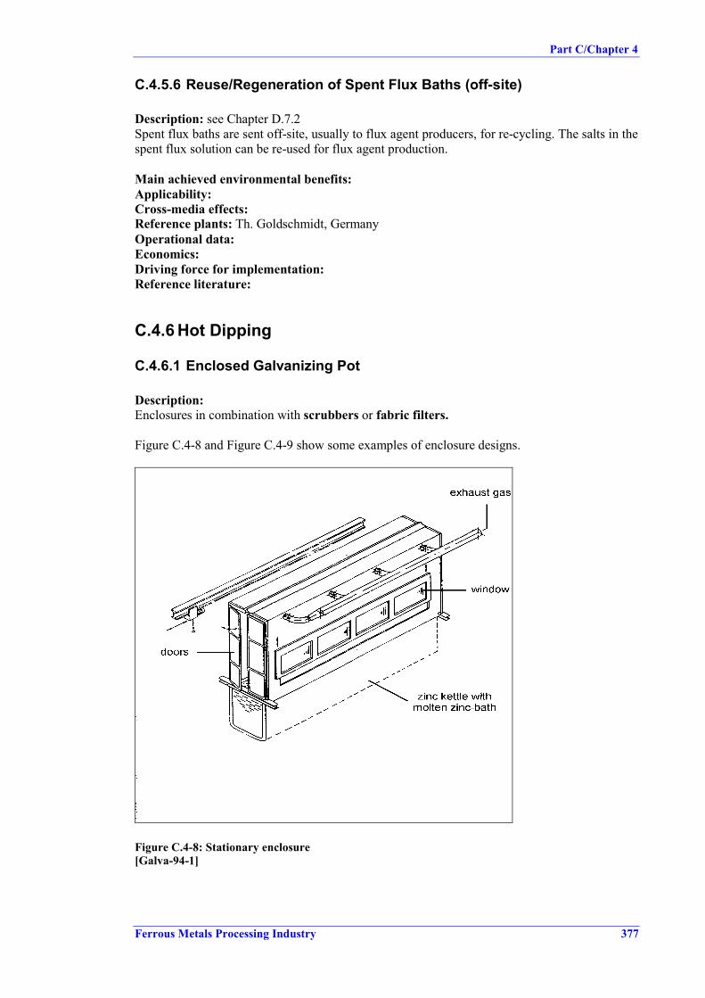
Part C/Chapter 4
Ferrous Metals Processing Industry 377
C.4.5.6 Reuse/Regeneration of Spent Flux Baths (off-site)
Description: see Chapter D.7.2Spent flux baths are sent off-site, usually to flux agent producers, for re-cycling. The salts in thespent flux solution can be re-used for flux agent production.
Main achieved environmental benefits:Applicability:Cross-media effects:Reference plants: Th. Goldschmidt, GermanyOperational data:Economics:Driving force for implementation:Reference literature:
C.4.6 Hot Dipping
C.4.6.1 Enclosed Galvanizing Pot
Description:Enclosures in combination with scrubbers or fabric filters.
Figure C.4-8 and Figure C.4-9 show some examples of enclosure designs.
Figure C.4-8: Stationary enclosure[Galva-94-1]

Part C/Chapter 4
378 Ferrous Metals Processing Industry
Figure C.4-9: Moveable enclosure with vertical moving side walls[Galva-94-1]
Main achieved environmental benefits:• Reduction of fugitive air emissions (reported 95 – 98 % capture of dust and other emissions
[Com2 B]).• Reduction of squirts.• Energy savings due to reduced surface heat loss from the galvanizing bath. [Com2 EGGA].
Applicability:• New and existing plants.• Loading in longitudinal direction of bath.
Cross-media effects:• Energy consumption (electrical energy is used for extraction fans, filter cleaning and
possibly filter heating), but compared to other suction systems weaker suction is required(meaning less energy is needed). [Com2 B].
• Wet scrubbers: generate waste water, requiring treatment, less recycling potential than fordry filter dust.
Reference plants: Verzinkerei Rhein-Main GmbH, Groß-Rohrheim, Germany
Operational data:
Table C.4-3 compares examples of particulates and fume from galvanizing kettles for differentabatement techniques.

Part C/Chapter 4
Ferrous Metals Processing Industry 379
Component Emission [mg/m3]No abatement
Emission [mg/m3]Wet scrubber (1,2)
Emission [mg/m3]Bag filter (3)
Dust 20 < 1.7 4.2 - 4.6Zinc 2.3 0.11 - 0.38 0.49 - 0.52ZnCl n.a. 0.16 - 0.34 n.a.NH4Cl 7.4 0.02 - 0.05 n.a.NH3 2.6 n.a n.a.HCl 23 n.a. n.a.Note: Source of data [Dan-EPA]1 Volume flow = 39500 m3
2 Pb-content: 0.005 - 0.007 mg/m3
Cd-content: < 0.0002 mg/m3
3 Volume flow = 13400 m3
Table C.4-3: Concentrations in emissions from galvanizing kettles
Example Verzinkerei Rhein-Main GmbH
Operational data:
Component Emission1) in mg/m3
Dust < 1Zinc 0.03ZnCl 0.1
NH4Cl 32HCl < 10
Note: Source of data [UBA-Hoesch-87]; volume flow = 23400 m3/h; removal system: fabric filter1) Mean values from 8 individual measurements; average measuring period 32 minutes, calculated as absolute
period of immersion with 5 to 8 dipping operations each
Table C.4-4: Concentrations in emissions from galvanizing kettles
Economics:At Verzinkerei Rhein-Main, investment costs of DM 1634167 and operating costs of DM309000 were incurred in 1985 for enclosure in combination with a fabric filter. The operatingcosts include DM 259000 for service of capital [UBA-Hoesch-87].
Other sources reported dust emissions from hot dipping of 1 – 3 mg/m3 using fabric filters.[Flatt/Knupp]
Economics:Driving force for implementation:Reference literature:
C.4.6.2 Lip-extraction at Galvanizing Pots
Description:Lip-extraction in combination with scrubbers or fabric filters.

Part C/Chapter 4
380 Ferrous Metals Processing Industry
Figure C.4-10: Bilateral peripheral exhaust with auxiliaries[Galva-94-1]
Applicability:• New and existing plants.
Cross-media effects:• Energy consumption (electrical energy is used for extraction fans, filter cleaning, and
possibly filter heating).• Wet scrubbers: generate waste water, requiring treatment, less recycling potential as for dry
filter dust.
Reference plants: Fa. Wilhelm Hähn, Kreuztal-Ferndorf, Germany
Operational data:
Example Wilhelm Hähn, Germany
Table C.4-5 gives some examples of emissions from a galvanizing kettle under differentconditions.
Point ofmeasurement
As3+
[µµµµg/m3]Cd3+
[µµµµg/m3]Pb2+
[µµµµg/m3]Zn2+
[mg/m3]NH4
+
[mg/m3]Cl-
[mg/m3]Dust
[mg/m3]Above zincsurface withoutair extraction
106.9 117.2 125.3 44.5 197.9 14.3 384.6
Above zincsurface with airextraction
1.4 2.9 53.1 0.9 0.2 1.2 0.5
Crude gas 3.6 5.1 49.0 6.2 17.5 7.4 24.1Cleaned gas 0.1 0.1 1.8 0.017 9.0 2.7 0.1Note: Source of data [UBA-Hähn-83]Based on case study: lip extraction, 3380 m3/m2. h = 32958 m3/h, abatement: bag filter
Table C.4-5: Examples for emissions from a galvanizing kettle

Part C/Chapter 4
Ferrous Metals Processing Industry 381
The emissions data are mean values from six individual measurements with an averagemeasuring period of 18 minutes, calculated as absolute immersion period with 2 – 4 dippingoperations each. Repeat measurements conducted in 1996 confirm these data and showed thefollowing results: dust <0.13 mg/m3 and HCl 0.9 mg/m3. These values are mean values from 4individual measurements with an average measuring period of 28 minutes, calculated asabsolute immersion period with 3 - 4 dipping operations each.
Fabric filters show reduction efficiencies of 99.6 %.
Economics:The burden on the product due strictly to pollution abatement measures, such as venting duringdegreasing, hot rinsing, flux bath and zinc bath as well as fabric filter for dust removal,averaged DM 32/t product in 1983. [UBA-Hähn-83]
Driving force for implementation:Reference literature:
C.4.6.3 Smoke-reduced Flux Agent
Description:In smoke-reduced flux agents, ammonia chloride is partly substituted by other alkali chlorides(e.g. potassium chloride).
Main achieved environmental benefits:• Reduced air emissions.• Reduced hard zinc.
Table C.4-6 compares the shares of flux agents emitted, remaining on coated workpieces andcontained in zinc ash for common ammonia chloride flux and potassium chloride flux.
Flux agent Emission Work piece Zinc ashZnCl2: 89 %NH4Cl: 11 %Salt content: 170 g/l
33 % 2 % 65 %
ZnCl2: 32 %KCl: 68 %Salt content: 170 g/l
19 % 1 % 80 %
Note: Source of data [ABAG]
Table C.4-6: Emission comparison of normal and smoke-reduced flux agents
Applicability:• New and existing.
Cross-media effects:• Zinc ash may be increased (reported by some sources).• Smoke reduced fluxes produce less visible fume but fumes of visibility is a function of
particle size there is a potential for smaller size therefore less visible airborne particulatetherefore greater possibility for adverse health effect of respirable dust. [Com2 UK Galv].Results from recent investigations, however state: no health concerns between the differentflux types and no concerns over the size of the airborne particulate. [Piat 19.9]
Part C/Chapter 4
382 Ferrous Metals Processing Industry
Reference plants:
Operational data:Flux agents based on zinc chloride/alkali chloride do not result in an additional pickling effectduring hot dipping and therefore do not dissolve more iron. This reduces the generation of hardzinc on one hand, but also requires optimum pickling in the pre-treatment section to achievehigh quality coatings. [ABAG]
Economics:Driving force for implementation:Reference literature:
C.4.6.4 Reuse of Filter Dust
Description:Precipitated dust from bag filters consist basically of ammonia chloride and zinc chloride (fluxagent). The dust is collected, packed in bags and periodically sent for recycling to flux agentproducers. Recycling might be limited by oil and grease content (less than 3 % is required) orby dioxin content.
Main achieved environmental benefits:• Reduction of waste.
Applicability:• New and existing plants with fabric filters.
Cross-media effects:Reference plants:Operational data:Economics:Driving force for implementation:Reference literature:
C.4.6.5 Reducing the Generation of Hard Zinc
Description:The following measures reduce the generation of hard zinc:- Sufficient rinsing following pickling.- Continuous regeneration of the flux bath.- Use of fluxing agents low in ammonium chloride which have a low pickling effect (removal
of iron).- Avoiding local overheating in the externally heated galvanizing kettles (reaction with the
boiler walls) [Com D], [Com2 EGGA].
Main achieved environmental benefits:- Less waste, more efficient use of raw material (no need to recycle hard zinc).
Applicability:- New and existing plants.
Cross-media effects:Reference plants:Operational data:Economics:

Part C/Chapter 4
Ferrous Metals Processing Industry 383
Driving force for implementation:Reference literature:
C.4.6.6 Reducing the Generation of Splashes
Description:The following measures reduce the generation of splashes:- Sufficient drying after the flux bath.- Areas surrounding the galvanizing kettles must be kept clean to obtain recoverable zinc
containing a minimum of impurities. [Com D].
Main achieved environmental benefits:- Less waste, more efficient use of raw material (no need to recycle splashes for zinc
recovery).
Applicability:- New and existing plants.
Cross-media effects:Reference plants:Operational data:Economics:Driving force for implementation:Reference literature:
C.4.6.7 Reuse of Zinc Ash
Description:Zinc grains can be melted from the zinc ash and recycled back to the galvanizing pot. Thereduction grade is 60 – 70 %. The remaining zinc oxide ash is refined further in specialisedindustry. [Com FIN]- Special melting pots are used to collect the zinc ash.- Melting pot is put to the Zinkof-furnace, in which zinc ash is melted at temperature of about
520 0C with a rotating movement. The molten zinc (60 - 65 wt-%) is returned to the moltenzinc kettle. The remaining oxide zinc ash is ground and sold to the secondary zinc industry.
Main achieved environmental benefits:- Reduced waste.
Applicability:- New and existing plants.
Cross-media effects:Reference plants: four galvanizing plants in Finland, for example KS-Sinkki Oy, Lievestuore,Finland [Com2 FIN]
Operational data:With described technique recycled zinc amount is 11.5 kg/t of galvanized steel. Price of theequipment is about 200 000 FIM. In addition to that, grinding equipment for grinding zinc ashalso has to be provided and it costs about 60 000 FIM. Net profit, when all the costs, exceptinvestment costs, are included, is about 2.20 – 2.80 FIM/kg recycled Zn depending upon themarket price of zinc.

Part C/Chapter 4
384 Ferrous Metals Processing Industry
Economics:Driving force for implementation:Reference literature:
C.4.6.8 Heat Recovery from Galvanising Kettle Heating
Description:Galvanizing kettles may be fired either by gaseous or liquid fuels. The method most commonlyused for heat recovery from combustion gas is transfer to air or water. Heat exchangers typicallyfabricated from banks of stainless steel tubes are used to recover heat from flue gas to air. Theflue products are normally on the tube side. Flue products may be introduced at 500 to 700o Cwhen the furnace is operating at full production rate. The heat exchanger may be placed directlyin the furnace flue duct but, in the absence of forced extraction of flue gases, only a small fluegas pressure drop can be tolerated. This limits the rate of heat transfer.
Shell and tube heat exchangers can be used to transfer heat from flue products to water orsteam, with flue gas on the shell side. Another common type of exchanger is a bank of finnedtubes placed in the flue duct. In this case water is on the tube side.
Gases may be drawn through the heat exchanger using a fan downstream of the exchanger inorder to increase the overall coefficient. This is a common arrangement for gas-to-water heatexchange. Both heat exchanger and fan are located in a branch parallel to the main flue duct,thus avoiding any back-pressure effect on the furnace. The fan consumes a small amount ofpower.
In a few cases flue gases are contacted directly with the outer surface of a pre-treatment tank,transferring heat by radiation and convection.
Heat exchangers for oil fuels and for surface heated baths require special design due to thepresence of SO2 and ash in the flue gases. [Com2 EGGA]
Main achieved environmental benefits:• Reduced fuel consumption.
Application:• New and existing plants• In principle, can be applied to any installation subject to economic analysis, which depends
on fuel price, thermal rating of furnace and demand for waste heat.• not normally interesting on two burner systems (small kettles) because there is not
enough heat available to be useful. Heat recovery systems are very frequentlyinstalled on four and six burner systems.
Cross media effects:.Reference plants:Operational data:
Economics: Energy reductions in the range 15 – 45 kWh/t black steel.
Driving force for implementation: Fuel costs.
Reference literature: Trade literature.

Part C/Chapter 4
Ferrous Metals Processing Industry 385
C.4.6.9 Efficiency of Furnace Heating/Control
Description:Furnace heating efficiency should be considered in two parts. They are firstly the efficiencywith which heat is transferred from the prime heat source to the galvanizing bath and, secondly,the efficiency with which the transferred heat is employed in maintaining the zinc temperature.
The efficiency of heat transfer to the kettle is governed by basic principles of heat transfer andcombustion engineering. Combustion of gases and oils results in a flow of flue gas productswhich carries away sensible and latent heat. This amounts typically to 45 – 55 % of the grosscalorific input of the fuel at maximum input. A small amount of electrical energy is used todrive the combustion air fan, and the pump or compressor used in oil heating. Use of electricityfor heating involves energy loss owing to reactance effects and often also to cooling oftemperature-sensitive parts of the heating system. Losses may be around 15 % of the meteredpower. For all energy sources, there is additional heat loss from the furnace case, although for awell-insulated furnace this is small, typically 2 % of the energy input. All losses in this categoryincrease as the heat input increases.
Losses from the system are also due to radiation and convection from the molten metal surfaceand from exposed parts of the top of the bath, such as the top flange on a steel kettle. The extentof these losses depends on the surface areas, conditions and temperatures, but is typically 15 to25 % of the heat originally transferred to the bath.
Flue gas heat losses may be reduced by optimizing the combustion process, by optimizingexcess air for combustion and by reducing air ingress to the furnace casing. The lowtemperature operation of the galvanizing process implies that there are limited opportunities forenergy saving by reduction of losses. The burner system must be capable of accommodating aturn down ratio of approximately 15:1.
Surface losses may be reduced during working (subject to adequate ventilation) by use of anenclosure over the bath, or limiting the open part of the surface to that required for the type ofgalvanizing in progress. When the kettle is on hot standby, reductions in heat loss can beobtained by the use of insulated covers which extend over the furnace top. Reducing the bathtemperature during hot standby periods rarely saves significant amounts of energy and, withsteel kettles, cycling of the bath temperature adversely affects the protective zinc-iron alloy,thus reducing the kettle’s working life.
Furnace efficiency is also affected by the control system. Higher efficiencies are obtained withcontrol systems which most closely match the heat input to the heat demand. Determination ofheat input is based on the molten zinc temperature, measured by thermocouples either immersedin the zinc or – for steel kettles – possibly by contact with the external kettle wall. Dependingon the flexibility of the heating system the controller often uses PID (Proportional, Integral,Derivative) or other control logic to keep the zinc temperature as constant as possible.
Combustion systems include High/Low (either maximum or minimum heat is delivered for aperiod), Modulating (the heat input varies constantly over a range between maximum andminimum), or Pulsing (a continual succession of maximum and minimum heat inputs isdelivered equating to a net intermediate heat input).
Main achieved environmental benefits:Applicability:Cross-media effects:Reference plants:Operational data:Economics:

Part C/Chapter 4
386 Ferrous Metals Processing Industry
Driving force for implementation:Reference literature:
C.4.6.10 Capture/Treatment of Emissions from Tube FinishingOperations
� No information submitted.

Part C/Chapter 5
Ferrous Metals Processing Industry 387
C.5. BEST AVAILABLE TECHNIQUES FOR BATCHGALVANIZING
In understanding this chapter and its contents, the attention of the reader is drawn back to thepreface of this document and in particular the fifth section of the preface: “How to understandand use this document”. The techniques and associated emission and/or consumption levels, orranges of levels, presented in this chapter have been assessed through an iterative processinvolving the following steps:
• Identification of the key environmental issues of batch galvanising. Among the importantissues are: emissions to air (HCl from pickling and dust and gaseous compounds from thekettle); spent process solutions (degreasing solutions, pickling baths and flux baths); oilywastes (e.g. from cleaning of degreasing baths) and zinc-containing residues (filter dust,zinc ash, hard zinc).
• Examination of the techniques most relevant to address those key issues.• Identification of the best environmental performance levels, on the basis of the available
data in the European Union and world-wide.• Examination of the conditions under which these performance levels were achieved; such as
costs, cross-media effects, main driving forces involved in implementation of thistechniques.
• Selection of the best available techniques (BAT) and the associated emission and/orconsumption levels for this sector in a general sense all according to Article 2(11) andAnnex IV of the Directive.
Expert judgement by the European IPPC Bureau and the relevant Technical Working Group(TWG) has played a key role in each of these steps and in the way in which the information ispresented here.
On the basis of this assessment, techniques, and as far as possible emission and consumptionlevels associated with the use of BAT, are presented in this chapter that are considered to beappropriate to the sector as a whole and in many cases reflect current performance of someinstallations within the sector. Where emission or consumption levels “associated with bestavailable techniques” are presented, this is to be understood as meaning that those levelsrepresent the environmental performance that could be anticipated as a result of the application,in this sector, of the techniques described, bearing in mind the balance of costs and advantagesinherent within the definition of BAT. However, they are neither emission nor consumptionlimit values and should not be understood as such. In some cases it may be technically possibleto achieve better emission or consumption levels but due to the costs involved or cross mediaconsiderations, they are not considered to be appropriate as BAT for the sector as a whole.However, such levels may be considered to be justified in more specific cases where there arespecial driving forces.
The emission and consumption levels associated with the use of BAT have to be seen togetherwith any specified reference conditions (e.g. averaging periods).
The concept of “levels associated with BAT” described above is to be distinguished from theterm “achievable level” used elsewhere in this document. Where a level is described as“achievable” using a particular technique or combination of techniques, this should beunderstood to mean that the level may be expected to be achieved over a substantial period oftime in a well maintained and operated installation or process using those techniques.

Part C/Chapter 5
388 Ferrous Metals Processing Industry
Where available, data concerning costs have been given together with the description of thetechniques presented in the previous chapter. These give a rough indication about themagnitude of costs involved. However, the actual cost of applying a technique will dependstrongly on the specific situation regarding, for example, taxes, fees, and the technicalcharacteristics of the installation concerned. It is not possible to evaluate such site-specificfactors fully in this document. In the absence of data concerning costs, conclusions oneconomic viability of techniques are drawn from observations on existing installations.
It is intended that the general BAT in this chapter are a reference point against which to judgethe current performance of an existing installation or to judge a proposal for a new installation.In this way they will assist in the determination of appropriate "BAT-based" conditions for theinstallation or in the establishment of general binding rules under Article 9(8). It is foreseenthat new installations can be designed to perform at or even better than the general BAT levelspresented here. It is also considered that existing installations could move towards the generalBAT levels or do better, subject to the technical and economic applicability of the techniques ineach case.
While the BREFs do not set legally binding standards, they are meant to give information forthe guidance of industry, Member States and the public on achievable emission andconsumption levels when using specified techniques. The appropriate limit values for anyspecific case will need to be determined taking into account the objectives of the IPPC Directiveand the local considerations.
This chapter discusses the best available techniques for reducing the environmental impactsfrom batch galvanising. Where possible, the structure follows the logic of the production lineand identifies BAT for individual processing stages. However, some measures, especiallyprimary or preventive measures, cannot be assigned to one single process step and have to beallocated to the plant as a whole. As far as possible and wherever the data available allowed,emission levels, efficiencies or recirculation rates are given an indication of the improvementthat can be expected by implementation of the techniques. For a number of techniques, theobvious positive effect cannot be described by an exact number, but some of these techniquesare nevertheless considered as BAT.
Unless stated otherwise the emission figures presented in the following BAT chapters are dailymean values. For emissions to air they are based on standard conditions of 273 K, 101.3 kPaand dry gas.
Discharges to water are indicated as daily mean value of a flow-rate-related 24-hour compositesample or a flow-rate-related composite sample over the actual operating time (for plants notoperated in three shifts).
For degreasing operations in batch galvanising plants, the following techniques are consideredBAT:• Installation of a degreasing step, unless items are totally grease-free which is rarely the case
in job galvanizing.• Optimum bath operation to enhance efficiency, e.g. by agitation.• Cleaning of degreasing solutions to extend lifetime (by skimming, centrifuge, etc.) and
recirculation; reuse of oily sludge, e.g. thermally.or• 'Biological degreasing' with in situ cleaning (grease and oil removal from degreaser
solution) by bacteria.
A primary measure to minimize environmental impact from pickling and stripping is tooperate both in separate treatment vessels, since ‘mixed acids’ (with both high iron and zinc

Part C/Chapter 5
Ferrous Metals Processing Industry 389
contents) cause problems in regeneration or reuse. As long as there are no suitable treatmentoptions for mixed acid, separate pickling and stripping and reuse of spent stripping liquor(external or internal e.g. to recover fluxing agent) are considered to be BAT for new andexisting plants.
If separation of pickling and stripping is not possible, e.g. when there is insufficient space toinstall additional pickling/stripping tanks, external reuse of the mixed acids for flux productionis considered BAT.
One central treatment plant for spent mixed pickle liquors using solvent-extraction and onegalvanizing plant operating this process have been reported (see Chapter C.4.3.8). Where such(external) treatment plants are available, recovery of HCl from spent mixed pickle liquors usingsolvent-extraction may be considered a viable alternative to fluxing agent recovery (see above).
For HCl pickling the following techniques are considered to be BAT to reduce environmentalimpacts:
• Close monitoring of bath temperature and concentration parameters: and operating withinthe limits given in Part D/Chapter D.6.1 ‘Open Pickling Bath Operation’.
• If operation outside the operational range given in D.6.1 is desired, e.g. if heated or higherconcentrated HCl-baths are used, installation of an extraction unit and treatment of theextraction air (e.g. by scrubbing) are considered BAT. The associated HCl emission level is2 – 30 mg/Nm³.
• Special attention to the actual pickling effect of the bath and use of pickling inhibitors toavoid over-pickling.
• Recovery of free-acid fraction from spent pickle liquor.or• External regeneration of pickling liquor.
• Zn removal from acid.• Use of spent pickle liquor for flux production.
Neutralisation of spent pickle liquor and the use of spent pickling liquor for emulsion splittingare not considered BAT.
Generally, good drainage between pre-treatment tanks is advocated. Furthermore, rinsing afterdegreasing and after pickling to avoid carry-over into subsequent process baths and thus toprolong the lifetime of these baths is essential. BAT is:• Static rinsing or rinsing cascades.• Reuse of rinse water to replenish preceding process baths.• Waste water-free-operation (waste water may be generated in exceptional cases, in which
waste water treatment is then required).
For fluxing, control of bath parameters and the optimized amount of flux used are important toreduce emission further down the process line as well. For the flux bath itself, side-streamregeneration of the solution (using e.g. H2O2, electrolytic oxidation or ion exchange) or, ifinstallation of a regeneration unit is not possible, regeneration by externals is possible. Bothinternal and external flux bath regeneration are considered BAT.
The main problem arising from hot dipping is air emissions resulting from reaction of the fluxagent during dipping. The following techniques are considered to be BAT:

Part C/Chapter 5
390 Ferrous Metals Processing Industry
• Capture of emissions from hot dipping by enclosure of the pot or by lip extraction followedby dust abatement (e.g by fabric filters or wet scrubbers). The dust level associated withthese techniques is < 5 mg/Nm³.
• Internal or external reuse of collected dust for flux production. As this dust mayoccasionally contain dioxins at low concentration due to upset conditions in the plant (badlydegreased items being galvanised), only recovery processes yielding fluxing agents free ofdioxins are BAT.
Although the opportunities for energy saving by heat transfer from flue gases from thegalvanizing kettles are limited due to low volumes and relatively low temperatures (450oC), it isgood practice to recover heat from this source either to hot water used elsewhere in the plant orto air for drying.
For all Zn-containing wastes (dross, hard zinc, and splashes/squirts), separate storage andprotection from rain and wind, and reuse in the non-ferrous metals industry or other sectors torecover the valuable substances they contain are considered to be BAT.

Part C/Chapter 6
Ferrous Metals Processing Industry 391
C.6. EMERGING TECHNIQUES FOR BATCH GALVANIZING
The process of galvanizing requires steel articles to be exposed to liquid zinc for sufficient timefor the zinc and steel to react to form the galvanized coating. The thickness and nature of thecoating are controlled by European standard. In recent years the quality of assets in the industryhas improved markedly, but the fundamental nature of the process has not changed due to thelimitations imposed by the need to expose heavy steel items to liquid zinc. There is, therefore,no emerging technique which is based on fundamentally different principles.
However, substantial efforts have been made, and continue to be made, to improve performancein the control of emissions to water and air.
The separation of Zn and Fe from mixed content pickle liquors has been a subject of interest forsome time. Several processes have been developed and reported in the open literature. Thesetechniques meet the requirements of BAT insofar as they maximise the recovery and recyclingof contained values while continuing to limit emissions. Overall, the water balance of thegalvanizing process is such that substantial make-up is required. In all cases reviewed byEGGA aqueous blow-down is recycled internally as part of make-up water. Build-up ofunwanted constituents does not appear to be a difficulty. A variety of BAT-compliant processesis likely to emerge in the near to medium term future.
Similarly, investigations into the reduction of fume emissions at source, either by the use of lowfume fluxes based on current fluxes or by the use of novel fluxing systems, are under way. Thepromised benefit of fume reduction at source is the possible substitution of the fabric filter by asimpler device such as a drop-out box with significant reduction in pressure drop and thuspower requirement. These investigations are recent and reported in the open literature only to alimited extent. Early indications are that the technique produces a low but, nevertheless, slightlyhigher particulate emission than the standard flux / fabric filter system, but requiressignificantly less power. It is possible that judgement about the balance of on-site particulateemissions and power plant greenhouse gas emissions will be such that the technique could beregarded as BAT compliant. [EGGA 7/00]
Developments on a novel flux formulation (thermaflux, US patent) which calim a reduction oflead content in the galvanizing bath and reduction of metal spatting during dipping, werereported. Technical feasibility has still to be proofed; no application of this technique in batchgalvanizing is known.

Part C/Chapter 7
Ferrous Metals Processing Industry 393
C.7. CONCLUDING REMARKS
The following conclusions and recommendations concern timing of the work, sources ofinformation, availability and quality of data, consensus amongst experts of the TWG andrecommendations for future work.
Timing of workThe drawing up of this BREF took about 2 ½ years. The major steps have been:
• First TWG meeting (kick-off meeting) 11 – 12.12.97• Submission of relevant information and data by TWG:
for Chapters 2 February – October ’98for Chapters 3 April – October ’98for Chapters 4 July – October ’98
• First draft December 1998• First consultation round 16.12.98 – 12.2.99• Evaluation of comments and redrafting: May – July ‘99
(response to comments, clarification andrequest for additional information)
• Submission of missing information/data: September – November ’99• Second draft December 1999• Second consultation 17.12.99 - 17.02.00• Second TWG meeting 22 – 24.03.00• Submissions on controversial issues that came up
during the 2nd TWG meeting: 28.03.00 – 19.07.00• Consultation on ‘new’ chapters (revised Chapters 5, 21.07.00 – 18.08.00
Chapter 7 Conclusions & Recommendations,Executive Summary, Chapter 4: SCR and SNCR)
• Final draft
Sources of information65 reports dealing with the various aspects of the ferrous metals processing sector weresubmitted. These reports contain very different kinds of information (statistical data, descriptionof production technologies, information on certain environmental measures including casestudies and emission/consumption data). They have been prepared from different points ofview; most of them only focusing on single aspects or media, only very few covering allenvironmental aspects.
During the period of work on the Ferrous Metals Processing BREF, industry shadow groups onhot rolling, cold rolling and continuous coating and the European General GalvanizersAssociation (EGGA) provided reports and papers on their sectors regarding the appliedproduction techniques and some environmental measures. Germany submitted a report on ‘BATin the German Ferrous Metals Processing Industry’.
The availability of such documents is essential for the quality of the document, but theirusefulness is potentially compromised if they are not sent in early in the process. Delays insubmitting crucial information, especially on the techniques to be considered in thedetermination of BAT, have led to delays in issuing drafts of this BREF.
Best available techniquesBAT have been identified for all three sub-sectors of ferrous metals processing and for theindividual production steps. They are described in detail in the three Chapters 5 providing

Part C/Chapter 7
394 Ferrous Metals Processing Industry
background and, where necessary, justification for selection as BAT and for the reported BAT-associated emission levels. The executive summary includes all these BAT conclusions.
Level of consensusPart A of this BREF contains several split views. There were three areas in which the TWG
could not reach an agreement:• BAT-associated dust levels for application of fabric filters/electrostatic precipitators• SCR and SNCR NOx reduction measures for reheating furnaces• S-content in fuel oil
On dust emissions, the TWG agreed that capturing and fabric filters are BAT, but there weretwo general points of view on what is achievable with fabric filters. Industry proposed, based ontheir experience and knowledge of achieved dust levels, the higher level of 20 mg/Nm³. SomeMember States and environmental NGOs considered below 5 mg/Nm³ to be the appropriateassociated level for fabric filters, but there were only very few figures and for most applicationsno data presented to support this view (see also recommendations for future work).
Information and data on SCR and SNCR in reheating furnaces was received at a very late stageof the work; during and after the second TWG meeting. Some TWG members considered thesetechniques to be BAT, while others thought the available information on technical details andon economics was not sufficient to allow a final decision to be made on whether or not SCR andSNCR are BAT. As this controversy was raised almost at the end of this exercise, there was notime to resolve the outstanding issues (see also recommendations for future work).
Another point of dissent was the issue of limiting S-content in fuel oil. Although a level ofS < 1% can lead to emissions as high as 1700 mg SO2 /Nm3, some TWG members thought thatthis should be BAT. Others regarded a lower S-limit in the fuel oil or additional SO2 reductionmeasures as BAT.
Parts B and C of this BREF enjoy a high level of consensus. No split views had to be noted. Allparties in the information exchange process consider them an acceptable result.
Recommendations for future workA lack of data and information on the performance of techniques to be considered in thedetermination of BAT, especially on achieved emission and consumption levels and oneconomics, was noted as a flaw of this BREF document. For future BREF reviews, all TWGmembers and interested parties should continue to collect these data and information and shouldmake them available earlier rather than later in the process.
For quite a number of the techniques to be considered in the determination of BAT, noinformation or only a technical description is available. Information on reference plants andactual performance data are scarce. For the revision of this document the missing informationshould be provided . Some of the techniques concerned are the following:Part A:− Optimized water pumps for laminar flows− Implementation of degreasing bath cascades− Hot water pre-degreasing− Heat utilisation for heating degreasing bath− Electrostatic oiling− Optimization of oil spray− Optimized finishing operation− Cleaning and reuse of grinding emulsion− Exhaust system (PRETEX/SBT)− External use of spent acid pickle liquor

Part C/Chapter 7
Ferrous Metals Processing Industry 395
Part C:− Storage and handling of raw materials and auxiliaries− Capture/treatment of emissions from tube finishing operations
Part D:− Implementation of degreasing bath cascades− Hot water pre-degreasing− Adsorption of surfactants and oil (precipitation followed by filtration)− Electrolytic pickling− Treatment of rinsing water using ion exchange, electrolytic iron removal, reverse osmosis,
oxidizing iron removal
Several techniques are presented in the Chapters 6 ‘Emerging Techniques’. The progress indevelopment and the suitability for application in the FMP sector should be checked for apotential move of these techniques to Chapter 4 ‘Techniques to be considered in thedetermination of BAT’ and/or to Chapter 5 ‘Best Available Techniques’.
The criticism was made that the presentation of some techniques was too positive, having beenderived mainly from suppliers’ information, and that only the advantages were presented. Thismainly concerns reclamation and regeneration processes for spent treatment baths, e.g. for spentpickling liquors or spent degreasing or flux baths. Here industry is requested to provide theinformation and results they have achieved with certain techniques, together with descriptionsof any problems they have experienced.
There is a need for more emission and consumption data generally, but of particular interest arefigures on NOx emissions (concentrations and specific emissions) both for furnaces that use airpreheating and those that do not. Such data would make possible both a more thoroughevaluation of the efficiency of reduction measures and a comparison of the advantages anddisadvantages of energy savings vs. NOx emissions.
More data are required on achieved dust emission levels for the various production steps of hotand cold rolling (Part A), where a split view on the BAT-associated dust level had to be statedin the BREF. Especially, those parties advocatingthe lower level of 5 mg/Nm³ should seek toprovide data to substantiate their view.
It was reported that the number of installations applying SCR (pusher type furnaces) is likely toincrease. When this BREF is reviewed, there should be more information available on theperformance and applicability of SCR and SNCR for reheating furnaces. Existing SCR andSNCR installations will have a longer operating history to draw on, which should help toanswer the criticism that the information available was based on too short an operating period.Possibly the disagreement on whether these techniques constitute BAT can be resolved then.
During the 2nd TWG meeting the point was raised that inductive heating was BAT for severalapplications in furnaces. In this BREF, inductive heating is included as a technique to beconsidered, but it was stated that the information available was not sufficient to decide whetherthe technique is BAT. More information and data should be collected to enable this decision tobe made.
Another issue raised was the dioxin content of dust from batch galvanizing and potential risksof dioxin build-up when these dusts are recycled. Efforts should continue to compileinformation and data of actual dioxin contents in dusts for normal plant operation. Availabledata should be provided to the IPPCB and the TWG to allow a judgement on this problem andenable an evaluation of the potential risk.
A revision of this BREF document is recommended for the year 2005.


PART DTechniques Common to several
Sub-sectors
Techniques to be considered in more than one sub-sector in thedetermination of BAT
In order to avoid repetition in describing certain techniques to be considered in thedetermination of BAT, Part D contains detailed technical descriptions and information ontechniques which might be applied to several sub sectors. Sector-specific aspects of thetechniques (main achieved environmental benefits, applicability, cross-media effects, referenceplants, operational data, economics, driving force for implementation and reference literature)are covered in the relevant part of this document (A, B or C), in which cross-references to PartD are included where relevant.


Part D/ Techniques Common to several Subsectors
Ferrous Metals Processing Industry 399
Best Available Technique Reference Document onFerrous Metals Processing
D.1 Furnaces: Thermal efficiency ..................................................................................................403D.1.1 Regenerative Burners.........................................................................................................403D.1.2 Recuperators and Recuperative Burners ............................................................................404
D.2 Furnaces: NOx reduction Measures .........................................................................................406D.2.1 Low-NOx Burner................................................................................................................406D.2.2 Limiting Air Preheating Temperatures ..............................................................................408D.2.3 External Flue Gas Recirculation (FGR) .............................................................................410D.2.4 Selective Catalytic Reduction (SCR) .................................................................................411D.2.5 Selective Non-Catalytic Reduction (SNCR) ......................................................................412D.2.6 Comparison of NOx Reduction Methods for Furnaces......................................................413
D.3 Oil Emulsions ..........................................................................................................................415D.3.1 Cleaning and Reuse of Emulsion .......................................................................................415D.3.2 Treatment of Spent Emulsion / Emulsion Splitting............................................................415D.3.3 Extraction of Oil Mist /Emulsion Fumes and Oil Abatement ............................................418
D.4 Alkaline Degreasing ................................................................................................................418D.4.1 Implementation of Degreasing Bath Cascades...................................................................418D.4.2 Hot water pre-degreasing ...................................................................................................418D.4.3 Maintenance and Cleaning of Degreasing Baths ...............................................................418D.4.4 Treatment of Spent Degreasing Bath .................................................................................420D.4.5 Treatment of Alkaline Waste Water ..................................................................................420D.4.6 Degreasing Fume Collection and Treatment......................................................................420
D.5 Pickling....................................................................................................................................421D.5.1 Open Pickling Bath Operation ...........................................................................................421D.5.2 Emission Control/Collection from Pickling.......................................................................422D.5.3 Abatement Techniques for Acid Gases, Vapour and Aerosols from Pickling (and Acid
Regeneration).....................................................................................................................424D.5.4 Hydrochloric Acid Pickling ...............................................................................................428D.5.5 Sulphuric Acid Pickling .....................................................................................................428D.5.6 Electrolytic Pickling...........................................................................................................429D.5.7 Mixed Acid Pickling ..........................................................................................................429D.5.8 NOx Reduction Measures for Mixed Acid Pickling...........................................................429D.5.9 Free Acid Reclamation.......................................................................................................437D.5.10 Acid Regeneration..............................................................................................................441D.5.11 Treatment of Acidic Waste / Waste Water.........................................................................451
D.6 Heating of Process Liquors (acid, emulsions…) .....................................................................452D.7 Fluxing.....................................................................................................................................454
D.7.1 On-site Regeneration of Flux Baths (Iron Removal) .........................................................454D.7.2 External Reutilization of Spent Flux Baths........................................................................456
D.8 Rinsing.....................................................................................................................................457D.8.1 Efficient (multiple) Use of Rinsing Water .........................................................................457D.8.2 Treatment of Rinsing Water...............................................................................................459
D.9 Process Water and Waste Water Treatment.............................................................................459D.9.1 Treatment of Oil- and Scale-bearing Process Water ..........................................................459D.9.2 Cooling Systems and Cooling Water Treatment................................................................464
Part D/ Techniques Common to several Subsectors
400 Ferrous Metals Processing Industry
List of figures
Figure D.1-1: Potential fuel savings with preheated combustion air ....................................................... 403Figure D.1-2: Schematic of a regenerative burner system ....................................................................... 404Figure D.1-3: Schematic of a self-recuperative burner ............................................................................ 405Figure D.1-4: Typical exhaust gas recuperators....................................................................................... 405Figure D.2-1: Schematic of a Low-NOx Burner with internal Flue Gas Recirculation ........................... 407Figure D.2-2: Schematic example of an air staged low-NOx Burner ...................................................... 407Figure D.2-3: Influence of air preheating temperatures (low range) on NOx emissions ........................ 409Figure D.2-4: Influence of air preheating temperatures (high range) on NOx emissions 1 ...................... 409Figure D.2-5: Effect of flue gas recirculation on NOx emission ............................................................. 410Figure D.3-1: Principle of ultrafiltration.................................................................................................. 418Figure D.4-1: Example flowsheet for ceramic filtration of degreasing solution...................................... 419Figure D.5-1: Limiting curve for the operation of open HCl pickling baths............................................ 421Figure D.5-2: Different extraction systems.............................................................................................. 423Figure D.5-3: Design principles for closed pickling tanks....................................................................... 423Figure D.5-4: Principle of packed scrubbers............................................................................................ 424Figure D.5-5: Principle of a cross-flow scrubber ..................................................................................... 426Figure D.5-6: Principle of plate scrubbers ............................................................................................... 426Figure D.5-7: Principle of fume filter ...................................................................................................... 428Figure D.5-8: Schematic for injecting H2O2 into pickling acid recirculation loop .................................. 431Figure D.5-9: Schematic for injecting H2O2 into pickling baths via a sparge pipe .................................. 431Figure D.5-10: Vacuum cooling crystallization process for H2SO4......................................................... 437Figure D.5-11: Evaporative acid recovery ............................................................................................... 438Figure D.5-12: Principle of Diffusiondialysis.......................................................................................... 440Figure D.5-13: Fluidised bed HCl acid regeneration process .................................................................. 441Figure D.5-14: Spray roasting HCl acid regeneration process................................................................. 443Figure D.5-15: Process flowsheet for the production of high purity oxides ............................................ 444Figure D.5-16: Spray roasting mixed acid regeneration process ............................................................. 445Figure D.5-17: Principle of Salt Splitting by Bipolar Membranes........................................................... 446Figure D.5-18: Evaporation Process for Mixed acid Regeneration [Com2 Fin]...................................... 448Figure D.6-1: Principle of heat exchangers.............................................................................................. 452Figure D.6-2: Principle of submerged combustion .................................................................................. 453Figure D.7-1: Flow sheet for flux regeneration........................................................................................ 454Figure D.7-2: Schematic of the electrolytic oxidation process ................................................................ 455Figure D.8-1: Rinsing systems................................................................................................................. 457Figure D.9-1: Circular Settling Tank (vertical)........................................................................................ 459Figure D.9-2: Horizontal Flow Settling Tank .......................................................................................... 460Figure D.9-3: Schematic of a lamella separator ....................................................................................... 460Figure D.9-4: Screw-type clarifier ........................................................................................................... 461Figure D.9-5: Example of a gravel filter with indication of backwash operation .................................... 462Figure D.9-6: Example of wire-netting filters with indication of backwash operation............................ 462Figure D.9-7: Aerated fine scale-trap....................................................................................................... 463Figure D.9-8: Magnetic filtration (example high gradient MF) ............................................................... 464

Part D/ Techniques Common to several Subsectors
Ferrous Metals Processing Industry 401
List of tables
Table D.2-1: Calculated percentage increase in fuel consumption from reduced air preheat...................410Table D.2-2: Comparison of NOx reduction methods..............................................................................413Table D.2-3: Estimated costs of NOx reduction techniques for a 50 MW furnace ..................................414Table D.5-1: Comparison of different NOx reduction measures for mixed acid pickling........................435Table D.5-2: Overview of regeneration and reclamation processes .........................................................449Table D.8-1: Comparison of water consumption for different rinsing systems........................................458Table D.9-1: Example of achieved emission levels for aerated fine scale-traps.......................................463


Part D/ Techniques Common to several Subsectors
Ferrous Metals Processing Industry 403
D.1 FURNACES: THERMAL EFFICIENCY
To improve thermal efficiency of furnaces, the exhaust gases from the furnace may be used topreheat the combustion air. Thermal efficiency increases with increasing preheated airtemperature and decreasing waste gas temperature. The diagram in Figure D.1-1 showspotential fuel savings achieved by combustion air preheating. Actual values might differ fromthese theoretical figures as they are subject to a number of other influences.
Figure D.1-1: Potential fuel savings with preheated combustion air[ETSU-G76] In general, two systems exist: the regenerative and the recuperative system/burner.
D.1.1 Regenerative Burners
Regenerative systems use two sets of heat exchangers, containing for example brick chequermaterial or ceramic balls. Figure D.1-2 shows an example for such a regenerative burnersystem. While one burner is in firing mode, the regenerator of the other burner is heated bydirect contact with the exhaust gas., the other heats the incoming combustion air. After a periodof time the flows are switched to reverse the process. Such systems can achieve air preheatingtemperatures of up to 1100 °C (and 1300 °C), but actual temperatures are dependent on thewaste gas inlet temperature. Based on the air preheat temperatures NOx emissions can be ashigh as 3000 mg/m3. [CITEPA]
A special type of regenerative burner is the integral bed burner which has a more compactdesign as the regenerative bed is incorporated in the body of the burner. These kind of burners

Part D/ Techniques Common to several Subsectors
404 Ferrous Metals Processing Industry
are especially suitable for retrofitting furnaces where space constraints may be a problem andfor small furnaces.
Regenerative systems are preferred for high waste gas temperatures to achieve air preheattemperatures above 600 °C. The air preheat temperature is limited by the process temperatureand is generally 150 to 200 °C below the process temperature. Thermal efficiency of the furnaceof 80 % and fuel savings of up to 60 % can be achieved. [EUROFER HR], [EUROFER CR]
Figure D.1-2: Schematic of a regenerative burner system[ETSU-G76]
A regenerative system is particularly attractive for batch processes because batch processesgenerally do not contain a preheat zone. In continuous furnaces equipped with a centralrecuperator system, a similar thermal efficiency is reached by means of a long unheated(preheat) zone, where the heat of the flue gases is transmitted by convection to the cold stock.[EUROFER HR]
D.1.2 Recuperators and Recuperative Burners
A recuperator is a heat exchanger fitted in the exhaust gas outlet, which allows heat to betransferred continuously through the heating surfaces to the incoming combustion air. Variousequipment designs are available. (Self-) recuperative burners have integral heat exchangers forpreheating combustion air.

Part D/ Techniques Common to several Subsectors
Ferrous Metals Processing Industry 405
Figure D.1-3: Schematic of a self-recuperative burner[ETSU-G76]
Figure D.1-4: Typical exhaust gas recuperators[ETSU-G76]
Recuperating the heat of flue gases allows air preheat temperature up to 550 or 620 °Cdepending on the process temperature. Higher air preheat temperatures are technically possible,but entail excessive cost due to the heat resistant construction-materials that would be required.A thermal efficiency of approximately 65 % can be reached. [EUROFER HR]

Part D/ Techniques Common to several Subsectors
406 Ferrous Metals Processing Industry
D.2 FURNACES: NOX REDUCTION MEASURES
The simplest method of reducing NOx emissions is to switch from a 'dirty' fuel to a 'clean' one,which in fact means switching to gas. This may not however be feasible for existing plants and,in practice, available plant gases determine the type of fuel used in furnaces. Also, for liquidand solid fuels the sulphur content is usually of more concern than the nitrogen. [HMIP-95-003]
Another simple method is to limit the preheat temperature of combustion air, which lowers theNOx emissions in the flue gas, but at the same time will result in higher fuel consumption andcause higher CO2 emissions. In this case a balanced compromise between energy efficiency andemission reduction needs to be found.
NOx reduction methods may be classified as primary and secondary. The primary methodsmodify the combustion process itself to limit the NOx formed in the combustion chamber. Thisis usually done by controlling the oxygen available to the fuel and/or the peak flametemperature. Such control can be achieved most easily by retrofitting conventional burners with'low-NOx burners', in which the mixing of fuel and air is carefully controlled to produce stagedcombustion. Other methods, including so-called flameless burners, external flue gasrecirculation or water injection, are only under development and are described in Chapter 6.[HMIP-95-003]
Secondary measures 'clean-up' the flue or exhaust gas by destroying the NOx that has beenformed during the combustion process. Methods for removing NOx (NO and NO2) fromexhaust gases fall into two categories. Dry processes involve the conversion of NOx to N2 byinjection of a reducing agent and may or may not involve a catalyst. The most widely used dryprocesses are selective in their operation, that is they are designed to remove NOx only, but afew techniques also remove SO2. Wet processes involve passing the flue gas through anaqueous solution which usually removes NOx and SO2 simultaneously. [HMIP-95-003]
The problem of wet methods is the accumulation of large amounts of waste water which mustbe treated before being disposed of. In contrast, dry processes do not generate any by-productsfor disposal other than spent catalyst and are generally simpler and more economic to applythan wet processes. However, some dry methods are sensitive to SO2 and particulates in the gasstream. [HMIP-95-003]
D.2.1 Low-NOx Burner
Low-NOx burner is a general term for a series of new burner types that combine several designfeatures to reduce the NOx emission level. Main principles of these burners are the reduction inpeak flame temperature, the reduction in residence time in the high temperature zone and thereduction in oxygen availability in the combustion zone. This is generally achieved by airstaging, fuel staging and/or internal flue gas recirculation. [HMIP-95-003] As there is amultitude of different burner designs, also varying from supplier to supplier, Figure D.2-1 andFigure D.2-2 show only a selection of different low-NOx burners available.
The recirculation of the flue gases from the furnace into the flame can be favoured by burnerdesign as shown in Figure D.2-1. This lowers the O2-concentration in the air/fuel mixture andcreates a quiet flame with lower temperature. The recirculation also achieves a chemicalreduction of the NOx in the flue gases by the hydrocarbons in the fuel. [EUROFER HR]

Part D/ Techniques Common to several Subsectors
Ferrous Metals Processing Industry 407
Figure D.2-1: Schematic of a Low-NOx Burner with internal Flue Gas Recirculation[ETSU-45]
A further reduction of the NOx level and of the dependency of the NOx level on the air preheattemperature can be achieved by burners with an increased jet flow, where the flame in somecases is not anchored to the tile of the burner or where the gas and combustion air inlets areseparated. [EUROFER HR]
A common mode of operation of low-NOx burners lies in the creation of a fuel-rich zone withinthe flame. This favours the conversion of fixed nitrogen, that is chemically-bound fuel-nitrogen,to N2. It also has the effect of reducing the peak flame temperature. Both fuel and thermal NOxmechanisms are retarded and NOx is reduced. There are two main types of low-NOx burnerswhich both involve the use of staged combustion to achieve the desired effect. These are air-staged and fuel-staged burners.
In air-staged burners, the first stage of combustion occurs in a slightly fuel-rich zone, at anoptimum fuel/air ratio (1.1 - 1.3) for conversion of the fuel nitrogen to N2. A second stage ofcombustion is operated fuel-lean by addition of secondary air in a such way as to complete thefuel burnout, with careful temperature control to minimize the formation of thermal NO in thiszone.
Figure D.2-2: Schematic example of an air staged low-NOx Burner[HMIP-95-003]

Part D/ Techniques Common to several Subsectors
408 Ferrous Metals Processing Industry
There are various designs of air-staged burners which differ in the way the two combustionzones are created. In aerodynamically air-staged burners, all the combustion air flows throughthe same burner opening, in such a way that aerodynamics is used to create the first, fuel-richzone. External air-staged burners use a separate air stream to complete burnout. In air-stagedpre-combustor burners, the fuel-rich zone is established in a separate pre-combustor section.Key design factors controlling the effectiveness of air-staged burners are the temperature andresidence time in each stage. Manufacturers generally claim a reduction in uncontrolled NOxemissions on gas firing of 50 – 60 % by means of air staging. [HMIP-95-003]
In fuel-staged burners, NO is allowed to be formed in the primary combustion zone, but fuel isinjected downstream to create a secondary fuel-rich, or 'reburn' zone where the NO is reduced toN2. Further air is added downstream to complete combustion of the excess fuel in a tertiarycombustion zone, again with careful control of temperature to minimize thermal NO formation.Reburn fuels can be natural gas or coal.
The key reactions responsible for conversion of NO to N2 in the fuel-rich zones of both types oflow-NOx burners are those between NO and small hydrocarbon- and nitrogen-containingradicals (such as CH, CH2, NH, NH2, NCO) which are present under these conditions. Themechanisms of NOx chemistry are complex and effectiveness of the methods described here toreduce NOx formation depends on a number of factors including burner design, operation, fuelquality (particularly the volatile and fuel-nitrogen content), particle size (especially for liquidand solid fuels) and scale of operation.
Low-NOx staged combustors are the most applicable of control techniques for industrialfurnaces and do not present many difficulties of installation. Some, but not all, designs of stagedcombustor result in lower burner exit velocities and this reduction in momentum may causechanges in furnace aerodynamics and hence problems with heat transfer distribution. Similarly,flames will tend to lengthen which may necessitate increases in excess air levels to avoid directflame contact with the material being heated. [HMIP-95-003]
Low-NOx burners can be more complex and/or bulky than conventional burners and may giverise to problems in furnace design or in retrofitting existing furnaces. Investment cost for retrofitdepends on the type and size of furnace and to what degree the new burners are compatible withthe existing combustion equipment. No increase of operating costs is connected with low-NOxburners. [ETSU-45]
D.2.2 Limiting Air Preheating Temperatures
Emission levels of NOx increase with increasing preheating temperatures of combustion air asis shown in Figure D.2-3 and Figure D.2-4. Thus limiting air preheating can be a measure tolimit NOx emissions.
On the other hand, the preheating of combustion air is a commonly applied measure to increasethe energy efficiency of furnaces and to decrease fuel consumption, as has been described inChapter D.2. The increase of fuel consumption to be expected from reducing air preheattemperatures can be seen in Table D.2-1.
Generally, plant operators are interested in reducing the fuel consumption as this implies amonetary benefit, but the reduction of fuel consumption can additionally reduce other airpollutants, such as CO2, SO2 and particulates. Thus a choice has to be made between energyefficiency and decrease of SO2 and CO2 emissions on one hand and increase of NOx emissionson the other hand. When keeping air preheating temperatures high, the application of secondaryNOx reduction measures might be necessary.

Part D/ Techniques Common to several Subsectors
Ferrous Metals Processing Industry 409
Figure D.2-3: Influence of air preheating temperatures (low range) on NOx emissions 1[ETSU-45]
Figure D.2-4: Influence of air preheating temperatures (high range) on NOx emissions 1[ETSU-45]
1 NOx concentrations expressed as mg/m3, corrected to 3 % oxygen on a dry basis, at 0°C and 101.3 kPa

Part D/ Techniques Common to several Subsectors
410 Ferrous Metals Processing Industry
1000 900 800 700 600 500 400 300 2001000 0.0 6.0 12.6 19.9 28.3 37.7 48.6 60.4 74.5900 0.0 6.3 13.1 21.1 30.0 40.3 51.4 64.7800 0.0 6.4 13.9 22.2 31.9 42.3 54.9700 0.0 7.0 14.9 24.0 33.8 45.6600 0.0 7.4 15.9 25.0 36.0500 0.0 7.9 16.4 26.7400 0.0 8.4 17.4300 0.0 8.8200 0.0
Ini
tial a
ir p
e-he
at [°
C]
Final air pre-heat [°C]
Table D.2-1: Calculated percentage increase in fuel consumption from reduced air preheat[ETSU-45]
D.2.3 External Flue Gas Recirculation (FGR)
Flue gas recirculation (FGR) is a technique for limiting peak flame temperatures. Recirculatingflue gases into the combustion air will reduce the oxygen to 17 to 19 % and lower flametemperatures, hence limiting thermal NOx formation. [HMIP-95-003], [HR]
The NOx reductions achieved by FGR are shown in Figure D.2-5. The diagram is based on arange of test data.
Figure D.2-5: Effect of flue gas recirculation on NOx emission[ETSU-45]
Some data from several different test rigs showed that FGR can achieve NOx reductionsapproaching 70 – 80 % depending on the fraction of the flue gas that is recirculated (FGR 20 to30 %), the temperature of the recirculated gases and whether or not the FGR is to be applied to alow-NOx burner system. Fractional reductions compared directly to a staged combustion burner
Part D/ Techniques Common to several Subsectors
Ferrous Metals Processing Industry 411
should be somewhat less, but the overall reductions with respect to baseline should still begreater, although there are insufficient experimental results to quantify this for high temperatureindustrial burners. [HMIP-95-003]
In principle, FGR should be applicable to most reheating and heat treatment processes.However, in practice, for retrofitting, there may be physical difficulties in installing ductworkand problems of accessibility. [HMIP-95-003]
At least one manufacturer offers FGR in conjunction with its low-NOx burner range and theremay well be others.
Regarding operational problems, there is some concern that there may be flame stabilityproblems at 'turndown' and that increased water vapour contents in the combustion products canincrease for example the scaling of the steel that is being heated. [HMIP-95-003]
Some doubts exist about how FGR is actually done in a multiburner combustion system.Variable composition fuels (and hence variable waste gas volumes) could also result incombustion control problems. [EUROFER HR]
D.2.4 Selective Catalytic Reduction (SCR)
The SCR process is the most highly developed and widely used method for NOx removal fromexhaust gases. The process involves the reduction of NO and NO2 to N2 of ammonia over acatalyst bed. The overall reactions are:
4 NO + 4 NH3 + O2 → 4 N2 + 6 H2O6 NO2 + 8 NH3 → 7 N2 + 12 H2O.
The optimum temperature window for these reactions is 300 – 400 oC. Usually, ammonia isadded slightly sub-stoichiometrically (0.9 – 1.0 mole per mole of NOx) to suppress carry-over.[HMIP-95-003], [ETSU-45], [HMIP-95-003]
The most effective and widely used catalyst is vanadium pentoxide, V2O5, supported on TiO2,Other substances exhibiting catalytic activity are Fe2O3 and CuO; the noble metals (Pt, Pd, Ru,Rh); oxides of the metals W, Mo, Cr, Co and Ni; certain zeolites and activated carbon. Thecatalyst may be employed in a variety of structures and configurations to alleviate the problemof blockage by particulates depending on the severity of the problem. A honeycomb shapedcatalyst is suitable in a fixed bed configuration because it permits the particles to pass throughwithout clogging. A moving bed configuration allows a deactivated or clogged catalyst to beconstantly regenerated. A parallel-flow arrangement is also suitable. [HMIP-95-003]
Deactivation by poisoning (Na, K, As), erosion or solid contamination may limit the lifetime ofthe catalyst. [EUROFER HR]
The efficiency of NOx reduction by SCR depends on the catalyst used and the initial NOxconcentration. Values of up to 95 % have been reported, with a typical range being 70 – 90 %[HMIP-95-003], [ETSU-gir-45]

Part D/ Techniques Common to several Subsectors
412 Ferrous Metals Processing Industry
D.2.5 Selective Non-Catalytic Reduction (SNCR)
In this process, also known as the thermal DeNOx process, ammonia is injected directly into theflue gas at higher temperatures to reduce NO to N2, without the aid of a catalyst. To ensure themaximum possible reduction of NOx it is necessary to inject the reagent at a point in theprocess where the exhaust gas temperature is within an optimum range. For ammonia the rangeis between 850 ºC and 1000 ºC and for urea the range is from 950 ºC to 1100 ºC. The overallreaction is:
4 NH3 + 4 NO + O2 → 4 N2 + 6 H2O
The presence of excess O2 in the exhaust gas is thus required, as well as a residence time of 0.1to 0.4 seconds. A feature of this process is that it is only effective over a narrow temperaturewindow. [HMIP-95-003]
The reaction mechanism is a homogeneous gas phase one, the key step being:
NH2 + NO
N2 + H20 (a)
N2+H+OH (b)
The chain-branching channel (b) producing radicals is crucial to sustaining the reaction: withoutit, the reaction would quickly terminate. This reaction is in competition with reactions of NH2with oxidizing radicals (O, OH) which lead to the formation of NO. This competition explainsthe existence of the temperature window. At temperatures below the low temperature limit, NOreduction is limited by radical chain termination steps in the mechanism competing effectivelywith chain-branching steps; at temperatures above the high temperature limit, NH3 oxidationdominates over NO reduction leading to net NO formation. Additives influence this window byaltering the balance between these processes. [HMIP-95-003]
Ammonia is potentially explosive and its safe storage would be a significant consideration withcost implications. [HMIP-95-003]

Part D/ Techniques Common to several Subsectors
Ferrous Metals Processing Industry 413
D.2.6 Comparison of NOx Reduction Methods for Furnaces
Technique Advantages Disadvantages
Low-NOxburners
- Moderate to high level of NOxreduction
- Fuel consumption unchanged- Low or zero operating cost penalty
- High capital cost- Longer flame (?)- Poor flame shape (?)- Reduced flame velocity (?)- Poor furnace temperature
uniformity (?)- Reduced flame stability (?)- Larger burners (?)- Poor turndown (?)
Limiting airpreheat
- Can be simple, with low or zerocapital cost
- Moderate to high level of NOxreduction
- Increased fuel costs- Downrating of combustion
equipment- Reduced flame stability- Reduced burner velocity therefore
furnace- temperature uniformity
Flue gasrecirculation
- Moderate to high level of NOxreduction
- Improved temperatureuniformity(?)
- Medium capital costs (if nouprating required)
- High capital cost (if upratingrequired)
- Increased fuel and electricity costs- More space required (especially if
uprating required)- Reduced flame stability- Downrating of existing
combustion systemSCR - High level of NOx removal
- Combustion system not downrated- Very high capital costs- Increased energy and operating
costs- Ammonia slip- Ammonia storage problems- Sensitive to changes in
temperature/flowrates- Requires specific waste gas
temperatureSNCR - Moderate to high level of NOx
reduction- Combustion system not downrated
- High capital cost- Increased energy and operating
costs- Ammonia slip- Ammonia storage problems
(unless urea is used)- Sensitive to changes in
temperature/flowrates/stoichiometry
- Requires specific furnacetemperature
Note Source [ETSU-gir-45](?) Indicates a possible or likely effectTable D.2-2: Comparison of NOx reduction methods(as reported by [ETSU-gir-45])

Part D/ Techniques Common to several Subsectors
414 Ferrous Metals Processing Industry
Technique Typical range ofNOx reduction
Initialcapital
cost(GBP‘000)
Operatingcost
(GBP/GJ)
Total cost of technique(GBP ‘000/year for 50 MW furnace)
2000hours/year
3000hours/year
4000hours/year
5000hours/year
6000hours/year
8000hours/year
Low-NOxburners
Up to 97 328 0.0 53.7 53.7 53.7 53.7 53.7 53.7
Limiting airpreheat
NA 0.0257for 50 %
NOxreduction
92.5 139 185 231 278 370
Flue gasrecirculation
Up to 93(44.74 15 % FGR)
75.6(631)*
0.098(0.072)*
47.6(129)*
65.2(142)*
82.9(154)*
101(167)*
118(180)*
153(206)*
SCR up to 95(Typically 70 - 90)
1100 - 2530
0.0722 205 - 438 218 - 451 231 - 464 244 - 477 257 - 490 283 - 516
SNCR(with NH3)
up to 85(Typically 50 - 60)
350 - 650 0.0361 69.9 - 119 76.4 - 125 82.9 - 132 89.4 - 138 95.9 - 145 109 - 158
Note Source of data [ETSU-45]NA Not available and, for the purposes of calculation, assumed to be small compared with operating cost.* Figures in brackets refer to case where burners and regenerators would need to be uprated.NB1 Flue gas recirculation operating cost figures all based on 15 % FGR.
Estimated fuel consumption penalty = 3.2 %Increased fan running costs (based on regenerative burners) = 1.6 % of fuel costs (0.32 % if burners and regeneratoars were uprated).
NB2 Water injection cost figures all based on 15 kg (water)/Gj (fuel):Estimated fuel cost penalty = 11.8 %Cost of water not included.
Table D.2-3: Estimated costs of NOx reduction techniques for a 50 MW furnace(as reported by [ETSU-gir-45])

Part D/ Techniques Common to several Subsectors
Ferrous Metals Processing Industry 415
D.3 OIL EMULSIONS
D.3.1 Cleaning and Reuse of Emulsion
Rolling emulsions from the mill stands, wet wire drawing lubricants etc. pick up particulatematter, steel slivers, scale and dust during operation. As the degree of contamination rises, theseimpurities affect the quality of the product and lead to process failure. To enable emulsionsystems to be run as circulation systems and to extend the lifetime of the emulsions, thecleanliness is controlled closely.
Solids can be removed from emulsions by gravity in settling tanks, in separators, meshfilters, magnetic filter etc.
To remove solids a centrifuge utilizes centrifugal forces. Dirty liquid is fed into the spinningrotor or bowl, whereby the liquid is accelerated and distributed onto the internal walls of thebowl. The solids separate and compact at the perimeter of the bowl. The solids remain in thebowl while the liquid exits, as it is displaced by the incoming liquid.
Once the bowl fills to maximum allowable capacity with waste solids, the automatic cleaningcycle is activated. At this point, the feed of dirty liquid is shut off and the rotor comes to acomplete stop. The internal scraping blades then rotate back and forth against the rotor whileremoving the solids, which dump into a collection hopper. [El-Hindi]
Depending on the particle size of the solids, mesh filters or media filtration using disposablepaper can be used. The liquid is forced through the filter media which extracts the fines, bygravity, pressure or vacuum.
However, a partial flow of the emulsion may need to be withdrawn from the system to maintainquality.
D.3.2 Treatment of Spent Emulsion / Emulsion Splitting
The partial flow discarded from the emulsion circuit systems requires treatment prior todischarge. This treatment basically constitutes the separation of the water and the oil phase. Thepurified water is discharged. The separated oil or oil-containing sludge may be reused, e.g.thermally by incineration. There are many different emulsion splitting systems each comprisingseveral processing steps. Treatments available comprise:
- Thermal: by evaporation and splitting with chemical additions.- Chemical: acid splitting, salt splitting, combined dosage of coagulants and polyeletrolytes.- Flotation.- Adsorption.- Electrolytical.- Membrane filtration (ultra-filtration, reverse osmosis).
D.3.2.1 Thermal Breaking/Thermal Emulsion Splitting/Evaporation
Thermal breaking utilizes a heat source, e.g. an internal heating tube or immersion gas burner,to raise the emulsion temperature to accelerate the evaporation rate, driving away the watercontent. The water exits as vapour leaving the increasingly concentrated oil as a separatedischarge. [El-Hindi]

Part D/ Techniques Common to several Subsectors
416 Ferrous Metals Processing Industry
The air saturated with water vapour is passed through coalescing elements to retain any possibledroplets of coolant in the air stream prior to discharge. As an option, a condenser unit using awater-cooled coil can be installed in the discharge stack to retrieve the water as condensate.This water stream can then be used as make-up water to be reintroduced to the emulsion system.[El-Hindi]
The concentrated oil left in the chamber is subjected to a cookdown cycle to drive out morewater content. By thermal breaking, an emulsion with initial concentrate of 5 to 7 percent oilcan be ultimately reduced to 90 percent oil and 10 percent water. With the greater amount ofwater content removed, the disposal volume and cost are much less. With the greaterconcentration of oil, the reuse option of incineration is more feasible. [El-Hindi]
D.3.2.2 Chemical Breaking of Emulsions
In splitting with acid/salt, the emulsified oil will mostly be adsorbed to sludge and will not beseparated as an oil phase. The addition of acids, iron/aluminium salts or polyelectrolytes causesthe oil emulsion to destabilise due to the neutralisation of the charged colloidal oil particles.Splitting of oil-containing emulsions with acids or salts is not a state-of-the-art technique, due tothe generation of large amounts of oil-containing neutralisation sludges and the contaminationof waste water by salt. Acids/salts can be used as aftertreatment in combined processes if onlysmall amounts of residual oil need to be removed.
Polyelectrolytes soluble in the oil phase (so-called „organic splitters“, e.g. tertiary andquaternary polyamines) do not produce sludge during the splitting process itself, but generate aliquid oil phase which can be removed and utilized. This process can be used to treat emulsionswith a high content of emulsified oil (a well-suited pre-treatment technique when a combinationof processes is applied). Polyelectrolytes (often used in combination with absorbents) throughwhich the proportion of emulsified oil is bound within flocs and which produce a removablesludge (flotation or sedimentation) should only be used when the oil content is low (less than300 mg/l), in order to reduce flocculant consumption, sludge volume and, thereby, costs. Whena combination of processes is applied, flocculation can be used as aftertreatment. [Com2 D]
D.3.2.3 Flotation
Flotation is a gravity separation process using different density of two media. The lightermedium (e.g. oil) is collected at the surface of the heavier medium (e.g. water) in a tank withlow turbulence. Even heavier media (e.g. flocs) can be collected at the water surface if flocs aremade lighter by gas bubbles sticking to the flocs. Gas bubbles must be smaller than the flocs,otherwise they will not stick. Small bubbles are usually produced by pressurising water and gastogether (dissolved air flotation), electrolytically (water split into hydrogen and oxygen gasbubbles) or by high shear forces (mechanical dispersing of gas into water). [Com2 A]
Flotation emulsion breaking usually means a two-step process consisting firstly of chemicalemulsion breaking (by dosing acid, flocculents and polyelectrolyte or electrochemically bydissolving the anode) and secondly of flotation for separating the flocs from water. [Com2 A]
The layer of floating sludge forming at the water surface (flotate) is removed mechanically. Ingeneral, flotation techniques can be distinguished inter alia by the way the gas bubbles areproduced:
- Pressure relief flotation (introduction of air-saturated pressurised water).- Electroflotation (electrolytical decomposition of water with formation of hydrogen and
oxygen bubbles).- Dispersion flotation (generation of microbubbles through injection of air via a hollow shaft).

Part D/ Techniques Common to several Subsectors
Ferrous Metals Processing Industry 417
No additional solids arise in the flotate sludge when polyelectrolytes are used for emulsionsplitting instead of acids/salts. [Com2 D]
D.3.2.4 Adsorption
Adsorption means adhering the oil particles to the surface of a solid or semisolid adsorbent. Theadsorbent may either be a fixed bed of solids (e.g. activated carbon) through which the emulsionis flowing or may be a powdered solid (e.g. activated carbon) or semisolid flocs (e.g. ironhydroxide) distributed into the liquid. Powder or flocs have to be finally separated from liquidby settling, flotation or filtering. [Com2 A]
Oil-contaminated adsorbent has to be discharged when exhausted and treated as sludge or has tobe burnt (or sometimes regenerated in case of fixed beds).
Fixed bed adsorbers and powder type adsorbers are only usable for very low oil concentrations,otherwise adsorbent is exhausted too fast and is therefore too expensive. It is not common asbasic emulsion treatment but it is sometimes used as a final polishing step of other types ofemulsion breaking. Adsorption to semisolid flocs is part of the chemical emulsion breaking.[Com2 A]
A special kind of adsorption are coalescing filters. These filters are filled with regular orirregular wire mesh, plastic or ceramic filling and will cause small oil droplets to collect andadhere to this filling. If collected oil volume increases, oil droplets (now bigger in size) willescape and rise up to the water surface from where they are skimmed off. Coalescing filters aresometimes used as emulsion pre-treatment to remove free oil droplets from an emulsion.[Com2 A]
Use of adsorbents for treating spent emulsions consumes large amounts of chemicals andgenerates considerable quantities of oil-containing waste sludge. [Com2 D]
D.3.2.5 Electrolytical Emulsion Splitting
In electrolytical emulsion splittings aluminium anodes are dissolved; the resulting sludge flakesbond the oil and float. To improve the separation effect polyelectrolyte can be added. Inaddition, control of the pH-value and the electrical conductivity is maintained.
All of the oil contained in the emulsion has to be removed as sludge. The process does notproduce an oil phase fit for use. [Com2 D]
D.3.2.6 Ultrafiltration
A successful alternative for emulsion with low initial oil concentration (< 2 %) is the use ofultrafiltration (UF), see Figure D.3-1, to mechanically split out the oils or soaps. The oil isseparated at the molecular level, as the emulsion is forced through membrane filters. Themembranes block oil molecules, while the water molecules pass through. The water, whichpasses through, is called permeate, while the restrained oil is called concentrate. Typically, theconcentration of the concentrate (oil) does not exceed 25 percent and is limited by the pluggingof the membranes. As membranes are plugged, the ultrafilter cartridges must be periodicallybackwashed. [El-Hindi]
The average separation efficiency of UF, related to normal industrial water, is approx. 40 l/h perm2 filter surface. [EUROFER HR]

Part D/ Techniques Common to several Subsectors
418 Ferrous Metals Processing Industry
Figure D.3-1: Principle of ultrafiltration[Fichtner]
D.3.3 Extraction of Oil Mist /Emulsion Fumes and OilAbatement
Emulsion fumes from the mill stands are extracted and passed through separators for cleaning.Eliminators containing baffle packing and impingement plates or mesh pads to separate the oilfrom the extracted airflow and in some cases electrostatic precipitators are used. Reductionefficiency is > 90 %.
D.4 ALKALINE DEGREASING
D.4.1 Implementation of Degreasing Bath Cascades� No information submitted.
D.4.2 Hot water pre-degreasing
(degreasing with hot water, 60–80 oC, can remove 99 % of the oil)� No further information submitted.
D.4.3 Maintenance and Cleaning of Degreasing Baths
High oil contents make degreasing solutions unusable and cleaning measures are applied toextent the life span of the bath. The following measures can be applied:
D.4.3.1 Mechanical Cleaning
Sludge, a mixture of oil, other impurities and spent degreaser, settling at the bottom ofdegreasing baths can be removed by scratchers. Suspended particles can also be removed bysedimentation in gravity separators.
As the emulsions of degreasing agents and oil/grease from the metal surface are usuallyunstable, they float on the surface in calm areas after a while. Calm areas can be achieved byspecial design features of the degreasing tank or if this is not possible, e.g. when the degreasing

Part D/ Techniques Common to several Subsectors
Ferrous Metals Processing Industry 419
solution is sprayed, by introducing a special calm tank where the solution can settle. Thefloating oil and grease can be removed by skimmers, discharge launders, etc.
With these measures, simply using natural gravity (separating time: a couple of hours), the lifeof degreasing baths can be prolonged by 2 or 4 times. Sludge withdrawn contains oils, grease,degreasing agent, scale, rust, dust etc. and is usually disposed. [ABAG], [Fichtner]
Separation is more effective using centrifuge separators or hydrocyclones, which split the oiland water phases within seconds. Very small oil and grease drops are separated more easily; theoil-rich part contains only 5 - 10 % water and unwanted carryout of degreasing chemicals isprevented. The life of the baths can be prolonged by up to 16 times. [ABAG]
D.4.3.2 Magnetic Separators / Filters
Magnetic separators can be used to remove the mixture of iron fines and oil from degreasingbaths.� No further information submitted.
D.4.3.3 Adsorption of Surfactants and Oil (Precipitation followed byFiltration)
� No information submitted.
D.4.3.4 Membrane Filtration
In micro- and ultrafiltration (see also Figure D.3-1: Principle of ultrafiltration) the degreasingbath is pumped through membranes (3 - 8 bar) in which oil, grease and spent surfactants areheld back due to the size of the molecules. To protect the membranes, the degreasing liquid isusually cleaned from particles in a settling tank or by other means first. Micro- andultrafiltration increase the lifetime of the bath by 10 to 20 times. [ABAG]
Figure D.4-1 shows the flow sheet of such a filtration plant; in regular production thedegreasing liquid is pumped out of the bath into a standard plate filter where all solid particlesare removed. The filtrate then goes on to a storage vessel, also known as a circulation vessel.The vessel contains the concentrated degreasing solution. [Sprang-IG-97]
Figure D.4-1: Example flowsheet for ceramic filtration of degreasing solution[Sprang-IG-97]

Part D/ Techniques Common to several Subsectors
420 Ferrous Metals Processing Industry
A second pump forces degreasing solution through the membrane section at high speed andpressure (approximately 2.5 bar). The free oil and oil dissolved by the surfactant are filtered outby the membrane while the clear liquid and free surfactants flow through it and back into thedegreasing bath. Thus, any oil that forms is removed during the course of normal production.Liquid circulates through the storage vessel and concentrates over time. When the oilconcentration is high enough the unit is turned off and the liquid (oil and water) in the storagevessel allowed to settle. After a period of time a two stage process takes place; the oil isseparated from the water phase and to recycle the active surfactants, a basic component of thedegreasing solution, thermal shock is employed in the second stage. This shock causes thesurfactant to release the oil trapped in it and to separate into two phases. Separation is highlyeffective and high-grade oil recovered. [Sprang-IG-97]
D.4.4 Treatment of Spent Degreasing Bath
Even though cleaning measures are applied to degreasing baths and the degreasing solution canbe circulated/ used over some time, degreasing baths eventually have to be discarded or partialflows have to be discarded on a continuous basis to maintain the degreasing quality. To reducethe oil load, the same measures can be applied as described for emulsion breaking/splitting inoil emulsion systems (see previous chapter).
The generated oily waste may be reused, depending on the oil concentration, e.g. byincineration. The filtrate or the already de-oiled water phase is then further treated in a wastewater treatment plant (see following Chapter D.4.5).
D.4.5 Treatment of Alkaline Waste Water
Partial flows from the degreasing solution cleaning circuit, rinsing water from the electrolyticdegreasing and waste water from the skin pass mill stand, which can not be reused in the mills,have to be treated prior to discharge. They are usually neutralised with lime or HCl in aneutralisation plant, passed through filters and finally discharged. The sludge is dewatered infilter presses and discharged for landfill deposit.
D.4.6 Degreasing Fume Collection and Treatment
Fumes generated by degreasing operations can be collected and extracted by commonly knownmeasures, such as closed degreasing tanks, enclosures extraction hoods, etc. The extracted aircan then be cleaned be means of demisters. The separation is based on mass inertia. Particles(liquids or solids) with a certain mass and speed follow their original direction. When theycollide with obstacles, because of their mass inertia they are separated from the carrier gasstream. Obstacles are created by means of simple walls, fillings (i.e. mesh wire), labyrinths etc.[Com-CC-2]

Part D/ Techniques Common to several Subsectors
Ferrous Metals Processing Industry 421
D.5 PICKLING
D.5.1 Open Pickling Bath Operation
The hydrogen chloride content in the gaseous phase above a hydrochloric acid pickling bathdepends to a large degree on bath temperature and concentration and is determined bythermodynamic equilibrium and the vapour pressure of the acid.
Figure D.5-1 shows the limiting curve for the operation of open HCl pickling baths given in the[VDI-RL-2579] 1
70
60
50
40
30
20
100
2 4 6 8 10 12 14 16 18
0 20 40 60 80 100 120 140 160 180HCl concentration [ g/l ]
Tem
pera
ture
[ºC
]
HCl mass content [ % ]
Figure D.5-1: Limiting curve for the operation of open HCl pickling baths[VDI-RL-2579], [Galv-BAT-E]
It is indicated that emissions from pickling baths are below 10 mg/m3 when the operating point(temperature and HCl concentration) of the baths is within the shaded area of this diagram.[VDI-RL-2579]By close control of process parameters (temperature, concentration) and by ensuring that bathoperating conditions are within these given limits, vapour extraction systems and subsequentabatement techniques may become redundant.
During operation the ferrous chloride concentration in the pickling baths rises. This results in anincreased pickle effect. At the same time, ferrous chloride in hydrochloric acid affects thevapour pressure of the acid in the same way as if the acid concentration was increased: thevapour pressure is increased. Comparing a pickle liquor with 1 % HCl and 6 % iron at 140 °F
1 Emission Control Guideline for Hot-dip Zinc Galvanizing Plants of the German Engineers Association, (Verein Deutscher Ingenieure)

Part D/ Techniques Common to several Subsectors
422 Ferrous Metals Processing Industry
(60 oC) with a straight 10 % acid solution, the vapour pressure is increased by five times.[Esco 3]
So, in determining the optimum operating range with respect to emission reduction, the ferrouschloride content should be taken into account.
Another aspect influencing the amount of acid vapour emitted is the air flow rate over the picklebath. Assuming an absolutely still atmosphere over the bath, the evaporation of acid wouldcome to a halt as the equilibrium, determined by the vapour pressure, is reached. A more or lessstrong and constant air flow over the pickling tank sweeps away the acid vapour and keeps theevaporation process going. The result is not only increased acid consumption, but also higheracid emissions. Air movement and, in the case of extraction systems, the extraction rate shouldbe kept as low as possible.
D.5.2 Emission Control/Collection from Pickling
In order to extract air emissions from pickling and/or other process baths, a variety of differentdesigns and techniques is available. Figure D.5-2 shows a collection of possible extractiondesigns applied in conventional open pickling tank operations.
The more open and the further away the extraction device is from the actual emission source thesmaller is the capture efficiency and the larger the volumes that need to be extracted to achievean acceptable emission capture efficiency. Roof and wall exhaust systems are usually easy toinstall and cheaper, but the resulting large air flows require large fans and emission abatementdevices. Furthermore, the building itself and the roofs act as collection hoods for acidicemissions and deteriorate accordingly. Also any equipment, such as cranes and hoists, close tothe pickling tanks or in the building will corrode rapidly.
Lip extraction and lateral hoods are designed to exhaust only from the area of the pickling tank,thus the resulting volume flows are much smaller.
Batch processes usually require open accessible tanks for loading and removing the items to bepickled, therefore only the former measures are applicable.
The most effective way to capture the emissions from pickling, however, is completelyclosed/sealed tanks as shown in Figure D.5-3. These types of tanks can be applied in continuousprocesses (e.g. for pickling sheet and wire) where the steel/wire enters the pickling tank throughsmall openings. The tanks are kept under slight negative pressure to avoid escape of fumes.

Part D/ Techniques Common to several Subsectors
Ferrous Metals Processing Industry 423
AEXHAUST
CRANE
TANKSAIR FLOWAIR FLOW
B
EXHAUST
CRANE
TANKSAIR FLOW
C
TANK
EXHAUST SUCTION DUCTSANY TWO OPPOSITE SIDES
SLOTS EACH SIDEFLANGE AIR FLOW
D
TANK
EXHAUST
HOOD
AIR FLOW
PUSH AIRSUPPLY
CRANE TRAVEL
A: roof extraction B: wall exhaustC: lip extraction D: lateral hood
Figure D.5-2: Different extraction systemsbased on [Stone]
EXHAUST AIR
STEELAIR
AIR
EXHAUST AIR
STEELAIR
AIR
Figure D.5-3: Design principles for closed pickling tanks[ESCO x]

Part D/ Techniques Common to several Subsectors
424 Ferrous Metals Processing Industry
D.5.3 Abatement Techniques for Acid Gases, Vapour andAerosols from Pickling (and Acid Regeneration)
Wet scrubbing systems are used to remove acid gas, aerosols or vapour from waste gases. Theprincipal of wet scrubbing is absorption of gas or liquid in the scrubbing medium by close gas-liquid contact. Absorption systems can have either aqueous or non-aqueous liquid phases. Theselection of the appropriate reagents depends upon the properties of the pollutant to be removedfrom the gas stream.
Water is suitable for absorbing soluble acidic gases such as: hydrogen chloride and hydrogenfluoride and also for absorbing ammonia. Alkaline solutions are suitable for absorbing lesssoluble acidic gases such as sulphur dioxide, hydrogen sulphide and chlorine. [Martin]
The gas absorber needs a liquid/gas interface of high surface area across which mass transfercan occur. This is usually achieved using packing materials which are coated with liquid or bydroplet/bubble formation. The absorber design also has to provide a means for renewing theliquid absorbent so that a high driving force for mass transfer is maintained.
Gas absorption is a rate process and consequently the concentration gradient (driving force forthe reaction) and the surface area of contact between the liquid and gaseous phase are crucialdesign parameters. The surface area is determined by the packing material or droplet size. Gasand liquid flow rates and pressure drop across the absorber influence the driving force, theefficiency and in some cases the surface area (droplet formation). In the following sections theprincipal wet scrubbing systems used in connection with scrubbing of waste gas from acidpickling are described.
Packed Scrubbers (Figure D.5-4) consist of an outer shell containing a bed of packing materialon support grids, liquid distributors, gas and liquid inlets and outlets, and a mist eliminator.
Figure D.5-4: Principle of packed scrubbers[ESCO 2]
The water is usually delivered to the top of the packing bed, and runs down, by gravity,splashing over the packing, while the waste gas enters the bottom of the scrubber, and is washedby the water as it passes upwards through the bed. With this countercurrent flow design, themost contaminated gas contacts the most contaminated water at the bottom of the scrubber, and

Part D/ Techniques Common to several Subsectors
Ferrous Metals Processing Industry 425
the cleanest gas contacts the cleanest water at the top of the scrubber. Other designs are possiblein which the liquid and gas flows may be cocurrent or cross current. [ESCO 2]
To get even flow and good contacting of air and water, the water has to be distributed evenlyover the top of the packing bed - this is usually done by a distribution header, equipped withspray nozzles. Also, to ensure that the gas can flow through the whole bed, the packing is heldup by a packing support. This packing support has to be open enough to allow the water and airto pass through without creating too much pressure drop, while still being strong enough to holdthe packing up, even when it is dirty, and flooded with water. [ESCO 2]
A disadvantage of packed scrubbers is that, in order to function properly, the packing needsquite a high water flow rate - about 200 gpm of water for 20000 cfm of air (equals 1.34 l/m3).So, instead of using fresh water, most packed scrubbers have recirculation pumps, which pumpthe water from the bottom of the scrubber to the top of the packing. A small, continuous flow ofwater has to be added to the scrubber to purge the acid removed from the gas stream, throughthe overflow. The disadvantages of this practice are: [ESCO 2]
• The pump requires maintenance.• The water at the top of the packing is now contaminated, so the advantages of
countercurrent flow are no longer obtained.• Any dirt in the water is pumped back into the packing, where it may separate and block the
distribution header or the packing. [ESCO 2].
Still, in comparison to plate scrubbers, packed scrubbers generate a large flow of low-concentration acid.
Higher scrubbing efficiency can be obtained in packed scrubbers by increasing the depth of thepacking bed. [ESCO 2]
The packed scrubber's strengths are its simple construction, toleration of poor installation, andability to operate over a wide range of gas flow rates. However, to keep a packed scrubberrunning at design efficiency (as opposed to just "running" i.e. having the air flow through it)requires a significant maintenance effort to keep the circulating pump going, ensuring that thewater distribution on to the packing is even, and keeping the packing clean. [ESCO 2]
The conventional packed scrubber is a vertical tower, with the air flowing up, and the waterrunning down. A variation on this is the cross-flow scrubber (Figure D.5-5). In the cross-flowscrubber, the waste gas flows horizontally through the packing, while the liquid still flowsdown, across the flow of the waste gas. The basic set-up is the same as for conventional packedscrubbers, and a circulating pump is still needed to keep the packing wet. [ESCO 2]
The advantage of the cross-flow scrubber is that it needs less head room, and the ducting isusually simpler and less expensive than for a vertical scrubber. However, cross-flow scrubbersare slightly less efficient than vertical counterflow at removing soluble gases. [ESCO 2]
An advanced type of cross-flow scrubber emulates the multi-stage scrubbing of a plate scrubber.In this version there are several packed beds in series. Each bed has a separate water supply, orcirculation system, and may use a structured packing, rather than a random one. This advancedtype of scrubber has quite a high pressure drop, and is not currently used in picklingapplications. Random packed cross-flow units are widely used. [ESCO 2]

Part D/ Techniques Common to several Subsectors
426 Ferrous Metals Processing Industry
Figure D.5-5: Principle of a cross-flow scrubber[ESCO 2]
Plate scrubbers (Figure D.5-6) consist of a vertical tower with several horizontal perforatedtrays (sieve plates) stacked in it. Baffles are situated a short distance above the apertures in theplates. Scrubbing liquid enters the top of the tower and flows along each of the trays successively.Dirty gas enters the bottom of the tower and flows upwards, passing through the perforations inthe plates. The velocity of the gas is sufficient to prevent liquid seeping through the perforations.[Martin]
Figure D.5-6: Principle of plate scrubbers[ESCO 2]
The absorption efficiency can be increased by adding more plates to the absorber (increasing thetower height) and by increasing the liquid flow rate. [Martin]
Because the water forms a pool on each plate, only a small flow of water is needed for efficientcontact. The flow is also needed to flush out dissolved fumes, and also to offset a little weepingthat occurs through the holes, due to surface tension effects. In general, recirculation pumps are

Part D/ Techniques Common to several Subsectors
Ferrous Metals Processing Industry 427
unnecessary on plate scrubbers, and these scrubbers operate in true countercurrent flow.[ESCO 2]
Plate scrubbers are simple and have no moving parts, but require careful installation, to ensurethe plates are level, and steady air flow. [ESCO 2] They can be susceptible to plugging andscaling, and are not suitable for foaming liquids. [Martin]
The plate scrubber's advantages are its low maintenance requirements, and once-through flow ofwater, which is useful in making high strength solutions suitable for recycling into the picklingtank. However, a plate scrubber needs careful installation (to level the plates), and has a limitedrange of air flow variation. [ESCO 2]
All that is needed to keep a plate scrubber operating at design efficiency is the proper flow rateof water to the top tray, and an air flow rate within the designed range. Reported waterconsumptions ranged from 0.06 to 0.13 l/m3. [ESCO 2]
A key element of scrubbers – as shown above - is the demister (entrainment separator, misteliminator). This is a device that ensures that the air leaving the scrubber is as free as possible ofwater droplets. [ESCO 2]
Demisters all work on the principle that air can change direction much more easily than waterdrops. By guiding the air through a channel or maze with several changes of direction, the waterdroplets are made to impact on a solid surface, where they build into larger drops, which are tooheavy to be carried by the air. [ESCO 2]
There are two main types of demister: knitted mesh and chevron baffles.
The knitted mesh type is simple to handle and install, and separates the water by agglomeratingit on fine plastic fibres. Its disadvantages are that it tends to remove dust, as well as water, andthe fine plastic fibres deteriorate in time. Eventually (3 - 5 years), the accumulated dust andfibre debris plug up the demister, and it has to be replaced. [ESCO 2]
The chevron type of demister consists of a bank of parallel, S-shaped blades, through which thegas passes - the water is removed by impact on the blade surface. This type of demister is notsusceptible to plugging, and has an almost unlimited life. [ESCO 2]
Both types of demister will remove over 99.99 % of the droplets created in wet scrubbers.[ESCO 2]
In a fume filter (see Figure D.5-7), the air passes at low velocity through a compacted fibrousbed. As it flows through, the droplets impact on the fibres, agglomerate, and eventually becomelarge enough to drain away by gravity. As this kind of filter also removes dust from the air, itrequires washing at regular intervals for cleaning. However, while packed and plate scrubbersusually use several gpm of water on a continuous basis, the filter only uses 30 - 50 gal/day(equals 114 – 190 l/d) for rinsing, and this water can be returned to the pickle tank ('no-effluent'scrubber). [ESCO 2]

Part D/ Techniques Common to several Subsectors
428 Ferrous Metals Processing Industry
Figure D.5-7: Principle of fume filter[ESCO 2]
D.5.4 Hydrochloric Acid Pickling
For HCl scrubbing, plate and packed scrubbers are both widely used and suitable devices, butplate scrubbers have the advantage that they produce a small volume of fairly strong acid, whichcan be returned to the pickle tank as recovered acid. This recovers the acid, which wouldotherwise be wasted, and so reduces the cost of waste treatment. [ESCO 2]
One problem that can sometimes arise in HCI pickling is the formation of aerosols, very finedroplets of liquid, that flow like a gas, but are already liquid. The particles will go right througha conventional scrubber completely untouched. The reasons for formation of these aerosols arenot well understood, but they seem to appear if the exhaust gas from the pickle line is verywarm and is suddenly cooled, for example, by mixing with a colder stream of air. This willusually only happen in high temperature strip lines which have very tight fume covers, or inacid regeneration plants. [ESCO 2]
Process conditions should be design in such a way that the formation of HCl aerosols isavoided. If this is not possible, installation of spraying zones or the use of high energyscrubbers (such as a venturi), a cooling scrubber or an agglomerating filter is necessary. [ESCO2], [Rituper-93]
Packed Scrubbers: achieve HCl emission levels of below 10 mg/m3 [Rituper-93]
D.5.5 Sulphuric Acid Pickling
Sulphuric acid tanks do not emit acid vapours, but they do generate very fine droplets - almostaerosol size. These droplets are produced by the bursting of very fine hydrogen bubbles, whichare created in the pickling process by the action of the acid on the steel, at the surface of thetank. These droplets are the acid fume which can be smelled near sulphuric pickling tanks.[ESCO 2]
The droplets are not fine enough to be true aerosols, but are too fine to be removed in aconventional entrainment eliminator. Removal of the droplets is a purely mechanical process -

Part D/ Techniques Common to several Subsectors
Ferrous Metals Processing Industry 429
the acid droplets have to impact on a surface, and be made to agglomerate until they are largeenough to separate from the air. Packed and plate scrubbers have been successfully used forthis purpose, and, in this application, cross-flow scrubbers are just as efficient as verticalcounterflow towers. Another device which has been used successfully for sulphuric acidremoval is the fume filter. [ESCO 2]
A combination of intensive spraying zone and droplets separator (demister) achieves H2SO4emission levels of 5 – 10 mg/m3. [Rituper]
D.5.6 Electrolytic Pickling� No information submitted.
D.5.7 Mixed Acid Pickling
Stainless steel is pickled in a mixture of nitric and hydrofluoric acid. Nitric acid is a low-boilingliquid, and hydrogen fluoride (HF) is a gas, like HCI; therefore these tanks emit vapours. Inaddition, they discharge droplets, generated by the bursting of nitrogen oxide (NOx) bubbles -however, these droplets are not so fine as the sulphuric droplets made in steel pickling, and areless of a problem. [ESCO 2]
The nitric and HF vapours and droplets are easily removed in a packed or plate scrubber, usinga small throughput of water. [ESCO 2] However, if aerosols are present, the operation of anintensive spraying zone may be required for an efficient aerosol precipitation. [DFIU]
The NOx gases are not easily removed, however, because they are not very soluble in water(refer to Chapter D.6.8.3 – D.6.8.5 for NOx abatement). [ESCO 2]
A problem that can occur in HF scrubbers is scaling, caused by the deposit of insoluble calciumfluoride. This is produced by the reaction of hard (calcium-bearing) water with the hydrofluoricacid, and can plug up the packing, the outlet pipes, downcomers or re-circulation piping. Thebest way to avoid this problem is to install a water softener to remove the calcium from thesupply to the scrubber. [ESCO 2]
D.5.8 NOx Reduction Measures for Mixed Acid Pickling
When stainless steel is pickled in mixed acid, the nitric acid reacts with the metal or metaloxides and is reduced to nitrous acid (HNO2), which is, in turn, in equilibrium with a mixture ofnitrogen oxides.
2 HNO2 � NO2↑ + NO↑ + H2O
In the case of batch pickling operations (e.g. for stainless steel tube), pickling is carried out atambient temperature. Batch processes usually apply open tanks, where a lower temperature andlonger pickling times (e.g. 60 - 90 minutes) reduce the rate of emission of NOx fumes.
Coil, sheet or wire pickling, if carried out continuously, requires higher acid temperatures inorder to maintain an effective pickling result in short pickling times (ie usually 2 - 4 minutes).As higher acid temperatures generates higher emissions of NOx fumes, closed tanks areinstalled. The following NOx supression and reduction measures are available:

Part D/ Techniques Common to several Subsectors
430 Ferrous Metals Processing Industry
D.5.8.1 NOx Supression by Injection of Hydrogen Peroxide (or Urea)
The reaction between hydrogen peroxide (H2O2) and NOx occurs in the aqueous phase, inwhich NOx reacts with water to form nitrous acid (HNO2).
The HNO2 is relatively unstable and will readily decompose back to NO2, NO and H2O. TheNOx would ultimately be emitted from the process. However, the presence of H2O2 rapidlyoxidizes the HNO2 to the more stable HNO3, thus preventing the re-formation and emission ofNOx. This behaviour is detailed in the following chemical reaction equations:
NO24NO2 (g) � N2O4 (g) N2O4 (aq)N2O4 (aq) + H2O� HNO2 + HNO3HNO2 + H2O2 � HNO3 + H2Oie 2NO2 + H2O2 � 2HNO3
NO/NO22NO + 2NO2 � N2O3 (g) + N2O3 (aq)N2O3 (aq) + H2O � 2HNO22HNO2+ 2H2O2 � 2HNO3 + 2H2Oie NO + NO2 + 2H2O2 � 2HNO3 + H2O
NONO (g) � NO (aq)3NO + 3H2O2 � 3NO2 (aq) + 3H2O3NO2 (aq) + H2O � 2HNO3 + NOie 2NO + 3H2O2 � 2HNO3 + 2H2O
The key to the efficient usage of hydrogen peroxide in NOx suppression, by addition to thepickling bath, lies in effective mixing.
When hydrogen peroxide is added to the pickling liquor containing both oxides of nitrogen andtransition metal ions, it will either oxidize the NOx, according to the chemistry outlined above,or will itself undergo catalytic decomposition by reaction with the metal ions.
NOx suppression by H2O2 injection into a recirculation loopAustenitic steels are generally endothermic in pickling character, while ferritic steels areexothermic due to the differences in chemical composition. Therefore, some form oftemperature control is installed. The normal method is to incorporate a recirculation loop,whereby the bath liquor is recirculated through either a heater or a cooler.
One method of effective mixing of H2O2 and the bath liquor is to inject the hydrogen peroxideinto the recirculated pickle liquor. The bath contents are pumped around a recirculation loop at arate of up to ten bath changes per hour. Hydrogen peroxide (35 %) is dosed into this loop at upto 1 litre per minute, dependent upon the process conditions pertaining. A schematic diagram ofthis operation is shown in Figure D.5-8.
Trials carried out have shown that NOx suppression efficiencies in excess of 90 % have beenachieved by this technique.

Part D/ Techniques Common to several Subsectors
Ferrous Metals Processing Industry 431
Figure D.5-8: Schematic for injecting H2O2 into pickling acid recirculation loop[WireInd-10-97]
NOx suppression by H2O2 injection into the pickling bath via a sparge pipeThe capital cost of a new installation of a recirculation loop to a pickling bath can be high if astatic pickling bath is in operation. Therefore, an alternative method of H2O2 addition to thepickling bath is to directly inject H2O2, into the pickling bath via a bifurcated sparge located inthe pickling bath. A simple sparge pipe, made from 30 mm ∅ polypropylene tubing, with 3 mmholes drilled at 150 mm intervals, is inserted into the bath. [WireInd-10-97]
Due to the large amount of insoluble scale which builds up in the pickling bath, the sparge pipeis arranged with the holes pointing at 45 º downwards to the horizontal to minimize blockages.The sparge pipe is positioned at the steel entry end of the bath, just beneath the moving steelsheet, to prevent accidental collision with the sheet and also to use the constant movement ofthe steel sheet as a method of effectively mixing the H2O2 into the pickling bath. A schematicdiagram of the sparge pipe system is shown in Figure D.5-9.
Trials carried out have shown that NOx suppression efficiencies in excess of 90 % have beenachieved using this technique. [WireInd-10-97]
Figure D.5-9: Schematic for injecting H2O2 into pickling baths via a sparge pipe[WireInd-10-97]
NOx suppression by H2O2 injection into a spray pickling facilityA further example of NOx suppression using hydrogen peroxide is the one used for pickling ofstainless steel plate in a spray chamber. The nitric acid/hydrofluoric acid pickling liquor is

Part D/ Techniques Common to several Subsectors
432 Ferrous Metals Processing Industry
sprayed onto both sides of the stainless steel plate; the pickling liquor is then returned from thespray chamber to the pickling holding tank, from where it is recycled to the spray chamber.[WireInd-10-97]
A pilot trial was carried out at a facility by injecting hydrogen peroxide into the liquorrecirculation line immediately before it splits into two branches. It was found that more than90 % of NOx emissions were suppressed within ten minutes of hydrogen peroxide beingintroduced, indicating that the NOx suppression reaction took place at the site of NOxgeneration. [WireInd-10-97] Other sources report NOx reduction by up to 70 % [fmp012].
NOx suppression by hydrogen peroxide has no adverse affect on stainless steel product quality.[WireInd-10-97]
Advantages of NOx suppression by hydrogen peroxide- Hydrogen peroxide converts NOx to nitric acid in-situ, and therefore reduces nitric acid
consumption, in some cases by 20 – 30 %.- No major plant change is required.- Existing hydrofluoric acid scrubber can be used with no neutralisation of the scrubber liquor
required, as the weak hydrofluoric acid solution formed can be returned to the process.
D.5.8.2 Nitric Acid-free Stainless Steel Pickling
In mixed acid pickling of stainless steel, the nitric acid contributes an acid and an oxidant to themetal pickling process. Theoretically, therefore, the replacement of the acid contribution byanother acid, for example sulphuric acid, and the oxidant contribution with hydrogen peroxide,will result in a nitric acid-free metal pickling solution.
Trials have been carried out at various steel mills in Europe, where this technology has beensuccessfully used for stainless steel pickling techniques. [WireInd-10-97]
These processes rely on the oxidizing nature of the ferric ion; the ferric ion content of thepickling liquor is maintained at a minimum concentration of 15 g/l. This is achieved by theintroduction of an oxidizing agent to oxidize the ferrous iron (Fe2+) formed during the picklingreaction to ferric iron (Fe3+).
The oxidizing agent chosen is normally hydrogen peroxide, as this does not introduce anyforeign ions into the pickling bath and the method of addition is essentially the same as thatused in NOx suppression techniques. This treatment can be used on all types of productionfacilities, i.e. continuous or batch pickling. [WireInd-10-97]
The actions of HF/H2O2 mixtures on stainless steel are considerably less aggressive than that ofHF/HNO3 at high pickling temperatures (ca 50 – 60 ºC), although the reverse of this has beenshown when pickling has been carried out at ambient temperatures of approximately 20 – 25 ºC.[WireInd-10-97]
Additives, such as nonionic surfactants and corrosion accelerators, are also added to thepickling bath, to maintain pickling efficiency. Stabilisers are added, to prolong the life of thehydrogen peroxide in the pickling bath. [WireInd-10-97]
Pilot trials which have been carried out have shown that the nitric acid-free pickling process hasa number of advantages when compared with the conventional nitric acid/hydrofluoric acidprocess. [WireInd-10-97]

Part D/ Techniques Common to several Subsectors
Ferrous Metals Processing Industry 433
Reported advantages of hydrogen peroxide-based nitric acid-free pickling• In certain cases, shorter pickling times.• Reduced sludge formation.• Longer bath life.• Greatly reduced intergranular corrosion.• Less aggressive pickling, which means reduced attack on the metal surface and reduced
weight loss of the steel.- Reduced NOx emissions and nitrate effluent discharges (in fact, there is an overall
reduction in volume of effluent per tonne of product per bath).- All effluents can be precipitated by lime treatment.- Sometimes no major modifications are required to use the process in existing pickling
plants; with no major equipment required except for a simple control system.- There is a reduction in product dissolution and a potential for an improvement in product
quality.
The hydrogen peroxide-based nitric acid-free pickling process can operate effectively at lowtemperatures, therefore saving on heating costs compared with the conventional nitricacid/hydrofluoric acid process, which is usually required to operate at approximately 60 ºC tobe effective. [WireInd-10-97]
D.5.8.3 Absorptive Scrubbing
Wet absorbers, as described in Chapter D.6.3, are used to abate NOx fumes from mixed acidpickling. As NO and NO2 are insoluble or only partially soluble in water, other washing media,such as NaOH, H2O2 or urea, are used.
The efficiency of NaOH absorbers depends on the NOx concentration and on the NO:NO2 ratioin the waste gas. To achieve satisfactory reductions long oxidation times or multi-stagescrubbers are necessary.
To enhance the efficiency of NOx abatement, two or more packed columns may be installed;one part operated as a reduction column, the other as an oxidation column. The reductioncolumns are operated countercurrently with NaOH and a reductant: sodium hydrosulphidesolution (NaHS). The reductant along with high pH reduces the NO2 entering the columnbottom to nitrogen and washes and neutralises any free acid that may be entrained in the gasstream. Fresh NaOH and NaHS are added to the washing liquid based on pH value and theoxidation reduction chemical potential (ORP). [LUDL]
The gas stream from the reduction column then enters the oxidation column where NO isoxidized to NO2. The gas enters the column at the top and flows cocurrently with the oxidizingsolution (e.g. sodium chlorite - NaClO2) at low pH. The sodium chlorite forms chlorine dioxide(ClO2) that oxidizes the NO. Fresh acid and NaClO2 are added based on pH and ORP. Thecycle of reduction and oxidation may be repeated to achieve sufficient NOx abatement rates.[LUDL]
When H2O2 is used for scrubbing, the scrubbing liquor usually consists of a mixture of HNO3and H2O2 at typical concentrations of 20 wt.-% and 0.5 wt.-% respectively. A benefit of usingH2O2 is that the by-product of the scrubbing process is nitric acid, instead of sodium nitratewhen using sodium hydroxide. This acid is recovered in usable concentrations and recycledback to the pickling process. Thus not only is the sodium nitrate waste disposal cost eliminatedbut the overall nitric acid consumption is reduced. [CITEPA]

Part D/ Techniques Common to several Subsectors
434 Ferrous Metals Processing Industry
D.5.8.4 Selective Catalytic Reduction (SCR)�For description refer to D.2.4.
D.5.8.5 Selective Non-Catalytic Reduction (SNCR)�For description refer to D.2.5.
D.5.8.6 Comparison of NOx Reduction Methods for Mixed Acid Pickling
Table D.5-1 compares the different NOx reduction measures and an gives an overview of cost.

Part D/ Techniques Common to several Subsectors
Ferrous Metals Processing Industry 435
NOx Supression byInjection
Absorptive Scrubbing
H2O2 Urea 1
Nitric Acid-freeStainless Steel
Pickling 2 NaOH H2O2
Selective CatalyticReduction
Selective Non-CatalyticReduction
Capital Costs low low high high very highVariable costs high low low high lowHNO3 Consumption lower higher no influence lower no influenceNOx Reduction very high very high low very high very highBy-products recovered no problem difficult to discharge recovered no problemSteel Surface Quality better 3 better 3 no influence no influence no influence
1 Comment: urea injection can lead to ammonia compounds in the effluent [Com2 CR]2 Comment: only limited application [Com2 CR]3 Comment: neither urea nor hydrogen peroxode injection give rise to better surface finish [Com2 CR]
Table D.5-1: Comparison of different NOx reduction measures for mixed acid pickling(as reported in [CITEPA])


Part D/ Techniques Common to several Subsectors
Ferrous Metals Processing Industry 437
D.5.9 Free Acid Reclamation
D.5.9.1 Crystallization (H2SO4)
The sulphuric acid recovery process by crystallization is based on the solubility relations ofwater, sulphuric acid and iron sulphate. Iron sulphate is more soluble at increasing temperaturesand crystallizes out of saturated solutions when being cooled. For the recovery of free sulphuricacid from spent pickle from H2SO4 pickling lines, the heptahydrate crystallization process,yielding FeSO4x7H2O, is usually applied in industry. With respect to the type of cooling, thefollowing heptahydrate crystallization processes for regeneration are available: crystallizationwith indirect cooling, cyclone crystallization and vacuum cooling crystallization. The treatmentof spent pickle solution by crystallization avoids the need to neutralise free acid; furthermorethe iron is precipitated as heptahydrate and does not have to be neutralised either. Withcrystallization processes a significant enhancement of the waste water releases and a reductionof the salt load can be achieved. As an example, Figure D.5-10 shows the vacuum coolingcrystallization process.
1 1
3
12
4
5
6
7
Vakuum.ds4
1. Crystallizer 5. Thickener2. Pre-cooler 6. Rotary screen3. Acid co-condensator 7. Sulphate storage4. Co-condensator
Figure D.5-10: Vacuum cooling crystallization process for H2SO4[DFIU98]
D.5.9.2 Evaporative Recovery (HCl)
The evaporative hydrochloric acid recovery system is a forced circulation flash evaporator withcontrolled two-stage condensation/separation. The spent acid solution is aggressively heated toextract the acid and water from the spent waste. Only a concentrated ferrous chloride solutionremains.
The spent acid solution is to the recovery unit via a filter and a preheat exchanger, utilizing theremaining heat of the acid and water vapours generated in the evaporative process. Thepreheated spent acid solution then enters the evaporation section where it quickly loops throughthe main heat exchanger and into the separator vessel where water and acid vaporise. Acid and

Part D/ Techniques Common to several Subsectors
438 Ferrous Metals Processing Industry
water vapour are continuously driven from the waste solution until the solution temperaturereaches about 110 ºC. At that temperature, the solution has reached saturation and is ready forremoval from the evaporator. A PLC (programmable logic controller) automatically adjusts therate of spent acid fed into the process and the volume of ferrous chloride concentrate removedfrom the loop and stored in a holding tank. [Cullivan-IG-97]
Forced by the expanding vapours in the separator, the acid and water vapours are driven throughthe feed exchanger and into the acid condenser. The condensing acid vapour combines withsome of the condensing water vapour as it descends through the acid condenser. Theconcentration of the acid is controlled in this step to return the right quality to the picklingprocess. The remaining water vapour is led into the water condenser where it is cooled andscrubbed of any residual acid vapour. No vapours leave the system because the process coolsany remaining vapour to a condensate. The final condensate can be re-used, e.g. as rinse waterin the pickling process.
An optional heating loop added to the acid condensing section can provide a precise picklingacid concentration. Since the recovered acid concentration typically ranges from five per cent to15 per cent, this additional cost is usually not warranted. The recovered acid is strong enoughfor pickling and is combined with a more concentrated mix of HCI when fresh make up acid isadded. [Cullivan-IG-97]
Figure D.5-11: Evaporative acid recovery[Cullivan-IG-97]
The process is easy to operate. Since it has only a few moving parts and the acid vapoursessentially clean the system while it operates, downtime for maintenance of heat exchangers and

Part D/ Techniques Common to several Subsectors
Ferrous Metals Processing Industry 439
reactors has proven minimal. Normal maintenance includes changing filters, attending to pumpsand checking the boiler and cooling tower loops to ensure optimum performance.[Cullivan-IG-97]
D.5.9.3 Retardation (HCl, H2SO4, HF/HNO3)
The principle of the process is based on the adsorption of free, undissociated acid to ion-exchange resins as the dissolved metals pass through the resin bed. In backwashing with water,the adsorbed acid is re-released because of the difference in osmotic pressure. Free-acidrecovery rates are about 80 – 90 % for hydrochloric acid and sulphuric acid. The advantages ofthe process are that it requires little apparatus and space. The energy requirement for theregeneration process is confined to electrical energy. Electricity consumption varies betweenapproximately 0.25 and 0.40 kWh/kg of iron depending on throughput. The requirement fordemineralised water is approximately 1 m3/m3 of regenerated pickling solution. [Com D],[Fichtner]
The use of the retardation process is feasible when acid consumption is at least about 40 l/h.The average metal content in the pickling solution should not exceed 50 - 60 g/l. The resultingwaste consists of a metallic salt solution which, depending upon composition, can be utilized.[Com D], [Fichtner]
D.5.9.4 Diffusion dialysis (HCl, H2SO4, HF/HNO3)
The diffusion dialysis process uses ion exchange membranes, which separate two differentliquids: the used acid and demineralised water. The concentration difference between the twosolutions is the motive power of this process. The special anion exchange membranes, having apositive surface charge in their polymer structure, make the diffusion of dissociated acid(anions) through the membrane possible, while the cations (metals) are held back by theirpositive charge. The hydrogen ion is an exception in this case. Owing to its small size, itdiffuses- together with the anions - through the membrane. [OSMOTA]
The membranes are assembled in a membrane stack similar to a filter press with a usual specificcapacity of 0.5 - 2 l/hm2. The demineralised water and the used acid are led in countercurrentthrough the cells in an alternating manner. The demineralised water adopts the free acid and theresulting diffusate is recycled to the pickling process. The other part-stream - dialysate - ismostly led to the neutralisation. In certain cases this part stream can also be recycled orretreated. [OSMOTA]
For years, the process of diffusion dialysis has been used successfully for recovery of H2SO4,HCl, HNO3 and HF. It is possible to extract 80 - 85 percent of free acids from used picklingsolutions and to recycle it in a purified form with about 5 percent metal pollution. [OSMOTA]
The membrane lifetime is normally 3 - 5 years, but it can be reduced by oxidizing substancessuch as hydrogen peroxide, chromic acid, nitric acid with concentrations of over 20 % as well astemperatures over 45 ºC and organic substances such as tensides, oils, grease, solvents orcleaners. In most cases in which organic substances cause membrane fouling, a pre-treatment ofthe raw solution with activated carbon does help. [OSMOTA]

Part D/ Techniques Common to several Subsectors
440 Ferrous Metals Processing Industry
M M M M M
DissolvedMetal
DissolvedMetal
DissolvedMetal
Acid
Acid
Acid
Acid
Acid
Acid
to pickle bath
to neutralization
spent acidfrom pickle bath
recovered acid
water
Acid AcidAcid
M = membrane
Figure D.5-12: Principle of Diffusiondialysis[Fichtner]
The advantages of the process are that it requires little apparatus and space and has lowoperating costs. The energy requirement for diffusion dialysis is confined to electricity to runthe pumps. Electricity consumption per kg of removed iron varies between 0.1 and 0.23 kWh.The requirement for demineralised rinse water is approx. 1 m3/m3 regenerated pickling solution.Diffusion dialysis can be used when acid consumption is at least about 60 l/h. The averagemetal content in the pickling solution should not exceed 50 - 60 g/l. [Com D], [Fichtner]
Further reported advantages of the process:• Small energy requirement.• Considerable reduction of fresh acid requirement, of neutralisation and deposition costs.• Very low maintenance costs.• Long membrane life.• Short amortisation time [OSMOTA].

Part D/ Techniques Common to several Subsectors
Ferrous Metals Processing Industry 441
D.5.10 Acid Regeneration
D.5.10.1 Pyrohydrolyse
D.5.10.1.1 Fluidised Bed Process (HCl)
The basis of the process is the thermal decomposition of spent pickle liquor, which is convertedat high temperature in the presence of water vapour and oxygen into hydrochloric acid and ironoxide:
4 FeCl2 + 4 H2O + O2 → 8 HCl ↑ + 2 Fe2O3 (1)
Figure D.5-13 shows the main sub-processes of the fluidised bed acid regeneration process. Thespent pickle liquor is pumped into a separating vessel and then concentrated in a Venturi loopby hot gases from the reactor. A share of the concentrated pickle from this loop is continuouslyfed into the fluidised bed of the reactor. Within the fluidised bed, which consists of iron oxidegranulate, acid and water are evaporated at a temperature of about 850°C and iron chloride isconverted into iron oxide and hydrochloric gas according to equation (1).
Fresh waterRinsing water
Regen. pickling acidSpent pickle
9
87
6
5
4
3
2
1
10
hclfluid.ds4
1. Fluidised bed reactor 6. Wet scrubber2. Cyclone 7. Off-gas ventilator3. Venturi-scrubber 8. Stack4. Separating vessel 9. Mist eliminator5. Absorber 10. Fan
Figure D.5-13: Fluidised bed HCl acid regeneration process[DFIU98]
Growth and new formation of iron oxide grains in the fluidized bed are controlled so that a dust-free granulated product is obtained with a grain size of 1 to 2 mm and a bulk density of about3.5 t/m3. The granular product is discharged continuously from the bottom of the reactor, andtransported by a vibrating cooling chute and vibrating spiral conveyor to the oxide storage bin.
Part D/ Techniques Common to several Subsectors
442 Ferrous Metals Processing Industry
The hot off-gas from the reactor contains hydrochloric gas, overheated steam, combustionproducts and small amounts of iron oxide dust, which is separated from the gas in a cyclone andrecycled to the fluidised bed. The off-gas is then cooled to a temperature of about 100°C in theVenturi scrubber. The thermal energy of the hot off-gases is used to concentrate the spentpickling liquour by evaporation before it is fed to the reactor. Very fine dust particles in the gasstream are removed by scrubbing.
From the venturi scrubber, the cooled gas stream goes to the absorber, where hydrogen chlorideis absorbed adiabatically with rinse liquor from the pickling line and fresh water. Thehydrochloric acid thus produced has a concentration of approximately 18 wt-%. It is recycled tothe pickling plant or held in a storage tank. After passing through a scrubbing stage and a mistcollector, the off-gas is virtually free of hydrochloric acid and is released to the atmosphere.
The iron oxide granular product can be used as raw material in various industries. The mostimportant options are the production of magnetic materials (eg, hard and soft ferrites), ironpowder for the fabrication of sintered parts and welding electrodes, and as an additive for theproduction of magnetic tapes, abrasives, tiles, glass, cosmetics and pigments.
The described fluidized bed hydrochloric acid regeneration can process spent pickle liquor ofany iron concentration. Even at the high iron concentration of preconcentrated pickle liquor, upto 250 g/l, the pipes do not block. Furthermore, spent pickle liquor with a high content of sludge(eg, from the pickling of high silicon steel) can be utilized without difficulty because of aspecial design of injection equipment.
As the recovered acid is nearly Fe++ free, the recovery efficiency is considerably higher than99 %, contrary to other regeneration processes, where up to 10 g/litre Fe++ can be expected.[Rituper-1]
D.5.10.1.2 Spray Roasting (HCl, HF/HNO3 )
Another regeneration option for hydrochloric acid is the spray roasting process. The principleof operation is similar for all roasting processes, but with some variation in equipment used. Anexample is shown in Figure D.5-14. The pyrohydrolytic separation of iron chloride and water iscarried out at a temperature of about 450°C (temp of reaction Sidmar: 600 oC) in the sprayroasting reactor. The spent acid is fed to a venturi recuperator where the hot gases coming fromthe reactor are cooled and the acid is pre-concentrated. The concentrate is then sprayed into thedirectly fired reactor from above. Hot burn gases cause the fine droplets to evaporate as theydescend. The ferrous chloride is separated into hydrochloric gas and iron oxide by means ofsteam and oxygen in the air according to the following reaction:
4 FeCl2 + 4 H2O + O2 → 8 HCl ↑ + 2 Fe2O3 (1)
The iron oxide thus formed is collected at the bottom of the reactor and conveyed pneumaticallyto an oxide bin. The piled weight of the powder is about 0.3 - 0.4 t/m3. (0.48 – 0.6 Sidmar)Thisoxide is a valuable raw material for the production of magnetic materials, i.e. hard and softferrites.

Part D/ Techniques Common to several Subsectors
Ferrous Metals Processing Industry 443
Figure D.5-14: Spray roasting HCl acid regeneration process[Karner-1]
The hydrochloric gas, steam and combustion gases are ducted via the pre-vaporiser to anabsorber. The resulting off-gas is subsequently cleaned by alkaline washing and is released via astack into the atmosphere. The generated iron oxide can be used for different purposesaccording to its quality.
The gases containing HCI are absorbed in an adiabatic column where rinse water from thepickling line can be used as absorption water. The generated hydrochloric acid (about 18 %) canbe returned to the pickling process. The off-gas from the absorption unit is subsequently cleanedin a caustic scrubber with the addition of sodium thiosulphate, which results in pollutantconcentrations of less than 2 mg/m3 of HCl and free Cl2.
Because of the application of the iron oxide by-product in the ferrite industry, higher qualitydemands on the oxide have arisen in recent years. Besides physical parameters such as specificsurface area, primary particle size and tap density, which are important for the solid statereactions of the iron oxide with manganese, nickel and zinc oxide, the impurity level of theoxide is critical. Therefore a preprocessing process was developed to produce ultra-pure ironoxide with especially low contents of silicon, phosphorous and heavy metals such as chromium,nickel or copper. The process flow sheet is shown in Figure D.5-15, presenting the followingprocess steps:
- Reduction of free acid and cementation of heavy metals by scrap.- Increase of pH by ammonia addition.- Partial oxidation of Fe2 + to Fe3+ leading to specific adsorption of Si and P to ferric and
aluminium hydroxide.- Filtration to remove hydroxide sludge.

Part D/ Techniques Common to several Subsectors
444 Ferrous Metals Processing Industry
Figure D.5-15: Process flowsheet for the production of high purity oxides[Karner-1]
The spray roasting process for the regeneration of mixed acids from stainless steel pickling isquite similar to the one for hydrochloric acid, but it also includes an isothermal absorption stepand a tail-gas cleaning system using a catalytic converter for NOx. The spent pickle liquorcontaining the fluoride complexes of iron, chromium, nickel and minor metals as well as freehydrofluoric and nitric acid is first led to a pre-evaporiser, where it is partly evaporated by thecontact with hot gases from the reactor. The preconcentrated pickle liquor is fed into the reactorvia nozzles. Inside, the reactor decomposition reactions of the following type are taking place:
2 FeF3 + 3 H2O → Fe2O3 + 6 HF2 CrF3 + 3 H2O → Cr2O3 + 6 HFNiF2 + H2O → NiO + 2 HF
In addition nitric acid is partly decomposed into nitrogen oxides:
2 HNO3→ NO + NO2 +H2O + O2
The reactor is directly heated with burners using natural or other gases. The mixed metal oxideis collected at the bottom of the reactor. The oxide is kept at 500 to 600 °C at the flat bottom ofthe reactor to reduce the fluoride content below 1.5 %. This oxide is usually pelletized and canbe recycled to the EAF. [Karner-1], [Com-Karner]
The reactor off-gases, which contain water vapour, combustion gases, HF, HNO3 and NOx areled to a two-stage absorption unit, where cooled recirculated acid is used for absorption.Hydrogen peroxide is added to the second column in order to oxidize NO to NO2, which can beabsorbed more easily. Contrary to the hydrochloric acid regeneration, the absorption is carriedout isothermally, i.e. the liquid in the 2 columns is recycled and cooled in external heatexchangers. In the columns, regenerated acid is produced which contains all of the free andbound hydrofluoric acid and up to 85 % of the nitric acid. The regenerated acid is reused in thepickling process. [Karner-1], [Com-Karner]

Part D/ Techniques Common to several Subsectors
Ferrous Metals Processing Industry 445
The off-gas after the absorption columns is first cleaned in an (alkaline) wet scrubber to removetraces of HF and the tail gases, which still contain NOx from nitric acid are cleaned by aselective catalytic reduction using NH3 or urea or ammonium compounds as a reducing agent.The NOx is thus converted to harmless nitrogen and water. Figure D.5-16 shows the flowsheetof such a spray roasting process for mixed acids (Pyromars process). [Karner-1], [Com-Karner]
Figure D.5-16: Spray roasting mixed acid regeneration process[Karner-1]
D.5.10.2 Electrolytic Regeneration (HCl, H2SO4)
The electrolytic regeneration of acid is based on iron precipitation at the cathode of theelectrolytic cell and water splitting and acid reformation at the anode.
For HCl a recovery of free and iron-bond acid is possible but, simultaneously with the watersplitting at the anode, chloride gas is formed. This requires a waste gas extraction and waste gascleaning unit.
In regenerating H2SO4 an additional electrolyte (ammonia sulphate) is used and cathode andanode are separated by an ion exchange membrane. Iron is precipitated on cathodic stainlesssteel plates while sulphate ions in the anodic part re-form H2SO4 which can be recircled to thepickling operation.
D.5.10.3 Bipolar Membrane (HF/HNO3)
Acid regeneration using bipolar membranes comprises a combination of processing steps. First,the free acid is recovered, e.g. by diffusiondialysis. Then the remaining spent acid solution isneutralised with potassium hydroxide (KOH), thus generating metal hydroxides and salts suchas potassium chloride (KCl) or -with mixed acids- potassium fluoride (KF). The metalhydroxides are precipitated as sludge and further processed, e.g. dewatered. By thoroughlywashing the metal hydroxide sludge, virtually all chloride and fluoride is transferred into
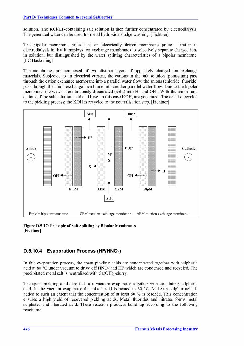
Part D/ Techniques Common to several Subsectors
446 Ferrous Metals Processing Industry
solution. The KCl/KF-containing salt solution is then further concentrated by electrodialysis.The generated water can be used for metal hydroxide sludge washing. [Fichtner]
The bipolar membrane process is an electrically driven membrane process similar toelectrodialysis in that it employs ion exchange membranes to selectively separate charged ionsin solution, but distinguished by the water splitting characteristics of a bipolar membrane.[EC Haskoning]
The membranes are composed of two distinct layers of oppositely charged ion exchangematerials. Subjected to an electrical current, the cations in the salt solution (potassium) passthrough the cation exchange membrane into a parallel water flow; the anions (chloride, fluoride)pass through the anion exchange membrane into another parallel water flow. Due to the bipolarmembrane, the water is continuously dissociated (split) into H+ and OH¯. With the anions andcations of the salt solution, acid and base, in this case KOH, are generated. The acid is recycledto the pickling process; the KOH is recycled to the neutralisation step. [Fichtner]
AEM CEM
+ -
Anode Cathode
OH-
H+
X-
Acid
Salt
OH-H+
X-
M+
M+
Base
BipM BipM
BipM= bipolar membrane CEM =cation exchange membrane AEM = anion exchange membrane
Figure D.5-17: Principle of Salt Splitting by Bipolar Membranes[Fichtner]
D.5.10.4 Evaporation Process (HF/HNO3)
In this evaporation process, the spent pickling acids are concentrated together with sulphuricacid at 80 °C under vacuum to drive off HNO3 and HF which are condensed and recycled. Theprecipitated metal salt is neutralised with Ca(OH)2-slurry.
The spent pickling acids are fed to a vacuum evaporator together with circulating sulphuricacid. In the vacuum evaporator the mixed acid is heated to 80 °C. Make-up sulphur acid isadded to such an extent that the concentration of at least 60 % is reached. This concentrationensures a high yield of recovered pickling acids. Metal fluorides and nitrates forms metalsulphates and liberated acid. These reaction products build up according to the followingreactions:

Part D/ Techniques Common to several Subsectors
Ferrous Metals Processing Industry 447
2 FeF2+ + 2 NO3
- + 3 H2SO4 � Fe2(SO4)3 + 4 HF + 2 HNO32 CrF2
+ + 2 NO3- + 3 H2SO4 � Cr2(SO4)3 + 4 HF + 2 HNO3
NiNO3+ + NO3
- + H2SO4 � NiSO4 + 2 HNO3
The water, HF and HNO3 are vaporized and condensed. The overflow of the condenser is led tothe product tank.
The metals form sulphate chain complexes in the strong sulphur acid solution, which causeincomplete crystallization of the metal sulphates. These complexes are decomposed by raisingboth the temperature and the H2SO4 concentration, which leads to the precipitation of the metalsand to evaporation of acid (HF and HNO3) residues. This heat treatment occurs in a submergedcombustion evaporator.
A long residence time in the evaporation-crystallization circuit also improves the filteringproperties of the sulphate salt formed at a temperature of 80 °C. The sulphate slurry from thecrystallizer tank is pumped to the cone thickener. The underflow of the thickener is led to thepress filter to separate metal sulphate cake. The filtrate is returned to the crystallizer. Thesulphate cake is fed into the neutralising reactor. In the reactor the cake is mixed with lime.
The heat treatment is done in a submerged combustion evaporator. The combustion gases areducted down below the liquor surface through a dip tube. The sulphur acid concentration of80 % is reached at 150 °C. The combustion gases are washed using a venturi scrubber torecover HF and HNO3 acids. This solution is combined with the main pickling acid stream,which is condensed in the vacuum evaporator stage. The underflow of the submergedevaporator is led to the crystallizer tank.
A very positive fact is that the process barely changes the fluoride and nitrate concentrationlevels in the recovered acids. A slight increase of the concentrations is obtained, which ensuresa proper water balance of pickling lines.
The process equipment has to be constructed using high quality materials. Special corrosion-resistant steel grades and fluorocarbon polymers have found extensive use as constructionmaterials for the process equipment. The flowsheet of the Outokumpu Pickling Acid Recoveryprocess is presented in Figure D.5-18.

Part D/ Techniques Common to several Subsectors
448 Ferrous Metals Processing Industry
Vacuumevaporator
Pickling AbsorberCondencer
Chrystallizer
Metal sulphateseparation
Slurry heat-treatment
HF , HNO3
HF, HNO3 , Me
H2SO4
Metal sulphatefilter cake
MeSO4H2SO4
H2SO4
H2SO4
Thickener
Figure D.5-18: Evaporation Process for Mixed acid Regeneration [Com2 Fin]
D.5.10.5 Overview of Regeneration and Recovery Processes
The following Table D.5-2 gives an overview of the available acid regeneration and acidreclamation techniques.

Part D/ Techniques Common to several Subsectors
Ferrous Metals Processing Industry 449
Processes for recovery and regeneration of spent acids from HCl pickling plantsPyrohydrolysis Retardation Dialysis Electrolytic oxidation Electrolytic Fe-precipitation Chemical oxidation Ion exchange
1. Principle of process. Regeneration Recovery of free HCl Recovery of free HCl Transformation ofFeCl2 to FeCl3
Regeneration of HClElectrolysis
Transformation of FeCl2
to FeCl3
Recovery of free HCl acid
2. Other products Iron-oxides - - FeCl3 Ferrous shots FeCl3 FeCl3
Waste for disposal - Acidic FeCl2 solution Acidic FeCl2 solution - - -3. Regeneration rate
total acid> 99 % For neutralisation For neutralisation > 95 % > 95 % > 95 %
free acid 75 - 90 % 75 - 90 % 50 - 70 %4. Input for regeneration - Electrical energy
- Natural gas- Fresh- and waste-water
- Electrical energy- VE-water
- Electrical energy- VE-water
- Electrical energy- muriatic acid
- Electrical energy - Electrical energy- HCI + air or Cl2 or HCI+ H2O2
- Electrical energy- VE-water- Oxidation agents as forchemical oxidation
5. Field of application l/h > 300 > 40 > 60 > 20 > 20 > 20 > 406. Complexity ofinstallation
High Low Medium Low Medium Medium High
7. Required space Big Small Medium Small Small Medium Medium8. Benefit / cost ratio High Medium Medium Medium Medium Low Low9. # plants 1 ca. 250 ca. 15 ca. 5 2 ??? ??? 1
Processes for recovery and regeneration of spent acids from H2SO4 pickling plantsCrystallization (indirect
cyclone- or vacuum-cooling)
Retardation Dialysis Electrolytic oxidation Process with HCI andpyrolysis
Crystallization androasting
Precipitation withsolvents
1. Principle of process Recovery of free H2SO4 Recovery of free H2SO4 Recovery of free H2SO4 Regeneration Regeneration Regeneration Recovery of free H2SO4
2. Other products FeSO4; 7H2O - - Ferrous shots Iron-oxide Iron-oxide Iron-oxideWaste for disposal (If Cr, Ni, Zn present) Acidic FeSO4 for
neutralisationAcidic FeSO4 for
neutralisation- - - (If Cr, Ni, Zn present)
3. Regeneration rate total acid
> 99 % > 95 % > 95 %
free acid > 99 % 80 - 90 % 75 - 85 % > 99 %4. Input for regeneration - Electrical energy
- Steam- Cooling water
- Electrical energy- VE-water
- Electrical energy- VE-water
- Electrical energy- Additional electrolytein loop
- Electrical energy- Natural gas- Cooling water- HCl in loop by fresh- andrinsing water
- Electrical energy- Steam- Natural gas- Cooling water- Fresh and waste water
- Electrical energy- Steam- Cooling water- Solvent in loops
5. Field of application l/h > 200 > 40 > 60 > 20 > 500 > 500 > 2006. Complexity ofinstallation
Medium/ high Low Medium Medium High High High
7. Required space Medium/ big Small Medium Medium Big Big Medium8. Benefit / cost ratio Medium Medium Medium Medium Low Low Low9. # plants 1 ca. 80 ca. 30 ca. 5 2 1 1 n.a.
Table D.5-2: Overview of regeneration and reclamation processes(as submitted by [DFIU99])

Part D/ Techniques Common to several Subsectors
450 Ferrous Metals Processing Industry
Processes for recovery and regeneration of spent acids from HNO3 / HF pickling plants
Solvent extraction Retardation Dialysis Crystallization Pyrohydrolysis Bipolarmembranes
Outokumpu process 2 Kawasakiprocess
1. Principle of process Total regeneration Regeneration of freeacids
Regeneration of freeacids
Regeneration of freeacids
Total regeneration Total regeneration Total regeneration Total regeneration
2. Regenerate / reg. acid Total HNO3 and HF Free HNO3 and HF Free HNO3 and HF Free HNO3 and HF Total HNO3 andHF
Total HNO3 andHF
Total HNO3 and HF TotalHNO3 and HF
3. Other products - Metal fluorides Metal oxide Metal hydroxides Ni(OH) 2 IronoxideWaste for disposal Metallic salt solution Metallic salt solution Metallic salt solution Metal hydroxides Metallic salt solution
3. Regeneration ratetotal acid
HNO3 80 - 95 %HF 50 - 65 %
HNO3 80 - 90 %HF 90 - 99 %
HNO3 90 - 95 %HF 90 - 97 %
HNO3 > 97 %HF 99 %
HNO3 75 - 90 %HF 85 - 95 %
free acids HNO3 80 - 95 %HF 80 - 90 %
HNO3 85 - 95 %HF 80 - 90 %
HNO3 80 - 95 %HF 50 - 55 %
4. Input for regeneration - Electrical energy- H2SO4
- Cooling water- TBP in loop- Activated carbon
- Electrical energy- VE-water
- Electrical energy- VE-water
- Electrical energy- Cooling water
- Electrical energy- Natural gas- Cooling water- Fresh- and wastewater- H2O2 or similar
- Electrical energy- Caustic potashsolution in loop- Diatom earth
- Electrical energy- H2SO4 in loop-- Propane- Limestone- Steam- Cooling water
- Electrical energy- Extraction agentsTBP und D2EHPA inloop- NH4HF2 in loop- Natural gas,- Freshwater
5. Field of application l/h >300 >40 >60 >300 >500 >100 4500 >10006. Complexity ofinstallation
Medium Low Medium Medium High High Medium Very high
7. Required space Medium Small Medium Medium Large Medium Medium Very large8. Benefit / cost ratio Medium Medium Medium Low Medium Medium Medium Medium9. # plants 1 2 ca. 30 ca. 5 1 2 2 2 11 world-wide, as at 1990, production and pilot plants2 Source of data [Com2 FIN]
Table D.5-2 cont.: Overview of regeneration and reclamation processes (as submitted by [DFIU99])

Part D/ Techniques Common to several Subsectors
Ferrous Metals Processing Industry 451
D.5.11 Treatment of Acidic Waste / Waste Water
D.5.11.1 Neutralisation of Acidic Waste Water
Acidic waste water from rinsing, from fume absorbers of the pickling tank exhaust system orfrom flushing (plant cleaning) that can not be reused elsewhere in the plant, neutralised (e.g.with alkaline waste waters from other plant operations) and treated prior to discharge to reducethe emissions. Dissolved metal ions are transformed into hydroxides or sparingly soluble saltsand subsequently eliminated by sedimentation, in many cases by adding flocculants. Theprecipitated metal sludge is de-watered in filter presses and disposed of. Neutralisation (of spent pickling baths) generates a large quantity of sludge. The sludge, mainlyconsisting of iron hydroxide and water, can be recycled for iron production as long as it is notcontaminated by unacceptable metals (e.g. zinc) or by other constituents. Care should be takento avoid mixing of waste water streams or sludges which can make recycling difficult.
Neutralisation can also create large amounts of neutral salts (e.g. NaCl, CaCl2, Na2SO4, CaSO4),most of which are very soluble in water and are discharged with the treated water. Removal isonly possible by very special, and in most cases uneconomical, treatment (reverse osmosis,electrodialysis or evaporation followed by ion exchange and concentrate evaporation with saltdrying). Even if these salts are removed, their mixed composition limits re-use and disposal tolandfill may be restricted by their solubility. [EUROFER CR]
A distinction has to be made between neutralisation sludges from stainless steel pickling andfrom carbon steel pickling. The sludge resultanting from neutralisation of mixed acid wastes isusually landfilled, as it cannot be recycled. [Com2 CR]
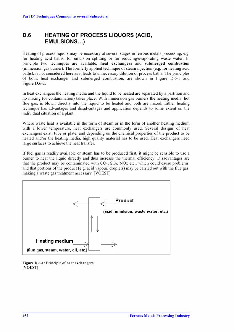
Part D/ Techniques Common to several Subsectors
452 Ferrous Metals Processing Industry
D.6 HEATING OF PROCESS LIQUORS (ACID,EMULSIONS…)
Heating of process liquors may be necessary at several stages in ferrous metals processing, e.g.for heating acid baths, for emulsion splitting or for reducing/evaporating waste water. Inprinciple two techniques are available: heat exchangers and submerged combustion(immersion gas burner). The formerly applied technique of steam injection (e.g. for heating acidbaths), is not considered here as it leads to unnecessary dilution of process baths. The principlesof both, heat exchanger and submerged combustion, are shown in Figure D.6-1 andFigure D.6-2.
In heat exchangers the heating media and the liquid to be heated are separated by a partition andno mixing (or contamination) takes place. With immersion gas burners the heating media, hotflue gas, is blown directly into the liquid to be heated and both are mixed. Either heatingtechnique has advantages and disadvantages and application depends to some extent on theindividual situation of a plant.
Where waste heat is available in the form of steam or in the form of another heating mediumwith a lower temperature, heat exchangers are commonly used. Several designs of heatexchangers exist, tube or plate, and depending on the chemical properties of the product to beheated and/or the heating media, high quality material has to be used. Heat exchangers needlarge surfaces to achieve the heat transfer.
If fuel gas is readily available or steam has to be produced first, it might be sensible to use aburner to heat the liquid directly and thus increase the thermal efficiency. Disadvantages arethat the product may be contaminated with CO2, SO2, NOx etc., which could cause problems,and that portions of the product (e.g. acid vapour, droplets) may be carried out with the flue gas,making a waste gas treatment necessary. [VOEST]
Figure D.6-1: Principle of heat exchangers[VOEST]

Part D/ Techniques Common to several Subsectors
Ferrous Metals Processing Industry 453
Figure D.6-2: Principle of submerged combustion[VOEST]
Some advantages of submerged combustion were reported, beside financial savings, reducedenergy consumption and acid consumption were claimed.

Part D/ Techniques Common to several Subsectors
454 Ferrous Metals Processing Industry
D.7 FLUXING
D.7.1 On-site Regeneration of Flux Baths (Iron Removal)
During operation the iron concentration in a flux solution is increased. At a certain level, theflux solution becomes unusable. In order to be able to recirculate the solution, the iron contentneeds to be removed. This can be done continuously or in batch operation.
D.7.1.1 Iron Removal Using Ammonia and H2O2 Oxidation
By means of addition of ammonia (for pH adjustment) and H2O2 (oxidant), iron is precipitatedas Fe(OH)3 and NH4Cl is produced according to the reactions:
HCI + NH4OH → NH4Cl + H2O2FeCl2 + H2O2 + 4NH4OH → 2Fe(OH)3 + 4NH4Cl
The precipitated iron hydroxide sludge is withdrawn and disposed of.
Fluxing bathZnCl2 + NH4Cl
Reactor
Sludge thickener
Sludge tankFilter press
Purified flux
Hydrogen peroxide
Ammonium water
Filter cake
Figure D.7-1: Flow sheet for flux regeneration[DK-BAT-93]
Zinc, initially present in solution or introduced by the workpieces impregnated with solutionfrom the rinsing or pickling baths, remains as ZnCl2.
Normally, the ratio of NH4Cl/ZnCl2 produced is higher than the ratio required by mostgalvanizers and the amount of salt produced is not sufficient to compensate for the consumptionof flux. This can be corrected by addition of depleted pickling or de-zincing solution, whichincreases the production of fluxing salts. Another option to influence the NH4Cl/ZnCl2 ratio ofsalts produced, is to pre-react the depleted pickling or the de-zincing solution with dross or ash;thus producing ZnCl2 instead of NH4Cl:
2HCl + Zn (dross) → ZnCl2 + H2 ↑2HCl + ZnO (ash) → ZnCl2 + H2O ↑

Part D/ Techniques Common to several Subsectors
Ferrous Metals Processing Industry 455
Automated pH and redox controls allow for a selective iron precipitation (about 50 % iron in thesolids) and a low oxidizing potential, avoiding the destruction of any organic additive in theflux. To obtain maximum thickening and filtration efficiency, a selective flocculant is added tothe pulp in the flocculator, resulting in a high settling rate of solids, excellent clarity of theoverflow and improved filtration characteristics of the underflow. A solid content of the press-filter cake of around 50 % is achievable.
It is possible to generate flux solution with a composition required by the galvanizer. For anoptimum composition of the flux, zinc chloride or ammonium chloride additions may berequired. [DK-BAT-93]
D.7.1.2 Iron Removal Using Electrolytic Oxidation
The electrolytic oxidation process consists of a reactor module or series of reactor modules forthe electrolytic oxidation of dissolved iron and a set of sedimentation tanks for the removal ofprecipitate from the process stream. A schematic flow diagram is shown in
Figure D.7-2: Schematic of the electrolytic oxidation process[Choice/Barr-IG-94]
As flux solution passes through the reactor, ferrous iron (II) is oxidized to ferric iron (III). Theferric iron (III) is precipitated as hydroxide. This is accompanied by the generation of acid. Asa result of these changes, the concentrations of dissolved iron and acid capacity in the streamleaving the reactor are lower than in the entering stream. Because of this, and because workcontinues to import rinse water or pickle solution to the main flux tank, the iron and acidcapacity in the recirculation tank are lower than in the main flux tank. The relationship betweenthe iron concentrations in the two tanks depends on a number of factors but, in practice, theconcentration in the recirculation tank can be brought down to near zero grams per litre andsteady concentrations in the main tank of less than 2 grams per litre can be achieved easily,

Part D/ Techniques Common to several Subsectors
456 Ferrous Metals Processing Industry
while concentrations of 1 gram per litre or lower can be achieved with careful operation.[Choice/Barr-IG-94]
· the system is based on a chloride balance and all the chloride carried over from the rinsetank to the flux tank is utilized in the generation of zinc ammonium chloride make-up
· iron is removed· no waste water treatment is necessary,· promotion of the rinse water to the acid tanks allows a significant saving in acid costs· water input and costs are minimized [Choice/Barr-IG-94]
Sourcing spare parts for the equipment was reported as a potential problem as the supplier isbased in Australia. [Com2 EGGA]
D.7.1.3 Iron Removal Using Ion Exchange Columns
The ion-exchange process uses resin to absorb the iron. As this process is sensitive to solidparticles, the flux solution is filtered first. This can be done with a standard plate-filter. Byadding concentrated NaOH, the pH is set to the required pH value. The neutralisation unit iscontinuously stirred to create a homogeneous solution. The solution is then pumped through theion-exchange column where iron is absorbed by the resin. After leaving the column, the liquidis returned to the rinse/flux bath. When the resin is saturated with iron, it must be stripped andregenerated. The stripping/regeneration solution is pumped from a storage vessel through thecolumn into another vessel. An exchange of iron and acid takes place in the column. Iron isdissolved in the HCl, while the acid is absorbed by the resin. [Sprang-IG-97]
D.7.2 External Reutilization of Spent Flux Baths
D.7.2.1 NH3 Removal, Precipitation and Partial Reuse for New FluxProduction
� No information submitted.
D.7.2.2 H2O2 Oxidation, Total Reuse for New Flux Production� No information submitted.

Part D/ Techniques Common to several Subsectors
Ferrous Metals Processing Industry 457
D.8 RINSING
D.8.1 Efficient (multiple) Use of Rinsing Water
Figure D.8-1 shows the variety of rinsing techniques available; ranging from out-dated flowrinsing to sophisticated combined rinsing systems. The associated water consumptions arelisted in Table D.8-1. Due to the high water consumption of flow rinsing, this technique is nolarger acceptable. Multiple (cascade) use of rinse water and static rinse tanks result insufficiently high concentrations in the rinse water to allow for the reuse in preceding processbaths or to allow for regeneration or reclamation measures applied to the process baths to beapplied to the rinse water as well.
Figure D.8-1: Rinsing systems[Rituper93]

Part D/ Techniques Common to several Subsectors
458 Ferrous Metals Processing Industry
Concentration in pickle bath[g/l]
100 200 600
Residual concentration in last rinse bath[mg/l]
5 10 20 50 5 10 20 50 5 10 20 50
Rinse criteria 2 104 104 5 103 2 103 4 104 2 104 104 4 103 1.2 105 6 104 3 104 1.2 104
Rinse system Number of Baths Rinse water consumption [m3/h] Rinse water consumption [m3/h] Rinse water consumption [m3/h]Flowrinse 1 2000 1000 500 200 4000 2000 1000 400 12000 6000 3000 12002-step cascade 2 14.1 10 7.1 4.5 20 14.1 10 6.3 34.6 24.5 17.3 113-step cascade 3 2.7 2.1 1.7 1.3 3.4 2.7 2.1 1.6 5.0 4.0 3.1 2.34-step cascade 4 1.2 1.0 0.9 0.7 l.4 1.2 1.0 0.8 1.9 1.6 1.3 1.0Static and flow rinse 2 400 200 100 40 800 400 200 80 2400 1200 600 240Static rinse2-step cascade
3 6.3 4.5 3.2 2.0 9.0 6.3 4.5 2.9 15.5 11.0 7.7 4.9
Static rinse3-step cascade
4 1.6 1.3 1.0 0.7 2.0 1.6 1.3 0.9 2.9 2.3 1.8 1.3
Spray rinseEfficiency 100 %
1 9.9 9.2 8.5 7.6 10.6 9.9 9.2 8.3 11.7 11.0 10.3 9.4
Spray rinseEfficiency 30 %
1 3.3 3.1 2.9 2.6 3.6 3.3 3.1 2.8 4.0 3.7 3.5 3.2
Note: carry-over 100 l/h
Table D.8-1: Comparison of water consumption for different rinsing systems[Rituper93]

Part D/ Techniques Common to several Subsectors
Ferrous Metals Processing Industry 459
D.8.2 Treatment of Rinsing Water
Ion exchange, electrolytic iron removal, reverse osmosis, oxidizing iron removal� No information submitted.
D.9 PROCESS WATER AND WASTE WATER TREATMENT
D.9.1 Treatment of Oil- and Scale-bearing Process Water
In most cases coarse scale is captured close to the spot where it arises by scale pits, smallgravity separators, to prevent installations from damage, e.g. if it is necessary to transport thescale-loaded water by pumps. Scale pits can reduce the content of suspended solids in the wastewater (load of 20 - 40 m3/(m2h)) from 200 - 800 mg/l to 60 - 100 mg/l. The advantage ofdecentralised scale arresting is that there is no sedimentation in the flume channels and lesscorrosion takes place.
For further coarse cleaning (intermediate cleaning), the water is usually physically treated insettling tanks to separate coarse scale and hydrocarbons. Different designs are available, e.g.vertically and horizontally flown settling tanks. Figure D.9-1 and Figure D.9-2 depict examplesof gravity separators.
The basic principle of these separators is that coarse particles settle on the bottom of the basinby gravity, while the major part of the oil dispersed in the water rises to the surface. The wateris discharged via an outlet equipped with a submerged barrier in front to prevent the oil floatingon the surface from being discharged with the purified water. The deposited sediments areusually conveyed to a sump by scrapers where they can be removed by excavators or pumps.
5
3
78
624
1round.ds4
1 Waste water inlet 5 Clear water collecting pipe2 Distribution cylinder 6 Clear water outlet3 Reservoir 7 Sludge reservoir4 Clear water spill-over 8 Ground scraper
(suction pipes for sludge removal are not indicated)
Figure D.9-1: Circular Settling Tank (vertical)[DFIU98]

Part D/ Techniques Common to several Subsectors
460 Ferrous Metals Processing Industry
4
2
3
5
settling.ds4
1
1 Waste water inlet 4 Clear water outlet2 Useful space for sedimentation 5 Sludge scraper3 Sludge reservoir
Figure D.9-2: Horizontal Flow Settling Tank[DFIU98]
The achievable reduction depends on tank size, particle size distribution, addition offlocculating agents and oil content. Settling tanks can reduce suspended solids from 40 - 80mg/l down to 20 - 35 mg/l (load 4 - 15 m3/(m2h)).
Other types of gravity separators are screw-type clarifier (or screw-type dewaterer) andlamella separator. Compared to settling basins they have a more compact construction. Inlamella separators (Figure D.9-3) the incoming water is led over a number of inclined plates(lamellas). The settling distance is much shorter. The settlements are forced down along theplates by gravity, while the oils move upwards along the underside of the plates and can becollected by skimming mechanisms. The purified water is discharged through an outlet, whichis separated from the basin by a submerged barrier. The sediment is discharged from the bottome.g. via a screw, which is also separated from the main basin by a submerged barrier.
Screw-type clarifiers (see Figure D.9-4) are basically settling tanks with an inclined bottom.The solids settling by gravity are transported out of the separator by a rotating screw, partiallysubmerged in the sediment.
Figure D.9-3: Schematic of a lamella separator[Fichtner]

Part D/ Techniques Common to several Subsectors
Ferrous Metals Processing Industry 461
Figure D.9-4: Screw-type clarifier[BSW-WWT-90]
In centrifugal separators the scale particles are pressed to the wall by the flow. On the wall ofthe separation chamber, the scale particles glide slowly downward to the collecting chamber.When the collecting chamber is full, automatic elutriation starts. A disadvantage of this methodis the fact that oil separation is not possible.
Oil floating on water surfaces is removed by oil skimmers. The oil adheres to an endless stripor hose, which is immersed in the basin. Together with this strip or hose the oil is transferred toa funnel outside of the basin where it is skimmed from the strip. A wheel can also be usedinstead of the endless strip.
Fine cleaning can be carried out in gravel- or sand filters (Figure D.9-5). The water flowsthrough the filter medium from the top to the bottom. Thus large amounts of scale, sludge andoil are retained. Depending on the cleaning system these filters can remove all particles carriedby the water down to a grain size of 1 micron. The cleaned but still thermally loaded water iscooled in cooling towers in order to achieve the right temperature for re-circulation. Gravel andsand filters need to be cleaned in order to remove particles and hydrocarbons. The filters arebackwashed after a fixed period or when a defined filter resistance has been reached.Backwashing is performed with water or air. The required volume of backwash water amountsto about 1 – 3 % of the cleaned water.
Some sand filters are operated with continuous backwashing. Here the water flows through thefilter medium from the bottom to the top. The sand is continuously transported upwards andconstantly washed. The purified sand falls on top of the clean sand bed.
The backwash water is usually highly contaminated and is either treated in the pre-cleaningunits, if necessary under addition of flocculating agents; or is treated separately in specialsludge treatment units.
For treatment of backwashing water from the sand filters, the water is thickened in athickener by adding flocculents and applying sedimentation techniques. The flocculent is addedand mixed with the backwash water in a pre-reaction chamber. In the central chamber thesludge settles down. The purified water is discharged through an indented weir and is returned

Part D/ Techniques Common to several Subsectors
462 Ferrous Metals Processing Industry
to a sand filter system. By means of a scraper the sludge is transported to the sludge sluice,where it is discharged.
If the arising sludge contains too much water, a press can be used for further dewatering. Such apress can be designed as a chamber filter press, a membrane filter press or a solid bowlcentrifuge. The filtered water is recirculated to the thickener. [EUROFER HR]
Figure D.9-5: Example of a gravel filter with indication of backwash operation[Theobald]
Another option for fine cleaning the pre-cleaned waste water is filters that consist ofcylindrical, wire-netting filtering elements (see Figure D.9-6).
Figure D.9-6: Example of wire-netting filters with indication of backwash operation[Theobald]

Part D/ Techniques Common to several Subsectors
Ferrous Metals Processing Industry 463
Operation cycles of these filters are divided into:• starting phase during which a layer of filtration aid is built up on the fine meshed filters• filtering phase during which further filtration aid is added to keep the filtrate and sludge
layer permeable• backwashing phase during which the filters are cleaned by reversing the flow direction.
Sludges obtained from backwashing can be dewatered directly and require special treatmentprior to reuse (e.g. in the sinter plant) only if they have a high oil contents. [Theobald]
For a more efficient intermediate cleaning and enhanced separation of scale and oil, so-calledaerated fine scale-traps have been developed as shown in Figure D.9-7. These combine theprinciples of sedimentation and flotation. The solids settle on the bottom and are removed byscrapers, while the air blown in (air bubbles) enhances the flotation of the oil.
Air inlet pipe row
Oilseparation-
zone
Ground scrapper
Figure D.9-7: Aerated fine scale-trap[DFIU 98]
Furthermore, the oil adsorbed by the fine scale is 'washed off' by agitation. Due to the betterseparation of oil and scale and the lowered oil content of the scale, the recycling options areimproved. With retaining times of 15 to 30 minutes and loads of 15 - 20 m3/(m2h), aerated finescale-traps can achieve reduction rates of 99 % for particles > 63 µm and 20 - 80 % for particlessized 31 - 63 µm (depending on the particle size distribution). [DFIU98], [Theobald],
Inlet[mg/l]
Outlet[mg/l]
Reduction[%]
Suspended solids 32.3 25.8 20.1Settleable Solids 95.5 44.2 53.7Fe total 43.5 24.6 43.4Hydrocarbons 1 2.0 1.3 35.0Note: Source of data [StuE-111-3]1 Determined according to DIN 38 409, part 18, 1981
Table D.9-1: Example of achieved emission levels for aerated fine scale-traps
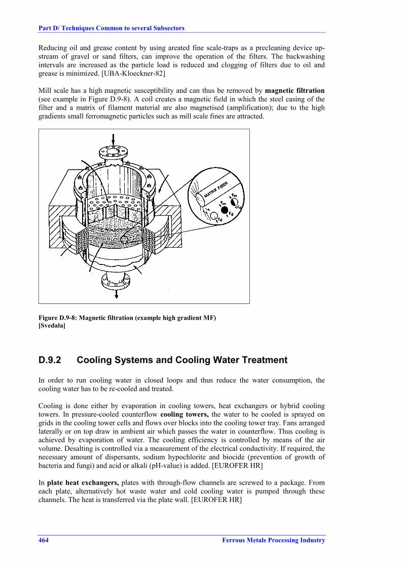
Part D/ Techniques Common to several Subsectors
464 Ferrous Metals Processing Industry
Reducing oil and grease content by using areated fine scale-traps as a precleaning device up-stream of gravel or sand filters, can improve the operation of the filters. The backwashingintervals are increased as the particle load is reduced and clogging of filters due to oil andgrease is minimized. [UBA-Kloeckner-82]
Mill scale has a high magnetic susceptibility and can thus be removed by magnetic filtration(see example in Figure D.9-8). A coil creates a magnetic field in which the steel casing of thefilter and a matrix of filament material are also magnetised (amplification); due to the highgradients small ferromagnetic particles such as mill scale fines are attracted.
Figure D.9-8: Magnetic filtration (example high gradient MF)[Svedala]
D.9.2 Cooling Systems and Cooling Water Treatment
In order to run cooling water in closed loops and thus reduce the water consumption, thecooling water has to be re-cooled and treated.
Cooling is done either by evaporation in cooling towers, heat exchangers or hybrid coolingtowers. In pressure-cooled counterflow cooling towers, the water to be cooled is sprayed ongrids in the cooling tower cells and flows over blocks into the cooling tower tray. Fans arrangedlaterally or on top draw in ambient air which passes the water in counterflow. Thus cooling isachieved by evaporation of water. The cooling efficiency is controlled by means of the airvolume. Desalting is controlled via a measurement of the electrical conductivity. If required, thenecessary amount of dispersants, sodium hypochlorite and biocide (prevention of growth ofbacteria and fungi) and acid or alkali (pH-value) is added. [EUROFER HR]
In plate heat exchangers, plates with through-flow channels are screwed to a package. Fromeach plate, alternatively hot waste water and cold cooling water is pumped through thesechannels. The heat is transferred via the plate wall. [EUROFER HR]

Part D/ Techniques Common to several Subsectors
Ferrous Metals Processing Industry 465
In hybrid cooling towers, a plate heat exchanger is installed in the upper part of the tower. Inthe lower part, the water is cooled by evaporation. Due to the heat exchanger, the air with100 % moisture is heated and condenses as fog some time later and with less intensity.
In the planning and installation of circuit-type water treatment plants with cooling towers, thegeographical situation of the respective mill has to be taken into consideration. Due to the waterevaporation in the recooling process, climatic conditions can be affected by the constantformation of fog and by so-called industrial snow, especially in central Europe. [EUROFERHR]


ANNEXES


Ferrous Metals Processing Industry 469
Best Available Technique Reference Document onFerrous Metals Processing
Annex I. Monitoring ............................................................................................................................471Annex II. Legislation ............................................................................................................................473Glossary ..............................................................................................................................................483References ..............................................................................................................................................487


Annexes
Ferrous Metals Processing Industry 471
ANNEX I. MONITORING
On issues specific to the ferrous metals processing sector, it was reported during the 2nd TWGmeeting that there are difficulties in measuring acid fumes (especially HF and in lowconcentration ranges) and on measuring fugitive emissions.
It was also mentioned that for discontinuous sampling, the sampling period and number ofsamples taken should be sufficient to demonstrate that the results are reflective of the actualperformance.
No further information on monitoring was submitted.


Annexes
Ferrous Metals Processing Industry 473
ANNEX II. LEGISLATION
No other information on legislation regarding the ferrous metals processing than that presentedin this annex was submitted. In cases where the legislation of certain Member States is missing,that information was not made available to the Bureau.
1. HELCOM and PARCOM Recommendations
In the following HELCOM and PARCOM recommendations regarding ferrous metals processesare summarized:
HELCOM Recommendation 11/7
1. As of January 1st 1995 dust emissions from processes (including rolling, furnaces in rollingmills and cutting) in the iron and steel industry should be avoided or collected and filteredbefore being allowed to enter into the atmosphere.
2. Fugitive emissions from all processes should be avoided as far as technically feasible e.g.by encapsulation, evacuation hoods combined with good housekeeping practices.
3. Fabric filters or technology environmentally equivalent should be used for dust cleaninge.g. in sintering plants, for secondary gases from blast furnaces and basic oxygen furnaces,in electric arc furnaces and at cutting and grinding operations.
When these technologies are used the particulate matter content of the filtered gases should,as a guiding value, not exceed 10 mg/m3 (ndg). In any case, the particulate matter content ofthe filtered gases should not exceed 50 mg/m3 (ndg).
4. A good process and device control and regular monitoring should be maintained in order tokeep emissions low. From 1987 dust emissions shall be continuously monitored if theparticulate emission is 5 kg/h or more or the cadmium emission is 5 g/h or more and thatinstallations with a particulate emission of 2 to 5 kg/h shall be equipped with measuringinstruments which continuously determine waste gas opacity, e.g. optical transmission.
HELCOM Recommendation 17/5
1. General requirements• process water, polluted cooling water and polluted stormwater should be treated separately
from unpolluted cooling water at each plant• installation of closed water systems should be developed for process water and polluted
cooling water in order to reach a circulation rate of at least 95 %• production processes, utilization of by-products, waste- and storm-water treatment
technology should be developed in order to minimise discharges• internal and external measures should be taken to minimise accidental discharges (e.g.
installation of sufficient storage capacity for untreated waste waters)• sludges should be disposed of in a manner causing minimal environmental hazard,
preferably by treating and entering the sludges to the blast furnace, sintering plant orelectric arc furnace
2. Requirements to the effluent of the plantAfter having fulfilled the general requirements under 1, the following limit values should not beexceeded as annual mean values:

Annexes
474 Ferrous Metals Processing Industry
Hot Rolling: Suspended Solids 50 g/t (or 1 t/a) Oil 10 g/t (or 0.2 t/a for existing plants only)Cold Rolling: Suspended Solids 10 g/t Oil 5 g/t
HELCOM Recommendation 13/6
Definition of best environmental practice
PARCOM Recommendation 92/3 concerning limitation of pollution from new secondarysteel production and rolling mills
Contracting parties to the convention for the prevention of marine pollution from land-basedsources agree that:
Measures should be taken to reduce NOx emissions at pickling plants where nitric acid is usedand NOx emissions (as NO2) exceed 5 tonnes /year. The measures should aim at a reduction rateof at least 70 %.
At least 95 % process water (i.e. water from direct cooling) should be recirculated from hotrolling and continuous casting machines.
The discharges of suspended solids (s.s.) and oil in bleed from process water systems from hotrolling should not exceed 50 g/tonne processed steel for suspended solids and 10 g/tonne for oil.
Before discharging spent oil emulsions from cold rolling, treatment by e.g. ultrafiltration shouldbe carried out. The discharges from cold rolling should not exceed 10 g/tonne for s.s. and 5g/tonne processed steel for oil. For plants with integrated waste water systems the total annualdischarge should not exceed the sum of the annual production multiplied with the values abovefor each process.
Waste water flow from pickling should be reduced as far as possible. Discharges of metals frompickling plants should be limited as follows:Ni 1 mg/lCr-tot 1 mg/lCr (VI) 0.1 mg/lZn 2 mg/lCd 0.2 mg/l(maximum concentration of metals in effluent water in unfiltered samples)
In pickling plants using more than 20 tonnes of nitric acid per year, measures should be taken inorder to reduce the nitrate discharges by applying acid regeneration, or equally efficient method.
Recovery of metals from all zinc-rich (zn concentration above 16 %) filter dust and filterdustfrom all stainless steel production should be carried out.
PARCOM Recommendation 90/1 of 14 June 1990 on the definition of the bestavailabletechnology for secondary iron and steel plants
The Paris Commission agrees that as a minimum the following measures constitute the bestavailable technology for secondary iron and steel plants:• Fabric filters for dust cleaning or equally efficient arrestment system at cutting, grinding
and scarfing operations• Regeneration of pickling baths and closing of rinse water systems• Addition of hydrogen peroxide to pickling baths containing nitric acid or any equivalent
measure which enables reduction on NOx to the atmosphere

Annexes
Ferrous Metals Processing Industry 475
• Sedimentation combined with filtration of waste water from continuous casting and rolling.Recirculation or re-use of the water.
• Metal recovery from filter dust.
2. GENERAL AUSTRIAN EMISSION LIMITS VALUES INTO AIR(see also ordinance Nr. 160)
2.1. Installations for Heating / Reheating / Heat Treatment(see BGBl. II Nr. 160, page 727, para. 5)
SO2 emission limit value, using coke oven gas 300 mg/Nm3
NOx emission limit value, using preheated air 750 mg/Nm3 (calc. as NO2)NOx emission limit value, not using preheated air 500 mg/Nm3 (calc. as NO2)O2 reference value for gas or liquid fuels is 5 % (details see page 726 of the ordinance)
2.2 Installations for Acid Surface Treatment(see BGBl. II Nr. 160, page 727, para. 7)
SO2emission limit value 300 mg/Nm3
NOx emission limit value 500 mg/Nm3 (calc. as NO2)O2 reference value for gas or liquid fuels is 3 %, for solid fuels 6 % (details see page 726 of theordinance)
The above limit value are half hourly mean values and have to be applied to new plants. Oldplants have to reach these values 5 years later, after this ordinance is entering into force, thatmeans in June 2002. More details are listed in the ordinance.
2.3 General Austrian Emission Limits into Water
Waste water Emission Limit Values for hot / cold metal treatment (rolling, forging, pressing,drawing,..); for more details see page 2835 – 2838 of the ordinance (BGBl. 345/1997)
Hot forming (pp. 2835) Cold forming (pp. 2836)running water public discharge
channelrunning water public discharge
channelGeneral ParameterTemperature 30 °C 35 °C 30 °C 35 °CFish toxicity GF 2 no affect on bio-
logical degradation4 no affect on bio-
logical degradationFilter out matter 50 mg/l 200 mg/l 50 200pH value 6.5 – 8.5 6.5 – 9.5 6.5 – 8.5 6.5 – 9.5Inorganic parameter mg/l mg/l mg/l mg/lChromium as Cr 0.5 0.5 0.5 0.5Chromium-VI as Cr 0.1 0.1Iron as Fe 2.0 2.0 2.0 2.0Copper as Cu 0.5 0.5Nickel as Ni 0.5 0.5 0.5 0.5Zinc as Zn 1.0 1.0 1.0 1.0Fluoride as F 30 30Nitrate as N 20 -Nitride as N 1.5 10Ammonium as N 5.0 5.0 -Phosphor as P 2.0 2.0 -Organic parameter mg/l mg/l mg/l mg/lChem. Oxygen demand,CSB calc. as O2
75 200 -
Sum of organic comp. 10 20 10 20Table 2-1: Waste water Emission Limit Values

Annexes
476 Ferrous Metals Processing Industry
This ordinance was entering into force in 1998 for new plants. Old plants have to fulfil therequirements within the next 7 years, which means until 2005. For further information related tomonitoring see §3 and 4 of the ordinance.
3. CURRENT GERMAN LEGISLATION RELEVANT FOR FERROUSMETAL PROCESSING ACTIVITIES
Important regulations relevant to ferrous metals processing activities in Germany are laid downin the BImSchG (Federal Immission Control Act), the WHG (Federal Water Act) and the KrW-/AbfG (Waste Avoidance, Recycling and Disposal Act for the Promotion of Closed SubstanceWaste Management and Ensuring Environmental Compatible Waste Disposal). Germany uses asegregated media licensing system for different environmental media, but the final decision onan installation is reached by the assessment of environmental impacts to all media by the localauthorities. Also noise requirements are considered in the licensing procedure. Germany aims atfavouring pollution prevention in the licensing procedure. The „precautionary principle“ has alegal status which permitts the setting of standards. Legal standards are not subject to anynegotiation in the licensing process in Germany.
In compliance with the federal structure of Germany, the implementation of environmental lawsand decrees is under the responsibility of the federal states (Bundesländer), which mayimplement the administrative procedure differently. For new plants, that are regarded asrelevant with respect to emissions and releases into the environment, also an environmentalimpact assessment is required during the licensing procedure (cf. Gesetz über dieUmweltverträglichkeitsprüfung, UVPG).
Area Legal Basis Regulations and ordinancesTransport Verkehrsrecht Gefahrgutverordnung Straße
Gefahrgutverordnung SchieneGefahrgutverordnung Binnenschifffahrt
Health and safety at work Chemikaliengesetz (ChemG) ChemikalienverbotsordnungGefahrstoffverordnung
Gewerbeordnung TA LärmArbeitsstättenverordung und -richtlinien
Emissions Bundes-Immissionsschutzgesetz(BImSchG)
Bundes-ImmissionsschutzverordnungenBundes-ImmissionsschutzverwaltungsvorschriftenTA LuftTA Lärm
Wasserhaushaltsgesetz (WHG) Katalog wassergefährdender StoffeAbwasserverwaltungsvorschriftenIndirekteinleiterverordnungen der Länder
Waste Abfallgesetz (AbfG) Abfall- und ReststoffüberwachungsverordnungAbfallbestimmungsverordnungReststoffbestimmungsverordnungTA AbfallTA Siedlungsabfall
Kreislaufwirtschaftsgesetz (KrW.-/AbfG)
Table 3-1: Legal basis and regulations alongside the product line
Table 3-1 gives an overview of the German legal basis and regulations for environmentalprotection in Germany alongside the product line. In the following, a selection of mostimportant acts, regulations and requirements concerning air and water quality for ferrous mtealsprocessing activities is presented.

Annexes
Ferrous Metals Processing Industry 477
3.1 German regulations concerning air quality
The basic law for air pollution control and noise abatement in Germany is the FederalImmission Control Act (Bundes-Immissionsschutzgesetz, BImSchG). It primarily aims towardsthe protection of the medium air, but it also applies to the media water and land in casepollution is introduced via the air. The BImSchG is complemented by 21 ordinances and theTechnical Instructions on Air Quality (TA Luft). Especially the TA Luft specifies in more detailrequirements to be met by installations subject to licensing. The next sections present importantacts and ordinances of German air pollution prevention in more detail.
3.1.1 Federal Immission Control Act (Bundes-Immissionsschutz-gesetz, BImSchG)
The BImSchG is the legal instrument for monitoring air pollution. Immission as defined withinthe law comprises air pollutants, and also noise, vibration, light, heat, radiation and associatedfactors affecting humans as well as animals, plants or other things. This concept alreadyimplements the idea of cross-media effects to a certain extent. The BImSchG requires federalauthorities to issue ordinances identifying the types of facilities, which are subject to licensing,set licensing requirements for these facilities, and impose emission limit values and technicalcontrol requirements for all facilities, whether licensed or not.
Especially article 5(1)3 BImSchG aims at the avoidance and minimisation of wastes andresidues. The paragraph emphasises the cross-media effects of industrial production.The concept of "state of the art technology" defined in the BImSchG is similar to the one ofBAT:
State of the art as used herein shall mean the state of development of advanced processes offacilities or modes of operation which is deemed to indicate the practical suitability of aparticular technique for restricting emission levels. When determining the state of the art,special consideration shall be given to comparable processes, facilities or modes of operationthat have been successfully proven in practical operation. (Article 3 paragraph 6 BImSchG)
In principle, "state of the art technology" is stated in terms of emission limits set by thelicensing authority, the choice of technology to comply with the emission limit levels is left toindustry. Necessary precautions against harmful effects on the environment are to be taken inparticular by using control measures corresponding to the state of the art. Depending on themass flow, some substances have to be measured continuously (eg. SOx, NOx, and particulates).Some relevant ordinances as well as selected requirements of the BImSchG are brieflypresented in the following.
3.1.1.1 Ordinance on installations subject to licensing (4. BImSchV)
The 4. BImSchV (Ordinance on installations subject to licensing) lists all installations that aresubject to licensing under the BImSchG. According to this ordinance (cf. Annex, row 1, N° 3.5and 3.6) installations for the rolling of metals and for scarfing have to undergo a formallicensing procedure, regardless if they are new installations or substantial alterations to location,nature or operation of existing installations.
3.1.1.2 Technical Instructions on Air Quality (TA Luft)
The Technical Instructions on Air Quality (TA Luft) have been set up as general administrativeregulations related to §48 BImSchG . The TA Luft further specifies the requirements to be metby installations subject to licensing. It prescribes limit values for most air pollutants as well asstructural and operational requirements designed to limit diffuse emissions. Specific regulationsfor ferrous metals processing activities by the TA Luft, directing at the avoidance andminimisation of air pollution, are laid down in N° 3.3.3.6.1 (plants for rolling metals, heatingand heat treatment furnaces) in N° 3.3.3.9.1. (galvanising installations), and in N° 3.3.3.10.1

Annexes
478 Ferrous Metals Processing Industry
(installation for surface treatment of metalls using HNO3). Requirements set out are listed inTable 3-2.
N° in TA Luft Reference Specification3.3.3.6.1 (rolling) Reference quantity Emissions values refer to a volume content of oxygen in
waste gas of 5 out of 1003.3.3.6.1 (rolling) Nitrogen oxides *) Emissions of nitrogen monoxide and nitrogen dioxide in
the waste gas of plants operating air preheating of200°C or more must not exceed the mass concentrationgiven in the figure below (Fig. 8-1), given as nitrogendioxide; possibilities, to control emissions by fuelengineering and other state of the art measures are to beemployed.
3.3.3.6.1 (rolling) Sulphur oxides If burnable gases are used in an interrelated productionbetween an iron and steel works and a coking plant,sulphur oxide emissions may not exceed the emissionvalue according to enclosure 1 to §16, 13th BImSchV.
3.3.3.9.1 (galvanising) Waste gas cleaning Installations for galvanising, using fluxes, are to beequipped with waste gas capturing devices likeencapsulation or hoods; waste gases need to be ductedto a waste gas cleaning facility.
3.3.3.9.1 (galvanising) Dust Dustlike emissions in waste gases must not exceed10mg/m3(STP).
3.3.3.9.1 (galvanising) Chlorine compounds Emissions of gaseous inorganic chlorine compounds inwaste gas must not exceed 20mg/m3(STP), given ashydrogen chloride.
3.3.3.9.1 (galvanising) Emission measurements The result of a single measurement is to be determinedby several dipping processes; measuring timecorresponds to the sum of single dipping times and shallcover usually ½ hour; dipping time is the periodbetween the 1st and the last contact of the galvanisedpiece with the galvanising bath.
Table 3-2: Technical requirements
200 300 400 500 600 700
Air peheating in °C
0,50
0,60
0,70
0,80
0,90
1,00
1,10
1,20
1,30
g/m3
Mas
s co
ncen
tratio
n of
NO
and
NO
2(sta
ted
as N
O2)
Figure 3-1: NOx emission limits TA Luft

Annexes
Ferrous Metals Processing Industry 479
*): The German Länderausschuß für Immissionsschutz (LAI) agreed on the 6th and 8th Mai of1991 in Bayreuth to put in concrete terms the making dynamic of the TA Luft for heating andheat treatment furnaces and settled the following emission values for NOx:new plants - 500mg/m3
existing plants with combustion air preheating- up to 450°C: 500mg/m3
- over 450°C: target value 500mg/m3
In case of using coke oven gas:- investigation of the individual case with a target value of 500mg/m3
Since the TA Luft was enacted in 1986, local authorities sometimes demand stricter emissionlimit values.
3.1.1.3 Technical Instruction on Noise Abatement (TA Lärm)
The Technical Instruction on Noise Abatement (TA Lärm) sets limits for noise emissions by theoperation of a facility, specified for various areas. The construction, operation or altering of afacility is granted only if the emission limits allowed for a specific area are not exceeded and ifstate-of-the-art noise protection measures are employed.
3.1.2 German regulations concerning the water quality
With respect to water management, each discharge, wherever it is located, has to comply withthe Federal Water Act (Wasserhaushaltsgesetz, WHG). The WHG is the legal instrument forwater pollution control, analogous to the BImschG for control of air pollution. Regulations ofthe WHG cover waste water streams generated by various industrial processes, includingferrous metals processing activities. According to the WHG, the use of surface, coastal, andground waters requires approval of the competent authority. Water protection legislation inGermany is implemented by the Ordinance on Waste Water (Abwasserverordnung, AbwV) andby general administrative regulations concerning minimum requirements to be met bydischarges, irrespective of the quality of the receiving medium. Generally, frame regulations forwater protection are provided on a federal level, but the federal states also add to waterlegislation by complementary regulations. The WHG is furthermore complemented by thedischarge levy act (Abwasserabgabengesetz: AbwAG). Tariffs are related to the mass andpossible hazard of the discharged waste water according to Table 8-3. For discharge of sewage,that exceeds the mentioned threshold values for concentrations or annual freights, thedischarging party has to pay a fee related to the given units of measurement.
Hazardous Substances Units of measurement(relating to a unit of hazard)
Threshold valuesConcentrations Annual freights
Oxydizable substances(given as COD)
50 kg Oxygen 20 mg/l 250 kg
Phosphor 3 kg 0.1 mg/l 15 kgNitrogen 25 kg 5 mg/l 125 kgOrganic Halogencompounds as AOX
2 kg Halogen, calculated as Cl 100 µg/l 10 kg
Mercury & compounds. 20 g 1 µg/l 0.1 kgCadmium & compounds 100 g 5 µg/l 0.5 kgChromium & compounds 500 g 50 µg/l 2.5 kgNickel & compounds 500 g 50 µg/l 2.5 kgLead & compounds 500 g 50 µg/l 2.5 kgCopper & compounds 1000 g 100 µg/l 5 kgFish toxicity 3,000 m3 discharges / GF GF =2 (dilution factor for non-lethality for
fishes of the discharge)
Table 3-4: Thresholds according to the discharge levy act

Annexes
480 Ferrous Metals Processing Industry
Minimum requirements are placed on sewage lines from certain legally fixed sources. Annex24a of the AbWV (Abwasserverordnung, AbWV) deals inter alia with ferrous metals processingactivities. This Annex applies inter alia to waste water generated by the following processes:continuous casting, hot forming, hot production of tubes, cold production of strip, coldproduction of tubes, sections, bright steel, wire, continuous surface treatment of semi finishedand finished steel products. In section 2.1.2 of that Annex requirements are stated to minimisethe level of harmful substances in the waste water. Table 8-7 provides important restrictionsestablished by the AbWV, especially for warm and cold forming. Excluded from this regulationis waste water from cooling systems for the indirect cooling of industrial processes and processwater treatment. Waste water obtained by these activities is subject to the provisions laid downin Annex 31, AbWV. Table 8-8 gives relevant requirements to discharges of this Annex 31. Ifthe stated values are not observed, approval for the discharge of waste water will be denied.Effluents of batch galvanising installations also need to comply with the provisions of Annex40, AbWV.
Hazardous Substances /Process
Hotforming
Hotproductionof tubes
Coldproductionof strip
Coldproductionof tubes, ...
Cont.surfacetreatment
Chemical Oxygen Demand COD 40 mg/l 200 mg/l 200 mg/l 300 mg/l 300 mg/lIron 5 mg/l 5 mg/l 3 mg/l 5 mg/l 5 mg/lHydrocarbons 5 mg/l 10 mg/l 10 mg/l 10 mg/l 5Nitrogen from nitrite (NO2-N) - - 5 mg/l 5 mg/l -Total phosphorus - - 2 mg/l 2 mg/l 2 mg/lFluoride - - 30 mg/l 30 mg/l -Lead - - - - 0.5 mg/lChromium, total 0.2 mg/l 0.5 mg/l 0.5 mg/l 0.5 mg/l 0.5 mg/lChromium VI - - 0.1 mg/l 0.1 mg/l 0.1 mg/lCopper - - - - 0.5Nickel 0.2 mg/l 0.5 mg/l 0.5 mg/l 0.5 mg/l 0.5 mg/lZinc 2 mg/l 2 mg/l 2 mg/l 2 mg/l 2 mg/lTin - - - - 2 mg/lCyanide - - - - 0.2 mg/lFish toxicity as thinning factor 2 2 6 6 6AOX - - - - 1 mg/l
Table 3-5: Requirements to discharges from the iron and steel production (Annex 24,AbwV)
Most federal state constituted complementary regulations for indirect discharges. TheseDirectives usually are applicable to industrial plants, as long as no federal regulations areprovided. However, as most plants concerned are directly discharging waste water and thereforehave to comply with the corresponding regulations for direct discharge, the Directives onIndirect Discharges are of minor interest.
Hazardous Substances Minimal RequirementsChemical Oxygen Demand COD 40 mg/lPhosphor compounds, given as P 3 mg/lZinc 4 mg/lAOX 0.15 mg/lAvailable residual chlorine 0.3 mg/lChromium compounds must not be containedMercury compounds must not be containedNitrite must not be containedMetal organic Compounds (Metal-Carbon-Compound) must not be contained
Table 3-6: Requirements to discharges from cooling systems of industrial processes (Annex 31,AbwV)

Annexes
Ferrous Metals Processing Industry 481
3.1.3 German regulations concerning the waste management and disposal ofhazardous materials
Waste legislation in Germany is laid down in the Act on Waste Prevention and Treatment(Abfallgesetz, AbfG). It is applied to the use and storage of waste, i.e. to substances to bedisposed of by the processor or to substances whose proper treatment is necessary to protect theenvironment. Additional requirements refer to waste from particular installations.
Legislation laying down measures aiming towards „avoidance, utilisation and disposal“ ofwaste is set down in the Recycling and Waste Management Act (Kreislaufwirtschafts- undAbfallgesetz, KrW-/AbfG), which came into force in October 1996 and is the most importantpart of the new AbfG. It broadens the entire national waste concept and sets new priorities withregard to the avoidance of and the duty to utilise waste. The KrW-/AbfG also codifiesmanufacturer’s product responsibility.
For administrational procedures, technical guidelines on waste (TA Abfall) and on municipalwaste (TA Siedlungsabfall) are of relevance. Furthermore, an administrative instruction,technical guideline on special wastes (TA Sonderabfall), regulates the handling of special waste.Facilities for treating waste have to fulfil requirements regulated in special decrees, based onArt. 5 BImSchG.
A working group of the federal states on waste (Länderarbeitsgemeinschaft Abfall, LAGA)issued a categorisation of waste types, comprising 589 types of waste, of which 333 havepriority for control (LAGA-Abfallartenkatalog). This catalogue was valid till 12/31/1998 andhas been replaced by the European waste catalogue (EWC) in the following. To facilitate thechange from the LAGA catalogue to the EWC, the German LAGA worked out an interimcatalogue (LAGA-Umsteigekatalog). Table 8-9 summarises the classification of selectedrelevant substances generated within ferrous metals activities.
Type of Waste LAGA Waste Key1 EWC Waste Key / remarksScale 351 02 120199Dismantled refractories 31103 100206Eisenhaltiger Staub ohne schädl. Beim. 35101 120102Ferrous scrap 35103 170405Zinc dross 35309 170404Iron hydroxide 51309 110104, 190201Iron chloride (FeCl3) 51519 060305Spent pickle 52102 060101, 060102, 060103,
060105, 110105Cooling agents 54401 120110Rolling mill sludge 54701 130501Sludge from oil separation 54703 130502
Table 3-7: Selected LAGA/EWC numbers for wastes resulting from selected FMP activities
1 Classification with reservation


Glossary
Ferrous Metals Processing Industry 483
GLOSSARY
Substances
CaCa(OH)2
CaCl2
CdCOCO2
CrCuFeFeCl2
Fe2O3
FeOxHClHFHgH2SO4
MnN2
NaClNO2
-
NOx
Na2SO4
NiNH3
NH4ClNONO2
PbSO2
ZnZnCl2
CalciumCalcium hydroxideCalcium chlorideCadmiumCarbon monoxideCarbon dioxideChromiumCopperIronIron chlorideIron oxide, ferric oxide
Hydrochloric AcidHydrofluoric AcidMercurySulphuric acidManganeseMolecular nitrogenSodium chlorideNitriteNitrogen OxidesSodium sulphateNickelAmmonia
Nitric oxideNitrogen dioxideLeadSulphur dioxideZincZinc chloride

Glossary
484 Ferrous Metals Processing Industry
Units
euroPa°Cgkgtminmmcmmm2
m3
Nm3
kWhkWthJshdyt/dt/ybarlvol%Mt/a
currency unit of EU (participating Member States)PascalDegree centigrade/Celsiusgramkilogrammetric tonne (1000kg)minutesmillimetrecentimetremetresquare metrecubic metrem3 at 273K, 101.3kPa, drykilowatt hourkilowatt thermaljoulesecondhourdayyeartonnes per daytonnes per year105 PalitrePercentage of the volumeMillion of tonnes per annum
Prefixes
µmckMG
micro 10-6
milli 10-3
centi 10-2
kilo 103
mega 106
giga 109

Glossary
Ferrous Metals Processing Industry 485
Abbreviations
∅BATBFBFGBOFBREFCCCOD
COGCREIPPCBEP€ or EURFFFMPHCHNx gasHOWAQHRHTCH2O2
IEFn.a.NGPCDD/FppmSCRSNCRSSTSSTWGVOC
AverageBest available technique as defined in Article 2(11) of the IPPC DirectiveBlast FurnaceBlast Furnace GasBasic Oxygen FurnaceBAT reference documentContinuous coating/continuos coatedChemical oxygen demand indicating the amount of chemically oxidisable organicmatter in the waste watersCoke Oven GasCold rolling/cold rolledEuropean Integrated Pollution Prevention and Control BureauElectrostatic PrecipitatorEuropean currency unitFabric FilterFerrous metals processingHydrocarbonNitrogen-hydrogen mixtureHot water quenchHot rolling/hot rolledHourly technical capacityHydrogen peroxideInformation exchange forumNot availableNatural gasPolychlorinated Dibenzo-p-Dioxins/FuransParts per millionSelective non-catalytic reductionSelective non-catalytic reductionSuspended solids (in waste water)Total suspended solids (in wastewater)Technical working groupVolatile organic compounds
Definitions of terms
Mixed acid/mixedliquor
Mixed acid
Stripping
HCl used for pickling of steel and for stripping of galvanized steel
A mixture of nitric and hydrofluoric acids, used to pickle stainless steel
De-zincing of steel by immersion in acid (HCl)


References
Ferrous Metals Processing Industry 487
REFERENCES
[ABAG]ABAG (Magdalena Sordo, Dominik Toussaint), 1993Vermeidung von Abfällen durch abfallarme Produktionsverfahre – Feuerverzinkereien -
[ABAG-BIO]Kunz, P. 1996Reststoffvermeidung durch ein biologisches Entfettungsspülbad in einer Feuerverzinkerei
[ABAG-Flux]Frauenhofer Institut, ISI (D)Toussaint, D.; Rotter, U. 1995Aufbereitung von Altfluxen aus Feuerverzinkereien
[AC-Kolloq]J. Schultes, R. DegelModerne Prozeβroute zur Erzeugung neuer Flachprodukte (Vortrag 23)12. Aachener Stahl Kolloquium 19.-20.6.1997
[algoma.com]Website, 1998Direct Strip Production Complex (DSPC)
[Bed-95]Beddows & Company, 1995The EU Cold Rolled Strip Industry
[Bekaert94]N.V. Bekaert S.A., 1994Company Information on Wire Technology
[Bekaert98]Bekaert, Bert Gielen, 1998Personal Information from Bert Gielen on Purpose an short description of processes inWire Industry
[BG-Com]Personal communication Mr. Gielen, Bekaert
[BGielen 31.3]Personal communication Mr. Gielen, Bekaert
[BSW-WWT-90]Prof. Dr. Schwandtner, 1990BSW. Abwasserbehandlung (Stand Mai 1990)Badische Stahlwerke Aktiengesellschaft
[CC-11/99]Input from CC-Shadow Group. EUROFER
[CEAM]Centro de Estudios y Asesoramiento Metalúrgico, 1995La fabricación de tubos de acero en la Comunidad (Steel Tube Production in theCommunity)

References
488 Ferrous Metals Processing Industry
[CET]Comité Européen de la Tréfilerie, 1998The european steel wire-drawing industry: description
[CET-BAT]Personal communication Mr. Bert Gielen
[Choice-Barr]G. Choice, N. BarrA continuous electrolytic preflux treatment unit
[CITEPA]CITEPA, 1994Technical Note on BAT to reduce emissions of pollutants into the air from hot and coldrolling mills in iron and steel industry,
[Com A]Comments on 1st draft FMP from Austria
[Com2 A]Comments on 2nd draft FMP from Austria
[Com2 B]Comments on 2nd draft FMP from Belgium
[Com BG]Comments on 1st draft FMP from Bert Gielen
[Com2 BG]Comments on 2nd draft FMP from Bert Gielen
[Com BG2]Comments on 1st draft FMP from Bert Gielen, additional
[Com BG3]Comments on 1st draft FMP from Bert Gielen, additional
[Com-CC-2]Comments on 1st draft FMP from Continuous Coating Shadow Group
[Com2 CC]Comments on 2nd draft FMP from Continuous Coating Shadow Group
[Com CR]Comments on 1st draft FMP from Cold Rolling Shadow Group
[Com2 CR]Comments on 2nd draft FMP from Cold Rolling Shadow Group
[Com D]Comments on 1st draft FMP from Germany
[Com2 D]Comments on 2nd draft FMP from Germany

References
Ferrous Metals Processing Industry 489
[Com DK]Comments on 1st draft FMP from Denmark
[Com E]Comments on 1st draft FMP from Spain
[Com EGGA]Comments on 1st draft FMP from EGGA
[Com2 EGGA]Comments on 2nd draft FMP from EGGA
[Com FIN]Comments on 1st draft FMP from Finland
[Com2 FIN]Comments on 2nd draft FMP from Finland
[Com HR]Comments on 1st draft FMP from Hot Rolling Shadow Group
[Com2 HR]Comments on 2nd draft FMP from Hot Rolling Shadow Group
[Com I]Comments on 1st draft FMP from Italy
[Com Karner]Comments on 1st draft FMP, e-mail from Karner
[Com NL]Comments on 1st draft FMP from Netherland
[Com UK]Comments on 1st draft FMP from UK
[Com2 UK Galv]Comments on 2nd draft FMP from UK Galvanisers
[Com VDMA]Comments on 1st draft FMP from VDMA
[Com2 Wedge]Comments on 2nd draft FMP from Wedge Group
[Corus 31.8]Personal communication Corus
[Cullivan-IG-97]Cullivan, B.Beta Control Systems Inc, USA, 1997Zero Discharge Yields Enchanced Production

References
490 Ferrous Metals Processing Industry
[Dan-EPA]Danish Environmental Protection Agency, 1998Personal Information from the Danish EPA on EU BAT for Ferrous Metal Processing
[Dammann]Dr. Ing. E. DammannAnlagen nach dem Stand der Technik für die Prozeβwasserbehandlung inWarmwalzweken und Stranggieβanlagen
[Danieli]Lordo, W.Danieli WeanMetal Bulletins International Coated Coil Conference, 1997Flexible Hot Dip Galvanizing with In-line Pickling Process for Evolving Markets
[DFIU 96]Rentz, O.; Pûchert, H.; Penkuhn, T.; Spengler, T.Stoffstrommanagement in der Eisen- und Stahlindustrie(Material Flow Management in the Iron and Steel Industry)E. Schmidt Verlag, Berlin (1996)
[DFIU 98]Rentz, O., 1998BAT in the German Ferrous Metals Rolling Industry (Chapters 1-3)
[DFIU 99]Rentz, O., 1999BAT in the German Ferrous Metals Rolling Industry Final
[DK 30.6]Personal communication DK
[DK-EPA-93]Batch Hot-dip Coating of Fabricated Steel ProductsDK-EPA; BAT-note (1993)
[DK-EPA-98]Danish Environmental Protection Agency, 1998Personal Communication, on EU BAT for Ferrous Metal Processing
[EC Haskoning]European CommissionTechno-economic Study on the Reduction Measures, Based on Best AvailableTechnologies, of Water Discharges and Waste Generation from Primary and SecondaryIron & Steel IndustryFinal report prepared by Haskoning NL-Nijmegen (1993)
[EC Study]C. Roederer and L. GourtsoyannisCoordinated study "Steel-Environment"DG XII-EUR 16955 EN (1996)
[EGGA]Input EGGA

References
Ferrous Metals Processing Industry 491
[EGGA5/98]European General Galvanizers Association, 1998Briefing note on General Galvanizing industry
[EGGA/99]EGGA, General Assembly 98, Gothenburg, Sweden
[EGGA7/99]Personal communication EGGA
[EGGA8/99]Personal communication EGGA
[EGGA7/00]Personal communication EGGA
[EGKS95]European Coal and Steel Community (ECSC), 1996ECSC Investments
[El-Hindi]El-Hindi, L.Fitertech, Inc. USAA study in Waste Minimization Techniques for Modern Wire and Cable Facilities(Abstract)
[EPA-453]National Emission Standards for Hazardous Air Pollutants for Steel Pickling – HClProcess Facilities and Hydrochloric Acid Regeneration Plants – Background Informationfor Promulgated StandardsU.S. Environmental Protection Agency, Office of Air Quality Planing and Standards, ResearchTriangle Park, NC 27711, December 1998, No. EPA-453/R-98-010b
[ERM95]ERM-Environmental Resources Management, 1995, Reference 1658Technical Note on BAT to Reduce Emissions of Pollutants into the Air from the Coating ofSteel Coil
[ESCO1]Stone, J.Esco Engineering, 1998The Whys and Hows of Waste Water Treatment for Picklers
[ESCO2]Stone, J.Esco Engineering, 1998The Whys and Hows of Pickle Line Fume Scrubbers
[ESCO3]Stone, J.Esco Engineering, 1997The Whys and Hows of Hydrochloric Acid Pickling

References
492 Ferrous Metals Processing Industry
[ETSU-CS-263]Kirk, J.Good Practice Programme ETSU (Good Practice - Case Study 263) 1995Hot charging practice for continuous steel reheating furnaces
[ETSU-FP15]Best Practice Programme (New practice – Final Profile 15), 1991Oxygen trim on a steel re-heat furnace
[ETSU-FP-64]Best Practice Programme (New practice – Final Profile 64), 1992Integral bed burners in a small continuous furnace
[ETSU-G76]The Energy Technology Support Unit (ETSU), 1993Continuous Steel Reheating Furnaces: Specification, Design and Equipment
[ETSU-G77]The Energy Technology Support Unit (ETSU), 1993Continuous Steel Reheating Furnaces: Operation and Maintenance
[ETSU-GIR-45]Energy Efficiency Office, General Report No. 45, 1996NOx Reduction Technology for Steel Reheating and Heat Treatment Furnaces
[ETSU-NP-54]The Energy Technology Support Unit (ETSU), 1993Dual-Fuel Regenerative Burners on a Large Re-Heating Furnace
[EUROFER 17.4]Personal communication EUROFER
[EUROFER 31.3]Personal communication EUROFER
[EUROFER 30.6]Personal communication EUROFER
[EUROFER 2.7]Personal communication EUROFER
[EUROFER 3.4]Personal communication EUROFER
[EUROFER 6.9]Personal communication EUROFER
[EUROFER CC]EUROFER, Task Group Coating, 1998Technical note on the BAT to the Integrated Pollution Prevention and Control. Draft:Coating of Steel Coil Hot Dip Processes

References
Ferrous Metals Processing Industry 493
[EUROFER CR]EUROFER, Task Group Cold Rolling, 1998Technical note on the BAT to the Integrated Pollution Prevention and Control. Draft:Cold Rolling Mill
[EUROFER HR]EUROFER, Task Group Hot Rolling, 1998Technical note on the BAT to the Integrated Pollution Prevention and Control. Draft: HotRolling Mill
[EUROSTAT]Eurostat, 1993The Iron and Steelworks Plants in the European Union
[Euro-Strategy]EuroStrategy Consultants, 1995The Community Wiredrawing Industry (Final Report)
[Fichtner]Fichtner, 1994Hessisches Vollzugs-programm zur durchführung des reststoffvermeidungs- und -verwertungsgebotes nach 5-I-3 bimschg
[FIN 28.3]Personal communication Finland
[Flem BAT]P.Vercaemst, P.Van den Steen, R. Dijkmans, 1999Best available Techniques (BAT) for Hot Dip Galvanising,Vito, 1999/PPE/R/037
[fmp012]UK, EA, 1993Chief Inspector´s Guidance to Inspectors, Process Guidance Note IPR 4/11 (Processes forthe Manufacture or recovery of Nitric Acid and Processes Involving the Manufacture orRelease of Acid-Forming Oxides of Nitrogen)
[GALVA-94-1]W. Riekehof (Hosokawa Mikropul GmbH), 1994Proceeding of Intergalva 1994Emission control of air pollutants in Hot Dip Galvanizing Plants
[GALVA-97-1]V, Hagebölling (Radebeul Gialvanizers)Proceeding of Intergalva 1997Zinkopal – A new dimension in corrosion protection for small parts
[Galv-BAT-E]Fundación Entorno, Junio 1999Instalaciones para la transfromación de metales ferrosos (epígrafe 2.3.c)
[Germany 7.4]Personal communication Germany

References
494 Ferrous Metals Processing Industry
[HMIP]Department of the Environment HMIP Commissioned Research (1993), DoE/HMIP/RR/066Davy Consultants, Davy Energy and Environmental, Ashmore House, Stockton-On-Tees (1993)Pollution Control for Casting and Shaping of Iron and Steel, Ferrous and Special Alloys
[HMIP-95-003]R.M. Davies, J. Sykes, D.R. WilliamsInspectorate of Pollution, Department of the Environment, 1995, DOE/HMIP/RR/95/003The Control of the Emissions of Oxides of Nitrogen from Certain Combustion Processes
[HR]EUROFER, Task Group Cold Rolling, 1998Technical note on the BAT to de Integrated Pollution Prevention and Control. Draft: HotRolling Mill, Chapter 2
[IISI]IISI, 1997Steel industry and the environment - technical and management issues
[Input-CR-1]Input Cold Rolling Shadow Group,
[Input-HR-1]Daniël Van RoosbroeckSIDMAR N.V. 1999
[Karner-1]Karner, W.; Hofkirchner, W.Metallurgical Plant and Technology International 1996, Vol. 19; nº 2Modern Pickling and Acid Regeneration Technology
[LUDL]Pengidore A., Cserr, G. Jr.Chemical Pickling Process at Allegehy Ludlum's nº 91 Anneal and Pickle LineAISE annual convention, 1996, Vol. 1, pages 187 -198
[Metall94]Pempera, F.G., Frommann, K.Metallurgica, 1994Turbulence Pickling Technology for Carbon Steel and Stainless Steel Strip (abstract)
[Met-Plant-Int-1-94]Anstots, T. Giesa, D., Spieckermann, K., Wuppermann, C.D.Metallurgical Plant and Technology International, 1994 . Vol. 17, nº 1The New Annealing and Pickling Line for Wide Stainless Strip in the Krefeld Works ofThyssen Stahl AG
[Near-Net-Shape]J.K. Brimacombe, I.V. SamarasekeraThe challenges of thin slab castingNear-Net-Shape Casting in the Minimills, Proceedings of the international Symposium 96,Metallurgical Society of the Canadian Institute of Mining

References
Ferrous Metals Processing Industry 495
[N.Stone2]J.N. Stone49th Annual Convention Wire Association International Toronto, 1979Design your pickle line for pollution control
[Oekopol 7.9]Personal communication Oekopol
[OSMOTA]Deuschle, A.,OSMOTA Membrantechnik GmbH, GermanyAESF Conference on Environmental Control for the Surface Finishing Industry, 1993Difussion Dialysis - An Economical Technology for Recovery of Acids From PicklingProcesses
[Pan-97]European Commission, 1997Panorama of EU Industry
[Piat 19.9]Personal communication Galvanizers Association (Mr. Piatkiewicz)
[Rituper-1]Rituper, R.Iron and Steel Engineer 1995 Vol. 72; nº 11High-Performance Effluent-free Pickling Plants with Fluid Bed Hydrochlor ic AcidRegeneration
[Rituper-93]Dr. R. Rituper: Beizen v. MeatllenSchriffreihe Galvano technikEugen G. Leuze Verlg Saulgan 1993
[SIDMAR]Personal communication SIDMAR
[Sprang-IG-97]Sprang, W.J.A.M.Bammens Groep BV, Netherlands, 1997New Separation Techniques for Galvanizing Plants
[SSAB]G. AnderssonPollution Prevention in the Hot Strip MillEuropean Symposium on Environmental Control in the Steel IndustryInternational Iron and Steel Institute 1995, pages 311 - 328
[STAT97]Wirtschaftsvereinigung Stahl 1997Statistical Year-book of the Steel Industry 1997
[Stone]Neil Stone, J.Economical fume control in pickle houses
References
496 Ferrous Metals Processing Industry
[StTimes 6/93]Saving energy in continuous reheat furnacesSteel Times, June 1994, pages 267 - 268
[StuE-96-7]Maximilian Zur und Gerhard Reimann, Dortmund, 1976Anwendung von Zweistoff-Filtern zur Kreislauf-Wasserbehandlung in einemWarmbreitbandwalzvwerkStahl und Eisen 96 (1976) Nr. 7
[StuE-111-3]Dammann, E.; Uphoff, R.; Kucera, J. (1994)Belüftete Feinzunderfäzur Behandlung von Prozeβ-wasser aus Stranggieβanlagen undWarmwalzwerken
[StuE-113-10]Arnold J., Gante, D., Hoffmann G.W., Meyer O.Stahl u. Eisen 113 (1993) nº 10Strategie und Anlagentechnik der Energiewirtschaft der Preussag Stahl AG
[StuE-114-1]Klose, R.; Uphoff, R.; Kucera, J. (1994)De-oiling of millscale sludge by a wet-mechanical procedure
[StuE-114-9]J. Szekely, G. TrapagadaZukunftsperspektiven fuer neue Technologien in der StahlindustrieStahl und Eisen 114 (1994) Nr. 9
[StuE-116-11]U. Grobe, P. Jakobshagen W. SchupeStahl und Eisen 116 (1996) Nr. 11Einsatz von Optimierungsrechnern an den Erwärmungsanlagen eines Rohrwalzwerkes
[StuE-117-5]F. T. MünchStahl und Eisen 117 (1997) Nr. 5Leistungssteigerung und Einsparung von Wärmeenergie bei er Warmbandherstellung
[StuE-118-2]Claus Hendricks, Horst Michael Aichinger, Michael Joksch und Hans Peter Domels, 1988Energieaspekte und gegenwärtiger Verbrauch an Energierohstoffen derWeltstahlerzeugungStahl und Eisen 118 (1998) Nr. 2
[StuE-118-5]B. Eng., M. Albedyhl, C. Klinkenberg, H. Langner, H. Pircher and K. WünnenbergStahl und Eisen 118 (1998) Nr. 5Werktoffliche Aspekte des Dünnbrammengieβens
[Svedala]M. Wallin, B. SchlittlerNovel Techniques for reclamation of Water and Scale-products in Steel Mill OperationsSvedala Industries, 1996

References
Ferrous Metals Processing Industry 497
[Tech Metal]Deutscher Verlag für Grundstoffindustrie-Leipzig (1990)Vortrag anlässlich der Mitgliederversammlung des Industrieverbands Feuerverzinken am1997
[Theobald]Theobald, W.Hintergrundpapier zum Anhang 24 (Anforderungen an die Eisen- und Stahlindustrie) zurRahmen-Abwasserverordnung nach §§§§ 7a Wasserhaushaltsgesetz
[UBA-Hähn-83]Dietrich Hähn, 1983Entwicklung einer fortschrittlichen Minderungs-technologie zur Luftreinhaltung an einerFeuer-verzinkungsanlage
[UBA-Hoesch-87]W. Ackermann, a-a. Kaskas, 1987Altanlagenprogramm des Bundesminiters des InnernVerminderung der eEmissionen einer Feuerverzinkungsanlage für Fertigtelle
[UBA-Huster-85]H-W. Lieber, H. Rasch, 1985Altanlagenprogramm des Bundesministers des innernEmissionsminderung durch Abgaserfassung und Abgasreinigung in einemStückverzinkungsbetrieb
[UBA-Kloeckner-82]G. Bastisch, 1996Klöckner Stahl GmbH, BremenInvestitionen zur Verminderung von UmweltbelastungenProgramm des Bundesministers für Umwelt, Naturschutz und Reaktorsicherheit
[UK-5/98]Andrew BondEnvironment Agency, 1998British Steel Hot Dipped Tinning Process, Brierley Hill, West Midlands
[Ullman's]Ullman's Encyclopedia of Industrial Chemistry, 5. editionSteelVCH Verlagsgesellschaft, Weinheim Vol. A 25 (1994) 63-307
[SVHG]Siegener Vereinkerei Holding GmbH, 1997Vortrag anlässlich der Mitgliederversammlung des Industrieverbands Feuerverzinken am1997
[Vanroosb 3.4]Personal communication Vanroosbroeck[VDI-RL-2579]Verein Deutscher Ingenieure, 1988VDI – Richtlinie 2579Emission Control Hot-Dip Zinc Galvanizing Plants
[Vercaemst 27.7]Personal communication Vercaemst

References
498 Ferrous Metals Processing Industry
[Vercaemst 30.3]Personal communication Vercaemst
[Weigel]Personal CommunicationStahl werke BREMENAnlage-Nr.: 3.5
[Welzel]Welzel, K.Maßnahmen zur Emissionsminderung bei Feuerverzinkungsanlagen100(1979) H.11 Haustechnik - Bauphysik - Umwelttechnik gi S 10/340
[WireInd-10-97]Sanders, N.J.Wire Industry, 1997 Vol. 64 nº 10; issue 766Hydrogen Peroxide Technology for NOx Suppression and Nitric Acid-free Pickling ofStainless Steel Wire and Wire Production
[WOLL]Woll, R.ZF-Getriebe GmbHBetriebsinterne Entsorgung von Hühlschmieremulsionen Durch Kombination vonOrganischer Vorspaltung und Mehrstufiger Membrantechnik - Abwasserfrei undAbfallminimiert