integrated models of a gas metal arc welding process and
TRANSCRIPT

ELEKTRONIKA IR ELEKTROTECHNIKA, ISSN 1392-1215, VOL. 20, NO. 7, 2014
1Abstract—The objective in this paper was to combine thesimulation of a Gas Metal Arc Welding (GMAW) processmodel with the simulation model of an inverter-based powermachine. The GMAW process was considered as an electricalcircuit and the mathematical model was based on physicaldescriptions of several parts of the GMAW process, as were theelectric circuit of the power supply, the arc dynamics, and theelectrode melting process. A simple welding application wassimulated and the welding parameters were derived fromseveral experimental conditions. Next, the dynamic behaviourof a full-bridge DC-DC converter was simulated and a suitablediscrete PI controller proposed for welding current feedbackcontrol. Both models, the GMAW model and the inverterpower supply model, were combined into a new simulationmodel of the GMAW process application together with aninverter based welding machine.
Index Terms—Power system modelling, process control,simulation, welding.
I. INTRODUCTION
The gas metal arc welding process is also called theMIG/MAG welding process, and is almost a substitute forthe stick-electrode arc welding process within industrynowadays. This process is often used to weld aluminiumusing an inert shielding-gas (MIG - metal inert gas) or forwelding certain ferrous metals using active shielding-gases(MAG). GMAW is an economical process suitable forwelding most of metals at all positions using lover energyvariations of the process. It is appropriate for usages insemi-automatic or automatic welding applications appliedthroughout high production industry.
Several research studies, for example [1]–[4], categorizethe GMAW process as an electrical circuit. A mathematicalmodel of the GMAW process is normally developed first. Adescription of the electric arc is then presented and allequations are combined into a general model that describesthe GMAW process. Simulation methods are used toillustrate the behaviour of the GMAW process. During thesesimulations the welding power source's dynamic behaviouris often simplified. Today, in modern welding machines theinverter-based transformer technologies are used for
Manuscript received January 14, 2014; accepted April 25, 2014.This research was funded by a grant (No. L2-2303) from the Ministry of
Higher Education, Science and Technology, Republic of Slovenia.
transforming a high voltage and a low current into lowvoltage and a strong current. The main advantages are thesmall volume, being lightweight, excellent controlperformance and good dynamic characteristics, which allowfast adaptation ability to arc load’s change. This is importantfor welding process stability and for the possibility ofrealizing different welding applications, such as pulsed DCwelding, pulsed AC welding, and others. The quality of theoutput welding current and voltage of a GMAW powersource has an important influence on the dynamic behaviourof the GMAW process and on the quality of the weldedproduct. With the aim of maintaining a high quality ofwelding results, the output welding current and voltage mustbe controlled during the welding process. Furthermore, areal time control system is an important element of modernGMAW welding machine [5], [6].
Modern GMAW equipment is the combination of asophisticated power electronic device and high performancemicroprocessor-based control systems. The developmentprocess of inverter-based welding power source with thecorresponding control system is a complex and expensiveprocess that requires extensive human and materialresources [7]. When using the simulation technique thequality of design process can be improved and the designcost can be significantly reduced. Therefore, with the aim ofimproving the design process, an attempt was made tocombine the simulation model of GMAW process with thesimulation model of an inverter based welding power source[8].
This paper studies the dynamic behaviour of full-bridgeinverter circuit together with the GMAW model. Bothmodels are combined into a simulation model of the GMAWwelding application with an inverter-based weldingmachine. The simulation results are useful for the rapiddevelopment of control algorithms of new power sources.
II. MODELLING OF THE GMAW PROCESS
As the GMAW process consists of several subsystemsincluding the power supply, the melting process of thefeeding wire, the dynamics of welding arc, the dropdynamics and the material transfer process, as illustrated inFig. 1, its dynamic behaviour depend on the characteristicsof each subsystems.
Integrated Models of a Gas Metal ARC WeldingProcess and Inverter based Power Supply for
Process Control Simulation StudiesM. Golob1
1Laboratory of Process Automation, Faculty of Electrical Engineering and Computer Science,University of Maribor,
Smetanova 17, SI-2000 Maribor, [email protected]
http://dx.doi.org/10.5755/j01.eee.20.7.8016
3
ELEKTRONIKA IR ELEKTROTECHNIKA, ISSN 1392-1215, VOL. 20, NO. 7, 2014
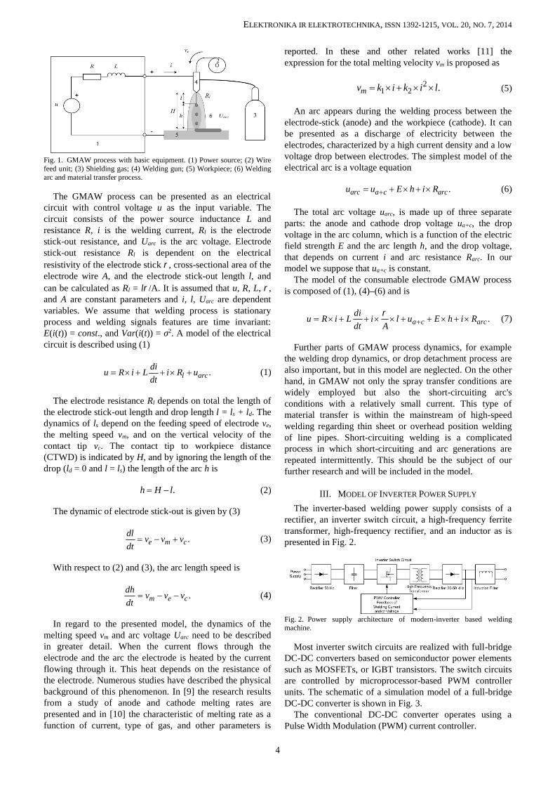
Fig. 1. GMAW process with basic equipment. (1) Power source; (2) Wirefeed unit; (3) Shielding gas; (4) Welding gun; (5) Workpiece; (6) Weldingarc and material transfer process.
The GMAW process can be presented as an electricalcircuit with control voltage u as the input variable. Thecircuit consists of the power source inductance L andresistance R, i is the welding current, Rl is the electrodestick-out resistance, and Uarc is the arc voltage. Electrodestick-out resistance Rl is dependent on the electricalresistivity of the electrode stick , cross-sectional area of theelectrode wire A, and the electrode stick-out length l, andcan be calculated as Rl = l/A. It is assumed that u, R, L, ,and A are constant parameters and i, l, Uarc are dependentvariables. We assume that welding process is stationaryprocess and welding signals features are time invariant:E(i(t)) = const., and Var(i(t)) = σ2. A model of the electricalcircuit is described using (1)
.l arcdiu R i L i R udt
(1)
The electrode resistance Rl depends on total the length ofthe electrode stick-out length and drop length l = ls + ld. Thedynamics of ls depend on the feeding speed of electrode ve,the melting speed vm, and on the vertical velocity of thecontact tip vc. The contact tip to workpiece distance(CTWD) is indicated by H, and by ignoring the length of thedrop (ld = 0 and l = ls) the length of the arc h is
.h H l (2)
The dynamic of electrode stick-out is given by (3)
.e m cdl v v vdt (3)
With respect to (2) and (3), the arc length speed is
.m e cdh v v vdt (4)
In regard to the presented model, the dynamics of themelting speed vm and arc voltage Uarc need to be describedin greater detail. When the current flows through theelectrode and the arc the electrode is heated by the currentflowing through it. This heat depends on the resistance ofthe electrode. Numerous studies have described the physicalbackground of this phenomenon. In [9] the research resultsfrom a study of anode and cathode melting rates arepresented and in [10] the characteristic of melting rate as afunction of current, type of gas, and other parameters is
reported. In these and other related works [11] theexpression for the total melting velocity vm is proposed as
21 2 .mv k i k i l (5)
An arc appears during the welding process between theelectrode-stick (anode) and the workpiece (cathode). It canbe presented as a discharge of electricity between theelectrodes, characterized by a high current density and a lowvoltage drop between electrodes. The simplest model of theelectrical arc is a voltage equation
.arc a c arcu u E h i R (6)
The total arc voltage uarc, is made up of three separateparts: the anode and cathode drop voltage ua+c, the dropvoltage in the arc column, which is a function of the electricfield strength E and the arc length h, and the drop voltage,that depends on current i and arc resistance Rarc. In ourmodel we suppose that ua+c is constant.
The model of the consumable electrode GMAW processis composed of (1), (4)–(6) and is
.a c arcdiu R i L i l u E h i Rdt A
(7)
Further parts of GMAW process dynamics, for examplethe welding drop dynamics, or drop detachment process arealso important, but in this model are neglected. On the otherhand, in GMAW not only the spray transfer conditions arewidely employed but also the short-circuiting arc'sconditions with a relatively small current. This type ofmaterial transfer is within the mainstream of high-speedwelding regarding thin sheet or overhead position weldingof line pipes. Short-circuiting welding is a complicatedprocess in which short-circuiting and arc generations arerepeated intermittently. This should be the subject of ourfurther research and will be included in the model.
III. MODEL OF INVERTER POWER SUPPLY
The inverter-based welding power supply consists of arectifier, an inverter switch circuit, a high-frequency ferritetransformer, high-frequency rectifier, and an inductor as ispresented in Fig. 2.
Fig. 2. Power supply architecture of modern-inverter based weldingmachine.
Most inverter switch circuits are realized with full-bridgeDC-DC converters based on semiconductor power elementssuch as MOSFETs, or IGBT transistors. The switch circuitsare controlled by microprocessor-based PWM controllerunits. The schematic of a simulation model of a full-bridgeDC-DC converter is shown in Fig. 3.
The conventional DC-DC converter operates using aPulse Width Modulation (PWM) current controller.
4

ELEKTRONIKA IR ELEKTROTECHNIKA, ISSN 1392-1215, VOL. 20, NO. 7, 2014
Fig. 3. DC-DC converter circuit using full-bridge PWM inverter withcorresponding control unit.
The DC-DC converter operates at constant switchingfrequency, which is usually limited to 20 kHz–50 kHz. Theamplitude of the welding current depends on the change ofthe phase shift between transistors S1, S2, S3, and S4. ThePWM signals are generated using a simple circuit and areused for driving four transistors by changing the duty cycle.In paper [12] the authors investigated the implementationsof different PWM control techniques on a microcontroller.These modulation techniques are used in order to enhancethe performances of three-phase inverters. The duty cyclesare usually controlled using feedback controller (voltage,current, or both). In [13] and [14] the implementationstudies of proportional-integral-derivative (PID) controllerare presented, but we decided to use a PI controller becauseit satisfies control performances well, and the lack ofderivative action may make the control system stabile in thecase of noisy data. The discrete parallel form is
1 ,
1S
PI pI
TC z K
T z
(8)
where KP is the proportional gain, TI is the integral timeconstant, and TS is the sampling time.
IV. SIMULATION RESULTS
An automatic welding application was assumed. Thoseparameters derived from the experimental conditions areshown in Table I.
TABLE I. GMAW PROCESS SIMULATION PARAMETERS.Parameter Descr. of the parameter Value
R Power source resistance 0.07 L Power source inductance 0.02 mH
Specific electrical resistance of
the electrode 0.1 /m
A Cross-sectional area of theelectrode wire 1.02 × 10⁻⁶ m2
E Electric field strength 675 V/mua+c Arc voltage constant 11.55 VRarc Arc resistance 0.03 ve Feeding speed of electrode 0.5 m/mink1 Empirical constant 0.626 m/(As)k2 Empirical constant 7.55 × 10⁻⁵ (A2s)-1
H Contact tip to workpiece distance(CTWD) 0.16 m
l Electrode stick-out length 0.10 m
A constant welding speed was supposed. The weldingtorch was positioned 16 mm (H) from the work distance.
The selected welding wire feed rate ve 50 mm/s and the opencircuit voltage u = 24 V were set. The first simulation wasperformed to find the welding current response when theCTWD was changed from 16 mm to 12 mm (at time 2.5 s)and back (at time 7.5 s). In addition, the electrode feedingspeed v was changed from 50 cm/min to 75 cm/min at timet = 5 s.
Fig. 2 shows the changes in the welding voltage andcurrent time responses, and the changes of the arc length.
Fig. 4. Simulated results of contact to workpiece voltage waveform (thirdplot) and welding current waveform (fourth plot). Simulation response ofthe GMAW model when the CTWD was changed from 16 mm to 12 mm(first plot) and the electrode feeding speed ve was changed from 0.5 m/minto 0.7 m/min (second plot).
The welding current rose and fell with the changes of Hand ve, as expected. It can be seen from the first plot inFig. 2 that the arc length h (dotted curve) decreased after theH changed from 16 mm to 12 mm and then increased backto the previous length. Accordingly, the electrode length lchanged from 11.25 mm to 7.5 mm, which meant that theelectrode melted at a higher speed when the currentincreased. In the second plot of Fig. 2 the electrode feedingspeed was increased from 50 mm/s do 70 mm/s. This led areduction of the arc resistance and an increasing of weldingcurrent.
A full-bridge circuit is simulated as the topology of themain inverter circuit. The load of the inverter depended onGMAW simulation model and was continuously changing.In Table II the design specification of the DC-DC converterand the circuit parameters are described, respectively.
TABLE II. DC-DC CONVERTER AND OTHER CIRCUITPARAMETERS.
Parameter Descr. of the parameter Valuefs Switching frequency 40 kHzC Capacitance 1 µFPn Transformer nominal power 5 kW
n1 : n2 : n2 Transformer turns ratio 3,5 : 1 : 1S1 - S4 Ideal switch, IGBT
Ron Switch internal resistance 140 mRs Snubber resistance 1MCsd Snubber capacitance 4,7 nFTs Control sample time 0.1 msTI PI controller Integral constant 2 msKP PI controller proportional gain 0,2 %/A
The simulation results from the welding using currentcontrol feedback and the PWM full-bridge DC-DCconverter are shown in Fig. 5.
Constant welding speed was supposed. The welding torchwas positioned at 16 mm (H) from work distance (CTWD)and after 5 ms H was increased to 18 mm, as is presented in
5

ELEKTRONIKA IR ELEKTROTECHNIKA, ISSN 1392-1215, VOL. 20, NO. 7, 2014
the first graph of Fig. 5. The welding wire feed-rate ve wasset at 70 mm/s. After 1 ms the welding current's set pointwas increased to 100 A, after 3 ms to 200 A, and finallyafter 7 ms to 150 A. The fourth plot in Fig. 5 presents thecurrent control system transient response, which was stablewith a small overshoot and was sufficiently fast. On the fifthplot the time response of the primary current is shown.
Fig. 5. Simulation results of the welding process with current controlfeedback and PWM full-bridge DC-DC converter-based welding powersource. The upper plot shows the change of the CTWD from 16 mm to18 mm. The forth plot presents the welding current transient response, andon the fifth plot the time response of the primary current is shown.
For a better presentation of the generated PWM signalsthe same simulation results were plotted within a timewindow from about 3 ms to 4 ms, and marked with an arrowin the fourth graph in Fig. 5.
Fig. 6. Simulation results of generated PWM signals, which depend on theduty cycle controlled with simple PI controller. The second and third plotsshow the PWM signals for driving the full-bridge DC-DC converterswitches. The fourth and fifth plots show the corresponding changes ofprimary current and secondary-welding current.
In the first plot of Fig. 6, the PWM frequency generator iscompared with current controller output (duty cycle). Insecond and third plots the PWM signals for driving the full-bridge DC-DC converter switches are presented. Theperiods of pulses A1 and A2 changes depended on the dutycycle determined by the discrete PI controller. Themaximum simulation step-size was 0.1 μs and the discretePI controller sample time was 100 μs.
V. CONCLUSIONS
A simulation application has been developed forsimulating the GMAW process and inverter-based weldingsource. The mathematical model is based on physicaldescriptions of several parts of the GMAW process, as arethe electric circuits of the power supply, the arc dynamics,the electrode melting process, etc. Further process parts, forexample the welding drop dynamics and drop detachmentprocess will be the subject of further research and should
also be included in simulation model of the GMAW process.The simulation of inverter power source for welding powersupply has been proposed and tested together with theGMAW simulation model. The simulation results showedthat the conventional full-bridge DC-DC converter withappropriate current feedback controller makes the outputwelding current follow the set references.
The proposed models and simulations, which are combinetogether to simulate the power source circuits usingsimulations of the GMAW process, are suitable for thedevelopment new power source circuits, for exampleresonant converters. By establishing appropriate models ofthe GMAW process and the full-bridge DC-DC convertermodel, simulation is an effective tool for investigating newwelding technologies, for example the Pulsed GMAWprocess, or Surface Tension Transfer welding process(STT). Simulation results could be very useful for the rapiddevelopment of new control algorithms and for thedesigning of new inverter control units.
REFERENCES
[1] K. L. Moore, D. S. Naidu, R. Yender, J. Tyler, “Arc Welding Control:Part 1 – Modelling and Analysis”, Nonlinear Analysis: Theory,Methods & Applications, vol. 30, pp. 3101–3111, 1997. [Online].Available: http://dx.doi.org/10.1016/S0362-546X(97)00372-6
[2] K. L. Moore, D. S. Naidu, S. Ozcelik, Modelling, Sensing andControl of Gas Metal Arc Welding. Oxford, UK: Elsevier ScienceLtd., 2003.
[3] M. Golob, A. Koves, A. Puklavec, B. Tovornik, “Modelling,simulation and fuzzy control of the GMAW process”, in Conf. Proc.15th Int. Federation of Automatic Control (IFAC) - Triennial WorldCongress on Automatic Control, Barcelona, Spain, 2002, vol. 13, pp.253–258.
[4] J. S. Thomsen, “Control of Pulsed Gas Metal Arc Welding”, Int.Journal of Modelling, Identification and Control, vol. 1, no. 2, pp.115–125, 2006.
[5] J. Zhang, B. L. Walcott, “Adaptive Interval Model Control of ArcWelding Process”, IEEE Trans. On Control Systems Technology, vol.14, pp. 1127–1134, 2006. [Online]. Available: http://dx.doi.org/10.1109/TCST.2006.880215
[6] J. Scemeliovas, “Determination of Optimal Pulse Current for ArcWelding”, Elektronika Ir Elektrotechnika, no. 7, pp. 87–90, 2009.
[7] M. D. Ngo, V. H. Duy, N. T. Phuong, H. K. Kim, S. B. Kim,“Development of digital gas metal arc welding system”, Journal ofMaterials Processing Technology, vol. 198, no. 1–3, pp. 384–391,2007. [Online]. Available: http://dx.doi.org/10.1016/j.jmatprotec.2007.02.010
[8] M. Golob, B. Tovornik, “Modelling, simulation and control of gasmetal arc welding”, in Proc. 7th Congress on Modelling andSimulation EUROSIM, Prague, Czech Republic, 2010, pp. 347–352.
[9] A. Lesnewich, “Control of the Melting Rate and Metal Transfer inGas Shielded Metal Arc Welding - Part 1”, Welding Journal, vol. 37,pp. 343s–354s, 1958.
[10] J. Tusek, M. Suban, “Dependence of Melting Rate in MIG/MAGWelding on the Type of Shielding Gas Used”, Journal of MaterialsProcessing Technology, vol. 119, pp. 185–192, 2001. [Online].Available: http://dx.doi.org/10.1016/S0924-0136(01)00940-2
[11] E. Halmoy, “Wire melting rate, droplet temperature and effectiveanode potential”, in Proc. Int. Conf. Arc Physics and Weld PoolBehaviour, London, England, 1979, pp. 49–57.
[12] C. Aghion, O. Ursaru, “Three-Phase inverter Controlled by ISCPWMand DPWM-S1”, Elektronika Ir Elektrotechnika, no. 3, pp. 87–90,2012.
[13] O. Krejcar, I. Spicka, R. Frischer, “Implementation of Full-FeaturedPID Regulator in Microcontrollers”, Elektronika Ir Elektrotechnika,no. 7, pp. 77–82, 2011.
[14] A. Petrovas, S. Lisauskas, R. Rinkeviciene, “Digital AutomaticControl System with PID Controller”, Elektronika Ir Elektrotechnika,no. 4, pp. 13–16, 2011.
6