integrated image processing and path planning for robotic sketching
TRANSCRIPT

Procedia CIRP 12 ( 2013 ) 199 – 204
Available online at www.sciencedirect.com
2212-8271 © 2013 The Authors. Published by Elsevier B.V.Selection and peer review under responsibility of Professor Roberto Tetidoi: 10.1016/j.procir.2013.09.035
ScienceDirect
8th CIRP Conference on Intelligent Computation in Manufacturing Engineering
Integrated image processing and path planning for robotic sketching
A. Mohammeda, L. Wanga,*, R.X. Gaob aVirtual Systems Research Centre, University of Skövde, 541 28 Skövde, Sweden
bDepartment of Mechanical Engineering, University of Connecticut, Storrs, CT, USA * Corresponding author. Tel.: +46-500-44-8519; fax: +46-500-44-8598. E-mail address: [email protected].
Abstract
Since the beginning of the development of machine vision, researchers have realized its importance in the robotics field, as it provides a useful tool for both the environment detection and decision making during the automation process. At the same time, path planning for robots influences many in the robotics and automation field and it has remained active for both methodology research and system implementation. This research combines machine vision with robot path planning with an aim of programming-free robotic applications. Particularly as a proof of concept, a programming-free robotic sketching prototype is developed as a case study. Within the context, this paper consists of three parts. The first part covers the processing of a facial image taken by a webcam to identify the contours that represent the image; the second part converts these contours to paths for an industrial robot to follow; and the third part controls the robot adaptively for sketching including auto-generation of control codes and self-calibration. The developed prototype is a closed-loop system with networked camera and robot. Intelligent computation is applied to identify the contours of the image with minimum representation of points and with the correct sequence of points for each curve (path); the sequence of the output robot paths represents the near-optimal sequence to preserve the minimum travelling time for the robot. The robot control module can also retrieve the TCP of the robot for off-site monitoring. The ultimate goal of this research is future applications of robot path following, e.g. ad-hoc robotic cutting or welding where the paths can be specified by hand-drawings of an operator on the target workpiece with zero programming for the operator. © 2012 The Authors. Published by Elsevier B.V. Selection and/or peer-review under responsibility of Professor Roberto Teti.
Keywords: Image processing; path planning; robotics; automation..
1. Introduction
Generally, robotic operations need to be detailed in advance to ensure their success in action. This creates constraints that limit the adaptability of a robotic system and cause two major disadvantages. First, extra hours are needed for programing a robot for the right operations. Second, the robot is thus limited to certain predefined operations, leading to a rigid automation.
In a dynamic manufacturing environment, a flexible and adaptive robot system is in demand. By integrating image processing with a robotic system, it contributes to the improved adaptability of the system, and at the same time it opens the door to other potential applications. Some of the noticeable research efforts were reported in [1] and [2], which demonstrated the possibility of using
a captured facial image. Another work [3] was done by
Lehni who used a dedicated robot to sketch large-scale portraits.
Robotic path/trajectory planning is another research topic, which affects the efficiency and productivity of a robotic system. Most of the research work in this area focused mainly on defining a collision free trajectory for robots [4], while others focused more on designing task-oriented robot path planning systems [5]. Solving the singularity issues during robot path planning is also the focus for many, such as the work reported in [6].
For effective path planning, representing information in the right form is crucial. In the literature, the ways of representing input information to a path planning system can be divided into two groups: one using 3D models of a workpiece to plan the robot path (see [7] for more details in this category), and the other planning the robot path based on captured images from a camera connected to a robotic system.
© 2013 The Authors. Published by Elsevier B.V.Selection and peer review under responsibility of Professor Roberto Teti

200 A. Mohammed et al. / Procedia CIRP 12 ( 2013 ) 199 – 204
The reported robot sketching works in the literature focused more on trying to produce an identical copy of a captured image. The capability for a system to sketch an arbitrary portrait and the ability to monitor and control the process from a remote location is still missing.
Targeting the challenge, the objective of this research is to develop an image-guided adaptive robotic system for industrial applications. In the current phase, the focus of the research is on rapid image processing, fast robot path planning, and remote monitoring and control of a robot for sketching. The concept and the prototype will be extended to laser cutting and welding etc., in the next phase, where the cutting paths or welding seams can be specified by operators via hand drawings or captured by cameras. The anticipated outcome of this research is an adaptive and programing-free robotic system for SMEs in customized job-shop operations.
This paper, in particular, introduces a web-based system that provides the ability for remote operators to monitor and control an industrial robot. The system aims to imitate the human behavior in sketching human facial portraits as a case study, while developing the required system functionality for the future extension. The main concept of this research is demonstrated and validated in the case study for adaptive decision making.
2. System Overview
The designed system provides the ability for remote operators to monitor and control the stages of image processing and robot sketching. An authorized operator can even access the system remotely using any computer running on any platform via a web portal of the system. At the same time, the system provides a certain level of control for the operators, predefined in the system. This is achieved by a Java applet, through which the operator can access the system with authentication.
Moreover, the remote operator has the possibility to perform various online operations to the physical robotic system, e.g. calibrating a work object and/or jogging the robot to a specific target pose.
The designed system consists of a network camera and an industrial robot, both of which are connected to an application server through Ethernet. A dedicated user interface is developed to control the camera, the image processing steps, and the robot sketching operations. As shown in Fig. 1, the system architecture consists of four modules. The central one is an application server, which establishes the communication with other modules. At the same time, it offers the needed decision making for image processing and robot path planning.
The second module represents an industrial robot, which sends data to the server for robot monitoring, and at the same time it receives control commands from the server and performs the task accordingly.
Fig. 1. System architecture
The third module is an IP-based network camera, which can be controlled remotely through an URL; it is used in the system to take snapshots of a human face or a work object, and then send the images to the server for processing.
A remote operator connected to the system via a web browser is represented by the fourth module, where the operator has access to monitor and control the process; this is done by using the facilities of a Java applet.
In summary, the system is designed to (1) capture a facial image of a person using the network camera, (2) transmit the image to the server, (3) retrieve its contours after image processing by the server, and (3) send the coordinates of the contours to the robot, point by point and contour by contour. The robot will follow the points to sketch the contours of the image on a paper sheet. A Sony SNC-CH110 camera and an ABB IRB140 robot are used in the current implementation.
3. System Implementation
3.1. Image processing procedures
As illustrated in Fig. 2, the procedures for image processing are described as follows.
201 A. Mohammed et al. / Procedia CIRP 12 ( 2013 ) 199 – 204
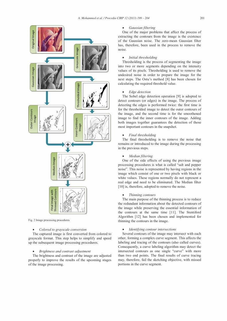
Fig. 2 Image processing procedures
Colored to grayscale conversion The captured image is first converted from colored to
grayscale format. This step helps to simplify and speed up the subsequent image processing procedures.
Brightness and contrast adjustment The brightness and contrast of the image are adjusted
properly to improve the results of the upcoming stages of the image processing.
Gaussian filtering One of the major problems that affect the process of
extracting the contours from the image is the existence of the Gaussian noise. The zero-mean Gaussian filter has, therefore, been used in the process to remove the noise.
Initial thresholding Thresholding is the process of segmenting the image
into two or more segments depending on the intensity values of its pixels. Thresholding is used to remove the undesired noise in order to prepare the image for the
ethod [8] has been chosen for calculating the required threshold value.
Edge detection The Sobel edge detection operation [9] is adopted to
detect contours (or edges) in the image. The process of detecting the edges is performed twice: the first time is for the thresholded image to detect the outer contours of the image, and the second time is for the smoothened image to find the inner contours of the image. Adding both images together guarantees the detection of those most important contours in the snapshot.
Final thresholding The final thresholding is to remove the noise that
remains or introduced to the image during the processing in the previous steps.
Median filtering One of the side effects of using the previous image
processing procedures salt and pepper . This noise is represented by having regions in the
image which consist of one or two pixels with black or white values. These regions normally do not represent a real edge and need to be eliminated. The Median filter [10] is, therefore, adopted to remove the noise.
Thinning contours The main purpose of the thinning process is to reduce
the redundant information about the detected contours of the image while preserving the essential information of the contours at the same time [11]. The Stentiford Algorithm [12] has been chosen and implemented for thinning the contours in the image.
Identifying contour intersections Several contours of the image may intersect with each
other, forming a complex curve segment. This affects the labeling and tracing of the contours (also called curves). Consequently, a curve labeling algorithm may detect the intersected contours as one than two end points. The final results of curve tracing may, therefore, fail the sketching objective, with missed portions in the curve segment.

202 A. Mohammed et al. / Procedia CIRP 12 ( 2013 ) 199 – 204
In order to trace the contours in the image correctly, the intersecting pixels (points) shared by more than one contour are distinguished first. These points separate the contours into shorter ones before all the contours can be labeled.
Contours labeling The contours in the image are labeled at this stage in
order to trace all contours one by one, independently and completely. The Connected Components Algorithm [13] has been used to label the contours in the image.
Contours tracing For effective sketching (or path following in welding/
cutting applications), the points in each contour must be organized in the correct order. This order guarantees that the contour tracing starts from the first point and ends with the last point.
Based on this observation, the process for tracing the contours begins by scanning the pixels in the image to find the one having a contour label. By checking its neighboring pixels of the current pixel, if only one of the neighbors belongs to the same contour, this pixel is the last or the first pixel of the contour. The next step is to add this pixel to a new list, and then to find the next neighboring pixel that belongs to the contour. After the new pixels are identified and added to the list, they are converted to background pixels. Repeat the procedure until all the pixels in the contour are found and all the contours in the image are scanned. Fig. 3 depicts the process of contour tracing.
Fig. 3 Tracing a contour point by point
Merging broken contours As mentioned earlier, resetting the common pixels of
those intersected contours can divide them into shorter ones. It is good for unique contour labeling but may not be efficient for contour tracing and following. In order to solve this problem, the following method is proposed. It starts iteratively by taking one endpoint of one contour,
and scans the endpoints of other contours one by one, by comparing the distance between the two endpoints and the difference in directions of the two endpoints. If the result of this comparison is within a specified threshold, the two contours (the two lists of points) will be merged in the correct order of points.
Fig. 4 gives one example to demonstrate how broken contours can be merged.
Fig. 4 Example of merging two sub-contours
3.2. Path planning
For smooth and efficient motions in robot sketching, two issues must be settled during path planning: the first one is to remove the redundant points in each contour from the list that represents the contour, and the second one is to find the optimal or near optimal sequence for sketching the contours so as to guarantee the shortest travelling time and smooth trajectory for the robot. This objective can be achieved as follows.
Point reduction In order to remove those redundant or unnecessary
points in each contour, the Douglas-Peucker Algorithm [14] has been chosen. This algorithm can reduce the total number of points in the contours while preserving the shape of these contours at the same time.
Finding the best sequence The Nearest Neighbor Algorithm [15] is preselected
to find the best sequence of the contours. This algorithm does not require heavy and expensive computation, but it offers a good chance for the system to converge to an optimal solution.
System integration The industrial robot in the system is connected to the
application server using HTTP communication protocol, and this protocol requires all information being sent in small data packets. Therefore, each contour in the image is represented by a number of data packets. The server packs these packets and sends them to the robot one by one. On the robot side, these packets are unpacked and executed accordingly.
The sequence of the packets received by the robot is crucial for smooth sketching. Therefore, each packet has

203 A. Mohammed et al. / Procedia CIRP 12 ( 2013 ) 199 – 204
two extra segments, indicating the identity of a contour and the packet order within the contour, respectively.
4. Experimental Results
The image processing and path planning module has been implemented using the Wise-ShopFloor framework [16]. The application server employed in the system has the following configuration: Intel Core i5 processor 2.8 GHz, 4GB RAM, NVidia GeForce GT 240 graphics card, running on Windows Vista operating system.
The prototype system has been tested with different facial snapshots. These snapshots included faces with different skin colors and facial expressions. It is found that the image processing module can retrieve the major contours of the snapshots and prepare the contours for robot path planning, efficiently. Furthermore, the path planning plays a major role in minimizing the points of these contours and preserving the contour shapes at the same time. The results of both the image processing and path planning satisfied the requirements of the sketching application. Fig. 5 shows the processing results.
Fig. 5 Results of image processing and path planning
5. Discussions and Conclusions
This paper presents a web-based system for image processing and path planning for robot sketching. It can be extended to other industrial applications such as robot welding and laser cutting. The remote monitoring and
control functions (beyond the scope of this paper) make the system practical for distant operations in distributed environment.
The results of this research reveal that the developed image processing and robot path planning module can process an image as efficiently as can be done manually via a commercial software tool. Beyond the efficiency, the true advantage of this module is its consistency, user-friendliness, seamless integration with robots, and better reliability towards industrial applications.
This prototype system has been tested using eight different snapshots with varying numbers of contours, ranging from 40 contours in a simple snapshot to 300 contours in a complex one. The time spent in each step during image processing and path planning was recorded and the stepwise time consumptions in percentage are shown in Fig. 6.
Fig. 6 Processing times with respect to total time
It is noticed after analyzing the processing times that the time spent for final thresholding does not depend on the number of contours. This is due to the fact that the algorithms used in the application are based on image scanning to read or manipulate each pixel in the image. The most determining factor in the processing time is the resolution of an image.
As shown in Fig. 6, a quite high percentage of the processing time is consumed for detecting the inner and outer contours of the image. Tracing the contours also takes long processing time, depending on the number of contours. This is due to the nature of the contour tracing algorithm that works in a recursive loop to manipulate the contours in the image. Our future work is to reduce the processing time as much as possible. This can be achieved by improving the efficiency of algorithms used in the time consuming processes.

204 A. Mohammed et al. / Procedia CIRP 12 ( 2013 ) 199 – 204
As mentioned before, the system developed in this research opens the door to many industrial applications by enhancing the adaptability of robots to changes. One of these applications would use the reported algorithms and the prototype to build a robotic cutting application (e.g. water-jet or laser cutting) that possesses the ability to follow any arbitrary cutting path, whereas the issue of auto-calibration of robots is handled by a macro-micro camera system (to be reported separately). The system can also be extended to improve the adaptability of arc welding and friction-stir welding, where the welding seams can be detected by a robot-mounted camera.
essential. In many situations, an operator may prefer to specify a path by hand drawing right on the workpiece, which can then be detected and converted to a robot path immediately. The tedious robot programming can thus be eliminated to boost shop-floor productivity.
Realizing the above-mentioned application potentials in real-world industrial settings is our future work.
References
[1] Gommel, M., Haitz, M., Zappe, J., 2004. Robotlab autoportrait Art and
Media Karlsruhe, 2004. [2] Stein, M., Madden, C., 2005. project: Long term
usage trends and the move to thre Proceedings of the IEEE Intl Conference on Robotics and Automation (ICRA).
[3] Lehni, J., 2002. Hektor: a graffiti output device, diploma project at the Ecole Cantonale d'Art de Lausanne, 2002.
[4] Saravanan, R., Ramabalan, S., Balamurugan, C., 2009. Evolutionary multi-criteria trajectory modeling of industrial robots in the presence of obstacles, Engineering Applications of Artificial Intelligence, Vol. 22, p. 329.
[5] Antonelli, G., Chiaverini, S., Curatella, C., Marino, A., 2009.
Proceedings of the IEEE International Conference on Automation and Logistics Shenyang, China, p. 1934, August 2009.
[6] Paganelli, D. Topological Methods for Singularity-Free Path-Planning, University of Bologna, Italy, p. 413.
[7] Chen, H., Fuhlbrigge, T., Li, X., 2009. A review of CAD-based robot path planning, Industrial Robot: An International Journal, Vol. 36, No. 1, p. 45, 2009.
[8] Xu, X., Xu, S., Jin, L., Song, E., 2010. Characteristic analysis of Otsu threshold and its applications, Elsevier B.V., Pattern Recognition Letters, Vol. 32, p. 956, 2010.
[9] Canny, J., 1986. A Computational Approach to Edge Detection, IEEE Transactions on Pattern Analysis and Machine Intelligence, Vol. PAMI-8, p. 679, 1986.
[10] Maheswari, D., Radha, V., 2010. Noise Removal in compound image using Median filter, International Journal on Computer Science and Engineering, Vol. 2, p. 1359, 2010.
[11] Jain, R., Kasturi, R., Schunck, B., 1995. Machine VisionMcGraw-Hill, 1995.
[12] Stentiford,F.W.M., Mortimer, R.G., 1983. Some New Heuristics for Thinning Binary Handprinted Characters for OCR, R. G. 1, IEEE Transactions on Systems, Man, and Cybernetics, Vol. SMC-13, p. 81, 1983.
[13] Dillencourt, M.B., Samet, H., Tamminen, M., 1992. A General Approach to Connected-Components Labeling for Arbitrary Image Representations, Journal of the Association for Computing Machinery, Vol. 39, p. 253, 1992.
[14] Douglas, D.H., Peucker, T.K., 1973. Algorithms for the reduction of the number of points required to represent a digitized line or its caricature, The Canadian Cartographer, Vol. 10, pp. 112, 1973.
[15] Edan, Y., Flash, T., Peiper, U.M., Shmulevich, I., Sarig, Y., 1991. Near-Minimum-Time Task Planning for Fruit-Picking Robots, IEEE Transactions on Robotics and Automation, Vol. 7, p. 48.
[16] Wang, L., 2008. -ShopFloor: An Integrated Approach for Web-Systems, Man, and Cybernetics Part C: Applications and Reviews, Vol.38, No.4, p.562, 2008.