integrated dynamic transit operations (idto): stakeholder input on concept of operations ( conops )...
DESCRIPTION
Integrated Dynamic Transit Operations (IDTO): Stakeholder Input on Concept of Operations ( ConOps ) Development. IDTO Stakeholders Meeting January 26 and 27, 2012 in Washington, DC. Welcome. Announcements. Sign-in sheet Agenda Workbook Administrative announcements. Key Meeting Elements. - PowerPoint PPT PresentationTRANSCRIPT
Integrated Dynamic Transit Operations (IDTO): Stakeholder Input on Concept of Operations (ConOps) Development
IDTO Stakeholders MeetingJanuary 26 and 27, 2012 in Washington, DC

2
Welcome
3
Announcements•Sign-in sheet•Agenda•Workbook•Administrative announcements

4
Key Meeting Elements•Information dissemination•Full group discussion•Group breakout sessions with debriefing
•Questions and answers

5
Meeting Agenda – Day 11. Welcome and Introductions2. Workshop Objectives and Desired
Outcomes3. IDTO Overview and Draft Visions4. BREAK5. Group discussion of transformative
concepts, current status, trends and perspectives
6. Briefing on DMA and Link to IDTO

6
Introductions
•Name•Organization•Area of Expertise
•Meeting Expectations

7
Meeting Outcomes1. Determine if scenarios are
correctly documented and represented
2. Gather detailed input for each scenario to finalize high level User Needs
3. Identify initial “Gaps” that need to be filled for IDTO applications to be operational

8
Goals and Objectives of the
Study

9
Goals of the Study1. Facilitate concept development and
needs refinement for IDTO applications2. Assess relevant prior and ongoing
research 3. Develop functional requirements and
corresponding performance requirements
4. Develop high-level data and communication needs
5. Assess readiness for development and testing

10
Goals of IDTO•Examine what technologies can help
people effortlessly transfer from one mode of travel (car, bus, train, etc.) to another for the fastest and most environmentally friendly trip
•Seek to make cross-modal travel truly possible
•Enable agencies and companies to manage their systems in light of the fact that people may be changing modes often

11
IDTO Applications Definitions• Connection Protection (T-CONNECT) - enable public
transportation providers and travelers to communicate to improve the probability of successful transit transfers. This application would potentially include intermodal and interagency coordination.
• Dynamic Transit Operations (T-DISP) - links available transportation service resources with travelers through dynamic transit vehicle scheduling, dispatching and routing capabilities. It would also enable travelers to make real-time trip requests through personal mobile devices.
• Dynamic Ridesharing (D-RIDE) - makes use of in-vehicle (drivers) and hand-held devices (riders) to dynamically identify and accept potential ridesharing opportunities along the travel route.

T-CONNECT Example

T-CONNECT: State of the Practice• T-Connect addresses problem of multiple transfers
between different transit modes by enabling communications to improve probability of a transfer
• Exists mostly for bus-to-bus transfers, but limited application of for rail-to-bus
• Relies on passenger request to driver
• No US examples of regional, multiple operator connection protection

T-DISP Example

T-DISP: State of the Practice•T-DISP addresses variety of transit services
offered in certain conditions and allows travelers to assess their travel options
•Dynamic transit services operated in numerous locations around the US, but very few employ technology. Use of technology more prevalent in European dynamic transit operations
•Orlando’s Lynx FlexBus and United We Ride/Mobility Services for All Americans projects will provide valuable information

D-RIDE Example

D-RIDE: State of the Practice • D-RIDE promotes ridesharing through in-vehicle and
handheld technologies, and improvements to information available for high occupancy vehicle/toll lanes
• Various forms of ridesharing since early 1990s, but now new “products” available using current technology
• Input from Ridesharing Institute (created 2011) and new ridesharing products critical to understand marketplace
• Limited toll lane and in-vehicle functionality

18
Investigate Answers to Questions1. Do current practices take full advantage
of new transit technologies, tools and data sources?
2. What emerging opportunities exist for the new generation of automated tools to be used to facilitate the deployment of the IDTO applications?
3. Is there strong motivation for a federal role in facilitating the development of new technologies and tools to capitalize on these identified opportunities?

19
Summary of Findings from Scan of Current
Practice
20
Findings: Literature Review•Academia•USDOT Programs•United We Ride/Mobility Services for All
Americans (UWR/MSAA)•Connected Vehicle Program•Dynamic Mobility Applications•Research conducted by TRB and other
associations

21
T-CONNECT Current Practice
FR Bus
Flex/DR/ Para Bus
Light/ Heavy Rail
Commuter Rail Ferry
Fixed-route Bus Y1 N N N NFlexible/Demand Response/ Paratransit Bus
N N N N N
Light/Heavy Rail Y2 N N N NCommuter Rail Y3 N N Y4 NFerry N N N N N

22
T-CONNECT Current Practice (cont’d)1. Several examples in fixed-route
implementations. Commonplace with many CAD/AVL systems
2. For example, UTA’s TCP deployment between TRAX light rail and fixed-route buses
3. For example, commuter rail to fixed-route bus in Brampton, Ontario
4. No evidence of direct T-CONNECT implementation, but commuter rail often provides “unconditional” transfers

23
T-CONNECT General Findings•Literature limited•Evaluation of UTA TCP program revealed
that program well-regarded•Fixed-route to Fixed-route TCP is only T-
CONNECT-type implementation that exists today in the US

24
T-CONNECT Challenges• Electronic information exchange necessary, but
important to ensure consistency of coordination on business processes related to transfers
• After-the-fact review of transfer trips should be conducted
• “Maximum allowed” waiting time should be defined
• Definition of TCP should be by route, not by vehicle
• Manual intervention should be allowed• Accuracy of real-time vehicle locations must be
ensured

25
T-DISP Current Practice• Application limited in US:
▫ Flexibly-routed service with technology limited▫ No one site with all T-DISP elements:
coordination of transportation services, transit technology, technology to provide information to travelers and travel management coordination center
• Existing programs with some elements:▫ UWR/MSAA initiative▫ FlexBus in Orlando, FL▫ North and East Brainerd routes in Chattanooga▫ Belbus in Belgium and Flexlinjen in Sweden

26
T-DISP General Findings•Service coordination challenges are
complex•Technology alone will not overcome
coordination barriers•Limited demonstration of technology
application and coordination together•Travelers and their needs, particularly
information, critical part of T-DISP concept•Few states that include transit in 511
systems

27
T-DISP Challenges•Difficulty in coordinating amount multiple
transit agencies, funding programs, and local, state and Federal entities
•Lack of effective coordination structures has contributed to:▫Service area gaps▫Limited services▫Confusing and low quality customer service
•Limited deployment of real-time transit information systems

28
D-RIDE Current Practice• Pilot in Santa Barbara County through
FHWA Value Pricing Pilot Program• FHWA-sponsored scan of casual
carpooling/ slugging phenomenon• Project in San Diego to sync software
with in-vehicle computer, and calculate number of passengers
• Rideshare pilot in Washington State SR 520 corridor
• Multiple private companies/programs

29
D-RIDE General Findings•Wide range of technologies employed, and
with more mobile and internet-based technologies
•Fear of strangers often cited as reason for not sharing rides, so focus on making participants more comfortable
•Providing familiar meeting points and drop-off locations in addition to users’ homes way to make participants more comfortable
•Marketing necessary to draw initial crowd•Incentives can draw more users

30
D-RIDE Challenges•Implementing controls to minimize safety
concerns regarding sharing a vehicle with a stranger
•Lack of established rideshare infrastructure (meeting points and drop-off locations)
31
Group Discussion of Transformative Concepts, Current Status, Trends and
Perspectives

32
T-CONNECT Goals and Objectives

33
T-CONNECT Goals1. Implement a system that improves
intermodal transfer connections involving multiple transit agencies
2. Deploy an application that improves the probability of transit connections
3. Improve rider satisfaction regarding transfers

34
T-CONNECT Objectives•Implement a system that improves
coordination between transit agencies and vehicles by utilizing various technologies such as “Connected Vehicle “
•To deploy a system that increases the number of successful transit connections
•Reduction in overall round-trip travel time for transit riders requiring transfers, and provision of accurate and relevant real-time passenger information

35
T-CONNECT Performance
Measures
36
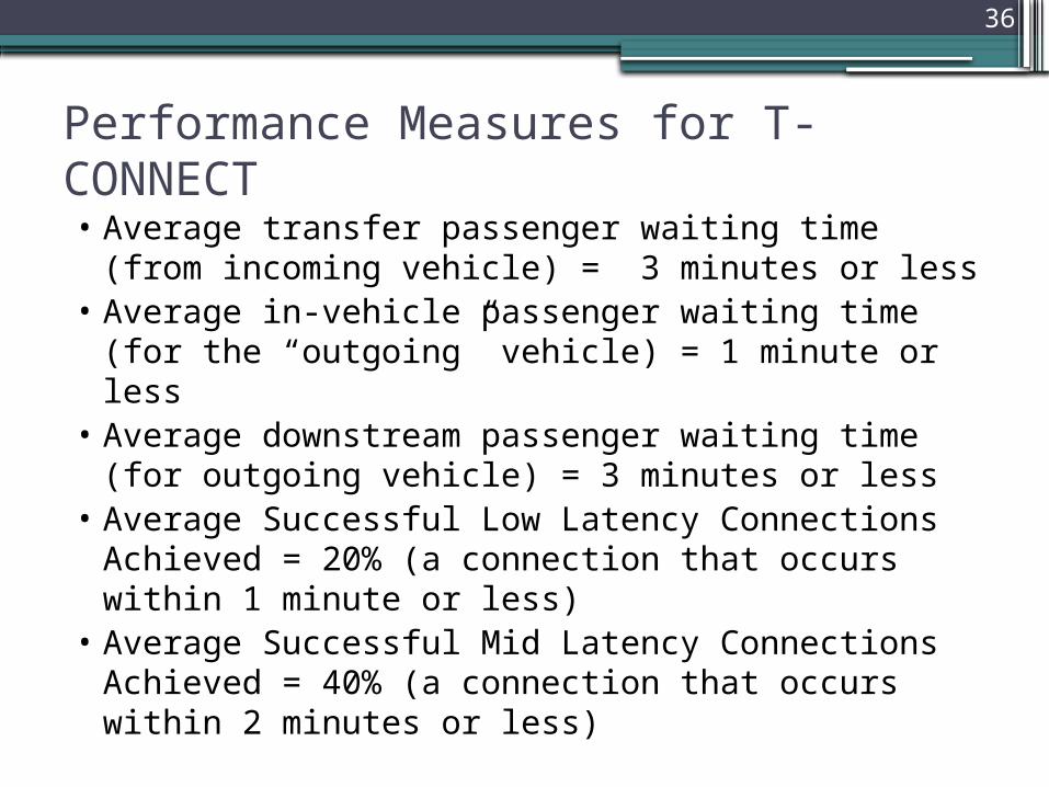
Performance Measures for T-CONNECT• Average transfer passenger waiting time (from
incoming vehicle) = 3 minutes or less• Average in-vehicle passenger waiting time (for
the “outgoing” vehicle) = 1 minute or less• Average downstream passenger waiting time (for
outgoing vehicle) = 3 minutes or less• Average Successful Low Latency Connections
Achieved = 20% (a connection that occurs within 1 minute or less)
• Average Successful Mid Latency Connections Achieved = 40% (a connection that occurs within 2 minutes or less)

37
Performance Measures for T-CONNECT (cont’d)
• Percentage of successful connections involving more than one agency: 95%
• Percentage of successful connections involving more than one mode: 95%
• Percentage of successful connection involving fixed and flexible modes: 90%
• Percentage of reduced complaints from customers regarding transfers: 90%
• Average response time to customers regarding a successful transfer request: 2 minutes

38
T-DISP Goals and Objectives
39
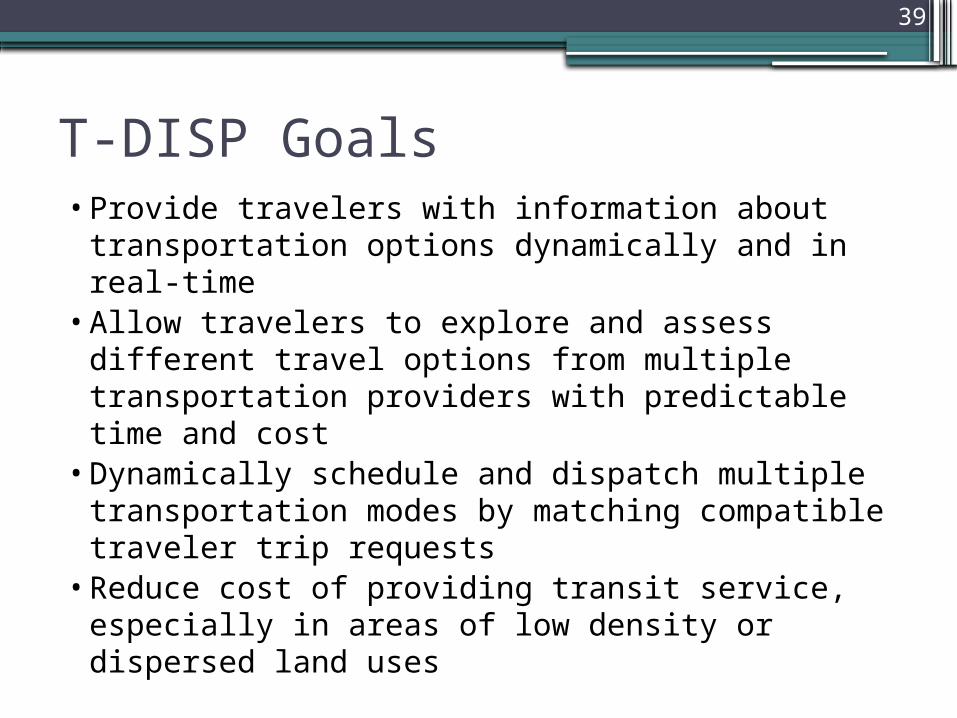
T-DISP Goals•Provide travelers with information about
transportation options dynamically and in real-time
•Allow travelers to explore and assess different travel options from multiple transportation providers with predictable time and cost
•Dynamically schedule and dispatch multiple transportation modes by matching compatible traveler trip requests
•Reduce cost of providing transit service, especially in areas of low density or dispersed land uses

40
T-DISP Objectives• Advance concept of demand-responsive
transportation services utilizing personal mobile devices with transportation providers’ on-board and central system technologies
• Provide a central system, such as Travel Management Coordination Center or decentralized system, to “ease” communications between transportation providers to leverage their services through dynamic routing, dispatching and scheduling based on real-time conditions
• Maximize use of multiple transportation providers and types of service within a region to provide effective service to the community

41
T-DISP Performance Measures

42
Performance Measures for T-DISP• Average time for traveler to make trip request,
receive and confirm trip = 45 seconds• Number of trips scheduled by the Control Center
compared to overall transit ridership (i.e., trips not scheduled through Control Center) per time frame (month, week, day)
• Average waiting time for a passenger for pickup since the time of trip request (for real-time trips only)
• Average on-board time for passengers

43
Performance Measures for T-DISP• Average boarding time for group trips• Number of trips performed by each mode• Number of trips performed by each provider,
public and private• Percentage of no-shows and cancellations• Reduction in cost per passenger

44
D-RIDE Goals and Objectives

45
D-RIDE Goals/Objectives1. Improve feasibility and convenience of
non-transit ridesharing options (e.g., car/vanpool) to increase mode-share and lessen congestion
2. To provide secure location-based data and accurate reporting of high occupancy vehicle (HOV) status for HOV and high occupancy toll (HOT) restricted lanes for HOV/HOT occupancy enforcement and improved tolling strategies

46
D-RIDE Performance
Measures

47
Performance Measures for D-RIDE• Number of participating users (concentration rate):
▫ 500 per 1 mile radius of passenger placing trip request▫ 750 per 2 mile radius of passenger placing trip request▫ 1,000 per 3 mile radius of passenger placing trip request
• Average passenger waiting time (waiting for ridematch vehicle) = 10 minutes or less
• Average number of ridematches (rate of occurrence):▫ 0-2 passenger to driver matches = < 5% of requests▫ 3-5 passenger to driver matches = at least 95% of requests▫ 6+ passenger to driver matches= 75% of requests
• Late arrivals (rate of occurrence) = <20% of all arrivals

48
Performance Measures for D-RIDE (cont’d)• Average response time to customers about a found ridematch
▫ 0-5 minutes = at least 95% of requests▫ 6+ minutes = < 5% of requests
• Total number of trips with modifications due to accident/incident with a vehicle = <5 per day
• Percentage of no-shows = <2% no shows = 95% of requests• Average on-board time for passengers by vehicle capacity (this
is a metric with no preset goals but should have data collected)▫ 1 passenger▫ 2 passengers▫ 3 passengers▫ 4 passengers
• Number of D-RIDE trips per month with HOV lane utilization▫ HOV 2+ = >75% D-RIDE trips per month▫ HOV 3+ = >80% D-RIDE trips per month

49
Dynamic Mobility Applications
Program

50
Dynamic Mobility Applications

51
Dynamic Mobility ApplicationsVision: Expedite development, testing, commercialization and
deployment of innovative mobility applications:▫ Maximize system productivity▫ Enhance mobility of individuals within the system
Objectives:• Create applications using frequently collected and rapidly
disseminated multi-source data from connected travelers, vehicles (automobiles, transit, freight) and infrastructure
• Develop and assess applications showing potential to improve nature, accuracy, precision and/or speed of dynamic decision making by system managers and system users
• Identify innovative forms of wireless connectivity supporting applications
• Demonstrate promising applications predicted to significantly improve capability of transportation system to provide safe, reliable, and secure movement of goods and people

52
Priority Applications
IDTO
Bun
dle

Dynamic Mobility Applications Program Roadmap
Decision pointLEGEND:High-Level Roadmap v1.5 (5/9/2011)
ProgramActivity Data Feed
Program Activity Track
Program Planning
Stakeholder Engagement
Demonstrations
Research and Development
Testing
Phase 2 ApplicationsDownselect
Outreach
Evaluation
Prototype Application
Application Identification
Phase 3 Demo Site Downselect
Phase 3 Demo(s)Phase 3 Demo Planning
Open Source Portal Development Deploy Open Source Portal
Do the candidate applications show enough promise to be tested?Do these applications address key performance measures?
Do we understand the communications requirements of these applications?
Are there clear and compelling arguments for deployments showing significant
benefits?
Ph. 2 Applications Testing
Data Capture
Data Capture
Connected Vehicle Demo(s)
Data Capture
Institutional and Policy
Standards
Ph. 2 Applications Development
Ph. 3 Apps Testing (OPT.)
Evaluation Planning Phase 2 Apps Evaluation Phase 3 Demo Evaluation(s)
Demo Coordination Planning
State-of-Practice Tech Assessments Develop and Refine Tools/Analytics For Impacts Assessment
PH.3 DECISION PO
INT
PH. 2 DECISION
POINT
Open SourceApplications
Data Capture
Define Measures
Data Capture
FOUNDATIONAL ANALYSISPHASE 1
RESEARCH, DEVELOPMENT & TESTING PHASE 2
DEMONSTRATION PHASE 3
9/09 9/11 9/13 9/15
Inst. and Policy Assessment
Standards Plan Standards Demonstration Standards Development and Testing
Inst. and Policy Requirements Revised Policies, Possible Rulemaking
Maintain Open Source Portal
Open SourcePortal

54
Meeting Agenda – Day 21. Recap and Description of Breakout
Sessions 2. Breakout Sessions:
▫T-CONNECT (facilitated by Carol Schweiger)
▫T-DISP (facilitated by Carrie Butler)▫D-RIDE (facilitated by Ayeshah
Abuelhiga) 3. BREAK4. Results/Recap of Breakout Sessions5. Revisit Draft IDTO Visions6. Wrap Up and Next Steps

55
Purpose of Concept of OperationsTo Confirm:1. Stakeholder needs and expectations are
captured2. Implementation is linked to different
disciplinary missions, goals and objectives3. Existing operational environment4. Where IDTO can enhance operations5. Potential future operational environment
with IDTO (ID necessary functional parts to operate)
6. Establish a list of high level requirements

56
Policy Constraints•Policies do not exist for IDTO.
Institutional and operational policies will evolve to exploit capabilities of new technologies and tools, but initiation may find resistance to automation of traditional operations
•Stakeholder commitment to roles and responsibilities is a vital component of the IDTO ConOps and should be embedded into the operational scenarios

57
Operational Constraints•Limitations of service provider
technologies and connectivity among providers
•Limitations and gaps in necessary data•Limitations in communications interfaces•Lack of standardization of data flows•Shortages in properly trained personnel•Trust of service providers•Lack of stakeholder organization and
awareness

58
Sample T-CONNECT Capabilities•Protect transfer requests between
multiple transit modes and agencies•Enhance mobility of riders primarily
dependent on paratransit services by providing intermodal transfers
•Bridge gap between transit and non-transit modes
•Assist with implementation of T-DISP and D-RIDE
59
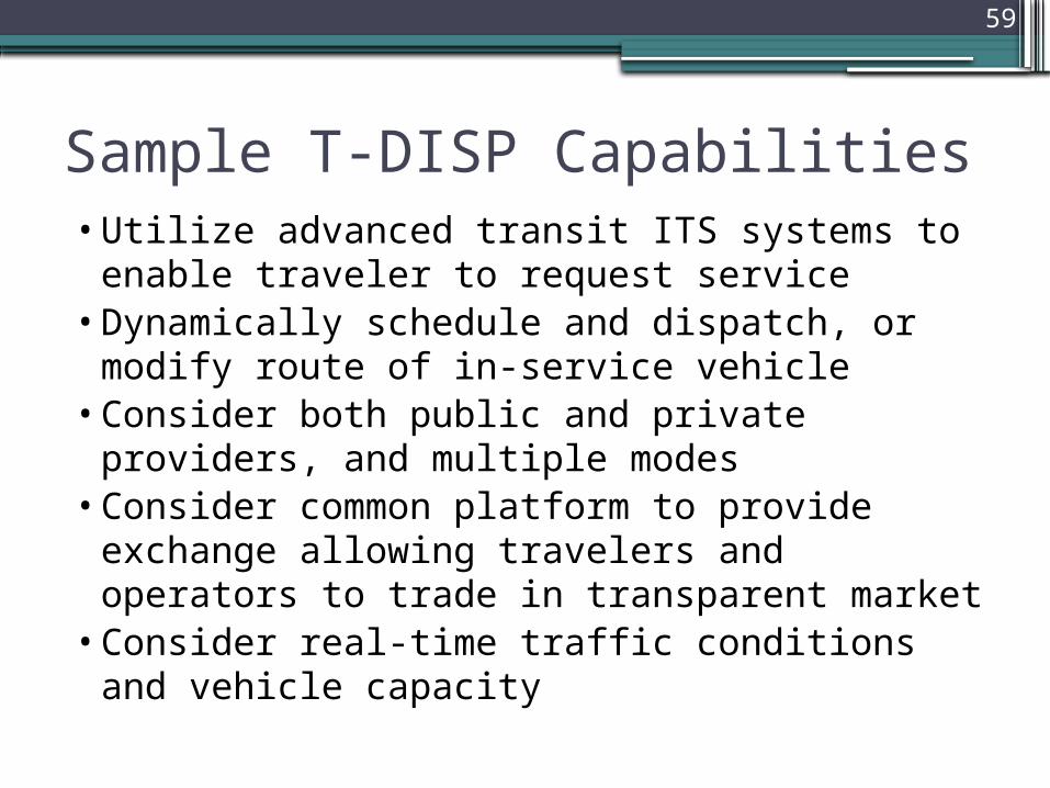
Sample T-DISP Capabilities•Utilize advanced transit ITS systems to
enable traveler to request service•Dynamically schedule and dispatch, or
modify route of in-service vehicle•Consider both public and private providers,
and multiple modes•Consider common platform to provide
exchange allowing travelers and operators to trade in transparent market
•Consider real-time traffic conditions and vehicle capacity

60
Sample D-RIDE Capabilities• Mobile platforms• Location-aware applications• Links to social networking• Opportunity for users to rank experiences• Create and save user profiles• Allow automated financial transactions• Provide incentive or loyalty rewards• Incorporate information on other modes of
transportation• Allow users to set preferences• Receive audio notifications when match made or
vehicle close to pick-up point

61
How do we get there… Transition

62
Desired Institutional Changes
•Coordination among regional institutions and application vendors
•Change in organizations to participate in IDTO implementation
•Participating organizations conduct business in a different way
•Procure technologies/systems jointly•Facilitate data exchange among institutions,
vendors and travelers•Familiarity with coordinated operations by
vendors

63
Desired Operational Changes
•The way agencies schedule and operate their services
•Provide services under policies and objectives from different governmental and regulatory agencies while satisfying the needs of travelers
•Nature of interfaces among existing and proposed technology systems
•Role of each agency in regional transportation system

64
Desired Technical Changes
•Incorporate old infrastructure into physical and logical architecture
•Incorporate manual processes•Account for individuals without mobile
devices to ensure “information equity”•Integrate new technologies into
organizations•Provide technical guidance and information
for agency staff•Add ITS infrastructure to specific areas
(e.g., rural)

65
Answer to Study Question #1Question #1:1. Do current practices take full advantage
of new transit technologies, tools and data sources?
Answer:No. The current state of the practice has yet to exploit the full potential.

66
Answer to Study Question #2Question #2:2. What emerging opportunities exist for
the new generation of automated technologies/tools to facilitate the deployment of the IDTO applications?
Answer:Many opportunities exist, but must consider not only new tools, but legacy systems and integration of both.

67
Answer to Study Question #3Question #3:1. Is there strong motivation for a Federal
role in facilitating the development of new technologies and tools to capitalize on these identified opportunities?
Answer:Yes.

68
User and User Needs

69
What are User Needs?•Formally documented customer
requirements. These inputs from you would be used as a starting basis for designing the IDTO applications
•User Needs will become the basis for development of system requirements for IDTO
•We will be working with the DRAFT User Needs during this meeting in hopes of confirming them before we leave on Friday

70
IDTO Scenarios Overview and Breakout Group Scenario Discussions

71
Scenario Analysis•Scenarios are diagrammed using high-
level system information flow diagrams
Needed:1. Changes to Scenario diagrams,
subsystems and data flow information2. ID gaps in order for IDTO to exist3. Changes to User Needs

72
Group Discussion Purpose•Gather your insights to better understand
the critical institutional and operational interactions and decision-making activities that underpin a successful IDTO application

73
Group Discussion Process•Work in groups (led by group facilitators)•Discussion to complete stakeholder input
for each scenario – 1.5 hours•Combine comments and modify
documents – 30 minutes•Debriefing feedback to whole group – 15
minutes/each group •Discussion of changes to overall IDTO
vision – 15-30 minutes

74
Group Discussion Tasks•Review each scenario for accuracy and
make modifications where necessary for subsystems and interconnects (who talks to whom), and what type of data will be exchanged
•Review and provide “User Need” input•Provide input to “Gaps” for developing
successful IDTO applications

75
BREAKOUT GROUP 1T-CONNECT Scenarios

6A: Verify ETA with TMC
3A: Verify ETA with TMC
Agency 1 Control Center
RiderTransfer Point
Traffic Management
Center
1: Send Request
3: Calc ETA
Agency 2 Control Center
6: Calc ETA8: Notify Driver
9: Notify Rider
10: Notify CC2
11A: Vehicle 1 Arrives
Vehicle 1 (Fixed-route Bus)
5: Location and RSA
11B: Vehicle 2 Arrives
Vehicle 2 (Fixed-route Bus)
Scenario #1 - Automated Approval of Transfer Between Fixed-route Buses
2: Location and RSA
4: CC1 Forwards Request to CC2
7: Auto OK

1: Rider requests for a transfer using personal device from when Vehicle 1 is late. Information is received by the Agency 1 Control Center (CC1)2: CC1 queries the current location and route and schedule adherence (RSA) information for Vehicle 1 3: CC1 calculates the predicted arrival at Transfer Point. for Vehicle 13A: CC1 corrects the predicted arrival information for Vehicle 1 based on real-time traffic data, if available4: CC1 forwards the transfer request to Agency 2 Control Center (CC2)5: CC1 queries the current location and RSA information for Vehicle 26: CC2 calculates the predicted arrival at Transfer Point. for Vehicle 26A: CC1 corrects the predicted arrival information for Vehicle 2 based on real-time traffic data, if available7: Based on available information, CC2 determines that transfer can be made from Vehicle 1 to Vehicle 28: Once CC2 determines that the transfer can be made from Vehicle 1 to Vehicle 2 and notifies the driver of Vehicle 2 and asks to wait for x minutes9: At the same time as Step 6, CC2 notifies the Rider of the successful transfer 10: At the same time as Step 6, CC2 notifies the CC1 of the successful transfer 11A and 11B: Vehicle 1 and Vehicle 2 arrive at the Transfer Point and Rider completes the successful transfer
Scenario #1 TransactionsDescription: Fixed-route buses (Vehicle 1 and Vehicle 2) operated by multiple agencies (Agency 1 and Agency 2) are involved. Transfer is requested by the Rider on Vehicle 1 using personal device and successfully completed when Rider boards Vehicle 2

6A: Verify ETA with TMC
3A: Verify ETA with TMC
10: Notify CC29: Notify
Rider
4: CC1 Forwards Request to CC2
Agency 1 Control Center
RiderTransfer Point
Traffic Management
Center
Agency 2 Control Center
1: Send Request 3: Calc ETA
6: Calc ETA
7: Manual OK
11A: Vehicle 1 Arrives
Vehicle 1 (Fixed-route Bus)
Vehicle 2 (Fixed-route Bus)
Scenario #2 - Denial and Manual Approval of Transfer Between Fixed-route Buses
2: Location and RSA
5: Location and RSA
8: Notify Driver
11B: Vehicle 2 Arrives

1: Rider requests for a transfer using personal device from when Vehicle 1 is late. Information is received by the Agency 1 Control Center (CC1)2: CC1 queries the current location and route and schedule adherence (RSA) information for Vehicle 1 3: CC1 calculates the predicted arrival at Transfer Point. for Vehicle 13A: CC1 corrects the predicted arrival information for Vehicle 1 based on real-time traffic data, if available4: CC1 forwards the transfer request to Agency 2 Control Center (CC2)5: CC1 queries the current location and RSA information for Vehicle 26: CC2 calculates the predicted arrival at Transfer Point. for Vehicle 26A: CC1 corrects the predicted arrival information for Vehicle 2 based on real-time traffic data, if available7: CC1 rejects the transfer request due to expected downstream delays and sends the request to Dispatcher queue for manual approval8: Once Dispatcher approves the transfer, CC1 automatically notifies the driver of Vehicle 2 to wait for Vehicle 1 for x minutes9: At the same time as Step 7, CC1 notifies the Rider of the successful transfer 10: At the same time as Step 7, CC1 notifies the CC1 of the successful transfer 11a and 11B : Vehicle 1 and Vehicle 2 arrive at the Transfer Point and Rider completes the successful transfer
Scenario #2 TransactionsDescription: Fixed-route buses (Vehicle 1 and Vehicle 2) operated by multiple agencies (Agency 1 and Agency 2) are involved. Transfer is requested by the Rider on Vehicle 1 using personal device but denied because Agency 2 does not have the current location and RSA data for Vehicle 2. Consequently, Agency 2 dispatcher intervenes and approves based on operational knowledge.

8: Notify Driver
Multi-modal Control Center
Vehicle 2(Fixed-route bus)
Transfer Point
Traffic Management
Center
Vehicle 1 (Demand Response
Van)
4A &5A: Verify ETA with TMC
4: Calc Vehicle 1 ETA
5: Calc Vehicle 2 ETA
6: Auto OK
7: Notify Driver
9A: Vehicle 1 Arrives
Scenario #3 - Automated Approval of Transfer from Demand Response to Fixed-route Bus
2: Location and RSA
3: Location and RSA
1: Send Request
9B: Vehicle 2 Arrives

1: Riders requests for a transfer via driver from Vehicle 1. Information is received by the Multi-modal Control Center (MCC)2: MCC queries the current location data and trip status data for Vehicle 13: MCC queries the current location, route and schedule adherence (RSA) and vehicle capacity information (for passengers on wheelchair) for Vehicle 2 4: MCC calculates the predicted arrival information for Vehicle 1 at the Transfer Point.4A: MCC corrects the predicted arrival information for Vehicle 1 based on real-time traffic data, if available 5: MCC calculates the predicted arrival information for Vehicle 2 at the Transfer Point.5A: MCC corrects the predicted arrival information for Vehicle 2 based on real-time traffic data, if available 6: Based on information from Steps 4,4A,5 and 5A, MCC determines that the all requested transfers from Vehicle 1 to Vehicle 2 can be completed7: MCC notifies Vehicle 2 of approved transfer and asks driver to wait for x minutes. May advise of approximate boarding time if passengers on wheelchair are involved8: MCC notifies Vehicle 1 of approved transfer 9A and 9B : Vehicle 1 and Vehicle 2 arrive at the Transfer Point and riders complete the successful transfer
Scenario #3 TransactionsDescription: Demand response van (Vehicle 1) and fixed-route bus (Vehicle 2) operated by the same multi-modal agency are involved. Transfer is requested from the Vehicle 1 to the Vehicle 2 by multiple riders through Vehicle 1 driver (via MDT) and successfully approved.

Scenario #4 - Automated Approval of Transfer from Train to Fixed-route Bus
6A: Verify ETA with TMC
Agency 1 Control Center
RiderTransfer Point
Traffic Management
Center
1: Send Request
3: Calc ETA
Agency 2 Control Center
6: Calc ETA8: Notify Driver
9: Notify Rider
10: Notify CC2
11A: Vehicle 1 Arrives
Vehicle 1 (Train)
5: Location and RSA
11B: Vehicle 2 Arrives
Vehicle 2 (Fixed-route Bus)
2: Location and SA
4: CC1 Forwards Request to CC2
7: Auto OK

1: Rider requests for a transfer using personal device from Vehicle 1 when that is running late. Information is received by the Agency 1 Control Center (CC1)2: CC1 queries the current location and schedule adherence (SA) information for Vehicle 1 3: CC1 calculates the predicted arrival at Transfer Point. for Vehicle 14: CC1 forwards the transfer request to Agency 2 Control Center (CC2)5: CC1 queries the current location and schedule adherence (SA) information for Vehicle 26: CC2 calculates the predicted arrival at Transfer Point. for Vehicle 26A: CC1 corrects the predicted arrival information for Vehicle 2 based on real-time traffic data, if available7: Based on available information, CC2 determines that transfer can be made from Vehicle 1 to Vehicle 28: Once CC2 determines that the transfer can be made from Vehicle 1 to Vehicle 2 and notifies the driver of Vehicle 2 and asks to wait for x minutes9: At the same time as Step 6, CC2 notifies the Rider of the successful transfer 10: At the same time as Step 6, CC2 notifies the CC1 of the successful transfer 11A and 11B: Vehicle 1 and Vehicle 2 arrive at the Transfer Point and Rider completes the successful transfer
T-CONNECT Scenario #4 TransactionsDescription: A Train (Vehicle 1) operated by Agency 1 and a fixed-route bus (Vehicle 2) operated by Agency 2 are involved. Transfer is requested by the Rider on Vehicle 1 using personal device and successfully completed when Rider boards Vehicle 2.

84
T-CONNECT User Needs

85
User NeedsUser Type User Need Description
Vehicle operator
Needs the vehicle to be connected wirelessly to the T-CONNECT system
Vehicles should be wirelessly connected using Connected Vehicle or other conventional wireless technologies
Vehicle operator
Needs access to T-CONNECT interface where transfer can be requested using a terminal
Drivers should be able to access the interface using a mobile data terminal (MDT) or a similar interface
Vehicle operator
Needs access to T-CONNECT interface where approval/denial of transfer is notified
Audio/visual notification of transfer request approval/denial should be provided by the T-CONNECT system
RiderNeeds access to T-CONNECT interface where transfer can be requested
Riders should be able to use a connected personal device to request transfer to a particular route
RiderNeeds access to T-CONNECT interface where real-time status of transfer request can be monitored
Riders should be able to use a connected personal device to monitor the status of their request
RiderNeeds access to T-CONNECT interface where approval/denial of transfer is notified
Riders should be able to receive a notification as per their preference (email, text message) when a transfer is approved or denied

86
User Needs (cont’d)User Type User Need Description
Dispatcher
Need to have the access to the T-CONNECT system to view the list of requested transfers, their status and operational resources (agencies, vehicles, drivers) involved
Dispatchers should always have access to the transfer requests and relevant analytical tools (view real-time status, calculate ETA, determine need for an additional bus etc.)
Dispatcher
Needs to have the access to the T-CONNECT system to manually intervene in the event there was a denial by the automated system for a valid transfer request due to operational anomalies
Dispatcher should have the ability to manually override the decision made by the T-CONNECT system in the event decision is going to have an impact on the operations due to real-time events not known to the automated system
Dispatcher
Needs to have access to real-time location, and real-time route and schedule adherence (RSA) information of vehicles involved in transfers.
Dispatcher should always have access to location, RSA and other event-based data (incident/accident) for all vehicles involved.

87
User Needs (cont’d)User Type User Need Description
Dispatcher
When multiple agencies/operational units are involved Dispatcher needs access to service agreements and service coordination tools
In the event where regional agencies are involved, access levels to operational tools owned by individual agencies should be determined. For example, Dispatcher of one particular agency may have access to only real-time location information for a partner agency vehicle
System Manager
Needs to enable two-way communication between T-CONNECT system and the vehicle
Two-way communication gateway and infrastructure as needed should be established so that connected vehicles can communicate with control center(s) and the T-CONNECT applications
System Manager
Needs to enable two-way communication between agencies whose vehicles are involved in the transfer
Two-way communication gateway and infrastructure as needed should be established between regional agencies so that control centers and operational tools/applications hosted by those centers can communicate in real-time when needed

88
User Needs (concluded)User Type User Need Description
System Manager
Needs the T-CONNECT system to be connected to a traffic management center
Two-way communication with regional traffic management centers should be established so that estimated time of arrival of vehicles can be corrected based on real-time or historic traffic information when available
Executive Manager
Needs to establish standard operating procedures to be used by T-CONNECT for approval and denial
Operational scenarios to be used by the automated T-CONNECT system should be established by the Executive Managers
Executive Manager
Need to establish regional fare collection and revenue sharing arrangements/technologies when multiple agencies are involved
Agencies involved in a particular transfer may have different transfer policies and fare collection technologies Thus managers should determine how these should be integrated such that the process is seamless to the rider.

89
T-CONNECT Scenario Comments and Modify
Documents30 Minutes

90
Group Discussion of Modifications1. Changes to scenario diagram, subsystem
and data flow information2. Gaps in order for T-CONNECT to exist3. Changes to User Needs

91
BREAKOUT GROUP 2T-DISP Scenarios

Transit Mode(DR, Flex, or
Deviated)
Control Center Rider
Transit Mode(Fixed Route – Bus, BRT, Rail)
Private Mode(Taxi, Shuttle,
Volunteer)
Traffic Management
Center
Scenario #1: T-DISP with Single Provider
1: Location data
1: Location data
4ii: Trip sent to vehicle
1: Location data
5iii: Trip sent to vehicle
2: Send ODT Request
4iii: Trip sent to rider
1: Real time Traffic data
3: Trip received
4: Trip analyzed
6: Downstream trips rerouted
5: Trip sent to private mode
LEGEND
Mode
Center
communications
Rider
Center

Scenario #1: Single transit provider operating multiple modes with the same on-board systems and data communications systems; If a trip cannot be met on public transportation, it is sent to a private mode. Assumptions: CAD/AVL and on-board systems; Data and voice communications; New or modified Scheduling System; New or modified Customer Messaging System
Transactions:1) Regular processes occurring on a daily basis, including:
• CAD/AVL system sending location data for all vehicles in the system that are eligible for service every 30 seconds via cellular or data radio communications
• Real-time traffic data sent to Control Center, and real-time “probe” data sent to Traffic Management Center
• Data messages sent back and forth between Control Center and Transit Modes (i.e. vehicles) via cellular or data radio communications
• Manifests or sets of trips are sent from Control Center to vehicles via cellular or data radio communications (or for fixed route modes are accessed at driver log on)
2) Rider requests a trip with origin, destination and time (ODT) and return trip using a web enabled mobile device with software application
3) Request received in Control Center that has route and schedule data available4) Trip request analyzed:
i. Trip request approved through scheduling systemii. Message sent to vehicle that needs to deviate to pick up the rideriii. Message sent to rider that trip can be made
5) Trip request analyzed but denied:i. Message sent to rider with information about private mode and cost of private modeii. Rider approves private trip and costiii. Message sent to Private Mode vehicle
6) Accepted trips are adjusted into remaining, downstream schedules for vehicles

Provider XProvider YProvider Z
Provider AProvider BProvider C
Provider QProvider RProvider S
Vehicle Location Data
Interface
Scenario #2: T-DISP with Multiple ProvidersTransit Mode(DR, Flex, or
Deviated)
Transit Mode(Fixed Route – Bus, BRT, Rail)
Private Mode(Taxi, Shuttle,
Volunteer)
Control Center Rider
Traffic Management
Center
2: Send ODT Request
4iii: Trip sent to rider
1: Real time Traffic data
3: Trip received
4: Trip analyzed
6: Downstream trips rerouted
5: Trip sent to private mode
1: Location data 5iii: Trip sent
to vehicle4ii: Trip sent
to vehicle
Messaging Interface
LEGEND
Mode
Center
communications
Rider
Center
Interface

Transactions:1) Regular processes occurring on a daily basis, including:
• CAD/AVL system sending location data for all vehicles in the system that are eligible for service every 30 seconds via cellular or data radio communications
• Data messages sent back and forth between Control Center and Transit Modes (i.e. vehicles) via cellular or data radio communications
• Real time traffic data sent to Control Center• Manifests or sets of trips are sent from Control Center to vehicles via cellular or data radio
communications (or for fixed route modes are accessed at driver log on)• Multiple agencies sending location data to an interface that “neutralizes” the location data
within the scheduling system2) Rider requests a trip with origin, destination and time (ODT) and return trip using a web enabled
mobile device with software application3) Request sent to Control Center that has route and schedule data4) Trip request analyzed:
i. Trip request approved through scheduling systemii. Message sent to vehicle that needs to deviate to pick up the rider Message sent to rider that
trip can be made5) Trip request analyzed but denied:
i. Message sent to rider with information about private mode and cost of private modeii. Rider approves private trip and costiii. Message sent to Private Mode vehicle
6) Accepted trips are adjusted into remaining, downstream schedules for vehicles
Scenario #2: Multiple providers operating in a multimodal environment; if a trip can’t be made on public transportation, it is sent to private mode; Different providers may use a different CAD/AVL system. Assumptions: CAD/AVL and on-board equipment; interface necessary for location data and messaging to vehicles.
Control Center
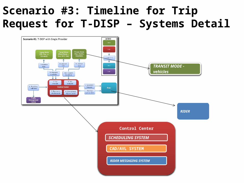
Scenario #3: Timeline for Trip Request for T-DISP – Systems Detail
CAD/AVL SYSTEM
SCHEDULING SYSTEM
RIDER MESSAGING SYSTEM
TRANSIT MODE - vehicles
RIDER

0 minutes
+ 3 minutes
+ 6 minutes
+ 9 minutes
+ 12 minutes
+ 15 minutes
Requests a trip
Accepts, modifies or rejects the trip
Arrives at pick up location
Boards vehicle
Alights vehicle
Trip information input into the system
Planned trip pushed to customer (option for private pay / taxi)
Confirmed trip sent to scheduling system
Manifest updated for driver on vehicle
Arrives at pick up location
Travels to destination
Arrives at destination
Vehicle location information available every 30 seconds
Manifest sent to driver on vehicle
Searches for available trip options; Determines routing, arrival, and departure times
Trip confirmed in system; Manifests updated; Trip sent to vehicle
TimeSTART
END
CAD/AVL SYSTEMSCHEDULINGSYSTEM
RIDER TRANSIT MODE vehicles
SCHEDULINGSYSTEM

Scenario #3: Timeline for Trip Request with Systems. For either single or multiple provider environment; trip denials sent to private mode. Assumptions: CAD/AVL and on-board equipment
1. Vehicle location information available every 30 seconds2. Requests a trip3. Trip information input into the system4. Searches for available trip options; Determines routing, arrival, and departure
times5. Planned trip pushed to customer (option for private pay / taxi)6. Accepts, modifies or rejects the trip7. Confirmed trip sent to scheduling system8. Trip confirmed in system; Manifests updated; Trip sent to vehicle9. Manifest sent to driver on vehicle10. Manifest updated for driver on vehicle11. Rider arrives at pick up location12. Vehicle arrives at pick up location13. Rider boards vehicle14. Vehicle travels to destination15. Vehicle arrives at destination
START
END

99
T-DISP User Needs

100
User NeedsUser Type User Need DescriptionTransportation Providers - Private and Public modes
Need to generate real-time data (from multiple modes and jurisdictions)
Any T-DISP architecture will need to generate real-time vehicle location data from multiple modes of transportation
Control CenterNeed to access real-time data (from multiple modes and jurisdictions)
Any T-DISP architecture will require access to real-time data from multiple modes of transportation
Control CenterNeed to access network configuration data from one or more sources
Network configuration data includes field device locations, roadway network, bus routes, and other types of static data
Control Center, Transportation Providers
Need business rules to guide decisions about how trips are distributed to transportation providers
Coordination efforts amongst transportation providers that include private and public entities will need to have an agreed business rule
Transportation providers, Control Center
Need scheduling parameters and operational policies to determine how trips are assigned and routed
Operational policies and detailed scheduling parameters will guide how individual trips are assigned and to which vehicle
Software vendors, Control Center
Need to expand the current capabilities of scheduling and routing software programs
T-DISP architecture will need a more robust system to dynamically route multi-modal service
101
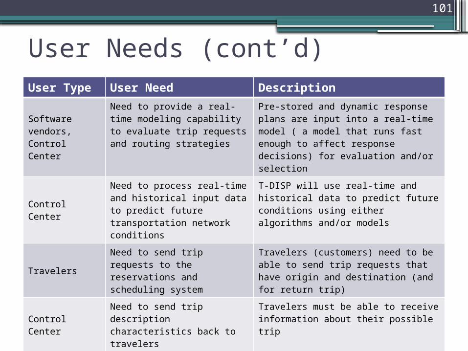
User Needs (cont’d)User Type User Need Description
Software vendors, Control Center
Need to provide a real-time modeling capability to evaluate trip requests and routing strategies
Pre-stored and dynamic response plans are input into a real-time model ( a model that runs fast enough to affect response decisions) for evaluation and/or selection
Control CenterNeed to process real-time and historical input data to predict future transportation network conditions
T-DISP will use real-time and historical data to predict future conditions using either algorithms and/or models
TravelersNeed to send trip requests to the reservations and scheduling system
Travelers (customers) need to be able to send trip requests that have origin and destination (and for return trip)
Control CenterNeed to send trip description characteristics back to travelers
Travelers must be able to receive information about their possible trip
Software vendors; Control Center; Transportation Providers
Need to develop an interface for different dispatch and vehicle location systems into the reservations / scheduling system
In a multiple provider environment, different CAD/AVL systems may be used so vehicle location data will need to be standardized

102
User Needs (concluded)User Type User Need DescriptionSoftware vendors; Control Center; Transportation Providers
Need to develop an interface for different dispatch and vehicle location systems to receive messages from the reservations / scheduling system
In a multiple provider environment, different CAD/AVL systems may be used so sending trip request data to the vehicles will need to be standardized

103
T-DISP Scenario Comments and Modify
Documents30 Minutes

104
Group Discussion of Modifications1. Changes to scenario diagram, subsystem
and data flow information2. Gaps in order for IDTO to exist3. Changes to user needs

105
BREAKOUT GROUP 3D-RIDE Scenarios

Scenario 1 – Rideshare Request (Simple)
Description: In this scenario, the passenger places a D-RIDE trip request for a rideshare match which is processed by the D-RIDE data center. Based on the user profiles stored and recognized by the system, the D-RIDE data center processes the information and outputs a list of ridematches (drivers seeking passengers) that suit the passenger’s travel request/trip plan.

Scenario 1- Assumptions and Elements• Assumptions:
▫ Ridematch is requested by the passenger using a personal hand-held device application or an internet form.
▫ Ridematch is requested by the driver through an in-vehicle application system using DSRC or wireless mobile technology.
▫ D-RIDE Data Center is capable of processing various types of data sent through the ridematching applications and can also process payment.
▫ D-RIDE Data Center is capable of interfacing with traffic data center’s traffic data for the routes being requested by the travelers.
• Description of elements:▫ Traveler: Both the passenger requesting a ride as well as the
traveler accepting passengers▫ Passenger: Traveler in need of a ride▫ Driver: Traveler in need of passengers▫ D-RIDE Data Center: Processes ridematch requests from
requestor route and location data▫ Traffic Data Center: May also be a TMC; provides traffic data
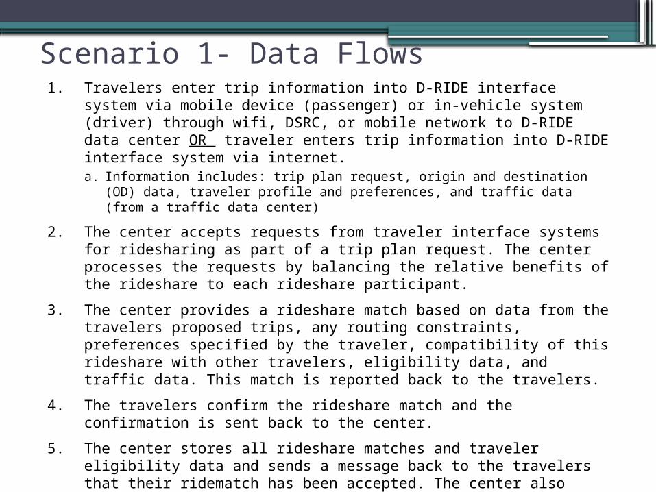
Scenario 1- Data Flows1. Travelers enter trip information into D-RIDE interface system via
mobile device (passenger) or in-vehicle system (driver) through wifi, DSRC, or mobile network to D-RIDE data center OR traveler enters trip information into D-RIDE interface system via internet.a. Information includes: trip plan request, origin and destination (OD) data,
traveler profile and preferences, and traffic data (from a traffic data center)
2. The center accepts requests from traveler interface systems for ridesharing as part of a trip plan request. The center processes the requests by balancing the relative benefits of the rideshare to each rideshare participant.
3. The center provides a rideshare match based on data from the travelers proposed trips, any routing constraints, preferences specified by the traveler, compatibility of this rideshare with other travelers, eligibility data, and traffic data. This match is reported back to the travelers.
4. The travelers confirm the rideshare match and the confirmation is sent back to the center.
5. The center stores all rideshare matches and traveler eligibility data and sends a message back to the travelers that their ridematch has been accepted. The center also supports payment transactions for the service.

Scenario 2 – Multi-Leg, Multi-Modal RequestDescription: In this scenario, the passenger places a D-RIDE trip request for a rideshare match along a route that is compromised by a major traffic delay. The center sends a message to add a transit leg to their trip, which upon passenger acceptance, is processed by the T-DISP control center to ultimately develop a driver+transit rideshare match. This match may include a leg of travel through ridesharing to a transit hub or vice versa.

Scenario 2- Assumptions and Elements• Assumptions:
▫ Ridematch is requested by the passenger using a personal hand-held device application or an internet form.
▫ Ridematch is requested by the driver through an in-vehicle application system using DSRC or wireless mobile technology.
▫ D-RIDE Data Center is capable of processing various types of data sent through the ridematching applications and can also process payment.
▫ D-RIDE Data Center is capable of interfacing with traffic data center’s traffic data for the routes being requested by the travelers.
▫ T-DISP Control Center is equipped with scheduling, CAD/AVL, traffic, and messaging systems that allow for transit trips and/or private modes to be scheduled.
▫ In this scenario, the D-RIDE Data Center and the T-DISP Control Center are separate entities that can communicate with one another. *An alternative scenario would be that the D-RIDE or T-DISP application could function as one combined control center (not displayed in this scenario).*
• Description of elements:▫ Traveler: Both the passenger requesting a ride as well as the traveler accepting passengers▫ Passenger: Traveler in need of a ride▫ Driver: Traveler in need of passengers▫ D-RIDE Data Center: Processes ridematch requests and requestor route and location data▫ Traffic Data Center: May also be a TMC; provides traffic data▫ T-DISP Control Center: Processes transit and private mode requests from requestor
location and route data▫ Transit: Includes fixed-route bus, BRT, rail, DR, flex, and deviated▫ Private Mode: Includes taxi, shuttle, and volunteer services

Scenario 2- Data Flows1. Travelers enter trip information into D-RIDE interface system
via mobile device (passenger) or in-vehicle system (driver) through wifi, DSRC, or mobile network to D-RIDE data center OR traveler enters trip information into D-RIDE interface system via internet.a. Information includes: trip plan request, origin and
destination (OD) data, traveler profile and preferences, and traffic data (from a traffic data center)
2. The center accepts requests from traveler interface systems for ridesharing as part of a trip plan request. The center processes the requests by balancing the relative benefits of the rideshare to each rideshare participant.
3. Using traffic data and route optimization, the center picks up that an incident is causing major delays along the passenger’s route and that transit or other private mode (taxi, shuttle) may be the best fastest option to their destination. The center sends a message to the passenger asking if they would like to add a transit leg to their trip.

Scenario 2- Data Flows (Cont.)4. The passenger accepts the addition of the transit leg to their trip. This
message is sent to the T-DISP Control Center via internet or wifi/DSRC/mobile network.
5. The T-DISP Control Center utilizes scheduling, CAD/AVL, and messaging systems to schedule a transit or private mode trip. The selected trip is sent to the D-RIDE Data Center to add as part of the overall ridematch output.
6. The center provides a combined driver + transit rideshare match based on data from the travelers proposed trips, any routing constraints, preferences specified by the traveler, compatibility of this rideshare with other travelers, eligibility data, and traffic data. This combined driver + transit rideshare match is reported back to the travelers and accepting transit
7. The travelers confirm the rideshare match and the confirmation is sent back to the center.
8. The center stores all rideshare matches and traveler eligibility data and sends a message back to the travelers that their ridematch has been accepted. The center also supports payment transactions for the service.

113
Scenario 3 –HOV/HOT Lane Enforcement and Tolling
Description: In this scenario, the georeferencing mechanism of the D-RIDE application and devices allows the D-RIDE data center to process the location of travelers (in vehicle and in a high-occupancy lane) in order to process HOV/HOT Lane violation citations and appropriate tolling charges.

Scenario 3 –HOV/HOT Lane Enforcement and TollingHOV/HOT Lane Enforcement Tolling

Scenario 3- Assumptions and Elements• Assumptions:
▫ D-RIDE applications on both the device and in-vehicle systems are capable of constantly sending location-based information associated with a unique identifier code for each user.
▫ D-RIDE Data Center is capable of processing constant flows of information from travelers in motion.
▫ D-RIDE Data Center is outfitted with georeferencing to know where HOV/HOT lanes are located and whether or not travelers are riding in the lane.
▫ Tolling and Enforcement Center can process e-tolling payments and issue violation citations.
• Description of elements:▫ Traveler: Both the passenger requesting a ride as well as the
traveler accepting passengers▫ D-RIDE Data Center: Processes ridematch requests and
requestor route and location data▫ Tolling and Enforcement Center: issues citations for
violations and processes e-tolling payments

Scenario 3- Data Flows - Enforcement1. Travelers that have been ridematched turn on their D-RIDE
applications (devices and in-vehicle) while en route. 2. The travelers enter into an HOV 2+ lane with their D-RIDE
applications still on. These applications emit a unique identifier code that is linked to individual passengers and the driver. This code is sent to the D-RIDE Data Center to process to location of the previously matched travelers which the system recognizes as paired.
3. Using GPS location information from the travelers’ D-RIDE applications, the center recognizes that the travelers have entered an HOV 3+ zone. With only 2 travelers known to the center to be in the ridematch, the center sends a message to the traffic tolling and enforcement center.
4. The Tolling and Enforcement Center sends a citation to the driver’s home using the traveler profile information sent with the violation message from the D-RIDE Data Center.
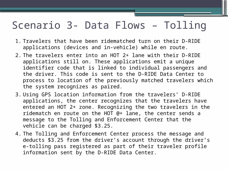
Scenario 3- Data Flows – Tolling 1. Travelers that have been ridematched turn on their D-RIDE
applications (devices and in-vehicle) while en route.2. The travelers enter into an HOT 2+ lane with their D-RIDE
applications still on. These applications emit a unique identifier code that is linked to individual passengers and the driver. This code is sent to the D-RIDE Data Center to process to location of the previously matched travelers which the system recognizes as paired.
3. Using GPS location information from the travelers’ D-RIDE applications, the center recognizes that the travelers have entered an HOT 2+ zone. Recognizing the two travelers in the ridematch en route on the HOT @+ lane, the center sends a message to the Tolling and Enforcement Center that the vehicle can be charged $3.25.
4. The Tolling and Enforcement Center process the message and deducts $3.25 from the driver’s account through the driver’s e-tolling pass registered as part of their traveler profile information sent by the D-RIDE Data Center.

118
D-RIDE User Needs
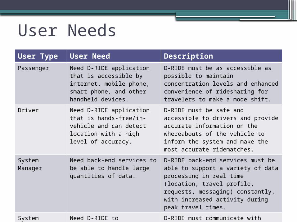
User NeedsUser Type User Need DescriptionPassenger Need D-RIDE application that
is accessible by internet, mobile phone, smart phone, and other handheld devices.
D-RIDE must be as accessible as possible to maintain concentration levels and enhanced convenience of ridesharing for travelers to make a mode shift.
Driver Need D-RIDE application that is hands-free/in-vehicle and can detect location with a high level of accuracy.
D-RIDE must be safe and accessible to drivers and provide accurate information on the whereabouts of the vehicle to inform the system and make the most accurate ridematches.
System Manager
Need back-end services to be able to handle large quantities of data.
D-RIDE back-end services must be able to support a variety of data processing in real time (location, travel profile, requests, messaging) constantly, with increased activity during peak travel times.
System Manager
Need D-RIDE to communicate with other data centers (TMCs, tolling, enforcement).
D-RIDE must communicate with traffic data centers (TMCs), tolling centers, and enforcement to realize full potential of services.

User Needs (cont’d)User Type User Need DescriptionPassenger Need D-RIDE application to
recognize location with a high level of accuracy.
D-RIDE must be able to locate a single traveler accurately for increased success rates for accurate matches.
System Manager
Need to access network configuration data from one or more sources.
Network configuration data includes field device locations, roadway network, priced routes, and other types of static data.
Passenger/Driver
User interface needs to display information simplistically and ranked in order of efficiency.
To promote travelers understanding information about their trip and matches, information must be displayed in a user-friendly manner, especially for drivers who should not be distracted by poor informational displays or confusing messaging.
Passenger/Driver Need to allow for two-way
communications between passenger and driver.
Results of the ridematch must be communicated to the travelers who each accept the ridematch, with the acceptance messages being relayed back to the D-RIDE system.

User Needs (concluded)User Type User Need DescriptionSystem Manager
Needs to have access to D-RIDE application.
Manual requests or system overrides may be necessary so the System Manager must be able to access the D-RIDE applications to either complete a user request or manually intervene when necessary .
System Manager
Needs to determine operational procedures on how ridematching should be performed.
Guidelines and logic regarding how ridematching is carried out must be established and maintained.
System Manager
Needs to define the how exception scenarios should be handled (e.g., incident/accident, delayed vehicle).
If an unforeseen circumstance compromises the completion of a trip, there must be an override function where the System Manager takes control to complete the trip.
Passenger/Driver
Need to be able to register for the D-RIDE program to create their user profile and define their preferences.
Automated ridematching can only occur if a user has set up their unique profile and established preferences for travel.

122
D-RIDE Scenario Comments and Modify
Documents30 Minutes
123
Group Discussion of Modifications1. Changes to scenario diagram, subsystem
and data flow information2. Gaps in order for IDTO to exist3. Changes to User Needs

124
Scenario Debriefing15 Minutes Each Group

125
Group Discussion of Modifications1. Changes to scenario diagrams,
subsystems and data flow information2. Gaps for all IDTO applications3. Changes to User Needs

126
Questions?

127
NEXT STEPS…Where do we go from here?

128
Schedule MilestonesTask/Milestone DateIDTO ConOps Webinar 10/26/11Draft Report on Stakeholder Input 2/16/12Draft ConOps Report 3/1/12Final Report on Stakeholder Input 3/15/12Walkthrough Workbook 4/3/12Draft IDTO Requirements 4/20/12Final ConOps Report 4/24/12Revised IDTO Requirements 5/18/12Walkthrough Workbook 5/23/12Final IDTO Requirements 7/2/12