insulation of flexible light emitting display for smart …€¦ · · 2014-05-17insulation of...
TRANSCRIPT

Insulation of flexible light emitting display for smart clothing
I. Parkova & A. Viļumsone Riga Technical University, Institute of Textile Material Technologies and Design, Latvia
Abstract
During research, insulation of textile circuits was investigated using three different silicon materials and one polyurethane film. For the test samples textile circuits with sewn/woven conductive yarns and attached light emitting diodes (LEDs) were used. Electrical properties were evaluated by measuring the emitted light intensity and electrical resistance before and after insulation and after washing. The given methods can further be used for insulation of other electronic components or circuits on textile, which can contribute to the development and improvement of smart textile/clothing technology. Keywords: illuminated textile, smart textile, flexible LED display, insulation.
1 Introduction
Nowadays clothing has more functions than just climatic protection and looking good. Developing smart and interactive apparel sector, clothing has obtained the additional ability to communicate with the environment and its wearer [1]. The concept of communication apparel may be perceived as the result of a convergence of two industries: textiles and electronics [2]. Electrotextiles represent a huge potential in creating a new generation of flexible textile platforms for electronic systems and smart garments [3]. In this paper research is focused on photonic textiles; improving the properties of textile light illuminated display. Flexible light emitting textile can be used as an output interface integrated into communication clothing by representing different animated images directly onto the clothing. Developing photonic clothing, it is important to ensure that the textile light emitting display is safe, so, in addition to functionality of the system it is significant to design a
High Performance and Optimum Design of Structures and Materials 603
doi:10.2495/HPSM140551
www.witpress.com, ISSN 1743-3509 (on-line) WIT Transactions on The Built Environment, Vol 137, © 2014 WIT Press
safe electronic system. The aim in intelligent textile improvement is to embed electronics directly into textile substrates. A challenging topic for electrotextile development is to get well functional, durable and safe electrotextiles which are visibly unchanged. Since smart clothing/textiles are still under development, many problems have occurred due to the absence of the standardization of technology. The additional functional properties should be tested to specific textile test standards. The electronic elements might have to be assessed for their resistance to cleaning and the textile elements need to be tested for electrical safety [4]. Insulation of the textile circuit is an important part of the system that ensures wear and operating safety – protecting electrical contacts and elements from short circuits, corrosion and impact of environmental conditions as well as protecting the wearer from the electrical system. In the smart textile research field several electrical circuit insulation methods are mentioned. Buechley and Eisenberg [5] offer to use ‘‘couching’’ embroidery stitch to insulate traces sewn in conductive thread as well as the use of non-conducting iron-on fabric patches and paint-on materials (latex, acrylic gel, fabric paints). These methods can be used for partial or total electrical contact insulation; however they are not suitable for light emitting textile insulation. In this case, it is necessary to choose transparent materials. Grén et al. [6] use transparent elastomeric materials to encapsulate electronic components in textile, insulating just individual elements (LEDs). If it is necessary to insulate a larger group of electronic elements, another coating technique should be used. It is provided to use developed light emitting display as the visual part (right side) of garment, therefore it is important to get both a transparent and homogeneous insulation layer. During research, insulation was done of textile circuits using three different silicon materials and one polyurethane film. The aim of this experimental study is to provide information about the possibilities of electronic circuit insulation on textile surfaces, encouraging the development of the textile electronic system insulation method.
2 Materials and methods
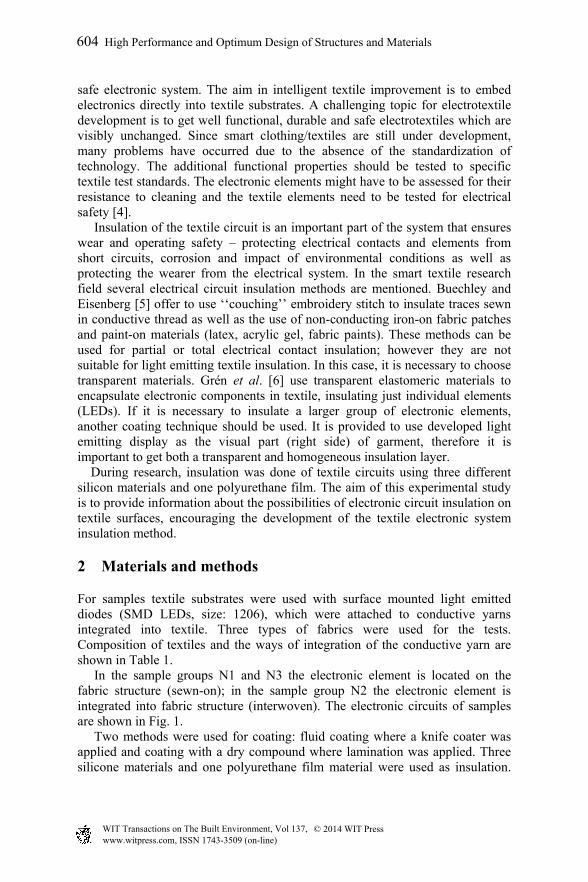
For samples textile substrates were used with surface mounted light emitted diodes (SMD LEDs, size: 1206), which were attached to conductive yarns integrated into textile. Three types of fabrics were used for the tests. Composition of textiles and the ways of integration of the conductive yarn are shown in Table 1. In the sample groups N1 and N3 the electronic element is located on the fabric structure (sewn-on); in the sample group N2 the electronic element is integrated into fabric structure (interwoven). The electronic circuits of samples are shown in Fig. 1. Two methods were used for coating: fluid coating where a knife coater was applied and coating with a dry compound where lamination was applied. Three silicone materials and one polyurethane film material were used as insulation.
604 High Performance and Optimum Design of Structures and Materials
www.witpress.com, ISSN 1743-3509 (on-line) WIT Transactions on The Built Environment, Vol 137, © 2014 WIT Press
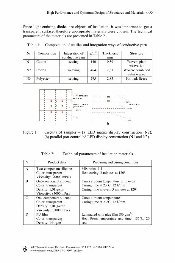
Since light emitting diodes are objects of insulation, it was important to get a transparent surface; therefore appropriate materials were chosen. The technical parameters of the materials are presented in Table 2.
Table 1: Composition of textiles and integration ways of conductive yarn.
Nr Composition Integration of conductive yarn
g/m2 Thickness, mm
Structure
N1 Cotton sewing 140 0,39 Woven: plain weave 1/1
N2 Cotton weaving 464 2,31 Woven: combined satin weave
N3 Polyester sewing 295 2,85 Knitted: fleece
a b
Figure 1: Circuits of samples – (a) LED matrix display construction (N2); (b) parallel port controlled LED display construction (N1 and N3)
Table 2: Technical parameters of insulation materials.
N Product data Preparing and curing conditions
A Two-component silicone Color: transparent Viscosity: 90000 mPa.s
Mix ratio: 1:1 Heat curing: 2 minutes at 120°
B One-component silicone Color: transparent Density: 1,01 g/cm³ Viscosity: 85000 mPa.s
Cures at room temperature or in oven Curing time at 23°C: 12 h/mm Curing time in oven: 3 minutes at 120°
C One-component silicone Color: transparent Density: 1,01 g/cm³ Viscosity: 85000 mPa.s
Cures at room temperature Curing time at 23°C: 12 h/mm
D PU film Color: transparent Density: 144 g/m2
Laminated with glue film (86 g/m2) Heat Press temperature and time: 135°C, 20 sec.
High Performance and Optimum Design of Structures and Materials 605
www.witpress.com, ISSN 1743-3509 (on-line) WIT Transactions on The Built Environment, Vol 137, © 2014 WIT Press

Electrical properties were evaluated with measurements of emitted light intensity and electrical resistance before and after insulation and after washing. For each diode switching 5V current (PC) and 100 ohm resistor was used. Intensity of emitted light. A Velleman DVM401 digital environment meter was used, accuracy of meter: ± 5%. Measurements were taken in a dark room, with a fixing light intensity value (in lux) at 85 mm distance from LED sample. To ensure constant light fixation for all measurements, an additional tool black mat carton tube (h = 85 mm) was used with an opening at both ends (D1=48 mm, D2= 20 mm). Electrical resistance. Two contact digital multimeters were used for measurements. Wash test. According to ISO standard 6330, domestic washing and drying procedures for textile testing, 5 wash tests were done in an A type washing machine with a temperature of 30±3°C, 400 rpm with 20g detergent. Each wash cycle (washing and spinning) lasted 31 minutes. Abrasion test. The Taber Rotary Platform Abraser was used; evaluating the durability of coating and electronic elements (resistance to abrasion). Abrasion test wheel: H-18, load: 250 g, speed: 60 cycles/min.
3 Conductive yarn selection for display
Currently different types of conductive yarns are commercially available. Yarns can be produced in various ways and can obtain very different properties in terms of conductivity, touch, strength, elasticity, etc. [7, 8]. Conductivity of yarn is important, this property is characterized by resistance in Ohms (Ω). To test the insulation materials’ influence on conductive textile contacts, three conductive yarns were used, which were sewn onto fabric N1 (length of seams: 35 cm). The properties of yarns are presented in Table 3.
Table 3: Properties of conductive yarns.
N Composition Linear density, dtex/f
Electrical resistance,
ohm/m
Structure
N1 copper + PA 330/34x7 2.3 7 ply, each copper foil twisted around PA fiber
N2 silver + PA 110/34x2 40.3 2ply PA coated with silver
N3 silver + PA 235/34x4 39.3 4ply PA coated with silver
The electrical resistance of conductive yarns was measured before sample insulation, after sample insulation and after sample washing. As shown in Fig. 2, stable values show in yarn N1 that the electrical resistance practically doesn’t change after insulation and after washing. As a result, yarn N1 is used for conductive traces in display samples.
606 High Performance and Optimum Design of Structures and Materials
www.witpress.com, ISSN 1743-3509 (on-line) WIT Transactions on The Built Environment, Vol 137, © 2014 WIT Press

Figure 2: Electrical resistance change of conductive yarns after washing.
4 Applying the insulation layer
Coatings have both functional and decorative providing properties in the area of electrical performance and/or environmental protection. In the area of environmental protection, the coating provides a barrier to moisture, physical and mechanical abuse, chemical attack, corrosion and weathering.
4.1 Silicone coating
Silicones are described as polymers that exhibit excellent weatherability, arc, track resistance and good resistance to impact, abrasion and chemicals [9]. In addition, silicones have excellent elasticity, low moisture uptake, ionic purity, low-temperature performance and thermal stability that make them especially suitable for protecting semiconductor devices [10]. For insulation, silicone material was used, which is provided for textile applications in order to achieve flexibility and a lasting coating on the textile surface. After processing, coatings which are provided for electronic insulation mostly become hard and inflexible. Silicone was applied with a manual knife-coating method, using stencils with different thicknesses. Integrated electronic elements cause surface irregularities, making it challenging to apply an even and thin coating. For the first samples a thin plain weave fabric was used (N1 from Table 1), where conductive yarn was sewn onto fabric. The sample had various thicknesses in different areas: the textile substrate – 0.39 mm; the conductive seam – 0.62 mm; the LED attached to the seam – 1.44 mm. This kind of structure makes it complicated to apply an even surface. In this case in order to get an even and fully insulated surface, the coating layer thickness should be thicker than the diameter of the conductive yarn. If electronic elements are used, the coating thickness should be thicker than the height of the element. Otherwise the coating doesn’t fully insulate the material (Fig. 3b), and it can damage the connection point as well (for example, the element disconnects from the conductive trace). A knife-on-blanket arrangement is suitable for coating dimensionally unstable substrates [11]. Using soft material under the sample during the coating process (Fig. 3d) it is possible to achieve a thinner coating – during coating process fabric surface deformation occurs as a result of the elements sinking into the textile substrate therefore for coating knife it is easier
High Performance and Optimum Design of Structures and Materials 607
www.witpress.com, ISSN 1743-3509 (on-line) WIT Transactions on The Built Environment, Vol 137, © 2014 WIT Press

to slide over the surface. The amount of coating is dependent on the tension of the blanket or knife pressure. Base material (substrate) selection is important as well; it is necessary to conform the electronic elements with the fabric structure, which can affect the quantity of coating material and the thickness of the coating layer. Using soft and thick fabric for circuit substrate (for example, fleece – sample group N3 from Table 1), fabric surface deformation occurs as a result of elements sinking into the textile substrate and the surface is fully insulated with a thin coating layer as well (Fig. 3e). As a result, there is a smaller increase of weight and thickness.
Figure 3: Schematic diagram of uncoated and coated sewn samples – a: non-insulated sample (N1); b: sample from thin fabric (N1) insulated with a thin layer on a hard surface; c: sample from thin fabric (N1) insulated with a thick layer (layer thickness > insulating element high) on a hard surface; d: sample from thin fabric (N1) insulated with a thin layer on a soft surface; e: sample from thick fabric (N3) insulated with a thin layer on a hard or soft surface.
The integration of electronic elements into textile structure eases the application of coating and allows it to be made thinner and more even; fully insulating the necessary area. Therefore for insulating experiments a woven electro-textile sample was designed, where light emitting diodes are integrated into the fabric structure. An electro-textile scheme with integrated LEDs in its structure (sample group N2) is shown in Fig. 4. Non-conductive floats covering fixed areas of display enables the light emitting diode to be hidden under floats; therefore LED locates inside the textile material. Since the fabric has a greater thickness, fabric surface deformation occurs during the coating process by elements sinking into the textile substrate (Fig. 4b). This relieves the coating process and allows a thinner coating to be achieved.
608 High Performance and Optimum Design of Structures and Materials
www.witpress.com, ISSN 1743-3509 (on-line) WIT Transactions on The Built Environment, Vol 137, © 2014 WIT Press

Figure 4: Schematic diagram of uncoated and coated woven samples (N2) – a: non-insulated sample; b: insulated sample.
4.2 Polyurethane (PU) film coating
Samples were laminated with PU film, bonding it to the textile with glue film fixed in a heat press. For experimental lamination a discontinuous operation heat press was used, however for such bonding, a continuous (roller type) heat press can be used as well. In both cases it is preferable to put soft material under the sample in the heat press to achieve more regular bonding (here 1 cm thick foam was used).
4.3 Other coating methods
Other coating methods were used as well: waterproofing spray for soft and hard shell apparel (water-bone) and bath with aqueous silicone emulsion. Thin coatings were obtained providing water impenetrability, but it doesn’t ensure insulation of conductive contacts and elements. Therefore these materials are not suitable for textile circuit insulation and weren’t involved in further research.
5 Results
After coating, the electrical properties of samples after durability tests were evaluated.
5.1 Wash test
For the wash test 19 samples were tested in sample group N1 (in total, 39 integrated LEDs) and 8 samples in sample group N2 (in total, 72 integrated LEDs). After washing, the illuminated light intensity in samples both increased and decreased. Although the correlation coefficient between parameter groups (unwashed samples and samples with different numbers of washing cycles) is from 0.55 (middle strength) till 0.91 (strong), results do not have a clear tendency. The total increase of light intensity is more related to failed LEDs with a given value 0 lux. A waterproof insulation layer protects display samples from the presence of moisture from a short circuit in the system and from corrosion as well. But it
High Performance and Optimum Design of Structures and Materials 609
www.witpress.com, ISSN 1743-3509 (on-line) WIT Transactions on The Built Environment, Vol 137, © 2014 WIT Press

cannot provide full protection from mechanical forces – after washing some part of LEDs did not work. Figs 5 and 6 show a summary of results – emitted light intensity and the number of working LEDs decreases in both cases (insulated and non-insulated samples); however the trendline shows that the average light intensity decreases faster in non-insulated samples.
Figure 5: Change of light intensity and number of failed LEDs after washing for the sample group N1: a – insulated samples; b – non-insulated samples.
Figure 6: Change of light intensity and number of failed LEDs after washing for sample group N2 (insulated).
Better durability after washing was achieved with PU film laminated samples – in sample group N2 after 5 wash cycles 22–56% of silicone coated LEDs (depending on the substrate material) and 11% of laminated LEDs didn’t work. Since silicone is an elastic material, during mechanical actions the coating doesn’t fix the material, but stretches along with it, therefore contacts can break. In laminated samples the film isn’t elastic – it doesn’t stretch with material and fixes yarns of material in place. The joining of electronic elements and textile materials is still a topical question. A soldered connection ensures good electrical contact, but since the electronic system is integrated into the textile, it is subjected to mechanical
610 High Performance and Optimum Design of Structures and Materials
www.witpress.com, ISSN 1743-3509 (on-line) WIT Transactions on The Built Environment, Vol 137, © 2014 WIT Press

deformations (like bending) that can result in broken contact. Unfortunately, insulation coating on tested samples didn’t ensure sufficiently strong and stable contact fixation. Some parts of the samples after insulation showed brighter light intensity (Figs 5a and 6). Coating works like a lens, where a ray emitted from an LED can change its angle. LEDs can move a bit during the coating process, which can affect perception of the emitted light as well. During experimental coating the process of different insulation types were performed: insulation coating from one side, insulation coating from both sides and encapsulation (Fig. 7).
Figure 7: Insulation types: a: insulation coating from one side; b: insulation coating from both sides; c: encapsulation.
It should be noted that any fabric has a 3-dimensional structure – length, width and thickness. Samples which were insulated from one or from both sides (Figs 7a and b) after washing became wet under the insulation layer as well. As shown in Fig. 8, water spreads through textile via the fabric thickness even if it is insulated from the upper and bottom sides. It influences the samples’ drying time – this is especially evident for thicker samples. Water presence can affect operation and quality of electronic elements so it is important to consider insulation along the sample edges. For example, if the display is integrated into the clothing, a waterproof base material and accessories should be used for apparel, welding should be used as a joining technology, if sewn joining is used – seams should be fixed with insulation tape.
Figure 8: Electronic element insulated on textile from both sides.
High Performance and Optimum Design of Structures and Materials 611
www.witpress.com, ISSN 1743-3509 (on-line) WIT Transactions on The Built Environment, Vol 137, © 2014 WIT Press

5.2 Abrasion test
To simulate wear and tear over a period of time, an abrasion test was carried out (the results are presented in Table 5). Samples were tested as long as the LED worked.
Table 4: Abrasion test results.
Sample group
LED resistance to abrasion, cycles Insulation material
Silicone PU film N1 1300 150 N2 13250 2050
Sample group N1 has weak abrasion resistance – laminated sample in average hold just 150 abrasion cycles; silicone coated samples – 1300 cycles. Due to the uneven structure of the surface, the coating was rubbed off and LEDs were damaged. Sample group N2 has better abrasion resistance because the diode locates inside the textile material structure and has insulation of additional textile yarns; also the thickness of material doesn’t differ highly in different points. Laminated samples on average hold 2050 cycles until the film is rubbed off and the LED doesn’t work. Silicone coated samples have better durability – after 2000 cycles the silicon is rubbed above the LEDs, but the LEDs are still working. On average, silicone coated samples hold 13,250 cycles until diode or contact is damaged.
6 Analysis and conclusions
Both insulation materials are suitable for electronic insulation on a textile surface. PU coating film is more suitable for textile circuits, where tension is not desired (including LED display) – film isn’t flexible, during mechanical impacts it doesn’t stretch with material and fixes material/yarns in place. In its turn, silicone insulation is suitable for textile circuits where tension is allowable, for example, stretch sensors, textile electrodes and so on. An electrical textile circuit insulation layer contributes to the improvement of wear properties. If textile integrated electronics have a rough structure, they do not conform to wear and comfort requirements. Application of coating improves the tactile sense of textile circuit and makes it more durable during wear. If electronic components are integrated into the textile structure (like in sample group N2), the material has a better sense of touch. However, this material is quite inconvenient to use in everyday life because of the long floats, which can hitch and easily can be pulled out of the textile structure. In this case, coating improves the textile’s convenience of use.
612 High Performance and Optimum Design of Structures and Materials
www.witpress.com, ISSN 1743-3509 (on-line) WIT Transactions on The Built Environment, Vol 137, © 2014 WIT Press

During a coating process using liquid insulation material (in this case – silicone) it is necessary to conform electronic elements to the fabric structure – it can have an impact on quantity of insulation materials and thickness of the coating layer. The type of material placed under samples during the coating process is important as well. In its turn, the integration of electronic elements into the textile structure eases application of coating and ensures a more even and thinner coating; fully insulating surface. In the abrasion test, silicone coated LED samples were more durable, but in the washing test, PU film laminated samples showed better results. For conductive traces in textile display samples, conductive yarn was selected with stable conductivity, which remains practically unchanged after insulation and washing. The electrical properties of the samples after insulation and washing tests didn’t change significantly; the weak point was connection joints, which broke in some parts of the sample due to the impact of mechanical actions. In samples SMD, LEDs were connected to conductive yarns, forming solder contacts directly onto the contact area of the diode. Connected conductive yarns due to the influence of mechanical impact can tear off the LED’s soldering terminal and as a result, the diode will not work anymore. In order to avoid this defect, it is necessary to add a diode to the printed circuit board (PCB) substrate to get a stable position of element. To retain flexibility of display, instead of a hard PCB, a flexible PCB surface can be used (like film), as well as a smaller size of diodes can be used (like 0806 or 0603 size SMD LED). The given methods can further be used for the insulation of other electronic components or circuits on textile, that can contribute to the development and improvement of smart textile/clothing technology.
7 Summary
Developing the smart and interactive apparel sector, clothing has obtained the additional ability to communicate with the environment and its wearer. In this paper, research is focused on photonic textiles, improving the properties of textile light illuminated display. Insulation of a textile circuit is an important part of a system that ensures wear and operating safety. During research, insulation of textile circuits with three different silicon materials and one polyurethane film was done. Two coating methods were used: fluid coating with a knife coater and coating with a dry compound where lamination was applied. For samples electro-textile substrates were used with attached SMD LEDs. Electrical properties were evaluated with measurements of emitted light intensity and electrical resistance before and after insulation and after washing. An abrasion test was carried out to simulate wear and tear over a period of time. Change of geometrical properties after insulation was fixed as well. In this paper, the textile circuit insulation process was described and several recommendations were given that could contribute to the development of smart textile insulation technology.
High Performance and Optimum Design of Structures and Materials 613
www.witpress.com, ISSN 1743-3509 (on-line) WIT Transactions on The Built Environment, Vol 137, © 2014 WIT Press

Acknowledgements
This work has been supported by the European Social Fund within the projects “Support for the implementation of doctoral studies at Riga Technical University”. Silicone materials were provided by companies Wacker and Dow Corning. Thanks to Mats Johansson (The Swedish School of Textiles, Sweden) and Aleksandrs Vališevskis (Riga Technical University, Latvia) for help and discussions.
References
[1] Kirstein, T., Cottet, D., Grzy, J., Tröster, G., Wearable computing systems – electronic textiles. Wearable Electronics and Photonics, ed. X.M. Tao, Woodhead publishing, p. 177, 2005.
[2] Koncar, V., Communication apparel and optical fibre fabric display, Wearable Electronics and Photonics, ed. X.M. Tao, Woodhead publishing, p. 156, 2005.
[3] Ghosh, T.K., Dhawan, A., Muth J.F., Formation of electrical circuits in textile structures. Intelligent textiles and clothing, ed. H. Mattila, Woodhead publishing, p. 239, 2006.
[4] Standard CEN/TR 16298:2011. Textiles and textile products — Smart textiles — Definitions, categorisation, applications and standardization needs. Online: http://www.cen.eu
[5] Buechley, L., Eisenberg, M, Fabric PCBs, electronic sequins, and socket buttons: techniques for e-textile craft. Personal and Ubiquitous Computing, Volume 13, Issue 2 , Springer-Verlag, London, pp. 133–150, 2007.
[6] Grén S., Kaappa E., Vanhala J, The use of elastomeric materials to encapsulate LEDs into the wearable electronics, Proceedings of 12th World Textile Conference AUTEX, Section I – Smart Textiles, pp. 1443–1448, 2012.
[7] Schwarz, A., Kazani, I., Cuny, L., Hertleer, C., Ghekiere, F., De Clercq, G., De Meyc, G. , Van Langenhove, L., Electro-conductive and elastic hybrid yarns – The effects of stretching, cyclic straining and washing on their electro-conductive properties, Materials and Design 32 (8-9), pp. 4247–4256, 2011.
[8] Parkova, I., Vališevskis, A., Ziemele, I., Briedis, U., Vilumsone, A., Improvements of Smart Garment Electronic Contact System. Advances in Science and Technology (Volume 80), TTP, Switzerland, pp. 90–93, 2013.
[9] Alvino, W.M., Plastic for electronics. Materials properties and design applications. McGraw-Hill, New York, 1994.
[10] Minges, M. L., Electronic Materials Handbook: Packaging, Vol. 1. ASM International, 1989.
[11] Sen, A.K., Tech, M., Coated Textiles. Principles and applications, ed. J. Damewood, Technomic Publishing Co., Inc., Pennsylvania, 2001.
614 High Performance and Optimum Design of Structures and Materials
www.witpress.com, ISSN 1743-3509 (on-line) WIT Transactions on The Built Environment, Vol 137, © 2014 WIT Press