insulation comparison vpi produced versus resin rich · fig 2 -example of development vpi facility...
TRANSCRIPT

Insulation Comparison – VPI produced versus Resin Rich
Robert Draper Franz Ramsauer Gerhard Lemesch
Andritz Hydro Canada Andritz Hydro Austria Andritz Hydro Austria
Introduction
Over time, various methods for producing stator
insulation for large rotating machines have
evolved. Within the industry there are basically
two types of insulation production methods.
One method is referred to as VPI (Vacuum
Pressure Impregnation) technology. This
method uses dry mica tapes, typically made of
mica paper and reinforcing layers bonded with a
relatively small amount of epoxy based adhesive
[3],[5]. The stator bars and coils are wrapped
with the dry mica tapes. After completing the
wrapping the coils and bars undergo a vacuum
cycle which removes volatiles and humidity, then
resin is introduced and pressurized, driving the
resin into the insulation. After undergoing the
Vacuum Pressure Impregnation process, the
resin penetrated, final product is cured
afterwards in an oven.
Fig 1 -Impregnation mold lifting out of the VAT
Fig 2 -Example of development VPI facility
The second manufacturing method is referred to
as Resin Rich technology. This method involves
applying tapes, that are also constructed from
mica paper and reinforcing layers [3],[5] that are
pre-wetted with a semi-cured epoxy resin (B-
staged), that are applied and then later heated
and compressed (either by dedicated press or
autoclave) causing the resin to flow and cure the
layers together.
Few companies are using both manufacturing
technologies as Andritz Hydro does. For us we
have well-grounded experience using both
methods for decades, so we feel we are in a good
position to provide an objective comparison for
people in the industry.

Fig 3 - Resin Rich Insulation Press
Discussion
All modern insulation systems used for stator
windings for rotating machine stators operating
above about 4kV are comprised, in general, of
the following basic materials;
Strand insulation, Dacron (1) glass, mica
tape or enamel, or combinations of
these.
Turn insulation, if used, of mica paper
tape (multi-turn coils only).
Internal potential grading for stator
bars, using a semi-conductive tape (to
achieve onerous requirements).
Groundwall insulation made of mica
paper, glass backers (strength),
sometimes film such as polyester (may
also be used in fleece form), and a
binding resin (either polyester or epoxy).
Semi Conducting slot armour, using
semi-conductive (glass fabric or
polyester fleece based).
End grading made of silicon carbide
loaded tapes or paints.
Inherently, since the basic materials are similar,
a reasonable technician would believe that all
systems should be capable of similar
performance.
In fact when comparing test results, life
characteristics in service, machine performance,
etc., this seems to be true, but this is based on
the caveat that the system designer has done the
correct homework and that the manufacturing
processes used (whether VPI or Resin Rich) is
stable and well controlled.
When the systems are adequately designed and
manufactured using proper quality control both
methods produce bars and coils that meet the
most onerous customer requirements, for
different operation regimes (run of river, and
stop/start duty) and fulfill the following
expectations;
Class F capability (thermal class 155°C).
Dimensional stability.
Elimination of significant voids in
groundwall insulation*.
Excellent DF and Tip-Up.
Low partial discharge levels.
Thermal cycle stability.
Good voltage endurance life.
High puncture strength.
Excellent grading system performance
during testing and operation (no
corona).
Consistent slot armour resistance in
proper range.
Excellent insulation quality even in end
winding area.
* Some micro voids always exist with all
manufacturing methods.

What is fundamentally different about the two
systems is the areas that manufacturing and
quality people need to focus their attention on
to make sure things go well , so this is the main
area to concentrate on. It should be noted in
advance that the issues described are
manageable to those with the proper expertise
and experience.
VPI Issues
The main potential issues that manufacturers
face when making VPI systems are;
1. Making sure that the resin penetrates
and fully wets through all layers of mica
tape in the insulation all the way down
to the copper. This can be extremely
challenging particularly as the geometry
of the bar and insulation builds
(different rated voltages) vary widely
among generator designs. Stator
windings with thick insulation build
(higher voltages) or bars for machines
with long stacks, pose the most
significant challenges. [1]
Fig 4 – Cross section of VPI’d bar
2. Making sure that during impregnation
in the VPI tank the resin gelation is
progressed to such an extent that very
little resin runs back out of the
insulation, when moving bars from the
VPI tank to the oven, as this could affect
the performance of the finished
insulation.
3. If the tapes used for manufacture
contain the resin catalyst, control of
taping is more important to minimize
separation of the tape layers as large
“pools” of resin, e.g. caused by
significant wrinkles may not cure
properly if separated too far from the
catalyst. [4]
Resin penetration as discussed in point 1, is
complex and many strategies are used to make
sure resin is fully penetrated, as if the
impregnation process is not well suited to the
particular geometry being produced (challenge
for long bars and those with heavy insulation
builds) dry mica layers, and/or lack of
impregnation resin may occur which are typically
near the copper.
This issue is compounded, if non-porous film
such as polyester (Mylar (1)) is used on the mica
tape as a backer, since this in conjunction with
the mica being non-porous inhibits resin flow
within the system. [8]
Well designed, VPI based insulation systems
utilize non-calcined mica papers or splittings,
and porous glass fabric tape backers since these
materials absorb resin freely and lead to good
penetration and high quality insulation as a
result [8],[6].
Systems that are well designed and
manufactured, typically avoid resin penetration
issues by monitoring the viscosity and the
reactivity of the resin, having regular resin
changes to the VPI storage tank (ageing can
affect resin viscosity and reactivity and in
consequence, the penetration ability of the
resin) and either monitoring the penetration by
using capacitance monitoring or “tank coils”
where prior to baking the insulation is cut from a
surplus coil to make sure all tape layers are
wetted. [7]
In some systems depending on tape flexibility
the first layers of tape are purposely applied to
achieve, small channels to facilitate resin to
penetrate axially down the length of the bar to
help ensure wetting. This measure can amongst
others help to make sure that the impregnating
resin is fully penetrated into the insulation but it
has to be done carefully so that the wrinkles are
not so large that pools of resin occur as discussed
in point 3.
Fig 5 - Taping a VPI bar on a modern 6-Axis
taping machine
Depending on the tapes and resins used, the
mica contents of both systems may vary. Lower
viscosity resins, and tapes with better, wetting
may result in higher mica loading within VPI
systems but this is not universally true. To the
extent possible system designers work to
maximize the mica content of the systems they
provide.
Generally, if increased mica loading is possible,
the result is excellent performance, provided,
the system is well designed, and is subject to
excellent performance [1].
As discussed in point 2, the issues that may occur
due to resin run out during transport between
the VPI tank and the oven can be avoided by
having a well-coordinated manufacturing
process. If the catalyst is in the mica tape the
un-catalyzed impregnation resin within the
insulation starts to gel already in the VPI tank
(early gelation phase). Therefore the amount of
resin running back out can be minimized, even
when heating in the oven starts and the resin
viscosity reduces prior to gelation.
A deep understanding of the resin viscosity as
well as the gelling process at impregnation
temperature and through the curing process is
important to ensure that no resin is running out.
If a significant amount of resin runs out of the bar
or coil, the result would be air filled voids within
the insulation leading to elevated partial
discharge levels and reduced insulation quality.
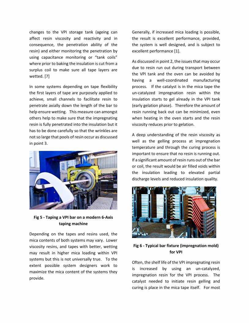
Fig 6 - Typical bar fixture (impregnation mold)
for VPI
Often, the shelf life of the VPI impregnating resin
is increased by using an un-catalyzed,
impregnation resin for the VPI process. The
catalyst needed to initiate resin gelling and
curing is place in the mica tape itself. For most

VPI systems the presence of catalyst in the mica
tape is indicated by the mica tape colour. Tapes
with catalyst used most often for VPI process is
“pink” in colour.
Fig 7 - VPI mica tape roll with catalyst (pink
catalyst)
Catalyzed resins start cross linking each time
they are exposed to temperature. Most often
the vacuum process requires that you heat the
stator bars/coils or complete stator to remove
humidity and volatiles. Each time the resin is
introduced, the resin has energy to start the
cross linking process. Therefore the resin’s
ability to penetrate the mica tapes decreases
over time, when the catalyst is in the resin itself.
When the catalyst (Issue 3) is in the mica tape,
resin gelling and curing occurs fast for the resin
that is in immediate contact with or very close to
the catalyst in the mica tape. If there is a
significant separation in the mica tape, the resin
that fills that area, may not cure fully during post
baking if the catalyst is at very low concentration
levels or zero. (Good process control helps avoid
this risk) This is also depending on the used VPI
tape (solubility of the catalyst in the resin and
distribution of the catalyst within the tape) and
technology regarding resin flow during the
impregnation process.
Residuals of not fully cured “pools” of resin can
cause issues with test parameters such as DF,
and Tip-Up.
Insulation system designers have found that
using catalyst systems that dissolve in the VPI
resin can virtually eliminate un-cured resin
pools. When the catalyst dissolves in the resin,
it is transported throughout the entire applied
insulation giving improved and more even cure
levels.
Resin Rich Issues
The challenges associated with the two methods
don’t result in a strong disadvantage for one
technology over the other, they are simply a
different set that also can be controlled with
proper knowledge and due diligence;
1. Resin rich systems start by having all the
resin they need to fully bond all layers
together, but it is possible to cure them
without giving sufficient time to allow
the voids to be eliminated by resin
flowing. This is known as pre-gelation.
Pre-gelation, if it occurs, results in
trapped voids particularly near the areas
where the resin carrying the trapped
void content exits the slot portion (end
grading). [1]

Fig 8- Rheometer plot showing resin
viscosity drop and then gelation occurs.
2. Control of tape input (quantity of tape)
and tension during winding of the bar, is
important since, at least for resin rich
coils and bars made in presses, the
presses will close to their stops, and too
little tape input results in voids and
under-compaction. Too much tape
input will result in over-squeezing the
insulation resulting in insufficient resin
content and resin poor areas. Also,
having extra tape input may make
closing the press challenging and
therefore oversized bars and coils may
result.
Fig 9 -Operator checking tape tension
3. For resin rich systems tapes compress
and the “excess” must go somewhere,
so the system typically is subject to
wrinkles near the surface of the
insulation. Mica tapes are typically
applied at the maximum consistent tape
tension that the tape can withstand
without breaking but even this does not
fully eliminate wrinkling [6] particularly
near the bend area where taping buildup
is larger.
Fig 10- Excess wrinkles resulting from lack
of tape tension
When pressing a resin rich system, the full slot
portion of the bar or coil is sealed into sacrifice
material to prevent the finished product from
sticking to the tooling, this helps to control the
outside condition of the finished product, but it
Fig 11- Stator Bar Ready to enter press with
sacrifice tape applied

Also, means that any air or volatile material must
exit from the ends of the slot portion. To do this
well, requires that the resin is heated, softened,
and pressed while the resin maintains a low
viscosity permitting the “voids” (air bubbles )to
exit entrained in the excess resin being
squeezed, without advancing the resin to the
state of gelation. The press cycle is of huge
importance to achieving this result. Well
controlled resin rich systems have processes for
monitoring the press cycle and have incoming
tape tests where resin reactivity is monitored
such as a Differential Scanning Calorimeter and
Rheometer, to allow small “tweaks” to the
pressing cycle to account for resin batches that
may be slightly different than each other.
Contrary to popular belief, taking a vat and
mixing the same resin components together in a
controlled way does not always achieve identical
reactivity results. A well monitored shop is ready
to account for the small variation that should be
expected.
Tape quantity and tension is extremely
important as for each system. There is an ideal
compaction range where the resin quantity of
the finished insulation is sufficient to bond and
fill voids, but not excessive.
Well controlled processes have manufacturing
routines for monitoring and controlling tape
tension and have a tape input feedback process
(based on measurement of physical compressed
thickness of tape or based on tape density), that
helps yield the correct amount of tape quantity
to the product in-spite of the tape dimensions
and tape constituents varying.
Lastly, no matter how well applied the mica tape
is over the coil by the taping machine, there is
friction associated with taping due to the resin in
the tape, and additionally, tape is applied by
round taping heads over a “basically”
rectangular bar or coil. Tapes compress more
naturally, at the corners, tensions are then
second greatest on the narrow edges of the bar
or coil, and finally at a lower tension level is the
taping on the longer sides. This means that the
applied insulation in cross section looks more
“pillow” profiled than rectangular during taping.
From there, the insulation is heated and
compacted into a truly rectangular profile, with
tapes tending to wrinkle midway down the long
flat sides of the bar or coil. Wrinkle control is
based on control of tape quantity, but also
taping tensions when insulating the bar. Overall
tensions when taping tend to be higher for resin
rich coils and bars than are needed to achieve a
good result for VPI based systems.
Fig 12 - Taped coil showing the “pillow” effect
Insulation system design is ultimately important
to reduce the effects of the potential issues but
also good design practice and testing provides

superior life and performance for both systems.
Having an insulation product that provides long
term service depends on the amount of
“homework” the design team and
manufacturing team has done to perfect the
insulation product.
Fig 13 – Cross section of Resin Rich Bar with
silicone side packing applied
In addition to the inherent manufacturing
challenges, there are also many other aspects to
the production of long lasting, high reliability
insulation systems. Many customers have strong
opinions regarding which basic insulation
process is used, collectively there seems to be a
strong bias – even among experts - towards
which materials can comprise a system.
There seems to be two different schools of
thought about material families. The “European
view” of good materials for making systems are,
in some respects, different than what North
Americans, typically put in specifications.
Imagine having a vendor’s bid proposing with the
following construction;
Enameled strand insulation with no
Dacron (1) glass.
Coils with no turn tape but rather either
simply enameled strands doing double
duty or the use of mica based (film
backed) tape insulation.
Proposing measuring PD levels only,
instead of DF and Tip-up.
These systems with the appropriate amount of
design and experience also work very well. In
general, enameled strands have higher dielectric
strength and lower incidence rates for strand
shorts. The resin system in the ground wall is
based on chemistry where excellent bonding to
the strand package is assured.
Most users outside North America have been
accepting mica based strand insulation instead
of dedicated mica based turn insulation (in multi-
turn coils), for some time, and their experience
is satisfactory. While for coils, the surges
associated with variable speed drives still
warrants the use of mica as a turn insulator.
Several manufacturers in Europe have stopped
the routine practice of doing DF and Tip-up on
100% of production in favor of testing PD for
their internal quality control. Today most voids
in production are very small, so PD likely is a
much more meaningful result than the older DF
and Tip-up numbers.
Conclusions
Based on experience, the risks to the user are
less about what manufacturing technology is
used, but rather more related to dealing with
suppliers that have done the right testing, using
excellent knowledge, experience and
technology. Dealing with suppliers offering fully
vetted systems provides the user with the lowest
risk for long term operation.

R&D work in the insulation technology is key for
providing insulation systems to users that are
reliable and will continue to meet future
specification needs. What inhibits
development, often is customer specifications
that rely in “old thinking” and are not current
with the technology that is available.
You do get what you pay for, in the insulation
world.
(*1) Registered trademark of EI Dupont.
References
1. F. T. Emery, “High dielectric
performance stator winding insulation
system for global VPI’ed air cooled
generators”, EICEMC, Indianapolis, IN,
USA, 2003
2. M. Lerchbacher, C. Sumereder, G.
Lemesch, F. Ramsauer, M. Muhr,
„Impact of small voids in solid insulating
materials“ ICPADM, Bangalore, India,
2012
3. G.C. Stone, E.A. Boulter, I. Culbert and H.
Dhirani, Electrical Insulation for Rotating
Machines, Wiley-IEEE Press, 2014
4. N. Frost, M. Winkeler, S. Tuckwell, “Mica
tape and VPI resin insulation system
options – continued studies”, EIC,
Seattle, WA, USA, 2015
5. M. Chapman, R. Bruetsch, “Micaceous
mainwall insulation for high-voltage
rotating machines”, ISEI, San Diego, CA,
USA, 2010
6. R. Vogelsang, R. Brutsch, K. Frohlich,
„The effect of tape overlapping in
winding insulation on tree growth and
breakdown time”, CEIDP, Boulder, CO,
USA, 2004
7. W. Grubelnik, C. Stiefmaier, “Un-
impregnated vpi tape testing and effects
on dielectric performance of VPI
insulation system”, EIC, Philadelphia, PA,
USA, 2014
8. W. Grubelnik, J. Roberts, B. Koerbler, P.
Marek, „ A new approach in insulation
systems for rotating machines“, EICEMC,
Indianapolis, IN, USA, 2005