instrumentation development for optical tracking …elagin/publications/aelagin...instrumentation...
TRANSCRIPT

Instrumentation Development for
Optical Tracking in Water and
Liquid Scintillator Detectors
Andrey ElaginUniversity of Chicago
DLNP, JINR, Dubna, October 13, 2017

Outline
• Ultra-fast timing frontier
• Optical tracking in water
• Optical tracking in liquid scintillator
• Potential application for 0nbb-decay search
• Large-Area Picosecond Photo-Detectors
2
Preface:• In 1 ns light travels 30cm; 1 ns is 1000 ps; 1ps -> 300 microns• Light is slow in (sub) picosecond domain• Speed of light in matter depends on the wavelength
e.g. in a typical scintillator: v(370 nm) = 0.191 m/nsv( 600 nm) = 0.203 m/ns
~2 ns difference over 6.5m distance(that’s a lot of picoseconds)

e, mu, pi, K, p,…
Cherenkov photons
10-20 micron pore
Amplification section: Gain-bandwidth, Signal-to-Noise, Power, Cost
Sub-Picosecond Timing Pre-requisites
1) Fast source (e.g. prompt Cherenkov light)2) Psec-level pixel size (e.g. MCP pores)3) High gain (e.g. MgO ALD MCPs give >107)4) Low noise
Schematic of an MCP-based Photo-Detector
3

Getting to 100 fs won’t be that easy but it’s a nice goal to have
2nd Chicago Photocathode
Workshop
4

LAPPDTM
Micro-Capillary Arrays by Incom Inc.
Material: borofloat glass Area: 8x8” Thickness: 1.2mm Pore size: 20 mm
Open area: 60-74%
Atomic Layer Deposition (ALD)- J.Elam and A.Mane at Argonne
(process is now licensed to Incom Inc.)- Arradiance Inc. (independently)
Micro-Channel Plates (MCPs)
20x20 cm2
~15mm
Large-Area Picosecond Photo-Detector
Single PE time resolution <50ps
LAPPDTM is being commercialized by Incom Inc. 5

LAPPD Prototype Testing ResultsSingle PE resolution
RSI 84, 061301 (2013), NIMA 732, (2013) 392
NIMA 795, (2015) 1See arXiv:1603.01843
for a complete LAPPD bibliography
Demonstrated characteristics:single PE timing ~50psmulti PE timing ~35 ps
differential timing ~5 psposition resolution < 1 mm
gain >107
Reconstruction of the laser beam footprint
6

7
LAPPD Electronics at Chicago
Delay-line anode
- 1.6 GHz bandwidth
- number of channels
scales linearly with area
PSEC-4 ASIC chip
- 6-channel, 1.5 GHz, 10-15 GS/s
30-Channel ACDC Card (5 PSEC-4) Central Card
(4-ACDC;120ch) 7
NIM 711 (2013) 124
NIM 735 (2014) 452

8

• 60-channel LAPPD prototype at the ANL Laser Lab• 180-channel self-triggered Optical TPC at Fermilab• Central card controls several front end boards• New central cards by Mircea Bogdan handles 1920 channels
9
Multichannel Systems

(T1, X1, Y1, Z)
(T2, X2, Y2, Z )
Vertex (e.g. p0->gg)
Tv, Xv, Yv, Zv
Detector Plane
One can reconstruct the vertex from the times and positions- 3D reconstruction
E.g. rare Kaon decays (KOTO at JPARC): background rejection by reconstructing p0 vertex space point (beat combinatorics background)
Vertexing Using Arrival 4D-points
Need 1ps
10

CDF top quark event
Colliders
• identify the quark content of charged particles• assign tracks and photons to vertices
Need 1ps
11

Suggestion to use LAPPD’s for DUSEL and the name (OTPC) due to Howard Nicholson
Optical Time Projection Chamber
Need < 100 ps
• Like a TPC but drifts photons instead of electrons • Exploits precise location and time for each detected photon• Would allow track /vertex reconstruction in large liquid counters
12
• It doesn’t have to be water (use prompt Cherenkov light that arrives early )• In fact, for long tracks optical tracking should also work using just scintillation

Cherenkov vs Scintillation Light
• Prompt emission
• Directional for each charged track segment
• Higher energy threshold
• Less abundant compared to scintillation light
• Conventionally used for particle ID, vertexing and “coarse” energy measurements
• Slow emission
• Isotropic for each charged track segment
• Very low energy threshold
• Abundant: usually completely overshadow Cherenkov light
• Conventionally used forvertexing and “precision” energy measurements
Combining the two should make for a very powerful detectorVery active field:JINST 7 (2012) P07010; PRD87 (2013) 071301; JINST 9 (2014) 06012; arXiv:1409.5864; NIMA 830 (2016) 303; NIMA 849 (2017) 102; PRC95 (2017) 055801; arXiv:1610.02011Current status: need fast timing and slow scintillators
Cherenkov Scintillation
13

Large Directional Liquid Scintillator
• Large scintillator detectors and large water-Cherenkov detectors have been very effective in measuring neutrinoproperties
• Combining the two technologies may allow expandedphysics reach of the next generation large neutrino experiments
• Physics Program of THEIA:- Neutrinoless double beta decay- Solar neutrinos- Geo-neutrinos- Supernova burst neutrinos & DSNB- Nucleon decay- Long-baseline physics (mass hierarchy, CP-violation)- Unexpected surprises
A concept drawingof the THEIA detector
Cherenkov light provides directionality (background suppression)Scintillation light provides good energy measurements
14
Several design options exist

Water
Direct Cherenkov light (yellow)
Photonis MCPs and Chicago striplines/PSEC4
Flat mirrors
1 foot/1000 psec muon
Reflected Cherenkov light (green)
780 psec later
Eric Oberla’s Ph.D thesis
Eric Oberla’s Optical TPC
15

Water
Flat mirrors
Reflected Cherenkov light arrives 780 psec later depending on position and angle
Photonis MCPs and Chicago striplines/PSEC4
Beam’s Eye View of the OTPC
16
Eric Oberla’s Ph.D thesis

OTPC at Fermilab Test Beam
5 cm
Five Photonis Planacons17
Eric Oberla’s Ph.D thesis

• 60 mrad angular resolution over a lever arm of 40cm• 1.5 cm spatial resolution (radiation length of H2O is 40cm)• See 780 psec separation of direct and mirror-reflected light• More details in Nucl. Instr. Meth. A814, pp19-32 April 1 (2016)
2 n
se
c
OTPC Results
18
Eric Oberla’s Ph.D thesis

A Note on Mirrors and the Optical TPCE. Oberla
E. Angelico
Simulation of reflection points of 20 photons inside a silvered sphere, color-coded by time
• Photo-cathode coverage is expensive• Mirrors may help to reduce cost of
very large detectors
“Adding psec-resolution changes the space in which considerations of Liouville’s Theorem operates from 3-dimensional to 4-dimensional. In analogy with accelerator physics, we can exchange transverse emittance to longitudinal emittance.
There may be interesting and clever ways to exploit this in large water/scint Cherenkov counters” -H. Frisch
Homage to T. Ypsilantis
19

Drawing from Sebastian Lorenz presentation
3D Optical Tracking
Reconstruction algorithms work with Cherenkov or scintillation light• B. Wonsak et al. Original motivation: LENA scintillator detector• M. Wetstein et al. Original motivation: water-Cherenkov LBNE detector
Need:• One reference point (space and time)• Single photon hit times
20
t

PMT timing PDF – Norm (0, 1 ns)
and three decay components:
4.6 ns [71%],
18 ns [22%] and
156 ns [7%]
For each photon hit:• Time defines drop-like surface• Gets smeared with time profile
(scintillation & PMT-timing)
• Weighted due to spatial constraints (acceptance, optical properties, light concentrator, …)
→ spatial p.d.f. for photon emission points
3D Optical Tracking using ScintillationB. Wonsak et al.
21
TTS = 1 ns

3D Optical Tracking using Scintillation
Decreased cell size
Decreased cell size
• Add up all signals• Divide result by local detection efficiency
→ Number density of emitted photons
• Use knowledge that all signals belong to same topology to 'connect' their information→ Use prior results to re-evaluate p.d.f. of each signal
3 GeV muon simulated in LENA
B. Wonsak et al.
Access to dE/dx
22

3D Optical Tracking using ScintillationCurrent Status (slide by S. Lorenz)
23

Liquid Scintillator Detectors
SNO+: 12 m diameter KamLAND-Zen: 13 m diameter
• Both detectors are searching for neutrinoless double beta decay• Surrounded by slow PMTs for light collection to measure energy
24

Double Beta Decay
Electrons energy
only possible if
the neutrino
is its own
antiparticle
It overlaps with 0nbb-decay energy
deposition and therefore this is
irreducible background without
event topology reconstruction
(need two-track vs one-track discriminant)
nn
e- e-
2nbb
0nbb
Background:Electron scattering of neutrinoscoming from 8B-decays in the sun
25

Can We See Event Topology in a LS Detector?
R=6.5m
Simulation of a 0nbb event(selected event with large angle between electrons)
2014 JINST 9 P06012
PE arrival times, TTS=100 ps
Fast (arrives early) and directional• directionality reconstruction• event topology reconstruction (e.g., 2-track vs 1-track) 26
• Distinct two-track topology withpreference to be “back-to-back”
• Most of electrons are above Cherenkov threshold

Idealized event displays: no multiple scattering, all light after QE=30% cut
S0
S1
S2
S3
Rotation invariant power spectrum
Spherical harmonics analysis
0nbb-decay 8B eventCherenkov PEs
Scintillation PEs
S power spectrum
Early Light Topology
27

Early Light Topology
Cherenkov PEs
Scintillation PEs
S0
S1
S2 S
3
Early PE: 0nbb-decay Early PE: 8B event
S power spectrum
Realistic event displays: early PEs only, KamLAND PMTs QE: Che~12%, Sci~23%
Key parameters determining
separation of 0nbb-decay from 8B
Scintillator properties
(narrow spectrum, slow rise time)
Photo-detector properties
(fast, large-area, high QE, red-sensitive)
28
NIMA 849 (2017) 102

2-Track vs 1-Track Event Topology
Multipole moment l=0 Multipole moment l=1
• Spherical harmonics analysis is rather simple, but it doesn’t use all available information
• Advanced machine learning techniques looking at 4-vectors of each photon hit should work better (probably makes more sense with a little more progresson the instrumentation front)
S0 S1
29
Topology reconstruction of MeV events could help against otherbackgrounds in searches for 0nbb-decay (e.g., 10C, 2.6MeV gammas)

0nbb vs 8B
Vertex res 5cm, events within R<3mScintillation rise time 1 ns
Vertex res 5cm, events within R<3mScintillation rise time 5 ns
Background rejection factor = 2 @ 70% signal efficiency
Background rejection factor = 3 @ 70% signal efficiency
For details see NIM A849 (2017) 102
Other backgrounds (gammas, alphas, 10C, etc) also have distinct topologiesEvent reconstruction in liquid scintillator would enable new opportunities
30

Illustration from a presentationby Gabriel Orebi Gann
THEIA
Plot credit: Andy Mastbaum
Broad detector R&D program to realize THEIA
• 50kt detector• 50% reduction of 8B• 0.5% natTe loading • 50t 130Te after fiducial cuts• 15 meV after 10 years
Multipurpose detector(including neutrino oscillation physics)
Potential for 0nbb-decay search
31

NuDot - Directional Liquid Scintillator
140 2” fast PMTs for timing
72 10” regular PMTs mounted onWinston Cones for energy resolution
Under construction at MIT, led by L. Winslow
2.2 m
R&D Towards Large Scale Detector for 0nbb-decay
Goals• Demonstrate directionality and event
topology reconstruction using che/sciseparation by fast timing- ideally by measuring 2nbb-decay
• Study scintillators, including quantum dots• Upgrade 10” PMTs with LAPPDs
Following up on the ideas discussed in JINST 7 P07010 and JINST 9 06012
32

FlatDot Demonstration
15 cm Quartz Vial
• Intermediate step towards 1m3 spherical NuDot- e.g. detection of Cherenkov “rings” from low energy
electrons using a tagged Compton source• Testing different scintillator cocktails
(including quantum dots)• Readout testing
2” PMTs with TTS=300ps
Note: there is an independent effort on Che/Sci light separation - the CHESS experiment at Berkeley by G. Orebi Gann et al., aXiv:1610.02011 and 1610.02029
Time (ns)
Raw pulses (the top two channels are the trigger)
Event display after corrections
33
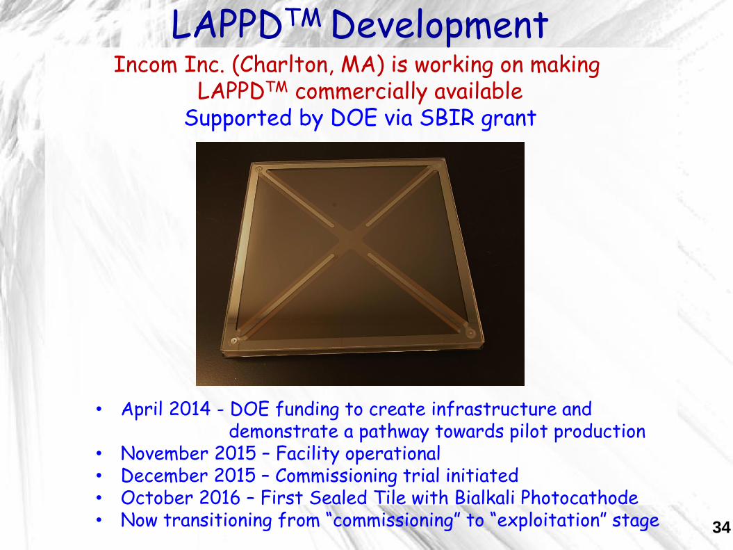
LAPPDTM Development
34
Incom Inc. (Charlton, MA) is working on making LAPPDTM commercially available
Supported by DOE via SBIR grant
• April 2014 - DOE funding to create infrastructure and demonstrate a pathway towards pilot production
• November 2015 – Facility operational• December 2015 – Commissioning trial initiated• October 2016 – First Sealed Tile with Bialkali Photocathode• Now transitioning from “commissioning” to “exploitation” stage

LAPPDTM @ Incom Inc.
Slide courtesy of Incom Inc. 35

Goal of the R&D Effort at UChicago
Affordable large-area many-pixel photo-detector systems
with picosecond time resolution
LAPPD module 20x20 cm2 Example of a Super Module
UChicago goal is to develop alternative high volume, scalable, low cost processing options
(in close collaboration with Incom Inc.)
We are exploring if an In-Situ process (without vacuum transfer) can be inexpensive and easier to scale for a very high volume production
36
Production rate of 50 LAPPDs/week would
cover 100m2 in one year

Can We Make LAPPDs in Batches Like PMTs?
37

In-Situ Assembly StrategySimplify the assembly process by avoiding vacuum transfer:
make photo-cathode after the top seal(PMT-like batch production)
Step 1: pre-deposit Sb on the top window prior to assemblyStep 2: pre-assemble MCP stack in the tile-baseStep 3: do top seal and bake in the same heat cycle
using dual vacuum systemStep 4: bring alkali vapors inside the tile to make photo-cathodeStep 5: flame seal the glass tube or crimp the copper tube
UChicago processing chamber
38
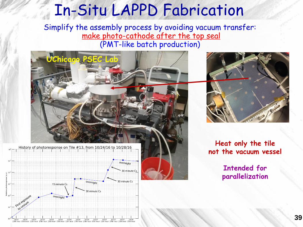
In-Situ LAPPD Fabrication
UChicago PSEC Lab
Simplify the assembly process by avoiding vacuum transfer:make photo-cathode after the top seal
(PMT-like batch production)
Heat only the tilenot the vacuum vessel
Intended for parallelization
39

In-Situ Assembly Facility UChicago
Looking forward towards transferring the in-situ process to industry
The idea is to achieve volume production by operating many small-sizevacuum processing chambers at the same time
UChicago PSEC Lab
40

First Signals from an In-Situ LAPPD
Near side: reflection from unterminated far end
Far side: reflection is superimposed on prompt
Source
far sidenear side
Source
Readout(50-Ohm transmission line)
(Sb cathode)
Readout(50-Ohm transmission line)
The tile is accessible for QC before photo-cathode shot This is helpful for the production yield
April, 2016
41

First Sealed In-Situ Glass LAPPDAugust 18, 2016
Flame seal by J.Gregar, Argonne
42
(Cs-Sb photo-cathode)

Ceramic Gen-II LAPPD
Tab for singleHV connection
Indium sealperimeter
Resistive buttons
January, 2017
43

Internal HV Divider
44

Reliable hermetic seal over a 90-cm long perimeterIndium Solder Flat Seal Recipe
Input:
• Two glass parts with flat contact surfaces
Process:
• Coat 200 nm of NiCr and 200 nm of Cu
on each contact surface (adapted from
seals by O.Siegmund at SSL UC Berkeley)
• Make a sandwich with indium wire
• Bake in vacuum at 250-300C for 24hrs
Key features:
• A good compression over the entire perimeter
is needed to compensate for non-flatness and
to ensure a good contact
• In good seals indium penetrates through entire
NiCr layer (Cu always “dissolves”)
glass window(8.66x8.66”)
glass frame(sidewall)
Sealed LAPPD tile
This recipe is now understood
It works well over large perimetersMetallization and compression are critical
Indium Solder Flat Seal Recipe
45

Metallurgy of the SealModerate temperatures and short exposure time:
• A thin layer of copper quickly dissolves in molten indium
• Indium diffuses into the NiCr layer
Depth profile XPS
The ion etch number is a measure for the depth of each XPS run
Layer depth (uncalibrated)
XPS access courtesy ofJ. Kurley and A. Filatov at UChicago
Glass with NiCr-Cu metallization exposed to InBi at ~100C for <1hrs
(it seals at these conditions)
InBi was scraped when still above melting (72C)
Low melting InBi alloy allows to explore temperaturesbelow melting of pure In (157C)
46

Metallurgy of a Good SealHigher temperatures and longer exposure time
• Indium penetrates through entire NiCr layer
XPS of the glass side of the interface
XPS data courtesy of A. Filatov at UChicago
Cut and scrape at the metal-glass interface
Inte
ns
ity (
a.u
.)
900 800 700 600
Ni(2p)Cr(2p)
control surface
scraped region
In(3p)
Binding energy, eV
Glass with NiCr-Cu metallization bonded by pure In at ~350C for 24hrs
(it seals at these conditions)
We now reliably seal at 250-300C for 12-24hrs 47

Indium seal recipes exist for a long time
PLANACONTM
(MCP-PMT by Photonis)
5 cm
Make larger photo-detectors
Our recipe scales well to large perimeter
Simplify the assembly process
Our recipe is compatible with PMT-like batch
production
Why do we need another indium seal recipe?
48

Gen-II LAPPD
10 nm NiCr ground layer insideis capacitively coupled
to an outside 50 Ohm RF anode
NiCr-Cu electrodingfor the top seal
Ground pins
Two tubulation portsfor the in-situ PC synthesis
(improved gas flow)
Monolithic ceramic body
• Robust ceramic body• Anode is not a part of
the vacuum package• Enables fabrication
of a generic tile fordifferent applications
• Compatible with in-situ and vacuum transfer assembly processes
Joint effort with Incom Inc. via DOE SBIR 49

Gen-II LAPPD: “inside-out” anode
• Custom anode is outside• Capacitively coupled • Compatible with high rate
applications
For details see NIMA 846 (2016) 75
Chose yourown readout
pattern
50
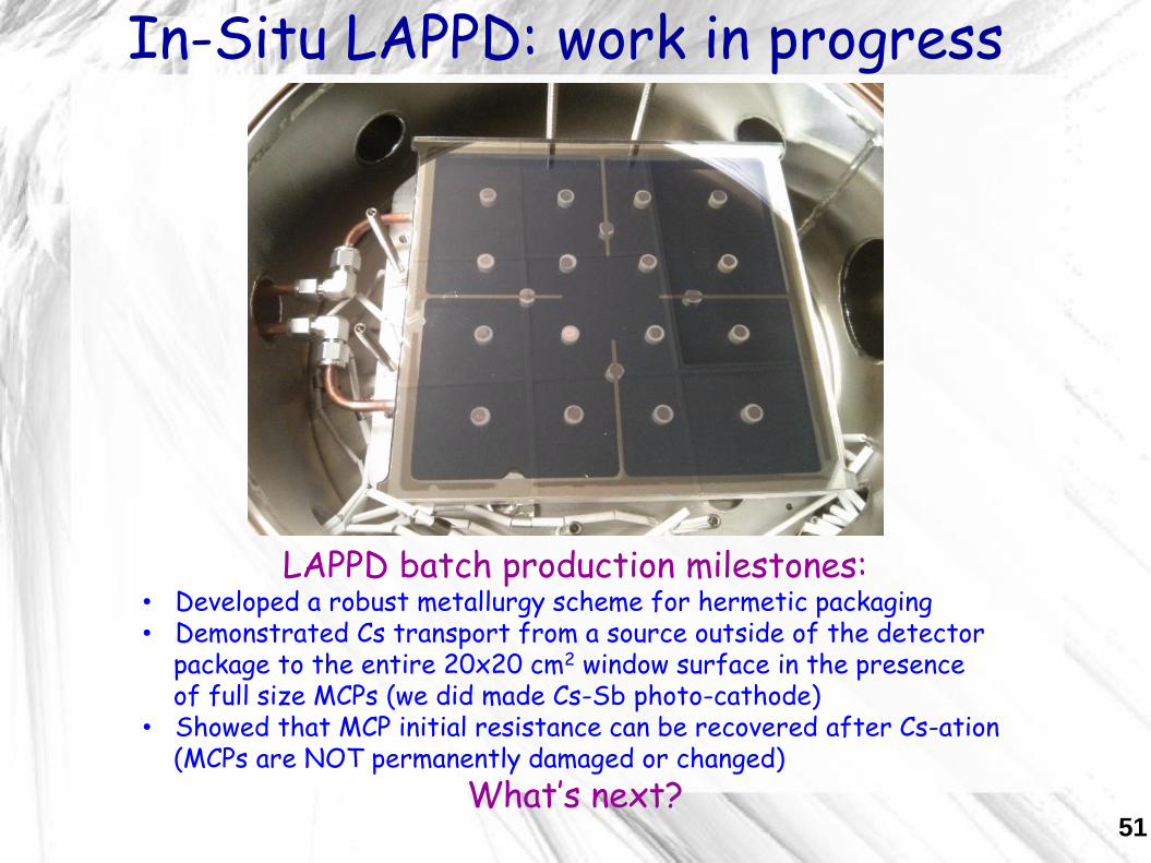
In-Situ LAPPD: work in progress
LAPPD batch production milestones:• Developed a robust metallurgy scheme for hermetic packaging• Demonstrated Cs transport from a source outside of the detector
package to the entire 20x20 cm2 window surface in the presenceof full size MCPs (we did made Cs-Sb photo-cathode)
• Showed that MCP initial resistance can be recovered after Cs-ation(MCPs are NOT permanently damaged or changed)
What’s next?51

10/12/2017 15
We’ve just got a new lab
Going Forward at Full Speed
We’ve got 2nd processing chamber(parallelization!)
We are getting lots of components
52
53
Take Away Message
Light is slow if measured in picoseconds
Lots of information can be recoveredby ‘drifting photons’ to a highly segmented
photo-detector
Detecting Cherenkov light in a liquid scintillator detector is very attractive
Large-Area Picosecond Photo-Detectorsare being developed
We really need lots of LAPPDs!(batch high volume production)

Evan Angelico, AE, Henry Frisch,
Rich Northrop, Carla Pilcher, Eric Spieglan
plus Eric Oberla and Mircea Bogdan on electronics
plus 12 high school and undergrad students last summer
UChicago PSEC Team
Thank you!
54

55
Back-up

56

57

58
PSEC4

59
OTPC

In-Situ Cathode Synthesis Trials in Progress
60
Evan (FIB/SEM) and Andrey (SEM)
E.g. The black powder from cesiating excess indiumSealing surface on top of sidewall
Black powder NiCr anode
(New windows will have no exposed
Cu- few weeks away)
Analysis showing it’s a CsIncompound

Low-Dose Whole-Body PET CameraChin-Tu Chen, Henry Frisch, Chien-Min Kao, and Heejong Kim
29

Simulation and reconstruction work by Carla Grosso-Pilcher
Low-Dose Whole-Body PET Camera
water-based liquid scintillator
photo-detector planes
30

Time resolution on 2 ends of 8”-anode
strip vs (S/N)-1 in psec (pair of 8” MCP’s)
< 6 psec
Laser spot size
Differential Time Resolution
7

Does the time resolution go as 1/N or 1/root-N photo-electrons?Hypothesis:• In an MCP-PMT the time jitter is dominated by the 1st strike:
path length to the 1st strike varies
• Smaller pores, increased bias angle are better
• “IF gain is such that a single photon shower makes the pulse (e.g. 107), time jitter is set by the probability that NO photon has arrived in interval dt” - H. FrischThis assumes that one fits the waveform to determine pulse T0
E.g. if 50 photoelectrons (from Cherenkov light in a window) arrive within 50 psec, the probability that one goes for T psec with NO photon making a first strike goes as e-T
=> a 1/N dependence
Large-signal Limit Dependence
8

Can We Detect Cherenkov Light?
Scintillation emission is slower
Longer wavelengths travel faster
Cherenkov light arrives earlier
Scintillation light is more intense and
Cherenkov light is usually lost in liquid
scintillator detectors e-
370 nm 0.191 m/ns600 nm 0.203 m/ns
~2 ns difference over 6.5m distance
Scintillation model based on KamLAND-Zen simulation
23

66
Directionality of Early Photons
C.Aberle, A.Elagin, H.Frisch,
M.Wetstein, L.Winslow
2014 JINST 9 P06012

67
½ Q (116Cd) =1.4 MeV ½ Q (48Ca) =2.1 MeV
Light yield: Cherenkov vs scintillation
What About Lower Energies?

0nbb vs 8B
Vertex res 5cm, events within R<3mSci rise time 1 ns
Ioverlap = 0.79

0nbb vs 8B
Vertex res 5cm, events within R<3mSci rise time 5 ns
Ioverlap = 0.64

70
Off-Center Events

71
0nbb-decay vs 10Ctwo-track vs a “complicated” topology
10C decay chain:
• 10C final state consist of a positron and gamma(e+ also gives 2x0.511MeV gammas after loosing energy to scintillation)
• Positron has lower kinetic energy than 0nbb electrons• Positron scintillates over shorter distance from primary vertex• Gammas can travel far from the primary vertex
10C vs 0nbb-decay: photons arrival time profile
Diagram by Jon Ouellet
10C background can be large at a shallow detector depth
TTS=100 ps

72
0nbb-decay vs 10CPhotons count in early light sample
Time profile for events uniformlydistributed within the fiducial volume, R<3m
Vertex resolution of 3cm is assumed
Spherical harmonics help here too
Disclaimer: there are other handles on 10C that are already in use (e.g., muon tag, secondary vertices). Actual improvement in separation power may vary.
TTS=100 ps

73

74

75

76